Fault Detection Technique for Compact AES Design
10
IOSR Journal of Applied Chemistry (IOSR-JAC) e-ISSN: 2278-5736. Volume 4, Issue 5 (May. – Jun. 2013), PP 15-24 www.iosrjournals.org www.iosrjournals.org 15 | Page Fault Detection Technique for Compact AES Design Nahala Basheer 1 , Ms. Nisha Lali R 2 , Mr. Rajeev S K 3 PG Scholar, ECE Department, Younus College of Engineering and TechnologyKerala Asst. Professor ECE Department Younus College of Engineering and Technology Kerala Head of the Department ECE Department Younus College of Engineering and Technology Kerala Abstract: Cryptography is a method that has been developed to ensure the secrecy of messages and transfer data securely. Advanced Encryption Standard (AES) has been made as the first choice for many critical applications because of the high level of security and the fast hardware and software implementations, many of which are power and resource constrained and requires reliable and efficient hardware implementations. Naturally occurring and maliciously injected faults reduce the reliability of Advanced Encryption Standard (AES) and may leak confidential information. In this paper, a lightweight concurrent fault detection scheme for the AES is presented. In the proposed approach, the composite field S-box and inverse S-box are divided into blocks and the predicted parities of these blocks are obtained. For high speed applications, S-box implementation based on lookup tables is avoided. Instead, logic gate implementations based on composite fields are utilized. A compact architecture for the AES Mix-columns operation and its inverse is also presented. This parity-based fault detection scheme reaches the maximum fault coverage when compared to other methods of fault detection. The proposed fault detection technique for AES encryption and decryption has the least area and power consumption compared to their counterparts with similar fault detection capabilities. Index terms: AES, composite fields, parity prediction, fault detection, S-box. I. INTRODUCTION The Advanced Encryption Standard (AES) has been accepted by NIST [1] as the symmetric key standard as a replacement for the previous standards because of its good characteristics in terms of security, cost, and efficient implementations for encryption and decryption of blocks of data. In encryption, under the influence of a key, a 128-bit block is encrypted by transforming it in a unique way into a new block of the same size. AES is symmetric since the same key is used for encryption and the reverse transformation, decryption. The only secret necessary to keep for security is the key. AES may be configured to use different key-lengths, the standard defines 3 lengths and the resulting algorithms are named AES-128, AES-192 and AES-256 respectively to indicate the length in bits of the key. After 10 rounds, the cipher text is generated where each encryption round (except for the final round) consists of four transformations. The four transformations of round of encryption are explained below. The 128 bits of input (and output) of each transformation are considered as a four by four matrix, called state, whose entries are eight bits. Except for the last round, the first transformation in each round is the bytes substitution, called SubBytes, which is implemented by 16 S-boxes. Shift-Rows is the second transformation in which the four bytes of the last three rows of the input state are cyclically shifted. The third transformation is Mixcolumns in which the columns are considered as polynomials over GF(2 8 ) and multiplied by a fixed polynomial. The final transformation is AddRoundKey in which a roundkey is added to the input by 128 two- input XOR gates. Among the transformations in the AES, the S-boxes in the encryption and the inverse S-boxes in the decryption are alone nonlinear. Fault detection in the AES hardware implementation is important in order to make the standard robust to the internal and malicious faults. There exists various fault detection schemes for the AES hardware implementation. For fault detection of the encryption or decryption in AES redundant units may be used [12], [14], where algorithm-level, round-level and operation-level concurrent error detection for the AES is used. A number of fault detection schemes based on the error detecting codes, also exists. For high performance AES implementations, using ROMs may not be preferable. The proposed fault detection approach is applied to the composite field AES encryption and decryption. There exist a number of fault detection approaches which are specific to composite field S-boxes and inverse S-boxes. In the scheme of [13], the fault detection of the multiplicative inversion of the S-box is considered. In [12], predicted parities have been used for the multiplicative inversion of a specific S-box using composite field and polynomial basis. Furthermore, the transformation matrices are also considered. In [12] and [6], the composite field S-boxes and inverse S-boxes (using polynomial basis) have been divided into sub-blocks and parity predictions are used for their fault detection.
-
Upload
independent -
Category
Documents
-
view
1 -
download
0
Transcript of Fault Detection Technique for Compact AES Design

IOSR Journal of Applied Chemistry (IOSR-JAC)
e-ISSN: 2278-5736. Volume 4, Issue 5 (May. – Jun. 2013), PP 15-24 www.iosrjournals.org
www.iosrjournals.org 15 | Page
Fault Detection Technique for Compact AES Design
Nahala Basheer1 ,
Ms. Nisha Lali R2 ,
Mr. Rajeev S K3
PG Scholar, ECE Department, Younus College of Engineering and TechnologyKerala
Asst. Professor ECE Department Younus College of Engineering and Technology Kerala
Head of the Department ECE Department Younus College of Engineering and Technology Kerala
Abstract: Cryptography is a method that has been developed to ensure the secrecy of messages and transfer data
securely. Advanced Encryption Standard (AES) has been made as the first choice for many critical applications
because of the high level of security and the fast hardware and software implementations, many of which are
power and resource constrained and requires reliable and efficient hardware implementations. Naturally
occurring and maliciously injected faults reduce the reliability of Advanced Encryption Standard (AES) and may
leak confidential information. In this paper, a lightweight concurrent fault detection scheme for the AES is
presented. In the proposed approach, the composite field S-box and inverse S-box are divided into blocks and the predicted parities of these blocks are obtained. For high speed applications, S-box implementation based on
lookup tables is avoided. Instead, logic gate implementations based on composite fields are utilized. A compact
architecture for the AES Mix-columns operation and its inverse is also presented. This parity-based fault
detection scheme reaches the maximum fault coverage when compared to other methods of fault detection. The
proposed fault detection technique for AES encryption and decryption has the least area and power consumption
compared to their counterparts with similar fault detection capabilities.
Index terms: AES, composite fields, parity prediction, fault detection, S-box.
I. INTRODUCTION The Advanced Encryption Standard (AES) has been accepted by NIST [1] as the symmetric key
standard as a replacement for the previous standards because of its good characteristics in terms of security, cost,
and efficient implementations for encryption and decryption of blocks of data. In encryption, under the influence
of a key, a 128-bit block is encrypted by transforming it in a unique way into a new block of the same size. AES
is symmetric since the same key is used for encryption and the reverse transformation, decryption. The only
secret necessary to keep for security is the key. AES may be configured to use different key-lengths, the standard
defines 3 lengths and the resulting algorithms are named AES-128, AES-192 and AES-256 respectively to
indicate the length in bits of the key. After 10 rounds, the cipher text is generated where each encryption round
(except for the final round) consists of four transformations. The four transformations of round of encryption are
explained below.
The 128 bits of input (and output) of each transformation are considered as a four by four matrix, called
state, whose entries are eight bits. Except for the last round, the first transformation in each round is the bytes substitution, called SubBytes, which is implemented by 16 S-boxes. Shift-Rows is the second transformation in
which the four bytes of the last three rows of the input state are cyclically shifted. The third transformation is
Mixcolumns in which the columns are considered as polynomials over GF(28) and multiplied by a fixed
polynomial. The final transformation is AddRoundKey in which a roundkey is added to the input by 128 two-
input XOR gates.
Among the transformations in the AES, the S-boxes in the encryption and the inverse S-boxes in the
decryption are alone nonlinear. Fault detection in the AES hardware implementation is important in order to
make the standard robust to the internal and malicious faults. There exists various fault detection schemes for the
AES hardware implementation. For fault detection of the encryption or decryption in AES redundant units may
be used [12], [14], where algorithm-level, round-level and operation-level concurrent error detection for the AES
is used. A number of fault detection schemes based on the error detecting codes, also exists. For high performance AES implementations, using ROMs may not be preferable. The proposed fault detection approach
is applied to the composite field AES encryption and decryption. There exist a number of fault detection
approaches which are specific to composite field S-boxes and inverse S-boxes. In the scheme of [13], the fault
detection of the multiplicative inversion of the S-box is considered. In [12], predicted parities have been used for
the multiplicative inversion of a specific S-box using composite field and polynomial basis. Furthermore, the
transformation matrices are also considered. In [12] and [6], the composite field S-boxes and inverse S-boxes
(using polynomial basis) have been divided into sub-blocks and parity predictions are used for their fault
detection.

Fault Detection Technique for Compact AES Design
www.iosrjournals.org 16 | Page
In the schemes proposed in [15] and [22], all the search space of composite fields is considered for
presenting optimum lightweight fault detection schemes. The scheme presented in [8] is for all the
transformations in the AES encryption/decryption independent of the ways these transformations are
implemented. Moreover, the scheme presented in [7] uses double-data-rate computation for counteracting the
fault attacks. Additionally, a fault detection scheme based on the Hamming and Reed-Solomon codes for
protecting the storage elements within the AES is proposed in [11]. It is also noted that, for the logic elements,
the scheme in [2] and the use of the partial duplication of the most vulnerable elements are proposed in [11].
Fig. 1. The S-box (the inverse S-box) using composite fields and polynomial basis and their fault detection blocks.
Fig. 2. The S-box (the inverse S-box) using composite fields and normal basis and their fault detection blocks.
All the S-boxes (respectively the inverse S-boxes) occupy much of the total AES encryption
(respectively decryption) area and their power consumption is around three fourths of that of the entire AES [16].
LUTs can be utilized for the AES S-boxes and inverse S-boxes in hardware implementation. This work involves
low-area implementation of the AES encryption and decryption using composite fields. The contributions of this paper are as follows.
The S-box and the inverse S-box has been designed to obtain low power and low area.
An alternative lightweight design for both forward and inverse mixcolumns operation required in the AES
hardware implementation is also presented.
A low-cost parity-based fault detection scheme for the S-box and the inverse S-box using composite fields is
presented, for increasing the error coverage. The predicted parities of the five blocks of the S-box and the
inverse S-box are obtained (three predicted parities for the multiplicative inversion and two for the
transformation and affine matrices).
The actual parity is obtained from the blocks using XOR gates. The predicted parity is compared with the
actual parity. The error gets indicated using the error indication flag.
The proposed fault detection scheme is simulated and maximum error coverage is obtained compared to existing methods. It is shown that the power and area of the proposed technique is least compared to the
schemes that have the same fault detection capabilities.
II. S-BOX AND INVERSE S-BOX IN COMPOSITE FIELDS In this section, the S-box and the inverse S-box operations and their composite-field realizations are
described. The S-box and the Inverse S-box are nonlinear operations which take 8-bit inputs and generate 8-bit
outputs. In the S-box, the irreducible polynomial of P(x) = x8 + x4 + x3 + x +1 is used to construct the binary
field GF(28). Let 𝑋 = 𝑥7𝑖=0 iα
i ∈ 𝐺𝐹(28) and 𝑌 = 𝑦7𝑖=0 iα
i ∈ 𝐺𝐹(28) be the input and the output of the S-box,
respectively, where α is a root of P(x), i.e. P(α)=0. Then, the S-box consists of the multiplicative inversion, i.e.,
X-1 ∈ GF(28), followed by an affine transformation. Moreover, let Y-1 ∈ GF(28) and X-1 ∈ GF(28) be the input and

Fault Detection Technique for Compact AES Design
www.iosrjournals.org 17 | Page
the output of the Inverse S-box, respectively. Then, the Inverse S-box consists of an inverse affine transformation
followed by the multiplicative inversion.
The composite fields can be represented using normal basis or polynomial basis. The S-box and inverse S-
box for the polynomial and normal bases are shown in Figs. 1 and 2, respectively. For the S-box using
polynomial basis (respectively normal basis), the transformation matrix ψ (respectively ψ') transforms a field
element X in the binary field GF(28) to the corresponding representation in the composite fields GF(28) / GF(24).
It is noted that the result of X= ηh u+ ηl is obtained using the irreducible polynomial u2+ τu + υ for polynomial basis method in Fig.1 and X= η'h u
16+ η'lu is obtained using the irreducible polynomial u2+ τ'u
+ υ for normal basis method in Fig.2.
The multiplicative inversion in Fig.1 consists of composite field multiplications, additions and an
inversion in the sub-field GF(24) over GF(2) / x4 + x + 1.The decomposition can be further applied to represent
GF(24) as a linear polynomial over GF(22) and then GF(2) using the irreducible polynomial υ2+Ωυ+υ and
w2+w+1, respectively. As a result, it is understood that the implementation of the multiplicative inversion can be
performed using the field represented by GF((24)2) or the field represented by GF(((22)2)2). For normal basis, the
decomposition is performed using the irreducible polynomials of υ2 + Ω'υ + υ' and w2 + w + 1, respectively.
For calculating the multiplicative inversion, the most efficient choice is to let Ω = τ = 1 (Ω' = τ' = 1) in the
above irreducible polynomials. Then, the multiplicative inversion of the S-box using polynomial basis and
normal basis are respectively, ( ηh u + ηl )
-1 = [(( ηh+ ηl ) + ηh2 υ )-1 ηh] u
+ (( ηh+ ηl ) + ηh2 υ )-1 ( ηh+ ηl ) (1)
( η'h u16 + η'l u )-1 = [( η'h η'l + (η'h
2 + ƞ'l2) υ')-1) η'h] u
16
+ [( η'h η'l + (η'h2 + ƞ'l
2) υ')-1) η'l] u (2)
It is noted that one can replace ƞ(ƞ') with σ(σ') to obtain (1) and (2) for the inverse S-box.
III. MIX COLUMN IMPLEMENTATION USING POLYNOMIALS The forward mix column transformation (in encryption process), called mix columns, operates on each
column individually. Each byte of a column is mapped into a new value that is a function of all four bytes in that
column. The transformation can be defined by the following matrix multiplication on State.
02 03 01 0101 02 03 0101 01 02 0303 01 01 02
𝑠0,0 s0,1 𝑠0,2 𝑠0.3𝑠1.0 𝑠1,1 𝑠1,2 𝑠1,3𝑠2,0 𝑠2,1 𝑠2,2 𝑠2,3𝑠3,0 𝑠3,1 𝑠3,2 𝑠3,3
=
𝑠′0,0 s′0,1 𝑠′0,2 𝑠′0.3𝑠′1.0 𝑠′1,1 𝑠′1,2 𝑠′1,3𝑠′2,0 𝑠′2,1 𝑠′2,2 𝑠′2,3𝑠′3,0 𝑠′3,1 𝑠′3,2 𝑠′3,3
Each element in the product matrix is the sum of products of elements of one row and one column. In
this case, the individual additions and multiplications are performed in GF (28). The mix columns transformation on a single column j (0≤ j≤ 3) of State can be expressed as
𝑠′0, 𝑗 = 2 ∗ 𝑠0, 𝑗 ⊕ 3 ∗ 𝑠1, 𝑗 ⊕ 𝑠2, 𝑗 ⊕ 𝑠3, 𝑗 𝑠′1, 𝑗 = 𝑠0, 𝑗 ⊕ 2 ∗ 𝑠1, 𝑗 ⊕(3*𝑠2, 𝑗) ⊕ 𝑠3, 𝑠′2, 𝑗 = 𝑠0, 𝑗 ⊕ 𝑠1, 𝑗 ⊕ 2 ∗ 𝑠2, 𝑗 ⊕ 3 ∗ 𝑠3, 𝑗
𝑠′3, 𝑗 = 3 ∗ 𝑠0, 𝑗 ⊕ 𝑠1, 𝑗 ⊕ 𝑠2, 𝑗 ⊕ (2 ∗ 𝑠3, 𝑗) (3)
As mix columns only requires multiplication by {02} and {03}, which, as we have seen, involved
simple shifts, conditional XORs, and XORs. This can be implemented in a more efficient way that eliminates the
shifts and conditional XORs. Equation Set (3) shows the equations for the mix columns transformation on a single column. Using the identity
{03} ・ x = ({02} ・ x) x, we can rewrite equation Set (3) as follows:
𝑇𝑚𝑝 = 𝑠0, 𝑗 ⊕ 𝑠1, 𝑗 ⊕ 𝑠2, 𝑗 ⊕ 𝑠3, 𝑗 𝑠′0, 𝑗 = 𝑠0, 𝑗 ⊕ 𝑇𝑚𝑝 ⊕ [ 2 ∗ 𝑠0, 𝑗 ⊕ 𝑠1, 𝑗 ] 𝑠′1, 𝑗 = 𝑠1, 𝑗 ⊕ 𝑇𝑚𝑝 ⊕ [ 2 ∗ 𝑠1, 𝑗 ⊕ 𝑠2, 𝑗 ] 𝑠′2, 𝑗 = 𝑠2, 𝑗 ⊕ 𝑇𝑚𝑝 ⊕ [ 2 ∗ 𝑠2, 𝑗 ⊕ 𝑠3, 𝑗 ] 𝑠′3, 𝑗 = 𝑠3, 𝑗 ⊕ 𝑇𝑚𝑝 ⊕ [ 2 ∗ 𝑠3, 𝑗 ⊕ 𝑠0, 𝑗 ] (4)
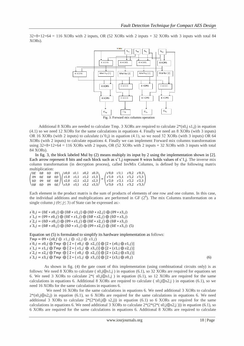
Multiplication by 02 equivalents to multiply by x [2]. The gate count of this implementation (using
combinational circuits only) is as shown in fig.(4) is as follows: 8 XORs to calculate ( s0,j ⊕ s1,j) in equation
(4.1), so 32 XORs are required for the same calculations in equations 4.
Additional 8 XORs are needed to calculate Tmp. 3 XORs are required to calculate 2*(s0,j s1,j) in equation (4.1)
so we need 12 XORs for the same calculations in equations 4. Finally we need an 8 XORs (with 3 inputs) OR 16
XORs (with 2 inputs) to calculate (s’0,j) in equation (4.1), so we need 32 XORs (with 3 inputs) OR 64 XORs
(with 2 inputs) to calculate equations 4. Finally we can implement Forward mix columns transformation using
Fault Detection Technique for Compact AES Design
www.iosrjournals.org 18 | Page
32+8+12+64 = 116 XORs with 2 inputs, OR (52 XORs with 2 inputs + 32 XORs with 3 inputs with total 84
XORs).
Fig. 3. Forward mix columns operation
Additional 8 XORs are needed to calculate Tmp. 3 XORs are required to calculate 2*(s0,j s1,j) in equation
(4.1) so we need 12 XORs for the same calculations in equations 4. Finally we need an 8 XORs (with 3 inputs)
OR 16 XORs (with 2 inputs) to calculate (s’0,j) in equation (4.1), so we need 32 XORs (with 3 inputs) OR 64
XORs (with 2 inputs) to calculate equations 4. Finally we can implement Forward mix columns transformation
using 32+8+12+64 = 116 XORs with 2 inputs, OR (52 XORs with 2 inputs + 32 XORs with 3 inputs with total
84 XORs).
In fig. 3, the block labeled Mul by (2) means multiply its input by 2 using the implementation shown in [2]. Each arrow represent 8 bits and each block such as s’1,j represent 8 wires holds values of s’1,j. The inverse mix
column transformation (in decryption process), called InvMix Columns, is defined by the following matrix
multiplication:
0𝐸 0𝐵 0𝐷 0909 0𝐸 0𝐵 0𝐷0𝐷 09 0𝐸 0𝐵0𝐵 0𝐷 09 0𝐸
𝑠0,0 s0,1 𝑠0,2 𝑠0.3𝑠1.0 𝑠1,1 𝑠1,2 𝑠1,3𝑠2,0 𝑠2,1 𝑠2,2 𝑠2,3𝑠3,0 𝑠3,1 𝑠3,2 𝑠3,3
=
𝑠′0,0 s′0,1 𝑠′0,2 𝑠′0.3𝑠′1.0 𝑠′1,1 𝑠′1,2 𝑠′1,3𝑠′2,0 𝑠′2,1 𝑠′2,2 𝑠′2,3𝑠′3,0 𝑠′3,1 𝑠′3,2 𝑠′3,3
Each element in the product matrix is the sum of products of elements of one row and one column. In this case, the individual additions and multiplications are performed in GF (28). The mix Columns transformation on a
single column j (0≤ j≤ 3) of State can be expressed as:-
𝑠 ′0, 𝑗 = 0𝐸 ∗ 𝑠0, 𝑗 ⊕ 0𝐵 ∗ 𝑠1, 𝑗 ⊕ 0𝐷 ∗ 𝑠2, 𝑗 ⊕ (09 ∗ 𝑠3, 𝑗) 𝑠 ′1, 𝑗 = 09 ∗ 𝑠0, 𝑗 ⊕ 0𝐸 ∗ 𝑠1, 𝑗 ⊕ 0𝐵 ∗ 𝑠2, 𝑗 ⊕ (0𝐷 ∗ 𝑠3, 𝑗) 𝑠 ′2, 𝑗 = 0𝐷 ∗ 𝑠0, 𝑗 ⊕ 09 ∗ 𝑠1, 𝑗 ⊕ 0𝐸 ∗ 𝑠2, 𝑗 ⊕ (0𝐵 ∗ 𝑠3, 𝑗) 𝑠 ′3, 𝑗 = 0𝐵 ∗ 𝑠0, 𝑗 ⊕ 0𝐷 ∗ 𝑠1, 𝑗 ⊕ 09 ∗ 𝑠2, 𝑗 ⊕ (0𝐸 ∗ 𝑠3, 𝑗) (5)
Equation set (5) is formulated to simplify its hardware implementation as follows: 𝑇𝑚𝑝 = 09 ∗ (𝑠0, 𝐽 ⊕ 𝑠1, 𝑗 ⊕ 𝑠2, 𝑗 ⊕ 𝑠3, 𝑗)
𝑠 ′0, 𝑗 = 𝑠0, 𝑗 ⊕ 𝑇𝑚𝑝 ⊕ 2 ∗ 𝑠0, 𝑗 ⊕ 𝑠2, 𝑗 ⊕ [2 ∗ 𝑠0, j ⊕ 𝑠1, 𝑗 ] 𝑠 ′1, 𝑗 = 𝑠1, 𝑗 ⊕ 𝑇𝑚𝑝 ⊕ 2 ∗ 𝑠1, 𝑗 ⊕ 𝑠3, 𝑗 ⊕ [2 ∗ 𝑠1, j ⊕ 𝑠2, 𝑗 ]
𝑠 ′2, 𝑗 = 𝑠2, 𝑗 ⊕ 𝑇𝑚𝑝 ⊕ 2 ∗ 𝑠0, 𝑗 ⊕ 𝑠2, 𝑗 ⊕ [2 ∗ 𝑠2, j ⊕ 𝑠3, 𝑗 ] 𝑠 ′3, 𝑗 = 𝑠3, 𝑗 ⊕ 𝑇𝑚𝑝 ⊕ 2 ∗ 𝑠1, 𝑗 ⊕ 𝑠3, 𝑗 ⊕ [2 ∗ 𝑠3, j ⊕ 𝑠0, 𝑗 (6)
As shown in fig. (4) the gate count of this implementation (using combinational circuits only) is as
follows: We need 8 XORs to calculate ( s0,j⊕s1,j ) in equation (6.1), so 32 XORs are required for equations set
6. We need 3 XORs to calculate 2*( s0,j⊕s1,j ) in equation (6.1), so 12 XORs are required for the same
calculations in equations 6. Additional 8 XORs are required to calculate ( s0,j⊕s2,j ) in equation (6.1), so we
need 16 XORs for the same calculations in equations 6.
We need 16 XORs for the same calculations in equations 6. We need additional 3 XORs to calculate
2*(s0,j⊕s2,j) in equation (6.1), so 6 XORs are required for the same calculations in equations 6. We need
additional 3 XORs to calculate 2*(2*(s0,j⊕ s2,j)) in equation (6.1) so 6 XORs are required for the same
calculations in equations 6. We need additional 3 XORs to calculate 2*(2*(2*( s0,j⊕s2,j ))) in equation (6.1), so 6 XORs are required for the same calculations in equations 6. Additional 8 XORs are required to calculate

Fault Detection Technique for Compact AES Design
www.iosrjournals.org 19 | Page
09*(s0,j⊕ s2,j), 8 XORs to calculate 09*(s1,j⊕ s3,j), and 8 XORs to calculate Tmp. Finally we need 24 XORs
to calculate s'0,j in equation (6.1), and 96 XORs for the same calculations in equations 6. Implementing inverse
mix columns transformation uses 32+12+16+6+6+6+16+8+96 = 198 XOR. Implementing forward and inverse
mix columns transformation uses 116 +198 = 314 XOR gates.
Fig. 4. Inverse mix columns operation
IV. FAULT DETECTION SCHEMES The S-box and the inverse S-box structures are divided into five blocks as shown in Fig.1 and 2 to
obtain the low-overhead parities. In these figures, the modulo-2 additions, consisting of 4 XOR gates, are shown
by two concentric circles with a plus inside. Furthermore, the multiplications in GF (24) are shown by rectangles
with crosses inside. Let bi be the output of block i denoted by dots in Fig.1 and 2 for S-box. The outputs of the
five blocks for S-box using polynomial basis in Fig.1 are represented as b1 = ηh+ ηl , b2 = γ, b3 =θ, b4 = σ and
b5 = Y. Similarly, for Fig.2 b1 = η'h+ η'l , b2 = γ', b3 =θ', b4 = σ' and b5 = Y. One can replace ƞ(ƞ') with σ(σ') and
X with Y for the inverse S-box. In the following, the least overhead parity are denoted by Ṕb1 - Ṕb5 in Figs. 1 and
2.
A. The S-Box and the Inverse S-Box using Polynomial Basis
The implementation complexities of different blocks of the S-box and the Inverse S-box and those for their predicted parities are dependent on the choice of the coefficients υ ε GF(24) and υ ε GF(22) in the
irreducible polynomials u2 + u + υ and v2 + v + υ used for the composite fields. The goal in the following
is to find υ ε GF(24) and υ ε GF(22) for the composite fields GF(((22)2)2) and υ ε GF(24) for the composite fields
GF((24)2) so that the area complexity of the entire fault detection implementations becomes optimum. According
to [19], 16 the possible combinations for υ ε GF(24) and υ ε GF(22) exist. Moreover, for the composite fields
GF((24)2), the possible choices for υ making the polynomial x2 + x + υ irreducible has been exhaustively
searched and found.
The blocks are explained below:
Blocks 1 and 5: Based on the possible values of υ and φ in GF(((22)2)2) ( υ in GF((24)2) ), the transformation
matrices in Fig. 1 in blocks 1 and 5 of the S-box and the inverse S-box can be constructed using the algorithm
presented in [21]. Using an exhaustive search, eight base elements in GF(((22)
2)2)
( or GF((24)2) ) to which eight base elements of GF(28) are mapped, are found to construct the transformation
matrix.
In [22], the Hamming weights, i.e., the number of nonzero elements, of the transformation matrices for the
case φ= {10}2 and different values of υ in GF(((22)2)2) are obtained. It is noted that in [21], instead of considering
the Hamming weights, sub expression sharing is suggested for obtaining the low-complexity implementations for

Fault Detection Technique for Compact AES Design
www.iosrjournals.org 20 | Page
the S-box. Here, we have also considered these transformation matrices for φ= {11}2 as well as the
transformation matrices for the inverse S-box for different values of υ and φ and have derived their area and
delay complexities. Moreover, the gate count and the critical path delay for blocks 1 and 5 and their predicted
parities, i.e., Ṕb1 and Ṕb5, of the S-box and the inverse S-box in have been obtained.
Blocks 2 and 4: As shown in Fig. 1, block 2 of the S-box and the inverse S-box consists of a multiplication, an
addition, a squaring and a multiplication by constant υ in GF((24)2) .The following lemma is presented for
deriving the predicted parity of the multiplication in GF((24)2), using which the predicted parities of blocks 2 and 4 in Fig. 1 are obtained.
Lemma 1: Let λ = ( λ3,λ2,λ1,λ0 ) and δ = ( δ3,δ2,δ1,δ0) be the inputs of the multiplier in GF((22)2). The predicted
parities of the result of the multiplication of λ and δ in GF((22)2) for φ= {10}2 and φ= {11}2 are as follows,
respectively
Ṕπ = λ3( δ3+δ2+δ0 )+ λ2( δ3+δ2+δ0 )+ λ1( δ2+δ0 )+
λ0( δ3+ δ0 +δ2+δ0) if φ= {10}2 (7)
Ṕπ = λ3( δ3 +δ0 )+ λ2( δ2+δ1+δ0 )+ λ1( δ2+δ0 )+
λ0( δ3+ δ0 +δ2+δ0) if φ= {11}2 (8)
The predicted parity of block 2 of the S-box and the inverse S-box, i.e., Ṕ in Fig.1, depends on the
choice of the coefficients υ ε GF ((22)2) and υ ε GF(22) []. Using Lemma 1, we have derived the complexity of
the predicted parity of block 2 for these coefficients. Furthermore, for block 4 in Fig.1, which consists of two
multiplications in GF ((22)2), one can also use Lemma 1 to derive the predicted parity. For block 2 of the S-box
(respectively the inverse S-box) over GF((24)2) in Fig. 1, only the multiplication by constant is affected for
different values of υs. For this block, we have exhaustively searched for and obtained the optimum
implementation for different values of υs. Moreover, block 4 in Fig. 1 is independent of the value of υ. Therefore,
the complexity of the predicted parity for this block is the same for all possible υs.
Block 3: We present the following theorem for block 3 of the
S-box and the inverse S-box over GF((22)2) in Fig. 1.
Theorem 1: Let γ = (γ3,γ2,γ1,γ0) be the input and θ=(θ3,θ2,θ1,θ0 ) be the output of an inverter in GF((22)2). The predicted parities of the result of the inversion in GF((22)2), i.e., Ṕb3 , for φ= {10}2 and φ= {11}2 are as follows,
respectively
Ṕθ= (͞γ2˅γ1)γ0+(γ1+γ0)γ3 if φ= {10}2 (9)
Ṕθ= (γ2 γ1˅ γ0) + γ3 γ1 if φ= {10}2 (10)
Where, ˅ represents OR operation. It is noted that the inversion in GF(24) [] in Fig. 1 is independent of the value
of υ. Therefore, the complexity of the predicted parity for this block is the same for any possible υs.
B. The S-Box and the Inverse S-Box Using Normal Basis
The optimum fault detection S-box using normal basis in Fig. 2 is derived. Here an exhaustive search for finding the optimum predicted parities based on the choice of the coefficients υ' ε GF(24) and υ' ε GF(22)
and for the five blocks of the inverse S-box using normal basis. We have exhaustively searched for the least
overhead transformation matrices and their parity predictions combined for the inverse S-box and have derived
the total complexity for the predicted parities of blocks 1 and 5, i.e., Ṕb1 and Ṕb5, and the delays associated with
them. These are used to obtain the optimum S-box inverse S-box and its parity predictions in this section. It is
also noted that as shown in Fig. 2, blocks 2, 3, and 4 of the S-box and the inverse S-box are the same. Therefore,
considering [15], the predicted parities of these blocks can be obtained for the inverse S-box.
C. Optimum parity prediction techniques
i. For polynomial basis:
Considering the discussions presented for different combinations of υ and φ for polynomial basis, the following optimum parity prediction technique is presented.
The fault detection S-Box using composite fields GF(((22)2)2) has the least area complexity for φ = {11}2 and υ=
{1010}2. For this optimum S-Box (PB1), the following predicted parities for the five blocks in Fig.1 are as given
below:
Ṕb1= x0
Ṕb2 = ƞ3(ƞ͞7+ƞ4)+ƞ2(ƞ͞7+ Pƞh)+ƞ1( ƞ6+ƞ4)+ƞ0 P͞ƞh+ƞ6+ƞ7

Fault Detection Technique for Compact AES Design
www.iosrjournals.org 21 | Page
Ṕb3=(γ2γ1˅γ0)+γ1γ3
Ṕb4 =ƞ3(θ3+θ0)+ƞ2(PΘ+θ3)+ƞ1(θ2+θ0)+ƞ0PΘ
Ṕb5 =σ7+σ5+σ3+σ2+σ0
where, Ṕƞh=ƞ7+ƞ6+ƞ5+ƞ4 and ṔΘ =θ3+θ2+θ1+θ0. Additionally, among all the possible values for using composite
fields GF ((24)2), υ= {1010}2 yields to the least complexity architecture for the optimum S-box (PB2),
respectively. Then, for the S-box we have:
Ṕb1= x7+x0
Ṕb2 = ƞ3ƞ4+ƞ2(ƞ5+ƞ4)+ƞ1(P͞ƞh+ƞ7)+ƞ0 P͞ƞh+ Pƞh +ƞ4
Ṕb3=͞γ3γ2͞γ0+γ0(͞γ1˅(͞γ͞͞2 ͞+͞γ3))
Ṕb4 =ƞ3θ0+ƞ2(θ1+θ0)+ƞ1(PΘ+θ3)+ƞ0PΘ
Ṕb5 =σ4+σ3+σ2+σ1+σ0
Furthermore, for the inverse S-box the following method is used. For the inverse S-box using composite field
GF(((22)2)2), choosing φ = {11}2 and υ = {1011}2 and for the one using composite field GF((24)2) having υ =
{1001}2 yields to the lowest area complexity architecture. It is noted that blocks 3 and 4 have the same predicted
parities as the S-box by swapping ƞ and σ. For other blocks of the optimum inverse S-box (PB1) we have:
Ṕb1= x͞0
Ṕb2 = σ3(͞σ7+σ4)+σ2(͞σ7+ Pƞh)+σ1(σ6+σ4)+σ0 P͞ƞh+σ6+σ7
Ṕb3=(γ2γ1˅γ0)+γ1γ3
Ṕb4 =ƞ3(θ3+θ0)+ƞ2(PΘ+θ3)+ƞ1(θ2+θ0)+ƞ0PΘ
Ṕb5 =ƞ7+ƞ5+ƞ3+ƞ2+ƞ0
Additionally, for the optimum inverse S-box (PB2) we have:
Ṕb1=͞x7͞+͞x0
Ṕb2 = σ3σ4+σ2(σ5+σ4)+σ1(P͞ƞh+σ7)+σ0 P͞ƞh+ Pƞh +σ4
Ṕb3=͞γ3γ2͞γ0+γ0(͞γ1˅(͞γ͞͞2 ͞+͞γ3))
Ṕb4 =ƞ3θ0+ƞ2(θ1+θ0)+ƞ1(PΘ+θ3)+ƞ0PΘ Ṕb5 = ƞ0
ii. For normal basis:
For different combinations of υ' and φ' for normal basis, for the S-box and the inverse S-box, φ' = {10}2
and υ' = {0001}2 have the least area for the operations and their fault detection circuits combined. The following
is the predicted parities for the S-box:
Ṕb1= x7+x5
Ṕb2 = (ƞ'7˅ƞ'3)+(ƞ'6˅ƞ'2)+(ƞ'4˅ ƞ'0)+ƞ'5ƞ'1
Ṕb3= γ͞'͞2͞γ͞'0(γ'3+ γ'1)+ γ'3 γ'1(γ'2+ γ'0)
Ṕb4 = (ƞ'7+ƞ'3) θ'3+(ƞ'6+ƞ'2) θ'2+(ƞ'5+ƞ'1) θ'1+(ƞ'4+ƞ'0) θ'0
Ṕb5 =σ'7+σ'5+σ'4+σ'3+σ'2
Moreover, for the inverse S-box, Ṕb2 - Ṕb4 are the same as those for the S-box by swapping ƞ' and σ'. For
the other blocks, the predicted parities are given as: Ṕb1= y7+y6+ y2+y1 and Ṕb5 =ƞ'7+ƞ'5+ƞ'4+ƞ'3+ƞ'2.
It is noted that the area overhead of the proposed scheme for the optimum structures consists of those
of the optimum parity predictions. In addition, 23 XORs for the actual parities (3 XORs for adding the coordinates
of each of ƞ'h+ƞ'l, γ' and θ' and 7 XORs each for those of ζ' and Y ) are utilized. Moreover, the delay overhead of
the predicted parities of five blocks can overlap the delays for the implementations of five blocks in Figs. 1 and
2. The only delay overhead for this scheme is the delay of the actual parity of block 5, which is 3TX, where TX, is
the delay of an XOR gate.
D. Error indication
In order to develop a fault detection structure, the predicted parity can be compared with the actual
parity in order to obtain the error indication flag of the corresponding block . By ORing five indication flags of
five blocks, the error indication of the entire S-box is obtained [15].
V. SIMULATION RESULTS

Fault Detection Technique for Compact AES Design
www.iosrjournals.org 22 | Page
First the S-box and the inverse S-box using composite fields is constructed for low area and low power
dissipation. Also the time delay is reduced compared to other techniques. Here S-Box and inverse S-Box are
constructed using both polynomial and normal basis. Then, single Struck-At-Faults have been introduced to the
S-box and the Inverse S-box and the corresponding output simulation is obtained. After that the circuit is tested
for multiple Struck-At-Faults. If exactly one bit error appears at the output of the S-box (respectively inverse S-
box), the presented fault detection scheme is able to detect it and the error coverage is about 100%. This is
because in this case, the error indication flag of the corresponding block alarms the error. However, due to the technological constraints, single stuck-at error may not be applicable for an attacker to gain more information
[23]. Thus, multiple bits will actually be flipped and hence multiple stuck-at errors are also considered in this
paper covering both natural faults and fault attacks [23].
Here a lightweight Mixcolumns is also implemented using logic gates. The total number of gates
required for implementing mix columns operation in the proposed design is 116+198 =314 XOR gates[],[]. Since
our design is implemented using combinational circuits only, each resultant mix column takes a single clock
cycle. The proposed mix column implementation takes four clock cycles compared to 28 clock cycles in [4]. The
circuit for both AES encryption and decryption is designed. Xilinx ISE 8.1 and ModelSim are the simulation
tools used here. The target device is XC2S600E. Finally, the error coverage has been calculated from the
obtained results. The design is also simulated for power, delay and area calculations. From the simulation result
the following is inferred. TABLE I
COMPARISON OF LUTS AND SLICES
Operation Architecture No. of 4-input
LUTs
No. of
slices
S-Box
LUT 250 158
PB 87 31
NB 83 31
Inverse S-Box
LUT 250 158
PB 84 31
NB 73 31
A. Low area and Low power
From the synthesis report, the number of LUTs and slices needed to design the S-box and the Inverse S-
box is calculated. Table I gives the comparison of the number of LUTs and slices used for the design of S-box
and Inverse S-box using various techniques. From the Table I the number of LUTs and Slices used for S-box
and Inverse S-box using composite fields is less when compared to S-box based on LUTs . Table II illustrates the comparison results based on simulation in terms of power.
TABLE II
COMPARISON OF POWER
Operation Architecture Power
(mW)
S-Box
LUT 56
PB 34
NB 34
Inverse S-Box
LUT 56
PB 34
NB 34
B. Fault detection
The proposed architecture for the S-box and Inverse S-box is able to find all the single Struck-At faults.
Faults are injected randomly on the input and output nodes of the logic gates. In the case of multiple Struck-At faults in S-box, also the faults have been identified. We have performed error simulations for the S-boxes and the
inverse S-boxes using the optimum composite field obtained in the previous section to confirm our above
theoretical computation. In our simulations, we use stuck-at error model at the outputs of the five blocks forcing
one or multiple nodes to be stuck at logic one (for stuck-at one) or zero (for stuck-at zero) independent of the
error-free values. We use Fibonacci implementation of the LFSRs for injecting random multiple errors, where,
the numbers, the locations and the types of the errors are randomly chosen. In this regard, the maximum
sequence length polynomial for the feedback is selected. The injected errors are transient, i.e., they last for one
clock cycle. However, the results would be the same if permanent errors are considered. The results of the error
simulation [] is shown in Table III. It is noted that in these tables, the optimum polynomial basis (PB) and

Fault Detection Technique for Compact AES Design
www.iosrjournals.org 23 | Page
normal basis (NB) are presented. As shown in the table, using five parity bits of the five blocks, the error
coverage for random faults reaches 97% which is the same as our theoretical computation in this section. This
error coverage will be increased if the outputs of more than one S-box (respectively inverse S-box) of the AES
implementation are erroneous. In this case, the errors detected in any of 16 S-boxes (respectively inverse S-
boxes) contribute to the total error coverage. Thus, error coverage of very close to 100% is achieved.
The optimum S-box and inverse S-box using normal basis have the least hardware complexity with the
fault detection scheme. Moreover, the optimum structures using composite fields and polynomial basis have the least post place and route timing overhead among other schemes. It is noted that using sub-pipelining for the
presented fault detection scheme in this paper, one can reach much faster hardware implementations of the
composite field fault detection structures. The AES encryption and decryption presented here using composite
fields and forward mix columns method has least area compared to its counterparts.
TABLE III
ERROR SIMULATION RESULTS
Operation Architecture Error coverage
S-Box (Inverse S-Box)
PB 97.008
NB 97.003
VI. CONCLUSION In this paper, low power AES encryption and decryption has been designed. Parity based fault detection scheme for the low power S-box and the Inverse S-box are presented in order to find the faults in the hardware
implementation of the S-box and the Inverse S-box. Instead of using the look-up table approach for the
implementation of the S-box and its parity prediction, the composite field arithmetic with logical gates is used.
Simulation results show that very high error coverage for the presented scheme is obtained when compared to
other fault detection schemes like those based on LUTs and redundant units. Also low power and low area is
achieved when compared to previous methods. An alternative lightweight design for both forward and inverse
mix columns operation required also included in the AES hardware implementation. The comparisons indicate
that the proposed mix-column design have less complexity than previous relevant work in gate size and no. of
clock cycles.
Acknowledgment The authors would like to thank the management, and Faculty Members of Department of Electronics and
Communication Engineering, Younus College of Engineering and Technology, Kollam, Kerala for many
insightful discussions and the facilities extended for completing the task.
REFERENCES
[1] Mehran Mozaffari-Kermani and Arash Reyhani-Masoleh, “A lightweight High-Performance Fault Detection Scheme for the
Advanced Encryption Standard Using Composite Fields” IEEE Trans. On Very Large Scale Integration (VLSI) Syestems, vol. 19, no.
1, pp. 85–591,January 2011.
[2] National Institute of Standards and Technologies, Announcing the Advanced Encryption Standard (AES) FIPS 197, Nov. 2001.
[3] R. Karri, K. Wu, P. Mishra, and K. Yongkook, “Fault-based side-channel cryptanalysis tolerant Rijndael symmetric block cipher
architecture,” in Proc. DFT, Oct. 2001, pp. 418–426..
[4] R. Karri, K. Wu, P. Mishra, and Y. Kim, “Concurrent error detection schemes for fault-based side-channel cryptanalysis of symmetric
blockciphers,” IEEE Trans. Comput.-Aided Des. Integr. Circuits Syst., vol. 21, no. 12, pp. 1509–1517, Dec. 2002.
[5] G. Bertoni, L. Breveglieri, I. Koren, P. Maistri, and V. Piuri, “Error analysis and detection procedures for a hardware implementation
of the advanced encryption standard,” IEEE Trans. Computers, vol. 52, no. 4, pp. 492–505, Apr. 2003.
[6] G. Bertoni, L. Breveglieri, I. Koren, P. Maistri and V. Piuri, “A parity code based fault detection for an implementation of the
advanced encryption standard,” Proc. of IEEE Int’l S mp., Defect and Fault Toler n e in VLSI S stems (DFT ’02), pp. 51-59, Nov.
2002.
[7] M. Mozaffari Kermani, “Fault Detection Schemes for High Performance VLSI Implementations of the Advanced Encryption
Standard,” M.E.Sc. Thesis, Department of Electrical and Computer Engineering, The University of Western Ontario, London,Ontario,
Canada, April 2007.
[8] M. Mozaffari-Kermani and A. Reyhani-Masoleh, “Concurrent Structure-Independent Fault Detection Schemes for the Advanced
Encryption Standard,” IEEE Trans. Computers, vol. 59, no. 5, pp. 608-622, May 2010.
[9] C. H. Yen and B. F.Wu, “Simple error detection methods for hardware implementation of advanced encryption standard,” IEEE
Trans. Computers, vol. 55, no. 6, pp. 720–731, Jun. 2006.
[10] G. Bertoni, L. Breveglieri, I. Koren, P. Maistri, and V. Piuri, “A parity code based fault detection for an implementation of the
advanced encryption standard,” in Proc. DFT, Nov. 2002, pp. 51–59.
[11] G. Bertoni, L. Breveglieri, I. Koren, P. Maistri, and V. Piuri, “Error analysis and detection procedures for a hardware implementation
of the advanced encryption standard,” IEEE Trans. Computers, vol. 52, no. 4, pp. 492–505, Apr. 2003.
[12] C. Moratelli, F. Ghellar, E. Cota, and M. Lubaszewski, “A fault-tolerant DFA-resistant AES core,” in Proc. ISCAS, 2008, pp. 244–
247.
[13] M. Mozaffari-Kermani and A. Reyhani-Masoleh, “Parity-based fault detection architecture of S-box for advanced encryption
standard,” in Proc. DFT, Oct. 2006, pp. 572–580.

Fault Detection Technique for Compact AES Design
www.iosrjournals.org 24 | Page
[14] S.-Y. Wu and H.-T. Yen, “On the S-box architectures with concurrent error detection for the advanced encryption standard,” IEICE
Trans. Fundam. Electron., Commun. Comput. Sci., vol. E89-A, no. 10, pp. 2583–2588, Oct. 2006.
[15] R. Karri, K. Wu, P. Mishra, and K. Yongkook, “Fault-based Side-Channel Cryptanalysis Tolerant Rijndael Symmetric Block Cipher
Architecture,” ro . IEEE Int’l Symp. Defect and Fault Toler n e in VLSI S stems (DFT ’01), pp. 418-426, Oct.2001
[16] M. Mozaffari-Kermani and A. Reyhani-Masoleh, “A lightweight concurrent fault detection scheme for the AES S-boxes using normal
basis,” in Proc. CHES, Aug. 2008, pp. 113–129.
[17] D. Canright, “A very compact S-box for AES,” in Proc. CHES, Aug. 2005, pp. 441–455.
[18] A. Satoh, S. Morioka, K. Takano, and S. Munetoh, “A compact Rijndael hardware architecture with S-box optimization,” in Proc.
ASIACRYPT, Dec. 2001, pp. 239–254.
[19] J.Wolkerstorfer, E. Oswald, and M. Lamberger, “An ASIC implementation of the AES SBoxes,” in Proc. CT-RSA, 2002, pp. 67–78.
[20] V. Rijmen, Dept. ESAT, Katholieke Universiteit Leuven, Leuven, Belgium, Efficient Implementation of the Rijndael S-Box, 2000.
[21] X. Zhang and K. K. Parhi, “High-speed VLSI architectures for the AES algorithm,” IEEE Trans. Very Large Scale Integr. (VLSI)
Syst., vol. VLSI-12, no. 9, pp. 957–967, Sep. 2004.
[22] X. Zhang and K. K. Parhi, “On the optimum constructions of composite field for the AES algorithm,” IEEE Trans. Circuits Syst. II,
Exp. Briefs, vol. 53, no. 10, pp. 1153–1157, Oct. 2006.
[23] N. Mentens, L. Batina, B. Preneel, and I. Verbauwhede, “A systematic evaluation of compact hardware implementations for the
RijndaelS-box,” in Proc. CT-RSA, Feb. 2005, pp. 323–333.
[24] L. Breveglieri, I. Koren, and P. Maistri, “An operation-centered approach to fault detection in symmetric cryptography ciphers,” IEEE
Trans. Computers, vol. C-56, no. 5, pp. 534–540, May 2007.
[25] Xilinx [Online]. Available: http://www.xilinx.com/