FANUC Series 16i/160i-LB OPERATOR'S MANUAL
912
FANUC Series 16*-LB FANUC Series 160*-LB OPERATOR’S MANUAL B-63664EN/02
-
Upload
khangminh22 -
Category
Documents
-
view
0 -
download
0
Transcript of FANUC Series 16i/160i-LB OPERATOR'S MANUAL

FANUC Series 16*-LB FANUC Series 160*-LB
OPERATOR’S MANUAL
B-63664EN/02

• No part of this manual may be reproduced in any form. • All specifications and designs are subject to change without notice. The export of this product is subject to the authorization of the government of the country from where the product is exported. In this manual we have tried as much as possible to describe all the various matters. However, we cannot describe all the matters which must not be done, or which cannot be done, because there are so many possibilities. Therefore, matters which are not especially described as possible in this manual should be regarded as ”impossible”. This manual contains the program names or device names of other companies, some of which are registered trademarks of respective owners. However, these names are not followed by or in the main body.

s–1
SAFETY PRECAUTIONS
This section describes the safety precautions related to the use of CNC units. It is essential that these precautionsbe observed by users to ensure the safe operation of machines equipped with a CNC unit (all descriptions in thissection assume this configuration). Note that some precautions are related only to specific functions, and thusmay not be applicable to certain CNC units.Users must also observe the safety precautions related to the machine, as described in the relevant manual suppliedby the machine tool builder. Before attempting to operate the machine or create a program to control the operationof the machine, the operator must become fully familiar with the contents of this manual and relevant manualsupplied by the machine tool builder.
Contents
1. DEFINITION OF WARNING, CAUTION, AND NOTE s–2. . . . . . . . . . . . . . . . . . . . . . .
2. GENERAL WARNINGS AND CAUTIONS s–3. . . . . . . . . . . . . . . . . . . . . . . . . . . . . . . .
3. WARNINGS AND CAUTIONS RELATED TO PROGRAMMING s–5. . . . . . . . . . . . .
4. WARNINGS AND CAUTIONS RELATED TO HANDLING s–7. . . . . . . . . . . . . . . . . . .
5. WARNINGS RELATED TO DAILY MAINTENANCE s–9. . . . . . . . . . . . . . . . . . . . . . . .

SAFETY PRECAUTIONS B–63664EN/02
s–2
1 DEFINITION OF WARNING, CAUTION, AND NOTE
This manual includes safety precautions for protecting the user and preventing damage to themachine. Precautions are classified into Warning and Caution according to their bearing on safety.Also, supplementary information is described as a Note. Read the Warning, Caution, and Notethoroughly before attempting to use the machine.
WARNING
Applied when there is a danger of the user being injured or when there is a danger of both the userbeing injured and the equipment being damaged if the approved procedure is not observed.
CAUTION
Applied when there is a danger of the equipment being damaged, if the approved procedure is notobserved.
NOTE
The Note is used to indicate supplementary information other than Warning and Caution.
� Read this manual carefully, and store it in a safe place.

B–63664EN/02 SAFETY PRECAUTIONS
s–3
2 GENERAL WARNINGS AND CAUTIONS
WARNING
1. Never attempt to machine a workpiece without first checking the operation of the machine.Before starting a production run, ensure that the machine is operating correctly by performinga trial run using, for example, the single block, feedrate override, or machine lock function orby operating the machine with neither a tool nor workpiece mounted. Failure to confirm thecorrect operation of the machine may result in the machine behaving unexpectedly, possiblycausing damage to the workpiece and/or machine itself, or injury to the user.
2. Before operating the machine, thoroughly check the entered data.Operating the machine with incorrectly specified data may result in the machine behavingunexpectedly, possibly causing damage to the workpiece and/or machine itself, or injury to theuser.
3. Ensure that the specified feedrate is appropriate for the intended operation. Generally, for eachmachine, there is a maximum allowable feedrate. The appropriate feedrate varies with theintended operation. Refer to the manual provided with the machine to determine the maximumallowable feedrate. If a machine is run at other than the correct speed, it may behaveunexpectedly, possibly causing damage to the workpiece and/or machine itself, or injury to theuser.
4. When using a tool compensation function, thoroughly check the direction and amount ofcompensation. Operating the machine with incorrectly specified data may result in the machine behavingunexpectedly, possibly causing damage to the workpiece and/or machine itself, or injury to theuser.
5. The parameters for the CNC and PMC are factory–set. Usually, there is not need to change them.When, however, there is not alternative other than to change a parameter, ensure that you fullyunderstand the function of the parameter before making any change.Failure to set a parameter correctly may result in the machine behaving unexpectedly, possiblycausing damage to the workpiece and/or machine itself, or injury to the user.
6. Some laser beams are invisible (cannot be seen by the eye).Before approaching the nozzle, check that the laser beam is off. Failure to do so subjects the userto the danger of serious injury.
7. A workpiece that has just undergone laser beam processing is very hot. Touching it, therefore,may cause injury to the user.

SAFETY PRECAUTIONS B–63664EN/02
s–4
CAUTION
1. Immediately after switching on the power, do not touch any of the keys on the MDI panel untilthe position display or alarm screen appears on the CNC unit.Some of the keys on the MDI panel are dedicated to maintenance or other special operations.Pressing any of these keys may place the CNC unit in other than its normal state. Starting themachine in this state may cause it to behave unexpectedly.
2. The operator’s manual and programming manual supplied with a CNC unit provide an overalldescription of the machine’s functions, including any optional functions. Note that the optionalfunctions will vary from one machine model to another. Therefore, some functions describedin the manuals may not actually be available for a particular model. Check the specification ofthe machine if in doubt.
3 Some functions may have been implemented at the request of the machine–tool builder. Whenusing such functions, refer to the manual supplied by the machine–tool builder for details of theiruse and any related cautions.
NOTE
Programs, parameters, and macro variables are stored in nonvolatile memory in the CNC unit.Usually, they are retained even if the power is turned off. Such data may be deleted inadvertently,however, or it may prove necessary to delete all data from nonvolatile memory as part of errorrecovery.To guard against the occurrence of the above, and assure quick restoration of deleted data, backupall vital data, and keep the backup copy in a safe place.

B–63664EN/02 SAFETY PRECAUTIONS
s–5
3 WARNINGS AND CAUTIONS RELATED TOPROGRAMMING
This section covers the major safety precautions related to programming. Before attempting toperform programming, read the supplied operator’s manual and programming manual carefullysuch that you are fully familiar with their contents.
WARNING
1. Coordinate system setting
If a coordinate system is established incorrectly, the machine may behave unexpectedly as aresult of the program issuing an otherwise valid move command.Such an unexpected operation may damage the tool, the machine itself, the workpiece, or causeinjury to the user.
2. Positioning by nonlinear interpolation
When performing positioning by nonlinear interpolation (positioning by nonlinear movementbetween the start and end points), the tool path must be carefully confirmed before performingprogramming.Positioning involves rapid traverse. If the tool collides with the workpiece, it may damage thetool, the machine itself, the workpiece, or cause injury to the user.
3. Function involving a rotation axis
When programming polar coordinate interpolation or normal–direction (perpendicular) control,pay careful attention to the speed of the rotation axis. Incorrect programming may result in therotation axis speed becoming excessively high, such that centrifugal force causes the chuck tolose its grip on the workpiece if the latter is not mounted securely.Such mishap is likely to damage the tool, the machine itself, the workpiece, or cause injury tothe user.
4. Inch/metric conversion
Switching between inch and metric inputs does not convert the measurement units of data suchas the workpiece origin offset, parameter, and current position. Before starting the machine,therefore, determine which measurement units are being used. Attempting to perform anoperation with invalid data specified may damage the tool, the machine itself, the workpiece, orcause injury to the user.
5. Stroke check
After switching on the power, perform a manual reference position return as required. Strokecheck is not possible before manual reference position return is performed. Note that when strokecheck is disabled, an alarm is not issued even if a stroke limit is exceeded, possibly damagingthe tool, the machine itself, the workpiece, or causing injury to the user.

SAFETY PRECAUTIONS B–63664EN/02
s–6
CAUTION
1. Absolute/incremental mode
If a program created with absolute values is run in incremental mode, or vice versa, the machinemay behave unexpectedly.
2. Plane selection
If an incorrect plane is specified for circular interpolation, helical interpolation, or a canned cycle,the machine may behave unexpectedly. Refer to the descriptions of the respective functions fordetails.
3. Torque limit skip
Before attempting a torque limit skip, apply the torque limit. If a torque limit skip is specifiedwithout the torque limit actually being applied, a move command will be executed withoutperforming a skip.
4. Programmable mirror image
Note that programmed operations vary considerably when a programmable mirror image isenabled.
5. Compensation function
If a command based on the machine coordinate system or a reference position return commandis issued in compensation function mode, compensation is temporarily canceled, resulting in theunexpected behavior of the machine.Before issuing any of the above commands, therefore, always cancel compensation functionmode.
6. Gap control
Tracing control is performed to keep the gap constant. During tracing control, ensure that thenozzle does not move to any location other than around the workpiece. Otherwise, the nozzle maycollide with the machine, possibly causing damage to the nozzle and the machine.

B–63664EN/02 SAFETY PRECAUTIONS
s–7
4 WARNINGS AND CAUTIONS RELATED TO HANDLING
This section presents safety precautions related to the handling of machine tools. Before attemptingto operate your machine, read the supplied operator’s manual and programming manual carefully,such that you are fully familiar with their contents.
WARNING
1. Manual operation
When operating the machine manually, determine the current position of the tool and workpiece,and ensure that the movement axis, direction, and feedrate have been specified correctly.Incorrect operation of the machine may damage the tool, the machine itself, the workpiece, orcause injury to the operator.
2. Manual reference position return
After switching on the power, perform manual reference position return as required. If themachine is operated without first performing manual reference position return, it may behaveunexpectedly. Stroke check is not possible before manual reference position return is performed.An unexpected operation of the machine may damage the tool, the machine itself, the workpiece,or cause injury to the user.
3. Manual numeric command
When issuing a manual numeric command, determine the current position of the tool andworkpiece, and ensure that the movement axis, direction, and command have been specifiedcorrectly, and that the entered values are valid.Attempting to operate the machine with an invalid command specified may damage the tool, themachine itself, the workpiece, or cause injury to the operator.
4. Manual handle feed
In manual handle feed, rotating the handle with a large scale factor, such as 100, applied causesthe tool and table to move rapidly. Careless handling may damage the tool and/or machine, orcause injury to the user.
5. Origin/preset operation
Basically, never attempt an origin/preset operation when the machine is operating under thecontrol of a program. Otherwise, the machine may behave unexpectedly, possibly damaging thetool, the machine itself, the tool, or causing injury to the user.

SAFETY PRECAUTIONS B–63664EN/02
s–8
WARNING
6. Workpiece coordinate system shift
Manual intervention, machine lock, or mirror imaging may shift the workpiece coordinatesystem. Before attempting to operate the machine under the control of a program, confirm thecoordinate system carefully.If the machine is operated under the control of a program without making allowances for any shiftin the workpiece coordinate system, the machine may behave unexpectedly, possibly damagingthe tool, the machine itself, the workpiece, or causing injury to the operator.
7. Software operator’s panel and menu switches
Using the software operator’s panel and menu switches, in combination with the MDI panel, itis possible to specify operations not supported by the machine operator’s panel, such as modechange, override value change, and jog feed commands.Note, however, that if the MDI panel keys are operated inadvertently, the machine may behaveunexpectedly, possibly damaging the tool, the machine itself, the workpiece, or causing injuryto the user.
CAUTION
1. Manual intervention
If manual intervention is performed during programmed operation of the machine, the tool pathmay vary when the machine is restarted. Before restarting the machine after manual intervention,therefore, confirm the settings of the manual absolute switches, parameters, andabsolute/incremental command mode.
2. Feed hold, override, and single block
The feed hold, feedrate override, and single block functions can be disabled using custom macrosystem variable #3004. Be careful when operating the machine in this case.
3. Dry run
Usually, a dry run is used to confirm the operation of the machine. During a dry run, the machineoperates at dry run speed, which differs from the corresponding programmed feedrate. Note thatthe dry run speed may sometimes be higher than the programmed feed rate.
4. Cutter compensation in MDI mode
Pay careful attention to a tool path specified by a command in MDI mode, because cuttercompensation is not applied. When a command is entered from the MDI to interrupt in automaticoperation in cutter compensation mode, pay particular attention to the tool path when automaticoperation is subsequently resumed. Refer to the descriptions of the corresponding functions fordetails.
5. Program editing
If the machine is stopped, after which the machining program is edited (modification, insertion,or deletion), the machine may behave unexpectedly if machining is resumed under the controlof that program. Basically, do not modify, insert, or delete commands from a machining programwhile it is in use.

B–63664EN/02 SAFETY PRECAUTIONS
s–9
5 WARNINGS RELATED TO DAILY MAINTENANCE
WARNING
1. Memory backup battery replacement
When replacing the memory backup batteries, keep the power to the machine (CNC) turned on,and apply an emergency stop to the machine. Because this work is performed with the poweron and the cabinet open, only those personnel who have received approved safety andmaintenance training may perform this work.When replacing the batteries, be careful not to touch the high–voltage circuits (marked andfitted with an insulating cover).Touching the uncovered high–voltage circuits presents an extremely dangerous electric shockhazard.
NOTE
The CNC uses batteries to preserve the contents of its memory, because it must retain data such asprograms, offsets, and parameters even while external power is not applied.If the battery voltage drops, a low battery voltage alarm is displayed on the machine operator’s panelor screen.When a low battery voltage alarm is displayed, replace the batteries within a week. Otherwise, thecontents of the CNC’s memory will be lost.Refer to the maintenance section of the operator’s manual or programming manual for details of thebattery replacement procedure.

SAFETY PRECAUTIONS B–63664EN/02
s–10
WARNING
2. Absolute pulse coder battery replacement
When replacing the memory backup batteries, keep the power to the machine (CNC) turned on,and apply an emergency stop to the machine. Because this work is performed with the poweron and the cabinet open, only those personnel who have received approved safety andmaintenance training may perform this work.When replacing the batteries, be careful not to touch the high–voltage circuits (marked andfitted with an insulating cover).Touching the uncovered high–voltage circuits presents an extremely dangerous electric shockhazard.
NOTE
The absolute pulse coder uses batteries to preserve its absolute position.If the battery voltage drops, a low battery voltage alarm is displayed on the machine operator’s panelor screen.When a low battery voltage alarm is displayed, replace the batteries within a week. Otherwise, theabsolute position data held by the pulse coder will be lost.Refer to the maintenance section of the operator’s manual or programming manual for details of thebattery replacement procedure.

B–63664EN/02 SAFETY PRECAUTIONS
s–11
WARNING
3. Fuse replacement
For some units, the chapter covering daily maintenance in the operator’s manual or programmingmanual describes the fuse replacement procedure.Before replacing a blown fuse, however, it is necessary to locate and remove the cause of theblown fuse.For this reason, only those personnel who have received approved safety and maintenancetraining may perform this work.When replacing a fuse with the cabinet open, be careful not to touch the high–voltage circuits(marked and fitted with an insulating cover).Touching an uncovered high–voltage circuit presents an extremely dangerous electric shockhazard.


B–63664EN/02 Table of Contents
c–1
SAFETY PRECAUTIONS S–1. . . . . . . . . . . . . . . . . . . . . . . . . . . . . . . . . . . . . . . . . . . . . . . . . . . . .
I. GENERAL
1. GENERAL 3. . . . . . . . . . . . . . . . . . . . . . . . . . . . . . . . . . . . . . . . . . . . . . . . . . . . . . . . . . . . 1.1 GENERAL FLOW OF OPERATION OF CNC MACHINE TOOL 6. . . . . . . . . . . . . . . . . . . . . . . . .
1.2 NOTES ON READING THIS MANUAL 7. . . . . . . . . . . . . . . . . . . . . . . . . . . . . . . . . . . . . . . . . . . . .
1.3 NOTES ON VARIOUS KINDS OF DATA 7. . . . . . . . . . . . . . . . . . . . . . . . . . . . . . . . . . . . . . . . . . . .
II. PROGRAMMING
1. GENERAL 11. . . . . . . . . . . . . . . . . . . . . . . . . . . . . . . . . . . . . . . . . . . . . . . . . . . . . . . . . . . . 1.1 NOZZLE MOVEMENT ALONG WORKPIECE PARTS FIGURE–INTERPOLATION 12. . . . . . . .
1.2 FEED–FEED FUNCTION 14. . . . . . . . . . . . . . . . . . . . . . . . . . . . . . . . . . . . . . . . . . . . . . . . . . . . . . . . .
1.3 PART DRAWING AND NOZZLE MOVEMENT 15. . . . . . . . . . . . . . . . . . . . . . . . . . . . . . . . . . . . . . . 1.3.1 Reference Position (Machine–Specific Position) 15. . . . . . . . . . . . . . . . . . . . . . . . . . . . . . . . . . . . . . . . . 1.3.2 Coordinate System on Part Drawing and Coordinate System Specified by
CNC – Coordinate System 16. . . . . . . . . . . . . . . . . . . . . . . . . . . . . . . . . . . . . . . . . . . . . . . . . . . . . . . . . . 1.3.3 How to Indicate Command Dimensions for Moving the Machine Absolute,
Incremental Commands 19. . . . . . . . . . . . . . . . . . . . . . . . . . . . . . . . . . . . . . . . . . . . . . . . . . . . . . . . . . . .
1.4 COMMAND FOR MACHINE OPERATIONS–MISCELLANEOUS FUNCTION 20. . . . . . . . . . . . .
1.5 PROGRAM CONFIGURATION 21. . . . . . . . . . . . . . . . . . . . . . . . . . . . . . . . . . . . . . . . . . . . . . . . . . . .
1.6 NOZZLE MOVEMENT RANGE–STROKE 25. . . . . . . . . . . . . . . . . . . . . . . . . . . . . . . . . . . . . . . . . . .
2. CONTROLLED AXES 26. . . . . . . . . . . . . . . . . . . . . . . . . . . . . . . . . . . . . . . . . . . . . . . . . . 2.1 CONTROLLED AXES 27. . . . . . . . . . . . . . . . . . . . . . . . . . . . . . . . . . . . . . . . . . . . . . . . . . . . . . . . . . . .
2.2 AXIS NAME 28. . . . . . . . . . . . . . . . . . . . . . . . . . . . . . . . . . . . . . . . . . . . . . . . . . . . . . . . . . . . . . . . . . . .
2.3 INCREMENT SYSTEM 29. . . . . . . . . . . . . . . . . . . . . . . . . . . . . . . . . . . . . . . . . . . . . . . . . . . . . . . . . . .
2.4 MAXIMUM STROKE 30. . . . . . . . . . . . . . . . . . . . . . . . . . . . . . . . . . . . . . . . . . . . . . . . . . . . . . . . . . . .
3. PREPARATORY FUNCTION (G FUNCTION) 31. . . . . . . . . . . . . . . . . . . . . . . . . . . . . .
4. INTERPOLATION FUNCTIONS 36. . . . . . . . . . . . . . . . . . . . . . . . . . . . . . . . . . . . . . . . . . 4.1 POSITIONING (G00) 37. . . . . . . . . . . . . . . . . . . . . . . . . . . . . . . . . . . . . . . . . . . . . . . . . . . . . . . . . . . . .
4.2 SINGLE DIRECTION POSITIONING (G60) 39. . . . . . . . . . . . . . . . . . . . . . . . . . . . . . . . . . . . . . . . . .
4.3 LINEAR INTERPOLATION (G01) 40. . . . . . . . . . . . . . . . . . . . . . . . . . . . . . . . . . . . . . . . . . . . . . . . . .
4.4 CIRCULAR INTERPOLATION (G02, G03) 42. . . . . . . . . . . . . . . . . . . . . . . . . . . . . . . . . . . . . . . . . . .
4.5 HELICAL INTERPOLATION (G02, G03) 46. . . . . . . . . . . . . . . . . . . . . . . . . . . . . . . . . . . . . . . . . . . .
4.6 HELICAL INTERPOLATION B (G02, G03) 47. . . . . . . . . . . . . . . . . . . . . . . . . . . . . . . . . . . . . . . . . .
4.7 POLAR COORDINATE INTERPOLATION (G12.1, G13.1) 48. . . . . . . . . . . . . . . . . . . . . . . . . . . . . .
4.8 CYLINDRICAL INTERPOLATION (G07.1) 52. . . . . . . . . . . . . . . . . . . . . . . . . . . . . . . . . . . . . . . . . .
4.9 HYPOTHETICAL AXIS INTERPOLATION (G07) 55. . . . . . . . . . . . . . . . . . . . . . . . . . . . . . . . . . . . .
4.10 SKIP FUNCTION (G31) 58. . . . . . . . . . . . . . . . . . . . . . . . . . . . . . . . . . . . . . . . . . . . . . . . . . . . . . . . . .
4.11 MULTI–STEP SKIP (G31) 60. . . . . . . . . . . . . . . . . . . . . . . . . . . . . . . . . . . . . . . . . . . . . . . . . . . . . . . . .
4.12 HIGH SPEED SKIP SIGNAL (G31) 61. . . . . . . . . . . . . . . . . . . . . . . . . . . . . . . . . . . . . . . . . . . . . . . . .

B–63664EN/02Table of Contents
c–2
5. FEED FUNCTIONS 62. . . . . . . . . . . . . . . . . . . . . . . . . . . . . . . . . . . . . . . . . . . . . . . . . . . . . 5.1 GENERAL 63. . . . . . . . . . . . . . . . . . . . . . . . . . . . . . . . . . . . . . . . . . . . . . . . . . . . . . . . . . . . . . . . . . . . .
5.2 RAPID TRAVERSE 65. . . . . . . . . . . . . . . . . . . . . . . . . . . . . . . . . . . . . . . . . . . . . . . . . . . . . . . . . . . . . .
5.3 MACHINING FEED 66. . . . . . . . . . . . . . . . . . . . . . . . . . . . . . . . . . . . . . . . . . . . . . . . . . . . . . . . . . . . . .
5.4 CUTTING FEEDRATE CONTROL 68. . . . . . . . . . . . . . . . . . . . . . . . . . . . . . . . . . . . . . . . . . . . . . . . . 5.4.1 Exact Stop (G09, G61), Cutting Mode (G64) 69. . . . . . . . . . . . . . . . . . . . . . . . . . . . . . . . . . . . . . . . . . . . 5.4.2 Automatic Corner Override 70. . . . . . . . . . . . . . . . . . . . . . . . . . . . . . . . . . . . . . . . . . . . . . . . . . . . . . . . .
5.4.2.1 Automatic override for inner corners (G62) 70. . . . . . . . . . . . . . . . . . . . . . . . . . . . . . . . . . . . . . .
5.4.2.2 Internal circular machining feedrate change 72. . . . . . . . . . . . . . . . . . . . . . . . . . . . . . . . . . . . . . .
5.4.3 Automatic Corner Deceleration 73. . . . . . . . . . . . . . . . . . . . . . . . . . . . . . . . . . . . . . . . . . . . . . . . . . . . . .
5.4.3.1 Corner deceleration according to the corner angle 73. . . . . . . . . . . . . . . . . . . . . . . . . . . . . . . . . .
5.4.3.2 Corner deceleration according to the feedrate difference between blocks along each axis 76. . . . . . . . . . . . . . . . . . . . . . . . . . . . . . . . . . . . . . . . . . . . . . . . . . . . . . . . . . . . .
5.5 DWELL (G04) 80. . . . . . . . . . . . . . . . . . . . . . . . . . . . . . . . . . . . . . . . . . . . . . . . . . . . . . . . . . . . . . . . . .
6. REFERENCE POSITION 81. . . . . . . . . . . . . . . . . . . . . . . . . . . . . . . . . . . . . . . . . . . . . . . . 6.1 REFERENCE POSITION RETURN 82. . . . . . . . . . . . . . . . . . . . . . . . . . . . . . . . . . . . . . . . . . . . . . . . .
6.2 FLOATING REFERENCE POSITION RETURN (G30.1) 87. . . . . . . . . . . . . . . . . . . . . . . . . . . . . . . .
7. COORDINATE SYSTEM 88. . . . . . . . . . . . . . . . . . . . . . . . . . . . . . . . . . . . . . . . . . . . . . . . 7.1 MACHINE COORDINATE SYSTEM 89. . . . . . . . . . . . . . . . . . . . . . . . . . . . . . . . . . . . . . . . . . . . . . . .
7.2 WORKPIECE COORDINATE SYSTEM 90. . . . . . . . . . . . . . . . . . . . . . . . . . . . . . . . . . . . . . . . . . . . . 7.2.1 Setting a Workpiece Coordinate System 90. . . . . . . . . . . . . . . . . . . . . . . . . . . . . . . . . . . . . . . . . . . . . . . . 7.2.2 Selecting a Workpiece Coordinate System 91. . . . . . . . . . . . . . . . . . . . . . . . . . . . . . . . . . . . . . . . . . . . . . 7.2.3 Changing Workpiece Coordinate System 92. . . . . . . . . . . . . . . . . . . . . . . . . . . . . . . . . . . . . . . . . . . . . . . 7.2.4 Workpiece Coordinate System Preset (G92.1) 95. . . . . . . . . . . . . . . . . . . . . . . . . . . . . . . . . . . . . . . . . . . 7.2.5 Adding Workpiece Coordinate Systems (G54.1 or G54) 97. . . . . . . . . . . . . . . . . . . . . . . . . . . . . . . . . . .
7.3 LOCAL COORDINATE SYSTEM 99. . . . . . . . . . . . . . . . . . . . . . . . . . . . . . . . . . . . . . . . . . . . . . . . . .
7.4 PLANE SELECTION 101. . . . . . . . . . . . . . . . . . . . . . . . . . . . . . . . . . . . . . . . . . . . . . . . . . . . . . . . . . . . .
8. COORDINATE VALUE AND DIMENSION 102. . . . . . . . . . . . . . . . . . . . . . . . . . . . . . . . . 8.1 ABSOLUTE AND INCREMENTAL PROGRAMMING (G90, G91) 103. . . . . . . . . . . . . . . . . . . . . . .
8.2 POLAR COORDINATE COMMAND (G15, G16) 104. . . . . . . . . . . . . . . . . . . . . . . . . . . . . . . . . . . . . .
8.3 INCH/METRIC CONVERSION (G20, G21) 107. . . . . . . . . . . . . . . . . . . . . . . . . . . . . . . . . . . . . . . . . . .
8.4 DECIMAL POINT PROGRAMMING 108. . . . . . . . . . . . . . . . . . . . . . . . . . . . . . . . . . . . . . . . . . . . . . . .
9. AUXILIARY FUNCTION 109. . . . . . . . . . . . . . . . . . . . . . . . . . . . . . . . . . . . . . . . . . . . . . . . . 9.1 AUXILIARY FUNCTION (M FUNCTION) 110. . . . . . . . . . . . . . . . . . . . . . . . . . . . . . . . . . . . . . . . . . .
9.2 MULTIPLE M COMMANDS IN A SINGLE BLOCK 111. . . . . . . . . . . . . . . . . . . . . . . . . . . . . . . . . . .
9.3 M CODE GROUP CHECK FUNCTION 112. . . . . . . . . . . . . . . . . . . . . . . . . . . . . . . . . . . . . . . . . . . . . .
9.4 THE SECOND AUXILIARY FUNCTIONS (B CODES) 113. . . . . . . . . . . . . . . . . . . . . . . . . . . . . . . . .
10.PROGRAM CONFIGURATION 114. . . . . . . . . . . . . . . . . . . . . . . . . . . . . . . . . . . . . . . . . . 10.1 PROGRAM COMPONENTS OTHER THAN PROGRAM SECTIONS 116. . . . . . . . . . . . . . . . . . . . .
10.2 PROGRAM SECTION CONFIGURATION 118. . . . . . . . . . . . . . . . . . . . . . . . . . . . . . . . . . . . . . . . . . .
10.3 SUBPROGRAM (M98, M99) 124. . . . . . . . . . . . . . . . . . . . . . . . . . . . . . . . . . . . . . . . . . . . . . . . . . . . . . .
10.4 8–DIGIT PROGRAM NUMBER 128. . . . . . . . . . . . . . . . . . . . . . . . . . . . . . . . . . . . . . . . . . . . . . . . . . . .

B–63664EN/02 ����� �� ����
c–3
11.FUNCTIONS TO SIMPLIFY PROGRAMMING 131. . . . . . . . . . . . . . . . . . . . . . . . . . . . . 11.1 OPTIONAL ANGLE CHAMFERING AND CORNER ROUNDING 132. . . . . . . . . . . . . . . . . . . . . . .
11.2 FIGURE COPY (G72.1, G72.2) 135. . . . . . . . . . . . . . . . . . . . . . . . . . . . . . . . . . . . . . . . . . . . . . . . . . . . .
12.COMPENSATION FUNCTION 142. . . . . . . . . . . . . . . . . . . . . . . . . . . . . . . . . . . . . . . . . . . 12.1 TOOL OFFSET (G45–G48) 143. . . . . . . . . . . . . . . . . . . . . . . . . . . . . . . . . . . . . . . . . . . . . . . . . . . . . . . .
12.2 OVERVIEW OF CUTTER COMPENSATION C (G40–G42) 148. . . . . . . . . . . . . . . . . . . . . . . . . . . . .
12.3 DETAILS OF CUTTER COMPENSATION C 154. . . . . . . . . . . . . . . . . . . . . . . . . . . . . . . . . . . . . . . . . 12.3.1 General 154. . . . . . . . . . . . . . . . . . . . . . . . . . . . . . . . . . . . . . . . . . . . . . . . . . . . . . . . . . . . . . . . . . . . . . . . . 12.3.2 Nozzle Movement in Start–up 155. . . . . . . . . . . . . . . . . . . . . . . . . . . . . . . . . . . . . . . . . . . . . . . . . . . . . . . 12.3.3 Nozzle Movement in Offset Mode 159. . . . . . . . . . . . . . . . . . . . . . . . . . . . . . . . . . . . . . . . . . . . . . . . . . . . 12.3.4 Nozzle Movement in Offset Mode Cancel 173. . . . . . . . . . . . . . . . . . . . . . . . . . . . . . . . . . . . . . . . . . . . . . 12.3.5 Interference Check 179. . . . . . . . . . . . . . . . . . . . . . . . . . . . . . . . . . . . . . . . . . . . . . . . . . . . . . . . . . . . . . . . 12.3.6 Overcutting by Cutter Compensation 184. . . . . . . . . . . . . . . . . . . . . . . . . . . . . . . . . . . . . . . . . . . . . . . . . . 12.3.7 Input Command from MDI 187. . . . . . . . . . . . . . . . . . . . . . . . . . . . . . . . . . . . . . . . . . . . . . . . . . . . . . . . . . 12.3.8 G53, G28, G30, G30.1 and G29 Commands in Cutter Compensation C Mode 188. . . . . . . . . . . . . . . . . . 12.3.9 Corner Circular Interpolation (G39) 207. . . . . . . . . . . . . . . . . . . . . . . . . . . . . . . . . . . . . . . . . . . . . . . . . . .
12.4 CUTTER COMPENSATION VALUES, NUMBER OF COMPENSATION VALUES, AND ENTERING VALUES FROM THE PROGRAM (G10) 209. . . . . . . . . . . . . . . . . . . . . . . . . . . . .
12.5 SCALING (G50, G51) 211. . . . . . . . . . . . . . . . . . . . . . . . . . . . . . . . . . . . . . . . . . . . . . . . . . . . . . . . . . . .
12.6 COORDINATE SYSTEM ROTATION (G68, G69) 216. . . . . . . . . . . . . . . . . . . . . . . . . . . . . . . . . . . . .
12.7 NORMAL DIRECTION CONTROL (G40.1, G41.1, G42.1 OR G150, G151, G152) 222. . . . . . . . . . .
12.8 PROGRAMMABLE MIRROR IMAGE (G50.1, G51.1) 227. . . . . . . . . . . . . . . . . . . . . . . . . . . . . . . . . .
13.CUSTOM MACRO 229. . . . . . . . . . . . . . . . . . . . . . . . . . . . . . . . . . . . . . . . . . . . . . . . . . . . . 13.1 VARIABLES 230. . . . . . . . . . . . . . . . . . . . . . . . . . . . . . . . . . . . . . . . . . . . . . . . . . . . . . . . . . . . . . . . . . . .
13.2 SYSTEM VARIABLES 234. . . . . . . . . . . . . . . . . . . . . . . . . . . . . . . . . . . . . . . . . . . . . . . . . . . . . . . . . . .
13.3 ARITHMETIC AND LOGIC OPERATION 244. . . . . . . . . . . . . . . . . . . . . . . . . . . . . . . . . . . . . . . . . . .
13.4 MACRO STATEMENTS AND NC STATEMENTS 249. . . . . . . . . . . . . . . . . . . . . . . . . . . . . . . . . . . . .
13.5 BRANCH AND REPETITION 250. . . . . . . . . . . . . . . . . . . . . . . . . . . . . . . . . . . . . . . . . . . . . . . . . . . . . 13.5.1 Unconditional Branch (GOTO Statement) 250. . . . . . . . . . . . . . . . . . . . . . . . . . . . . . . . . . . . . . . . . . . . . . 13.5.2 Conditional Branch (IF Statement) 251. . . . . . . . . . . . . . . . . . . . . . . . . . . . . . . . . . . . . . . . . . . . . . . . . . . . 13.5.3 Repetition (While Statement) 252. . . . . . . . . . . . . . . . . . . . . . . . . . . . . . . . . . . . . . . . . . . . . . . . . . . . . . . .
13.6 MACRO CALL 254. . . . . . . . . . . . . . . . . . . . . . . . . . . . . . . . . . . . . . . . . . . . . . . . . . . . . . . . . . . . . . . . . . 13.6.1 Simple Call (G65) 255. . . . . . . . . . . . . . . . . . . . . . . . . . . . . . . . . . . . . . . . . . . . . . . . . . . . . . . . . . . . . . . . . 13.6.2 Modal Call (G66) 259. . . . . . . . . . . . . . . . . . . . . . . . . . . . . . . . . . . . . . . . . . . . . . . . . . . . . . . . . . . . . . . . . 13.6.3 Macro Call Using G Code 261. . . . . . . . . . . . . . . . . . . . . . . . . . . . . . . . . . . . . . . . . . . . . . . . . . . . . . . . . . 13.6.4 Macro Call Using an M Code 262. . . . . . . . . . . . . . . . . . . . . . . . . . . . . . . . . . . . . . . . . . . . . . . . . . . . . . . . 13.6.5 Subprogram Call Using an M Code 264. . . . . . . . . . . . . . . . . . . . . . . . . . . . . . . . . . . . . . . . . . . . . . . . . . . 13.6.6 Subprogram Calls Using a T Code 265. . . . . . . . . . . . . . . . . . . . . . . . . . . . . . . . . . . . . . . . . . . . . . . . . . . .
13.7 PROCESSING MACRO STATEMENTS 266. . . . . . . . . . . . . . . . . . . . . . . . . . . . . . . . . . . . . . . . . . . . . . 13.7.1 Details of NC Statements and Macro Statements Execution 266. . . . . . . . . . . . . . . . . . . . . . . . . . . . . . . . . 13.7.2 Caution for Using System Variables 268. . . . . . . . . . . . . . . . . . . . . . . . . . . . . . . . . . . . . . . . . . . . . . . . . . .
13.8 REGISTERING CUSTOM MACRO PROGRAMS 271. . . . . . . . . . . . . . . . . . . . . . . . . . . . . . . . . . . . . .
13.9 LIMITATIONS 272. . . . . . . . . . . . . . . . . . . . . . . . . . . . . . . . . . . . . . . . . . . . . . . . . . . . . . . . . . . . . . . . . .
13.10 EXTERNAL OUTPUT COMMANDS 273. . . . . . . . . . . . . . . . . . . . . . . . . . . . . . . . . . . . . . . . . . . . . . .
13.11 INTERRUPTION TYPE CUSTOM MACRO 277. . . . . . . . . . . . . . . . . . . . . . . . . . . . . . . . . . . . . . . . . . 13.11.1 Specification Method 278. . . . . . . . . . . . . . . . . . . . . . . . . . . . . . . . . . . . . . . . . . . . . . . . . . . . . . . . . . . . . . 13.11.2 Details of Functions 279. . . . . . . . . . . . . . . . . . . . . . . . . . . . . . . . . . . . . . . . . . . . . . . . . . . . . . . . . . . . . . .

B–63664EN/02Table of Contents
c–4
14.PROGRAMMABLE PARAMETER ENTRY (G10) 286. . . . . . . . . . . . . . . . . . . . . . . . . . .
15.MEMORY OPERATION USING FS15 TAPE FORMAT 288. . . . . . . . . . . . . . . . . . . . . .
16.HIGH SPEED CUTTING FUNCTIONS 289. . . . . . . . . . . . . . . . . . . . . . . . . . . . . . . . . . . . 16.1 FEEDRATE CLAMPING BY ARC RADIUS 290. . . . . . . . . . . . . . . . . . . . . . . . . . . . . . . . . . . . . . . . . .
16.2 ADVANCED PREVIEW CONTROL (G08) 291. . . . . . . . . . . . . . . . . . . . . . . . . . . . . . . . . . . . . . . . . . .
16.3 HIGH–SPEED REMOTE BUFFER 293. . . . . . . . . . . . . . . . . . . . . . . . . . . . . . . . . . . . . . . . . . . . . . . . . . 16.3.1 High–Speed Remote Buffer A (G05) 293. . . . . . . . . . . . . . . . . . . . . . . . . . . . . . . . . . . . . . . . . . . . . . . . . .
16.4 DISTRIBUTION PROCESSING TERMINATION MONITORING FUNCTION FOR THE HIGH–SPEED MACHINING COMMAND (G05) 296. . . . . . . . . . . . . . . . . . . . . . . . . . . . .
16.5 HIGH–PRECISION CONTOUR CONTROL (G05) 297. . . . . . . . . . . . . . . . . . . . . . . . . . . . . . . . . . . . .
16.6 HIGH–SPEED LINEAR INTERPOLATION (G05) 305. . . . . . . . . . . . . . . . . . . . . . . . . . . . . . . . . . . . .
16.7 AI CONTOUR CONTROL FUNCTION/AI NANO CONTOUR CONTROL FUNCTION 308. . . . . .
17.AXIS CONTROL FUNCTIONS 327. . . . . . . . . . . . . . . . . . . . . . . . . . . . . . . . . . . . . . . . . . . 17.1 SIMPLE SYNCHRONOUS CONTROL 328. . . . . . . . . . . . . . . . . . . . . . . . . . . . . . . . . . . . . . . . . . . . . .
17.2 ROTARY AXIS ROLL–OVER 331. . . . . . . . . . . . . . . . . . . . . . . . . . . . . . . . . . . . . . . . . . . . . . . . . . . . .
17.3 TANDEM CONTROL 332. . . . . . . . . . . . . . . . . . . . . . . . . . . . . . . . . . . . . . . . . . . . . . . . . . . . . . . . . . . .
18.SPECIFYING THE LASER FUNCTION 333. . . . . . . . . . . . . . . . . . . . . . . . . . . . . . . . . . . 18.1 CONTOUR MACHINING (G01, G02, G03, AND G12) 334. . . . . . . . . . . . . . . . . . . . . . . . . . . . . . . . .
18.2 PIERCING FUNCTION (G24) 336. . . . . . . . . . . . . . . . . . . . . . . . . . . . . . . . . . . . . . . . . . . . . . . . . . . . . .
18.3 LASER POWER CONTROL (G63) 339. . . . . . . . . . . . . . . . . . . . . . . . . . . . . . . . . . . . . . . . . . . . . . . . . .
18.4 BEAM OUTPUT CONDITION DELAY FUNCTION 349. . . . . . . . . . . . . . . . . . . . . . . . . . . . . . . . . . .
18.5 STEP FUNCTION 351. . . . . . . . . . . . . . . . . . . . . . . . . . . . . . . . . . . . . . . . . . . . . . . . . . . . . . . . . . . . . . .
18.6 ASSIST GAS CONTROL (G32) 356. . . . . . . . . . . . . . . . . . . . . . . . . . . . . . . . . . . . . . . . . . . . . . . . . . . . 18.6.1 Flow Pattern Specification 356. . . . . . . . . . . . . . . . . . . . . . . . . . . . . . . . . . . . . . . . . . . . . . . . . . . . . . . . . . 18.6.2 Direct Assist Gas Control Specification 357. . . . . . . . . . . . . . . . . . . . . . . . . . . . . . . . . . . . . . . . . . . . . . . . 18.6.3 Direct Gas Pressure Control Specification Using the Machining Condition Setting Function 359. . . . . . . .
18.7 MACHINING CONDITION SETTING FUNCTION (E CODE) 360. . . . . . . . . . . . . . . . . . . . . . . . . . . 18.7.1 Piercing Command 361. . . . . . . . . . . . . . . . . . . . . . . . . . . . . . . . . . . . . . . . . . . . . . . . . . . . . . . . . . . . . . . . 18.7.2 Cutting Command 361. . . . . . . . . . . . . . . . . . . . . . . . . . . . . . . . . . . . . . . . . . . . . . . . . . . . . . . . . . . . . . . . 18.7.3 Reading a Comment 362. . . . . . . . . . . . . . . . . . . . . . . . . . . . . . . . . . . . . . . . . . . . . . . . . . . . . . . . . . . . . . . 18.7.4 Edge Machining Function 363. . . . . . . . . . . . . . . . . . . . . . . . . . . . . . . . . . . . . . . . . . . . . . . . . . . . . . . . . . 18.7.5 Startup Machining Function 370. . . . . . . . . . . . . . . . . . . . . . . . . . . . . . . . . . . . . . . . . . . . . . . . . . . . . . . . .
18.8 HIGH–SPEED LASER MACHINING FUNCTION 372. . . . . . . . . . . . . . . . . . . . . . . . . . . . . . . . . . . . .
18.9 GAP CONTROL FUNCTION 381. . . . . . . . . . . . . . . . . . . . . . . . . . . . . . . . . . . . . . . . . . . . . . . . . . . . . .
18.10 LASER HIGH–SPEED CONTROL FUNCTION 382. . . . . . . . . . . . . . . . . . . . . . . . . . . . . . . . . . . . . . .
19.THREE–DIMENSIONAL CUTTING FUNCTION 385. . . . . . . . . . . . . . . . . . . . . . . . . . . . 19.1 ATTITUDE CONTROL 386. . . . . . . . . . . . . . . . . . . . . . . . . . . . . . . . . . . . . . . . . . . . . . . . . . . . . . . . . . .
19.2 SPATIAL CIRCULAR INTERPOLATION (G12) 387. . . . . . . . . . . . . . . . . . . . . . . . . . . . . . . . . . . . . . .
19.3 SPATIAL CORNER ROUNDING (G33 AND G34) 389. . . . . . . . . . . . . . . . . . . . . . . . . . . . . . . . . . . . .
19.4 THREE–DIMENSIONAL COORDINATE CONVERSION FUNCTION (G68 AND G69) 391. . . . . .
19.5 PROCESSING HEAD A–AXIS LENGTH COMPENSATION FUNCTION (G71) 393. . . . . . . . . . . . .
19.6 IMPROVEMENT IN NOZZLE LENGTH COMPENSATION 395. . . . . . . . . . . . . . . . . . . . . . . . . . . . .

B–63664EN/02 ����� �� ����
c–5
19.7 THREE–DIMENSIONAL TRANSFORM FUNCTION (G98, G99) 398. . . . . . . . . . . . . . . . . . . . . . . .
19.8 FEEDRATE CLAMP FUNCTION IN POSITION CONTROL B 402. . . . . . . . . . . . . . . . . . . . . . . . . . .
19.9 AUTOMATIC FEEDRATE OVERRIDE UNDER POSITION CONTROL B 405. . . . . . . . . . . . . . . . .
19.10 TORCH TURNING CONTROL FUNCTION 407. . . . . . . . . . . . . . . . . . . . . . . . . . . . . . . . . . . . . . . . . .
III. OPERATION
1. GENERAL 415. . . . . . . . . . . . . . . . . . . . . . . . . . . . . . . . . . . . . . . . . . . . . . . . . . . . . . . . . . . . 1.1 MANUAL OPERATION 416. . . . . . . . . . . . . . . . . . . . . . . . . . . . . . . . . . . . . . . . . . . . . . . . . . . . . . . . . .
1.2 MOVING THE NOZZLE USING A PROGRAM–AUTOMATIC OPERATION 418. . . . . . . . . . . . . . .
1.3 OPERATIONS FOR AUTOMATIC OPERATION 420. . . . . . . . . . . . . . . . . . . . . . . . . . . . . . . . . . . . . .
1.4 TEST OPERATION 422. . . . . . . . . . . . . . . . . . . . . . . . . . . . . . . . . . . . . . . . . . . . . . . . . . . . . . . . . . . . . . 1.4.1 Check by Running the Machine 422. . . . . . . . . . . . . . . . . . . . . . . . . . . . . . . . . . . . . . . . . . . . . . . . . . . . . . 1.4.2 Checking the Position Display Change Without Running the Machine 423. . . . . . . . . . . . . . . . . . . . . . . .
1.5 EDITING A PROGRAM 424. . . . . . . . . . . . . . . . . . . . . . . . . . . . . . . . . . . . . . . . . . . . . . . . . . . . . . . . . .
1.6 DISPLAYING AND SETTING DATA 425. . . . . . . . . . . . . . . . . . . . . . . . . . . . . . . . . . . . . . . . . . . . . . . .
1.7 DISPLAY 428. . . . . . . . . . . . . . . . . . . . . . . . . . . . . . . . . . . . . . . . . . . . . . . . . . . . . . . . . . . . . . . . . . . . . . 1.7.1 Program Display 428. . . . . . . . . . . . . . . . . . . . . . . . . . . . . . . . . . . . . . . . . . . . . . . . . . . . . . . . . . . . . . . . . . 1.7.2 Current Position Display 429. . . . . . . . . . . . . . . . . . . . . . . . . . . . . . . . . . . . . . . . . . . . . . . . . . . . . . . . . . . . 1.7.3 Alarm Display 429. . . . . . . . . . . . . . . . . . . . . . . . . . . . . . . . . . . . . . . . . . . . . . . . . . . . . . . . . . . . . . . . . . . 1.7.4 Part Count Display and Run Time Display 430. . . . . . . . . . . . . . . . . . . . . . . . . . . . . . . . . . . . . . . . . . . . . . 1.7.5 Graphic Display 430. . . . . . . . . . . . . . . . . . . . . . . . . . . . . . . . . . . . . . . . . . . . . . . . . . . . . . . . . . . . . . . . . .
1.8 DATA INPUT/OUTPUT 431. . . . . . . . . . . . . . . . . . . . . . . . . . . . . . . . . . . . . . . . . . . . . . . . . . . . . . . . . . .
2. OPERATIONAL DEVICES 432. . . . . . . . . . . . . . . . . . . . . . . . . . . . . . . . . . . . . . . . . . . . . . 2.1 SETTING AND DISPLAY UNITS 433. . . . . . . . . . . . . . . . . . . . . . . . . . . . . . . . . . . . . . . . . . . . . . . . . .
2.1.1 7.2″/8.4″ LCD–mounted Type CNC Control Unit 434. . . . . . . . . . . . . . . . . . . . . . . . . . . . . . . . . . . . . . . . 2.1.2 9.5″/10.4″ LCD–mounted Type CNC Control Unit 434. . . . . . . . . . . . . . . . . . . . . . . . . . . . . . . . . . . . . . . 2.1.3 Stand–alone Type Small MDI Unit 435. . . . . . . . . . . . . . . . . . . . . . . . . . . . . . . . . . . . . . . . . . . . . . . . . . . . 2.1.4 Stand–alone Type Standard MDI Unit 436. . . . . . . . . . . . . . . . . . . . . . . . . . . . . . . . . . . . . . . . . . . . . . . . . 2.1.5 Stand–alone Type 61 Fullkey MDI Unit 437. . . . . . . . . . . . . . . . . . . . . . . . . . . . . . . . . . . . . . . . . . . . . . . .
2.2 EXPLANATION OF THE KEYBOARD 438. . . . . . . . . . . . . . . . . . . . . . . . . . . . . . . . . . . . . . . . . . . . . .
2.3 FUNCTION KEYS AND SOFT KEYS 440. . . . . . . . . . . . . . . . . . . . . . . . . . . . . . . . . . . . . . . . . . . . . . . 2.3.1 General Screen Operations 440. . . . . . . . . . . . . . . . . . . . . . . . . . . . . . . . . . . . . . . . . . . . . . . . . . . . . . . . . . 2.3.2 Function Keys 441. . . . . . . . . . . . . . . . . . . . . . . . . . . . . . . . . . . . . . . . . . . . . . . . . . . . . . . . . . . . . . . . . . . 2.3.3 Soft Keys 442. . . . . . . . . . . . . . . . . . . . . . . . . . . . . . . . . . . . . . . . . . . . . . . . . . . . . . . . . . . . . . . . . . . . . . . 2.3.4 Key Input and Input Buffer 460. . . . . . . . . . . . . . . . . . . . . . . . . . . . . . . . . . . . . . . . . . . . . . . . . . . . . . . . . . 2.3.5 Warning Messages 461. . . . . . . . . . . . . . . . . . . . . . . . . . . . . . . . . . . . . . . . . . . . . . . . . . . . . . . . . . . . . . . . 2.3.6 Soft Key Configuration 462. . . . . . . . . . . . . . . . . . . . . . . . . . . . . . . . . . . . . . . . . . . . . . . . . . . . . . . . . . . .
2.4 EXTERNAL I/O DEVICES 463. . . . . . . . . . . . . . . . . . . . . . . . . . . . . . . . . . . . . . . . . . . . . . . . . . . . . . . . 2.4.1 FANUC Handy File 465. . . . . . . . . . . . . . . . . . . . . . . . . . . . . . . . . . . . . . . . . . . . . . . . . . . . . . . . . . . . . . .
2.5 POWER ON/OFF 466. . . . . . . . . . . . . . . . . . . . . . . . . . . . . . . . . . . . . . . . . . . . . . . . . . . . . . . . . . . . . . . . 2.5.1 Turning on the Power 466. . . . . . . . . . . . . . . . . . . . . . . . . . . . . . . . . . . . . . . . . . . . . . . . . . . . . . . . . . . . . . 2.5.2 Screen Displayed at Power–on 467. . . . . . . . . . . . . . . . . . . . . . . . . . . . . . . . . . . . . . . . . . . . . . . . . . . . . . . 2.5.3 Power Disconnection 468. . . . . . . . . . . . . . . . . . . . . . . . . . . . . . . . . . . . . . . . . . . . . . . . . . . . . . . . . . . . . .
3. MANUAL OPERATION 469. . . . . . . . . . . . . . . . . . . . . . . . . . . . . . . . . . . . . . . . . . . . . . . . . 3.1 MANUAL REFERENCE POSITION RETURN 470. . . . . . . . . . . . . . . . . . . . . . . . . . . . . . . . . . . . . . . .
3.2 JOG FEED 472. . . . . . . . . . . . . . . . . . . . . . . . . . . . . . . . . . . . . . . . . . . . . . . . . . . . . . . . . . . . . . . . . . . . .
3.3 INCREMENTAL FEED 474. . . . . . . . . . . . . . . . . . . . . . . . . . . . . . . . . . . . . . . . . . . . . . . . . . . . . . . . . . .

B–63664EN/02Table of Contents
c–6
3.4 MANUAL HANDLE FEED 475. . . . . . . . . . . . . . . . . . . . . . . . . . . . . . . . . . . . . . . . . . . . . . . . . . . . . . . .
3.5 MANUAL ABSOLUTE ON AND OFF 478. . . . . . . . . . . . . . . . . . . . . . . . . . . . . . . . . . . . . . . . . . . . . . .
4. AUTOMATIC OPERATION 483. . . . . . . . . . . . . . . . . . . . . . . . . . . . . . . . . . . . . . . . . . . . . . 4.1 MEMORY OPERATION 484. . . . . . . . . . . . . . . . . . . . . . . . . . . . . . . . . . . . . . . . . . . . . . . . . . . . . . . . . .
4.2 MDI OPERATION 486. . . . . . . . . . . . . . . . . . . . . . . . . . . . . . . . . . . . . . . . . . . . . . . . . . . . . . . . . . . . . . .
4.3 DNC OPERATION 490. . . . . . . . . . . . . . . . . . . . . . . . . . . . . . . . . . . . . . . . . . . . . . . . . . . . . . . . . . . . . . .
4.4 SIMULTANEOUS INPUT/OUTPUT 493. . . . . . . . . . . . . . . . . . . . . . . . . . . . . . . . . . . . . . . . . . . . . . . . .
4.5 PROGRAM RESTART 495. . . . . . . . . . . . . . . . . . . . . . . . . . . . . . . . . . . . . . . . . . . . . . . . . . . . . . . . . . . .
4.6 SCHEDULING FUNCTION 504. . . . . . . . . . . . . . . . . . . . . . . . . . . . . . . . . . . . . . . . . . . . . . . . . . . . . . .
4.7 SUBPROGRAM CALL FUNCTION (M198) 509. . . . . . . . . . . . . . . . . . . . . . . . . . . . . . . . . . . . . . . . . .
4.8 MANUAL HANDLE INTERRUPTION 511. . . . . . . . . . . . . . . . . . . . . . . . . . . . . . . . . . . . . . . . . . . . . .
4.9 MIRROR IMAGE 514. . . . . . . . . . . . . . . . . . . . . . . . . . . . . . . . . . . . . . . . . . . . . . . . . . . . . . . . . . . . . . . .
4.10 RETRACE FUNCTION 516. . . . . . . . . . . . . . . . . . . . . . . . . . . . . . . . . . . . . . . . . . . . . . . . . . . . . . . . . . .
4.11 MANUAL INTERVENTION AND RETURN 523. . . . . . . . . . . . . . . . . . . . . . . . . . . . . . . . . . . . . . . . .
4.12 DNC OPERATION WITH MEMORY CARD 525. . . . . . . . . . . . . . . . . . . . . . . . . . . . . . . . . . . . . . . . . . 4.12.1 Specification 525. . . . . . . . . . . . . . . . . . . . . . . . . . . . . . . . . . . . . . . . . . . . . . . . . . . . . . . . . . . . . . . . . . . . . 4.12.2 Operations 526. . . . . . . . . . . . . . . . . . . . . . . . . . . . . . . . . . . . . . . . . . . . . . . . . . . . . . . . . . . . . . . . . . . . . .
4.12.2.1 DNC operation 526. . . . . . . . . . . . . . . . . . . . . . . . . . . . . . . . . . . . . . . . . . . . . . . . . . . . . . . . . . . . .
4.12.2.2 Subprogram call (M198) 527. . . . . . . . . . . . . . . . . . . . . . . . . . . . . . . . . . . . . . . . . . . . . . . . . . . . .
4.12.3 Limitation and Notes 528. . . . . . . . . . . . . . . . . . . . . . . . . . . . . . . . . . . . . . . . . . . . . . . . . . . . . . . . . . . . . . 4.12.4 Parameter 528. . . . . . . . . . . . . . . . . . . . . . . . . . . . . . . . . . . . . . . . . . . . . . . . . . . . . . . . . . . . . . . . . . . . . . . 4.12.5 Connecting PCMCIA Card Attachment 529. . . . . . . . . . . . . . . . . . . . . . . . . . . . . . . . . . . . . . . . . . . . . . . .
4.12.5.1 Specification number 529. . . . . . . . . . . . . . . . . . . . . . . . . . . . . . . . . . . . . . . . . . . . . . . . . . . . . . . .
4.12.5.2 Assembling 529. . . . . . . . . . . . . . . . . . . . . . . . . . . . . . . . . . . . . . . . . . . . . . . . . . . . . . . . . . . . . . .
4.12.6 Recommended Memory Card 531. . . . . . . . . . . . . . . . . . . . . . . . . . . . . . . . . . . . . . . . . . . . . . . . . . . . . . . .
5. TEST OPERATION 532. . . . . . . . . . . . . . . . . . . . . . . . . . . . . . . . . . . . . . . . . . . . . . . . . . . . . 5.1 MACHINE LOCK AND AUXILIARY FUNCTION LOCK 533. . . . . . . . . . . . . . . . . . . . . . . . . . . . . . .
5.2 FEEDRATE OVERRIDE 535. . . . . . . . . . . . . . . . . . . . . . . . . . . . . . . . . . . . . . . . . . . . . . . . . . . . . . . . . .
5.3 RAPID TRAVERSE OVERRIDE 536. . . . . . . . . . . . . . . . . . . . . . . . . . . . . . . . . . . . . . . . . . . . . . . . . . .
5.4 DRY RUN 537. . . . . . . . . . . . . . . . . . . . . . . . . . . . . . . . . . . . . . . . . . . . . . . . . . . . . . . . . . . . . . . . . . . . . .
5.5 SINGLE BLOCK 538. . . . . . . . . . . . . . . . . . . . . . . . . . . . . . . . . . . . . . . . . . . . . . . . . . . . . . . . . . . . . . . .
6. SAFETY FUNCTIONS 539. . . . . . . . . . . . . . . . . . . . . . . . . . . . . . . . . . . . . . . . . . . . . . . . . . 6.1 EMERGENCY STOP 540. . . . . . . . . . . . . . . . . . . . . . . . . . . . . . . . . . . . . . . . . . . . . . . . . . . . . . . . . . . . .
6.2 OVERTRAVEL 541. . . . . . . . . . . . . . . . . . . . . . . . . . . . . . . . . . . . . . . . . . . . . . . . . . . . . . . . . . . . . . . . . .
6.3 STROKE CHECK 542. . . . . . . . . . . . . . . . . . . . . . . . . . . . . . . . . . . . . . . . . . . . . . . . . . . . . . . . . . . . . . . .
6.4 STROKE LIMIT CHECK PRIOR TO PERFORMING MOVEMENT 546. . . . . . . . . . . . . . . . . . . . . . .
7. ALARM AND SELF–DIAGNOSIS FUNCTIONS 548. . . . . . . . . . . . . . . . . . . . . . . . . . . . 7.1 ALARM DISPLAY 549. . . . . . . . . . . . . . . . . . . . . . . . . . . . . . . . . . . . . . . . . . . . . . . . . . . . . . . . . . . . . . .
7.2 ALARM HISTORY DISPLAY 551. . . . . . . . . . . . . . . . . . . . . . . . . . . . . . . . . . . . . . . . . . . . . . . . . . . . . .
7.3 CHECKING BY SELF–DIAGNOSTIC SCREEN 552. . . . . . . . . . . . . . . . . . . . . . . . . . . . . . . . . . . . . . .

B–63664EN/02 ����� �� ����
c–7
8. DATA INPUT/OUTPUT 555. . . . . . . . . . . . . . . . . . . . . . . . . . . . . . . . . . . . . . . . . . . . . . . . . . 8.1 FILES 556. . . . . . . . . . . . . . . . . . . . . . . . . . . . . . . . . . . . . . . . . . . . . . . . . . . . . . . . . . . . . . . . . . . . . . . . .
8.2 FILE SEARCH 558. . . . . . . . . . . . . . . . . . . . . . . . . . . . . . . . . . . . . . . . . . . . . . . . . . . . . . . . . . . . . . . . . .
8.3 FILE DELETION 559. . . . . . . . . . . . . . . . . . . . . . . . . . . . . . . . . . . . . . . . . . . . . . . . . . . . . . . . . . . . . . . .
8.4 PROGRAM INPUT/OUTPUT 560. . . . . . . . . . . . . . . . . . . . . . . . . . . . . . . . . . . . . . . . . . . . . . . . . . . . . . 8.4.1 Inputting a Program 560. . . . . . . . . . . . . . . . . . . . . . . . . . . . . . . . . . . . . . . . . . . . . . . . . . . . . . . . . . . . . . . 8.4.2 Outputting a Program 563. . . . . . . . . . . . . . . . . . . . . . . . . . . . . . . . . . . . . . . . . . . . . . . . . . . . . . . . . . . . . .
8.5 OFFSET DATA INPUT AND OUTPUT 565. . . . . . . . . . . . . . . . . . . . . . . . . . . . . . . . . . . . . . . . . . . . . . 8.5.1 Inputting Offset Data 565. . . . . . . . . . . . . . . . . . . . . . . . . . . . . . . . . . . . . . . . . . . . . . . . . . . . . . . . . . . . . . 8.5.2 Outputting Offset Data 566. . . . . . . . . . . . . . . . . . . . . . . . . . . . . . . . . . . . . . . . . . . . . . . . . . . . . . . . . . . . .
8.6 INPUTTING AND OUTPUTTING PARAMETERS AND PITCH ERROR COMPENSATION DATA 567. . . . . . . . . . . . . . . . . . . . . . . . . . . . . . . . . . . . . . . . . . . .
8.6.1 Inputting Parameters 567. . . . . . . . . . . . . . . . . . . . . . . . . . . . . . . . . . . . . . . . . . . . . . . . . . . . . . . . . . . . . . . 8.6.2 Outputting Parameters 568. . . . . . . . . . . . . . . . . . . . . . . . . . . . . . . . . . . . . . . . . . . . . . . . . . . . . . . . . . . . . 8.6.3 Inputting Pitch Error Compensation Data 569. . . . . . . . . . . . . . . . . . . . . . . . . . . . . . . . . . . . . . . . . . . . . . . 8.6.4 Outputting Pitch Error Compensation Data 570. . . . . . . . . . . . . . . . . . . . . . . . . . . . . . . . . . . . . . . . . . . . .
8.7 INPUTTING/OUTPUTTING CUSTOM MACRO COMMON VARIABLES 571. . . . . . . . . . . . . . . . . 8.7.1 Inputting Custom Macro Common Variables 571. . . . . . . . . . . . . . . . . . . . . . . . . . . . . . . . . . . . . . . . . . . . 8.7.2 Outputting Custom Macro Common Variable 572. . . . . . . . . . . . . . . . . . . . . . . . . . . . . . . . . . . . . . . . . . . .
8.8 DISPLAYING DIRECTORY OF FLOPPY CASSETTE 573. . . . . . . . . . . . . . . . . . . . . . . . . . . . . . . . . . 8.8.1 Displaying the Directory 574. . . . . . . . . . . . . . . . . . . . . . . . . . . . . . . . . . . . . . . . . . . . . . . . . . . . . . . . . . . . 8.8.2 Reading Files 577. . . . . . . . . . . . . . . . . . . . . . . . . . . . . . . . . . . . . . . . . . . . . . . . . . . . . . . . . . . . . . . . . . . . 8.8.3 Outputting Programs 578. . . . . . . . . . . . . . . . . . . . . . . . . . . . . . . . . . . . . . . . . . . . . . . . . . . . . . . . . . . . . . 8.8.4 Deleting Files 579. . . . . . . . . . . . . . . . . . . . . . . . . . . . . . . . . . . . . . . . . . . . . . . . . . . . . . . . . . . . . . . . . . . .
8.9 OUTPUTTING A PROGRAM LIST FOR A SPECIFIED GROUP 581. . . . . . . . . . . . . . . . . . . . . . . . .
8.10 DATA INPUT/OUTPUT ON THE ALL IO SCREEN 582. . . . . . . . . . . . . . . . . . . . . . . . . . . . . . . . . . . . 8.10.1 Setting Input/Output–Related Parameters 583. . . . . . . . . . . . . . . . . . . . . . . . . . . . . . . . . . . . . . . . . . . . . . . 8.10.2 Inputting and Outputting Programs 584. . . . . . . . . . . . . . . . . . . . . . . . . . . . . . . . . . . . . . . . . . . . . . . . . . . 8.10.3 Inputting and Outputting Parameters 589. . . . . . . . . . . . . . . . . . . . . . . . . . . . . . . . . . . . . . . . . . . . . . . . . . 8.10.4 Inputting and Outputting Offset Data 591. . . . . . . . . . . . . . . . . . . . . . . . . . . . . . . . . . . . . . . . . . . . . . . . . . 8.10.5 Outputting Custom Macro Common Variables 593. . . . . . . . . . . . . . . . . . . . . . . . . . . . . . . . . . . . . . . . . . . 8.10.6 Inputting and Outputting Floppy Files 594. . . . . . . . . . . . . . . . . . . . . . . . . . . . . . . . . . . . . . . . . . . . . . . . .
8.11 DATA INPUT/OUTPUT USING A MEMORY CARD 599. . . . . . . . . . . . . . . . . . . . . . . . . . . . . . . . . . .
8.12 DATA INPUT/OUTPUT BY EMBEDDED ETHERNET 611. . . . . . . . . . . . . . . . . . . . . . . . . . . . . . . . . 8.12.1 FTP File Transfer Function 611. . . . . . . . . . . . . . . . . . . . . . . . . . . . . . . . . . . . . . . . . . . . . . . . . . . . . . . . . .
8.12.1.1 Host file list display 611. . . . . . . . . . . . . . . . . . . . . . . . . . . . . . . . . . . . . . . . . . . . . . . . . . . . . . . . .
8.12.1.2 Host file search 614. . . . . . . . . . . . . . . . . . . . . . . . . . . . . . . . . . . . . . . . . . . . . . . . . . . . . . . . . . . . .
8.12.1.3 Host file deletion 614. . . . . . . . . . . . . . . . . . . . . . . . . . . . . . . . . . . . . . . . . . . . . . . . . . . . . . . . . . .
8.12.1.4 NC program input 615. . . . . . . . . . . . . . . . . . . . . . . . . . . . . . . . . . . . . . . . . . . . . . . . . . . . . . . . . .
8.12.1.5 NC program output 617. . . . . . . . . . . . . . . . . . . . . . . . . . . . . . . . . . . . . . . . . . . . . . . . . . . . . . . . .
8.12.1.6 Input/output of various types of data 618. . . . . . . . . . . . . . . . . . . . . . . . . . . . . . . . . . . . . . . . . . . .
8.12.1.7 Checking and changing of the connection host 624. . . . . . . . . . . . . . . . . . . . . . . . . . . . . . . . . . . .
9. EDITING PROGRAMS 627. . . . . . . . . . . . . . . . . . . . . . . . . . . . . . . . . . . . . . . . . . . . . . . . . . 9.1 INSERTING, ALTERING AND DELETING A WORD 628. . . . . . . . . . . . . . . . . . . . . . . . . . . . . . . . . .
9.1.1 Word Search 629. . . . . . . . . . . . . . . . . . . . . . . . . . . . . . . . . . . . . . . . . . . . . . . . . . . . . . . . . . . . . . . . . . . . . 9.1.2 Heading a Program 631. . . . . . . . . . . . . . . . . . . . . . . . . . . . . . . . . . . . . . . . . . . . . . . . . . . . . . . . . . . . . . . . 9.1.3 Inserting a Word 632. . . . . . . . . . . . . . . . . . . . . . . . . . . . . . . . . . . . . . . . . . . . . . . . . . . . . . . . . . . . . . . . . . 9.1.4 Altering a Word 633. . . . . . . . . . . . . . . . . . . . . . . . . . . . . . . . . . . . . . . . . . . . . . . . . . . . . . . . . . . . . . . . . . 9.1.5 Deleting a Word 634. . . . . . . . . . . . . . . . . . . . . . . . . . . . . . . . . . . . . . . . . . . . . . . . . . . . . . . . . . . . . . . . . .

B–63664EN/02Table of Contents
c–8
9.2 DELETING BLOCKS 635. . . . . . . . . . . . . . . . . . . . . . . . . . . . . . . . . . . . . . . . . . . . . . . . . . . . . . . . . . . . 9.2.1 Deleting a Block 635. . . . . . . . . . . . . . . . . . . . . . . . . . . . . . . . . . . . . . . . . . . . . . . . . . . . . . . . . . . . . . . . . . 9.2.2 Deleting Multiple Blocks 636. . . . . . . . . . . . . . . . . . . . . . . . . . . . . . . . . . . . . . . . . . . . . . . . . . . . . . . . . . .
9.3 PROGRAM NUMBER SEARCH 637. . . . . . . . . . . . . . . . . . . . . . . . . . . . . . . . . . . . . . . . . . . . . . . . . . .
9.4 SEQUENCE NUMBER SEARCH 638. . . . . . . . . . . . . . . . . . . . . . . . . . . . . . . . . . . . . . . . . . . . . . . . . . .
9.5 DELETING PROGRAMS 640. . . . . . . . . . . . . . . . . . . . . . . . . . . . . . . . . . . . . . . . . . . . . . . . . . . . . . . . . 9.5.1 Deleting One Program 640. . . . . . . . . . . . . . . . . . . . . . . . . . . . . . . . . . . . . . . . . . . . . . . . . . . . . . . . . . . . . 9.5.2 Deleting All Programs 640. . . . . . . . . . . . . . . . . . . . . . . . . . . . . . . . . . . . . . . . . . . . . . . . . . . . . . . . . . . . . 9.5.3 Deleting More Than One Program by Specifying a Range 641. . . . . . . . . . . . . . . . . . . . . . . . . . . . . . . . . .
9.6 EXTENDED PART PROGRAM EDITING FUNCTION 642. . . . . . . . . . . . . . . . . . . . . . . . . . . . . . . . . 9.6.1 Copying an Entire Program 642. . . . . . . . . . . . . . . . . . . . . . . . . . . . . . . . . . . . . . . . . . . . . . . . . . . . . . . . . 9.6.2 Copying Part of a Program 643. . . . . . . . . . . . . . . . . . . . . . . . . . . . . . . . . . . . . . . . . . . . . . . . . . . . . . . . . . 9.6.3 Moving Part of a Program 644. . . . . . . . . . . . . . . . . . . . . . . . . . . . . . . . . . . . . . . . . . . . . . . . . . . . . . . . . . 9.6.4 Merging a Program 645. . . . . . . . . . . . . . . . . . . . . . . . . . . . . . . . . . . . . . . . . . . . . . . . . . . . . . . . . . . . . . . . 9.6.5 Supplementary Explanation for Copying, Moving and Merging 646. . . . . . . . . . . . . . . . . . . . . . . . . . . . . 9.6.6 Replacement of Words and Addresses 648. . . . . . . . . . . . . . . . . . . . . . . . . . . . . . . . . . . . . . . . . . . . . . . . .
9.7 EDITING OF CUSTOM MACROS 650. . . . . . . . . . . . . . . . . . . . . . . . . . . . . . . . . . . . . . . . . . . . . . . . . .
9.8 BACKGROUND EDITING 651. . . . . . . . . . . . . . . . . . . . . . . . . . . . . . . . . . . . . . . . . . . . . . . . . . . . . . . .
9.9 PASSWORD FUNCTION 652. . . . . . . . . . . . . . . . . . . . . . . . . . . . . . . . . . . . . . . . . . . . . . . . . . . . . . . . .
10.CREATING PROGRAMS 654. . . . . . . . . . . . . . . . . . . . . . . . . . . . . . . . . . . . . . . . . . . . . . . . 10.1 CREATING PROGRAMS USING THE MDI PANEL 655. . . . . . . . . . . . . . . . . . . . . . . . . . . . . . . . . . .
10.2 AUTOMATIC INSERTION OF SEQUENCE NUMBERS 656. . . . . . . . . . . . . . . . . . . . . . . . . . . . . . . .
10.3 CREATING PROGRAMS IN TEACH IN MODE (PLAYBACK) 657. . . . . . . . . . . . . . . . . . . . . . . . . .
11.SETTING AND DISPLAYING DATA 660. . . . . . . . . . . . . . . . . . . . . . . . . . . . . . . . . . . . . .
11.1 SCREENS DISPLAYED BY FUNCTION KEY POS 668. . . . . . . . . . . . . . . . . . . . . . . . . . . . . . . . . . .
11.1.1 Position Display in the Work Coordinate System 669. . . . . . . . . . . . . . . . . . . . . . . . . . . . . . . . . . . . . . . . . 11.1.2 Position Display in the Relative Coordinate System 670. . . . . . . . . . . . . . . . . . . . . . . . . . . . . . . . . . . . . . . 11.1.3 Overall Position Display 672. . . . . . . . . . . . . . . . . . . . . . . . . . . . . . . . . . . . . . . . . . . . . . . . . . . . . . . . . . . . 11.1.4 Presetting the Workpiece Coordinate System 673. . . . . . . . . . . . . . . . . . . . . . . . . . . . . . . . . . . . . . . . . . . . 11.1.5 Actual Feedrate Display 674. . . . . . . . . . . . . . . . . . . . . . . . . . . . . . . . . . . . . . . . . . . . . . . . . . . . . . . . . . . . 11.1.6 Display of Run Time and Parts Count 675. . . . . . . . . . . . . . . . . . . . . . . . . . . . . . . . . . . . . . . . . . . . . . . . . 11.1.7 Setting the Floating Reference Position 676. . . . . . . . . . . . . . . . . . . . . . . . . . . . . . . . . . . . . . . . . . . . . . . . 11.1.8 Operating Monitor Display 677. . . . . . . . . . . . . . . . . . . . . . . . . . . . . . . . . . . . . . . . . . . . . . . . . . . . . . . . . .
11.2 SCREENS DISPLAYED BY FUNCTION KEY PROG
(IN MEMORY MODE OR MDI MODE) 678. . . . . . . . . . . . . . . . . . . . . . . . . . . . . . . . . . . . . . . . . . . . . 11.2.1 Program Contents Display 679. . . . . . . . . . . . . . . . . . . . . . . . . . . . . . . . . . . . . . . . . . . . . . . . . . . . . . . . . . 11.2.2 Current Block Display Screen 680. . . . . . . . . . . . . . . . . . . . . . . . . . . . . . . . . . . . . . . . . . . . . . . . . . . . . . . . 11.2.3 Next Block Display Screen 681. . . . . . . . . . . . . . . . . . . . . . . . . . . . . . . . . . . . . . . . . . . . . . . . . . . . . . . . . . 11.2.4 Program Check Screen 682. . . . . . . . . . . . . . . . . . . . . . . . . . . . . . . . . . . . . . . . . . . . . . . . . . . . . . . . . . . . . 11.2.5 Program Screen for MDI Operation 684. . . . . . . . . . . . . . . . . . . . . . . . . . . . . . . . . . . . . . . . . . . . . . . . . . . 11.2.6 Stamping the Machining Time 685. . . . . . . . . . . . . . . . . . . . . . . . . . . . . . . . . . . . . . . . . . . . . . . . . . . . . . .
11.3 SCREENS DISPLAYED BY FUNCTION KEY PROG (IN THE EDIT MODE) 693. . . . . . . . . . . . . . .
11.3.1 Displaying Memory Used and a List of Programs 693. . . . . . . . . . . . . . . . . . . . . . . . . . . . . . . . . . . . . . . . 11.3.2 Displaying a Program List for a Specified Group 696. . . . . . . . . . . . . . . . . . . . . . . . . . . . . . . . . . . . . . . . .

B–63664EN/02 ����� �� ����
c–9
11.4 SCREENS DISPLAYED BY FUNCTION KEY OFFSETSETTING 699. . . . . . . . . . . . . . . . . . . . . . . . . . . . . . . . . . .
11.4.1 Setting and Displaying the Tool Offset Value 700. . . . . . . . . . . . . . . . . . . . . . . . . . . . . . . . . . . . . . . . . . . . 11.4.2 Displaying and Entering Setting Data 703. . . . . . . . . . . . . . . . . . . . . . . . . . . . . . . . . . . . . . . . . . . . . . . . . . 11.4.3 Sequence Number Comparison and Stop 705. . . . . . . . . . . . . . . . . . . . . . . . . . . . . . . . . . . . . . . . . . . . . . . 11.4.4 Displaying and Setting Run Time, Parts Count, and Time 707. . . . . . . . . . . . . . . . . . . . . . . . . . . . . . . . . . 11.4.5 Displaying and Setting the Workpiece Origin Offset Value 709. . . . . . . . . . . . . . . . . . . . . . . . . . . . . . . . . . 11.4.6 Direct Input of Measured Workpiece Origin Offsets 710. . . . . . . . . . . . . . . . . . . . . . . . . . . . . . . . . . . . . . . 11.4.7 Displaying and Setting Custom Macro Common Variables 712. . . . . . . . . . . . . . . . . . . . . . . . . . . . . . . . . 11.4.8 Displaying Pattern Data and Pattern Menu 713. . . . . . . . . . . . . . . . . . . . . . . . . . . . . . . . . . . . . . . . . . . . . . 11.4.9 Displaying and Setting the Software Operator’s Panel 715. . . . . . . . . . . . . . . . . . . . . . . . . . . . . . . . . . . . .
11.5 SCREENS DISPLAYED BY FUNCTION KEY SYSTEM 717. . . . . . . . . . . . . . . . . . . . . . . . . . . . . . . . . . .
11.5.1 Displaying and Setting Parameters 718. . . . . . . . . . . . . . . . . . . . . . . . . . . . . . . . . . . . . . . . . . . . . . . . . . . . 11.5.2 Displaying and Setting Pitch Error Compensation Data 720. . . . . . . . . . . . . . . . . . . . . . . . . . . . . . . . . . . .
11.6 DISPLAYING THE PROGRAM NUMBER, SEQUENCE NUMBER, AND STATUS, AND WARNING MESSAGES FOR DATA SETTING OR INPUT/OUTPUT OPERATION 722. . . . .
11.6.1 Displaying the Program Number and Sequence Number 722. . . . . . . . . . . . . . . . . . . . . . . . . . . . . . . . . . . 11.6.2 Displaying the Status and Warning for Data Setting or Input/Output Operation 723. . . . . . . . . . . . . . . . . .
11.7 SCREENS DISPLAYED BY FUNCTION KEY MESSAGE 725. . . . . . . . . . . . . . . . . . . . . . . . . . . . . . . . . . .
11.7.1 External Operator Message History Display 725. . . . . . . . . . . . . . . . . . . . . . . . . . . . . . . . . . . . . . . . . . . . .
11.8 CLEARING THE SCREEN 727. . . . . . . . . . . . . . . . . . . . . . . . . . . . . . . . . . . . . . . . . . . . . . . . . . . . . . . . 11.8.1 Erase Screen Display 727. . . . . . . . . . . . . . . . . . . . . . . . . . . . . . . . . . . . . . . . . . . . . . . . . . . . . . . . . . . . . . 11.8.2 Automatic Erase Screen Display 728. . . . . . . . . . . . . . . . . . . . . . . . . . . . . . . . . . . . . . . . . . . . . . . . . . . . . .
12.GRAPHICS FUNCTION 729. . . . . . . . . . . . . . . . . . . . . . . . . . . . . . . . . . . . . . . . . . . . . . . . . 12.1 GRAPHICS DISPLAY 730. . . . . . . . . . . . . . . . . . . . . . . . . . . . . . . . . . . . . . . . . . . . . . . . . . . . . . . . . . . .
12.2 DYNAMIC GRAPHIC DISPLAY 736. . . . . . . . . . . . . . . . . . . . . . . . . . . . . . . . . . . . . . . . . . . . . . . . . . . 12.2.1 Path Drawing 736. . . . . . . . . . . . . . . . . . . . . . . . . . . . . . . . . . . . . . . . . . . . . . . . . . . . . . . . . . . . . . . . . . . . 12.2.2 Solid Graphics 745. . . . . . . . . . . . . . . . . . . . . . . . . . . . . . . . . . . . . . . . . . . . . . . . . . . . . . . . . . . . . . . . . . .
13.HELP FUNCTION 756. . . . . . . . . . . . . . . . . . . . . . . . . . . . . . . . . . . . . . . . . . . . . . . . . . . . . .
14.SCREEN HARDCOPY 761. . . . . . . . . . . . . . . . . . . . . . . . . . . . . . . . . . . . . . . . . . . . . . . . . .
15.LASER FUNCTION 764. . . . . . . . . . . . . . . . . . . . . . . . . . . . . . . . . . . . . . . . . . . . . . . . . . . . 15.1 LASER POWER SCREEN 765. . . . . . . . . . . . . . . . . . . . . . . . . . . . . . . . . . . . . . . . . . . . . . . . . . . . . . . . .
15.2 LASER SETTING SCREEN 766. . . . . . . . . . . . . . . . . . . . . . . . . . . . . . . . . . . . . . . . . . . . . . . . . . . . . . .
15.3 POWER COMPENSATION 769. . . . . . . . . . . . . . . . . . . . . . . . . . . . . . . . . . . . . . . . . . . . . . . . . . . . . . . .
15.4 AUTOMATIC AGING FUNCTION SETTING SCREEN 770. . . . . . . . . . . . . . . . . . . . . . . . . . . . . . . .
15.5 NEAR–POINT SEARCH FUNCTION 778. . . . . . . . . . . . . . . . . . . . . . . . . . . . . . . . . . . . . . . . . . . . . . .
15.6 GAP CONTROL AXIS SWITCHING 780. . . . . . . . . . . . . . . . . . . . . . . . . . . . . . . . . . . . . . . . . . . . . . . .
15.7 APPROACH FEED FUNCTION 781. . . . . . . . . . . . . . . . . . . . . . . . . . . . . . . . . . . . . . . . . . . . . . . . . . . .
15.8 MANUAL OPERATION IN HAND COORDINATE SYSTEM 782. . . . . . . . . . . . . . . . . . . . . . . . . . . .
15.9 CUTTING CONDITION SETTING FUNCTION 784. . . . . . . . . . . . . . . . . . . . . . . . . . . . . . . . . . . . . . .
15.10 LASER STATUS SCREEN 797. . . . . . . . . . . . . . . . . . . . . . . . . . . . . . . . . . . . . . . . . . . . . . . . . . . . . . . .
15.11 THREE–VARIABLE TRANSFORM FUNCTION 798. . . . . . . . . . . . . . . . . . . . . . . . . . . . . . . . . . . . . .

B–63664EN/02Table of Contents
c–10
IV. MAINTENANCE
1. METHOD OF REPLACING BATTERY 801. . . . . . . . . . . . . . . . . . . . . . . . . . . . . . . . . . . . 1.1 REPLACING BATTERY FOR LCD–MOUNTED TYPE i SERIES 802. . . . . . . . . . . . . . . . . . . . . . . .
1.2 REPLACING THE BATTERY FOR STAND–ALONE TYPE i SERIES 805. . . . . . . . . . . . . . . . . . . . .
1.3 BATTERY IN THE CNC DISPLAY UNIT WITH PC FUNCTIONS (3 VDC) 808. . . . . . . . . . . . . . . .
1.4 BATTERY FOR SEPARATE ABSOLUTE PULSE CODERS (6 VDC) 810. . . . . . . . . . . . . . . . . . . . . .
1.5 BATTERY FOR BUILT–IN ABSOLUTE PULSE CODERS (6 VDC) 811. . . . . . . . . . . . . . . . . . . . . . 1.5.1 Method of Replacing Battery for Servo Amplifier αi series 811. . . . . . . . . . . . . . . . . . . . . . . . . . . . . . . . . 1.5.2 Method of Replacing Battery for Servo Amplifier β series 817. . . . . . . . . . . . . . . . . . . . . . . . . . . . . . . . . .
APPENDIX
A. TAPE CODE LIST 823. . . . . . . . . . . . . . . . . . . . . . . . . . . . . . . . . . . . . . . . . . . . . . . . . . . . . .
B. LIST OF FUNCTIONS AND TAPE FORMAT 826. . . . . . . . . . . . . . . . . . . . . . . . . . . . . . .
C. RANGE OF COMMAND VALUE 832. . . . . . . . . . . . . . . . . . . . . . . . . . . . . . . . . . . . . . . . .
D. NOMOGRAPHS 835. . . . . . . . . . . . . . . . . . . . . . . . . . . . . . . . . . . . . . . . . . . . . . . . . . . . . . . D.1 BEAM PATH AT CORNER 836. . . . . . . . . . . . . . . . . . . . . . . . . . . . . . . . . . . . . . . . . . . . . . . . . . . . . . . .
D.2 RADIUS DIRECTION ERROR AT CIRCLE CUTTING 839. . . . . . . . . . . . . . . . . . . . . . . . . . . . . . . . .
E. STATUS WHEN TURNING POWER ON, WHEN CLEAR AND WHEN RESET 840. . . . . . . . . . . . . . . . . . . . . . . . . . . . . . . . . . . . . . . . . . . . . . . . . . . .
F. CHARACTER–TO–CODES CORRESPONDENCE TABLE 842. . . . . . . . . . . . . . . . . .
G. ALARM LIST 843. . . . . . . . . . . . . . . . . . . . . . . . . . . . . . . . . . . . . . . . . . . . . . . . . . . . . . . . . .
H. GLOSSARY 863. . . . . . . . . . . . . . . . . . . . . . . . . . . . . . . . . . . . . . . . . . . . . . . . . . . . . . . . . . .

I. GENERAL


GENERALB–63664EN/02 1. GENERAL
3
1 GENERAL
This manual consists of the following parts:
I. GENERALDescribes chapter organization, applicable models, related manuals,and notes for reading this manual.
II. PROGRAMMINGDescribes each function: Format used to program functions in the NClanguage, characteristics, and restrictions.
III. OPERATIONDescribes the manual operation and automatic operation of a machine,procedures for inputting and outputting data, and procedures forediting a program.
IV. MAINTENANCEDescribes procedures for replacing batteries.
APPENDIXLists tape codes, valid data ranges, and error codes.
Some functions described in this manual may not be applied to someproducts. For detail, refer to the DESCRIPTIONS manual(B–63662EN).
This manual does not describe parameters in detail. For details onparameters mentioned in this manual, refer to the manual for parameters(B–63530EN, B–63670EN).
This manual describes all optional functions. Look up the optionsincorporated into your system in the manual written by the machine toolbuilder.
The models covered by this manual, and their abbreviations are:
Product name Abbreviations
FANUC Series 16i–LB 16i–LB Series 16i
FANUC Series 160i–LB 160i–LB Series 160i
This manual uses the following symbols:
PI _ : Indicates a combination of axes such asX__ Y__ Z (used in PROGRAMMING.).
: Indicates the end of a block. It actually corre-sponds to the ISO code LF or EIA code CR.
;
����� ���� ���
����� ������

GENERAL1. GENERAL B–63664EN/02
4
Table 1 (a) Manuals Related to the Series 16i/160i–LA
Manual name Specificationnumber
FANUC Series 16i/18i/160i/180i–MODEL BDESCRIPTIONS
B–63522EN
FANUC Series 16i/18i/160i/180i–MODEL BCONNECTION MANUAL (HARDWARE)
B–63523EN
FANUC Series 16i/18i/160i/180i–MODEL BCONNECTION MANUAL (FUNCTION)
B–63523EN–1
FANUC Series 16i/18i/160i/180i–MODEL BPARAMETER MANUAL
B–63530EN
FANUC Series 16i/160i–LB DESCRIPTIONS B–63662EN
FANUC Series 16i/160i–LB CONNECTION MANUAL B–63663EN
FANUC Series 16i/160i–LB OPERATOR’S MANUAL B–63664EN *
FANUC Series 16i/160i–LB MAINTENANCE MANUAL B–63665EN
FANUC Series 16i/160i–LB PARAMETER MANUAL B–63670EN
Programming
Macro Compiler/Macro Executor PROGRAMMING MANUAL
B–61803E–1
C Language Executor PROGRAMMING MANUAL
B–62443EN–3
FAPT MACRO COMPILER (For Personal Computer) PROGRAMMING MANUAL
B–66102E
PMC
PMC Ladder Language PROGRAMMING MANUAL
B–61863E
PMC C Language PROGRAMMING MANUAL
B–61863E–1
Network
PROFIBUS–DP Board OPERATOR’S MANUAL
B–62924EN
Ethernet Board/DATA SERVER Board OPERATOR’S MANUAL
B–63354EN
DeviceNet Board OPERATOR’S MANUAL
B–63404EN
����� ������ ������� �������i����i���

GENERALB–63664EN/02 1. GENERAL
5
Table 1 (a) Manuals Related to the SERVO MOTOR α series
Manual name Specificationnumber
FANUC AC SERVO MOTOR α series DESCRIPTIONS B–65142E
FANUC AC SERVO MOTOR α series PARAMETER MANUAL B–65150E
FANUC SERVO AMPLIFIER α series DESCRIPTIONS B–65162E
FANUC SERVO MOTOR α series MAINTENANCE MANUAL B–65165E
����� ������ ������� !"# �#$#! �
������

GENERAL1. GENERAL B–63664EN/02
6
When machining the part using the CNC machine tool, first prepare theprogram, then operate the CNC machine by using the program.
1) First, prepare the program from a part drawing to operate the CNCmachine tool.How to prepare the program is described in the Chapter II.PROGRAMMING.
2) The program is to be read into the CNC system. Then, mount theworkpieces and tools on the machine, and operate the nozzle accordingto the programming. Finally, execute the machining actually.How to operate the CNC system is described in the Chapter III.OPERATION.
Part drawing
Part programming
CHAPTER II PROGRAMMING CHAPTER III OPERATION
CNC MACHINE TOOL
Before the actual programming, make the machining plan for how tomachine the part.Machining plan1. Determination of workpieces machining range2. Method of mounting workpieces on the machine tool3. Machining sequence in every machining process4. Cutting conditions
Cutting process 1 2
Cutting procedure Peripheral machining Hole machining
1. Cutting nozzle
2. Cutting conditions: Feedrate, beam output
3. Nozzle path
Hole cutting
Nozzle
Prepare the program of the nozzle path and cutting condition accordingto the workpiece figure, for each cutting.
1.1GENERAL FLOW OFOPERATION OF CNCMACHINE TOOL

GENERALB–63664EN/02 1. GENERAL
7
CAUTION
1 The function of an CNC machine tool system depends notonly on the CNC, but on the combination of the machinetool, its magnetic cabinet, the servo system, the CNC, theoperator ’s panels, etc. It is too difficult to describe thefunction, programming, and operation relating to allcombinations. This manual generally describes these fromthe stand–point of the CNC. So, for details on a particularCNC machine tool, refer to the manual issued by themachine tool builder, which should take precedence overthis manual.
2 Headings are placed in the left margin so that the reader caneasily access necessary information. When locating thenecessary information, the reader can save time bysearching though these headings.
3 This manual describes as many reasonable variations inequipment usage as possible. It cannot address everycombination of features, options and commands thatshould not be attempted.If a particular combination of operations is not described, itshould not be attempted.
CAUTION
Machining programs, parameters, variables, etc. are storedin the CNC unit internal non–volatile memory. In general,these contents are not lost by the switching ON/OFF of thepower. However, it is possible that a state can occur whereprecious data stored in the non–volatile memory has to bedeleted, because of deletions from a maloperation, or by afailure restoration. In order to restore rapidly when this kindof mishap occurs, it is recommended that you create a copyof the various kinds of data beforehand.
1.2NOTES ON READINGTHIS MANUAL
1.3NOTES ON VARIOUSKINDS OF DATA


II. PROGRAMMING


PROGRAMMINGB–63664EN/02 1. GENERAL
11
1 �������

PROGRAMMING1. GENERAL B–63664EN/02
12
The nozzle moves along straight lines and arcs constituting the workpieceparts figure (See II–4).
The function of moving the nozzle along straight lines and arcs is calledthe interpolation.
ProgramG01 Y__;X__Y__ ;
Workpiece
Nozzle
Fig.1.1 (a) Nozzle movement along a straight line
ProgramG03X_ _Y_ _R_ _;
Nozzle
Workpiece
Fig.1.1 (b) Nozzle movement along an arc
1.1NOZZLE MOVEMENTALONG WORKPIECEPARTS FIGURE–INTERPOLATION
Explanations
� Nozzle movement alonga straight line
� Nozzle movement alongan arc

PROGRAMMINGB–63664EN/02 1. GENERAL
13
Symbols of the programmed commands G01, G02, ... are called thepreparatory function and specify the type of interpolation conducted inthe control unit.
(a) Movement along straight line
G01 Y__;X––Y––––;
(b) Movement along arc
G03X––Y––R––;
Control unit
X axis
Y axis
Nozzlemove-ment
Interpolation
a) Movement along straight line
b) Movement along arc
Fig.1.1 (c) Interpolation function
CAUTION
Some machines move tables instead of tools but thismanual assumes that nozzle is moved against workpieces.

PROGRAMMING1. GENERAL B–63664EN/02
14
Movement of the nozzle at a specified speed for cutting a workpiece iscalled the feed.
Nozzle
Fmm/min
Workpiece
Table
Fig.1.2 (a) Feed function
Feedrates can be specified by using actual numerics. For example, to feedthe nozzle at a rate of 150 mm/min, specify the following in the program:F150.0The function of deciding the feed rate is called the feed function (SeeII–5).
1.2FEED–FEED FUNCTION

PROGRAMMINGB–63664EN/02 1. GENERAL
15
A CNC machine tool is provided with a fixed position. Normally,programming of absolute zero point as described later are performed atthis position. This position is called the reference position.
Reference position
Nozzle
Workpiece
Table
Fig.1.3.1 Reference position
The nozzle can be moved to the reference position in two ways:
(1)Manual reference position return (See III–3.1)Reference position return is performed by manual button operation.
(2)Automatic reference position return (See II–6)In general, manual reference position return is performed first after thepower is turned on. In order to move the nozzle to the referenceposition for workpiece change thereafter, the function of automaticreference position return is used.
1.3PART DRAWING ANDNOZZLE MOVEMENT
1.3.1Reference Position(Machine–SpecificPosition)
����� ���
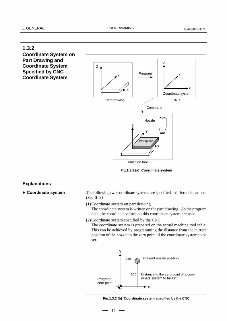
PROGRAMMING1. GENERAL B–63664EN/02
16
Z
Y
X
Part drawing
Z
�
�
Coordinate system
Z
Y
X
Nozzle
Workpiece
Machine tool
Program
Command
CNC
Fig.1.3.2 (a) Coordinate system
The following two coordinate systems are specified at different locations:(See II–8)
(1)Coordinate system on part drawingThe coordinate system is written on the part drawing. As the programdata, the coordinate values on this coordinate system are used.
(2)Coordinate system specified by the CNCThe coordinate system is prepared on the actual machine tool table.This can be achieved by programming the distance from the currentposition of the nozzle to the zero point of the coordinate system to beset.
230
300Programzero point
Distance to the zero point of a coor-dinate system to be set
Present nozzle position
Y
X
Fig.1.3.2 (b) Coordinate system specified by the CNC
1.3.2Coordinate System onPart Drawing andCoordinate SystemSpecified by CNC –Coordinate System
Explanations
� Coordinate system

PROGRAMMINGB–63664EN/02 1. GENERAL
17
The positional relation between these two coordinate systems isdetermined when a workpiece is set on the table.
Y Y
Table
Workpiece
X
X
Coordinate system spe-cified by the CNC estab-lished on the table
Coordinate system onpart drawing estab-lished on the work-piece
Fig.1.3.2 (c) Coordinate system specified by CNC and coordinate system on part drawing
The nozzle moves on the coordinate system specified by the CNC inaccordance with the command program generated with respect to thecoordinate system on the part drawing, and cuts a workpiece into a shapeon the drawing.Therefore, in order to correctly cut the workpiece as specified on thedrawing, the two coordinate systems must be set at the same position.
To set the two coordinate systems at the same position, simple methodsshall be used according to workpiece shape, the number of machinings.
(1) Using a standard plane and point of the workpiece.
Program zero point
Y
X
Workpiece’s standard pointFixed distance
Bring the nozzle center to the workpiece standard point. And set the coordinate system specified by CNC at this position.
Fixed distance
� Methods of setting thetwo coordinate systemsin the same position

PROGRAMMING1. GENERAL B–63664EN/02
18
(2) Mounting a workpiece directly against the jig
Jig
Program zero point
Meet the nozzle center to the reference position. And set the coordinate systemspecified by CNC at this position. (Jig shall be mounted on the predeterminedpoint from the reference position.)
(3) Mounting a workpiece on a pallet, then mounting the workpiece and pallet on the jig
ÂÂÂÂÂÂÂÂÂÂÂÂÂÂÂÂÂÂÂÂÂÂÂÂÂÂÂÂÂÂÂÂÂÂÂÂÂÂÂÂÂÂÂÂÂÂÂÂÂ
Pallet
(Jig and coordinate system shall be specified by the same as (2)).
Jig
Workpiece

PROGRAMMINGB–63664EN/02 1. GENERAL
19
Coordinate values of command for moving the tool can be indicated byabsolute or incremental designation (See II–9.1).
The nozzle moves to a point at ”the distance from zero point of thecoordinate system” that is to the position of the coordinate values.
B(10,30,20)
Y
�
Nozzle
�
Command specifying movement frompoint A to point B
�
G90 X10.0 Y30.0 Z20.0 ;
Coordinates of point B
Specify the distance from the previous nozzle position to the next nozzleposition.
Y
�
�
�
�
X=40
Z=–10
G91 X40.0 Y–30.0 Z–10.0 ;
Distance and direction for movement along each axis
Nozzle
Command specifying movement frompoint A to point B
Y=–30
1.3.3How to IndicateCommand Dimensionsfor Moving the MachineAbsolute, IncrementalCommands
Explanations
� Absolute coordinates
� Incremental coordinates

PROGRAMMING1. GENERAL B–63664EN/02
20
When laser arting is actually started, it is necessary to operate a workshooter, and tip conveyer. For this purpose, on–off operations of workshooter and tip conveyer should be controlled (See II–9).
The function of specifying the on–off operations of the components of themachine is called the miscellaneous function. In general, the function isspecified by an M code.
1.4COMMAND FORMACHINE OPERA-TIONS–MISCELLA-NEOUS FUNCTION

PROGRAMMINGB–63664EN/02 1. GENERAL
21
A group of commands given to the CNC for operating the machine iscalled the program. By specifying the commands, the nozzle is movedalong a straight line or an arc.In the program, specify the commands in the sequence of actual nozzlemovements.
Block
⋅
⋅
⋅
⋅
Program
Nozzle movement sequence
Block
Block
Block
Block
Fig.1.5 (a) Program configuration
A group of commands at each step of the sequence is called the block.The program consists of a group of blocks for a series of machining. Thenumber for discriminating each block is called the sequence number, andthe number for discriminating each program is called the program number(See II–10).
1.5PROGRAMCONFIGURATION

PROGRAMMING1. GENERAL B–63664EN/02
22
The block and the program have the following configurations.
N ���� G �� X���� Y����� M �� ;
� ���
Sequence number
Preparatory function
Dimension word
Miscel-laneous function
End of block
Fig.1.5 (b) Block configuration
A block starts with a sequence number that identifies the block and endswith an end–of–block code.This manual indicates the end–of–block code by ; (LF in the ISO code andCR in the EIA code).
;O����;
⋅
⋅
⋅
M30 ;
Program number
Block
Block
Block
End of program
⋅
⋅
⋅
Fig.1.5 (c) Program configuration
Normally, a program number is specified after the end–of–block (;) codeat the beginning of the program, and a program end code (M02 or M30)is specified at the end of the program.
Explanations
� Block
� Program

PROGRAMMINGB–63664EN/02 1. GENERAL
23
When machining of the same pattern appears at many portions of aprogram, a program for the pattern is created. This is called thesubprogram. On the other hand, the original program is called the mainprogram. When a subprogram execution command appears duringexecution of the main program, commands of the subprogram areexecuted. When execution of the subprogram is finished, the sequencereturns to the main program.
Main program
M98P1001
⋅⋅
M98P1002
M98P1001
⋅
⋅
⋅
⋅
⋅
⋅
⋅
⋅
⋅
Subprogram #1
Subprogram #2
O1001
M99
Program for hole #1
Program forhole #2
O1002
M99
Hole #1
Hole #2
Hole #1
Hole #2
� Main program andsubprogram

PROGRAMMING1. GENERAL B–63664EN/02
24
Because laserbeam has a radius, the center of the beam path goes aroundthe workpiece with the cutter radius deviated.
Workpiece
Beam path using cutter compensation
Processed partfigure
Beam
If radius of beam are stored in the CNC (Data Display and Setting : seeIII–11), the tool can be moved by cutter radius apart from the machiningpart figure. This function is called cutter compensation (See II–12.2 and12.3).
� Machining using the sideof cutter – Cuttercompensation function(See II–12.2, 12.3)

PROGRAMMINGB–63664EN/02 1. GENERAL
25
Limit switches are installed at the ends of each axis on the machine toprevent tools from moving beyond the ends. The range in which tools canmove is called the stroke.
ÇÇÇÇÇÇÇÇÇÇÇÇÇÇÇÇÇÇ
Motor
Limit switch
Table
Machine zero point
Specify these distances.
Beam cannot enter this area. The area is specified by data in memory ora program.
Besides strokes defined with limit switches, the operator can define anarea which the nozzle cannot enter using a program or data in memory.This function is called stroke check (see III–6.3).
1.6NOZZLE MOVEMENTRANGE–STROKE

PROGRAMMING2. CONTROLLED AXES B–63664EN/02
26
2 CONTROLLED AXES

PROGRAMMING 2. CONTROLLED AXESB–63664EN/02
27
Item16i–LB
160i–LB
No. of basic controlled axes 3 axes
Controlled axes expansion (total) Max. 8 axes
Basic simultaneously controlled axes 2 axes
Simultaneously controlled axes expansion (total) Max. 6 axes
NOTEThe number of simultaneously controllable axes for manualoperation jog feed, manual reference position return, ormanual rapid traverse) is 1 or 3 (1 when bit 0 (JAX) ofparameter 1002 is set to 0 and 3 when it is set to 1).
2.1CONTROLLED AXES
Series 16i, Series 160i

PROGRAMMING2. CONTROLLED AXES B–63664EN/02
28
The names of three basic axes are always X, Y, and Z. The name of anadditional axis can be set to A, B, C, U, V, or W by using parameter 1020.Parameter No. 1020 is used to determine the name of each axis.When this parameter is set to 0 or a character other than the validcharacters is specified, an axis name from 1 to 8 is assigned by default.
When a default axis name (1 to 8) is used, operation in the MEM mode,MDI mode or RMT mode is disabled.
If a duplicate axis name is specified in the parameter, operation is enabledonly for the axis specified first.
2.2AXIS NAME
Limitations
� Default axis name
� Duplicate axis names

PROGRAMMING 2. CONTROLLED AXESB–63664EN/02
29
The increment system consists of the least input increment (for input) andleast command increment (for output). The least input increment is theleast increment for programming the travel distance. The least commandincrement is the least increment for moving the tool on the machine. Bothincrements are represented in mm, inches, or deg.The increment system is classified into IS–B.
Name of increment
system
Least input increment
Least commandincrement
Maximum stroke
IS–B0.001mm0.0001inch0.001deg
0.001mm0.0001inch0.001deg
99999.999mm9999.9999inch99999.999deg
The least command increment is either metric or inch depending on themachine tool. Set metric or inch to the parameter INM (No.100#0).For selection between metric and inch for the least input increment, Gcode (G20 or G21) or a setting parameter selects it.
Combined use of the inch system and the metric system is not allowed.There are functions that cannot be used between axes with different unitsystems (circular interpolation, cutter compensation, etc.). For theincrement system, see the machine tool builder’s manual.
2.3INCREMENT SYSTEM

PROGRAMMING2. CONTROLLED AXES B–63664EN/02
30
Maximum stroke = Least command increment�99999999 See 2.3 Incremen System.
Table 2.4 Maximum strokes
Increment system Maximum stroke
IS–B
Metric machine system ±99999.999 mm±99999.999 deg
IS–BInch machine system ±9999.9999 inch
±99999.999 deg
NOTE1 A command exceeding the maximum stroke cannot be
specified.2 The actual stroke depends on the machine tool.
2.4MAXIMUM STROKE

PROGRAMMINGB–63664EN/023. PREPARATORY FUNCTION
(G FUNCTION)
31
3 ����������� �������� �� ���������
A number following address G determines the meaning of the commandfor the concerned block.G codes are divided into the following two types.
Type Meaning
One–shot G code The G code is effective only in the block in which it isspecified.
Modal G code The G code is effective until another G code of thesame group is specified.
(Example )G01 and G00 are modal G codes in group 01.
G01X ;G00Z ;G01X ;G00Z ;
G01 is effective in this range.

PROGRAMMING3. PREPARATORY FUNCTION
(G FUNCTION) B–63664EN/02
32
1.When the clear state (bit 6 (CLR) of parameter No. 3402) is set atpower–up or reset, the modal G codes are placed in the states describedbelow.
(1) The modal G codes are placed in the states marked with asindicated in Table 3.
(2) G20 and G21 remain unchanged when the clear state is set atpower–up or reset.
(3) Which status G22 or G23 at power on is set by parameter G23(No. 3402#7). However, G22 and G23 remain unchanged whenthe clear state is set at reset.
(4) The user can select G00 or G01 by setting bit 0 (G01) of parameterNo. 3402.
(5) The user can select G90 or G91 by setting bit 3 (G91) of parameterNo. 3402.
(6) The user can select G17, G18, or G19 by setting bit 1(parameterG18) and bit 2 (parameter G19) of parameter No. 3402.
2.G codes other than G10 and G11 are one–shot G codes.
3.When a G code not listed in the G code list is specified, or a G code thathas no corresponding option is specified, P/S alarm No. 010 is output.
4.Multiple G codes can be specified in the same block if each G codebelongs to a different group. If multiple G codes that belong to the samegroup are specified in the same block, only the last G code specified isvalid.
5.G codes are indicated by group.
6.The group of G60 is switched according to the setting of the MDL bit(bit 0 of parameter 5431). (When the MDL bit is set to 0, the 00 groupis selected. When the MDL bit is set to 1, the 01 group is selected.)
Explanations

PROGRAMMINGB–63664EN/023. PREPARATORY FUNCTION
(G FUNCTION)
33
Table 3 G Code List (1/3)
Code Group Function
G00
01
Positioning
G01 01
Linear interpolation
G02 01
Circular interpolation/Helical interpolation CW
G03 Circular interpolation/Helical interpolation CCW
G04
00
Dwell, Exact stop
G05
00
High–speed remote buffer/High–precision contour control
G05.1
00
AI contour control / AI nano contour control
G05.4
00
HRV3 on off
G07 00
Hypothetical axis interpolation
G07.1 (G107) 00
Cylindrical interpolation
G08 Advanced preview control
G09 Exact stop
G10 Programmable data input
G11 Programmable data input mode cancel
G12 01 Spatial circular interpolation
G12.125
Polar coordinate interpolation mode
G13.125
Polar coordinate interpolation mode cancel
G1331
Gap control mode
G1431
Gap control mode cancel
G1517
Polar coordinates command cancel
G1617
Polar coordinates command
G17
02
XpYp plane Xp: X axis or a parallel axis
G18 02 ZpXp plane Yp: Y axis or a parallel axis
G19 YpZp plane Zp: Z axis or a parallel axis
G2006
Inch input
G2106
Metric input
G2204
Stored stroke check function on
G2304
Stored stroke check function off
G24
00
Piercing command
G27
00
Reference position return check
G28
00
Automatic return to reference position
G2900
Automatic return from reference position
G3000
2nd, 3rd and 4th reference position return
G30.1 Floating reference point return
G31 Skip function
G32 Assist gas command
G3334
Spatial corner R insertion
G3434
Spatial corner R insertion cancel
G39 00 Corner circular interpolation

PROGRAMMING3. PREPARATORY FUNCTION
(G FUNCTION) B–63664EN/02
34
Table 3 G Code List (2/3)
Code Group Function
G4007
Cutter compensation cancel
G41 07 Cutter compensation left
G42 Cutter compensation right
G40.1 (G150)
18
Normal direction control cancel mode
G41.1 (G151) 18 Normal direction control left on
G42.1 (G152) Normal direction control right on
G45
00
Tool offset increase
G4600
Tool offset decrease
G4700
Tool offset double increase
G48 Tool offset double decrease
G5011
Scaling cancel
G5111
Scaling
G50.122
Programmable mirror image cancel
G51.122
Programmable mirror image
G5200
Local coordinate system setting
G5300
Machine coordinate system selection
G54
14
Workpiece coordinate system 1 selection
G54.1
14
Additional workpiece coordinate system selection
G55
14
Workpiece coordinate system 2 selection
G56 14 Workpiece coordinate system 3 selection
G57 Workpiece coordinate system 4 selection
G58 Workpiece coordinate system 5 selection
G59 Workpiece coordinate system 6 selection
G60 00/01 Unidirectional positioning
G6115
Exact stop mode
G6215
Automatic corner override
G63 00 Laser power control
G64 15 Machining mode
G65 00 Macro call
G6612
Macro modal call
G6712
Macro modal call cancel
G6816
Coordinate rotation
G6916
Coordinate rotation cancel
G6832
Three–dimensional coordinate conversion
G6932
Three–dimensional coordinate conversion cancel
G71
00
A–axis length compensation
G72.1 00 Rotation copy
G72.2 Linear copy
G8416
Coordinate rotation
G8516
Coordinate rotation cancel

PROGRAMMINGB–63664EN/023. PREPARATORY FUNCTION
(G FUNCTION)
35
Table 3 G Code List (3/3)
Code Group Function
G9003
Absolute command
G9103
Increment command
G9200
Setting for workpiece coordinate system
G92.100
Workpiece coordinate system preset
G9833
Three–dimensional conversion
G9933
Three–dimensional conversion cancel
CAUTION
The G codes for coordinate rotation are G68, G69, G84, andG85.If, however, the three–dimensional coordinate conversionoption is added, G68 and G69 are the G codes forthree–dimensional coordinate conversion.

PROGRAMMING4. INTERPOLATION FUNCTIONS B–63664EN/02
36
4 INTERPOLATION FUNCTIONS

PROGRAMMINGB–63664EN/02 4. INTERPOLATION FUNCTIONS
37
In the absolute command, coordinate value of the end point isprogrammed.In the incremental command the distance the nozzle moves isprogrammed.
_: For an absolute command, the coordinates of an end position, and for an incremental commnad, the distance the nozzle moves.
G00 _;IP
IP
Either of the following nozzle paths can be selected according to bit 1(LRP) of parameter No. 1401.
� Nonlinear interpolation positioningThe nozzle is positioned with the rapid traverse rate for each axisseparately. The nozzle path is not normally straight.
� Linear interpolation positioningThe nozzle moves along a line to the specified position. The nozzleis positioned within the shortest possible time at a speed that is notmore than the rapid traverse rate for each axis. However, thenozzle path is not the same as in linear interpolation (G01).
End position Non linear interpolation positioning
Start position
Linear interpolation positioning
The rapid traverse rate in G00 command is set to the parameter No. 1420for each axis independently by the machine tool builder. In theposiitoning mode actuated by G00, the tool is accelerated to apredetermined speed at the start of a block and is decelerated at the endof a block. Execution proceeds to the next block after confirming thein–position. “In–position ” means that the feed motor is within the specified range.This range is determined by the machine tool builder by setting toparameter (No. 1826).In–position check for each block can be disabled by setting bit 5 (NCI)of parameter No.1601 accordingly.
4.1POSITIONING (G00)
Format
Explanations

PROGRAMMING4. INTERPOLATION FUNCTIONS B–63664EN/02
38
The rapid traverse rate cannot be specified in the address F.Even if linear interpolation positioning is specified, nonlinearinterpolation positioning is used in the following cases. Therefore, becareful to ensure that the tool does not foul the workpiece.�G28 specifying positioning between the reference and intermediate
positions.�G53
Limitations
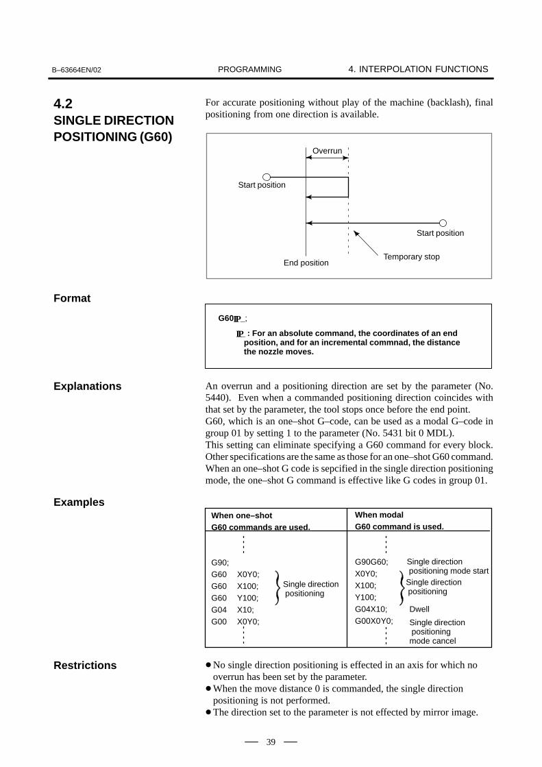
PROGRAMMINGB–63664EN/02 4. INTERPOLATION FUNCTIONS
39
For accurate positioning without play of the machine (backlash), finalpositioning from one direction is available.
Start position
Temporary stopEnd position
Overrun
Start position
_ : For an absolute command, the coordinates of an end position, and for an incremental commnad, the distancethe nozzle moves.
G60 _;IP
IP
An overrun and a positioning direction are set by the parameter (No.5440). Even when a commanded positioning direction coincides withthat set by the parameter, the tool stops once before the end point.G60, which is an one–shot G–code, can be used as a modal G–code ingroup 01 by setting 1 to the parameter (No. 5431 bit 0 MDL).This setting can eliminate specifying a G60 command for every block.Other specifications are the same as those for an one–shot G60 command.When an one–shot G code is sepcified in the single direction positioningmode, the one–shot G command is effective like G codes in group 01.
When one–shot G60 commands are used.
G90;G60 X0Y0;G60 X100;G60 Y100;G04 X10;G00 X0Y0;
When modal G60 command is used.
G90G60;X0Y0;X100;Y100;G04X10;G00X0Y0;
Single direction positioning
Single direction positioning
Single direction positioningmode cancel
Dwell
Single direction positioning mode start
�No single direction positioning is effected in an axis for which nooverrun has been set by the parameter.
�When the move distance 0 is commanded, the single directionpositioning is not performed.
�The direction set to the parameter is not effected by mirror image.
4.2SINGLE DIRECTIONPOSITIONING (G60)
Format
Explanations
Examples
Restrictions

PROGRAMMING4. INTERPOLATION FUNCTIONS B–63664EN/02
40
Nozzle can move along a line
F_:Speed of nozzle feed (Feedrate)
_:For an absolute command, the coordinates of an end point , and for an incremental commnad, the distance the nozzle moves.
G01 _F_;IP
IP
A tools move along a line to the specified position at the feedratespecified in F.The feedrate specified in F is effective until a new value is specified. Itneed not be specified for each block.The feedrate commanded by the F code is measured along the nozzle path.If the F code is not commanded, the feedrate is regarded as zero.The feedrate of each axis direction is as follows.
F� � �L� f
F� ��
L� f
F� ��
L� f
Feed rate of α axis direction :
F� ��L� f
L � �2 � �2 � �2 � �2�
G01ααββγγζζFf ;
Feed rate of Γ axis direction :
Feed rate of Β axis direction :
Feed rate of Ζ axis direction :
The feed rate of the rotary axis is commanded in the unit of deg/min (theunit is decimal point position).
When the straight line axis α(such as X, Y, or Z) and the rotating axis β(such as A, B, or C) are linearly interpolated, the feed rate is that in whichthe tangential feed rate in the α and β cartesian coordinate system iscommanded by F(mm/min). β–axis feedrate is obtained ; at first, the time required for distribution iscalculated by using the above fromula, then the β –axis feedrate unit ischanged to deg 1min.
4.3LINEARINTERPOLATION(G01)
Format
Explanations

PROGRAMMINGB–63664EN/02 4. INTERPOLATION FUNCTIONS
41
A calculation example is as follows.G91 G01 X20.0B40.0 F300.0 ;This changes the unit of the C axis from 40.0 deg to 40mm with metricinput. The time required for distribution is calculated as follows:
202 � 402�
300
400.14907
The feed rate for the C axis is
0.14907 (min)
268.3 deg�min
In simultaneous 3 axes control, the feed rate is calculated the same wayas in 2 axes control.
100.0
200.00
�G91� G01X200.0Y100.0F200.0
Y axis
(End position)
X axis(Start position)
90°(Start point)
(End point)Feedrate is 300 deg/min
G91G01C–90.0 G300.0 ;Feed rate of 300deg/min
Examples
� Linear interpolation
� ������� ��� ���
���� �� � �

PROGRAMMING4. INTERPOLATION FUNCTIONS B–63664EN/02
42
The command below will move a nozzle along a circular arc.
�� G03
Arc in the XpYp plane
��! � ��� ZpXp ���
G18
��! � ��� YpZp ���
Xp_Yp_G02
G03
G02
G03G02G19
Xp_ p_
Yp_ Zp_
I_ J_
R_F_ ;
I_ K_R_
F_
J_ K_
R_F_
Table 4.4 Description of the Command Format
Command Description
G17 Specification of arc on XpYp plane
G18 Specification of arc on ZpXp plane
G19 Specification of arc on YpZp plane
G02 Circular Interpolation Clockwise direction (CW)
G03 Circular Interpolation Counterclockwise direction (CCW)
Xp_ Command values of X axis or its parallel axis (set by parameter No. 1022)
Yp_ Command values of Y axis or its parallel axis (set by parameter No. 1022)
Zp_ Command values of Z axis or its parallel axis (set by parameter No. 1022)
I_ Xp axis distance from the start point to the center of an arcwith sign
J_ Yp axis distance from the start point to the center of an arcwith sign
K_ Zp axis distance from the start point to the center of an arcwith sign
R_ Arc radius (with sign)
F_ Feedrate along the arc
4.4CIRCULARINTERPOLATION(G02, G03)
Format

PROGRAMMINGB–63664EN/02 4. INTERPOLATION FUNCTIONS
43
“Clockwise”(G02) and “counterclockwise”(G03) on the XpYp plane(ZpXp plane or YpZp plane) are defined when the XpYp plane is viewedin the positive–to–negative direction of the Zp axis (Yp axis or Xp axis,respectively) in the Cartesian coordinate system. See the figure below.
G02
G03
XpG17 G18 G19
G02
G03
G02
G03
Yp Xp Zp
Zp Yp
The end point of an arc is specified by address Xp, Yp or Zp, and isexpressed as an absolute or incremental value according to G90 or G91.For the incremental value, the distance of the end point which is viewedfrom the start point of the arc is specified.
The arc center is specified by addresses I, J, and K for the Xp, Yp, and Zpaxes, respectively. The numerical value following I, J, or K, however, isa vector component in which the arc center is seen from the start point,and is always specified as an incremental value irrespective of G90 andG91, as shown below.I, J, and K must be signed according to the direction.
End point (x,y)
Center
Startpoint
End point (z,x) End point (y,z)
Startpoint
Startpoint
������ Center
ix
y xz
k
zy
j
j i k
I0,J0, and K0 can be omitted. When Xp, Yp , and Zp are omitted (the endpoint is the same as the start point) and the center is specified with I, J,and K, a 360° arc (circle) is specified.G021; Command for a circleIf the difference between the radius at the start point and that at theend point exceeds the permitted value in a parameter (No.3410), an P/Salarm (No.020) occurs.
Explanations
� " ��!� �� �� ��� ! �!#�
������� ��
� " ���!� $�%�� �� �
�!
� " ���!� ���$ ��� ����
�� �� �� ��� !����� �� �!

PROGRAMMING4. INTERPOLATION FUNCTIONS B–63664EN/02
44
The distance between an arc and the center of a circle that contains the arccan be specified using the radius, R, of the circle instead of I, J, and K.In this case, one arc is less than 180°, and the other is more than 180° areconsidered. When an arc exceeding 180° is commanded, the radius mustbe specified with a negative value. If Xp, Yp, and Zp are all omitted, ifthe end point is located at the same position as the start point and whenR is used, an arc of 0° is programmed G02R ; (The cutter does not move.)
r=50mm
End point
Start point r=50mm
1
2
For arc �(1)(less than 180°)G91 G02 XP60.0 YP20.0 R50.0 F300.0 ;
For arc (2)(greater than 180°)G91 G02 XP60.0 YP20.0 R–50.0 F300.0 ;
Y
X
The feedrate in circular interpolation is equal to the feed rate specified bythe F code, and the feedrate along the arc (the tangential feedrate of thearc) is controlled to be the specified feedrate.The error between the specified feedrate and the actual nozzle feedrate is±2% or less. However, this feed rate is measured along the arc after thecutter compensation is applied
If I, J, K, and R addresses are specified simultaneously, the arc specifiedby address R takes precedence and the other are ignored.If an axis not comprising the specified plane is commanded, an alarm isdisplayed.For example, if axis U is specified as a parallel axis to X axis when planeXY is specified, an P/S alarm (No.028)is displayed.When an arc having a center angle approaching 180° is specified, thecalculated center coordinates may contain an error. In such a case, specifythe center of the arc with I, J, and K.
� ��! �� #�
� �������
Restrictions

PROGRAMMINGB–63664EN/02 4. INTERPOLATION FUNCTIONS
45
100
60
40
090 120 140 200
60R
50R
Y axis
X axis
The above tool path can be programmed as follows ;��� �� ����� ������������������� ���� � �
��� ��� � ��� � ��������� ������
��� � ���� ���������� �
or��������� ����� �
��� ��� � ��� � ���������� ������
��� � ���� ����������� �
��� �� ���� � ��� ������������ ��� ������ ����� ����� ������
��� ������ ����� ����� �
or�� ��� ������ ����� ������ ����� �
��� ������ ����� ������ �
Examples

PROGRAMMING4. INTERPOLATION FUNCTIONS B–63664EN/02
46
Helical interpolation which moved helically is enabled by specifying upto two other axes which move synchronously with the circularinterpolation by circular commands.
G03
Synchronously with arc of XpYp plane
Synchronously with arc of ZpXp plane
G18
Synchronously with arc of YpZp plane
Xp&Yp&G02
G03
G02
G03
G02G19
Xp&Zp&
Yp&Zp&
I&J&
R_α&(β&)F&'
I&K&�&
J&K&
R&
G17
α&�β&)F_;
α&�β&)F&;
α,β: Any one axis where circular interpolation is not applied.Up to two other axes can be specified.
The command method is to simply or secondary add a move commandaxis which is not circular interpolation axes. An F command specifies afeed rate along a circular arc. Therefore, the feed rate of the linear axisis as follows:
F×Length of linear axis
Length of circular arc
Determine the feed rate so the linear axis feed rate does not exceed anyof the various limit values.Bit 0 (HFC) of parameter No. 1404 can be usedto prevent the linear axis feedrate from exceeding various limit values.
Z
Nozzle path
The feedrate along the circumference of two cir-cular interpolated axes is the specified feedrate.
YX
⋅Cutter compensation is applied only for a circular arc.⋅Tool offset and tool length compensation cannot be used in a block in which a helical interpolation is commanded.
4.5HELICALINTERPOLATION(G02, G03)
Format
Explanations
Restrictions

PROGRAMMINGB–63664EN/02 4. INTERPOLATION FUNCTIONS
47
Helical interpolation B moves the nozzle in a helical manner. Thisinterpolation can be executed by specifying the circular interpolationcommand together with up to four additional axes in simplehigh–precision contour control mode (see II–NO TAG).
G03
With an arc in the XpYp plane
With an arc in the ZpXp plane
G18
With an arc in the YpZp plane
Xp&Yp&G02
G03
G02
G03
G02G19
Xp&Zp&
Yp&Zp&
I&J&
R_α&β&γ&δ&F&'
I&K&�&
J&K&
R&
G17
α&β&γ&δ&F&'
α&β&γ&δ&F&'
α, β, γ, δ : Any axis to which circular interpolation is not applied. Up to four axes can be specified.
Basically, the command can be specified by adding two movement axesto a standard helical interpolation command (see II–4.5). Address Fshould be followed by a tangential velocity, which has been determinedby also taking movement along the linear axes into consideration.
Z
Nozzle path
The feedrate equals the tangential velocity determined by alsotaking movement along the linear axes into consideration.
YX
⋅ The command of helical interpolation B can be specified only in AIcontour control mode.
⋅ Cutter compensation is applied only to an arc.⋅ In a block containing the helical interpolation command, the tool offset
command or tool length compensation command cannot be specified.
4.6HELICALINTERPOLATION B(G02, G03)Format
Explanations
Limitations

PROGRAMMING4. INTERPOLATION FUNCTIONS B–63664EN/02
48
Polar coordinate interpolation is a function that exercises contour controlin converting a command programmed in a Cartesian coordinate systemto the movement of a linear axis (movement of a tool) and the movementof a rotary axis (rotation of a workpiece).
G12.1 ; Starts polar coordinate interpolation mode (enables polarcoordinate interpolation)
Polar coordinate interpolation mode is cancelled (for notperforming polar coordinate interpolation)
G13.1 ;
Specify linear or circular interpolation using coordinates in aCartesian coordinate system consisting of a linear axis and rotary axis (virtual axis).
Specify G12.1 and G13.1 in Separate Blocks.
G12.1 starts the polar coordinate interpolation mode and selects a polarcoordinate interpolation plane (Fig. 4.7). Polar coordinateinterpolation is performed on this plane.
Rotary axis (virtual axis)(unit:mm or inch)
Linear axis(unit:mm or inch)
Fig.4.7 Polar coordinate interpolation plane.
Origin of the local coordinate system (G52 command)(Or origin of the workpiece coordinate system)
When the power is turned on or the system is reset, polar coordinateinterpolation is canceled (G13.1).The linear and rotation axes for polar coordinate interpolation must be setin parameters (No. 5460 and 5461) beforehand.
CAUTION
The plane used before G12.1 is specified (plane selectedby G17, G18, or G19) is canceled. It is restored when G13.1(canceling polar coordinate interpolation) is specified. When the system is reset, polar coordinate interpolation iscanceled and the plane specified by G17, G18, or G19 isused.
4.7POLAR COORDINATEINTERPOLATION(G12.1, G13.1)
Format
Explanations
� Polar coordinateinterpolation plane

PROGRAMMINGB–63664EN/02 4. INTERPOLATION FUNCTIONS
49
In the polar coordinate interpolation mode, program commands arespecified with Cartesian coordinates on the polar coordinate interpolationplane. The axis address for the rotation axis is used as the axis addressfor the second axis (virtual axis) in the plane. Whether a diameter orradius is specified for the first axis in the plane is the same as for therotation axis regardless of the specification for the first axis in the plane.The virtual axis is at coordinate 0 immediately after G12.1 is specified.Polar interpolation is started assuming the angle of 0 for the position ofthe tool when G12.1 is specified.Specify the feedrate as a speed (relative speed between the workpiece andtool) tangential to the polar coordinate interpolation plane (Cartesiancoordinate system) using F.
G01 Linear interpolation. . . . . . . . . . . . G02, G03 Circular interpolation. . . . . . . G04 Dwell, Exact stop. . . . . . . . . . . . G40, G41, G42 Cutter compensation . . .
(Polar coordinate interpolation is applied to the path after cutter compensation.)
G65, G66, G67 Custom macro command. . . G90, G91 Absolute command, incremental command. . . . . . .
The addresses for specifying the radius of an arc for circular interpolation(G02 or G03) in the polar coordinate interpolation plane depend on thefirst axis in the plane (linear axis).
⋅ I and J in the Xp–Yp plane when the linear axis is the X–axis or an axisparallel to the X–axis.
⋅ J and K in the Yp–Zp plane when the linear axis is the Y–axis or an axisparallel to the Y–axis.
⋅ K and I in the Zp–Xp plane when the linear axis is the Z–axis or an axisparallel to the Z–axis.
The radius of an arc can be specified also with an R command.
The tool moves along such axes normally, independent of polarcoordinate interpolation.
Actual coordinates are displayed. However, the remaining distance tomove in a block is displayed based on the coordinates in the polarcoordinate interpolation plane (Cartesian coordinates).
Before G12.1 is specified, a local coordinate system (or workpiececoordinate system) where the center of the rotary axis is the origin of thecoordinate system must be set. In the G12.1 mode, the coordinate systemmust not be changed (G92, G52, G53, relative coordinate reset, G54through G59, etc.).
The polar coordinate interpolation mode cannot be started or terminated(G12.1 or G13.1) in the tool offset mode (G41 or G42). G12.1 or G13.1must be specified in the tool offset canceled mode (G40).
� Distance moved andfeedrate for polarcoordinate interpolation
The unit for coordinates on the hypothetical axis isthe same as the unit for the linear axis (mm/inch)
The unit for the feedrateis mm/min or inch/min
� G codes which can bespecified in the polarcoordinate interpolationmode
� � �!#� ������� �� �
��� ��� !���� ���
���
� Movement along axesnot in the polarcoordinate interpolationplane in the polarcoordinate interpolationmode
� Current position displayin the polar coordinateinterpolation mode
Limitations
� ����� ��� �(���$ ���
��� ��� !���� ���
������� ��
� ��� ������ !�$$��

PROGRAMMING4. INTERPOLATION FUNCTIONS B–63664EN/02
50
A tool offset must be specified before the G12.1 mode is set. No offsetcan be changed in the G12.1 mode.
For a block in the G12.1 mode, the program cannot be restarted.
Polar coordinate interpolation converts the tool movement for a figureprogrammed in a Cartesian coordinate system to the tool movement in therotation axis (C–axis) and the linear axis (X–axis). When the tool movescloser to the center of the workpiece, the C–axis component of thefeedrate becomes larger and may exceed the maximum cutting feedratefor the C–axis (set in parameter (No. 1422)), causing an alarm (see thefigure below). To prevent the C–axis component from exceeding themaximum cutting feedrate for the C–axis, reduce the feedrate specifiedwith address F or create a program so that the beam (center of the beamwhen cutter compensation is applied) does not move close to the centerof the workpiece.
L : Distance (in mm) between the beam center and workpiece center when the beam center is the nearest to the workpiece center
R : Maximum cutting feedrate (deg/min) of the C axis Then, a speed specifiable with address F in polar coordinate interpolation can be given by the formula below.Specify a speed allowed by the formula. The formula provides a theoretical value; in practice, a value slightlysmaller than a theoretical value may need to be used due to a calculation error.
L1
L2
L3θ3
θ2
θ1
X∆ Consider lines L1, L2, and L3. ∆X is the distance the tool moves per time unitat the feedrate specified with address F in the Cartesian coordinate system.As the tool moves from L1 to L2 to L3, the angle at which the tool moves pertime unit corresponding to ∆X in the Cartesian coordinate system increasesfromθ1 toθ 2 to θ3. In other words, the C–axis component of the feedrate becomes larger as thetool moves closer to the center of the workpiece. The C component of thefeedrate may exceed the maximum cutting feedrate for the C–axis becausethe tool movement in the Cartesian coordinate system has been converted tothe tool movement for the C–axis and the X–axis.
F < L × R ×180π
(mm/min)
WARNING
The function cannot be used with a three–dimensional machine.
� Tool offset command
� Program restart
� Cutting feedrate for therotation axis

PROGRAMMINGB–63664EN/02 4. INTERPOLATION FUNCTIONS
51
Example of Polar Coordinate Interpolation Program Based on X Axis (Linear Axis) and C Axis (Rotary Axis)
C’(hypothetical axis)
C axis Path after cutter compensation
Program path
N204
N205
N206
N203
N202 N201
N208
N207
X axis
Z axis
N200
beam
O0001 ;
N010 T0101
N0100 G90 G00 X60.0 C0 Z_ ; Positioning to start position
N0200 G12.1 ; Start of polar coordinate interpolation
N0201 G42 G01 X20.0 F_ ;
N0202 C10.0 ;
N0203 G03 X10.0 C20.0 R10.0 ;
N0204 G01 X–20.0 ; Geometry program
N0205 C–10.0 ; (program based on cartesian coordinates on
N0206 G03 X–10.0 C–20.0 I10.0 J0 ; X–C’ plane)
N0207 G01 X20.0 ;
N0208 C0 ;
N0209 G40 X60.0 ;
N0210 G13.1 ; Cancellation of polar coordinate interpolation
N0300 Z_ ;
N0400 X_ C_ ;
N0900M30 ;
Examples

PROGRAMMING4. INTERPOLATION FUNCTIONS B–63664EN/02
52
The amount of travel of a rotary axis specified by an angle is onceinternally converted to a distance of a linear axis along the outer surfaceso that linear interpolation or circular interpolation can be performed withanother axis. After interpolation, such a distance is converted back to theamount of travel of the rotary axis.
G07.1 r ; Starts the cylindrical interpolation mode (enables cylindrical interpolation).
G07.1 0 ; The cylindrical interpolation mode is cancelled.
:::
: An address for the rotation axisr : The radius of the cylinder
Specify G07.1 r ; and G07.1 0; in separate blocks.G107 can be used instead of G07.1.
IP
IP
IP
IP IP
Use parameter (No. 1022) to specify whether the rotation axis is the X–,Y–, or Z–axis, or an axis parallel to one of these axes. Specify the G codeto select a plane for which the rotation axis is the specified linear axis.For example, when the rotation axis is an axis parallel to the X–axis, G17must specify an Xp–Yp plane, which is a plane defined by the rotation axisand the Y–axis or an axis parallel to the Y–axis.Only one rotation axis can be set for cylindrical interpolation.
A feedrate specified in the cylindrical interpolation mode is a speed on thedeveloped cylindrical surface.
In the cylindrical interpolation mode, circular interpolation is possiblewith the rotation axis and another linear axis. Radius R is used incommands in the same way as described in II–4.4. The unit for a radius is not degrees but millimeters (for metric input) orinches (for inch input). < Example Circular interpolation between the Z axis and C axis >
For the C axis of parameter (No.1022), 5 (axis parallel with the X axis)is to be set. In this case, the command for circular interpolation is
G18 Z__C__;G02 (G03) Z__C__R__;
For the C axis of parameter (No.1022), 6 (axis parallel with the Y axis)may be specified instead. In this case, however, the command forcircular interpolation is
G19 C__Z__;G02 (G03) Z__C__R__;
To perform tool offset in the cylindrical interpolation mode, cancel anyongoing cutter compensation mode before entering the cylindricalinterpolation mode. Then, start and terminate tool offset within thecylindrical interpolation mode.
4.8CYLINDRICALINTERPOLATION(G07.1)
Format
Explanations� Plane selection
(G17, G18, G19)
� �������
� Circular interpolation(G02, G03)
� Tool offset

PROGRAMMINGB–63664EN/02 4. INTERPOLATION FUNCTIONS
53
In the cylindrical interpolation mode, the amount of travel of a rotary axisspecified by an angle is once internally converted to a distance of a linearaxis on the outer surface so that linear interpolation or circularinterpolation can be performed with another axis. After interpolation,such a distance is converted back to an angle. For this conversion, theamount of travel is rounded to a least input increment.So when the radius of a cylinder is small, the actual amount of travel candiffer from a specified amount of travel. Note, however, that such an erroris not accumulative.If manual operation is performed in the cylindrical interpolation modewith manual absolute on, an error can occur for the reason describedabove.
Specified valueThe actual amountof travel 2×2πR
MOTION REV �MOTION REV
MOTION REV � The amount of travel per rotation of the rotation axis (Set-ting value of parameter No. 1260)
R :
:Rounded to the least input increment
Workpiece radius
� � 2×2πR
In the cylindrical interpolation mode, an arc radius cannot be specifiedwith word address I, J, or K.
If the cylindrical interpolation mode is started when cutter compensationis already applied, circular interpolation is not correctly performed in thecylindrical interpolation mode.
In the cylindrical interpolation mode, positioning operations (includingthose that produce rapid traverse cycles such as G28, G53, G73, G74,G76, G80 through G89) cannot be specified. Before positioning can bespecified, the cylindrical interpolation mode must be cancelled.Cylindrical interpolation (G07.1) cannot be performed in the positioningmode (G00).
In the cylindrical interpolation mode, a workpiece coordinate system(G92, G54 through G59) or local coordinate system (G52) cannot bespecified.
In the cylindrical interpolation mode, the cylindrical interpolation modecannot be reset. The cylindrical interpolation mode must be cancelledbefore the cylindrical interpolation mode can be reset.
A tool offset must be specified before the cylindrical interpolation modeis set. No offset can be changed in the cylindrical interpolation mode.
� Cylindrical interpolationaccuracy
Limitations
� Arc radius specificationin the cylindricalinterpolation mode
� Circular interpolationand cutter compensation
� Positioning
� Coordinate systemsetting
� �( ��� ! ������� ��
$��� ���� �)
� ��� ������

PROGRAMMING4. INTERPOLATION FUNCTIONS B–63664EN/02
54
Example of a Cylindrical Interpolation Program
C
mm
Z
���
���
��� ���120110
90
7060
0 30 60 70 150 190 230 270 360 deg
N05
N06
N07
N08 N09
O0001 (CYLINDRICAL INTERPOLATION ); N01 G00 G90 Z100.0 C0 ; N02 G01 G91 G18 Z0 C0 ; N03 G07.1 C57299 ;N04 G90 G01 G42 Z120.0 D01 F250 ; N05 C30.0 ; N06 G03 Z90.0 C60.0 R30.0 ; N07 G01 Z70.0 ; N08 G02 Z60.0 C70.0 R10.0 ; N09 G01 C150.0 ;N10 G02 Z70.0 C190.0 R75.0 ;N11 G01 Z110.0 C230.0 ; N12 G03 Z120.0 C270.0 R75.0 ; N13 G01 C360.0 ;N14 G40 Z100.0 ;N15 G07.1 C0 ;N16 M30 ;
C
Z R
Examples

PROGRAMMINGB–63664EN/02 4. INTERPOLATION FUNCTIONS
55
One of the X–, Y–, and X–axes can be specified as a hypothetical axis.Although the axis specified as a hypothetical axis does not allowoperation by any subsequent program commands, interpolation isperformed internally. If, therefore, one circular interpolation axis isspecified as a hypothetical axis, circular interpolation is performed on theremaining one axis only, allowing the feedrate to be changed in a sinewave fashion.When circular interpolation is performed on the Y– and Z–axes with theZ–axis specified as a hypothetical axis, it is possible to machine thecorners of a rectangular pipe placed in parallel with the X–axis byapplying gap control to the Z–axis and rotating the rectangular pipe abouta helical axis.
G07 α0 ; Sets a hypothetical axis.G07 α1 ; Cancels a hypothetical axis.where, α is any of the addresses on a controlled axis.
When hypothetical axis interpolation mode is set by executing the G070 command, the axis specified as a hypothetical axis does not allowoperation by any program instructions other than gap control commands.Thus, the machine, absolute, and relative coordinates are not updated.Inhypothetical axis interpolation mode, interpolation is performed on thoseaxes including the hypothetical axis. In the block where the hypotheticalaxis is specified, therefore, the speed of the nozzle end point will not beas specified.The G07 1 command cancels hypothetical axis interpolation mode; in thecoordinate system with the axis specified as the hypothetical axis,operation is restarted with the values assumed before hypothetical axisinterpolation mode was set.
Sine interpolation is possible by performing pulse distribution with oneof the circular interpolation axes subject to helical interpolation used asa hypothetical axis.If helical interpolation is performed on the YZ plane with the Z axisspecified as a hypothetical axis, sine interpolation is performed on the X–and Y–axes. In sine interpolation on the YZ plane in one cycle, thehypothetical axis is the X axis.
X 2 � Y 2 � r 2
Y � rSIN �2�l
Z�
where r is the arc radius.
where l is the amount of movement on the
Z–axis in one cycle.
4.9HYPOTHETICAL AXISINTERPOLATION(G07)
Format
Explanations
� Operation
� Sine interpolation

PROGRAMMING4. INTERPOLATION FUNCTIONS B–63664EN/02
56
Y
Z2π
O
r
π
1
Interlock, stroke limits, and external deceleration are effective even forthe hypothetical axis.
Handle interrupts are effective even on the hypothetical axis. Thus,movement is performed by a handle interrupt.
An axis can be specified as both a hypothetical and gap control axis at thesame time. An axis specified as a gap control axis can also be specifiedas a hypothetical axis, while an axis specified as a hypothetical axis canalso be specified as a gap control axis.
A hypothetical axis is effective during automatic operation only. It is noteffective during manual operation.
Hypothetical axis interpolation must be specified by incremental valuesonly. If it is specified by absolute values, the feedrate for each axis onwhich interpolation has been performed may not be correct.
Coordinate rotation is not effective. Coordinate rotation cannot causerotation about a helical axis.
Cutter compensation cannot be specified. Even if it is specified, it is notperformed normally.
If pre–interpolation acceleration/deceleration and advanced previewcontrol are used, hypothetical axis interpolation cannot be specified.Advanced preview control mode must be turned off.
� Interlock, stroke limits,and externaldeceleration
� Handle interrupts
� Gap control
Limitations
� Manual operation
� Move command
� Coordinate rotation
� Cutter compensation
� Pre–interpolationacceleration/decelerationand advanced previewcontrol

PROGRAMMINGB–63664EN/02 4. INTERPOLATION FUNCTIONS
57
Y
Z20.00
10.0
N001 G07 X0 ;N002 G91 G17 G03 X–20.2 Y0.0 I–10.0 Z20.0 F100 ;N003 G01 X10.0 ;N004 G07 X1 ; From the N002 to N003 blocks, the X–axis is set to a hypothetical axis.The N002 block specifies helical cutting in which the Z–axis is the linearaxis. Since no movement takes place along the X axis, movement alongthe Y–axis is performed while performing sine interpolation along theZ–axis. In the N003 block, there is no movement along the X–axis, and so themachine dwells until interpolation terminates.
(Sample program)G07Z0 ; The Z–axis is set to a hypothetical axis. G02X0Z0I10.0F4. ; The feedrate on the X–axis changes sinusoidally. G07Z1 ; The use of the Z–axis as a hypothetical axis is
canceled.
F
4.0
Xt
Examples
� Sine interpolation
� Changing the feedrate toform a sine curve

PROGRAMMING4. INTERPOLATION FUNCTIONS B–63664EN/02
58
Linear interpolation can be commanded by specifying axial movefollowing the G31 command, like G01. If an external skip signal is inputduring the execution of this command, execution of the command isinterrupted and the next block is executed.The skip function is used when the end of machining is not programmedbut specified with a signal from the machine. It is used also for measuringthe dimensions of a workpiece.
G31 _ ;
G31: One–shot G code (If is effective only in the block in which itis specified)
IP
The coordinate values when the skip signal is turned on can be used in acustom macro because they are stored in the custom macro systemvariable #5061 to #5068, as follows:
#5061 X axis coordinate value#5062 Y axis coordinate value#5063 Z axis coordinate value#5064 4th axis coordinate value#5065 5th axis coordinate value#5066 6th axis coordinate value#5067 7th axis coordinate value#5068 8th axis coordinate value
WARNING
Disable feedrate override, dry run, and automaticacceleration/deceleration (however, these become availableby setting the parameter SKF No.6200#7 to 1.) allowing foran error in the position of the beam when a skip signal isinput.To disable beam output, set parameter No. 15004#2 to 1.
NOTEIf G31 command is issued while cutter compensation C isapplied, an P/S alarm of No.035 is displayed. Cancel thecutter compensation with the G40 command before the G31command is specified.
4.10SKIP FUNCTION(G31)
Format
Explanations
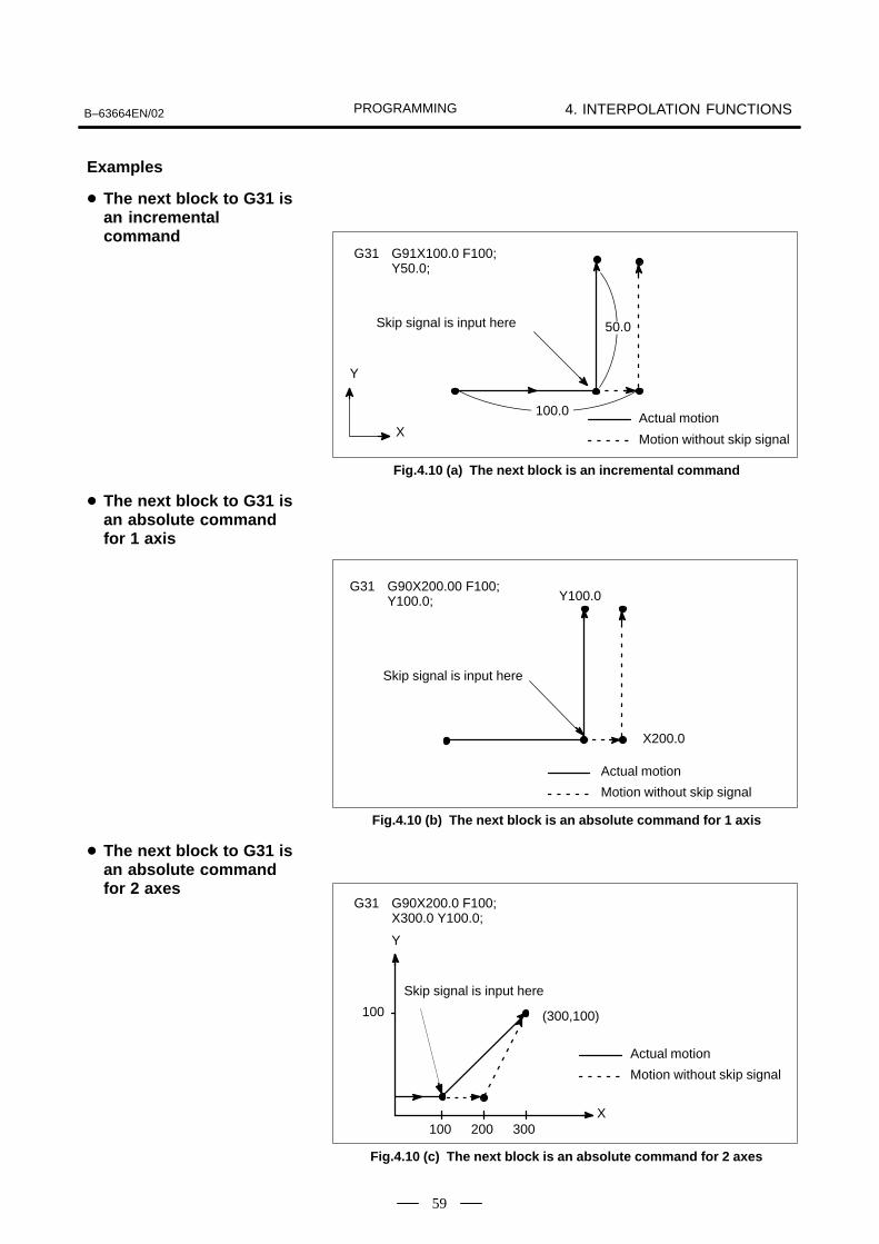
PROGRAMMINGB–63664EN/02 4. INTERPOLATION FUNCTIONS
59
G31 G91X100.0 F100;Y50.0;
50.0
100.0
Skip signal is input here
Actual motion
Motion without skip signal
Y
X
Fig.4.10 (a) The next block is an incremental command
G31 G90X200.00 F100;Y100.0; Y100.0
X200.0
Skip signal is input here
Actual motion
Motion without skip signal
Fig.4.10 (b) The next block is an absolute command for 1 axis
(300,100)
Y
X100 200 300
100
G31 G90X200.0 F100;X300.0 Y100.0;
Actual motion
Motion without skip signal
Skip signal is input here
Fig.4.10 (c) The next block is an absolute command for 2 axes
Examples
� The next block to G31 isan incrementalcommand
� The next block to G31 isan absolute commandfor 1 axis
� The next block to G31 isan absolute commandfor 2 axes

PROGRAMMING4. INTERPOLATION FUNCTIONS B–63664EN/02
60
In a block specifying P1 to P4 after G31, the multi–step skip functionstores coordinates in a custom macro variable when a skip signal (4–pointor 8–point) is turned on.Parameters No. 6202 to No. 6205 can be used to select a 4–point or8–point skip signal. One skip signal can be set to match multiple Pn orQn (n=1,2,3,4) as well as to match a Pn or Qn on a one–to–one basis.Parameters DS1 to DS8 (No. 6206 #0A#7) can be used for dwell.
Move commandG31 IP __ F __ P __ ;
G04 X (U, P)__ (Q__);
Dwell
_ : End pointF_ : FeedrateP_ : P1–P4
X(U, P)_ : Dwell timeQ_ : Q1 – Q4
IP
IP
Multi–step skip is caused by specifying P1, P2, P3, or P4 in a G31 block.For an explanation of selecting (P1, P2, P3, or P4), refer to the manualsupplied by the machine tool builder.Specifying Q1, Q2, Q3, or Q4 in G04 (dwell command) enables dwellskip in a similar way to specifying G31. A skip may occur even if Q isnot specified. For an explanation of selecting (Q1, Q2, Q3, or Q4), referto the manual supplied by the machine tool builder.
Parameter Nos. 6202 to 6205 can be used to specify whether the 4–pointor 8–point skip signal is used. Specification is not limited to one–to–onecorrespondence. It is possible to specify that one skip signal correspondto two or more Pn’s or Qn’s (n=1, 2, 3, 4). Also, bits 0 (DS1) to 7 (DS8)of parameter No. 6206 can be used to specify dwell.
CAUTION
Dwell is not skipped when Qn is not specified andparameters DS1–DS8 (No. 6206#0–#7) are not set.
4.11MULTI–STEP SKIP(G31)
Format
Explanations
� Correspondence to skipsignals

PROGRAMMINGB–63664EN/02 4. INTERPOLATION FUNCTIONS
61
The skip function operates based on a high–speed skip signal (connecteddirectly to the NC; not via the PMC) instead of an ordinary skip signal.In this case, up to eight signals can be input. Delay and error of skip signal input is 0 – 2 msec at the NC side (notconsidering those at the PMC side). This high–speed skip signal input function keeps this value to 0.1 msecor less, thus allowing high precision measurement.
For details, refer to the appropriate manual supplied from the machinetool builder.
G31 IP_ ;
G31: One–shot G code (If is effective only in the block in which it is specified)
IP
4.12HIGH SPEED SKIPSIGNAL (G31)
Format

PROGRAMMING5. FEED FUNCTIONS B–63664EN/02
62
5 ���" ��������*

PROGRAMMINGB–63664EN/02 5. FEED FUNCTIONS
63
The feed functions control the feedrate of the nozzle. The following twofeed functions are available:
1. Rapid traverseWhen the positioning command (G00) is specified, the nozzle movesat a rapid traverse feedrate set in the CNC (parameter No. 1420).
2. Cutting feed The nozzle moves at a programmed cutting feedrate.
Override can be applied to a rapid traverse rate or cutting feedrate usingthe switch on the machine operator’s panel.
To prevent a mechanical shock, acceleration/deceleration is automaticallyapplied when the nozzle starts and ends its movement (Fig.5.1 (a)).
FR
Rapid traverse rate
Time
T�
TR
FR : Rapid traverse rate
: Acceleration/deceleration timeconstant for rap-id traverse rate
0
Time
Feed rate
FCFC
�
TC TC
TR
TC
: Feedrate: Acceleration/
deceleration timeconstant for a cut-ting feedrate
Fig.5.1 (a) Automatic acceleration/deceleration (example)
5.1GENERAL
� Feed functions
� Override
� Automatic acceleration/deceleration

PROGRAMMING5. FEED FUNCTIONS B–63664EN/02
64
If the direction of movement changes between specified blocks duringcutting feed, a rounded–corner path may result (Fig.5.1 (b)).
0
Programmed path
Actual tool path
�
�
Fig.5.1 (b) Example of Tool Path between Two Blocks
In circular interpolation, a radial error occurs (Fig.5.1 (c)).
0
�
�
�
∆��Error
Programmed path
Actual tool path
Fig.5.1 (c) Example of Radial Error in Circular Interpolation
The rounded–corner path shown in Fig.5.1 (b) and the error shown inFig.5.1 (c) depend on the feedrate. So, the feedrate needs to be controlledfor the nozzle to move as programmed.
� Tool path in a cuttingfeed

PROGRAMMINGB–63664EN/02 5. FEED FUNCTIONS
65
G00 IP_ ;
G00 : G code (group 01) for positioning (rapid traverse) IP_ ; Dimension word for the end point
IP
IP
The positioning command (G00) positions the nozzle by rapid traverse.In rapid traverse, the next block is executed after the specified feedratebecomes 0 and the servo motor reaches a certain range set by the machinetool builder (in–position check).A rapid traverse rate is set for each axis by parameter No. 1420, so no rapidtraverse feedrate need be programmed.The following overrides can be applied to a rapid traverse rate with theswitch on the machine operator’s panel:F0, 25, 50, 100%F0: Allows a fixed feedrate to be set for each axis by parameter No. 1421.For detailed information, refer to the appropriate manual of the machinetool builder.
5.2RAPID TRAVERSE
Format
Explanations
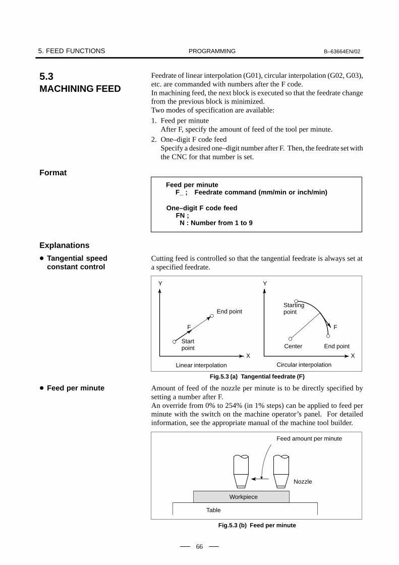
PROGRAMMING5. FEED FUNCTIONS B–63664EN/02
66
Feedrate of linear interpolation (G01), circular interpolation (G02, G03),etc. are commanded with numbers after the F code. In machining feed, the next block is executed so that the feedrate changefrom the previous block is minimized.Two modes of specification are available:
1. Feed per minuteAfter F, specify the amount of feed of the tool per minute.
2. One–digit F code feedSpecify a desired one–digit number after F. Then, the feedrate set withthe CNC for that number is set.
Feed per minuteF_ ; Feedrate command (mm/min or inch/min)
One–digit F code feedFN ; N : Number from 1 to 9
Cutting feed is controlled so that the tangential feedrate is always set ata specified feedrate.
X
End pointStarting point
X
FF
Center End pointStartpoint
Linear interpolation Circular interpolation
Y Y
Fig.5.3 (a) Tangential feedrate (F)
Amount of feed of the nozzle per minute is to be directly specified bysetting a number after F.An override from 0% to 254% (in 1% steps) can be applied to feed perminute with the switch on the machine operator’s panel. For detailedinformation, see the appropriate manual of the machine tool builder.
Table
Nozzle
Feed amount per minute
Workpiece
Fig.5.3 (b) Feed per minute
5.3MACHINING FEED
Format
Explanations
� Tangential speedconstant control
� Feed per minute

PROGRAMMINGB–63664EN/02 5. FEED FUNCTIONS
67
WARNING
No override can be used for some commands.
When a one–digit number from 1 to 9 is specified after F, the feedrateset for that number in a parameter (Nos. 1451 to 1459) is used. WhenF0 is specified, the rapid traverse rate is applied.The feedrate corresponding to the number currently selected can beincreased or decreased by turning on the switch for changing F1–digitfeedrate on the machine operator’s panel, then by rotating the manualpulse generator.The increment/decrement, ∆F, in feedrate per scale of the manual pulsegenerator is as follows:
F � Fmax100X
∆
Fmax : feedrate upper limit for F1–F4 set by parameter (No.1460), orfeedrate upper limit for F5–F9 set by parameter (No.1461)
X :any value of 1–127 set by parameter (No.1450)The feedrate set or altered is kept even while the power is off. The currentfeed rate is displayed on the screen.
A common upper limit can be set on the cutting feedrate along each axiswith parameter No. 1422. If an actual cutting feedrate (with an overrideapplied) exceeds a specified upper limit, it is clamped to the upper limit.Parameter No. 1430 can be used to specify the maximum cutting feedratefor each axis only for linear interpolation and circular interpolation.When the cutting feedrate along an axis exceeds the maximum feedratefor the axis as a result of interpolation, the cutting feedrate is clamped tothe maximum feedrate.
NOTEAn upper limit is set in mm/min or inch/min. CNC calculationmay involve a feedrate error of ±2% with respect to aspecified value. However, this is not true for acceleration/deceleration. To be more specific, this error is calculatedwith respect to a measurement on the time the tool takes tomove 500 mm or more during the steady state:
See Appendix C for range of feedrate command value.
� One–digit F code feed
� Cutting feedrate clamp
Reference

PROGRAMMING5. FEED FUNCTIONS B–63664EN/02
68
Cutting feedrate can be controlled, as indicated in Table 5.4.
Table 5.4 Cutting Feedrate Control
Function name G code Validity of G code Description
Exact stop G09This function is valid for specifiedblocks only.
The nozzle is decelerated at the endpoint of a block, then an in–positioncheck is made. Then the next block isexecuted.
Exact stop mode G61Once specified, this function is valid until G62 or G64 is specified.
The nozzle is decelerated at the endpoint of a block, then an in–positioncheck is made. Then the next block isexecuted.
Machining mode G64Once specified, this function is valid until G61, G62, or G63 is specified.
The nozzle is not decelerated at the endpoint of a block, but the next block isexecuted.
Auto–maticcornerover-ride
Automatic overridefor inner corners
G62Once specified, this function is valid until G61 or G64 is specified.
When the nozzle moves along an inner corner during cutter compensation, over-ride is applied to the cutting feedrate tosuppress the amount of cutting per unitof time so that a good surface finish canbe produced.over-
rideInternal circular cut-ting feedrate change
–This function is valid in the cuttercompensation mode, regardless ofthe G code.
The internal circular cutting feedrate ischanged.
NOTE1 The purpose of in–position check is to check that the servo
motor has reached within a specified range (specified witha parameter by the machine tool builder).In–position check is not performed when bit 5 (NCI) ofparameter No. 1601 is set to 1.
2 Inner corner angle θ: 2°< θ � α � 178°(α is a set value)
Exact stop G09 IP_ ;Exact stop mode G61 ;
Machining mode G64 ;
Automatic corner override G62 ;
IP
5.4CUTTING FEEDRATECONTROL
θ
Workpiece
Tool
Format

PROGRAMMINGB–63664EN/02 5. FEED FUNCTIONS
69
The inter–block paths followed by the beam in the exact stop mode,cutting mode, and tapping mode are different (Fig.5.4.1).
0
Y
���
���In–position check
Beam path in the exact stop mode
Beam path in the machining mode
X
Fig.5.4.1 Example of Beam Paths from Block (1) to Block (2)
CAUTION
The machining mode (G64 mode) is set at power–on orsystem clear.
5.4.1Exact Stop (G09, G61),Cutting Mode (G64)
Explanations

PROGRAMMING5. FEED FUNCTIONS B–63664EN/02
70
When cutter compensation is performed, the movement of the nozzle isautomatically decelerated at an inner corner and internal circular area.This produces a smoothly machined surface.
When G62 is specified, and the nozzle path with cutter compensationapplied forms an inner corner, the feedrate is automatically overriddenat both ends of the corner. There are four types of inner corners (Fig.5.4.2.1 (a)).2°�θ�θp�178° in Fig.5.4.2.1 (a)θp is a value set with parameter No. 1711. When θ is approximatelyequal to θp, the inner corner is determined with an error of 0.001,orless.
θ
:Beam center path
:Beam
:Programmed path
θ
θ
θ
1. Straight line–straight line 2. Straight line–arc
3. Arc–straight line 4. Arc–arc
Fig.5.4.2.1 (a) Inner corner
5.4.2Automatic CornerOverride
5.4.2.1 Automatic override forinner corners (G62)
Explanations� Override condition

PROGRAMMINGB–63664EN/02 5. FEED FUNCTIONS
71
When a corner is determined to be an inner corner, the feedrate isoverridden before and after the inner corner. The distances Ls and Le,where the feedrate is overridden, are distances from points on the beamcenter path to the corner (Fig.5.4.2.1 (b), Fig.5.4.2.1 (c), Fig.5.4.2.1 (d)).Ls and Le are set with parameter Nos. 1713 and 1714.
Programmed path
Lea b
Ls
Beam center path
The feedrate is overridden from point a to point b.
FIg.5.4.2.1 (b) Override Range (Straight Line to Straight Line)
When a programmed path consists of two arcs, the feedrate is overriddenif the start and end points are in the same quadrant or in adjacent quadrants(Fig.5.4.2.1 (c)).
a
Le
Ls
b
Programmed path
The feedrate is overridden from point a to b.
Beam center path
Fig.5.4.2.1 (c) Override Range (Arc to Arc)
Regarding program (2) of an arc, the feedrate is overridden from point ato point b and from point c to point d (Fig.5.4.2.1 (d)).
c
d a
LsLe
b
Ls Le
(2)
Programmed path
Beam center pathBeam
Fig.5.4.2.1 (d) Override Range (Straight Line to Arc, Arc to Straight Line)
Override range

PROGRAMMING5. FEED FUNCTIONS B–63664EN/02
72
An override value is set with parameter No. 1712. An override value isvalid even for dry run and F1–digit specification.In the feed per minute mode, the actual feedrate is as follows:
F × (automatic override for inner corners) × (feedrate override)
Override for inner corners is disabled during acceleration/decelerationbefore interpolation.
Override for inner corners is disabled if the corner is preceded by astart–up block or followed by a block including G41 or G42.
Override for inner corners is not performed if the offset is zero.
For internally offset circular cutting, the feedrate on a programmed pathis set to a specified feedrate (F) by specifying the circular cutting feedratewith respect to F, as indicated below (Fig.5.4.2.2). This function is validin the cutter compensation mode, regardless of the G62 code.
F � RcRp
Rc : Beam center path radiusRp : Programmed radius
It is also valid for the dry run and the one–digit F command.
Rc
Rp
Programmed path
Beam centerpath
Fig.5.4.2.2 Internal circular cutting feedrate change
If Rc is much smaller than Rp, Rc/Rp0; the tool stops. A minimumdeceleration ratio (MDR) is to be specified with parameter No. 1710.When Rc/Rp�MDR, the feedrate of the tool is (F×MDR).
CAUTION
When internal circular machining must be performed together with override for inner corners,the feedrate of the nozzle is as follows:
(override for the inner corners)×(feedrate override)F � RcRp
�
Override value
Limitations
� Acceleration/deceleration before interpolation
� Start–up/G41, G42
� Offset
5.4.2.2 Internal circularmachining feedratechange

PROGRAMMINGB–63664EN/02 5. FEED FUNCTIONS
73
This function automatically controls the feedrate at a corner according tothe corner angle between the machining blocks or the feedrate differencebetween the blocks along each axis.This function is effective when ACD, bit 6 of parameter No. 1601, is setto 1, the system is in G64 mode (machining mode), and a cutting–feedblock (block A) is followed by another cutting–feed block (block B).The feedrate between machining blocks is controlled according to thecorner angle between the blocks or the feedrate difference between theblocks along each axis. These two methods can be switched with CSD,bit 4 of parameter No. 1602.
This function decelerates the feedrate when the angle between blocks Aand B on the selected plane is smaller than the angle specified in parameterNo. 1740. The function executes block B when the feedrates along boththe first and second axes are smaller than the feedrate specified inparameter No. 1741. In this case, the function determines that the numberof accumulated pulses is zero.
The flowchart for feedrate control is shown below.
START
Yes
Yes
END
No
No
Is the corner angle smaller thanthe angle specified in parameter(No. 1740)?
Are the feedrates along the X– and Y–axes smaller than that specified in parameter (No. 1741)?
Further decelerates the feedrate in block A
The number of accumulatedpulses is determined to be zero and block B is executed
5.4.3Automatic CornerDeceleration
5.4.3.1 Corner decelerationaccording to the cornerangle
Explanations
� Flowchart for feedratecontrol

PROGRAMMING5. FEED FUNCTIONS B–63664EN/02
74
When the corner angle is smaller than the angle specified in theparameter, the relationship between the feedrate and time is as shownbelow. Although accumulated pulses equivalent to the hatched arearemain at time t, the next block is executed because the feedrate of theautomatic acceleration/deceleration circuit is smaller than theparameter–set value. This function is effective only for movement onthe selected plane.
ÍÍÍÍÍÍÍÍ�
Feedrate V
Block A Block B
Parameter–set feedrate
Time t
When acceleration/deceleration before interpolation is effective, therelationship between the feedrate and time is as shown below. When theangle between blocks A and B on the selected plane is smaller than theangle specified in parameter (No. 1740), and the feedrates specified inblocks A and B are larger than that specified in parameter (No. 1777), thefeedrate is decelerated to the parameter–set value in block A, andaccelerated to the feedrate specified in block B. The acceleration dependson the parameter for acceleration/deceleration before interpolation.
Feedrate
Block A Block B
Parameter–set feedrate (parameter No. 1777)
Time
The angle between two blocks (blocks A and B) is assumed to be angleθ, as shown below.
1. Between linear movements
θ
θθ
θ
2. Between linear and circular movements(angle between the linear movement and tangent to the circular movement)
3. Between circular movements(angle between the tangents to the circular movements)
� Feedrate and time
� Acceleration/deceleration beforeinterpolation
� Angle between twoblocks

PROGRAMMINGB–63664EN/02 5. FEED FUNCTIONS
75
The machining angle is compared with the angle specified in parameter(No. 1740) for movements on the selected plane only. Machiningfeedrates are compared with that specified in parameter (No. 1741) formovement along the first and second axes on the selected plane only. Thismeans, when movement occurs along three or more axes, only thatmovement along the first and second axes on the selected plane isconsidered.
Corner roundness is determined by the angle and feedrate specified inparameter (Nos. 1740 and 1741). To always make a sharp corner, setthe angle to zero and the feedrate to 180000 (equivalent to 180degrees).
When G90 (exact stop) is specified, exact stop is performed irrespectiveof the angle and feedrate specified in parameter (Nos. 1740 and 1741).
Those parameters related to automatic corner deceleration in advancedpreview control mode are shown below.
Parameter description Normalmode
Advancedpreview
control mode
Switching the methods for automatic cornerdeceleration
No.1602#4 No.1602#4
Lower limit of feedrate in automatic cornerdeceleration based on the angle
No.1777 No.1778
Limit angle in corner deceleration based onthe angle
No.1740 No.1779
This function cannot be enabled for a single block or during dry run.
� Selected plane
� Corner roundness
� Exact stop
� Advanced previewcontrol
Limitations

PROGRAMMING5. FEED FUNCTIONS B–63664EN/02
76
This function decelerates the feedrate when the difference between thefeedrates at the end point of block A and the start point of block B alongeach axis is larger than the value specified in parameter No. 1781. Thefunction executes block B when the feedrates along all axes are smallerthan the feedrate specified in parameter No. 1741. In this case, thefunction determines that the number of accumulated pulses is zero.
The flowchart for feedrate control is shown below.
START
Yes
Yes
END
No
No
Is the feedrate difference betweenblocks along each axis larger thanthe value specified in parameter(No. 1781)?
Are the feedrates along all axessmaller than that specified inparameter (No. 1741)? Further decelerates the
feedrate in block A
The number of accumulated pulsesis determined to be zero and blockB is executed.
When the feedrate difference between blocks along each axis is larger thanthe value specified in parameter No. 1781, the relationship between thefeedrate and time is as shown below. Although accumulated pulsesequivalent to the hatched area remain at time t, the next block is executedbecause the feedrate of the automatic acceleration/deceleration circuit issmaller than the feedrate specified in parameter No. 1741.
ÍÍÍÍÍÍÍÍ�
Feedrate V
Block A Block B
Parameter–set feedrate
Time t
5.4.3.2 Corner decelerationaccording to the feedratedifference betweenblocks along each axis
Explanations
� Flowchart for feedratecontrol
� Feedrate and time

PROGRAMMINGB–63664EN/02 5. FEED FUNCTIONS
77
When acceleration/deceleration before interpolation is effective, therelationship between the feedrate and time is as described below. When the feedrate difference between blocks A and B along each axis islarger than the value specified in parameter No. 1780, the feedrate isdecelerated to the corner feedrate calculated from the feedrate differencealong each axis.Let the feedrate be F. Compare the feedrate difference along each axis(Vc[X], Vc[Y], ...) with the value specified in parameter No. 1780, Vmax.When the difference exceeds Vmax, calculate R as shown below.
R=����
��
Fc=F �����
�
N1
N2 N1 G01 G91 X80. Y20. F3000 ;N2 X20. Y80. ;
Rmax=����
�� [����]
F �����
�
Find the maximum value for R among the calculated values for the axes.Let it be Rmax. Then, the corner feedrate can be obtained as follows:
(Example)
From the figure, it can be seen that the feedrate differences along the X–and Y–axes (Vc[X] and Vc[Y]) exceed Vmax. Calculate Rmax to getFc. When the feedrate is decelerated to Fc at the corner, the feedratedifference along each axis do not exceed Vmax.
When this movement is specified, the feedrate along each axis is asshown in the next figure.
� Acceleration /deceleration beforeinterpolation

PROGRAMMING5. FEED FUNCTIONS B–63664EN/02
78
N1 N2 t
F�Rmax
1
Vc [Y]
Vc [X] Vmax
Vmax
Feedrate alongthe X–axis
Without corner deceleration
With corner deceleration
Feedrate alongthe Y–axis
Feedrate alongthe tangentat the corner
The allowable feedrate difference can be specified for each axis inparameter No. 1783.
The feedrate difference is also checked during dry–run operation orduring deceleration caused by an external signal, using feedratecommands specified in a program.
When G90 (exact stop) is specified, exact stop is performed irrespectiveof the parameter settings.
If an override is changed during operation, the feedrate difference willnot be checked correctly.
� Setting the allowablefeedrate difference alongeach axis
� Checking the feedratedifference
� Exact stop
� Override

PROGRAMMINGB–63664EN/02 5. FEED FUNCTIONS
79
Parameters related to automatic corner deceleration in advancedpreview control mode are shown below.
Parameter description Normalmode
Advancedpreview
control mode
Switching the methods for automatic cornerdeceleration
No.1602#4 No.1602#4
Allowable feedrate difference (for all axis) inautomatic corner deceleration based on thefeedrate difference
No.1780 No.1780
Allowable feedrate difference (for each axis)in automatic corner deceleration based onthe feedrate difference
No.1783 No.1783
This function is not effective for feed–per–rotation commands,address–F–with–one–digit commands, rigid tapping, and a single block.
� Advanced previewcontrol
Limitations

PROGRAMMING5. FEED FUNCTIONS B–63664EN/02
80
Dwell G04 X_ ; or G04 P_ ; X_ : Specify a time P_ : Specify a time
By specifying a dwell, the execution of the next block is delayed by thespecified time. In addition, a dwell can be specified to make an exactcheck in the machining mode (G64 mode).
Table 5.5 (a) Command value range of the dwell time (Command by X)
Increment system Command value range Dwell time unit
IS–B 0.001 to 99999.999 sec
Table 5.5 (b) Command value range of the dwell time (Command by P)
Increment system Command value range Dwell time unit
IS–B 1 to 99999999 0.001 sec
5.5DWELL (G04)
Format
Explanations

PROGRAMMINGB–63664EN/02 6. REFERENCE POSITION
81
6 REFERENCE POSITION
A CNC machine tool has a special position where, generally, the nozzleis exchanged or the coordinate system is set, as described later. Thisposition is referred to as a reference position.

PROGRAMMING6. REFERENCE POSITION B–63664EN/02
82
The reference position is a fixed position on a machine nozzle to whichthe tool can easily be moved by the reference position return function.Up to four reference positions can be specified by setting coordinates inthe machine coordinate system in parameters (No. 1240 to 1243).
Reference position
Machine zero point
3rd reference position
2nd reference position
4th reference position
Fig.6.1 (a) Machine zero point and reference positions
�
�
6.1REFERENCEPOSITION RETURN
General
� Reference position

PROGRAMMINGB–63664EN/02 6. REFERENCE POSITION
83
Tools are automatically moved to the reference position via anintermediate position along a specified axis. Or, tools are automaticallymoved from the reference position to a specified position via anintermediate position along a specified axis. When reference positionreturn is completed, the lamp for indicating the completion of return goeson.
A (Start position for reference position return)
B (Intermediate position)
C (Destination of return from thereference position)
R (Reference position)Reference position return A→B→RReturn from the reference positionR→B→C
Fig.6.1 (b) Reference position return and return form the reference position
The reference position return check (G27) is the function which checkswhether the tool has correctly returned to the reference position asspecified in the program. If the tool has correctly returned to the referenceposition along a specified axis, the lamp for the axis goes on.
�+, 'PI
�-. �+ & '
Reference position return
3rd reference position return
4th reference position return
2nd reference position return
PI : Command specifying the intermediate position (Absolute/incremental command)
�-. �- '
�-. �/ '
(P2 can be omitted.)
PI
PI
PI
�+0 '
PI : Command specifying the destination of return from reference position (Absolute/incremental command)
PI
�+7 '
PI : Command specifying the reference position (Absolute/incremental command)
PI
� Reference positionreturn and movementfrom the referenceposition
� Reference positionreturn check
���$�
� Reference positionreturn
� Return from referenceposition
� Reference positionreturn check

PROGRAMMING6. REFERENCE POSITION B–63664EN/02
84
Positioning to the intermediate or reference positions are performed at therapid traverse rate of each axis.Therefore, for safety, the cutter compensation, and tool lengthcompensation should be cancelled before executing this command.The coordinates for the intermediate position are stored in the CNC onlyfor the axes for which a value is specified in a G28 block. For the otheraxes, the previously specified coordinates are used. Example N1 G28 X40.0 ; Intermediate position (X40.0)
N2 G28 Y60.0 ; Intermediate position (X40.0, Y60.0)
In a system without an absolute–position detector, the first, third, andfourth reference position return functions can be used only after thereference position return (G28) or manual reference position return (seeIII–3.1) is made. The G30 command is generally used when the automatictool changer (ATC) position differs from the reference position.
In general, it is commanded immediately following the G28 command orG30. For incremental programming, the command value specifies theincremental value from the intermediate point.Positioning to the intermediate or reference points are performed at therapid traverse rate of each axis.When the workpiece coordinate system is changed after the tool reachesthe reference position through the intermediate point by the G28command, the intermediate point also shifts to a new coordinate system.If G29 is then commanded, the tool moves to to the commanded positionthrough the intermediate point which has been shifted to the newcoordinate system.The same operations are performed also for G30 commands.
G27 command positions the tool at rapid traverse rate. If the tool reachesthe reference position, the reference position return lamp lights up. However, if the position reached by the tool is not the reference position,an alarm (No. 092) is displayed.
Before a machine coordinate system is established with the first return tothe reference position after power–on, the manual and automaticreference position return feedrates and automatic rapid traverse rateconform to the setting of parameter No. 1428, if any, for each axis. Evenafter a machine coordinate system is established upon the completion ofreference position return, the manual reference position return feedrateconforms to the setting of the parameter. Even after a machine coordinatesystem is established upon the completion of reference position return,the manual reference postiion return feedrate conforms to the setting ofthe parameter.
����� ���
� Reference positionreturn (G28)
� 2nd, 3rd, and 4threference position return(G30)
� Return from thereference position (G29)
� Reference positionreturn check (G27)
� Setting of the referenceposition return feedrate

PROGRAMMINGB–63664EN/02 6. REFERENCE POSITION
85
NOTE1 To this feedrate, a rapid traverse override (F0 ,25,50,100%)
is applied, for which the setting is 100%.2 After a machine coordinate system has been established
upon the completion of reference position return, theautomatic reference position return feedrate will conform tothe ordinary rapid traverse rate.
3 For the manual rapid traverse rate used before a machinecoordinate system is estavlished upon the completion ofreference position return a jog feedrate or manual rapidtraverse rate can be selected usting RPD (bit 0 of parameterNo. 1401).
Before a coordinatesystem is established
After a coordinatesystem is established
Automatic reference posi-tion return (G28)
No. 1428 No.1420
Automatic rapid traverse(G00)
No.1428 No.1420
Manual reference positionreturn
No.1428 No.1428
Manual rapid traverse rate No.1423 *1 No.1424
NOTE4 When parameter No. 1428 is set to 0, the feedrates conform
to the parameter settings shown below.
Before a coordinatesystem is established
After a coordinatesystem is established
Automatic reference posi-tion return (G28)
No. 1420 No.1420
Automatic rapid traverse(G00)
No.1420 No.1420
Manual reference positionreturn
No.1424 No.1424
Manual rapid traverse rate No.1423 *1 No.1424
1420 : Rapid traverse rate1423 : Jog feedrate1424 : Manual rapid traverse rate
*1 Setting of parameter No.1424 when RPD (bit 0 of parameter No.1401)is set to 1.

PROGRAMMING6. REFERENCE POSITION B–63664EN/02
86
The lamp for indicating the completion of return does not go on when themachine lock is turned on, even when the tool has automatically returnedto the reference position. In this case, it is not checked whether the toolhas returned to the reference position even when a G27 command isspecified.
When the G28 command is specified when manual return to the referenceposition has not been performed after the power has been turned on, themovement from the intermediate point is the same as in manual return tothe reference position.In this case, the tool moves in the direction for reference position returnspecified in parameter ZMIx (bit 5 of No. 1006). Therefore the specifiedintermediate position must be a position to which reference positionreturn is possible.
In an offset mode, the position to be reached by the tool with the G27command is the position obtained by adding the offset value. Therefore,if the position with the offset value added is not the reference position, thelamp does not light up, but an alarm is displayed instead. Usually, canceloffsets before G27 is commanded.
When the machine tool system is an inch system with metric input, thereference position return lamp may also light up even if the programmedposition is shifted from the reference position by the least settingincrement. This is because the least setting increment of the machine toolsystem is smaller than its least command increment.
See III–3.1.
G28G90X1000.0Y500.0 ; (Programs movement from A to B) M1111 ; (Changing the tool at the reference position)G29X1300.0Y200.0 ; (Programs movement from B to C)
A
B
C
RReference position
200
300
500
200 1000 1300
Y
X
The tool is changed at the reference position
Fig.6.1 (c) Reference position return and return from the reference position
Restrictions
� Status the machine lockbeing turned on
� First return to thereference position afterthe power has beenturned on (without anabsolute positiondetector)
� Reference positionreturn check in an offsetmode
� Lighting the lamp whenthe programmed positiondoes not coincide withthe reference position
�������!�
� Manual referenceposition return
Examples

PROGRAMMINGB–63664EN/02 6. REFERENCE POSITION
87
Tools ca be returned to the floating reference position.A floating reference point is a position on a machine tool, and serves asa reference point for machine tool operation. A floating reference point need not always be fixed, but can be moved asrequired.
& '�-.1�
Command of the intermediate position of the floating referenceposition (Absolute command/incremental command)
& 2
IP
IP
Generally speaking, on a machining center or milling machine, cuttingtools can be replaced only at specific positions. A position where tools canbe replaced is defined as the second or third reference point. Using G30can easily move the cutting tools back to these points. On some machinetools, the cutting tools can be replaced at any position unless they interferewith the workpiece.With these machines, the cutting tools should be replaced at a position asclose to the workpiece as possible so as to minimize the machine cycletime. For this purpose, the tool change position is to be changed,depending on the figure of the workpiece. This operation can easily beperformed using this function. That is, a tool change position suitable forthe workpiece is memorized as a floating reference point. Then commandG30. 1 can easily cause return to the tool change position.A floating reference point becomes a machine coordinate positionmemorized by pressing the soft key [SET FRP] on the current positionsdisplay screen (see III–11.1.7). The G30.1 block first positions the toolat the intermediate point along the specified axes at rapid traverse rate,then further moves the tool from the intermediate point to the floatingreference point at rapid traverse rate.Before using G30.1, cancel cutter compensation and tool lengthcompensation.A floating reference point is not lost even if power is turned off.The function for returning from the reference position (G29) can be usedfor moving the tool from the floating reference position (see II–6.1).
Y
X
Workpiece
Intermediate position (50,40)
Floating reference position
G30.1 G90 X50.0 Y40.0 ;
6.2FLOATINGREFERENCEPOSITION RETURN(G30.1)
Format
Explanations
Examples

PROGRAMMING7. COORDINATE SYSTEM B–63664EN/02
88
7 COORDINATE SYSTEM
By teaching the CNC a desired nozzle position, the nozzle can be movedto the position. Such a nozzle position is represented by coordinates ina coordinate system. Coordinates are specified using program axes.When three program axes, the X–axis, Y–axis, and Z–axis, are used,coordinates are specified as follows: X_Y_Z_
This command is referred to as a dimension word.
Z
Y
X
40.0
50.0
25.0
Fig.7 Nozzle position specified by X40.0Y50.0Z25.0
Coordinates are specified in one of following three coordinate systems:
(1)Machine coordinate system
(2)Workpiece coordinate system
(3)Local coordinate system
The number of the axes of a coordinate system varies from one machineto another. So, in this manual, a dimension word is represented as IP_.

PROGRAMMINGB–63664EN/02 7. COORDINATE SYSTEM
89
The point that is specific to a machine and serves as the reference of themachine is referred to as the machine zero point. A machine tool buildersets a machine zero point for each machine.A coordinate system with a machine zero point set as its origin is referredto as a machine coordinate system.A machine coordinate system is set by performing manual referenceposition return after power–on (see III–3.1). A machine coordinatesystem, once set, remains unchanged until the power is turned off.
(G90)G53 IP _ ;
IP _; Absolute dimension word
IP
IP
When a command is specified the position on a machine coordinatesystem, the nozzle moves to the position by rapid traverse. G53, whichis used to select a machine coordinate system, is a one–shot G code; thatis, it is valid only in the block in which it is specified on a machinecoordinate system. Specify an absolute command (G90) for G53. Whenan incremental command (G91) is specified, the G53 command isignored. When the nozzle is to be moved to a machine–specific positionsuch as a nozzle change position, program the movement in a machinecoordinate system based on G53.
When the G53 command is specified, cancel the cutter compensation, toollength offset, and tool offset.
Since the machine coordinate system must be set before the G53command is specified, at least one manual reference position return orautomatic reference position return by the G28 command must beperformed after the power is turned on. This is not necessary when anabsolute–position detector is attached.
When manual reference position return is performed after power–on, amachine coordinate system is set so that the reference position is at thecoordinate values of (α, β) set using parameter No.1240.
β
Machine zero
α
Machine coordinate system
Reference position
7.1MACHINECOORDINATESYSTEM
Format
Explanations
� Selecting a machinecoordinate system (G53)
Restrictions
� Cancel of thecompensation function
� G53 specificationimmediately afterpower–on
Reference

PROGRAMMING7. COORDINATE SYSTEM B–63664EN/02
90
A coordinate system used for machining a workpiece is referred to as aworkpiece coordinate system. A workpiece coordinate system is to be setwith the CNC beforehand (setting a workpiece coordinate system).A machining program sets a workpiece coordinate system (selecting aworkpiece coordinate system).A set workpiece coordinate system can be changed by shifting its origin(changing a workpiece coordinate system).
A workpiece coordinate system can be set using one of three methods:
(1) Method using G92A workpiece coordinate system is set by specifying a value after G92in the program.
(2) Automatic setting If bit 0 of parameter SPR No. 1201 is set beforehand, a workpiececoordinate system is automatically set when manual referenceposition return is performed (see Part III–3.1.).This function is, however, disabled when the workpiece coordinatesystem option is being used.
(3) Input using the MDI panelSix workpiece coordinate systems can be set beforehand using theMDI panel (see Part III–11.4.5.).When using an absolute command, establish the workpiececoordinate system in any of the above ways.
(G90) G92 IP_IP
A workpiece coordinate system is set so that a point on the nozzle, suchas the nozzle tip, is at specified coordinates. If a coordinate system is setusing G92 during nozzle length offset, a coordinate system in which theposition before offset matches the position specified in G92 is set.Cutter compensation is cancelled temporarily with G92.
7.2WORKPIECECOORDINATESYSTEM
7.2.1Setting a WorkpieceCoordinate System
Format
� Setting a workpiececoordinate system by G92
Explanations

PROGRAMMINGB–63664EN/02 7. COORDINATE SYSTEM
91
25.2 X
Z
23.0
0 X
Z
600.0
1200.0If an absolute command is is-sued, the base point moves tothe commanded position. Inorder to move the nozzle tip tothe commanded position, thedifference from the nozzle tipto the base point is compen-sated by tool length offset.
Setting the coordinate system by theG92X25.2Z23.0; command(The nozzle tip is the start point for the pro-gram.)
Setting the coordinate system by the G92X600.0Z1200.0; command (The base point on the nozzle holder is the start point for the pro-gram.)
Base point
Example 1 Example 2
0
The user can choose from set workpiece coordinate systems as describedbelow. (For information about the methods of setting, see II– 7.2.1.)(1)Once a workpiece coordinate system is selected by G92 or automatic
workpiece coordinate system setting, absolute commands work withthe workpiece coordinate system.
(2)Choosing from six workpiece coordinate systems set using the MDIpanelBy specifying a G code from G54 to G59, one of the workpiececoordinate systems 1 to 6 can be selected.G54 Workpiece coordinate system 1G55 Workpiece coordinate system 2G56 Workpiece coordinate system 3G57 Workpiece coordinate system 4G58 Workpiece coordinate system 5G59 Workpiece coordinate system 6Workpiece coordinate system 1 to 6 are established after referenceposition return after the power is turned on. When the power is turnedon, G54 coordinate system is selected.
X
Y
100.0
40.0
In this example, positioning is made topositions (X=40.0, Y=100.0) in workpiececoordinate system 2.
G90 G55 G00 X40.0 Y100.0 ;
Workpiece coordinate system 2 (G55)
Fig.7.2.2
Examples
7.2.2Selecting a WorkpieceCoordinate System
Examples

PROGRAMMING7. COORDINATE SYSTEM B–63664EN/02
92
The six workpiece coordinate systems specified with G54 to G59 canbe changed by changing an external workpiece zero point offset valueor workpiece zero point offset value. Three methods are available to change an external workpiece zeropoint offset value or workpiece zero point offset value.(1) Inputting from the MDI panel (see III–11.4.5)(2) Programming by G10 or G92(3) Using the external data input function
An external workpiece zero point offset value can be changed byinput signal to CNC. Refer to machine tool builder’s manual fordetails
ZOFS2 ZOFS3ZOFS4
ZOFS5
ZOFS1
ZOFS6
EXOFS : External workpiece zero point offset valueZOFS1 to ZOFS6 : Workpiece zero point offset value
EXOFS
Workpiece coordinate system 1 (G54)
Workpiece coordinate system 2 (G55)
Workpiece coordinate system 3 (G56)
Workpiece coordinate system 4 (G57)
Workpiece coordinate system 5 (G58)
Workpiece coordinate system 6 (G59)
Machine zero
Fig.7.2.3 Changing an external workpiece zero point offset value or workpiece zero point offset value
G10 L2 Pp I _;p=0 : External workpiece zero point offset valuep=1 to 6 : Workpiece zero point offset value correspond to workpiece
coordinate system 1 to 6IP : For an absolute command (G90), workpiece zero point offset for
each axis.For an incremental command (G91), value to be added to the setworkpiece zero point offset for each axis (the result of addition becomes the new workpiece zero point offset).
IP
IP
G92 IP _;IP
7.2.3Changing WorkpieceCoordinate System
Format
� Changing by G10
� Changing by G92

PROGRAMMINGB–63664EN/02 7. COORDINATE SYSTEM
93
With the G10 command, each workpiece coordinate system can bechanged separately.
By specifying G92IP_;, a workpiece coordinate system (selected with acode from G54 to G59) is shifted to set a new workpiece coordinatesystem so that the current tool position matches the specified coordinates( IP _).Then, the amount of coordinate system shift is added to all the workpiecezero point offset values. This means that all the workpiece coordinatesystems are shifted by the same amount.
WARNING
When a coordinate system is set with G92 after an externalworkpiece zero point offset value is set, the coordinatesystem is not affected by the external workpiece zero pointoffset value. When G92X100.0Z80.0; is specified, forexample, the coordinate system having its current nozzlereference position at X = 100.0 and Z = 80.0 is set.
Explanations
� Changing by G10
� Changing by G92

PROGRAMMING7. COORDINATE SYSTEM B–63664EN/02
94
X
X
YY
A
160 100
100
100
200
If G92X100Y100; is commanded when the toolis positioned at (200, 160) in G54 mode, work-piece coordinate system 1 (X’ – Y’) shifted byvector A is created.
60
G54 workpiece coordinate system
Nozzle position
New workpiece coordinate system
Original workpiece coordinate system
1200.0
Z
Z
X
X600.0
600.0
1200.0
Z’
Z
X
X
X’ – Z’ New workpiece coordinate systemX – Z Original workpiece coordinate systemA : Offset value created by G92B,C : Workpiece zero point offset value in the original workpiece
coordinate system
A
B
C
A
G54 Workpiece coordinate system
G55 Workpiece coordinate system
Suppose that a G54 workpiece coordi-nate system is specified. Then, a G55workpiece coordinate system wherethe black circle on the nozzle (figure atthe left) is at (600.0,12000.0) can be setwith the following command if the rela-tive relationship between the G54 work-piece coordinate system and G55workpiece coordinate system is set cor-rectly:G92X600.0Z1200.0;Also, sup-pose that pallets are loaded at two dif-ferent positions. If the relative relation-ship of the coordinate systems of thepallets at the two positions is correctlyset by handling the coordinate systemsas the G54 workpiece coordinate sys-tem and G55 workpiece coordinatesystem, a coordinate system shift withG92 in one pallet causes the samecoordinate system shift in the other pal-let. This means that workpieces on twopallets can be machined with the sameprogram just by specifying G54 or G55.
��$���

PROGRAMMINGB–63664EN/02 7. COORDINATE SYSTEM
95
The workpiece coordinate system preset function presets a workpiececoordinate system shifted by manual intervention to the pre–shiftworkpiece coordinate system. The latter system is displaced from themachine zero point by a workpiece zero point offset value. There are two methods for using the workpiece coordinate system presetfunction. One method uses a programmed command (G92.1). The otheruses MDI operations on the absolute position display screen, relativeposition display screen, and overall position display screen (III– 11.1.4).
G92.1 IP 0 ; IP 0 ; Specifies axis addresses subject to the workpiece
coordinate system preset operation. Axes that are not specified are not subject to the preset operation.
IPIP
When manual reference position return operation is performed in the resetstate, a workpiece coordinate system is shifted by the workpiece zeropoint offset value from the machine coordinate system zero point.Suppose that the manual reference position return operation is performedwhen a workpiece coordinate system is selected with G54. In this case,a workpiece coordinate system is automatically set which has its zeropoint displaced from the machine zero point by the G54 workpiece zeropoint offset value; the distance from the zero point of the workpiececoordinate system to the reference position represents the current positionin the workpiece coordinate system.
G54 workpiece coordinate system
Reference position
Manual reference position return
Reference position
G54 workpiece zero point offset value
If an absolute position detector is provided, the workpiece coordinatesystem automatically set at power–up has its zero point displaced fromthe machine zero point by the G54 workpiece zero point offset value. Themachine position at the time of power–up is read from the absoluteposition detector and the current position in the workpiece coordinatesystem is set by subtracting the G54 workpiece zero point offset valuefrom this machine position. The workpiece coordinate system set bythese operations is shifted from the machine coordinate system using thecommands and operations listed next page.
7.2.4Workpiece CoordinateSystem Preset (G92.1)
Format
Explanations

PROGRAMMING7. COORDINATE SYSTEM B–63664EN/02
96
(a) Manual intervention performed when the manual absolute signal is off(b) Move command executed in the machine lock state(c) Movement by handle interrupt(d) Operation using the mirror image function (e) Setting the local coordinate system using G52, or shifting the
workpiece coordinate system using G92
In the case of (a) above, the workpiece coordinate system is shifted by theamount of movement during manual intervention.
Po
Pn
WZn
WZo
G54 workpiece coordinate system before manual intervention
Workpiece zero point offset value
G54 workpiece coordinate system after manual intervention
Amount of movement during manual intervention
Machine zero point
In the operation above, a workpiece coordinate system once shifted canbe preset using G code specification or MDI operation to a workpiececoordinate system displaced by a workpiece zero point offset value fromthe machine zero point. This is the same as when manual referenceposition return operation is performed on a workpiece coordinate systemthat has been shifted. In this example, such G code specification or MDIoperation has the effect of returning workpiece coordinate system zeropoint WZn to the original zero point WZo, and the distance from WZo toPn is used to represent the current position in the workpiece coordinatesystem.
Bit 3 (PPD) of parameter No. 3104 specifies whether to preset relativecoordinates (RELATIVE) as well as absolute coordinates.
When no workpiece coordinate system option (G54 to G59) is selected,the workpiece coordinate system is preset to the coordinate system set byautomatic workpiece coordinate system setting. When automaticworkpiece coordinate system setting is not selected, the workpiececoordinate system is preset with its zero point placed at the referenceposition.
When using the workpiece coordinate system preset function, cancelcompensation modes: cutter compensation and tool offset. If the functionis executed without cancelling these modes, compensation vectors aretemporarily cancelled.
The workpiece coordinate system preset function is not executed duringprogram restart.
Do not use the workpiece coordinate system preset function when thescaling, coordinate system rotation, programmable image, or drawingcopy mode is set.
Limitations
� Cutter compensation,tool offset
� Program restart
� Prohibited modes

PROGRAMMINGB–63664EN/02 7. COORDINATE SYSTEM
97
Besides the six workpiece coordinate systems (standard workpiececoordinate systems) selectable with G54 to G59, 48 additional workpiececoordinate systems (additional workpiece coordinate systems) can beused. Alternatively, up to 300 additional workpiece coordinate systemscan be used.
G54.1Pn ; or G54Pn ;
Pn : Codes specifying the additional workpiece coordinate systemsn : 1 to 48 or 1 to 300
G10L20 Pn IP _;
Pn : Codes specifying the workpiece coordinate system for setting the workpiece zero point offset value
n : 1 to 48 or 1 to 300IP_ : Axis addresses and a value set as the workpiece zero point
offset
IP
IP
When a P code is specified together with G54.1 (G54), the correspondingcoordinate system is selected from the additional workpiece coordinatesystems (1 to 48 or 1 to 300).A workpiece coordinate system, once selected, is valid until anotherworkpiece coordinate system is selected. Standard workpiece coordinatesystem 1 (selectable with G54) is selected at power–on.
G54.1 P1 Additional workpiece coordinate system 1� � � � � �G54.1 P2 Additional workpiece coordinate system 2� � � � � �
G54.1 P48 Additional workpiece coordinate system 48� � � � �
G54.1 P300 Additional workpiece coordinate system 300� � � �
As with the standard workpiece coordinate systems, the followingoperations can be performed for a workpiece zero point offset in anadditional workpiece coordinate system:
(1)The OFFSET function key can be used to display and set a workpiecezero point offset value.
(2)The G10 function enables a workpiece zero point offset value to be setby programming (refer to II–7.2.3).
(3)A custom macro allows a workpiece zero point offset value to behandled as a system variable.
(4)Workpiece zero point offset data can be entered or output as externaldata.
(5)The PMC window function enables workpiece zero point offset datato be read as program command modal data.
7.2.5Adding WorkpieceCoordinate Systems(G54.1 or G54)
Format
� Selecting the additional workpiece coordinatesystems
� Setting the workpiecezero point offset value in the additionalworkpiece coordinatesystems
Explanations
� Selecting the additionalworkpiece coordinatesystems

PROGRAMMING7. COORDINATE SYSTEM B–63664EN/02
98
When an absolute workpiece zero point offset value is specified, thespecified value becomes a new offset value. When an incrementalworkpiece zero point offset value is specified, the specified value is addedto the current offset value to produce a new offset value.
A P code must be specified after G54.1 (G54). If G54.1 is not followedby a P code in the same block, additional workpiece coordinate system1 (G54.1P1) is assumed.If a value not within the specifiable range is specified in a P code, an P/Salarm ( No. 030) is issued.P codes other than workpiece offset numbers cannot be specified in aG54.1 (G54) block.
Example) G54.1 (G54) G04 P1000 ;
� Setting the workpiecezero point offset value inthe additional workpiececoordinate systems
Limitations� *��! �( �) � !����

PROGRAMMINGB–63664EN/02 7. COORDINATE SYSTEM
99
When a program is created in a workpiece coordinate system, a childworkpiece coordinate system can be set for easier programming. Such achild coordinate system is referred to as a local coordinate system.
G52 IP _; Setting the local coordinate system
G52 IP 0 ; Canceling of the local coordinate system
IP _ : Origin of the local coordinate system
......IP
IP
IP
By specifying G52 IP _;, a local coordinate system can be set in all theworkpiece coordinate systems (G54 to G59). The origin of each localcoordinate system is set at the position specified by IP _ in the workpiececoordinate system.When a local coordinate system is set, the move commands in absolutemode (G90), which is subsequently commanded, are the coordinatevalues in the local coordinate system. The local coordinate system canbe changed by specifying the G52 command with the zero point of a newlocal coordinate system in the workpiece coordinate system. To cancel the local coordinate system and specify the coordinate value inthe workpiece coordinate system, match the zero point of the localcoordinate system with that of the workpiece coordinate system.
IP_
IP_
(G59 : Workpiece coordinate system 6)
(G54 : Workpiece coordinate system 1)
G55G56 G57
G58
Reference point
Machine coordinate system origin
(Machine coordinate system)
(Local coordinate system)
(Local coordinate system)
IP
IP
Fig.7.3 Setting the local coordinate system
7.3LOCAL COORDINATESYSTEM
Format
Explanations

PROGRAMMING7. COORDINATE SYSTEM B–63664EN/02
100
WARNING
1 When an axis returns to the reference point by the manual reference point return function,thezero point of the local coordinate system of the axis matches that of the work coordinate system.The same is true when the following command is issued:
G52α0; α:Axis which returns to the reference point
2 The local coordinate system setting does not change the workpiece and machine coordinatesystems.
3 Whether the local coordinate system is canceled at reset depends on the parameter setting.The local coordinate system is canceled when either CLR, bit 6 of parameter No.3402 or RLC,bit 3 of parameter No.1202 is set to 1.
4 If coordinate values are not specified for all axes when setting a workpiece coordinate systemwith the G92 command, the local coordinate systems of axes for which coordinate values werenot specified are not cancelled, but remain unchanged.
5 G52 cancels the offset temporarily in cutter compensation.6 Command a move command immediately after the G52 block in the absolute mode.

PROGRAMMINGB–63664EN/02 7. COORDINATE SYSTEM
101
Select the planes for circular interpolation, cutter compensation. The following table lists G–codes and the planes selected by them.
Table 7.4 Plane selected by G code
G code Selectedplane Xp Yp Zp
G17 Xp Yp planeX–axis or an Y–axis or an Z–axis or an
G18 Zp Xp planeX–axis or anaxis parallel
to it
Y–axis or an axis parallel
to it
Z–axis or an axis parallel
to itG19 Yp Zp plane
to it to it to it
Xp, Yp, Zp are determined by the axis address appeared in the block inwhich G17, G18 or G19 is commanded.When an axis address is omitted in G17, G18 or G19 block, it is assumedthat the addresses of basic three axes are omitted.Parameter No. 1022 is used to specify that an optional axis be parallel tothe each axis of the X, Y–, and Z–axes as the basic three axes.The plane is unchanged in the block in which G17, G18 or G19 is notcommanded.When the power is turned on or the CNC is reset, G17 (XY plane), G18(ZX plane), or G19 (YZ plane) is selected by bits 1 (G18) and 2 (G19) ofparameter 3402.The movement instruction is irrelevant to the plane selection.
Plane selection when the X–axis is parallel with the U–axis. G17X_Y_ XY plane, G17U_Y_ UY planeG18X_Z_ ZX plane X_Y_ Plane is unchanged (ZX plane)G17 XY planeG18 ZX planeG17 U_ UY planeG18Y_ ; ZX plane, Y axis moves regardless without any
relation to the plane.
7.4PLANE SELECTION
Explanations
Examples

PROGRAMMING8. COORDINATE VALUE AND DIMENSION B–63664EN/02
102
8 ����"����� 3���� ��" "�4��*���
This chapter contains the following topics.
8.1 ABSOLUTE AND INCREMENTAL PROGRAMMING (G90, G91)8.2 POLAR COORDINATE COMMAND (G15, G16)8.3 INCH/METRIC CONVERSION (G20, G21)8.4 DECIMAL POINT PROGRAMMING

PROGRAMMINGB–63664EN/028. COORDINATE VALUE
AND DIMENSION
103
There are two ways to command travels of the nozzle; the absolutecommand, and the incremental command. In the absolute command,coordinate value of the end position is programmed; in the incrementalcommand, move distance of the position itself is programmed. G90 andG91 are used to command absolute or incremental command,respectively.
Absolute command
Incremental command
G90 _ ;
G91 _ ;
IP
IP
Absolute command
Incremental command
G90 X40.0 Y70.0 ;
G91 X–60.0 Y40.0 ;
Y
X
70.0
30.0
40.0 100.0
!�" #$%�%�
&���� #$%�%�
8.1ABSOLUTE ANDINCREMENTALPROGRAMMING(G90, G91)
���$�
��$���

PROGRAMMING8. COORDINATE VALUE AND DIMENSION B–63664EN/02
104
The end point coordinate value can be input in polar coordinates (radiusand angle). The plus direction of the angle is counterclockwise of the selected planefirst axis + direction, and the minus direction is clockwise.Both radius and angle can be commanded in either absolute orincremental command (G90, G91).
_
G�� G�� G16 ;
_ ;
G15 ;
G16 Polar coordinate command
G15
G��
G��
Starting the polar coordinate command (polarcoordinate mode)
Polar coordinate command
Canceling the polar coordinate command (polar coordinatemode)
Polar coordinate command cancel
Plane selection of the polar coordinate command (G17, G18 or G19)
G90 specifies the zero point of the work coordinate system asthe origin of the polar coordinate system, from which a radiusis measured.G91 specifies the current position as the origin of the polarcoordinate system, from which a radius is measured.
Specifying the addresses of axes constituting the plane se-lected for the polar coordinate system, and their values First axis : radius of polar coordinateSecond axis : radius of polar coordinate
G00 IP
IP
Specify the radius (the distance between the zero point and the point) tobe programmed with an absolute command. The zero point of the workcoordinate system is set as the origin of the polar coordinate system.When a local coordinate system (G52) is used, the origin of the localcoordinate system becomes the center of the polar coordinates.
RadiusCommand position
Actual positionAngle
��"%'$
Angle
Command position
Actual position
When the angle is specified with an absolute command
When the angle is specified with an incremental command
8.2POLAR COORDINATECOMMAND (G15, G16)
���$�
� Setting the zero point ofthe workpiece coordinate system as theorigin of the polarcoordinate system

PROGRAMMINGB–63664EN/028. COORDINATE VALUE
AND DIMENSION
105
Specify the radius (the distance between the current position and thepoint) to be programmed with an incremental command. The currentposition is set as the origin of the polar coordinate system.
Radius
Command position
Actual position
Angle
When the angle is specified with an absolute command
When the angle is specified with an incremental command
Command position
Actual position
AngleRadius
�� (� �%���
Y
150°
30°
100mm
270°X
– The zero point of the work coordinate system is set as the origin of the polarcoordinate system.
– The XY plane is selected.
N1 G17 G90 G16 ;Polar coordinate command, X–Y plane selectionThe origin of the polar coordinate system is the same as that of theworkpiece coordinate system.
�� ��� � ���� ������
Radius: 100 mm, angle: 30 deg.N� ��� � ����
Drilling macro call� ��� � �����
Radius: 100 mm, angle: 150 deg.�� ��� � ����
Drilling macro callN� ��� �������
Radius: 100 mm, angle: 270 deg.N� ��� � ����
Drilling macro callN� � ��
Polar coordinate command cancel�� ����
N1 G17 G90 G16;Polar coordinate command, X–Y plane selection]The origin of the polar coordinate system is the same as that of theworkpiece coordinate system.
� Setting the currentposition as the origin ofthe polar coordinatesystem
��$���
� If the radius and theangle are specified byabsolute values
� If the radius is specifiedby an absolute value andthe angle by anincremental value

PROGRAMMING8. COORDINATE VALUE AND DIMENSION B–63664EN/02
106
�� ��� � ���� ������
Radius: 100 mm, angle: 30 deg.N� ��� � ����
Drilling macro call� �� ��� � �����
Radius: 100 mm, angle: +120 deg.�� ��� � ����
Drilling macro callN� �� ��� � �����
Radius: 100 mm, angle: +120 deg.N� ��� � ����
Drilling macro callN� � ��
Polar coordinate command cancel�� ����
Drilling macro
� ����
� �� � ��
�� ���
Piercing�� �� ����� ������
Bolt hole machining� ��� ������
Bolt hole machining�� ��� � ��
�� ����
In the polar coordinate mode, specify a radius for circular interpolationor helical cutting (G02, G03) with R.
Axes specified for the following commands are not considered part of thepolar coordinate command:
– Dwell (G04)– Programmable data input (G10)– Setting the local coordinate system (G52)– Converting the workpiece coordinate system (G92) – Selecting the machine coordinate system (G53) – Stored stroke check (G22)– Coordinate system rotation (G68)– Scaling (G51)
Arbitrary angle chamfering and corner rounding cannot be specified inpolar coordinate mode.
Limitations
� Specifying a radius inthe polar coordinatemode
� Axes that are notconsidered part of apolar coordinatecommand in the polarcoordinate mode
� Arbitrary anglechamfering and cornerrounding

PROGRAMMINGB–63664EN/028. COORDINATE VALUE
AND DIMENSION
107
Either inch or metric input can be selected by G code.
G20 ;
G21 ;
Inch input
mm input
This G code must be specified in an independent block before setting thecoordinate system at the beginning of the program. After the G code forinch/metric conversion is specified, the unit of input data is switched tothe least inch or metric input increment. The unit of data input for degreesremains unchanged.The unit systems for the following values arechanged after inch/metric conversion:
– Feedrate commanded by F code– Positional command – Work zero point offset value – Tool compensation value– Unit of scale for manual pulse generator– Movement distance in incremental feed– Some parametersWhen the power is turned on, the G code is the same as that held beforethe power was turned off.
WARNING
G20 and G21 must not be switched during a program.
CAUTION
1 When switching inch input (G20) to metric input (G21) and vice versa, the tool compensationvalue must be re–set according to the least input increment.However, when bit 0 (OIM) of parameter 5006 is 1, tool compensation values are automaticallyconverted and need not be re–set.
2 For the first G28 command after switching inch input to metric input or vice versa, operation fromthe intermediate point is the same as that for manual reference position return. The tool movesfrom the intermediate point in the direction for reference position return, specified with bit 5(ZMI) of parameter No. 1006.
NOTE1 When the least input increment and the least command increment systems are different, the
maximum error is half of the least command increment. This error is not accumulated.2 The inch and metric input can also be switched using settings (Refer to III–11.4.2).
8.3INCH/METRICCONVERSION (G20, G21)
���$�

PROGRAMMING8. COORDINATE VALUE AND DIMENSION B–63664EN/02
108
Numerical values can be entered with a decimal point. A decimal pointcan be used when entering a distance, time, or speed. Decimal points canbe specified with the following addresses:X, Y, Z, U, V, W, A, B, C, I, J, K, Q, R, and F.
There are two types of decimal point notation: calculator–type notationand standard notation.When calculator–type decimal notation is used, a value without decimalpoint is considered to be specified in millimeters inch,or deg. Whenstandard decimal notation is used, such a value is considered to bespecified in least input increments.Select either calculator–type orstandard decimal notation by using the DPI bit (bit 0 of parameter3401).Values can be specified both with and without decimal point in asingle program.
Program commandPocket calculatortype decimal point
programming
Standard type decimalpoint programming
X1000Command value withoutdecimal point
1000mmUnit : mm
1mm
Unit : Least input increment(0.001 mm)
X1000.0Command value withdecimal point
1000mmUnit : mm
1000mmUnit : mm
WARNING
In a single block, specify a G code before entering a value. The position of decimal point maydepend on the command.Examples:G20; Input in inchesX1.0 G04; X1.0 is considered to be a distance and processed as X10000. This command
is equivalent to G04 X10000. The tool dwells for 10 seconds.G04 X1.0; Equivalent to G04 X1000. The tool dwells for one second.
NOTE� Fractions less than the least input increment are truncated.
Examples:X1.23456; Truncated to X1.234 when the least input increment is 0.001 mm.
Processed as X1.2345 when the least input increment is 0.0001 inch.� When more than eight digits are specified, an alarm occurs. If a value is entered with a decimal
point, the number of digits is also checked after the value is converted to an integer accordingto the least input increment.Examples:X1.23456789; P/S alarm (No.003) occurs because more than eight digits are specified.X123456.7; If the least input increment is 0.001 mm, the value is converted to integer
123456700. Because the integer has more than eight digits, an alarm occurs.
8.4DECIMAL POINTPROGRAMMING
����� ���
��$���

PROGRAMMINGB–63664EN/02 9. AUXILIARY FUNCTION
109
9 ��5������ ��������
There are two types of auxiliary functions ; miscellaneous function (Mcode) for specifying program end and so on, and secondary auxiliaryfunction (B code) for specifying index table positioning.When a move command and miscellaneous function are specified in the same block, the commands are executed in one of the following two ways:
i) Simultaneous execution of the move command and miscellaneousfunction commands.
ii) Executing miscellaneous function commands upon completion ofmove command execution.
The selection of either sequence depends on the machine tool builder’sspecification. Refer to the manual issued by the machine tool builder fordetails.
General

PROGRAMMING9. AUXILIARY FUNCTION B–63664EN/02
110
When a numeral is specified following address M, code signal and astrobe signal are sent to the machine. The machine uses these signals toturn on or off its functions.Usually, only one M code can be specified in one block. In some cases,however, up to three M codes can be specified for some types of machinetools.Which M code corresponds to which machine function is determined bythe machine tool builder.The machine processes all operations specified by M codes except thosespecified by M98, M99,M198 or called subprogram(Parameter No.6071to 6079), or called custom macro (Parameter No.6080 to 6089). Refer tothe machine tool builder’s instruction manual for details.
The following M codes have special meanings.
This indicates the end of the main programAutomatic operation is stopped and the CNC unit is reset. This differs with the machine tool builder.After a block specifying the end of the program is executed,control returns to the start of the program.Bit 5 of parameter 3404 (M02) or bit 4 of parameter 3404 (M30) can beused to disable M02, M30 from returning control to the start of theprogram.
Automatic operation is stopped after a block containing M00 is executed.When the program is stopped, all existing modal information remainsunchanged. The automatic operation can be restarted by actuating thecycle operation. This differs with the machine tool builder.
Similarly to M00, automatic operation is stopped after a block containingM01 is executed. This code is only effective when the Optional Stopswitch on the machine operator’s panel has been pressed.
This code is used to call a subprogram. The code and strobe signals are not sent. See the subprogram (II– 10.3) for details .
This code indicates the end of a subprogram. M99 execution returns control to the main program. The code and strobesignals are not sent. See the subprogram (II–10.3) for details.
This code is used to call a subprogram of a file in the external input/outputfunction. See the description of the subprogram call function (III–4.7) fordetails.
NOTEThe block following M00, M01, M02, or M30 is not pre–read(buffered). Similarly, ten M codes which do not buffer canbe set by parameters (Nos. 3411 to 3420). Refer to themachine tool builder’s instruction manual for these M codes.
9.1AUXILIARYFUNCTION (M FUNCTION)
Explanations
� 4.+64.-
���� �� ���)�$�
� 4..
����)�$ �����
� 4.�
���� �� �����
� 40,
�� �) �� �#78
���)�$)
� 400
���� �� �#7���)�$�
� M198 (Calling asubprogram)

PROGRAMMINGB–63664EN/02 9. AUXILIARY FUNCTION
111
In general, only one M code can be specified in a block. However, up tothree M codes can be specified at once in a block by setting bit 7 (M3B)of parameter No. 3404 to 1. Up to three M codes specified in a block aresimultaneously output to the machine. This means that compared withthe conventional method of a single M command in a single block, ashorter cycle time can be realized in machining.
CNC allows up to three M codes to be specified in one block.However, some M codes cannot be specified at the same time due tomechanical operation restrictions. For detailed information about themechanical operation restrictions on simultaneous specification ofmultiple M codes in one block, refer to the manual of each machinetool builder.M00, M01, M02, M30, M98, M99, or M198 must not be specifiedtogether with another M code.Some M codes other than M00, M01, M02, M30, M98, M99, andM198 cannot be specified together with other M codes; each of thoseM codes must be specified in a single block. Such M codes include these which direct the CNC to perform internaloperations in addition to sending the M codes themselves to themachine. To be specified, such M codes are M codes for callingprogram numbers 9001 to 9009 and M codes for disabling advancereading (buffering) of subsequent blocks. Meanwhile, multiple of Mcodes that direct the CNC only to send the M codes themselves(without performing internal operations ) can be specified in a singleblock.
One M command in a single block
Multiple M commandsin a single block
M40 ;M50 ;M60 ;G28G91X0Y0Z0 ;
:::
M40M50M60 ;G28G91X0Y0Z0 ;
:::::
9.2MULTIPLE MCOMMANDS IN A SINGLE BLOCK
Explanations
Examples

PROGRAMMING9. AUXILIARY FUNCTION B–63664EN/02
112
The M code group check function checks if a combination of multiple Mcodes (up to three M codes) contained in a block is correct.This function has two purposes. One is to detect if any of the multiple Mcodes specified in a block include an M code that must be specified alone.The other purpose is to detect if any of the multiple M codes specified ina block include M codes that belong to the same group. In either of thesecases, P/S alarm No. 5016 is issued.For details on group data setting, refer to the manual available from themachine tool builder.
Up to 500 M codes can be specified. In general, M0 to M99 arealways specified. M codes from M100 and up are optional.
Group numbers can be set from 0 to 127. Note, however, that 0 and 1have special meanings. Group number 0 represents M codes that neednot be checked. Group number 1 represents M codes that must bespecified alone.
9.3M CODE GROUPCHECK FUNCTION
Explanations
� M code setting
� Group numbers

PROGRAMMINGB–63664EN/02 9. AUXILIARY FUNCTION
113
After a value that follows address B is issued, the code and strobe signalsare output. The code is preserved until another B code is issued. Themachine uses it to index the rotation axis. Each block can contain only oneB code. Setting parameter No. 3460 enables using A, C, V, or W in placeof address B. Note, however, that they cannot be used together with thecontrol axis address.Refer to the manual issued by the machine tool builder for details.
0 to 99999999
1. To enable the use of a decimal point, set bit 0 (AUP) of parameter No.3450 to 1.
Command Output valueB10. 10000B10 10
2. Use bit 0 (DPI) of parameter No. 3401 to specify whether the magnification for B output will be �1000 or �1 when a decimal point is omitted.
Command Output valueDPI=1 B1 1000DPI=0 B1 1
3. Use bit 0 (AUX) of parameter No. 3405 to specify whether the magnification for B output will be �1000 or �10000 when a decimal point is omitted for the inch Input system (only when DPI=1).
Command Output valueAUX=1 B1 10000AUX=0 B1 1000
An address (B or one specified using parameter No. 3460) used with thesecond auxiliary function cannot be used as the name (parameter No.1020) of the control axis.
9.4THE SECONDAUXILIARYFUNCTIONS (B CODES)
Explanations
� Valid data range
� Specification
Limitations

PROGRAMMING10. PROGRAM CONFIGURATION B–63664EN/02
114
10 ������4 �������������
There are two program types, main program and subprogram. Normally,the CNC operates according to the main program. However, when acommand calling a subprogram is encountered in the main program,control is passed to the subprogram. When a command specifying areturn to the main program is encountered in a subprogram, control isreturned to the main program.
Follow the direction of thesubprogram
Main program &'�#�)���
Instruction 1
Instruction 2
Instruction n
Instruction 1
Instruction 2
Instruction n+1
���'�� � �(� ��%� #�)���
Fig.10 (a) Main program and Subprogram
The CNC memory can hold up to 400 main programs and subprograms(63 as standard). A main program can be selected from the stored mainprograms to operate the machine. See III–9.3 or III–10 in OPERATIONfor the methods of registering and selecting programs.
General
� Main program andsubprogram

PROGRAMMINGB–63664EN/02 10. PROGRAM CONFIGURATION
115
A program consists of the following components:
Table 10 Program components
Components Descriptions
Tape start Symbol indicating the start of a program file
Leader section Used for the title of a program file, etc.
Program start Symbol indicating the start of a program
Program section Commands for machining
Comment section Comments or directions for the operator
Tape end Symbol indicating the end of a program file
Tape start % TITLE ;
O0001 ;
M30 ;
%
(COMMENT)Program section
Leader section
Program start
Comment section
Tape end
Fig.10 (b) Program configuration
A program section consists of several blocks. A program section startswith a program number and ends with a program end code.
���)�$ ��!� �� ���)�$ ��!� ��
!��� )#�� ��
Program number O0001 ;Block 1 N1 G91 G00 X120.0 Y80.0 ;Block 2 N2 G43 Z–32.0 H01 ; : :Block n Nn Z0 ;Program end M30 ;
A block contains information necessary for machining, such as a movecommand or assist gas on/off command.Specifying a slash (/) at the startof a block disables the execution of some blocks (see “optional blockskip” in II–10.2).
� Program components
� Program sectionconfiguration

PROGRAMMING10. PROGRAM CONFIGURATION B–63664EN/02
116
This section describes program components other than program sections.See II–10.2 for a program section.
% TITLE ;
O0001 ;
M30 ;
%
(COMMENT)
Tape start
Program section
Leader section
Program start
Comment section
Tape end
Fig.10.1 Program configuration
The tape start indicates the start of a file that contains NC programs.The mark is not required when programs are entered using SYSTEM Por ordinary personal computers. The mark is not displayed on the screen.However, if the file is output,the mark is automatically output at the startof the file.
Table 10.1 (a) Code of a tape start
Name ISOcode
EIAcode Notation in this manual
Tape start % ER %
Data entered before the programs in a file constitutes a leader section. When machining is started, the label skip state is usually set by turningon the power or resetting the system. In the label skip state, allinformation is ignored until the first end–of–block code is read. When afile is read into the CNC unit from an I/O device, leader sections areskipped by the label skip function.A leader section generally contains information such as a file header.When a leader section is skipped, even a TV parity check is not made. Soa leader section can contain any codes except the EOB code.
The program start code is to be entered immediately after a leader section,that is, immediately before a program section. This code indicates the start of a program, and is always required todisable the label skip function.With SYSTEM P or ordinary personal computers, this code can be enteredby pressing the return key.
Table 10.1 (b) Code of a program start
Name ISOcode
EIAcode Notation in this manual
Program start LF CR ;
NOTEIf one file contains multiple programs, the EOB code forlabel skip operation must not appear before a second orsubsequent program number.
10.1PROGRAMCOMPONENTSOTHER THANPROGRAMSECTIONS
Explanations� Tape start
� Leader section
� Program start

PROGRAMMINGB–63664EN/02 10. PROGRAM CONFIGURATION
117
Any information enclosed by the control–out and control–in codes isregarded as a comment.The user can enter a header, comments, directions to the operator, etc. ina comment section.
Table 10.1 (c) Codes of a control–in and a control–out
Name ISOcode
EIAcode
Notation in thismanual Meaning
Control–out ( 2–4–5 ( Start of comment section
Control–in ) 2–4–7 ) End of comment section
When a program is read into memory for memory operation, commentsections, if any, are not ignored but are also read into memory. Note,however, that codes other than those listed in the code table in AppendixA are ignored, and thus are not read into memory. When data in memory is output on external I/O device(See III–8), thecomment sections are also output.When a program is displayed on the screen, its comment sections are alsodisplayed. However, those codes that were ignored when read intomemory are not output or displayed.During memory operation or DNC operation, all comment sections areignored.The TV check function can be used for a comment section by settingparameter CTV (bit 1 of No. 0100).
CAUTION
If a long comment section appears in the middle of aprogram section, a move along an axis may be suspendedfor a long time because of such a comment section. So acomment section should be placed where movementsuspension may occur or no movement is involved.
NOTE1 If only a control–in code is read with no matching
control–out code, the read control–in code is ignored.2 The EOB code cannot be used in a comment.
A tape end is to be placed at the end of a file containing NC programs.If programs are entered using the automatic programming system, themark need not be entered. The mark is not displayed on the screen. However, when a file is output,the mark is automatically output at the end of the file.If an attempt is made to execute % when M02 or M03 is not placed at theend of the program, the P/S alarm (No. 5010) is occurred.
Table 10.1 (d) Code of a tape end
Name ISOcode
EIAcode
Notation in thismanual
Tape end % ER %
� Comment section
� Tape end

PROGRAMMING10. PROGRAM CONFIGURATION B–63664EN/02
118
This section describes elements of a program section. See II–10.1 forprogram components other than program sections.
%
(COMMENT)
% TITLE;
O0001 ;N1 … ;
M30 ;
Program section Comment section
Program number
Sequence number
Program end
Fig.10.2 (a) Program configuration
A program number consisting of address O followed by a four–digitnumber is assigned to each program at the beginning registered inmemory to identify the program.In ISO code, the colon ( : ) can be used instead of O.When no program number is specified at the start of a program, thesequence number (N....) at the start of the program is regarded as itsprogram number. If a five–digit sequence number is used, the lower fourdigits are registered as a program number. If the lower four digits are all0, the program number registered immediately before added to 1 isregistered as a program number. Note, however, that N0 cannot be usedfor a program number. If there is no program number or sequence number at the start of aprogram, a program number must be specified using the MDI panel whenthe program is stored in memory (See III–8.4 or III–10.1)
NOTEProgram numbers 8000 to 9999 may be used by machinetool builders, and the user may not be able to use thesenumbers.
10.2PROGRAM SECTIONCONFIGURATION
� Program number

PROGRAMMINGB–63664EN/02 10. PROGRAM CONFIGURATION
119
A program consists of several commands. One command unit is called ablock. One block is separated from another with an EOB of end of blockcode.
Table 10.2 (a) EOB code
Name ISOcode
EIAcode
Notation in thismanual
End of block (EOB) LF CR ;
At the head of a block, a sequence number consisting of address Nfollowed by a number not longer than five digits (1 to 99999) can beplaced. Sequence numbers can be specified in a random order, and anynumbers can be skipped. Sequence numbers may be specified for allblocks or only for desired blocks of the program. In general, however, itis convenient to assign sequence numbers in ascending order in phasewith the machining steps.
N300 X200.0 Z300.0 ; A sequence number is underlined.
Fig.10.2 (b) Sequence number and block (example)
NOTEN0 must not be used for the reason of file compatibility withother CNC systems.Program number 0 cannot be used. So 0 must not be usedfor a sequence number regarded as a program number.
A parity check is made for a block on input tape vertically. If the numberof characters in one block (starting with the code immediately after anEOB and ending with the next EOB) is odd, an P/S alarm (No.002) isoutput. No TV check is made only for those parts that are skipped by thelabel skip function. Bit 1 (CTV) of parameter No. 0100 is used to specifywhether comments enclosed in parentheses are counted as charactersduring TV check. The TV check function can be enabled or disabled bysetting on the MDI unit (See III–11.4.2.).
� Sequence number andblock
� TV check (Vertical paritycheck along tape)

PROGRAMMING10. PROGRAM CONFIGURATION B–63664EN/02
120
A block consists of one or more words. A word consists of an addressfollowed by a number some digits long. (The plus sign (+) or minus sign(–) may be prefixed to a number.)Word = Address + number (Example : X–1000)For an address, one of the letters (A to Z) is used ; an address defines themeaning of a number that follows the address. Table 10.2 (b) indicatesthe usable addresses and their meanings.The same address may have different meanings, depending on thepreparatory function specification.
Table 10.2 (b) Major functions and addresses
Function Address Meaning
Program number O (*1) Program number
Sequence number N Sequence number
Preparatory–function G Specifies a motion mode (linear, arc, etc.)
Dimension word X,Y,Z,A,B,C,U,V,W
Coordinate axis move command
R Arc radius
I, J, K Coordinate values of arc center
Feed function F Specifies feedrate.
Laser function S Output power
P Pulse frequency
Q Pulse duty
R Piercing time
E Machining condition number
Miscellaneous function M Specifies on/off controll on machinetool.
B Table indeximg, etc.
Offset number D,H Specifies offset number.
Dwell P,X Specifies dwell time.
Program number designation
P Specifies subprogram number.
Number of repetitions P Number of subprogram repetitions
NOTEIn ISO code, the colon ( : ) can also be used as the addressof a program number.
Fig.10.2 (c) 1 block (example)
N_ G_ X_ Y_ F_ S_ M_ ;
&�*'����
�'����
Preparatoryfunction
Dimensionword
Feed–function
Laserfunction
Miscellaneousfunction
� Block configuration(word and address)

PROGRAMMINGB–63664EN/02 10. PROGRAM CONFIGURATION
121
Major addresses and the ranges of values specified for the addresses areshown below. Note that these figures represent limits on the CNC side,which are totally different from limits on the machine tool side. Forexample, the CNC allows a tool to traverse up to about 100 m (inmillimeter input) along the X axis.However, an actual stroke along the X axis may be limited to 2 m for aspecific machine tool. Similarly, the CNC may be able to control a cutting federate of up to 240m/min, but the machine tool may not allow more than 3 m/min. Whendeveloping a program, the user should carefully read the manuals of themachine tool as well as this manual to be familiar with the restrictions onprogramming.
Table 10.2 (c) Major addresses and ranges of command values
Function Address Input in mm Input in inch
Program number O (1) 1–9999 1–9999
Sequence number N 1–99999 1–99999
Preparatory function G 0–99 0–99
Dimension word X, Y, Z,U, V, W,A, B, C,I, J, K, R,
�99999.999mm �9999.9999inch
Feed per minute F 1–240000mm/min 0.01–9600.00inch/min
Laser function S 0 to 7000 W 0 to 7000 W
P 5 to 2000 Hz 5 to 2000 Hz
Q 0 to 100 % 0 to 100 %
R 0 to 99999.999 se-conds
0 to 99999.999 se-conds
E 1 to 30, 101 to 110 1 to 30, 101 to 110
Auxiliary function M 0–99999999 0–99999999
B 0–99999999 0–99999999
Offset number H, D 0–400 0–400
Dwell X, P 0–99999.999s 0–99999.999s
Designation of a pro-gram number
P 1–9999 1–9999
Number of repetitions P 1–9999 1–9999
NOTEIn ISO code, the colon ( : ) can also be used as the addressof a program number.
� Major addresses andranges of commandvalues
PROGRAMMING10. PROGRAM CONFIGURATION B–63664EN/02
122
When a slash followed by a number (/n (n=1 to 9)) is specified at the headof a block, and optional block skip switch n on the machine operator panelis set to on, the information contained in the block for which /ncorresponding to switch number n is specified is ignored in DNCoperation or memory operation.When optional block skip switch n is set to off, the information containedin the block for which /n is specified is valid. This means that the operatorcan determine whether to skip the block containing /n.Number 1 for /1 can be omitted. However, when two or more optionalblock skip switches are used for one block, number 1 for /1 cannot beomitted.Example)
(Incorrect) (Correct)//3 G00X10.0; /1/3 G00X10.0;
This function is ignored when programs are loaded into memory. Blockscontaining /n are also stored in memory, regardless of how the optionalblock skip switch is set.Programs held in memory can be output, regardless of how the optionalblock skip switches are set.Optional block skip is effective even during sequence number searchoperation.Depending on the machine tool, all optional block skip switches (1 to 9)may not be usable. Refer to manuals of the machine tool builder to findwhich switches are usable.
WARNING
1 Position of a slashA slash (/) must be specified at the head of a block. If a slashis placed elsewhere, the information from the slash toimmediately before the EOB code is ignored.
2 Disabling an optional block skip switchOptional block skip operation is processed when blocks areread from memory or tape into a buffer. Even if a switch isset to on after blocks are read into a buffer, the blocksalready read are not ignored.
NOTETV and TH checkWhen an optional block skip switch is on. TH and TV checksare made for the skipped portions in the same way as whenthe optional block skip switch is off.
� Optional block skip

PROGRAMMINGB–63664EN/02 10. PROGRAM CONFIGURATION
123
The end of a program is indicated by programming one of the followingcodes at the end of the program:
Table 10.2 (d) Code of a program end
Code Meaning usage
M02 For main program
M30
M99 For subprogram
If one of the program end codes is executed in program execution, theCNC terminates the execution of the program, and the reset state is set.When the subprogram end code is executed, control returns to theprogram that called the subprogram.
WARNING
A block containing an optional block skip code such as /M02; , /M30 ; , or /M99 ; is not regarded as the end of a program,if the optional block skip switch on the machine operator’spanel is set to on.(See “Optional block skip”.)
� Program end

PROGRAMMING10. PROGRAM CONFIGURATION B–63664EN/02
124
If a program contains a fixed sequence or frequently repeated pattern, sucha sequence or pattern can be stored as a subprogram in memory to simplifythe program.A subprogram can be called from the main program. A called subprogram can also call another subprogram.
O ���� ;
M99 ;
Subprogram number (or the colon (:) optionally in the case of ISO)
Program end
One subprogram
M99 need not constitute a separate block as indicated below.Example) X100.0 Y100.0 M99 ;
M98 P ��� ���� ; ↑Subprogram number
↑Number of timesthe subprogram iscalled repeatedly
When no repetition data is specified, the subprogram is called just once.
When the main program calls a subprogram, it is regarded as a one–levelsubprogram call. Thus, subprogram calls can be nested up to four levelsas shown below.
O0001 ;
M98P1000 ;
M30 ;
Main program
O3000 ;
M99 ;
O1000 ;
M98P2000 ;
M99 ;
O2000 ;
M98P3000 ;
M99 ;
Subprogram
(One–level nesting) (Two–level nesting) (Three–level nesting)
Subprogram Subprogram
O4000 ;
M99 ;(Four–level nesting)
Subprogram
M98P4000 ;
A single call command can repeatedly call a subprogram up to 999 times.For compatibility with automatic programming systems, in the firstblock, Nxxxx can be used instead of a subprogram number that followsO (or :). A sequence number after N is registered as a subprogram number.
10.3SUBPROGRAM (M98, M99)
Format
� Subprogramconfiguration
� Subprogram call
Explanations

PROGRAMMINGB–63664EN/02 10. PROGRAM CONFIGURATION
125
See III–10 for the method of registering a subprogram.
NOTE1 The M98 and M99 code signal and strobe signal are not
output to the machine tool.2 If the subprogram number specified by address P cannot be
found, an alarm (No. 078) is output.
� M98 P51002 ;
� X1000.0 M98 P1200 ;
� Execution sequence of subprograms called from a main program
A subprogram can call another subprogram in the same way as a main pro-gram calls a subprogram.
This command specifies ”Call the subprogram (number 1002) five times insuccession.” A subprogram call command (M98P_) can be specified in thesame block as a move command.
This example calls the subprogram (number 1200) after an X movement.
1 2 3Main program
N0010 0 ;
N0020 0 ;N0030 M98 P21010 ;
N0040 0 ;N0050 M98 P1010 ;
N0060 0 ;
Subprogram
O1010 0 ;
N1020 0 ;
N1030 0 ;
N1040 0 ;
N1050 0 ;
N1060 0 M99 ;
� Reference
Examples

PROGRAMMING10. PROGRAM CONFIGURATION B–63664EN/02
126
If P is used to specify a sequence number when a subprogram isterminated, control does not return to the block after the calling block, butreturns to the block with the sequence number specified by P. Note,however, that P is ignored if the main program is operating in a mode otherthan memory operation mode.This method consumes a much longer time than the normal return methodto return to the main program.
Subprogram
O0010 … ;
N1020 … ;
N1030 … ;
N1040 … ;
N1050 … ;
N1060 M99 P0060 ;
Main program
N0010 … ;
N0020 … ;
N0030 M98 P1010 ;
N0040 … ;
N0050 … ;
N0060 … ;
If M99 is executed in a main program, control returns to the start of themain program. For example, M99 can be executed by placing /M99 ; atan appropriate location of the main program and setting the optional blockskip function to off when executing the main program. When M99 isexecuted, control returns to the start of the main program, then executionis repeated starting at the head of the main program.Execution is repeated while the optional block skip function is set to off.If the optional block skip function is set to on, the /M99 ; block is skipped; control is passed to the next block for continued execution.If/M99Pn ; is specified, control returns not to the start of the mainprogram, but to sequence number n. In this case, a longer time is requiredto return to sequence number n.
N0010 … ;
N0020 … ;
N0030 … ;
N0040 … ;
N0050 … ;
N0060 M99 P0030 ;
N0070 … ;
N0080 M02 ;
/ Optional blockskipON
Optional block skipOFF
Special Usage
� Specifying the sequencenumber for the returndestination in the mainprogram
� Using M99 in the mainprogram

PROGRAMMINGB–63664EN/02 10. PROGRAM CONFIGURATION
127
A subprogram can be executed just like a main program by searching forthe start of the subprogram with the MDI.(See III–9.3 for information about search operation.)In this case, if a block containing M99 is executed, control returns to thestart of the subprogram for repeated execution. If a block containingM99Pn is executed, control returns to the block with sequence number nin the subprogram for repeated execution. To terminate this program, ablock containing /M02 ; or /M30 ; must be placed at an appropriatelocation, and the optional block switch must be set to off ; this switch isto be set to on first.
N1010 … ;
N1020 … ;
N1030 … ;
N1040 M02 ;
N1050 M99 P1020 ;
/ Optional block skipON
� Using a subprogram only

PROGRAMMING10. PROGRAM CONFIGURATION B–63664EN/02
128
The 8–digit program number function enables specification of programnumbers with eight digits following address O (O00000001 toO99999999).
Editing of subprograms O00008000 to O00008999, O00009000 toO00009999, O80000000 to O89999999, and O90000000 to O99999999can be disabled.
Parameter Program numbers for which editing is disabled
NE8(No.3202#0) O00008000 to O00008999
NE9(No.3202#4) O00009000 to O00009999
P8E(No.3204#3) O80000000 to O89999999
P9E(No.3204#4) O90000000 to O99999999
NOTEWhen a wrong password has been specified for thepassword function (see III–9.9), the settings of NE9 (bit 3 ofparameter No. 3202) and P9E (bit 4 of parameter No. 3204)cannot be changed.
For program punch by specifying a range, files are named as follows:When punching by specifying O00000001 and O00123456: “O00000001–G”When punching by specifying O12345678 and O45678900: “O12345678–G”
Special subprogram numbers can be changed by using bit 5 (SPR) ofparameter No. 3204.
1) Macro call using G code
Parameter used tospecify G code
Program numberspecify G code
When SPR = 0 When SPR = 1
No.6050
No.6051
No.6052
No.6053
No.6054
No.6055
No.6056
No.6057
No.6058
No.6059
O00009010
O00009011
O00009012
O00009013
O00009014
O00009015
O00009016
O00009017
O00009018
O00009019
O90009010
O90009011
O90009012
O90009013
O90009014
O90009015
O90009016
O90009017
O90009018
O90009019
10.48–DIGIT PROGRAM NUMBER
Explanations
� Disabling editing ofprograms
� File name
� Special programs

PROGRAMMINGB–63664EN/02 10. PROGRAM CONFIGURATION
129
2) Macro call using M code
Parameter used tospecify M code
Program numberspecify M code
When SPR = 0 When SPR = 1
No.6080
No.6081
No.6082
No.6083
No.6084
No.6085
No.6086
No.6087
No.6088
No.6089
O00009020
O00009021
O00009022
O00009023
O00009024
O00009025
O00009026
O00009027
O00009028
O00009029
O90009020
O90009021
O90009022
O90009023
O90009024
O90009025
O90009026
O90009027
O90009028
O90009029
3) Subprogram call using M code
Parameter used tospecify M code
Program numberspecify M code
When SPR = 0 When SPR = 1
No.6071
No.6072
No.6073
No.6074
No.6075
No.6076
No.6077
No.6078
No.6079
O00009001
O00009002
O00009003
O00009004
O00009005
O00009006
O00009007
O00009008
O00009009
O90009001
O90009002
O90009003
O90009004
O90009005
O90009006
O90009007
O90009008
O90009009
4) Macro call using T code
Parameter used tospecify T code
Program numberspecify T code
When SPR = 0 When SPR = 1
TCS(No.6001#5) O00009000 O90009000
5) Macro call using ASCII code
Parameter used tospecify ASCII code
Program numberspecify ASCII code
When SPR = 0 When SPR = 1
No.6090
No.6091
O00009004
O00009005
O90009004
O90009005
External input signals can be used to search for a program number. Aprogram stored in CNC memory can be selected by externally inputtinga program number, between 1 and 99999999, to the CNC. For details,refer to the appropriate manual supplied from the machine tool builder.
� External programnumber search

PROGRAMMING10. PROGRAM CONFIGURATION B–63664EN/02
130
This function disables subprogram call unless FS15 tape format (seeII–15) is used. This restriction also applies to calling a program inexternal I/O devices (M198).
(Example)
M98 P12345678 ;
Subprogram number only. The repetition
count is not included.
The eight–digit program number cannot be used in DNC1, DNC2,Ethernet, data server, open CNC, and graphic conversation functions.
Limitations
� Subprogram call
� DNC

PROGRAMMINGB–63664EN/0211. FUNCTIONS TO SIMPLIFY
PROGRAMMING
131
11 ��������* �� *�4����� ������44���
This chapter explains the following items:
11.1 OPTIONAL ANGLE CHAMFERING AND CORNER ROUNDING11.2 FIGURE COPY (G72.1, G72.2)
General

PROGRAMMING11. FUNCTIONS TO SIMPLIFY
PROGRAMMING B–63664EN/02
132
Chamfering and corner rounding blocks can be inserted automaticallybetween the following:⋅Between linear interpolation and linear interpolation blocks⋅Between linear interpolation and circular interpolation blocks ⋅Between circular interpolation and linear interpolation blocks⋅Between circular interpolation and circular interpolationblocks
, C_
, R_
Chamfering
������ �
When the above specification is added to the end of a block that specifieslinear interpolation (G01) or circular interpolation (G02 or G03), achamfering or corner rounding block is inserted.Blocks specifying chamfering and corner rounding can be specifiedconsecutively.
After C, specify the distance from the virtual corner point to the start andend points. The virtual corner point is the corner point that would existif chamfering were not performed.
C
C
Hypothetical corner intersection
Inserted chamfering block
(1) G91 G01 X100.0 ,C10.0 ;(2) X100.0 Y100.0 ;
After R, specify the radius for corner rounding.
(1) G91 G01 X100.0 ,R10.0 ;(2) X100.0 Y100.0 ;
Center of a circle with radius R
R
11.1OPTIONAL ANGLECHAMFERING ANDCORNER ROUNDING
Format
Explanations
� Chamfering
� Corner R

PROGRAMMINGB–63664EN/0211. FUNCTIONS TO SIMPLIFY
PROGRAMMING
133
N001 G92 G90 X0 Y0 ;N002 G00 X10.0 Y10.0 ;N003 G01 X50.0 F10.0 ,C5.0 ;N004 Y25.0 ,R8.0 ;N005 G03 X80.0 Y50.0 R30.0 ,R8.0 ;N006 G01 X50.0 ,R8.0 ;N007 Y70.0 ,C5.0 ;N008 X10.0 ,C5.0 ;N009 Y10.0 ;N010 G00 X0 Y0 ;N011 M0 ;
010.0 20.0 30.0 40.0 50.0 80.070.060.0
10.0
20.0
30.0
40.0
50.0
60.0
70.0
Y
XN001
N002N003
N005
N004
N006
N007
N008
N009
N010N011
Examples

PROGRAMMING11. FUNCTIONS TO SIMPLIFY
PROGRAMMING B–63664EN/02
134
Chamfering and corner rounding can be performed only in the planespecified by plane selection (G17, G18, or G19). These functions cannotbe performed for parallel axes.
A block specifying chamfering or corner rounding must be followed bya block that specifies a move command using linear interpolation (G01)or circular interpolation (G02 or G03). If the next block does not containthese specifications, P/S alarm No. 052 is issued.
A chamfering or corner rounding block can be inserted only for movecommands which are performed in the same plane. In a block that comesimmediately after plane switching (G17, G18, or G19 is specified),neither chamfering nor corner rounding can be specified.
If the inserted chamfering or corner rounding block causes the tool to gobeyond the original interpolation move range, P/S alarm No.055 is issued.
CC
G91 G01 X30.0 ;G03 X7.5 Y16.0 R37.0 ,C28.0 ;G03 X67.0 Y–27.0 R55.0 ;
The nozzle path without chamfering is indicatedwith a solid line.
Chamfering block tobe inserted
If no arc end point is specified with a G02 or G03 command, the machinetool does not operate properly.
In a block that comes immediately after the coordinate system is changed(G92, or G52 to G59) or a return to the reference position (G28 to G30)is specified, neither chamfering nor corner rounding can be specified.
When two linear interpolation operations are performed, the chamferingor corner rounding block is regarded as having a travel distance of zeroif the angle between the two straight lines is within ±1�. When linearinterpolation and circular interpolation operations are performed, thecorner rounding block is regarded as having a travel distance of zero if theangle between the straight line and the tangent to the arc at the intersectionis within ±1�. When two circular interpolation operations are performed,the corner rounding block is regarded as having a travel distance of zeroif the angle between the tangents to the arcs at the intersection is within±1�.
The following G codes cannot be used in a block that specifies chamferingor corner rounding. They also cannot be used between chamfering andcorner rounding blocks that define a continuous figure.⋅G codes of group 00 (except G04)⋅G68 of group 16
Chamfering and corner R are not used in the DNC operation.
Restrictions
� Plane selection
� Next block
� Plane switching
� Exceeding the moverange
� Coordinate system
� Travel distance 0
� Unavailable G codes
� DNC operation

PROGRAMMINGB–63664EN/0211. FUNCTIONS TO SIMPLIFY
PROGRAMMING
135
Machining can be repeated after moving or rotating the figure using asubprogram.
� Rotational copy Xp–Yp plane (specified by G17) : G72.1 P_ L_ Xp_ Yp_ R_ ;Zp–Xp plane (specified by G18) : G72.1 P_ L_ Zp_ Xp_ R_ ;Yp–Zp plane (specified by G19) : G72.1 P_ L_ Yp_ Zp_ R ;_
P :Subprogram numberL :Number of times the operation is repeatedXp :Center of rotation on the Xp axis
(Xp : X–axis or an axis parallel to the X–axis)Yp :Center of rotation on the Yp axis
(Yp: Y–axis or an axis parallel to the Y–axis)Zp :Center of rotation on the Zp axis
(Zp: Z–axis or an axis parallel to the Z–axis)R :Angular displacement
(A positive value indicates a counterclockwise angular displacement.Specify an incremental value.)
Specify a plane selection command (G17, G18, or G19) to select the plane onwhich the rotational copy is made.
� Linear copy Xp–Yp plane (specified by G17) : G72.2 P_ L_ I_ J_ ;Zp–Xp plane (specified by G18) : G72.2 P_ L_ K_ I_ ; Yp–Zp plane (specified by G19) : G72.2 P_ L_ J_ K_;
P :Subprogram numberL :Number of times the operation is repeatedI :Shift along the Xp axisJ :Shift along the Yp axisK :Shift along the Zp axis
Specify a plane selection command (G17, G18, or G19) to select the plane onwhich the linear copy is made.
Always specify a move command in the first block of a subprogram thatperforms a rotational or linear copy. If the first block contains only theprogram number such as O1234; and does not have a move command,movement may stop at the start point of the figure made by the n–th (n= 1, 2, 3, ...) copying. Specify the first move command in the absolute mode.
(Example of an incorrect program)O1234 ;G00 G90 X100.0 Y200.0 ;⋅⋅⋅⋅ ;⋅⋅⋅⋅ ;M99 ;
(Example of a correct program)O1000 G00 G90 X100.0 Y200.0 ;⋅⋅⋅⋅ ;⋅⋅⋅⋅ ;M99 ;
11.2FIGURE COPY (G72.1, G72.2)
Format
Explanations
� First block of thesubprogram

PROGRAMMING11. FUNCTIONS TO SIMPLIFY
PROGRAMMING B–63664EN/02
136
The linear copy command can be specified in a subprogram for arotational copy. Also, the rotational copy command can be specified ina subprogram for a linear copy.
In a subprogram for rotational or linear copying, M98 for calling anothersubprogram or G65 for calling a macro can be specified.
The center of rotation specified with G72.1 is processed as an absoluteposition even in the incremental mode.
In a block with G72.1, addresses other than P, L, Xp, Yp, Zp, or R areignored. The subprogram number (P), coordinates of the center ofrotation (Xp, Yp, Zp), and angular displacement (R) must be specified. In a block with G72.2, addresses other than P, L, I, J, or K are ignored.The subprogram number (P) and shift (I, J, K) must be specified.
If the subprogram number specified with P is not found, P/S alarm No.078 occurs. If P is not specified, P/S alarm No. 076 occurs.
If L is omitted, the repetition count is assumed to be 1 and the sub–program is called only once.
In a block with G72.1, an increment in angular displacement is specifiedwith address R. The angular displacement of the figure made by the n–throtation is calculated as follows : R � (n – 1).In a block with G72.2, an increment in shift is specified with addressesI, J, and K. The shift of the figure made by the n–th movement iscalculated as follows : (Programmed shift) � (n – 1).
If a subprogram is called by G72.1 or G72.2, the nesting level is increasedby one in the same manner as when M98 is specified.
The coordinates of a figure moved rotationally or linearly (block endposition) can be read from #5001 and subsequent system variables of thecustom macro of rotational or linear copy.
If the end point of the figure made by the n–th copy does not agree withthe start point of the figure to be made by the next (n + 1) copy, the figureis moved from the end point to the start point, then copying is started.(Generally, this disagreement occurs if an incorrect angular displacementor shift is specified.)
Y
90P0
P1 P2
P3
P4 P5
P6 P7
X
End point of the first copy
Start point of the second copy
Start point�
� � �
� �
� � �
� Combination ofrotational and linearcopying
� Subprogram calling
� Specifying the center ofrotation
� Specifying address
� Address P
� Address L
� Increment in angulardisplacement or shift
� Nesting level of asubprogram
� Block end position
� Disagreement betweenend point and start point

PROGRAMMINGB–63664EN/0211. FUNCTIONS TO SIMPLIFY
PROGRAMMING
137
O1000 ;N10 G92 X–20.0 Y0 ;N20 G00 G90 X0 Y0 ;N30 G01 G17 G41 X20. Y0 D01 F10 ; (P0)N40 Y20. ; (P1)N50 X30. ; (P2)N60 G72.2 P2000 L3 I90. J0 ;
O2000 G90 G01 X40. ; (P3)N100 Y40. ; (P4)N200 G01 X80. ; (P5)N300 G01 Y20. ; (P6)N400 X100. ; (P7)N500 M99;
Main program
Although a shift of 70 mm was required, I90.0 wasspecified instead of I70.0. Since an incorrect shiftwas specified, the end point of the figure made bythe n–th copy disagrees with the start point of thefigure to be made by the next (n + 1) copy.
Subprogram
G72.1 cannot be specified more than once in a subprogram for making arotational copy (If this is attempted, P/S alarm No.160 will occur). G72.2cannot be specified more than once in a subprogram for making a linearcopy (If this is attempted, P/S alarm No. 161 will occur).
Within a program that performs a rotational or linear copy, the followingmust not be specified:⋅Command for changing the selected plane (G17 to G19)⋅Command for specifying polar coordinates⋅Reference position return command ⋅Coordinate system rotation, scaling, programmable mirror imageThe command for rotational or linear copying can be specified after acommand for coordinate system rotation, scaling, or programmablemirror image is executed.
The figure cannot be copied during chamfering, corner rounding, or tooloffset.
The two axes of the plane for copying a figure must have an identical unitsystem.
Single–block stops are not performed in a block with G721.1 or G72.2.
In a subprogram for copying a figure, the G code for cutter compensationC or compensation amount (H or D code) cannot be changed. G92 andG54 to G59 cannot be changed either. Those codes must be specifiedbefore figure copying is started.
Limitations
� Specifying two or morecommands to copy afigure
� Commands that must notbe specified
� Modes that must not beselected
� Unit system
� Single block
� Specifying cuttercompensation and theworkpiece coordinatesystem

PROGRAMMING11. FUNCTIONS TO SIMPLIFY
PROGRAMMING B–63664EN/02
138
120
Y
P3
P0
P1 XP6
P5
+,
P2
� Rotational copy
O1000 ;N10 G92 X40.0 Y50.0 ;N20 G00 G90 X_ Y_ ; (P0)N30 G01 G17 G41 X_ Y_ D01 F10 ; (P1)N40 G72.1 P2000 L3 X0 Y0 R120.0 ;N50 G40 G01 X_ Y_ I_ J_ (P0)N60 G00 X40.0 Y50.0 ;N70 M30 ;
O2000 G03 X_ Y_ R30.0 ; (P2)N100 G01 X_ Y_ ; (P3)N200 G03 X_ Y_ R10.0 ; (P4)N300 G01 X_ Y_ ; (P5)N400 G03 X_ Y_ R30.0 ; (P6)N500 M99;
Main program
Sub program
Start point
Examples

PROGRAMMINGB–63664EN/0211. FUNCTIONS TO SIMPLIFY
PROGRAMMING
139
� Rotational copy (spot boring)
O3000 ;N10 G92 G17 X80.0 Y50.0 ; (P0)N20 G72.1 P4000 L6 X0 Y0 R60.0 ;N30 G80 G00 X80.0 Y50.0 ; (P0)N40 M30 ;
O4000 N100 G90 G81 X_ Y_ R_ Z_ F_ ; (P1)N200 M99 ;
Y
P1P0
60°
X
Start point
Main program
Subprogram

PROGRAMMING11. FUNCTIONS TO SIMPLIFY
PROGRAMMING B–63664EN/02
140
� Linear copy
O1000 ;N10 G92 X–20.0 Y0 ;N20 G00 G90 X0 Y0 ;N30 G01 G17 G41 X_ Y_ D01 F10 ; (P0)N40 Y_ ; (P1)N50 X_ ; (P2)N60 G72.2 P2000 L3 I70.0 J0 ;N70 X_ Y_ ; (P8)N80 X0 ;N90 G00 G40 X–20.0 Y0 ;N100 M30 ;
O2000 G90 G01 X_ ; (P3)N100 Y_ ; (P4)N200 G02 X_ I_ ; (P5)N300 G01 Y_ ; (P6)N400 X_ ; (P7)N500 M99 ;
P8P0
P1
P2
P4
P370 70 70
X
P5
P7
Y
P6
Start point
Main program
Subprogram

PROGRAMMINGB–63664EN/0211. FUNCTIONS TO SIMPLIFY
PROGRAMMING
141
� Combination of rotationalcopying and linearcopying (bolt hole circle)
O1000 ;N10 G92 G17 X100.0 Y80.0 ; (P0)N20 G72.1 P2000 X0 Y0 L8 R45.0 ;N30 G80 G00 X100.0 Y80.0 ; (P0)N40 M30 ;
O2000 N100 G72.2 P3000 I0 J_ L3 ;N200 M99 ;
Y
X
45°
P1
P0
O3000 N110 G90 G81 X_ Y_ R_ Z_ F_ ; (P1)N210 M99 ;
Start point
Main program
Subprogram (rotational copy)
Subprogram (linear copy)

PROGRAMMING12. COMPENSATION FUNCTION B–63664EN/02
142
12 ��4���*����� ��������
This chapter describes the following compensation functions:
12.1 TOOL OFFSET (G45–G48)12.2 OVERVIEW OF CUTTER COMPENSATION C (G40–G42)12.3 DETAILS OF CUTTER COMPENSATION C12.4 CUTTER COMPENSATION VALUES, NUMBER OF
COMPENSATION VALUES, AND ENTERING VALUES FROMTHE PROGRAM (G10)
12.5 SCALING (G50, G51)12.6 COORDINATE SYSTEM ROTATION (G68, G69)12.7 NORMAL DIRECTION CONTROL
(G40.1, G41.1, G42.1 OR G150, G151, G152)12.8 PROGRAMMABLE MIRROR IMAGE (G50.1, G51.1)
�����

PROGRAMMINGB–63664EN/02 12. COMPENSATION FUNCTION
143
The programmed travel distance of the nozzle can be increased ordecreased by a specified tool offset value or by twice the offset value.The tool offset function can also be applied to an additionalaxis.
ÇÇÇÇÇÇÇÇÇ
Programmed pathNozzle center pathTool
Workpiece
: Command for moving the tool
G45 _D_ ; Increase the travel distance by the tool offset value
Decrease the travel distance by the tool offset value
Increase the travel distance by twice the tool offset value
Decrease the travel distance by twice the tool offset value
D : Code for specifying the tool offset value
G45 to G48 : One–shot G code for increasing or decreasing the traveldistance
G46 _D_ ;
G47 _D_ ;
G48 _D_ ;
IP
IP
IP
IP
IP
12.1TOOL OFFSET(G45–G48)
Format

PROGRAMMING12. COMPENSATION FUNCTION B–63664EN/02
144
As shown in Table 12.1 (a), the travel distance of the nozzle is increasedor decreased by the specified tool offset value.In the absolute mode, the travel distance is increased or decreased as thenozzle is moved from the end position of the previous block to theposition specified by the block containing G45 to G48.
G code When a positive tool offset val-ue is specified
When a negative tool offsetvalue is specified
Start position End position
G45
G46
G47
G48
Programmed movement distanceTool offset value
Actual movement position
Table 12.1 (a) Increase and decrease of the travel distance
Start position End position
Start position End positionStart position End position
Start position End position Start position End position
Start position End position Start position End position
If a move command with a travel distance of zero is specified in theincremental command (G91) mode, the nozzle is moved by the distancecorresponding to the specified tool offset value.If a move command with a travel distance of zero is specified in theabsolute command (G90) mode, the nozzle is not moved.
Once selected by D code, the tool offset value remains unchanged untilanother tool offset value is selected.Tool offset values can be set within the following range:
Table 12.1 (b) Range of tool offset values
Metric input inch input
Tool offset value 0 to ±999.999mm 0 to ±99.9999inch
0 to ±999.999deg 0 to ±999.999deg
D0 always indicates a tool offset value of zero.
Explanations
� Increase and decrease
� ��� ������ %#�

PROGRAMMINGB–63664EN/02 12. COMPENSATION FUNCTION
145
WARNING
1 When G45 to G48 is specified to n axes (n=1–6) simultaneously in a motion block, offset isapplied to all n axes.When the cutter is offset only for cutter radius or diameter in taper cutting, overcutting orundercutting occurs. Therefore, use cutter compensation (G40 or G42) shown in II–12.2.
2 G45 to G48 (tool offset) must not be used in the G41 or G42 (cutter compensation) mode.
ÇÇÇÇÇÇÇÇÇ
ÇÇÇÇÇÇÇÇÇ
ÇÇÇÇÇÇÇÇÇ
ÇÇÇÇÇÇÇÇÇ
Shape actually cut
Desiredshape
Overcutting
Y axis
Undercutting
G01 X_ F_ ;G47 X_ Y_ D_ ; Y_ ;
G01 G45 X_ F_ D_; X_ Y_ ;G45 Y_ ;
X axis
Desired shape
Shape actually cut
Y axis
X axis

PROGRAMMING12. COMPENSATION FUNCTION B–63664EN/02
146
NOTE1 When the specified direction is reversed by decrease as shown in the figure below, the tool
moves in the opposite direction.
2 Tool offset can be applied to circular interpolation (G02, G03) with the G45 to G48 commandsonly for 1/4 and 3/4 circles using addresses I, J and K by the parameter setting, providing thatthe coordinate rotation be not specified at the same time. This function is provided forcompatibility with the conventional CNC tape without any cutter compensation. The functionshould not be used when a new CNC program is prepared.
3 D code should be used in tool offset mode (G45 to G48). However, H code can be used bysetting the parameter TPH (No. 5001-.� because of compatibility with conventional CNC tapeformat. The H code must be used under length offset cancel (G49).
G46 X2.50 ;Tool offset value+3.70
Equivalent commandX–1.20 ;
Movement of the tool Program commandStartposition End
position
Tool offset value
Example
ÇÇÇÇÇÇÇÇÇ
ÇÇÇÇÇÇÇÇÇ
ÇÇÇÇÇÇ
N1
N2
N3N4
Program
N1 G46 G00 X_ Y_ D_ ;N2 G45 G01 Y_ F_ ;N3 G45 G03 X_ Y_ I_ ;N4 G01 X_ ;
Tool offset for circular interpolation
Programmed nozzle path
Actual nozzle path

PROGRAMMINGB–63664EN/02 12. COMPENSATION FUNCTION
147
ÇÇÇÇÇÇÇÇÇ
Tool (beam) diameter : 20φOffset No. : 01Tool offset value : +10.0
80 50
40
50
40
30R
N1 N2
N3
N4
N5
N6 N7
N8
N9N10
N11
N12
N13
N1430 3040
X axis
Y axis
Program using tool offset
Origin
30R
Program
N1 G91 G46 G00 X80.0 Y50.0 D01 ;N2 G47 G01 X50.0 F120.0 ;N3 Y40.0 ;N4 G48 X40.0 ;N5 Y–40.0 ;N6 G45 X30.0 ;N7 G45 G03 X30.0 Y30.0 J30.0 ;N8 G45 G01 Y20.0 ;N9 G46 X0 ; Decreases toward the positive direction for
movement amount “0”. The beam moves in the –X direction by theoffset value.
N10 G46 G02 X–30.0 Y30.0 J30.0 ;N11 G45 G01 Y0 ; Increase toward the positive direction for movement
amount “0”. The beam moves in the +Y direction by the offset value.N12 G47 X–120.0 ;N13 G47 Y–80.0 ;N14 G46 G00 X80.0 Y–50.0 ;
��$���

PROGRAMMING12. COMPENSATION FUNCTION B–63664EN/02
148
When the beam is moved, the nozzle path can be shifted by the radius ofthe nozzle (Fig.12.2 (a)). To make an offset as large as the radius of the beam, CNC first creates anoffset vector with a length equal to the radius of the nozzle (start–up). Theoffset vector is perpendicular to the nozzle path. The tail of the vector ison the workpiece side and the head positions to the center of the beam.If a linear interpolation or circular interpolation command is specifiedafter start–up, the nozzle path can be shifted by the length of the offsetvector during machining. To return the nozzle to the start position at the end of machining, cancelthe cutter compensation mode.
ÇÇÇÇÇÇÇÇÇ
Start–up
Cutter compensation cancel
Fig.12.2 (a) Outline of Cutter Compensation C
12.2OVERVIEW OFCUTTERCOMPENSATION C(G40–G42)

PROGRAMMINGB–63664EN/02 12. COMPENSATION FUNCTION
149
� Start up(Cutter compensationstart)
G00(or G01)G41(or G42) P_ D_ ;
G41
G42P_
D_
: Cutter compensation left (Group07)
: Cutter compensation right (Group07)
: Command for axis movement: Code for specifying as the cutter compensation value(1–3digits) (D code)
� Cutter compensationcancel(offset mode cancel)
G40 _ ;
G40 : Cutter compensation cancel(Group 07) (Offset mode cancel): Command for axis movement
� Selection of the offsetplane
Offset plane
XpYp
ZpXp
YpZp
Command for plane selection
G17 ;
G18 ;
G19 ;
_
Xp_Yp_
Xp_Zp_
Yp_Zp_
IP
IP
P_IP
IP
IP
At the beginning when power is applied the control is in the cancel mode.In the cancel mode, the vector is always 0, and the beam center pathcoincides with the programmed path.
When a cutter compensation command (G41 or G42, nonzero dimensionwords in the offset plane, and D code other than D0) is specified in theoffset cancel mode, the CNC enters the offset mode.Moving the nozzle with this command is called start–up.Specify positioning (G00) or linear interpolation (G01) for start–up. Ifcircular interpolation (G02, G03) is specified, P/S alarm 34 occurs.When processing the start–up block and subsequent blocks, the CNCprereads two blocks.
In the offset mode, compensation is accomplished by positioning (G00),linear interpolation (G01), or circular interpolation (G02, G03). If two ormore blocks that do not move the nozzle (miscellaneous function, dwell,etc.) are processed in the offset mode, the tool will make either anexcessive or insufficient cut. If the offset plane is switched in the offsetmode, P/S alarm 37 occurs and the nozzle is stopped.
Format
Explanations
� Offset cancel mode
� Start Up
� Offset mode

PROGRAMMING12. COMPENSATION FUNCTION B–63664EN/02
150
In the offset mode, when a block which satisfies any one of the followingconditions is executed, the CNC enters the offset cancel mode, and theaction of this block is called the offset cancel. 1. G40 has been commanded. 2. 0 has been commanded as the offset number for cutter compensation.When performing offset cancel, circular arc commands (G02 and G03) arenot available. If a circular arc is commanded, an P/S alarm (No. 034) isgenerated and the nozzle stops.In the offset cancel, the control executes the instructions in that block andthe block in the cutter compensation buffer. In the meantime, in the caseof a single block mode, after reading one block, the control executes it andstops. By pushing the cycle start button once more, one block is executedwithout reading the next block.Then the control is in the cancel mode, and normally, the block to beexecuted next will be stored in the buffer register and the next block is notread into the buffer for cutter compensation.
Offset cancel mode Offset mode
Start up
Offset modecancel
(G41/G42)
(G40/D0)
Fig.12.2 (b) Changing the offset mode
In general, the cutter compensation value shall be changed in the cancelmode, when changing tools. If the cutter compensation value is changedin offset mode, the vector at the end point of the block is calculated forthe new cutter compensation value.
Calculated from the cuttercompensation value in the blockN6
Calculated from the cuttercompensation value in the block N7
N7
N6N8
Fig.12.2 (c) Changing the Cutter Compensation Value
Programmed path
� Offset mode cancel
� Change of the Cutter compensationvalue

PROGRAMMINGB–63664EN/02 12. COMPENSATION FUNCTION
151
If the offset amount is negative (–), distribution is made for a figure inwhich G41’s and G42’s are all replaced with each other on the program.Consequently, if the nozzle center is passing around the outside of theworkpiece, it will pass around the inside, and vice versa.The figure below shows one example. Generally, the offset amount isprogrammed to be positive (+).When a nozzle path is programmed as in ((1)), if the offset amount is madenegative (–), the tool center moves as in ((2)), and vice versa.Consequently, the same tape permits cutting both male and femaleshapes, and any gap between them can be adjusted by the selection of theoffset amount. Applicable if start–up and cancel is A type. (See II– 12.3.2and 12.3.4)
Fig.12.2 (d) Beam Center Paths when Positive and Negative Cutter Compensation Values are Specified
ÇÇÇÇÇÇÇÇÇ
ÇÇÇÇÇÇ
��� ���
Programmed path
Beam center path
Assign a cutter compensation values to the D codes on the MDI panel.The table below shows the range in which cutter compensation values canbe specified.
mm input inch input
Cutter compensation value 0 to ±999.999mm 0 to ±99.9999inch
NOTE1 The cutter compensation value corresponding to offset No.
0, that is, D0 always means 0. It is impossible to set D0 toany other offset amount.
2 Cutter compensation C can be specified by H code withparameter OFH (No. 5001 #2) set to 1.
The offset vector is the two dimensional vector that is equal to the cuttercompensation value assigned by D code. It is calculated inside the controlunit, and its direction is up–dated in accordance with the progress of thetool in each block.The offset vector is deleted by reset.
Specify a cutter compensation value with a number assigned to it. Thenumber consists of 1 to 3 digits after address D (D code). The D code isvalid until another D code is specified. The D code is used to specify thetool offset value as well as the cutter compensation value.
� Positive/negative cuttercompensation value andtool center path
� Cutter compensationvalue setting
� ������ %�!���
� Specifying a cuttercompensation value

PROGRAMMING12. COMPENSATION FUNCTION B–63664EN/02
152
Offset calculation is carried out in the plane determined by G17, G18 andG19, (G codes for plane selection). This plane is called the offset plane.Compensation is not executed for the coordinate of a position which is notin the specified plane. The programmed values are used as they are.In simultaneous 3 axes control, the beam path projected on the offset planeis compensated. The offset plane is changed during the offset cancel mode. If it isperformed during the offset mode, a P/S alarm (No. 37) is displayed andthe machine is stopped.
In cutter compensation mode, spatial circular interpolation, spatial cornerR insertion, and three–dimensional conversion cannot be performed.
� Plane selection andvector
Limitations

PROGRAMMINGB–63664EN/02 12. COMPENSATION FUNCTION
153
ÇÇÇÇÇÇÇÇÇ
Y axis
X axis Unit : mm
N1
Start position
650R
C2 (1550,1550)
650R
C3 (–150,1150)
250R
C1(700,1300)
P4(500,1150) P5(900,1150)
P6(950,900)
P9(700,650)P8
(1150,550)
P7(1150,900)
P1(250,550)
P3(450,900)P2(250,900)
N2
N3
N4
N5
N6
N7
N8
N9N10
N11
G92 X0 Y0 Z0 ; Specifies absolute coordinates.. . . . . . . . . . . . . . . . . . . . . . The nozzle is positioned at the start position (X0, Y0, Z0).
N1 G90 G17 G00 G41 D07 X250.0 Y550.0 ; Starts cutter compensation (start–up). The nozzle is shifted tothe left of the programmed path by the distance specified in D07.In other words the beam path is shifted by the radius of the beam(offset mode) because D07 is set to 15 beforehand (the radius ofthe tool is 15 mm).
N2 G01 Y900.0 F150 ; Specifies machining from P1 to P2.. . . . . . . . . . . . . . . . . . N3 X450.0 ; Specifies machining from P2 to P3.. . . . . . . . . . . . . . . . . . . . . . . . . . . N4 G03 X500.0 Y1150.0 R650.0 : Specifies machining from P3 to P4.. . . . . . . . . N5 G02 X900.0 R–250.0 ; Specifies machining from P4 to P5.. . . . . . . . . . . . . . . N6 G03 X950.0 Y900.0 R650.0 ; Specifies machining from P5 to P6.. . . . . . . . . . N7 G01 X1150.0 ; Specifies machining from P6 to P7.. . . . . . . . . . . . . . . . . . . . . . N8 Y550.0 ; Specifies machining from P7 to P8.. . . . . . . . . . . . . . . . . . . . . . . . . . . N9 X700.0 Y650.0 ; Specifies machining from P8 to P9.. . . . . . . . . . . . . . . . . . N10 X250.0 Y550.0 ; Specifies machining from P9 to P1.. . . . . . . . . . . . . . . . . N11 G00 G40 X0 Y0 ; Cancels the offset mode.. . . . . . . . . . . . . . . .
The nozzle is returned to the start position (X0, Y0, Z0).
��$���

PROGRAMMING12. COMPENSATION FUNCTION B–63664EN/02
154
This section provides a detailed explanation of the movement of the beamfor cutter compensation C outlined in Section 12.2.This section consists of the following subsections:
12.3.1 General12.3.2 Nozzle Movement in Start–up12.3.3 Nozzle Movement in Offset Mode12.3.4 Nozzle Movement in Offset Mode Cancel12.3.5 Interference Check12.3.6 Overcutting by Cutter Compensation12.3.7 Input command from MDI12.3.8 G53, G28, G30, G30.1 and G29 commands in cutter
compensation C mode12.3.9 Corner Circular Interpolation (G39)
When an angle of intersection created by beam paths specified with movecommands for two blocks is over 180°, it is referred to as “inner side.”When the angle is between 0° and 180°, it is referred to as “outer side.”
αWorkpieceα
Programmed path
Inner side
180°�α 0°�α<180°
Outer side
Workpiece
Programmed path
The following symbols are used in subsequent figures:– S indicates a position at which a single block is executed once.– SS indicates a position at which a single block is executed twice.– SSS indicates a position at which a single block is executed three times.– L indicates that the nozzle moves along a straight line.– C indicates that the nozzle moves along an arc.– r indicates the cutter compensation value.– An intersection is a position at which the programmed paths of two
blocks intersect with each other after they are shifted by r. – indicates the center of the beam.
12.3DETAILS OF CUTTERCOMPENSATION C
12.3.1General
� Inner side and outer side
� 4�� �) �� �($7��

PROGRAMMINGB–63664EN/02 12. COMPENSATION FUNCTION
155
When the offset cancel mode is changed to offset mode, the nozzle movesas illustrated below (start–up):
α
LS
G42r
L
α
S
r
LC
G42
Beam center pathStart position
Programmed path
Work-piece
Linear→Circular
Start position
Workpiece
Beam center path
Linear→Linear
12.3.2Nozzle Movement inStart–up
Explanations
� Nozzle movementaround an inner side of acorner��,.°�α�

PROGRAMMING12. COMPENSATION FUNCTION B–63664EN/02
156
Beam path in start–up has two types A and B, and they are selected byparameter SUP (No. 5003#0).
Linear→Linear
α
Programmed path
Beam center pathLS
G42
r
L
Linear→Circular
r
Type A
Type B
α
LS
G42
L
Workpiece
Start position
r
L
Linear→Linear
Linear→Circular
Workpiece
Start position
Start position
Work-piece
Programmed path
Beam center pathIntersection
Intersection
Work-piece
Programmed path
Start position
C
G42
L
r
S
α
Beam center path
L
L
α
S
C
G42
r
L
r
Programmed path
Work-piece
Beam center path
� Nozzle movementaround the outside of acorner at an obtuseangle�0.°�α<�,.°�

PROGRAMMINGB–63664EN/02 12. COMPENSATION FUNCTION
157
Beam path in start–up has two types A and B, and they are selected byparameter SUP (No.5003#0).
α
LS
G42
r
L
S C
Type A
Type B
r
G42L
G42
L
L L
L
S
r
r
G42
L
L
L
S
r
r
C
L
L
Linear→Linear
Linear→Circular
Linear→Linear
Linear→Circular
Workpiece
Work-piece
Workpiece
Work-piece
Start position
Start position
Start position
Start position
Programmed path
Programmed path
Programmed path
Programmed path
Beam center path
Beam center path
Beam center path
Beam center path
α
α
α
r
G41
G41
L
L
S
Start position
Beam center path
Programmed path
Less than 1 deg
� Nozzle movementaround the outside of anacute angle (α<0.°)
� Beam movement aroundthe outside linear→linearat an acute angle lessthan 1 degree�α<�°�

PROGRAMMING12. COMPENSATION FUNCTION B–63664EN/02
158
If the command is specified at start–up, the offset vector is not created.
S
N9
N6
N7
N8
SS
G91 G40 … ; :N6 X100.0 Y100.0 ;N7 G41 X0 ;N8 Y–100.0 ;N9 Y–100.0 X100.0 ;
Programmed path
Beam center path
r
NOTEFor the definition of blocks that do not move the nozzle, seeII–12.3.3.
� A block without nozzlemovement specified atstart–up

PROGRAMMINGB–63664EN/02 12. COMPENSATION FUNCTION
159
In the offset mode, the nozzle moves as illustrated below:
α
L
L
α
C
S
L
S
C
L
S
CSC
Linear→Circular
Linear→Linear
Programmed path
IntersectionBeam center path
Workpiece
Work-piece
Beam center path
Intersection
Programmed path
Workpiece
Programmed path
Beam center pathIntersection
Circular→Linear
Circular→Circular
Work-piece
Beam center pathProgrammed path
Intersection
α
α
12.3.3��99� 4�%�$��� �
������ 4���
Explanations
� Nozzle movementaround the inside of acorner (�,.°�α)

PROGRAMMING12. COMPENSATION FUNCTION B–63664EN/02
160
r
rS
r
Intersection
Programmed path
Beam center path
Intersection
Also in case of arc to straight line, straight line to arc and arc to arc, thereader should infer in the same procedure.
� Nozzle movementaround the inside �α<�°�with an abnormally longvector, linear → linear

PROGRAMMINGB–63664EN/02 12. COMPENSATION FUNCTION
161
α
L
r
C
S
L
S
C
L
S
L
L
r
L
LL
S
rr
Linear→Linear
Linear→Circular
Programmed path
Beam center pathIntersection
Workpiece
Circular→Linear
Circular→Circular
Intersection
Beam center path Programmed path
Work-piece
IntersectionBeam center path
Programmed path
Workpiece
Work-piece
Programmed path
Intersection
Beam center path
α
α
α
C
C
� Nozzle movementaround the outsidecorner at an obtuseangle (90°�α<180°)

PROGRAMMING12. COMPENSATION FUNCTION B–63664EN/02
162
α
L
L L
L
S r
r
L
L
r
r
C
L
L
L
L L
L
r
r
L
S
L
S
r
r
L
C
CL
Linear→Linear
Programmed path
Beam center path
Workpiece
Linear→Circular
Circular→Linear
Circular→Circular
Programmed path
Work-piece
Beam center path
Workpiece
Programmed path
Beam center path
Work-piece
Beam center path Programmed path
α
α
α
S
C
� Nozzle movementaround the outsidecorner at an acute angle(α<90°)

PROGRAMMINGB–63664EN/02 12. COMPENSATION FUNCTION
163
If the end of a line leading to an arc is programmed as the end of the arcby mistake as illustrated below, the system assumes that cuttercompensation has been executed with respect to an imaginary circle thathas the same center as the arc and passes the specified end position. Basedon this assumption, the system creates a vector and carries outcompensation. The resulting beam center path is different from thatcreated by applying cutter compensation to the programmed path inwhich the line leading to the arc is considered straight.
rr
Center of the arc
Imaginary circle
Leading of the arc End the arc
L
LL
r CS
Programmed path
Beam center path
Work-piece
The same description applies to beam movement between two circularpaths.
If the cutter compensation value is sufficiently small, the two circularbeam center paths made after compensation intersect at a position (P).Intersection P may not occur if an excessively large value is specified forcutter compensation. When this is predicted, P/S alarm No.033 occursat the end of the previous block and the beam is stopped. In the exampleshown below, beam center paths along arcs A and B intersect at P whena sufficiently small value is specified for cutter compensation. If anexcessively large value is specified, this intersection does not occur.
When the cutter compensation valueis large
Arc BP
When the cutter compensa-tion value is small
Alarm(No.033)occurs and the tod stops
Programmed path
Center of the arc B Center of the arc A
Arc A
r r
� When it is exceptional
End position for the arc is noton the arc
There is no inner intersection

PROGRAMMING12. COMPENSATION FUNCTION B–63664EN/02
164
If the center of the arc is identical with the start position or end point, P/Salarm (No. 038) is displayed, and the nozzle will stop at the end positionof the preceding block.
N5 N6
N7
r
Alarm(No.038)is displayed and the toolstops
(G41)N5 G01 X100.0 ;N6 G02 X100.0 I0 J0 ;N7 G03 Y–100.0 J–100.0 ;Beam center path
Programmed path
The offset direction is decided by G codes (G41 and G42) for beam radiusand the sign of cutter compensation value as follows.
Sign of offset amount
Gcode+ –
G41 Left side offset Right side offset
G42 Right side offset Left side offset
The offset direction can be changed in the offset mode. If the offsetdirection is changed in a block, a vector is generated at the intersectionof the beam center path of that block and the beam center path of apreceding block. However, the change is not available in the start–upblock and the block following it.
��� !����� �� ��� �! � ���� :
! ; �� ��� ���� ��� � �� ��
��� ��� ��� � ��
� Change in the offsetdirection in the offsetmode

PROGRAMMINGB–63664EN/02 12. COMPENSATION FUNCTION
165
L
L
L
S
r r
G42
G41
G41G42
r
r
S
C
r
r
LC
S
S
G41
G41
G42
G42
C
C
r
r
Linear→Linear
Linear→Circular
Programmed path
Beam center path
Workpiece
Programmed path
Beam center path
Workpiece
Workpiece
Workpiece
Workpiece
Programmed path
Beam center path
Circular→Linear
Circular→Circular
Beam center path
Programmed path
Workpiece
Workpiece
Workpiece
Beam center path with an in-tersection

PROGRAMMING12. COMPENSATION FUNCTION B–63664EN/02
166
When changing the offset direction in block A to block B using G41 andG42, if intersection with the offset path is not required, the vector normalto block B is created at the start point of block B.
G41(G42) (G42)
L
L
L
A B
r
r
S
G42
G41
L S
L
S
(G41) G42
A
B
L
S
r
L L
G41
C
C
r
r r
(G42)
S
S
Center
(G42)
Linear→Linear
Linear→Circular
Programmed path
Beam center path
Programmed path
Beam center path
Workpiece
Workpiece
Beam center path
Programmed path
Circular→Circular
An arc whose end positionis not on the arc
Programmed path
Beam center pathCenter
C
(G41)
Beam center path without anintersection

PROGRAMMINGB–63664EN/02 12. COMPENSATION FUNCTION
167
Normally there is almost no possibility of generating this situation.However, when G41 and G42 are changed, or when a G40 wascommanded with address I, J, and K this situation can occur.In this case of the figure, the cutter compensation is not performed withmore than one circle circumference: an arc is formed from P1 to P2 asshown. Depending on the circumstances, an alarm may be displayed dueto the ”Interference Check” described later. To execute a circle with morethan one circumference, the circle must be specified in segments.
N5
N6
N7
P1 P2
(G42)
N5 G01 G91 X500.0 Y–700.0 ;
N6 G41 G02 J–500.0 ;
N7 G42 G01 X500.0 Y700.0 ;
Programmed pathBeam center path
The length of beam centerpath larger than the circumfer-ence of a circle

PROGRAMMING12. COMPENSATION FUNCTION B–63664EN/02
168
If the following command is specified in the offset mode, the offset modeis temporarily canceled then automatically restored. The offset mode canbe canceled and started as described in II–12.3.2 and 12.3.4.
If G28 is specified in the offset mode, the offset mode is canceled at anintermediate position. If the vector still remains after the beam is returnedto the reference position, the components of the vector are reset to zerowith respect to each axis along which reference position return has beenmade.
(G42 G00)S
S
S
S
G28
G00 rr
Intermediate position
Reference position
If G29 is commanded in the offset mode, the offset will be cancelled atthe intermediate point, and the offset mode will be restored automaticallyfrom the subsequent block.
G29 specified immediately after G28
(G42 G00)S
S
S
G28
G00r
r
(G42 G00)
S
SG00r
r
S
S
G29
G29
Beam center path
Programmed path
Reference position
Intermediate position
Intermediate position
Beam center path
Programmed path
G29 specified not immediately after G28
G29
� Temporary cuttercompensation cancel
Specifying G28 (automatic re-turn to the reference position)in the offset mode
Specifying G29 (automatic re-turn from the reference posi-tion) in the offset mode

PROGRAMMINGB–63664EN/02 12. COMPENSATION FUNCTION
169
The offset vector can be set to form a right angle to the moving directionin the previous block, irrespective of machining inner or outer side, bycommanding the cutter compensation G code (G41, G42) in the offsetmode, independently. If this code is specified in a circular command,correct circular motion will not be obtained.When the direction of offset is expected to be changed by the commandof cutter compensation G code (G41, G42), refer to Subsec. “Changingin the offset direction in the offset mode”.
Linear→Linear
r
A block specified by G42G42 mode
r
CIntersection
SL
L
S
L
Circular→Linear
A block specified by G42
Intersection
Programmed path
G42 mode
Beam center path
During offset mode, if G92 (absolute zero point programming) iscommanded,the offset vector is temporarily cancelled and thereafteroffset mode is automatically restored.In this case, without movement of offset cancel, the beam moves directlyfrom the intersecting point to the commanded point where offset vectoris canceled. Also when restored to offset mode, the beam moves directlyto the intersecting point.
S
LL L
L
S
SN5 N6
N7
N8
G92 block(G41)N5 G91 G01 X300.0 Y700.0 ;N6 X–300.0 Y600.0 ;N7 G92 X100.0 Y200.0 ;N8 G90 G01 X400.0 Y800.0 ;
Beam center path
Programmed path
� Cutter compensation Gcode in the offset mode
� Command cancelling theoffset vector temporarily

PROGRAMMING12. COMPENSATION FUNCTION B–63664EN/02
170
The following blocks have no beam movement. In these blocks, the beamwill not move even if cutter compensation is effected.
M05 ; M code output. . . . . . . . . . . . S21 ; S code output. . . . . . . . . . . . G04 X10.0 ; Dwell. . . . . . . G10 L11 P01 R10.0 ; Cutter compensation value setting(G17) Z200.0 ; Move command not included in . . . .
the offset plane.G90 ; G code only. . . . . . . . . . . . G91 X0 ; Move distance is zero.. . . . . . . . .
Commands (1)to (6) are of no movement.
When a single block without baem movement is commanded in the offsetmode, the vector and beam center path are the same as those when theblock is not commanded. This block is executed at the single block stoppoint.
L
N6
N7 N8
L
SS
N6 G91 X100.0 Y100.0 ;N7 G04 X100.0 ;N8 X100.0 ;
Beam center path
Programmed path
Block N7 is executed here.
However, when the move distance is zero, even if the block is commandedsingly, beam motion becomes the same as that when more than one blockof without beam movement are commanded, which will be describedsubsequently.
L
N6
N7 N8
LSS
N6 G91 X100.0 Y100.0 ;N7 X0 ;N8 X100.0 ;
Programmed path
Beam center path
Two blocks without beam movement should not be commandedconsecutively. If commanded, a vector whose length is equal to the offsetvalue is produced in a normal direction to beam motion in earlier block,so overcutting may result.
L
N6
N7 N8
LSSS
N6 G91 X100.0 Y100.0 ;N7 S21 ;N8 G04 X10.0 ;N9 X100.0 ;
Blocks N7 and N8 are executedhere.
N9Programmed path
Beam center path
� A block without beammovement
A block without beam move-ment specified in offset mode

PROGRAMMINGB–63664EN/02 12. COMPENSATION FUNCTION
171
When two or more vectors are produced at the end of a block, the beammoves linearly from one vector to another. This movement is called thecorner movement. If these vectors almost coincide with each other, the corner movementisn’t performed and the latter vector is ignored.
r
�Vx
�VY
This vector is ignored, if ∆Vx�∆V Limit, and ∆VY�∆V Limit
r
Programmed path
Beam center path
If ∆Vx�∆Vlimit and ∆Vy�∆Vlimit, the latter vector is ignored. The∆Vlimit is set in advance by parameter (No. 5010).If these vectors do not coincide, a move is generated to turn around thecorner. This move belongs to the latter block.
This move belongs to block N7, thus, the feedrateis equal to that in block N7.If the block N7 is G00 mode, the beam is moved atG00 mode, while if it is G01, G02, G03, the tool ismoved at G01 mode.
S
N6 N7
However, if the path of the next block is semicircular or more, the abovefunction is not performed.The reason for this is as follows:
� Corner movement

PROGRAMMING12. COMPENSATION FUNCTION B–63664EN/02
172
N4 G41 G91 G01 X150.0Y200.‘0 ;N5 X150.0 Y200.0 ;N6 G02 J–600.0 ; N7 G01 X150.0 Y–200.0 ; N8 G40 X150.0 Y–200.0 ;
P1
P2 P3 P4P5
P6
N5
N6
N4
N7
N8
Programmed pathBeam center path
If the vector is not ignored, the beam path is as follows:P1 → P2 → P3 → (Circle) → P4 → P5 → P6
But if the distance between P2 and P3 is negligible, the point P3 isignored. Therefore, the beam path is as follows: P2 → P4 Namely, circle cutting by the block N6 is ignored.
For manual operation during the cutter compensation, refer to SectionIII–3.5, “ Manual Absolute ON and OFF.”
� Interruption of manualoperation

PROGRAMMINGB–63664EN/02 12. COMPENSATION FUNCTION
173
α
S
r
LC
α
L S
G40r
L
Workpiece
G40
L
Programmed path
Programmed path Beam center path
Beam center path
Work-piece
Linear→Linear
Circular→Linear
12.3.4��99� 4�%�$��� �
������ 4��� ��!�
Explanations
� Nozzle movementaround an inside corner(180°�α)

PROGRAMMING12. COMPENSATION FUNCTION B–63664EN/02
174
Beam path has two types, A and B; and they are selected by parameterSUP (No. 5003#0).
α
L S
G40
r
L
α
S
r
C
Type A
Type B
α
LS
G40
L
Intersection
r
α
SC
rr
LL
G40
L
G40
L
Programmed path
Workpiece
Beam center path
Linear→Linear
Circular→Linear
Linear→Linear
Work-piece
Programmed path Beam center path
Workpiece
Programmed path
Beam center path
Circular→Linear
Work-piece
Programmed path Beam center pathIntersection
� Nozzle movementaround an outside cornerat an obtuse angle�0.°�α<�,.°�

PROGRAMMINGB–63664EN/02 12. COMPENSATION FUNCTION
175
Beam path has two types, A and B : and they are selected by parameterSUP (No. 5003#0)
α
L S
G40
r
L
SC
Type A
Type B
r
α
G40
L
LL
Lr
r
L
L
S
r
r
C
L
L
G42
αG40
L
G42
L
α
S
Linear→Linear
Circular→Linear
Programmed path
Beam center path
Workpiece
Work-piece
Beam center pathProgrammed path
Linear→Linear
Circular→Linear
Workpiece
Programmed path
Beam center path
Programmed pathBeam center path
Work-piece
� Nozzle movementaround an outside cornerat an acute angle(α<90°)

PROGRAMMING12. COMPENSATION FUNCTION B–63664EN/02
176
Start position
r
G40
(G42)
L
L
S
1°or less
Programmed path
Tool center path
When a block without beam movement is commanded together with anoffset cancel, a vector whose length is equal to the offset value is producedin a normal direction to beam motion in the earlier block, the vector iscancelled in the next move command.
L
N6
N7 N8
LSS
N6 G91 X100.0 Y100.0;N7 G40 ;N8 X100.0 Z0 ;
Beam center path
Programmed path
� Nozzle movementaround the outsidelinear→linear at an acuteangle less than 1 degree(α<1°)
� A block without nozzlemovement specifiedtogether with offsetcancel

PROGRAMMINGB–63664EN/02 12. COMPENSATION FUNCTION
177
If a G41 or G42 block precedes a block in which G40 and I_, J_, K_ arespecified, the system assumes that the path is programmed as a path fromthe end position determined by the former block to a vector determinedby (I,J), (I,K), or (J,K). The direction of compensation in the former blockis inherited.
E(a, b)
r
N1 (G42 mode) ;N2 G40 Xa Yb I_ J_ ;
(I, J)
r
X
S
N2
N1
(G42)
Workpiece
Programmed path
Beam center path
In the N1 block, the tool center moves towards X.In the N2 block, the tool moves towards E.
G40
In this case, note that the CNC obtains an intersection of the beam pathirrespective of whether inner or outer side machining is specified
r
X
S
(G42)
E
G40
r
(I, J)
Beam center path
Programmed path
When an intersection is not obtainable, the beam comes to the normalposition to the previous block at the end of the previous block.
E
(I, J)
r
S
G40X
r
Beam center path
Programmed path(G42)
� Block containing G40and I_J_K_
The previous block containsG41 or G42

PROGRAMMING12. COMPENSATION FUNCTION B–63664EN/02
178
In the example shown below, the beam does not trace the circle more thanonce. It moves along the arc from P1 to P2. The interference checkfunction described in II–12.3.5 may raise an alarm.
(I, J)
N5
N6
N7
P1
P2
(G41)N5 G01 G91 X100.0 ;N6 G02 J–60.0 ;N7 G40 G01 X50.0 Y50.0 I–10.0 J–10.0 ;
Beam center path
Programmed path
To make the beam trace a circle more than once, program two or morearcs.
The length of the beam centerpath larger than the circumfer-ence of a circle

PROGRAMMINGB–63664EN/02 12. COMPENSATION FUNCTION
179
Beam overcutting is called interference. The interference check functionchecks for tool overcutting in advance. However, all interference cannotbe checked by this function. The interference check is performed even ifovercutting does not occur.
(1) The direction of the tool path is different from that of the programmedpath (from 90 degrees to 270 degrees between these paths).
Beam center path Programmed path
Programmed path
Beam center path
The directions ofthese two paths aredifferent (180°).
The directions ofthese two paths aredifferent (180°).
12.3.5Interference Check
Explanations
� Criteria for detectinginterference

PROGRAMMING12. COMPENSATION FUNCTION B–63664EN/02
180
(2) In addition to the condition (1), the angle between the start point andend point on the beam center path is quite different from that betweenthe start point and end point on the programmed path in circularmachining(more than 180 degrees).
Center
N5N6
N7
r1r2
Beam center path
Programmed path
(G41)N5 G01 G91 X800.0 Y200.0 D1 ;N6 G02 X320.0 Y–160.0 I–200.0 J–800.0 D2 ;N7 G01 X200.0 Y–500.0 ;(Cutter compensation value corresponding to D1 : r1 = 200.0)(Cutter compensation value corresponding to D2 : r2 = 600.0)
In the above example, the arc in block N6 is placed in the one quadrant.But after cutter compensation, the arc is placed in the four quadrants.

PROGRAMMINGB–63664EN/02 12. COMPENSATION FUNCTION
181
(1) Removal of the vector causing the interference When cutter compensation is performed for blocks A, B and C andvectors V1, V2, V3 and V4 between blocks A and B, and V5, V6, V7and V8 between B and C are produced, the nearest vectors are checkedfirst. If interference occurs, they are ignored. But if the vectors to beignored due to interference are the last vectors at the corner, theycannot be ignored.Check between vectors V4 and V5 Interference ––– V4 and V5 are ignored.Check between V3 and V6 Interference ––– V3 and V6 are ignored Check between V2 and V7 Interference ––– V2 and V7 are Ignored Check between V1 and V8 Interference ––––– V1 and V8 are cannot be ignored If while checking, a vector without interference is detected,subsequent vectors are not checked. If block B is a circularmovement, a linear movement is produced if the vectors areinterfered.
(Example 1) The beam moves linearly from V1 to V8
Beamcenter path C
C
C
r r
V1V2
V3
V4V5
V6
V7V8
A
O1 O2
B
Programmed path
V4, V5 : InterferenceV3, V6 : InterferenceV2, V7 : InterferenceV1, V8 : No Interference
� Correction ofinterference in advance

PROGRAMMING12. COMPENSATION FUNCTION B–63664EN/02
182
(Example 2) The beam moves linearly from V1, V2, V7, to V8
V6 V3
V5
CC
C
r r
V1
V2
V4
V7
V8
A
O1 O2
B
V4, V5 : InterferenceV3, V6 : InterferenceV2, V7 : No Interference
Programmed path
Beam centerpath
(2) If the interference occurs after correction (1), the beam is stopped withan alarm.If the interference occurs after correction (1) or if there are only onepair of vectors from the beginning of checking and the vectorsinterfere, the P/S alarm (No.41) is displayed and the beam is stoppedimmediately after execution of the preceding block. If the block isexecuted by the single block operation, the beam is stopped at the endof the block.
C
V6
A
B
V5 V2
V1
Stopped
Beam center path
Programmed path
After ignoring vectors V2 and V5 because of interference, interferencealso occurs between vectors V1 and V6. The alarm is displayed andthe beam is stopped.

PROGRAMMINGB–63664EN/02 12. COMPENSATION FUNCTION
183
(1) Depression which is smaller than the cutter compensation value
Beam center path
AB
C
Stopped
Programmed path
There is no actual interference, but since the direction programmed inblock B is opposite to that of the path after cutter compensation the beamstops and an alarm is displayed.
(2) Groove which is smaller than the cutter compensation value
A B C
Programmed path Beam center path
Stopped
Like (1), P/S alarm is displayed because of the interference as thedirection is reverse in block B.
� When interference isassumed although actualinterference does notoccur

PROGRAMMING12. COMPENSATION FUNCTION B–63664EN/02
184
When the radius of a corner is smaller than the beam radius, because theinner offsetting of the cutter will result in overcuttings, an alarm isdisplayed and the CNC stops at the start of the block. In single blockoperation, the overcutting is generated because the beam is stopped afterthe block execution.
Beam center path
ÇÇÇÇÇÇÇÇ
Programmed path
Workpiece
An alarm is generatedand the operationstops
An alarm is generated andthe operation stops here insingle block operation
If the CNC does notstop, overcutting occurs
ÇÇÇÇÇÇ
Since the cutter compensation forces the path of the center of the nozzleto move in the reverse of the programmed direction, overcutting willresult. In this case an alarm is displayed and the CNC stops at the start ofthe block.
ÇÇÇÇÇÇÇÇÇÇÇÇÇÇÇÇÇÇÇÇ
ÇÇÇÇÇÇÇÇÇÇÇÇÇÇÇÇÇÇÇÇ
Beam center path
Programmed path
Workpiece
An alarm is displayed and the operationstops
Overcutting if the operation would not stop
12.3.6�%��!#�� �) 7( �#����
��$����� ��
Explanations
� Machining an insidecorner at a radiussmaller than the beamradius
� Machining a groovesmaller than the beamradius

PROGRAMMINGB–63664EN/02 12. COMPENSATION FUNCTION
185
When machining of the step is commanded by circular machining in thecase of a program containing a step smaller than the beam radius, the pathof the center of beam with the ordinary offset becomes reverse to theprogrammed direction. In this case, the first vector is ignored, and thebeam moves linearly to the second vector position. The single blockoperation is stopped at this point. If the machining is not in the singleblock mode, the cycle operation is continued. If the step is of linear, noalarm will be generated and cut correctly. However uncut part willremain.
ÇÇÇÇÇÇÇÇÇÇÇÇÇÇÇÇÇÇÇÇÇÇÇÇÇÇÇÇÇÇÇÇÇÇÇÇÇÇÇÇÇÇ
SThe first vector is ignored
Beam center path
Programmed path
Workpiece
Center of the circu-lar machining
An overcutting will result if the first vector is not ignored.However, beam moves linearly.
Linear movement Stop position after execution of a singleblock
It is usually used such a method that the beam is moved along the Z axisafter the cutter compensation is effected at some distance from theworkpiece at the start of the machining.In the case above, if it is desired to divide the motion along the Z axis intorapid traverse and cutting feed, follow the procedure below.
ÊÊÊÊÊÊÊÊÊÊÊÊÊÊÊÊÊÊÊÊ
Work-piece
N1
N1 G91 G00 G41 X500.0 Y500.0 D1 ;N3 G01 Z–300.0 F100 ;N6 Y1000.0 F200 ;
N6
(500, 500)N3:Move command in Z axis
After compensation
In the program example above, when executing block N1, blocks N3 andN6 are also entered into the buffer storage, and by the relationship amongthem the correct compensation is performed as in the figure above.Then, if the block N3 (move command in Z axis) is divided as follows:As there are two move command blocks not included in the selected planeand the block N6 cannot be entered into the buffer storage, the beam centerpath is calculated by the information of N1 in the figure above. That is,the offset vector is not calculated in start–up and the overcutting mayresult.
� Machining a step smallerthan the tool radius
� Starting compensationand cutting along theZ–axis

PROGRAMMING12. COMPENSATION FUNCTION B–63664EN/02
186
The above example should be modified as follows:
ÊÊÊÊÊÊÊÊÊÊÊÊÊÊÊÊÊÊÊÊÊÊÊÊÊN1
N1 G91 G00 G41 X500.0 Y500.0 D1 ;N3 G01 Z–250.0 ;N5 G01 Z–50.0 F100 ;N6 Y1000.0 F200 ;
N6
(500, 500)N3, N5:Move command for the Z axis
After compensation
Workpiece
The move command in the same direction as that of the move commandafter the motion in Z axis should be programmed.
ÊÊÊÊÊÊÊÊÊÊÊÊÊÊÊÊÊÊÊÊ
ÊÊÊÊÊÊÊÊÊÊÊÊÊÊÊÊÊÊÊÊ
N1
N1 G91 G00 G41 X500.0 Y400.0 D1 ;N2 Y100.0 ;N3 Z–250.0 ;N5 G01 Z–50.0 F100 ;N6 Y1000.0 F200 ;
N6
N2
Workpiece
After compensation
N3, N5 : Move command for the Zaxis (2blocks)(500, 500)
As the block with sequence No. N2 has the move command in the samedirection as that of the block with sequence No. N6, the correctcompensation is performed.

PROGRAMMINGB–63664EN/02 12. COMPENSATION FUNCTION
187
Cutter compensation C is not performed for commands input from theMDI.However, when automatic operation using the absolute commands istemporarily stopped by the single block function, MDI operation isperformed, then automatic operation starts again, the beam path is asfollows :In this case, the vectors at the start position of the next block are translatedand the other vectors are produced by the next two blocks. Therefore,from next block but one, cutter compensation C is accurately performed.
VB2
VB1
VC1’
VC1
VC2
VB1’
VB2’
PB
PA
PB’
PC
PD
Commandfor MDI
When position PA, PB, and PC are programmed in an absolute command,beam is stopped by the single block function after executing the blockfrom PA to PB and the beam is moved by MDI operation. Vectors VB1 andVB2 are translated to VB1’ and VB2’ and offset vectors are recalculated forthe vectors VC1 and VC2 between block PB–PC and PC–PD.However, since vector VB2 is not calculated again, compensation isaccurately performed from position PC.
12.3.7Input Command fromMDI

PROGRAMMING12. COMPENSATION FUNCTION B–63664EN/02
188
A function has been added which performs positioning by automaticallycanceling a cutter compensation vector when G53 is specified in cuttercompensation C mode, then automatically restoring that cuttercompensation vector with the execution of the next move command.The cutter compensation vector restoration mode is of FS16 type whenCCN (bit 2 of parameter No. 5003) is set to 0; it is of FS15 type when CCNis set to 1. When G28, G30, or G30.1 is specified in cutter compensation C mode,automatic reference position return is performed by automaticallycanceling a cutter compensation vector, that cutter compensation vectorautomatically being restored with the execution of the next movecommand. In this case, the timing and format of cutter compensationvector cancellation/restoration, performed when CCN (bit 2 of parameterNo. 5003) is set to 1, are changed to FS15 type.When CCN (bit 2 of parameter No. 5003) is set to 0, the conventionalspecification remains applicable.
When G29 is specified in cutter compensation C mode, the cuttercompensation vector is automatically canceled/restored. In this case, thetiming and format of cutter compensation vector cancellation/restoration,performed when CCN (bit 2 of parameter No. 5003) is set to 1, arechanged to FS15 type.When CCN (bit 2 of parameter No. 5003) is set to 0, the conventionalspecification remains applicable.
When G53 is specified in cutter compensation C mode, the previous blockgenerates a vector that is perpendicular to the move direction and whichhas the same magnitude as the offset value. Then, the offset vector iscanceled when movement to a specified position is performed in themachine coordinate system. In the next block, offset mode isautomatically resumed.
Note that cutter compensation vector restoration is started when CCN (bit2 of parameter No. 5003) is set to 0; when CCN is set to 1, an intersectionvector is generated (FS15 type).
12.3.8G53, G28, G30, G30.1and G29 Commands inCutter Compensation CMode
Explanations
� G53 command in cuttercompensation C mode

PROGRAMMINGB–63664EN/02 12. COMPENSATION FUNCTION
189
(1)G53 specified in offset modeWhen CCN (bit 2 of parameter No.5003)=0
Oxxxx;G90G41_ _;
G53X_Y_;
G00
[Type A] Start–up
rr
s s(G41G00)G53
s
G00
[Type B]
Start–up
rr
s sG53
s
G00
G00
When CCN (bit 2 of parameter No.5003)=1
G00
[FS15 Type]
r
s s(G41G00)
G53
s
G00
(2) Incremental G53 specified in offset modeWhen CCN (bit 2 of parameter No.5003)=0
O××××;G91G41_ _;
G53X_Y_;
G90G00
[Type A] Start–up
rr
ss
(G91G41G00)G53
G00
G90G00
[Type B]
r
r
ss
(G91G41G00)G53
G00
rStart–up

PROGRAMMING12. COMPENSATION FUNCTION B–63664EN/02
190
When CCN (bit2 of parameter No.5003)=1
G90G00
[FS15 Type]
r
s
s
(G91G41G00)G53
G00
(3)G53 specified in offset mode with no movement specified When CCN (bit2 of parameter No.5003)=0
Oxxxx;G90G41_ _;
G00X20.Y20. ;G53X20.Y20. ;
G00
[Type A]
Start–upr
r
s
s(G41G00)G53
G00
G00
[Type B]
r
rs
s
(G41G00)G53
G00
Start–up
When CCN (bit2 of parameter No.5003)=1
G00
[FS15 Type]
rs
s
(G41G00)G53
G00

PROGRAMMINGB–63664EN/02 12. COMPENSATION FUNCTION
191
WARNING
1 When cutter compensation C mode is set and all–axis machine lock is applied, the G53command does not perform positioning along the axes to which machine lock is applied. Thevector, however, is preserved. When CCN (bit 2 of parameter No. 5003) is set to 0, the vectoris canceled. (Note that even if the FS15 type is used, the vector is canceled when each–axismachine lock is applied.)
Example 1: When CCN (bit 2 of parameter No. 5003) = 0, type A is used, and all–axis machine lock is applied
Example 2: When CCN (bit 2 of parameter No. 5003) = 1 and all–axis machine lock is applied [FS15 type]
Example 3: When CCN (bit 2 of parameter No. 5003) = 1 and specified–axis machine lock is applied [FS15 type]
2 When G53 is specified for a compensation axis in cutter compensation mode, the vectors alongthe other axes are also canceled. (This also applies when CCN (bit 2 of parameter No.5003)is set to 1. When the FS15 type is used, only the vector along a specified axis is canceled.Note that the FS15 type cancellation differs from the actual FS15 specification in this point.)
Example: When CCN (bit 2 of parameter No.5003)=1[FS 15 type]
G53
(G41G00)
�
sG00
s
�
G00
G53
(G41G00)
�
sG00
s
�
G00
G53
(G41G00)
�
s G00
s
�
G00
G53Z_
(G41X_Z_)�
s
G00
s
G00s

PROGRAMMING12. COMPENSATION FUNCTION B–63664EN/02
192
NOTE1 When a G53 command specifies an axis that is not in the cutter compensation C plane, a
perpendicular vector is generated at the end point of the previous block, and the beam doesnot move. In the next block, offset mode is automatically resumed (in the same way as whentwo or more continuous blocks do not specify any move commands).
Example: When CCN (bit 2 of parameter No. 5003) = 0, and type A is used
2 When a G53 block is specified to become a start–up block, the next block actually becomesthe start–up block. When CCN (bit 2 of parameter No. 5003) is set to 1, an intersection vectoris generated.
Example: When CCN (bit 2 of parameter No. 5003) = 0 and type A is used
s
G53Z_
G00
(G41G00X_Y_)
�
�
s
sG00
G00
Start–up
s
G00
G41G53�
s
sG00
G00Start–up

PROGRAMMINGB–63664EN/02 12. COMPENSATION FUNCTION
193
When G28, G30, or G30.1 is specified in cutter compensation C mode,an operation of FS15 type is performed if CCN (bit 2 of parameter No.5003) is set to 1.
This means that an intersection vector is generated in the previous block,and a perpendicular vector is generated at an intermediate position. Offsetvector cancellation is performed when movement is made from theintermediate position to the reference position. As part of restoration, anintersection vector is generated between a block and the next block.
(1)G28, G30, or G30.1, specified in offset mode (with movement to bothan intermediate position and reference position performed)
(a) For return by G29When CCN (bit 2 of parameter No. 5003) = 0
Oxxxx;G91G41_ _ _;
G28X40.Y0 ;G29X45.Y15. ;
G29
[Type A] IntermediatepositionG28/30/30.1
r
rs(G42G01)
G01ss Return posiiton
Reference position or floatingreference position
G29
[Type B]IntermediatepositionG28/30/30.1
s(G42G01)
G01ss
s
s
r
Return posiiton
Reference position or floatingreference position
When CCN (bit 2 of parameter No. 5003) = 1
G29
[FS15 Type] Intermediate positionG28/30/30.1s
(G42G01)G01
ss
�
s
Return posiiton
Reference position or floatingreference position
� G28, G30, or G30.1command in cuttercompensation C mode

PROGRAMMING12. COMPENSATION FUNCTION B–63664EN/02
194
(b) For return by G00When CCN (bit 2 of parameter No. 5503) = 0
G00
[Type A]
(G42G01)
G01s
��
s
s
Oxxxx;G91G41_ _ _;
G28X40.Y0 ;
G00
[Type B]
s
(G42G01)
G01s
��
s
s
Reference position or floatingreference position
Reference position or floatingreference position
s
Intermediate positionG28/30/30.1
Intermediate positionG28/30/30.1
When CCN (bit 2 of parameter No. 5503) = 1
G00
[FS15 Type]
s
(G42G01)
G01s
��
s
s
Reference position or floatingreference position
Intermediate positionG28/30/30.1
(2)G28, G30, or G30.1, specified in offset mode (with movement to anintermediate position not performed)
(a) For return by G29When CCN (bit 2 of parameter No. 5503) = 0
O××××;G91G41_ _ _;
G28X0Y0 ;G29X0Y0 ; G29
[Type A]
r
s(G42G01) G01
G29
[Type B]
G28/30/30.1
s(G42G01) G01 s
s
s
G28/30/30.1G01
r
s
G01
Intermediate position = return position
Intermediate position = return position
Reference position or floatingreference position
Reference position or floatingreference position

PROGRAMMINGB–63664EN/02 12. COMPENSATION FUNCTION
195
When CCN (bit 2 of parameter No. 5503) = 1
G29
[FS15 Type]
G28/30/30.1
s(G42G01) G01 s
r
s
G01
Intermediate position = return position
Reference position or floatingreference position
(b)For return by G00When CCN (bit 2 of parameter No.5503)=0
Oxxxx;G91G41_ _ _;
G28X0Y0 ;
G00
[Type A]
rs(G42G01)
[Type B]
G28/30/30.1
s(G42G01)
s
s
s
G28/30/30.1
G01
r
s G01
r
Start–up
G00
r
Reference position or floatingreference position
Intermediateposition
Intermediateposition
Start–up
Reference position or floatingreference position
When CCN (bit 2 of parameter No.5503)=1
G00
[FS15 Type]
G28/30/30.1
s
(G41G01) G01s
r
s
Reference position or floatingreference position
Intermediateposition

PROGRAMMING12. COMPENSATION FUNCTION B–63664EN/02
196
(3)G28, G30, or G30.1, specified in offset mode (with movement to a reference position not performed)(a) For return by G29
When CCN (bit 2 of parameter No.5503)=0
Oxxxx;G91G41_ _ _;
G28X40.Y–40.;G29X40.Y40.;
G29
[Type A]
rs(G42G01)
[Type B]
G28/30/30.1
s
(G42G01) s
s
sG28/30/30.1
G01
rs G01
r
rG29
Reference position or floatingreference position=Intermedi-ate position
Return position
Return position
Reference position or floatingreference position=Intermedi-ate position
When CCN (bit 2 of parameter No.5503)=1
G29
[FS15 Type]
G28/30/30.1s(G42G01) G01
rs
s
Return position
Reference position or floatingreference position=Intermedi-ate position
(b)For return by G00When CCN (bit 2 of parameter No.5503)=0
Oxxxx;G91G41_ _ _;
G28X40.Y–40.;G00
[Type A]
rs(G41G01)
[Type B]
G28/30/30.1 s
(G41G01) s
ss
G28/30/30.1
G01
r
s G01
r
Start–up
r
G00
Start–up
Reference position or floatingreference position=Intermedi-ate position
Reference position or floatingreference position=Intermedi-ate position
When CCN (bit 2 of parameter No.5503)=1
G00
[FS15 Type]
G28/30/30.1s(G41G01) G01
rs
s
Reference position or floatingreference position=Intermedi-ate position

PROGRAMMINGB–63664EN/02 12. COMPENSATION FUNCTION
197
(4)G28, G30, or G30.1 specified in offset mode (with no movementperformed)
(a) For return by G29When CCN (bit 2 of parameter No.5503)=0
O××××;G91G41_ _ _;
G28X0Y0;G29X0Y0;
[Type A]
r
s(G41G01)
[Type B]G28/30/30.1/G29
(G41G01)
G28/30/30.1/G29
G01
r
s G01
G01
G01
Reference position or floatingreference position=Intermediate position=return position
Intersection vector
Reference position or floatingreference position=Intermediate position=return position
Intersection vector
When CCN (bit 2 of parameter No.5503)=1
G01
[FS15 Type]G28/30/30.1/G29
s
(G42G01) r
G01Reference position or floatingreference position=Intermediate position=return position
Intersection vector
(b)For return by G00When CCN (bit 2 of parameter No.5503)=0
O××××;G91G41_ _ _;
G28X0Y0;G00
[Type A]
rs
(G41G01)
[Type B]
G28/30/30.1
(G41G01)s
s
G28/30/30.1
G01
rs
G01
Start–up
rG00
Start–up
Reference position or floatingreference position=Intermediate position
Reference position or floatingreference position=Intermediate position

PROGRAMMING12. COMPENSATION FUNCTION B–63664EN/02
198
When CCN (bit 2 of parameter No.5503)=1
G00
[FS15 Type]
G28/30/30.1
(G41G01)
G01
r
sReference position or floatingreference position=Intermediate position
WARNING
1 When a G28, G30, or G30.1 command is specified during all–axis machine lock, aperpendicular offset vector is applied at the intermediate position, and movement to thereference position is not performed; the vector is preserved. Note, however, that even if theFS15 type is used, the vector is canceled only when each–axis machine lock is applied. (The FS15 type preserves the vector even when each–axis machine lock is applied.)
Example1: When CCN (bit 2 of parameter No.5003)=1 and all–axis machine lock is applied
Example2: When CCN (bit 2 of parameter No.5003)=1 and each–axis machine lock is applied
2 When G28, G30, or G30.1 is specified for a compensation axis in cutter compensation mode,the vectors along the other axes are also canceled. (This also applies when CCN (bit 2 ofparameter No. 5003) is set to 1. When the FS15 type is used, only the vector along a specifiedaxis is canceled. Note that the FS15 type cancellation differs from the actual FS15 specificationin this point.)
Example: When CCN (bit 2 of parameter No.5003)=1
G28
(G42G01)r
s
G01
s G01
[FS15Type ]
s
r
sReference position or floatingreference positionIntermediate position
G28Z_
s s
s
r
G00
G00(G41G00X_Z_)
Intermediate positionReference position or floatingreference position
(G42G01)
r
s
s
[FS15Type]
s
G01
G01G28s
Reference position or floatingreference positionIntermediate position
[FS15Type]

PROGRAMMINGB–63664EN/02 12. COMPENSATION FUNCTION
199
NOTE1 When a G28, G30, or G30.1 command specifies an axis that is not in the cutter compensation
C plane, a perpendicular vector is generated at the end point of the previous block, and the tooldoes not move. In the next block, offset mode is automatically resumed (in the same way aswhen two or more continuous blocks do not specify any move commands).
Example: When CCN (bit 2 of parameter No. 5003) = 1
2 When a G28, G30, or G30.1 block is specified such that the block becomes a start–up block,a vector perpendicular to the move direction is generated at an intermediate position, thensubsequently canceled at the reference position. In the next block, an intersection vector isgenerated.
Example: When CCN (bit 2 of parameter No.5003)=1
s
G28(G30/30.1)Z__
G01(G41G01X_Y_)
r
s
s
[FS15 Type]
G01
[FS15 Type] G01
r
s
G42G28
s
s G01
G01
s
Reference position or floatingreference position
Intermediate position

PROGRAMMING12. COMPENSATION FUNCTION B–63664EN/02
200
When G29 is specified in cutter compensation C mode, an operation ofFS15 type is performed if CCN (bit 2 of parameter No. 5003) is set to 1.
This means that an intersection vector is generated in the previous block,and vector cancellation is performed when a movement to an intermediateposition is performed. When movement from the intermediate positionto the return position is performed, the vector is restored; an intersectionvector is generated between the block and the next block.
(1)G29 specified in offset mode (with movement to both an intermediateposition and reference position performed)
(a) For specification made immediately after automatic referenceposition return When CCN (bit 2 of parameter No.5003)=0
O××××;G91G41_ _ _;
G28X40.Y0;G29X45.Y15.;
G29
[Type A]
r
s
(G42G01)
G01
G29
[Type B]
G28/30/30.1
s
(G42G01)
G01s
s
sG28/30/30.1
ss
s
Return position
Reference position or floatingreference position
Reference position or floatingreference position
Intermediate position
Return positionIntermediateposition
When CCN (bit 2 of parameter No.5003)=1
G29
[FS15 Type]
G28/30/30.1
(G42G01)
G01
s
rss
s
Return position
Reference position or floatingreference position
Intermediate position
� G29 command in cuttercompensation C mode

PROGRAMMINGB–63664EN/02 12. COMPENSATION FUNCTION
201
(b)For specification made other than immediately after automaticreference position return
When CCN (bit 2 of parameter No.5003)=0
O××××;G91G41_ _ _;
G29X40.Y40.;
[Type A]
G29
[Type B]
(G42G01)G01
s
sr
ss
ssr
(G42G01)r
r
G01
Return position
Intermediate position
G29
Intermediate position
Return position
Start–up
Start–up
When CCN (bit 2 of parameter No.5003)=1
G29
[FS15 Type]
(G42G01)G01s
ss
Intermediateposition
Return position
(2)G29 specified in offset mode (with movement to an intermediateposition not performed)
(a) For specification made immediately after automatic referenceposition return
When CCN (bit 2 of parameter No.5003)=0
O××××;G91G41_ _ _;
G28X40.Y–40.;G29X40.Y40.;
[Type A]
(G42G01)
G29
[Type B]
s
(G42G01)
sG28/30/30.1 r
s
r
sG28/30/30.1
sG29
sr
G01
G01
Reference position or floatingreference position=Intermedi-ate position
Return position
Return position
Reference position or floatingreference position=Intermedi-ate position

PROGRAMMING12. COMPENSATION FUNCTION B–63664EN/02
202
When CCN (bit 2 of parameter No.5003)=1
G29
[FS15 Type]
G28/30/30.1(G42G01) G01s
rs
sReturn position
Reference position or floatingreference position=Intermedi-ate position
(b)For specification made other than immediately after automaticreference position return
When CCN (bit 2 of parameter No.5003)=0
O××××;G91G41_ _ _;
G29X40.Y–40.;
[Type A]
(G42G01)
G29
[Type B]
s
(G42G01)
s
rs
rG01
G01
sr
G29 G01
sr r
s G01
Intermediate position
Return position
Intermediate position
Return position
Start–up
Start–up
When CCN (bit 2 of parameter No.5003)=1
G29
[FS15 Type]
(G42G01)
G01
sr
s
s G01
Return position
Intermediate position

PROGRAMMINGB–63664EN/02 12. COMPENSATION FUNCTION
203
(3)G29 specified in offset mode (with movement to a reference positionnot performed)
(a) For specification made immediately after automatic referenceposition return
When CCN (bit 2 of parameter No.5003)=0
O××××;G91G41_ _ _;
G28X0Y0;G29X0Y0;
[Type A]
(G42G01)
G29
s s
G28/30/30.1
s
r
[Type B]
(G42G01)
G29
s s
G28/30/30.1
s
r G01
G01
G01
G01
Intermediate position=Return position
Reference position or floatingreference position
Intermediate position=Return position
Reference position or floatingreference position
When CCN (bit 2 of parameter No.5003)=1
G29
[FS15 Type]
G28/30/30.1
(G42G01) G01 s
r
s
s
G01
Intermediate position=Return position
Reference position or floatingreference position

PROGRAMMING12. COMPENSATION FUNCTION B–63664EN/02
204
(b)For specification made other than immediately after automaticreference position return
O××××;G91G41_ _ _;
G29X0Y0;
[Type A]
(G42G01)
G29
[Type B]
s
(G42G01)
s
s
r
s
s
G29
s G01
G01
G01
G01
Intermediate position=Return position
Intermediate position=Return position
When CCN (bit 2 of parameter No.5003)=1
[FS15 Type]
(G42G01)s
s
G29
s G01
G01
Intermediate position=Return position

PROGRAMMINGB–63664EN/02 12. COMPENSATION FUNCTION
205
(4)G29 specified in offset mode (with movement to an intermediateposition and reference position not performed)
(a) For specification made immediately after automatic referenceposition return
When CCN (bit 2 of parameter No.5003)=0
O××××;G91G41_ _ _;
G28X0Y0;G29X0Y0;
[Type A]
(G41G01)
s
s
G28/30/30.1,G29
r
[Type B]
(G41G01)
s s
r
G01
G01G01
G01
s
G28/30/30.1,G29
Reference position or floatingreference position=Intermediate position=return position
Intersection vector
Intersection vector
Reference position or floatingreference position=Intermediate position=return position
When CCN (bit 2 of parameter No.5003)=1
[FS15 Type]
G28/30/30.1,G29
(G42G01)G01
r
s sG01
Intersection vector
Reference position or floatingreference position=Intermediate position=return position

PROGRAMMING12. COMPENSATION FUNCTION B–63664EN/02
206
(b)For specification made other than immediately after automaticreference position return
When CCN (bit 2 of parameter No.5003)=0
O××××;G91G41_ _ _;
G29X0Y0;
[Type A]
(G41G01)
s
r
[Type B]
(G41G01)s
sr G01
G01 G01
G01
sG29
G29
Intermediate position=return position
Intermediate position=return position
When CCN (bit 2 of parameter No.5003)=1
[FS15 Type]
(G41G01)G01r
s
s
G01G29
Intermediate position=return position
NOTEWhen a G29 command is specified for an axis that is not in the cutter compensation C planein cutter compensation C mode, a perpendicular vector is generated at the end point of theprevious block, and the tool does not move. In the next block, an intersection vector isgenerated (in the same way as when two or more continuous blocks do not specify any movecommands).
sG29Z__
(G41G01X_Y_)
r
s
G01G01

PROGRAMMINGB–63664EN/02 12. COMPENSATION FUNCTION
207
By specifying G39 in offset mode during cutter compensation C, cornercircular interpolation can be performed. The radius of the corner circularinterpolation equals the compensation value.
In offset mode
or
G39 ;
;I_J_I_K_J_K_
G39
When the command indicated above is specified, corner circularinterpolation in which the radius equals compensation value can beperformed. G41 or G42 preceding the command determines whether thearc is clockwise or counterclockwise. G39 is a one–shot G code.
When G39; is programmed, the arc at the corner is formed so that thevector at the end point of the arc is perpendicular to the start point of thenext block.
When G39 is specified with I, J, and K, the arc at the corner is formed sothat the vector at the end point of the arc is perpendicular to the vectordefined by the I, J, and K values.
In a block containing G39, no move command can be specified.
Two or more consecutive non–move blocks must not be specified after ablock containing G39 without I, J, or K. (A single block specifying atravel distance of zero is assumed to be two or more consecutivenon–move blocks.) If the non–move blocks are specified, the offsetvector is temporarily lost. Then, offset mode is automatically restored.
Use with edge machining or startup machining is not supported.
12.3.9Corner CircularInterpolation (G39)
Format
Explanations
� Corner circularinterpolation
� G39 without I, J, or K
� G39 with I, J, and K
Limitations
� Move command
� Non–move command
� Use with edge machiningor startup machining

PROGRAMMING12. COMPENSATION FUNCTION B–63664EN/02
208
X axis
Y axis
(0.0, 10.0)
(–10.0, 10.0)
Block N1 Offset vector
Block N2
Block N3
Programmed path
Beam center path
(In offset mode)N1 Y10.0 ; N2 G39 ; N3 X-10.0 ;
.
.
.
.
.
.
.
.
X axis
Y axis
(In offset mode)N1 Y10.0 ; N2 G39 I–1.0 J2.0 ; N3 X-10.0 Y20.0 ;
.
.
.
.
.
.
.
.
Block N1 Offset vectorBlock N2
Block N3
Programmedpath
Beam center path
�/�0���1 2�����
(0.0, 10.0)
(–10.0, 20.0)
Examples
� G39 without I, J, or K
� G39 with I, J, and K

PROGRAMMINGB–63664EN/02 12. COMPENSATION FUNCTION
209
Cutter compensation values include beam geometry compensationvalues and beam wear compensation (Fig.12.4 (a)).
ÇÇÇÇÇÇÇÇÇÇÇÇÇÇÇ
OFSG
OFSWOFSG:Geometric compensation value
OFSW:Wear compensation value
Reference position
Fig.12.4 (a) Geometric compensation and wear compensation
Cutter compensation values can be entered into CNC memory from theCRT/MDI panel (see section III–11.4.1) or from a program.A cutter compensation value is selected from the CNC memory when thecorresponding code is specified after address H or D in a program. The value is used for beam length compensation, cutter compensation, orthe tool offset.
Table 12.4 (a) shows the valid input range of cutter compensation values.
Table 12.4 (a) The valid input range of cutter compensation valueIncre-ment
Geometric compensation value Wear compensation valuement
system Metric input Inch input Metric input Inch input
IS–B �999.999 mm �99.9999inch �99.999 mm �9.9999 inch
The memory can hold 32, 64, 99, 200, 400, 499, or 999 tool compensationvalues (option).Address D or H is used in the program. The address used depends onwhich of the following functions is used: tool offset (see II–12.1), or cuttercompensation C (see II–12.3).The range of the number that comes after the address (D or H) depens onthe number of cutter compensation values : 0 to 32, 0 to 64, 0 to 99, 0 to200, 0 to 400, 0 to 499, or 0 to 999.
12.4CUTTERCOMPENSATIONVALUES, NUMBEROF COMPENSATIONVALUES, ANDENTERING VALUESFROM THEPROGRAM (G10)
Explanations
� Valid range of cuttercompensation values
� Number of cuttercompensation valuesand the addresses to bespecified

PROGRAMMING12. COMPENSATION FUNCTION B–63664EN/02
210
Cutter compensation memory A, B, or C can be used.The cutter compensation memory determines the cutter compensationvalues that are entered (set) (Table 12.4 (b)).
Table 12.4 (b) Setting contents cutter compensation memory and cutter compensation value
Cutter compensation value Cutter compensationmemory A
Cutter compensationmemory B
Cutter compensationmemory C
Beam geometry compensa-tion value for address D
Set beam geometry + beamwear compensation valuesfor addresses D and H (val-
Set beam geometry com-pensation values for ad-dresses D and H (values can
set
Beam geometry compensa-tion value for address H
for addresses D and H (val-ues can be specified with ei-ther address).
dresses D and H (values canbe specified with either ad-dress).
set
Beam wear compensationfor value address D
Set beam wear compensa-tion values for addresses Dand H (values can be speci-
set
Beam wear compensation value for address H
and H (values can be speci-fied with either address). set
The programming format depends on which cutter compensationmemory is used.
Table 12.4 (c) Setting range of Tool compensation memory and Tool compensation value
Variety of cutter compensation memory Format
ACutter compensation value (geometry compensationvalue+wear compensation value)
G10L11P_R_;
BGeometry compensation value G10L10P_R_;
BWear compensation value G10L11P_R_;
C
Geometry compensation value for H code G10L10P_R_;
CGeometry compensation value for D code G10L12P_R_;
CWear compensation value for H code G10L11P_R_;
Wear compensation value for D code G10L13P_R_;
P : Number of cutter compensationR : Cutter compensation value in the absolute command(G90) mode
Value to be added to the specified cutter compensation value in theincremental command(G91) mode (the sum is also a beamcompensation value.)
NOTETo provide compatibility with the format of older CNCprograms, the system allows L1 to be specified instead ofL11.
� Cutter compensationmemory and the cuttercompensation value tobe entered
Format
� Input of cuttercompensation value byprograming

PROGRAMMINGB–63664EN/02 12. COMPENSATION FUNCTION
211
A programmed figure can be magnified or reduced (scaling).The dimensions specified with X_, Y_, and Z_ can each be scaled up ordown with the same or different rates of magnification.The magnification rate can be specified in the program.Unless specified in the program, the magnification rate specified in theparameter is applied.
Y
X
P4
P4’
P1
P1’
P3’
P2’
P2
P3
P0
P0:Scaling center0
Fig.12.5 (a) Scaling(P1 P2 P3 P4�P1’P2’P3’P4’)
G51X_Y_Z_P_ ; Scaling start
Scaling is effective. (Scaling mode)
Format Meaning of command
X_Y_Z _ : Absolute command for center coordinate valueof scaling
P_ : Scaling magnification
G50 ; Scaling cancel
SCALING UP OR DOWN ALONG ALL AXESAT THE SAME RATE OF MAGNIFICATION
G51_X_Y_Z_I_J_K_;Scaling start X_Y_Z_ Absolute command for center coordinate valueof scaling
I_J_K_ Scaling magnification forX axis Y axis and Z axis respectivelyG50 Scaling cancel
Format Meaning of command
Scaling is effective. (Scaling mode)
Scaling up or down along each axes at a differentrate of magnification (mirror image)
WARNING
Specify G51 in a separate block. After the figure is enlargedor reduced, specify G50 to cancel the scaling mode.
12.5SCALING (G50, G51)
Format

PROGRAMMING12. COMPENSATION FUNCTION B–63664EN/02
212
Least input increment of scaling magnification is: 0.001 or 0.00001 It isdepended on parameter SCR (No. 5400#7) which value is selected. Ifscaling P is not specified on the block of scaling (G51X_Y_Z_P_ ;), thescaling magnification set to parameter (No. 5411) is applicable. If X,Y,Zare omitted, the beam position where the G51 command was specifiedserves as the scaling center.
Each axis can be scaled by different magnifications. Also when a negativemagnification is specified, a mirror image is applied. First of all, set aparameter XSC (No. 5400#6) which validates each axis scaling (mirrorimage).Then, set parameter SCLx (No. 5401#0) to enable scaling along each axis.Least input increment of scaling magnification of each axis (I, J, K) is0.001 or 0.00001( set parameter SCR (No. 5400#7)).Magnification is set to parameter 5421 within the range +0.00001 to+9.99999 or +0.001 to +999.999If a negative value is set, mirror image is effected.If magnification I, J or K is not commanded, a magnification value set toparameter (No. 5421) is effective. However, a value other than 0 must beset to the parameter.
NOTEDecimal point programming can not be used to specify therate of magnification (I, J, K).
Y axis
X axis
b
a
d
a/b : Scaling magnification of X axisc/d : Scaling magnification of Y axis
0 : Scaling center
Programmed figure
Scaled figure
0c
Fig.12.5 (b) Scaling of each axis
Explanations
� Scaling up or downalong all axes at thesame rate ofmagnification
� Scaling of each axis,programmable mirrorimage(negative magnification)

PROGRAMMINGB–63664EN/02 12. COMPENSATION FUNCTION
213
Even if different magnifications are applie to each axis in circularinterpolation, the beam will not trace an ellipse.When different magnifications are applied to axes and a circularinterpolation is specified with radius R, it becomes as following figure12.5 (c) (in the example shown below, a magnification of 2 is applied tothe X–component and a magnification of 1 is applied to the Y–component.).
G90 G00 X0.0 Y100.0 ;G51 X0.0 Y0.0 Z0.0 I2000 J1000;G02 X100.0 Y0.0 R100.0 F500 ;
Above commands are equivalent to the following command:
G90 G00 X0.0 Y100.0 Z0.0 ;G02 X200.0 Y0.0 R200.0 F500 ;
Magnification of radius R depends on I, or J whichever is larger.
(0,0) (100.0) (200.0)
Y
X
Scaled shape
Fig.12.5 (c) Scaling for circular interpolation1
When different magnifications are applied to axes and a circularinterpolation is specified with I, J and K, it becomes as following figure12.5 (d) (In the example shown below, a magnification of 2 is applied tothe X–component and a magnification of 1 is applied to theY–component.).
G90 G00 X0.0 Y0.0 ;G51 X0.0 Y0.0 I2000 J1000;G02 X100.0 Y0.0 I0.0 J–100.0 F500 ;
Above commands are equivalent to the following commands.
G90 G00 X0.0 Y100.0;G02 X200.0 Y0.0 I0.0 J–100.0 F500 ;
In this case, the end point does not beet the radius, a linear section isincluded.
(0,0) (100.0) (200.0)
Y
X
Scaled shape
(100.0)
(200.0)
Fig.12.5 (d) Scaling for circular interpolation 2
� Scaling of circularinterpolation

PROGRAMMING12. COMPENSATION FUNCTION B–63664EN/02
214
This scaling is not applicable to cutter compensation values, beam lengthoffset values, and tool offset values (Fig.12.5 (e)).
Cutter compensation values are not scaled.
Programmed figure
Scaled figure
Fig.12.5 (e) Scaling during cutter compensation
In manual operation, the travel distance cannot be increased or decreasedusing the scaling function.
In scaling mode, G28, G30, or commands related to the coordinate system(G52 to G59) must not be specified. When any of these G codes isnecessary, specify it after canceling scaling mode.
WARNING
1 If a parameter setting value is employed as a scaling magnification without specifying P, thesetting value at G51 command time is employed as the scaling magnification, and a changeof this value, if any, is not effective.
2 Before specifying the G code for reference position return (G27, G28, G29, G30) or coordinatesystem setting (G92), cancel the scaling mode.
3 If scaling results are rounded by counting fractions of 5 and over as a unit and disregardingthe rest, the move amount may become zero. In this case, the block is regarded as a nomovement block, and therefore, it may affect the beam movement by cutter compensation C.See the description of blocks that do not move the beam at II–12.3.3.
NOTE1 The position display represents the coordinate value after scaling.2 When a mirror image was applied to one axis of the specified plane, the following results:
(1)Circular command Direction of rotation is reversed.(2)Cutter compensation C Offset direction is reversed.. . . . . . . . . . . . . . . . . . . . . . . . . . . . . . . . . (3)Coordinate system rotation Rotation angle is reversed.. . . . . . . . . . . . . . . . . . . . . . . . . . . . . .
� Cutter compensation
� Invalid scaling
� Commands related toreference position returnand coordinate system

PROGRAMMINGB–63664EN/02 12. COMPENSATION FUNCTION
215
Example of a mirror image programSubprogramO9000 ;G00 G90 X60.0 Y60.0;G01 X100.0 F100; G01 Y100.0;G01 X60.0 Y60.0;M99;Main programN10 G00 G90;N20M98P9000;N30 G51 X50.0 Y50.0 I–1000 J1000;N40 M98 P9000;N50 G51 X50.0 Y50.0 I–1000 J–1000;N60 M98 P9000;N70 G51 X50.0 Y50.0 I1000 J–1000N80 M98 P9000;N90 G50;
6050
100
50 60 100
Y
X
40
400
Fig.12.5 (f) Example of a mirror image program
Examples

PROGRAMMING12. COMPENSATION FUNCTION B–63664EN/02
216
A programmed shape can be rotated. By using this function it becomespossible, for example, to modify a program using a rotation commandwhen a workpiece has been placed with some angle rotated from theprogrammed position on the machine. Further, when there is a patterncomprising some identical shapes in the positions rotated from a shape,the time required for programming and the length of the program can bereduced by preparing a subprogram of the shape and calling it afterrotation.
Angle of rotation
Center of rotation
�
��
Fig.12.6 (a) Coordinate system rotation
G68 α_β_R_ ; Start rotation of a coordinate system.
G17 (G18 or G19) : Select the plane in which contains the figure to be rotated.
α_β_ Absolute command for two of the x_,y_,and Z_ axes that correspond to the current plane selected by a command (G17, G18, or G19). The command specifies the coordinates of the center of rotation forthe values specified subsequent to G68.
R_ Angular displacement with a positive value indicatescounter clockwise rotation. Bit 0 of parameter 5400 selects whether the specified angular displacement isalwarys considered an absolute value or is consideredan absolute or incremental value depending on thespecified G code (G90 or G91).
Least input increment: 0.001 deg Valid data range : –360,000 A360,000
Coordinate system rotation mode (The coordinate system is rotated.)
G69 ; Coordinate system rotation cancel command
Format
Meaning of command
G17G18G19
12.6COORDINATESYSTEM ROTATION(G68, G69)
Format

PROGRAMMINGB–63664EN/02 12. COMPENSATION FUNCTION
217
(α, β)
X
Z
Center ofrotation
Angle of rotation R (incremental value)Angle of rotation (absolute value)
Fig.12.6 (b) Coordinate system rotation
NOTEWhen a decimal fraction is used to specify angulardisplacement (R_), the 1’s digit corresponds to degreeunits.
The G code for selecting a plane (G17,G18,or G19) can be specifiedbefore the block containing the G code for coordinate system rotation(G68). G17, G18 or G19 must not be designated in the mode of coordinatesystem rotation.
The center of rotation for an incremental command programmed afterG68 but before an absolute command is the nozzle position when G68 wasprogrammed (Fig.12.7 (c)).
When α_β_ is not programmed, the nozzle position when G68 wasprogrammed is assumed as the center of rotation.
When R_ is not specified, the value specified in parameter 5410 isassumed as the angular displacement.
The G code used to cancel coordinate system rotation (G69) may bespecified in a block in which another command is specified.
Cutter compensation, tool length compensation, tool offset, and othercompensation operations are executed after the coordinate system isrotated.
As the G code for coordinate system rotation, G84 and G85 can be usedin addition to G68 and G69. If the three–dimensional coordinateconversion option is added, G68 and G69 are the G codes forthree–dimensional coordinate conversion.
Explanations
� G code for selecting aplane: G17,G18 or G19
� Incremental command incoordinate systemrotation mode
� Center of rotation
� Angular displacement
� Coordinate systemrotation cancelcommand
� Tool compensation
� Relationship withthree–dimensionalcoordinate conversion(G68, G69)

PROGRAMMING12. COMPENSATION FUNCTION B–63664EN/02
218
In coordinate system rotation mode, G codes related to reference positionreturn (G27, G28, G29, G30, etc.) and those for changing the coordinatesystem (G52 to G59, G92, etc.) must not be specified. If any of these Gcodes is necessary, specify it only after canceling coordinate systemrotation mode.
In coordinate conversion, the two axes on the selected plane are rotated.When this function is used with a three–dimensional machine, rotation isnot applied to the nozzle attitude. To convert the coordinate system forthe nozzle attitude, use the three–dimensional conversion function.
The first move command after the coordinate system rotation cancelcommand (G69) must be specified with absolute values. If an incrementalmove command is specified, correct movement will not be performed.
N1 G92 X 500.0 Y 500.0 G69 G17 ;N2 G68 X700.0 Y300.0 R60.0 ;N3 G90 G01 X0 Y0 F200 ;
(G91X500.0Y500.0)N4 G91 X1000.0 ;N5 G02 Y1000.0 R1000.0 ;N6 G03 X 1000.0 I 500.0 J 500.0 ;N7 G01 Y 1000.0 ;N8 G69 G90 X 500.0 Y 500.0 M02 ;
Beam path when the incremental command is designated in the N3block (in parenthesis)
Originally programmed beam path
Center of rotation(700.0,300.0)
Beam path after rotation
3�,
(–500.0,–500.0)
��1��
Fig.12.6 (c) Absolute/incremental command during coordinate system rotation
Limitations
� Commands related toreference position returnand the coordinatesystem
� Nozzle attitudeconversion
� Incremental command
Explanations
Absolute/Incrementalposition commands

PROGRAMMINGB–63664EN/02 12. COMPENSATION FUNCTION
219
N1 G92 X0 Y0 G69 G01 ;N2 G42 G90 X1000 Y1000 F1000 D01 ;N3 G68 R 30000 ;N4 G91 X2000 ;N5 G03 Y1000 R1000 J500 ;N6 G01 X 2000 ;N7 Y 1000 ;N8 G69 G40 G90 X0 Y0 M30 ;
It is possible to specify G68 and G69 in cutter compensation C mode.The rotation plane must coincide with the plane of cutter compensa-tion C.
Programmed shape before coordinate system rotation
Programmed shape after coordinate system rotation
Tool path
30°
(0, 0)
Fig.12.6 (d) Cutter compensation C and coordinate system rotation
If a coordinate system rotation command is executed in the scaling mode(G51 mode), the coordinate value (α,β,) of the rotation center will also bescaled, but not the rotation angle (R). When a move command is issued,the scaling is applied first and then the coordinates are rotated.A coordinate system rotation command (G68) should not be issued incutter compensation C mode (G41, G42) on scaling mode (G51). Thecoordinate system rotation command should always be specified prior tosetting the cutter compensation C mode.
1. When the system is not in cutter compensation mode C, specify thecommands in the following order :
G51 ; scaling mode startG68 ; coordinate system rotation mode start
G69 ; coordinate system rotation mode cancelG50 ; scaling mode cancel
Examples
� Cutter compensation Cand coordinate systemrotation
� Scaling and coordinate system rotation

PROGRAMMING12. COMPENSATION FUNCTION B–63664EN/02
220
2. When the system is in cutter compensation model C, specify thecommands in the following order (Fig.12.6(e)) :(cutter compensation C cancel)
G51 ; scaling mode startG68 ; coordinate system rotation start
: G41 ; cutter compensation C mode start
:
When only coordinate system rotation is applied
When scaling and coordinatesystem rotation are applied
When only scalingis applied
Cutting program
0
100.0
200.0
200.0 400.0X
Y
G92 X0 Y0 ;G51 X300.0 Y150.0 P500 ;G68 X200.0 Y100.0 R45.0 ;G01 X400.0 Y100.0 ;Y100.0 ;X–200.0 ;Y–100.0 ;X200.0 ;
Fig.12.6 (e) Scaling and coordinate system rotation in cutter compensation C mode

PROGRAMMINGB–63664EN/02 12. COMPENSATION FUNCTION
221
It is possible to store one program as a subprogram and recall subprogramby changing the angle.
Programmed path
When offset isapplied(0, –10.0)
Subprogram
(0, 0)
Sample program for when the RIN bit (bit 0 of parameter 5400) is setto 1. The specified angular displancement is treated as an absolute orincremental value depending on the specified G code (G90 or G91).
G92 X0 Y0 G69 G17;G01 F200 H01 ;M98 P2100 ;M98 P072200 ;G00 G90 X0 Y0 M30 ;
O 2200 G68 X0 Y0 G91 R45.0 ;G90 M98 P2100 ;M99 ;
O 2100 G90 G01 G42 X0 Y–10.0 ;X4.142 ;X7.071 Y–7.071 ;G40 ; M99 ;
Fig.12.6 (f) Coordinate system rotation command
� Repetitive commands forcoordinate systemrotation

PROGRAMMING12. COMPENSATION FUNCTION B–63664EN/02
222
When a beam with a rotation axis (C–axis) is moved in the XY planeduring cutting, the normal direction control function can control the beamso that the C–axis is always perpendicular to the beam path (Fig.12.7 (a)).
C–axis
Programmedbeam path
Normal direction
Programmedbeam path
C–axis
Fig.12.7 (a) Nozzle Operation (Example)
G code Function Explanation
G41.1 or G151 Normal direction control left
If the workpiece is to the right of thenozzle path looking toward thedirection in which the nozzle ad-vances, the normal direction con-trol left (G41.1 or G151) function is
G42.1 or G152 Normal direction control right
trol left (G41.1 or G151) function isspecified. After G41.1 (or G151) or G42.1 (orG152) is specified, the normaldirection control function is en-abled (normal direction control
G40.1 or G150 Normal direction control cancel
abled (normal direction controlmode). When G40.1 (or G150) is speci-fied, the normal direction controlmode is canceled.
12.7NORMAL DIRECTIONCONTROL (G40.1,G41.1, G42.1 ORG150, G151, G152)
���$�

PROGRAMMINGB–63664EN/02 12. COMPENSATION FUNCTION
223
Center of the arc
Fig.12.7 (c) Normal direction control right (G42.1)
Programmed path
Beam center path
Fig.12.7 (b) Normal direction control left (G41.1)
Beam center path
Programmed path
When viewed from the center of rotation around the C–axis, the angulardisplacement about the C–axis is determined as shown in Fig.12.7 (d).The positive side of the X–axis is assumed to be 0 , the positive side ofthe Y–axis is 90°, the negative side of the X–axis is 180°, and the negativeside of the Y–axis is 270°.
Center of rotation
+Y
180° +X
270°
0°
90°
Fig.12.7 (d) Angle of the C axis
When the cancel mode is switched to the normal direction control mode,the C–axis becomes perpendicular to the beam path at the beginning ofthe block containing G41.1 or G42.1.In the interface between blocks in the normal direction control mode, acommand to move the beam is automatically inserted so that the C–axisbecomes perpendicular to the beam path at the beginning of each block.The beam is first oriented so that the C–axis becomes perpendicular to thebeam path specified by the move command, then it is moved along the X–and Y axes.In the cutter compensation mode, the beam is oriented so that the C–axisbecomes perpendicular to the beam path created after compensation.In single–block operation, the beam is not stopped between a commandfor rotation of the beam and a command for movement along the X– andY–axes. A single–block stop always occurs after the beam is movedalong the X– and Y–axes.
Explanations
� ��)� �� ��� � � �
� Normal direction controlof the C axis

PROGRAMMING12. COMPENSATION FUNCTION B–63664EN/02
224
S
N1
N2
S
N3
S
Programmed path
S : Single block stop point
Beam center path
Fig.12.7 (e) Point at which a Single–Block Stop Occurs in the Normal Direction Control Mode
Before circular interpolation is started, the C–axis is rotated so that theC–axis becomes normal to the arc at the start point. During circularinterpolation, the beam is controlled so that the C–axis is alwaysperpendicular to the beam path determined by circular interpolation.
Center of the arcProgrammed path
Beam center path
The beam is controlled so that the C–axisis always normal to the beam path determined by circular interpolation.
A rotation command is insertedso that the C–axis becomes nor-mal to the arc at the start point.
Fig.12.7 (f) Normal direction control of the circular interpolation
NOTEDuring normal direction control, the C axis always rotatesthrough an angle less than 180 deg. I.e., it rotates inwhichever direction provides the shorter route.

PROGRAMMINGB–63664EN/02 12. COMPENSATION FUNCTION
225
Movement of the tool inserted at the beginning of each block is executedat the feedrate set in parameter 5481. If dry run mode is on at that time,the dry run feedrate is applied. If the tool is to be moved along the X–andY–axes in rapid traverse (G00) mode, the rapid traverse feedrate isapplied.
The federate of the C axis during circular interpolation is defined by thefollowing formula.
Amount of movement of the C axis (deg)
Length of arc (mm or inch)(deg/min)F×
F : Federate (mm/min or inch/min) specified by the correspondingblock of the arc
Amount of movement of the C axis : The difference in angles at thebeginning and the end of theblock.
NOTEIf the federate of the C axis exceeds the maximum cuttingspeed of the C axis specified to parameter No. 1422, thefederate of each of the other axes is clamped to keep thefederate of the C axis below the maximum cutting speed ofthe C axis.
A C–axis to which normal–direction control is applied can be assignedto any axis with parameter No. 5480.
When the rotation angle to be inserted, calculated by normal–directioncontrol, is smaller than the value set with parameter No. 5482, thecorresponding rotation block is not inserted for the axis to whichnormal–direction control is applied. This ignored rotation angle is addedto the next rotation angle to be inserted, the total angle being subject tothe same check at the next block.If an angle of 360 degrees or more is specified, the corresponding rotationblock is not inserted.If an angle of 180 degrees or more is specified in a block other than thatfor circular interpolation with a C–axis rotation angle of 180 degrees ormore, the corresponding rotation block is not inserted.
� C axis feedrate
� Normal direction controlaxis
� Angle for which figureinsertion is ignored

PROGRAMMING12. COMPENSATION FUNCTION B–63664EN/02
226
Specify the maximum distance for which machining is performed withthe same normal direction as that of the preceding block.
� Linear movementWhen distance N2, shown below, is smaller than the set value,machining for block N2 is performed using the same direction as thatfor block N1.
N1
N2
N3
Beam–center path
Distance
Programmed path
� Circular movementWhen the diameter of block N2, shown below, is smaller than the setvalue, machining for block N2 is performed using the same normaldirection as that for block N1. The orientation of the axis to whichnormal–direction control is applied, relative to the normal direction ofblock N2, does not change as machining proceeds along the arc.
N1
N2
N3
Beam–center path
Programmed path
Diameter
NOTE1 Do not specify any command to the C axis during normal
direction control. Any command specified at this time isignored.
2 Before processing starts, it is necessary to correlate theworkpiece coordinate of the C axis with the actual positionof the C axis on the machine using the coordinate systemsetting (G92) or the like.
3 The helical cutting option is required to use this function.Helical cutting cannot be specified in the normal directioncontrol mode.
4 Normal direction control cannot be performed by the G53move command.
5 The C–axis must be a rotation axis.
� Movement for which arcinsertion is ignored

PROGRAMMINGB–63664EN/02 12. COMPENSATION FUNCTION
227
A mirror image of a programmed command can be produced with respectto a programmed axis of symmetry (Fig.12.8 (a)).
Y
10060
50
.� X
60
100(1)(2)
(3) (4)
(1) Original image of a programmed command
Axis of symmetry (X=50)
Axis of symmetry(Y=50)
(2) Image symmetrical about a line parallel to the Y–axis and crossing the X–axis at 50
(3) Image symmetrical about point (50, 50)
(4) Image symmetrical about a line parallel to the X–axis and crossingthe Y–axis at 50
40
0
400
Fig.12.8 (a) Programmable Mirror image
G51.1 _ ; Setting a programmable image
A mirror image of a command specified in theseblocks is produced with respect to the axis of symmetry specified by G51.1 _;.
G50.1 _ ; Canceling a programmable mirror image
_ : Point (position) and axis of symmetry for producinga mirror image when specified with G51.1.Axis of symmetry for producing a mirror image whenspecified with G50.1. Point of symmetry is not speci–fied.
IP
IP
IP
IP
12.8PROGRAMMABLEMIRROR IMAGE(G50.1, G51.1)
Format

PROGRAMMING12. COMPENSATION FUNCTION B–63664EN/02
228
If the programmable mirror image function is specified when thecommand for producing a mirror image is also selected by a CNC externalswitch or CNC setting (see III–4.7), the programmable mirror imagefunction is executed first.
Applying a mirror image to one of the axes on a specified plane changesthe following commands as follows :
Command Explanation
Circular command G02 and G03 are interchanged.
Cutter compensation G41 and G42 are interchanged.
Coordinate rotation CW and CCW (directions of rotation) are interchanged.
Processing proceeds from program mirror image to scaling andcoordinate rotation in the stated order. The commands should be specifiedin this order, and, for cancellation, in the reverse order. Do not specifyG50.1 or G51.1 during scaling or coordinate rotation mode.
In programmable mirror image mode, G codes related to referenceposition return (G27, G28, G29, G30, etc.) and those for changing thecoordinate system (G52 to G59, G92, etc.) must not be specified. If anyof these G codes is necessary, specify it only after canceling theprogrammable mirror image mode.
Explanations
� Mirror image by setting
� Mirror image on a singleaxis in a specified plane
Limitations
� Scaling/coordinatesystem rotation
� Commands related toreference position returnand coordinate system
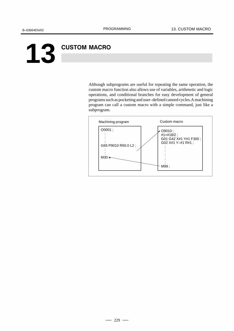
PROGRAMMINGB–63664EN/02 13. CUSTOM MACRO
229
13 ��*��4 4����
Although subprograms are useful for repeating the same operation, thecustom macro function also allows use of variables, arithmetic and logicoperations, and conditional branches for easy development of generalprograms such as pocketing and user–defined canned cycles.A machiningprogram can call a custom macro with a simple command, just like asubprogram.
O0001 ; : : :G65 P9010 R50.0 L2 ; : :M30 ;
Machining program Custom macro
O9010 ;#1=#18/2 ;G01 G42 X#1 Y#1 F300 ;G02 X#1 Y–#1 R#1 ; : : : : :M99 ;

PROGRAMMING13. CUSTOM MACRO B–63664EN/02
230
An ordinary machining program specifies a G code and the travel distancedirectly with a numeric value; examples are G100 and X100.0.With a custom macro, numeric values can be specified directly or usinga variable number. When a variable number is used, the variable valuecan be changed by a program or using operations on the MDI panel.
#1=#2+100 ;
G01 X#1 F300 ;
When specifying a variable, specify a number sign (#) followed by avariable number. General–purpose programming languages allow a nameto be assigned to a variable, but this capability is not available for custommacros.
Example: #1
An expression can be used to specify a variable number. In such a case,the expression must be enclosed in brackets.
Example: #[#1+#2–12]
Variables are classified into four types by variable number.
Table 13.1 Types of variables
Variablenumber
Type ofvariable
Function
#0 Alwaysnull
This variable is always null. No value canbe assigned to this variable.
#1 – #33 Localvariables
Local variables can only be used within amacro to hold data such as the results ofoperations. When the power is turned off,local variables are initialized to null. Whena macro is called, arguments are assignedto local variables.
#100 – #149 (#199)#500 – #531 (#999)
Commonvariables
Common variables can be shared amongdifferent macro programs. When the pow-er is turned off, variables #100 to #149 areinitialized to null. Variables #500 to #531hold data even when the power is turnedoff. As an option, common variables #150to #199 and #532 to #999 are also avail-able. However, when these values are us-ing.
#1000 – Systemvariables
System variables are used to read andwrite a variety of NC data items such asthe current position and cutter compensa-tion values.
NOTECommon variables #150 to #199 and #532 to #999 areoptional.
13.1VARIABLES
����� ��
� Variable representation
� Types of variables

PROGRAMMINGB–63664EN/02 13. CUSTOM MACRO
231
Local and common variables can have value 0 or a value in the followingranges :–1047 to –10–29
010–29 to 1047
If the result of calculation turns out to be invalid, an P/S alarm No. 111is issued.
When a variable value is defined in a program, the decimal point can beomitted.
Example:When #1=123; is defined, the actual value of variable #1 is 123.000.
To reference the value of a variable in a program, specify a word addressfollowed by the variable number. When an expression is used to specifya variable, enclose the expression in brackets.
Example: G01X[#1+#2]F#3;
A referenced variable value is automatically rounded according to theleast input increment of the address.
Example: When G00X#1; is executed on a 1/1000–mm CNC with 12.3456assigned to variable #1, the actual command is interpreted asG00X12.346;.
To reverse the sign of a referenced variable value, prefix a minus sign (–)to #.
Example: G00X–#1;
When an undefined variable is referenced, the variable is ignored up to anaddress word.
Example:When the value of variable #1 is 0, and the value of variable #2 is null,execution of G00X#1Y#2; results in G00X0;.
When the value of a variable is not defined, such a variable is referred toas a “null” variable. Variable #0 is always a null variable. It cannot bewritten to, but it can be read.
(a) QuotationWhen an undefined variable is quotated, the address itself is alsoignored.
When #1 = < vacant > When #1 = 0
G90 X100 Y#1�
G90 X100
G90 X100 Y#1�
G90 X100 Y0
� Range of variable values
� Omission of the decimalpoint
� Referencing variables
� Undefined variable

PROGRAMMING13. CUSTOM MACRO B–63664EN/02
232
(b)Operation< vacant > is the same as 0 except when replaced by < vacant>
When #1 = < vacant > When #1 = 0
#2 = #1�
#2 = < vacant >
#2 = #1�
#2 = 0
#2 = #1*5�
#2 = 0
#2 = #1*5�
#2 = 0
#2 = #1+#1�
#2 = 0
#2 = #1 + #1�
#2 = 0
(c) Conditional expressions< vacant > differs from 0 only for EQ and NE.
When #1 = < vacant > When #1 = 0
#1 EQ #0�
Established
#1 EQ #0�
Not established
#1 NE 0�
Established
#1 NE 0�
Not established
#1 GE #0�
Established
#1 GE #0�
Established
#1 GT 0�
Not established
#1 GT 0�
Not established
VARIABLE O1234 N12345
NO. DATA NO. DATA
100 123.456 108
101 0.000 109
102 110
103 111
104 112
105 113
106 114
107 115
ACTUAL POSITION (RELATIVE)
X 0.000 Y 0.000
Z 0.000 B 0.000
MEM **** *** *** 18:42:15
[ MACRO ] [ MENU ] [ OPR ] [ ] [ (OPRT) ]
� When the value of a variable is blank, the variable is null.� The mark ******** indicates an overflow (when the absolute
value of a variable is greater than 99999999) or an underflow (whenthe absolute value of a variable is less than 0.0000001).
� Display the valiable

PROGRAMMINGB–63664EN/02 13. CUSTOM MACRO
233
Program numbers, sequence numbers, and optional block skip numberscannot be referenced using variables.
Example:Variables cannot be used in the following ways:O#1;/#2G00X100.0;N#3Y200.0;
� $ �� ���

PROGRAMMING13. CUSTOM MACRO B–63664EN/02
234
System variables can be used to read and write internal NC data such ascutter compensation values and current position data. Note, however, thatsome system variables can only be read. System variables are essentialfor automation and general–purpose program development.
Signals can be exchanged between the programmable machine controller(PMC) and custom macros.
Table 13.2 (a) System variables for interface signals
Variable number Function
#1000–#1015#1032
A 16–bit signal can be sent from the PMC to a custommacro. Variables #1000 to #1015 are used to read asignal bit by bit. Variable #1032 is used to read all 16 bitsof a signal at one time.
#1100–#1115#1132
A 16–bit signal can be sent from a custom macro to thePMC. Variables #1100 to #1115 are used to write a signalbit by bit. Variable #1132 is used to write all 16 bits of asignal at one time.
#1133 Variable #1133 is used to write all 32 bits of a signal atone time from a custom macro to the PMC.Note, that values from –99999999 to +99999999 can beused for #1133.
For detailed information, refer to the connection manual (function)(B–63523EN–1).
Tool compensation values can be read and written using system variables.Usable variable numbers depend on the number of compensation pairs,whether a distinction is made between geometric compensation and wearcompensation, and whether a distinction is made between tool lengthcompensation and cutter compensation. When the number of compensationpairs is not greater than 200, variables #2001 to #2400 can also be used.
Table 13.2 (b) System variables for tool compensation memory A
Compensation number System variable
1:200:999
#10001 (#2001):#10200 (#2200):#10999
Table 13.2 (c) System variables for cutter compensation memory B
Compensationnumber Geometry compensation Wear compensation
1:200:999
#11001 (#2201):#11200 (#2400):#11999
#10001 (#2001):#10200 (#2200):#10999
13.2SYSTEM VARIABLES
Explanations
� Interface signals
� Tool compensationvalues

PROGRAMMINGB–63664EN/02 13. CUSTOM MACRO
235
Table 13.2 (d) System variables for tool compensation memory C
Compensation
Beam length compensation (H) Cutter compensation(D)
Compensationnumber Geometric
compensationWear
compensation
Geomet-ric com-
pensation
Wearcom-
pensation
1:200:999
#11001(#2201):#11201(#2400):#11999
#10001(#2001):#10201(#2200):#10999
#13001:
:#13999
#12001:
:#12999
Table 13.2 (e) System variable for macro alarms
Variablenumber Function
#3000 When a value from 0 to 200 is assigned to variable #3000,the CNC stops with an alarm. After an expression, an alarmmessage not longer than 26 characters can be described.The CRT screen displays alarm numbers by adding 3000 tothe value in variable #3000 along with an alarm message.
Example:#3000=1(TOOL NOT FOUND);→ The alarm screen displays “3001 TOOL NOT FOUND.”
Execution of the program can be stopped, and then a message can bedisplayed.
Variablenumber Function
#3006 When “#3006=1 (MESSAGE);” is commanded in the macro,the program executes blocks up to the immediately previousone and then stops.
When a message of up to 26 characters, which is enclosedby a control–in character (“(”) and control–out character (“)”),is programmed in the same block, the message is displayedon the external operator message screen.
� Macro alarms
� Stop with a message

PROGRAMMING13. CUSTOM MACRO B–63664EN/02
236
Time information can be read and written.
Table 13.2 (f) System variables for time information
Variablenumber Function
#3001 This variable functions as a timer that counts in 1–millisecondincrements at all times. When the power is turned on, the val-ue of this variable is reset to 0. When 2147483648 millisec-onds is reached, the value of this timer returns to 0.
#3002 This variable functions as a timer that counts in 1–hour incre-ments when the cycle start lamp is on. This timer preserves itsvalue even when the power is turned off. When 9544.371767hours is reached, the value of this timer returns to 0.
#3011 This variable can be used to read the current date (year/month/day). Year/month/day information is converted to an apparentdecimal number. For example, February 28, 2002 is repre-sented as 20020228.
#3012 This variable can be used to read the current time (hours/min-utes/seconds). Hours/minutes/seconds information is con-verted to an apparent decimal number. For example, 34 min-utes and 56 seconds after 3 p.m. is represented as 153456.
The control state of automatic operation can be changed.
Table 13.2 (g) System variable (#3003) for automatic operation control
#3003 Single block Completion of an auxiliaryfunction
0 Enabled To be awaited
1 Disabled To be awaited
2 Enabled Not to be awaited
3 Disabled Not to be awaited
� When the power is turned on, the value of this variable is 0.
� When single block stop is disabled, single block stop operation is notperformed even if the single block switch is set to ON.
� When a wait for the completion of auxiliary functions (M, S, and Tfunctions) is not specified, program execution proceeds to the nextblock before completion of auxiliary functions. Also, distributioncompletion signal DEN is not output.
� Time information
� Automatic operationcontrol

PROGRAMMINGB–63664EN/02 13. CUSTOM MACRO
237
Table 13.2 (h) System variable (#3004) for automatic operation control
#3004 Feed hold Feedrate Override Exact stop
0 Enabled Enabled Enabled
1 Disabled Enabled Enabled
2 Enabled Disabled Enabled
3 Disabled Disabled Enabled
4 Enabled Enabled Disabled
5 Disabled Enabled Disabled
6 Enabled Disabled Disabled
7 Disabled Disabled Disabled
� When the power is turned on, the value of this variable is 0.
� When feed hold is disabled:
(1) When the feed hold button is held down, the machine stops in thesingle block stop mode. However, single block stop operation isnot performed when the single block mode is disabled withvariable #3003.
(2) When the feed hold button is pressed then released, the feed holdlamp comes on, but the machine does not stop; program executioncontinues and the machine stops at the first block where feed holdis enabled.
� When feedrate override is disabled, an override of 100% is alwaysapplied regardless of the setting of the feedrate override switch on themachine operator’s panel.
� When exact stop check is disabled, no exact stop check (positioncheck) is made even in blocks including those which do not performcutting.
Settings can be read and written. Binary values are converted todecimals.
#9 (FCV) : Whether to use the FS15 tape format conversion capability#5 (SEQ) : Whether to automatically insert sequence numbers#2 (INI) : Millimeter input or inch input#1 (ISO) : Whether to use EIA or ISO as the output code#0 (TVC) : Whether to make a TV check
#15 #14 #13 #12 #11 #10 #9 #8
FCVSetting
#7 #6 #5 #4 #3 #2 #1 #0
SEQ INI ISO TVCSetting
#3005
� *��� �)�

PROGRAMMING13. CUSTOM MACRO B–63664EN/02
238
The mirror–image status for each axis set using an external switch orsetting operation can be read through the output signal (mirror–imagecheck signal). The mirror–image status present at that time can bechecked. (See III–4.7)The value obtained in binary is converted into decimal notation.
#7 #6 #5 #4 #3 #2 #1 #0
8th axis 7th axisSetting
#3007
6th axis 5th axis 4th axis 3th axis 2th axis 1th axis
For each bit,0 (mirror–image function is disabled)
or1 (mirror–image function is enabled)
is indicated.
Example : If #3007 is 3, the mirror–image function is enabled for the first and second axes.
� When the mirror–image function is set for a certain axis by both themirror–image signal and setting, the signal value and setting value areORed and then output.
� When mirror–image signals for axes other than the controlled axes areturned on, they are still read into system variable #3007.
� System variable #3007 is a write–protected system variable. If anattempt is made to write data in the variable, P/S 116 alarm “WRITEPROTECTED VARIABLE” is issued.
The number (target number) of parts required and the number (completionnumber) of machined parts can be read and written.
Table 13.2 (i) System variables for the number of parts required and the number of machined parts
Variable number Function
#3901 Number of machined parts (completion number)
#3902 Number of required parts (target number)
NOTEDo not substitute a negative value.
� Mirror image
� Number of machinedparts

PROGRAMMINGB–63664EN/02 13. CUSTOM MACRO
239
Modal information specified in blocks up to the immediately precedingblock can be read.
Table 13.2 (j) System variables for modal information
Variable number Function
#4001#4002#4003#4004#4005#4006#4007#4008#4009#4010#4011#4012#4013#4014#4015#4016
:#4022#4102#4107#4109#4111#4113#4114#4115#4119#4120#4130
G00, G01, G02, G03, G33 (Group 01)G17, G18, G19 (Group 02)G90, G91 (Group 03)
(Group 04)(Group 05)
G20, G21 (Group 06)G40, G41, G42 (Group 07)
(Group 08)(Group 09)(Group 10)
G50, G51 (Group 11)G65, G66, G67 (Group 12)
(Group 13)G54–G59 (Group 14)G61–G64 (Group 15)G68, G69 (Group 16) : :
(Group 22)B codeD codeF codeH codeM codeSequence numberProgram numberS codeT codeP code (number of the currently selected addition-al workpiece coordinate system)
Example:When #1=#4001; is executed, the resulting value in #1 is 17, 18, or 19.If the specified system variable for reading modal informationcorresponds to a G code group which cannot be used, a P/S alarm isissued.
� Modal information

PROGRAMMING13. CUSTOM MACRO B–63664EN/02
240
Position information cannot be written but can be read.
Table 13.2 (k) System variables for position information
Variablenumber
Positioninformation
Coordinatesystem
Cutter com-pensation
value
Readoperation
duringmovement
#5001–#5008 Block end point Workpiececoordinatesystem
Not included
Enabled
#5021–#5028 Current position Machinecoordinatesystem
Included Disabled
#5041–#5048 Current position Workpiececoordinate
#5061–#5068 Skip signal posi-tion
coordinatesystem Enabled
#5101–#5108 Deviated servoposition
Disabled
� The first digit (from 1 to 8) represents an axis number.
� The nozzle position where the skip signal is turned on in a G31 (skipfunction) block is held in variables #5061 to #5068. When the skipsignal is not turned on in a G31 block, the end point of the specifiedblock is held in these variables.
� When read during movement is ”disabled,” this means that expectedvalues cannot be read due to the buffering (preread) function.
� Current position

PROGRAMMINGB–63664EN/02 13. CUSTOM MACRO
241
Workpiece zero point offset values can be read and written.
Table 13.2 (l) System variables for workpiece zero point offset values
Variablenumber Function
#5201:
#5208
First–axis external workpiece zero point offset value :Eighth–axis external workpiece zero point offset value
#5221:
#5228
First–axis G54 workpiece zero point offset value :Eighth–axis G54 workpiece zero point offset value
#5241:
#5248
First–axis G55 workpiece zero point offset value :Eighth–axis G55 workpiece zero point offset value
#5261:
#5268
First–axis G56 workpiece zero point offset value :Eighth–axis G56 workpiece zero point offset value
#5281:
#5288
First–axis G57 workpiece zero point offset value :Eighth–axis G57 workpiece zero point offset value
#5301:
#5308
First–axis G58 workpiece zero point offset value :Eighth–axis G58 workpiece zero point offset value
#5321:
#5328
First–axis G59 workpiece zero point offset value :Eighth–axis G59 workpiece zero point offset value
#7001:
#7008
First–axis workpiece zero point offset value (G54.1 P1) :Eighth–axis workpiece zero point offset value
#7021:
#7028
First–axis workpiece zero point offset value (G54.1 P2) :Eighth–axis workpiece zero point offset value
: :
#7941:
#7948
First–axis workpiece zero point offset value (G54.1 P48) :Eighth–axis workpiece zero point offset value
#14001:
#14008
First–axis workpiece zero point offset value (G54.1 P1) :Eighth–axis workpiece zero point offset value
#14021:
#14028
First–axis workpiece zero point offset value (G54.1 P2) :Eighth–axis workpiece zero point offset value
: :
#19980:
#19988
First–axis workpiece zero point offset value (G54.1 P300) :Eighth–axis workpiece zero point offset value
� Workpiece coordinatesystem compensationvalues (workpiece zeropoint offset values)

PROGRAMMING13. CUSTOM MACRO B–63664EN/02
242
The following variables can also be used:
Axis Function Variable number
First axis External workpiece zero point offset
G54 workpiece zero point offset
G55 workpiece zero point offset
G56 workpiece zero point offset
G57 workpiece zero point offset
G58 workpiece zero point offset
G59 workpiece zero point offset
#2500
#2501
#2502
#2503
#2504
#2505
#2506
#5201
#5221
#5241
#5261
#5281
#5301
#5321
Secondaxis
External workpiece zero point offset
G54 workpiece zero point offset
G55 workpiece zero point offset
G56 workpiece zero point offset
G57 workpiece zero point offset
G58 workpiece zero point offset
G59 workpiece zero point offset
#2600
#2601
#2602
#2603
#2604
#2605
#2606
#5202
#5222
#5242
#5262
#5282
#5302
#5322
Third axis External workpiece zero point offset
G54 workpiece zero point offset
G55 workpiece zero point offset
G56 workpiece zero point offset
G57 workpiece zero point offset
G58 workpiece zero point offset
G59 workpiece zero point offset
#2700
#2701
#2702
#2703
#2704
#2705
#2706
#5203
#5223
#5243
#5263
#5283
#5303
#5323
Fourth axis External workpiece zero point offset
G54 workpiece zero point offset
G55 workpiece zero point offset
G56 workpiece zero point offset
G57 workpiece zero point offset
G58 workpiece zero point offset
G59 workpiece zero point offset
#2800
#2801
#2802
#2803
#2804
#2805
#2806
#5204
#5224
#5244
#5264
#5284
#5304
#5324
NOTETo use variables #2500 to #2806 and #5201 to #5328,optional variables for the workpiece coordinate systems arenecessary.Optional variables for 48 additional workpiece coordinatesystems are #7001 to #7948 (G54.1 P1 to G54.1 P48).Optional variables for 300 additional workpiece coordinatesystems are #14001 to #19988 (G54.1 P1 to G54.1 P300).With these variables, #7001 to #7948 can also be used.

PROGRAMMINGB–63664EN/02 13. CUSTOM MACRO
243
By reading the following custom macro variables, the most recentlyspecified E code including program preprocessing can be read.
Table 13.2 (m) System variables for the cutting condition setting function
Variablenumber Function
#6032 Look–ahead piercing E code
#6033 Look–ahead cutting E code
� #6032 and #6033 are variables for read only. If an attempt is made towrite data to these variables, alarm 116 is issued.
� When reading these variables with the macro executor, add 100000 tovariable numbers #6032 and #6033, and specify #106032 and#106033, respectively.
� If the cutting condition setting function option is not provided, thesevariables read 0.
� Use these variables in machining programs (such as custom macrocalls and execution macro calls).
� E codes written with #6030 and #6031 cannot be read.
The Z–axis motion in the gap controlled axis automatic save/restorefunction can be modified by rewriting the contents of the followingcustom macro variables:
Table 13.2 (n) System variables for the gap controlled axis automaticsave/restore function
Variablenumber Function
#6048 X– and Y–axis motion start position (PRM. No.15865)
#6049 Deceleration start position (PRM. No.15866)
#6050 Function end position (PRM. No.15867)
For details of the function, refer to “FS16i–LB Connection Manual”(B–63663EN).
The operation of the function for beam output during approach can bemodified by rewriting the contents of the following custom macro variables:
Table 13.2 (o) System variables for the function for beam output duringapproach
Variablenumber Function
#6051 Gap deviation value at which beam output starts (parameter No. 15870)
#6052 Adjustment ratio of gap control axis speed (parameter No. 15871)
#6053 Gap control axis control extension time (parameter No. 15872)
For details of the function, refer to “FS16i–LB Connection Manual”(B–63663EN).
NOTE1 While the function for beam output during Z–axis approach
is operating, do not change the content of #6051.2 Do not assign any negative value to #6052 and #6053.
� Cutting condition settingfunction
� Gap controlled axisautomatic save/restorefunction
� Function for beam outputduring approach

PROGRAMMING13. CUSTOM MACRO B–63664EN/02
244
The operations listed in Table 13.3(a) can be performed on variables. Theexpression to the right of the operator can contain constants and/orvariables combined by a function or operator. Variables #j and #K in anexpression can be replaced with a constant. Variables on the left can alsobe replaced with an expression.
Table 13.3 (a) Arithmetic and logic operation
Function Format Remarks
Definition #i=#j
SumDifferenceProductQuotient
#i=#j+#k;#i=#j–#k;#i=#j*#k;#i=#j/#k;
Sine
Arcsine
TangentArctangent
#i=SIN[#j];#i=ASIN[#j];#i=COS[#j];#i=ACOS[#j];#i=TAN[#j];#i=ATAN[#j]/[#k];
An angle is specified in de-grees. 90 degrees and 30minutes is represented as90.5 degrees.
Square rootAbsolute valueRounding offRounding downRounding upNatural logarithmExponential function
#i=SQRT[#j];#i=ABS[#j];#i=ROUND[#j];#i=FIX[#j];#i=FUP[#j];#i=LN[#j];#i=EXP[#j];
ORXORAND
#i=#j OR #k;#i=#j XOR #k;#i=#j AND #k;
A logical operation is per-formed on binary numbersbit by bit.
Conversion from BCD to BINConversion from BIN to BCD
#i=BIN[#j];#i=BCD[#j];
Used for signal exchangeto and from the PMC
The units of angles used with the SIN, COS, ASIN, ACOS, TAN, andATAN functions are degrees. For example, 90 degrees and 30 minutes isrepresented as 90.5 degrees.
� The solution ranges are as indicated below:When the NAT bit (bit 0 of parameter 6004) is set to 0: 270� to 90�When the NAT bit (bit 0 of parameter 6004) is set to 1: –90� to 90�
� When #j is beyond the range of –1 to 1, P/S alarm No. 111 is issued.
� A constant can be used instead of the #j variable.
� The solution ranges from 180° to 0°.
� When #j is beyond the range of –1 to 1, P/S alarm No. 111 is issued.
� A constant can be used instead of the #j variable.
13.3ARITHMETIC ANDLOGIC OPERATION
Explanations
� Angle units
� ARCSIN #i = ASIN[#j];
� ARCCOS #i = ACOS[#j];

PROGRAMMINGB–63664EN/02 13. CUSTOM MACRO
245
� Specify the lengths of two sides, separated by a slash (/).
� The solution ranges are as follows:
When the NAT bit (bit 0 of parameter 6004) is set to 0: 0� to 360�
[Example] When #1 = ATAN[–1]/[–1]; is specified, #1 is 225.0.
When the NAT bit (bit 0 of parameter 6004) is set to 1: –180� to 180�
[Example] When #1 = ATAN[–1]/[–1]; is specified, #1 is –135.0.0.
� A constant can be used instead of the #j variable.
� Note that the relative error may become 10–8 or greater.
� When the antilogarithm (#j) is zero or smaller, P/S alarm No. 111 isissued.
� A constant can be used instead of the #j variable.
� Note that the relative error may become 10–8 or greater.
� When the result of the operation exceeds 3.65 X 1047 (j is about 110),an overflow occurs and P/S alarm No. 111 is issued.
� A constant can be used instead of the #j variable.
� When the ROUND function is included in an arithmetic or logicoperation command, IF statement, or WHILE statement, the ROUNDfunction rounds off at the first decimal place.
Example:When #1=ROUND[#2]; is executed where #2 holds 1.2345, the valueof variable #1 is 1.0.
� When the ROUND function is used in NC statement addresses, theROUND function rounds off the specified value according to the leastinput increment of the address.
Example:Creation of a drilling program that cuts according to the values ofvariables #1 and #2, then returns to the original position Suppose that the increment system is 1/1000 mm, variable #1 holds1.2345, and variable #2 holds 2.3456. Then, G00 G91 X–#1; Moves 1.235 mm.G01 X–#2 F300; Moves 2.346 mm.G00 X[#1+#2]; Since 1.2345 + 2.3456 = 3.5801, the travel distance
is 3.580, which does not return the beam to theoriginal position.
This difference comes from whether addition is performed before orafter rounding off. G00X–[ROUND[#1]+ROUND[#2]] must bespecified to return the beam to the original position.
� ARCTAN #i =ATAN[#j]/[#k];
� Natural logarithm #i =LN[#j];
� Exponential function #i =EXP[#j];
� ROUND function

PROGRAMMING13. CUSTOM MACRO B–63664EN/02
246
With CNC, when the absolute value of the integer produced by anoperation on a number is greater than the absolute value of the originalnumber, such an operation is referred to as rounding up to an integer.Conversely, when the absolute value of the integer produced by anoperation on a number is less than the absolute value of the originalnumber, such an operation is referred to as rounding down to an integer.Be particularly careful when handling negative numbers.
Example:Suppose that #1=1.2 and #2=–1.2.When #3=FUP[#1] is executed, 2.0 is assigned to #3.When #3=FIX[#1] is executed, 1.0 is assigned to #3.When #3=FUP[#2] is executed, –2.0 is assigned to #3.When #3=FIX[#2] is executed, –1.0 is assigned to #3.
When a function is specified in a program, the first two characters of thefunction name can be used to specify the function (See III–9.7).
Example:ROUND → ROFIX → FI
� Functions� Operations such as multiplication and division (*, /, AND) Operations such as addition and subtraction (+, –, OR, XOR)
Example) #1=#2+#3*SIN[#4];
and indicate the order of operations.
�
�
� �,
Brackets are used to change the order of operations. Brackets can be usedto a depth of five levels including the brackets used to enclose a function.When a depth of five levels is exceeded, P/S alarm No. 118 occurs.
Example) #1=SIN [ [ [#2+#3] *#4 +#5] *#6] ;
� to indicate the order of operations.
�
�
�
� Rounding up and downto an integer
� Abbreviations ofarithmetic and logicoperation commands
� Priority of operations
� Bracket nesting

PROGRAMMINGB–63664EN/02 13. CUSTOM MACRO
247
Brackets ([, ]) are used to enclose an expression. Note that parenthesesare used for comments.
Errors may occur when operations are performed.
Table 13.3 (b) Errors involved in operations
Operation Averageerror
Maximumerror
Type of error
a = b*c 1.55×10⁻¹⁰ 4.66×10⁻¹⁰
a = b / c 4.66×10⁻¹⁰ 1.88×10⁻⁹
1.24×10⁻⁹ 3.73×10⁻⁹
a = b + ca = b – c
2.33×10⁻¹⁰ 5.32×10⁻¹⁰
a = SIN [ b ]a = COS [ b ]
5.0×10⁻⁹ 1.0×10⁻⁸
a = ATAN [ b ] / [ c ](Note4)
1.8×10⁻⁶ 3.6×10⁻⁶
NOTE1 The relative error depends on the result of the operation.2 Smaller of the two types of errors is used.3 The absolute error is constant, regardless of the result of the
operation.4 Function TAN performs SIN/COS.5 If the result of the operation by the SIN, COS, or TAN
function is less than 1.0 x 10⁻⁸ or is not 0 because of theprecision of the operation, the result of the operation can benormalized to 0 by setting bit 1 of parameter No. 6004 to 1.
� The precision of variable values is about 8 decimal digits. When verylarge numbers are handled in an addition or subtraction, the expectedresults may not be obtained.
Example:When an attempt is made to assign the following values to variables#1 and #2: #1=9876543210123.456 #2=9876543277777.777the values of the variables become: #1=9876543200000.000 #2=9876543300000.000In this case, when #3=#2–#1; is calculated, #3=100000.000 results.(The actual result of this calculation is slightly different because it isperformed in binary.)
� $ �� ���
� Brackets
� Operation error
�
aa � b�
Relative error (Note1)
�
bMin
�
c,
(Note2)
ε
Absolute error (Note3)
degrees

PROGRAMMING13. CUSTOM MACRO B–63664EN/02
248
� Also be aware of errors that can result from conditional expressionsusing EQ, NE, GE, GT, LE, and LT.
Example:IF[#1 EQ #2] is effected by errors in both #1 and #2, possibly resultingin an incorrect decision.Therefore, instead find the difference between the two variables withIF[ABS[#1–#2]LT0.001].Then, assume that the values of the two variables are equal when thedifference does not exceed an allowable limit (0.001 in this case).
� Also, be careful when rounding down a value.
Example:When #2=#1*1000; is calculated where #1=0.002;, the resulting valueof variable #2 is not exactly 2 but 1.99999997. Here, when #3=FIX[#2]; is specified, the resulting value of variable#1 is not 2.0 but 1.0. In this case, round down the value after correctingthe error so that the result is greater than the expected number, or roundit off as follows:#3=FIX[#2+0.001]#3=ROUND[#2]
When a divisor of zero is specified in a division or TAN[90], P/S alarmNo. 112 occurs.
� Divisor

PROGRAMMINGB–63664EN/02 13. CUSTOM MACRO
249
The following blocks are referred to as macro statements:� Blocks containing an arithmetic or logic operation (=) � Blocks containing a control statement (such as GOTO, DO, END)� Blocks containing a macro call command (such as macro calls byG65, G66, G67, or other G codes, or by M codes)Any block other thana macro statement is referred to as an NC statement.
� Even when single block mode is on, the machine does not stop. Note,however, that the machine stops in the single block mode when bit 5of parameter SBM No. 6000 is 1.
� Macro blocks are not regarded as blocks that involve no movement inthe cutter compensation mode (see II–13.7).
� NC statements that include a subprogram call command (such assubprogram calls by M98 or other M codes, or by T codes) and notinclude other command addresses except an O,N or L address have thesame property as macro statements.
� The blocks not include other command addresses (included M99)except an O,N,P or L address have the same property as macrostatements.
13.4MACROSTATEMENTS ANDNC STATEMENTS
����� ���
� Differences from NCstatements
� NC statements that havethe same property asmacro statements

PROGRAMMING13. CUSTOM MACRO B–63664EN/02
250
In a program, the flow of control can be changed using the GOTOstatement and IF statement. Three types of branch and repetitionoperations are used:
Branch and repetition GOTO statement (unconditional branch)
IF statement (conditional branch: if ..., then...)
WHILE statement (repetition while ...)
A branch to sequence number n occurs. When a sequence number outsideof the range 1 to 99999 is specified, P/S alarm No. 128 occurs. A sequencenumber can also be specified using an expression.
GOTO n ; n: Sequence number (1 to 99999)
Example: GOTO 1;GOTO#10;
13.5BRANCH ANDREPETITION
13.5.1Unconditional Branch(GOTO Statement)

PROGRAMMINGB–63664EN/02 13. CUSTOM MACRO
251
Specify a conditional expression after IF.
If the specified conditional expression is satisfied, a branch to sequencenumber n occurs. If the specified condition is not satisfied, the next blockis executed.
IF [#1 GT 10] GOTO 2 ;
N2 G00 G91 X10.0 ; :
If the value of variable #1 is greater than 10, a branch to sequence numberN2 occurs.
If the condi-tion is not sa-tisfied Processing If the condition is satisfied
If the specified conditional expression is satisfied, a predetermined macrostatement is executed. Only a single macro statement is executed.
IF [#1 EQ #2] THEN#3=0 ;
If the values of #1 and #2 are the same, 0 is assigned to #3.
A conditional expression must include an operator inserted between twovariables or between a variable and constant, and must be enclosed inbrackets ([, ]). An expression can be used instead of a variable.
Operators each consist of two letters and are used to compare two valuesto determine whether they are equal or one value is smaller or greater thanthe other value. Note that the inequality sign cannot be used.
Table 13.5.2 Operators
Operator Meaning
EQ Equal to(=)
NE Not equal to(�)
GT Greater than(>)
GE Greater than or equal to(�)
LT Less than(<)
LE Less than or equal to(�)
The sample program below finds the total of numbers 1 to 10.
O9500; #1=0; Initial value of the variable to hold the sum. . . . . . . . . . . . . . . . . #2=1; Initial value of the variable as an addend. . . . . . . . . . . . . . . . . N1 IF[#2 GT 10] GOTO 2; Branch to N2 when the addend is greater than .
10 #1=#1+#2; Calculation to find the sum. . . . . . . . . . . . . #2=#2+1; Next addend. . . . . . . . . . . . . . GOTO 1; Branch to N1. . . . . . . . . . . . . . . N2 M30; End of program. . . . . . . . . . . . . . . .
13.5.2Conditional Branch (IF Statement)
IF[<conditionalexpression>]GOTOn
IF[<conditionalexpression>]THEN
����� ���
� Conditional expression
� Operators
Sample program

PROGRAMMING13. CUSTOM MACRO B–63664EN/02
252
Specify a conditional expression after WHILE. While the specifiedcondition is satisfied, the program from DO to END is executed. If thespecified condition is not satisfied, program execution proceeds to theblock after END.
WHILE [conditional expression] DO m ; (m=1,2,3)
END m ; :
ProcessingIf the condi-tion is not sa-tisfied
If the condi-tion is satis-fied
While the specified condition is satisfied, the program from DO to ENDafter WHILE is executed. If the specified condition is not satisfied,program execution proceeds to the block after END. The same format asfor the IF statement applies. A number after DO and a number after ENDare identification numbers for specifying the range of execution. Thenumbers 1, 2, and 3 can be used. When a number other than 1, 2, and 3is used, P/S alarm No. 126 occurs.
The identification numbers (1 to 3) in a DO–END loop can be used asmany times as desired. Note, however, when a program includes crossingrepetition loops (overlapped DO ranges), P/S alarm No. 124 occurs.
1. The identification numbers(1 to 3) can be used as manytimes as required.
WHILE [ … ] DO 1 ;
END 1 ;:
WHILE [ … ] DO 1 ;
END 1 ;
WHILE [ … ] DO 1 ;
END 1 ;:
WHILE [ … ] DO 2 ;
END 2 ;
WHILE [ … ] DO 1 ;
WHILE [ … ] DO 2 ;:
WHILE [ … ] DO 3 ;:
END 3 ;:
END 2 ;:
END 1 ;
WHILE [ … ] DO 1 ;
END 1 ;
IF [ … ] GOTO n ;
Nn
WHILE [ … ] DO 1 ;
END 1 ;
IF [ … ] GOTO n ;
Nn … ;
:
2. DO ranges cannot overlap.
Processing
Processing
Processing
Processing
Processing
3. DO loops can be nested to amaximum depth of three levels.
4. Control can be transferred tothe outside of a loop.
5. Branches cannot be made toa location within a loop.
13.5.3Repetition (While Statement)
����� ���
� Nesting

PROGRAMMINGB–63664EN/02 13. CUSTOM MACRO
253
When DO m is specified without specifying the WHILE statement, aninfinite loop ranging from DO to END is produced.
When a branch to the sequence number specified in a GOTO statementoccurs, the sequence number is searched for. For this reason, processingin the reverse direction takes a longer time than processing in the forwarddirection. Using the WHILE statement for repetition reduces processingtime.
In a conditional expression that uses EQ or NE, a <vacant> and zero havedifferent effects. In other types of conditional expressions, a <vacant> isregarded as zero.
The sample program below finds the total of numbers 1 to 10.
O0001;#1=0;#2=1;WHILE[#2 LE 10]DO 1;#1=#1+#2;#2=#2+1;END 1;M30;
� $ �� ���
� Infinite loops
� Processing time
� Undefined variable
Sample program

PROGRAMMING13. CUSTOM MACRO B–63664EN/02
254
A macro program can be called using the following methods:
Macro call Simple call (G65)modal call (G66, G67)Macro call with G codeMacro call with M codeSubprogram call with M codeSubprogram call with T code
Macro call (G65) differs from subprogram call (M98) as described below.
� With G65, an argument (data passed to a macro) can be specified. M98does not have this capability.
� When an M98 block contains another NC command (for example,G01 X100.0 M98Pp), the subprogram is called after the command isexecuted. On the other hand, G65 unconditionally calls a macro.
� When an M98 block contains another NC command (for example,G01 X100.0 M98Pp), the machine stops in the single block mode. Onthe other hand, G65 does not stops the machine.
� With G65, the level of local variables changes. With M98, the levelof local variables does not change.
13.6MACRO CALL
� $ �� ���
� Differences betweenmacro calls andsubprogram calls

PROGRAMMINGB–63664EN/02 13. CUSTOM MACRO
255
When G65 is specified, the custom macro specified at address P is called.Data (argument) can be passed to the custom macro program.
G65 P p L � <argument–specification> ;
P : Number of the program to call� : Repetition count (1 by default)Argument : Data passed to the macro
O0001 ; :G65 P9010 L2 A1.0 B2.0 ; :M30 ;
O9010 ;#3=#1+#2 ;IF [#3 GT 360] GOTO 9 ;G00 G91 X#3 ;N9 M99 ;
� After G65, specify at address P the program number of the custommacro to call.
� When a number of repetitions is required, specify a number from 1 to9999 after address L. When L is omitted, 1 is assumed.
� By using argument specification, values are assigned to correspondinglocal variables.
Two types of argument specification are available. Argumentspecification I uses letters other than G, L, O, N, and P once each.Argument specification II uses A, B, and C once each and also uses I, J,and K up to ten times. The type of argument specification is determinedautomatically according to the letters used.
Argument specification I
ABCDEFH
#1#2#3#7#8#9#11
IJKMQRS
#4#5#6#13#17#18#19
TUVWXYZ
#20#21#22#23#24#25#26
Address Address AddressVariablenumber
Variablenumber
Variablenumber
� Addresses G, L, N, O, and P cannot be used in arguments.
� Addresses that need not be specified can be omitted. Local variablescorresponding to an omitted address are set to null.
13.6.1Simple Call (G65)
����� ���
� Call
� Argument specification

PROGRAMMING13. CUSTOM MACRO B–63664EN/02
256
Argument specification II Argument specification II uses A, B, and C once each and uses I, J, andK up to ten times. Argument specification II is used to pass values suchas three–dimensional coordinates as arguments.
ABCI1J1K1I2J2K2I3J3
#1#2#3#4#5#6#7#8#9#10#11
K3I4J4K4I5J5K5I6J6K6I7
#12#13#14#15#16#17#18#19#20#21#22
J7K7I8J8K8I9J9K9I10J10K10
#23#24#25#26#27#28#29#30#31#32#33
AddressVariablenumber Address
Variablenumber Address
Variablenumber
� Subscripts of I, J, and K for indicating the order of argumentspecification are not written in the actual program.
G65 must be specified before any argument.
The CNC internally identifies argument specification I and argumentspecification II. If a mixture of argument specification I and argumentspecification II is specified, the type of argument specification specifiedlater takes precedence.
The units used for argument data passed without a decimal pointcorrespond to the least input increment of each address. The value of anargument passed without a decimal point may vary according to thesystem configuration of the machine. It is good practice to use decimalpoints in macro call arguments to maintain program compatibility.
Calls can be nested to a depth of four levels including simple calls (G65)and modal calls (G66). This does not include subprogram calls (M98).
� Local variables from level 0 to 4 are provided for nesting.
� The level of the main program is 0.
� Each time a macro is called (with G65 or G66), the local variable levelis incremented by one. The values of the local variables at the previouslevel are saved in the CNC.
� $ �� ���
� Format
� Mixture of argumentspecifications I and II
� Position of the decimalpoint
� Call nesting
� Local variable levels

PROGRAMMINGB–63664EN/02 13. CUSTOM MACRO
257
� When M99 is executed in a macro program, control returns to thecalling program. At that time, the local variable level is decrementedby one; the values of the local variables saved when the macro wascalled are restored.
O0001 ; :#1=1 ;G65 P2 A2 ; : :M30 ;
O0002 ; :#1=2;G65 P3 A3 ; : :M99 ;
O0003 ; :#1=3;G65 P4 A4 ; : :M99 ;
O0004 ; :#1=4;G65 P5 A5 ; : :M99 ;
O0005 ; :#1=5; : : :M99 ;
#1 1
::
#33
#1 2
::
#33
#1 3
::
#33
#1 4
::
#33
#1 5
::
#33
#100–, #500–
Main program(level 0) Macro (level 1) Macro (level 2) Macro (level 3)
Macro(level 4)
Local variables(level 0) (Level 1) (Level 2) (Level 3) (Level 4)
Common variables
Variables that can be read from and written to bymacros at different levels
A macro is created which drills H holes at intervals of B degrees after astart angle of A degrees along the periphery of a circle with radius I.The center of the circle is (X,Y). Commands can be specified in eitherthe absolute or incremental mode. To drill in the clockwise direction,specify a negative value for B.
ÉÉÉÉÉÉÉÉÉ
ÉÉÉÉ
ÉÉÉÉÉÉ
H=3
H=4
H=2H=1
A
BB
Center (X,Y)Radius I
Sample program(bolt hole circle)

PROGRAMMING13. CUSTOM MACRO B–63664EN/02
258
G65 P9100 X x Y y Z z F f I i A a B b H h ;
X: X coordinate of the center of the circle (absolute or incremental specification)(#24)
Y: Y coordinate of the center of the circle (absolute or incremental specification)(#25)
Z : Hole radius (#26)F : Cutting feedrate (#9)I : Radius of the circle (#4)A: Drilling start angle (#1)B: Incremental angle (clockwise when a negative value is specified)
(#2)H: Number of holes (#11)
O0002;G90 G92 X0 Y0 Z0;G65 P9100 X100.0 Y50.0 Z–10.0 F500 I100.0 A0 B45.0 H5;M30;
O9100;#3=#4003; Stores G code of group 3.. . . . . . . . . . IF[#3 EQ 90]GOTO 1; Branches to N1 in the G90 mode.. #24=#5001+#24; Calculates the X coordinate of the center.. . . . . . #25=#5002+#25; Calculates the Y coordinate of the center.. . . . . .
N1 WHILE[#11 GT 0]DO 1;Until the number of remaining holes . . . . . . . . . . . . . . . . . . reaches 0
#5=#24+#4*COS[#1]; Calculates the X coordinate of the hole center.. . #6=#25+#4*SIN[#1]; Calculates the Y coordinate of the hole center.. . #5=#5+#26; X coordinate of the drilling start position. . . . . . . . . G90 G00 X#5 Y#6; Moves to the drilling start position.. . . . G02 I–#26 F#9; Drilling. . . . . . #1=#1+#2; Updates the angle.. . . . . . . . . . #11=#11–1; Decrements the number of holes.. . . . . . . . . . END 1;G#3; Returns the G code to the original state.. . . . . . . . . . . . . . . M99;
Meaning of variables:
#3: Stores the G code of group 3.#5: X coordinate of the drilling start position for the hole to be drilled#6: Y coordinate of the drilling start position for the hole to be drilled
� Calling format
� Program calling a macroprogram
� Macro program (called program)

PROGRAMMINGB–63664EN/02 13. CUSTOM MACRO
259
Once G66 is issued to specify a modal call a macro is called after a blockspecifying movement along axes is executed. This continues until G67is issued to cancel a modal call.
O0001 ; :G66 P9100 L2 A1.0 B2.0 ;G00 G90 X100.0 ;Y200.0 ;X150.0 Y300.0 ;G67 ; :M30 ;
O9100 ; :G00 Z–#1 ;G01 Z–#2 F300 ; : : : :M99 ;
G66 P p L � <argument–specification> ;
P : Number of the program to call� : Repetition count (1 by default)Argument : Data passed to the macro
� After G66, specify at address P a program number subject to a modalcall.
� When a number of repetitions is required, a number from 1 to 9999 canbe specified at address L.
� As with a simple call (G65), data passed to a macro program isspecified in arguments.
When a G67 code is specified, modal macro calls are no longer performedin subsequent blocks.
Calls can be nested to a depth of four levels including simple calls (G65)and modal calls (G66). This does not include subprogram calls (M98).
Modal calls can be nested by specifying another G66 code during a modalcall.
� In a G66 block, no macros can be called.
� G66 needs to be specified before any arguments.
� No macros can be called in a block which contains a code such as amiscellaneous function that does not involve movement along an axis.
� Local variables (arguments) can only be set in G66 blocks. Note thatlocal variables are not set each time a modal call is performed.
13.6.2Modal Call (G66)
����� ���
� Call
� Cancellation
� Call nesting
� Modal call nesting
� $ �� ���

PROGRAMMING13. CUSTOM MACRO B–63664EN/02
260
Bolt hole circles are machined. Each time positioning is performed, a bolthole is machined at that location.
270°
Bolt hole
X
Y
� The origin of the polar coordinate system is the same as that of theworkpiece coordinate system.
� The plane is the X–Y plane.
150°
30°
G65 P9110 Rr;
R: Radius of a bolt hole circle (#18). . . . . . . . . . . . . . . . . . . . . . . . .
O0001; G17 G90 G16; Polar coordinate command, X–Y plane selection. .
The origin of the polar coordinate system is the sameas that of the workpiece coordinate system.
G66 P9110 R10.0 F2000; Macro modal call specification. . . G00 X100.0 Y30.0; Radius: 100 mm, angle: 30 deg.. . . . . . . . G00 X150.0; Radius: 100 mm, angle: 150 deg.. . . . . . . . . . . . . . G00 Y270.0; Radius: 100 mm, angle: 270 deg.. . . . . . . . . . . . . . G15; Polar coordinate command cancel. . . . . . . . . . . . . . . . . . . . M30;
O9110;G91 G15;G24; Piercing. . . . . . . . . . . . . . . . . . . . . G01 Y–#18; Bolt hole machining. . . . . . . . . . . . . . . G03 J#18; Bolt hole machining. . . . . . . . . . . . . . . . G90 G16;M99;
Sample program
� Calling format
� Program that calls amacro program
� Macro program (program called)
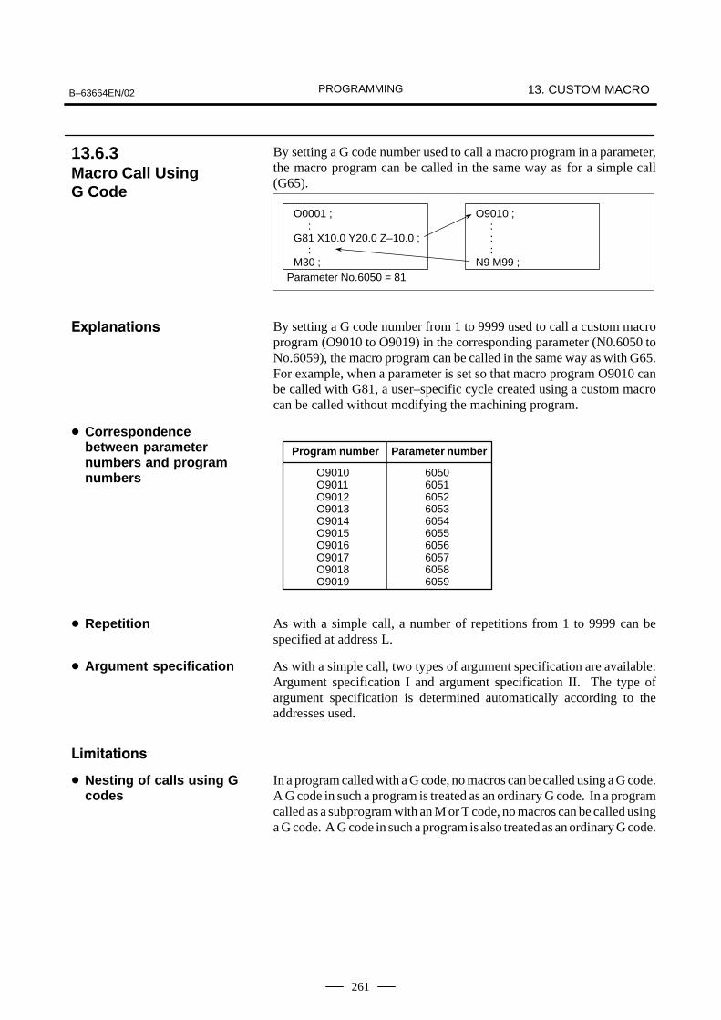
PROGRAMMINGB–63664EN/02 13. CUSTOM MACRO
261
By setting a G code number used to call a macro program in a parameter,the macro program can be called in the same way as for a simple call(G65).
O0001 ; :G81 X10.0 Y20.0 Z–10.0 ; :M30 ;
O9010 ; : : :N9 M99 ;
Parameter No.6050 = 81
By setting a G code number from 1 to 9999 used to call a custom macroprogram (O9010 to O9019) in the corresponding parameter (N0.6050 toNo.6059), the macro program can be called in the same way as with G65.For example, when a parameter is set so that macro program O9010 canbe called with G81, a user–specific cycle created using a custom macrocan be called without modifying the machining program.
O9010O9011O9012O9013O9014O9015O9016O9017O9018O9019
6050605160526053605460556056605760586059
Program number Parameter number
As with a simple call, a number of repetitions from 1 to 9999 can bespecified at address L.
As with a simple call, two types of argument specification are available:Argument specification I and argument specification II. The type ofargument specification is determined automatically according to theaddresses used.
In a program called with a G code, no macros can be called using a G code.A G code in such a program is treated as an ordinary G code. In a programcalled as a subprogram with an M or T code, no macros can be called usinga G code. A G code in such a program is also treated as an ordinary G code.
13.6.3Macro Call Using G Code
����� ���
� Correspondencebetween parameternumbers and programnumbers
� Repetition
� Argument specification
� $ �� ���
� Nesting of calls using Gcodes

PROGRAMMING13. CUSTOM MACRO B–63664EN/02
262
By setting an M code number used to call a macro program in a parameter,the macro program can be called in the same way as with a simple call(G65).
O0001 ; :M50 A1.0 B2.0 ; :M30 ;
O9020 ; : : :M99 ;
Parameter No.6080 = 50
By setting an M code number from 1 to 99999999 used to call a custommacro program (9020 to 9029) in the corresponding parameter (No.6080to No.6089), the macro program can be called in the same way as withG65.
Program number Parameter number
O9020O9021O9022O9023O9024O9025O9026O9027O9028O9029
6080608160826083608460856086608760886089
As with a simple call, a number of repetitions from 1 to 9999 can bespecified at address L.
As with a simple call, two types of argument specification are available:Argument specification I and argument specification II. The type ofargument specification is determined automatically according to theaddresses used.
� An M code used to call a macro program must be specified at the startof a block.
� In a macro called with a G code or in a program called as a subprogramwith an M or T code, no macros can be called using an M code. An Mcode in such a macro or program is treated as an ordinary M code.
The time each assist gas is used is measured by using the macro callfunction with an M code.� Measure the total time that assist gas types 1 to 3 are used.� Determine the variables for storing the assist gas type numbers and the
measured times, as follows:
#501 Total time assist gas type 1 is used
#502 Total time assist gas type 2 is used
#503 Total time assist gas type 3 is used
13.6.4Macro Call Using an M Code
����� ���
� Correspondencebetween parameternumbers and programnumbers
� Repetition
� Argument specification
� $ �� ���
Sample program

PROGRAMMINGB–63664EN/02 13. CUSTOM MACRO
263
� Because system variable #3002 is used as the timer for time measurement, the time during which the cycle start lamp is lit is measured. However, the stop time due to single–block operation and feed hold is excluded.
Set 15 for parameter No. 6080.
Set ”0” for variables #501 to #503.
M15 Aa Bb;
A: Assist gas type (#1). . . . . . . . . . . . . . . . . . . . . . . . . . . . . . . . . . . . B: Flow pattern (#2). . . . . . . . . . . . . . . . . . . . . . . . . . . . . . . . . . . . . .
O0001; M15 A1 B1; Selects assist gas type 1 and flow pattern 1.. .
. . . . M15 A2 B1; Selects assist gas type 2 and flow pattern 1.. .
. . . . M15 A3 B1; Selects assist gas type 3 and flow pattern 1.. .
. . . . M15 A0; Deselects the assist gas.. . . .
. . . . M30;
O9020;IF [#100 EQ 0] GOTO 10;IF [#100 GT 3] GOTO 10;# [500 + #100] = #3002 + # [500 + #100];
Updates the time that the assist gas is used.. . . . . . . . . . . . . . . . . . . . . . . N10 #100 = #1;#3002 = 0;IF [#1 EQ 0] GOTO 15; Checks the selected assist gas type.. . IF [#1 EQ 3] GOTO 15;IF [#2 EQ 0] GOTO 15; Checks the selected flow pattern.. . IF [#2 EQ 3] GOTO 15;G32 P#1 Q#2; Selects the assist gas.. . . . . . . . . . . M99;M15 G32 P0; aa Stops the assist gas.. . . . . . . . . M99;
� Parameter specification
� Variable value setting
� Calling format
� Program that calls amacro program
� Macro program (programcalled)

PROGRAMMING13. CUSTOM MACRO B–63664EN/02
264
By setting an M code number used to call a subprogram (macro program)in a parameter, the macro program can be called in the same way as witha subprogram call (M98).
O0001 ; :M03 ; :M30 ;
O9001 ; : : :M99 ;
Parameter No.6071 = 03
By setting an M code number from 1 to 99999999 used to call asubprogram in a parameter (No.6071 toNo. 6079), the correspondingcustom macro program (O9001 to O9009) can be called in the same wayas with M98.
Program number Parameter number
O9001O9002O9003O9004O9005O9006O9007O9008O9009
607160726073607460756076607760786079
As with a simple call, a number of repetitions from 1 to 9999 can bespecified at address L.
Argument specification is not allowed.
An M code in a macro program that has been called is treated as anordinary M code.
In a macro called with a G code or in a program called with an M or T code,no subprograms can be called using an M code. An M code in such amacro or program is treated as an ordinary M code.
13.6.5Subprogram Call Usingan M Code
����� ���
� Correspondencebetween parameternumbers and programnumbers
� Repetition
� Argument specification
� M code
� $ �� ���

PROGRAMMINGB–63664EN/02 13. CUSTOM MACRO
265
By enabling subprograms (macro program) to be called with a T code ina parameter, a macro program can be called each time the T code isspecified in the machining program.
O0001 ; :T23 ; :M30 ;
O9000 ; : : :M99 ;
Bit 5 of parameter 6001 = 1
By setting bit 5 of parameter TCS No.6001 to 1, the macro programO9000 can be called when a T code is specified in the machining program.A T code specified in a machining program is assigned to commonvariable #149.
In a macro called with a G code or in a program called with an M or T code,no subprograms can be called using a T code. A T code in such a macroor program is treated as an ordinary T code.
13.6.6Subprogram CallsUsing a T Code
����� ���
� Call
� $ �� ���

PROGRAMMING13. CUSTOM MACRO B–63664EN/02
266
For smooth machining, the CNC prereads the NC statement to beperformed next. This operation is referred to as buffering. During AIcontour control mode, the CNC prereads not only the next block but alsothe multiple blocks. And in the cutter compensation mode (G41, G42),the CNC prereads the NC statements two or three blocks ahead to findintersections even if the CNC is not in AI contour control mode. Macrostatements for arithmetic expressions and conditional branches areprocessed as soon as they are read into the buffer. Therefore, the timingof the macro statement execution is not always the specified order. At the blocks containing M00, M01, M02 or M30, blocks containingM–codes for which buffering is suppressed by setting parameter(No.3411–3432), and blocks containing prevention buffering G codessuch as G53, the CNC stops to preread the NC statement after that. Then,the stop of the macro statement execution is guaranteed until such Mcodes or G codes complete its execution.
N1 G31 X100.0 ; N2 #100=1 :
>
> :Block being executed
NC statementexecution
Macro statement execution
Buffer
N1
N2
NOTEIn case that you need to execute the macro statement aftercompleting the block just before the macro statement,specify M code or G code that are not buffered just beforethe macro statement. Specially, in case of reading / writingthe system variables to control signals, coordinates, offsetvalue, etc., it may different system variable data by thetiming of the NC statement execution. To avoid thisphenomenon, specify such M codes or G codes before themacro statement, if necessary.
13.7PROCESSINGMACROSTATEMENTS
13.7.1Details of NCStatements and MacroStatements Execution
� When the next block isnot buffered (M codes that are notbuffered, G31, etc.)

PROGRAMMINGB–63664EN/02 13. CUSTOM MACRO
267
N1 X100.0 ;>
> : Block being executed� : Block read into the buffer
NC statementexecution
Macro statementexecution
Buffer
N1
N2 N3
N4
N2 #1=100 ;N3 #2=200 ;N4 Y200.0 ; :
N4
When N1 is being executed, the next NC statement (N4) is read into thebuffer. The macro statements (N2, N3) between N1 and N4 are processedduring execution of N1.
N1 G01 G41 G91 X50.0 Y30.0 F100 Dd ;>
> : Block being executed� : Blocks read into the buffer
NC statementexecution
Macro statementexecution
Buffer
N1
N2
N3
N2 #1=100 ;N3 X100.0 ;N4 #2=200 ;N5 Y50.0 ; :
N4
N5
N3
When N1 is being executed, the NC statements in the next two blocks (upto N5) are read into the buffer. The macro statements (N2, N4) betweenN1 and N5 are processed during execution of N1.
� Buffering the next blockin other than cuttercompensation mode(G41, G42) (normallyprereading one block)
� Buffering the next blockin cutter compensationmode (G41, G42)

PROGRAMMING13. CUSTOM MACRO B–63664EN/02
268
N1 G01 G41 X100.0 G100 Dd ;>
> : Block being executed� : Blocks read into the buffer
N1
N2
N3
N2 #1=100 ;N3 Y100.0 ;N4 #2=200 ;N5 M08 ;N6 #3=300 ;N7 X200.0 ; :
N4
N3
N5
N6
N7
NC statementexecution
Macro statementexecution
Buffer
When the NC1 block is being executed, the NC statements in the next twoblocks (up to N5) are read into the buffer. Since N5 is a block that involvesno movement, an intersection cannot be calculated. In this case, the NCstatements in the next three blocks (up to N7) are read. The macrostatements (N2, N4, and N6) between N1 and N7 are processed duringexecution of N1.
In case of using the following system variables in macro program and youneed to execute the macro program after completing the block executionjust before the macro program, M code which can prevent buffering(parameter No.3411–3432) or G53 command block is necessary justbefore the macro program.
Meaning ReadWrite
Number of Variable
Note(In case not to
command M code preventing buffer-ing or G53 block.)
Interface signals Read #1000 – #1015 ,#1032
The data is read atbuffering a macro pro-gram.
Write #1100 – #1115 ,#1132
The data is written atbuffering a macro pro-gram.
Tool compensationvalues
Write #10001 – The data is written atbuffering a macro pro-gram.
Macro alarms Write #3000 Macro alarm is gener-ated at maximum 2blocks before a macroprogram.
Program stop with message
Write #3006 Program stops atmaximum 2 blocksbefore a macro pro-gram.
� When the next blockinvolves no movement incutter compensation C(G41, G42) mode
13.7.2Caution for UsingSystem Variables

PROGRAMMINGB–63664EN/02 13. CUSTOM MACRO
269
Meaning
Note(In case not to
command M code preventing buffer-ing or G53 block.)
Number of Variable
ReadWrite
Time information Read
Write
#3001,#3002 The data is read / writ-ten at buffering a mac-ro program.
Read #3011,#3012 The data is read atbuffering a macro pro-gram.
Automatic operationcontrol
Write #3003, #3004 Setting data is avail-able at maximum 2blocks before a macroprogram.
Settings Write #3005 The data is written atbuffering a macro pro-gram.
Mirror image Read #3007 The data is read atbuffering a macro pro-gram.
Currently selectedadditional workpiececoordinate system
Read #4130(P)
#4014 (G54 – G59)
The data is read atmaximum 3 blocksbefore a macro pro-gram.
Current position(Machine coordinatesystem)
Read #5021 – #5028 The uncertain positionin moving is read.
Current position(Workpiece coordi-nate system)
Read #5041 – #5048 The uncertain positionin moving is read.
Tool length offset value
Read #5081 – #5088 The offset value ofcurrent executionblock is read.
Deviated servo position
Read #5101 – #5108 The uncertain devi-ation in moving isread.
Workpiece zero point offset value
Write #5201 – #5328
#7001 – #7948
#14001 –#19988
The data is written atbuffering a macro pro-gram.

PROGRAMMING13. CUSTOM MACRO B–63664EN/02
270
Example)
O0001 O2000N1 X10.Y10.; (Mxx ;) Specify preventing buffering M code or G53N2 M98P2000; N100 #1=#5041;(Reading X axis current position)N3 Y200.0; N101 #2=#5042;(Reading Y axis current position) : :
M99;
In above case, the buffering of N2 block is done and the macro programof O2000 is read and executed during N1 block of main program O1000execution. Therefore, the current position readings are executed duringaxes movements at N1 block. So the unexpected position data can be readto #1 and #2 because of axes movements. In this case, please specify Mcode preventing buffering Mxx ; (or G53 ;) just before N100 block ofO2000. By this, the position data at completing the execution of N1 blockcan be read to #1 and #2 because O2000 is executed after completing theexecution of N1 block of O0001.

PROGRAMMINGB–63664EN/02 13. CUSTOM MACRO
271
Custom macro programs are similar to subprograms. They can beregistered and edited in the same way as subprograms. The storagecapacity is determined by the total length of tape used to store both custommacros and subprograms.
13.8REGISTERINGCUSTOM MACROPROGRAMS

PROGRAMMING13. CUSTOM MACRO B–63664EN/02
272
The macro call command can be specified in MDI mode. Duringautomatic operation, however, it is impossible to switch to the MDI modefor a macro program call.
A custom macro program cannot be searched for a sequence number.
Even while a macro program is being executed, blocks can be stopped inthe single block mode.A block containing a macro call command (G65, G66, or G67) does notstop even when the single block mode is on. Blocks containing arithmeticoperation commands and control commands can be stopped in singleblock mode by setting SBM (bit 5 of parameter 6000) to 1.Single block stop operation is used for testing custom macro programs.Note that when a single block stop occurs at a macro statement in cuttercompensation C mode, the statement is assumed to be a block that doesnot involve movement, and proper compensation cannot be performed insome cases. (Strictly speaking, the block is regarded as specifying amovement with a travel distance 0.)
A / appearing in the middle of an <expression> (enclosed in brackets [] on the right–hand side of an arithmetic expression) is regarded as adivision operator; it is not regarded as the specifier for an optional blockskip code.
By setting NE8 (bit 0 of parameter 3202) and NE9 (bit 4 of parameter3202) to 1, deletion and editing are disabled for custom macro programsand subprograms with program numbers 8000 to 8999 and 9000 to 9999.This prevents registered custom macro programs and subprograms frombeing destroyed by accident. When the entire memory is cleared (by
pressing the RESET and DELETE keys at the same time to turn on the power),
the contents of memory such as custom macro programs are deleted.
With a reset operation, local variables and common variables #100 to#149 are cleared to null values. They can be prevented from clearing bysetting, CLV and CCV (bits 7 and 6 of parameter 6001). System variables#1000 to #1133 are not cleared.A reset operation clears any called states of custom macro programs andsubprograms, and any DO states, and returns control to the main program.
As with M98, the M and T codes used for subprogram calls are notdisplayed.
When a feed hold is enabled during execution of a macro statement, themachine stops after execution of the macro statement. The machine alsostops when a reset or alarm occurs.
+0.0000001 to +99999999–99999999 to –0.0000001The number of significant digits is 8 (decimal). If this range is exceeded,P/S alarm No. 003 occurs.
13.9LIMITATIONS
� MDI operation
� Sequence numbersearch
� Single block
� Optional block skip
� Operation in EDIT mode
� Reset
� Display of the PROGRAMRESTART
� Feed hold
� Constant values that canbe used in <expression>

PROGRAMMINGB–63664EN/02 13. CUSTOM MACRO
273
In addition to the standard custom macro commands, the following macrocommands are available. They are referred to as external outputcommands.– BPRNT– DPRNT– POPEN– PCLOSThese commands are provided to output variable values and charactersthrough the reader/punch interface.
Specify these commands in the following order:
Open command: POPENBefore specifying a sequence of data output commands, specify thiscommand to establish a connection to an external input/output device.
Data output command: BPRNT or DPRNTSpecify necessary data output.
Close command: PCLOSWhen all data output commands have completed, specify PCLOS torelease a connection to an external input/output device.
POPENPOPEN establishes a connection to an external input/output device. Itmust be specified before a sequence of data output commands. The CNCoutputs a DC2 control code.
BPRNT [ a #b [ c ] … ]
Number of significant decimal placesVariable
Character
The BPRNT command outputs characters and variable values in binary.
(i) Specified characters are converted to the codes according to thesetting data (ISO) that is output at that time.Specifiable characters are as follows:– Letters (A to Z)– Numbers– Special characters (*, /, +, –, etc.)An asterisk (*) is output by a space code.
(ii) All variables are stored with a decimal point. Specify a variablefollowed by the number of significant decimal places enclosed inbrackets. A variable value is treated as 2–word (32–bit) data,including the decimal digits. It is output as binary data starting fromthe highest byte.
(iii) When specified data has been output, an EOB code is outputaccording to the setting code (ISO).
(iv) Null variables are regarded as 0.
13.10EXTERNAL OUTPUTCOMMANDS
����� ���
� Open command POPEN
� Data output commandBPRNT

PROGRAMMING13. CUSTOM MACRO B–63664EN/02
274
Example )
LF12 (0000000C)M–1638400(FFE70000)
�
410 (0000019A)XSpace�
BPRNT [ C** X#100 [3] Y#101 [3] M#10 [0] ]Variable value #100=0.40956 #101=–1638.4 #10=12.34
DPRNT [ a #b [ c d ] … ]
Number of significant decimal places
Number of significant digits in the integer part
Variable
Character
The DPRNT command outputs characters and each digit in the value ofa variable according to the code set in the settings (ISO).
(i) For an explanation of the DPRNT command, see Items (i), (iii), and(iv) for the BPRNT command.
(ii) When outputting a variable, specify # followed by the variablenumber, then specify the number of digits in the integer part and thenumber of decimal places enclosed in brackets. One code is output for each of the specified number of digits, startingwith the highest digit. For each digit, a code is output according tothe settings (ISO). The decimal point is also output using a code setin the settings (ISO).Each variable must be a numeric value consisting of up to eightdigits. When high–order digits are zeros, these zeros are not outputif PRT (bit1 of parameter 6001) is 1. If parameter PRT is 0, a spacecode is output each time a zero is encountered.When the number of decimal places is not zero, digits in the decimalpart are always output. If the number of decimal places is zero, nodecimal point is output.When PRT (bit 1 of parameter 6001) is 0, a space code is output toindicate a positive number instead of +; if parameter PRT is 1, nocode is output.
� Data output commandDPRNT

PROGRAMMINGB–63664EN/02 13. CUSTOM MACRO
275
Example )
sp
spspsp
sp
sp
DPRNT [ X#2 [53] Y#5 [53] T#30 [20] ]Variable value #2=128.47398 #5=–91.2 #30=123.456
(1) Parameter PRT(No.6001#1)=0
L F
T
Y –
X
91200
128474
23
sp
LF
T23
Y–91.200
X128.474
(2) Parameter PRT(No.6001#1)=0
PCLOS ;The PCLOS command releases a connection to an external input/outputdevice. Specify this command when all data output commands haveterminated. DC4 control code is output from the CNC.
Specify the channel use for setting data (I/O channel). According to thespecification of this data, set data items (such as the baud rate) for thereader/punch interface.I/O channel 0 : Parameters (No.101, No.102 and No.103)I/O channel 1 : Parameters (No.111, No.112 and No.113)I/O channel 2 : Parameters (No.112, No.122 and No.123)Never specify the output device FANUC Cassette or Floppy for punching.When specifying a DPRNT command to output data, specify whetherleading zeros are output as spaces (by setting PRT (bit 1 of parameter6001) to 1 or 0).To indicate the end of a line of data in ISO code, specify whether to useonly an LF (CRO, of bit 4 of parameter 6001 is 0) or an LF and CR (CROof bit 4 of parameter 6001 is 1).
� Close command PCLOS
� Required setting

PROGRAMMING13. CUSTOM MACRO B–63664EN/02
276
NOTE1 It is not necessary to always specify the open command
(POPEN), data output command (BPRNT, DPRNT), andclose command (PCLOS) together. Once an opencommand is specified at the beginning of a program, it doesnot need to be specified again except after a closecommand was specified.
2 Be sure to specify open commands and close commandsin pairs. Specify the close command at the end of theprogram. However, do not specify a close command if noopen command has been specified.
3 When a reset operation is performed while commands arebeing output by a data output command, output is stoppedand subsequent data is erased. Therefore, when a resetoperation is performed by a code such as M30 at the endof a program that performs data output, specify a closecommand at the end of the program so that processing suchas M30 is not performed until all data is output.
4 Abbreviated macro words enclosed in brackets [ ] remainsunchanged. However, note that when the characters inbrackets are divided and input several times, the secondand subsequent abbreviations are converted and input.
5 O can be specified in brackets [ ]. Note that when thecharacters in brackets [ ] are divided and input severaltimes, O is omitted in the second and subsequent inputs.

PROGRAMMINGB–63664EN/02 13. CUSTOM MACRO
277
When a program is being executed, another program can be called byinputting an interrupt signal (UINT) from the machine. This function isreferred to as an interruption type custom macro function. Program aninterrupt command in the following format:
M96 P���� ;
M97 ;
Enables custom macro interrupt
Disables custom macro interrupt
Use of the interruption type custom macro function allows the user to calla program during execution of an arbitrary block of another program.This allows programs to be operated to match situations which vary fromtime to time.
(1)When a tool abnormality is detected, processing to handle theabnormality is started by an external signal.
(2)A sequence of machining operations is interrupted by anothermachining operation without the cancellation of the current operation.
(3)At regular intervals, information on current machining is read.Listed above are examples like adaptive control applications of theinterruption type custom macro function.
Interruptsignal(UINT)*
Interruptsignal(UINT)*
Interruptsignal(UINT)*
M96Pxxxx;
N����;
M97 ;
M99 (P����);
O xxxx;
Fig.13.11 Interruption type sustom macro function
When M96Pxxxx is specified in a program, subsequent programoperation can be interrupted by an interrupt signal (UINT) input toexecute the program specified by Pxxxx.When the interrupt signal (UINT, marked by * in Fig.13.11 is input duringexecution of the interrupt program or after M97 is specified, it is ignored.
13.11INTERRUPTION TYPECUSTOM MACRO
���$�
����� ���

PROGRAMMING13. CUSTOM MACRO B–63664EN/02
278
A custom macro interrupt is available only during program execution. Itis enabled under the following conditions– When memory operation or MDI operation is selected– When STL (start lamp) is on– When a custom macro interrupt is not currently being processed
Generally, the custom macro interrupt function is used by specifying M96to enable the interrupt signal (UINT) and M97 to disable the signal.Once M96 is specified, a custom macro interrupt can be initiated by theinput of the interrupt signal (UINT) until M97 is specified or the NC isreset. After M97 is specified or the NC is reset, no custom macrointerrupts are initiated even when the interrupt signal (UINT) is input.The interrupt signal (UINT) is ignored until another M96 command isspecified.
10
M96 M97 M96
Interrupt signal(UINT)
Effective interruptinput signal
When UINT is kept on
The interrupt signal (UINT) becomes valid after M96 is specified. Evenwhen the signal is input in M97 mode, it is ignored. When the signal inputin M97 mode is kept on until M96 is specified, a custom macro interruptis initiated as soon as M96 is specified (only when the status–triggeredscheme is employed); when the edge–triggered scheme is employed, thecustom macro interrupt is not initiated even when M96 is specified.
NOTEFor the status–triggered and edge–triggered schemes, seeItem “Custom macro interrupt signal (UINT)” of II– 13.11.2.
13.11.1Specification Method
����� ���
� Interrupt conditions
� Specification

PROGRAMMINGB–63664EN/02 13. CUSTOM MACRO
279
There are two types of custom macro interrupts: Subprogram–typeinterrupts and macro–type interrupts. The interrupt type used is selectedby MSB (bit 5 of parameter 6003).
(a) Subprogram–type interruptAn interrupt program is called as a subprogram. This means that thelevels of local variables remain unchanged before and after the interrupt.This interrupt is not included in the nesting level of subprogram calls.
(b) Macro–type interruptAn interrupt program is called as a custom macro. This means that thelevels of local variables change before and after the interrupt. Theinterrupt is not included in the nesting level of custom macro calls. Whena subprogram call or a custom macro call is performed within the interruptprogram, this call is included in the nesting level of subprogram calls orcustom macro calls. Arguments cannot be passed from the currentprogram even when the custom macro interrupt is a macro–type interrupt.
In general, custom macro interrupts are controlled by M96 and M97.However, these M codes, may already being used for other purposes (suchas an M function or macro M code call) by some machine tool builders.For this reason, MPR (bit 4 of parameter 6003) is provided to set M codesfor custom macro interrupt control.When specifying this parameter to use the custom macro interrupt controlM codes set by parameters, set parameters 6033 and 6034 as follows:Set the M code to enable custom macro interrupts in parameter 6033, andset the M code to disable custom macro interrupts in parameter 6034.When specifying that parameter–set M codes are not used, M96 and M97are used as the custom macro control M codes regardless of the settingsof parameters 6033 and 6034.The M codes used for custom macro interrupt control are processedinternally (they are not output to external units). However, in terms ofprogram compatibility, it is undesirable to use M codes other than M96and M97 to control custom macro interrupts.
When performing a custom macro interrupt, the user may want tointerrupt the NC statement being executed, or the user may not want toperform the interrupt until the execution of the current block is completed.MIN (bit 2 of parameter 6003)is used to select whether to performinterrupts even in the middle of a block or to wait until the end of theblock.
(i) When the interrupt signal (UINT) is input, any movement or dwellbeing performed is stopped immediately and the interrupt programis executed.
(ii) If there are NC statements in the interrupt program, the command inthe interrupted block is lost and the NC statement in the interruptprogram is executed. When control is returned to the interruptedprogram, the program is restarted from the next block after theinterrupted block.
13.11.2Details of Functions
����� ���
� Subprogram–typeinterrupt and macro–typeinterrupt
� M codes for custommacro interrupt control
� Custom macro interruptsand NC statements
Type I (when an interrupt isperformed even in themiddle of a block)

PROGRAMMING13. CUSTOM MACRO B–63664EN/02
280
(iii) If there are no NC statements in the interrupt program, control isreturned to the interrupted program by M99, then the program isrestarted from the command in the interrupted block.
ÉÉÉÉÉÉÉÉÉÉÉÉ
Execution in progress
Normal program
Interrupted by macro interrupt
Execution in progress
Interrupt signal (UINT) input
CNC command restart;when there are no NC state-ments in the interrupt pro-gram
Custom macrointerrupt
(i) If the block being executed is not a block that consists of several cycleoperations such as automatic reference position return (G28), aninterrupt is performed as follows:When an interrupt signal (UINT) is input, macro statements in theinterrupt program are executed immediately unless an NC statementis encountered in the interrupt program. NC statements are notexecuted until the current block is completed.
(ii) If the block being executed consists of several cycle operations, aninterrupt is performed as follows:When the last movement in the cycle operations is started, macrostatements in the interrupt program are executed unless an NCstatement is encountered. NC statements are executed after all cycleoperations are completed.
ÉÉÉÉÉÉ
Execution in progress
Normal program
Execution in progress
Interrupt signal (UINT) input
Custom macrointerrupt
NC statement in theinterrupt program
Type II (when an interrupt isperformed at the end ofthe block)

PROGRAMMINGB–63664EN/02 13. CUSTOM MACRO
281
The interrupt signal becomes valid after execution starts of a block thatcontains M96 for enabling custom macro interrupts. The signal becomesinvalid when execution starts of a block that contains M97.While an interrupt program is being executed, the interrupt signalbecomes invalid. The signal become valid when the execution of theblock that immediately follows the interrupted block in the main programis started after control returns from the interrupt program. In type I, if theinterrupt program consists of only macro statements, the interrupt signalbecomes valid when execution of the interrupted block is started aftercontrol returns from the interrupt program.
Even when cycle operation is in progress, movement is interrupted, andthe interrupt program is executed. If the interrupt program contains noNC statements, the cycle operation is restarted after control is returned tothe interrupted program. If there are NC statements, the remainingoperations in the interrupted cycle are discarded, and the next block isexecuted.
When the last movement of the cycle operation is started, macrostatements in the interrupt program are executed unless an NC statementis encountered. NC statements are executed after cycle operation iscompleted.
� Conditions for enablingand disabling the custommacro interrupt signal
� Custom macro interruptduring execution of ablock that involves cycleoperation
For type I
For type II

PROGRAMMING13. CUSTOM MACRO B–63664EN/02
282
There are two schemes for custom macro interrupt signal (UINT) input:The status–triggered scheme and edge– triggered scheme. When thestatus–triggered scheme is used, the signal is valid when it is on. Whenthe edge triggered scheme is used, the signal becomes valid on the risingedge when it switches from off to on status.One of the two schemes is selected with TSE (bit 3 of parameter 6003).When the status–triggered scheme is selected by this parameter, a custommacro interrupt is generated if the interrupt signal (UINT) is on at the timethe signal becomes valid. By keeping the interrupt signal (UINT) on, theinterrupt program can be executed repeatedly.When the edge–triggered scheme is selected, the interrupt signal (UINT)becomes valid only on its rising edge. Therefore, the interrupt programis executed only momentarily (in cases when the program consists of onlymacro statements). When the status–triggered scheme is inappropriate,or when a custom macro interrupt is to be performed just once for theentire program (in this case, the interrupt signal may be kept on), theedge–triggered scheme is useful.Except for the specific applications mentioned above, use of eitherscheme results in the same effects. The time from signal input until acustom macro interrupt is executed does not vary between the twoschemes.
1
0
Interrupt signal (UINT)
Interruptexecution
Interruptexecution
Interruptexecution
Interruptexecution
Interruptexecution
Status–triggeredscheme
Edge–triggeredscheme
In the above example, an interrupt is executed four times when the statustriggered scheme is used; when the edge– triggered scheme is used, theinterrupt is executed just once.
� Custom macro interruptsignal (UINT)

PROGRAMMINGB–63664EN/02 13. CUSTOM MACRO
283
To return control from a custom macro interrupt to the interruptedprogram, specify M99. A sequence number in the interrupted programcan also be specified using address P. If this is specified, the program issearched from the beginning for the specified sequence number. Controlis returned to the first sequence number found.When a custom macro interrupt program is being executed, no interruptsare generated. To enable another interrupt, execute M99. When M99 isspecified alone, it is executed before the preceding commands terminate.Therefore, a custom macro interrupt is enabled for the last command ofthe interrupt program. If this is inconvenient, custom macro interruptsshould be controlled by specifying M96 and M97 in the program.When a custom macro interrupt is being executed, no other custom macrointerrupts are generated; when an interrupt is generated, additionalinterrupts are inhibited automatically. Executing M99 makes it possiblefor another custom macro interrupt to occur. M99 specified alone in ablock is executed before the previous block terminates. In the followingexample, an interrupt is enabled for the Gxx block of O1234. When thesignal is input, O1234 is executed again. O5678 is controlled by M96 andM97. In this case, an interrupt is not enabled for O5678 (enabled aftercontrol is returned to O1000).
M99;
GxxXxxx;
O1234
O1000;
M96P1234;
M96P5678
M97
O5678
GxxXxxx;M96;M99;
M97
Interrupt
Interrupt
Interrupt
Interrupt
NOTEWhen an M99 block consists only of address O, N, P, L, orM, this block is regarded as belonging to the previous blockin the program. Therefore, a single–block stop does notoccur for this block. In terms of programming, the following� and � are basically the same. (The difference iswhether G�� is executed before M99 is recognized.)� G�� X��� ;
M99 ;� G�� X��� M99 ;
� Return from a custommacro interrupt

PROGRAMMING13. CUSTOM MACRO B–63664EN/02
284
A custom macro interrupt is different from a normal program call. It isinitiated by an interrupt signal (UINT) during program execution. Ingeneral, any modifications of modal information made by the interruptprogram should not affect the interrupted program.For this reason, even when modal information is modified by the interruptprogram, the modal information before the interrupt is restored whencontrol is returned to the interrupted program by M99.When control is returned from the interrupt program to the interruptedprogram by M99 Pxxxx, modal information can again be controlled bythe program. In this case, the new continuous information modified bythe interrupt program is passed to the interrupted program. Restoration ofthe old modal information present before the interrupt is not desirable.This is because after control is returned, some programs may operatedifferently depending on the modal information present before theinterrupt. In this case, the following measures are applicable:
(1)The interrupt program provides modal information to be used aftercontrol is returned to the interrupted program.
(2)After control is returned to the interrupted program, modalinformation is specified again as necessary.
O∆∆∆∆
M96Pxxx
N����;
M99(P����);
Oxxx;
Interrupt signal (UINT)
(Without P specification)
Modify modalinformation
Modalinformation remainsunchanged before andafter the interrupt.
(With P specification)
The new modal information modified by the interrupt programis present.
The modal information present before the interrupt becomes valid. Thenew modal information modified by the interrupt program is madeinvalid.
The new modal information modified by the interrupt program remainsvalid even after control is returned. The old modal information which wasvalid in the interrupted block can be read using custom macro systemvariables #4001 to #4120.Note that when modal information is modified by the interrupt program,system variables #4001 to #4120 are not changed.
� Custom macro interruptand modal information
Modal information whencontrol is returned byM99
Modal information whencontrol is returned byM99 P����

PROGRAMMINGB–63664EN/02 13. CUSTOM MACRO
285
� The coordinates of point A can be read using system variables #5001and up until the first NC statement is encountered.
� The coordinates of point A’ can be read after an NC statement with nomove specifications appears.
� The machine coordinates and workpiece coordinates of point B’ canbe read using system variables #5021 and up and #5041 and up.
B’
B
A’
A
Interrupt generatedBeam center path
Offset vector
Programmed beam path
When the interrupt signal (UINT) is input and an interrupt program iscalled, the custom macro modal call is canceled (G67). However, whenG66 is specified in the interrupt program, the custom macro modal callbecomes valid. When control is returned from the interrupt program byM99, the modal call is restored to the state it was in before the interruptwas generated. When control is returned by M99Pxxxx;, the modal callin the interrupt program remains valid.
When the interrupt signal (UINT) is input while a return operation is beingperformed in the dry run mode after the search operation for programrestart, the interrupt program is called after restart operation terminatesfor all axes. This means that interrupt type II is used regardless of theparameter setting.
“Interruption type custom macro” cannot be done during DNC operationor executing a program with an external input–output device.
� System variables(position informationvalues) for the interruptprogram
� Custom macro interruptand custom macromodal call
� Custom macro interruptand program restart
� DNC operation andinterruption type custommacro

PROGRAMMING14. PROGRAMMABLE PARAMETER
ENTRY (G10) B–63664EN/02
286
14 ������44�<�� ����4���� ����� ���.�
The values of parameters can be entered in a lprogram. This function isused for setting pitch error compensation data when attachments arechanged or the maximum cutting feedrate or cutting time constants arechanged to meet changing machining conditions.
G10L50; Parameter entry mode settingN_R_; For parameters other than the axis typeN_P_R_; For axis type parameters
G11; Parameter entry mode cancel
N_: Parameter No. (5–digit) or compensation position No. for pitch errorscompensation +10,000 (5–digit)
R_: Parameter setting value (Leading zeros can be omitted.)P_: Axis No. 1 to 8 (Used for entering axis type parameters)
4�� �) �� !�$$��
���$�
Do not use a decimal point in a value set in a parameter (R_).a decimal point cannot be used in a custom macro variable for R_either.
Specify an axis number (P_) from 1 to 8 (up to eight axes) for an axis typeparameter. The control axes are numbered in the order in which they aredisplayed on theCNC display.For example, specity P2 for the control axis which is displayed second.
WARNING
Do not fail to perform reference point return manually afterchanging the pitch error compensation data or backlashcompensation data. Without this, the machine position candeviate from the correct position.
NOTEOther NC statements cannot be specified while inparameter input mode.
General
Format
Explanations
� ��$���� ���� �)
%#� (R_)
� �� � ��1��&�

PROGRAMMINGB–63664EN/0214. PROGRAMMABLE PARAMETER
ENTRY (G10)
287
1. Set bit 2 (SBP) of bit type parameter No. 3404
G10L50 ; Parameter entry modeN3404 R 00000100 ; SBP settingG11 ; cancel parameter entry mode
2. Change the values for the Z–axis (3rd axis) and A–axis (4th axis) inaxis type parameter No. 1322 (the coordinates of stored stroke limit2 in the positive direction for each axis).
G10L50 ; Parameter entry modeN1322P3R4500 ; Modify Z axisN1322P4R12000 ; Modify A axisG11 ; cancel parameter entry mode
Examples

PROGRAMMING15. MEMORY OPERATION USING
FS15 TAPE FORMAT B–63664EN/02
288
15 MEMORY OPERATION USING FS15 TAPE FORMAT
Memory operation of the program registered by FS15 tape format ispossible with setting of the setting parameter (No. 0001#1).
Data formats for cutter compensation and subprogram calling aredifferent between the Series 16 and Series 15. The Series 15 data formatscan be processed for memory operation.Other data formats must complywith the Series 16.When a value out of the specified range for the Series16 is registered, an alarm occurs. Functions not available in the Series 16cannot be registered or used for memory operation.
Offset numbers are specified by address D in the Series 15. When anoffset number is specified by address D, the modal value specified byaddress H is replaced with the offset number specified by address D.
If a subprogram number of more than four digits is specified, the fourlow–order digits are regarded as the subprogram number. If no repeatcount is specified, 1 is assumed.
Table 15 (a) Subprogram call data format
CNC Data format
Series 15 M98 P����� L���� ;P : Subprogram numberL : Repetition count (1 to 9999)
Series 16
The Series 15 and Series 16 use different addresses for the repeat countfor canned cycles as listed in Table 15 (a).
Table 15 (b) Address for times of repetition of canned cycle
CNC Address
Series 15 L
Series 16 K
General
Explanations
� Address for the cuttercompensation offsetnumber
� Subprogram call
M98 P���� ���� ;
Repetition count Subprogram number (1 to 999)
� Address for the cannedcycle repetition count

PROGRAMMINGB–63664EN/02 16. HIGH SPEED CUTTING FUNCTIONS
289
16 =��= *���" ������� ��������*

PROGRAMMING16. HIGH SPEED CUTTING FUNCTIONS B–63664EN/02
290
When an arc is cut at a high speed in circular interpolation, a radial errorexists between the actual beam path and the programmed arc. Anapproximation of this error can be obtained from the followingexpression:
0
�
�
r
∆��Error
∆r : Maximum radial error (mm) v : Feedrate (mm/s) r : Arc radius (mm)T1 : Time constant (s) for exponential acceleration/deceleration of
cutting feedT2 : Time constant of the servo motor (s)
∆r= (T12+T2
2)21
�
4�
Programmed path
Actual path
When actual machining is performed, radius r of the arc to be machinedand permissible error Dr are given. Then, maximum allowable feedratev (mm/min) is determined from the above expression.
The function for clamping the feedrate by the arc radius automaticallyclamps the feedrate of arc cutting to the value set in a parameter. Thisfunction is effective when the specified feedrate may cause the radialerror for an arc with a programmed radius to exceed the permissibledegree of error.
For details, refer to the relevant manual published by the machine beambuilder.
16.1���"����
���4���� <� ���
��"��*

PROGRAMMINGB–63664EN/02 16. HIGH SPEED CUTTING FUNCTIONS
291
This function is designed for high–speed precise machining. With thisfunction, the delay due to acceleration/deceleration and the delay in theservo system which increase as the feedrate becomes higher can besuppressed.The beam can then follow specified values accurately and errors in themachining profile can be reduced.This function becomes effective when advanced preview control mode isentered.For details, refer to the relevant manual published by the machine beambuilder.
P1 : Turn on advanced preview control mode.P0 : Turn off advanced preview control mode.
G08 P_
In look–ahead control mode, the following functions are available:(1) Linear acceleration/deceleration before interpolation(2) Automatic corner deceleration functionFor details on the above functions, see the connection manual (function)(B–63523EN–1). Each function, specific parameters are provided.
Advanced preview control mode is canceled by reset.
Specify G08 code only in a block.
In the advanced preview control mode, the optional functions listed belowcan be specified.
NOTETo use a function other than the following optional functions,turn the advanced preview control mode off, specify thedesired function, then turn the mode on again.
16.2�"3����" ���3��>
������� ��.,�
Format
Explanations
� �% 7� �#�!� ���
� �����
Limitations
� G08 command
� Functions that can bespecified

PROGRAMMING16. HIGH SPEED CUTTING FUNCTIONS B–63664EN/02
292
⋅ High–precision contour control⋅ Axis control by the PMC
(Bits 4 (G8R) and 3 (G8C) of parameter No. 8004 can be set to also usethis function in the look–ahead control mode.)
⋅ Single direction positioning⋅ Polar coordinate command⋅ Helical interpolation⋅ Program restart⋅ External deceleration⋅ Simple synchronous control⋅ Sequence number comparison and stop⋅ Position switch
(Bit 3 (PSF) of parameter No. 6901 can be set to also use this functionin the advanced preview control mode. When this parameter is set to1, the time of signal output varies. This may require ladder program modificationand other action.)
⋅ Custom macro B⋅ Optional–angle chamfering/corner rounding⋅ Inch/metric conversion⋅ Programmable mirror image⋅ Automatic corner override
(Only the internal circular cutting feedrate change is valid.)⋅ Scaling⋅ Coordinate system rotation⋅ Workpiece coordinate system⋅ Figure copy⋅ Workpiece coordinate system preset⋅ Cutter compensation C⋅ Corner circular interpolation⋅ Tool offset⋅ Graphic display⋅ Dynamic graphic display

PROGRAMMINGB–63664EN/02 16. HIGH SPEED CUTTING FUNCTIONS
293
A remote buffer can continuously supply a large amount of data to theCNC at high speeds when connected to the host computer or input/outputequipment via a serial interface.
CNC
RS–232–C / RS–422Remote buffer
Host computer
Input/output equipment
When the remote buffer is connected online to the host computer, fast andreliable DNC operation is possible.The remote buffer function includes high–speed remote buffer A andhigh–speed remote buffer B for high–speed machining. High–speedremote buffer A uses binary data. High–speed remote buffer B uses NClanguage. For details on remote buffer specifications, refer to the“Remote Buffer Supplement” (B–61802E–1).
Specify G05 only in a block using normal NC command format. Thenspecify move data in the special format explained below. When zero isspecified as the travel distance along all axes, normal NC commandformat can be used again for subsequent command specification.
CNC
RS–232–C / RS–422Host computer
Remote buffer
16.3HIGH–SPEEDREMOTE BUFFER
16.3.1High–Speed RemoteBuffer A (G05)

PROGRAMMING16. HIGH SPEED CUTTING FUNCTIONS B–63664EN/02
294
VBinary input operation enabled : G05;VBinary input operation disabled : The travel distance along
all axes are set to zero.VData format for binary input operation
�
Data sequence
1st axis
2nd axis
Nth axis
Check byte
Byte
High byte
High byte
High byte
Low byte
Low byte
Low byte
In the data format for binary input operation, the travel distancealong each axis (2 bytes) per unit time is specified. The travel dis-tances along all axes are placed sequentially from the first axis,then a check byte is added. (The data length for one block is [2 � N+ 1] bytes).All data must be specified in binary.
The unit time (in ms) can be selected by setting bits 4, 5, and 6 ofparameter IT0,IT1,IT2 No. 7501.
The following unit is used for specifying the travel distance along eachaxis. (A negative travel distance is indicated in 2’s complement.)
Increment system IS–B Unit
Millimeter machine 0.001 mm
Inch machine 0.0001 inch
The data format of the travel distance is as follows. The bits marked * areused to specify a travel distance per unit time.
Format
Explanations
� Selecting the unit time
� Travel distance data

PROGRAMMINGB–63664EN/02 16. HIGH SPEED CUTTING FUNCTIONS
295
* * * * * * * * * * * * * *
15 14 13 12 11 10 9 8 7 6 5 4 3 2 1 0
00
00 000 00 0 001 1 1 11 1
Example: When the travel distance is 700 µm per unit time (millimeter machine with increment system IS–B)
15 14 13 12 11 10 9 8 7 6 5 4 3 2 1 0
All bytes of the block except for the check byte ([2*N] bytes) are summedup, and any bits above 8th bit are discarded.
The CNC reads (2 x N + 1)–byte data (where N is the number of axes) forevery unit time that is set in the parameter. To allow the CNC to continuemachining without interruption, the following minimum baud rate isrequired for data transfer between the host and remote buffer:
(2×N+1) × × 1000 baud (T : Unit time)T
11
If G05 is specified in cutter compensation mode, the P/S 178 alarm isissued.
Feed hold and interlock are effective.
The mirror image function (programmable mirror image and settingmirror image) cannot be turned on or off in the G05 mode.
In binary input operation mode, when beam movement starts and stopsin cutting feed mode, exponential acceleration/deceleration is performed(the acceleration/deceleration time constant set in parameter No. 1622 isused).
In binary input operation mode, only linear interpolation as specified inthe defined data format is executed (equivalent to the incrementalcommand for linear interpolation).
The single block, feedrate override, and maximum cutting feedrate clampfunctions have no effect. The program restart, block restart, andhigh–speed machining functions cannot be used. In addition, miscella–neous functions cannot be executed in binary operation.
No data can be stored in memory.
� Check Byte
� Transfer speed
� Cutter compensation
� Feed hold and interlock
� Mirror image
� Acceleration /deceleration type
Limitations
� Modal command
� Invalid functions
� Memory registration

PROGRAMMING16. HIGH SPEED CUTTING FUNCTIONS B–63664EN/02
296
During high–speed machining, the distribution processing status ismonitored. When distribution processing terminates, P/S alarm No. 000and P/S alarm No. 179 are issued upon completion of the high–speedmachining command (according to the setting of ITPDL (bit 7 ofparameter No. 7501)).
These P/S alarms can be canceled only by turning off the CNC power.
High–speed machining using the high–speed remote buffer A function.
Failure to perform normal distribution processing because distributionprocessing required for high–speed machining exceeded the CNCprocessing capacity, or because distribution data sent from the host wasdelayed for some reason
Alarm
Alarm No. Message Contents
000 PLEASETURN OFFPOWER
During high–speed machining, distribution pro-cessing was terminated.Related parameters:Remote buffer transfer baud rate (parameter
179 PARAM.(PRM No.7510) SETTING ERROR
Remote buffer transfer baud rate (parameterNo. 133)Number of controlled axes in high–speed ma-chining (parameter No. 7150)High–speed axis selection during high–speedmachining (bit 0 of parameter No. 7510)
16.4DISTRIBUTIONPROCESSINGTERMINATIONMONITORINGFUNCTION FOR THEHIGH–SPEEDMACHININGCOMMAND (G05)
Explanations
� High–speed machiningcommand
� Distribution processingtermination

PROGRAMMINGB–63664EN/02 16. HIGH SPEED CUTTING FUNCTIONS
297
Some machining errors are due to the CNC. Such errors includemachining errors caused by acceleration/deceleration after interpolation.To eliminate these errors, the following functions are performed at highspeed by an RISC processor. These functions are called high–precisioncontour control functions.
(1)Function for multiple–block look–ahead acceleration/decelerationbefore interpolation. This function eliminates machining errors dueto acceleration/deceleration.
(2)Automatic speed control function which enables smooth acceleration/deceleration by considering changes in the figure and speed andallowable acceleration for the machine. This is performed by readingmultiple blocks in advance.
For details on high–precision contour control using RISC, refer to therelevant manual published by the machine tool builder.
G05P10000 ; Start HPCC mode
G05P0 ; End HPCC mode
The mode used to perform high–precision contour control using RISC iscalled HPCC mode. To start the HPCC mode in a certain block, specify G05P10000 beforethat block. To end the HPCC mode, specify G05P0 at the point at whichto end the mode.
The following data can be specified in HPCC mode:G00 : Positioning (Note)G01 : Linear interpolationG02 : Circular interpolation, helical interpolation (CW)G03 : Circular interpolation, helical interpolation (CCW)G17 : Plane selection (XpYp plane)
where, Xp is the X–axis or a parallel axis;G18 : Plane selection (ZpXp plane)
where, Yp is the Y–axis or a parallel axis;G19 : Plane selection (YpZp plane)
where, Zp is the Z–axis or a parallel axis.G40 : Cutter compensation cancelG41 : Cutter compensation, leftG42 : Cutter compensation, rightG50 : Scaling cancelG51 : Scaling startG68 : Coordinate rotation startG69 : Coordinate rotation cancelG90 : Absolute commandG91 : Incremental commandDxxx : Specifying a D code Fxxxxx : Specifying an F code Nxxxxx : Specifying a sequence number G05P10000 : Setting the HPCC mode G05P0 : Canceling the HPCC modeI, J, K, R : I, J, K, and R specified for circular interpolation
16.5HIGH–PRECISIONCONTOUR CONTROL(G05)
Format
Explanations
� HPCC mode
� Data that can bespecified

PROGRAMMING16. HIGH SPEED CUTTING FUNCTIONS B–63664EN/02
298
S, P, Q, E : Specifying a laser output condition (the feedrate and tool compensation amount cannot be changed)
Data for movement along axis : Data for moving the tool along theaxis set in parameter No. 1020 (anyaxis selected from X, Y, Z, U, V, W, A,B, and C)
( ) : Control–in and control–out commands (comment specification)
/n : Optional block skip command (n is a number.)Mxxxx : Auxiliary function (Note)Txxxx : Auxiliary function (Note)Bxxxx : Auxiliary function (Note)M98, M198, etc. : Subprogram call
NOTE1 G00, auxiliary functions, subprogram call (M98, M198), and macro
call M and T codes can be specified in the HPCC mode only whenbit 1 of parameter MSU No. 8403 is 1. If these codes are specifiedwhen MSU is not 1, an alarm is issued.(Alarm No.5012 for G00 and alarm No.9 for auxiliary functions andsubprogram calls)
2 To specify the following functions in HPCC mode, the followingparameters are required. Specifying any of the following functionswithout setting the corresponding parameter causes an alarm.Helical interpolation : Parameter G02 (No.8485*)(Alarm to be issued: No.28)Scaling, coordinate rotation : Parameter G51 (No. 8485)(Alarm to be issued: No.10)

PROGRAMMINGB–63664EN/02 16. HIGH SPEED CUTTING FUNCTIONS
299
In the HPCC mode, specifying unspecifiable data causes an alarm. Tospecify a program containing unspecifiable data, specify G05P0 to exitfrom the HPCC mode before specifying the program.
< Sample program >
O0001 ;G05P10000 ; HPCC–ONG00X100.Y200. ;G91G01X100Y200Z300F2000 ;X200Y300Z400 ;X300Y400Z500 ;X400Y500Z600 ;X300Y400Z500 ;M98P0002 ; SUB PROGRAMX10. ;G05P0 ; HPCC–OFFG90G51X0Y0Z0 ;X500Y400Z300 ;X600Y500Z400 ;G50 ;G05 P10000 ; HPCC–ONX100Y200 ;X200Y400 ;G05P0 ; HPCC–OFFG04X3. ;M30 ;
O0002 ;G00X50.Y50. ;M11 ;G02I20.F3000 ;G01X100. ;G03I80. ;G01X–50. ;G02I100.F5000 ;
G01X200.Y300.F1500 ;X50.Y100.Z150. ;T24 ;M99 ;
�
Main program Subprogram
Note) When bit 1 of parameter MSUNo. 8403 is 1
When the cutter compensation C option is provided, cutter compensationC is enabled even in HPCC mode. Operation in the offset mode is thesame as when HPCC mode is not set, except in the following cases:
� When the end point for an arc does not lie on the arcIn the HPCC mode, when the end point for an arc does not lie on thearc, the start point and end point are connected with a smooth curve;no arc leading line is created. In this case, the system assumes animaginary circle to perform cutter compensation C. The center of theimaginary circle is the same as the center of the arc, but the imaginarycircle passes through the end point. Under the assumption that cuttercompensation has been performed with respect to the imaginary circle,the system creates a vector and performs compensation.
LL
S
r
L
r
Imaginary circle
Programmed pathArc end point
Center
� When unspecifiable datais specified
� Cutter compensation C

PROGRAMMING16. HIGH SPEED CUTTING FUNCTIONS B–63664EN/02
300
� When the offset mode is canceled temporarilyIn the HPCC mode, automatic reference position return (G28) andautomatic return from the reference position (G29) cannot bespecified. Therefore, commands that must cancel the offset modetemporarily cannot be specified.
When using cutter compensation C in the HPCC mode, note the followingpoints:
(1)When G05 P10000 and G05 P0, and G41/G42 and G40 are to bespecified together, G41/G42 to G40 must be nested between G05P10000 and G05 P0. This means that HPCC mode cannot be startedor canceled in cutter compensation (G41/G42) mode. If such aspecification is made, the P/S alarm No.0178 or P/S alarm No.5013P/S alarm is issued.
G05 P10000 ;
G41 X__ Y__ D01 ;
G40 X__ Y__ ;
G42 X__ Y__ D02 ;
G40 X__ Y__ ; G05 P0 ;
�(Example of a correct program)
Cutter compensation (G41) mode
Cutter compensation(G42) mode
HPCC mode
G41 X__ Y__ D01 ;
G05 P10000 ;
�
�
G05 P10000 ;
G41 X__ Y__ D01 ;
G05 P0 ;
�
�
(Example of an incorrect program (1))
When the start of HPCC mode is specifiedin cutter compensation mode, the P/Salarm No.0178 is issued.
(Example of an incorrect program (2))
When cancellation of HPCC mode is specifiedin cutter compensation mode, the P/S alarmNo.5013 alarm is issued.
�
�
�
�
�
�
�

PROGRAMMINGB–63664EN/02 16. HIGH SPEED CUTTING FUNCTIONS
301
(2)When a block containing no movement operation is specified togetherwith the cutter compensation cancel code (G40), a vector with a lengthequal to the offset value is created in a direction perpendicular to themovement direction of the previous block. Cutter compensation modeis canceled while this vector still remains. This vector is canceledwhen the next move command is executed.
N6
N7 N8
N6 G91 X100. Z100. ;N7 G40 ;N8 X100. ;
�
�
N6 G91 X100. Z100. ;N7 G40 ;N8 G05 P0 ;
�
�
If cutter compensation mode is canceled while a vector still remainsand HPCC mode is canceled before a move command is specified,the P/S alarm No.5013 is issued.
The P/S alarm No. 5013 is issued.
(3)When an offset value is changed during cutter compensation C inHPCC mode, the new offset value is not used until a block specifyinga D code appears.

PROGRAMMING16. HIGH SPEED CUTTING FUNCTIONS B–63664EN/02
302
When bit 1 of parameter MSU No. 8403 is set to 1, G00, M, T, and B codescan be specified even in HPCC mode. When specifying these codes inHPCC mode, note the following:
(1) When a G00, M, S, T, or B code is specified in cutter compensationmode, the offset vector created in the previous block is maintained.
(Example 1) When the following program is executed formachining with offset value D1 set to 10 mm, the startpoint of N6 is determined by the vector createdbetween N3 and N4:
N1 N2N3 N4
N5 N6
N7
N8
O0001 ;G92 G90 X–10. Y20. ;G05 P10000 ;N1 G01 G42 X0 D1 F1000 ;N2 X20. ;N3 X40. Y0 ;N4 X60. Y20 ;N5 M01 ;N6 X80. ;N7 X90. Y–20. ;N8 G40 Y–50. ;G05 P0 ;M30
This vector is used as the vectorbetween N4 and N6.
Programmed pathBeam path
An incorrect offset value is used in this range.
(Example 2) When the following program is executed formachining with offset value D1 set to 10 mm, the startpoint of N5 is determined by the vector createdbetween N3 and N4. If the simplified G00 executionfunction is enabled (by setting bit 7 of parameter SG0No. 8403 to 1), a correct vector can be obtained at theintersection of N4 and N5.
N1 N2N3 N4
N5
N6
N7
O0001 ;G92 G90 X–10. Y20. ;G05 P10000 ;N1 G01 G42 X0 D1 F1000 ;N2 X20. ;N3 X40. Y0 ;N4 X60. Y20 ;N5 G00 X80. ;N6 G01 X90. Y–20. ;N7 G40. Y–50. ;G05 P0 ;M30
This vector is used as the vector betweenN4 and N5, and N5 and N6.
Programmed pathBeam pathAn incorrect offset value is used in this range.
� Positioning and auxiliaryfunctions

PROGRAMMINGB–63664EN/02 16. HIGH SPEED CUTTING FUNCTIONS
303
(2) When G00 is specified with bit 7 of parameter SG0 No. 8403 set to 1,the following points should be noted:⋅Since the G00 command is replaced by the G01 command, the beam moves at the feedrate set in parameter No. 8481 even when data is specified for two axes.
Example) If the following is specified when parameter No. 8481 isset to 1000 mm/min, F1000 is used instead of F1414 G00 X100. Y100. ;
� Since the G00 command is replaced by the G01 command, rapidtraverse override is disabled and cutting feed override is enabled.
� For acceleration/deceleration after interpolation, the time constantused for cutting feed acceleration/deceleration after interpolationis selected.
� Linear and bell–shaped acceleration/deceleration before inter–polation in HPCC mode is enabled.
� No position check is performed.
� Linear interpolation type positioning is performed.
When G05P10000 is specified, “HPCC” starts blinking at the right–bottom of the screen. While “HPCC” is blinking, the system performsautomatic operation in HPCC mode.
O1234 N00010
MEM STRT MTN * * * 01 : 23 : 45 HPCC
PRGRM
G05 P10000 ; Executed blockN10 X10. Y10. Z10. ; Block being executedN20 X10. Y10. Z10. ;/ N30 X10. Y10. Z10. ;/2 N40 X10. Y10. Z10. ;N50 X10. Y10. Z10. ;N60 X10. Y10. Z10. ;N70 (FANUC Series 16) ;N80 X10. Y10. Z10. ;N90 X10. Y10. Z10. ;N100 X10. Y10. Z10. ;N110 X10. Y10. Z10. ;G05 P0 ;
PROGRAM(MEMORY)
Display example for when the system is in HPCC mode (Program screen)
(OPRT)NEXT
� Status display

PROGRAMMING16. HIGH SPEED CUTTING FUNCTIONS B–63664EN/02
304
Before G05P10000 can be specified, the following modal values must beset. If they are not set, the P/S alarm No. 5012 is issued.
G code Meaning
G13.1 Cancels polar coordinate interpolation.
G15 Cancels a polar coordinate command.
G40 Cancels cutter compensation.
G40.1 Cancels normal direction control.
G50 Cancels scaling.
G50.1 Cancels the programmable mirror image function.
G64 Cutting mode
G69 Cancels coordinate conversion.
G94 Feed per minute
M97 Cancels interrupt type macros.
The G05P10000 block cannot be executed in the single block mode.
The second feedrate override and optional block skip functions cannot beused in HPCC mode unless these options are provided.
Externally–requested deceleration, feed at address F with one digit, andautomatic corner override commands are ignored.
Switching to the MDI mode cannot be performed in HPCC mode. Inaddition, MDI operation is not possible.
Interlock (for each axis and in each direction) is disabled in HPCC mode.
In HPCC mode, never change the external mirror image signal (DIsignal), parameter–set mirror image, and each–axis machine lock.
In HPCC mode, calculator type input (when bit 0 of parameter DPI No.3401 is 1) is ignored.
A program containing G05P10000; cannot be restarted.
No custom macros can be specified in HPCC mode.
In scaling for each axis, a negative magnification cannot be used to createa mirror image.
Limitations
� Modes that can bespecified
� Single block
� Second feedrate overrideand optional block skip
� Invalid command
� MDI operation
� Interlock
� Mirror image andmachine lock
� Calculator–type input
� Program reset
� Custom macro
� Scaling

PROGRAMMINGB–63664EN/02 16. HIGH SPEED CUTTING FUNCTIONS
305
The high–speed linear interpolation function processes a move commandrelated to a controlled axis not by ordinary linear interpolation but byhigh–speed linear interpolation. The function enables the high–speedexecution of an NC program including a series of minute amounts oftravel.
G05 P2 ; Start high–speed linear interpolation
G05 P0 ; End high–speed linear interpolation
A block for specifying G05 must not contain any other command.
The high–speed linear interpolation start command G05 P2; places thesystem in high–speed linear interpolation mode, in which high–speedlinear interpolation is executed. The high–speed linear interpolation endcommand G05 P0; places the system in the standard NC programoperation mode.At power–up or in the NC reset state, the system enters the standard NCprogram operation mode.
The commands that can be programmed in high–speed linearinterpolation mode are:X/Y/Z/C–axis incremental travel distance command, cutting feedratecommand, and high–speed linear interpolation end command.In high–speed linear interpolation mode, an address other than thoselisted in the following table is ignored.
Address Description
X–––.––– X–axis incremental travel distance
Y–––.––– Y–axis incremental travel distance
Z–––.––– Z–axis incremental travel distance
C–––.––– C–axis incremental travel distance
G05 P0 ; High–speed linear interpolation end command
A travel distance specified in high–speed linear interpolation mode isregarded as being an incremental travel distance, regardless of theG90/G91 mode setting.
Specify a cutting feedrate in high–speed linear interpolation mode. If nocutting feedrate is specified, the modal F value is assumed.
Maximum feedrate
Interpolation period: 8 msec
Interpolation period: 4 msec
(IS–B, metric input) 122,848 mm/min 245,696 mm/min(IS–B, inch input) 12,284.8 inch/min 24,569.6 inch/nim
(Maximum feedrate) =
122,848 � (interpolation period)
8(IS–B, metric input)
16.6HIGH–SPEED LINEARINTERPOLATION(G05)
Format
Explanations� High–speed linear
interpolation mode
� Commands inhigh–speed linearinterpolation mode
� X/Y/Z/C–axis incrementaltraveling distance
� Cutting feedrate

PROGRAMMING16. HIGH SPEED CUTTING FUNCTIONS B–63664EN/02
306
Minimum feedrate
Interpolation period: 8 msec
Interpolation period: 4 msec
(IS–B, metric input) 4 mm/min 8 mm/min(IS–B, inch input) 0.38 inch/min 0.76 inch/mim
(Minimum feedrate) = 4 � (interpolation period)
8 (IS–B, metric input)
In high–speed linear interpolation mode, the NC interpolation period canbe changed. As the interpolation period decreases, the machining speedand precision increase.IT2, IT1, and IT0 bits (bits 6, 5, and 4 of parameter 7501)
IT2 IT1 IT0 Interpolation period
0
0
0
0
1
0
1
0
1
1
0
0
1
1
1
8 msec in high–speed linear interpolation mode
4 msec in high–speed linear interpolation mode
2 msec in high–speed linear interpolation mode
1 msec in high–speed linear interpolation mode
0.5 msec in high–speed linear interpolation mode
Up to four axes can be controlled. The names of the controlled axes areX, Y, Z, and C. Any other axis name is ignored. Set X, Y, Z, then C inaxis name setting parameter 1020.
Only the linear interpolation function can be executed. Circularinterpolation and other interpolation functions cannot be executed.
Movement cannot be specified by absolute values. A specified traveldistance is always considered as an incremental travel distance, regardlessof the G90/G91 mode setting.
The feed per revolution command cannot be specified. Feed per minuteis always assumed, regardless of the G94/G95 mode setting.
High–speed linear interpolation commands cannot be specified in cuttercompensation mode (G41/G42). If the high–speed linear interpolationstart command is specified in cutter compensation mode, P/S alarm No.178 is issued.
The high–speed interpolation commands cannot be specified in polarcoordinate interpolation mode (G12.1), scaling mode (G51), orcoordinate system rotation mode.
� Interpolation period
Limitations� Controlled axes
� Enabled interpolation
� Absolute command
� Feed per revolution
� Cutter compensation
� Modes related to thecoordinate system

PROGRAMMINGB–63664EN/02 16. HIGH SPEED CUTTING FUNCTIONS
307
Single–block operation is disabled in high–speed linear interpolationmode.
:G05 P2 ; X10 Z20 F1000 ;
: : :
Y30 ; G05 P0 ;
:
Handled as a single block
Feed hold is disabled in high–speed linear interpolation mode.
The cutting feed override function is enabled. Because of the intermediatebuffer between high–speed linear interpolation processing and axis movecommand processing, the override is applied only after the elapse of aslight delay after the override signal is switched.
The maximum cutting feedrate for each axis (parameter 1430) is invalidin high–speed linear interpolation mode. The maximum cutting feedratefor all axes (parameter 1422) becomes valid.
No macro variables or macro statements can be used in high–speed linearinterpolation mode. If their use is attempted, P/S alarm No. 009 is issued.When an optional block skip symbol / is specified, P/S alarm No. 009 isissued as well.
No comment can be specified.
If a G code other than G05 P0 is specified in high–speed linearinterpolation mode, P/S alarm No. 010 is issued.
<Sample program>
NC programO0001 ;G00 X0 Y0 Z0 ;
:::
G05 P2 ; X10 Y20 F1000 ; X5 Y6 Z7 ;
:::
G05 P0 ;G00 DDD ;
:::
M02 ;%
Standard operation mode
High–speed linear interpolationstart command
High–speed linear interpolationmode (high–speed linear interpolation)
High–speed linear interpolationend command
Standard operation mode
� Single–block operation
� Feed hold
� Cutting feed override
� Maximum cuttingfeedrate for each axis
� Custom macro/optionalblock skip
� Comment
� G codes
Example

PROGRAMMING16. HIGH SPEED CUTTING FUNCTIONS B–63664EN/02
308
The AI contour control/AI nano contour control function is provided forhigh–speed, high–precision machining. This function enablessuppression of acceleration/deceleration delays and servo delays thatbecome larger with increases in the feedrate and reduction of machiningprofile errors.Look–ahead acceleration/deceleration before interpolation is enabled forup to 40 blocks in AI contour control or for up to 180 blocks in AI nanocontour control. This enables execution of smooth acceleration/deceleration extending over multiple blocks and higher machining.The AI nano contour control function calculates a position command tobe output to the digital servo in nanometers (nm) with nano–interpolation,so the machine can be moved smoothly and the surface precision isimproved.
This function is enabled by setting the AI contour control or AI nanocontour control mode.
G05.1 Q _ ;Q1 : AI contour control/AI nano contour control mode onQ0 : AI contour control/AI nano contour control mode off
NOTE1 Always specify G05.1 in an independent block.2 The AI contour control/AI nano contour control mode is also
canceled by a reset.3 When the AI nano contour control option is installed, bit 0
(NAN) of parameter No. 7053 is set to 1 to set the AI contourcontrol mode.
16.7AI CONTOURCONTROLFUNCTION/AI NANOCONTOUR CONTROLFUNCTION
Overview
Explanation
� Format

PROGRAMMINGB–63664EN/02 16. HIGH SPEED CUTTING FUNCTIONS
309
The functions listed below are valid in the AI contour control/AI nanocontour control mode:
⋅ Nano–interpolation (only in the AI nano contour control mode)⋅ Look–ahead linear acceleration/deceleration before interpolation⋅ Look–ahead bell–shaped acceleration/deceleration before interpolation
(The option of look–ahead bell–shaped acceleration/deceleration before interpolation is required.)
⋅ Automatic corner deceleration⋅ Feedrate clamping by acceleration⋅ Feedrate clamping by arc radius⋅ Block overlap (up to five blocks)⋅ Advanced preview feed forward
Nano–interpolation calculates a position command to be output to thedigital servo in nanometers (nm) for a conventional program. Using thecalculation results, a smooth position command is output to the servo, sothe machine can be moved smoothly and the surface precision isimproved.
Combination with HRVcontrol improves thefollow–up ability.
Calculates the position precisely.
Uses a conventionalprogram.
NC programNano–
interpolation High–precision servo control
Servo motor
NOTEThe positioning precision depends on the detection unit.
For a cutting feed command in the feed per minute mode, linearacceleration/deceleration can be applied before interpolation, that is, forthe specified feedrate by reading up to 40 blocks (in the AI contour controlmode) or 180 blocks (in the AI nano contour control mode) in advance.With acceleration/deceleration after interpolation, the interpolated data ischanged because acceleration/deceleration is applied to the data. Withacceleration/deceleration before interpolation, the interpolated datacannot be changed by acceleration/deceleration because acceleration/deceleration is applied to the feedrate data before interpolation. For thisreason, the interpolated data can always be applied to the specifiedstraight line or curve to eliminate machining profile errors caused byacceleration/deceleration delays.
� Functions valid in the AIcontour control/AI nanocontour control mode
� Nano–interpolation (onlyin the AI nano contourcontrol mode)
� Look–ahead linearacceleration/decelerationbefore interpolation

PROGRAMMING16. HIGH SPEED CUTTING FUNCTIONS B–63664EN/02
310
Linear interpolation, circular interpolation, etc.
Distributionpulse
Specifiedfeedrate
Linear accelera-tion/deceleration
before interpolation
Feedrate calculation
Servo control
Acceleration/deceleration
after interpolation
Interpolation calculation
(Example of deceleration)
Deceleration is started in a prior block so that the feedrate specified forthe target block is reached at the execution.
Feedrate
N1
F2
F1
Point1
Point2
Specified feedrate
Feedrate determined by acceleration/deceleration before interpolation
F3
N2Time
To decelerate from feedrate F3 to F2, deceleration must start with point 1.To decelerate from feedrate F2 to F1, deceleration must start with point 2.
Multiple blocks can be read in advance to perform deceleration extendingover several blocks.
(Example of acceleration)
Acceleration is performed so that the feedrate specified for the targetblock is reached at the execution.
Time
Feedrate determined by acceleration/deceleration before interpolation
Feedrate
N1
F3
F2
F1N2
Specified feedrate

PROGRAMMINGB–63664EN/02 16. HIGH SPEED CUTTING FUNCTIONS
311
Linear acceleration/deceleration before interpolation for cutting feed inthe AI contour control/AI nano contour control mode can be changed tobell–shaped acceleration/deceleration before interpolation. Withbell–shaped acceleration/deceleration before interpolation, smoothacceleration/deceleration can be applied to the cutting feedrate to reducethe shock on the machine by fluctuations in acceleration that are involvedin changes in the cutting feedrate.To use this function, the option of look–ahead bell–shaped acceleration/deceleration before interpolation is required.
Time
Acceleration
tbtb
tbtb
ta ta
tc tc
tbtbtbtb
tata
tctc
Feedrate
Time
Linear acceleration/deceleration
Bell–shaped acceleration/deceleration
ta Depends on the linear acceleration.tb Time constant for bell–shaped
acceleration/decelerationtc Bell–shaped acceleration/
deceleration time
tc = ta + tbta is not constant and depends on the specified feedrate.
ta =Specified feedrate
Linear acceleration
tb is constant.
tc = ta + tb12.
Linear acceleration/deceleration
Bell–shaped acceleration/deceleration
ta Depends on the linear acceleration.tb Time constant for bell–shaped
acceleration/decelerationtc Bell–shaped acceleration/
deceleration time
� Look–ahead bell–shapedacceleration/decelerationbefore interpolation

PROGRAMMING16. HIGH SPEED CUTTING FUNCTIONS B–63664EN/02
312
When the feedrate is changed, deceleration and acceleration areperformed as follows:
For deceleration: Bell–shaped deceleration is started in the precedingblock so that deceleration terminates by the beginning of the block inwhich the feedrate is changed.For acceleration: Bell–shaped acceleration is started after thebeginning of the block in which the feedrate is changed.
Deceleration
Fa
Fb
TimeN2N1
Acceleration
Feedrate
Fb
Fa
TimeN2N1
Between contiguous two blocks, the feedrate difference for an axis mayexceed the setting (parameter No. 1783). In this case, the feedrate at thecorner is calculated as follows based on the axis for which the ratio of theactual feedrate difference to the allowable feedrate difference is thelargest. Deceleration is performed so that the feedrate is reached at theinterface of the blocks.The change in the feedrate for each axis (Vx, Vy, ...) during movement atthe specified feedrate F is compared with the setting of parameter No.1783 (Vprm–x, Vprm–y, ...). If the change in the feedrate for any axisexceeds the setting of the parameter, the following expression is used:
Rmax � max� VxVprm x
,Vy
Vprm y, , ,�
The required feedrate (Fc) is obtained as follows and deceleration isperformed at the corner:
Fc � F � 1Rmax
For example, assume that the tool move direction changes by 90 degreesfrom movement along the X–axis to that along the Y–axis. Also assumethat the specified feedrate is 1000 mm/min and the allowable feedratedifference (parameter No. 1783) is 500 mm/min. Deceleration isperformed as shown in the figure below:
� Automatic cornerdeceleration

PROGRAMMINGB–63664EN/02 16. HIGH SPEED CUTTING FUNCTIONS
313
Fee
drat
e al
ong
the
X–a
xis
N1
N2
N2N1
F1000
F500
F1000
F500
F1000
F500
N2
N1
Tool path when decelerationis not performed at the corner
Tool path when deceleration isperformed at the corner
N1 G01 G91 X100. F1000 ;N2 Y100. ;
Feedrate
Feedrate
Feedrate
When deceleration is not performed at the corner
When deceleration is performed at the corner
Time
Time
Time
Fee
drat
e al
ong
the
Y–a
xis
Tang
entia
l feed
rate

PROGRAMMING16. HIGH SPEED CUTTING FUNCTIONS B–63664EN/02
314
When continuous minute straight lines form curves as shown in theexample in the figure below, the feedrate difference for each axis at eachcorner is not so large. For this reason, deceleration according to thefeedrate difference is not effective. Continuous small feedrate differencesmake a large acceleration for each axis as a whole, however.
In this case, deceleration is performed to suppress the shock on themachine and machining errors caused by too large acceleration. Thefeedrate is decreased so that the acceleration for each axis that is obtainedusing the expression below does not exceed the allowable accelerationsetting for all axes.
The allowable acceleration is set based on the maximum cutting feedrate(parameter No. 1432) and time required to reach the feedrate (parameterNo. 1785).
Acceleration for each axis =
Feedrate difference for each axis at each corner
max�Travel distance in preceding blockF , Travel distance in following block
F�
The decreased feedrate is obtained for each corner. The decreased feedrateobtained at the start or end point of the block, whichever is lower, is usedas the actual feedrate.
(Example) In the example below, deceleration is performed because theacceleration (gradient of each dotted line in the feedrategraphs) from N2 to N4 and from N6 to N8 is too large.
N9
N5
N1
N2N3
N4
N6
N7
N8
� Feedrate clamping byacceleration

PROGRAMMINGB–63664EN/02 16. HIGH SPEED CUTTING FUNCTIONS
315
N9N5N1N9N5N1
The maximum allowable feedrate v for an arc of radius r specified in aprogram is calculated using the arc radius R and maximum allowablefeedrate V (setting of a parameter) for the radius as follows so that theacceleration in an arc block does not exceed the allowable value. If thespecified feedrate exceeds the feedrate v, the feedrate is automaticallyclamped to the feedrate v.
Maximum allowable feedrate � V2
RR : Arc radius V : Feedrate for arc radius R
then, the maximum allowable feedrate v for an arc of radius r can beobtained using the following expression:
v � � (r�R) � V
NOTEAs the specified arc radius becomes smaller, the maximumallowable feedrate v becomes lower. If the maximumallowable feedrate v is lower than the setting of parameterNo. 1732 (lower feedrate limit for feedrate clamping by arcradius), it can be assumed to be the setting of the parameterto prevent the maximum allowable feedrate from becomingtoo low.
� Feedrate clamping byarc radius

PROGRAMMING16. HIGH SPEED CUTTING FUNCTIONS B–63664EN/02
316
By setting the corresponding parameter, the linear or non–linearinterpolation type can be selected. (In the AI nano contour control mode,the non–linear interpolation type cannot be selected.)When the linear interpolation type is selected, acceleration/decelerationis performed before interpolation and linear interpolation typepositioning is used for movement. For acceleration/deceleration, linearor bell–shaped acceleration/deceleration can be selected by setting thecorresponding parameter. (To select bell–shaped acceleration/deceleration,the option of bell–shaped acceleration/deceleration for rapid traverse isrequired.)The feedrate during movement and acceleration for acceleration/decelerationbefore interpolation are obtained as follows:
(1) Feedrate during movement
The minimum value obtained using the following expression for eachaxis along which movement is done is used as the feedrate duringmovement:
Rapid traverse rate for each axis (parameter No. 1420) =
Amount of travel in blockAmount of travel for each axis
(2) Acceleration for acceleration/deceleration before interpolation
� For linear acceleration/deceleration
The minimum value obtained using the following expression for eachaxis along which movement is done is used as the acceleration for linearacceleration/deceleration before interpolation during movement:
Rapid traverse rate for each axis (parameter No. 1420)Time constant for each axis (parameter No. 1620)
�
Amount of travel in blockAmount of travel for each axis
� For bell–shaped acceleration/deceleration
The time constant set in parameter No. 1621 (time constant forbell–shaped acceleration/deceleration for rapid traverse for each axis) forthe axis for which the minimum value is obtained using the aboveexpression is applied to the feedrate obtained using the aboveacceleration.
� Rapid traverse

PROGRAMMINGB–63664EN/02 16. HIGH SPEED CUTTING FUNCTIONS
317
tbtbtbtb
tata
tctc
Feedrate
Time
Linear acceleration/deceleration
Bell–shaped acceleration/deceleration
ta Depends on the linear acceleration.tb Time constant for bell–shaped
acceleration/decelerationtc Bell–shaped acceleration/
deceleration time
tc = ta + tbta is not constant, but varies with therapid traverse rate and rapid traversetime constant of a specified axis.
tb is determined by an axis.

PROGRAMMING16. HIGH SPEED CUTTING FUNCTIONS B–63664EN/02
318
If the feedrate during movement is F, the acceleration for linearacceleration/deceleration is A, the time constant for bell–shapedacceleration/deceleration is T, the time required for acceleration/deceleration can be obtained as follows:
Time required for acceleration/deceleration= F/A (linear acceleration/deceleration)= F/A+T (bell–shaped acceleration/deceleration)
Feedrate
F
TimeT/2T/2 F/A
TT
F/A : Time required for linear acceleration
T : Time required for rounding the corner
When the non–linear interpolation type is selected, movement isperformed at the feedrate set in parameter No. 1420 withacceleration/deceleration set in parameter No. 1620. The correspondingvalue can be set in parameter No. 1621 to select bell–shapedacceleration/deceleration. (To select bell–shaped acceleration/deceleration,the option of bell–shaped acceleration/deceleration for rapid traverse isrequired.)
NOTE1 Rapid traverse block overlap is disabled.2 To use bell–shaped acceleration/deceleration, the option of
bell–shaped acceleration/deceleration for rapid traverse isrequired.

PROGRAMMINGB–63664EN/02 16. HIGH SPEED CUTTING FUNCTIONS
319
In the following tables, AI control means the AI contour control/AI nanocontour control mode.
(1)Parameters related to linear acceleration/deceleration beforeinterpolation
Parameter
Parameter number
ParameterNormal
Ad-vancedpreviewcontrol
AI contour
Acceleration/deceleration type (A or B) FWB/1602#0 None
Parameter 1 for setting the acceleration 1630 1770
Parameter 2 for setting the acceleration 1631 1771
Feedrate at which an overtravel alarm occurs 1784
(2)Parameters related to automatic corner deceleration
Parameter
Parameter number
ParameterNormal
Ad-vancedpreviewcontrol
AI contour
Method for determining whether to performautomatic corner deceleration (angle/fee-drate difference)
CSD/1602#4 None
Lower feedrate limit (control according to theangle)
1778 1777 None
Angle at which automatic corner decelerationis performed (control according to the angle)
1740 1779 None
Allowable feedrate difference for all axes(control according to the feedrate difference)
1780 None
Allowable feedrate difference for each axis(control according to the feedrate difference)
1783
Acceleration/deceleration type (Type A/Type B)
FWB/1602#0 None
(3) Parameter related to feedrate clamping by acceleration
Parameter
Parameter number
ParameterNormal
Ad-vancedpreviewcontrol
AI contour
Parameter for determining the allowable ac-celeration
None 1785
� Correspondingparameter numbers inthe normal mode,advanced previewcontrol mode, and AIcontour control/AI nanocontour control mode

PROGRAMMING16. HIGH SPEED CUTTING FUNCTIONS B–63664EN/02
320
(4)Parameters related to feedrate clamping by arc radius
Parameter
Parameter number
ParameterNormal
Ad-vancedpreviewcontrol
AI contour
Arc radius corresponding to the upper fee-drate limit
1731
Upper feedrate limit at arc radius R 1730
Lower clamped feedrate limit 1732
(5)Other parameters
Parameter
Parameter number
ParameterNormal
Ad-vancedpreviewcontrol
AI contour
Precision of radius errors in circular interpola-tion
PCIR1/3403#0 None
Maximum cutting feedrate (common to allaxes)
1422 1431 1422
Maximum cutting feedrate (for each axis) 1430 1432
Rapid traverse movement type* LRP/1401#1 AIR/7054#1
LRP/1401#1
Time constant for bell–shaped acceleration/deceleration for rapid traverse
1621
Arc radius corresponding to the upper fee-drate limit
1731
* For AI nano–contour control, the rapid traverse movement type is not setwith a parameter, but is always linear interpolation positioning.
Num-ber
Message Description
5110 IMPROPER G CODE
(G05.1 Q1 MODE)
An unspecifiable G code was specified inthe AI contour control/AI nano contourcontrol mode.
5111 IMPROPER MODAL G CODE
(G05.1 Q1)
An unavailable modal G code was foundwhen the AI contour control/AI nano con-tour control mode was specified.
5112 G08 CAN NOT BECOMMANDED
(G05.1 Q1)
The look–ahead control command (G08)was specified in the AI contour control/AInano contour control mode.
5114 CAN NOT ERROR INMDI MODE
(G05.1 Q1)
Intervention by manual operation was per-formed during execution of the G28, G30,G30.1, or G53 command (linear interpola-tion type) in the AI contour control mode.After that, automatic operation was re-started at a position other than the stopposition.
Alarms

PROGRAMMINGB–63664EN/02 16. HIGH SPEED CUTTING FUNCTIONS
321
Num-ber
DescriptionMessage
5156 ILLEGAL AXIS OPERATION
(AICC)
In the AI contour control/AI nano contourcontrol mode, the controlled axis selectionsignal (PMC axis control) changed.
In the AI contour control/AI nano contourcontrol mode, the simple synchronousaxis selection signal changed.
5157 PARAMETER 0
(AICC)
The setting of the parameter for specifyingthe maximum cutting feedrate (No. 1422,1432, or 1420) is 0.
The setting of the parameter for specifyingacceleration/deceleration before interpola-tion (No. 1770 or 1771) is 0.
1) This function requires the AI contour control function or AI nanocontour control function option.When the AI contour control function option is installed, thelook–ahead control function (G08P1) can also be specified. When theAI nano contour control function option is installed, the AI contourcontrol function and advanced preview control function (G08P1) canalso be specified.
2) When the total distance of blocks read in advance reaches the distancefor decelerating from the current feedrate, deceleration is started.When look–ahead operation proceeds and the total distance of blocksincreases by termination of deceleration, acceleration is started again.If a series of blocks with a small amount of travel are specified, thedeceleration and acceleration may be alternated, which prevents thefeedrate from being constant. In this case, specify a lower feedrate.
3) When the dry run signal is inverted from “0” to “1” or from “1” to “0”during movement along an axis, acceleration/deceleration isperformed to the specified feedrate without deceleration to feedrate 0.
4) If a non–movement block or one–shot G code command such as G04is found in the AI contour control/AI nano contour control mode, themovement is decelerated and temporarily stopped in the precedingblock.
5) For acceleration/deceleration after interpolation, use linear orbell–shaped acceleration/deceleration. Exponential acceleration/deceleration cannot be used.
6) This function cannot be used together with the three–dimensionalcutting function.
Notes

PROGRAMMING16. HIGH SPEED CUTTING FUNCTIONS B–63664EN/02
322
Axis control � � Can be specified. � � Cannot be specified.
Name Function
Number of controlled axes 3 to 8To use four to eight axes, another option is required.
Number of simultaneously con-trolled axes
Up to 6To use three or more simultaneously controlledaxes, another option is required.
Axis name The basic three axes are fixed to X, Y, and Z.Other axes are any of U, V, W, A, B, and C.
Least input increment 0.001 mm, 0.001 deg, 0.0001 inch
Simple synchronous control � If the AI contour control/AI nano contour controloption is installed, however, switching betweensynchronous and normal operation cannot beperformed during automatic operation (whenthe automatic operation signal (OP) is set to 1)regardless of whether the AI contour control/AInano contour control mode is set. In this case,switching causes a PS213 alarm.
Twin table �
Tandem control � Full preloading cannot be performed, however.
Inch/metric conversion (G20, G21)
� (*1)
Interlock �
Interlock for each axis � Movement along all axes stops.To stop movement only along the interlock axisin non–linear interpolation type positioning inthe AI contour control mode, set bit 5 (AIL) ofparameter No. 7054 to 1 and bit 4 (XIK) of pa-rameter No. 1002 to 0.
Machine lock � When the machine lock signal for each axis(MLK1 to MLK8) is turned on or off, accelera-tion/deceleration is not applied to the axis forwhich machine lock is performed.
Stroke check before movement �
Mirror image �
Stored pitch error compensation �
Gradient compensation �
Straightness compensation �
Position switch � Set bit 3 (PSF) of parameter No. 6901 to 1.When this parameter is set to 1, the signal out-put timing changes.
Unexpected disturbance torquedetection
�
Manual handle interruption � (AI contour control)Manual handle interruption is disabled duringswitching to the AI contour control mode.
� (AI nano contour control)
Interpolation functions� � Can be specified. � � Cannot be specified.
Name Function
Positioning (G00) �
Single direction positioning (G60) � To perform single direction positioning in the AIcontour control/AI nano contour control mode,set bit 4 (ADP) of parameter No. 7055 to 1.
Exact stop (G09) �
Exact stop mode (G61) �
Linear interpolation (G01) �
Circular interpolation (G02, G03) � (Circular interpolation for multiple quadrants isenabled.)
� Specifications

PROGRAMMINGB–63664EN/02 16. HIGH SPEED CUTTING FUNCTIONS
323
Name Function
Dwell (G04) � (Dwell with the time in seconds or speed speci-fied) For dwell with the speed specified, anoth-er option is required.
Polar coordinate interpolation(G12.1, G13.1)
�
Cylindrical interpolation (G07.1) �
Helical interpolation (G02, G03) � (Circular interpolation + linear interpolation forup to four axes)When the helical interpolation option isinstalled, linear interpolation for up to two axesis performed. When the helical interpolation Boption is installed, linear interpolation for up tofour axes is performed. Specify the feedrateincluding the helical axis in the feedrate com-mand.
Hypothetical axis interpolation(G07)
�
Skip function (G31) � (*1)
High–speed skip function (G31) � (*1)
Multistage skip function (G31 Px) � (*1)
Reference position return (G28) � (*1)
To execute G28 in the status in which the refer-ence position is not established, set bit 2 (ALZ)of parameter No. 7055 to 1.
Reference position return check(G27)
� (*1)
2nd, 3rd, and 4th reference posi-tion return (G30)
� (*1)
Floating reference position return(G30.1)
� (*1)
Normal direction control (G41.1, G42.1)
� (AI contour control)Set bit 2 (ANM) of parameter No. 5484 to 1.
� (AI nano contour control)
High–speed cycle cutting (G05) �
High–speed linear interpolation(G05P2)
�
Feed functions � � Can be specified. � � Cannot be specified.
Name Function
Rapid traverse rate Up to 240 m/min (0.001 mm)
Rapid traverse rate override F0, 25, 50, 100 %
Rapid traverse rate override in in-crements of 1%
0 to 100 %
Feed per minute (G94) �
Cutting feedrate clamp �
Bell–shaped acceleration/decel-eration for rapid traverse
�
Positioning according to the opti-mum acceleration
�
Linear acceleration/decelerationafter cutting feed interpolation
�
Bell–shaped acceleration/decel-eration after cutting feed interpola-tion
�
Linear acceleration/decelerationbefore cutting feed interpolation
� (Up to 40 blocks are read in advance in the AIcontour control mode.)(Up to 180 blocks are read in advance in the AInano contour control mode.)
Feedrate override 0 to 254 %
Second feedrate override �

PROGRAMMING16. HIGH SPEED CUTTING FUNCTIONS B–63664EN/02
324
Name Function
One–digit F code feed � To enable feedrate change using a manualhandle, set bit 1 (AF1) of parameter No. 7055to 1.
Override cancel �
External deceleration �
Look–ahead bell–shaped accel-eration/deceleration before inter-polation
�
High–precision contour control(G05P10000)
�
Program input � � Can be specified. � � Cannot be specified.
Name Function
Control in/control out command () �
Optional block skip command (/n: n is a number.)
�
Absolute command (G90)/incremental command (G91)
�
Decimal point programming/pock-et calculator type decimal pointprogramming
�
10–fold input unit �
Plane selection (G17, G18, G19) �
Rotation axis specification �
Rotation axis roll over �
Polar coordinate command (G16) �
Local coordinate system (G52) � (*1)
Machine coordinate system (G53) � (*1)
Workpiece coordinate system (G54 to G59)(G54.1Pxx)
�
Workpiece coordinate system(G92)
� (*1)
Workpiece coordinate system pre-set (G92.1)
� (*1)
Arbitrary angle chamfering/cornerrounding
�
Programmable data input (G10) � (*1)
Only the tool offset value, workpiece origin off-set, and parameter can be changed.
Custom macro B � See the description of ”Notes on using custommacros.”
Addition of custom macro com-mon variables
�
Pattern data input �
Interruption type custom macro �
Arc radius R programming �
Automatic corner override (G62) � Set bit 0 (ACO) of parameter No. 7055 to 1.
Automatic corner deceleration �
Feedrate clamping by arc radius �
Scaling (G51) �
Coordinate system rotation (G68) �
Programmable mirror image (G51.1)
�
Retrace �
F15 tape format �

PROGRAMMINGB–63664EN/02 16. HIGH SPEED CUTTING FUNCTIONS
325
Auxiliary functions/spindle–speed functions� � Can be specified. � �Cannot be specified.
Name Function
Auxiliary function (Mxxxx) � The function code and function strobe signalsare output only.
Second auxiliary function (Bxxxx) � The function code and function strobe signalsare output only.
High–speed M/S/T/B interface �
Multiple miscellaneous functionspecification
�
M code group check �
Laser function� The command can be issued.� The command cannot be issued.
Name Function
Laser output command � G01S_P_Q_; Can be issued.
Piercing command (G24) � High–speed piercing is included.
Assist gas command (G32) �
Z–axis gap control (G13/G14) � Performing Z–axis gap control pre-vents the Z–axis from being subjectedto AI contour control.
Power control (G63) �
Machining condition setting func-tion
� The E code command can be issued.However, neither a cutter compensa-tion amount nor a feedrate can bespecified.
Edge cutting and start–up cutting �
Step control �
Beam delay control � A delay amount is specified in a sepa-rate parameter.
Cutting restart function �
Constant–optical path lengthcontrol
� A mirror axis under constant–opticalpath length control cannot be sub-mitted to AI contour control.
Extended buffer �
Interaction control �
Attitude control A and B � Cannot be used simultaneously withhelical interpolation B.
Three–dimensional transformfunction (G98/G99)
�
Three–dimensional coordinatetransform function (G68/G69)
�
Spatial corner rounding insertion(G33/G34)
�
Spatial arc interpolation (G12) �
Near–point search �
Machining head A–axis lengthcompensation function (G71)
�
Program restart (laser specifica-tion)
�

PROGRAMMING16. HIGH SPEED CUTTING FUNCTIONS B–63664EN/02
326
Tool compensation functions� � Can be specified. � � Cannot be specified.
Name Function
Tool function (Txxxx) � The function code and function strobe signalsare output only.
Tool offset memory B �
Tool offset memory C �
Tool offset (G45 to G48) �
Cutter compensation C (G40, G41, G42)
�
Other functions � � Can be specified. � � Cannot be specified.
Name Function
Cycle start/feed hold �
Dry run �
Single block �
Sequence number comparisonand stop
�
Program restart � For the time constant for acceleration/decelera-tion during movement to the restart position,the following parameters are used:When exponential acceleration/deceleration isused: Parameter Nos. 1624 and 1625When linear/bell–shaped acceleration/decel-eration is used: Parameter No. 1622To set the acceleration/deceleration type, usebits 0 and 1 of parameter No. 1610.
Macro executor (execution macro)
�
MDI operation �
Manual intervention �
NOTE1 The above tables include a function that another option is
required for specifying.2 Multiple blocks are not read in advance.
When G05.1 Q1 is specified, the modal G codes must be set as listedbelow. If one of these conditions is satisfied, a PS5111 alarm occurs.
G code(s) Description
G00G01G02G03
PositioningLinear interpolationCircular interpolation (CW)Circular interpolation (CCW)
G13.1 Polar coordinate interpolation cancel mode
G15 Polar coordinate command cancel
G40 Cutter compensation cancel
G40.1 Normal direction control cancel mode
G50 Scaling cancel
G50.1 Programmable mirror image cancel
G64 Cutting mode
G67 Macro modal call cancel
G69 Coordinate system rotation cancel
G94 Feed per minute
� ���� � ��� ��� ���� �) ���
�� !����#� !�����?��
��� !����#� !�����
$���

PROGRAMMINGB–63664EN/02 17. AXIS CONTROL FUNCTIONS
327
17 �5�* ������� ��������*

PROGRAMMING17. AXIS CONTROL FUNCTIONS B–63664EN/02
328
It is possible to change the operating mode for two or more specified axesto either synchronous operation or normal operation by an input signalfrom the machine.Synchronous control can be performed for up to four pairs of axes withthe Series 16, according to the parameter setting (parameter No. 8311).The following operating modes are applicable to machines having twotables driven independently by separate control axes. The followingexample is of a machine with two tables driven independently by the Yaxis and V axis. If the axis names and axis sets that are actually being useddiffer from those in the example, substitute the actual names for thosebelow.
V
X
Y
Z
Fig.17.1 Example of axis configuration of the machine operated by simple synchronous control
This mode is used for, for example, machining large workpieces thatextend over two tables.While operating one axis with a move command, it is possible tosynchronously move the other axis. In the synchronous mode, the axisto which the move command applies is called the master axis, and the axisthat moves synchronously with the master axis is called the slave axis.In this example, it is assumed that Y axis is the master axis and V axis isthe slave axis. Here, the Y axis and the V axis move synchronously inaccordance with program command Yyyyy issued to the Y axis (masteraxis).Synchronous operation is possible during automatic operation, jog feed,manual handle feed using the manual pulse generator, and incrementalfeed.
17.1SIMPLESYNCHRONOUSCONTROL
Explanations
� Synchronous operation

PROGRAMMINGB–63664EN/02 17. AXIS CONTROL FUNCTIONS
329
This operating mode is used for machining different workpieces on eachtable. The operation is the same as in ordinary CNC control, where themovement of the master axis and slave axis is controlled by theindependent axis address (Y and V). It is possible to issue the movecommands to both the master axis and slave axis in the same block.
(1) The Y axis moves normally according to program command Yyyyyissued to the master axis.
(2) The V axis moves normally according to program command Vvvvvissued to the slave axis.
(3) The Y axis and the V axis move simultaneously according to programcommand YyyyyVvvvv.Both automatic and manual operations are the same as in ordinaryCNC control.
For how to switch between the synchronous operation and normaloperation modes, refer to the relevant manual published by the machinebeam builder.
When the automatic reference position return command (G28) and the2nd/3rd/4th reference position return command (G30) are issued duringsynchronous operation, the V axis follows the same movement as the Yaxis returns to the reference position. If the V axis is positioned at thereference position after the return movement is complete, the referenceposition return complete signal of the V axis goes on when that of the Yaxis goes on.As a rule, commands G28 and G30 must be issued in the normal operatingmode.
When the automatic reference position return check command (G27) isissued during synchronous operation, the V axis and Y axis move intandem. If both the Y axis and the V axis have reached their respectivereference positions after the movement is complete, the reference positionreturn complete signals go on. If either axis is not at the referenceposition, an alarm is issued. As a rule, command G27 must be issued inthe normal operating mode.
When a move command is issued to the slave axis during synchronousoperation, a P/S alarm (No. 213) is issued.
The axis to be used as the master axis is set in parameter No. 8311.The slave axis is selected by an external signal.
Setting bit 7 (SMF) of parameter No. 3105 to 1 suppresses display of theactual speed of the slave axes.
� Normal operation
� Switching betweensynchronous operationand normal operation
� Automatic referenceposition return
� Automatic referenceposition return check
� Specifying the slave axis
� Master axis and slaveaxis
� Displaying actual speedfor master axis only

PROGRAMMING17. AXIS CONTROL FUNCTIONS B–63664EN/02
330
In synchronous axis control, commands that require no axis motion, suchas the workpiece coordinate system setup command (G92) and the localcoordinate system setup command (G52), are set to the Y axis by programcommand Yyyyy issued to the master axis.
For signals such as external deceleration, interlock, and machine lock,only the signals issued to the master axis are valid in the synchronousoperating mode. Signals issued to other axes are ignored.
Both the pitch error and backlash are compensated independently for themaster axis and the slave axis.
Turn on the manual absolute switch during synchronous operation. If itis off, the slave axis may not move correctly.
The difference between the master axis and slave axis in servo positionaldeviation is always monitored. If the difference exceeds the parameter–set limit, an P/S alarm (No. 213) is issued.
The difference between the master axis and slave axis in machinecoordinates is always monitored. If the difference exceeds the parameter–set limit, an P/S alarm (No. 407) is issued.
When the power is turned on, compensation pulses are output for the slaveaxis to match the machine position of the master axis with the machineposition of the slave axis. (This is enabled only when the absoluteposition detection function is used.)
Compensation for out–of–synchronism (where the difference betweenthe master and slave axes in servo positional deviation is alwaysmonitored and the servo motor for the slave axis is compensated to reducethe difference) is not performed.
When the machine is manually returned to the reference position duringsynchronous operation, both the master axis and the slave axis movesynchronously until the acceleration movement is complete. However,grid detection thereafter is carried out independently.
Limitations
� Setting a coordinatesystem
� External deceleration,interlock, and machinelock
� Pitch errorcompensation
� Manual absolute
� Synchronization errorcheck using positionaldeviation
� Synchronization errorcheck using machinecoordinates
� Synchronization
� Compensation forout–of–synchronism
� Manual referenceposition return

PROGRAMMINGB–63664EN/02 17. AXIS CONTROL FUNCTIONS
331
The roll–over function prevents coordinates for the rotation axis fromoverflowing. The roll–over function is enabled by setting bit 0 ofparameter ROAx 1008 to 1.
For an incremental command, the tool moves the angle specified in thecommand. For an absolute command, the coordinates after the tool hasmoved are values set in parameter No. 1260, and rounded by the anglecorresponding to one rotation. The tool moves in the direction in whichthe final coordinates are closest when bit 1 of parameter RABx No. 1008is set to 0. Displayed values for relative coordinates are also rounded bythe angle corresponding to one rotation when bit 2 of parameter RRLx No.1008 is set to 1.
Assume that axis A is the rotating axis and that the amount of movementper rotation is 360.000 (parameter No. 1260 = 360000). When thefollowing program is executed using the roll–over function of the rotatingaxis, the axis moves as shown below.
G90 A0 ;Sequence
number
Actualmovement
value
Absolute coordinate value after movement
end
N1 G90 A–150.0 ; N1 –150 210
N2 G90 A540.0 ; N2 –30 180
N3 G90 A–620.0 ; N3 –80 100
N4 G91 A380.0 ; N4 +380 120
N5 G91 A–840.0 ; N5 –840 0
Relative coordinate value
–720°
–0°
–360°
–0° –0°
–0° 360°
–0°
N1
N2
N3
N4
N5
210°(Absolute)
180°100°
120°
Absolute coordinate value
17.2ROTARY AXISROLL–OVERExplanations
��$���

PROGRAMMING17. AXIS CONTROL FUNCTIONS B–63664EN/02
332
When enough torque for driving a large table cannot be produced by onlyone motor, two motors can be used for movement along a single axis.Positioning is performed by the main motor only. The submotor is usedonly to produce torque. With this tandem control function, the torqueproduced can be doubled.
Table
Ball screw
Main motor
Submotor
Fig.17.3 Example of operation
In general, the NC regards tandem control as being performed for oneaxis. However, for servo parameter management and servo alarmmonitoring, tandem control is regarded as being performed for two axes.For details, refer to the relevant manual published by the machine toolbuilder.
17.3TANDEM CONTROL

PROGRAMMING 18. SPECIFYING THE LASER FUNCTIONB–63664EN/02
333
18 *��������� �=� ��*�� ��������

PROGRAMMING18. SPECIFYING THE LASER FUNCTION B–63664EN/02
334
The laser power can be controlled in a block containing machiningcommands (linear interpolation G01 and circular interpolation G02 andG03).
G03
G02
G01
S_P_Q_;
S_2 Peak power (W)P_: Pulse frequency �=9�
Q_2 Pulse duty (%)
When a machining command is specified with S, P, and Q, the valuesspecified for S, P, and Q are set for the corresponding parameters, so thatthe laser beam is controlled according to these parameters.Thus, S, P, andQ, described in Format, need not necessarily be specified each time acommand is specified. If any of the items is not specified, the value set previously for thecorresponding parameter is assumed.
Specifies the peak power of the laser.
Specifies the pulse frequency at which laser beam pulses are to be output.
Specifies the pulse duty (ratio of the pulse ON time to the pulse period)at which laser beam pulses are to be output.
Table 18.1 Valid Ranges
Item Valid range Unit Parameter
S_ 0 to 7000W 1W 15040
P_ 5 to 2000Hz 1Hz 15041
Q_ 0 to 100% 1% 15042
One cycle
P: Frequency (number of oscillations per second)
Q: Pulse duty
18.1CONTOURMACHINING (G01, G02, G03, AND G12)
Format
Explanations
� Control method
� Peak power
� Pulse frequency
� Pulse duty

PROGRAMMING 18. SPECIFYING THE LASER FUNCTIONB–63664EN/02
335
The peak power that can actually be output is limited by the capacity ofthe laser oscillator. Thus, the maximum and minimum peak powers thatcan be specified are specified by parameters (PRM.15210 for themaximum, PRM.15211 for the minimum).
Override can be applied to each of the items, peak power, pulse frequency,and pulse duty.
Item Valid override range Unit
S_ 0 to 200% 1%
P_ 0 to 200% 1%
Q_ 0 to 150% 10%
Although the minimum unit of the pulse frequency is 1 Hz, the resolutionis 0.01 ms. The actual minimum unit depends on this resolution.
Limitations
� Limitations on the outputpower
� Override
� Pulse frequencyresolution

PROGRAMMING18. SPECIFYING THE LASER FUNCTION B–63664EN/02
336
Stable piercing can be performed in the shortest time by changing theoutput during piercing (drilling) in a step fashion to achieve the optimumpower.
G24 S_P_Q_I_J_K_H_R_;
S_ : Peak power (W)
P_ : Initial pulse frequency (Hz)
Q_ : Initial pulse duty (%)
I_ : Pulse frequency increment (Hz)
J_ : Pulse duty increment (%)
K_ : Step time (msec)
H_ : Number of steps
R_ : Piercing time (msec)
The average output is increased by increasing the pulse frequency and thepulse duty for every unit time while maintaining the peak power of thelaser beam.When G24 is specified with S to R, the values specified for S to R are setfor the corresponding parameters, so that the laser beam is controlled withthese parameters.Thus, S to R, described in Format, need not necessarily be specified eachtime the command is specified. If any of the items is not specified, thevalue set previously for the corresponding parameter is assumed. If,however, the number of steps (H) is omitted, the value set for theparameter is not used, but the number of steps is assumed to be 0. Thisis in order to maintain compatibility with older models.
Duty frequency
P: Initial frequencyQ: Initial duty
Piercing Cutting
I: Frequency incrementJ: Duty increment
K: Step time
R: Piercing time Time
Specifies the peak power during piercing.
Specifies the initial pulse frequency during piercing.
18.2PIERCING FUNCTION(G24)
Format
Explanations
� Control method
� Peak power
� Initial pulse frequency

PROGRAMMING 18. SPECIFYING THE LASER FUNCTIONB–63664EN/02
337
Specifies the initial pulse duty (ratio of the pulse ON time to the pulseperiod) during piercing.
Specifies the pulse frequency increment per step during piercing.
Specifies the increment of the pulse duty (ratio of the pulse ON time tothe pulse period) per step during piercing.
Specifies the duration of a single step during piercing.
Specifies the total number of steps during piercing.
Specifies the duration that piercing is to be performed. The duration mustbe greater than the step time multiplied by the number of steps. If it isshorter, piercing will terminate once the piercing time has elapsed, beforethe specified number of steps are executed.
Table 18.2 Valid Ranges
Item Valid range Unit Parameter
S_ 0 to 7000W 1W 15080
P_ 5 to 2000Hz 1Hz 15081
Q_ 0 to 100% 1% 15082
I_ 0 to 2000Hz 1Hz 15083
J_ 0 to 100% 1% 15084
K_ 0 to 32767msec 1msec 15085
H_ 0 to 32767 1 15086
R_ 0 to 99999999msec 1msec 15087
If only the data for piercing is to be changed without performing piercing,G10 can be used to specify the parameters corresponding to the desireddata items.G10 L50; Data setting modeN_R_; N=Parameter number, R=Data itemN_R_: N=Parameter number, R=Data item. . . . .
G11; Data setting mode cancel
During piercing, the piercing time can be extended or shortened by usingan external signal.
� When ”Extend” is performed during piercing, the final continuationtime is extended.
� When ”Shorten” is performed during piercing, piercing terminates atthe rising edge of a signal.
� Whether the piercing time set for a parameter is to be updated with theactual piercing time when Extend or Shorten is performed can bespecified using a parameter.
� Initial pulse duty
� Pulse frequencyincrement
� Pulse duty increment
� Step time
� Number of steps
� Piercing time
� Data change command
� Function for changingthe piercing timeexternally

PROGRAMMING18. SPECIFYING THE LASER FUNCTION B–63664EN/02
338
#7
15003#6 #5 #4 #3 #2 #1
HPT#0
HPT Specifies whether the piercing time is to be updated when Extend orShorten is performed.
1 : Does not update the time.0 : Updates the time (default).
Override cannot be applied to the data items for piercing (peak power,pulse frequency, pulse duty, etc.).
Parameter
Limitations
� Override

PROGRAMMING 18. SPECIFYING THE LASER FUNCTIONB–63664EN/02
339
The laser power control function ensures uniform machining bycontrolling the peak power, pulse frequency, and pulse duty when theactual feedrate changes from that specified for corners and otherlocations.
G63 P1; Laser power control mode
G63 P0; Laser power control mode cancel
NOTEG63 must be specified independently. (Do not specify otherG codes in the block.)
The laser power control function controls the power specification, pulsefrequency, and pulse duty, using the formula shown below:
M � Mo � (Mc–Mo) FFc
Mo : Power, frequency, or duty at a feedrate (F) of 0.Set with a parameter.
Mmin : Minimum clamp value for the power, frequency, or duty (parameter).Set with a parameter.
Mc : Power, frequency, or duty specified when laser power control mode is ON.Set with a program.
Fc : Feedrate specified when laser power control mode is ON.Set with a program.
F Fc
M
Mc
Mmin
Mo
Peak powerPulse frequencyPulse duty
Feedrate
Fig.18.3 Relationship between the Feedrate and the Beam Output Conditions
18.3LASER POWERCONTROL (G63)
Format
Explanations
� Control method

PROGRAMMING18. SPECIFYING THE LASER FUNCTION B–63664EN/02
340
Whether the laser power control function is to be enabled or disabled canbe specified using the laser setup screen or a parameter.
1) Specification using the laser setup screenThe laser power control function is enabled by setting the powercontrol item on the laser setup screen to 1.� Power control (on the laser setup screen)1: The laser power control function can be used.0: The laser power control function cannot be used. When this value
is set, laser power control mode, described later, cannot be set.
2) Specification using a parameterThe laser power control function is enabled by setting bit 0 (LPC) ofparameter No. 15000 to 1.� Bit 0 (LPC) of parameter No. 150001: The laser power control function can be used.0: The laser power control function cannot be used. When this value
is set, laser power control mode, described later, cannot be set.
Any of the control items, peak power, pulse frequency, and pulse duty, canbe selected using a parameter (PRM.15096). More than one item can beselected.If none of these items is selected, no power control is performed.
The power control function uses the nozzle feedrate to calculate each laseroutput factor (peak power, pulse frequency, and pulse duty). To get holdof this feedrate accurately, you must specify which machine axis is relatedto the operation of the nozzle, using parameter No. 15089.If this parameter is omitted, the first and second axes are assumed to havebeen set up.An axis subjected to simplified synchronization control is related to themovement of the nozzle. This axis, together with the master axis, shouldbe excluded from the setting.
If the laser power control function is enabled using the laser setup screenor the appropriate parameter, the peak power, pulse frequency, and pulseduty can be controlled in proportion to the feedrate by specifying G63P1.The system is returned from laser power control mode either byspecifying G63P0 or by entering a reset signal (laser power control modeis canceled).
� Specifying whether toenable or disable thefunction
� Selecting the controlitem
� Axes that can besubjected to powercontrol
� Laser power controlmode

PROGRAMMING 18. SPECIFYING THE LASER FUNCTIONB–63664EN/02
341
The power control mode can be turned on and off also by specifying Ecodes.Ten types of cutting conditions for the power control function can beregistered as cutting data for the cutting condition setting function.These condition data types are assigned E901 to E910 and are treated asan auxiliary data group of cutting condition data (E1 to E10).Each set of cutting condition data includes an item for setting powercontrol conditions. When this cutting condition item is specified in amachining program, the corresponding power control conditions aretransferred to parameters, and the power control mode is entered.Based on the feedrate, power, frequency, and duty cycle set for specifiedcutting conditions (E1 to E10), the rates of change in output conditionsfrom the power, frequency, and duty cycle at a feedrate of 0 set in specifiedpower control conditions are calculated according to the change infeedrate.To cancel the power control function, specify cutting conditions that donot include any power control condition setting (0 is set in the powercontrol condition item).The following power control conditions can be registered:
Item Transferdestinationparameter
Setting range Increment system
Minimum peak power (clamp value) 15090 0 to 9999 W
Peak power at a feedrate (F) of 0 15097 0 to 9999 W
Minimum pulse frequency (clamp value) 15091 5 to 2000 Hz
Pulse frequency at a feedrate (F) of 0 15098 5 to 2000 Hz
Minimum pulse duty cycle (clamp value) 15092 0 to 100 %
Duty cycle at a feedrate (F) of 0 15099 0 to 100 %
Allowable variation in feedrate (dead–band width) 15450 0 to 32767 mm/min or %
The following show the cutting data screen and the power control datascreen:
[CUTTING] ACTIVE DATA NO. CUTTING = 5 PIERCING = 103
NO. FEED PWR FREQ DUTY GAS GAS GAS GAP OFSET EDGE START POWER PRESS.KIND TIME UP CTL
1 ***.** **** **** *** **.* * *.* **.**** ***.**** *** *** *** 2 ***.** **** **** *** **.* * *.* **.**** ***.**** *** *** *** 3 ***.** **** **** *** **.* * *.* **.**** ***.**** *** *** *** 4 ***.** **** **** *** **.* * *.* **.**** ***.**** *** *** *** 5 ***.** **** **** *** **.* * *.* **.**** ***.**** *** *** ***
6 ***.** **** **** *** **.* * *.* **.**** ***.**** *** *** *** 7 ***.** **** **** *** **.* * *.* **.**** ***.**** *** *** *** 8 ***.** **** **** *** **.* * *.* **.**** ***.**** *** *** *** 9 ***.** **** **** *** **.* * *.* **.**** ***.**** *** *** ***10 ***.** **** **** *** **.* * *.* **.**** ***.**** *** *** ***
Cutting data screen
� Specification with Ecodes

PROGRAMMING18. SPECIFYING THE LASER FUNCTION B–63664EN/02
342
[POWER CONTROL] ACTIVE DATA NO. CUTTING = 5 PIERCING = 103
NO. POWER FREQUENCY DUTY PWR./SPEED VAR.MIN F=0 MIN F=0 MIN F=0
901 **** **** **** **** *** *** *****902 **** **** **** **** *** *** *****903 **** **** **** **** *** *** *****904 **** **** **** **** *** *** *****905 **** **** **** **** *** *** *****
906 **** **** **** **** *** *** *****907 **** **** **** **** *** *** *****908 **** **** **** **** *** *** *****909 **** **** **** **** *** *** *****910 **** **** **** **** *** *** *****
Power control data screen
Power control mode can be turned on/off using an external signal. Fordetails, refer to the “FANUC Series 16i/160i–LB Connection Manual(B–63663EN).”
If, in power control mode, an E code is specified to change the machiningconditions, the items corresponding to Mc and Fc in Fig 18.3 are changedwith the corresponding machining conditions specified with the E code.Then, processing continues.If, however, the edge machining/startup machining (E201 to E205) or thestep function (E301 to E305) is specified, this takes precedence and powercontrol mode is canceled.
If a step control command (E301 to E305) is issued, it is impossible toshift to the power control mode. If a step control command is issued inthe power control mode, the power control mode is canceledautomatically. If an edge cutting/start–up cutting command (E201 toE205) is issued, the behavior of the machine varies depending on thesetting of bit 7 (EGM) of parameter No. 15096.
If EGM = 0When the edge cutting/start–up cutting mode is entered (E201 to E205 isissued in the machining program), the power control mode is canceled.
If EGM = 1The power control mode is not canceled even when the edgecutting/start–up cutting mode is entered. Power control is kept at a haltafter corner edge piercing begins until a movement through a returndistance is completed. When power control is at a halt, beam outputconditions are controlled in edge cutting/start–up cutting.
� Specification with anexternal signal
� Using the function withthe machining conditionsetting functions (E codecommands)
� Using the functiontogether with the edgecutting, start–up cutting,or step control function

PROGRAMMING 18. SPECIFYING THE LASER FUNCTIONB–63664EN/02
343
When G01 is used instead of G00 to perform positioning, beam outputmust be stopped during positioning operation.When G01S0 or G01Q0 is specified because G01 is used for positioningin the power control mode, the power and pulse duty cycle are clampedat the minimum peak power (parameter No. 15090) and minimum pulseduty cycle (parameter No. 15092) of power control, so the beam cannotsometimes be stopped.When bit 4 (SQ0) of parameter No. 15096 is set to 1, power control isstopped if either the specified peak power (parameter No. 15040) or thespecified pulse duty cycle (parameter No. 15042) is set to 0.This can surely stop the beam also at the time of positioning.When the beam is stopped using G01S0, however, the minimum outputpower (parameter No. 15211) must be set to 1.
The reference feedrate (Fc in Fig. 18.3) is usually used as a specifiedfeedrate when the power control mode is entered. By setting bit 5 ofparameter No. 15096, a feedrate obtained by applying a feedrate overrideto a specified feedrate can be used as a reference feedrate.
1) When the specified feedrate when the power control mode is enteredis the reference feedrate (bit 5 of parameter No. 15096 is set to 0)
In this case, even when the feedrate override value is changed in the powercontrol mode, the reference feedrate is kept unchanged, but the actualfeedrate changes. So, the laser output changes according to the actualfeedrate.
Laser output
Reference feedrate Fc
Actual feedrate
Override changed (large to small value)
Time
Actual feedrate and laser output (1)
2) When the reference feedrate is obtained by applying a feedrate overrideto a specified feedrate (bit 5 of parameter No. 15096 is set to 1)
In this case, as the override value is changed, the reference feedratechanges. Therefore, when the feedrate is steady, the laser output is keptunchanged; during acceleration/deceleration due to change in override,the laser output changes.If the feedrate override value is decreased, the actual feedrate and laseroutput are changed as shown below.
� When using G01 tospecify positioning
� Reference feedrate whenthe feedrate overridevalue has been changed

PROGRAMMING18. SPECIFYING THE LASER FUNCTION B–63664EN/02
344
Laser output
The laser output increases becausethe reference feedrate lowers.
Actual feedrate
Override changed (large to small value)
Time
Reference feedrate Fc afteroverride is changed
As the feedrate becomessteady, the original laseroutput level is restored.
Actual feedrate and laser output (2)
When an F command is specified in the power control mode, the referencefeedrate is assumed as follows as in the case where the override ischanged:
When bit 5 of parameter No. 15096 is set to 0The reference feedrate is not changed.
When bit 5 of parameter No. 15096 is set to 1The reference feedrate is changed to the value specified with address F.
(G code specification)
(If controlling the power specification, pulse frequency, and pulse duty)O0001;
Both Mo and Mmin are assumed to be 0.. . . . . . . . . . . . . . . G01 S1000 P1000 Q100 F1000; *1G63 P1; Laser power control modeG91 G01 X70.0; Power: 1000 W, frequency: 1000 Hz, duty: 100%G01 Y100.0 F500; Power: 500 W, frequency: 500 Hz, duty: 50%G01 X–70.0 F750; Power: 750 W, frequency: 750 Hz, duty: 75%G63 P0; Laser power control mode cancelG01 X30.0; Power: 1000 W, frequency: 1000 Hz, duty: 100%. . . . . . . . . . . . . .
M30;
*1Before issuing G63P1, you must specify a machiningcondition that corresponds to Mc shown in Fig. 18.3.
Specification using E codes(When the power command, pulse frequency, and pulse duty cycle arecontrolled)
When an E code for cutting is specified in a program, the correspondingcutting conditions are searched for, and if the conditions include a powercontrol condition setting, the power control mode is entered.In the following example, the E001 command enters the power controlmode, and the E003 command cancels the power control mode.
� Reference feedrate whenthe feedrate is changedusing an F command
Sample

PROGRAMMING 18. SPECIFYING THE LASER FUNCTIONB–63664EN/02
345
Program Cutting condition screen Power control condition screen
POWER CTL POWER FREQUENCY DUTY PWR./SPEED VAR.0001 ;
-----------------
E001 ;
G91 G01 X70.0 ;
G01 Y100.0 ;
G01 X–70.0 ;
E003 ;
G01 X–30.0 ;
----------------
M30 ;
E001 901
E003 0
E901
E902
·
E910
#7
15000#6 #5
FLT#4 #3 #2 #1 #0
LPC
LPC0 : Disables the power control function.1 : Enables the power control function.
If 0 is set, power control mode cannot be set. The G code or input signalfor entering power control mode is ignored.
FLT During power control, the first–order lag filter is:0 : Disabled.1 : Enabled.
When this parameter is set to 1, the first–order filter is applied to theoutput command. This delays the output command.The time constant of the filter is set in parameter No. 15094.
#7
LP815089#6LP7
#5LP6
#4LP5
#3
LP4#2
LPZ#1
LPY#0
LPX
LP* Specifies whether to use the *–axis in feedrate calculation.0 : Not use.1 : Use.
The composite feedrate for the axes selected in this parameter is used tocalculate each laser output factor. If no axis is specified, it is assumed thatthe first axis (LPX) and the second axis (LPY) are specified.
Parameter

PROGRAMMING18. SPECIFYING THE LASER FUNCTION B–63664EN/02
346
15090 Minimum power specification value
[Data unit] W
[Data range] 0 to 7000Minimum clamp value for the power specification value that correspondsto Mmin. If the power specification value calculated from the currentfeedrate is less than the value set for this parameter, clamping is performedwith this value.
15091 Minimum pulse frequency
[Data unit] Hz
[Data range] 5 to 2000Minimum clamp value for the pulse frequency that corresponds to Mminin Fig.18.3. If the frequency calculated from the current feedrate is lessthan the value set for this parameter, clamping is performed with thisvalue.
15092 Minimum pulse duty
[Data unit] %
[Data range] 0 to 100Minimum clamp value for the pulse duty that corresponds to Mmin inFig.18.3. If the duty calculated from the current feedrate is less than thevalue set for this parameter, clamping is performed with this value.
15094 Power control filter time constant
[Unit of data ] ms
[Valid data range] 8 to 32767This parameter specifies a time constant for the primary delay filter usedto delay the power command for synchronization with machine feed.The primary delay filter is expressed as follows:
On � On–1 � (In–On–1)TsTc
Ts: 8 ms (sampling time)
Tc: To be set in this parameter (time constant)
15095 Allowable variation in power control speed
[Unit of data ] mm/min
[Valid data range] 0 to 255The calculated feedrate slightly fluctuates also in a steady state, and thedata items (specified power, pulse frequency, and pulse duty) calculatedbased on the feedrate also fluctuate. To prevent these unnecessaryfluctuations, specify the width of a dead zone for feedrate fluctuations.

PROGRAMMING 18. SPECIFYING THE LASER FUNCTIONB–63664EN/02
347
#7
EGM15096#6
SDB#5
FOV#4
SQ0#3 #2
PCD#1
PCF#0
PCP
PCP Specifies whether to control the power specification value with thefeedrate.0 : Does not control the value.1 : Controls the value.
PCF Specifies whether to control the pulse frequency with the feedrate.
0 : Does not control the frequency.1 : Controls the frequency.
PCD Specifies whether to control the pulse duty with the feedrate.0 : Does not control the pulse duty.1 : Controls the pulse duty.
SQ0 If 0 is set as either the specified peak power (S) or specified pulse dutycycle (Q), the power control function is:0 : Performed.1 : Stopped.
Whether the specified peak power or pulse duty cycle has become 0 or notis determined by the peak power setting in parameter No. 15040 and thepulse duty cycle setting in parameter No. 15042.Therefore, even when these parameters are set to 0 by a method other thanthe specification of addresses S, P, and Q in a machining program, powercontrol is stopped.
FOV When the feedrate override has been changed in the power control mode,the feedrate used as the reference feedrate for power control is:0 : Not changed.1 : The feedrate overridden by the new override value.
SDB To set the allowable variation width of power control feedrate (parameterNo. 15095):0 : Specify a feedrate (mm/min) directly.1 : Set the percentage (0 to 100%) to the specified feedrate used when the
system enters the power control mode.
EGM In edge machining mode and start–up machining mode:0 : Power control mode is canceled.1 : Power control is stopped only during the return distance movement in
edge machining and start–up machining.
Edge machining mode and start–up machining mode refer to the states inwhich E numbers specifying the respective cutting conditions for edgemachining and start–up machining have been selected.
15097 Parameter for calculating the rate of output change (output at a feedrate (F) of 0)
[Data unit] W
[Data range] 0 to 7000Sets the power specification value corresponding to Mo, i.e., the valueassumed when the feedrate (F) is equal to 0. The rate of output change iscalculated with this value and the output value specified when powercontrol mode is ON (Mc).

PROGRAMMING18. SPECIFYING THE LASER FUNCTION B–63664EN/02
348
15098 Parameter for calculating the rate of frequency change (frequency at a feedrate(F) of 0)
[Data unit] Hz
[Data range] 5 to 2000Sets the frequency corresponding to Mo, i.e., the frequency assumedwhen the feedrate (F) is equal to 0. The rate of output change is calculatedwith this value and the frequency specified when power control mode isON (Mc).
15099 Parameter for calculating the rate of duty change (output at a feedrate (F) of 0)
[Data unit] %
[Data range] 0 to 100Sets the duty corresponding to Mo, i.e., the duty assumed when thefeedrate (F) is equal to 0. The rate of duty change is calculated with thisvalue and the duty specified when power control mode is ON (Mc).
If the laser power control function is to be used in high–precision contourcontrol mode (HPCC mode), enable laser power control mode beforesetting high–precision contour control mode. Similarly, cancelhigh–precision contour control mode before canceling laser powercontrol mode.
The laser power control function cannot be used together with the pulseenhanced function. The pulse enhanced function is not effective in powercontrol mode.
The laser power control function can be used on a linear axis only. Itcannot, therefore, be used together with any function that causes rotationabout a rotation axis, such as the cylindrical interpolation function.
The laser power control function cannot be used with thethree–dimensional machining functions.
Limitations
� High–precision contourcontrol mode
� Pulse enhanced function
� Use on a rotation axis
� Three–dimensionalmachining functions

PROGRAMMING 18. SPECIFYING THE LASER FUNCTIONB–63664EN/02
349
If the laser beam output conditions are to be changed when there areconsecutive machining blocks, the output conditions are changed to thosefor the next block at the deceleration position of the current block. Thelarger the feedrate, the larger the difference between the block gaps on theprogrammed beam path and the positions at which the output conditionsare actually changed. The timing at which the beam output conditions areto be changed can be delayed in order to compensate for this differenceand turn the beam ON/OFF at the optimum positions.
For a given block, a beam control command is issued to the laser oscillatorin sync with a move command to the servo. The beam output conditiondelay function delays the issue of the beam control command to the laseroscillator so that it is issued after the move command to the servo. Theoutput condition delay is set with a parameter. The delay can be 0 to 64ms in 8 ms units.If the beam is OFF (the next block is not a machining block), the outputconditions are not delayed.
Beam outputcondition com-mand
Output conditions forblock A
Output conditions for block A
Output conditionsfor block B
Output conditionsfor block B
t t
t: Beam output condition delay (parameter)
Actual beam outputconditions
#7
DLY15005#6 #5 #4 #3 #2 #1 #0
DLY0 : Disables the beam output condition delay function.1 : Enables the beam output condition delay function.
15219 Beam output condition delay
[Data unit] 8 ms
[Data range] 0 to 8The change of beam output conditions is delayed by the value set for thisparameter.
18.4BEAM OUTPUTCONDITION DELAYFUNCTION
Explanations
� Control method
Parameter

PROGRAMMING18. SPECIFYING THE LASER FUNCTION B–63664EN/02
350
A dedicated parameter (PRM.15410) is provided so that another delaytime can be set in high–precision contour control mode (HPCC mode).
1) Of the functions controlling the output conditions, the followingcannot be used together with the beam output condition delayfunction. (If they are used, the beam output condition delay functionis disabled.)� Piercing and high–speed piercing functions� Edge machining function. (The function is assumed to be used if a
machining number is specified.)� Startup machining function. (The function is assumed to be used if
a machining number is specified.)
2) Beam output condition data using system variables in macros cannotbe changed.
3) Beam output condition data using window functions cannot bechanged.
4) Beam output condition data using G10 (programmable parameterinput) cannot be changed.
5) During automatic operation, beam output condition data cannot bechanged on the laser setup screen.
Limitations
� High–precision contourcontrol function
� Using this functiontogether with otherfunctions

PROGRAMMING 18. SPECIFYING THE LASER FUNCTIONB–63664EN/02
351
The step function controls the laser power in steps for a set distance,starting from the weld start point and for another set distance ending atthe weld end point when welding is performed with laser beammachining, to achieve good welding results. The figure below shows anoutline of the ramp UP/DOWN distances and power control. The laserpower is changed in ten steps over each of the set distances.
Ramp UP step distance Ramp DOWN step distance
10 10
Distance
The ramp UP step distance multiplied by 10 is called the ramp UP distance, while theramp DOWN step distance multiplied by 10 is called the ramp DOWN distance.
1 1
The data area provided for the step function is capable of storing five dataitem sets, each set consisting of the data items listed below. E301 to E305are allocated as the E numbers for specifying the individual data items.
a) Ramp UP step distance
Step power 1
Step power 2
Step power 3
Step power 4
Step power 5
Step power 6
Step power 7
Step power 8
Step power 9
Step power 10
b) Ramp DOWN step distance
Step power 1
Step power 2
Step power 3
Step power 4
Step power 5
Step power 6
Step power 7
Step power 8
Step power 9
Step power 10
One set consists of the items listed under both a) and b).
18.5STEP FUNCTION
Explanations
� Setting the machiningconditions

PROGRAMMING18. SPECIFYING THE LASER FUNCTION B–63664EN/02
352
Step Step power
distancemm
1 2 3 4 5 6 7 8 9 10
301 Up 00.000 0000 0000 0000 0000 0000 0000 0000 0000 0000 0000
301 Down 00.000 0000 0000 0000 0000 0000 0000 0000 0000 0000 0000
302 Up 00.000 0000 0000 0000 0000 0000 0000 0000 0000 0000 0000
302 Down 00.000 0000 0000 0000 0000 0000 0000 0000 0000 0000 0000
303 Up 00.000 0000 0000 0000 0000 0000 0000 0000 0000 0000 0000
303 Down 00.000 0000 0000 0000 0000 0000 0000 0000 0000 0000 0000
304 Up 00.000 0000 0000 0000 0000 0000 0000 0000 0000 0000 0000
304 Down 00.000 0000 0000 0000 0000 0000 0000 0000 0000 0000 0000
305 Up 00.000 0000 0000 0000 0000 0000 0000 0000 0000 0000 0000
305 Down 00.000 0000 0000 0000 0000 0000 0000 0000 0000 0000 0000
The valid data ranges are as follows:Ramp UP/DOWN step distance : 0 to 65.000 mmStep power : 0 to 7000 WRamp UP/DOWN operation is performed by measuring the distance ofthe straight line from the machining start point to the machining end pointin a single cutting block.
The number of steps in which the laser power is changed in step controlis 10. This number is fixed.
On the CNC, the data area for step control is reserved, but the screen forsetting the machining conditions is not provided. Access the data areausing C language function of a PMC.
In a machining program, step control mode is set by specifying commandE301 to E305. Only the laser power is changed in step control mode; theother machining conditions set with the previously specified E1 to E10commands remain as is.
The ramp UP and DOWN distances cannot extend over multiple blocks.
Power override is effective for the laser power output in step control.
For an arc, step control is possible if the distance of the straight line fromthe start and end points is longer than the sum of the ramp UP and DOWNdistances. A full circle, on which the start and end points are the same,does not satisfy this condition and, therefore, step control is not possible.If, however, the circle is divided in a machining program, step control canbe performed on each part of the full circle.
If, in the machining block subject to step control, the remaining amountof movement becomes shorter than the DOWN distance before themovement along the ramp UP distance is completed, an alarm is issued.An alarm is also issued if movement along the ramp UP distance is notcompleted in the single block.
Alarm No. Message (Japanese/English)
4131 Invalid step distance/STEP LENGTH
� Valid data ranges
� Number of steps
� Writing to and readingfrom the data area
� Step control mode
� Step distances
� Power override
� Operation on arcs
� Alarm

PROGRAMMING 18. SPECIFYING THE LASER FUNCTIONB–63664EN/02
353
The following is a machining program example:O0010;G92G90X0Y0;
(1)E1; Cutting/machining condition definition. . .
(2)E301; Step control mode & condition definition. . .
(3)G01X100;
(4)E302; Step control condition definition. . .
(5)G01X300.:
(6)E300; Step control mode cancel. . . G01X400.;M30;
Distance
E301 E302 E300
1) In block (1), the feedrate, assist gas pressure, laser output conditions,etc., are defined.
2) In block (2), the machining conditions in step control mode aredefined.
3) In block (4), the machining conditions in step control mode arechanged, and machining continues.
4) In block (6), step control mode is canceled and normal cutting feedmachining is executed.
In the machining program example, if the conditions in step control arenot changed and step control is executed with the same E number (300 to399) throughout the program, the following is performed automatically:
I) If the subsequent block is a cutting block, ramp DOWN operation isnot performed.
II) If the preceding block is a cutting block, ramp UP operation is notperformed.
If there are consecutive cutting blocks and the E number changes aftereach block, as in the program example, step control is executed accordingto the set values regardless of whether the preceding or subsequent blockis a cutting block.
Examples

PROGRAMMING18. SPECIFYING THE LASER FUNCTION B–63664EN/02
354
In step control mode, only the laser power is changed according to the setdistances; other conditions such as the frequency, duty, and feedrate arenot changed. The data effective at that time is inherited. After the 10thstep, where ramp UP operation ends, the laser power is held constant. Thatis, the laser power assumed at the 10th step remains effective until rampDOWN operation starts. If, during ramp UP or ramp DOWN operation,the amount of movement in one interpolation period in the CNC is largerthan the distance for one step, the power may not be changed accuratelyin ten steps. Should this occur, adjustment is required with the rampdistance per step, feedrate, time constant, or bit 7 of parameter No. 15008.
#7
RMP15008#6 #5 #4 #3 #2 #1 #0
RMP In the step function,
0 : Measures the movement distance with the UP/DOWN step distancesonly.
1 : Measures the movement distance with the UP/DOWN step and thespecified feed rate.
15730 Distance for one step during ramp UP operation
[Data format] Word
[Data unit] 1/1000 mm
[Data range] 0 to 65000Sets the distance for one step during ramp UP operation in step control.
15731 Ramp UP step power 1
15732 Ramp UP step power 2
15733 Ramp UP step power 3
15734 Ramp UP step power 4
15735 Ramp UP step power 5
15736 Ramp UP step power 6
15737 Ramp UP step power 7
15738 Ramp UP step power 8
15739 Ramp UP step power 9
15740 Ramp UP step power 10
[Data format] Word
[Data unit] W
[Data range] 0 to 7000Sets the laser power for each step during ramp UP operation in stepcontrol.
Parameter

PROGRAMMING 18. SPECIFYING THE LASER FUNCTIONB–63664EN/02
355
15745 Distance for one step during ramp DOWN operation
[Data format] Word
[Data unit] 1/1000 mm
[Data range] 0 to 65000Sets the distance for one step during ramp DOWN operation in stepcontrol.
15746 Ramp DOWN step power 1
15747 Ramp DOWN step power 2
15748 Ramp DOWN step power 3
15749 Ramp DOWN step power 4
15750 Ramp DOWN step power 5
15751 Ramp DOWN step power 6
15752 Ramp DOWN step power 7
15753 Ramp DOWN step power 8
15754 Ramp DOWN step power 9
15755 Ramp DOWN step power 10
[Data format] Word
[Data unit] W
[Data range] 0 to 7000Sets the laser power for each step during ramp UP operation in stepcontrol.
� This function is an option function, and requires the following separatefunctions:1) Option function, ”machining condition setting function”2) Option function, ”expansion retention type memory add function”
� This function can be used to its full advantage when used with theFANUC C series laser.
� This function cannot be used with the automatic corner overridefunction, edge machining function, and startup machining function.The step function takes precedence.
� This function is not effective when the single block, dry run, ormachine lock function is used.
� This function can be used together only with X–Y plane facing.It cannot be used together with any other function (such as cylindricalinterpolation, normal–direction control, or three–dimensionalcutting).
� The sample programs, machining conditions, and other informationdescribed in this manual do not represent actual machining conditions.
� The information described in this manual is subject to change withoutnotice.
Limitations

PROGRAMMING18. SPECIFYING THE LASER FUNCTION B–63664EN/02
356
The assist gas command (G32) performs assist gas control. Two methodsof assist gas control are supported: flow pattern specification and directgas pressure control specification.G32 is specified to output, switch, or stop the assist gas.
With this method, an assist gas output condition is set for each of threestages: before machining (pre–flow), during machining (machiningflow), and after machining (post–flow). Then, the number assigned to aset of these conditions is specified.
G32 P_ Q_;
P_: Assist gas type
Q_: Gas flow pattern
Specify the number assigned to the type of assist gas to be output.For the correspondence between the assist gas numbers and types of assistgas actually output, refer to the operator’s manual provided by themachine tool builder.When P0 is specified, the assist gas output is stopped.
Specify the number assigned to the desired assist gas flow pattern to beoutput.As a flow pattern, specify the assist gas pressures and output periodsapplicable before and after machining, and the assist gas pressureapplicable during machining on the laser setting screen.
ÔÔÔÔÔÔÔÔ
ÕÕÕÕÕÕÕÕÕÕÕÕÕÕÕÕÕÕÕÕÕ
ŸŸŸŸŸŸŸŸŸŸ
ŽŽŽŽŽŽŽŽŽŽŽŽŽŽŽŽŽŽŽŽŽ
Pressure
Assist gas
Pre–flowMachining flow
Post–flow
Time
Time
Laser beam
Table 18.6.1 Specifiable Value Range
Command Specifiable value range
P_ 0 to 3, 0 to 7
Q_ 0 to 3
* The user can choose between a set of three types of assist gas and a setof seven types of assist gas by setting bit 0 of parameter No. 15001.
18.6ASSIST GASCONTROL (G32)
18.6.1Flow PatternSpecification
Format
Explanations� Assist gas type
� Flow pattern

PROGRAMMING 18. SPECIFYING THE LASER FUNCTIONB–63664EN/02
357
When assist gas is output with G32, the shutter is opened. When theoutput of assist gas is stopped with G32P0, the shutter is closed.
Whether to use flow pattern specification or direct gas pressure controlspecification is determined by the specification following G32. However,the method to be used may be ambiguous, depending on the specification.In such a case, the method to be used is determined by the setting of bit0 of parameter No. 15004.
With this method, assist gas is output without changing the pressure, andmachining is started after assist gas has been output for a certain period(gas pressure settling time). When the machining is stopped, the outputof the assist gas is also stopped.
G32 P_ T_ R_;
P_: Assist gas type
T_: Assist gas pressure
R_: Assist gas pressure settling time
For the correspondence between the assist gas numbers and the types ofassist gas that are actually output, refer to the operator’s manual providedby the machine tool builder.When P0 is specified, the output of the assist gas is stopped.
Specify a desired assist gas output pressure.
� Shutter control
Limitations
� Switching between flowpattern specification anddirect gas pressurecontrol specification
18.6.2Direct Assist GasControl Specification
Format
Explanations
� Specify the type of assistgas to be output.
� Assist gas pressure

PROGRAMMING18. SPECIFYING THE LASER FUNCTION B–63664EN/02
358
Specify a settling time for the assist gas. The settling time is the periodfrom the assist gas first being output until a specified assist gas pressureis reached. Machining is started once this settling time has elapsed.
ÔÔÔÔÔÔÔÔÔÔÔÔÔÔÔÔ
ŽŽŽŽŽŽŽŽŽŽŽŽŽŽŽŽŽŽŽŽŽŽŽŽ
ÕÕÕÕÕÕÕÕÕÕÕÕÕÕÕÕÕÕÕÕÕÕÕÕÕÕÕÕÕÕÕÕ
Pressure
Assist gas
Time
Time
Laser beam
T: Assist gas pressure
R: Assist gas settling time
Table 18.6.2 Specifiable Value Range
Command Specifiable valuerange
Specifiable valuerange
P_ 0 to 3, 0 to 7
T_ 0 to 255 0.01MPa
R_ 0 to 32767 10msec
* The user can choose a set of three types of assist gas or a set of seventypes of assist gas by setting bit 0 of parameter No. 15001.
When assist gas is output with G32, the shutter is opened. When theoutput of assist gas is stopped with G32P0, the shutter is closed.
With direct gas pressure control specification, a value specified in themachining program is stored in a parameter, and assist gas is controlledby the parameter value. For assist gas control, a parameter for machiningand a parameter for piercing are supported. When the machiningcondition setting function is not used, only a parameter for machining isused.
Whether to use flow pattern specification or direct gas pressure controlspecification is determined by the specification following G32. However,the method to be used may be ambiguous, depending on the specification.In such a case, the method to be used is determined by the setting of bit0 of parameter No. 15004.
� Assist gas settling time
� Shutter control
Limitations
� Machining conditionsetting function
� Switching between flowpattern specification anddirect gas pressurecontrol specification

PROGRAMMING 18. SPECIFYING THE LASER FUNCTIONB–63664EN/02
359
When the machining condition setting function is used, assist gasspecification data for piercing and machining can be registeredbeforehand. Then, a desired type of assist gas operation can be specifiedfor execution in address L after G32.Format
E_; Machining condition selection
G32 L_; Assist gas specification
E_: Machining condition
L_: Assist gas data
Select the machining conditions registered with the machining conditionsetting function. Up to ten conditions for machining and up to threeconditions for piercing can be registered. Select one condition formachining and one condition for piercing.
Select the stop of assist gas, the output of assist gas for machining, or theoutput of assist gas for piercing.
L0 : Stops assist gas.
L1 : Outputs assist gas for machining.
L2 : Outputs assist gas for piercing.
Table 18.6.3 Specifiable Value Range
Command Specifiable value range
E_ 1 to 10 (for machining), 101 to 103 (for piercing)
L_ 0 to 2
When assist gas is output with G32, the shutter is opened. When theoutput of assist gas is stopped with G32P0, the shutter is closed.
When assist gas is to be output with G32L_;, specify a desired machiningcondition with E code before specifying G32L_;.
18.6.3Direct Gas PressureControl SpecificationUsing the MachiningCondition SettingFunction
Format
Explanations
� Machining condition
� Assist gas data
� Shutter control
Limitations
� Machining conditionspecification

PROGRAMMING18. SPECIFYING THE LASER FUNCTION B–63664EN/02
360
Data consisting of a set of items required for laser machining can benumbered and registered in a data area. Then, when a program specifiesa data number, the corresponding data is read to perform laser machining.This data area has an enough capacity for holding data required formachining one type of workpiece (material and plate thickness), soconditions required for machining can be set just by specifying a datanumber. High–speed access to this area is possible, so data can bemodified manually and easily even during program execution.Furthermore, modified data can be registered, so machining conditionscan be updated easily.When the option for additional cutting condition registration is specified,the specifications of the conventional machining condition settingfunction can be expanded.For details of the expanded specifications, see “OPERATION”.
#715004
#6ECH
#5 #4 #3 #2 #1 #0
[Data type] Bit
ECH Upon reset, the active E number is:0 : Not cleared.1 : Cleared.
#715008
#6 #5 #4 #3SOC
#2 #1 #0
[Data type] BitSOC When the machining condition setting function is used, the reference
displacement amount of gap control is used as the reference displacementamount of piercing:0 : Except during machining.1 : Only during piercing.
15350 M code for reading comments
[Data type] Word
[Unit of data ]
[Valid data range] 1 to 999Set the code number of an auxiliary function for reading comments.
15360 Start address of R area for data for modification
[Data type] Word
[Unit of data ]
[Valid data range] 1 to 997When an address in the R area of the PMC is set, data for modificationis assigned with the set address regarded as the start address.When the modification function is not to be used, set 0.
18.7MACHININGCONDITION SETTINGFUNCTION (E CODE)
Parameters

PROGRAMMING 18. SPECIFYING THE LASER FUNCTIONB–63664EN/02
361
By specifying an E code together with G24, the conditions required formachining can be set.
� When an E code is combined with the G codeG24 E__;
� When an E code is specified aloneE__;
G24;� E_: Piercing data set number (101 to 103, 101 to 110)
�
�
�
When G24 is specified, the CNC calls the set of data corresponding to theE code, and piercing is performed according to the data. An E code canalso be specified alone.Once an E code has been specified, G24 not followed by an additional Ecode performs processing under the same machining conditions.
By specifying an E code together with a cutting feed command, theconditions required for machining can be set.
� When an E code is combined with a G codeG01 (G02, G03, G12) E__;
� When an E code is specified aloneE__;
G01 X__Y__;� E_: Machining data set number (1 to 10, 1 to 30)
�
�
�
When a machining feed command is executed, the CNC calls the set ofdata corresponding to the E code, and machining is performed accordingto the data. An E code can also be specified alone.Once an E code has been specified, a machining feed command notfollowed by an additional E code performs processing under the samemachining conditions.
18.7.1Piercing Command
Format
Explanations
18.7.2Cutting Command
Format
Explanations

PROGRAMMING18. SPECIFYING THE LASER FUNCTION B–63664EN/02
362
An M code for transferring a comment is provided.This code can be set in parameter No. 15350.Use of this M code allows a comment consisting of up to 24 alphanumericcharacters to be posted to the PMC via the window function.In a comment, the material of a workpiece can be specified.
Mxxx (*************);Within 24 characters including alphabeticalcharacters, numeric characters, a decimal point, anda sign.
where, xxx represents the value set in parameter No. 15350.
G92X_Y_Z; : Sets a coordinate system.E1; : Specifies a machining data set number.E101; : Specifies a piercing data set number.M200; [Macro call]
G32L2; : Opens the assist gas start shutter according to the data ofE101.
G24; : Performs piercing according to the data of E101.G32L1; ; Switches the assist gas according to the data of E001.
G01X_Y_; : Executes start–up machining if an auxiliary data set number is set in the item of start–up machining selectionof E001.
X_Y_; : Performs cutting according to the data set of E001.�
�
�
�
M201; [Macro call]G32L0; : Stops the output of assist gas, and closes the shutter.
M30; : Ends the program.
18.7.3Reading a Comment
Sample programs

PROGRAMMING 18. SPECIFYING THE LASER FUNCTIONB–63664EN/02
363
The edge machining function is used to sharpen an edge of a workpiece.This function consists of edge detection, gradual stop control, piercing,and control over the power and feedrate used in the transition frompiercing to machining. This function is useful for an edge that is smallerthan a specified angle.
When an edge data number is set in the edge selection item of themachining data group on the machining condition setting screen, the edgemachining function is enabled. This means that edge machining is appliednot to the nozzle path on the program but to the offset nozzle path.To disable the edge machining function, set 0 in the edge selection item.
No. FEED PWR FREQ DUTY GAS GAS GAS DEF EDGE APPR POWER CTL
1 ***** **** **** *** **.* ** *.* –*.*** –*.*** 201 *** ***2 ***** **** **** *** **.* ** *.* –*.*** –*.*** 0 *** ***3 ***** **** **** *** **.* ** *.* –*.*** –*.*** 205 *** ***4 ***** **** **** *** **.* ** *.* –*.*** –*.*** 203 *** ***5 ***** **** **** *** **.* ** *.* –*.*** –*.*** 204 *** ***
If a machining data set number is specified in address E in the machiningprogram, the edge selection item in the specified machining data isreferenced when the program is executed. Then, the edge data set numberis read to perform edge machining.
� For an explanation of data setting, see Section III–15.9.
18.7.4Edge MachiningFunction
Enabling/disabling theedge machining function
Screen

PROGRAMMING18. SPECIFYING THE LASER FUNCTION B–63664EN/02
364
In G64 mode (machining feed), the angle θ of the corner formed by twomachining feed blocks (A and B) is calculated.
θ
(a) Straight line with straight line
B(G01)
A(G01)
(b) Straight line with arc
θB(G01)
A(G02)
θ
A(G01)
B(G03)
(c) Arc with arc
θ
B(G02)
A(G02)
If a calculated angle is smaller than a set value, a corner is assumed; agradual stop occurs at the end point of block A, and feedrate and powercontrol is applied.
Explanations
� Edge determination

PROGRAMMING 18. SPECIFYING THE LASER FUNCTIONB–63664EN/02
365
At the transition from block A to block B, machining is performed asshown below.
Se,Pe,QeSa,Pa,Qa
Fa
Fr
Sb,Pr,Qr
Sb,Pb,Qb
Fb
Time
Feedrate/power
Block A Te Lr
Block B
Fa : Feedrate of block ASa : Output peak value of block APa : Pulse frequency of block AQa : Pulse duty cycle of block ASe : Piercing output peak valuePe : Piercing pulse frequencyQe : Piercing pulse duty cycleTe : Piercing timeLr : Return distanceFr : Return feedratePr : Return frequencyQr : Return duty cycleFb : Feedrate of block BSb : Output peak value of block BPb : Pulse frequency of block BQb : Pulse duty cycle of block B
Data of block A
Edge machining data
Data of block B
(1)A gradual stop occurs at the end point of block A.
(2)The output is held until a gradual stop occurs.
(3)Piercing is performed at the top of the corner.
(4)Upon the completion of piercing, a block B movement starts.
(5)Before switching to the machining condition of block B, the feedrateis changed to the return feedrate until the amount of travel equals thereturn distance. Then, the output peak value, return frequency, andreturn duty cycle for block B cutting are set for startup.
(6)When the return distance is moved, machining is continued byswitching to the machining condition of block B.
CAUTION1 As the return distance, a value exceeding the length for one
block cannot be specified.2 Return peak value Sb’ can be set in parameter No. 15059.
It is set when as output peak value Sb’ over distance Lr, avalue different from peak value Sb for block B is to be set.When this value is set to 0, machining is performed on theassumption that Sb’ equals Sb.
� Feedrate and powercontrol

PROGRAMMING18. SPECIFYING THE LASER FUNCTION B–63664EN/02
366
When the cutter compensation function is used in edge machining mode,a miniature block that does not exist in the machining program may begenerated, depending on the mode (G41 or G42). The figure below showshow edge machining is performed at a corner where a miniature blockoccurs.
Y
X
Generated miniature block
Piercing for edge machining
Set return distance
Piercing for edge machining
O300 ;G92G90X0Y0Z0 ;E1 ;G42 ;G01X50.Y0. ;G01X0.Y50. ;G01X0.Y0. ;G40 ;M30 ;
: Edge machining: Movement according to the machining program: Movement when the cutter compensation function is used
(1)Piercing for edge machining is performed before a miniature block.
(2) In a miniature block generated for cutter compensation, cutting feedis executed according to the set return feedrate, return power, andreturn duty cycle.
(3)Until cutting feed is performed for the set return distance after theoperation of (2), the return feedrate, return frequency, and return dutycycle are valid.
(4)After cutting feed is performed for the return distance, the normalfeedrate and beam output condition are resumed.
This means that the distance where the return feedrate, return power,return frequency, and return duty cycle are valid becomes longer, so thata miniature block is generated.When a miniature block is generated by cutter compensation, whether toperform edge machining is selected by determining the angle of a cornernot by calculating the angle between the current block and the next in themachining program, but by calculating the angle between the currentblock and the miniature block.When the cutter compensation function is used, set an operation angle,considering not only the processing performed by the machining programbut also a generated miniature block.If you want to execute edge cutting on a path specified in the machiningprogram during cutter compensation, set bit 4 of parameter No. 15012 to1.
In edge machining also, conventional commands (such as S, P, Q, and F)can be used with a machining program.
� Cutter compensationfunction and edgemachining operation
� Combination withconventional commands

PROGRAMMING 18. SPECIFYING THE LASER FUNCTIONB–63664EN/02
367
When assist gas switching is performed for piercing in edge machining,whether to output a beam for the assist gas settling time can be specifiedby setting bit 4 of parameter No. 15004.
When assist gas switching is not to be performed for edge machining, setthe assist gas selection value to 0 or the same value as for machining. If0 is set as the assist gas selection value for edge machining, the assist gasselection value for machining is used.
In assist gas switching performed at the start of piercing in edgemachining, at the start of the subsequent return distance cutting, and at thestart of startup machining, when the gas type and gas pressure definedwith a specified edge selection number and startup selection number arethe same as those for cutting, set bit 3 of parameter No. 15011 to 1 if theset assist gas settling time is to be ignored.
When the assist gas output conditions defined with a specified edgeselection number or a startup selection number are to be used as the assistgas output conditions for return distance cutting in edge machining andstartup machining, set bit 0 of parameter No. 15011 to 1.
If bit 0 of parameter No. 15011 and bit 3 of parameter No. 15011 are setat the same time, the setting of bit 0 of parameter No. 15011 is assumed.The setting of bit 3 is ignored.
1) ParameterWhen assist gas is switched for edge machining, whether to stop beamoutput during the assist gas settling time can be specified.
#7
15004#6 #5 #4
EDG#3 #2 #1 #0
EDG
0 : Stops beam output when assist gas is switched for edge machining.1 : Does not stop beam output when assist gas is switched for edge
machining.
2) Nonselection of assist gasWhen assist gas selection is not required for edge machining, specify0 or the same value as that used for machining for the assist gasselection on the edge machining condition setting screen.With this setting, the execution of a settling time for assist gasswitching can be ignored.
The normal override function can be used for the following settings usedto perform edge machining:
� Return feedrate
� Return frequency
� Return duty cycle
As the reference displacement value and gap value for gap control in edgemachining, values set in the edge machining conditions are used. If a setvalue is 0, the value set for machining becomes effective.
� Assist gas in edgemachining
� Override
� Gap control

PROGRAMMING18. SPECIFYING THE LASER FUNCTION B–63664EN/02
368
If portions at or around a corner that are left uncut in edge cutting, settingbit 2 of parameter No. 15007 or bit 7 of parameter No. 15012 to 1 mayimprove this phenomenon.If you want to perform edge cutting even in the exact stop mode, set bit4 of parameter No. 15007 to 1.If you want to enable the edge cutting function to be used together withthe arc radius–based feedrate clamp function, set bit 7 of parameter No.15010 to 1.
(1)The machining condition setting function option must be prepared.
(2)When this function is used, the automatic corner override functioncannot be used.
(3)This function and automatic corner deceleration cannot be used at thesame time.
(4) In single block and dry run operations, this function does not work.
(5)This function is valid only for facing. This function cannot bespecified in circular interpolation, normal direction control, andthree–dimensional machining commands.
[Classification] Output signal
[Function] This signal indicates that machining is being performed for the returndistance.
[Operation] This signal is set to 1 when machining is being performed for the returndistance in edge machining and startup machining. After machining forthe return distance is completed, the signal is set to 0.
#7F223
#6STUP
#5 #4 #3 #2 #1 #0
#715004
#6 #5 #4EDG
#3 #2 #1 #0
[Data type] Bit
EDG When the assist gas is switched in edge machining, the beam is:0 : Turned off.1 : Not turned off.
Other settings related tocutting
Limitations
Signal
� Constant optical pathlength control startsignal STUP<F223#6>
Signal address
Parameters

PROGRAMMING 18. SPECIFYING THE LASER FUNCTIONB–63664EN/02
369
#715007
#6 #5 #4XSC
#3ECK
#2ESE
#1 #0
[Data type] BitESE If piercing is to be executed in edge machining, it is:
0 : Executed upon the completion of distribution.1 : Executed after a smoothing error check is performed upon the
completion of distribution.
ECK In edge machining, the angle is judged with:0 : The actual machining path.1 : The path in the machining program.
CAUTIONThis setting is ignored if bit 4 of parameter No. 15012 is setto 1.
XSC In exact stop mode, the edge machining function is:0 : Not executed.1 : Executed.
#7OVE15010
#6 #5 #4 #3 #2 #1 #0
[Data type] BitOVE Edge machining and feedrate clamp by arc radius:
0 : Cannot be used at the same time.1 : Can be used at the same time.
CAUTION
Set this parameter to 1.
#715011
#6 #5CSC
#4 #3LVE
#2 #1 #0EDS
[Data type] BitEDS For machining for the return distance in edge machining and startup
machining, the cutting conditions are assumed as follows:0 : The cutting conditions are set as conventional.1 : As the laser power, assist gas type, and assist gas pressure, the
conditions for piercing in edge machining are used.
CAUTION
This setting takes priority over bit 3 of parameter No. 1511.
LVE Assist gas switching at the start of edge machining and the start of thesubsequent return distance cutting is performed as follows:0 : The conventional specifications are observed.1 : The settling time is ignored if the gas type and gas pressure remain
unchanged.

PROGRAMMING18. SPECIFYING THE LASER FUNCTION B–63664EN/02
370
CAUTIONThis setting is ignored if bit 0 of parameter No. 15011 is setto 1.
CSC In the startup machining mode, when S, P, Q, or F is specified at the sametime in the first G01, G02, or G03 block that appears after G24:0 : Startup machining is performed in the conventional manner,
regardless of the S, P, Q, or F command.1 : The startup machining is canceled, and cutting is performed with the
specified S, P, Q, or F value.
#7EXS15012
#6 #5 #4CVA
#3 #2 #1 #0
[Data type] Bit
CVA The angle in the edge machining function is:0 : Determined according to the setting of bit 3 of parameter No. 15007.1 : Determined by the programmed path regardless of the setting of bit 3
of parameter No. 15007.
EXS When the edge machining function is executed, switching to the piercingconditions is performed:0 : Upon completion of distribution (if bit 2 of parameter No. 15007 is set
to 0), or at the end of acceleration/deceleration (if bit 2 of parameterNo. 15007 is set to 1).
1 : After the in–position check for all axes has been made.
15059 return peak value
[Data type] Word
[Unit of data ] W
[Valid data range] 0 to 7000At the time of startup from a corner during edge machining, the returnfeedrate, return frequency, and return duty cycle are used for operationuntil movement is made over the distance set as the return distance, butthe output peak value used for operation is a programmed value.When a value is set as the return peak value, this setting is used foroperation instead of the programmed value.
The edge machining function determines the angle between two cuttingblocks to perform machining at the start of the latter block according tothe set machining conditions. On the other hand, when movement is madefrom G24 (piercing) to a cutting block, the startup machining functionmachines the set return distance according to the set machiningconditions.
18.7.5Startup MachiningFunction

PROGRAMMING 18. SPECIFYING THE LASER FUNCTIONB–63664EN/02
371
When selecting startup machining mode, set a desired number from 201to 205 in the startup selection item on the machining data group screenof the machining condition setting screen in the same way as in edgemachining mode selection. At this time, the same number can be set forboth edge machining and startup machining. Moreover, only startupmachining mode can be selected without selecting edge machining mode.When startup machining mode need not be selected, set 0.
For startup machining, the machining conditions set on the edgemachining condition setting screen are used, However, the data requiredfor startup machining consists only of a return feedrate, return distance,return power, return frequency, and return duty cycle; the other settingdata does not affect the startup machining.
In startup machining mode also, conventional commands (such as S, P,Q, and F) can be used with a machining program.
� To use this function, the optional machining condition setting functionis required.
� This function cannot be used with the single block function or dry runfunction.
� This function can be used together only with X–Y plane facing.It cannot be used together with any other function (such as cylindricalinterpolation, normal–direction control, or three–dimensionalcutting).
� When this function is used, automatic corner override cannot be used.� This function and automatic corner deceleration cannot be used at the
same time.
(1)After assist gas specification using G32, piercing is performed withG24.
(2)Upon the completion of piercing, the assist gas is switched to that usedfor machining, and cutting is started.
(3)At this time, in section A (set return distance), machining is performedaccording to the feedrate, power, frequency, and duty cycle set forstartup machining.
(4)After machining is performed for the return distance, the normalfeedrate and beam output condition are resumed as in the case of edgemachining.
Y
X
G24
G00
G01
SectionA
O301 ;G92G90X0Y0Z0 ;E1 ;E101 ;G00X50. Y50.G32L2 ;G24 ;G32L1 ;G01X50.Y. ;G01X0.Y. ;G01X0.Y100. ;G01X100.Y100. ;G01X100.Y0. ;G01X50.Y0. ;G32L0 ;M30 ;
Startup machining modeselection
Explanations� Machining conditio
� Combination withconventional commands
Limitations
Examples

PROGRAMMING18. SPECIFYING THE LASER FUNCTION B–63664EN/02
372
The high–speed laser machining function offers the following functions:
(1)RISC control(2)Beam on/off control in the RISC mode(3)Beam output condition delay control(4)Power control function(5)Parameter switch function for high–speed machining
This function can be used only for a two–dimensional command. If thisfunction is used for a three–dimensional command, no alarm is generated,but this function does not operate normally.This function is optional.
To execute successive miniature blocks accurately at high speed, thefollowing functions are implemented:
(1)Multi–block look–ahead acceleration/deceleration function beforeinterpolation
(2)Automatic feedrate control function
For details, refer to the Operator’s Manual (B–63534EN) provided withthe FANUC Series 160i/160i–MB.
The beam output condition can be changed by specifying S, P, Q, and Ein RISC mode.
(1) In the same way as in the normal mode, specify S (peak power), P(pulse frequency), Q (pulse duty cycle), and E (machining conditionnumber) in a block specifying G01 (G02 or G03).
(2)An E code can be specified singly. The machine decelerates in theblock.
(3)The Q command is used to turn the beam on or off in RISC mode. Toturn the beam on, specify Q = 1 to 100. To turn the beam off, specifyQ = 0.
(4) In RISC mode, the tracing control commands (G13, G14), assist gascontrol command (G32), piercing command (G24), and power controlcommand (G63) cannot be specified. These commands must bespecified before setting RISC mode or after canceling RISC mode.
To compensate for the delay between machine operation and beam on/offoperation, beam output is delayed for a parameter–set delay from the startof the block.
(1)A delay of 0 to 64 ms, in units of 8 ms, can be set using a dedicatedparameter.
(2)This function can be enabled or disabled by a parameter.(3)This function is enabled in RISC mode.
In beam output condition delay control mode, output conditionmodifications can be made only by using the S, P, Q, and E codes in theprogram. Output condition modifications cannot be made by using themethods below.
18.8HIGH–SPEED LASERMACHININGFUNCTION
Outline
RISC control
Beam on/off control inRISC mode
Beam output delaycontrol

PROGRAMMING 18. SPECIFYING THE LASER FUNCTIONB–63664EN/02
373
� Method that rewrites parameter settings with G10
� Method that rewrites specified output condition values with thePMC–CNC window
� Method that rewrites specified output condition values with systemvariables of the macro executor
� Method that rewrites specified output condition values on the lasersetting screen
According to the actual feedrate, the laser power control function controlseach of the laser output conditions: peak power, pulse frequency, andpulse duty cycle.When laser power control mode, described below, is set with a G code orexternal signal, the power specification, pulse frequency, and pulse dutycycle are controlled according to the following formula:
M � Mo � (Mc–Mo) FFc
Mo : Each data item (power, frequency, duty cycle) when feedrate F = 0 To be set by parameters
Mmin : Minimum clamp value for each data item (parameter)To be set by parameters
Mc : Each specified data item when laser power control mode is setTo be set by programming
Fc : Specified feedrate when laser power control mode is setTo be set by programming
FeedrateF Fc
M
Mc
Mmin
Mo
Peak powerPulse frequencyPulse duty cycle
Laser power control mode can be set with a G code or external signal.When power control mode is set, the power control mode on signal(F224#1) is output.
G codeG63 P1; : Laser power control modeG63 P0; : Laser power control mode cancel
External signalG224#1 Power control mode signal
Laser power controlfunction
� Power control mode

PROGRAMMING18. SPECIFYING THE LASER FUNCTION B–63664EN/02
374
Whether to enable or disable the power control function can be set usingthe laser setting screen or a parameter.Setting using the laser setting screenBy setting the power control item on the laser setting screen to 1, thepower control function can be enabled.Setting using a parameterBy setting bit 0 of parameter No. 15000 to 1, the power control functioncan be enabled.
Whether peak power, pulse frequency, or the pulse duty cycle is to becontrolled can be freely determined using parameter No. 15096. Multipleitems can also be selected.
The power control function uses the feedrate of the nozzle to calculate thevalue of each laser output element (peak power, pulse frequency, andpulse duty cycle). To determine the feedrate accurately, the axes of themachine that are related to the operation of the nozzle are set usingparameter No. 15089.When this parameter is not set, the specification of the first and secondaxes is assumed.A synchronous axis for simple synchronization control is related to theoperation of the nozzle, but must be excluded from the setting because itis counted, together with the master axis, as one axis.
Even in the steady state, the feedrate fluctuates very slightly. So, the valueof each data item calculated from the feedrate fluctuates accordingly. Toprevent this fluctuation, an allowable feedrate fluctuation width (deadzone) can be set using a parameter.If the feedrate of a block being executed fluctuates within the value setwith a parameter, the specified feedrate is assumed to be satisfied; thevalue of each data item is not changed.
The power control function changes the value of each laser output dataitem in proportion to the specified feedrate. However, laser outputchanges earlier due to a delay in the machine system (servo system), sothat a change in the machine system movement does not match a changein laser output. To compensate for this mismatch, a primary delay filteris used for the feedrate data of the machine system. Thus, a change in thelaser output can be delayed accordingly. A primary delay filter is set usinga parameter.
To use the laser power control function in RISC mode, enable powercontrol mode before entering RISC mode. Similarly, before cancelingpower control mode, exit from RISC mode.
When the laser power control function is used, the laser output conditionsto be controlled can be selected by parameters.
The laser power control function cannot be used together with the pulseenhanced function. In power control mode, the pulse enhanced functionis disabled.
Groups of parameters related to the high–speed high–precisioncontouring function based on RISC can be registered.From the registered groups of parameters, the optimum group ofparameters for a machining state can be selected.
� Enabling/disabling thefunction
� Control item selection
� Axis subject to powercontrol
� Dead zone for feedratefluctuations
� Machine system delaycompensation
� Laser power controlfunction in RISC mode
� Selection of laserconditions to becontrolled
� Combination with thepulse enhanced function
Parameter switchfunction
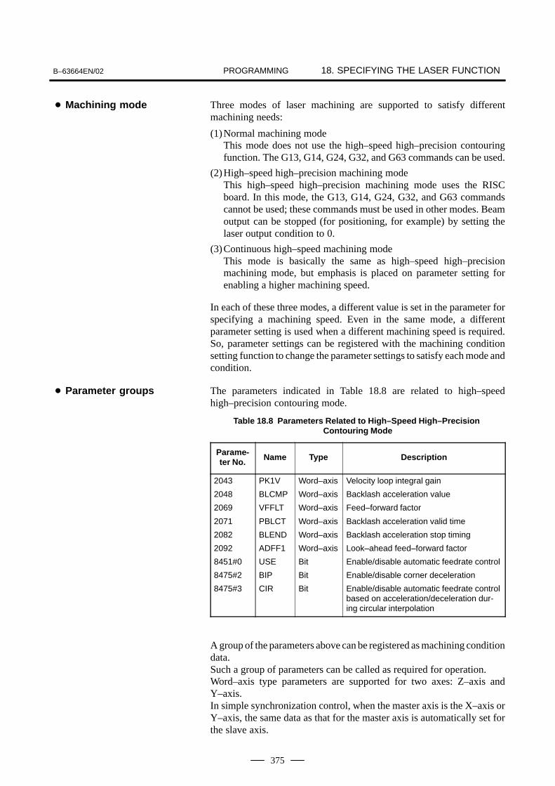
PROGRAMMING 18. SPECIFYING THE LASER FUNCTIONB–63664EN/02
375
Three modes of laser machining are supported to satisfy differentmachining needs:
(1)Normal machining modeThis mode does not use the high–speed high–precision contouringfunction. The G13, G14, G24, G32, and G63 commands can be used.
(2)High–speed high–precision machining modeThis high–speed high–precision machining mode uses the RISCboard. In this mode, the G13, G14, G24, G32, and G63 commandscannot be used; these commands must be used in other modes. Beamoutput can be stopped (for positioning, for example) by setting thelaser output condition to 0.
(3)Continuous high–speed machining modeThis mode is basically the same as high–speed high–precisionmachining mode, but emphasis is placed on parameter setting forenabling a higher machining speed.
In each of these three modes, a different value is set in the parameter forspecifying a machining speed. Even in the same mode, a differentparameter setting is used when a different machining speed is required.So, parameter settings can be registered with the machining conditionsetting function to change the parameter settings to satisfy each mode andcondition.
The parameters indicated in Table 18.8 are related to high–speedhigh–precision contouring mode.
Table 18.8 Parameters Related to High–Speed High–Precision Contouring Mode
Parame-ter No. Name Type Description
2043
2048
2069
2071
2082
2092
8451#0
8475#2
8475#3
PK1V
BLCMP
VFFLT
PBLCT
BLEND
ADFF1
USE
BIP
CIR
Word–axis
Word–axis
Word–axis
Word–axis
Word–axis
Word–axis
Bit
Bit
Bit
Velocity loop integral gain
Backlash acceleration value
Feed–forward factor
Backlash acceleration valid time
Backlash acceleration stop timing
Look–ahead feed–forward factor
Enable/disable automatic feedrate control
Enable/disable corner deceleration
Enable/disable automatic feedrate controlbased on acceleration/deceleration dur-ing circular interpolation
A group of the parameters above can be registered as machining conditiondata.Such a group of parameters can be called as required for operation.Word–axis type parameters are supported for two axes: Z–axis andY–axis.In simple synchronization control, when the master axis is the X–axis orY–axis, the same data as that for the master axis is automatically set forthe slave axis.
� Machining mode
� Parameter groups

PROGRAMMING18. SPECIFYING THE LASER FUNCTION B–63664EN/02
376
(1)An E code is specified to select a parameter. When an E code isspecified, it is stored as an active E code.
(2)An E code from E501 to E506 is used.
(3)When a command for setting RISC mode is executed, parameterswitching is performed. So, specify an E code immediately before acommand for setting RISC mode.
(4)For parameter switching, an active E code is used. So, if an E code isnot specified before a command for setting RISC mode, the numberremaining in the active E code is used for operation.
(5)When an E code is specified in RISC mode, the active E code isupdated, but parameter switching is not performed. To switch theparameter, first cancel RISC mode, then specify RISC mode again.
[Classification] Input signal
[Function] Specifies transition to power control mode.
[Operation] Transition to and return from power control mode are performed asdescribed below.Transition = (G63P1) OR (power control mode signal on)When G63P1 is specified in the machining program, or while the powercontrol mode signal is set to 1 by the PMC, power control mode is set.Return = (G63P0) AND (power control mode signal off)When the G63P0 state is specified in the machining program, and whenthe power control mode signal is set to 0, power control mode is canceled.Usually, the G63P0 state occurs immediately after the CNC is started orupon a reset. So, if G63P1 is not specified, G63P0 need not be specified.This means that, if a transition to the power control mode is made usingan external signal, a return is accomplished by turning off the externalsignal. If transition to the power control mode is made by G63P1 specifiedin the machining program, a return is accomplished by specifying G63P0.Power command changes made when the power control mode signal isused are indicated below (when only the power command is controlled).
O0002;
...................
G91 G00 X100.0 Y100.0;
N1 G01 X70.0 S1000 P1000 Q100 F1000;
N2 G01 Y100.0 F750;
N3 G01 X–70.0 F500;
N4 G01 Y–100.0 F300;
G91 G00 X0 Y0;
M30;
N1 N2 N3 N4
Power control signal and power command
� Specification
Signal
� Power control modesignal PWCTL<G224#1>

PROGRAMMING 18. SPECIFYING THE LASER FUNCTIONB–63664EN/02
377
[Classification] Output signal
[Function] Notifies the PMC that the power control mode is set.
[Operation] Output when transition to the power control mode is completed.
#7
G0224#6 #5 #4 #3 #2 #1
PWCTL#0
#7
G0224#6 #5 #4 #3 #2 #1
PCMD#0
#7
15000#6 #5
FLT#4 #3 #2 #1 #0
LPC
LPC0 : Disables the power control function.1 : Enables the power control function.
When LPC is set to 0, transition to power control mode is disabled. TheG code and input signal for setting power control mode are ignored.
FLT0 : Disables the filter for power control.1 : Enables the filter for power control.
When FLT is set to 1, parameter No. 15094 is enabled to allow an outputcommand to be delayed.
#7
LP815089#6LP7
#5LP6
#4LP5
#3
LP4#2
LPZ#1
LPY#0
LPX
LP*0 : Does not use the *–axis for feedrate calculation.1 : Uses the *–axis for feedrate calculation.
Each laser output element is calculated using the composite feedratealong the axes selected with this parameter. When no axis is selected, thespecification of the first axis (LPX) and the second axis (LPY) is assumed.
15090 Minimum power value
[Unit of data ] W
[Valid data range] 0 to 7000This parameter specifies a minimum power clamp value. If the powervalue calculated from the current feedrate becomes lower than the valueset in this parameter, the power value is clamped to the value set in thisparameter.
� Power control modeon signal PCMD<F224#1>
� Signal address
Parameters

PROGRAMMING18. SPECIFYING THE LASER FUNCTION B–63664EN/02
378
15091 Minimum pulse frequency
[Unit of data ] Hz
[Valid data range] 5 to 2000This parameter specifies a minimum pulse frequency clamp value. If thefrequency calculated from the current feedrate becomes lower than thevalue set in this parameter, the frequency is clamped to the value set in thisparameter.
15092 Minimum pulse duty cycle
[Unit of data ] %
[Valid data range] 0 to 100This parameter specifies a minimum pulse duty cycle clamp value. If theduty cycle calculated from the current feedrate becomes lower than thevalue set in this parameter, the duty cycle is clamped to the value set inthis parameter.
15094 Power control filter time constant
[Unit of data ] ms
[Valid data range] 8 to 32767This parameter specifies a time constant for the primary delay filter usedto delay the power command for synchronization with machine feed.The primary delay filter is expressed as follows:
On � On–1 � (In–On–1)TsTc
Ts: 8 ms (sampling time)
Tc: To be set in this parameter (time constant)
15095 Allowable variation in power control speed
[Unit of data ] mm/min
[Valid data range] 0 to 255The calculated feedrate slightly fluctuates also in a steady state, and thedata items (specified power, pulse frequency, and pulse duty) calculatedbased on the feedrate also fluctuate. To prevent these unnecessaryfluctuations, specify the width of a dead zone for feedrate fluctuations.
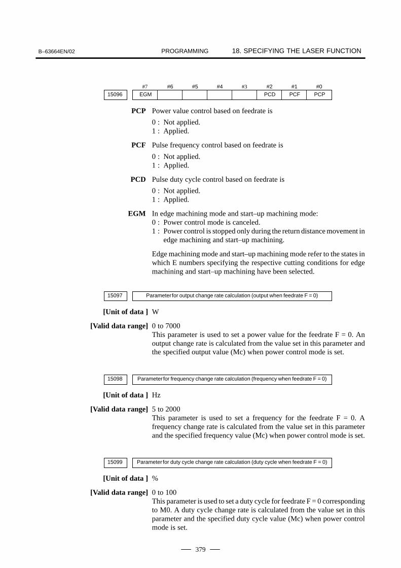
PROGRAMMING 18. SPECIFYING THE LASER FUNCTIONB–63664EN/02
379
#7
EGM15096#6 #5 #4 #3 #2
PCD#1
PCF#0
PCP
PCP Power value control based on feedrate is
0 : Not applied.1 : Applied.
PCF Pulse frequency control based on feedrate is
0 : Not applied.1 : Applied.
PCD Pulse duty cycle control based on feedrate is
0 : Not applied.1 : Applied.
EGM In edge machining mode and start–up machining mode:0 : Power control mode is canceled.1 : Power control is stopped only during the return distance movement in
edge machining and start–up machining.
Edge machining mode and start–up machining mode refer to the states inwhich E numbers specifying the respective cutting conditions for edgemachining and start–up machining have been selected.
15097 Parameter for output change rate calculation (output when feedrate F = 0)
[Unit of data ] W
[Valid data range] 0 to 7000This parameter is used to set a power value for the feedrate F = 0. Anoutput change rate is calculated from the value set in this parameter andthe specified output value (Mc) when power control mode is set.
15098 Parameter for frequency change rate calculation (frequency when feedrate F = 0)
[Unit of data ] Hz
[Valid data range] 5 to 2000This parameter is used to set a frequency for the feedrate F = 0. Afrequency change rate is calculated from the value set in this parameterand the specified frequency value (Mc) when power control mode is set.
15099 Parameter for duty cycle change rate calculation (duty cycle when feedrate F = 0)
[Unit of data ] %
[Valid data range] 0 to 100This parameter is used to set a duty cycle for feedrate F = 0 correspondingto M0. A duty cycle change rate is calculated from the value set in thisparameter and the specified duty cycle value (Mc) when power controlmode is set.

PROGRAMMING18. SPECIFYING THE LASER FUNCTION B–63664EN/02
380
NOTE
1 With the parameter switch function, the parameter for theZ–axis cannot be changed.
2 With the parameter switch function, the parameter for themirror axis used for constant optical path length controlcannot be changed.
3 A display unit equivalent to the 10.4–inch LCD is required.4 This function can be used together only with X–Y plane
facing.It cannot be used together with any other function (such ascylindrical interpolation, normal–direction control, orthree–dimensional cutting).
Note

PROGRAMMING 18. SPECIFYING THE LASER FUNCTIONB–63664EN/02
381
When inputting the signal from a sensor which is installed at the end ofthe nozzle of the laser processing system to detect the distance from theworkpiece, the CNC issues a move command for the Z–axis (or W–axis)to obtain a specified distance between the nozzle and the workpiece.For details, refer to “FS16i–LB Connection Manual” (B–63663EN).
� Set gap control modeG13 P__ (R__L__);
� Cancel gap control modeG14;
P__: Reference displacement valueR__: Gap amountL__: Gap controlled axis (switching between Z– and W–axes)
When G13 is specified, the CNC enters the gap control mode to controlthe distance between the cutting nozzle and workpiece according to thesignal input from the gap sensor so that the distance specified by P or Rcan be obtained.When G14 is specified, or when a reset is made, the gap control mode iscanceled.
NOTEIn the gap control mode, the CNC performs velocity controlinstead of position control, which is the control methodusually used. Therefore, programmed move commands(G00, G01, and so on) and manual move commands mustnot be issued for the Z–axis in the gap control mode.
18.9GAP CONTROLFUNCTION
Overview
Command format
Explanation

PROGRAMMING18. SPECIFYING THE LASER FUNCTION B–63664EN/02
382
This function enables laser output functions in the AI contour controlmode and the AI nano contour control mode. For details of the AI contourcontrol mode and the AI nano contour control mode, refer to theFS16i–MB Operator’s Manual (B–63534EN).
The following functions can be used in the AI contour control mode andthe AI nano contour control mode:
Laser output commandsPower control functionBeam delay control functionLaser output ON/OFF control high–speed processing
Laser output commands S, P, Q, and E can be specified in the AI contourcontrol mode and AI nano contour control mode. Specify thesecommands in a block specifying G01 (G02, or G03) in the same way asordinary laser output commands.
The power control function controls the laser output in proportion to thecutting feedrate. This prevents the laser output from becomingexcessively high when the feedrate decreases in corners and other parts,therefore preventing cutting failures.In the AI contour control mode and AI nano contour control mode, muchmore appropriate power control is enabled than in the normal mode.For details of the power control function, see Section 18.3.
FeedrateLaser power
Laser power
Processing period inAI nano mode
Normal processing period
Time
Feedrate
Conceptual diagram of power control
18.10LASER HIGH–SPEEDCONTROL FUNCTION
Overview
Specification
� Laser output commands
� Power control function

PROGRAMMING 18. SPECIFYING THE LASER FUNCTIONB–63664EN/02
383
The beam delay control function controls the laser output timingaccording to the delay in the machine.The beam output timing can be delayed according to the delay timing setin parameter No. 15219.In the AI contour control mode and AI nano contour control mode, controlis performed with a shorter processing period than the processing periodused in the normal mode to enhance reduction of variation in machiningstart point.For details of the beam delay control function, see Section 18.4.
X, Y Specified position
Actual position
Delay time
Beam on/off
Time
Conceptual diagram of beam delay control
In the AI contour control mode and AI nano contour control mode, theexecution of programmed laser output commands is controlled at shorterprocessing intervals than in the normal mode. Even when laser machiningis performed at high speed, high precision is attained.
#77050
#6MI1
#5MI0
#4 #3 #2 #1 #0
MI1, MI0 Set the batch transfer quantity in the AI contour control mode and AI nanocontour control mode.
MI1 MI0 Batch transfer quantity
0 0 1
0 1 2
1 0 4
� Beam delay controlfunction
� Beam on/off control
Parameters

PROGRAMMING18. SPECIFYING THE LASER FUNCTION B–63664EN/02
384
#7DLY15005
#6 #5 #4 #3 #2 #1 #0
DLY0 : Disables the beam delay function.1 : Enables the beam delay function.
15219 Beam output condition delay time
[Unit of data ] 8msec or 2msec (depending on the batch transfer quantity)
[Valid data range] 0 to 8Switching of beam output conditions is delayed by the time set in thisparameter.
� This function is optional.
� Before this function can be used, the AI contour control or AI nanocontour control function option is required.
� When using this function, set the batch transfer quantity to 4. If otherthan 4 is set, high–speed processing is not performed.
� This function is enabled for two–dimensional machining only.
� When using this function, disable AI contour control and AI nanocontour control for the Z–axis.
Remarks

PROGRAMMING19. THREE–DIMENSIONAL
CUTTING FUNCTIONB–63664EN/02
385
19 THREE–DIMENSIONAL CUTTING FUNCTION

PROGRAMMING19. THREE–DIMENSIONAL
CUTTING FUNCTION B–63664EN/02
386
If attitude control is specified with five or more controlled axes specified,nozzles are put under attitude control with the fourth and fifth axes usedas rotational axes, thus realizing a three–dimensional machine tool.The following two attitude control schemes are provided according to theshape of nozzle heads.
1) Attitude control A (zero–offset head)
2) Attitude control B (offset head)
Ask the machine tool builder which scheme your machine tool has.
The following limitations apply when the attitude control function isprovided. The terms used in the description are defined as follows:
a) The term ”three–dimensional machine tool” refers to a machinetool that performs attitude control.
b) The term “three–dimensional cutting” refers to cuttingimplemented using linear– and rotary–axis commands.
c) The term “two–dimensional cutting” refers to cutting implementedusing linear–axis commands.
1) The following functions cannot be used for three–dimensional cutting.Do not include these functions in three–dimensional programs.
� Advanced preview control
� AI contour control/AI nano contour control
� Laser power control
� Step control
� Edge cutting function
� Start–up cutting function
� Cutting restart
2) The following functions cannot be used for three–dimensional cutting.
� High–precision contour control and related functions
� High–speed laser cutting
19.1ATTITUDE CONTROL
Overview
Limitations

PROGRAMMING19. THREE–DIMENSIONAL
CUTTING FUNCTIONB–63664EN/02
387
Spatial circular interpolation can be performed by specifying midpointsand end points following G12.
G12 Xm__Ym__Zm__Am__Bm__;Xe__Ye__Ze__Ae__Be__;
A: Fourth axisB: Fifth axis
Table 19.2 Explanation of the Command Format
Command Explanation
G12 Spatial circular interpolation
Xm_ Amount of travel to the midpoint on the X–axis
Ym_ Amount of travel to the midpoint on the Y–axis
Zm_ Amount of travel to the midpoint on the Z–axis
Am_ Amount of travel to the midpoint on the A–axis
Bm_ Amount of travel to the midpoint on the B–axis
Xe_ Amount of travel to the end point on the X–axis
Ye_ Amount of travel to the end point on the Y–axis
Ze_ Amount of travel to the end point on the Z–axis
Ae_ Amount of travel to the end point on the A–axis
Be_ Amount of travel to the end point on the B–axis
G12 specifies spatial circular interpolation.This command is modal and effective until the next G00, G01, G02, orG03 is issued.
Specify the amount of travel to the midpoint on the arc for Xm, Ym, Zm,Am, and Bm and the amount of travel to the end point for Xe, Ye, Ze, Ae,and Be.Specify absolute or incremental values for the amounts according to G90or G91.When incremental values are specified, the end point is indicated by thedistance from the midpoint.
19.2SPATIAL CIRCULARINTERPOLATION(G12)
Format
Explanations
� G12
� Amount of travel alongan arc

PROGRAMMING19. THREE–DIMENSIONAL
CUTTING FUNCTION B–63664EN/02
388
1) For spatial circular interpolation, the path to the end point along an arccan be obtained by specifying the midpoint as well as the end point.The movement can be divided into the following two blocks: a blockfrom the start point to the midpoint and a block from the midpoint tothe end point. Therefore, during single–block operation, the nozzledoes not move at the first start, but moves from the start point to theend point at the second start.
2) When spatial circular interpolation is specified continuously, the endpoint of the previous block is used as the start point of the next block.(Always specify the midpoint and end point because the midpoint ofthe previous block is not used as the start point of the next block.)
3) The G12 command is treated as linear interpolation if it cannot createan arc because:
(a) Neither a midpoint block nor an end–point block has beenspecified,
(b)The start point, midpoint, and end point are on a straight line, or
(c) Two or more of the start point, midpoint, and end point areidentical.
4) The G12 command cannot specify axis movement for any axis otherthan the first to fifth axes, because alarm 4025 occurs.
5) G12 cannot be issued during coordinate system rotation (G84).
6) G12 cannot be issued during three–dimensional coordinate transform(G68).
7) G12 cannot be issued during cutter compensation. It must be issuedwith cutter compensation canceled.
Limitations

PROGRAMMING19. THREE–DIMENSIONAL
CUTTING FUNCTIONB–63664EN/02
389
Spatial corner rounding automatically inserts an arc of the specifiedradius into the corner made by two linear movements in space.
G33 G01X__Y__Z__A__B__R__F__;X__Y__Z__A__B__;R__;X__Y__Z__A__B__;
G34;
Table 19.3 Explanation of the Command Format
Command Explanation
G33 Starts the spatial corner rounding mode.
G34 Stops the spatial corner rounding mode.
G01 Linear interpolation
X_ Amount of travel to the end point on the X–axis
Y_ Amount of travel to the end point on the Y–axis
Z_ Amount of travel to the end point on the Z–axis
A_ Amount of travel to the end point on the A–axis
B_ Amount of travel to the end point on the B–axis
R_ Specifies the radius of an arc.
F_ Feedrate
G33 specifies spatial corner rounding mode while G34 cancels the mode.When a one–shot G code is issued in the G33 mode, the spatial cornerrounding mode is canceled.
Use G01 to issue a move command in G33 mode.If a G code in group 01 other than G01 is issued in G33 mode, an alarmoccurs.
Use R to specify the radius of an arc to be inserted.When no R command is specified in the block in which G33 is specified,the nozzle moves linearly.When only the radius of an arc is specified in a block, an arc is insertedinto the corner between the blocks before and after that block.When an R command is specified following X, Y, and Z commands in ablock, an arc is inserted into the corner between that block and the nextblock.
19.3SPATIAL CORNERROUNDING (G33 AND G34)
Format
Explanations
� Starting and stoppingspatial corner roundingmode
� Move command inspatial corner roundingmode
� Specifying the radius ofan arc

PROGRAMMING19. THREE–DIMENSIONAL
CUTTING FUNCTION B–63664EN/02
390
1) When the angle made by the current block with the next block is lessthan 1° or 180° ± 1° , the nozzle moves linearly at the corner with noarc inserted.
2) During single–block operation, the nozzle moves to the end point ofthe corner, then stops.
3) During MDI operation, after the first block is entered and the startbutton is pressed, then the second block is entered and the button ispressed, the nozzle moves along the path specified in the first blockto the end point of the corner. When G34 is entered in the third blockand the start button is pressed, the nozzle moves to the end point ofthe path specified in the second block. When a move command isspecified in the third block, the nozzle moves in the same way as forthe first block.
4) G33 cannot be issued during coordinate system rotation (G84).
5) The following G code commands cannot be issued in the G33 mode,because alarm 4017 occurs:G00, G02, G03, G12, G40, G41, G42, G28, G29, G30, G31, and G53
6) If any of the following G codes is issued simultaneously with the G01move command, no corner rounding is inserted:G09, G54 to G59, and G codes in group 00
7) Any command other than the G01 move command cannot be issuedimmediately after G33 is issued; it is ignored if issued.
8) Do not specify a block that does not involve movement in the G33mode.(The block would be executed before the immediately preceding G01move command.)
9) If a command that does not involve movement is specified in thesame block as the G01 which is in the G33 mode, it is executedsimultaneously with the previous G01 move command but one.
10) Do not issue an auxiliary function such as an M or T code during theG33 mode.(An auxiliary function issued in the same block as G01 is executedsimultaneously with the previous G01 move command but one andoutput at two points; linear and arc start points.)
11) G33 cannot be used simultaneously with cutter compensation. IssueG33 with cutter compensation canceled.
12) An axis move command for any axis other than the first to fifth axescannot be issued in the G33 mode, because alarm 4025 occurs.
Limitations

PROGRAMMING19. THREE–DIMENSIONAL
CUTTING FUNCTIONB–63664EN/02
391
The origin of coordinate conversion, nozzle direction, and positiveX–axis direction can be specified in the block in which thethree–dimensional coordinate conversion command (G68) is specified tochange the programmed coordinate system, as follows:
G68 X_ Y_ Z_ A_ B_ I_ J_ K_ ;
G69;
G01 X_ Y_ Z_ A_ B_ F_ ;G01 X_ Y_ Z_ A_ B_ ;G01 X_ Y_ Z_ A_ B_ ;G02 X_ Y_ I_ J_ ;G03 X_ Y_ I_ J_ ;G01 X_ Y_ Z_ A_ B_ ;
Turn on three–dimensionalcoordinate transform.
Block to be converted
End of three–dimensionalcoordinate transform
Table 19.4 Explanation of the Command Format
Command Explanation
G68 Three–dimensional coordinate conversion mode
G69 Cancellation of three–dimensional coordinate conversion
X_ X coordinate of the origin of coordinate conversion
Y_ Y coordinate of the origin of coordinate conversion
Z_ Z coordinate of the origin of coordinate conversion
A_ A coordinate in the nozzle direction
B_ B coordinate in the nozzle direction
I_ X element of the vector suggesting the positive X–axisdirection
J_ Y element of the vector suggesting the positive X–axisdirection
K_ Z element of the vector suggesting the positive X–axisdirection
The G68 command specifies three–dimensional coordinate conversionmode.G69 cancels the mode.When reset is performed during three–dimensional coordinateconversion, three–dimensional coordinate conversion mode is canceledand the normal coordinate system is restored.
Specify the origin of coordinate conversion with an absolute value.
19.4THREE–DIMENSIONALCOORDINATECONVERSIONFUNCTION (G68 AND G69)
Format
Explanations
� Three–dimensionalcoordinate conversionmode/cancellation
� Origin of coordinateconversion

PROGRAMMING19. THREE–DIMENSIONAL
CUTTING FUNCTION B–63664EN/02
392
For the nozzle direction, three–dimensional coordinate conversion is notperformed. That is, the nozzle direction is assumed to be oriented in theZ–axis direction.
Specify the vector with incremental values starting from the origin ofcoordinate conversion.When (I,J,K) is omitted, the X–axis is assumed to be parallel to the XYplane before conversion.
1) G68 cannot be issued simultaneously with scaling (G51) or coordinatesystem rotation (G84).
2) Neither G68 nor G69 can be issued if a cutter compensation offsetvector is left in the CNC.
3) Three–dimension transform (G98) cannot be issued in the G68 mode.
4) Spatial arc interpolation (G12) cannot be issued in the G68 mode.
5) A machine coordinate system–based move command (G27, G28,G29, or G53) cannot be issued in the G68 mode.
6) If JOG or MDI intervention is required in the G68 mode, an absolute(G90) command must be used to specify movement in the G68 mode.
7) The work coordinate system cannot be changed in the G68 mode.
� Nozzle direction
� Vector suggesting thepositive X–axis direction
Limitations

PROGRAMMING19. THREE–DIMENSIONAL
CUTTING FUNCTIONB–63664EN/02
393
The length of the second arm of a three–dimensional offset–type machinemay be changed due to replacement of the processing head. In this case,nozzle tip fixing control cannot operate normally without referenceposition return.This function enables tip fixing control to be performed with the currentposition without reference position return by entering the length of thereplaced nozzle from a program when a processing head is replaced.
G71 R__;
R__ : Length of the replaced nozzleUnit : 0.001mm (metric output)
0.0001inch (inch output)
When G71 is executed, parameter 15619 (nozzle length) is rewritten withthe value specified by address R, and the nozzle is positioned to the nozzletip position before replacement at a rapid traverse rate by movement alongthe X, Y, and Z axes. At this time, the position along the fourth and fifthaxes does not change. Movement by G71 is the same as positioning byG00. The feedrate and other settings specified for G00 are used.The length of the arm used for tip fixing control is indicated by the valueobtained by adding the length of the second arm set for parameter No.15616.
Traveldistance
Second armlength ParameterNo. 15616
Nozzle length beforereplacement
Nozzle tip fixing control is executed at this position.
Before G71 isissued
Nozzle length af-ter replacement(specify this valuefor R.)
After G71 is issued(The nozzle is posi-tioned at the nozzleposition before re-placement.)
19.5PROCESSING HEADA–AXIS LENGTHCOMPENSATIONFUNCTION (G71)
Format
Explanations
� Operation

PROGRAMMING19. THREE–DIMENSIONAL
CUTTING FUNCTION B–63664EN/02
394
15616 Second arm length
Sets the length of the second arm.
Range of valid settings: 0 to 500000 (metric output)
0 to 196850 (inch output)
Unit : 0.001 mm (metric output)
0.0001 inch (inch output)
15619 Nozzle length
Sets the length of the nozzle.When G71 is executed, the value specified for address R is set.
Range of valid settings : PRM. 15616 + PRM. 15619 � 500000(metric output)
PRM. 15616 + PRM. 15619 � 196850(inch output)
Unit : 0.001 mm (metric output)
0.0001 inch (inch output)
Alarm number Explanation
P/S4021 A negative value is specified as the length of the nozzle.The nozzle length falls outside the specification range. Thetotal of the second arm length and nozzle length must beno more than 500 mm (19.685 inches).
1 A change made to the nozzle length, using G71, is retained as aparameter even after the power is turned off. To use it in relation tonozzle compensation, cancel it, using G71R0.When rewriting parameter 15619 with other than G71, always performreference position return.
2 Before movement by G71, the stroke limit is checked.
3 G71 is a one–shot G code.
Parameter
Alarm
Limitations

PROGRAMMING19. THREE–DIMENSIONAL
CUTTING FUNCTIONB–63664EN/02
395
Normally, the travel distance in G71R_ is used for executing a positioningcommand (Fig. 19.6 (a)), but it can be used for interpolation at the sametime when the next move command is executed. (Fig. 19.6 (b))
<1> Movementfor nozzle lengthcompensation
Nozzle
<2> Fifth–axismovement
Machining height 2Machining height 1
Workpiece
Tool center point TCP
Fig.19.6 (a)
Tool center point TCP
Workpiece
Machining height 2Machining height 1
Nozzle
Fig.19.6 (b)
The following shows an example in which the nozzle becomes shorter(the machining height decreases) depending on the machining attitude.
<1> Movementfor arm lengthcompensation
Nozzle<2> Fifth–axismovement
Machining height 1
Machining height 2
Workpiece
Tool center point TCP
Fig.19.6 (c)
Tool center point TCP
Workpiece
Machining height 1
Machining height 2
Nozzle
Fig.19.6 (d)
The travel distancefor arm length compensation is included in fifth–axismovement.
19.6IMPROVEMENT IN NOZZLE LENGTH COMPENSATIONOverview

PROGRAMMING19. THREE–DIMENSIONAL
CUTTING FUNCTION B–63664EN/02
396
If bit 1 (NZB) of parameter No. 15625 is set to 1, the compensation valuein G71R_ is stored in the NC, and it is used for interpolation at the sametime when the move command specified in the next or a subsequent blockis executed. As the R value specified in G71R_, specify the second armlength compensation value in the attitude for beveling (the angle of thefifth axis). (See the figure below.)When machining is performed with the fifth axis attitude kept unchanged,the beveling command (G71P1) need not be specified. The bevelingcommand is required when machining is performed by changing the fifthaxis attitude while maintaining the current machining height.
Tool center point TCP
Machining height 2
Machining height 1
Nozzle
Workpiece
Length specified in G71R_
#715602
#6 #5 #4 #3OF2
#2 #1 #0
[Data type] Bit
OF2 Be sure to set this bit to 1 when using this function.
#715625
#6 #5 #4 #3 #2 #1NZB
#0
[Data type] Bit
NZB Compensation movement by the G71R_ command causes:
0 : Positioning in that block.1 : Interpolation at the same time when a block specifying the next
interpolation movement command is executed.
Specification
Parameter

PROGRAMMING19. THREE–DIMENSIONAL
CUTTING FUNCTIONB–63664EN/02
397
Bit 1 (NZB) of parameter No. 15625 is set to 1. (A: Fourth axis, B: Fifthaxis)
�
�
N01 G71 R piercing position; ... 2nd arm length compensation (no axis movement)N02 G01 X_ Y_ F_; ... Perform interpolation of compensation value together with
move commandN03 G24 S_ P_ Q_ R_; ... PiercingN04 G71 R cutting position; ... 2nd arm length compensation (no axis movement)N05 G01 X_ Y_ B_ F_; ... Perform interpolation of compensation value together with
... move command�
N10 G71 P1; ... Enable beveling compensation�
� (Program for changing beveling angle)�
N20 G71 P0; ... Disable beveling compensation�
(1) In this specification, bit 2 (OF2) of parameter No. 15602 must be setto 1.
(2) If a block specifying the next movement after the G71R_ command isa positioning block, compensation is not performed, and thecompensation value is maintained until the next interpolationcommand is encountered.
(3) If the travel amount of the block specified next to the G71R_ commandis 0, compensation is not performed, and the compensation value ismaintained until a block specifying the next movement isencountered.
(4)Be sure to specify the G71R_ command in the G71P0 mode. It isimpossible to specify the G71P1 command before the compensationoperation is completed (for example, when the above compensationoperation is maintained).
(5)When the automatic feedrate override function operates duringcompensation, operation is performed at a feedrate lower than theclamp feedrate set in parameter Nos. 15621 and 15622.
(6)After G71R_ is specified, when a reset is applied during execution ofthe compensation operation or before the compensation operation,compensation for the rest of the compensation value is performed ata time.
Sample program
Notes

PROGRAMMING19. THREE–DIMENSIONAL
CUTTING FUNCTION B–63664EN/02
398
When a given point in the coordinate system for the processing programis specified as the base point and a target point corresponding to the basepoint is also specified, the processing program, transformed in threedimensions, runs. Mirror image transform and three–dimensionalmovement transform are provided for the three–dimensional transformfunction.
To specify base and target points (see ”Explanations”) for this function,the following methods are available:
(1)Specifying the points in a program
(a) Mirror image transform
G98 P0 X_ Y_ Z_ ;G98 Q0 X_ Y_ Z_ ;
G99;
G01 X_ Y_ Z_ A_ B_ F_ ;G01 X_ Y_ Z_ A_ B_ ;G02 X_ Y_ I_ J_ ;G03 X_ Y_ I_ J_ ;
(b) Three–dimensional movement transform
G98 P1 X_ Y_ Z_ ;G98 P2 X_ Y_ Z_ ;G98 P3 X_ Y_ Z_ ;G98 Q1 X_ Y_ Z_ ;G98 Q2 X_ Y_ Z_ ;G98 Q3 X_ Y_ Z_ ;
G99;
G01 X_ Y_ Z_ A_ B_ F_ ;G01 X_ Y_ Z_ A_ B_ ;G02 X_ Y_ I_ J_ ;G03 X_ Y_ I_ J_ ;
Block to be subjected totransform
Reference pointTarget point
End of three–dimensionaltransform
Reference point 1Reference point 2Reference point 3Target point 1Target point 2Target point 3
Block to be subjected totransform
End of three–dimensionaltransform
When the program is executed, the coordinates at the base and targetpoints are written into the settings. When Q0 or Q3 is read, transformprocessing starts according to the values of the settings.
(2)Specifying the points using settings
(a) Mirror image transform
G98 Q0 ;
G99;
G01 X_ Y_ Z_ A_ B_ F_ ;G01 X_ Y_ Z_ A_ B_ ;G02 X_ Y_ I_ J_ ;G03 X_ Y_ I_ J_ ;
(b) Three–dimensional movement transform
G98 Q3 ;
G99;
G01 X_ Y_ Z_ A_ B_ F_ ;G01 X_ Y_ Z_ A_ B_ ;G02 X_ Y_ I_ J_ ;G03 X_ Y_ I_ J_ ;
Block to be subjected totransform
Turn on mirrorimage transform.
End of three–dimensionaltransform
Turn on three–dimensional transform.
Block to be subjected totransform
End of three–dimensionaltransform
19.7THREE–DIMENSIONALTRANSFORMFUNCTION (G98, G99)
Format

PROGRAMMING19. THREE–DIMENSIONAL
CUTTING FUNCTIONB–63664EN/02
399
Set the coordinates at the base and target points on the setting screen (seePart III, ”Operation”) in advance and specify the above command in theprogram.When the program is executed and the above command is read, transformprocessing starts according to the values of the settings.
When the base point before transformation, P0 (X,Y,Z), and target pointafter transformation, Q0 (X,Y,Z), are specified, the plane whichperpendicularly bisects the straight line connecting these two points isobtained as the target plane. On the plane, a mirror image transform isperformed for the program to be transformed.
P0x,y,z
Q0i,j,k
Path beforetransformation
Targetplane
Path aftertransformation
When the three base points before transformation, (P1,P2,P3), and thetarget points after transformation, (Q1,Q2,Q3), are specified, thecoordinate system after transformation is obtained. The program to betransformed moves to the coordinate system.
P1
P2
P3
Q1
Q2
Q3
Explanations
� Mirror image transform
� Three–dimensionalmovement transform

PROGRAMMING19. THREE–DIMENSIONAL
CUTTING FUNCTION B–63664EN/02
400
Mirror image transform and movement transform can be specifiedsimultaneously.For example, when a movement transform is specified, then a mirrorimage transform is specified without specifying a cancel command asfollows, both transforms are effective.Cancel command G99 cancels all commands. To cancel multipletransform commands and specify only one of these transform commands,cancel these commands using G99, then respecify the required command.When a command becomes effective, ”(Selected)” is displayed followingthe title on the setting screen.
G98Q0 ;Move command group A mirror image transform is effective.G99 ;G98 Q3 ;Move command group A movement transform is effective.G98Q0 ;Move command group A movement transform is effective.
A mirror image transform is effective.G99 ;Move command group Normal operationG98Q0 ;Move command group A mirror image transform is effective.
1) Assume that the following program is executed. When control istransferred from move command group (a) to move command group(b) and from move command group (b) to move command group (c),movement stops and the beam is turned off.
Move command group (a)G98Q0 ; or Q3 ;Move command group (b) The three–dimensional G99 ; transform function is effective.Move command group (c)
2) When specifying a complete circle with G02 and G03 commands inthe G98 mode, split it into two blocks.
3) Cutter compensation cannot be performed in the G98 mode. Beforespecifying cutter compensation, issue three–dimensional coordinatetransform (G68) in the G98 mode.
4) G98 cannot be issued simultaneously with scaling (G51) or coordinatesystem rotation (G84).
5) A machine coordinate system–based move command (G27, G28,G29, or G53) cannot be issued in the G98 mode.
6) If JOG or MDI intervention is required in the G98 mode, an absolute(G90) command must be used to specify movement in the G98 mode.
� Specifying mirror imagetransform and movementtransformsimultaneously
Limitations

PROGRAMMING19. THREE–DIMENSIONAL
CUTTING FUNCTIONB–63664EN/02
401
7) Immediately after G98, three–dimensional transform is performed onnozzle movement based on the current position of the nozzle. So,unexpected changes may occur to the nozzle position. Before issuingG98, therefore, position the fourth and fifth axes in such a point wherechanges to the nozzle position can be foreseen.(It is recommended that the fourth and fifth axes be set to the originbefore the nozzle is returned to the basic position.)
8) A three–dimensional coordinate transform command (G68) can beissued in the G98 mode.
#715601
#6 #5 #4 #3RDC
#2 #1 #0
[Data type] Bit
RDC In three–dimensional conversion, the rotation around the fourth and fifthaxes is:
0 : In a direction in which the distance of movement becomes shorter.When a software OT area is encountered if the axis rotation isperformed in the shorter–distance direction, however, the rotation isperformed in the opposite direction.
1 : Not the same as usual. For the fourth axis, the direction of travelbefore the conversion is assumed. If there are two solutions, the onenearer the amount of travel before the conversion is selected. Thesolution for the fifth axis is determined with the solution selected forthe fourth axis.
15623Angle at which rotation is assumed to be only plane rotation in three–dimensional
conversion
[Data type] Two–word
[Unit of data] 0.001 deg
[Valid data range] 0 to 89999
If, in three–dimensional conversion, the difference between theinclination of the plane containing three reference points (P1, P2, and P3)and that of the plane containing three target points (Q1, Q2, and Q3) isequal to or less than the angle specified in this parameter, the inclinationdifference is ignored and the rotation is assumed to be only rotation in theX–Y plane.If this parameter is 0, this compensation process is not executed.
Parameters

√√
PROGRAMMING19. THREE–DIMENSIONAL
CUTTING FUNCTION B–63664EN/02
402
If the fourth and fifth axes are specified simultaneously with the X–, Y–,and Z–axes, the X–, Y–, and Z–axis feedrates may become very high afterposition control B compensation is applied. This function is intended toclamp the feedrate specified in the command so that the X–, Y–, andZ–axis feedrates with position control B compensation applied will notexceed the respective rapid traverse rates (parameter No. 1420). It isenabled for G01, G02, G03, G12, and interpolation–type G00 commands.
The clamp feedrate for block “G91 G01 Xx Yy Zz Aa Bb Ff” is obtainedas explained below. In this description, the A– and B–axes are specified as the fourth and fifthaxes, respectively.The maximum X–axis feedrate with position control B applied can beestimated using the following expression.
Fxmaz=[f*x/L]+[f*a/L*(π*R/180)]+[f*b/L*(π*P/180)]L= (x2+y2+z2): Distance through which the nozzle tip movR= [(Length of the first arm)2+(Length of the second arm)2]P; Length of the second armf*x/L: X–axis feedrate derived from the Xx commandf*a/L*(π*R180): Maximum X–axis feedrate generated by
applying the Aa command compensationf*b/L*(π*P180): Maximum X–axis feedrate generated by
applying the Bb command compensation
Calculate “f” so that Fxmax is not higher than the X–axis traverse rate(parameter No. 1420).
fx=Rpdx/{[x/L]+[a/L*(π*R/180)]+[b/L*(π*P/180)]}fx: “f” obtained for the X–axisRpdx: X–axis rapid traverse rate (parameter No. 1420)
Similarly, obtain the clamp feedrate from the maximum Y–axis feedrate.
Fymax=[f*y/L]+[f*a/L*(π*R/180)]+[f*b/L*(π*P/180)]fy=Rpdy/{[y/L]+[a/L*(π*R/180)]+[b/L*(π*P/180)]}
fy: “f” obtained for the Y–axisRpdy: Y–axis rapid traverse rate (parameter No. 1420)
Because no Aa command–based compensation occurs for the Z–axis,
Fzmax=[f*z/L]+[f*b/L*(π*P/180)]fz=Rpdz/{[z/L]+[b/L*(π*P/180)]}
fz: “f” obtained for the Z–axisRpdz: Z–axis rapid traverse rate (parameter No. 1420)
The smallest of “fx,” “fy,” and “fz” is used as the minimum cuttingfeedrate clamp value.
Remark) [f*a/L*(π*R/180)] and [f*b/L*(π*P/180)] do not occur at thesame time. So, each axis feedrate after clamped is slightlylower than the corresponding rapid traverse rate.
In “G91 G02 Xx Yy Zz Aa Bb Ff”, the maximum feedrates of the X–, Y–,and Z–axes are estimated at:
Fxmax=f+[f*a/L*(π*R/180)]+[f*b/L*(π*P/180)]Fymax=f+[f*a/L*(π*R/180)]+[f*b/L*(π*P/180)]Fzmax=[f*y/L]+[f*b/L*(π*P/180)]
19.8FEEDRATE CLAMPFUNCTION INPOSITION CONTROL B
Explanations

√
√
√
PROGRAMMING19. THREE–DIMENSIONAL
CUTTING FUNCTIONB–63664EN/02
403
Therefore, the following expressions give clamp values for the feedrates.
fx=Rpdx/{1+[a/L*(π*R/180)]+[b/L*(π*P/180)]}fy=Rpdy/{1+[a/L*(π*R/180)]+[b/L*(π*P/180)]}fz=Rpdz/{[z/L]+[b/L*(π*P/180)]}
Setting bit 1 of parameter No. 15602 effects clamping with the maximumfeedrate after position control taken into account.
#715602
#6FMX
#5 #4 #3 #2 #1 #0
FMX If an offset–type nozzle is used, the cutting speed is:
1 : Not clamped.0 : Clamped by considering the maximum speed after position control.
Length of the first arm: 130 mmLength of the second arm: 145 mmRapid traverse rates for individual axes: X = 24000, Y = 24000, Z =20000, A = 4000, and B = 80000Upper limit to machining feedrate for the A– and B–axes: A = 4000 andB = 8000Under the above conditions, let us calculate the feedrate clamp value forthe following command block:
G91 G01 X10. Y20. Z30. A45. B90. F5000;
Distance through which the nozzle tip moves is:L = (102+202+302)=37.416
Let f be the feedrate of the nozzle tip after clamped.
The specified X–axis feedrate component is: FXL=f*10/L=0.267*fThe specified Y–axis feedrate component is: FYL=f*20/L=0.535*fThe specified Z–axis feedrate component is: FZL=f*30/L=0.802*fThe A–axis feedrate is: FAL=f*45/L=1.203*fThe B–axis feedrate is: FBL=f*90/L=2.405*f
Assuming that the A–axis operates with the B–axis at 90°,
The maximum X–axis feedrate under A–axis position control is:FXA=FAL*π* (1302+1452)/180=4.089*f
The maximum Y–axis feedrate under A–axis position control is:FYA=FAL*π* (1302+1452)/180=4.089*f
The maximum Z–axis feedrate under A–axis position control is:FZA=0
Assuming that the B–axis operates with the A–axis at 0°,The maximum X–axis feedrate under B–axis position control is:
FXB=FBL*π*145/180=6.086*fAssuming that the B–axis operates with the A–axis at 90°,
The maximum Y–axis feedrate under B–axis position control is:FYB=FBL*π*145/180=6.086*f
The maximum Z–axis feedrate under B–axis position control is:FXB=FBL*π*145/180=6.086*f
Summing the specified X–, Y–, and Z–axis feedrate components and theX–, Y–, and Z–axis feedrates under A– and B–axis position control yieldsthe following estimates:
Parameters
Example problem

PROGRAMMING19. THREE–DIMENSIONAL
CUTTING FUNCTION B–63664EN/02
404
The estimated maximum X–axis feedrate is:FXMAX=FXL+FXA+FXB=10.442*f
The estimated maximum Y–axis feedrate is:FYMAX=FYL+FYA+FYB=10.71*f
The estimated maximum Z–axis feedrate is:FZMAX=FZL+0+FZB=6.888*f
If f is determined so that FXMAX, FYMAX, and FZMAX do not exceed therespective rapid traverse rates of the X–, Y–, and Z–axes:
f = 2298 because FXMAX = 10.442*f�24000f = 2241 because FYMAX = 10.71*f�24000f = 2904 because FZMAX = 6.888*f�20000
For any of the X–, Y–, and Z–axis feedrates to be lower than the respectiverapid traverse rates, the nozzle tip feedrate must be 2241 mm/min.

PROGRAMMING19. THREE–DIMENSIONAL
CUTTING FUNCTIONB–63664EN/02
405
If a specified feedrate output to the motor of each axis exceeds theparameter–specified feedrate, this function applies automatic overridinginstantly so that the output feedrate is lowered to within theparameter–specified feedrate. This way, it is possible to clamp, on anexecution level, the X–, Y–, and Z–axis feedrate with position control Bcompensation applied.
If the feedrate of any axis exceeds the feedrate specified in parameter No.15621 during axis movement, automatic overriding is applied instantlyto lower it to within the parameter–specified feedrate. Because thisfunction works for all axes in common, no deviation from the specifiedtool path will occur during interpolation. Moreover, the override valuecan increase automatically so that the actual feedrate will not becomelower than necessary. However, the override value will not exceed 100%,so the actual feedrate does not become higher than specified.This function works in the cycle next to the one in which a feedrate higherthan the limit is detected. So, the parameter–specified feedrate may beexceeded a little.If a command–specified feedrate becomes higher than the feedratespecified in parameter No. 15621, the override value always changes. So,the nozzle tip feedrate does not become constant even within the samecommand block. Therefore, it is necessary to set parameter No. 15621with a value that will not cause overriding during usual cutting.This function works not only in automatic operation but also in all othermodes such as jog and handle feed.
Block “G91 G01 X4. A360. F10000” causes overriding shown below.The A–axis is the fourth axis.
[If this function is disabled] [If this function is enabled]
Feedrate
A–axis feedrateA–axis feedrate
Y–axis feedrate Y–axis feedrate
X–axis feedrate
X–axis feedrate
Maximum X–axisfeedrate
Maximum Y–axisfeedrate
00
Feedrate
Maximum Y–axisfeedrate
Maximum X–axisfeedrate
19.9AUTOMATICFEEDRATEOVERRIDE UNDERPOSITION CONTROL B
Explanations

PROGRAMMING19. THREE–DIMENSIONAL
CUTTING FUNCTION B–63664EN/02
406
15621 Maximum speed 1 after position control
[Data type] Two–word axis
[Unit of data, valid data range]Increment system Unit of data IS–A, IS–B IS–CMillimeter machine 1 mm/min or 1 deg/min 0 to 240000 0 to 100000
Inch machine 0.1 inch/min or 1 deg/min 0 to 96000 0 to 48000
Specify the maximum speed after position control. The speed on eachaxis may be overridden so as not to exceed this setting.The maximum speed check is not performed on an axis for which 0 is set.
15622 Maximum speed 2 after position control
[Data type] Two–word axis
[Unit of data, valid data range]Increment system Unit of data IS–A, IS–B IS–CMillimeter machine 1 mm/min or 1 deg/min 0 to 240000 0 to 100000
Inch machine 0.1 inch/min or 1 deg/min 0 to 96000 0 to 48000
Specify the maximum speed after position control. The speed on eachaxis may be overridden so as not to exceed this setting. This parameter iseffective when the position control B speed clamp select signal (G224#7,OTPMX2) is 1. When OTPMX2 is 0, parameter No. 15621 is effective.Parameter No. 15621 is effective to an axis for which 0 is set in thisparameter.
#7OTPMX2G224
#6 #5 #4 #3 #2 #1 #0
Position control B feedrate clamp switching signal
OTPMX2 Selects which parameter is to be used to specify the maximum value forautomatic feedrate overriding under position control B.
1 : Automatic overriding occurs based on parameter No. 15621.0 : Automatic overriding occurs based on parameter No. 15622.
Parameters
Signal

PROGRAMMING19. THREE–DIMENSIONAL
CUTTING FUNCTIONB–63664EN/02
407
When beveling is performed, the bevel torch must always be positionedin a direction normal to a specified straight line or arc. The torch turningcontrol function controls the bevel torch so that it is positioned in thenormal direction without stopping the operation of the torch end at a pointbetween adjacent blocks. This function is optional.
The rotary axis for torch turning control is specified in parameter No.5490.The rotation center of the rotary axis is an axis perpendicular to the X–Yplane (that is, the Z–axis).The angle of the rotary axis is defined on a counterclockwise basis asfollows:
0° :+X direction90° :+Y direction180° :–X direction270° :–YX direction(The angle ranges from 0 to 360°.)
Fig. 19.10 (a) Angle definition
Parameter No. 5490 = Axis number of the rotary axisThe following parameters are set for the axis specified in parameter No.5490:Parameter No. 1006#0 = 1Parameter No. 1008#0 = 1Parameter No. 1260 = 360000Parameter No. 1430 = Maximum rotation speedParameter No. 7052#0 = 1
For details of parameters, see “Parameter” described later.
19.10TORCH TURNINGCONTROL FUNCTION
Overview
Specification
� Definition of a rotary axis

PROGRAMMING19. THREE–DIMENSIONAL
CUTTING FUNCTION B–63664EN/02
408
Torch turning control is specified with the following G codes:
G41.1 (G151) : Turn torch leftG42.1 (G152) : Turn torch rightG40.1 (G150) : Cancel torch turning
These G codes are the same as for normal direction control. Whether touse these G codes for torch turning control or normal direction control isselected by the TRTENB (G0201#6) signal.
G0201#6 = 1 : Torch turning controlG0201#6 = 0 : Normal direction control
For details of this signal, see “Signal” described later.
Torch turning control can be used for the positioning and interpolationcommands listed below. For other interpolation commands, torch turningcontrol is not performed.
G00 : PositioningG01 : Linear interpolationG02, G03 : Circular interpolation
Torch turning control controls the bevel torch so that it is positioned inthe normal direction to a specified straight line or arc without stopping theoperation of the torch end at a point between adjacent blocks.For a straight line, while linear interpolation is being performed, therotary axis of the bevel torch is fed at a constant feedrate to position therotary axis in the direction normal to the straight line.For an arc, while circular interpolation is being performed, the rotary axisof the bevel torch is positioned in the normal direction to the arc, whichchanges from time to time.In G01, G02, and G03 blocks, positioning to the normal direction in torchturning control is performed at a feedrate set in parameter No. 1430. Ina G00 block, the positioning feedrate is set in parameter No. 1420. Forpositioning, the rotary axis always turns 180° or less (control for theshorter amount).Examples of torch turning control operation are given in Figs. 19.10 (b)and 19.10 (c). For an acute–angled corner, create a machining programas shown in Fig. 19.10 (c).
Programmed command
Workpiece
Turned while moved
Normal direction
Torch orientation
Turn torch left
(Sample program)
N01 G90N02 G41.1N03 G01Xx1Yy1N04 G01Xx2Yy2
(x2,y2)
(x1,y1)
Fig. 19.10 (b) Turning the torch left
� G codes for torch turningcontrol
� Usable interpolationcommands
� Operation

PROGRAMMING19. THREE–DIMENSIONAL
CUTTING FUNCTIONB–63664EN/02
409
Turn torch right
(Sample program)
For circular interpolation,always turning in direction normal to arc
Arc center
Workpiece
Turned while moved
N01 G90N02 G42.1N03 G01Xx1Yy1N04 G03Xx2Yy2Rr2
(x2,y2)
(x1,y1)
Fig. 19.10 (c) Turning the torch right
Workpiece
Normaldirection
Torchorientation
Turn torch left
(Sample program)
N01 G90N02 G41.1N03 G01Xx1Yy1N04 G01Xx2Yy2
(x2,y2)
(x1,y1)
Fig. 19.10 (d) Turning the torch left (inside a corner)
WorkpieceTurned whilemoved
Normaldirection Torch orientation
Turn torch left
(Sample program)
Turn torch left
Cancel torch turning
Cancel torch turning
Turn torch leftN01 G90N02 G41.1N03 G01Xx1Yy1N04 G40.1N05 G01Xx2Yy2N06 G41.1N07 G01Xx3Yy3
(x2,y2)
(x1,y1)
(x3,y3)
Fig. 19.10 (d) Turning the torch left (when turning is canceled in the middle)

PROGRAMMING19. THREE–DIMENSIONAL
CUTTING FUNCTION B–63664EN/02
410
#71006
#6 #5 #4 #3 #2 #1 #0ROTx
[Data type] Bit axis
ROTx Setting linear or rotary axis.0 : Linear axis1 : Rotary axis
#71008
#6 #5 #4 #3 #2 #1 #0ROAx
[Data type] Bit axis
ROAx The rotary axis roll–over function is:
0 : Invalid1 : Valid
1260 Amount of a shift per one rotation of a rotary axis
[Data type] 2–word axis
[Unit of data]
Input increment IS–B UnitUnit of data 0.001 deg
[Valid data range] 1000 to 99999999Set the amount of a shift per one rotation of a rotary asis.
1420 Rapid traverse rate for each axis
[Data type] 2–word axis
[Unit of data, valid data range]
Increment system Unit of dataValid data range
Increment system Unit of dataIS–B
Millimeter machine 1 mm/min 30 to 240000Inch machine 0.1 inch/min 30 to 96000Rotary axis 1deg/min 30 to 240000
Set the rapid traverse rate when the rapid traverse override is 100% foreach axis.
1430 Maximum cutting feedrate for each axis
[Data type] 2–word axis
[Unit of data, valid data range]
Increment system Unit of dataValid data range
Increment system Unit of dataIS–B
Rotary axis 1deg/min 6 to 240000
Specify the maximum cutting feedrate for each axis.A feedrate for each axis is clamped in cutting feed so that it does notexceed the maximum feedrate specified for each axis.
Parameters

PROGRAMMING19. THREE–DIMENSIONAL
CUTTING FUNCTIONB–63664EN/02
411
5483 Limit value of movement that is executed at the normal direction angle of apreceding block
[Data type] 2–word
[Unit of data]
Increment system IS–B UnitMillimeter input 0.001 mm
Inch input 0.0001 inch
[Valid data range] 1 to 99999999This parameter sets the limit value of movement at the normal directionangle of a preceding block.For details, refer to the parameter manual.
5490 Axis number of a rotary axis for torch turning control
[Data type] Byte
[Unit of data] None
[Valid data range] 1 to the maximum number of controlled axesSet the axis number of a rotary axis used for torch turning control.
#77052
#6 #5 #4 #3 #2 #1 #0NMI
[Data type] Bit axis
NMIx Always set to 1.For the rotary axis used for torch turning control, be sure to set this bit to 1.
#715625
#6 #5 #4 #3CNZ
#2 #1 #0
[Data type] Bit
CNZ In normal direction control and torch turning control, the orientation ofthe C–axis is determined as follows:
0 : The conventional specification is followed.1 : When the normal direction control or torch turning control mode is
entered, the angle of the C–axis is set so that the C–axis is in thenormal direction.

PROGRAMMING19. THREE–DIMENSIONAL
CUTTING FUNCTION B–63664EN/02
412
[Classification]
[Function] When this signal is driven to “1”, specifying G41.1 or G42.1 (G151 orG152) enables torch turning control.When this signal is “0”, normal direction control is enabled.This signal status can be changed only in the G40.1 (G150) mode.
#7G201
#6TRTENB
#5 #4 #3 #2 #1 #0
Signal
� Torch turning controlenable signalTRTENB<G201#6>

III. OPERATION


OPERATIONB–63664EN/02 1. GENERAL
415
1 �������

OPERATION1. GENERAL B–63664EN/02
416
The CNC machine nozzle has a position used to determine the machineposition.This position is called the reference position.Generally, the nozzle is moved to the reference position immediately afterthe power is turned on. Moving the nozzle to the reference position usingswitches and buttons on the machine operator’s panel is called manualreference position return. (See Section III–3.1.)
Reference position
Nozzle
Machine operator’s panel
Fig.1.1 (a) Manual Reference Position Return
The nozzle can also be moved to the reference position using programcommands.This operation is called automatic reference position return. (See SectionII–6.)
1.1MANUAL OPERATION
Explanations
� Manual referenceposition return

OPERATIONB–63664EN/02 1. GENERAL
417
The machine operator’s panel switches, buttons, and manual handle canbe used to move the nozzle along each axis.
Nozzle
Workpiece
Machine operator’s panel
Manual handle
Fig.1.1 (b) Moving the Nozzle Manually
(i) Jog feed (See Section III–3.2.)The nozzle moves continuously while a button is held down.
(ii)Incremental feed (See Section III–3.3.)The nozzle moves by the predetermined distance each time a buttonis pressed.
(iii)Manual handle feed (See Section III–3.4.)The nozzle moves by the distance corresponding to the degree ofhandle rotation when the manual handle is rotated.
� Moving the nozzlemanually

OPERATION1. GENERAL B–63664EN/02
418
Moving the machine according to a created program is calledautomatic operation.Automatic operation includes memory and MDI operations. (SeeSection III–4.)
Program
Nozzle
01000 ;G92_X_ ;G00... ;G01...... ;
.
.
.
.
Fig.1.2 (a) Moving the Nozzle Using a Program
A program can be stored in CNC memory to enable operation of themachine according to the contents of the memory. This operation is calledmemory operation.
CNC Machine
Memory
Fig.1.2 (b) Memory Operation
A program can be specified from the MDI keyboard to operate themachine according to the commands in the program. This operation iscalled MDI operation.
MDI keyboard CNC Machine
Manual program input
Fig.1.2 (c) MDI Operation
1.2MOVING THENOZZLE USING APROGRAM–AUTOMATICOPERATION
Explanations
� Memory operation
� MDI operation

OPERATIONB–63664EN/02 1. GENERAL
419
In this mode of operation, the program is not registered in the CNCmemory. It is read from the external input/output devices instead. Thisis called DNC operation. This mode is useful when the program is toolarge to fit the CNC memory.
� DNC operation

OPERATION1. GENERAL B–63664EN/02
420
Select a program for the workpiece to be processed. Generally, oneprogram is prepared for one workpiece. When multiple programs arestored on a tape or in memory, search the tape or memory for the programnumber (see Section III–9.3.) to select the program to be used.
Program forworkpiece 2
G92
In memory or on a tape
O1001 Program number
M30
G92
O1002G92
M30
Program number Program numbersearch
Automaticoperation
O1003 Program numberM30
Program for workpiece 3
Program for work-piece 1
Fig.1.3 (a) Selecting a Program for Automatic Operation
Pressing the cycle start button starts automatic operation.Pressing the feed hold or reset button halts or stops automatic operation.When the program stop or program end command is specified in theprogram, automatic operation stops before it is complete.Once the process is complete, automatic operation stops. (See SectionIII–4.)
Cycle start Manual start
Feed hold Reset Automatic operation
Program stopProgram end
Stop by the program
Manual stop
Fig.1.3 (b) Starting and Stopping Automatic Operation
1.3OPERATIONS FORAUTOMATICOPERATION
Explanations
� Selection of a program
� Starting and stoppingautomatic operation

OPERATIONB–63664EN/02 1. GENERAL
421
The manual handle can be rotated during automatic operation to add themanual–feed amount to the automatic–feed amount for the nozzlemovement. (See Section III–4.8.)
Workpiece
Nozzle
Depth of cutspecified in theprogram
Depth of cut spe-cified using themanual handle
Fig.1.3 (c) Handle Interruption during Automatic Operation
� Handle interruption

OPERATION1. GENERAL B–63664EN/02
422
Before processing is started for a production run, automatic operationmay be performed to check the created program to see whether themachine moves as desired.This check can be made by running the machine or checking the currentposition display change without actually running the machine. (SeeSection III–5.)
Remove the workpiece and check only the movement of the nozzle. Selectthe nozzle feedrate using the dial on the machine operator’s panel. (SeeSection III–5.4.)
Nozzle
Table
Fig.1.4.1 (a) Dry Run
Check the program by changing the program command. (See SectionIII–5.2.)
Programmed feedrate: 100 mm/min
Feedrate after feedrate override: 20 mm/min
Workpiece
Nozzle
Fig.1.4.1 (b) Feedrate Override
1.4TEST OPERATION
1.4.1Check by Running theMachine
Explanations
� Dry run
� Feedrate override

OPERATIONB–63664EN/02 1. GENERAL
423
When the cycle start button is pressed, the nozzle performs one operation,then stops. When the cycle start button is pressed again, the nozzleperforms the next operation, then stops. The program is checked in thisway. (See Section III–5.5.)
Cyclestart
Nozzle
Cyclestart
Cyclestart
Cyclestart
StopStop
Stop
Workpiece
Fig.1.4.1 (c) Single Block
Nozzle
CRT/MDI
XYZ
Change according to themachine movement
The nozzle does not move. Only thecurrent position display for each axischanges.
Workpiece
Fig.1.4.2 (a) Machine Lock
When automatic operation is performed in auxiliary function lock modeas well as in machine lock mode (see Section III–5.1), all auxiliaryfunctions are disabled. (See Section III–5.1.)
� Single block
1.4.2Checking the PositionDisplay ChangeWithout Running theMachine
Explanations
� Machine lock
� Auxiliary function lock

OPERATION1. GENERAL B–63664EN/02
424
After a created program has been stored into memory, it can be correctedor modified from the MDI panel (see Section III–9).This operation can be performed using the part program storage and editfunction.
Storing a program Correcting or modifying the program
MDI
Tape reader
CNC tape (program) CNC CNC
Fig.1.5 Editing a Program
1.5EDITING A PROGRAM

OPERATIONB–63664EN/02 1. GENERAL
425
A new value can be set for the data stored in CNC internal memory on thescreen by key operation, and memory data can be displayed on the screen.(See Chapter III–11.)
Setting data
Displaying data
Screen
MDI
CNC memory
Keys
Fig.1.6 (a) Displaying and Setting Data
Setting
DisplayScreen
MDI
Geometric compensa-tion
Tool offset number 1 12.3 25.0
Tool offset number 2 20.0 40.0
Tool offset number 3 ��� ���
������ ��� ���
������ ��� ���
CNC memory
Wearcompensa-tion
Keys
Fig.1.6 (b) Displaying and Setting Offset Values
The nozzle has nozzle dimensions (beam diameter and so on).When a workpiece is processed into a given figure, the nozzle pathdepends on the processing conditions. By setting data related to the nozzledimensions in CNC memory in advance, the beam path which allows eachnozzle to be used for processing a workpiece into the figure specified inthe program can automatically be generated internally for the sameprogram under differing processing conditions.Data related to nozzle dimensions is called the offset value. (See SectionIII–11.4.1.)
1.6DISPLAYING ANDSETTING DATA
Explanations
� Offset value

OPERATION1. GENERAL B–63664EN/02
426
Proces-sing pro-file
Processing path of the second nozzle (beam)
Processing path of the first nozzle (beam)
Offset value for the first nozzle (beam)
Offset value for the second nozzle (beam)
Fig.1.6 (c) Offset Values
Aside from parameters, data is set by the operator during machineoperation as required to change the machine characteristics.For example, the following data can be set:
� Inch/metric conversion
� Data related to I/O devices
� Mirror image processing on/off
The above data is referred to as the settings. (See Section III–11.4.2.)
Setting
Screen Keys
MDI
Display
CNC memory
ProgramAutomaticoperation
Movement ofthe machine
Operatingcharacteristics
Settings
Inch/metric conversionI/O device dataMirror image processing on/off
�
�
�
Fig.1.6 (d) Displaying and Setting Settings
� Displaying and settingsettings
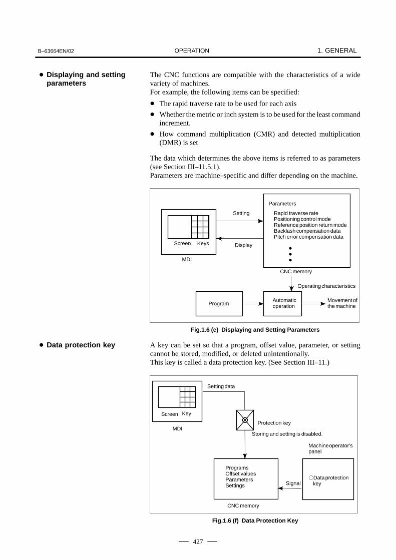
OPERATIONB–63664EN/02 1. GENERAL
427
The CNC functions are compatible with the characteristics of a widevariety of machines.For example, the following items can be specified:
� The rapid traverse rate to be used for each axis
� Whether the metric or inch system is to be used for the least commandincrement.
� How command multiplication (CMR) and detected multiplication(DMR) is set
The data which determines the above items is referred to as parameters(see Section III–11.5.1).Parameters are machine–specific and differ depending on the machine.
Setting
Screen Keys
MDI
Display
CNC memory
Parameters
Rapid traverse ratePositioning control modeReference position return modeBacklash compensation dataPitch error compensation data
�
�
�
ProgramAutomatic operation
Movement ofthe machine
Operating characteristics
Fig.1.6 (e) Displaying and Setting Parameters
A key can be set so that a program, offset value, parameter, or settingcannot be stored, modified, or deleted unintentionally.This key is called a data protection key. (See Section III–11.)
ProgramsOffset valuesParametersSettings
Setting data
Machine operator’spanel
Screen Key
�Data protection key
MDI
Signal
Protection key
Storing and setting is disabled.
CNC memory
Fig.1.6 (f) Data Protection Key
� Displaying and settingparameters
� Data protection key

OPERATION1. GENERAL B–63664EN/02
428
The contents of the program currently being executed are displayed.The program to be executed next and a list of programs are also displayed.(See Section III–11.2.1.)
PROGRAM
MEM STOP * * * * * * * 13 : 18 : 14
O1100 N00005
��
PRGRM
N1 G90 G17 G00 G41 D07 X250.0 Y550.0 ;N2 G01 Y900.0 F150 ;N3 X450.0 ;N4 G03 X500.0 Y1150.0 R650.0 ;
N6 G03 X950.0 Y900.0 R650.0 ;N7 G01 X1150.0 ;N8 Y550.0 ;N9 X700.0 Y650.0 ;N10 X250.0 Y550.0 ;N11 G00 G40 X0 Y0 ;
N5 G02 X900.0 R–250.0 ;
Active program numberActive sequence number
The cursor indicates the block that iscurrently being executed.
Program currently executed
CHECK CURRNT NEXT (OPRT)
PROGRAM DIRECTORY O0001 N00010
>_EDIT **** *** *** 16:52:13[ PRGRM ] [ DIR ] [ ] [ ] [ (OPRT) ]
PROGRAM (NUM.) MEMORY (CHAR.) USED: 60 3321
FREE: 2 429
O0240 (SHAFT XSF301 ) : ( )
Program dilectory
1.7DISPLAY
1.7.1Program Display

OPERATIONB–63664EN/02 1. GENERAL
429
The current position of the nozzle is displayed with the coordinates ineach coordinate system.The distance from the current position to the target position can also bedisplayed. (See Sections III–11.1.1 to III–11.1.3.)
Y
X
x
y
Workpiece coordinate system
* * * * * * * * * *
O0003 N00003
(OPRT)
��� 19 : 47 : 45
RUNTIME 0H41M CYCLE TIME 0H 0M22SPART COUNT ��
REL ALLABS
ACTUAL POSITION (ABSOLUTE)
X 150.000Y 300.000Z 100.000
If a problem occurs during the operation, the corresponding error code andalarm message are displayed on the screen. (See Section III–7.1.)See Appendix G for details of the error codes.
MEM STOP * * * * * * 19 : 55 : 22
O1000 N00003
��
MSG HISTRY
��� ���� � ����
ALM
ALARM
ALARM MESSAGE
1.7.2Current PositionDisplay
1.7.3Alarm Display

OPERATION1. GENERAL B–63664EN/02
430
When this option is selected, the following two items are displayed on thescreen: Run time and part count. (See Section III–11.4.4.)
X 150.000Y 300.000Z 100.000
ACTUAL POSITION (ABSOLUTE)
* * *
O0003 N00003
(OPRT)
MEM STRT 20 : 22 : 23
RUNTIME 0H16M CYCLE TIME 0H 1M 0SPARTCOUNT ��
REL ALL
FIN
ABS
Figures can be displayed on the following planes (see Section III–12):
(1)XY plane(2)YZ plane(3)XZ plane(4)Three–dimensional display
X
Z
Y
X
Three–dimensional display (isometric)
Display on the XY plane Display on the YZ plane
Display on the XZ plane
(1)
(3) (4)
X
Y
Z
Y
Z
(2)
Fig.1.7.5 Graphic Display
1.7.4Part Count Display andRun Time Display
1.7.5Graphic Display

OPERATIONB–63664EN/02 1. GENERAL
431
Programs, offset values, parameters, etc. input in CNC memory can beoutput to paper tape, cassette, or a floppy disk for saving. After onceoutput to a medium, the data can be input into CNC memory.(Refer to III–8)
Memory
Program
Offset
Parameters
Reader/puncherinterface
Portable tape reader
CNCAutomatic programming system
Floppy disk
FANUC Floppycassette adaptor
FANUC Floppy Cassette
SYSTEM P
FANUC PPR
Paper tape
.
.
.
Memory cardadapter
(incorporated CNC)
Memory card
Fig.1.8 Data Output
1.8DATA INPUT/OUTPUT

OPERATION2. OPERATIONAL DEVICES B–63664EN/02
432
2 ��������� ��� ��
The available operational devices include the setting and display unitattached to the CNC, the machine operator’s panel, and externalinput/output devices such as a Handy File.

OPERATIONB–63664EN/02 2. OPERATIONAL DEVICES
433
The setting and display units are shown in Subsections 2.1.1 to 2.1.5 ofPart III.
7.2”/8.4” LCD–mounted type CNC control unit III–2.1.1. . . . . . . . 9.5”/10.4” LCD–mounted type CNC control unit III–2.1.2. . . . . . . Stand–alone type small MDI unit III–2.1.3. . . . . . . . . . . . . . . . . . . Stand–alone type standard MDI unit III–2.1.4. . . . . . . . . . . . . . . . . Stand–alone type 61 fullkey MDI unit III–2.1.5. . . . . . . . . . . . . . .
2.1SETTING ANDDISPLAY UNITS

OPERATION2. OPERATIONAL DEVICES B–63664EN/02
434
2.1.17.2″/8.4″ LCD–mountedType CNC Control Unit
2.1.29.5″/10.4″ LCD–mountedType CNC Control Unit

OPERATIONB–63664EN/02 2. OPERATIONAL DEVICES
435
Function keys
Address/numeric keys
Shift key
Cancel (CAN) key
Input key
Edit keys
Help key
Reset key
Cursor keys
Page change keys
2.1.3Stand–alone TypeSmall MDI Unit

OPERATION2. OPERATIONAL DEVICES B–63664EN/02
436
Shift keyPage change keys
Cursor keys
Function keys
Input key
Cancel (CAN) key
Edit keys
Address/numeric keysReset keyHelp key
2.1.4Stand–alone TypeStandard MDI Unit

OPERATIONB–63664EN/02 2. OPERATIONAL DEVICES
437
Page change keysHelp key
Address/numeric keys
Cursor keys
Shift keyFunction keys
Edit keys
Cancel (CAN) key Input key
Reset key
2.1.5Stand–alone Type 61Fullkey MDI Unit

OPERATION2. OPERATIONAL DEVICES B–63664EN/02
438
Table 2.2 Explanation of the MDI keyboard
Number Name Explanation
1 RESET key Press this key to reset the CNC, to cancel an alarm, etc.
2 HELP key Press this button to use the help function when uncertain about the operation ofan MDI key (help function).In case of 160i, this key is assigned to ”Esc” key of the personal computer.
3 Soft keys The soft keys have various functions, according to the Applications. The soft keyfunctions are displayed at the bottom of the screen.
4 Address and numeric keys Press these keys to input alphabetic, numeric, and other characters.
5 SHIFT key Some keys have two characters on their keytop. Pressing the <SHIFT> keyswitches the characters. Special character Ê is displayed on the screen when acharacter indicated at the bottom right corner on the keytop can be entered.
6 INPUT key When an address or a numerical key is pressed, the data is input to the buffer,
and it is displayed on the screen. To copy the data in the key input buffer to the
offset register, etc., press the key. This key is equivalent to the [INPUT]
key of the soft keys, and either can be pressed to produce the same result.
INPUT
7 Cancel key Press this key to delete the last character or symbol input to the key input buffer.When the key input buffer displays
>N001X100Z_and the cancel key is pressed, Z is canceled and>N001X100_is displayed.
8 Program edit keys Press these keys when editing the program.
9 Function keys Press theses keys to switch display screens for each function.See lll – 2.3 for detailas of the function keys.
2.2EXPLANATION OFTHE KEYBOARD
RESET
HELP
(N 4 …
SHIFT
INPUT
CAN
CAN
ALTER INSERT DELETE: Alteration (In case of 160i, this key is assigned to ”Tab” key
of the personal computer.)
: Insertion
: Deletion
ALTER
DELETE
INSERT
…POS PROG

OPERATIONB–63664EN/02 2. OPERATIONAL DEVICES
439
Table 2.2 Explanation of the MDI keyboard
Number ExplanationName
10 Cursor move keys There are four different cursor move keys.
: This key is used to move the cursor to the right or in the forwarddirection. The cursor is moved in short units in the forward direction.
: This key is used to move the cursor to the left or in the reversedirection. The cursor is moved in short units in the reverse direction.
: This key is used to move the cursor in a downward or forward direction. The cursor is moved in large units in the forward direction.
: This key is used to move the cursor in an upward or reverse direction.
The cursor is moved in large units in the reverse direction.
11 Page change keys Two kinds of page change keys are described below.
: This key is used to changeover the page on the screen in the forward direction.
: This key is used to changeover the page on the screen in thereverse direction.
PAGE
PAGE
PAGE
PAGE

OPERATION2. OPERATIONAL DEVICES B–63664EN/02
440
The function keys are used to select the type of screen (function) to bedisplayed. When a soft key (section select soft key) is pressedimmediately after a function key, the screen (section) corresponding to theselected function can be selected.
1 Press a function key on the MDI panel. The chapter selection softkeys that belong to the selected function appear.
2 Press one of the chapter selection soft keys. The screen for theselected chapter appears. If the soft key for a target chapter is notdisplayed, press the continuous menu key (next–menu key).In some cases, additional chapters can be selected within a chapter.
3 When the target chapter screen is displayed, press the operationselection key to display data to be manipulated.
4 To redisplay the chapter selection soft keys, press the return menukey.
The general screen display procedure is explained above. However,the actual display procedure varies from one screen to another. Fordetails, see the description of individual operations.
2.3FUNCTION KEYS ANDSOFT KEYS
2.3.1General ScreenOperations
OFFSET
SETTINGPROGPOS
SYSTEM GRAPHMESSAGE
Function keys
(OPRT)
Chapter selectionsoft keys Operation
selectionkey
Return menu key Continuous menu key
CUSTOM

OPERATIONB–63664EN/02 2. OPERATIONAL DEVICES
441
Function keys are provided to select the type of screen to be displayed.The following function keys are provided on the MDI panel:
Press this key to display the position screen.
Press this key to display the program screen.
Press this key to display the offset/setting screen and laser settingscreen.
Press this key to display the system screen.
Press this key to display the message screen.
Press this key to display the graphics screen.
Press this key to display the custom screen (conversational macroscreen).In case of 160i, this key is assigned to “Ctrl” key of the personal computer.
In case of 160i, this key is assigned to “Alt” key of the personal computer.
2.3.2Function Keys
POS
PROG
OFFSET
SETTING
SYSTEM
MESSAGE
GRAPH
CUSTOM

OPERATION2. OPERATIONAL DEVICES B–63664EN/02
442
To display a more detailed screen, press a function key followed by a softkey. Soft keys are also used for actual operations.The following illustrates how soft key displays are changed by pressingeach function key.
: Indicates a screen that can be displayed by pressing afunction key(*1)
: Indicates a soft key(*2)
: Indicates input from the MDI panel.
: Indicates a soft key displayed in green.
: Indicates the continuous menu key (rightmost soft key)(*3).
� �
� �
� �
The symbols in the following figures mean as shown below :
: Indicates screens
*1 Press function keys to switch between screens that are used frequently.
*2 Some soft keys are not displayed depending on the optionconfiguration.
*3 In some cases, the continuous menu key is omitted when the 12 softkeys display unit is used.
2.3.3Soft Keys

OPERATIONB–63664EN/02 2. OPERATIONAL DEVICES
443
Monitor screen
[(OPRT)] [PTSPRE] [EXEC]
[RUNPRE] [EXEC]
[ABS]
Absolute coordinate display
POS
[(OPRT)][REL] ����� �� ������ �
�ORIGIN�
[PRESET]
[ALLEXE]
(Axis name) [EXEC]
[PTSPRE] [EXEC]
[RUNPRE] [EXEC]
[ALL]
[HNDL]
[MONI]
!�"# $�% #�����#��� #��&&���' (% #)� "��*#��� $�% POSPOSITION SCREEN
Relative coordinate display
Current position display
Handle interruption
[(OPRT)] ����� �� ������ �
�ORIGIN�
[PRESET]
[ALLEXE]
(Axis name) [EXEC]
[PTSPRE] [EXEC]
[RUNPRE] [EXEC]
[WORK] [ALLEXE][EXEC](Axis name, 0)
[(OPRT)] [PTSPRE] [EXEC]
[RUNPRE] [EXEC]
[(OPRT)] [PTSPRE] [EXEC]
[RUNPRE] [EXEC]

OPERATION2. OPERATIONAL DEVICES B–63664EN/02
444
[ABS]
[(OPRT)] [BG–EDT][O SRH]
[PRGRM]
Program display screen
PROG
!�"# $�% #�����#��� #��&&���' (% #)� "��*#��� $�%
�� #)� ��� ��'�PROG
[N SRH][REWIND]
See “When the soft key [BG–EDT] is pressed”
[(OPRT)][CHECK]
Program check display screen
[REL]
Current block display screen
[(OPRT)] [BG–EDT][CURRNT]
Next block display screen
[(OPRT)] [BG–EDT][NEXT]
Program restart display screen
[(OPRT)] [BG–EDT][RSTR]
���
(O number)(N number)
PROGRAM SCREEN
See “When the soft key [BG–EDT] is pressed”
See “When the soft key [BG–EDT] is pressed”
See “When the soft key [BG–EDT] is pressed”
[F SRH]
[P TYPE][Q TYPE]
[CAN][EXEC]
[BG–EDT][O SRH][N SRH]
[REWIND]
See “When the soft key [BG–EDT] is pressed”(O number)(N number)
[F SRH]
[P TYPE][Q TYPE]
[CAN][EXEC]
(2)(Continued on the next page)
1/2
(N number)
(N number)

OPERATIONB–63664EN/02 2. OPERATIONAL DEVICES
445
[FL.SDL] [PRGRM]
File directory display screen
[(OPRT)][DIR] [SELECT][EXEC](number) [F SET]
Schedule operation display screen
[(OPRT)][SCHDUL] [CLEAR]
(Schedule data)
[CAN][EXEC]
[INPUT]
Return to ��� (Program display)
(2)2/2

OPERATION2. OPERATIONAL DEVICES B–63664EN/02
446
1/2
[(OPRT)] [BG–EDT](O number) [O SRH]
[PRGRM]
Program display
PROG
(Address) [SRH↓]
[REWIND](Address) [SRH↑]
[F SRH] [CAN](N number) [EXEC]
[READ] [CHAIN][STOP][CAN]
[EXEC][PUNCH] [STOP]
[CAN][EXEC]
[DELETE] [CAN][EXEC]
[EX–EDT] [COPY] [CRSR∼][∼CRSR][∼BTTM][ALL]
[MOVE] [CRSR∼][∼CRSR][∼BTTM][ALL]
[MERGE] [∼CRSR][∼BTTM]
[CHANGE] (Address) [BEFORE]
(Address) [AFTER] [SKIP][1–EXEC][EXEC]
(1)(Continued on the next page)
(The cursor moves to the end of a program.)
(O number)
(O number)
(N number)
!�"# $�% #�����#��� #��&&���' (% #)� "��*#��� $�%
�� #)� ���+ ��'�
PROGPROGRAM SCREEN
(O number) [EXEC]
(O number) [EXEC]
(O number) [EXEC]
!��,-)�� #)� ��"# $�% �.� ��+� �� /�����',

OPERATIONB–63664EN/02 2. OPERATIONAL DEVICES
447
(1)2/2
[(OPRT)] [BG–EDT](O number) [O SRH]
[LIB]
Program directory display
[READ] [CHAIN][STOP][CAN]
[EXEC][PUNCH] [STOP]
[CAN][EXEC]
(O number)
(O number)
�#��� #� #)� /��&���
!��,-)�� #)� ��"# $�% �.� ��+� �� /�����',
[F SRH][CAN][EXEC]
[READ]
[STOP][CAN]
[PUNCH]
[F SET]
[F SET]
[EXEC]
[O SET]
[STOP][CAN]
[F SET]
[EXEC]
[O SET]
[DELETE][CAN]
[F SET]
Floppy directory display
[FLOPPY][DIR] ( number)
(O number)
(number)(O number)
[PRGRM][(OPRT)]
�#��� #� #)� /��&���
(number)
(number)
[EXEC]

OPERATION2. OPERATIONAL DEVICES B–63664EN/02
448
[(OPRT)] [BG–EDT][PRGRM]
Program display
PROG
!�"# $�% #�����#��� #��&&���' (% #)� "��*#��� $�%
�� #)� ��� ��'�
PROGPROGRAM SCREEN
[(OPRT)] [BG–EDT][MDI]
Program input screen
(Address)(Address)
[SRH↓][SRH↑]
Current block display screen
[(OPRT)] [BG–EDT][CURRNT]
Next block display screen
[(OPRT)] [BG–EDT][NEXT]
Program restart display screen
[(OPRT)] [BG–EDT][RSTR]
See “When the soft key [BG–EDT] is pressed”
See “When the soft key [BG–EDT] is pressed”
See “When the soft key [BG–EDT] is pressed”
See “When the soft key [BG–EDT] is pressed”
See “When the soft key [BG–EDT] is pressed”
[REWIND]

OPERATIONB–63664EN/02 2. OPERATIONAL DEVICES
449
[(OPRT)] [BG–EDT][PRGRM]
Program display
PROG
!�"# $�% #�����#��� #��&&���' (% #)� "��*#��� $�%
�� #)� 01�23 4��3 �� �5 ��'�
PROGPROGRAM SCREEN
Current block display screen
[(OPRT)] [BG–EDT][CURRNT]
Next block display screen
[(OPRT)] [BG–EDT][NEXT]
Program restart display screen
[(OPRT)] [BG–EDT][RSTR]
See “When the soft key [BG–EDT] is pressed”
See “When the soft key [BG–EDT] is pressed”
See “When the soft key [BG–EDT] is pressed”
See “When the soft key [BG–EDT] is pressed”
Program display
PROG
!�"# $�% #�����#��� #��&&���' (% #)� "��*#��� $�%
�� #)� +4�� �� +0�2 ��'�PROGPROGRAM SCREEN
[(OPRT)] [BG–EDT][PRGRM]
(Address)(Address)
[SRH↓][SRH↑]
(O number)
[REWIND]
[(OPRT)] [BG–EDT](O number) [O SRH]
[LIB]
Program directory display
�#��� #� #)� /��&���
See “When the soft key [BG–EDT] is pressed”
See “When the soft key [BG–EDT] is pressed”
[O SRH] �#��� #� #)� /��&���

OPERATION2. OPERATIONAL DEVICES B–63664EN/02
450
1/2
[(OPRT)] [BG–END](O number) [O SRH]
[PRGRM]
Program display
PROG
(Address) [SRH↓]
[REWIND](Address) [SRH↑]
[F SRH] [CAN](N number) [EXEC]
[READ] [CHAIN][STOP][CAN]
[EXEC][PUNCH] [STOP]
[CAN][EXEC]
[DELETE] [CAN][EXEC]
[EX–EDT] [COPY] [CRSR∼][∼CRSR][∼BTTM][ALL]
[MOVE] [CRSR∼][∼CRSR][∼BTTM][ALL]
[MERGE] [∼CRSR][∼BTTM]
[CHANGE] (Address) [BEFORE]
(Address) [AFTER] [SKIP][1–EXEC][EXEC]
(1)(Continued on the next page)
(The cursor moves to the end of a program.)
(O number)
(O number)
(N number)
!�"# $�% #�����#��� #��&&���' (% #)� "��*#��� $�%
�-)�� #)� ��"# $�% �.� ��+� �� /�����' �� � ��'���
PROGPROGRAM SCREEN
(O number) [EXEC]
(O number) [EXEC]
(O number) [EXEC]

OPERATIONB–63664EN/02 2. OPERATIONAL DEVICES
451
[(OPRT)] [BG–EDT](O number) [O SRH]
[LIB]
Program directory display
[READ] [CHAIN][STOP][CAN]
[EXEC][PUNCH] [STOP]
[CAN][EXEC]
(1)
(O number)
(O number)
[F SRH][CAN][EXEC]
[READ]
[STOP][CAN]
[PUNCH]
[F SET]
[F SET]
[EXEC]
[O SET]
[STOP][CAN]
[F SET]
[EXEC]
[O SET]
[DELETE][CAN]
[F SET]
[EXEC]
Floppy directory display
[FLOPPY][DIR]
2/2
�#��� #� #)� /��&���
(number)
(number)(O number)
(number)(O number)
(number)
[PRGRM][(OPRT)]
�#��� #� #)� /��&���

OPERATION2. OPERATIONAL DEVICES B–63664EN/02
452
[(OPRT)][OFFSET]
Tool offset screen
!�"# $�% #�����#��� #��&&���' (% #)� "��*#��� $�%
OFFSET
SETTING
(Number)(Axis name)(Numeral)(Numeral)
[NO SRH][INP.C.]
[+INPUT][INPUT]
[(OPRT)][SETING]
Setting screen
(Numeral)(Numeral)
[NO SRH]
[+INPUT][INPUT]
[ON:1][OFF:0]
[(OPRT)][WORK]
Workpiece coordinate system setting screen
(Axis, Numeral)(Numeral)
[NO SRH][MEASUR][INPUT]
(Number)
(Number)
OFFSETSETTINGOFFSET/SETTING SCREEN
[(OPRT)][MACRO]
Macro variables display screen
(Numeral)
[NO SRH]
[INPUT]
(Number)(Axis name) [INP.C.]
[CLEAR] [ALL][WEAR][GEOM]
[READ] [CAN][WEAR]
[PUNCH] [CAN][EXEC]
(1)
1/2
(Numeral) [INPUT]
[PUNCH] [CAN][EXEC]

OPERATIONB–63664EN/02 2. OPERATIONAL DEVICES
453
[OPR]
Software operator’s panel screen
2/2(1)
[MODEM]
Modem card screen
[MD.MON][MD.SET]

OPERATION2. OPERATIONAL DEVICES B–63664EN/02
454
[POWER]
Laser power display screen
!�"# $�% #�����#��� #��&&���' (% #)� "��*#��� $�%
[TRACE][SET]
Laser setting screen
[ZERO]
[STATUS]
Laser status display screen
OFFSET
SETTINGLASER SETTING SCREEN
[(OPRT)][START][END][W–AXIS]
[CUT][DATA]
Processing condition setting screen
[+INPUT][(OPRT)] (Numeral)
[INPUT][PIERCE] [(OPRT)]
[EDGE] [(OPRT)]
[3D. TRN]
Three–dimensional transform screen
[PWR.CT] [(OPRT)]
[+INPUT]
[+INPUT]
[+INPUT]
[INPUT]
[INPUT]
[INPUT]
(Numeral)
(Numeral)(Numeral)
(Numeral)(Numeral)
(Numeral)(Numeral)
OFFSET
SETTING
[PRM.CG] [(OPRT)] [+INPUT]
[INPUT]
(Numeral)(Numeral)
(1)
1/2
[AGING]

OPERATIONB–63664EN/02 2. OPERATIONAL DEVICES
455
2/2
(1)
[PW.OFS][MAINT.]
Laser maintenance screen
[CAN][(OPRT)] [PUNCH][EXEC]
[ACT.TM] [CAN][(OPRT)] [PUNCH][EXEC]
[DISCH.] [CAN][(OPRT)] [PUNCH][EXEC]
[L ALM] [CAN][(OPRT)] [PUNCH][EXEC]
[PWR FB] [+INPUT][(OPRT)] (Numeral)[INPUT](Numeral)
[PS TC] [(OPRT)] [CAN][EXEC]
[LEAK] [+INPUT][(OPRT)] (Numeral)[INPUT](Numeral)
[TUNE] [(OPRT)] [CAN][DISCH.]

OPERATION2. OPERATIONAL DEVICES B–63664EN/02
456
!�"# $�% #�����#��� #��&&���' (% #)� "��*#��� $�%
[(OPRT)][PARAM]
Parameter screen
(Numeral)(Numeral)
[NO SRH]
[+INPUT][INPUT]
[ON:1][OFF:0]
(Number)
SYSTEM
SYSTEM
[READ] [CAN][EXEC]
[PUNCH] [CAN][EXEC]
[(OPRT)][DGNOS]
Diagnosis screen
[NO SRH](Number)
[PMC]
PMC screen
1/2
SYSTEM SCREEN
[SYSTEM]
System configuration screen
(4)(Continued on the next page)

OPERATIONB–63664EN/02 2. OPERATIONAL DEVICES
457
[W.DGNS]
Waveform diagnosis screen
(4)
[W.PRM][W.GRPH] [STSRT]
[TIME→][←TIME][H–DOBL][H–HALF]
[STSRT][CH–1↑]
[V–DOBL][V–HALF]
[CH–1↓]
[STSRT][CH–2↑]
[V–DOBL][V–HALF]
[CH–2↓]
2/2
[(OPRT)][SV.PRM]
Servo parameter screen
[ON:1][OFF:0]
[SV.SET][SV.TUN]
(Numeral) [INPUT]
[SV.TRC] [(OPRT)][TRACE][TRNSF]
[(OPRT)][PITCH]
Pitch error compensation screen
(Numeral)(Numeral)
[NO SRH]
[+INPUT][INPUT]
[ON:1][OFF:0]
(No.)
[READ] [CAN][EXEC]
[PUNCH] [CAN][EXEC]

OPERATION2. OPERATIONAL DEVICES B–63664EN/02
458
!�"# $�% #�����#��� #��&&���' (% #)� "��*#��� $�%
[ALARM]
Alarm display screen
MESSAGE
MESSAGE
[MSG]
Message display screen
[HISTRY]
Alarm history screen
[(OPRT)] [CLEAR]
������� � ����
[ALARM]
!�"# $�% #�����#��� #��&&���' (% #)� "��*#��� $�%
Alarm detail screen
HELP
HELP
[OPRAT]
Operation method screen
[PARAM]
Parameter table screen
[(OPRT)] [SELECT]
���� � ����
[(OPRT)] [SELECT]

OPERATIONB–63664EN/02 2. OPERATIONAL DEVICES
459
!�"# $�% #�����#��� #��&&���' (% #)� "��*#��� $�%
[(OPRT)]
[PARAM]
Solid graphics
GRAPH
GRAPH
[BLANK] [ANEW]
[(OPRT)][3–PLN] [ ][←][→][↑][↓]
[(OPRT)][EXEC] [A.ST][F.ST][STOP][REWIND]
[+ROT][–ROT][+TILT][–TILT]
[(OPRT)][REVIEW] [ANEW][+ROT][–ROT][+TILT][–TILT]
[PARAM]
GRAPHIC SCREEN
Tool path graphics
Solid graphics
[(OPRT)]
[PARAM]
Beam path graphics
GRAPH
[EXEC] [AUTO][STSRT][STOP][REWIND][CLEAR]
[(OPRT)][ZOOM] [EXEC][←][→][↑][↓]
[POS]

OPERATION2. OPERATIONAL DEVICES B–63664EN/02
460
When an address and a numerical key are pressed, the charactercorresponding to that key is input once into the key input buffer. Thecontents of the key input buffer is displayed at the bottom of the CRTscreen. In order to indicate that it is key input data, a “>” symbol is displayedimmediately in front of it. A “_” is displayed at the end of the key inputdata indicating the input position of the next character.
Key input buffer display
[ ] [ ] [ ] [ ] [ ]
���+ �2� �67�8798
� 1���:���;�
Fig.2.3.4 Key input buffer display
To input the lower character of the keys that have two characters inscribed
on them, first press the SHIFT key and then the key in question.
When the SHIFT key is pressed, “_” indicating the next character input
position changes to “~”. Now lowercase characters can be entered (shiftstate).When a character is input in shift status the shift status is canceled.
Furthermore, if the SHIFT key is pressed in shift status, the shift status is
canceled.It is possible to input up to 32 characters at a time in the key input buffer.
Press the CAN key to cancel a character or symbol input in the key input
buffer.
(Example) When the key input buffer displays >N001X100Z_
and the cancel CAN key is pressed, Z is canceled and
>N001X100_ is displayed.
2.3.4Key Input and InputBuffer

OPERATIONB–63664EN/02 2. OPERATIONAL DEVICES
461
After a character or number has been input from the MDI panel, a data
check is executed when INPUT key or a soft key is pressed. In the case of
incorrect input data or the wrong operation a flashing warning messagewill be displayed on the status display line.
Warning messagedisplay
Display of key inputbuffer
Soft key display
Status display[ ] [ ] [ ] [ ] [ ]
���+ -�1� ����
� �
Fig.2.3.5 Warning message display
Table 2.3.5 Warning Messages
Warning message Content
FORMAT ERROR The format is incorrect.
WRITE PROTECT Key input is invalid because of data protect keyor the parameter is not write enabled.
DATA IS OUT OF RANGE The input value exceeds the permitted range.
TOO MANY DIGITS The input value exceeds the permitted numberof digits.
WRONG MODE Parameter input is not possible in any mode other than MDI mode.
EDIT REJECTED It is not possible to edit in the current CNC status.
2.3.5Warning Messages

OPERATION2. OPERATIONAL DEVICES B–63664EN/02
462
There are 12 soft keys in the 10.4″LCD/MDI or 9.5″LCD/MDI. Asillustrated below, the 5 soft keys on the right and those on the right andleft edges operate in the same way as the 7.2″LCD or 8.4″ LCD, whereasthe 5 keys on the left hand side are expansion keys dedicated to the10.4″LCD or 9.5″LCD.
ÇÇÇÇÇÇÇÇÇÇÇÇÇÇÇÇÇÇ
7.2″LCD, 8.4″ LCD soft key
10.4″LCD, 9.5″LCD dedicated expansion soft keys
Fig.2.3.6 LCD soft key configuration
10.4″LCD, 9.5″LCD soft key
Whenever a position display appears in the left half of the screen after a
function key other than POS is pressed, the soft keys on the left half of
the soft key display area are displayed as follows:
ABS REL ALL HNDL
The soft key corresponding to the position display is indicated in reversevideo.This manual may refer to 10.4″and 9.5″LCD display units as 12 soft keytypes, and 7.2″ and 8.4″ LCD display units as 7 soft key types.
2.3.6Soft Key Configuration

OPERATIONB–63664EN/02 2. OPERATIONAL DEVICES
463
Five types of external input/output devices are available. This sectionoutlines each device. For details on these devices, refer to thecorresponding manuals listed below.
Table 2.4 External I/O device
Device name UsageMax.
storagecapacity
Referencemanual
FANUC Handy File Easy–to–use, multi functioninput/output device. It is designed for FA equipmentand uses floppy disks.
3600m B–61834E
The following data can be input/output to or from external input/outputdevices:1. Programs2. Offset data3. Parameters4. Custom macro common variablesFor how data is input and output, see III–8.
2.4EXTERNAL I/ODEVICES

OPERATION2. OPERATIONAL DEVICES B–63664EN/02
464
Before an external input/output device can be used, parameters must beset as follows.
CNC
MAIN CPU BOARD OPTION–1 BOARD
Channel 1 Channel 2 Channel 3
JD5A JD5B
RS–422RS–232–CRS–232–C
JD5C JD6A
RS–232–C
Reader/puncher
Host computer
Host computer
Reader/puncher
I/O CHANNEL=0orI/O CHANNEL=1
I/O CHANNEL=2 I/O CHANNEL=3 I/O CHANNEL=3
CNC has three channels of reader/punch interfaces. The input/outputdevice to be used is specified by setting the channel connected to thatdevice in setting parameter I/O CHANNEL.The specified data, such as a baud rate and the number of stop bits, of aninput/output device connected to a specific channel must be set inparameters for that channel in advance.For channel 1, two combinations of parameters to specify the input/outputdevice data are provided.The following shows the interrelation between the reader/punch interfaceparameters for the channels.
���������

OPERATIONB–63664EN/02 2. OPERATIONAL DEVICES
465
0020 I/O CHANNEL
Specify a channel for an input/output device.
I/O CHANNEL = 0 : Channel 1 = 1 : Channel 1 = 2 : Channel 2 = 3 : Channel 3 = 4 : Memory card = 4 : interface
I/O CHANNEL=0(channel 1)
0101 Stop bit and other data
0102 Number specified forthe input/output device
0103 Baud rate
I/O CHANNEL=1(channel 1)
0111 Stop bit and other data
0112 Number specified forthe input/output device
0113 Baud rate
I/O CHANNEL=2(channel 2)
0121
0122
0123
I/O CHANNEL=3(channel 3)
0131
0132
0133
0134 Selection of protocol
0135Selection of RS–422or RS–232C, andother data
Input/output channelnumber (parameter0020)
Parameter Number
Stop bit and other data
Number specified forthe input/output deviceBaud rate
Stop bit and other data
Number specified forthe input/output deviceBaud rate
Memory Card =4interface
The Handy File is an easy–to–use, multi function floppy diskinput/output device designed for FA equipment. By operating the HandyFile directly or remotely from a unit connected to the Handy File,programs can be transferred and edited.The Handy File uses 3.5–inch floppy disks, which do not have theproblems of paper tape (i.e., noisy during input/output, easily broken, andbulky).One or more programs (up to 1.44M bytes, which is equivalent to thememory capacity of 3600–m paper tape) can be stored on one floppy disk.
RS–232–C orRS–422 Interface(Punch panel, etc.)
FANUC Handy File
RS–232–CInterface
RS–422Interface
2.4.1FANUC Handy File

OPERATION2. OPERATIONAL DEVICES B–63664EN/02
466
Procedure of turning on the power
1 Check that the appearance of the CNC machine tool is normal. (For example, check that front door and rear door are closed.)
2 Turn on the power according to the manual issued by the machinetool builder.
3 After the power is turned on, check that the position screen isdisplayed. An alarm screen is displayed if an alarm occurs uponpower–on. If the screen shown in Section III–2.5.2 is displayed, asystem failure may have occurred.
MEM STRT MTN *** 09:06:35[ ABS ] [ REL ] [ ALL ] [ HNDL ] [ OPRT ]
ACTUAL POSITION(ABSOLUTE) O1000 N00010
PART COUNT 5RUN TIME 0H15M CYCLE TIME 0H 0M38SACT.F 3000 MM/M S 0 T0000
X 123.456Y 363.233Z 0.000
Current position display (7 soft keys type)
4 Check that the fan motor is rotating.
WARNING
Until the positional or alarm screen is displayed at the poweron, do not touch them. Some keys are used for themaintenance or special operation purpose. When they arepressed, unexpected operation may be caused.
2.5POWER ON/OFF
2.5.1Turning on the Power
Procedure

OPERATIONB–63664EN/02 2. OPERATIONAL DEVICES
467
If a hardware failure or installation error occurs, the system displays oneof the following three types of screens then stops.Information such as the type of printed circuit board installed in each slotis indicated. This information and the LED states are useful for failurerecovery.
SLOT CONFIGURATION DISPLAY
0 : 003E40001 : 304642022 : 005043033 : 4 : 5 :
0 : 1 : 2 : 3 : 4 : 5 :
Physical slot number (secondary)
Information such as the module ID of an installed printed circuit board
Physical slot number (primary)
Internally–assigned slot number
Module functionTypes of printed circuit boards
For more information about the types of printed circuit boards and modulefunctions, refer to the Maintenance manual (B–63525EN).
2.5.2Screen Displayed atPower–on
Slot status display

OPERATION2. OPERATIONAL DEVICES B–63664EN/02
468
B8H1 – 01SLOT 01 (3046) : ENDSLOT 02 (3050) : Blank: Setting not completed
Module ID
Slot number
END: Setting completed
B8H1 – 01 CNC control software
SERVO : 90B0–01SUB : xxxx–xxOMM : yyyy–yyPMC : zzzz–zz
Digital servo ROM
Sub CPU (remote buffer)Order–made macro/macrocompilerPMC
The software configuration can be displayed on the system configurationscreen also. Refer to the Maintenance manual (B–63665EN) for the systemconfiguration screen.
Power Disconnection
1 Check that the LED indicating the cycle start is off on the operator’spanel.
2 Check that all movable parts of the CNC machine beam is stopping.
3 If an external input/output device such as the Handy File is connectedto the CNC, turn off the external input/output device.
4 Continue to press the POWER OFF pushbutton for about 5 seconds.
5 Refer to the machine beam builder’s manual for turning off the powerto the machine.
Screen indicatingmodule setting status
Display of softwareconfiguration
2.5.3Power Disconnection
Procedure

OPERATIONB–63664EN/02 3. MANUAL OPERATION
469
3 ������ �������
MANUAL OPERATION are six kinds as follows :3.1 Manual reference position return3.2 Jog feed3.3 Incremental feed3.4 Manual handle feed3.5 Manual absolute on and off

OPERATION3. MANUAL OPERATION B–63664EN/02
470
The nozzle is returned to the reference position as follows :The nozzle is moved in the direction specified in parameter ZMI (bit 5 ofNo. 1006) for each axis with the reference position return switch on themachine operator’s panel. The nozzle moves to the deceleration point atthe rapid traverse rate, then moves to the reference position at the FLspeed. The rapid traverse rate and FL speed are specified in parameters(No. 1420,1421, and 1425).Fourstep rapid traverse override is effective during rapid traverse.When the nozzle has returned to the reference position, the referenceposition return completion LED goes on. The nozzle generally movesalong only a single axis, but can move along three axes simultane ouslywhen specified so in parameter JAX(bit 0 of No.1002).
Rapid traverse areaRapid traverse rate(Rapid traverse overrideis effective.)
DecelerateareaFL speed
ReferencepositionDeceleration point
Procedure for Manual Reference Position Return
1 Press the reference position return switch, one of the mode selectionswithces.
2 To decerease the feedrate, press a rapid traverse override switch.When the nozzle has returned to the reference position, the referenceposition return completion LED goes on.
3 Press the feed axis and direction selection switch corresponding to theaxis and direction for reference position return. Continue pressing theswitch until the nozzle returns to the reference position. The nozzlecan be moved along three axes simultaneously when specified so inan appropriate parameter setting. The nozzle moves to thedeceleration point at the rapid traverse rate, then moves to thereference position at the FL speed set in a parameter.
4 Perform the same operations for other axes, if necessary.The above is an example. Refer to the appropriate manual provided bythe machine nozzle builder for the actual operations.
XMIRRROR IMAGE
Y Z C X2 Y2 Z2 X Y Z
PRO-GRAMSTOP
M02/ M30
MANUABS
SPINDLEORI TAP
ATCREADY MC?
ZERO POSITION
3.1MANUALREFERENCEPOSITION RETURN
REMOTE MDIMEMORYEDIT
HANDLE ZERO RETURN
TEACHJOG
MODE Procedure
10025 50F0
RAPID TRAVERSE OVERRIDE (%)
+C +Z +Y
+X–X
–C–Y –Z
RAPID
AXIS DIRECTION

OPERATIONB–63664EN/02 3. MANUAL OPERATION
471
Bit 0 (ZPR) of parameter No. 1201 is used for automatically setting thecoordinate system. When ZPR is set, the coordinate system isautomatically determined when manual reference position return isperformed. When �, � and � are set in parameter 1250, the workpiece coordinatesystem is determined so that reference point the tip of the reference nozzleis X= �, Y = �, Z = � when reference position return is performed. Thishas the same effect as specifying the following command for referenceposition return: G92X�Y�Z�;However, when options of the workpiece coordinate system is selected,it is not able to use.
Once the REFERENCE POSITION RETURN COMPLETION LEDlights at the completion of reference position return, the nozzle does notmove unless the REFERENCE POSITION RETURN switch is turnedoff.
The REFERENCE POSITION RETURN COMPLETION LED isextinguished by either of the following operations:– Moving from the reference position. – Entering an emergency stop state.
For the distance (Not in the deceleration condition) to return the nozzleto the reference position, refer to the manual issued by the machine toolbuilder.
Explanations
� Automatically setting thecoordinate system
������������
� ������ ��� ���� �����
� �� ������ !������� ���"��
���!������ ���
� �� #������� �� ���"�� ��
�� ������ !�������

OPERATION3. MANUAL OPERATION B–63664EN/02
472
In the jog mode, pressing a feed axis and direction selection switch on themachine operator’s panel continuously moves the nozzle along theselected axis in the selected direction.The jog feedrate is specified in a parameter (No.1423)The jog feedrate can be adjusted with the jog feedrate override dial.Pressing the rapid traverse switch moves the nozzle at the rapid traversefeedrate (No. 1424) regardless of the postiotion of the jog feedrateoverride dial. This function is called the manual rapid traverse. Manual operation is allowed for one axis at a time. 3 axes can be selected at a time by parameter JAX (No.1002#0).
Z
X
Y
While a switch is held down,the nozzle moves in the direc-tion specified by the switch.
Procedure for JOG feed
1 Press the jog switch, one of the mode selection switches.
2 Press the feed axis and direction selection switch corresponding to theaxis and direction the nozzle is to be moved. While the switch ispressed, the nozzle moves at the feedrate specified in a parameter (No.1423). The nozzle stops when the switch is released.
3 The jog feedrate can be adjusted with the jog feedrate override dial.
4 Pressing the rapid traverse switch while pressing a feed axis anddirection selection switch moves the nozzle at the rapid traverse ratewhile the rapid traverse switch is pressed. Rapid traverse override bythe rapid traverse override switches is effective during rapid traverse.
The above is an example. Refer to the appropriate manual providedby the machine tool builder for the actual operations.
3.2JOG FEED
MEMORY
ÂÂÂÂ
REMOTE MDIEDIT
ZERORETURN
JOGHANDLE
MODE
TEACH
+C +Z +Y
+X–X
–C–Y –Z
RAPID
AXIS DIRECTION Procedure
0 2000
JOG FEED RATE �<����
F0 50 10025
RAPID TRAVERSE
OVERRIDE (%)

OPERATIONB–63664EN/02 3. MANUAL OPERATION
473
Feedrate, time constant and method of automatic acceleration/deceleration for manual rapid traverse are the same as G00 in programmedcommand.
Changing the mode to the jog mode while pressing a feed axis anddirection selection switch does not enable jog feed. To enable jog feed,enter the jog mode first, then press a feed axis and direction selectionswitch.
If reference position return is not performed after power–on, pushingRAPID TRAVERSE button does not actuate the rapid traverse but theremains at the JOG feedrate. This function can be disabled by settingparameter RPD (No.1401#01).
Limitations
� ������������$#�������%
���� �� ��!�# ��������
� ����� � ��#��
� ��!�# �������� !���� ��
�� ������ !������� ���"��

OPERATION3. MANUAL OPERATION B–63664EN/02
474
In the incremental (INC) mode, pressing a feed axis and directionselection switch on the machine operator’s panel moves the nozzle onestep along the selected axis in the selected direction. The minimumdistance the nozzle is moved is the least input increment. Each step canbe 10, 100, or 1000 times the least input increment. This mode is effective when a manual pulse generator is notconnected.
Y
X
Z
NozzleEach time a switch ispressed, the nozzlemoves one step in thedirection specified by theswitch.
Procedure for Incremental Feed
1 Press the INC switch, one of the mode selection switches.
2 Select the distance to be moved for each step with themagnification dial�
3 Press the feed axis and direction selection switch corresponding tothe axis and direction the nozzle is to be moved. Each time aswitch is pressed, the nozzle moves one step. The feedrate is thesame as the jog feedrate.
4 Pressing the rapid traverse switch while pressing a feed axis anddirection selection switch moves the nozzle at the rapid traverse rate.Rapid traverse override by the rapid traverse override switch iseffective during rapid traverse.
The above is an example. Refer to the appropriate manual providedby the machine nozzle builder for the actual operations.
3.3INCREMENTAL FEED
X10 X100
X1 X1000
+C +Z +Y
+X–X
–C–Y –Z
RAPID
AXIS DIRECTION

OPERATIONB–63664EN/02 3. MANUAL OPERATION
475
In the handle mode, the nozzle can be minutely moved by rotating themanual pulse generator on the machine operator’s panel. Select the axisalong which the nozzle is to be moved with the handle feed axis selectionswitches.The minimum distance the nozzle is moved when the manual pulsegenerator is rotated by one graduation is equal to the least input increment.Or the distance the nozzle is moved when the manual pulse generator isrotated by one graduation can be magnified by 10 times or by one of thetwo magnifications specified by parameters (No. 7113 and 7114).
Z
X
Y
Manual pulse generator
Procedure for Manual Handle Feed
1 Press the HANDLE switch, one of the mode selection switches.
2 Select the axis along which the nozzle is to be moved by pressing ahandle feed axis selection switch.
3 Select the magnification for the distance the nozzle is to be moved bypressing a handle feed magnification switch. The minimum distancethe nozzle is moved when the manual pulse generator is rotated by onegraduation is equal to the least input increment.
4 Move the nozzle along the selected axis by rotating the handle.Rotating the handle 360 degrees moves the nozzle the distanceequivalent to 100 graduations.The above is an example. Refer to the appropriate manual providedby the machine tool builder for the actual operations.
3.4MANUAL HANDLEFEED
TEACHJOGHANDLE
MDIMEMORY REMOTE
ZERORETURN
MODE
EDIT
Manual pulse generator

OPERATION3. MANUAL OPERATION B–63664EN/02
476
Parameter JHD (bit 0 of No. 7100) enables or disables the manual handlefeed in the JOG mode.When the parameter JHD( bit 0 of No. 7100) is set 1,both manual handlefeed and incremental feed are enabled.
Parameter THD (bit 1 of No. 7100) enables or disables the manual handlefeed in the TEACH IN JOG mode.
Parameter HPF (bit 4 of No. 7100) or (No. 7117) specifies as follows:
• Parameter HPF (bit 4 of No. 7100)
Set value 0 : The feedrate is clamped at the rapid traverse rate andgenerated pulses exceeding the rapid traverse rate areignored.(The distance the nozzle is moved may not match the graduations on the manual pulse generator.)
Set value 1 : The feedrate is clamped at the rapid traverse rate andgenerated pulses exceeding the rapid traverse rate are notignored but accumulated in the CNC.(No longer rotating the handle does not immediately stopthe nozzle. The nozzle is moved by the pulses accumulated in the CNC before it stops.)
• Parameter HPF (No. 7117) (It is available when parameter HPF is 0.)
Set value 0 : The feedrate is clamped at the rapid traverse rate andgenerated pulses exceeding the rapid traverse rate areignored.(The distance the nozzle is moved may notmatch the graduations on the manual pulse generator.)
Other than 0 : The feedrate is clamped at the rapid traverse rate and generated pulses exceeding the rapid traverse rate are notignored but accumulated in the CNC until the limitspecified in parameter No. 7117 is reached.(No longer rotating the handle does not immediately stopthe nozzle. The nozzle is moved by the pulses accumulated in the CNC before it stops.)
Parameter HNGx (No. 7102 #0) switches the direction of MPG in whichthe nozzle moves along an axis, corresponding to the direction in whichthe handle of the manual pulse generator is rotated.
�&!���������
� Availability of manualpulse generator in Jogmode (JHD)
� Availability of manualpulse generator inTEACH IN JOG mode(THD)
� A command to the MPGexceeding rapid traverserate (HPF)
� Movement direction ofan axis to the rotation ofMPG (HNGX)

OPERATIONB–63664EN/02 3. MANUAL OPERATION
477
Up to three manual pulse generators can be connected, one for each axis.The three manual pulse generators can be simultaneously operated.
WARNING
Rotating the handle quickly with a large magnification suchas x100 moves the nozzle too fast. The feedrate is clampedat the rapid traverse feedrate.
NOTERotate the manual pulse generator at a rate of five rotationsper second or lower. If the manual pulse generator isrotated at a rate higher than five rotations per second, thenozzle may not stop immediately after the handle is nolonger rotated or the distance the nozzle moves may notmatch the graduations on the manual pulse generator.
������������
� Number of MPGs

OPERATION3. MANUAL OPERATION B–63664EN/02
478
Whether the distance the nozzle is moved by manual operation is addedto the coordinates can be selected by turning the manual absolute switchon or off on the machine operator’s panel. When the switch is turned on,the distance the nozzle is moved by manual operation is added to thecoordinates. When the switch is turned off, the distance the nozzle ismoved by manual operation is not added to the coordinates.
OP1
P2
Y–axis
X–axis
Manual operation
The coordinates change by the amount oftravel by manual operation.
Fig.3.5 (a) Coordinates with the switch ON
The coordinates do not change.
X2
X1
Y1
Y2
P1
P2
O1
O2
Fig.3.5 (b) Coordinates with the switch OFF
3.5MANUAL ABSOLUTEON AND OFF

OPERATIONB–63664EN/02 3. MANUAL OPERATION
479
The following describes the relation between manual operation andcoordinates when the manual absolute switch is turned on or off, using aprogram example.
G01G90
X200.0Y150.0
X100.0Y100.0F010
X300.0Y200.0
; �
; �
; �
The subsequent figures use the following notation:
Movement of the nozzle when the switch is onMovement of the nozzle when the switch is off
The coordinates after manual operation include the distance the nozzle ismoved by the manual operation. When the switch is off, therefore, sub-tract the distance the nozzle is moved by the manual operation.
Coordinates when block � has been executed after manual operation(X–axis +20.0, Y–axis +100.0) at the end of movement of block.
Y
X
(120.0 , 200.0)(220.0 , 250.0)
(200.0 , 150.0)
Switch OFF
Switch ON
(1��.0 , �00.0)
Manual operation
Coordinates when the feed hold button is pressed while block � is beingexecuted, manual operation (Y–axis + 75.0) is performed, and the cyclestart button is pressed and released.
(300.0 , 275.0)
(300.0 , 200.0)(200.0 , 150.0)(150.0 , 125.0)
(150.0 , 200.0)
(200.0 , 225.0)
Y
X
Switch OFF
Switch ON
Manual operation
Explanation
� Manual operation afterthe end of block
� ���"�� �!������� � ��� �
��# ���#

OPERATION3. MANUAL OPERATION B–63664EN/02
480
Coordinates when the feed hold button is pressed while block � is beingexecuted, manual operation (Y–axis +75.0) is performed, the control unitis reset with the RESET button, and block � is read again
(300.0 , 275.0)
(200.0,150.0)(300.0 , 200.0)
(150.0 , 200.0)(200.0,225.0)
(150.0 , 125.0)(100.0 , 100.0)
Y
XSwitch OFF
Switch ON
Manual operation
When there is only one axis in the following command, only thecommanded axis returns.
Manual operation
N2
N1
N3
N1G01X100.0Y100.0F500;N2X200.0;N3Y150.0;
Y
X(100.0 , 100.0)
(200.0 , 100.0)
(200.0 , 150.0)
Switch OFF
Switch ON
When the following commands are incremental commands, operation isthe same as when the switch is OFF.
When the switch is OFFAfter manual operation is performed with the switch OFF during cuttercompensation, automatic operation is restarted then the nozzle movesparallel to the movement that would have been performed if manualmovement had not been performed. The amount of separation equals tothe amount that was performed manually.
Manual operation
Beam path
Programmed path
Beam path aftermanual operation
� When reset after amanual operationfollowing a feed hold
� When a movementcommand in the nextblock is only one axis
� When the next moveblock is an incremental
� Manual operation duringcutter compensation

OPERATIONB–63664EN/02 3. MANUAL OPERATION
481
When the switch is ON during cutter compensationOperation of the machine upon return to automatic operation after manualintervention with the switch is ON during execution with an absolutecommand program in the cutter compensation mode will be described.The vector created from the remaining part of the current block and thebeginning of the next block is shifted in parallel. A new vector is createdbased on the next block, the block following the next block and theamount of manual movement. This also applies when manual operationis performed during cornering.
Manual operation performed in other than corneringAssume that the feed hold was applied at point PH while moving from PAto PB of programmed path PA, PB, and PC and that the nozzle wasmanually moved to PH’. The block end point PB moves to the point PB’by the amount of manual movement, and vectors VB1 and VB2 at PB alsomove to VB1’ and VB2’. Vectors VC1 and VC2 between the next two blocksPB – PC and PC – PD are discarded and new vectors VC1’ and VC2’ (VC2’= VC2 in this example) are produced from the relation between PB’ – PCand PC – PD. However, since VB2’ is not a newly calculated vector, correctoffset is not performed at block PB’ – PC. Offset is correctly performedafter PC.
VC1
VC2
PA
PD
PC
PH’
PB
VB2
VB1
VB2’
VC1’
PH
VB1’Beam path after manual operation
Programmed path(absolute command)
Manual operation
P’B
Beam path before manual operation

OPERATION3. MANUAL OPERATION B–63664EN/02
482
Manual operation during corneringThis is an example when manual operation is performed during cornering.VA2’, VB1’, and VB2’ are vectors moved in parallel with VA2, VB1 and VB2by the amount of manual movement. The new vectors are calculatedfrom VC1 and VC2. Then correct cutter compensation is performed for theblocks following Pc.
VB2
VB1
VC1
VC2
PA’
PCPB
VC1’
VA1VA2
VA2’ VA1’PH’
PH
PA
VB1’
VB2’
Beam path after manual operation
Programmed path(absolute command)
Beam path before manual operation
Manual operation
Manual operation after single block stopManual operation was performed when execution of a block wasterminated by single block stop.Vectors VB1 and VB2 are shifted by the amount of manual operation.Sub–sequent processing is the same as case a described above. An MDIoperation can also be interveneted as well as manual operation. Themovement is the same as that by manual operation.
VB2
VB1
VC1
VC2PC
PB’
VC1’
VB2’
VB1’
PB
PA
Beam path after manual operation
Manual operation
Programmed path(absolute command)
Beam path before manual operation

OPERATIONB–63664EN/02 4. AUTOMATIC OPERATION
483
4 ����� �������
Programmed operation of a CNC machine tool is referred to as automaticoperation.This chapter explains the following types of automatic operation:
• MEMORY OPERATIONOperation by executing a program registered in CNC memory
• MDI OPERATIONOperation by executing a program entered from the MDI panel
� DNC operationOperation while reading a program from an input/output device
� SIMULTANEOUS INPUT/OUTPUTProgram execution and memory registration can be performedsimultaneously.
• PROGRAM RESTARTRestarting a program for automatic operation from an intermediatepoint
• SCHEDULING FUNCTIONScheduled operation by executing programs (files) registered in anexternal input/output device (Handy File, FLOPPY CASSETTE, orFA Card)
• SUBPROGRAM CALL FUNCTIONFunction for calling and executing subprograms (files) registered in anexternal input/output device (Handy File, Floppy Cassette, or FACard) during memory operation
• MANUAL HANDLE INTERRUPTIONFunction for performing manual feed during movement executed byautomatic operation
• MIRROR IMAGEFunction for enabling mirror–image movement along an axis duringautomatic operation
• RETRACE FUNCTIONFunction for moving the nozzle in the reverse direction to retrace thepath followed, and for moving the nozzle in the forward directionagain along the retraced path.
• MANUAL INTERVENTION AND RETURNFunction restarting automatic operation by returning the nozzle to theposition where manual intervention was started during automaticoperation
• Retreat and retry functionsThis function enables machining to be restarted from the start block.

OPERATION4. AUTOMATIC OPERATION B–63664EN/02
484
Programs are registered in memory in advance. When one of theseprograms is selected and the cycle start switch on the machine operator’spanel is pressed, automatic operation starts, and the cycle start LED goeson.When the feed hold switch on the machine operator’s panel is pressedduring automatic operation, automatic operation is stopped temporarily.When the cycle start switch is pressed again, automatic operation isrestarted.
When the RESET key on the MDI panel is pressed, automatic operation
terminates and the reset state is entered.The following procedure is given as an example. For actual operation,refer to the manual supplied by the machine tool builder.
Procedure for Memory Operation
1 Press the MEMORY mode selection switch.
2 Select a program from the registered programs. To do this, follow thesteps below.
2–1 Press PROG to display the program screen.
2–2 Press address O .
2–3 Enter a program number using the numeric keys.
2–4 Press the [O SRH] soft key.
3 Press the cycle start switch on the machine operator’s panel.Automatic operation starts, and the cycle start LED goes on. Whenautomatic operation terminates, the cycle start LED goes off.
4 To stop or cancel memory operation midway through, follow thesteps below.
a. Stopping memory operationPress the feed hold switch on the machine operator’s panel. Thefeed hold LED goes on and the cycle start LED goes off. Themachine responds as follows:
(i) When the machine was moving, feed operation deceleratesand stops.
(ii) When dwell was being performed, dwell is stopped.
(iii) When M, T was being executed, the operation is stopped afterM, T is finished.
When the cycle start switch on the machine operator’s panel ispressed while the feed hold LED is on, machine operation restarts.
b. Terminating memory operation
Press the RESET key on the MDI panel.
Automatic operation is terminated and the reset state is entered. When a reset is applied during movement, movement deceleratesthen stops.
4.1MEMORYOPERATION
Procedure

OPERATIONB–63664EN/02 4. AUTOMATIC OPERATION
485
After memory operation is started, the following are executed:
(1) A one–block command is read from the specified program.
(2) The block command is decoded.
(3) The command execution is started.
(4) The command in the next block is read.
(5) Buffering is executed. That is, the command is decoded to allowimmediate execution.
(6) Immediately after the preceding block is executed, execution of thenext block can be started. This is because buffering has beenexecuted.
(7) Hereafter, memory operation can be executed by repeating thesteps (4) to.(6)
Memory operation can be stopped using one of two methods: Specify astop command, or press a key on the machine operator’s panel.
– The stop commands include M00 (program stop), M01 (optionalstop), and M02 and M30 (program end).
– There are two keys to stop memory operation: The feed hold keyand reset key.
Memory operation is stopped after a block containing M00 is executed.When the program is stopped, all existing modal information remainsunchanged as in single block operation. The memory operation can berestarted by pressing the cycle start button. Operation may varydepending on the machine tool builder. Refer to the manual supplied bythe machine tool builder.
Similarly to M00, memory operation is stopped after a block containingM01 is executed. This code is only effective when the Optional Stopswitch on the machine operator’s panel is set to ON. Operation may varydepending on the machine tool builder. Refer to the manual supplied bythe machine tool builder.
When M02 or M30 (specified at the end of the main program) is read,memory operation is terminated and the reset state is entered.In some machines, M30 returns control to the top of the program. Fordetails, refer to the manual supplied by the machine tool builder.
When Feed Hold button on the operator’s panel is pressed during memoryoperation, the nozzle decelerates to a stop at a time.
Automatic operation can be stopped and the system can be made to the
reset state by using RESET key on the MDI panel or external reset signal.
When reset operation is applied to the system during a nozzle movingstatus, the motion is slowed down then stops.
When the optional block skip switch on the machine operator’s panel isturned on, blocks containing a slash (/) are ignored.
A file (subprogram) in an external input/output device such as a FloppyCassette can be called and executed during memory operation. Fordetails, see Section 4.7.
Explanation
Memory operation
Stopping and terminatingmemory operation
� ������� ���! (�'')
� �!������ ���! (�'()
� ������� ��#
)�'*+ �,')
� -��# ���#
� �����
� Optional block skip
Calling a subprogramstored in an externalinput/output device

OPERATION4. AUTOMATIC OPERATION B–63664EN/02
486
In the MDI mode, a program consisting of up to 10 lines can be createdin the same format as normal programs and executed from the MDI panel.MDI operation is used for simple test operations.The following procedure is given as an example. For actual operation,refer to the manual supplied by the machine tool builder.
Procedure for MDI Operation
1 Press the MDI mode selection switch.
2 Press the PROG function key on the MDI panel to select the program
screen. The following screen appears:
O0010 N00002PROGRAM ( MDI )
MDI * * * * * * * * * * 20 : 40 : 05
PRGRM CURRNT NEXT (OPRT)
O0000;
G00 G90 G94 G40 G80 G50 G54 G69G17 G22 G21 G49 G98 G67 G64 G15
B H MT DF S
>_
MDI
Program number O0000 is entered automatically.
3 Prepare a program to be executed by an operation similar to normalprogram editing. M99 specified in the last block can return control tothe beginning of the program after operation ends. Word insertion,modification, deletion, word search, address search, and programsearch are available for programs created in the MDI mode. Forprogram editing, see III–9.
4 To entirely erase a program created in MDI mode,use one of thefollowing methods:
a. Enter address O , then press the DELETE key on the MDI panel.
b. Alternatively, press the RESET key. In this case, set bit 7 of
parameter MCL No. 3203 to 1 in advance.
4.2MDI OPERATION
Procedure

OPERATIONB–63664EN/02 4. AUTOMATIC OPERATION
487
5 To execute a program, set the cursor on the head of the program. (Startfrom an intermediate point is possible.) Push Cycle Start button onthe operator’s panel. By this action, the prepared program will start.When the program end (M02, M30) or ER(%) is executed, theprepared program will be automatically erased and the operation willend.By command of M99, control returns to the head of the preparedprogram.
O0001 N00003
MDI * * * * * * * * * * 12 : 42 : 39
PRGRM CURRNT NEXT (OPRT)
PROGRAM ( MDI )G00 X100.0 Y200. ;
M03 ;G01 Z120.0 F500 ;M93 P9010 ;G00 Z0.0 ;%
G00 G90 G94 G40 G80 G50 G54 G69G17 G22 G21 G49 G98 G67 G64 G15
B H MT DF S
>_
O0000
MDI
6 To stop or terminate MDI operation in midway through, follow thesteps below.
a. Stopping MDI operationPress the feed hold switch on the machine operator’s panel. Thefeed hold LED goes on and the cycle start LED goes off. Themachine responds as follows:
(i) When the machine was moving, feed operation deceleratesand stops.
(ii) When dwell was being performed, dwell is stopped.
(iii) When M, T was being executed, the operation is stopped afterM, T is finished.
When the cycle start switch on the machine operator’s panel ispressed, machine operation restarts.
b. Terminating MDI operation
Press the RESET key on the MDI panel.
Automatic operation is terminated and the reset state is entered. When a reset is applied during movement, movement deceleratesthen stops.

OPERATION4. AUTOMATIC OPERATION B–63664EN/02
488
The previous explanation of how to execute and stop memory operationalso applies to MDI operation, except that in MDI operation, M30 doesnot return control to the beginning of the program (M99 performs thisfunction).
Programs prepared in the MDI mode will be erased in the following cases:
� In MDI operation, if M02, M30 or ER(%) is executed.(If bit 6 (MER) of parameter No. 3203 is set to 1, however, theprogram is erased when execution of the last block of the programis completed by single–block operation.)
� In MEMORY mode, if memory operation is performed.
� In EDIT mode, if any editing is performed.
� Background editing is performed.
� Upon reset when bit 7 (MCL) of parameter No. 3203 is set to 1
After the editing operation during the stop of MDI operation was done,operation starts from the current cursor position.
A program can be edited during MDI operation. The editing of a program,however, is disabled until the CNC is reset, when bit 5 (MIE) of parameterNo. 3203 is set accordingly.
Programs created in MDI mode cannot be registered.
A program can have as many lines as can fit on one page of the screen.A program consisting of up to six lines can be created. When parameterMDL (No. 3107 #7) is set to 0 to specify a mode that suppresses thedisplay of continuous–state information, a program of up to 10 lines canbe created.If the created program exceeds the specified number of lines, % (ER) isdeleted (prevents insertion and modification).
Calls to subprograms (M98) can be specified in a program created in theMDI mode. This means that a program registered in memory can becalled and executed during MDI operation. In addition to the mainprogram executed by automatic operation, up to two levels of subprogramnesting are allowed (when the custom macro option is provided, up to fourlevels are allowed).
Main program Subprogram
One–level nesting Two–level nesting
O0000;
M98P 1000;
M30;
O1000; O2000;
M98P M98P2000; 3000;
M99; M99;
Subprogram
Fig.4.2 Nesting Level of Subprograms Called from the MDI Program
Explanation
� ������� ��� !������
� �������
� Editing a program duringMDI operation
Limitations
� Program registration
� Number of lines in a program
� Subprogram nesting

OPERATIONB–63664EN/02 4. AUTOMATIC OPERATION
489
When the custom macro option is provided, macro programs can also becreated, called, and executed in the MDI mode. However, macro callcommands cannot be executed when the mode is changed to MDI modeafter memory operation is stopped during execution of a subprogram.
When a program is created in the MDI mode, an empty area in programmemory is used. If program memory is full, no programs can be createdin the MDI mode.
� ����� ����
� �����. ����

OPERATION4. AUTOMATIC OPERATION B–63664EN/02
490
By activating automatic operation during the DNC operation mode(RMT), it is possible to perform machining (DNC operation) while aprogram is being read in via reader/puncher interface, or remote buffer.If the floppy cassette directory display option is available, it is possibleto select files (programs) saved in an external input/output unit of a floppyformat (Handy File, FLOPPY CASSETTE, or FA card) and specify(schedule) the sequence and frequency of execution for automaticoperation. (see III–4.4)To use the DNC operation function, it is necessary to set the parametersrelated to the reader/punch interface, and remote buffer in advance.The following procedure is an example. For actual operation, see themanual provided by the machine tool builder.
DNC OPERATION
1 Search for the program (file) to be executed.
2 Press the REMOTE switch on the machine operator’s panel to setRMT mode, then press the cycle start switch. The selected file isexecuted. For details of the use of the REMOTE switch, refer to therelevant manual supplied by the machine tool builder.
PROGRAM CHECK O0001 N00020
N020 X100.0 Z100.0 (DNC–PROG) ;N030 X200.0 Z200.0 ;N050 X400.0 Z400.0 ;
(RELATIVE) (DIST TO GO) G00 G17 G90 X 100.000 X 0.000 G22 G94 G21 Y 100.000 Y 0.000 G41 G49 G80 Z 0.000 Z 0.000 G98 G50 G67 A 0.000 A 0.000 B C 0.000 C 0.000 H M HD.T NX.T D M F S M ACT.F SACT REPEAT RMT STRT MTN *** 21:20:05 [ ABS ] [ REL ] [ ] [ ] [ (OPRT) ]
� Program check screen(Seven soft keys type)
4.3DNC OPERATION
�����#"��

OPERATIONB–63664EN/02 4. AUTOMATIC OPERATION
491
PROGRAM O0001 N00020
N020 X100.0 Z100.0 (DNC–PROG) ;N030 X200.0 Z200.0 ;N040 X300.0 Z300.0 ;N050 X400.0 Z400.0 ;N060 X500.0 Z500.0 ;N070 X600.0 Z600.0 ;N080 X700.0 Z400.0 ;N090 X800.0 Z400.0 ;N100 x900.0 z400.0 ;N110 x1000.0 z1000.0 ;N120 x800.0 z800.0 ;
RMT STRT MTN *** 21:20:05 [ PRGRM ] [ CHECK ] [ ] [ ] [ (OPRT) ]
� Program screen(Seven soft keys type)
PROGRAM
N020 X100.0 (DNC–PROG) ;N030 X90.0 ;N040 X80.0 ;N050 X70.0 ;N060 X60.0 ;N070 X50.0 ;N080 X40.0 ;N090 X30.0 ;N100 X20.0 ;N110 X10.0 ;N120 X0.0 ;N130 Z100.0 ;N140 Z90.0 ;N150 Z80.0 ;N160 Z70.0 ;N170 Z60.0 ;
=
F0001 N00020
N180 Z50.0 ;N190 Z40.0 ;N200 Z30.0 ;N210 Z20.0 ;N220 Z10.0 ;N230 Z0.0 ;N240 M02 ;%
RMT STRT MTN *** 22:23:24
� Program screen(Twelve soft keys type)
PRGRM CHECK (OPRT)
During DNC operation, the program currently being executed isdisplayed on the program check screen and program screen.The number of displayed program blocks depends on the program beingexecuted.Any comment enclosed between a control–out mark (() and control–inmark ()) within a block is also displayed.
� During DNC operation, sub programs stored in memory can be called.
� During DNC operation, macro programs stored in memory can becalled.
Explanations

OPERATION4. AUTOMATIC OPERATION B–63664EN/02
492
In program display, no more than 256 characters can be displayed.Accordingly, character display may be truncated in the middle of a block.
In DNC operation, M198 cannot be executed. If M198 is executed, P/Salarm No. 210 is issued.
In DNC operation, custom macros can be specified, but no repeatinstruction and branch instruction can be programmed. If a repeatinstruction or branch instruction is executed, P/S alarm No. 123 is issued.When reserved words (such as IF, WHILE, COS, and NE) used withcustom macros in DNC operation are displayed during program display,a blank is inserted between adjacent characters.
Example[During DNC operation]
#102=SIN[#100] ; → #102 = S I N[#100] ;IF[#100NE0]GOTO5 ; → I F[#100NE0] G O T O 5 ;
When control is returned from a subprogram or macro program to thecalling program during DNC operation, it becomes impossible to use areturn command (M99P****) for which a sequence number is specified.
Number Message Contents
086 DR SIGNAL OFF When entering data in the memory byusing Reader / Puncher interface, theready signal (DR) of reader / puncherwas turned off.Power supply of I/O unit is off or cable isnot connected or a P.C.B. is defective.
123 CAN NOT USE MACROCOMMAND IN DNC
Macro control command is used duringDNC operation.Modify the program.
210 CAN NOT COMANDM198/M199
Or M198 is executed in the DNC opera-tion. Modify the program.
Limitations
� Limit on number ofcharacters
� M198 (command forcalling a program fromwithin an externalinput/output unit)
� Custom macro
� M99
Alarm

OPERATIONB–63664EN/02 4. AUTOMATIC OPERATION
493
While an automation operation is being performed, a program input froman I/O device connected to the reader/punch interface can be executed andthe program can be registered in memory at the same time.In addition, a program can be output through the reader/punch interfacewhile the program registered in memory being executed.
Simultaneous Input/Output
1 Search for the program (file) to be output and executed.
2 Press the REMOTE switch on the machine operator’s panel to setRMT mode. For details of the use of the REMOTE switch, refer to therelevant manual supplied by the machine tool builder.
3 Set the simultaneous output operation mode select signal to 1.
4 Press the cycle start switch.
5 Program output and execution is performed on a block–by–blockbasis.
PROGRAM CHECK F0001 N00100
N100 X100. Y100. ;N200 G01 X50. Y50. ;N300 G00 X0 Y0 ;
(RELATIVE) (DIST TO GO) G00 G17 G90 X 100.000 X 0.000 G22 G94 G21 Y 100.000 Y 0.000 G40 G49 G80 Z 0.000 Z 0.000 G98 G50 G67 A 0.000 A 0.000 B C 0.000 C 0.000 H M HD.T NX.T D M F S M ACT.F SACT REPEAT RMT STRT MTN *** 21:20:05 [ ABS ] [ REL ] [ ] [ ] [ (OPRT) ]
Program check screen
When a program is displayed, three blocks are displayed: the blockcurrently being executed and the next two to be executed. When the singleblock function is selected, only the block currently being executed isdisplayed.Any comment enclosed between a control–out mark (() and control–inmark ()) within a block is not displayed.
1 Search for the program (file) to be output and executed.
2 Press the REMOTE switch on the machine operator’s panel to setRMT mode. For details of the use of the REMOTE switch, refer to therelevant manual supplied by the machine tool builder.
3 Set the simultaneous output operation mode select signal to 1.
4 Press the cycle start switch.
5 Program output and execution is performed on a block–by–blockbasis.
4.4SIMULTANEOUSINPUT/OUTPUT
�����#"��
� Basic simultaneous input procedure
� Basic simultaneous outputprocedure

OPERATION4. AUTOMATIC OPERATION B–63664EN/02
494
M198 cannot be executed in the input, output and run simultaneous mode.An attempt to do so results in alarm No. 210.
A macro control command cannot be executed in the input, output and runsimultaneous mode. An attempt to do so results in P/S alarm No. 123.
If an alarm condition occurs during the input, output and run simultaneousmode, a block being processed when the alarm condition occurs and allblocks before that are input or output.
In the output and run simultaneous mode, if a device used is a floppy diskdrive or FA card, the file name is the execution program number.
When a program is being executed in the output and run simultaneousmode, if a subprogram is called, only the main program is output.
Number Message Contents
123CAN NOT USE MACROCOMMAND IN DNC
Macro control command is used duringDNC operation.Modify the program.
210CAN NOT COMMANDM198/M199
M198 or M199 is executed in the DNCoperation. M198 is executed in theDNC operation. Modify the program.
222DNC OP. NOT AL-LOWED IN BG.–EDIT
Input and output are executed at a timein the background edition.Execute a correct operation.
Limitations
� M198 (command forcalling a program fromwithin an externalinput/output unit)
� Macro control command
� Alarm
� File name
� Sub program call
Alarm

OPERATIONB–63664EN/02 4. AUTOMATIC OPERATION
495
When you want to restart the machining operation after a day off, you canuse this function. Machining can be restarted from the target block byspecifying the sequence or block number of that block.This function can also be used as a high–speed program check function.There are three restart methods: the P–type, Q–type, andlaser–specification methods.
P typeFS0–L type
Machining can be restarted from any point.
Programmed start point(processing start point)
Restart position
Return operation
Q type Before machining is restarted, the machine must bemoved to the programmed start point (processing startpoint).
Programmed start point (processing start point)
Restartposition
Return operation
4.5PROGRAM RESTART

OPERATION4. AUTOMATIC OPERATION B–63664EN/02
496
Procedure for program restart by specifying a sequence number (P and Q types)
1 Retract the nozzle and perform the required operations (such asreplacement of the nozzle). Change the offset value if required. (Go toProcedure 2.)[Q type]
1 When the power is turned on or an emergency stop is released,perform the required operations at that time, including referenceposition return.
2 Move the machine manually to the programmed start point(processing start point) and set the modal data and coordinate systemin the same conditions as those at the processing start.
3 If required, change the offset value. (Go to Procedure 2.)
1 Set the program restart switch on the machine operator’s panel to theON position.
2 Press the PROG function key to display the program to be restarted.
3 Find the start of the program.
4 Enter the sequence number of the block from which the program is tobe restarted, then press the [P TYPE] or [Q TYPE] soft key.
When the same sequence number appears more than once, thelocation of the target sequence number must be specified. Specify thecount before the sequence number.
Procedure 1
[ P TYPE ]
[ Q TYPE ]
Procedure 2
[Common to P and Q types]
N �����
Sequence number
[Q TYPE]
or
[P TYPE]
N
Sequence number
[Q TYPE]
or
[P TYPE]Count
��� �����

OPERATIONB–63664EN/02 4. AUTOMATIC OPERATION
497
5 A search is made for the sequence number, and the program restartscreen appears on the screen.
PROGRAM RESTART
DESTINATIONX 57. 096Y 56. 877Z 56. 943
M 1 21 21 21 21 21 * * * * * * * *
* * * * * * * ** * * * * * * *
T * * * * * * * ** * * * * * * *
S * * * * *
O0002 0N0100
S 0 T0000
MEM * * * * * * * * * * 10 : 10 : 40
FL.SDL (OPRT)RSTR
DISTANCE TO GO1 X 1. 4592 Y 10. 3093 Z 7. 320
DESTINATION indicates the position at which processing is to restart.DISTANCE TO GO indicates the distance from the current nozzleposition to the position where processing is to restart. The number to theleft of each axis name indicates the order of the axis (determined byparameter setting) along which the nozzle moves to the restart position.The coordinates and amount of travel for restarting the program can bedisplayed for up to five axes. If your system supports six or more axes,pressing the [RSTR] soft key again displays the data for the sixth andsubsequent axes. (The program restart screen displays only the data forCNC–controlled axes.)M: Fourteen most recently specified M codesT: Two most recently specified T codesB: Most recently specified B codeCodes are displayed in the order in which they are specified. All codesare cleared by a program restart command or cycle start in the reset state.
6 Set the program restart switch to the OFF position. At this time, thenumber to the left of each axis name under DISTANCE TO GOblinks.
7 Check the screen for the M, T, and B codes to be executed. When M,T, and B codes are to be executed, place the CNC in MDI mode, thenexecute the M, T, and B functions in MDI mode. After execution,restore the CNC to the previous mode. These codes are not displayedon the program restart screen.
8 Check that the distance indicated under DISTANCE TO GO iscorrect. Also check whether the nozzle will hit the workpiece or otherobject when it moves to the processing restart position. If the nozzlewill hit an object, move the nozzle manually to a position from whichthe nozzle can move to the processing restart position withoutencountering any obstacles.
9 Press the cycle start button. The nozzle moves to the processingrestart position at the dry run feedrate sequentially along axes in theorder specified by parameter settings (No. 7310). Processing is thenrestarted.

OPERATION4. AUTOMATIC OPERATION B–63664EN/02
498
Procedure for program restart by specifying a block number (P and Q types)
1 Retract the nozzle and perform the required operations (such asreplacement of the nozzle). Change the offset value if required. (Go toProcedure 2.)
1 When the power is turned on or an emergency stop is released,perform the required operations at that time, including referenceposition return.
2 Move the machine manually to the programmed start point(processing start point) and set the modal data and coordinate systemunder the same conditions as those at processing start.
3 If required, change the offset value. (Go to Procedure 2.)
1 Set the program restart switch on the machine operator’s panel to theON position.
2 Press the PROG function key to display the program to be restarted.
3 Find the start of the program. Press the RESET key.
4 Enter the number of the block from which the program is to berestarted, then press the [P TYPE] or [Q TYPE] soft key. The blocknumber can consist of up to eight digits.
Procedure 1
[ P TYPE ]
[ Q TYPE ]
Procedure 2
[Common to P and Q types]
. � � � � � � � �
Block number
[P TYPE]
or
[Q TYPE]

OPERATIONB–63664EN/02 4. AUTOMATIC OPERATION
499
5 A search in made for the block number, and the program restart screenappears on the screen.
PROGRAM RESTART
DESTINATIONX 57. 096Y 56. 877Z 56. 943
DISTANCE TO GOX 1. 459Y 10. 309Z 7. 320
M 1 21 21 21 21 21 * * * * * * * *
* * * * * * * ** * * * * * * *
T * * * * * * * ** * * * * * * *
S * * * * *
O0002 N01000
S 0 T0000
MEM * * * * * * * * * * 10 : 10 : 40
FL.SDL (OPRT)RSTR
BC : 00000002
DESTINATION indicates the position at which processing is torestart.DISTANCE TO GO indicates the distance from the current nozzleposition to the position where processing is to restart. The number to theleft of each axis name indicates the order of the axis (determined byparameter setting) along which the nozzle moves to the restart position.The coordinates and amount of travel for restarting the program canbe displayed for up to five axes. If your system supports six or moreaxes, pressing the [RSTR] soft key again displays the data for thesixth and subsequent axes. (The program restart screen displays onlythe data for CNC–controlled axes.)M: Fourteen most recently specified M codesT: Two most recently specified T codesB: Most recently specified B codeCodes are displayed in the order in which they are specified. All codesare cleared by a program restart command or cycle start in the reset state.
6 Set the program restart switch to the OFF position. At this time, thenumber to the left of each axis name under DISTANCE TO GO blinks.
7 Check the screen for the M and T codes to be executed. When M and Tcodes are to be executed, place the CNC in MDI mode, then executethe M and T functions in MDI mode. After execution, restore theCNC to the previous mode. These codes are not displayed on theprogram restart screen.
8 Check that the distance indicated under DISTANCE TO GO iscorrect. Also check whether the nozzle will hit the workpiece or otherobject when it moves to the processing restart position. If the nozzlewill hit an object, move the nozzle manually to a position from whichthe nozzle can move to the processing restart position withoutencountering any obstacles.
9 Press the cycle start button. The nozzle moves to the processingrestart position at the dry run feedrate sequentially along the axes inthe order specified by parameter settings (No. 7310). Processing isthen restarted.

OPERATION4. AUTOMATIC OPERATION B–63664EN/02
500
When the NC is stopped, the number of executed blocks is displayed onthe program screen or program restart screen. The operator can specify thenumber of the block from which the program is to be restarted, by notingthe number displayed on the screen. The displayed number indicates thenumber of the block that was executed most recently. For example, torestart the program from the block at which execution stopped, specify thevalue of the displayed number + 1.
The number of blocks is counted from the start of processing, assumingone NC statement line of a CNC program to be one block.
< Example 1 >
CNC Program Number of blocks
O 0001 ;G90 G92 X0 Y0 Z0 ;G01 X100. F100 ;G03 X01 –50. F50 ;M30 ;
12345
< Example 2 >
CNC Program Number of blocks
O 0001 ;G90 G92 X0 Y0 Z0 ;G90 G00 Z100. ;G81 X100. Y0. Z–120. R–80. F50. ;#1 = #1 + 1 ;#2 = #2 + 1 ;#3 = #3 + 1 ;G00 X0 Z0 ;M30 ;
123444456
Macro statements are not counted as blocks.
The number of blocks is also stored after the power is turned off. Thestored number of blocks is cleared by cycle start in reset state.
The program screen usually displays the number of the block beingexecuted. Once the execution of a block is complete, the CNC is reset, orthe program is stopped by single–block stop, the program screen displaysthe number of the block that was executed most recentlyWhen a CNC program is halted or stopped by feed hold, reset, orsingle–block stop, the following block numbers are displayed:
Feed hold : Block being executedReset : Block executed most recentlySingle–block stop : Block executed most recently
For example, when the CNC is reset during the execution of block 10, thedisplayed block number changes from 10 to 9.
When MDI intervention is performed while the program is stopped bysingle–block stop, the CNC commands used for intervention are notcounted as blocks.
When the length of the block number displayed on the program screenexceeds eight digits, the block number is reset to 0 and countingcontinues.
Explanations� Block number
� Storing and clearing thenumber of blocks
� Block number displayedwhen a program ishalted or stopped
� MDI intervention
� Block number consistingof more than eight digits

OPERATIONB–63664EN/02 4. AUTOMATIC OPERATION
501
Procedure for program restart by specifying a block (laser specification)
1 Retract the nozzle and perform required operations (such asreplacement of the nozzle).
1 Select EDIT mode, then move the cursor to the block from which theprogram is to be restarted.
2 Select MEM mode, then press the laser specification program restartswitch (for the actual switch name, refer to the manual provided bythe machine tool builder).
3 Press the cycle start button. A search is made for the block from thetop of the program.When the block before the block from which the program is to berestarted is read, the nozzle is positioned to that point and enters thefeed hold state.
4 Press the laser specification program restart switch again, then pressthe cycle start button again. Automatic operation starts from the targetblock.
Under any of the following conditions, P–type restart cannot beperformed:
⋅ When automatic operation has not been performed since the powerwas turned on
⋅ When automatic operation has not been performed since anemergency stop was released
⋅ When automatic operation has not been performed since thecoordinate system was changed or shifted (change to an externalworkpiece origin offset value)
The block from which the program is to be restarted need not be that blockexecuted when operation was interrupted. The program can be restartedfrom any block. When P–type restart is performed, the restart block mustuse the same coordinate system as the block executed when operation wasinterrupted.
When single–block mode is set during movement to the restart position,operation stops every time the nozzle completes movement along an axis.When operation is stopped in single–block mode, MDI interventioncannot be performed.
During movement to the restart position, manual intervention can be used toperform a return operation for an axis for which it has not yet been performed.A return operation cannot be performed again on axes for which a return hasalready been completed.
Never perform reset during the period between the start of a search forrestart and the restart of processing. Otherwise, restart must be performedagain from the first step.
Procedure 1
Procedure 2
Limitations
� P–type restart
� ������� /���0
� ������ /���0
� ���"�� ������������
� �����

OPERATION4. AUTOMATIC OPERATION B–63664EN/02
502
Regardless of whether processing has started, manual absolute modemust be set when manual operation is performed.
If no absolute–position detector (absolute pulse coder) is provided, beforerestart, always perform reference position return after turning on thepower.
During search operation, neither a dwell command nor laser outputcommand is executed.
(1)The program executed just before can be restarted.
(2)The program executed before the power was turned off cannot berestarted when the power is turned on again.
(3)For programs that are to be restarted, it is impossible to change a workcoordinate system.
(4)Move commands (G27, G28, G29, G30, and G53) that use themachine coordinate system are ignored during program restart.
(5)No program can be restarted from a midpoint of a spatial arcinterpolation (G12) command.
(6)A program cannot be restarted from a block in a subprogram.
(7)All manual operations must be performed with “manual absolute”turned on no matter whether machining has not been started or hasbeen finished.
(8)Neither the dwell command nor the laser output command is executedduring a search.
Alarm number Explanation
071The specified block number for restarting the program is notfound.
094After interruption, a coordinate system was set, then P–typerestart was specified.
095After interruption, the coordinate system shift was changed,then P–type restart was specified.
096After interruption, the coordinate system was changed, thenP–type restart was specified.
097
When automatic operation has not been performed sincethe power was turned on, an emergency stop was re-leased, or alarm 094 to 097 was reset, P–type restart wasspecified.
098After the power was turned on, a restart operation was per-formed without reference position return, but a G28 com-mand was found in the program.
099A move command was issued from the MDI panel during arestart operation.
5020An erroneous parameter was specififed for restarting a pro-gram.
� ���"�� �/���"��
� �� ������ !������� ���"��
� Dwell command andlaser output command
� Laser specification
Alarm

OPERATIONB–63664EN/02 4. AUTOMATIC OPERATION
503
CAUTION
As a rule, the nozzle cannot be returned to the correctposition in any of the following cases.Special care must be taken in the following cases becausenone of them causes an alarm: � Manual operation is performed when the manual
absolute mode is off. � Manual operation is performed in machine lock mode. � The mirror image function is used. � Manual intervention is performed while the nozzle is
moving along an axis to return to the target position. � Restart is specified for a block between the block for skip
cutting and absolute command block which appearsafter that block.

OPERATION4. AUTOMATIC OPERATION B–63664EN/02
504
The schedule function allows the operator to select files (programs)registered on a floppy–disk in an external input/output device (HandyFile, Floppy Cassette, or FA Card) and specify the execution order andnumber of repetitions (scheduling) for performing automatic operation.It is also possible to select only one file from the files in the externalinput/output device and execute it during automatic operation.This function is effective, when the floppy cassette directory displayoption is avairable and the floppy cassette is selected as the valid I/Odevice.
FILE DIRECTORY
FILE NO. FILE NAME
0001 O0010 0002 O0020 0003 O0030 0004 O0040
Set file number andnumber of repetitions.
ORDER FILE NO REPETITION
01 0002 2 02 0003 1 03 0004 3 04 0001 2
Scheduling screen
Executing automatic operation
List of files in an external input/output device
4.6SCHEDULINGFUNCTION

OPERATIONB–63664EN/02 4. AUTOMATIC OPERATION
505
Procedure for Scheduling Function
1 Press the MEMORY switch on the machine operator’s panel, then
press the PROG function key on the MDI panel.
2 Press the rightmost soft key (continuous menu key), then press the[FL. SDL] soft key. A list of files registered in the Floppy Cassette isdisplayed on screen No. 1. To display more files that are notdisplayed on this screen, press the page key on the MDI panel. Filesregistered in the Floppy Cassette can also be displayed successively.
FILE DIRECTORY O0001 N00000
MEM * * * * * * * * * * 19 : 14 : 47
PRGRM (OPRT)
CURRENT SELECTED : SCHEDULENO. FILE NAME (METER) VOL0000 SCHEDULE0001 PARAMETER 58.50002 ALL PROGRAM 11.00003 O0001 1.90004 O0002 1.90005 O0010 1.90006 O0020 1.90007 O0040 1.90008 O0050 1.9
SCHDUL
Screen No.1
DIR
3 Press the [(OPRT)] and [SELECT] soft keys to display “SELECTFILE NO.” (on screen No. 2). Enter a file number, then press the [FSET] and [EXEC] soft keys. The file for the entered file number isselected, and the file name is indicated after “CURRENTSELECTED:”.
O0001 N00000
MEM * * * * * * * * * * 19 : 17 : 10
FILE DIRECTORY
CURRENT SELECTED:O0040NO. FILE NAME (METER) VOL0000 SCHEDULE0001 PARAMETER 58.50002 ALL PROGRAM 11.00003 O0001 1.90004 O0002 1.90005 O0010 1.90006 O0020 1.90007 O0040 1.90008 O0050 1.9SELECT FILE NO.=7
F SET EXEC
Screen No.2
>_
Procedure� Procedure for executing
one file

OPERATION4. AUTOMATIC OPERATION B–63664EN/02
506
4 Press the REMOTE switch on the machine operator’s panel to enterthe RMT mode, then press the cycle start switch. The selected file isexecuted. For details on the REMOTE switch, refer to the manualsupplied by the machine tool builder. The selected file number isindicated at the upper right corner of the screen as an F number(instead of an O number).
F0007 N00000
RMT * * * * * * * * * * 13 : 27 : 54
FILE DIRECTORY
CURRENT SELECTED:O0040
PRGRM (OPRT)SCHDUL
Screen No.3
DIR
1 Display the list of files registered in the Floppy Cassette. The displayprocedure is the same as in steps 1 and 2 for executing one file.
2 On screen No. 2, press the [(OPRT)] and [SELECT] soft keys todisplay “SELECT FILE NO.”
3 Enter file number 0, and press the [F SET], and [EXEC] soft keys.“SCHEDULE” is indicated after “CURRENT SELECTED:”.
4 Press the leftmost soft key (return menu key) and the [SCHDUL] softkey. Screen No. 4 appears.
F0000 N02000
MEM * * * * * * * * * * 22 : 07 : 00
FILE DIRECTORY
ORDER FILE NO. REQ.REP CUR.REP 01 02 03 04 05 06 07 08 09 10
>_
PRGRM DIR
Screen No.4
SCHDUL (OPRT)
Move the cursor and enter the file numbers and number of repetitionsin the order in which to execute the files. At this time, the currentnumber of repetitions “CUR.REP” is 0.
� Procedure for executingthe scheduling function

OPERATIONB–63664EN/02 4. AUTOMATIC OPERATION
507
5 Press the REMOTE switch on the machine operator’s panel to enterthe RMT mode, then press the start switch. The files are executed inthe specified order. When a file is being executed, the cursor ispositioned at the number of that file.The current number of repetitions CUR.REP is increased when M02or M30 is executed in the program being run.
O0000 N02000
RMT * * * * * * * * * * 10 : 10 : 40
FILE DIRECTORY
ORDER FILE NO. REQ.REP CUR.REP 01 5 5 02 0003 23 23 03 0004 9999 156 04 0005 LOOP 0 05 06 07 08 09 10
PRGRM (OPRT)DIR
Screen No.5
SCHDUL
0007
If no file number is specified on screen No. 4 (the file number field is leftblank), program execution is stopped at that point. To leave the file
number field blank, press numeric key 0 then INPUT .
If a negative value is set as the number of repetitions, <LOOP> isdisplayed, and the file is repeated indefinitely.
When the [(OPRT)], [CLEAR], and [EXEC] soft keys are pressed onscreen No. 4, all data is cleared. However, these keys do not functionwhile a file is being executed.
When the soft key [PRGRM] is pressed on screen No. 1, 2, 3, 4, or 5, theprogram screen is displayed.
Up to 9999 can be specified as the number of repetitions. If 0 is set for afile, the file becomes invalid and is not executed.
By pressing the page key on screen No. 4, up to 20 files can be registered.
When M codes other than M02 and M30 are executed in a program, thecurrent number of repetitions is not increased.
During the execution of file, the floppy directory display of backgroundediting cannot be referenced.
Explanations
� Specifying no filenumber
� Endless repetition
� Clear
� Return to the programscreen
Restrictions
� Number of repetitions
� Number of filesregistered
� M code
� Displaying the floppydisk directory during fileexecution

OPERATION4. AUTOMATIC OPERATION B–63664EN/02
508
To resume automatic operation after it is suspended for scheduledoperation, press the reset button.
Alarm No. Description
086 An attempt was made to execute a file that was not regis-tered in the floppy disk.
210 M198 and M099 were executed during scheduled opera-tion, or M198 was executed during DNC operation.
� ���������� �"�������
�!�������
�����

OPERATIONB–63664EN/02 4. AUTOMATIC OPERATION
509
The subprogram call function is provided to call and execute subprogram
files stored in an external input/output device(Handy File, FLOPPY
CASSETTE, FA Card)during memory operation.
When the following block in a program in CNC memory is executed, a
subprogram file in the external input/output device is called:
To use this function, the Floppy Cassette directory display option mustbe installed.
1. FS15 tape format
M198 P���� L∆∆∆∆ ;
Number of repetitions
File number for a file in the I/O device
I/O devices call instruction
2. Other than FS15 tape format
M198 P���� ∆∆∆∆ ;
Number of repetitions
I/O devices call instruction
File number for a file in the I/O device
The subprogram call function is enabled when parameter No.0102 for theinput/output device is set to 3. When the custom macro option is provided,either format 1 or 2 can be used. A different M code can be used for asubprogram call depending on the setting of parameter No.6030. In thiscase, M198 is executed as a normal M code. The file number is specifiedat address P. If the SBP bit (bit 2) of parameter No.3404 is set to 1, aprogram number can be specified. When a file number is specified ataddress P, Fxxxx is indicated instead of Oxxxx.
Programs in memory execution mode
1� >
16 > ��6� ???? 5� � ���(��
1� ��@� ���� ��6� >
19 >
18 >
: First call/return
: Second call/return
: Third call/return
Program in the external input/output device
Fig.4.7 Program Flow When M198 is Specified
4.7SUBPROGRAM CALLFUNCTION (M198)
Format
Explanation

OPERATION4. AUTOMATIC OPERATION B–63664EN/02
510
NOTE1 When M198 in the program of the file saved in a floppy
cassette is executed, a P/S alarm (No.210) is given. Whena program in the memory of CNC is called and M198 isexecuted during execution of a program of the file saved ina floppy cassette, M198 is changed to an ordinary M–code.
6 When MDI is intervened and M198 is executed after M198is commanded in the memory mode, M198 is changed to anordinary M–code. When the reset operation is done in theMDI mode after M198 is commanded in the MEMORYmode, it does not influence on the memory operation andthe operation is continued by restarting it in the MEMORYmode.
Restrictions

OPERATIONB–63664EN/02 4. AUTOMATIC OPERATION
511
The movement by manual handle operation can be done by overlapping
it with the movement by automatic operation in the automatic operation
mode.
Z
X
Depth of cutspecified byhandle inter-ruption
Nozzle positionafter handle inter-ruption
Nozzle positionduring automaticoperation
Fig.4.8 Manual Handle Interruption
� Handle interruption axis selection signalsFor the handle interruption axis selection signals, refer to the manualsupplied by the machine tool builder.
During automatic operation, handle interruption is enabled for an axis ifthe handle interruption axis selection signal for that axis is on. Handleinterruption is performed by turning the handle of the manual pulsegenerator.
WARNING
The travel distance by handle interruption is determinedaccording to the amount by which the manual pulsegenerator is turned and the handle feed magnification (x1,x10, xM, xN).Since this movement is not accelerated or decelerated, it isvery dangerous to use a large magnification value forhandle interruption.The move amount per scale at x1 magnification is 0.001 mm(metric output) or 0.0001 inch (inch output).
NOTEHandle interruption is disabled when the machine is lockedduring automatic operation.
4.8MANUAL HANDLEINTERRUPTION

OPERATION4. AUTOMATIC OPERATION B–63664EN/02
512
The following table indicates the relation between other functions and themovement by handle interrupt.
Display RelationMachine lock Machine lock is effective. The nozzle does not move
even when this signal turns on.Interlock Interlock is effective. The nozzle does not move even
when this signal turns on.Mirror image Mirror image is not effective. Interrupt functions on the
plus direction by plus direction command, even if thissignal turns on.
The following table shows the relation between various position displaydata and the movement by handle interrupt.
Display RelationAbsolute coordinate value
Handle interruption does not change absolute coordi-nates.
Relative coordinate value Handle interruption does not change relative coordinates.
Machine coordinate value
Machine coordinates are changed by the travel distancespecified by handle interruption.
Press the function key POS , then press the chapter selection soft key
[HNDL].The move amount by the handle interrupt is displayed. The following 4kinds of data are displayed concurrently.
O0000 N02000
MDI * * * * * * * * * * 10 : 29 : 51
HANDLE INTERRUPTION
(INPUT UNIT) (OUTPUT UNIT)X 69.594 X 69.594Y 137.783 Y 137.783Z –61.439 Z –61.439
(RELATIVE)X 0.000 X 0.000Y 0.000 Y 0.000Z 0.000 Z 0.000
(DISTANCE TO GO)
PART COUNT 287RUN TIME 1H 12M CYCLE TIME 0H 0M 0S
ABS REL ALL (OPRT)HNDL
(a) INPUT UNIT : Handle interrupt move amount in input unitsystem Indicates the travel distance specified by handleinterruption according to the least inputincrement.
(b) OUTPUT UNI : Handle interrupt move amount in output unitsystem
Indicates the travel distance specified by handleinterruption according to the least commandincrement.
Explanations
� Relation with otherfunctions
� Position display
� Travel distance display

OPERATIONB–63664EN/02 4. AUTOMATIC OPERATION
513
(c) RELATIVE : Position in relative coordinate system These values have no effect on the travel distance
specified by handle interruption.
(d) DISTANCE TO GO : The remaining travel distance in the currentblock has no effect on the travel distancespecified by handle interruption.
The handle interrupt move amount is cleared when the manual referenceposition return ends every axis.
Actual position display of five axes (or more) system is the same “ALL”position display. (See III–11.1.3)
� Display of five axes ormore

OPERATION4. AUTOMATIC OPERATION B–63664EN/02
514
During automatic operation, the mirror image function can be used for
movement along an axis. To use this function, set the mirror image switch
to ON on the machine operator’s panel, or set the mirror image setting to
ON from the MDI panel.
Y
X
Y–axis mirror image goes on.
Programmed tool path
Tool path after the mirror image function is used
Tool
Fig.4.9 Mirror Image
The following procedure is given as an example. For actual operation,refer to the manual supplied by the machine tool builder.
1 Press the single block switch to stop automatic operation. When themirror image function is used from the begining of operation, this stepis omitted.
2 Press the mirror image switch for the target axis on the machineoperator’s panel.Alternatively, turn on the mirror image setting by following the stepsbelow:
2–1 Set the MDI mode.
2–2 Press the OFFSETSETTING function key.
2–3 Press the [SETING] soft key for chapter selection to display thesetting screen.
SETTING (MIRROR IMAGE) O0020 N00001
MEM * * * * * * * * * * 14 : 47 : 57
MIRROR IMAGE X = (0 : OFF 1 : ON)MIRROR IMAGE Y = 0 (0 : OFF 1 : ON)MIRROR IMAGE Z = 0 (0 : OFF 1 : OM)
OFFSET WORK (OPRT)
>_
1
SETING
4.9MIRROR IMAGE
Procedure

OPERATIONB–63664EN/02 4. AUTOMATIC OPERATION
515
2–4 Move the cursor to the mirror image setting position, then set thetarget axis to 1.
3 Enter an automatic operation mode (memory mode or MDI mode),then press the cycle start button to start automatic operation.
� The mirror image function can also be turned on and off by setting bit0 of parameter 0012 (MIRx) to 1 or 0.
� For the mirror image switches, refer to the manual supplied by themachine tool builder.
The direction of movement during manual operation, the direction ofmovement from an intemidiate point to the reference position duringautomatic reference position return (G28), the direction of approachduring unidirectional positioning (G60) cannot be reserved.
Explanations
Limitations

OPERATION4. AUTOMATIC OPERATION B–63664EN/02
516
With the retrace function, the nozzle can be moved in the reverse direction(reverse movement) by using the REVERSE switch during automaticoperation to trace the programmed path. The retrace function also enablesthe user to move the nozzle in the forward direction again (forward returnmovement) along the retraced path until the retrace start position isreached. When the nozzle reaches the retrace start position, the nozzleresumes movement according to the program. This function is specific to a two–dimensional machine tool, andtherefore cannot be used with a three–dimensional function.
Procedure for Retrace Operation
To move the nozzle in the forward direction, turn off the REVERSEswitch on the operator’s panel, then press the cycle start switch. If theREVERSE switch on the operator’s panel is on, the nozzle moves in thereverse direction or completes reverse movement.Three methods are available for moving the nozzle in the reverse directionalong the programmed path.
1) When the nozzle is moving in the forward direction, turn on theREVERSE switch on the operator’s panel during block execution.
2) When the nozzle is moving in the forward direction, turn on theREVERSE switch on the operator’s panel after a single block stop.
3) When the nozzle is moving in the forward direction, turn on theREVERSE switch on the operator’s panel after a feed hold stop.
In the case of 1) above, the nozzle starts reverse movement aftercompletion of the block currently being executed (after execution up tothe position of a single block stop). Turning on the REVERSE switch onthe operator’s panel does not immediately start reverse movement.
REVERSE swtch rurned on
Cycle start (forward movement started)
�A���� ��A����# �#��#�'
5��B��' ��A����#
�A���� ��A����#
In the case of 2) above, the nozzle starts reverse movement at the positionof a single block stop when the cycle start switch is pressed.
Single block stopREVERSE switchturned on cycle start
5��B��' ��A����#
�A���� ��A����#
�A���� ��A����# �#��#�'
Cycle start (forward movement started)
4.10RETRACE FUNCTION
�����#"��
� Forward movement →Reverse movement

OPERATIONB–63664EN/02 4. AUTOMATIC OPERATION
517
In the case of 3) above, the nozzle starts reverse movement at the positionof a feed hold stop when the cycle start switch is pressed.
Feed hold stopREVERSE switchrurned on cycle start
�%* � �#��#
�"��B��' ��A����# �#��#�'�
�A���� ��A����# �#��#�'
5��B��' ��A����#
�A���� ��A����#
Three methods are available for moving the nozzle in the forwarddirection again along the retraced path.
1) When the nozzle is moving in the reverse direction, turn off theREVERSE switch on the operator’s panel during block execution.
2) When the nozzle is moving in the reverse direction, turn off theREVERSE switch on the operator’s panel after a single block stop.
3) When the nozzle is moving in the reverse direction, turn offtheREVERSE switch on the operator’s panel after a feed hold stop.
In the case of 1) above, the nozzle starts forward return movement aftercompletion of the block currently being executed (after execution up tothe position of a single block stop). Turning off the REVERSE switch onthe operator’s panel does not immediately start forward return movement.
Cycle start(forward movement started)
�A���� ��A����#
�#��#�'
Forward return movementstarted
REVERSEswitchturned off
5��B��' ��A����#
�A���� ��A����#
5��B��' ��#��� ��A����#
In the case of 2) above, the nozzle starts forward return movement at theposition of a single block stop when the cycle start switch is pressed.
Cycle start(forward movement started)
Single block stopREVERSE switchturned off Cycle start
Forward return movement started
�A���� ��A����#
�#��#�'
Forward movementReverse movementForward returnmovemnt
� Reverse movement →Forward return movement

OPERATION4. AUTOMATIC OPERATION B–63664EN/02
518
In the case of 3) above, the nozzle starts forward return movement at theposition of a feed hold stop when the cycle start switch is pressed.
Cycle start(forward movement started)
Feed hold stop REVERSEswitch turned offCycle start
Forward return movement started
Reverse movement started
5��B��' ��A����#
�A���� ��A����#
5��B��' ��#���
��A����#
When there are no more blocks for which to perform reverse movement(when the nozzle has moved back to the initial forward movement blockor the nozzle has not yet started forward movement), the reversemovement completion state is entered and operation stops.Even when the cycle start switch is pressed with the REVERSE switchon the operator’s panel turned on, no operation is performed (the reversemovement completion state remains unchanged). When the cycle startswitch is pressed after turning off the REVERSE switch on the operator’spanel, the nozzle starts forward return movement or forward movement.
Cycle start(forward movement started)
Reverse movementcompleted REVERSE switchturned offCycle start
Forward return movementstarted
Reverse movement started
5��B��' ��A����#
�A���� ��A����#
5��B��' ��#��� ��A����#
When the nozzle completes a forward return movement up to the blockwhere reverse movement was started, the nozzle automatically resumesforward movement. Programmed commands are read and programexecution is continued. No particular operation is required to resumeforward movement.When beam movement switches from forward return movement toforward movement, the display of RTRY (Re–TRY) in the lower–rightcorner of the screen disappears.
Cycle start(forward movement started)
Reverse movement started
Forward movement started
Forward return movement started
5��B��' ��A����#
�A���� ��A����#
5��B��' ��#��� ��A����#
� Reverse movement → Reverse movement completion → Forward return movement
� Forward return movement → Forward movement

OPERATIONB–63664EN/02 4. AUTOMATIC OPERATION
519
If the beam moves in the reverse direction after a feed hold stop, the beamstops forward return movement at the position of the feed hold stop, thenresumes forward movement. If the beam moves in the reverse directionafter a single block stop, the nozzle also stops forward return movementat the position of the single block stop.
Cycle start (forward movement started)
Feed hold stopReverse movementsignal=1,cycle start
Reverse movement started
Forward return movement started
Forward movement started
5��B��' ��A����#
�A���� ��A����#
5��B��' ��#���
��A����#
In automatic operation, a program is usually executed in the order thatcommands are specified. This mode of execution is referred to as forwardmovement. The retrace function can execute in reverse, program blocksthat have already been executed. This mode of execution is referred to asreverse movement. In reverse movement, the nozzle can retrace thenozzle path followed by forward movement.A program can be executed in the reverse direction only for those blocksthat have already been executed in the forward direction. Approximately 40 to 80 blocks can be executed in the reverse direction,depending on the program.During reverse movement, the REVERSE MOVEMENT LED is on andRVRS blinks in the lower–right corner of the screen to indicate that thenozzle is undergoing reverse movement. The nozzle can perform reverse movement one block at a time when thesingle block mode is set.
The nozzle can be moved again along the retraced path of the blocks inthe forward direction up to the block where reverse movement wasstarted. This movement is referred to as forward return movement. Inforward return movement, the beam moves along the same path asforward movement up to the position where reverse movement started.When the beam returns to the block where reverse movement was started,the nozzle resumes forward movement according to the program.In forward return movement, the REVERSE MOVEMENT LED is offand RTRY (Re–TRY) blinks in the lower–right corner of the screen toindicate that the nozzle is undergoing forward return movement. Whenthe beam switches from forward return movement to forward movement,RTRY (Re–TRY) disappears from the lower–right corner of the screen.The nozzle can perform forward return movement one block at a timewhen the single block mode is set.
Explanations
� Forward movement andreverse movement
� Forward returnmovement

OPERATION4. AUTOMATIC OPERATION B–63664EN/02
520
When there are no more blocks for which to perform reverse movement(when the nozzle has moved back along the path of all memorized blocksor the nozzle has not yet started forward movement), operation stops.This is referred to as reverse movement completion.Upon reverse movement completion, the REVERSE MOVEMENT LEDgoes off, and RVED (ReVerse EnD) blinks in the lower–right corner ofthe screen to indicate that reverse movement is completed.
Upon reset (when the RESET key on the MDI panel is pressed, theexternal reset signal is applied, or the reset and rewind signal is applied),the memorized reverse movement blocks are cleared.
A feedrate for reverse movement can be specified using parameter (No.1414). When this parameter is set to 0, the feedrate used for forwardmovement is used.For forward return movement, the feedrate for forward movement isalways used.In reverse movement and forward return movement, the feedrate overridefunction, rapid traverse override function, and dry run function areenabled.
Reverse movement stops when any of the commands or modes listedbelow appears. If an attempt is made during forward movement to stopforward movement with feed hold stop and then move the beam in thereverse direction when any of the commands and modes below isspecified, the reverse movement completion state occurs.⋅ Cylindrical interpolation (G07.1, G107)⋅ Polar coordinate interpolation mode (G12.1)⋅ Inch/metric conversion (G20/ G21)⋅ Reference position return check (G27)⋅ Return to reference position (G28)⋅ Return from reference position (G29)⋅ 2nd, 3rd, and 4th reference position return (G30)⋅ Floating reference position return (G30.1)⋅ Machine coordinate system selection (G53)⋅ High speed remote buffer A (G05)⋅ High precision contour control (RISC) (G05P10000)⋅ AI contour control (G05. IQ1)⋅ Advanced preview control (G08)⋅ Spatial circular interpolation (G12)⋅ Starts the spatial corner rounding mode (G33)⋅ Stops the spatial corner rounding mode (G34)⋅ Three–dimensional coordinate conversion (G68)⋅ Three–dimensional coordinate conversion cancel (G69)⋅ AI–axis length compensation (G71)⋅ Three–dimensional conversion (G98)⋅ Three–dimensional conversion cancel (G99)
� Reverse movement completion
� Reset
� Feedrate
Limitations
� Block that disablesreverse movement

OPERATIONB–63664EN/02 4. AUTOMATIC OPERATION
521
Be sure to specify the radius of an arc with R.
WARNING
If an end point is not correctly placed on an arc (if a leadingline is produced) when an arc center is specified using I, J,and K, the nozzle does not perform correct reversemovement.
1. Never initiate an interrupt during reverse movement.
2. Never perform reverse movement for an interrupte block and theprogram that has issure the interrupt.
If the operation mode is switched after a single block stop from memoryoperation to MDI operation or vice versa during reverse movement orforward return movement, reverse movement, forward return movement,and forward movement can no longer be performed. To restart operation,return the mode to the original mode, then press the cycle start switch.
When the nozzle is positioned based on nonlinear interpolation by settingbit 1 (LRP) of parameter No. 1401 to 0, the path of the beam for reversemovement does not match the path for forward movement. The path forforward return movement is the same as the path for forward movement.When the nozzle is positioned based on linear interpolation by setting bit1 (LRP) of parameter No. 1401 to 1, the path of the beam for reversemovement matches the path for forward movement.
X
Y
Positioning based on nonlinear interpolation (LRP=0)
Positioning based on linear interpolation (LRP=1)
5��B��' ��A����#
�A���� ��A����#
5��B��' ��#���
��A����#
The dwell command (G04) is executed in reverse movement and forwardreturn movement in the same way as during ordinary operation.
A cutter compensation value, parameter, pitch error data, workpiece zeropoint offset value, setting specified or modified using the programmabledata setting code (G10) are ignored in reverse movement and forwardreturn movement.
The on/off state of the stored stroke check function present at the end offorward movement remains unchanged during reverse movement andforward return movement. This means that the actual on/off state maydiffer from the modal G22/G23 indication. When reverse movement orforward return movement is cancelled upon reset, the modal G22/G23indication at that time becomes valid.The setting of an area with G22 X_Y_Z_I_J_K at the end of forwardmovement remains unchanged.
� Circularinterpolation(G02,G03)
� Interrupt–type custommacro
� Switching automaticoperation mode
� Positioning (G00)
� Dwell (G04)
� Programmable datasetting (G10)
� Stored stroke checkfunction on/off (G22,G23)

OPERATION4. AUTOMATIC OPERATION B–63664EN/02
522
In reverse movement and forward return movement, the skip signal isignored. In reverse movement and forward return movement, the beammoves along the path actually followed in forward movement.
Forward return movement
�A����
��A����#
When the signal is not applied (G31) (Programmed path)
Forward movement(actual path)
!$�/ ��&�� �� �����
The M, T functions, and secondary auxiliary functions (B functions) areoutput directly in reverse movement and forward return movement.When an M, T function, or secondary auxiliary function (B function) isspecified in a block containing a move command, the function and themove command are output at the same time in forward movement, reversemovement, and forward return movement. This means that the positionwhere an M, T function, or secondary auxiliary function (B function) isoutput differs in forward movement, reverse movement, and forwardreturn movement.
Even if a cutter compensation value is modified in reverse movement orforward return movement, the beam moves according to thecompensation value used when the block was executed in the forwardmovement.
All custom macro operations are ignored in reverse movement andforward return movement.The values of macro variables present at the end of forward movementremain unchanged.
When the nozzle has been moved by manual intervention, return thenozzle to the original position before moving the nozzle in the reversedirection after a feed hold stop or single block stop.In reverse movement,the nozzle cannot move along the path made during manual intervention.All movements made by manual intervention are ignored in reversemovement and forward return movement.
When a block with the mirror image function specified by a signal orsetting is memorized in forward movement, the mirror image function iseliminated; the block is memorized as originally programmed. Accordingly, in reverse movement and forward return movement, the beammoves along the programmed path.In reverse movement or forward returnmovement, the mirror image function can be specified by a signal or setting.When the nozzle performs reverse movement or forward returnmovement for a block where the mirror image function is specified by theprogrammable mirror image code (G51.1), the beam moves along theactual path incorporating the mirror image function.
CAUTION
During reverse movement, the nozzle may touch aworkpiece. To prevent this condition from occurring, raisethe nozzle, or take some other precautions, before startingreverse movement.
� Skip funtion (G31)
� Auxiliary function
� Cutter compensationvalue
� Custom macro operation
� Manual intervention
� Mirror image

OPERATIONB–63664EN/02 4. AUTOMATIC OPERATION
523
In cases such as when beam movement along an axis is stopped by feedhold during automatic operation so that manual intervention can be usedto replace the nozzle: When automatic operation is restarted, this functionreturns the nozzle to the position where manual intervention was started.To use the conventional program restart function, the switches on theoperator’s panel must be used in conjunction with the MDI keys. Thisfunction does not require such operations.
Before this function can be used, MIN (bit 0 of parameter No. 7001) mustbe set to 1.
In manual absolute off mode, the nozzle does not return to the stopposition, but instead operates according to the manual absolute on/offfunction.
For the return operation, the dry run feedrate is used, and the jog feedrateoverride function is enabled.
Return operation is performed according to positioning based onnonlinear interpolation.
If the single block stop switch is on during return operation, the nozzlestops at the stop position and restarts movement when the cycle startswitch is pressed.
If a reset occurs or an alarm is issued during manual intervention or thereturn operation, this function is cancelled.
This function can be used in the MDI mode as well.
This function is enabled only when the automatic operation hold LED ison. When there is no travel distance remaining, this function has no effecteven if a feed hold stop is performed with the automatic operation holdsignal *SP (bit 5 of G008).
When the nozzle is replaced for a reason, the beam movement cannot berestarted by a changed offset in the middle of the interrupted block.
When performing manual intervention, never use the machine lock,mirror image, or scaling functions.
4.11MANUALINTERVENTION ANDRETURN
Explanations
� Manual absolute on/off
� Override
� Return operation
� Single block
� Cancellation
� MDI mode
Limitations
� Enabling and disabling manual intervention and return
� Offset
� Machine lock, mirrorimage, and scaling

OPERATION4. AUTOMATIC OPERATION B–63664EN/02
524
Block startpoint
N1
1. Processing is performed for block N1.
Nozzle
N2
2. The nozzle is stopped by feed hold during the execution of block N1 (point A).
3. The nozzle is manually retracted to point B, then nozzle movement is restarted.
B
4. The nozzle automatically returns to point A at the dry run feedrate, then the remaining move command in block N1 is executed.
N1
�
N2
N1
�
N2
N1 �
N2
B
WARNING
When performing manual intervention, pay particularattention of machining and the shape of the workpiece sothat the machine and nozzle are not damaged.
Example

OPERATIONB–63664EN/02 4. AUTOMATIC OPERATION
525
“DNC operation with Memory Card” is a function that it is possible toperform machining with executing the program in the memory card,which is assembled to the memory card interface, where is the left sideof the screen.
There are two methods to use this function as follows.
(a) By starting automatic operation (cycle start) during the DNCoperation mode (RMT), it is possible to perform machining (DNCoperation) while a program is being read from a memory card, as byusing the external input/output unit such as a floppy cassette and so on.(Fig.4.12.1 (a))
(b) It is possible to read sub–programs written in the memory card andexecute them by the command Subprogram call (M198). (Fig.4.12.1(b))
It is possible to do the DNCoperation with Memory cardinstead of the normal memoryoperation by memory in the CNC.
Memory in CNC(Program)
Memory Card(Program)
Execution of programs
Normal Memoryoperation bymemory in theCNC
DNC operationwith Memorycard
Fig.4.12.1 (a)
It is possible to execute thesubprogram in the memory cardduring memory operation.
Memory in CNC(Program)
Memory Card(Sub Program)
Execution of programs
Normal Memoryoperation by memoryin the CNC
SubprogramCall (M198)
Fig.4.12.1 (b)
4.12DNC OPERATIONWITH MEMORYCARD
4.12.1Specification

OPERATION4. AUTOMATIC OPERATION B–63664EN/02
526
NOTE1 To use this function, it is necessary to set the parameter of
No.20 to 4 by setting screen. No.20 [I/O CHANEL: Setting to select an input/output unit]Setting value is 4.: It means using the memory cardinterface.
2 When CNC control unit is a stand–alone type, the memorycard interface on the left side of the screen of the display unitis available. But the interface on the control unit is notavailable.
Please set the parameter of No.20 to 4 in the setting screen in advance.
(1)Change to RMT mode.(2)Push [PROGRAM] function key.
(3)Push [ > ] soft key (continuance menu).(4)When [DNC–CD] soft key is pushed, the following screen is
displayed.
(5)The screen can be scrolled by page key. An arbitrary file number isinput, and [F SRH] soft key is pushed. Then the arbitrary file nameis displayed at the top of DNC operation (memory card) screen.
(6)When the file number that is executed is input and the [DNC–ST] softkey is pushed, the file name that is selected is set to DNC FILE.
(7)When the cycle start is done, the program that is selected is executed.
4.12.2Operations
4.12.2.1DNC operation
Handling explanation

OPERATIONB–63664EN/02 4. AUTOMATIC OPERATION
527
When the following block in a program in CNC memory is executed, asubprogram file in memory card is called.
1. Normal format
M198 P���� ∆∆∆∆ ;
File number for a file inthe memory card
Number of repetitionMemory card call instruction
2. FS15 tape format
M198 P���� L∆∆∆∆ ;
File number for a file in thememory card
Memory card call instruction
File number of repetition
When the custom macro option is provided, both format 1 and 2 can beused. A different M code can be used for a subprogram call dependingon the setting of parameter No. 6030. In this case, M198 is executed asa normal M code. The file number is specified at address P. If the SBP(bit 2) of parameter No. 3404 is set to 1, a program number can bespecified. When a file number is specified at address P, Fxxxx is indicatedinstead of Oxxxx.
NOTEPlease set the parameter of No. 20 to 4 in the setting screenin advance.
4.12.2.2Subprogram call (M198)
Format
Explanation

OPERATION4. AUTOMATIC OPERATION B–63664EN/02
528
(1)The memory card can not be accessed, such as display of memory cardlist and so on, during the DNC operation with memory card.
(2) It is possible to execute the DNC operation with memory card on multipath system. However, it is not possible to call programs from theplural paths at the same time.
(3)The selection of DNC operation file that is set at DNC OPERATIONscreen is cleared by the power supply turn off and on. After the powersupply is turned on again, it is necessary to select the DNC operationfile again.
(4)Please do not pull out and insert memory card during the DNCoperation with memory card.
(5) It is not possible to call a program in the memory card from the DNCoperation program.
(6) In case of using this function, the PMCIA card attachment written atsection 6 must be used to prevent a poor connection of the memorycard from occurring by vibration of the machine.
(7) In case of the stand–alone type i series that the display unit is a Displaylink unit, this function can not be used.
(8)The memory card interface on the stand–alone type controller is notavailable. Please use the memory card interface on the display unit.
#7DNM0138
#6 #5 #4 #3 #2 #1 #0
[Data type] Bit
#7 (DNM) The DNC operation with memory card function is0 : disable.
1 : enable.
4.12.3Limitation and Notes
4.12.4Parameter

OPERATIONB–63664EN/02 4. AUTOMATIC OPERATION
529
Specification Remarks
A02B–0236–K160 For 7.2″ LCD or 8.4″ LCD
A02B–0236–K161 For 9.5″ LCD or 10.4″ LCD
1) How to assemble to the unitAssemble an attachment guide and a control unit to the cabinet byscrewing together as follow figure.
The attachment guide is 1.6mm thick. Pay attention for the length ofthe screws when you assemble them.
Attachment guide
4.12.5Connecting PCMCIACard Attachment
4.12.5.1Specification number
4.12.5.2Assembling

OPERATION4. AUTOMATIC OPERATION B–63664EN/02
530
2) How to mount the card
(a) Insert the card to slit of the attachment. Please pay attention to thedirection of the card. (Please mach the direction of ditch on thecard.)
(b)Push up the card to the upper end of the attachment.
3) Assembling of the attachmentInsert the memory card with the attachment into the memory cardinterface as following figure. And, fix the attachment guide byscrewing the screw of the attachment guide by manual.
Attachment
Memory card interface
Screw to fix the attachment

OPERATIONB–63664EN/02 4. AUTOMATIC OPERATION
531
4) Appearance after connection
NOTE1 In both case of stand–alone type i series and LCD mounted
type i series, the memory card interface where is the left sideof the screen of the display unit. (The memory card interfaceon the stand–alone type controller is not available.)
2 It is impossible to assemble the display unit and theattachment guide from inside of the cabinet.
3 The memory card must be used in the condition, as thecoolant cannot be poured directly on it.
Maker Type Capacity
Hitachi LTD HB289016A4 16MB
HB289032A4 32MB
HB289160A4 160MB
Matushita electric BN–012AB 12MB
BN–020AB 20MB
BN–040AB 40MB
SanDisk SDP3B–4 4MB
SDP3B–20 20MB
SDP3B–40 40MB
4.12.6RecommendedMemory Card

OPERATION5. TEST OPERATION B–63664EN/02
532
5 �� �������
The following functions are used to check before actual machiningwhether the machine operates as specified by the created program.
5.1 Machine Lock and Auxiliary Function Lock5.2 Feedrate Override5.3 Rapid Traverse Override5.4 Dry Run5.5 Single Block

OPERATIONB–63664EN/02 5. TEST OPERATION
533
To display the change in the position without moving the nozzle, usemachine lock.There are two types of machine lock: all–axis machine lock, which stopsthe movement along all axes, and specified–axis machine lock, whichstops the movement along specified axes only. In addition, auxiliaryfunction lock, which disables M, T, and B (2nd auxiliary function)commands, is available for checking a program together with machinelock.
Nozzle
MDI
XYZ
The nozzle does not move, and onlythe current position display for eachaxis changes.
Workpiece
Fig.5.1 Machine lock
Procedure for Machine Lock and Auxiliary Function Lock
Press the machine lock switch on the operator’s panel. The nozzle doesnot move but the position along each axis changes on the display as if thenozzle were moving.Some machines have a machine lock switch for each axis. On suchmachines, press the machine lock switches for the axes along which thenozzle is to be stopped. Refer to the appropriate manual provided by themachine tool builder for machine lock.
WARNING
The positional relationship between the workpiececoordinates and machine coordinates may differ before andafter automatic operation using machine lock. In such acase, specify the workpiece coordinate system by using acoordinate setting command or by performing manualreference position return.
Press the auxiliary function lock switch on the operator’s panel. M, T, andB codes are disabled and not executed. Refer to the appropriate manualprovided by the machine tool builder for auxiliary function lock.
5.1MACHINE LOCK ANDAUXILIARYFUNCTION LOCK
� Machine Lock
� Auxiliary Function Lock

OPERATION5. TEST OPERATION B–63664EN/02
534
M, T, and B commands are executed in the machine lock state.
When a G27, G28, or G30 command is issued in the machine lock state,the command is accepted but the nozzle does not move to the referenceposition and the reference position return LED does not go on.
M00, M01, M02, M30, M98, M99, and M198 (subprogram callingfunction) commands are executed even in the auxiliary function lockstate. M codes for calling a subprogram (parameters No. 6071 to 6079)and those for calling a custom macro (parameter No. 6080 to 6089) arealso executed.
Restrictions
� M, T, B command by onlymachine lock
� Reference positionreturn under MachineLock
� � ��#�� ��� ���0�# /.
�"&�����. "������ ���0

OPERATIONB–63664EN/02 5. TEST OPERATION
535
A programmed feedrate can be reduced or increased by a percentage (%)selected by the override dial.This feature is used to check a program.For example, when a feedrate of 100 mm/min is specified in the program,setting the override dial to 50% moves the tool at 50 mm/min.
NozzleProcessing can bechecked by changingthe feedrate specifiedin the program.
Programmed feedrate:100 mm/min
Feedrate after feedrateoverride: 50 mm/min
Workpiece
Fig.5.2 Feedrate override
Procedure for Feedrate Override
Set the feedrate override dial to the desired percentage (%) on the machineoperator’s panel, before or during automatic operation.On some machines, the same dial is used for the feedrate override dial andjog feedrate dial. Refer to the appropriate manual provided by themachine tool builder for feedrate override.
The override that can be specified ranges from 0 to 254%. For individualmachines, the range depends on the specifications of the machine toolbuilder.
5.2FEEDRATEOVERRIDE
0 200
JOG FEED RATE OVERRIDE
������������
� Override Range

OPERATION5. TEST OPERATION B–63664EN/02
536
An override of four steps (F0, 25%, 50%, and 100%) can be applied to therapid traverse rate. F0 is set by a parameter (No. 1421).
Rapid traverserate: 10 m/min
Override:50%
5m/min
Fig.5.3 Rapid traverse override
Rapid Traverse Override
Select one of the four feedrates with the rapid traverse override switchduring rapid traverse. Refer to the appropriate manual provided by themachine tool builder for rapid traverse override.
The following types of rapid traverse are available. Rapid traverseoverride can be applied for each of them.1) Rapid traverse by G002) Rapid traverse in G27, G28, G29, G30, G53 3) Manual rapid traverse4) Rapid traverse of manual reference position return
5.3RAPID TRAVERSEOVERRIDE
Procedure
10025 50
LOW
Rapid traverse override
�&!��������

OPERATIONB–63664EN/02 5. TEST OPERATION
537
The nozzle is moved at the feedrate specified by a parameter regardlessof the feedrate specified in the program. This function is used forchecking the movement of the beam under the state that the workpiece isremoved from the table.
Nozzle
Table
Fig.5.4 Dry run
Procedure for Dry Run
Press the dry run switch on the machine operator’s panel during automaticoperation.The beam moves at the feedrate specified in a parameter. The rapidtraverse switch can also be used for changing the feedrate.Refer to the appropriate manual provided by the machine tool builder fordry run.
The dry run feedrate changes as shown in the table below according to therapid traverse switch and parameters.
Rapid traversebutton
Program commandbutton Rapid traverse Feed
ON Rapid traverse rate Dry run feedrate�Max.JV *2)
OFF Dry run speed�JV,or rapid traverse rate *1)
Dry run feedrate�JV*2)
Max. cutting feedrate Setting by parameter No.1422. . . . .
Rapid traverse rate Setting by parameter No.1420. . . . . . .
Dry run feedrate Setting by parameter No.1410. . . . . . . . .
JV: Jog feedrate override
*1) Dry run feedrate x JV when parameter RDR (bit 6 of No. 1401) is
1. Rapid traverse rate when parameter RDR is 0.
JV: Jog feedrate override
*2) Clamped to the maximum cutting feedrate
JVmax: Maximum value of jog feedrate override
5.4DRY RUN
�����#"��
�&!��������
� ��. �"� ��#����
DRYRUN
MCLOCK
SINGLEBLOCK
OPTSTOP
MSTLOCK
BLOCKSKIP
WORKLIGHT

OPERATION5. TEST OPERATION B–63664EN/02
538
Pressing the single block switch starts the single block mode. When thecycle start button is pressed in the single block mode, the nozzle stopsafter a single block in the program is executed. Check the program in thesingle block mode by executing the program block by block.
Nozzle
Cyclestart
Cyclestart
Cyclestart
StopStop
Stop
Workpiece
Fig.5.5 Single block
Procedure for Single block
1 Press the single block switch on the machine operator’s panel. Theexecution of the program is stopped after the current block isexecuted.
2 Press the cycle start button to execute the next block. The nozzlestops after the block is executed.
Refer to the appropriate manual provided by the machine tool builderfor single block execution.
If G28 to G30 are issued, the single block function is effective at theintermediate point.
Single block stop is not performed in a block containing M98P_;. M99;or G65.However, single block stop is even performed in a block with M98P_ orM99 command, if the block contains an address other than O, N, P, L.
5.5SINGLE BLOCK
�����#"��
Explanation
� Reference positionreturn and single block
� Subprogram call andsingle block

OPERATIONB–63664EN/02 6. SAFETY FUNCTIONS
539
6 ��-�1 -�� ���
To immediately stop the machine for safety, press the Emergency stopbutton. To prevent the nozzle from exceeding the stroke ends, Overtravelcheck and Stroke check are available. This chapter describes emergencystop., overtravel check, and stroke check.

OPERATION6. SAFETY FUNCTIONS B–63664EN/02
540
If you press Emergency Stop button on the machine operator’s panel, themachine movement stops in a moment.
EMERGENCY STOP
Red
Fig.6.1 Emergency stop
This button is locked when it is pressed. Although it varies with the
machine tool builder, the button can usually be unlocked by twisting it.
EMERGENCY STOP interrupts the current to the motor. Causes of trouble must be removed before the button is released.EMERGENCY STOP stops lasing and the machine enters the LRDY state.
6.1EMERGENCY STOP
�&!��������

OPERATIONB–63664EN/02 6. SAFETY FUNCTIONS
541
When the beam tries to move beyond the stroke end set by the machinetool limit switch, the nozzle decelerates and stops because of working thelimit switch and an OVER TRAVEL is displayed.
Decelerationand stop
Strokeend
Limitswitch
Y
X
Fig.6.2 Overtravel
When the nozzle touches a limit switch along an axis during automaticoperation, the nozzle is decelerated and stopped along all axes and anovertravel alarm is displayed.
In manual operation, the nozzle is decelerated and stopped only along theaxis for which the nozzle has touched a limit switch. The nozzle stillmoves along the other axes.
Press the reset button to reset the alarm after moving the nozzle to thesafety direction by manual operation. For details on operation, refer tothe operator’s manual of the machine tool builder.
AlarmNo. Message Description
506 Overtravel: +nThe nozzle has exceeded the hardware–speci-fied overtravel limit along the positive nth axis(n: 1 to 8).
507 Overtravel: –nThe nozzle has exceeded the hardware–speci-fied overtravel limit along the negative nth axis (n: 1 to 8).
6.2OVERTRAVEL
Explanation
� Overtravel duringautomatic operation
� Overtravel duringmanual operation
� Releasing overtravel
Alarm

OPERATION6. SAFETY FUNCTIONS B–63664EN/02
542
Two forbidden areas for tool can be specified with stored stroke check 1,stored stroke check 2, and stored stroke check 3.
ÇÇÇÇÇÇÇÇÇÇÇÇÇÇÇÇÇÇÇÇÇÇÇÇÇÇÇÇÇÇÇÇÇÇÇÇÇÇÇÇÇÇÇÇÇÇÇÇÇÇÇÇÇÇÇÇÇÇÇÇÇÇÇÇÇÇÇÇÇÇÇÇÇÇÇÇÇÇÇÇÇÇÇÇ
(I,J,K)
(I,J,K)
(X,Y,Z)
ÇÇ : Forbidden area for the tool
ÇÇÇÇÇÇÇÇÇÇÇÇÇÇÇÇÇÇÇÇÇÇÇÇÇÇÇÇÇÇÇÇ
(X,Y,Z)
ÇÇÇÇÇÇÇÇÇÇÇÇÇÇÇÇÇÇÇÇÇÇÇÇ
(1)Forbidden area is inside.
(2)Forbidden area is outside
ÇÇÇÇÇÇÇÇÇÇÇÇÇÇÇÇÇÇÇÇÇÇÇÇÇÇÇÇÇÇÇÇÇÇÇÇÇÇÇÇÇÇÇÇÇÇÇÇÇÇÇÇ
Ç
Fig.6.3 (a) Stroke check
When the tool exceeds a stored stroke limit, an alarm is displayed and thenozzle is decelerated and stopped.When the nozzle enters a forbidden area and an alarm is generated, thenozzle can be moved in the reverse direction from which the nozzle came.
Parameters (Nos. 1320, 1321 or Nos. 1326, 1327) set boundary. Outsidethe area of the set limits is a forbidden area. The machine tool builderusually sets this area as the maximum stroke.
Parameters (Nos. 1322, 1323) or commands set these boundaries. Insideor outside the area of the limit can be set as the forbidden area. ParameterOUT (No. 1300#0) selects either inside or outside as the forbidden area.
In case of program command a G22 command forbids the nozzle to enterthe forbidden area, and a G23 command permits the nozzle to enter theforbidden area. Each of G22; and G23; should be commandedindependently of another commands in a block.The command below creates or changes the forbidden area:
6.3STROKE CHECK
Explanation
� Stored stroke check 1
� Stored stroke check 2(G22, G23)

OPERATIONB–63664EN/02 6. SAFETY FUNCTIONS
543
(I,J,K)
ÇÇÇÇÇÇÇÇÇÇÇÇÇÇÇÇÇÇÇÇÇÇÇÇÇÇÇÇÇÇÇÇ
(X,Y,Z)
X>I, Y>J, Z>KX–I >ζ (In least command increment)Y–J >ζ (In least command increment)Z–K >ζ ((In least command increment)
G 22X_Y_Z_I_J_K_;
ζ (mm)=7500
F
F=Rapid traverse speed (mm/min)
Fig.6.3 (b) Creating or changing the forbidden area using a program
When setting the area by parameters, points A and B in the figure belowmust be set.
B (I,J,K)
ÇÇÇÇÇÇÇÇÇÇÇÇÇÇÇÇÇÇÇÇÇÇÇÇÇÇÇÇÇÇÇÇ
A (X,Y,Z)
X>I, Y>J, Z>KX–I >ζ (In least command increment)Y–J >ζ (In least command increment)Z–K >ζ ((In least command increment)
ζ (mm)=7500
F
F=Rapid traverse speed (mm/min)
Fig.6.3 (c) Creating or changing the forbidden area using a parameters
In stored stroke check 2, even if you mistake the order of the coordinatevalue of the two points, a rectangular, with the two points being theapexes, will be set as the area.The X, Y, Z, I, J, and K values set in parameter Nos. 1322 and 1323 mustbe coordinate values in the machine coordinate system, and they must beset in the least command increment (output unit). The X, Y, Z, I, J, andK values programmed using G22 must be coordinate values in themachine coordinate system, and they must be set in the least inputincrement (input unit).The programmed data are then converted into the numerical values in theleast command increment, and the values are set as the parameters.
Set the boundary with parameters No. 1324 and 1325. The area inside theboundary becomes the forbidden area.
� Stored stroke check 3

OPERATION6. SAFETY FUNCTIONS B–63664EN/02
544
Depending on the result of checking whether the nozzle enters theforbidden area or which part of the nozzle enters the forbidden area, theway of measuring X, Y, Z, I, J, and K varies.If point A (The top of the nozzle) is checked in Fig.6.3 (d) , the distance“a” should be set as the data for the stored stroke limit function. If pointB (The nozzle chuck) is checked, the distance “b” must be set. Whenchecking the nozzle tip (like point A), and if the nozzle length varies foreach nozzle, setting the forbidden area for the longest nozzle requires nore–setting and results in safe operation.
ÇÇÇÇÇÇÇÇÇÇÇÇÇÇÇÇÇÇÇÇÇÇÇÇÇÇÇÇ
A
B
a
b
Position of thenozzle afterreference posi-tion return
Area boundary
Fig.6.3 (d) Setting the forbidden area
Area can be set in piles.
ÇÇÇÇÇÇÇÇÇÇÇÇÇÇÇÇÇÇÇÇÇÇÇÇÇÇÇÇÇÇÇÇÇÇÇÇÇÇÇÇÇÇÇÇÇÇÇÇÇÇÇÇÇÇÇÇÇÇÇÇ
ÇÇÇÇÇÇÇÇÇÇÇÇ
Fig.6.3 (e) Setting the forbidden area over lapping
Unnecessary limits should be set beyond the machine stroke.
If the maximum rapid traverse rate is F (mm/min), the maximum overrunamount, L (mm), of the stored stroke limit is obtained from the followingexpression:
L (mm) = F/7500The nozzle enters the specified inhibited area by up to L (mm). Bit 7(BFA) of parameter No. 1300 can be used to stop the nozzle when itreaches a point L mm short of the specified area. In this case, the nozzlewill not enter the inhibited area.
Each limit becomes effective after the power is turned on and manualreference position return or automatic reference position return by G28has been performed.After the power is turned on, if the reference position is in the forbiddenarea of each limit, an alarm is generated immediately. (Only in G22 modefor stored stroke limit 2).
� Checkpoint for theforbidden area
� Forbidden area over lapping
� Overrun amount ofstored stroke limit
� Effective time for aforbidden area

OPERATIONB–63664EN/02 6. SAFETY FUNCTIONS
545
If the enters a forbidden area and an alarm is generated, the nozzle can bemoved only in the backward direction. To cancel the alarm, move thenozzle backward until it is outside the forbidden area and reset the system.When the alarm is canceled, the nozzle can be moved both backward andforward.
When G23 is switched to G22 in the forbidden area, the following results.
(1)When the forbidden area is inside, an alarm is informed in the nextmove.
(2)When the forbidden area is outside, an alarm is informed immediately.
Parameter BFA (bit 7 of No. 1300) selects whether an alarm is displayedimmediately before the nozzle enters the forbidden area or immediatelyafter the nozzle has entered the forbidden area.
NOTEIn setting a forbidden area, if the two points to be set are thesame, the area is as follows:
(1) When the forbidden area is stored stroke check 1, all areasare forbidden areas.
(2) When the forbidden area is stored stroke check 2 or storedstroke check 3, all areas are movable areas.
AlarmNumber Message Contents
500 OVER TRAVEL: +n Exceeded the n–th axis (1–8) + side storedstroke limit I.
501 OVER TRAVEL: –n Exceeded the n–th axis (1–8) � sidestored stroke limit I.
502 OVER TRAVEL: +n Exceeded the n–th axis (1–8) + side storedstroke limit II.
503 OVER TRAVEL: –n Exceeded the n–th axis (1–8) � sidestored stroke limit II.
504 OVER TRAVEL: +n Exceeded the n–th axis (1–8) + side storedstroke limit III.
505 OVER TRAVEL: –n Exceeded the n–th axis (1–8) � sidestored stroke limit III.
� Releasing the alarms
� Change from G23 toG22 in a forbidden area
� Timing for displaying an alarm
Alarms

OPERATION6. SAFETY FUNCTIONS B–63664EN/02
546
During automatic operation, before the movement specified by a givenblock is started, whether the nozzle enters the inhibited area defined bystored stroke limit 1 is checked by determining the position of the endpoint from the current position of the X, Y, and Z axes and a specifiedamount of travel. If the nozzle is found to enter the inhibited area definedby a stored stroke limit, the nozzle is stopped immediately upon the startof movement for that block, and an alarm is displayed.
WARNING
Whether the coordinates of the end point, reached as aresult of traversing the distance specified in each block, arein a inhibited area is checked. In this case, the path followedby a move command is not checked. However, if the nozzleenters the inhibited area defined by stored stroke limit 1, analarm is issued. (See the examples below.)
Example 1)
a
Inhibited area defined bystored stroke limit 1
Start pointEnd point
The nozzle is stopped at point a accord-ing to stored stroke limit 1.
Immediately upon movement commencingfrom the start point, the nozzle is stopped toenable a stroke limit check to be performedbefore movement.
Inhibited area defined bystored stroke limit 1
End point
6.4STROKE LIMITCHECK PRIOR TOPERFORMINGMOVEMENT

OPERATIONB–63664EN/02 6. SAFETY FUNCTIONS
547
When a stroke limit check prior to movement is performed, whether tocheck the movement performed by a G31 (skip) block can be determinedusing NPC (bit 2 of parameter No. 15600).
If machine lock is applied at the start of movement, no stroke limit checkmade before movement is performed.
When a program is restarted, an alarm is issued if the restart position iswithin a inhibited area.
When the execution of a block is restarted after manual interventionfollowing a feed hold stop, no alarm is issued even if the end pointfollowing a manual intervention is within a inhibited area.
If a block consisting of multiple operations is executed, an alarm is issuedat the start point of any operation whose end point falls within a inhibitedarea.
In simple synchronous control, only the master axis is checked; no slaveaxes are checked.
In three–dimensional coordinate conversion mode, no check is made.
No check is performed while drawing is being performed as part ofdynamic graphic display (only drawing (no machining) is beingperformed).
No check is made for a movement based on PMC axis control.
No check is made for a movement based on high–speed, high–precisioncontour control (HPCC).
Number Message Contents
4700 PROGRAM ERROR(OT +)
The value specified in the X-axis move com-mand exceeded the positive value of storedstroke limit 1. (Advance check)
4701 PROGRAM ERROR(OT –)
The value specified in the X-axis move com-mand exceeded the negative value of storedstroke limit 1. (Advance check)
4702 PROGRAM ERROR(OT +)
The value specified in the Y-axis move com-mand exceeded the positive value of storedstroke limit 1. (Advance check)
4703 PROGRAM ERROR(OT –)
The value specified in the Y-axis move com-mand exceeded the negative value of storedstroke limit 1. (Advance check)
4704 PROGRAM ERROR(OT +)
The value specified in the Z-axis move com-mand exceeded the positive value of storedstroke limit 1. (Advance check)
4705 PROGRAM ERROR(OT –)
The value specified in the Z-axis move com-mand exceeded the negative value of storedstroke limit 1. (Advance check)
Explanations
Limitations
� Machine lock
� Program restart
� Manual interventionfollowing a feed holdstop
� A block consisting ofmultiple operations
� Simple synchronouscontrol
� Three–dimensionalcoordinate conversion
� Drawing
� PMC axis control
� High–speedhigh–precision contourcontrol (HPCC)
Alarm

OPERATION7. ALARM AND SELF–DIAGNOSIS FUNCTIONS B–63664EN/02
548
7 ����� ��� ���-%������� -�� ���
When an alarm occurs, the corresponding alarm screen appears to indicatethe cause of the alarm. The causes of alarms are classified by error codes.Up to 25 previous alarms can be stored and displayed on the screen (alarmhistory display).The system may sometimes seem to be at a halt, although no alarm isdisplayed. In this case, the system may be performing some processing.The state of the system can be checked using the self–diagnostic function.

OPERATIONB–63664EN/027. ALARM AND SELF–DIAGNOSIS
FUNCTIONS
549
When an alarm occurs, the alarm screen appears.
ARALM
ALARM MESSAGE
MDI * * * * * * * * * * 18 : 52 : 05
0000 00000
100 PARAMETER WRITE ENABLE510 OVER TR1AVEL :+X520 OVER TRAVEL :+2530 OVER TRAVEL :+3
MSG HISTRY
S 0 T0000ALM
In some cases, the alarm screen does not appear, but an ALM is displayedat the bottom of the screen.
INPUT+INPUTOFF:0ON:1NO.SRH
ALM
PARAMETER (RS232C INTERFACE) O1000 N00010
MEM * * * * * * * * * * 08 : 41 : 27S 0 T0000
0100 ENS NCR CTV0 0 0 0 0 0 0 0
0101 NFD XIK ASI SB20 0 0 0 0 0 0 1
0102 DEVICE NUM. (CH0) 20103 BAUDRATE (CH0) 100111 NFD ASI SB2
0 0 0 0 0 0 0 00112 DEVICE NUM. (CH1) 00113 BAUDRATE (CH1) 0
>_
In this case, display the alarm screen as follows:
1. Press the function key MESSAGE .
2. Press the chapter selection soft key [ALARM].
7.1ALARM DISPLAY
Explanations
� Alarm screen
� Another method foralarm displays

OPERATION7. ALARM AND SELF–DIAGNOSIS FUNCTIONS B–63664EN/02
550
Error codes and messages indicate the cause of an alarm. To recover froman alarm, eliminate the cause and press the reset key.
The error codes are classified as follows:No. 000 to 255 : P/S alarm (Program errors) (*)No. 300 to 349 : Absolute pulse coder (APC) alarmsNo. 350 to 399 : Serial pulse coder (SPC) alarmsNo. 400 to 499 : Servo alarmsNo. 500 to 599 : Overtravel alarmsNo. 700 to 749 : Overheat alarmsNo. 900 to 999 : System alarmsNo. 4000 to 4999 : Laser alarmsNo. 5000 to : P/S alarm (Program errors)
* For an alarm (No. 000 to 255) that occurs in association withbackground operation, the indication “xxxBP/S alarm” is provided(where xxx is an alarm number). Only a BP/S alarm is provided forNo. 140.See the error code list in the appendix for details of the error codes.
� Reset of the alarm
� Error codes

OPERATIONB–63664EN/027. ALARM AND SELF–DIAGNOSIS
FUNCTIONS
551
Up to 25 of the most recent CNC alarms are stored and displayed on thescreen.Display the alarm history as follows:
Procedure for Alarm History Display
1 Press the function key MESSAGE .
2 Press the chapter selection soft key [HISTRY].The alarm history appears.The following information items are displayed. (1)The date the alarm was issued (2)Alarm No. (3)Alarm message (some contains no message) (4)Page No.
3 Change the page by the 1–page change key.
4 To delete the recorded information, press the softkey [(OPRT)] thenthe [DELETE] key.
ALARM HISTORY O0100 N00001
MEM * * * * * * * * * * 19 : 47 : 45
(1)01.02.14 16:43:48(2)010 (3)MPROPER G–CODE
01.02.13 8:22:21 506 OVER TRAVEL : +1 01.02.12 20:15:43 417 SERVO ALARM : X AXIS DGTL PARAM
ALARM MSG HISTRY (OPRT)
PAGE=1 (4)
7.2ALARM HISTORYDISPLAY
Procedure

OPERATION7. ALARM AND SELF–DIAGNOSIS FUNCTIONS B–63664EN/02
552
The system may sometimes seem to be at a halt, although no alarm hasoccurred. In this case, the system may be performing some processing.The state of the system can be checked by displaying the self–diagnosticscreen.
Procedure for Diagnois
1 Press the function key SYSTEM .
2 Press the chapter select key [DGNOS].
3 The diagnostic screen has more than 1 pages. Select the screen by thefollowing operation.(1) Change the page by the 1–page change key.(2) Method by soft key – Key input the number of the diagnostic data to be displayed. – Press [N SRCH].
DGNOS
DIAGNOSTIC (GENERAL) O0000 N0000
EDIT * * * * * * * * * * 14 : 51 : 55
000 WAITING FOR FIN SIGNAL :0001 MOTION :0002 DWELL :0003 IN–POSITION CHECK :0004 FEEDRATE OVERRIDE 0% :0005 INTERLOCK/START–LOCK :0006 SPINDLE SPEED ARRIVAL CHECK :0
PARAM PMC SYSTEM (OPRT)
>_
7.3CHECKING BYSELF–DIAGNOSTICSCREEN
�����#"��

OPERATIONB–63664EN/027. ALARM AND SELF–DIAGNOSIS
FUNCTIONS
553
Diagnostic numbers 000 to 015 indicate states when a command is beingspecified but appears as if it were not being executed. The table belowlists the internal states when 1 is displayed at the right end of each line onthe screen.
Table 7.3 (a) Alarm displays when a command is specified but appears as if it were not being executed
No. Display Internal status when 1 is displayed
000 WAITING FOR FIN SIGNAL M, T function being executed
001 MOTION Move command in automatic operation being executed
002 DWELL Dwell being executed
003 IN–POSITION CHECK In–position check being executed
004 FEEDRATE OVERRIDE 0% Cutting feed override 0%
005 INTERLOCK/START–LOCK Interlock ON
010 PUNCHING Data being output via reader puncher interface
011 READING Data being input via reader puncher interface
013 JOG FEEDRATE OVERRIDE 0% Jog override 0%
014 WAITING FOR RESET.ESP.RRW.OFF Emergency stop, external reset, reset & rewind, or MDIpanel reset key on
015 EXTERNAL PROGRAM NUMBER SEARCH
External program number searching
Table 7.3 (b) Alarm displays when an automatic operation is stopped or paused.
No. Display Internal status when 1 is displayed
020 CUT SPEED UP/DOWN Set when emergency stop turns on or when servo alarmoccurs
021 RESET BUTTON ON Set when reset key turns on
022 RESET AND REWIND ON Reset and rewind turned on
023 EMERGENCY STOP ON Set when emergency stop turns on
024 RESET ON Set when external reset, emergency stop, reset, or reset& rewind key turns on
025 STOP MOTION OR DWELL A flag which stops pulse distribution. It is set in the fol-lowing cases.(1) External reset turned on.(2) Reset & rewind turned on.(3) Emergency stop turned on.(4) Feed hold turned on.(5) The MDI panel reset key turned on.(6) Switched to the manual mode(JOG/HANDLE/INC).(7) Other alarm occurred.
(There is also alarm which is not set.)
Explanations

OPERATION7. ALARM AND SELF–DIAGNOSIS FUNCTIONS B–63664EN/02
554
The table below shows the signals and states which are enabled when eachdiagnostic data item is 1. Each combination of the values of the diagnosticdata indicates a unique state.
020
021
022
023
024
025
1
1
1
1
1
1
1
1
1
1 1 1
1
1
0
0
0
0
0
0
0
0
0 0
0
0
0
0
0
0
0
0
0
0
0
0
0
0
0
0
0
0
Emergency stop signal input
External reset signal input
MDI reset button turned on
Reset & rewind input
Servo alarm generation
Changed to another mode or feed hold
Single block stop
CUT SPEED UP/DOWN
RESET BUTTON ON
RESET AND REWIND ON
EMERGENCY STOP ON
RESET ON
STOP MOTION OR DWELL
Diagnostic numbers 030 and 031 indicate TH alarm states.
No. Display Meaning of data
030 CHARACTER NUMBER TH DATA The position of the character which caused TH alarm isdisplayed by the number of characters from the begin-ning of the block at TH alarm
031 TH DATA Read code of character which caused TH alarm

OPERATIONB–63664EN/02 8. DATA INPUT/OUTPUT
555
8 ��� ���$����
NC data is transferred between the NC and external input/output devicessuch as the Handy File. The memory card interface located to the left of the display can be usedto read information on a memory card in the CNC or write it to the card.The following types of data can be entered and output :
1.Program2.Offset data3.Parameter4.Pitch error compensation data5.Custom macro common variable
Before an input/output device can be used, the input/output relatedparameters must be set. For how to set parameters, see III–2 “OPERATIONAL DEVICES”.
FANUC Handy File
! 966
��#��"�*�
! 6�6 �
��#��"�*�
RS–232–C orRS–422 interface(Punch panel etc...)
�����% *��'
��#��"�*�
���#���� �C� '�A�*��
�����% *��'

OPERATION8. DATA INPUT/OUTPUT B–63664EN/02
556
Of the external input/output devices, the FANUC Handy File use floppydisks as their input/output medium.In this manual, these input/output medium is generally referred to as afloppy.Unlike an NC tape, a floppy allows the user to freely choose from severaltypes of data stored on one medium on a file–by–file basis.Input/output is possible with data extending over more than one floppydisk.
The unit of data, which is input/output between the floppy and the CNCby one input/output operation (pressing the VREADW or VPUNCHWkey), is called a HfileI. When inputting CNC programs from, oroutputting them to the floppy, for example, one or all programs within theCNC memory are handled as one file.Files are assigned automatically file numbers 1,2,3,4 and so on, with thelead file as 1.
File 1 File n BlankFile 2 File 3
When one file has been entered over two floppies, LEDs on the adaptorflash alternately on completion of data input/output between the firstfloppy and the CNC, prompting floppy replacement. In this case, take thefirst floppy out of the adaptor and insert a second floppy in its place. Then,data input/output will continue automatically.Floppy replacement is prompted when the second floppy and later isrequired during file search–out, data input/output between the CNC andthe floppy, or file deletion.Floppy 1
File 1 File 2 File 3 File (k–1) File k
Floppy 2
Continuation offile k File (k+1) File n Blank
Since floppy replacement is processed by the input/output device, nospecial operation is required. The CNC will interrupt data input/outputoperation until the next floppy is inserted into the adaptor.When reset operation is applied to the CNC during a request for floppyreplacement, the CNC is not reset at once, but reset after the floppy hasbeen replaced.
8.1FILES
Explanations
� 2��� �� � -���
� ��3"��� �� ��!!.
��!��������

OPERATIONB–63664EN/02 8. DATA INPUT/OUTPUT
557
The floppy is provided with the write protect switch. Set the switch tothe write enable state. Then, start output operation.
(2) Write–enabled (Reading, writing, and deletion are possible.)
Write protect switch of a cassette
(1) Write–protected(Only reading ispossible.)
Fig.8.1 Protect swtich
Once written in the cassette or card, data can subsequently be read out bycorrespondence between the data contents and file numbers. Thiscorrespondence cannot be verified, unless the data contents and filenumbers are output to the CNC and displayed. The data contents can bedisplayed with display function for directory of floppy disk(See Section III–8.8).To display the contents,write the file numbers and the contents on thememo column which is the back of floppy.
(Entry example on MEMO)File 1 NC parametersFile 2 Offset dataFile 3 NC program O0100
⋅ ⋅⋅ ⋅⋅ ⋅
File (n–1) NC program O0500File n NC program O0600
� ������� �4����
� 2������ ����

OPERATION8. DATA INPUT/OUTPUT B–63664EN/02
558
When the program is input from the floppy, the file to be input firstmust be searched.For this purpose, proceed as follows:
File 1
File searching of the file n
File n BlankFile 2 File 3
File heading
1 Press the EDIT or MEMORY switch on the machine operator’s panel.
2 Press function key PROG , then the program contents display screen or
program check screen appears.
3 Press soft key [(OPRT)].
4 Press the rightmost soft key (next–menu key).
5 Enter address N.
6 Enter the number of the file to search for.⋅ N0
The beginning of the cassette or card is searched.⋅ One of N1 to N9999
Of the file Nos. 1 to 9999, a designated file is searched.⋅ N–9999
The file next to that accessed just before is searched.⋅ N–9998
When N–9998 is designated, N–9999 is automatically insertedeach time a file is input or output. This condition is reset by thedesignation of N1,N1 to 9999, or N�9999 or reset.
7 Press soft keys [F SRH] and [EXEC]. The specified file is searched for.
The same result is obtained both by sequentially searching the files byspecifying Nos. N1 to N9999 and by first searching one of N1 to N9999and then using the N–9999 searching method. The searching time isshorter in the latter case.
Alarm No. Description
86
The ready signal (DR) of an input/output device is off.
An alarm is not immediately indicated in the CNC even when analarm occurs during head searching (when a file is not found, orthe like).
An alarm is given when the input/output operation is performedafter that. This alarm is also raised when N1 is specified for writ-ing data to an empty floppy. (In this case, specify No.)
8.2FILE SEARCH
�����#"��
Explanation
� -��� ������ /. �%5555
�����

OPERATIONB–63664EN/02 8. DATA INPUT/OUTPUT
559
Files stored on a floppy can be deleted file by file as required.
File deletion
1 Insert the floppy into the input/output device so that it is ready forwriting.
2 Press the EDIT switch on the machine operator’s panel.
3 Press function key PROG , then the program contents display screen
appears.
4 Press soft key [(OPRT)]
5 Press the rightmost soft key (next–menu key).
6 Enter address N.
7 Enter the number (from 1 to 9999) of the file to delete.
8 Press soft key [DELETE] and then press soft key [DELETE].The file specified in step 7 is deleted.
When a file is deleted, the file numbers after the deleted file are eachdecremented by one. Suppose that a file numbered k was deleted. In thiscase, files are renumbered as follows:
Before deletion after deletion1 to (k>1) 1 to (k>1)k Deleted(k+1) to n k to (n>1)
Set the write protect switch to the write enable state to delete the files.
8.3FILE DELETION
�����#"��
Explanations
� -��� �"�/�� � ��� ��� ���
�� #�����#
� ������� �4����

OPERATION8. DATA INPUT/OUTPUT B–63664EN/02
560
This section describes how to load a program into the CNC from a floppyor NC tape.
Inputting a program
1 Make sure the input device is ready for reading.
2 Press the EDIT switch on the machine operator’s panel.
3 When using a floppy, search for the required file according to theprocedure in III–8.2.
4 Press function key PROG , then the program contents display screen or
program directory screen appears.
5 Press soft key [(OPRT)].
6 Press the rightmost soft key (next–menu key).
7 After entering address O, specify a program number to be assigned tothe program. When no program number is specified here, theprogram number used on the floppy or NC tape is assigned.
8 Press soft keys [READ] and [EXEC]The program is input and the program number specified in step 7 isassigned to the program.
If a program is input while the data protect key on the machine operator’spanel turns ON, the program loaded into the memory is verified againstthe contents of the floppy or NC tape.If a mismatch is found during collation, the collation is terminated withan alarm (P/S No. 079).If the operation above is performed with the data protection key turnsOFF, collation is not performed, but programs are registered in memory.
When a tape holds multiple programs, the tape is read up to ER (or %).
O1111 M02; ER(%)O2222 M30; O3333 M02;
8.4PROGRAMINPUT/OUTPUT
8.4.1Inputting a Program
�����#"��
Explanations
� ��������
� �!"����� �"���!��
!������� ��� �� �
��!�

OPERATIONB–63664EN/02 8. DATA INPUT/OUTPUT
561
• When a program is entered without specifying a program number.⋅ The O–number of the program on the NC tape is assigned to the
program. If the program has no O–number, the N–number in the first block isassigned to the program.
⋅ When the program has neither an O–number nor N–number, theprevious program number is incremented by one and the result isassigned to the program.
⋅ When the program does not have an O–number but has a five–digitsequence number at the start of the program, the lower four digits of thesequence number are used as the program number. If the lower fourdigits are zeros, the previously registered program number isincremented by one and the result is assigned to the program.
• When a program is entered with a program number The O–number on the NC tape is ignored and the specified number isassigned to the program. When the program is followed by additionalprograms, the first additional program is given the program number.Additional program numbers are calculated by adding one to the lastprogram.
The method of registration operation is the same as the method offoreground operation. However, this operation registers a program in thebackground editing area. As with edit operation, the operations describedbelow are required at the end to register a program in foreground programmemory.
[(OPRT)] [BG–END]
You can input a program to be appended to the end of a registeredprogram.
Registered program Input program Program after input�1234 ; �5678 ; �1234 ;������� ; ������� ; ������� ;����� ; ����� ; ����� ;���� ; ���� ; ���� ;��� ; ��� ; ��� ;% % %
�5678 ;������� ;����� ;���� ;��� ;%
In the above example, all lines of program O5678 are appended to the endof program O1234. In this case, program number O5678 is not registered.When inputting a program to be appended to a registered program, pressthe [READ] soft key without specifying a program number in step 8.Then, press the [CHAIN] and [EXEC] soft keys.� In entire program input, all lines of a program are appended, except for
its O number.� When canceling additional input mode, press the reset key or the [CAN]
or [STOP] soft key.� Pressing the [CHAIN] soft key positions the cursor to the end of the
registered program. Once a program has been input, the cursor ispositioned to the start of the new program.
� Additional input is possible only when a program has already beenregistered.
� ������� �"�/��� �� �
� ��!�
� ������� ������������ ��
��� /��0���"�#
� Additional program input

OPERATION8. DATA INPUT/OUTPUT B–63664EN/02
562
If an attempt has been made to register a program having the same numberas that of a previously registered program, P/S alarm 073 is issued and theprogram cannot be registered.
Alarm No. Description
70 The size of memory is not sufficient to store the input programs
73 An attempt was made to store a program with an existing pro-gram number.
79The verification operation found a mismatch between a programloaded into memory and the contents of the program on thefloppy or NC tape.
� Defining the sameprogram number as thatof an existing program
�����

OPERATIONB–63664EN/02 8. DATA INPUT/OUTPUT
563
A program stored in the memory of the CNC unit is output to a floppy orNC tape.
Outputting a program
1 Make sure the output device is ready for output.
2 To output to an NC tape, specify the punch code system (ISO or EIA)using a parameter.
3 Press the EDIT switch on the machine operator’s panel.
4 Press function key PROG , then the program contents display screen or
program directory screen appears.
5 Press soft key [(OPRT)].
6 Press the rightmost soft key (next–menu key).
7 Enter address O.
8 Enter a program number. If –9999 is entered, all programs stored inmemory are output.To output multiple programs at one time, enter a range as follows :O∆∆∆∆,O����
Programs No.∆∆∆∆ to No.���� are output.The program library screen displays program numbers in ascendingorder when bit 4 (SOR) of parameter No. 3107 is set to 1.
9 Press soft keys [PUNCH] and [EXEC] The specified program or programs are output.
When output is conducted to the floppy, the program is output as the newfile after the files existing in the floppy. New files are to be written fromthe beginning with making the old files invalid, use the above outputoperation after the N0 head searching.
When P/S alarm (No. 86) occurs during program output, the floppy isrestored to the condition before the output.
When program output is conducted after N1 to N9999 head searching, thenew file is output as the designated n–th position. In this case, 1 to n–1files are effective, but the files after the old n–th one are deleted. If analarm occurs during output, only the 1 to n–1 files are restored.
To efficiently use the memory in the cassette or card, output the programby setting parameter NFD (No. 0101#7,No. 0111#7 or 0121#7) to 1. Thisparameter makes the feed is not output, utilizing the memory efficiently.
Head searching with a file No. is necessary when a file output from theCNC to the floppy is again input to the CNC memory or compared withthe content of the CNC memory. Therefore, immediately after a file isoutput from the CNC to the floppy, record the file No. on the memo.
8.4.2Outputting a Program
�����#"��
Explanations(Output to a floppy)
� -��� �"�!"� ��������
� �� ����� 4���� �
!������ �� �"�!"�
� �"�!"����� � !������
� ��� ��� ���#���
� � ������ "�� � �����.
� �� ��� ���� �����#

OPERATION8. DATA INPUT/OUTPUT B–63664EN/02
564
Punch operation can be performed in the same way as in the foreground.This function alone can punch out a program selected for foregroundoperation.<O> (Program No.) [PUNCH] [EXEC]: Punches out a specified program.<O> H–9999I [PUNCH] [EXEC]: Punches out all programs.
A program is output to paper tape in the following format:
ER(%)
Program
Feed of 3 feet Feed of 3 feet
ER(%)
If three–feet feeding is too long, press the CAN key during feed
punching to cancel the subsequent feed punching.
A space code for TV check is automatically punched.
When a program is punched in ISO code, two CR codes are punched afteran LF code.
LF CR CR
By setting NCR (bit 3 of parameter No. 0100), CRs can be omitted so thateach LF appears without a CR.
Press the RESET key to stop punch operation.
All programs are output to paper tape in the following format.
Program Program Program
Feed of 1–feet Feed of 3–feet
ER(%)
ER(%)
The sequence of the programs punched is undefined.
� �"������ !������� ��
��� /��0���"�#
Explanations(Output to an NC tape)
� -�����
� � ����0
� �� ��#�
� ���!!��� ��� !"���
� �"������ ��� !�������

OPERATIONB–63664EN/02 8. DATA INPUT/OUTPUT
565
Offset data is loaded into the memory of the CNC from a floppy or NCtape. The input format is the same as for offset value output. See III– 8.5.2.When an offset value is loaded which has the same offset number as anoffset number already registered in the memory, the loaded offset datareplaces existing data.
Inputting offset data
1 Make sure the input device is ready for reading.
2 Press the EDIT switch on the machine operator’s panel.
3 When using a floppy, search for the required file according to theprocedure in III–8.2.
4 Press function key OFFSETSETTING , then the cutter compensation screen
appears.
5 Press soft keys [(OPRT)].
6 Press rightmost soft key (next menu key).
7 Press soft keys [READ] and [EXEC].
8 The input offset data will be displayed on the screen after completionof input operation.
8.5OFFSET DATA INPUTAND OUTPUT
8.5.1Inputting Offset Data
�����#"��

OPERATION8. DATA INPUT/OUTPUT B–63664EN/02
566
All offset data is output in a output format from the memory of the CNCto a floppy or NC tape.
��#/�##��& �""��# '�#�
1 Make sure the output device is ready for output.
2 Specify the punch code system (ISO or EIA) using a parameter.
3 Press the EDIT switch on the machine operator’s panel.
4 Press function key OFFSETSETTING , then the cutter compensation screen
appears.
5 Press soft key [(OPRT)].
6 Press the rightmost soft key (next–menu key)
7 Press soft keys [PUNCH] and [EXEC].Offset data is output in the output format described below.
Output format is as follows:
Format
(1)For cutter compensation memory AG10 L11 P_R_;
where P_: Offset No.R_: Cutter compensation amount
(2)For cutter compensation memory BSetting/changing the geometric compensation amountG10 L10 P_R_;Setting/changing the wear compensation amountG10 L11 P_R_;
(3)For cutter compensation memory CSetting/changing the geometric compensation amount for H codeG10 L10 P_R_;Setting/changing the geometric compensation amount for D codeG10 L12 P_R_;Setting/changing the wear compensation amount for H codeG10 L11 P_R_;Setting/changing the wear compensation amount for D codeG10 L13 P_R_;
The L1 command may be used instead of L11 for format compatibility ofthe conventional CNC.
When the floppy disk directory display function is used, the name of theoutput file is OFFSET.
8.5.2Outputting Offset Data
�����#"��
Explanations
� �"�!"� �����
� �"�!"� ��� ����

OPERATIONB–63664EN/02 8. DATA INPUT/OUTPUT
567
Parameters and pitch error compensation data are input and output fromdifferent screens, respectively. This chapter describes how to enter them.
Parameters are loaded into the memory of the CNC unit from a floppy orNC tape. The input format is the same as the output format. See III–8.6.2.When a parameter is loaded which has the same data number as aparameter already registered in the memory, the loaded parameterreplaces the existing parameter.
Inputting parameters
1 Make sure the input device is ready for reading.
2 When using a floppy, search for the required file according to theprocedure in III–8.2.
3 Press the EMERGENCY STOP button on the machine operator’spanel.
4 Press function key OFFSETSETTING .
5 Press the soft key [SETING] for chapter selection, then the settingscreen appears.
6 Enter 1 in response to the prompt for “PARAMETER WRITE(PWE)” in setting data. Alarm P/S100 (indicating that parameters canbe written) appears.
7 Press soft key SYSTEM .
8 Press chapter selection soft key [PARAM], then the parameter screenappears.
9 Press soft key [(OPRT)].
10 Press the rightmost soft key (next–menu key).
11 Press soft keys [READ] and [EXEC].Parameters are read into memory. Upon completion of input, the“INPUT” indicator at the lower–right corner of the screen disappears.
12 Press function key OFFSETSETTING .
13 Press soft key [SETING] for chapter selection.
14 Enter 0 in response to the prompt for “PARAMETER WRITE(PWE)” in setting data.
15 Turn the power to the CNC back on.
16 Release the EMERGENCY STOP button on the machine operator’spanel.
8.6INPUTTING ANDOUTPUTTINGPARAMETERS ANDPITCH ERRORCOMPENSATIONDATA
8.6.1Inputting Parameters
�����#"��

OPERATION8. DATA INPUT/OUTPUT B–63664EN/02
568
All parameters are output in the defined format from the memory of theCNC to a floppy or NC tape.
Outputting parameters
1 Make sure the output device is ready for output.
2 Specify the punch code system (ISO or EIA) using a parameter.
3 Press the EDIT switch on the machine operator’s panel.
4 Press function key SYSTEM , then the parameter screen appears.
5 Press chapter selection soft key [PARAM].
6 Press soft key [(OPRT)].
7 Press rightmost soft key (next–menu key).
8 Press soft keys [PUNCH].
9 To output all parameters, press the [ALL] soft key. To output onlyparameters which are set to other than 0, press the [NON–0] soft key.
10 Press soft key [EXEC]. All parameters are output in the defined format.
Output format is as follows:N P ;. . . . . . . N A1P A2P AnP ;. . . . . . . . N P ;. . . . . . .
N : Parameter No.. . . A : Axis No.(n is the number of control axis). . . P : Parameter setting value .. . .
To suppress the output of the following parameters, press the [PUNCH]soft key then [NON–0] soft key.
Other than axis type Axis type
Bit type Parameter for which all bitsare set to 0
Parameter for an axis forwhich all bits are set to 0.
Value type Paramter whose value is 0. Parameter for an axis forwhich the value is 0.
When the floppy disk directory display function is used, the name of theoutput file is PARAMETER.Once all parameters have been output, the output file is named ALLPARAMETER. Once only parameters which are set to other than 0 havebeen output, the output file is named NON–0. PARAMETER.
8.6.2Outputting Parameters
�����#"��
Explanations
� �"�!"� �����
� Suppressing output ofparameters set to 0
� �"�!"� ��� ����

OPERATIONB–63664EN/02 8. DATA INPUT/OUTPUT
569
Pitch error compensation data are loaded into the memory of the CNCfrom a floppy or NC tape. The input format is the same as the outputformat. See III–8.6.4. When a pitch error compensation data is loadedwhich has the corresponding data number as a pitch error compensationdata already registered in the memory, the loaded data replaces theexisting data.
Pitch error compensation data
1 Make sure the input device is ready for reading.
2 When using a floppy, search for the required file according to theprocedure in III–8.2.
3 Press the EMERGENCY STOP button on the machine operator’spanel.
4 Press function key OFFSETSETTING .
5 Press the soft key [SETING] for chapter selection.
6 Enter 1 in response to the prompt for writing parameters (PWE).Alarm P/S100 (indicating that parameters can be written) appears.
7 Press soft key SYSTEM .
8 Press the rightmost soft key (next–menu key)and press chapter selection soft key [PITCH].
9 Press soft key [(OPRT)].
10 Press the rightmost soft key (next–menu key).
11 Press soft keys [READ] and [EXEC].Parameters are read into memory. Upon completion of input, the“INPUT” indicator at the lower–right corner of the screen disappears.
12 Press function key OFFSETSETTING .
13 Press soft key [SETING] for chapter selection.
14 Enter 0 in response to the prompt for “PARAMETER WRITE(PWE)” in setting data.
15 Turn the power to the CNC back on.
16 Release the EMERGENCY STOP button on the machine operator’spanel.
Parameters Nos. 3620 to 3624 and pitch error compensation data must beset correctly to apply pitch error compensation correctly (See III–11.5.2).
8.6.3Inputting Pitch ErrorCompensation Data
�����#"��
Explanations
� Pitch errorcompensation

OPERATION8. DATA INPUT/OUTPUT B–63664EN/02
570
All pitch error compensation data are output in the defined format fromthe memory of the CNC to a floppy or NC tape.
Outputting Pitch Error Compensation Data
1 Make sure the output device is ready for output.
2 Specify the punch code system (ISO or EIA) using a parameter.
3 Press the EDIT switch on the machine operator’s panel.
4 Press function key SYSTEM .
5 Press the rightmost soft key (next–menu key) and press chapterselection soft key [PITCH].
6 Press soft key [(OPRT)].
7 Press rightmost soft key (next–menu key).
8 Press soft keys [PUNCH] and [EXEC]. All parameters are output in the defined format.
Output format is as follows:N 10000 P ;. . . N 11023 P ;. . . . . . N : Pitch error compensation point No. +10000. . . P : Pitch error compensation data. . .
When the floppy disk directory display function is used, the name of theoutput file is “PITCH ERROR”.
8.6.4Outputting Pitch ErrorCompensation Data
�����#"��
Explanations
� �"�!"� �����
� �"�!"� ��� ����

OPERATIONB–63664EN/02 8. DATA INPUT/OUTPUT
571
The value of a custom macro common variable (#500 to #999) is loadedinto the memory of the CNC from a floppy or NC tape. The same formatused to output custom macro common variables is used for input. SeeIII–8.7.2. For a custom macro common variable to be valid, the input datamust be executed by pressing the cycle start button after data is input.When the value of a common variable is loaded into memory, this valuereplaces the value of the same common variable already existing (if any)in memory.
Inputting custom macro common variables
1 Register the program which has been output, as described in SectionIII–8.7.2, in memory according to the program input proceduredescribed in Section III–8.4.1.
2 Press the MEMORY switch on the machine operator’s panel uponcompleting input.
3 Press the cycle start button to execute the loaded program.
4 Display the macro vriable screen to check whether the values of thecommon variables have been set correctly.
Display of the macro variable screen
⋅ Press function key OFFSETSETTING .
⋅ Press the rightmost soft key (next–menu key).⋅ Press soft key [MACRO].⋅ Select a variable with the page keys or numeric keys and soft key [NO.SRH].
The common variables #500 to #531 can be input and output. (When theoption is added as the common variables, #500 to #999 can be input andoutput.)When the option for adding a common variable is specified, values from#500 to #999 can be input and output. #100 to #149 (When the option isadded as the common variables, #100 to #199 can be input and output.)can be input and output when bit 3 (PV5) of parameter No. 6001 is set to1.
8.7INPUTTING/OUTPUTTING CUSTOM MACROCOMMON VARIABLES
8.7.1Inputting CustomMacro CommonVariables
�����#"��
Explanations
� ����� �����/���
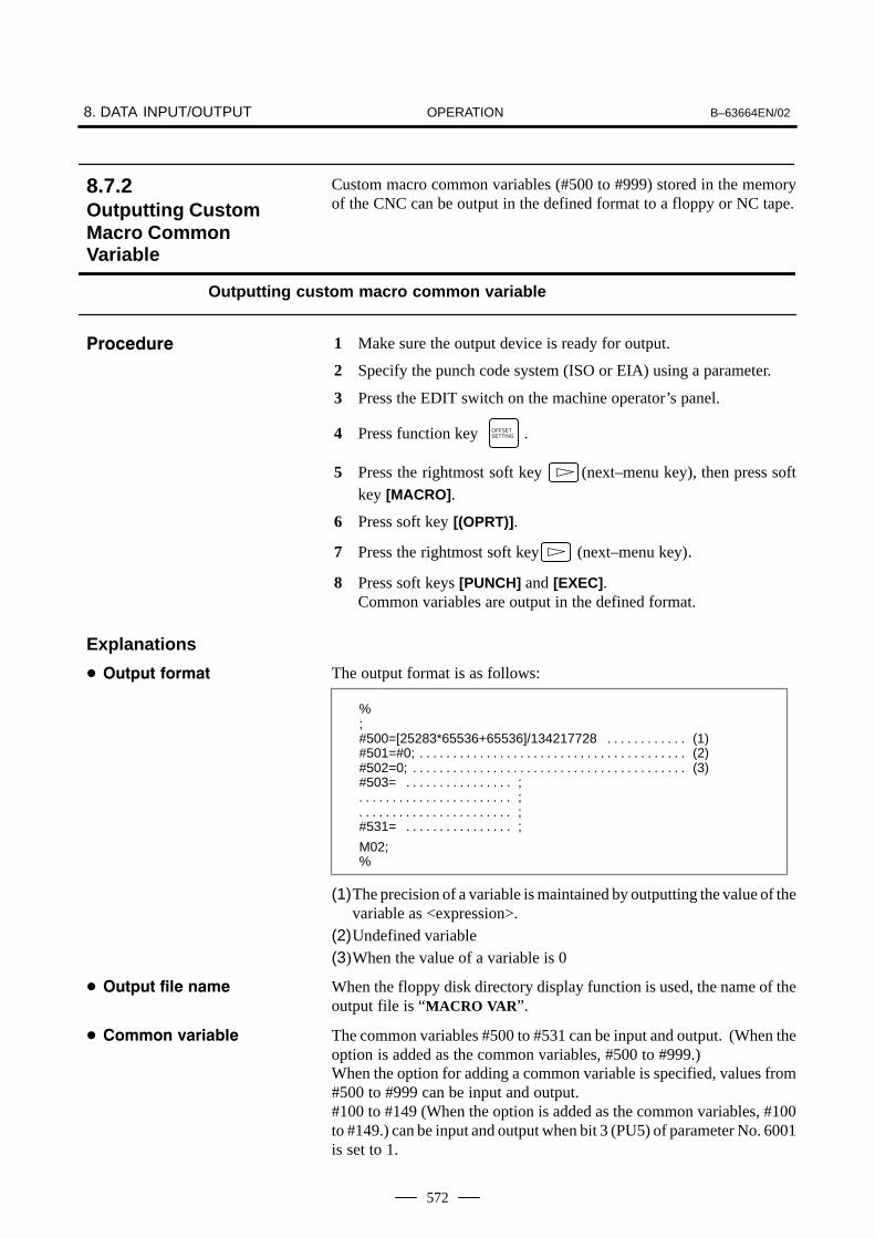
OPERATION8. DATA INPUT/OUTPUT B–63664EN/02
572
Custom macro common variables (#500 to #999) stored in the memoryof the CNC can be output in the defined format to a floppy or NC tape.
Outputting custom macro common variable
1 Make sure the output device is ready for output.
2 Specify the punch code system (ISO or EIA) using a parameter.
3 Press the EDIT switch on the machine operator’s panel.
4 Press function key OFFSETSETTING .
5 Press the rightmost soft key (next–menu key), then press softkey [MACRO].
6 Press soft key [(OPRT)].
7 Press the rightmost soft key (next–menu key).
8 Press soft keys [PUNCH] and [EXEC].Common variables are output in the defined format.
The output format is as follows:
%;#500=[25283*65536+65536]/134217728 (1). . . . . . . . . . . . #501=#0; (2). . . . . . . . . . . . . . . . . . . . . . . . . . . . . . . . . . . . . . . . #502=0; (3). . . . . . . . . . . . . . . . . . . . . . . . . . . . . . . . . . . . . . . . . #503= ;. . . . . . . . . . . . . . . .
;. . . . . . . . . . . . . . . . . . . . . . . ;. . . . . . . . . . . . . . . . . . . . . . .
#531= ;. . . . . . . . . . . . . . . .
M02;%
(1)The precision of a variable is maintained by outputting the value of thevariable as <expression>.
(2)Undefined variable(3)When the value of a variable is 0
When the floppy disk directory display function is used, the name of theoutput file is “MACRO VAR”.
The common variables #500 to #531 can be input and output. (When theoption is added as the common variables, #500 to #999.)When the option for adding a common variable is specified, values from#500 to #999 can be input and output.#100 to #149 (When the option is added as the common variables, #100to #149.) can be input and output when bit 3 (PU5) of parameter No. 6001is set to 1.
8.7.2Outputting CustomMacro CommonVariable
�����#"��
Explanations
� �"�!"� �����
� �"�!"� ��� ����
� ����� �����/��
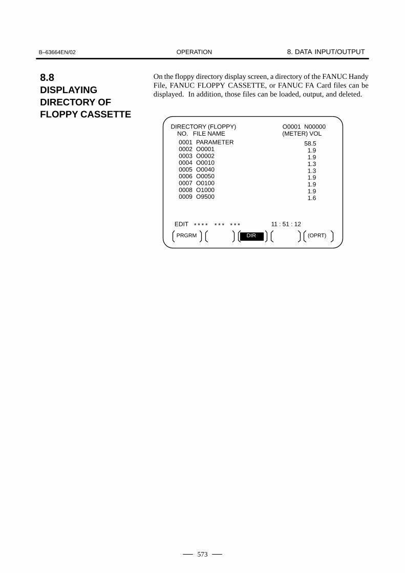
OPERATIONB–63664EN/02 8. DATA INPUT/OUTPUT
573
On the floppy directory display screen, a directory of the FANUC HandyFile, FANUC FLOPPY CASSETTE, or FANUC FA Card files can bedisplayed. In addition, those files can be loaded, output, and deleted.
O0001 N00000 (METER) VOL
EDIT * * * * * * * * * * 11 : 51 : 12
PRGRM (OPRT)DIR
DIRECTORY (FLOPPY) NO. FILE NAME
0001 PARAMETER0002 O00010003 O00020004 O00100005 O00400006 O00500007 O01000008 O10000009 O9500
58.5 1.9 1.9 1.3 1.3 1.9 1.9 1.9 1.6
8.8DISPLAYINGDIRECTORY OFFLOPPY CASSETTE

OPERATION8. DATA INPUT/OUTPUT B–63664EN/02
574
Displaying the directory of floppy cassette files
Use the following procedure to display a directory of all thefiles stored in a floppy:
1 Press the EDIT switch on the machine operator’s panel.
2 Press function key PROG .
3 Press the rightmost soft key (next–menu key).
4 Press soft key [FLOPPY].
5 Press page key PAGE
or PAGE
.
6 The screen below appears.
O0001 N00000 (METER) VOL
EDIT * * * * * * * * * * 11 : 53 : 04
0001 PARAMETER0002 O00010003 O00020004 O00100005 O00400006 O00500007 O01000008 O10000009 O9500
58.5 1.9 1.9 1.3 1.3 1.9 1.9 1.9 1.6
DIRECTORY (FLOPPY) NO. FILE NAME
READ PUNCH DELETEF SRH
Fig.8.8.1 (a)
7 Press a page key again to display another page of the directory.
8.8.1Displaying theDirectory
�����#"�� (

OPERATIONB–63664EN/02 8. DATA INPUT/OUTPUT
575
Use the following procedure to display a directory of filesstarting with a specified file number :
1 Press the EDIT switch on the machine operator’s panel.
2 Press function key PROG .
3 Press the rightmost soft key (next–menu key).
4 Press soft key [FLOPPY].
5 Press soft key [(OPRT)].
6 Press soft key [F SRH].
7 Enter a file number.
8 Press soft keys [F SET] and [EXEC].
9 Press a page key to display another page of the directory.
10 Press soft key [CAN] to return to the soft key display shown in thescreen of Fig.8.8.1 (a).
EDIT * * * * * * * * * * 11 : 54 : 19
SEARCH FILE NO. =>_
O0001 N00000 (METER) VOL
DIRECTORY (FLOPPY) NO. FILE NAME
CANF SET EXEC
Fig.8.8.1 (b)
0005 O00400006 O00500007 O01000008 O10000009 O9500
1.3 1.9 1.9 1.9 1.6
�����#"�� *

OPERATION8. DATA INPUT/OUTPUT B–63664EN/02
576
NO:Displays the file numberFILE NAME: Displays the file name.(METER) : Converts and prints out the file capacity to paper tape
length.You can also produce H(FEET) I by setting the INPUT UNIT to INCH of the setting data.VOL. : When the file is multi–volume, that state is displayed.
C01
C02L03
C(number)means CONTINUEL(number)means LASTnumber number of floppies or cards
(Ex.) Floppy or card A
Floppy or card BFloppy or card C
Explanations
� ������ ���#� ��# �����
��������

OPERATIONB–63664EN/02 8. DATA INPUT/OUTPUT
577
The contents of the specified file number are read to the memory of NC.
Reading files
1 Press the EDIT switch on the machine operator’s panel.
2 Press function key PROG .
3 Press the rightmost soft key (next–menu key).
4 Press soft key [FLOPPY].
5 Press soft key [(OPRT)].
6 Press soft key [READ].
* * * * * * * * * * 11 : 55 : 04
READ FILE NO. =>_
���+
O0001 N00000 (METER) VOL
DIRECTORY (FLOPPY) NO. FILE NAME
CANF SET EXEC
PROGRAM NO. =
O SET STOP
0001 PARAMETER0002 O00010003 O00020004 O00100005 O00400006 O00500007 O01000008 O10000009 O9500
58.5 1.9 1.9 1.3 1.3 1.9 1.9 1.9 1.6
7 Enter a file number.
8 Press soft key [F SET].
9 To modify the program number, enter the program number, then presssoft key [O SET].
10 Press soft key [EXEC]. The file number indicated in the lower–leftcorner of the screen is automatically incremented by one.
11 Press soft key [CAN] to return to the soft key display shown inthe screen of Fig.8.8.1 (a).
8.8.2Reading Files
�����#"��

OPERATION8. DATA INPUT/OUTPUT B–63664EN/02
578
Any program in the memory of the CNC unit can be output to a floppyas a file.
Outputting programs
1 Press the EDIT switch on the machine operator’s panel.
2 Press function key PROG .
3 Press the rightmost soft key (next–menu key).
4 Press soft key [FLOPPY].
5 Press soft key [(OPRT)].
6 Press soft key [PUNCH].
EDIT * * * * * * * * * * 11 : 55 : 26
PUNCH FILE NO. =>_
O0002 N01000(METER) VOL
DIRECTORY (FLOPPY) NO. FILE NAME
CANF SET EXEC
PROGRAM NO. =
O SET STOP
0001 PARAMETER0002 O00010003 O00020004 O00100005 O00400006 O00500007 O01000008 O10000009 O9500
58.5 1.9 1.9 1.3 1.3 1.9 1.9 1.9 1.6
7 Enter a program number. To write all programs into a single file, enter–9999 in the program number field. In this case, the file name“ALL.PROGRAM” is registered.
8 Press soft key [O SET].
9 Press soft key [EXEC]. The program or programs specified in step 7are written after the last file on the floppy. To output the program afterdeleting files starting with an existing file number, key in the filenumber, then press soft key [F SET] followed by soft key [EXEC].
10 Press soft key [CAN] to return to the soft key display shown inthe screen of Fig.8.8.1 (a).
8.8.3Outputting Programs
�����#"��

OPERATIONB–63664EN/02 8. DATA INPUT/OUTPUT
579
The file with the specified file number is deleted.
Deleting files
1 Press the EDIT switch on the machine operator’s panel.
2 Press function key PROG .
3 Press the rightmost soft key (next–menu key).
4 Press soft key [FLOPPY].
5 Press soft key [(OPRT)].
6 Press soft key [DELETE].
EDIT * * * * * * * * * * 11 : 55 : 51
DELETE FILE NO. =>_
O0001 N00000 (METER) VOL
DIRECTORY (FLOPPY) NO. FILE NAME
CANF SET EXECF NAME
NAME=
0001 PARAMETER0002 O00010003 O00020004 O00100005 O00400006 O00500007 O01000008 O10000009 O9500
58.5 1.9 1.9 1.3 1.3 1.9 1.9 1.9 1.6
7 Specify the file to be deleted.When specifying the file with a file number, type the number and press soft key [F SET]. When specifying the file with a file name,type the name and press soft key [F NAME].
8 Press soft key [EXEC]. The file specified in the file number field is deleted. When a file isdeleted, the file numbers after the deleted file are each decrementedby one.
9 Press soft key [CAN] to return to the soft key display shown inthe screen of Fig.8.8.1 (a).
8.8.4Deleting Files
�����#"��

OPERATION8. DATA INPUT/OUTPUT B–63664EN/02
580
If [F SET] or [O SET] is pressed without key inputting file number andprogram number, file number or program number shows blank. When0 is entered for file numbers or program numbers, 1 is displayed.
To use channel 0 ,set a device number in parameter (No. 102).Set the I/O device number to parameter (No. 112) when cannel 1 is used.Set it to (No. 0122) when channel 2 is used.
For the numeral input in the data input area with FILE No. andPROGRAM No., only lower 4 digits become valid.
When the data protection key on the machine operator’s panel is ON, no programs are read from the floppy. They are verified againstthe contents of the memory of the CNC instead.
Alarm No. Contents
71 An invalid file number or program number was entered.(Specified program number is not found.)
79 Verification operation found a mismatch between a programloaded into memory and the contents of the floppy
86
The dataset–ready signal (DR) for the input/output device isturned off. (The no file error or duplicate file error occurred onthe input/output device because an invalid file number, pro-gram number, or file name was entered.
������������
� Inputting file numbersand program numberswith keys
� I/O devices
� Significantdigits
� Collation
�����

OPERATIONB–63664EN/02 8. DATA INPUT/OUTPUT
581
CNC programs stored in memory can be grouped according to theirnames, thus enabling the output of CNC programs in group units. SectionIII–11.3.2 explains the display of a program listing for a specified group.
Procedure for Outputting a Program List for a Specified Group
1 Display the program list screen for a group of programs, as describedin Section III–11.3.2.
PROGRAM DIRECTORY (GROUP) O0001 N00010
EDIT * * * * * * * * * * * * * 16 : 52 : 13
PRGRM DIR (OPRT)
PROGRAM (NUM.) MEMORY (CHAR.)USED: 60 3321FREE: 2 429
O0020 (GEAR–1000 MAIN )O0040 (GEAR–1000 SUB–1 )O0200 (GEAR–1000 SUB–2 )O2000 (GEAR–1000 SUB–3 )
>_
2 Press the [(OPRT)] operation soft key.
3 Press the right–most soft key (continuous menu key).
4 Press the [PUNCH] operation soft key.
5 Press the [AL–GRP] operation soft key.
The CNC programs in the group for which a search is made areoutput. When these programs are output to a floppy disk, they areoutput to a file named GROUP.PROGRAM.
8.9OUTPUTTING A PROGRAM LISTFOR A SPECIFIEDGROUP
�����#"��
BG–EDT O–SRH GROUP
PUNCHREAD
AL–GRP STOP EXECCAN

OPERATION8. DATA INPUT/OUTPUT B–63664EN/02
582
To input/output a particular type of data, the corresponding screen isusually selected. For example, the parameter screen is used for parameterinput from or output to an external input/output unit, while the programscreen is used for program input or output. However, programs,parameters, offset data, and macro variables can all be input and outputusing a single common screen, that is, the ALL IO screen.
READ/PUNCH (PROGRAM) O1234 N12345
MDI
* * * * * * * * * * * * * 12:34:56
PRGRM PARAM OFFSET (OPRT)
I/O CHANNEL 3 TV CHECK OFFDEVICE NUM. 0 PUNCH CODE ISOBAUDRATE 4800 INPUT CODE ASCIISTOP BIT 2 FEED OUTPUT FEEDNULL INPUT (EIA) NO EOB OUTPUT (ISO) CRTV CHECK (NOTES) ON BAUDRATE CLK. INNERCD CHECK (232C) OFF RESET/ALARM ONPARITY BIT OFF SAT COMMAND HOSTINTERFACE RS422 COM PROTCOL AEND CODE EXT COM CODE ASCII
(0:EIA 1:ISO)>1_
MACRO
Fig.8.10 ALL IO screen (when channel 3 is being used for input/output)
8.10DATA INPUT/OUTPUTON THE ALL IOSCREEN

OPERATIONB–63664EN/02 8. DATA INPUT/OUTPUT
583
Input/output–related parameters can be set on the ALL IO screen.Parameters can be set, regardless of the mode.
Setting input/output–related parameters
1 Press function key SYSTEM .
2 Press the rightmost soft key (next–menu key) several times.
3 Press soft key [ALL IO] to display the ALL IO screen.
NOTE1 If program or floppy is selected in EDIT mode, the program
directory or floppy screen is displayed.2 When the power is first turned on, program is selected by
default.
READ/PUNCH (PROGRAM) O1234 N12345
MDI * * * * * * * * * * * * * 12:34:56
PRGRM PARAM OFFSET (OPRT)
I/O CHANNEL 3 TV CHECK OFFDEVICE NUM. 0 PUNCH CODE ISOBAUDRATE 4800 INPUT CODE ASCIISTOP BIT 2 FEED OUTPUT FEEDNULL INPUT (EIA) NO EOB OUTPUT (ISO) CRTV CHECK (NOTES) ON BAUDRATE CLK. INNERCD CHECK (232C) OFF RESET/ALARM ONPARITY BIT OFF SAT COMMAND HOSTINTERFACE RS422 COM PROTCOL AEND CODE EXT COM CODE ASCII
(0:EIA 1:ISO)>1_
MACRO
NOTEBaud rate clock, CD check (232C), reset/alarm report, andthe parity bit for parameter No. 134, as well as thecommunication code, end code, communication protocol,interface, and SAT command for parameter No. 135 aredisplayed only when channel 3 is being used forinput/output.
4 Select the soft key corresponding to the desired type of data (program,parameter, and so forth).
5 Set the parameters corresponding to the type of input/output unit to beused. (Parameter setting is possible regardless of the mode.)
8.10.1SettingInput/Output–RelatedParameters
�����#"��

OPERATION8. DATA INPUT/OUTPUT B–63664EN/02
584
A program can be input and output using the ALL IO screen.When entering a program using a cassette or card, the user must specifythe input file containing the program (file search).
File search
1 Press soft key [PRGRM] on the ALL IO screen, described in Section8.10.1.
2 Select EDIT mode. A program directory is displayed.
3 Press soft key [(OPRT)]. The screen and soft keys change as shownbelow.
⋅ A program directory is displayed only in EDIT mode. In all othermodes, the ALL IO screen is displayed.
O0001 N00010
EDIT * * * * * * * * * * * * * 14:46:09
F SRH READ PUNCH (OPRT)
>_
PROGRAM (NUM.) MEMORY (CHAR.)USED : 60 3321FREE : 2 429
O0010 O0001 O0003 O0002 O0555 O0999O0062 O0004 O0005 O1111 O0969 O6666O0021 O1234 O0588 O0020 O0040
DELETE
4 Enter address N.
5 Enter the number of the file to be found.⋅ N0
The first floppy file is found.⋅ One of N1 to N9999
Among the files numbered from 1 to 9999, a specified file is found.⋅ N–9999
The file immediately after that used most recently is found.⋅ N–9998
When –9998 is specified, the next file is found. Then, each timea file input/output operation is performed, N–9999 is automaticallyinserted. This means that subsequent files can be sequentiallyfound automatically.This state is canceled by specifying N0, N1 to N9999, or N–9999,or upon a reset.
6 Press soft keys [F SRH] and [EXEC]. The specified file is found.
8.10.2Inputting andOutputting Programs
�����#"��
EXECCAN

OPERATIONB–63664EN/02 8. DATA INPUT/OUTPUT
585
When a file already exists in a cassette or card, specifying N0 or N1 hasthe same effect. If N1 is specified when there is no file on the cassette orcard, an alarm is issued because the first file cannot be found. SpecifyingN0 places the head at the start of the cassette or card, regardless of whetherthe cassette/card already contains files. So, no alarm is issued in this case.N0 can be used, for example, when a program is written into a newcassette or card, or when a previously used cassette or card is used onceall the files it contains have been erased.
If an alarm (file search failure, for example) is generated during filesearch, the CNC does not issue an alarm immediately. However, a P/Salarm (No. 086) is issued if input/output is subsequently performed onthat file.
Instead of sequentially searching for files by specifying actual filenumbers every time, the user can specify the first file number, then findthe subsequent files by specifying N–9999. When N–9999 is specified,the time required for file search can be reduced.
Explanations
� Difference between N0and N1
� Alarm issue during filesearch
� File search using N–9999

OPERATION8. DATA INPUT/OUTPUT B–63664EN/02
586
Inputting a program
1 Press soft key [PRGRM] on the ALL IO screen, described in Section8.10.1.
2 Select EDIT mode. A program directory is displayed.
3 Press soft key [(OPRT)]. The screen and soft keys change as shownbelow.
⋅ A program directory is displayed only in EDIT mode. In all othermodes, the ALL IO screen is displayed.
O0001 N00010
EDIT * * * * * * * * * * * * * 14:46:09
F SRH READ PUNCH (OPRT)
>_
PROGRAM (NUM.) MEMORY (CHAR.)USED : 60 3321FREE : 2 429
O0010 O0001 O0003 O0002 O0555 O0999O0062 O0004 O0005 O1111 O0969 O6666O0021 O1234 O0588 O0020 O0040
DELETE
4 To specify a program number to be assigned to an input program,enter address O, followed by the desired program number.If no program number is specified, the program number in the file oron the NC tape is assigned as is.
5 Press soft key [READ], then [EXEC].The program is input with the program number specified in step 4assigned.To cancel input, press soft key [CAN].To stop input prior to its completion, press soft key [STOP].
�����#"��
EXECCANSTOP

OPERATIONB–63664EN/02 8. DATA INPUT/OUTPUT
587
Outputting programs
1 Press soft key [PRGRM] on the ALL IO screen, described in Section8.10.1.
2 Select EDIT mode. A program directory is displayed.
3 Press soft key [(OPRT)]. The screen and soft keys change as shownbelow.
⋅ A program directory is displayed only in EDIT mode. In all othermodes, the ALL IO screen is displayed.
O0001 N00010
EDIT * * * * * * * * * * * * * 14:46:09
F SRH READ PUNCH (OPRT)
>_
PROGRAM (NUM.) MEMORY (CHAR.)USED : 60 3321FREE : 2 429
O0010 O0001 O0003 O0002 O0555 O0999O0062 O0004 O0005 O1111 O0969 O6666O0021 O1234 O0588 O0020 O0040
DELETE
4 Enter address O.
5 Enter a desired program number.If –9999 is entered, all programs in memory are output.To output a range of programs, enter O∆∆∆∆, O����.. Theprograms numbered from ∆∆∆∆ to ���� are output.When bit 4 (SOR) of parameter No. 3107 for sorted display is set to 1on the program library screen, programs are output in order, startingfrom those having the smallest program numbers.
6 Press soft key [PUNCH], then [EXEC].The specified program or programs are output. If steps 4 and 5 areomitted, the currently selected program is output.To cancel output, press soft key [CAN].To stop output prior to its completion, press soft key [STOP].
�����#"��
EXECCANSTOP

OPERATION8. DATA INPUT/OUTPUT B–63664EN/02
588
Deleting files
1 Press soft key [PRGRM] on the ALL IO screen, described in Section8.10.1.
2 Select EDIT mode. A program directory is displayed.
3 Press soft key [(OPRT)]. The screen and soft keys change as shownbelow.
⋅ A program directory is displayed only in EDIT mode. In all othermodes, the ALL IO screen is displayed.
O0001 N00010
EDIT * * * * * * * * * * * * * 14:46:09
F SRH READ PUNCH (OPRT)
>_
PROGRAM (NUM.) MEMORY (CHAR.)USED : 60 3321FREE : 2 429
O0010 O0001 O0003 O0002 O0555 O0999O0062 O0004 O0005 O1111 O0969 O6666O0021 O1234 O0588 O0020 O0040
DELETE
4 Press soft key [DELETE].
5 Enter a file number, from 1 to 9999, to indicate the file to be deleted.
6 Press soft key [EXEC].The k–th file, specified in step 5, is deleted.
After deletion of the k–th file, the previous file numbers (k+1) to n aredecremented by 1 to k to (n–1).
Before deletion After deletion1 to (k–1) 1 to (k–1)
K Delete(k+1) to n k to (n–1)
Before a file can be deleted, the write protect switch of the cassette mustbe set to make the cassette writable.
�����#"��
EXECCAN
Explanations
� File numbers afterdeletion
� Write protect

OPERATIONB–63664EN/02 8. DATA INPUT/OUTPUT
589
Parameters can be input and output using the ALL IO screen.
Inputting parameters
1 Press soft key [PARAM] on the ALL IO screen, described in Section8.10.1.
2 Select EDIT mode.
3 Press soft key [(OPRT)]. The screen and soft keys change as shownbelow.
READ/PUNCH (PARAMETER) O1234 N12345
MDI
* * * * * * * * * * * * * 12:34:56
READ PUNCH
I/O CHANNEL 3 TV CHECK OFFDEVICE NUM. 0 PUNCH CODE ISOBAUDRATE 4800 INPUT CODE ASCIISTOP BIT 2 FEED OUTPUT FEEDNULL INPUT (EIA) NO EOB OUTPUT (ISO) CRTV CHECK (NOTES) ON BAUDRATE CLK. INNERCD CHECK (232C) OFF RESET/ALARM ONPARITY BIT OFF COM CODE ASCIIEND CODE EXT COM PROTCOL AINTERFACE RS422 SAT COMMAND HOST
(0:EIA 1:ISO)>1_
4 Press soft key [READ], then [EXEC].The parameters are read, and the ”INPUT” indicator blinks at thelower–right corner of the screen. Upon the completion of input, the”INPUT” indicator is cleared from the screen.To cancel input, press soft key [CAN].
8.10.3Inputting andOutputting Parameters
�����#"��
EXECCAN

OPERATION8. DATA INPUT/OUTPUT B–63664EN/02
590
Outputting parameters
1 Press soft key [PARAM] on the ALL IO screen, described in Section8.10.1.
2 Select EDIT mode.
3 Press soft key [(OPRT)]. The screen and soft keys change as shownbelow.
READ/PUNCH (PARAMETER) O1234 N12345
MDI
* * * * * * * * * * * * * 12:34:56
READ PUNCH
I/O CHANNEL 3 TV CHECK OFFDEVICE NUM. 0 PUNCH CODE ISOBAUDRATE 4800 INPUT CODE ASCIISTOP BIT 2 FEED OUTPUT FEEDNULL INPUT (EIA) NO EOB OUTPUT (ISO) CRTV CHECK (NOTES) ON BAUDRATE CLK. INNERCD CHECK (232C) OFF RESET/ALARM ONPARITY BIT OFF COM CODE ASCIIEND CODE EXT COM PROTCOL AINTERFACE RS422 SAT COMMAND HOST
(0:EIA 1:ISO)>1_
4 Press soft key [PUNCH], then [EXEC].The parameters are output, and the ”OUTPUT” indicator blinks at thelower–right corner of the screen. Upon the completion of output, the”OUTPUT” indicator is cleared from the screen.To cancel output, press soft key [CAN].
�����#"��
EXECCAN

OPERATIONB–63664EN/02 8. DATA INPUT/OUTPUT
591
Offset data can be input and output using the ALL IO screen.
Inputting offset data
1 Press soft key [OFFSET] on the ALL IO screen, described in Section8.10.1.
2 Select EDIT mode.
3 Press soft key [(OPRT)]. The screen and soft keys change as shownbelow.
READ/PUNCH (OFFSET) O1234 N12345
MDI
* * * * * * * * * * * * * 12:34:56
READ PUNCH
I/O CHANNEL 3 TV CHECK OFFDEVICE NUM. 0 PUNCH CODE ISOBAUDRATE 4800 INPUT CODE ASCIISTOP BIT 2 FEED OUTPUT FEEDNULL INPUT (EIA) NO EOB OUTPUT (ISO) CRTV CHECK (NOTES) ON BAUDRATE CLK. INNERCD CHECK (232C) OFF RESET/ALARM ONPARITY BIT OFF COM CODE ASCIIEND CODE EXT COM PROTCOL AINTERFACE RS422 SAT COMMAND HOST
(0:EIA 1:ISO)>1_
4 Press soft key [READ], then [EXEC].The offset data is read, and the ”INPUT” indicator blinks at thelower–right corner of the screen. Upon the completion of input, the ”INPUT” indicator is cleared fromthe screen.To cancel input, press soft key [CAN].
8.10.4Inputting andOutputting Offset Data
�����#"��
EXECCAN

OPERATION8. DATA INPUT/OUTPUT B–63664EN/02
592
Outputting offset data
1 Press soft key [OFFSET] on the ALL IO screen, described in Section8.10.1.
2 Select EDIT mode.
3 Press soft key [(OPRT)]. The screen and soft keys change as shownbelow.
READ/PUNCH (OFFSET) O1234 N12345
MDI
* * * * * * * * * * * * * 12:34:56
READ PUNCH
I/O CHANNEL 3 TV CHECK OFFDEVICE NUM. 0 PUNCH CODE ISOBAUDRATE 4800 INPUT CODE ASCIISTOP BIT 2 FEED OUTPUT FEEDNULL INPUT (EIA) NO EOB OUTPUT (ISO) CRTV CHECK (NOTES) ON BAUDRATE CLK. INNERCD CHECK (232C) OFF RESET/ALARM ONPARITY BIT OFF COM CODE ASCIIEND CODE EXT COM PROTCOL AINTERFACE RS422 SAT COMMAND HOST
(0:EIA 1:ISO)>1_
4 Press soft key [PUNCH], then [EXEC].The offset data is output, and the ”OUTPUT” indicator blinks at thelower–right corner of the screen. Upon the completion of output, the”OUTPUT” indicator is cleared from the screen.To cancel output, press soft key [CAN].
�����#"��
EXECCAN
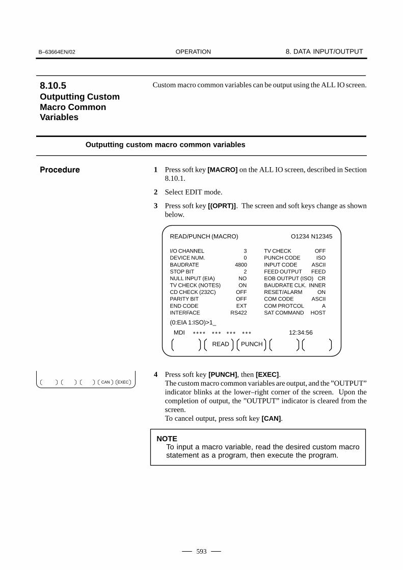
OPERATIONB–63664EN/02 8. DATA INPUT/OUTPUT
593
Custom macro common variables can be output using the ALL IO screen.
Outputting custom macro common variables
1 Press soft key [MACRO] on the ALL IO screen, described in Section8.10.1.
2 Select EDIT mode.
3 Press soft key [(OPRT)]. The screen and soft keys change as shownbelow.
READ/PUNCH (MACRO) O1234 N12345
MDI
* * * * * * * * * * * * * 12:34:56
READ PUNCH
I/O CHANNEL 3 TV CHECK OFFDEVICE NUM. 0 PUNCH CODE ISOBAUDRATE 4800 INPUT CODE ASCIISTOP BIT 2 FEED OUTPUT FEEDNULL INPUT (EIA) NO EOB OUTPUT (ISO) CRTV CHECK (NOTES) ON BAUDRATE CLK. INNERCD CHECK (232C) OFF RESET/ALARM ONPARITY BIT OFF COM CODE ASCIIEND CODE EXT COM PROTCOL AINTERFACE RS422 SAT COMMAND HOST
(0:EIA 1:ISO)>1_
4 Press soft key [PUNCH], then [EXEC].The custom macro common variables are output, and the ”OUTPUT”indicator blinks at the lower–right corner of the screen. Upon thecompletion of output, the ”OUTPUT” indicator is cleared from thescreen.To cancel output, press soft key [CAN].
NOTETo input a macro variable, read the desired custom macrostatement as a program, then execute the program.
8.10.5Outputting CustomMacro CommonVariables
�����#"��
EXECCAN

OPERATION8. DATA INPUT/OUTPUT B–63664EN/02
594
The ALL IO screen supports the display of a directory of floppy files, aswell as the input and output of floppy files.
Displaying a file directory
1 Press the rightmost soft key (next–menu key) on the ALL IOscreen, described in Section 8.10.1.
2 Press soft key [FLOPPY].
3 Select EDIT mode. The floppy screen is displayed.
4 Press soft key [(OPRT)]. The screen and soft keys change as shownbelow.
⋅ The floppy screen is displayed only in EDIT mode. In all othermodes, the ALL IO screen is displayed.
READ/PUNCH (FLOPPY) O1234 N12345
MDI
* * * * * * * * * * * * * 12:34:56
F SRH READ PUNCH
>
DELETE
5 Press soft key [F SRH].
6 Enter the number of the desired file, then press soft key [F SET].
7 Press soft key [EXEC]. A directory is displayed, with the specifiedfile uppermost. Subsequent files in the directory can be displayed bypressing the page key.
8.10.6Inputting andOutputting FloppyFiles
�����#"��
EXECCANF SET

OPERATIONB–63664EN/02 8. DATA INPUT/OUTPUT
595
READ/PUNCH (FLOPPY) No. FILE NAME
O1234 N12345(Meter) VOL
EDIT
* * * * * * * * * * * * * 12:34:56
F SRH EXEC
0001 PARAMETER0002 ALL.PROGRAM0003 O00010004 O00020005 O00030006 O00040007 O00050008 O00100009 O0020
F SRHFile No.=2
>2_
CAN
46.112.311.911.911.911.911.911.911.9
A directory in which the first file is uppermost can be displayedsimply by pressing the page key. (Soft key [F SRH] need not bepressed.)

OPERATION8. DATA INPUT/OUTPUT B–63664EN/02
596
Inputting a file
1 Press the rightmost soft key (next–menu key) on the ALL IO
screen, described in Section 8.10.1.
2 Press soft key [FLOPPY].
3 Select EDIT mode. The floppy screen is displayed.
4 Press soft key [(OPRT)]. The screen and soft keys change as shownbelow.The floppy screen is displayed only in EDIT mode. In all othermodes, the ALL IO screen is displayed.
READ/PUNCH (FLOPPY) O1234 N12345
MDI
* * * * * * * * * * * * * 12:34:56
F SRH READ PUNCH
>
DELETE
5 Press soft key [READ].
6 Enter the number of a file or program to be input.
⋅ Setting a file number: Enter the number of the desired file, thenpress soft key [F SET].
⋅ Setting a program number: Enter the number of the desiredprogram, then press soft key [O SET].
7 Press soft key [EXEC]. The specified file or program is read, and the ”INPUT” indicatorblinks at the lower–right corner of the screen. Upon the completion ofinput, the ”INPUT” indicator is cleared from the screen.
�����#"��
EXECCANF SET O SET STOP

OPERATIONB–63664EN/02 8. DATA INPUT/OUTPUT
597
Outputting a file
1 Press the rightmost soft key (next–menu key) on the ALL IO
screen, described in Section 8.10.1.
2 Press soft key [FLOPPY].
3 Select EDIT mode. The floppy screen is displayed.
4 Press soft key [(OPRT)]. The screen and soft keys change as shownbelow.The floppy screen is displayed only in EDIT mode. In all othermodes, the ALL IO screen is displayed.
READ/PUNCH (FLOPPY) O1234 N12345
MDI
* * * * * * * * * * * * * 12:34:56
F SRH READ PUNCH
>
DELETE
5 Press soft key [PUNCH].
6 Enter the number of the program to be output, together with a desiredoutput file number.
⋅ Setting a file number: Enter the number of the desired file, thenpress soft key [F SET].
⋅ Setting a program number: Enter the number of the desiredprogram, then press soft key [O SET].
7 Press soft key [EXEC].The specified program is output, and the ”OUTPUT” indicator blinksat the lower–right corner of the screen. Upon the completion ofoutput, the ”OUTPUT” indicator is cleared from the screen.If no file number is specified, the program is written at the end of thecurrently registered files.
�����#"��
EXECCANF SET O SET STOP

OPERATION8. DATA INPUT/OUTPUT B–63664EN/02
598
Deleting a file
1 Press the rightmost soft key (next–menu key) on the ALL IO
screen, described in Section 8.10.1.
2 Press soft key [FLOPPY].
3 Select EDIT mode. The floppy screen is displayed.
4 Press soft key [(OPRT)]. The screen and soft keys change as shownbelow.The floppy screen is displayed only in EDIT mode. In all othermodes, the ALL IO screen is displayed.
READ/PUNCH (FLOPPY) O1234 N12345
MDI
* * * * * * * * * * * * * 12:34:56
F SRH READ PUNCH
>
DELETE
5 Press soft key [DELETE].
6 Enter the number of the desired file, then press soft key [F SET].
7 Press soft key [EXEC]. The specified file is deleted. After the file hasbeen deleted, the subsequent files are shifted up.
�����#"��
EXECCANF SET

OPERATIONB–63664EN/02 8. DATA INPUT/OUTPUT
599
By setting the I/O channel (parameter No. 20) to 4, files on a memory cardcan be referenced, and different types of data such as part programs,parameters, and offset data on a memory card can be input and output intext file format.The major functions are listed below.
⋅ Displaying a directory of stored files
The files stored on a memory card can be displayed on the directoryscreen.
⋅ Searching for a file
A search is made for a file on a memory card and, if found, it isdisplayed on the directory screen.
⋅ Reading a file
Text–format files can be read from a memory card.
⋅ Writing a file
Data such as part programs can be stored to a memory card in text fileformat.
⋅ Deleting a file
A file can be selected and deleted from a memory card.
�1�
Writing a file
Reading a file
Displaying a directory
Searching for a file
Deleting a file
Memory card
8.11DATA INPUT/OUTPUTUSING A MEMORYCARD

OPERATION8. DATA INPUT/OUTPUT B–63664EN/02
600
Displaying a directory of stored files
1 Press the EDIT switch on the machine operator’s panel.
2 Press function key PROG .
3 Press the rightmost soft key (next–menu key).
4 Press soft key [CARD]. The screen shown below is displayed. Using
page keys and , the screen can be scrolled.
PROG (OPRT)DIR +
DIRECTORY (M–CARD) No. FILE NAME SIZE DATE
O0034 N00045
0001 O1000 123456 96/07/100002 O1001 118458 96/07/300003 O0002 113250 96/07/300004 O2000 173456 96/07/310005 O2001 113444 96/07/310006 O3001 118483 96/08/020007 O3300 111406 96/08/050008 O3400 112420 96/07/310009 O3500 117460 96/07/31
~ ~
5 Comments relating to each file can be displayed by pressing soft key[DIR+].
PROG (OPRT)DIR +
DIRECTORY (M–CARD) No. FILE NAME COMMENT
O0034 N00045
0001 O1000 (COMMENT )0002 O1001 (SUB PROGRAM )0003 O0002 (12345678 )0004 O2000 ( )0005 O2001 ( )0006 O3001 (SKIP–K )0007 O3300 (HI–SPEED )0008 O3400 ( )0009 O3500 (TEST PROGRAM)
~ ~
6 Repeatedly pressing soft key [DIR+] toggles the screen between thedisplay of comments and the display of sizes and dates.Any comment described after the O number in the file is displayed.Up to 18 characters can be displayed on the screen.
�����#"��

OPERATIONB–63664EN/02 8. DATA INPUT/OUTPUT
601
Searching for a file
1 Press the EDIT switch on the machine operator’s panel.
2 Press function key PROG .
3 Press the rightmost soft key (next–menu key).
4 Press soft key [CARD]. The screen shown below is displayed.
PROG (OPRT)DIR +
DIRECTORY (M–CARD) No. FILE NAME SIZE DATE
O0034 N00045
0001 O1000 123456 96/07/100002 O1001 118458 96/07/300003 O0002 113250 96/07/300004 O2000 173456 96/07/310005 O2001 113444 96/07/310006 O3001 118483 96/08/020007 O3300 111406 96/08/050008 O3400 112420 96/07/310009 O3500 117460 96/07/31
~ ~
5 Press soft key [(OPRT)].
6 Set the number of the desired file number with soft key [F SRH].Then, start the search by pressing soft key [EXEC]. If found, the file isdisplayed at the top of the directory screen.
DIRECTORY (M–CARD) No. FILE NAME COMMENT
O0034 N00045
0019 O1000 (MAIN PROGRAM)0020 O1010 (SUBPROGRAM–1)0021 O1020 (COMMENT )0022 O1030 (COMMENT )
~ ~
When a search is made for file number 19
�����#"��
DELETEPUNCHF SRH F READ N READ

OPERATION8. DATA INPUT/OUTPUT B–63664EN/02
602
Reading a file
1 Press the EDIT switch on the machine operator’s panel.
2 Press function key PROG.
3 Press the rightmost soft key (next–menu key).
4 Press soft key [CARD]. Then, the screen shown below is displayed.
PROG (OPRT)DIR +
DIRECTORY (M–CARD) No. FILE NAME SIZE DATE
O0034 N00045
0001 O1000 123456 96/07/100002 O1001 118458 96/07/300003 O0002 113250 96/07/300004 O2000 173456 96/07/310005 O2001 113444 96/07/310006 O3001 118483 96/08/020007 O3300 111406 96/08/050008 O3400 112420 96/07/310009 O3500 117460 96/07/31
~ ~
5 Press soft key [(OPRT)].
6 To specify a file number, press soft key [F READ]. The screen shownbelow is displayed.
F NAME EXECSTOPO SET CAN
DIRECTORY (M–CARD) No. FILE NAME COMMENT
O0001 N00010
0019 O1000 (MAIN PROGRAM)0020 O1010 (SUBPROGRAM–1)0021 O1030 (COMMENT )
~ ~
READFILE NAME=20 PROGRAM No.=120
>
EDIT 15:40:21* * * * * * * * * * *
7 Enter file number 20 from the MDI panel, then set the file number bypressing soft key [F SET]. Next, enter program number 120, then setthe program number by pressing soft key [O SET]. Then, press softkey [EXEC].
⋅ File number 20 is registered as O0120 in the CNC.
⋅ Set a program number to register a read file with a separate Onumber. If no program number is set, the O number in the file namecolumn is registered.
�����#"��
DELETEPUNCHF SRH F READ N READ

OPERATIONB–63664EN/02 8. DATA INPUT/OUTPUT
603
8 To specify a file with its file name, press soft key [N READ] in step 6above. The screen shown below is displayed.
F NAME EXECSTOPO SET CAN
DIRECTORY (M–CARD) No. FILE NAME COMMENT
O0001 N00010
0012 O0050 (MAIN PROGRAM)0013 TESTPRO (SUB PROGRAM–1)0014 O0060 (MACRO PROGRAM)
~ ~
READ FILE NAME =TESTPROPROGRAM No. =1230
>
EDIT 15:40:21* * * * * * * * * * *
9 To register file name TESTPRO as O1230, enter file name TESTPROfrom the MDI panel, then set the file name with soft key [F NAME].Next, enter program number 1230, then set the program number withsoft key [O SET]. Then, press soft key [EXEC].

OPERATION8. DATA INPUT/OUTPUT B–63664EN/02
604
Writing a file
1 Press the EDIT switch on the machine operator’s panel.
2 Press function key PROG .
3 Press the rightmost soft key (next–menu key).
4 Press soft key [CARD]. The screen shown below is displayed.
PROG (OPRT)DIR +
DIRECTORY (M–CARD) No. FILE NAME SIZE DATE
O0034 N00045
0001 O1000 123456 96/07/100002 O1001 118458 96/07/300003 O0002 113250 96/07/300004 O2000 173456 96/07/310005 O2001 113444 96/07/310006 O3001 118483 96/08/020007 O3300 111406 96/08/050008 O3400 112420 96/07/310009 O3500 117460 96/07/31
~ ~
5 Press soft key [(OPRT)].
6 Press soft key [PUNCH].
7 Enter a desired O number from the MDI panel, then set the programnumber with soft key [O SET]. When soft key [EXEC] is pressed after the setting shown below hasbeen made, for example, the file is written under program numberO1230.
F NAME EXECSTOPO SET CAN
EDIT
* * * * * * * * * * * 15:40:21
PUNCH FILE NAME =PROGRAM No. =1230
>
~ ~
8 In the same way as for O number setting, enter a desired file namefrom the MDI panel, then set the file name with soft key [F SET].When soft key [EXEC] is pressed after the setting shown below hasbeen made, for example, the file is written under program numberO1230 and file name ABCD12.
F NAME EXECSTOPO SET CAN
EDIT
* * * * * * * * * * * 15:40:21
PUNCH FILE NAME =ABCD12PROGRAM No. =1230
>
~ ~
�����#"��
DELETEPUNCHF SRH F READ N READ

OPERATIONB–63664EN/02 8. DATA INPUT/OUTPUT
605
When a file having the same name is already registered in the memorycard, the existing file will be overwritten.
To write all programs, set program number = –9999. If no file name isspecified in this case, file name PROGRAM.ALL is used for registration.
The following restrictions are imposed on file name setting:
<File name setting> �������� . ���
� �
Not longer than 8characters
Extension not longerthan 3 characters
Explanations
� Registering the same filename
� Writing all programs
� File name restrictions

OPERATION8. DATA INPUT/OUTPUT B–63664EN/02
606
Deleting a file
1 Press the EDIT switch on the machine operator’s panel.
2 Press function key PROG .
3 Press the rightmost soft key (next–menu key).
4 Press soft key [CARD]. The screen shown below is displayed.
PROG (OPRT)DIR +
DIRECTORY (M–CARD) No. FILE NAME SIZE DATE
O0034 N00045
0001 O1000 123456 96/07/100002 O1001 118458 96/07/300003 O0002 113250 96/07/300004 O2000 173456 96/07/310005 O2001 113444 96/07/310006 O3001 118483 96/08/020007 O3300 111406 96/08/050008 O3400 112420 96/07/310009 O3500 117460 96/07/31
~ ~
5 Press soft key [(OPRT)].
6 Set the number of the desired file with soft key [DELETE], then presssoft key [EXEC]. The file is deleted, and the directory screen isdisplayed again.
DIRECTORY (M–CARD) No. FILE NAME COMMENT
O0034 N00045
0019 O1000 (MAIN PROGRAM)0020 O1010 (SUBPROGRAM–1)0021 O1020 (COMMENT )0022 O1030 (COMMENT )
~ ~File name O1020 is deleted.
When file number 21 is deleted
DIRECTORY (M–CARD) No. FILE NAME COMMENT
O0034 N00045
0019 O1000 (MAIN PROGRAM)0020 O1010 (SUBPROGRAM–1)0021 O1020 (COMMENT )0022 O1030 (COMMENT )
~ ~
File number 21 is assigned to the next file name.
�����#"��
DELETEPUNCHF SRH F READ N READ

OPERATIONB–63664EN/02 8. DATA INPUT/OUTPUT
607
Batch input/output with a memory card
On the ALL IO screen, different types of data including part programs,parameters, offset data, pitch error data, custom macros, and workpiececoordinate system data can be input and output using a memory card; thescreen for each type of data need not be displayed for input/output.
Memory card ALL IO screen�
�
Data item name
Part programParameter Offset data Pitch error data Custom macroWorkpiece coordinate systemdata (additional coordinate systems)Compensation coefficient historydataRun hour dataAlarm history data related to dis-chargeLaser alarm history dataPower feedback data
1 Press the EDIT switch on the machine operator’s panel.
2 Press function key SYSTEM .
3 Press the rightmost soft key (next–menu key) several times.
4 Press soft key [ALL IO]. The screen shown below is displayed.
PROG (OPRT)OFFSETPARAM
READ/PUNCH (PROGRAM) No. FILE NAME SIZE DATE
O0001 N00001
*0001 O0222 332010 96–04–06*0002 O1003 334450 96–05–04*0003 MACROVAR.DAT 653400 96–05–12*0004 O0002 341205 96–05–13
[PROGRAM]*O0001 O0002 O0003 O0005 O0100 O0020*O0006 O0004 O0110 O0200 O2200 O0441*O0330>EDIT 10:07:37* * * * * * * * * * *
Upper part : Directory of files on the memory card Lower part : Directory of registered programs
5 With cursor keys and , the user can choose between upper
part scrolling and lower part scrolling. (An asterisk (*) displayed atthe left edge indicates the part for which scrolling is possible.)
: Used for memory card file directory scrolling.
: Used for program directory scrolling.
�����#"��

OPERATION8. DATA INPUT/OUTPUT B–63664EN/02
608
6 With page keys and , scroll through the file directory or
program directory.
When this screen is displayed, the program data item is selected. The softkeys for other screens are displayed by pressing the rightmost soft key
(next–menu key). Soft key [M–CARD] represents a separatememory card function for saving and restoring system RAM data. (SeeSubsec. NO TAG.)
MACRO (OPRT)WORKPITCH
(OPRT)M–CARD
When a data item other than program is selected, the screen displays onlya file directory.A data item is indicated, in parentheses, on the title line.
READ/PUNCH (PARAMETER) No. FILE NAME SIZE DATE
O0001 N00001
0001 O0222 332010 96/04/060002 O1003 334450 96/05/040003 MACROVAR.DAT 653400 96/05/120004 O0003 334610 96/05/040005 O0001 334254 96/06/040006 O0002 333750 96/06/040007 CNCPARAM.DAT 334453 96/06/04
~ ~
Program directory display does not match bit 0 (NAM) of parameter No.3107, or bit 4 (SOR) of parameter No. 3107.
Display the following soft keys with soft key [(OPRT)].
F SRH DELETEN READF READ PUNCH
The operation of each function is the same as on the directory (memorycard) screen. Soft key [O SET], used for program number setting, and the”PROGRAM NUMBER =” indication are not displayed for data itemsother than program.
[F SRH] : Finds a specified file number.[F READ] : Reads a specified file number.[PUNCH] : Writes a file.[N READ] : Reads a file under a specified file name.[DELETE] : Deletes a specified file number.
Explanations
� Each data item
� Program directorydisplay
� Using each function

OPERATIONB–63664EN/02 8. DATA INPUT/OUTPUT
609
NOTEWith a memory card, RMT mode operation and thesubprogram call function (based on the M198 command)cannot be used.
File format and error messages
All files that are read from and written to a memory card are of text format.The format is described below.A file starts with % or LF, followed by the actual data. A file always endswith %. In a read operation, data between the first % and the next LF isskipped. Each block ends with an LF, not a semicolon (;).
⋅ LF: 0A (hexadecimal) of ASCII code
⋅ When a file containing lowercase letters, kana characters, and severalspecial characters (such as $, \, and !) is read, those letters andcharacters are ignored.Example:
%O0001(MEMORY CARD SAMPLE FILE)G17 G49 G97G92 X–11.3 Y2.33
⋅⋅
M30%
⋅ ASCII code is used for input/output, regardless of the settingparameter (ISO/EIA).
⋅ Bit 3 of parameter No. 0100 can be used to specify whether the end ofblock code (EOB) is output as ”LF” only, or as ”LF, CR, CR.”
If an error occurs during memory card input/output, a corresponding errormessage is displayed.
EDIT
* * * * * * * * * * * 15:40:21
M–CARD ERROR ����
FILE No. = 1 PROGRAM No. =13>_
0028 O0003 777382 96–06–14
F SET EXECSTOPO SET CAN
~ ~
���� represents a memory card error code.
Format
Error messages

OPERATION8. DATA INPUT/OUTPUT B–63664EN/02
610
Code Meaning
99 Part preceding the FAT area on the memory card is destroyed.
102 The memory card does not have sufficient free space.
105 No memory card is mounted.
106 A memory card is already mounted.
110 The specified directory cannot be found.
111 There are too many files under the root directory to allow adirectory to be added.
114 The specified file cannot be found.
115 The specified file is protected.
117 The file has not yet been opened.
118 The file is already open.
119 The file is locked.
121 The memory card does not have sufficient free space.
122 The specified file name is invalid.
124 The extension of the specified file is invalid.
129 A non–corresponding function was specified.
130 The specification of a device is invalid.
131 The specification of a pathname is invalid.
133 Multiple files are open at the same time.
135 The device is not formatted.
140 The file has the read/write disabled attribute.
Memory Card ErrorCodes

OPERATIONB–63664EN/02 8. DATA INPUT/OUTPUT
611
The operation of the FTP file transfer function is described below.
A list of the files held on the hard disk embedded to the host computer isdisplayed.
1 Press the function key PROG .
2 Press the continuous menu key at the right end of the soft key display.
3 Press the [HOST] soft key. The host file list screen appears. TheEthernet functions currently available are displayed.
The upper row displays the usable embedded Ethernet functiondevice.The embedded port or PCMCIA card is displayed.The lower row displays the usable Ethernet option boards. When nooption board is installed, no information is displayed.
4 When you press the [EMBEDD] soft key, a list of the files held on thehost computer specified with the embedded Ethernet port isdisplayed.
8.12DATA INPUT/OUTPUTBY EMBEDDEDETHERNET
8.12.1FTP File TransferFunction
8.12.1.1 Host file list display
�����#"��

OPERATION8. DATA INPUT/OUTPUT B–63664EN/02
612
NOTEDepending on the FTP server software, the number ofdisplayed programs may differ between the host file listscreen above and the host file list (detail) screen describedbelow.
5 When a list of files is larger than one page, the screen display can be
switched using the page keys PAGE
PAGE
.
6 Press the [UPDATE] soft key to update the screen display.
7 Press the [SWITCH] soft key. The host file list (detail) screenappears.

OPERATIONB–63664EN/02 8. DATA INPUT/OUTPUT
613
NOTEThe host file list (detail) screen shown above is an exampleof screen display, and information displayed may varyaccording to the specification of the FTP server used withthe host computer.
Display items
The number of files registered in the directory (folder) of the hostcomputer currently connected is displayed.
The number of the host currently connected is displayed.
List of operations
This operation switches between normal display and detail display.
This operation updates information displayed.
This operation stops [SEARCH] operation.
This operation updates screen information so that a file specified by itsfile number is placed at the start of the list.
This operation deletes a file held on the hard disk embedded to the hostcomputer.
This operation reads a file held on the hard disk embedded to the hostcomputer to the CNC part program storage. This soft key is displayedonly when 9 is set as the input/output device number of the CNC, and theCNC is placed in the EDIT mode.
� Number of registeredprogram files
� Currently connectedhost
� SWITCH
� UPDATE
� STOP
� SEARCH
� DELETE
� READ

OPERATION8. DATA INPUT/OUTPUT B–63664EN/02
614
This operation outputs a file held in the CNC part program storage to thehard disk embedded to the host computer. This soft key is displayed onlywhen 9 is set as the input/output device number of the CNC, and the CNCis placed in the EDIT mode.
When a list of the files held on the hard disk embedded to the hostcomputer is displayed, a file can be placed at the start of the list byspecifying its file number.
1 Display the host file list screen.
2 Press the [SEARCH] soft key.
3 Type the file number of a file to be displayed at the start of the list withthe MDI keys.[Input format]
<file–number>
4 Press the [EXEC] soft key.
5 During search, “SEARCH” blinks in the lower–right corner of thescreen.
A file held on the hard disk embedded to the host computer can be deleted.
1 Display the host file list screen.
2 Press the [DELETE] soft key.
3 Type the file number or file name of a file to be deleted, with the MDIkeys.[Input format]
<file–number>or<file–name>
4 Press the [EXEC] soft key.
5 During deletion, “DELETE” blinks in the lower–right corner of thescreen.
NOTE1 When a file number is used for deletion, only a file displayed
on the host file list screen can be deleted.2 The information displayed at the right end of the host file list
(detail) screen is recognized as a file name. So, whendeleting a host file from the host file list (detail) screen byspecifying its file number, check that a file name is displayedat the right end of the screen, before specifying the filenumber.
� PUNCH
8.12.1.2 Host file search
�����#"��
8.12.1.3 Host file deletion
�����#"��

OPERATIONB–63664EN/02 8. DATA INPUT/OUTPUT
615
A file (NC program) on the host computer can be read to the CNCmemory.
For the host file list screen
1 Place the CNC in the EDIT mode.
2 Display the host file list screen.
3 Press the [READ] soft key.
4 Type the file number or file name of an NC program to be input, withthe MDI keys. [Input format]
<file–number>or<file–name>
5 Press the [EXEC] soft key.
6 During input, “INPUT” blinks in the lower–right corner of the screen.
CAUTION
1 If the CNC memory holds an NC program that has the sameO number as that of an NC program to be input, the NCprogram in the CNC memory is overwritten when bit 2 ofparameter No. 3201 is set to 1.
2 If an NC program is input when bit 0 of parameter No. 3201is set to 1, all NC programs in the CNC memory areautomatically deleted before NC program input.
[Example of use]When a file with the file name O0001.DAT held on the hard diskembedded to the host computer is to be input to the CNC memory, enterO001.DAT. Note, however, that the O number input to the CNC memorydepends on the O number described in the file named O0001.DAT.
NOTEWhen a file is input from this screen to the CNC memory, theO number described in the file is input.
8.12.1.4 NC program input
�����#"��

OPERATION8. DATA INPUT/OUTPUT B–63664EN/02
616
For the program screen
1 Place the CNC in the EDIT mode.
2 Press the function key PROG .
3 Press the continuous menu key at the right end of the soft key display.
4 Press the [PRGRM] soft key. The program screen appears.
5 Press the [(OPRT)] soft key.
6 Press the continuous menu key at the right end of the soft key display.
7 Press the [READ] soft key.
8 Type the O number of an NC program to be input, with the MDI keys.[Input format]
<O–number>
9 Press the [EXEC] soft key.
10 During input, “INPUT” blinks in the lower–right corner of the screen.
CAUTION
1 If the CNC memory holds an NC program that has the sameO number as that of an NC program to be input, the NCprogram in the CNC memory is overwritten when bit 2 ofparameter No. 3201 is set to 1.
2 If an NC program is input when bit 0 of parameter No. 3201is set to 1, all NC programs in the CNC memory areautomatically deleted before NC program input.
NOTEThe valid O number of a file to be input to the CNC memoryis Oxxxx (with xxxx representing a number) only.
�����#"��

OPERATIONB–63664EN/02 8. DATA INPUT/OUTPUT
617
A file (NC program) in the CNC memory can be output to the hostcomputer.
For the host file list screen
1 Place the CNC in the EDIT mode.
2 Display the host file list screen.
3 Press the [PUNCH] soft key.
4 Type the O number of an NC program to be output, with the MDIkeys.[Input format]
<O–number>
5 Press the [EXEC] soft key.
6 During output, “OUTPUT” blinks in the lower–right corner of thescreen.
[Example of use]When an NC program (O0001) in the CNC memory is to be output to thehard disk embedded to the host computer, enter O0001.
NOTEAn outputted file name is Oxxxx.
For the program screen
1 Place the CNC in the EDIT mode.
2 Press the function key PROG .
3 Press the continuous menu key at the right end of the soft key display.
4 Press the [PRGRM] soft key. The program screen appears.
5 Press the [(OPRT)] soft key.
6 Press the continuous menu key at the right end of the soft key display.
7 Press the [PUNCH] soft key.
8 Type the O number of an NC program to be output, with the MDIkeys.[Input format]
<O–number>
8.12.1.5 NC program output
�����#"��
�����#"��

OPERATION8. DATA INPUT/OUTPUT B–63664EN/02
618
9 Press the [EXEC] soft key.
10 During output, “OUTPUT” blinks in the lower–right corner of thescreen.
NOTEAn outputted file name is Oxxxx.
With the FTP file transfer function, the types of data listed below can beinput/output. This subsection describes the input/output method.
A) NC parameter
B) Tool offset value
C) Custom macro variable
D) Workpiece orogin offset value
E) Pitch error compensation data
F) M code group
G) Operation history data
Parameter input
The file (NC parameter) on the host computer can be input to the CNCmemory.
1 Place the CNC in the EDIT mode.
2 Press the function key SYSTEM .
3 Press the continuous menu key at the right end of the soft key display.
4 Press the [PARAM] soft key. The parameter screen appears.
5 Press the [(OPRT)] soft key.
6 Press the continuous menu key at the right end of the soft key display.
7 Press the [READ] soft key.
8 Press the [EXEC] soft key.
9 During input, “INPUT” blinks in the lower–right corner of the screen.
The fixed file name PRAMETER is used.
Refer to the operator’s manual of each CNC.
8.12.1.6 Input/output of varioustypes of data
�����#"��
File name
File format, restrictions

OPERATIONB–63664EN/02 8. DATA INPUT/OUTPUT
619
Parameter output
The file (NC parameter) in the CNC memory can be output to the hostcomputer.
1 Place the CNC in the EDIT mode.
2 Press the function key SYSTEM .
3 Press the continuous menu key at the right end of the soft key display.
4 Press the [PARAM] soft key. The parameter screen appears.
5 Press the [(OPRT)] soft key.
6 Press the continuous menu key at the right end of the soft key display.
7 Press the [PUNCH] soft key.
8 Press the [EXEC] soft key.
9 During output, “OUTPUT” blinks in the lower–right corner of thescreen.
The fixed file name PRAMETER is used.
Refer to the operator’s manual of each CNC.
Tool offset value input
The file (tool offset value) on the host computer can be input to the CNCmemory.
1 Place the CNC in the EDIT mode.
2 Press the function key OFFSETSETTING .
3 Press the continuous menu key at the right end of the soft key display.
4 Press the [OFFSET] soft key. The tool compensation screen appears.
5 Press the [(OPRT)] soft key.
6 Press the continuous menu key at the right end of the soft key display.
7 Press the [READ] soft key.
8 Press the [EXEC] soft key.
9 During input, “INPUT” blinks in the lower–right corner of the screen.
The fixed file name TOOLOFS is used.
Refer to the operator’s manual of each CNC.
�����#"��
File name
File format, restrictions
�����#"��
File name
File format, restrictions

OPERATION8. DATA INPUT/OUTPUT B–63664EN/02
620
Tool offset value output
The file (tool offset value) in the CNC memory can be output to the hostcomputer.
1 Place the CNC in the EDIT mode.
2 Press the function key OFFSETSETTING .
3 Press the continuous menu key at the right end of the soft key display.
4 Press the [OFFSET] soft key. The tool compensation screen appears.
5 Press the [(OPRT)] soft key.
6 Press the continuous menu key at the right end of the soft key display.
7 Press the [PUNCH] soft key.
8 Press the [EXEC] soft key.
9 During output, “OUTPUT” blinks in the lower–right corner of thescreen.
The fixed file name TOOLOFS is used.
Refer to the operator’s manual of each CNC.
Workpiece origin offset value input
The file (workpiece origin offset value) on the host computer can be inputto the CNC memory.
1 Place the CNC in the EDIT mode.
2 Press the function key OFFSETSETTING .
3 Press the continuous menu key at the right end of the soft key display.
4 Press the [WORK] soft key. The workpiece coordinate system settingscreen appears.
5 Press the [(OPRT)] soft key.
6 Press the continuous menu key at the right end of the soft key display.
7 Press the [READ] soft key.
8 Press the [EXEC] soft key.
9 During input, “INPUT” blinks in the lower–right corner of the screen.
The fixed file name WORKOFS is used.
Refer to the operator’s manual of each CNC.
�����#"��
File name
File format, restrictions
�����#"��
File name
File format, restrictions

OPERATIONB–63664EN/02 8. DATA INPUT/OUTPUT
621
Workpiece origin offset value output
The file (workpiece origin offset value) in the CNC memory can be outputto the host computer.
1 Place the CNC in the EDIT mode.
2 Press the function key OFFSETSETTING .
3 Press the continuous menu key at the right end of the soft key display.
4 Press the [WORK] soft key. The workpiece coordinate system settingscreen appears.
5 Press the [(OPRT)] soft key.
6 Press the continuous menu key at the right end of the soft key display.
7 Press the [PUNCH] soft key.
8 Press the [EXEC] soft key.
9 During output, “OUTPUT” blinks in the lower–right corner of thescreen.
The fixed file name WORKOFS is used.
Refer to the operator’s manual of each CNC.
Pitch error compensation input
The file (pitch error compensation) on the host computer can be input tothe CNC memory.
1 Place the CNC in the EDIT mode.
2 Press the function key SYSTEM .
3 Press the continuous menu key at the right end of the soft key display.
4 Press the [PITCH] soft key. The pitch error setting screen appears.
5 Press the [(OPRT)] soft key.
6 Press the continuous menu key at the right end of the soft key display.
7 Press the [READ] soft key.
8 Press the [EXEC] soft key.
9 During input, “INPUT” blinks in the lower–right corner of the screen.
The fixed file name PITCH is used.
Refer to the operator’s manual of each CNC.
�����#"��
File name
File format, restrictions
�����#"��
File name
File format, restrictions

OPERATION8. DATA INPUT/OUTPUT B–63664EN/02
622
Pitch error compensation output
The file (pitch error compensation) in the CNC memory can be output tothe host computer.
1 Place the CNC in the EDIT mode.
2 Press the function key SYSTEM .
3 Press the continuous menu key at the right end of the soft key display.
4 Press the [PITCH] soft key. The pitch error setting screen appears.
5 Press the [(OPRT)] soft key.
6 Press the continuous menu key at the right end of the soft key display.
7 Press the [PUNCH] soft key.
8 Press the [EXEC] soft key.
9 During output, “OUTPUT” blinks in the lower–right corner of thescreen.
The fixed file name PITCH is used.
Refer to the operator’s manual of each CNC.
M code group input
The file (M code group) on the host computer can be input to the CNCmemory.
1 Place the CNC in the EDIT mode.
2 Press the function key SYSTEM .
3 Press the continuous menu key at the right end of the soft key display.
4 Press the [M–CODE] soft key. The M code group setting screenappears.
5 Press the [(OPRT)] soft key.
6 Press the continuous menu key at the right end of the soft key display.
7 Press the [READ] soft key.
8 Press the [EXEC] soft key.
9 During input, “INPUT” blinks in the lower–right corner of the screen.
The fixed file name M–CODE is used.
Refer to the operator’s manual of each CNC.
�����#"��
File name
File format, restrictions
�����#"��
File name
File format, restrictions

OPERATIONB–63664EN/02 8. DATA INPUT/OUTPUT
623
M code group output
The file (M code group) in the CNC memory can be output to the hostcomputer.
1 Place the CNC in the EDIT mode.
2 Press the function key SYSTEM .
3 Press the continuous menu key at the right end of the soft key display.
4 Press the [M–CODE] soft key. The M code group setting screenappears.
5 Press the [(OPRT)] soft key.
6 Press the continuous menu key at the right end of the soft key display.
7 Press the [PUNCH] soft key.
8 Press the [EXEC] soft key.
9 During output, “OUTPUT” blinks in the lower–right corner of thescreen.
The fixed file name M–CODE is used.
Refer to the operator’s manual of each CNC.
Operation history data input
The file (operation history data) on the host computer can be input to theCNC memory.
1 Place the CNC in the EDIT mode.
2 Press the function key SYSTEM .
3 Press the continuous menu key at the right end of the soft key display.
4 Press the [OPEHIS] soft key. The operation history screen appears.
5 Press the [(OPRT)] soft key.
6 Press the continuous menu key at the right end of the soft key display.
7 Press the [READ] soft key.
8 Press the [EXEC] soft key.
9 During input, “INPUT” blinks in the lower–right corner of the screen.
The fixed file name HISTORY is used.
Refer to the operator’s manual of each CNC.
�����#"��
File name
File format, restrictions
�����#"��
File name
File format, restrictions

OPERATION8. DATA INPUT/OUTPUT B–63664EN/02
624
Operation history data output
The file (operation history data) in the CNC memory can be output to thehost computer.
1 Place the CNC in the EDIT mode.
2 Press the function key SYSTEM .
3 Press the continuous menu key at the right end of the soft key display.
4 Press the [OPEHIS] soft key. The operation history screen appears.
5 Press the [(OPRT)] soft key.
6 Press the continuous menu key at the right end of the soft key display.
7 Press the [PUNCH] soft key.
8 Press the [EXEC] soft key.
9 During output, “OUTPUT” blinks in the lower–right corner of thescreen.
The fixed file name HISTORY is used.
Refer to the operator’s manual of each CNC.
The host computer to which the FTP file transfer function attempts tomake a connection as the current communication destination can bechecked.
1 Press the function key PROG .
2 Press the continuous menu key at the right end of the soft key display.
3 Press the [CONECT] soft key. The connection host change screenappears. The Ethernet functions currently available are displayed.
�����#"��
File name
File format, restrictions
8.12.1.7 Checking and changingof the connection host
�����#"��

OPERATIONB–63664EN/02 8. DATA INPUT/OUTPUT
625
The upper row displays the usable embedded Ethernet functiondevice.The embedded port or PCMCIA card is displayed.The lower row displays the usable Ethernet option boards. When nooption board is installed, no information is displayed.
4 When you press the [EMBEDD] soft key, a list of the connection hostcomputers specified with the embedded Ethernet port is displayed.If the usable embedded Ethernet function device is the PCMCIA card,the [PCMCIA] soft key is displayed instead of the [EMBEDD] softkey. When you press the [PCMCIA] soft key, a list of the connectionhost computers specified with the PCMCIA Ethernet card isdisplayed.

OPERATION8. DATA INPUT/OUTPUT B–63664EN/02
626
NOTEThe title of the host computer that is the currentcommunication destination of the data server board isdisplayed in reverse video.
5 The connected host can be changed by pressing the [CON–1],[CON–2], or [CON–3] soft key.
Display items
Those values that are set on the Ethernet parameter setting screen aredisplayed.
List of operations
This operation changes the connected host to host 1.
This operation changes the connected host to host 2.
This operation changes the connected host to host 3.
� Port number, IP address,user name, login DIR
� CON–1
� CON–2
� CON–3

OPERATIONB–63664EN/02 9. EDITING PROGRAMS
627
9 ���� ��������
This chapter describes how to edit programs registered in the CNC.Editing includes the insertion, modification, deletion, and replacement ofwords. Editing also includes deletion of the entire program and automaticinsertion of sequence numbers. The extended part program editingfunction can copy, move, and merge programs. This chapter alsodescribes program number search, sequence number search, word search,and address search, which are performed before editing the program.
1) Program number search: See III–9.3.2) Sequence number search: See III–9.4.3) Word search: See III–9.1.1.4) Address search: See III–9.1.1.
1) Inserting, altering, and deleting a word: See III–9.1.3 to 9.1.5.2) Replacing words and addresses: See III–9.6.6.3) Deleting blocks: See III–9.2. 4) Copying, moving, and merging programs: See III–9.6.1 and 9.6.5.5) Deleting programs: See III–9.5.
Search for partof program to beedited
Inserting, altering,and deleting programs
Registration
Editing
Output Execution
General

OPERATION9. EDITING PROGRAMS B–63664EN/02
628
This section outlines the procedure for inserting, modifying, and deletinga word in a program registered in memory.
Procedure for inserting, altering and deleting a word
1 Select EDIT mode.
2 Press PROG .
3 Select a program to be edited.If a program to be edited is selected, perform the operation 4.If a program to be edited is not selected, search for the programnumber.
4 Search for a word to be modified.⋅ Scan method⋅ Word search method
5 Perform an operation such as altering, inserting, or deleting a word.
A word is an address followed by a number. With a custom macro, theconcept of word is ambiguous.So the editing unit is considered here.The editing unit is a unit subject to alteration or deletion in one operation.In one scan operation, the cursor indicates the start of an editing unit.An insertion is made after an editing unit.Definition of editing unit
(i) Program portion from an address to immediately before the nextaddress
(ii)An address is an alphabet, IF, WHILE, GOTO, END, DO=,or ; (EOB).According to this definition, a word is an editing unit.
The word “word,” when used in the description of editing, means anediting unit according to the precise definition.
WARNING
The user cannot continue program execution after altering, inserting, or deleting data of theprogram by suspending machining in progress by means of an operation such as a single blockstop or feed hold operation during program execution. If such a modification is made, theprogram may not be executed exactly according to the contents of the program displayed onthe screen after machining is resumed. So, when the contents of memory are to be modifiedby part program editing, be sure to enter the reset state or reset the system upon completionof editing before executing the program.
9.1INSERTING,ALTERING ANDDELETING A WORD
Explanation
� Concept of word andediting unit

OPERATIONB–63664EN/02 9. EDITING PROGRAMS
629
A word can be searched for by merely moving the cursor through the text(scanning), by word search, or by address search.
Procedure for scanning a program
1 Press the cursor key .
The cursor moves forward word by word on the screen; the cursor isdisplayed at a selected word.
2 Press the cursor key .
The cursor moves backward word by word on the screen; the cursor isdisplayed at a selected word.
Example) When Z1250.0 is scanned
Program O0050 N01234O0050 ;N01234 X100.0S12 ;N56789 M03 ;M02 ;%
;Z1250.0
3 Holding down the cursor key or scans words
continuously.
4 The first word of the next block is searched for when the cursor key
is pressed.
5 The first word of the previous block is searched for when the cursor
key is pressed.
6 Holding down the cursor key or moves the cursor to the
head of a block continuously.
7 Pressing the page key PAGE
displays the next page and searches for
the first word of the page.
8 Pressing the page key PAGE
displays the previous page and searches
for the first word of the page.
9 Holding down the page key PAGE
or PAGE
displays one page after
another.
9.1.12��# ������

OPERATION9. EDITING PROGRAMS B–63664EN/02
630
Procedure for searching a word
Example) of Searching for S12
PROGRAM O0050 N01234O0050 ;
X100.0 Z1250.0 ;S12 ;N56789 M03 ;M02 ;%
N01234
N01234 is beingsearched for/scanned currently.S12 is searchedfor.
1 Key in address S .
2 Key in 1 2 .
⋅ S12 cannot be searched for if only S1 is keyed in.⋅ S09 cannot be searched for by keying in only S9. To search for S09, be sure to key in S09.
3 Pressing the [SRH↓] key starts search operation.Upon completion of search operation, the cursor is displayed at S12.Pressing the [SRH↑] key rather than the [SRH↓] key performs searchoperation in the reverse direction.
Procedure for searching an address
Example) of Searching for M03
PROGRAM O0050 N01234O0050 ;
X100.0 Z1250.0 ;S12 ;N56789 M03 ;M02 ;%
N01234
N01234 is beingsearched for/scanned currently.
M03 is searchedfor.
1 Key in address M .
2 Press the [SRH↓] key.Upon completion of search operation, the cursor is displayed at M03.Pressing the [SRH↑] key rather than the [SRH↓] key performs searchoperation in the reverse direction.
����� �"�/�� ������!����
D� The word or address being searched for was not found.
�����

OPERATIONB–63664EN/02 9. EDITING PROGRAMS
631
The cursor can be jumped to the top of a program. This function is calledheading the program pointer. This section describes the three methodsfor heading the program pointer.
Procedure for Heading a Program
1 Press RESET when the program screen is selected in EDIT mode.
When the cursor has returned to the start of the program, the contentsof the program are displayed from its start on the screen.
Search for the program number.
1 Press address O ,when a program screen is selected in the
MEMORY or EDIT mode.
2 Input a program number.
3 Press the soft key [O SRH].
1 Select [MEMORY] or [EDIT] mode.
2 Press PROG .
3 Press the [(OPRT)] key.
4 Press the [REWIND] key.
9.1.2���#��� � �������
Method 1
Method 2
Method 3

OPERATION9. EDITING PROGRAMS B–63664EN/02
632
Procedure for inserting a word
1 Search for or scan the word immediately before a word to be inserted.
2 Key in an address to be inserted.
3 Key in data.
4 Press the INSERT key.
Example of Inserting T15
1 Search for or scan Z1250.
Program O0050 N01234O0050 ;N01234 X100.0S12 ;N56789 M03 ;M02 ;%
Z1250.0 ;Z1250.0 issearched for/scanned.
2 Key in T 1 5 .
3 Press the INSERT key.
Program O0050 N01234O0050 ;N01234 X100.0 Z1250.0 T15 ;S12 ;N56789 M03 ;M02 ;%
T15 is inserted.
9.1.3Inserting a Word
Procedure

OPERATIONB–63664EN/02 9. EDITING PROGRAMS
633
Procedure for altering a word
1 Search for or scan a word to be altered.
2 Key in an address to be inserted.
3 Key in data.
4 Press the ALTER key.
Example of changing T15 to M15
1 Search for or scan T15.
Program O0050 N01234O0050 ;N01234 X100.0 Z1250.0S12 ;N56789 M03 ;M02 ;%
T15 ;T15 is searchedfor/scanned.
2 Key in M 1 5 .
3 Press the ALTER key.
Program O0050 N01234O0050 ;N1234 X100.0 Z1250.0 M15 ;S12 ;N5678 M03 ;M02 ;%
T15 is changed toM15.
9.1.4Altering a Word
Procedure

OPERATION9. EDITING PROGRAMS B–63664EN/02
634
Procedure for deleting a word
1 Search for or scan a word to be deleted.
2 Press the DELETE key.
Example of deleting X100.0
1 Search for or scan X100.0.
Program O0050 N01234O0050 ;N01234S12 ;N56789 M03 ;M02 ;%
X100.0X100.0 issearched for/scanned.
Z1250.0 M15 ;
2 Press the DELETE key.
Program O0050 N01234O0050 ;N01234 Z1250.0 M15 ;S12 ;N56789 M03 ;M02 ;%
X100.0 is deleted.
9.1.5Deleting a Word
Procedure

OPERATIONB–63664EN/02 9. EDITING PROGRAMS
635
A block or blocks can be deleted in a program.
The procedure below deletes a block up to its EOB code; the cursoradvances to the address of the next word.
Procedure for deleting a block
1 Search for or scan address N for a block to be deleted.
2 Key in EOB .
3 Press the DELETE .
Example of deleting a block of N01234
1 Search for or scan N01234.
Program O0050 N01234O0050 ;
Z1250.0 M15 ;S12 ;N56789 M03 ;M02 ;%
N01234 N01234 issearched for/scanned.
2 Key in EOB .
3 Press the DELETE key.
Program O0050 N01234O0050 ;S12 ;N56789 M03 ;M02 ;%
Block containingN01234 hasbeen deleted.
9.2DELETING BLOCKS
9.2.1Deleting a Block
Procedure

OPERATION9. EDITING PROGRAMS B–63664EN/02
636
The blocks from the currently displayed word to the block with a specifiedsequence number can be deleted.
Procedure for deleting multiple blocks
1 Search for or scan a word in the first block of a portion to be deleted.
2 Key in address N .
3 Key in the sequence number for the last block of the portion to bedeleted.
4 Press the DELETE key.
Example of deleting blocks from a block containing N01234 to a block containing N56789
1 Search for or scan N01234.
Program O0050 N01234O0050 ;
Z1250.0 M15 ;S12 ;N56789 M03 ;M02 ;%
N01234 N01234 issearched for/scanned.
2 Key in N 5 6 7 8 9 .
Program O0050 N01234O0050 ;
Z1250.0 M15 ;S12 ;N56789 M03 ;M02 ;%
N01234Underlinedpart is de-leted.
3 Press the DELETE key.
Program O0050 N01234O0050 ;M02 ;%
Blocks from blockcontainingN01234 to blockcontainingN56789 havebeen deleted.
NOTEIf there are too many blocks to be deleted, a P/S alarm (No.070) may occur. If the alarm occurs, reduce the number ofblocks to be deleted.
9.2.2Deleting MultipleBlocks
Procedure

OPERATIONB–63664EN/02 9. EDITING PROGRAMS
637
When memory holds multiple programs, a program can be searched for.There are three methods as follows.
Procedure for program number search
1 Select EDIT or MEMORY mode.
2 Press PROG to display the program screen.
3 Key in address O .
4 Key in a program number to be searched for.
5 Press the [O SRH] key.
6 Upon completion of search operation, the program number searchedfor is displayed in the upper–right corner of the screenIf the program is not found , P/S alarm No. 71 occurs.
1 Select EDIT or MEMORY mode.
2 Press PROG to display the program screen.
3 Press the [O SRH] key.In this case, the next program in the directory is searched for .
This method searches for the program number (0001 to 0015)corresponding to a signal on the machine beam side to start automaticoperation. Refer to the relevant manual prepared by the machine toolbuilder for detailed information on operation.
1 Select MEMORY mode.
2 Set the reset state(*1)⋅The reset state is the state where the LED for indicating that automatic operation is in progress is off. (Refer to the relevant manual of the machine tool builder.)
3 Set the program number selection signal on the machine beam side toa number from 01 to 15.
⋅ If the program corresponding to a signal on the machine beam side is not registered, P/S alarm (No. 059) is raised.
4 Press the cycle start button.
⋅ When the signal on the machine beam side represents 00, program number search operation is not performed.
No. Contents
59 The program with the selected number cannot be searchedduring external program number search.
71 The specified program number was not found during program number search.
9.3PROGRAM NUMBERSEARCH
Method 1
Method 2
Method 3
Alarm

OPERATION9. EDITING PROGRAMS B–63664EN/02
638
Sequence number search operation is usually used to search for asequence number in the middle of a program so that execution can bestarted or restarted at the block of the sequence number.
Example) Sequence number 02346 in a program (O0002) issearched for.
Program
O0001 ;N01234 X100.0 Z100.0 ;S12 ; :O0002 ;N02345 X20.0 Z20.0 ;N02346 X10.0 Y10.0 ; :O0003 ; :
Selected program
Target sequencenumber is found.
This section issearched starting atthe beginning. (Search operation isperformed only within aprogram.)
Procedure for sequence number search
1 Select MEMORY mode.
2 Press PROG .
3 ⋅ If the program contains a sequence number to be searched for,perform the operations 4 to 7 below.
⋅ If the program does not contain a sequence number to be searchedfor,select the program number of the program that contains thesequence number to be searched for.
4 Key in address N .
5 Key in a sequence number to be searched for.
6 Press the [N SRH] key.
7 Upon completion of search operation, the sequence number searchedfor is displayed in the upper–right corner of the screen.If the specified sequence number is not found in the program currentlyselected, P/S alarm No. 060 occurs.
9.4SEQUENCE NUMBERSEARCH

OPERATIONB–63664EN/02 9. EDITING PROGRAMS
639
Those blocks that are skipped do not affect the CNC. This means that thedata in the skipped blocks such as coordinates and M, T codes does notalter the CNC coordinates and modal values.So, in the first block where execution is to be started or restarted by usinga sequence number search command, be sure to enter required M and Tcodes and coordinates. A block searched for by sequence number searchusually represents a point of shifting from one process to another. Whena block in the middle of a process must be searched for to restart executionat the block, specify M, T codes, G codes, coordinates, and so forth asrequired from the MDI after closely checking the machine tool and NCstates at that point.
During search operation, the following checks are made: ⋅ Optional block skip
During sequence number search operation, M98Pxxxx (subprogram call)is not executed. So a P/S alarm (No.060) is raised if an attempt is madeto search for a sequence number in a subprogram called by the programcurrently selected.
O1234 : :M98 P5678 ; : :
Main program Subprogram
O5678 :N88888 :M99 ; :
If an attempt is made to search for N88888 in the example above, an alarm is raised.
Number Contents
60Command sequence number was not found in the se-quence number search.
Explanations
� Operation during Search
� Checking during search
Limitations
� Searching insub–program
Alarm

OPERATION9. EDITING PROGRAMS B–63664EN/02
640
Programs registered in memory can be deleted,either one program by oneprogram or all at once. Also, More than one program can be deleted byspecifying a range.
A program registered in memory can be deleted.
Procedure for deleting one program
1 Select the EDIT mode.
2 Press PROG to display the program screen.
3 Key in address O .
4 Key in a desired program number.
5 Press the DELETE key.
The program with the entered program number is deleted.
All programs registered in memory can be deleted.
Procedure for deleting all programs
1 Select the EDIT mode.
2 Press PROG to display the program screen.
3 Key in address O .
4 Key in –9999.
5 Press edit key DELETE to delete all programs.
9.5DELETINGPROGRAMS
9.5.1Deleting One Program
9.5.2Deleting All Programs

OPERATIONB–63664EN/02 9. EDITING PROGRAMS
641
Programs within a specified range in memory are deleted.
Procedure for deleting more than one program by specifying a range
1 Select the EDIT mode.
2 Press PROG to display the program screen.
3 Enter the range of program numbers to be deleted with address andnumeric keys in the following format:OXXXX,OYYYYwhere XXXX is the starting number of the programs to be deleted andYYYY is the ending number of the programs to be deleted.
4 Press edit key DELETE to delete programs No. XXXX to No. YYYY.
9.5.3Deleting More ThanOne Program bySpecifying a Range

OPERATION9. EDITING PROGRAMS B–63664EN/02
642
With the extended part program editing function, the operations describedbelow can be performed using soft keys for programs that have beenregistered in memory.Following editing operations are available :⋅ All or part of a program can be copied or moved to another program.⋅ One program can be merged at free position into other programs.⋅ A specified word or address in a program can be replaced with another
word or address.
A new program can be created by copying a program.
A
Oxxxx
A
Oxxxx
After copy
A
Oyyyy
Copy
Before copy
Fig.9.6.1 Copying an Entire Program
In Fig.9.6.1, the program with program number xxxx is copied to a newlycreated program with program number yyyy. The program created bycopy operation is the same as the original program except the programnumber.
Procedure of copying an entire program
1 Enter the EDIT mode.
2 Press function key PROG .
3 Press soft key [(OPRT)].
4 Press the continuous menu key.
5 Press soft key [EX–EDT].
6 Check that the screen for the program to be copied is selected and press soft key [COPY].
7 Press soft key [ALL].
8 Enter the number of the new program (with only numeric keys ) and
press the INPUT key.
9 Press soft key [EXEC].
9.6EXTENDED PARTPROGRAM EDITINGFUNCTION
9.6.1Copying an EntireProgram
Continuousmenu key
0 9Numeric keys
(OPRT)
(EX–EDT)
COPY
ALL
EXEC
�

OPERATIONB–63664EN/02 9. EDITING PROGRAMS
643
A new program can be created by copying part of a program.
B
Oxxxx Oxxxx
After copy
B
Oyyyy
Copy
Before copy
Fig.9.6.2 Copying Part of a Program
A
C
B
A
C
In Fig.9.6.2, part B of the program with program number xxxx is copiedto a newly created program with program number yyyy. The program forwhich an editing range is specified remains unchanged after copyoperation.
Procedure for copying part of a program
1 Perform steps 1 to 6 in III–9.6.1.
2 Move the cursor to the start of the range to be copied and press soft key[CRSR�].
3 Move the cursor to the end of the range to be copied and press soft key[�CRSR] or [�BTTM] (in the latter case, the range to the end of theprogram is copied regardless of the position of the cursor).
4 Enter the number of the new program (with only numeric keys) and
press the INPUT key.
5 Press soft key [EXEC].
9.6.2Copying Part of a Program
CRSR�
0 9
�CRSR �BTTM
EXEC
Numeric keys �

OPERATION9. EDITING PROGRAMS B–63664EN/02
644
A new program can be created by moving part of a program.
B
Oxxxx Oxxxx
After copy
B
Oyyyy
Copy
Before copy
Fig.9.6.3 Moving Part of a Program
A
C
A
C
In Fig.9.6.3, part B of the program with program number xxxx is movedto a newly created program with program number yyyy; part B is deletedfrom the program with program number xxxx.
Procedure for moving part of a program
1 Perform steps 1 to 5 in III–9.6.1.
2 Check that the screen for the program to be moved is selected andpress soft key [MOVE].
3 Move the cursor to the start of the range to be moved and press softkey [CRSR�].
4 Move the cursor to the end of the range to be moved and press soft key[�CRSR] or [�BTTM](in the latter case, the range to the end of theprogram is copied regardless of the position of the cursor).
5 Enter the number of the new program (with only numeric keys) and
press the INPUT key.
6 Press soft key [EXEC].
9.6.3Moving Part of a Program
CRSR�
EXEC
0 9Numeric keys
�CRSR �BTTM
MOVE
�

OPERATIONB–63664EN/02 9. EDITING PROGRAMS
645
Another program can be inserted at an arbitrary position in the currentprogram.
Oxxxx
Before merge
B
Oyyyy
Merge
Fig.9.6.4 Merging a program at a specified location
A
Oxxxx
After merge
B
Oyyyy
B
A
C
C
Mergelocation
In Fig.9.6.4, the program with program number XXXX is merged with theprogram with program number YYYY. The OYYYY program remainsunchanged after merge operation.
Procedure for merging a program
1 Perform steps 1 to 5 in III–9.6.1.
2 Check that the screen for the program to be edited is selected and presssoft key [MERGE].
3 Move the cursor to the position at which another program is to beinserted and press soft key [�’CRSR] or [�BTTM’](in the latter case,the end of the current program is displayed).
4 Enter the number of the program to be inserted (with only numeric
keys) and press the INPUT key.
5 Press soft key [EXEC].The program with the number specified in step 4 is inserted before thecursor positioned in step 3.
9.6.4Merging a Program
EXEC
0 9
�’CRSR �BTTM’
MERGE
Numeric keys �

OPERATION9. EDITING PROGRAMS B–63664EN/02
646
The setting of an editing range start point with [CRSR�] can be changedfreely until an editing range end point is set with [�CRSR] or [�BTTM].If an editing range start point is set after an editing range end point, theediting range must be reset starting with a start point.The setting of an editing range start point and end point remains valid untilan operation is performed to invalidate the setting.One of the following operations invalidates a setting:
⋅ An edit operation other than address search, word search/scan, andsearch for the start of a program is performed after a start point or endpoint is set.
⋅ Processing is returned to operation selection after a start point or endpoint is set.
In copying program and moving program, if [EXEC] is pressed withoutspecifying a program number after an editing range end point is set, aprogram with program number O0000 is registered as a work program.This O0000 program has the following features:⋅ The program can be edited in the same way as a general program.
(Do not run the program.)
⋅ If a copy or move operation is newly performed, the previousinformation is deleted at execution time, and newly set information(all or part of the program) is reregistered. (In merge operation, theprevious information is not deleted.) However, the program, whenselected for foreground operation, cannot be reregistered in thebackground. (A BP/S alarm No. 140 is raised.) When the program isreregistered, a free area is produced. Delete such a free area with the
RESET key.
⋅ When the program becomes unnecessary, delete the program by a normal editing operation.
When the system is waiting for a program number to be entered,no edit operation can be performed.
If a program number is specified by 5 or more digits, a format error isgenerated.
9.6.5SupplementaryExplanation forCopying, Moving andMerging
Explanations
� Setting an editing range
� Without specifying aprogram number
� Editing when the systemwaiting for a programnumber to be entered
Limitations
� �"�/�� � #����� ��
!������ �"�/��

OPERATIONB–63664EN/02 9. EDITING PROGRAMS
647
����� ��6 �������
D�
���
�����% (�*��� ����""�*���# B)� � *�/%��& �� �����#��&
� /��&���? ��/% �� �����#��� �� #������#�'?
+)� /�B�� B�� ��#����/#�' '����& *�/%��&3 ��A��&3 ��
�����#��& � /��&��� ��' �����% ���' "�� �'�#��& ���#
(� * ����'? -)�� #)�� � ��� �**���3 /���� #)� $�%
B)� � /������& "��*#��� $�% ?
�� % #)� /��&��� (���& �'�#�' �� '� �#�'?
PROG
RESET
Alarm

OPERATION9. EDITING PROGRAMS B–63664EN/02
648
Replace one or more specified words.Replacement can be applied to all occurrences or just one occurrence ofspecified words or addresses in the program.
Procedure for replacement of words or addresses
1 Perform steps 1 to 5 in III–9.6.1.
2 Press soft key [CHANGE].
3 Enter the word or address to be replaced.
4 Press soft key [BEFORE].
5 Enter the new word or address.
6 Press soft key [AFTER].
7 Press soft key [EXEC] to replace all the specified words or addressesafter the cursor.Press soft key [1–EXEC] to search for and replace the first occurrenceof the specified word or adress after the cursor.Press soft key [SKIP] to only search for the first occurrence of thespecified word or address after the cursor.
[CHANGE] X 1 0 0 [BEFORE] Y 2 0 0[AFTER][EXEC]
[CHANGE] X 1 0 0 Y 2 0 0 [BEFORE]
X 3 0 [AFTER][EXEC]
[CHANGE] I F [BEFORE] W H I L E [AFTER]
[EXEC]
[CHANGE] X [BEFORE] , C 1 0 [AFTER][EXEC]
9.6.6Replacement of Wordsand Addresses
EXEC
BEFORE
CHANGE
AFTER
1–EXECSKIP
Examples
� Replace X100 with Y200
� Replace X100Y200 withX30
� Replace IF with WHILE
� Replace X with ,C10

OPERATIONB–63664EN/02 9. EDITING PROGRAMS
649
The following custom macro words are replaceable:IF, WHILE, GOTO, END, DO, BPRNT, DPRINT, POPEN, PCLOSThe abbreviations of custom macro words can be specified.When abbreviations are used, however, the screen displays theabbreviations as they are key input, even after soft key [BEFORE] and[AFTER] are pressed.
Up to 15 characters can be specified for words before or after replacement.(Sixteen or more characters cannot be specified.)
Words before or after replacement must start with a character representingan address.(A format error occurs.)
Explanation
� Replacing custommacros
Restrictions
� The number ofcharacters forreplacement
� The characters forreplacement

OPERATION9. EDITING PROGRAMS B–63664EN/02
650
Unlike ordinary programs, custom macro programs are modified,inserted, or deleted based on editing units.Custom macro words can be entered in abbreviated form.Comments can be entered in a program.Refer to the III–10.1 for the comments of a program.
When editing a custom macro already entered, the user can move thecursor to each editing unit that starts with any of the following charactersand symbols:An editing unit is a range in which the cursor appears. Programs aredeleted, changed, or inserted on a per–editing–unit basis.
(a) Address(b) # located at the start of the left side of a substitution statement(c) /, (,=, and ;(d) First character of IF, WHILE, GOTO, END, DO, POPEN, BPRNT,
DPRNT and PCLOSOn the screen, a blank is placed before each of the above characters andsymbols. (Example) Head positions where the cursor is placedN001 X–#100 ;#1 =123 ;N002 /2 X[12/#3] ;N003 X–SQRT[#3/3[#4+1]] ;N004 X–#2 Z#1 ;N005 #5 =1+2–#10 ;IF[#1NE0] GOTO10 ;WHILE[#2LE5] DO1 ;#[200+#2] =#210 ;#2 =#2+1 ;END1 ;
When a custom macro word is altered or inserted, the first two charactersor more can replace the entire word.Namely,WHILE → WH GOTO → GO XOR → XO AND → ANSIN → SI ASIN → AS COS → CO ACOS → ACTAN → TA ATAN → AT SQRT → SQ ABS → ABBCD → BC BIN → BI FIX → FI FUP → FU ROUND → RO END → EN EXP → EX THEN → THPOPEN → PO BPRNT → BP DPRNT → DP PCLOS → PC (Example) Keying inWH [AB [#2 ] LE RO [#3 ] ] has the same effect asWHILE [ABS [#2 ] LE ROUND [#3 ] ]The program is also displayed in this way.
9.7EDITING OF CUSTOMMACROS
Explanations
� Editing unit
� Abbreviations of custommacro word

OPERATIONB–63664EN/02 9. EDITING PROGRAMS
651
Editing a program while executing another program is called backgroundediting. The method of editing is the same as for ordinary editing(foreground editing).A program edited in the background should be registered in foregroundprogram memory by performing the following operation:During background editing, all programs cannot be deleted at once.
Procedure for background editing
1 Enter EDIT or MEMORY mode. Memory mode is allowed even while the program is being executed.
2 Press function key PROG .
3 Press soft key [(OPRT)], then press soft key [BG–EDT].The background editing screen is displayed (PROGRAM(BG–EDIT) is displayed at the top left of the screen).
4 Edit a program on the background editing screen in the same way asfor ordinary program editing.
5 After editing is completed, press soft key [(OPRT)], then press softkey [BG–EDT]. The edited program is registered in foregroundprogram memory.
Alarms that may occur during background editing do not affectforeground operation. Conversely, alarms that may occur duringforeground operation do not affect background editing. In backgroundediting, if an attempt is made to edit a program selected for foregroundoperation, a BP/S alarm (No. 140) is raised. On the other hand, if anattempt is made to select a program subjected to background editingduring foreground operation (by means of subprogram calling or programnumber search operation using an external signal), a P/S alarm (Nos. 059,078) is raised in foreground operation. As with foreground programediting, P/S alarms occur in background editing. However, to distinguishthese alarms from foreground alarms, BP/S is displayed in the data inputline on the background editing screen.
9.8BACKGROUNDEDITING
Explanation
� Alarms duringbackground editing

OPERATION9. EDITING PROGRAMS B–63664EN/02
652
The password function (bit 4 (NE9) of parameter No. 3202) can be lockedusing parameter No. 3210 (PASSWD) and parameter No. 3211(KEYWD) to protect program Nos. 9000 to 9999. In the locked state,parameter NE9 cannot be set to 0. In this state, program Nos. 9000 to 9999cannot be modified unless the correct keyword is set.A locked state means that the value set in the parameter PASSWD differsfrom the value set in the parameter KEYWD. The values set in theseparameters are not displayed. The locked state is released when the valuealready set in the parameter PASSWD is also set in parameter KEYWD.When 0 is displayed in parameter PASSWD, parameter PASSWD is notset.
Procedure for locking and unlocking
1 Set the MDI mode.
2 Enable parameter writing. At this time, P/S alarm No. 100 is issuedon the CNC. (See III–11.4.2)
3 Set parameter No. 3210 (PASSWD). At this time, the locked state isset.
4 Disable parameter writing.
5 Press the RESET key to release the alarm state.
1 Set the MDI mode.
2 Enable parameter writing. At this time, P/S alarm No. 100 is issuedon the CNC. (See III–11.4.2)
3 In parameter No. 3211 (KEYWD), set the same value as set inparameter No. 3210 (PASSWD) for locking. At this time, the lockedstate is released.
4 Set bit 4 (NE9) of parameter No. 3202 to 0.
5 Disable parameter writing.
6 Press the RESET key to release the alarm state.
7 Subprograms from program Nos. 9000 to 9999 can now be edited.
The locked state is set when a value is set in the parameter PASSWD.However, note that parameter PASSWD can be set only when the lockedstate is not set (when PASSWD = 0, or PASSWD = KEYWD). If anattempt is made to set parameter PASSWD in other cases, a warning isgiven to indicate that writing is disabled. When the locked state is set(when PASSWD = 0 and PASSWD = KEYWD), parameter NE9 isautomatically set to 1. If an attempt is made to set NE9 to 0, a warningis given to indicate that writing is disabled.
Parameter PASSWD can be changed when the locked state is released(when PASSWD = 0, or PASSWD = KEYWD). After step 3 in theprocedure for unlocking, a new value can be set in the parameterPASSWD. From that time on, this new value must be set in parameterKEYWD to release the locked state.
9.9PASSWORDFUNCTION
���0���
�����0���
Explanations� Setting parameter
PASSWD
� Changing parameterPASSWD

OPERATIONB–63664EN/02 9. EDITING PROGRAMS
653
When 0 is set in the parameter PASSWD, the number 0 is displayed, andthe password function is disabled. In other words, the password functioncan be disabled by either not setting parameter PASSWD at all, or bysetting 0 in parameter PASSWD after step 3 of the procedure forunlocking. To ensure that the locked state is not entered, care must betaken not to set a value other than 0 in parameter PASSWD.
After the locked state has been released, it can be set again by setting adifferent value in parameter PASSWD, or by turning the power to the NCoff then on again to reset parameter KEYWD.
CAUTION
Once the locked state is set, parameter NE9 cannot be setto 0 and parameter PASSWD cannot be changed until thelocked state is released or the memory all–clear operationis performed. Special care must be taken in settingparameter PASSWD.
� Setting 0 in parameterPASSWD
� Re–locking

OPERATION10. CREATING PROGRAMS B–63664EN/02
654
10 ����� ��������
Programs can be created using any of the following methods:⋅ MDI keyboard⋅ PROGRAMMING IN TEACH IN MODE⋅ AUTOMATIC PROGRAM PREPARATION DEVICE (FANUC
SYSTEM P)
This chapter describes creating programs using the MDI panel, Teach INmode. This chapter also describes the automatic insertion of sequencenumbers.

OPERATIONB–63664EN/02 10. CREATING PROGRAMS
655
Programs can be created in the EDIT mode using the program editingfunctions described in III–9.
Procedure for Creating Programs Using the MDI Panel
1 Enter the EDIT mode.
2 Press the PROG key.
3 Press address key O and enter the program number.
4 Press the INSERT key.
5 Create a program using the program editing functions described inIII–9.
Comments can be written in a program using the control in/out codes.
Example) O0001 (FANUC SERIES 16) ;M08 (COOLANT ON) ;
� When the INSERT key is pressed after the control–out code “(”,
comments, and control–in code “)” have been typed, the typedcomments are registered.
� When the INSERT key is pressed midway through comments, to enter
the rest of comments later, the data typed before the INSERT key is
pressed may not be correctly registered (not entered, modified, or lost)because the data is subject to an entry check which is performed innormal editing.
Note the following to enter a comment:
� Control–in code “)” cannot be registered by itself.
� Comments entered after the INSERT key is pressed must not begin with
a number, space, or address O.
� If an abbreviation for a macro is entered, the abbreviation is convertedinto a macro word and registered (see Section III–9.7).
� Address O and subsequent numbers, or a space can be entered but areomitted when registered.
10.1CREATINGPROGRAMS USINGTHE MDI PANEL
Procedure
Explanation
� Comments in a program

OPERATION10. CREATING PROGRAMS B–63664EN/02
656
Sequence numbers can be automatically inserted in each block when aprogram is created using the MDI keys in the EDIT mode.Set the increment for sequence numbers in parameter 3216.
Procedure for automatic insertion of sequence numbers
1 Set 1 for SEQUENCE NO. (see III–11.4.2).2 Enter the EDIT mode.
3 Press PROG to display the program screen.
4 Search for or register the number of a program to be edited and movethe cursor to the EOB (;) of the block after which automatic insertionof sequence numbers is started.When a program number is registered and an EOB (;) is entered with
the INSERT key, sequence numbers are automatically inserted starting
with 0. Change the initial value, if required, according to step 10, thenskip to step 7.
5 Press address key N and enter the initial value of N.
6 Press INSERT .
7 Enter each word of a block.
8 Press EOB .
9 Press INSERT . The EOB is registered in memory and sequence numbers
are automatically inserted. For example, if the initial value of N is 10and the parameter for the increment is set to 2, N12 inserted anddisplayed below the line where a new block is specified.
EDIT * * * * * * * * * * 13 : 18 : 08
PROGRAM O0040 N00012
O0040 ;N10 G92 X0 Y0 Z0 ;
%
O SRH SRH� REWIND
_
N12
PRGRM SRH�
10 � In the example above, if N12 is not necessary in the next block,
pressing the DELETE key after N12 is displayed deletes N12.
� To insert N100 in the next block instead of N12, enter N100 and
press ALTER after N12 is displayed. N100 is registered and initial
value is changed to 100.
10.2AUTOMATICINSERTION OFSEQUENCENUMBERS
Procedure

OPERATIONB–63664EN/02 10. CREATING PROGRAMS
657
When the playback option is selected, the TEACH IN JOG mode andTEACH IN HANDLE mode are added. In these modes, a machine positionalong the X, Y, and Z axes obtained by manual operation is stored inmemory as a program position to create a program.The words other than X, Y, and Z, which include O, N, G, R, F, C, M, S,T, P, Q, and EOB, can be stored in memory in the same way as in EDITmode.
Procedure for Creating Programs in TEACH IN Mode
The procedure described below can be used to store a machine positionalong the X, Y, and Z axes.
1 Select the TEACH IN JOG mode or TEACH IN HANDLE mode.
2 Move the nozzle to the desired position with jog or handle.
3 Press PROG key to display the program screen. Search for or register
the number of a program to be edited and move the cursor to theposition where the machine position along each axis is to beregistered (inserted).
4 Key in address X .
5 Press the INSERT key. Then a machine position along the X axis is
stored in memory.
(Example) X10.521 Absolute positon (for mm input)X10521 Data stored in memory
6 Similarly, key in Y , then press the INSERT key. Then a machine
position along the Y axis is stored in memory. Further, key in Z ,
then press the INSERT key. Then a machine position along the Z axis is
stored in memory.
All coordinates stored using this method are absolute coordinates.
O1234 ;N1 G92 X10000 Y0 Z10000 ;N2 G00 G90 X3025 Y23723 ;N3 G01 Z–325 F300 ;N4 M02 ;
X
Z
Y
P0
(10.0, 0, 10.0)
P1
P2
(3.025, 23.723, 10.0)
(3.025, 23.723, –0.325)
10.3CREATINGPROGRAMS INTEACH IN MODE(PLAYBACK)
�����#"��
Examples

OPERATION10. CREATING PROGRAMS B–63664EN/02
658
1 Set the setting data SEQUENCE NO. to 1 (on). (The incremental valueparameter (No. 3216) is assumed to be “1”.)
2 Select the TEACH IN HANDLE mode.
3 Make positioning at position P0 by the manual pulse generator.
4 Select the program screen.
5 Enter program number O1234 as follows:
O 1 2 3 4 INSERT
This operation registers program number O1234 in memory.Next, press the following keys:
EOB INSERT
An EOB (;) is entered after program number O1234. Because nonumber is specified after N, sequence numbers are automaticallyinserted for N0 and the first block (N1) is registered in memory.
6 Enter the P0 machine position for data of the first block as follows:
G 9 2 INSERT X INSERT Y INSERT Z
INSERT EOB INSERT
This operation registers G92X10000Y0Z10000; in memory. Theautomatic sequence number insertion function registers N2 of thesecond block in memory.
7 Position the tool at P1 with the manual pulse generator.
8 Enter the P1 machine position for data of the second block as follows:
G 0 0 INSERT G 9 0 X INSERT Y
INSERT EOB INSERT
This operation registers G00G90X3025Z23723; in memory. Theautomatic sequence number insertion function registers N3 of the thirdblock in memory.
9 Position the tool at P2 with the manual pulse generator.
10 Enter the P2 machine position for data of the third block as follows:
G 0 1 INSERT Z INSERT F 3 0 0
INSERT EOB INSERT
This operation registers G01Z –325F300; in memory. The automatic sequence number insertion function registers N4 of thefourth block in memory.
11 Register M02; in memory as follows:
M 0 2 INSERT EOB INSERT
N5 indicating the fifth block is stored in memory using the automatic
sequence number insertion function. Press the DELETE key to delete it.
This completes the registration of the sample program.

OPERATIONB–63664EN/02 10. CREATING PROGRAMS
659
The contents of memory can be checked in the TEACH IN mode by usingthe same procedure as in EDIT mode.
PROGRAM O1234 N00004
(RELATIVE) (ABSOLUTE)X –6.975 X 3.025Y 23.723 Y 23.723Z –10.325 Z –0.325
O1234 ;N1 G92 X10000 Y0 Z10000 ;N2 G00 G90 X3025 Y23723 ;N3 G01 Z–325 F300 ;N4 M02 %
THND * * * * * * * * * * 14 : 17 : 27
LIB (OPRT)
;
_
PRGRM
When a value is keyed in after keying in address X , Y , or Z ,
then the INSERT key is pressed, the value keyed in for a machine position
is added for registration. This operation is useful to correct a machineposition by key–in operation.
Commands to be entered before and after a machine position must beentered before and after the machine position is registered, by using thesame operation as program editing in EDIT mode.
Explanations
� Checking contents of thememory
� Registering a positionwith compensation
� Registering commandsother than positioncommands

OPERATION11. SETTING AND DISPLAYING DATA B–63664EN/02
660
11 ���� ��� �����1�� ���
To operate a CNC machine tool, various data must be set on the MDI panelfor the CNC. The operator can monitor the state of operation with datadisplayed during operation.This chapter describes how to display and set data for each function.
The screen transition for when each function key on the MDI panel ispressed is shown below. The subsections referenced for each screen arealso shown. See the appropriate subsection for details of each screen andthe setting procedure on the screen. See other chapters for screens notdescribed in this chapter.
See Chapter 7 for the screen that appears when function key MESSAGE is
pressed. See Chapter 12 for the screen that appears when function key
GRAPH is pressed. See Chapter 13 for the screen that appears when function
key HELP is pressed. In general, function key CUSTOM is prepared by the
machine tool builder and used for macros. Refer to the manual issued bythe machine tool builder for the screen that appears when function key
CUSTOM is pressed.
The machine may have a data protection key to protect part programs,cutter compensation values, setting data, and custom macro variables.Refer to the manual issued by the machine tool builder for where the dataprotection key is located and how to use it.
General
Explanations
MESSAGE
PROG
SYSTEM
OFFSETSETTINGPOS
GRAPH
HELP CUSTOM
⋅Screen transition chart
MDI function keys(Shaded keys ( ) are describedin this chapter.)
� ���� !��������� 0�.

OPERATIONB–63664EN/02 11. SETTING AND DISPLAYING DATA
661
POS
!*���� #�����#��� #��&&���' (% #)� "��*#��� $�% POSPOSITION DISPLAY SCREEN
Current position screen
���#��� '��/ �% �"
B��$ *���'���#�
�%�#��
⇒ !�� ��� ��?�?�?
���/ �% �" /��#
*���# ��' ���
#���
⇒ !�� ��� ��?�?E?
���/ �% �" �*#��
�/��'
⇒ !�� ��� ��?�?8?
!�##��& �" " ��#��&
��"����*� /���#���
⇒ !�� ��� ��?�?D?
���#��� '��/ �%�
�� �#�A� *���'���#�
�%�#��
⇒ !�� ��� ��?�?6?
+�#� /���#��� '��/ �%
�" ��*) *���'���#�
�%�#��
⇒ !�� ��� ��?�?�?
����� )��' �
��#����/#���
⇒!�� ��� 9?�?
ABS REL ALL HNDL (OPRT)
���/ �% �" �/��F
�#��& ����#��
⇒!�� ��� ��?�?�?
MONI (OPRT)
���/ �% �" /��#
*���# ��' ���
#���
⇒ !�� ��� ��?�?E?
���/ �% �" /��#
*���# ��' ���
#���
⇒ !�� ��� ��?�?E?
Current position screen
���/ �% �" �*#��
�/��'
⇒ !�� ��� ��?�?8?
���/ �% �" �*#��
�/��'
⇒ !�� ��� ��?�?8?
!�##��& �" " ��#��&
��"����*� /���#���
⇒ !�� ��� ��?�?D?
!�##��& �" " ��#��&
��"����*� /���#���
⇒ !�� ��� ��?�?D?
!�##��& �" �� �#�A�
*���'���#� A� ���
⇒ !�� ��� ��?�?6?
!�##��& �" �� �#�A�
*���'���#� A� ���
⇒ !�� ��� ��?�?6?

OPERATION11. SETTING AND DISPLAYING DATA B–63664EN/02
662
Program screen
���/ �% �" /��F
&��� *��#��#�
⇒ !�� ��� ��?6?�?
���/ �% �" *�����#
( �*$ ��' ��'�
'�#�
⇒ !�� ��� ��?6?6?
PRGRM CHECK CURRNT NEXT (OPRT)
PROG
!*���� #�����#��� #��&&���' (% #)� "��*#��� $�%
�� #)� ����G �� ��� ��'�
PROG
PROGRAM SCREEN
MEM
���/ �% �" *�����#
( �*$ ��' ���#
( �*$
⇒ !�� ��� ��?6?�?
��&��� (���& ���*�#�'
�(�� �#� *���'���#� A� ��
���#��*� #� &�
��'� A� ���
⇒ !�� ��� ��?6?9?
��&��� (���& ���*�#�'
� �#�A� *���'���#� A� ��
���#��*� #� &�
��'� A� ���
⇒ !�� ��� ��?6?9?
���/ �% �" /��&���
���(�� ��' ��F
H���*� ���(��
⇒ !�� ��� ��?E?�?
��.!� ��2�
RSTR FL.SDL (OPRT)
MEM
������'
"�� ��� �/���#���
⇒ !�� ��� ��?6?8?
(Displayed in theMDI mode)
��&��� ���#��#
�*����
⇒ !�� ��� 9?8?
�!�0�I2��PRGRM�
���/ �% �" "� �
'���*#��%
⇒ !�� ��� 9?E?
!�##��& �"
�*)�'� �
!�� ��� 9?E?
Program screen
����
*: Displayed in MDI mode
MDI7
(MDI)*

OPERATIONB–63664EN/02 11. SETTING AND DISPLAYING DATA
663
��&��� �'�#��&
�*����
⇒ !�� ��� @
��&��� �����%
��' /��&��� '�F
��*#��%
⇒ !�� ��� ��?�?�?
PRGRM LIB (OPRT)
PROG
EDIT
FLOPPY (OPRT)
EDIT
5� � '���*#��%
�*���� "��
" �//% '��$�
⇒ !�� ��� �?�
Program screen
PROGRAM SCREEN!*���� #�����#��� #��&&���' (% #)� "��*#��� $�%
�� #)� ���+ ��'�
PROG
Program screen

OPERATION11. SETTING AND DISPLAYING DATA B–63664EN/02
664
!�"#B��� �/���F
#��J� /��� �B�#*)
�!�� ��(��*? ��?9?@?
Tool offset value
���/ �% �" #��
�""��# A� ��
⇒ !�� ��� ��?9?�?
OFFSET SETTING WORK (OPRT)
!*���� #�����#��� #��&&���' (% #)� "��*#��� $�%
OFFSET
SETTING
OFFSET
SETTINGOFFSET/SETTING SCREEN
���/ �% �" ��#F
#��& '�#�
⇒ !�� ��� ��?9?6?
!�##��& �" #��
�""��# '�#�
⇒ !�� ��� ��?9?�?
�����#�� ��##��&
⇒ !�� ��� ��?9?6?!�##��& �" B��$
���&�� �""��# A� ��
⇒ !�� ��� ��?9?8?!�##��& ��H���*����(�� *��/��������' �#�/⇒ !�� ��� ��?9?�?
!�##��& #)� ���(�� �" /��#� ��H����'
⇒ !�� ��� ��?9?9?
!�##��& ��� #��� ��'
/��#� *���#
⇒ !�� ��� ��?9?9?
���/ �%��& ��#F
#��& #���
⇒ !�� ��� ��?9?9?
MACRO MENU OPR (OPRT)
���/ �%��& /�##���
����
�!�� ��(��*? ��?9?�?
���/ �%��& /�##���
'�#�
�!�� ��(��*? ��?9?�?
!�##��& ��*��
A����( ��
�!�� ��(��*? ��?9?D?
Tool offset value
���/ �% �" B��$F
/��*� *���'���#�
�%�#��
⇒ !�� ��� ��?9?8?
���/ �% �"
��*�� A����( ��
�!�� ��(��*? ��?9?D?
���/ �%��& ��"#F
B��� �/���#��J�
/���
�!�� ��(��*? ��?9?@?

OPERATIONB–63664EN/02 11. SETTING AND DISPLAYING DATA
665
Laser Setting Screen !*���� #�����#��� #��&&���' (% #)� "��*#��� $�% OFFSETSETTING
Laser display screen
POWER SET DATA
OFFSET
SETTING
STATUS
Laser display screen
3D. TRN
2���� ��##��&
"��*#���
�!�� ��*? �8?6
��##��& *��'�#���
��##��& "��*#���
�!�� ��*? �8?@
2���� '��/ �%
�*����
�!�� ��*? �8?�
� ����������
*��A�������
"��*#���
�!�� ��*? �8?��
2���� �#�#�� '��F
/ �% "��*#���
�!�� ��*? �8?��
MAINT.

OPERATION11. SETTING AND DISPLAYING DATA B–63664EN/02
666
Parameter screen
PARAM DGNOS SYSTEM (OPRT)
PITCH (OPRT)
SYSTEM
SYSTEM
SYSTEM SCREEN
PMC
���/ �% �"
/�����#�� �*����
⇒ !�� ��� ��?8?�?
!�##��& �" /�����#��
⇒ !�� ��� ��?8?�?
���/ �% �"
'��&�����
�*����
⇒ !�� ��� D?�?
SV.PRM SP.PRM
���/ �% �" /�#*)
����� '�#�
⇒ !�� ��� ��?8?6?
!*���� #�����#��� #��&&���' (% #)� "��*#��� $�%
Parameter screen

OPERATIONB–63664EN/02 11. SETTING AND DISPLAYING DATA
667
The table below lists the data set on each screen.
Table 11 Setting screens and data on them
No. Setting screen Contents of setting Referenceitem
1 Tool offset value Tool offset valueTool length offset value
III–11.4.1Tool length offset valueCutter compensation value
2 Setting data(handy) Parameter writeTV checkPunch codeInput unit (mm/inch)I/O channelAutomatic insert of Sequence No.Conversion of tape format (F15)
III–11.4.2
Sequence number comparison and stop III–11.4.3
3 Setting data (mirror image) Mirror image III–11.4.2
4 Setting data (timer) Parts required III–11.4.4
5 Macro variables Custom macro common variables(#100 to #149) or (#100 to #199)(#500 to #531) or (#500 to #599)
III–11.4.7
6 Parameter Parameter III–11.5.1
7 Pitch error Pitch error compensation data III–11.5.2
8 software operator’s panel Mode selectionJog feed axis selectionJog rapid traverseAxis selection for Manual pulse generatorMultiplication for manual pulse generatorJog feedrateFeedrate overrideRapid traverse overrideOptional block skipSingle blockMachine lockDry runProtect keyFeed hold
III–11.4.9
9 Workpiece coordinate sys-tem setting
Workpiece origin offset value III–11.4.5
10 Current position displayscreen
Floating reference position III–11.1.7
11 Laser setting Contouring dataHole processing dataPower supply selection and settingPower control settingAssist gas selectionGas flow selectionGas flow data
III–15.2
12 Gap control setting screen Reference displacement valueZero point adjustmentStart pointEnd pointDisplacement value
13 Processing condition set-ting
Processing data for contouringProcessing data for hole processingProcessing data for edge processingServo parameter for high–speed laser pro-cessing
III–15.9
14 Three–dimensional trans-form
Mirror image transform coordinate dataMovement transform coordinate data
III–15.11
� ������� ������s

OPERATION11. SETTING AND DISPLAYING DATA B–63664EN/02
668
Press function key POS to display the current position of the beam.
The following three screens are used to display the current position of thebeam:⋅Position display screen for the work coordinate system.⋅Position display screen for the relative coordinate system.⋅Overall position display screen.The above screens can also display the feedrate, run time, and the numberof parts. In addition, a floating reference position can be set on thesescreens.
Function key POS can also be used to display the load on the servo motor
and spindle motor and the rotation speed of the spindle motor (operatingmonitor display).
Function key POS can also be used to display the screen for displaying
the distance moved by handle interruption. See III–4.8 for details on thisscreen.
11.1SCREENSDISPLAYED BYFUNCTION KEY POS

OPERATIONB–63664EN/02 11. SETTING AND DISPLAYING DATA
669
Displays the current position of the beam in the workpiece coordinatesystem. The current position changes as the beam moves. The least inputincrement is used as the unit for numeric values. The title at the top ofthe screen indicates that absolute coordinates are used.
Display procedure for the current position screen in the workpiece coordinate system
1 Press function key POS .
2 Press soft key [ABS].
3 On the 7 soft keys type, press the [ABS] soft key one more time todisplay the coordinates along axes other than the six standard axes.
MEM STRT MTN *** 09:06:35[ ABS ] [ REL ] [ ALL ] [ HNDL ] [ OPRT ]
ACTUAL POSITION(ABSOLUTE) O1000 N00010
PART COUNT 5RUN TIME 0H15M CYCLE TIME 0H 0M38SACT.F 3000 MM/M S 0 T0000
X 123.456Y 363.233Z 0.000
Bits 6 and 7 of parameter No. 3104 (DAL, DAC) can be used to selectwhether the displayed values include beam length offset and cuttercompensation.
On the common screen for 7 soft keys type and 12 soft keys type, only thecoordinates for the first to fifth axes are displayed initially when there aresix or more controlled axes. Pressing the [ABS] soft key displays thecoordinates for the sixth and subsequent axes.(The common screen indicates the current position and modalinformation on its left side and various functions such as parameters andoffsets on its right side.)
11.1.1�������� ���!��. �� ���
2��0 ���#�����
�.����
Explanations
� Display includingcompensation values
� Displaying the sixth andsubsequent axes

OPERATION11. SETTING AND DISPLAYING DATA B–63664EN/02
670
Displays the current position of the beam in a relative coordinate systembased on the coordinates set by the operator. The current position changesas the beam moves. The increment system is used as the unit for numericvalues. The title at the top of the screen indicates that relative coordinatesare used.
Display procedure for the current position screen with the relative coordinate system
1 Press function key POS .
2 Press soft key [REL].
3 On the 7 soft keys type, press the [REL] soft key one more time todisplay the coordinates along axes other than the six standard axes.
MEM STRT MTN *** 09:06:35[ ABS ] [ REL ] [ ALL ] [ HNDL ] [ OPRT ]
ACTUAL POSITION(RELATIVE) O1000 N00010
PART COUNT 5RUN TIME 0H15M CYCLE TIME 0H 0M38SACT.F 3000 MM/M S 0 T0000
X 123.456Y 363.233Z 0.000
See Explanations for the procedure for setting the coordinates.
11.1.2�������� ���!��. �� ���
�������� ���#�����
�.����

OPERATIONB–63664EN/02 11. SETTING AND DISPLAYING DATA
671
The current position of the tool in the relative coordinate system can bereset to 0 or preset to a specified value as follows:
Procedure to set the axis coordinate to a specified value
1 Enter an axis address (such as X or Y) on the screen for the relativecoordinates. The indication for the specified axis blinks and the softkeys change as shown on the left.
2 ⋅ To reset the coordinate to 0, press soft key [ORGIN]. The relativecoordinate for the blinking axis is reset to 0.
⋅ To preset the coordinate to a specified value, enter the value andpress soft key [PRESET]. The relative coordinate for the blinkingaxis is set to the entered value.
Procedure to reset all axes
1 Press soft key [(OPRT)].
2 Press soft key [ORIGIN].
3 Press soft key [ALLEXE].The relative coordinates for all axes are reset to 0.
Bits 4 and 5 of parameter No. 3104 (DRL, DRC) can be used to selectwhether the displayed values include beam length offset and cuttercompensation.
Bit 3 of parameter No. 3104 (PPD) is used to specify whether thedisplayed positions in the relative coordinate system are preset to thesame values as in the workpiece coordinate system when a coordinatesystem is set by a G92 command or when the manual reference positionreturn is made.
On the common screen for 7 soft keys type and 12 soft keys type, only thecoordinates for the first to fifth axes are displayed initially when there aresix or more controlled axes.Only the coordinates for the first to fifth axes are displayed initiallywhenever when there are six or more controlled axes. Pressing the [REL]soft key displays the coordinates for the sixth and subsequent axes.
Explanations
� Setting the relativecoordinates
�����#"��
ORIGIN
246.912Y 913.780Z 578.246
>XMEM
PRESET
X
�����#"��
ORIGIN
EXEC
RELABS ALL (OPRT)
ALLEXE
� Display includingcompensation values
� Presetting by setting acoordinate system
� Displaying the sixth andsubsequent axes

OPERATION11. SETTING AND DISPLAYING DATA B–63664EN/02
672
Displays the following positions on a screen : Current positions of thebeam in the workpiece coordinate system, relative coordinate system, andmachine coordinate system, and the remaining distance. The relativecoordinates can also be set on this screen. See III–11.1.2 for theprocedure.
Procedure for displaying overall position display screen
1 Press function key POS .
2 Press soft key [ALL].
(RELATIVE)X 246.912Y 913.780Z 1578.246
(ABSOLUTE)X 123.456Y 456.890Z 789.123
(MACHINE)X 0.000Y 0.000Z 0.000
(DISTANCE TO GO)X 0.000Y 0.000Z 0.000
MEM **** *** *** 09:06:35[ ABS ] [ REL ] [ ALL ] [ HNDL ] [ OPRT ]
ACTUAL POSITION O1000 N00010
PART COUNT 5RUN TIME 0H15M CYCLE TIME 0H 0M38SACT.F 3000 MM/M S 0 T0000
� Display with one–path control
The current positions of the beam in the following coordinate systems aredisplayed at the same time:� Current position in the relative coordinate system
(relative coordinate)� Current position in the work coordinate system
(absolute coordinate)� Current position in the machine coordinate system
(machine coordinate)� Distance to go (distance to go)
The distance remaining is displayed in the MEMORY or MDI mode. Thedistance the beam is yet to be moved in the current block is displayed.
The least command increment is used as the unit for values displayed inthe machine coordinate system. However, the least input increment canbe used by setting bit 0 (MCN) of parameter No. 3104.
Only the coordinates for the first to fifth axes are displayed initiallywhenever there are six or more controlled axes. Pressing the [ALL] softkey displays the coordinates for the sixth and subsequent axes.Relative coordinates cannot be displayed together with absolutecoordinates whenever there are five or more controlled axes. Pressing the[ALL] soft key toggles the display between absolute and relativecoordinates.The total position display screen also supports the resetting of the relativecoordintes to 0 or presetting of them to specified values. See the procedurefor resetting the relative coordintes described in Subsection III–11.1.2
11.1.3������� ��������
���!��.
�����#"��
Explanations� ���#����� #��!��.
� �������� �� ��
� ������� ����#�����
�.����
� Displaing the sixth andsubsequent axes
� Displaying the fifth andsubsequent axes
� Resetting the relativecoordinates

OPERATIONB–63664EN/02 11. SETTING AND DISPLAYING DATA
673
A workpiece coordinate system shifted by an operation such as manualintervention can be preset using MDI operations to a pre–shift workpiececoordinate system. The latter coordinate system is displaced from themachine zero point by a workpiece zero point offset value.A command (G92.1) can be programmed to preset a workpiece coordinatesystem. (See II–7.2.4 in the section for programming.)
Procedure for Presetting the Workpiece Coordinate System
1 Press function key POS .
2 Press soft key [(OPRT)].
3 When [WRK–CD] is not displayed, press the continuous menukey .
4 Press soft key [WRK–CD].
5 Press soft key [ALLAXS] to preset all axes.
6 To preset a particular axis in step 5, enter the axis name ( X , Y ,
...) and 0 , then press soft key [AXS–CD].
This function can be executed when the reset state or automatic operationstop state is entered, regardless of the operation mode.
As with absolute coordinates, bit 3 (PPD) of parameter No. 3104 is usedto specify whether to preset relative coordinates (RELATIVE).
11.1.4Presetting theWorkpiece CoordinateSystem
�����#"��
-K ��
�22�:! �:! ��
ABS REL ALL ���
Explanations
� Operation mode
� Presetting relativecoordinates

OPERATION11. SETTING AND DISPLAYING DATA B–63664EN/02
674
The actual feedrate on the machine (per minute) can be displayed on acurrent position display screen or program check screen by setting bit 0(DPF) of parameter 3105. On the 12 soft keys type, the actual feedrateis always displayed.
Display procedure for the actual feedrate on the current position display screen
1 Press function key POS to display a current position display screen.
MEM STRT MTN *** 09:06:35[ ABS ] [ REL ] [ ALL ] [ HNDL ] [ OPRT ]
ACTUAL POSITION(ABSOLUTE) O1000 N00010
PART COUNT 5RUN TIME 0H15M CYCLE TIME 0H 0M38SACT.F 3000 MM/M S 0 T0000
X 123.456Y 363.233Z 0.000
Actual feedrate is displayed after ACT.F.
The actual feedrate is displayed in units of millimeter/min or inch/min(depending on the specified least input increment) under the display of thecurrent position.
The actual rate is calculated by the following expression:
Fact � n
i�1
(fi)2
wheren : Number of axesfi : Cutting feed rate in the tangential direction of each axis or rapid
traverse rateFact : Actual feedrate displayedThe display unit: mm/min (metric input).
inch/min (Inch input, Two digits below the decimalpoint are displayed.)
The feedrate along the PMC axis can be omitted by setting bit 1 (PCF) ofparameter No. 3105.
In the case of movement of rotary axis, the speed is displayed in units ofdeg/min but is displayed on the screen in units of input system at that time.For example, when the rotary axis moves at 50 deg/min, the following isdisplayed: 0.50 INCH/M
The program check screen also displays the actual feedrate.
11.1.5���"�� -��#����
���!��.
�����#"��
Explanations� ���"�� ��#���� ���"�
� ���"�� ��#���� #��!��.
� �����. �&��
� ���"�� ��#���� #��!��.
�� ��� ����� ������

OPERATIONB–63664EN/02 11. SETTING AND DISPLAYING DATA
675
The run time, cycle time, and the number of machined parts are displayedon the current position display screens.
Procedure for displaying run time and parts count on the current position display screen
1 Press function key POS to display a current position display screen.
MEM STRT MTN *** 09:06:35[ ABS ] [ REL ] [ ALL ] [ HNDL ] [ OPRT ]
ACTUAL POSITION(RELATIVE) O1000 N00010
PART COUNT 5RUN TIME 0H15M CYCLE TIME 0H 0M38SACT.F 3000 MM/M S 0 T0000
X 123.456Y 363.233Z 0.000
The number of machined parts (PART COUNT), run time (RUNTIME), and cycle time (CYCLE TIME) are displayed under thecurrent position.
Indicates the number of machined parts. The number is incremented eachtime M02, M30, or an M code specified by parameter No. 6710 isexecuted.
Indicates the total run time during automatic operation, excluding the stopand feed hold time.
Indicates the run time of one automatic operation, excluding the stop andfeed hold time. This is automatically preset to 0 when a cycle start isperformed at reset state. It is preset to 0 even when power is removed.
Details of the run time and the number of machined parts are displayedon the setting screen. See III–11.4.5.
The number of machined parts and run time cannot be set on currentposition display screens. They can be set by parameters No. 6711, 6751,and 6752 or on the setting screen.
Bit 0 (PCM) of parameter No. 6700 is used to specify whether the numberof machined parts is incremented each time M02, M30, or an M codespecified by parameter No. 6710 is executed, or only each time an M codespecified by parameter No. 6710 is executed.
11.1.6���!��. � �"� ���
��# ����� �"��
�����#"��
�&!���������
� PART COUNT
� ��� ��
� 1 �� ��
� ���!��. �� ��� �����
������
� ��������� �������
� Incrementing the numberof machined parts

OPERATION11. SETTING AND DISPLAYING DATA B–63664EN/02
676
To perform floating reference position return with a G30.1 command, thefloating reference position must be set beforehand.
Procedure for setting the floating reference position
1 Press function key POS to display a screen used for displaying the
current position.
2 Move the beam to the floating reference position by jogging.
3 Press soft key [(OPRT)].
4 Press soft key [SET FRP].
5 To register the floating reference positions for all axes, press soft key[ALLEXE].To register the floating reference position of a specific axis, enter the
name of the axis [ X , Y , etc.), then press soft key [EXEC]. Two
or more names can be entered consecutively (e.g.,
X Y Z [EXEC]).
The above operation stores the floating reference position. It can bechecked with parameter (No. 1244).
6 In step 4, the floating reference position along a specified axis can
also be stored by entering the axis name (such as X or Y ) and
pressing soft key [SET FRP].
By parameter FPC (bit 3 of parameter No. 1201), the relative position canbe preset to 0 when a floating reference position is registered.
11.1.7������� ��� -�������
�� ������ ��������
�����#"��
SET FRP
EXEC
RELABS ALL (OPRT)
ALLEXE
Explanations
� ���������� ��� ��������
����#����� �.����

OPERATIONB–63664EN/02 11. SETTING AND DISPLAYING DATA
677
The reading on the load meter can be displayed for each servo axis andthe serial spindle by setting bit 5 (OPM) of parameter No. 3111 to 1.
Procedure for displaying the operating monitor
1 Press function key POS to display a current position display screen.
2 Press the continuous–menu key .
3 Press soft key [MONI].
X : * * * 80% S1 : 201%
Y : * * * * * 0% (SPEED METER RPM)
Z : * * * * * 0% S1 : * * * 1500
OPERATING MONITOR O0001 N00001 (LOAD METER)
[
MEM STRT MTN *** 09:06:35[ MONI ] [ ] [ ] [ ] [ (OPRT) ]
PART COUNT 5RUN TIME 0H15M CYCLE TIME 0H 0M38SACT.F 3000 MM/M
The reading on the load meter can be displayed for up to eight servo axesby setting parameters Nos. 3151 to 3158.When all these parameters are set to 0, data is displayed only to the 3rdaxis.
The bar graph for the load meter shows load up to 200% (only a value isdisplayed for load exceeding 200%).
The reading on the load meter depends on servo parameter No. 2086.
If the value of a load meter exceeds 100%, the bar graph turns purple.
11.1.8�!������� �������
���!��.
�����#"��
Explanations
� ���!��. � ��� ����� �&��
� ���� � ���!�
� Load meter
� ���� � ���!�

OPERATION11. SETTING AND DISPLAYING DATA B–63664EN/02
678
This section describes the screens displayed by pressing function key
PROG in MEMORY or MDI mode.The first four of the following screens
display the execution state for the program currently being executed inMEMORY or MDI mode and the last screen displays the command valuesfor MDI operation in the MDI mode:
1. Program contents display screen2. Current block display screen3. Next block display screen4. Program check screen5. Program screen for MDI operation6. Stamping the machining time
Function key PROG can also be pressed in MEMORY mode to display the
program restart screen and scheduling screen.See III–4.5 for the program restart screen.See III–4.6 for the scheduling screen.
11.2SCREENSDISPLAYED BYFUNCTION KEY(IN MEMORY MODEOR MDI MODE)
PROG

OPERATIONB–63664EN/02 11. SETTING AND DISPLAYING DATA
679
Displays the program currently being executed in MEMORY or MDImode.
Procedure for displaying the program contents
1 Press function key PROG to display the program screen.
2 Press chapter selection soft key [PRGRM].The cursor is positioned at the block currently being executed.
O2000 ;N100 G92 X0 Y0 Z70. ;N110 G91 G00 Y–70. ;N120 Z–70. ;
N140 G41 G03 X–17.5 Y17.5 R17.5 ;N150 G01 X–25. ;N160 G02 X27.5 Y27.5 R27.5 ;N170 G01 X20. ;N180 G02 X45. Y45. R45. ;
> _ S 0 T0000MEM STRT *** 16:05:59[ PRGRM ] [ CHECK ] [ CURRNT ] [ NEXT ] [ (OPRT) ]
PROGRAM O2000 N00130
N130 G42 G39 I–17.5 ;
On the 12 soft keys type, the contents of the program are displayed on theright half of the screen or on the entire screen (switched each time soft key[PRGRM] is pressed).
PROGRAM O0006 N00000
=
O0003 ;N001 G92X0Y0Z0;N002 G90 G00 Z250.0 T11 M6;N003 G43 Z0 H11;N004 S30 M3N005 G99 G81X400.0 R Y–350.0
Z–153.0R–97.0 F120;N006 Y–550.0;N007 G98Y–750.0;N008 G99X1200.0;N009 Y–550.0;N010 G98Y–350.0;N011 G00X0Y0M5;N012 G49Z250.0T15M6;N013 G43Z0H15;N014 S20M3;
N015 G99G82X550.0Y–450.0Z–130.0R–97.0P300F70;
N016 G98Y–650.0;N017 G99X1050.0;N018 G98Y–450.0;N019 G00X0Y0M5;N020 G49Z250.0T31M6;N021 G43Z0H31;N022 S10M3;N023 G85G99X800.0Y–350.0
Z–153.0R47.0F50;N024 G91Y–200.0K2;N025 G28X0Y0M5;N026 G49Z0;N027 M0;
EDIT **** *** *** 07:12:55
� !0 !0↑ !0↓ �-�1�
11.2.1������� �������
���!��.
Explanations
� (* �� � 0�.� �.!�

OPERATION11. SETTING AND DISPLAYING DATA B–63664EN/02
680
Displays the block currently being executed and modal data in theMEMORY or MDI mode.
Procedure for displaying the current block display screen
1 Press function key PROG .
2 Press chapter selection soft key [CURRNT].The block currently being executed and modal data are displayed.The screen displays up to 22 modal G codes and up to 11 G codesspecified in the current block.
(CURRNT) (MODAL)
G01 X 17.500 G67 G01 F 2000G17 F 2000 G54 G17G41 H 2 G64 G91G80 G69 G22
G15 G94G40 .1 G21 H 2 DG25 G41
G49 TG80G98 SG50
> _ S 0 T0000MEM STRT *** 16:05:59[ PRGRM ] [ CHECK ] [ CURRNT ] [ NEXT ] [ (OPRT) ]
PROGRAM O2000 N00130
The current block display screen is not provided for 12 soft keys type.Press soft key [PRGRM] to display the contents of the program on theright half of the screen. The block currently being executed is indicatedby the cursor. Modal data is displayed on the left half of the screen. Thescreen displays up to 18 modal G codes.
ACTUAL POSITION(ABSOLUTE)
X 0.000Y 0.000Z 30.000
��� �9� �89 5 8�� � �
��D �9� �E9
�@� ��� �E@ 0 8
�66 �@� ��8 � + @
�@9 �8� �68
�6� �ED ! E���
!��+ �
O3001 N00000
F 0
�.! �2 �22 �� 1�:+ ��+�
PROGRAMO3001 ;G40 ;G49 M06 T9 ;G0 G54 G90 X0 Y0 ;G43 Z30. H5 S6000 M3 ;M0 ;X17.5 Y–22 ;Z–6.5 ;G10 P11 R0.995 F500 ;M30 ;%
>_ MEM **** *** *** 07:07:40
=
(MODAL)
MM/MIN
11.2.2 "����� 8���0 ���!��.
������
�����#"��
Explanations� (* �� � 0�.� �.!�

OPERATIONB–63664EN/02 11. SETTING AND DISPLAYING DATA
681
Displays the block currently being executed and the block to be executednext in the MEMORY or MDI mode.
Procedure for displaying the next block display screen
1 Press function key PROG .
2 Press chapter selection soft key [NEXT].The block currently being executed and the block to be executed nextare displayed.The screen displays up to 11 G codes specified in the current blockand up to 11 G codes specified in the next block.
G01 X 17.500 G39 I –17.500G17 F 2000 G42G41 H 2G80
(CURRNT) (NEXT)
> _ S 0 T0000MEM STRT *** 16:05:59[ PRGRM ][ CHECK ][ CURRNT ][ NEXT ][ (OPRT) ]
PROGRAM O2000 N00130
11.2.3��&� 8���0 ���!��.
������
�����#"��

OPERATION11. SETTING AND DISPLAYING DATA B–63664EN/02
682
Displays the program currently being executed, current position of thebeam, and modal data in the MEMORY mode.
Procedure for displaying the program check screen
1 Press function key PROG .
2 Press chapter selection soft key [CHECK].The program currently being executed, current position of the beam,and modal data are displayed.
O0010 ;G92 G90 X100. Y200. Z50. ;G00 X0 Y0 Z0 ;G01 Z250. F1000 ;(ABSOLUTE)(DIST TO GO) G00 G94G80
X 0.000 X 0.000 G17 G21 G98Y 0.000 Y 0.000 G90 G40 G50Z 0.000 Z 0.000 G22 G49 G67
BH M
T DF S
> _ S 0 T0000MEM STRT *** 16:05:59[ PRGRM ][ CHECK ][ CURRNT ][ NEXT ][ (OPRT) ]
PROGRAM O2000 N00130� Display with one–path control
(7 soft keys type)
The screen displays up to four blocks of the current program, starting fromthe block currently being executed. The block currently being executedis displayed in reverse video. During DNC operation, however, only threeblocks can be displayed.
The position in the workpiece coordinate system or relative coordinatesystem and the remaining distance are displayed. The absolute positionsand relative positions are switched by soft keys [ABS] and [REL].When there are six or more controlled axes, pressing the [ABS] soft keytoggles the display between the absolute coordinates for the first to fifthaxes and those for the sixth to eighth axes. Pressing the [REL] soft keytoggles the relative coordinate display in the same way.
Up to 12 modal G codes are displayed.
During automatic operation, the actual speed, SACT, and repeat count aredisplayed. The key input prompt (>_) is displayed otherwise.
Then bit 2 (PCT) of parameter No. 3108 is set to 1, the T codes specifiedwith the PMC (HD.T/NX.T) are displayed instead of those specified inthe program. Refer to the FANUC PMC Programming Manual(B–61863E) for details of HD.T/NX.T.
11.2.4������� ���0 ������
�����#"��
Explanations
� ������� #��!��.
� "����� !������� #��!��.
� Modal G codes
� Display during automaticoperation
� T codes

OPERATIONB–63664EN/02 11. SETTING AND DISPLAYING DATA
683
The program check screen is not provided for 12 soft keys type. Press softkey [PRGRM] to display the contents of the program on the right half ofthe screen. The block currently being executed is indicated by the cursor.The current position of the beam and modal data are displayed on the lefthalf of the screen.Up to 18 modal G codes are displayed.
ACTUAL POSITION(ABSOLUTE)
X 0.000Y 0.000Z 30.000
��� �9� �89 5 8�� � �
��D �9� �E9
�@� ��� �E@ 0 8
�66 �@� ��8 � + @
�@9 �8� �68
�6� �ED ! E���
!��+ �
O3001 N00000
F 0
�.! �2 �22 �� 1�:+ ��+�
PROGRAMO3001 ;G40 ;G49 M06 T9 ;G0 G54 G90 X0 Y0 ;G43 Z30. H5 S6000 M3 ;M0 ;X17.5 Y–22 ;Z–6.5 ;G10 P11 R0.995 F500 ;M30 ;%
>_ MEM **** *** *** 07:07:40
=
(MODAL)
MM/MIN
� (* �� � 0�.� �.!�

OPERATION11. SETTING AND DISPLAYING DATA B–63664EN/02
684
Displays the program input from the MDI and modal data in the MDImode.
Procedure for displaying the program screen for MDI operation
1 Press function key PROG .
2 Press chapter selection soft key [MDI].The program input from the MDI and modal data are displayed.
O0000 G00 X100.0 Z200.0 ;M03 ;G01 Z120.0 F500 ;M98 P9010 ;G00 Z0.0 ;%
G00 G90 G94 G40 G80 G50 G54 G69G17 G22 G21 G49 G98 G67 G64 G15 H M T D F S
> _ S 0 T0000MDI **** *** *** 16:05:59[ PRGRM ] [ MDI ] [ CURRNT ] [ NEXT ] [ (OPRT) ]
PROGRAM (MDI) O2000 N00130
Program
Modal information
See III–4.2 for MDI operation.
The modal data is displayed when bit 7 (MDL) of parameter No. 3107 isset to 1. Up to 16 modal G codes are displayed. On the 12 soft keys type,however, the contents of the program are displayed on the right half of thescreen and the modal data is displayed on the left half of the screen,regardless of this parameter.
During automatic operation, the actual speed, SACT, and repeat count aredisplayed. The key input prompt (>_) is displayed otherwise.
11.2.5������� ������ ��
�� �!�������
Procedure
Explanations
� �� �!�������
� ��#�� �� ��������
� Displaying duringautomatic operation

OPERATIONB–63664EN/02 11. SETTING AND DISPLAYING DATA
685
When a machining program is executed, the machining time of the mainprogram is displayed on the program machining time display screen. Themachining times of up to ten main programs are displayed inhours/minutes/seconds. When more than ten programs are executed, datafor the oldest programs is discarded.
Procedure for Stamping Machining Time
1 Select the memory operation mode, then press the RESET key.
2 Select the program screen, then select a program whose machiningtime is to be calculated.
3 Execute the program to perform actual machining.
4 When the RESET key is pressed, or M02 or M30 is executed, the
machining time count operation stops. When the machining timedisplay screen is selected, the program number of the stopped mainprogram and its machining time are displayed.To display the machining time display screen, use the procedurebelow. (Machining time data can be displayed in any mode andduring background editing.)
� Press the function key PROG .
� Press the rightmost soft key once or twice to display soft key [TIME].� Press soft key [TIME]. The machining time display screen appears.
PROGRAM (TIME) O0010 N00002
> _ EDIT **** *** *** 16:52:13 [ TIME ] [ ] [ ] [ ] [ (OPRT) ]
NO. TIMEO0020 12H48M02S
Machining time display screen
11.2.6����!��� ��� ���������
���
�����#"�� (
��������� ����
����"������ ��# #��!��.

OPERATION11. SETTING AND DISPLAYING DATA B–63664EN/02
686
5 To calculate the machining times of additional programs, repeat theabove procedure. The machining time display screen displays theexecuted main program numbers and their machining timessequentially.Note, that machining time data cannot be displayed for more than tenmain programs. When more than ten programs are executed, data forthe oldest programs is discarded. The screens below show how thescreen display changes from the initial state where the machining timesof ten main programs (O0020, O0040, ..., and O0200) are displayedto the state where the machining time of the main program O0220 iscalculated.
PROGRAM (TIME) O0000 N00000
NO. TIME O0020 12H48M01S O0040 0H48M01S O0060 4H16M01S O0080 0H16M01S O0100 1H20M01S O0120 2H08M02S O0140 2H32M01S O0160 0H51M01S O0180 15H04M01S O0200 0H56M01S
>_ EDIT **** *** *** 16:52:13[ TIME ][ ][ ][ ][(OPRT) ]
PROGRAM (TIME) O0000 N00000
NO. TIME O0040 0H48M01S O0060 4H16M01S O0080 0H16M01S O0100 1H20M01S O0120 2H08M02S O0140 2H32M01S O0160 0H51M01S O0180 15H04M01S O0200 0H56M01S O0220 0H03M01S
>_ EDIT **** *** *** 16:52:20[ TIME ][ ][ ][ ][(OPRT) ]

OPERATIONB–63664EN/02 11. SETTING AND DISPLAYING DATA
687
1 To insert the calculated machining time of a program in a program as acomment, the machining time of the program must be displayed onthe machining time display screen. Before stamping the machiningtime of the program, check that the machining time display screenshows the program number
2 Set the part program storage and edit mode or background edit stateand select the program screen. Then select the program whosemachining time is to be inserted.
3 Suppose that the machining time of O0100 is displayed on themachining time display screen.Press soft key [(OPRT)] to display theoperation soft keys. Then, hold down the rightmost soft key until softkey [TIME–INSERT] appears. When soft key [TIME–INSERT] ispressed, the cursor moves to the start of the program, and themachining time of the program is inserted after the program number.
O0100 ;N10 G92 X100. Z10. ;N20 S1500 M03 ;N30 G00 X20.5 Z5. T0101 ;N40 G01 X–10. F25. ;N50 G02 X–16.5 Z–12. R2. ;N60 G01 X40. ;N70 X42. Z–13. ;N80 Z–50. ;N90 X44. Z–51. ;N100 X80. ;
EDIT **** *** *** 16:05:59[ INS–TM ] [ ] [ ] [ ] [ ]
PROGRAM O0100 N00000
O0100 (001H20M01S) ;N10 G92 X100. Z10. ;N20 S1500 M03 ;N30 G00 X20.5 Z5. T0101 ;N40 G01 Z–10. F25. ;N50 G02 X16.5 Z–12. R2. ;N60 G01 X40. ;N70 X42. Z–13. ;N80 Z–50. ;N90 X44. Z–51. ;N100 X80. ;
EDIT **** *** *** 16:05:59[ INS–TM ] [ ] [ ] [ ] [ ]
PROGRAM O0100 N00000
�����#"�� *
����!��� ���������
����

OPERATION11. SETTING AND DISPLAYING DATA B–63664EN/02
688
4 If a comment already exists in the block containing the programnumber of a program whose machining time is to be inserted, themachining time is inserted after the existing comment.
O0100 (SHAFT XSF001) ;N10 G92 X100. Z10. ;N20 S1500 M03 ;N30 G00 X20.5 Z5. T0101 ;N40 G01 X–10. F25. ;N50 G02 X16.5 Z–12. R2. ;N60 G01 X40. ;N70 X42. Z–13. ;N80 Z–50. ;N90 X44. Z–51. ;N100 X80. ;
EDIT **** *** *** 16:52:13[ INS–TM ] [ ] [ ] [ ] [ ]
PROGRAM O0100 0N0000
O0100 (SHAFT XSF001)(001H20M01S) ;N10 G92 X100. Z10. ;N20 S1500 M03 ;N30 G00 X20.5 Z5. T0101 ;N40 G01 Z–10. F25. ;N50 G02 X16.5 Z–12. R2. ;N60 G01 X40. ;N70 X42. Z–13. ;N80 Z–50. ;N90 X44. Z–51. ;N100 X80. ;
PROGRAM O0100 N00000
EDIT **** *** *** 16:52:13[ INS–TM ] [ ] [ ] [ ] [ ]
5 The machining time of a program inserted as a comment can bedisplayed after an existing program comment on the programdirectory screen.
PROGRAM (NUM.) MEMORY (CHAR.) USED: 60 3321
FREE: 2 429
O0020 (GEAR XGR001 ):(012H48M01S)O0002 (GEAR XGR002 ):(000H48M01S)O0010 (BOLT YBT001 ):(004H16M01S)O0020 (BOLT YBT002 ):(000H16M01S)O0040 (SHAFT XSF001):(001H20M01S)O0050 (SHAFT XSF002):(002H08M01S)O0100 (SHAFT XSF011 ):(002H32M02S)O0200 (PLATE XPL100 ):(000H51M01S)
PROGRAM DIRECTORY O0001 N00010
>_EDIT **** *** *** 14:46:09[ PRGRM ] [ DIR ] [ ] [ ] [ (OPRT) ]

OPERATIONB–63664EN/02 11. SETTING AND DISPLAYING DATA
689
Machining time is counted from the initial start after a reset in memoryoperation mode to the next reset. If a reset does not occur duringoperation, machining time is counted from the start to M02 (or M30).However, note that the time during which operation is held is not counted,but the time used to wait for completion of M, T, and/or B functions iscounted.
The displayed machining time can be inserted (stamped) as a commentin a program stored in memory. Machining time is inserted as a commentafter the program number.
The machining time inserted after a program number can be displayed onthe program directory screen by setting bit 0 (NAM) of parameter No.3107 to 1. This lets the user know the machining time of each program.This information is useful as reference data when planning processing.
When program execution is terminated by an alarm during the machiningtime count, the machining time until the alarm is released is counted.
If the user specifies that M02 does not reset the CNC but returnscompletion signal FIN to the CNC to restart the program from thebeginning successively (with bit 5 (M02) of parameter No. 3404 set to 0),the machining time count stops when M02 returns completion signal FIN.
When the machining time of a program to be stamped is not displayed onthe machining time display screen, the machining time cannot be insertedinto the program even if soft key [TIME–INSERT] is pressed.
Explanations
� Machining time
� Stamping the machiningtime
� Program directory
Limitations
� Alarm
� M02
� Stamping the machiningtime

OPERATION11. SETTING AND DISPLAYING DATA B–63664EN/02
690
When the machining time inserted into a program is displayed on theprogram directory screen and the comment after the program numberconsists of only machining time data, the machining time is displayed inboth the program name display field and machining time display field.If machining time data is inserted into a program as shown below, theprogram directory screen does not display the data or displays only partof the data.
EDIT **** *** *** 16:52:13[ INS–TM ] [ ] [ ] [ ] [ ]
PROGRAM O0100 N00000
O0240 (SHAFT XSF301 MATERIAL=FC25) (001H20M01S);N10 G92 X100. Z10. ;N20 S1500 M03 ;N30 G00 X20.5 Z5. T0101 ;N40 G01 Z–10. F25. ;N50 G02 X16.5 Z–12. R2. ;N60 G01 X40. ;N70 X42. Z–13. ;N80 Z–50. ;N90 X44. Z–51. ;
PROGRAM DIRECTORY O0001 N00010
>_EDIT **** *** *** 16:52:13[ PRGRM ] [ DIR ] [ ] [ ] [ (OPRT) ]
Example 19 Program directory screen when a program name longer than 16 characters
All characters after the first 16 characters of the program comment are discarded and the machining time display field is left blank.
PROGRAM (NUM.) MEMORY (CHAR.) USED: 60 3321
FREE: 2 429
O0240 (SHAFT XSF301 ) : ( )
� Program directory

OPERATIONB–63664EN/02 11. SETTING AND DISPLAYING DATA
691
EDIT **** *** *** 16:52:13[ INS–TM ] [ ] [ ] [ ] [ ]
PROGRAM O0260 N00000
O0260 (SHAFT XSF302) (001H15M59S) (001H20M01S) ;N10 G92 X100. Z10. ;N20 S1500 M03 ;N30 G00 X20.5 Z5. T0101 ;N40 G01 Z–10. F25. ;N50 G02 X16.5 Z–12. R2. ;N60 G01 X40. ;N70 X42. Z–13. ;N80 Z–50. ;N90 X44. Z–51. ;
PROGRAM (NUM.) MEMORY (CHAR.) USED: 60 3321
FREE: 2 429
O0260 (SHAFT XSF302 ) : (001H15M59S)
PROGRAM DIRECTORY O0001 N00010
>_EDIT **** *** *** 16:52:13[ PRGRM ] [ DIR ] [ ] [ ] [ (OPRT) ]
Example 2: Program directory screen when two or more machiningtimes are stamped.
Only the first machining time is displayed.

OPERATION11. SETTING AND DISPLAYING DATA B–63664EN/02
692
PROGRAM O0280 N00000
O0280 (SHAFT XSF303) (1H10M59S)N10 G92 X100. Z10. ;N20 S1500 M03 ;N30 G00 X20.5 Z5. T0101 ;N40 G01 Z–10. F25. ;N50 G02 X16.5 Z–12. R2. ;N60 G01 X40. ;N70 X42. Z–13. ;N80 Z–50. ;N90 X44. Z–51. ;N100 X80. ;
PROGRAM (NUM.) MEMORY (CHAR.) USED: 60 3321
FREE: 2 429
O0260 (SHAFT XSF302 ) : (001H15M59S)O0280 (SHAFT XSF303 ) : ( )
PROGRAM DIRECTORY O0001 N00010
Example 3: Program directory screen when inserted machining time datadoes not conform to the format hhhHmmMssS (3–digit number followed by H, 2–digit number followed by M, and 2–digit number followed by S, in this order)
The machining time display field is blank.
EDIT **** *** *** 16:52:13[ INS–TM ] [ ] [ ] [ ] [ ]
>_EDIT **** *** *** 16:52:13[ PRGRM ] [ DIR ] [ ] [ ] [ (OPRT) ]
If an incorrect machining time is calculated (such as when a reset occursduring program execution), reexecute the program to calculate the correctmachining time. If the machining time display screen displays multipleprograms with the same program number, select the machining time of thelatest program number for insertion into the program.
� Correcting themachining time

OPERATIONB–63664EN/02 11. SETTING AND DISPLAYING DATA
693
This section describes the screens displayed by pressing function key
PROG in the EDIT mode. Function key PROG in the EDIT mode can
display the program editing screen and the program list screen (displays
memory used and a list of programs). Pressing function key PROG in the
EDIT mode can also display the conversational graphics programmingscreen and the floppy file directory screen. See III–9 for the programediting screen and conversational graphics programming screen. SeeIII–8 for the floppy file directory screen.
Displays the number of registered programs, memory used, and a list ofregistered programs.
Procedure for displaying memory used and a list of programs
1 Select the EDIT mode.
2 Press function key PROG .
3 Press chapter selection soft key [DIR].
PROGRAM (NUM.) MEMORY (CHAR.) USED: 60 3321
FREE: 2 429
O0010 O0001 O0003 O0002 O0555 O0999O0062 O0004 O0005 O1111 O0969 O6666O0021 O1234 O0588 O0020 O0040
> _ S 0 T0000MDI **** *** *** 16:05:59[ PRGRM ] [ DIR ] [ ] [ C.A.P. ] [ (OPRT) ]
PROGRAM DIRECTORY O0001 N00010
11.3SCREENSDISPLAYED BYFUNCTION KEY (IN THE EDIT MODE)
PROG
11.3.1Displaying MemoryUsed and a List ofPrograms
�����#"��

OPERATION11. SETTING AND DISPLAYING DATA B–63664EN/02
694
PROGRAM NO. USEDPROGRAM NO. USED : The number of the programs registered
(including the subprograms)FREE : The number of programs which can be
registered additionally.
MEMORY AREA USEDMEMORY AREA USED : The capacity of the program memory in which
data is registered (indicated by the number ofcharacters).
FREE : The capacity of the program memory whichcan be used additionally (indicated by thenumber of characters).
Program Nos. registered are indicated.Also, the program name, size, and updated date can be displayed in theprogram table by setting parameter NAM (No. 3107#0) to 1.
To toggle between the program name list (Fig.11.3.1 (a)) and the programsize and program update date list (Fig.11.3.1 (b)), click the [List] soft key.
The update date is also changed when the program number is changed.
PROGRAM (NUM.) MEMORY (CHAR.) USED: 60 3321
FREE: 2 429
O0001 (MACRO–GCODE.MAIN)O0002 (MACRO–GCODE.SUB1)O0010 (TEST–PROGRAM.ARTHMETIC NO.1)O0020 (TEST–PROGRAM.F10–MACRO)O0040 (TEST–PROGRAM.OFFSET)O0050O0100 (INCH/MM CONVERT CHECK NO.1)O0200 (MACRO–MCODE.MAIN)
> _EDIT **** *** *** 16:05:59[ PRGRM ] [ DIR ] [ ] [ C.A.P. ] [ (OPRT) ]
PROGRAM DIRECTORY O0001 N00010
Fig.11.3.1 (a)
Explanations
� Details of memory used
� ������� ��/���. ����

OPERATIONB–63664EN/02 11. SETTING AND DISPLAYING DATA
695
PROGRAM (NUM.) MEMORY (CHAR.) USED: 60 3321
FREE: 2 429
O0001 1,360 1996–06–12 14:40O0002 1,240 1996–06–12 14:55O0010 1,420 1996–07–01 11:02O0020 1,180 1996–08–14 09:40O0040 1,140 1996–03–25 18:40O0050 1,160 1996–08–26 16:40O0100 1,120 1996–04–03 13:11
> _EDIT **** *** *** 16:05:59[ PRGRM ] [ DIR+ ] [ ] [ C.A.P. ] [ (OPRT) ]
PROGRAM DIRECTORY O0001 N00010
Fig.11.3.1 (b)
When the NAM parameter (No.3107#0) is 0, only program numbers aredisplayed.
Always enter a program name between the control out and control incodes immediately after the program number. Up to 31 characters can be used for naming a program within theparentheses. If 31 characters are exceeded, the exceeded characters arenot displayed. Only program number is displayed for the program without any programname.
(∆∆∆∆…∆)� ;
��&��� ���(�� ��&��� ���� ��/ #� �� *)���*#����
����
Programs are displayed in the same order that they are registered in theprogram library list. However, if bit 4 (SOR) of parameter 3107 is set to1, programs are displayed in the order of program number starting fromthe smallest one.
When no program has been deleted from the list, each program isregistered at the end of the list.If some programs in the list were deleted, then a new program isregistered, the new program is inserted in the empty location in the listcreated by the deleted programs.
Example) When bit 4 (SOR) of parameter 3107 is 0
1. After clearing all programs, register programs O0001, O0002, O0003,O0004, and O0005 in this order. The program library list displays theprograms in the following order:O0001, O0002, O0003, O0004, O0005
2. Delete O0002 and O0004. The program library list displays theprograms in the following order:O0001, O0003, O0005
3. Register O0009. The program library list displays the programs in thefollowing order:O0001, O0009, O0003, O0005
� ������� ����
� Order in which programsare displayed in theprogram library list
� Order in which programsare registered

OPERATION11. SETTING AND DISPLAYING DATA B–63664EN/02
696
In addition to the normal listing of the numbers and names of CNCprograms stored in memory, programs can be listed in units of groups,according to the product to be machined, for example.
To assign CNC programs to the same group, assign names to thoseprograms, beginning each name with the same character string.
By searching through the program names for a specified character string,the program numbers and names of all the programs having namesincluding that string are listed.
Procedure for Displaying a Program List for a Specified Group
1 Enter EDIT or background editing mode.
2 Press the PROG function key.
3 Press the PROG function key or [DIR] soft key to display the program
list.
PROGRAM (NUM.) MEMORY (CHAR.) USED: 60 3321
FREE: 2 429
O0020 (GEAR–1000 MAIN)O0040 (GEAR–1000 SUB–1)O0060 (SHAFT–2000 MAIN)O0100 (SHAFT–2000 SUB–1)O0200 (GEAR–1000 SUB–2)O1000 (FRANGE–3000 MAIN)O2000 (GEAR–1000 SUB–3)O3000 (SHAFT–2000 SUB–2)
> _EDIT **** *** *** 16:52:13[ PRGRM ] [ DIR ] [ ] [ ] [ (OPRT) ]
PROGRAM DIRECTORY O0001 N00010
4 Press the [(OPRT)] operation soft key.
5 Press the [GROUP] operation soft key.
6 Press the [NAME] operation soft key.
7 Enter the character string corresponding to the group for which asearch is to be made, using the MDI keys. No restrictions are imposedon the length of a program name. Note, however, that search is madebased on only the first 32 characters.
Example: To search for those CNC programs having names thatbegin with character string “GEAR–1000,” enter thefollowing:>GEAR–1000*_
11.3.2Displaying a ProgramList for a SpecifiedGroup
�����#"��
BG–EDT O–SRH GROUP
(NAME) PR–GRP

OPERATIONB–63664EN/02 11. SETTING AND DISPLAYING DATA
697
8 Pressing the [EXEC] operation soft key displays the group–unitprogram list screen, listing all those programs whose name includesthe specified character string.
PROGRAM (NUM.) MEMORY (CHAR.) USED: 60 3321
FREE: 2 429
O0020 (GEAR–1000 MAIN)O0040 (GEAR–1000 SUB–1)O0200 (GEAR–1000 SUB–2)O2000 (GEAR–1000 SUB–3)
> _EDIT **** *** *** 16:52:25[ PRGRM ] [ DIR ] [ ] [ ] [ (OPRT) ]
PROGRAM DIRECTORY (GROUP) O0001 N00010
[Group–unit program list screen displayed when a search is made for “GEAR–1000*”]
When the program list consists of two or more pages, the pages can bechanged by using a page key.
In the above example, the asterisk (*) must not be omitted. The asteriskindicates an arbitrary character string (wild card specification).
“GEAR–1000*” indicates that the first nine characters of the targetprogram names must be “GEAR–1000,” followed by an arbitrarycharacter string. If only “GEAR–1000” is entered, a search is made onlyfor those CNC programs having the nine–character name “GEAR–1000.”
A question mark (?) can be used to specify a single arbitrary character.For example, entering “????–1000” enables a search to be made forprograms having names which start with four arbitrary characters,followed by “–1000”.
EXEC
Explanations
� * and ?

OPERATION11. SETTING AND DISPLAYING DATA B–63664EN/02
698
[Example of using wild cards](Entered character string) (Group for which the search will be made)(a) “*” CNC programs having any name(b) “*ABC” CNC programs having names which end
with “ABC”(c) “ABC*” CNC programs having names which start
with “ABC”(d) “*ABC*” CNC programs having names which
include “ABC”(e) “?A?C” CNC programs having four–character
names, the second and fourth charactersof which are A and C, respectively
(f) “??A?C” CNC programs having five–characternames, the third and fifth characters ofwhich are A and C, respectively
(g) “123*456” CNC programs having names which startwith “123” and which end with “456”
If no program is located as a result of a search for an entered characterstring, warning message “DATA NOT FOUND” is displayed on theprogram list screen.
A group–unit program list, generated by a search, is held until the poweris turned off or until another search is performed.
After changing the screen from the group–unit program list to anotherscreen, pressing the [PR–GRP] operation soft key (displayed in step 6)redisplays the group–unit program list screen, on which the programnames for the previously searched group are listed. Using this soft keyeliminates the need to enter the relevant character string again to redisplaythe search results after changing the screen.
Assume that the main programs and subprograms for machining gear partnumber 1000 all have names which include character string“GEAR–1000.” The numbers and names of those programs can be listedby searching through the names of all CNC programs for character string“GEAR–1000.” This function facilitates the management of the CNCprograms stored in large–capacity memory.
� When the specifiedcharacter string cannotbe found
� Holding the group forwhich a search is made
� Group for whichprevious search wasmade
Examples

OPERATIONB–63664EN/02 11. SETTING AND DISPLAYING DATA
699
Press function key OFFSETSETTING to display or set cutter compensation values and
other data.This section describes how to display or set the following data:
1. Tool offset value2. Settings3. Run time and part count4. Workpiece origin offset value5. Custom macro common variables6. Pattern menu and pattern data7. Software operator’s panel
This section also describes measurement of beam length and the sequencenumber comparison and stop function.The pattern menu, pattern data, software operator’s panel depend on thespecifications of the machine tool builder. See the manual issued by themachine tool builder for details.
11.4SCREENSDISPLAYED BYFUNCTION KEY OFFSET
SETTING

OPERATION11. SETTING AND DISPLAYING DATA B–63664EN/02
700
Tool offset values, beam length offset values, and cutter compensationvalues are specified by D codes or H codes in a program. Compensationvalues corresponding to D codes or H codes are displayed or set on thescreen.
Procedure for setting and displaying the tool offset value
1 Press function key OFFSETSETTING .
2 Press chapter selection soft key [OFFSET] or press OFFSETSETTING several
times until the cutter compensation screen is displayed.The screen varies according to the type of tool offset memory.
OFFSET O0001 N00000 NO. DATA NO. DATA 001 1.000 009 0.000 002 –2.000 010 –7.500 003 0.000 011 12.000 004 5.000 012 –20.000 005 0.000 013 0.000 006 0.000 014 0.000 007 0.000 015 0.000 008 0.000 016 0.000ACTUAL POSITION (RELATIVE) X 0.000 Y 0.000 Z 0.000
Tool offset memory A
> _ MDI **** *** *** 16:05:59[ OFFSET ] [ SETING ] [ WORK ] [ ] [ (OPRT) ]
OFFSET O0001 N00000NO. GEOM(H) WEAR(H) GEOM(D) WEAR(D)001 10.000 0.000 0.000 0.000
002 –1.000 0.000 0.000 0.000 003 0.000 0.000 0.000 0.000 004 20.000 0.000 0.000 0.000 005 0.000 0.000 0.000 0.000 006 0.000 0.000 0.000 0.000 007 0.000 0.000 0.000 0.000 008 0.000 0.000 0.000 0.000ACTUAL POSITION (RELATIVE) X 0.000 Y 0.000 Z 0.000
Tool offset memory C
> _MDI **** *** *** 16:05:59[ OFFSET ] [ SETING ] [ WORK ] [ ] [ (OPRT) ]
11.4.1������� ��# ���!��.���
��� ��� � ��� ���"�
�����#"��

OPERATIONB–63664EN/02 11. SETTING AND DISPLAYING DATA
701
3 Move the cursor to the compensation value to be set or changed usingpage keys and cursor keys, or enter the compensation number for thecompensation value to be set or changed and press soft key[NO.SRH].
4 To set a compensation value, enter a value and press soft key [INPUT].To change the compensation value, enter a value to add to the currentvalue (a negative value to reduce the current value) and press soft key[+INPUT]. Or, enter a new value and press soft key [INPUT].
A decimal point can be used when entering a compensation value.
An external input/output device can be used to input or output a tool offsetvalue. See III–8.
There are tool offset memories A, B, and C, which are classified asfollows:
Tool offset memory AD codes and H codes are treated the same. Tool geometry compensationand tool wear compensation are treated the same.
Tool offset memory BD codes and H codes are treated the same. Tool geometry compensationand tool wear compensation are treated differently.
Tool offset memory CD codes and H codes are treated differently. Tool geometrycompensation and tool wear compensation are treated differently.
The entry of compensation values may be disabled by setting bit 0 (WOF)and bit 1 (GOF) of parameter 3290 (not applied to tool offset memory A).And then, the input of cutter compensation values from the MDI can beinhibited for a specified range of offset numbers. The first offset numberfor which the input of a value is inhibited is set in parameter No. 3294.The number of offset numbers, starting from the specified first number,for which the input of a value is inhibited is set in parameter No. 3295.Consecutive input values are set as follows:
1) When values are input for offset numbers, starting from one for whichinput is not inhibited to one for which input is inhibited, a warning isissued and values are set only for those offset numbers for which inputis not inhibited.
2) When values are input for offset numbers, starting from one for whichinput is inhibited to one for which input is not inhibited, a warning isissued and no values are set.
Explanations
� ������� !���� ��!"�
� ����� ������� �����#
� ��� � ��� �����.
� Disabling entry ofcompensation values

OPERATION11. SETTING AND DISPLAYING DATA B–63664EN/02
702
OFFSET
NO. DATA NO. DATA 001 0.000 017 0.000 002 0.000 018 0.000 003 0.000 019 0.000 004 0.000 020 0.000 005 0.000 021 0.000 006 0.000 022 0.000 007 0.000 023 0.000 008 0.000 024 0.000 009 0.000 025 0.000 010 0.000 026 0.000 011 0.000 027 0.000 012 0.000 028 0.000 013 0.000 029 0.000 014 0.000 030 0.000 015 0.000 031 0.000 016 0.000 032 0.000
>_MDI **** *** *** 20:45:00
O0000 N00000
X–12345.678Y–12345.678Z–12345.678A–12345.678B–12345.678C–12345.6787–12345.6788–12345.678
ACTUAL POSITION (RELATIVE)
����)���:
Offset memory A
OFFSET
OFFSET
(LENGTH) (RADIUS) ACTUAL POSITION
NO. GEOM WEAR GEOM WEAR (RELATIVE) 001 0.000 0.000 0.000 0.000 X 0.000 002 0.000 0.000 0.000 0.000 Y 0.000 003 0.000 0.000 0.000 0.000 Z 0.000 004 0.000 0.000 0.000 0.000 A 0.000 005 0.000 0.000 0.000 0.000 B 0.000 006 0.000 0.000 0.000 0.000 C 0.000 007 0.000 0.000 0.000 0.000 7 0.000 008 0.000 0.000 0.000 0.000 8 0.000 009 0.000 0.000 0.000 0.000 010 0.000 0.000 0.000 0.000 011 0.000 0.000 0.000 0.000 012 0.000 0.000 0.000 0.000 013 0.000 0.000 0.000 0.000 014 0.000 0.000 0.000 0.000 015 0.000 0.000 0.000 0.000 016 0.000 0.000 0.000 0.000>_
MDI **** *** *** 20:45:00
O0000 N00000
(OPRT)SETTING
Offset memory C
OFFSET
� 12 soft keys type

OPERATIONB–63664EN/02 11. SETTING AND DISPLAYING DATA
703
Data such as the TV check flag and punch code is set on the setting datascreen. On this screen, the operator can also enable/disable parameterwriting, enable/disable the automatic insertion of sequence numbers inprogram editing, and perform settings for the sequence numbercomparison and stop function.See III–10.2 for automatic insertion of sequence numbers.See III–11.4.3 for the sequence number comparison and stop function.This subsection describes how to set data.
Procedure for setting the setting data
1 Select the MDI mode.
2 Press function key OFFSETSETTING .
3 Press soft key [SETING] to display the setting data screen.This screen consists of several pages.
Press page key PAGE
or PAGE
until the desired screen is displayed.
An example of the setting data screen is shown below.
SETTING (HANDY) O0001 N00000
> _MDI **** *** *** 16:05:59[ OFFSET ] [ SETING ] [ WORK ] [ ] [ (OPRT) ]
PARAMETER WRITE = 1 (0:DISABLE 1:ENABLE)
TV CHECK = 0 (0:OFF 1:ON)
PUNCH CODE = 1 (0:EIA 1:ISO)
INPUT UNIT = 0 (0:MM 1:INCH)
I/O CHANNEL = 0 (0–3:CHANNEL NO.)
SEQUENCE NO. = 0 (0:OFF 1:ON)
TAPE FORMAT = 0 (0:NO CNV 1:F15)
SEQUENCE STOP = 0 (PROGRAM NO.)
SEQUENCE STOP = 0 (SEQUENCE NO.)
SETTING (HANDY) O0001 N00000
> _MDI **** *** *** 16:05:59[ OFFSET ] [ SETING ] [ WORK ] [ ] [ (OPRT) ]
MIRROR IMAGE X = 1 (0:OFF 1:ON)
MIRROR IMAGE Y = 0 (0:OFF 1:ON)
MIRROR IMAGE Z = 0 (0:OFF 1:ON)
11.4.2���!��.��� ��#
�������� ������� Data
Procedure

OPERATION11. SETTING AND DISPLAYING DATA B–63664EN/02
704
4 Move the cursor to the item to be changed by pressing cursor keys
, , , or .
5 Enter a new value and press soft key [INPUT].
Setting whether parameter writing is enabled or disabled.0 : Disabled1 : Enabled
Setting to perform TV check.0 : No TV check1 : Perform TV check
Setting code when data is output through reader puncher interface.0 : EIA code output1 : ISO code output
Setting a program input unit, inch or metric system0 : Metric1 : Inch
Using channel of reader/puncher interface.0 : Channel 01 : Channel 12 : Channel 23 : Channel 3
Setting of whether to perform automatic insertion of the sequence numberor not at program edit in the EDIT mode.0 : Does not perform automatic sequence number insertion.1 : Perform automatic sequence number insertion.
Setting the F15 tape format conversion.0 : Tape format is not converted.1 : Tape format is converted.See II. PROGRAMMING for the F15 tape format.
Setting the sequence number with which the operation stops for thesequence number comparison and stop function and the number of theprogram to which the sequence number belongs
Setting of mirror image ON/OFF for each axes.0 : Mirror image off1 : Mirror image on
Page key PAGE
or PAGE
can also be pressed to display the SETTING
(TIMER) screen. See III–11.4.5 for this screen.
Contents of settings
� PARAMETER WRITE
� TV CHECK
� PUNCH CODE
� INPUT UNIT
� I/O CHANNEL
� SEQUENCE STOP
� TAPE FORMAT
� ��;��� � ���
� MIRROR IMAGE
� Others

OPERATIONB–63664EN/02 11. SETTING AND DISPLAYING DATA
705
If a block containing a specified sequence number appears in the programbeing executed, operation enters single block mode after the block isexecuted.
Procedure for sequence number comparison and stop
1 Select the MDI mode.
2 Press function key OFFSETSETTING .
3 Press chapter selection soft key [SETING].
4 Press page key PAGE
or PAGE
several times until the following screen
is displayed.
SETTING (HANDY) O0001 N00000
> _MDI **** *** *** 16:05:59[ OFFSET ] [ SETING ] [ WORK ] [ ] [ (OPRT) ]
PARAMETER WRITE = 1 (0:DISABLE 1:ENABLE)TV CHECK = 0 (0:OFF 1:ON)PUNCH CODE = 1 (0:EIA 1:ISO)INPUT UNIT = 0 (0:MM 1:INCH)I/O CHANNEL = 0 (0–3:CHANNEL NO.)SEQUENCE NO. = 0 (0:OFF 1:ON)TAPE FORMAT = 0 (0:NO CNV 1:F10/11)SEQUENCE STOP = 0 (PROGRAM NO.)SEQUENCE STOP = 11 (SEQUENCE NO.)
5 Enter in (PROGRAM NO.) for SEQUENCE STOP the number (1 to9999) of the program containing the sequence number with whichoperation stops.
6 Enter in (SEQUENCE NO.) for SEQUENCE STOP (with five or lessdigits) the sequence number with which operation is stopped.
7 When automatic operation is executed, operation enters single blockmode at the block containing the sequence number which has beenset.
11.4.3��3"���� �"�/��
��!������ ��# ���!
�����#"��

OPERATION11. SETTING AND DISPLAYING DATA B–63664EN/02
706
After the specified sequence number is found during the execution of theprogram, the sequence number set for sequence number compensationand stop is decremented by one. When the power is turned on, the settingof the sequence number is 0.
If the predetermined sequence number is found in a block in which allcommands are those to be processed within the CNC control unit, theexecution does not stop at that block.Example N1 #1=1 ; N2 IF [#1 EQ 1] GOTO 08 ; N3 GOTO 09 ; N4 M98 P1000 ; N5 M99 ;In the example shown above, if the predetermined sequence number isfound, the execution of the program does not stop.
If the predetermined sequence number appears twice or more in aprogram, the execution of the program stops after the block in which thepredetermined sequence number is found for the first time is executed.
If the predetermined sequence number is found in a block which is to beexecuted repeatedly, the execution of the program stops after the block isexecuted specified times.
Explanations
� Sequence number afterthe program is executed
� Exceptional blocks
� When the samesequence number isfound several times inthe program
� Block to be repeated aspecified number oftimes

OPERATIONB–63664EN/02 11. SETTING AND DISPLAYING DATA
707
Various run times, the total number of machined parts, number of partsrequired, and number of machined parts can be displayed. This data canbe set by parameters or on this screen (except for the total number ofmachined parts and the time during which the power is on, which can beset only by parameters).This screen can also display the clock time. The time can be set on thescreen.
Procedure for Displaying and Setting Run Time, Parts Count and Time
1 Select the MDI mode.
2 Press function key OFFSETSETTING .
3 Press chapter selection soft key [SETING].
4 Press page key PAGE
or PAGE
several times until the following screen
is displayed.
PARTS TOTAL = 14PARTS REQUIRED = 0PARTS COUNT = 23
POWER ON = 4H 31M OPERATING TIME = 0H 0M 0SCUTTING TIME = 0H 37M 5SFREE PURPOSE = 0H 0M 0SCYCLE TIME = 0H 0M 0S DATE = 1993/07/05 TIME= 11:32:52
> _MDI **** *** *** 16:05:59[ OFFSET ] [ SETING ] [ WORK ] [ ] [ (OPRT) ]
SETTING (TIMER) O0001 N00000
5 To set the number of parts required, move the cursor to PARTSREQUIRED and enter the number of parts to be machined.
6 To set the clock, move the cursor to DATE or TIME, enter a new dateor time, then press soft key [INPUT].
11.4.4���!��.��� ��# �������
�"� ���+ ����� �"��+
��# ���
�����#"��

OPERATION11. SETTING AND DISPLAYING DATA B–63664EN/02
708
This value is incremented by one when M02, M30, or an M code specifiedby parameter 6710 is executed. This value cannot be set on this screen.Set the value in parameter 6712.
It is used for setting the number of machined parts required.When the “0” is set to it, there is no limitation to the number of parts.Also, its setting can be made by the parameter (NO. 6713).
This value is incremented by one when M02, M30, or an M code specifiedby parameter 6710 is executed. The value can also be set by parameter6711. In general, this value is reset when it reaches the number of partsrequired. Refer to the manual issued by the machine tool builder fordetails.
Displays the total time which the power is on. This value cannot be seton this screen but can be preset in parameter 6710.
Indicates the total run time during automatic operation, excluding thestop and feed hold time.This value can be preset in parameter 6751 or 6752.
Displays the total time taken by cutting that involves cutting feed such aslinear interpolation (G01) and circular interpolation (G02 or G03). Thisvalue can be preset in parameter 6753 or 6754.
This value can be used, for example, as the total time during which coolantflows. Refer to the manual issued by the machine tool builder for details.
Indicates the run time of one automatic operation, excluding the stop andfeed hold time. This is automatically preset to 0 when a cycle start isperformed at reset state. It is preset to 0 even when power is removed.
Displays the current date and time. The date and time can be set on thisscreen.
When the command of M02 or M30 is executed, the total number ofmachined parts and the number of machined parts are incremented by one.Therefore, create the program so that M02 or M30 is executed every timethe processing of one part is completed. Furthermore, if an M code setto the parameter (NO. 6710) is executed, counting is made in the similarmanner. Also, it is possible to disable counting even if M02 or M30 isexecuted (parameter PCM (No. 6700#0) is set to 1). For details, see themanual issued by machine tool builders.
Negative value cannot be set. Also, the setting of “M” and “S” of run timeis valid from 0 to 59.Negative value may not be set to the total number of machined parts.
Neither negative value nor the value exceeding the value in the followingtable can be set.
Item Maximum value Item Maximum value
Year 2085 Hour 23
Month 12 Minute 59
Day 31 Second 59
Display items
� ���� ���
� ���� ��;����
� ���� ���
� ��2�� ��
� ������� ��
� ��� ��
� -��� �������
� 1 �� ��
� ��� ��# ��
Limitations
� �����
Restrictions
� �"� ���� ��# !��� ��"��
settings
� ��� ��������

OPERATIONB–63664EN/02 11. SETTING AND DISPLAYING DATA
709
Displays the workpiece origin offset for each workpiece coordinatesystem (G54 to G59, G54.1 P1 to G54.1 P48 and G54.1 P1 to G54.1P300) and external workpiece origin offset. The workpiece origin offsetand external workpiece origin offset can be set on this screen.
Procedure for Displaying and Setting the Workpiece Origin Offset Value
1 Press function key OFFSETSETTING .
2 Press chapter selection soft key [WORK].The workpiece coordinate system setting screen is displayed.
(G54) NO. DATA 00 X 0.000 (EXT) Y 0.000
Z 0.000
01 X 20.000 (G54) Y 50.000
Z 30.000
NO. DATA 02 X 152.580 (G55) Y 234.000
Z 112.000
03 X 300.000 (G56) Y 200.000
Z 189.000
WORK COORDINATES O0001 N00000
> _ S 0 T0000MDI **** *** *** 16:05:59[ OFFSET ] [ SETING ] [ WORK ] [ ] [ (OPRT) ]
3 The screen for displaying the workpiece origin offset values consistsof two or more pages. Display a desired page in either of thefollowing two ways:
� Press the page up PAGE
or page down PAGE
key.
� Enter the workpiece coordinate system number (0 : externalworkpiece origin offset, 1 to 6: workpiece coordinate systems G54to G59, P1 to P48 : workpiece coordinate systems G54.1 P1 toG54.1 P48, P1 to P300 : workpiece coordinate systems G54.1 P1to G54.1 P300) and press operation selection soft key [NO.SRH].
4 Turn off the data protection key to enable writing.
5 Move the cursor to the workpiece origin offset to be changed.
6 Enter a desired value by pressing numeric keys, then press soft key[INPUT]. The entered value is specified in the the workpiece originoffset value. Or, by entering a desired value with numeric keys andpressing soft key [+INPUT], the entered value can be added to theprevious offset value.
7 Repeat 5 and 6 to change other offset values.
8 Turn on the data protection key to disable writing.
11.4.5���!��.��� ��# �������
��� 2��0!���� ������
� ��� ���"�
�����#"��

OPERATION11. SETTING AND DISPLAYING DATA B–63664EN/02
710
This function is used to compensate for the difference between theprogrammed workpiece coordinate system and the actual workpiececoordinate system. The measured offset for the origin of the workpiececoordinate system can be input on the screen such that the commandvalues match the actual dimensions.Selecting the new coordinate system matches the programmed coordinatesystem with the actual coordinate system.
Procedure for Direct Inputting of Measured Workpiece Origin Offsets
O’
O
Origin
Previous offset
New offset
Surface A
Surface B
Programmed workpiece origin
α
β
X
x
Y y
1 When the workpiece is shaped as shown above, position the referencetool manually until it touches surface A of the workpiece.
2 Retract the beam without changing the Y coordinate.
3 Measure distance α between surface A and the programmed origin ofthe workpiece coordinate system as shown above.
4 Press function key OFFSETSETTING .
11.4.6Direct Input ofMeasured WorkpieceOrigin Offsets
�����#"��

OPERATIONB–63664EN/02 11. SETTING AND DISPLAYING DATA
711
5 To display the workpiece origin offset setting screen, press thechapter selection soft key [WORK].
NO. DATA NO. DATA 00 X 0.000 02 X 0.000 (EXT) Y 0.000 (G55) Y 0.000 Z 0.000 Z 0.000
01 X 0.000 03 X 0.000 (G54) Y 0.000 (G56) Y 0.000 Z 0.000 Z 0.000
WORK COORDINATES O1234 N56789(G54)
> Z100. S 0 T0000MDI **** *** *** 16:05:59[ NO.SRH ] [ MEASUR ] [ ] [ +INPUT ] [ INPUT ]
6 Position the cursor to the workpiece origin offset value to be set.
7 Press the address key for the axis along which the offset is to be set(Y–axis in this example).
8 Enter the measured value (α) then press the [MEASUR] soft key.
9 Move the reference beam manually until it touches surface B of theworkpiece.
10 Retract the beam without changing the X coordinate.
11 Measure distance β then enter the distance at X on the screen in thesame way as in steps 7 and 8.
Offsets for two or more axes cannot be input at the same time.
This function cannot be used while a program is being executed.
Limitations
� Consecutive input
� During programexecution

OPERATION11. SETTING AND DISPLAYING DATA B–63664EN/02
712
Displays common variables (#100 to #149 or #100 to #199, and #500 to#531 or #500 to #999) on the screen. When the absolute value for acommon variable exceeds 99999999, ******** is displayed. The valuesfor variables can be set on this screen. Relative coordinates can also beset to valiables.
Procedure for displaying and setting custom macro common variables
1 Press function key OFFSETSETTING .
2 Press the continuous menu key , then press chapter selection
soft key [MACRO].The following screen is displayed:
NO. DATA NO. DATA 100 1000.000 108 0.000 101 0.000 109 40000.000 102 –50000.000 110 153020.00 103 0.000 111 0001.000 104 1238501.0 112 0.000 105 0.000 113 20000.000 106 0.000 114 0.000 107 0.000 115 0.000 ACTUAL POSITION (RELATIVE) X 0.000 Y 0.000 Z 0.000
VARIABLE O0001 N00000
> _ S 0 T0000MDI **** *** *** 16:05:59[ NO.SRH ] [ ] [ INP.C. ] [ ] [ INPUT ]
3 Move the cursor to the variable number to set using either of thefollowing methods:– Enter the variable number and press soft key [NO.SRH].– Move the cursor to the variable number to set by pressing page keys
PAGE and/or
PAGE
and cursor keys , , , and/or .
4 Enter data with numeric keys and press soft key [INPUT].
5 To set a relative coordinate in a variable, press address key X ,
Y , or Z , then press soft key [INP.C.].
6 To set a blank in a variable, just press soft key [INPUT]. The valuefield for the variable becomes blank.
11.4.7���!��.��� ��# �������
"���� �����
����� �����/���
�����#"��
Continuous menu key
MACRO

OPERATIONB–63664EN/02 11. SETTING AND DISPLAYING DATA
713
This subsection uses an example to describe how to display or setmachining menus (pattern menus) created by the machine tool builder.Refer to the manual issued by the machine tool builder for the actualpattern menus and pattern data. See II. PROGRAMMING for the patterndata entry function.
Procedure for displaying the pattern data and the pattern menu
1 Press function key OFFSETSETTING .
2 Press the continuous menu key , then press chapter selectionsoft key [MENU].The following screen (pattern menu screen) is displayed:
1. TAPPING 2. DRILLING 3. BORING 4. POCKET 5. BOLT HOLE 6. LINE ANGLE 7. GRID 8. PECK 9. 10.
MENU : HOLE PATTERN O0000 N00000
> _MDI **** *** *** 16:05:59[ MACRO ] [ MENU ] [ OPR ] [ ] [ (OPRT) ]
3 Enter a pattern number and press soft key [SELECT].
In this example, press 5 , then press [SELECT].
The following screen (pattern data screen) is displayed:
NO. NAME DATA COMMENT500 TOOL 0.000501 STANDARD X 0.000 *BOLT HOLE502 STANDARD Y 0.000 CIRCLE*503 RADIUS 0.000 SET PATTERN504 S. ANGL 0.000 DATA TO VAR.505 HOLES NO 0.000 NO.500–505.506 0.000507 0.000
ACTUAL POSITION (RELATIVE) X 0.000 Y 0.000 Z 0.000
VAR. : BOLT HOLE O0001 N00000
> _MDI **** *** *** 16:05:59[ OFFSET ] [SETING] [ ] [ ] [ (OPRT) ]
11.4.8���!��.��� ������� ����
��# ������� ���"
�����#"��
Continuous menu key
MENU

OPERATION11. SETTING AND DISPLAYING DATA B–63664EN/02
714
4 Enter necessary pattern data and press INPUT .
5 After entering all necessary data, enter the MEMORY mode and pressthe cycle start button to start machining.
HOLE PATTERN : Menu titleAn optional character string can be displayed within 12 characters.
BOLE HOLE : Pattern nameAn optional character string can be displayed within 10 characters.
The machine tool builder should program character strings of menu titleand pattern name by custom macro, and load them into the programmemory.
BOLT HOLE : Pattern data titleAn optional character string can be displayed within 12 characters.
TOOL : Variable nameAn optional character string can be displayed within 10 characters.
BOLT HOLE CIRCLE : Comment statementAn optional character string comment can be displayed up to 12characters/line by 8 lines.
The machine tool builder should program the character strings of variablename and comment statement by custom macro, and load them into theprogram memory.
Explanations
� �&!�������� � ���
!������ ���" ������
� �&!�������� � ���
!������ #��� ������

OPERATIONB–63664EN/02 11. SETTING AND DISPLAYING DATA
715
With this function, functions of the switches on the machine operator’spanel can be controlled from the MDI panel.This means that mode selection and jog feed override selection can beperformed on the MDI panel and the corresponding switches on themachine operator’s panel can be omitted.Jog feed can be performed using numeric keys.
Procedure for displaying and setting the software operator’s panel
1 Press function key OFFSETSETTING .
2 Press the continuous menu key , then press chapter selection softkey [OPR].
3 The screen consists of several pages.
Press page key PAGE
or PAGE
until the desired screen is displayed.
OPERATOR’S PANEL O0000 N00000
MODE : MDI MEM EDIT HNDL JOG REF
STEP MULTI. : *1 *10 *100 RAPID OVRD. : 100% 50% 25% F0 JOG FEED : 2.0% ************** FEED OVRD. : 100% ***ACTUAL POSITION (ABSOLUTE) X 0.000 Y 0.000 Z 0.000
>_MDI **** *** *** 16:05:59[ MACRO ] [ ] [ OPR ] [TOOLLF] [ (OPRT) ]
OPERATOR’S PANEL O0000 N00000
BLOCK SKIP : OFF ONSINGLE BLOCK : OFF ONMACHINE LOCK : OFF ONPROTECT KEY : PROTECT RELEASEFEED HOLD : OFF
ACTUAL POSITION (ABSOLUTE) X 0.000 Y 0.000
Z 0.000
S 0 T0000MDI **** *** *** 16:05:59[ MACRO ] [ ] [ OPR ] [ TOOLLF ] [ (OPRT) ]
11.4.9���!��.��� ��# �������
��� �� �4���
�!������<� �����
�����#"��
Continuous menu key
MOPR

OPERATION11. SETTING AND DISPLAYING DATA B–63664EN/02
716
4 Move the cursor to the desired switch by pressing cursor key or
.
5 Push the cursor move key or to match the mark to an
arbitrary position and set the desired condition.
6 Press one of the following arrow keys to perform jog feed. Press the
5 key together with an arrow key to perform jog rapid traverse.
1
8
2
4 5 6
97
3
The valid operations on the software operator’s panel are shown below.Whether to use the CRT/MDI panel or machine operator’s panel for eachgroup of operations can be selected by parameter 7200.Group1 : Mode selectionGroup2 : Selection of jog feed axis, jog rapid traverseGroup3 : Selection of manual pulse generator feed axis, selection of
manual pulse magnification x1, x10, x100Group4 : Jog federate, federate override, rapid traverse overrideGroup5 : Optional block skip, single block, machine lock, dry runGroup6 : Protect keyGroup7 : Feed hold
The groups for which the machine operator’s panel is selected byparameter 7200 are not displayed on the software operator’s panel.
When the CRT indicates other than the software operator’s panel screenand diagnostic screen, jog feed is not conducted even if the arrow key ispushed.
The feed axis and direction corresponding to the arrow keys can be setwith parameters (Nos. 7210 to 7217).
Eight optionally definable switches are added as an extended function ofthe software operator’s panel. The name of these switches can be set byparameters (Nos. 7220 to 7283) as character strings of max. 8 characters.For the meanings of these switches, refer to the manual issued by machinetool builder.
�&!���������
� Valid operations
� Display
� Screens on which jogfeed is valid
� Jog feed and arrow keys
� ������� !"�!���
�4������

OPERATIONB–63664EN/02 11. SETTING AND DISPLAYING DATA
717
When the CNC and machine are connected, parameters must be set todetermine the specifications and functions of the machine in order to fullyutilize the characteristics of the servo motor or other parts.This chapter describes how to set parameters on the MDI panel.Parameters can also be set with external input/output devices such as theHandy File (see III–8).In addition, pitch error compensation data used for improving theprecision in positioning with the ball screw on the machine can be set or
displayed by the operations under function key SYSTEM .
See III–7 for the diagnostic screens displayed by pressing function key
SYSTEM .
11.5SCREENSDISPLAYED BYFUNCTION KEY SYSTEM

OPERATION11. SETTING AND DISPLAYING DATA B–63664EN/02
718
When the CNC and machine are connected, parameters are set todetermine the specifications and functions of the machine in order to fullyutilize the characteristics of the servo motor. The setting of parametersdepends on the machine. Refer to the parameter list prepared by themachine tool builder.Normally, the user need not change parameter setting.
Procedure for displaying and setting parameters
1 Set 1 for PARAMETER WRITE to enable writing. See the procedurefor enabling/disabling parameter writing described below.
2 Press function key SYSTEM .
3 Press chapter selection soft key [PARAM] to display the parameterscreen.
PARAMETER (SETTING) O0010 N00002 0000 SEQ INI ISO TVC 0 0 0 0 0 0 0 0 0001 FCV 0 0 0 0 0 0 0 0 0012 MIR X 0 0 0 0 0 0 0 0 Y 0 0 0 0 0 0 0 0 Z 0 0 0 0 0 0 0 0 0020 I/O CHANNEL 0 0022 0
> _THND **** *** *** 16:05:59[ PARAM ] [ DGNOS ] [ PMC ] [ SYSTEM ] [ (OPRT) ]
4 Move the cursor to the parameter number to be set or displayed ineither of the following ways:
� Enter the parameter number and press soft key [NO.SRH] .
� Move the cursor to the parameter number using the page keys,
PAGE and
PAGE
, and cursor keys, , , , and .
5 To set the parameter, enter a new value with numeric keys and presssoft key [INPUT]. The parameter is set to the entered value and thevalue is displayed.
6 Set 0 for PARAMETER WRITE to disable writing.
11.5.1���!��.��� ��# �������
����������
�����#"��

OPERATIONB–63664EN/02 11. SETTING AND DISPLAYING DATA
719
Procedure for enabling/displaying parameter writing
1 Select the MDI mode or enter state emergency stop.
2 Press function key OFFSETSETTING .
3 Press soft key [SETING] to display the setting screen.
SETTING (HANDY) O0001 N00000
> _ S 0 T0000MDI **** *** *** 16:05:59[ OFFSET ] [ SETING ] [ WORK ] [ ] [ (OPRT) ]
PARAMETER WRITE = 1 (0:DISABLE 1:ENABLE)TV CHECK = 0 (0:OFF 1:ON)PUNCH CODE = 1 (0:EIA 1:ISO)INPUT UNIT = 0 (0:MM 1:INCH)I/O CHANNEL = 0 (0–3:CHANNEL NO.)SEQUENCE NO. = 0 (0:OFF 1:ON)TAPE FORMAT = 0 (0:NO CNV 1:F10/11)SEQUENCE STOP = 0 (PROGRAM NO.)SEQUENCE STOP = 11 (SEQUENCE NO.)
4 Move the cursor to PARAMETER WRITE using cursor keys.
5 Press soft key [(OPRT)], then press [1: ON] to enable parameterwriting.At this time, the CNC enters the P/S alarm state (No. 100).
6 After setting parameters, return to the setting screen. Move the cursorto PARAMETER WRITE and press soft key [(OPRT)] , then press [0: OFF].
7 Depress the RESET key to release the alarm condition. If P/S alarm No.
000 has occurred, however, turn off the power supply and then turn iton, otherwise the P/S alarm is not released.
See III–8 for setting parameters with external input/output devices suchas the Handy File.
Some parameters are not effective until the power is turned off and onagain after they are set. Setting such parameters causes P/S alarm 000.In this case, turn off the power, then turn it on again.
Refer to the FANUC Series 16i/18i/160i/180i–B Parameter Manual(B–63530EN) or FANUC Series 16i/160i–LB Parameter Manual(B–63670EN) for the parameter list.
Some parameters can be set on the setting screen if the parameter listindicates ”Setting entry is acceptable”. Setting 1 for PARAMETERWRITE is not necessary when three parameters are set on the settingscreen.
Explanations� Setting parameters with
external input/outputdevices
� Parameters that requireturning off the power
� Parameter list
� ������� #���

OPERATION11. SETTING AND DISPLAYING DATA B–63664EN/02
720
If pitch error compensation data is specified, pitch errors of each axis canbe compensated in detection unit per axis. Pitch error compensation data is set for each compensation point at theintervals specified for each axis. The origin of compensation is thereference position to which the tool is returned.The pitch error compensation data is set according to the characteristicsof the machine connected to the NC. The content of this data variesaccording to the machine model. If it is changed, the machine accuracyis reduced.In principle, the end user must not alter this data.Pitch error compensation data can be set with external devices such as theHandy File (see III–8). Compensation data can also be written directlywith the MDI panel.The following parameters must be set for pitch error compensation. Setthe pitch error compensation value for each pitch error compensationpoint number set by these parameters.In the following example, 33 is set for the pitch error compensation pointat the reference position.
1
2
3
333231 34 35 36 37
–1
–2
34 35 36 3731 32 33
+3 –1 –1 +1 +2 –1 –3
Reference position
�#*) ����� *��/����#��� A� �� ��(�� �#� A� ���
Compensation number parameterfor the reference position (No.3620)
Compensation number pa-rameter for the compensa-tion point having the largestvalue (No. 3622)
Compensation magnificationparameter (No. 3623)
Compensation number parameterfor the compensation point havingthe smallest value (No. 3621)
Compensationposition number
Compensation intervalparameter (No. 3624)
Compensationvalue to be set
� Number of the pitch error compensation point at the reference position(for each axis) : Parameter No. 3620
� Number of the pitch error compensation point having the smallestvalue (for each axis) : Parameter No. 3621
� Number of the pitch error compensation point having the largest value(for each axis) : Parameter No. 3622
� Pitch error compensation magnification (for each axis) : ParameterNo. 3623
� Interval of the pitch error compensation points (for each axis) :Parameter No. 3624
11.5.2���!��.��� ��# �������
����� �����
��!�������� ����

OPERATIONB–63664EN/02 11. SETTING AND DISPLAYING DATA
721
Procedure for displaying and setting the pitch error compensation data
1 Set the following parameters:
� Number of the pitch error compensation point at the referenceposition (for each axis): Parameter No. 3620
� Number of the pitch error compensation point having the smallestvalue (for each axis): Parameter No. 3621
� Number of the pitch error compensation point having the largestvalue (for each axis): Parameter No. 3622
� Pitch error compensation magnification (for each axis):Parameter No. 3623
� Interval of the pitch error compensation points (for each axis):Parameter No. 3624
2 Press function key SYSTEM .
3 Press the continuous menu key , then press chapter selection softkey [PITCH].The following screen is displayed:
�+ �� !�++�1� ����� 1�����
NO. DATA0000 00001 00002 00003 00004 00005 00006 00007 00008 00009 0
NO. DATA0010 00011 00012 00013 00014 00015 00016 00017 00018 00019 0
NO. DATA0020 00021 00022 00023 00024 00025 00026 00027 00028 00029 0
(X)
> _MEM **** *** *** 16:05:59[ NO.SRH ] [ ON:1 ] [ OFF:0 ] [ +INPUT ] [ –INPUT ]
4 Move the cursor to the compensation point number to be set in eitherof the following ways:
� Enter the compensation point number and press the [NO.SRH] softkey.
� Move the cursor to the compensation point number using the page
keys, PAGE
and PAGE
, and cursor keys, , , , and
.
5 Enter a value with numeric keys and press the [INPUT] soft key.
�����#"��
�+�0
Continuous menu key

OPERATION11. SETTING AND DISPLAYING DATA B–63664EN/02
722
The program number, sequence number, and current CNC status arealways displayed on the screen except when the power is turned on, asystem alarm occurs, or the PMC screen is displayed.If data setting or the input/output operation is incorrect, the CNC does notaccept the operation and displays a warning message.This section describes the display of the program number, sequencenumber, and status, and warning messages displayed for incorrect datasetting or input/output operation.
The program number and sequence number are displayed at the top righton the screen as shown below.
O2000 ;N100 G92 X0 Y0 Z70. ;N110 G91 G00 Y–70. ;N120 Z–70. ;N130 G42 G39 I–17.5N140 G41 G03 X–17.5 Y17.5 R17.5 ;N150 G01 X–25. ;N160 G02 X27.5 Y27.5 R27.5N170 G01 X20. ;N180 G02 X45. Y45. R45. ;
> _EDIT **** *** *** 16:05:59[ PRGRM ] [ CHECK ] [ CURRNT ] [ NEXT ] [ (OPRT) ]
PROGRAM O2000 N00130!�H���*�
1�?
��&���
1�?
The program number and sequence number displayed depend on thescreen and are given below:
On the program screen in the EDIT mode on Background edit screen :The program No. being edited and the sequence number just prior to thecursor are indicated.
Other than above screens :The program No. and the sequence No. executed last are indicated.
Immediately after program number search or sequence numbersearch :
Immediately after the program No. search and sequence No. search, theprogram No. and the sequence No. searched are indicated.
11.6DISPLAYING THEPROGRAM NUMBER,SEQUENCENUMBER, ANDSTATUS, ANDWARNINGMESSAGES FORDATA SETTING ORINPUT/OUTPUTOPERATION
11.6.1���!��.��� ��� �������
�"�/�� ��# ��3"����
�"�/��

OPERATIONB–63664EN/02 11. SETTING AND DISPLAYING DATA
723
The current mode, automatic operation state, alarm state, and programediting state are displayed on the next to last line on the screen allowingthe operator to readily understand the operation condition of the system.If data setting or the input/output operation is incorrect, the CNC does notaccept the operation and a warning message is displayed on the next to lastline of the screen. This prevents invalid data setting and input/outputerrors.
EDIT STOP MTN FIN ALM hh:mm:ss INPUT
––EMG––
(8)(1) (2) (3) (4)
(5)
(6) (7)
(Display soft keys)
(9) Data is out of range.(Note) Actually, this is displayed in the area starting from (2).
(Note) Actually, 5 is displayed inthe area for (3) and (4).
HEAD1(10)
NOTEActually, ���� is displayed at the position where ��� is nowdisplayed.
MDI : Manual data input, MDI operationMEM : Automatic operation (memory operation)RMT : Automatic operation (DNC operation, or such like)EDIT : Memory editingHND : Manual handle feedJOG : Jog feedTJOG : TEACH IN JOGTHND : TEACH IN HANDLEINC : Manual incremental feedREF : Manual reference position return
**** : Reset (When the power is turned on or the state in whichprogram execution has terminated and automatic operation hasterminated.)
STOP : Automatic operation stop (The state in which one block hasbeen executed and automatic operation is stopped.)
HOLD : Feed hold (The state in which execution of one block has beeninterrupted and automatic operation is stopped.)
STRT : Automatic operation start–up (The state in which the systemoperates automatically)
MTN : Indicates that the axis is moving.DWL : Indicates the dwell state.*** : Indicates a state other than the above.
FIN : Indicates the state in which an auxiliary function is beingexecuted. (Waiting for the complete signal from the PMC)
*** : Indicates a state other than the above.
11.6.2Displaying the Statusand Warning for DataSetting or Input/OutputOperation
�&!���������
Description of each display
(1) "����� ��#�
(2) �"������� �!�������
����"�
(3) �&�� ������
����"�$#4��� ����"�
(4) State in which anauxiliary function isbeing executed

OPERATION11. SETTING AND DISPLAYING DATA B–63664EN/02
724
––EMG–– : : Indicates emergency stop.(Blinks in reversed display.)––RESET–– : Indicates that the reset signal is being received.
ALM : Indicates that an alarm is issued. (Blinks in reversed display.)BAT : Indicates that the battery is low. (Blinks in reversed display.)Space : Indicates a state other than the above.
hh:mm:ss – Hours, minutes, and seconds
INPUT : Indicates that data is being input.OUTPUT : Indicates that data is being output.SRCH : Indicates that a search is being performed.EDIT : Indicates that another editing operation is being performed
(insertion, modification, etc.)LSK : Indicates that labels are skipped when data is input.RSTR : Indicates that the program is being restartedSpace : Indicates that no editing operation is being performed.
When invalid data is entered (wrong format, value out of range, etc.),when input is disabled (wrong mode, write disabled, etc.), or wheninput/output operation is incorrect (wrong mode, etc.), a warning messageis displayed. In this case, the CNC does not accept the setting orinput/output operation (retry the operation according to the message).The following are examples of warning messages:
(Display sof tkeys)
Example 1)When a parameter is entered
> 1EDIT WRONG MODE
(Display soft keys)
Example 2)When a parameter is entered
> 999999999MDI TOO MANY DIGITS
(Display soft keys)
Example 3)When a parameter is output to an external input/output device
> _MEM WRONG MODE
(5) Emergency stop orreset status
(6) ����� ����"�
(7) "����� ����
(8) ������� �#����� ����"�
(9) Warning for data settingor input/outputoperation

OPERATIONB–63664EN/02 11. SETTING AND DISPLAYING DATA
725
By pressing the function key MESSAGE , data such as alarms, alarm history
data, and external messages can be displayed.For information relating to alarm display, see Section III–7.1. Forinformation relating to alarm history display, see Section III–7.2.For information relating to external message display, see the relevantmanual supplied by the machine tool builder.
External operator messages can be preserved as history data.Preserved history data can be displayed on the external operator messagehistory screen.
Procedure for external operator message history display
1 Press the MESSAGE function key.
2 Press the continuous menu key , then press the chapter selectionsoft key [MSGHIS]. The screen shown below appears.
MESSAGE HISTORY O0000 N0000094/01/01 17:25:00 PAGE:1
NO. ****
MEM STRT MIN FIN ALM 09:36:48[ ] [ MSGHIS ] [ ] [ ] [ (OPRT) ]
Date and Page numberMessage nuumber
Display range(Up to 255 characters)
NOTEUp to 255 characters can be specified for an externaloperator message. By setting MS1 and MS0 (bits 7 and 6of parameter No. 3113), however, the number of charactersthat can be preserved as external operator message historydata can be restricted, and the number of history data itemsselected.
11.7SCREENSDISPLAYED BYFUNCTION KEY MESSAGE
11.7.1External OperatorMessage HistoryDisplay
�����#"��
MSGHIS
Continuous menu key

OPERATION11. SETTING AND DISPLAYING DATA B–63664EN/02
726
When an external operator message number is specified, updating of theexternal operator message history data is started; this updating iscontinued until a new external operator message number is specified ordeletion of the external operator message history data is specified.
To clear external operator message history data, press the [CLEAR] softkey. This clears all external operator message history data. (Set MSGCR(bit 0 of parameter No. 3113) to 1.)Note that when MS1 and MS0 (bits 7 and 6 of parameter No. 3113), usedto specify the number of external operator message history data items tobe displayed, are changed, all existing external operator message historydata is cleared.
Before this function can be used, the external data input function oroptional external message function must be selected.
Explanations
� Updating externaloperator messagehistory data
� Clearing externaloperator messagehistory data
Limitations
� Option

OPERATIONB–63664EN/02 11. SETTING AND DISPLAYING DATA
727
Displaying the same characters in the same positions on the screen causesa LCD to degrade relatively quickly. To help prevent this, the screen canbe cleared by pressing specific keys. It is also possible to specify theautomatic clearing of the screen if no keys are pressed during a periodspecified with a parameter.But, the life of the back light may be contracted all the more when theclearing of screen and re–indication of screen are repeated beyond thenecessity.This effect can be expected when a screen is cleared for more than onehour.
Holding down the CAN key and pressing an arbitrary function key clears
the screen.
Procedure for erase screen display
Hold down the CAN key and press an arbitrary function key (such as
POS and PROG ).
Press an arbitrary function key.
11.8CLEARING THESCREEN
11.8.1Erase Screen Display
�����#"��
� Clearing the screen
� Restoring the screen

OPERATION11. SETTING AND DISPLAYING DATA B–63664EN/02
728
The CNC screen is automatically cleared if no keys are pressed during theperiod (in minutes) specified with a parameter. The CNC screen isrestored by pressing any key.
Procedure for automatic erase screen display
The CNC screen is cleared once the period (minutes) specified withparameter No. 3123 has elapsed, provided the following conditions aresatisfied:
Conditions for clearing the CNC screen
� Parameter No. 3123 is set to other than 0.
� None of the following keys have been pressed:MDI keysSoft keysExternal input keys
� No alarm has been issued.
The cleared CNC screen is restored once at least one of the followingconditions is satisfied:
Conditions for restoring the CNC screen
� Any of the following keys has been pressed:MDI keysSoft keysExternally input keys
� An alarm has been issued.
Some machines feature a special key for restoring the screen. For anexplanation of the location and use of this key, refer to the correspondingmanual, supplied by the machine tool builder.
If parameter No. 3123 is set to 0, clearing of the screen using the CAN key
and a function key (III–11.8.1) is disabled.
CAUTION
Pressing any key while the screen is being cleared restores
the screen. In such a case, however, the function assigned
to the pressed key is initiated. Do not press the ,
, or key to restore the screen, therefore.ALTERINSERT
DELET
11.8.2Automatic EraseScreen Display
� Clearing the screen
� Restoring the screen
Explanations
� Clearing the screenusing + function keyCAN

OPERATIONB–63664EN/02 12. GRAPHICS FUNCTION
729
12 ����� � -�� ��
Two graphic functions are available. One is a graphic display function,and the other is a dynamic graphic display function.
The graphic display function can draw the beam path specified by aprogram being executed on a screen. The graphic display function alsoallows enlargement and reduction of the display.
The dynamic graphic display function can draw a beam path andmachining profile.In beam path drawing, automatic scaling and solid drawing are possible.In machining profile drawing, the status of machining in progress can bedrawn through simulation. Blank figures can also be drawn.
This chapter mainly explains drawing procedures and drawingparameters for the following:
1. Drawing the beam path specified by a program being executed, withthe graphic display function
2. Drawing the beam path with the dynamic graphic display function
3. Drawing the machining profile with the dynamic graphic displayfunction

OPERATION12. GRAPHICS FUNCTION B–63664EN/02
730
It is possible to draw the programmed beam path on the screen, whichmakes it possible to check the progress of machining, while observing thepath on the screen.In addition, it is also possible to enlarge/reduce the screen.Before drawing, graphic parameters must be set.When the dynamic graphics function is used, the graphics functiondescribed in this section cannot be used. See Section 12.2 for the dynamicgraphics function.
Graphics display procedure
1 Press function key GRAPH . Press CUSTOM
GRAPH for a small MDI unit.
The graphic parameter screen shown below appears. (If this screendoes not appear, press soft key [PARAM].)
GRAPHIC PARAMETER
MDI * * * * * * * * * * 14 : 23 : 54
O0000 N00000
GRAPH
AXES P= (XY=0.YZ=1,ZY=2, XZ=3, XYZ=4, ZXY=5)RANGE (MAX.)X= 115000 Y= 150000 Z= 0RANGE (MIN.)X= 0 Y= 0 Z= 0SCALE K= 70GRAPHIC CENTERX= 57500 Y= 75000 Z= 0PROGRAM STOP N= 0AUTO ERASE A= 1
���
9
2 Move the cursor with the cursor keys to a parameter to set.
3 Enter data, then press the INPUT key.
4 Repeat steps 2 and 3 until all required parameters are specified.
5 Press soft key [GRAPH].
12.1GRAPHICS DISPLAY
�����#"��

OPERATIONB–63664EN/02 12. GRAPHICS FUNCTION
731
6 Automatic operation is started and machine movement is drawn onthe screen.
MEM * * * * * * * * * * 14 : 23 : 03
0001 00012
��0���
Z
X Y S 0T
X 0.000Y 0.000Z 0.000
The size of the graphic screen will be as follows:
Gc : Center of the screen
Note : ( ) indicate the values for 7 soft keys type.
�*
98�D8��� 72mm(120)
72mm(120)
98�D8���
Fig.12.1 (a) Graphic range
As shown in Fig.12.1 (a), the maximum graphics range is an area ofapprox. 144 mm (width) × 90 mm (height) for 7 soft keys type and approx.240 mm (width) ×150 mm (height) for 12 soft keys type.
To draw a section of the program within the actual graphics range, set thegraphics range using one of the following two methods:
1 . Set the center coordinates of the range and the magnification.
2 . Set the maximum and minimum coordinates for the range in theprogram.
Whether 1 or 2 is used depends on which parameters are set last. Agraphics range which has been set is retained when the power is turnedoff.
Explanation
� RANGE (Actual graphic range)
� Setting the graphicsrange

OPERATION12. GRAPHICS FUNCTION B–63664EN/02
732
Set the center of the graphic range to the center of the screen. If thedrawing range in the program can be contained in the above actualgraphics range, set the magnification to 1 (actual value set is 100).
When the drawing range is larger than the maximum graphics range ormuch smaller than the maximum graphics range, the graphicsmagnification should be changed. The graphics magnification is 0.01 to100.00 times, which is usually determined as follows;
Graphics magnification=Graphics magnification (H), or graphicsmagnifications (V), whichever is smaller
Graphics magnification H =α/(length on program to horizontaldirection axis)
Graphics magnification V=β/(length on program to verticaldirection axis)
α:144mm (for 7 soft keys type)α:240mm (for 12 soft keys type)β:90mm (for 7 soft keys type)β:150mm (for 12 soft keys type)
Gc : Center of screen
Program
GcProgram
Graphics range before magnification �� �// ��'
Graphics range after magnification is applied
The graphics magnification is always based on the center of the screen.
�*
Graphics range before magnification �� �// ��'
Graphics range after magnification is applied
Fig.12.1 (b) Applying graphics magnification (Example of enlargement)
1. Setting the centercoordinate of thegraphics range andgraphics magnification

OPERATIONB–63664EN/02 12. GRAPHICS FUNCTION
733
When the actual beam path is not near the center of the screen, method 1will cause the beam path to be drawn out of the geaphics range if graphicsmagnification is not set properly.To avoid such cases, the following six graphic parameters are prepared;
Graphic range (Max.) XGraphic range (Max.) YGraphic range (Max.) ZGraphic range (Min.) XGraphic range (Min.) YGraphic range (Min.) Z
With the above parameters, the center of screen (Gcx, Gcy, Gcz) isdetermined by the CNC as follows;
Gcx = (X (MAX.) + X (MIN.) ) /2Gcy = (Y (MAX.) + Y (MIN.) ) /2Gcz = (Z (MAX.) + Z (MIN.) ) / 2
The unit of the value will be 0.001 mm or 0.0001 inch depending on theinput unit.Graphics magnification is applied automatically. When the graphicsrange is specified, the center coordinates and magnification do not needto be calculated.
The graphic origin and graphic center point will not be changed even ifthe workpiece coordinate origin is changed.In other words, the workpiece coordinate origin is always consistent withthe graphic origin.
(Example)
Graphics origin
Gc (=30mm, 50mm)
G
:
G92 X60. Y90. ;After execution
Graphics origin=workpiece coordinate origin
G
:
Graphics point (60mm, 90mm)
As shown in the above example, when the command of G92 is specified, the drawing is moved as indicated by . The position of the graphics origin or graphics center does not change.
Graphics pointGc
Fig.12.1 (c) Workpiece coordinate origin and graphics origin
2. Setting the maximumand minimumcoordinates for thedrawing range in theprogram
� Work coordinate systemand graphics

OPERATION12. GRAPHICS FUNCTION B–63664EN/02
734
⋅ AXESSpecify the plane to use for drawing. The user can choose from thefollowing six coordinate systems.
G
;
X
X X
X
GG ;
;
;
;
G
G
(1) (2) (3)
(4) (5)(6)
= 0 : Select (1)= 1 : Select (2)= 2 : Select (3)= 3 : Select (4)= 4 : Select (5)= 5 : Select (6)
The rotating angle (horizontal, vertical) for isometric display of 5) and 6) isfixed at 45°in both cases.
Fig.12.1 (d) Coordinate system
⋅ RANGE (Max., Min.)Set the graphic range displayed on the screen by specifying maximumand minimum values along each axis.
X=Maximum value X=Minimum valueY=Maximum value Y=Minimum valueZ=Maximum value Z=Minimum valueValid range: 0 to �9999999
NOTE1 The units are 0.001 mm or 0.0001 inch. Note that the
maximum value must be greater than the minimum value foreach axis.
2 When setting the graphics range with the graphicsparameters for the maximum and minimum values, do notset the parameters for the magnification and screen centercoordinates afterwards. Only the parameters set last areeffective.
⋅ SCALESet the graphic magnificationThe setting range is 0 to 10000 (unit:0.01 time).
� Graphics parameter

OPERATIONB–63664EN/02 12. GRAPHICS FUNCTION
735
⋅ GRAPHIC CENTERX=Y=Z=Set the coordinate value on the workpiece coordinate system atgraphic center.
NOTE1 When MAX. and MIN. of RANGE are set, the values will be
set automatically once drawing is executed2 When setting the graphics range with the graphics
parameters for the magnification and screen centercoordinates, do not set the parameters for the maximumand minimum values afterward. Only the parameters setlast are effective.
⋅ PROGRAM STOPN=Set the sequence No. of the end block when necessary to partiallydisplay.This value is automatically cancelled and set to –1 once drawing isexecuted.
⋅ AUTO ERASE1 : Erase the previous drawing automatically when the automatic
operation is started under reset condition.0 : Not erase automatically.
Since the graphic drawing is done when coordinate value is renewedduring automatic operation, etc., it is necessary to start the program byautomatic operation. To execute drawing without moving the machine,therefore, enter the machine lock state.
When the AUTO operation is started under reset condition, the programis executed after deleting the previous drawing automatically (Automaticdeleting=1). It is possible not to delete the previous drawing by graphicparameter (Automatic deleting=0).
When necessary to display a part of a program, search the starting blockto be drawn by the sequence No. search, and set the sequence No. of theend block to the PROGRAM STOP N= of the graphic parameter beforestarting the program under cycle operation mode.
The tool path is shown with a dashed line ( ) for rapid traverse andwith a solid line ( ) for cutting feed.
In case the feed rate is considerably high, drawing may not be executedcorrectly, decrease the speed by dry–run, etc. to execute drawing.
� Executing drawing only
� Deleting the previousdrawing
� Drawing a part of aprogram
� Drawing using dashedlines and solid lines
Limitations
� Feedrate

OPERATION12. GRAPHICS FUNCTION B–63664EN/02
736
There are the following two functions in Dynamic Graphics.
Path graphic
Solid graphic
This is used to draw the path of beam center com-manded by the part program.
This is used to draw the workpiece figure machined bytool movement commanded by the part program.
The path graphic function is used to precisely check the part program fordrawing the beam path with a line. The solid graphic function is used todraw the workpiece figure to be machined with a program. Thus, it is easyto recognize roughly the part program. These two functions can be usedfreely by switching them.
The path graphic feature calls a program from memory and draws the toolpath specified by the program. This feature provides the followingfunctions.
The user can choose the drawing plane from four types of plane views,two types of isometric projection views, and biplane view.
When an isometric projection view is used, the drawing can be rotatedhorizontally and vertically.
A drawing can be enlarged or reduced by specifying a magnification from0.01 to 100 with respect to the actual size. In addition, a drawing can beautomatically enlarged or reduced by setting maximum and minimumvalues.
A range of the program can be drawn by specifying a starting sequencenumber and ending sequence number.
The user can specify whether to apply length offset and cuttercompensation to drawing. This way, either the actual programmed pathor the beam path can be drawn.
When a beam path is drawn on a screen, the colors used can be chosenfrom seven colors including white. The color of the beam path can bechanged according to the T code.
The CNC automatically determines the maximum and minimum drawingcoordinates for each program. This means that drawing can be performedwith a magnification automatically determined according to thesemaximum and minimum values.
Except for biplane views the user can enlarge all types of drawings by afactor of up to 100 while looking at the drawing that has been made.
The current nozzle position can be displayed on the screen.
The current position can also be indicated using coordinates.
12.2DYNAMIC GRAPHICDISPLAY
12.2.1Path Drawing
1. Drawing plane
2. Drawing rotation
3. Drawing enlargement and reduction
4. Partial drawing
5. Programmed pathand beam path drawing
6. Color
7. Automatic scaling
8. Partial enlargement drawing
9. Indicating the currentbeam position with a mark
10. Indicating the coordinates of the current position

OPERATIONB–63664EN/02 12. GRAPHICS FUNCTION
737
Coordinate axes and actual size dimension lines are displayed togetherwith the drawing so that actual size can be referenced.
The first six functions above (1. to 6.) are available by setting the graphicparameters. The seventh to ninth functions (7. to 9.) are mainly executedusing soft keys after drawing has been setup. The tenth function (10.) isenabled by setting a parameter. The eleventh function (11.) can be usedat any time.
Path drawing procedure
1 To draw a beam path, necessary data must be set beforehand.
So press the function button GRAPH some times ( CUSTOM
GRAPH for the small
MDI).The “PATH GRAPHIC (PARAMETER)” is displayed.
MDI * * * * * * * * * * 14 : 25 : 07
PATH GRAPHIC (PARAMETER–1) O0000 N00002
AXES P=(XY=0, YZ=1, ZY=2, XZ=3, XYZ=4, ZXY=5, 2P=6)ANGLE ROTATION A= 0 TILTING A= 0SCALE K= 0.00CENTER OR MAX./MIN.
X=130.000 Y= 110.000 Z= 50.000 I= 0.000 J= –10.000 K= 0.000START SEQ. NO. N= 0END SEQ. NO. N= 0NO. A=
��� POSEXEC SCALE
4
MDI * * * * * * * * * * 14 : 25 : 51
PATH GRAPHIC (PARAMETER–2) O0000 N00001
TOOL. COMP P=COLOR (0123456) PATH P= 0 TOOL Q= 0 AUTO CHANGE R= 0
�
��� POSEXEC SCALE
2 There are two screens for setting drawing parameters.Press the page key according to the setting items for selectingscreens.
3 Set the cursor to an item to be set by cursor keys.
11. Displayingcoordinate axes andactual sizedimensions lines
Procedure

OPERATION12. GRAPHICS FUNCTION B–63664EN/02
738
4 Input numerics by numeric keys.
5 Press the INPUT key.
The input numerics are set by these operations and the cursorautomatically moves to the next setting items. The set data is held evenafter the power is turned off.
6 Set the operation mode to the memory mode, press function key
PROG , and call the part program which should be drawn.
7 Press function key GRAPH ( CUSTOM
GRAPH for a small MDI) several times to
redisplay the PATH GRAPHIC (PARAMETER) screen, then press softkey [EXEC] to display the PATH GRAPHIC (EXECUTION) screen.
MEM * * * * * * * * * * 10 : 10 : 40
�+0 ��0�� ��:��I+��1� O1126 N01126
Y
X
25.8
��!��I+� !+�+ !+� �-�1�
8 Press soft key [(OPRT)], then press soft key [AUTO] or [START].Pressing [AUTO] enables automatic scaling. See item 7 inintroduction of path drawing and the description of soft key [AUTO]in Explanations for details. Drawing is now started. During drawing,the message ”DRAWING” blinks at the lower–right corner of the CRTscreen.
9 Press soft key [STOP] to pause drawing. The indication of “STOP”blinks at the lower right corner on the CRT screen. Press soft key[START] to start drawing. In addition, press soft key [REWIND] toredraw from the top of program before pressing soft key [START].
10 Execute the last of part program (M02/M30) to end drawing. Thiswill cause, blinking of the “DRAWING” light to turn off. Thebeam path view drawn can be retained until the power is turned offunless a new beam path view is drawn.

OPERATIONB–63664EN/02 12. GRAPHICS FUNCTION
739
11 For partial drawing enlargement, display the PATH GRAPHIC(SCALE) screen by pressing the soft key [ZOOM] on the PATHGRAPHIC (PARAMETER) screen of step 1 above. The beam pathis displayed. Next, press soft key [(OPRT)].
MEM * * * * * * * * * * 10 : 10 : 40
�+0 ��0�� �!��2�� O1126 N01126
!��2�
1.00
Y
X
25.8
�:�� ↑→← ↓
12 Perform positioning of marks displayed at the center of the screento the center of the part enlarged using soft keys [←], [→], [↓],and [↑].
13 Set the relative magnification rate for the beam path view which isbeing drawn using the address keys “P” and “M”. When you pressaddress key P or M, the following results:
Address key Function
P The relative magnification rate increases by 0.1.
M The relative magnification rate decreases by 0.1.
The relative magnification rate is continuously changed by keepingthe address keys depressed. It is possible to magnify up to 100times in reference to the actual dimensions.
14 Press the soft key [EXEC] after setting the relative magnificationrate. Then, the screen automatically changes to “BEAM PATH(EXECUTION)” and the drawing of set partial enlargement viewstarts. The set partial enlargement status is valid until soft key[AUTO] or [ERASE] is pressed.
Partial enlargement

OPERATION12. GRAPHICS FUNCTION B–63664EN/02
740
15 To display a mark at the current nozzle position, display thePATH GRAPHIC (POSITION) screen by pressing soft key [POS]on the PATH GRAPHIC (PARAMETER) screen of step 1 above.This mark blinks at the current nozzle center position on the beampath.
14 : 27 : 47
�+0 ��0�� ��!�+��1� O1126 N01126
Y
X
25.8
��� �:�� !��2�
MDI * * * * * * * * * *
�!
The relationship between the setting value and drawing screen is as shownbelow:
Setting value Drawing screen
0 Plane view (XY)
1 Plane view (YZ)
2 Plane view (ZY)
3 Plane view (XZ)
4 Isometric projection (XYZ)
5 Isometric projection (ZXY)
6 Biplane view (XY,XZ)
The following coordinate systems are selected.
X
Y ZXY YZ
ZY XZ
X
Y Z
Y
Z
P=0 P=1
P=2 P=3
Fig.12.2.1 (a) Coordinate systems for the plane view
Mark display
Explanations
� AXES
� Plane view (XY,YZ,ZY,XZ)

OPERATIONB–63664EN/02 12. GRAPHICS FUNCTION
741
Projector view by isometric can be drawn.
Y
XYZ
X
Z Y
ZXY
XZ
P=4 P=5
Fig.12.2.1 (b) Coordinate systems for the isometric projection
X
Y Z
X
LE
Fig.12.2.1 (c) Coordinate systems for the biplane view
Biplanes (XY and XZ) can be drawn simultaneously. The maximum andminimum coordinate values must be set to draw the biplane view. Themaximum and minimum coordinate values can also be set by performingautomatic scaling
The direction of the coordinate axis is set when the isometric projectionis the setting of the drawing screen. The direction is set by horizontal andvertical rotation angles. The unit is expressed in degrees.
The horizontal rotation angle is set in the range of –180°to +180°inreference to the vertical axis. Set a positive value for clockwise rotationof the coordinate axis. Thus, the direction of projection (visual field)becomes counterclockwise.
Rotating
Fig.12.2.1 (d) Rotating
� Isometric projection(XYZ,ZXY)
� Biplane view
� ANGLE
� ROTATION

OPERATION12. GRAPHICS FUNCTION B–63664EN/02
742
The tilting angle of the vertical axis is set in the range of –90°to +90°inreference to the horizontal axis crossing the vertical axis at a right angle.When a positive value is set, the vertical axis slants to the other side ofthe graphic screen. Thus, the projection direction (visual field) becomesthe horizontal direction.
Tilting
Fig.12.2.1 (e) Tilting
Set the magnification rate of drawing from 0.01 to 100.00. When 1.0 isset, drawing is carried out in actual dimensions. When 0 is set, thedrawing magnification rate is automatically set based on the setting ofmaximum and minimum coordinate values of drawing.
When a graphics (drawing) magnification of 0 is set, maximumcoordinates on the X–axis, Y–axis, and Z–axis in the workpiececoordinate system must be set in addresses X, Y, and Z, and minimumcoordinates must be set in addresses I, J, and K, to specify the graphics(drawing) range. For biplane view drawing, maximum and minimumcoordinates for drawing must be specified.When a drawing magnification other than 0 is set, the X, Y, and Zcoordinates of the drawing center in the workpiece coordinate systemmust be set in addresses X, Y, and Z. Addresses I, J, and K are not used.The table below summarizes the setting requirements described above.
Setting the drawingmagnification rate
Settingmagnification rate Address X/Y/Z Address I/J/K
Other than 0Drawing center coordinatevalue of X, Y, and Z axes
Ignored
0 or biplane view drawing
Drawing maximum coordinate value of
X, Y, and Z axes
Drawing minimum coordinate value of
X, Y, and Z axes
Set the start and end sequence numbers of drawing in five digits each. Thepart program for drawing is executed from the head and only the partenclosed by the start sequence and end sequence numbers is drawn. When0 is commanded as the start sequence number, drawing is performed fromthe head of the program. In addition, when 0 is commanded as the endsequence number, drawing is performed up to the end of program. Thesequence number is referred to regardless of either main program orsubprogram.
� TILTING
� SCALE
� CENTER OR MAX./MIN.
� START SEQ. NO. andEND SEQ. NO.

OPERATIONB–63664EN/02 12. GRAPHICS FUNCTION
743
It is possible to set whether the beam path is drawn by making the beamlength offset or cutter compensation valid or invalid.
Setting value Cutter compensation
0 Perform drawing by making cutter compensation valid(An actual beam path is drawn.)
1 Perform drawing by making cutter compensation invalid (A programmed path is drawn.)
Always set 0 before drawing when indicating the mark of the currentnozzle position.
Specify the color of the beam path. In the case of monochrome it is notrequired to set it. The relationship between the setting value and color isas shown below:
Setting value Color
0 White
1 Red
2 Green
3 Yellow
4 Blue
5 Purple
6 Light blue
⋅ PATH Specify the color of the beam path.⋅ TOOL Specify the color of the current position mark of the beam.⋅ AUTO CHANGE Set if for changing the color of the beam path
automatically according to the T –code command.
Setting value Function
0 The color of the beam path is not changed.
1 The color of the beam path is changed automatically.
When 1 is set, the setting value of the color designation of PATH isincremented by 1 every time the T code is commanded. At the same time,the color of the beam path changes. If the setting value exceeds 6, it returnsto 0.
Software key Function
[AUTO] Automatic scaling is performed. Obtain the maximum and minimum coordinates of the part program before performingdrawing, specify them for the maximum and minimum values ofdrawing parameters, and set the drawing magnification rate to0 before starting drawing. Thus, the beam path view is properlylaid out on the screen.
[START] Drawing starts. When the [START] is pressed while the drawing is not in STOP, the part program starts from the top ofthe part program. Press the [START] while the drawing is instop to allow drawing to be carried out continuously.
[STOP] Stop drawing. (Single block stop)
[REWIND] Press this key to start drawing from the top of part program.Searches for the beginning of a part program.
[ERASE] Erase the beam path view which has been drawn.
� Cutter compensation
� COLOR
� Soft key functions on the“PATH GRAPHIC[EXECUTION]”screen

OPERATION12. GRAPHICS FUNCTION B–63664EN/02
744
No part program which has not been registered in memory can be drawn.Also, it is necessary that the M02 or M30 should be commanded at theend of the part program.
The period of mark blinking is short when the nozzle is moving andbecomes longer when the nozzle stops.The mark indicating the current position of nozzle is displayed on the XYplane view when the biplane drawing is performed.
Parameter No. 6501 (CSR, bit 5) is used to specify whether to use orx as the mark for indicating the current beam position and the center ofa partially enlarged drawing.
Parameter No. 6500 (DPO, bit 5) is used to specify whether to display thecoordinates of the current position on the beam path drawing screen.
If a program specifies a coordinate system change, parameter 6501 (ORG,bit 0) is used to specify whether to draw without changing the coordinatesystem or to draw by regarding the current drawing position as the currentposition in the new coordinate system.
If machine operation is not allowed, no drawing can be carried out. Nodrawing can be made during machine operation. The setting data andswitches required for drawing are as shown below:
Setting data and switch Status
Tool offset amount Set it properly when performing drawingwhile the tool offset amount becomes valid.
Single block Off
Optional block skip Set it properly.
Feed hold Off
The partial enlargement can be carried out on the plane view and isometricprojection view. No partial enlargement can be made in the drawing ofthe biplane view.
In dynamic graphics display, drawing cannot be executed while themachine is operating even though this is possible in ordinary graphicsdisplay (see III–12.1). However, after drawing is executed, the operatorcan see how the beam moves along the beam path by operating themachine while displaying the mark for the current position of the nozzle.It is necessary that the setting data and switches related to the machineoperation should be the same status between drawing operation andmachining operation for properly displaying the current position ofnozzle on the drawn beam path.
� Graphic program
� Mark for the nozzlecurrent position
� Position mark
� Display of the coordinatevalue
� ������� ��� ����#�����
�.����
Restrictions
� Graphic condition
� Partial enlargement
� Nozzle current position

OPERATIONB–63664EN/02 12. GRAPHICS FUNCTION
745
The solid graphics draws the figure of a workpieces machined by themovement of a beam.The following graphic functions are provided :
Solid model graphic is drawn by surfaces so that the machined figure canbe recognized concretely.
It is possible to draw a blank figure before machining.A rectangular parallelepiped and a circular column or cylinder can bedrawn. A circular column or cylinder parallel to the X–axis, Y–axis, orZ–axis can be selected.
It is possible to draw the progress of machining by simulation.
It is possible to draw the final finish machined figure.
The user can choose from four drawing directions and eight tilting angles.
It is possible to draw XY plane views as well as solid model views. Heightof the workpiece is discriminated by color for color or brightness formonochrome.
In addition to a solid drawing, a triplane view can be drawn. The user canchoose from four types of plane view and side view positions. The usercan freely change the cross–section position of a side view.
It is possible to install nozzle in the direction which is parallel to the Xor Y axis as well as the Z axis.
12.2.2Solid Graphics
1. Solid model graphic
2. Blank figure graphics
3. Drawing of machining progress
4. Drawing of final machined figure
5. Changing of drawing direction
6. Plane view graphics
7. Triplane view graphic
8. Horizontal hole machining

OPERATION12. GRAPHICS FUNCTION B–63664EN/02
746
Solid graphics drawing procedure
1 To draw a machining profile, necessary data must be set beforehand.
So press the function key GRAPH ( CUSTOM
GRAPH for the small MDI).
The screen of ”SOLID GRAPHIC (PARAMETER)” is displayed.
SOLID GRAPHIC (PARAMETER) O0000 N00003BLANK FORM P= X= 0.000 Y= 0.000 Z= 0.000 I= 120.000 J= 100.000 K= 40.000
TOOL FORM P= 2R= 7.500 K= 0.000
PROJECTION P= 3Q= 1 R= 0
INTENSITY P= 4(0123456) Q= 2 R= 1START SEQ.NO. N= 0END SEQ.NO. N= 0ANIM. SPEED N= 0
MDI * * * * * * * * * * 14 : 42 : 17��
.2�1K �:�� �<��-���
2 Use a cursor key to move the cursor to an item to be set.3 Input numerics for the item at the cursor using the numeric key.
4 Press the INPUT .
Input numerics can be set by these operations and the cursor moves to thenext setting item automatically. The set data is retained even if the poweris turned off.See Explanations for details on settings.
5 To draw a blank figure, display the SOLID GRAPHIC (BLANK)screen by pressing soft key [BLANK] on the SOLID GRAPHIC(PARAMETER) screen of step 1 above.
!�2�� ��0�� �.2�1K� O1126 N1126
Z
Y
X
MEM * * * * * * * * * * 10 : 10 : 40
�1�- –+�2+=+�2+–�+=�+
6 Press soft key [ANEW]. This allows the blank figure drawing to beperformed based on the blank figure data set.
Procedure
� SOLID GRAPHIC(BLANK)

OPERATIONB–63664EN/02 12. GRAPHICS FUNCTION
747
7 Press soft keys [+ROT] [–ROT] [+TILT], and [–TILT], whenperforming drawing by changing the drawing directions. ParametersP and Q for the drawing direction are changed and the figure isredrawn with the new parameters.
8 Set the operation mode to the memory mode, press function key
PROG , and call the subject part program of drawing.
9 To draw a machining profile, display the SOLID GRAPHIC(EXECUTION) screen by pressing soft key [EXEC] on the SOLIDGRAPHIC (PARAMETER) screen of step 1 above.
ÅÅÅÅÅÅÅÅÅÅÅÅÅÅÅ
ÅÅÅÅÅÅÅÅÅÅÅÅÅÅÅÅÅÅÅÅÅÅÅÅÅÅÅÅÅÅÅÅÅÅÅÔÔÔÔ
!�2�� ��0�� ��:��I+��1�
Z
Y
X
O1126 N01126
�?!+ 5?!+ !+� �-�1�
O1126 N01126
Y
X
!�2�� ��0�� ��:��I+��1�
�?!+ 5?!+ !+� �-�1�
10 Press soft key [(OPRT)] and press either soft key [A.ST] or [F.ST].When [A.ST] is pressed, the status of machining in progress is drawnby simulation. When [F.ST] is pressed, the profile during machiningis not drawn. Only the finished profile produced by the program isdrawn. This allows drawing to be started. When “STOP” is not displayed at the lower right corner of the screen,the program is executed from its head. “DRAWING” blinks at thelower right corner of CRT screen during drawing.
� SOLID GRAPHICS(EXECUTION)

OPERATION12. GRAPHICS FUNCTION B–63664EN/02
748
11 Press soft key [STOP] to stop drawing temporarily. Drawing isstopped after drawing the current block and “STOP” blinks at thelower right corner of CRT screen. Press soft key [A.ST] or [F.ST]when restarting drawing. Press soft key [REWIND] and then the[A.ST] or [F.ST] if redrawing from the head. It is possible to continuedrawing after changing the solid graphic parameters in temporarystop.
12 When the end of program (M02 or M03) is executed, the drawingends and the blinking of “DRAWING” stops. Then, the final finishfigure is drawn on the CRT screen. The drawn figure view is retaineduntil the power is turned off as long as a new machine figure view isdrawn.
13 The color, intensity, or drawing direction of a machining figure whichhas been drawn can be changed and the figure redrawn.To redraw the figure, first change the parameters for the color,intensity, or drawing direction on the SOLID GRAPHIC(PARAMETER) screen shown in step 1, then press soft key[REVIEW] to display the SOLID GRAPHIC (REVIEW) screen.
ÔÔÔÔ
ÔÔÔÔ
ÅÅÅÅÅÅÅÅÅÅÅÅÅÅÅÅÅÅ
!�2�� ��0�� ��<��-�
Z
Y
X
O1126 N01126
ÅÅÅÅÅÅÅÅÅÅÅÅÅÅÅÅÅÅÅÅÅÅÅÅÔÔ
�1�- =�+ –�+ =+�2+ –+�2+
14 Press soft key [(OPRT)], then press soft key [ANEW]. The machiningfigure is redrawn with the color, intensity, or drawing direction set instep 13.
15 To redraw the figure in a different mode, press soft key [+ROT],[–ROT], [+TILT], or [–TILT]. Parameters P and Q for the drawingdirection are changed and the figure is redrawn with the newparamaters.
� REVIEW

OPERATIONB–63664EN/02 12. GRAPHICS FUNCTION
749
16 The machined figure can be drawn on the tri–plane view.To draw a triplane view, press the rightmost soft key (next–menu key)on the SOLID GRAPHIC (PARAMETER) screen of step 1 above, thenpress soft key [3–PLN] and [(OPRT)]. The SOLID GRAPHIC(3–PLANE) screen appears.
SOLID GRAPHIC (3–PLANE) 01126 N01126
← ↑ ↓→
Each time soft key [ ] is pressed, the side–view drawings dis-played change as follows.
Right view and rear view
Rear view and left view
Left view and front view
Front view and right view
17
18 The sectional position of side view can be changed by the soft keys[←], [→], [↑], and [↓]. With the sectional position of the left/right side view, the marks � and� indicating the sectional position can be moved using the soft keys[←] and [→]. With the sectional position of rear/front side view, the marks and �indicating the sectional position can be moved using the soft keys [↑],and [↓]. Keep the keys depressed to change sectional/viewscontinuously.
� Triplane view drawing

OPERATION12. GRAPHICS FUNCTION B–63664EN/02
750
Set the type of blank figure under P. The relationship between the settingvalue and figure is as follows:
P Blank figure
0 Rectangular parallelepiped (Cubed)
1 Column or cylinder (parallel to Z–axis)
Set the X–axis, Y–axis, and Z–axis coordinate values of standard pointof materials in workpiece coordinate system to the addresses X, Y, and Z.The standard point of materials is the corner point in the negativedirection in the case of rectangular parallelepiped blank figure and thecenter point of bottom in the case of column and cylinder materials.
Set the dimensions of materials. The relationship between the addressesI, J, and K and setting value is as shown below:
Material I J K
Rectangular Length in X–axisdirection
Length in Y–axisdirection
Length in Z–axisdirection
Column Radius of circle 0 Length of column
Cylinder Radius of externalcircle
Radius of internalcircle
Length of cylinder
Z
KY
J
I(X,Y,Z) JI
X
(X,Y,Z)
K
Explanations
GRAPHICS PARAMETER
� BLANK FORM
♦ BLANK FORM (P)
♦ Material positions(X,Y,Z)
♦ Material dimensions(I,J,K)

OPERATIONB–63664EN/02 12. GRAPHICS FUNCTION
751
Set the machining direction of nozzle. The relationship between thesetting value and machining direction is as shown below.
P Machining direction of tools
0,1 Parallel to the Z–axis (perform machining from the + direction)
Set the dimensions of beam. The relationship between the displayedaddress and setting value is as shown below:
Address Setting numerics
R Radius of beam
K Distance from the program point to nozzle tip (normally 0)
K
Program point
Tip of the nozzle
The relationship between graphic method and direction and setting valueis as shown below:
P Graphic method and direction
0, 4 Oblique projection view (+ X–axis)
1, 5 Oblique projection view (+ Y–axis)
2, 6 Oblique projection view (– X–axis)
3, 7 Oblique projection view (–Y–axis)
This setting value can also be incremented or decremented by the softkeys [+ROT] or [– ROT]. In this case, if the setting value exceeds 7, itreturns to 0. If it is smaller than 0, it becomes 7.
In addition, pressing the soft key [+TILT] displays a top view and the softkey [– TILT] displays a solid drawing.
The vertical axis is fixed to the Z–axis.
� NOZZLE FORM♦ Machining nozzle
orientation (P)
♦ Dimensions of beam (R,K)
� PROJECTION
♦ Graphics methodand direction (P)
� VERTICAL AXIS

OPERATION12. GRAPHICS FUNCTION B–63664EN/02
752
Specify the intensity of the drawing screen when performing drawing onthe monochrome, and the color of the drawing screen when performingdrawing on the color screen. The relationship between the setting,intensity, and color is as shown below:However, when the plane view is displayed on the monochrome. Thebrighter surface, whichever is specified by P or Q becomes the top surface.
Setting value Intensity Color
0 Maximum brightness White
1
Light
Red
2 Light Green
3
Light
↓Yellow
4↓
Blue
5 Dark Purple
6
Dark
Light blue
The relationship between the display address, surface, and line on themachined figure view is as shown below:
Address Oblique projectionview Plane view Triplane view
P Upper surface Upper surface Upper/lower surface
Q Side surface Middle surface Left/right surface
R Ridge Ridge Ridge
Remarks The intensity/color offront surface is between P and Q
Lower surfaceis blank
The intensity/color ofplane view is betweenP and Q
P Q
P+Q
P
Q
Blank
P
P+Q Q
Oblique projection view
Plane view
Triplan view
Specify the start sequence number and end sequence number of eachdrawing in a five–digit numeric. The subject part program is executedfrom the head. But only the part enclosed by the start sequence numberand end sequence numeric is drawn. When 0 is commanded as the startsequence number, the program is drawn from its head. When 0 iscommanded as the end sequence number, the program is drawn to its end.The comparison of sequence number is performed regardless of mainprogram and subprogram.
� INTENSITY
� START SEQ. NO. andEND SEQ. NO.

OPERATIONB–63664EN/02 12. GRAPHICS FUNCTION
753
Set interval of animated simulation drawing ranging from 0 to 255.Every time the machining proceeds by the number set, the drawing isrepeated. If 0 is set, drawing is repeated at every 1 block execution.
Soft key Function
[A.ST] Simulate and draw the progress of machining.
[F.ST] No figure during machining is drawn and only the finalfinish figure by that program is drawn.
[STOP] When pressed, stops drawing at the end of block (singleblock stop).
[REWIND]Press this key to perform drawing from the head of partprogram. Heading is performed automatically after execu-tion of program end (M02/M30).
No part program which has not been registered in memory can be drawn.It is also necessary that the M02 or M30 be commanded at the end of thepart program.
It is possible to specify BLANK FORM and BEAM FORM in the partprogram. The command format is as shown below. If it is commandedduring execution of drawing, the item corresponding to the screen of“SOLID GRAPHIC (PARAMETER)” is set and drawing continues with theset data.
� Command of BLANK FORMG10 L90 P_X_Y_Z_I_J_K_ ;
The command value succeeding the address is the same as thenumeric set to the address being displayed at the item of BLANKFORM of “SOLID GRAPHIC (PARAMETER)”. If BLANK FORMis commanded, drawing continues after a new blank figure isdrawn.
� Command of BEAM FORMG10 L91 P_R_K_ ;
The command value succeeding the address is the same as thenumeric set to the address being displayed at the item of BEAMFORM of screen “SOLID GRAPHIC (PARAMETER)”. If 0 iscommanded with the beam radius value, no machining simulationis performed thereafter.
Parameter No. 6500 (DPO, bit 5) is used to specify whether to display thecoordinates of the current position on SOLID GRAPHIC screen.
Parameter No. 6501 (3PL, bit 2) is used to select whether to draw atriplane view with the third–angle or first–angle projection.
Parameter No. 6501 (RID, bit 3) is used to specify whether to draw ridgesin plane view drawing.
Parameter No. 6501 (FIM, bit 4) is used to specify whether to display asolid graphics in the rough mode or in the fine mode. When a solidgraphics is drawn in the fine mode, the drawing speed is slower than whendrawn in the rough mode.
In triplane drawing, a value can be specified for changing the position ofthe cross section while the soft key is held down. A value from 0 to 10can be set. When 0 is specified, a value of 1 is used. (Parameter No. 6515)
� ANIM. SPEED
� Soft key functions on the“SOLID GRAPHIC(EXECUTION)”screen
� Graphics program
� �!��� .��� ��� /���0
��� ��# /��� ��� ��
��� !��� !������
� Display of the coordinatevalue
� Graphic method
� Ridge drawing
� ���!��. ��#�
� Cross section positionchange

OPERATION12. GRAPHICS FUNCTION B–63664EN/02
754
Right view and rear view
[ ]
Rear view and left view
Front view and right view Left view and front view
[ ]
[ ][ ]
Rear view
Top view
Right side viewLeft side view
Front view
Example) The side views of the figure below are illustrated.
In the above figure, the side views displayed are switched as follows.
Press
Press
Press Press
Examples
� Side view selection intriplane drawing

OPERATIONB–63664EN/02 12. GRAPHICS FUNCTION
755
Some examples of cross–sectional views are given below for the left viewand front view shown on the previous page.
ÕÕÕÕÕÕÕÕÕÕÕÕÕÕÕ
Sectional view 1
ÕÕÕÕÕ ÕÕ
ÕÕÕÕÕÕ
ÕÕÕÕÕÕ
ÕÕÕÕÕÕÕÕÕÕÕÕ
ÕÕÕ
ÕÕÕÕÕÕ
Sectional view 2
If the machine operation is not enabled, no drawing can be made. Nodrawing can be made during operation of machine. The main setting dataand switches needed on drawing are as shown below:
Setting data/switch Status needed for drawing
Tool offset valueIt is necessary to set the cutter compensationvalue properly. The beam length offset is ig-nored.
Single block Off
Optional block skip Properly set it.
Feed hold Off
In solid graphics, paths based on helical interpolation cannot be drawn.
� Cross section positionselection in triplanedrawing
Limitations
� ���!��� ���#�����
� ������� �����!�������

OPERATION13. HELP FUNCTION B–63664EN/02
756
13 ���� -�� ��
The help function displays on the screen detailed information aboutalarms issued in the CNC and about CNC operations. The followinginformation is displayed.
When the CNC is operated incorrectly or an erroneous machiningprogram is executed, the CNC enters the alarm state. The help screendisplays detailed information about the alarm that has been issued andhow to reset it. The detailed information is displayed only for a limitednumber of P/S alarms. These alarms are often misunderstood and arerather difficult to understand.
If you are not sure about a CNC operation, refer to the help screen forinformation about each operation.
When setting or referring to a system parameter, if you are not sure of thenumber of the parameter, the help screen displays a list of parameter Nos.for each function.
Help Function Procedure
1 Press the HELP key on the MDI panel. HELP (INITIAL MENU) screen
is displayed.
Fig.13 (a) HELP (INITIAL MENU) Screen
HELP (INITIAL MENU) O1234 N00001
***** HELP *****
1. ALARM DETAIL 2. OPERATION METHOD 3. PARAMETER TABLE
S 0 T0000MEM **** *** *** 10:12:25[ ALARM ] [OPERAT] [ PARAM ] [ ] [ ]
The user cannot switch the screen display from the PMC screen orCUSTOM screen to the help screen. The user can return to the normal
CNC screen by pressing the HELP key or another function key.
� Detailed information ofalarms
� Operation method
� Parameter table
Procedure

OPERATIONB–63664EN/02 13. HELP FUNCTION
757
2 Press soft key [ALARM] on the HELP (INITIAL MENU) screen todisplay detailed information about an alarm currently beingraised.
Normal explana–tion on alarm
Fig.13 (b) ALARM DETAIL Screen when Alarm P/S 027 is issued
Function classification
Alarm details
Alarm No.
HELP (ALARM DETAIL) O0010 N00001
NUMBER : 027M‘SAGE : NO AXES COMMANDED IN G43/G44FUNCTION : BEAM LENGTH COMPENSATION CALARM :
IN BEAM LENGTH COMPENSATION TYPE C,NO AXIS IS DESIGNATED IN G43 & G44BLOCKS. IN BEAM LENGTH COMPENSATIONTYPE C, IT TRIES TO LATCH ON TO ANOTHER AXIS WITHOUT OFFSET CANCE–LING.
>100 S 0 T0000MEM **** *** *** 10:12:25[ ALARM ] [OPERAT] [ PARAM ] [ ] [ ]
Note that only details of the alarm identified at the top of the screenare displayed on the screen.If the alarms are all reset while the help screen is displayed, the alarmdisplayed on the ALARM DETAIL screen is deleted, indicating that noalarm is issued.
Fig.13 (c) ALARM DETAIL Screen when No Alarm is issued
HELP (ALARM DETAIL) O1234 N00001
NUMBER :M‘SAGE :FUNCTION :ALARM :
<<ALARM IS NOT GENERATED>>
ENTER THE DETAIL–REQUIRED ALARM NUMBER, AND PRESS [SELECT] KEY
>100 S 0 T0000MEM **** *** *** 10:12:25[ ALARM ] [OPERAT] [ PARAM ] [ ] [ ]
Details on laser alarms are not displayed.
ALARM DETAIL screen
Limitations
� Laser alarms

OPERATION13. HELP FUNCTION B–63664EN/02
758
3 To get details on another alarm number, first enter the alarm number,then press soft key [SELECT]. This operation is useful forinvestigating alarms not currently being raised.
Fig.13 (d) How to select each ALARM DETAILS
>100 S 0 T0000MEM **** *** *** 10:12:25[ ] [ ] [ ] [ ] [ SELECT ]
The following is the screen when P/S alarm 100 is selected asexample.
Fig.13 (e) ALARM DETAIL Screen when P/S 100 is selected
HELP (ALARM DETAIL) O1234 N00001
NUMBER : 100M‘SAGE : PARAMETER WRITE ENABLEFUNCTION :ALARM :
<<ALARM IS NOT GENERATED>>
>100 S 0 T0000MEM **** *** *** 10:12:25[ ] [ ] [ ] [ ] [ SELECT ]
4 To determine an operating procedure for the CNC, press the soft key[OPERAT] key on the HELP (INITIAL MENU) screen. TheOPERATION METHOD menu screen is then displayed.
HELP (OPERATION METHOD) O1234 N00001
1.PROGRAM EDIT2.SEARCH3.RESET4.DATA INPUT WITH MDI5.DATA INPUT WITH TAPE6.OUTPUT7. INPUT WITH FANUC CASSETTE8.OUTPUT WITH FANUC CASSETTE9.MEMORY CLEAR
Fig.13 (f) OPERATION METHOD Menu Screen
>100 S 0 T0000MEM **** *** *** 00:00:00[ ALARM ] [OPERAT] [ PARAM ] [ ] [ (OPRT) ]
To select an operating procedure, enter an item No. from the keyboardthen press the [SELECT] key.
OPERATION METHOD screen

OPERATIONB–63664EN/02 13. HELP FUNCTION
759
Fig.13 (g) How to select each OPERATION METHOD screen
>1 S 0 T0000MEM **** *** *** 10:12:25[ ] [ ] [ ] [ ] [ SELECT ]
When “1. PROGRAM EDIT” is selected, for example, the screen inFigure 13 (h) is displayed.On each OPERATION METHOD screen, it is possible to change thedisplayed page by pressing the PAGE key. The current page No. isshown at the upper right corner on the screen.
HELP (OPERATION METHOD) 01234 N00001<< 1. PROGRAM EDIT >> 1/4*DELETE ALL PROGRAMS
MODE : EDITSCREEN : PROGRAMOPR : (O–9999) – <DELETE>
*DELETE ONE PROGRAMMODE : EDITSCREEN : PROGRAMOPR : (O+PROGRAM NUMBER) – <DELETE>
Each item
Page/maximumpageOperationSet modeOperationlocationOperating procedure
Fig.13 (h) Selected OPERATION METHOD screen
>_ S 0 T0000MEM **** *** *** 10:12:25[ ALARM ] [OPERAT] [ PARAM ] [ ] [ ]
5 To return to the OPERATION METHOD menu screen, press theRETURN MENU key to display “[OPERAT]” again, and then pressthe [OPERAT] key again.To directly select another OPERATION METHOD screen on thescreen shown in Figure 13 (h), enter an item No. from the keyboardand press the [SELECT] key.
Fig.13 (i) How to select another OPERATION METHOD screen
>3 S 0 T0000MEM **** *** *** 10:12:25[ ] [ ] [ ] [ ] [ SELECT ]
6 If you are not sure of the No. of a system parameter to be set, or to referto a system parameter, press the [PARAM] key on the HELP (INITIALMENU) screen. A list of parameter Nos. for each function isdisplayed. (See Figure 13 (j).)It is possible to change the displayed page on the parameter screen.
RETURN MENU key
PARAMETER TABLEscreen
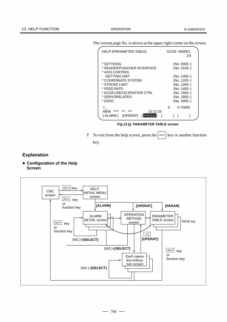
OPERATION13. HELP FUNCTION B–63664EN/02
760
The current page No. is shown at the upper right corner on the screen.
Fig.13 (j) PARAMETER TABLE screen
HELP (PARAMETER TABLE) 01234 N000011/4
* SETTEING (No. 0000∼)* READER/PUNCHER INTERFACE (No. 0100∼)* AXIS CONTROL
/SETTING UNIT (No. 1000∼)* COORDINATE SYSTEM (No. 1200∼)* STROKE LIMIT (No. 1300∼)* FEED RATE (No. 1400∼)* ACCEL/DECELERATION CTRL (No. 1600∼)* SERVORELATED (No. 1800∼)* DI/DO (No. 3000∼)
>_ S 0 T0000MEM **** *** *** 10:12:25[ ALARM ] [OPERAT] [ PARAM ] [ ] [ ]
7 To exit from the help screen, press the HELP key or another function
key.
[ALARM]
ALARMDETAIL screen
OPERATIONMETHOD
screen
PARAMETERTABLE screen
[OPERAT] [PARAM]
keyCNC
screen
Each opera-tion instruc-tion screen
[OPERAT]
(NO.)+[SELECT]
(NO.)+[SELECT]
key or function key
HELP INITIAL MENU
screen
HELP
key orfunction key
HELP
HELP
PAGE key
key or function key
HELP
(NO.)+[SELECT]
Explanation
� Configuration of the HelpScreen

OPERATIONB–63664EN/02 14. SCREEN HARDCOPY
761
14 SCREEN HARDCOPY
The screen hardcopy function outputs the information displayed on theCNC screen as 640*480–dot bitmap data. This function makes it possibleto produce a hard copy of a still image displayed on the CNC.The created bitmap data can be displayed on a PC.
Screen Hardcopy Procedure
1 Check the parameter settings. To use the screen hardcopy function,set bit 7 of parameter 3301 to 1 and parameter 20 (I/O channelselection) to 4 (memory card I/F). Set other relative parameters (bits0, 2, and 3 of parameter 3301) as needed. In a multipath system, setthe parameters for each path.
2 Insert a memory card.
3 To start the function, set hardcopy start signal HDREQ (G67#7) to 1.Alternatively, hold down the [SHIFT] key for five seconds.
4 To end the function, press the [CAN] key. Alternatively, set hardcopy stop signal HDABT (G67#6) to 1.
5 While the screen hardcopy operation is in progress, the hardcopy inprogress signal (F061#3) is tied to 1. For several tens of seconds (orseveral seconds, for a monochrome LCD) before the hardcopyoperation ends, the screen image stands still.
6 When the screen hardcopy operation is completed, the hardcopy inprogress signal (F061#3) goes 0.
While the screen hardcopy operation is in progress, the screen imagekeeps still. This means that the clock displayed on the screen indicatesthe beginning and end of the operation. When the clock stops countingseconds, the hard copy operation starts. The clock resumes countingseconds when the screen hard copy operation ends.
Supplementaryexplanation

OPERATION14. SCREEN HARDCOPY B–63664EN/02
762
NOTE1 During the screen hardcopy operation, key input is disabled
for several tens of seconds. Until the screen hardcopyoperation ends, the screen image lies still. During thisperiod, the hardcopy in progress signal (F061#3) is tied to1. No other signal is output. Avoid turning off the powerindiscriminately during that period.
2 If the [SHIFT] or [CAN] key is customized by C executor, forinstance, the screen hardcopy operation may disable the[SHIFT] or [CAN] key.
3 A normal hard copy may not be produced while the screenimage is moving.
A hard copy of the following screens cannot be produced.
1 Screen of the FS–160i (CNC with personal computer function)
2 System alarm screen
3 Screen while RS–232–C is being used
4 Screen during automatic or manual operation (A hard copy can beproduced in a rest of the operation.)
The bitmap files created by the screen hardcopy function are named asfollows, in order in which they are created after power–up:
‘HDCPY000.BMP’ (Name of the first hardcopy file created afterpower–up)
‘HDCPY001.BMP’ (Name of the second hardcopy file created afterpower–up)
:
:
‘HDCPY099.BMP’
NOTE1 A screen hardcopy file produced after the file HDCPY099.
BMP is output will be named as HDCPY000.BMP.2 If a BMP file output by the screen hardcopy function has the
same name as a file present on a memory card, the file onthe memory card is overwritten unconditionally.
3 When the hardcopy function is carried out after power isturned off and on again, the first output file is named asHDCPY000.BMP again. If the inserted memory card has afile having the same name, the file is unconditionallyoverwritten. Note this when continuously producing hardcopies of various screens.
Limitations
File name

OPERATIONB–63664EN/02 14. SCREEN HARDCOPY
763
The number of colors used in created bitmap data depend on the displaycontrol card, the LCD hardware, and the display mode of the CNC screen.Table 14 (a) indicates the relationships.
Table 14 (a) Colors of BMP data created by the screen hardcopy function
LCDhardware
CNCscreen dis-play mode
Colorsdisplayedon CNC
Colors used in createdBMP data Remarks
MonochromeLCD
— 2 colors 2 colors Shades of gray are not supported.
VG
A c
ard Color LCD VGA–comp
atible modeCharacter:
16 colorsGraphic:
16 colors
When bit 0 of parameter3301 is set to 0: 256 colorsWhen bit 0 of parameter3301 is set to 1: 16 colors
Most CNC screens use this mode. Notethat colors may not be normally displayedin the 16–color mode.
VGA mode 256 colors 256 colors A special screen can be prepared by Cexecutor, for instance.
Table 14 (b) indicates the sizes of bitmap data created by the screenhardcopy function.
Table 14 (b) Sizes of bitmap data created by the screen hardcopy function
Bitmap colors File size (bytes)
Monochrome (2 colors) 38,462
Color (16 colors) 153,718
Color (256 colors) 308,278
If bit 2 of parameter 3301 is set to 1, an alarm message can be output whenthe hardcopy operation ends in failure.(P/S alarm Nos. 5212 to 5214)
Colors of data
Data size
Alarm message

OPERATION15. LASER FUNCTION B–63664EN/02
764
15 ����� -�� ��

OPERATIONB–63664EN/02 15. LASER FUNCTION
765
The following data items are displayed on the laser power screen.
� Current output power� Actual output power� Pulse frequency� Pulse duty� Error
1 Press the OFFSETSETTING function key.
2 Press the [POWER] soft key.
LASER POWER O0000 N00000
PC 1000 W
PA 1000 W
FR 2000 Hz
DU 100 %
E 0.000 MM
S 0 T0000MDI **** *** *** 21:20:07[ POWER ][ SET ][ ][ ][ ]
Fig.15.1
Current output power (PC) : Displays the currently specified outputpower in Watt (W) .The data indicates the value before a poweroverride is applied.
Actual output power (PA ) : Displays the actual output power in Watt(W) .
Pulse frequency (FR ) : Displays the currently specified pulsefrequency in Hertz (Hz) .
Pulse duty (DU ) : Displays the currently specified pulse dutyas a percentage (%) .
Error (E) : Displays the error of Z-axis gap control inmm.
Data items, PC , FR , and DU normally show contouring data. Duringpiercing, they show piercing data.
15.1LASER POWERSCREEN
�����#"��
Explanations
� Data items
� Piercing data

OPERATION15. LASER FUNCTION B–63664EN/02
766
The data necessary to laser processing can be set on these screens.
* For operating the tracing setting screen, see the description of Z-axis gapcontrol.
1 Press the OFFSETSETTING function key.
2 Press the [SET] soft key.
3 Press the page key to select a desired screen.
4 Move the cursor to the item to be changed using the cursor keys.
5 Enter the value and press the INPUT key.
LASER SETTING O0000 N00000
CONTOURING POWER = 1000 WFREQUENCY = 2000 HzDUTY = 100 %
PIERCING POW4R = 800 WFREQUENCY = 1000 HzDUTY = 50 %
POWER SELECT = 0 (0:ALL,1:HLF)POWER CONTROL = 0 (0:OFF,1:ON)
MIN. DUTY = 10 %ASSIST GAS SELECT = 0GAS FLOW SELECT = 1>_ S 0 T0000MDI **** *** *** 21:12:20[ SET ][ TRACE ][ ][ xxxxx ][ ]
Fig.15.2 (a)
LASER SETTING O0000 N00000
GAS FLOW 1 PRE–TIME = 1.00 SPRE–PRES. = 100WORK–PRES. = 200AFTER–TIME = 1.00 SAFTER–PRES. = 100
GAS FLOW 2 PRE–TIME = 1.00 SPRE–PRES. = 100WORK–PRE = 200AFTER–TIME = 1.00 SAFTER–PRE = 100
>_ S 0 T0000MDI **** *** *** 21:12:59[ POWER ][ SET ][ ][ AGING ][ ]
Fig.15.2 (b)
15.2LASER SETTINGSCREEN
Procedure

OPERATIONB–63664EN/02 15. LASER FUNCTION
767
LASER SETTING O0000 N00000
GAS FLOW 3 PRE–TIME = 1.00 SPRE–PRES. = 100WORK–PRES. = 200AFTER–TIME = 1.00 SAFTER–PRES. = 100
>_ S 0 T0000MDI **** *** *** 21:14:54[ POWER ][ SET ][ ][ AGING ][ ]
Fig.15.2 (c)
Specify the laser power items for contouring (power pulse frequency andpulse duty) .
Parameter Item at cursor Setting unit Setting range
Output power (POWER) W (Watt) 0 to 7000 W
Pulse frequency (FREQUENCY) Hz (Hertz) 5 to 2000 Hz
Pulse duty (DUTY) % 0 to 100 %
When new values for the laser power are specified in the machining modeblock (G01, G02, or G03) in the part program, the program executionoverwrites the old values with the new ones.
Specify the laser power items for piercing. Their respective setting rangesand units are the same as those for contouring. When new values for thelaser power are specified with the piercing command (G24) in the partprogram, the program execution overwrites the old values with the newones.
Specify the number of power devices (the number of effective dischargetubes) . Either the number of all tubes or half the number can be specified.
Setting 0 : All tubes are used. 1 : Half of the tubes are used.
To change the setting, turn off the HV, then turn it on. The number ofeffective discharge tubes is then changed.
To enable laser power control (function for controlling the pulse dutyaccording to the feedrate) , set this parameter to 1.When the laser power control function is enabled, laser power iscontrolled with a G63 P1 command or by turning on the correspondingPMC signal, PWCTL.
Explanations
� Laser power forcontouring
� Laser power for piercing
� Power selection
� Power control (on/off)

OPERATION15. LASER FUNCTION B–63664EN/02
768
Specify the minimum duty to be clamped for laser power control. Whenthe calculated pulse duty is less than this setting during laser powercontrol, this setting is used.
Specify the type of assist gas to be used 0 to 3 or 0 to 7 (which depends:on the setting of PRM15001#0) can be specified. When 0 is specified, noassist gas is selected. When address P is specified for the assist gas selectcommand (G32) in the program, the program execution overwrites the oldsetting with the new setting. For the correspondence between settings 1 to 7 and actual assist gas types,refer to the relevant manual of the machine tool builder. The setting assist gas selection is set to 0 by reset.
Specify the supply pattern of the assist gas flow. 1 to 3 can be specified. One of gas flows 1 to 3 is selected accordingly.
Specify the supply pattern of gas flow 1. The supply patterns of gas flowcorresponds to the following 5 settings.
Pressure
Pressure inthe previousstep
Preflow Working flow
Machiningpressure
After-flow
Pressure inthe subse-quent step
Time
Time for the subsequent stepTime for the previous step
The units and setting ranges of time and pressure are as follows.
Setting unit Setting range
Time 0. 01sec 0 to 9999 sec
Pres Refer to the relevant manual of themachine tool builder.
0 to 255
Specify the supply pattern of gas flow 2. The settings are the same as those of gas flow 1.
Specify the supply pattern of gas flow 3.The settings are the same as those of gas flow 1.
Laser setting is possible in any modes. It is also possible while the machine operates.
The protect key switch does not work for laser setting.
� Power control (minimum duty)
� Assist gas selection
� Gas flow selection
� Gas flow 1
� Gas flow 2
� Gas flow 3
Limitations

OPERATIONB–63664EN/02 15. LASER FUNCTION
769
The power compensation function prevents the actual output power frombecoming less than the specified power because of a dirty mirror or otherreasons.
Procedure for power compensation
1 Setting the parametersNo. 15000#4 : Power compensation enable/ disable No. 15200 : Power compensation command output when half of
all discharge tubes are used.No. 15201 : Power compensation command output when all the
discharge tubes are used.No. 15203 : Power compensation limit.No. 15204 : Power compensation coefficientNo. 15205 : Power compensation time.
Please refer the parameter sheet attached the laser oscillator.
2 Generating the laser oscillator If the laser is discharged by setting the HV on, the power specified inparameter No. 15200 or No. 15201 becomes effective. The function compares the specified power with the actual power andcalculates a power compensation coefficient.
Calculating the Power compensation coefficient as follows.
Cp= (Pc/Pa) ∗1024
Cp : Power compensation coefficientPa : Actual PowerPc : Command power (PRM No. 15200 or No. 15201)
Outputting laser beam with shutter close by setting power for setting time,and read the actual laser power from the power sensor when the laser isgenerated.
The commanding power to laser oscillator becomes as follows.
Pl=Cp∗Pp/ 1024
Pl : Commanding power to laser oscillatorCp : Power compensation coefficientPp : Power commanded in a part program
If the calculated power compensation coefficient exceeds the powercompensation limit (PRM No. 15203), the value is clamped at the limit.When this occurs, the system displays a message indicating that themirror needs to be cleaned and outputs the MWRN signal (F220#6) toreport that it is time to clean the mirror. The alarm can be released by resetting the system, but the MWRN signalis continued to output till the system power off.
When the function is invalidated with the parameter, the powercompensation coefficient is set 1024.
15.3POWERCOMPENSATION
�����#"��
Explanations
� Power compensationcoefficient
� Commanding the power
� Requiring mirror clean
Limitations

OPERATION15. LASER FUNCTION B–63664EN/02
770
The automatic aging function setting screen shows a list of settingsrequired for the automatic aging function. On this screen, settingsrequired for aging operation and power compensation can be referencedand changed at a time. This screen is displayed regardless of whether theautomatic aging function is enabled or disabled.
This screen can be displayed by following the procedure below.
1 Press the “OFRFSET” MDI key several times to display the laserscreen.
2 Press the [SET] soft key.
3 Press the [AGING] soft key to display the aging screen.
POWER SET DATA 3D.TRN
SET TRACE W–AXIS AGING
Soft key operation: Aging setting screen
The screen consists of three pages in total. The first page and second pageare related to aging operation. The third page is related to powercompensation operation.
Screen display First page
AGING FUNCTION
[AGING SETTING 1]AGING (0:OFF,1:ON) = *REMAINING CYCLE = ***YEAR DATA = ****MONTH DATA = ****DAT DATA = ****HOUR DATA = ****
TIME LEFT = **** MIN.MANUAL MODE (0:OFF,1:ON) = *SET MANUAL TIMES = ***
[ ][ ][ ][ ][ ]
Corresponding parameter Nos.
No.15008#6No.15334No.15335No.15336No.15337No.15338
No.15340
15.4AUTOMATIC AGINGFUNCTION SETTINGSCREEN
Procedure
Explanations
Screens

OPERATIONB–63664EN/02 15. LASER FUNCTION
771
The items displayed on the first page are listed below. The valid datarange in the following applies when a value is input on this screen.
Name Aging (0: Off, 1: On)
Meaning Disables or enables the automatic aging function.
Parameter No.15008#6
Valid data range 0 or 1
Name Rest
Meaning The rest of the CNC–determined number of times theaging operation is performed
Parameter No.15334
Valid data range 0 to 255
Name Year data
Meaning Time data(NOTE)
Parameter No.15335
Valid data range 0 to 2100
Name Month data
Meaning Time data(NOTE)
Parameter No.15336
Valid data range 0 to 12
Name Day data
Meaning Time data(NOTE)
Parameter No.15337
Valid data range 0 to 31
Name Hour data
Meaning Time data(NOTE)
Parameter No.15338
Valid data range 0 to 23

OPERATION15. LASER FUNCTION B–63664EN/02
772
NOTEThe time data is updated when the oscillator is in the LSTRand subsequent later stages. When LSTR is turned off, thevalues present at this point of time are maintained. Whenthe automatic aging function is disabled (bit 6 of parameterNo. 15008 is set to 0), however, the time data is not updated.
Name Remaining time
Meaning An estimated remaining time of the aging operation in-cluding the power compensation operation is indicated inminutes. Because the indicated value is an estimatedvalue, it may differ from the actual operation time.
Parameter —
Valid data range This item can be referenced only. No value can be set.
Name Manual mode (0: Off, 1: On)
Meaning This item is set to 0 at CNC power–up. When RUN–ONis performed after this item is set to 1, the aging opera-tion is performed as many times as the number set asthe “No. of manual operations” regardless of whether theaging function is enabled or disabled and of the period inwhich the oscillator has been stopped. When aging iscompleted, and the LSTR state is entered, this item is setto 0 automatically. Even when this item is set to 1 afterRUN–ON, this item does not become effective, andmanual aging by this item is not started. The value set inthis item is determined at the time of RUN–ON, so evenwhen the setting of this item is changed during agingoperation, the operation does not change.
Parameter —
Valid data range 0 or 1
Name No. of manual operations
Meaning Set the number of times aging is to be performed whenthe aging operation is started manually. If bit 4 of param-eter No. 15014 is set to 0, the CNC sets this item to 2. Ifbit 4 of parameter No. 15014 is set to 1, a value from 2 to255 can be set.
Parameter No.15340
Valid data range 2 to 255

OPERATIONB–63664EN/02 15. LASER FUNCTION
773
Screen display Second page
AGING FUNCTION
[AGING SETTING 2]POWER = * WFREQUENCY = *** HZDUTY = **** %CAL. TIME = **** SGAS PRESS.(50Hz) = ****GAS PRESS.(60Hz) = ****INTERVAL = **** H
[ ][ ][ ][ ][ ]
Corresponding parameter Nos.
No.15326No.15327No.15328No.15329No.15330No.15331No.15339
The items displayed on the second page are listed below. The valid datarange in the following applies when a value is input on this screen.
Name Power
Meaning Laser power during aging operation
Parameter No.15326
Valid data range 0 to 9999
Name Frequency
Meaning Frequency during aging operation
Parameter No.15327
Valid data range 0 to 2000
Name Duty
Meaning Duty cycle during aging operation
Parameter No.15328
Valid data range 0 to 100
Name Compensation time
Meaning Power compensation time during aging operation
Parameter No.15329
Valid data range 0 to 32767

OPERATION15. LASER FUNCTION B–63664EN/02
774
Name Gas pressure (50 Hz)
Meaning Value of pressure in tubes during aging operation
Parameter No.15330
Valid data range 0 to 32767
Name Gas pressure (60 Hz)
Meaning Value of pressure in tubes during aging operation
Parameter No.15331
Valid data range 0 to 32767
Name Stop time
Meaning Oscillator stop time that requires aging operation
Parameter No.15339
Valid data range 0 to 32767 (valid range: 30 to 120)
Screen display Third page
AGING FUNCTION
[POWER CALIBRATION]CALIB. (0:OFF,1:ON) = *POWER (HALF) = * WPOWER (ALL) = * WFREQUENCY = *** HZDUTY = *** %CAL. TIME = **** SGAS PRESS.(50Hz) = ****GAS PRESS.(60Hz) = ****
[ ][ ][ ][ ][ ]
Corresponding parameter Nos.
No.15000#4No.15200No.15201No.15321No.15322No.15205No.15242No.15243
Name Compensation (0: Off, 1: On)
Meaning Disables or enables power compensation.
Parameter No.15000#4
Valid data range 0 or 1

OPERATIONB–63664EN/02 15. LASER FUNCTION
775
Name Power (half)
Meaning Specified power compensation output value when half ofdischarge tubes are used
Parameter No.15200
Valid data range 0 to 9999
Name Power (all)
Meaning Specified power compensation output value when alldischarge tubes are used
Parameter No.15201
Valid data range 0 to 9999
Name Frequency
Meaning Specified frequency during power compensation
Parameter No.15321
Valid data range 0 to 2000
Name Duty
Meaning Specified duty cycle during power compensation
Parameter No.15322
Valid data range 0 to 100
Name Compensation time
Meaning Power compensation time setting
Parameter No.15205
Valid data range 0 to 32767
Name Gas pressure (50 Hz)
Meaning Value of pressure in tubes during oscillation
Parameter No.15242
Valid data range 0 to 32767
Name Gas pressure (60 Hz)
Meaning Value of pressure in tubes during oscillation
Parameter No.15243
Valid data range 0 to 32767

OPERATION15. LASER FUNCTION B–63664EN/02
776
When the aging operation is to be started manually at the time ofmaintenance of the oscillator, it can be started by setting on the agingsetting screen. At power–up of the CNC, the “Manual mode” item on thefirst page of the aging function setting screen is initially set to 0. Whenthis item is set to 1 then RUN–ON is performed, the aging operation isperformed as many times as the number set in “No. of manual operations”regardless of whether the aging function is enabled or disabled and of theperiod for which the oscillator has been stopped. When the LSTR stateis entered after aging is completed, the “Manual mode” is set to 0automatically. Even when this item is set to 1 after RUN–ON, this itemdoes not become effective, and manual aging by this item is not started.The value set in this item is determined at the time of RUN–ON, so evenwhen the setting of this item is changed during aging operation, theoperation does not change.
As the aging operation starts, the gas pressure and laser output conditionsettings are automatically rewritten for aging. When the aging operationis in progress, to stop the aging operation and to execute the ordinary startsequence, follow the steps explained below. (The same steps are used forboth manual aging and automatic aging.)
1 Stop the laser oscillator (RUN–OFF) to place the oscillator in thepurge state.
2 On the first page of the screen, set “Manual mode” to 0.
3 On the first page of the screen, set “Aging” to 1.
4 On the first page of the screen, set the current time in the time dataitems.
5 After changing the settings, restart the oscillator (RUN–ON). Theparameters for specifying the gas pressure values (parameter Nos.15242 and 15243) are changed to the values set in parameter Nos.15324 and 15325, and the power compensation conditions(parameter Nos. 15201, 15332, 15333, and 15205) are changed to thevalues set in parameter Nos. 15320 to 15323 automatically.
1 Perform HV–OFF.
2 On the first page of the screen, set the “Rest” to 0.
3 Perform HV–ON again. The parameters for specifying the gaspressure values (parameter Nos. 15242 and 15243) are changed to thevalues set in parameter Nos. 15324 and 15325, and the powercompensation conditions (parameter Nos. 15201, 15332, 15333, and15205) are changed to the values set in parameter Nos. 15320 to15323 automatically.
The way of displaying the above screen items can be changed byparameter setting. If bit 4 of parameter No. 15014 is set to 0, only the firstpage of the above screen is displayed, allowing change of the “Manualmode” setting only. The second and third pages are not displayed.If bit 4 of parameter No. 15014 is set to 1, all pages and items aredisplayed.
Starting the agingoperation manually
Ending aging
When the unit does notallow HV–ON(high–voltage ON)operation
When the unit allowsHV–ON (high–voltageON)
Changing the screendisplay

OPERATIONB–63664EN/02 15. LASER FUNCTION
777
#715014
#6 #5 #4MAG
#3 #2 #1 #0
[Data type] Bit
MAG On the aging setting screen:
1 : All items on all pages are displayed. As the No. of manual operations,a value from 2 to 255 may be set.
0 : Only the first page is displayed, and the on/off setting for the manualmode may be changed. The No. of manual operations is always set to2.
Parameter

OPERATION15. LASER FUNCTION B–63664EN/02
778
The block satisfied as follows is searched for , and the laser nozzle ispositioned to the start point of the block and the machine is set in the feedhold status.
1 Where the distance Ls between the start point of the block and thecurrent position of the laser nozzle does not exceed the distancespecified in a parameter.
2 Where the distance Le between the end point of the block and thecurrent position of the laser nozzle exceeds Ls.
Procedure for near-point search function
1 Change the mode to MEM.
2 Find the beginning of the program.
3 Turn on the DI signal for near-point search (G226#0 NRSRH).
4 Push the start button.
5 The near-point search is worked above operation. The near-point search busy signal (F225#1 LNSR) and cycle startlamp signal (F000#5 STL) is output in searching.
6 The cycle start lamp signal is turned off when the searching isfinished. Turn off the DI signal for near-point search and on the start buttonafter finishing the search. And the near-point search busy signal is turned off and the program isre-started.
Set the near- point distance in parameter No. 15635. The laser nozzle is positioned to the start point of the block in case thatthe distance between the start point and the cerrent position of the lasernozzle does not exceed the near- point distance.
(1) The program that is to execute the near–point search function mustbe the one that ran by memory operation just before a near–pointsearch was made. If a near–point search is made without running theprogram by memory operation, positioning cannot be performedcorrectly. This is because the machine position at the start of anormal operation is memorized as the reference position for anear–point search. The buffer used for this purpose is provided tomemorize the machine position related to the program thatperformed an automatic operation (MEM, MDI, or DNC) mostrecently but not for individual programs. Therefore, no near–pointsearch can be made after MDI or DNC operation.
(2) When the power was turned off and on gain, it is impossible to makea near–point search for the program executed before the power wasturned off.
(3) A near–point search cannot be triggered again when it is already inprogress. Once a near–point search was made and a block wasfound, that is, bit 0 of G226 (NRSCH) = 1, bit 1 of F225 (LNSR) =1, and bit 5 of F000 (STL) = 0, executing a cycle start again resultsin alarm PS4000. Before making a re–search, effect a reset.
15.5NEAR–POINTSEARCH FUNCTION
�����#"��
Explanations
� Near-point distance
Limitations

OPERATIONB–63664EN/02 15. LASER FUNCTION
779
(4) If there is no block in which the distance Ls between the currentnozzle position and block start point is shorter than the value set inparameter 15635 during a near–point search, alarm PS4000 occurs.
(5) If the current nozzle position is near the memorized near–pointsearch reference position during a near–point search, the nozzle ismoved to the reference position.
(6) No dwell command is executed during a near–point search.
(7) During a near–point search, all M and T codes are output. The PMCmust handle them.
(8) No laser power is output during a near–point search.
(9) If a program to be subjected to a search contains a command relatedto a reference position return, include an absolute command after it.During the search, G27, G28, G29, and G30 are ignored, and theabsolute command is used to re–set the coordinates.
(10) Positioning at the block found in a search is performed for all axesat a time. When positioning is completed, the nozzle keeps itsattitude for the start point of the block.
(11) In a system provided with attitude control B, alarm PS4002 occursif the G53 operation has not been set to the fixed–tip mode (bit 3 ofPRM.15600 (MIA) = 0).
(12) During the G33 mode, positioning is made at the coordinatesspecified in the program but not at the end point of an automaticallyinserted arc.
(13) Do not use gap control for any axis other than the W–axis during anear–point search. Specifying Z–axis gap control results in alarm PS4001.
(14) For programs that are to be subjected to a near–point search, it isimpossible to change a work coordinate system.
(15) For programs that are to be subjected to a near–point search, allmanual operations must be performed with ”manual absolute”turned on no matter whether machining has not been started or hasbeen finished.
(16) Once a near–point search is made, manual intervention is impossiblebefore the program is restarted.
(17) Machine coordinate system–based move commands (G27, G28,G29, G30, and G53) are ignored during a near–point search.
(18) If the end point of a block is a near point, and the block is followedby a block with G27, G28, G29, G30, or G53, the latter block isassumed to be at a near point.

OPERATION15. LASER FUNCTION B–63664EN/02
780
If the three–dimensional cutting function supports W–axis gap control,setting the gap control feed signal to “1” selects the Z–axis as a gap controlaxis. Activating Z–axis gap control enables the Z–axis to gap controlmovement along the X– and Y–axes when they are operated manually.
Procedure for gap control axis switching
1 Turn on the gap control axis switching signal (G225#0 ZTRM).
2 Turn on the gap control start signal (G225#3 TCST).
3 Change the mode to JOG or HNDL and X and/or Y axes are moved bymanual operation.
This function cannot be executed when the manual operation in handcoordinate system.
When the gap control feed function is being executed, the Z-axis jog feedsignal is ignored.
15.6GAP CONTROL AXISSWITCHING
Procedure
Limitations

OPERATIONB–63664EN/02 15. LASER FUNCTION
781
The approach feed mode is ON , if the gap control feed signal is turnedon when the W-axis tracing control function is added.The signal from the gap sennsor is monitored in approach feed mode.If the signal from the sensor is 0 or more (too close to the workpiece), thejog feed in the X, Y and Z directions and the nozzle direction is stopped.
Procedure for approach feed function
1 Turn on the approach feed signal (G225#1 ZAPR).
2 The jog feed is stopped automatically, if the nozzle is too close to theworkpiece when the nozzle is feeded in jog mode.
3 To release the machine from stopped status, set the approach feedsignal to 0 and the jog feed select signal to 0, then select the approachfeed function again.
15.7APPROACH FEEDFUNCTION
Procedure

OPERATION15. LASER FUNCTION B–63664EN/02
782
The term ”hand coordinate system” refers to a coordinate system definedbased on the nozzle attitude with the nozzle tip position regarded as theorigin in attitude control A or B. In a hand coordinate system defined inan arbitrary space, axis movement is implemented by moving an axis ormore at a time using the feed signal for the X–, Y– or Z–axes.Using this function makes it easy to position the nozzle during programcreation by teaching.
Procedure for manual operation in hand coordinate system
(1)Attitude control A
� Letting +Zh be a direction normal to the nozzle;
� Letting B be a point viewed from basic–attitude point A in parallelto the +Y direction, and letting +Yh be a direction parallel to lineAB at the nozzle tip; and
� With the thumb and the first and second fingers of the left handextended at right angles to one another, letting +Yh and +Zh be thedirections of the first finger and thumb, respectively; let +Zh be thedirection of the second finger.
Point A
Point B
Parallel
Hand coordinate system
+Z
+Y+Zh
+Yh
+Xh
+X
α
β
15.8MANUALOPERATION IN HANDCOORDINATESYSTEM
Definition of the handcoordinate

OPERATIONB–63664EN/02 15. LASER FUNCTION
783
(2)Attitude control B
� Letting +Zh be a direction normal to the nozzle;
� Letting +Xh be the α–axis arm direction;
� With the thumb and the first and second fingers of the left handextended at right angles to one another, letting +Xh and +Zh be thedirections of the second finger and thumb, respectively; let +Yh bethe direction of the first finger.
Machine coordinates(x, y, z)
X
α
L1 +ZhY
Z
β+Xh
Hand coordinatesystem
+YhL2
1 Turn on the manual operation in hand coordinate system signal(G226#3 HNDCD).
2 Jog feedEach axis moves in the ± Xh-axis direction using jog feed axisdirection signal ± X. They also move in the ± Yh-axis direction usinga ± Y signal and the ± Zh-axis direction using a ± Z signal.For the jog feed in the hand coordinate system, one-axis operation(including α and β axes) is performed at the same time. When jog feedaxis direction signal ± α and ± β are specified, the rotarion axisoperates in the nozzle tip fixed mode. If execution of the rotation axiscommand stops, the hand coordinate system is updated to a newcoordinate system.A linear axis command is executed in the updated hand coordinatesystem.
3 Handle feed Each axis can be moved in the ± Xh-axis direction using a manualpulse generator when manual handle feed axis select signal HXturned on. They also move in the ± Yh-axis direction using ± HYsignal and the ± Zh-axis direction using a ± HZ signal.
H4 (4th axis: α axis) and H5 (5th axis: β axis) handle feeds cannot beaccepted when hand coordinate mode select signal HNDCD is set to 1.To move the α and β axes by the handle feed, set the HNDCD signal to0. When manual handle feed axis select signal H4 or H5 is selected, seta PMC ladder so that the HNDCD signal is “0”. This facilitates theoperation. Set all the X–, Y–, and Z–axes to the same manual feedrate.
Procedure
Limitations
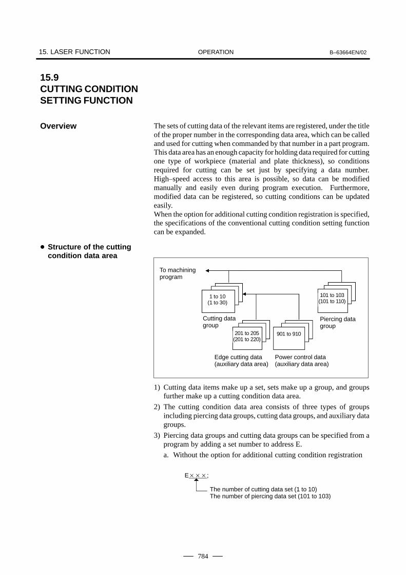
OPERATION15. LASER FUNCTION B–63664EN/02
784
The sets of cutting data of the relevant items are registered, under the titleof the proper number in the corresponding data area, which can be calledand used for cutting when commanded by that number in a part program.This data area has an enough capacity for holding data required for cuttingone type of workpiece (material and plate thickness), so conditionsrequired for cutting can be set just by specifying a data number.High–speed access to this area is possible, so data can be modifiedmanually and easily even during program execution. Furthermore,modified data can be registered, so cutting conditions can be updatedeasily.When the option for additional cutting condition registration is specified,the specifications of the conventional cutting condition setting functioncan be expanded.
To machiningprogram
Cutting datagroup
Edge cutting data(auxiliary data area)
Power control data(auxiliary data area)
Piercing datagroup
1 to 10(1 to 30)
201 to 205(201 to 220)
101 to 103(101 to 110)
901 to 910
1) Cutting data items make up a set, sets make up a group, and groupsfurther make up a cutting condition data area.
2) The cutting condition data area consists of three types of groupsincluding piercing data groups, cutting data groups, and auxiliary datagroups.
3) Piercing data groups and cutting data groups can be specified from aprogram by adding a set number to address E.
a. Without the option for additional cutting condition registration
E���;
The number of cutting data set (1 to 10)The number of piercing data set (101 to 103)
15.9CUTTING CONDITIONSETTING FUNCTION
Overview
� Structure of the cuttingcondition data area

OPERATIONB–63664EN/02 15. LASER FUNCTION
785
b. With the option for additional cutting condition registration
E���;
The number of cutting data set (1 to 30)The number of piercing data set (101 to 110)
4) Auxiliary data groups are specified from data items in cutting datagroups. It is impossible to specify auxiliary data groups directly withaddress E.
Piercing data consists of the items listed below.For the operation of piercing, see Section 18.2, “PIERCINGFUNCTION”, in Part II, “PROGRAMMING”.
1) Setting items
Data item Setting range Unit
Peak power 0 to 9999 W
Initial frequency 5 to 2000 Hz
Initial duty 0 to 100 %
Step frequency 0 to 2000 Hz
Step duty 0 to 99 %
Step time 0 to 9.999 Sec
Step number 0 to 99
Piercing time 0.001 to 999.999 Sec
Assist gas pressure 0 to 9.99 MPa
Assist gas select 1 to 7
Gas settling time 0 to 9.9 Sec
Reference displace –9.999 to 9.999 mm
2) SizeA group consists of three sets, each consisting of the above items,when the option for additional cutting condition registration is notprovided, or a group consists of ten sets when the option for additionalcutting condition registration is provided.
3) Calling methodIf a piercing data set number is specified with address E in a program,the data set with the specified number is read as active data.
E���;
The number of piercing data set (101 to 103(*1), 101 to110(*2))
*1 Without the option for additional cutting condition registration*2 With the option for additional cutting condition registration
Items of cuttingcondition data groups
� Piercing data group

OPERATION15. LASER FUNCTION B–63664EN/02
786
Cutting data consists of the items listed below.For the meaning of cutting data, see Section 18.1, “CONTOURMACHINING”, in Part II, “PROGRAMMING”.
1) Setting items
Data item Setting range Unit
Withoutadditional cutting
conditionregistration
With additionalcutting condition
registration
Feedrate 0 to 99999 0 to 99999 mm/min
Cutting peak power 0 to 9999 0 to 9999 W
Cutting frequency 5 to 2000 5 to 2000 Hz
Cutting duty 0 to 100 0 to 100 %
Assist gas pressure 0 to 9.99 0 to 9.99 MPa
Assist gas select 1 to 7 1 to 7
Gas settling time 0 to 9.9 0 to 9.9 Sec
Reference displace –9.999 to 9.999 –9.999 to 9.999 mm
Cutter compensation –9.999 to 9.999 –9.999 to 9.999 mm
Edge cutting select 0/201 to 205 0/201 to 215 Aux. data No.
Startup select 0/201 to 205 0/201 to 215 Aux. data No.
Power control select(*3)
0/901 to 910 0/901 to 910 Aux. data No.
*3 Supported by the FS16i–LB and later
2) SizeA group consists of 10 sets, each consisting of the above items, whenthe option for additional cutting condition registration is not provided,or a group consists of 30 sets when the option for additional cuttingcondition registration is provided.
3) Calling methodIf a cutting data set number is specified with address E in a program,the data set with the specified number is read as active data and usedfor control when the cutting feed command is executed.
E���;
The number of cutting data set (1 to 10(*4), 1 to 30(*5))
*4 Without the option for additional cutting condition registration*5 With the option for additional cutting condition registration
� Cutting data group

OPERATIONB–63664EN/02 15. LASER FUNCTION
787
Edge cutting data groups and power control data groups are provided asauxiliary data groups.
1. Edge cutting data group
Edge cutting data is used for edge cutting, which is performed to cut acorner sharply, and for using the startup function, which operates whencontouring is started after piercing. When used, edge cutting data is calledfrom “Edge cutting select” or “Startup select” of a cutting data group.For the operations of edge cutting and startup, see Subsection 18.7.3,“Edge Machining Function”, and Subsection 18.7.4, “Startup MachiningFunction”, in Part II, “PROGRAMMING”.
1) Setting items
Data item Setting range Unit
Judge angle for edge 0 to 180 Degree
Piercing power 0 to 9999 W
Piercing frequency 5 to 2000 Hz
Piercing duty 0 to 100 %
Piercing time 0 to 999.999 Sec
Piercing gas press 0 to 9.99 MPa
Piercing gas select 0 to 99
Recovery distance 0 to 99.999 mm
Recovery feedrate 0 to 9999 mm/min
Recovery frequency 5 to 2000 Hz
Recovery duty 0 to 100 %
2) SizeA group consists of five sets, each consisting of the above items, whenthe option for additional cutting condition registration is not provided,or a group consists of 20 sets when the option for additional cuttingcondition registration is provided.
3) Calling methodData is called indirectly.In “Edge cutting select” or “Startup select” of cutting data groups, setedge cutting data numbers from 201 to 205 in advance if the option foradditional cutting condition registration is not provided, or set edgecutting data numbers from 201 to 220 in advance if the option foradditional cutting condition registration is provided. Then, whencutting data is read, edge cutting data is called at the same time.
(1)Specified peak power
[Data type] Word
[Unit of data] W
[Valid data range] 0 to 7000
Set a peak power to be specified for each data table.
� Auxiliary data group

OPERATION15. LASER FUNCTION B–63664EN/02
788
(2)Specified frequency
[Data type] Word
[Unit of data] Hz
[Valid data range] 0 to 2000
Set a frequency to be specified for each data table.
(3)Specified duty cycle
[Data type] Word
[Unit of data] %
[Valid data range] 0 to 100
Set a duty cycle to be specified for each data table.
2. Power control data group
Power control data consists of the items listed below.For the operation of power control, see Section 18.3, “LASER POWERCONTROL”, in Part II, “PROGRAMMING”.
1) Setting items
Data item Setting range Unit
Minimum peak power (clamp value) 0 to 9999 W
Peak power at feedrate (F) of 0 0 to 9999 W
Minimum pulse frequency (clamp value) 5 to 2000 Hz
Pulse frequency at feedrate (F) of 0 5 to 2000 Hz
Minimum pulse duty cycle (clamp value) 0 to 100 %
Duty cycle at feedrate (F) of 0 0 to 100 %
Allowable feedrate variation width(dead–band)
0 to 32767 mm/min or %
2) SizeA group consists of 10 sets, each consisting of the above items.
3) Calling methodData is called indirectly.In “Power control select” of cutting data groups, set power controlcondition numbers from 901 to 210 in advance. Then, when cuttingdata is read, power control data is called at the same time.

OPERATIONB–63664EN/02 15. LASER FUNCTION
789
1) Displaying each cutting data group registration screen
a. Press the OFFSET/SETTING function key several times. Then,the following soft keys are displayed:
POWER SET DATA 3D.TRN
b. Press the [DATA] soft key. Then, the following soft keys aredisplayed:
CUT PIERCE EDGE PWR.CT OPRT
c. Press the soft key of a desired cutting data group. Then the datagroup is displayed.
Cutting data group > [CUT]Piercing data group > [PIERCE]Edge data group > [EDGE]Power control data group > [POWER C]
2) Indication of the name of displayed dataThe name of the displayed data is indicated at the beginning of thescreen.
Example:xxxxx
3) Indication of the active data numberFollowing the name of the displayed data, the numbers of the cuttingdata set and piercing data set that are currently active are indicated.
Example:xxxxx
To clear the E number by reset operation, set bit 6 of parameter No.15004 to 1.
Cutting data screen
[CUTTING] ACTIVE DATA NO. CUTTING = 5 PIERCING = 103
NO. FEED PWR FREQ DUTY GAS GAS GAS GAP OFSET EDGE START POWER PRESS.KIND TIME UP CTL
1 ***.** **** **** *** **.* * *.* **.**** ***.**** *** *** *** 2 ***.** **** **** *** **.* * *.* **.**** ***.**** *** *** *** 3 ***.** **** **** *** **.* * *.* **.**** ***.**** *** *** *** 4 ***.** **** **** *** **.* * *.* **.**** ***.**** *** *** *** 5 ***.** **** **** *** **.* * *.* **.**** ***.**** *** *** ***
6 ***.** **** **** *** **.* * *.* **.**** ***.**** *** *** *** 7 ***.** **** **** *** **.* * *.* **.**** ***.**** *** *** *** 8 ***.** **** **** *** **.* * *.* **.**** ***.**** *** *** *** 9 ***.** **** **** *** **.* * *.* **.**** ***.**** *** *** ***10 ***.** **** **** *** **.* * *.* **.**** ***.**** *** *** ***
Displaying cuttingcondition data area

OPERATION15. LASER FUNCTION B–63664EN/02
790
Piercing data screen
[PIERCING] ACTIVE DATA NO. CUTTING = 5 PIERCING = 103
No. PWR. [INITIAL] [INCREM.] [STEP] PIRC [ASSIST GAS] DEFFREQ. DUTY FREQ. DUTY TIME CNT TIME PRESS. KIND TIME
101 **** **** *** **** *** *.*** ** ***.*** **.* ** *.* –*.***102 **** **** *** **** *** *.*** ** ***.*** **.* ** *.* –*.***103 **** **** *** **** *** *.*** ** ***.*** **.* ** *.* –*.***104 **** **** *** **** *** *.*** ** ***.*** **.* ** *.* –*.***105 **** **** *** **** *** *.*** ** ***.*** **.* ** *.* –*.***
106 **** **** *** **** *** *.*** ** ***.*** **.* ** *.* –*.***107 **** **** *** **** *** *.*** ** ***.*** **.* ** *.* –*.***108 **** **** *** **** *** *.*** ** ***.*** **.* ** *.* –*.***109 **** **** *** **** *** *.*** ** ***.*** **.* ** *.* –*.***110 **** **** *** **** *** *.*** ** ***.*** **.* ** *.* –*.***
Edge cutting data screen
[EDGE] ACTIVE DATA NO. CUTTING = 5 PIERCING = 103
No. ANGL. PWR FREQ DUTY PIRC GAS GAS STRT STRT STRT STRT DEFTIME PRESS. KIND DIST FEED FREQ. DUTY
201 *** **** **** *** ***.*** **.* ** **.*** **** **** **** –*.***202 *** **** **** *** ***.*** **.* ** **.*** **** **** **** –*.***203 *** **** **** *** ***.*** **.* ** **.*** **** **** **** –*.***204 *** **** **** *** ***.*** **.* ** **.*** **** **** **** –*.***205 *** **** **** *** ***.*** **.* ** **.*** **** **** **** –*.***
206 *** **** **** *** ***.*** **.* ** **.*** **** **** **** –*.***207 *** **** **** *** ***.*** **.* ** **.*** **** **** **** –*.***208 *** **** **** *** ***.*** **.* ** **.*** **** **** **** –*.***209 *** **** **** *** ***.*** **.* ** **.*** **** **** **** –*.***210 *** **** **** *** ***.*** **.* ** **.*** **** **** **** –*.***
Power control data screen
[POWER CONTROL] ACTIVE DATA NO. CUTTING = 5 PIERCING = 103
No. POWER FREQUENCY DUTY PWR./SPEED VAR.MIN F=0 MIN F=0 MIN F=0
901 **** **** **** **** *** *** *****902 **** **** **** **** *** *** *****903 **** **** **** **** *** *** *****904 **** **** **** **** *** *** *****905 **** **** **** **** *** *** *****
906 **** **** **** **** *** *** *****907 **** **** **** **** *** *** *****908 **** **** **** **** *** *** *****909 **** **** **** **** *** *** *****910 **** **** **** **** *** *** *****

OPERATIONB–63664EN/02 15. LASER FUNCTION
791
1) Function for changing cutting condition data by screen operationsSelect and display a screen, and press the [OPRT] soft key. Then,modification becomes possible. Move the cursor to the item tochange, and modify data.
a. When data with a currently active number is modified, the activedata of the items except the “Cutter compensation” item is alsomodified immediately.
b. The new “Cutter compensation” data after the modificationbecomes valid when the block at which the buffer content isrewritten has been executed.
2) Function for modifying cutting data by using an external signalWhen modification data is transferred from the PMC to the CNC, dataof a specified item of cutting data with the currently active set numbercan be increased and decreased.Registered data of piercing data groups, power control data groups,and auxiliary data groups cannot be changed.This function cannot be used when the option for additional cuttingcondition registration is specified.
a. Specifying an R areaThree bytes in the R area of the PMC are allocated to modificationdata. When the start address of the R area is set in parameter No.15360, a 3–byte area starting from the start address is allocated.
b. Modification dataThe three bytes in the R area which are allocated by parametersetting are assigned to the item to change, change amount, andchange magnification as shown below. The CNC reads the threebytes of data at intervals of 16 ms, and modifies cutting data.The cutting data to change is the data of an item specified by theitem to change in the cutting data with the set number selected bythe E code. The data is increased or decreased by the value obtainedby multiplying the change amount by the change magnification.The following data can be modified:
– Feedrate– Peak power– Pulse frequency– Pulse duty cycle– Gap control reference displacement– Assist gas pressure
Modifying cuttingcondition data

OPERATION15. LASER FUNCTION B–63664EN/02
792
Start address Item to change
[Data type] Byte
[Valid data range] 1 to 255
Item to change Data
Feedrate 1
Peak power 2
Pulse frequency 3
Pulse duty cycle 4
Gap control reference displacement 5
Assist gas pressure 6
Start address + 1 Change amount
[Data type] Byte
[Valid data range] �127
[Unit of data] See the following.
Item to change Data
Feedrate 1 mm/min
Peak power 1 W
Pulse frequency 1 Hz
Pulse duty cycle 1 %
Gap control reference displacement 0.001 mm
Assist gas pressure 0.01 MPa
Start address + 2 Change magnification
[Data type] Byte
[Valid data range] 1 to 255
c. Transmission and reception of cutting dataThe CNC reads the change amount data at intervals of 16 ms. Ifthe read data is not 0, the CNC successively reads the item tochange and the change magnification data, then writes 0 to thechange amount to complete data reception. So, after checking thatthe change amount data is 0, the PMC sets data of the item tochange and the change magnification (if the data is the same as theprevious data, the setting can be omitted), then writes the changeamount at the end.

OPERATIONB–63664EN/02 15. LASER FUNCTION
793
An override can be applied to the cutting condition data listed below byusing an external signal.For details of override, refer to “FS16i Connection Manual (Function)”(B–63523EN–1) and “FS16i–LB Connection Manual” (B–63663EN).
– Feedrate– Peak power– Pulse frequency– Pulse duty cycle– Assist gas pressure
The data area of the cutting condition setting function allows high–speedaccess but has a small capacity.To use many types of workpiece materials, it is necessary to prepare aseparate cutting condition data file and transfer necessary data from thefile to the cutting condition data area. With the expansion nonvolatilememory controllable by the PMC and the enhanced CNC–PMC windowfunction, application software that uses the expansion nonvolatilememory as a cutting condition data file can be developed by using C ofthe PMC.
1) Data transfer between the cutting condition data area and expansionnonvolatile memoryThe PMC–CNC window function allows data transmission andreception between the CNC data area and the expansion nonvolatilememory.This can be used for functions that use an M code for comment readingmentioned above to specify necessary data for cutting, transfer the datafrom the expansion nonvolatile memory, in which all cutting conditiondata has been registered in advance, to the data area, and performoperation while making high–speed access to the transferred data.
2) Data transfer between the cutting condition data area and macroexecutorSystem variables are assigned to data items so that data can be readfrom and written in the cutting condition data area by usingconversational macros and execution macros.This function cannot be used when the option for additional cuttingcondition registration is specified.
Override
Expansion of cuttingcondition data
� Transmission andreception of cuttingcondition data

OPERATION15. LASER FUNCTION B–63664EN/02
794
a. Piercing data
Data item E101 E102 E103
Peak power #6500 #6515 #6530
Initial frequency #6501 #6516 #6531
Initial duty #6502 #6517 #6532
Step frequency #6503 #6518 #6533
Step duty #6504 #6519 #6534
Step time #6505 #6520 #6535
Step number #6506 #6521 #6536
Piercing time #6507 #6522 #6537
Assist gas pressure #6508 #6523 #6538
Assist gas type #6509 #6524 #6539
Gas settling time #6510 #6525 #6540
Reference displace #6511 #6526 #6541
b. Cutting data
Data item E1 E2 E3 E4 E5
Feedrate #6300 #6315 #6330 #6345 #6360
Cutting peak power #6301 #6316 #6331 #6346 #6361
Cutting frequency #6302 #6317 #6332 #6347 #6362
Cutting duty #6303 #6318 #6333 #6348 #6363
Assist gas pressure #6304 #6319 #6334 #6349 #6364
Assist gas select #6305 #6320 #6335 #6350 #6365
Gas settling time #6306 #6321 #6336 #6351 #6366
Reference displace #6307 #6322 #6337 #6352 #6367
Cutter compensation #6308 #6323 #6338 #6353 #6368
Edge cutting select #6309 #6324 #6339 #6354 #6369
Startup select #6310 #6325 #6340 #6355 #6370
Power control #6311 #6326 #6341 #6356 #6371
Data item E6 E7 E8 E9 E10
Feedrate #6375 #6390 #6405 #6420 #6435
Cutting peak power #6376 #6391 #6406 #6421 #6436
Cutting frequency #6377 #6392 #6407 #6422 #6437
Cutting duty #6378 #6393 #6408 #6423 #6438
Assist gas pressure #6379 #6394 #6409 #6424 #6439
Assist gas select #6380 #6395 #6410 #6425 #6440
Gas settling time #6381 #6396 #6411 #6426 #6441
Reference displace #6382 #6397 #6412 #6427 #6442
Cutter compensation #6383 #6398 #6413 #6428 #6443
Edge cutting select #6384 #6399 #6414 #6429 #6444
Startup select #6385 #6400 #6415 #6430 #6445
Power control #6386 #6401 #6416 #6431 #6446

OPERATIONB–63664EN/02 15. LASER FUNCTION
795
c. Edge data
Data item E201 E202 E203 E204 E205
Judge angle for edge #6700 #6715 #6730 #6745 #6760
Piercing power #6701 #6716 #6731 #6746 #6761
Piercing frequency #6702 #6717 #6732 #6747 #6762
Piercing duty #6703 #6718 #6733 #6748 #6763
Piercing time #6704 #6719 #6734 #6749 #6764
Piercing gas press #6705 #6720 #6735 #6750 #6765
Piercing gas select #6706 #6721 #6736 #6751 #6766
Recovery distance #6707 #6722 #6737 #6752 #6767
Recovery feedrate #6708 #6723 #6738 #6753 #6768
Recovery frequency #6709 #6724 #6739 #6754 #6769
Recovery duty #6710 #6725 #6740 #6755 #6770
Tracing displacement #6711 #6726 #6741 #6756 #6771
d. Active E code
Data item —
Piercing data set No. #6030
Cutting data set No. #6031
3) Power control data operation by custom macrosSystem variables are assigned to data items to allow custom macrosto read and write power control data.These system variables can be referenced by the macro executor. Inthis case, the number used for reference is obtained by adding 100000to the corresponding system variable used by custom macros.For example, data a custom macro references by using #6550 can bereferenced by the macro executor by using #106550.
Data item E901 E902 E903 E904 E905 E906 E907 E908 E909 E910
Minimum power #6550 #6560 #6570 #6580 #6590 #6600 #6610 #6620 #6630 #6640
Power at feedrate of 0 #6551 #6561 #6571 #6581 #6591 #6601 #6611 #6621 #6631 #6641
Minimum frequency #6552 #6562 #6572 #6582 #6592 #6602 #6612 #6622 #6632 #6642
Frequency at feedrate of 0 #6553 #6563 #6573 #6583 #6593 #6603 #6613 #6623 #6633 #6643
inimum duty cycle #6554 #6564 #6574 #6584 #6594 #6604 #6614 #6624 #6634 #6644
Duty cycle at feedrate of 0 #6555 #6565 #6575 #6585 #6595 #6605 #6615 #6625 #6635 #6645
Allowable feedrate variation width #6556 #6566 #6576 #6586 #6596 #6606 #6616 #6626 #6636 #6646

OPERATION15. LASER FUNCTION B–63664EN/02
796
4 Data transfer using FOCAS1With the FOCAS1 (FANUC Open CNC API Specifications version 1)window function, cutting condition data can be transferred between apersonal computer, the CNC, and the PMC via Ethernet (TCP/IP) orHSSB (High Speed Serial Bus).This allows a large amount of cutting condition data to be held in thepersonal computer and used.This function cannot be used when the option for additional cuttingcondition registration is specified.For details on how to use the function, refer to the FOCAS1 datawindow library specifications.
Data item Without additionalcutting condition
registration
With additionalcutting condition
registration
Number of cutting data sets 10 30
Number of piercing data sets 3 10
Number of edge cutting data sets (auxiliary data) 5 20
Number of power control data sets (auxiliary data) 10 10
Function for modifying cutting data by using an external signal �
Comment read
Data transfer between cutting condition data area and expansionnonvolatile memory
Data transfer between cutting condition data area and macro executor �
Data transfer using FOCAS1 �
: Available � : Not available
Functions

OPERATIONB–63664EN/02 15. LASER FUNCTION
797
The current data of laser are displayed.
1 Press OFFSETSETTING key, and the following soft keys are displayed.
POWER SET DATA
2 Press next- menu key .3 Press [STATUS] key.4 Laser status screen is displayed as follows.
MAT. ***********E CODE CUTTING *** PIERCING ***
F FEED ***** mm/min
PC POWER **** W
FR FREQUENCY **** Hz
DU DUTY *** %
GK GAS SELECT *
GP GAS PRESSURE *.** MPA
ER DEFLECTION –*.*** mm
D OFFSET *.*** mm
STATUS
O ***** N *****
FA FEED ***** mm/min
PA POWER **** W
X –*****.***Y –*****.***Z –*****.***4 –*****.***
E–code : The current data set number for cutting andpiercing of processing condition settingfunction is shown.
Feedrate (F) : The commanded feedrate is shown. Unit mm/ min
Command power (PC) : The commanded laser peak power beforeapplying override is shown.Unit Watt (W)
Pulse frequency (FR) : The commanded pulse frequency is shown. Unit Hertz (Hz)
Pulse duty (DU) : The commanded pulse duty is shown. Unit %
Assist gas select (Gk) : The commanded assist gas select is shown.Assist gas pressure (Gp) : The actual assist gas pressure is shown.
Unit MPaError of gap control (E) : Error of gap control is shown.
Unit mmOffset value (D) : The current tool offset value is shown.
Unit mmProgram No. (O) : The current program No. is shown.Sequence No. (N) : The current sequence No. in a part program is
shown.Actual feedrate (FA) : Actual feedrate is shown.
Unit mm/ minActual power (PA) : Actual laser power is shown.
Unit Watt (W)Position : The current position in the relative coordinate
is shown.
15.10LASER STATUSSCREEN�����#"��
Explanations� Meaning of items

OPERATION15. LASER FUNCTION B–63664EN/02
798
When the target point and the basic point is specified, an arbitrary pointin the coordinate system of a part program is converted into the partprogram by three dimensions. The mirror image conversion and threedimension movement conversion are prepared as three-variabletransform function.
1 When the function key OFFSETSETTING is pushed, the softkey is displayed as
follows.
POWER SET DATA 3D.TRN
2 Push the soft key [3D. TRN].3 The mirror image source screen is displayed as follows.
MIRROR IMAGE SOURCE O0001 N0001
SOURCE (P) DESTINA. (Q)X–99999.999 X–99999.999
#0 Y–99999.999 Y–99999.999Z–99999.999 Z–99999.999
[ POWER ][ SET ][ DATA ][ 3D.TRN ][ ]
SHIFT FUNC. O0001 N0001
SOURCE (P) DESTINA. (Q)X–99999.999 X–99999.999
#1 Y–99999.999 Y–99999.999Z–99999.999 Z–99999.999
X–99999.999 X–99999.999#2 Y–99999.999 Y–99999.999
Z–99999.999 Z–99999.999
#3 Y–99999.999 Y–99999.999Z–99999.999 Z–99999.999
[ POWER ][ SET ][ DATA ][ 3D.TRN ][ ]
4 The screen consists of the mirror image source conversion and thethree dimension movement conversion. It is 2 page, and change thepage by the page key.
5 Move the cursor on the item where data must be set, and push the
function key INPUT after inputting value.
It is impossoble to set these data during operating a part program.
15.11THREE–VARIABLETRANSFORMFUNCTION
Procedure
Limitations

IV. MAINTENANCE


MAINTENANCEB–63664EN/02 1. METHOD OF REPLACING BATTERY
801
1 METHOD OF REPLACING BATTERY
This chapter describes how to replace the CNC backup battery andabsolute pulse coder battery. This chapter consists of the followingsections:
1.1 REPLACING BATTERY FOR LCD–MOUNTED TYPE iSERIES
1.2 REPLACING THE BATTERY FOR STAND–ALONE TYPE iSERIES
1.3 BATTERY IN THE CNC DISPLAY UNIT WITH PCFUNCTIONS (3 VDC)
1.4 BATTERY FOR SEPARATE ABSOLUTE PULSE CODERS(6 VDC)
1.5 BATTERY FOR BUILT–IN ABSOLUTE PULSE CODERS (6 VDC)
Part programs, offset data, and system parameters are stored in CMOSmemory in the control unit. The power to the CMOS memory is backedup by a lithium battery mounted on the front panel of the control unit.Therefore, the above data is not lost even if the main battery fails. Thebackup battery is installed in the control unit prior to being shipped fromthe factory. This battery can provide backup for the memory contents forabout a year.
When the battery voltage falls, alarm message “BAT” blinks on the LCDdisplay and the battery alarm signal is output to the PMC. When thisalarm is displayed, replace the battery as soon as possible. In general, thebattery can be replaced within one or two weeks of the alarm first beingissued. This, however, depends on the system configuration.
If the battery voltage subsequently drops further, backup of memory canno longer be provided. Turning on the power to the control unit in thisstate causes system alarm 910 (SRAM parity alarm) to be issued becausethe contents of memory are lost. Replace the battery, clear the entirememory, then reenter the data.Replace the memory backup battery within a few minutes while thecontrol unit is brought off.The following two kinds of batteries can be used.
� Lithium battery, incorporated into the CNC control unit.
� Two alkaline dry cells (size D) in an external battery case.
NOTEA lithium battery is installed as standard at the factory.
Battery for memorybackup

MAINTENANCE1. METHOD OF REPLACING BATTERY B–63664EN/02
802
When a lithium battery is usedPrepare a new lithium battery (ordering code: A02B–0200–K102(FANUC specification: A98L–0031–0012)).
1) Turn on the power to the CNC. After about 30 seconds, turn off thepower.
2) Remove the old battery from the top of the CNC control unit.First, unplug the battery connector, then take the battery out of itscase.The battery case of a control unit without option slots is located at thetop end of the unit as shown in the figure of the previous page. Thebattery case of a control unit with 2 slots or 4 slots is located in thecentral area of the top of the unit (between fans).
3) Insert a new battery and reconnect the connector.
Battery case
Connector
Lithium battery
A02B–0200–K102
WARNING
Using other than the recommended battery may result in thebattery exploding. Replace the battery only with thespecified battery (A02B–0200–K102).
1.1REPLACINGBATTERY FORLCD–MOUNTEDTYPE i SERIES
� Replacement procedure

MAINTENANCEB–63664EN/02 1. METHOD OF REPLACING BATTERY
803
CAUTION
Steps 1) to 3) should be completed within 30 minutes (orwithin 5 minutes for the 160i/180i with the PC function). Donot leave the control unit without a battery for any longerthan the specified period. Otherwise, the contents ofmemory may be lost.If steps 1) to 3) may not be completed within 30 minutes,save all contents of the CMOS memory to the memory cardbeforehand. Thus, if the contents of the CMOS memory arelost, the contents can be restored easily. For the method of operation, refer to Maintenance manual(B–63005EN).
When discarding a battery, observe the applicable ordinances or otherrules of your local government. Also, cover the terminals of the batterywith vinyl tape or the like to prevent a short–circuit.

MAINTENANCE1. METHOD OF REPLACING BATTERY B–63664EN/02
804
1) Prepare two alkaline dry cells (size D) commercially available.
2) Turn on the power to the Series 16i/18i/160i/180i.
3) Remove the battery case cover.
4) Replace the cells, paying careful attention to their orientation.
5) Reinstall the cover onto the battery case.
CAUTION
When replacing the alkaline dry cells while the power is off,use the same procedure as that for lithium batteryreplacement described above.
Cover
Alkaline dry cell �2
Connection terminal on the rear
Battery case
Mounting hole �4
Replacing commercial alkaline drycells (size D)

MAINTENANCEB–63664EN/02 1. METHOD OF REPLACING BATTERY
805
If a lithium battery is used, have A02B–0200–K102 (FANUC internalcode: A98L–0031–0012) handy.
(1)Turn the CNC on. About 30 seconds later, turn the CNC off.
(2)Remove the battery from the top area of the CNC unit.Disconnect the connector first. Then, remove the battery from thebattery case.The battery case is provided in the top area of the face plate of the mainCPU board.
(3)Replace the battery, then connect the connector.
Battery case
Lithium batteryA02B–0200–K102
Connector
WARNING
The incorrect mounting of the battery may cause anexplosion. Avoid using any battery other than the onespecified here (A02B–0200–K102).
1.2REPLACING THE BATTERY FORSTAND–ALONE TYPEi SERIES
� Replacing the battery

MAINTENANCE1. METHOD OF REPLACING BATTERY B–63664EN/02
806
NOTEComplete steps (1) to (3) within 30 minutes.If the battery is left removed for a long time, the memorywould lose the contents.If there is a danger that the replacement cannot becompleted within 30 minutes, save the whole contents of theCMOS memory to a memory card. The contents of thememory can be easily restored with the memory card incase the memory loses the contents.
Discard the dead battery, observing appropriate municipal rules andregulations. When discarding the battery, insulate the terminal with a tapeso that no short–circuit would occur.
(1)Have commercial D–size alkaline dry cells handy.
(2)Turn the CNC on.
(3)Remove the lid from the battery case.
(4)Replace the old dry cells with new ones. Mount the dry cells in acorrect orientation.
(5)Replace the lid on the battery case.
NOTEIn the power–off state, the battery should be replaced as inthe case of the lithium battery, which is descried above.
When using commercialD–size alkaline dry cells
� Replacing the battery

MAINTENANCEB–63664EN/02 1. METHOD OF REPLACING BATTERY
807
Connection terminalon the back
Case
4 mounting holes
2 dry cells
Lid

MAINTENANCE1. METHOD OF REPLACING BATTERY B–63664EN/02
808
A lithium battery is used to back up BIOS data in the CNC display unitwith PC functions. This battery is factory–set in the CNC display unitwith PC functions. This battery has sufficient capacity to retain BIOSdata for one year.
When the battery voltage becomes low, the LCD screen blinks. (The LCDscreen also blinks if a fan alarm is issued.) If the screen blinks, replacethe battery as soon as possible (within one week). FANUC recommendsthat the battery be replaced once per year regardless of whether a batteryalarm is issued.
(1)To guard against the possible loss or destruction of BIOS parameters,write down the BIOS parameter values.
(2)Obtain a new lithium battery (A02B–0200–K102).
(3)After power has been supplied for at least five seconds, turn off thepower to CNC display unit with PC functions. Remove the intelligentterminal from the panel so that replacement work can be done from therear of the intelligent terminal.
(4)Detach the connector of the lithium battery, and remove the batteryfrom the battery holder.
(5)Run the cable for the new lithium battery as shown in the Fig. 1.3.
(6)Attach the connector, and place the battery in the battery holder.
(7) Install CNC display unit with PC functions again.
(8)Turn on the power, and check that the BIOS parameters are maintained(BIOS setup is not activated forcibly).
Between removing an old battery and inserting new battery, no more thanfive minutes must be allowed to elapse.
1.3BATTERY IN THECNC DISPLAY UNITWITH PC FUNCTIONS(3 VDC)
Replacing the battery

MAINTENANCEB–63664EN/02 1. METHOD OF REPLACING BATTERY
809
Lithium batteryA02B–0200–K102
Battery holder
Connector(BAT1)
Fig. 1.3 Lithium battery connection for CNC display unit with PC functions

MAINTENANCE1. METHOD OF REPLACING BATTERY B–63664EN/02
810
One battery unit can maintain current position data for six absolute pulsecoders for a year.When the voltage of the battery becomes low, APC alarms 306 to 308 (+axis name) are displayed on the CRT display. When APC alarm 307 isdisplayed, replace the battery as soon as possible. In general, the batteryshould be replaced within one or two weeks, however, this depends on thenumber of pulse coders used.If the voltage of the battery becomes any lower, the current positions forthe pulse coders can no longer be maintained. Turning on the power tothe control unit in this state causes APC alarm 300 (reference positionreturn request alarm) to occur. Return the tool to the reference positionafter replacing the battery. See Section 7.1.3 for details of connecting the battery to separate absolutepulse coders. The battery for the built–in absolute pulse coder is installedin the servo amplifier. For an explanation of the replacement procedure,refer to the FANUC SERVO MOTOR � Series Maintenance Manual.
Obtain four commercially available alkaline batteries (size D).
(1)Turn on the power to the machine (i Series CNC).
(2)Loosen the screws on the battery case connected to the interface unitof the detector separately installed, and remove the cover.
(3)Replace the dry batteries in the case.Note the polarity of the batteries as shown in the figure below (orienttwo batteries one way and the other two in the opposite direction).
ÅÅ
ÅÅ
ÅÅ
Å
Ç
ÇÇ
Screws
Cover
(4)After installing the new batteries, replace the cover.
(5)Turn off the power to the machine (i Series CNC).
WARNING
If the batteries are installed incorrectly, an explosion mayoccur. Never use batteries other than the specified type(Size D alkaline batteries).
CAUTION
Replace batteries while the power to the i Series CNC is on.Note that, if batteries are replaced while no power issupplied to the CNC, the recorded absolute position is lost.
1.4BATTERY FORSEPARATEABSOLUTE PULSECODERS (6 VDC)
Replacing batteries

MAINTENANCEB–63664EN/02 1. METHOD OF REPLACING BATTERY
811
When the battery voltage falls, APC alarms 306 to 308 are displayed onthe screen. When APC alarm 307 is displayed, replace the battery as soonas possible. In general, the battery should be replaced within one or twoweeks of the alarm first appearing. This, however, depends on the numberof pulse coders being used.If the battery voltage drops any further, the current positions for the pulsecoders will be lost. Turning on the power to the control unit in this state.
(1)APC alarm 306 (battery zero alarm) and APC alarm 300 (referenceposition return request alarm) occur. Return the tool to the referenceposition after replacing the battery.
(2)The battery for the built–in absolute pulse coder is connected with theservo amplifier.
(3)Note that the attachment methods of the battery and orderingspecifications of battery are different from SERVO AMPLIFIER �iseries (SVM) to SERVO AMPLIFIER � series.
The battery unit for the absolute pulse coder can be connected using[Connection scheme 1] and [Connection scheme 2] explained below.Refer to Subsection 9.3.2.6, “Battery” in “FANUC SERVO AMPLIFIER�i series Descriptions (B–63282EN)” for details.
PSM
CXA2A
SVM SVM
Battery case
A06B–6050–K060
Battery
A06B–6050–K061
Connector
A06B–6110–K211
CXA2A CXA2A
CXA2B CXA2B
– If a low battery voltage or a battery voltage of 0 V is indicated by anAPC (absolute pulse coder) alarm, replace the battery.If a battery voltage of 0 V is indicated, you need to make a zero pointreturn.
– The absolute pulse coder of the ai series servo motor is incorporatedwith a backup capacitor as standard. This backup capacitor enables anabsolute position detection to be continued for about 10 minutes.Therefore, no zero point return need be performed if the time duringwhich servo amplifier power is kept off for battery replacement iswithin 10 minutes.
– When the replacing of the battery takes more than 10 minutes, replacethe battery after see Item [Caution No.1 for battery replacement].
1.5BATTERY FORBUILT–IN ABSOLUTEPULSE CODERS (6 VDC)
1.5.1Method of ReplacingBattery for ServoAmplifier �i series
[Connection scheme 1]Supplying power fromone battery unit to morethan one SVM

MAINTENANCE1. METHOD OF REPLACING BATTERY B–63664EN/02
812
– The service life of the batteries is about two years if they are used ina six–axis configuration with �i series servo motors and one year ifthey are used in a six–axis configuration with � series servo motors.FANUC recommends that you replace the batteries periodicallyaccording to the battery service life.
– The battery unit consists of four R20 alkaline batteries. Commercialbatteries can be used in the battery unit. The optional battery offeredby FANUC is A06B–6050–K061.
WARNING
1 Do not connect more than one battery to the same BATL(B3) line. If the output voltage is different between thebatteries, they may be short–circuited, resulting in thebatteries becoming very hot.
2 Install the battery with correct polarity. If the battery isinstalled with incorrect polarity, it may overheat, blow out, orcatch fire.
SVM
Battery
A06B–6073–K001
CX5X
Battery case
A06B–6114–K500
SVM
Battery
A06B–6073–K001
CX5X
Battery case
A06B–6114–K500
– If a low battery voltage or a battery voltage of 0 V is indicated by an APC(absolute pulse coder) alarm, replace the battery(A06B–6073–K001).If a battery voltage of 0 V is indicated, you need to make a zero pointreturn.
[Connection scheme 2]Incorporating each SVMwith batteries

MAINTENANCEB–63664EN/02 1. METHOD OF REPLACING BATTERY
813
– The absolute pulse coder of the �i series servo motor is incorporatedwith a backup capacitor as standard. This backup capacitor enables anabsolute position detection to be continued for about 10 minutes.Therefore, no zero point return need be performed if the time duringwhich servo amplifier power is kept off for battery replacement iswithin 10 minutes.On the contrary, the absolute pulse coder of the standard � series servomotor is not incorporated with a backup capacitor. Be careful whenreplacing the battery for this pulse coder. See [Caution No.1 for batteryreplacement] at the end of this section for details.
– The service life of the batteries is about two years with �i series servomotors and one year with � series servo motors.FANUC recommends that you replace the batteries periodicallyaccording to the battery service life.
– The built–in batteries are not commercially available. They must bepurchased from FANUC. So, FANUC recommends that you keepspares.
WARNING
1 When using the built–in batteries (A06B–6073–K001), donot connect them to the BATL (B3) of connector CXA2A/CXA2B.The output voltages from different SVM batteries may beshort–circuited, resulting in the batteries becoming very hot.
2 Do not connect more than one battery to the same BATL(B3) line. If the output voltage is different between thebatteries, they may be short–circuited, resulting in thebatteries becoming very hot.
3 Install the battery with correct polarity. If the battery isinstalled with incorrect polarity, it may overheat, blow out, orcatch fire.

MAINTENANCE1. METHOD OF REPLACING BATTERY B–63664EN/02
814
[Installation procedure for the battery]
(1)Remove the battery cover from the SVM.
(2) Install the battery in the SVM as shown in the figure below.
(3) Install the battery cover.
(4)Attach the battery connector to CX5X of the SVM.
Battery
SVM
Battery cover
Inserting direction
Red: +6V
Black: 0V
CX5X
+6 V
0 V
Connector
Cable side
CAUTION
1 When the battery is installed in the SVM from the side fromwhich the cable is drawn, the cable may be stretched tight,which can lead to a poor contact condition. Therefore, installthe battery so that the cable is not extended tightly.
2 Be careful when handling the connector. See [Caution No.2for battery replacement] at the end of this section for details.
The pulse coder for the � series servo motor is not incorporated with abackup capacitor as standard. To keep the absolute position informationin the absolute pulse coder, you need to keep the control power turned onduring battery replacement. Follow the procedure explained below.
[Replacing procedure for the battery]
1. Make sure that the power to the SVM is on (the 7–segment LED onthe front of the SVM is on).
2. Make sure that the emergency stop button of the system has beenpressed.
3. Make sure that the motor is not activated.
4. Make sure that the DC link charge LED of the SVM is off.
5. Remove the old battery, and install a new battery.
6. This completes the replacement. You can turn off the power to thesystem.
[Caution No.1 for batteryreplacement]

MAINTENANCEB–63664EN/02 1. METHOD OF REPLACING BATTERY
815
WARNING
1 When replacing the battery, be careful not to touch baremetal parts in the panel. In particular, be careful not to touchany high–voltage circuits due to the electric shock hazard.
2 Before replacing the battery, check that the DC link chargeconfirmation LED on the front of the servo amplifier is off.Neglecting this check creates an electric shock hazard.
3 Install the battery with correct polarity. If the battery isinstalled with incorrect polarity, it may overheat, blow out, orcatch fire.
4 Avoid a short–circuit between the +6V and 0V lines of abattery or cable. A short–circuit may lead to a hot battery, anexplosion, or fire.
If an excessive strain is applied to a connector when it is inserted orremoved, a poor contact may result. When inserting and removing thebattery connector, therefore, be careful not to apply an excessivewrenching force to it; just follow the instructions given in the followingtable.
(1)Attaching connectors
<1>Check the attachment position.
<2>
10 degrees or less
Plug the cable connector while raising itslightly.
<5>
5 degrees or less
Here, the angle of the cable connector tothe horizontal must be 5 degrees or less.
<3>After passing the lock pin, insert the connector straight.
<4>The attachment of the connector is completed.
[Caution No.2 for batteryreplacement]

MAINTENANCE1. METHOD OF REPLACING BATTERY B–63664EN/02
816
(2) Detaching the connector
<1>
Hold both the sides of the cable insulatorand the cable, and pull them horizontally.
<2>
10 degrees or less
Pull out the cable side while raising it slightly.
<3>
5 degrees or less
Here, the angle of the cable to the horizontal must be 5 degrees or less.
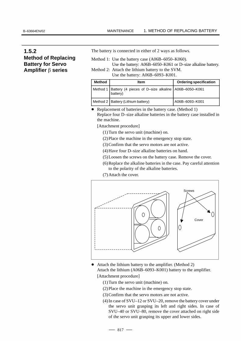
MAINTENANCEB–63664EN/02 1. METHOD OF REPLACING BATTERY
817
The battery is connected in either of 2 ways as follows.
Method 1: Use the battery case (A06B–6050–K060).Use the battery: A06B–6050–K061 or D–size alkaline battery.
Method 2: Attach the lithium battery to the SVM.Use the battery: A06B–6093–K001.
Method Item Ordering specification
Method 1 Battery (4 pieces of D–size alkalinebattery)
A06B–6050–K061
Method 2 Battery (Lithium battery) A06B–6093–K001
� Replacement of batteries in the battery case. (Method 1)Replace four D–size alkaline batteries in the battery case installed inthe machine.
[Attachment procedure]
(1)Turn the servo unit (machine) on.
(2)Place the machine in the emergency stop state.(3)Confirm that the servo motors are not active.
(4)Have four D–size alkaline batteries on hand.
(5)Loosen the screws on the battery case. Remove the cover.
(6)Replace the alkaline batteries in the case. Pay careful attentionto the polarity of the alkaline batteries.
(7)Attach the cover.
Screws
Cover
� Attach the lithium battery to the amplifier. (Method 2)Attach the lithium (A06B–6093–K001) battery to the amplifier.
[Attachment procedure]
(1)Turn the servo unit (machine) on.
(2)Place the machine in the emergency stop state.
(3)Confirm that the servo motors are not active.(4) In case of SVU–12 or SVU–20, remove the battery cover under
the servo unit grasping its left and right sides. In case ofSVU–40 or SVU–80, remove the cover attached on right sideof the servo unit grasping its upper and lower sides.
1.5.2Method of ReplacingBattery for ServoAmplifier � series

MAINTENANCE1. METHOD OF REPLACING BATTERY B–63664EN/02
818
(5)Remove the battery from the servo unit.
(6)Replace the battery and connect the battery cable with theconnector CX5X or CX5Y of the servo unit.
(7)Mount the battery cover.
SVU–12, SVU–20
Battery Battery cover
Pass the battery cable to this slit.
SVU–40, SVU–80
CAUTION
The connector of the battery can be connected with eitherof CX5X and CX5Y.

MAINTENANCEB–63664EN/02 1. METHOD OF REPLACING BATTERY
819
Old batteries should be disposed as “INDUSTRIAL WASTES”according to the regulations of the country or autonomy where yourmachine has been installed.
Used batteries


APPENDIX


APPENDIXB–63664EN/02 A. TAPE CODE LIST
823
A TAPE CODE LIST
ISO code EIA code Meaning
Character 8 7 6 5 4 3 2 1 Character 8 7 6 5 4 3 2 1WithoutCUSTOMMACURO B
WithCUSTOMMACRO B
0 � � � 0 � � Number 0
1 � � � � � 1 � � Number 1
2 � � � � � 2 � � Number 2
3 � � � � � 3 � � � � Number 3
4 � � � � � 4 � � Number 4
5 � � � � � 5 � � � � Number 5
6 � � � � � 6 � � � � Number 6
7 � � � � � � � 7 � � � � Number 7
8 � � � � � 8 � � Number 8
9 � � � � � 9 � � � � Number 9
A � � � a � � � � Address A
B � � � b � � � � Address B
C � � � � � c � � � � � � Address C
D � � � d � � � � Address D
E � � � � � e � � � � � � Address E
F � � � � � f � � � � � � Address F
G � � � � � g � � � � � � Address G
H � � � h � � � � Address H
I � � � � � i � � � � � � Address I
J � � � � � j � � � � � Address J
K � � � � � k � � � � Address K
L � � � � � l � � � � Address L
M � � � � � m � � � � Address M
N � � � � � n � � � � Address N
O � � � � � � � o � � � � Address O
P � � � p � � � � � � Address P
Q � � � � � q � � � � Address Q
R � � � � � r � � � � Address R
S � � � � � s � � � � Address S
T � � � � � t � � � � Address T
U � � � � � u � � � � Address U
V � � � � � v � � � � Address V
W � � � � � � � w � � � � Address W
X � � � � � x � � � � � � Address X
Y � � � � � y � � � � Address Y
Z � � � � � z � � � � Address Z

APPENDIXA. TAPE CODE LIST B–63664EN/02
824
ISO code EIA code Meaning
Character 8 7 6 5 4 3 2 1 Character 8 7 6 5 4 3 2 1
WithoutCUSTOMMACRO
B
WithCUSTOMMACRO
B
DEL � � � � � � � � � Del � � � � � � � � Delete (deleting a mispunch)
× ×
NUL � Blank � No punch. With EIAcode, this code cannotbe used in a significantinformation section.
× ×
BS � � � BS � � � � Backspace × ×HT � � � Tab � � � � � � Tabulator × ×
LF or NL � � � CR or EOB � � End of block
CR � � � � � Carriage return × ×SP � � � SP � � Space � �
% � � � � � ER � � � � Absolute rewind stop
( � � � (2–4–5) � � � � Control out (start of comment)
) � � � � � (2–4–7) � � � � Control in (end of comment)
+ � � � � � + � � � � Plus sign ∆– � � � � � – � � Minus sign
: � � � � � Colon (address O)
/ � � � � � � � / � � � � Optional block skip
. � � � � � . � � � � � � Period (decimal point)
# � � � � � Parameter(No. 6012)
Sharp
$ � � � Dollar sign ∆ �
& � � � � � & � � � � Ampersand ∆ �
’ � � � � � ___ Apostrophe ∆ �
* � � � � � Parameter(No. 6010)
Asterisk∆
, � � � � � , � � � � � � Comma
; � � � � � � � Semicolon ∆ ∆< � � � � � Left angle bracket ∆ ∆= � � � � � � � Parameter
(No. 6011)Equal sign
∆
> � � � � � � � Right angle bracket ∆ ∆? � � � � � � � Question mark ∆ �
@ � � � Commercial at mark ∆ �
” � � Quotation mark ∆ ∆[ � � � � � � � Parameter
(No. 6013)Left square bracket
∆
] � � � � � � � Parameter(No. 6014)
Right square bracket∆

APPENDIXB–63664EN/02 A. TAPE CODE LIST
825
NOTE1 The symbols used in the remark column have the following meanings.
(Space) : The character will be registered in memory and has a specific meaning.If it is used incorrectly in a statement other than a comment, an alarm occurs.
× : The character will not be registered in memory and will be ignored.∆ : The character will be registered in memory, but will be ignored during program
execution.� : The character will be registered in memory. If it is used in a statement other than
a comment, an alarm occurs.� : If it is used in a statement other than a comment, the character will not be
registered in memory. If it is used in a comment, it will be registered in memory.2 Codes not in this table are ignored if their parity is correct.3 Codes with incorrect parity cause the TH alarm. But they are ignored without generating the
TH alarm when they are in the comment section.4 A character with all eight holes punched is ignored and does not generate TH alarm in EIA code.

APPENDIXB. LIST OF FUNCTIONS AND
TAPE FORMAT B–63664EN/02
826
B LIST OF FUNCTIONS AND TAPE FORMAT
Some functions cannot be added as options depending on the model.In the tables below, PI :presents a combination of arbitrary axisaddresses using X,Y,Z,A,B and C (such as X_Y_Z_A_).x = 1st basic axis (X usually) y = 2nd basic axis (Y usually) z = 3rd basic axis (Z usually)
Functions Illustration Tape format
Positioning (G00) PI
Start point
G00 _ ;PI
Linear interpolation (G01) PI
Start point
G01 _ S_P_Q_F_;PI
Circular interpolation (G02, G03)
(x, y)
G03(x, y)
JR
I
G02
Startpoint
Startpoint
R
I
J
G17G02
G03X_ Y_
R_
I_ J_S_ P_ Q_ F_ ;
G18G02
G03X_ Z_
R_
I_ K_S_ P_ Q_ F_ ;
G19G02
G03Y_ Z_
R_
J_ K_S_ P_ Q_ F_ ;
Helical interpolation(G02, G03)
Z
Startpoint
(xyz)
(x, y)
(In case of X–Y plane)
G17G02
G03X_ Y_
R_
I_ J_α_ F_ ;
G18G02
G03X_ Z_
R_
I_ K_α_ F_ ;
G19G02
G03Y_ Z_
R_
J_ K_α_ F_ ;
α : Any axis other than circular interpolation axes.
Dwell (G04)G04
X_ ;P_

APPENDIXB–63664EN/02B. LIST OF FUNCTIONS AND
TAPE FORMAT
827
Functions Tape formatIllustration
Cylindrical interpolation(G07.1)
G07 _R_; Cylindrical interpolationR: Radius of cylinder
G07 0; Cylindrical interpolationcancel
PI
PI
Look–ahead control (G08) G08 P1:Look–ahead control mode on
G08 P0:Look–ahead control mode off
Exact stop (G09) Velocity
Time
PI _;G09 G02
G03
G01
Change of offset value byprogram (G10)
Tool offset memory AG10 L11 P_R_;Tool offset memory BG10 L10 P_R_; (Wear offset value)G11 L11 P_R_; (Geometry offset value)Tool offset memory CG10 L10 P_R_; (Wear offset value/H)G10 L11 P_R_; (Geometry offset value/H)G10 L12 P_R_; (Wear offset value/D)G10 L13 P_R_; (Geometry offset value/D)
Spatial circular interpolation(G12)
Zp
XpStart point
YpMidpoint
End point
G12 _S _ P_ Q_ F ; MidpointG12 _ ; End point
PIPI
Gap control (G13, G14) G13 P_L_ ; Gap modeG14 ; Gap mode cancellation
Polar coordinate (G15,G16) Yp
Xp(x y)
Xp
YpLocal coordinate
Work coordinate system
G17 G16 Xp_ Yp_ ;. . . G18 G16 Zp_ Xp_ ;. . . G19 G16 Yp_ Zp_ ;. . . G15 ; Cancel
Plane section(G17, G18, G19)
G17 ;G18 ;G19 ;
Inch/millimeter conversion (G20, G21)
Inch input
Millimeter input
G20 ;
G21 ;
Stored stroke check(G22, G23)
(XYZ)
(IJK)
G22 X_Y_Z_I_J_K_;
G23 Cancel;

APPENDIXB. LIST OF FUNCTIONS AND
TAPE FORMAT B–63664EN/02
828
Functions Tape formatIllustration
Piercing
R
I,J
K
P,Q
S:POWER H:STEPFlequencyduty
Time
G24 S_P_Q_I_J_K_H_R_
Reference position return check (G27)
PI
Start point
G27 _ ;PI
Reference position return(G28)2nd, reference position re-turn (G30)
PI
Start point
Reference position
Intermediate position
(G28)
2nd referenceposition (G30)
G28 _ ;PI
G30 _ ;PI
Return from reference position to start point (G29)
PIIntermediate position
Reference position G29 _ ;PI
Skip function (G31) PI
Start pointSkip signal
G31 _ F_;PI
Assist gas control P_Q_G32
P_T_R_
Spatial corner R insertion (G33, G34)
Zp
XpStartpoint
Yp
Endpoint
G33 G01 ; Spatical corner R insertion mode on
X_ Y_ Z_ A_ B_ R_ F_ ;X_ Y_ Z_ A_ B_ ;X_ Y_ Z_ A_ B_ ;R_ ;X_ Y_ Z_ A_ B_ ;G34 ; Mode corner
Cutter compensation C (G40 – G42)
ÇÇÇÇÇÇÇÇÇ
ÇÇÇÇÇÇÇÇÇÇÇÇÇÇÇ
G41
G42
G40
Tool
G17G18G19
G41G42 D_ ;
D : Tool offsetG40 : Cancel
Normal direction control (G40.1, G41.1, G42.1) (G150, G151, G152)
G41.1 (G151) Normal direction control leftG42.1 (G152) Normal direction control rightG40.1 (G150) Normal direction control cansel

APPENDIXB–63664EN/02B. LIST OF FUNCTIONS AND
TAPE FORMAT
829
Functions Tape formatIllustration
Tool offset (G45 to G48) G 45
G 46
G 47
G 48
Increase
Decrease
2 timesincrease
Com
IP
IP
2 timeDecrease
_ D_;IPG45G46
D : Tool offset number
G47G48
Scaling (G50, G51)
P1’
P1 P2
P4 P3
P2’
P4’ P3’PI
G51 _ P_;
P, I, J, K : Scaling magnificationX, Y, Z : Center coordinate value of scaling
G50 ; Cancel
PI
Programmable mirror image Mirror G51.1 _ ; G50.1 ; ...Cancel
IP
Setting of localcoordinate system(G52) x
yPI
Local coordinatesystem
Work coordinatesystem
G52 _ ;PI
Command in machine coor-dinate system(G53)
G53 _ ;PI
Selection of work coordinate system(G54 – G59)
PIWork zeropointoffset
Work coordinatesystem
Machine coordinate system
G54
:G59
P� �I
Single direction positioning (G60)
PI G60 _ ;PI
Exact stop mode, Automat-ic corner override v
tG64
v
G61t
G61_ ; Exact stop modeG62_ ; Automatic corner override
Power control (G63)
T
T
F
G63 P1 ; Power control modeG63 P0 ; Power control mode cancellation

APPENDIXB. LIST OF FUNCTIONS AND
TAPE FORMAT B–63664EN/02
830
Functions Tape formatIllustration
Custom macro(G65, G66, G67)
G65 P_L _ ;O_ ;
M99 ;
Macro One–shot call G65 P_ L_ <Argument assignment> ; P : Program No. L : Number of repeatitionModal call G66 G67 ; Cancel
P_L_ <Argument assignment>;
Coordinate system rotation(G68, G69)
Y
X(x y)
(In case of X–Y plane)
�
G68G17 X_ Y_
G18 Z_ X_
G19 Y_ Z_
R α ;
G69 ; Cancel
Three–dimensional coordi-nate conversion (G68, G69)
G68 X_ Y_ Z_ A_ B_ I_ J_ K_ ;G01 _ F_;G02 _ ;G03 _ ; . . .G69 ;
IPIPIP
Processing head A axislength compensation (G71)
R
Second armlength
G71 R_;
Coordinate system rotation(G84, G85)
Y
X(x y)
(In case of X–Y plane)
�
G84G17 X_ Y_ G18 Z_ X_G19 Y_ Z_
R α ;
Absolute/incremental programming (G90/G91)
G90_ ; Absolute commandG91_ ; Incremental commandG90_ G91_ ; Combined use
Change of workpiece coordinate system (G92)
ÇÇÇÇPI
G92 _ ;PI

APPENDIXB–63664EN/02B. LIST OF FUNCTIONS AND
TAPE FORMAT
831
Functions Tape formatIllustration
Workpiece coordinate sys-tem preset (G92.1)
G92.1 0 ;PI
Three–dimensional trans-form (G98, G99)
P0
Q0
P1
P2
P3
Q1
Q2
Q3
Mirror image transform
G98 P0 X_Y_Z_; Base point
G98 Q0 X_Y_Z_; Target point
Movement transform
G98 P1 X_Y_Z_; Base point
G98 P2 X_Y_Z_; Base point
G98 P3 X_Y_Z_; Base point
G98 Q1 X_Y_Z_; Target point
G98 Q2 X_Y_Z_; Target point
G98 Q3 X_Y_Z_; Target point

APPENDIXC. RANGE OF COMMAND VALUE B–63664EN/02
832
C ����� �� ���� �� ��
Increment system
IS–B
Least input increment 0.001 mm
Least command increment 0.001 mm
Max. programmable dimension ±99999.999 mm
Max. rapid traverse Note 240000 mm/min
Feedrate range Note 1 to 240000 mm/min
Incremental feed 0.001, 0.01, 0.1, 1 mm/step
Cutter compensation 0 to ±999.999 mm
Dwell time 0 to 99999.999 sec
Increment system
IS–B
Least input increment 0.0001 inch
Least command increment 0.001 mm
Max. programmable dimension ±9999.9999 inch
Max. rapid traverse Note 240000 mm/min
Feedrate range Note 0.01 to 9600 inch/min
Incremental feed 0.0001, 0.001, 0.01, 0.1 inch/step
Cutter compensation 0 to ±99.9999 inch
Dwell time 0 to 99999.999 sec
Linear axis� In case of millimeter
input, feed screw ismillimeter
� �� ���� �� ���� ������
���� ����� �� �!!� ����

APPENDIXB–63664EN/02 C. RANGE OF COMMAND VALUE
833
Increment system
IS–B
Least input increment 0.0001 inch
Least command increment 0.0001 inch
Max. programmable dimension ±9999.9999 inch
Max. rapid traverse Note 9600 inch/min
Feedrate range Note 0.01 to 9600 inch/min
Incremental feed 0.0001, 0.001, 0.01, 0.1 inch/step
Cutter compensation 0 to ±99.9999 inch
Dwell time 0 to 99999.999 sec
Increment system
IS–B
Least input increment 0.001 mm
Least command increment 0.0001 inch
Max. programmable dimension ±99999.999 mm
Max. rapid traverse Note 9600 inch/min
Feedrate range Note 1 to 240000 mm/min
Incremental feed 0.001, 0.01, 0.1, 1 mm/step
Cutter compensation 0 to ±999.999 mm
Dwell time 0 to 99999.999 sec
� �� ���� �� ���� ������
���� ����� �� ����
� �� ���� �� �!!� ����
������ ���� ����� �� ����

APPENDIXC. RANGE OF COMMAND VALUE B–63664EN/02
834
Increment system
IS–B
Least input increment 0.001 deg
Least command increment 0.001 deg
Max. programmable dimension ±99999.999 deg
Max. rapid traverse Note 240000 deg/min
Feedrate range Note 1 to 240000 deg/min
Incremental feed 0.001, 0.01, 0.1, 1 deg/step
NOTEThe feedrate range shown above are limitations dependingon CNC interpolation capacity. As a whole system,limitations depending on servo system must also beconsidered.
Peak power 0 to 7000W
Pulse frequency 5 to 2000Hz
Pulse duty 0 to 100%
Displacement from the Gapcontrol base point
0 to ±32,767mm
Rotation axis
Laser command

APPENDIXB–63664EN/02 D. NOMOGRAPHS
835
D ������"#$

APPENDIXD. NOMOGRAPHS B–63664EN/02
836
When servo system delay (by exponential acceleration/deceleration atcutting or caused by the positioning system when a servo motor is used)is accompanied by cornering, a slight deviation is produced between thebeam path (nozzle center path) and the programmed path as shown inFig.D.1 (a).Time constant T1 of the exponential acceleration/deceleration is fixed to0.
θ
V1
V2
Beam path
Fig.D.1 (a) Slight deviation between the beam path and the programmed path
Programmed path
This tool path is determined by the following parameters:• Feedrate (V1, V2)• Corner angle (�)• Exponential acceleration / deceleration time constant (T1) at
cutting (T1 = 0) • Presence or absence of buffer register.The above parameters are used to theoretically analyze the beam path andabove beam path is drawn with the parameter which is set as an example.When actually programming, the above items must be considered andprogramming must be performed carefully so that the shape of theworkpiece is within the desired precision.In other words, when the shape of the workpiece is not within thetheoretical precision, the commands of the next block must not be readuntil the specified feedrate becomes zero. The dwell function is then usedto stop the machine for the appropriate period.
D.1BEAM PATH AT CORNER

APPENDIXB–63664EN/02 D. NOMOGRAPHS
837
The beam path shown in Fig.D.1 (b) is analyzed based on the followingconditions:Feedrate is constant at both blocks before and after cornering.The controller has a buffer register. (The error differs with the readingspeed of the tape reader, number of characters of the next block, etc.)
θ
V
VX1
VY1φ1
VY2
VX2
φ2
V
Z
X0
Fig.D.1 (b) Example of tool path
VX1 � V cos�1
VY1 � V sin�1
VX2 � V cos�2
VY2 � V sin�2
V : Feedrate at both blocks before and after corneringVX1 : X–axis component of feedrate of preceding blockVY1 : Y–axis component of feedrate of preceding blockVX2 : X–axis component of feedrate of following blockVY2 : Y–axis component of feedrate of following blockθ : Corner angleφ1 : Angle formed by specified path direction of preceding block
and X–axisφ2 : Angle formed by specified path direction of following block
and X–axis
Analysis
� Description of conditionsand symbols

APPENDIXD. NOMOGRAPHS B–63664EN/02
838
Fig.D.1 (c) Initial value
Y0
X0
V
0
The initial value when cornering begins, that is, the X and Y coordinatesat the end of command distribution by the controller, is determined by thefeedrate and the positioning system time constant of the servo motor.
X0 � VX1(T1 � T2)
Y0 � VY1(T1 � T2)
T1:Exponential acceleration / deceleration time constant. (T=0)T2:Time constant of positioning system (Inverse of position loop gain)
The equations below represent the feedrate for the corner section inX–axis direction and Y–axis direction.
VX(t) � (VX2–VX1)[1–VX1
T1–T2{T1 exp(– t
T1)–T2 exp(– t
T2)} � VX1]
� VX2[1–VX1
T1–T2{T1 exp(– t
T1)–T2 exp(– t
T2)}]
VY(t) �VY1–VY2
T1–T2{T1 exp(– t
T1)–T2 exp(– t
T2)} � VY2
Therefore, the coordinates of the tool path at time t are calculated from thefollowing equations:
X(t) ��t
0
VX(t)dt–X0
�
VX2–VX1
T1–T2{T1
2 exp(– tT1
)–T22 exp(– t
T2)}–VX2(T1 � T2–t)
Y(t) ��t
0
VY(t)dt–Y0
�
VY2–VY1
T1–T2{T1
2 exp(– tT1
)–T22 exp(– t
T2)}–VY2(T1 � T2–t)
� Initial value calculation
� Analysis of corner toolpath

APPENDIXB–63664EN/02 D. NOMOGRAPHS
839
When a servo motor is used, the positioning system causes an errorbetween input commands and output results. Since the beam advancesalong the specified segment, an error is not produced in linearinterpolation. In circular interpolation, however, radial errors may beproduced, sepecially for circular cutting at high speeds.This error can be obtained as follows:
�r � 12
(T12� T2
2) V2
r
�rY
X
(1). . . . . . .
Command path
Actual path
�r : Maximum radius error (mm)v : Feedrate (mm/s)r : Circle radius (mm)T1 : Exponential acceleration/deceleration time constant (sec) at cutting
(T=0) T2 : Time constant of positoning system (sec).
(Inverse of positon loop gain)
r
In the case of bell–shaped acceleration/deceleration and linear accelera-tion/deceleration after cutting feed interpolation, an approximation of thisradius error can be obtained with the following expression:
Thus, the radius error in the case of bell–shaped acceleration/decelerationand linear acceleration/deceleration after interpolation is smaller than in case of exponential acceleration/deceleration by a factor of 12, excludingany error caused by a servo loop time constant.
�r � ( 124
T12�
12
T22) V2
r
Since the machining radius r (mm) and allowable error ∆r (mm) of theworkpiece is given in actual machining, the allowable limit feedrate(mm/sec) is determined by equation (1).Since the acceleration/deceleration time constant at cutting which is setby this equipment varies with the machine tool, refer to the manual issuedby the machine tool builder.
D.2RADIUS DIRECTIONERROR AT CIRCLECUTTING

APPENDIXE. STATUS WHEN TURNING POWER ON,
WHEN CLEAR AND WHEN RESET B–63664EN/02
840
E $%�%�$ &#�� %������ "�&�� ��� &#�� ���
��� &#�� ��$�%
Parameter CLR (No. 3402#6) is used to select whether resetting the CNCplaces it in the cleared state or in the reset state (0: reset state/1: clearedstate).The symbols in the tables below mean the following : �:The status is not changed or the movement is continued.×:The status is cancelled or the movement is interrupted.
Item When turning power on Cleared Reset
Setting data
Offset value � � �
dataData set by the MDIsetting operation
� � �
Parameter � � �
Various data
Programs in memory � � �
dataContents in the bufferstorage
× × � : MDI mode× : Other mode
Display of sequencenumber
� � (Note 1) � (Note 1)
One shot G code × × ×
Modal G code Initial G codes.(The G20 and G21 codes return tothe same state they were in whenthe power was last turned off.)
Initial G codes.(G20/G21 are notchanged.)
�
F Zero Zero �
T, M × � �
K (Number of repeats) × × ×
Workpiece coordinate value Zero � �
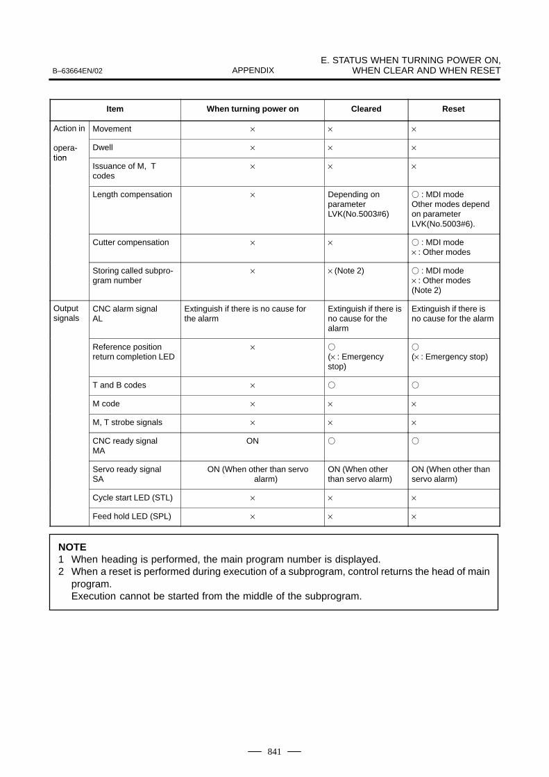
APPENDIXB–63664EN/02E. STATUS WHEN TURNING POWER ON,
WHEN CLEAR AND WHEN RESET
841
Item ResetClearedWhen turning power on
Action in Movement × × ×
opera-tion
Dwell × × ×tion
Issuance of M, Tcodes
× × ×
Length compensation × Depending onparameterLVK(No.5003#6)
� : MDI modeOther modes dependon parameterLVK(No.5003#6).
Cutter compensation × × � : MDI mode× : Other modes
Storing called subpro-gram number
× × (Note 2) � : MDI mode× : Other modes (Note 2)
Output signals
CNC alarm signal AL
Extinguish if there is no cause for the alarm
Extinguish if there isno cause for thealarm
Extinguish if there isno cause for the alarm
Reference position return completion LED
× � (× : Emergencystop)
� (× : Emergency stop)
T and B codes × � �
M code × × ×
M, T strobe signals × × ×
CNC ready signal MA
ON � �
Servo ready signalSA
ON (When other than servoalarm)
ON (When otherthan servo alarm)
ON (When other than servo alarm)
Cycle start LED (STL) × × ×
Feed hold LED (SPL) × × ×
NOTE1 When heading is performed, the main program number is displayed.2 When a reset is performed during execution of a subprogram, control returns the head of main
program.Execution cannot be started from the middle of the subprogram.

F. CHARACTER–TO–CODE CORRESPONDENCE TABLE B–63664EN/02
842
F #���%��'%�'���$ ����$"������ %�( �
Char-acter Code Comment Char-
acter Code Comment
A 065 6 054
B 066 7 055
C 067 8 056
D 068 9 057
E 069 032 Space
F 070 ! 033 Exclamation mark
G 071 ” 034 Quotation mark
H 072 # 035 Hash sign
I 073 $ 036 Dollar sign
J 074 % 037 Percent
K 075 & 038 Ampersand
L 076 ’ 039 Apostrophe
M 077 ( 040 Left parenthesis
N 078 ) 041 Right parenthesis
O 079 * 042 Asterisk
P 080 + 043 Plus sign
Q 081 , 044 Comma
R 082 – 045 Minus sign
S 083 . 046 Period
T 084 / 047 Slash
U 085 : 058 Colon
V 086 ; 059 Semicolon
W 087 < 060 Left angle bracket
X 088 = 061 Equal sign
Y 089 > 062 Right angle bracket
Z 090 ? 063 Question mark
0 048 @ 064 HAtI mark
1 049 [ 091 Left square bracket
2 050 ^ 092
3 051 ] 094 Right square bracket
4 052 _ 095 Underscore
5 053

APPENDIXB–63664EN/02 G. ALARM LIST
843
GALARM LIST
1) Program errors (P/S alarm)
Number Message Contents
000 PLEASE TURN OFF POWER A parameter which requires the power off was input, turn off power.
001 TH PARITY ALARM TH alarm (A character with incorrect parity was input). Correct the tape.
002 TV PARITY ALARM TV alarm (The number of characters in a block is odd). This alarm willbe generated only when the TV check is effective.
003 TOO MANY DIGITS Data exceeding the maximum allowable number of digits was input.(Refer to the item of max. programmable dimensions.)
004 ADDRESS NOT FOUND A numeral or the sign “ – ” was input without an address at the beginningof a block. Modify the program .
005 NO DATA AFTER ADDRESS The address was not followed by the appropriate data but was followedby another address or EOB code. Modify the program.
006 ILLEGAL USE OF NEGATIVE SIGN Sign “ .” input error (Sign “ – ” was input after an address with which itcannot be used. Or two or more “ – ” signs were input.) Modify the program.
007 ILLEGAL USE OF DECIMAL POINT Decimal point “ – ” input error (A decimal point was input after an addresswith which it can not be used. Or two decimal points were input.)Modify the program.
009 ILLEGAL ADDRESS INPUT Unusable character was input in significant area.Modify the program.
010 IMPROPER G–CODE An unusable G code or G code corresponding to the function not pro-vided is specified. Modify the program.
011 NO FEEDRATE COMMANDED Feedrate was not commanded to a cutting feed or the feedrate was in-adequate. Modify the program.
015 TOO MANY AXES COMMANDED The number of the commanded axes exceeded that of simultaneouslycontrolled axes.
020 OVER TOLERANCE OF RADIUS In circular interpolation (G02 or G03), difference of the distance betweenthe start point and the center of an arc and that between the end pointand the center of the arc exceeded the value specified in parameter No.3410.
021 ILLEGAL PLANE AXIS COMMAN-DED
An axis not included in the selected plane (by using G17, G18, G19) wascommanded in circular interpolation. Modify the program.
022 NO CIRCULAR RADIUS When circular interpolation is specified, neither R (specifying an arc ra-dius), nor I, J, and K (specifying the distance from a start point to the cen-ter) is specified.
025 CANNOT COMMAND F0 IN G02/G03 F0 (fast feed) was instructed by F1 –digit column feed in circular inter-polation. Modify the program.
028 ILLEGAL PLANE SELECT In the plane selection command, two or more axes in the same directionare commanded.Modify the program.
029 ILLEGAL OFFSET VALUE The offset values specified by H code is too large.Modify the program.
030 ILLEGAL OFFSET NUMBER The offset number specified by D/H code for cutter compensation is toolarge. Alternatively, the number of the additional workpiece coordinatesystem specified by a P code is too large. Modify the program.
031 ILLEGAL P COMMAND IN G10 In setting an offset amount by G10, the offset number following addressP was excessive or it was not specified.Modify the program.
032 ILLEGAL OFFSET VALUE IN G10 In setting an offset amount by G10 or in writing an offset amount by sys-tem variables, the offset amount was excessive.
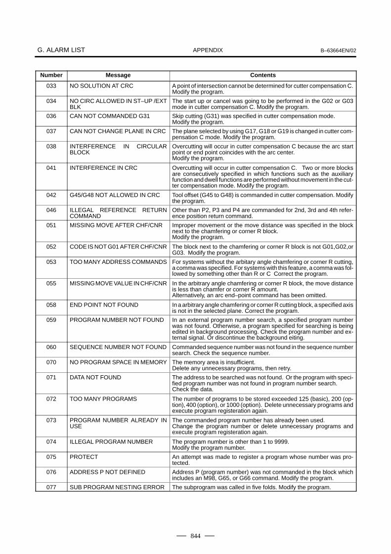
APPENDIXG. ALARM LIST B–63664EN/02
844
Number ContentsMessage
033 NO SOLUTION AT CRC A point of intersection cannot be determined for cutter compensation C.Modify the program.
034 NO CIRC ALLOWED IN ST–UP /EXTBLK
The start up or cancel was going to be performed in the G02 or G03mode in cutter compensation C. Modify the program.
036 CAN NOT COMMANDED G31 Skip cutting (G31) was specified in cutter compensation mode.Modify the program.
037 CAN NOT CHANGE PLANE IN CRC The plane selected by using G17, G18 or G19 is changed in cutter com-pensation C mode. Modify the program.
038 INTERFERENCE IN CIRCULARBLOCK
Overcutting will occur in cutter compensation C because the arc startpoint or end point coincides with the arc center. Modify the program.
041 INTERFERENCE IN CRC Overcutting will occur in cutter compensation C. Two or more blocksare consecutively specified in which functions such as the auxiliaryfunction and dwell functions are performed without movement in the cut-ter compensation mode. Modify the program.
042 G45/G48 NOT ALLOWED IN CRC Tool offset (G45 to G48) is commanded in cutter compensation. Modifythe program.
046 ILLEGAL REFERENCE RETURNCOMMAND
Other than P2, P3 and P4 are commanded for 2nd, 3rd and 4th refer-ence position return command.
051 MISSING MOVE AFTER CHF/CNR Improper movement or the move distance was specified in the blocknext to the chamfering or corner R block.Modify the program.
052 CODE IS NOT G01 AFTER CHF/CNR The block next to the chamfering or corner R block is not G01,G02,orG03. Modify the program.
053 TOO MANY ADDRESS COMMANDS For systems without the arbitary angle chamfering or corner R cutting,a comma was specified. For systems with this feature, a comma was fol-lowed by something other than R or C Correct the program.
055 MISSING MOVE VALUE IN CHF/CNR In the arbitrary angle chamfering or corner R block, the move distanceis less than chamfer or corner R amount.Alternatively, an arc end–point command has been omitted.
058 END POINT NOT FOUND In a arbitrary angle chamfering or corner R cutting block, a specified axisis not in the selected plane. Correct the program.
059 PROGRAM NUMBER NOT FOUND In an external program number search, a specified program numberwas not found. Otherwise, a program specified for searching is beingedited in background processing. Check the program number and ex-ternal signal. Or discontinue the background eiting.
060 SEQUENCE NUMBER NOT FOUND Commanded sequence number was not found in the sequence numbersearch. Check the sequence number.
070 NO PROGRAM SPACE IN MEMORY The memory area is insufficient.Delete any unnecessary programs, then retry.
071 DATA NOT FOUND The address to be searched was not found. Or the program with speci-fied program number was not found in program number search.Check the data.
072 TOO MANY PROGRAMS The number of programs to be stored exceeded 125 (basic), 200 (op-tion), 400 (option), or 1000 (option). Delete unnecessary programs andexecute program registeration again.
073 PROGRAM NUMBER ALREADY INUSE
The commanded program number has already been used.Change the program number or delete unnecessary programs andexecute program registeration again.
074 ILLEGAL PROGRAM NUMBER The program number is other than 1 to 9999.Modify the program number.
075 PROTECT An attempt was made to register a program whose number was pro-tected.
076 ADDRESS P NOT DEFINED Address P (program number) was not commanded in the block whichincludes an M98, G65, or G66 command. Modify the program.
077 SUB PROGRAM NESTING ERROR The subprogram was called in five folds. Modify the program.

APPENDIXB–63664EN/02 G. ALARM LIST
845
Number ContentsMessage
078 NUMBER NOT FOUND A program number or a sequence number which was specified by ad-dress P in the block which includes an M98, M99, M65 or G66 was notfound. The sequence number specified by a GOTO statement was notfound. Otherwise, a called program is being edited in background pro-cessing. Correct the program, or discontinue the background editing.
079 PROGRAM VERIFY ERROR In memory or program collation,a program in memory does not agreewith that read from an external I/O device. Check both the programs inmemory and those from the external device.
085 COMMUNICATION ERROR When entering data in the memory by using Reader / Puncher interface,an overrun, parity or framing error was generated. The number of bitsof input data or setting of baud rate or specification No. of I/O unit is in-correct.
086 DR SIGNAL OFF When entering data in the memory by using Reader / Puncher interface,the ready signal (DR) of reader / puncher was off.Power supply of I/O unit is off or cable is not connected or a P.C.B. is de-fective.
087 BUFFER OVERFLOW When entering data in the memory by using Reader / Puncher interface,though the read terminate command is specified, input is not interruptedafter 10 characters read. I/O unit or P.C.B. is defective.
088 LAN FILE TRANS ERROR(CHANNEL–1)
File data transfer over the OSI–Ethernet was terminated as a result ofa transfer error.
089 LAN FILE TRANS ERROR(CHANNEL–2)
File data transfer over the OSI–Ethernet was terminated as a result ofa transfer error.
090 REFERENCE RETURN INCOM-PLETE
The reference position return cannot be performed normally becausethe reference position return start point is too close to the reference posi-tion or the speed is too slow. Separate the start point far enough fromthe reference position, or specify a sufficiently fast speed for referenceposition return.
091 REFERENCE RETURN INCOM-PLETE
In the automatic operation halt state, manual reference position returncannot be performed.
092 AXES NOT ON THE REFERENCEPOINT
The commanded axis by G27 (Reference position return check) did notreturn to the reference position.
094 P TYPE NOT ALLOWED (COORDCHG)
P type cannot be specified when the program is restarted. (After the au-tomatic operation was interrupted, the coordinate system setting opera-tion was performed.) Perform the correct operation according to th oper-ator’s manual.
095 P TYPE NOT ALLOWED (EXT OFSCHG)
P type cannot be specified when the program is restarted. (After theautomatic operation was interrupted, the external workpiece offsetamount changed.)
096 P TYPE NOT ALLOWED (WRK OFSCHG)
P type cannot be specified when the program is restarted. (After the au-tomatic operation was interrupted, the workpiece offset amountchanged.)
097 P TYPE NOT ALLOWED (AUTOEXEC)
P type cannot be directed when the program is restarted. (After powerON, after emergency stop or P/S alarm 94 to 97 were reset, no automatic operation is performed.) Perform automatic operation.
098 G28 FOUND IN SEQUENCE RE-TURN
A command of the program restart was specified without the referenceposition return operation after power ON or emergency stop, and G28was found during search. Perform the reference position return.
099 MDI EXEC NOT ALLOWED AFT.SEARCH
After completion of search in program restart, a move command is givenwith MDI.
100 PARAMETER WRITE ENABLE On the PARAMETER(SETTING) screen, PWE(parameter writing en-abled) is set to 1. Set it to 0, then reset the system.
101 PLEASE CLEAR MEMORY The power turned off while rewriting the memory by program edit opera-tion. If this alarm has occurred, press <RESET> while pressing<PROG>, and only the program being edited will be deleted.Register the deleted program.
109 FORMAT ERROR IN G08 A value other than 0 or 1 was specified after P in the G08 code, or novalue was specified.
110 DATA OVERFLOW The absolute value of fixed decimal point display data exceeds the al-lowable range. Modify the program.

APPENDIXG. ALARM LIST B–63664EN/02
846
Number ContentsMessage
111 CALCULATED DATA OVERFLOW The result of calculation is out of the allowable range (–1047 to –10–29,0, and 10–29 to 1047).
112 DIVIDED BY ZERO Division by zero was specified. (including tan 90°)113 IMPROPER COMMAND A function which cannot be used in custom macro is commanded.
Modify the program.
114 FORMAT ERROR IN MACRO There is an error in other formats than <Formula>.Modify the program.
115 ILLEGAL VARIABLE NUMBER A value not defined as a variable number is designated in the custommacro or in high–speed cycle cutting.The header contents are improper in a high–speed cycle cutting. Thisalarm is given in the following cases:1. The header corresponding to the specified machining cycle number
called is not found.2. The cycle connection data value is out of the allowable range
(0 – 999).3. The number of data in the header is out of the allowable range
(0 – 32767).4. The start data variable number of executable format data is out of
the allowable range (#20000 – #85535).5. The storing data variable number of executable format data is out of
the allowable range (#85535).6. The storing start data variable number of executable format datais
overlapped with the variable number used in the header.Modify the program.
116 WRITE PROTECTED VARIABLE The left side of substitution statement is a variable whose substitutionis inhibited. Modify the program.
118 PARENTHESIS NESTING ERROR The nesting of bracket exceeds the upper limit (quintuple).Modify the program.
119 ILLEGAL ARGUMENT The SQRT argument is negative, BCD argument is negative, or othervalues than 0 to 9 are present on each line of BIN argument.Modify the program.
122 QUADRUPLICATE MACRO MODAL–CALL
A total of four macro calls and macro modal calls are nested. Correctthe program.
123 CAN NOT USE MACRO COMMANDIN DNC
Macro control command is used during DNC operation.Modify the program.
124 MISSING END STATEMENT DO – END does not correspond to 1 : 1. Modify the program.
125 FORMAT ERROR IN MACRO <Formula> format is erroneous. Modify the program.
126 ILLEGAL LOOP NUMBER In DOn, 1� n �3 is not established. Modify the program.
127 NC, MACRO STATEMENT IN SAMEBLOCK
NC and custom macro commands coexist.Modify the program.
128 ILLEGAL MACRO SEQUENCE NUM-BER
The sequence number specified in the branch command was not 0 to9999. Or, it cannot be searched. Modify the program.
129 ILLEGAL ARGUMENT ADDRESS An address which is not allowed in <Argument Designation > is used.Modify the program.
130 ILLEGAL AXIS OPERATION An axis control command was given by PMC to an axis controlled byCNC. Or an axis control command was given by CNC to an axis con-trolled by PMC. Modify the program.
131 TOO MANY EXTERNAL ALARMMESSAGES
Five or more alarms have generated in external alarm message. Consult the PMC ladder diagram to find the cause.
132 ALARM NUMBER NOT FOUND No alarm No. concerned exists in external alarm message clear.Check the PMC ladder diagram.
133 ILLEGAL DATA IN EXT. ALARM MSG Small section data is erroneous in external alarm message or externaloperator message. Check the PMC ladder diagram.
138 SUPERIMPOSED DATA OVERFLOW
In PMC–based axis control, the increment for pulse distribution on theCNC and PMC side are too large when the superimposed control ex-tended function is used.
139 CAN NOT CHANGE PMC CONTROLAXIS
An axis is selected in commanding by PMC axis control.Modify the program.
141 CAN NOT COMMAND G51 IN CRC G51 (Scaling ON) is commanded in the tool offset mode.Modify the program.

APPENDIXB–63664EN/02 G. ALARM LIST
847
Number ContentsMessage
142 ILLEGAL SCALE RATE Scaling magnification is commanded in other than 1 – 999999.Correct the scaling magnification setting (G51 Pp or parameter. . 5411 or 5421).
143 SCALED MOTION DATA OVER-FLOW
The scaling results, move distance, coordinate value and circular radiusexceed the maximum command value. Correct the program or scalingmangification.
144 ILLEGAL PLANE SELECTED The coordinate rotation plane and arc or cutter compensation C planemust be the same. Modify the program.
145 ILLEGAL CONDITIONS IN POLARCOORDINATE INTERPOLATION
The conditions are incorrect when the polar coordinate interpolationstarts or it is canceled.1) In modes other than G40, G12.1/G13.1 was specified.2) An error is found in the plane selection. Parameters No. 5460 and
No. 5461 are incorrectly specified.Modify the value of program or parameter.
146 IMPROPER G CODE G codes which cannot be specified in the polar coordinate interpolationmode was specified. See section polar coordinate interpolation andmodify the program.
148 ILLEGAL SETTING DATA Automatic corner override deceleration rate is out of the settable rangeof judgement angle. Modify the parameters (No.1710 to No.1714)
160 G72.1 NESTING ERROR Code G72.1 was specified in a sub–program after the same code hadalready been specified for copying with rotation.
161 G72.2 NESTING ERROR Code G72.2 was specified in a sub–program after the same code hadalready been specified for parallel copying.
175 ILLEGAL G107 COMMAND Conditions when performing cylindrical interpolation start or cancel notcorrect. To change the mode to the cylindrical interpolation mode, spec-ify the command in a format of “G07.1 rotation–axis name radius of cylin-der.”
176 IMPROPER G–CODE IN G107 Any of the following G codes which cannot be specified in the cylindricalinterpolation mode was specified.1) G codes for positioning, such as G28 including the codes specifying
the rapid traverse cycle2) G codes for setting a coordinate system: G52,G92,3) G code for selecting coordinate system: G53 G54–G59Modify the program.
177 CHECK SUM ERROR(G05 MODE)
Check sum errorModify the program.
178 G05 COMMANDED IN G41/G42MODE
G05 was commanded in the G41/G42 mode.Correct the program.
179 PARAM. (PRM NO. 7510) SETTINGERROR
The number of controlled axes set by the parameter 7510 exceeds themaximum number. Modify the parameter setting value.
180 COMMUNICATION ERROR (REMOTE BUF)
Remote buffer connection alarm has generated. Confirm the number ofcables, parameters and I/O device.
199 MACRO WORD UNDEFINED Undefined macro word was used. Modify the custom macro.
210 CAN NOT COMAND M198/M99 1) M198 and M99 are executed in the schedule operation. Or M198is executed in the DNC operation.
2) In a multiple repetitive pocketing canned cycle, an interrupt macrowas specified, and M99 was executed.
212 ILLEGAL PLANE SELECT The arbitrary angle chamfering or a corner R is commanded or the planeincluding an additional axis. Correct the program.
213 ILLEGAL COMMAND IN SYNCHRO–MODE
Any of the following alarms occurred in the operation with the simplesynchronization control.1) The program issued the move command to the slave axis.2) The program issued the manual continuous feed/manual handle
feed/incremental feed command to the slave axis.3) The program issued the automatic reference position return com-
mand without executing the manual reference position return afterthe power was turned on.
4) The difference between the position error amount of the master andslave axes exceeded the value specified in parameter No. 8313.
214 ILLEGAL COMMAND IN SYNCHRO–MODE
Coordinate system is set or cutter compensation of the shift type isexecuted in the synchronous control. Correct the program.

APPENDIXG. ALARM LIST B–63664EN/02
848
Number ContentsMessage
222 DNC OP. NOT ALLOWED IN BG.–EDIT
Input and output are executed at a time in the background edition.Execute a correct operation.
224 RETURN TO REFERENCE POINT Reference position return has not been performed before the automaticoperation starts. Perform reference position return only when parameterZRNX (No.1005#0) is 0.
231 ILLEGAL FORMAT IN G10 OR L50 Any of the following errors occurred in the specified format at the programmable–parameter input.1) Address N or R was not entered.2) A number not specified for a parameter was entered.3) The axis number was too large.4) An axis number was not specified in the axis–type parameter.5) An axis number was specified in the parameter which is not an axis
type.6) An attempt was made to reset bit 4 of parameter 3202 (NE9) or
change parameter 3210 (PSSWD) when they are protected by apassword. Correct the program.
232 TOO MANY HELICAL AXIS COM-MANDS
Three or more axes (in the normal direction control mode two or moreaxes) were specified as helical axes in the helical interpolation mode.
233 DEVICE BUSY When an attempt was made to use a unit such as that connected via theRS–232–C interface, other users were using it.
239 BP/S ALARM While punching was being performed with the function for controlling ex-ternal I/O units ,background editing was performed.
240 BP/S ALARM Background editing was performed during MDI operation.
4000 P/S ALARM Although the end of a record is reached, the near point is not foundduring near point search. ”END OF RECORD” was read during pro-gram restart (laser specification).
4001 P/S ALARM The Z–axis is specified as the gap control axis during near pointsearch or program restart (laser specification).
4002 G CODE UNAVAILABLE DURINGSEARCH
G53 is specified in independent axis mode (bit 3 of PRM. 15600, MIA= 1) during near point search or program restart (laser specification).
4004 THREE–DIMENSIONAL COORDI-NATE CONVERSION ALARM
One or two of the I, J, and K commands are not specified or a com-mand for the X, Y, Z, 4, or 5 axis is not specified.
4005 THREE–DIMENSIONAL COORDI-NATE CONVERSION ALARM
G27, G28, or G29 was issued during three–dimensional coordinateconversion.
4006 THREE–DIMENSIONAL COORDI-NATE CONVERSION ALARM
G68 was issued again during three–dimensional coordinate conver-sion.
4007 THREE–DIMENSIONAL COORDI-NATE CONVERSION ALARM
G12 (spatial circular interpolation) was issued during three–dimen-sional coordinate conversion.
4008 THREE–DIMENSIONAL COORDI-NATE CONVERSION ALARM
Scaling or coordinate rotation was specified during three–dimension-al coordinate conversion.
4010 THREE–DIMENSIONAL TRANS-FORM FORMAT ERROR
The G98 command format is invalid.
4011 MATRIX TRANSFORM ERROR No matrix can be created during G98 processing.
4012 COORDINATE CONVERSION ER-ROR
Coordinate conversion cannot be performed for G98.
4016 P/S ALARM The value of arc radius R specified in G33 mode is too large.
4017 P/S ALARM A G code in group 01 other than G01 was issued in G33 mode. Cut-ter compensation was specified in G33 mode.
4021 P/S ALARM A negative value is specified as the length of the nozzle. The nozzlelength falls outside the specification range. The total of the secondarm length and nozzle length must be a maximum of 500 mm(19.685 inches).
4025 P/S ALARM The spatial arc or spatial corner rounding command specifies axismovement for an axis other than the first to fifth axes.

APPENDIXB–63664EN/02 G. ALARM LIST
849
Number ContentsMessage
4026 COMMUNICATION ERROR An overrun, parity, or framing error occurred during read via the interfaceof the teaching box.The number of the input data bits is incorrect, or the set baud rate or I/Odevice specification number is illegal.
4027 DR SIGNAL OFF The I/O device operation ready signal (DR) is off when data is input oroutput via the interface of the teaching box.The power to the I/O device may be off, or there may be a cable discon-nection or a printed circuit board failure.
4028 BUFFER OVERFLOW During data read via the interface of the teaching box, although a readoperation is stopped, input continues even after ten characters havebeen input. The I/O device or printed circuit board is faulty.
4031 MIRROR AXIS PRM. SETTING ERROR
For the mirror axis under constant optical path control, the following pa-rameters are not set:Bit 0 of parameter No. 7052 = 1, bit 1 of parameter No. 2005 = 0, bit 7of parameter No. 1819 = 1, bit 0 of parameter No. 6131 = 0, parameterNo. 7510 = 2
4032 APPROACH TIME ERROR Because the value set in parameter No. 15782 is too large, the ap-proach operation feedrate cannot be controlled at the time of beam out-put. Set a smaller value than the piercing time (parameter No. 15087)in parameter No. 15872.
4033 Z AXIS PRM. ERROR For the Z–axis, the following settings are not made: Bit 5 of parameterNo. 1806 = 1, bit 1 of parameter No. 2224 = 1
4700 PROGRAM ERROR (OT +) The value specified in the X-axis move command exceeded the posi-tive value of stored stroke limit 1. (Advance check)
4701 PROGRAM ERROR (OT –) The value specified in the X-axis move command exceeded the neg-ative value of stored stroke limit 1. (Advance check)
4702 PROGRAM ERROR (OT +) The value specified in the Y-axis move command exceeded the posi-tive value of stored stroke limit 1. (Advance check)
4703 PROGRAM ERROR (OT –) The value specified in the Y-axis move command exceeded the neg-ative value of stored stroke limit 1. (Advance check)
4704 PROGRAM ERROR (OT +) The value specified in the Z-axis move command exceeded the posi-tive value of stored stroke limit 1. (Advance check)
4705 PROGRAM ERROR (OT –) The value specified in the Z-axis move command exceeded the neg-ative value of stored stroke limit 1. (Advance check)
5000 ILLEGAL COMMAND CODE The specified code was incorrect in the high–precision contour con-trol (HPCC) mode.
5003 ILLEGAL PARAMETER (HPCC) The parameter setting is incorrect.
5004 HPCC NOT READY High–precision contour control is not ready.
5006 TOO MANY WORD IN ONE BLOCK The number of words specified in a block exceeded 26 in the HPCCmode.
5007 TOO LARGE DISTANCE In the HPCC mode, the machine moved beyond the limit.
5009 PARAMETER ZERO (DRY RUN) The maximum feedrate (parameter No. 1422) or the feedrate in dryrun (parameter No. 1410) is 0 in the HPCC model.
5010 END OF RECORD The end of record (%) was specified.
5011 PARAMETER ZERO(CUT MAX) The maximum cutting feedrate (parameter No. 1422) is 0.
5012 G05 P10000 ILLEGAL START UP(HPCC)
G05 P10000 has been specified in a mode from which HPCC modecannot be entered.
5013 HPCC:CRC OFS REMAIN AT CANCEL
G05P0 has been specified in G41/G42 mode or before cancellationaxis is not found.
5014 TRACE DATA NOT FOUND Trace data is not available, preventing transfer from being performed.
5016 ILLEGAL COMBINATION OF MCODE
M codes which belonged to the same group were specified in ablock. Alternatively,an M code which must be specified without otherM codes in the block was specified in a block with other M codes.
5020 PARAMETER OF RESTARTERROR
The parameter for specifying program restart is not set correctly.
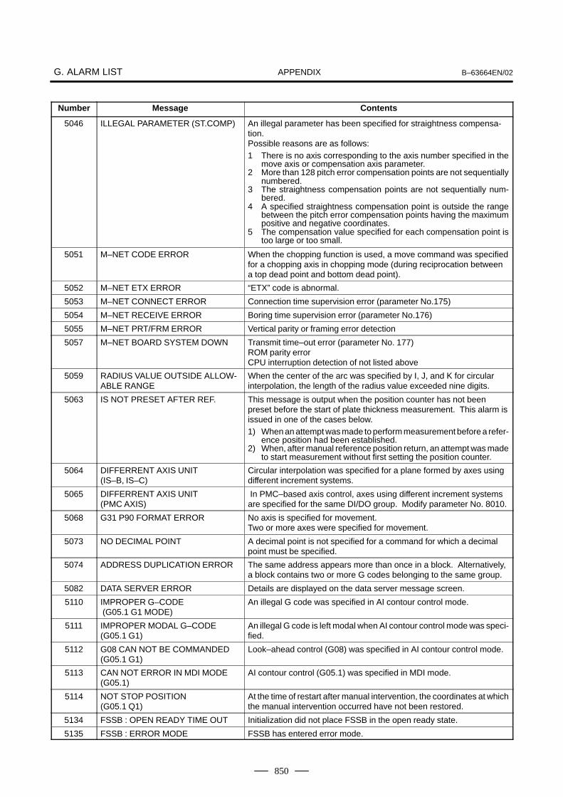
APPENDIXG. ALARM LIST B–63664EN/02
850
Number ContentsMessage
5046 ILLEGAL PARAMETER (ST.COMP) An illegal parameter has been specified for straightness compensa-tion.Possible reasons are as follows:1 There is no axis corresponding to the axis number specified in the
move axis or compensation axis parameter.2 More than 128 pitch error compensation points are not sequentially
numbered.3 The straightness compensation points are not sequentially num-
bered.4 A specified straightness compensation point is outside the range
between the pitch error compensation points having the maximumpositive and negative coordinates.
5 The compensation value specified for each compensation point istoo large or too small.
5051 M–NET CODE ERROR When the chopping function is used, a move command was specifiedfor a chopping axis in chopping mode (during reciprocation betweena top dead point and bottom dead point).
5052 M–NET ETX ERROR “ETX” code is abnormal.
5053 M–NET CONNECT ERROR Connection time supervision error (parameter No.175)
5054 M–NET RECEIVE ERROR Boring time supervision error (parameter No.176)
5055 M–NET PRT/FRM ERROR Vertical parity or framing error detection
5057 M–NET BOARD SYSTEM DOWN Transmit time–out error (parameter No. 177)ROM parity errorCPU interruption detection of not listed above
5059 RADIUS VALUE OUTSIDE ALLOW-ABLE RANGE
When the center of the arc was specified by I, J, and K for circularinterpolation, the length of the radius value exceeded nine digits.
5063 IS NOT PRESET AFTER REF. This message is output when the position counter has not been preset before the start of plate thickness measurement. This alarm isissued in one of the cases below.1) When an attempt was made to perform measurement before a refer-
ence position had been established.2) When, after manual reference position return, an attempt was made
to start measurement without first setting the position counter.
5064 DIFFERRENT AXIS UNIT(IS–B, IS–C)
Circular interpolation was specified for a plane formed by axes usingdifferent increment systems.
5065 DIFFERRENT AXIS UNIT(PMC AXIS)
In PMC–based axis control, axes using different increment systemsare specified for the same DI/DO group. Modify parameter No. 8010.
5068 G31 P90 FORMAT ERROR No axis is specified for movement.Two or more axes were specified for movement.
5073 NO DECIMAL POINT A decimal point is not specified for a command for which a decimalpoint must be specified.
5074 ADDRESS DUPLICATION ERROR The same address appears more than once in a block. Alternatively,a block contains two or more G codes belonging to the same group.
5082 DATA SERVER ERROR Details are displayed on the data server message screen.
5110 IMPROPER G–CODE (G05.1 G1 MODE)
An illegal G code was specified in AI contour control mode.
5111 IMPROPER MODAL G–CODE(G05.1 G1)
An illegal G code is left modal when AI contour control mode was speci-fied.
5112 G08 CAN NOT BE COMMANDED(G05.1 G1)
Look–ahead control (G08) was specified in AI contour control mode.
5113 CAN NOT ERROR IN MDI MODE(G05.1)
AI contour control (G05.1) was specified in MDI mode.
5114 NOT STOP POSITION(G05.1 Q1)
At the time of restart after manual intervention, the coordinates at whichthe manual intervention occurred have not been restored.
5134 FSSB : OPEN READY TIME OUT Initialization did not place FSSB in the open ready state.
5135 FSSB : ERROR MODE FSSB has entered error mode.

APPENDIXB–63664EN/02 G. ALARM LIST
851
Number ContentsMessage
5136 FSSB : NUMBER OF AMPS ISSMALL
In comparison with the number of controlled axes, the number of amplifi-ers recognized by FSSB is not enough.
5137 FSSB : CONFIGURATION ERROR FSSB detected a configuration error.
5138 FSSB : AXIS SETTING NOT COM-PLETE
In automatic setting mode, axis setting has not been made yet.Perform axis setting on the FSSB setting screen.
5139 FSSB : ERROR Servo initialization did not terminate normally.The optical cable may be defective, or there may be an error in connec-tion to the amplifier or another module.Check the optical cable and the connection status.
5156 ILLEGAL AXIS OPERATION(SHPCC)
In simple high–precision contour control (SHPCC) mode, the controlledaxis selection signal (PMC axis control) changes.In SHPCC mode, the simple synchronous axis selection signalchanges.
5157 PARAMETER ZERO (AICC) Zero is set in the parameter for the maximum cutting feedrate (parame-ter No. 1422 or 1432).Zero is set in the parameter for the acceleration/deceleration before in-terpolation (parameter No. 1770 or 1771).Set the parameter correctly.
5196 ILLEGAL OPERATION (HPCC) Detach operation was performed in HPCC mode. (If detach operationis performed in HPCC mode, this alarm is issued after the currentlyexecuted block terminates.)
5197 FSSB : OPEN TIME OUT The CNC permitted FSSB to open, but FSSB was not opened.
5198 FSSB : ID DATA NOT READ Temporary assignment failed, so amplifier initial ID information could notbe read.
5199 FINE TORQUE SENSING PARAME-TER
A parameter related to the fine torque sensing function is illegal.
· The storage interval is invalid.
· An invalid axis number is set as the target axis.
Correct the parameter.
5212 SCREEN COPY : PARAMETER ER-ROR
There is a parameter setting error. Check that 4 is set as the I/O channel.
5213 SCREEN COPY : COMMUNICA-TION ERROR
The memory card cannot be used. Check the memory card. (Checkwhether the memory card is write–protected or defective.)
5214 SCREEN COPY : DATA TRANSFERERROR
Data transfer to the memory card failed.Check whether the memory card space is insufficient and whether thememory card was removed during data transfer.
5218 ILLEGAL PARAMETER (INCL.COMP)
There is an inclination compensation parameter setting error.Cause:
1. The number of pitch error compensation points between the nega-tive (–) end and positive (+) end exceeds 128.
2. The relationship in magnitude among the inclination compensationpoint numbers is incorrect.
3. An inclination compensation point is not located between the nega-tive (–) end and positive (+) end of the pitch error compensationpoints.
4. The amount of compensation per compensation point is too large ortoo small.
Correct the parameter.
5220 REFERENCE POINT ADJUST-MENT MODE
A parameter for automatically set a reference position is set. (Bit 2 ofparameter No. 1819 = 1)Perform automatic setting.(Position the machine at the reference position manually, then performmanual reference position return.)Supplementary: Automatic setting sets bit 2 of parameter No. 1819 to0.

APPENDIXG. ALARM LIST B–63664EN/02
852
Number ContentsMessage
5222 SRAM CORRECTABLE ERROR The SRAM correctable error cannot be corrected.Cause:A memory problem occurred during memory initialization.Action:Replace the master printed circuit board (SRAM module).
5227 FILE NOT FOUND A specified file is not found during communication with the built–inHandy File.
5228 SAME NAME USED There are duplicate file names in the built–in Handy File.
5229 WRITE PROTECTED A floppy disk in the built–in Handy File is write protected.
5231 TOO MANY FILES The number of files exceeds the limit during communication with thebuilt–in Handy File.
5232 DATA OVER–FLOW There is not enough floppy disk space in the built–in Handy File.
5235 COMMUNICATION ERROR A communication error occurred during communication with the built–inHandy File.
5237 READ ERROR A floppy disk in the built–in Handy File cannot be read from. The floppydisk may be defective, or the head may be dirty. Alternatively, the HandyFile is defective.
5238 WRITE ERROR A floppy disk in the built–in Handy File cannot be written to. The floppydisk may be defective, or the head may be dirty. Alternatively, the HandyFile is defective.
5242 ILLEGAL AXIS NUMBER(M series)
The axis number of the synchronous master axis or slave axis is incor-rect. (This alarm is issued when flexible synchronization is turned on.)Alternatively, the axis number of the slave axis is smaller than that of themaster axis.
5257 G41/G42 NOT ALLOWED IN MDI MODE
G41/G42 (cutter compensation C) was specified in MDI mode. (De-pending on the setting of bit 4 of parameter No. 5008)
5302 ILLEGAL COMMAND IN G68 MODE A command to set the coordinate system is specified in the coordinatesystem rotation mode.
5303 TOUCH PANEL ERROR A touch panel error occurred.Cause:
1. The touch panel is kept pressed.
2. The touch panel was pressed when power was turned on.
Remove the above causes, and turn on the power again.
5306 MODE CHANGE ERROR In a one–touch macro call, mode switching at the time of activation is notperformed correctly.
5307 INTERNAL DATA OVER FLOW In the following function, internal data exceeds the allowable range.
1) Improvement of the rotation axis feedrate
5311 FSSB:ILLEGAL CONNECTION A connection related to FSSB is illegal.This alarm is issued when either of the following is found:
1. Two axes having adjacent servo axis numbers (parameter No.1023), odd number and even number, are assigned to amplifiers towhich different FSSB systems are connected.
2. The system does not satisfy the requirements for performing HRVcontrol, and use of two pulse modules connected to different FSSBsystems having different FSSB current control cycles is specified.
*AICC = AI contour control

APPENDIXB–63664EN/02 G. ALARM LIST
853
2) Background edit alarm
Number Message Contents
??? BP/S alarm BP/S alarm occurs in the same number as the P/S alarm that occurs inordinary program edit.(P/S alarm No. 070, 071, 072, 073, 074, 085 to 087)Modify the program.
140 BP/S alarm It was attempted to select or delete in the background a program beingselected in the foreground. (NOTE) Use background editing correctly.
NOTEAlarm in background edit is displayed in the key input line of the background edit screen insteadof the ordinary alarm screen and is resettable by any of the MDI key operation.
3) Absolute pulse coder (APC) alarm
Number Message Contents
300 nth–axis origin return Manual reference position return is required for the nth–axis (n=1 to 8).
301 APC alarm: nth–axis communication nth–axis (n=1 to 8) APC communication error. Failure in data transmis-sion Possible causes include a faulty APC, cable, or servo interface module.
302 APC alarm: nth–axis over time nth–axis (n=1 to 8) APC overtime error.Failure in data transmission.Possible causes include a faulty APC, cable, or servo interface module.
303 APC alarm: nth–axis framing nth–axis (n=1 to 8) APC framing error. Failure in data transmission.Possible causes include a faulty APC, cable, or servo interface module.
304 APC alarm: nth–axis parity nth–axis (n=1 to 8) APC parity error.Failure in data transmission.Possible causes include a faulty APC, cable, or servo interface module.
305 APC alarm: nth–axis pulse error nth–axis (n=1 to 8) APC pulse error alarm. APC alarm.APC or cable may be faulty.
306 APC alarm: nth–axis battery voltage0
nth–axis (n=1 to 8) APC battery voltage has decreased to a low level sothat the data cannot be held. APC alarm. Battery or cable may be faulty.
307 APC alarm: nth–axis battery low 1 nth–axis (n=1 to 8) axis APC battery voltage reaches a level where thebattery must be renewed.APC alarm. Replace the battery.
308 APC alarm: nth–axis battery low 2 nth–axis (n=1 to 8) APC battery voltage has reached a level where thebattery must be renewed (including when power is OFF).APC alarm .Replace battery.
309 APC ALARM : n AXIS ZRN IMPOSSIBL
An attempt was made to perform reference position return without rotat-ing the motor through one or more turns. Rotate the motor through oneor more turns, turn off the power then on again, then perform referenceposition return.
4) Industosyn alarms
No. Message Contents
330 INDUCTOSYN:DATA ALARM The absolute–position data (offset data) from Inductosyn cannot bedetected.
331 INDUCTOSYN:ILLEGAL PRM Parameter No. 1874, 1875, or 1876 is set to 0.

APPENDIXG. ALARM LIST B–63664EN/02
854
5) Serial pulse coder (SPC) alarms When either of the following alarms is issued, a possible cause is a faulty serial pulse coder or cable.
Number Message Description
360 n AXIS : ABNORMAL CHECKSUM(INT)
A checksum error occurred in the built–in pulse coder.
361 n AXIS : ABNORMAL PHASE DATA(INT)
A phase data error occurred in the built–in pulse coder.
362 n AXIS : ABNORMAL REV.DATA(INT)
A rotation speed count error occurred in the built–in pulse coder.
363 n AXIS : ABNORMAL CLOCK (INT) A clock error occurred in the built–in pulse coder.
364 n AXIS : SOFT PHASE ALARM (INT) The digital servo software detected invalid data in the built–in pulsecoder.
365 n AXIS : BROKEN LED (INT) An LED error occurred in the built–in pulse coder.
366 n AXIS : PULSE MISS (INT) A pulse error occurred in the built–in pulse coder.
367 n AXIS : COUNT MISS (INT) A count error occurred in the built–in pulse coder.
368 n AXIS : SERIAL DATA ERROR(INT)
Communication data from the built–in pulse coder cannot be re-ceived.
369 n AXIS : DATA TRANS. ERROR(INT)
A CRC or stop bit error occurred in the communication data beingreceived from the built–in pulse coder.
380 n AXIS : BROKEN LED (EXT) The separate detector is erroneous.
381 n AXIS : ABNORMAL PHASE (EXT LIN)
A phase data error occurred in the separate linear scale.
382 n AXIS : COUNT MISS (EXT) A pulse error occurred in the separate detector.
383 n AXIS : PULSE MISS (EXT) A count error occurred in the separate detector.
384 n AXIS : SOFT PHASE ALARM(EXT)
The digital servo software detected invalid data in the separate de-tector.
385 n AXIS : SERIAL DATA ERROR(EXT)
Communication data from the separate detector cannot be received.
386 n AXIS : DATA TRANS. ERROR(EXT)
A CRC or stop bit error occurred in the communication data beingreceived from the separate detector.
387 n AXIS : ABNORMAL ENCODER(EXT)
An error occurs in the separate detector. For details, contact themanufacturer of the scale.
The details of serial pulse coder alarm No. 350 (pulse coder alarm) aredisplayed in the diagnosis display (No. 202) as shown below.
#7 #6 #5 #4 #3 #2 #1 #0
CSA BLA PHA PCA BZA CKA SPH202
SPH : The serial pulse coder or feedback cable is defective. Replacethe serial pulse coder or cable.
CKA : The serial pulse coder is defective. Replace it.BZA : The pulse coder was supplied with power for the first time.
Make sure that the batteries are connected.Turn the power off, then turn it on again and perform a referenceposition return. This alarm has nothing to do with alarm No. 350(serial pulse coder alarm).
PCA : The serial pulse coder is defective. Replace it.PHA : The serial pulse coder or feedback cable is defective. replace the
serial pulse coder or cable.BLA : The battery voltage is low. Replace the batteries. This alarm
has nothing to do with alarm No. 350 (serial pulse coder alarm).CSA : The serial pulse coder is defective. Replace it.
� The details of serialpulse coder alarmNo.350

APPENDIXB–63664EN/02 G. ALARM LIST
855
The details of serial pulse coder alarm No. 351 (communication alarm)are displayed in the diagnosis display (No. 203) as shown below.
#7 #6 #5 #4 #3 #2 #1 #0
DTE CRC STB PRM203
PRM: An invalid parameter was found. Alarm No. 417 (invalid servo parameter) is also issued.
STB : the serial pulse coder encountered a communication error.The pulse coder, feedback cable, or feedback receiver circuitis defective.Replace the pulse coder, feedback cable, or NC–axis board.
CRC : The serial pulse coder encountered a communication error.The pulse coder, feedback cable, or feedback receiver circuitis defective. Replace the pulse coder, feedback cable, orNC–axis board.
DTE : The serial pulse coder encountered a communication error.The pulse coder, feedbak cable, or feedback receiver circuitis defective. Replace the pulse coder, feedback cable, orNC–axis board
6) Servo alarms
Number Message Contents
401 SERVO ALARM: n–TH AXIS VRDYOFF
The n–th axis (axis 1 to 8) servo amplifier READY signal (DRDY) went off.Refer to procedure of trouble shooting.
402 SERVO ALARM: SV CARD NOT EX-IST
The axis control card is not provided.
403 SERVO ALARM: CARD/SOFT MIS-MATCH
The combination of the axis control card and servo software is illegal.The possible causes are as follows:
· A correct axis control card is not provided.
· Correct servo software is not installed on flash memory.
404 SERVO ALARM: n–TH AXIS VRDYON
Even though the n–th axis (axis 1 to 8) READY signal (MCON) went off,the servo amplifier READY signal (DRDY) is still on. Or, when the powerwas turned on, DRDY went on even though MCON was off.Check that the servo interface module and servo amp are connected.
405 SERVO ALARM: (ZERO POINT RE-TURN FAULT)
Position control system fault. Due to an NC or servo system fault in thereference position return, there is the possibility that reference positionreturn could not be executed correctly. Try again from the manual refer-ence position return.
407 SERVO ALARM: EXCESS ERROR The following failure occurred during simplified synchronization control.1) The difference in synchronous axis position deviation exceeded the
value set in parameter No. 8314.
409 SERVO ALARM: n AXIS TORQUEALM
Abnormal servo motor load has been detected.
410 SERVO ALARM: n–TH AXIS – EX-CESS ERROR
Either of the following failures occurred.1) The position deviation when the n axis stops exceeded the value set
in parameter No. 1829.2) The amount of compensation for synchronization exceeded the value
set in parameter No. 8325 during simplified synchronization control.This alarm can be generated only for the slave axis.
411 SERVO ALARM: n–TH AXIS – EX-CESS ERROR
The position deviation value when the n–th axis (axis 1 to 8) moves islarger than the set value.
413 SERVO ALARM: n–th AXIS – LSIOVERFLOW
The contents of the error register for the n–th axis (axis 1 to 8) exceeded�231 power. This error usually occurs as the result of an improperly setparameters.
415 SERVO ALARM: n–TH AXIS – EX-CESS SHIFT
A speed higher than 524288000 units/s was attempted to be set in then–th axis (axis 1 to 8). This error occurs as the result of improperly setCMR.
� The details of serial pulse coder alarm No.351

APPENDIXG. ALARM LIST B–63664EN/02
856
Number ContentsMessage
417 SERVO ALARM: n–TH AXIS – PA-RAMETER INCORRECT
This alarm occurs when the n–th axis (axis 1 to 8) is in one of the condi-tions listed below. (Digital servo system alarm)1) The value set in Parameter No. 2020 (motor form) is out of the speci-
fied limit.2) A proper value (111 or –111) is not set in parameter No.2022 (motor
revolution direction).3) Illegal data (a value below 0, etc.) was set in parameter No. 2023
(number of speed feedback pulses per motor revolution).4) Illegal data (a value below 0, etc.) was set in parameter No. 2024
(number of position feedback pulses per motor revolution).5) Parameters No. 2084 and No. 2085 (flexible field gear rate) have not
been set.6) A value outside the limit of {1 to the number of control axes} or a non–
continuous value (Parameter 1023 (servo axis number) contains avalue out of the range from 1 to the number of axes, or an isolatedvalue (for example, 4 not prceded by 3).was set in parameter No.1023 (servo axisnumber).
7) A parameter is set incorrectly for PMC axis torque control. (Thetorque constant parameter is set to 0.)
420 SERVO ALARM: n AXIS SYNCTORQUE(M series)
During simple synchronous control, the difference between the torquecommands for the master and slave axes exceeded the value set in pa-rameter No. 2031.
421 SERVO ALARM: n AXIS EXCESSER (D)
The difference between the errors in the semi–closed loop and closedloop has become excessive during dual position feedback. Check thevalues of the dual position conversion coefficients in parameters No.2078 and 2079.
422 SERVO ALARM: n AXIS In torque control of PMC axis control, a specified allowable speedhas been exceeded.
423 SERVO ALARM: n AXIS In torque control of PMC axis control, the parameter–set allowablecumulative travel distance has been exceeded.
430 n AXIS : SV. MOTOR OVERHEAT A servo motor overheat occurred.
431 n AXIS : CNV. OVERLOAD 1) αiPS: Overheat occurred.
2) β series SVU: Overheat occurred.
432 n AXIS : CNV. LOWVOLT CON./POWFAULT
1) αiPS: Phase missing occurred in the input voltage.
2) αiPSR: The control power supply voltage has dropped.
3) α series SVU: The control power supply voltage has dropped.
433 n AXIS : CNV. LOW VOLT DC LINK 1) αiPS: The DC link voltage has dropped.
2) αiPSR: The DC link voltage has dropped.
3) α series SVU: The DC link voltage has dropped.
4) β series SVU: The DC link voltage has dropped.
434 n AXIS : INV. LOW VOLT CONTROL αiSV: The control power supply voltage has dropped.
435 n AXIS : INV. LOW VOLT DC LINK αiSV: The DC link voltage has dropped.
436 n AXIS : SOFTTHERMAL (OVC) The digital servo software detected the soft thermal state (OVC).
437 n AXIS : CNV. OVERCURRENTPOWER
αiPS: Overcurrent flowed into the input circuit.
438 n AXIS : INV. ABNORMAL CUR-RENT
1) αiSV: The motor current is too high.
2) α series SVU: The motor current is too high.
3) β series SVU: The motor current is too high.
439 n AXIS : CNV. OVERVOLT POWER 1) αiPS: The DC link voltage is too high.
2) αiPSR: The DC link voltage is too high.
3) α series SVU: The C link voltage is too high.
4) β series SVU: The link voltage is too high.
440 n AXIS : CNV. EX DECELERATIONPOW.
1) αiPSR: The regenerative discharge amount is too large.
2) α series SVU: The regenerative discharge amount is too large. Al-ternatively, the regenerative discharge circuit is abnormal.

APPENDIXB–63664EN/02 G. ALARM LIST
857
Number ContentsMessage
441 n AXIS : ABNORMAL CURRENTOFFSET
The digital servo software detected an abnormality in the motor cur-rent detection circuit.
442 n AXIS : CNV. CHARGE FAULT/INV.DB
1) αiPS: The spare discharge circuit of the DC link is abnormal.
2) αiPSR: The spare discharge circuit of the DC link is abnormal.
3) α series SVU: The dynamic brake circuit is abnormal.
443 n AXIS : CNV. COOLING FAN FAIL-URE
1) αiPS: The internal stirring fan failed.
2) αiPSR: The internal stirring fan failed.
3) β series SVU: The internal stirring fan failed.
444 n AXIS : INV. COOLING FAN FAIL-URE
αiSV: The internal stirring fan failed.
445 n AXIS : SOFT DISCONNECTALARM
The digital servo software detected a broken wire in the pulse coder.
446 n AXIS : HARD DISCONNECTALARM
A broken wire in the built–in pulse coder was detected by hardware.
447 n AXIS : HARD DISCONNECT (EXT) A broken wire in the separate detector was detected by hardware.
448 n AXIS : UNMATCHED FEEDBACKALARM
The sign of feedback data from the built–in pulse coder differs fromthat of feedback data from the separate detector.
449 n AXIS : INV. IPM ALARM 1) αiSV: IPM (intelligent power module) detected an alarm.
2) α series SVU: IPM (intelligent power module) detected an alarm.
453 n AXIS : SPC SOFT DISCONNECTALARM
Software disconnection alarm of the α pulse coder.Turn off the power to the CNC, then remove and insert the pulse cod-er cable. If this alarm is issued again, replace the pulse coder.
456 ILLEGAL CURRENT LOOP The current control cycle settings (parameter No. 2004, bit 0 of pa-rameter No. 2003, and bit 0 of parameter No. 2013) are incorrect.Possible problems are as follows.
– For the two axes whose servo axis numbers (settings of parameterNo. 1023) are an odd number followed by an even number (a pairof axes 1 and 2 or axes 5 and 6, for example), a different current con-trol cycle is set for each of the axes.
– The requirements for slaves needed for the set current control cycle,including the number, type, and connection method of them, are notsatisfied.
457 ILLEGAL HI HRV (250US) Use of high–speed HRV is specified although the current controlcycle is 200 �s.
458 CURRENT LOOP ERROR The current control cycle setting does not match the actual currentcontrol cycle.
459 HI HRV SETTING ERROR For the two axes whose servo axis numbers (settings of parameterNo. 1023) are an odd number followed by an even number (a pair ofaxes 1 and 2 or axes 5 and 6, for example), the SVM for one of theaxes supports high–speed HRV control but the SVM for the otherdoes not. Refer to the SVM specification.
460 n AXIS : FSSB DISCONNECT FSSB communication was disconnected suddenly. The possiblecauses are as follows:1) The FSSB communication cable was disconnected or broken.2) The power to the amplifier was turned off suddenly.3) A low–voltage alarm was issued by the amplifier.
461 n AXIS : ILLEGAL AMP INTERFACE The axes of the 2–axis amplifier were assigned to the fast type interface.
462 n AXIS : SEND CNC DATA FAILED Because of an FSSB communication error, a slave could not receivecorrect data.
463 n AXIS : SEND SLAVE DATAFAILED
Because of an FSSB communication error, the servo system couldnot receive correct data.
464 n AXIS : WRITE ID DATA FAILED An attempt was made to write maintenance information on the ampli-fier maintenance screen, but it failed.

APPENDIXG. ALARM LIST B–63664EN/02
858
Number ContentsMessage
465 n AXIS : READ ID DATA FAILED At power–up, amplifier initial ID information could not be read.
466 n AXIS : MOTOR/AMP COMBINA-TION
The maximum current rating for the amplifier does not match that forthe motor.
467 n AXIS : ILLEGAL SETTING OFAXIS
The servo function for the following has not been enabled when anaxis occupying a single DSP (corresponding to two ordinary axes) isspecified on the axis setting screen.1. Learning control (bit 5 of parameter No. 2008 = 1)2. High–speed current loop (bit 0 of parameter No. 2004 = 1)3. High–speed interface axis (bit 4 of parameter No. 2005 = 1)
468 HI HRV SETTING ERROR (AMP) Use of high–speed HRV is specified for a controlled axis of an ampli-fier which does not support high–speed HRV.
The details of servo alarm No. 414 are displayed in the diagnosis display(No. 200 and No.204) as shown below.
#7 #6 #5 #4 #3 #2 #1 #0
OVL LV OVC HCA HVA DCA FBA OFA200
OFA : An overflow alarm is being generated inside of digital servo.FBA : A disconnection alarm is being generated.
(This bit causes servo alarm No.416.The details are indicatedin diagnostic data No. 201)
DCA : A regenerative discharge circuit alarm is being generated inservo amp.Check LED.
HVA : An overvoltage alarm is being generated in servo amp. Check LED.
HCA : An abnormal current alarm is being generated in servo amp.Check LED.
OVC : A overcurrent alarm is being generated inside of digital servo.LV : A low voltage alarm is being generated in servo amp.
Check LED.OVL : An overload alarm is being generated.
(This bit causes servo alarm No. 400. The details are indicatedin diagnostic data No.201).
#7 #6 #5 #4 #3 #2 #1 #0
OFS MCC LDA PMS204
PMS : A feedback pulse error has occured because the feedback cableis defective.
LDA : The LED indicates that serial pulse coder C is defectiveMCC : A magnetic contactor contact in the servo amplifier has
welded.OFS : A current conversion error has occured in the digital servo.
The details of servo alarms No. 400 and No. 416 are displayed in thediagnosis display (No. 201) as shown below.
#7 #6 #5 #4 #3 #2 #1 #0
ALD EXP201
When OVL equal 1 in diagnostic data No.200 (servo alarm No. 400 is being generated):ALD 0 : Motor overheating
1 : Amplifier overheating
� Details of servo alarm No.414
� Details of servo alarms No. 400 andNo.416

APPENDIXB–63664EN/02 G. ALARM LIST
859
When FBA equal 1 in diagnostic data No.200 (servo alarm No. 416 is being generated):
ALD EXP Alarm details
1 0 Built–in pulse coder disconnection (hardware)
1 1 Separately installed pulse coder disconnection (hardware)
0 0 Pulse coder is not connected due to software.
7) Over travel alarms
Number Message Contents
500 OVER TRAVEL : +n Exceeded the n–th axis (axis 1 to 8) + side stored stroke limit I.(Parameter No.1320 or 1326 NOTE)
501 OVER TRAVEL : –n Exceeded the n–th axis (axis 1 to 8) – side stored stroke limit I.(Parameter No.1321 or 1327 NOTE)
502 OVER TRAVEL : +n Exceeded the n–th axis (axis 1 to 8) + side stored stroke limit II.(Parameter No.1322 )
503 OVER TRAVEL : –n Exceeded the n–th axis (axis 1 to 8) – side stored stroke limit II.(Parameter No.1323)
504 OVER TRAVEL : +n Exceeded the n–th axis (axis 1 to 8) – side stored stroke limit III.(Parameter No.1324)
505 OVER TRAVEL : –n Exceeded the n–th axis (axis 1 to 8) – side stored stroke limit III.(Parameter No.1325)
506 OVER TRAVEL : +n Exceeded the n–th axis (axis 1 to 8) + side hardware OT.
507 OVER TRAVEL : –n Exceeded the n–th axis (axis 1 to 8) – side hardware OT.
510 OVER TRAVEL : +n A stroke limit check, made before starting movement, found that the endpoint of a block falls within the plus (+) side inhibited area along the n–axis defined by a stroke limit. Correct the program.
511 OVER TRAVEL : –n A stroke limit check, made before starting movement, found that the endpoint of a block falls within the minus (–) side inhibited area along theN–axis defined by a stroke limit. Correct the program.
NOTEParameters 1326 and 1327 are effective when EXLM (stroke limit switch signal) is on.
8) Overheat alarms
Number Message Contents
700 OVERHEAT: CONTROL UNIT Control unit overheatCheck that the fan motor operates normally, and clean the air filter.
701 OVERHEAT: FAN MOTOR The fan motor on the top of the cabinet for the contorl unit is overheated.Check the operation of the fan motor and replace the motor if necessary.
9) Laser alarms
Number Message Contents
4050 CONTOUR DATA ERROR The value set as contour data is beyond the allowable range.
4051 ASSIST GAS DATA ERR. The value specified for assist gas is beyond the allowable range.
4052 TRACE DATA ERROR The value specified for gap control is beyond the allowable range.
4053 PIERCING DATA ERROR The piercing data value is beyond the allowable range.

APPENDIXG. ALARM LIST B–63664EN/02
860
Number ContentsMessage
4054 E CODE DATA ERROR The specified E code value is beyond the allowable range.
4055 E CODE NOT COMMANDED Because no E code is specified, a laser output calculation cannot beperformed.
4056 OPT. PATH NOT SET In constant optical path control, the mirror block position cannot becalculated with the current positions of the axes. Perform referenceposition return.
4060 TRACE ERROR EXCESS In gap control, the nozzle is brought too close to the workpiece.
4061 A/D CONVERTER–1 A/D converter 1 (for reading power and gas pressure) on the laserinterface board does not perform conversion normally.
4062 A/D CONVERTER–2 A/D converter 2 (for reading voltage and current) on the laser interfaceboard does not perform conversion normally.
4063 RF POWER SUPPLY The R/F power supply in the laser oscillator becomes abnormal.
4065 SHUTTER ACTION The mechanical shutter in the laser oscillator does not operate normally.
4066 DISCHARGING At the start of discharging of the oscillator, discharging could not beperformed normally.
4067 LASER CABINET OH The temperature in the oscillator has exceeded a specified level.
4068 BEAM REFLECTION The beam reflection from the workpiece has exceeded a specified level.
4069 LASER IF PCB The laser interface board is not connected. Alternatively, the laserinterface board is abnormal.
4070 CHILLER NOT READY No ready signal has been received from the chiller.
4071 ASSIST GAS NOT READY No ready signal has been received from the assist gas supply unit.
4072 CHILL FLOW The flow rate of water supplied to the oscillator is insufficient.
4073 LASER GAS PRES. The laser gas pressure supplied to the oscillator is too low.
4074 OXIGEN DENSITY The oxygen concentration in the oscillator exceeds a specified level.
4075 CHILL TEMP. There is dew condensation in the oscillator. The water temperature istoo low.
4076 LASER POWER DOWN The laser power lowered from the average value of commands by aspecified value or more.
4077 ABSORBER TEMP. The temperature of the absorber has exceeded a specified value.
4078 LASER TUBE PRES. The laser gas pressure has exceeded the range of (100 (1 = 13Pa) ofthe set value.
4079 PUSH RESET KEY The emergency stop button was pressed. Release the emergency stopstate, then press the reset key. This message is issued when anemergency stop state is entered in the stages from LRDY to LSTR.
4080 LASER TUBE EXHAUST At RUN–ON, a specified gas pressure cannot be obtained byexhaustion within 10 minutes.
4081 GAS PRES. CONTROL The laser gas pressure is not within the range of (20 (1 = 13 (P) ofthe set value in 45 seconds after the start of gas pressure control.
4082 TUBE PRES. SENSOR The value from the negative pressure sensor is 0.The negative sensor may be faulty, or there may be a cabledisconnection.
4083 SHUTTER NOT OPEN Although the shutter was not open, a laser output command wasissued.
4085 MIRROR CLEANING Because the output compensation coefficient has exceeded a specifiedvalue, clean the mirrors.
4087 SHUTTER OH The shutter temperature has exceeded a specified level.
4088 LASER VOLTAGE DOWN The discharging tube voltage has lowered below a specified level.
4089 ASSIST GAS NO SELECT Although assist gas was not active, a laser output command wasissued.
4090 LASER NOT GENERATE Although the oscillator did not generate oscillation, a laser outputcommand was issued.
4091 INVERTER The inverter for the blower is abnormal.
4093 BLOWER GREASE Because vibration in the turbo blower has increased, change grease.

APPENDIXB–63664EN/02 G. ALARM LIST
861
Number ContentsMessage
4094 VANE PUMP The vacuum pump is abnormal. A thermal trip occurred in the magneticcontactor because of overload on the vacuum pump.
4095 A/D CONVERTER–3 A/D converter 3 (for reading gap displacement) does not operatenormally. Check the analog input board in the CNC.
4096 UNDER TRACING With the gap control axis selection function, an attempt was made toswitch between axis selection signals during gap control.
4097 TRACE AXIS SELECT With the gap control axis selection function, no gap control axisselection signal is selected, or more than one gap control axis selectionsignal is selected.
4098 TRACE AXIS & PLANE With the gap control axis selection function, plane selection is specifiedfor the gap controlled axis.
4099 GAS PRES. NOT REACH When the base discharge state is entered, the laser gas pressure hasnot reached a specified pressure level.
4100 INVERTER 1 Blower inverter 1 becomes abnormal.
4101 OUT OF FREQUENCY 1 The inverter frequency has not reached a specified level within 120seconds after turbo blower 1 was started.
4102 OUT OF VIBRATION1 Vibration in turbo blower 1 was detected.
4103 T.B NOT STOPPING 1 The rotation speed of turbo blower 1 has not lowered to a specified levelwithin 120 seconds after RUN–OFF.
4104 TURBO OVER CURRENT 1 An overcurrent alarm was issued in turbo blower 1.
4105 TURBO TEMP. 1 The temperature of turbo blower 1 has exceeded a specified level.
4106 BLOWER OIL SHORTAGE Lubricant in turbo blower is insufficient.
4107 MIRROR NOT INSTALLED The folding mirror is not mounted.
4110 INVERTER 2 Blower inverter 2 becomes abnormal.
4111 OUT OF FREQUENCY 2 The inverter frequency has not reached a specified level within 120seconds after turbo blower 2 was started.
4112 OUT OF VIBRATION 2 Vibration in turbo blower 2 was detected.
4113 T. B NOT STOPPING 2 The rotation speed of turbo blower 2 has not lowered to a specified levelwithin 120 seconds after RUN–OFF.
4114 TURBO OVER CURRENT 2 An overcurrent alarm was issued in turbo blower 2.
4115 TURBO TEMP. 2 The temperature of turbo blower 2 has exceeded a specified level.
4116 BLOWER OIL TIM LIMIT Turbo blower oil has been used for a longer time than the replacementperiod.Because there is a possibility that the turbo blower is damaged, changeoil as soon as possible.
4124 OVER COOL Even when warm–up operation is performed, the temperature of theoscillator cannot increase to a specified level or higher.
4129 SHTR OPEN IN DISCHRG The shutter was opened during discharging in the oscillator.
4130 STEP TIME NOT SET The step time for high–speed piercing is not set.
4131 INCORRECT STEP DISTANCESETTING
In step control, the rest of travel distance becomes shorter than theramp–down distance before the ramp–up distance is completed.Alternatively, the ramp–up distance cannot be completed within oneblock.
4132 PARAMETER WAS CHANGED. The setting of parameter No. 15223, 15242, or 15243 was changed.
4133 TRACE DEC. POSITION The gap control displacement observed at the start of gap control issmaller than the deceleration start deviation (parameter No. 15848).Sufficient deceleration for the gap controlled axis may fail, which cancause a collision with the workpiece. This alarm is not issued if bit 2 ofparameter No. 15840 is set to 1.
4134 PRG. ERROR FOR TRACE A move command for the gap controlled axis was issued from themachining program during gap control.
4135 PULSE PFB DATA ERROR Because the pulse power feedback table data read through a memorycard or reader/punch interface was incorrect, the read operation wasstopped halfway.
4136 INTERNAL PRESSURE TOO HIGH This alarm is issued when the pressure inside the laser gas mixerbecomes too high (1MPa).

APPENDIXG. ALARM LIST B–63664EN/02
862
Number ContentsMessage
4137 MIXER POWER FAILURE This alarm is issued when a power failure occurs on the relay printedcircuit board in the laser gas mixer.
4138 INSUFFICIENT DEGREE OF VACUUM
This alarm is issued when a specified degree of vacuum cannot beachieved within a specified time during vacuum operation of the lasergas mixer.
4139 MIXER PRESSURE SWITCH ERROR
This alarm is issued when the laser gas supply pressure in the oscillatoris lowered, but the tank supply pressure of the laser gas mixer is notlowered.
10) System alarms (These alarms cannot be reset with reset key.)
Number Message Contents
900 ROM PARITY A parity error occurred in the CNC, macro, or servo ROM. Correctthe contents of the flash ROM having the displayed number.
910 SRAM PARITY : (BYTE 0) A RAM parity error occurred in the part program storage RAM. Clearthe RAM, or replace the SRAM module or motherboard. Subse-
911 SRAM PARITY : (BYTE 1)the RAM, or replace the SRAM module or motherboard. Subse-quently, re–set the parameters and all other data.
912 DRAM PARITY : (BYTE 0) A RAM parity error occurred in the DRAM module. Replace theDRAM module.
913 DRAM PARITY : (BYTE 1)
A RAM parity error occurred in the DRAM module. Replace theDRAM module.
914 DRAM PARITY : (BYTE 2)
915 DRAM PARITY : (BYTE 3)
916 DRAM PARITY : (BYTE 4)
917 DRAM PARITY : (BYTE 5)
918 DRAM PARITY : (BYTE 6)
919 DRAM PARITY : (BYTE 7)
920 SERVO ALARM (1–4 AXIS) Servo alarm (first to fourth axis). A watchdog alarm condition oc-curred, or a RAM parity error occurred in the axis control card.Replace the axis control card.
921 SERVO ALARM (5–8 AXIS) Servo alarm (fifth to eighth axis). A watchdog alarm condition oc-curred, or a RAM parity error occurred in the axis control card.Replace the axis control card.
926 FSSB ALARM FSSB alarm.Replace the axis control card.
930 CPU INTERRUPT CPU error (abnormal interrupt).The motherboard or CPU card may be faulty.
935 SRAM ECC ERROR An error occurred in RAM for part program storage.Action:Replace the master printed circuit board (SRAM module), performall–clear operation, and set all parameter and other data again.
950 PMC SYSTEM ALARM An error occurred in the PMC.The PMC control circuit on the motherboard may be faulty.
951 PMC WATCH DOG ALARM An error occurred in the PMC.(Watchdog alarm)The motherboard may be faulty.
972 NMI OCCURRED IN OTHER MOD-ULE
An NMI occurred on a board other than the motherboard.The option board may be faulty.
973 NON MASK INTERRUPT An NMI occurred as a result of an unknown cause.
974 F–BUS ERROR A bus error occurred on the FANUC bus.The motherboard or option board may be faulty.
975 BUS ERROR A bus error occurred on the motherboard.The motherboard may be faulty.
976 L–BUS ERROR A bus error occurred on the local bus.The motherboard may be faulty.

APPENDIXB–63664EN/02 H. GLOSSARY
863
H GLOSSARY
Term Description
[A]Absolute linear scale Detector for an absolute position on a straight line.
Absolute position detector Detector that indicates the absolute coordinates of a machine element, relativeto a selected origin.
Absolute programming Method of programming the coordinates of a tool movement end point.
Absolute pulse coder Rotary absolute position detector.
Absolute value Distance or angle from the origin of a coordinate system.
Actual cutting feedrate display Display of a tool feedrate per minute.
Address Alphabetic character that defines the use to which the number that follows it isapplied (ie x axis command).
Alarm Error detected by the CNC, such as a program error, operator error, or hardwarefailure.
Alarm history display Storing alarms detected by the CNC and displaying them on the screen.
Angular axis control Controlling the movement of each of two controlled axes mounted at an angleother than a right angle. Programming is done in rectangular coordinates.
Approach forbidden area That part of a safety zone which a tool is forbidden to enter.
Argument specification Assigning an actual value to a variable used in a custom macro program to becalled.
ASCII code Information exchange code complying with the applicable ANSI standard. Usedin numerical control.
Assist gas Gas provided to the workpiece during laser processing. Oxygen, inert gas, orother gas is used depending on the workpiece material and the processing meth-od.
Assist gas control Series of control relating to assist gas output, including switching of the gas typeand control of the gas pressure. The optimum gas can be selected according tothe material of the workpiece and the method of processing.
Assist gas pressure override Manual control in which the operator can temporarily change the assist gas pres-sure during operation. This function is used to create the same figure with differ-ent materials or stock thicknesses.
Attitude control A Three–dimensional control applied to the attitude of a processing head for whichthe nozzle tip position is fixed (zero offset type).
Attitude control B Three–dimensional control applied to the attitude of an offset–type processinghead.
Automatic acceleration/ deceleration Applying acceleration/deceleration automatically when the tool starts or stopsmoving, in order to reduce mechanical stress imposed on the machine.
Automatic corner deceleration Changing the cutting feedrate for machining a corner according to a differencein the corner angle between machining blocks or a difference in the cutting fee-drate between axes.
Automatic corner override Overriding the cutting feedrate for an inner corner and changing the cutting fee-drate for an inner arc.
Automatic insertion of sequence number Automatically inserting a sequence number into each block in EDIT mode duringprogram creation based on manual data input.
Automatic operation Operation based on a program.

APPENDIXH. GLOSSARY B–63664EN/02
864
Term Description
Automatic override for inner corner Automatically overriding a cutting feedrate at each end of an inner corner, pro-duced based on a tool path that has been subjected to cutter compensation.
ToolWorkpiece
α
Inner corner is defined by 180° � α
Automatic reference position return Automatically feeding a specified axis to a reference position using a programcommand.
Automatic tool length measurement Issuing an automatic measurement command to the CNC to move the tool to themeasurement position, thereby allowing the CNC to automatically calculate thetool offset value.
Automatic tool offset Giving an automatic measurement command to the CNC and moving the tool toa measurement position, thereby letting the CNC automatically measure tool off-set values.
Auxiliary function lock Disabling a specified M, S, or T function.
Axis control function Generic name for control functions for controlled axes.
Axis interchange Switching the correspondence between a specified axis movement commandand the machine axis that actually moves.
Axis name Name given to an axis controlled by the CNC or PMC.
Axis number Number used to associate an axis name used in programming with the recogni-tion number (controlled axis number) of the CNC control section and the recogni-tion number (servo axis number) of a machine drive motor.
Axis recomposition (Two–path controlfunction)
Two–path synchronous, composite, and superposition control.
[B]B code Coded number, following the B address, that specifies the second auxiliary func-
tion or index table indexing.
B–axis control function Drilling or boring performed using an axis (B–axis) that operates independentlyof the two basic axes (X and Z) of a lathe.
Background editing Editing a program during the execution of another program.
Background graphic display Drawing a machining path specified by a program during the execution ofanother program.
Backlash compensation Compensation for mechanical backlash.
Balace cut Machining a thin workpiece by cutting it from both sides in order to prevent theworkpiece from deforming, thereby achieving a high level precision.
Base point Start point of a pattern function program, such as the position of the tool whena pattern function is specified or the position that is identified with coordinatesspecified using a base point command.
Base point command Specifying the coordinates of a base point for the pattern function.
Basic controlled axes Controlled axis having a name fixed by the CNC.
Cutter compensation C Compensating the figure by displacing the beam from the programmed beampath by the radius of the actual beam, in the direction perpendicular to the beampath.
Cutter compensation memory Number of cutter compensation values which can be stored in CNC memory.
Bending compensation Compensating the position of a hole for displacement due to the workpiece beingbent.
Block One of the command units constituting a program.

APPENDIXB–63664EN/02 H. GLOSSARY
865
Term Description
Block restart Resuming automatic operation from the start, or an intermediate point, of a blockif automatic operation has been interrupted in that block due, for example, to toolbreakage.
Buffering Standby state set up before a command is executed.
[C]C–axis control Controlling a tool angle using a C command.
C–axis synchronous control Using two motors to synchronously control the punch and die of a tool underC–axis control.
Calling a subprogram stored in externalmemory
Calling and executing a subprogram from an external input/output device suchas a floppy cassette or program File Mate during memory operation.
Canned cycle Set of predefined sequences prepared for boring, drilling, and/or tapping.
Chamfering Obliquely cutting an inner or outer corner of a workpiece.
Changing workpiece coordinate system Relocating the origin of a workpiece coordinate system.
Chopping function Grinding the side surface of a workpiece by executing a contour program for anaxis other than the grinding axis while constantly moving the grinding axis backand forth.
Chuck and tail stock barrier Checking for interference between the chuck, tail stock, and tool to prevent dam-age to the machine.
Circle cutting function Simplified machining method for producing a true circle by moving a tool alongthe circumference of a target circle from the center of the circle.
Circular interpolation Obtaining a path necessary to move the tool along an arc in a specified plane.
Circular threading Combination of two–axis circular interpolation and linear interpolation for up totwo axes, one of which is the major axis in circular interpolation while the otheris any axis. Circular threading can be used for constant–pitch threading, groov-ing, and tool grinding on a barrel–shaped surface.
Clamp of maximum spindle speed Specifying a rotation speed per minute as the maximum spindle speed duringconstant surface speed control.
Cleared state Initially specified device state.
Command format Array of program component enabling direct manipulation of the CNC.
Comment section Information such as comments and directions output to the operator.
Common variable Macro variable that can be used by two or more different custom macro pro-grams.
Compensating backlash along C–axis foreach tool group
Compensating the position of tools that can be controlled using the C–axis forC–axis backlash.
Compensating position of C–axis Correcting mechanical error when a tool that can be controlled using the C–axisis mounted.
Compensation function Generic term applied to tool path, backlash, and pitch error compensation.
Composite control (Two– path controlfunction)
Two–path control in which a move command for an axis in one of the paths isexchanged with a move command for an axis in the other path.
Conical interpolation Obtaining a conical path by adding a one–axis movement command to a spiralinterpolation command to specify an increment/decrement per spiral turn for theadded axis.
Constant surface speed control Controlling the spindle speed during turning so that the cutting feedrate remainsconstant despite changes in the target radius.
Continuous threading Threading in which threading command blocks are specified continuously sothat spindle synchronization is not lost between blocks. This method is usefulfor producing special threads such as one for which the lead changes midway.
Controlled axis Axis controlled by the CNC or PMC.
Conversational automatic programmingfunction
Programming by entering data in response to figures and guidance displayed onthe screen,

APPENDIXH. GLOSSARY B–63664EN/02
866
Term Description
Conversational programming with graphicfunction
Interactively programming blocks, one at a time, based on a G code menu dis-played on the screen.
Coordinate system Right–hand orthogonal coordinate system in which three linear axes, X, Y, andZ, are normal to one another. This is used to define coordinates for informing theCNC of the position to which the tool is to be fed.
Coordinate system rotation Rotating a figure, specified in a program, around a specified point.
Corner circular interpolation Circular interpolation performed at a corner of the tool path by using the tool offsetvalues as the corner radius in offset mode for tool nose radius compensation.
Corner offset circular interpolation Circular interpolation performed at a corner between blocks by using the tool off-set value as the corner radius during cutter compensation.
Corner R Grinding the outer or inner corner of a workpiece to make it round.
CRT/MDI Panel which incorporates both a cathode ray tube (CRT) and a manual data input(MDI) keyboard. Used to display and set program and data in the CNC.
Cs axis control switching function Program–controlled switching between Cs axes (spindles subjected to contourcontrol) controlled by each tool part.
Current position display Displaying the current tool position using coordinates.
Custom macro A program or sub–program which, in addition to commanding motion and givingcommands to the machine, can also communicate with the PMC, do calcula-tions, and do conditional executions, branches and loops.
Custom macro Interrupt signal Interrupt signal used to execute an interruption type custom macro.
Cutter compensation Shifting a tool path programmed for a tool by the offset value (radius) of the toolin a direction normal to the tool path.
Cutting feed Feeding a tool at a speed (cutting feedrate) specified in a program.
Cutting feedrate clamp Clamping the cutting feedrate to the upper limit specified with the CNC if a com-mand specifies a value greater than the upper limit.
Cutting feedrate override Manual control in which the operator can change the cutting feedrate.
Cutting mode Operation mode in which the tool moves to the next block without being deceler-ated at the end of the current block.
Cutting speed Tool feedrate relative to the feedrate for the workpiece being cut.
Cycle start Starting an automatic operation.
Cycle time Duration of one automatic operation session (excluding stop and pause).
Cylindrical interpolation Converting the rotation angle of a rotary axis into a displacement on a linear axison the circumference of a circle in the CNC, performing linear interpolation or cir-cular interpolation between the linear axis and another axis, then converting theinterpolated distance to an angle. Cylindrical interpolation is used to simplify pro-gramming for grooving in a cylindrical cam.
[D]D code Coded number, following the D address, that specifies a tool offset number.
Data protection key Key provided to protect programs, offset values, parameters, and setting datafrom being inadvertently registered, altered, or deleted.
Decimal point programming Entering numeric data using a decimal point.
Diameter programming Programming for turning in which the amount of movement along the X–axis (orcoordinates) is represented using diameters.
Dimension word Word that represents an amount related to axis movement. It can be an axismovement destination or an arc radius.
Direct drawing dimension programming Operating the CNC based on a program that uses line angles, chamfer values,and corner R values on machining drawings.
Direct input or tool offset value measuredB
Automatically setting a tool offset value or workpiece coordinate system shiftvalue in a CNC for a lathe by manually operating the tool.
Directory List of files.

APPENDIXB–63664EN/02 H. GLOSSARY
867
Term Description
Distance to go The remaining amount of movement specified in a block.
Distribution amount Number of pulses to be distributed during pulse distribution.
DNC operation Automatic operation based on a program being loaded into the CNC via an inter-face. In this operation, the program to be loaded can be specified, and the CNCcan be operated based on the specified execution sequence and a specifiedexecution count.
Drilling mode Mode in which a hole can be machined.
Dry run Operation for program testing with no workpiece attached. A feedrate can beselected manually to override a programmed feedrate.
Dwell Deferring the execution of the next block by a specified period.
Dynamic graphic display Drawing a programmed tool path and a target figure on the CNC screen.
[E]Each–block calling Unconditionally calling a specified custom macro program for each individual
CNC command block.
EDIT mode CNC state in which programs can be edited.
Editing unit Minimum unit in which program editing, such as deletion, can be performed.Usually the editing unit begins at one address and ends jut before the nextaddress.
EIA code Information exchange code complying with EIA standard EIA–244–B (abolishedin July, 1992). Used in numerical control.
Emergency stop Entering an emergency stop signal to the CNC to cancel all commands, therebybringing the machine to an immediate stop.
End of block code (EOB) Code (character) that signifies the end of a block.
End of program Miscellaneous function indicating the end of a main program. (M02,M30)
End of record (EOR) Code that signifies the end of a program. This code is displayed as a percentsymbol ( % ) on the CNC program screen.
End of subprogram Miscellaneous function indicating the end of a subprogram. (M99)
Error code Number assigned to a classified alarm
Exact stop mode Operation mode in which the tool is decelerated at the end of a block. The nextblock is not started until after it has been confirmed that the tool is in an in–posi-tion state.
Exponential interpolation Changing the rotation of a workpiece exponentially as the rotary axis moves, andperforming linear interpolation between that axis and another. Used for taperedgrooving with a constant spiral angle.
Extended part program editing CNC program editing, such as copying or moving an individual CNC program,or connecting it to another CNC program.
External I/O device Device connected to the CNC to transfer programs and tool offset data with theCNC.
External motion function Outputting a signal (external operation function signal) from the CNC each timea block in a program finishes positioning, causing the machine to perform a spe-cific operation.
External workpiece origin offset value Offset value from the machine zero point used to offset the workpiece coordinatesystem origin. There is only one external workpiece origin offset value, commonto all workpiece coordinate systems, while the workpiece origin offset value isprovided for each individual workpiece coordinate system.
[F]F code Coded number, following the F address, that specifies a feedrate or an amount
of feed relative to a workpiece.
Feed function Controlling the tool feedrate.
Feed hold Temporarily stopping feed during program execution.

APPENDIXH. GLOSSARY B–63664EN/02
868
Term Description
Feed per minute Cutting feed in which the distance the tool is to advance is specified per minute.
Feed per revolution Cutting feed in which the distance the tool is to advance is specified per spindlerotation.
Feedrate clamp based on arc radius Automatically clamping a circular cutting feedrate so that an arc radius error dueto post–interpolation acceleration/deceleration and servo delay does not exceedan allowable error.
Figure copy Repetitive machining performed by rotating a figure specified by a subprogram,or shifting it in parallel.
File Named set that is stored or processed as a single unit.
File heading Specifying a file that is to be manipulated (for example, to be input to the CNC).
Floating reference position return Returning a tool to a floating reference position. The floating reference positionserves as a reference position for a specified mechanical operation. It is not nec-essarily a fixed position. It may be relocated.
Forbidden area Area where a tool is forbidden to enter.
Format guidance Displaying program creation guidance in a specified format on the screen.
Function for switching between diameterand radius programming
Preparatory function for switching between diameter and radius specifications.
Function key Key on the MDI keyboard used to select a screen to be displayed on the CNCdisplay unit. Function keys are classified by function.
[G]G code Code that represents a preparatory instruction. A number that allows the G
address.
G function Command that determines a machine and/or CNC function mode, such as inter-polation type , canned cycle, threading, and coordinate system selection.
Geometric offset value That part of a tool offset value which compensates for the geometry of the tool.
Graphic function Drawing the trajectory of a tool, being driven by the current machining program,on the CNC screen.
Group number Common number assigned to G codes having similar functions. For example,group number 00 is assigned to one–shot G codes such as G04, G05 and G45.
[H]H code Coded number, following the H address, that specifies a tool offset number in a
machining center.
Helical interpolation Obtaining a path for moving the tool along a spiral by feeding another axis in syn-chronization with circular interpolation.
Help function Displaying detail information relating to alarm detected by the CNC, or operatinginstructions for the CNC, on the screen.
High precision contour control The following functions, executed at high speed to eliminate machining error dueto post–interpolation acceleration/deceleration. (1) Pre–interpolation error– freeacceleration/deceleration based on multiple blocks read in advance. (2) Smoothacceleration/deceleration in which changes in shape and speed are accommo-dated and the allowable acceleration of the machine is observed by reading mul-tiple blocks in advance.
High–speed cycle cutting Converting a figure to be machined to a group of data items that can be distrib-uted as high–speed pulses, saving the conversion results to memory, andexecuting the CNC command to call the data group in a machining cycle.
High–speed machining function Executing preprocessing for a machining program before actual machining, sav-ing the preprocessing results into memory, and performing actual machiningbased on the preprocessing results retrieved from memory.
High–speed remote buffer Enabling the supply of a large amount of data to the CNC both at high speed andcontinuously via a serial interface.
High–speed remote buffer A High–speed remote buffer for supplying movement data in binary.

APPENDIXB–63664EN/02 H. GLOSSARY
869
Term Description
High–speed remote buffer B High–speed remote buffer for supplying movement data as source code createdin an automatic programming unit.
HPCC mode Mode in which high–precision contour control (HPCC) is performed.
Hypothetical axis interpolation Distributing pulses by using one of circular interpolation axes as a hypotheticalaxis, thereby varying the feedrate of the controlled axis sinusoidally.
[I]I/O channel Channel used to transfer data between input/output devices and the CNC.
Imaginary tool note Point defined on an imaginary axial straight line extending from the tip of a tool.This makes it easier to set the tool to its start position or reference position.
In–position State in which a servo motor is positioned to a point within a specified range (pre-viously set in the CNC).
Inch threading Precise threading in which the number of thread crests per inch is specified.
Inch/metric switching Selecting whether data is to be input in inch or metric units.
Increment system Generic term for least input increment and least command increment.
Incremental feed Feeding a controlled axis by a preset amount each time the corresponding but-ton is pressed.
Incremental programming Method by which an amount of tool movement (relative to the previous tool posi-tion) is programmed.
Incremental value Distance or angle relative to the previous position.
Index table indexing function Indexing on the index table of a machining center.
Initial position Level in a hole axial direction to which positioning is performed for the first timeduring a canned hole machining cycle. Succeeding drills return to the R Plane.
Input buffer Area into which input data is temporarily saved.
Interference check Preventing a tool from overcutting the workpiece or from striking the tool on theother tool post.
Interlock Preventing the movement of a controlled axis. This function is enabled by sup-plying an interlock signal to the CNC.
Internal circular cutting feedrate change Controlling circular cutting so that the feedrate for a programmed path matchesthe specified cutting feedrate when the actual tool path is offset within the pro-grammed tool path.
Interpolation functions Obtaining a tool path according to a function (such as a linear or arc function) cor-responding to a specified preparatory function.
Interruption type custom macro Calling a program to be executed by entering an interrupt signal to the CNC dur-ing the execution of another program.
Inverse time feed Cutting feed for which the reciprocal of the time required to feed the tool is speci-fied.
Involute interpolation Determining the path necessary to move the tool along an involute curve in aspecified plane.
ISO code Information exchange code complying with the applicable ISO standard. Usedin numerical control.
[J]Jog feed Manually feeding a specified controlled axis at a specified feedrate.
Jog feedrate override Manual control in which the operator can change the jog feedrate.
[L]Lag of servo system State in which the feed axis of a machine lags behind the corresponding feed
command.

APPENDIXH. GLOSSARY B–63664EN/02
870
Term Description
Laser beam on/off control Turning on and off a laser beam. A laser beam can be turned on and off eithermanually or automatically.
Laser sequence control Control applied to the series of operations from activation to stop of the laser os-cillator. Control of a carbonic gas laser oscillator and that of a YAG laser oscillatorare supported.
LCD/MDI Panel which incorporates both a liquid crystal display (LCD) panel and a manualdata input (MDI) keyboard. Used to display and set programs and data in theCNC.
Leader section Program component used as a program file header.
Leading edge compensation Offsetting a tool path by the tool radius so that the tool edge coincides with a pro-grammed path if the tool (tool axis) is oriented in an arbitrary direction in three–di-mensional space.
Least command increment The smallest unit of controlled axis movement that can be specified by the CNCor PMC.
Least input increment The smallest unit of data that can be input to a program.
Linear acceleration/ deceleration aftercutting feed interpolation
Linear acceleration/deceleration applied to a specified cutting feedrate, in whichthe post–interpolation cutting feedrate is proportional to the elapsed time.
Linear acceleration/ deceleration beforecutting feed interpolation
Linear acceleration/deceleration applied to a specified cutting feedrate, in whichthe pre–interpolation cutting feedrate is proportional to the elapsed time.
Linear axis Axis along which a machine element moves linearly with the X–, Y–, or Z–axisof the machine coordinate system, or axis parallel to that axis.
Linear copy Repetitive machining performed by moving a subprogram–specified figure inparallel.
Linear interpolation Obtaining a path necessary to move the tool along a straight line.
Linear interpolation type positioning Positioning in which the tool path coincides with a path obtained by linear inter-polation.
Load meter display Representing as a bar graph, the load ratio of a servo motor or spindle motor rela-tive to its rated load as 100%.
Local coordinate system Coordinate system defined in a workpiece coordinate system in order to facilitateprogramming based on the workpiece coordinate system.
Local variable Macro variable that can be independently used in individual custom macro pro-gram.
Look–ahead control Enabling high–speed, high–precision machining by suppressing acceleration/deceleration delays and servo delays that would otherwise become larger withincreases in the feedrate.
[M]M code Coded number, following the M address, that specifies a miscellaneous function.
M code group check function Checking that the combination of M codes specified in a block is valid.
M code group function Displaying M codes by group and checking that the combination of M codes spe-cified in a block is valid.
M codes for tool post synchronization M code that causes a tool post to wait for another during machining.
M function Specifying machine operations such as start and stop of the spindle and the endof a program.
Machine coordinate system Coordinate system whose origin is defined as being the machine zero point, amachine–specific point which acts as a reference point for the machine
Machine lock Changing position displays, without moving the controlled axes, for programchecking.
Machining time stamp function Measuring the time required to execute a program, on a memory operation basis,and displaying the measured time on the CNC screen. The measured time iswritten as a comment in the program.
Macro call Calling a custom macro program for execution, passing parameters.

APPENDIXB–63664EN/02 H. GLOSSARY
871
Term Description
Macro compiler/macro executer Programs used to convert a custom macro source to an executable form (macrocompiler), save the conversion results into ROM, and execute them (macro exe-cuter).
Macro statement Block containing a calculation command, control command, or macro call com-mand.
Macro variable Variable used in a custom macro program.
Main program Set of instructions that form the main part of a program. This term is used in con-trast to the term subprogram.
Manual absolute on and off Manual intervention for selecting whether to add the amount of movementcaused by manual operation to the coordinates (current position in a workpiececoordinate system) handled by the CNC.
Manual feed in specified direction Feeding a controlled axis manually in any specified direction.
Manual handle feed Feeding a specified controlled axis by rotating the handle to generate commandpulses.
Manual handle interruption Manual handle feed performed during automatic operation, in such a way thatthe manual–feed amount is added to the automatic–feed amount.
Manual intervention Pausing automatic operation and starting manual operation.
Manual numeric command Feeding a controlled axis in jog mode by executing the data specified in programform.
Manual operation Feeding a controlled axis manually.
Manual per revolution feed Jog feed in which the feedrate is obtained by multiplying the feedrate per rotation,set in the CNC, by the spindle speed. Used to override the jog feedrate.
Manual pressing Manual control in which the operator presses a button on the machine operator’spanel to start punching.
Manual pulse generator Unit that converts rotation to pulse train when its handle is rotated manually.Used for manual handle speed.
Manual rapid traverse Feeding a controlled axis at the rapid traverse rate in jog mode.
Manual reference position return Manual feeding a specified controlled axis to a reference position.
Master axis Axis for which move commands can be specified during synchronous operation.
Maximum Stroke Maximum range of movement that can be controlled by the CNC or PMC.
MDI mode Mode in which MDI operation is possible.
MDI operation Automatic operation based on a program input to the CNC from the MDI key-board. The program is erased upon the completion of MDI operation.
Memory mode Mode in which memory operation can be performed.
Memory operation Automatic operation based on a program previously stored into CNC memory.
Menu switch Use of the CRT/MDI, LCD/MDI or PDP/MDI panel to emulate some switches onthe machine operator’s panel.
Mirror images Inverting an incremental value for a programmed dimension word along a speci-fied coordinate axis from positive to negative, or vice versa, with respect to a spe-cified reference point.
Miscellaneous function Auxiliary function Specifying start or stop of the spindle, or the end of a program. Spindle and toolfunctions may sometimes be included, in which case the term auxiliary functionis used.
Modal call Calling a custom macro program (once an instruction to call it is specified) eachtime a block having an axis movement command is executed. The calling isrepeated until the call instruction is canceled.
Modal G code G code which, once issued, remains valid until another G code in the same groupis issued.
Mode Holding a specified function in the CNC. For example, once a cutter compensa-tion preparatory function is issued, the CNC stays in the state in which cuttercompensation is possible until a cutter compensation cancel preparatory func-tion is issued (cutter compensation mode).

APPENDIXH. GLOSSARY B–63664EN/02
872
Term Description
Mode selection Selecting an operation mode.
Move command calling Calling a specific custom program from a block containing a move command,after the move command has been executed.
Multi–edit function Displaying two programs side–by–side so that they can be edited simulta-neously.
Multi–piece machining function Using simplified commands to punch out two or more products of the sameshape from a workpiece.
Multibuffer Preventing interpolation from being stopped between blocks by buffering multi-ple blocks.
Multiple M commands in a single block Enabling the issue of more than one M code in a single block.
Multiple repetitive cycle Canned cycle that is repeated until a program–specified target figure is attained.By means of this method, the specification of only a final figure, for example,enables the automatic determination of intermediate tool paths.
Multiple subscreens Displaying information about the current position and a program being executedon a subscreen (window placed on the main screen).
Multiple tool control Automatically indexing tools in a multiple–tool unit, which consists of two or moredifferent tools in a single tool holder.
[N]NC statement Non–macro statement block that directly controls the CNC.
Nibbling Punching performed by running the press continuously and repetitively.
Nonlinear interpolation type positioning Positioning individual axes independently.
Normal direction control Controlling a rotary axis so that the tool is oriented in a direction normal to thatof its forward motion.
Normal operation Operation in which the movements of the master and slave axes are specifiedusing separate axis addresses. This is equivalent to normal CNC operation andis used to machine workpieces on different tables independently.
Number of registerable programs Number of programs that can be saved to CNC memory.
[O]Offset Deviation from a true tool path or coordinate system origin to compensate for tool
size. Synonymous with “compensation”.
Offset memory CNC memory used for storing tool offset values, workpiece origin offset values,and external workpiece origin offset values.
Offset mode CNC state in which tool path offset is allowed.
Offset plane Plane in which tool path offset is active.
Offset space Space in which tool path offset is allowed.
Offset vector Vector whose direction and size are the same as those of a specified tool offset.As the tool advances, the vector direction is rewritten for individual blocksaccording to calculations within the CNC so that it is always held normal to thetool path.
One–digit F code feed Cutting feed in which the tool is fed at the feedrate set in the CNC, and which cor-responds to the digit (from 1 to 9) immediately after the F address.
One–shot G code G code that remains valid only within the block in which it is listed ( such as G31).
Operating monitor display Display of the servo axis load meter, spindle load meter, and speed meter.
Operation in the tape mode Automatic operation based on a program loaded into the CNC via an interface.In this operation, the program to be loaded can be specified, and the CNC canbe operated based on the specified execution sequence and specified execu-tion count.
Operation mode Mode in which automatic or manual operation is possible.

APPENDIXB–63664EN/02 H. GLOSSARY
873
Term Description
Operator message display Screen used to inform the operator of the current machine status, and to displayprompts to the operator.
Optional block skip Adding a “/”, followed by a number, to the beginning of a block so that that blockcan be selectively skipped.
Optional stop Miscellaneous functions for causing a program to pause when the “OptionalStop” switch on the machine operator’s panel is set to the ON position.
Output ahead of T–code function Searching fhrough a machining program for T commands in the executionsequence, starting from the beginning, and outputting the detected T commandsbefore executing the program. This function enables the machine to prepare fortool exchange.
Overall position display Simultaneous display of the current position and remaining distance in the work-piece coordinate system, relative coordinate system, and machine coordinatesystem.
Override cancel Clamping a feedrate override value to 100%.
Override playback Storing a cutting feedrate override value and spindle speed override value duringthe execution of a program. Restoring and using the override values when theprogram is next executed.
Overtravel Decelerating and stopping a tool if it goes beyond a machine stroke end, and dis-playing an alarm.
[P]P/S alarm Alarm related to programs and manipulation.
Parallel axis Controlled axis (such as the U–, V–, or W–axis) parallel to the X–, Y–, or Z–axis,respectively.
Parallel operation Operation mode in which a move command for a certain program axis is usedto simultaneously feed two or more controlled axes (parallel axes) having thesame name. A parallel axis is represented using a combination of the same axisname address as for the corresponding basic axis and a number (such as X1,X2, and so on).
Parameter Data (such as feedrate, coordinate system, spindle, and tool parameters) set inthe CNC to define its specifications.
Part program Sequence of instructions created using a language and format that support thedirect manipulation of the CNC. Alternatively, a sequence of instructions pre-pared as input data to be processed during automatic programming.
Part program storage length Size of a program that can be stored in CNC memory as an equivalent paper tapelength (number of characters x 2.54 mm).
Password function Disabling the editing of specific programs (such as those identified by programnumber 09000 to 09999).
Pattern data input Simplified programming in which menus are used to set numeric data (patterndate), based on drawings, in the CNC.
Pattern function Punching at two or more positions arranged in a known layout, using a singleblock.
Pattern storage and recall Pattern function in which codes A1 to A5 are assigned to patterns of the samefigure, storing them, and restoring them using codes B1 to B5 when necessary.
PDP/MDI Panel which incorporates both a plasma display panel (PDP) and a manual datainput (MDI) keyboard. Used to display and set programs and data in the CNC.
Pitch error compensation Compensating for pitch errors in a mechanical feed section.
Plane conversion function Machining in which a machining program created on a G17 plane is convertedso that the resulting figure looks the same when viewed from another plane inan orthogonal coordinate system.
Plane selection Selecting a plane for circular interpolation, a plane for cutter compensation, aplane for coordinate system rotation, or a plane for hole machining, using a pre-paratory function.
Playback function Programming in which a command assumes that a position to which the tool ismoved manually is that command’s target tool position.

APPENDIXH. GLOSSARY B–63664EN/02
874
Term Description
PMC Sequence controller configured in the CNC and used to execute ladder program.The term PMC stands for programmable machine controller. The PMC is placedbetween the CNC and machine to control the input/output of signals betweenthem.
Pocket calculator type decimal point pro-gramming
Decimal number input in which the values are input in units of mm, inches, ordegrees.
Polar coordinate command Program command that specifies the end point of tool movement in a polar coor-dinate system (using a radius and angle).
Polar coordinate interpolation Interpolation performed by converting a command programmed in an orthogonalcoordinate system into a combination of a linear axis movement (tool movement)and rotary axis movement (workpiece rotation). This is used, for example, whengrinding a cam shaft.
Polygon turning Machining a polygon by changing the rotation ratio between the workpiece andtool, and the number of cutters used.
Position coder Device, connected to the spindle by means of a belt, that detects and outputs therotation angle of the spindle as a pulse train. It is used to detect the tool exchangeposition and to perform threading.
Positioning Feeding a tool to the target position at a traverse feedrate previously specifiedin the CNC.
Power output command Command for specifying the peak power when outputting a laser. The peak pow-er is specified with the value immediately after the S address in the block whichcontains G01 (G02, G03, or G24).
Preparatory function Command that determines a machine and/or CNC function mode, such as inter-polation type, canned cycle, threading, and coordinate selection.
Press start lock Preventing a press from starting. The press is prevented from starting by input-ting a press start lock signal to the CNC.
Press start waiting Deferring the start of a press according to the machine conditions. The press isprevented from starting until a press start waiting signal applied from the machineis released.
Pressing (Punch) Using a punch press to punch out a product from a workpiece or mold a product.
Program In the CNC operator’s manual, a sequence of instructions created using a lan-guage and format enabling direct manipulation of the CNC. In many cases, othertypes of programs are identified using qualifiers, as in “conversational pro-grams.”
Program encryption Protecting programmed information by mean of encryption.
Program end Miscellaneous function indicating the end of a main program.
Program number Number following the O address that is added to the beginning of a program todiscriminate it from others.
Program number search Searching through programs for one identified by a specified number, and callingthat program once located.
Program restart Resuming automatic operation from an intermediate block of the program.
Program section The part of a program between a program number and an end–of–programcode.
Program start Symbol signifying the start of a program.
Program stop Miscellaneous function for temporarily stopping program execution.
Programmable mirror image The ability, in the part program, to command mirror image of axes(is).
Programmable parameter input Enabling a program to change parameter values. This function is used to setpitch error compensation data, or change the maximum cutting feedrate or cut-ting constants according to the machining condition.
Programmable rapid traverse override Overriding a rapid traverse rate during automatic operation by specifying the Faddress followed by a number from 1 to 4 that corresponds to the override ratio.

APPENDIXB–63664EN/02 H. GLOSSARY
875
Term Description
Programmed path Tool path drawn using a specific point on a cutting tool when compensation hasnot been applied for that tool. In a program, a programmed tool path and com-pensation (such as tool length compensation or cutter compensation) are speci-fied independently. The CNC determines the actual tool path by correcting theprogrammed path according to a compensation command.
Pulse distribution Converting the amount of movement specified for each axis to a number ofpulses, according to a command issued for a tool path, and distributing thepulses to each controlled axis.
Pulse frequency override Manual control in which the operator can temporarily change the laser pulse fre-quency during operation, to vary the laser output power. This function is used tocreate the same figure with different materials or stock thicknesses.
Punch forbidden area Disabling punch commands (if any) in a safety zone.
[R]R Plane Return position level in a hole axial direction, set up in the immediate vicinity of
a workpiece, in order to quicken hole machining operations when a canned cycleis used repeatedly to machine holes.
Radius programming Programming for turning in which the amount of movement along the X–axis (orcoordinates) is represented using radiuses.
Rapid traverse Feeding the tool at a speed (rapid traverse rate) specified in the CNC when apositioning command is issued.
Rapid traverse override Manual control in which the operator can change the rapid traverse rate duringmachining.
Reader/puncher interface Interface between an input/output device and the CNC.
Reference position Specific position on the machine along an axis, relative to the origin of a machinecoordinate system.
Reference position return Moving a specified axis to the reference position.
Reference position return check Checking that the tool has been successfully returned to the reference position.This check is used by a program that is designed to return a tool to the referenceposition.
Relative coordinate system Coordinate system established in reference to the coordinates set by the opera-tor using the CNC.
Repeat search Searching for an address or word again by using the repeat key.
Reset state Initial state defined for a device.
Retrace function Causing a tool to move back along a path which it previously traversed (reverse),then retracing the same path again (re–forward).
Retract Automatic operation in which the tool is retracted by a programmed amount.
Return point levelR Plane
Level to which a tool is retracted from the bottom of a hole being created duringthe execution of a canned cycle. This is either the point R level or initial level.
Rewinding a program Locating the beginning of a program.
Rigid tapping High–precision tapping achieved by controlling spindle rotation and drill axisfeed as two–axis linear interpolation so that no tapping pitch error occurs at thebottom of the hole during acceleration/deceleration.
Rotary axis Axis (such as A, B, or C) that rotates about a linear axis in a machine.
Rotary axis roll–over function Rounding off a rotary axis coordinate to within 360.
Rotary table dynamic fixture offset Automatically calculating an offset from a rotation center when the rotary tablerotates, thereby defining a workpiece coordinate system.
Rotational copy Repetitive machining performed by rotating a subprogram–specified shape.
Rotational handle feed around tool tip Manually feeding a tool using a handle in such a way that, when the tool directionis changed, the tool tip is held in the same position.
RS–232–C EIA standard specifying a binary serial data interface for input/output devices.
RS–422 EIA standard specifying a binary serial data interface for input/output devices.

APPENDIXH. GLOSSARY B–63664EN/02
876
Term Description
[S]S code Coded number, following the S address, that specifies the rotational speed of the
spindle.
S function Controlling the rotational speed of the spindle by specifying a number after theS address.
Scaling Reducing or enlarging a programmed figure, using a specified point as the cen-ter.
Scheduling function Selecting a file on an external input/output floppy device, so that automaticoperation is performed based on the specified execution sequence and speci-fied execution count.
Second auxiliary function Auxiliary function for specifying a function such as indexing table positioning.
Selecting a workpiece coordinate system Selecting a workpiece coordinate system from those set in the CNC.
Self–diagnosis function Failure diagnostic function provided for the CNC. This function identifiesmechanical, electrical, and human errors.
Sequence number A number preceded by the N address and placed at the beginning of a programblock to identify a specific block.(need not be sequential)
Sequence number comparison and stop Searching for a block identified by a specified sequence number during programexecution, executing the target block (if found), and then stopping automaticoperation.
Sequence number search Searching a program for the block identified by a specified sequence numberand selecting that block.
Serial pulse coder Rotary detector that encodes a detected position as serial data prior to transmis-sion.
Servo off Shutting down the power supply for a servo motor. This function is enabled byinputting a signal to the CNC. It can be used to clamp a controlled axis mechani-cally and to prevent a servo motor from being overloaded.
Setting a workpiece coordinate system Defining a workpiece coordinate system in the CNC.
Setting data Data that is selected and set by the user in the CNC to determine the CNC specifi-cations, such as output data code setting, command format setting, and input/output device selection setting.
Shutter control Opening and closing the mechanical shutter of the laser oscillator. The shuttercan be opened and closed either manually or automatically.
Significant information section The part of a program which begins at the program number and ends at the endof the program, and from which all comments have been executed.
Simple call Custom macro program calling in which a call instruction is issued each time theprogram is to be executed.
Simple conversational programming Creating a program according to a menu displayed on a screen.
Simple synchronous control Controlling two axes with one command, in some CNCs ignoring any differencein lag between the axes. The axes can be synchronized or separately controlledbased on machine input in some CNCs.
Simultaneous automatic and manualoperation
Simultaneously executing automatic and manual operations.
Simultaneously controlled axes Axis that can be controlled simultaneously with another.
Single block Automatic operation in which one program block is executed each time CYCLESTART is initiated.

APPENDIXB–63664EN/02 H. GLOSSARY
877
Term Description
Single direction positioning Final positioning performed in a single direction to accurately position a tool orworkpiece by excluding play, or lost motion, in the mechanical section.
Start pointOvertravel
Endpoint
Endpoint
Temporary stop
Start point
Skip function Linear interpolation (G31) in which the commanded motion and remaining dis-tance–to–go is discarded when a signal (skip signal) is received from outside theCNC. The position is saved in a system variable.
Skip signal Input signal received from outside the CNC, informing the CNC of the movementend point during the execution of a skip motion command.
Slave axis Axis whose movement is synchronized with the master axis during synchronousoperation.
Smooth interpolation Interpolation in which a figure requiring a high degree of accuracy, such as a cor-ner, is machined based on programmed commands, and in which a figure havinga large radius requiring a smooth finish is machined by generating a curve froma sequence of specified points and subsequently interpolating it.
Soft key Key displayed on the CNC display unit. Used to select a menu or command.
Software operator’s panel Software–implemented operator’s panel that enables the CRT/MDI panel to takethe place of the indicators and switches of the machine operator’s panel.
Spindle control switch function Program–controlled switching between the spindles controlled by each tool poston a two–spindle, two–tool post machine.
Spindle orientation Stopping the spindle at a preset position.
Spindle positioning Orienting a workpiece, attached to the spindle, to a certain angle.
Spindle speed fluctuation detection func-tion
Issuing an alarm when the actual spindle speed becomes a value higher or lowerthan that specified because of a condition existing in the machine.
Spindle speed function Controlling the rotation speed of the spindle by specifying a number after the Saddress.
Spiral interpolation Determining a spiral path by specifying an increment or decrement in the numberof rotations or a radius per rotation, as well as a circular interpolation command.
Spline interpolation Determining a path for a spline curve that passes through a series of specifiedpoints.
Start–up Tool movement when cutter compensation is started in offset cancel mode.
Status display Displaying the status of the CNC operation.
Storage of macro Registering a macro by placing the U address, followed by a two–digit number,before two or more block commands to be stored, and by closing the commandswith a V address followed by the same two–digit number used with the Uaddress.
Stored stroke check Setting a forbidden area in the CNC for a tool, decelerating the tool to a stop, andissuing an alarm if the tool is about to enter the forbidden area.
Stored stroke limit (See “Stored stroke check.”)
Stroke limit check before move Stroke limit check performed before the movement specified in a block is started.
Subprogram Program that can be called repeatedly by the control section of another program.
Superposition control (Two–path controlfunction)
Two–path control in which a move command for an axis in one of the paths issuperimposed on an axis in the other path.
Synchronization control (Two–path con-trol function)
Two–path control in which a move command for an axis in one of the paths isused to control an axis in the other path so that they are synchronized.

APPENDIXH. GLOSSARY B–63664EN/02
878
Term Description
Synchronous operation Operation in which an axis is controlled using a move command for another axisso that both axes are synchronized. This is used to machine extremely largeworkpieces that extend over two tables.
System variable Macro variable used to read or write CNC data, such as a tool offset value andcurrent position.
[T]T code Coded number, following the T address, that specifies a tool function.
T command neglect Ignoring T commands. This function is enabled by supplying an ignore T com-mand signal to the CNC.
T function Specifying a tool or data related to the specified tool.
T–axis control In a turret punch press machine, causing the CNC to calculate the requiredamount of movement relative to the current turret position and the turret positioncorresponding to a T command, thereby indexing the turret.
Tandem control Control in which two motors are used to drive a single axis. This is used to drive,for example, a table that would be too large for a single motor to supply sufficienttorque.
Tangential speed constant control Maintaining a constant feedrate tangential to the tool path.
Tape code Information interchange code used for numerical control.
Tape end Symbol indicating the end of a program file.
Tape start Symbol indicating the beginning of a program file.
Tapping mode?? mixture of continuous threading and???
Operation mode in which the tool moves to the next block without being deceler-ated at the end of the current block. Cutting feedrate override and feed hold aredisable in this operation mode.
TEACH IN HANDLE mode TEACH–IN mode where the manual operation is manual handle feed.
TEACH IN JOG mode TEACH–IN mode where the manual operation is jog feed.
TEACH IN mode Mode used to store information about the position of a controlled axis, obtainedby manual operation, into the CNC memory for program creation.
Test operation Confirming that a program operates as intended.
TH check Checking whether the total number of 1 bits in a character is even or odd.
Thread cutting Threading performed by feeding the tool at the cutting feedrate, per minute,determined from spindle speeds that are read at constant intervals.
Three–dimensional coordinate conver-sion
Three–dimensional coordinate conversion around a rotation center axis per-formed by specifying the center of rotation, the direction of the rotation centeraxis, and rotation angle.
Three–dimensional cutter compensation Offsetting, by the tool radius, a tool (tool axis) that is oriented in an arbitrary direc-tion in three–dimensional space by using a plane normal to the tool axis as acompensation plane. Instances of three–dimensional cutter compensationinclude tool side compensation and leading edge compensation.
Three–dimensional handle feed Operation performed on a tool tilted around a rotary axis by using the manualhandle. Instances of three–dimensional handle feed include tool direction han-dle feed, tool normal direction handle feed, and rotational handle feed around thetool tip.
Three–dimensional rigid tapping Rigid tapping performed using a tool (tool axis) that is oriented in an arbitrarydirection in three–dimensional space along the tool axis.
Three–dimensional tool compensation Offsetting a tool path by the tool offset value in a three–dimensional direction spe-cified in a program.
Tool direction handle feed Manually feeding a tool tilted by the rotation of a rotary axis in a direction parallelto the tool axis of that tool.
Tool function Specifying a tool or data related to the specific tool.
Tool length compensation Compensating for the difference in length between the tool assumed during pro-gramming and the tool to be used for actual machining.

APPENDIXB–63664EN/02 H. GLOSSARY
879
Term Description
Tool length compensation along the toolaxis
Tool length compensation for a tool (tool axis) that is oriented in an arbitrary direc-tion in three–dimensional space.
Tool length measurement Manual operation in which a reference tool and the tool to be measured arepressed against a fixed point on the machine, one after the other, and the differ-ence in length between the tools is set as a tool length offset value in the CNC.
Tool length/workpiece origin measure-ment B
Measuring and setting the tool length/workpiece origin offset value and settingit.
Tool life management function Managing the life (number of uses or age) of tools in a group and automaticallyselecting a new tool from the same group once the life of the current tool expires.
Tool normal direction handle feed Manually feeding a tool tilted by the rotation of a rotary axis in a direction normalto the tool axis of that tool.
Tool nose radius compensation Compensation for any difference between a programmed tool position and theactual nose contour of a tool having a circular nose. This compensation is per-formed in a direction normal to the tool path.(lathes)
Tool offset Shifting a specified tool along the controlled axis.
Tool offset memory CNC memory used to store tool offset values.
Tool offset number Number preceded by the H or D address to specify a tool offset value.
Tool offset value Offset value used by the tool length compensation, cutter compensation, andtool offset functions.
Tool path Tool path drawn using a specific point on a cutting tool.
Tool post interference check Operation in which the CNC detects a command that may cause the two toolposts of the CNC lathe to interfere with each other and stops the tool posts beforethey can collide.
Tool retract and recover Retracting a tool from the workpiece, allowing the tool to be exchanged duringmachining (if broken) or the state of machining to be checked, and subsequentlyrepositioning the tool to restart machining.
Tool selection function Number that follows the T address, used to select a tool on the machine.
Tool side compensation Offsetting, by the tool radius, a tool (tool axis) that is oriented in an arbitrary direc-tion in three–dimensional space, so that the side of the tool coincides with theprogrammed tool path.
Trace interlock function Stopping tracing control temporarily. This function is used to prevent the lasernozzle from dropping into a processed hole when it passes that hole during trac-ing control.
Tracing control Control applied to maintain a constant distance between the workpiece surfaceand nozzle tip. This function is used to enable stable processing by ensuring thatthe focal position in the direction of the workpiece thickness remains constant.
Traverse inhibit limit function Stopping an axis and continuing automatic operation if an absolute value relatedto that axis exceeds a preset value.
TV check Checking whether the total number of characters in a block (starting immediatelyafter an end–of–block code and ending at the next end–of–block code) is evenor odd.
Twin table control Switching between synchronous, independent, and normal operation for two ormore specified axes.
Two–path control function Controlling the two tool posts on the CNC lathe simultaneously and indepen-dently.
[W]Warning message Message displayed on the screen to indicate when incorrect data has been
entered or an invalid operation has been performed from the CRT/MDI panel.
Waveform diagnosis function Displaying data relating to servo and spindle motor movement graphically.
Wear offset value The part of a tool offset value used to compensate for tool wear.
Word Set consisting of an address followed by a multiple–digit number. A word is acomponent of a block.

APPENDIXH. GLOSSARY B–63664EN/02
880
Term Description
Workpiece coordiate system shift Shifting a workpiece coordinate system set in the CNC as required so that itmatches a workpiece coordinate system assumed during programming.
Workpiece coordinate system Coordinate system that is fixed for a workpiece and is used to machine that work-piece.
Workpiece coordinate system preset Returning a workpiece coordinate system to its initial position if it has beenshifted manually.
Workpiece origin offset value Offset of the origin of a workpiece coordinate system from the machine zeropoint. If an external workpiece origin offset value is given, an offset from themachine zero point is defined by combining the external workpiece origin offsetand the workpiece origin offset.
Workpiece zero point manual setting func-tion
Specifying the workpiece origin offset on the workpiece origin offset screen sothat the current position matches the specified origin.

IndexB–63664EN/02
i–1
[Numbers]7.2″/8.4″ LCD–mounted Type CNC Control Unit, 434
8–Digit Program Number, 128
9.5″/10.4″ LCD–mounted Type CNC Control Unit,434
[A]Absolute and Incremental Programming (G90, G91),
103
Actual Feedrate Display, 674
Adding Workpiece Coordinate Systems (G54.1 orG54), 97
Advanced Preview Control (G08), 291
AI Contour Control Function/AI Nano ContourControl Function, 308
Alarm and Self–Diagnosis Functions, 548
Alarm Display, 429, 549
Alarm History Display, 551
Alarm List, 843
Altering a Word, 633
Approach Feed Function, 781
Arithmetic and Logic Operation, 244
Assembling, 529
Assist Gas Control (G32), 356
Attitude Control, 386
Automatic Aging Function Setting Screen, 770
Automatic Corner Deceleration, 73
Automatic Corner Override, 70
Automatic Erase Screen Display, 728
Automatic Feedrate Override Under Position ControlB, 405
Automatic Insertion of Sequence Numbers, 656
Automatic Operation, 483
Automatic Override for Inner Corners (G62), 70
Auxiliary Function, 109
Auxiliary Function (M Function), 110
Axis Control Functions, 327
Axis Name, 28
[B]Background Editing, 651
Battery for Built–In Absolute Pulse Coders (6 VDC),811
Battery for Separate Absolute Pulse Coders (6 VDC),810
Battery in the CNC Display Unit with PC Functions(3 VDC), 808
Beam Output Condition Delay Function, 349
Beam Path at Corner, 836
Branch and Repetition, 250
[C]Caution for Using System Variables, 268
Changing Workpiece Coordinate System, 92
Character–to–Codes Correspondence Table, 842
Check by Running the Machine, 422
Checking and Changing of the Connection Host, 624
Checking by Self–Diagnostic Screen, 552
Checking the Position Display Change WithoutRunning the Machine, 423
Circular Interpolation (G02, G03), 42
Clearing the Screen, 727
Command for Machine Operations–MiscellaneousFunction, 20
Compensation Function, 142
Conditional Branch (IF Statement), 251
Connecting PCMCIA Card Attachment, 529
Contour Machining (G01, G02, G03, and G12), 334
Controlled Axes, 26, 27
Coordinate System, 88
Coordinate System on Part Drawing and CoordinateSystem Specified by CNC – Coordinate System, 16
Coordinate System Rotation (G68, G69), 216
Coordinate Value and Dimension, 102
Copying an Entire Program, 642
Copying Part of a Program, 643
Corner Circular Interpolation (G39), 207
Corner Deceleration According to the Corner Angle,73
Corner Deceleration According to the FeedrateDifference Between Blocks Along Each Axis, 76
Creating Programs, 654
Creating Programs in Teach in Mode (Playback), 657
Creating Programs Using the MDI Panel, 655
Current Block Display Screen, 680
Current Position Display, 429
Custom Macro, 229
Cutter Compensation Values, Number ofCompensation Values, and Entering Values from theProgram (G10), 209

Index B–63664EN/02
i–2
Cutting Command, 361
Cutting Condition Setting Function, 784
Cutting Feedrate Control, 68
Cylindrical Interpolation (G07.1), 52
[D]Data Input/Output, 431, 555
Data Input/Output by Embedded Ethernet, 611
Data Input/Output on the All IO Screen, 582
Data Input/Output Using a Memory Card, 599
Decimal Point Programming, 108
Deleting a Block, 635
Deleting a Word, 634
Deleting All Programs, 640
Deleting Blocks, 635
Deleting Files, 579
Deleting More Than One Program by Specifying aRange, 641
Deleting Multiple Blocks, 636
Deleting One Program, 640
Deleting Programs, 640
Details of Cutter Compensation C, 154
Details of Functions, 279
Details of NC Statements and Macro StatementsExecution, 266
Direct Assist Gas Control Specification, 357
Direct Gas Pressure Control Specification Using theMachining Condition Setting Function, 359
Direct Input of Measured Workpiece Origin Offsets,710
Display, 428
Display of Run Time and Parts Count, 675
Displaying a Program List for a Specified Group , 696
Displaying and Entering Setting Data, 703
Displaying and Setting Custom Macro CommonVariables, 712
Displaying and Setting Data, 425
Displaying and Setting Parameters, 718
Displaying and Setting Pitch Error CompensationData, 720
Displaying and Setting Run Time, Parts Count, andTime, 707
Displaying and Setting the Software Operator’s Panel,715
Displaying and Setting the Workpiece Origin OffsetValue, 709
Displaying Directory of Floppy Cassette, 573
Displaying Memory Used and a List of Programs, 693
Displaying Pattern Data and Pattern Menu, 713
Displaying the Directory, 574
Displaying the Program Number and SequenceNumber, 722
Displaying the Program Number, Sequence Number,and Status, and Warning Messages for Data Settingor Input/Output Operation, 722
Displaying the Status and Warning for Data Setting orInput/Output Operation, 723
Distribution Processing Termination MonitoringFunction for the High–Speed Machining Command(G05), 296
DNC Operation, 490
DNC operation, 526
DNC Operation with Memory Card, 525
Dry Run, 537
Dwell (G04), 80
Dynamic Graphic Display, 736
[E]Edge Machining Function, 363
Editing a Program, 424
Editing of Custom Macros, 650
Editing Programs, 627
Emergency Stop, 540
Erase Screen Display, 727
Exact Stop (G09, G61), Cutting Mode (G64), 69
Explanation of the Keyboard, 438
Extended Part Program Editing Function, 642
External I/O Devices, 463
External Operator Message History Display, 725
External Output Commands, 273
[F]FANUC Handy File, 465
Feed Functions, 62
Feed–Feed Function, 14
Feedrate Clamp Function in Position Control B, 402
Feedrate Clamping by Arc Radius, 290
Feedrate Override, 535
Figure Copy (G72.1, G72.2), 135
File Deletion, 559
File Search, 558

B–63664EN/02 Index
i–3
Files, 556
Floating Reference Position Return (G30.1), 87
Flow Pattern Specification, 356
FTP File Transfer Function, 611
Function Keys, 441
Function Keys and Soft Keys, 440
Functions to Simplify Programming, 131
[G]G53, G28, G30, G30.1 and G29 Commands in Cutter
Compensation C Mode, 188
Gap Control Axis Switching, 780
Gap Control Function, 381
General Flow of Operation of CNC Machine Tool, 6
General Screen Operations, 440
Glossary, 863
Graphic Display, 430
Graphics Display, 730
Graphics Function, 729
[H]Heading a Program, 631
Helical Interpolation (G02, G03), 46
Helical Interpolation B (G02, G03), 47
Help Function, 756
High Speed Cutting Functions, 289
High Speed Skip Signal (G31), 61
High–Precision Contour Control (G05), 297
High–Speed Laser Machining Function, 372
High–Speed Linear Interpolation (G05), 305
High–Speed Remote Buffer, 293
High–Speed Remote Buffer A (G05), 293
Host File Deletion, 614
Host File List Display, 611
Host File Search, 614
How to Indicate Command Dimensions for Movingthe Machine Absolute, Incremental Commands, 19
Hypothetical Axis Interpolation (G07), 55
[I]Improvement in Nozzle Length Compensation, 395
Inch/Metric Conversion (G20, G21), 107
Increment System, 29
Incremental Feed, 474
Input Command from MDI, 187
Input/Output of Various Types of Data, 618
Inputting a Program, 560
Inputting and Outputting Floppy Files, 594
Inputting and Outputting Offset Data, 591
Inputting and Outputting Parameters, 589
Inputting and Outputting Parameters and Pitch ErrorCompensation Data, 567
Inputting and Outputting Programs, 584
Inputting Custom Macro Common Variables, 571
Inputting Offset Data, 565
Inputting Parameters, 567
Inputting Pitch Error Compensation Data, 569
Inputting/Outputting Custom Macro CommonVariables, 571
Inserting a Word, 632
Inserting, Altering and Deleting a Word, 628
Interference Check, 179
Internal Circular Machining Feedrate Change, 72
Interpolation Functions, 36
Interruption Type Custom Macro, 277
[J]Jog Feed, 472
[K]Key Input and Input Buffer, 460
[L]Laser Function, 764
Laser High–speed Control Function, 382
Laser Power Control (G63), 339
Laser Power Screen, 765
Laser Setting Screen, 766
Laser Status Screen, 797
Limitation and Notes, 528
Limitations, 272
Linear Interpolation (G01), 40
List of Function and Tape Format, 826
Local Coordinate System, 99

Index B–63664EN/02
i–4
[M]M Code Group Check Function, 112
Machine Coordinate System, 89
Machine Lock and Auxiliary Function Lock, 533
Machining Condition Setting Function (E Code), 360
Machining Feed, 66
Macro Call, 254
Macro Call Using an M Code, 262
Macro Call Using G Code, 261
Macro Statements and NC Statements, 249
Manual Absolute ON and OFF, 478
Manual Handle Feed, 475
Manual Handle Interruption, 511
Manual Intervention and Return, 523
Manual Operation, 416, 469
Manual Operation in Hand Coordinate System, 782
Manual Reference Position Return, 470
Maximum Stroke, 30
MDI Operation, 486
Memory Operation, 484
Memory Operation Using FS15 Tape Format, 288
Merging a Program, 645
Method of Replacing Battery, 801
Method of Replacing Battery for Servo Amplifier αiSeries, 811
Method of Replacing Battery for Servo Amplifier βSeries, 817
Mirror Image, 514
Modal Call (G66), 259
Moving Part of a Program, 644
Moving the Nozzle Using a Program–AutomaticOperation, 418
Multi–Step Skip (G31), 60
Multiple M Commands in a Single Block, 111
[N]NC Program Input, 615
NC Program Output, 617
Near–Point Search Function, 778
Next Block Display Screen, 681
Nomographs, 835
Normal Direction Control (G40.1, G41.1, G42.1 orG150, G151, G152), 222
Notes on Reading this Manual, 7
Notes on Various Kinds of Data, 7
Nozzle Movement Along Workpiece PartsFigure–Interpolation, 12
Nozzle Movement in Offset Mode, 159
Nozzle Movement in Offset Mode Cancel, 173
Nozzle Movement in Start–up, 155
Nozzle Movement Range–Stroke, 25
[O]Offset Data Input and Output, 565
Operating Monitor Display, 677
Operational Devices, 432
Operations, 526
Operations for Automatic Operation, 420
Optional Angle Chamfering and Corner Rounding,132
Outputting a Program, 563
Outputting a Program List for a Specified Group, 581
Outputting Custom Macro Common Variable, 572
Outputting Custom Macro Common Variables, 593
Outputting Offset Data, 566
Outputting Parameters, 568
Outputting Pitch Error Compensation Data, 570
Outputting Programs, 578
Overall Position Display, 672
Overcutting by Cutter Compensation, 184
Overtravel, 541
Overview of Cutter Compensation C (G40–G42), 148
[P]Parameter, 528
Part Count Display and Run Time Display, 430
Part Drawing and Nozzle Movement, 15
Password Function, 652
Path Drawing, 736
Piercing Command, 361
Piercing Function (G24), 336
Plane Selection, 101
Polar Coordinate Command (G15, G16), 104
Polar Coordinate Interpolation (G12.1, G13.1), 48
Position Display in the Relative Coordinate System,670
Position Display in the Work Coordinate System, 669
Positioning (G00), 37

B–63664EN/02 Index
i–5
Power Compensation, 769
Power Disconnection, 468
Power ON/OFF, 466
Preparatory Function (G Function), 31
Presetting the Workpiece Coordinate System, 673
Processing Head A–Axis Length CompensationFunction (G71), 393
Processing Macro Statements, 266
Program Check Screen, 682
Program Components Other than Program Sections,116
Program Configuration, 21, 114
Program Contents Display, 679
Program Display, 428
Program Input/Output, 560
Program Number Search, 637
Program Restart, 495
Program Screen for MDI Operation, 684
Program Section Configuration, 118
Programmable Mirror Image (G50.1, G51.1), 227
Programmable Parameter Entry (G10), 286
[R]Radius Direction Error at Circle Cutting, 839
Range of Command Value, 832
Rapid Traverse, 65
Rapid Traverse Override, 536
Reading a Comment, 362
Reading Files, 577
Recommended Memory Card, 531
Reference Position, 81
Reference Position (Machine–Specific Position), 15
Reference Position Return, 82
Registering Custom Macro Programs, 271
Repetition (While Statement), 252
Replacement of Words and Addresses, 648
Replacing Battery for LCD–Mounted Type i Series,802
Replacing the Battery for Stand–Alone Type i Series,805
Retrace Function, 516
Rotary Axis Roll–Over, 331
[S]Safety Functions, 539
Scaling (G50, G51), 211
Scheduling Function, 504
Screen Displayed at Power–on, 467
Screen Hardcopy, 761
Screens Displayed by Function Key POS , 668
Screens Displayed by Function Key MESSAGE , 725
Screens Displayed by Function Key OFFSETSETTING , 699
Screens Displayed by Function Key PROG
(In Memory Mode or MDI Mode), 678
Screens Displayed by Function key PROG
(In the Edit Mode), 693
Screens Displayed by Function Key SYSTEM , 717
Selecting a Workpiece Coordinate System, 91
Sequence Number Comparison and Stop, 705
Sequence Number Search, 638
Setting a Workpiece Coordinate System, 90
Setting and Display Units, 433
Setting and Displaying Data, 660
Setting and Displaying the Tool Offset Value, 700
Setting Input/Output–Related Parameters, 583
Setting the Floating Reference Position, 676
Simple Call (G65), 255
Simple Synchronous Control, 328
Simultaneous Input/Output, 493
Single Block, 538
Single Direction Positioning (G60), 39
Skip Function (G31), 58
Soft Key Configuration, 462
Soft Keys, 442
Solid Graphics, 745
Spatial Circular Interpolation (G12), 387
Spatial Corner Rounding (G33 and G34), 389
Specification, 525
Specification Method, 278
Specification Number, 529
Specifying the Laser Function, 333
Stamping the Machining Time, 685

Index B–63664EN/02
i–6
Stand–alone Type 61 Fullkey MDI Unit, 437
Stand–alone Type Small MDI Unit, 435
Stand–alone Type Standard MDI Unit, 436
Startup Machining Function, 370
Status when Turning Power ON, when Clear andwhen Reset, 840
Step Function, 351
Stroke Check, 542
Stroke Limit Check Prior to Performing Movement,546
Subprogram (M98, M99), 124
Subprogram call (M198), 527
Subprogram Call Function (M198), 509
Subprogram Call Using an M Code, 264
Subprogram Calls Using a T Code, 265
Supplementary Explanation for Copying, Moving andMerging, 646
System Variables, 234
[T]Tandem Control, 332
Tape Code List, 823
Test Operation, 422, 532
The Second Auxiliary Functions (B Codes), 113
Three–Dimensional Coordinate Conversion Function(G68 and G69), 391
Three–Dimensional Cutting Function, 385
Three–Dimensional Transform Function (G98, G99),398
Three–Variable Transform Function, 798
Tool Offset (G45–G48), 143
Torch Turning Control Function, 407
Turning on the Power, 466
[U]Unconditional Branch (GOTO Statement), 250
[V]Variables, 230
[W]Warning Messages, 461
Word Search, 629
Workpiece Coordinate System, 90
Workpiece Coordinate System Preset (G92.1), 95

Rev
isio
n R
eco
rd
FAN
UC�S
erie
s�16
i/160
i–L
BO
PE
RA
TO
R’S
MA
NU
AL
(B
–636
64E
N)
02M
ay, 2
005
�A
dditi
on o
f fol
low
ing
item
s:
Hig
h–sp
eed
skip
sig
nal (
G31
), A
I nan
o co
ntou
r co
ntro
l,M
achi
ning
con
ditio
n se
tting
func
tion
(E c
ode)
, Gap
con
trol
func
tion,
Las
er h
igh–
spee
d co
ntro
l fun
ctio
n, Im
prov
emen
tin
noz
zle
leng
th c
ompe
nsat
ion,
Tor
ch tu
rnin
g co
ntro
l fun
c-tio
n, D
ata
inpu
t/out
put b
y em
bedd
ed E
ther
net,
and
Aut
o-m
atic
agi
ng fu
nctio
n se
tting
scr
een
�A
dditi
on o
f fol
low
ing
syst
em v
aria
bles
: C
uttin
g co
nditi
on s
ettin
g fu
nctio
n, G
ap c
ontr
olle
d ax
is a
uto-
mat
ic s
ave/
rest
ore
func
tion,
and
Fun
ctio
n fo
r be
am o
utpu
tdu
ring
appr
oach
�A
dditi
on o
f fol
low
ing
lase
r fu
nctio
ns:
Spe
cific
atio
n w
ith E
cod
es, G
ap c
ontr
olle
d ax
is a
utom
atic
save
/res
tore
func
tion,
and
Fun
ctio
n fo
r be
am o
utpu
t dur
ing
appr
oach
�A
dditi
on o
f fol
low
ing
“met
hod
of r
epla
cing
bat
tery
”:B
atte
ry in
the
CN
C d
ispl
ay u
nit w
ith P
C fu
nctio
ns (
3 V
DC
)
�A
dditi
on o
f ala
rms
�C
orre
ctio
n of
err
ors
01Ju
n., 2
002
Edi
tion
Dat
eC
onte
nts
Edi
tion
Dat
eC
onte
nts