FACILITY DESIGN GUIDELINES - UVA Sustainability
150
FACILITY DESIGN GUIDELINES University of Virginia Facilities Management & University Building Official Thirteenth Edition – December 2021
-
Upload
khangminh22 -
Category
Documents
-
view
0 -
download
0
Transcript of FACILITY DESIGN GUIDELINES - UVA Sustainability

FACILITY DESIGN GUIDELINES University of Virginia Facilities Management & University Building Official
Thirteenth Edition – December 2021

i
FACILITY DESIGN GUIDELINES Office of the University Building Official and University Facilities Management
This Thirteenth Edition of the University of Virginia Facility Design Guidelines has been updated to reflect current design and construction practices as well as the needs of the University for its efficient and well-designed buildings. In making this update, several hundred suggestions from across and outside the University were considered. Previous requirements were reevaluated to determine their continued applicability. Major changes in this edition include the location of the Green Building Standards – now in Chapter 8 rather than in the Appendix – and a stand-alone chapter for Energy and Utilities in Chapter 4. Numerous other changes small and large occur throughout the document which are listed in a separate change log document posted on OUBO’s webpage. The Facility Design Guidelines are intended to be used by architects, engineers, and designers involved in the preparation of construction documents for the University of Virginia. The Guidelines also serve as a reference for University project managers, construction managers, and others whose responsibilities relate to construction and renovation work at UVA. They are meant to apply institutional lessons-learned through design and construction, as well as building operation and maintenance. The Guidelines provide procedural and technical requirements broadly applicable to all design and construction. As part of the contractual agreement between the design professional and the University, conscientious application of the Guidelines is a tool to expedite the design and construction process in a cooperative, partnering effort. It is intended that the requirements of the Guidelines be incorporated into design documents. Thus, they shall be followed for all University projects unless due process is used for waiver or modification. For unique project circumstances that warrant alternatives to these Guidelines, consideration will be given via the Determination and Findings process, which is approved by the University Building Official and the Facilities Management Chief Facilities Officer. Requirements found within the Virginia Uniform Statewide Building Code (VUSBC) and its referenced standards are not repeated within these guidelines. The VUSBC is applicable to all University of Virginia buildings without exception. If any part of these guidelines unintentionally conflict with current or future VUSBC or other state or federal regulations, the most restrictive requirements apply. Recommendations are always welcome for simplifications, additions, and modifications to the Guidelines. Edits occur approximately every three years. Please email suggestions to [email protected].

ii
TABLE OF CONTENTS
CHAPTER 1 GENERAL REQUIREMENTS 1
1.1 GENERAL INFORMATION 1 1.1.1 DEFINITIONS/TERMS 1 1.1.2 DOCUMENTS 1 1.1.3 LIFE SAFETY DRAWING STANDARDS FOR ALL PROJECTS 2 1.2 CODES, UVA REVIEWS, PERMITS 2 1.2.1 GENERAL REQUIREMENTS 2 1.2.2 REVIEWS AND APPROVALS 6 1.2.3 PERMITS 7 1.3 SITE PLANNING REQUIREMENTS 8 1.3.1 GENERAL REQUIREMENTS 8 1.3.2 STORMWATER MANAGEMENT / EROSION & SEDIMENT CONTROL 9 1.3.3 ENVIRONMENTAL IMPACT REPORTS [EIR] 11 1.4 BUILDING PLANNING REQUIREMENTS 11 1.4.1 GENERAL REQUIREMENTS 11 1.4.2 SPACE PLANNING 11 1.4.3 SECURITY 12 1.4.4 HAZARDS 18 1.4.5 REQUIREMENTS FOR SPECIFIC USES 22 1.4.6 BUILDING DEDICATION PLAQUES 25 1.5 PROJECT CLOSE OUT 25 1.5.1 FINAL CLEANING 25 1.5.2 SITE RESTORATION 26 1.5.3 OPERATION AND MAINTENANCE MANUALS/DATA 26 1.5.4 SPARE PARTS AND MAINTENANCE MATERIALS 27 1.5.5 PREVENTATIVE MAINTENANCE SYSTEMS EQUIPMENT LISTS 27 1.5.6 WARRANTIES AND GUARANTEES 27 1.5.7 BENEFICIAL OCCUPANCY/FINAL INSPECTION 28
CHAPTER 2 HISTORIC PRESERVATION 29
2.1 HISTORIC PRESERVATION GENERAL 29 2.2 PRESERVATION GUIDELINES 29 2.3 CARE AND MAINTENANCE 29 2.4 ADAPTIVE USE OF BUILDINGS AND LANDSCAPES 30 2.5 ARCHAEOLOGICAL CONCERNS 30
CHAPTER 3 SITEWORK 31
3.1 SITEWORK GENERAL 31 3.1.1 INTRODUCTION 31 3.1.2 CONSTRUCTION SITE FENCING 31 3.1.3 PETROLEUM STORAGE TANKS 31 3.1.4 OIL INTERCEPTORS 32

iii
3.2 SITE PREPARATION 32 3.2.1 SITE CLEARING AND BUILDING REMOVAL 32 3.2.2 DUST, MUD, AND DIRT CONTROL 32 3.2.3 PLANT PROTECTION 32 3.2.4 EARTHWORK 32 3.3 SITE DEVELOPMENT 33 3.3.1 PLANTING 33 3.3.2 PAVING AND CURBS 33 3.3.3 SIDEWALKS AND STAIRS 34 3.3.4 EXTERIOR SITE FURNISHINGS 35
CHAPTER 4 ENERGY AND UTILITIES 36
4.1 OVERVIEW 36 4.1.1 UNDERGROUND UTILITY SEPARATION 36 4.1.2 UTILITY TRENCH CUTS IN ROADWAYS 36 4.1.3 UNDERGROUND UTILITY OFFSETS 36 4.2 STORM SYSTEMS 36 4.2.1 BUIDLING AND ROOF DRAINAGE 37 4.2.2 STORM INLETS AND STRUCTURES 37 4.2.3 SITE STORM SYSTEMS 37 4.3 SANITARY SYSTEMS 38 4.3.1 SITE SANITARY SYSTEMS 38 4.3.2 SANITARY UTILITY VAULTS AND CLEANOUTS 38 4.4 EXTERIOR DOMESTIC AND FIRE SERVICE WATER PIPING 39 4.4.1 EXTERIOR CHILLED WATER PIPING 39 4.4.2 EXTERIOR DOMESTIC HOT WATER 40 4.5 HEATING SYSTEMS 40 4.5.1 SOURCES 40 4.5.2 STEAM AND HOT WATER TUNNELS AND DISTRIBUTION SYSTEMS 41 4.6 POWER & LIGHT 43 4.6.1 SITE LIGHTING 43 4.6.2 SERVICE AND DISTRIBUTION 45
CHAPTER 5 BUILDING ENVELOPE 49
5.1 CONCRETE 49 5.1.1 ARCHITECTURAL CONCRETE 49 5.1.2 CAST IN PLACE CONCRETE 49 5.1.3 FIBER REINFORCED CONCRETE 49 5.1.4 POST TENSIONED STRUCTURAL CONCRETE 49 5.1.5 SLAB ON GRADE 50 5.2 SUPERSTRUCTURE 50 5.2.1 GEOTECHNICAL DESIGN AND EARTH PRESSURE LATERAL LOADS 50 5.2.2 STRUCTURAL COMPATIBILITY WITH EQUIPMENT: VIBRATION, MAGNETICS, ELECTRICAL SENSITIVITY 50 5.2.3 ADDITION OF LOADS TO EXISTING STRUCTURES 50 5.2.4 SPRAY FIREPROOFING DESIGN AND SPECIFICATION 50 5.3 EXTERIOR ENCLOSURE 51 5.3.1 EXTERIOR WALLS 51

iv
5.3.2 EXTERIOR PAINT 52 5.3.3 EXTERIOR WINDOWS 52 5.3.4 EXTERIOR DOORS 52 5.4 ROOFING 53 5.4.1 GENERAL 53 5.4.2 LOW-SLOPE ROOFS AND ACCEPTABLE ROOFING SYSTEMS 53 5.4.3 STEEP-SLOPE ROOFS AND ACCEPTABLE ROOFING SYSTEMS 54 5.4.4 ROOFTOP-MOUNTED PHOTOVOLTAIC SYSTEMS 55 5.4.5 VEGETATED/TERRACE ROOFS AND ACCEPTABLE ROOFING SYSTEMS 56 5.4.6 UNACCEPTABLE ROOFING SYSTEMS 56 5.4.7 STEEL ROOF DECK 56 5.4.8 BLOCKING AND MISCELLANEOUS CARPENTRY 56 5.5 ROOF DRAINAGE, EQUIPMENT, AND ACCESSORIES 57 5.5.1 GENERAL 57 5.5.2 ATTACHED GUTTERS 57 5.5.3 BUILT-IN GUTTERS 57 5.5.4 DOWNSPOUTS 58 5.5.5 SNOW GUARDS 58 5.5.6 ROOFTOP SAFETY 58 5.5.7 ROOFTOP EQUIPMENT 58 5.5.8 ROOF HATCHES 59 5.5.9 SKYLIGHT STRUCTURES AND CLERESTORY WINDOWS 59
CHAPTER 6 INTERIORS 60
6.1 DESIGN AND FINISH CRITERIA 60 6.2 PARTITIONS 60 6.2.1 GENERAL 60 6.2.2 FIRE RATED ASSEMBLIES AND FIRE STOPPING 60 6.2.3 OPEN OFFICE PARTITIONS 60 6.2.4 GLAZING 61 6.3 INTERIOR DOORS 61 6.3.1 GENERAL 61 6.3.2 MISCELLANEOUS DOOR HARDWARE 61 6.3.3 LOCKSETS AND ACCESS CONTROL 61 6.4 INTERIOR SPECIALTIES 61 6.4.1 FIRE EXTINGUISHERS 61 6.4.2 INTERIOR SIGNAGE 62 6.4.3 TOILET AND BATH ACCESSORIES 62 6.4.4 TOILET PARTITIONS 62 6.4.5 WALL AND CORNER GUARDS 62 6.4.6 CHALKBOARDS 62 6.4.7 CUBICLE CURTAINS 63 6.4.8 DRINKING FOUNTAIN WITH BOTTLE FILL STATION 63 6.5 INTERIOR FINISHES 63 6.5.1 WALL FINISHES 63 6.5.2 FLOOR FINISHES 63 6.5.3 CEILING FINISHES 64

v
CHAPTER 7 BUILDING SERVICES 65
7.1 BUILDING SERVICES GENERAL 65 7.1.1 INTRODUCTION 65 7.1.2 REVENUE METERS FOR UTILITIES 66 7.1.3 SUBMETERING 66 7.1.4 AESTHETIC CONCERNS 66 7.1.5 SOUND PRESSURE LEVEL REQUIREMENTS 67 7.1.6 OPERATIONS AND MAINTENANCE MANUALS 67 7.1.7 COMMISSIONING 67 7.1.8 TRAINING AND DEMONSTRATION OF SYSTEMS 67 7.2 ELEVATORS 67 7.3 PLUMBING 68 7.3.1 DOMESTIC WATER 68 7.3.2 MATERIALS AND SYSTEMS 68 7.3.3 IDENTIFICATION 69 7.3.4 WATER DISTRIBUTION 69 7.3.5 STORM AND SANITARY WASTE SYSTEMS 70 7.3.6 PIPING SYSTEMS FOR GASES 70 7.3.7 EMERGENCY SHOWER AND EYEWASH EQUIPMENT 70 7.4 HEATING, VENTILATION, AND AIR CONDITIONING 71 7.4.1 DESIGN PARAMETERS 71 7.4.2 CHEMICAL CLEANING AND CHEMICAL WATER TREATMENT OF BOILERS AND HVAC SYSTEMS 72 7.4.3 MECHANICAL LOCATION AND EQUIPMENT 74 7.4.4 HEATING 76 7.4.5 VENTILATION 78 7.4.6 AIR CONDITIONING 82 7.4.7 COOLING COIL CONDENSATE 84 7.5 FIRE PROTECTION SYSTEMS 85 7.5.1 GENERAL 85 7.5.2 FIRE PROTECTION SPRINKLERS 85 7.5.3 FIRE PUMPS 87 7.5.4 PROTECTION DURING CONSTRUCTION 88 7.6 ELECTRICAL SYSTEMS 88 7.6.1 BUILDING ELECTRICAL SYSTEMS 88 7.6.2 SPECIAL SYSTEMS 96 7.6.3 ELECTRICAL TESTING 100 7.6.4 RECORD OR AS-BUILT DOCUMENTS 101 7.7 ELECTRONIC MONITORING AND CONTROLS 101 7.7.1 APPLICATION 101 7.7.2 BIDDING PROCEDURES 104 7.7.3 CONTRACT DOCUMENT GUIDELINES 104
CHAPTER 8 GREEN BUILDING STANDARDS 106
8.1 GENERAL REQUIREMENTS FOR ALL PROJECTS 106 8.1.1 ENERGY 106 8.1.2 INDOOR ENVIRONMENTAL QUALITY 110 8.1.3 MATERIALS 111

vi
8.1.4 WATER 113 8.1.5 SITE & LANDSCAPE 113 8.1.6 LIFE CYCLE COST 114 8.2 CAPTIAL PROJECTS – NEW CONSTRUCTION AND MAJOR RENOVATIONS 114 8.2.1 PROJECT INITIATION 114 8.2.2 DESIGN AND CONSTRUCTION 115
APPENDIX A – FIGURES 117
APPENDIX B – UTILITY METERING REQUIREMENTS 135
APPENDIX C – ELEVATORS 140
APPENDIX D – NOT USED 141
APPENDIX E – UNIVERSITY OF VIRGINIA SPACE PLANNING GUIDELINES 142
APPENDIX F – LOCKSETS & ACCESS CONTROL 143

1
Chapter 1 General Requirements
1.1 GENERAL INFORMATION
University of Virginia Facilities Design Guidelines shall apply to all design projects unless specifically waived by the Chief Facilities Officer. Exceptions to the Guidelines shall be submitted by the Project Manager to the Chief Facilities Officer through the University Building Official (OUBO) with a “Determinations and Finding Report.”
1.1.1 DEFINITIONS/TERMS Grounds: Comprised of Central Grounds, North Grounds, and West Grounds as illustrated in Figure 1.
Historic Grounds: Area bounded by Jefferson Park Avenue, McCormick Road, University Avenue and Hospital Drive (up to and including facades of Cobb Hall, McKim Hall, Barringer Wing and Old Medical School buildings along Hospital Drive), as illustrated in Figure 2. Portions of Rugby Road are also designated as a historic district.
The Academical Village: Original Jefferson designed buildings and grounds, including the land bounded by McCormick Road, University Avenue and Hospital Drive; also including the South Lawn in front of Cabell Hall, as illustrated in Figure 3.
Central Grounds: The area bounded by Emmet Street, University Avenue, Hospital Drive and Jefferson Park Avenue is the Historic Grounds and the Academic Village, as illustrated in Figure 4.
University of Virginia Health System (UVA Health) Area: The School of Medicine, School of Nursing, Health Sciences Library and Medical Center are components of the Jefferson Park Avenue precinct bounded by Hospital Drive, University Avenue, Jefferson Park Avenue, the CSX Railroad, the Norfolk Southern Railroad and Brandon Avenue. Additionally, UVA Health includes the Moser Radiation Therapy Center at 2871 Ivy Road, U.S. 250 West and other off-site clinical facilities.
Architect/Engineer (A/E): The Architect or Engineer of record who contracts with the University as the prime design professional to provide architectural or engineering services for a project. The term includes any associates or consultants employed by the A/E of record in the provision of project design services.
Project Manager (PM): The University’s designated representative for the project. This term is synonymous with “University of Virginia Project Manager” as defined in the most current version of Higher Education Capital Outlay Manual (HECOM).
1.1.2 DOCUMENTS Documents shall conform to the CADD version currently in use by Facilities Management and confirm the mode of transmission prior to project initiation. Specific drawing requirements shall be in accordance with the most current version of HECOM.
Contract bid documents are to be dated with the actual date of final submission incorporating the review comments by the Office of the University Building Official and other applicable University

2
reviews. All project specifications shall be provided in PDF format (preferred) or the most current version of Microsoft Word format.
Facilities Management’s base map is based on a set control datum. This control datum shall be used for all electronic mediums that pertain to mapping, civil and site work. Mapping shall be in accordance with National Map Accuracy Standards, based on Virginia State Plane Coordinate System, South Zone and North American Datum 1983 (NAD83). Vertical control is based on the North American Vertical Datum 1988 (NAVD88). NAVD88 Control Monuments have been established in various locations on the University Grounds using this datum. All construction or survey work shall be performed based on the most recent established control.
1.1.3 LIFE SAFETY DRAWING STANDARDS FOR ALL PROJECTS Accurate life safety drawings shall be provided to Geospatial Engineering Services (GES) for all projects, regardless of occupancy or project size, both during CD submittal and as corrected as-builts prior to project closeout. Floorplan drawings for all disciplines shall follow UVA Life Safety Requirements. GES maintains up to date life safety drawings for all University Hospital projects to facilitate accreditation; Project Managers may request up to date info from GES.
Life safety drawings shall contain the following minimum information:
● Legend clearly identifying life safety features ● Areas of the building that are fully sprinklered ● All use groups and occupant loads ● Location of exits from each floor, exit access and common path of travel distances, dead end
length, and diagonal separation of exits necessary to show code compliance ● Locations of all hazardous storage areas ● Control area (and/or laboratory unit) boundaries, size, and # floors above/below grade ● Locations of all rated assemblies, identifying the type and hour rating required ● Locations of all smoke barriers, identifying the hour rating required ● Identification of all smoke compartments (follow existing labeling system for new
compartments in existing UVA Health buildings) ● Suite boundaries, size of the suites, and identification of patient sleeping, patient non-sleeping,
and non-patient suites ● Locations of chutes and shafts
1.2 CODES, UVA REVIEWS, PERMITS
1.2.1 GENERAL REQUIREMENTS
1.2.1.1 VIRGINIA UNIFORM STATEWIDE BUILDING CODE
The Building Code for all University projects on Commonwealth property is the current edition of the Virginia Uniform Statewide Building Code (VUSBC) with supplemental requirements, clarifications and modifications as indicated in this Manual. Refer to section 1.2.1.3 Accessibility for accessibility standards for state-owned facilities and associated clarifications. The provisions of the VUSBC are based on nationally recognized model building codes and fire codes published by the

3
International Code Council, Inc. These model codes are adopted by reference into the VUSBC. The VUSBC is divided into 3 stand-alone parts:
Part I - The Virginia Construction Code Regulations specific to the construction of new buildings and additions
Part II – The Virginia Rehabilitation Code Regulations specific to the rehabilitation of existing buildings, including renovations and change of occupancy
Part III – The Virginia Maintenance Code (Not applicable to UVA construction and renovation projects)
The applicable code shall be the code in effect at the time the HECO-5 Preliminary Designs are approved and authorization is given to proceed with development of the Construction Documents. If Preliminary Designs are approved during the four months prior to the effective date of a new edition of the VUSBC, the applicable code shall be designated by the University Building Official.
1.2.1.2 OTHER FEDERAL, STATE, AND LOCAL REGULATIONS
Certain projects may be required to comply with other federal or state regulations. Those requirements may take precedence, equal, or exceed the construction, health, safety, and welfare standards regulated by VUSBC and are approved after review by OUBO. These include:
Title II, Americans with Disabilities Act of 1990
Virginia Statewide Fire Prevention Code (SFPC)
Virginia Industrialized Building Safety Regulations (IBSR)
Virginia Manufactured Home Safety Regulations (MHSR)
Virginia Amusement Device Regulations (VADR)
Virginia Public Building Safety Regulations
Virginia Fire Safety Regulations
Virginia Department of Environmental Quality (DEQ) Regulations
Virginia Department of Health Regulations
Section 504 of the Rehabilitation Act of 1973 (HUD)
Fair Housing Act Accessibility Guidelines (HUD)
Facilities Guidelines Institute (FGI) for the Design and Construction of Healthcare Facilities
City of Charlottesville
Albemarle County
Local Railroads including CSX, Norfolk Southern, and the Buckingham Branch
1.2.1.3 ACCESSIBILITY
The Americans with Disabilities Act, 1990: Title II, Subtitle A (and not Title III) applies to all state-owned buildings and structures. The accessibility standards to be used are the 2010 Standards for Accessible Design (2010 ADA Standards) published September 15, 2010, excluding the 2010

4
Standards for Public Accommodations and Commercial Facilities: Title III (Pages 15-30), and as clarified herein.
In addition, the following standards and regulations shall be used in planning and designing new construction, renovations, or replacements for University projects on Commonwealth property:
1. Where standards conflict between this document and 2010 ADA Standards, the standard that is more stringent (i.e., more favorable to the disabled) shall govern.
2. Non-Discrimination under State Grants and Programs: These regulations, promulgated by the Board for Rights of Virginians with Disabilities and effective on October 1, 1990, implement Va. Code Section 51.5-40.
1.2.1.3.1 ADDITIONAL GUIDELINES FOR ACCESSIBILITY AND USABILITY
The following apply to all University projects:
1. Van parking is required in new parking and major renovations of existing parking areas. 2. Inside the primary accessible entry, directional signage shall be provided in the Lobby, or
similar space, identifying the location of the elevator and accessible toilets. Sign(s) shall comply with ADA 2010 and shall include raised text which is duplicated in braille.
3. Automated door operators are required at major entrances, both outside and inside of exterior and vestibule doors, as well as at any other door along the accessible route. Operators shall be selected to meet code requirements, minimize energy use and align with building user preferences.
4. Design entries to the primary public restrooms on the main floor of the building to eliminate any sight line to users in the restroom. Provide automated door operators both outside and inside of each primary public restroom entry door.
5. The use of accessibility approved lever-handled door hardware is required in new construction and renovations without regard to the numbers of doors involved.
6. Facilities shall be designed so that accessibility does not stand out. For example, restroom lavatories, lab workbenches, and breakroom counters shall be of uniform design meeting accessibility standards. This does not apply to accessible toilet stalls or urinals.
7. Teaching and research laboratories shall have a minimum of 5%, but not less than one, work station for each type of process (fume hood, bench, sink, etc.). Compliance may be achieved using readily adjustable modular casework and equipment.
8. Platform lifts are prohibited in new construction. The Barrier-Free Access Committee must approve use of platform lifts in renovation projects, where ramps are not feasible.
9. All stairways shall be designed to be accessible. 10. Where two-way communication devices are required at elevator lobbies and Areas of
Refuge, they shall be of durable design and shall connect with the Emergency Communications Center.
11. New interior sloped floors where no handrail is required by VUSBC or ADA shall have a contrasting finish (floor material, color, or texture). Regardless of degree of slope, carpet shall not be used on interior sloped floors.
5
1.2.1.3.2 CLARIFICATIONS FOR UNIVERSITY-OWNED BUILDINGS
Accessible facilities must be provided at the completion of construction. Adaptable facilities do not meet the requirements for accessibility unless demonstrated to OUBO to be readily implemented on demand.
1.2.1.3.3 ELEVATOR ACCESS
As clarification of 2010 ADA Standards Section 206.2.3, Accessible Routes, Multistory Buildings and Facilities, all passenger elevators shall be accessible to the disabled, and multistory residential facilities shall include at least one accessible route to each floor level and each mezzanine in a building. Exception 4 does not apply to residential facilities.
1.2.1.4 LIFE SAFETY CODE
The requirements of the Life Safety Code, NFPA 101, apply only to the University Hospital and clinical facilities accredited by the Joint Commission on Accreditation of Healthcare Organizations (Joint Commission) and accepting federal Medicare and Medicaid funds. In case of conflict, the most stringent requirements apply. Should there be a conflict with VUSBC that critically affects accreditation by the Joint Commission this must be resolved with the University Building Official.
1.2.1.5 DEMOLITION
Demolition or renovation work, which occurs on the floor below or above the primary construction site, shall be shown sufficiently to convey the extent of work necessary to maintain or maximize functional occupancy of the effected space.
1.2.1.6 REACTIVATED PROJECTS
Prior to reactivating a project that has been inactive for a period during which the effective Code has changed, the University Building Official shall determine which Code applies. The Plans and Specifications shall be revised as necessary to comply.
1.2.1.7 MODIFICATIONS TO CODE REQUIREMENTS
If a modification to the VUSBC is thought to be necessary, the A/E shall request such modification in writing with the preliminary design submittal. The request shall clearly state the nature of the problem and the supporting rationale and justification for the modification. All requests to waive or grant a modification to the requirements of the VUSBC will be addressed to the University Building Official using a Determinations and Findings Report (D&F) for Code Modifications.
1.2.1.8 USE GROUP GUIDELINES
The following guidance shall be used for buildings and structures at the University:
1. Buildings for business training and vocational training shall be classified and designed for the Use Group corresponding to the training taught.
2. Academic buildings, which include classroom-type education functions (including associated professor/teacher office spaces) where large groups of students must change classes on a schedule must incorporate a 72” minimum corridor width at classrooms.
3. The occupant load for all classrooms, and for breakrooms 750 square feet or greater, shall be calculated using the “Assembly without fixed seats” 15 occupants/sf load factor in VUSBC Chapter 10.

6
4. Dormitories, Fraternity and Sorority Houses, and similar dwelling units with sleeping accommodations shall provide one of the following: a. Written University policy that prohibits the use of the residences as lodging for
persons/groups/occupants for periods less than 30 days; or b. Design that complies with the most stringent requirements of both VUSBC Use Group
R-1 (Hotels) and Group R-2 (Dormitory), exclusive of minimum required plumbing facilities, which are to be based on Use Group R-2.
5. Cabins, beach houses, lodges and similar dwelling units with sleeping accommodations rented to family groups: a. Residences for rent less for than 30 days with a maximum occupant load of 16 shall
comply with the requirements for Use Group R-3. b. Residences for rent for less than 30 days with a maximum occupant load of greater
than 16 shall comply with the requirements for Use Group R-1.
1.2.2 REVIEWS AND APPROVALS Submit documents to Geospatial Engineering Services.
1.2.2.1 FIRE SAFETY
Fire Safety reviews will be conducted by the University Review Unit for all construction projects. The Office of the University Building Official (OUBO) shall submit Capital Project ($2M+) review comments and Working Drawings to the appropriate Regional State Fire Marshal’s office for their use in inspection of these projects and record purposes.
By University policy, all renovation projects are required to provide fire and life safety improvements up to 10% of the construction cost or to the extent required by Code, whichever is greater.
Fire suppression, fire detection and fire alarm Shop Drawings shall be reviewed and approved prior to the work being installed. Where a complete fire protection system is designed and shown on the Final Documents, the Drawings and/or Specifications shall state that deviations in materials, locations, configurations or sizes proposed by the contractor are subject to being reviewed under the provisions of Section 26 of the Contract General Conditions as a “substitution.”
When the fire suppression, fire detection and fire alarm systems are not complete on the Final Documents, then Shop Drawings or Submittal data shall first be reviewed and approved by the A/E. The reviewed documents, with any added notations by the A/E, shall be submitted to the University Building Official’s office for final review and approval.
1.2.2.2 GREEN BUILDING STANDARDS
The University of Virginia Green Building Standards in Chapter 8: Green Building Standards outline UVA’s minimum expectations for aligning University-wide sustainability goals with building design, construction, and maintenance. The Standards apply to all projects which require a building or project permit.
Where there is a conflict between the Facility Design Guidelines general text and the specifics noted in Chapter 8, the more restrictive requirement shall govern.

7
1.2.2.3 OTHER REQUIRED REVIEWS
The following departments may provide review comments in parallel with the Office of the University Building Official. OUBO incorporates these review comments in their specific discipline reviews when received prior to release of comments. All architectural and engineering consultants shall provide written comment response to the Project Manager for distribution to OUBO, as well as relevant UVA teams, including:
1. Facilities Management, including HVAC, fire systems, elevator, landscape, recycling, building services, sustainability, systems control, environmental compliance, energy & utilities, technology & innovation
2. Facilities Management Health System Physical Plant 3. Office of Safety and Emergency Preparedness 4. University Police Department 5. Environmental Health and Safety 6. Environmental Resources
For projects with industrial, athletic, or similar uses, a noise study comparing ambient background noise to noise from anticipated operations must be provided to OUBO and OAU.
Documents for deferred submittal items shall be submitted to the appropriate registered design professional who shall review and then approve them. They should then forward them to the building official with a notation indicating that the deferred submittal documents have been reviewed and approved. Deferred submittal items shall not be installed until they have been approved by the building official.
1.2.3 PERMITS Construction on University (state-owned) property requires a building permit whether constructed by Virginia licensed contractors, Facilities Management personnel, or other allowed “self-service” University personnel. OUBOs Building Permits and Project Permits Policy, or a subsequent update, describes the procedures applicable to building permits and project permits (under the “Annual Permit” authorization). This directive further defines construction-related work that does not require a building or project permit. If there is a question as to applicability of a building permit or a project permit, consult with OUBO.
Building permits are to be submitted as follows. Under Virginia law, Contractors may not start construction without an approved building permit:
1. Download and complete the current HECO-17 building permit form as an Excel format file. 2. Submit the building permit electronically to [email protected] for
processing by OUBO. 3. Projects requiring Stormwater Management or Erosion and Sediment Control Plans must have
such plans approved by the UVA Annual Standards and Specifications Administrator prior to permit approval ([email protected])
4. Projects in or affecting patient healthcare facilities require Infection Control Risk Assessment (ICRA) and Interim Life Safety Measures (ILSM) documentation to be submitted and approved by Health System Physical Plant (HSPP) prior to permit approval. The Project Manager is responsible to ensure HSPP has the ability to review the design documents.

8
5. Properties under the ownership of the University of Virginia Foundation or the University of Virginia Physicians Group (UPG) require building permits for construction from the City of Charlottesville, County of Albemarle, or other applicable Building Official in whose jurisdiction the property is located. Design documents for these properties may, however, be subject to review for Facilities Design Guideline requirements and constructability by the OUBO if it is known at the time of construction that the building will be acquired as a University owned and operated building.
6. Construction projects at the Mountain Lake Biological Station are issued building permits by the Giles County Building Official. These projects are reviewed by the OUBO for compliance with the Facilities Design Guidelines and constructability.
1.3 SITE PLANNING REQUIREMENTS
1.3.1 GENERAL REQUIREMENTS
1.3.1.1 SITING AND RELATIONSHIP TO CONTIGUOUS SITES
Approved area studies and criteria developed by the Office of the Architect for the University shall be incorporated into building and site design. Sustainable site practices such as pervious pavement, vegetated roofs and low impact design stormwater management are encouraged. Efficient and safe vehicular, pedestrian and service access shall be achieved with pedestrian safety having priority. Provide for emergency access for fire, ambulance, police, and service vehicles, including access for policing the building perimeter and pedestrian paths. See 1.4.3 Security.
No building roof and sky silhouette in the Central Grounds area, the UVA Health area, or readily visible on a line of sight with the Rotunda, shall rise higher than the visual spring line of the Rotunda dome (elevation 631.75 feet above sea level).
1.3.1.2 POLICY FOR PARKING SPACE PLANNING
In addition to the VUSBC and ADA, refer to the Parking Policy for Capital Projects which applies to all new buildings, additions, and major renovations. Parking on site and off site in designated University parking lots or structures may be considered in meeting parking requirements when committed to employees, students and public visitors using the building(s). Parking plans may be developed for entire complexes that address the total parking spaces available for all buildings and their associated Use Groups. Determination of site parking shall be achieved in programming, but not later than Preliminary Design, as coordinated through the Project Manager in consultation with the Office of the Architect for the University.
Accessible parking spaces shall be located closest to the nearest accessible entrance on an accessible route and no more than 250 feet from the accessible entrance.
1.3.1.3 MINIMUM STANDARDS FOR PARKING SPACES
The following minimum parking space dimensions are standards for use in the design of parking decks, parking garages and parking lots on University property. Parking configurations and aisle widths shall be designed to meet or exceed the minimum dimensions recommended by recognized parking design standards. Consideration shall be given to the duration of parking/turnover rate in

9
the sizing of spaces and aisles and to the protection of columns and walls by the use of wheel stops, bollards or guardrails.
Parking Decks, Lots and Garages Utilizing Self-Parking
Vehicle type Minimum Width Minimum Length
Standard cars 8’-6” 18’-0”
Compact cars* 8’-0” 15’-0”
Handicapped spaces** See 2010 ADA Standards 502
*Compact car spaces may be incorporated/designated when restrictions by walls, columns, piers, or other restraints impede the use of standard size spaces. ** Locate H/C spaces to minimize H/C users’ exposure to crossing traffic.
1.3.1.4 SITE INVESTIGATION
The A/E shall not rely on University records pertaining to site conditions as existing records are not guaranteed to be accurate. In coordination with the Project Manager, the A/E shall determine any site investigation, including underground utilities and/or structures, warranted to reasonably prevent conflict or unforeseen project cost.
1.3.1.5 BUILDING CONSTRUCTION IN A FLOOD PLAIN
Executive Memorandum 2-97 prohibits the construction of new University-owned buildings within the 100-year flood plain unless a modification is granted by the University Building Official, and after consultation with the State Coordinator for the National Flood Insurance Program.
1.3.1.6 SITE SURVEYS
All project site surveys shall include trees and planted shrub beds withing the project boundaries. Surveys shall include tree species, DBH, and canopy extents. Extent of shrub beds shall be included.
1.3.2 STORMWATER MANAGEMENT / EROSION & SEDIMENT CONTROL
1.3.2.1 GENERAL REQUIREMENTS
All projects involving land-disturbing activity subject to Virginia Stormwater Management (SWM) and Erosion and Sediment and Control (E&SC) Laws and Regulations shall be bound by the DEQ-Approved UVA Annual Standards and Specifications for SWM/E&SC. Additionally, they shall follow the guidelines of the Energy & Utilities Master Plan Stormwater section or appropriate watershed master plan for Meadow Creek or Moore’s Creek. Consideration of stormwater requirements should be made early in the project planning and design process. When possible, coordinate with concurrent or future projects within the same sub-watershed to satisfy stormwater requirements and limit impact on existing habitat.

10
The University will ensure that their projects are located, designed, and constructed to protect the water quality and living resources of local streams and rivers and the Chesapeake Bay. Projects are encouraged to manage their stormwater requirements on-site using low impact development (LID) techniques that attempt to reconnect stormwater to the natural hydrologic cycle. Vegetated stormwater management facilities should be designed as site amenities that benefit the University community by providing accessible and attractive landscapes, educational opportunities and effective habitat. Excess treatment capacity in an existing SWM facility to meet a project’s stormwater management requirements may be used if all of the following conditions are met:
1. The SWM facility was designed under the same technical criteria as the proposed site or conversion calculations must be approved prior to site plan approval,
2. The SWM facility has adequate capacity for the project, and 3. A Stormwater D&F is approved.
1.3.2.2 EROSION AND SEDIMENT CONTROL PLANS
Disturbance of land exceeding 10,000 square feet in Albemarle County or 6,000 square feet in the City of Charlottesville requires submission of an E&SC plan and narrative to the UVA Annual Standards and Specifications Administrator for approval at the Construction Documents stage of plan development. Preparation and submission of the plan and narrative shall follow the requirements of the latest version of UVA’s Annual Standards and Specifications for SWM/E&SC and the Virginia E&SC Handbook. In addition, the project manager must notify UVA’s Annual Standards and Specifications Administrator regarding the project’s certified responsible land responsible disturber (RDL) as well as provide the target groundbreaking date two weeks prior to disturbance.
1.3.2.3 STORMWATER MANAGEMENT PLANS
Site-specific SWM plans shall be prepared for all projects involving a regulated land-disturbing activity exceeding one acre in Albemarle County or 6000 square feet in the City of Charlottesville. SWM plans are also required for:
1. Land-disturbing activity within a watershed of a regional water quality SWM facility; or 2. Projects that incorporate the use of stormwater Best Management Practice (BMP)
SWM Plans shall be submitted to UVA’s Annual Standards and Specifications Administrator for approval with the E&SC plan, if required. The SWM plan is not a substitute for the E&SC plan.
1.3.2.4 CONSTRUCTION GENERAL PERMITS
Projects resulting in land disturbance equal to or greater than one acre must be covered under a VSMP General Permit for Discharges of Stormwater from Construction Activities (VAR10). The project’s general contractor should apply for coverage under this permit. Information can be found on DEQ’s website. Preparation of a Stormwater Pollution Prevention Plan (SWPPP) is a requirement of the general permit. Permit coverage is not a substitute for the E&SC or SWM plans.
1.3.2.5 PLANS AND SPECIFICATIONS
Site-Specific SWM and E&SC Plans will follow the latest regulations and design standards and include the information requested in the UVA Annual Standards and Specifications for SWM/E&SC.
Requirements shall be included in the specifications to assign to the general contractor (as part of the contract) the responsibility of E&SC and SWM at all sites (on or off the University’s property) of
11
borrowing, wasting, or stockpiling of soil products. A statement similar to the following shall be used:
“The contractor shall be responsible for satisfying any and all erosion and sediment control (ESC) and stormwater management (SWM) requirements for any land disturbing activities, including but not limited to, on-site or off-site borrow, on-site or off-site stockpiling or disposal of waste materials. Before undertaking any land disturbing activity for which the plans do not specifically address erosion control and stormwater management, the contractor shall contact the UVA Annual Standards and Specifications Administrator to determine what E&SC and SWM measures are necessary. The contractor shall completely satisfy all requirements of the E&SC and SWM regulations before continuing with the concerned activity.”
1.3.3 ENVIRONMENTAL IMPACT REPORTS [EIR] Projects, which have a projected $500,000 or greater budget and have exterior scope of work, shall consult the Environmental Resources Department. Consultation should be scheduled prior to the construction documents submission. With the construction document submission to the Office of the University Building Official, provide verification of whether or not an EIR is to be provided.
Review by the regulatory agencies requires 60 days and shall be completed prior to commencing work.
1.4 BUILDING PLANNING REQUIREMENTS
1.4.1 GENERAL REQUIREMENTS
1.4.1.1 FIRE DETECTION, SUPPRESSION AND SIGNALING SYSTEMS
All new construction must include fire detection and suppression systems. Projects within existing facilities must include fire detection and suppression systems, but the cost of added fire detection in existing facilities need not exceed 3% of the renovation project construction cost.
Academic buildings with classroom and associated office space where large groups of students change class on a regular schedule, and buildings housing research, testing and science laboratories, must include a fire protection signaling system.
1.4.1.2 FLOOR AND ROOF DESIGN LOADS
Where the live loads in storage, mechanical, or similar spaces have been designed to exceed 50 pounds per square foot, the live loads shall be posted in that part of each story in which they apply.
1.4.2 SPACE PLANNING Space planning of offices and conference rooms shall be based on the University of Virginia Space Planning Guidelines (Appendix E) and in consultation with the Assistant Director for Space Management. Space planning of classrooms and furnishings is established on a per-project basis in consultation with the Assistant Director. In existing buildings, reconfiguration to standards should be weighed against the impact on historic material and a cost/benefit analysis.
The A/E may not make assumptions or exceptions to the information outlined in Appendix E.

12
1.4.2.1 ROOM AND DOOR NUMBER ASSIGNMENT PROCEDURE
All rooms must have State Council of Higher Education (SCHEV) room numbers assigned by the Assistant Director for Space Management or, in UVA Health, by the Office of Facilities Planning and Capital Development. The A/E, through the Project Manager, shall provide CAD files or half-size copies of floor plans not later than at the Preliminary Design submission for the assignment for room number assignments. Assigned room numbers shall be incorporated in the Construction Document submission. Any room configuration changes subsequent to room number assignment must be resubmitted for revised numbering.
Door numbers shall relate to assigned room numbers. A single door shall be numbered to match the room, such as 1001, 1001A or J1001 (where assigned room numbers have a suffix or prefix). Multiple doors in a room shall be numbered in a logical sequence such as 1001A, 1001B, or 1001A-1, 1001A-2.
During the bid phase the A/E shall provide a final CAD plan to the appropriate Space Administrator (Academic or UVA Health). Only relevant CAD layers should be visible in the file – i.e., walls, windows, doors, interior ramps, stairs, elevators, shafts, toilets, partitions (low/half walls, retractable wall systems, modular partitioning), roof outline, assigned SCHEV room numbering, room name, and occupancy load.
Where room and door-numbering signage is provided by the contractor it shall be installed prior to final inspection for occupancy or substantial completion.
1.4.3 SECURITY
1.4.3.1 DESIGN FOR CRIME PREVENTION
Projects shall be submitted to the Department of Safety and Security to review campus safety, security, card access and security camera locations. The Project Manager should schedule this review concurrent with the completion of Schematic Design.
Particular concerns, include landscaping, building entrances, walkways, and parking areas, which shall be adequately lighted and free of areas hidden from view that could encourage criminal activity. Line of sight and accessibility for police personnel shall be given design consideration, including proposed or future surveillance cameras.
The design process shall evaluate the following Design Checklist for Crime Prevention:
1. Make it difficult for people to harm the building, its occupants, and contents. 2. Use barriers to keep service vehicles from having easy access to areas not intended for
vehicular traffic. 3. Provide adequate lighting. 4. Ensure emergency telephones are readily available. (See 1.4.3.6 Emergency Telephones) 5. Prevent unauthorized access from inside and outside the building to roofs, attics, adjacent
buildings, and utility tunnels. 6. Design landscaping to contribute to security. 7. Incorporate Crime Prevention through Environmental Design (CPTED) concepts.
Parking under a building is not permitted and parking near a building is subject to scrutiny.
Underground utility structures (tunnels) required to have fire and emergency ingress or egress shall be alarmed to send signals to the police or a manned security post, and to FM Systems Control

13
Center, as well as to audible devices at the point of entry and elsewhere within the building or on the building exterior. These alarmed points of entry shall be keyed so that authorized personnel can interrupt and reactivate the alarm circuit when the opening is closed.
1.4.3.2 SECURITY ACCESS (CARD READER) SYSTEM
All new buildings, renovation projects exceeding $5,000,000 in project cost, or existing buildings with a building code change of use, shall include a security access (card reader) system for all exterior doors, and for such interior doors as determined by the Building Committee. The security access system shall be installed and operational prior to the issuance of a Certificate of Use and Occupancy.
The A/E, through the Project Manager, shall determine the design and operational compatibility of the security access system in consultation with the Office of the Vice President for Business Operations (Academic buildings) or Clinical Engineering and Biomedical Communications (UVA Health buildings). The system shall be compatible with the University’s existing door security system(s). Submittals shall include product data and shop drawings. The system and components must be fully coordinated and integrated with all other building finishes, systems, and components. The system shall be submitted to the Office of the University Building Official, and to the Office of Vice President for Business Operations (Academic buildings) or ID Services (UVA Health buildings) for review and approval.
See also 1.4.3.5 Electronic Access Controls.
1.4.3.3 SURVEILLANCE CAMERA SYSTEMS
For all new buildings, renovation projects exceeding $5,000,000 in project cost, or existing buildings with a building code change of use, the Office of Safety and Emergency Preparedness shall consider applicability of exterior and interior cameras.
When exterior cameras are requested, the project shall provide infrastructure as follows:
1. Conduit from selected exterior locations to accessible points inside the building 2. Power accessible to selected camera locations 3. Backboards at selected utility room locations, with power, data connection and adequate
spatial requirements to accommodate and support the installation of a University compatible security camera system
4. The required exterior security camera infrastructure shall be installed and operational prior to the issuance of a Certificate of Use and Occupancy.
The University Architect’s Office shall advise on the appearance and location of exterior cameras, consistent with achieving intended functionality.
The Department of Police will generally provide monitoring of security camera systems, but this service may require projects to provide additional monitoring capacity at the Department’s central monitoring facility.
1.4.3.4 LED EMERGENCY NOTIFICATOIN DISPLAYS
All new or renovated classrooms or places of assembly with 60 or more persons shall provide a University furnished, contractor installed LED Emergency Notification display and Power Over Ethernet network connection. For more information about the LED Emergency Notification Displays

14
or other UVA Alert services, contact ITS Emergency Notification Systems at [email protected].
Major renovations (10,000 square feet or $1,000,000 construction) shall incorporate security access systems. Smaller renovation access will be determined on a case-by-case basis. The Project Manager shall consult with the Department of Safety and Security, and/or Hospital Security as appropriate, to ensure incorporation of Crime Prevention through Environmental Design (CPTED) concepts.
Power for security systems and devices is to be from an emergency circuit where available.
1.4.3.5 ELECTRONIC ACCESS CONTROLS
1.4.3.5.1 GENERAL
Exterior doors in new construction and major renovations (plus select interior doors as requested by building occupants) shall be equipped with electronic access controls connected to the University’s one card system. Through standing contract with the CBORD Group, Inc., the University electronic access control uses CBORD’s Squadron access control panels. Squadron panels communicate with the University’s CBORD CSGold servers over the University network, granting real-time access based on privileges assigned through the one card system.
1.4.3.5.2 PERIMETER CONTROLS
Effective design and implementation of any electronic access control system requires an understanding of the intended use and typical daily operation of the facility. In order to be effective, the entire building perimeter must be addressed to determine the most cost-effective combination and layering of access control, including:
1. Primary entrance (during & after hours use). Typically equipped with card reader to allow after hours entrance, door is electronically locked & unlocked by predetermined schedule. Free egress at all times. Components include: a. card reader b. electronic locking hardware c. door position switch d. request-to-exit detector e. local alarm sounder
2. Secondary entrance (accessible during normal business hours only). No after-hours access, door is electronically locked & unlocked by predetermined schedule. Free egress at all times. Components include: a. electronic locking hardware b. door position switch c. request-to-exit detector d. local alarm sounder
3. “Exit Only” door. Exit doors cannot be locked. If egress control is required, a “Delayed Egress” function is allowed in some instances with approval by the University Building Official. All of the delayed egress requirements noted in the code must be included. Components include: a. door position switch b. local alarm sounder c. request-to-exit detector (not installed if designed for emergency exit only)

15
When determining whether card reader, electronic locking/unlocking, or monitoring should be specified, it is important to evaluate occupancy and use patterns for the facility. Where possible, points of highest traffic shall be equipped with electronic hardware for daily locking/unlocking. Card readers shall be installed on well-lit, easily identifiable and visible entrances. Monitoring and local audible (“prop”) alarms shall be configured for all entrances to discourage propping of doors after hours. Keys shall not be issued to these doors, eliminating problems and costs associated with lost/misplaced/stolen keys and associated rekeying expenses. Lost cards can be immediately deactivated and new credentials issued without impacting other facility users.
1.4.3.5.3 SELECTION OF ELECTRONIC DOOR HARDWARE
The A/E shall follow the guidelines below when specifying electronic door hardware:
1. Function shall be fail secure: a. Hardware provides free mechanical egress b. No connection required to building fire alarm system
Note: certain life safety or fire code provisions may dictate the use of fail-safe hardware and interconnection with the building fire alarm system for specific doors. These exceptions must be coordinated with the Project Manager and reviewed by the University’s access control specialist.
2. Electric locks, electric strikes and electric trim shall be 24Vdc. Provide filtered & regulated 24Vdc to power electric strikes, locks, and trim.
3. Electric latch retraction devices (See Appendix F for approved equipment list): a. Typically require a manufacturer-specific power supply high in-rush current
dictates conductor size and maximum cable length to power supply. i. Max cable length may dictate installation of power supply near door
ii. Where possible, mount power supply in access control closet b. Power supply to be mounted in central access control closet, adjacent to Squadron
controls, with 120V AC cord and plug connection. c. Specify hardware which includes battery backup integral to power supply
4. ADA doors with power operators shall be equipped with electric strike or electric latch retraction device and be interconnected with the electronic access controls.
5. If pulls are desired on both leaves of double doors, both leaves shall receive electronic hardware (i.e., both doors unlock/unlatch on card swipe).
a. If electric hardware is not desired on both leaves, the inactive leaf shall not be equipped with an exterior pull.
b. Double doors with a single active leaf and one inactive leaf must be configured to ensure positive automatic latching of the inactive leaf whenever the active leaf is closed and latched. Manual head/foot bolts are not permitted on doors with electronic access controls.
6. Magnetic locks are discouraged due to increased life safety concerns (connection to fire system, local physical bypass switch, etc.).
7. Delayed egress hardware shall not be specified where the security posture dictates a locking hardware.
1.4.3.5.4 SPECIALTY HARDWARE
In addition to standard electronic hardware, which can be activated/controlled via relay contact closure or application of power, specialty products: Schlage AD-300 networked wired locks and
16
Schlage AD-400 networked wireless locks are integrated with and fully configurable through CSGold. These specialty hardware options require far less door & frame prep than standard hardwired installations and can in some instances significantly reduce installation costs.
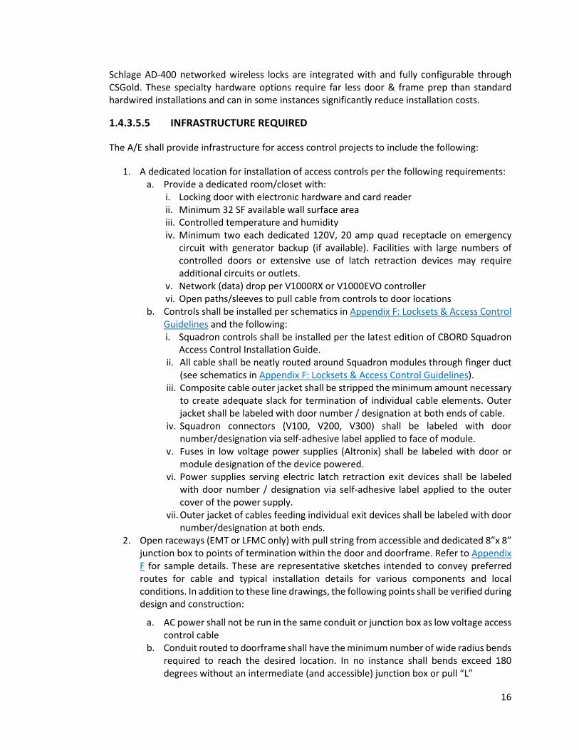
1.4.3.5.5 INFRASTRUCTURE REQUIRED
The A/E shall provide infrastructure for access control projects to include the following:
1. A dedicated location for installation of access controls per the following requirements: a. Provide a dedicated room/closet with:
i. Locking door with electronic hardware and card reader ii. Minimum 32 SF available wall surface area iii. Controlled temperature and humidity iv. Minimum two each dedicated 120V, 20 amp quad receptacle on emergency
circuit with generator backup (if available). Facilities with large numbers of controlled doors or extensive use of latch retraction devices may require additional circuits or outlets.
v. Network (data) drop per V1000RX or V1000EVO controller vi. Open paths/sleeves to pull cable from controls to door locations
b. Controls shall be installed per schematics in Appendix F: Locksets & Access Control Guidelines and the following: i. Squadron controls shall be installed per the latest edition of CBORD Squadron
Access Control Installation Guide. ii. All cable shall be neatly routed around Squadron modules through finger duct
(see schematics in Appendix F: Locksets & Access Control Guidelines). iii. Composite cable outer jacket shall be stripped the minimum amount necessary
to create adequate slack for termination of individual cable elements. Outer jacket shall be labeled with door number / designation at both ends of cable.
iv. Squadron connectors (V100, V200, V300) shall be labeled with door number/designation via self-adhesive label applied to face of module.
v. Fuses in low voltage power supplies (Altronix) shall be labeled with door or module designation of the device powered.
vi. Power supplies serving electric latch retraction exit devices shall be labeled with door number / designation via self-adhesive label applied to the outer cover of the power supply.
vii. Outer jacket of cables feeding individual exit devices shall be labeled with door number/designation at both ends.
2. Open raceways (EMT or LFMC only) with pull string from accessible and dedicated 8”x 8” junction box to points of termination within the door and doorframe. Refer to Appendix F for sample details. These are representative sketches intended to convey preferred routes for cable and typical installation details for various components and local conditions. In addition to these line drawings, the following points shall be verified during design and construction:
a. AC power shall not be run in the same conduit or junction box as low voltage access control cable
b. Conduit routed to doorframe shall have the minimum number of wide radius bends required to reach the desired location. In no instance shall bends exceed 180 degrees without an intermediate (and accessible) junction box or pull “L”

17
i. Minimum conduit size to accommodate composite cable is 1” C ii. Minimum conduit size to accommodate up to three individual cables separated
from the composite cable is ¾” C iii. Minimum conduit size to accommodate one or two cables separated from the
composite cable is ½” C c. Install pull strings from junction box to point of termination in all conduits d. Grouted frames shall be equipped with mortar boxes around electric hinges,
electric power transfers, electric strikes, door contacts, etc. e. Use factory installed raceway within hollow metal frames f. Where ADA operators are installed:
i. ADA push button must be hardwired to the ADA operator ii. Card reader shall be installed adjacent to ADA pushbutton, and may share a
common conduit run to the 8”x 8” junction box
1.4.3.5.6 CONTRACTOR-FURNISHED COMPONENTS
The contractor shall furnish the following components and services with respect to access control projects (See Appendix F for approved equipment list):
1. Card readers 2. Alarm horns/sounders 3. Request-to-exit devices (motion detectors) 4. Door position switches (door contacts), normally open 5. Modular DC power supplies serving:
a. Squadron controls b. Request-to-exit devices (motion detectors) c. Alarm horns/sounders d. Electric strikes/locks e. Note: power supplies for latch retraction hardware shall be provided by hardware
supplier 6. Cable
1.4.3.6 EMERGENCY TELEPHONES
New buildings, new parking lots and major site work projects shall provide location(s) for emergency telephone(s) that are accessible, hands-free operated and located on or near lighted walkways providing visibility and comfort in their use. The Project Manager shall determine approved locations and type of installation in consultation with the University Safety and Security Committee.
Two types of emergency telephone styles are applicable. In all installations the telephone shall be University provided and installed on or in the assembly. Power for emergency telephones is to be an emergency circuit where available:
1. The type applicable to most locations is a Facilities Management fabricated and installed assembly as illustrated in Figure 5; installation will include all necessary wiring, cabling, the telephone, and the light fixture.
2. For areas determined by the University Safety and Security Committee and large parking lots (more than 49 cars), the use of a pre-manufactured “tower” type emergency telephone assembly is appropriate. For each 99 parking spaces, an additional emergency telephone is

18
required. The University Landscape Architect must approve “tower” type assemblies taller than 8’ for large parking lots where visibility over vans and similar taller vehicles is required.
Where tower-type emergency telephones are specified, the design shall be similar to GAI-Tronics Corporation Model 234 Stanchion and/or model ETP-MT/R by Talk-A-Phone Co. and shall be ADA compliant. Color(s) shall be approved by the University Landscape Architect.
1.4.4 HAZARDS
1.4.4.1 ASBESTOS ABATEMENT
1.4.4.1.1 GENERAL ASBESTOS ABATEMENT DISCOVERY REQUIREMENTS
Buildings constructed prior to 1988 are presumed to have Asbestos-Containing Materials (ACM) until such materials have been tested and found not to contain asbestos. The University shall test for ACM prior to submittal of the Preliminary Design in accordance with UVA policy on ACM Management through the Office of Environmental Health & Safety (OEHS). An asbestos survey/inspection report must be made available to the project A/E for information and use in preparing the project documents and cost estimate for asbestos abatement. The A/E is responsible to the University to coordinate the design with the asbestos abatement work in order to prevent conflicts, claims and work stoppages.
If asbestos-containing materials are found, the University’s licensed asbestos designer in concert with the A/E will prepare an Asbestos Abatement Specification. Based on the asbestos survey/inspection report and the Asbestos Abatement Specification, the construction documents shall indicate all locations where ACM have been found and/or where ACM are to be disturbed.
The demolition plan sheets and the architectural floor plan sheets for each floor shall have an Asbestos Disclosure Statement indicating one of the following:
1. “An asbestos inspection was performed and no asbestos-containing materials were found. The asbestos survey/inspection report is available to the Contractor(s) for demolition and construction.”
2. “An asbestos inspection was performed and asbestos-containing materials were found generally in the areas indicated. However, the Work in this Project is not intended to disturb the existing asbestos-containing materials. The asbestos survey/inspection report and the Asbestos Management Plan are available to the Contractor(s) for demolition and construction.”
3. “An asbestos inspection was performed and asbestos-containing materials were found generally in the areas indicated. The asbestos survey/inspection report is available to the Contractor(s). The asbestos-containing materials shall be removed prior to any other Work being performed in these areas. The Asbestos Abatement Specification is included in the documents. OEHS will mark-up the Asbestos Management Plan to show the “As-Built” conditions at the conclusion of the Work.”
4. “An asbestos inspection was performed and asbestos-containing materials were found generally in the areas indicated. The asbestos survey/inspection report and the Asbestos Abatement Specification are available to the Contractor(s) for demolition and construction. Asbestos-containing materials shall not be disturbed in this Work except where specifically indicated and required for connections to utilities. Where such

19
connections are required, the UVA PM and OEHS will determine approved procedures as specified. The asbestos-containing materials that are to remain and the new non asbestos-containing material shall be labeled accordingly. OEHS will mark-up the Asbestos Management Plan to show the “As-Built” conditions at the conclusion of the Work.”
In addition, the use of materials that contain asbestos shall be prohibited in any new construction or renovation work. See section 11 (e) of the General Conditions of the Contract for Capital Outlay Projects for asbestos-related work insurance requirements.
1.4.4.1.2 ASBESTOS REMOVAL
Asbestos removal requires a building permit. All ACM that may be disturbed as a result of the Work must be removed or properly repaired. The University has two contracting options for use in removal of asbestos:
1. A separate contract for removal of the asbestos prior to renovation, demolition or addition; or,
2. A contract where the abatement is an integral part of the renovation, addition or demolition project in which the general contractor is licensed as an asbestos contractor or hires a licensed asbestos abatement Subcontractor to perform the work.
1.4.4.1.3 REMOVAL AND REPLACEMENT OF SPRAYED-ON FIREPROOFING
The A/E, in consultation with the University, shall verify early in the design phase with the Office of the University Building Official the original purpose of any fireproofing material to be removed or replaced and what, if anything, must be done to restore the fire resistive characteristics. If sprayed-on ACM is to be replaced, the A/E shall submit copies of the proposed specifications for the intended replacement material and any bridging encapsulate for review. The bridging encapsulate must be correctly matched with the replacement material to ensure maximum bonding strength and to maintain the intended fire rating integrity of the assembly. See also 5.2.4 Spray Fireproofing Design and Specification.
1.4.4.1.4 ASBESTOS RELATED WORK INSURANCE REQUIREMENTS
See SECTION 11(e) of General Conditions of the Contract for Capital Outlay Projects requires the asbestos contractor or subcontractor, as the case may be, to name the A/E as an additional insured on the contractor’s liability insurance with asbestos coverage. Where the A/E for the renovation project prepares the asbestos project drawings, the requirement of SECTION 11(d) to name the A/E as an insured party is waived. Professional Liability/Errors and Omissions insurance, with asbestos coverage, in an amount not less than $1M is required.
1.4.4.1.5 CONFLICT OF INTEREST POLICIES
All laboratories utilized for asbestos sampling analyses for project purposes shall have no direct business or financial relationship with the contractors conducting asbestos abatement activities.
1.4.4.2 SPECIAL PROCEDURES FOR LEAD CONTAINING PAINT
In renovation and demolition projects OEHS shall conduct a survey for lead-containing paint, documenting all quantities and locations found. Where lead-containing paint is suspected or pre-

20
determined, an estimated cost for any special procedures required shall be included in the cost estimate supporting the construction budget or budget request.
The construction documents for all renovation, demolition and addition projects shall indicate all locations where lead-containing paint is to be disturbed or to remain, and shall include a Lead-Containing Paint Disclosure Statement indicating one of the following:
1. “A lead-containing paint inspection was performed, and no lead-containing paint was found.”
2. “A lead-containing paint inspection was performed, and lead-containing paint was found in indicated areas. However, the work in this project is not intended to disturb existing lead-containing paint.”
3. “A lead-containing paint inspection was performed, and lead-containing paint was found in the areas indicated. The contractor shall be responsible for compliance with all VOSHA regulations regarding lead-containing paint protection for workers.”
Following removal of lead-containing paint, additional TCLP tests in accordance with EPA guidelines shall be done on these materials to determine disposal requirements as hazardous waste or as ordinary construction debris. It is unlawful for materials identified as hazardous waste to be disposed of with ordinary construction debris.
1.4.4.3 CONFINED SPACE REQUIREMENTS
All structures shall be designed in an effort to minimize confined spaces where configuration, size or location hinders the activities of the employees who must enter and work in the space and the space is not designed for continuous occupancy (examples include underground vaults and tanks). Where newly created confined space is unavoidable, the following guidelines must be considered to reduce the hazards associated with the space:
1. Install a remote monitoring and inspection system and automated cleaning system to eliminate or minimize the need for entry.
2. Provide mechanical ventilation to avoid build-up of contaminants or combustible atmospheres.
3. Design adequate means of entry and exit to accommodate persons who may be required to wear personal protective equipment, a breathing apparatus, and protective clothing.
4. Design suitable illumination on emergency power (no timer switches) for safe entry, conducting work and exiting.
5. Eliminate fall hazards. Provide fixed ladders, guardrails, platforms and anchor points for personal fall arrest systems, and provide non-slip work surfaces (e.g., textured flooring).
1.4.4.4 EMERGENCY GENERATORS & OTHER FUEL BURNING EQUIPMENT
All fuel burning equipment requires evaluation for inclusion in the University of Virginia Federal Title V Air Permit and for permitting as a new stationary source (9VAC5-80). The Project Manager is to provide the Associate Director for Environmental Resources with the following information to facilitate the environmental review and permit applications:
1. Copy of the manufacturer’s specifications 2. Copy of any available emissions data from the manufacturer 3. Size/capacity (kW, hp or btu/hr) 4. Manufacturer, model number and serial number 5. Fuel type

21
6. Fuel tank specifications 7. Generator/boiler and tank location 8. Installation completion date
The manufacturer’s specifications must be provided for each new piece of fuel burning equipment before they are purchased. FM Environmental Resources shall be notified of any removal, replacement or modifications of any fuel burning equipment in order to maintain the University’s permit documentation accordingly.
The Contractor shall submit the emissions certificate from the manufacturer documenting the air emissions performance.
Generator fuel shall be ultra-low sulfur diesel (max sulfur of 15 ppm) and shall meet regulatory requirements. A fuel certification shall be provided by the Contractor and include:
1. Name of supplier 2. Date of fuel received 3. Volume of fuel delivered in shipment 4. Statement that oil complies with ASTM specs for No. 2 fuel oil 5. Sulfur content of oil and method used to determine sulfur content
Exhaust stacks shall be installed so as to not cause or contribute to a condition of air pollution back into the building of interest or adjacent sensitive locations (e.g., stack height is 10 feet above rooftop, vertical discharge, avoiding discharge into nearby outside air intakes or windows). Generators shall not be installed on roofs.
Provide cam locks on the load side of the generator breaker for the purpose of load bank testing and temporary generator installation in the event of a generator failure. Provide 2 #14 AWG conductors from the transfer switch to the generator to enable a contact to disconnect the load bank if building power is interrupted during load bank testing. Provide a hard-wired interface from the generator to the UVA BAS system to monitor the following points (at a minimum): generator general alarm, generator fuel tank level, and automatic transfer switch (ATS) position
Professional designers under contract to the University for a specific project are responsible for compliance with all legislated requirements.
1.4.4.5 HAZARDOUS WASTE STORAGE
In addition to code requirements (including rated enclosure, dedicated ventilation and floor containment system), the A/E must adhere to the following guidelines when designing a hazardous waste shipping, receiving and/or storage area:
1. Doors to the area must be equipped with locks to prevent unauthorized entry. 2. Waste containers must be adequately segregated and contained. Provide minimum 3’ of aisle
space between shelving and waste containers. 3. Radioactive material storage may require special locking arrangements. Contact Radiation
Safety Officer for any additional requirements.
In addition to code-required equipment (including fire suppression, extinguishers, emergency shower and eyewash), a spill kit must be provided in hazardous waste storage areas.

22
1.4.4.6 FALL HAZARDS
Structures shall be designed to eliminate fall hazards for persons engaged in maintenance, repairs and related activity. Where exposures to fall hazards are unavoidable, incorporate the following into building design:
1. Anchorages to which personal fall arrest equipment is attached shall be capable of supporting at least 5,000 lbs (22.2 kN) per employee attached as required by the Occupational Health and Safety Administration (OSHA Standard 1926.502).
2. Install guardrails and toe boards where people are exposed to falls ≥ 4’. Standard railings with standard toe boards shall be installed on all exposed sides except at the entrance to the opening. The railings and toe boards shall be constructed in accordance with the ANSI standard A1264.1-1995.
1.4.4.7 SOURCES OF NOXIOUS OR TOXIC FUMES
Projects shall be designed to prevent noxious/toxic fumes from entering occupied spaces, recognizing some buildings have more stringent needs (such as where large numbers of persons gather or in medical research buildings). All new buildings and those projects involving major renovations and upgrading of heating, ventilation, and air conditioning systems shall incorporate the following:
1. Site and building design shall include consideration of outside air intakes for heating, ventilation and air conditioning related to sources of noxious or toxic fumes. The A/E and Project Manager are required to understand existing conditions and/or prevailing winds and account for these factors in the project design.
2. Outside air intakes shall be sufficiently above exterior grade (30’-0” or at third story level) and remote from loading docks, emergency or ambulance vehicle entrances, etc., on all new buildings and major renovations to avoid intake of noxious or toxic fumes associated with vehicles, maintenance equipment, electrical generators, similar sources of fumes permanently or intermittently associated with building functions and maintenance, and to discourage malicious contamination. Consideration also shall include proximity to wind-blown dust from streets, fields and ground care activities, designated tobacco smoking areas, combustion by-products, and biogenic materials related to evaporative cooling towers or intentional human contamination.
3. Dedicated mailrooms shall be exhausted and shall be under negative pressure.
1.4.5 REQUIREMENTS FOR SPECIFIC USES
1.4.5.1 CUSTODIAL ROOMS
Provide one custodial room for each 15,000 to 18,000 gross square feet, with a minimum of one room per floor. Locate closets adjacent to restrooms and elevators. Valves, electric panels and equipment, thermostats, and terminal boards for telephone, date or other low voltage equipment shall not be placed in custodial rooms.
Provide a central custodial room in each building on a level accessible from a service or loading dock entrance, containing a minimum area of 130 square feet (20 square feet in trailers), to accommodate the following:

23
1. Floor space for one wheeled cart and one floor machine 2. 18 linear feet of heavy duty metal shelving 24” deep with 18” vertical separation between
shelves, not exceeding 7’-2” from floor to top shelf 3. 3' x 3' floor sink with drain and three mop holders, with impermeable surface 2’ minimum
above the sink on any adjacent wall 4. Broom hanger strip to accommodate minimum of three brooms 5. Space to accommodate two stepladders 6. Space for small desk with data/telephone outlet 7. Two GFCI type duplex electrical outlets centered 18” above the floor in accessible
locations (one adjacent to corridor door) 8. Motion detector switch for overhead light fixture 9. Water resistant epoxy flooring (turned up 4”) with a floor drain. Floor shall slope 1/4” per
foot floor to the drain throughout the room. 10. Four metal hooks mounted on inside of corridor door. If door is fire-rated, hooks may be
located adjacent to the door
1.4.5.2 INFORMATION TECHNOLOGY SERVICES (ITS)
The Project Manager shall coordinate ITS requirements with Information Technology and Communications during Programming and Schematic Design. ITS equipment rooms shall be dedicated for ITS use only (telephone, data and entertainment video services). These rooms shall not be used to support any other building utility.
The University IT Building and Cabling Standard is applicable to newly installed systems. All systems shall meet this standard unless specific exceptions are obtained directly from the Office of UVA IT Enterprise Infrastructure.
Telecommunications room/closets shall include the following:
1. Minimum size 6’ x 8’ (serving up to 100 outlets). Room size must accommodate projected number of outlets served including not less than 33% growth.
2. Minimum height 9’ 3. No suspended ceiling unless required by building code 4. A lockable 3’ x 6’-8” out-swinging door. If in-swinging door is required by building code,
the room size may need to be increased. 5. 50 foot-candles illumination level at 3’ above floor, light fixtures mounted 8’-6” minimum
clear above floor (no wall mounted light fixtures) 6. IT rooms shall be cooled by a dedicated piece of HVAC equipment, with the cooling source
preferably from the central chilled water system. No water piping shall be run over IT equipment. Verify chilled water is available year round. An ambient temperature of less than eighty degrees (typical heat load < 6,000 watts), with 30-75% relative humidity, and slight positive pressure must be maintained at all times. Cold supply air shall be directed down to the “cold” side of equipment intakes, and the return duct termination shall be high in the space above the “hot” discharge of the equipment. HVAC requirements shall be maintained 24/7 the entire year.
7. Fire-treated ¾” plywood installed from floor to 8’ above floor on minimum 3 walls of room

24
8. Stacked vertically where possible and interconnected by four 4” bushed sleeve floor penetrations extending 1” above the floor
9. Interconnected horizontally at minimum of every three floors with a cable tray above suspended ceiling (or conduit where ceiling is not accessible), with a run distance not exceeding 90 meters.
10. Within 90 meters cable run distance of the most remote site. Multiple closets are required if this distance cannot be achieved with one closet.
Cable tray, when provided, shall be a minimum of 12” x 4” deep. See 7.6.3.1 Telecommunications, for additional technical requirements, such as electrical power outlets, building entrance termination, grounding, cable tray, conduit, and outlets.
1.4.5.3 AUDIO-VISUAL TECHNOLOGIES
All projects requiring audio-visual systems for any spaces must coordinate with ITS-Classroom Support during design development.
1.4.5.4 LACTATION ROOM DESIGN
Under The Patient Protection and Affordable Care Act (PPACA), the University is required to provide an area, other than a bathroom, that is private and free from intrusion from coworkers and the public, which may be used by an employee to express (pump) breast milk. The space can be temporarily assigned or converted for the duration of a mother’s need; departments should reference the following guidelines when retrofitting existing spaces to serve this purpose. The A/E shall incorporate the following guidelines when planning lactation rooms in new buildings or major renovations:
1. Size: 50 SF 2. Location: A safe, accessible area 3. Access Privacy: Install a user-operated, indicator deadbolt that displays an “occupied”
message to discourage interruptions. 4. Sound Privacy: Extend wall framing to the structure above to minimize sound transmission;
install sound attenuation; installation of fabric panels on the walls is encouraged. 5. Furniture: Provide a table to be used as a work surface. Provide a comfortable, adjustable
task chair with arms. 6. Electrical: Provide an electrical outlet to power breast pump and refrigerator. 7. Plumbing: Provide a sink and faucet combination deep enough to wash bottles and pump
parts. Specify gooseneck or kitchen-type faucets. 8. Lighting: Specify task lighting over the work area. 9. HVAC: Locate individual thermostat in room for user control and thermal comfort. 10. Equipment: Install an Energy Star certified compact refrigerator for milk storage. 11. Accessories: Provide trashcan, paper towel dispenser, coat hook, mirror, and hand
sanitizer
1.4.5.5 UVA RECYCLING SPACE GUIDELINES
All projects shall comply with UVA’s Recycling Station Guidelines. For all capital projects and renovation projects involving significant spatial reconfiguration, the Project Manager shall coordinate with UVA Recycling to determine additional trash and recycling space requirements specific to the tenants’ needs and building requirements.

25
1.4.5.6 VIVARIUMS
Vivarium and other research or clinically related animal holding facilities are required to meet architectural, mechanical, electrical and plumbing standards established by the current edition of the Guide for the Care and Use of Laboratory Animals, Institute of Laboratory Animal Resources, Commission on Life Sciences, National Research Council and National Academy Press.
1.4.5.7 LASER LABS (CLASS 4 AND 3B)
All new and renovated laboratories housing research that employs Class 4 lasers shall be designed with a laser-controlled area (LCA). All new and renovated laboratories housing research that employs Class 3B lasers should be designed with a laser-controlled area (LCA). The designs will be submitted to, reviewed and approved by the University Laser Safety Officer. In addition to all building code and ADA requirements, minimum design requirements for the LCA can be found at the EHS website under Laser Safety.
1.4.5.8 MAKER LAB SPACES Spaces with equipment for making and assembling that produce odors, vapors, volatiles, fumes, dust, particulates or smoke shall have adequate exhaust to remove all contaminants. Some maker lab equipment can trigger air permitting requirements, regardless of whether or not the equipment exhaust to the exterior of the building. Consult with UVA Environmental Resources during the design process to assess if an air permit is required.
Maker Labs and similar spaces shall have controlled access. An emergency eyewash shall be provided. Consult the UVA Environmental Health & Safety web page on Shop and Studio Safety for additional requirements.
1.4.6 BUILDING DEDICATION PLAQUES Building dedicatory plaques are included as part of all new building projects. See the Commemorative Plaques on the Office of the Architect for the University of Virginia web site for design guidelines. The University shall procure and install the plaque.
Unless approved by the President of the University, building identification shall not be engraved onto or included in the fabric of the building, such as in a cornerstone, engraved stone or surface mounted lettering.
1.5 PROJECT CLOSE OUT
1.5.1 FINAL CLEANING Final cleaning shall include, but not be limited to, cleaning in compliance with manufacturer's instructions, interior and exterior glass, mirrors, floors, other interior finishes, mechanical and electrical equipment, removal of stains and foreign substances exposed to view, vacuuming of clean soft surfaces, polishing of transparent or glossy surfaces, and other such requirements to leave the project area in finished condition. Final cleaning shall be inspected by Building Services with the Construction Administrative Manager or Project Manager.
Contractor shall be responsible for resilient floor stripping and finishes. A Green Seal floor finish shall be required. The contractor must consult with Building Services Management Team prior to the start of project floor care step.

26
1.5.2 SITE RESTORATION The contractor shall restore all existing gravel areas, paved areas, walks, drives, storm drains, etc. to their original condition.
The contractor shall restore all grassed or turf areas disturbed by construction activities, including areas used for access, staging, parking and storage in accordance with established requirements in the construction documents and found acceptable to the University’s Landscape Superintendent. General instructions to restore grassed or turf areas to original condition are not acceptable. Copies of the University's Turf Restoration Specifications are available through the Project Manager.
When the Project Manager directs that finish landscaping is to be accomplished by separate contract, the construction documents shall include specific requirements for leaving the site ready for landscaping.
1.5.3 OPERATION AND MAINTENANCE MANUALS/DATA The contractor shall submit all operations and maintenance manuals to the A/E for review and approval. The A/E approved manuals shall be submitted to the Construction Administration Manager prior to final demonstration of the equipment.
For new buildings or major renovations, the contractor shall provide a cabinet for maintenance manuals in a visible, secure location sized to contain a complete set of operations and maintenance manuals.
Provide one complete set of manuals in both digital and printed format to be delivered to the A/E for submission to Facilities Management through the Construction Administration Manager. Each set of manuals is to be in individually bound volumes based upon CSI standard specification headings.
Manual binders shall accommodate 8.5”x11” pages, be stiff-backed, plastic or canvas covered three ring type loose-leaf binders with the project name and division permanently lettered on the spine. When larger pages are necessary, they shall be neatly folded to 8.5”x11” as pullouts or foldouts.
Each copy of the manuals shall include:
1. Names, addresses and trades of all applicable subcontractors, manufacturers and equipment 2. Complete maintenance instructions from the manufacturer's local representative for each
item of operable equipment, as well as the name, address and telephone number of the installing subcontractor
3. Catalog data on all items submitted and other pertinent data such as mortar colors, brick selected, and colors selected for all finished materials and fabrics
4. Catalog data on all furnished plumbing fixtures, valves, water heaters, heating equipment, light fixtures and similar equipment and systems. Manufacturer's promotional literature is not acceptable
5. Manufacturer's name, model number, service manual, spare parts list and descriptive literature for all components used
6. Preventive maintenance instructions and schedules for all major equipment 7. List of most frequently encountered breakdowns and repairs/trouble shooting manual(s) 8. Instructions for starting and operating the actual system as installed 9. Detailed one-line, color-coded wiring diagrams 10. Schedules on contractor’s As-Built drawings and subsequent A/E’s Record Drawings shall
indicate the actual make, model and size for each piece of equipment used.

27
11. Sections for major equipment to be included in the Preventive Maintenance Systems Equipment Lists (See 1.5.5 Preventative Maintenance Systems Equipment Lists) should be identified by unique ID number to be provided by Facilities Management CMMS staff.
12. Floor plans identifying all lighting control device locations. 13. An air handler level HVAC zone mapping floor plan that indicates which rooms are served by
each air handler.
1.5.4 SPARE PARTS AND MAINTENANCE MATERIALS
Spare parts and maintenance materials shall be turned over to the Construction Administration Manager at final inspection. Keys, other than those provided by Facilities Management, shall be delivered to the Construction Administration Manager at the final inspection. Construction documents shall state these requirements. See Appendix F: Locksets and Access Control.
1.5.5 PREVENTATIVE MAINTENANCE SYSTEMS EQUIPMENT LISTS For all projects installing new or replacement equipment requiring routine/preventive maintenance by Facilities Management (FM), equipment should be clearly identified in equipment schedules within the project documents in the Construction Documents. Schedules should address components of systems including but not limited to: elevators, fire protection and detection systems, electrical, HVAC, refrigeration, roofing, water and sewer, heat distribution, plumbing, and storm water management practice. Equipment schedules shall include unique asset ID numbers that are generated from UVA’s Integrated Workplace Management System (IWMS). The numbers will be provided to the UVA project manager by the UVA preventative maintenance manager. Engineers should plan to provide equipment lists for asset ID assignment to the UVA project manager early, so as not to delay Construction Document submittal. In addition, projects demolishing or replacing existing equipment currently tracked in UVA’s IWMS must clearly identify such equipment and its asset ID number(s). The UVA preventative maintenance manager may assist the project manager with identifying existing asset numbers for equipment to be demolished.
During construction, the contractor shall complete a data inventory spreadsheet (Asset Turnover Form) for all installed equipment and building components individually listed on the equipment schedule as well as any equipment added to the project scope following permit issuance. Prior to turnover to UVA, the contracting team will submit a draft of the completed data inventory (Asset Turnover Form) to the UVA preventive maintenance manager for review. Upon successful review, the preventive maintenance manager will upload the newly installed assets into UVA’s IWMS and provide barcode stickers with the unique asset IDs for each piece of equipment identified to be added to the IWMS. The Project Team will be responsible for applying barcode stickers on the installed equipment and provide all special tools, training and test equipment required for maintenance.
1.5.6 WARRANTIES AND GUARANTEES All warranties and guarantees shall be drawn in the name of the Commonwealth of Virginia and the Rector and Board of Visitors of the University of Virginia and shall be delivered in print and digital format by the A/E to the Construction Administration Manager.
The contractor shall submit PDF files of warranties and guarantees and one commercial quality, hardback binder sized to accommodate 8.5 by 11-inch pages, with a table of contents and one copy of

28
each warranty or guarantee. Marked tabs shall separate warranties and guarantees in sections following the order of the specifications.
Training shall be provided to Building Services staff if new or unusual floor finishes are installed. Specification manuals for floor care shall be provided to Building Services Superintendent and Associate Director.
1.5.7 BENEFICIAL OCCUPANCY/FINAL INSPECTION Prior to beneficial occupancy of a project, the building(s) must be inspected and accepted, on both interior and exterior, by the Project Manager, Construction Administration Manager, A/E and the Office of the University Building Official. Exterior lighting shall be operational and exposed earth adjacent to buildings and walkways serving buildings shall be graded and protected to prevent erosion. Trash receptacle pads shall be in place and accessible to collection equipment. Any continuing construction activity on the balance of the project, including equipment and vehicle access, shall be identified on a list.
The contractor is responsible for the final inspection held in the presence of the Project Manager, the Construction Administration Manager and the A/E. The responsible Facilities Operations or UVA Health Physical Plant Zone Maintenance Supervisor shall be a participant.
Inspection of Capital Outlay projects by both the Office of the University Building Official and a representative of the State Fire Marshal is required. The Project Manager or Construction Administration Manager will coordinate this inspection(s) as determined with the A/E.
29
Chapter 2 Historic Preservation
2.1 HISTORIC PRESERVATION GENERAL The Historic Grounds consists of buildings within the Central Grounds Area, including Thomas Jefferson’s Academical Village, that are considered historic landmarks. In addition, many other buildings within the University are classified as landmarks or components of designated historic districts. See the website of the Office of the Architect for the University for the Historic Preservation Framework Plan, Historic Structures Report, and other preservation-related information.
2.2 PRESERVATION GUIDELINES The management and conservation of historic resources is a priority requiring cooperation between departments and disciplines throughout all phases of the work. Observe the following guidelines on all projects related to historic resources at the University:
1. Historically significant structures and landscapes must be recognized and acknowledged to promote appreciation, understanding and respect for them.
2. Pursue an active program of studying and recording the University’s historic resources. 3. Historic Structure Reports, Building Assessment Studies and Cultural Landscape Reports should
be performed as needed on buildings and landscapes as a part of project planning. 4. An active public outreach program involving presentations by preservation staff should be
developed to communicate the findings and goals of the Preservation Framework Plan to Facilities Management, the schools and departments within the University, and to the broader Charlottesville community.
5. The permanent collection of records and information chronicling the development and evolution of the University’s historic resources should be maintained and enhanced.
6. An active program for listing resources on the National Register of Historic Places should be pursued.
7. Archaeology must be incorporated into projects involving ground disturbances. 8. A design review process involving preservation specialists on the University staff should be
implemented to evaluate proposed repairs on, alterations to and improvements of historic resources. Revisions to projects may be necessary to avoid altering or damaging the integrity of a building or landscape.
2.3 CARE AND MAINTENANCE In the on-going process of maintenance, the most appropriate action is the one that achieves the desired goal with the least negative effect on the historic resource. Historic resources are the product of practices and materials not commonly employed in contemporary construction; therefore, the use of traditional methods, techniques and skills for conservation should be embraced by the University to ensure appropriate repair and maintenance of historic buildings.
1. Active conservation of historic buildings and landscapes is an integral part of planning for repair and maintenance.
2. Employ the least intrusive methods of stabilization and repair when dealing with historic building fabric.

30
3. Retain original fabric and character-defining features. Missing original features should be replicated faithfully without reproducing original failures or shortcomings.
4. The University should maintain its staff of skilled tradespeople who are knowledgeable in traditional materials and construction practices and are capable of performing maintenance and repairs in a manner which is equal to or better than that found in the original construction of historic buildings.
5. Completed work must visually match work from the resource’s period of significance. 6. Photographic and written documentation should be incorporated into all phases of work
conducted on historic buildings and landscapes.
2.4 ADAPTIVE USE OF BUILDINGS AND LANDSCAPES Improvements and alterations to historic resources should have minimal effect on the integrity of the building and/or landscape while extending the life and use of the resource. Alterations to accommodate ephemeral uses and occupancy should be reversible. Permanent improvements to accommodate changes in use should be executed to a degree of quality equal to or exceeding that of the original construction.
1. Evaluate the effect of proposed alterations to the integrity of the historic resource based on the significance of the building or landscape in question.
2. Consider the original design of a building or site and its significant features when planning for reuse or adaptation. Ideally the use of buildings should be compatible with their original function/plan to minimize changes to layout.
3. Ensure the installation and/or replacement of services and systems does not adversely affect the integrity of buildings and landscapes.
4. Reverse past alterations that detract from the integrity of the historic resource when circumstances allow.
5. Mothball vacant or underutilized historic buildings according to standards put forward by the National Park Service in Preservation Brief 31 to protect structures from deterioration and maintain them until appropriate use allows for their occupancy and repair.
6. Architectural fragments, significant elements and pieces of building systems removed from structures should be recorded, archived, and protected for future research and study.
2.5 ARCHAEOLOGICAL CONCERNS On occasion, the University discovers subsurface archaeological materials requiring immediate, expedient investigation as to their merits and the means by which they will be removed or preserved. It is the University’s responsibility to advise the A/E of known or suspected sites having archaeological significance, as well as the intent of the University to perform an archaeological investigation.
In the event of a discovery during construction, notify the Project Manager immediately and he/she will make provisions for site investigation.
31
Chapter 3 Sitework
3.1 SITEWORK GENERAL
3.1.1 INTRODUCTION The Project Manager shall coordinate review of all projects involving sitework or landscaping with the University Landscape Architect, FM Landscape Services, the Arboretum and Landscape Committee, and the Department of Safety and Security. Coordinate exterior signage with the Office of the Architect for the University, the Office of the University Building Official, and the UVA Fire Marshall. Coordinate site utilities with the FM Department of Energy and Utilities.
Other sections affecting sitework and landscape design include: 1.3.2 Stormwater Management / Erosion and Sediment Control, 1.4.4.1.2 Asbestos Removal, 1.4.4.2 Special Procedures for Lead Containing Paint, and 5.5.7 Rooftop Equipment.
3.1.2 CONSTRUCTION SITE FENCING Standard construction site fencing should be 8’ chain link fencing with a top rail and green vision screening. For projects in the Central Grounds that are highly visible and with a duration exceeding one year, the Project Manager should consult with the building committee to consider the use of UVA 8’ plywood fence and associated details.
3.1.3 PETROLEUM STORAGE TANKS All petroleum tanks, aboveground storage tanks (ASTs) and underground storage tanks (USTs), must be double-walled, and all associated underground piping must be double-walled. Underground storage tanks are not permitted without approval by the CFO. Drawings and specifications for any tank, either AST or UST, shall be reviewed and approved by the University FM Environmental Resources for compliance with Department of Environmental Quality (DEQ) requirements and the University’s more restrictive EPA Spill Prevention, Countermeasures and Control plan. Documentation of FM Environmental Resources approval is required prior to issuance of a building permit. Copies of as-built tank drawings, inspection reports, and passing test results for tank components shall be provided by the Project Manager to FM Environmental Resources to document compliance with regulatory requirements. DEQ additionally requires the University to obtain building permits from the University Building Official for removal and replacement of tanks. The DEQ also requires that ASTs over 660 gallons and regulated USTs (motor fuel and generator fuel) be registered. All required registration information must be supplied by the contractor. Technical standards related to storage tanks are contained in the State Water Control Board Regulations: 9VAC25-580 Underground Storage Tanks (UST): Technical Standards and Corrective Action Requirements and 9VAC25-91, Facility and Aboveground Storage Tank (AST) Regulation, and in federal regulations 40 CFR 112 pertaining to Spill Prevention Control and Countermeasures Plans (SCCC).

32
3.1.4 OIL INTERCEPTORS Oil interceptors shall be provided for all parking garages and large parking lots where wash-down maintenance is performed. Interceptors shall be designed according to established standards for size and water quality control. There shall be adequate access for cleaning all areas of the separator with a vacuum pump and compartments shall be constructed horizontally. A minimum of one access point into each compartment within the separator shall be provided. Access points shall be no further than 10’ apart, regardless of the number of compartments. Access covers shall have a minimum opening dimension of 24” in diameter.
3.2 SITE PREPARATION
3.2.1 SITE CLEARING AND BUILDING REMOVAL All logs, stumps, brush, wood, and refuse shall be disposed of away from University Grounds in an approved landfill. On-site burning is prohibited. When buildings are to be removed, procedural requirements and approval are required prior to demolition. The Project Manager, through Space and Real Estate Management, shall have obtained required State approval. The University shall perform an asbestos and lead paint survey and the information shall be included in the construction documents.
3.2.2 DUST, MUD, AND DIRT CONTROL The site shall be prepared in accordance with 1.3.2 Stormwater Management Stormwater Management / Erosion and Sediment Control. This includes controlling dust, dirt, and mud. The regulations governing sediment control can be found in the Erosion and Sediment Control regulations 9VAC25-840 et seq. as amended. Regulations governing dust emissions can be found in 9VAC5-40-90 and 9VAC5-50-90.
3.2.3 PLANT PROTECTION Trees, shrubs and planting beds within the Contract Limit Lines are to be protected with rigid fencing (wood or chain link) to prevent damage from external construction activities. Tree protection shall be located, at a minimum, at the dripline of the tree canopy. Tree protection fencing is to be installed prior to any other activity occurring on the site and is to remain in place until final inspection. Selection of trees to be protected and tree protection shall be coordinated through the Facilities Management Landscape Superintendent. All tree removal requires prior approval by the Office of the Architect for the University and/or the Arboretum and Landscape Committee. The parking of vehicles, construction access, and storage of any construction materials shall not occur under the driplines of trees to be protected.
3.2.4 EARTHWORK Earthwork specifications shall include soil and aggregate material definitions for all materials used on the project. The soil materials shall be defined by a recognized soil classification system, such as the Unified Soil Classification System or the AASHTO Soil Classification System. The aggregates shall include gradations required for each material.

33
3.2.4.1 GEOTECHNICAL REPORT A Geotechnical/Soils Report shall be included in the Appendix to the Specifications as well as a disclaimer stating that the report is not part of the construction documents. The report should include the following:
1. Subsurface profiles (boring logs) and limits showing the extent of rock, existing fill materials, water and existing unsuitable bearing materials;
2. A statement noting whether over-excavation and replacement with suitable materials is required;
3. Definition of suitable materials for structural fill, general fill and backfill. Note: Suitable materials that become saturated are not automatically rendered unsuitable;
4. For projects requiring a stormwater management plan, site soils should be classified in accordance with the US Department of Agriculture’s hydrological soil group criteria;
5. The Geotechnical Report/Engineer shall set a tolerance from the optimum moisture content to account for field conditions during construction.
3.2.4.2 EARTHWORK SPECIFICATIONS
1. Specifications for fill materials shall state whether they are included in the Base Price/Bid or will be an extra cost item.
2. Rock excavation shall be included in the Base Price/Bid to the extent that locations are sufficiently identified in the Geotechnical/Soils Report.
3. The specifications shall list the tests required (i.e. ASTM, AASHTO, VDOT, or other test procedures) and stipulate the values to be achieved.
3.3 SITE DEVELOPMENT
3.3.1 PLANTING The selection of plant material and the planting and maintenance of trees, shrubs and herbaceous plants must be consistent with the current American Standard for Nursery Stock (AAN). Warranty period is one year minimum. The contractor’s responsibilities include the protection of plantings, pest control, pruning, watering and plant material during warranty period. All plant material soil conditions must be inspected by the Facilities Management Landscape Superintendent.
3.3.1.1 SOIL PREPARATION Soils in areas to be planted that are compacted above 85% maximum density shall be mechanically loosened to a minimum uniform depth of 24” below final grade. Inadequate soil conditions must be addressed prior to planting.
3.3.1.2 PLANTING PROCEDURES The width of each planting hole should be three times the size of the root ball. The depth of the hole shall be 2” less than the distance from the bottom of the root ball to the root collar. The bottom and sides of the each hole should be scarified to encourage root development. Upon planting, all plants must be inspected to ensure that the root collar is exposed.
3.3.2 PAVING AND CURBS Minimum slope for all paved surfaces shall be 1%. Maximum slopes for streets, service drives and parking lots shall be 8%. Guidance on acceptable paver types may be found in OAU-LTS.

34
Curbs shall comply with the 6” Virginia Department of Transportation (VDOT) CG-2 Standard. Painted striped crosswalks shall be provided at all road intersections. Curb ramps shall comply with VDOT CG-12 Standards; detectable warnings shall be safety yellow (exceptions made for Historic Grounds). The use of pervious paver systems over impervious is encouraged whenever possible. Pavement thickness at utility trenches shall be a minimum of one-and-one-half times existing pavement thickness or, as noted above, whichever is higher. Backfill in utility trenches under pavements shall be VDOT #21A above top of bedding to underside of pavement. Unless modified by documented site conditions and geotechnical recommendations, asphalt paving shall be:
Course/VDOT Specification
Roads
Parking
Pedestrian walks
Surface/SM-9.5A
2”
1 ½ ”
2”
Binder/ BM-25.0A
3”
2”
Not applicable
Sub-base/21A
10”
6”
6”
Sub-grade compaction
*98%
95%
95%
*Maximum dry density (ASTM D698, Method D)
3.3.2.1 FIRE APPARATUS ACCESS ROAD AND LOADING
Buildings shall be accessible to fire department apparatus by way of an approved access road with an asphalt, concrete or other approved driving surface capable of supporting the imposed load of fire apparatus weighing at least 85,000 pounds. Fire apparatus access roads shall be of an all-weather surface that is easily distinguishable from the surrounding area. The use of re-enforced turf or similar material for roadway surface is prohibited. Fire apparatus access roads shall have an unobstructed driving surface width of not less than 20 feet (26 feet adjacent to fire hydrants) and an unobstructed vertical clearance of not less than 13 feet 6 inches. The fire code official shall have the authority to require an increase in the minimum access widths where they are inadequate for fire or rescue operations. Documentation from a registered engineer that the final construction is in accordance with approved plans or the requirements of the Fire Code may be requested.
3.3.3 SIDEWALKS AND STAIRS The choice of sidewalks shall be in consultation with the University Landscape Architect. Sidewalks will be separated from curbs by planting areas for pedestrian safety, except where restricted by urban site needs.
See Figure 9 for concrete sidewalks. The color for concrete shall be Canvas by Soloman as specified in OAU-LTS. Any other color shall be approved by Office of the Architect for the University. Where sidewalks abut existing structures, expansion joints shall be provided. Brick sidewalks shall be constructed on concrete per Figure 10. Provide positive drainage 1.5% to 2.0% to prevent water

35
accumulation on exterior stairs. Where post-mounted handrails occur, detail the embedment to minimize deterioration of the posts and/or the concrete slab.
3.3.4 EXTERIOR SITE FURNISHINGS Standards for EXTERIOR FURNISHINGS, BICYCLE RACKS, BENCHES, TRASH AND RECYCLING RECEPTACLES, and BOLLARDS are covered in OAU-LTS.

36
Chapter 4 Energy and Utilities
4.1 OVERVIEW The Energy and Utilities at UVA Charlottesville are based on a district energy model. All utilities to a proposed building site are to be furnished from University central distribution systems, unless either unavailable or demonstrated to be impractical in terms of design or cost. Utilities not available or impractical from central distribution systems must be generated at the proposed building.
Specifications shall include requirements which result in alterations or connections to any University domestic water, steam, hot water, chilled water, sanitary, storm, electrical (power and exterior lighting), plumbing, and exterior utilities distribution, shall be coordinated with Facilities Management Energy & Utilities Department through the Project Manager.
4.1.1 UNDERGROUND UTILITY SEPARATION In addition to applicable code requirements for domestic water, a minimum of 12” vertically and 12” horizontally, wall-to-wall, shall be provided between any two utilities and utilities structures.
4.1.2 UTILITY TRENCH CUTS IN ROADWAYS Utility trench cuts in roadways shall be limited to 200’ maximum and shall be covered with traffic- rated steel plates at the close of construction activities each day and/or properly barricaded throughout construction.
4.1.3 UNDERGROUND UTILITY OFFSETS New underground utilities shall not be placed within the dripline of existing trees without approval and coordination by the Office of the Architect and FM Landscape Services. Utilities shall be installed using directional boring with boring pits located outside the tree dripline. Open trenching is discouraged. If approved within 10’ of existing trees, use HDPE butt-welded pressure piping. Coordinate root and soil protection with the Landscape Superintendent.
New shade trees shall not be planted in the following setbacks. Removal of existing trees within these setbacks requires approval:
1. Within 10’ of existing water bearing lines (domestic, chilled, medium temperature) 2. Within 10’ of existing gas lines 3. Within 10’ of existing sanitary or storm lines with joints, or within 5’ of existing sanitary
or storm lines without joints 4. Within 5’ of communication lines 5. Directly over ductbanks
4.2 STORM SYSTEMS See section 1.3.2 Stormwater Management / Erosion and Sediment Control for projects required to address stormwater management.

37
4.2.1 BUIDLING AND ROOF DRAINAGE Drainage piping shall be located as approved by the Facilities Management Energy and Utilities Department and other applicable authorities when located in streets, right-of ways or easements not on University property. All building roof drainage, including external downspouts, areaway drains, and foundation drains shall be connected to a storm water management practice, cistern or the storm sewer system.
If connecting to the storm sewer system, connections shall preferably be made to a storm utility vault or a drop inlet directly. Where the preferred connection is not feasible or economically justified, the connection shall be to the storm sewer with a “Y” a maximum of 50” away from the building. Provide cleanout at roof drain and at a change in direction of any drainage piping. Where a storm system is not available, a new system shall be provided.
4.2.2 STORM INLETS AND STRUCTURES The following requirements apply to storm inlets and structures:
1. Virginia Department of Transportation (VDOT) standard structures are to be used. In historic areas, smaller dimensioned structures may be approved on a case-by-case basis.
2. Curb inlets shall be used for all surface drainage for roadways and parking lots unless vegetated swales or bio retention filters are used
3. All grates for yard inlets shall meet handicapped accessibility standards. 4. Grate inlets shall be used for all lawn areas. 5. Dome top inlets are preferred in landscaped areas. 6. Inlet grates shall be bicycle-safe and orientated with the long axis perpendicular to the direction
of traffic. 7. The tops of all structures shall be flush with the pavement surface. 8. Inlet structure grating shall be heavy-duty traffic rated providing a minimum 24” clear opening
for access. 9. For pipe diameters up to 18” or a depth of 4’-0”, the minimum inside size for drop inlets shall
be 24”. For pipe diameters greater than 18” or deeper than 4’-0”, drop inlets shall be 48”
Area drains, clean outs and yard drains with minimum pipe size and cover shall use shallow cast iron fittings or heavy-duty HS 20 traffic fittings.
Provide storm structures (manholes) for storm systems adjacent to all buildings to which laterals from the building are directly connected. Laterals shall be a maximum of fifty feet (50’). The cleanouts shall be installed in a concrete pad flush with the surface and be HS-20 rated. Storm structures shall occur at changes in direction and in straight runs at a maximum of four hundred feet (400’). Storm structures shall have a minimum inside diameter of 48” with shaped flow troughs at the bottom. Storm structure frame and cover shall be HS-20 rated and shall provide a minimum 24” clear opening for access. Joints in precast utility vaults – inside and out – shall be filled with non-shrink grout and finished smooth. Storm structures shall be coated from the outside with a bitumastic/coal tar based waterproof coating. Pipe connections to storm structures shall be made with flexible rubber boots. At existing structures, install sleeves prior to connections.
4.2.3 SITE STORM SYSTEMS Storm mains shall be a minimum of 15” in diameter. Lines serving yard drains shall be 8” to 12”. Roof, area and foundation drains shall be 4” to 6” for single drain laterals and 8” to 12” for multiple drain

38
collector laterals.
HDPE double–walled corrugated pipe is preferred for all applications. Class III Reinforced Concrete Piping (RCP) is acceptable for all applications. Foundation and retaining wall drains shall be perforated solid wall schedule 40 Polyvinyl Chloride (PVC) with solvent joints wrapped in geotextile fabric with a VDOT #10 (stone dust) bed and cover. Under slab drains can be corrugated PVC.
A minimum cover of 24” shall be provided for storm piping. All buried storm lines shall have VDOT #10 (stone dust) or VDOT Sand – Type A bed and cover. The minimum slope shall result in a self-cleaning velocity (2 fps minimum) for the diameter used. Pipe on a 20% or greater slope shall be secured with concrete anchors.
4.3 SANITARY SYSTEMS The University owned sanitary sewerage system connects to city-maintained sewerage lines and the Rivanna Water and Sewer Authority’s treatment plants.
4.3.1 SITE SANITARY SYSTEMS Sanitary pipe shall be a minimum of 4” for laterals and 8” for mains. Sanitary piping shall be cast iron (CI), ductile iron (DI), HDPE pressure pipe, or solvent weld jointed schedule 40 PVC. HDPE and PVC are not allowed above grade at the Heating Plant. A minimum cover of 36” shall be provided for sanitary piping.
4.3.2 SANITARY UTILITY VAULTS AND CLEANOUTS Provide utility vaults on sanitary systems adjacent to all buildings to which laterals from the building are directly connected. Where sanitary laterals exceed 20’, a clean out shall be provided just outside the building. Laterals shall be a maximum of fifty feet (50’). The cleanouts shall be installed in a concrete pad flush with the surface and be HS-20 rated.
Utility vaults shall occur at changes in direction and in straight runs at a maximum of 200’. Utility vaults shall have a minimum 48” inside diameter with shaped flow troughs at the bottom. Utility vault frame and cover shall be HS-20 rated, providing a minimum 24” clear opening for access.
Utility vaults with an invert change of 18” or two times the inlet pipe diameter—whichever is greater—shall be provided with drop piping outside the utility vault. Joints in precast utility vaults (inside and outside) shall be filled with non-shrink grout and finished smooth. Utility vaults shall be coated from inside with vapor/moisture penetration preventing epoxy coating and from the outside with bitumastic/coal tar based waterproof coating.
Pipe connections to utility vaults shall be made with flexible rubber boots. At existing structures install sleeve prior to connection. Use flexible, mechanical clamps, grout and water stop for a leak-proof connection.
All sanitary utility vaults shall be vacuum tested at 10 inches of mercury per the table below:
Depth of Utility
Vault Diameter of Utility Vault (Feet)
Feet 4 feet 6 feet Time (Seconds) Time (Seconds)
<14 60 60

39
16 60 67 18 60 73 20 60 81 22 60 89 24 60 97 26 64 105 28 69 113
=>30 74 121
The vacuum test method shall be in accordance with ASTM C1244-05a, except as specified otherwise herein.
4.4 EXTERIOR DOMESTIC AND FIRE SERVICE WATER PIPING Underground domestic water distribution pipe shall be HDPE Dimension Ratio (DR)11 piping (preferred) or asphalt coated, cement lined ductile iron, Class 52 or higher with flexible restrained joints. All hardware for ductile iron piping shall be epoxy coated. All fittings for HDPE shall be molded fittings. If fabricated fittings are used the DR must increase to maintain the pressure rating. When sizing piping, ensure the inside diameter of the piping is used to meet necessary flow requirements. Branch lines 2” and smaller can be type K copper with silver soldered joints or HDPE. All mains (piping serving more than one building) shall be a minimum of 6” diameter. The entry point into buildings shall be made with factory flanged ductile iron pipe, class 53 or higher or HDPE.
New domestic water branches shall preferably be connected to existing mains with full size tees. Full size resilient seat gate valves shall be provided on the branch line, the downstream side of the tee and the upstream side of the tee.
All piping shall have VDOT #10 (stone dust) or a VDOT Sand – Type A bed and cover. Provide a minimum of 3’-0” cover. All buried domestic and fire service lines shall be pressure tested at in accordance with ASTM International F 2164, Standard Practice for Field Leak Testing of Polyethylene (PE) Pressure Piping Systems Using Hydrostatic Pressure. Domestic water lines shall be bacteria tested per ANSI/AWWA C651-14 – Disinfecting Water Main Standard. Underground fire service piping shall be tested and approved in accordance with the current edition of NFPA 13.
4.4.1 EXTERIOR CHILLED WATER PIPING Underground chilled water distribution pipe shall be HDPE DR11 (preferred), or asphalt coated, cement lined ductile iron, Class 52 or higher with flexible restrained joints. All hardware for ductile iron piping shall be epoxy coated. All fittings for HDPE shall be molded fittings and if fabricated fittings are used the DR must increase to maintain the pressure rating. When sizing piping, ensure the inside diameter of the piping is used to meet necessary flow requirements. All mains shall be a minimum of 6” interior diameter.
New chilled water branches shall preferably be connected to existing mains with full size tees. Full size resilient seat gate valves shall be provided on the branch line as well as the downstream side of the tee.
Buried HDPE chilled water piping does not require insulation. Buried ductile iron supply piping shall be insulated with 1” of field installed rigid foam glass with a 50 mil poly jacket.
All buried chilled water lines shall have VDOT #10 (stone dust) or a VDOT Sand – Type A bed and cover. Chilled water lines shall have a minimum 4’-0” cover. All buried domestic lines shall be pressure tested

40
at in accordance with American Society of Testing and Materials (ASTM) International F 2164, Standard Practice for Field Leak Testing of Polyethylene (PE) Pressure Piping Systems Using Hydrostatic Pressure.
4.4.2 EXTERIOR DOMESTIC HOT WATER The University is working to eliminate distributed domestic hot water systems by providing dedicated domestic water heating systems for each building. Parts of the University continue to receive distributed domestic hot water from various sources. These systems include:
• Hereford College • Alderman Road Residence Halls • The Lawn • West Complex
For domestic water heating systems, all direct buried pipe shall comply with the following:
1. The carrier pipe shall be type K copper with a 15% (minimum) silver soldered joints. 2. The back fill material shall be VDOT Sand – Type A (preferred) or VDOT #10 (stone dust).
4.5 HEATING SYSTEMS
4.5.1 SOURCES 1. It is the intent of the University to minimize the expansion of or additions to the existing steam
system. If new steam piping is being proposed, the project team must coordinate the request and requirements with Energy and Utilities. High Pressure Steam (HPS) is available to most UVA Health (Hospital and Medical School) buildings at 180 psig. All HPS piping shall be designed for 270 psig saturated steam (413°F). Steam is generated year-round at the Central Heating Plant. Steam shall NOT to be used as primary building heat where medium temperature hot water is or can be made available. Steam or Medium Temperature Hot Water (MTHW) shall be used for summer humidity control where required. Steam shall also be used, via a heat exchanger (steam-to-steam or steam-to-water) for process use in laboratories, food preparation areas and domestic hot water generation systems. Central steam shall not be directly used for heating, humidifying, or sterilizing. The maximum designed steam velocity shall be 7,200 feet per minute. High pressure steam from the University system shall be dropped to low pressure steam in a two-stage PRV station; the University defines the intermediate stage, usually 60 to 80 psig, as Medium Pressure Steam.
2. Heating Hot Water: See Figure 11B for plant supply and return water temperatures and seasonal reset schedules.
a. MTHW is defined as heating water between 170°F – 230°F. The University maintains two MTHW loops, one originating at the Central Heating Plant and the other from the Massie Road Plant.
b. Low Temperature Hot Water (LTHW) is defined as heating water below 170°F: The University maintains two LTHW loops, one originating at the North Grounds Mechanical Plant and the other from the Ivy Mountain Central Utility Plant. Some additional areas of the Grounds are served with distributed LTHW. Buildings served with distributed LTHW shall have distribution pumps serving the building and do not require blending loops or isolation heat exchangers.

41
4.5.2 STEAM AND HOT WATER TUNNELS AND DISTRIBUTION SYSTEMS It is the intent of the University the move away from designing and installing new tunnel systems for Utilities. Where existing utility tunnels exist, it is the intent to reuse the existing tunnel for the modification, replacement, or installation of piping in these locations. All new piping systems to be installed outside the footprint of an existing tunnel are to be direct buried.
4.5.2.1 STEAM SYSTEMS
Main HPS service entrances shall have a block and bleed valve assembly. Steam Pressure Reducing Valves (PRV) shall be cast steel. Spence, Sarco and Armstrong are acceptable manufacturers for steam PRVs. The first stage PRVs shall be Class 300.
Steam strainers shall be installed horizontally so condensate does not collect.
Inverted bucket traps shall not be used. Float & Thermostatic traps are preferred for equipment loads and drip on low pressure and medium pressure steam. Bimetallic traps are preferred for drip on HPS. Equipment traps shall have bypasses; drip traps shall not. Provide ¼” test ports with ball valves just upstream of the check valve after all steam traps. Provide a steam trap monitoring device on the condensate line downstream of equipment traps and program to alarm on detection of live steam or sub cooled condensate.
Specify pressure powered condensate pumps rather than electric. Pressure powered pumps shall be sized to operate with medium pressure steam. Electric condensate pumps where used shall be on emergency power.
4.5.2.2 STEAM PIPING, FITTINGS, AND VALVES
All HPS, high pressure drip, pumped condensate pipe including direct buried/pre- insulated piping systems shall be A-106 seamless, fittings shall be class 300 malleable iron, cast steel or forged steel (not cast iron); flange bolts shall be grade B7 and flange gaskets shall be spiral wound metal or spiral wound polytetrafluoroethylene (PTFE) that is rated for at least 500°F. Steam and condensate pipe/valves 1” and smaller can have threaded joints, larger pipe shall have socket weld or butt weld joints. All steam condensate lines shall be Schedule 80 and all fittings on condensate lines shall be Class 300. Materials of construction and fabrication must lie within allowable stress values specified by the American Society of Mechanical Engineers (ASME) Code. Design life will be 30 years.
For steel, pre-insulated/direct-buried pipe the following shall apply for all steam pressures, and condensate:
1. Shut off valves shall be provided on direct buried system on the downstream legs of all tees and just outside buildings that are more than 100 feet from the nearest shut off valve. The valves shall be in a precast concrete utility vault or direct buried where approved by UVA Energy and Utilities.
2. The jacket shall be extruded HDPE with a minimum wall thickness of 125 mils on pipe up to 12” and 150 mils for larger pipe and a water stop between each section of carrier pipe. All HDPE on any project shall be provided by the same manufacturer. The jacket shall be pressure tested prior to backfilling. A leak detection wire shall be provided inside the jacket.
3. The insulation on steam systems shall be rated for at least 700 degrees, regardless of the steam pressure.
4. The back fill material shall be VDOT Sand – Type A (preferred) or VDOT #10 (stone dust).

42
5. Consult with Energy & Utilities for additional information and requirements
Valves on the 2 ½” and larger high-pressure steam and pumped condensate shall be cast steel class 300 high performance lugged butterfly valves with M-filled PTFE, reinforced polytetrafluoroethylene (RTFE) or Xtreme seat and seals with double or triple offset seats. Valves for HPS shall be rated for 270 psig saturated steam (413°F). Acceptable manufacturers for high performance butterfly valves are Adams, Bray, Jamesbury, and Zwick. All sizes of butterfly valves on all steam pressures shall have gear operators.
Valves on 2” and smaller high-pressure steam and pumped condensate, shall be cast steel class 300 high performance full port flanged ball valves with carbon steel body, stainless steel ball and stem, and M-filled PTFE, RTFE or Xtreme seat and seals and gear operator, Valves for HPS shall be rated for 270 psig saturated steam (413°F). Acceptable manufacturers for high performance ball valves are Adams, Bray, Jamesbury, and Zwick.
Valves on all steam traps, vents, and drip legs shall be 800 lb. welded bonnet gate valves.
4.5.2.3 HEATING HOT WATER PIPING, FITTINGS, AND VALVES
All MTHW/LTHW pipe shall be:
• Direct buried/pre-insulated piping systems A-106 seamless, fittings shall be class 300 malleable iron, cast steel or forged steel (not cast iron); flange bolts shall be grade B7 and flange gaskets shall be spiral wound metal or spiral wound PTFE that is rated for at least 500°F. Materials of construction and fabrication must lie within allowable stress values specified by the ASME Code. Design life will be 30 years.
• Cross-linked polyethylene (PE-Xa), if the piping system meets the UVA provided heating water loop temperature and pressure requirements. Design life will be 30 years.
• Plastic piping system which meets the UVA provided heating water loop temperature and pressure requirements. Design life will be 30 years.
The following shall apply for all heating hot water piping systems (unless otherwise stated):
• New branch lines shall be connected to existing mains with full size tees. Pre-insulated ball valves for steel piping and resilient seated gate valves rated for 250 psi at 250oF for all other piping shall be provided on the branch line as well as the downstream side of the tee.
• For steel piping systems, the jacket shall be extruded HDPE with a minimum wall thickness of 125 mils on pipe up to 12” and 150 mils for larger pipe and a water stop between each section of carrier pipe. All HDPE on any project shall be provided by the same manufacturer. The jacket shall be pressure tested prior to backfilling. A leak detection wire shall be provided inside the jacket.
• For steel piping systems, pre-insulated/direct-buried pipe, the insulation shall be rated for at least 250°F regardless of the actual temperature of the fluid.
• The back fill material shall be VDOT Sand – Type A (preferred) or VDOT #10 (stone dust). • Consult with Energy & Utilities for additional information and requirements.
Above-grade MTHW systems, valves shall be:
• Butterfly valves: Cast steel class 300 high performance lugged butterfly valves with M-filled PTFE, Xtreme or better seat and seals with double offset seats and gear operator. Valves for MTHW shall be rated for 250 psig and 400°F.
• Ball valves: Cast steel class 300# high performance full port flanged valves with carbon steel

43
body, stainless steel ball and stem, and M-filled PTFE seat and seals and can be used on lines up to 4”. Valves on pipe 2” and smaller shall be socket weld or threaded joints. Valves for MTHW shall be rated for 250 psig and 400°F.
Above-grade LTHW systems, valves shall be:
• Butterfly valves: Cast steel class 150 high performance lugged butterfly valves with M-filled PTFE, Xtreme or better seat and seals with double offset seats and gear operator. Valves for LTHW shall be rated for 250 psig and 400°F.
• Ball valves: Cast steel class 150 high performance full port flanged valves with carbon steel body, stainless steel ball and stem, and M-filled PTFE seat and seals. Valves on pipe 2” and smaller shall be socket weld or threaded joints. Valves for LTHW shall be rated for 250 psig and 400°F.
The first set of valves after piping has entered the building shall meet the associated MTHW/LTHW piping and valve requirements of the system they are connected to.
4.5.2.4 EXPANSION JOINTS (STEAM AND HOT WATER)
Expansion joints on heating pipe shall be class 300 packed slip type or ball joints, packable under pressure. Bellows type expansion joints shall not be used. Expansion joints on HPS, pumped condensate and MTHW shall have welded joints rather than flanges. Where appropriate slip expansion joints with an integral foot can be used in lieu of an expansion joint and separate anchor. Acceptable manufacturers are Adsco, Advanced Thermal Systems and Yarway. Provide calcium silicate insulation on the main body of the expansion joints and provide a removable flexible insulation blanket that overlaps the calcium silicate by 4” on each side. Install slip expansion joints so the pipe expands into the joint in the direction of flow. Install ball joints in the direction of flow per the manufacturer’s instructions.
4.5.2.5 INSULATION
Insulation in steam and MTHW tunnels shall be fiberglass rated for 800°F or calcium silicate with aluminum jacketing (color to match existing systems); applied to fittings with waterproof adhesive and copper or stainless-steel wires.
4.6 POWER & LIGHT
4.6.1 SITE LIGHTING All exterior steps, roadways and main pathways shall be lighted.
4.6.1.1 DESIGN REQUIREMENTS
1. Voltage drop calculations for site lighting circuits shall be provided with the contract document submission. Circuit wire sizes shall be such that site lighting voltage drops do not exceed 2% for new site lighting circuits and 3% total for existing circuits to which lights are added.
2. Point-by-point foot-candle calculations of the site lighting shall be provided with the contract document submission; foot-candle calculations shall include the Illuminating Engineering Society (IES) design level/classification used. Unless noted otherwise below, all lighting levels and ratios shall be per IES standards and Virginia Uniform Statewide Building Code (VUSBC).

44
Illumination Requirements
Location/Area
Horizontal fc levels*
Vertical fc levels*
Ratio
Parking Primary walks, ramps, and pedestrian areas
1.0 avg, 0.25 min
0.5 – 0.8 avg
4:1 avg to min
Secondary walks, ramps, and pedestrian areas
0.5 avg, 0.15 min
0.5 – 0.8 avg
4:1 avg to min
Exterior steps
1.0 avg, 0.25 min
none
4:1 avg to min
* Horizontal and Vertical foot-candle (fc) levels are measured at grade.
3. Light pollution study: All capital projects are required to submit a report with calculations that illustrate the amount of light emittance produced by site lighting, exterior building- mounted fixtures, and exterior light spill from interior fixtures. Calculations shall include reflection from the ground surface and interior light scattered at the surface of the exterior glazing. Two goals should be: 1) as little light as possible passing through a horizontal plane above the building; and 2) minimizing the light passing through the vertical planes surrounding the building, above ground level. A narrative of the design intent and proposed calculations shall be included in the Schematic Basis of Design report. This report shall identify areas of greatest potential for light pollution and recommendations to minimize the impact. The final report with supporting calculations, assumptions, and recommendations shall be submitted with the contract document submission. Foot-candle values shall be submitted along both horizontal and vertical planes to demonstrate how the goals have been met. The Architect/ Engineer shall identify the costs of the light pollution study as a line item for review by the University PM prior to conducting the study.
4.6.1.2 LIGHT FIXTURE REQUIREMENTS
All exterior lighting fixtures shall use LED lamps only. Lens shall be impact-resistant tempered glass with a minimum 0.125” thickness. All new or replacement exterior lighting in proximity to the University’s Astronomy Observation Facilities shall be reviewed by the Department of Astronomy. See Figure 8 for this Observatory-Sensitive Zone.
4.6.1.3 LIGHT FIXTURES AND SPECIAL REQUIREMENTS FOR ON-GROUNDS FACILITIES
All exterior lighting fixtures on Grounds shall conform to the Office of the Architect for the University’s Exterior Lighting Study and the UVA Office of the Architect for the University’s Landscape Typologies and Standards.

45
Site lighting poles and fixtures will be Owner Furnished and Owner Installed (OFOI). The Owner, Power and Light will provide pole and light fixture and will make final connections. The Contractor shall provide necessary conduit and shall stub out of the building to a handhole box, and shall provide the contactor, controller photocell and wiring to the handhole. Handholes must be HS-20 or Tier 22 traffic rated, minimum. The Owner will install all conduit, wiring, foundations and poles and fixtures beyond the handhole. The Contractor shall coordinate with Owner for notification as to the schedule. All other lighting, such as building mounted, patio, courtyard, handrail and exterior steps and bollard light fixtures, shall be Contractor Furnished and Contractor Installed (CFCI); Approval by Power and Light and the Office of the Architect is required for all Contractor Furnished site lighting. The Owner will not install these fixtures. Concrete pole bases that are near vehicular traffic shall be not less than 36” tall or other acceptable height in consultation with Power and Light.
4.6.1.4 LIGHT FIXTURES AND SPECIAL REQUIREMENTS FOR OFF-GROUNDS FACILITIES
See Figure 6 for Edgewater fixture for major pathways.
Acceptable Fixture Manufacturers for Fixture 6 (Edgewater) include:
Spring City Edgewater ALMEDM-LE095/EV1/4000-Diffuse pebble acrylic-(vc3)-RSG Antique Lighting: Catalog# UVAL35-20LED1000MA-4K-ACT-MVOLT-N3-ANCM294 (custom
catalog# for UVA) King KS6-S-R-B2AR-III-75-SSL-1042-277V-4000K
Lamp wattage and IES distribution type to be determined by layout.
Note: Manufacturer make/model/options change without notice. Please contact Power and Light for latest fixture make/model.
4.6.1.5 INSTALLATION REQUIREMENTS
Site lighting fixtures are to be powered with underground copper wiring in 1-1/4” PVC conduit. Burial depth shall be 18” minimum. Site lighting shall be photocell controlled in logical groups. Individual unit photocell controls are to be used only where grouping of lights is not practical.
All pole and post-mounted lighting fixtures shall be numbered on the construction documents and on the erected fixture. Fixture ID number and label size/style can be obtained from Geospatial Engineering Services or Power and Light.
4.6.2 SERVICE AND DISTRIBUTION
4.6.2.1 POWER
New buildings or services shall be connected to the University’s distribution system. Where existing buildings or services are connected directly to Dominion Energy, renovation and addition projects shall convert these services to the University's distribution system. The utility transformer will be owned by either FM-Power and Light or Dominion Energy depending on the power provider.
For all new services, relocations, switchgear upgrades, utility data requests (for coordination or arc-flash study), drop service (shutdowns) and any other associated work at all Dominion Energy direct-drop buildings, please contact Power and Light. Any work that will involve working with Dominion Energy must be planned and coordinated. Please include Power and Light during project design and planning conversations. On Dominion Energy services, all secondary conductors from the transformer, CT cabinets, and meters that are the property of Dominion Energy shall not be
46
demolished without their permission and any new secondary conductors, CT cabinet and meter will be provided by Dominion Energy. All installation must conform to Dominion Energy’s Blue Book, latest edition.
4.6.2.2 MEDIUM-VOLTAGE TRANSFORMERS AND PRIMARY SWITCHES
All new or replacement transformers shall be rated for primary voltage of 12,470V for North Grounds substation service or 13,200V for Cavalier and Alderman substation services. Copper or aluminum windings may be used for outdoor liquid filled primary transformers. All other dry type transformers shall have copper windings. Primary taps shall be sized for 600A conductors. Architect/ Engineer can request a certain transformer size however, the transformer sizing will be determined by Power and Light. All medium voltage cabling, transformer and switches will be procured by Power and Light and will be billed to the project.
Internal tank fuse links or fuses are prohibited. All primary overload protection shall be external to the transformer. All buildings shall be fed with two primary feeders, where dual primary feeders are available. Transformers serviced with dual feeder configuration shall have a separate external fused 15 KV selector switch. The basis of design for primary pad-mounted switches shall be S&C PMH type, either PMH-6, PMH-9 or S&C Vista 321.
1. Exterior transformers shall be pad mounted, liquid-filled type with the following:
a. Dead front with 200 amp load-break bushing well inserts b. Temperature rise of 65°C c. Outside Air cooled d. Where exterior pad-mounted transformer and/or switches are used, Facilities
Management in consultation with the Architect for the University shall approve their locations.
2. Interior transformers shall be dry-type with the following:
a. Temperature rise of 115°C maximum b. High Voltage Basic Impulse Level of 95 kV c. A cast primary and either a vacuum pressure impregnated (VPI) or cast secondary is
preferred d. Ambient Air cooled with at least the provisions for Forced Air cooling.
As an alternative, a silicone or other less-flammable liquid-filled transformer (as defined by NEC 450.23) may be used indoors. The liquid shall be Factory Mutual approved. Transformer characteristics shall be the same as for exterior liquid-filled transformers.
Electrical services for research, medical and other critical facilities shall be designed utilizing a double-ended transformer configuration with a secondary tiebreaker. They shall be designed with auto-tie operation. Dual transformers shall be designed to permit replacement of either unit without disturbing the other transformer.
4.6.2.3 DISTRIBUTION
4.6.2.3.1 PRIMARY CABLE
1. Shall be copper, single conductor cable, listed for 15 kV service. 2. Type MV-105, insulated to 133% insulation level, 220 mils. EPR is preferred. 3. All cable shall be suitable for use in wet or dry locations. 4. Shielding may be either a copper tape shield or corrugated drain wire system.

47
5. Cable shall be identified by phase markings on the outer jacket at intervals not to exceed 2’.
6. Cable shall be installed in concrete encased underground duct banks and electrical vaults. Direct burial of primary cable (>600V) is not allowed.
7. Primary cables run between electrical vaults shall be either 500 or 750 kcmil, depending upon the UVA primary feeders involved. Cables from the last electrical vault to the primary switch may be smaller and are typically 2/0 copper.
4.6.2.3.2 TERMINATIONS
1. All electrical vault medium voltage cable splices shall be made with re-connectable modular splice kits that meet ANSI/IEEE Standard 386.
2. In electrical vaults and other accessible enclosures, wrap individual primary cables separately with fire retardant tape.
4.6.2.3.3 DUCTBANKS 1. Shall be a continuous concrete structure with reinforcing, #4 bars (minimum 2 bars)
longitudinal at 1 bar per 48” width of duct bank at bottom with minimum 3” cover. 2. Shall use 6” Schedule 40 PVC conduit for runs between electrical vaults. Duct banks runs
from last electrical vault to primary switch may use 5” conduits. 3. Top of duct bank shall be a minimum of 24” below finished grade. 4. Shall slope to drain to prevent accumulation of water in the duct bank and shall not have
any low points. 5. A utility marker tape shall be buried 12” above each duct bank. 6. A mandrel shall be pulled through all duct banks prior to cable installation. 7. Concrete for duct banks and electrical vaults shall have a minimum compressive strength
of 3,000 psi at 28 days, meeting requirements of ACI 318 and ACI 301.
4.6.2.3.4 ELECTRICAL VAULTS
Refer to Electrical Vault Detail in Appendix A (Figure 14)
1. At change of direction for main electrical line 2. At intervals not exceeding 300’ in a straight run. 3. Minimum of 8’ x 8’x 6’-6” (interior dimensions). 4. Minimum 3’-0” diameter frame and cover opening for access from outside. 5. Shall be waterproofed with coal tar bitumen. 6. Covers in paved areas shall be sealed. 7. Shall have 18” x 18” x 12” deep corner sump. Floor to slope gently to sump. Sump shall
be drained through percolation (improved if required with stone filled pit) or through a drainpipe sloped to daylight with the end protected against rodent entry.
8. The light switch and fan switch shall be 20 amp, 120 volt devices with covers in a rain tight device box mounted near the electrical vault opening for easy access from outside.
9. A ground rod shall be provided at each electrical vault. Ground rod penetration shall be watertight.
10. Precast electrical vaults shall not have more than two sections. The joint between sections shall be sealed watertight.
11. All construction including cover shall be HS 20 traffic rated. 12. Refer to Standard UVA Vault Ladder detail in Appendix A (Figure 13). 13. Electric vaults do not require ladder or light.

48
4.6.2.3.5 SERVICE CONDUCTORS
Service conductors from transformer to building shall be concrete encased. Reinforcing shall be provided for large and/or lengthy runs. Where multiple taps are made at the service transformer, each of the feeder shall have overcurrent protection at the nearest point of entry.
4.6.2.4 TESTING REQUIREMENTS
All electrical systems shall be tested prior to acceptance. All testing shall be in accordance with the International Electrical Testing Association (NETA) Acceptance Testing Specifications, manufacturer’s recommendations or other approved testing standards. An independent testing company shall perform testing. Contractor shall notify the testing agency when the systems are ready for testing.
Copies of test reports and any recommendations shall be furnished to the Project Manager. Power and Light shall be notified in advance of testing.

49
Chapter 5 Building Envelope
The building envelope shall incorporate materials and detailing consistent with a building life span of not less than 50 years, with optimized energy management and environmental sensitivity.
Proposed changes to a building exterior, including new exterior mechanical systems, shall receive pre-approval from the Office of the Architect prior to OUBO review.
5.1 CONCRETE Minimum concrete strength shall be 3,000 PSI. Exposed aggregate shall not be used for exterior surfaces due to freeze-thaw.
Wet curing is required. Use of a curing compound must be approved and is limited to instances where application of moisture is impractical; where application of such compounds will not jeopardize appearance of concrete or bond to additional concrete; and where concrete surface is to be finished with paint, tiles, waterproofing, roofing or chemical seal.
5.1.1 ARCHITECTURAL CONCRETE The Contractor shall provide a sample panel for exterior exposed concrete walls prior to construction showing all finishes, texture of formed material, sandblasting, etc. Concrete used in sample panels shall be provided from the project concrete supplier and shall represent the approved mix for strength and texture.
5.1.2 CAST IN PLACE CONCRETE Specifications shall include the following requirements:
1. ACI 301, Specifications for Structural Concrete shall be incorporated by reference. 2. Field tests of fresh concrete shall include ASTM C172 (Sampling), ASTM C143 (Slump), ASTM
C31 (Specimens), ASTM 231 or ASTM C173 (Air Content), and ASTM C138 (Density). 3. The University shall engage the Services of the concrete testing laboratory to perform the
sampling, cylinder preparation and delivery, testing and reporting. The Contractor shall be responsible for adequate advance Notice to the testing laboratory for the Contractor’s concrete pours/placement.
5.1.3 FIBER REINFORCED CONCRETE Use of fibrillated polypropylene fiber for secondary reinforcement to control surface cracking in exposed concrete slabs on grade is encouraged. However, fibrillated polypropylene fiber is not a substitute for reinforcing for structural and expansion/contraction requirements.
5.1.4 POST TENSIONED STRUCTURAL CONCRETE The A/E shall give special consideration to the finished appearance of jacking-ends, insert requirements, and tendons and reinforcing steel cover of post-tensioned structural members.

50
5.1.5 SLAB ON GRADE Slab on grade floors in all academic, public use and service buildings; and public use, mechanical, laundry and storage rooms in residential/dormitory buildings; shall be minimum 5” thick with WWF 6x6- W2.9xW2.9 reinforcing. Slab on grade floors in residential/dormitory buildings, other than rooms noted above, shall be minimum 4” thick with WWF 6x6- W1.4xW1.4 reinforcing. Reinforcing top cover shall be 1” minimum to 2” maximum.
5.2 SUPERSTRUCTURE
5.2.1 GEOTECHNICAL DESIGN AND EARTH PRESSURE LATERAL LOADS Building framing shall be designed to resist Earth Pressure Lateral Loads internally. In situations of unbalanced Earth Pressure Lateral Loads against a building/structure, calculations shall be performed to verify Global stability of excavation at critical stages of construction, whether excavation support systems are used or not, and for the completed building/structure condition after final grading.
5.2.2 STRUCTURAL COMPATIBILITY WITH EQUIPMENT: VIBRATION, MAGNETICS, ELECTRICAL SENSITIVITY Structural framing for research laboratories and other uses with sensitive instrumentation shall be designed to resist vibration. The Basis of Design Narrative shall note the vibration criteria used to develop structural calculations and construction details.
Research and medical facility structures intended to house magnetically and electrically sensitive equipment must be designed using compatible structural materials and techniques.
5.2.3 ADDITION OF LOADS TO EXISTING STRUCTURES Prior to mounting any antennae, microwave dishes, HVAC equipment or other items on the roof of an existing building, the adequacy of the structural framing to support the additional live, dead, wind lateral loads, vibration, and overturning moments at attachments shall be checked by a licensed Structural Engineer. Rooftop additions as described above are subject to approval by the Office of the Architect and the AARB.
5.2.4 SPRAY FIREPROOFING DESIGN AND SPECIFICATION A spray fireproofing submittal – including drawings with typical and unique details – shall clearly show and coordinate locations, ratings, and the specific fireproofing products used.
The Office of the University Building Official may require submission of shop drawings for review, depending on extent of SFRM scope and documentation provided during the design phase reviews.
At the intersection of structural steel members with different thicknesses of spray fireproofing, provide spray fireproofing equal to the greater thickness on all members for a distance of 2' minimum from the intersection of the members.
Spray fireproofing shall meet or exceed the fire rating on all clips, hangers, light gauge framing, support sleeves and other attachments covered at the area of attachment to a structural member.

51
5.3 EXTERIOR ENCLOSURE
5.3.1 EXTERIOR WALLS Masonry veneer exterior walls may use either concrete masonry unit (CMU), metal-stud framing, or other approved materials for veneer backup. Exterior envelopes using materials other than CMU require submittal of the following:
1. An approved hygrothermal analysis based on ASHRAE 160 indicating satisfactory performance with respect to condensation management and relative humidity
2. Stainless steel anchorage 3. 18-gauge (minimum) studs
5.3.1.1 MOISTURE PROOFING
University buildings shall not be designed with basement floor levels below the water table. The following criteria shall be met for other conditions:
1. Soils with little or no obvious water content: a. Waterproof walls and provide protection board. b. Provide perforated type drainage pipe with gravel surrounding. c. Backfill with suitable material that has some porosity.
2. Damp to wet soils with no obvious water source: a. Waterproof walls and provide protection board. If geotechnical type drainboard is
used, protection board may not be required. b. Provide perforated drainage pipe and, if necessary, surround with full height gravel to
the underside of the impervious soil or material. c. Provide impervious soil or material at finish grade.
5.3.1.2 BRICK SELECTION
During the Preliminary Design phase, the A/E shall obtain approval from the Office of the Architect for the University (OAU) for brick, mortar and joint tooling.
Wood mould brick shall be used on most University buildings. Wire cut brick shall in general be used for all University of Virginia College at Wise projects. Removal of existing brick for use on additions or renovations shall be carefully executed to prevent cracks, splits, spalls and damage to the surface integrity of the units.
Additions to existing buildings shall match the existing brick in size, color, texture and compressive strength. If new brick and/or mortar are to match an existing pattern, the specifications shall identify the wall area of roughly 100 bricks to be matched. Mortars with color pigments shall be premixed.
The specifications shall require the contractor to erect one or more wall panels (4'-0" x 4'-0" minimum) of the selected bricks, mortar, masonry backup, wall ties, insulation and limestone/precast stone trim, etc. The A/E and the OAU will approve the panel for workmanship and conformance with the approved selection of brick and mortar.
5.3.1.3 WALL DETAILS
Parapets: All parapet walls up to 3’-0” height above roofing shall be flashed from coping to roofing.

52
Masonry Thresholds: Brick or stone thresholds in conjunction with metal thresholds shall rest entirely on the building foundation walls.
Coatings: Water repellent coatings on above-grade masonry shall not be used.
Masonry Accessories: Water stops shall be built-in rubber type. Dovetail slots and anchors shall be used for masonry veneer over concrete walls. Weep holes shall be rope wicks spaced no more than 16” on center, or open head joint weeps with metal, mesh or plastic screens, spaced no more than 24” on center.
Cladding and Siding: Metal clad buildings shall be used only for utility type structures not located on the Historic Grounds, Central Grounds or in view from publicly traveled streets and walkways, unless approved by the OAU. Wood siding is an acceptable material only in ancillary areas such as dormers.
Flashing: All through wall flashing shall be 16-oz. minimum copper or equivalent fabric-coated copper. Stainless steel through wall flashing may be used with prior approval of the OAU. If stainless steel flashing is used, it shall be Type 304 Stainless Steel meeting the requirements of ASTM A666, and shall be a minimum of 0.018 in. (0.4572 mm) thick. Other metals or vinyl flashing shall not be used. All coping flashing shall be through wall type.
Sealants, Caulking and Seals: The color and appearance of sealants and caulk are to be approved by the OAU as part of the overall design review. Caulk or sealant joints should be ¾” maximum width. If a joint is requested to be wider, then an appropriate finish material/cover should be installed.
Portland Cement Plaster: Portland cement plaster stucco, with or without aggregate, may be used for base and finish coats over masonry, roughened monolithic concrete and metal lath. It shall not be used over wood lath, fiberboard lath, gypsum lath, gypsum tile or other types of base coat.
5.3.2 EXTERIOR PAINT A color schedule for all exterior materials shall be submitted for approval by the Office of the Architect for the University.
Paint removal by open flame shall not be permitted. Where paint is removed by a heating process, a fire extinguisher must be available at the work site.
5.3.3 EXTERIOR WINDOWS Metal windows and storefront shall have thermal break frames and insulating glass. For all buildings, the use of double-glazing is required, with a vacuum seal and low E glass.
Aside from the required use on the Historic Grounds, the use of wood windows must be approved by the Office of the Architect for the University and the Director of Facilities, Planning and Construction.
Crank operators shall not be used on operable windows. If an interior mounted storm sash is provided, it shall be hinged or otherwise readily accessible for window maintenance.
5.3.4 EXTERIOR DOORS All main entrance doors along accessible routes shall be equipped with automated door operators. The location of wall-mounted, door operator push buttons shall be coordinated with the Office of University Building Official. Use of floor/mat activators is prohibited. See 1.4.3 Security.

53
Plastic laminate finish on exterior doors is prohibited.
5.3.4.1 METAL DOORS/FRAMES
Metal doors shall be insulated. Hollow metal doors shall have 16-gauge facing skins, be galvanized, and be one and 1 3/4” thick minimum. Knockdown frames are prohibited.
5.3.4.2 WOOD DOORS
Solid core wood doors shall be five ply, 1 3/4” thick minimum. Paneled wood doors shall be detailed and manufactured to withstand weather exposure. Use of paneled style door is restricted to the Historic Grounds when pre-approved by the Office of the Architect for the University.
5.4 ROOFING
5.4.1 GENERAL 1. Consultation with the University Roofing Project Manager is mandatory for all projects with
new roofing as well as reroofing projects. 2. All roof assemblies shall be constructed as VUSBC Class A. 3. Calculations are required for all projects that include roofing and shall be provided on the
drawings: a. Roof drainage system calculations for primary and secondary drain capacity and sizing. b. Wind uplift design pressures calculations.
4. Plans shall include basic roof information separated into discernable sections, each including: square feet area, roof type, slope directions, insulation thickness and type (when used), elevation, and deck type.
5. Where warranted by manufacturers, fasteners into concrete and masonry shall be of a type that can be easily removed without damage during future roof replacements.
6. Consultation with the University Roofing Project Manager is mandatory at the conclusion of roofing and shall include presentation of:
a. Roofing contractor’s guarantee. b. Manufacturer’s warranty. c. Manufacturer’s certification that roofing materials used comply with specified ASTM
standards. d. Final roofing survey report. e. Form DGS-30-328 History of Roofing.
5.4.2 LOW-SLOPE ROOFS AND ACCEPTABLE ROOFING SYSTEMS
5.4.2.1 WARRANTY
1. All low-slope roofs shall obtain primary and secondary roofing and insulation materials from the roof system manufacturer to ensure a single-source responsibility for entire roofing system.
2. Manufacturer’s total system warranty period shall be fifteen years; all detailing will be designed and specified to meet thirty-year warranty requirements.
3. Roofing contractor’s guarantee period shall be two years.
5.4.2.2 ROOF SLOPE

54
1. Specify that all saddles and crickets shall have a slope twice that of the roof field. 2. Specify that all valleys shall slope a minimum of 1/8" per foot.
5.4.2.3 WIND UPLIFT
1. Complete roof assemblies shall comply with ANSI/SPRI WD-1 and ASCE 7.
5.4.2.4 INSULATION
1. Polyisocyanurate board insulation shall be used and have a nominal average compressible strength of 25 psi. When a high-density top layer with minimum ½” thickness is provided, then 20 psi insulation is acceptable.
2. Board insulation shall be installed with a minimum of two layers per manufacturer’s installation instructions. Fit boards together with no gaps and stagger joints in both directions to achieve a complete thermal envelope.
3. The following items require preapproval by the University Roofing Project Manager: CFC’s (chlorinated fluorocarbons) insulation blowing agent, phenolic foam insulation and organic fiberboard insulation (including use as tapered edges).
4. Mechanical fasteners for post-tensioned concrete decks or pre-stressed concrete panels require preapproval by the University Roofing Project Manager.
5. Pull tests shall be provided for all mechanically fastened systems.
5.4.2.5 ACCEPTABLE LOW SLOPE ROOFING SYSTEMS
Single-Ply Membrane (SPM): Acceptable systems include:
1. Single-ply, fully-adhered, reinforced black EPDM membrane, 60-mil thickness. 2. Single-ply, fully-adhered, non-reinforced black EPDM membrane, 60-mil thickness, with
high-density cover board. 3. Single-ply, fully-adhered, non-reinforced black EPDM membrane, 90-mil thickness.
The University Roofing Project Manager and CC&R Facilities Associate Director must approve single-ply membrane roof systems that do not match these standards. Built-Up Roof (BUR): A hybrid BUR is acceptable for heating plants and similar facilities where documented preapproval is provided by the University Roofing Project Manager. The acceptable system is a 3-ply asphalt built-up roof with a granule-surfaced modified bitumen cap sheet having a minimum cap sheet thickness of 150 mils.
Solar Reflective Membranes: For projects where a membrane with greater solar reflectivity is desired, documented preapproval from the University Roofing Project Manager and CC&R Facilities Associate Director is required. The membrane specified shall contain KEE HP or have a KEE molecular weight of greater than 50%. If approved, the roof must be protected from discoloration during construction, washed, and left clean at the completion of work. TPO roofs are not permitted on Academic Division Buildings.
5.4.3 STEEP-SLOPE ROOFS AND ACCEPTABLE ROOFING SYSTEMS
5.4.3.1 GENERAL REQUIREMENTS
1. 60 mil, self-adhesive polymer-modified bituminous sheet ice and water barrier with slip resistant mineral granule surface shall extend continuously: from outer edges of eaves and

55
gutters to 30” minimum beyond the line of the exterior wall below, 30” from rake edges and roof penetrations, and 36” to both sides of valleys. Use #30 un-perforated asphalt saturated roofing felt.
2. Closed valleys are prohibited. Exceptions may be applicable for historic structures.
5.4.3.2 ACCEPTABLE STEEP-SLOPE ROOFING SYSTEMS
1. Slate a. Slate from Arvonia, Buckingham County, Virginia. b. Specify genuine unfading blue-black slate, ASTM C406, Grade S-1, of size, thickness,
texture, exposure style, shape and color to match existing. All slate shall be hard, dense, sound, and rock punched for two nails.
c. No cracked slate shall be used. No broken corners on covered ends shall be allowed. All exposed corners shall be partially full. Slate used at the University is typically 3/8” thick nominally, with face dimensions of 10” wide by 16” long. No corner break shall exceed 1/2” in either dimension. Slates shall have the following physical properties:
d. Modulus of rupture: 9,000 psi per ASTM C120 e. Water absorption rate: 0.25% per ASTM C121 f. Depth of softening/acid resistance: 0.001 inches per ASTM C217 g. New slate roofs shall be installed over 3/4” tongue and groove, solid lumber decking.
Use of plywood as a nailing deck is prohibited. h. Copper nails are to be used to hang slate. i. When ice and water barrier is used as an underlayment for slate, it shall be rated for
high temperature. 2. Metal
a. Terne-coated stainless steel; field-formed double-lock standing-seam b. Terne-coated copper; field-formed double-lock standing-seam c. Copper; field-formed double-lock standing-seam d. Aluminum or steel; architectural standing seam manufactured roof panel system, PVDF
finish 3. Shingles (other than slate)
a. Use of wood shingles or shakes is prohibited, except for in-kind replacement of existing roofing.
b. Three-tab fiberglass or dimensional shingles may be used with preapproval from the Office of the University Architect.
c. Minimum warranty accepted for asphalt shingles is thirty years; lifetime warranty is preferred.
5.4.4 ROOFTOP-MOUNTED PHOTOVOLTAIC SYSTEMS 1. Coordinate with the UVA Office for Sustainability to determine the feasibility of solar
photovoltaic installations on all low-slope roofs. 2. The following guidelines shall be followed for PV installations:
a. NRCA Guidelines for Rooftop-Mounted Photovoltaic Systems. b. Single Ply Roofing Industry (SPRI) Technical Bulletin 1-13. c. Roof system manufacturer’s requirements.

56
5.4.5 VEGETATED/TERRACE ROOFS AND ACCEPTABLE ROOFING SYSTEMS See the Office of the Architect for the University’s Vegetated Roof Standards for additional requirements and the Department of Environmental Quality Design Specifications for vegetated roofs for additional requirements. Submit vegetated roof plans to the Annual Standards and Specifications Administrator for compliance review.
5.4.6 UNACCEPTABLE ROOFING SYSTEMS The following roofing systems are not permitted for use at the University unless preapproved by the University Roofing Project manager:
1. Ballasted single-ply membranes a. Where accepted, minimum requirements include 10-12 pounds of ballast per square foot,
double-washed, rounded, and smooth river gravel, with a diameter not to exceed 1½”. b. Ballasted systems are prohibited on any UVA Health facility.
2. Mechanically fastened single-ply membranes 3. Sprayed-on polyurethane foam 4. Modified bitumen systems, except the Built-Up Roofing system noted in 5.4.2.5. 5. Cold applied roof systems 6. Any roof systems that are torch applied 7. Protected roof membrane (PMR) systems, also referred to as inverted roof membrane
assemblies (IRMA), except as noted in 5.4.5. 8. Application of a new roofing system over an existing system; roof-over or re-cover
5.4.7 STEEL ROOF DECK 1. Corrosion protection is critical to maintain the structural integrity of the roof deck from
moisture leaks through the roofing membrane. NRCA Bulletin 15-91 provides guidance on protection.
2. The steel roof deck is required to be Factory Galvanized, G-60 or G-90 (ASTM A924-94) or Factory coating with aluminum zinc alloy (ASTM A792).
3. ‘Primer paint’ coated deck is not permitted.
5.4.8 BLOCKING AND MISCELLANEOUS CARPENTRY 1. Oriented strand board (OSB) or particleboard shall be permitted only with specific approval by
the University Roofing Project Manager. 2. All panel materials shall be rated for exterior use. Wood blocking to be untreated southern
yellow pine, except where required by code to be fire retardant treated lumber. 3. Power-driven screw-type fasteners shall be used to fasten wood to wood, or wood to masonry.

57
5.5 ROOF DRAINAGE, EQUIPMENT, AND ACCESSORIES
5.5.1 GENERAL 1. New roofs and major renovations must have access via an enclosed stairway. In renovations,
ladder or hatchway access is acceptable only if stairway is impractical. Means for safe access to all adjacent roof levels shall be provided from the main roof.
2. Ladders 24 feet and higher shall not use safety cages as a means of protecting workers. New vertical ladders and/or alterations to existing ladders require a ladder safety system or personal fall arrest system.
3. All buildings shall have a positive means of conducting rainwater from the roof to a stormwater management practice, cistern, or the storm sewer system.
4. When an entire flat roof system is being replaced on a roof and there are no secondary (emergency) roof drains or scuppers, secondary drainage shall be provided as part of the re-roofing project.
5. Metal flashing, counter flashing, cleats, clips, drip edges, exposed metal trim/ridge cap, cant strips, scuppers, eyebrow roof vents, and exposed metal valleys shall be one the following materials: a. Terne-coated stainless steel b. Terne-coated copper c. Copper
6. Continuous cleats are required. 7. Built-in reglets shall be provided for new wall-flashing terminations. Surface applied reglets
shall only be provided on existing buildings where installation of built-in reglets is not possible. To facilitate future roof replacements or recoveries two-piece counter flashings shall be provided at terminations.
8. Solder all non-expansion joints in metal work. Avoid lap joints where possible.
5.5.2 ATTACHED GUTTERS 1. On sloped roofs, adequately sized and securely installed gutters of minimum 16-gauge metal
shall be specified. Stainless steel or PVDF-coated steel may be used on additions to existing buildings with similar existing gutters and may be used on new buildings where the context does not heavily reference traditional style and/or materials. A minimum slope of 1/16-inch per foot for gutters is required. A minimum of two downspouts for each drain area shall be provided.
2. Gutter spikes are not allowed.
5.5.3 BUILT-IN GUTTERS Built-in gutters are only permitted with an approved D&F. Where approved the following shall apply:
1. Built-in metal gutter liner shall be terne-coated stainless steel, terne-coated copper, or copper. 2. Lap joints are not permitted. 3. Expansion joints are required.

58
5.5.4 DOWNSPOUTS 1. Downspouts shall be a minimum of 16-gauge, shall be adequately sized and securely fastened
to the vertical plane, and shall empty into a cast iron boot at grade connected to a storm water management practice, cistern or the storm sewer system. For existing facilities where this is not possible, water will be directed away from the building and new splash blocks will be provided.
2. Where a building is located near trees, down leader protective baskets shall be provided to keep leaves from entering drain inlets in gutters.
5.5.5 SNOW GUARDS 1. Snow guards are required for all roofs with a slope of 6 in 12 or greater and over all entrances
regardless of slope. 2. On slate roofs and historic hand-formed standing-seam roofs a minimum of three staggered
rows of guards are required. Snow guards shall be butterfly type: copper, stainless steel, or bronze.
3. Wire snow guards are not acceptable. 4. On new/modern standing-seam metal roofs, use metal snow rail systems that are attached to
the standing seams. Butterfly type snow guards mounted on top of the standing seams are not acceptable.
5.5.6 ROOFTOP SAFETY 1. OSHA approved fall protection shall be provided for 100% coverage on all new and replacement
roofs and considered in the following order: a. Elimination of Hazard: Remove maintained equipment from the roof, provide a 42”
minimum height barrier (e.g. parapet, railing), keep necessary equipment and drains away from roof edge.
b. Protection by Fall Restraint c. Protection by Fall Arrest
2. Consultation with the University Roofing Project Manager and Facilities Management’s Office of Health and Safety is required for all fall protection designs.
3. When UVA FM maintenance have specified/required that exterior elements are to be maintained or cleaned by suspension methods (such as boatswain’s chair, rope descent, or temporary scaffolding), then designs shall incorporate support systems (anchors, davits, outriggers, etc.) which allow access to the building elements to be maintained.
5.5.7 ROOFTOP EQUIPMENT 1. Rooftop mounted equipment (excluding fume hood exhausts, power roof ventilators, and
similar equipment functionally required on the roof) is discouraged. Rooftop equipment in new construction is subject to approval by the Office of the Architect for the University and must be screened from view of other buildings, streets and walkways.
2. Abandoned equipment shall be removed and the decking repaired on re-roofing projects. 3. Where new rooftop equipment or repair/replacement of existing rooftop equipment is
approved, the project must incorporate the following:

59
a. Provide adequate space and appropriate lighting for access and maintenance of the equipment. Elevated equipment must have permanently installed ladders and platforms to all equipment access panels and items requiring ongoing maintenance.
b. Provide durable walk pads from roof access point to and around all rooftop equipment. Walk pads must be at least 2’ wide and extend 6’ from the equipment on the sides requiring service accessibility.
c. Provide 12” clearance under rooftop equipment and horizontal supporting members to finished roof (24” clearance if the equipment is > 24” wide). Supports shall be mounted and fastened to structural deck or framing, not insulation.
d. Use of wood sleepers for rooftop equipment is prohibited. e. Equipment curbs shall not be placed in drainage valleys. Crickets shall be installed on
upslope sides of equipment curbs.
5.5.8 ROOF HATCHES 1. Where roof hatches are utilized, they shall be insulated, lockable, and feature thermal breaks. 2. Design of roof hatches shall meet OSHA standard for fall protection. Fall protection measures
including but not limited to: top of ladder extension devices, safety railing systems, and tie-off anchors.
5.5.9 SKYLIGHT STRUCTURES AND CLERESTORY WINDOWS 1. The use of skylight structures, unit skylights and clerestory windows shall be approved as part
of the Schematic or Preliminary Design process by the Office of the Architect of the University. 2. Design of skylights and roof replacements at existing skylights shall meet OSHA standards for
fall protection. 3. Drawings and specifications for skylights or clerestory windows shall indicate dimensioning,
flashing, sealants, gaskets, joints and other quality criteria intended to prevent leaks and minimize maintenance. All skylights shall have a minimum 5” high curb on sloped roofs; 12” on flat roofs.

60
Chapter 6 Interiors
6.1 DESIGN AND FINISH CRITERIA Building entrances, lobbies and significant public areas are within the purview of the Building & Grounds Committee, and as such, require design input and approval by the Office of the Architect for the University (OAU). The OAU is responsible for the design of building interiors, including furniture, fixtures, equipment and systems (FF&E) – approval shall be coordinated by the Project Manager.
As a public university, extravagant and higher maintenance finishes are discouraged. Interior finishes shall be selected from manufacturer’s standard material selection; custom material selections are prohibited.
See additional finish requirements in Chapter 8: Green Building Standards.
6.2 PARTITIONS
6.2.1 GENERAL Metal stud or masonry partitions shall be used for all non-bearing partitions. Metal stud minimum thickness for non-bearing partitions shall be 20-gauge-Drywall (minimum thickness 0.0296 in), 16” on center. Bearing partitions shall be 20-gauge-Structural or heavier depending on loading and shall be designed in accordance with AISI S100.
Accordion folding partitions are prohibited.
6.2.2 FIRE RATED ASSEMBLIES AND FIRE STOPPING Fire rated assembly details, with approved independent testing agency numbers, shall be indicated on architectural drawings for Preliminary Design and Construction Documents. The A/E shall incorporate into specifications the requirement that the contractor shall notify the owner’s representative of non-compliant or omitted fire stopping encountered during construction. Specifications shall include requirements for closing all openings in fire-rated assemblies at the close of work each day.
Fire rated penetrations and joint assemblies shall be marked with a label identifying:
1. “WARNING. FIRE RATED PENETRATION OR JOINT ASSEMBLY. DO NOT DISTURB. NOTIFY BUILDING MANAGEMENT OF ANY DAMAGE.”
2. The fire rated design number from a listing agency 3. The hourly rating 4. The manufacturer of the fire rated materials 5. The specific product used 6. The installer’s name and company
6.2.3 OPEN OFFICE PARTITIONS The University utilizes established contracts for the design, purchase and installation of open office partitions and associated components. The A/E shall review the vendor’s drawings and specifications

61
for coordination and interface with electrical systems and incorporate the system design into the contract documents.
6.2.4 GLAZING Glazing for interior partitions shall have a minimum thickness of 1/4". Glazing in interior partitions which are 7'-0" or less above the finished floor shall be tempered glass. Structural cross rails at handrail height, or a visual graphic or pattern extending over the entire surface of the glass, shall be provided at all interior glazed partitions. D&Fs are not permitted for this requirement. Glass specified to have Underwriter's Laboratory (UL) Listing shall have the label left on the glass. The University will remove the labels after acceptance of the building or renovation.
6.3 INTERIOR DOORS
6.3.1 GENERAL Doors shall have a minimum width of 3'-0" and minimum height of 7’-0". Wood doors shall be five plies, solid core with a minimum thickness of 1¾”, and a lifetime warranty. Metal doorframes shall be welded construction. Clear glazed vision panels shall be used in all classroom and stair doors. Doors with a full glass lite shall have a minimum 5½” vertical stile to accept UVA standard operating hardware.
The following door types are not accepted: folding doors, pocket doors, hollow core wood doors, and plastic laminated doors. Dutch doors are prohibited in UVA Health.
6.3.2 MISCELLANEOUS DOOR HARDWARE Doors wider than 3'-0" or which have closers shall have ball bearing hinges or full length, continuous style hinges. Door closers shall be of the heavy-duty cast iron type with a minimum 10-year warranty. Aluminum bodies are prohibited. Closers shall be mounted to doors with through-bolts. Floor pivot hinges, floor closers and concealed overhead closers are prohibited.
Wall-mounted doorknob bumpers shall be backed by intermediate steel plates or channel reinforcement. Floor stops are prohibited. Doors subject to abuse by equipment associated with building function shall have kick plates as well as guards to prevent damage to door or hardware.
In UVA Health buildings, low-energy door operators shall be Horton 4100LE, and power-assisted door operators are not permitted.
6.3.3 LOCKSETS AND ACCESS CONTROL See Appendix F.
6.4 INTERIOR SPECIALTIES
6.4.1 FIRE EXTINGUISHERS Fire Extinguisher Cabinets in existing UVA Health buildings shall be identified consistent with existing cabinets. Cabinets in new UVA Health buildings shall meet the current NFPA 10 requirements for identification of fire extinguisher locations. A wall mounted blue light shall be installed above all fire extinguisher cabinets in the Hospital.

62
6.4.2 INTERIOR SIGNAGE Interior signage shall be provided by contract or by Facilities Management personnel as directed by the Project Manager. The interior signage package for all capital projects shall be submitted to OUBO for approval prior to installation of signs. Wall mounted directories are required for new buildings, additions and renovated structures (where existing directories are not adaptable).
6.4.3 TOILET AND BATH ACCESSORIES The A/E in consultation with the Project Manager shall consider the established practices of Facilities Operations, Health System Physical Plant or Student Housing Division when placing accessories. Ensure all accessories are shown on plans and elevations. The UVA Health shall have infrared controls that are hard-wired, with battery backup, on all hand washing sinks in public areas and paddle blades on sinks in clinical areas. The following accessories shall be provided/shown on the plans:
1. The University provides Toilet Paper Dispensers, Paper Towel Dispenses, Soap Dispensers, Sanitary Napkin Disposals, and in some locations, Sanitary Napkin Dispensers. These appliances are to be Owner Furnished, Contractor Installed (OFCI). PM to coordinate with Custodial Services for the number and location of these dispensers and disposal.
2. Not less than one soap dispenser per two lavatories in each restroom. Countertop mounted soap dispensers are prohibited.
3. A 3” minimum width metal shelf above all lavatories not mounted in a countertop. Shelf shall be finished to match adjacent accessory trim and approximately 18” in length. The shelf may be integral with the mirror.
4. Mirrors shall include a minimum ten-year warranty against silver spoilage. 5. Free-standing waste receptacles with a minimum capacity of 32 gallons in all toilets having
more than one lavatory.
6.4.4 TOILET PARTITIONS Steel, ASTM A424, Type I, commercial quality overhead braced toilet partitions are required. Alternative materials (plastic laminate, marble and high-density polymer resin) are to be approved through the Project Manager prior to the submission of the Preliminary Design for review. Exposed particleboard or wood toilet partitions are prohibited.
6.4.5 WALL AND CORNER GUARDS Wall and corner guards are required in corridors and other areas where service carts, moveable equipment, hospital patient stretchers or beds and similar equipment will be used.
6.4.6 CHALKBOARDS Use chalkboards of laminated porcelain/ceramic enamel coated steel face material. Slate chalkboards are prohibited in UVA Health.
All chalkboards will have trim of aluminum or wood, full width chalk trays, and tack strip with map rails as an integral part of the chalkboard assembly head trim in all classrooms. Map rail combo hook/clips are suggested for each board supplied. Include accessories for map rail use. A 50-year warranty or

63
better is recommended for classroom chalkboards. Chalkboard color of black is recommended in classroom application.
6.4.7 CUBICLE CURTAINS University of Virginia Health Sciences Center may utilize separate contract(s) for purchasing cubicle curtains. The A/E must incorporate the products from the selected vendor(s) into the project design and determine, with the Project Manager, the responsibilities of the contractor to be incorporated in the construction documents.
6.4.8 DRINKING FOUNTAIN WITH BOTTLE FILL STATION In new construction and major renovation projects, provide at least one drinking fountain with an integrated water bottle fill station located in a public area of the building.
6.5 INTERIOR FINISHES Agency 209 (UVA Health) projects shall comply with the approved University Hospital (UVA Health) Finishes List, based on type of occupancy (Hospital, Ambulatory Care Clinic, Business/Admin). Deviation from the approved Finish List requires written pre-approval.
6.5.1 WALL FINISHES The minimum single layer thickness of gypsum wallboard shall be 5/8” for walls.
6.5.1.1 PAINT SELECTION AND COLOR
Paint finishes shall be satin, except for UVA Health, which shall be eggshell. Trim finish shall be semi-gloss. Other paint finishes may be acceptable with approval through the Project Manager. Paint selections are to be made during the design process. Health System paint colors shall be approved by UVA Health Facilities Planning and Capital Development.
6.5.1.2 WALL COVERINGS
Wall coverings with textures capable of harboring dirt and/or organic contamination are prohibited in patient care facilities.
Specify 5% quantities in whole rolls of wall covering materials for each project in which they are used. Additional materials are to be turned over to the Construction Administration Manager.
Vinyl coated wall coverings shall be medium weight (14 to 20 oz. per square yard) in areas with average traffic (offices, reception areas, hospital rooms and dining rooms) and heavy weight (24 to 32 oz. per square yard) for areas where there is heavy traffic or wear (corridors, classrooms, gymnasiums and service areas).
6.5.2 FLOOR FINISHES
6.5.2.1 CONCRETE FLOORS
All exposed concrete floors shall be sealed.

64
6.5.2.2 CERAMIC AND QUARRY TILE
Ceramic tile floor and base shall be used in restrooms and showers with non-slip floor surfacing. Cement backer board shall be used in all metal stud partition systems. Detailing shall minimize moisture penetration. Quarry tile floor and base shall be used in laundries and food preparation areas and shall have integral non-ferrous non-slip surfacing.
6.5.2.3 HARDWOOD FLOORING
Hardwood flooring, excluding athletic flooring, requires Facilities Management approval coordinated by the Project Manager. Weather protected entrances shall be installed to prevent water damage. When approved for use over a concrete slab, a moisture barrier is required. Wood flooring is not allowed in patient care areas.
6.5.2.4 RESILIENT FLOORING
Resilient tile flooring shall be homogeneous solid composition with minimum 1/8” thickness. Specify American Biltrite Texas Granite 24”x24” vinyl composition tile for Health System projects. Specify 12”x12” tile for all other projects.
6.5.2.5 RESILIENT BASE
The standard resilient base in University facilities is a heavy-duty vinyl or rubber base with a minimum thickness of 0.125” and a minimum height of 4”. For areas subject to heavy-wheeled equipment traffic or frequent maintenance buffing equipment, the minimum height shall 6”. Outside corners shall be specified as premolded.
6.5.2.6 CARPET
The use of separate padding under carpet is prohibited except when authorized by Facilities Management. Carpet in UVA Health is prohibited in all clinical areas.
6.5.3 CEILING FINISHES
6.5.3.1 GENERAL
Access to all utilities above the ceiling shall be provided regardless of ceiling type used. Access panels shall be shown on the contract documents. The A/E shall provide clear requirements in the plans and specifications for the proper reinforcement and support of lighting fixtures and access panels in finished ceilings.
6.5.3.2 SUSPENDED ACOUSTICAL TILE
When using acoustical tile systems in alterations, they should match any existing tiles in the area. Armstrong is the suggested provider in UVA Health. Large interlocking tiles require prior written approval.

65
Chapter 7 Building Services
7.1 BUILDING SERVICES GENERAL
7.1.1 INTRODUCTION Heating ventilation and air conditioning (HVAC) equipment, electrical systems, elevator systems and building equipment shall be as energy efficient as possible. EPA ENERGY STAR equipment shall be provided whenever available.
University buildings shall be designed for at least a 40-year life with minimum life cycle cost rather than low first cost. See UVA Life Cycle Cost Calculator (Chapter 8: Green Building Standards) for details and standard inputs. All building components should be new and the most current model with readily available replacement parts for the expected life of each item.
All mechanical and plumbing equipment that require maintenance shall be readily and safely accessible. Where equipment, valves, and components that require maintenance are installed above a ceiling, they shall be installed as low as practical.
During renovations all plumbing/mechanical pipe, equipment, and associated components that are being taken out of service shall be removed. Pipe and equipment can only be abandoned in place where removal would require cutting into the building structure.
Ethylene Glycol shall not be used except where provided with proprietary local cooling systems; Propylene Glycol is acceptable where freeze protection is needed. When glycol heating, cooling or fire protection systems are fully or partially drained, all glycol shall be recovered. Glycol systems shall be configured and signage provided to prevent any amount of glycol from being discharged into the storm or sanitary drain systems except for an emergency discharge of a glycol fire protection system. The full procedure on glycol management is available at:
https://www.fm.virginia.edu/depts/operations/environmental/procedures.html
For systems serving a building area greater than a renovation project area, or affecting other occupied facilities, specifications shall require that Facilities Operations (Health System Physical Plant for UVA Health) be notified through the Construction Administration Manager not less than ten working days before such systems may be affected.
Spaces designated as unfinished in new construction shall have plumbing, HVAC and electrical utilities stubbed into them so that when they are finished in the future no demolition is required in the space and outside of it to provide utilities.
All building systems with IT networking capabilities (wired, WiFi, cellular, Bluetooth, Zigbee, etc) except for pre-approved Building Automation Systems and car reader systems, must receive approval from FM Technology and Innovation ([email protected]). FM-T&I will act as a point of contact for a committee representing appropriate stakeholders. Example building systems include lighting, elevator, and electrical systems with one or more IP-addressed components.

66
7.1.2 REVENUE METERS FOR UTILITIES All utilities in all buildings shall be metered and shall be connected to building automation systems to be monitored and totaled at the Systems Control Center.
All meters shall be owner furnished and contractor installed and shall be installed and operational prior to connection of utilities. The operation and calibration of all meters shall be verified and corrected, if necessary, within ten working days of connection to utilities.
See also 7.3.1.2 Domestic Hot Water; 7.4.2.3 Meters, Gauges, Indicators and Thermostats; 7.6.2.4 Electricity Metering; and 7.7 Electronic Monitoring and Controls.
7.1.3 SUBMETERING The following guidelines outline when building submetering shall be installed.
7.1.3.1 TENANT SUBMETERING
All main utilities (domestic water, domestic hot water, building chilled water, building hot water, electricity) serving a non-UVA tenant (i.e., food service) shall be metered in accordance with this section.
7.1.3.2 DOMESTIC WATER SUBMETERING
Provide a separate revenue grade flow meter for irrigation systems, boiler, chiller and cooling tower make-up and blow down. Flow meters shall be owner furnished and contractor installed (OFCI). Flow meter shall be installed on the domestic cold water make-up line, where applicable.
7.1.3.3 DOMESTIC HOT WATER SUBMETERING Provide a non-revenue grade flow meter for domestic and service hot water uses connected to water heaters greater than 20,000 Btu (or 6 kW). Flow meters shall be owner furnished and contractor installed (OFCI). Flow meter shall be installed on the domestic cold water make-up line.
7.1.3.4 CHILLED WATER SUBMETERING Provide a non-revenue grade flow meter for chilled beam supply and process chilled water uses. Provide a meter at all process chilled water heat exchangers. Flow meters shall be OFCI.
7.1.3.5 RECLAIMED WATER SUBMETERING Provide a non-revenue grade flow meter for all reclaimed water installations. Flow meters shall be OFCI.
7.1.3.6 ELECTICAL SUBMETERING
Where a project requires additional electrical submetering beyond building-level metering, electrical submeters shall be contractor furnished and contractor installed (CFCI).
See also 7.3.1.2 Domestic Water; 7.4.2.3 Meters, Gauges, Indicators and Thermostats; 7.6.2.4 Electricity Metering; 7.7 Electronic Monitoring and Controls; and Appendix B.
7.1.4 AESTHETIC CONCERNS Repairs and modifications to existing concealed mechanical, plumbing, electrical and utility equipment shall remain concealed, both on the interior and exterior of buildings.

67
7.1.5 SOUND PRESSURE LEVEL REQUIREMENTS Sound pressure levels around exterior mechanical and electrical equipment shall not exceed the limits set forth in the City of Charlottesville or Albemarle County Noise Ordinance, or the dBA/time limitations set forth in the Occupational Noise Exposure/Hearing Conservation Amendment latest edition.
7.1.6 OPERATIONS AND MAINTENANCE MANUALS See 1.5.4 Spare Parts and Maintenance Materials.
7.1.7 COMMISSIONING All new and replacement mechanical, plumbing, electrical and envelope systems shall be commissioned per the requirements in LEED, ASHRAE Guideline-0, and procedures as directed by the Project Manager. Requirements in those standards for testing after one year in service shall be included. In addition, all fire and smoke dampers shall be tested for operability after one year in service.
Specifications shall stipulate that until commissioning and BAS Closeout Process are satisfactorily completed, no heating, ventilation and air conditioning system will be accepted by the University. The warranty period on all equipment will begin only after acceptance by the University.
See Chapter 8: Green Building Standards for additional commissioning requirements.
7.1.8 TRAINING AND DEMONSTRATION OF SYSTEMS After commissioning is complete, but prior to beneficial occupancy or substantial completion, the contractor shall provide field training for designated Facilities Management personnel who are responsible for the operation and maintenance of HVAC, building automation system, electrical, emergency safety equipment, fire protection/detection equipment and systems and stormwater management practices. Classroom training can be held prior to commissioning. Field training shall include a demonstration of all required maintenance activities and proper operation of all control sequences. Dedicated training shall be provided on equipment or systems that are new technologies or new to the University. The A/E shall schedule all training and demonstration activities no less than two weeks in advance.
Training shall cover the use and maintenance of specialty diagnostic tools and specialty diagnostic tools shall be provided to the owner. For compliance with UVA’s Federal Title V Permit, a written record of training shall be generated that includes the names of trainees, the date of training and the nature of the training. This requirement applies to emergency generators, other fuel burning equipment, and other sources of air pollution. A copy of the training records shall be provided to FM Environmental Resources.
7.2 ELEVATORS The A/E is encouraged to consult with the Elevator Maintenance Supervisor by arrangement with the Project Manager. Recommendations may include proven manufacturers to be included in specifications. Cab door heights over 8’-0” shall be prohibited unless approved by the Operations Department. Additional specification requirements are noted in Appendix C: Elevators.

68
7.3 PLUMBING
7.3.1 DOMESTIC WATER
7.3.1.1 WATER SUPPLY AND TREATMENT
Domestic water is obtained from the University distribution system. New service lines shall be valved at the point of connection to the main and at entry to the building. The use of domestic water for process cooling is prohibited. Note in specifications that water lines shall be disinfected and tested for bacteria at the completion of project.
Pressure reducing valves (PRV) shall be provided in all buildings at the domestic water entrance just downstream of the meter. On the domestic water service entrance provide a strainer, meter with bypass loop, PRV with bypass loop, and then two parallel full size back flow preventers. Isolation valves shall be installed so that either BFP can be removed. Back flow preventers shall be mounted a maximum of 5’-0” above the floor and shall be readily accessible for maintenance.
Vacuum breakers used for mop sinks and food service shall be pressure type in accordance with ASSE 1020.
See 4.4 Exterior Domestic and Fire Service Water Piping for requirements also applicable to exterior domestic water piping.
7.3.1.2 DOMESTIC HOT WATER
One hundred-and forty-degree Fahrenheit domestic hot water is produced in the Hospital Building. Contact Facilities Management Energy and Utilities or UVA Health Physical Plant for specific locations served. Any necessary water heaters used in Health System buildings shall be double wall.
Where available, water from one of the University’s heating water loops shall be used to generate domestic hot water. Domestic hot water should be generated (and stored if needed) at 140° F minimum. The ASSE-1017 compliant master mixing valve shall be a digital type. The connection to the heating hot water system shall be upstream of the building heating water blending system. See Figure 11B for the current plant supply and return water temperatures and seasonal reset schedules. However, the University’s long-term goal is to reduce the heating water distribution temperature to 130° F, so adequate space and connections shall be provided for a future electric topping heater.
Tankless or localized point of use electric water heaters shall be used for small loads. Water heaters shall not be installed above ceilings.
Chemical sterilization and/or booster heater systems must be used for dishwashing needs instead of higher temperature supply hot water.
7.3.2 MATERIALS AND SYSTEMS All domestic water piping inside buildings shall be copper or stainless steel. Copper shall be type L hard drawn with soldered joints, however mechanical joints may be used on domestic cold water and domestic hot water up to 190° downstream of the PRV. Mechanically extracted tees shall not be used. Stainless steel pipe with welded joints can be used on larger size domestic water where more economical than copper. Supports and other metal parts subject to wear use shall be galvanized. All fittings shall be at least Class 150.

69
Shut off valves are required at the main service entrance into buildings, on each floor, on take-offs from all vertical risers, on branch lines from the mains and at the connection to each piece of equipment.
Domestic water pipe shall not be installed in or under concrete slabs on grade, except where necessitated by building entrances or under sidewalks. Pipe sleeves shall extend 2” above the floor to serve as a dam in any area where flooding is possible due to nearby plumbing fixtures or mechanical equipment.
Faucets shall contain all mechanical parts “above deck” (i.e., inside the faucet head). Faucets, flush valves, and other materials shall not require an 'app' or remote to program and/or operate.
See Chapter 8: Green Building Standards for water fixture requirements. See also 6.4.8 Drinking Fountain with Bottle Fill Station.
All piping systems shall be hydrostatically tested after installation. The test pressure shall be 150 PSI or 1 ½ times the working pressure, whichever is greater. Components not suitable for a 150 psig test may be tested at a lower pressure and then valved off for the 150 psig test. New or modified branches can be tested at system pressure. Test duration on pipe with soldered joints shall be at least two hours; the test duration on pipe with mechanical joints shall be 24 hours.
7.3.3 IDENTIFICATION All piping and equipment in mechanical equipment rooms and central plants shall be completely painted according to the “Scheme for the Identification of Piping Systems,” ANSI A13.1 and the “Safety Code Color for Marking Physical Hazards,” ANSI Z53.1, latest revisions.
All piping in buildings shall be identified by means of alphabetical stencils and color codes, showing contents of the piping and the direction of flow. Piping shall be identified at 30’-0” intervals, on both sides of penetrations through walls and floors, and at each directional change.
All valves shall also be identified with stamped brass tags or discs secured with non-ferrous beaded chain. Valve numbers shall be engraved or stamped as large as possible on tags (1” x 2”) or discs (1.25” diameter) attached to the valves by 10-gauge brass "S" hooks. Provide a framed valve schedule in mechanical rooms.
7.3.4 WATER DISTRIBUTION Note the following details when preparing plans and specifications:
1. Insulation on domestic water lines shall be continuous through floors, walls and studs. 2. Closed water piping systems shall have air vents to purge any trapped air. 3. Valves shall be compatible with piping materials. Non-ferrous full port ball valves up to 4” can
be used on domestic water. Non-ferrous or ductile iron butterfly valves can be used on 2 ½” and above. Gate valves shall not be used except where provided with backflow prevention devices.
4. Drain valves shall be installed in accessible locations at all low points in the piping system to permit drainage and servicing.
5. Dielectric fittings shall not be used and 6” long brass nipples shall be used when connecting piping of dissimilar metals.
6. When plumbing fixtures are removed but not replaced, domestic water pipes shall be removed to within five pipe diameters of the main to prevent leaving a long dead leg, and
70
terminated with a capped ball valve. Where plumbing fixtures are removed but the water pipes will be reused the pipes shall be capped to prevent debris from entering pipes.
7. Aerators shall not be used in any patient care areas or hospital areas where they would create a legionella risk.
8. Hose bibs shall be spaced at a maximum of 100’ around the entire building. 9. On demand water heaters designed for low flow fixtures shall be installed where appropriate.
7.3.5 STORM AND SANITARY WASTE SYSTEMS Sanitary cleanouts shall be located with a minimum floor clearance of 15” from adjoining walls or built-in features, such as toilet stalls or casework. Unless approved as an exception for servicing vertical risers, cleanouts shall not be located in vertical surfaces. Where wall cleanouts are allowed, the access shall be within 1” of the wall. Also provide cleanouts on sanitary and storm lines on exterior lines within 5’ of the building.
All storm lines shall be continuous from the inlet to a stormwater management practice, cistern, or the storm system outside the building; high level drains and drains from sloped roofs shall not discharge onto lower roofs unless needed for a Green Roof or LEED credit. The construction manager and contractor shall inform UVA’s Annual Standards and Specifications Manager prior to installing stormwater management practices (BMPs) so they may be inspected.
Pumped discharge lines from sewage and storm ejectors shall not be combined with gravity drains inside buildings. Pumped and gravity drains shall run separately to the nearest manhole.
All gravity storm and sanitary drains shall be cast iron except for an acid resistant material where justified and for under slab and footing drains. Pumped storm and sanitary lines shall be copper; type L inside the building and type K outside. Footing drains exterior to the building shall be schedule 40 PVC or cast iron. Foundation drains, storm drains under the slab, and sanitary drains under the slab can be Schedule 40 PVC.
7.3.6 PIPING SYSTEMS FOR GASES Piped gas systems shall be thoroughly identified and coded and all fuel gas pipe downstream of the meter shall be above grade. Natural gas outlets shall not be installed in bio-safety cabinets or other contained rooms or areas that are not fully exhausted. Natural gas shut-off valves shall be provided at the entrance to the room in which the gas is being used. Unions shall be provided downstream of tees. Close nipples and shoulder nipples shall not be used on natural gas systems.
Piping of any gases in UVA Health (Hospital and Medical School) projects will require special coordination with UVA Health Physical Plant. All medical gas outlets shall be D.I.S.S. type. All piping, tubing and fittings shall be pre-cleaned. Copper shall be type K.
Vacuum pumps shall be CLAW, variable speed, oil lubricated or dry rotary vane type; liquid ring vacuum pumps shall not be used.
Air compressors shall be variable speed.
7.3.7 EMERGENCY SHOWER AND EYEWASH EQUIPMENT Emergency eyewash and shower stations are required in areas where chemical, biological, radiological or physical hazards exist that may expose the eyes or body to corrosive, infectious or other injurious materials. These hazards and spaces include labs with and without fume hoods, HIV/HBV, hazardous

71
drugs, caustics, battery charging stations, chemical treatment for hydronic systems, surgical suites, vivarium, art studios and maker lab spaces. The location of emergency irrigation equipment shall be made upon consultation with OEHS and will adhere to applicable regulations and consensus guidelines (e.g. The National Research Council’s/Prudent Practices for Handling Hazardous Chemicals in Laboratories/National Academy Press, most recent edition). Locations shall be in the same room as the hazard, within 50 feet in the path of travel and no more than 10 seconds of walking time from the hazard. The specifications and installation of emergency irrigation equipment shall comply with the latest version of ANSI Standard Z358.1. Tempering valves are required and should be set to discharge 85°F. All spaces where Biosafety Level 2 or Animal Biosafety Level 2 (housing) and above materials are manipulated require a permanently installed eyewash and a hand wash sink.
Safety showers should be highly visible and identified with signs or decals. Showers with pull down bars are preferred over chain pulls. Provide floor drains below emergency showers.
ANSI-approved eyewash facilities shall be provided in at least one sink in each laboratory or work area (i.e., shop areas, mechanical rooms, etc.) if substances used there are known to present a potential eye hazard. The project team should work with OEHS and the customer to ensure that sink functions that will occur in the laboratory do not obscure the presence of the eyewash fountain or obstruct access.
7.4 HEATING, VENTILATION, AND AIR CONDITIONING
7.4.1 DESIGN PARAMETERS
7.4.1.1 ENERGY PERFORMANCE
See Chapter 8: Green Building Standards for energy performance requirements.
7.4.1.2 DESIGN CONDITIONS
See Figure 11 and 11a for inside and outside design criteria.
For any Occupancy/Use not shown in the Inside Design Condition Criteria (Figure 11) consult ASHRAE Handbooks or other applicable references for suggested criteria and obtain CFO approval of conditions proposed for use in design.
7.4.1.3 CONTROLS AND SYSTEMS
1. Mount supply and return fan VFDs close enough together so the readouts can be seen at the same time without moving.
2. Constant volume systems shall only be used where required by program or where variable volume air control is impractical. Constant volume recirculating systems shall have a means to pre-cool and dehumidify outside air before being mixed with the return air rather than cooling the entire supply airstream to dehumidify and then reheating. A chilled water coil, heat recovery device or other method approved by Facilities Management may be used.
3. Individual offices shall have means of ensuring acceptable temperature control (user adjustable thermostat and control device, appropriate zoning or other designed means). Where air terminal devices serve multiple offices provide a temperature sensor in each office, averaged to control the air terminal device.

72
4. Untempered outside air shall not be supplied directly to occupied spaces or into the returns of fan coil units.
5. AHU coils shall have a minimum of eight (8) inches clearance between them and other components, front and back, to facilitate field installation of BAS sensors.
7.4.1.4 IDENTIFICATION
1. Piping and equipment in mechanical equipment rooms and central plants shall be completely painted according to the “Scheme for the Identification of Piping Systems”, ANSI A13.1 and the “Safety Code Color for Marking Physical Hazards,” ANSI Z53.1, latest revisions. Piping in buildings shall be identified by means of alphabetical stencils and color codes, showing contents of the piping and the direction of flow. Piping and duct shall be identified at 20-foot intervals, on both sides of penetrations through walls and floors, and at each directional change.
2. Valves shall be identified with valve numbers engraved or stamped as large as possible on brass tags (1” x 2”) or brass discs (1.25” diameter) attached to the valves by 10-gauge brass "S" hooks. Provide a framed valve schedule in mechanical rooms.
3. Motor driven equipment, HVAC components and major electrical boxes shall be individually numbered on the drawings by the A/E and have corresponding number plates on the equipment. (Example: For unit heaters, use UH-1, UH-2, etc., even though both units are of the same size and type.) All designations shall be integrated with and distinguished from existing designations.
4. The construction documents shall require the contractor to color identify all equipment using the numbering system shown on the drawings with a color that contrasts with the equipment finish. In finished areas, identification shall be located on the inside surfaces of access doors; in unfinished areas, identification shall be located on outside surfaces. Gravographic plastic or comparable plastic tags shall be used and permanently attached at both the equipment and the disconnect/VFD.
5. New equipment containing 50 pounds or more of refrigerant should have a nameplate attached which identifies the manufacturer, model and serial numbers, date of manufacture, type of refrigerant, and maximum quantity (full charge) of refrigerant in the system.
7.4.2 CHEMICAL CLEANING AND CHEMICAL WATER TREATMENT OF BOILERS AND HVAC SYSTEMS
1. The boilers, the HVAC systems, all system piping, and all system related equipment shall be thoroughly flushed per the manufacturer’s instructions. Steel pipe shall be flushed with appropriate cleaning chemicals.
2. In individual buildings, only closed loop systems, such as secondary heating water and process water, shall have chemical treatment (chemical treatment for fluids from central systems will be provided at the heating or chiller plant).
3. The contractor is responsible for providing all equipment, fittings, tubes, valves, connections, labor, chemicals, and miscellaneous hardware for the boiler boil-out, for the flushing, cleaning and associated water treatment and for the initial chemical water treatment for the boilers and HVAC systems.
4. The University provides chemicals to be used for the initial treatment of the system after flushing and cleaning have been completed.

73
5. The A/E must specify that the contractor notify the University approximately thirty days before the boil-out/cleaning of the system and the application of the chemicals are started. The University’s Water Treatment Consultant shall observe and monitor the boil-out/cleaning of the system and the initial charge of chemicals required for placing the equipment in normal service.
6. The Construction Documents shall require that after cleaning and chemically treating boilers and HVAC systems, the contractor shall furnish the University, in writing, the following information: a. Date of initial treatment. b. Type of chemical(s) used for treatment. c. Estimated date that further treatment or testing will be required.
7.4.2.1 DISTRIBUTION
1. Taps shall be provided to measure flow rate (GPM) at each pump and at each heat exchanger; however, circuit setters shall not be used. Wells for thermometers shall be provided before and after each heat exchanger.
2. Hydronic pipe shall not be installed in or under concrete slabs on grade, except where necessitated by building entrances or under sidewalks.
3. Shut off valves are required at the main service entrance into buildings and on each floor at takeoffs from all vertical risers. Full port ball valves can be used on pipe up to 4”; butterfly valves can be used on pipe 2-1/2” and larger. Gate valves shall not be used. All air handler coils, reheat coils, convectors and fan coil units shall incorporate isolation valves.
4. Strainers shall be provided at the inlet to all pumps and loads. All strainers shall be provided with blow down valves (use ball valves). Blow down lines shall be extended so the valve and valve handle are clear of the pipe insulation. The outlet shall be clear of adjacent pipe and other obstructions.
5. Hydronic pipe shall be steel or Type L hard drawn copper. Joints shall be soldered, brazed, threaded, welded, or flanged. Mechanical joints can be used on services 190° F and below. Mechanically extracted tees shall not be used. All fittings shall be Class 150 or higher. Flexible connectors can be used on terminal heating and cooling devices (they shall not be kinked).
6. 6” long (between threads) brass nipples shall be used when joining dissimilar metals. Dielectric fittings, unions, and flanges shall not be used.
7.4.2.2 TESTING AND BALANCING
1. All HVAC systems shall be tested and balanced in accordance with a standard of a recognized testing laboratory.
2. All piping shall be tested at 150 PSI or 1.5 times the design pressure, whichever is greater. Test duration shall be at least two hours; where mechanical joints (such as Pro-Press) are allowed, the hydro test shall be held for 24 hours. Pressure tests shall be witnessed by the Energy and Utilities Department System Manager, the Maintenance Superintendent, or their designees.
3. All welds in high pressure steam, pumped condensate and MTHW piping shall be x-rayed. The x-rays of the welds shall satisfy ASME B-31.1.

74
4. In steam PRV stations, the pipe up to the shut off valves downstream of the first stage PRV’s shall be pressure tested and x-rayed per the requirements of HPS.
5. Testing and balancing of building chilled and hot water distribution pumps shall use the revenue meters and not the DP across pumps. A portable meter with less than 1% error shall be used on branches that do not have full flow; a suitable meter can be borrowed from the University if available.
7.4.2.3 METERS, GAUGES, INDICATORS AND THERMOSTATS
All incoming utilities in all buildings shall be metered and shall be connected to the University’s electric power monitoring (SCADA) system. See 7.7.1 Application.
1. See Appendix B: Utility Metering Requirements. 2. Gauges shall be specified on supply/return of pumps, chillers, converters and where lines
enter and exit mechanical rooms. 3. Thermometers shall be specified on supply/return water chillers, air-handling units, fan
coil units and at other points. 4. Gauges for general use shall have screw-type recalibration, bronze bushed movements
and single unit construction. a. In main mechanical rooms, provide 4.5” diameter gauges for all steam pressures, and
mounted a maximum of 8’-0” above the operating floor. b. Gauges shall be calibrated for static head. c. All gauges shall be non-pulsating. d. Pipe taps for gauges shall be between the 3 and 9 o’clock positions. e. Isolation valves for gauges shall be ball valves rather than gauge cocks.
5. Temperature gauges are acceptable where mercury thermometers would be difficult to read.
6. Gauges and thermometers shall read to twice the operating pressure or temperature.
7.4.3 MECHANICAL LOCATION AND EQUIPMENT See 5.5.7 Rooftop Equipment and 7.4.5.1 Sources/Outside Air.
7.4.3.1 MECHANICAL ROOMS
The A/E shall, in the earliest stages of design development, be responsible for establishing and/or verifying programmatic requirements for mechanical rooms in order to provide for replacing the largest piece of equipment without removing permanent walls or large items of equipment or equipment essential to the ongoing day to day building use. In phased projects, mechanical rooms shall be sized to include equipment for all the phases.
Concrete floors in mechanical rooms shall be sealed.
7.4.3.2 FIRE SEPARATION OF EQUIPMENT
Direct fired heating equipment and make-up air heating equipment shall be separated from other air handling equipment by a one-hour fire-resistance rated wall except for combination heating and cooling equipment.
Buildings with critical loads as identified by the Energy and Utilities Department shall have external taps for the connection of a portable boiler and/or chiller.

75
Attic spaces may be used for air handling equipment; however, compressors, condensers and distribution pumps shall not be located in attics. Attic access shall be from interior stairs (or elevator where practical), which shall be large enough and suitable for replacement of the largest component of the mechanical equipment. Attic mechanical spaces shall be equipped with space for storage of mechanical drawings, maintenance manuals, filters, etc. Floor moisture detectors shall be tied to University’s Systems Control Center and all AHUs in attics shall have protection so a large leak will not flood floors below.
7.4.3.3 EQUIPMENT
All coils, pumps, fan coil units, VAV boxes, terminal heat transfer units, control valves and other devices requiring service shall have adequate isolation valves and unions or flanges to allow replacement without a total system drain down. Unions shall be provided on both sides of every automatic control valve. Shut off valves on chilled water, heating hot water, steam, condensate, and glycol shall be ball or butterfly. Butterfly valves 6” and larger shall have gear operators. All sizes of valves installed higher than 7’-0” shall have chain drives. Triple duty valves are acceptable on constant volume pumps but are not acceptable on variable volume pumps.
All air handler units shall be provided with a single point of electrical hook up when appropriate to size or type. All other air handlers shall show all circuits and voltages necessary for fans, lights, etc.
Floor mounted pumps shall have suction diffusers.
Flexible pipe joints shall be braided stainless steel rather than rubber.
Cogged V-belts shall be specified for constant speed motors, HTD type belts shall be specified for motors with VFDs.
Pipe sleeves shall extend 2” above the floor to serve as a dam in all areas where plumbing fixtures or mechanical equipment present a possibility of flooding.
7.4.3.4 VIBRATION AND SOUND ISOLATION REQUIREMENTS
Mechanical and electrical equipment, associated piping and ductwork shall be mounted on vibration isolators to minimize transmission of vibration and noise to the building structure or spaces. All motors over five horsepower must be solidly attached to a base common with the driven unit to minimize alignment problems. Solid sheaves and band belts shall be used to minimize vibration in multiple V-belt driven equipment. All rotating equipment shall be balanced, both statically and dynamically. The structure supporting the equipment shall not have any natural frequencies within +/- 20% of the normal operating speeds. The equipment, while operating, shall not exceed a self-excited radial vibration velocity of 0.10” per second or an axial vibration velocity of 0.05” per second when measured with a vibration meter. Vibration test pickups shall be placed on bearing caps in the horizontal, vertical, and axial directions or on equipment mounting feet if the bearing caps are concealed.
Walls and floors enclosing mechanical rooms adjacent to occupied spaces shall have a sound attenuation factor of 10 decibels or greater, above the determined or probable airborne noise level of the operating equipment. In no such applications shall the rating be less than a 55-decibel STC (Sound Transmission Class).

76
7.4.4 HEATING
7.4.4.1 SOURCES 1. Heating Hot Water: Refer to Chapter 4. 2. Steam: In many buildings in the Central Grounds, steam is available. Refer to Chapter 3 for
additional details. High Pressure and Medium Pressure steam systems shall be dropped to low pressure steam using pressure staging and pressure reducing valve stations. Each pressure reducing valve station shall have a 1/3 and 2/3 capacity PRV and a bypass. The MPS and LPS headers shall have pressure relief valves vented to atmosphere through the roof. All uncontaminated steam condensate, including condensate from clean steam humidification systems must be returned to the system. All drip condensate from humidifiers shall be returned to the building condensate system. Steam from the central plant shall not be used directly for winter humidification. Plant steam or MTHW may be used to make clean steam for humidification. Water softener and automatic blow down are required. Clean steam generators shall be shut down in the summer.
3. Electric heating: Electric heating sources shall be considered the preferred method in areas where University-provided hot water is not available. Heat pump type systems shall be used for space heating/cooling and centralized domestic water heating applications. Electric resistance heating is permissible for cooking and point-of-use water heating applications. The use of electric resistance as the primary source of heat is not allowed.
4. Natural Gas: The use of natural gas in buildings shall be limited to applications where cost-effective electric heating alternatives are not available. Natural gas shall not be used for new space or water heating installations within buildings. Consideration for future electrical infrastructure shall be considered to enable electrification of gas equipment prior to the University's target date of eliminating on-site combustion by 2050.
7.4.4.2 MATERIALS AND EQUIPMENT
7.4.4.2.1 HEAT EXCHANGERS
All steam to LTHW converters shall have 90/10 copper/nickel tubes and brass tube sheets. Provide thermometers (or temperature gauges) on all legs of water-to-water heat exchangers, and on both fluid legs of steam converters. Provide elbows on the header connections to facilitate tube removal. Vent lines from pressure relief lines shall be run to the nearest floor drain and anchored at the end.
All fired or unfired pressure vessels whether a part of an equipment package or an entire piece of equipment shall be specified to comply with the ASME Code. The specifications shall require that the pressure vessel be so stamped in an easily identifiable location and that the manufacturer’s data indicating ASME compliance be submitted. Comply with the Boiler and Pressure Vessel Rules and Regulations issued by DLI.
7.4.4.2.2 INSULATION
Insulation on high-pressure steam, pumped condensate, and MTHW in mechanical rooms shall be fiberglass rated for 800°F or calcium silicate with a glued canvas jacket. Insulation on pre-insulated direct-buried MTHW lines shall be rated for at least 300°F. The minimum insulation thickness on HPS and MTHW shall be 4” on pipe 6” and above and 3” on pipe 4” and smaller. Removable insulation blankets with double D-rings and straps shall be provided on all steam, condensate and hot water valves and fittings that cannot be properly fitted with fiberglass or

77
calcium silicate insulation. Insulation used in walls, ducts, and piping shall not have added formaldehyde.
7.4.4.2.3 MISCELLANEOUS HEATING COMPONENTS
1. All duct reheat coils shall have access doors or panels to allow inspection and cleaning of coil inlet.
2. All fittings on secondary hot water systems shall be class 150 or better. 3. Humidifiers shall have insulated dispersion tubes. The outlets of dispersion tubes shall
be oriented per the manufacturer’s instructions.
7.4.4.2.4 BOILERS
1. All new and replacement oil fired boilers that exceed 1 MM BTUH and gas fired boilers that exceed 10 MM BTUH fuel input require an air permit from DEQ prior to ordering the equipment. Coordinate with the Facilities Management Energy and Utilities Department through the Project Manager.
2. FM Environmental Resources shall be notified of any removal, replacement, or new installation of boilers of any size.
3. All gas and fuel oil burners shall be low NOX.
7.4.4.3 BUILDING DISTRIBUTION AND CONTROLS
Fan coil units, perimeter radiation, preheat coils, reheat coils and all other heating in occupied spaces shall use secondary heating water from a blending system located in the building served by the University heating water distribution system. These secondary heating water systems shall be designed as part of a 4-pipe system rather than dual temperature systems.
In inpatient buildings and other critical buildings as specified provide valves and capped tees on the building steam system or LTHW loop for connection of a temporary boiler for emergency heat. The backup system shall be sized for all building loads, including domestic hot water, humidifiers, sterilizers, autoclaves, etc. Consult with the Project Manager, HSPP, and Facilities Management Energy and Utilities Department for specific requirements.
The secondary heating water for a building shall be between 90-190°F for heating. The re-heat water temperature shall be reset down in the summer and if practical controls shall be provided to shut off the re-heat pump(s) in extremely hot weather.
Hot water re-heat systems and combined pre-heat and re-heat systems shall be variable volume with 2-way control valves. The hot water pump speed shall be controlled by an end-of-line differential pressure sensor. All control valves on heating coils shall be industrial grade-pressure independent type. Valves on pre-heat coils shall be normally open/fail open, valves on re-heat coils shall be fail in place.
Blender sections shall be provided on all AHUs other than single pass units to ensure that the outside air and return air are adequately mixed. Pre-heat coils on single pass AHUs shall have a recirculation pump on the pre-heat coil supply or return connection. Face and bypass dampers shall not be used on pre-heat coils.
Automatic control valves on humidifiers shall be normally-closed/fail-closed. Provide hard-wire safety circuit to fail valve closed to prevent saturation. Safety device shall be installed in duct work downstream of wetting distance of humidifier

78
7.4.5 VENTILATION
7.4.5.1 SOURCES/OUTSIDE AIR
Outside air intakes shall not draw in exhaust air from adjacent systems, loading docks, parking lots, emergency generators, emergency or ambulance vehicle entrances, chemical storage, sewer manholes or other external sources of noxious or toxic fumes. Consideration also shall include proximity to wind-blown dust from streets, fields and ground care activities, designated tobacco smoking areas, combustion by-products and biogenic materials related to evaporative cooling towers or intentional human contamination. Outside air intakes shall be far enough above grade to discourage or prevent criminal contaminations.
An assessment shall be made during the design process to review the outside air intakes of buildings near the construction site for the purpose of determining the impact construction-generated emissions may have on the air intake quality of said buildings and to develop an air intake mitigation plan for University review, approval and coordination with the contractor if a plan is required (i.e., air intake locations for surrounding buildings on Site Plans, vulnerability assessment by OEHS and protection recommendations in Contract Documents, plan to ensure management efforts do not adversely affect adjacent building HVAC equipment, “scrubbers”, additional filtration [charcoal], use of extension hoses to pipe exhaust to a more desirable location, temporarily relocating louvers, restriction on location of engine exhaust and volatile emissions, and special hours for deliveries, dumpster pick up, and toilet cleaning).
To avoid re-entrainment of hazardous or noxious sources of exhaust air into the building or into adjacent buildings’ air intakes and other sensitive locations, wind tunnel testing or other modeling must be performed to ensure adequate dispersion of the exhaust sources. Any architectural barrier constructed to mask unwanted appearance of stacks, penthouse, mechanical equipment shall be evaluated for its effects on re-entrainment.
Mechanical plans shall include a ventilation matrix documenting ventilation calculation set points required by ASHRAE 62.1 including Zone Area (Az), Area Ventilation Rate (Ra), Zone Maximum Population (Zp), Population Ventilation Rate (Pz), Zone Ventilation Effectiveness (Ez), Steady-state CO2 Concentration (See ASHRAE Guideline 36), Assumed Metabolic Rate (MET), ASHRAE Space Type Classification, Average Zone Height, Source Air Handling Unit, Application of Demand Control Ventilation, and Type of Demand Control Ventilation Control (CO2, Occupancy Sensor, etc.).
7.4.5.2 MATERIALS
Duct sealer shall be mold-resistant water based low-VOC.
Internal thermal duct insulation liner shall not be permitted. Acoustical duct lining shall be epoxy, acrylic, synthetic latex or Mylar coated. During renovations all lined duct in the area being renovated shall be replaced.
Duct elbows must have turning vanes or an inside radius of at least ½ of the duct width. Transition elbows are not acceptable.
Filters shall be provided on both sides of heat recovery devices. A window and light shall be provided to allow viewing of filters without stepping into the exhaust air stream.
Perforated returns shall not be used.

79
7.4.5.3 DISTRIBUTION AND GENERAL EXHAUST
See Division 1 of the Specifications for additional dust control requirements. Ventilation systems in UVA Health facilities shall comply with ASHRAE 170.
Plenum returns are not permitted above suspended acoustic tile ceilings. (Where a plenum return is approved by a waiver to the Guidelines, lined “Z” ducts shall be provided on all return grills for sound attenuation). Plenum returns may be allowed in fully enclosed soffits for normal return air.
Within any UVA Health building all return, relief, and exhaust air shall be discharged directly to the exterior without relieving into any spaces that have interior connectivity to occupied spaces - including mechanical rooms and occupiable service enclosures.
All exhaust fans shall be located outside the building so there will not be any positively pressurized duct inside the building. Where a fan must be inside the building envelope it shall be mounted directly to the discharge plenum or louver to minimize the length of positively pressurized duct inside the building. Outlets of multiple exhaust fans shall not be manifolded together unless backdraft protection is provided.
The discharge velocity from the stacks of lab exhaust and other noxious exhaust shall be at least 3,000 fpm and the plume shall be high enough to clear nearby obstructions; for higher hazard exhaust a higher discharge velocity or wind tunnel evaluation may be required; this requirement applies to induced flow type fans as well as fans with straight stacks. Fan exhaust air velocities below 3,000 FPM are allowable if wind study results meet dilution criteria established for the odor or hazardous emissions and the study results are reviewed and accepted by EHS and OUBO.
Variable geometry nozzle devices are not allowable. Centrifugal fans with a vertical discharge are suitable for most lab exhaust; high dilution exhaust fans shall not be used. Outlets of rooftop exhaust fans for lab exhaust and other noxious exhaust shall be at least 7’ above the top of the fan and at least 10’ above the roof; this requirement applies to induced flow type fans as well as fans with straight stacks. Where exhaust fans have inlet bypass openings below the fan, the bottom of the bypass openings shall be above any nearby screens and obstructions and at least 7’ above the roof.
Fans shall be positioned so as to allow ready access to all fans, motors, belts, drives, isolation dampers controls and attached ductwork. Fans shall have adequate space for removal and replacement of fan and/or fan parts.
Minimal exhaust requirements above Code requirements are:
1. Dedicated mailrooms shall be fully exhausted. 2. Areas with sinks and/or microwaves: 50 cfm each. 3. Custodial rooms and rooms having mop or service sinks: 75 cfm each. 4. Showers, bathtubs, whirlpools, spas, etc.: 50 cfm exhaust each; 50 cfm per person for
fixtures designed for more than one occupant unless demonstrated that less exhaust is required due to diversity.
5. Electrical and communications closets shall be exhausted unless a dedicated FCU is used for cooling.
6. Machine rooms for hydraulic elevators: 50 cfm. 7. Battery charging rooms: Not less than 0.5 cfm per square foot.

80
7.4.5.4 FIRE AND SMOKE DAMPERS
Specifications shall provide the following minimum to demonstrate compliance with Code requirements:
1. Description of the acceptance testing requirements with requirement that tests are to be witnessed by the University Building Official’s office, and responsible State Fire Marshal Office for Capital Projects.
2. All fire dampers shall be dynamic unless the University agrees that the AHU will stop functioning in case of a fire.
3. Fire damper access doors in large ducts shall be a minimum of 24” x 24”. 4. Where fire and smoke dampers are installed above ceilings and are not visible from floor
level, a permanent label identifying the damper shall be attached to the ceiling/ceiling grid. Letters shall be at least ½” in height reading FIRE/SMOKE DAMPER, SMOKE DAMPER, or FIRE DAMPER.
5. When Fire/Smoke dampers are connected to the building fire alarm system and the damper load exceeds the fire alarm system relay ratings, Auxiliary (NON-FIRE ALARM) relays shall be provided to control Line Voltage for each damper on a circuit. Auxiliary relays shall be rated to support the damper load.
6. A complete list of installed dampers and test results shall be provided to the Project Manager at the conclusion of the acceptance testing. The list shall include the make, model, type, fuse link type and rating, damper location, Aim Assett ID, and test result. Project manager or designee shall ensure information is documented and maintained in Aim. Coordinate asset records with Facilities Management Maintenance Manager at [email protected].
Smoke damper actuation utilizing corridor detection is the preferred method for use in ducts that penetrate the corridor walls in the University Hospital.
Where smoke dampers are activated by duct smoke detectors with minimum air velocity requirements, BAS shall initiate closure of all smoke dampers associated with the particular air handling system when the system is stopped (schedule, maintenance, or failure). To avoid UUKL/UL864 requirement of BAS components, BAS closure of smoke dampers shall be facilitated in series with the fire alarm control of damper so as not to impact life-safety operation. BAS shall monitor position of any BAS-closed smoke damper that impedes more than 25% of total air handling system flow or is in the duct run of a controlling static pressure sensor.
7.4.5.5 SMOKE CONTROL SYSTEMS
Any smoke control system requiring a UL 864 listing shall be directly controlled by the fire alarm system and completely separate from the BAS. Smoke control systems shall stay within the capabilities of the fire alarm system. Specifications shall provide a description of the acceptance testing requirements.
The A/E shall review the Shop Drawings for compliance with Code and shall:
1. Verify the Underwriters Laboratory (UL) listings and classifications for the materials, components and equipment provided for the project result in a Code compliant smoke control system.
2. Provide a sealed statement indicating that the Shop Drawings submitted for the smoke control systems satisfy the requirements of the Contract Documents, the VUSBC.

81
3. The A/E shall provide the University Building Official’s office with the approved Shop Drawings and a copy of the sealed statement.
4. Smoke detectors used to control smoke or fire/smoke damper operation shall be listed for use with the building fire alarm system.
The University Building Official’s office and responsible State Fire Marshal Office shall observe the installed components of the smoke control system(s) and witness the smoke control system(s) performance tests. The A/E and contractor shall certify that the smoke control system(s) is complete.
7.4.5.6 FUME HOODS AND LAB EXHAUST
Face velocities for standard fume hoods shall be between 80 and 100 fpm; face velocities for low flow hoods shall between 60 and 80 fpm.
Air velocity in the occupied space near the hood shall be no more than 50% of the required hood face velocity. Select and locate diffusers with appropriate throw velocities in order to minimize the adverse influence of air motion near hoods.
All new chemical fume hoods shall comply with the UVA Laboratory Chemical Fume Hood Design and Installation Guidelines found on the EH&S web site.
All new and renovated fume hoods shall be field tested per a modified ASHRAE 110 method per the University Industrial Hygienist’s specification. Third party testing will be coordinated by EHS and the report will be submitted to and reviewed by the University Industrial Hygienist.
Proprietary variable volume fume hood controls shall only be used in labs that have fume hoods, and where it is acceptable for the number of lab air changes per hour to be reduced when the fume hood sash is closed. Control of fume hood and laboratory air valves shall be executed in compliance with UVA Automation Services BAS Standards documents.
Based upon a risk assessment by the EHS, laboratory exhaust systems may necessitate the following:
1. A visual differential pressure indicator such as ball-in-tube; this shall only have a control output or audible alarm if directed.
2. A dedicated exhaust system and fans. 3. A positive means such as a sail switch to detect a loss of exhaust flow and shut off supply
air. 4. A redundant exhaust fan that will start automatically upon failure of the operating fan. The
lead fan should be in the “hand” position and the backup fan should be in the “auto” position so it will start automatically upon loss of flow. Neither fan should have a stop function from the DDC system.
5. Positive means such as a bubble tight damper to shut off the supply air upon loss of exhaust to prevent positive pressure in the space.
6. All controls shall be hard wired so they will function properly even in the event of a failure of the BAS; however all failures shall alarm the BAS.
7. BSL3 containment laboratory design, operational parameters and procedures must be verified and documented prior to operation. The laboratory shall be designed such that under failure conditions the airflow will not be reversed. Airflow in biocontainment facilities BSL3 and ABSL3 shall be designed to move from “clean” areas toward the biocontainment space. The system shall be designed to maintain a negative pressure

82
differential of at least 12.5 Pa (0.05 in. wg). Monitoring and control devices shall be provided to ensure that the pressure differential is maintained.
8. Supply air fans, exhaust air fans and all devices and equipment serving and/or associated with BSL3 and ABSL3, which are required to maintain biocontainment of the space shall be connected to an emergency electrical power system.
7.4.5.7 GAS DETECTION AND ALARMS
The design of any laboratory intending to use or store hazardous gas or gases or cryogenic liquids should be reviewed by EHS to determine if detection, alarm and control systems should be incorporated into the laboratory design. All such spaces shall have appropriate warning signage. All such systems shall be controlled by a dedicated toxic gas monitoring system (TGMS) or remotely monitored by the UVA Systems Control Center through the Keltron System when feasible; if not, monitoring shall be provided through the University approved BAS already present in the space for HVAC controls. Where the BAS is utilized for monitoring a gas detection alarm the local controller and all upstream BAS infrastructure shall be powered from an emergency power source. Evaluation and risk assessment should include consideration of the hazardous properties and physiological warning properties of the gas as well as the anticipated applications, amounts and concentrations used and existing engineering controls. Alarm set-points for gas detection systems shall be determined according to current OSHA and ACGIH exposure limits. Consult with EHS for an assessment.
Spaces with quantities of cryogenic liquids that exceed the minimum threshold quantities in the compressed gas standard CGA P-18 shall have oxygen monitoring (zirconium dioxide oxygen depletion type) and exhaust. Exhaust inlets shall be provided at high and low levels and near the likely concentrations of vented gas. At an oxygen level of 19.5% a local and supervisory alarm shall be provided and exhaust shall be increase to an intermediate level (10 to 15 air changes per hour). At an oxygen level of 18% a local and system alarm shall be provided and the exhaust shall be increased to the maximum level (20 to 25 air changes per hour).
Contact EH&S for additional information on oxygen sensors and alarm sequences.
7.4.6 AIR CONDITIONING
7.4.6.1 SOURCES
All air conditioning shall use chilled water from a University central plant unless another source is approved by the Facilities Management Energy and Utilities Department and the Operations Department. If chilled water is not currently available to a site but is planned to be available by the completion of a project, then that project shall be designed to utilize plant-chilled water.
On VRF systems provide isolation valves on all lines from distribution boxes. Where multiple condenser units are used in a VRF system, provide isolation valves for each condenser. VRF condensers shall be monitored by the University BAS. Designs for VRF systems shall specify the type and quantity of refrigerant.
Water-cooled equipment and condensing units using domestic, potable water on a single-pass cycle are prohibited. Where a process water system is needed, it shall be served by the building chilled water system through a heat exchanger and shall have filters after the process water pumps. Process water systems shall be capable of providing 60 psi differential pressure across the most remote load but can be an open loop with a tank or a closed loop.

83
FM Environmental Resources shall be notified of any addition, removal or modification (i.e., refrigerant type change) of any equipment containing 50 lbs. or more of refrigerant in order to maintain the University’s permit documentation accordingly.
7.4.6.2 REFRIGERATION SYSTEMS
Refrigerant sensors, which initiate both an audible and a visual alarm outside the room are required. All alarms shall be connected to the BAS. Rooms with the potential for a refrigerant leak shall be mechanically ventilated.
Refrigerant from all equipment, regardless of size, shall be recovered prior to disposal. Evacuated equipment must be labeled using either a special sticker or permanent marker noting that all refrigerant has been evacuated and the date of the evacuation. The contractor shall not demolish the equipment until notified in writing by Facilities Management that the refrigerant has been removed. When a waiver has been granted for the contractor to remove refrigerant the specifications shall call out ODS Section 608 of the Clean Air Act.
7.4.6.3 MATERIALS AND EQUIPMENT
See 4.4 Exterior Domestic and Fire Service Water Piping.
Butterfly valves on the chilled water in main mechanical rooms including around the chilled water pumps shall be cast steel class 150 high performance lugged butterfly valves with M-filled Poly Tetra Fluro Ethylene (PTFE), Xtreme or better seat and seals with double offset seats and gear operator; high performance ball valves may be used on pipe up to 4”. There is no special temperature rating. Acceptable manufacturers for high performance ball and butterfly valves are Adams, Bray, Jamesbury, and Zwick.
Butterfly valves on the chilled branches (other than around the heat exchangers and pumps) shall be class 150 lugged with stainless steel or nylon coated ductile iron disks (aluminum-bronze disks shall not be used); ball valves may be used on pipe up to 4”. There are no special temperature rating, other specific requirements or brand preferences.
If copper is used, a brass nipple at least 6” long shall be used where the copper joins the University ductile iron chilled water distribution pipes. Copper chilled water lines shall be type L hard drawn. Dielectric unions shall not be used.
Flange gaskets on chilled water shall be rubber, PTFE, EPDM or other similar material; paper/compressed fiber gaskets shall not be used.
Chilled water distribution piping inside buildings can be welded seam steel pipe with threaded, welded, or flanged joints (mechanical joints are not allowed on steel pipe); or type L copper with either soldered or mechanical joints. PVC pipe shall not be used.
All fittings on chilled water pipe shall be Class 150 or better. Victaulic fittings used on chilled water pipe shall use stainless steel bolts and shall not use zinc plated bolts.
Pumps shall be enclosed in a waterproof insulated metal box, constructed of minimum 18-gage galvanized or stainless steel. Box shall be screwed, have bolts with wing nuts or quick connect latches to facilitate easy removal and reinstallation. The box shall be sturdy enough for a person to stand on.
Chilled water coils shall be sized for 44°F supply water temperature and 62°F return water temperature at peak load conditions however a lower return water temperature can be used if the

84
coil size is excessive. During off peak conditions it is acceptable for the return water temperature to be above 62°F.
Chilled water coils shall have a maximum of 450 feet per minute face velocity, 6 rows and a maximum of 12 fins per inch however more rows will be allowed if the air resistance is less than ½” of water. The coil face area can be as large as needed to obtain the required performance however a lower return water temperature can be used if the coil size is excessive.
Chilled water coil control valves shall be two-way industrial grade pressure independent control valves. For CHW coils located in unconditioned spaces, dedicated outside air units, and units with outside air connections but without preheat coils, CHW valves shall be installed on the supply lines and fail closed upon activation of freezestat safety circuit. A check valve shall be installed on the return line to isolate system CHW pressure from coil. Separate flow control devices such as circuit setters, balancing valves, etc. should not be used. PT ports shall be provided across the control valve for flow and DP verification. Ports may be integral to the valve body or provided in-line piping.
Cooling coil casings and drain pans shall be stainless steel. All structural supports, etc. in air handling units immediately downstream of humidifiers shall be stainless steel.
Cooling tower fans shall have variable frequency drives (VFDs) and aluminum fan blades. Condenser water pumps shall have VFDs unless Facilities Management Energy and Utilities Department agrees that an engineering and economic analysis indicates that they are not feasible or are not in accordance with manufacturers recommendations. Cooling tower make-up water shall be filtered.
7.4.6.4 CONTROLS
Chilled water loads shall be variable volume using end of line differential pressure to control pump speed. The end of line differential pressure can also be measured across the most remote-control valve.
The chilled water service entrance shall have a thermal energy meter package on the supply as well as manual isolation valves on the supply and return. The Contractor shall provide a thermometer or temperature gauge on the supply and return. The Contractor shall provide pressure gauges and sensors on the supply and return valve. A supply pressure sensor, differential pressure sensor and pressure relief valve shall be provided at the most remote load. The Contractor shall provide a full size bypass around the building chilled water pump with a strainer and check valve, and temperature and pressure gauges and sensors downstream of the pump and bypass. A back up pump is only required for critical loads. A “bridge” connection between the supply and return shall not be provided.
All chilled water loads above 600 feet elevation shall be served by a dedicated “high zone” chilled water loop with the heat exchanger and pump located just below 600 feet.
7.4.7 COOLING COIL CONDENSATE
7.4.7.1 REMOVAL
Cooling coil condensate recovery and reuse shall occur whenever cost effective means to do so are available. Example strategies include injection into the building chilled water return, or routing to a chilled water plant/cooling tower sump. Coordinate with Energy and Utilities. For release into landscaping, a French drain shall be utilized if it can be terminated within landscaping at least 2 feet

85
from the building exterior wall. If a French drain cannot be utilized, a sanitary drain or roof drain are acceptable alternatives.
7.4.7.2 MATERIALS
Cooling coil condensate lines shall be minimum ¾” diameter for units 5 tons and below and 1¼“ diameter for units above 5 tons. Cooling coil condensate lines can be type L or M copper or PVC. Galvanized steel pipe shall not be used. Cooling coil condensate lines shall have cleanouts that allow access of all branches of the condensate drain system. An air gap of at least two pipe diameters shall be provided at the discharge.
7.5 FIRE PROTECTION SYSTEMS
7.5.1 GENERAL In addition to required building codes, automatic fire suppression sprinkler systems shall be installed in new buildings, additions and in renovations of existing buildings consistent with University administrative policy.
Knox-Boxes shall be 4100 series. Boxes may be ordered by contacting Office of Environmental Health and Safety.
For UVA Health, automatic fire suppression sprinkler heads shall be concealed type in all ceiling areas with custom color cover plates to match ceiling paint color. In mechanical areas and areas without ceilings they shall be brass.
In buildings of two or more stories, standpipes shall occur in each exit stair with fire department hose connections at each level. Floor Control Valve assemblies are required on all floors. C&O threads shall be used on fire hose connections in buildings located in City of Charlottesville and Albemarle County (C&O thread count shall be 3.28x8).
Renovations of spaces that have fire hose cabinets shall remove hoses.
Fire extinguishers and cabinets shall be specified by the A/E. Cabinets shall be Contractor purchased and installed. Extinguishers shall be Owner purchased and installed.
7.5.2 FIRE PROTECTION SPRINKLERS In buildings requiring sprinklers, fire pumps or fire protection standpipes, a separate backflow preventer for fire protection shall be provided. Fire protection service shall not be through the domestic metered water system. Sprinkler control valves located above suspended ceilings shall be marked with a “Sprinkler Control Valve” sign on the ceiling panel.
7.5.2.1 SPRINKLER HEAD DATABASE
The University maintains a sprinkler head database for all sprinkler heads installed in its facilities, both existing and new. The database is to be updated whenever a new building is ready to occupy; whenever the fire protection system is added to, upgraded, or replaced in existing facilities; and whenever sprinkler heads in an existing system are replaced for whatever reason. At the completion of a project, the sprinkler contractor shall supply an “as built” inventory. Submit the Sprinkler Inventory Form to [email protected].

86
7.5.2.2 SPRINKLER DESIGN DOCUMENTS
The A/E shall provide project specific Drawings and Specifications that define a Code-compliant fire sprinkler system. Performance criteria do not meet this intent. Construction Documents shall indicate that changes to the design during construction shall be considered substitutions. Changes shall be submitted to the University Building Official for review. The A/E shall confirm that the fire sprinkler system is complete, functional and Code compliant.
Drawings shall provide the following minimum information to demonstrate compliance with the requirements of the VUSBC and NFPA 13:
1. Small scale drawing showing locations of water hydrants, test and flow hydrants (for water flow tests) and routing of underground pipe. Indicate the water flow tests results, the date and time taken, and who conducted the test.
2. Identification of all existing sprinkler systems and standpipe systems, including any new connections to existing systems.
3. Sprinkler riser diagram with appropriate fittings, accessories, sizes, alarms, valves, etc. noted.
4. Location of all system drains, inspector’s test station(s) and associated discharge/ draining piping.
5. Requirements 1 – 4 above may be omitted for minor alterations to an existing sprinkler system involving only re-location of existing sprinkler head locations without extensive branch or main piping reconfiguration. For minor alterations meeting this criteria, submit drawings showing only the changes proposed to the existing system, identifying existing piping and heads to remain, existing heads to be removed/relocated, changes to piping, and new/relocated sprinkler head locations. The addition of heads to an existing system requires hydraulic calculations or justification by “pipe schedule” design method by the A/E.
Specifications shall provide the following minimum to demonstrate compliance with the requirements of the VUSBC and NFPA 13:
1. Wording that the type of systems, the location of major components, the quantity, type, coverage, location of sprinklers and distribution systems are not to be altered by the Contractor without approval of the A/E and University Building Official.
2. Description of the acceptance testing requirements, and which of the acceptance tests are to be witnessed by the University Building Official’s office.
Shop Drawings (Working Drawing Plans, product data and calculations, or minor alteration plans) are to be reviewed by the A/E for compliance with Final Construction Documents and the Code. Prior to submittal to OUBO, the A/E shall:
1. Provide a “sealed” statement, attached to the reviewed Shop Drawings, indicating that the fire suppression sprinkler Shop Drawings (Working Drawing Plans, product data and calculations, or minor alteration plans) satisfy the requirements of the Contract Documents and the VUSBC and NFPA 13.
2. Provide the University Building Official with two copies of the approved complete fire suppression sprinkler Shop Drawings.
Fire suppression sprinkler systems are to be acceptance tested in accordance with Code requirements. The University Building Official’s office shall observe the installed fire suppression

87
sprinkler system and witness the fire suppression sprinkler system performance tests. The A/E and contractor shall certify that the fire suppression sprinkler system is complete prior to testing. Similar requirements to the above are required for fire suppression systems utilizing clean agents.
7.5.2.3 INSTALLATION, INSPECTION AND ACCEPTANCE
Fire department building and riser connections shall be coordinated through the UVA Fire Marshal (for Academic System buildings) or UVA Health Physical Plant Fire Protection Inspector (for Health System buildings). The location of Post Indicator Valves and Fire Alarm Control Panels shall be approved by the authorized person from the Charlottesville Fire Department, or appropriate jurisdiction for projects not located on University Grounds. Signage noting the exterior location of the FDC and PIV shall be 12”x12”.
Specifications shall indicate that following the completed installation, Facilities Management or its independent consultant will inspect the installation and report any deficiencies prior to final inspection by OUBO.
7.5.3 FIRE PUMPS Where the building characteristics are such that the water supply requirements of a fire sprinkler system/standpipe system cannot be provided by a public water system, an automatically controlled fire pump shall be designed into the fire suppression system. The A/E shall provide project specific drawings and specifications that define a Code compliant fire sprinkler system that includes an automatic fire pump(s). Performance criteria do not meet this intent.
Fire pump controllers shall have digital volt/amp meter.
Fire pumps that are powered by fuel burning equipment must also follow the requirements in 1.4.4.4 Emergency Generators & Other Fuel Burning Equipment.
7.5.3.1 FIRE PUMP DESIGN DOCUMENTS
Drawings shall provide the following minimum information to in addition to the requirements of the VUSBC, NFPA 13, and NFPA 20:
1. Show the location of electrical components of the fire pump, driver, fire pump controller, and ancillary electrical components, and provide details.
2. Show the location, size, and routing of the conduits and conductors serving the fire pump, driver, fire pump controller, and ancillary electrical components.
3. Provide details of the electrical components serving the fire pump, driver, fire pump controller, piping, components and piping specialties.
4. Where multiple fire pumps or multiple sources of power are required, provide a diagram that defines all of the applicable components and sequence of operation.
Specifications shall provide the following minimum information to in addition to the requirements of the VUSBC, NFPA 13, and NFPA 20:
1. Complete specifications to reflect the systems that are defined on the drawings. 2. Wording that indicates that Fire Pump and ancillary components are not to be altered or
modified without the written approval of the A/E and the University Building Official. Changes to the design depicted within the Construction Documents shall be considered

88
“Substitutions” in accord with the General Conditions of the Construction Contract and are to be documented by Change Order.
3. A description of the Acceptance Testing Requirements, to be witnessed by OUBO. 4. Where an existing fire pump is to be used in the project, the performance and condition is
to be established and validated. Submit a copy of the recent Report of the Fire Pump Inspection, Testing and Maintenance compliant with the Virginia Statewide Fire Prevention Code.
5. Shop Drawings (product data, sketches and certified shop test pump curves) are to be reviewed by the A/E for compliance with the contract documents and Code, including verification of the Underwriters Laboratory (UL) listings and classifications for the materials, components and equipment provided. Two copies of the approved Shop Drawings, with a sealed statement that they satisfy the requirements of the Contract Documents and Code shall be provided to the University Building Official’s office.
6. Fire pump(s) is (are) to be acceptance tested in accord with Code requirements. The University Building Official’s office shall observe the installed fire pump(s) and ancillary components, and shall witness the fire pump(s) performance test. The A/E and Contractor shall certify that the fire pump installation is complete.
7.5.4 PROTECTION DURING CONSTRUCTION In renovation projects where the building is to remain occupied during construction, the following statements shall be shown on the Life Safety cover sheet in the Contract Documents:
All existing fire protection systems shall remain operational during construction. If temporary shutdown is necessary, the system shall be returned to operational condition as soon as possible and no later than the end of each working day prior to the Contractor leaving the job site. The Contractor is to notify the University Fire Marshal prior to any necessary shutdowns. Any necessary shutdowns shall not affect other areas not involved with this construction project.
All operational standpipes are to be maintained at all times in accordance with VEBC 1206.
Sprinkler systems in areas being renovated shall be operational when the Contractor leaves the site each day and in accordance with VEBC 1207. A fire watch shall be provided at all times that a sprinkler system is inactive.
7.6 ELECTRICAL SYSTEMS
7.6.1 BUILDING ELECTRICAL SYSTEMS
7.6.1.1 GENERAL
7.6.1.1.1 IDENTIFICATION
1. All electrical equipment and circuits shall be marked and labeled for identification and safety purposes.
2. Laminated nameplates shall be used on the exterior surfaces of all electrical equipment. 3. Junction and pull boxes may be labeled using a black indelible marker. Label to be on the
exterior of the cover unless box is exposed in finished locations.
89
4. Receptacles and other wiring devices are to have a label on the back of the cover plate indicating circuit(s) to device.
5. Emergency receptacles shall be red in color and have a label on the cover plate indicating the panel board and the circuit number.
6. Emergency light fixtures shall be identified by a permanent red dot/circle on the frame. 7. Conductor color-coding shall match the existing building convention. If none exists, the
phase colors for 120/208V systems shall be red, blue, and black; neutral shall be white. The phase colors for 277/480V shall be yellow, orange, and brown; neutral shall be grey.
8. A copy of the one-line diagram shall be laminated and be permanently mounted near the main switchgear. For renovation projects changes to the one-line diagram shall be added and posted.
7.6.1.1.2 CALCULATIONS
The following calculations shall be submitted to UBO with the Contract Documents:
1. Building short circuit 2. Building load 3. Feeder voltage drop 4. Generator load calculations. Where a generator requires stepped load starting, the
load sequence, time delays, and how the stepping will be achieved shall be indicated on the drawings.
7.6.1.1.3 ARC FLASH STUDY AND LABELS
1. An arc flash study shall be completed for all new buildings. For renovations, existing arc flash studies shall be updated by the engineer or contractor to reflect changes. Where a study has not previously been done, one shall be completed, at UBO’s determination, if a significant portion of the electrical system is being updated as part of the project.
2. Arc flash analysis shall be completed using SKM Power Tools software. Submit a copy of the arc flash study to UBO after approval from the engineer. A copy of the project SKM file shall be submitted to UVA.
3. An “infinite bus assumption” shall not be used for arc flash calculations. All utility data should be site-specific and requested from UVA or Dominion.
4. Contractor shall provide arc-flash labels indicating equipment name, system voltage, limited approach boundary, restricted approach boundary, arc flash boundary, incident energy values in cal/cm2 and the corresponding working distance in accordance with NEC110.16 and NFPA 70E. Additionally, use red “DANGER” headers on all labels indicating an incident energy value of 40 cal/cm2
or more, and orange “WARNING” headers on all labels less than 40 cal/cm2, in accordance with ANSI Z535.4.
7.6.1.2 DEMOLITION
All wire shall be removed back to the last active device, junction box or panelboard. All exposed and/or accessible conduits and boxes shall be removed. When telecommunications systems are replaced, abandoned wire and cabling shall be removed with walls and ceilings restored to their pre-existing condition. Coordinate with ITS personnel through the Project Manager.

90
The Contractor shall coordinate the disposal of PCB ballasts and fluorescent lamps through the Project Manager. Coordinate disposal of tritium powered exit signs (ionizing radiation hazard) with Environmental Health & Safety (EHS).
7.6.1.3 SWITCHGEAR, PANELBOARDS AND TRANSFORMERS
Bussing shall be copper. Separate neutral and equipment grounding busses shall be provided. Circuit breakers shall be bolt-on type. Load centers are not permitted. Series rated equipment is not allowed. All panelboards shall have an internal main breaker and manufacturer-installed guards that provide a dead-front condition with the cover removed for maintenance. Main-lug-only panels shall not be used.
7.6.1.3.1 SWITCHGEAR
Building switches and switchgear shall be located in appropriate electrical rooms. Switches (and other electrical equipment) will be permitted, by exception, on the exterior of buildings with an approved D&F. Provide transient voltage surge suppression (TVSS) at main switchgear (for new buildings and major renovations).
7.6.1.3.2 PANELBOARDS
Schedules shall be provided for all electrical construction involving panelboards and switchboards. Schedules shall indicate all loads, and their locations using final room numbers, served by each breaker. Spares shall be left in the OFF position.
All new panelboards shall have 20% spare capacity for future use. Provide four 1” conduits stubbed out into an accessible ceiling space for new recessed mounted panelboards.
7.6.1.3.3 LOW VOLTAGE TRANSFORMERS
Dry-type transformers shall have copper windings. Transformers shall meet or exceed the requirements of NEMA TP-1 for energy efficient transformers.
Transformers with the capacity to store 55 gallons or more of petroleum oil-based fluids are subject to University Spill Prevention, Control and Countermeasures (SPCC) Plan. Notify the Power System Distribution Manager and SPCC Program Manager or FM SPCC Coordinator of the new equipment so it may be added to the transformer inventory.
K-factor transformers shall be used where large quantities of harmonic producing loads are present.
7.6.1.4 ELECTRICITY METERING
See APPENDIX B: Utility Metering Requirements.
7.6.1.5 CONDUITS
1. All wiring shall be run in conduit, surface metal raceway or cable tray. Use EMT conduit for indoor applications, unless exposed to physical damage. In outdoor applications, use rigid galvanized steel conduit where exposed and rigid non-metallic (PVC) for underground installations. Exceptions are noted below.
2. All conduits shall be concealed in finished areas. Surface mounted raceways may be used only for horizontal distribution of electrical and data cabling in computer rooms, computer

91
classrooms and laboratories. Pre-existing conditions of surface mounted wiring and conduit does not constitute permission to add surface mounted hardware and raceway.
3. Minimum conduit size shall be ¾”. Exception: where light fixtures will only accept a ½” whip. 4. MC cable may be used for 20-amp branch circuits where allowed by code and under the
following conditions: a. Wiring shall be in conduit from the panel to a junction box located above the ceiling in
the space served by the branch circuit. MC cable may not be used for through wall penetrations.
b. Wiring from the junction box to lights or receptacles may be MC cable, up to a distance of 25 feet.
c. UVA Health facilities: Use hospital grade MC cable, Southwire Series HCF MCAP or equivalent as manufactured by AFC MC-STAT. Interlocked armor shall meet the NEC 517.13 grounding requirement and shall meet Federal Specification A-A59544. Fittings shall be listed for use with interlocking armor.
d. MC cable shall not be used for emergency circuits or fire alarm wiring. e. MC cable shall not be exposed, surface mounted, or used in electrical or mechanical
rooms, closets, or shafts. 5. Flexible metal conduit (FMC) or liquid tight flexible conduit (LFMC) not exceeding 6’ in length
shall be used only for light fixture whips or for connections to motors or equipment subject to movement or vibration. Exceptions may be granted for renovation projects allowing over 6’ of flexible conduit where:
a. In locations that are not accessible b. For the connection of light fixtures, provided they have an insulated ground wire sized
in accordance with NEC c. In connections to systems furniture and under floor power requirements for computer
server room applications 6. EMT conduit from the communications or control wiring (under 50V) wall outlet box may
terminate several inches above the ceiling where lay-in ceiling tile is used. Cabling above the ceiling shall be neatly bundled and attached to or independently supported from the building structure above. Wiring, conduit or cable shall not be laid on the ceiling system or attached to the ceiling suspension wire.
7. All empty conduits shall have a 65 lb. test polymer (or equivalent) pull string tied off at both ends.
7.6.1.6 WIRING
1. All conductors shall be copper with 75°C insulation or better. Aluminum conductors may be used on feeders with an ampacity of 200 amps or greater. All terminations on aluminum conductors must be with crimped fittings, and must be bolted and torqued. Set screw type terminations are not permitted with aluminum conductors.
2. All power and lighting circuit conductors shall be #12 AWG or larger. #8 AWG and larger shall be stranded conductors and #10 AWG and smaller shall be solid conductors.
3. Minimum control wires shall be #14 AWG and minimum signal wire no smaller than #18 AWG unless otherwise recommended by manufacturer.
4. No more than three single phase circuits or eight current-carrying conductors shall be run in a single conduit.
5. All new circuits shall have a green equipment-grounding conductor sized per NEC.

92
7.6.1.7 DEVICES
Ground fault circuit interrupter outlets or breakers are required on all power outlets within 6’ of water sources. Where the presence of water or grounded surfaces contributes to a hazardous environment, ground fault protection is required.
All devices shall be 20A, heavy-duty specification (minimum) grade devices. Residential grade devices are not permitted.
Receptacles shall be mounted with the ground pole in the UP position unless otherwise directed.
Academic Building Requirements: Receptacles served from a generator shall be marked with a University approved colored faceplate.
UVA Health requirements:
1. Light switches shall be ivory in color. 2. All receptacles used in UVA Health shall be hospital grade. 3. Normal power receptacles shall be ivory in color and emergency power receptacles shall be
red in color. 4. Cover plates shall be brushed aluminum, chrome or stainless steel with embossed circuit
designations.
7.6.1.8 LIGHTING
See Chapter 8: Green Building Standards for Lighting Properties Table.
For exterior fixture requirements, see 4.6.1 Site Lighting.
The following energy conservation measures shall be used:
1. Building designs shall take maximum advantage of natural light. Ambient light sensors, dimmers and programmable controllers are to be used where large amounts of glazing are present.
2. Occupancy sensors shall be set to Manual ON, Auto OFF and have integral light level sensor where appropriate.
3. Operation of the occupancy sensors; including Manual ON, Auto OFF operation; shall be verified by the commissioning agent.
4. All spaces shall have a control device in the space to enable the lights after hours. Enabling this control device after hours should not enable the lights in the entire building. This control shall be verified by the commissioning agent.
5. Exterior lighting shall be controlled through the use of photocells and not through BAS. 6. Minimize glare in offices or office areas where computers are used by implementing such
methods as low-brightness luminaries, indirect lighting and/or minimizing luminance ratios between different surfaces.
7. LED lamps shall be used for lighting. 8. 12-hour timer switches with “hold on” option are to be used to control lights in mechanical
rooms. 9. The use of 2’ x 2’ light fixtures shall be limited to those areas that are architecturally
appropriate. Tandem wiring of lighting fixtures is not allowed. 10. Non-catalog and custom lighting fixtures shall not be used unless economically justified
and approved by Facilities Management. Such fixtures shall be UL listed/labeled.

93
7.6.1.8.1 FLUORESCENT LAMPS
New and replacement fixtures shall be LED. The color temperature shall be coordinated with the user. Fluorescent lamps are for maintenance of existing fixtures.
7.6.1.8.2 LED LUMINAIRES AND LAMPS
All LED luminaires or LED luminaire replacement kits shall be tested in accordance with IESNA LM79, Approved method: Electrical and Photometric Measurements of Solid-State Lighting Products and IESNA LM80, Measuring Lumen Maintenance of LED Light Sources. The Warranty of all LED products shall be five years minimum for both LED modules and drivers.
Conversions of luminaires from fluorescent to LED technology will be accomplished with a complete retrofit kit. “Plug-and-play” type LED bulbs that work with existing fluorescent ballasts shall be permissible. Removing existing fluorescent ballasts to allow for direct-wire LED bulbs is prohibited.
Exit signs shall be LED type. Notify EHS if Tritium signs (ionizing radiation hazard) are used. Exit signs in UVA Health buildings shall have red lettering and graphics.
7.6.1.8.3 LIGHTING LEVELS AND CALCULATIONS
Interior lighting levels shall comply with the recommended footcandle (fc) levels found in IESNA Lighting Handbook, latest edition. Lighting levels for office spaces shall be 30 fc. Lighting levels for mechanical and electrical rooms shall be 20-30 fc. Lighting level for telecommunications rooms or closets shall be 50 fc. The use of task lighting is to be maximized. The illuminance ratio for maximum to minimum light levels shall not exceed 10:1 in any occupied space.
Footcandle calculations for normal and emergency operation shall be submitted with the Contract Documents. Design fc, IES illuminance category, calculation plane height and any weighting factors used, shall be indicated on the fc calculations. Submit fixtures cuts of all proposed fixtures at the Preliminary Design submittal. Submit any revised or added fixture cuts with the Contract Documents.
7.6.1.8.4 INSTALLATION REQUIREMENTS
Recessed light fixtures are to be suspended from the structure. Do not support solely from the ceiling suspension system.
The locations of light fixtures in mechanical spaces shall be field coordinated so that access to lights for relamping, maintenance and replacement is maintained with appropriate illumination levels. For safety reasons light fixtures will be located at or around equipment so that maintenance personnel will not obscure the required illumination.
7.6.1.8.5 CLASSROOM LIGHTING CONTROL TEMPLATE
Classroom lighting controls shall be coordinated alongside audio-visual requirements through the ITS-Classroom Support during design development ([email protected]). See also 1.4.5.3.
7.6.1.8.6 UVA HEALTH REQUIREMENTS
1. All patient corridors shall use direct/indirect lights. 2. Some specialty fixtures may be allowed in public areas and high-profile spaces.

94
3. Offices shall use direct/indirect lights. 4. Patient room light fixtures shall be multi-function, providing indirect ambient, direct
reading, examination, and nurse/night light. 5. Exam lights are typically owner furnished and contractor installed. Confirm specification
and selection with UVA Health Clinical Engineering Systems department. 6. Where medical uses, such as MRIs, or diagnostic and treatment areas require special
lighting specifications, their use is approved. 7. Dimmable down lights may be incandescent or LED for clinical applications. 8. Non-dimmable down lights shall be fluorescent or LED.
7.6.1.9 MOTORS AND STARTERS
Provide electronically commutated motors (ECM) for all motors two horsepower and below. Use higher horsepower motors when available. ECMs shall include a modulating speed controller. Where ECM speed is to be modulated by BAS, ECM shall accept a hardwire analog speed reference. ECMs and their speed controllers shall not be stepped (High/Medium/Low) type.
Provide variable frequency drives (VFDs) for all fans and motors above 2 horsepower. VFDs shall be provided with a BACnet MS/TP connection that enables the BAS to trend energy and consumption.
Motors ¾ hp and larger shall be 3-phase, using the highest available appropriate voltage. All such motors shall be equipped with permanently lubricated bearings.
All motors shall be NEMA Premium Efficiency type, complying with the requirements of the latest edition of NEMA MG 1, with a service factor of 1.1 or better. All motors between 1 and 200 hp shall exceed these standards where possible and economically justified.
Sheaves and V-belts on belt driven equipment shall be rated for 150% of motor horsepower. Belts shall be guarded to provide safety protection, ventilation and cool operation. Solid sheaves and band belts shall be used to minimize vibration in multiple V-belt driven equipment.
All motors, except light-duty fractional horsepower motors, shall be provided with motor controllers. Controllers shall provide under-voltage protection when used with momentary contact control devices and under-voltage release when used with maintained contact control devices. Controllers shall also provide phase-loss (single phasing) protection.
A lockable disconnecting means shall be provided at all motor locations within sight (50’) and reach of motor location. All motors and their disconnecting means shall be clearly marked to identify the motor that the disconnect serves. Circuit breakers shall not serve as motor disconnecting means.
7.6.1.10 VARIABLE FREQUENCY DRIVES
All variable frequency drives (VFDs) shall be able to communicate with Building Automation System controls, through BACNET MS/TP. Where multiple VFDs are fed from the same panelboard or MCC, the contractor shall provide a harmonic analysis, at the highest point of commonality, to show compliance with IEEE 519. Include analysis with drive submittals. VFDs shall be pulse width modulated (PWM) type using IGBT technology.
VFDs shall be provided with by-pass isolation switches. In UVA Health, VFDs shall be 12-pulse for higher than 100 hp and greater and 6-pulse drives for less than 100 hp. A 5% impedance line-reactor shall be included with all new VFDs unless there is already upstream filtering in place or harmonic analysis indicates a different harmonic mitigation strategy.

95
7.6.1.11 BUS DUCT INSTALLATIONS
Include the following paragraph in specifications for bus ducts:
“The bus duct shall not be energized until the A/E has received and reviewed a letter from the contractor and a Commonwealth of Virginia Licensed Professional Engineer provided by the contractor, certifying that the installation was inspected, and it was determined that the entire bus duct system has been properly installed in accordance with the Final Construction Documents, including approved Shop Drawings and/or manufacturer’s instructions for this Project.”
The certification of this work shall include the torque pressure used to tighten bolts at all spliced joints in the bus duct system.
7.6.1.12 LIGHTNING PROTECTION SYSTEMS
For new facilities, roof replacements, and solar array installations the A/E shall evaluate the building to determine if a lightning protection system is required. Lightning protection systems shall be provided on structures with risk factor of 4 or greater as determined by NFPA 780.
A lightning protection system is not required where either:
1. Ten times the Annual Threat of Occurrence (10 x Nd) is less than the Tolerable Lightning Frequency (NC), as calculated in the Simplified Risk Assessment (L.5).
2. The total Risk (R) is less than the maximum Tolerable Risk (RT), as calculated in the Detailed Risk Assessment, for each type of loss relevant to the structure (L.6).
Provide a note on the project cover sheet or electrical cover sheet specifying the risk factors and specify if a lightning protection system is required. Risk evaluation documentation shall be made available upon request.
Photovoltaic array installations shall be provided a minimum of a lightning arrestor either at the array or at the output of the inverter to protect downstream equipment regardless of the risk factor.
7.6.1.12.1 LIGHTNING PROTECTION SYSTEM LABELING AND CERTIFICATION
Initial certification or re-certification by inspection is required for all lightning protection systems that are installed or modified as part of a construction project. The inspection shall be performed by either:
1. Underwriters Laboratories under the most recent edition of UL 96A: Standard for Installation Requirements for Lightning Protection Systems.
2. A Lightning Protection Institute certified inspector under the appropriate Lightning Protection Institute master certificate inspection.
The inspection shall certify the final installation to obtain a master label for all elements to include the facility and services entering the facility.
The installation contractor shall provide a third party master label inspection to OUBO prior to project close out. Should the contractor not be able to obtain a complete master label, the contractor shall provide the remaining certification at their expense prior to issuance of a final Certificate of Use and Occupancy or Building Permit Close Out. These are typically part of UL 96A, Chapter 13. Planning and coordination of inspections shall be conducted during the design phase, and shall be coordinated with OUBO.

96
7.6.2 SPECIAL SYSTEMS
7.6.2.1 TELECOMMUNICATIONS
See also 1.4.5.2 Information Technology Services (ITS) the ITS guidelines and 1.4.3.6 Emergency Telephones.
The University owns its own telephone system and integrates its information technology and cabling for telecommunications under management by the Department of Information Technology and Communications.
Contractor shall provide a system of conduits, outlet boxes, backboards, etc., to support the installation of cabling by others, unless otherwise directed by the Project Manager in writing.
The conduit or raceway system shall be sized to accommodate the foreseeable uses of the building plus 25%. Outlet boxes shall be a standard 4” x 4” outlet box with single gang plaster ring and 1”C to above accessible ceiling. Conduit end shall be bushed. All buildings, including residential facilities, require information technology outlets, unless otherwise directed by Project Manager in writing.
Telecommunications rooms/closets shall have a minimum of two 20A, 125V receptacle circuits and one NEMA L14-30R receptacle circuit. UVA Health IT closets shall have a minimum of one L6/30 receptacle. Quad receptacles shall be located at 48” on center on all walls and shall be clearly labeled. Telecommunications room receptacles shall be served by emergency power where available. Cable bundles through rated wall assemblies at telecom or electrical rooms shall be installed using a fire protection pass-through sleeve (Hilti “Speed Sleeve” or equivalent). Use of these sleeves at all rated wall assemblies is preferred in the health system.
Sleeves through floor assemblies for conduit, cabling or other penetrations shall extend at least 1” above the finished floor. Provide a minimum of four 4” penetrations per closet. In existing buildings the precise location of penetrations shall be marked on the site with an “X” mark on the floor or wall for review and approval by designated Facilities Management personnel prior to coring.
Provide a green grounding conductor back to the main service ground from each telephone backboard. Leave a minimum of 12” slack at the backboard for connection to equipment by others.
7.6.2.2 TELECOMMUNICATION CABLING STANDARDS
The Council on Information Management has adopted Standards for Telecommunications Cabling that shall be used when preparing designs related to telecommunications wiring for University-owned buildings.
The following standards of the Electronic Industries Association are referenced in the Telecommunications Cabling Standard:
ANSI/EIA/TIA-568-A Commercial Building Telecommunications Cabling Standard
ANSI/EIA/TIA-569 Commercial Building Telecommunications Pathways and Spaces
ANSI/EIA/TIA-570 Residential and Light Commercial Telecommunications Cabling Standard
ANSI/EIA/TIA-606 Administration Standard for the Telecommunications Infrastructure for Commercial Buildings
ANSI/EIA/TIA-607 Commercial Building Grounding and Bonding Requirements for Telecommunications

97
7.6.2.3 CABLE TELEVISION
Cable television services shall be provided in University residential facilities. Cable connection is obtained from the holder of the local cable franchise or from a University system as coordinated through the Project Manager.
Contractor shall provide a system of conduits, outlet boxes, backboards, etc. to support the installation of cabling by others unless directed otherwise by the Project Manager in writing.
Cable television services shall coordinate with Clinical Engineering in UVA Health areas.
7.6.2.4 SECURITY
The A/E shall determine in consultation with the Project Manager the application of security systems for each project. The issue of security is particularly applicable for computer operations, UVA Health facilities, residential facilities, and exterior access doors.
The A/E through the Project Manager shall consult the University of Virginia Police Department during the design of security systems to ensure that the proposed system meets Police Department recommendations for compatibility with existing systems and the adequacy of the proposed design.
Card reader access systems shall be required at a minimum of one major, visible building entrance as coordinated with the University Police through the Project Manager.
Security alarm systems are monitored at either the University Police Station on Route 250 West or at the Systems Control Center in the Leake Building. At a minimum, contractor shall provide a system of conduits, outlet boxes, backboards, etc., to support the installation of a security system by others unless directed otherwise by the Project Manager in writing.
7.6.2.5 CLASS 2 AND 3 ELECTRICAL CABLES
All cables including but not necessarily limited to data, voice, alarm, and security system cables and wires, installed in University-owned facilities shall be self-supported with an approved hanger device when cables or wires are not installed in an electrical raceway. Cables shall be supported at no greater than twelve-foot intervals and securely fastened to the building structure. All cabling not installed in conduit shall be plenum rated.
All Class 2 wiring installed for the Building Automation System shall comply with wiring standards contained in UVA Automation Services' BAS Standards documents.
7.6.2.6 FIRE DETECTION AND ALARM SYSTEMS
7.6.2.6.1 CONSTRUCTION DOCUMENTS REQUIREMENTS
The A/E shall provide project specific drawings and specifications that define a Code compliant fire alarm system. Performance criteria do not meet this intent. The A/E shall confirm that the fire detection and alarm systems are complete, functional and Code compliant.
7.6.2.6.2 SPECIFICATIONS
1. Provide wording that the contractor shall not alter the location and type of fire alarm system initiating appliances, control and trouble signaling equipment, location of major components without written approval by the A/E and University Building Official.

98
2. Provide description of the acceptance testing requirements and which of the acceptance tests are to be witnessed by the University Building Official.
7.6.2.6.3 REQUIRED CALCULATIONS
1. Quantity and location of the audible alarms as indicated on the drawings to achieve the Code defined sound pressure levels in each of the respective spaces.
2. Required capacity of the secondary power supply attained. 3. Candela performance for alarm notification devices, including any provided with
protective covers.
7.6.2.6.4 SHOP DRAWINGS
The A/E of record shall provide a “sealed” statement, attached to the reviewed Shop Drawings, indicating that the fire alarm Shop Drawings (Working Drawing Plans, product data, and calculations) satisfy the requirements of the Final Construction Documents and the Code [citing applicable National Fire Protection Association (NFPA) criteria].
7.6.2.6.5 SYSTEM REQUIREMENTS
The fire alarm system shall be a Siemens Cerberus ProFire Alarm Control Panel. The fire alarm system shall be provided with tone and voice evacuation subsystem as an extension or integral part of a building fire alarm system. A digital message repeater shall also be provided with a microphone allowing for local paging from the annunciator. Renovations to existing systems must remain compatible with the existing fire alarm control panel. All initiating and notification appliances shall be UL listed to be used with the fire alarm system.
Fire alarm devices (other than pull stations) shall be white for new buildings and where an entire floor is renovated. Where a portion of a floor is renovated, devices shall match the color of existing devices.
In vivaria, audible notification appliances provided shall not be in the audible range of rodents. UL listed appliances for that use shall be provided. Basis of design product is Silentone by Arrowmight. With prior approval from OUBO, visual only notification appliances may be installed in vivaria and in their immediate vicinity.
All fire alarm systems and components should be serviceable by FM Fire Protection personnel or training shall be provided by the manufacturer at the expense of the installing contractor.
Where new devices will be added to an existing system, they shall match the types of, or be compatible with, the system already in place unless otherwise directed by the Project Manager in writing. Devices added to an existing system shall be listed as compatible for use by the system manufacturer.
Fire alarm equipment that is obsolete and is no longer manufactured at the time of the system installation or during the warranty period shall be replaced by the installation contractor at no additional cost to the University.
7.6.2.6.5.1 Fire Alarm System Monitoring
All buildings with fire alarm systems shall have either the fire alarm panel (FACP) or remote annunciator at the main entrance or other location approved by the local fire department.

99
All fire alarm systems in University facilities in Charlottesville shall be monitored by the Facilities Management Systems Control Center (SCC) through extension of existing Keltron system. All projects should ensure that dry-type contact relay pairs are available from building fire alarm panel(s) for alarm, trouble, and supervisory conditions (points). Additional building information such as alarm on a floor-by-floor, or by-zone basis may be achieved through direct digital communication between Keltron system devices and building fire alarm system. In addition, where fire pumps are installed, there shall be normally open dry contacts for signaling up to four additional points for the Fire Pump Running, Fire Pump Power Loss, Fire Pump Phase Reversal and Fire Pump Power Transfer.
Near the time of project commissioning, the owner will furnish and install suitable communications and interface devices to ensure points are monitored at SCC. The Project Managers shall ensure that the cost of the interface devices and associated labor are included in the base budget for all new construction. The transceiver shall be located next to the building main fire alarm control panel. Additional work may include running a conduit from transceiver to an antenna on exterior wall or roof for wireless signal. Project Manager should consult with the Fire-and-Life-Safety Manager as early in the process as possible to determine the appropriate level of monitoring for the project and to determine if there may be any problems in establishing communication with the facility.
University remote facilities, not in Charlottesville, without a constantly attended monitoring center shall have a contract in place with a company that provides services to meet the definition of listed Remote Supervising Station Service in accordance with NFPA 72. The services shall include runner service to the facility. Equipment installation, inspection, testing and maintenance are the responsibility of University.
7.6.2.6.5.2 Installation Requirements
All fire alarm wiring shall be installed in conduit. Junction box covers shall be painted red with letters “F/A” using a permanent marker on the cover.
Fire alarm signaling line and notification appliance circuits shall not be electrically loaded beyond 80% of full capacity to allow for future expansion of the system.
All fire alarm initiating devices, control modules, speaker, horn, and strobe circuits shall be labeled to identify the device address, circuit origin and function, as applicable on the device.
Auxiliary devices that are interfaced with the fire system (such as magnetic door hardware, security interfaces, BAS, sound systems, and lighting) shall have their own dedicated power source and shall not be powered by the fire alarm system.
Provide a listed addressable relay for fire alarm shutdown status for any mechanical equipment requiring duct smoke detectors.
When fire/smoke dampers are connected to the building fire alarm system and the damper load exceeds the fire alarm system relay ratings, auxiliary (NON FIRE ALARM) relays shall be provided to control line voltage for each damper on a circuit. Auxiliary relays shall be rated to support the damper load.
Spare parts shall be provided for each type of initiating, field control module and notification devices installed on the fire alarm system. A minimum of three of each type of device, or 5% of the total number of each type of device installed in the building, whichever is greater, shall be provided to the Project Manager.

100
Smoke detectors must be non-ionizing radiation brands or if ionizing radiation, then they must be domestic (USA).
Termination connections, other than terminals provided on devices affixed to the box, shall not be made in a junction or termination box smaller than 6”x6”x3”, or the equivalent volume. Termination box covers shall be labeled. Connections shall be made using terminal strips or wire nuts.
7.6.2.6.5.3 Project Closeout and Inspections
The final version or revision of all intelligent fire alarm control panel software shall be turned over to the Project Manager for the University’s Fire Protection Supervisor in addition to the record of completion form in an electronic media format such as a CD or USB Flash Drive.
1. All fire alarm initiating devices shall be labeled with the device address.
2. All notification devices shall be labeled with a distinct 6-digit number (“XXX-XXX”).
3. All fire alarm initiating, notification, and auxiliary devices either added or deleted from a fire alarm system, shall be captured on a Fire System Device Inventory form and submitted to [email protected] prior to occupancy.
Fire alarm systems are to be acceptance tested in accord to Code requirements. UVA Fire Protection Group shall observe the installed system and witness the fire alarm system performance tests prior to University Building Official office and responsible State Fire Marshal Office. The A/E and contractor shall certify that the fire alarm system is complete.
See 1.4.3.5 Electronic Access Controls.
7.6.2.7 OTHER SPECIAL SYSTEMS
Other special systems such as nurse call, intercom, audio/visual or paging shall be provided on a project-by-project basis.
UVA Health nurse call and patient care shower electrical boxes shall be installed such that:
1. Patient shower pull station electrical boxes to be installed on the same wall as and to the left of the showerhead at 6’-6” to the center of the box.
2. Color touch screen VOIP annunciator, single or dual patient stations, staff or duty stations and intercom recommended equipment is RACO 942 with 822 cover (8” x 4” x 2-½” box with 3-gang plaster ring).
3. Color touch screen VOIP console, code blue, shower pull station, toilet pull station, dome light, card reader, and push-to-open recommended equipment is RACO 231 with 782 cover (4” x 4” box with 1-gang ring).
4. Where a single manufacturer is identified, University Project Manager shall verify conformance with state procurement regulations.
7.6.3 ELECTRICAL TESTING All electrical systems shall be tested prior to acceptance. All testing shall be in accordance with the International Electrical Testing Association (NETA) Acceptance Testing Specifications, manufacturer’s

101
recommendations or other approved testing standards. An independent testing company shall perform testing. Contractor shall notify the testing agency when the systems are ready for testing. Copies of test reports and any recommendations shall be furnished to the Project Manager. Facilities Management shall be notified in advance of testing and shall have the option of witnessing any or all tests.
All testing of electrical systems of a capacity of greater than 30 kW must be coordinated at least two working days in advance with the Facilities Management Department of Operations or the UVA Health Physical Plant, as appropriate and coordinated by the Construction Administration Manager. Testing may be required to be performed during off-hours.
7.6.4 RECORD OR AS-BUILT DOCUMENTS At a minimum, electrical as-built documents shall contain the following information:
1. Location of all underground electric lines, telephone lines, manholes, pull boxes, etc. 2. Location of all conduits in and/or under slab 3. Location of all device boxes in slab 4. Location/routing of all conduits greater than 1” and any associated pull boxes 5. Location of all transformers, panelboards, switchgear, etc. 6. Final one-line and/or riser diagram to include the final fuse sizes 7. Final circuit numbers for all devices and final panel schedules 8. Final manufacturer and make for all fixture types 9. Exterior lighting information as detailed in 4.6.1 Site Lighting. 10. Final location of all exit and emergency lighting 11. Final locations of all fire alarm devices, terminal cabinets, etc. 12. Final locations of all telephone, and other low voltage system backboards 13. Final locations of all lighting control devices 14. HVAC zone maps by air-handling unit that clearly indicated which areas of the building are
served by each air-handling unit.
See 1.5.3 Operation and Maintenance Manuals/Data.
7.7 ELECTRONIC MONITORING AND CONTROLS
7.7.1 APPLICATION All building automation system controls shall be specified in Division 25. Only building automation system technologies natively from one of UVA’s preapproved building automation system vendors shall be used. Any packaged equipment to be integrated into the BAS for monitoring shall be native BACnet and reviewed and approved by Automation Services prior to purchase.
Systems that require remote monitoring and/or control, utilizing the existing approved computerized central systems, include, but are not limited to: (1) HVAC, (2) fuel burning equipment, and (3) emergency generators.
The extent and nature of controls and/or monitoring systems shall be determined and submitted for approval in the Preliminary Design phase of the project. The use of stand-alone electric controls requires an approved D&F. See Appendix B: Utility Metering Requirements and Chapter 8: Green Building Standards for sub-metering. All non-electric meters shall be owner furnished and contractor installed (OFCI). Electric meters shall be contractor furnished and contractor installed.

102
7.7.1.1 GENERAL GUIDELINES
1. Controls system design and installation shall be in accordance with UVA BAS Standards documents.
2. The vendor of electronic monitoring and controls shall provide all control devices. 3. All controls shall be DDC and all actuation shall be electric. 4. A five-year warranty shall be specified on electric actuators. 5. During renovations all pneumatics in the area being renovated shall be replaced with DDC
and electric actuation. 6. Individual offices shall have means of ensuring acceptable temperature control (user
adjustable thermostat and control device, appropriate zoning or other designed means). Where air terminal devices serve multiple offices provide a temperature sensor in each office, averaged to control the air terminal device.
7. Provide Magnahelic or inclined manometer on all air filters. 8. The air tubing on VAV boxes shall be neoprene rather than rubber or plastic. 9. All dual technology lighting control occupancy sensors shall be capable of integration into
the University's HVAC control system via integral auxiliary contact (not through BACnet network integration).
10. Controls such as carbon dioxide (CO2) or occupancy sensors shall be used to modulate outside airflow in densely occupied spaces (25 square feet per person or less) unless demonstrated not to be cost effective. On units with CO2 control, the sequence of operation shall specify the maximum CO2 PPM concentration and the maximum and minimum airflow setpoints.
11. Units with CO2 controls will be shut off during unoccupied hours when CO2, temp, and relative humidity are satisfied; and restarted on demand by any of those sensors. When all classrooms on a given system are empty during normal occupied hours, the outside air damper shall not close but shall go to a minimum position as required by code, and the CO2 level will be allowed to fluctuate. If extreme conditions prevent the system from maintaining all set points, the CO2 level will be allowed to drift. The BAS will monitor points as required to detect failure to maintain any set point.
12. Untempered outside air shall not be supplied directly to occupied spaces. 13. Sequence will specify if fans run continuously or can be shut off. Supply, return, and exhaust
fans shall be interlocked as required. 14. AHUs should have manual override to run unit with high outside airflow (for venting odors
from new carpet/furniture, floods, etc.) 15. Where perimeter heat is needed at large windows and exterior walls, it shall be interlocked
with AHU/zone control. Perimeter heat will normally be supplied from a building LTHW loop. 16. Freeze protection shall be provided on all HVAC equipment with an OA connection.
Freezestats shall stop the supply and return fans, close the outside damper, and open the heating coil valve directly, without relying on any controller or controls logic programming. Where DDC is used, the freezestat controls shall be completely independent of the DDC system. Where freezestats are impractical or not possible (e.g. small fan coil units), freeze protection via alternative means (analog temp sensor w/logic, etc) may be implemented with UVA Automation Services written approval. For FCUs supplied with unconditioned OA, OA connection point shall be not less than 5 linear feet and one change in direction from coil face to facilitate adequate mixing of RA and OA air streams.

103
7.7.1.2 CRITICAL LOADS
In buildings with critical loads, as determined by Facilities Management, all necessary components of the HVAC, control and communications systems shall be on emergency power
Critical safeties on HVAC systems shall be hard wired rather than controlled by the DDC system. All safeties shall include a minimum of two sets of integrated contacts to facilitate operation of unit safety circuit and simultaneous monitoring by the DDC system. Use of external relays as additional contacts is not acceptable.
Critical exhaust fans (Vivarium, BSL suites, rad hoods, perchloric acid hoods, etc.) that run continuously should not have a start/stop function on the DDC system. Provide a manual hand/off/auto switch and failure alarm to the DDC. Where two fans are provided the “lead” fan will be in the “hand” position and the “lag” fan will be in the “auto” position so the DDC system can start the “lag” fan automatically upon a failure of the “lead” fan.
7.7.1.3 SENSORS
Building automation system (BAS) sensors used for energy monitoring shall be provided with thermal energy packages per Appendix B: Utility Metering Requirements. Outside air conditions shall be obtained via the network sensor at the Leake building, with the primary failsafe being the networked BACnet weather station. Facilities with critical functions dependent on OAC may use a local weather station as its primary sensor, as approved by Automation Services and the Office of the University Architect.
7.7.1.4 SMOKE DETECTORS
Where the fire alarm is required to interlock with HVAC equipment, the fire alarm system shall provide a minimum of two sets of dry contacts for BAS monitoring and hardwired equipment interlocks. These contacts may be provisioned in the form of integrated smoke detector contacts or approved remote relay devices native to the fire system. Additional contacts may be required, depending on equipment configuration and interlock requirements.
7.7.1.5 ANIMAL HOLDING ROOMS
Provide temperature and humidity display for each animal holding room. Displays shall be NIST traceable, with NEMA type enclosures, equivalent to Vaisala HMT331/HMT/333. If displays are located inside the animal rooms they shall have a waterproof enclosure suitable for periodic wash downs. The sensors for these displays shall be the controlling sensors and should be suitable for high humidity environments with quick recovery for saturation events, equivalent to HMT337 series. If the humidifier is provided in the central station AHU, the humidity sensors shall be averaged for control.
7.7.1.6 BSL-3 LABS
BSL-3 labs shall have a means to completely shut off the supply air if exhaust air is lost to prevent a positive pressure in the space; this shall be via a hardwired connection, NOT through the DDC system. Bubble or gas tight dampers on the supply air may be appropriate in some situations.

104
A central UPS system or a number of local UPS systems should be used to back-up all building-wide low voltage systems that are essential for BLS-3 containment operation as well as critical research, patient care and other critical systems.
7.7.2 BIDDING PROCEDURES
The Project Manager shall solicit pricing proposals from UVA prequalified control system vendors as part of the primary project bid documents. As an alternative, the A/E and Project Manager, through the Facilities Planning and Construction Office of Contract Administration, may provide drawings and specifications to providers of approved BAS systems and negotiate pricing separately from the primary project bid documents. The selected BAS supplier shall be contracted and the primary project bid documents shall include assignment of this negotiated price to all bidders.
7.7.3 CONTRACT DOCUMENT GUIDELINES
The UVA Building Automation System Standards shall be included in the Contract Documents or incorporated by reference stating that the Controls Contractor must adhere to the latest version of the BAS Standards. Sequence of operations shall be per UVA Standard Control Sequences. Unless otherwise agreed in consultation with UVA the A/E will include the Building Automation System Guidelines (incorporate in Section 25 0000 of the Specifications) from the BAS Controls webpage in the Contract Documents.
The A/E shall also incorporate the following in the Contract Documents:
1. Sequence of operations shall be noted on the control drawings. Specification shall require the Contractor to permanently mount a copy near the equipment.
2. AHU points list, airflow schematic, and sequence of operations shall be on the same sheet. AHU schedule (with gallons per minute) and detail shall also be on this same sheet, unless space prohibits.
3. Pumps point list, pump flow diagram and sequence of operations shall be on the same sheet. Pump schedule and detail shall be on this same sheet, unless space prohibits.
4. Building plans shall include chilled water, hot water/steam and airflow schematics. Designs for renovation projects shall update existing building schematics.
5. Provide a component coordination responsibility matrix specifying the HVAC, ATC and Electrical Contractor’s scope of work for devices furnished, installed or wired by different divisions of specifications. The matrix should include the following headings: Device, Furnished By, Installed By, Power By, Control Wiring By, and Fire Alarm Wiring By.
6. BAS control power to be shown on electrical power plans at each equipment location terminating at a junction and indicating circuiting. Controls shall be provided with dedicated circuits, separate of equipment power, except for powered terminal equipment such as fan coil units and unit heaters. Where controlled equipment is powered from an emergency power source associated control power circuit and all BAS infrastructure upstream of controller shall also be powered from an emergency power source. Power for controls shall not be from adjacent lighting or receptacles. Control circuits shall serve no more than 30 terminal units and be readily identified on panel schedules. Centralized low voltage transformers/power supplies for distributed terminal units shall not be used except where approved by UVA Automation Services.

105
Prior to beneficial occupancy, BAS Closeout Procedure shall be complete and reviewed by Systems Control Center and Automation Services. Project database and graphics shall merged into UVA's Production Database for control, monitoring, and alarm response by System Control Center. The warranty period on all equipment will begin only after system acceptance by the University.

106
Chapter 8 Green Building Standards The University of Virginia Green Building Standards outline UVA’s minimum expectations for aligning University-wide sustainability goals with building design, construction, and maintenance. Each specification has one or more of the following goals: reduce environmental impact, reduce anticipated life cycle costs, and/or promote healthier and safer buildings. The Green Building Standards section 8.1 applies to all projects (any project requiring a building or project permit), within the project’s scope of work. Supplemental standards for new construction and major renovations for which LEED certification is already a minimum requirement are included in Section 8.2. New construction and major renovation projects should begin coordination with UVA Office for Sustainability ([email protected]) as early as possible and no later than the Schematic Design stage.
8.1 GENERAL REQUIREMENTS FOR ALL PROJECTS The following requirements apply to all project (any project requiring a building or project permit).
8.1.1 ENERGY The following requirements focus on building energy consumption.
8.1.1.1 HVAC
1. Equipment rooms (lab equipment rooms, autoclave rooms, and all other spaces with a high heat load) shall be separately zoned and provided with dedicated cooling. Cooling system shall be connected to central chilled water where feasible. Verify chilled water is available year-round.
2. Provide airside economizers for all air handling systems with a cooling capacity equal to or greater than 54,000 Btu/h. The system shall be capable of modulating outdoor air and return air dampers to provide up to 100% of the design supply air quantity as outdoor air for cooling.
3. The maximum allowable fan system power shall be ten percent (10%) less than the requirements outlined in latest edition of ASHRAE Standard 90.1 (Table 6.5.3.1-1) for each fan system. Document compliance using Table 8.1.1.5.4 or similar (e.g., COMcheck compliance form).
4. Provide energy recovery for outside air systems per the most recent version of the Virginia Energy Conservation Code section C403.7.4. Any exceptions shall be reviewed by UVA and accompanied by a life cycle cost analysis.
5. All heating water strainers, control valves, and balancing valves, including 1” and smaller, shall be insulated in accordance with Table C403.2.10 Minimum Pipe Insulation Thickness of the current version of the Virginia Energy Conservation Code.
6. Intermittent local exhaust & make up air systems (such as kitchen hoods, paint spray booths, etc.) shall be switched. Demand control ventilation is preferred in commercial kitchen applications.
7. During equipment replacement, consider opportunities to right-size equipment based on updated calculations and assumptions.

107
8. Preference shall be given to refrigerants of low global warming potential (GWP) as outlined in the Kigali Amendment to the Montreal Protocol.
8.1.1.2 LIGHTING
1. Lighting power densities (LPD) for each space type shall be no greater than the 'Space-by-Space' allowances and/or the 'Building Exteriors' allowances provided in latest edition of ASHRAE Standard 90.1 (Table 9.6.1 and 9.4.2, respectively). Document compliance using Table 8.1.1.5.3 or similar.
2. Exterior lighting required for safety and security (including egress) shall be on whenever the exterior is dark. Site and exterior architectural accent lighting should be on a different schedule so it can be shut off during certain hours. Site and exterior architectural accent lighting shall be on separate control circuits, controlled via an astronomical schedule or on a photocell with a schedule override.
3. Provide high trim for all dimmable lighting via the lighting control system. 4. Local, non-network lighting control systems are preferred to networked lighting control
systems. Coordinate with UVA Automation Services and UVA FM Technology & Innovation ([email protected]) wherever network systems are pursued.
5. Existing non-LED light fixtures within the project scope shall not be reused. 6. Projection should be designed to minimize light pollution. Refer to 4.6.1 Site Lighting
requirements for more information. 7. Lighting characteristics and controls shall comply with the following lighting properties
table.

108
8.1.1.3 FOSSIL FUEL FREE DESIGN
In light of UVA's articulated fossil fuel free goal, the on-site combustion of fuels is strongly discouraged unless required for life safety and emergency back-up systems. Consider replacing existing systems which consume fossil fuels with an appropriate alternative served by district energy or electricity.
8.1.1.4 EQUIPMENT
All new equipment shall be Energy Star and/or CEE Tier 2 certified where available. Examples include laboratory and kitchen equipment (e.g., refrigerators, freezers, ovens, etc), office equipment (e.g., monitors, printers, multifunction devices, etc), and AV/IT equipment (e.g., televisions, projectors, video walls, servers, network devices, etc).

109
8.1.1.5 ENERGY COMPLIANCE TABLES
Provide the following energy compliance summary tables for all applicable envelope, lighting, and HVAC systems at Preliminary Design and Construction Document submissions. Equivalent tables or standardized outputs (e.g., COMcheck) are also acceptable.
Table 8.1.1.5.1
OPAQUE ENVELOPE
ASSEBMLY DESCRIPTION CODE DESIGN
R-VALUE R-VALUE*
Assembly #1
Assembly #2 ...
* Design R-value shall be effective R-value and include the effects of thermal bridging
Table 8.1.1.5.2
FENESTRATION
ASSEBMLY ORIENTATION CODE DESIGN
U-FACTOR SHGC U-FACTOR* SHGC VLT
Assembly #1 Assembly #2 ... * Design U-factor shall represent full assembly, not center-of-glass
Table 8.1.1.5.3
LIGHTING POWER DENSITY
SPACE REQUIREMENT* DESIGN
W / SF WATTS AREA (SF) W / SF
Space type #1 Space type #2 ... * See table in section 8.1.1.2: Lighting
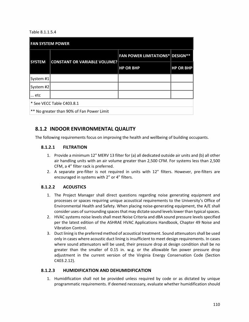
110
Table 8.1.1.5.4
FAN SYSTEM POWER
SYSTEM CONSTANT OR VARIABLE VOLUME? FAN POWER LIMITATIONS* DESIGN**
HP OR BHP HP OR BHP
System #1 System #2 ... etc * See VECC Table C403.8.1
** No greater than 90% of Fan Power Limit
8.1.2 INDOOR ENVIRONMENTAL QUALITY The following requirements focus on improving the health and wellbeing of building occupants.
8.1.2.1 FILTRATION
1. Provide a minimum 12" MERV 13 filter for (a) all dedicated outside air units and (b) all other air handling units with an air volume greater than 2,500 CFM. For systems less than 2,500 CFM, a 4” filter rack is preferred.
2. A separate pre-filter is not required in units with 12" filters. However, pre-filters are encouraged in systems with 2” or 4” filters.
8.1.2.2 ACOUSTICS
1. The Project Manager shall direct questions regarding noise generating equipment and processes or spaces requiring unique acoustical requirements to the University’s Office of Environmental Health and Safety. When placing noise-generating equipment, the A/E shall consider uses of surrounding spaces that may dictate sound levels lower than typical spaces.
2. HVAC systems noise levels shall meet Noise Criteria and dBA sound pressure levels specified per the latest edition of the ASHRAE HVAC Applications Handbook, Chapter 49 Noise and Vibration Control.
3. Duct lining is the preferred method of acoustical treatment. Sound attenuators shall be used only in cases where acoustic duct lining is insufficient to meet design requirements. In cases where sound attenuators will be used, their pressure drop at design condition shall be no greater than the smaller of 0.15 in. w.g. or the allowable fan power pressure drop adjustment in the current version of the Virginia Energy Conservation Code (Section C403.2.12).
8.1.2.3 HUMIDIFICATION AND DEHUMIDIFICATION
1. Humidification shall not be provided unless required by code or as dictated by unique programmatic requirements. If deemed necessary, evaluate whether humidification should

111
be provided at the air handling unit level or via decentralized systems. All water for humidification shall be reverse osmosis water.
2. A system capable of maintaining a maximum allowable dewpoint of 60F shall be provided. If dewpoint control is not available, the system shall maintain a maximum allowable relative humidity of 60%.
3. Systems incorporating chilled beams or other radiant space cooling devices shall maintain a maximum allowable dewpoint in those spaces that is 2F below the supply water temperature to those devices.
8.1.2.4 VENTILATION
1. No outside air shall be provided to spaces during scheduled unoccupied times. If an occupancy sensor determines the space is vacant during scheduled occupied times, the outside air shall be set to the minimum allowed by code. During scheduled unoccupied times, if occupancy is sensed either by an occupancy sensor or by manual override of a temperature sensor, the requisite outside air shall be provided until the space returns to an unoccupied state.
2. New projects introducing natural ventilation or operable windows to a space shall provide window interlocks or some other means of sensing open windows that disables HVAC to the space while natural ventilation is being provided or windows are open. Natural ventilation shall not be considered an energy savings strategy unless it is automated.
8.1.2.5 CONSTRUCTION
Meet or exceed all applicable recommended control measures of the Sheet Metal and Air Conditioning National Contractors Association (SMACNA) IAQ Guidelines for Occupied Buildings under Construction (aligned with LEED v4.1 credit - Construction Indoor Air Quality Management Plan).
8.1.3 MATERIALS The following requirements focus on providing building materials that are safe for contractors, maintenance staff, and building occupants and provide guidance toward proper disposal of trash and recycling.
8.1.3.1 LOW EMMITTING INTERIOR MATERIALS
1. Meet the following requirements as outlined in the LEED v4.1 EQ Credit: Low-Emitting Materials:
a. All paints and coatings wet-applied on site must meet the applicable volatile organic compound (VOC) limits outlined in the LEED v4.1 EQ Credit: Low Emitting Materials (e.g., SCAQMD Rule 1113).
b. All adhesives and sealants wet-applied on site must meet the applicable VOC limits outlined in the LEED v4.1 EQ Credit: Low Emitting Materials (e.g., SCAQMD Rule 1168).
c. All new furniture and furnishing items must meet the applicable VOC limits outlined in the LEED v4.1 EQ Credit: Low Emitting Materials (e.g., ANSI/BIFMA e3-2014e).
d. No composite wood with added formaldehyde shall be used. e. Products achieving GreenGuard Gold certification meet the intent of these
requirements. 2. Additional Requirements:

112
a. No fiberglass insulation for walls, ducts and piping with added formaldehyde shall be used. Insulation achieving GreenGuard Gold certification meets the intent of this requirement.
8.1.3.2 RECYCLING DURING CONSTRUCTION
1. Coordinate with UVA Recycling for plastics, cardboard, and scrap metal containers and service.
2. Coordinate with UVA Reuse Store to dispose of usable furniture. 3. Construction and demolition debris separation on site is encouraged. Use a material
recovery facility for remaining waste. Preference shall be given to material recovery facilities that provide waste diversion rates verified by a third party such as the Recycling Certification Institute.
8.1.3.3 TRASH AND RECYCLING CONTAINERS
All projects shall comply with UVA’s Recycling Station Guidelines. For interiors, all capital projects and renovation projects involving significant spatial reconfiguration, the Project Manager shall coordinate with UVA Recycling to determine additional trash and recycling space requirements specific to the tenants’ needs and building requirements. Wherever a trash receptacle is specified, also specify recycling receptacles. Exterior container locations shall be coordinated with the Office of the Architect for the University.
8.1.3.4 COMMERCIAL TRASH AND RECYCLING
1. Provide space for exterior commercial trash, recycling, and compost containers. The containers should share the same concrete pad. Coordinate with UVA Recycling (434-982-5050; [email protected]) for exterior commercial container requirements. Locations must be identified on plans.
2. Exterior commercial trash and recycling containers shall be provided by UVA Recycling. Coordinate with UVA Recycling to schedule the delivery of exterior commercial containers. Plan accordingly for longer-lead items such as compactors.
3. Personnel access from the building to the commercial containers shall be clearly identified on the plans and free of obstructions.
4. Trash and Recycling compactors and guide rails shall be provided by UVA Recycling. Compactor provided by UVA shall be 34 cubic yard, self-contained compactor, 208/230/460v, 3-phase power with 1.7 to 2 cubic yard charge box and appropriate enclosed hopper. Provide compactor pad, location, and 208/230/460v, 3-phase power based on Marathon model RJ-250SC 34 yd. Guide rails shall be installed on site in coordination with UVA Recycling.
5. Exterior commercial trash containers shall not be located above spaces sensitive to noise or vibration. Usable space below commercial trash containers shall not be occupied space (mechanical rooms, storage, etc. are acceptable). Exterior commercial trash containers located under cover shall be coordinated with UVA Recycling to ensure sufficient clear height for container pickup.

113
8.1.4 WATER The following requirements focus on improving water consumption and the efficiency of domestic water heating and delivery systems.
8.1.4.1 DOMESTIC HOT WATER
Lavatory piping systems shall be designed to deliver hot water within 10 seconds.
8.1.4.2 FIXTURES
New plumbing fixtures shall meet the following fixture requirements.
FIXTURE TYPE REQUIREMENT
Faucets - Public Bathrooms 0.5 gallons per minute (GPM) Faucets – Private or Residential Bathrooms 0.5 GPM Faucets - Laboratories 1.5 GPM Faucets - Teaching Laboratories 1.0 GPM Faucets - Kitchenettes / Breakrooms 1.5 GPM Water Closets - Patient Care 1.6 gallons per flush (GPF) Water Closets - Residence Halls Dual Flush: 1.1/1.6 GPF and WaterSense labeled Water Closets - All Other 1.28 GPF and WaterSense labeled Urinals - Patient Care 0.5 GPF and WaterSense labeled Urinals - All Other 0.125 GPF and WaterSense labeled Showerheads 1.8 GPM; verify pressure to provide adequate flow Water Fountains and Bottle Fill Stations Energy Star certified Washing Machines Energy Star certified Ice Makers Energy Star certified Dishwashers Energy Star certified Refrigerators and Freezers Energy Star certified
All other water consuming fixtures and equipment not listed (i.e. lab equipment, commercial kitchen equipment, etc.) shall be selected to be water and energy efficient. All equipment shall be submitted for review to the University of Virginia.
8.1.5 SITE & LANDSCAPE The following requirements focus on water use reduction and sustainable planting strategies.
8.1.5.1 IRRIGATION
1. Design landscapes to not require permanent irrigation systems, especially those using potable water. Specify plantings that do not require irrigation after establishment.
2. If irrigation is necessary, such as on an intensive green roof or an athletic field, use non-potable water sources such as condensate or rainwater capture wherever feasible. Potable water may be used for temporary irrigation during plant establishment period.

114
3. If irrigation is necessary, design irrigation systems for minimum water use using high-efficiency equipment with moisture sensing capabilities, contingent upon approval of a Determinations and Findings waiver to use potable water.
8.1.5.2 PLANTINGS
1. Develop design intent and plantings in accordance with UVA Landscape Typologies and Standards. Coordinate with Landscape Services and Office of the Architect.
2. Use vegetation to reduce urban heat island effect and minimize building energy use. Specify and locate trees to shade paved areas, especially dark surfaces such as asphalt and brick. Specify vegetation such as green roofs, green walls, and shade trees to reduce building energy consumption.
8.1.6 LIFE CYCLE COST Perform ongoing life cycle cost analyses according to the following requirements:
1. Using the UVA Life Cycle Cost (LCC) Calculator, analyze major systems (e.g., envelope, HVAC, etc.) options at significant design stages (SD, PD, and CD). Coordinate with energy modeling efforts, where applicable.
2. Provide life cycle justification, including documentation of LCC metrics for all life cycle cost-based decisions.
3. When evaluating cost-saving measures (e.g., value management sessions), present operational costs in addition to first costs using the UVA Life Cycle Cost Calculator.
8.2 CAPTIAL PROJECTS – NEW CONSTRUCTION AND MAJOR RENOVATIONS This portion of the Standards applies to Capital Projects for which LEED certification is already required. The prescriptive requirements in section 8.1 above also apply to these projects.
8.2.1 PROJECT INITIATION Collaborate with the UVA Office for Sustainability ([email protected]) to provide the following:
1. Project-specific sustainability goals and priorities (stretch goals beyond minimum UVA and LEED requirements) via Owner’s Project Requirements (OPR) early in the planning process, prior to initiation of design. At a minimum, consider the feasibility of the following approaches in the project’s goals:
a. Deep energy reductions – a zero energy or zero carbon building b. Water reclamation - Cooling coil condensate collection, rainwater harvesting, etc. c. Passive House certification d. Living Building Challenge certification e. Healthy materials focus – including Red List free, “Red List light,” or Six Classes materials
specifications. f. Embodied carbon focus – measurement and tracking of embodied carbon and low-
embodied carbon materials specifications g. EV-ready infrastructure – including sufficient electrical capacity, spare accessible
electrical panels, and conduit runs to EV-ready parking spaces h. Green healthcare initiatives – alignment with the LEED Integrated Process for Health
Promotion credit and/or the GRESB Health and Well-being Module
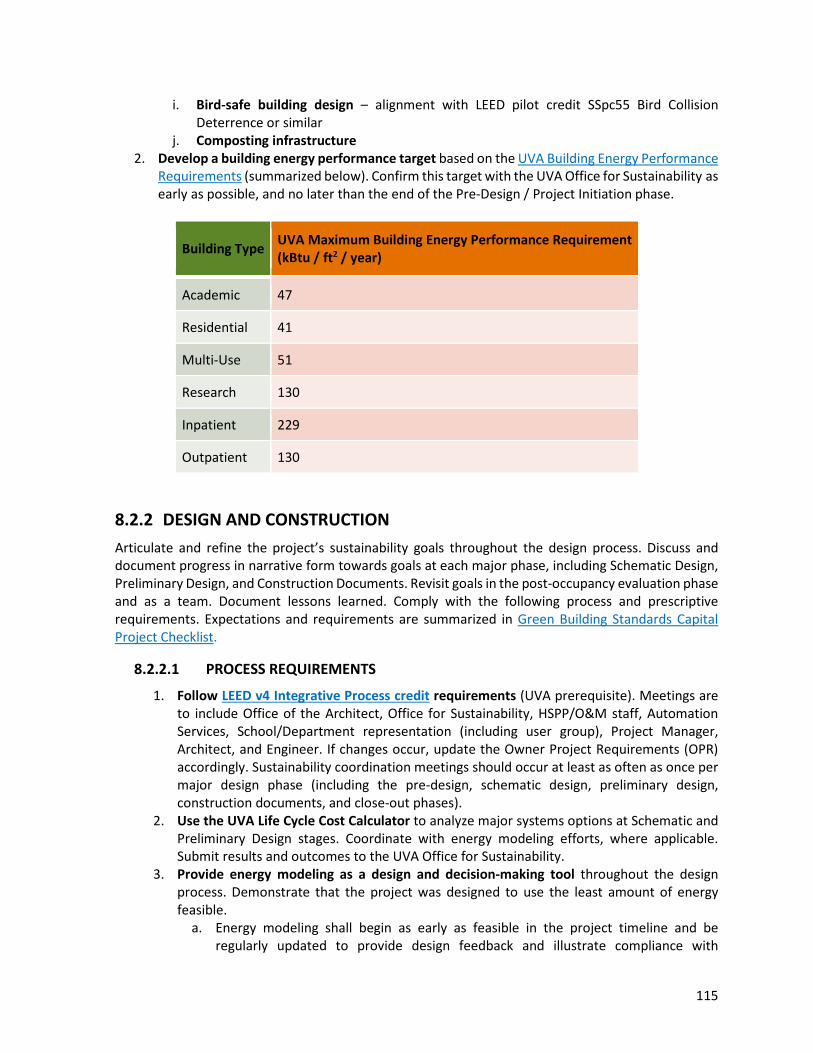
115
i. Bird-safe building design – alignment with LEED pilot credit SSpc55 Bird Collision Deterrence or similar
j. Composting infrastructure 2. Develop a building energy performance target based on the UVA Building Energy Performance
Requirements (summarized below). Confirm this target with the UVA Office for Sustainability as early as possible, and no later than the end of the Pre-Design / Project Initiation phase.
Building Type UVA Maximum Building Energy Performance Requirement (kBtu / ft2 / year)
Academic 47
Residential 41
Multi-Use 51
Research 130
Inpatient 229
Outpatient 130
8.2.2 DESIGN AND CONSTRUCTION Articulate and refine the project’s sustainability goals throughout the design process. Discuss and document progress in narrative form towards goals at each major phase, including Schematic Design, Preliminary Design, and Construction Documents. Revisit goals in the post-occupancy evaluation phase and as a team. Document lessons learned. Comply with the following process and prescriptive requirements. Expectations and requirements are summarized in Green Building Standards Capital Project Checklist.
8.2.2.1 PROCESS REQUIREMENTS
1. Follow LEED v4 Integrative Process credit requirements (UVA prerequisite). Meetings are to include Office of the Architect, Office for Sustainability, HSPP/O&M staff, Automation Services, School/Department representation (including user group), Project Manager, Architect, and Engineer. If changes occur, update the Owner Project Requirements (OPR) accordingly. Sustainability coordination meetings should occur at least as often as once per major design phase (including the pre-design, schematic design, preliminary design, construction documents, and close-out phases).
2. Use the UVA Life Cycle Cost Calculator to analyze major systems options at Schematic and Preliminary Design stages. Coordinate with energy modeling efforts, where applicable. Submit results and outcomes to the UVA Office for Sustainability.
3. Provide energy modeling as a design and decision-making tool throughout the design process. Demonstrate that the project was designed to use the least amount of energy feasible.
a. Energy modeling shall begin as early as feasible in the project timeline and be regularly updated to provide design feedback and illustrate compliance with
https://sustainability.virginia.edu/resources/uva-green-building-standards-capital-project-checklist

116
the energy use intensity (EUI) target per section 8.2.1.2. A simple box model is sufficient for pre-design stages, and a whole building energy model shall be developed no later than the Schematic Design milestone.
b. Energy modeling inputs and results shall be submitted in accordance with the UVA Energy Modeling and Reporting Standards and include parametric analyses for significant design alternatives (e.g., envelope construction, shading, window-to-wall ratio, mechanical systems). These results shall be shared with the UVA Office for Sustainability during each major design phase.
c. For all non-single pass air systems, provide an energy model and life cycle cost analysis of a dedicated outside air system with energy recovery and terminal heating and cooling units (e.g., chilled beams, radiant systems, fan coil units, blower coil units) compared with the proposed system.
d. The full, working energy model shall be provided to UVA for ownership at the completion of the project.
8.2.2.2 PRESCRIPTIVE REQUIREMENTS
1. Solar-ready design. All new low-slope roofs shall be designed to be “solar-ready” and include conduit to the roof, room for future inverters, confirmation that structural design is sufficient for future solar photovoltaic (PV) installation, and a rooftop equipment layout that optimizes solar access. Coordinate with UVA Energy and Utilities for engineering, procurement, and installation of solar panels. See NREL Solar Ready Buildings Planning Guide for more information about solar-ready best practices.
2. Fossil fuel free design. The on-site combustion of fuels shall be prohibited unless required for life safety and emergency back-up systems. Space heating, water heating, cooking, and humidification applications shall all be provided via district heating or electricity-based equipment. Exceptions will be determined via the D&F process.
3. Achieve LEED v4 MR Credit: Construction and Demolition Waste Management Option 1 (Diversion).
4. Achieve LEED v4 EA Credit: Enhanced Commissioning Option 1, Path 2 (Enhanced and Monitoring-Based Commissioning) and Option 2 (Building Enclosure Commissioning).

117
APPENDIX A – Figures

118
Figure 1: University Grounds

119
Figure 2: Historic Grounds
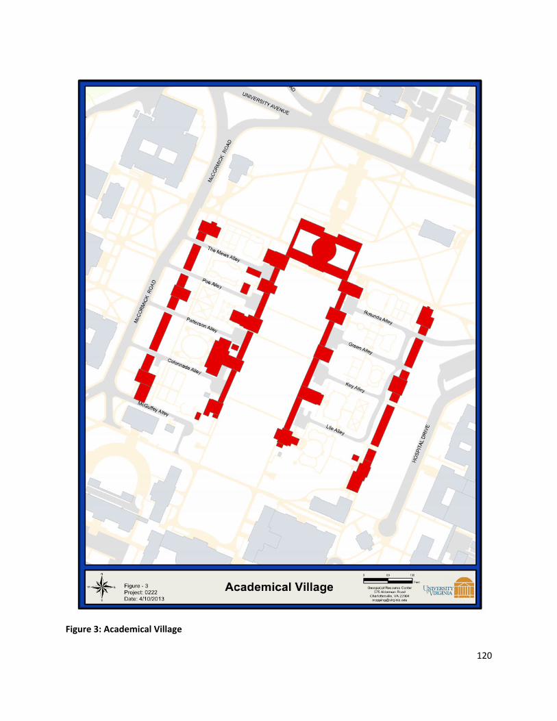
120
Figure 3: Academical Village

121
Figure 4: Central Grounds

122
Figure 5: Emergency Phones

123
Figure 6: Cast Iron Light Fixture

124
Figure 7: Parking Lot / Roadway Light Fixture

125
Figure 8: Observatory Sensitive Zone

126
Figure 9: Integral Concrete Sidewalk and Curb

127
Figure 10: Brick Walk Paving

128
INSIDE DESIGN CONDITION CRITERIA
Occupancy/Use Summer (Cooling)
Occupied / Unoccupied Winter (Heating)
Occupied / Unoccupied
Offices/Classroom/ Lecture 74°F / 80°F 70°F / 62°F
Residential 74°F / 80°F 70°F / 62°F
Libraries * 74°F / 80°F 70°F / 62°F
Archival Storage in Libraries Special Special
Art Storage in Museums Special Special
IT/Telecom Rooms 80°F / 80°F 55° for freeze protection
Warehouse, Mechanical Rooms, Storage Rooms and Electrical Rooms
Ventilate with outside air unless otherwise approved
55°F for freeze protection
Pools ** Special Special
Hospitals Consult the ASHRAE Guide or other applicable references
Consult the ASHRAE Guide or other applicable references
Laboratories (Educational/Research) 74°F / 80°F 30% RH minimum
70°F / 62°F 30% RH minimum
Gymnasiums/Recreation, Indoor Tennis and Racquetball Courts, Weight Rooms and Aerobic Rooms
72°F / 80°F 68°F / 62°F
Locker Rooms/Showers 76°F / 80°F 70°F / 62°F
Figure 11: Inside Design Condition Criteria *Conditions may vary depending upon actual user justified requirements. Deviations must be approved by the CFO. **Cooling for type occupancy/use must be justified to and approved by the CFO.

129
OUTSIDE DESIGN CONDITION CRITERIA
Charlottesville, VA
Summer (Cooling) Winter (Heating) Evaporation
Drybulb 95°F 15°F 89°F
Wetbulb 76°F ‐ 79°F Figure 11A: Outside Design Condition Criteria
The following table provides overall building supply and return water temperatures to which systems shall be designed. The designer shall make every effort to meet these design requirements, however, if not practical for equipment to obtain these values, a determination and findings is required.
BUILDING HEATING AND CHILLED WATER SUPPLY
AND RETURN DESIGN WATER TEMPERATURES
All buildings on Grounds
Supply Return
Chilled Water 44°F 62°F
Heating Water 130°F * 100°F
Figure 11B: Building heating and chilled water supply and return design water temperatures
*The indicated temperature is for systems downstream of a low temperature heating water heat exchanger and may not apply to all projects. Verify heating water supply temperatures with Energy and Utilities, Paul Zmick.
PLANT HEATING SUPPLY AND RETURN DESIGN
WATER TEMPERATURES
Supply ** Return **
Chilled Water Plants – CHW 42°F 62°F
Main Heating Plant – MTHW 170°F 140°F
Massie Road Plant 160°F 130°F
North Grounds Plant 140°F 110°F
Figure 11C: Heating Plant supply and return design water temperatures
**The indicated temperatures are for peak conditions only. Verify design conditions with supply air temperature reset schedules.

130
COMPONENT COORDINATION (Scope of work/responsibility matrix – current CSI sections may be used) Device Furnished
By Installed By
Power Wiring
Control/ Interlock Wiring
Fire Alarm Wiring
Air Handler Devices 1 Duct Smoke Detectors 16000 15000 N/A (from
FA system)
N/A 16000
2 Duct Smoke Detector Auxiliary Contents
16000 16000 16000 17000 16000
3 Smoke Dampers at AHU’s
15000 15000 N/A 17000 N/A
4 Smoke Damper Actuators at AHU’s
15000 15000 16000 17000 N/A
5 Fire Dampers 15000 15000 N/A N/A N/A 6 Air Flow Stations 17000 15000 N/A 17000 N/A 7 Automatic Control
Dampers (unless specified with unit)
17000 15000 N/A 17000 N/A
8 Automatic Control Damper Actuators
17000 17000 17000 17000 N/A
9 Variable Speed Drives 15000 or 16000
16000 16000 17000 N/A
10 Humidifiers 15000 15000 16000 17000 N/A 11 Humidifier Control Valve 15000 15000 N/A 17000 N/A 12 Humidifier Isolation
Valve 17000 15000 N/A 17000 N/A
13 Humidifier Airflow Switch
15000 15000 N/A 17000 N/A
VAV and Terminal Units 14 Supply & Exhaust
Terminal Boxes (VAV’s) 15000 15000 16000 17000 N/A
15 Terminal Flow Pick‐up 15000 15000 N/A 15000 N/A 16 Terminal Damper
Actuator (if not provided by box manufacturer)
17000 15000 N/A 17000 N/A
17 Terminal DDC Controller 17000 15000 16000 17000 N/A 18 Terminal Reheat Valves 17000 15000 N/A 17000 N/A Continued on next page Continued from previous page Laboratory Controls 19 Supply, Hood Exhaust &
General Exhaust Air 17000 15000 N/A 17000 N/A

131
Valves 20 Controls at Fume Hood 17000 17000 16000 17000 N/A 21 Isolation Room Controls 17000 17000 16000 17000 N/A Meters 22 Water Flow Meters 17000 15000 16000 17000 N/A 23 Electrical Demand
Meters 16000 16000 16000 17000 N/A
24 Steam Flow Meters 17000 15000 16000 17000 N/A Digital Control Panels 25 DDC Panels if shown on
Electrical Drawings 17000 17000 16000 17000 N/A
26 DDC Panels if NOT shown on Electrical Drawings
17000 17000 16000 if 120V
17000 N/A
Control Air 27 Air Compressor 17000 15000 16000 N/A N/A 28 Air Dryer 17000 17000 16000 N/A N/A Water Systems 29 Hydronic Control Valves 17000 15000 N/A 17000 N/A 30 Water Flow Switches for
Chiller 15000 15000 16000 17000 N/A
31 Cooling Tower 15000 15000 16000 17000 N/A Miscellaneous Systems 32 Refrigerant Monitoring 17000 17000 16000 17000 N/A 33 Split System (Heat
Pumps, etc.) 15000 15000 16000 17000 N/A
34 Chemical Feed Systems 15000 15000 16000 17000 N/A 35 Kitchen Hood System 15000 15000 16000 16000 or
17000 16000
Figure 12: Component Coordination Matrix

132
Figure 13: Standard UVA Vault Ladder for Steam Tunnels and Manholes Greater than 10’ Deep [not required for Electrical manholes]

133
Figure 14: Electrical Manhole/Vault Detail

134
Figure 15: Electrical Ductbank Section

135
APPENDIX B – Utility Metering Requirements General The contractor shall be responsible for proper installation of the meter per manufacturer’s guidelines and for enabling consumption calculations during construction before the utility service is turned on, unless waived by the Director of Energy & Utilities.
Temporary meters for construction use can be supplied by Metering staff without connection to the SCADA and will be read monthly. Portable metering needs to remain accessible when in service. The meter must be returned to Metering staff within 10 days of service disconnection or construction contractor will be billed for a replacement meter. Consumption during construction will use design maximum values when meter data is not available.
Electricity
Application Electric Substations and Building Primary Electric Switchgear: o Power quality meters o For University substations, the highest level of power quality meters are
required, typically including waveform capture and significant event storage capabilities
Building Electric Sub Meters o Energy meters
All Electric Meters: o Revenue‐grade o MODBUS/Ethernet interfaces accessible via either
Direct Ethernet connection or Local metering (Modbus) communications trunk
Local display of demand Local display of totalized consumption
Connectivity Installations shall be digitally integrated into the SCADA system via MODBUS/Ethernet protocol over Ethernet.
Meters on building primary feeders will also be interfaced to the building automation system (BAS) for energy management use. This is accomplished by Metering staff using 3rd‐party software and BACnet or OPC interfaces.
Minimum data to be mapped to the SCADA system: o Frequency o Apparent power, total and per‐phase o Reactive power, total and per‐phase o Real power (kW), total and per‐phase o Energy (kWh) o Voltage, per phase and 3‐phase avg (L‐L and L‐N) o Current, per phase and 3‐phase avg o Total harmonic distortion (voltage and current) if meter is capable

136
Compatible Meters
Advanced Power Quality Meters: • Schneider Electric PM8000 • Schneider Electric ION7400 • Schneider Electric ION8650 • Schneider Electric ION7550/7650 • Schneider Electric ION9000
Energy Meters: • Power Logic PM5000 series • ION 6200 • PowerLogic PM3000 • PowerLogic PM3500 • Setra Power Meter
Multi‐circuit Power and Energy Meters Sub‐metering: • Power Logic EM4800 • Power Logic EM4900 • Setra Power Meter
Domestic Water
Application
Low Consumption Domestic Water Meters: o Deemed “low consumption” by the University Metering staff o Shall be turbine, positive displacement, or ultrasonic
Domestic Water Meters (not low consumption): o Need to meet Federal and State guidelines for meter liners on all services
All Domestic Water Meters must have: o Local display of volumetric flow rate o Local display of totalized consumption
Connectivity
Installations shall be digitally integrated into the SCADA system via Modbus/Ethernet protocol.
Totalization, volumetric flow rate, and diagnostic data shall be mapped into the SCADA.
Compatible Meters
Magnetic flowmeters: • Toshiba LF & GF series • Endress + Hauser Proline • Badger ModMag • Azbil / Vortek instruments (TBD)
Ultrasonic flow: • Flexim Fluxus series
Chilled Water & Heating Hot Water
Application Chilled/Hot Water Meter Placement: o 10 unobstructed pipe diameters of straight pipe upstream AND

137
o 5 unobstructed pipe diameters of straight pipe downstream
Chilled/Hot Water Pipe Sizes from 1” to 48”: o Ultrasonic energy BTU meters o Matched RTD strap‐on temperature sensors required
BAS or Industrial Control of Chillers and Boilers:
o Separate magnetic flow meters (in addition to energy meters & temperature sensors as stated above)
o The use of Magnetic flow meters for thermal energy will require an Energy Flow computer
All Chilled/Hot Water Meters: o Local display of energy demand o Local display of volumetric flow rate o Local display of totalized energy consumption
Connectivity All installations shall be digitally integrated into the SCADA via Modbus/Ethernet protocol.
Minimum data to be mapped into the SCADA o Totalization o Energy o Linear flow rate o Volumetric flow rate o Supply temperature o Return temperature o Diagnostic data
Meter shall calculate and display energy consumption without SCADA support.
Compatible Meters
Ultrasonic Energy BTU Meters: • Flexim Fluxus Thermal Energy series • Vortek Thermal Energy SonoPro (for low consumption services)
Ultrasonic Flow Meters: • Flexim FLUXUS series • Vortek SonoPro • See magnetic flow meters above in water section
Steam
Application Steam Meter Placement: o 10 unobstructed pipe diameters of straight pipe upstream AND o 5 unobstructed pipe diameters of straight pipe downstream
Steam Services > 8”:
o Insertion turbine meters OR o Vortex shedding meters
Steam Services <= 8”:

138
o Spring‐loaded, variable area meters Steam Condensate:
o Ultrasonic flow meter w/ transducer RTD built in o Must be approved by Metering staff when a steam flow meter cannot be
installed All Steam Meters:
Local display of demand Local display of totalized consumption Local display of compensation input values where applicable
Connectivity All installations shall be digitally integrated into the SCADA via Modbus/Ethernet protocol.
Minimum data to be mapped into the SCADA o Totalization o Flow rate o Diagnostic data
Steam meters shall calculate and display energy or mass flow rate demand and total consumption without SCADA support.
Condensate meters shall calculate and display volumetric flow demand and consumption.
Steam meter installations that require a flow computer for compensation calculations shall integrate the computer with the SCADA via the Modbus/Ethernet connection.
Compatible Meters
Spring‐Loaded Variable Area Meters: • Spirax Sarco Gilflo, ILVA, w/ Scanner 2000 DP: (Energy flow computer
KEP • SuperTROL or Spirax Sarco M850) • Spirax Sarco TVA series • Vortek VorCone
Turbine / Vortex meters: • Spirax Sarco RIM20 • Spirax‐Sarco VIM20 • Vortek Turbo Pro VTP • Vortek Turbo Pro V • Azbil AX2200 / AX2300
Oil
Application All Oil Meters: o Ultrasonic, or Teflon lined magnetic flow meters o Local display of demand o Local display of totalized consumption
Connectivity • Installations shall be digitally integrated into the SCADA via Modbus/Ethernet protocol.

139
• Minimum data to be mapped into the SCADA
• Totalization
• Volumetric flow rate
• Diagnostic data
Compatible Meters
Ultrasonic Flow Meters: • Flexim Fluxus series
Magnetic Flow Meters:
• See magnetic flow meters above in water section Natural Gas
Application All Natural Gas Meters: o Thermal Mass flowmeters o Local display of demand o Local display of totalized consumption
Connectivity • Installations shall be digitally integrated into the SCADA via Modbus/Ethernet protocol.
• Totalization, volumetric flow rate, and diagnostic data shall be mapped into the SCADA.
Compatible Meters
Thermal mass flowmeters: • Spirax Sarco MTI10 / MTL10 • Sierra BoilerTrak

140
APPENDIX C – Elevators
This section of the FDG is maintained online. See Appendix C – Elevators on OUBO website for current requirements and details.

141
APPENDIX D – Not Used

142
APPENDIX E – University of Virginia Space Planning Guidelines This section of the FDG is maintained online by Geospatial Engineering Resources. See Appendix E: Space Planning Guidelines for current requirements and details.

143
APPENDIX F – Locksets & Access Control This section of the FDG is maintained online. See Appendix F: Locksets & Access Control Guidelines on OUBO website for current requirements and details.