Experimental study on corrosion of transmission line tower ...
8
INTERNATIONAL JOURNAL OF CIVIL AND STRUCTURAL ENGINEERING Volume 1, No 1, 2010 © Copyright 2010 All rights reserved Integrated Publishing services Research Article ISSN 0976 – 4399 27 Experimental study on corrosion of transmission line tower foundation and its rehabilitation S.Christian Johnson 1 G.S.Thirugnanam 2 1 Research Scholar 2 Head & Professor in civil Engg.IRTT,. Erode. ABSTRACT In transmission line towers, the tower legs are usually set in concrete which generally provides good protection to the steel. However defects and cracks in the concrete can allow water and salts to penetrate with subsequent corrosion and weakening of the leg. When ferrous materials oxidized to ferrous oxide (corrosion) its volume is obviously more than original ferrous material hence the chimney concrete will undergo strain resulting in formation of cracks. The cracks open, draining the water in to chimney concrete enhancing the corrosion process resulting finally in spalling of chimney concrete. This form of corrosion of stub angle just above the muffing or within the muffing is very common in saline areas. If this is not attended at proper time, the tower may collapse under abnormal climatic conditions. Maintenance and refurbishment of inservice electric power transmission lines require accurate knowledge of components condition in order to develop cost effective programs to extend their useful life. Degradation of foundation concrete can be best assessed by excavation. This is the most rigorous method since it allows determination of the extent and type of corrosion attack, including possible involvement of microbial induced corrosion. In this paper, Physical, Chemical and electro chemical parameters, studied on transmission line tower stubs excavated from inland and coastal areas have been presented. A methodology for rehabilitation of transmission tower stubs has been discussed. Key words: Corrosion, Transmission lines, Galvanizing 1 Introduction In transmission line towers, the tower legs are usually set in concrete which generally provides good protection to the steel. However defects and cracks in the concrete can allow water and salts to penetrate with subsequent corrosion and weakening of the leg. When ferrous materials oxidized to ferrous oxide (corrosion) its volume is obviously more than original ferrous material hence the chimney concrete will undergo strain resulting in formation of cracks. The cracks open, draining the water in to chimney concrete enhancing the corrosion process resulting finally in spalling of chimney concrete. This form of corrosion of stub angle just above the muffing or within the muffing is very common in saline areas. If this is not attended at proper time, the tower may collapse under abnormal climatic conditions.
-
Upload
khangminh22 -
Category
Documents
-
view
1 -
download
0
Transcript of Experimental study on corrosion of transmission line tower ...

INTERNATIONAL JOURNAL OF CIVIL AND STRUCTURAL ENGINEERING Volume 1, No 1, 2010
© Copyright 2010 All rights reserved Integrated Publishing services Research Article ISSN 0976 – 4399
27
Experimental study on corrosion of transmission line tower foundation and its rehabilitation
S.Christian Johnson 1 G.S.Thirugnanam 2
1 Research Scholar 2 Head & Professor in civil Engg.IRTT,. Erode.
ABSTRACT
In transmission line towers, the tower legs are usually set in concrete which generally provides good protection to the steel. However defects and cracks in the concrete can allow water and salts to penetrate with subsequent corrosion and weakening of the leg. When ferrous materials oxidized to ferrous oxide (corrosion) its volume is obviously more than original ferrous material hence the chimney concrete will undergo strain resulting in formation of cracks. The cracks open, draining the water in to chimney concrete enhancing the corrosion process resulting finally in spalling of chimney concrete. This form of corrosion of stub angle just above the muffing or within the muffing is very common in saline areas. If this is not attended at proper time, the tower may collapse under abnormal climatic conditions. Maintenance and refurbishment of inservice electric power transmission lines require accurate knowledge of components condition in order to develop cost effective programs to extend their useful life. Degradation of foundation concrete can be best assessed by excavation. This is the most rigorous method since it allows determination of the extent and type of corrosion attack, including possible involvement of microbial induced corrosion.
In this paper, Physical, Chemical and electro chemical parameters, studied on transmission line tower stubs excavated from inland and coastal areas have been presented. A methodology for rehabilitation of transmission tower stubs has been discussed.
Key words: Corrosion, Transmission lines, Galvanizing
1 Introduction In transmission line towers, the tower legs are usually set in concrete which generally provides good protection to the steel. However defects and cracks in the concrete can allow water and salts to penetrate with subsequent corrosion and weakening of the leg. When ferrous materials oxidized to ferrous oxide (corrosion) its volume is obviously more than original ferrous material hence the chimney concrete will undergo strain resulting in formation of cracks. The cracks open, draining the water in to chimney concrete enhancing the corrosion process resulting finally in spalling of chimney concrete. This form of corrosion of stub angle just above the muffing or within the muffing is very common in saline areas. If this is not attended at proper time, the tower may collapse under abnormal climatic conditions.
INTERNATIONAL JOURNAL OF CIVIL AND STRUCTURAL ENGINEERING Volume 1, No 1, 2010
© Copyright 2010 All rights reserved Integrated Publishing services Research Article ISSN 0976 – 4399
28
Maintenance and refurbishment of inservice electric power transmission lines require accurate knowledge of components condition in order to develop cost effective programs to extend their useful life. Degradation of foundations enclosed in concrete or grillagetype can be best assessed by excavation. This is the most rigorous method since it allows determination of the extent and type of corrosion attack, including possible involvement of microbial induced corrosion. To minimize excavation at every footing, tests to indicate the presence of stray current and/or galvanic corrosion can be used. Stray current and galvanic corrosion can be identified by potential surveys of the footings with a Cu/CuSO4 halfcell reference electrode.
1.1 Removal of stub from the field: As a part of the study, two transmission line tower stubs one in Coimbatore and
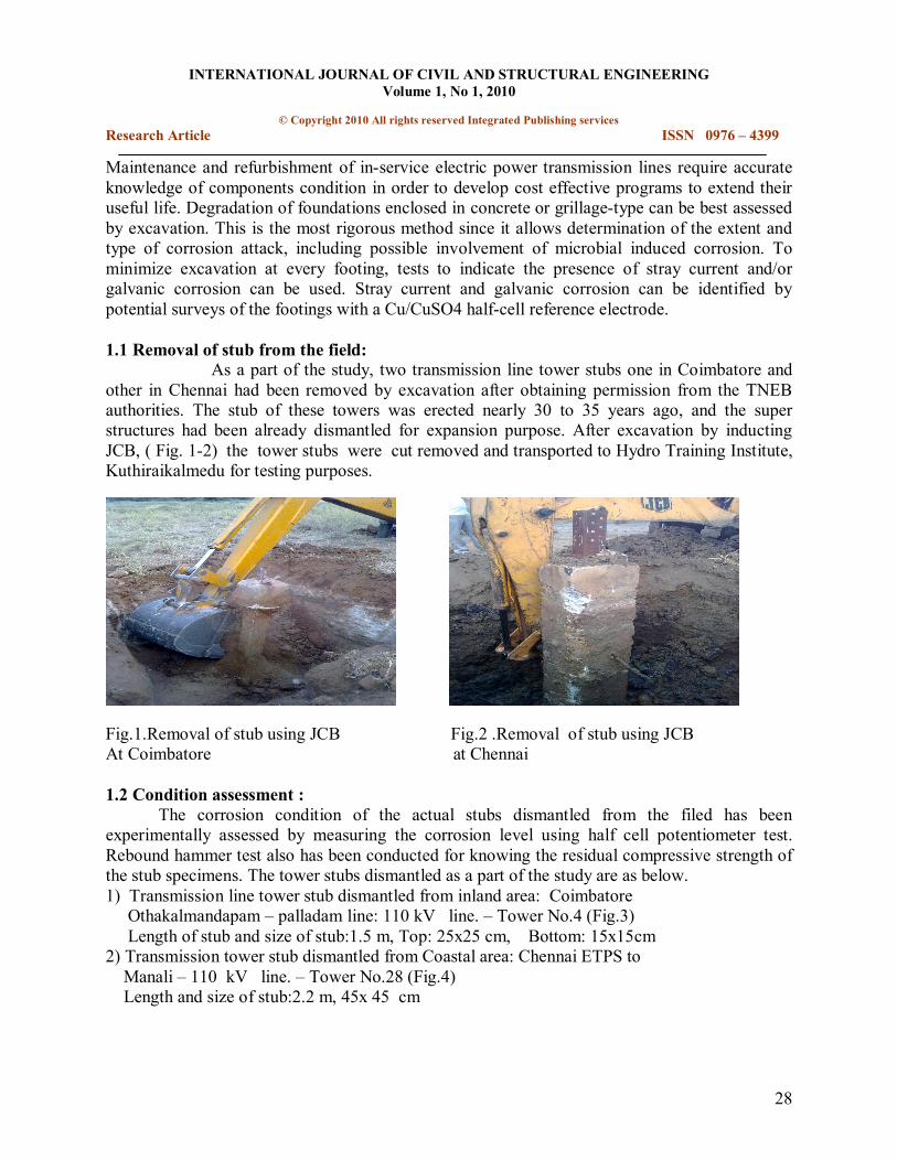
other in Chennai had been removed by excavation after obtaining permission from the TNEB authorities. The stub of these towers was erected nearly 30 to 35 years ago, and the super structures had been already dismantled for expansion purpose. After excavation by inducting JCB, ( Fig. 12) the tower stubs were cut removed and transported to Hydro Training Institute, Kuthiraikalmedu for testing purposes.
Fig.1.Removal of stub using JCB Fig.2 .Removal of stub using JCB At Coimbatore at Chennai
1.2 Condition assessment : The corrosion condition of the actual stubs dismantled from the filed has been
experimentally assessed by measuring the corrosion level using half cell potentiometer test. Rebound hammer test also has been conducted for knowing the residual compressive strength of the stub specimens. The tower stubs dismantled as a part of the study are as below. 1) Transmission line tower stub dismantled from inland area: Coimbatore
Othakalmandapam – palladam line: 110 kV line. – Tower No.4 (Fig.3) Length of stub and size of stub:1.5 m, Top: 25x25 cm, Bottom: 15x15cm
2) Transmission tower stub dismantled from Coastal area: Chennai ETPS to Manali – 110 kV line. – Tower No.28 (Fig.4) Length and size of stub:2.2 m, 45x 45 cm
INTERNATIONAL JOURNAL OF CIVIL AND STRUCTURAL ENGINEERING Volume 1, No 1, 2010
© Copyright 2010 All rights reserved Integrated Publishing services Research Article ISSN 0976 – 4399
29
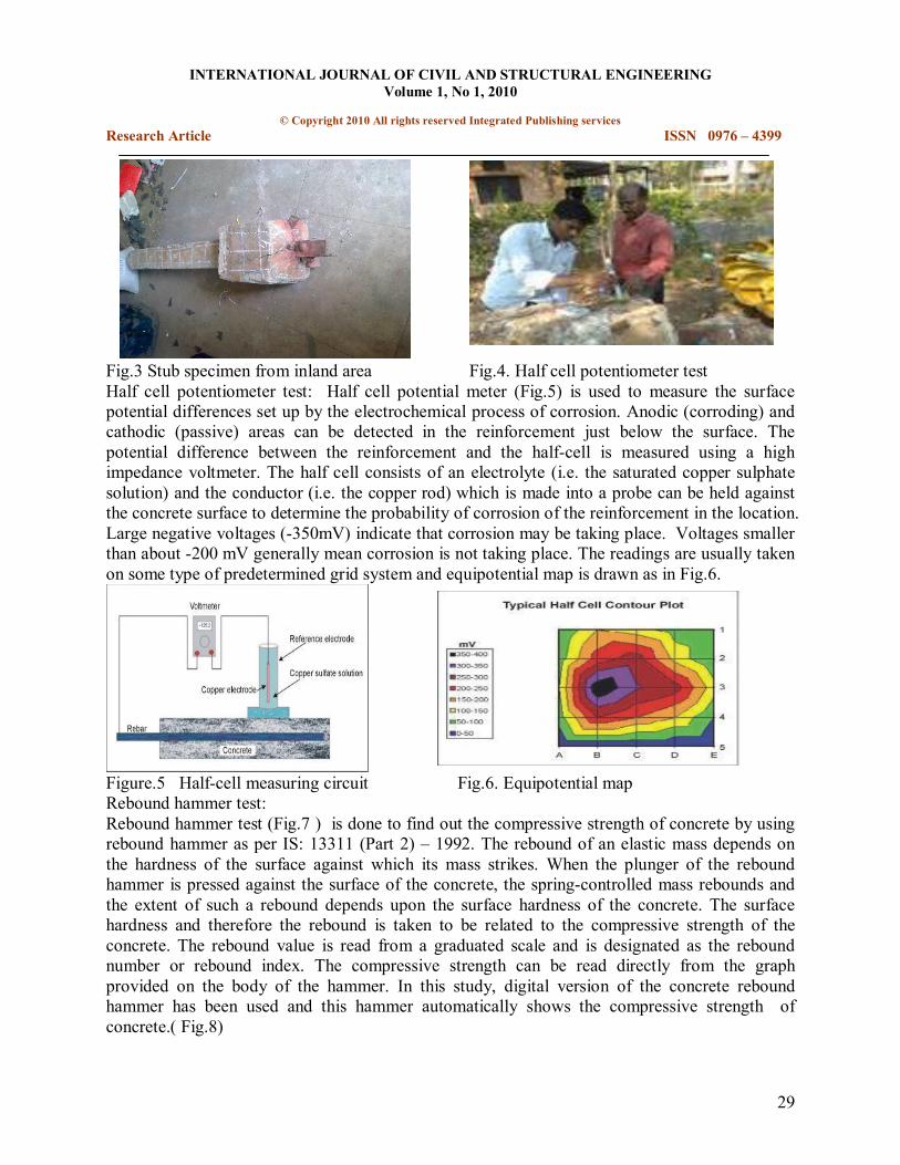
Fig.3 Stub specimen from inland area Fig.4. Half cell potentiometer test Half cell potentiometer test: Half cell potential meter (Fig.5) is used to measure the surface potential differences set up by the electrochemical process of corrosion. Anodic (corroding) and cathodic (passive) areas can be detected in the reinforcement just below the surface. The potential difference between the reinforcement and the halfcell is measured using a high impedance voltmeter. The half cell consists of an electrolyte (i.e. the saturated copper sulphate solution) and the conductor (i.e. the copper rod) which is made into a probe can be held against the concrete surface to determine the probability of corrosion of the reinforcement in the location. Large negative voltages (350mV) indicate that corrosion may be taking place. Voltages smaller than about 200 mV generally mean corrosion is not taking place. The readings are usually taken on some type of predetermined grid system and equipotential map is drawn as in Fig.6.
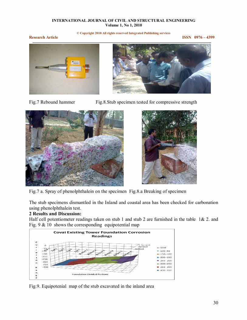
Figure.5 Halfcell measuring circuit Fig.6. Equipotential map Rebound hammer test: Rebound hammer test (Fig.7 ) is done to find out the compressive strength of concrete by using rebound hammer as per IS: 13311 (Part 2) – 1992. The rebound of an elastic mass depends on the hardness of the surface against which its mass strikes. When the plunger of the rebound hammer is pressed against the surface of the concrete, the springcontrolled mass rebounds and the extent of such a rebound depends upon the surface hardness of the concrete. The surface hardness and therefore the rebound is taken to be related to the compressive strength of the concrete. The rebound value is read from a graduated scale and is designated as the rebound number or rebound index. The compressive strength can be read directly from the graph provided on the body of the hammer. In this study, digital version of the concrete rebound hammer has been used and this hammer automatically shows the compressive strength of concrete.( Fig.8)
INTERNATIONAL JOURNAL OF CIVIL AND STRUCTURAL ENGINEERING Volume 1, No 1, 2010
© Copyright 2010 All rights reserved Integrated Publishing services Research Article ISSN 0976 – 4399
30
Fig.7 Rebound hammer Fig.8.Stub specimen tested for compressive strength
Fig.7 a. Spray of phenolphthalein on the specimen Fig.8.a Breaking of specimen
The stub specimens dismantled in the Inland and coastal area has been checked for carbonation using phenolphthalein test. 2 Results and Discussion: Half cell potentiometer readings taken on stub 1 and stub 2 are furnished in the table 1& 2. and Fig. 9 & 10 shows the corresponding equipotential map
Fig.9. Equipotenial map of the stub excavated in the inland area
INTERNATIONAL JOURNAL OF CIVIL AND STRUCTURAL ENGINEERING Volume 1, No 1, 2010
© Copyright 2010 All rights reserved Integrated Publishing services Research Article ISSN 0976 – 4399
31
Top1 Top 2 Top 3 Middle 1
Middle2 Middle 3 Bottom 1
Bottom 2
Bottom 3
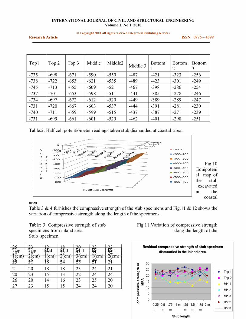
735 698 671 590 550 487 421 323 256 738 722 653 621 535 489 423 301 249 745 713 655 609 521 467 398 286 254 737 701 653 598 511 441 385 278 246 734 697 672 612 520 449 389 289 247 731 720 667 603 537 444 391 281 230 740 711 659 599 515 437 387 271 239 731 699 661 601 529 462 401 298 251
Table.2. Half cell potentiometer readings taken stub dismantled at coastal area.
Fig.10 Equipoteni al map of the stub excavated in the
coastal area Table 3 & 4 furnishes the compressive strength of the stub specimens and Fig.11 & 12 shows the variation of compressive strength along the length of the specimens.
Table: 3. Compressive strength of stub Fig.11.Variation of compressive strength specimens from inland area along the length of the Stub specimen
Top 1(cm)
Top 2(cm)
Mid 1(cm)
Mid 2(cm)
Mid 3(cm)
Bot 1(cm)
Bot 2(cm)
23 21 18 24 25 21 21 21 20 18 18 23 24 21 20 23 15 13 22 24 24 26 20 14 16 23 25 20 27 23 15 15 24 24 20
25 23 12 18 20 22 22 20 26 17 22 23 25 24 26 25 15 23 26 20 18
Residual compressive strength of stub specimen dismantled in the inland area.
0
5
10
15
20
25
30
0.25 m
0.5m
.75m
1 m 1.25 m
1.5m
1.75 m
2 m
Stub length
compres
sive
stren
gth in
MPA
Top 1
Top 2
Mid 1
Mid 2
Mid 3
Bot 2
Bot 3

INTERNATIONAL JOURNAL OF CIVIL AND STRUCTURAL ENGINEERING Volume 1, No 1, 2010
© Copyright 2010 All rights reserved Integrated Publishing services Research Article ISSN 0976 – 4399
32
Table 4.:Compressive strength in MPA of stub Fig.12. Variation of compressive strength specimens from coastal area. along the length of the stub specimens
Table.5. Carbonation depth in cm of stub Fig.13 Variation carbonation depth along the length specimen From Inland area: of the specimens (Inland area)
. Variationof carbonation depth along the length
of the specimen.
0
5
10
15
0.25 m
0.5 m
0.75 m
1 m 1.25 m
1.5 m
1.75 m
Stub length
Carbo
natio
n de
pth
TOP 1
TOP 2
M ID 1
M ID 2 M ID 3 BOT 1
BOT 2 BOT 3
Fig.14 Carbonation depth in the stub specimen dismantled at inland area
Top 1(cm)
Top 2(cm)
Mid 1(cm)
Mid 2(cm)
Mid 3(cm)
Bot 1(cm)
Bot 2(cm)
11 12 13 9 11 9 9 9 8 12 9 8 8 8 7 8 10 7 9 7 7 8 9 9 10 7 8 6 7 11 10 8 6 5 7 5 10 11 9 5 4 8 4 8 7 8 6 5 6 7 9 10 7 4 4 5
TOP 1(cm)
TOP 2(cm)
MID 1(cm)
MID 2(cm)
MID 3(cm)
BOT 1(cm)
BOT 2(cm)
8 9 2 1.5 1.5 1.5 1 9 10 2 1.5 1.5 1 1 7 9 1 1.5 1.5 1 1 8 8 1.5 2 1 1.5 1.5 9 8 1.5 2 1 1.5 1.5 8 9 1 1.5 1 1 1 9 8 1.5 2 1.5 1 1.5 8 9 1 1.5 1 1.5 1
Residual compressive strength of stub dismantled from the coastal area
0
5
10
15
0.25 m
0.5 m .75 m 1 m 1.25 m
1.5 m 1.75 m
2 m
Stub length compressive strength
in MPA
Top 1
Top 2
Mid 1
Mid 2
Mid 3
Bot 1
Bot 2
INTERNATIONAL JOURNAL OF CIVIL AND STRUCTURAL ENGINEERING Volume 1, No 1, 2010
© Copyright 2010 All rights reserved Integrated Publishing services Research Article ISSN 0976 – 4399
33
10 8
6
4 2 0
TOP 1(cm)
TOP 2(cm)
MID 1(cm)
MID 2(cm)
MID 3(cm)
BOT 1(cm)
BOT 2(cm)
Foundation div ided portions
Carbonation depth
20
64
86
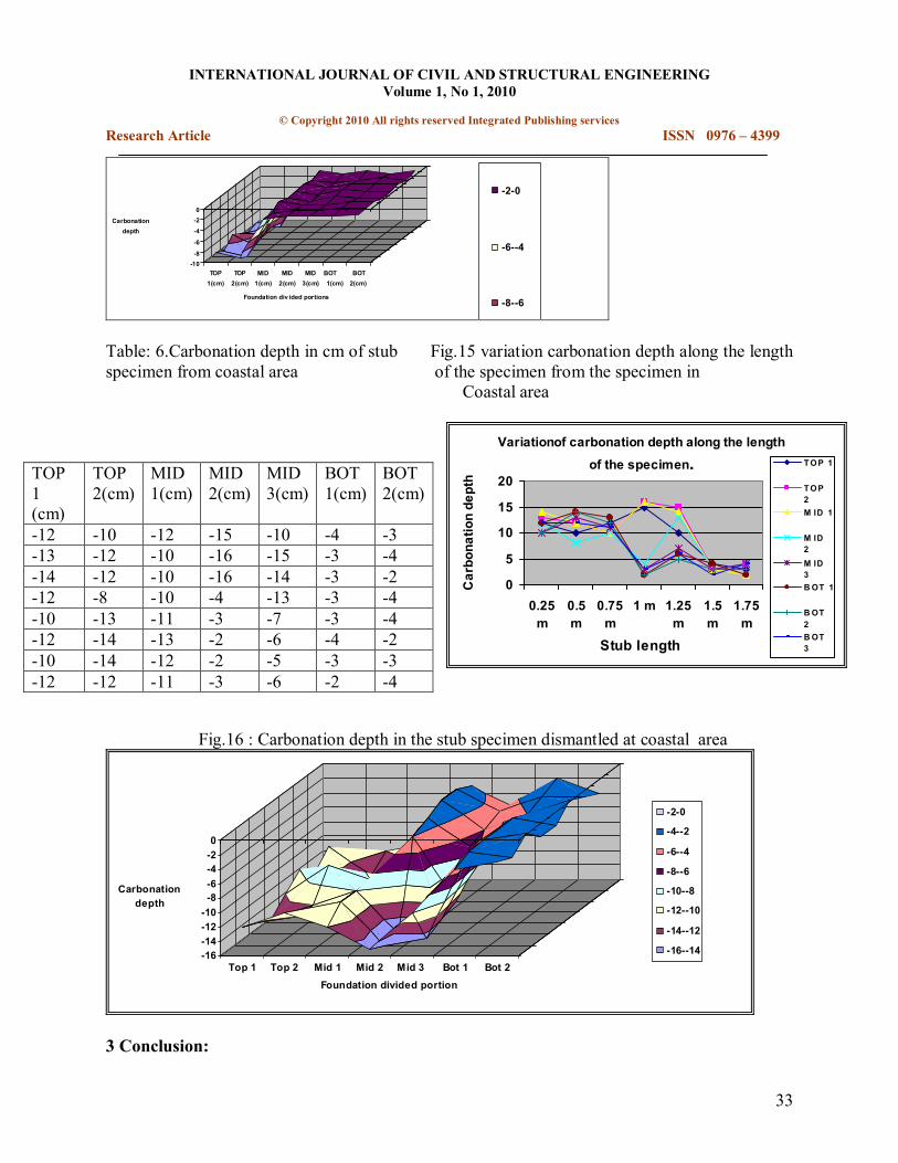
Table: 6.Carbonation depth in cm of stub Fig.15 variation carbonation depth along the length specimen from coastal area of the specimen from the specimen in
Coastal area
Variationof carbonation depth along the length of the specimen.
0
5
10
15
20
0.25 m
0.5 m
0.75 m
1 m 1.25 m
1.5 m
1.75 m
Stub length
Carbo
natio
n de
pth
TOP 1
TOP 2 M ID 1
M ID 2 M ID 3 BOT 1
BOT 2 BOT 3
Fig.16 : Carbonation depth in the stub specimen dismantled at coastal area
16 14 12 10 8 6 4 2 0
Top 1 Top 2 Mid 1 Mid 2 Mid 3 Bot 1 Bot 2 Foundation divided portion
Carbonation depth
20
42
64
86
108
1210
1412
1614
3 Conclusion:
TOP 1 (cm)
TOP 2(cm)
MID 1(cm)
MID 2(cm)
MID 3(cm)
BOT 1(cm)
BOT 2(cm)
12 10 12 15 10 4 3 13 12 10 16 15 3 4 14 12 10 16 14 3 2 12 8 10 4 13 3 4 10 13 11 3 7 3 4 12 14 13 2 6 4 2 10 14 12 2 5 3 3 12 12 11 3 6 2 4
INTERNATIONAL JOURNAL OF CIVIL AND STRUCTURAL ENGINEERING Volume 1, No 1, 2010
© Copyright 2010 All rights reserved Integrated Publishing services Research Article ISSN 0976 – 4399
34
From the Condition assessment tests conducted on the actual stub specimens of transmission tower foundations, following observations have been made.
The embedded portion of the stubs in the inland area are almost unaffected by corrosion and the half cell potentiometer readings confirm this. The rebound hammer test conducted on the stub from inland area indicates the concrete strength above M 20 and this is due to the fact the concrete is not affected by carbonation or chloride ingress. A kind of Pitting/crevice corrosion noticed in the stub angle /coping interface at the muffing portion of the stub from the inland area is only a local distress. The stubs tested in the coastal areas shows all the readings above ASTM limit and the corrosion level is alarming also in the embedded portion. The rebound hammer test conducted on the stub from inland areas indicates lesser than M10 concrete in the major area of embedded portion of the stubs because of carbonation, chloride and other chemicals in such a coastal cum industrial environment. The phenolphthalein test conducted shows clearly about the extent of carbonation depth. For about 35 cm from the Ground level, the total concrete has been carbonated in the coastal area. In the Inland specimens, the full carbonation in the coping portion is due to failure of coping due to poor quality and bond. Based on the observation, a methodology for protecting the concrete stub angle interface is being developed and experimentally studied. A methodology for protecting the concrete surface and stub angle is also being developed as a part of the study.
4 References:
1) S.Christian Johnson, et.al “ Durability of tower foundations” Proceedings of International conference on advances and techniques in civil Engineering” 79 Jan’2010 , organised by VLB Janakiammal college of Engineering and Technology, Coimbatore. 2). David Huughes ,”Monitoring steel tower foundation corrosion utility uses polarization resistance, condition assessment technique”Aug 1,1996, wwe.tdworld..com 3).Lan Flately, “Nondestructive Testing of concrete leg Foundations” Apr 1,2005 www.tdworld.com 4).Marrit Forsannder,”Steel in soil subjected to complicate corrosion conditions that do not exist in air”. Jul 1, 2006 www.tdworld.com