1279 Grenfell Tower
306
1279 Grenfell Tower DRAFT 03 November 2013 MAX00001054 0001 MAX00001054/1
-
Upload
khangminh22 -
Category
Documents
-
view
13 -
download
0
Transcript of 1279 Grenfell Tower

1279 Grenfell Tower
DRAFT
03 November 2013
MAX00001054 0001 MAX00001054/1
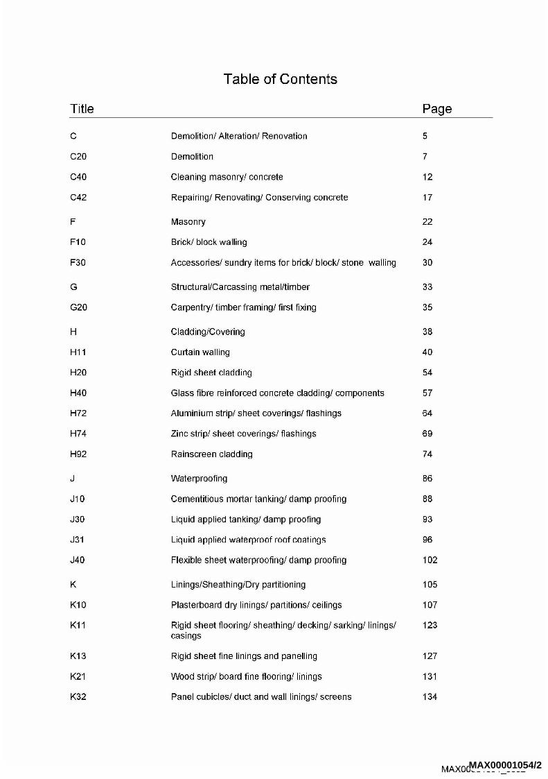
Title
Table of Contents
Page
C Demolition/Alteration/Renovation 5
C20 Demolition 7
C40 Cleaning masonry/concrete 12
042 Repairing/Renovating/Conserving concrete 17
F Masonry 22
FIO Brick/block walling 24
FSO Accessories/sundry items for brick/block/stone walling 30
G Structural/Carcassing metal/timber 33
G20 Carpentry/timber framing/first fixing 35
H Cladding/Covering 38
H l l Curtain walling 40
H20 Rigid sheet cladding 54
H40 Glass fibre reinforced concrete cladding/ components 57
H72 Aluminium strip/ sheet coverings/ flashings 64
H74 Zinc strip/sheet coverings/flashings 69
H92 Rainscreen cladding 74
J Waterproofing 86
J10 Cementitious mortar tanking/damp proofing 88
JSO Liquid applied tanking/damp proofing 93
JSl Liquid applied waterproof roof coatings 96
J40 Flexible sheet waterproofing/ damp proofing 102
K Linings/Sheathing/Dry partitioning 105
Kl 0 Plasterboard dry linings/ partitions/ ceilings 107
Kl 1 Rigid sheet flooring/ sheathing/ decking/ sarking/ linings/ 123
casings
K13 Rigid sheet fine linings and panelling 127
K21 Wood strip/board fine flooring/linings 131
K32 Panel cubicles/ duct and wall linings/ screens 134
MAX00001054 0002 MAX00001054/2

K40 Demountable suspended ceilings 139
K41 Raised access floors 146
L Windows/Doors/Stairs 153
L10 Wndows/ Rooflights/ Screens/ Louvres 155
L20 Doors/shutters/hatches 161
LSO Stairs/ladders/walkways/handrails/balustrades 169
L40 General glazing 172
M Surface finishes 176
M10 Cement based levelling/wearing screeds 178
M20 Plastered/Rendered/Roughcast coatings 185
M21 Insulation with rendered finish 191
M40 Stone/concrete/quarry/ceramic tiling/mosaic 196
MSO Rubber/ plastics/ cork/ lino/ carpet tiling/ sheeting 203
M60 Painting/clear finishing 211
M61 Intumescent coatings for fire protection of steelwork 218
N Furniture/Equipment 223
N10 General fixtures/furnishings/equipment 225
N11 Domestic kitchen fittings, furnishings and equipment 231
N13 Sanitary appliances and fittings 238
N14 General internal signage systems 253
N15 Internal fire and safety signage systems 257
P Building fabric sundries 259
P10 Sundry insulation/proofing work 261
P20 Unframed isolated trims/ skirtings/ sundry items 266
P21 Door/window ironmongery 269
R Disposal systems 276
R10 Rainwater drainage systems 278
Z Building fabric reference specification 281
Z10 Purpose made joinery 283
Z11 Purpose made metalwork 286
Z12 Preservative/fire retardant treatment 291
MAX00001054 0003 MAX00001054/3

Z20 Fixings and adhesives
Z21 Mortars
Z22 Sealants
Z31 Powder coatings
MAX00001054_0004 MAX00001054/4

c Demolition/Alteration/ Renovation
MAX00001054 0005 MAX00001054/5

C20 Demolition
MAX00001054 0006 MAX00001054/6
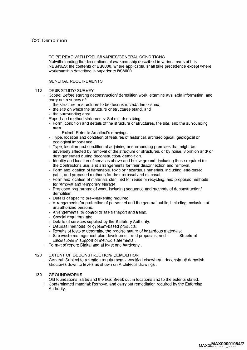
C20 Demolition
TO BE READ WITH PRELIMINARIES/GENERAL CONDITIONS • Notwithstanding the descriptions of workmanship described in various parts of this
NBS/NES; the contents of BS8000, where applicable, shall take precedence except where workmanship described is superior to BS8000.
GENERAL REQUIREMENTS
110 DESK STUDY/ SURVEY • Scope: Before starting deconstruction/ demolition work, examine available information, and
carry out a survey of: - the structure or structures to be deconstructed/ demolished, - the site on which the structure or structures stand, and - the surrounding area.
• Report and method statements: Submit, describing: - Form, condition and details ofthe structure or structures, the site, and the surrounding
area. Extent: Referto Architect's drawings .
- Type, location and condition of features of historical, archaeological, geological or ecological importance.
- Type, location and condition of adjoining or surrounding premises that might be adversely affected by removal ofthe structure or structures, or by noise, vibration and/ or dust generated during deconstruction/ demolition.
- Identity and location of services above and below ground, including those required for the Contractor's use, and arrangements for their disconnection and removal.
- Form and location of flammable, toxic or hazardous materials, including lead-based paint, and proposed methods for their removal and disposal.
- Form and location of materials identified for reuse or recycling, and proposed methods for removal and temporary storage.
- Proposed programme of work, including sequence and methods of deconstruction/ demolition.
- Details of specific pre-weakening required. - Arrangements for protection of personnel and the general public, including exclusion of
unauthorized persons. - Arrangements for control of site transport and traffic. - Special requirements: - Details of services supplied by the Statutory Authority; - Disposal methods for gypsum-based products; - Results of tests to determine the precise nature of hazardous materials; - Site waste management plan development and proposals; and - Structural
calculations in support of method statements . • Format of report: Digital and at least one hardcopy .
120 EXTENT OF DECONSTRUCTION/ DEMOLITION • General: Subject to retention requirements specified elsewhere, deconstruct/ demolish
structures down to levels as shown on Architect's drawings .
130 GROUNDWORKS • Old foundations, slabs and the like: Break out in locations and to the extents stated. • Contaminated material: Remove, and carry out remediation required by the Enforcing
Authority.
MAX00001054 0007 MAX00001054/7
140 BENCHMARKS • Unrecorded bench marks and other survey information: Give notice when found. Do not
remove marks or destroy the fabric on which they are found.
150 FEATURES TO BE RETAINED • General: Keep in place and protect the following: Referto Architect's drawings.
SERVICES AFFECTED BY DECONSTRUCTION/ DEMOLITION
210 SERVICES REGULATIONS • Work carried out to or affecting new and/ or existing services: Carry out in accordance with
the byelaws and/ or regulations ofthe relevant Statutory Authority.
220 LOCATION OF SERVICES • Services affected by deconstruction/ demolition work: Locate and mark positions. • Mains services marking: Arrange with the appropriate authorities for services to be located
and marked. - Marking standard: In accordance with National Joint Utilities Group 'Guidelines on the
positioning and colour coding of underground utilities' apparatus'.
230 SERVICES DISCONNECTION ARRANGED BY CONTRACTOR • General: Arrange with the appropriate authorities for disconnection of services and removal
of fittings and equipment owned by those authorities priorto starting deconstruction/ demolition.
240 DISCONNECTION OF DRAINS • General: Locate, disconnect and seal disused foul and surface water drains. • Sealing: Permanent, and within the site.
250 LIVE FOUL AND SURFACE WATER DRAINS • Drains and associated manholes, inspection chambers, gullies, vent pipes and fittings:
- Protect; maintain normal flow during deconstruction/demolition. - Make good any damage arising from deconstruction/ demolition work. - Leave clean and in working order at completion of deconstruction/ demolition work.
• Other requirements: Post completion camera survey; extent TBC.
260 SERVICE BYPASS CONNECTIONS • General: Provide as necessary to maintain continuity of services to occupied areas ofthe
site on which the deconstruction/ demolition is taking place and to adjoining sites/ properties.
• Minimum notice to adjoining owners and all affected occupiers: 72 hours, if shutdown is necessary during changeover.
270 SERVICES TO BE RETAINED • Damage to services: Give notice, and notify relevant service authorities and/ or owner/
occupier regarding damage arising from deconstruction/ demolition. • Repairs to services: Complete as directed, and to the satisfaction ofthe service authority or
owner.
MAX00001054 0008 MAX00001054/8
DECONSTRUCTION/ DEMOLITION WORK
310 WORKMANSHIP • Standard: Demolish structures in accordance with BS 6187. • Operatives:
- Appropriately skilled and experienced for the type of work. - Holding, or in training to obtain, relevant CITB Certificates of Competence.
• Site staff responsible for supervision and control of work: Experienced in the assessment of risks involved and methods of deconstruction/demolition to be used.
320 GAS OR VAPOUR RISKS • Precautions: Prevent fire and/ or explosion caused by gas and/ or vapour from tanks,
pipes, etc.
330 DUST CONTROL • General: Reduce airborne dust by periodically spraying deconstruction/ demolition works
with an appropriate wetting agent. Keep public roadways and footpaths clear of mud and debris.
• Lead dust: Submit method statement for control, containment and clean-up regimes.
340 HEALTH HAZARDS • Precautions: Protect site operatives and general public from hazards associated with
vibration, dangerous fumes and dust arising during the course ofthe Works.
350 ADJOINING PROPERTY • Temporary support and protection: Provide. Maintain and alter, as necessary, as work
proceeds. Do not leave unnecessary or unstable projections. • Defects: Report immediately on discovery. • Damage: Minimize. Repair promptly to ensure safety, stability, weather protection and
security. • Support to foundations: Do not disturb.
360 STRUCTURES TO BE RETAINED • Extent: As indicated on Architect's drawings. • Parts which are to be kept in place: Protect. • Interface between retained structures and deconstruction/demolition: Cut away and strip
out with care to minimize making good.
370 PARTLY DEMOLISHED STRUCTURES • General: Leave in a stable condition, with adequate temporary support at each stage to
prevent risk of uncontrolled collapse. Make secure outside working hours. • Temporary works: Prevent overloading due to debris. • Access: Prevent access by unauthorized persons.
380 DANGEROUS OPENINGS • General: Provide guarding at all times, including outside of working hours. Illuminate during
hours of darkness. • Access: Prevent access by unauthorized persons.
390 ASBESTOS-CONTAINING MATERIALS - KNOWN OCCURRENCES • General: Materials containing asbestos are known to be present in: Referto TMO asbestos
report. • Removal: By contractor licensed by the Health and Safety Executive, and priorto other
works starting in these locations.
MAX00001054 0009 MAX00001054/9
391 ASBESTOS-CONTAINING MATERIALS - UNKNOWN OCCURRENCES • Discovery: Give notice immediately of suspected asbestos-containing materials when
discovered during deconstruction/demolition work. Avoid disturbing such materials. • Removal: Submit statutory risk assessments and details of proposed methods for safe
removal.
410 UNFORESEEN HAZARDS • Discovery: Give notice immediately when hazards such as unrecorded voids, tanks,
chemicals, are discovered during deconstruction/demolition. • Removal: Submit details of proposed methods for filling, removal, etc.
MATERIALS ARISING
510 CONTRACTOR'S PROPERTY • Components and materials arising from the deconstruction/ demolition work: Property of
the Contractor except where otherwise provided. • Action: Remove from site as work proceeds where not to be reused or recycled for site
use.
520 RECYCLED MATERIALS • Materials arising from deconstruction/ demolition work: Can be recycled or reused
elsewhere in the project, subject to compliance with the appropriate specification and in accordance with any site waste management plan.
• Evidence of compliance: Submit full details and supporting documentation. - Verification: Allow adequate time in programme for verification of compliance.
MAX00001054 0010 MAX00001054/10

C40 Cleaning masonry/ concrete
MAX00001054 0011 MAX00001054/11

C40 Cleaning masonry/ concrete
TO BE READ WITH PRELIMINARIES/ GENERAL CONDITIONS. • Notwithstanding the descriptions of workmanship described in various parts of this
NBS/NES; the contents of BS8000, where applicable, shall take precedence except where workmanship described is superior to BS8000.
• The manufacturers noted within this specification are indicative and may be substituted with similar or equal alternatives.
• All manufacturers must provide evidence that the VOC emission level/content of their products are tested in accordance with BS EN13300:2001.
GENERAL/ PREPARATION
110 SCOPE OF WORK • Refer to Architect's drawings.
120 RELATED REPAIR AND REMEDIAL WORKS • Work to be carried out before cleaning work: Grouting/ filling to cracks in concrete, as
section C42.
142 REMOVAL OF FITTINGS • Timing: Before commencement of cleaning work. • Disturbance to surfaces: Minimize. • Items for disposal:
- Bird preventive devices from ledges; - Brackets; - Fasteners; - Metal clips; and - Vine eyes.
• Items to be kept for reuse: TBC.
160 PROTECTION • Surfaces not designated for cleaning: Prevent damage, including marking and staining. • Openings: Prevent ingress of water, cleaning agents and detritus.
- Vents and grilles: Seek instructions before sealing up. • Temporary mechanical fastenings:
- In masonry: Locate in joints. - In other surfaces: Seek instructions.
• Additional protection: Submit proposals .
175 CONTROL AND DISPOSAL OF WASH WATER AND DETRITUS • Disposal: Safely. Obtain approvals from relevant Authority. • Control of wash water: Collect and divert to prevent ingress and damage to building fabric
and adjacent areas. • Above and below ground drainage systems: Keep free from detritus and maintain normal
operation.
180 COLD WEATHER • Cleaning procedures using water: Do not use when airtemperature is at or below 5 0C.
Protect damp surfaces from frost. • Chemical cleaning agents: Do not use when surface temperatures are below those
recommended by manufacturer.
MAX00001054 0012 MAX00001054/12

190 CLEANING GENERALLY • Operatives: Appropriately trained and experienced for each type of cleaning work.
- Evidence of training: Submit on request. • Control of cleaning: Confine cleaning processes and materials to designated areas.
Prevent wind drift. • Detritus: Remove regularly. Dispose of safely. • Monitoring: Frequently check results of cleaning compared to approved trial samples. If
results established by trials are not achieved, seek instructions. • Modifications to cleaning methods and materials: Seek instructions.
215 RECORD OF CLEANING WORKS • Written report: Record cleaning methods and procedures used for each type of surface and
deposit. - Content: Relevant attributes of cleaning methods used including:
Equipment and settings. Dwell times. Number of applications. Ambient temperatures.
• Additional documentation: Survey before cleaning: Photogrammetric drawings of each elevation.
• Submission: At completion of cleaning works.
PRODUCTS/ EQUIPMENT 300 COMPATIBILITY OF CHEMICAL PRODUCTS
• Products: Compatible and produced by the same manufacturer.
312 SURFACE BIOCIDES • Types: Registered by the Health and Safety Executive (HSE) and listed on the HSE
website under non-agricultural pesticides. • Compatibility with surface: Free from staining or other harmful effects.
322 ABRASIVE CLEANING EQUIPMENT • Manufacturer/ Supplier: Contractor's choice.
- Product reference: Submit proposals. • Nozzle types: Subject to site trials. • Abrasives: Subject to site trials.
332 WATER SPRAY (MOUNTED NOZZLES) • Equipment:
- Spray/ Nozzle types: Subject to site trials . - Nozzles: Position and direction adjustable, relative to surfaces and profiles. - Controls: Submit proposals .
342 PRESSURIZED WATER CLEANING EQUIPMENT • Manufacturer: Contractor's choice.
- Product reference: Submit proposals. • Operational pressure: Submit proposals. • Nozzles: Subject to site trials.
352 STEAM CLEANING EQUIPMENT • Manufacturer: Contractor's choice .
- Product reference: Submit proposals .
MAX00001054 0013 MAX00001054/13

362 CHEMICAL AGENTS FOR GRAFFITI REMOVAL • Manufacturer: Contractor's choice.
- Product reference: Submit proposals.
APPLICATION
412 REMOVAL OF LOOSELY ADHERED DEPOSITS • Timing: Before commencement of other cleaning methods. • Surfaces: Prevent damage, including abrasion.
422 BIOCIDE APPLICATION • Preparation: Dampen dry growths and Remove loose growths. • Surfaces: Prevent damage, including abrasion. • Biocide treatment: Appropriate solutions to kill growths and inhibit further growths.
- Dead growths: Remove.
452 ABRASIVES CLEANING • Surfaces: Minimize abrasion.
- Ingrained deposits: Seek instructions. • Equipment settings (including nozzle type and distance from surface): Adjust regularly to
achieve optimum cleaning performance for each surface. • Detritus: Remove with clean water.
462 WATER SPRAY CLEANING (MOUNTED NOZZLES) • Surfaces: Minimize water run-off. Prevent damage. • Adjustment of washing cycle and nozzle positions: Regularly to achieve optimum cleaning
performance.
472 PRESSURIZED WATER CLEANING • Surfaces: Prevent damage, including abrasion. • Equipment settings (including nozzle type and distance from surface): Adjust regularly to
achieve optimum cleaning performance for each surface.
482 STEAM CLEANING • Surfaces: Prevent damage, including abrasion. • Equipment settings (including nozzle type and distance from surface): Adjust regularly to
achieve optimum cleaning performance for each surface.
495 TESTING pH VALUES FOR CHEMICAL CLEANING • pH indicator: To distinguish pH values between 1-14. • Testing before cleaning:
- Clean rinsing water, wetted surfaces and joints: Test for pH. Record as 'control' values. • Testing after water rinsing and neutralization:
- Wetted surfaces and joints: Record pH values. - Acceptance criteria: Seek instructions.
MAX00001054 0014 MAX00001054/14

500 CHEMICAL CLEANING • Surfaces: Prevent damage, including discolouration, bleaching and efflorescence. • Product variables (including concentrations, dwell times and number of applications):
Adjust for each surface to achieve optimum cleaning performance. • Application: To wetted surfaces.
- Drying out: Prevent unless recommended otherwise by cleaning product manufacturer. • Removal of chemicals and neutralization: As recommended by product manufacturer,
including rinsing with clean water. - Additional treatment: Where water rinsing is insufficient to neutralize surface, apply
compatible neutralizing agent. - Surfaces and joints: Minimize absorption of chemicals. Prevent damage, including
abrasion.
MAX00001054 0015 MAX00001054/15

C42 Repairing/ Renovating/ Conserving concrete
MAX00001054 0016 MAX00001054/16

C42 Repairing/ Renovating/ Conserving concrete
TO BE READ WITH PRELIMINARIES/GENERAL CONDITIONS. • Notwithstanding the descriptions of workmanship described in various parts of this
NBS/NES; the contents of BS8000, where applicable, shall take precedence except where workmanship described is superior to BS8000.
• The manufacturers noted within this specification are indicative and may be substituted with similar or equal alternatives.
• All manufacturers must provide evidence that the VOC emission level/content of their products are tested in accordance with BS EN13300:2001.
GENERAL
105 INFORMATION REQUIRED WITH TENDER • Details of repair system including manufacturer and product references; data sheets; third
party product certification.
110 SURVEY REPORT • Report available for inspection from Curtins Consulting.
125 INVESTIGATIONS BY CONTRACTOR • Purpose: To confirm location and extent of defects before repairs undertaken. • Tests/ Observations: Condition and test methods from BS EN 1504-10 table 4 - 1
(delamination); 40 (covermeter); 11 (carbonation depth); 12 (chloride content); 36 (compressive strength; core and crushing test). - Location: At agreed locations.
• Period of notice to allow inspections (minimum): TBC.
135 TEST RECORDS • Submittals: Comprehensive records of results for each test including locations/ date/ time.
- Timing of submissions following testing: Submit proposals. - Photographic records: Digital.
• Testing authority: United Kingdom Accreditation Service (UKAS) approved independent laboratory.
140 COORDINATION OF TEMPORARY WORKS • Standard: To BS 5975. • Falsework coordinator: Appoint a suitably qualified and experienced person. • Responsibilities: In addition to those listed in BS 5975, clause 6.3.1.3, to ensure that:
- Relevant requirements for temporary supports, whether known at the outset or discovered in the course ofthe repair works, are fully considered.
- Removal of concrete/ reinforcement is only undertaken when it is safe to do so and temporary supports are in place.
• Period of appointment: From commencement of Contract until completion of repair works.
MAX00001054 0017 MAX00001054/17
150 CONCRETE REPLACEMENT REPAIRS CONCRETE FRAME • Location: As pre-tender survey report. • Concrete removal:
- Extent: Loose concrete and Severely cracked concrete. - Limitations on removal: Submit proposals. - Method: Submit proposals.
• Reinforcement replacement: - Extent: Not required. - Jointing: Not required.
• Reinforcement treatment: Submit proposals. • Concrete replacement: Hand applied mortar. • Finish: Surface regularity compatible with existing adjacent concrete. • Other requirements: Abseiling to carry out repairs not permitted.
155 CRACK REPAIRS EXPOSED SURFACES INTERNALLY AND EXTERNALLY • Location: As survey report. • Crack types/ widths: As survey report. • Primary function: Sealing against water and other adverse agents. • Grouting material: Water based, polymer modified cementitious mortar. • Application method: Submit proposals.
- Finish: Flush. • Other requirements: None.
180 CONTRACTOR DESIGNED REPAIRS CONCRETE FRAME • Type of structure: In situ concrete frame and slabs with large pre-cast structural spandrel
panels. • Location of defects: As survey report. • Condition of structure: As survey report. • Design life: Minimum as design life of surrounding concrete. • Other requirements: Internal surfaces to achieve even and smooth finish priorto emulsion
paint coating.
PRODUCTS
305 PROPRIETARY REPAIR SYSTEMS • Products: Compatible and supplied by the same manufacturer as part of a total repair
system.
MAX00001054 0018 MAX00001054/18
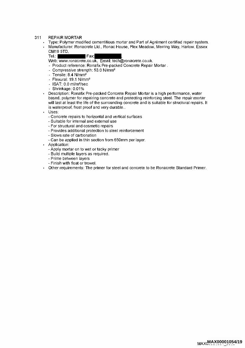
REPAIR MORTAR Type: Polymer modified cementitious mortar and Part of Agrement certified repair system. Manufacturer: Ronacrete Ltd., Ronac House, Flex Meadow, Merring Way, Harlow, Essex CM19 STD, Tel.: ^^^^^^^B F a x : ^ ^ ^ ^ ^ ^ ^ | , Web: www.ronacrete.co.uk, Email: [email protected]. - Product reference: Ronafix Pre-packed Concrete Repair Mortar. - Compressive strength: 53.0 N/mm2
- Tensile: 8.4 N/mm 2
- Flexural: 19.1 N/mm 2
- ISAT: 0.0 ml/m2/sec - Shrinkage: 0.01% Description: Ronafix Pre-packed Concrete Repair Mortar is a high performance, water based, polymer for repairing concrete and protecting reinforcing steel. The repair mortar will last at least the life ofthe surrounding concrete and is suitable for structural repairs. It is waterproof, frost proof and very durable.. Uses: - Concrete repairs to horizontal and vertical surfaces - Suitable for internal and external use - For structural and cosmetic repairs - Provides additional protection to steel reinforcement - Slows rate of carbonation - Can be applied in thin section from 650mm per layer. Application: - Apply mortar on to wet or tacky primer - Build multiple layers as required. - Prime between layers - Finish with float ortrowel. Other requirements: The primer for steel and concrete to be Ronacrete Standard Primer.
MAX00001054 0019 MAX00001054/19

321 LEVELLING/ SMOOTHING COATS • Type: Pre-packed water-based, acrylic polymer modified slurry coat and pore filler for
concrete surfaces. It is suitable for levelling, filling blowholes and filling pebble nests in concrete surfaces.
• Manufacturer: Ronacrete Ltd., Ronac House, Flex Meadow, Merring Way, Harlow, Essex CM19 STD, Te I.: ^ ^ ^ ^ ^ ^ ^ | F a x ^ ^ ^ ^ ^ ^ ^ H , Web: www.ronacrete.co.uk, Email: [email protected]. - Product reference: RonaBond Slurry Coat. - Minimum application depth: 1mm - Maximum application depth: 10mm - Bond strength: 1.38N/m2
- ISAT: O.Oml/m2/sec. • Description:
RonaBond Slurry Coat is a pre-packed slurry coat for surface finishing priorto coating; It can be applied to concrete to fill blemishes and blow holes, pebble nests and larger static cracks; Also apply overthe entire surfaces to achieve a textured or smooth surface priorto application of paint applied coatings.
• Uses: - Fill blowholes and pebble nests up to 10mm - Form even surfaces prior to application of paint applied coating - Apply by brush ortrowel to achieve textured or smooth finish.
• Application: Apply the mixed material to the prepared and dampened surface by brush, roller or airless spray ensuring total coverage and a uniform surface appearance; Application method and technique will determine the finished texture; Avoid application of RonaBond Slurry Coat in severe drying conditions; If this is unavoidable then use mist spray to maintain a damp environment during the first 24 hours of application, to ensure proper and even curing; Typical application thickness is 1 mm - Smm per coat; If a second coat is required allow the first to dry for 24 hours before applying the second coat.
• Other requirements: RonaBond Slurry Coat can be used in most weather conditions and in a wide temperature range, from +3 0C to 25 0 C and above. At high ambient and material temperature the working time ofthe mix will be reduced; it will be increased at lower temperatures.
EXECUTION
605 EXECUTION GENERALLY • Standard: To BS EN 1504-10. • Operatives' skill and experience: Appropriate for the types of preparation and application.
- Evidence: Submit on request.
620 TRIAL SAMPLES • Location/ Size: Exposed horizontal and vertical concrete surface 1m 2. • Trial type/purpose: Coating system - colour, texture and flatness.
630 CLEANING CONCRETE SURFACES • Extent: To reveal surface condition and aid investigation work. Minimize disruption to
concrete surfaces and materials. Leave no harmful residual cleaning agents. • Methods: Refer to clause 311 and 321.
645 CLEANING REINFORCEMENT • Standard of cleaning: Submit proposals.
MAX00001054 0020 MAX00001054/20

660 PREPARATION OF CONCRETE SUBSTRATES • Soundness: Remove loose or otherwise defective material and repair significant cracks
and gaps. • Preparation:
- Roughening for key: Refer to clause 311 and 321. - Wetting of substrate: Referto clause 311 and 321.
• Condition immediately before placing replacement material: - Cleanliness: Free from loose material, with no debris, tying wire clippings, and other
matter that could adversely affect bond. - Surface condition: Referto clause 311 and 321.
670 GROUTING CRACKS/VOIDS • Substrates: Clean. Keep free of detritus. • Pressure: Minimum necessary to fill cracks completely. Leave no voids and prevent
disruption to structure.
675 CURING CONCRETE/ MORTAR • Requirement: Keep surface layers of concrete/ mortar moist throughout curing period,
including perimeters and abutments, by either restricting evaporation or continuously wetting surfaces of concrete/ mortar. - Surfaces covered by formwork: Retain formwork in position and, where necessary to
satisfy curing period, cover surfaces immediately after striking. - Top surfaces: If covering is removed for finishing operations, replace it immediately
afterwards
COMPLETION
710 RECORD OF LOCATION/ EXTENT OF REPAIRS • Repair record forms:
- Content: Unique repair reference number for cross-referencing to record drawings; details of repair including dimensions and explanatory sketches; agreements and special requirements.
- Copies: TBC. - Source of record forms: Contractor's standard.
• Record drawings: Required on marked up contract drawings.
MAX00001054 0021 MAX00001054/21

F Masonry
MAX00001054 0022 MAX00001054/22

F10 Brick/ block walling
MAX00001054 0023 MAX00001054/23

F10 Brick/ block walling
TO BE READ WITH PRELIMINARIES/ GENERAL CONDITIONS. • Notwithstanding the descriptions of workmanship described in various parts of this
NBS/NES; the contents of BS8000, where applicable, shall take precedence except where workmanship described is superior to BS8000.
• The manufacturers noted within this specification are indicative and may be substituted with similar or equal alternatives.
• Manufacturers should either provide a BRE Global BES6001 Product certificate or supply evidence of a independently certified Environmental Management System.
TYPES OF WALLING
255 CONCRETE FACING BLOCKWORK BOXING CLUB • Blocks: To BS EN 771-3.
- Manufacturer: Topblock. Product reference: Hemelite Paint Quality.
- Configuration: Group 1. - Compressive strength:
Mean value: 3.6 N/mm2. Characteristic value: 3.6 N/mm2. Category: I.
- Freeze/Thaw resistance: Not applicable. - Recycled content: 50% (minimum) to BS EN ISO 14021. - Work sizes (length x width x height): 440 x 140 x 215 mm.
Tolerance category: D1. - Finish/Colour: unfinished. - Special shapes: N/A. - Additional requirements:
Regupal isolating strips as F30/185 Fair faced concrete lintels as F30/745.
• Mortar: As section Z21. - Standard: To BS EN 998-2. - Mix: 1:1:6 cement:lime:sand 4 N/mm 2 (mortar class 4). - Additional requirements: None.
• Bond: Half lap stretcher. • Joints: Bucket handle. • Features: None.
MAX00001054 0024 MAX00001054/24
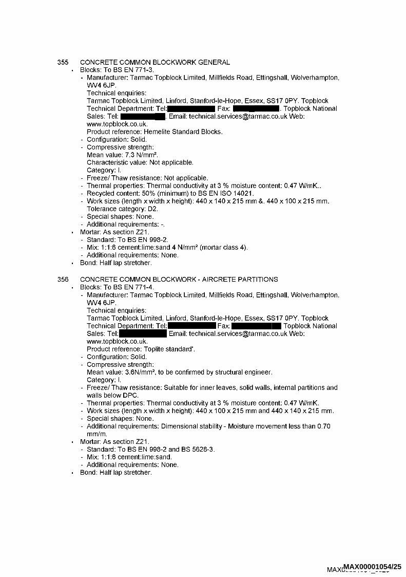
355 CONCRETE COMMON BLOCKWORK GENERAL • Blocks: To BSEN 771-3.
- Manufacturer: Tarmac Topblock Limited, Millfields Road, Ettingshall, Wolverhampton, WV4 6JP. Technical enquiries: Tarmac Topblock Limited, Linford, Stanford-le-Hope, Essex, SS17 OPY. Topblock Technical Department: T e h ^ ^ ^ ^ ^ ^ ^ H Fax: I ^ ^ ^ ^ ^ H . Topblock National Sales: Tel: ^ ^ ^ ^ ^ ^ B . Email: [email protected] Web: www.topblock.co.uk. Product reference: Hemelite Standard Blocks.
- Configuration: Solid. - Compressive strength:
Mean value: 7.3 N/mm2. Characteristic value: Not applicable. Category: I.
- Freeze/Thaw resistance: Not applicable. - Thermal properties: Thermal conductivity at 3 % moisture content: 0.47 W/mK.. - Recycled content: 50% (minimum) to BS EN ISO 14021. - Work sizes (length x width x height): 440 x 140 x 215 mm &. 440 x 100 x 215 mm.
Tolerance category: D2. - Special shapes: None. - Additional requirements: -.
• Mortar: As section Z21. - Standard: To BS EN 998-2. - Mix: 1:1:6 cement:lime:sand 4 N/mm 2 (mortar class 4). - Additional requirements: None.
• Bond: Half lap stretcher.
356 CONCRETE COMMON BLOCKWORK - AIRCRETE PARTITIONS • Blocks: To BS EN 771-4.
- Manufacturer: Tarmac Topblock Limited, Millfields Road, Ettingshall, Wolverhampton, WV4 6JP. Technical enquiries: Tarmac Topblock Limited, Linford, Stanford-le-Hope, Essex, SS17 OPY. Topblock Technical D e p a i l m e n t ^ T e l . ^ ^ ^ ^ ^ ^ ^ H F a x : ^ ^ ^ ^ ^ ^ ^ ^ Topblock National Sales: T e l : ^ ^ ^ ^ ^ ^ ^ | Email: [email protected] Web: www.topblock.co.uk. Product reference: Toplite standard'.
- Configuration: Solid. - Compressive strength:
Mean value: 3.6N/mm2, to be confirmed by structural engineer. Category: I.
- Freeze/ Thaw resistance: Suitable for inner leaves, solid walls, internal partitions and walls below DPC.
- Thermal properties: Thermal conductivity at 3 % moisture content: 0.47 W/mK. - Work sizes (length x width x height): 440 x 100 x 215 mm and 440 x 140 x 215 mm. - Special shapes: None. - Additional requirements: Dimensional stability - Moisture movement less than 0.70
mm/m. • Mortar: As section Z21.
- Standard: To BS EN 998-2 and BS 5628-3. - Mix: 1:1:6 cement:lime:sand. - Additional requirements: None.
• Bond: Half lap stretcher.
MAX00001054 0025 MAX00001054/25
TESTING
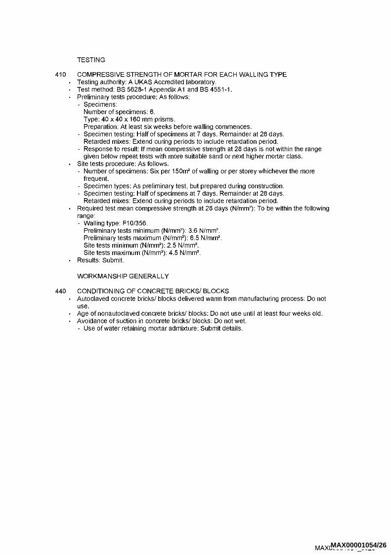
410 COMPRESSIVE STRENGTH OF MORTAR FOR EACH WALLING TYPE • Testing authority: A UKAS Accredited laboratory. • Test method: BS 5628-1 Appendix A1 and BS 4551-1. • Preliminary tests procedure: As follows:
- Specimens: Number of specimens: 6. Type: 40 x 40 x 160 mm prisms. Preparation: At least six weeks before walling commences.
- Specimen testing: Half of specimens at 7 days. Remainder at 28 days. Retarded mixes: Extend curing periods to include retardation period.
- Response to result: If mean compressive strength at 28 days is not within the range given below repeat tests with more suitable sand or next higher mortar class.
• Site tests procedure: As follows. - Number of specimens: Six per 150m 2 of walling or per storey whichever the more
frequent. - Specimen types: As preliminary test, but prepared during construction. - Specimen testing: Half of specimens at 7 days. Remainder at 28 days.
Retarded mixes: Extend curing periods to include retardation period. • Required test mean compressive strength at 28 days (N/mm 2): To be within the following
range: - Walling type: F10/356.
Preliminary tests minimum (N/mm 2): 3.6 N/mm2. Preliminary tests maximum (N/mm 2): 6.5 N/mm 2. Site tests minimum (N/mm 2): 2.5 N/mm2. Site tests maximum (N/mm 2): 4.5 N/mm2.
• Results: Submit.
WORKMANSHIP GENERALLY
440 CONDITIONING OF CONCRETE BRICKS/ BLOCKS • Autoclaved concrete bricks/ blocks delivered warm from manufacturing process: Do not
use. • Age of nonautoclaved concrete bricks/ blocks: Do not use until at least four weeks old. • Avoidance of suction in concrete bricks/ blocks: Do not wet.
- Use of water retaining mortar admixture: Submit details.
MAX00001054 0026 MAX00001054/26
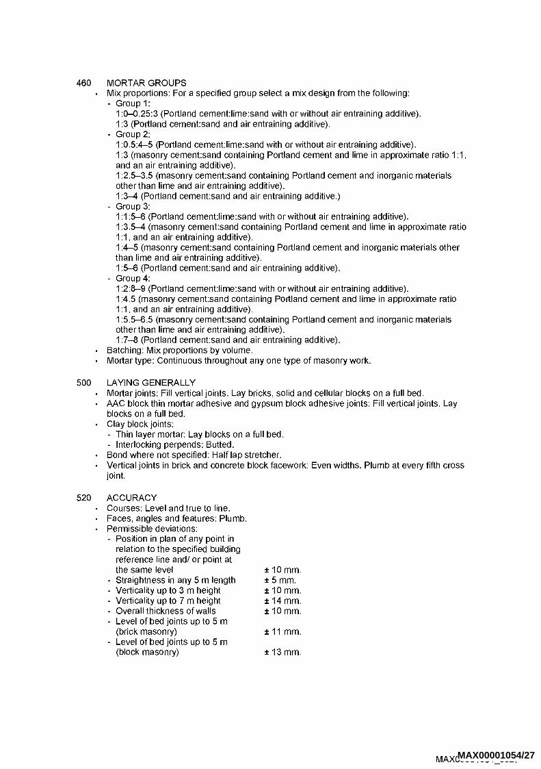
460 MORTAR GROUPS • Mix proportions: For a specified group select a mix design from the following:
- Group 1: 1:0-0.25:3 (Portland cement:lime:sand with or without air entraining additive). 1:3 (Portland cementsand and air entraining additive).
- Group 2: 1:0.5:4-5 (Portland cement:lime:sand with or without air entraining additive). 1:3 (masonry cementsand containing Portland cement and lime in approximate ratio 1:1, and an air entraining additive). 1:2.5-3.5 (masonry cementsand containing Portland cement and inorganic materials otherthan lime and air entraining additive). 1:3-4 (Portland cementsand and air entraining additive.)
- Group 3: 1:1:5-6 (Portland cement:lime:sand with or without air entraining additive). 1:3.5-4 (masonry cementsand containing Portland cement and lime in approximate ratio 1:1, and an air entraining additive). 1:4-5 (masonry cementsand containing Portland cement and inorganic materials other than lime and air entraining additive). 1:5-6 (Portland cementsand and air entraining additive).
- Group 4: 1:2:8-9 (Portland cement:lime:sand with or without air entraining additive). 1:4.5 (masonry cementsand containing Portland cement and lime in approximate ratio 1:1, and an air entraining additive). 1:5.5-6.5 (masonry cementsand containing Portland cement and inorganic materials otherthan lime and air entraining additive). 1:7-8 (Portland cementsand and air entraining additive).
• Batching: Mix proportions by volume. • Mortar type: Continuous throughout any one type of masonry work.
500 LAYING GENERALLY • Mortar joints: Fill verticaljoints. Lay bricks, solid and cellular blocks on a full bed. • AAC block thin mortar adhesive and gypsum block adhesive joints: Fill vertical joints. Lay
blocks on a full bed. • Clay block joints:
- Thin layer mortar: Lay blocks on a full bed. - Interlocking perpends: Butted.
• Bond where not specified: Half lap stretcher. • Vertical joints in brick and concrete block facework: Even widths. Plumb at every fifth cross
joint.
520 ACCURACY • Courses: Level and true to line. • Faces, angles and features: Plumb. • Permissible deviations:
- Position in plan of any point in relation to the specified building reference line and/ or point at the same level + 10 mm
- Straightness in any 5 m length + 5 mm. - Verticality up to 3 m height + 10 mm - Verticality up to 7 m height + 14 mm - Overall thickness of walls + 10 mm - Level of bed joints up to 5 m
(brick masonry) ± 11 mm - Level of bed joints up to 5 m
(block masonry) + 13 mm
MAX00001054 0027 MAX00001054/27
535 HEIGHT OF LIFTS IN WALLING USING CEMENT GAUGED OR HYDRAULIC LIME MORTAR
• Quoins and advance work: Rack back. • Lift height (maximum): 1.2 m above any other part of work at any time. • Daily lift height (maximum): 1.5 m for any one leaf.
545 LEVELLING OF SEPARATE LEAVES • Locations for equal levelling of cavity wall leaves: As follows:
- Every course containing vertical twist type ties or other rigid ties. - Every third tie course for double triangle/ butterfly ties. - Courses in which lintels are to be bedded.
595 LINTELS • Bearing: Ensure full length masonry units occur immediately under lintel ends.
610 SUPPORT OF EXISTING WORK • Joint above inserted lintel or masonry: Fully consolidated with semidry mortar to support
existing structure.
620 BLOCK BONDING NEW WALLS TO EXISTING • Pocket requirements: Formed as follows:
- Width: Full thickness of new wall. - Depth (minimum): 100 mm. - Vertical spacing:
Brick to brick: 4 courses high at 8 course centres. Block to block: Every other course.
• Pocket joints: Fully filled with mortar.
635 JOINTING • Profile: Consistent in appearance.
645 ACCESSIBLE JOINTS NOT EXPOSED TO VIEW • Jointing: Struck flush as work proceeds.
671 FIRE STOPPING • Avoidance of fire and smoke penetration: Fit tightly between cavity barriers and masonry.
Leave no gaps.
690 ADVERSE WEATHER • General: Do not use frozen materials or lay on frozen surfaces. • Airtemperature requirements: Do not lay bricks/ blocks:
- In cement gauged mortars when at or below 3 0 C and falling or unless it is at least 1 0C and rising.
- In hydraulic lime:sand mortars when at or below 5 0 C and falling or below 3 0C and rising. - In thin joint mortar glue when outside the limits set by the mortar manufacturer.
• Temperature of walling during curing: Above freezing until hardened. • Newly erected walling: Protect at all times from:
- Rain and snow. - Drying out too rapidly in hot conditions and in drying winds.
MAX00001054 0028 MAX00001054/28

FSO Accessories/ sundry items for brick/ block/ stone
walling
MAX00001054 0029 MAX00001054/29
FSO Accessories/ sundry items for brick/ block/ stone walling
TO BE READ WITH PRELIMINARIES/ GENERAL CONDITIONS. • Notwithstanding the descriptions of workmanship described in various parts of this
NBS/NES; the contents of BS8000, where applicable, shall take precedence except where workmanship described is superior to BS8000.
• The manufacturers noted within this specification are indicative and may be substituted with similar or equal alternatives.
• Manufacturers should either provide a BRE Global BES6001 Product certificate or supply evidence of a independently certified Environmental Management System.
CAVITIES
121 CLEANLINESS • Cavity base and faces and ties: Free from mortar and debris.
185 TRANSMITTED NOISE REDUCTION SYSTEM SEPARATING WALLS • Type: Party wall system. • Manufacturer: CMS Danskin Acoustics Ltd
Unit 2 Lyncastle Road, Appleton, Warrington WA4 4SN T e l : ^ ^ ^ ^ ^ ^ ^ H F a x : ^ ^ ^ ^ ^ ^ H Web.:www.cmsdanskin.co.uk. - Product reference: Regupol® 601 OXHT Isolating Strip.
• Components: Composite rubber/ PUR strip designed to sit beneath block work partitions and walls to reduce structure borne noise.
REINFORCING/ FIXING ACCESSORIES
220 WALL TIES SEPARATING CONCRETE BLOCK CAVITY WALLS • Manufacturer: Ancon Building Products, President Way, President Park, Sheffield S4 7UR.
Tel: ^^^^^^H. Fax: Email: [email protected], Website: www.ancon.co.uk. - Product reference: Staifix HRT4 Housing Wall Tie
- Standard: To PD6697 - Type: 4, Masonry light duty.
• Material/ finish: Austenitic stainless steel - Grade 1.4301 (304) / Austenitic stainless steel -Grade 1.4401 (316).
• Sizes: 200 mm.
225 FIXING TIES IN MASONRY CAVITY WALLS • Embedment in mortar beds (minimum): 50 mm. • Placement: Sloping slightly downwards towards outer leaf, without bending. Drip centred in
the cavity and pointing downwards. • Spacing: Staggered in alternate courses.
- Horizontal centres: 750 mm . - Vertical centres: 450 mm .
• Additional ties: Provide within 225 mm of reveals of unbonded openings. - Spacing: At not more than 300 mm centres vertically .
MAX00001054 0030 MAX00001054/30

241 WALL STARTERS/ CONNECTORS • Manufacturer: Ancon Building Products, President Way, President Park, Sheffield S4 7UR
Tel: ^^^^^^H Fax: ^^^^^^^H Email: [email protected], Web site: www.ancon.co.uk. - Product reference: 36/8 Wall Extension System with PP36 ties including debonding
sleeves. • Material/ finish: Austenitic stainless steel. • Sizes: Varies.
250 SLIDING ANCHOR RESTRAINT SLIP TIES BLOCK WORK • Manufacturer: Ancon Building Products, President Way, President Park, Sheffield S4 7UR
Tel: ^^^^^^M F a x : ^ ^ ^ ^ ^ ^ ^ B Email: [email protected], Website: www.ancon.co.uk. - Product reference: Ancon IHR-V head restraints.
• Material/ finish: Austenitic stainless steel. • Sizes: To suit 10Omm block work.
FLEXIBLE DAMP PROOF COURSES/ CAVITY TRAYS
330 DAMP PROOF COURSE - POLYMERIC • Manufacturer: RIW Limited, Arc House, Terrace Road South, Binfield, RG42 4PZ,
Tel : ^ ^ ^ ^ ^ ^ ^ t , Fax E-mail: [email protected], Web : www.riw.co.uk. - Product reference: RIW Sheetseal 9000 DPC.
INSTALLATION OF DPCS/CAVITYTRAYS
415 HORIZONTAL DPCS • Placement: In continuous lengths on full even bed of fresh mortar, with 100 mm laps at
joints and full laps at angles. • Wdth: At least full width of leaf unless otherwise specified. Edges of dpc not covered with
mortar or projecting into cavity. • Overlying construction: Immediately cover with full even bed of mortar to receive next
masonry course. • Overall finished joint thickness: As close to normal as practicable.
425 GROUND LEVEL DPCS • Joint with damp proof membrane: Continuous and effectively sealed.
445 SILL DPCS • Form and placement: In one piece and turned up at back when sill is in contact with inner
leaf.
455 COPING/CAPPING DPCS • Placement: Bed in one operation to ensure maximum bond between masonry units, mortar
and dpc. • Dpcs crossing cavity: Provide rigid support to prevent sagging.
465 SEALING DPCS GENERALLY • Overlaps and junctions: Seal with Seal with RIW Jointing Tape .
JOINTS
630 UNEXPOSED CONTRACTION JOINTS • Formation: Close butt as work proceeds.
MAX00001054 0031 MAX00001054/31

650 POINTING IN FLASHINGS • Joint preparation: Free of debris and lightly wetted. • Pointing mortar: As for adjacent walling. • Placement: Fill joint and finish flush.
670 TOPS OF NONLOADBEARING WALLS • Restraints: Referto Clause 250 .
- Fixing: Secure to soffit. • Joint filler: Mineral wool
Joint sealant: Arbo XL 1075 Fire Retardant Acrylic Sealant Colour: White Manufacturer: Adshead Ratcliffe, Derby Road, Belper, Derbyshire, DE56 1WJ. Tel: ^ ^ ^ B F a x : ^ ^ ^ ^ ^ ^ ^ B . Email: [email protected] Web: www.arbo.co.uk . - Placement: Full, no gaps.
PROPRIETARY SILLS/ LINTELS/ COPINGS/ DRESSINGS
745 PRESTRESSED CONCRETE LINTELS • Standard: To BS EN 845-2. • Manufacturer: Naylor Lintels, Longlands Industrial Estate, Milner Way, Ossett, West
Yorkshire, WF5 9JE Tel: ^ ^ ^ ^ ^ ^ ^ B , F a x : ^ ^ ^ ^ ^ ^ ^ H [email protected], Web: www.naylorlintels.co.uk. - Product reference: Referto Engineer's schedule.
• Types: As schedule. • Sizes: As schedule. • Additional requirements: Fair faced unless specified otherwise on schedule. • Placement: Bed on mortar used for adjacent work. Prop at not more than 1.2 m centres to
prevent displacement during construction. Retain props in position for not less than 14 days or until mortar has matured, whichever is longer. - Bearing length (minimum): As schedule.
755 PREFABRICATED STEEL LINTELS • Standard: To BS EN 845-2. • Manufacturer: Naylor Lintels, Longlands Industrial Estate, Milner Way, Ossett, West
Yorkshire, WF5 9JE ^ ^ ^ ^ ^ ^ ^ T e l : ^ ^ ^ ^ ^ ^ ^ B F a x ^ ^ ^ ^ ^ ^ ^ J Email: [email protected], Web: www.naylorlintels.co.uk. - Product reference: Referto Engineer's schedule. Types: As schedule. Material/ finish: Austenitic stainless steel. Sizes: As schedule. Additional requirements: Consult engineer for allowable deflection under load. Placement: Bed on mortar used for adjacent work. - Bearing length (minimum): 100 mm.
MISCELLANEOUS ITEMS
830 BUILDING IN FRAMES • Preparation: Remove horns and provide support. • Fixing cramps: Fully bed in mortar.
840 OPENINGS FOR FRAMES • Formation: Use accurate, rigid templates to required size.
MAX00001054 0032 MAX00001054/32

G Structural/Carcassing metal/timber
MAX00001054 0033 MAX00001054/33

G20 Carpentry/ timber framing/f i rst f ixing
MAX00001054 0034 MAX00001054/34

G20 Carpentry/ timber framing/f i rst fixing
TO BE READ WITH PRELIMINARIES/ GENERAL CONDITIONS. Notwithstanding the descriptions of workmanship described in various parts of this NBS/NES; the contents of BS8000, where applicable, shall take precedence except where workmanship described is superior to BS8000. The manufacturers noted within this specification are indicative and may be substituted with similar or equal alternatives. All manufacturers/suppliers of plywood must provide evidence that their product is tested in accordance with EN 13986:2004 and complies with Formaldehyde class E1. They must verify that regulated wood preservatives are absent from their product as defined by the standard.
GENERAL
105 TIMBER PROCUREMENT • Timber (including timber for wood based products): Obtained from well managed forests/
plantations in accordance with: - The laws governing forest management in the producer country or countries. - International agreements such as the Convention on International Trade in Endangered
Species of wild fauna and flora (CITES). • Documentation: Provide either:
- Documentary evidence (which has been or can be independently verified) regarding the provenance of all timber supplied, or
- Evidence that suppliers have adopted and are implementing a formal environmental purchasing policy for timber and wood based products.
150 STRENGTH GRADING OF TIMBER • Grader: A company currently registered under a third party quality assurance scheme
operated by a certification body approved by the UK Timber Grading Committee.
160 GRADING AND MARKING OF SOFTWOOD • Timber of a target/ finished thickness less than 100 mm and not specified for wet exposure:
Graded at an average moisture content not exceeding 20% with no reading being in excess of 24% and clearly marked as 'DRY' or 'KD' (kiln dried).
• Timber graded undried (green) and specified for installation at higher moisture contents: Clearly marked as 'WET' or 'GRN'.
• Structural timber members cut from large graded sections: Regraded to approval and marked accordingly.
PRODUCTS
270 UNGRADED SOFTWOOD FOR NONSTRUCTURAL USE GENERALLY • Quality of timber: Free from decay, insect attack (except pinhole borers) and with no knots
wider than half the width ofthe section. • Surface finish: Planed all round. • Treatment:
- Preservative treatment: Organic solvent impregnation to NBS section Z12 and Wood Protection Association Commodity Specification C8; Evidence must be provided thatthe softwood is free of any regulated wood preservatives
- Design service life: 40 years. - Fire retardant treatment: None required.
MAX00001054 0035 MAX00001054/35
310 STRUCTURAL PLYWOOD TO ENTRANCE LOBBY ROOF STRUCTURE & AS PATTRESS IN STUD WALLS
• Standard: To the relevant national standards and quality control procedures specified in BS 5268-2, and so marked.
• Type: To BS 5268-2 from FSC source. • Grade: Sheathing. • Nominal thickness/ number of plies: 1 Smm. • Finish: Unsanded. • Treatment: Referto General conditions the start of this section.
- Preservative treatment: Organic solvent impregnation to NBS section Z12 and Wood protection Association Commodity Specification C5. Design service life: 40 years.
- Fire retardant treatment: None required.
311 NON-STRUCTURAL PLYWOOD GENERALLY • Standard: To an approved national standard. • Thickness: 18mm. • Appearance class to BS EN 635: E1. • Bond quality to BS EN 314-2: Class 1. • Finish: Unsanded. • Treatment:
- Preservative treatment: Organic solvent impregnation to NBS section Z12 and Wood protection Association Commodity Specification C5. Design service life: 40 years.
- Fire retardant treatment: None required.
WORKMANSHIP GENERALLY
402 CROSS SECTION DIMENSIONS OF NONSTRUCTURAL SOFTWOOD • Dimensions: Dimensions in this specification and shown on drawings are finished sizes. • Maximum permitted deviations from finished sizes: As stated in BS EN 1313-1:
- Clause 6 for sawn sections. - Clause NA.2 for further processed sections.
420 WARPING OF TIMBER • Bow, spring, twist and cup: Not greater than the limits set down in BS 4978 or BS EN
14081-1 for softwood, or BS 5756 for hardwood.
430 SELECTION AND USE OF TIMBER • Timber members damaged, crushed or split beyond the limits permitted by their grading:
Do not use.
435 NOTCHES, HOLES AND JOINTS IN TIMBER • Notches and holes: Position in relation to knots or other defects such that the strength of
members will not be reduced. • Scarf joints, finger joints and splice plates: Do not use without approval.
440 PROCESSING TREATED TIMBER • Cutting and machining: Carry out as much as possible before treatment. • Extensively processed timber: Retreat timber sawn lengthways, thicknessed, planed,
ploughed, etc. • Surfaces exposed by minor cutting/ drilling: Treat with two flood coats of a solution
recommended by main treatment solution manufacturer.
MAX00001054 0036 MAX00001054/36
451 MOISTURE CONTENT TESTING • Procedure: When instructed, test timber sections with an approved electrical moisture
meter. • Test sample: Test 5% but not less than 10 lengths of each cross-section in the centre of
the length. • Test results: 90% of values obtained to be within the specified range. Provide records of all
tests.
510 PROTECTION • Generally: Keep timber dry and do not overstress, distort or disfigure sections or
components during transit, storage, lifting, erection or fixing. • Timber and components: Store undercover, clear of the ground and with good ventilation.
Support on regularly spaced, level bearers on a dry, firm base. Open pile to ensure free movement of air through the stack.
• Trussed rafters: Keep vertical during handling and storage.
JOINTING TIMBER
570 JOINTING/FIXING GENERALLY • Generally: Where not specified precisely, select methods of jointing and fixing and types,
sizes and spacings of fasteners in compliance with section Z20.
ERECTION AND INSTALLATION
900 EAVES SOFFIT VENTILATORS • Manufacturer: Contractor's choice.
- Product reference: Submit proposals. • Type: Continuous strip. • Colour: TBC. • Airway: The equivalent of a continuous opening of not less than 25 mm for full length of
eaves.
MAX00001054 0037 MAX00001054/37

H Cladding/Covering
MAX00001054 0038 MAX00001054/38

H11 Curtain walling
MAX00001054 0039 MAX00001054/39

H11 Curtain walling
TO BE READ WITH PRELIMINARIES/ GENERAL CONDITIONS. • Notwithstanding the descriptions of workmanship described in various parts of this
NBS/NES; the contents of BS8000, where applicable, shall take precedence except where workmanship described is superior to BS8000.
• The manufacturers noted within this specification are indicative and may be substituted with similar or equal alternatives.
• Manufacturers should either provide a BRE Global BES6001 Product certificate or supply evidence of a independently certified Environmental Management System.
TENDERING
10 INFORMATION TO BE PROVIDED WITH TENDER • Submit the following curtain walling particulars:
- Typical plan, section and elevation drawings at suitable scales. - Typical detailed drawings at large scales, including insulated glass units, Trespa
spandrel panels and louvre units . - Technical information and certification demonstrating compliance with specification of
proposed incorporated products and finishes, including insulated glass units, Trespa spandrel panels, louvre units and flanking construction .
- Certification, reports and calculations demonstrating compliance with specification of proposed curtain walling.
- Proposals for connections to and support from the building structure and building components.
- Proposals for amendments to primary supporting structure and for secondary supporting structure additional to that shown on preliminary design drawings.
- Schedule of builder's work, special provisions and special attendance by others. - Examples of standard documentation from which project quality plan will be prepared. - Preliminary fabrication and installation method statements and programme. - Schedule of products and finishes with a design life expectancy less than that specified
in clause 440, with proposals for frequencies and methods of replacement. - Proposals for replacing damaged or failed products. - Areas of non-compliance with the specification.
MAX00001054 0040 MAX00001054/40
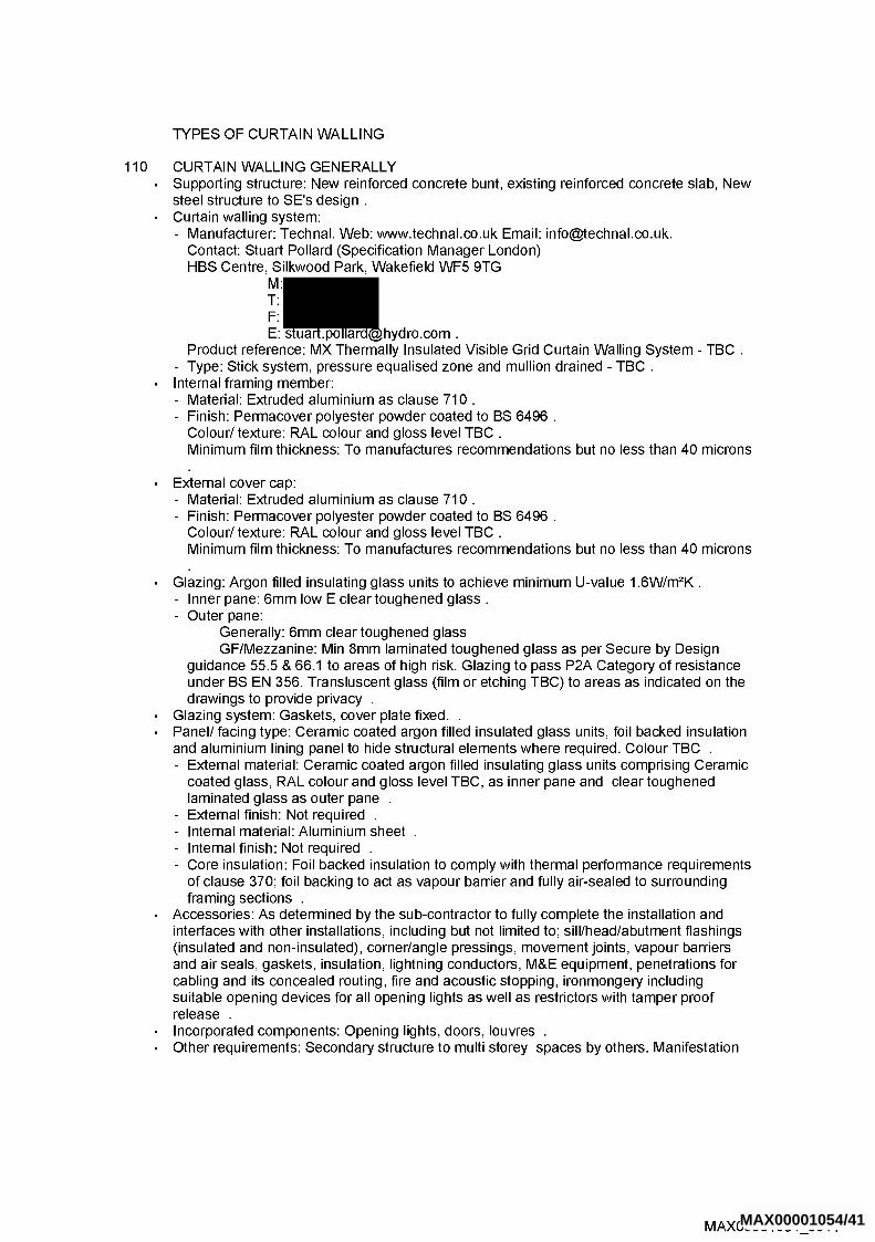
TYPES OF CURTAIN WALLING
110 CURTAIN WALLING GENERALLY • Supporting structure: New reinforced concrete bunt, existing reinforced concrete slab, New
steel structure to SE's design . • Curtain walling system:
- Manufacturer: Technal. Web: www.technal.co.uk Email: [email protected]. Contact: Stuart Pollard (Specification Manager London) HBS Centre, Silkwood Park, Wakefield WF5 9TG
E: [email protected] . Product reference: MX Thermally Insulated Visible Grid Curtain Walling System - TBC .
- Type: Stick system, pressure equalised zone and mullion drained - TBC . • Internal framing member:
- Material: Extruded aluminium as clause 710 . - Finish: Permacover polyester powder coated to BS 6496 .
Colour/texture: RAL colour and gloss level TBC . Minimum film thickness: To manufactures recommendations but no less than 40 microns
• External cover cap: - Material: Extruded aluminium as clause 710 . - Finish: Permacover polyester powder coated to BS 6496 .
Colour/texture: RAL colour and gloss level TBC . Minimum film thickness: To manufactures recommendations but no less than 40 microns
• Glazing: Argon filled insulating glass units to achieve minimum U-value 1.6W/m2K . - Inner pane: 6mm low E clear toughened glass . - Outer pane:
Generally: 6mm clear toughened glass GF/Mezzanine: Min Smm laminated toughened glass as per Secure by Design
guidance 55.5 & 66.1 to areas of high risk. Glazing to pass P2A Category of resistance under BS EN 356. Transluscent glass (film or etching TBC) to areas as indicated on the drawings to provide privacy .
• Glazing system: Gaskets, cover plate fixed. . • Panel/ facing type: Ceramic coated argon filled insulated glass units, foil backed insulation
and aluminium lining panel to hide structural elements where required. Colour TBC . - External material: Ceramic coated argon filled insulating glass units comprising Ceramic
coated glass, RAL colour and gloss level TBC, as inner pane and clear toughened laminated glass as outer pane .
- External finish: Not required . - Internal material: Aluminium sheet . - Internal finish: Not required . - Core insulation: Foil backed insulation to comply with thermal performance requirements
of clause 370; foil backing to act as vapour barrier and fully air-sealed to surrounding framing sections .
• Accessories: As determined by the sub-contractor to fully complete the installation and interfaces with other installations, including but not limited to; sill/head/abutment flashings (insulated and non-insulated), corner/angle pressings, movement joints, vapour barriers and air seals, gaskets, insulation, lightning conductors, M&E equipment, penetrations for cabling and its concealed routing, fire and acoustic stopping, ironmongery including suitable opening devices for all opening lights as well as restrictors with tamper proof release .
• Incorporated components: Opening lights, doors, louvres . • Other requirements: Secondary structure to multi storey spaces by others. Manifestation
MAX00001054 0041 MAX00001054/41

to comply with Building Regulations Approved Document Part N and M. Note requirement to achieve Class 0 spread of flam. Note A Technal Approved dealer is to verify that any proposed glass types are suitable to take all applied loads including wind, snow and guarding loads .
135 DOORS Manufacturer: Technal. Web: www.technal.co.uk Email: [email protected]. Contact: Stuart Pollard (Specification Manager London) HBS Centre, Silkwood Park, Wakefield WF5 9TG
M : ^ ^ ^ ^ ^ H T : ^ ^ ^ ^ ^ H
E: [email protected] . - Product reference: Submit Proposals including supporting documentation to demonstrate
suitability for intensive use in high traffic/high wear environment. • Material: Aluminium . • Finish: Permacover polyester powder coated to BS 6496 .
- Colour/texture: RAL colour and gloss level to be confirmed . - Minimum film thickness: To manufactures recommendations but no less than 40 microns
• Fixing: Submit proposals for concealed fixings into curtain walling . • Other requirements: Door furniture as determined by the sub-contractor and suitable for
intensive use in high traffic/high wear environment. Provide evidence of certification that doors pass under PAS 24:2012. Door design to prevent fingertrapping - submit proposals. Installation to be fully completed including, but not limited to: Pull handle/push plate, lever handles, locks, closers, kickplates, hinges, thresholds and perimeter seals as well as maglocks, security contacts and fully automatic electro-hydraulic swing door operators including their wire ways. Provide smoke vent(s), including actuators, fully automated in line with Engineer's specification .
141 LOUVRES TO COVER OPENING VENTS as indicated on the drawings • Manufacturer: Submit proposals .
- Product reference: Submit proposals . • Material: Aluminium . • Finish: Permacover polyester powder coated to BS 6496 .
- Colour/texture: RAL colour and gloss level TBC . - Minimum film thickness: 40 micrometres .
• Louvre blade pitch and angle: - Pitch: SOmm - Angle: 45°.
• Fixing: Surface fixed to window frame. Secure and vandal proof fixing. Submit proposals . • Other requirements:
- Free area to Environmental Engineer's requirement - Bird mesh - Secure to withstand manual attack .
150 MATERIALS SPECIFICATION • Minimum 'BRE Green Guide to Specification Online' rating: Submit proposals.
GENERAL REQUIREMENTS/ PREPARATORY WORK
210 DESIGN • Curtain walling and associated features: Complete the detailed design. Submit before
commencement of fabrication. • Related works: Coordinate in the detailed design.
MAX00001054 0042 MAX00001054/42

220 SPECIFICATION • Compliance standard: The Centre for Window and Cladding Technology (CWCT)
'Standard for systemised building envelopes'. • Reference information: Forthe duration ofthe contract, keep available atthe design office,
workshop and on site copies of: - The CWCT 'Standard for systemised building envelopes'. - Publications invoked by the CWCT 'Standard for systemised building envelopes'.
230 INFORMATION TO BE PROVIDED DURING DETAILED DESIGN STAGE • Submit the following curtain walling particulars:
- A schedule of detailed drawings and dates for submission for comment. - A schedule of loads that will be transmitted from the curtain walling to the structure. - Proposed fixing anchor details relevant to structural design and construction. - A detailed testing programme in compliance with the Main Contract master programme. - A detailed fabrication and installation programme in compliance with the Main Contract
master programme. - Proposals to support outstanding applications for Building Regulation consents or
relaxations.
232 QUALITY PLAN • Requirement: Submit during detailed design. • Content: In accordance with BS 5750, BS EN ISO 9001 and including the following:
- Name ofthe quality manager. - Quality assessment procedures. - Inspection procedures to be adopted in checking the work. - Stages at which check lists will be used and samples ofthe lists. - List of work procedures on the correct use of materials or components, both off site and
on site. - List of product information with latest revisions. - Subcontractors involved in the work. - Subcontractors' quality plans. - Storage, handling, transport and protection procedures. - Procedure for registering and reporting non compliances. - Maintenance procedures and calibration records. - Certification that completed work complies with specification. - Check list register to ensure all items have been inspected and non compliances
discharged.
235 INFORMATION TO BE PROVIDED BEFORE COMMENCEMENT TESTING OR FABRICATION OF CURTAIN WALLING
• Submit the following curtain walling particulars: - Detailed drawings to fully describe fabrication and installation. - Detailed calculations to prove compliance with design/ performance requirements. - Project specific fabrication, handling and installation method statements. - Certification for incorporated components manufactured by others confirming their
suitability for proposed locations in the curtain walling. - Recommendations for spare parts for future repairs or replacements.
• Recommendations for safe dismantling and recycling or disposal of products.
250 PRODUCT SAMPLES • General: Before commencing detailed design, submit labelled samples of:
- Ceramic coated glass panel, HPL panel, typical mullion with pressure plate cap and typical mullion with retention toggle and structural silicon seal. - Coated samples should be in specified RAL colour and gloss level .
MAX00001054 0043 MAX00001054/43

260 SAMPLES OF FIXINGS • General: During detailed design, submit labelled samples of each type of fixing anchor,
including casting-in restraints and shims, togetherwith manufacturers' recommended torque figures.
270 FABRICATION SAMPLES • General: During detailed design, submit samples of: 600x600mm assembly comprising;
mullion, transom and ceramic coated glass panel with insulation and plasterboard framing . - Obtain approval of appearance before proceeding.
DESIGN/ PERFORMANCE REQUIREMENTS
305 CWCT 'STANDARD FOR SYSTEMISED BUILDING ENVELOPES' • General: Unless specified or agreed otherwise comply with:
Part 2 - Loads, fixings and movement. Part 3 - Air, water and wind resistance. Part 4 - Operable components, additional elements and means of access. Part 5 - Thermal, moisture and acoustic performance. Part 6 - Fire performance Part 7 - Robustness, durability, tolerances and workmanship.
• Project performance requirements specified in this subsection: Read in conjunction with CWCT performance criteria.
312 INTEGRITY • Requirement: The curtain walling must resist wind loads, dead loads and design live loads,
and accommodate deflections and movements without damage. • Design wind pressure: Calculate in accordance with BS 6399-2, Standard Method:
- Basic wind speed (Vb): 21 m/s. - Altitude factor (Sa): 1.004. - Direction factor (Sd): 1.0. - Seasonal factor (Ss): 1. - Probability factor (Sp): 1. - Terrain and building factor (Sb): 1.89. - Size effect factor (Ca): 1. - External pressure coefficients (Cpe): -2.0 to +0.2 (roofs). -0.5 to +0.85 (walls). - Internal pressure coefficients (Cpi): -0.3 to +.2. - Dominant opening: Sub-contractor to establish.
• Hard body impact loads: To BS 8200: - Location and category: Sub-contractor to establish.
• Soft body impact loads - curtain walling to BS EN 14019: - Location and classification: Sub-contractor to establish.
• Soft body impact loads - glass to BS EN 12600: - Location and classification: Sub-contractor to establish.
• Permanent imposed loads: Glazing, spandrel panels, internal lining. • Temporary imposed loads: Maintenance, occupants, impact.
320 DEFLECTION UNDER DEAD LOADS • Requirement: Framing members parallel to the curtain walling plane must not:
- Reduce glass bite to less than 75% of design dimension. - Reduce edge clearance to less than 3 mm between members and immediately adjacent
glazing units, panel/ facing units or other fixed units. - Reduce clearance to less than 2 mm between members and movable components such
as doors and windows.
MAX00001054 0044 MAX00001054/44
325 DEFLECTION UNDER WIND LOAD • Requirement: To CWCT 'Standard for systemised building envelopes' clause 3.5 2 and the
following additional requirements: Consult structural engineer. • Additional stiffness to CWCT 'Standard for systemised building envelopes' clause 3.5 4.2: Consult structural engineer.
330 GENERAL MOVEMENT • Requirement: Curtain walling must accommodate anticipated building movements as
follows: Consult structural engineer for any information required .
332 APPEARANCE AND FIT • Requirement: Design curtain walling system:
- To ensure position and alignment of all parts and features as shown on preliminary design drawings.
- To accommodate deviations in the primary support structure. • Primary support structure: Before commencing installation of curtain walling system, carry
out survey sufficient to verify that required accuracy of erection can be achieved. - Give notice: Ifthe structure will not allowthe required accuracy or security of erection. - Design tolerances: Referto Preliminaries and Section E05.
• Curtain wall envelope zone tolerances: - Width: Submit proposals.
Critical reference location: Submit proposals. • Maximum permitted component and installation tolerances: Submit proposals.
340 AIR PERMEABILITY • Requirement: Permissible air leakage rates of 1.5m3/hr/m2 for fixed lights and 2.0
nfVhr/lin.m for opening lights must not be exceeded when the curtain walling is subjected to the peak test pressure.
• Permeability class to BSEN 12152: A4. - Peak test pressure: 600 Pa.
345 AIR PERMEABILITY EXFILTRATION • Requirement: The maximum permissible air exfiltration rate through the curtain walling
system must not exceed: 5 m3/(h.m2) at a test pressure of 50 Pa.
350 WATER PENETRATION • Watertightness class to BS EN 12154: R7.
- Peak test pressure: 600 Pa. • Additional requirements: Underside of any transom not to be wetted at peak test pressure.
370 THERMAL PROPERTIES • Method of calculating the thermal transmittance (U-value) of curtain walling/ each zone of
curtain walling: Weighted U-value. • Average U-value of curtain walling: Minimum 1.6 W/m 2K as per Service Engineer's
performance requirements. • Curtain wall zone interfaces: Co-ordinate to achieve required average U-value. • Method for assessing thermal transmittance (U-value) of assemblies: By calculation.
380 SOLAR AND LIGHT CONTROL • Total solar energy transmission:
- Maximum g-value - glazing only: not greater than 40%. - Maximum effective g-value - glazing with shading devices: Not applicable.
• Visible light transmission: - Minimum light transmission - glazing only: not less than 70%. - Minimum effective light transmission - glazing with shading devices: Not applicable.
MAX00001054 0045 MAX00001054/45
385 THERMAL STRESS IN GLAZING • Glass panes/ units: Must have adequate resistance to thermal stress generated by
orientation, shading, solar control and construction.
390 AVOIDANCE OF CONDENSATION • Requirement: Notional psychrometric conditions under which condensation must not form
on building interior surfaces of framing members or any part of infill panels/ facings are: - Notional outdoor psychrometric conditions as BS 6229, table A1 . - Notional indoor psychrometric conditions:
Temperature: 20 o C. Relative humidity: 50%. Vapour pressure: 1.28 kPa .
410 SOUND TRANSMITTANCE • Minimum weighted sound reduction index (Rw) to BS EN ISO 717-1:
- Between internal and external surfaces of curtain walling: 32dB. • Minimum weighted standardized level difference (DnTw) to BS EN ISO 717-1:
- Between adjacent floors abutting curtain walling: 45dB Dn,f,w. - Between adjacent rooms on same floor abutting curtain walling: 45dB Dn,f,w.
420 FIRE RESISTANCE OF CURTAIN WALLING • Standard: To BS 476-22.
- Minimum periods and criteria: Not required .
425 INTERNAL SURFACE SPREAD OF FLAME OF CURTAIN WALLING • Standard: To BS 476-7.
- Class 0.
430 FIRE STOPPING • Locations: At junctions of curtain walling with compartment walls and floors. • Materials and methods of fixing: To ensure fire resistance not less than that specified for
compartment walls and floors.
435 OPENING LIGHTS (WINDOWS) • Performance criteria: To CWCT 'Standard for systemised building envelopes' Part 3. • Security:
- Applicable opening lights: All. - Security rating: To LPS 1175 security rating classification (submit proposals).
• Opening lights restrictive catches to CWCT 'Standard for systemised building envelopes' clause 4.2.5: To all opening lights in windows to floors above ground level with sill below 1500mm or windows at ground level presenting a collision hazard.
• Ventilation requirement: To comply with Building Regulations AD Part F 2010. • Wndows to be cleaned from inside ofthe building: As schedule. • Fasteners: Concealed multipoint, operated by an internal handle. • Integral locks: TBC.
MAX00001054 0046 MAX00001054/46

436 DOORS AND OTHER ACCESS FACILITIES • Performance criteria: To CWCT 'Standard for systemised building envelopes' Part 3. • Access facilities designated for use by disabled persons: All main entrance doors. • Strength and durability: To CWCT 'Standard for systemised building envelopes' clause
4.3.3. - Forces and tests: Submit proposal.
• Security: - Applicable doors: All external doors. - Security rating: To LPS 1175 security rating classification or equivalent (submit
proposals).
437 LOUVRES • Performance classification to BS EN 13030.
- Discharge operation: Inlet. - Water penetration class: B. - Discharge/ entry loss coefficient class: 4.
440 DURABILITY • Relevant agents or degradation mechanisms: Sub-contractor to establish. • Design life ofthe curtain walling system: Not less than 40 years. • Secondary components: Submit details togetherwith required maintenance regime,
replacement periods and methods of replacement.
445 LIGHTNING PROTECTION SYSTEM • Curtain wall components used as part of lightning protection system: Consult Service
Engineer.
450 SAFETY • Finished surfaces of curtain walling: Accessible internal and external areas must not:
- Have irregularities capable of inflicting personal injury. - Release irritant or staining substances.
461 STRUCTURAL SEALANT REQUIREMENTS • Structural sealant panel units: Installable, removable and replaceable without site
application of structural bonding sealant. • Structural sealant glazing design: Must limit design tensile stress of sealants to 138 kPa.
BREEAM PERFORMANCE REQUIREMENTS
475 DAYLIGHT PERFORMANCE • Daylight calculations: In accordance with BS 8206-2, CIBSE 'Lighting guide LG10' and
BRE 'Site layout guide'. • BREEAM requirements:
- Submit the following: Daylight performance schedule. - Calculations showing: Average daylight factor expressed as a percentage for each room/
area.
485 POTENTIAL FOR NATURAL VENTILATION • Submit design plan and elevation drawings, and calculations confirming the following: A
copy ofthe results from a software modelling tool recommended in CIBSE AM10 .
MAX00001054 0047 MAX00001054/47

TESTING
510 COMPARISON (TYPE) TESTING • Requirement: To CWCT 'Standard for systemised building envelopes', Part 8. • Test results and reports: Before commencement of curtain walling fabrication and
installation, submit proof of compliance with this specification.
520 PROJECT TESTING (SITE) • Test results and reports: Before installation of general areas of curtain walling, submit proof
of compliance with this specification.
530 TESTING AUTHORITY • Requirement: Project testing must be carried out by a United Kingdom Accreditation
Service (UKAS) approved independent laboratory.
635 SITE HOSE TEST • Requirement: To CWCT 'Standard for systemised building envelopes', 'Standard test
methods for building envelopes' Section 9. - Joints to be tested: 5% of facade area in agreed locations.
PRODUCTS
710 ALUMINIUM ALLOY FRAMING SECTIONS • Standard: To relevant parts of BS EN 515, BS EN 573, BS EN 755 and BS EN 12020. • Alloy, temper and thickness: Suitable forthe application and specified finish. • Structural members: To BS 8118.
712 ALUMINIUM ALLOY SHEET • Standards: To relevant parts of BS EN 485, BS EN 515 and BS EN 573. • Alloy, temper and thickness: Suitable forthe application and specified finish.
730 MECHANICAL FIXINGS • Stainless steel: To BS EN ISO 3506, grade A2 generally, grade A4 when used in severely
corrosive environments. • Carbon steel: To BS 4190 and suitable for galvanizing or other protective coating. • Aluminium brackets, rivets and shear pins: To relevant parts of BS EN 755.
732 ADHESIVES • General: Not degradable by moisture or water vapour.
735 FIXING ANCHORS • Type and use: Reviewed and approved by fixing manufacturers. Submit confirmatory
information on request. • Dimensions: Not less than recommended by their manufacturers. • Adjustment capability: Sufficient in three dimensions to accommodate building structure
and curtain walling fabrication/ installation tolerances.
MAX00001054 0048 MAX00001054/48

737 GLASS GENERALLY • Standards: To BS 952 and relevant parts of:
- BS EN 572 for basic soda lime silicate glass. - BS EN 1096 for coated glass. - BS EN 1748 for borosilicate glass. - BS EN 1863 for heat strengthened soda lime silicate glass. - BS EN 12150 for thermally toughened soda lime silicate glass. - BS EN 13024 for thermally toughened borosilicate glass. - BS EN ISO 12543 for laminated glass.
• Glass quality: Clean and free from obvious scratches, bubbles, cracks, ripplings, dimples and other defects.
• Glass edges: Generally undamaged. Shells and chips not more than 2 mm deep and extending not more than 5 mm across the surface are acceptable if ground out.
739 DIMENSIONAL TOLERANCES ON GLASS • Measurement of tolerances: Before any thermal toughening/ heat strengthening. • Pane dimensions less than 1500 mm:
- For 3 to 6 mm thick glass: ± 1.0 mm. - For 8 to 12 mm thick glass: ± 1.5 mm. - For 15 mm thick glass: ± 2.0 mm. - For 19 mm and 25 mm thick glass: ± 2.5 mm.
• Pane dimensions more than 1500 mm: - For 3 to 6 mm thick glass: ± 1.5 mm. - For 8 to 12 mm thick glass: ± 2.0 mm. - For 15 mm thick glass: ± 2.5 mm. - For 19 mm and 25 mm thick glass: ± 3.0 mm.
• Pane squareness: Not more than 4 mm difference in diagonal measurements.
741 DISTORTIONAL TOLERANCES ON GLASS • Measurement of tolerances: After any thermal toughening/ heat strengthening. • Maximum bow: 0.2% of pane dimension. • Maximum roller wave:
- For 3 to 5 mm thick glass: 0.5 mm. - For 6 to 10 mm thick glass: 0.3 mm. - For 12 mm and thicker glass: 0.15 mm.
• Maximum edge dip: - For 3 to 5 mm thick glass: 0.8 mm. - For 6 to 10 mm thick glass: 0.5 mm. - For 12 mm and thicker glass: 0.25 mm.
745 INSULATING GLASS UNITS • Standard and labels for hermetically sealed units: To BS EN 1279. • Label: Each pane. • Colourof aluminium perimeter spacers: Natural. • Perimeter taping: Not to be used. • Perimeter seals:
- Resistant to UV light degradation on exposed edges. - Compatible with structural, assembly and weather sealants.
750 INFILL PANELS/ FACINGS • Tolerances:
- Deviation in size (maximum): ± 1 mm. - Deviation in flatness from plane per 2 m length (maximum): ± 1 mm.
• Rigidity: Adequate to comply with design/ performance requirements.
MAX00001054 0049 MAX00001054/49
760 GASKETS • Material:
- Noncellular rubber to BS 4255-1. - Cellular rubber to ASTM-C509.
• Continuity: Outer gaskets of single front sealed curtain walling systems and inner gaskets of drained and ventilated or pressure equalized curtain walling systems must be formed in a complete frame with sealed joints. Vulcanized rubber gaskets must have factory moulded corner joints.
• Durability: Resistant to oxidation, ozone and UV degradation.
765 WEATHERSTRIPPING OF OPENING UNITS • Material:
- Noncellular rubber to BS 4255-1. - Cellular rubber to ASTM-C509. - Polypropylene woven pile, silicone treated.
• Attachment: Fixed in undercut grooves in framing sections using preformed corners, with any joints in the length.
770 GENERAL SEALANTS • Selection: In accordance with BS 6213 from:
- Silicone. - One part polysulfide. - Two part polysulfide. - One ortwo part polyurethane.
• Classification and requirements: To BS EN ISO 11600. • Reaction to contact products and finishes: Stable and compatible.
772 CURTAIN WALLING JOINT ASSEMBLY SEALANTS • Material: One part, low modulus silicone to BS EN ISO 11600, type F or G. Neutral curing
where in contact with or close proximity to other products that may be adversely affected by acetoxy curing.
• Manufacturer: Submit proposals. - Product reference: Submit proposals.
780 THERMAL INSULATION • Material: Submit proposal.
- Recycled content: Contractor's choice. - Properties: Durable, rot and vermin proof and not degradable by moisture or water
vapour. • Fixing: Attached to or supported within the curtain walling so as not to bulge, sag,
delaminate or detach during installation or in situ during the life ofthe curtain walling.
785 VAPOUR CONTROL LAYER • Acceptable materials:
- Aluminium alloy. - Carbon steel, galvanized or protective coated. - Stainless steel. - Reinforced membranes: Foil, plastics or rubbers, protected both sides by rigid facings/
linings. • Location: Warm side of thermal insulation. • Integrity: Continuous, free from gaps and sealed at joints.
MAX00001054 0050 MAX00001054/50

FINISHES
830 POWDER COATING • Requirement: As section Z31.
FABRICATION AND INSTALLATION
910 GENERALLY • Electrolytic corrosion: Prevent. Submit proposed methods. • Fixings: Concealed unless indicated on detailed drawings. Where exposed they must
match material and finish ofthe products fixed. • Fabrication: Machine cut and drill products in the workshop wherever possible. • Identification of products: Mark or tag to facilitate identification during assembly, handling,
storage and installation. Do not mark surfaces visible in the completed installation.
912 METALWORK • Requirement: As section Z11, unless specified otherwise in this section.
915 GLAZING • Requirement: As section L40, unless specified otherwise in this section. • Directional patterned/ wired glass: Generally fix parallel to surround and align adjacent
panes where seen together at close quarters.
917 FIXINGS/ADHESIVES APPLICATION • Requirement: As section Z20, unless specified otherwise in this section.
920 SEALANT APPLICATION • Requirement: As section Z22, unless specified otherwise in this section.
930 ASSEMBLY • General: Carry out as much assembly as possible in the workshop. • Joints (otherthan movement joints): Rigidly secured, reinforced where necessary and fixed
with hairline abutments. • Displacement of components in assembled units: Submit proposals for reassembly on site.
955 FIXING ANCHOR INSTALLATION • Site drilling or cutting into structure: Submit proposals for positions otherthan shown on
detailed drawings. • Concrete supporting structure:
- Cast-in inserts: Provide detailed locational information. Protect cavities in inserts from entry of concrete.
- Edge fixing distances: Not less than recommended by fixing anchor manufacturers. • Corrective fabrication: Minimize. Where necessary, submit proposals.
965 PRELIMINARY CURTAIN WALLING INSTALLATION • Requirement: Complete an area for inspection and approval of appearance as follows: One
bay .
970 CURTAIN WALLING INSTALLATION • Securing to fixing anchors: Through holes formed during fabrication only. • Tightening mechanical fasteners: To manufacturer's recommended torque figures. Do not
overtighten fasteners intended to permit differential movement. • Protective coverings: Remove only where necessary to facilitate installation and from
surfaces that will be inaccessible on completion.
MAX00001054 0051 MAX00001054/51

975 WELDING • In situ welding: Not permitted. .
980 INTERFACES • Flashings, closers, etc: Locate and form correctly to provide weathertight junctions with the
curtain walling.
982 IRONMONGERY • Assembly and fixing: Accurately, using fasteners with matching finish supplied by
ironmongery manufacturer. • Completion: Check, adjust and lubricate as necessary to ensure correct functioning.
985 MAINTENANCE • Maintenance manual: Incorporate details within the Building Manual in accordance with
CWCT 'Standard for systemised building envelopes' clause 7.6.1. - Materials certification and test reports to be included: Consult main contractor.
MAX00001054 0052 MAX00001054/52

H20 Rigid sheet cladding
MAX00001054 0053 MAX00001054/53

H20 Rigid sheet cladding
TO BE READ WITH PRELIMINARIES/GENERAL CONDITIONS. • Notwithstanding the descriptions of workmanship described in various parts of this
NBS/NES; the contents of BS8000, where applicable, shall take precedence except where workmanship described is superior to BS8000.
• The manufacturers noted within this specification are indicative and may be substituted with similar or equal alternatives.
• Manufacturers should either provide a BRE Global BES6001 Product certificate or supply evidence of a independently certified Environmental Management System.
TYPE(S) OF SHEET CLADDING
150 SHEET CLADDING TO EXTERNAL SOFFIT OF UNDERCROFT • Support structure: Reinforced concrete slab. • Board/ Sheet:
- Manufacturer: Rockwool B.V. Rockpanel Group, Wern Tarw, Pencoed, Bridgend. CF35 6NY^ T: ^ ^ ^ ^ ^ ^ ^ 1 , F: ^ ^ H www.rockpanel.co.uk, [email protected]. Product reference: Rockpanel Rockclad Durable.
- Material: Compressed rock fibre - Size: 1200x2500 mm.
- Thickness: Smm. - Finish/ Colour: Standard light grey RAL 7035. - Fasteners: Concealed fixing to aluminium carrier rail system as recommended by board
manufacturer. Number and location: As recommended by board manufacturer and to suit board layout.
- Joints: Type/ Treatment: Closed unsealed . Width: Close butted.
• Airgap: N/A. • Support system: Metal carrier rails on suspension rods.
- Manufacturer: Contractors choice. Product reference: Submit proposal.
- Material: Stainless steel. - Fasteners: As recommended by manufacturer.
Number and location: As recommended bythe manufacturer and to suit board layout. • Breather membrane: Not required. • Cavity barriers: Not required. • Thermal insulation: Not required. • Vapour control layer: Not required. • Accessories: Trims around columns,additional support for light fittings, ventilation profile. • Other requirements: None.
MAX00001054 0054 MAX00001054/54
152 SHEET CLADDING 'CROWN' AT ROOF LEVEL • Support structure: Precast and in-situ reinforced concrete elements. • Board/ Sheet:
- Manufacturer: TRESPA UK LTD, Grosvenor House, Hollinswood Road, Central Park, Te Iford Shropshire, TF2 9TW T e l : ^ ^ ^ ^ ^ ^ ^ ^ ^ ^ ^ . Fax: • • • • • • • • I Web: www.trespa.com, Email: [email protected]. Product reference: Trespa Meteon.
- Material: External quality high pressure laminate (HPL). - Thickness: As recommended by board manufacturer to suit location and environmental
conditions. - Finish/Colour: TBC. - Fasteners: Fixed to aluminium subframe in accordance with board manufacturer's
recommendation to suit location and environmental conditions. Number and location: As recommended by board manufacturer to suit board layout and environmental conditions.
- Joints: Type/ Treatment: Open . Wdth: 150mm.
• Airgap: N/A. • Support system: Purpose build galvanized steel sub-frame to structural engineer's detail.
- Fasteners: As recommended by manufacturer to suit environmental conditions. Number and location: As recommended bythe manufacturer to suit board layout.
• Accessories: as required to complete installation. • Other requirements: None.
GENERAL REQUIREMENTS
210 CONTROL SAMPLES • General: Complete an area ofthe cladding and obtain approval of appearance before
proceeding. - Location: TBC. - Extent of area: 4 m 2 .
260 FIXING SHEETS • General: Secure to supports without producing distortion. • Fasteners: Evenly spaced in straight lines, in pairs across joints and sufficient distance
from edge of sheet to prevent damage.
MAX00001054 0055 MAX00001054/55

H40 Glass fibre reinforced concrete cladding/ components
MAX00001054 0056 MAX00001054/56
H40 Glass fibre reinforced concrete cladding/ components
TO BE READ WITH PRELIMINARIES/ GENERAL CONDITIONS. • Notwithstanding the descriptions of workmanship described in various parts of this
NBS/NES; the contents of BS8000, where applicable, shall take precedence except where workmanship described is superior to BS8000.
• The manufacturers noted within this specification are indicative and may be substituted with similar or equal alternatives.
• Manufacturers should either provide a BRE Global BES6001 Product certificate or supply evidence of a independently certified Environmental Management System.
TYPES OF CLADDING/ COMPONENTS
130 PROPRIETARY GRC COMPONENTS COLUMN CLADDING • Primary support structure: Existing reinforced concrete columns . • GRC components:
- Manufacturer: Hering UK LLP Wessex House, Oxford Road, Newbury Berkshire RG14 1PA T: ^ ^ H Fax:^^^^^^H Email: [email protected], Web: www.heringinternational.com. Product reference: betoShell XXL.
- Construction: Manufacturer's standard. - Finish: Smooth with colour neutral anti-graffiti coating. - Fire rating: External surfaces: Class 1 surface spread of flame to BS 476-7.
• Fixings and fasteners: Facade panel fixing system to component manufacturer's recommendation.
• Joints: Open. • Accessories/Other requirements:
-As required to complete installation of GRC components - Insulation to be installed priorto installation of GRC components in accordance with environmental engineer's requirements
- Panel support system to be suitable for high traffic area with high risk of vandalism.
GENERAL REQUIREMENTS/ PREPARATORY WORK 205 CONTRACTOR'S DESIGN OF CLADDING TO COLUMNS
• Design responsibility: Determine sizes and thickness of cladding panels and type size, number and spacing of fixings to suit architect's panel layout.
• Structural and fire requirements: - Generally: As section 650. - Modifications: None. - Design: Complete the design in accordance with the designated code of practice to
satisfy specified performance criteria. • Functional requirements: As specified in this section. • Additional requirements: Comply with the recommendations of GRCA publications
'Specification forthe manufacture, curing and testing of GRC products' and 'Guide to fixings for glass fibre reinforced concrete cladding'.
225 FIXINGS AND FASTENERS TO COMPONENTS • Fixing type: Submit proposals.
- Material: Austenitic stainless steel, grade 1.4401 (316). - Isolation of fixings: Separate dissimilar metals at risk of bimetallic corrosion with suitable
plastic washers, sleeves etc.
MAX00001054 0057 MAX00001054/57
240 INFORMATION TO BE PROVIDED DURING DETAILED DESIGN • Submit the following GRC particulars:
- A schedule of detailed drawings and dates for submission for comment. - A schedule of loads that will be transmitted from GRC to the support structure/
background. - Proposed fixing details and systems relevant to structural design and construction with
methods of adjustment and tolerances. - A schedule of fabrication tolerances/ size tolerances. - A schedule of mix details with design limit of proportionality (LOP) and modulus of
rupture (MOR) for each mix. - A detailed testing programme in compliance with Main Contract master programme. - A detailed fabrication and installation programme in compliance with Main Contract
master programme. • Timing of submissions: Consult main contractor.
250 PRODUCT CONTROL SAMPLES • GRC samples: Before general manufacture obtain approval of appearance of fully tested
compliant control samples of: A typical cladding panel. - Finish: Include all variations efface mix and applied surface finish
260 FIXING SAMPLES • Fixings: At an agreed stage during detailed design, submit samples of: All proposed GRC
fixings.
DESIGN/ PERFORMANCE REQUIREMENTS
330 PANEL ACCURACY • Finished dimensions of completed panels: Within the permissible deviations given in BS
8297, table 11. • Accuracy of moulds: Check overall dimensions, straightness, squareness, twist and
flatness of moulds immediately before each reuse, and of each unit as soon as possible after demoulding. Make adjustments to moulds as necessary.
TESTING
410 QUALITY CONTROL • Production control standard: To BS EN 1169. • Quality control standard: To BS EN ISO 9001 orthe GRCA Approved Manufacturers
Scheme.
420 DRY MATERIALS • Production samples: Take during manufacture. • Constituent samples: Take roving, sand, cement and facing material samples from each
consignment. Store until test data has been processed. • Admixtures, curing agents, formwork release agents: Retain manufacturers' certificates.
MAX00001054 0058 MAX00001054/58

430 WET MATERIALS • Production samples: Take before production starts and when mix or equipment settings
are changed. - Matrix consistency standard: To BS EN 1170-1.
Roving delivery rate: Bag test to GRCA, 'Specification forthe manufacture, curing and testing of GRC products'.
• Test boards: Take from each shift. - Fibre content standard: To BS EN 1170-2.
• Thickness tests: At regular intervals over area of each production panel. • Values for compliance:
- Minimum fibre content requirement (for all mixes): As mix design.
440 CURED MATERIALS • Test board frequency: Take from each production team at each shift.
- Curing: Under water. • Test for structural requirements:
- Bending strength standard: To BS EN 1170-5. - Time: 28 days after production.
• Tests for other requirements: - Absorption and dry density standard: To BS EN 1170-6. - Time: Daily.
• Values for compliance: Minimum test board requirements are: - Vibration cast (grade 5):
Average limit of proportionality (LOP) of 4 consecutive test samples: 6.5 N/mm2. Minimum LOP of individual test sample: 5.0 N/mm2. Average modulus of rupture (MOR) of 4 consecutive test samples: 7.0 N/mm2. Minimum MOR of individual test sample: 5.0 N/mm2. Minimum bulk density (dry): 1800 kg/m 3. Minimum bulk density (wet): 2000 kg/m 3.
- Vibration cast (grade 10 or 10P): Average LOP of 4 consecutive test samples: 7.25 N/mm2. Minimum LOP of individual test sample: 5.0 N/mm2. Average MOR of 4 consecutive test samples: 12.0 N/mm2. Minimum MOR of individual test sample: 8.50 N/mm2. Minimum bulk density (dry): 1800 kg/m 3. Minimum bulk density (wet): 2000 kg/m 3.
- Spray-up (grade 18 or 18P): Average LOP of 4 consecutive test samples: 8.0 N/mm2. Minimum LOP of individual test sample: 6.0 N/mm2. Average MOR of 4 consecutive test samples: 21.0 N/mm2. Minimum MOR of individual test sample: 15.0 N/mm2. Minimum bulk density (dry): 1800 kg/m 3. Minimum bulk density (wet): 2000 kg/m 3.
• Other tests: - Full scale load tests, minimum two panels taken at random, age 28 days - Weathering type tests as BS EN 1170-8, at 10, 25 and 50 ageing cycles.
450 PRODUCTION NON-COMPLIANCE • Extent of GRC at risk:
- Failure of single test board: Material produced between previous complying test board and next complying test board.
- Failure of consecutive groups of four boards: First and fourth test boards togetherwith all intervening material.
• Action in the event of production non-compliance: Submit proposals.
MAX00001054 0059 MAX00001054/59

MATERIALS
510 ALKALI-RESISTANT GLASS FIBRE • Standard: To BS EN 15422.
- Type: Alkali-resistant, continuous filament glass fibre. • Manufacturer: Contractor's choice.
- Product reference: Submit proposal.
520 CEMENT • Standard: To BS EN 197-1, CEM 1 Portland cement.
- Type: Ordinary Portland cement, 52.5N.
530 SAND • Type: Silica sand to GRCA 'Specification forthe manufacture, curing and testing of GRC
products'.
540 MIXING WATER • Standard: To BS EN 1008.
550 ADMIXTURES • Type: Submit proposals. • Calcium chloride based admixtures: Do not use if GRC contains cast-in steel.
580 SURFACE COATING • Coating: Anti-graffiti coating, colour neutral.
- Manufacturer: Submit proposal. Product reference: Submit proposal.
• Application: As recommended by manufacturer.
MANUFACTURE
610 GENERALLY • Standard: To GRCA 'Specification for manufacture, curing and testing of GRC products'
and BS EN 1169 for factory production.
615 MOULDS • Material and construction: To accommodate the panel size, complexity and detail
incorporated in the product.
620 CEMENTITIOUS SLURRY • Mixing: In high shear mixer in accordance with the mixer manufacturer's instructions and
loading sequence.
625 PREMIX GRC • Mixing: In forced pan mixer, gradually incorporating AR fibres into cementitious slurry.
630 SPRAY-UP GRC • Spraying: Use proprietary equipment that incorporates simultaneous deposition of known
quantities of matrix and chopped glass fibre.
640 MIST COAT • Mix: As backing mix without fibres • Additives: Acrylic polymer may be included in mist coat slurry. • Thickness: As thin as practicable. • Pigments: As backing mix.
MAX00001054 0060 MAX00001054/60

645 FACE MIX • Consolidation: To a uniform, consistent thickness appropriate for proposed finish and to
prevent backing mix being visible once unit has cured. • Thickness measurement: Check and record at regular intervals over entire unit.
650 BACKING MIX • Consolidation: In thin layers of 3-4 mm to achieve the required thickness. • Thickness measurement: Check and record total thickness of GRC at same locations as
facing mix.
660 CONSOLIDATION • Method: By trowelling, tamping, rolling or vibration, combinations of these or by vacuum de
-watering. • Layers: Compact each sprayed layer and final layer before matrix has set.
680 CURING NON-POLYMER GRADE GRC • Before demoulding: Cover filled mould with polyethylene immediately after spraying and
compacting. - Temperature: Minimum 5 0 C, maximum 50 oC. - Duration: Until component has gained sufficient strength for demoulding and
transporting. • After demoulding:
- Temperature: Minimum 16°C, maximum 30 oC. - Duration: Minimum seven days. - Humidity: 95% relative humidity.
INSTALLATION
710 GENERALLY • Prefabrication: Complete products and attach fixings in workshop wherever possible. • Identification: Mark or tag products. Do not mark surfaces visible in the complete
installation. • Electrolytic corrosion: Isolate dissimilar metals.
720 SUITABILITY OF STRUCTURE • Contractor's survey:
- Programme: Not less than two weeks before commencement of cladding installation. - Scope: Geometric survey of supporting structure, checking line, level and fixing points. - Coordinate: With surveys for adjacent cladding. - Give notice: Ifthe structure will not allowthe required accuracy or security of erection.
• Setting out: Establish erection datum points, lines and levels for a complete elevation at a time unless otherwise agreed.
730 INSTALLATION OF INTERFACES • General: Locate flashings, closers etc. correctly with neat overlaps to cladding to form
weatherproof junctions.
740 METALWORK • Material standards and fabrication: As section Z11.
750 WELDING • In situ welding: Not permitted.
MAX00001054 0061 MAX00001054/61
765 ACCURACY OF ERECTION OF GRC COMPONENTS • Joint widths: Within joint lengths, including in-line continuations across transverse joints, as
follows: - Tolerance: Greatest width not to exceed least width by more than 15% width of joint. - Variations: Evenly distribute, with no sudden changes.
• Offset in elevation: Between component edges across transverse joints not to exceed 10% width of joint.
• Offset in plan or section: Between flat faces of adjacent units across joints not to exceed 10 % width of joint.
• Sealant joints width limitations: To recommendations of sealant manufacturer. • Finished work: True to line and plane with satisfactory fit at junctions.
770 FIXING • Torque figures and shim dimensions: Do not exceed fixing manufacturer's
recommendations. • Grouting: Fill at dowel positions to panel base supports with resilient filler as recommended
by GRC manufacturer. • Give notice: Before covering up loadbearing fixings.
MAX00001054 0062 MAX00001054/62

H72 Aluminium str ip/sheet coverings/f lashings
MAX00001054 0063 MAX00001054/63

H72 Aluminium strip/ sheet coverings/f lashings
TO BE READ WITH PRELIMINARIES/ GENERAL CONDITIONS. • Notwithstanding the descriptions of workmanship described in various parts of this
NBS/NES; the contents of BS8000, where applicable, shall take precedence except where workmanship described is superior to BS8000.
• The manufacturers noted within this specification are indicative and may be substituted with similar or equal alternatives.
• Manufacturers should either provide a BRE Global BES6001 Product certificate or supply evidence of a independently certified Environmental Management System.
TYPES OF ALUMINIUM WORK
251 WEATHERING TO PARAPET OF PLANT ROOM • Manufacturer: Submit proposal. • Product: Preformed parapet capping system on fixing straps • Substrate: Timber board on concrete parapet (referto architect's drawings). • Underlay: Contractor's choice. • Aluminium: Pressed aluminium alloy sheet to BS EN 485/515/573, grade 1050A-H14/4015-
H12. - Finish: Polyester powder coated to BS 6496. - Thickness: 2mm.
• Performance: Calculate wind loads in accordance with BS 6399:Part 2 • Joints: Extruded aluminium alloy concealed fixing straps with protected double nib
extruded neoprene weatherseals at all joints and maximum 1500mm spacing. • Weathering fall: Minimum 1:60 towards inside • Edge details: Unequal legs (referto architect's drawings. • Fixing: Copings securely snapped on to fixing strap with allowance for thermal movement;
no fixings to pass through the coping or be visible; fix in accordance with manufacturer's instructions.
• Accessories: Items to be purpose-made such as corners, junctions and other fittings, mitred and welded, to be supplied as necessary.
252 WEATHERING TO ENTRANCE CANOPY • Manufacturer: Submit proposal. • Product: Preformed parapet capping system on fixing straps • Substrate: Plywood on steel frame structure (refer to architect's drawings). • Underlay: Contractor's choice. • Aluminium: Pressed aluminium alloy sheet to BS EN 485/515/573, grade 1050A-H14/4015-
H12. - Finish: Polyester powder coated to BS 6496. - Thickness: 2mm.
• Performance: Calculate wind loads in accordance with BS 6399:Part 2 • Joints: Extruded aluminium alloy concealed fixing straps with protected double nib
extruded neoprene weatherseals at all joints and maximum 1500mm spacing. • Weathering fall: Minimum 1:60 towards inside • Edge details: Referto architect's drawings. • Fixing: Copings securely snapped on to fixing strap with allowance for thermal movement;
no fixings to pass through the coping or be visible; fix in accordance with manufacturer's instructions.
• Accessories: Items to be purpose-made such as corners, junctions and other fittings, mitred and welded, to be supplied as necessary.
MAX00001054 0064 MAX00001054/64

420 COVER FLASHINGS TO EDGE OF WATER PROOFING • Aluminium: Coated sheet/strip.
- Alloy designation: EN AW-1050A. - Temper: H I2 . - Finish: Polyester powder coated. - Thickness: 2.0mm.
• Dimensions: - Lengths: Not more than 2 m, with end to end joints lapped not less than 100 mm. - Cover to roofing upstand: Not less than 75 mm, with bottom edge welted 15 mm.
• Fixing: Visibly fixed into backing wall at top, clips at laps and 450 mm centres.
GENERAL REQUIREMENTS/ PREPARATORY WORK
510 WORKMANSHIP GENERALLY • Standard: Generally to CP 143-15. • Fabrication and fixing: To provide a secure, free draining and completely weathertight
installation. • Operatives: Trained in the application of aluminium coverings/ flashings. Submit records of
experience on request. • Measuring, marking, cutting and forming: Prior to assembly wherever possible. • Marking out: Wth pencil, chalk or crayon. Do not use scribers or other sharp instruments
without approval. • Folding: Wth mechanical or manual presses to give straight, regular and tight bends,
leaving panels free from ripples, kinks, buckling and cracks. Use hand tools only for folding details that cannot be pressed.
• Surface protection: Fully coat surfaces to be embedded in concrete or mortar with high build bitumen based paint, after folding.
• Sharp metal edges: Fold under or remove as work proceeds. • Joints: Do not use sealants to attain waterproofing. • Finished aluminium work: Fully supported, adequately fixed to resist wind uplift and able to
accommodate thermal movement without distortion or stress. - Protection: Prevent staining, discolouration and damage by subsequent works.
515 WELDING • In situ welding: Not permitted.
525 COATED ALUMINIUM STRIP/SHEET • Manufacturer: Submit proposals.
- Product reference: Submit proposals.
535 INTEGRITY OF ALUMINIUM • Requirement: Design coverings/ flashings and methods of attachment to prevent loss of
weathertightness and permanent deformation due to wind pressure or suction. • Wnd loads: Calculate in accordance with BS 6399:Part 2. • Structural requirements:
- Generally: As section B50. Modifications: None.
• Design: Complete in accordance with the designated code of practice to satisfy specified performance criteria.
550 LIGHTNING PROTECTION • Aluminium coverings: Attach the following to a lightning protection system copings and
flashings. • Electrical continuity: Provide between aluminium strips/ sheets via welting of joints.
MAX00001054 0065 MAX00001054/65

555 LAYOUT • Setting out of longitudinal and cross joints: Submit proposals.
560 CONTROL SAMPLES • General: Complete areas of finished work and obtain approval of appearance before
proceeding: • Size: Submit proposals. • Location: Submit proposals.
610 SUITABILITY OF SUBSTRATES • Condition: Dry and free of dust, debris, grease and other deleterious matter.
630 PLYWOOD UNDERLAY • Standard: Manufactured to an approved national standard and to BS EN 636, section 7
(plywood for use in humid conditions). - Sheet size: 2400 or 1200 x 1200 mm and 6 mm thick.
• Laying: Parallel to perimeter edges with cross joints staggered and a 0.5 to 1 mm gap between sheets.
• Fixing: Wth 25 mm annular ringed shank aluminium or galvanized steel nails, at 300 mm grid centres overthe area of each sheet and at 150 mm centres along edges, set in 10 mm from perimeter edges and in pairs across joints. - Nail heads: Set flush with or just below surface.
640 TIMBER FOR USE WITH ALUMINIUM WORK • Quality: Planed, free from wane, splits, pitch pockets, decay and insect attack (ambrosia
beetle excepted). • Moisture content: Not more than 22% at time of fixing and covering. • Preservative treatment: Organic solvent as section Z12, and Wood Protection Association
Commodity Specification C8.
FIXING
710 FIXINGS FOR CLIPS • Nails to timber substrates: Aluminium to BS 1202-3 for aluminium clips. Stainless steel
(austenitic) for stainless steel clips. - Shank type: Annular ringed or helical threaded. - Shank diameter: Not less than 2.65 mm. - Head: Flat. - Length: Not less than 25 mm or equal to substrate thickness.
• Screws to concrete/ masonry substrates: Sherardized or zinc plated steel to BS 1210, table 2, or aluminium to BS 1210, table 5 for aluminium clips. Stainless steel (austenitic) to BS 1210, table 4 for stainless steel clips. - Diameter: Not less than 3.35 mm. - Length: Not less than 25 mm. - Washers and plastic plugs: Compatible with screws.
• Screws to composite metal decks: Selftapping, as recommended by the deck and aluminium manufacturer/ supplier for aluminium or stainless steel clips.
760 CONTINUOUS CLIPS • Material: Cut from same alloy and thickness as that being secured. • Dimensions:
- Wdth: Sufficient to suit detail. - Length: Not more than 1.8 m.
• Fixing: To substrate at 150 mm centres. Welt edge of strip/ sheet being fixed to continuous clip and dress down.
MAX00001054 0066 MAX00001054/66

JOINTING
810 FORMING DETAILS • Folds and welts: Form without thinning or splitting the strip/ sheet. • Thermal movement: Form details with appropriate allowance for movement, without
impairment of security at full expansion or contraction.
815 FREE EDGE DETAILS • Visible feature edges: Finish with 15 mm welts.
MAX00001054 0067 MAX00001054/67

H74 Zinc strip/ sheet coverings/f lashings
MAX00001054 0068 MAX00001054/68

H74 Zinc strip/ sheet coverings/ flashings
TO BE READ WITH PRELIMINARIES/ GENERAL CONDITIONS. • Notwithstanding the descriptions of workmanship described in various parts of this
NBS/NES; the contents of BS8000, where applicable, shall take precedence except where workmanship described is superior to BS8000.
• The manufacturers noted within this specification are indicative and may be substituted with similar or equal alternatives.
• Manufacturers should either provide a BRE Global BES6001 Product certificate or supply evidence of a independently certified Environmental Management System.
TYPES OF ZINC WORK
250 WEATHERING TO TO ROOF EDGE • Substrate: Plywood (referto architect's drawings). • Underlay: Contractor's choice. • Zinc: Standard temper alloy.
- Finish: As clause 520. - Thickness: 0.7 mm.
• Joints: Single lock welts. - Spacing: maximum 930mm.
• Edge details: Drip edge detail. • Fixing: Determined by Contractor as clause 535. • Accessories:
- Fixing of lightning conductor strips - As required to complete installation.
410 APRON FLASHINGS TO COLUMNS ABOVE ROOF LEVEL • Zinc: Standard temper alloy.
- Finish: As clause 520. - Thickness: 0.8 mm.
• Dimensions: - Lengths: Not more than As required.
End to end joints: Lapped not less than 100 mm. - Upstand: Not less than 100 mm. - Cover to abutment: Not less than 100 mm.
• Fixing: Determined by Contractor.
MAX00001054 0069 MAX00001054/69
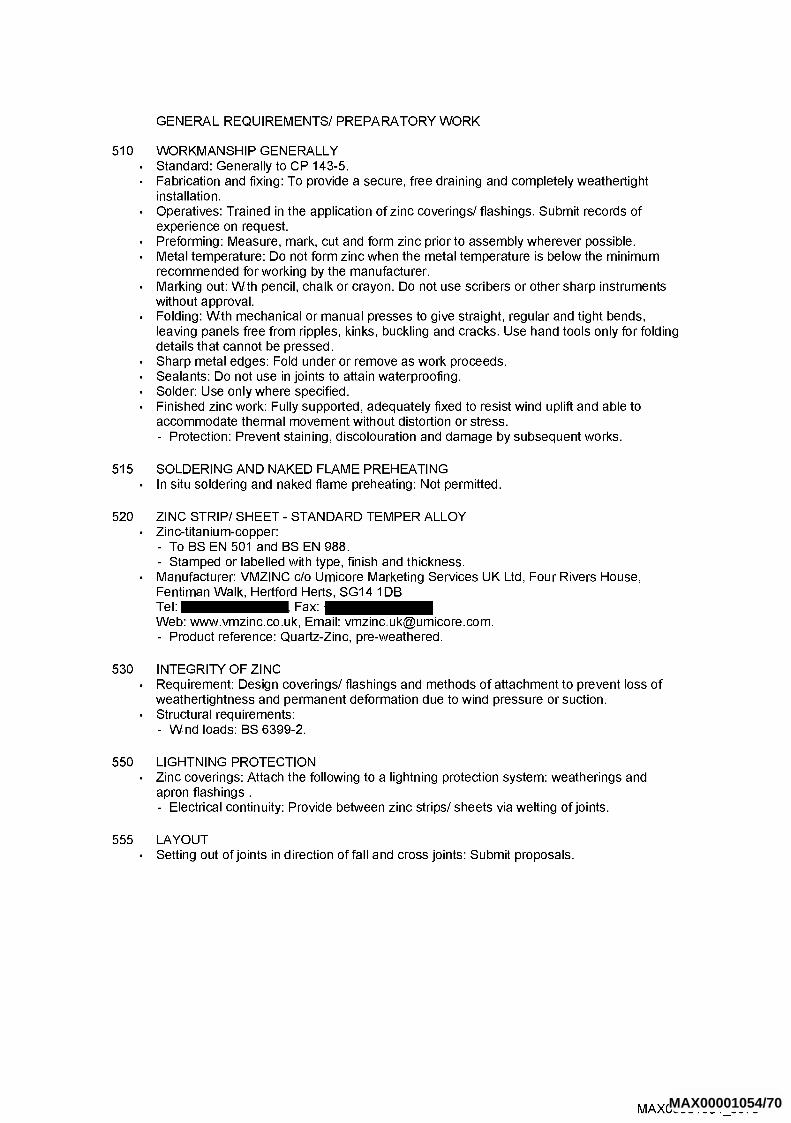
GENERAL REQUIREMENTS/ PREPARATORY WORK
510 WORKMANSHIP GENERALLY • Standard: Generally to CP 143-5. • Fabrication and fixing: To provide a secure, free draining and completely weathertight
installation. • Operatives: Trained in the application of zinc coverings/ flashings. Submit records of
experience on request. • Preforming: Measure, mark, cut and form zinc priorto assembly wherever possible. • Metal temperature: Do not form zinc when the metal temperature is below the minimum
recommended for working by the manufacturer. • Marking out: Wth pencil, chalk or crayon. Do not use scribers or other sharp instruments
without approval. • Folding: Wth mechanical or manual presses to give straight, regular and tight bends,
leaving panels free from ripples, kinks, buckling and cracks. Use hand tools only for folding details that cannot be pressed.
• Sharp metal edges: Fold under or remove as work proceeds. • Sealants: Do not use in joints to attain waterproofing. • Solder: Use only where specified. • Finished zinc work: Fully supported, adequately fixed to resist wind uplift and able to
accommodate thermal movement without distortion or stress. - Protection: Prevent staining, discolouration and damage by subsequent works.
515 SOLDERING AND NAKED FLAME PREHEATING • In situ soldering and naked flame preheating: Not permitted.
520 ZINC STRIP/ SHEET - STANDARD TEMPER ALLOY • Zinc-titanium-copper:
- To BS EN 501 and BS EN 988. - Stamped or labelled with type, finish and thickness.
• Manufacturer: VMZINC c/o Umicore Marketing Services UK Ltd, Four Rivers House, Fentiman Walk, Hertford Herts, SG14 1 DB Tel: ^^^^^^^^^H Fax: Web: www.vmzinc.co.uk, Email: [email protected]. - Product reference: Quartz-Zinc, pre-weathered.
530 INTEGRITY OF ZINC • Requirement: Design coverings/ flashings and methods of attachment to prevent loss of
weathertightness and permanent deformation due to wind pressure or suction. • Structural requirements:
- Wnd loads: BS 6399-2.
550 LIGHTNING PROTECTION • Zinc coverings: Attach the following to a lightning protection system: weatherings and
apron flashings .
- Electrical continuity: Provide between zinc strips/ sheets via welting of joints.
555 LAYOUT • Setting out of joints in direction of fall and cross joints: Submit proposals.
MAX00001054 0070 MAX00001054/70
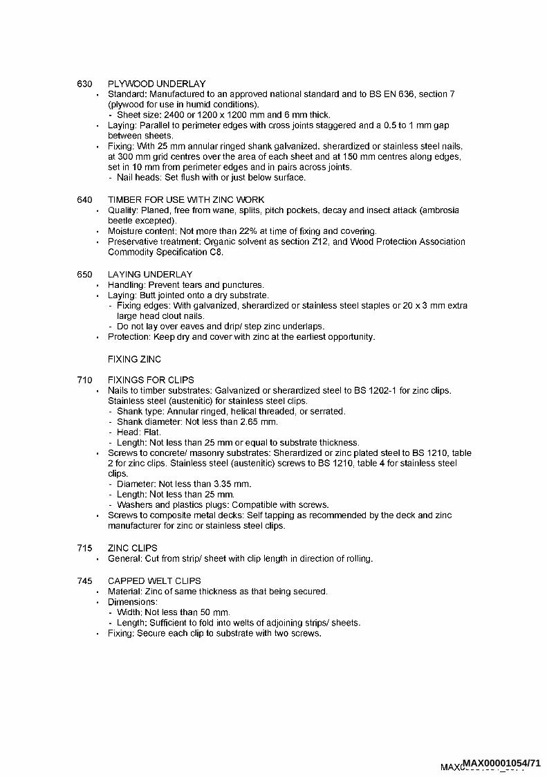
630 PLYWOOD UNDERLAY • Standard: Manufactured to an approved national standard and to BS EN 636, section 7
(plywood for use in humid conditions). - Sheet size: 2400 or 1200 x 1200 mm and 6 mm thick.
• Laying: Parallel to perimeter edges with cross joints staggered and a 0.5 to 1 mm gap between sheets.
• Fixing: Wth 25 mm annular ringed shank galvanized, sherardized or stainless steel nails, at 300 mm grid centres overthe area of each sheet and at 150 mm centres along edges, set in 10 mm from perimeter edges and in pairs across joints. - Nail heads: Set flush with or just below surface.
640 TIMBER FOR USE WITH ZINC WORK • Quality: Planed, free from wane, splits, pitch pockets, decay and insect attack (ambrosia
beetle excepted). • Moisture content: Not more than 22% at time of fixing and covering. • Preservative treatment: Organic solvent as section Z12, and Wood Protection Association
Commodity Specification C8.
650 LAYING UNDERLAY • Handling: Prevent tears and punctures. • Laying: Butt jointed onto a dry substrate.
- Fixing edges: Wth galvanized, sherardized or stainless steel staples or 20 x 3 mm extra large head clout nails.
- Do not lay over eaves and drip/ step zinc underlaps. • Protection: Keep dry and cover with zinc at the earliest opportunity.
FIXING ZINC
710 FIXINGS FOR CLIPS • Nails to timber substrates: Galvanized or sherardized steel to BS 1202-1 for zinc clips.
Stainless steel (austenitic) for stainless steel clips. - Shank type: Annular ringed, helical threaded, or serrated. - Shank diameter: Not less than 2.65 mm. - Head: Flat. - Length: Not less than 25 mm or equal to substrate thickness.
• Screws to concrete/ masonry substrates: Sherardized or zinc plated steel to BS 1210, table 2 for zinc clips. Stainless steel (austenitic) screws to BS 1210, table 4 for stainless steel clips. - Diameter: Not less than 3.35 mm. - Length: Not less than 25 mm. - Washers and plastics plugs: Compatible with screws.
• Screws to composite metal decks: Selftapping as recommended by the deck and zinc manufacturer for zinc or stainless steel clips.
715 ZINC CLIPS • General: Cut from strip/ sheet with clip length in direction of rolling.
745 CAPPED WELT CLIPS • Material: Zinc of same thickness as that being secured. • Dimensions:
- Wdth: Not less than 50 mm. - Length: Sufficient to fold into welts of adjoining strips/ sheets.
• Fixing: Secure each clip to substrate with two screws.
MAX00001054 0071 MAX00001054/71

750 CLIPS FOR FLASHINGS/ CROSS JOINTS • Material: Zinc of same thickness as that being secured. • Dimensions:
- Width: Not less than 50 mm. - Length: To suit detail.
• Fixing: Secure each clip to substrate with two fixings not more than 50 mm from edge of strip/ sheet being fixed. Clips folded around edges of strip/ sheet to be turned over 25 mm.
760 CONTINUOUS CLIPS • Material: Zinc of same thickness as that being secured. • Dimensions:
- Wdth: To suit detail. - Length: Not more than 1800 mm.
• Fixing: To substrate at 200 mm centres. Welt edge of strip/ sheet being fixed to continuous clip and dress down.
JOINTING ZINC
810 FORMING DETAILS • Folds and welts: Form without thinning, or splitting the strip/ sheet. • Thermal movement: Form details with appropriate allowance for movement, without
impairment of security at full expansion or contraction.
815 FREE EDGE DETAILS • Visible feature edges: Finish with 15 mm welts .
850 CAPPED WELT JOINTS • Zinc coverings:
- Joint allowances: Form strips/ sheets with 15 mm open welts each side of 15 mm open joint.
- Fixing: Clips at 400 mm centres. • Cover cap: Zinc of same finish and thickness as that being jointed. Preformed, 50 mm
wide, in lengths to suit detail with any joints lapped 75 mm. Fold around strip/ sheet welts and clips and neatly close.
880 SINGLE LOCK WELT JOINTS • Joint allowance: 100 mm overlap and 50 mm underlap. • Underlap: Welt and secure with clips two per bay. • Overlap: Welt around underlap and clips and dress down.
885 SINGLE LOCK WELT WITH CHECK WELT JOINTS • Underlap: Fold 30 mm anticapillary welt at top edge and secure with clips, two per bay. • Overlap: Welt bottom edge of overlap 30 mm and lay 250 mm over underlap.
- Fixing: Secure welt with continuous clip, 60 mm wide, soldered to underlap.
MAX00001054 0072 MAX00001054/72

H92 Rainscreen cladding
MAX00001054 0073 MAX00001054/73

H92 Rainscreen cladding
TO BE READ WITH PRELIMINARIES/GENERAL CONDITIONS. • Notwithstanding the descriptions of workmanship described in various parts of this
NBS/NES; the contents of BS8000, where applicable, shall take precedence except where workmanship described is superior to BS8000.
• The manufacturers noted within this specification are indicative and may be substituted with similar or equal alternatives.
• Manufacturers should either provide a BRE Global BES6001 Product certificate or supply evidence of a independently certified Environmental Management System.
TENDERING
10 INFORMATION TO BE PROVIDED WITH TENDER • Submit the following cladding particulars:
- Typical plan, section and elevation drawings at suitable scales. - Typical detailed drawings at large scales, including flashing and abutment details . - Technical information and certification demonstrating compliance with specification of
proposed incorporated products and finishes, including thermal insulation . - Certification, reports and calculations demonstrating compliance with specification of
proposed cladding. - Proposals for connections to and support from the primary support structure. - Proposals for primary support structure additional to that shown on preliminary design
drawings. - Schedule of builder's work, special provisions and special attendance by others. - Examples of standard documentation from which project quality plan will be prepared. - Preliminary fabrication and installation method statements and programme. - Proposals for replacing damaged or failed products. - Areas of non-compliance with specification.
MAX00001054 0074 MAX00001054/74

TYPE(S) OF RAINSCREEN CLADDING
120 RAINSCREEN CLADDING TO COLUMNS & EXTERNAL ENVELOPE OF MAIN ENTRANCE CANOPY
• Primary support structure: Reinforced concrete half column with precast concrete cladding. • Rainscreen cladding system:
- Manufacturer: Submit proposals. - Type: Drained and back ventilated.
• Rainscreen panel: - Manufacturer:
KME Architectural Solutions C/O KME Yorkshire Limited East Lancashire Road Kirkby http://www.kmearchitectural.com. Product reference: PROTEUS HR honeycomb rainscreen panel.
- Material: aluminium honeycomb core structurally bonded between two lightweight zinc skins. zinc sheets manufacturer: NedZink B.V., Postbus 2135, 6020 AC Budel, Hoofdstraat 1, 6024 AA Budel-Dorplein, Netherland Tel: ^ ^ H web: nedzink.com
zinc sheets supplier: SIG Zinc & Copper, Warnell, Welton, Carlisle, Cumbria, CA5 7HH Contact: Simon Walker Category Manager [email protected]
- Thickness: To be confirmed by manufacturer. Provide backing panels to easy-to-reach locations if required to pass Category A under BS8200: 1985.
- Finish/ Colour: NedZink NOVA, pre-weathered. - Fasteners: Concealed as recommended by panel manufacturer.
Number and location: As recommended by panel manufacturer to suite location and panel layout.
- Joint type: TBC. - Joint width: 20mm.
• Airgap: min 25 mm. • Secondary support/framing system: Vertical rails with fixing brackets on thermal break
spacers. - Manufacturer: Submit proposals.
Product reference: As recommended by panel manufacturer to suit location and panel layout.
- Material: Aluminium. - Fasteners: As recommended by panel manufacturer.
Number and location: As recommended by panel manufacturer to suite location and panel layout.
• Backing wall: Existing diamond shaped reinforced concrete half column with precast concrete cladding. - Vapour control layer: As clause 780. - Thermal insulation: As clause 776. - Breather membrane: As clause 785.
• Accessories: Include products, fixings and interfaces necessary to complete the fabrication and installation.
MAX00001054 0075 MAX00001054/75
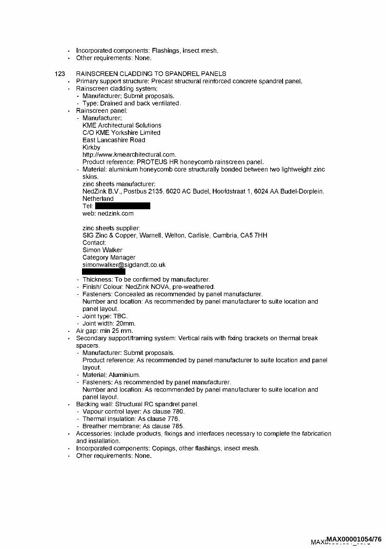
• Incorporated components: Flashings, insect mesh. • Other requirements: None.
123 RAINSCREEN CLADDING TO SPANDREL PANELS • Primary support structure: Precast structural reinforced concrete spandrel panel. • Rainscreen cladding system:
- Manufacturer: Submit proposals. - Type: Drained and back ventilated.
• Rainscreen panel: - Manufacturer:
KME Architectural Solutions C/O KME Yorkshire Limited East Lancashire Road Kirkby http://www.kmearchitectural.com. Product reference: PROTEUS HR honeycomb rainscreen panel.
- Material: aluminium honeycomb core structurally bonded between two lightweight zinc skins. zinc sheets manufacturer: NedZink B.V., Postbus 2135, 6020 AC Budel, Hoofdstraat 1, 6024 AA Budel-Dorplein, Netherland Tel: H ^ H web: nedzink.com
zinc sheets supplier: SIG Zinc & Copper, Warnell, Welton, Carlisle, Cumbria, CA5 7HH Contact: Simon Walker Category Manager ^i^^^ggs i g d a n d t. co. u k
- Thickness: To be confirmed by manufacturer. - Finish/ Colour: NedZink NOVA, pre-weathered. - Fasteners: Concealed as recommended by panel manufacturer.
Number and location: As recommended by panel manufacturer to suite location and panel layout.
- Joint type: TBC. - Joint width: 20mm.
• Airgap: min 25 mm. • Secondary support/framing system: Vertical rails with fixing brackets on thermal break
spacers. - Manufacturer: Submit proposals.
Product reference: As recommended by panel manufacturer to suite location and panel layout.
- Material: Aluminium. - Fasteners: As recommended by panel manufacturer.
Number and location: As recommended by panel manufacturer to suite location and panel layout.
• Backing wall: Structural RC spandrel panel. - Vapour control layer: As clause 780. - Thermal insulation: As clause 776. - Breather membrane: As clause 785.
• Accessories: Include products, fixings and interfaces necessary to complete the fabrication and installation.
• Incorporated components: Copings, other flashings, insect mesh. • Other requirements: None.
MAX00001054 0076 MAX00001054/76
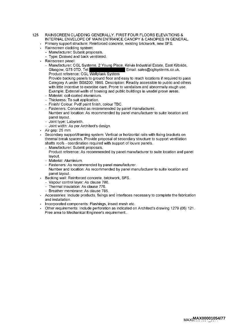
125 RAINSCREEN CLADDING GENERALLY. FIRST FOUR FLOORS ELEVATIONS & INTERNAL ENVELOPE OF MAIN ENTRANCE CANOPY & CANOPIES IN GENERAL.
• Primary support structure: Reinforced concrete, existing brickwork, new SFS. • Rainscreen cladding system:
- Manufacturer: Submit proposals. - Type: Drained and back ventilated.
• Rainscreen panel: - Manufacturer: CGL Systems, 2 Young Place, Kelvin Industrial Estate, East Kilbride,
Glasgow, G75 OTD, T e l : ^ ^ ^ ^ ^ ^ ^ ^ ^ ^ | Email: [email protected]. Product reference: CGL Wallplank System Provide backing panels to ground floor and easy to reach locations if required to pass Category A under BS8200: 1985. Description: Readily accessible to public and others with little incentive to exercise care. Prone to vandalism and abnormally rough use. Example: External walls of housing and public buildings in vandal prone areas.
- Material: coil-coated aluminium. - Thickness: To suit application. - Finish/ Colour: Pvdf paint finish, colour TBC. - Fasteners: Concealed as recommended by panel manufacturer.
Number and location: As recommended by panel manufacturer to suite location and panel layout.
- Joint type: Labyrinth. - Joint width: As per Architect's design.
• Airgap: 25 mm. • Secondary support/framing system: Vertical or horizontal rails with fixing brackets on
thermal break spacers. Provide proposal of secondary structure to support ventilation shafts roofs - coordination required with support of louvre panels. - Manufacturer: Submit proposals.
Product reference: As recommended by panel manufacturer to suite location and panel layout.
- Material: Aluminium. - Fasteners: As recommended by panel manufacturer.
Number and location: As recommended by panel manufacturer to suite location and panel layout.
• Backing wall: Reinforced concrete, brickwork, SFS. - Vapour control layer: As clause 780. - Thermal insulation: As clause 776. - Breather membrane: As clause 785.
• Accessories: Include products, fixings and interfaces necessary to complete the fabrication and installation.
• Incorporated components: Flashings, insect mesh etc. • Other requirements: Include perforation as indicated on Architect's drawing 1279 (06) 121.
Free area to Mechanical Engineer's requirement..
MAX00001054 0077 MAX00001054/77
130 MAJOR NONSTANDARD COMPONENTS 'CROWN' • Manufacturer: VMZINC c/o Umicore Marketing Services UK Ltd, Four Rivers House,
Fentiman Walk, Hertford Herts, SG14 1DB T e l : ^ ^ ^ ^ ^ ^ ^ ^ H F a x : ^ ^ ^ ^ ^ ^ ^ ^ ^ H Web: www.vmzinc.co.uk, Email: [email protected]. - Product reference: VMZINC composite.
• Material: Panel made up of two sheets of zinc that are 0.5 mm thick and thermo-glued on either side of a mineral-rich polyethylene core. - Thickness: 4mm.
• Finish: Quartz-Zinc, pre-weathered. • Fixing:
As recommended by panel manufacturer to suit environmental conditions; Large wedge shaped elements fixed backto galvanized steel subframe to structural engineer's detail installed on top of existing RC columns.
• Other requirements: Include products, fixings and interfaces necessary to complete the fabrication and installation.
GENERAL REQUIREMENTS/PREPARATORY WORK
210 DESIGN • Rainscreen cladding system and associated features: Complete detailed design in
accordance with this specification and the preliminary design drawings and submit before commencement of fabrication.
• Related works: Coordinate in detailed design.
215 DESIGN PROPOSALS • Submission of alternative proposals: Preliminary design drawings indicate intent. Other
reasonable proposals will be considered.
220 SPECIFICATION • Compliance standards: The Centre for Window and Cladding Technology (CWCT)
'Standard for systemised building envelopes'. • Reference information: Forthe duration ofthe contract, keep available atthe design office,
workshop and on site copies of: - The Centre for Wndow and Cladding Technology (CWCT) 'Standard for systemised
building envelopes'. - Publications invoked by the CWCT 'Standard for systemised building envelopes'.
230 INFORMATION TO BE PROVIDED DURING DETAILED DESIGN • Submit the following cladding particulars:
- A schedule of detailed drawings and dates for submission for comment. - A schedule of loads that will be transmitted from the rainscreen cladding to the structure. - Proposed fixing details and systems relevant to the structural design and construction
with methods of adjustment and tolerances. - A schedule of fabrication tolerances/ size tolerances. - A detailed testing programme in compliance with the Main Contract master programme. - A detailed fabrication and installation programme in compliance with the Main Contract
master programme. - Proposals to support outstanding applications for Building Regulation consents or
relaxations.
MAX00001054 0078 MAX00001054/78

232 QUALITY PLAN • Requirement: Submit during detailed design. • Content: In accordance with BS EN ISO 9001 and including the following:
- Name ofthe quality manager. - Quality assessment procedures. - Inspection procedures to be adopted in checking the work. - Stages at which check lists will be used and samples ofthe lists. - List of work procedures on the correct use of materials or components, both off site and
on site. - List of product information with latest revisions. - Subcontractors involved in the work. - Subcontractors quality plans. - Storage, handling, transport and protection procedures. - Procedure for registering and reporting non compliances. - Maintenance procedures and calibration records. - Certification that completed work complies with specification. - Check list register to ensure all items have been inspected and non compliances
discharged.
235 INFORMATION TO BE PROVIDED BEFORE COMMENCEMENT OF TESTING OR MANUFACTURE OF RAINSCREEN CLADDING SYSTEM
• Submit the following cladding particulars: - Detailed drawings to fully describe fabrication and installation. - Detailed calculations to prove compliance with design/ performance requirements. - Project specific fabrication, handling and installation method statements. - Certification for incorporated components manufactured by others confirming their
suitability for proposed locations in the rainscreen cladding. - Recommendations for spare parts for future repairs or replacements. - Recommendations for safe dismantling and recycling or disposal of products.
240 PRODUCT SAMPLES • General: Before commencing detailed design, submit labelled samples of: panels in clause
120, 123, 125 and 130 .
250 SAMPLES OF FIXINGS • General: During detailed design, submit labelled samples of each type of fixing, together
with manufacturers' recommended torque figures.
260 FABRICATION SAMPLES • General: During detailed design, submit samples of: 600x600mm cladding incorporating
horizontal and vertical joints for clause 120, 123, 125 and 130 . Obtain approval of appearance before proceeding.
DESIGN/PERFORMANCE REQUIREMENTS
310 CWCT 'STANDARD FOR SYSTEMISED BUILDING ENVELOPES' • General: Unless specified or agreed otherwise comply with:
Part 2 - Loads, fixings and movement. Part 3 - Air, water and wind resistance. Part 4 - Operable components, additional elements and means of access. Part 5 - Thermal, moisture and acoustic performance. Part 6 - Fire performance. Part 7 - Robustness, durability, tolerances and workmanship.
• Project performance requirements specified in this subsection: Read in conjunction with CWCT performance requirements.
MAX00001054 0079 MAX00001054/79

342 CONTRACTOR'S DESIGN OF RAINSCREEN GENERALLY • Design responsibility: Determine sizes and thickness of panels and types, sizes and
numbers of fixings to suit backing wall and the layout and details of supporting steelwork. • Design standard: To CWCT 'Standard for systemised building envelopes'. • Structural and fire requirements:
- Generally: As section 650. - Modifications: None. - Design: Complete the design in accordance with the designated code of practice to
satisfy specified performance criteria. • Functional requirements: As specified in this section, with fire stopping to the requirements
ofthe 6uilding Regulations. • Additional requirements: As specified in this section.
350 DEFLECTION UNDER WIND LOAD • Requirement: For listed components, at positive and negative applications ofthe design
wind pressure, normal deflections are not to exceed: - Panel support system to be suitable for high traffic area with high risk of vandalism.
• Additional stiffness to CWCT 'Standard for systemised building envelopes' clause 3.5.4.2: N ot allowed.
360 WIND RESISTANCE - CYCLIC LOADING • Requirement: No reduction in the integrity ofthe rainscreen cladding must occur when
subjected to the test sequence given in CWCT 'Standard for systemised building envelopes', clause 8.14.6.
• Test method: As clause 665. - Effective wind pressure: To be established by sub-contractor.
370 APPEARANCE AND FIT • Requirement: Design rainscreen wall:
- To ensure position and alignment of all parts and features as shown on preliminary design drawings.
- To accommodate deviations in the primary support structure. • Primary support structure: 6efore commencing installation of rainscreen cladding system,
carry out survey sufficient to verify that required accuracy of erection can be achieved. - Give notice: Ifthe structure will not allowthe required accuracy or security of erection. - Design tolerances: TBC.
• Rainscreen envelope zone tolerances: - Wdth: TBC.
Critical reference location: TBC. • Maximum permitted component and installation tolerances:
Panel length ±2 mm. Panel width ±1 mm. Secondary support bracket length ±1 mm. Panel tolerance ±2 mm, installation tolerance ±2 mm, overall = ±4 mm.
380 GENERAL MOVEMENT • Requirement: Rainscreen cladding must accommodate anticipated building movements as
follows: Consult Structural Engineer for information .
385 THERMAL MOVEMENT - SERVICE TEMPERATURE RANGES • Requirement: To CWCT 'Standard for systemised building envelopes' clause 2.7.2
amended and/ or with the addition ofthe following: TBC.
MAX00001054 0080 MAX00001054/80
390 AIR PERMEABILITY EXFILTRATION • Requirement: The maximum permissible air exfiltration rate through the building envelope
system must not exceed: 4 m3/(h.m2) at a test pressure of 50 Pa.
410 AIR PERMEABILITY • Permeability class to BS EN 12152: A4.
- Peak test pressure: 600 Pa.
420 WATER PENETRATION • Watertightness class to BS EN 12154: R7.
- Peak test pressure: 600 Pa. • Additional requirements: Insulation attached to backing wall not to be wetted at peak test
pressure.
425 WIND LOAD SERVICEABILITY AND SAFETY OF RAINSCREEN PANELS - CYCLIC WIND LOADING
• Method of determination: By calculation: Submit verification performance.
430 THERMAL PROPERTIES • Method for calculating the thermal transmittance (U-value) ofthe rainscreen wall: Weighted
U-value. • Average U-value of rainscreen wall: 0.15W/m2K. • Method for assessing thermal transmittance (U-value) of assemblies: By calculation.
440 AVOIDANCE OF CONDENSATION • Requirement: Psychrometric conditions under which condensation must not form within or
on the interior surface ofthe rainscreen wall or any surface ofthe wall that is on the warm side of insulation are: - Notional outdoor psychrometric conditions as BS 6229, table A1 . - Notional indoor psychrometric conditions:
Temperature: 20 o C. Relative humidity: 55%. Vapour pressure: 1.28 kPa .
• Wnter interstitial condensate: - Calculated amount (maximum): 0.35 kg/m 2. - Calculated annual net retention: Nil.
450 VAPOUR CONTROL LAYER • Interstitial condensation risk within rainscreen wall: Determine using the method described
in BS 5250 Annex D. If necessary, provide a suitable vapour control layer to ensure that damage and nuisance from interstitial condensation does not occur.
460 SOUND TRANSMITTANCE • Minimum weighted sound reduction index (Rw) to BS EN ISO 717-1:
- Between internal and external surfaces of rainscreen clad wall: 32 dB Rw. • Minimum weighted standardized level difference (DnTw) to BS EN ISO 717-1.
- Between adjacent floors abutting rainscreen clad wall: 45 dB DnTw. - Between adjacent rooms on same floor abutting rainscreen clad wall: 45 dB DnTw.
480 FIRE RESISTANCE OF BACKING WALL TO BS 476- 21 • Minimum periods and criteria: 60 min. integrity, 60 min. insulation .
485 INTERNAL SURFACE SPREAD OF FLAME OF BACKING WALL TO BS 476-7 • Class: 0 .
MAX00001054 0081 MAX00001054/81
490 CAVITY FIRE BARRIERS TO BS 476-20 • Requirement: To resist the passage of flame and smoke for not less than 30 min. integrity,
30 min, insulation TBC .
495 DURABILITY • Relevant agents or degradation mechanisms: To be determined by sub-contractor. • Design life ofthe rainscreen cladding system: Not less than 50 years. • Secondary components: Submit details togetherwith required maintenance regime,
replacement periods and methods of replacement.
497 LIGHTNING PROTECTION SYSTEM • Rainscreen components used as part of lightning protection system: Consult services
engineer.
TESTING
510 COMPARISON (TYPE) TESTING • Verification of performance:
- Submit: Certification and reports satisfying CWCT 'Standard for systemised building envelopes', clause 1.5.5 items a and b.
• Commencement of fabrication and installation of rainscreen cladding: Not until test results and reports showing compliance with this specification have been submitted.
685 SITE HOSE TEST • Requirement: To CWCT 'Standard for systemised building envelopes', 'Standard test
methods for building envelopes' Section 9. - Joints to be tested: Horizontal, vertical and corner joints over 5% of cladding area.
Location to be agreed.
PRODUCTS
710 ALUMINIUM ALLOY FRAMING SECTIONS • Standards: To BS EN 755 alloy EN AW-6063 and suitable for the specified finish. • Structural members: To comply with BS EN 1999-1-1, -3 and -4.
712 ALUMINIUM ALLOY SHEET • Standards: To BS EN 485, BS EN 515 and BS EN 573. • Alloy, temper and thickness: Suitable forthe application and specified finish.
715 CARBON STEEL FRAMING SECTIONS/ REINFORCEMENT • Standards: To the relevant parts of BS 7668, BS EN 10029, BS EN 10025, and BS EN
10210. • Thickness: Suitable for the application, and for galvanizing or other protective coating.
730 MECHANICAL FIXINGS - MATERIAL REQUIREMENTS • Stainless steel: To BS EN ISO 3506 grade A2 generally, grade A4 when used in severely
corrosive environments. • Carbon steel: To BS 4190 and suitable for galvanizing or other protective coating. • Aluminium: To BS EN 755.
MAX00001054 0082 MAX00001054/82
735 FIXINGS AND FASTENERS • Type and use: Reviewed and approved by manufacturers. Submit confirmatory information
on request. • Dimensions: Not less than recommended by their manufacturers. • Adjustment capability: Sufficient in three dimensions to accommodate primary support
structure and rainscreen cladding fabrication/ installation tolerances.
760 GASKETS • Material:
- Noncellular rubber to BS 4255-1. - Cellular rubber to ASTM-C509.
• Durability: Resistant to oxidation, ozone and UV degradation.
765 WEATHERSTRIPPING OF OPENING UNITS • Material: • - Noncellular rubber to BS 4255-1.
- Cellular rubber to ASTM-C509. - Polypropylene woven pile, silicone treated.
• Installation: Fixed in undercut grooves in framing sections using preformed corners with any joints in the length.
770 GENERAL SEALANTS • Selection: In accordance with BS 6213 from:
- Silicone. - One part polysulfide. - Two part polysulfide. - One ortwo part polyurethane.
• Classification and requirements: To BS EN ISO 11600. • Reaction to contact products and finishes: Stable and compatible.
776 THERMAL INSULATION • Material: Zero ODP rigid polyisocyanurate insulation board. BRE Green Guide rating A+. • Manufacturer: Celotex Ltd, Lady Lane Industrial Estate, Hadleigh Ipswich Suffolk IP7 6BA
Web: celotex.co.uk, Email: [email protected]. - Product reference: FRSOOO aluminium foil faced both sides.
- Conductivity: 0.021 W/mk. • Thickness: Not less than 150mm for spandrel panels and SOmm for columns.
- Required performance: Referto clause 430. • Recycled content: Manufacturer to confirm. • Fixing: Attached to the outer face or supported within the backing wall so as not to bulge,
sag, delaminate or detach during installation or in situ during the life ofthe rainscreen cladding.
MAX00001054 0083 MAX00001054/83
780 VAPOUR CONTROL LAYER • Material: Reinforced polyethylene with High Tensile scrim reinforcement.
- Minimum vapour resistance: 250 MN s/g. - Manufacturer: Industrial Textiles & Plastics Ltd, Stillington Road, Easingwold, York,
Y061 3FA. Tel: ^^^^^^M- F a x ^ ^ ^ ^ ^ ^ J . Email: [email protected] Web: www.powerlon.com / www.itpltd.com. Product reference: Powerlon® 150 VCL Reinforced Vapour Control Layer.
• Continuity: No breaks and with the minimum of joints. - Penetrations and abutments: Seal to vapour control layer. If necessary, prime substrates
to achieve full bond. - Sheet laps: Not less than 150 mm, seal with tape. Prime substrates as necessary to
achieve full bond. • Sheet tape: Double sided sealant with vapour resistivity not less than the vapour control
sheet. - Size (width and thickness): A continuous double row of 15mm x 1.5mm Powerbond butyl
sealing tape spaced 75mm apart is recommended for overlap sealing. It is essential that all surfaces are clean and dry. The number of joints should be kept to a minimum by using the full width ofthe membrane. All joints should be firmly pressed together using a hand-held pressure roller to ensure that the double sided tape has adhered properly to the barrier.
• Sheet repairs and punctures: Seal with lapped patch of vapour control membrane and continuous band of sealant tape along edges.
785 BREATHER MEMBRANE • Material: Reinforced polyethylene with High Tensile scrim reinforcement. • Manufacturer: Industrial Textiles & Plastics Ltd, Stillington Road, Easingwold, York, Y061
3FA. Tel: ^ ^ ^ ^ ^ ^ ^ | F a x : ^ ^ ^ ^ ^ ^ ^ | Email: [email protected] Web: www.powerlon.com / www.itpltd.com. - Product reference: Powerlon® Airbarrier.
• Continuity: No breaks. Minimize joints. - Penetrations and abutments: Attach to breather membrane with tape. Achieve full bond. - Laps: Not less than 150 mm, bond with tape. Achieve full bond.
• Tape: As recommended by breather membrane manufacturer. • Repairs: Lapped patch of breather membrane material secured with continuous band of
tape on edges.
• Junctions at flashings, sills, gutters etc. Overlap and allow free drainage to exterior.
FABRICATION AND INSTALLATION 910 GENERALLY
• Electrolytic corrosion: Take necessary measures to prevent. • Identification of products: Mark or tag to facilitate identification during assembly, handling,
storage and installation. Do not mark surfaces visible in the complete installation.
912 METALWORK • Requirement: As section Z11, unless specified otherwise in this section.
925 SEALANT APPLICATION • Requirement: As section Z22, unless specified otherwise in this section.
930 ASSEMBLY • Location: Carry out as much assembly as possible in the workshop. • Joints: Other than movement joints and designed open joints, must be rigidly secured,
reinforced where necessary and fixed with hairline abutments. • Displacement of components in assembled units: Submit proposals for reassembly on site.
MAX00001054 0084 MAX00001054/84

960 PRELIMINARY RAINSCREEN CLADDING INSTALLATION • Requirement: Complete an area of cladding as set out below for inspection and approval of
appearance. Approved facade section .
970 RAINSCREEN CLADDING INSTALLATION • Tightening mechanical fasteners: To manufacturer's recommended torque figures. Do not
overtighten fasteners intended to permit differential movement. • Protective coverings: Remove only where necessary to facilitate installation and from
surfaces which will be inaccessible on completion.
975 WELDING • In situ welding: Not permitted.
980 INTERFACES • Installation: Locate flashings, closers etc. correctly and neatly overlap cladding to form a
weathertight junction.
985 DAMAGE • Repairs: Do not repair cladding without approval.
- Approval: Will not be given where the proposed repair will impair performance or appearance.
• Record of repairs: Prepare schedule or record on drawings for inclusion in the maintenance manual.
995 MAINTENANCE • Maintenance manual: Incorporate details within the Building Manual in accordance with
CWCT 'Standard for systemised building envelopes', clause 7.6.1. - Materials certification and test reports to be included: As requested.
MAX00001054 0085 MAX00001054/85

J Waterproofing
MAX00001054 0086 MAX00001054/86

J10 Cementitious mortar tanking/ damp proofing
MAX00001054 0087 MAX00001054/87
J10 Cementitious mortar tanking/ damp proofing
TO BE READ WITH PRELIMINARIES/ GENERAL CONDITIONS Notwithstanding the descriptions of workmanship described in various parts of this NBS/NES; the contents of BS8000, where applicable, shall take precedence except where workmanship described is superior to BS8000. The manufacturers noted within this specification are indicative and may be substituted with similar or equal alternatives. Manufacturers should either provide a BRE Global BES6001 Product certificate or supply evidence of a independently certified Environmental Management System.
TYPES OF TANKING/ DAMP PROOFING
111 POLYMER MODIFIED CEMENTITIOUS SLURRY COATING GENERALLY • Substrate: Concrete. • Manufacturer: RIW Limited, Arc House, Terrace Road South, Binfield, RG42 4PZ
Tel Fax E-mail: [email protected], Web : www.riw.co.uk. - Product reference: RIW Cementseal.
• Coats (excluding dubbing out): - Number (excluding keying mixes): Two. - Thickness: 2mm.
• Other requirements: RIW Cementseal Primer required for horizontal surfaces.
MAX00001054 0088 MAX00001054/88
121 CEMENT: SAND MORTAR WITH PROPRIETARY WATERPROOF ADMIXTURE BOXING SHOWERS, ACCESSIBLE CHANGE
• Substrate: Cement screed, Sand/cement render. • Waterproof admixture manufacturer: Mapei U.K. Ltd. Mapei House Steel Park Road -
Halesowen, West Midlands, B62 SHD Tel. ^^^^^^^H, F a x ^ ^ ^ ^ ^ ^ ^ ^ H Email: [email protected], Web: www.mapei.com. - Product reference: Mapelastic Two-component Flexible Cementitious Mortar.
• Preparation of substrates: [ Generally: All surfaces to be sound and perfectly clean; absorbent surfaces must
be dampened beforehand with water; Concrete: Remove all cement laitance, flaky parts and traces of powder, grease, oil
and form release agents; remove damaged parts and rust and repair with Mapegrout or Planitop 400;
Cementitious screeds: Setting cracks or cracks by plastic or hygrometric shrinkage must be filled beforehand with Eporip; to level out deviations up to 3cm use Planitop Fast 330;
Gypsum plaster: To be sufficiently cured, well bonded and free from all dust and paint; surface to be treated with Primer G by Mapei UK Ltd priorto application of Mapelastic].
• Mixing: [ Pour liquid component (B) into a suitable container, then slowly add powder component (A) while stirring with a mechanical mixer until perfectly homogeneous mix is achieved;low-speed mechanical mixer to be used to prevent to much air being dragged into mixture; make sure no powder remains stuck to sides or bottom ofthe container].
• Application: [ - Apply within 60 minutes of being mixed - Smooth off prepared surfaces by applying a thin first coat with smooth towel; - Second coat to be applied on top of first coat while this is still fresh; - Final thickness no less then 2mm].
• Accessories: [ - Mapeband TPE to be used to seal structural joints and joints subject to high dynamic
stress; - Mapeband to be used to waterproof check joints, fillet joints between horizontal and
vertical elements; - Special kit from Drain range to be used to seal drain holes].
• Curing: [Allow for 5 days curing period before laying tiles]. • Finishes: [
- Ceramic tiles to be laid using MAPEI cementitious adhesives; - Grout joints between tiles with suitable cementitious grout; - Seal expansion joints with suitable flexible sealant from MAPEI range.].
• Other requirements: [ - Not to be sued for thick coatings (more than 2mm per coat); - Not to be applied at temperatures below +8°C; - Cement, aggregates and water not to be added; - Protect from rain and water spillage for the first 24 hours ofthe application].
MATERIALS AND MAKING OF MORTAR
330 MOVEMENT JOINT SYSTEM • Manufacturer: RIW Limited, Arc House, Terrace Road South, Binfield, RG42 4PZ
Tel :^^^^^^^H, Fax : ^ ^ ^ ^ ^ ^ ^ | E-mail: [email protected], Web : www.riw.co.uk. - Product reference: RIW Cementjoint, embedded between 2 1mm thick coats. - Application: As section Z22.
MAX00001054 0089 MAX00001054/89
PREPARING SUBSTRATES
410 SUITABILITY OF SUBSTRATES • Preparation generally: To tanking mortar/ admixture manufacturer's recommendations. • Stability and soundness: Free from movement, and loose or weak areas that will cause
failure of tanking. • Key: To achieve firm adhesion of tanking. • Contamination: Free from previous coatings and contaminants including dirt, dust,
efflorescence, mould, oil, paint and plaster. • Cracks, porous patches and other defective areas subject to water pressure and liable to
admit water: Control and seal using waterproof mortar recommended by the tanking mortar manufacturer.
• Holes/ Recesses for fixings (where permitted): Prepared to receive fasteners. • Openings and chases: Prepared, including sleeves for pipe penetrations and chases to
receive waterproofing compounds/ sealants.
420 PREPARATION OF MORTAR JOINTS AND CAVITIES • Mortar joints: Rake out to a depth of 12 mm (minimum).
- Debris: Remove and flush out with water. - Fill: Repoint with waterproof mortar to the tanking mortar manufacturer's
recommendations. • Blow holes, cavities, cracks, etc: Remove loose material and fill flush using waterproof
mortar recommended bythe tanking mortar manufacturer.
430 TANKING INTEGRITY • Penetrations for fixings, services, etc: Not permitted .
EXECUTION
510 APPLICATION GENERALLY • Application methods and coating sequence: As recommended by the tanking mortar/
admixture manufacturer to achieve a water resistant structure.
520 JOINTS/ JUNCTIONS AND PENETRATIONS • Abutments, joints and active cracks: Sealed and watertight.
- Movement joints: Centred over joints in substrate and extended through waterproof coating and finishes.
- Daywork joints in successive coatings: Staggered and lapped. - Angled joints: Not permitted.
• Penetrations: Watertight.
530 APPEARANCE OF TANKING • Render/ Screed coatings: Even and consistent. Free from rippling, hollows, ridges, cracks
and crazing. - Accuracy: A true plane, to correct line and level. Walls and reveals plumb and square
with neat arrises • Thin slurry coatings: Consistent and free from hollows, cracks and crazing. Suitable to
receive specified finish.
551 CURING AND DRYING • General: Prevent premature setting, uneven drying and cracking of each coat. • Curing coatings: Prevent evaporation from surface by the use of primer as recommended
by tanking mortar manufacturer. - Curing period (minimum): Normally overnight, temperature dependent.
MAX00001054 0090 MAX00001054/90

560 PROTECTION . Mechanical damage: Prevent impact and abrasion. . Application of protective coatings/ linings: After completion of curing.
MAX00001054_0091 MAX00001054/91

JSO Liquid applied tanking/damp proofing
MAX00001054 0092 MAX00001054/92

JSO Liquid applied tanking/ damp proofing
TO BE READ WITH PRELIMINARIES/GENERAL CONDITIONS • Notwithstanding the descriptions of workmanship described in various parts of this
NBS/NES; the contents of BS8000, where applicable, shall take precedence except where workmanship described is superior to BS8000.
• The manufacturers noted within this specification are indicative and may be substituted with similar or equal alternatives.
• Manufacturers should either provide a BRE Global BES6001 Product certificate or supply evidence of a independently certified Environmental Management System.
TYPES OF TANKING/ DAMP PROOFING
130 COLD APPLIED DAMP PROOFING GENERALLY • Substrate: In situ concrete slab. • Primer: Not required. • Coating: Epoxy resin.
- Manufacturer: RIW Limited, Arc House, Terrace Road South, Binfield, RG42 4PZ Te l : ^ ^ ^ ^ ^ ^ H . Fax E-mail: [email protected], Web : www.riw.co.uk. Product reference: Toughseal.
- Application: Two coats. • Reinforcement: RIW Flexiseal in accordance with manufacturer's recommendations. • Blinding:
- Generally not required; - Key for mechanical bond: RIW aggregate, Grad 1 where required; - wearing surface: RIW Aggregate Grade 2 where required.
EXECUTION
205 SUITABILITY OF SUBSTRATE • Substrates generally:
- Smooth, even textured, clean, dry and frost free. - Wthin tolerances for level and surface regularity. - Vertical and horizontal surfaces: Correctly prepared and free from irregularities.
• Curing period for concrete substrates (minimum): 7 days. • Moisture content and stability of substrate: Must not impair integrity of finished tanking/
damp proofing. • Preliminary work: Complete including:
- Chases. - External angles. - Formation of upstands and kerbs. - Movement joints. - Penetrations/ Outlets.
MAX00001054 0093 MAX00001054/93

211 COATING APPLICATION • Preparation : Make good to surfaces to be coated. • Adjacent surfaces exposed to view in finished work: Protect. • Coatings:
- Uniform, continuous coverage. - Do not allow to pool in hollows. - Firmly adhered to substrate and free from imperfections. - Prevent damage to finished coatings.
• Penetrations: Completely impervious. • Final covering: Apply as soon as possible after coating has hardened.
220 COLD APPLIED COATINGS • Thinning: Not permitted unless recommended by manufacturer. • Successive coats:
- Allow to dry before applying next. - Apply at right angles to previous.
235 MODIFIED COATINGS • Air and surface temperatures: Do not apply if below minimum recommended by coating
manufacturer. • Curing: Keep dry until fully cured.
260 JUNCTIONS WITH DPCS • Dpcs: Clean, all edges fully exposed. • Application: Fully coat dpc and overlap adjacent surfaces by (minimum) 75 mm.
270 BLINDING • Coatings: Blind whilst tacky .
• Surplus material: Remove when coatings are completely dry.
COMPLETION 310 INSPECTION
• Interim and final inspections: Submit reports.
320 ELECTRONIC INTEGRITY TEST • Testing authority: Submit proposals. • Timing of test: Priorto, and on completion of access by other trades. • Condition of coating prior to testing:
- Complete to a stage where integrity can be tested. - Surface: Clean.
• Test results and waterproof integrity certificate: Submit on completion of testing.
340 BACKFILLING TO EXTERNAL COATINGS • Timing: Carry out as soon as possible after tanking and protection are complete.
MAX00001054 0094 MAX00001054/94

J31 Liquid applied waterproof roof coatings
MAX00001054 0095 MAX00001054/95
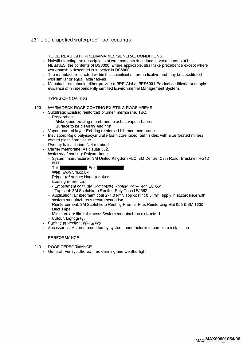
J31 Liquid applied waterproof roof coatings
TO BE READ WITH PRELIMINARIES/GENERAL CONDITIONS. • Notwithstanding the descriptions of workmanship described in various parts of this
NBS/NES; the contents of BS8000, where applicable, shall take precedence except where workmanship described is superior to BS8000.
• The manufacturers noted within this specification are indicative and may be substituted with similar or equal alternatives.
• Manufacturers should either provide a BRE Global BES6001 Product certificate or supply evidence of a independently certified Environmental Management System.
TYPES OF COATING
120 WARM DECK ROOF COATING EXISTING ROOF AREAS • Substrate: Existing reinforced bitumen membrane, TBC.
- Preparation: •Make good existing membrane to act as vapour barrier •Surface to be clean try and firm.
• Vapour control layer: Existing reinforced bitumen membrane. • Insulation: Rigid polyisocyanurate foam core faced, both sides, with a perforated mineral
coated glass fibre tissue. • Overlay to insulation: Not required. • Carrier membrane: As clause 352.
Waterproof coating: Polyurethane. - System manufacturer: 3M United Kingdom PLC, 3M Centre, Cain Road, Bracknell RG12
SHT ^ ^ ^ ^ ^ ^ T e L ^ ^ ^ ^ ^ ^ ^ I Fax: ^ ^ ^ ^ ^ ^ H Web: www.3m.co.uk. Primer reference: None required. Coating reference: - Embedment coat: 3M Scotchkote Roofing Poly-Tech EC 661 - Top coat: 3M Scotchkote Roofing Poly-Tech UV662.
- Application: Embedment coat 2x1.0 l/m2, Top coat 1x0.51 Im2; apply in accordance with system manufacturer's recommendation.
- Reinforcement: 3M Scotchkote Roofing Premier Plus Reinforcing Mat 055 & 3M 1900 Duct Tape.
- Minimum dry film thickness: System manufacturer's standard. - Colour: Light grey.
• Surface protection: Walkways.
• Accessories: As recommended by system manufacturer to complete installation.
PERFORMANCE 210 ROOF PERFORMANCE
• General: Firmly adhered, free draining and weathertight.
MAX00001054 0096 MAX00001054/96
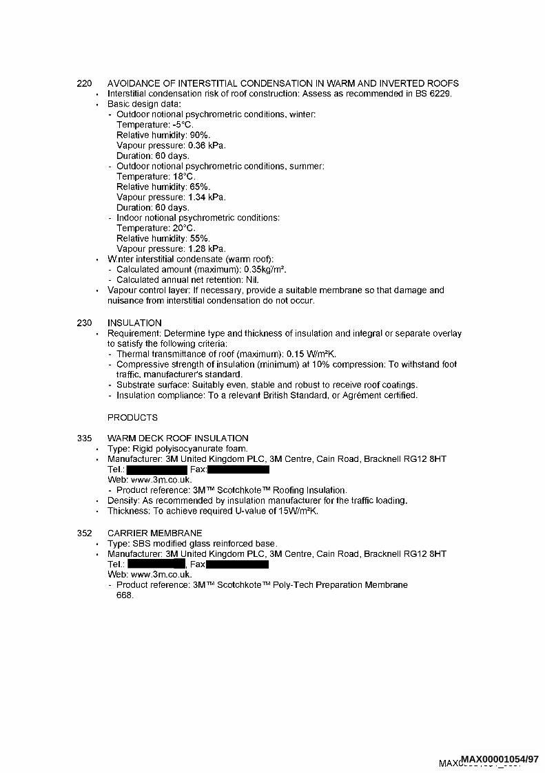
220 AVOIDANCE OF INTERSTITIAL CONDENSATION IN WARM AND INVERTED ROOFS • Interstitial condensation risk of roof construction: Assess as recommended in BS 6229. • Basic design data:
- Outdoor notional psychrometric conditions, winter: Temperature: -5 0 C. Relative humidity: 90%. Vapour pressure: 0.36 kPa. Duration: 60 days.
- Outdoor notional psychrometric conditions, summer: Temperature: 18 0C. Relative humidity: 65%. Vapour pressure: 1.34 kPa. Duration: 60 days.
- Indoor notional psychrometric conditions: Temperature: 20 o C. Relative humidity: 55%. Vapour pressure: 1.28 kPa.
• Wnter interstitial condensate (warm roof): - Calculated amount (maximum): 0.35kg/m2. - Calculated annual net retention: Nil.
• Vapour control layer: If necessary, provide a suitable membrane so that damage and nuisance from interstitial condensation do not occur.
230 INSULATION • Requirement: Determine type and thickness of insulation and integral or separate overlay
to satisfy the following criteria: - Thermal transmittance of roof (maximum): 0.15 W/m 2K. - Compressive strength of insulation (minimum) at 10% compression: To withstand foot
traffic, manufacturer's standard. - Substrate surface: Suitably even, stable and robust to receive roof coatings. - Insulation compliance: To a relevant British Standard, or Agrement certified.
PRODUCTS
335 WARM DECK ROOF INSULATION • Type: Rigid polyisocyanurate foam. • Manufacturer: 3M United Kingdom PLC, 3M Centre, Cain Road, Bracknell RG12 SHT
T e l . : ^ ^ ^ ^ ^ ^ ^ | F a x : ^ ^ ^ ^ ^ ^ ^ H Web: www.3m.co.uk. - Product reference: 3M™ Scotchkote™ Roofing Insulation.
• Density: As recommended by insulation manufacturer forthe traffic loading. • Thickness: To achieve required U-value of 15W/m2K.
352 CARRIER MEMBRANE • Type: SBS modified glass reinforced base. • Manufacturer: 3M United Kingdom PLC, 3M Centre, Cain Road, Bracknell RG12 SHT
Tel.: ^ ^ ^ ^ ^ ^ H , F a x ^ ^ ^ ^ ^ ^ ^ B Web: www.3m.co.uk. - Product reference: 3M™ Scotchkote™ Poly-Tech Preparation Membrane
668.
MAX00001054 0097 MAX00001054/97
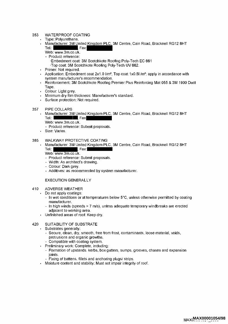
353 WATERPROOF COATING • Type: Polyurethane. • Mani£acturer3iym PLC, 3M Centre, Cain Road, Bracknell RG12 SHT
Tel.: ^^ H Fax:| Web: www.3m.co.uk. - Product reference:
•Embedment coat: 3M Scotchkote Roofing Poly-Tech EC 661 •Top coat: 3M Scotchkote Roofing Poly-Tech UV662.
• Primer: Not required. • Application: Embedment coat 2x1.0 l/m2, Top coat 1x0.51 Im2; apply in accordance with
system manufacturer's recommendation. • Reinforcement: 3M Scotchkote Roofing Premier Plus Reinforcing Mat 055 & 3M 1900 Duct
Tape. • Colour: Light grey. • Minimum dry film thickness: Manufacturer's standard. • Surface protection: Not required.
357 PIPE COLLARS • Manufacturer: 3M United Kingdom PLC, 3M Centre, Cain Road, Bracknell RG12 SHT
Tel.: ^ ^ ^ ^ ^ ^ H . F a x ^ ^ ^ ^ ^ ^ ^ | Web: www.3m.co.uk. - Product reference: Submit proposals.
• Size: Varies.
385 WALKWAY PROTECTIVE COATING • Manufacturer: 3M United Kingdom PLC, 3M Centre, Cain Road, Bracknell RG12 SHT
Tel.: ^ ^ ^ ^ ^ ^ ^ F a x : ^ ^ ^ ^ ^ ^ ^ | Web: www.3m.co.uk. - Product reference: Submit proposals. - Wdth: As architect's drawing. - Colour: Dark grey. - Additives: as recommended by system manufacturer.
EXECUTION GENERALLY
410 ADVERSE WEATHER • Do not apply coatings:
- In wet conditions or at temperatures below 5 0C, unless otherwise permitted by coating manufacturer.
- In high winds (speeds > 7 m/s), unless adequate temporary windbreaks are erected adjacent to working area.
• Unfinished areas of roof: Keep dry.
420 SUITABILITY OF SUBSTRATE • Substrates generally:
- Secure, clean, dry, smooth, free from frost, contaminants, loose material, voids, protrusions and organic growths.
- Compatible with coating system. • Preliminary work: Complete, including:
- Formation of upstands, kerbs, box gutters, sumps, grooves, chases and expansion joints.
- Fixing of battens, fillets and anchoring plugs/ strips. • Moisture content and stability: Must not impair integrity of roof.
MAX00001054 0098 MAX00001054/98
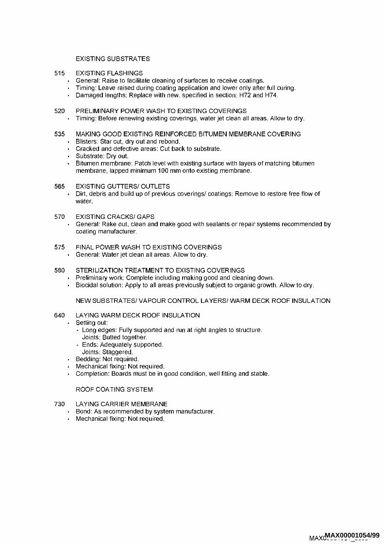
EXISTING SUBSTRATES
515 EXISTING FLASHINGS • General: Raise to facilitate cleaning of surfaces to receive coatings. • Timing: Leave raised during coating application and lower only after full curing. • Damaged lengths: Replace with new, specified in section: H72 and H74.
520 PRELIMINARY POWER WASH TO EXISTING COVERINGS • Timing: Before renewing existing coverings, water jet clean all areas. Allow to dry.
535 MAKING GOOD EXISTING REINFORCED BITUMEN MEMBRANE COVERING • Blisters: Star cut, dry out and rebond. • Cracked and defective areas: Cut back to substrate. • Substrate: Dry out. • Bitumen membrane: Patch level with existing surface with layers of matching bitumen
membrane, lapped minimum 100 mm onto existing membrane.
565 EXISTING GUTTERS/ OUTLETS • Dirt, debris and build up of previous coverings/ coatings: Remove to restore free flow of
water.
570 EXISTING CRACKS/ GAPS • General: Rake out, clean and make good with sealants or repair systems recommended by
coating manufacturer.
575 FINAL POWER WASH TO EXISTING COVERINGS • General: Water jet clean all areas. Allow to dry.
580 STERILIZATION TREATMENT TO EXISTING COVERINGS • Preliminary work: Complete including making good and cleaning down. • Biocidal solution: Apply to all areas previously subject to organic growth. Allow to dry.
NEW SUBSTRATES/VAPOUR CONTROL LAYERS/WARM DECK ROOF INSULATION
640 LAYING WARM DECK ROOF INSULATION • Setting out:
- Long edges: Fully supported and run at right angles to structure. Joints: Butted together.
- Ends: Adequately supported. Joints: Staggered.
• Bedding: Not required. • Mechanical fixing: Not required.
• Completion: Boards must be in good condition, well fitting and stable.
ROOF COATING SYSTEM 730 LAYING CARRIER MEMBRANE
• Bond: As recommended by system manufacturer. • Mechanical fixing: Not required.
MAX00001054 0099 MAX00001054/99

740 MOVEMENT JOINTS IN SUBSTRATE • Debonding tape: Apply over movement joints. • Reinforcement strip: Apply over debonding tape.
- Bedding: Preliminary coating application. - Joints: Lap in length. - Bond: Continuous over whole surface, with no air pockets. - Condition at completion: Smooth.
760 APPLICATION OF ROOF COATINGS • Thickness: Monitor by taking wet/ dry film thickness readings. • Continuity: Maintain full thickness of coatings around angles, junctions and features. • Rainwater outlets: Form with watertight joints. • Drainage systems: Do not allow liquid coatings to enter piped rainwater or foul systems. • Edge trims: Apply coatings over horizontal leg of trim and into recess.
770 SKIRTINGS AND UPSTANDS • Top edges of coatings: Where not protected by flashings, apply into chases cut to a
minimum depth of 10 mm. • Completion of chases: When coatings are fully cured, prepare chase and apply sealant as
section Z22. - Sealant: To BS EN ISO 11600.
Colour: As coating.
SURFACING
890 APPLYING WALKWAY PROTECTIVE COATING • Coverage per coat (minimum): as recommended by system manufacturer. • Surface coverage: Even and full.
COMPLETION
910 INSPECTION • Coating surfaces: Check when cured for discontinuities.
- Defective areas: Apply another coating.
920 ELECTRONIC ROOF INTEGRITY TEST • Testing authority: Submit proposals. • Timing of test: Priorto, and on completion of access by other trades. • Condition of roof priorto testing:
- Coating: Complete to a stage where integrity can be tested. - Surface: Clean.
• Test results: Submit. • Waterproof integrity certificate: On completion of testing, submit.
940 COMPLETION • Roof areas: Clean.
- Outlets: Clear. - Flashings: Dressed into place.
• Work necessary to provide a weathertight finish: Complete. • Storage of materials on finished surface: Not permitted. • Completed coatings: Protect against damage.
MAX00001054 0100 MAX00001054/100

J40 Flexible sheet waterproofing/ damp proofing
MAX00001054 0101 MAX00001054/101
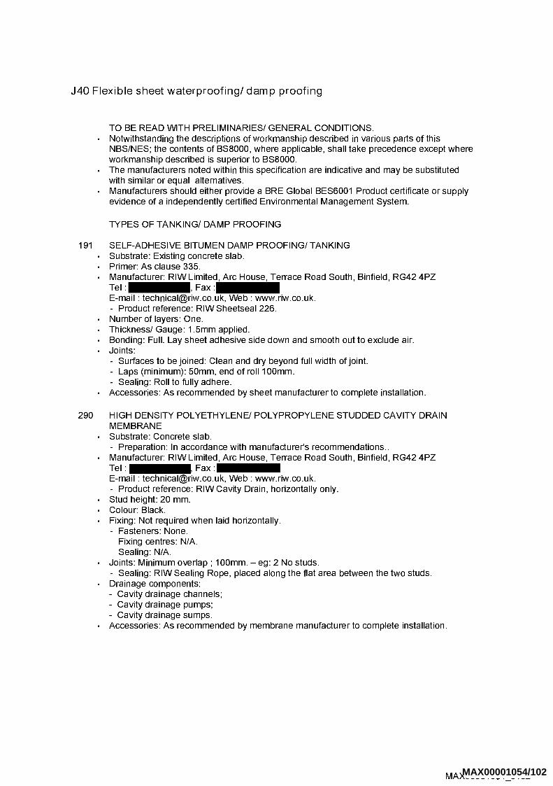
J40 Flexible sheet waterproofing/ damp proofing
TO BE READ WITH PRELIMINARIES/ GENERAL CONDITIONS. Notwithstanding the descriptions of workmanship described in various parts of this NBS/NES; the contents of BS8000, where applicable, shall take precedence except where workmanship described is superior to BS8000. The manufacturers noted within this specification are indicative and may be substituted with similar or equal alternatives. Manufacturers should either provide a BRE Global BES6001 Product certificate or supply evidence of a independently certified Environmental Management System.
TYPES OF TANKING/ DAMP PROOFING
191 SELF-ADHESIVE BITUMEN DAMP PROOFING/ TANKING • Substrate: Existing concrete slab. • Primer: As clause 335. • Manufacturer: RIW Limited, Arc House, Terrace Road South, Binfield, RG42 4PZ
Tel : ^ ^ ^ ^ ^ ^ ^ | , Fax E-mail: [email protected], Web : www.riw.co.uk. - Product reference: RIW Sheetseal 226.
• Number of layers: One. • Thickness/ Gauge: 1.5mm applied. • Bonding: Full. Lay sheet adhesive side down and smooth out to exclude air. • Joints:
- Surfaces to be joined: Clean and dry beyond full width of joint. - Laps (minimum): 50mm, end of roll 100mm. - Sealing: Roll to fully adhere.
• Accessories: As recommended by sheet manufacturer to complete installation.
290 HIGH DENSITY POLYETHYLENE/ POLYPROPYLENE STUDDED CAVITY DRAIN MEMBRANE
• Substrate: Concrete slab. - Preparation: In accordance with manufacturer's recommendations..
• Manufacturer: RIW Limited, Arc House, Terrace Road South, Binfield, RG42 4PZ Te l : Fax : ^^^^^^H E-mail: [email protected], Web : www.riw.co.uk. - Product reference: RIW Cavity Drain, horizontally only.
• Stud height: 20 mm. • Colour: Black. • Fixing: Not required when laid horizontally.
- Fasteners: None. Fixing centres: N/A. Sealing: N/A.
• Joints: Minimum overlap ; 100mm. - eg: 2 No studs. - Sealing: RlWSealing Rope, placed along the flat area between the two studs.
• Drainage components: - Cavity drainage channels; - Cavity drainage pumps; - Cavity drainage sumps.
• Accessories: As recommended by membrane manufacturer to complete installation.
MAX00001054 0102 MAX00001054/102
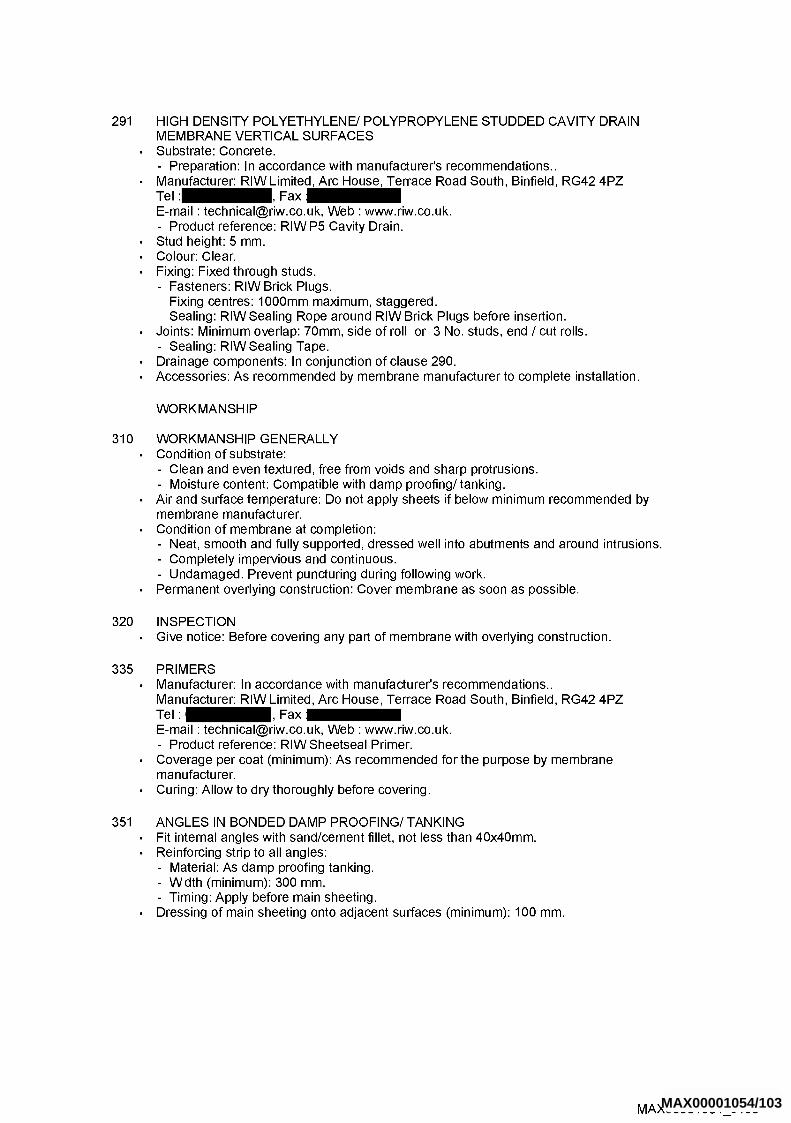
291 HIGH DENSITY POLYETHYLENE/ POLYPROPYLENE STUDDED CAVITY DRAIN MEMBRANE VERTICAL SURFACES
• Substrate: Concrete. - Preparation: In accordance with manufacturer's recommendations..
• Manufacturer: RIW Limited, Arc House, Terrace Road South, Binfield, RG42 4PZ Tel : ^ ^ ^ ^ ^ ^ ^ H i Fax E-mail: [email protected], Web : www.riw.co.uk. - Product reference: RIWP5 Cavity Drain.
• Stud height: 5 mm. • Colour: Clear. • Fixing: Fixed through studs.
- Fasteners: RIW Brick Plugs. Fixing centres: 1000mm maximum, staggered. Sealing: RlWSealing Rope around RIW Brick Plugs before insertion.
• Joints: Minimum overlap: 70mm, side of roll or 3 No. studs, end / cut rolls. - Sealing: RlWSealing Tape.
• Drainage components: In conjunction of clause 290. • Accessories: As recommended by membrane manufacturer to complete installation.
WORKMANSHIP
310 WORKMANSHIP GENERALLY • Condition of substrate:
- Clean and even textured, free from voids and sharp protrusions. - Moisture content: Compatible with damp proofing/ tanking.
• Air and surface temperature: Do not apply sheets if below minimum recommended by membrane manufacturer.
• Condition of membrane at completion: - Neat, smooth and fully supported, dressed well into abutments and around intrusions. - Completely impervious and continuous. - Undamaged. Prevent puncturing during following work.
• Permanent overlying construction: Cover membrane as soon as possible.
320 INSPECTION • Give notice: Before covering any part of membrane with overlying construction.
335 PRIMERS • Manufacturer: In accordance with manufacturer's recommendations..
Manufacturer: RIW Limited, Arc House, Terrace Road South, Binfield, RG42 4PZ Tel : Fax E-mail: [email protected], Web : www.riw.co.uk. - Product reference: RIW Sheetseal Primer.
• Coverage per coat (minimum): As recommended forthe purpose by membrane manufacturer.
• Curing: Allow to dry thoroughly before covering.
351 ANGLES IN BONDED DAMP PROOFING/ TANKING • Fit internal angles with sand/cement fillet, not less than 40x40mm. • Reinforcing strip to all angles:
- Material: As damp proofing tanking. - Wdth (minimum): 300 mm. - Timing: Apply before main sheeting.
• Dressing of main sheeting onto adjacent surfaces (minimum): 100 mm.
MAX00001054 0103 MAX00001054/103
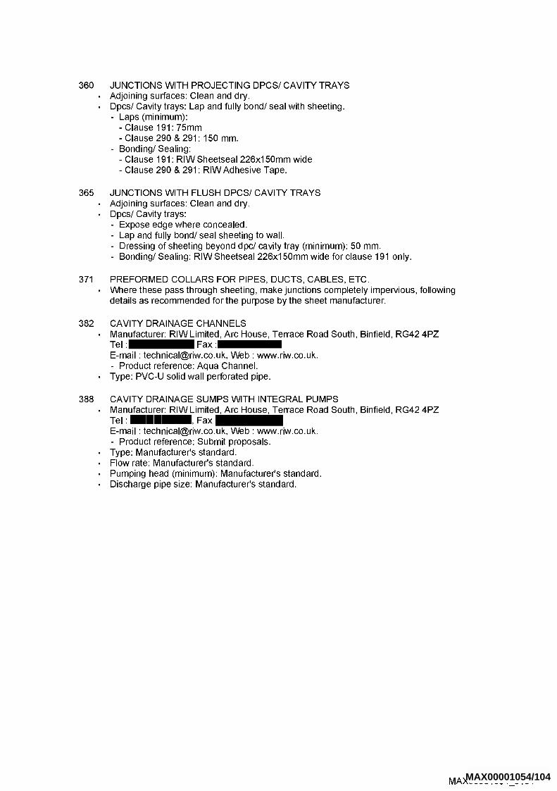
360 JUNCTIONS WITH PROJECTING DPCS/ CAVITY TRAYS • Adjoining surfaces: Clean and dry. • Dpcs/ Cavity trays: Lap and fully bond/ seal with sheeting.
- Laps (minimum): - Clause 191: 75mm - Clause 290 & 291: 150 mm.
- Bonding/Sealing: - Clause 191: RIW Sheetseal 226x150mm wide - Clause 290 & 291: RIW Adhesive Tape.
365 JUNCTIONS WITH FLUSH DPCS/ CAVITY TRAYS • Adjoining surfaces: Clean and dry. • Dpcs/ Cavity trays:
- Expose edge where concealed. - Lap and fully bond/ seal sheeting to wall. - Dressing of sheeting beyond dpc/ cavity tray (minimum): 50 mm. - Bonding/Sealing: RIW Sheetseal 226x1 SOmm wide for clause 191 only.
371 PREFORMED COLLARS FOR PIPES, DUCTS, CABLES, ETC. • Where these pass through sheeting, make junctions completely impervious, following
details as recommended forthe purpose by the sheet manufacturer.
382 CAVITY DRAINAGE CHANNELS • Manufacturer: RIW Limited, Arc House, Terrace Road South, Binfield, RG42 4PZ
Tel :^^^H Fax : ^ ^ ^ ^ ^ ^ ^ H E-mail: [email protected], Web : www.riw.co.uk. - Product reference: Aqua Channel.
• Type: PVC-U solid wall perforated pipe.
388 CAVITY DRAINAGE SUMPS WITH INTEGRAL PUMPS • Manufacturer: RIW Limited, Arc House, Terrace Road South, Binfield, RG42 4PZ
Te l : ^^ H. Fax ^^^H E-mail: [email protected], Web : www.riw.co.uk. - Product reference: Submit proposals.
• Type: Manufacturer's standard. • Flow rate: Manufacturer's standard. • Pumping head (minimum): Manufacturer's standard. • Discharge pipe size: Manufacturer's standard.
MAX00001054 0104 MAX00001054/104

K Linings/Sheathing/Dry partitioning
MAX00001054 0105 MAX00001054/105

K10 Plasterboard dry linings/ partit ions/ ceilings
MAX00001054 0106 MAX00001054/106
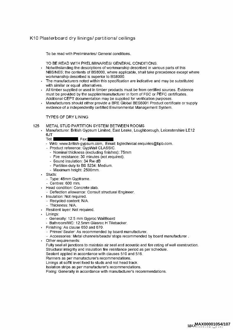
K10 Plasterboard dry linings/ partitions/ ceilings
To be read with Preliminaries/ General conditions.
TO BE READ WITH PRELIMINARIES/ GENERAL CONDITIONS. • Notwithstanding the descriptions of workmanship described in various parts of this
NBS/NES; the contents of BS8000, where applicable, shall take precedence except where workmanship described is superior to BS8000.
• The manufacturers noted within this specification are indicative and may be substituted with similar or equal alternatives.
• All timber supplied or used in timber products must be from certified sources. Evidence must be provided by the supplier/manufacturer in form of FSC or PEFC certificates. Additional CEPT documentation may be supplied for verification purposes.
• Manufacturers should either provide a BRE Global BES6001 Product certificate or supply evidence of a independently certified Environmental Management System.
TYPES OF DRY LINING
125 METAL STUD PARTITION SYSTEM BETWEEN ROOMS • Manufacturer: British Gypsum Limited, East Leake, Loughborough, Leicestershire LE12
6JT Tel: ^^^^^^M, Fax :^^^^^^^H. - Web: www.british-gypsum.com, Email: [email protected]. - Product reference: GypWall CLASSIC.
- Nominal thickness (excluding finishes): 75mm - Fire resistance: 30 minutes (not required). - Sound insulation: 34 Rw dB - Partition duty to BS 5234: Medium. - Maximum height: 2500mm.
• Studs: - Type: 48mm Gypframe. - Centres: 600 mm.
• Head condition: Concrete slab. - Deflection allowance: Consult structural Engineer.
• Insulation: Not required. - Recycled content: N/A. - Thickness: N/A.
• Resilient layer: Not required. • Linings:
- Generally: 12.5 mm Gyproc WailBoard - Bathroom/WC: 12.5mm Glasroc H Tilebacker.
• Finishing: As clause 650 and 670. - Primer/Sealer: As recommended by board manufacturer. - Accessories: Metal channels/beads/ stops recommended by board manufacturer.
• Other requirements: Fully seal all junctions to maintain air seal and acoustic and fire rating of wall construction. Structural integrity and insulation fire resistance period as per schedule. Sealant applied in accordance with clauses 510 and 516. Runners as per manufacturer's recommendations. Linings at soffit level fixed to studs and not head track. Isolation strips as per manufacturer's recommendations. Fixing: Generally in accordance with manufacturer's recommendations.
MAX00001054 0107 MAX00001054/107

126 METAL STUD PARTITION SYSTEM BETWEEN ROOMS • Manufacturer: British Gypsum Limited, East Leake, Loughborough, Leicestershire LE12
6JT Tel: ^^^^^^H< F a x ^ ^ ^ ^ ^ ^ ^ | - Web: www.british-gypsum.com, Email: [email protected]. - Product reference: GypWall CLASSIC.
- Nominal thickness (excluding finishes): 97mm - Fire resistance: 30 minutes. - Sound insulation: 36 Rw dB - Partition duty to BS 5234: Medium. - Maximum height: 3600mm.
• Studs: - Type: 70mm Gypframe. - Centres: 600 mm.
• Head condition: Concrete slab. - Deflection allowance: Consult structural Engineer.
• Insulation: Not required. - Recycled content: N/A. - Thickness: N/A.
• Resilient layer: Not required. • Linings:
- Generally: 12.5 mm Gyproc WailBoard - Bathrooms/WC/Shower area: 12.5mm Glasroc H Tilebacker.
• Finishing: As clause 650 and 670. - Primer/Sealer: As recommended by board manufacturer. - Accessories: Metal channels/beads/ stops recommended by board manufacturer.
• Other requirements: Fully seal all junctions to maintain air seal and acoustic and fire rating of wall construction. Structural integrity and insulation fire resistance period as per schedule. Sealant applied in accordance with clauses 510 and 516. Runners as per manufacturer's recommendations. Linings at soffit level fixed to studs and not head track. Isolation strips as per manufacturer's recommendations. Fixing: Generally in accordance with manufacturer's recommendations.
MAX00001054 0108 MAX00001054/108
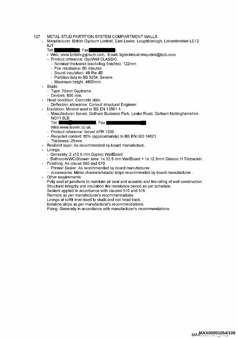
127 METAL STUD PARTITION SYSTEM COMPARTMENT WALLS • Manufacturer: British Gypsum Limited, East Leake, Loughborough, Leicestershire LE12
6JT T e L ^ ^ ^ ^ ^ ^ H , F a x ^ ^ ^ ^ ^ ^ ^ | . - Web: www.british-gypsum.com, Email: [email protected]. - Product reference: GypWall CLASSIC.
- Nominal thickness (excluding finishes): 122mm - Fire resistance: 60 minutes. - Sound insulation: 49 Rw dB - Partition duty to BS 5234: Severe. - Maximum height: 4600mm.
• Studs: - Type: 70mm Gypframe. - Centres: 600 mm.
• Head condition: Concrete slab. - Deflection allowance: Consult structural Engineer.
• Insulation: Mineral wool to BS EN 13501-1. - Manufacturer: Isover, Gotham Business Park, Leake Road, Gotham Nottinghamshire
NG11 OLB, Tel: ^^B^^^^^^^H. Fax : ^ ^ H ^ ^ ^ ^ ^ ^ ^ H Web:www.isover. co.uk.
- Product reference: Isover APR 1200 - Recycled content: 80% (approximately) to BS EN ISO 14021. - Thickness: 25mm.
• Resilient layer: As recommended by board manufacture. • Linings:
- Generally: 2 x12.5 mm Gyproc WallBoard - Bathroom/WC/Shower area: 1x 12.5 mm WailBoard + 1x 12.5mm Glasroc H Tilebacker.
• Finishing: As clause 650 and 670. - Primer/ Sealer: As recommended by board manufacturer. - Accessories: Metal channels/beads/ stops recommended by board manufacturer.
• Other requirements: Fully seal all junctions to maintain air seal and acoustic and fire rating of wall construction. Structural integrity and insulation fire resistance period as per schedule. Sealant applied in accordance with clauses 510 and 516. Runners as per manufacturer's recommendations. Linings at soffit level fixed to studs and not head track. Isolation strips as per manufacturer's recommendations. Fixing: Generally in accordance with manufacturer's recommendations.
MAX00001054 0109 MAX00001054/109
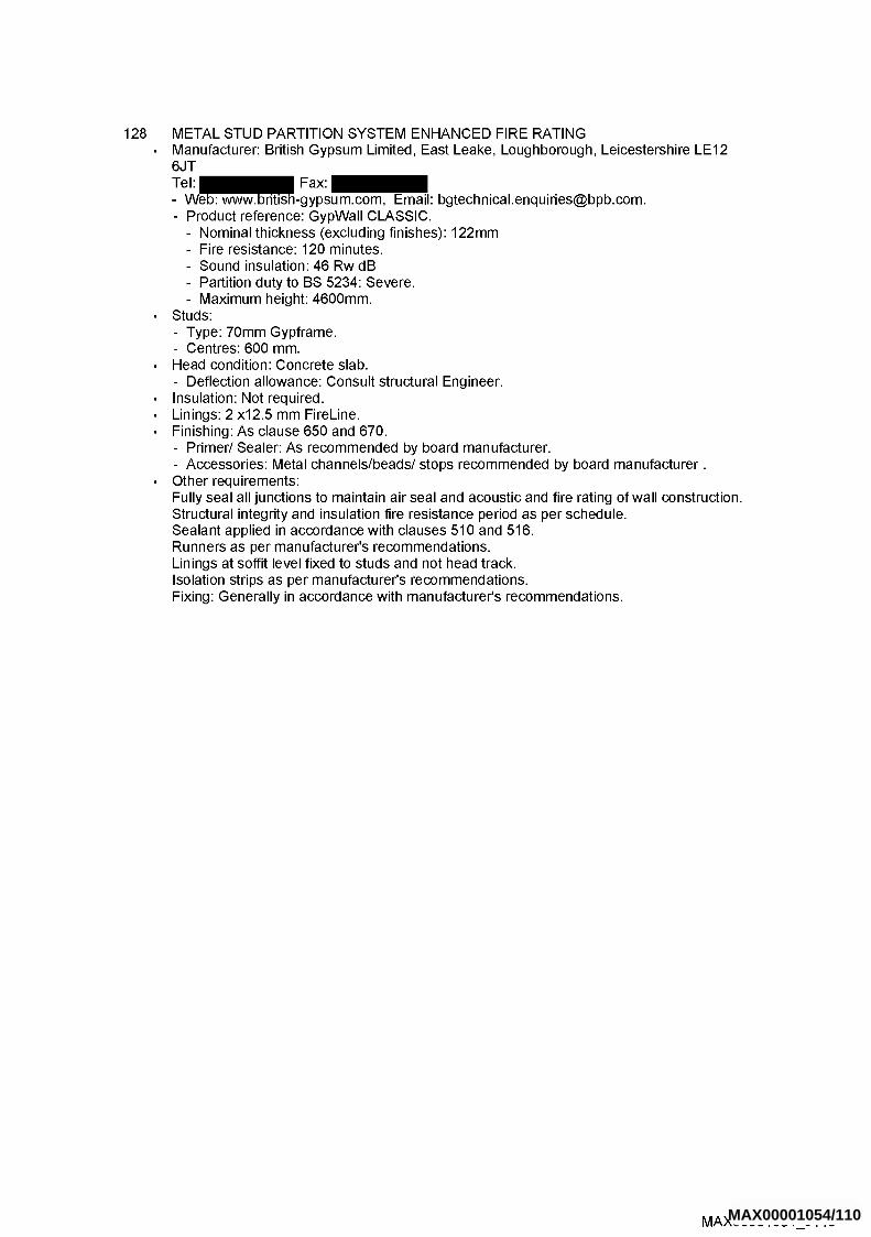
128 METAL STUD PARTITION SYSTEM ENHANCED FIRE RATING • Manufacturer: British Gypsum Limited, East Leake, Loughborough, Leicestershire LE12
6JT
- WeDMwwv^ntisn-gypsum.com, Email: [email protected]. - Product reference: GypWall CLASSIC.
- Nominal thickness (excluding finishes): 122mm - Fire resistance: 120 minutes. - Sound insulation: 46 Rw dB - Partition duty to BS 5234: Severe. - Maximum height: 4600mm.
• Studs: - Type: 70mm Gypframe. - Centres: 600 mm.
• Head condition: Concrete slab. - Deflection allowance: Consult structural Engineer.
• Insulation: Not required. • Linings: 2 x12.5 mm FireLine. • Finishing: As clause 650 and 670.
- Primer/Sealer: As recommended by board manufacturer. - Accessories: Metal channels/beads/ stops recommended by board manufacturer.
• Other requirements: Fully seal all junctions to maintain air seal and acoustic and fire rating of wall construction. Structural integrity and insulation fire resistance period as per schedule. Sealant applied in accordance with clauses 510 and 516. Runners as per manufacturer's recommendations. Linings at soffit level fixed to studs and not head track. Isolation strips as per manufacturer's recommendations. Fixing: Generally in accordance with manufacturer's recommendations.
MAX00001054 0110 MAX00001054/110
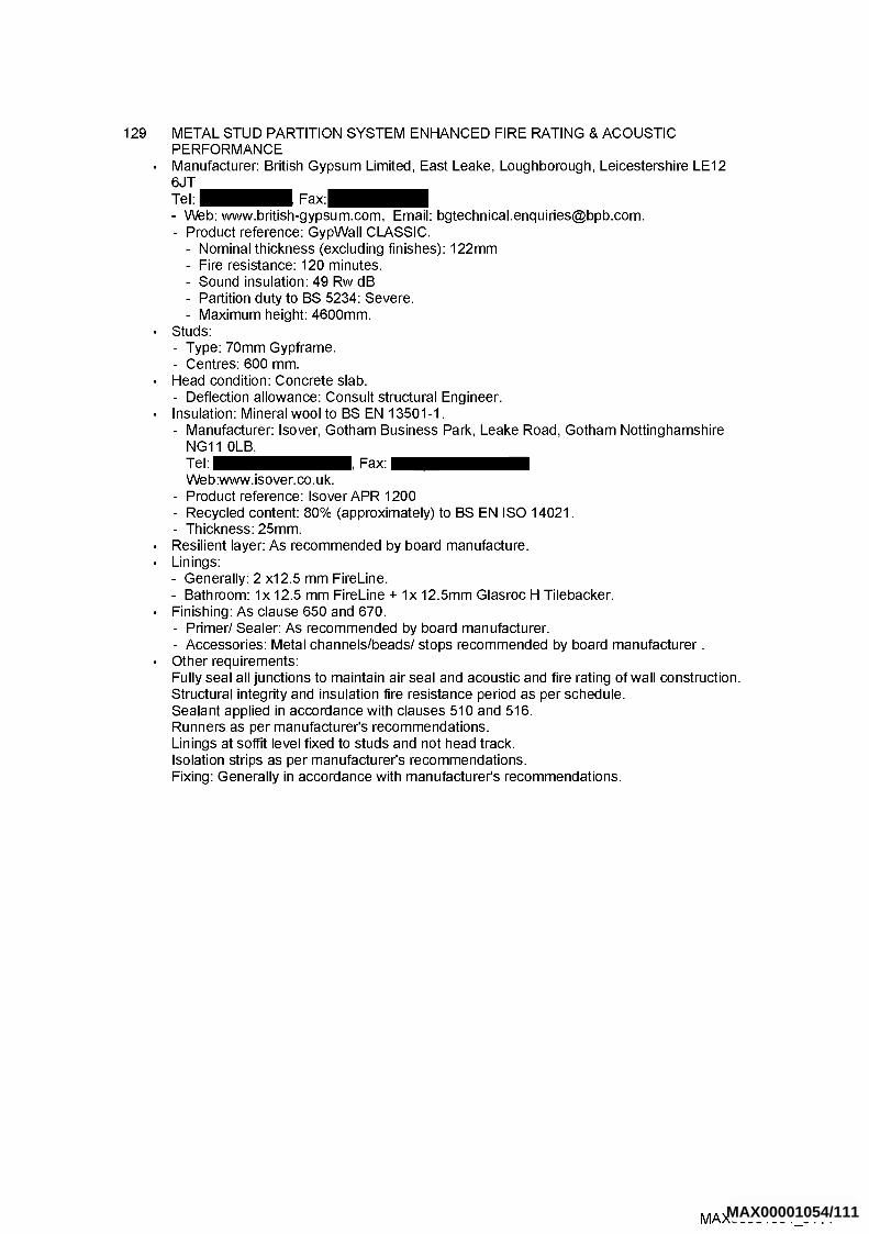
129 METAL STUD PARTITION SYSTEM ENHANCED FIRE RATING & ACOUSTIC PERFORMANCE
• Manufacturer: British Gypsum Limited, East Leake, Loughborough, Leicestershire LE12
Tel: ^ ^ ^ ^ ^ ^ ^ | , Fax:^^^^^^^B - Web: www.british-gypsum.com, Email: [email protected]. - Product reference: GypWall CLASSIC.
- Nominal thickness (excluding finishes): 122mm - Fire resistance: 120 minutes. - Sound insulation: 49 Rw dB - Partition duty to BS 5234: Severe. - Maximum height: 4600mm.
• Studs: - Type: 70mm Gypframe. - Centres: 600 mm.
• Head condition: Concrete slab. - Deflection allowance: Consult structural Engineer.
• Insulation: Mineral wool to BS EN 13501-1. - Manufacturer: Isover, Gotham Business Park, Leake Road, Gotham Nottinghamshire
NG11 OLB, Tel: ^H^^^^^^^H, Fax: ^^H^^^^^^^H Web:www.isover. co.uk.
- Product reference: Isover APR 1200 - Recycled content: 80% (approximately) to BS EN ISO 14021. - Thickness: 25mm.
• Resilient layer: As recommended by board manufacture. • Linings:
- Generally: 2 x12.5 mm FireLine. - Bathroom: 1x 12.5 mm FireLine + 1x 12.5mm Glasroc H Tilebacker.
• Finishing: As clause 650 and 670. - Primer/ Sealer: As recommended by board manufacturer. - Accessories: Metal channels/beads/ stops recommended by board manufacturer.
• Other requirements: Fully seal all junctions to maintain air seal and acoustic and fire rating of wall construction. Structural integrity and insulation fire resistance period as per schedule. Sealant applied in accordance with clauses 510 and 516. Runners as per manufacturer's recommendations. Linings at soffit level fixed to studs and not head track. Isolation strips as per manufacturer's recommendations. Fixing: Generally in accordance with manufacturer's recommendations.
MAX00001054 0111 MAX00001054/111

135 METAL STUD PARTITION SYSTEM SHAFT WALL • Manufacturer: British Gypsum Limited, East Leake, Loughborough, Leicestershire LE12
6JT Tel: ^ ^ ^ ^ ^ ^ H F a x : ^ ^ ^ ^ ^ ^ ^ | - Web: www.british-gypsum.com, Email: [email protected]. - Product reference: ShaftWall.
- Nominal thickness (excluding finishes): 119mm - Fire resistance: 60 minutes. - Sound insulation: 47 Rw dB - Partition duty to BS 5234: Severe. - Maximum height: 6000mm.
• Studs: - Type: 92mm Gypframe T Stud + Gypframe Retaining Channels. - Centres: As recommended by board manufacture.
• Head condition: Concrete slab. - Deflection allowance: Consult structural Engineer.
• Insulation: Mineral wool to BS EN 13501-1. - Manufacturer: Isover, Gotham Business Park, Leake Road, Gotham Nottinghamshire
NG11 OLB, Tel: Fax: ^^B^^^^^^^H Web:www.isover. co.uk.
- Product reference: Isover APR 1200 - Recycled content: 80% (approximately) to BS EN ISO 14021. - Thickness: 25mm.
• Resilient layer: As recommended by board manufacture. • Linings:
- Gyproc CoreBoard between studs secured with retaining channels. - Generally: 2 x 12.5mm FireLine. - Bathroom: 1x 12.5 mm FireLine + 1x 12.5mm Glasroc H Tilebacker.
• Finishing: As clause 650 and 670. - Primer/ Sealer: As recommended by board manufacturer. - Accessories: Metal channels/beads/ stops recommended by board manufacturer.
• Other requirements: Fully seal all junctions to maintain air seal and acoustic and fire rating of wall construction. Structural integrity and insulation fire resistance period as per schedule. Sealant applied in accordance with clauses 510 and 516. Runners as per manufacturer's recommendations. Linings at soffit level fixed to studs and not head track. Isolation strips as per manufacturer's recommendations. Fixing: Generally in accordance with manufacturer's recommendations.
MAX00001054 0112 MAX00001054/112

155 WALL LINING SYSTEM (METAL STUDS) TO EXTERNAL WALLS • Manufacturer: British Gypsum Limited, East Leake, Loughborough, Leicestershire LE12
6JT Tel: ^ ^ ^ ^ ^ H Fax: Web: www.british-gypsum.com, Email: [email protected]. - Product reference: GypLyner IWL
- Nominal thickness (excluding finishes): Approx. 160mm - Maximum height: 3600mm.
• Studs: - Type: 92 I 90 TStud. - Centres: 600 mm.
• Cavity between wall and studs: 100 mm. • Unbraced height (maximum): 3600. • Head condition: Concrete slab.
- Deflection allowance: Consult structural Engineer. • Insulation: Mineral wool to BS EN 13501-1
- Manufacturer: Isover, Gotham Business Park, Leake Road, Gotham Nottinghamshire NG11 OLB, Tel: Fax: Web:www.isover. co.uk. - Product Reference: SF2 Steel Frame Infill Batt. - Recycled content: 80% (approximately) to BS EN ISO 14021. - Thickness: 100mm.
• Vapour control layer: Refer to group J10. • Resilient layer: As recommended by board manufacturer. • Linings: ThermaLine Super
- Thickness: 70mm. - Thermal performance of lining + insulation between studs 0.21 W/m 2K.
• Access units: As clause 430. • Finishing: As clause 650 and 670.
- Primer/ Sealer: As recommended by board manufacturer. - Accessories: Metal channels/beads/ stops recommended by board manufacturer.
• Other requirements: Fully seal all junctions to maintain air seal and acoustic and fire rating of wall construction.
180 WALL LINING TO CURTAIN WALLING • Manufacturer: British Gypsum Limited, East Leake, Loughborough, Leicestershire LE12
T e l : ^ ^ ^ ^ ^ ^ ^ | F a x : ^ ^ ^ ^ ^ ^ ^ H Web: www.british-gypsum.com, Email: [email protected]. - Product reference: Gyproc WailBoard lining board.
• Wall: PPC aluminium curtain walling system, refer to section H11. • Furring centres: 400 mm fixed to CW transoms between mullions. • Linings: 12.5mm Gyproc WallBoar. • Finishing: As clause 650 and 670.
- Primer/Sealer: As recommended by board manufacturer. - Accessories: As recommended by board manufacturer to complete installation.
• Other requirements: Fully seal all junctions to maintain air seal and acoustic rating of wall construction. Sealant applied in accordance with clauses 510.
MAX00001054 0113 MAX00001054/113

185 WALL LINING SYSTEM (ADHESIVE) GENERALLY • Manufacturer: British Gypsum Limited, East Leake, Loughborough, Leicestershire LE12
6JT T e l : ^ ^ ^ ^ ^ ^ ^ | F a x : ^ ^ ^ ^ ^ ^ ^ | Web: www.british-gypsum.com, Email: [email protected]. - Product reference: DriLyner BASIC.
• Wall: Concrete, block work or brickwork. • Adhesive method: Dabs as clause 620 and 625. • Linings: 12.5mm Gyproc WailBoard. • Finishing: As clause 650 and 670.
- Primer/Sealer: As recommended by board manufacturer. - Accessories: Corner beads and stop beads recommended by board manufacturer.
• Other requirements: Sealant applied in accordance with clauses 510.
186 WALL LINING SYSTEM (ADHESIVE) TO EXISTING EXTERNAL WALL • Manufacturer: British Gypsum Limited, East Leake, Loughborough, Leicestershire LE12
6JT Tel: ^ ^ ^ ^ ^ ^ H , F a x ^ ^ ^ ^ ^ ^ ^ B Web: www.british-gypsum.com, Email: [email protected]. - Product reference: DriLyner RF.
• Wall: Concrete, block work or brickwork. • Adhesive method: Dabs as clause 620 and 625. • Linings: 90mm ThermaLine super. • Thermal performance: TBC. • Finishing: As clause 650 and 670.
- Primer/Sealer: As recommended by board manufacturer. - Accessories: Corner beads and stop beads recommended by board manufacturer.
• Other requirements: Sealant applied in accordance with clauses 510.
MAX00001054 0114 MAX00001054/114

220 PROPRIETARY SUSPENDED CEILING SYSTEM • Manufacturer: British Gypsum Limited, East Leake, Loughborough, Leicestershire LE12
6JT T e l : ^ ^ ^ ^ ^ ^ H , F a x : ^ ^ ^ ^ ^ ^ B Web: www.british-gypsum.com, Email: [email protected]. - Product reference: CasoLine MF.
• Lining board: 15mm Gyproc WailBoard. - Finishing: Seamless jointing. - Accessories: Metal beads/ stops recommended by lining board manufacturer.
• Suspension system: - Grid centres: Primary grid centres 1200 mm; Secondary grid centres 600 mm. - Hangers: FEA1 Steel Angle.
- Primary grid: MF7 Primary Support Channel. - Secondary grid: MF5 Ceiling Section. Length: To give ceiling soffit height above finished floor level of approx. 3000mm to 3500 mm, referto architect's drawings. Centres:
•Hangers -1200 mm •Primary and secondary grid - see above.
Top fixing: To suit structural soffit of insitu concrete slab. • Insulation: Not required.
- Thickness: Not applicable. • Access units: as clause 430. • Integrated services fittings: None. • Accessories/Other requirements:
Movement control joints to manufacturer's recommendations; The ceiling system must safely support loads including services fittings as per Services Engineers Documentation; Fixing of services in accordance with frame and lining manufacturer's recommendations; Fire stopping around service penetrations as section P12.
225 PROPRIETARY CEILING LINING SYSTEM • Manufacturer: British Gypsum Limited, East Leake, Loughborough, Leicestershire LE12
6JT T e l : ^ ^ ^ ^ ^ ^ ^ | F a x : ^ ^ ^ ^ ^ ^ ^ | Web: www.british-gypsum.com, Email: [email protected]. - Product reference: GypLyner Universal.
• Lining board: 15mm Gyproc WailBoard. - Finishing: Seamless jointing. - Accessories: Metal beads/ stops recommended by lining board manufacturer.
• Suspension system: - Grid centres: 600 mm. - Hangers: GL2 Bracket.
Length: Approx. 35mm. Centres: 1200 mm. Top fixing: To suit structural soffit of insitu concrete slab.
• Insulation: Not required. - Thickness: Not applicable.
• Access units: Not required. • Integrated services fittings: None. • Accessories/Other requirements:
Movement control joints to manufacturer's recommendations; Fire stopping around service penetrations as section P12.
MAX00001054 0115 MAX00001054/115
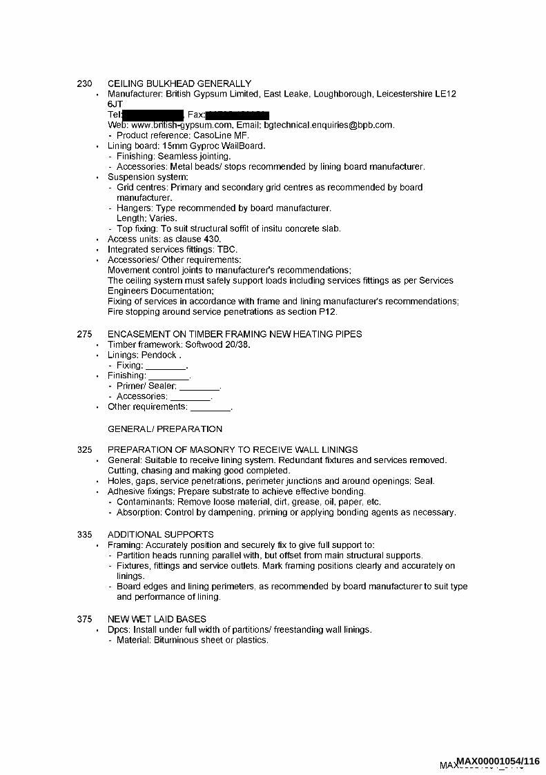
230 CEILING BULKHEAD GENERALLY • Manufacturer: British Gypsum Limited, East Leake, Loughborough, Leicestershire LE12
6JT
WeDMwwv^nt is r^ypsum.com, Email: [email protected]. - Product reference: CasoLine MF.
• Lining board: 15mm Gyproc WailBoard. - Finishing: Seamless jointing. - Accessories: Metal beads/ stops recommended by lining board manufacturer.
• Suspension system: - Grid centres: Primary and secondary grid centres as recommended by board
manufacturer. - Hangers: Type recommended by board manufacturer.
Length: Varies. - Top fixing: To suit structural soffit of insitu concrete slab.
• Access units: as clause 430. • Integrated services fittings: TBC. • Accessories/Other requirements:
Movement control joints to manufacturer's recommendations; The ceiling system must safely support loads including services fittings as per Services Engineers Documentation; Fixing of services in accordance with frame and lining manufacturer's recommendations; Fire stopping around service penetrations as section P12.
275 ENCASEMENT ON TIMBER FRAMING NEW HEATING PIPES • Timber framework: Softwood 20/38. • Linings: Pendock.
- Fixing: . • Finishing: .
- Primer/ Sealer: . - Accessories: .
• Other requirements: .
GENERAL/ PREPARATION
325 PREPARATION OF MASONRY TO RECEIVE WALL LININGS • General: Suitable to receive lining system. Redundant fixtures and services removed.
Cutting, chasing and making good completed. • Holes, gaps, service penetrations, perimeter junctions and around openings: Seal. • Adhesive fixings: Prepare substrate to achieve effective bonding.
- Contaminants: Remove loose material, dirt, grease, oil, paper, etc. - Absorption: Control by dampening, priming or applying bonding agents as necessary.
335 ADDITIONAL SUPPORTS • Framing: Accurately position and securely fix to give full support to:
- Partition heads running parallel with, but offset from main structural supports. - Fixtures, fittings and service outlets. Mark framing positions clearly and accurately on
linings. - Board edges and lining perimeters, as recommended by board manufacturer to suit type
and performance of lining.
375 NEW WET LAID BASES • Dpcs: Install under full width of partitions/ freestanding wall linings.
- Material: Bituminous sheet or plastics.
MAX00001054 0116 MAX00001054/116

385 SERVICE PENETRATIONS • The dry lining contractor must liaise with the Main Contractor and other contractors to
ensure that fire resistance and other specified performance requirements are not impaired by service penetrations.
• In particular: - Form framed openings accurately for grouped services, ducts, etc. allowing for
associated fire barriers. - Provide insulation backings to recessed electrical outlets and switches as recommended
by the plasterboard manufacturer.
395 CONTROL SAMPLES • General: Complete areas of finished work and obtain approval of appearance before
proceeding. • Type of dry lining: All partition and ceiling types.
- Location/ Size: TBC.
COMPONENTS
401 GYPSUM PLASTERBOARD • Type: Gyproc Wallboard. • Core density (minimum): 650 kg/m 3. • Recycled content: 84% (minimum) to BS EN ISO 14021. • Exposed surface and edge profiles: Suitable to receive specified finish.
403A GYPSUM PLASTERBOARD (MOISTURE RESISTANT) • Type: Glasroc H Tilebacke. • Core: Moisture resistant.
- Density (minimum): 900 kg/m 3. • Paper facings: Moisture resistant. • Recycled content: 84% (minimum) to BS EN ISO 14021. • Exposed surface and edge profiles: Suitable to receive specified finish.
404 GYPSUM PLASTERBOARD (IMPROVED FIRE PROTECTION) • Type: Gyproc Fireline. • Core: Including fibres and/ or other additives for improved cohesion.
- Density (minimum): 800 kg/m 3. • Recycled content: 84% (minimum) to BS EN ISO 14021. • Exposed surface and edge profiles: Suitable to receive specified finish.
415 GYPSUM PLASTERBOARD SHAFT WALL • Type: Gyproc CoreBoard. • Core density (minimum): Consult manufacturer. • Recycled content: 84% (minimum) to BS EN ISO 14021. • Exposed surface and edge profiles: Clean and undamaged.
430 ACCESS PANELS GENERALLY • Type: Flush metal access panels .
- Sizes: 600 mm x 600 mm generally - Location: To M&E Engineer's and M&E Subcontractor requirements .
• Frame: Bead for taping and jointing . • Panel: Electro galvanised, polyester powder coated. Colour: TBC . • Lock:
- Ceiling: concealed hinges or pivots with key operated locks. - Wall: security locking .
MAX00001054 0117 MAX00001054/117

432 METAL STUDS • Manufacturer: British Gypsum Ltd, East Leake, Loughborough, Leicestershire LE12 6JT
T e l : ^ ^ ^ ^ ^ ^ ^ | F a x : ^ ^ ^ ^ ^ ^ ^ | Email: [email protected], Web: www.british-gypsum.com . - Product reference:
• Gypframe Steel Stud, Channel, Track and Accessories; • Shaftwall Stud, Channel, Track and Accessories .
INSTALLATION
435 DRY LININGS GENERALLY • General: Use fixing, jointing, sealing and finishing materials, components and installation
methods recommended by board manufacturer. • Cutting plasterboards: Neatly and accurately without damaging core or tearing paper
facing. - Cut edges: Minimize and position at internal angles wherever possible. Mask with bound
edges of adjacent boards at external corners. • Fixings boards: Securely and firmly to suitably prepared and accurately levelled
backgrounds. • Finishing: Neatly to give flush, smooth, flat surfaces free from bowing and abrupt changes
of level.
445 CEILINGS • Sequence: Fix boards to ceilings before installing dry lined walls and partitions. • Orientation of boards: Fix with bound edges at right angles to supports and with ends
staggered in adjacent rows. • Two layer boarding: Stagger joints between layers.
455 METAL FRAMING FOR PARTITIONS/ WALL LININGS • Setting out: Accurately aligned and plumb.
- Frame/ Stud positions: Equal centres to suit specified linings, maintaining sequence across openings.
- Additional studs: To support vertical edges of boards. • Fixing centres at perimeters (maximum): 600 mm. • Openings: Form accurately.
- Doorsets: Use sleeved or boxed metal studs and/ or suitable timber framing to achieve strength grade requirements for framing assembly and adequately support weight of door.
- Services penetrations: Allow for associated fire stopping.
460 SHAFT WALL • Notwithstanding clause 455, fix head channel securely at not more than SOOmm centres,
incorporating fire sealant. 485 SUSPENDED CEILING GRIDS
• Setting out: Accurately aligned and level. - Grid members and hangers: Centres to suit specified linings and imposed loads. - Additional grid members: Provide bracing and stiffening at upstands, partition heads,
access hatches, etc. • Fixing: Securely at perimeters, grid joints, top and bottom hanger fixings.
MAX00001054 0118 MAX00001054/118
505 INSTALLING MINERAL WOOL INSULATION • Fitting insulation: Closely butted joints and no gaps. Use fasteners to prevent slumping or
displacement. • Services:
- Electrical cables overlaid by insulation: Sized accordingly. - Ceilings: Cut insulation around electrical fittings, etc.
510 SEALING GAPS AND AIR PATHS • Location of sealant: To perimeter abutments and around openings.
- Pressurized shafts and ducts: At board-to-board and board-to-metal frame junctions. • Application: To clean, dry and dust free surfaces as a continuous bead with no gaps.
- Gaps greater than 6 mm between floor and underside of plasterboard: After sealing, fill with jointing compound.
515 ACOUSTIC SEALANT • Location of sealant: At junctions with adjoining structure, and at other air paths. • Application: Apply as a continuous bead to clean, dry, dust free surfaces, leaving no gaps.
After application of sealant, bulk fill gaps between floor and underside of plasterboard using joint compound recommended by board manufacturer.
520 AIR PRESSURE SEALANT • Location of sealant:
- To all framing members at perimeter junctions with walls, floors and ceilings, air gaps around openings, and other potential air leakage points.
- To frame members priorto fitting core boards and around fire stops cloaking horizontal core board joints.
- To all metal framing around board perimeters of first layer boarding and board perimeters when fixing outer layer board.
• Application: Apply as a continuous bead leaving no gaps.
530 CAVITY FIRE BARRIERS WITHIN PARTITIONS/ WALL LININGS • Metal framed systems:
- Material: Wre reinforced mineral wool 50 mm (minimum) thick. - Installation: Form accurately and fix securely with no gaps to provide a complete barrier
to smoke and flame. • Adhesive fixed wall lining systems:
- Material: Adhesive compound. - Installation: Form in a continuous line with no gaps to provide a complete barrier to
smoke and flame.
545 CAVITY FIRE BARRIERS WITHIN SUSPENDED CEILINGS • Type: 50 mm mineral wool wire reinforced mattress. • Fire resistance: To BS 476-20, 30/30 minutes (Integrity/ Insulation). • Ceiling void subdivision: Fix barriers as drawings. • Fixing at perimeters and joints: Secure, stable and continuous with no gaps, to provide a
complete barrier to smoke and flame. • Service penetrations: Cut and pack to maintain barrier integrity. Sleeve flexible materials.
Adequately support services passing through barrier. • Ceiling systems for fire protection: Do not impair fire resisting performance of ceiling
system.
555 FIRE STOPPING AT PERIMETERS OF DRY LINING SYSTEMS • Material: Tightly packed mineral wool or intumescent mastic/ sealant. • Application: To perimeter abutments to provide a complete barrier to smoke and flame.
MAX00001054 0119 MAX00001054/119
560 JOINTS BETWEEN BOARDS • Tapered edged plasterboards:
- Bound edges: Lightly butted. - Cut/ unbound edges: 3 mm gap.
• Square edged plasterboards: 3 mm gap. • Square edged fibre reinforced gypsum boards: 5 mm gap.
565 VERTICAL JOINTS • Joints: Centre on studs.
- Partitions: Stagger joints on opposite sides of studs. - Two layer boarding: Stagger joints between layers.
570 HORIZONTAL JOINTS • Surfaces exposed to view: Horizontal joints not permitted. Seek instructions where height
of partition/ lining exceeds maximum available length of board. • Two layer boarding: Stagger joints between layers by at least 600 mm. • Edges of boards: Support using additional framing.
- Two layer boarding: Support edges of outer layer.
580 INSULATION BACKED PLASTERBOARD • General: Do not damage or cut away insulation to accommodate services. • Installation at corners: Carefully cut back insulation or plasterboard as appropriate along
edges of boards to give a continuous plasterboard face, with no gaps in insulation.
590 FIXING PLASTERBOARD TO METAL FRAMING/ FURRINGS • Partitions/ Wall linings: Fix securely and firmly at the following centres (maximum):
- Single layer boarding: To all framing at 300 mm centres. Reduce to 200 mm centres at external angles.
- Multi-layer boarding: Face layer at 300 mm centres, and previous layers around perimeters at 300 mm centres.
• Ceilings: 230 mm. Reduce to 150 mm at board ends and at lining perimeters. • Position of screws from edges of boards (minimum): 10 mm.
- Screw heads: Set in a depression. Do not break paper or gypsum core.
591 FIXING PLASTERBOARD TO METAL SUPPORTS SHAFT WALL Working from the centre of each board, fix securely to all supports at maximum SOOmm centres, reduced to 200mm at external angles.
• Ceilings: 230 mm. Reduce to 150 mm at board ends and at lining perimeters. Fix working from the centre of each board. Position screws not less than 13mm from cut edges and 10mm from bound edges of boards. Set heads in a depression; do not break paper or gypsum core.
595 DEFLECTION HEADS • Fixing boards: Do not fix to head channels.
MAX00001054 0120 MAX00001054/120

620 FIXING PLASTERBOARD WITH ADHESIVE DABS • Setting out boards: Accurately aligned and plumb. • Fixing to substrates: Securely using adhesive dabs. • Adhesive dab spacings for each board:
- Horizontally: One row along top edge and one continuous dab along bottom edge. - Vertically: One row along each edge and thereafter at intermediate spacings to suit size
of board: Thickness (mm) Wdth (mm) Dab centres (mm) 9.5 1200 400
9.5/12.5 900 450 12.5 1200 600
• Adhesive dab dimensions (width x length): At least 50-75 mm x 250 mm. - Position of dabs from edges/ ends of boards (minimum): 25 mm.
625 FIXING INSULATION BACKED PLASTERBOARD WITH ADHESIVE DABS • Fixing to substrates: In addition to adhesive dab fixings, secure boards with nailable plugs
in locations recommended by board manufacturer.
FINISHING
650 LEVEL OF DRY LINING ACROSS JOINTS • Sudden irregularities: Not permitted. • Joint deviations: Measure from faces of adjacent boards using methods and straightedges
(450 mm long with feet/ pads) to BS 8212, clause 3.3.5. - Tapered edge joints:
Permissible deviation (maximum) across joints when measured with feet resting on boards: 3 mm.
- External angles: Permissible deviation (maximum) for both faces: 4 mm.
- Internal angles: Permissible deviation (maximum) for both faces: 5 mm.
670 SEAMLESS JOINTING TO PLASTERBOARDS • Cut edges of boards: Lightly sand to remove paper burrs. • Filling and taping: Fill joints, gaps and internal angles with jointing compound and cover
with continuous lengths of paper tape, fully bedded. • Protection of edges/ corners: Reinforce external angles, stop ends, etc. with specified
edge/ angle bead. • Finishing: Apply jointing compound. Feather out each application beyond previous
application to give a flush, smooth, seamless surface. • Nail/ screw depressions: Fill with jointing compound to give a flush surface. • Minor imperfections: Remove by light sanding.
692 RIGID BEADS/STOPS • Internal: To BS EN 13658-1. • External: To BSEN 13658-2.
695 INSTALLING BEADS/ STOPS • Cutting: Neatly using mitres at return angles. • Fixing: Securely using longest possible lengths, plumb, square and true to line and level,
ensuring full contact of wings with substrate. • Finishing: After joint compounds/ plasters have been applied, remove surplus material
while still wet from surfaces of beads exposed to view.
MAX00001054 0121 MAX00001054/121

K11 Rigid sheet f looring/ sheathing/ decking/ sarking/
l inings/ casings
MAX00001054 0122 MAX00001054/122

K11 Rigid sheet f looring/ sheathing/ decking/ sarking/ linings/ casings
TO BE READ WITH PRELIMINARIES/ GENERAL CONDITIONS. • Notwithstanding the descriptions of workmanship described in various parts of this
NBS/NES; the contents of BS8000, where applicable, shall take precedence except where workmanship described is superior to BS8000.
• The manufacturers noted within this specification are indicative and may be substituted with similar or equal alternatives.
• All manufacturers of wood flooring must provide evidence that their product is tested in accordance with EN 14342:2005 and comply with Formaldehyde class E1. They must verify that regulated wood preservatives are absent as defined by the standard.
• All manufacturers of laminated wood flooring must provide evidence that their product is tested in accordance with EN 14041:2004 and comply with Formaldehyde class E1. They must verify that regulated wood preservatives are absent as defined by the standard.
• All timber supplied or used in timber products must be from certified sources. Evidence must be provided by the supplier/manufacturer in form of FSC or PEFC certificates. Additional CEPT documentation may be supplied for verification purposes.
TYPES OF FLOORING/ SHEATHING/ DECKING/ SARKING/ LINING/ CASINGS
110 WOOD-BASED SHEETS GENERALLY • Standard: To BS EN 13986.
- Evidence of compliance: Submit.
MAX00001054 0123 MAX00001054/123

115 BATTENED PLYWOOD FLOATING FLOOR BOXING CLUB TRAINING AREA • Substrate: Leveling screed to M10.
- Preparation: Clean, level and dry. • Resilient layer:
Supplier Reference: Mason UK 01252 716 610, http://www.mason-uk.co.uk MFS-150 (yellow) Spring Floor Mounts, nailed to battens at 600mm intervals. - Recycled content: Contractor's choice.
• Loose laid battens: 100X50 battens on at 600mm centres . - Additional battens: -.
• Thermal insulation between battens: -. - Recycled content: Not applicable.
• Vapour control layer: 1000 gauge virgin polyethylene sheet. • Floating substrate: Not required. • Flooring: Plywood to an approved national standard.
- Bonding quality to BS EN 314-2: Class 2. - Appearance class to BS EN 635: Class III. - Finish: Unsanded. - Thickness: 2 layers 18 mm ply, glued and screwed.. - Edges: Tongued and grooved all edges. - Other requirements: -.
• Installation: - Floors with no vapour control layer: Adhesive fixed to each batten. - Setting out of floating substrate (where specified): Long edges running across battens.
End joints central over battens and staggered. - Setting out of flooring: Long edges running across battens. End joints central over
battens and staggered. All joints glued. Flooring laid over floating substrate: Spot bonded to floating substrate. Joints must not coincide.
- Fixing flooring to each batten: Fasteners: 50 mm x 8 gauge wood screws into pilot holes . Fixing centres (maximum): Around floor perimeter and along short edges of each board: 150 mm. Along intermediate supports: 300 mm. Fixing distance from edges: 25 mm from long edges and minimum 10 mm from short edges.
• Bonding/ Jointing adhesive: Contractor's choice . • Expansion provision:
- Clear expansion gap around perimeter of floor area and upstands: 1 mm per metre run of floor, with a minimum gap of 10 mm .
- Intermediate expansion/ movement joints: As recommended by flooring manufacturer.
WORKMANSHIP
910 INSTALLATION GENERALLY • Timing: Building to be weathertight before fixing boards internally. • Moisture content of timber supports (maximum): 18%. • Joints between boards: Accurately aligned, of constant width and parallel to perimeter
edges. • Methods of fixing, and fasteners: As section Z20 where not specified otherwise.
915 DRYNESS OF CONCRETE/ SCREED SUBSTRATES FOR FLOATING FLOORS • Relative humidity above substrate when tested with a hygrometer to BS 8201, Appendix A
(maximum): 75%. - Test points: All corners, around perimeter, and random points over area being tested. - Drying aids: Turned off for not less than 4 days before testing.
MAX00001054 0124 MAX00001054/124
920 VAPOUR CONTROL LAYER IN FLOATING FLOOR CONSTRUCTION • Location: Immediately below floating layer. • Installation:
- Joints: Overlapped by minimum 150 mm and sealed with vapour resistant tape. - Treatment of membrane at perimeter of flooring and upstands: Turned up and sealed to
top face of flooring using a method approved bythe board manufacturer. • Excess material: Trimmed off neatly after fixing skirtings/ cover beads. • Condition of membrane before laying flooring: Clean and dry.
925 BATTENS FOR FLOATING FLOORS • Timber quality: Free from decay, insect attack (except ambrosia beetle damage) and with
no knots wider than half the width ofthe section. • Preservative treatment: As section Z12 and Wood Protection Association Commodity
Specification C8. - Type/ Desired service life: Acoustic floor system manufacturer's standard.
• Moisture content at time of laying (maximum): 16%.
930 ADDITIONAL SUPPORTS • Additional studs, noggings/ dwangs (Scot) and battens:
- Provision: In accordance with board manufacturer's recommendations and as follows: Tongue and groove jointed rigid board areas: To all unsupported perimeter edges. Butt jointed rigid board areas: To all unsupported edges.
- Size: Not less than 50 mm wide and of adequate thickness. - Quality of timber: As for adjacent timber supports. - Treatment (where required): As for adjacent timber supports.
940 BOARD MOISTURE CONTENT AND CONDITIONING • Moisture content of boards at time of fixing: Appropriate to end use. • Conditioning regime: Submit proposals.
950 MOISTURE CONTENT TESTING • Test regime and equipment: Submit proposals. • Test results: Submit record of tests and results.
960 FIXING GENERALLY • Boards/ sheets: Fixed securely to each support without distortion and true to line and level. • Fasteners: Evenly spaced in straight lines and, unless otherwise recommended by board
manufacturer, in pairs across joints. - Distance from edge of board/ sheet: Sufficient to prevent damage.
• Surplus adhesive: Removed as the work proceeds.
980 OPEN JOINTS • Perimeter joints, expansion joints and joints between boards: Free from plaster, mortar
droppings and other debris. • Temporary wedges and packings: Removed on completion of board fixing.
990 ACCESS PANELS • Size and position: Agree before boards are fixed. • Additional noggings/ dwangs (Scot), battens, etc: Provide and fix as necessary.
MAX00001054 0125 MAX00001054/125

K13 Rigid sheet fine linings and panelling
MAX00001054 0126 MAX00001054/126

K13 Rigid sheet fine linings and panelling
TO BE READ WITH PRELIMINARIES/ GENERAL CONDITIONS. Notwithstanding the descriptions of workmanship described in various parts of this NBS/NES; the contents of BS8000, where applicable, shall take precedence except where workmanship described is superior to BS8000. The manufacturers noted within this specification are indicative and may be substituted with similar or equal alternatives. All manufacturers of vinyl, carpet and PVC-U linings to walls must provide evidence that their product is tested in accordance with EN 14041:2004 and complies with Formaldehyde class E1. They must verify that regulated preservatives are absent as defined by the standard. All manufacturers of flooring adhesives and adhesives for rigid wall coverings must provide evidence that their product is tested in accordance with EN 13999-1:2007. They must verify that carcinogenic or sensitising volatile substances are absent from their product.
MAX00001054 0127 MAX00001054/127

TYPES OF LINING AND PANELLING
146 PROPRIETARY PVCu LININGS TO WALLS • Substrate: Concrete, block work and plasterboard. • Panels:
- Manufacturer: Altro Limited - Works Road, Letchworth Garden City, Herts, Hertfordshire SG6 I N W Tel: ^ ^ B ^ ^ ^ ^ ^ ^ ^ l . Fax: ^^B^^^^^^^H Web: www.altro.co.uk, Email: [email protected]. Product reference: Altro Whiterock™ W103/W104.
- Board/ Panel type: Extruded semi-rigid PVCu sheet, EU Grade. - Wdth: 1220mm. - Length: 2500mm (W103) or 3000mm (W104). - Thickness: 2.5mm. - Wheight: 3.5 kg/m 2. - Colour: White. - Light reflectance value: 95. - Surface finis: Satin.
• Method of fixing panels: Adhered to substrate in accordance with manufacturer's recommendations.
• Adhesive (and primer if recommended by manufacturer): AltroFix™ W139 Support the panel on double sided tape (Ref: A815 or A915 or welded system) whilst adhesive cures (approx. 3-5 hours - full cure 24 hours); Back of sheets to be cleaned using Altro Whiterock cleaner/thinner or Desolvit wipes.
• Joint treatment: All joints should be covered with high impact PVCu 'H' joint sections (two-part joint trim, or single part joint trim). Alternatively a 3-4mm Altro Whiterock silicone sealant joint can be used. All such joints are to be primed with Altro cleaner thinner before sealant is applied.
• Abutments: - To window frame, door frames, architraves, ceiling & quarry tile: Wipe clean & prime the edges with cleaner/thinner and seal with Altro Whiterock silicone sealant, white, 3-4mm width joint. - To PVC flooring with coved skirting: Overlapped by 50mm with Altro Whiterock, close bottom of sheet with silicon.
• Finish: Protective film to be removed and any marks and dirt wiped off using Altro Whiterock cleaner/thinner or Desolvit wipes . Antistatic solution to be applied to all surfaces when dry.
• Service penetrations: All holes to be cut to allow 3-4mm silicone seal around all penetrations. Clean with leaner/thinner and seal with Altro Whiterock silicone sealant
• Accessories: If required, high impact PVCu two-part start and edge trimer high impact PVCu single part heavy duty start and edge trim.
GENERAL REQUIREMENTS
210 ADVANCE REGISTRATION • Materials registered in advance by the Employer: Obtain from supplier named in
Preliminaries section A56. - Ordering: Supersede Employer's registration and take over responsibility by an orderto
the supplier covering price, supply and delivery to suit progress ofthe work.
220 MATERIAL SAMPLES • Representative samples of designated materials: Submit before placing orders.
- Designated materials: Altro Whiterock™ for splashbacks and wall linings .
MAX00001054 0128 MAX00001054/128

230 CONTROL SAMPLES • Sample area: Complete as part ofthe finished work.
- Clause reference: clause 146 . - Location: Kitchen, WC, shower area . - Size (minimum):
Kitchenette: H 450mm x L 1000mm Handwash basin: H 400mm x L 600mm Shower area: complete panel .
- Included features: Joint, abutments, service penetrations . • Approval of appearance: Obtain before proceeding.
260 ENVIRONMENTAL CONDITIONS • General requirements priorto starting work specified in this section: Building weathertight;
wet trades completed and affected areas dried out. • Temperature and humidity before, during and after fixing lining/ panelling: Maintained at
levels approximating to those which will prevail after building is occupied.
FABRICATION/ FIXING/ FINISHING
350 FIXING LININGS AND PANELLING • Setting out: Accurate, true to line and level, free from undulations and lipping, with lines
and joints aligned, straight and parallel unless specified otherwise. • Movement allowance: Adequate for future moisture and temperature movement of boards. • Fixing of panels: Secure, to prevent pulling away, bowing, or other movement during use. • Methods of fixing and fasteners: As section Z20 unless specified otherwise. • Trims: Wherever possible, to be in unjointed lengths between angles or ends of runs.
- Running joints: Where unavoidable, submit proposals for location and method of jointing. - Angle joints: Mitred, unless specified otherwise.
MAX00001054 0129 MAX00001054/129

K21 Wood strip/ board fine f looring/ linings
MAX00001054 0130 MAX00001054/130

K21 Wood strip/ board fine f looring/ linings
TO BE READ WITH PRELIMINARIES/ GENERAL CONDITIONS. • Notwithstanding the descriptions of workmanship described in various parts of this
NBS/NES; the contents of BS8000, where applicable, shall take precedence except where workmanship described is superior to BS8000.
• The manufacturers noted within this specification are indicative and may be substituted with similar or equal alternatives.
• All manufacturers of wood flooring must provide evidence that their product is tested in accordance with EN 14342:2005 and comply with Formaldehyde class E1. They must verify that regulated wood preservatives are absent as defined by the standard.
• All manufacturers of laminated wood flooring must provide evidence that their product is tested in accordance with EN 14041:2004 and comply with Formaldehyde class E1. They must verify that regulated wood preservatives are absent as defined by the standard.
• All timber supplied or used in timber products must be from certified sources. Evidence must be provided by the supplier/manufacturer in form of FSC or PEFC certificates. Additional CEPT documentation may be supplied for verification purposes.
TYPES OF FLOORING/ LINING
110 WOOD FLOORING BOXING CLUB • Substrate: Plywood floating floor as K11/115.
- Preparation: Clean and dry. • Vapour control layer: not required. • Strips/ Boards: Free from decay, through splits and insect attack (including ambrosia
beetle damage, unless permitted in the class/grade specified). Planed all round. - Manufacturer/ Supplier:
Boen Uk Ltd, Unit 320-322, Beech Drive, Hartlebury Trading Estate, Hartlebury Worcestershire, DY10 4JB, Tel. ^ ^ ^ ^ ^ ^ H F a x : ^ ^ ^ ^ ^ ^ ^ ^ . E - M a i l : [email protected] Web: www.boen.com Contact: Area Project Manager: Dave Carrington.
- Wood species: Oak. - Appearance class/ Grade: Finale. - Finished face width: 209mm. - Finished thickness: Mmm. - Edges: Square. - Moisture content at time of fixing: Boen precise milling technique Unilin /X-Press Clic
joints side and end matched. Moisture content at time of fixing: 7% + / - 1 % . . - Method of fixing/joining: Floating floor - Boards are Unilin Clic self-locking, glue-less
joints along length and X-Press lock system on the heading joints.. • Finish: Factory finished. • Accessories: Oak skirting to hide expansion gaps. • Other requirements: Aluminium transition strips at thresholds.
GENERAL/ PREPARATION
210 WORKMANSHIP GENERALLY • Moisture content of timber supports: 12-14%. • Methods of fixing and fasteners: As section Z20 where not specified. • Protection: Protect from dirt, stains and damage using suitable coverings and boards laid
as the work proceeds.
MAX00001054 0131 MAX00001054/131
220 ENVIRONMENTAL CONDITIONS • General requirements priorto starting work specified in this section: Building weathertight,
wet trades completed and affected areas dried out. • Temperature and humidity before, during and after installing strips/ boards: Maintained at
levels approximating to those which will prevail after building is occupied.
230 HEATING SYSTEM • Operating mode: Intermittent. • Room temperatures for which the system has been designed: 15-18 degrees C. • Operation up to Completion: Submit proposals.
250 FIXTURES • Fixtures around which strip flooring is to be fixed: Installed before starting work specified in
this section.
260 DRYNESS OF CONCRETE/ SCREED SUBSTRATES FOR FLOORING • Relative humidity above substrate when tested with a hygrometer to BS 8201, Appendix A
(maximum): 75%. - Test points: All corners, around perimeter, and random points over area being tested.
• Drying aids: Turned off for not less than four days before testing.
270 STRIP/ BOARD MOISTURE CONTENT TESTING • Test regime and equipment: Submit proposals. • Test results: Submit record of tests and results.
290 CONTROL SAMPLES • Sample area: Complete as part ofthe finished work.
- Clause reference: Clause 115. - Location: TBC. - Size (minimum): 1.5m2. - Included features: Skirting boards, thresholds, pipe covers and resilient layer.
• Approval of appearance: Obtain before proceeding.
FIXING/ FINISHING
335 TREATED TIMBER • Surfaces exposed by minor cutting and drilling: Treated with two flood coats of a solution
recommended forthe purpose by main treatment solution manufacturer.
361 EXPANSION PROVISION • Expansion gaps:
- Edges of flooring: Parallel to lie of strips/ boards, width as recommended by flooring manufacturer.
- Ends of flooring: 10 mm wide. • Spacer blocks and debris: Removed before fixing skirtings/ cover fillets. • Intermediate expansion/ movement joints: Formed as recommended by flooring
manufacturer/ supplier.
370 FINISH TO FLOORING • Exposed fastener heads: Punched or set below surface and filled with stopping to match
wood. • Strips/ Boards: Sanded to give a clean, smooth and flush surface free from score marks. • Finish: As recommended by flooring manufacturer.
MAX00001054 0132 MAX00001054/132

K32 Panel cubicles/duct and wall l inings/screens
MAX00001054 0133 MAX00001054/133
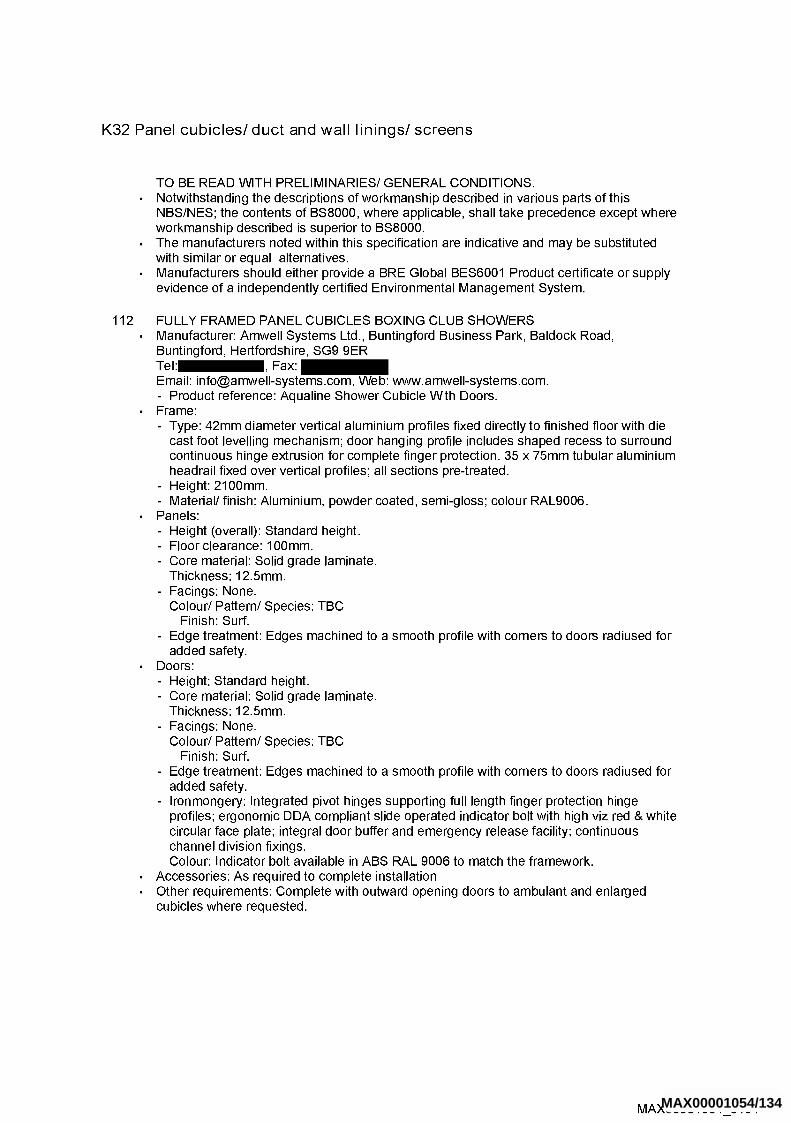
K32 Panel cubicles/ duct and wall l inings/ screens
TO BE READ WITH PRELIMINARIES/ GENERAL CONDITIONS. • Notwithstanding the descriptions of workmanship described in various parts of this
NBS/NES; the contents of BS8000, where applicable, shall take precedence except where workmanship described is superior to BS8000.
• The manufacturers noted within this specification are indicative and may be substituted with similar or equal alternatives.
• Manufacturers should either provide a BRE Global BES6001 Product certificate or supply evidence of a independently certified Environmental Management System.
112 FULLY FRAMED PANEL CUBICLES BOXING CLUB SHOWERS • Manufacturer: Amwell Systems Ltd., Buntingford Business Park, Baldock Road,
Buntingford, Hertfordshire, SG9 9ER Teh^^^^^^^H, Fax: Email: [email protected], Web: www.amwell-systems.com. - Product reference: Aqualine Shower Cubicle Wth Doors.
• Frame: - Type: 42mm diameter vertical aluminium profiles fixed directly to finished floor with die
cast foot levelling mechanism; door hanging profile includes shaped recess to surround continuous hinge extrusion for complete finger protection. 35 x 75mm tubular aluminium headrail fixed over vertical profiles; all sections pre-treated.
- Height: 2100mm. - Material/ finish: Aluminium, powder coated, semi-gloss; colour RAL9006.
• Panels: - Height (overall): Standard height. - Floor clearance: 100mm. - Core material: Solid grade laminate.
Thickness: 12.5mm. - Facings: None.
Colour/ Pattern/ Species: TBC Finish: Surf.
- Edge treatment: Edges machined to a smooth profile with corners to doors radiused for added safety.
• Doors: - Height: Standard height. - Core material: Solid grade laminate.
Thickness: 12.5mm. - Facings: None.
Colour/ Pattern/ Species: TBC Finish: Surf.
- Edge treatment: Edges machined to a smooth profile with corners to doors radiused for added safety.
- Ironmongery: Integrated pivot hinges supporting full length finger protection hinge profiles; ergonomic DDA compliant slide operated indicator bolt with high viz red & white circular face plate; integral door buffer and emergency release facility; continuous channel division fixings. Colour: Indicator bolt available in ABS RAL 9006 to match the framework.
• Accessories: As required to complete installation • Other requirements: Complete with outward opening doors to ambulant and enlarged
cubicles where requested.
MAX00001054 0134 MAX00001054/134

113 FULLY FRAMED PANEL CUBICLES BOXING CLUB MALE WC • Manufacturer: Amwell Systems Ltd., Buntingford Business Park, Baldock Road,
Buntmafot^JHertfgrdshire, SG9 9ER Tel: flfe^^^H. F a x : ^ ^ ^ ^ ^ ^ ^ l Email: [email protected], Web: www.amwell-systems.com. - Product reference: Impact standard+ Toilet cubicles.
• Panels/Doors: - Core material: Moisture resistant chipboard (to V313).
Thickness: 18mm. - Facings: Faced both sides with high pressure laminate (HPL).
Colour/ Pattern/ Species: Colour to be confirmed from Amwell Washroom HPL selection. Finish: Surf.
- Edge treatment: All edges are lipped with corresponding / contrasting durable PVC. • Pilaster:
- Core material: Moisture resistant chipboard (to V313). Thickness: 18mm.
- Facings: Faced both sides with high pressure laminate (HPL). Colour/ Pattern/ Species: Colour to be confirmed from Amwell Washroom MFC selection.
Finish: Surf. - Edge treatment: Vertical edges postformed to form continuous radius.
• Headrails: Rigid polished aluminium angle section with bull-nosed leading edge. • Legs: Polished aluminium rectangular aluminium design, through fixed into partitions;
adjustable to accommodate varying floor levels. • Ironmongery: Aluminium pivot hinge; coat hook; ergonomic DDA compliant slide operated
indicator bolt with circular face plate; Integral door buffer and emergency release facility; channel bracket partition fixings.
Finish/Colour: Polished. • Dimensions: 2100mm overall height including 100mm floor clearance. • Accessories: As required to complete installation • Other requirements: Complete with outward opening doors to ambulant and enlarged
cubicles where requested. Cubicles with inward opening doors to be set out to maintain 450mm diameter manoeuvring space within the cubicle.
114 FULLY FRAMED PANEL CUBICLES NURSERY • Manufacturer: Amwell Systems Ltd., Buntingford Business Park, Baldock Road,
Buntingford, Hertfordshire, SG9 9ER Tel: ^ m m ^ g p a x . Email: [email protected], Web: www.amwell-systems.com. - Product reference: Playtime Arches HPL range.
• Panels/Doors/Pilaster: - Core material: Moisture resistant chipboard (to V313).
Thickness: 18mm. Height: 1260mm from FFL to the top ofthe door. (Including ground clearance)
- Facings: Faced both sides with high pressure laminate (HPL). Colour/ Pattern/ Species: Colour to be confirmed from Amwell Washroom HPL selection.
- Edge treatment: All edges are lipped with corresponding / contrasting durable PVC. • Ironmongery: Universal Aluminium safety hinge, powder coated Light Grey; pilaster base
extrusion for added rigidity; ergonomic DDA compliant slide operated indicator bolt with circular face plate; integral door buffer and emergency release facility; coat hook and channel bracket partition fixings.
Finish/Colour: Colour to be confirmed from Amwell Washroom selection . • Dimensions: 1350mm overall height including 160mm floor clearance. • Accessories: As required to complete installation • Other requirements: Complete with outward opening doors to ambulant and enlarged
cubicles where requested.
MAX00001054 0135 MAX00001054/135
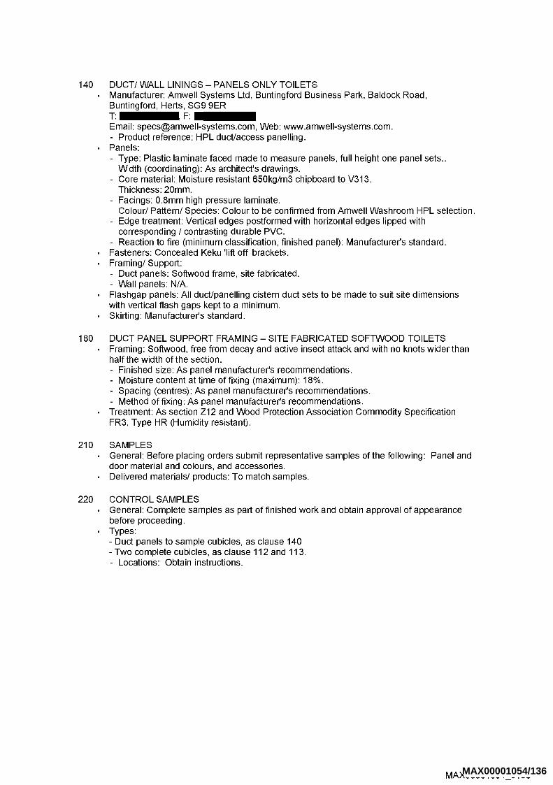
140 DUCT/ WALL LININGS - PANELS ONLY TOILETS • Manufacturer: Amwell Systems Ltd, Buntingford Business Park, Baldock Road,
Buntingford, Herts, SG99ER T: ^^^^M F: ^^^^^M Email: [email protected], Web: www.amwell-systems.com. - Product reference: HPL duct/access panelling.
• Panels: - Type: Plastic laminate faced made to measure panels, full height one panel sets..
Wdth (coordinating): As architect's drawings. - Core material: Moisture resistant 650kg/m3 chipboard to V313.
Thickness: 20mm. - Facings: 0.8mm high pressure laminate.
Colour/ Pattern/ Species: Colour to be confirmed from Amwell Washroom HPL selection. - Edge treatment: Vertical edges postformed with horizontal edges lipped with
corresponding / contrasting durable PVC. - Reaction to fire (minimum classification, finished panel): Manufacturer's standard.
• Fasteners: Concealed Keku 'lift off brackets. • Framing/ Support:
- Duct panels: Softwood frame, site fabricated. - Wall panels: N/A.
• Flashgap panels: All duct/panelling cistern duct sets to be made to suit site dimensions with vertical flash gaps kept to a minimum.
• Skirting: Manufacturer's standard.
180 DUCT PANEL SUPPORT FRAMING - SITE FABRICATED SOFTWOOD TOILETS • Framing: Softwood, free from decay and active insect attack and with no knots wider than
half the width ofthe section. - Finished size: As panel manufacturer's recommendations. - Moisture content at time of fixing (maximum): 18%. - Spacing (centres): As panel manufacturer's recommendations. - Method of fixing: As panel manufacturer's recommendations.
• Treatment: As section Z12 and Wood Protection Association Commodity Specification FRS, Type HR (Humidity resistant).
210 SAMPLES • General: Before placing orders submit representative samples ofthe following: Panel and
door material and colours, and accessories. • Delivered materials/ products: To match samples.
220 CONTROL SAMPLES • General: Complete samples as part of finished work and obtain approval of appearance
before proceeding. • Types:
- Duct panels to sample cubicles, as clause 140 - Two complete cubicles, as clause 112 and 113. - Locations: Obtain instructions.
MAX00001054 0136 MAX00001054/136

250 INSTALLATION • Programming: Do not install cubicles or duct/ wall panels before building is weathertight,
wet trades have finished their work, wall and floor finishes are complete, and the building is well dried out.
• Accuracy: Set out to ensure frames and/ or panels and doors are plumb, level and accurately aligned.
• Modifications: Do not cut, plane or sand prefinished components except where shown on drawings.
• Fixing: Secure components using methods and fasteners recommended by the cubicle/ panel manufacturer. Prevent pulling away, bowing or other distortions to frames, panels and doors.
• Moisture and thermal movement: Make adequate allowance for future movement.
MAX00001054 0137 MAX00001054/137

K40 Demountable suspended ceilings
MAX00001054 0138 MAX00001054/138

K40 Demountable suspended ceilings
TO BE READ WITH PRELIMINARIES/GENERAL CONDITIONS. • Notwithstanding the descriptions of workmanship described in various parts of this
NBS/NES; the contents of BS8000, where applicable, shall take precedence except where workmanship described is superior to BS8000.
• The manufacturers noted within this specification are indicative and may be substituted with similar or equal alternatives.
• All manufacturers of suspended ceiling tiles must provide evidence that their product is tested in accordance with EN 13964:2004 and complies with Formaldehyde class E1. They must verify that the product does not contain asbestos.
• Manufacturers should either provide a BRE Global BES6001 Product certificate or supply evidence of a independently certified Environmental Management System.
TYPES OF CEILING SYSTEM
115 UNIT SUSPENDED CEILING SYSTEM INSPECTOR/RA OFFICES & BOXING CLUB • Ceiling system manufacturer: Armstrong World Industries Ltd. Building Products Division,
Armstronc^House, 33 Market Square, Uxbridge UBS 1NG T e l : ^ H ^ ^ ^ I . Fax: ^ ^ ^ ^ ^ ^ ^ H Web: www.armstrong.co.uk. - Product reference: Sierra OP 3783M.
• Ceiling: - Infill units: Sierra
- Material: Mineral. - Edge : Tegular. - Colour: White.
- Ceiling module: 600 x 600 mm. - Soffit height above finished floor level: Referto architect's drawings.
• Grid: - Form: Interlocking. - Exposure: Exposed.
• Access: Infill units fully demountable. • Suspension system: Prelude XL. • Perimeter trim: Shadowline painted. • Accessories: As required to complete installation. • Integrated services fittings: Hangers and housings for linear luminaires. • Other requirements: Cavity barrier as clause 287.
GENERAL/ PERFORMANCE
210 ENVIRONMENT • Environmental classification to BS EN 13964:
- RA Offices & Boxing Club: Class A - Changing rooms/Showers: Class C.
COMPONENTS
240 SAMPLES • General: Submit representative samples ofthe following: Clause 115.
MAX00001054 0139 MAX00001054/139

245 STANDARDS • Components: To BS EN 10346.
- Aluminium sheet, strip and plate: To BS EN 485. - Aluminium bars, tubes and sections: To relevant parts of BS EN 515, BS EN 573, BS EN
755 and BS EN 12020.
287 CAVITY BARRIERS • Standard: To BS 476-20 and -22. • Manufacturer: Submit proposals.
- Product reference: Submit proposals. • Fire resistance: To BS 476-20 and -22, 30 minutes integrity and insulation. • Type/ Material: Wire reinforced mineral wool. • Thickness: Manufacturer's standard. • Density: Manufacturer's standard. • Facings/ Wrappings: Aluminium foil to back (facing void) and edges, white glass fibre
tissue to front.
EXECUTION
302 CONTROL SAMPLES • General: Complete areas as part ofthe finished work in the following locations:
- RA offices - Boxing Club - Shower areas.
• Approval: Obtain before completing areas of similar work.
305 SETTING OUT • General: Completed ceiling should present, overthe whole of its surface exposed to the
room below, a continuous and even surface, jointed (where applicable) at regular intervals. • Infill and access units, integrated services: Fitted correctly and aligned. • Edge/ perimeter infill units size (minimum): Half standard width or length. • Corner infill units size (minimum): Half standard width and length. • Grid: Position to suit infill unit sizes. Allow for permitted deviations from nominal sizes of
infill unit. • Infill joints and exposed suspension members: Straight, aligned and parallel to walls,
unless specified otherwise. • Suitability of construction: Give notice where building elements and features to which the
ceiling systems relate are not square, straight or level.
310 BRACING • General: Secure, with additional bracing and stiffening to give a stable ceiling system
resistant to design loads and pressures.
315 PROTECTION • Loading: Do not apply loads for which the suspension system is not designed. • Ceiling materials: When necessary, remove and replace correctly using special tools and
clean gloves, etc. as appropriate.
MAX00001054 0140 MAX00001054/140

320 TOP FIXING • Building structure: Verify suitability. • Structural soffit: Insitu concrete slab.
- Suitability to receive specified fixings: Evaluate and confirm. • Fixing generally: In accordance with BS EN 13964. • Fixing to:
- Concrete: Drill and insert suitable expanding anchors. - Aerated concrete: Fix through from the top of concrete units and provide a system of
primary support channels. - Structural steel: Drill, or use suitable proprietary clips/ adaptors. - Metal roof decking: Fix to sides of liner tray corrugations. - Timber: Fix to side of joists at least 50 mm from bottom edge. If ceiling system is
intended for fire protection, fix into top third of joists. - Hollow structural members: Submit fixing proposals.
325 INSTALLING HANGERS • Wire hangers: Straighten and tension before use. • Installation: Install vertical or near vertical, without bends or kinks. Do not allow hangers to
press against fittings, services, or insulation covering ducts/ pipes. • Obstructions: Where obstructions prevent vertical installation, either brace diagonal
hangers against lateral movement, or hang ceiling system on an appropriate rigid sub-grid bridging across obstructions and supported to prevent lateral movement.
• Extra hangers: Provide as necessary to carry additional loads. • Fixing:
- Wre hangers: Tie securely at top with tight bends to loops to prevent vertical movement. - Angle/ strap hangers: Do not use rivets for top fixing.
• Spacings: As recommended by manufacturer.
335 INSTALLING PERIMETER TRIMS • Jointing: Neat and accurate, without lipping ortwisting.
- External and internal corners: Mitre joints generally. Overlap joints at internal corners are not acceptable. - Intermediate butt joints: Minimize. Use longest available lengths of trim. Align adjacent
lengths. • Fixing: Fix firmly to perimeter wall, edge battens or other building structure.
- Fasteners: As recommended by manufacturer. - Fixing centres: As recommended by manufacturer.
340 EXPOSED GRIDS • Grid fixings: As recommended by manufacturer. • Main runners: Install level. Do not kink or bend hangers.
- Spliced joints: Stagger. - Wre hangers passing through main runners: Use sharp bends and tightly wrapped
loops. - Angle/ strap hangers: Do not use rivets for bottom fixing. - Angular displacement of long axis of one runner in relation to next runner in line with it:
Not visually apparent. • Cross members supported by main runners or other cross members: Install perpendicular
to intersecting runners. • Cross tees: Flat and coplanar with flanges of main runners after panel insertion.
- Cross tees over 600 mm long, cut and resting on perimeter trim: Provide an additional hanger.
• Holding down clips: Locate to manufacturer's recommendations. - Fire protecting/ resisting ceiling systems: Use clip type featured in the fire test/
assessment.
MAX00001054 0141 MAX00001054/141

355 INSTALLING INFILL UNITS • General:
- Perimeter infill units: Trimmed, as necessary, to fully fill space between last grid member and perimeter trim. Prevent subsequent movement.
- Deeply textured infill units: Minimize variations in apparent texture and colour. In particular, avoid patchiness.
• Concealed grids: Install infill units uniformly, straight and aligned. Avoid dimension creep. - Infill units around recessed luminaires and similar openings: Prevent movement and
displacement.
385 UPSTANDS AND BULKHEADS • Vertical ceiling systems: Support and brace to provide alignment and stability. • High upstands: Provide support at base of upstand.
390 OPENINGS IN CEILING MATERIALS • General: Neat and accurate. To suit sizes and edge details of fittings. Do not distort ceiling
system.
395 INTEGRATED SERVICES • General: Position services accurately, support adequately. Align and level in relation to the
ceiling and suspension system. Do not diminish performance of ceiling system. • Small fittings: Support with rigid backing boards or other suitable means. Do not damage or
distort the ceiling. - Surface spread of flame rating of additional supporting material: Not less than ceiling
material. • Services outlets:
- Supported by ceiling system: Provide additional hangers. - Independently supported: Provide flanges to support ceiling system.
401 CEILING MOUNTED LUMINAIRES • Support: Support by ceiling.
- Independently supported luminaires: Suspension adjusted to line and level of ceiling. - Ceiling supported luminaires: Modifications and/ or extra support required: TBC by
installer. • Surface mounted luminaires: Units installed so that in event of a fire the designed grid
expansion provision is not affected. • Modular fluorescent recessed luminaires: Compatible with ceiling module. Extension boxes
must not foul ceiling system. • Recessed rows of luminaires: Provide flanges for support of grid and infill units, unless
mounted above grid flanges. Retain in position with lateral restraint. • Fire protecting/ resisting ceiling systems: Luminaires must not diminish protection integrity
of ceiling system. • Access: Provide access for maintenance of luminaires.
406 TRUNKING • Recessed trunking: Provide flanges for support of grid and infill units, unless mounted
above grid flanges. Retain in position with lateral restraint.
MAX00001054 0142 MAX00001054/142

411 MECHANICAL SERVICES • Fan coil units:
- Inlet/ Outlet grilles: Trim ceiling grid and infill units to suit. - Space beneath: Sufficient for ceiling system components. - Suspension and connections: Permit accurate setting out and levelling of fan coil units.
• Air grilles and diffusers: - Setting out: Accurate and level. - Linear air diffusers: Retain in place with lateral restraint. Provide flanges for support of
grid and infill units. - Grille/ Diffuser ceiling joints: Provide smudge rings and edge seals.
• Smoke detectors and PA speakers: - Ceiling infill units: Scribe and trim to suit. - Independent suspension: Required. - Flexible connections: Required.
• Sprinkler heads: Carefully set out and level.
425 INSTALLING CAVITY FIRE BARRIERS • Maximum ceiling void dimension in any direction: 20m. • Fixing: To manufacturer's requirements.
- General: Fix barriers securely to channels or angles at abutments to building structure. - At perimeters and joints: Provide permanent stability and continuity with no gaps to form
a complete barrier to smoke and flame. • Joints: Form to preserve integrity in fire. • Service penetrations: Cut barriers neatly to accommodate services. Fit fire resistant
sleeves around flexible materials. Fill gaps around services to fire barrier manufacturer's recommendations to maintain barrier integrity. Adequately support services passing through the barrier.
• Ceiling systems intended for fire protection: Do not impair fire resisting performance of ceiling system.
• Ceiling systems not intended for fire protection: Do not mechanically interlink barriers with ceiling system.
500 ELECTRICAL CONTINUITY AND EARTH BONDING • Substantial conductive parts ofthe ceiling system: Electrically continuous and fully earth
bonded to carry prospective earth fault currents. - Standard: To BS7671.
• Sequence: Complete earth bonding as soon as possible after completion of each independent area of suspension system.
• Testing: After completion ofthe ceiling system, associated services and fittings, test conductive parts of suspension system required to carry earth fault current, or used as bonding connections. Give notice before testing. - Electrical continuity: Measure from various distant conductive points of ceiling system
and to earth bar in distribution board serving the area. - Test current: Sufficient to indicate probable electrical performance under fault conditions. - Test instrument: Type providing a pulse of about 25 A at safe voltage for safe duration,
and indicating resistance in ranges 0-2 ohms and 0-20 ohms. - Resistance of measuring conductors: Deduce from test instrument readings. - Test readings: Record and certify. Add results to resistance of other parts ofthe path
forming the earth fault loop.
MAX00001054 0143 MAX00001054/143

COMPLETION
520 USER INSTRUCTIONS • Contents: Include the following:
- Correct methods for removing and replacing infill units and other components. - Cleaning methods and materials. - Recommendations for redecoration. - Ceiling systems intended for fire protection: Limitations placed on subsequent alterations
and maintenance procedures, to ensure that their fire performance is not impaired. - Maximum number, position and value of point loads that can be applied to ceiling system
after installation.
530 SPARES • General: At Completion supply the following: 20 tiles for ceiling systems in clause 115.
MAX00001054 0144 MAX00001054/144

K41 Raised access floors
MAX00001054 0145 MAX00001054/145
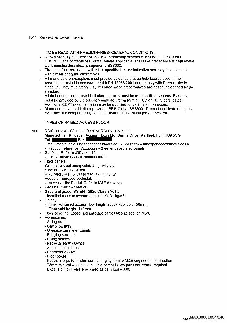
K41 Raised access floors
TO BE READ WITH PRELIMINARIES/ GENERAL CONDITIONS. Notwithstanding the descriptions of workmanship described in various parts of this NBS/NES; the contents of BS8000, where applicable, shall take precedence except where workmanship described is superior to BS8000. The manufacturers noted within this specification are indicative and may be substituted with similar or equal alternatives. All manufacturers/suppliers must provide evidence that particle boards used in their product are tested in accordance with EN 13986:2004 and comply with Formaldehyde class E1. They must verify that regulated wood preservatives are absent as defined by the standard. All timber supplied or used in timber products must be from certified sources. Evidence must be provided by the supplier/manufacturer in form of FSC or PEFC certificates. Additional CEPT documentation may be supplied for verification purposes. Manufacturers should either provide a BRE Global BES6001 Product certificate or supply evidence of a independently certified Environmental Management System.
TYPES OF RAISED ACCESS FLOOR
130 RAISED ACCESS FLOOR GENERALLY- CARPET. Manufacturer: Kingspan Access Floors Ltd, Burma Drive, Marfleet, Hull, HU9 SSG Te l :^^^^^^^H F a x : ^ ^ ^ ^ ^ ^ ^ H Email: [email protected], Web: www.kingspanaccessfloors.co.uk. - Product reference: Woodcore - Steel encapsulated panels.
• Subfloor: Refer to JSO and J40. - Preparation: Consult manufacturer.
• Floor panels: Woodcore steel encapsulated - gravity lay Size: 600 x600 x31mm RGS Medium Duty Class 3 to BS EN 12825 Pedestal: Europed pedestal. - Accessibility: Partial: Referto M&E drawings.
• Pedestal fixing: Adhesive. • Structural grade: BS EN 12825 Class 3/A/3/2
- Installed mass of system (maximum): 31 kg/m 2. • Height:
- Finished raised access floor height above subfloor: 150mm. - Floor void height: 119mm.
• Floor covering: Loose laid antistatic carpet tiles as section MSO. • Accessories:
- Stringers - Cavity barriers - Oversize perimeter panels - Bridging sections - Fixing screws - Pedestal earth clamps - Aluminium foil tape - Perimeter gasket - Floor boxes - Pedestal clips for underfloor heating system to M&E engineers specification - 75mm mineral wool slab acoustic barrier below partitions where required - Expansion joint where required as per clause 336.
MAX00001054 0146 MAX00001054/146

RAISED ACCESS FLOOR GENERALLY- SHEET FINISHES. Manufacturer: Kingspan Access Floors Ltd, Burma Drive, Marfleet, Hull, HU9 SSG T e l : ^ ^ ^ ^ ^ ^ H Fax: ^ ^ ^ ^ ^ ^ H Email: [email protected], Web: www.kingspanaccessfloors.co.uk. - Product reference: Woodcore - Steel encapsulated panels. Subfloor: Referto JSO and J40. - Preparation: Consult manufacturer. Floor panels: Woodcore steel encapsulated - gravity lay Size: 600 x600 x31mm RGS Medium Duty Class 3 to BS EN 12825 Pedestal: Europed pedestal. - Accessibility: Partial: Referto M&E drawings. Pedestal fixing: Adhesive. Structural grade: BS EN 12825 Class 3/A/3/2 - Installed mass of system (maximum): 31 kg/m 2. Height: - Finished raised access floor height above subfloor: 145mm. - Floor void height: 114mm. Floor covering: Sheet flooring as section MSO laid on 6.5mm plywood overlay as clause M50/560. Accessories: - Stringers - Cavity barriers - Oversize perimeter panels - Bridging sections - Fixing screws - Pedestal earth clamps - Aluminium foil tape - Perimeter gasket - Floor boxes - Pedestal clips for underfloor heating system to M&E engineers specification - 75mm mineral wool slab acoustic barrier below partitions where required - Expansion joint where required as per clause 336.
MAX00001054 0147 MAX00001054/147

132 RAISED ACCESS FLOOR STORAGE AREA. Manufacturer: Kingspan Access Floors Ltd, Burma Drive, Marfleet, Hull, HU9 SSG Te l :^^^^^^^H Fax: ^^^^^^^M Email: [email protected], Web: www.kingspanaccessfloors.co.uk. - Product reference: Woodcore - Steel encapsulated panels.
• Subfloor: Refer to JSO and J40. - Preparation: Consult manufacturer.
• Floor panels: Woodcore steel encapsulated - gravity lay Size: 600 x600 x32mm RG6 Heavy Duty Class 3 to BS EN 12825 Alpha 5 pedestal. - Accessibility: Partial: Referto M&E drawings.
• Pedestal fixing: Adhesive. . Structural grade: BS EN 12825 Class 6/A/3/2
- Installed mass of system (maximum): 44 kg/m 2. • Height:
- Finished raised access floor height above subfloor: 145mm. - Floor void height: 113mm.
• Floor covering: Sheet flooring as section MSO laid on 6.5mm plywood overlay as clause M50/560.
• Accessories: - Stringers - Cavity barriers - Oversize perimeter panels - Bridging sections - Fixing screws - Pedestal earth clamps - Aluminium foil tape - Perimeter gasket - Floor boxes - Pedestal clips for underfloor heating system to M&E engineers specification - 75mm mineral wool slab acoustic barrier below partitions where required - Expansion joint where required as per clause 336.
GENERAL/ PERFORMANCE
219 INSTALLATION • Completed installation: Clean and stable. Free from bounce and vibration. No lipping
between floor panels.
234 FIRE PERFORMANCE • Reaction to fire: In accordance with Building Regulations, class 0. • Resistance to fire: To BS 476-20 and -21 , 30 minutes loadbearing capacity and integrity.
239 SOUND TRANSMISSION • Laboratory system test: In accordance with BS EN ISOI 0848-2.
- Airborne sound insulation: 41dB . - Impact sound insulation: 71dB . - Test report: Submit.
MAX00001054 0148 MAX00001054/148
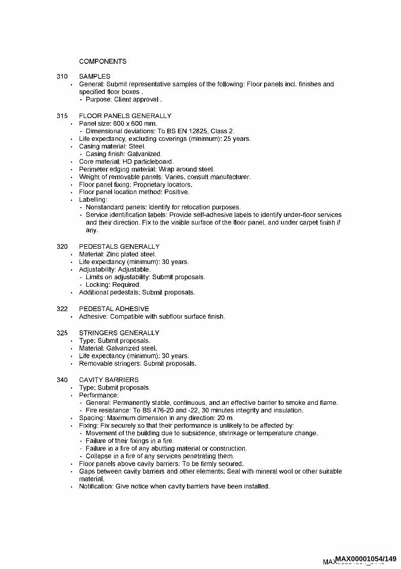
COMPONENTS
310 SAMPLES • General: Submit representative samples ofthe following: Floor panels incl. finishes and
specified floor boxes . - Purpose: Client approval .
315 FLOOR PANELS GENERALLY • Panel size: 600 x 600 mm.
- Dimensional deviations: To BS EN 12825, Class 2. • Life expectancy, excluding coverings (minimum): 25 years. • Casing material: Steel.
- Casing finish: Galvanized. • Core material: HD particleboard. • Perimeter edging material: Wrap around steel. • Weight of removable panels: Varies, consult manufacturer. • Floor panel fixing: Proprietary locators. • Floor panel location method: Positive. • Labelling:
- Nonstandard panels: Identify for relocation purposes. - Service identification labels: Provide self-adhesive labels to identify under-floor services
and their direction. Fix to the visible surface ofthe floor panel, and under carpet finish if any.
320 PEDESTALS GENERALLY • Material: Zinc plated steel. • Life expectancy (minimum): 30 years. • Adjustability: Adjustable.
- Limits on adjustability: Submit proposals. - Locking: Required.
• Additional pedestals: Submit proposals.
322 PEDESTAL ADHESIVE • Adhesive: Compatible with subfloor surface finish.
325 STRINGERS GENERALLY • Type: Submit proposals. • Material: Galvanized steel. • Life expectancy (minimum): 30 years. • Removable stringers: Submit proposals.
340 CAVITY BARRIERS • Type: Submit proposals. • Performance:
- General: Permanently stable, continuous, and an effective barrier to smoke and flame. - Fire resistance: To BS 476-20 and -22, 30 minutes integrity and insulation.
• Spacing: Maximum dimension in any direction: 20 m. • Fixing: Fix securely so that their performance is unlikely to be affected by:
- Movement ofthe building due to subsidence, shrinkage or temperature change. - Failure of their fixings in a fire. - Failure in a fire of any abutting material or construction. - Collapse in a fire of any services penetrating them.
• Floor panels above cavity barriers: To be firmly secured. • Gaps between cavity barriers and other elements: Seal with mineral wool or other suitable
material. • Notification: Give notice when cavity barriers have been installed.
MAX00001054 0149 MAX00001054/149
390 SUNDRY ACCESSORIES EXPANSION JOINTS • Component: Expansion joints.
- Manufacturer: Tremco illbruck Ltd, Bentall Business Park, Washington, tyne and Wear NE37 SJD Tel: ^ H F a x : ^ ^ ^ ^ ^ H Email: [email protected], Web: www.tremco-illbruck.com . Product reference: Compriband Interspan FSN 146-21.
INSTALLATION
410 CONTROL SAMPLES • General: Complete areas of finished work in the following locations: Inspectors & RA
offices/Storage .
421 PREPARATION • Areas where flooring is to be installed: Clean before installation and keep clean during
installation. • Setting out of flooring: Indelibly mark pedestal positions before installing services. • Fixtures: Before installing floor, complete fixtures that floor panels are to be cut around, or
that are to be bridged by floor supports. • Bridging structures - supplementary supports: N/A.
425 ENVIRONMENTAL CONDITIONS • General: Dry, well ventilated, not subject to rapid variations or extremes of temperature or
humidity. • RH of air (maximum): 75%. • Subfloors:
- Moisture content: Test to BS 8201 using an accurately calibrated hygrometer. - RH (maximum): 75%. - Temperature (minimum): 5 0C.
431 DUSTPROOFING • Preparation: Surfaces to be sealed must be clean, dry and free from dust, grease and
other contaminants. • Extent of sealing: Concrete and masonry surfaces within raised access floor void. • Sealer: Recommended by raised access floor manufacturer. Compatible with materials
used to pack and/ or fix pedestals. - Colour: Tinted; different tint for each coat. - First coat: Apply before pedestals are erected. - Second coat: Apply after completion of services and other associated work.
433 PEDESTAL ADHESIVE TESTING • Test method: Submit proposals. • Rate of testing:
- Pre-installation: Submit proposals. - During installation: 1%, selected at random.
• Wtnessing: Arrange for pre-installation testing to be witnessed by: Contract Administrator. • Results of testing during installation: Submit.
MAX00001054 0150 MAX00001054/150

435 CUT FLOOR PANELS • Size (minimum): Half standard width x half standard length. • Edges:
- Burrs and rough edges: Make smooth. - Sealing: Seal exposed cut edges of floor panels that have moisture sensitive or
combustible cores. Sealer: Self adhesive aluminium foil tape, rated class 0 as defined in Building Regulations.
445 PERIMETERS • Expansion gaps:
- Size: 10 mm. - Location: At abutments.
• Expansion gap filling: - Filler type: Resilient closed cell. - Filling: Before fixing skirtings and cover strips.
465 ELECTRICAL CONTINUITY AND EARTH BONDING • Standard: To BS 7671. • Substantial metal parts of raised access floor: Electrically continuous and fully earth
bonded. • Bonding methods: Submit proposals. • Earthing methods: Submit proposals. • Rooms used for electronic data processing equipment: Submit proposal. • Earth bonding connection points: Determine number and location. Provide connectors. • Total resistance of earth fault loop (maximum): Resistance required to operate earth fault
protection devices to BS 7671. • Electrical continuity and earth bonding tests:
- General: Test complete raised access floor. - Points for testing: Randomly selected pedestals, stringers, tops and bottoms of floor
panels.
470 INTEGRAL FINISHES ELECTRICAL RESISTANCE TESTING • Location: Test complete raised access floor. • Extent of testing: Test complete raised access floor. • Testing agent: Qualified electrician.
COMPLETION
510 TOOLS • Floor panel lifting devices: At completion, supply one set of suitable devices for each type
of raised access floor finish installed. Train designated personnel in their use. • Pedestal locking: At completion, supply one set of tools for releasing pedestal locking.
MAX00001054 0151 MAX00001054/151

515 USER INSTRUCTIONS • User manual contents: Include the following:
- Correct method for lifting and replacing floor panels and stringers. - Limitations on sequence, number and positions of floor panels and stringers that can be
removed safely at one time. - Permissible loading, with guidance on use of spreader plates when shifting heavy
equipment and subsequent maintenance. - Methods for installing cabling and ducts to prevent damage to supporting structure. - Methods for cleaning floor panels and integral finishes. - Method for replacing integral floor panel coverings. - Method for adjusting and locking pedestals. - Recommended maintenance methods and frequency.
Minimum maintenance-free life of raised access floor system. Minimum maintenance-free life of replaceable parts where this differs from that ofthe whole system. Minimum period during which replaceable components will be available.
- Installation instructions, including COSHH Assessment.
520 SPARES • General: At completion, supply the following:
Clause 1 3 0 - 5 Panels Clause 1 3 1 - 5 Panels Clause 1 3 2 - 5 Panels.
525 CLEANING • Subfloors: At completion, thoroughly clean accessible areas of subfloors and leave free of
dust and debris. • Raised access floor: Before delivery of items carried by floor, clean thoroughly.
MAX00001054 0152 MAX00001054/152

L Windows/Doors/Stairs
MAX00001054 0153 MAX00001054/153

L10 Windows/ Rooflights/ Screens/ Louvres
MAX00001054 0154 MAX00001054/154

L10 Windows/ Rooflights/ Screens/ Louvres
TO BE READ WITH PRELIMINARIES/ GENERAL CONDITIONS. • Notwithstanding the descriptions of workmanship described in various parts of this
NBS/NES; the contents of BS8000, where applicable, shall take precedence except where workmanship described is superior to BS8000.
• The manufacturers noted within this specification are indicative and may be substituted with similar or equal alternatives.
• Manufacturers should either provide a BRE Global BES6001 Product certificate or supply evidence of a independently certified Environmental Management System.
GENERAL
110 EVIDENCE OF PERFORMANCE • Certification: Provide independently certified evidence that all incorporated components
comply with specified performance requirements.
111 EVIDENCE OF BREAAM RATING • Certification: Provide independently certified evidence that all incorporated new windows
achieve minimum BRE Green Guide rating B for Domestic Use.
150 DAYLIGHT PERFORMANCE • Daylight calculations: In accordance with BS 8206-2 and CIBSE 'Lighting guide LG10'. • BREEAM requirements:
- Submit: Daylight performance schedule. - Calculations showing: Average daylight factor expressed as a percentage for each room/
area.
PRODUCTS
205 WINDOW MATERIALS SPECIFICATION • Minimum BRE 'Green Guide to Specification Online' rating: B.
MAX00001054 0155 MAX00001054/155

ALUMINIUM WINDOWS SIDE & BOTTOM HUNG - TILT & TURN OPENING Manufacturer: Wcona - UK. www: http://www.wicona.co.uk Contact: Stuart Pollard (Specification Manager London) HBS Centre, Silkwood Park, Wakefield WF5 9TG
T: ^ ^ ^ ^ ^ H F: E: [email protected].
- Product reference: Wcline 65 evo. Finish as delivered: Polyester powder coating. Glazing details: Argon filled insulating glass units to achieve minimum U-value 1.6W/m2K. - Inner pane: 6mm low E clear toughened glass. - Outer pane:
Generally: 6mm clear toughened glass GF/Mezzanine: min Smm clear laminated glass. Transluscent where indicated on
the drawings to provide privacy . Glazing system: Mechanical corner cleats and stainless steel corner braces; EPDM gaskets . - Beading: Internal snap on aluminium box beads . Ironmongery/ Accessories: As determined by the sub-contractor to fully complete the installation and interfaces with other installations. Including but not limited to: colour coordinated hinges and locking handles, multipoint locking, releasable restrictors, couplings, sill/head/abutment flashings, vapour barriers and air seals . Fixing: Aluminium extrusion angles fixed to the existing concrete structure, fixing the window top and bottom. Manufacturer: Harley Curtain Wall UK Ltd, Harley House, Brooklands Park, Farningham Road, Crowborough, East Sussex, TN6 2JD, Contact: MARK HARRIS ^ ^ ^ ^ ^ ^ Commercial Manager Tel: ^ ^ ^ ^ ^ ^ ^ | . Galvanised steel frame cramps to concrete reveal as clause 782 if required. .
MAX00001054 0156 MAX00001054/156

332 ALUMINIUM WINDOWS FIXED UNIT - ALUMINIUM Manufacturer: Wcona - UK. www: http://www.wicona.co.uk Contact: Stuart Pollard (Specification Manager London) HBS Centre, Silkwood Park, Wakefield WF5 9TG
M : ^ ^ ^ ^ ^ H T: ^ ^ ^ ^ ^ H F: E: [email protected].
- Product reference: Submit proposals. • Finish as delivered: Polyester powder coating. • Panel/ facing type: Aluminium faced insulated panel comprising core insulation, aluminium
lining panel and integrated channel profile around perimeter, fully air-sealed at edges to achieve minimum U-value 0.15W/m2K. - External material: Aluminium panel. - External finish: Polyester powdercoated. Colour TBC. - Internal material: Aluminium sheet. - Internal finish: Polyester powder coated, colour TBC
• Panel retention system: Mechanical corner cleats and stainless steel corner braces; EPDM gaskets. - Beading: Internal snap on aluminium box beads.
• Ironmongery/Accessories: As determined by the sub-contractor to fully complete the installation and interfaces with other installations. Including but not limited to: couplings, sill/head/abutment flashings, vapour barriers and air seals. Allow for M&E penetration (for ventilation ducts) where required.
• Fixing: Galvanised steel frame cramps to masonry/concrete reveal as clause 782.
332A ALUMINIUM WINDOWS FIXED UNIT - GLASS Manufacturer: Wcona - UK. www: http://www.wicona.co.uk Contact: Stuart Pollard (Specification Manager London) HBS Centre, Silkwood Park, Wakefield WF5 9TG
E: [email protected]. - Product reference: Submit proposals.
• Finish as delivered: Polyester powder coating. • Panel/ facing type: Glass faced insulated panel comprising ceramic coated argon filled
insulated glass units, foil backed insulation and aluminium lining panel and integrated channel profile around perimeter, fully air-sealed at edges to achieve minimum U-value 0.15W/m2K. - External material: Glass. - External finish: Colour TBC. - Internal material: Aluminium sheet. - Internal finish: Polyester powder coated, colour TBC
• Panel retention system: Mechanical corner cleats and stainless steel corner braces; EPDM gaskets. - Beading: Internal snap on aluminium box beads.
• Ironmongery/Accessories: As determined by the sub-contractor to fully complete the installation and interfaces with other installations. Including but not limited to: couplings, sill/head/abutment flashings, vapour barriers and air seals.
• Fixing: Galvanised steel frame cramps to masonry/concrete reveal as clause 782.
MAX00001054 0157 MAX00001054/157
650 METAL LOUVRES • Manufacturer: RENSON Fabrications Ltd, Fairfax Units 1-5 - Bircholt Roac^Padwood
Industrial Estate, Maidstone - Kent ME15 9SF - United Kingdom. Tel: ^ ^ ^ ^ ^ ^ ^ ^ H Email: [email protected]. Website: www.rensonuk.net. - Product reference: Continuous louvre LO66 (TBC)
Location: External ventilation shafts for basement area. Referto Architect's drawings. • Material: Aluminium.
- Finish as delivered: Powder coated. Colour TBC. • Fire resistance rating: Not applicable. • Number of louvre banks: As recommended by manufacturer. • Louvre blade pitch and angle: 66mm (TBC). • Blanking panels: Not required. • Accessories/Other requirements:
- Free area to Environmental Engineer's requirement - Insect mesh - Water penetration protection class B - Drainage channel to bottom of louvre - Secure and vandal proof fixing - Secure to withstand manual attack.
• Fixing: To subcontractor's design. Secure and vandal proof fixing. Submit proposals. Indicative design intent shown on Architect's drawing 1279 (06) 122.
650A METAL LOUVRES [TO COVER OPENING VENTS as indicated on the drawings]
• Manufacturer: Submit proposals. - Product reference: Submit proposals.
• Material: Aluminium. - Finish as delivered: Powder coated.
• Fire resistance rating: Not applicable. • Number of louvre banks: One. • Louvre blade pitch and angle:
- Pitch: 50mm - Angle: 45°.
• Blanking panels: TBC. • Accessories/Other requirements:
- Free area to Environmental Engineer's requirement - Bird mesh - Secure to withstand manual attack on ground and mezzanine floors.
• Fixing: Surface fixed to window frame. Secure and vandal proof fixing. Submit proposals.
690A AUTOMATED OPENING VENTS FOR HOT SMOKE RELEASE • Manufacturer: Submit proposals.
- Product reference: Submit proposals. • Type: Submit proposals in line with performance criteria described in drawings (TBC) and
Fire Strategy Report. • Finish as delivered: to match adjacent window vents.
- Colour: to match adjacent windows. • Accessories/ Special features: Provide smoke vent(s) (TBC), including actuators, fully
automated in line with Engineer's specification. • Fixing: Part of window assembly - compatible with window manufacturer's design.
MAX00001054 0158 MAX00001054/158
EXECUTION
710 PROTECTION OF COMPONENTS • General: Do not deliver to site components that cannot be installed immediately or placed
in clean, dry floored and covered storage. • Stored components: Stack vertical or near vertical on level bearers, separated with spacers
to prevent damage by and to projecting ironmongery, beads, etc.
730 PRIMING/SEALING • Wood surfaces inaccessible after installation: Prime or seal as specified before fixing
components.
765 WINDOW INSTALLATION GENERALLY • Installation: Into prepared openings. • Gap between frame edge and surrounding construction:
- Minimum: Smm. - Maximum: 10mm.
• Distortion: Install windows without twist or diagonal racking.
782 FIXING OF ALUMINIUM FRAMES • Standard: As section Z20. • Fasteners: Galvanized carbon steel frame cramps.
- Spacing: When not predrilled or specified otherwise, position fasteners not more than 250 mm from ends of each jamb, adjacent to each hanging point of opening lights, and at maximum 600 mm centres.
810 SEALANT JOINTS • Sealant:
- Manufacturer: Submit proposals. Product reference: Submit proposals.
- Colour: TBC. - Application: As section Z22 to prepared joints. Finish triangular fillets to a flat or slightly
convex profile.
820 IRONMONGERY • Fixing: Assemble and fix carefully and accurately using fasteners with matching finish
supplied by ironmongery manufacturer. Do not damage ironmongery and adjacent surfaces.
• Checking/ Adjusting/ Lubricating: Carry out at Completion and ensure correct functioning.
MAX00001054 0159 MAX00001054/159

L20 Doors/ shutters/ hatches
MAX00001054 0160 MAX00001054/160
L20 Doors/ shutters/ hatches
TO BE READ WITH PRELIMINARIES/ GENERAL CONDITIONS. • Notwithstanding the descriptions of workmanship described in various parts of this
NBS/NES; the contents of BS8000, where applicable, shall take precedence except where workmanship described is superior to BS8000.
• The manufacturers noted within this specification are indicative and may be substituted with similar or equal alternatives.
• All manufacturers/suppliers of plywood and particle board must provide evidence that their product is tested in accordance with EN 13986:2004 and complies with Formaldehyde class E1. They must verify that regulated wood preservatives are absent from their product as defined by the standard.
• All timber supplied or used in timber products must be from certified sources. Evidence must be provided by the supplier/manufacturer in form of FSC or PEFC certificates. Additional CEPT documentation may be supplied for verification purposes.
• Manufacturers should either provide a BRE Global BES6001 Product certificate or supply evidence of a independently certified Environmental Management System.
GENERAL
110 EVIDENCE OF PERFORMANCE • Certification: Provide independently certified evidence that all incorporated components
comply with specified performance requirements.
115 FIRE RESISTING DOORS/ DOORSETS/ ASSEMBLIES • Evidence of fire performance: Provide certified evidence, in the form of a product
conformity certificate, directly relevant fire test report or engineering assessment, that each door/ doorset/ assembly supplied will comply with the specified requirements for fire resistance if tested to BS 476-22, BS EN 1634-1 or BS EN 1634-3. Such certification must cover door and frame materials, glass and glazing materials and their installation, essential and ancillary ironmongery, hinges and seals.
120 NON FIRE RESISTING DOORS/ DOORSETS/ASSEMBLIES • Provide certified evidence, in the form of a product conformity certificate or engineering
assessment, that each door/ doorset/ assembly supplied will comply with the specified requirements to BS EN 14351-1. Such certification must cover door and frame materials, glass and glazing materials and their installation, essential and ancillary ironmongery, hinges and seals.
150 SITE DIMENSIONS • Procedure: Before starting work on designated items take site dimensions, record on shop
drawings and use to ensure accurate fabrication. • Designated items: TBC.
170 CONTROL SAMPLES • Procedure:
- Finalize component details. - Fabricate one of each ofthe following designated items as part ofthe quantity required
for the project. - Obtain approval of appearance and quality before proceeding with manufacture ofthe
remaining quantity. • Designated items: Internal door.
MAX00001054 0161 MAX00001054/161
PRODUCTS
280 DOORS STEEL EXTERNAL • Manufacturer: Prima Doors Ltd, Newby Road Industrial Estate, Hazel Grove, Cheshire SK7
5DA T e l . ^ ^ ^ ^ ^ ^ ^ ^ Fax. ^ ^ ^ ^ ^ ^ ^ H Web. www.primadoors.co.uk, Email [email protected]. - Product reference: Secureguard Grade 2.
• Finish as delivered: Polyester powder coated to BS 6496, RAL colour and gloss level TBC. • Glazing/ Infill details: Not applicable.
- Manifestation: Not applicable. - Beading: Not required.
• Ironmongery: As ironmongery schedule. • Other requirements:
- Prima standard seals -Threshold in compliance with Building Reg. AD Part M and BS8300:2009+A1:2010.
410 WOOD DOORSETS INTERNAL • Manufacturer: Leaderflush Shapland, Head Office, Milnhay Road, Langley Mill,
Nottingham^&ie 4AZ T e l : ^ ^ ^ ^ ^ ^ ! , Fax: Web: www.leaderflushshapland.co.uk, Email: [email protected]. - Product reference: Designer.
• Door leaf: - Facings: MDF board. - Lippings: 3 mm hardwood lippings to long edges. - Finish as delivered: Full factory finish (Velvalux Opaque paint system).
- Colour/texture: RAL colour and gloss level TBC. - Core: Medium duty.
• Frame and architraves: - Wood species: MDF.
- Frame type: Split frame with integral architraves and planted stop (Cubith). - Finish as delivered: Full factory finish (Velvalux Opaque paint system).
- Colour/texture: RAL colour and gloss level TBC. • Preservative treatment: Not required. • Glazing/ Infill details: Clear single glazing where specified in door schedule.
- Manifestation: Not required. - Beading: External to manufacturer's standard.
• Ironmongery: As ironmongery schedule. • Perimeter seals: Not required. • Other requirements: Finger guard required for doors installed in nursery. • Fixing: Predrilled, plugged and screwed with colour matched pellets.
MAX00001054 0162 MAX00001054/162
411 WOOD DOORSETS INTERNAL FD30S • Manufacturer: Leaderflush Shapland, Head Office, Milnhay Road, Langley Mill,
Nottingham, NG16 4AZ Tel: 01773 530500, Fax: 01773 530040 Web: www.leaderflushshapland.co.uk, Email: [email protected]. - Product reference: Designer.
• Door leaf: - Facings: MDF board. - Lippings: 3 mm hardwood lippings to long edges. - Finish as delivered: Full factory finish (Velvalux Opaque paint system). - Colour/texture: RAL colour and gloss level TBC. - Core:
Generally: Heavy duty. Wthin flats: Medium duty.
• Frame and architraves: - Wood species: Maple. - Frame type: Split frame with integral architraves and planted stop (Cubith). - Finish as delivered: Full factory finish, (Velvalux Opaque paint system). - Colour/texture: RAL colour and gloss level TBC.
• Preservative treatment: Not required. • Glazing/ Infill details: Clear fire-resisting glazing to achieve FD30S rating where specified in
door schedule. - Manifestation: Not required. - Beading: External to manufacturer's standard.
• Ironmongery: As ironmongery schedule. • Perimeter seals: Fire and smoke seal as required to achieve FD30S rating. • Other requirements: Finger guard required for doors installed in nursery. • Fixing: Predrilled, plugged and screwed with colour matched pellets.
412 WOOD DOORSETS INTERNAL FD60S • Manufacturer: Leaderflush Shapland, Head Office, Milnhay Road, Langley Mill,
Nottingham, NG16 4AZ Tel: ^ ^ ^ ^ ^ p a x : ^^^^^^^g Web: www.leaderflushshapland.co.uk, Email: [email protected]. - Product reference: Designer.
• Door leaf: - Facings: MDF board. - Lippings: 3 mm hardwood lippings to long edges. - Finish as delivered: Full factory finish (Velvalux Opaque paint system). - Colour/texture: RAL colour and gloss level TBC. - Core: Heavy duty.
• Frame and architraves: - Wood species: Maple. - Frame type: Split frame with integral architraves and planted stop (Cubith). - Finish as delivered: Full factory finish (Velvalux Opaque paint system). - Colour/texture: RAL colour and gloss level TBC.
• Preservative treatment: Not required. • Glazing/ Infill details: Clear fire-resisting glazing to achieve FD60S rating where specified
in door schedule. - Manifestation: Not required. - Beading: External to manufacturer's standard.
• Ironmongery: As ironmongery schedule. • Perimeter seals: Fire and smoke seal as required to achieve FD60S rating. • Other requirements: Finger guard required for doors installed in nursery. • Fixing: Predrilled, plugged and screwed with colour matched pellets.
MAX00001054 0163 MAX00001054/163
490 AUTOMATIC DOORS MAIN ENTRANCE • Type: Fully automatic electro-hydraulic swing door operator. • Manufacturer: DORMA UK Limited, Automatics division, Wilbury Way, Hitchin,
Hertfordshire, SG4 OAB Tel: ^^^^^^^B F a x M M M H M M Email: [email protected], Web: www.dorma-uk.co.uk. - Product reference: DORMA ED 200.
• Materials/finishes: - Doors: Aluminium. - Frames: Aluminium. - Screens: Aluminium
- Finishes: Polyester powder coated to BS 6496, colour RAL and gloss level (TBC). • Glazing/ Infill details:
- 6.4mm laminated outer pane - argon filled cavity - 6mm toughened inner pane with soft low emissive coating - U-value not exceeding 1.6W/m2K. - Manifestation: As drawing.
• Activation and control system: o Adjustable opening angle; o Variable opening, closing and hold open times; o Adjustable backcheck; o Adjustable delayed action; o Adjustable wall blanking for safety sensors; o External program switch (integrated 3-position program switch as standard); o Monitored battery back up to keep door shut (fail secure) in case of a power failure or upon a signal from the interfaced fire alarm system . - Safety devices:
o DORMA IRS-2 infrared safety sensors; o DORMA SVP emergency exit motor locking with self-locking action .
- Breakout facility: Emergency Break glass . • Locking mechanism: Electric strikes (fail secure principal). • Signs: As per ironmongery schedule . • Barriers: Required . • Other requirements:
o Threshold in compliance with Building Reg. AD Part M and BS8300:2009+A1:2010; o Installation to be carried out by manufacturer's engineers; installed to BS 7036 .
MAX00001054 0164 MAX00001054/164

525 SLIDING POCKET DOORS BATHROOMS IN FLATS • Manufacturer: Portman Pocket Doors, C/o Royde & Tucker Ltd, Bilton Road, Cadwell
Lane, Hitchin SG4 OSB ^ ^ ^ ^ ^ ^ ^ Tel: • • • • • • F a x : ^ ^ ^ ^ ^ ^ ^ | Web: www.-pocketdoors.co.uk, E-mail: [email protected]. - Product reference: FD30 Fire Door Kit.
• Performance: Fire resistance: FD30 UKAS certified. • Arrangement: Single leaf.
- Track system: As supplied - Finish: Painted, full factory finish, RAL colour and gloss level TBC.
• Door leaf: 44mm - Core: Medium duty - Facings: MDF. - Finish as delivered: Painted, full factory finish, RAL colour and gloss level TBC. - Glazing/ Infill details: Not required.
Manifestation: Not applicable. • Operation: Manual. • Ironmongery: As ironmongery schedule. • Other requirements: Factory finished timber door linings to be delivered complete with
intumescent fire seals and pre-cut and formed plasterboard sections to be wrapped around the sub-frame providing required fire integrity.
610 ROLLER SHUTTERS/ CURTAINS CONCIERGE DESK • Manufacturer: Armashield LLP, Innovation House, Marples Way, Havant, Hampshire P09
1UH Tel: - ^ M ^ ^ ^ ^ ^ ^ ^ H Fax: ^ g ^ ^ ^ ^ g ^ ^ Web: www.armashieldsecurity.com, email: [email protected]. - Product reference: Rollashield FC120.
• Performance: Fire and smoke curtain, 120 minutes fire rated. • Arrangement: Vertical, fitted into reveal. • Shutter/ curtain material: 0.65 mm fire rated fabric stitched and hemmed with Kevlar and
stainless steel thread. - Finish as delivered: Polyester powder coated, RAL colour and gloss level TBC.
• Frame/ Guides: Galvanized steel. - Finish as delivered: Polyester powder coated, RAL colour and gloss level TBC.
• Operation: Electrical, controlled release activated by fire alarm link via audio visual warning unit (FDI) - Motor: Manufacturer's standard.
• Ironmongery: N/A. • Other requirements: All interfaces to adjacent structural and non-structural elements to be
120min fire rated and smoke tight.
MAX00001054 0165 MAX00001054/165

612 ROLLER GRILLES INSPECTORS & RA OFFICES • Manufacturer: Armashield LLP, Innovation House, Marples Way, Havant, Hampshire P09
1UH T e l : ^ ^ ^ ^ ^ ^ ^ ^ ^ ^ H Fax: Web: www.armashieldsecurity.com, email: [email protected] . - Product reference: Armalink 95 . Arrangement: Vertical, fitted into reveal . Grille curtain: Galvanized steel . - Finish as delivered: Polyester powder coated, RAL colour and gloss level TBC . Frame/ Guides: Galvanized steel . - Finish as delivered: Polyester powder coated, RAL colour and gloss level TBC . Operation: Electrical, with key switch - Motor: Manufacturer's standard . Ironmongery: N/A . Other requirements: As recommended by manufacturer.
613 ROLLER GRILLES EBM, CONCIERGE & NURSERY • Manufacturer: Armashield LLP, Innovation House, Marples Way, Havant, Hampshire P09
1 U H ^ ^ ^ ^ ^ ^ ^ ^ Tel: ^^^^^^^^^^B F a x : ^ ^ ^ ^ ^ ^ ^ ^ ^ ^ H Web: www.armashieldsecurity.com, email: [email protected] . - Product reference: Armroll AL .
• Arrangement: Vertical, fitted into reveal . • Grille curtain: Single-skinned extruded aluminium flat lath, brick-bond punched .
- Finish as delivered: Polyester powder coated, RAL colour and gloss level TBC . • Frame/ Guides: Aluminium .
- Finish as delivered: Polyester powder coated, RAL colour and gloss level TBC . • Operation: Spring-assist manual operation . • Ironmongery: N/A. • Other requirements:
- To be installed to the inside of fenestration. - All accessories required to complete installation to be included .
EXECUTION
710 PROTECTION OF COMPONENTS • General: Do not deliver to site components that cannot be installed immediately or placed
in clean, dry, floored and covered storage. • Stored components: Stacked on level bearers, separated with spacers to prevent damage
by and to projecting ironmongery, beads, etc.
730 PRIMING/SEALING • Wood surfaces inaccessible after installation: Primed or sealed as specified before fixing
components.
750 FIXING DOORSETS • Timing: After associated rooms have been made weathertight and the work of wet trades is
finished and dried out.
760 BUILDING IN • General: Not permitted unless indicated on drawings.
790 FIXING OF WOOD FRAMES • Spacing of fixings (frames not predrilled): Maximum 150 mm from ends of each jamb and
at 600 mm maximum centres.
MAX00001054 0166 MAX00001054/166
800 FIXING OF LOOSE THRESHOLDS • Spacing of fixings: Maximum 150 mm from each end and at 600 mm maximum centres.
809 FIRE RESISTING/ SMOKE CONTROL DOORS/ DOORSETS/ ROLLER SHUTTERS/ CURTAINS
• Installation: By a firm currently registered under a third party accredited fire door installer scheme in accordance with instructions supplied with the product conformity certificate, test report or engineering assessment.
820 SEALANT JOINTS • Sealant:
- Manufacturer: Contractor's choice . Product reference: Contractor's choice .
- Colour: TBC . - Application: As section Z22 to prepared joints. Triangular fillets finished to a flat or
slightly convex profile.
830 FIXING IRONMONGERY GENERALLY • Fasteners: Supplied by ironmongery manufacturer.
- Finish/ Corrosion resistance: To match ironmongery. • Holes for components: No larger than required for satisfactory fit/ operation. • Adjacent surfaces: Undamaged. • Moving parts: Adjusted, lubricated and functioning correctly at completion.
840 FIXING IRONMONGERY TO FIRE RESISTING DOOR ASSEMBLIES • General: All items fixed in accordance with door leaf manufacturer's recommendations
ensuring that integrity ofthe assembly, as established by testing, is not compromised. • Holes for through fixings and components: Accurately cut.
- Clearances: Not more than 8 mm unless protected by intumescent paste or similar. - Lock/ Latch cases for fire doors requiring > 60 minutes integrity performance: Coated
with intumescent paint or paste before installation.
850 LOCATION OF HINGES • Primary hinges: Where not specified otherwise, positioned with centre lines 250 mm from
top and bottom of door leaf. • Third hinge: Where specified, positioned with centre line 250 mm below centre line of top
hinge . • Hinges for fire resisting doors: Positioned in accordance with door leaf manufacturer's
recommendations.
860 INSTALLATION OF EMERGENCY EXIT DEVICES • Standard: Unless specified otherwise, install panic bolts/ latches in accordance with BS EN
1125.
MAX00001054 0167 MAX00001054/167

LSO Stairs/ ladders/walkways/ handrails/ balustrades
MAX00001054 0168 MAX00001054/168
LSO Stairs/ ladders/ walkways/ handrails/ balustrades
TO BE READ WITH PRELIMINARIES/ GENERAL CONDITIONS. • Notwithstanding the descriptions of workmanship described in various parts of this
NBS/NES; the contents of BS8000, where applicable, shall take precedence except where workmanship described is superior to BS8000.
• The manufacturers noted within this specification are indicative and may be substituted with similar or equal alternatives.
• Manufacturers should either provide a BRE Global BES6001 Product certificate or supply evidence of a independently certified Environmental Management System.
PRELIMINARY INFORMATION/ REQUIREMENTS
130 SITE DIMENSIONS • Procedure: Before starting work on designated items take site dimensions, record on shop
drawings and use to ensure accurate fabrication. - Designated items: Balustrades.
COMPONENTS
550 PURPOSE MADE BALUSTRADES INTERNAL STAIR & LOBBY VOID • Component material, grade and finish as delivered:
- Guarding: Powder coated flat steel uprights with 12mm clear toughened safety glass infill - Finish/texture: RAL colour and gloss level TBC.
- Handrails: Stainless steel - brushed CHS nominal 50mm dia. Lower handrail: Not required - Height of guarding: 1300mm in total.
• Workmanship: - Joinery: Not applicable. - Metalwork: To section Z11.
• Other requirements: - Welding to be ground smooth - Guarding to be in compliance with AD part K and N.
• Fixing: Side fixed to insitu concrete floor slab and stair edge as per architect's and structural engineer's drawings. - Centres: As per architect's and structural engineer's drawings.
551 PURPOSE MADE BALUSTRADES TO EXTERNAL WALKWAY • Component material, grade and finish as delivered:
- Guarding: Powder coated RHS steel uprights with perforated powder coated steel infill panels - Finish/texture: RAL colour and gloss level TBC.
- Handrails: Stainless steel - brushed CHS nominal 50mm dia. Lower handrail: Not required - Height of guarding: 110Omm in total.
• Workmanship: - Joinery: Not applicable. - Metalwork: To section Z11.
• Other requirements: - Welding to be ground smooth - Guarding to be in compliance with AD part K and N.
• Fixing: Side fixed to steel as per architect's and structural engineer's drawings. - Centres: As per architect's and structural engineer's drawings.
MAX00001054 0169 MAX00001054/169
570 PURPOSE MADE HANDRAILS TO STAIRS • Component material, grade and finish as delivered:
- Handrails: Stainless steel - brushed CHS nominal 50mm dia. Lower handrail: Not required.
- Brackets: Stainless steel - brushed. • Workmanship:
- Joinery: Not applicable. - Metalwork: To section Z11.
• Other requirements: Welding to be ground smooth. • Fixing: Face fixed to curtain walling and concrete wall.
- Centres: As per architect's drawings.
INSTALLATION
620 PRIMING/SEALING/PAINTING • Surfaces inaccessible after assembly/installation: Before fixing components, apply full
protective/decorative treatment/coating system.
630 CORROSION PROTECTION OF DISSIMILAR MATERIALS • Components/ substrates/ fasteners of dissimilar materials: Isolate using washers/ sleeves
or other suitable means to separate materials to avoid corrosion and/ or staining.
640 INSTALLATION GENERALLY • Fasteners and methods of fixing: To section Z20. • Structural members: Do not modify, cut, notch or make holes in structural members, except
as indicated on drawings. • Temporary support: Do not use stairs, walkways or balustrades as temporary support or
strutting for other work. • Applied finishes: Substrates to be even, dry, sound and free from contaminants. Make
good substrate surfaces and prepare/ prime as finish manufacturer's recommendation before application.
COMPLETION
910 INSPECTION • Timing: Consult main contractor. • Period of notice (minimum): Consult main contractor.
920 DOCUMENTATION • Contents:
- Copies of structural design calculations/test reports. - General product information. - Installation information. - Inspection and maintenance reports.
• Number of copies: Consult main contractor. • Submission: Consult main contractor.
MAX00001054 0170 MAX00001054/170

L40 General glazing
MAX00001054 0171 MAX00001054/171
L40 General glazing
TO BE READ WITH PRELIMINARIES/ GENERAL CONDITIONS. • Notwithstanding the descriptions of workmanship described in various parts of this
NBS/NES; the contents of BS8000, where applicable, shall take precedence except where workmanship described is superior to BS8000.
• The manufacturers noted within this specification are indicative and may be substituted with similar or equal alternatives.
• Manufacturers should either provide a BRE Global BES6001 Product certificate or supply evidence of a independently certified Environmental Management System.
GENERAL REQUIREMENTS
150 WORKMANSHIP GENERALLY • Glazing generally: To BS 6262. • Integrity: Glazing must be wind and watertight under all conditions with full allowance made
for deflections and other movements. • Dimensional tolerances: Panes/ sheets to be within ± 2 mm of specified dimensions. • Materials:
- Compatibility: Glass/ plastics, surround materials, sealers, primers and paints/ clear finishes to be used together to be compatible. Avoid contact between glazing panes/ units and alkaline materials such as cement and lime.
- Protection: Keep materials dry until fixed. Protect insulating glass units and plastics glazing sheets from the sun and other heat sources.
155 GLASS GENERALLY • Standards: To BS 952 and relevant parts of:
- BS EN 572 for basic soda lime silicate glass. - BS EN 1096 for coated glass. - BS EN 1748-1 for borosilicate glass. - BS EN 1748-2 for ceramic glass. - BS EN 1863 for heat strengthened soda lime silicate glass. - BS EN 12150 for thermally toughened soda lime silicate safety glass. - BS EN 12337 for chemically strengthened soda lime silicate glass. - BS EN 13024 for thermally toughened borosilicate safety glass. - BS EN ISO 12543 for laminated glass and laminated safety glass.
• Panes/sheets: Clean and free from obvious scratches, bubbles, cracks, rippling, dimples and other defects. - Edges: Generally undamaged. Shells and chips not more than 2 mm deep and
extending not more than 5 mm across the surface are acceptable if ground out.
MAX00001054 0172 MAX00001054/172
TYPES OF GLAZING
230 BEAD FIXED SINGLE GLAZING TO INTERNAL DOORSETS • Pane material: Laminated or toughened glass to BS6206
- Thickness: to be determined by manufacturer to suit pane size; - Manufacturer: Submit proposal .
• Surround/ bead: Softwood frame with hardwood beads . - Preparation: Prime and paint as M60/133 . - Bead location: Outside . - Bead fixing: Pinned or screwed;
Beads fixed on both sides, to be determined by manufacturer dependent on frame/rebate detail .
• Glazing compound: Nonsetting compound . • Glazing installation:
- Glass: Located centrally in surround using setting and location blocks and distance pieces.
- Finished thickness of back bedding after inserting glazing (minimum): 3 mm. - Front bedding: Applied to fill voids. - Beads: Bedded in glazing compound and fixed securely. - Visible edge of glazing compound: Finished internally and externally with a smooth
chamfer.
250 BEAD FIXED SINGLE GLAZING TO INTERNAL FIRE-RATED DOORSETS • Pane material:
- 10mm fire rated glazing to be Pilkington Pyrodur™ Glass; - Glazing Manufacturer:
Pilkington United Kingdom Limited, Head Office, Prescot Road, St Helens, Merseyside, WA10 3TT
Tel: iNHHMB, F a x : ^ ^ ^ ^ ^ ^ ^ ^ Web: www.pilkington.com .
• Surround/ bead: Softwood frame with hardwood beads . - Preparation: Prime and paint as M60/133 . - Bead location: Outside . - Bead fixing: Screw fixed with brass cups and screws .
• Glazing system: - Tape: As per manufacturer's recommendations . - Bead bedding sealant: One-part, fire rated intumescent acrylic sealant . - Capping sealant: Not required .
• Glazing installation: - Glass: Located centrally in surround using setting and location blocks. - Glazing tape: Top edge approximately 6 mm short of sight line on external side of
glazing, to allow for capping sealant. Corners butt jointed with no gaps. - Thickness of glazing tape bed (minimum): 3 mm on both sides of glazing after
compression. - Beads: Bedded in sealant, pressed firmly into position to compress tape, and fixed
securely. - Excess tape on internal side: Carefully trimmed to a smooth chamfer. - Capping sealant: Applied to fill void between bead and glazing and finished to a smooth
chamfer.
MAX00001054 0173 MAX00001054/173

390 SINGLE GLAZED SLIDING WINDOW CONCIERGE AND BOXING CLUB OFFICE • System type: 2 No. Pane. • Channel/surround:
- Manufacturer: Savekers Limited, 101 Aldridge Road, Perry Barr, Birmingham, B42 2TS
E: [email protected], www.savekers.com. - Product reference: Heavislide system. - Finish: Polished aluminium.
• System fixing: Bottom Track - Double bottom track fixed through counter top to timber plate. Abutment - Side track fixed through PPC aluminium pressing to timber batten. Head Track - Double top track fixed through PPC aluminium plate to timber frame.
• Glass: 10mm toughened glass, all edges polished. • Installation: In accordance with manufacturer's recommendations. • Accessories: As required to achieve complete system installation, to include but not limited
to: - Draught excluder clips. - 38mm finger hole. - End stops. - Security plunger lock - satin chrome finish.
• Other requirements: Additional framing support as required.
505 FIRE RESISTANT TAPE/ STRIP GLAZING TO ENTRANCE LOBBY • Fire resistance rating: 120 minutes integrity and insulation . • Pane material: Intumescent laminated glass - internal grade
- Manufacturer: Pilkington Building Products Prescot Road, St Helens, WA10 3TT T e l : ^ ^ ^ ^ ^ ^ H F a x ^ ^ ^ ^ ^ ^ ^ l email: [email protected], Web: www.pilkington.co.uk. - Product reference: Pyrostop 120-104 = 23mm Pyrostop 60-101 / 6mm steel spacer/ 23mm Pyrostop 60-101 . - Orientation: As recommended by manufacturer.
• Frame/ Surround material: Rectangular hollow section steel frame, joints to substrate filled with mineral wool .
• Beads: - Material: Steel angles with extruded aluminium snap-on capping . - Location: Both sides . - Fixing: 38 mm long No 8 stainless steel screws and cups at maximum 200 mm centres .
• Glazing system: - Tape/ Strip: Ceramic fibre tape . - Pointing sealant: Silicone mastic .
• Installation: By a firm currently registered under a UKAS certified accreditation scheme for the installation of fire resistant glazing, in accordance with glazing manufacturer's recommendations.
520 FIRE RATING • Assessment of capability: Submit proposed construction details of designated items to a
UKAS/ NAMAS accredited laboratory or other approved authority for assessment of capability of achieving specified fire ratings. - Test standard: To BS 476-22.
• Assessment/test results and reports: Submit immediately they are available, and before installing glazing.
• Designated items: Screen between entrance lobby and lift core.
MAX00001054 0174 MAX00001054/174

630 MANIFESTATION TO GLAZED FIRE RATED SCREEN . Design: Two SOmm bands of dots.
- Art work: Not applicable. - Media: Scale drawings.
. Technique: Applied film.
MAX00001054_0175 MAX00001054/175

M Surface finishes
MAX00001054 0176 MAX00001054/176

M10 Cement based levell ing/wearing screeds
MAX00001054 0177 MAX00001054/177

M10 Cement based levelling/ wearing screeds
TO BE READ WITH PRELIMINARIES/GENERAL CONDITIONS. • Notwithstanding the descriptions of workmanship described in various parts of this
NBS/NES; the contents of BS8000, where applicable, shall take precedence except where workmanship described is superior to BS8000.
• The manufacturers noted within this specification are indicative and may be substituted with similar or equal alternatives.
• Manufacturers should either provide a BRE Global BES6001 Product certificate or supply evidence of a independently certified Environmental Management System.
TYPES OF SCREED
130 PROPRIETARY QUICK DRYING LEVELLING SCREEDS FLOATING CONSTRUCTION • Substrate: In situ concrete slab. • Screed manufacturer: Flowcrete UK Limited, The Flooring Technology Centre, Booth Lane,
Sandbach, Cheshire, CW11 3QF T e l : ^ ^ ^ ^ ^ ^ ^ F a x : ^ ^ ^ ^ ^ ^ H Email: [email protected], Web: www.flowcrete.com. - Product reference: Isocrete Heavy Duty Fast-K.
• Screed construction: Unbonded, as clause 280. - Reinforcement for crack control: PP Fibres with a strip of steel fabric to BS4483 ref. D49
across day joints. • Thickness:
- Nominal: SOmm. - Minimum: 60mm generally but SOmm at thresholds.
• Mix: - Cement: Special / As clause 302. - Proportions: To manufacturer's recommendations.
• In situ crushing resistance (ISCR) category: A (3 mm maximum indentation). - Mass of test weight: 4 kg.
• Flatness/ Surface regularity class: SR2. • Finish: Trowelled, as clause 540.
- To receive: Carpet tiles and sheet flooring as Section M50,ceramic tiles as Section M40 in shower areas.
• Other requirements: As recommended by manufacturer to complete installation.
MAX00001054 0178 MAX00001054/178
131 PROPRIETARY QUICK DRYING LEVELLING SCREEDS GENERALLY • Substrate: In situ concrete slab. • Screed manufacturer: Flowcrete UK Limited, The Flooring Technology Centre, Booth Lane,
Sandbach, Cheshire, CWl 1 3QF T e k ^ ^ ^ ^ ^ ^ ^ H Fax: ^^^^^^^H Email: [email protected], Web: www.flowcrete.com. - Product reference: Isocrete Fast-K Screed.
• Screed construction: Unbonded, as clause 280. - Reinforcement for crack control: PP Fibres with a strip of steel fabric to BS4483 ref. D49
across day joints. • Thickness:
- Nominal: 45mm. - Minimum: 40mm.
• Mix: - Cement: Special / As clause 302. - Proportions: To manufacturer's recommendations.
• In situ crushing resistance (ISCR) category: A (3 mm maximum indentation). - Mass of test weight: 4 kg.
• Flatness/ Surface regularity class: SR2. • Finish: Trowelled, as clause 540.
- To receive: Carpet tiles and sheet flooring as Section M50,ceramic tiles as Section M40 in shower areas.
• Other requirements: As recommended by manufacturer to complete installation.
132 PROPRIETARY QUICK DRYING LEVELLING SCREEDS THIN BED • Substrate: Existing in-situ concrete slab/screed. • Screed manufacturer: Flowcrete UK Limited, The Flooring Technology Centre, Booth Lane,
Sandbach, Cheshire, CW113QF Te I: Fax: ^^^^^^H Email: [email protected], Web: www.flowcrete.com. - Product reference: Isocrete Self Level Plus.
• Screed construction: Fully bonded, as clause 260. - Reinforcement for crack control: Not required.
• Thickness: - Nominal: 7mm. - Minimum: Smm.
• Mix: - Cement: As recommended by screed manufacturer. - Proportions: To manufacturer's recommendations.
• In situ crushing resistance (ISCR) category: A (3 mm maximum indentation). - Mass of test weight: 4 kg.
• Flatness/ Surface regularity class: SR1. • Finish: n/a.
- To receive: Carpet tiles and sheet flooring as Section M50,ceramic tiles as Section M40, or Battened timber floor as K11.
• Other requirements: As recommended by manufacturer to complete installation.
MAX00001054 0179 MAX00001054/179
186 PROPRIETARY POLYMER LEVELLING SCREEDS GENERALLY • Substrate: In situ concrete slab. • Screed manufacturer: ARDEX UK Ltd., Homefield Road, Haverhill, Suffolk CB9 8QP
T e l : ^ ^ ^ ^ ^ ^ ^ ^ ^ ^ , Fax: ^ ^ ^ ^ ^ ^ ^ ^ ^ H Web: www.ardex.co.uk, Email: [email protected]. - Product reference: ARDITEX RS TRADE.
• Screed construction: Fully bonded. • Thickness:
- Minimum: 1.5mm. - Maximum: 6mm in one application.
• Preparation: - Surface of sub-floor to be clean and free of dust, oil, adhesive residues and loosely adhered materials. - Highly porous or absorbent sub-floors to be damped down with water (without leaving puddles) or to be primed with ARDITEX RS latex diluted 1 part to 4 parts water. Allow to dry before applying ARDITEX RS TRADE.
• Application: - Apply only at temperatures above +5 0C. - Spread with trowel to required thickness in one operation.
• Finish to receive: Carpet tile and linoleum sheet.
• Other requirements: As recommended by manufacturer to complete installation.
GENERALLY/ PREPARATION 205 DESIGN LIFE OF SCREEDS
• Duration: 60 years . - Subject to reasonable wear and tear.
• Location: Circulation areas . • Condition of use: Subject to correct loading and traffic usage throughout duration.
210 SUITABILITY OF SUBSTRATES • General:
- Suitable for specified levels and flatness/ regularity of finished surfaces. Consider permissible minimum and maximum thicknesses of screeds.
- Sound and free from significant cracks and gaps. • Concrete strength: In accordance with BS 8204-1, Table 2. • Cleanliness: Remove plaster, debris and dirt. • Moisture content: To suit screed type. New concrete slabs to receive fully or partially
bonded construction must be dried out by exposure to the air for minimum six weeks.
215 SURFACE HARDNESS OF SUBSTRATES TO RECEIVE POLYMER MODIFIED WEARING SCREEDS
• General: Substrates must restrain stresses that occur during setting and hardening of wearing screeds.
• Test for surface hardness: To BS EN 12504-2 using a rebound hammer with compliance values selected from the following: Screed thickness Rebound hammer value
15 mm or less Greater than 25 Greater than 15 mm Greater than 30
Report: Submit details of areas where substrates surface hardness does not comply with these values.
MAX00001054 0180 MAX00001054/180
220 PROPRIETARY LEVELLING/ WEARING SCREEDS • General: Materials, mix proportions, mixing methods, minimum/ maximum thicknesses and
workmanship must be in accordance with recommendations of screed manufacturer. • Standard: To BS 8204-3.
230 CONTROL SAMPLES • General: Complete areas of finished work and obtain approval of appearance before
proceeding. • Screed type: As clause 130 and 186.
- Location/ Size: Submit proposal.
250 CONDUITS UNDER FLOATING SCREEDS • Haunching: Before laying insulation for floating screeds, haunch up in 1:4 cementsand on
both sides of conduits.
260 FULLY BONDED CONSTRUCTION • Preparation: Generally in accordance with BS 8204-1. • Removing mortar matrix: Shortly before laying screed, expose coarse aggregate over
entire area of hardened substrate. • Texture of surface: Suitable to accept screed and achieve a full bond over complete area. • Bonding coat: Manufacturer's standard.
280 UNBONDED CONSTRUCTION • Separation: Lay screed over a suitable sheet dpm or a separating layer.
- Type: Polyethylene sheet, minimum 125 micrometres thick (500 gauge). • Installation of separating layer: Lay on clean substrate. Turn up forfull depth of screed at
abutments with walls, columns, etc. Lap 100 mm at joints.
BATCHING/MIXING
302 CEMENTS • Cement types: In accordance with BS 8204-1, clause 5.1.3.
305 AGGREGATES • Sand: To BS EN 13139.
- Grading limits: In accordance with BS 8204-1, Table B.1. • Coarse aggregates for fine concrete levelling screeds:
- Standard: To BS EN 12620. - Designation: 4/10.
• Lightweight aggregates: In accordance with BS 8204-1, Annex A.
306 PROPRIETARY POLYMER MODIFIED SCREEDS • Cement types: In accordance with BS 8204-3. • Sand: To BS EN 13139:
- Grading limits: 0/2 mm (MP) category 1. • Aggregates: In accordance with BS 8204-3.
307 ADMIXTURES • Standard: In accordance with BS 8204-1, Table 1. • Calcium chloride: Do not use in admixtures.
MAX00001054 0181 MAX00001054/181

310 BATCHING WITH DENSE AGGREGATES • Mix proportions: Specified by weight. • Batching: Select from:
- Batch by weight. - Batch by volume: Permitted on the basis of previously established weightvolume
relationships ofthe particular materials. Use accurate gauge boxes. Allow for bulking of damp sand.
311 BATCHING WITH LIGHTWEIGHT AGGREGATES • Standard: In accordance with BS 8204-1, Annex A. • Mix proportions: Specified by volume. • Batching: Use accurate gauge boxes.
330 MIXING • Water content: Minimum necessary to achieve full compaction, low enough to prevent
excessive water being brought to surface during compaction. • Mixing: Mix materials thoroughly to uniform consistency. Mixes otherthan no-fines must be
mixed in a suitable forced action mechanical mixer. Do not use a free fall drum type mixer. • Consistency: Use while sufficiently plastic for full compaction. • Ready-mixed retarded screed mortar: Use within working time and site temperatures
recommended by manufacturer. Do not retemper.
335 IN SITU CRUSHING RESISTANCE (ISCR) • Standards and category: In accordance with BS 8204-1, table 4.
- Testing of bonded and unbonded screeds: To Annex D. - Testing of floating levelling screeds: To Annex E.
340 ADVERSE WEATHER • Screeds surface temperature: Maintain above 5 0 C for a minimum of four days after laying. • Hot weather: Prevent premature setting or drying out.
LAYING
345 LEVEL OF SCREED SURFACES • Permissible deviation: (allowing for thickness of coverings) ±5 mm from datum.
350 SCREEDING TO FALLS • Minimum screed cover: Maintain at the lowest point. • Falls: Gradual and consistent.
- Gradient (minimum): 1:80 and 1:60 as per drawings .
355 FLATNESS/ SURFACE REGULARITY OF FLOOR SCREEDS • Standard: In accordance with BS 8204-1, Table 5. • Test: In accordance with BS 8204-1, Annex C. • Sudden irregularities: Not permitted.
375 COMPACTION OF SCREEDS • General: Compact thoroughly over entire area. • Screeds over 50 mm thick: Lay in two layers of approximately equal thickness. Roughen
surface of compacted lower layer then immediately lay upper layer.
392 GENERAL REINFORCEMENT • Steel fabric: To BS 4483.
- Type: D49. • Installation: In accordance with BS 8204-1.
MAX00001054 0182 MAX00001054/182

395 STRIP REINFORCEMENT • Location: Across day joints . • Steel fabric: To BS 4483.
- Type Isocrete PP Fibres with a strip of steel fabric to BS 4483 Ref: D49 . - Width of strips: 600 mm .
• Installation: In accordance with BS 8204-1.
405 JOINTS IN LEVELLING SCREEDS GENERALLY • Laying screeds: Lay continuously using 'wet screeds' between strips or bays. Minimize
defined joints. • Daywork joints: Form with vertical edge.
406 BAY JOINTS IN LEVELLING SCREEDS • Screed type: As clause 130. • Bay sizes:
- Area (maximum): Consult manufacturer. - Length (maximum): Consult manufacturer.
• Location of bay joints: Coordinate with those required for substrate slab and floor covering.
440 CRACK INDUCING GROOVES IN LEVELLING SCREEDS • Groove depth: At least half the depth of screed. • Cutting grooves: Straight, vertical and accurately positioned. Select from the following:
- Trowel cut as screed is laid.
- Saw cut sufficiently early after laying to prevent random cracking.
FINISHING/CURING 510 FINISHING GENERALLY
• Timing: Carry out all finishing operations at optimum times in relation to setting and hardening of screed material.
• Prohibited treatments to screed surfaces: - Wetting to assist surface working. - Sprinkling cement.
540 TROWELLED FINISH TO LEVELLING SCREEDS • Floating: To an even texture with no ridges or steps. • Trowelling: To a uniform, smooth but not polished surface, free from trowel marks and
other blemishes, and suitable to receive specified flooring material.
650 CURING • General: Prevent premature drying. Immediately after laying, protect surface from wind,
draughts and strong sunlight. As soon as screed has set sufficiently, closely cover with polyethylene sheeting.
• Curing period (minimum): Keep polyethylene sheeting in position for: period recommended by screed manufacturer.
• Drying after curing: Allow screeds to dry gradually. Do not subject screeds to artificial drying conditions that will cause cracking or other shrinkage related problems.
MAX00001054 0183 MAX00001054/183

M20 Plastered/ Rendered/ Roughcast coatings
MAX00001054 0184 MAX00001054/184

M20 Plastered/ Rendered/ Roughcast coatings
TO BE READ WITH PRELIMINARIES/ GENERAL CONDITIONS. • Notwithstanding the descriptions of workmanship described in various parts of this
NBS/NES; the contents of BS8000, where applicable, shall take precedence except where workmanship described is superior to BS8000.
• The manufacturers noted within this specification are indicative and may be substituted with similar or equal alternatives.
• Manufacturers should either provide a BRE Global BES6001 Product certificate or supply evidence of a independently certified Environmental Management System.
TYPES OF COATING
210 LIGHTWEIGHT GYPSUM PLASTER GENERALLY • Substrate: Blockwork as clause F10/355 and insitu concrete.
- Preparation: Bonding agent recommended by plaster manufacturer. • Manufacturer: British Gypsum Ltd, East Leake, Loughborough, Leics. LE12 6JT
Tel: ^ ^ ^ ^ ^ ^ H , Fax: ^ ^ ^ ^ ^ ^ H Web: www.british-gypsum.com, email: [email protected].
• Undercoats: To BS EN 13279-1. - Product reference: Thistle Hardwall Undercoat Plaster. - Thickness (excluding dubbing out and keys): 11mm maximum.
• Final coat: Finish plaster to BS EN 13279-1. - Product reference: Thistle Plaster finish. - Thickness: 2-3 mm. - Finish: Smooth.
• Accessories: Beads and stops.
GENERAL
418 CONTROL SAMPLES • Complete sample areas, being part ofthe finished work, in locations as follows: Entrance
lobby.
424 SPECIAL PROTECTION OF HISTORIC PLASTERWORK • General: Prevent damage and disturbance to retained plasterwork. • Protection methods: Submit proposals.
MATERIALS AND MARKING OF MORTAR
497 COLD WEATHER • General: Do not use frozen materials or apply coatings on frozen or frost bound substrates. • External work: Avoid when airtemperature is at or below 5 0 C and falling or below 3 0C and
rising. Maintain temperature of work above freezing until coatings have fully hardened. • Internal work: Take precautions to enable internal coating work to proceed without
detriment when airtemperature is below 3 0C.
MAX00001054 0185 MAX00001054/185

PREPARING SUBSTRATES
510 SUITABILITY OF SUBSTRATES • Soundness: Free from loose areas and significant cracks and gaps. • Cutting, chasing, making good, fixing of conduits and services outlets and the like:
Completed. • Tolerances: Permitting specified flatness/ regularity of finished coatings. • Cleanliness: Free from dirt, dust, efflorescence and mould, and other contaminants
incompatible with coatings.
531 ROUGHENING FOR KEY • Substrates: Roughen thoroughly and evenly.
- Depth of surface removal: Minimum necessary to provide an effective key.
536 SPATTERDASH KEY • Materials:
- Cement: To BS EN 197-1 and CE marked. - Sand: Clean, coarse. - Admixtures: SBR bonding agent, Agrement certified.
• Mix proportions (cementsand): 1:1.5-2. • Consistency: Thick slurry, well stirred. • Application: Throw onto dampened background and leave rough.
- Thickness: 3-5 mm. • Curing: Controlled to achieve a firm bond to substrate.
541 BONDING AGENT APPLICATION • General: Apply evenly to substrate to achieve effective bond of plaster/ render coat.
Protect adjacent joinery and other surfaces.
551 REMOVAL AND RENEWAL OF EXISTING PLASTER/ RENDER • Location and extent: Agree, at least on a provisional basis, before work commences.
Minimize extent of removal and renewal.
566 REMOVING DEFECTIVE EXISTING PLASTER • Plaster for removal: Detached, soft, friable, badly cracked, affected by efflorescence or
otherwise damaged. - Hollow, detached areas: Obtain instructions.
• Stained plaster: Submit proposals. • Removing defective plaster. Cut back to a square, sound edge. • Faults in substrate (structural deficiencies, damp, etc.): Submit proposals. • Cracks:
- Fine hairline cracking/ crazing: Leave. - Other cracks: Obtain instructions.
• Dust and loose material: Remove from exposed substrates and edges.
MAX00001054 0186 MAX00001054/186
568 EXISTING DAMP AFFECTED PLASTER/ RENDER • Plaster affected by rising damp: Remove to a height of 300 mm above highest point
reached by damp or 1 m above dpc, whichever is higher. • Perished and salt contaminated masonry:
- Mortar joints: Rake out. - Masonry units: Submit proposals.
• Faults in substrate (structural deficiencies, additional sources of damp, etc.): Submit proposals.
• Drying out substrates: Establish drying conditions. Leave walls to dry for as long as possible before plastering.
• Dust and loose material: Remove from exposed substrates and edges.
BACKINGS/ BEADS/ JOINTS
600 ADDITIONAL FRAMING SUPPORTS FOR BACKINGS • Framing: Accurately position and securely fix to give full support to fixtures, fittings and
service outlets. • Support board edges and perimeters: As recommended by board manufacturer to suit type
and performance of board.
605 GYPSUM PLASTERBOARD BACKINGS • Type: To BS EN 520 Type D.
- Core density (minimum): 650 kg/m 3. • Exposed surface and edge profiles: Suitable to receive specified plaster finish.
611 FIXING PLASTERBOARD BACKINGS GENERALLY • Manufacturer: Contractor's choice.
- Product reference: Contractor's choice. • Accessories, materials and installation methods: As recommended by the plasterboard
manufacturer.
612 JOINTS IN PLASTERBOARD BACKINGS • Ceilings:
- Bound edges: At right angles to supports and with ends staggered in adjacent rows. - Two layer boarding: Stagger joints between layers.
• Partitions/walls: - Verticaljoints: Centre on studs. Stagger joints on opposite sides of studs.
Two layer boarding: Stagger joints between layers. - Horizontal joints:
Two layer boarding: Stagger joints between layers by at least 600 mm. Support edges of outer layer.
• Joint widths (maximum): 3 mm.
630 BEADS/ STOPS FOR INTERNAL USE GENERALLY • Material: Galvanized steel to BS EN 13658-1.
640 BEADS/ STOPS GENERALLY • Location: External angles and stop ends except where specified otherwise. • Corners: Neat mitres at return angles. • Fixing: Secure, using longest possible lengths, plumb, square and true to line and level,
ensuring full contact of wings with substrate. - Beads/ stops for external render: Fix mechanically.
• Finishing: After coatings have been applied, remove surplus material while still wet, from surfaces of beads/ stops exposed to view.
MAX00001054 0187 MAX00001054/187
646 CRACK CONTROL AT JUNCTIONS BETWEEN DISSIMILAR SOLID SUBSTRATES • Locations: Where defined movement joints are not required. Where dissimilar solid
substrate materials are in same plane and rigidly bonded or tied together. • Crack control materials:
- Isolating layer: Building paper to BS 1521. - Metal lathing: Internally: Galvanized steel plain expanded metal with spacers.
• Installation: Fix metal lathing over isolating layer. Stagger fixings along both edges of lathing.
• Wdth of installation over single junctions: - Isolating layer: 150 mm. - Lathing: 300 mm.
• Wdth of installation across face of dissimilar substrate material (column, beam, etc. with face width not greater than 450 mm): - Isolating layer: 25 mm (minimum) beyond junctions with adjacent substrate. - Lathing: 100 mm (minimum) beyond edges of isolating layer.
653 SEALANT MOVEMENT JOINTS WITH STOP BEAD EDGINGS FOR INTERNAL PLASTER
• Stop beads: As clause 630, either side of joint, aligned straight &true. • Installation: Centred over joint in substrate.
- Joint width: 10mm. - Fixing: Steel screws.
• Sealant: - Manufacturer: Contractor's choice.
Product reference: Contractor's choice. - Preparation and application: As section Z22. As recommended by manufacturer.
659 PLASTERBOARD JOINTS • Joints and angles (except where coincident with metal beads). Reinforce with continuous
lengths of jointing tape.
673 PLASTERING OVER CONDUITS/ SERVICE CHASES • General: Prevent cracking over conduits and other services. • Services chased into substrate: Isolate from coating by covering with galvanized metal
lathing, fixed at staggered centres along both edges.
INTERNAL PLASTERING
710 APPLICATION GENERALLY • Application of coatings: Firmly and in one continuous operation between angles and joints.
Achieve good adhesion. • Appearance of finished surfaces: Even and consistent. Free from rippling, hollows, ridges,
cracks and crazing. - Accuracy: Finish to a true plane, to correct line and level, with angles and corners to a
right angle unless specified otherwise, and with walls and reveals plumb and square. • Drying out: Prevent excessively rapid or localized drying out.
715 FLATNESS/ SURFACE REGULARITY • Sudden irregularities: Not permitted. • Deviation of plaster surface: Measure from underside of a straight edge placed anywhere
on surface. - Permissible deviation (maximum) for plaster not less than 13 mm thick: 3 mm in any
consecutive length of 1800 mm.
MAX00001054 0188 MAX00001054/188

720 DUBBING OUT • General: Correct substrate inaccuracies. • New smooth dense concrete and similar surfaces: Dubbing out prohibited unless total
plaster thickness is within range recommended by plaster manufacturer. • Thickness of any one coat (maximum): 10 mm. • Mix: As undercoat. • Application: Achieve firm bond. Allow each coat to set sufficiently before the next is
applied. Cross scratch surface of each coat.
725 UNDERCOATS GENERALLY • General: Rule to an even surface. Cross scratch to provide a key for the next coat. • Undercoats on metal lathing: Work well into interstices to obtain maximum key. • Undercoats gauged with Portland cement: Do not apply next coat until drying shrinkage is
substantially complete.
742 THIN COAT PLASTER • Preparation for plasters less than 2 mm thick: Fill holes, scratches and voids with finishing
plaster.
777 SMOOTH FINISH • Appearance: A tight, matt, smooth surface with no hollows, abrupt changes of level or
trowel marks. Avoid water brush, excessive trowelling and over polishing.
MAX00001054 0189 MAX00001054/189

M21 Insulation with rendered finish
MAX00001054 0190 MAX00001054/190

M21 Insulation with rendered finish
TO BE READ WITH PRELIMINARIES/GENERAL CONDITIONS. • Notwithstanding the descriptions of workmanship described in various parts of this
NBS/NES; the contents of BS8000, where applicable, shall take precedence except where workmanship described is superior to BS8000.
• The manufacturers noted within this specification are indicative and may be substituted with similar or equal alternatives.
• Manufacturers should either provide a BRE Global BES6001 Product certificate or supply evidence of a independently certified Environmental Management System.
GENERAL/ SYSTEM REQUIREMENTS
120 SURVEY OF STRUCTURAL SUBSTRATE • Timing: Before starting work covered in this section. • Objective: To confirm suitability for application of external wall insulation system. • Survey report: Submit, covering:
- The form and condition ofthe structural substrate. - A schedule of repairs and/ or additional works necessary to render the substrate suitable
to receive the system. - A schedule of services, fixtures and fittings requiring removal to facilitate installation of
the system. - Proposals for treatment of cold bridges that may occur as a result of installing the
system, e.g. at door and window reveals, concrete floor edges, movement joints. - Any other relevant information.
160 REMEDIAL WORK • Remedial work shown to be necessary by survey: Forms part of this Contract and is
covered by a provisional sum .
180 STRUCTURAL SUBSTRATE • Description: Concrete. • Preparation: Fungicidal wash, if recommended by insulated render system manufacturer..
MAX00001054 0191 MAX00001054/191
211 EXTERNAL WALL INSULATION SYSTEM TO ROOF PLANTROOM • Manufacturer: Manufacturer and reference: Sto Ltd, 2 Gordon Avenue, Hillington Park,
Glasgow G52 4TG. TeL^^^^^^HFax: Email: [email protected] Web: www.sto.co.uk www.sto.ie. - System reference: StoTherm Classic K.
• Preparation: Existing substrate should be clean, dry and free of loose coatings or dirt etc; make good as necessary.
• Pre-treatment: StoPrim Micro penetrating silicone based primer, diluted 1:10 by volume with water applied by brush, roller or spray to friable, sanding or highly absorbent surfaces; consult system manufacturer for details.
• Insulation: Expanded polystyrene. - Thickness: To achieve required U-value. - Density: 15 kg/m 3. - Minimum compressive strength: 70 kN/m2 @ 10% compression, consult system
manufacturer for details. - Method of fixing: Adhesive, type recommended by system manufacturer to suit substrate.
• Insulation support rails: Sto Aluminium horizontal starter track 2m long; size of aluminium starter track to suit thickness of insulation. - Method of fixing: Sto Specified stainless steel hammer-drive / screw-set screws to suit
substrates in accordance with Sto Ltd recommendations and on-site pull out tests; Consult Sto Ltd to determine specific fixing type; packing shims to be used to overcome surface irregularities in the substrate.
• Beads/Trims: - Sto PVC Mesh Angle beads - Sto Armour Angle - StoSeal tape compressible waterproof sealing tape - Sto StopSeal Bead - Sto Drip Edge bead - Movement joint beads Type E or V a s required.
• Render carrier/ Reinforcement: - Sto Armat Classic cement-free, fibre-reinforced acrylic reinforcing coat; thickness to be such to ensure the reinforcing mesh is fully embedded and a level surface is provided (minimum Smm); - Reinforcement shall be Sto Glass Fibre Reinforcing Mesh with symmetrical interlaced glass fibre made from twisted multi-end strands, styrene butadiene coated to provide a high resistance to alkali attack and is manufactured so as to prevent laminar movement and deformation.
• Render: StoSilco cement free silicone resin render with minimum of 30% silicone resin content by mass ofthe binder - Decorative finish: K-Stippled. - Thickness: 2.0mm. - Colour: TBC.
• Fixing into/through system: - Sto-Fix Roundel - A 10mm deep x 90mm diameter recessed fixing plate for the secure attachment of lightweight items, (Number / name plates, switch boxes, etc.); - Sto-Fix Mini ND (98 x 98mm) / Midi ND (98 x 138mm) - Mounting blocks manufactured from rigid EPS foam, for fixing light fittings, pipe clips, and other light to medium weight objects; - Sto-Fix Mini / Midi mounting blocks are not suitable as a compression underlay for heavyweight items - use the Sto-Fix Maxi; - Sto-Fix Maxi HD (198 x 198mm)- Rigid Polyurethane foam blocks used as a compression underlay when fixing heavy items through an insulated system back to the structural substrate; Sto-Fix Maxi mounting blocks have a compressive strength of 2.3N/mm2 and are used to prevent compression ofthe insulation;
MAX00001054 0192 MAX00001054/192

- Sto-Fix Spiral ID 60 - a post-completion component to facilitate the fixing of lightweight items such as some pipe clips, security lights, signage, etc. Maximum load: 10Kg (NOTE: Sto-Fix Spiral fixings are suitable only for use in StoTherm Classic systems. Sto-Fix Spiral fixings are not suitable for use in StoTherm Mineral systems).
310 DESIGN GENERALLY • Complete the detailed design ofthe system and associated features shown on the
drawings to meet the requirements of this specification.
335 IMPACT RESISTANCE OF NON-LOADBEARING VERTICAL SURFACES • Height of zones: To BS 8200. • Location and category of hard and soft body impact loads: Roof level, category D. • Other requirements:
- Wind Loading should be calculated to BS 6399 Part 2;
- Loading patterns should be subdivided into zoned areas throughout the facade.
360 SAMPLES • Procedure: Submit samples/ examples of designated items for approval. Keep approved
samples on site forthe duration ofthe contract for inspection/ comparison purposes. • Designated items: Requested coloured renders on insulation, 300 x SOOmm .
380 UNIFORMITY OF COLOUR AND TEXTURE OF COATING MIXES • Type/ proportion of constituent materials: Unchanged once samples of coatings have been
approved.
• Supplies of materials: Sufficient to give consistent and uniform colour and texture.
INSTALLATION 410 INSTALLATION
• Installer: The system manufacturer, or a contractor approved by the system manufacturer.
420 ADVERSE WEATHER • Materials/ Surfaces: Do not use frozen materials and do not apply materials to frost bound
surfaces. • Adhesives/ Mortars/ Renders: Do not apply when air temperature is:
- At or below 5 0 C on a falling thermometer or below 3 0C on a rising thermometer, or when temperature ofthe air or wall surface is above 30 oC and the surface is not protected.
- Outside range recommended by manufacturer, if different from above. • Temperature ofthe work: Maintain above minimum level recommended by manufacturer
until adhesive/ mortar/ render has fully hardened. • Newly rendered surfaces: Protect against adverse weather conditions. • Coatings damaged by adverse weather: Replace.
430 SUBSTRATES • Condition before pretreatment/ application of coatings: Structurally sound, adequately true
and level, dry, free from contamination by dirt, dust, efflorescence or other deleterious substances and in a suitable condition to receive specified coatings.
440 ON SITE PULL OUT TESTS ON FIXING PINS • Objective: To prove suitability of structural substrate and determine size and number of
fixings required. • Pull out test load: Consult fixing manufacturer. • Notice: Give notice of testing timetable to Main contractor.
- Period of notice: Consult main contractor.
MAX00001054 0193 MAX00001054/193
450 PREPARATION OF BACKGROUNDS • Remove efflorescence, dust and other loose material by thoroughly dry brushing. • Remove all traces of paint, dirt and other substances incompatible with adhesive by
scrubbing with clean water containing detergent and washing off with plenty of clean water. • Allow to dry before applying coatings unless specified otherwise.
460 CLEANLINESS • Carefully protect all existing work and approaches using suitable boards, sheets, etc. • Clean off any droppings from finished work immediately.
490 CONSTRUCTION/ MOVEMENT JOINTS • Location: Coincident with movement joints in substrate. • Bead/ Trims: As clause 211. • Formation: Accurately to detail. • Modifications to joint locations/ design: Agree revisions before proceeding.
520 SUPPORTS FOR SERVICES/ FITTINGS • Service/ fitting: Access ladder, aerials and other services. • Location: Existing position. • Type of support: As recommended by system manufacturer.
530 SEALANT JOINTS • Locations: At all interfaces between insulation and dissimilar materials . • Sealant:
- StoSeal Tape 2D 15/ 2-6, installed thickness 2 - 6mm; - StoSeal Tape 2D 15/ 5-12, installed thickness 5 - 12mm; - Sto StopSeal Bead - for use at recessed heads & reveals only; NOTE: Sto Seal Tape must be compressed during installation. Insufficient compression may result in interfaces not being weatherproof.
• Joints: Formed in accordance with section Z22 and system manufacturer's recommendations using any necessary joint fillers, backing strips, etc.
550 INSPECTION OF COMPLETED INSTALLATION • Timing: As soon as possible after completion ofthe work and before removing scaffolding. • Notice for inspection (minimum): Consult main contractor. • Defects: Report immediately.
MAX00001054 0194 MAX00001054/194

M40 Stone/ concrete/ quarry/ ceramic t i l ing/ mosaic
MAX00001054 0195 MAX00001054/195
M40 Stone/ concrete/ quarry/ ceramic ti l ing/ mosaic
TO BE READ WITH PRELIMINARIES/ GENERAL CONDITIONS. • Notwithstanding the descriptions of workmanship described in various parts of this
NBS/NES; the contents of BS8000, where applicable, shall take precedence except where workmanship described is superior to BS8000.
• The manufacturers noted within this specification are indicative and may be substituted with similar or equal alternatives.
• Manufacturers should either provide a BRE Global BES6001 Product certificate or supply evidence of a independently certified Environmental Management System.
TYPES OF TILING/ MOSAIC
110 TILING TO ENTRANCE LOBBY/STAIR • Tiles: Anti-slip floor tiles.
- Manufacturer/ Supplier: Submit proposals. Product reference: Submit proposals.
- Colour: Grey. - Finish: Unglazed. - Size: 600 x 600 mm. - Thickness: Manufacturer's standard to suit purpose. - Slip potential:
Slip resistance value (SRV) (minimum)/ Pendulum test value (PTV) (minimum) to BS EN 13036-4 or BS EN 14231 (natural stone only): Dry58 Wet42. Surface roughness (Rz) (minimum) to BS 1134: Manufacturer's standard. SlipSTD class: Manufacturer's standard.
- Recycled content: Submit proposals. • Background/ Base: Insitu concrete and Screed M10/130.
- Preparation: As recommended by tile manufacturer. • Intermediate substrate: Not required. • Bedding: Adhesive bed - notched trowel method, as clause 710.
- Reinforcement: Not applicable. - Adhesive to BS EN 12004: As recommended by tile manufacturer.
• Joint width: 4 mm. • Grout: Cement based grout.
- Type/classification: CG2A. - Admixture: As recommended by grout manufacturer.
• Movement joints: In accordance with BS 5385-3 and manufacturers recommendations. Refer also to clause 81.
• Accessories: - Nosings and edge trims to stairs as in section M50/750; - Edge trims light and stair well as in section M50/745.
MAX00001054 0196 MAX00001054/196
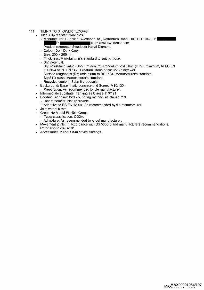
TILING TO SHOWER FLOORS Tiles: Slip resistant floor tiles. ^ ^ ^ ^ ^ ^ - Manufacturer/ Supplier: Swedecor Ltd., Rotterdam Road, Hull. HU7 OXU. T:
^ ^ ^ | F : ^ ^ ^ ^ ^ ^ ^ ^ ^ ^ | w e b : www.swedecor.com. Product reference: Swedecor Kartal Diamond.
- Colour: Dotti Dark Grey. - Size: 200 x 200 mm. - Thickness: Manufacturer's standard to suit purpose. - Slip potential:
Slip resistance value (SRV) (minimum)/ Pendulum test value (PTV) (minimum) to BS EN 13036-4 orBS EN 14231 (natural stone only): 35/25 dry/wet. Surface roughness (Rz) (minimum) to BS 1134: Manufacturer's standard. SlipSTD class: Manufacturer's standard.
- Recycled content: Submit proposals. Background/ Base: Insitu concrete and Screed M10/130. - Preparation: As recommended by tile manufacturer. Intermediate substrate: Tanking as Clause J10/121. Bedding: Adhesive bed - buttering method, as clause 710. - Reinforcement: Not applicable. - Adhesive to BS EN 12004: As recommended by tile manufacturer. Joint width: 6 mm. Grout: No Mould Flexible Grout. - Type/classification: CG2A. - Admixture: As recommended by grout manufacturer. Movement joints: In accordance with BS 5385-3 and manufacturers recommendations. Refer also to clause 81. Accessories: Kartel Sit-in coved skirtings..
MAX00001054 0197 MAX00001054/197
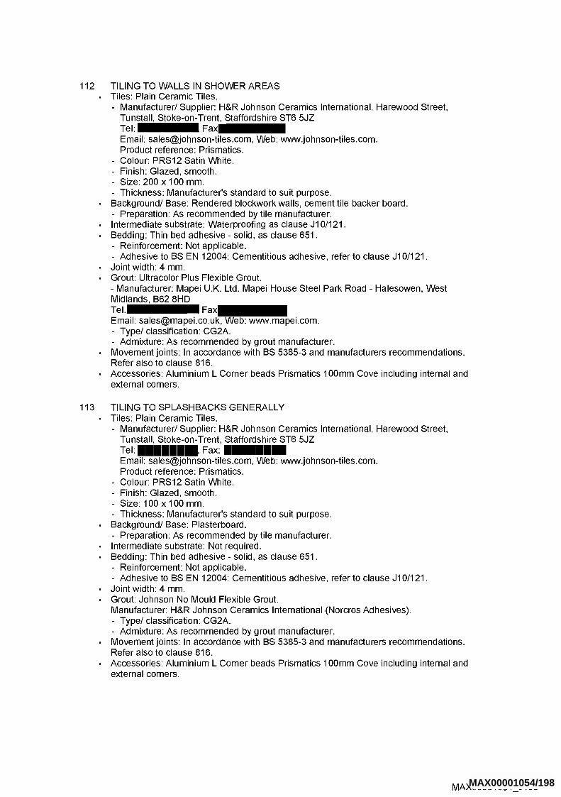
112 TILINGTO WALLS IN SHOWER AREAS • Tiles: Plain Ceramic Tiles.
- Manufacturer/ Supplier: H&R Johnson Ceramics International, Harewood Street, Tunstall, Stoke-on-Trent, Staffordshire ST6 5JZ Tel: ^^^^^^H F a x ^ ^ ^ ^ ^ ^ ^ ^ l Email: [email protected], Web: www.johnson-tiles.com. Product reference: Prismatics.
- Colour: PRS12 Satin White. - Finish: Glazed, smooth. - Size: 200 x 100 mm. - Thickness: Manufacturer's standard to suit purpose.
• Background/ Base: Rendered blockwork walls, cement tile backer board. - Preparation: As recommended by tile manufacturer.
• Intermediate substrate: Waterproofing as clause J10/121. • Bedding: Thin bed adhesive - solid, as clause 651.
- Reinforcement: Not applicable. - Adhesive to BS EN 12004: Cementitious adhesive, referto clause J10/121.
• Joint width: 4 mm. • Grout: Ultracolor Plus Flexible Grout.
- Manufacturer: Mapei U.K. Ltd. Mapei House Steel Park Road - Halesowen, West Midlands, B62 SHD Tel. ^ ^ ^ ^H Fax^^^^^^^^l Email: [email protected], Web: www.mapei.com. - Type/classification: CG2A. - Admixture: As recommended by grout manufacturer.
• Movement joints: In accordance with BS 5385-3 and manufacturers recommendations. Refer also to clause 816.
• Accessories: Aluminium L Corner beads Prismatics 100mm Cove including internal and external corners.
113 TILING TO SPLASHBACKS GENERALLY • Tiles: Plain Ceramic Tiles.
- Manufacturer/ Supplier: H&R Johnson Ceramics International, Harewood Street, Tunstall, Stoke-on-Trent, Staffordshire ST6 5JZ Tel: ^ ^ ^^^B Fax: ^ ^ ^ ^ ^ ^ ^ | Email: [email protected], Web: www.johnson-tiles.com. Product reference: Prismatics.
- Colour: PRS12 Satin White. - Finish: Glazed, smooth. - Size: 100 x 100 mm. - Thickness: Manufacturer's standard to suit purpose.
• Background/ Base: Plasterboard. - Preparation: As recommended by tile manufacturer.
• Intermediate substrate: Not required. • Bedding: Thin bed adhesive - solid, as clause 651.
- Reinforcement: Not applicable. - Adhesive to BS EN 12004: Cementitious adhesive, referto clause J10/121.
• Joint width: 4 mm. • Grout: Johnson No Mould Flexible Grout.
Manufacturer: H&R Johnson Ceramics International (Norcros Adhesives). - Type/classification: CG2A. - Admixture: As recommended by grout manufacturer.
• Movement joints: In accordance with BS 5385-3 and manufacturers recommendations. Refer also to clause 816.
• Accessories: Aluminium L Corner beads Prismatics 100mm Cove including internal and external corners.
MAX00001054 0198 MAX00001054/198

GENERAL
210 SUITABILITY OF BACKGROUNDS/ BASES • Background/ base tolerances: To permit specified flatness/ regularity of finished surfaces
given the permissible minimum and maximum thickness of bedding. • New background drying times (minimum):
- Concrete walls: 6 weeks. - Brick/ block walls: 6 weeks. - Rendering: 2 weeks. - Gypsum plaster: 4 weeks.
• New base drying times (minimum): - Concrete slabs: 6 weeks. - CemenLsand screeds: 3 weeks.
215 FALLS IN THE BASES • General: Give notice if falls are inadequate.
260 CONTROL SAMPLES • General: Complete sample areas, being part of finished work, in locations as follows: Entra
nee lobby. - Approval of appearance: Obtain before proceeding.
• Floor covering slip resistance testing: As clause 900.
PREPARATION
310 EXISTING BACKGROUNDS/BASES GENERALLY • Efflorescence, laitance, dirt and other loose material: Remove. • Deposits of oil, grease and other materials incompatible with the bedding: Remove. • Tile, paint and other nonporous surfaces: Clean. • Wet backgrounds: Dry before tiling.
355 OLD ADHESIVE RESIDUES ON CONCRETE/SCREED BASES • Soft or unsound adhesive residues: Remove without damaging base.
370 NEW IN SITU CONCRETE • Backgrounds/ bases to be tiled: Remove mould oil, surface retarders and other materials
incompatible with bedding.
438 PREPARING CONCRETE BASES FOR FULLY BONDED BEDDING • Surface cementsand matrix: Remove to expose coarse aggregate. • Surface preparation: Suitable to achieve a full bond with bedding. Select from:
- Keep well wetted for several hours. Remove free water then brush in a slurry bonding coat. Slurry: As recommended by adhesive manufacturer.
- Prepare, prime as necessary and apply a bonding agent. Bonding agent: BBA certified SBR bonding agent.
460 SMOOTHING UNDERLAYMENT • Type: Recommended by adhesive manufacturer. • Condition: Allow to dry before tiling.
MAX00001054 0199 MAX00001054/199

FIXING
510 FIXING GENERALLY • Colour/ shade: Unintended variations within tiles for use in each area/ room are not
permitted. - Variegated tiles: Mix thoroughly.
• Adhesive: Compatible with background/ base. Prime if recommended by adhesive manufacturer.
• Use of admixtures with cementitious adhesives: Only admixtures approved by adhesive manufacturer.
• Cut tiles: Neat and accurate. • Fixing: Provide adhesion over entire background/ base and tile backs. • Final appearance: Before bedding material sets, make adjustments necessary to give true,
regular appearance to tiles and joints when viewed under final lighting conditions. • Surplus bedding material: Clean from joints and face of tiles without disturbing tiles.
530 SETTING OUT • Joints: True to line, continuous and without steps.
- Joints on walls: Horizontal, vertical and aligned round corners. - Joints in floors: Parallel to the main axis ofthe space or specified features.
• Cut tiles: Minimize number, maximize size and locate unobtrusively. • Joints in adjoining floors and walls: Align. • Joints in adjoining floors and skirtings: Align. • Movement joints: Where locations are not indicated, submit proposals. • Setting out of Floor tiles : Drawing references: As per architect's drawings. • Setting out of N/A : Submit proposals.
540 LEVEL OF FLOOR TILING • Permissible deviation in level from datum to be +/- 5mm.
550 FLATNESS/ REGULARITY OF TILING/ MOSAICS • Sudden irregularities: Not permitted. • Deviation of surface: Measure from underside of a 2 m straightedge with 3 mm thick feet
placed anywhere on surface. The straightedge should not be obstructed by the tiles and no gap should be greater than 6 mm, i.e. a tolerance of + 3 mm.
560 LEVEL OF TILING ACROSS JOINTS • Deviation (maximum) between tile surfaces either side of any type of joint:
- 1 mm for joints less than 6 mm wide. - 2 mm for joints 6 mm or greater in width.
600 SIT-ON TILE SKIRTINGS • Sequence: Bed solid to wall after laying floor tiles. • Bedding: Cement based adhesive.
710 ADHESIVE BED - NOTCHED TROWEL AND BUTTERING METHOD (FLOORS) • Application: Floated coat of adhesive to dry base and comb surface. • Tiling: Apply coat of adhesive to backs of dry tiles. Fill any ribbed, deep keyed or button
profiles. Press tiles firmly onto float coat. • Finished adhesive thickness: Wthin range allowed by manufacturer.
MAX00001054 0200 MAX00001054/200

MOVEMENT JOINTS/ GROUTING/ COMPLETION
815 SEALANT MOVEMENT JOINTS IN TILING TO FLOORS • Joints: Extend through tiles and bedding to base/ background. Centre over joints in base/
background. - Width: 6 mm.
• Sealant: Submit proposal. - Colour: TBC.
- Preparation and application: As section 722.
875 GROUTING • Sequence: Grout when bed/adhesive has set sufficient to prevent disturbance of tiles. • Joints: 6 mm deep (or depth of tile if less). Free from dust and debris. • Grouting: Fill joints completely, tool to profile, clean off surface. Leave free from blemishes.
- Profile: Flush. • Polishing: When grout is hard, polish tiling with a dry cloth.
885 COLOURED GROUT • Staining of tiles: Not permitted • Evaluating risk of staining: Apply grout to a few tiles in a small trial area. If discoloration
occurs apply a protective sealerto tiles and repeat trial.
900 TRL PENDULUM FLOOR COVERING SLIP RESISTANCE TESTING • Floor covering(s) to be tested: M40/110. • Testing authority: A UKAS accredited laboratory. • Test: To BS EN 13036-4.
- Floor covering condition: Dry and wet. - Wtnessing/ Certification: Arrange for tests to be witnessed/ certified by: Contract
Administrator. - Report: Submit.
MAX00001054 0201 MAX00001054/201

MSO Rubber/ plastics/ cork/ lino/ carpet t i l ing/ sheeting
MAX00001054 0202 MAX00001054/202
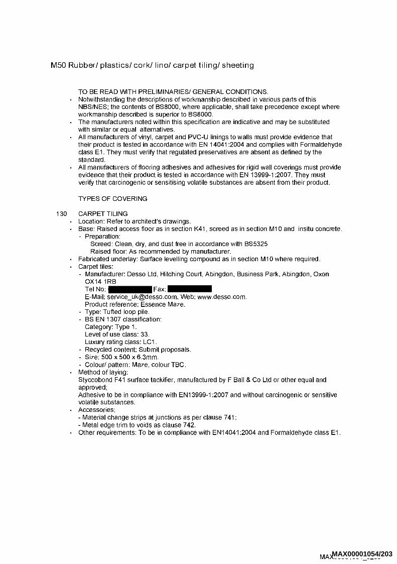
MSO Rubber/ plastics/ cork/ lino/ carpet t i l ing/ sheeting
TO BE READ WITH PRELIMINARIES/ GENERAL CONDITIONS. • Notwithstanding the descriptions of workmanship described in various parts of this
NBS/NES; the contents of BS8000, where applicable, shall take precedence except where workmanship described is superior to BS8000.
• The manufacturers noted within this specification are indicative and may be substituted with similar or equal alternatives.
• All manufacturers of vinyl, carpet and PVC-U linings to walls must provide evidence that their product is tested in accordance with EN 14041:2004 and complies with Formaldehyde class E1. They must verify that regulated preservatives are absent as defined by the standard.
• All manufacturers of flooring adhesives and adhesives for rigid wall coverings must provide evidence that their product is tested in accordance with EN 13999-1:2007. They must verify that carcinogenic or sensitising volatile substances are absent from their product.
TYPES OF COVERING
130 CARPET TILING • Location: Referto architect's drawings. • Base: Raised access floor as in section K41, screed as in section M10 and insitu concrete.
- Preparation: Screed: Clean, dry, and dust free in accordance with BS5325 Raised floor: As recommended by manufacturer.
• Fabricated underlay: Surface levelling compound as in section M10 where required. • Carpet tiles:
- Manufacturer: Desso Ltd, Hitching Court, Abingdon, Business Park, Abingdon, Oxon OX14 1RB
No: Fax: ^^^^^^^H E-Mail: [email protected], Web: www.desso.com. Product reference: Essence Maze.
- Type: Tufted loop pile. - BS EN 1307 classification:
Category: Type 1. Level of use class: 33. Luxury rating class: LC1.
- Recycled content: Submit proposals. - Size: 500x500 x 6.3mm. - Colour/ pattern: Maze, colour TBC.
• Method of laying: Styccobond F41 surface tackifier, manufactured by F Ball & Co Ltd or other equal and approved; Adhesive to be in compliance with ENl 3999-1:2007 and without carcinogenic or sensitive volatile substances.
• Accessories: - Material change strips at junctions as per clause 741; - Metal edge trim to voids as clause 742.
• Other requirements: To be in compliance with EN14041:2004 and Formaldehyde class E1.
MAX00001054 0203 MAX00001054/203

150 SHEETINGVINYL • Location: Referto architect's drawings. • Base: Screed as in section M10, raised access floor as in section K41 and insitu concrete.
- Preparation: Screed base: apply smoothing bed as clause 460 to remove any surface irregularities and steps, prepare surface in accordance with BS 8203 as clause 210 Raised floor: As recommended by manufacturer.
• Fabricated underlay: - Screed base: not required - Raised floor: Plywood as clause 560.
• Flooring roll: Homogeneous PVC to BS EN 649. - Manufacturer: Polyflor Ltd, Head Office, PO Box 3, Radcliffe New Road, Whitefield,
Manchester M45 7NR UK ^ ^ ^ ^ ^ ^ T e l e p h o n e ^ ^ ^ ^ ^ ^ ^ , F a x ^ ^ ^ ^ ^ ^ ^ H Email [email protected], Web: www.polyflor.com. Product reference: Polysafe Vogue Ultra PUR Safety Floor.
- BS EN 685 class: 34. - Slip potential:
Slip resistance value (SRV) (minimum)/ Pendulum test value (PTV) (minimum) to BS 7976: Not applicable.
EN 13893: Class DS, AS/NZS 4586: R9. Surface roughness (Rz) (minimum) to BS 1134: Manufacturer's standard.
- Recycled content: 25% . - Wdth: 2000 mm. - Thickness: 2.0mm. - Colour/pattern: Colour TBC.
• Adhesive (and primer if recommended by manufacturer): To be approved by manufacture to ensure full compatibility; To be in compliance with EN13999-1:2007 and without carcinogenic or sensitive volatile substances.
• Seam welding: Hot welding with complimentary coloured rod. • Accessories:
- Mastic seal junctions to skirtings, P20/200; - Coved vinyl up-stand (clause 740) TBC; - Junctions to adjoining finishes with transition strips as clause 741; - Metal edge trim to voids as clause 742 - Stair nosings and edge trims as clause 750.
• Finishing: As clause 820. • Other requirements:
- Acousitfoam underlay where located above occupied spaces. - Cutting in and Sealing to duct covers to areas as required; - Screed up to transition strip where abutting barrier matting.
MAX00001054 0204 MAX00001054/204

155 PVC SHEET FLOORING IN SPECIAL WET AREAS • Location: Bathrooms; Boxing club toilets and changing areas. • Base: Screed as in section M10 or insitu concrete.
- Preparation: Screed base: apply smoothing bed as clause 460 to remove any surface irregularities and steps, prepare surface in accordance with BS 8203 as clause 210.
• Fabricated underlay: As recommended by manufacturer. • Flooring roll: PVC to BS EN 13553. ^ ^ ^ ^ ^ ^
- Manufacturer: Altro, www.altro.co.uk; [email protected], T e l ^ ^ ^ ^ ^ ^ ^ l Product reference: Altro Marine 20.
- Identity code: W1A. - BS EN 685 class: 34. - Slip potential:
Slip resistance value (SRV) (minimum)/ Pendulum test value (PTV) (minimum) to BS 7976: TBA. Surface roughness (Rz) (minimum) to BS 1134: 20 micrometres.
- Recycled content: Manufacturer to confirm. - Wdth: 2000 mm. - Thickness: 2.0mm. - Colour/pattern: Colour TBC.
• Adhesive (and primer if recommended by manufacturer): Altrofix A19 Plus;.
• Seam welding: Hot welding with complimentary coloured rod. • Accessories:
- Coved vinyl up-stand as clause 740; - Junctions to adjoining finishes with transition strips as clause 74.
• Finishing: As clause 820. • Other requirements:
- Cutting in and Sealing to duct covers to areas as required; - To be in compliance with EN14041:2004 and Formaldehyde class E1.
195 FLOOR FINISH MATERIALS SPECIFICATION • Minimum BRE 'Green Guide to Specification Online' rating: A.
GENERAL REQUIREMENTS
210 WORKMANSHIP GENERALLY • Base condition after preparation: Rigid, dry, sound, smooth and free from grease, dirt and
other contaminants. • Finished coverings: Accurately fitted, tightly jointed, securely bonded, smooth and free
from air bubbles, rippling, adhesive marks and stains.
220 SAMPLES • Covering samples: Before placing orders, submit representative sample of each type.
230 CONTROL SAMPLES • General: Complete areas of finished work in approved locations as follows, and obtain
approval of appearance before proceeding: - Clause 130, office space - Clause 150, nursery - Clause 155, boxing club shower - Clause 156, residential bathroom - Clause 157, changing area .
250 LAYOUT - ROLL MATERIALS • Setting out of seams: Agree setting out for sheeting types M50/150 and 157 .
MAX00001054 0205 MAX00001054/205

251 LAYOUT - SEAMS IN ROLL MATERIALS • Setting out: Minimise occurrences of seams and cross seams. • Cross seams: Not permitted in following locations:
- Nursery - Boxing club.
252 LAYOUT - PATTERNS • Setting out: Agree setting out for covering types M50/ 130 .
270 EXTRA MATERIAL • Provision of extra material: At completion, hand to Employer extra material of each type of
covering to extent of the lesser of a minimum of 1 No. roll or 5% extra of each colour / finish.
330 COMMENCEMENT • Required condition of works priorto laying materials:
- Building is weathertight and well dried out. - Wet trades have finished work. - Paintwork is finished and dry. - Conflicting overhead work is complete. - Floor service outlets, duct covers and other fixtures around which materials are to be cut
are fixed. • Notification: Submit not less than 48 hours before commencing laying.
340 CONDITIONING • Priorto laying: Condition materials by unpacking and separating in spaces where they are
to be laid. Maintain resilient flooring rolls in an upright position. Unroll carpet and keep flat on a supporting surface.
• Conditioning time and temperature (minimum): As recommended by manufacturer with time extended by a factor of two for materials stored or transported at a temperature of less than 10 oC immediately priorto laying.
350 ENVIRONMENT • Temperature and humidity: Before, during and after laying, maintain approximately at
levels which will prevail after building is occupied. • Ventilation: Before during and after laying, maintain adequate provision.
PREPARING BASES
410 NEW BASES • Suitability of bases and conditions within any area: Commencement of laying of coverings
will be taken as acceptance of suitability.
420 EXISTING BASES • Notification: Before commencing work, confirm that existing bases will, after preparation,
be suitable to receive coverings. • Suitability of bases and conditions within any area: Commencement of laying of coverings
will be taken as acceptance of suitability.
MAX00001054 0206 MAX00001054/206
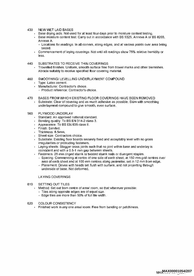
430 NEW WET LAID BASES • Base drying aids: Not used for at least four days prior to moisture content testing. • Base moisture content test: Carry out in accordance with BS 5325, Annexe A or BS 8203,
Annexe A. - Locations for readings: In all corners, along edges, and at various points over area being
tested. • Commencement of laying coverings: Not until all readings show 75% relative humidity or
less.
440 SUBSTRATES TO RECEIVE THIN COVERINGS • Trowelled finishes: Uniform, smooth surface free from trowel marks and other blemishes.
Abrade suitably to receive specified floor covering material.
460 SMOOTHING/ LEVELLING UNDERLAYMENT COMPOUND • Type: Latex cement. • Manufacturer: Contractor's choice.
- Product reference: Contractor's choice.
470 BASES FROM WHICH EXISTING FLOOR COVERINGS HAVE BEEN REMOVED • Substrate: Clear of covering and as much adhesive as possible. Skim with smoothing
underlayment compound to give smooth, even surface.
560 PLYWOOD UNDERLAY • Standard: An approved national standard. • Bonding quality: To BS EN 314-2 class 3. • Appearance: To BS EN 635 class II. • Finish: Sanded. • Thickness: 6.5mm. • Sheet size: Contractors choice. • Substrate: Existing floor boards securely fixed and acceptably level with no gross
irregularities or protruding fasteners. • Laying sheets: Stagger cross joints such that no joint within base and underlay is
coincident and with a 0.5-1 mm gap between sheets. • Fasteners: 25 mm ringed shank or twisted shank nails or divergent staples.
- Spacing: Commencing at centre of one side of each sheet, at 150 mm grid centres over area of each sheet and at 100 mm centres along perimeter, set in 12 mm from edge.
- Placement: Driven with heads set flush with surface, and not projecting through underside of base. Not deformed.
LAYING COVERINGS
610 SETTING OUT TILES • Method: Set out from centre of area/ room, so that wherever possible:
- Tiles along opposite edges are of equal size. - Edge tiles are more than 50% of full tile width.
620 COLOUR CONSISTENCY • Finished work in any one area/ room: Free from banding or patchiness.
MAX00001054 0207 MAX00001054/207
640 ADHESIVE FIXING GENERALLY • Adhesive type: As specified, as recommended by covering/ underlay, manufacturer or as
approved. • Primer: Type and usage as recommended by adhesive manufacturer. • Application: As necessary to achieve good bond. • Finished surface: Free from trowel ridges, high spots caused by particles on the substrate,
and other irregularities.
650 SEAMS • Patterns: Matched. • Joints: Tight without gaps.
680 SEAM WELDING COVERINGS • Commencement: At least 24 hours after laying, or after adhesive has set. • Joints: Neat, smooth, strongly bonded, flush with finished surface.
700 LOOSE LAID CARPET TILES • Areas of adhered tiles: Secure using double sided tape or peelable adhesive. • Joints: Butted.
- Perimeter joints: Accurately cut to match abutment and prevent movement.
720 DOORWAYS • Joint location: On centre line of door leaf.
740 EDGINGS AND COVER STRIPS • Manufacturer: Gradus Ltd, Park Green, Macclesfield, Cheshire SK11 7LZ UK
Tel: 01625 428922, Fax: 01625 433949 Email: [email protected], Web: www.gradusworld.com . - Product reference: Submit proposal .
• Material/ finish: Aluminium, finish TBC . • Fixing: Secure with edge of covering gripped. Use matching fasteners where exposed to
view
745 EDGE TRIMS TO LIGHT AND STAIR WELL • Manufacturer: Gradus Ltd, Park Green, Macclesfield, Cheshire SK11 7LZ UK
Tel: Fax : ^ ^ ^ ^ ^ ^ ^ H Email: [email protected], Web: www.gradusworld.com . - Product reference: Submit proposal for edge trim to ceramic tiling as in section M40/110
• Material/ finish: Aluminium, finish TBC . • Fixing: Secure with edge of ceramic tiling covered. Use matching fasteners where exposed
to view.
MAX00001054 0208 MAX00001054/208
750 STAIR NOSINGS AND TRIMS • Manufacturer: Gradus Ltd, Park Green, Macclesfield, Cheshire SK11 7LZ UK
Tel: ^ ^ ^B F a x : ^ ^ ^ ^ ^ ^ ^ | Email: [email protected], Web: www.gradusworld.com. - Product reference: Submit proposal for nosings and edge trims to ceramic tiling (referto
section M40/110) on stairs and landings. • Material/finish:
- Aluminium with coloured PVC insert; - Finish TBC - Colour of insert TBC.
• Fixing: Secure, level and with mitred joints. Adjusted to suit thickness of covering with continuous packing strips of hardboard or plywood. Nosings and packing strips bedded in gap-filling adhesive recommended by nosing manufacturer. - Screw fixing with matching plugs: Where required and exposed to view.
780 TRAFFICKING AFTER LAYING • Covering types: Clauses 150,155,156 and 157. • Traffic free period: minimum 5 days.
COMPLETION
820 FINISHING PVC FLOORING • Cleaning operations:
- Wash floor with water containing neutral (pH 6-9) detergent. If necessary, lightly scrub heavily soiled areas.
- Rinse with clean water, removing surplus to prevent damage to adhesive. Allow to dry. • Emulsion polish: Two coats of a type recommended by covering manufacturer.
861 SLIP RESISTANCE TESTING • Testing authority: A UKAS accredited laboratory. • Floor covering(s) to be tested: M50/155, 156 and 157. • Test: To BS 7976.
- Floor covering condition: Dry and wet. - Wtnessing/ Certification: Arrange for tests to be witnessed/ certified by: Contract
Administrator. • Report: Submit.
880 WASTE • Spare covering material: Retain suitable material for patching. On completion submit
pieces for selection. Hand over selected pieces to Employer.
MAX00001054 0209 MAX00001054/209

M60 Painting/clear f inishing
MAX00001054 0210 MAX00001054/210
M60 Painting/clear f inishing
TO BE READ WITH PRELIMINARIES/GENERAL CONDITIONS. • Notwithstanding the descriptions of workmanship described in various parts of this
NBS/NES; the contents of BS8000, where applicable, shall take precedence except where workmanship described is superior to BS8000.
• The manufacturers noted within this specification are indicative and may be substituted with similar or equal alternatives.
• All manufacturers of decorative paint and varnishes must provide evidence that the VOC emission level/content of their products are tested in accordance with BS EN13300:2001 and comply with the criteria of Decorative Paint Directive 2004/42/CE.
COATING SYSTEMS
110 EMULSION PAINT TO INTERNAL PLASTERED SURFACES • Manufacturer: ICI Paints, Wexham Road, Slough, SL2 SDS
Tel: 0870 242 1100, Web: www.duluxtrade.co.uk. - Product reference: Dulux Trade Diamond Matt
- VOC: max 30g/l in compliance with EU Directive 2004/42/EC. • Surfaces: Gypsum plaster as clause M20/210.
- Preparation: As clauses 400 and 580. • Initial coats: Thinning coat Dulux Trade Diamond Matt applied by brush/roller, all in
accordance with manufacturer's instructions. • - Number of coats: 1. • Undercoats: Dulux Trade Diamond Matt spray applied in accordance with manufacturer's
recommendations. - Number of coats: 1.
• Finishing coats: Dulux Trade Diamond Matt roller applied in accordance with manufacturer's recommendations (applied to be applied after first fix electrical). - Number of coats: 1.
111 EMULSION PAINT TO INTERNAL INSITU CONCRETE AND CONCRETE BLOCK SURFACES
• Manufacturer: ICI Paints, Wexham Road, Slough, SL2 SDS Tel: Web: www.duluxtrade.co.uk. - Product reference: Dulux Trade Diamond Matt
- VOC: max 30g/l in compliance with EU Directive 2004/42/EC. • Surfaces: Gypsum plaster as clause M20/210.
- Preparation: As clauses 400, 560 and 570. • Initial coats: Thinning coat Dulux Trade Diamond Matt applied by brush/roller, all in
accordance with manufacturer's instructions. • - Number of coats: 1. • Undercoats: Dulux Trade Diamond Matt spray applied in accordance with manufacturer's
recommendations. - Number of coats: 1.
• Finishing coats: Dulux Trade Diamond Matt roller applied in accordance with manufacturer's recommendations (applied to be applied after first fix electrical). - Number of coats: 1.
• Other requirements: Note: 1 coat Dulux Trade Blockfiller with 1 coat Diamond Matt finishing coat acceptable as alternative coating.
MAX00001054 0211 MAX00001054/211
112 EMULSION PAINT PLASTERBOARD • Manufacturer: ICI Paints, Wexham Road, Slough, SL2 SDS
Tel: ^^^^^^^M Web: www.duluxtrade.co.uk. - Product reference: Dulux Trade Diamond Silk
- VOC: max 30g/l in compliance with EU Directive 2004/42/EC. • Surfaces: Gypsum plaster as clause M20/210.
- Preparation: As clauses 400 and 590. • Initial coats: Thinning coat Dulux Trade Diamond Silk applied by brush/roller, all in
accordance with manufacturer's instructions. • - Number of coats: 1. • Undercoats: Dulux Trade Diamond Silk spray applied in accordance with manufacturer's
recommendations. - Number of coats: 1.
• Finishing coats: Dulux Trade Diamond Silk roller applied in accordance with manufacturer's recommendations (applied to be applied after first fix electrical). - Number of coats: 1.
150 EGGSHELL/ SATIN PAINT TO PLASTER & DRY LINING - WET & KITCHEN AREAS • Manufacturer: ICI Paints, Wexham Road, Slough, SL2 SDS
Tel: 0870 242 1100, Web: www.duluxtrade.co.u. - Product reference: Dulux Trade Diamond Eggshell
- VOC: max22g/l in compliance with EU Directive 2004/42/EC. • Surfaces: Plaster and dry lining surface.
- Preparation: In accordance with manufacturer's recommendations and as clauses 400, 580 and 590.
• Initial coats: Dulux Trade All Purpose Primer in accordance with manufacturer's instructions. - Number of coats: 1.
• Undercoats: Not required. - Number of coats: N/A.
• Finishing coats: Dulux Trade Diamond Eggshell. - Number of coats: 2.
151 EGGSHELL/ SATIN PAINT TO STEEL WORK • Manufacturer: ICI Paints, Wexham Road, Slough, SL2 SDS
T e l : ^ ^ ^ ^ ^ ^ ^ H W e b : www.duluxtrade.co.u. - Product reference: Dulux Trade Eggshell
- VOC: max 300g/l in compliance with EU Directive 2004/42/EC. • Surfaces: Internal exposed steelwork.
- Preparation: In accordance with manufacturer's recommendations and as clauses 400, 500 and 511.
• Initial coats: - Factory primed steelwork: Make sure primer is compatible and undamaged; clean in accordance with manufacturer's recommendations; - Unprimed steelwork: Use Dulux Trade Metalshield Quick Drying Metal Primer in accordance with manufacturer's instructions. - Number of coats: 1.
• Undercoats: Not required. - Number of coats: N/A.
• Finishing coats: Dulux Trade Eggshell. - Number of coats: 2.
MAX00001054 0212 MAX00001054/212

152 EGGSHELL/ SATIN PAINT TO SKIRTING, SILL BOARDS, TRIMS & DOOR FRAMES • Manufacturer: ICI Paints, Wexham Road, Slough, SL2 SDS
T e l : ^ ^ ^ ^ ^ ^ ^ H Web: www.duluxtrade.co.u. - Product reference: Dulux Trade Diamond Satinwood
- VOC: max 75g/l in compliance with EU Directive 2004/42/EC. • Surfaces: Internal MDF, internal grade plywood, soft- and hardwood frames.
- Preparation: As clauses 400 and 481; fill and sand down joints/nail screw holes; filler in accordance with manufacturer's recommendations.
• Initial coats: - Wood: Dulux Trade Quick Drying Wood Primer Undercoat - MDF: Dulux Trade Quick Drying MDF Primer Undercoat. - Number of coats: 1 .
• Undercoats: Not required . - Number of coats: N/A .
• Finishing coats: Dulux Trade Diamond Satinwood in accordance with manufacturer's recommendations . - Number of coats: min. 2 .
175 PROTECTIVE COATING ANTI-GRAFFITI FINISH • Manufacturer: ICI Paints, Wexham Road, Slough, SL2 SDS
T e l : ^ ^ ^ ^ ^ ^ ^ | Web: www.duluxtrade.co.uk. - Product reference: Dulux Trade Anti Graffiti Finish
- VOC: max 140g/l in compliance with EU Directive 2004/42/EC. • Surfaces: Plaster, plasterboard and internal exposed concrete.
- Preparation: as clauses 400, 560, 580, 590 and to manufacturer's recommendations. • Initial coats: Dulux Trade Anti Graffiti Sealer in accordance with manufacturer's instructions.
- Number of coats: 1. • Undercoats: Dulux Trade Anti Graffiti Primer in accordance with manufacturer's instructions
- Number of coats: 1. • Finishing coats: Dulux Trade Anti Graffiti Finish in accordance with manufacturer's
instructions. • Application: Brush, roller or conventional spray equipment.
- Number of coats: 3. - Slip resistance value - water wet (minimum): Not applicable .
180 FLOOR COATING TO CONCRETE FLOORS • Manufacturer: Ronacrete Limited, Ronac House, Flex Meadow, Merring Way, Harlow,
Esse, CM19 STD ^ ^ ^ ^ ^ ^ T e h ^ ^ ^ ^ ^ ^ ^ H F a x : ^ ^ ^ ^ ^ ^ ^ | Email: [email protected], Web: www.ronacrete.co.uk. - Product reference: RonaFloor EWB
- VOC: content 0.03%. • Surfaces: Exposed concrete floors.
- Preparation: As clauses 400 and 560. • Initial coats: RonaFloor EWB applied by roller, all in accordance with manufacturer's
instructions, incorporate RonaFloor A/S Aggregate into initial coat whilst wet and allow to cure to provide slip resistance. - Number of coats: 1.
• Finishing coats: RonaFloor EWB applied by roller. - Number of coats: 1. - Slip resistance value - water wet (minimum): PTV to BS 7976 of 40 .
MAX00001054 0213 MAX00001054/213
GENERALLY
210 COATING MATERIALS • Manufacturers: Obtain materials from any ofthe following:
ICI paints- Dulux Trade. • Selected manufacturers: Submit names before commencement of coating work.
215 HANDLING AND STORAGE • Coating materials: Deliver in sealed containers, labelled clearly with brand name, type of
material and manufacturer's batch number. • Materials from more than one batch: Store separately. Allocate to distinct parts or areas of
the work.
220 COMPATIBILITY • Coating materials selected by contractor:
- Recommended by their manufacturers forthe particular surface and conditions of exposure.
- Compatible with each other. - Compatible with and not inhibiting performance of preservative/fire retardant
pretreatments.
280 PROTECTION • 'Wet paint' signs and barriers: Provide where necessary to protect other operatives and
general public, and to prevent damage to freshly applied coatings.
301 CONTROL SAMPLES • Sample areas of finished work: Carry out, including preparation, as follows:
Types of coating Location M60/110,111,112. Entrance lobby, nursery, boxing club . M60/150 . Office and domestic kitchen . M60/152 . Entrance lobby, nursery, boxing club . M60/175. TBC
• Approval of appearance: Obtain before commencement of general coating work.
320 INSPECTION BY COATING MANUFACTURERS • General: Permit manufacturers to inspect work in progress and take samples of their
materials from site if requested.
MAX00001054 0214 MAX00001054/214

PREPARATION
400 PREPARATION GENERALLY • Standard: In accordance with BS 6150. • Suspected existing hazardous materials: Prepare risk assessments and method
statements covering operations, disposal of waste, containment and reoccupation, and obtain approval before commencing work.
• Preparation materials: Types recommended by their manufacturers and the coating manufacturer forthe situation and surfaces being prepared.
• Substrates: Sufficiently dry in depth to suit coating. • Efflorescence salts: Remove. • Dirt, grease and oil: Remove. Give notice if contamination of surfaces/substrates has
occurred. • Surface irregularities: Remove. • Joints, cracks, holes and other depressions: Fill flush with surface, to provide smooth
finish. • Dust, particles and residues from preparation: Remove and dispose of safely. • Water based stoppers and fillers:
- Apply before priming unless recommended otherwise by manufacturer. - If applied after priming: Patch prime.
• Oil based stoppers and fillers: Apply after priming. • Doors, opening windows and other moving parts:
- Ease, if necessary, before coating. - Prime resulting bare areas.
425 IRONMONGERY • Removal: Before commencing work: Remove ironmongery from surfaces to be coated. • Hinges: Do not remove. • Replacement: Refurbishment as necessary; refit when coating is dry.
440 PREVIOUSLY COATED SURFACES GENERALLY • Preparation: In accordance with BS 6150, clause 11.5. • Contaminated or hazardous surfaces: Give notice of:
- Coatings suspected of containing lead. - Substrates suspected of containing asbestos or other hazardous materials. - Significant rot, corrosion or other degradation of substrates.
• Suspected existing hazardous materials: Prepare risk assessments and method statements covering operations, disposal of waste, containment and reoccupation, and obtain approval before commencing work.
• Removing coatings: Do not damage substrate and adjacent surfaces or adversely affect subsequent coatings.
• Loose, flaking or otherwise defective areas: Carefully remove to a firm edge. • Alkali affected coatings: Completely remove. • Retained coatings:
- Thoroughly clean to remove dirt, grease and contaminants. - Gloss coated surfaces: Provide key.
• Partly removed coatings: - Additional preparatory coats: Apply to restore original coating thicknesses. - Junctions: Provide flush surface.
• Completely stripped surfaces: Prepare as for uncoated surfaces.
481 UNCOATED WOOD • General: Provide smooth, even finish with
eased. • Heads of fasteners: Countersink sufficient • Resinous areas and knots: Apply two coat
arrises and moulding edges lightly rounded or
to hold stoppers/fillers, s of knotting.
MAX00001054 0215 MAX00001054/215

500 PREPRIMED STEEL • Areas of defective primer, corrosion and loose scale: Take backto bare metal. Reprime as
soon as possible.
511 GALVANIZED, SHERARDIZED AND ELECTROPLATED STEEL • White rust: Remove. • Pretreatment: Apply one ofthe following:
- 'T wash'/ mordant solution to blacken whole surface. - Etching primer recommended by coating system manufacturer.
560 UNCOATED CONCRETE • Release agents: Remove.
570 UNCOATED MASONRY/ RENDERING • Loose and flaking material: remove.
580 UNCOATED PLASTER • Nibs, trowel marks and plaster splashes: Scrape off. • Overtrowelled 'polished' areas: Key lightly.
590 UNCOATED PLASTERBOARD • Depressions around fixings: Fill with stoppers/ fillers
622 ORGANIC GROWTHS • Dead and loose growths and infected coatings: Scrape off and remove from site. • Treatment biocide: Apply appropriate solution to growth areas and surrounding surfaces. • Residual effect biocide: Apply appropriate solution to inhibit re-establishment of growths.
645 SEALING OF INTERNAL MOVEMENT JOINTS • General: To junctions of walls and ceilings with architraves, skirtings and other trims. • Sealant: Water based acrylic.
- Manufacturer: Contractor's choice. Product reference: Submit proposals.
- Preparation and application: As section Z22.
APPLICATION
711 COATING GENERALLY • Application standard: In accordance with BS 6150, clause 9. • Conditions: Maintain suitable temperature, humidity and air quality during application and
drying. • Surfaces: Clean and dry at time of application. • Thinning and intermixing of coatings: Not permitted unless recommended by manufacturer. • Overpainting: Do not paint over intumescent strips or silicone mastics. • Priming coats:
- Thickness: To suit surface porosity. - Application: As soon as possible on same day as preparation is completed.
• Finish: - Even, smooth and of uniform colour. - Free from brush marks, sags, runs and other defects. - Cut in neatly.
• Doors, opening windows and other moving parts: Ease before coating and between coats.
MAX00001054 0216 MAX00001054/216

M61 Intumescent coatings for fire protection of steelwork
MAX00001054 0217 MAX00001054/217

M61 Intumescent coatings for fire protection of steelwork
TO BE READ WITH PRELIMINARIES/GENERAL CONDITIONS Notwithstanding the descriptions of workmanship described in various parts of this NBS/NES; the contents of BS8000, where applicable, shall take precedence except where workmanship described is superior to BS8000. The manufacturers noted within this specification are indicative and may be substituted with similar or equal alternatives. All manufacturers of decorative paints and varnishes must provide evidence that the VOC emission level/content of their products are tested in accordance with BS EN13300:2001 and comply with the criteria of Decorative Paint Directive 2004/42/CE.
MAX00001054 0218 MAX00001054/218

PROTECTIVE COATING SYSTEMS
110 ON SITE COATING TO PRIMED STEEL GENERALLY • Use/ location: Internal structural steelwork not part ofthe structural frame ofthe building. • Fire resistance to BS 476-21: 60 minutes. • Preparation and priming: By steelwork contractor, as section G10.
- Primer: S707-60 should be applied onto a clean, undamaged, dry and primed steel surface. Certain types of primers can cause adhesion problems and should be avoided. These include chlorinated rubbers, bitumen, thermoplastic primers. Nullifire have carried out compatibility testing on a wide range of primers and can be contacted on ^ ^ ^ ^ ^ ^ ^ ^ ^ ^ | f o r confirmation of compatibility with S707-60. Galvanised surfaces should be prepared by an application of T-wash or mordant solution followed by a compatible non-saponifiable primer. The primer should be applied in accordance with the manufacturer's instructions. If a zinc rich primer is used, it is advisable to seal this with a suitable tie coat or travel coat priorto shipment to site. Ifthe steel is left exposed to the atmosphere with just a zinc rich primer, surface salts may build up on the steel. These salts, if not adequately removed, may cause adhesion problems for any subsequent coating applied. Removal ofthe salts can be achieved by high-pressure washing. If adequate removal ofthe salts cannot be guaranteed, a suitable tie coat may have to be applied priorto the application ofthe S707-60 Waterborne Basecoat. Nullifire should be consulted for technical advice when zinc rich primers orthe overcoating of existing paints are specified for use..
• Intumescent coat: - Manufacturer: Nullifire Ltd., Torrington Avenue, Coventry CV4 9TJ
Tel. Fax ^^I^^^^^^^H E-mail: [email protected], Web: www.nullifire.com. Product reference: S707-60 Waterborne Basecoat, white thin film intumescent coating forthe fire protection of internal structural steelwork - VOC: 15g/l in compliance with EU Directive 2004/42/EC.
- Finish: Non-visible areas - Basic, as clause 440; visible areas frequented by public-High decorative, as clause 460. - Site conditions: Nullifire S707-60 is recommended for application and use on dry protected structural steel only. Ifthe basecoat is allowed to get wet, it is likely to be damaged - blistering and wrinkling may occur. S707-60 should only be applied when the air and steel temperatures are above 5 0C. Relative humidity should be below 80% for successful application. Steel surface temperature should be a minimum of 3 0C above the dew point. Ensure the steel is dry and free from contact with rain or condensation during the application and drying of S707 -60..
• Top sealer coat: Type recommended by intumescent coating manufacturer. - Dry film thickness: As recommended by manufacturer and as clause 490. - Colour: To be confirmed from standard range of BS/RAL colours.
• Bolt head/ nut protection: As main steelwork.
MAX00001054 0219 MAX00001054/219

111 ON SITE COATING TO PRIMED STEEL STRUCTURAL BUILDING FRAME • Use/ location: Internal structural steelwork as part ofthe structural frame ofthe building. • Fire resistance to BS 476-21: 120 minutes. • Preparation and priming: By steelwork contractor, as section G10.
- Primer: S707-120 should be applied onto a clean, undamaged, dry and primed steel surface. Certain types of primers can cause adhesion problems and should be avoided. These include chlorinated rubbers, bitumen, thermoplastic primers. Nullifire have carried out compatibility testing on a wide range of primers and can be contacted on ^B^^^^^^^Hfor confirmation of compatibility with S707-60. Galvanised surfaces should be prepared by an application of T-wash or mordant solution followed by a compatible non-saponifiable primer. The primer should be applied in accordance with the manufacturer's instructions. If a zinc rich primer is used, it is advisable to seal this with a suitable tie coat or travel coat priorto shipment to site. Ifthe steel is left exposed to the atmosphere with just a zinc rich primer, surface salts may build up on the steel. These salts, if not adequately removed, may cause adhesion problems for any subsequent coating applied. Removal ofthe salts can be achieved by high-pressure washing. If adequate removal ofthe salts cannot be guaranteed, a suitable tie coat may have to be applied priorto the application ofthe S707-60 Waterborne Basecoat. Nullifire should be consulted for technical advice when zinc rich primers orthe overcoating of existing paints are specified for use..
• Intumescent coat: - Manufacturer: Nullifire Ltd., Torrington Avenue, Coventry CV4 9TJ
Tel. Fax - ^ ^ ^ ^ ^ ^ ^ ^ ^ B E-mail: [email protected], Web: www.nullifire.com. Product reference: S707-120 Waterborne Basecoat, white thin film intumescent coating forthe fire protection of internal structural steelwork - VOC: Consult manufacturer for compliance with EU Directive 2004/42/EC.
- Finish: Non-visible areas - Basic, as clause 440; visible areas frequented by public-High decorative, as clause 460. - Site conditions: Nullifire S707-120 is recommended for application and use on dry protected structural steel only. Ifthe basecoat is allowed to get wet, it is likely to be damaged - blistering and wrinkling may occur. S707-120 should only be applied when the air and steel temperatures are above 5°C. Relative humidity should be below 80% for successful application. Steel surface temperature should be a minimum of 3 0C above the dew point. Ensure the steel is dry and free from contact with rain or condensation during the application and drying of S707 -120..
• Top sealer coat: Type recommended by intumescent coating manufacturer. - Dry film thickness: As recommended by manufacturer and as clause 490. - Colour: To be confirmed from standard range of BS/RAL colours.
• Bolt head/ nut protection: As main steelwork.
GENERAL REQUIREMENTS
205 VALIDATION OF MATERIALS • Project specific evaluation of intumescent coating materials:
- Standard: To BS 8202-2, clause 4. - Test results: Submit on request.
210 WORKING PROCEDURES • Standard: To BS 8202-2. • Give notice: Before commencing surface preparation and coating application. • Quality control: Record project specific procedures for surface preparation and coating
application.
MAX00001054 0220 MAX00001054/220
215 WORKING CONDITIONS • General: Maintain suitable temperature, humidity and air quality during coating application
and drying. • Surfaces to be coated: Clean and dry at time of coating application.
220 APPLICATOR'S PERSONNEL • Operatives: Trained/ experienced in anticorrosive and intumescent coatings. • Evidence of training/ experience: Submit on request.
250 SPRAYED COATING APPLICATION • Spray drift: Minimize. • Masking: Protect designated adjacent surfaces.
- Designated surfaces: All junctions to adjacent materials.
260 CONTROL SAMPLES • General: Carry out sample areas of finished work as follows:
TBC. • Approval of appearance: Obtain before commencement of general coating application.
270 INSPECTION • Permit intumescent coating manufacturer to:
- Inspect work in progress. - Inspect quality control records. - Take dry film thickness and other measurements. - Take samples of coating products.
• Intumescent coating manufacturer's inspection reports: Submit without delay.
PREPARATION OF SURFACES
315 NEW STEEL-BLAST CLEANING • Preparation: Remove oil and grease. • Blast cleaning:
- Atmospheric condition: Dry. - Abrasive: Suitable type and size, free from fines, moisture and oil. - Finish: To BS EN ISO 8501-1, preparation grade SA21/2, with an average profile of
approximately 75 micrometres. - Abrasive residues and moisture: Remove.
• Primer: Apply as soon as possible after cleaning and before gingering or blackening appears.
APPLICATION OF COATINGS
410 INTUMESCENT DRY FILM THICKNESS (DFT) • Required dft: Determine for every steel member to give specified period of fire resistance.
Use intumescent coating manufacturer's current published loading tables. - Special sections and partial fire exposure conditions: Obtain required dft in writing from
manufacturer. • Schedule and drawings: Submit at least two weeks before starting work.
- Schedule content: Member sizes, weights/thicknesses, loading conditions, etc. showing, for each variant, the exposed perimeter/ sectional area (Hp/A) ratio and required dft.
- Drawing content: Steelwork drawings marked in colour to show required dft for each member.
MAX00001054 0221 MAX00001054/221

420 MEASUREMENT OF INTUMESCENT DFT • Primer dft: Determine average dft (for deduction from total dft after application of
intumescent). • Intumescent dft: Determine at:
- 500 mm centres along each coated plane of universal sections (8 planes), and rectangular hollow sections (4 planes).
- 125 mm centres along coated circular hollow sections, spread evenly around circumference.
• Acceptance standard: - Average intumescent dft: Not less than required dft (exclusive of primer and top sealer). - Local intumescent dft: Not less than 80% of required dft. Areas greater than 100 mm
equivalent diameter with a dft of less than 80% of required dft must be brought up to thickness.
440 BASIC FINISH • Definition: Reasonably smooth and even. Orange peel, other texture, minor runs and
similar minor defects are acceptable.
460 HIGH DECORATIVE FINISH • Definition: High standard of evenness, smoothness and gloss when viewed from a
minimum distance of 2 m.
490 TOP SEALER COAT • Application: To achieve dft recommended by manufacturer and to give an even, solid,
opaque appearance, free from runs, sags and other visual defects.
530 RECORDS OF COATED STEEL • On completion of intumescent coating work, submit:
- Accurate surface preparation and coating application records. - Fire resistance certificates. - Intumescent coating manufacturer's recommendations for maintenance and overcoating.
MAX00001054 0222 MAX00001054/222

N Furniture/Equipment
MAX00001054 0223 MAX00001054/223

N10 General fixtures/ furnishings/ equipment
MAX00001054 0224 MAX00001054/224

N10 General f ixtures/ furnishings/ equipment
TO BE READ WITH PRELIMINARIES/GENERAL CONDITIONS. Notwithstanding the descriptions of workmanship described in various parts of this NBS/NES; the contents of BS8000, where applicable, shall take precedence except where workmanship described is superior to BS8000. The manufacturers noted within this specification are indicative and may be substituted with similar or equal alternatives. All manufacturers/suppliers of plywood and particle board must provide evidence that their product is tested in accordance with EN 13986:2004 and complies with Formaldehyde class E1. They must verify that regulated wood preservatives are absent from their product as defined by the standard. All timber supplied or used in timber products must be from certified sources. Evidence must be provided by the supplier/manufacturer in form of FSC or PEFC certificates. Additional CEPT documentation may be supplied for verification purposes.
PRODUCTS
110 PURPOSE MADE RECEPTION COUNTER • Manufacturer: Contractor's choice. • Standard: To BS EN 527, BS 8300. • Timber: To BS EN 942.
- Species: Hardwood. - Appearance class: J2. - Moisture content on delivery: 9 to 13%.
• Wood based boards: N/A. - Counter top: Solid hardwood.
• Metal: Brushed stainless steel legs and brackets as required for counter support. - Grade: 304.
• Other materials: As required to complete installation. • Finishes: Hardwood matt varnished. • Adhesive: To BS EN 204, durability class D1. • Fixings: Legs and brackets screwed to counter top.
- Fasteners: As recommended by manufacturer. • Joinery workmanship: As section Z l 0. • Metalwork materials and workmanship: As section Z11. • Other requirements:
Counter top for Concierge to be build into opening in wall rated F120 without compromising integrity and insulation requirements.
MAX00001054 0225 MAX00001054/225

146 VANITY UNIT BOXING CLUB & NURSERY Item: Vanity unit.
• Manufacturer: Amwell Systems Ltd., Buntingford Business Park, Baldock Road, Buntingford, Hertfordshire, SG9 9ER
Email: [email protected], Web: www.amwell-systems.com. - Product reference: SGL Vanity Unit System.
• Dimensions: - Height: SOOmm. - Length: Referto architect's drawings.
• Vanity top: 350mm wide bed manufactured from solid grade laminate (SGL) incorporating extruded aluminium jointing section to link laminate bed to downstand and upstand. - Finish/colour: Laminate colour to be confirmed from Amwell Washroom SGL selection,
finish Fini A. Aluminium available in light or dark grey powder coated finish. - Front edge profile: Laminate top and 75mm upstand rebated into extruded aluminium
jointing section. Jointing section has smooth coved radius. • Underpanel material: 12/1 Smm solid grade laminate (SGL) to provide maximum protection
against water and vandalism. - Finish/colour: Laminate colour to be confirmed from Amwell Washroom SGL selection,
finish Fini A. - Edge treatment: Edges are machined to a smooth profile.
• Accessories: Concealed Keku 'push fit' brackets. • Supports: Treated softwood framework, notched and screwed made to measure and site
assembled. • Other requirements: Complete with cut outs for semi-inset hand wash basins,
(sanitaryware & silicone sealant by others).
170 BENCHES AND LINKED SEATS BOXING CLUB - CHANGING ROOMS • Manufacturer: Amwell Systems Ltd., Buntingford Business Park, Baldock Road,
Buntingford, Hertfordshire, SG9 9ER T e h ^ ^ ^ ^ ^ ^ ^ B F a x : ^ ^ ^ ^ ^ ^ ^ | Email: [email protected], Web: www.amwell-systems.com. - Product reference: Aquabench.
• Seat/ Back: - Material: Seat comprising three 90mm wide slates manufactured from 27mm thick
hardwood to give generally an overall width of SOOmm, leading edge and exposed corners radiused for safety.
- Finish/Colour: Ash,factory lacquer finish. • Frame:
- Material: Wall and floor mounted benching supported by aluminium tubular 'L' profile brackets..
- Finish/ Colour: Pre-treated & polyester powder coated, RAL colour and gloss level TBC. • Fixing: All fixings are stainless steel. • Fittings/ Other requirements: Complete with independent wall mounted hat & coat rack with
double coat hooks @ SOOmm ctr.
MAX00001054 0226 MAX00001054/226

220 LOCKERS BOXING CLUB • Manufacturer: Amwell Systems Ltd., Buntingford Business Park, Baldock Road,
Buntingford, Hertfordshire J_SG9_9ER^ T e L ^ ^ ^ ^ ^ ^ H F a x : ^ ^ ^ ^ ^ ^ ^ | Email: [email protected], Web: www.amwell-systems.com. - Product reference: Aquasafe.
- Configuration: 3 tier lockers. • Standard: To BS 4680.
- Test level: Heavy. • Material:
Panels/ Doors: 12/13 mm solid grade laminate (SGL) doors and shelves, with edges polished to a smooth profile and corners to doors radiused for safety. Carcass panels manufactured from 6mm white SGL. Support: Polyester powder coated aluminium uprights on all corners to form rigid structure and allow total sizing flexibility. - Finish/ Colour: Door colour to be confirmed from Amwell Washroom SGL selection.
- Dimensions: 1950mm overall height including 150mm plinth, SOOmm wide and 515mm deep.
• Fittings: Recessed stainless steel butt hinges with built in stop feature to limit door opening to 105 / durable surface mounted number plates / double coat hooks are supplied within compartments on 1, 2 & Z shaped lockers / key operated coin return lock mechanism complete with wrist straps and 1 Nr extra key per compartment.
• Other requirements: Complete with solid grade laminate levelling plinth.
240 BLINDS TO CURTAIN WALLING • Manufacturer: Levolux Limited, Forward Drive, Harrow, Middlesex, HAS 8NT
Tel: Fax: H H I M B V Web: www.levolux.com, Email: [email protected] . - Product reference: Levolux 760L.
• Type: Roller blind - Roller diameter: To manufacturer's recommendation. - Hem bar: Extruded 20mm diameter bottom bar SAA finish, colour TBC - Dimensions: Referto blind schedule. - Fixing: Face fixed into curtain walling mullions or top fixed into insitu concrete with universal brackets to subcontractor's detail.
• Material: - Fabric: Levolux Vision Screen Fabric 3%, colour TBC. - Brackets: Aluminium. - Finish/ Colour: Polyester powder coated, colour TBC.
• Operation: Manual continuous bead chain control. • Accessories/Other requirements:
- Side guide wires where required; - Fabric to be fire rated class 0 for surface spread of flame.
MAX00001054 0227 MAX00001054/227
241 DIM-OUT BLINDS TO CURTAIN WALLING • Manufacturer: Levolux Limited, Forward Drive, Harrow, Middlesex, HAS 8NT
Tel: ^ ^ ^ ^ ^ ^ J , F a x : ^ ^ ^ ^ ^ ^ ^ ^ | Web: www.levolux.com, Email: [email protected] . - Product reference: Levolux 760L.
• Type: Roller blind - Roller diameter: To manufacturer's recommendation. - Hem bar: Extruded 20mm diameter bottom bar SAA finish, colour TBC - Dimensions: Referto blind schedule. - Fixing: Face fixed into curtain walling mullions or top fixed into insitu concrete with universal brackets to subcontractor's detail.
• Material: - Fabric: Pastel knight II PVC/Fibreglass construction 400g/m.sq. 100% opacity, colour TBC. - Brackets: Aluminium. - Finish/ Colour: Polyester powder coated, colour TBC.
• Operation: Manual continuous bead chain control. • Accessories/Other requirements:
- Side guide wires where required; - Fabric to be fire rated class 0 for surface spread of flame.
270 MIRRORS CHANGING ROOM & WC • Material: Class C safety glass to BS 6206 . • Quality: Free from tarnishing, discoloration, scratches and other defects visible in the
designed viewing conditions. Reflection undistorted. • Size: 600mm wide & 1000mm high. • Backing: Aluminium foil. • Edges: Smoothed. • Fixing: Securely fixed with screws, adjusting as necessary to ensure true undistorted
reflection; screw heads to be covered with caps. • Installation: Accurately with sides vertical.
290 MATWELL FRAMES TO ENTRANCE LOBBY • Manufacturer: Jaymart Rubber & Plastics Ltd., Woodlands Trading Estate, Eden Vale
Road, Westbury, Wltshire BA13 SQS Tel: ^ ^ ^ ^ ^ ^ H Fax: ^^^^^H Web: www.jaymart.co.uk, Email: [email protected]. - Product reference: Recessed matwell frames.
• Material: Aluminium. - Finish: Manufacturer's standard.
• Size: For size and location referto architect's drawings. • Angles: To manufacturer's recommendation to suit entrance matting.
- Corners: Mitred and welded. - Angle size: As required to suit entrance matting.
300 ENTRANCE MATTING TO ENTRANCE LOBBY • Manufacturer: Jaymart Rubber & Plastics Ltd., Woodlands Trading Estate, Eden Vale
Road, Westbury, Wltshire BA13 3QS Tel: ^^^^^^B Fax: Web: www.jaymart.co.uk, Email: [email protected] . - Product reference: Grime-Rail Firefighter
- Type: Specialist fire resistant low smoke emission Vamac 7300 ribbed rubber/aluminium entrance matting. - Construction: Closed .
• Colour: Black . • Size: For size and location referto architect's drawings .
MAX00001054 0228 MAX00001054/228

310 LOOSE LAID MATTING TO BOXING CLUB • Purpose/ location: Shock and sound absorption, free weight area. • Manufacturer: Pavigym UK @ Escape Fitness LTD, Unit 5, The Office Village, Cygnet
Park, PE7 8FD Peterborough Cambridgeshire TeL^^^^^H - Product reference: Free Weight S&S
- Installation: Interlocking system. • Size: 1000mm x 1000mm x 29mm
- Weight: 8.7 kg - Sound proofing: 21dB.
• Colour: TBC.
350 MISCELLANEOUS FITTINGS • Item: Corner guards for plasterboard walls. • Manufacturer: Construction Specialities (UK) Ltd, 1010 Westcott Venture Park, Westcott'
Bucks, HP18 OXB ^ ^ ^ ^ ^ ^ ^ ^ T e l : ^ ^ ^ ^ ^ ^ ^ ^ ^ ^ | F a x : - ^ ^ ^ ^ ^ ^ ^ ^ ^ H E-mail: [email protected], Web.: www.c-sgroup.co.uk. - Product reference: Heavy duty SS corner guard 40AB.
• Size/ Capacity: 40mmx40mmx1500mm. • Finish/Colour: Dull polished. • Fixing: Installed with construction adhesive. • Other requirements: For location referto architect's drawings.
EXECUTION
710 MOISTURE CONTENT OF WOOD AND WOOD BASED BOARDS • Temperature and humidity: During delivery, storage, fixing and to handover maintain
conditions to suit specified moisture contents of timber components. • Testing: When instructed, test components with approved moisture meter to
manufacturer's recommendations.
720 INSTALLATION GENERALLY • General: As Preliminaries section A33. • Fixing and fasteners: As section Z20. • Services: As Engineering Services specification.
760 SEALANT BEDDING AND POINTING • Application: As section Z22. • Bedding: Sink to top of worktop. • Pointing: Between units and splash backs.
770 TRIMS • Lengths: Wherever possible, unjointed between angles or ends of runs. • Running joints: Where unavoidable, obtain approval of location and method of jointing. • Angle joints: Mitred.
COMPLETION
910 GENERAL • Doors and drawers: Accurately aligned, not binding. Adjusted to ensure smooth operation. • Ironmongery: Checked, adjusted and lubricated to ensure correct functioning.
MAX00001054 0229 MAX00001054/229

N11 Domestic kitchen fitt ings, fumishings and equipment
MAX00001054 0230 MAX00001054/230

N11 Domestic kitchen fitt ings, furnishings and equipment
TO BE READ WITH PRELIMINARIES/ GENERAL CONDITIONS. • Notwithstanding the descriptions of workmanship described in various parts of this
NBS/NES; the contents of BS8000, where applicable, shall take precedence except where workmanship described is superior to BS8000.
• The manufacturers noted within this specification are indicative and may be substituted with similar or equal alternatives.
• All manufacturers/suppliers of plywood and particle board must provide evidence that their product is tested in accordance with EN 13986:2004 and complies with Formaldehyde class E1. They must verify that regulated wood preservatives are absent from their product as defined by the standard.
• All timber supplied or used in timber products must be from certified sources. Evidence must be provided by the supplier/manufacturer in form of FSC or PEFC certificates. Additional CEPT documentation may be supplied for verification purposes.
PRODUCTS
310 FITTED BASE UNITS TO OFFICES & NURSERY • Standard: To BS 6222 -2 and -3, and BS EN 14749. • Manufacturer: Submit proposals.
- Product reference: Submit proposals. • Structural performance: To BS 6222-2, test level H. • Dimensions: To BS EN 1116. • Surface finishes: To BS 6222-3. • Doors and drawer fronts:
- Material: PVC foil laminate on MDF. - Style: Slab.
- Finish and colour: Satin white. - Edges: All round with durable PVC edging. - Other requirements: Concealed adjustable metal door hinges.
• Side panels, plinths and shelves: - Material:
Side panels: PVC foil laminate on MDF; Cabinet/plinth/shelves: Laminated MFC 18mm (backs 15mm).
- Finish and colour: Side panels/plinth: Satin white. Cabinet/shelves: Manufacturer's standard.
- Edges: All round with durable PVC edging. • Accessories:
- Fully adjustable legs; - Circular bar handle suite, brushed stainless steel; - Further accessories TBC.
MAX00001054 0231 MAX00001054/231

311 FITTED BASE UNITS TO FLATS • Standard: To BS 6222 -2 and -3, and BS EN 14749. • Manufacturer: Submit proposals.
- Product reference: Submit proposals. • Structural performance: To BS 6222-2, test level G. • Dimensions: To BS EN 1116. • Surface finishes: To BS 6222-3. • Doors and drawer fronts:
- Material: PVC foil laminate on MDF. - Style: Slab.
- Finish and colour: TBC. - Edges: All round with durable PVC edging. - Other requirements: Concealed adjustable metal door hinges.
• Side panels, plinths and shelves: - Material:
Side panels: PVC foil laminate on MDF; Cabinet/plinth/shelves: Laminated MFC 18mm (backs 15mm).
- Finish and colour: Side panels/plinth: TBC. Cabinet/shelves: Manufacturer's standard.
- Edges: All round with durable PVC edging. • Accessories:
- Fully adjustable legs; - Circular bar handle suite, silver anodised aluminium; - Further accessories TBC.
320 FITTED WALL UNITS TO OFFICES & NURSERY • Standard: To BS 6222 -2 and -3, and BS EN 14749. • Manufacturer: Submit proposal.
- Product reference: Submit proposal. • Structural performance: To BS 6222-2, test level H. • Dimensions: To BS EN 1116. • Surface finishes: To BS 6222-3. • Doors and drawer fronts:
- Material: PVC foil laminate on MDF. - Style: Slab.
- Finish and colour: Satin white. - Edges: All round with durable PVC edging. - Other requirements: Concealed adjustable metal door hinges.
• Side panels and shelves: - Material:
Side panels: PVC foil laminate on MDF; Cabinet/plinth/shelves: Laminated MFC 18mm (backs 15mm).
- Finish and colour: Side panels/plinth: Satin white. Cabinet/shelves: Manufacturer's standard.
- Edges: All round with durable PVC edging. • Accessories:
- Circular bar handle suite, brushed stainless steel; - Concealed worktop lighting; - Further accessories TBC.
MAX00001054 0232 MAX00001054/232

321 FITTED WALL UNITS TO FLATS • Standard: To BS 6222 -2 and -3, and BS EN 14749. • Manufacturer: Submit proposal.
- Product reference: Submit proposal. • Structural performance: To BS 6222-2, test level G. • Dimensions: To BS EN 1116. • Surface finishes: To BS 6222-3. • Doors and drawer fronts:
- Material: PVC foil laminate on MDF. - Style: Slab.
- Finish and colour: TBC. - Edges: All round with durable PVC edging. - Other requirements: Concealed adjustable metal door hinges.
• Side panels and shelves: - Material:
Side panels: PVC foil laminate on MDF; Cabinet/plinth/shelves: Laminated MFC 18mm (backs 15mm).
- Finish and colour: Side panels/plinth: TBC. Cabinet/shelves: Manufacturer's standard.
- Edges: All round with durable PVC edging. • Accessories:
- Circular bar handle suite, silver anodised aluminium; - Concealed worktop lighting; - Further accessories TBC.
340 WORKTOPS TO OFFICE & NURSERY KITCHEN • Standard: To BS 6222-3. • Manufacturer: Submit proposals.
- Product reference: Submit proposals. • Material: HPL covered E1 grade high density particle board.
- Finish/colour: Slightly structured, anthracite or black. • Dimensions:
- Thickness: 40mm - Wdth: approx. 670mm - Length: referto architect's drawings.
• Exposed edges: HPL post-formed with drip groove. • Support: Base units as in clause 310. • Other requirements: Matching HPL upstands to walls.
341 WORKTOPS TO KITCHEN IN FLATS • Standard: To BS 6222-3. • Manufacturer: Submit proposals.
- Product reference: Submit proposals. • Material: HPL covered E1 grade high density particle board.
- Finish/colour: TBC. • Shape: L shaped. • Dimensions:
- Thickness: 40mm - Wdth: approx. 670mm - Length: referto architect's drawings.
• Exposed edges: HPL post-formed with drip groove. • Support: Base units as in clause 310. • Other requirements: Matching HPL upstands to walls.
MAX00001054 0233 MAX00001054/233

350 SINKS, TAPS, TRAPS AND WASTES TO OFFICE & NURSERY KITCHEN • Sinks:
- Standard: To BS EN 13310. - Manufacturer: Submit proposal.
Product reference: Submit proposal. - Configuration: Sink and a half with drainer, handed in accordance with architect'
drawings. - Overall size: Manufacturer's standard. - Material: Stainless steel .
Colour and finish: Brushed. • Tap/ chainstay/ overflow holes: One tap hole, overflow hole and no chainstay hole. • Taps: Mixer.
- Manufacturer: Submit proposal. Product reference: Submit proposal. - Flow rate (maximum): 7.5l/min.
- Operation: Dual control tap. - Material: Chromed steel.
• Wastes: Basket strainer waste. - Standard: To BS EN 274-1, -2 and -3. - Manufacturer: Submit proposal.
Product reference: Submit proposal. - Size: To fit sink . - Material: Chromed steel. - Tail: Unslotted.
• Traps: Tubular, P type. - Standard: To BS EN 274-1, -2 and -3. - Manufacturer: Submit proposal.
Product reference: Submit proposal. - Size: To fit waste. - Material: Plastic. - Depth of seal (minimum): 75 mm.
• Accessories: None.
MAX00001054 0234 MAX00001054/234

351 SINKS, TAPS, TRAPS AND WASTES TO KITCHEN IN FLATS • Sinks:
- Standard: To BS EN 13310. - Manufacturer: Submit proposal.
Product reference: Submit proposal. - Configuration: Sink and a half with drainer, handed in accordance with architect'
drawings. - Overall size: Manufacturer's standard. - Material: Stainless steel .
Colour and finish: Brushed. • Tap/ chainstay/ overflow holes: One tap hole, overflow hole and no chainstay hole. • Taps: Mixer.
- Manufacturer: Submit proposal. Product reference: Submit proposal. - Type: Swan neck swivel spout. - Flow rate (maximum): 7.5l/min.
- Operation: Single control tap. - Material: Chromed steel.
• Wastes: Basket strainer waste. - Standard: To BS EN 274-1, -2 and -3. - Manufacturer: Submit proposal.
Product reference: Submit proposal. - Size: To fit sink . - Material: Chromed steel. - Tail: Unslotted.
• Traps: Tubular, P type. - Standard: To BS EN 274-1, -2 and -3. - Manufacturer: Submit proposal.
Product reference: Submit proposal. - Size: To fit waste. - Material: Plastic. - Depth of seal (minimum): 75 mm.
• Accessories: None.
361 APPLIANCES TO KITCHEN IN FLATS • Item:
- Built-in oven; - Dishwasher; - Inset hob unit; - Refrigerator; - Washing machine.
• Manufacturer: Submit proposal. - Product reference: Submit proposal.
• Colour and finish: To suit kitchen units. • Service connections:
- Hot and cold water; - Mains electricity.
390 SEALANT • Standard: To BS EN ISO 11600, class F20 HM. • Type: One part silicone.
- Manufacturer: Contractor's choice. Product reference: Submit proposals.
• Colour: TBC.
MAX00001054 0235 MAX00001054/235

EXECUTION
610 MOISTURE CONTENT OF WOOD AND WOOD BASED BOARDS • Control and monitoring:
- Method statement: Submit.
620 INSTALLATION GENERALLY • Fixings and adhesives: As section Z20. • Services: As Engineering Services specification.
630 INSTALLING UNITS AND WORKTOPS • General: Well fitting, stable and secure.
640 INSTALLING APPLIANCES • Connections: Provide to electric, gas, and hot and cold water services.
650 INSTALLING SINKS, TAPS AND WASTES • Water supply: To BS EN 806-2 and -4. • Taps:
- Fixing: Secure, watertight seal with the appliance. - Positioning: Hot tap to left of cold tap as viewed by the user ofthe appliance.
• Wastes: - Bedding: Waterproof jointing compound. - Fixing: Wth resilient washer between appliance and backnut.
660 SEALANT BEDDING AND POINTING • Application: As section Z22. • Bedding: Inset sink and hob unit. • Pointing: Between units and splash backs.
COMPLETION
910 GENERAL • Doors and drawers: Accurately aligned, not binding. Adjusted to ensure smooth operation. • Ironmongery: Checked, adjusted and lubricated to ensure correct functioning.
920 APPLIANCE COMMISSIONING • Appliance operation, functions and controls: Verify. • Documentation: Submit guarantees, instruction manuals, etc.
MAX00001054 0236 MAX00001054/236

N13 Sanitary appliances and fittings
MAX00001054 0237 MAX00001054/237
N13 Sanitary appliances and fitt ings
TO BE READ WITH PRELIMINARIES/ GENERAL CONDITIONS. • Notwithstanding the descriptions of workmanship described in various parts of this
NBS/NES; the contents of BS8000, where applicable, shall take precedence except where workmanship described is superior to BS8000.
• The manufacturers noted within this specification are indicative and may be substituted with similar or equal alternatives.
PRODUCTS
300 WCS AND CISTERNS NON-DOMESTIC • WC standard: To Defra WC suite performance specification or equivalent approved by
relevant water company. • Type: Sandringham 21 Back to Wall WC. • Pan:
- Standards: To BS EN 37 and BS EN 997. - Manufacturer: Armitage Shanks.
Product reference: E8974 Sandringham 21 back to wall WC pan with horizontal outlet. - Material: Vitreous china, white.
• Seat and cover: - Standard: To BS 1254. - Manufacturer: Armitage Shanks.
Product reference: Gemini Regerence RS 4055. - Material: Heavy duty white plastic. - Finish/ Colour: White.
• Pan connector: - Standard: To BS 5627. - Manufacturer: Contractor's choice.
Product reference: To manufacturer's recommendation. - Colour: White.
• Cistern: - Standard: Not applicable. - Manufacturer: Arnitage Shanks.
Product reference: S4270 Conceala 2 cistern. - Material: Heavy duty white plastic. - Finish/Colour: White.
Flushing arrangement: Single flush valve and internal overflow, to BS EN 14055. - Manufacturer: Armitage Shanks.
Product reference: S4463 push button. - Operating control: Pneumatic actuator. - Water supply connection: Side. - Flush volume: 4.5L.
• Flush pipe: Concealed. - Manufacturer: Armitage Shanks.
Product reference: S4463. - Material: Plastics, white.
• Accessories: .
MAX00001054 0238 MAX00001054/238
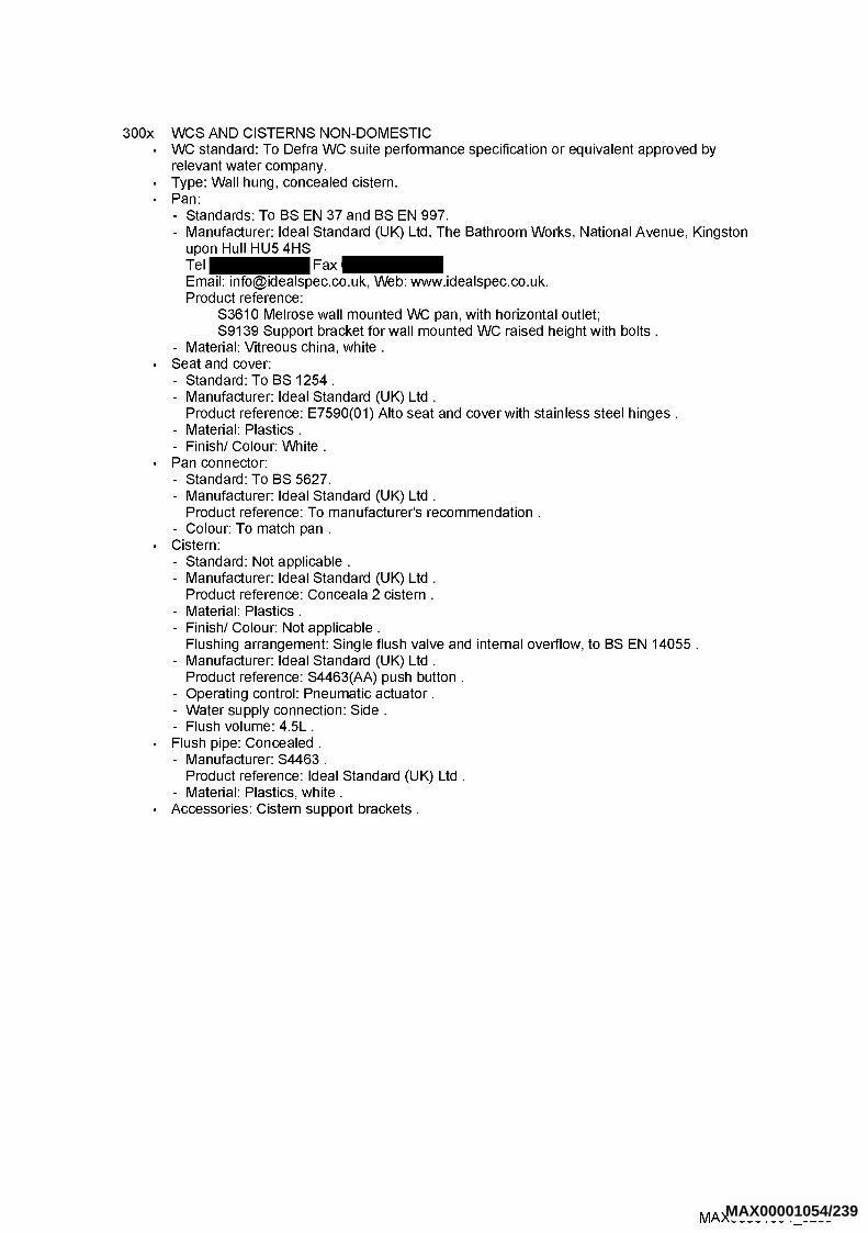
300x WCS AND CISTERNS NON-DOMESTIC • WC standard: To Defra WC suite performance specification or equivalent approved by
relevant water company. • Type: Wall hung, concealed cistern. • Pan:
- Standards: To BS EN 37 and BS EN 997. - Manufacturer: Ideal Standard (UK) Ltd, The Bathroom Works, National Avenue, Kingston
upon Hull HU5 4HS ^ ^ ^ ^ ^ ^ Tel Fax Email: [email protected], Web: www.idealspec.co.uk. Product reference:
S3610 Melrose wall mounted WC pan, with horizontal outlet; S9139 Support bracket for wall mounted WC raised height with bolts .
- Material: Vitreous china, white . • Seat and cover:
- Standard: To BS 1254 . - Manufacturer: Ideal Standard (UK) Ltd .
Product reference: E7590(01) Alto seat and cover with stainless steel hinges . - Material: Plastics . - Finish/ Colour: White .
• Pan connector: - Standard: To BS 5627. - Manufacturer: Ideal Standard (UK) Ltd .
Product reference: To manufacturer's recommendation . - Colour: To match pan .
• Cistern: - Standard: Not applicable . - Manufacturer: Ideal Standard (UK) Ltd .
Product reference: Conceala 2 cistern . - Material: Plastics . - Finish/ Colour: Not applicable .
Flushing arrangement: Single flush valve and internal overflow, to BS EN 14055 . - Manufacturer: Ideal Standard (UK) Ltd .
Product reference: S4463(AA) push button . - Operating control: Pneumatic actuator. - Water supply connection: Side . - Flush volume: 4.5L .
• Flush pipe: Concealed . - Manufacturer: S4463 .
Product reference: Ideal Standard (UK) Ltd . - Material: Plastics, white .
• Accessories: Cistern support brackets .
MAX00001054 0239 MAX00001054/239

WCS AND CISTERNS DOMESTIC WC standard: To Defra WC suite performance specification or equivalent approved by relevant water company. Type: Sandringham 21 Low Level WC Pan. Pan: - Standards: To BS EN 37 and BS EN 997. - Manufacturer: Armitage Shanks.
Product reference: Magnia Reference S3510. - Material: Vitreous china, white. Seat and cover: - Standard: To BS 1254. - Manufacturer: Armitage Shanks.
Product reference: Gemini Reference RS 4055. - Material: Heavy duty white plastic. - Finish/Colour: White. Pan connector: - Standard: To BS 5627. - Manufacturer: Contractor's choice.
Product reference: To manufacturer's recommendation. - Colour: White. Cistern: - Standard: Not applicable. - Manufacturer: Armitage Shanks.
Product reference: S3900 Compact cistern, 6 litre, for side supply: internal overflow with Freeflo plastic syphon fittings and Microvalve HP/LP side supply ballvalve, plastic flushbend, Simpla inlet connector, supports, chrome plated front lever.
- Material: Vitreous china. - Finish/Colour: White.
Flushing arrangement: Dual flush, bottom supply and internal overflow. - Manufacturer: Armitage Shanks.
Product reference: Integrated in cistern. - Operating control: Chrome plated front lever. - Water supply connection: Side. - Flush volume: 6L. Accessories: WC to be screwed to floor and cistern to be screwed to wall. Joint to wall to be sealed with waterproof sealant.
MAX00001054 0240 MAX00001054/240
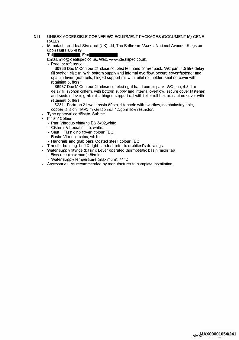
UNISEX ACCESSIBLE CORNER WC EQUIPMENT PACKAGES (DOCUMENT M) GENE RALLY Manufacturer: Ideal Standard (UK) Ltd, The Bathroom Works, National Avenue, Kingston upon Hull HU5 4HS
Email: [email protected], Web: www.idealspec.co.uk. - Product reference:
56966 Doc M Contour 21 close coupled left hand corner pack, WC pan, 4.5 litre delay fill syphon cistern, with bottom supply and internal overflow, secure cover fastener and spatula lever, grab rails, hinged support rail with toilet roll holder, seat no cover with retaining buffers;
56967 Doc M Contour 21 close coupled right hand corner pack, WC pan, 4.5 litre delay fill syphon cistern, with bottom supply and internal overflow, secure cover fastener and spatula lever, grab rails, hinged support rail with toilet roll holder, seat no cover with retaining buffers
S2311 Portman 21 washbasin 50cm, 1 taphole with overflow, no chainstay hole, copper tails on TMV3 mixer tap incl. 1.5gpm flow restrictor.
Type approval certificate: Submit. Finish/ Colour: - Pan: Vitreous china to BS 3402,white. - Cistern: Vitreous china, white. - Seat: Plastic no cover, colour TBC. - Basin: Vitreous china, white. - Handrails and grab bars: Coated steel, colour TBC. Transfer handing: Left & right handed, referto architect's drawings. Water supply fittings (basin): Lever operated thermostatic basin mixer tap - Flow rate (maximum): 5l/min. - Water supply temperature (maximum): 41 0C. Accessories: As recommended by manufacturer to complete installation.
MAX00001054 0241 MAX00001054/241

312 WC FOR AMBULANT DISABLED PEOPLE GENERALLY • Manufacturer: Ideal Standard (UK) Ltd, The Bathroom Works, National Avenue, Kingston
upon HullHU5 4HS Tel ^^^^^^B Fax ^^^^^^^M Email: [email protected], Web: www.idealspec.co.uk. - Product reference:
S3077 (WC HD) Contour 21 rimless wall mounted WC pan horizontal outlet, 70cm HTM projection
S9139 Support bracket for wall mounted WC raised height with bolts. - Material: Vitreous china, white.
• Seat and cover: - Standard: To BS 1254. - Manufacturer: Ideal Standard (UK) Ltd.
Product reference: S4066 Contour 21 seat no cover, top fixing hinges and retaining buffers.
- Material: Plastic. - Finish/ Colour: Black.
• Pan connector: - Standard: To BS 5627. - Manufacturer: Ideal Standard (UK) Ltd.
Product reference: S4303 Contour 21 Extension Connector outlet for 70/75cm WC pan outlet.
- Colour: White. • Cistern:
- Standard: Not applicable. - Manufacturer: Ideal Standard (UK) Ltd.
Product reference: S4259 Conceala 2 cistern 4.5 Litre syphon low level side supply and internal overflow plastic flushbends, spatula lever.
- Material: Plastic. • Flush pipe: Concealed.
- Manufacturer: deal Standard (UK) Ltd. - Product reference: S4302 Contour 21 flushpipe constructed, necessary for installation. - Material: Plastic.
• Accessories: - Ideal Standard Ltd. S6481 Contour 21 back support rail for 70cm projection HTM64 WC, 40 x 17 x 35mm diameter tube; - Ideal Standard Ltd. S6884 Cushion for back support with clips - Grab rails as per clause 436 (2no) installed vertically and horizontally in accordance with BS8300 - Hinged support rail as per clause 437 (1no) installed in accordance with BS8300 - Colostomy shelf d/w 150mm x 400mm, white vitreous china.
321 URINALS - WATERLESS BOXING CLUB • Urinal:
- Manufacturer: Ideal Standard (UK) Ltd, The Bathroom Works, National Avenue, Kingston upon Hull HU5 4HS Tel ^ ^ ^ H Fax| Email: [email protected], Web: www.idealspec.co.uk. Product reference: S6321 (UR H) Aridian waterless bowl urinal, shrouded outlet.
- Material: Vitreous china, white. - Installation: To be connected to waste pipe system which is adequately vented.
• Wastes and traps: Renewable cartridge with outlet adaptor. - Manufacturer: As Urinal.
Product reference: S6282 single replacement cartridge. • Accessories: Fixing hangers and toggle bolts.
MAX00001054 0242 MAX00001054/242
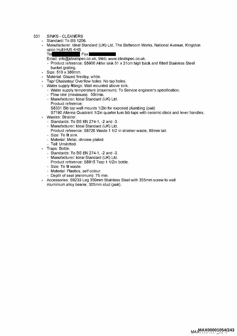
SINKS - CLEANERS Standard: To BS 1206. Manufacturer: Ideal Standard (UK) Ltd, The Bathroom Works, National Avenue, Kingston upon Hull HU5 4HS
Tel^^^^^^^B F a x ^ ^ ^ ^ ^ ^ ^ H Email: [email protected], Web: www.idealspec.co.uk. - Product reference: S5900 Alder sink 51 x 31cm high back and fitted Stainless Steel
bucket grating. Size: 510 x 380mm. Material: Glazed fireclay, white. Tap/ Chainstay/ Overflow holes: No tap holes. Water supply fittings: Wall mounted above sink. - Water supply temperature (maximum): To Service engineer's specification. - Flow rate (maximum): 501/min. - Manufacturer: Ideal Standard (UK) Ltd.
Product reference: S8331 Bib tap wall mounts 1/2in for exposed plumbing (pair) S7190 Alterna Quadrant 1/2in quarter turn bib taps with ceramic discs and lever handles.
Wastes: Strainer. - Standards: To BS EN 274-1, -2 and -3. - Manufacturer: Ideal Standard (UK) Ltd.
Product reference: S8726 Waste 1 1/2 in strainer waste, SOmm tail. - Size: To fit sink. - Material: Metal, chrome plated. - Tail: Unslotted. Traps: Bottle. - Standards: To BS EN 274-1, -2 and -3. - Manufacturer: Ideal Standard (UK) Ltd.
Product reference: S8915 Trap 1 1/2in bottle. - Size: To fit waste. - Material: Plastics, self colour. - Depth of seal (minimum): 75 mm. Accessories: S9233 Leg 350mm Stainless Steel with 355mm screw to wall Aluminium alloy bearer, 305mm stud (pair).
MAX00001054 0243 MAX00001054/243

335 WASH BASINS - PEDESTAL • Manufacturer: Armitage Shanks.
- Product reference: S2113 Sandringham 56cm washbasin, 2 taphole with overflow and chainstay hole.
• Size: 560 x 480 mm. • Material: Vitreous china, white. • Tap/ Chainstay/ Overflow holes: One tap hole, centre and overflow hole. • Water supply fittings: Pegler.
- Water supply temperature (maximum): 41 0C. - Flow rate (maximum): 5l/min. - Manufacturer: Pegler.
Product reference: Performa reference 2159QT. - Operation: Lever handles.
• Wastes: Pop up. - Standards: To BS EN 274-1, -2 and -3. - Manufacturer: Contractor's choice.
Product reference: Contractor's choice. - Size: To fit basin. - Material: Metal, chrome plated. - Tail: Slotted.
• Traps: Bottle. - Standards: To BS EN 274-1, -2 and -3. - Manufacturer: Ideal Standard (UK) Ltd.
Product reference: S8920 Trap 1 1/4in resealing bottle. - Size: To fit waste. - Material: Plastics, chrome plated. - Depth of seal (minimum): 75 mm.
• Accessories: As enquired to complete installation.
MAX00001054 0244 MAX00001054/244
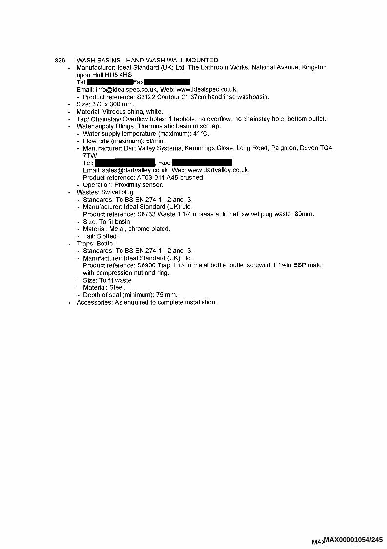
336 WASH BASINS - HAND WASH WALL MOUNTED • Manufacturer: Ideal Standard (UK) Ltd, The Bathroom Works, National Avenue, Kingston
upon HullHU5 4HS Tel ^^^^^^^BFaxI Email: [email protected], Web: www.idealspec.co.uk. - Product reference: S2122 Contour 21 37cm handrinse washbasin.
• Size: 370 x 300 mm. • Material: Vitreous china, white. • Tap/ Chainstay/ Overflow holes: 1 taphole, no overflow, no chainstay hole, bottom outlet. • Water supply fittings: Thermostatic basin mixer tap.
- Water supply temperature (maximum): 41 0C. - Flow rate (maximum): 5l/min.
- Manufacturer: Dart Valley Systems, Kemmings Close, Long Road, Paignton, Devon TQ4
Tel: Fax: Email: [email protected], Web: www.dartvalley.co.uk. Product reference: AT03-011 A45 brushed.
- Operation: Proximity sensor. • Wastes: Swivel plug.
- Standards: To BS EN 274-1, -2 and -3. - Manufacturer: Ideal Standard (UK) Ltd.
Product reference: S8733 Waste 1 1/4in brass anti theft swivel plug waste, SOmm. - Size: To fit basin. - Material: Metal, chrome plated. - Tail: Slotted.
• Traps: Bottle. - Standards: To BS EN 274-1, -2 and -3. - Manufacturer: Ideal Standard (UK) Ltd.
Product reference: S8900 Trap 1 1/4in metal bottle, outlet screwed 1 1/4in BSP male with compression nut and ring.
- Size: To fit waste. - Material: Steel. - Depth of seal (minimum): 75 mm.
• Accessories: As enquired to complete installation.
MAX00001054 0245 MAX00001054/245

337 WASH BASINS DOMESTIC WALL MOUNTED • Manufacturer: Ideal Standard (UK) Ltd, The Bathroom Works, National Avenue, Kingston
upon Hull HU5 4HS ^ ^ ^ ^ ^ ^
Email: [email protected], Web: www.idealspec.co.uk. - Product reference: E7881 Concept Cube 50cm washbasin, 1 taphole with overflow.
• Size: 500 x 460 mm. • Material: Vitreous china, white. • Tap/ Chainstay/ Overflow holes: 1 taphole, no overflow, no chainstay hole, bottom outlet. • Water supply fittings: Thermostatic basin mixer tap.
- Water supply temperature (maximum): 41 0C. - Flow rate (maximum): 5l/min. - Manufacturer: Ideal Standard (UK) Ltd.
Product reference: B9915 Concept Blue washbasin mixer 1 hole. - Operation: Lever handles.
• Wastes: Pop up. - Standards: To BS EN 274-1, -2 and -3. - Manufacturer: Ideal Standard (UK) Ltd.
Product reference: Part of tap. - Size: To fit basin. - Material: Metal, chrome plated. - Tail: Slotted.
• Traps: Bottle. - Standards: To BS EN 274-1, -2 and -3. - Manufacturer: Ideal Standard (UK) Ltd.
Product reference: S8910 Trap 1 1/4in plastic bottle, 75mm seal. - Size: To fit waste. - Material: Plastics, self colour. - Depth of seal (minimum): 75 mm.
• Accessories: - E7839 Concept semi-pedestal for 50cm; - E0157 wall fixing set, with semi-pedestal screwed to wall.
MAX00001054 0246 MAX00001054/246

355 BATHS - RECTANGULAR DOMESTIC • Standard: BS EN 198. • Manufacturer: Ideal Standard (UK) Ltd, The Bathroom Works, National Avenue, Kingston
upon Hull HU5 4HS Tel ^^^^^^^H F a x ^ ^ ^ ^ ^ ^ ^ | Email: [email protected], Web: www.idealspec.co.uk. - Product reference: E7295 Concept bath with 2 tapholes, suitable for standard waste and
overflow only. • Size: 170cm x 75cm . • Volume to overflow (maximum): Manufacturer's standard. • Material: Acrylic sheet, white. • Tap/ Chainstay/ Overflow holes: Two tap holes. • Water supply fittings: Bath mixer tap with shower hose, handspray and wall mounting
bracket. - Water supply temperature (maximum): 41 0C. - Flow rate (maximum): 6 U minute at 3 bar. - Manufacturer: Ideal Standard (UK) Ltd.
Product reference: A4054 Active dual control two hole thermostatic bath shower mixer with shower set.
• Wastes: Pop up. - Standards: To BS EN 274-1, -2 and -3. - Manufacturer: Ideal Standard (UK) Ltd.
Product reference: E5795 Waste 1 1/2in combined bath waste and overflow. - Size: DN 40. - Material: Metal, chrome plated. - Tail: Slotted.
• Traps: Tubular, P type. - Standards: To BS EN 274-1, -2 and -3. - Manufacturer: Ideal Standard (UK) Ltd.
Product reference: S8970 Trap 1 1/2 with 75mm seal, multi-purpose outlet suitable for plastic and BS copper pipe.
- Size: DN 40. - Material: Plastics, self colour. - Depth of seal (minimum): 50 mm.
• Accessories: - E5800 Bath pop-up waste operating handle and cover only; - E3194 Unilux 170cm front bath panel; - E3195 Unilux 75cm end bath panel.
376 SHOWER UNITS BOXING CLUB • Shower fittings: Electronic shower control unit.
- Manufacturer: Dart Valley Systems, Kemmings Close, Long Road, Paignton, Devon TQ4 7TW^^^_^^^_ ^^^^^^^^ Tel: Fax: Email: [email protected], Web: www.dartvalley.co.uk. Product reference: SH01-006 Ceiling height TMV3 tower with high security shower head, wave-on, wall mounted.
- Finish: Stainless steel. - Operating control: Proximity sensor. - Water supply temperature (maximum): 41 0C. - Flow rate: 8 U min.
• Enclosure: Referto section K32. - Manufacturer: Referto section K32.
Product reference: Referto section K32. • Accessories: As recommended by manufacturer to complete installation.
MAX00001054 0247 MAX00001054/247

377 ACCESSIBLE SHOWER EQUIPMENT PACKAGES (DOCUMENT M) GENERALLY • Shower fittings: Thermostatic shower mixer, concealed, handspray and hose.
- Manufacturer: Ideal Standard (UK) Ltd, The Bathroom Works, National Avenue, Kingston upon Hull HU5 4HS Tel^^^^^B Fax^^^^^H Email: [email protected], Web: www.idealspec.co.uk.
- Product reference: S6960 Shower room pack with folding shower seat and back support in grey, 3 x 60cm grab rails, 2 x hinged rails and 2 x 45cm grab rails, lever operated thermostatic mixer for Concealed supplies, shower handset holder, handset & hose, fixed short projection shower head.
- Finish: Shower kit: Chrome plated; Rails, seat: PPC colour TBC.
- Operating control: Manual. - Water supply temperature (maximum): 41 0C. - Flow rate: 8 U min.
• Enclosure: Referto clause 492. - Manufacturer: Referto clause 492.
Product reference: Referto clause 492. • Accessories: As recommended by manufacturer to complete installation.
380 DRINKING FOUNTAINS BOXING CLUB • Type: Chilled, mains-fed point-of-use water cooler, floor standing. • Manufacturer: Submit proposals.
- Product reference: Submit proposals. - Material:
Cabinet - Brushed stainless steel, satin Basin - Polished stainless steel.
- Dimensions: Submit proposal but approx. 1000mm high • Jet and valve: Heavy duty cup/bottle filler self close swan neck tap and push button
operated bubbler. - Material: Chrome plated brass.
• Capacity: min. 25L chilled water per hour. • Chiller type: Direct chill. • Refrigerant type: Non-toxic R134A. • Filtration type: Compiiantwith current regulations, manufacturer to advise. • Installation:
- Water, drainage and power to be available at location of fountain; - Installation to comply with current IEE regulations.
• Accessories: To contain security covers to protect all water and electrical connections. • Additional requirements:
- To comply with HSE requirements; - To be attached to both the wall and the floor to prevent vandalism.
436 HANDRAILS AND GRAB BARS TO AMBULANT DISABLED WC • Manufacturer: Ideal Standard (UK) Ltd, The Bathroom Works, National Avenue, Kingston
upon HullHU5 4HS Tel ^ ^ ^ B F a x ^ ^ ^ ^ ^ ^ ^ ^ l Email: [email protected], Web: www.idealspec.co.uk. - Product reference: S6454 Contour 21 grab rail straight.
- Installation: Wall mounted vertically and horizontally in accordance with BS8300. • Diameter: 35mm. - Length: 600mm .
• Material: Aluminium . • Finish/ Colour: Polyester powder coated, colour TBC .
MAX00001054 0248 MAX00001054/248
437 DROP DOWN SUPPORT RAIL TO AMBULANT DISABLED WC • Manufacturer: Ideal Standard (UK) Ltd, The Bathroom Works, National Avenue, Kingston
u p o i m j I I H U M H S
Te l^^^^^^B F a x ^ ^ ^ ^ ^ ^ ^ B Email: [email protected], Web: www.idealspec.co.uk. - Product reference: S6467 Contour 21 hinged arm support rail. • Diameter: 35mm. - Projection: SOOmm .
• Material: Aluminium . • Finish/ Colour: Polyester powder coated, colour TBC . • Installation: Wall mounted in accordance with BS8300 . • Accessories: S6468 Toilet roll holder for Contour 21 hinged support arm .
442 PAPER TOWEL DISPENSERS • Manufacturer: Submit proposals.
- Type: Wall mounted. - Product reference: Submit proposals.
• Material: Brushed stainless steel. • Finish/Colour: satin.
458 SOAP DISPENSERS GENERALLY • Manufacturer: Submit proposals.
- Type: Wall mounted. - Product reference: Submit proposals.
• Material: Brushed stainless steel. • Finish/ Colour: Satin.
462 TOILET PAPER HOLDERS GENERALLY • Manufacturer: Submit proposals
- Type: Jumbo toilet roll holder. - Product reference: Submit proposals.
• Material/ finish: Brushed stainless steel. • Finish/ Colour: Satin.
492 PRIVACY CURTAINS ACCESSIBLE SHOWERS. • Manufacturer: Submit proposals.
- Type: Straight rail with curtain. - Product reference: Submit proposals
- Length: Approx. 1100mm. • Material:
- Rail: Chrome plated brass. - Curtain: Nylon, white.
• Finish/ Colour: N/A.
495 SHOWER BATH SCREEN GENERALLY. Manufacturer: Ideal Standard (UK) Ltd, The Bathroom Works, National Avenue, Kingston upon HullHU5 4HS T e l ^ ^ ^ ^ ^ ^ H , Fax| Email: [email protected], Web: www.idealspec.co.uk. - Product reference: L6210 Synergy Angle shower bath screen, unhanded with clear glass
and silver finish wall profile. • Material: 6mm clear toughened safety glass. • Finish/ Colour: Cover profile and top caps in polished silver. • Fixing: Concealed wall fixings.
MAX00001054 0249 MAX00001054/249

505 LINEAR DRAINAGE TO VINYL FLOORS • Type: Linear stainless steel perforated Channel Drain. • Manufacturer: Wade International Ltd., Third Avenue, Halstead, Essex, C09 2SX
T e l : ^ ^ ^ ^ ^ ^ ^ ^ ^ ^ | Fax: ^ ^ ^ ^ ^ ^ ^ ^ ^ ^ E-mail: [email protected], Web: w w w M w a o ^ L ^ ^ ^ ^ - Product reference: SVF channel and SS32150 grating.
• General dimensions: To be confirmed by Service engineer. • Outlet connection: To be confirmed by Service engineer. • Thickness of floor finish: Referto clause M50/155.
510 POINT DRAINAGE - FLOOR GULLY TO VINYL FLOORS • Type: Linear stainless steel perforated Channel Drain. • Manufacturer: Wade I n t e r n a t i o n a ^ ^ J i i r ^ v e n u ^ H a l s t e a d , Essex, C09 2SX
T e L ^ ^ ^ ^ ^ ^ ^ H , Fax: E-mail: [email protected], Web: www.wade.eu. - Product reference:
Gully body: to be confirmed by service engineer; Grating: K2307 Stainless steel .
• General dimensions: To be confirmed by Service engineer. • Outlet connection: To be confirmed by Service engineer. • Thickness of floor finish: Referto clause M50/155 .
580 SEALANT FOR POINTING • Standard: To BS EN ISO 11600.
- Class: F20HM. • Type: Silicone based to BS 5885. Type B with fungicide. • Manufacturer: Contractor's choice.
- Product reference: Contractor's choice. • Colour: TBC.
EXECUTION
610 INSTALLATION GENERALLY • Assembly and fixing: Surfaces designed to falls to drain as intended. • Fasteners: Nonferrous or stainless steel. • Supply and discharge pipework: Fix before appliances. • Fixing: Fix appliances securely to structure. Do not support on pipework. • Jointing and bedding compounds: Recommended by manufacturers of appliances,
accessories and pipes being jointed or bedded. • Appliances: Do not use. Do not stand on appliances. • On completion: Components and accessories working correctly with no leaks. • Labels and stickers: Remove.
613 COMPATIBILITY OF COMPONENTS • General: Each sanitary assembly must consist of functionally compatible components,
preferably obtained from a single manufacturer. - Exceptions: None.
620 NOGGINGS AND BEARERS • Noggings, bearers, etc. to support sanitary appliances and fittings: Position accurately. Fix
securely.
630 TILED BACKGROUNDS OTHER THAN SPLASHBACKS • Timing: Complete before fixing appliances. • Fixing appliances: Do not overstress tiles.
MAX00001054 0250 MAX00001054/250

650 INSTALLING WC PANS • Floor mounted pans: Screw fix and fit cover caps over screw heads. Do not use mortar or
other beddings. • Seat and cover: Stable when raised.
660 INSTALLING SLAB URINALS • Waterproofing of walls and floor (specified elsewhere): Completed before fixing urinal
components. • Gap between components: 3 mm. • Space behind channels and slabs: Grout with 1:5 cementsand grout. • Pointing: Rake out joints to 10 mm depth. Point flush with waterproof jointing compound
recommended by urinal manufacturer.
670 INSTALLING CISTERNS • Cistern operating components: Obtain from cistern manufacturer.
- Float operated valve: Matched to pressure of water supply. • Overflow pipe: Fixed to falls and located to give visible warning of discharge.
- Location: Agreed, where not shown on drawings.
710 INSTALLING TAPS • Fixing: Secure against twisting. • Seal with appliance: Watertight. • Positioning: Hot tap to left of cold tap as viewed by user of appliance.
720 INSTALLING WASTES AND OVERFLOWS • Bedding: Waterproof jointing compound. • Fixing: Wth resilient washer between appliance and backnut.
755 SEALANT BEDDING AND POINTING • Bedding: Bed and point basins to underside of vanity units. . • Pointing: Joints between appliances and splashbacks. .
MAX00001054 0251 MAX00001054/251

N14 General internal signage systems
MAX00001054 0252 MAX00001054/252
N14 General internal signage systems
TO BE READ WITH PRELIMINARIES/ GENERAL CONDITIONS. • Notwithstanding the descriptions of workmanship described in various parts of this
NBS/NES; the contents of BS8000, where applicable, shall take precedence except where workmanship described is superior to BS8000.
• The manufacturers noted within this specification are indicative and may be substituted with similar or equal alternatives.
• Manufacturers should either provide a BRE Global BES6001 Product certificate or supply evidence of a independently certified Environmental Management System.
GENERAL
110 SIGNAGE SYSTEM FOR DIRECTORY AND WAYFINDING • System manufacturer: Submit proposals .
- Product reference: Submit proposals . • Layout and dimensions: TBC . • Lettering:
- Language: English . - Font: Foundry TBC . - Colour: RAL colour TBC . - Size: TBC .
• Symbols and graphics: Logo . - Colour: Corporate colour RAL TBC . - Size: TBC .
• Background colour: RAL colour TBC . • Sign type: Aluminium plate .
- Inserts: Manufacturer's standard . - Manufacturing process: Screen print.
• Supports/ Fixings: Wall mounted, screw-fixed concealed . • Accessories: To be compliant with AD Part M and BS8300 requirements .
111 SIGNAGE SYSTEM FOR DOORS • System manufacturer: Submit proposals .
- Product reference: Submit proposals . • Layout and dimensions: TBC . • Lettering:
- Language: English . - Font: Foundry TBC . - Colour: RAL colour TBC . - Size: TBC .
• Symbols and graphics: Not applicable . - Colour: Not applicable . - Size: Not applicable .
• Background colour: RAL colour TBC . • Sign type: Aluminium plate .
- Inserts: Manufacturer's standard . - Manufacturing process: Screen print.
• Supports/ Fixings: Wall mounted, screw-fixed concealed . • Accessories: To be compliant with AD Part M and BS8300 requirements .
MAX00001054 0253 MAX00001054/253
130 EXTERNAL SIGNAGE SYSTEM DIRECTORY POST MOUNTED • System manufacturer: Submit proposals .
- Product reference: Submit proposals . • Layout and dimensions: TBC . • Lettering:
- Language: English . - Font: Foundry TBC . - Colour: RAL colour TBC . - Size: TBC .
• Symbols and graphics: Logo, arrows . - Colour: TBC . - Size: TBC .
• Background colour: RAL colour TBC . • Sign type: Stove enamelled .
- Inserts: Manufacturer's standard . - Manufacturing process: Contractor's choice .
• Supports/ Fixings: Posts for external signs . • Accessories: To be compliant with AD Part M and BS8300 requirements .
131 EXTERNAL SIGNAGE SYSTEM WAYFINDING WALL MOUNTED • System manufacturer: Submit proposals .
- Product reference: Submit proposals . • Layout and dimensions: TBC . • Lettering:
- Language: English . - Font: Foundry TBC . - Colour: RAL colour TBC . - Size: TBC .
• Symbols and graphics: Logo, arrows . - Colour: TBC . - Size: TBC .
• Background colour: RAL colour TBC . • Sign type: Stove enamelled .
- Inserts: Manufacturer's standard . - Manufacturing process: Contractor's choice .
• Supports/ Fixings: Wall mounted, concealed screw fixed . • Accessories: To be compliant with AD Part M and BS8300 requirements .
SYSTEM PERFORMANCE
210 GENERAL REQUIREMENTS • Signage system: Complete to BS 559, including facing information, components, inserts,
accessories and fixings necessary to complete the system. - Comply with the requirements of: Wayfinding strategy.
• Geometric shapes, colours and layout: In accordance with BS 8501. • Design standard for disabled people: In accordance with BS 8300. • Proposals: Submit drawings, schedules, technical information, calculations and
manufacturer's literature.
240 FIRE REACTION OF INTERNAL SIGNAGE SYSTEM • Non flammable surface:
- Standard: Min. Class 1 to BS 476-7 .
MAX00001054 0254 MAX00001054/254
280 DESIGN LIFE SIGNAGE SYSTEMS GENERALLY • Duration: 10 years .
- Subject to reasonable wear and tear. • Condition of use: Subject to regular maintenance.
295 SIGNAGE SAMPLES BOARD • Samples board: Submit.
- Content: Selected labelled signs, showing methods of fixing. - Conformity: Retain samples on site forthe duration ofthe contract or until instructed to
remove.
- Delivered product: To conform with labelled samples.
PRODUCTS 305 PRODUCTS GENERALLY
• Standard: To BS 559.
EXECUTION
610 FIXING SIGNS GENERALLY • Installation: To BS 559.
- Secure, plumb and level. • Strength of fasteners: Sufficient to support all live and dead loads. • Fasteners and or adhesives: As section Z20.
• Fixings showing on surface of sign: Must not detract from the message being displayed.
COMPLETION 910 DOCUMENTATION
• Submit: - Manufacturer's maintenance instructions. - Guarantees, warranties, test certificates, record schedules and log books.
MAX00001054 0255 MAX00001054/255

N15 Internal fire and safety signage systems
MAX00001054 0256 MAX00001054/256
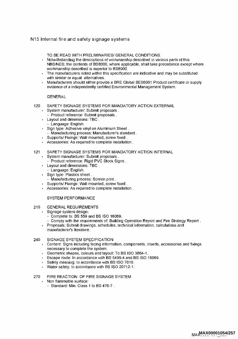
N15 Internal fire and safety signage systems
TO BE READ WITH PRELIMINARIES/ GENERAL CONDITIONS. • Notwithstanding the descriptions of workmanship described in various parts of this
NBS/NES; the contents of BS8000, where applicable, shall take precedence except where workmanship described is superior to BS8000.
• The manufacturers noted within this specification are indicative and may be substituted with similar or equal alternatives.
• Manufacturers should either provide a BRE Global BES6001 Product certificate or supply evidence of a independently certified Environmental Management System.
GENERAL
120 SAFETY SIGNAGE SYSTEMS FOR MANDATORY ACTION EXTERNAL • System manufacturer: Submit proposals .
- Product reference: Submit proposals . • Layout and dimensions: TBC .
- Language: English. • Sign type: Adhesive vinyl on Aluminium Sheet.
- Manufacturing process: Manufacturer's standard . • Supports/ Fixings: Wall mounted, screw fixed . • Accessories: As required to complete installation .
121 SAFETY SIGNAGE SYSTEMS FOR MANDATORY ACTION INTERNAL • System manufacturer: Submit proposals .
- Product reference: Rigid PVC Stock Signs . • Layout and dimensions: TBC .
- Language: English. • Sign type: Plastics sheet.
- Manufacturing process: Screen print. • Supports/ Fixings: Wall mounted, screw fixed . • Accessories: As required to complete installation .
SYSTEM PERFORMANCE
210 GENERAL REQUIREMENTS • Signage system design:
- Complete to: BS 559 and BS ISO 16069. - Comply with the requirements of: Building Operation Report and Fire Strategy Report.
• Proposals: Submit drawings, schedules, technical information, calculations and manufacturer's literature.
240 SIGNAGE SYSTEM SPECIFICATION • Content: Signs including facing information, components, inserts, accessories and fixings
necessary to complete the system. • Geometric shapes, colours and layout: To BS ISO 3864-1. • Escape route: In accordance with BS 5499-4 and BS ISO 16069. • Safety meaning: In accordance with BS ISO 7010. • Water safety: In accordance with BS ISO 20712-1.
270 FIRE REACTION OF FIRE SIGNAGE SYSTEM • Non flammable surface:
- Standard: Min. Class 1 to BS 476-7 .
MAX00001054 0257 MAX00001054/257
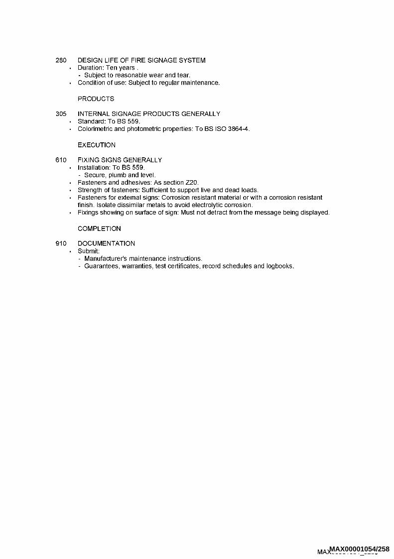
280 DESIGN LIFE OF FIRE SIGNAGE SYSTEM • Duration: Ten years .
- Subject to reasonable wear and tear. • Condition of use: Subject to regular maintenance.
PRODUCTS
305 INTERNAL SIGNAGE PRODUCTS GENERALLY • Standard: To BS 559.
• Colorimetric and photometric properties: To BS ISO 3864-4.
EXECUTION 610 FIXING SIGNS GENERALLY
• Installation: To BS 559. - Secure, plumb and level.
• Fasteners and adhesives: As section Z20. • Strength of fasteners: Sufficient to support live and dead loads. • Fasteners for external signs: Corrosion resistant material or with a corrosion resistant
finish. Isolate dissimilar metals to avoid electrolytic corrosion. • Fixings showing on surface of sign: Must not detract from the message being displayed.
COMPLETION
910 DOCUMENTATION • Submit:
- Manufacturer's maintenance instructions. - Guarantees, warranties, test certificates, record schedules and logbooks.
MAX00001054 0258 MAX00001054/258

p Building fabric sundries
MAX00001054 0259 MAX00001054/259

P10 Sundry insulat ion/proofing work
MAX00001054 0260 MAX00001054/260

P10 Sundry insulation/ proofing work
SUNDRY INSULATION/ PROOFING WORK
TO BE READ WITH PRELIMINARIES/ GENERAL CONDITIONS. • Notwithstanding the descriptions of workmanship described in various parts of this
NBS/NES; the contents of BS8000, where applicable, shall take precedence except where workmanship described is superior to BS8000.
• The manufacturers noted within this specification are indicative and may be substituted with similar or equal alternatives.
• Manufacturers should either provide a BRE Global BES6001 Product certificate or supply evidence of a independently certified Environmental Management System.
TYPES OF INSULATION
191 INSULATION FITTED BETWEEN MULLIONS BEHIND SPANDREL PANELS • Manufacturer: Rockwool Limited, Pencoed, Bridgend, CF35 6NY
Tel: ^^ H. Email: [email protected], Web: www.rockwool.co.uk. - Product reference: RW4, factory faced. - Density: Not less than 80kg/m 3
• Material: Mineral wool to BS EN 13162. - Facing: Tissue or aluminium foil faced as required.
• Recycled content: Submit proposals. • Thickness: To achieve a U value of 0.15 W/m 2K. • Installation requirements:
- Joints: Butted, no gaps. Seal joints with adhesive tape. - Fasteners: Use where necessary to retain insulation and/ or prevent slumping.
218 INSULATION FIXED TO BACKING WALL GENERALLY • Manufacturer: Rockwool Limited, Pencoed, Bridgend, CF35 6NY
Tel: ^^^^^^^H Email: [email protected], Web: www.rockwool.co.uk. - Product reference: RW5, factory faced. - Density: Not less than 100kg/m3
• Material: Mineral wool to BS EN 13162. - Facing: Tissue or aluminium foil faced as required.
• Recycled content: Submit proposals. • Thickness: To achieve a U value of 0.15 W/m 2K. • Installation requirements:
- Joints: Butted, no gaps. Cut and fit tightly between/around cladding supports. - Fasteners: Use where necessary to retain insulation and/ or prevent slumping.
235 COMPRESSIBLE INSULATION IN GAPS • Manufacturer: Rockwool Limited, Pencoed, Bridgend, CF35 6NY
Tel: Email: [email protected], Web: www.rockwool.co.uk. - Product reference: Flexible Slabs RWA45. - Density: Not less than 45kg/m 3
• Material: Mineral wool to BS EN 13162. - Facing: Not required.
• Recycled content: Submit proposals. • Thickness: To suite application available in 30/40/50/60/75/ /100mm. • Installation requirements:
- Joints: Butted, no gaps. Cut and fit tightly between/around cladding supports. - Fasteners: Use where necessary to retain insulation and/ or prevent slumping.
MAX00001054 0261 MAX00001054/261
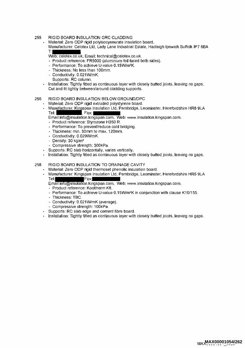
255 RIGID BOARD INSULATION GRC CLADDING • Material: Zero ODP rigid polyisocyanurate insulation board.
Manufacturer: Celotex Ltd, Lady Lane Industrial Estate, Hadleigh Ipswich Suffolk IP7 6BA
Web: celotex.co.uk, Email: [email protected]. - Product reference: FR5000 (aluminium foil faced both sides). - Performance: To achieve U-value 0.15W/m2K. - Thickness: No less than 100mm. - Conductivity: 0.021 W/mK.
Supports: RC column. • Installation: Tightly fitted as continuous layer with closely butted joints, leaving no gaps.
Cut and fit tightly between/around cladding supports.
256 RIGID BOARD INSULATION BELOW GROUND/DPC • Material: Zero ODP rigid extruded polystyrene board. • Manufacturei^<inc|span Insulation Ltd, Pembridge, Leominster, Herefordshire HR6 9LA
Tel: ^^^^^^H, Fax: B B H H H I Email:[email protected], Web: www.insulation.kingspan.com. - Product reference: Styrozone H350 R. - Performance: To prevent/reduce cold bridging. - Thickness: min. SOmm to max. 120mm. - Conductivity: 0.029W/mK. - Density: 30 kg/m 3
- Compressive strength: SOOkPa. • Supports: RC slab horizontally, varies vertically. • Installation: Tightly fitted as continuous layer with closely butted joints, leaving no gaps.
258 RIGID BOARD INSULATION TO DRAINAGE CAVITY • Material: Zero ODP rigid thermoset phenolic insulation board. • Manufacturer: Kingspan Insulation Ltd, Pembridge, Leominster, Herefordshire HR6 9LA
T e ' : H H H H | Fax:^^^^^H [email protected], Web: www.insulation.kingspan.com. - Product reference: Kooltherm K8. - Performance: To achieve U-value 0.15W/m2K in conjunction with clause K10/155. - Thickness: TBC. - Conductivity: 0.021 W/mK (average). - Compressive strength: 100kPa.
• Supports: RC slab edge and cement fibre board. • Installation: Tightly fitted as continuous layer with closely butted joints, leaving no gaps.
MAX00001054 0262 MAX00001054/262

310 VAPOUR CONTROL LAYER GENERALLY • Manufacturer: Industrial Textiles & Plastics Ltd, Stillington Road, Easingwold, York Y061
3 F A ^ ^ ^ ^ ^ ^ T e L ^ ^ ^ ^ ^ ^ ^ H F a x : ^ ^ ^ ^ ^ ^ ^ | Email: [email protected], Web: www.itpltd.com. - Product reference: Powerlon VCL150.
• Material: Polyethylene-based membranes with a mono-filament scrim for tensile strength. • Minimum vapour resistance: 272 MNs/g. • Installation requirements:
- Setting out: Joints minimized. - Method of fixing: Laid loose and sealed at edges to manufacturer's recommendation to
provide continuity. - Joints: At supports only, lapped 150 mm minimum. - Openings: Membrane fixed to reveals. - Joints and edges: Sealed with double sided tape with vapour resistivity not less than the
vapour control layer. • Penetrations: Sealed. • Other requirements: As required to complete installation.
320 BREATHER MEMBRANE • Manufacturer: Manufacturer and reference: Industrial Textiles & Plastics Ltd, Stillington
Road, Easingwold, York Y061 3FA T e l : ^ ^ ^ ^ ^ ^ ^ ^ F a x : ^ ^ ^ ^ ^ ^ ^ ^ Email: [email protected], Web: www.itpltd.com. - Product reference: UltraPerm Lite.
- Water vapour permeability: min. 1700g/m2/24hrs. • Material: Non-woven polyolefin triple laminate membrane. • Installation requirements:
- Setting out: Joints minimized. Membrane to form a continuous barrier to prevent water, snow and wind blown dust reaching the substrate.
- Method of fixing: Laid loose and sealed at edges to manufacturer's recommendation to provide continuity.
- Joints: Lapped 100 mm minimum horizontally and 150 mm minimum vertically. - Openings: Membrane fixed to reveals. - Bottom edges: Membrane lapped over flashings, sills, etc. to allow free drainage to the
exterior. • Penetrations: Sealed.
430 WIRED MINERAL WOOL SMALL CAVITY BARRIERS • Material: Wre reinforced mineral wool minimum 50 mm thick. • Fire resistance rating: To BS EN 1363, El 30. • Installation requirements:
- Fasteners: Staples at maximum 150 mm centres. Fold cavity barrier if necessary to ensure a tight fit.
- Joints and intersections: Butted, no gaps.
MAX00001054 0263 MAX00001054/263
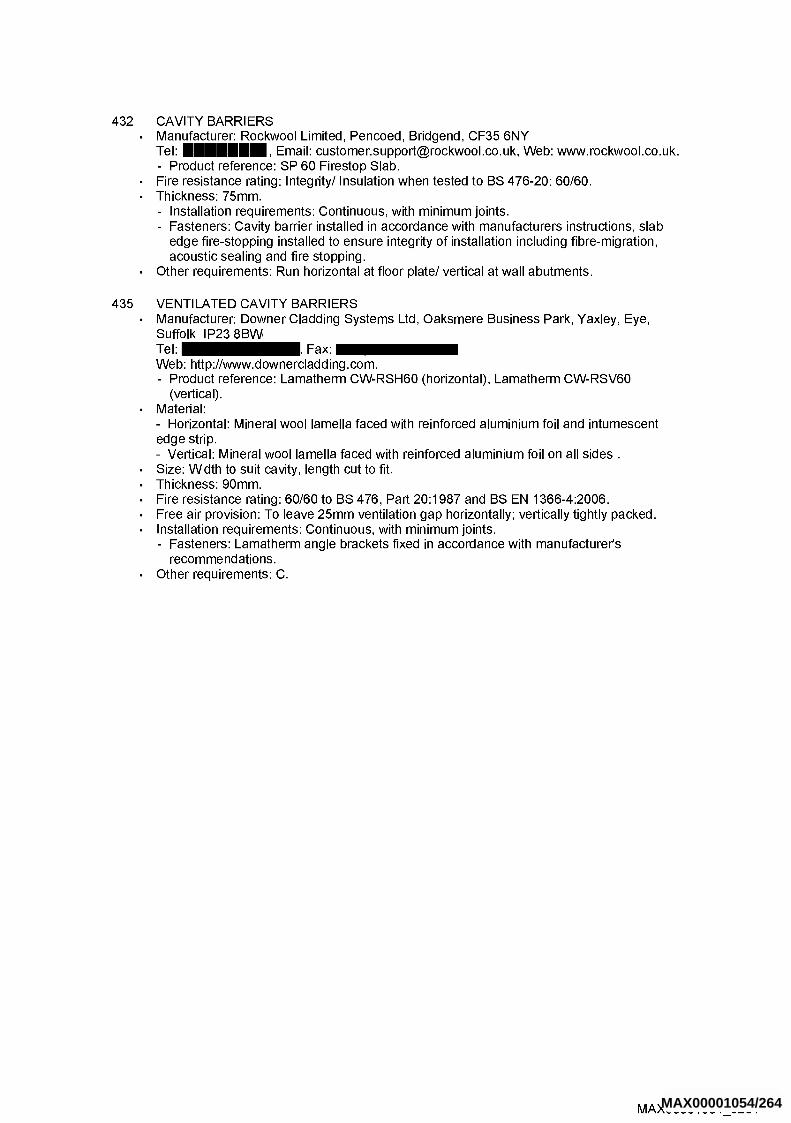
432 CAVITY BARRIERS • Manufacturer: Rockwool Limited, Pencoed, Bridgend, CF35 6NY
Tel: ^ ^ ^ ^ ^ ^ H , Email: [email protected], Web: www.rockwool.co.uk. - Product reference: SP 60 Firestop Slab.
• Fire resistance rating: Integrity/ Insulation when tested to BS 476-20: 60/60. • Thickness: 75mm.
- Installation requirements: Continuous, with minimum joints. - Fasteners: Cavity barrier installed in accordance with manufacturers instructions, slab
edge fire-stopping installed to ensure integrity of installation including fibre-migration, acoustic sealing and fire stopping.
• Other requirements: Run horizontal at floor plate/ vertical at wall abutments.
435 VENTILATED CAVITY BARRIERS • Manufacturer: Downer Cladding Systems Ltd, Oaksmere Business Park, Yaxley, Eye,
Suffolk IP23 8BW Tel: ^^^^^^^^^^H Fax: ^^B^^^^^^^H Web: http://www.downercladding.com. - Product reference: Lamatherm CW-RSH60 (horizontal), Lamatherm CW-RSV60
(vertical). • Material:
- Horizontal: Mineral wool lamella faced with reinforced aluminium foil and intumescent edge strip. - Vertical: Mineral wool lamella faced with reinforced aluminium foil on all sides .
• Size: Wdth to suit cavity, length cut to fit. • Thickness: 90mm. • Fire resistance rating: 60/60 to BS 476, Part 20:1987 and BS EN 1366-4:2006. • Free air provision: To leave 25mm ventilation gap horizontally; vertically tightly packed. • Installation requirements: Continuous, with minimum joints.
- Fasteners: Lamatherm angle brackets fixed in accordance with manufacturer's recommendations.
• Other requirements: C.
MAX00001054 0264 MAX00001054/264

P20 Unframed isolated t r ims/sk i r t ings/sundry items
MAX00001054 0265 MAX00001054/265

P20 Unframed isolated tr ims/ skirt ings/ sundry items
TO BE READ WITH PRELIMINARIES/ GENERAL CONDITIONS • Notwithstanding the descriptions of workmanship described in various parts of this
NBS/NES; the contents of BS8000, where applicable, shall take precedence except where workmanship described is superior to BS8000.
• The manufacturers noted within this specification are indicative and may be substituted with similar or equal alternatives.
• All manufacturers of MDF boards must provide evidence that their product is tested in accordance with EN 13986:2004 and complies with Formaldehyde class E1. They must verify that regulated wood preservatives are absent as defined by the standard.
• All timber supplied or used in timber products must be from certified sources. Evidence must be provided by the supplier/manufacturer in form of FSC or PEFC certificates. Additional CEPT documentation may be supplied for verification purposes.
170 PROPRIETARY THRESHOLD COVER TO ENTRANCE DOORS • Manufacturer: Contractor's choice.
- Product reference: Submit proposals. • Size: Approx. 200mm wide; for length refer to architect's drawings. • Finish/ Colour: Aluminium mill finished with grooved non-slip surface. • Accessories: As recommended by manufacturer to complete installation. • Fixing: Screw fixed or adhered depending on substrate and manufacturer's
recommendation. - Jointing: Not applicable.
180 PROPRIETARY PIPEWORK ENCASEMENT • Manufacturer: Alumasc Interior Building Products, Halesfield 19, Telford, Shropshire TF7
4QT Tel: ^ ^ ^ ^ ^ ^ ^ H Fax: ^B^^^^^^^l Web: http://www.pendock.co.uk, Email: [email protected]. - Product reference: Pendock TK Plywood Casing System .
• Size: Angle section with sloping top edge; - Thickness: Smm - Wdth: 75mm - Total height: 110mm - Standard length: 2500mm.
• Finish/Colour: Melamine/White. • Accessories:
- Internal and external corners; - Butt joint covers; - Stop ends.
• Fixing: Face fixed to softwood battens with zinc screws with decorative caps and collars. - Position of fixings: 50 mm from each end and equally spaced along the profile at approx.
600 centres. - Jointing: Butt joints incorporating 'push fit'joint covers.
MAX00001054 0266 MAX00001054/266

201 MEDIUM DENSITY FIBREBOARD SKIRTING BOARDS • Manufacturer: Submit proposals.
- Product reference: Contractor's choice. • Standard: To BS EN 622-5.
- Type: MDF. - Formaldehyde class: To BS EN 622-1, Class E1.
• Fire rating: Not applicable. • Thickness: 15mm
- Height: 110mm. Edges: Pencil rounded outward facing top edge 2mm.
• Finish: Painted, colour TBC. • Support/ Fixing: Concealed screw fixing with plugs. • Other requirements: No regulated wood preservatives
202 MEDIUM DENSITY FIBREBOARD WINDOW SILL BOARDS • Manufacturer: Submit proposals.
- Product reference: Contractor's choice. • Standard: To BS EN 622-5.
- Type: MDF. - Formaldehyde class: To BS EN 622-1, Class E1.
• Fire rating: Not applicable. • Thickness: 20mm.
Edges: Pencil rounded outward facing edges 2mm. • Finish: Painted, colour TBC. • Support/ Fixing: Fix to softwood grounds with lost head nails at 600 mm centres. • Other requirements: No regulated wood preservatives
203 MEDIUM DENSITY FIBREBOARD TRIMS & ARCHITRAVES • Manufacturer: Submit proposals.
- Product reference: Contractor's choice. • Standard: To BS EN 622-5.
- Type: MDF. - Formaldehyde class: To BS EN 622-1, Class E1.
• Fire rating: Not applicable. • Thickness: 25mm.
Edges: Square shaped edges. • Finish: Painted, colour TBC. • Support/ Fixing: Fix to softwood grounds with lost head nails at 600 mm centres. • Other requirements: No regulated wood preservatives
EXECUTION
510 INSTALLATION GENERALLY • Joinery workmanship: As section Z10. • Metal workmanship: As section Z11. • Methods of fixing and fasteners: As section Z20 where not specified. • Straight runs: To be in one piece, or in long lengths with as few joints as possible. • Running joints: Location and method of forming to be agreed where not detailed. • Joints at angles: Mitre, unless shown otherwise. • Position and level: To be agreed where not detailed.
MAX00001054 0267 MAX00001054/267

P21 Door/window ironmongery
MAX00001054 0268 MAX00001054/268

P21 Door/window ironmongery
TO BE READ WITH PRELIMINARIES/ GENERAL CONDITIONS • Notwithstanding the descriptions of workmanship described in various parts of this
NBS/NES; the contents of BS8000, where applicable, shall take precedence except where workmanship described is superior to BS8000.
• The manufacturers noted within this specification are indicative and may be substituted with similar or equal alternatives.
• Manufacturers should either provide a BRE Global BES6001 Product certificate or supply evidence of a independently certified Environmental Management System.
GENERAL
121 IRONMONGERY FROM SINGLE PROPRIETARY RANGE • Manufacturer: Ingersoll Rand Security Technologies, Bescot Crescent, Walsall, West
Midlands, WS1 4DL, ^ ^ ^ ^ ^ ^ ^ ^ T e l . ^ ^ ^ ^ ^ ^ ^ 1 Fax. Web: www.security.ingersollrand.com . - Product reference: Briton Specification Series Door Hardware .
• Principal material/ finish: Satin stainless steel, 316 Grade . • Items unavailable within selected range: Submit proposals.
141 SAMPLE BOARDS • General: Before placing orders with suppliers submit a sample board, containing labelled
samples of ironmongery and showing methods of fixing. • Range: Include Lever handles, escutcheon, lockcase, pull handles, push plates and WC
gender signs . - Conformity: Retain board on site in an approved location forthe duration ofthe contract.
Ensure conformity of ironmongery as delivered with labelled samples.
170 IRONMONGERY FOR FIRE DOORS • Relevant products: Ironmongery fixed to, or morticed into, the component parts of a fire
resisting door assembly. • Compliance: Ironmongery included in successful tests to BS 476-22 or BS EN 1634-1 on
door assemblies similar to those proposed. - Certification: Submit CERTIFIRE certificates .
• Melting point of components (except decorative non functional parts): 800 oC minimum.
180 CATEGORY OF DUTY FOR DOOR IRONMONGERY • Standard: To DD 171.
- Category of duty of doors: As per section L20 . • General: Durability of ironmongery components to be compatible with stated category of
duty of each door leaf. - Exclusions: Ironmongery with specific duty or 'category of use' defined elsewhere.
Documentation: Before placing orders with suppliers submit documentation showing product compliance with stated category of duty.
MAX00001054 0269 MAX00001054/269
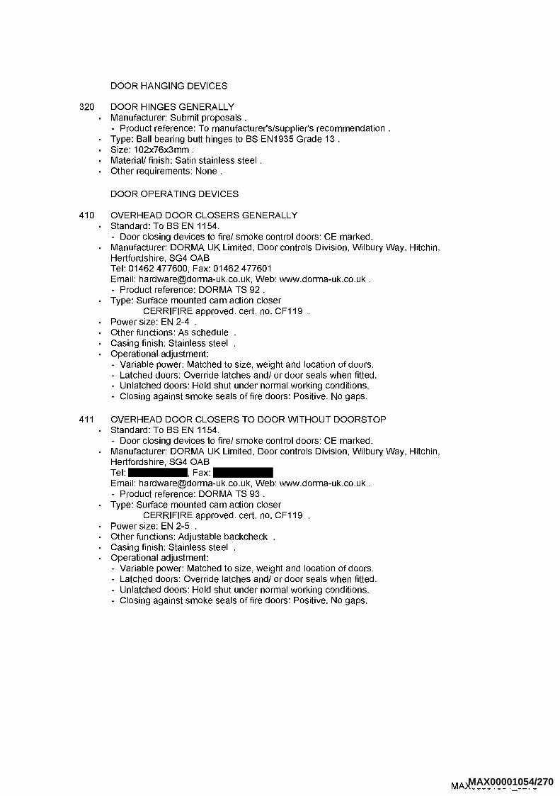
DOOR HANGING DEVICES
320 DOOR HINGES GENERALLY • Manufacturer: Submit proposals .
- Product reference: To manufacturer's/supplier's recommendation . • Type: Ball bearing butt hinges to BS EN1935 Grade 13 . • Size: 102x76x3mm . • Material/ finish: Satin stainless steel . • Other requirements: None .
DOOR OPERATING DEVICES
410 OVERHEAD DOOR CLOSERS GENERALLY • Standard: To BS EN 1154.
- Door closing devices to fire/ smoke control doors: CE marked. • Manufacturer: DORMA UK Limited, Door controls Division, Wilbury Way, Hitchin,
Hertfordshire, SG4 OAB Tel: 01462 477600, Fax: 01462 477601 Email: [email protected], Web: www.dorma-uk.co.uk . - Product reference: DORMA TS 92 .
• Type: Surface mounted cam action closer CERRIFIRE approved, cert. no. CF119 .
• Power size: EN 2-4 . • Other functions: As schedule . • Casing finish: Stainless steel . • Operational adjustment:
- Variable power: Matched to size, weight and location of doors. - Latched doors: Override latches and/ or door seals when fitted. - Unlatched doors: Hold shut under normal working conditions. - Closing against smoke seals of fire doors: Positive. No gaps.
411 OVERHEAD DOOR CLOSERS TO DOOR WITHOUT DOORSTOP . Standard: To BS EN 1154.
- Door closing devices to fire/ smoke control doors: CE marked. • Manufacturer: DORMA UK Limited, Door controls Division, Wilbury Way, Hitchin,
Hertfordshire, SG4 OAB ^ ^ ^ ^ ^ ^ Tel: ^ ^ ^ ^ ^ ^ H , Fax: ^ ^ ^ ^ ^ ^ H Email: [email protected], Web: www.dorma-uk.co.uk . - Product reference: DORMA TS 93 .
• Type: Surface mounted cam action closer CERRIFIRE approved, cert. no. CF119 .
• Power size: EN 2-5 . • Other functions: Adjustable backcheck . • Casing finish: Stainless steel . • Operational adjustment:
- Variable power: Matched to size, weight and location of doors. - Latched doors: Override latches and/ or door seals when fitted. - Unlatched doors: Hold shut under normal working conditions. - Closing against smoke seals of fire doors: Positive. No gaps.
MAX00001054 0270 MAX00001054/270

DOOR SECURING DEVICES
510 THIEF RESISTANT DOOR LOCKS ENTRANCE DOORS TO FLATS, OFFICES & COMMUNITY ROOM
• Standard: To BS 3621 and Kitemarked. • Manufacturer: Ingersoll Rand Security Technologies, Bescot Crescent, Walsall, West
Midlands WS1 4DL . T e l . ^ ^ ^ ^ ^ ^ ^ l Fax. Web: www.security.ingersollrand.com - Product reference: Briton 5520 Cylinder Sashlock .
• Type: Mortice sashlock for europrofile cylinder - Cylinder: CISA Astral S with Grade 1 attack resistance .
• Backset: 60mm . • Material/finish:
- Case: Mild steel 1.5mm with a black powder coated finish; - Forend & strike: Satin stainless steel; - Cylinder: Satin nickel plated stainless steel .
• Keying: TBC .
515 DOOR LOCKS OFFICES, NURSERY, BOXING CLUB, COMMUNITY ROOM • Standard: To BS EN 12209.
Manufacturer: Ingersoll Rand Security Technologies, Bescot Crescent, Walsall, West Midlands WS1 4DL . Tel. Fax. • • • • • • • • 1 Web: www.security.ingersollrand.com . - Product reference: Briton 5520 Cylinder Sashlock .
• Type: Mortice sashlock for standard europrofile cylinder. • Backset: 60mm . • Material/finish:
- Case: Mild steel 1.5mm with a black powder coated finish; - Forend & strike: Satin stainless steel .
• Keying: TBC .
516 DOOR LOCKS FLATS • Standard: To BSEN 12209.
Manufacturer: Ingersoll Rand Security Technologies, Bescot Crescent, Walsall, West Midlands WS1 4DL . Tel. Fax. ^ ^ ^ ^ ^ ^ ^ ^ ^ ^ Web: www.security.ingersollrand.com . - Product reference: Legge 2736 Lever Sashlock .
• Type: Mortice sashlock for lever key . • Backset: 57 mm . • Material/finish:
- Case: Mild steel with a black powder coated finish; - Forend: Satin stainless steel .
• Keying: TBC .
MAX00001054 0271 MAX00001054/271

520 BATHROOM DOOR LOCKS GENERALLY • Standard: To BSEN 12209.
Manufacturer: Ingersoll Rand Security Technologies, Bescot Crescent, Walsall, West Midlands WS1 4DL . Tel. Fax. ^^I^^^^^^^H Web: www.security.ingersollrand.com . - Product reference: Briton 5520 Cylinder Sashlock .
• Type: Mortice sashlock for bathroom turn and indicator. • Backset: 60mm . • Material/finish:
- Case: Mild steel 1.5mm with a black powder coated finish; - Forend & strike: Satin stainless steel .
• Keying: TBC .
521 BATHROOM DOOR LOCKS SLIDING DOORS • Standard: To BS EN 12209.
Manufacturer: Submit proposals . - Product reference: Submit proposals .
• Type: Clawbolt operated by turn/emergency release . • Backset: 57mm . • Material/ finish: Stainless steel . • Keying: Not applicable .
577 PANIC EXIT DEVICES TO ESCAPE DOORS • Standard: To BS EN 1125.
- Panic exit devices for locked doors on escape routes: CE marked. • Manufacturer: Ingersoll Rand Security Technologies, Bescot Crescent, Walsall, West
Midlands WS1 4DL . Tel .^^^^^^B Fax. Web: www.security.ingersollrand.com - Product reference: Briton 570 .
• Type: Touchbar 2/3 point locking panic device with upper and lower pullman catches • Material/ finish: Powder coated steel, colour to match door furniture . • Additional requirements: Security alarmed .
DOOR FURNITURE
610 LEVER HANDLES GENERALLY • Standard: To BS EN 1906. • Manufacturer: Ingersoll Rand Security Technologies, Bescot Crescent, Walsall, West
Midlands WS1 4DL . Tel. ^^^^^^^^Fax. ^ ^ ^ ^ ^ g ^ ^ Web: www.security.ingersollrand.com . - Product reference: Briton 4640.20.R.SS . Style: Return to door lever handle on rose . Size: 20mm dia . Material/ finish: Satin stainless steel, grade 316 . Mounting: To manufacturer's recommendation . Additional requirements: None .
MAX00001054 0272 MAX00001054/272
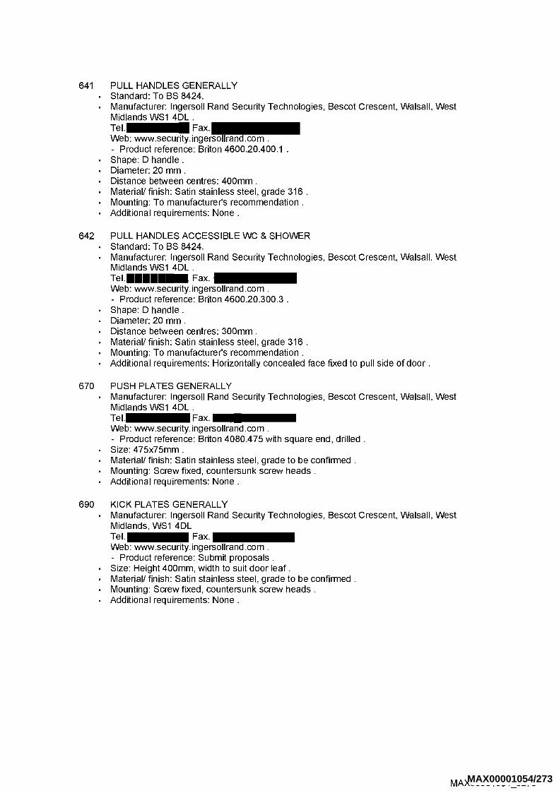
641 PULL HANDLES GENERALLY • Standard: To BS 8424. • Manufacturer: Ingersoll Rand Security Technologies, Bescot Crescent, Walsall, West
Midlands WS1 4DL . T e l . ^ ^ ^ ^ ^ ^ ^ l Fax. Web: www.security.ingersollrand.com - Product reference: Briton 4600.20.400.1 . Shape: D handle . Diameter: 20 mm . Distance between centres: 400mm . Material/ finish: Satin stainless steel, grade 316 Mounting: To manufacturer's recommendation . Additional requirements: None .
642 PULL HANDLES ACCESSIBLE WC & SHOWER • Standard: To BS 8424. • Manufacturer: Ingersoll Rand Security Technologies, Bescot Crescent, Walsall, West
Midlands WS1 4DL . ^ ^ ^ ^ ^ ^ ^ ^ Tel. ^^^^^H, Fax. Web: www.security.ingersollrand.com . - Product reference: Briton 4600.20.300.3 . Shape: D handle . Diameter: 20 mm . Distance between centres: SOOmm . Material/ finish: Satin stainless steel, grade 316 . Mounting: To manufacturer's recommendation . Additional requirements: Horizontally concealed face fixed to pull side of door.
670 PUSH PLATES GENERALLY • Manufacturer: Ingersoll Rand Security Technologies, Bescot Crescent, Walsall, West
Midlands WS1 4DL . T e l . ^ ^ ^ ^ ^ ^ ^ H Fax. ^^R^^^^^^^H Web: www.security.ingersollrand.com . - Product reference: Briton 4080.475 with square end, drilled .
• Size: 475x75mm . • Material/ finish: Satin stainless steel, grade to be confirmed . • Mounting: Screw fixed, countersunk screw heads . • Additional requirements: None .
690 KICK PLATES GENERALLY • Manufacturer: Ingersoll Rand Security Technologies, Bescot Crescent, Walsall, West
Midlands, WS1 4DL Tel .^^^^^^B Fax. ^ ^ ^ ^ H Web: www.security.ingersollrand.com . - Product reference: Submit proposals .
• Size: Height 400mm, width to suit door leaf. • Material/ finish: Satin stainless steel, grade to be confirmed . • Mounting: Screw fixed, countersunk screw heads . • Additional requirements: None .
MAX00001054 0273 MAX00001054/273
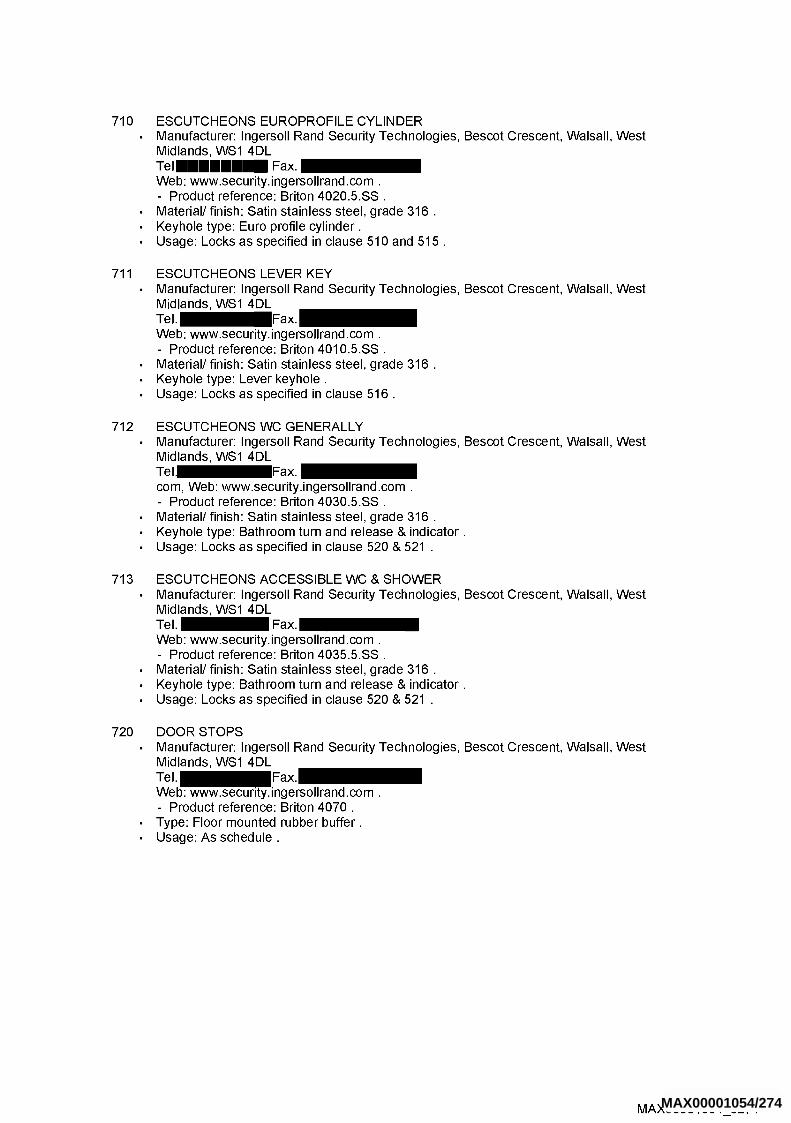
710 ESCUTCHEONS EUROPROFILE CYLINDER • Manufacturer: Ingersoll Rand Security Technologies, Bescot Crescent, Walsall, West
Midlands, WS1 4DL ^ ^ ^ ^ ^ ^ ^ ^ Tel^^^^^^^H Fax. ^ ^ ^ ^ H Web: www.security.ingersollrand.com . - Product reference: Briton 4020.5.SS .
• Material/ finish: Satin stainless steel, grade 316 . • Keyhole type: Euro profile cylinder. • Usage: Locks as specified in clause 510 and 515 .
711 ESCUTCHEONS LEVER KEY • Manufacturer: Ingersoll Rand Security Technologies, Bescot Crescent, Walsall, West
Midlands, WS1 4DL Tel. ^ ^ ^ ^ ^ ^ ^ ^ F a x . Web: www.security.ingersollrand.com . - Product reference: Briton 4010.5.SS .
• Material/ finish: Satin stainless steel, grade 316 . • Keyhole type: Lever keyhole . • Usage: Locks as specified in clause 516 .
712 ESCUTCHEONS WC GENERALLY • Manufacturer: Ingersoll Rand Security Technologies, Bescot Crescent, Walsall, West
Midlands, WS1 4DL ^ ^ ^ ^ ^ ^ ^ ^ T e l . ^ ^ ^ ^ ^ ^ ^ ^ | F a x . com, Web: www.security.ingersollrand.com . - Product reference: Briton 4030.5.SS .
• Material/ finish: Satin stainless steel, grade 316 . • Keyhole type: Bathroom turn and release & indicator. • Usage: Locks as specified in clause 520 & 521 .
713 ESCUTCHEONS ACCESSIBLE WC & SHOWER • Manufacturer: Ingersoll Rand Security Technologies, Bescot Crescent, Walsall, West
Midlands, WS1 4DL Tel. Fax. ^I^^^^^^^H Web: www.security.ingersollrand.com . - Product reference: Briton 4035.5.SS .
• Material/ finish: Satin stainless steel, grade 316 . • Keyhole type: Bathroom turn and release & indicator. • Usage: Locks as specified in clause 520 & 521 .
720 DOOR STOPS • Manufacturer: Ingersoll Rand Security Technologies, Bescot Crescent, Walsall, West
Midlands, WS1 4DL Tel. Fax. | Web: www.security.ingersollrand.com - Product reference: Briton 4070 .
• Type: Floor mounted rubber buffer. • Usage: As schedule .
MAX00001054 0274 MAX00001054/274
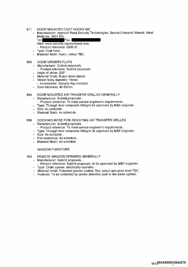
811 DOOR MOUNTED COAT HOOKS WC • Manufacturer: Ingersoll Rand Security Technologies, Bescot Crescent, Walsall, West
Midlands, WS1 4DL Te I Fax. Web: www.security.ingersollrand.com - Product reference: 0305 01 .
• Type: Coat hook . • Material/finish: Nylon, colour TBC .
890 DOOR VIEWERS FLATS • Manufacturer: Submit proposals .
- Product reference: Submit proposals . • Angle of vision: 200° . • Material/finish: Brass nickel plated . • Viewer body diameter: 14mm;
- Accessories: Security flap included . • Door thickness: 40-55mm .
895 DOOR MOUNTED AIR TRANSFER GRILLES GENERALLY • Manufacturer: Submit proposals .
- Product reference: To meet service engineer's requirements . • Type: Through door composite fitting to be approved by M&E engineer. • Size: As schedule . • Material/ finish: As schedule .
896 DOOR MOUNTED FIRE RESISTING AIR TRANSFER GRILLES • Manufacturer: Submit proposals .
- Product reference: To meet service engineer's requirements . • Type: Through door composite fitting to be approved by M&E engineer. • Size: As schedule . • Fire resistance: As schedule . • Material/ finish: As schedule .
WINDOW FURNITURE
935 REMOTE WINDOW OPENERS GENERALLY • Manufacturer: Submit proposals .
- Product reference: Submit proposals, to be approved by M&E engineer. • Type: Chain opener, electrically operated . • Material/ finish: Polyester powder coated, RAL colour and gloss level TBC . • Features: To be controlled by smoke detection and/ or fire alarm system .
MAX00001054 0275 MAX00001054/275

R posal systems
MAX00001054 0276 MAX00001054/276

R10 Rainwater drainage systems
MAX00001054 0277 MAX00001054/277
R10 Rainwater drainage systems
TO BE READ WITH PRELIMINARIES/ GENERAL CONDITIONS. • Notwithstanding the descriptions of workmanship described in various parts of this
NBS/NES; the contents of BS8000, where applicable, shall take precedence except where workmanship described is superior to BS8000.
• The manufacturers noted within this specification are indicative and may be substituted with similar or equal alternatives.
• Manufacturers should either provide a BRE Global BES6001 Product certificate or supply evidence of a independently certified Environmental Management System.
GENERAL
110 GRAVITY RAINWATER DRAINAGE SYSTEM • Rainwater outlets: None. • Gutters: PVC-U angular. • Pipework: PVC-U. • Below ground drainage: Submit proposals. • Disposal: To surface water drainage. • Controls: Not applicable. • Accessories: Anticlimb rainwater pipe covers.
SYSTEM PERFORMANCE
221 COLLECTION AND DISTRIBUTION OF RAINWATER • General: Complete, and without leakage or noise nuisance.
PRODUCTS
350 PVC-U GUTTERS • Standard: To the relevant parts of BS EN 607 and BS EN 1462, Kitemark certified. • Manufacturer: Submit proposals.
- Product reference: Submit proposals. • Recycled content: 10% (minimum) to BS EN ISO 14021. • Profile: Box. • Nominal size: 114 mm. • Colour: Black. • Brackets: PVC-U 2 screw type.
- Fixings: Stainless steel screws. Size: 114mm.
• Accessories: - Gutter stop ends; - Running outlets; - Angles.
MAX00001054 0278 MAX00001054/278
420 PVC-U PIPEWORK - EXTERNAL • Standard: To BS EN 12200-1, Kitemark certified. • Manufacturer: Submit proposals.
- Product reference: Submit proposals. • Recycled content: 10% (minimum) to BS EN ISO 14021. • Section: Rectangular. • Nominal size: DN63. • Colour: Black. • Brackets: PVC-U clips, black.
- Fixings: Stainless steel screws. Size: To suit pipework.
• Accessories: - Access fittings; - Adjustable offset units; - Connectors; - Bends.
EXECUTION
600 PREPARATION • Work to be completed before commencing work specified in this section:
- Below ground drainage. Alternatively, make temporary arrangements for dispersal of rainwater without damage or disfigurement ofthe building fabric and surroundings.
- Painting of surfaces which will be concealed or inaccessible.
605 INSTALLATION GENERALLY • Electrolytic corrosion: Avoid contact between dissimilar metals where corrosion may occur. • Plastics and galvanized steel pipes: Do not bend. • Allowance for thermal and building movement: Provide and maintain clearance as fixing
and jointing proceeds. • Protection:
- Fit purpose made temporary caps to prevent ingress of debris. - Fit access covers, cleaning eyes and blanking plates as the work proceeds.
610 FIXING AND JOINTING GUTTERS • Joints: Watertight. • Brackets: Securely fixed.
- Fixings: Plugged and screwed into masonry and concrete. Fixing centres: 600 mm.
- Additional brackets: Where necessary to maintain support and stability, provide at joints in gutters and near angles and outlets.
• Roofing underlay: Dressed into gutter.
MAX00001054 0279 MAX00001054/279

635 FIXING PIPEWORK • Pipework: Fix securely, plumb and/ or true to line. • Branches and low gradient sections: Fix with uniform and adequate falls to drain efficiently. • Externally socketed pipes and fittings: Fix with sockets facing upstream. • Additional supports: Provide as necessary to support junctions and changes in direction. • Vertical pipes:
- Provide a loadbearing support at least at every storey level. - Tighten fixings as work proceeds so that every storey is self supporting. - Wedge joints in unsealed metal pipes to prevent rattling.
• Wall and floor penetrations: Isolate pipework from structure. - Pipe sleeves: As section P31. - Masking plates: Fix at penetrations if visible in the finished work.
• Expansion joint pipe sockets: Fix rigidly to buildings. Elsewhere, provide brackets and fixings that allow pipes to slide.
640 FIXING VERTICAL PIPEWORK • Bracket fixings: Screwed into substrate. • Distance between bracket fixing centres (maximum): To manufacturer's recommendations.
650 JOINTING PIPEWORK AND GUTTERS • General: Joint with materials and fittings that will make effective and durable connections. • Jointing differing pipework and gutter systems: Use adaptors intended forthe purpose. • Cut ends of pipes and gutters: Clean and square. Remove burrs and swarf. Chamfer pipe
ends before inserting into ring seal sockets. • Jointing or mating surfaces: Clean and, where necessary, lubricate immediately before
assembly. • Junctions: Form with fittings intended for the purpose. • Jointing material: Strike off flush. Do not allow it to project into bore of pipes and fittings. • Surplus flux, solvent jointing materials and cement: Remove.
700 ACCESS FOR TESTING AND MAINTENANCE • General: Install pipework and gutters with adequate clearance to permit testing, cleaning
and maintenance, including painting where necessary. • Access fittings and rodding eyes: Position so that they are not obstructed.
COMPLETION
910 GUTTER TEST • Preparation: Temporarily block all outlets. • Testing: Fill gutters to overflow level and after 5 minutes closely inspect for leakage.
915 MAINTENANCE INSTRUCTIONS • General: At completion, submit printed instructions recommending procedures for
maintenance ofthe rainwater installation, including full details of recommended inspection, cleaning and repair procedures.
920 IMMEDIATELY BEFORE HANDOVER • Construction rubbish, debris, swarf, temporary caps and fine dust which may enter the
rainwater system: Remove. Do not sweep or flush into the rainwater system. • Access covers, rodding eyes, outlet gratings and the like: Secure complete with fixings.
MAX00001054 0280 MAX00001054/280

z Building fabric reference specification
MAX00001054 0281 MAX00001054/281

Z10 Purpose made joinery
MAX00001054 0282 MAX00001054/282
Z10 Purpose made joinery
TO BE READ WITH PRELIMINARIES/ GENERAL CONDITIONS. • Notwithstanding the descriptions of workmanship described in various parts of this
NBS/NES; the contents of BS8000, where applicable, shall take precedence except where workmanship described is superior to BS8000.
110 FABRICATION • Standard: To BS 1186-2. • Sections: Accurate in profile and length, and free from twist and bowing. Formed out of
solid unless shown otherwise. - Machined surfaces: Smooth and free from tearing, wooliness, chip bruising and other
machining defects. • Joints: Tight and close fitting. • Assembled components: Rigid. Free from distortion. • Screws: Provide pilot holes.
- Screws of 8 gauge (4 mm diameter) or more and screws into hardwood: Provide clearance holes.
- Countersink screws: Heads sunk at least 2 mm below surfaces visible in completed work.
• Adhesives: Compatible with wood preservatives applied and end uses of timber.
120 CROSS SECTION DIMENSIONS OF TIMBER • General: Dimensions on drawings are finished sizes. • Maximum permitted deviations from finished sizes:
- Softwood sections: To BS EN 1313-1:-Clause 6 for sawn sections.
- Hardwood sections: To BS EN 1313-2:-Clause 6 for sawn sections. Clause NA.3 forfurther processed sections.
130 PRESERVATIVE TREATED WOOD • Cutting and machining: Completed as far as possible before treatment. • Extensively processed timber: Retreat timber sawn lengthways, thicknessed, planed,
ploughed, etc. • Surfaces exposed by minor cutting and/ or drilling: Treat as recommended by main
treatment solution manufacturer.
140 MOISTURE CONTENT • Wood and wood based products: Maintained within range specified forthe component
during manufacture and storage.
210 LAMINATED PLASTICS VENEERED BOARDS/ PANELS • Fabrication: To British Laminated Plastics Fabricators Association Ltd (BLF) fabricating
standards. • Balancing veneer: From decorative veneer manufacturer and of similar composition.
Applied to reverse side of core material. • Finished components: Free from defects, including bow, twist, scratches, chipping, cracks,
pimpling, indentations, glue marks, staining and variations in colour and pattern. • Joints visible in completed work: Tight butted, true and flush.
MAX00001054 0283 MAX00001054/283
220 WOOD VENEERED BOARDS/ PANELS • Core material and veneers: Conditioned before bonding. • Setting out: Veneer features and grain pattern aligned regularly and symmetrically unless
instructed otherwise. • Balancing veneer: Applied to reverse side of core material.
- Moisture and temperature movement characteristics: As facing veneer. • Veneer edges: Tight butted and flush, with no gaps. • Tolerance of veneer thickness (maximum): ± 0.5 mm. • Finished components: Free from defects, including bow, twist, scratches, chipping, splits,
blebs, indentations, glue marks and staining. • Surface finish: Fine, smooth, free from sanding marks.
250 FINISHING • Surfaces: Smooth, even and suitable to receive finishes.
- Arrises: Eased unless shown otherwise on drawings. • End grain in external components: Sealed with primer or sealer as section M60 and
allowed to dry before assembly.
MAX00001054 0284 MAX00001054/284

Z11 Purpose made metalwork
MAX00001054 0285 MAX00001054/285

Z11 Purpose made metalwork
TO BE READ WITH PRELIMINARIES/ GENERAL CONDITIONS. • Notwithstanding the descriptions of workmanship described in various parts of this
NBS/NES; the contents of BS8000, where applicable, shall take precedence except where workmanship described is superior to BS8000.
310 MATERIALS GENERALLY • Grades of metals, section dimensions and properties: To appropriate British Standards.
When not specified, select grades and sections appropriate forthe purpose. • Prefinished metal: May be used if methods of fabrication do not damage or alter
appearance of finish, and finish is adequately protected. • Fasteners: To appropriate British Standards and, unless specified otherwise, of same
metal as component being fastened, with matching coating or finish.
320 STEEL LONG AND FLAT PRODUCTS • Hot rolled structural steels (excluding structural hollow sections and tubes): To BS EN
10025-1. • Fine grain steels, including special steels: To BS EN 10025-3 and -4. • Steels with improved atmospheric corrosion resistance: To BS EN 10025-5.
330 STEEL PLATE, SHEET AND STRIP • Plates and wide flats, high yield strength steel: To BS EN 10025-6.
340 HOT ROLLED STEEL PLATE, SHEET AND STRIP • Flat products, high yield strength for cold forming: To BS EN 10149-1, -2 and -3. • Carbon steel sheet and strip for cold forming: To BS EN 10111. • Narrow strip, formable steel and steel for general engineering purposes: To BS 1449-1.8
and BS 1449-1.14.
350 COLD ROLLED STEEL PLATE, SHEET AND STRIP • Steel sections: To BS EN 10162. • Flat products, high yield strength micro-alloyed steels for cold forming: To BS EN 10268. • Carbon steel flat products for cold forming: To BS EN 10130 and BS EN 10131. • Uncoated carbon steel narrow strip for cold forming: To BS EN 10139 and BS EN 10140. • Narrow strip steel for general engineering purposes: To BS EN 10132-1, -2, and -3. • Carbon steel flat products for vitreous enamelling: To BS EN 10209.
360 COATED STEEL FLAT PRODUCTS • Hot dip zinc coated carbon steel sheet and strip for cold forming: To BS EN 10346 and BS
EN 10143. • Hot dip zinc coated structural steel sheet and strip: To BS EN 10143 and BS EN 10346. • Hot dip zinc-aluminium (za) coated sheet and strip: To BS EN 10346. • Hot dip aluminium-zinc (az) coated sheet and strip: To BS EN 10346. • Organic coated flat products: To BS EN 10169.
370 STEEL STRUCTURAL HOLLOW SECTIONS (SHS) • Non alloy and fine grain steels, hot finished: To BS EN 10210-1 and -2. • Non-alloy and fine grain steels, cold formed welded: To BS EN 10219-2. • Weather resistant steels, hot finished: To BS 7668.
MAX00001054 0286 MAX00001054/286
380 OTHER STEEL SECTIONS • Equal flange tees: To BS EN 10055. • Equal and unequal angles: To BS EN 10056-1 and -2. • Wire, carbon steel for general engineering purposes: To BS 1052. • Wre and wire products, general: To BS EN 10218-2. • Tubes:
- Seamless circular: To BS EN 10297-1. - Seamless cold drawn: To BS EN 10305-1. - Welded and cold sized square and rectangular: To BS EN 10305-5. - Welded circular: To BS EN 10296-1. - Welded cold drawn: To BS EN 10305-2. - Welded cold sized: To BS EN 10305-3.
400 STAINLESS STEEL PRODUCTS • Chemical composition and physical properties: To BS EN 10088-1. • Sheet, strip and plate: To BS EN 10088-2. • Semi-finished products bars, rods and sections: To BS EN 10088-3. • Wre: To BS EN 1088-3. • Tubes:
- Welded circular: To BS EN 10296-2. - Seamless circular: To BS EN 10297-2.
410 ALUMINIUM ALLOY PRODUCTS • Designations:
- Designation system, chemical composition and forms: To BS EN 573-1, -2, -3 and -5. - Temper designations: To BS EN 515.
• Sheet, strip and plate: To BS EN 485-1 to -4. • Cold drawn rods, bars and tubes: To BS EN 754-1 and -2. • Extruded rods, bars, tubes and profiles: To BS EN 755-1 and -2. • Drawn wire: To BS EN 1301 - 1 , -2 and -3. • Rivet, bolt and screw stock: To BS 1473. • Structural sections: To BS 1161.
FABRICATION
515 FABRICATION GENERALLY • Contact between dissimilar metals in components: Avoid. • Finished components: Rigid and free from distortion, cracks, burrs and sharp arrises.
- Moving parts: Free moving without binding. • Corner junctions of identical sections: Mitre.
520 COLD FORMED WORK • Profiles: Accurate, with straight arrises.
525 ADHESIVE BONDING • Preparation of surfaces of metals to receive adhesives:
- Degrease. - Abrade mechanically or chemically etch. - Prime: To suit adhesive.
• Adhesive bond: Form under pressure.
MAX00001054 0287 MAX00001054/287
527 WELDING GENERALLY. • Welding procedures:
- Method and standard: Metal arc welding to BS EN 1011-1 and -2 and TIG welding to BS EN 1011-3.
- Welding Procedure Specification (WPS): Submit 2 copies before commencement of welding.
• Preparation: - Joint preparation: Clean thoroughly. - Surfaces of materials that will be self-finished and visible in the completed work: protect
from weld splatter. • Jointing:
- Joints: Fully bond parent and filler metal throughout with no inclusions, holes, porosity or cracks.
- Dissimilar metals: Welding not permitted. - Strength requirements: Welds to achieve design loads. - Heat straightening: Not permitted. - Complex assemblies: Agree priority for welding members to minimize distortion caused
by subsequent welds. - Tack welds: Use only for temporary attachment. - Jigs: Provide to support and restrain members during welding. - Filler plates: Not permitted. - Lap joints: Minimum 5 x metal thickness or 25 mm, whichever is greater. - Weld terminations: Clean and sound.
530 STAINLESS STEEL FABRICATION • Guillotining or punching: Do not use for metal thicknesses greater that 10 mm. • Thermal cutting:
- Carbonation in the heat affected zone: Remove, after cutting. • Bending:
- Plates or bars: Cold bending radius not less than material thickness. - Tubes: Cold bending radius not less than 2 xtube diameter.
• Welding: In addition to general welding requirements: - Protect adjacent surfaces from weld spatter. - Pickle all welds before post fabrication treatments.
• Protection: Provide protection to fabricated components during transit and on site.
555 BRAZING • Standard: To BS EN 14324. • Testing:
- Destructive testing: To BS EN 12797. - Nondestructive testing: To BS EN 12799.
FINISHING
710 FINISHING WELDED AND BRAZED JOINTS VISIBLE IN COMPLETE WORK • Standard: To BS EN ISO 8501-3.
- Preparation grade: P3. • Butt joints: Smooth, and flush with adjacent surfaces. • Fillet joints: Neat. • Grinding: Grind smooth where indicated on drawings.
745 PREPARATION FOR APPLICATION OF COATINGS • General: Complete fabrication, and drill fixing holes before applying coatings. • Paint, grease, flux, rust, burrs and sharp arrises: Remove.
MAX00001054 0288 MAX00001054/288

780 GALVANIZING • Standard: To BSEN ISO 1461. • Preparation:
- Vent and drain holes: Provide in accordance with BS EN ISO 14713-1 and -2. Seal after sections have been drained and cooled.
- Components subjected to cold working stresses: Heat treat to relieve stresses before galvanizing.
- Welding slag: Remove. - Component cleaning: To BS EN ISO 8501-3. - Grade: St 272.
COMPLETION
910 DOCUMENTATION • Submit:
- Manufacturer's maintenance instructions. - Guarantees, warranties, test certificates, record schedules and log books.
920 COMPLETION • Protection: Remove. • Cleaning and maintenance: Carry out in accordance with procedures detailed in
fabricators' guarantees.
MAX00001054 0289 MAX00001054/289

Z12 Preservative/fire retardant treatment
MAX00001054 0290 MAX00001054/290
Z12 Preservative/fire retardant treatment
TO BE READ WITH PRELIMINARIES/ GENERAL CONDITIONS. • Notwithstanding the descriptions of workmanship described in various parts of this
NBS/NES; the contents of BS8000, where applicable, shall take precedence except where workmanship described is superior to BS8000.
110 TREATMENT APPLICATION • Timing: After cutting and machining timber, and before assembling components. • Processor: Licensed by manufacturer of specified treatment solution.
- Operatives: Must have completed the WPA training scheme . • Certification: For each batch of timber provide a certificate of assurance that treatment has
been carried out as specified.
120 COMMODITY SPECIFICATIONS • Standard: Current edition ofthe Wood Protection Association (WPA) publication 'Industrial
wood preservation specification and practice'.
130 PRESERVATIVE TREATMENT SOLUTION STRENGTHS/ TREATMENT CYCLES • General: Select to achieve specified service life and to suit treatability of specified wood
species.
160 ORGANIC SOLVENT PRESERVATIVE TREATMENT • Solution:
- Manufacturer: Contractor's choice. Product reference: Submit proposals.
- Application: Double vacuum + low pressure impregnation, or immersion. • Moisture content of wood:
- At time of treatment: As specified forthe timber/ component at time of fixing. - After treatment: Timber to be surface dry before use.
165 WATER-BASED MICROEMULSION PRESERVATIVE TREATMENT • Solution:
- Manufacturer: Contractor's choice. Product reference: Submit proposals.
- Application: Double vacuum + low pressure impregnation. • Moisture content of wood:
- At time of treatment: As specified forthe timber/ component at time of fixing. - After treatment: Timber to be surface dry before use.
167 BORON COMPOUND PRESERVATIVE TREATMENT • Solution:
- Manufacturer: Contractor's choice. Product reference: Submit proposals.
- Application: High pressure impregnation. • Moisture content of wood:
- At time of treatment: Not more than 28%. - After treatment: Timber to be surface dry before using.
MAX00001054 0291 MAX00001054/291
210 FIRE RETARDANT TREATMENT • Solution type: Dry interior.
- Manufacturer: Contractor's choice. Product reference: Submit proposals.
- Application: Vacuum + pressure impregnation. • Moisture content of wood:
- At time of treatment: As specified forthe timber/ component at time of fixing. - After treatment: Timber to be redried slowly at temperatures not exceeding 65 0C to
minimize distortion and degradation.
610 MAKING GOOD TO PRESERVATIVE TREATMENT ON-SITE • Preservative solution: Compatible with off-site treatment. • Application: In accordance with preservative manufacturer's recommendations.
620 MAKING GOOD TO FIRE RETARDANT TREATMENT ON-SITE • Fire retardant: Compatible with off-site treatment. • Application: In accordance with fire retardant manufacturer's recommendations.
MAX00001054 0292 MAX00001054/292

Z20 Fixings and adhesives
MAX00001054 0293 MAX00001054/293

Z20 Fixings and adhesives
TO BE READ WITH PRELIMINARIES/ GENERAL CONDITIONS. • Notwithstanding the descriptions of workmanship described in various parts of this
NBS/NES; the contents of BS8000, where applicable, shall take precedence except where workmanship described is superior to BS8000.
PRODUCTS
310 FASTENERS GENERALLY • Materials: To have:
- Bimetallic corrosion resistance appropriate to items being fixed. - Atmospheric corrosion resistance appropriate to fixing location.
• Appearance: Submit samples on request.
320 PACKINGS • Materials: Noncompressible, corrosion proof. • Area of packings: Sufficient to transfer loads.
330 NAILED TIMBER FASTENERS • Nails:
- Steel: To BS 1202-1 orBS EN 10230-1. - Copper: To BS EN 1202-2. - Aluminium: To BS 1202-3.
340 MASONRY FIXINGS • Light duty: Plugs and screws. • Heavy duty: Expansion anchors or chemical anchors.
350 PLUGS • Type: Proprietary types to suit substrate, loads to be supported and conditions expected in
use.
360 ANCHORS • Types:
- Expansion: For use in substrate strong enough to resist forces generated by expansion of anchor.
- Adhesive or chemical: For use in substrate where expansion of anchor would fracture substrate. For use in irregular substrate where expansion anchors cannot transfer load on anchor.
- Cavity: For use where the anchor is retained by toggles ofthe plug locking onto the inside face ofthe cavity.
370 WOOD SCREWS • Type:
- Wood screws (traditional pattern). Standard: To BS 1210. - Wood screws. Pattern: Parallel, fully threaded shank or twin thread types.
• Washers and screw cups: Where required are to be of same material as screw.
MAX00001054 0294 MAX00001054/294
380 MISCELLANEOUS SCREWS • Type: To suit the fixing requirement ofthe components and substrate.
- Pattern: Self-tapping, metallic drive screws, or power driven screws. • Washers and screw cups: Where required to be of same material as screw.
390 ADHESIVES GENERALLY • Standards:
- Hot-setting phenolic and aminoplastic: To BS 1203. - Thermosetting wood adhesives: To BS EN 12765. - Thermoplastic adhesives: To BS EN 204.
410 POWDER ACTUATED FIXING SYSTEMS • Types of fastener, accessories and consumables: As recommended by tool manufacturer.
EXECUTION
610 FIXING GENERALLY • Integrity of supported components: Select types, sizes, quantities and spacings of fixings,
fasteners and packings to retain supported components without distortion or loss of support.
• Components, substrates, fixings and fasteners of dissimilar metals: Isolate with washers/ sleeves to avoid bimetallic corrosion.
• Appearance: Fixings to be in straight lines at regular centres.
620 FIXING THROUGH FINISHES • Penetration of fasteners and plugs into substrate: To achieve a secure fixing.
630 FIXING PACKINGS • Function: To take up tolerances and prevent distortion of materials and components. • Limits: Do not use packings beyond thicknesses recommended by fixings and fasteners
manufacturer. • Locations: Not within zones to be filled with sealant.
640 FIXING CRAMPS • Cramp positions: Maximum 150 mm from each end of frame sections and at 600 mm
maximum centres. • Fasteners: Fix cramps to frames with screws of same material as cramps. • Fixings in masonry work: Fully bed in mortar.
650 NAILED TIMBER FIXING • Penetration: Drive fully in without splitting or crushing timber. • Surfaces visible in completed work: Punch nail heads below wrot surfaces. • Nailed timber joints: Two nails per joint (minimum), opposed skew driven.
660 SCREW FIXING • Finished level of countersunk screw heads:
- Exposed: Flush with timber surface. - Concealed (holes filled or stopped): Sink minimum 2 mm below surface.
670 PELLETED COUNTERSUNK SCREW FIXING • Finished level of countersunk screw heads: Minimum 6 mm below timber surface. • Pellets: Cut from matching timber, match grain and glue in to full depth of hole. • Finished level of pellets: Flush with surface.
MAX00001054 0295 MAX00001054/295

680 PLUGGED COUNTERSUNK SCREW FIXING • Finished level of countersunk screw heads: Minimum 6 mm below timber surface. • Plugs: Glue in to full depth of hole. • Finished level of plugs: Projecting above surface.
690 USING POWDER ACTUATED FIXING SYSTEMS • Powder actuated fixing tools: To BS 4078-2 and Kitemark certified. • Operatives: Trained and certified as competent by tool manufacturer.
700 APPLYING ADHESIVES • Surfaces: Clean. Adjust regularity and texture to suit bonding and gap filling characteristics
of adhesive. • Support and clamping during setting: Provide as necessary. Do not mark surfaces of or
distort components being fixed. • Finished adhesive joints: Fully bonded. Free of surplus adhesive.
MAX00001054 0296 MAX00001054/296

Z21 Mortars
MAX00001054 0297 MAX00001054/297

Z21 Mortars
TO BE READ WITH PRELIMINARIES/ GENERAL CONDITIONS. • Notwithstanding the descriptions of workmanship described in various parts of this
NBS/NES; the contents of BS8000, where applicable, shall take precedence except where workmanship described is superior to BS8000
CEMENT GAUGED MORTARS
110 CEMENT GAUGED MORTAR MIXES • Specification: Proportions and additional requirements for mortar materials are specified
elsewhere.
120 SAND FOR SITE MADE CEMENT GAUGED MASONRY MORTARS • Standard: To BS EN 13139. • Grading: 0/2 (FP or MP).
- Fines content where the proportion of sand in a mortar mix is specified as a range (e.g. 1:1: 5-6): Lower proportion of sand: Use category 3 fines. Higher proportion of sand: Use category 2 fines.
• Sand for facework mortar: Maintain consistent colour and texture. Obtain from one source.
160 CEMENTS FOR MORTARS • Cement: To BS EN 197-1 and CE marked.
- Types: Portland cement, CEM I. Portland limestone cement, CEM ll/A-L or CEM ll/A-LL.
Portland slag cement, CEM ll/B-S. Portland fly ash cement, CEM ll/B-V.
- Strength class: 32.5, 42.5 or 52.5. • White cement: To BS EN 197-1 and CE marked.
- Type: Portland cement, CEM I. - Strength class: 52.5.
• Sulfate resisting Portland cement: - Types: To BS 4027 and Kitemarked.
To BS EN 197-1 fly ash cement, CEM ll/B-V and CE marked. - Strength class: 32.5, 42.5 or 52.5.
• Masonry cement: To BS EN 413-1 and CE marked. - Class: MC 12.5.
180 ADMIXTURES FOR SITE MADE CEMENT GAUGED MORTARS • Air entraining (plasticizing) admixtures: To BS EN 934-3 and compatible with other mortar
constituents. • Other admixtures: Submit proposals. • Prohibited admixtures: Calcium chloride, ethylene glycol and any admixture containing
calcium chloride.
190 RETARDED READY TO USE CEMENT GAUGED MORTAR • Standard: To BS EN 998-2. • Lime for cement:lime:sand mortars: Nonhydraulic to BS EN 459-1.
- Type: CL 90S. • Pigments for coloured mortars: To BS EN 12878. • Time and temperature limitations: Use within limits prescribed by mortar manufacturer.
- Retempering: Restore workability with water only within prescribed time limits.
MAX00001054 0298 MAX00001054/298
200 STORAGE OF CEMENT GAUGED MORTAR MATERIALS • Sands and aggregates: Keep different types/ grades in separate stockpiles on hard, clean,
free-draining bases. • Factory made ready-mixed lime:sand/ ready to use retarded mortars: Keep in covered
containers to prevent drying out or wetting. • Bagged cement/ hydrated lime: Store off the ground in dry conditions.
210 MAKING CEMENT GAUGED MORTARS • Batching: By volume. Use clean and accurate gauge boxes or buckets.
- Mix proportions: Based on dry sand. Allow for bulking of damp sand. • Mixing: Mix materials thoroughly to uniform consistency, free from lumps.
- Mortars containing air entraining admixtures: Mix mechanically. Do not overmix. • Working time (maximum): Two hours at normal temperatures. • Contamination: Prevent intermixing with other materials.
MAX00001054 0299 MAX00001054/299

722 Sealants
MAX00001054 0300 MAX00001054/300

Z22 Sealants
TO BE READ WITH PRELIMINARIES/GENERAL CONDITIONS. • Notwithstanding the descriptions of workmanship described in various parts of this
NBS/NES; the contents of BS8000, where applicable, shall take precedence except where workmanship described is superior to BS8000.
PRODUCTS
310 JOINTSGENERALLY • Primer, backing strip, bond breaker: Types recommended by sealant manufacturer.
EXECUTION
610 SUITABILITY OF JOINTS • Presealing checks:
- Joint dimensions: Within limits specified for the sealant. - Substrate quality: Surfaces regular, undamaged and stable.
• Joints not fit to receive sealant: Submit proposals for rectification.
620 PREPARING JOINTS • Surfaces to which sealant must adhere:
- Remove temporary coatings, tapes, loosely adhering material, dust, oil, grease, surface water and contaminants that may affect bond.
- Clean using materials and methods recommended by sealant manufacturer. • Vulnerable surfaces adjacent to joints: Mask to prevent staining or smearing with primer or
sealant. • Backing strip and/ or bond breaker installation: Insert into joint to correct depth, without
stretching ortwisting, leaving no gaps. • Protection: Keep joints clean and protect from damage until sealant is applied.
630 APPLYING SEALANTS • Substrate: Dry (unless recommended otherwise) and unaffected by frost, ice or snow. • Environmental conditions: Do not dry or raise temperature of joints by heating. • Sealant application: Fill joints completely and neatly, ensuring firm adhesion to substrates. • Sealant profiles:
- Butt and lapjoints: Slightly concave. - Fillet joints: Flat or slightly convex.
• Protection: Protect finished joints from contamination or damage until sealant has cured.
MAX00001054 0301 MAX00001054/301

Z31 Powder coatings
MAX00001054 0302 MAX00001054/302
Z31 Powder coatings
TO BE READ WITH PRELIMINARIES/ GENERAL CONDITIONS. • Notwithstanding the descriptions of workmanship described in various parts of this
NBS/NES; the contents of BS8000, where applicable, shall take precedence except where workmanship described is superior to BS8000.
120 POWDER COATING MATERIALS • Manufacturer: Obtain from one only ofthe following: Contractor's choice. • Selected manufacturer: Submit details before commencement of powder coating including:
- Name and contact details. - Details of accreditation schemes. - Technical data of product including current Agrement certificates.
210 WORKING PROCEDURES • Comply with the follow following standards.
- Aluminium components: To BS 6496 or BS EN 12206-1. - Steel components: To BS EN 13438. - Safety standards: To British Coatings Federation 'Code of safe practice - Application of
thermosetting powder coatings by electrostatic spraying'.
220 POWDER COATING APPLICATORS • Applicator requirements:
- Approved by powder coating manufacturer. - Currently certified to BS EN ISO 9001. - Comply with quality procedures, guarantee conditions, standards and tests required by
powdercoating manufacturer. - Applicator to use only one plant. - Selected applicator: Submit details before commencement of powder coating including:
Name and contact details. Details of accreditation schemes.
225 GUARANTEES • Powder coating manufacturer and applicator guarantees:
- Submit sample copies before commencement of powder coating. - Submit signed project specific copies on completion of work.
230 CONTROL SAMPLES • Sequence: Prior to ordering materials for the works, obtain approval of appearance for:
- Powder coated samples: Of various grades and forms of background metal to be used, showing any colour, texture and gloss variation.
- Fabrication samples: Showing joint assembly, how powdercoating is affected and how any cut metal edges are finished and protected.
• Samples to include the following information: - Product reference. - Colour. - Reference number. - Name. - Gloss level.
MAX00001054 0303 MAX00001054/303

240 QUALITY ASSURANCE SYSTEM • Requirement: Powder and coating application to the following designated components is to
be tested and approved in accordance with the Qualicoat system. - Designated components: All.
250 COMPONENT DESIGN • Condition of components to be powder coated:
- To comply with relevant recommendations of BS 4479-1, -3, and -4. - Of suitable size to fit plant capacity. - Of suitable thickness to withstand oven curing.
310 PRETREATMENT OF ALUMINIUM COMPONENTS • Condition of components to be pretreated:
- Free from corrosion and damage. - All welding and jointing completed and finish off as specified. - Free from impurities including soil, grease, oil. - Suitable for and compatible with the pretreatment process.
• Conversion coating requirements: - Chromate system: To BS 6496 or BS EN 12206-1. - Chromate-free system: To BS EN 12206-1. Submit details before using.
• Rinsing requirements: Use demineralized water. Drain and dry.
320 PRETREATMENT OF STEEL COMPONENTS • Condition of components to be pretreated:
- Free from corrosion and damage. - All welding and jointing completed and finish off as specified. - Free from impurities including soil, grease, oil. - Suitable for and compatible with the pretreatment process.
• Conversion coating requirements: To BS EN 13438. • Rinsing requirements: Use demineralized water. Drain and dry.
430 EXTENT OF POWDER COATINGS • Application: To visible component surfaces, and concealed surfaces requiring protection.
Coated surfaces will be deemed 'significant surfaces' for relevant BS 6496 or BS EN 13438 performance requirements.
435 APPLICATION OF POWDER COATINGS • Surfaces to receive powder coatings: Free from dust or powder deposits. • Powder colours: Obtain from one batch of one manufacturer. • Commencement of powder coating: To be continuous from pretreatment. • Jig points: Not visible on coated components. • Curing: Controlled to attain metal temperatures and hold periods recommended by powder
coating manufacturer. • Stripping and recoating of components: Only acceptable by prior agreement of powder
coating manufacturer. Stripping, pretreatment and powder coating are to be in accordance with manufacturer's requirements.
• Overcoating of components: Not acceptable.
MAX00001054 0304 MAX00001054/304

440 PERFORMANCE AND APPEARANCE OF POWDER COATINGS • For aluminium components:
- Standard: To BS 6496 or BS EN 12206-1. • For steel components:
- Standard: To BS EN 13438. • Visual inspection after powder coating: Significant surface viewing distances to be as
specified in the relevant Standard, unless specified otherwise. • Colour and gloss levels: To conform with approved samples.
450 ALUMINIUM ALLOY FABRICATIONS • Units may be assembled:
- Before powder coating. - From components powder coated after cutting to size. - Where approved, from components powdercoated before cutting to size.
• Exposure of uncoated background metal: Not acceptable. • Assembly sealants: Compatible with powder coatings. Obtain approval of colour if sealants
are visible after fabrication.
460 STEEL FABRICATIONS • Unit assembly: Wherever practical, before powder coating. • Exposure of uncoated background metal: Not acceptable. • Assembly sealants: Compatible with powder coatings. Obtain approval of colour if sealants
are visible after fabrication.
470 FIXINGS • Exposed metal fixings: Powder coat togetherwith components, or coat with matching
repair paint system applied in accordance with the powder coating manufacturer's recommendations.
480 DAMAGED COMPONENTS - REPAIR/ REPLACEMENT • Before delivery to site: Check all components for damage to powder coatings. Replace
damaged components. • Site damage: Submit proposals for repair or replacement.
510 PROTECTION • Powder coated surfaces of components: Protect from damage during handling and
installation, or by subsequent site operations. • Protective coverings: Must be:
- Resistant to weather conditions. - Partially removable to suit building in and access to fixing points.
• Protective tapes in contact with powder coatings: Must be: - Low tack, self adhesive and light in colour. - Applied and removed in accordance with tape and powdercoating manufacturers'
recommendations. Do not use solvents to remove residues as these are detrimental to the coating.
• Inspection of protection: Carry out monthly. Promptly repair any deterioration or deficiency.
MAX00001054 0305 MAX00001054/305

535 DOCUMENTATION • Submit the following information for each batch of powder coated components:
- Supplier. - Trade name. - Colour. - Type of powder. - Method of application. - Batch and reference number. - Statutory requirements. - Test certificates. - Maintenance instructions.
540 COMPLETION • Protection: Remove. • Cleaning and maintenance of powder coatings: Carry out in accordance with procedures
detailed in powdercoating manufacturer and applicator guarantees.
MAX00001054 0306 MAX00001054/306