Experimental study of a liquid fluidization in a microfluidic channel
9
1 EXPERIMENTAL STUDY OF A LIQUID FLUIDIZATION IN A MICROFLUIDIC CHANNEL V. Zivkovic*, M. J. Biggs † and Z. Alwahabi School of Chemical Engineering, The University of Adelaide, Adelaide, SA, 5005, Australia * E-mail: [email protected] † E-mail: [email protected] Keywords: Fluidization; Granular materials; Liquid Fluidized Bed; Microfluidics; Microfluidized bed; Multiphase flow Introduction Microfluidics 1-3 is the science and technology of processing and manipulation of small amounts of fluids in conduits having dimensions of the order of tens to hundreds of micrometers. Just as integrated microelectronic circuits revolutionized computation by enormously reducing the space, labor, and time required for complex calculations, microfluidics holds promise in the automation of chemical and biochemical analyses and processing as well as in the field of medical diagnostics 4-6 . However, transport processes in microfluidic systems are dominated by molecular diffusion as the flows are almost universally laminar. This has the potential to over-shadow many of the benefits of miniaturization for applications such as micro-reactors, 7,8 which is one of the areas in chemical engineering where microfluidics is said to offer great potential. 9,10 Fluidized beds have long been used at the macroscale to substantially enhance mixing, heat and mass transfer. Recent simulation work has shown that they may also offer similar benefits at the microscale. 11,12 In addition, the use of small microparticles would offer significant surface area per unit volume, making microfluidized beds ideal in diagnostics and similar contexts. 13,14 The concept of a liquid micro-fluidized bed was introduced recently to refer to beds with inner diameters of a few millimetres 15 , though the ‘micro’ prefix in this case is used in the traditional sense of a small tubular reactor in the reactor engineering context. However, nowadays with the widening use of micro-fabrication techniques this prefix generally refers to fluidic systems on micro-chips with micro-channels of non-circular geometry, usually rectangular cross-section 7 . Furthermore, surface forces are more important for channels smaller than 1 mm, which may be considered as a coarse boundary between micro- and macro-scale flows. 16,17 The already- mentioned experimental study 15 and more recent work 18 were performed in capillaries of around 1 millimetre in
Transcript of Experimental study of a liquid fluidization in a microfluidic channel

1
EXPERIMENTAL STUDY OF A LIQUID FLUIDIZATION IN A MICROFLUIDIC CHANNEL
V. Zivkovic*, M. J. Biggs† and Z. Alwahabi
School of Chemical Engineering, The University of Adelaide, Adelaide, SA, 5005, Australia * E-mail: [email protected]
† E-mail: [email protected]
Keywords: Fluidization; Granular materials; Liquid Fluidized Bed; Microfluidics; Microfluidized bed; Multiphase flow
Introduction
Microfluidics1-3 is the science and technology of processing and manipulation of small amounts of fluids in
conduits having dimensions of the order of tens to hundreds of micrometers. Just as integrated microelectronic
circuits revolutionized computation by enormously reducing the space, labor, and time required for complex
calculations, microfluidics holds promise in the automation of chemical and biochemical analyses and
processing as well as in the field of medical diagnostics4-6. However, transport processes in microfluidic
systems are dominated by molecular diffusion as the flows are almost universally laminar. This has the
potential to over-shadow many of the benefits of miniaturization for applications such as micro-reactors,7,8
which is one of the areas in chemical engineering where microfluidics is said to offer great potential.9,10
Fluidized beds have long been used at the macroscale to substantially enhance mixing, heat and mass
transfer. Recent simulation work has shown that they may also offer similar benefits at the microscale.11,12 In
addition, the use of small microparticles would offer significant surface area per unit volume, making
microfluidized beds ideal in diagnostics and similar contexts.13,14
The concept of a liquid micro-fluidized bed was introduced recently to refer to beds with inner diameters of a
few millimetres15, though the ‘micro’ prefix in this case is used in the traditional sense of a small tubular reactor
in the reactor engineering context. However, nowadays with the widening use of micro-fabrication techniques
this prefix generally refers to fluidic systems on micro-chips with micro-channels of non-circular geometry,
usually rectangular cross-section7. Furthermore, surface forces are more important for channels smaller than 1
mm, which may be considered as a coarse boundary between micro- and macro-scale flows.16,17 The already-
mentioned experimental study15 and more recent work18 were performed in capillaries of around 1 millimetre in
2
size (1 mm and 0.8 mm respectively) which puts them on the boundary between macro- and micro-scales.
Here we report the experimentally study of liquid fluidization of approximately 30 m glass microparticles in a
rectangular microfluidic channel with a cross-section of 400 μm x 175 μm – as far as we are aware, this is the
first such experimental realisation of a fluidized bed in channels typical of microfluidics. The aim of the study
reported here was to first realise such a microfluidized bed and then examine the validity of the classical
fluidized bed design equations for it. This was achieved by determining minimum fluidization velocity (Umf) and
superficial velocity-voidage relationship experimentally and comparing them with predictions of models that are
typically used at the macroscale.
Experimental details
Microfluidized bed
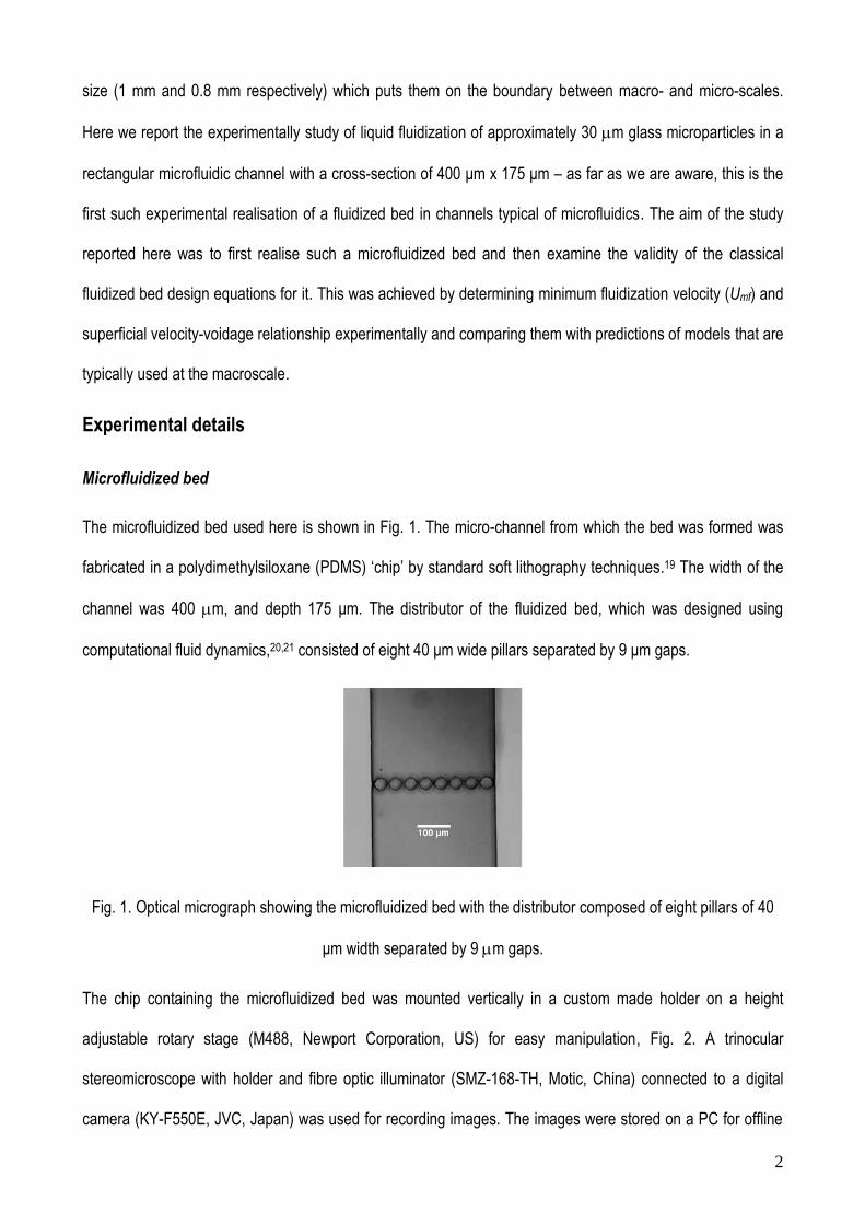
The microfluidized bed used here is shown in Fig. 1. The micro-channel from which the bed was formed was
fabricated in a polydimethylsiloxane (PDMS) ‘chip’ by standard soft lithography techniques.19 The width of the
channel was 400 m, and depth 175 μm. The distributor of the fluidized bed, which was designed using
computational fluid dynamics,20,21 consisted of eight 40 μm wide pillars separated by 9 μm gaps.
Fig. 1. Optical micrograph showing the microfluidized bed with the distributor composed of eight pillars of 40
μm width separated by 9 m gaps.
The chip containing the microfluidized bed was mounted vertically in a custom made holder on a height
adjustable rotary stage (M488, Newport Corporation, US) for easy manipulation, Fig. 2. A trinocular
stereomicroscope with holder and fibre optic illuminator (SMZ-168-TH, Motic, China) connected to a digital
camera (KY-F550E, JVC, Japan) was used for recording images. The images were stored on a PC for offline

3
analysis. The fluidizing liquid was pumped by the PHD ULTRA syringe pump (Harvard Apparatus, US) at
desired flow rates. Experiments were performed at an ambient temperature of 25°C.
Fig. 2. Schematic of experimental setup for the top-view flow visualization.
Fluidizing material
The bed was composed of as-supplied soda lime glass microspheres of diameter d = 30.51.5 μm and
density ρ = 2500 kg/m3 (Cospheric LLC, US). Both deionized water, surfactant-containing deionized water and
ethanol were used to fluidize the particles. The water was obtained from an ELGA PURELAB (VWS Ltd., UK)
classic water purification system. The anhydrous ethanol (≥ 99.5%) and the non-ionic surfactant Tween 80
used was as-supplied by Sigma Aldrich (St. Louis, Missouri, US ).
Results
Water as a fluidizing medium: adhesion problem
Initial efforts to fluidize the glass particles in the microfluidized bed using deionized water proved impossible
due to the particles adhering to the PDMS walls of the micro-fluidized bed as shown in Fig. 3. Subsequently, a
non-ionic surfactant (Tween 80) was used in an attempt to minimize the effect of adhesive forces relative to
the buoyancy and gravity forces.22 However, adhesion still occurred, albeit to a lesser extent, with the micro-
particles only being observed to flow at superficial velocities several times the particle settling velocity
(approximately 750 μm/s), leading to their rapid elution from the bed. This indicates that whilst the surfactant
lead to some decrease in the particle-particle and particle-wall adhesion forces as anticipated,22 it was still
insufficient to enable fluidization.

4
Fig. 3. Optical micrograph showing adhesion of glass particles to PDMS walls of the micro-channel when
deionized water is used as the fluidizing medium
0 200 400 600 800 1000 1200
nl/min nl/min nl/min nl/min nl/min nl/min nl/ min
400 μm
h0
h
Fig. 4. Optical micrographs of the micro-fluidized bed at different ethanol volumetric flow rates. Initial height h0
= 3.215 ± 0.015 mm (see video online for greater detail).
Ethanol as a fluidizing medium
Ethanol proved to be a good fluidizing medium for the glass particles used here in the PDMS micro-channel,
with smooth, stable homogenous fluidization behaviour (see video in supplementary information. Fig. 4 shows
photos of the bed expansions of the particles at different ethanol flow rates. There was a sharp flat interface
between the top of the bed and freeboard as typical for liquid fluidized bed. Particle adhesion to the
microchannel walls was not observed.
Expansion experiments were performed starting from the highest flow rate and then incrementally decreasing
the flow rate to avoid pressure overshoot, which could be present due to the small channel-to-particle diameter

5
ratio (approximately 8 based on hydraulic diameter of micro-channel, Dh = 243.5 μm).18 At flow rates at or
below 200 nl/min, minor particle leakage through the distributor was observed (see video); this was taken into
account in the subsequent analysis. Two cycles of defluidization were performed; no further were possible with
the chip due to failure of the pillars that constitute the distributor.
0 50 100 150 200 250 3000.0
0.2
0.4
0.6
0.8
1.0
(h-h
0)/
h0
U [m/s]
Umf
Fig. 5. Relative bed height (h-h0)/ h0 as a function of ethanol superficial velocity, U, for two experimental runs:
squares (1st run, h0 = 3.335 mm) and circles (2nd run, h0 = 3.215 mm).
ImageJ23 was used for offline image analysis to obtain the height of the fluidized bed as a function of ethanol
flow rate, which is shown in Fig. 5 for two defluidization experiments. The fact that the data from the two
experiments are essentially identical indicates the fluidization behaviour is quite repeatable. The noticeable
particle leakage at superficial velocities just above the incipient fluidization point meant the minimum
fluidization velocity, Umf, had to be determined by extrapolating Fig. 5 to the packed bed height. Although this
introduces some uncertainties, the estimated minimum fluidisation velocity of Umf = 17.25 ± 1.35 μm/s falls
within the range of 18.3 ± 3 μm/s predicted by the Ergun equation24 using an estimated packed bed voidage25
of εmf = 0.46 ± 0.02. This somewhat higher bed porosity than the value typically used for packed beds in
fluidization experiments, εmf0.426, is a consequence of the significant effect that the wall has on the packing
here relative to typical fluidised beds where the channel-to-particle diameter ratios are much larger.

6
Knowledge of the bed expansion characteristic (i.e. the relationship between the liquid superficial velocity, U,
and bed voidage, ε) is crucial as bed voidage significantly influences the mixing, heat and mass transfer
characteristics of fluidized beds. Using the data in Fig. 5, the bed expansion characteristic for the micro-
fluidized bed shown in Fig. 6 was estimated using
h
hmf
0)1(1 (1)
where εmf0.46 ± 0.0225. The bed expansion data in this figure is well described by the well-known empirical
Richardson-Zaki equation,27 which can be expressed as
n
tkUU (2)
where Ut is the particles settling velocity, k a parameter that was set to unity in the original work of Richardson
and Zaki27 that was concerned with the laminar regime, and n an exponent that takes a value of 4.65 in their
original work. Here we obtain from the slope of the line in Fig. 6 an exponent value of n = 5.07 ± 0.30, which
is clearly greater than that of the original Richardson and Zaki27 work, but closer to a value of 4.9 obtained by
Fan et al.28 for fluidization of glass microsphere (the smallest being 54 μm) in a macroscale bed.
Extrapolating the experimental data to a voidage of unity gives 1600 ± 60 μm/s, which is almost double the
theoretical Stokes law terminal velocity, Ut = 836 μm/s. This suggests that for the micro-fluidized bed
considered here k = 1.91 ± 0.07, which is in stark contrast with macroscopic experiments where k ≤ 1 in
general26, with only Fan et al.28 obtaining k values slightly above unity. Although not mentioned by them,
analysis of the experimental data of Potic et al.15 for water fluidization in an 800 m diameter capillary gives
values similar to that obtained by us here (k = 1.70 ± 0.35). These higher than usual values of the empirical
constant, k, are probably due to the greater significance of surface forces in microfluidics, although a small de-
fluidized zone near the distributor may also play some part, at least in our experiments. Fan et al.28 did
observe a change of slope at high voidages not considered in our work here – if this does occur, a second k
value will be obtained that is closer to unity. Further investigation of this and other points raised above is
underway and will be reported in a fuller paper in due course.

7
0.5 0.6 0.7 0.8 0.9 110
100
1000
2000
Ut (
m/s
)
Fig. 6. Micro-fluidized bed expansion characteristics of 30 μm glass particles inside a 400 x 175 μm
microfluidics channel. Line is the best-fit to the Richardson-Zaki model, Eq. 2 with lower and upper prediction
bounds (segmented lines). Bars represent error in experimental points (y-errors smaller than symbols).
Conclusion
Fluidization of approximately 30 m particles within a micro-channel of 175 x 400 m rectangular cross-
section using ethanol as a fluidizing medium demonstrated for the first time as far as we are aware that
fluidization is possible in what can be truly called micro-channels. Comparison of the behavior observed in this
micro-fluidized bed system with the conventional equations for fluidization shows that these equations are a
good starting point for the design of micro-fluidized beds. The Ergun equation,24 is applicable for evaluating the
minimum fluidizing velocity provided the effect of the small particle/micro-channel diameter on the packed bed
voidage is accounted for. The original empirical Richardson and Zaki27 correlation, equation (2), also
describes the micro-fluidized bed behavior observed here well, although higher values of empirical constants
(k and n) than observed in more traditional fluidization are obtained – this requires further elucidation. Finally,
fluidization was impossible when using deionized water as a fluidizing medium, demonstrating the importance
of considering surface forces in true micro-fluidized bed systems.
Acknowledgement
8
The micro-channel fabrication was performed at the South Australian node of the Australian National
Fabrication Facility under the National Collaborative Research Infrastructure Strategy.
Literature cited 1. Squires TM, Quake SR. Microfluidics: Fluid physics at the nanoliter scale. Rev. Mod. Phy.
2005;77(3):977.
2. Stone HA, Stroock AD, Ajdari A. Engineering flows in small devices: Microfluidics towards lab-on-
a-chip. Annu. Rev. Fluid Mech. 2004;36(1):381-411.
3. Whitesides GM. The origins and the future of microfluidics. Nature. 2006;442(7101):368-373.
4. Abgrall P, Gué A-M. Lab-on-chip technologies: making a microfluidic network and coupling it into
a complete microsystems: a review. J. Micromech. Microeng. 2007;17(5):R15.
5. Haeberle S, Zengerle R. Microfluidic platforms for lab-on-a-chip applications. Lab Chip.
2007;7(9):1094-1110.
6. Melin J, Quake SR. Microfluidic Large-Scale Integration: The Evolution of Design Rules for
Biological Automation. Annu. Rev. Biophys. Biomol. Struct. 2007;36(1):213-231.
7. Jensen KF. Microreaction engineering -- is small better? Chem. Eng. Sci. 2001;56(2):293-303.
8. Haswell SJ. Chemical technology: All together now. Nature. 2006;441(7094):705-705.
9. Charpentier J-C. Four main objectives for the future of chemical and process engineering mainly
concerned by the science and technologies of new materials production. Chem. Eng. J. 2005;107(1-
3):3-17.
10. Dudukovic MP. Frontiers in Reactor Engineering. Science. August 7, 2009 2009;325(5941):698-701.
11. Derksen JJ. Scalar mixing by granular particles. AIChE J. 2008;54(7):1741-1747.
12. Derksen JJ. Scalar mixing with fixed and fluidized particles in micro-reactors. Chem. Eng. Res. Des.
2009;87(4):550-556.
13. Derveaux S, Stubbe B, Braeckmans K, Roelant C, Sato K, Demeester J, De Smedt S. Synergism
between particle-based multiplexing and microfluidics technologies may bring diagnostics closer to
the patient. Anal. Bioanal. Chem. 2008;391(7):2453-2467.
14. Lim CT, Zhang Y. Bead-based microfluidic immunoassays: The next generation. Biosens.
Bioelectron. 2007;22(7):1197-1204.
15. Potic B, Kersten SRA, Ye M, van der Hoef MA, Kuipers JAM, van Swaaij WPM. Fluidization with
hot compressed water in micro-reactors. Chem. Eng. Sci. 2005;60(22):5982-5990.
16. Hartman RL, Jensen KF. Microchemical systems for continuous-flow synthesis. Lab Chip.
2009;9(17):2495-2507.
17. Gunther A, Jensen KF. Multiphase microfluidics: from flow characteristics to chemical and
materials synthesis. Lab Chip. 2006;6(12):1487-1503.
18. Doroodchi E, Peng Z, Sathe M, Abbasi-Shavazi E, Evans GM. Fluidisation and packed bed
behaviour in capillary tubes. Powder Technol.;In Press, Corrected Proof.
19. Whitesides GM, Ostuni E, Takayama S, Jiang X, Ingber DE. Soft lithography in biology and
biochemistry. Vol 32001:335-373.
20. Zivkovic V, Biggs MJ, Alwahabi Z. Design of a distributor for a micro-fluidized bed. Paper
presented at: Chemeca 2010; Adelaide, Australia.
21. Zivkovic V, Zerna P, Alwahabi Z, Biggs MJ. A pressure drop correlation for low Reynolds number
Newtonian flows through a rectangular orifice in a similarly shaped micro-channel. Chem. Eng. Res.
Des. accepted on 01/03/2012.
22. Shukla N, Henthorn K. Effect of relative particle size on large particle detachment from a
microchannel. Microfluid. Nanofluid. 2009;6(4):521-527.
23. Abràmoff MD, Magalhães PJ, Ram SJ. Image processing with imageJ. Biophotonics International.
2004;11(7):36-41.
24. Ergun S. Fluid flow through packed columns. Chem. Eng. Prog. 1952;48:89-94.
25. Porosity is based on weighing of settled particles inside square glass capillaries (200 x 200 microns).
Four different size microparticles were used giving correspoding channel-to-particle ratios of 5.2,
5.8, 6.6 and 7.5. We extrapolated these results to channel-to-particle ratio of 8 to obtain estimate of
porosity inside our micro-channel. We used double the absolute error of porosity measurement to
take into account extrapolation error and difference between micro-channel and capillary (aspect
ratio and material).

9
26. Epstein N. Liquid-solids fluidization. In: Yang W-C, ed. Handbook of fluidization and fluid-particle
systems. New York: Marcel Dekker; 2003:705-764.
27. Richardson JF, Zaki WN. The sedimentation of a suspension of uniform spheres under conditions of
viscous flow. Chem. Eng. Sci. 1954;3(2):65-73.
28. Fan Z, Xuanyu Z, Lichuang X. Particulate fluidization of uniformly sized spheres. Paper presented
at: Fluidization '85: Science and Technology, Conference Papers, Second China-Japan
Symposium1985; Kunming, China.