Experimental investigations on cryogenic cooling by liquid nitrogen in the end milling of hardened...
7
Experimental investigations on cryogenic cooling by liquid nitrogen in the end milling of hardened steel S. Ravi ⇑ , M. Pradeep Kumar Department of Mechanical Engineering, CEG, Anna University, Chennai 600 025, India article info Article history: Received 18 February 2011 Received in revised form 21 June 2011 Accepted 21 June 2011 Available online 29 June 2011 Keywords: End milling LN 2 machining Hardened tool steel Cutting temperature abstract Milling of hardened steel generates excessive heat during the chip formation process, which increases the temperature of cutting tool and accelerates tool wear. Application of conventional cutting fluid in milling process may not effectively control the heat generation also it has inherent health and environmental problems. To minimize health hazard and environmental problems caused by using conventional cutting fluid, a cryogenic cooling set up is developed to cool tool–chip interface using liquid nitrogen (LN 2 ). This paper presents results on the effect of LN 2 as a coolant on machinability of hardened AISI H13 tool steel for varying cutting speed in the range of 75–125 m/min during end milling with PVD TiAlN coated car- bide inserts at a constant feed rate. The results show that machining with LN 2 lowers cutting tempera- ture, tool flank wear, surface roughness and cutting forces as compared with dry and wet machining. With LN 2 cooling, it has been found that the cutting temperature was reduced by 57–60% and 37–42%; the tool flank wear was reduced by 29–34% and 10–12%; the surface roughness was decreased by 33–40% and 25–29% compared to dry and wet machining. The cutting forces also decreased moderately compared to dry and wet machining. This can be attributed to the fact that LN 2 machining provides better cooling and lubrication through substantial reduction in the cutting zone temperature. Ó 2011 Elsevier Ltd. All rights reserved. 1. Introduction Difficult-to-machine materials, such as AISI H13 hardened steels, are widely used in extrusion dies, die casting dies, hot forg- ing dies and plastic mould dies due to their higher resistance to thermal shock and thermal fatigue, high temperature strength, good toughness, ductility, and dimensional stability during hard- ening. While machining hardened steel, the contact friction be- tween the tool–workpiece and tool–chip interfaces generates high temperatures on the cutting tool. This generated heat in- creases workpiece surface roughness, and decreases the tool life and the dimensional accuracy of the work material. The cutting fluid is invariably used as a coolant to reduce the heat generated and friction between the tool–workpiece and the tool–chip inter- faces, and also wash away the chips from the tool. Problems with the use of conventional coolants are the potential health hazards to the operating personnel which on contact or inhalation of mist or fumes, and improper disposal of cutting fluids that cause serious environmental problems, such as water and soil pollution [3,30]. The application of a minimum quantity of lubrication consists of a mixture of compressed air and oil droplets to the chip–tool interface, called mist coolant [16,21,18,14,25]. However, applying a mist coolant also poses serious health hazards including eye irri- tation; Breathing of the mist may also cause serious respiratory problems and air pollution [31]. Researchers have investigated the use of cutting fluid with the high pressure coolant to reduce the cutting temperature and im- prove machining performance [10,17]. However, the cooling effect of a high pressure coolant does not meet industry standards. When the coolant pressure was increased from 15 to 20.3 MPa, the tool life decreased rapidly due to excessive notch wear reported by Ezugwu et al. [7]. With the applications of chilled air cooling dur- ing machining, the tool life and surface finish are improved. Rah- man et al. [19] studied the performance of chilled air cooling in end milling on ASSAB 718 mould steel and found improved tool life and surface finish, and reduced cutting forces as compared with dry and conventional coolant cutting. Su et al. [23] studied the ef- fect of dry, flood coolant, nitrogen oil mist, compressed cold nitro- gen gas (0 °C and 10 °C), and compressed cold nitrogen gas and oil mist cutting conditions on tool life during high speed end mill- ing of Ti–6Al–4V. It was found that the tool life under compressed cold nitrogen gas and oil mist cooling conditions have increased 2.69 times compared to dry cutting and 1.93 times over nitrogen oil mist. It was also reported that the tool life was less when using a flood coolant because of the effect of mechanical and thermal 0011-2275/$ - see front matter Ó 2011 Elsevier Ltd. All rights reserved. doi:10.1016/j.cryogenics.2011.06.006 ⇑ Corresponding author. Mobile: +91 9443465454. E-mail address: [email protected] (S. Ravi). Cryogenics 51 (2011) 509–515 Contents lists available at ScienceDirect Cryogenics journal homepage: www.elsevier.com/locate/cryogenics
Transcript of Experimental investigations on cryogenic cooling by liquid nitrogen in the end milling of hardened...
Cryogenics 51 (2011) 509–515
Contents lists available at ScienceDirect
Cryogenics
journal homepage: www.elsevier .com/locate /cryogenics
Experimental investigations on cryogenic cooling by liquid nitrogenin the end milling of hardened steel
S. Ravi ⇑, M. Pradeep KumarDepartment of Mechanical Engineering, CEG, Anna University, Chennai 600 025, India
a r t i c l e i n f o
Article history:Received 18 February 2011Received in revised form 21 June 2011Accepted 21 June 2011Available online 29 June 2011
Keywords:End millingLN2 machiningHardened tool steelCutting temperature
0011-2275/$ - see front matter � 2011 Elsevier Ltd. Adoi:10.1016/j.cryogenics.2011.06.006
⇑ Corresponding author. Mobile: +91 9443465454.E-mail address: [email protected] (S. Ravi).
a b s t r a c t
Milling of hardened steel generates excessive heat during the chip formation process, which increases thetemperature of cutting tool and accelerates tool wear. Application of conventional cutting fluid in millingprocess may not effectively control the heat generation also it has inherent health and environmentalproblems. To minimize health hazard and environmental problems caused by using conventional cuttingfluid, a cryogenic cooling set up is developed to cool tool–chip interface using liquid nitrogen (LN2). Thispaper presents results on the effect of LN2 as a coolant on machinability of hardened AISI H13 tool steelfor varying cutting speed in the range of 75–125 m/min during end milling with PVD TiAlN coated car-bide inserts at a constant feed rate. The results show that machining with LN2 lowers cutting tempera-ture, tool flank wear, surface roughness and cutting forces as compared with dry and wet machining.With LN2 cooling, it has been found that the cutting temperature was reduced by 57–60% and 37–42%;the tool flank wear was reduced by 29–34% and 10–12%; the surface roughness was decreased by33–40% and 25–29% compared to dry and wet machining. The cutting forces also decreased moderatelycompared to dry and wet machining. This can be attributed to the fact that LN2 machining provides bettercooling and lubrication through substantial reduction in the cutting zone temperature.
� 2011 Elsevier Ltd. All rights reserved.
1. Introduction
Difficult-to-machine materials, such as AISI H13 hardenedsteels, are widely used in extrusion dies, die casting dies, hot forg-ing dies and plastic mould dies due to their higher resistance tothermal shock and thermal fatigue, high temperature strength,good toughness, ductility, and dimensional stability during hard-ening. While machining hardened steel, the contact friction be-tween the tool–workpiece and tool–chip interfaces generateshigh temperatures on the cutting tool. This generated heat in-creases workpiece surface roughness, and decreases the tool lifeand the dimensional accuracy of the work material. The cuttingfluid is invariably used as a coolant to reduce the heat generatedand friction between the tool–workpiece and the tool–chip inter-faces, and also wash away the chips from the tool. Problems withthe use of conventional coolants are the potential health hazardsto the operating personnel which on contact or inhalation of mistor fumes, and improper disposal of cutting fluids that cause seriousenvironmental problems, such as water and soil pollution [3,30].The application of a minimum quantity of lubrication consists ofa mixture of compressed air and oil droplets to the chip–tool
ll rights reserved.
interface, called mist coolant [16,21,18,14,25]. However, applyinga mist coolant also poses serious health hazards including eye irri-tation; Breathing of the mist may also cause serious respiratoryproblems and air pollution [31].
Researchers have investigated the use of cutting fluid with thehigh pressure coolant to reduce the cutting temperature and im-prove machining performance [10,17]. However, the cooling effectof a high pressure coolant does not meet industry standards. Whenthe coolant pressure was increased from 15 to 20.3 MPa, the toollife decreased rapidly due to excessive notch wear reported byEzugwu et al. [7]. With the applications of chilled air cooling dur-ing machining, the tool life and surface finish are improved. Rah-man et al. [19] studied the performance of chilled air cooling inend milling on ASSAB 718 mould steel and found improved tool lifeand surface finish, and reduced cutting forces as compared withdry and conventional coolant cutting. Su et al. [23] studied the ef-fect of dry, flood coolant, nitrogen oil mist, compressed cold nitro-gen gas (0 �C and �10 �C), and compressed cold nitrogen gas andoil mist cutting conditions on tool life during high speed end mill-ing of Ti–6Al–4V. It was found that the tool life under compressedcold nitrogen gas and oil mist cooling conditions have increased2.69 times compared to dry cutting and 1.93 times over nitrogenoil mist. It was also reported that the tool life was less when usinga flood coolant because of the effect of mechanical and thermal

Table 1Experimental parameters.
Constant conditions:Type of operation: Slot millingWorkpiece material: Hardened AISI H13 tool steelTool holder diameter: 16 mmLength of cut: 150 mmAxial depth of cut, aa : 0.5 mmNumber of inserts: 2Helix angle: 30�Type of inserts: XDHT 090308 – HX (P20)Tool holder: WIDIA M680 – 90� shoulder mill
Experimental variables:Cutting speed, v: 75,100,125 m/minFeed rate, Fz : 0.02 mm/toothCooling method: Dry, wet and cryogenic cooling (LN2)
510 S. Ravi, M. Pradeep Kumar / Cryogenics 51 (2011) 509–515
impact, which causes thermal cracks on the cutting edge. Su et al.[24] conducted an experimental investigation on tool wear, surfacefinish, and chip shape for high speed milling of AISI D2 cold worktool steel under dry cutting, minimal quantity lubrication, air cool-ing, and air cooling with minimal quantity lubrication conditions.It was observed that the application of air cooling with minimalquantity lubrication techniques resulted longer tool life comparedto dry and minimum quantity lubrication.
Yalcin et al. [29] performed end milling on AISI 1050 steel underdry, fluid and air cooling cutting conditions. The experimental re-sults showed that the surface roughness values for air cooling arelower than that of dry milling, and higher compared to those underfluid cooling. It was also reported that the flank wear in air coolingwas closer to that in fluid cooling, and higher in dry milling com-pared to the fluid and cool air cooling systems. Cardoso et al.[15] carried out end milling of AISI H13 and AISI D2 steels withTiAlN coated and PCBN tools, under dry, compressed, and cold aircooling systems. The results indicated that the cold air cooling sys-tems provided better results compared with dry and compressedair cooling conditions. It was noted that the cutting temperaturewas higher in the machining of AISI D2 steel compared to AISIH13 steel. Ghani et al. [8] studied the performance of P10 TiNcoated carbide tools for end milling of AISI H13 steel at a highercutting speed and found that the feed rate and depth of cut hadthe most significant effect on tool life. Elbestawi et al. [6] investi-gated the cutting tool performance and surface finish of AISI H13tool steel for different process parameters. The experimental re-sults indicated that the average cutting force for a 55 HRC toolwas smaller than that for a 45 HRC tool. It was also observed that,the main mode of tool failure for the CBN tool was flank wear.
Recently, experiments have been conducted to study the effectof LN2 cooling on tool wear, surface roughness and dimensionalconsistency in the turning operation [28,20,4,27]. It was found thatcryogenic cooling by LN2 jets provided reduced tool wear, bettersurface roughness and higher dimensional accuracy as comparedto dry and wet machining, due to the substantial reduction inthe cutting temperature, which enables maintenance of the sharp-ness of the cutting edge.
In machining, the application of LN2 into the tool–chip inter-faces should provide effective cooling and lubrication without pol-luting the environment. However, more work is required toexplore the potential of using LN2 cooling in the machining ofhardened steels. Therefore, a new LN2 cooling system was devel-oped for reducing the cutting zone temperature. In this system,the LN2 is applied to cool the cutting zone, particularly tool–chipinterface by using nozzle. LN2 can easily penetrate into the tool–chip interface to reduce the cutting temperature. The objective ofthis research is, to experimentally investigate the influence of three
Fig. 1. Illustration of cryo
machining conditions such as dry, wet and LN2 cooling on the cut-ting temperature, tool wear, surface roughness, and cutting force,for end milling of hardened AISI H13 tool steel under different cut-ting speeds and feeds.
2. Experimental setup and procedure
The experiments were conducted on a CNC vertical machiningcentre (ARIX VMC 100). The workpiece material for investigationwas AISI H13 hardened tool steel of hardness 52 HRC; It had mate-rial dimensions: 150 � 100 � 50 mm. Flat bottom end mill P20TiAlN PVD coated carbide inserts were used in this study. The cut-ting parameters used in this experiment are listed in Table 1. Drymachining was performed without using any coolant. The problemwith dry machining is less cooling ability of air, making it ineffec-tive for the removal of heat during machining. In general, the rateof heat removal depends on the convection heat transfer coeffi-cient and temperature of the cutting fluid. An increase in the con-vection heat transfer coefficient with high pressure air (�2000 W/m2 K at pressure of 4–7 bar) compared to dry machining (�20 W/m2 K) [2,11]. In wet machining, commercial grade soluble oil wasused with a volumetric oil water ratio of 1:20. Large quantities ofcoolant are used at low pressure to remove the heat generatedfrom the cutting zone. However, the reduction of the cutting tem-perature in the cutting zone is only to a certain extent. At highercutting temperature, the conventional coolant effect is reduced be-cause the heat transfer coefficient is decreased as a result of boilingof the coolant. In order to reduce the cutting temperature and im-prove the machining performance, the recent method of a cryo-genic coolant system was designed to inject liquefied nitrogen
genic cooling setup.

S. Ravi, M. Pradeep Kumar / Cryogenics 51 (2011) 509–515 511
onto the chip–tool interface at a delivery pressure of three bar.When the compressed air is supplied through the LN2 tank, whichfurther increases the heat transfer rate and results in lower cuttingzone temperature. Liquefied nitrogen readily boils on contact withthe workpiece (boiling point = �196 �C) to form nitrogen gas andbecomes part of the air. Therefore, it is considered naturally recy-cling and environmentally friendly. A schematic diagram of theexperimental set up is shown in Fig. 1. A 150 mm long slot was ma-chined during each pass for the end milling experiments. The ef-fects on cutting parameters under dry, wet and LN2 machiningconditions were measured.
In this experiment, the cutting temperature was measured onthe rake face of the cutting tool insert using non-contact infraredthermometer at different machining conditions. The cutting forcecomponents Fx, Fy and Fz were measured using a three componentpiezo electric kistler dynamometer (Type 9257B), a kistler chargeamplifier (Type 5070A), and data acquisition software (Dynowaretype 2825A). The tool wear was measured using a tool maker’smicroscope, according to the tool wear criteria as per ISO standard8688, with an average flank wear (VB) of 0.3 mm. The surfaceroughness (Ra), of the workpiece was measured at different loca-tions along the length of the cut, using the Taylor-Hobson surfaceroughness tester (Surftronic 3+) with a sampling length of 0.8 mm.The chips were collected at different machining conditions, andanalysed with a scanning electron microscope (SEM). All measure-ments were repeated three times, and the average of these mea-surements was taken as a final value of cutting temperature, toolwear, surface roughness, and cutting forces for different machiningconditions.
3. Experimental results and discussions
3.1. Effect of LN2 cooling on cutting temperature
Fig. 2 shows the variations of cutting temperature for differentcutting speeds under dry, wet and LN2 machining conditions. Itwas observed that as the cutting speed is increased, the cuttingtemperature increases under all the machining conditions, whichmay be attributed to an increase in the cutting energy dissipationrate. The higher temperature in the cutting zone leads to softeningof the cutting tool, which accelerate the tool wear and its breakage.Therefore, by reducing cutting speed improves the machinabilityindices. It can be seen that lower temperatures are observed withLN2 machining. The cutting temperature at a cutting speed of
Fig. 2. Effect of cutting speed on cutting temperature at depth of cut of 0.5 mm andfeed rate of 0.02 mm/tooth.
125 m/min and feed rate of 0.02 mm/tooth was 582 �C, 396 �Cand 246 �C for dry, wet, and LN2 machining, respectively. The cut-ting temperature for LN2 cooling was reduced by 57% over the drymachining and 37% over the wet machining cases. This is becausewhen LN2 is supplied onto the tool–chip interface, it evaporatesquickly by absorbing the heat resulting in the reduction of the cut-ting temperature. As the cutting speed was increased from 75 m/min to 100 m/min, the variation in reduction of the cutting tem-perature due to LN2 cooling was found to be 1.93% and 3.45% com-pared to dry and wet machining. When the cutting speed wasincreased further from 100 m/min to 125 m/min, the variation inreduction of the cutting temperature due to LN2 cooling was3.17% and 4.37% respectively. At higher cutting speeds, the cuttingtemperature is increased due to the nature of the chip–tool contactand heat transfer during machining [5]. It was evident that the LN2
cooling effect becomes less effective for higher cutting speeds. Fornormal cutting speeds, LN2 cooling reduces cutting temperature by57–60% compared to dry machining and 37–42% compared to wetmachining.
3.2. Effect of LN2 cooling on flank wear
Fig. 3 shows the average flank wear for various cutting speeds atdifferent machining conditions. With an increase in the cuttingspeed, tool wear increased for all machining conditions. At highercutting speeds, higher cutting temperature is generated at the cut-ting zone, which accelerates the tool wear and consequently re-duces the tool life [1,26]. Further, at a higher cutting speed, thetool–chip contact length is shorter, which causes the cutting forceto be concentrated adjacent to the main cutting edge. Due to thehigher cutting temperature, the cutting edge becomes soften andthe concentrated cutting force near the cutting edge leads to defor-mation and deflection [13]. This can be attributed to the fact thatthe tool wear is increased at higher cutting speeds. At a cuttingspeed of 125 m/min and feed rate of 0.02 mm/tooth, the averageflank wear was 0.282 mm, 0.210 mm and 0.186 mm for dry, wetand LN2 machining. The reduction in the average flank wear dueto LN2 machining was 34% over dry machining and 11% over wetmachining. The reduction of flank wear with LN2 machining maybe a result of substantial reduction in the cutting zone temperatureand decreased friction force between the tool and workpiece. Inwet machining, large quantities of coolant are applied at low pres-sure into the cutting zone, in order to remove the heat, which wasnot able to penetrate into tool–chip interface. This is because of the
Fig. 3. Effect of cutting speed on average flank wear at depth of cut of 0.5 mm andfeed rate of 0.02 mm/tooth.

512 S. Ravi, M. Pradeep Kumar / Cryogenics 51 (2011) 509–515
fact that the soluble oil in wet machining has a smaller effect ontool–chip interface, whereas LN2 machining has a higher coolingeffect. In LN2 machining, the average flank wear was reduced by29–34% over dry machining and 10–12% over wet machining.
3.3. Effect of LN2 cooling on surface roughness
Fig. 4 shows the surface roughness (Ra) of the workpiece at dif-ferent cutting speeds for the three machining conditions. It can beobserved that with an increase in the cutting speed, the surfaceroughness decreases for all the machining conditions. In general,an increase in the cutting speed decreases the surface roughness[22]. With the application of a LN2 coolant, the surface roughnessis reduced resulting in improved surface quality of the workpiece.The average surface roughness value at a cutting speed of 100 m/min and a feed rate of 0.02 mm/tooth was 3.92 lm, 3.21 lm and2.32 lm for the dry, wet and LN2 cases. The variation in the per-centage reduction of the average surface roughness due to LN2
machining was found to be 40% over that of dry machining and27% over that of wet machining. This is due to the lower cuttingforces and tool wear, and less adhesion through a reduction of cut-ting zone temperature between the tool–chip and tool–workpieceinterfaces, resulting in improved surface quality under LN2
machining. LN2 machining reduced the average surface roughnessby 33–40% compared to dry machining and 25–29% compared towet machining.
3.4. Effect of LN2 cooling on cutting force (Fx, Fy and Fz)
Fig. 5a–c shows the effects of the cutting speed on the feed force(Fx), normal force (Fy), and axial force (Fz) under all machining con-ditions at a constant feed rate. In general, the cutting force de-creases with increasing cutting speeds [22]. A similar trend hasbeen observed, that all the cutting force components decrease asthe cutting speed increases. This is due to the fact that as the cut-ting speed increases, higher cutting temperature is generated atthe cutting zone causes softening of the workpiece, and there byresults in corresponding decrease in the cutting force. Further,the cutting force decreases at higher cutting temperatures due toless energy being required in deforming the material [8]. In addi-tion to the higher cutting temperature effect on the cutting forceat a higher cutting speed, the tool–chip contact length decreases,increasing the shear plane angle resulting in increased shear stress
Fig. 4. Effect of cutting speed on average surface roughness at depth of cut of0.5 mm and feed rate of 0.02 mm/tooth.
Fig. 5. Effect of cutting speed on cutting force (a) feed force (Fx), (b) normal force(Fy) and (c) axial force (Fz), at depth of cut of 0.5 mm and feed rate of 0.02 mm/tooth.
[12]. This causes a reduced cutting force at higher cutting speeds. Itwas observed that the cutting force components obtained with LN2
machining are lower than those of dry and wet machining. The Fx
force at a cutting speed of 125 m/min and feed rate of 0.02 mm/tooth was 336 N, 282 N and 256 N for dry, wet and LN2 machiningrespectively. The Fy force for the same cutting conditions was381 N, 328 N and 286 N respectively. The Fz force values are398 N, 346 N and 294 N respectively. It can be observed that thereduction in the Fx, Fy and Fz forces due to LN2 cooling was 23%,
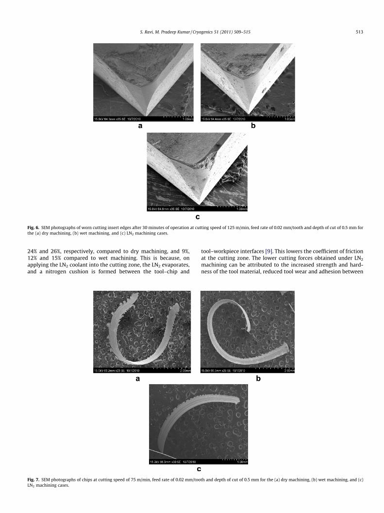
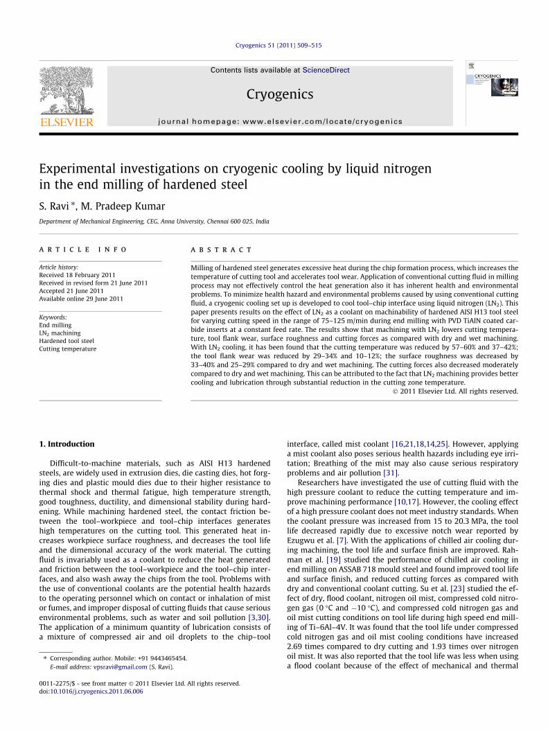
Fig. 6. SEM photographs of worn cutting insert edges after 30 minutes of operation at cutting speed of 125 m/min, feed rate of 0.02 mm/tooth and depth of cut of 0.5 mm forthe (a) dry machining, (b) wet machining, and (c) LN2 machining cases.
S. Ravi, M. Pradeep Kumar / Cryogenics 51 (2011) 509–515 513
24% and 26%, respectively, compared to dry machining, and 9%,12% and 15% compared to wet machining. This is because, onapplying the LN2 coolant into the cutting zone, the LN2 evaporates,and a nitrogen cushion is formed between the tool–chip and
Fig. 7. SEM photographs of chips at cutting speed of 75 m/min, feed rate of 0.02 mm/tooLN2 machining cases.
tool–workpiece interfaces [9]. This lowers the coefficient of frictionat the cutting zone. The lower cutting forces obtained under LN2
machining can be attributed to the increased strength and hard-ness of the tool material, reduced tool wear and adhesion between
th and depth of cut of 0.5 mm for the (a) dry machining, (b) wet machining, and (c)

Fig. 8. SEM micrographs of chips at cutting speed of 125 m/min, feed rate of 0.02 mm/tooth and depth of cut of 0.5 mm for the (a) dry machining, (b) wet machining, and (c)LN2 machining cases.
514 S. Ravi, M. Pradeep Kumar / Cryogenics 51 (2011) 509–515
the tool–chip and tool–workpiece interfaces through the reductionof the cutting temperature. In LN2 machining, the Fx, Fy and Fz
forces are decreased by 22–24%, 19–24% and 20–26% comparedto dry machining, and 4–9%, 9–12% and 11–15% compared to wetmachining respectively.
4. Tool wear morphology
Fig. 6 shows the SEM photographs of the worn insert edges after30 min of machining under dry, wet, and LN2 machining condi-tions. In the milling process, the cyclic heating and cooling at thecutting edge results in very high stress and higher cutting temper-ature. As the cutting is progressed, initiates thermal cracking andedge chipping. It is hypothesized that the typical failure modesin the cutting tool inserts are thermal cracking and edge chipping.It was also observed that the chipping of the cutting edge was ob-tained under all three machining conditions. In dry cutting, severechipping of the cutting edge was observed, followed by wet, andthen LN2 machining. In LN2 machining, lesser chipping was found,compared to dry and wet machining. The chipping of the cuttingedge was observed in wet machining due to the formation of ther-mal cracks near the cutting edge resulting in a fracture of the cut-ting edge. However, cutting inserts in LN2 machining were lessseriously affected by thermal fatigue. This is due to reduced tem-perature in the cutting zone, which will remove the generated heateffectively and improve the tool life.
Fig. 7 shows SEM images of chip shapes for a cutting speed of75 m/min, a feed rate of 0.02 mm/tooth, and a depth of cut of0.5 mm under dry, wet, and LN2 machining conditions. In LN2 cool-ant machining, shorter chips are obtained compared to those in dryand wet machining. This may be attributed mainly due to betterpenetration of LN2 into the tool–chip interface, resulting in thereduction of the cutting temperature. At a lower temperature,the chip cannot promote curl due to increased chip hardness and
lower ductility. Further, the colour of the chips obtained underthe three machining conditions is also different. In dry cutting,the chips produced are dark blue in colour, which was caused bythe extreme heat generated at the tool–chip interface that resultsin burnt chips. The chips obtained in the case of wet machiningare black, which also indicates intense heat generated at thetool–chip interface. This is because the conventional coolant doesnot penetrate into the tool–chip interface resulting in an inade-quate lubrication effect, whereas, the chips produced by LN2
machining were silver in colour indicating chips that were notburnt, due to the better cooling and lubrication effect.
Fig. 8 shows SEM images of the chip morphology for a cuttingspeed of 125 m/min, a feed rate of 0.02 mm/tooth, and a depth ofcut of 0.5 mm under dry, wet, and LN2 machining conditions. Indry cutting, large serrated teeth are obtained indicating the heavyshearing action at the cutting zone. In the case of wet machiningalso, similar serrated teeth are produced due to the intensiveshearing action. This can be attributed to the fact that conventionalcoolant does not provide effective cooling and lubrication at thetool–chip interface. However, smaller serrated teeth are producedunder LN2 machining, indicating lower shearing forces comparedto those under dry and wet machining. This is because, the pene-tration of LN2 into the tool–chip interface results in the formationof a nitrogen cushion, which reduces the friction.
5. Conclusions
The experiments were conducted on end milling of hardenedAISI H13 tool steel using LN2 coolant to investigate cutting perfor-mance and changes in cutting temperature, tool wear, surfaceroughness, cutting force, tool wear morphology and geometry ofthe chip shape. Results for application of LN2 coolant was comparedto those for dry and wet machining. Based on the results of theexperimental investigation, the following conclusions are drawn.

S. Ravi, M. Pradeep Kumar / Cryogenics 51 (2011) 509–515 515
1. LN2 machining provides lower cutting temperature, toolwear, surface roughness and cutting force compared tothose under dry, wet machining conditions. This is becauseof the better cooling and lubrication effect through sub-stantial reduction in the cutting zone temperature. Thereduction in the cutting temperature using the LN2 coolantis substantial at a lower cutting speeds.
2. The experimental results indicate that compared to dry andwet machining, LN2 machining reduced the cutting temper-ature in the range of 57–60% and 37–42%; while the toolwear decreased approximately in the range of 29–34%and 10–12%; further, the average surface roughnessdecreased moderately in the range of 33–40% and 25–29%.
3. The cutting forces (Fx, Fy and Fz) in the LN2 machining wasreduced in the range of 22–24%, 19–24% and 20–26%respectively compared to dry machining, while the reduc-tion of the cutting forces range by 4–9%, 9–12% and 11–15% compared to wet machining respectively.
4. The SEM photographs of chips showed that the shearingaction in the case of LN2 machining was lower indicatingthat small serrations, which were relatively higher in thecase of dry and wet machining. The chip curl cannot be pro-moted under the LN2 machining condition causing shortchips are produced.
The application of the LN2 coolant in the end milling of hard-ened AISI H13 tool steel can provide not only environmentalfriendliness, but also an improvement in the tool life, surface finishand a reduction in the cutting force.
Acknowledgements
The authors are thankful to the staff members of ComputerAided Manufacturing Laboratory, Department of Mechanical Engi-neering, College of Engineering, Guindy, Anna University, Chennaifor providing their cooperation and technical assistance in fabrica-tion of experimental set-up and conducting experiments.
References
[1] Abrao AM, Wise MLH, Aspinwall DK. Tool life and workpiece surface integrityevaluation when machining hardened AISI H13 steel and AISI E52100 steelswith conventional ceramic and PCBN tool materials. Technical Paper. SME;1995. p. 95–159.
[2] Bareggi A, O’donnell GE, Torrance A. Modeling and experimental analysis ofhigh speed air jets used during metal cutting as a coolant technique. In:Proceedings of the third CIRP international conference on high performancecutting, Dublin, Ireland; 2008. p. 337–46.
[3] Byrne G, Scolta E. Environmentally clean manufacturing process – a strategicapproach. Ann CIRP 1993;42(1):471–4.
[4] Dhar NR, Paul S, Chattopadhyay AB. Machining of AISI 4140 steel undercryogenic cooling-tool wear, surface roughness and dimensional deviation. JMater Process Technol 2002;123:483–9.
[5] Dhananchezian M, Pradeep kumar M. Cryogenic turning of the Ti–6Al–4V alloywith modified cutting tool inserts. Cryogenics 2011;51:34–40.
[6] Elbestawi MA, Chen L, Becze CE, El-Wardany TI. High speed milling of dies andmoulds in their hardened state. Ann CIRP 1997;46(1):57–62.
[7] Ezugwu EO, Bonney J, Fadare DA, Sales WF. Machining nickel-base, Inconel718, alloy with ceramic tools under finishing conditions with various coolantsupply pressures. J Mater Process Technol 2005;162–163:609–14.
[8] Ghani JA, Choudhury IA, Majuki HH. Performance of P10 TiN coated carbidetools when end milling AISI H13 tool steel at high cutting speed. J MaterProcess Technol 2004;153(154):1062–6.
[9] Kalyan Kumar KVBS, Choudhury SK. Investigation of tool wear and cuttingforce in cryogenic machining using design of experiments. J Mater ProcessTechnol 2008;203:95–101.
[10] Kovacevic R, Cherukuthota C, Mazurkiewicz M. High pressure water jetcooling/lubrication to improve machining efficiency in milling. Int J MachTools Manuf 1995;35(10):1459–73.
[11] Kopes L, Arenson M. Determination of convective cooling conditions inturning. Ann CIRP 1999:47–52.
[12] Korkut I, Donertas MA. The influence of feed rate and cutting speed on thecutting forces, surface roughness and tool–chip contact length during facemilling. Mater Des 2007;28:308–12.
[13] Liu ZQ, Ai X, Zhang H, Wang ZT, Wan Y. Wear patterns and mechanisms ofcutting tools in high speed face milling. J Mater Process Technol2002;129:222–6.
[14] Lio YS, Lin HM, Chen YC. Feasibility study of the minimum quantity lubricationin high speed end milling of NAK 80 hardened steel by coated carbide tool. Int JMach Tools Manuf 2007;47:1667–76.
[15] Brandoa Lincoln Cardoso, Coelho Reginaldo Teixeira, Rodrigues AlessandroRoger. Experimental and theoretical study of work piece temperature whenend milling hardened steels using TiAlN coated & PCBN-tipped tools. J MaterProcess Technol 2008;199:234–44.
[16] Machado AR, Wallbank J. The effect of extremely low lubricant volumes inmachining. Wear 1997;210:76–82.
[17] Rahman M, Senthil Kumar A, Choudhury MR. Identification of effective zonesfor high pressure coolant in milling. Ann CIRP 2000;49(1):47–52.
[18] Rahman M, Senthil Kumar A, Salam MU. Evaluation of minimal quantities oflubricant in end milling. Int J Adv Manuf Technol 2001;18:235–41.
[19] Rahman M, Senthil Kumar A, Salam MU, Ling MS. Effect of chilled air onmachining performance in end milling. Int J Mach Tools Manuf2003;21:787–95.
[20] Hong Shane Y, Ding Yucheng. Cooling approaches and cutting temperatures incryogenic machining of Ti–6Al–4V. Int J Mach Tools Manuf 2001;41:1417–37.
[21] Sokovic M, Mijanovic K. Ecological aspects of the cutting fluids and itsinfluence of quantifiable parameters of the cutting processes. J Mater ProcessTechnol 2001;109:181–9.
[22] Sornakumar T, Senthil Kumar A. Machinability of bronze–alumina compositewith tungsten carbide cutting tool inserts. J Mater Process Technol2008;202:402–5.
[23] Su Y, He N, Li L, Li XL. An experimental investigation of effects of cooling/lubrication conditions on tool wear in high-speed end milling of Ti–6Al–4V.Wear 2006;261:760–6.
[24] Su Y, He N, Li L, Iqbal A, Xiao MH, Xu S, et al. Refrigerated cooling air cutting ofdifficult to cut materials. Int J Mach Tools Manuf 2007;48(6):927–33.
[25] Thepsonthi T, Hamdi M, Mitsui K. Investigation into minimal cutting fluidapplication in high speed milling hardened steel using carbide mills. Int J MachTools Manuf 2009;49:156–62.
[26] Trend EM. Metal cutting. Third ed. London: Butterworth–Heinemann; 1991.[27] Venugopal KA, Paul S, Chattopadhyay AB. Growth of tool wear in turning of Ti–
6Al–4V alloy under cryogenic cooling. Wear 2007;262:1071–8.[28] Wang ZY, Rajurkar KP, Murugappan M. Cryogenic PCBN turning of ceramics
(Si3N4). Wear 1996;195:1–6.[29] Yalcin B, Ozgur AE, Koru M. The effects of various cooling strategies on surface
roughness and tool wear during soft materials milling. Mater Des2009;30:896–9.
[30] Young P, Byrne G, Cotterel M. Manufacturing and the environment. Int J AdvManuf Technol 1997;13(7):488–93.
[31] Ning Yuvan, Rahman M, Wong YS. Investigation of chip formation in highspeed end milling. J Mater Process Technol 2001;133:360–7.