Fighting collusion in auctions: An experimental investigation
Upload
khangminh22Category
view
2download
0
IOSR Journal of Mechanical and Civil Engineering (IOSR-JMCE)
e-ISSN: 2278-1684,p-ISSN: 2320-334X, Volume 14, Issue 1 Ver. VI (Jan. - Feb. 2017), PP 76-85
www.iosrjournals.org
DOI: 10.9790/1684-1401067685 www.iosrjournals.org 76 | Page
Experimental Investigation of Thermosyphon for
Different Parameters
Ajay D. Pingale 1, Chetan M. Patil
2, Parag B. Marathe
3
1,2,3(Department of Mechanical Engineering, Dr. D Y Patil School of Engineering, Charoli, Pune)
Abstract: Heat transfer characteristics of circular Two phase closed thermosyphon (TPCT) charged with
different fluids (Propylene Glycol and Ethylene Glycol) of 1000mm length and 19mm outside diameter were
determined for different fill volume ratio (40% and 60%), inclination angle (0° to 50° from vertical) and heat
input supplied (60°C to 80°C). An experimental study was performed on TPCT charged with EG and PG with
different fill volume ratio and results obtained were compared for all inclination and heat inputs setup
developed. The efficiencies of TPCT found to be deteriorate with respect to increase in inclination angle for
both the fluids. Optimum inclination angle for PG-TPCT is 20° to 30° and that for EG-TPCT is 20° to 30° for
both fill volume ratio. With increase in a heat input the efficiencies were begin to increase but less affected with
fill volume ratio. The average efficiency of EG-TPCT is found to be higher.
Keywords: Two phase closed thermosiphon (TPCT), EG, PG.
I. Introduction
The heat pipe is an effective heat transfer device. It is a device having a very high thermal conductance.
The idea of heat pipe was first introduced by the Perkins family in the nineteen century for which they receive
the UK Patent No. 7059 [1]
for using small quantity of water in Perkins tube and operating on a two phase cycle.
Later on this concept was more developed by Gaugler in 1942. In the today‘s world, the scientific community is
striving for effective utilization of energy. The heat transfer characteristics of TPCT have been investigated by
many researchers for various types of fluids like water, alcohols, refrigerants etc. but most of the investigations
have been limited to either low or high heat inputs.
Ajit M. Kate et. al.[4]
studied the effect of cross sectional geometries, working fluid fill charge, heat input and
inclination angle on the performance of wickless heat pipe has been investigated experimentally. The
experimental results indicate that the temperature distribution along wall surface of elliptical cross section was
higher than circular section geometry wickless heat pipe. The liquid film in the evaporator was dried out when
fill charge is less and heat inputs are higher. The heat inputs had very significant effect on wickless heat pipe
having less working fluid fill charge. The elliptical cross section pipe shows better performance than circular
cross section wickless heat pipes at higher heat inputs. Highest heat transfer coefficient was observed between
inclinations of around 10° to 20°.
M. Karthikeyan et al.[5]
studied the thermal performance of an inclined two phase closed thermosyphon with
different working fluid had been investigated experimentally. Based on the results obtained they draws the
following conclusions, the thermal resistance is indirectly proportional to the heat input which means with the
increase of heat input, the thermal resistance of thermosyphon decreases. The heat transfer coefficient increases
with the increase in heat flux. The evaporator (boiling) heat transfer coefficient is slightly higher than the
condensation heat transfer coefficient. Performance of two phase closed thermosyphon with aqueous solution of
n-butanol has the maximum thermal performance than that of two phase closed thermosyphon with de-ionized
water.
Y. Gandal et. al.[6]
conducted experiment to study the heat transfer characteristic of two phase closed
thermosyphon (TPCT) using Propylene Glycol (PG) is analyzed experimentally and compared with Deionized
(DI) water for different inclinations and heat input. The experimental results indicate that the Propylene Glycol
thermosyphon works better at higher heat inputs and the optimum inclination angle for PG thermosyphon is
between 20°- 30° and that for DI water is 10° to 20°. The TPCT is an efficient heat transfer device due to their
high heat transfer capabilities with no exterior power requirement. It transfers a large amount of heat with very
small temperature difference. It is vertically oriented with liquid pool at bottom. Heat is given to evaporator
section and vapour forms rises up to the condenser section where it condense heat to the surrounding and return
to the evaporator section along with the tube wall due to gravitational force. The main benefit of TPCT is that it
requires no mechanical pumping and which makes it inexpensive and reliable.
E. Hahne et. al.[7]
an experimental investigation was performed in order to observe the effect of the inclination
angle on the transport behavior of a closed two-phase thermosyphon. An effective thermal conductivity of the
thermosyphon is found to be strongly depending on inclination and heat flow rate. Separate consideration of the
transport regimes in the various zones showed their individual influence upon the overall behavior. The
Experimental Investigation of Thermosyphon for Different Parameters
DOI: 10.9790/1684-1401067685 www.iosrjournals.org 77 | Page
condensation in the cooling zone exhibits the largest transport resistance. The heat transfer with boiling in the
heating zone shows large local differences and depends strongly on inclination.
C. Wang et. al.[8]
performed an experimental study on heat transfer performance of a gravity-assisted heat pipe
is described. ‗Dowtherm A‘ has been used as working fluid. The effect of fill volume ratio, inclination angle,
thermal resistance and heating length ratio on the rate of heat flow were investigated. The maximum rate of heat
flow increases along with the decrease of fill ratio and heat length ratio. The range of optimum inclination is
within 30° to 60°.
II. Experimental Work Based on the literature review the following factors were finalized for the present experimental work.
Table 1: Parameters Selection for Thermosyphon Sr Parameters Remarks
1 Geometry Circular
2 Material Copper
3 Working Fluid Ethylene Glycol, Propylene Glycol (50% Purity)
4 Total length 1000 mm.
5 Length of evaporator 400 mm
6 Length of adiabatic 200 mm
7 Length of condenser 400 mm
8 Filling ratio 40% and 60%
9 Inclination angle 0°, 10°, 20°, 30°,40° and
50° fromvertical
10 Heat input 60°C, 70°C, 80°C
11 Cold water mass flow rate 0.0454 lps
12 Pressure inside TPCT 10-2 Torr
13 Evaporator heating method Water bath
14 Insulation 12mm glass wool
15 Thermocouples K type
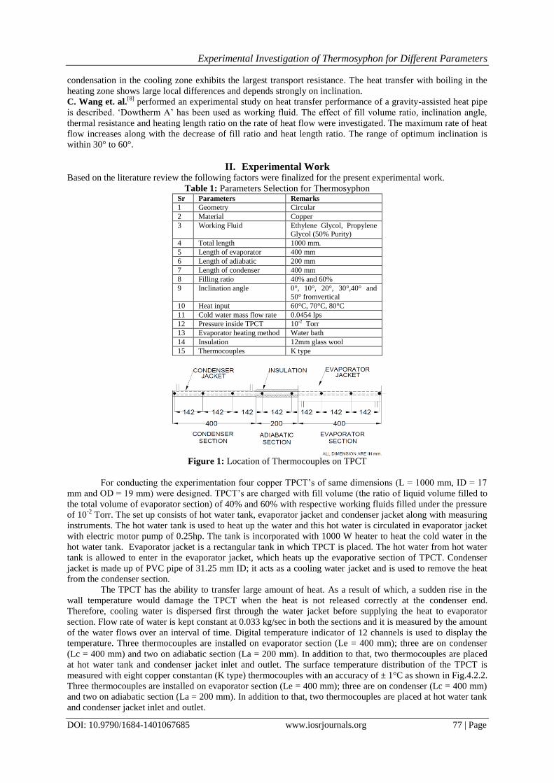
Figure 1: Location of Thermocouples on TPCT
For conducting the experimentation four copper TPCT‘s of same dimensions (L = 1000 mm, ID = 17
mm and OD = 19 mm) were designed. TPCT‘s are charged with fill volume (the ratio of liquid volume filled to
the total volume of evaporator section) of 40% and 60% with respective working fluids filled under the pressure
of 10-2
Torr. The set up consists of hot water tank, evaporator jacket and condenser jacket along with measuring
instruments. The hot water tank is used to heat up the water and this hot water is circulated in evaporator jacket
with electric motor pump of 0.25hp. The tank is incorporated with 1000 W heater to heat the cold water in the
hot water tank. Evaporator jacket is a rectangular tank in which TPCT is placed. The hot water from hot water
tank is allowed to enter in the evaporator jacket, which heats up the evaporative section of TPCT. Condenser
jacket is made up of PVC pipe of 31.25 mm ID; it acts as a cooling water jacket and is used to remove the heat
from the condenser section.
The TPCT has the ability to transfer large amount of heat. As a result of which, a sudden rise in the
wall temperature would damage the TPCT when the heat is not released correctly at the condenser end.
Therefore, cooling water is dispersed first through the water jacket before supplying the heat to evaporator
section. Flow rate of water is kept constant at 0.033 kg/sec in both the sections and it is measured by the amount
of the water flows over an interval of time. Digital temperature indicator of 12 channels is used to display the
temperature. Three thermocouples are installed on evaporator section (Le = 400 mm); three are on condenser
(Lc = 400 mm) and two on adiabatic section (La = 200 mm). In addition to that, two thermocouples are placed
at hot water tank and condenser jacket inlet and outlet. The surface temperature distribution of the TPCT is
measured with eight copper constantan (K type) thermocouples with an accuracy of ± 1°C as shown in Fig.4.2.2.
Three thermocouples are installed on evaporator section (Le = 400 mm); three are on condenser (Lc = 400 mm)
and two on adiabatic section (La = 200 mm). In addition to that, two thermocouples are placed at hot water tank
and condenser jacket inlet and outlet.
Experimental Investigation of Thermosyphon for Different Parameters
DOI: 10.9790/1684-1401067685 www.iosrjournals.org 78 | Page
A PID controller is used to cut off the heater by sensing evaporator jacket temperature. This
thermocouple makes the assurance of desired temperature achievement in evaporator jacket. The hot water is
continuously circulated from hot water tank to evaporator jacket so as to achieve uniform temperature in
evaporator jacket. Glass wool insulation of 12mm thickness is provided to adiabatic section, evaporator jacket,
hot water tank and piping systems to avoid the heat loss to the surrounding. An energy meter is provided to
measure energy consumption while conducting the experimentation. An angle holder slot is made available for
giving tilt to TPCT from 0° to 60° inclination with a step size of 10° from vertical.
The experimental procedure consists of four identical TPCT of same dimensions as mentioned above.
One is charged with ethylene glycol and other with propylene glycol with 50% purity with 40% and 60% as a
fill volume ratio. Initially heater is on and water is allowed to get heated in hot water tank. This hot water is
continuously circulated in the evaporator jacket with the help of motor which ensures uniform temperature
achievement in evaporator jacket. PID controller is provided to cut the heater, when the desired temperature is
reached in evaporator jacket.
3. Observation from Experimental Work
The experimental study was performed to compare the thermal performance of two phase closed
thermosyphon charged with propylene glycol and EG as a working fluid. The TPCT is tested for different fill
volume ratio, inclination angle and heat input supplied from which the following points were studied in detail.
Evaporator heat transfer coefficient (he): The heat absorption capacity of evaporator section of TPCT is determined by heat transfer coefficient (he)
which is given by equation (1),
he= Qe/ (π*di*Le*(∆Te-∆Ta)) (1)
Where, Qe is the rate of heat absorbed by the evaporator section of TPCT from the hot water of the evaporator
jacket and is obtained from the equation (2) as mentioned below,
Qe= me*Cp*(Teti-Teto) (2)
Where,
me = 0.033kg/s; Cp = 4187 j/kg-˚C, Teto = 63.4˚C and Teti = 58.2˚C,
(Teti-Teto)= 63.4-58.2≈ 60C
Qe= 0.033* 4187* 6 = 829.03 W
Since, ∆Te= (Te1+Te2+Te3)/3and Ta= (Ta1+Ta2)/2
∆Te= (53.9+51.5+52.7)/3= 52.7 0C
Similarly, ∆Ta=(48.8+47.9)/2= 48.35 0C
he= 829.03/(π*0.017*0.4*(52.70-48.35))
=7984 W/m2-
0C
Condenser heat transfer rate (Qc)
The amount of heat transferred by condenser section to the surrounding cold water in condenser jacket is
calculated by considering the mass flow rate and specific heat and inlet and outlet temperature difference of
water, as given in equation (3)
Qc= mc*Cp*(Tco-Tci) (3)
Where,
mc = 0.033kg/s; Cp = 4187 j/kg-˚C, Tco = 35.4˚C and Tci = 29˚C
Qc= 0.033*4187*(35.4-29) =884.29W
Condenser heat transfer coefficient (hc)
The heat transfer capacity of condenser section for TPCT is determined by heat transfer coefficient (hc) which is
evaluated by using equation (4)
hc= Qc/(π*di*Lc*(∆Ta-∆Tc) (4)
Where, Qc = 884.29 W,
∆Ta= 48.35 0C and ∆Tc=37.37
0C
hc=884.29/(π*0.017-0.4*(48.35-37.37))=3373W/m2-
0C
Development of thermal resistance (Rth)
The thermal resistance of the TPCT gives the amount of resistance observed by the heat flow from evaporator to
condenser section. It is the average temperature difference between the evaporator and condenser to the amount
of heat absorbed by TPCT which is calculated by expression (5),
Rth= (∆Te-∆Tc)/Qe (5)
Where, ∆Te=52.70C, ∆Tc=37.37
0C and
Qe = 829.03 W
Rth= (52.7-37.37)/829.03=0.00185 0C/W
Experimental Investigation of Thermosyphon for Different Parameters
DOI: 10.9790/1684-1401067685 www.iosrjournals.org 79 | Page
Efficiency of thermosyphon
The efficiency of TPCT is calculated as the ratio of amount of heat rejected (hc) by the condenser to the amount
of heat absorbed (he) by the evaporator section of the TPCT.
η= hc/he
Where, hc =3373W/m2-
0C and he = 7984 W/m
2-0C
η= 3373/7984= 42.25%
During experimentation it is required to achieve steady state for accurate reading. To achieve steady state we
took 10 readings for each heat input, fill volume ratio and inclination.
For the calculation purpose we considered all above parameters like Evaporator heat transfer coefficient,
condenser heat transfer rate, condenser heat transfer coefficient, thermal resistance and efficiency.
III. Results And Discussion Temperature reading on thermosyphon surface is required to calculate thermal properties. We took
readings of temperature from experimentation for different parameters. The variation in temperature shows the
behavior of TPCT. From those temperature readings we calculated thermal properties like thermal efficiency,
thermal resistance and heat transfer coefficient. Following readings and graphs shows temperature distribution,
thermal efficiency and thermal resistance of TPCT.
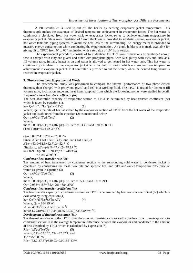
Temperature distribution along length of TPCT
Following table shows distribution of temperature along a length of Thermosyphon. In which Te1, Te2,
Te3 are the temperatures at evaporator section; TA1, TA2 are the temperatures at adiabatic section and Tc1, Tc2, Tc3
are the temperatures at condenser section. From these readings we plot a graph of Temperature (°C) Vs Length
of TPCT (mm) for different inclination angle.
Figure 2: Plot of Temperature (°C) Vs Length of TPCT (mm) for 0° inclination angle
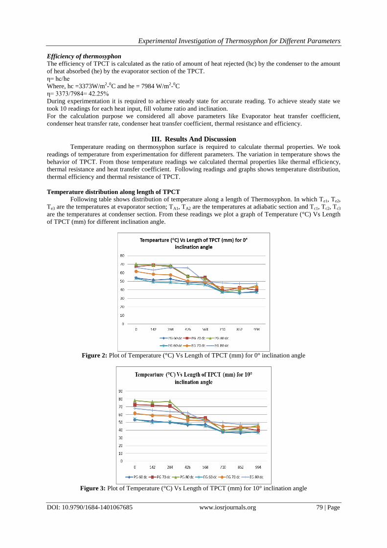
Figure 3: Plot of Temperature (°C) Vs Length of TPCT (mm) for 10° inclination angle
Experimental Investigation of Thermosyphon for Different Parameters
DOI: 10.9790/1684-1401067685 www.iosrjournals.org 80 | Page
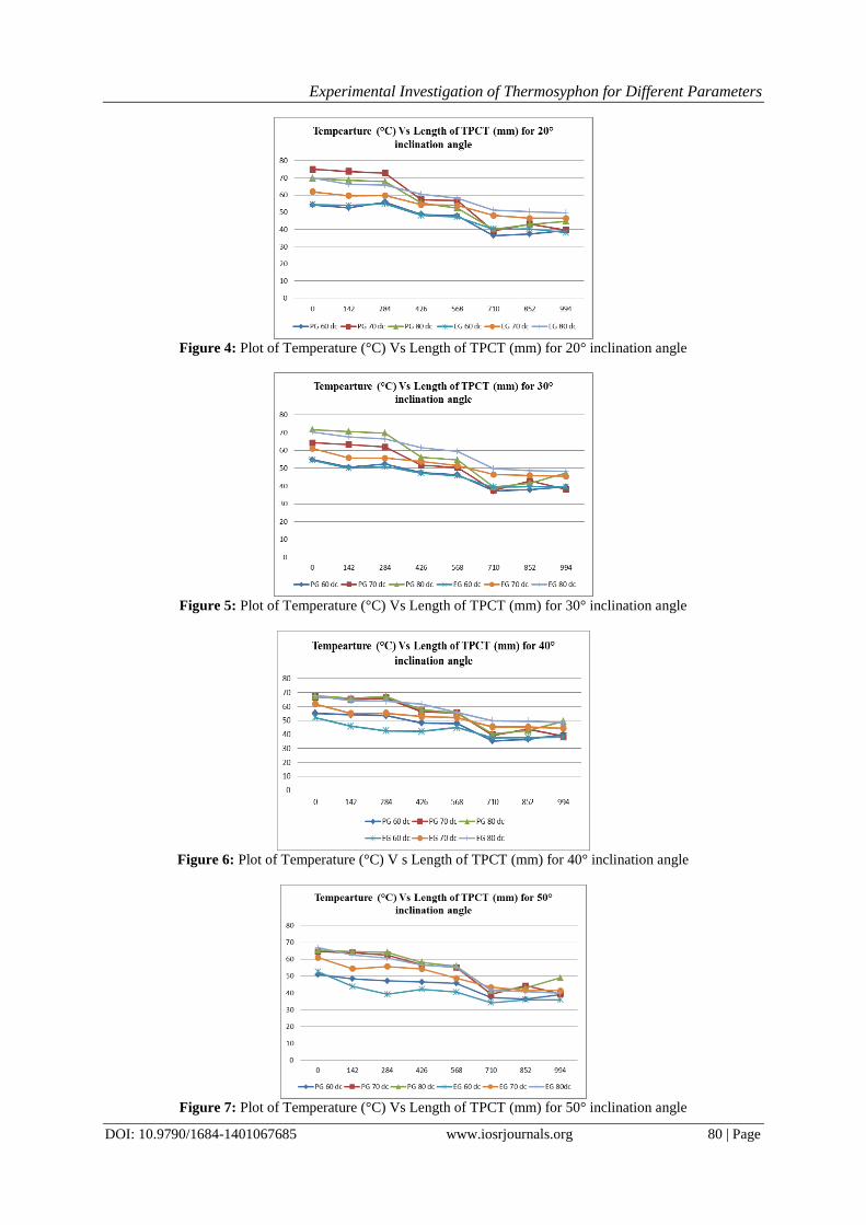
Figure 4: Plot of Temperature (°C) Vs Length of TPCT (mm) for 20° inclination angle
Figure 5: Plot of Temperature (°C) Vs Length of TPCT (mm) for 30° inclination angle
Figure 6: Plot of Temperature (°C) V s Length of TPCT (mm) for 40° inclination angle
Figure 7: Plot of Temperature (°C) Vs Length of TPCT (mm) for 50° inclination angle
Experimental Investigation of Thermosyphon for Different Parameters
DOI: 10.9790/1684-1401067685 www.iosrjournals.org 81 | Page
Remark on temperature distribution:
1. We provide heat input at evaporator section but this total heat cannot transfer to condenser section due to
heat loss and in adiabatic section temperature distribution along length is almost same.
2. Distribution of temperature along length of TPCT is in decreasing manner.
3. EG TPCT shows better temperature distribution over PG TPCT.
Variation of efficiency for inclination angle and heat input
Efficiency is the parameter use to represent the performance of TPCT. From obtained reading we have
calculated the efficiency of TPCT for different inclination angle, heat input and fill volume ratio.
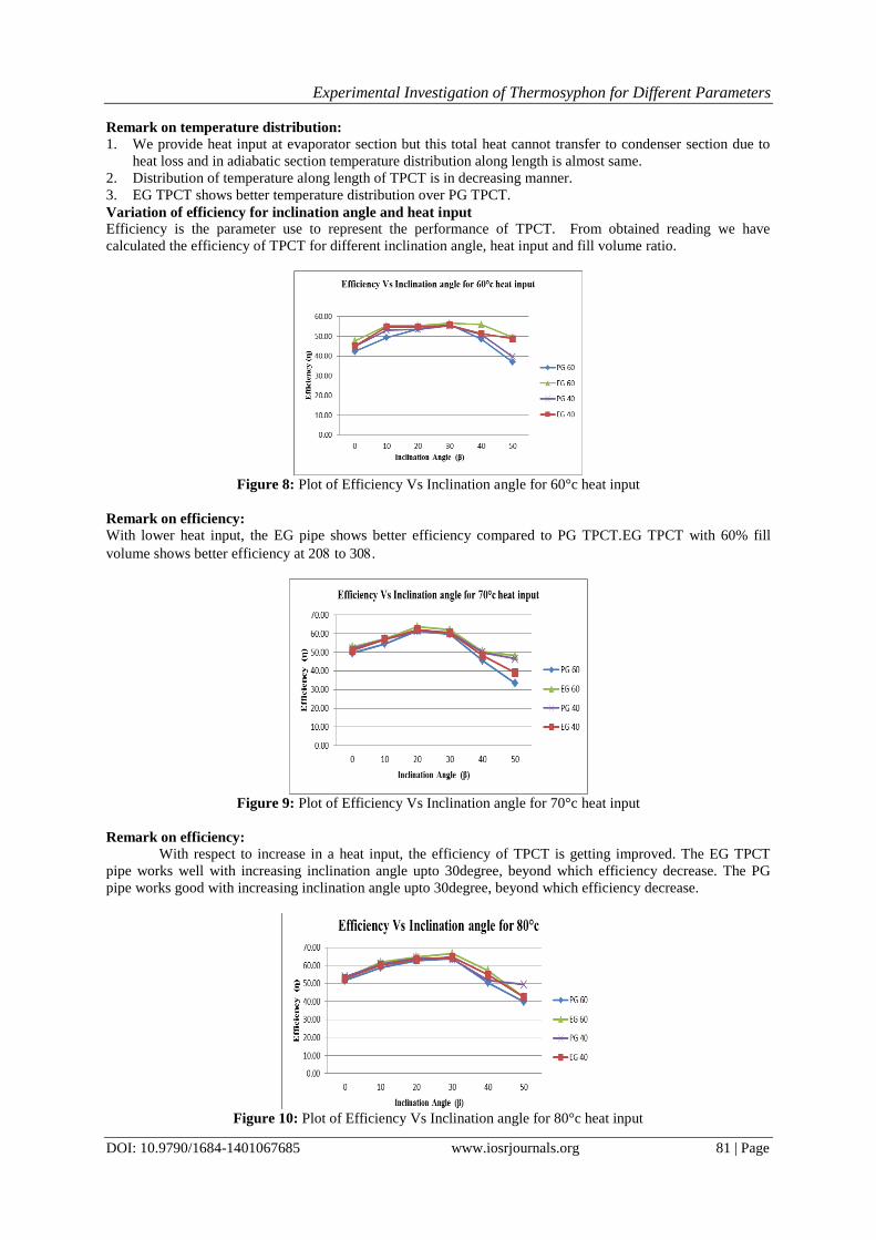
Figure 8: Plot of Efficiency Vs Inclination angle for 60°c heat input
Remark on efficiency:
With lower heat input, the EG pipe shows better efficiency compared to PG TPCT.EG TPCT with 60% fill
volume shows better efficiency at 20 to 30.
Figure 9: Plot of Efficiency Vs Inclination angle for 70°c heat input
Remark on efficiency:
With respect to increase in a heat input, the efficiency of TPCT is getting improved. The EG TPCT
pipe works well with increasing inclination angle upto 30degree, beyond which efficiency decrease. The PG
pipe works good with increasing inclination angle upto 30degree, beyond which efficiency decrease.
Figure 10: Plot of Efficiency Vs Inclination angle for 80°c heat input
Experimental Investigation of Thermosyphon for Different Parameters
DOI: 10.9790/1684-1401067685 www.iosrjournals.org 82 | Page
Remark on efficiency:
The maximum Efficiency of PG pipe is 64.20% found to be at a heat input of 80dc, at an inclination of
30degree. The maximum Efficiency of EG (60), pipe is 66.57 % found to be at a heat input of 80dc, at an
inclination of 30degree.
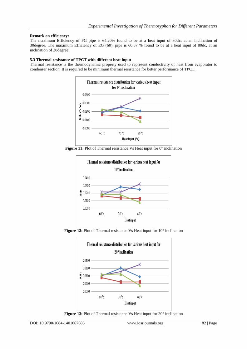
5.3 Thermal resistance of TPCT with different heat input
Thermal resistance is the thermodynamic property used to represent conductivity of heat from evaporator to
condenser section. It is required to be minimum thermal resistance for better performance of TPCT.
Figure 11: Plot of Thermal resistance Vs Heat input for 0° inclination
Figure 12: Plot of Thermal resistance Vs Heat input for 10° inclination
Figure 13: Plot of Thermal resistance Vs Heat input for 20° inclination
Experimental Investigation of Thermosyphon for Different Parameters
DOI: 10.9790/1684-1401067685 www.iosrjournals.org 83 | Page
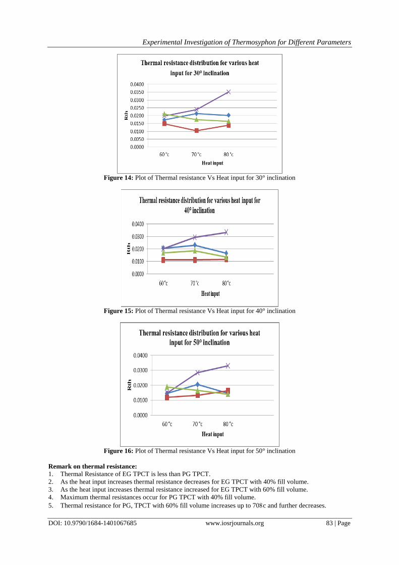
Figure 14: Plot of Thermal resistance Vs Heat input for 30° inclination
Figure 15: Plot of Thermal resistance Vs Heat input for 40° inclination
Figure 16: Plot of Thermal resistance Vs Heat input for 50° inclination
Remark on thermal resistance:
1. Thermal Resistance of EG TPCT is less than PG TPCT.
2. As the heat input increases thermal resistance decreases for EG TPCT with 40% fill volume.
3. As the heat input increases thermal resistance increased for EG TPCT with 60% fill volume.
4. Maximum thermal resistances occur for PG TPCT with 40% fill volume.
5. Thermal resistance for PG, TPCT with 60% fill volume increases up to 70c and further decreases.
Experimental Investigation of Thermosyphon for Different Parameters
DOI: 10.9790/1684-1401067685 www.iosrjournals.org 84 | Page
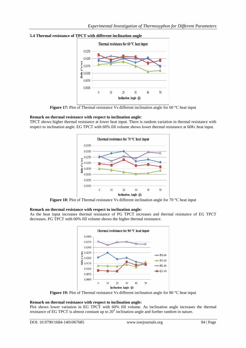
5.4 Thermal resistance of TPCT with different inclination angle
Figure 17: Plot of Thermal resistance Vs different inclination angle for 60 °C heat input
Remark on thermal resistance with respect to inclination angle:
TPCT shows higher thermal resistance at lower heat input. There is random variation in thermal resistance with
respect to inclination angle. EG TPCT with 60% fill volume shows lower thermal resistance at 60c heat input.
Figure 18: Plot of Thermal resistance Vs different inclination angle for 70 °C heat input
Remark on thermal resistance with respect to inclination angle:
As the heat input increases thermal resistance of PG TPCT increases and thermal resistance of EG TPCT
decreases. PG TPCT with 60% fill volume shows the higher thermal resistance.
Figure 19: Plot of Thermal resistance Vs different inclination angle for 80 °C heat input
Remark on thermal resistance with respect to inclination angle:
Plot shows lower variation in EG TPCT with 60% fill volume. As inclination angle increases the thermal
resistance of EG TPCT is almost constant up to 200 inclination angle and further random in nature.
Experimental Investigation of Thermosyphon for Different Parameters
DOI: 10.9790/1684-1401067685 www.iosrjournals.org 85 | Page
IV. Conclusion
1. With respect to increase in a heat input, the efficiency of TPCT is getting improved.
2. For higher heat input EG TPCT found to be work better than PG TPCT.
3. With lower heat input, the EG pipe shows better efficiency compared to PG pipe.
4. EG pipe shows better efficiency compared to all other pipes at maximum inclination angle.
5. The PG pipe works well with increasing inclination angle upto 30 degree, beyond which efficiency
decrease.
6. The EG TPCT pipe works well with increasing inclination angle upto 30degree, beyond which efficiency
decrease.
7. EG TPCT shows less thermal resistance over PG TPCT.
8. For EG TPCT with 60% fill volume and PG TPCT with 40% fill volume shows decreasing thermal
resistance as heat input increases.
9. EG TPCT with 40% fill volume and PG TPCT with 60% fill volume shows increasing thermal resistance as
heat input increases.
10. There is random variation in thermal resistance with respect to inclination angle.
11. Heat transfer rate is found to be improved for EG TPCT at 80 cover all inclination angles.
References [1] Reay D. A. and Kew P.A., ―Heat pipes – Theory, Design and Applications‖, 5th ed., Butterworth Heinemann, UK, 2006, pp.1 – 2.
[2] H. Li, A. Akbarzadeh and P. Johnson, ―The thermal characteristics of a closed two-phase thermosyphon at low temperature
difference‖, Heat Recovery Systems & CHP, 1991, 11(6), pp. 533-540. [3] Wei Guo, Darin W. Nutter, ―An experimental study of axial conduction through a thermosyphon pipe wall‖, Applied Thermal
Engineering, 2009, 29, pp. 3536–3541.
[4] A. Kate and R. Kulkarni, ―Effect of Pipe Cross Section Geometries and Inclination Angle on Heat Transfer Characteristics of Wickless Heat Pipe‖, International Journal of Engineering Research and Technology, 2010, 3(3), pp. 699—710.
[5] M. Karthikeyan, S. Vaidyanathan, B. Sivaraman, ―Thermal performance of a two phase closed thermosyphon using aqueous
solution‖, International Journal of Engineering Science and Technology, 2010,2 (5), pp. 913-918. [6] Yogesh S. Gandal, ―Experimental Investigation of Two Phase Closed Thermosyphon Using Propylene Glycol As a working Fluid‖,
August 2014, ISSN: 2278-0181, Volume 3.
[7] E. Hahne and U. Gross, ―The influence of the inclination angle on the performance of a closed two phase thermosyphon‖, Heat recovery system, 1981, 1, pp. 267-274.
[8] C. Wang, D.Q. Xn and S.P. Li, ―Investigation of heat transfer on the Dowtherm A gravity assisted heat pipe‖, Heat and Mass
transfer, 1993, 29, pp. 1-8. [9] H. Nguyen-chi and M. Groll, ―Entrainment or flooding limit in a closed two phase thermosyphon‖, Heat Recovery System, 1981, 1,
pp. 275-286. [10] Stephane lips and Josua P. Meyer, ―Experimental study of convective condensation in an inclined smooth tube.‖ Part 1: Inclination
effect on flow pattern and heat transfer coefficient, 55(2012), pp. 395-404
Copyright © 2022 FDOKUMEN