Experimental investigation of HFRP composite beams
27
SP-275 Editors: Rajan Sen Rudolf Seracino Carol Shield Will Gold 10th International Symposium 10th International Symposium Fiber-Reinforced Polymer Reinforcement for Concrete Structures Fiber-Reinforced Polymer Reinforcement for Concrete Structures
-
Upload
independent -
Category
Documents
-
view
0 -
download
0
Transcript of Experimental investigation of HFRP composite beams

SP-275
SP-275
Editors:Rajan SenRudolf SeracinoCarol ShieldWill Gold
SP-275
First printing: March 2011
ISBN: 0-87031-412-210th International Symposium10th International Symposium
Fiber-Reinforced Polymer Reinforcem
ent for Concrete Structures
The American Concrete Institute sponsored the First International Symposium for Fiber Reinforced Polymer (FRP) Reinforcement for Reinforced Concrete Structures at the Spring 1993 ACI Convention in Vancouver, Canada. At this inaugural event the international research community agreed to repeat these symposia every second year, rotating venues in various continents. Since 1993, the symposia have been held in Ghent, Belgium (1995); Sapporo, Japan (1997); Baltimore, MD, USA (1999); Cambridge, England (2001); Singapore (2003); Kansas City, MO, USA (2005); Patras, Greece (2007); and Sydney, Australia (2009). This volume represents the tenth in the symposium series, held in Tampa, FL, USA, April 2-4, 2011.
This volume contains 72 papers from 16 countries that address wide-ranging topics. The papers have been placed in twelve chapters that correspond to the sessions presented at the symposium. These cover internally reinforced members, strengthening of columns, material characterization, bond, emerging FRP systems, shear strengthening, fatigue and anchorage systems, masonry, extreme events, applications, durability and strengthening.
Fiber-Reinforced Polymer Reinforcement for
Concrete Structures
Fiber-Reinforced Polymer Reinforcement for
Concrete Structures

Experimental Investigation of HFRP Composite Beams
Hiroshi Mutsuyoshi, Nguyen Duc Hai, Kensuke Shiroki, Thiru Aravinthan, and
Allan Manalo
Synopsis: This paper presents the development of composite beams using hybrid
CFRP/GFRP (HFRP) I-beam and Normal Strength Concrete (NSC) slab and precast
Ultra-High Performance fiber reinforced Concrete (UHPFRC) slab. UHPFRC has high
strength and high ductility allowing for a reduction in the cross-sectional area and self
weight of the beam. A number of full-scale flexural beam tests were conducted using
different dimensions of slab and with/without epoxy bonding between the slab and HFRP
I-beam. The test results suggested that the flexural stiffness of composite beams with
bolted and bonded shear connection is higher than that with bolted-only shear connection.
Delamination failure was not observed in the compressive flange of the HFRP I-beam
and the high tensile strength of CFRP in the bottom flange was effectively utilized with
the addition of the UHPFRC slab on the top flange.
Keywords: Composite beam, hybrid fiber reinforced polymer, normal strength concrete,
ultra-high performance fiber-reinforced concrete, flexural stiffness
13-1

Biographical information
Dr. Hiroshi Mutsuyoshi is a Professor at the Department of Civil and Environmental
Engineering at Saitama University, Japan. He received his doctoral degree in Engineering
from the University of Tokyo in 1984. He is the president of the Japan Reinforcing Bar
Joints Institute. He is a member of the ACI International Partnership Committee, 440
Committee and a convener of TG 9.14 (extradosed tendons) of fib-Commission 9
(Reinforcing and Prestressing Materials and Systems).
Dr. Nguyen Duc Hai is a postdoctoral research fellow at Saitama University. He obtained
his PhD degree from Saitama University in 2010. His research interests include FRP
composites in structural engineering, testing and FE analysis of FRP composite
structures, mechanics of composite materials and structures, innovative bridge materials
and strengthening and rehabilitation of civil infrastructures using FRP composites. He is
a member of the International Institute for FRP in Construction (IIFC).
Mr. Kensuke Shiroki is a structural engineer at Japan Railway Construction, Transport
and Technology Agency. He achieved his master’s degree in civil engineering at Saitama
University in 2010. He is a member of the Japan Concrete Institute (JCI).
Dr. Thiru Aravinthan is an Associate Professor in Engineered Fibre Composites affiliated
with CEEFC, at the University of Southern Queensland in Toowoomba, Australia. He
leads major R&D projects in the CEEFC especially on the application of fibre composite
materials in civil infrastructure and leading the education and training within CEEFC. He
has more than 20 years of combined research, industry and teaching experience in
structural and materials engineering. He is a council member of IIFC.
Mr. Allan Manalo is a PhD student at the CEEFC at the University of Southern
Queensland (USQ), Toowoomba, Australia. He was awarded a Master’s in Engineering
Degree in March 2008 after completing a research work on hybrid FRP composites
13-2 Mutsuyoshi et al.

bridge girder at Saitama University, Japan. He joined USQ in April 2008 to pursue a
doctoral degree in structural engineering and currently doing research on the behavior of
fibre composite sandwich beams for structural applications.
INTRODUCTION
Fiber Reinforced Polymer (FRP) has several advantages such as high strength, light
weight and corrosion resistance. In recent years, FRP materials have been applied to
structural members in many pedestrian and road bridges. Presently, a hybrid FRP (HFRP)
composite beam for bridge girder applications is being developed. This beam optimizes
the combined use of Carbon Fiber Reinforced Polymer (CFRP) and Glass Fiber
Reinforced Polymer (GFRP) in a single wide-flange beam section. While CFRP has high
tensile strength and stiffness, it is relatively expensive, whereas GFRP is comparatively
less expensive but its mechanical properties are lower than those of CFRP. In a beam
subjected to bending moment about the strong axis, the top and bottom flanges are
subjected to high axial stress while the web is subjected to shear stress. In the HFRP
beam, the flanges are fabricated using a combination of CFRP and GFRP layers. On the
other hand, the web is composed entirely of GFRP because it is not subjected to the same
high stresses. The HFRP beam therefore utilizes the advantages of both CFRP and GFRP
for strength, stiffness and economy. The HFRP beam is expected to find its application in
severe corrosive environments or where lightweight rapid construction is required. The
application of HFRP composites could also contribute to a reduction of life cycle costs
(LCC) of the structure and environmental load due to its low carbon dioxide emission
(Sakai 2005; Tanaka et al. 2006).
This paper presents the flexural behavior of HFRP beams and composite behavior of
HFRP beam and a topping slab. Two types of materials used for topping slab are
considered including Normal Strength Concrete (NSC) and Ultra-High Performance fiber
reinforced concrete (UHPFRC). Different dimensions of slab and with/without epoxy
bonding between the slab and HFRP I-beam are utilized. A number of full-scale flexural
Experimental Investigation of HFRP Composite Beams 13-3

beam tests are performed and the test results are discussed focusing on flexural stiffness
of the composite beams.
RESEARCH SIGNIFICANCE
Many infrastructures all over the world suffer from deterioration problems resulting in
reduction of their service life. This problem has been severely affecting many bridges
especially in the coastal areas. It is therefore urgent to apply sustainable materials to
bridge structures to improve their durability. Accordingly, hybrid Fiber Reinforced
Polymers (HFRP) beams consisted of CFRP and GFRP have been utilized in this study.
The current work has provided valuable experimental data on flexural behavior of HFRP
beams and composite action between HFRP beams and topping slabs. Ultra-High
Performance fiber reinforced concrete (UHPFRC) was selected for the topping slab since
it has a great potential in reducing self weight and improving flexural stiffness of HFRP-
concrete structures.
FLEXURAL TEST OF HFRP BEAMS
HFRP Beams
The HFRP I-beams were manufactured by pultrusion process using the FRP layer
composition shown in Table 1. The top and bottom flanges of the I-beam are composed
of CFRP and GFRP in order to increase flexural strength and beam stiffness. All CFRP
fibers in the flanges are aligned in the longitudinal direction (oriented at 0 degree) while
the GFRP is oriented at 0, 90 and ±45 degrees to provide integrity across the flange
width, and avoid strong anisotropic behavior. The web is composed entirely of GFRP
because of the lower stresses, and to reduce cost. The overall height of the HFRP beam is
250 mm (9.84 in.) and the flange width is 95 mm (3.74 in.). The flange thickness is 14
mm (0.55 in.) and the web thickness is 9 mm (0.35 in.) as shown in Figure 1. The
mechanical properties of CFRP and GFRP are listed in Table 1. The effective mechanical
properties of the HFRP laminates obtained from the material tests are listed in Table 2.
13-4 Mutsuyoshi et al.

222
943
R5
14
95
250 GFRP
9CFRP + GFRP
Figure 1—Dimensions of HFRP I-beams (unit: mm) [1 in. = 25.4 mm]
Table 1—Mechanical properties of materials
Parameters Notation CFRP
0° GFRP 0/90°
GFRP ±45°
GFRP CSM
Volume Fraction
Vf, % 55 53 53 25
Volume Content
Flange, % 33 17 41 9 Web, % 0 43 43 14
Young’s Modulus
E11, GPa (ksi) 128.1
(18580) 25.9
(3760) 11.1
(1610) 11.1
(1610)
E22, GPa (ksi) 14.9
(2160) 25.9
(3760) 11.1
(1610) 11.1
(1610) Shear
Modulus G12, GPa (ksi)
5.5 (800)
4.4 (640)
10.9 (1580)
4.2 (610)
Poisson’s Ratio 12, 0.32 0.12 0.58 0.31
Table 2—Effective Mechanical Properties of HFRP Laminates
Flange Web Compressive strength, MPa (psi) 394 (57150) 299 (43370)
Tensile strength, MPa (psi) 884 (128210) 185 (26830) Young’s modulus, GPa (ksi) 49.6 (7190) 17.8 (2580)
Test Program
The beams were simply supported and tested in four-point bending at a span of 3000 mm
(118.1 in.) with an interior loading span of 1000 mm (39.4 in.). Web stiffeners were
installed to prevent crippling and warping at the supports and local failure at the loading
points. The timber stiffeners were bonded with FRP beam by epoxy adhesion. Safety rigs
Experimental Investigation of HFRP Composite Beams 13-5

were installed near the supports to prevent beams from sudden falling in the case of any
lateral buckling. The test setup is shown schematically in Figure 2. All beams were
fabricated of CFRP and GFRP in the flanges and only GFRP in the web.
Support block
Hydraulic jack
Load cell
Steel plate
Spreader beam
FRP BEAM
10001000 1000
3000
Safety RigSafety Rig
Steel plate
Support block
(a) Configuration (unit: mm)
(b) Actual view
Figure 2—Test setup [1 in = 25.4 mm]
Test Results and Discussions
Figure 3 shows the relationship between the load and mid-span deflection of the
pultruded I-beam. It can be seen that the behavior of beam is almost linear up to the
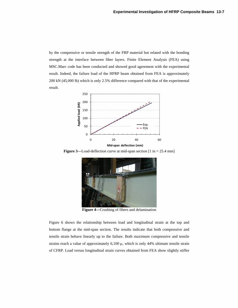
failure. The typical failure mode of pultruded beams is shown in Figures 4-5. It was
crushing of fibers near the loading point due to load concentration followed by
delamination of the compressive flange between the upper and lower part of the top
flange. It seems that the load carrying capacity of the pultruded I-beam is not governed
13-6 Mutsuyoshi et al.
by the compressive or tensile strength of the FRP material but related with the bonding
strength at the interface between fiber layers. Finite Element Analysis (FEA) using
MSC.Marc code has been conducted and showed good agreement with the experimental
result. Indeed, the failure load of the HFRP beam obtained from FEA is approximately
200 kN (45000 lb) which is only 2.5% difference compared with that of the experimental
result.
0
50
100
150
200
250
0 20 40 60
Applied load
(kN
)
Mid‐span deflection (mm)
Exp.FEA
Figure 3—Load-deflection curve at mid-span section [1 in = 25.4 mm]
Figure 4—Crushing of fibers and delamination
Figure 6 shows the relationship between load and longitudinal strain at the top and
bottom flange at the mid-span section. The results indicate that both compressive and
tensile strain behave linearly up to the failure. Both maximum compressive and tensile
strains reach a value of approximately 6100 , which is only 44% ultimate tensile strain
of CFRP. Load versus longitudinal strain curves obtained from FEA show slightly stiffer
Experimental Investigation of HFRP Composite Beams 13-7

behaviors than those obtained from the experiments. These differences could be due to
imperfections of FRP layers in the manufacturing process of HFRP specimens.
Figure 5—Closer view of delamination
0
50
100
150
200
250
‐10000 ‐5000 0 5000 10000
Applied load
(kN
)
Strain in top/bottom flange at mid‐span ()
Exp. (TF)FEA (TF)Exp. (BF)FEA (BF)
TF = Top flangeBF = Bottom flange
Figure 6—Load-longitudinal strain curve [1 kN = 224 lb]
FLEXURAL TEST OF HFRP-NSC COMPOSITE BEAMS
As discussed in the previous section on the flexural behavior of HFRP beams, it was
reported that the HFRP I-beams subjected to bending failed in the compressive flange
due to delamination between the CFRP and the GFRP interface. These test results suggest
that the individual HFRP beams could not utilize the high tensile strength of the CFRP in
the tension flange. To fully utilize this strength, the delamination failure in the
compression flange must be avoided. One approach to accomplish this is to reduce the
13-8 Mutsuyoshi et al.
stress in the HFRP compression flange by adding a concrete topping slab to resist the
compressive forces. This is analogous to composite steel construction where compression
buckling failure of the steel top flange can be avoided by using the concrete topping slab
to carry compression force.
This section aims to develop a composite beam using HFRP I-beams and a Normal
Strength Concrete (NSC) topping slab. It is expected that the composite beam system will
increase beam stiffness, prevent buckling and delamination in the HFRP compressive
flange and more effectively utilize the high tensile strength of the CFRP in the HFRP
tension flange. Since the slab will carry most of compressive forces, it is no longer
necessary to include CFRP in the top flange. However, during manufacturing of the
HFRP I-beam, it was determined that the top and bottom flanges must have the same
properties to avoid initial beam deformation after pultrusion process.
Test Specimen
Specimen HFRP-NSC represents the HFRP composite beam with cast-in-place NSC slab
bonded with epoxy and steel u-bolts. The length of the HFRP beam is 3600 mm (141.7
in.) with a clear span of 3000 mm (118.1 in.). High strength steel u-bolts made of 10 mm
(0.39 in.) diameter and epoxy resin were used as shear connectors. The steel u-bolts were
spaced at 150 mm (5.91 in.). The top flange of the HFRP beam was sandpapered and
cleaned with acetone to give a rough bond surface before the application of epoxy
adhesives. The NSC slab was 100 mm (3.94 in.) thick and 400 mm (15.75 in.) wide with
10 steel bars [16 mm (0.63 in.) diameter bars] to provide additional compressive force on
the concrete section. The NSC has a mean cylinder strength of 32 MPa (4640 psi)
obtained from compression test at 14 days (at the same age of testing the specimen). Five
steel bars with 16 mm (0.63 in.) diameter were used in the bottom to delay the formation
of tension cracks and limit the crack width on the NSC slab. Lateral steel ties with aspect
of 300 mm (11.81 in.) in the shear span and 150 mm (5.91 in.) between the loading points
were installed to provide confinement of concrete. The steel bars have an elastic modulus
of 200 GPa (29010 ksi) and a yield strength of 300 MPa (43510 psi). The dimensions
and configurations of the test specimen are shown in Figure 7.
Experimental Investigation of HFRP Composite Beams 13-9

(a) Cross section
(b) Loading configuration
Figure 7—Dimensions and configurations of specimen HFRP-NSC [1 in = 25.4 mm]
Test Program
Four point bending test was conducted. The test setup is shown in Figure 8. A hydraulic
jack was used to apply the load monotonically through a spreader beam. The deflection,
strains and failure mode were recorded during loading and until failure of the specimen.
13-10 Mutsuyoshi et al.

Figure 8—Test setup of HFRP-NSC
Test Results
The load and middle span deflection curve of HFRP beam with an overlying NSC slab is
shown in Figure 9. Based on the figure, the load increased linearly with deflection until
an applied load of 196 kN (44100 lb) and a reduction in stiffness was observed until final
failure. The reduced stiffness may be caused by the development of diagonal cracks
within the shear span which contributed to the downward deflection of the beam. HFRP-
NSC failed due to crushing of the concrete at the shear span followed by shear failure of
the top flange and web of the HFRP beam at an applied load of 427 kN (96000 lb) with a
middle span deflection of 73.9 mm (2.91 in.). Consequently, result of the experimental
investigation showed that the composite action with a NSC slab could overcome
deflection limitations inherent in HFRP beam and a higher load carrying capacity at final
failure could be attained compared to HFRP beam alone.
Hydraulic jack
Draw wire displacement
transducer LVDT
Experimental Investigation of HFRP Composite Beams 13-11

0
100
200
300
400
500
0 20 40 60 80 100
Lo
ad (k
N)
Deflection (mm)
Figure 9—Load and middle span deflection curve of HFRP-NSC [1 in = 25.4 mm]
Figure 10 shows the failure mode of HFRP composite beam with NSC slab. Development
of diagonal cracks within the shear span started at a load of 196 kN (44100 lb). The
crack width increased with the increase of load and lead to the compression failure of
concrete slab near the loading point followed by shear failure on the top flange. Shear
failure in the top flange of HFRP beam may be due to stress concentration in the holes
provided for the u-bolts. This was not the expected failure mode as the HFRP composite
beam was designed to fail by rupture of the HFRP in tension. However in actual design,
this may be a preferable failure mode because cracks in the concrete slab will give an
adequate warning of impending failure to the structure.
(a) Compression failure of NSC slab (b) Shear failure of HFRP beam
Figure 10—Failure mode of specimen HFRP-NSC
13-12 Mutsuyoshi et al.

FLEXURAL TEST OF HFRP-UHPFRC COMPOSITE BEAMS
The behaviors of composite beams using HFRP beam and NSC topping slab verified the
importance of composite action in increasing the beam stiffness and utilizing the high
tensile strength of the HFRP beam. These have been reported by Deskovic et al. (1995),
Keller et al. (2007), Correia et al. (2007) as well. However, the use of NSC required a
larger cross-sectional area for the deck to attain a tensile failure for HFRP, thus, resulted
to a heavy composite beam system. In order to maintain the light weight of the HFRP
beam in the composite beam, high performance concrete topping slab should be used.
Elmahdy et al. (2008) investigated the behavior of the hybrid section consisted of GFRP
pultruded hollow box section with Ultra High-Performance Concrete (UHPC) cast on top.
Steel reinforced polymer sheet or CFRP sheet was applied at the base of the section. The
results indicated that the application of UHPC and tensile reinforcement sheets increased
the flexural capacity of the hybrid section by approximately 3.7 times when compared to
the strength of the GFRP hollow section alone. Unfortunately, there have been very few
works done so far on the behavior of hybrid FRP-UHPC system. This study aims to
further investigate the composite behavior of this system for bridge applications. Ultra-
High Performance Fiber Reinforced Concrete (UHPFRC) was selected for the topping
slab. The UHPFRC used in this study had a compressive strength of 180 MPa (26110
psi) and a tensile strength of 8.8 MPa (1280 psi), with high ductility in both tension and
compression due to the crack-bridging effect of the high strength steel fibers included in
the UHPFRC. Therefore steel bars are not necessary to reinforce the UHPFRC slab for
shrinkage and temperature effects, thereby reducing the slab thickness and overall self-
weight of the composite HFRP-UHPFRC beam system.
Ultra High Performance Fiber Reinforced Concrete (UHPFRC)
Mixture proportions of the UHPFRC are listed in Table 3. The UHPFRC is composed of
water, premixed cementitious powder, sand, water reducing agent and steel fibers. The
premixed cementitious powder includes ordinary Portland cement, pozzolanic materials
(usually silica fume) and ettringite according to Japanese standards for blended cement.
The steel fibers have a tensile strength of 2000 MPa (290080 psi) and lengths of 22 mm
Experimental Investigation of HFRP Composite Beams 13-13

(0.87 in.) and 15 mm (0.59 in.). The fibers were added at approximately 1.75% volume
ratio. The UHPFRC slabs were precasted and cured at 85 Celsius degrees for 24 hours.
Compression tests were performed on 100200 mm (3.947.87 in.) cylinders of the
UHPFRC to determine compressive strength and modulus of elasticity. Moduli of rupture
tests were performed on 100100400 mm (3.943.9415.75 in.) specimens to
determine the tensile strength of the UHPFRC. Three specimens were tested for each
material property and the average values are listed in Table 4.
Table 3—Mix Proportions of UHPFRC
Air content, %
Unit quantity, kg/m3 (lb/ft3) Steel fiber,
kg/m3 (lb/ft3) Water Premix cement
Sand W.R.
Admixture
2.0 205
(12.80) 1287
(80.34) 898
(56.06) 32.2
(2.01) 137.4 (8.58)
Table 4—Test Results of UHPFRC Material
Compressive strength f’c, MPa (psi)
Tensile strength ft, MPa (psi)
Young’s modulus Ec, GPa (ksi)
173 (25090) 14.3 (2070) 48.6 (7050)
Test Variables
The test variables for the full-scale beam flexural tests are listed in Table 5. Five
specimens with different dimensions for the UHPFRC slab were tested. The geometry of
the test specimens and the dimensions of the beam cross-sections are shown in Figures 11
and 12. The total length of each specimen is 3500 mm (137.8 in.) with the flexural and
shear spans at 1000 mm (39.4 in.) as shown in Figure 11. Timber stiffeners were
installed at a spacing of 500 mm (19.7 in.) on both sides of the web to prevent web
buckling. The stiffeners were bonded to the HFRP specimens using epoxy bonding.
Different types of shear connectors including headed bolts with/without epoxy bonding
and slab anchors were tested to investigate the composite/non-composite actions between
the HFRP beam and the UHPFRC slab. The spacing of headed bolts and slab anchors was
13-14 Mutsuyoshi et al.

determined from the shear connection tests to prevent premature bolt shear failure as
shown in Figure 13. A torque wrench was used to apply 20 N-m (177 lb-in.) torque to the
bolts in all specimens.
Table 5—Flexural Beam Test Variables
Specimen name
Shear connector
Epoxy bonding
Width of UHPFRC slab, mm (in.)
Thickness of UHPFRC slab, mm (in.)
Embedded length of bolt, mm (in.)
B-135-50 M16 bolt No 135 (5.31) 50 (1.97) 35 (1.38) SA-135-50 Slab anchor No 135 (5.31) 50 (1.97) 35 (1.38) BE-95-50 M16 bolt Yes 95 (3.74) 50 (1.97) 35 (1.38) BE-135-35 M16 bolt Yes 135 (5.31) 35 (1.38) 30 (1.18) BE-135-50 M16 bolt Yes 135 (5.31) 50 (1.97) 35 (1.38)
1000 1000 1000
Safety RigStiffener
Figure 11—Geometry of specimen for flexural test (unit: mm) [1 in = 25.4 mm]
(a) B/BE-135-50 (b) BE-95-50
Experimental Investigation of HFRP Composite Beams 13-15

(c) BE-135-35 (d) SA-135-50
Figure 12—Dimensions of the beam cross-sections (unit: mm) [1 in = 25.4 mm]
(a) Specimens with bolts
(b) Specimen with slab anchors
Figure 13—Locations of shear connectors (unit: mm) [1 in = 25.4 mm]
Experimental Setup and Procedure
Four point bending test was conducted on all specimens. The experimental setup is
shown in Figure 14. The load was applied by a manually operated hydraulic jack until
beam failure. The applied load, deflection at mid-span, and strains in the HFRP beam
section were measured throughout the test.
13-16 Mutsuyoshi et al.

Figure 14—Flexural beam test setup
Results and Discussion
Figure 15 shows the load and mid-span deflection relationship of each specimen. For
comparison, the load-deflection relation curve for a HFRP beam without UHPFRC slab
(control specimen) and a composite beam with NSC slab (specimen HFRP-NSC) are also
included in Figure 15. All specimens with bolt shear connectors show higher stiffness and
loading carrying capacity than the control specimen. In particular, the stiffness of
specimen BE-135-50 is approximately 15% higher compared with that of specimen B-
135-50. On the other hand, the specimen SA-135-50 did not perform well compared to
the specimens using headed bolts. The stiffness of the load-deflection curve of specimen
BE-135-50 is only 1.6 times lower than that of specimen HFRP-NSC. However, it is
important to note that the total cross sectional area of the slab in specimen BE-135-50 is
5.9 times lower than that of specimen HFRP-NSC. This indicates that the use of
UHPFRC slab is more effective than NSC slab in terms of structural stiffness and weight.
Experimental Investigation of HFRP Composite Beams 13-17

0
50
100
150
200
250
300
350
400
450
500
0 20 40 60 80 100
Loa
d (k
N)
Deflection (mm)
B-135-50
SA-135-50
BE-95-50
BE-135-35
BE-135-50
HFRP-NSC
Control specimen
HFRP-NSC
Control specimen
HFRP-UHPFRC 15%
Figure 15—Load-deflection relationships [1 in = 25.4 mm]
0
50
100
150
200
250
300
350
‐6000 ‐1000 4000 9000
Section depth(m
m)
Axial strain ()
100kN200kN300kN400kN470kN (Failure)
0
50
100
150
200
250
300
350
‐6000 ‐1000 4000 9000
Section depth(m
m)
Axial strain ()
100kN200kN300kN400kN437kN (Failure)
(a) BE-135-50 (b) B-135-50
13-18 Mutsuyoshi et al.

0
50
100
150
200
250
300
350
‐5000 0 5000 10000
Section depth (m
m)
Axial strain ()
100kN
200kN
232kN (Failure)
(c) SA-135-50
Figure 16—Longitudinal strain over depth of composite beam [1 in = 25.4 mm]
Figure 16 shows the relationship between the load and longitudinal strain through the
depth of the composite beam at mid-span for various load levels, including failure load.
As shown in Figure 16a, the specimen with epoxy bonding shows a linear strain
distribution through the cross-section. On the other hand, Figures 16b and 16c shows
slipping at the interface between the UHPFRC slab and the HFRP beam for specimen
without epoxy bonding. This result indicates that specimens with bolted and bonded
connection show full composite action until the final failure. The specimen with shear
anchors showed even larger slip than the specimens with bolts. The results also show that
at failure, the maximum tensile strain recorded at the tensile flange of the HFRP is
approximately 10000 . This level of strain is significantly higher than the 6,000
recorded at failure in the tensile flange of the HFRP beam tested without slab. This shows
that the addition of UHPFRC slab on the HFRP beam resulted to the effective utilization
of the high tensile strength of the CFRP.
Str 1
Str 9
Str 8Str 7
Str 5, 6
Str 4
Str 2, 3
Experimental Investigation of HFRP Composite Beams 13-19

‐4500
‐4000
‐3500
‐3000
‐2500
‐2000
‐1500
‐1000
‐500
0
‐6 ‐4 ‐2 0 2 4 6
Strain ()
Distance from bolt hole (mm)
100kN
200kN
300kN
400kN
437kN
(a) Specimen without epoxy
‐1400
‐1200
‐1000
‐800
‐600
‐400
‐200
0
‐6 ‐4 ‐2 0 2 4 6
Strain (
)
Distance from bolt hole (mm)
100kN
200kN
300kN
381kN
(b) Specimen with epoxy
Figure 17—Strain distribution in HFRP top flange near bolt hole [1 in = 25.4 mm]
The strain distributions along the top flange of the HFRP beam near a bolt hole in the left
shear span are shown in Figure 17. As shown in Figure 17a for a specimen without
epoxy, the strain to the right of the bolt is small while strain to the left of the bolt shows
high compression in the HFRP beam flange. This strain distribution indicates that
slipping occurred at the interface between the UHPFRC slab and the HFRP beam
allowing the bolts to bear against the edge of the hole to resist the horizontal shear flow.
On the other hand, this behavior was not observed in specimens with epoxy bonding.
Figure 17b shows that the strains in the HFRP beam flange are uniformly distributed
Strain gages
13-20 Mutsuyoshi et al.

regardless of the bolt types and bolt hole location. These results confirm that the slipping
between the UHPFRC slab and the HFRP beam was resisted by the epoxy bonding
especially in the shear span where horizontal shear stress is significant. The bolts also
serve to prevent peeling at the UHPFRC slab to HFRP beam interface, and to provide
reserve strength if debonding occurs.
All specimens with headed bolts failed due to crushing of the UHPFRC slab at a loading
point followed by crushing of the HFRP beam flange as shown in Figure 18a.
Delamination of the top flange of the HFRP beam was observed in specimen SA-135-50
with shear anchors (Figure 18b). This failure mode is similar to that of HFRP beam
without slab, however the failure was not brittle as the UHPFRC slab carried compressive
force even after delamination failure occurred. In addition, a few of the slab anchors
failed in shear, while the others caused bearing failure in the HFRP beam flange.
(a) Crushing of UHPFRC slab (b) HFRP flange delamination failure
Figure 18—Failure modes of composite beams in flexure
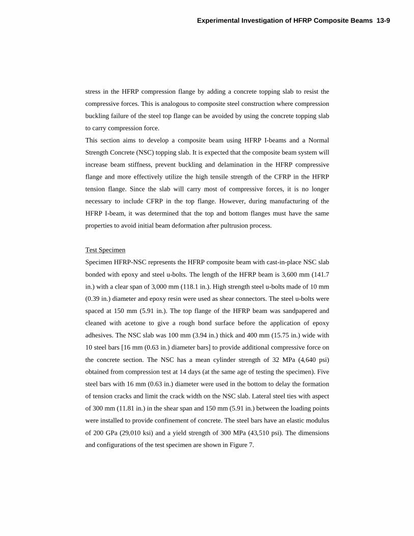
Fiber model analysis of the HFRP-UHPFRC composite girders was conducted and the
results were compared with the experimental results. Bernoulli-Euler theory was assumed
in this analysis. Bi-linear stress-strain relationship from the design code for ultra high
strength fiber reinforced concrete structures (Figure 19) was used to model UHPFRC
(JSCE 2004).
Experimental Investigation of HFRP Composite Beams 13-21
Compressive stress
Strain
0.85f’ck/Ec
0.85f’ck
0.0035
Figure 19—Bi-linear stress-strain relationship of UHPFRC
Table 6 shows comparisons between analytical and experimental results for the HFRP-
UHPFRC composite beams used headed bolt and epoxy bonding as shear connectors.
The results indicated that the analytical model could well predict the failure load and
failure mode of beams. The differences in failure load between the analysis and
experiment are less than 5%. However, the analytical model over-estimates the stiffness
of the composite beam as shown in Figure 20. According to the analytical model,
compression failure of the UHPFRC slab should occur at mid-span. However, failure
occurred at the loading point in the experiment and higher strains were recorded at the
loading point due to stress concentration. The disagreement in stiffness between the
analytical and experimental results is attributed in part to early plastic behavior at the
loading point caused by this stress concentration. The analytical model assume perfect
bond between the UHPFRC and HFRP, whereas the test specimens may experience some
deformation at the bond interface.
13-22 Mutsuyoshi et al.

0
100
200
300
400
500
600
0 10 20 30 40 50 60 70
Loa
d (k
N)
Deflection (mm)
BE-95-50 (Experiment)
BE-95-50 (Analysis)BE-135-35 (Experiment)BE-135-35 (Analysis)
BE-135-50 (Experiment)BE-135-50 (Analysis)
Figure 20—Comparisons of load-defection curves between experiments and analysis
[1 in = 25.4 mm]
Table 6—Flexural Beam Test Results at Failure
Beam Predicted failure load, kN (lb)
Actual failure load, kN (lb)
Predicted/actual failure mode
B-135-50 438 (98500) Compression – UHPFRC SA-135-50 232 (52200) Delamination – HFRP top flange BE-95-50 384 (86300) 382 (85900) Compression – UHPFRC BE-135-35 411 (92400) 394 (88600) Compression – UHPFRC BE-135-50 481 (108100) 470 (105660) Compression – UHPFRC HFRP-NSC 427 (96000) Compression – NSC
CONCLUSIONS
This paper presents an experimental study of HFRP beams and composite beams
consisting of HFRP beams and concrete topping slabs connected by bolts or slab anchors.
The main conclusions from the study are summarized as follows:
1. The investigated HFRP beams behave linearly under flexural load and failed suddenly
without forewarning. The failure was crushing of fibers near the loading point due to load
Experimental Investigation of HFRP Composite Beams 13-23

concentration followed by the delamination of the compressive flange between the
interface of CFRP and GFRP layers.
2. Composite beams consisting of HFRP beams and concrete topping slabs significantly
improve their flexural stiffness and effectively utilize the superior properties of the HFRP
materials.
3. The use of UHPFRC slab is more effective than NSC slab in terms of structural
stiffness and weight.
4. HFRP-UHPFRC composite beams with headed bolt shear connectors provide
considerable stiffness and strength increase compared with HFRP beams without
concrete topping slab.
5. Composite beams with epoxy bonding between the UHPFRC slab and HFRP beam top
flange showed an approximately 15% increase in flexural stiffness than beams connected
with bolts only.
ACKNOWLEDGMENTS
The authors would like to thank Kajima Corporation for providing Ultra High
Performance Fiber Reinforced Concrete “SUQCEM” (Super high-Quality CEmentitious
Material).
REFERENCES
Concrete Committee of Japan Society of Civil Engineers (JSCE-2004).
“Recommendations for Design and Construction of Ultra High Performance Fiber
Reinforced Concrete Structures”.
Elmahdy, A., El-Hacha, R., and Shrive, N. (2008). “Flexural behavior of hybrid
composite girders for bridge construction”. Proceedings of the ACI special
publication on FRP stay-in-place forms for concrete structures, the ACI spring
convention in Los Angeles, CA, USA.
13-24 Mutsuyoshi et al.

Hirokazu Tanaka, Hitoshi Tazawa, Morio Kurita, Takumi Shimomura (2006). “A case
study on life-cycle assessment of environmental aspect of FRP structures”.
Proceedings of Third International Conference on FRP Composites in Civil
Engineering (CICE 2006), Florida, USA, pp. 175-178.
J.R. Correia, F.A. Branco, J.G. Ferreira (2007). “Flexural behaviour of GFRP-concrete
hybrid beams with interconnection slip”. Composite Struct 77 (1), pp. 66–78.
Keller, T., Schaumann, E., Vallée, T. (2007). “Flexural behavior of a hybrid FRP and
lightweight concrete sandwich bridge deck”. Composites Part A 38 (3), pp. 879–
889.
Koji Sakai (2005). “Environmental Design for Concrete Structures”. Journal of Advanced
Concrete Technology, Vol.3, No.1, pp.17-28.
Allan Manalo, Hiroshi Mutsuyoshi, Thiru Aravinthan, Takahiro Matsui (2009).
“Behaviour of Hybrid FRP Composite I-Girder with Concrete Deck”. FRPRCS-9,
Sydney, Australia.
Nguyen Duc Hai, Hiroshi Mutsuyoshi, Shingo Asamoto, and Takahiro Matsui (2010).
“Structural Behavior of Hybrid FRP Composite I-Beam”. Journal of Construction
and Building Materials, Vol. 24, pp. 956-969.
Nikola Deskovic, Thanasis C. Triantafillou, Urs Meier (1995). “Innovative Design of
FRP Combined with Concrete: Short-Term Behavior”. J. Struct. Engrg. Volume
121, Issue 7, pp. 1069-1078.
Nikola Deskovic, Thanasis C. Triantafillou, Urs Meier (1995). “Innovative Design of
FRP Combined with Concrete: Long-Term Behavior”. J. Struct. Engrg. Volume
121, Issue 7, pp. 1079-1089.
Experimental Investigation of HFRP Composite Beams 13-25

13-26 Mutsuyoshi et al.


![[Composite Cultures] - CORE](https://static.fdokumen.com/doc/165x107/6325e67de491bcb36c0a86c0/composite-cultures-core.jpg)