
A numerical study of the western Cosmonaut polynya in a coupled ocean-sea ice model
Upload
khangminh22Category
view
3download
0
Experimental and numerical study on coupled motion responses of a floatingcrane vessel and a lifted subsea manifold in deep water
B.W. Nam*, N.W. Kim, S.Y. Hong
Korean Research Institute of Ship & Ocean Engineering, 104 Sinseong-ro, Yuseong-gu, Daejeon 305-343, Republic of Korea
Received 2 September 2016; revised 2 November 2016; accepted 2 January 2017
Available online 13 January 2017
Abstract
The floating crane vessel in waves gives rise to the motion of the lifted object which is connected to the hoisting wire. The dynamic tensioninduced by the lifted object also affects the motion responses of the floating crane vessel in return. In this study, coupled motion responses of afloating crane vessel and a lifted subsea manifold during deep-water installation operations were investigated by both experiments and numericalcalculations. A series of model tests for the deep-water lifting operation were performed at Ocean Engineering Basin of KRISO. For the modeltest, the vessel with a crane control system and a typical subsea manifold were examined. To validate the experimental results, a frequency-domain motion analysis method is applied. The coupled motion equations of the crane vessel and the lifted object are solved in the fre-quency domain with an additional linear stiffness matrix due to the hoisting wire. The hydrodynamic coefficients of the lifted object, which is asignificant factor to affect the coupled dynamics, are estimated based on the perforation value of the structure and the CFD results. The dis-cussions were made on three main points. First, the motion characteristics of the lifted object as well as the crane vessel were studied bycomparing the calculation results. Second, the dynamic tension of the hoisting wire were evaluated under the various wave conditions. Finaldiscussion was made on the effect of passive heave compensator on the motion and tension responses.Copyright © 2017 Society of Naval Architects of Korea. Production and hosting by Elsevier B.V. This is an open access article under theCC BY-NC-ND license (http://creativecommons.org/licenses/by-nc-nd/4.0/).
Keywords: Coupled motion; Crane vessel; Subsea manifold; Model test; Lifting operation
1. Introduction
There are various installation methods for subsea equip-ment in deep water. Conventional crane-wire installationmethod has been widely used in real-sea operations. For thesafety of the crane lifting operations, it is required to check thecrane capacity, rigging design and the structural strength of thelifted object. If the weight of the lifted object is considerable,the coupled dynamics of the crane vessel and the lifted objectbecome quite important. Dynamic amplification factor of hookload can be increased by the coupled dynamic effect. As forthe subsea installation, the water depth is a critical parameterof the vertical resonance of the hoisting system. Recently, new
installation methods such as pendulum installation method,pencil buoy method and sheave method, also have beendevised to overcome the limitation or disadvantage of thecrane-wire installation method.
A typical crane installation operation in deep water consistsof four main phases (DNV, 2011). First phase is lifting offfrom deck of a transportation barge and maneuvering the ob-ject, in which the transient behavior of the lifted object shouldbe suppressed to avoid collision. Second phase is loweringoperation through the wave zone. In this stage, variousexternal forces including weight, buoyancy, slamming force,wave force are acting on the lifted object, changing in timeaccording to the lifting locations of the object. The slackcondition of the hoisting wires also should be check. Thirdphase is deep-water lowering (or lifting) operation, in whichvertical oscillation of the lifted object can be a significantfactor. As the hoisting wire is getting longer, the first eigen
* Corresponding author. Fax: þ82 42 866 3919.
E-mail address: [email protected] (B.W. Nam).
Peer review under responsibility of Society of Naval Architects of Korea.
Available online at www.sciencedirect.com
ScienceDirectPublishing Services by Elsevier
International Journal of Naval Architecture and Ocean Engineering 9 (2017) 552e567http://www.journals.elsevier.com/international-journal-of-naval-architecture-and-ocean-engineering/
http://dx.doi.org/10.1016/j.ijnaoe.2017.01.002
p2092-6782 e2092-6790/Copyright © 2017 Society of Naval Architects of Korea. Production and hosting by Elsevier B.V. This is an open access article under the
CC BY-NC-ND license (http://creativecommons.org/licenses/by-nc-nd/4.0/).

period of the hoisting system can be getting longer up to theoperational wave period. In this case, the resonant verticalmotions of the lifted object and the large dynamic tension ofthe hoisting wire can occur during the lowering operation.Final phase is touching down on sea bed and retrieval, which islanding stage. Horizontal offset and motions of the lifted ob-ject, which are mainly affected by the low-frequency hori-zontal motions of the vessel as well as ocean current, can beimportant considerations related to the accurate positioning ofthe subsea equipment. Appropriate weather conditions shouldbe screened before the real-sea operation.
During the deepwater lowering or lifting operation, a heavecompensation system can be employed to mitigate the verticalresonant motion of the lifted equipment and reduce the dy-namic loads in the hoisting wire system. Three types of heavecompensators have been used in deep water lifts: Passive,active and combined heave compensators. A Passive HeaveCompensator (PHC) is a kind of spring-damper systems whichshift resonant frequency of vertical motion of hoisting wiresystem. The passive heave compensator is also designed toreduce impacts on offshore cranes by adding damping in thehoisting wire. An Active Heave Compensator (AHC) useseither controlled winches or hydraulic pistons, and referencesignals. The active heave compensation systems generally useinformation from vessel Motion Reference Unit (MRU) tocontrol payout length of winch line.
Regarding the real-sea deepwater installation operation ofsubsea equipment, dynamic analysis method is widely used indesign stage to predict the motion responses of the subseaequipment and determine the capacity of the installationequipment and the weather windows. For example, Galgoulet al. (2001) described the analyses and all the problemsencountered during the installation project of a PETROBRASmanifold in a 1860 m water depth, at the Roncador field in theCampos Basin, offshore Rio de Janeiro. They also pointed outthe axial resonance can be a major concern as the installationdepths increase to 3,000 m. Kimiaei et al. (2009) presented asimplified numerical model for the accurate estimation ofhydrodynamic forces on subsea platforms and compared theresults of the DNV guidelines. They carried out a series ofsensitivity analyses using DNV guideline and OrcaFlexmodels. Vries et al. (2011) described the monitoring campaignon a typical example of a deep water lowering operation. Theysuggested the monitoring results about the subsea behavior oftwo suction piles during the installation operation in 2700 mwater depth using a support vessel. They also compared themonitoring results with numerical models used for dynamicanalysis and concluded that dynamic analysis methods can beapplicable to prediction of the motion and load for subseastructure in deepwater installation operation. Legras and Wang(2011) suggested a new method to determine criteria forlowering operations based on real time monitoring of thevessel motion and time-domain simulation. They alsodescribed the application of the method on an installationvessel for lowering operations in West Africa. Wang et al.(2011) carried out pipeline installation analysis and jumperlowering analysis by using the commercial software OrcaFlex.
They discussed the technical challenges to install the rigidpipeline with PLET, jumper and flying leads. Nam et al.(2013) developed a time-domain analysis program forfloating crane vessel systems. They investigated the effect ofheave compensator during lowering operation of subseaequipment.
Only a few model tests related to subsea installation orfloating crane can be found in literature survey. Clauss et al.(2000) showed an experimental study of the nonlinear dy-namics of floating cranes. Fujarra et al. (2008) carried out aseres of simplified model test in order to dimensioning thelaunching cables and to define the limit environmental con-ditions for the subsea installation. Nam et al. (2015) performedan experimental study on deepwater crane installation ofsubsea equipment in waves. They carried out a model test fordeepwater lowering and lifting operation of subsea equipmentunder both regular and irregular wave conditions. They alsodiscussed the effect of passive heave compensator on thedeepwater lowering operation of a manifold. To overcome thelimitation of water depth in basin, new experimental techniqueusing truncated hoisting system was introduced.
In this study, coupled motion responses of a floating cranevessel and a lifted subsea manifold during deep-water instal-lation operations were investigated. A series of model tests forthe deepwater lifting operation were performed at Ocean En-gineering Basin of KRISO. To validate the experimental re-sults, a frequency-domain motion analysis was carried out.Under various irregular wave conditions, the motion responsesof the vessel as well as the lifted object were examined. Thedynamic tension of the hoisting wire were also evaluatedunder the different wave period conditions. Discussion is madeon the effect of passive heave compensator on the motion andtension responses.
2. Model test
2.1. Experimental models
A floating crane vessel named ‘HD2500’, which has beenused in real-sea installation project by Hyundai Heavy In-dustry (HHI), was selected in this model test. The main di-mensions of the crane vessel are 130 m(L)*36 m(B)*10.5 m(D). The displacement of the vessel is about 15,000ton. Fig. 1 shows the image and experimental model for thecrane vessel. The scale ratio of the model is 1:50 and thescaled vessel model was made of wood. The crane vessel isequipped with dynamic positioning system for the deepwateroperations. Four azimuth thrusters are located at each cornerof the vessel. The GM value and roll natural period wereadjusted by inclining and free-decay tests. The pitch gyrationwas measured with a swing table test. There is a single cranesystem with maximum capacity 2500 ton on the deck of thevessel.
Among various types of subsea equipment, a typical subseamanifold was considered in this model test. Fig. 2 shows CADimage and experimental model of the manifold. The presentmanifold has complex geometry, which consists of complex
553B.W. Nam et al. / International Journal of Naval Architecture and Ocean Engineering 9 (2017) 552e567

porous plates and truss frames. The main dimension of themanifold is 15.6 m(L)*12.3 m(B)*4.3 m(D). The air weight ofthe manifold is about 150 ton. The experimental model of themanifold was made of plastic material by using 3-D printing
techniques. In order to adjust the model weight, the additionallead weights are put inside the model of the manifold. Table 1summarized the main dimensions of the crane vessel and themanifold.
2.2. Crane system and passive heave compensator
The crane system is consisted of three main parts, i.e.boom, backstay and crane base. Fig. 3 shows CAD image andexperimental model of the crane system in which the maincrane frame is made of wood. The electric motors are utilizedfor hoisting wire and boom rotation. The crane control motoris connected to winch drum via reduction gear and coupling,shown in Fig. 4. In this study, the hoisting wire tension wasmeasured by using 1-axis loadcell and pulley system. Tomatch the vertical natural period of the hoisting system, theaxial stiffness of the hoisting wire in the model scale should beequivalent to that of the real system. In this study, severalnylon lines for fishing were tested and then the most appro-priate one was chosen.
Passive heave compensator can be modeled as additionalspring and damper. Fig. 5 shows a photo and schematic dia-gram of the passive heave compensator. It is well-known thatthe passive heave compensator reduces peak heave and tensionresponse of the hoisting system by shifting the resonant period(Nam et al., 2013). Although actual passive heave compen-sator has nonlinear spring and damping characteristics, a linear
Fig. 1. Image (left) and experimental model (right) for the floating crane vessel.
Fig. 2. Experimental models for the subsea manifold.
Table 1
Main dimensions of the installation vessel and the subsea equipment.
Item Installation vessel Manifold
L 130.0 m 15.6 m
B 36.0 m 12.3 m
D 10.5 m 4.3 m
Weight Abt 15,000 ton Abt. 150 ton
Fig. 3. CAD model (left) and experimental model of the crane system.
554 B.W. Nam et al. / International Journal of Naval Architecture and Ocean Engineering 9 (2017) 552e567

spring can be used to investigate the fundamental effect ofpassive heave compensator. In this study, passive heavecompensator is modeled as a linear spring, while damper is notconsidered.
2.3. Experimental conditions and measurement
First, a white noise test was carried out to evaluate themotion and tension RAOs. Then the coupled motion responses
of the vessel and the lifted manifold were examined undervarious irregular wave conditions. Fig. 6 shows white noiseand irregular wave spectra which have been used in the presentmodel test. Irregular wave conditions are summarized in Table2. The wave spectra used in this study are ITTC spectra. Thesignificant wave height is fixed as 1.0 m because the instal-lation operation is normally performed under the mild oceanenvironment when the significant wave height is less than1.0 m or 1.5 m. The wave periods range from 4.0 s to 14.0 s.
Fig. 4. Crane control motor (left) and tension measurement system (right).
Fig. 5. Photo (left) and schematic diagram (right) of passive heave compensator.
Fig. 6. White noise and irregular wave spectra.
555B.W. Nam et al. / International Journal of Naval Architecture and Ocean Engineering 9 (2017) 552e567

The wave periods longer than 10 s are less meaningful fornormal installation sites. However, for some specific installa-tion areas, the swell conditions of long wave periods can becritical for the installation operations. In addition, we want toevaluate PHC performance under wide-range periodconditions.
In order to measure the motion of the lifted subsea equip-ment in water, a underwater jig and two cameras were intro-duced in this model test, shown in Fig. 7. The underwater jigwas installed in the pit at water depth of �700 m. A black ballmaker is attached to the subsea equipment in order to capturethe motion of the lifted object by applying image processing.Fig. 8 shows the typical motion trajectories of the liftedmanifold extracted from the recorded experimental movie.
3. Numerical analysis
3.1. Equation of motion
In this study, it is assumed that the crane vessel experience6-dof motions and the lifted object is subjected to only 3-doftranslation motions. Total coupled motion equations can beexpressed like followings;
�
�u2
�
MV þAVðuÞ 06�3
03�6 MS þAS
�
� iu
�
BpotV ðuÞ 06�3
03�6 BvisS
��
��
xVxS
�
þ�
ChydroV þCwire
V CwireVS
CwireSV Cwire
S
��
xVxS
�
¼�
FVðuÞ03�3
�
ð1Þwhere, MV and MS are the inertia matrix of the vessel and thelifted structure, respectively. AVðuÞ and Bpot
V ðuÞ are theadded-mass matrix and potential damping matrix of the vessel,which are basically functions of the motion frequency. Theseadded-mass and potential damping coefficients of the surfacevessel can be easily evaluated by applying conventional waveGreen function method with boundary element method. In thisstudy, higher-order boundary element method is applied toobtain the added-mass and damping coefficients of the vessel.AS and Bvis
S are the added-mass matrix and the viscousdamping matrix of the lifted structure. If the lifting location isdeep enough, the added-mass of the lifted structure can beassumed to be constant and potential damping is negligible. Inthis case, additional damping due to the viscous drag forcebecomes significant compared to the potential damping. In thisstudy, linearized viscous damping is considered. Chydro
V is thehydrodynamic restoring matrix. Cwire
V , CwireS , Cwire
VS , CwireSV are
the linear spring matrix due to the crane wire, which connectsthe vessel and the lifted structure.
3.2. Hydrodynamic coefficient of the manifold
The motion response of the lifted object in water are quitedependent on the hydrodynamic forces which can be decom-posed into added-mass and hydrodynamic damping forces.
Table 2
Irregular wave conditions.
Wave ID Spectrum Tz (sec) Tp (sec) Hs (m)
IRW01 ITTC 4.000 5.620 1.000
IRW02 ITTC 6.000 8.429 1.000
IRW03 ITTC 8.000 11.239 1.000
IRW04 ITTC 10.000 14.049 1.000
IRW05 ITTC 12.000 16.859 1.000
IRW06 ITTC 14.000 19.669 1.000
Fig. 7. Underwater jig (left), camera (middle) and image processing results (right).
Fig. 8. Motion trajectories of the lifted subsea manifold under the irregular wave conditions (water depth ¼ �700 m).
556 B.W. Nam et al. / International Journal of Naval Architecture and Ocean Engineering 9 (2017) 552e567

The added-mass values of the submerged object is mainlydetermined of the object shape. Since the manifold has com-plex truss frame and porous plate, it can be predicted that theweight in water of the manifold can increases significantlyrather than the weight in air. However, it is hard to estimate theadded-mass values of this kind of complex geometry. In thisstudy, in order to estimate the added-mass of the manifold, theextrapolation method based on the structure perforation isapplied. Fig. 9 shows the several manifold geometry withdifferent perforation values. Fig. 10 shows the added-massratios according to the structure perforation values withrespect to the solid structure with no perforation. Thecomputational results are compared with the simplified esti-mation formula which was suggested by DNV (2011). Basedon these calculation results, the estimated added-mass ratioranges around 10%e20% of the added-mass at the solidmanifold given in Fig. 9(a). In the later calculations, theadded-mass of the manifold is assumed as about 128 ton,which corresponds to 15% of the added-mass of the solidmanifold with no perforation.
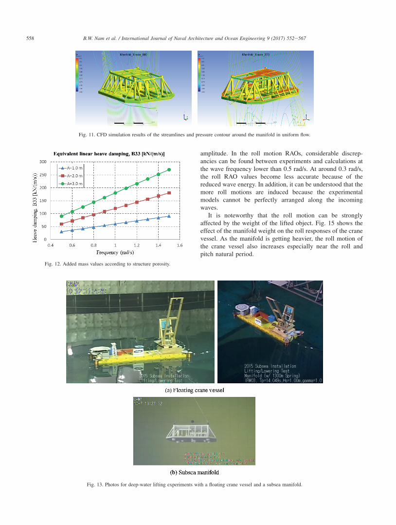
To estimate the drag coefficient of the subsea manifold,CFD calculations were carried out by using commercial CFDsoftware (Park et al., 2013). Fig. 11 shows the CFD simulationresults in two opposite inflow angles. Based on the CFD re-sults, the drag coefficient ðCDÞ is about 0:722, where theprojection areaðAPÞ is 192:0 m2. In this case, quadratic heavedamping coefficient ðbnon99 Þ is about 70 kN$s2=m2. The equiv-alent linear heave damping coefficients ðbeq99Þ are shown inFig. 12. In principle, the equivalent linear damping coefficientvaries with excitation frequency and motion amplitude. Asshown in figure, the equivalent damping coefficient rangesfrom 50 kN$s=m to 250 kN$s=m.
4. Results & discussions
In this study, a series of model tests were performed toevaluate deep-water crane operation of lifting the subseamanifold. Fig. 13 shows photos for the floating crane vesseland the lifted subsea equipment during the model test. The pitin the center of the basin was utilized to ensure the enoughwater depth. The crane vessel was positioned so that thelowering position was located in the center of the pit.Considering the scale ratio, the maximum water depth of thebasin was equivalent to 700 m in real scale. The dynamicpositioning system was used for the crane vessel withoutmooring system, where proportional gains of the DP system
were set as the natural periods of horizontal vessel motionsbecame around 200 s. In this study, only port-side lifting op-erations with single hoisting wire were taken into account.Black ball makers, shown in Fig. 13(b), were attached to themanifold for the motion capturing by using image processing.
4.1. Motion responses of the installation vessel
The motion RAOs of the crane vessel, shown in Fig. 14,were obtained from the white noise test during the liftingoperation of the subsea manifold. In this case, the liftinglocation is about �700 m under the still water and waveheading is 180�. For the comparison, the frequency-domaincalculation results are also plotted together with the experi-mental data. Heave and pitch RAOs show typical motion re-sponses of the barge vessel under the head sea conditions. Themaximum pitch motion of the vessel is about 1.3� per unitincident amplitude when the wave frequency is around 0.6 rad/s. If the wave length is similar to the vessel length at around0.8 rad/s, the pitch motion slightly decreases due to thecancelation effect and the heave motion locally increases. Thesecondary pitch peak can be also found 0.9 rad/s. What isnoticeable in the vessel motion is that the significant rollmotions occur even in the head waves. This is because theinteraction with the lifted object via the hoisting wire tensionbrings about the roll motions of the crane vessel. The rollresonance of the crane vessel happens at around 0.60 rad/s andthe maximum roll motion is about 0.8� per unit incident
Fig. 9. Various manifold geometry with different perforation.
Fig. 10. Added mass ratio values according to structure perforation.
557B.W. Nam et al. / International Journal of Naval Architecture and Ocean Engineering 9 (2017) 552e567
amplitude. In the roll motion RAOs, considerable discrep-ancies can be found between experiments and calculations atthe wave frequency lower than 0.5 rad/s. At around 0.3 rad/s,the roll RAO values become less accurate because of thereduced wave energy. In addition, it can be understood that themore roll motions are induced because the experimentalmodels cannot be perfectly arranged along the incomingwaves.
It is noteworthy that the roll motion can be stronglyaffected by the weight of the lifted object. Fig. 15 shows theeffect of the manifold weight on the roll responses of the cranevessel. As the manifold is getting heavier, the roll motion ofthe crane vessel also increases especially near the roll andpitch natural period.
Fig. 11. CFD simulation results of the streamlines and pressure contour around the manifold in uniform flow.
Fig. 12. Added mass values according to structure porosity.
Fig. 13. Photos for deep-water lifting experiments with a floating crane vessel and a subsea manifold.
558 B.W. Nam et al. / International Journal of Naval Architecture and Ocean Engineering 9 (2017) 552e567
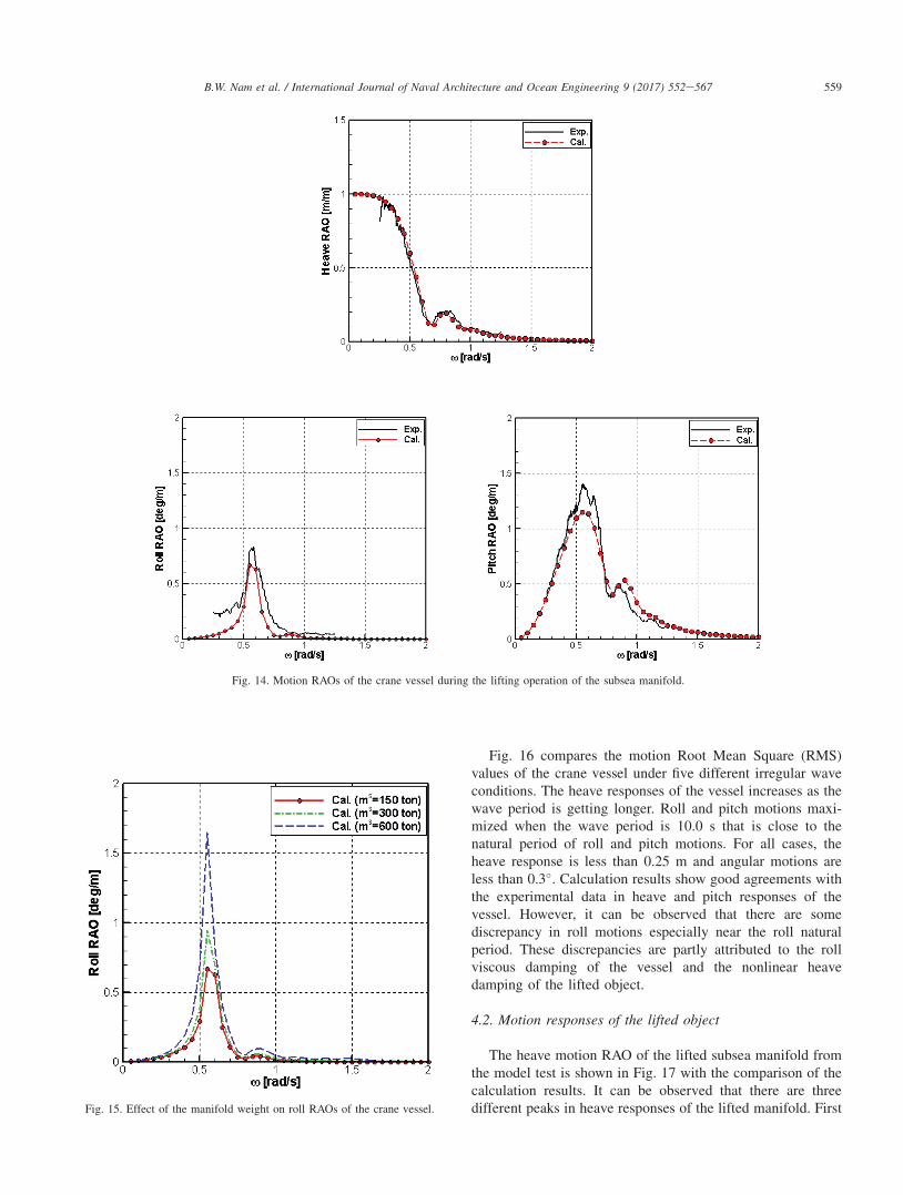
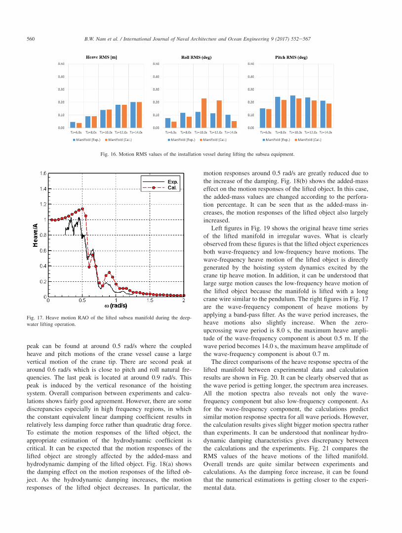
Fig. 16 compares the motion Root Mean Square (RMS)values of the crane vessel under five different irregular waveconditions. The heave responses of the vessel increases as thewave period is getting longer. Roll and pitch motions maxi-mized when the wave period is 10.0 s that is close to thenatural period of roll and pitch motions. For all cases, theheave response is less than 0.25 m and angular motions areless than 0.3�. Calculation results show good agreements withthe experimental data in heave and pitch responses of thevessel. However, it can be observed that there are somediscrepancy in roll motions especially near the roll naturalperiod. These discrepancies are partly attributed to the rollviscous damping of the vessel and the nonlinear heavedamping of the lifted object.
4.2. Motion responses of the lifted object
The heave motion RAO of the lifted subsea manifold fromthe model test is shown in Fig. 17 with the comparison of thecalculation results. It can be observed that there are threedifferent peaks in heave responses of the lifted manifold. First
Fig. 14. Motion RAOs of the crane vessel during the lifting operation of the subsea manifold.
Fig. 15. Effect of the manifold weight on roll RAOs of the crane vessel.
559B.W. Nam et al. / International Journal of Naval Architecture and Ocean Engineering 9 (2017) 552e567
peak can be found at around 0.5 rad/s where the coupledheave and pitch motions of the crane vessel cause a largevertical motion of the crane tip. There are second peak ataround 0.6 rad/s which is close to pitch and roll natural fre-quencies. The last peak is located at around 0.9 rad/s. Thispeak is induced by the vertical resonance of the hoistingsystem. Overall comparison between experiments and calcu-lations shows fairly good agreement. However, there are somediscrepancies especially in high frequency regions, in whichthe constant equivalent linear damping coefficient results inrelatively less damping force rather than quadratic drag force.To estimate the motion responses of the lifted object, theappropriate estimation of the hydrodynamic coefficient iscritical. It can be expected that the motion responses of thelifted object are strongly affected by the added-mass andhydrodynamic damping of the lifted object. Fig. 18(a) showsthe damping effect on the motion responses of the lifted ob-ject. As the hydrodynamic damping increases, the motionresponses of the lifted object decreases. In particular, the
motion responses around 0.5 rad/s are greatly reduced due tothe increase of the damping. Fig. 18(b) shows the added-masseffect on the motion responses of the lifted object. In this case,the added-mass values are changed according to the perfora-tion percentage. It can be seen that as the added-mass in-creases, the motion responses of the lifted object also largelyincreased.
Left figures in Fig. 19 shows the original heave time seriesof the lifted manifold in irregular waves. What is clearlyobserved from these figures is that the lifted object experiencesboth wave-frequency and low-frequency heave motions. Thewave-frequency heave motion of the lifted object is directlygenerated by the hoisting system dynamics excited by thecrane tip heave motion. In addition, it can be understood thatlarge surge motion causes the low-frequency heave motion ofthe lifted object because the manifold is lifted with a longcrane wire similar to the pendulum. The right figures in Fig. 17are the wave-frequency component of heave motions byapplying a band-pass filter. As the wave period increases, theheave motions also slightly increase. When the zero-upcrossing wave period is 8.0 s, the maximum heave ampli-tude of the wave-frequency component is about 0.5 m. If thewave period becomes 14.0 s, the maximum heave amplitude ofthe wave-frequency component is about 0.7 m.
The direct comparisons of the heave response spectra of thelifted manifold between experimental data and calculationresults are shown in Fig. 20. It can be clearly observed that asthe wave period is getting longer, the spectrum area increases.All the motion spectra also reveals not only the wave-frequency component but also low-frequency component. Asfor the wave-frequency component, the calculations predictsimilar motion response spectra for all wave periods. However,the calculation results gives slight bigger motion spectra ratherthan experiments. It can be understood that nonlinear hydro-dynamic damping characteristics gives discrepancy betweenthe calculations and the experiments. Fig. 21 compares theRMS values of the heave motions of the lifted manifold.Overall trends are quite similar between experiments andcalculations. As the damping force increase, it can be foundthat the numerical estimations is getting closer to the experi-mental data.
Fig. 16. Motion RMS values of the installation vessel during lifting the subsea equipment.
Fig. 17. Heave motion RAO of the lifted subsea manifold during the deep-
water lifting operation.
560 B.W. Nam et al. / International Journal of Naval Architecture and Ocean Engineering 9 (2017) 552e567

Fig. 18. Heave responses spectra of the crane tip and lifted subsea equipment during the deep-water lifting operation in irregular waves.
Fig. 19. Heave time series of the manifold during the deep-water lifting operation in irregular waves (Manifold, water depth ¼ �700 m).
561B.W. Nam et al. / International Journal of Naval Architecture and Ocean Engineering 9 (2017) 552e567

Fig. 22 shows estimated heave motion responses of thelifted subsea manifold under various wave height conditions.As the wave period is getting longer, the heave motion re-sponses of the lifted manifold increase. If the wave period isenough long, heave Significant Double Amplitude (SDA)value is similar to the significant wave height of the incidentwave spectrum. This means that the motion response of thelifted object is similar to the incident wave elevations as thewave period is getting longer.
4.3. Dynamic tension of hoisting wire
The dynamic tension of the hoisting wire is determined byrelative heave motion between the crane tip and the liftedobject. Thus, the dynamic tension RAOs of the hoisting wireare largely affected by the motion response of the lifted object.Fig. 23 compares the tension RAOs between the experimentsfrom the white noise test and calculation results. Similar to theheave motion RAOs of the lifted manifold, the tension RAOsalso shows three peak responses. The maximum dynamictension is about 18 tonf which is correspond to 12% of the
Fig. 20. Comparison of heave responses spectra of the lifted manifold in irregular waves.
Fig. 21. Comparison of the wave-frequency heave RMS values of the lifted
subsea equipment under the irregular wave conditions.
Fig. 22. Estimated heave motion responses of the lifted subsea manifold under
various wave height conditions.
562 B.W. Nam et al. / International Journal of Naval Architecture and Ocean Engineering 9 (2017) 552e567

manifold weight in air. Maximum dynamic tension happens ataround 0.6 rad/s which is close to the pitch and roll resonantconditions. As shown in the figure, another peak response canbe found at around 0.9 rad/s. These second peak is attributedto the vertical resonance of the hoisting system which isdependent on the hoisting wire stiffness and the lifted objectweight. The dynamic tension response of the hoisting wirealso can be changed by the hydrodynamic coefficient of thelifted object. Fig. 24 shows the effect of added-mass and hy-drodynamic damping on the tension RAOs of the hoisting wireduring the lifting operation.
Figs. 25 and 26 show the time series and spectra of thedynamic tension of the hoisting wires under the irregular waveconditions, respectively. As the wave period is getting longer,the tension response spectrum is also shifted to the low fre-quency ranges. When the wave period is 10.0 s, the tension
response is maximized. The overall calculations results of thetension spectra are quite similar trends to the experimentaldata. In Fig. 27, the significant positive amplitudes of thehoisting wire tension are compared between experiments andcalculation results. In this study, zero-upcrossing analysismethod is applied to extract the statistical values from thetension time series. The comparison shows quite goodagreement.
4.4. Effect of passive heave compensator
The performance of the passive heave compensator (PHC)is quite dependent on the spring and damping characteristicsof the PHC system. Left figures of Fig. 28 show the heaveRAOs of the manifold from the model tests when the threedifferent passive heave compensators are applied. In this case,‘PHC1’, ‘PHC2’ and ‘PHC3’ have the stiffnesses of 120 kN/m, 250 kN/m and 490 kN/m, respectively. ‘PHC1’ has rela-tively softer stiffness rather than ‘PHC2’ and ‘PHC3’. When‘PHC1’ is used, it can be clearly seen that the passive heavecompensator is effectively working, in which the usage of thepassive heave compensator reduces the heave motion if thewave frequency is higher than 0.4 rad/s. However, when‘PHC2’ or ‘PHC3’ is used, the effect of the passive heavecompensator is not clearly seen and the heave motions of thelifted manifold increase instead. Similar to the experimentaldata, calculation results also indicate that the usage of ‘PHC1’only reduces the heave motion of the lifted manifold.
The effect of passive heave compensator can also be foundin tension RAOs shown in Fig. 29. While ‘PHC2’ and ‘PHC3’increases the tension response of the crane wire, only ‘PHC1’greatly reduces the tension responses for all frequency ranges.The calculation results also demonstrates that only ‘PHC1’ iseffective to reduce the dynamic tension of the crane wire.There results indicate the optimal design of the passive heavecompensator is critical factor when we consider the passiveheave compensator in the crane lifting operation.
Fig. 23. Tension RAOs of the hoisting wire during the lifting operations.
Fig. 24. Tension RAOs of the hoisting wire during the lifting operations.
563B.W. Nam et al. / International Journal of Naval Architecture and Ocean Engineering 9 (2017) 552e567

Fig. 30 shows the effect of the passive heave compensatorby showing the direct comparison of the heave time series ofthe manifold and the dynamic tensions of the hoisting wiresunder three different irregular wave conditions. Relatively,heave compensation effect is not clearly observed for all waveconditions. Whereas, the dynamic tension of the hoisting wiresare significantly reduced if the wave period is less than 10.0 s.
Fig. 31(a) compares the heave RMS values of the manifoldand dynamic tension responses of the hoisting wire under fivedifferent irregular wave conditions from the model tests. Ascan be seen, the heave compensation effect is not clearlyobserved. If the wave period is longer than 10.0 s, the passiveheave compensator causes the increase of the heave motion ofthe manifold. This is because the shift of the resonance by the
Fig. 25. Time series of the dynamic tension of the hoisting wires during the lifting operation under the irregular wave conditions (water depth ¼ �700 m).
Fig. 26. Dynamic tension spectra of the hoisting wire in irregular waves.
564 B.W. Nam et al. / International Journal of Naval Architecture and Ocean Engineering 9 (2017) 552e567

usage of PHC results in high heave motion under the longwave period conditions. However, dynamic tension values isclearly reduced due to the usage of PHC. In particular, whenthe wave period is less than 10.0 s, the PHC reduces the dy-namic tension of the hoisting wire by about 30e50%. Thecalculations results, shown in Fig. 31(b), also reveals the PHCeffect on heave motion and tension responses. However, thetension reduction effect due to the PHC usage is relativelysmaller rather than the experimental data. This is mainlyattribute to the discrepancy of the tension responses in low-frequency range.
5. Conclusions
An experimental and numerical study was conducted forinvestigating deepwater crane installation operation of the
Fig. 27. Comparison of tension responses of the hoisting wire under the
irregular wave conditions (water depth ¼ �700 m).
Fig. 28. Effect of the passive heave compensator on heave RAOs of the manifold.
Fig. 29. Effect of the passive heave compensator on dynamic tension RAOs of the hoisting wire.
565B.W. Nam et al. / International Journal of Naval Architecture and Ocean Engineering 9 (2017) 552e567

Fig. 30. Comparison of the manifold heaves and the wire tensions in irregular waves due to the passive heave compensator.
Fig. 31. Comparison of heave RMS of the manifold and dynamic tension RMS of the hoisting wire due to the passive heave compensator under five different
irregular wave conditions.
566 B.W. Nam et al. / International Journal of Naval Architecture and Ocean Engineering 9 (2017) 552e567

subsea equipment in waves. From a series of model tests andnumerical calculations, the following conclusions are drawn.
� The crane vessel experience the significant roll motionseven in the head waves because the interaction with thelifted object via the hoisting wire tension brings about theroll motions of the vessel. These roll motions are greatlyaffected by the weight of the lifted object.
� Heave motion of the lifted subsea manifold reveals threepeak responses which is mainly caused by crane-tip mo-tion and the vertical resonance of the hoisting system. Theheave motion are strongly affected by the added-mass andhydrodynamic damping of the lifted object.
� The dynamic tension responses of the hoisting wire aregreatly changed by the hydrodynamic coefficient of thelifted object. Maximum dynamic tension happens at thepitch and roll resonant conditions.
� The effect of passive heave compensator is clearlyobserved during deep-water lifting operations It isconfirmed that the passive heave compensator shifts theresonant frequency of the hoisting system to the low fre-quency range. For short wave periods, the efficiency of thepassive heave compensator is maximized in reducing dy-namic tension of hoisting wire.
� The present calculation method in frequency domainshows fairly good agreement with the experimental data.Some discrepancies are found especially at high frequencyranges, where nonlinear damping characteristics is sig-nificant. In the future, nonlinear time-domain simulationswith nonlinear drag model will be carried out to evaluatethe nonlinear coupled dynamics between the crane vesseland the lifted object.
Acknowledgements
This research has been partly funded by a Grand-in-Aid forStrategy Technology Development Programs from the KoreaMinistry of Trade, Industry & Energy (No. 10038598,
“Development of deep water installation design and analysistechnology” & No. 10042452, “Engineering TechnologyDevelopment for the 3,000 m Deepwater Subsea Equipment andURF Installation to advance to Deepwater Offshore PlantMarket”).
References
Clauss, G.F., Vannahme, M., Ellermann, K., Kreuzer, E., 2000. Subharmonic
oscillations of moore floating cranes. In: Proc Offshore Technology Con-
ference, Houston, OTC-11953.
DNV, 2011. Modelling and Analysis of Marine Operation. DNV-RP-H103.
Fujarra, A.L.C., Tannuri, E.A., Masetti, I.Q., Igreja, H., 2008. Experimental
and numerical evaluation of the installation of subsea equipments for risers
support. In: Pro Int Conf on Offshore Mechanics and Arctic Eng, Hono-
lulu, OMAE 2008e57472.Galgoul, N.Z., Labanca, E.L., Claro, C.A., 2001. Experience gained during the
istallation design of the poncador manifold in a 1860m water depth. In: Prc
Int Conf on Offshore Mechanics and Arctic Eng, Rio de Janeiro, Brazil,
OMAE 2001/OTF-1063.
Kimiaei, M., JiaJing, X., Yu, H., 2009. Comparing the results of a simplified
numerical model with DNV guidelines for installation of subsea platforms.
In: Prc Int Conf on Offshore Mechanics and Arctic Eng, Honolulu, OMAE
2009e79356.
Legras, J.L., Wang, J., 2011. Criteria for the operation of lowering a structure
to the seabed based on the installation vessel motion. In: Proc Offshore
Technology Conference, Houston, OTC-21250.
Nam, B.W., Hong, S.Y., Kim, Y.S., Kim, J.W., 2013. Effects of passive and
active heave compensators on deepwater lifting operation. Int J Offshore
Polar Eng 23 (1), 33e37.Nam, B.W., Kim, N.W., Choi, Y.M., Hong, S.Y., Kim, J.W., 2015. An
experimental study on deepwater crane installation of subsea equipment in
waves. In: Proc of Int Offshore and Polar Eng Conf, Kona, Big Island,
Hawaii, USA, pp. 1279e1283.Park, Y.S., Kim, W.J., Nam, B.W., 2013. CFD simulation of hydrodynamic
forces acting on subsea manifold templates at wave zone. In: Proc of Int
Offshore and Polar Eng Conf, Anchorage, Alaska, USA, pp. 654e661.
Vries, J.P., Drunen, Dijk, R., Zoontjes, R., 2011. Offshore monitoring
campaign on installation of suction piles in deep water fields. In: Proc
Offshore Technology Conference, Houston, OTC-21291.
Wang, J., Hagen, R.K., Radan, E., Bullock, J., 2011. Technical challenges and
success for rigid pipeline with PLET, jumper and flying leads installation
in conger 9 field. In: Proc Offshore Technology Conference, Houston,
OTC-21209.
567B.W. Nam et al. / International Journal of Naval Architecture and Ocean Engineering 9 (2017) 552e567
Copyright © 2022 FDOKUMEN