EVB-KSZ9563 Evaluation Board User's Guide
28
2018 Microchip Technology Inc. DS50002726B EVB-KSZ9563 Evaluation Board User’s Guide
-
Upload
khangminh22 -
Category
Documents
-
view
1 -
download
0
Transcript of EVB-KSZ9563 Evaluation Board User's Guide

2018 Microchip Technology Inc. DS50002726B
EVB-KSZ9563 Evaluation Board
User’s Guide

DS50002726B-page 2 2018 Microchip Technology Inc.
Note the following details of the code protection feature on Microchip devices:
• Microchip products meet the specification contained in their particular Microchip Data Sheet.
• Microchip believes that its family of products is one of the most secure families of its kind on the market today, when used in the intended manner and under normal conditions.
• There are dishonest and possibly illegal methods used to breach the code protection feature. All of these methods, to our knowledge, require using the Microchip products in a manner outside the operating specifications contained in Microchip’s Data Sheets. Most likely, the person doing so is engaged in theft of intellectual property.
• Microchip is willing to work with the customer who is concerned about the integrity of their code.
• Neither Microchip nor any other semiconductor manufacturer can guarantee the security of their code. Code protection does not mean that we are guaranteeing the product as “unbreakable.”
Code protection is constantly evolving. We at Microchip are committed to continuously improving the code protection features of our products. Attempts to break Microchip’s code protection feature may be a violation of the Digital Millennium Copyright Act. If such acts allow unauthorized access to your software or other copyrighted work, you may have a right to sue for relief under that Act.
Microchip received ISO/TS-16949:2009 certification for its worldwide headquarters, design and wafer fabrication facilities in Chandler and Tempe, Arizona; Gresham, Oregon and design centers in California and India. The Company’s quality system processes and procedures are for its PIC® MCUs and dsPIC® DSCs, KEELOQ® code hopping devices, Serial EEPROMs, microperipherals, nonvolatile memory and analog products. In addition, Microchip’s quality system for the design and manufacture of development systems is ISO 9001:2000 certified.
QUALITYMANAGEMENTSYSTEMCERTIFIEDBYDNV
== ISO/TS16949==
Information contained in this publication regarding device applications and the like is provided only for your convenience and may be superseded by updates. It is your responsibility to ensure that your application meets with your specifications. MICROCHIP MAKES NO REPRESENTATIONS OR WARRANTIES OF ANY KIND WHETHER EXPRESS OR IMPLIED, WRITTEN OR ORAL, STATUTORY OR OTHERWISE, RELATED TO THE INFORMATION, INCLUDING BUT NOT LIMITED TO ITS CONDITION, QUALITY, PERFORMANCE, MERCHANTABILITY OR FITNESS FOR PURPOSE. Microchip disclaims all liability arising from this information and its use. Use of Micro-chip devices in life support and/or safety applications is entirely at the buyer’s risk, and the buyer agrees to defend, indemnify and hold harmless Microchip from any and all damages, claims, suits, or expenses resulting from such use. No licenses are conveyed, implicitly or otherwise, under any Microchip intellectual property rights unless otherwise stated.
Trademarks
The Microchip name and logo, the Microchip logo, AnyRate, AVR, AVR logo, AVR Freaks, BitCloud, chipKIT, chipKIT logo, CryptoMemory, CryptoRF, dsPIC, FlashFlex, flexPWR, Heldo, JukeBlox, KeeLoq, Kleer, LANCheck, LINK MD, maXStylus, maXTouch, MediaLB, megaAVR, MOST, MOST logo, MPLAB, OptoLyzer, PIC, picoPower, PICSTART, PIC32 logo, Prochip Designer, QTouch, SAM-BA, SpyNIC, SST, SST Logo, SuperFlash, tinyAVR, UNI/O, and XMEGA are registered trademarks of Microchip Technology Incorporated in the U.S.A. and other countries.
ClockWorks, The Embedded Control Solutions Company, EtherSynch, Hyper Speed Control, HyperLight Load, IntelliMOS, mTouch, Precision Edge, and Quiet-Wire are registered trademarks of Microchip Technology Incorporated in the U.S.A.
Adjacent Key Suppression, AKS, Analog-for-the-Digital Age, Any Capacitor, AnyIn, AnyOut, BodyCom, CodeGuard, CryptoAuthentication, CryptoAutomotive, CryptoCompanion, CryptoController, dsPICDEM, dsPICDEM.net, Dynamic Average Matching, DAM, ECAN, EtherGREEN, In-Circuit Serial Programming, ICSP, INICnet, Inter-Chip Connectivity, JitterBlocker, KleerNet, KleerNet logo, memBrain, Mindi, MiWi, motorBench, MPASM, MPF, MPLAB Certified logo, MPLIB, MPLINK, MultiTRAK, NetDetach, Omniscient Code Generation, PICDEM, PICDEM.net, PICkit, PICtail, PowerSmart, PureSilicon, QMatrix, REAL ICE, Ripple Blocker, SAM-ICE, Serial Quad I/O, SMART-I.S., SQI, SuperSwitcher, SuperSwitcher II, Total Endurance, TSHARC, USBCheck, VariSense, ViewSpan, WiperLock, Wireless DNA, and ZENA are trademarks of Microchip Technology Incorporated in the U.S.A. and other countries.
SQTP is a service mark of Microchip Technology Incorporated in the U.S.A.
Silicon Storage Technology is a registered trademark of Microchip Technology Inc. in other countries.
GestIC is a registered trademark of Microchip Technology Germany II GmbH & Co. KG, a subsidiary of Microchip Technology Inc., in other countries.
All other trademarks mentioned herein are property of their respective companies.
© 2018, Microchip Technology Incorporated, All Rights Reserved.
ISBN: 978-1-5224-3340-8

EVB-KSZ9563 EVALUATION BOARD
USER’S GUIDE
Table of Contents
Preface ........................................................................................................................... 5Introduction............................................................................................................ 5
Document Layout .................................................................................................. 5
Conventions Used in this Guide ............................................................................ 6
The Microchip Website.......................................................................................... 7
Development Systems Customer Change Notification Service ............................ 7
Customer Support ................................................................................................. 7
Document Revision History ................................................................................... 8
Chapter 1. Overview1.1 Introduction ..................................................................................................... 91.2 References ................................................................................................... 10
Chapter 2. Getting Started2.1 Introduction ................................................................................................... 112.2 Power Source ............................................................................................... 11
2.2.1 Power Probe Points ................................................................................... 112.2.2 Current Access Rework/Probe Points ....................................................... 11
2.3 Clock ............................................................................................................ 112.4 RESET ......................................................................................................... 12
2.4.1 Power-On Reset ........................................................................................ 122.4.2 Manual Reset ............................................................................................ 12
2.5 Board features and configuration ................................................................. 122.5.1 PHY Ports – Integrated Magnetic Jacks .................................................... 142.5.2 PHY Ports – LEDs ..................................................................................... 142.5.3 Pin Strapping Configuration ...................................................................... 142.5.4 GPIO Signal Headers ................................................................................ 152.5.5 INTRP_N Output ....................................................................................... 152.5.6 PME_N Output .......................................................................................... 15
2.6 Using the EVB-KSZ9563 .............................................................................. 16
Appendix A. EVB-KSZ9563 Evaluation BoardA.1 Introduction .................................................................................................. 17
Appendix B. SchematicsB.1 Introduction .................................................................................................. 19
Appendix C. Bill of Materials (BOM)C.1 Introduction .................................................................................................. 23
Appendix D. Silk ScreenD.1 Introduction .................................................................................................. 26
Worldwide Sales and Service .................................................................................... 28
2018 Microchip Technology Inc. DS50002726B-page 3

EVB-KSZ9563 Evaluation Board User’s Guide
NOTES:
DS50002726B-page 4 2018 Microchip Technology Inc.

EVB-KSZ9563 EVALUATION BOARD
USER’S GUIDE
Preface
NOTICE TO CUSTOMERS
All documentation becomes dated, and this manual is no exception. Microchip tools and documentation are constantly evolving to meet customer needs, so some actual dialogs and/or tool descriptions may differ from those in this document. Please refer to our website (www.microchip.com) to obtain the latest documentation available.
Documents are identified with a “DS” number. This number is located on the bottom of each page, in front of the page number. The numbering convention for the DS number is “DSXXXXXA”, where “XXXXX” is the document number and “A” is the revision level of the document.
For the most up-to-date information on development tools, see the MPLAB® IDE online help. Select the Help menu, and then Topics to open a list of available online help files.
INTRODUCTION
This chapter contains general information that will be useful to know before using the EVB-KSZ9563 Evaluation Board. Items discussed in this chapter include:
• Document Layout
• Conventions Used in this Guide
• The Microchip Website
• Development Systems Customer Change Notification Service
• Customer Support
• Document Revision History
DOCUMENT LAYOUT
This document describes how to use the EVB-KSZ9563 Evaluation Board as a development tool for the KSZ9563, a 3-Port Gigabit Ethernet Switch with RGMII Interface and IEEE 1588v2/802.1AS support.
• Chapter 1. “Overview” – This chapter provides a brief description of the EVB-KSZ9563.
• Chapter 2. “Getting Started” – This chapter includes instructions on how to get started with the EVB-KSZ9563.
• Appendix A. “EVB-KSZ9563 Evaluation Board” – This appendix shows the physical EVB-KSZ9563.
• Appendix B. “Schematics” – This appendix shows the EVB-KSZ9563 schemat-ics.
• Appendix C. “Bill of Materials (BOM)” – This appendix includes the EVB-KSZ9563 Bill of Materials (BOM).
• Appendix D. “Silk Screen” – This appendix includes the EVB-KSZ9563 silk screen.
2018 Microchip Technology Inc. DS50002726B-page 5

EVB-KSZ9563 Evaluation Board User’s Guide
CONVENTIONS USED IN THIS GUIDE
This manual uses the following documentation conventions:
DOCUMENTATION CONVENTIONS
Description Represents Examples
Arial font:
Italic characters Referenced books MPLAB® IDE User’s Guide
Emphasized text ...is the only compiler...
Initial caps A window the Output window
A dialog the Settings dialog
A menu selection select Enable Programmer
Quotes A field name in a window or dialog
“Save project before build”
Underlined, italic text with right angle bracket
A menu path File>Save
Bold characters A dialog button Click OK
A tab Click the Power tab
N‘Rnnnn A number in verilog format, where N is the total number of digits, R is the radix and n is a digit.
4‘b0010, 2‘hF1
Text in angle brackets < > A key on the keyboard Press <Enter>, <F1>
Courier New font:
Plain Courier New Sample source code #define START
Filenames autoexec.bat
File paths c:\mcc18\h
Keywords _asm, _endasm, static
Command-line options -Opa+, -Opa-
Bit values 0, 1
Constants 0xFF, ‘A’
Italic Courier New A variable argument file.o, where file can be any valid filename
Square brackets [ ] Optional arguments mcc18 [options] file [options]
Curly brackets and pipe character: { | }
Choice of mutually exclusive arguments; an OR selection
errorlevel {0|1}
Ellipses... Replaces repeated text var_name [, var_name...]
Represents code supplied by user
void main (void){ ...}
DS50002726B-page 6 2018 Microchip Technology Inc.

Preface
THE MICROCHIP WEBSITE
Microchip provides online support via our website at www.microchip.com. This website is used as a means to make files and information easily available to customers. Acces-sible by using your favorite Internet browser, the website contains the following infor-mation:
• Product Support – Data sheets and errata, application notes and sample programs, design resources, user’s guides and hardware support documents, latest software releases, and archived software
• General Technical Support – Frequently Asked Questions (FAQs), technical support requests, online discussion groups, and Microchip consultant program member listing
• Business of Microchip – Product selector and ordering guides, latest Microchip press releases, listing of seminars and events, and listings of Microchip sales offices, distributors, and factory representatives
DEVELOPMENT SYSTEMS CUSTOMER CHANGE NOTIFICATION SERVICE
Microchip’s customer notification service helps keep customers current on Microchip products. Subscribers will receive e-mail notification whenever there are changes, updates, revisions or errata related to a specified product family or development tool of interest.
To register, access the Microchip website at www.microchip.com, click on Customer Change Notification and follow the registration instructions.
The Development Systems product group categories are:• Compilers – The latest information on Microchip C compilers, assemblers, linkers
and other language tools. These include all MPLAB C compilers; all MPLAB assemblers (including MPASM assembler); all MPLAB linkers (including MPLINK object linker); and all MPLAB librarians (including MPLIB object librarian).
• Emulators – The latest information on Microchip in-circuit emulators.This includes the MPLAB® REALICE and MPLAB ICE 2000 in-circuit emulators.
• In-Circuit Debuggers – The latest information on the Microchip in-circuit debuggers. This includes MPLAB ICD 3 in-circuit debuggers and PICkit 3 debug express.
• MPLAB IDE – The latest information on Microchip MPLAB IDE, the Windows Integrated Development Environment for development systems tools. This list is focused on the MPLAB IDE, MPLAB IDE Project Manager, MPLAB Editor and MPLAB SIM simulator, as well as general editing and debugging features.
• Programmers – The latest information on Microchip programmers, which include production programmers such as MPLAB REAL ICE in-circuit emulator, MPLAB ICD 3 in-circuit debugger, and MPLAB PM3 device programmers. Also included are non-production development programmers such as PICSTART Plus and PIC-kit 2 and 3.
CUSTOMER SUPPORT
Users of Microchip products can receive assistance through several channels:
• Distributor or Representative
• Local Sales Office
• Field Application Engineer (FAE)
• Technical Support
2018 Microchip Technology Inc. DS50002726B-page 7

EVB-KSZ9563 Evaluation Board User’s Guide
Customers should contact their distributor, representative or field application engineer (FAE) for support. Local sales offices are also available to help customers. A listing of sales offices and locations is included in the back of this document.
Technical support is available through the website at: http://www.microchip.com/support
DOCUMENT REVISION HISTORY
Revisions Section/Figure/Entry Correction
DS50002726B (07-26-18)
Chapter 1. “Overview” Updated text and Figure 1-1.
Chapter 2. “Getting Started”
Updated text as well as Figure 2-1, Figure 2-2, Figure 2-3, and Figure 2-4.
Appendix A. “EVB-KSZ9563 Evalu-ation Board”
Updated board pictures in Figure A-1 and Figure A-2.
Appendix B. “Schematics”
Updated the schematics. See Figure B-1, Figure B-2, and Figure B-3.
Appendix C. “Bill of Materials (BOM)”
Updated BOM to reflect replacement of OSC circuit with XTAL circuit. See Table C-1.
Appendix B. “Schematics”
Updated board top and bottom silk-screens. See Figure D-1 and Figure D-2.
DS50002726A (02-07-18)
Initial release
DS50002726B-page 8 2018 Microchip Technology Inc.

EVB-KSZ9563 EVALUATION BOARD
USER’S GUIDE
Chapter 1. Overview
1.1 INTRODUCTION
The EVB-KSZ9563 Evaluation Board is a plug-in card that interfaces directly with a mating Microchip host processor or controller board, such as the SAMA5D3 Ethernet Development System Board. It features the KSZ9563, a highly integrated networking device that incorporates a layer-2+ managed Gigabit Ethernet switch, two 10BASE-T/100BASE-TX/ 1000BASE-T physical layer transceivers (PHYs) and asso-ciated MAC units, and one MAC port configured as the RGMII interface. The board’s two PHY ports are connected to RJ45 Ethernet jacks with integrated magnetics, and the RGMII MAC interface is brought out to a high-speed multi-pin (HS) connector.
Together, the EVB-KSZ9563 and SAMA5D3 Ethernet Development System provide a highly-flexible platform for evaluation of basic PHY/Switch features via static Con-trol-Status Registers (CSRs) and development of firmware for advanced MAC/Switch features that require interaction with upper network layers (e.g., IEEE1588 PTP, AVB, and RSTP/MSTP).
The scope of this document is meant to describe the EVB-KSZ9563 setup and its user interface features. A simplified block diagram of the board is shown in Figure 1-1.
FIGURE 1-1: EVB-KSZ9563 FUNCTIONAL BLOCK DIAGRAM
KSZ9563
25MHz
Crystal
Plug‐in to Microchip host processor/controller board(e.g., SAMA5D3‐EDS Board)
10/100/1000RJ45 Magnetic Jack
10/100/1000RJ45 Magnetic Jack
Pin Strappings(pu/pd steering resistors )
RESETRC/Diode
Port_1
Port_2
Dual‐LED
Dual‐LED
Port_3
RGMII Port
High‐Speed Connector
(bottom PCB mou
nt)
RGMII
SPI
MIC33153YHJBuck Regulator
1.2V adjustable output
AVDDL core
DVDDL core
AVDDH
(transceiver)
VDDIO
(digital pins)
5V_HS_Connector
3V3_HS_Connector
2V5_HS_Connector (option)
VARIO_HS_Connector
GPIOs for1588/AVB
2018 Microchip Technology Inc. DS50002726B-page 9

EVB-KSZ9563 Evaluation Board User’s Guide
1.2 REFERENCES
Concepts and materials available in the following documents may be helpful when reading this document. Visit www.microchip.com for the latest documentation.
• KSZ9563 Data Sheet
• EVB-KSZ9563 Schematics
• SAMA5D3 Ethernet Development System Schematics
• SAMA5D3 Ethernet Development System Board User’s Guide
• MIC33153YHJ Data Sheet
DS50002726B-page 10 2018 Microchip Technology Inc.

EVB-KSZ9563 EVALUATION BOARD
USER’S GUIDE
Chapter 2. Getting Started
2.1 INTRODUCTION
The EVB-KSZ9563 Evaluation Board is designed as a plug-in card to interface directly with a mating Microchip host processor or controller board, such as the SAMA5D3-EDS Board, that supplies full power and provides full register access and configuration via IBA, SPI, or I2C bus management.
2.2 POWER SOURCE
The EVB-KSZ9563 is completely bus-powered from its mating Microchip host proces-sor or controller board. Input power is delivered via the high-speed multi-pin (HS) con-nector.
Refer to Figure 2-3 and board schematics in Appendix B. “Schematics” for details.
2.2.1 Power Probe Points
The power probe points along with the ground test points are shown in Figure 2-2.
2.2.2 Current Access Rework/Probe Points
The EVB-KSZ9563 design is not intended to perform current measurements on the device. If needed, the current access points to measure the current consumptions of the KSZ9563 power rails are across the following series ferrite beads to the board pow-ers.
• DVDDL: FB2
• AVDDL: FB3
• VDDIO: FB6
• AVDDH: FB4 for 3.3V (default populate) and FB1 for 2.5V (default not populate)
Note: Populate either FB4 only or FB1 only. If 2.5V AVDDH is desired, FB4 should be “Do Not Populate (DNP)” and FB1 should be populated.
Remove the above ferrite beads and place the current probes in series across the power probe points (Section 2.2.1 “Power Probe Points”) that are joined by the fer-rite beads. See also Appendix B. “Schematics”.
Board LED components are connected to the VDDIO power rail, and thus the mea-sured current is higher than the amount consumed by only the KSZ9563 device.
2.3 CLOCK
The EVB-KSZ9563 utilizes a 25 MHz crystal to generate the input reference clock for the KSZ9563 device. Refer to Figure 2-1 and the board schematics in Appendix B. “Schematics” for details.
2018 Microchip Technology Inc. DS50002726B-page 11

EVB-KSZ9563 Evaluation Board User’s Guide
2.4 RESET
2.4.1 Power-On Reset
The discrete RC/Diode (R12, C8, and D3) circuit provides power-on reset to the KSZ9563 device.
2.4.2 Manual Reset
The SW1 reset button can be pressed and released to provide manual reset to the KSZ9563 device after power-up. Refer to Figure 2-1 and the board schematics in Appendix B. “Schematics” for details.
2.5 BOARD FEATURES AND CONFIGURATION
The following sub-sections describe the board features and configuration settings.
Figure 2-1 displays the top view of the EVB-KSZ9563 with key features, jumpers, and headers which are highlighted in red. The Microchip components are highlighted in blue.
FIGURE 2-1: EVB-KSZ9563 TOP VIEW WITH CALLOUTS
5V Power LED
(from HS
connector, J7)
SW1
(reset button)
GPIO
signals
(for 1588
/AVB)
Quiet‐WIRE
(pin strapping)
INTRP_N output
(signal / LED
)
PME_N output
(signal / LED
)
IBA M
ode
(pin strap
ping)
PHY Port 1
LED Status
PHY Port 2
LED Status
PHY Port 1
10/100/1000
Magnetic Jack
PHY Port 2
10/100/1000
Magnetic Jack
Microchip
MIC33153
YHJ
Buck Regu
lator
Microchip
KSZ9563
3‐port Gigabit Ethernet Switch
DS50002726B-page 12 2018 Microchip Technology Inc.

Getting Started
Figure 2-2 displays the power probe points along with the ground test points.
FIGURE 2-2: EVB-KSZ9563 POWER/GROUND CALLOUTS
5V from HS_Connector, J7 (TP2)
1.2V Output ofMIC33153YHJBuck Regulator (TP8)
Ground (TP20)Ground(TP18)
Ground(TP4)
Ground (TP7)
VARIO from HS_Connector, J7(TP3) 2V5 from HS_Connector, J7
(TP6)
3V3 from HS_Connector, J7 (TP9)
VDDIO rail of KSZ 9563 (TP11)
AVDDL rail of KSZ 9563 (TP12)
AVDDH rail of KSZ9563 (TP5)
DVDDL rail of KSZ 9563 (TP10)
2018 Microchip Technology Inc. DS50002726B-page 13

EVB-KSZ9563 Evaluation Board User’s Guide
Figure 2-3 displays the bottom view of the EVB-KSZ9563 with the HS connector (J7) (highlighted in red) directly plugging into a mating Microchip MAC processor or control-ler board.
FIGURE 2-3: EVB-KSZ9563 BOTTOM VIEW WITH CALLOUT
High-speed connector to MAC processor/
controller board
2.5.1 PHY Ports – Integrated Magnetic Jacks
PHY ports 1 and 2 (J2 and J6) support 10BASE-T/100BASE-TX/1000BASE-T with both Auto-negotiation enabled and Auto-MDI/MDI-X enabled as the power-up defaults.
2.5.2 PHY Ports – LEDs
Two Dual-LEDs (D2 and D6) provide the link status for PHY ports 1 and 2, respectively. The LED descriptions are listed in Table 2-1.
TABLE 2-1: PHY PORTS - LED DESCRIPTION
LED LED Color Description
D2, D6
Green Solid color: 1-Gbps LinkBlinking: Activity (RX, TX)
Red Solid color: 100-Mbps LinkBlinking: Activity (RX, TX)
Orange Solid color: 10-Mbps LinkBlinking: Activity (RX, TX)
Off Link off
2.5.3 Pin Strapping Configuration
As the power-up or reset defaults, the KSZ9563 device is configured via internal or external pull-up or pull-down resistors to the following settings:
• PHY Ports 1 and 2: Auto-negotiation enabled and Energy-Efficient Ethernet (EEE) enabled
• MAC Port 3: RGMII mode at 1000 Mbps speed
• Start Switch: The switch forwards packets immediately after hardware reset.
• Management: SPI Slave mode
DS50002726B-page 14 2018 Microchip Technology Inc.

Getting Started
The In-band Management Access (IBA) mode and Quiet-Wire® pin strappings can be enabled or disabled using the 3-pin jumpers in Table 2-2. Set the desired jumper set-tings prior to board power-up, hardware reset, or both.
TABLE 2-2: PIN STRAPPING JUMPERS
Jumper Label DescriptionClose Pins
1-2Close Pins
2-3
J1 IBA mode IBA provides full register read and write access via any one of the three data ports.
Disable Enable(default)
J5 Quiet-Wire Quiet-Wire filtering is implemented on-chip to enhance 100BASE-TX EMC performance by reducing both conducted and radiated emissions from the TXP/M signal differential pair.
Enable Disable(default)
Refer to the board schematics in Appendix B. “Schematics” and the KSZ9563 Data Sheet for further details on the pin strappings.
2.5.4 GPIO Signal Headers
Table 2-3 shows the GPIO signals that support the IEEE 1588 Precision Time Protocol (PTP).
TABLE 2-3: GPIO SIGNAL HEADERS
Header Label Description Pin 1 Pin 2
J1 GPIO_2 The GPIO_2 pin is configurable to implement IEEE1588 event trigger outputs and timestamp capture inputs to support real-time application requirements.
No Connect GPIO_2(KSZ9563pin 40)
J5 GPIO_1 The GPIO_1 pin is configurable to implement IEEE1588 event trigger outputs and timestamp capture inputs to support real-time application requirements.
Ground GPIO_1(KSZ9563pin 39)
Refer to the board schematics in Appendix B. “Schematics” and the KSZ9563 Data Sheet for further details and usage on the GPIO signal pins.
2.5.5 INTRP_N Output
The INTRP_N output at test point TP14 provides the interrupt output from the KSZ9563 device. By default, it is active low and drives low to turn on D4 when asserted.
Refer to the board schematics in Appendix B. “Schematics” and the KSZ9563 Data Sheet for further details and usage on the INTRP_N signal.
2.5.6 PME_N Output
The PME_N output at test point TP16 provides the Power Management Event (PME) interrupt output for Wake-on-LAN (WoL) from the KSZ9563 device. By default, it is active low and drives low to turn on D5 when asserted.
Refer to the board schematics in Appendix B. “Schematics” and the KSZ9563 Data Sheet for further details and usage on the PME_N signal.
2018 Microchip Technology Inc. DS50002726B-page 15

EVB-KSZ9563 Evaluation Board User’s Guide
2.6 USING THE EVB-KSZ9563
The EVB-KSZ9563 directly plugs into a mating Microchip host controller or processor board, such as the SAMA5D3-EDS Board, that delivers full power and provides full reg-ister access and configuration via IBA, SPI, or I2C bus management.
Together, the EVB-KSZ9563 and the SAMA5D3-EDS enable 10/100/1000-Mbps Ethernet traffic switching across all three data ports of the KSZ9563 device, with RGMII MAC Port 3 connecting to the SAMA5D3 processor and PHY Port 1 and Port 2 con-necting via copper Ethernet cable (CAT-5 UTP or better) to external Ethernet devices.
All KSZ9563 registers are accessible via IBA, SPI, or I2C bus management from the SAMA5D3-EDS Board, enabling full evaluation and firmware development for all KSZ9563 MAC/Switch features and interaction with upper network layers.
Refer to the SAMA5D3-EDS Board documentation on its usage.
Figure 2-4 shows the EVB-KSZ9563 connected to the SAMA5D3-EDS Board.
FIGURE 2-4: EVB-KSZ9563 AND SAMA5D3-EDS EVALUATION AND FIRMWARE DEVELOPMENT PLATFORM
DS50002726B-page 16 2018 Microchip Technology Inc.

EVB-KSZ9563 EVALUATION BOARD
USER’S GUIDE
Appendix A. EVB-KSZ9563 Evaluation Board
A.1 INTRODUCTION
This appendix shows the EVB-KSZ9563 Evaluation Board. See Figure A-1 and Figure A-2.
FIGURE A-1: EVB-KSZ9563 EVALUATION BOARD (TOP VIEW)
2018 Microchip Technology Inc. DS50002726B-page 17

EVB-KSZ9563 Evaluation Board User’s Guide
FIGURE A-2: EVB-KSZ9563 EVALUATION BOARD (BOTTOM VIEW)
DS50002726B-page 18 2018 Microchip Technology Inc.

EVB-KSZ9563 EVALUATION BOARD
USER’S GUIDE
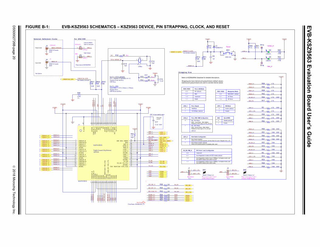
Appendix B. Schematics
B.1 INTRODUCTION
This appendix includes the EVB-KSZ9563 Evaluation Board schematics. See Figure B-1, Figure B-2, and Figure B-3.
2018 Microchip Technology Inc. DS50002726B-page 19
EV
B-K
SZ
9563 Evalu
ation
Bo
ard U
ser’s Gu
ide
DS
50002726B
-page 20
2018 M
icrochip Technolo
gy Inc.
ESET
INTRP_N
PME_N
"INTRP_N"
"PME_N"
VDDIO
470R
R20
470R
R43
4.7kR51
4.7kR50
VDDIO
s.
alues);values.
t in Register 0x0_3_00.
default)
Full-duplex mode), and
Full-duplex mode), and
VDDIO
D914 Reset
RXD3_U1
RXD2_U1
RXD1_U1
RXD0_U1
RX_ER_U1
SDO_PU
4.7kR29
4.7kR36
4.7kR39
4.7kR42
4.7k DNPR34
4.7kR17
LED1_0 4.7k DNPR2
LED1_1_PU
LED2_0
LED2_1
PME_N
4.7kR7
4.7k DNPR35
4.7k DNPR27
4.7k DNPR52
RXD3_U1
RXD2_U1
RXD1_U1
RXD0_U1
RX_ER_U1
SDO_PD
RX_DV_U1
LED1_0
LED1_1_PD
LED2_0
LED2_1
PME_N
750R DNPR3
750RR10
750RR33
750RR28
750R DNPR38
750RR44
750R DNPR30
750R DNPR31
750R DNPR40
750R DNPR41
750RR37
750RR16
1, x
0, 1
0, 0
Management ModeD1, RXD0
I2C Slave
MDC/MDIO (default)
SPI Slave
1
0
IBA ModeD1_1
Disable
Enable (default)
Quiet-WIREO
Enable
Disable (default)
*2-3Quiet-WIRE
SDO_PD
SDO_PUSDO
GREEN
D4
GREEN
D5
12
3
J5
TP14
TP16
1 4
2 3
SPST-NO
SW1
Place across pins 2 and 3of Quiet-WIRE Header
Shunt 2.54mm 1x2
SH2
FIGURE B-1: EVB-KSZ9563 SCHEMATICS – KSZ9563 DEVICE, PIN STRAPPING, CLOCK, AND R
AVDDH
TXRX1B_PTXRX1B_NTXRX1C_PTXRX1C_N
TXRX1D_PTXRX1D_N
TXRX2A_PTXRX2A_N
TXRX2B_PTXRX2B_NTXRX2C_PTXRX2C_N
AVDDL
TXR
X2D
_PTX
RX
2D_N
TXRX1B_P3TXRX1B_N3TXRX1C_P3TXRX1C_N3
TXRX1D_P3TXRX1D_N3
TXRX2A_P3TXRX2A_N3
TXRX2B_P3TXRX2B_N3TXRX2C_P3TXRX2C_N3
TXRX2D_PTXRX2D_N
TXRX2D_P3TXRX2D_N3
TXRX1A_PTXRX1A_N
TXRX1A_P3TXRX1A_N3
VDDIO
DVDDL
RX
D3_
U1
RX
D2_
U1
RX
D1_
U1
RX
D0_
U1
TXD
3TX
D2
TXD
1TX
D0
RX
_ER
_U1
RX
_DV
_U1
RX
_CLK
_U1
SDI_SDA_MDIOSDORESET_NINTRP_NPME_NLED2_1LED2_0
GPIO_2GPIO_1
TX_ERTX_EN
TX_CLK
SDI_SDA_MDIO 3SDO 3
INTRP_N 3PME_N 3LED2_1 3LED2_0 3
TX_ER 3TX_EN 3
TX_CLK 3
TXD0 3TXD1 3TXD2 3TXD3 3
RX_CLK 3
RXD0 3RXD1 3RXD2 3RXD3 3
RX_ER 3
RX_DV 3
TXD0TXD1TXD2TXD3
RXD0RXD1RXD2RXD3
RX_DV
RX_CLK
RX_ER
SC
S_N
SC
L_M
DC
ISE
T
TXR
X1A
_NTX
RX
1A_P
XI
XO
LED
1_0
LED
1_1
SCL_MDC 3SCS_N 3
SCL_MDCSCS_N
LED1_1 3LED1_0 3
LED1_1LED1_0
6.04k1%
R49
External Reference Clocks
Input clock
Output clock MMCX_SYNCLKO
MMCX_XI
For AVB/1588
Place close to KSZ9563RNX
Close for MMCXOpen for test point
Open always
0.1uF DNP
C17
15pFC14
XO
15pFC13
XTAL-MEMS_XI
VDDIO
0.1uFC12
Place closeto pin 46
RST_N input stability option
GPIO_2
GPIO_1
Strapping Pins
Refer to KSZ9563RNX Datasheet for detailed description
Strapping pins have internal pull-ups/pull-downs (default vexternal pull-ups/pull-downs are used to override internal
1
1000Mbps0
Port_3 SpeedLED2_1
10/100Mbps (default)
0, 1
0, 0
1, 1
1, 0
RMII
MII (default)
Port_3 xMII ModeRXD3, RXD2
RGMII
<reserved>
MII: PHY Mode
1
RMII: Clock Mode - RMII 50MHzReference Clock output on RX_CLK pin
0
Port_3 MII / RMII ConfigurationLED2_0
(default)
MII: MAC ModeRMII: Normal Mode - RMII 50MHzReference Clock input to TX_CLK pin
1
Start Switch disabledSwitch will not forward packets until the Start bit is se
0
Start Switch ConfigurationLED1_0
Start Switch enabled (default)Switch will forward packets immediately after reset.
Auto-Negotiation enable with EEE enable (
PHY Ports 1 and 2 ConfigurationRX_ER, PME_N
0, 0
0, 1
1, 1
1, 0
<reserved>
Auto-Negotiation disable (Force 100Mbps, Auto-MDIX disable (set to MDI-X mode)
Auto-Negotiation disable (Force 100Mbps, Auto-MDIX disable (set to MDI mode)
RESET_N
0RR18
0RR19
0RDNP
R480RDNP
R47
25REFCLK_QTS25REFCLK_QTS3from Samtec connector
22RR26
22RR32
22RR25RX_DV_U1
RX_CLK_U1
RX_ER_U1
22RR2122RR2222RR2322RR24
RXD3_U1RXD2_U1RXD1_U1RXD0_U1
RX_DV_U1
RX_CLK_U1
RX_ER_U1
RXD3_U1RXD2_U1RXD1_U1RXD0_U1
iNet ClassClassName: RGMII-RX_U1
100kR12
VDDIO
MMBD3
1uF
C8
0RDNP
R130RR11
RESET_N_QTS3
RESET_N
from Samtec connectorRESET_N_QTS
RX
LE
1
0
SD
0RR14
0RDNP
R15
LED1_1_PD
LED1_1_PULED1_1
*2-3IBA Mode
GPIO_2
GPIO_1XI
SYNCLKOSYNCLKO
GND
Test Options
Rosc
Rxtal
Rxo
P/N = ABM8G-25.000MHZ-4Y-T3
4-pin SMD, L x W (3.20mm x 2.50mm)
For Y1 = XTAL (default):
Populate Rxtal and RxoDNP Rosc
For Y1 = OSC:
Populate RoscDNP Rxtal and Rxo
4.7kDNP
R53
VDDIO
12
3
J1
1 2JP1
1 2JP2
2
1
MMCX FemaleDNP
J4
21
MMCX FemaleDNP
J3
TXRX1P_B1
TXRX1M_B2
TXRX1P_C3
TXRX1M_C4
TXRX1P_D6 AVDDL5
TXRX1M_D7
AVDDH8
TXRX2P_A9
TXRX2M_A10
AVDDL11
TXRX2P_B12
TXRX2M_B13
TXRX2P_C14
TXRX2M_C15
AVDDL16
TXR
X2P
_D17
TXR
X2M
_D18
AVD
DH
19
DV
DD
L20
RX
D3
21
RX
D2
22
RX
D1
23
RX
D0
24
RX
C/R
EFC
LKO
/RX
_CLK
25
VD
DIO
26
RX
_DV
/CR
S_D
V/R
X_C
TL27
RX
_ER
28
TXD
329
TXD
230
TXD
131
TXD
032
TXC / REFCLKI / GTX_CLK 33DVDDL 34TX_EN / TX_CTL 35TX_ER 36DVDDL 37VDDIO 38GPIO_1 39GPIO_2 40DVDDL 41LED2_0 42LED2_1 43PME_N 44INTR_N 45RST_N 46SDO 47SDI / SDA / MDIO 48
SCS_
N49
KSZ9563RNX
Paddle Ground (Chip Bottom)(QFN64)
SCL
/MD
C50
P_G
ND
65
AVD
DH
61TX
RX
1P_A
62TX
RX
1M_A
63AV
DD
L64
DV
DD
L51
LED
1_0
52L
ED1_
153
VD
DIO
54D
VD
DL
55AV
DD
L56
XO
57X
I58
GN
D59
ISET
60
KSZ9563RNX
U1
Place across pins 2 and 3of IBA Mode Header
Shunt 2.54mm 1x2
SH1
4 2
13
25Mhz
Y1

2018
Microchip T
echnology Inc.D
S5
0002726B-p
age 21
FIG ONNECTOR
s
MII / RMII / RGMII Port
PHY Mode
(mount on Bottom Side of Board)
TOP VIEW - component placement side pin-outs
VARIO_QTS
5V_QTS
2V5_QTS
3V3_QTS
VARIO_QTSVV
5V_QTS
2V5_QTS
3V3_QTS
iPower
ClassName: PowerPort 3 (PHY Mode)
RESET_N_QTSINTRP_N INTRP_N 2
RESET_N_QTS 2
PME_N PME_N 2
SDI_SDA_MDIOSCL_MDCSDOSCS_N SCS_N 2
SDO 2SCL_MDC 2SDI_SDA_MDIO 2
25REFCLK_QTS 25REFCLK_QTS 2
5V_QTS
3V3_QTS
2V5_QTS
VARIO_QTS
135791113151719
2468
101214161820
212325272931333537394143454749
51535557596163656769717375777981838587899193959799
222426283032343638404244464850
525456586062646668707274767880828486889092949698
100GND 101-108
QTS-050-XX-L-D-A-GP
J7
URE B-2: EVB-KSZ9563 SCHEMATICS – PORTS 1 AND 2 PHYS; PORT 3 MAC – MII/RMII/RGMII C
iNet Class
ClassName: Power
TXRX1A_PTXRX1A_N
TXRX1B_PTXRX1B_N
TXRX1C_PTXRX1C_N
TXRX1D_PTXRX1D_N
TXRX1C_P 2TXRX1C_N 2
TXRX1D_P 2TXRX1D_N 2
RJ45_Chassis
220 OHM
FB5
RJ45_Chassis
PHY Port 1
Solid Color : 1G Link[0, 1]Blinking : Activity (RX, TX)
Solid Color : 100M LinkBlinking : Activity (RX, TX)
[1, 0]
Solid Color : 10M LinkBlinking : Activity (RX, TX)
[0, 0]
[1, 1] Link off
Tri-color Dual-LED Mode
Pins[LEDx_1, LEDx_0] Description
Green
Red
Orange
[toggling, 1]
[1, toggling]
[toggling, toggling]
<off>
Dual-LEDColor
(power-up default setting)
LED1_1 2
LED1_0 2
VDDIO
VDDIO
LED2_1 2LED2_1
LED2_0 2LED2_0
TXRX1A_N 2TXRX1A_P 2
TXRX1B_N 2TXRX1B_P 2
0.1uFC30
0.1uFC23
0.1uFC22
0.1uFC31
42
1 3GREEN
RED
GREEN, RED
D2
42
1 3GREEN
RED
GREEN, RED
D6
TXRX2A_PTXRX2A_N
TXRX2B_PTXRX2B_N
TXRX2C_PTXRX2C_N
TXRX2D_PTXRX2D_N
0.1uFC45
0.1uFC44
0.1uFC43
0.1uFC46
TXRX2A_P 2TXRX2A_N 2
TXRX2B_P 2TXRX2B_N 2
TXRX2C_P 2
TXRX2D_N 2
TXRX2C_N 2
TXRX2D_P 2
LED1_1
LED1_0
MH6
MTHOLE 4-40 120DL 220PAD
MH1
Mounting Holes (for RJ45_Chassis)
RJ45_Chassis RJ45_Chassis
TXD1
iNet Clas
ClassName: QTS-PHY-RX
TXD1
iNet Class
ClassName: QTS-PHY-TX
RX_ER
For the xMII pins, Micrel parts naming convention isreferenced to the PHY side regardless of whether theswitch is in MAC mode or PHY mode. That is, "TX"named pins are inputs and "RX" named pins are outputsfor MAC mode and PHY mode.
MH2
Mounting Holes (for QTS connector)
MH3 MH4
RXD0
RXD2
RXD1
RXD02
RXD12
RXD22
iPower
iPower
"Port 1"
"Port 2"
iNet Class
ClassName: Power
RJ45_Chassis
PHY Port 2
RXD3RXD32
RX_DVRX_DV2
RX_CLKRX_CLK2
RX_ER2
TX_ERTX_ER2
TX_EN
TX_CLKTX_CLK2
TX_EN2
TXD3TXD32
TXD2TXD22
TXD0TXD02
TXD12
330R
R9
330R
R4
330R
R45
330R
R46
TRD1- 10TRCT1 12TRD1+ 11
TRD4- 9TRCT4 7TRD4+ 8
TRD2- 5TRCT2 6TRD2+ 4
TRD3- 2TRCT3 1TRD3+ 3
SHIELD1075 Ohms
1nF,2kV
1 TRP1+
2 TRP1-3 TRP2+
6 TRP2-4 TRP3+
5 TRP3-7 TRP4+
8 TRP4-4X
JACK RJ45 MAGJACK
J6
TRD1- 10TRCT1 12TRD1+ 11
TRD4- 9TRCT4 7TRD4+ 8
TRD2- 5TRCT2 6TRD2+ 4
TRD3- 2TRCT3 1TRD3+ 3
SHIELD1075 Ohms
1nF,2kV
1 TRP1+
2 TRP1-3 TRP2+
6 TRP2-4 TRP3+
5 TRP3-7 TRP4+
8 TRP4-4X
JACK RJ45 MAGJACK
J2
PCB Layout Constraint:
Match trace lengths between the KSZ9563RNX deviceand the Samtec connectors for each of the followingClass Name groupings:
* RGMII-RX_U1 + QTS-PHY-RX* QTS-PHY-TX

EV
B-K
SZ
9563 Evalu
ation
Bo
ard U
ser’s Gu
ide
DS
50002726B
-page 22
2018 M
icrochip Technolo
gy Inc.
0.1uF
C42
0.1uF
C16
0.1uF
C37
0.1uF
C32
0.1uF
C28
AVDDLU1 - KSZ9563RNXDecouple Pins 5, 11, 16, 56, 64
0.1uF
C40
0.1uF
C19
0.1uF
C18
0.1uF
C33
0.1uF
C26
U1 - KSZ9563RNXDecouple Pins 20, 34, 37, 41, 51, 55
DVDDL
Top Layer
Bottom Layer
0.1uF
C27
0.1uF
C41
0.1uF
C34
0.1uF
C29
AVDDH U1 - KSZ9563RNXDecouple Pins 8, 19, 61
0.1uF
C39
0.1uF
C36
0.1uF
C15
VDDIO U1 - KSZ9563RNXDecouple Pins 26, 38, 54
22uF
C35
22uF
C24
22uF
C25
22uF
C38
FIGURE B-3: EVB-KSZ9563 SCHEMATICS – BOARD POWER I/O AND REGULATORS
FID5 FID1 FID3
FID6 FID2 FID4
iFID5 FID1 FID3
iFID6 FID2 FID4
Fiducials
MPZ1608Y101B
FB3
AVDDL
0.1uF
C9
MPZ1608Y101B
FB2
DVDDL
0.1uF
C11
1V2
1V2 @ 1.2A
4.7uFC4
274kR6
294KR5
1V2
10kR8
iPower
iPower
iPower
On-board current < 0.25A
On-board current < 0.40A
TP1
"5V Ext."
2.2k
R1
5V_QTS
iPower
0.1uF
C6
iPower
AVDDH
0.1uF
C21
iPower
VDDIO
AVDDH
VDDIOOn-board current < 0.10A
On-board current < 0.20AMPZ1608Y101B
DNPFB1
MPZ1608Y101B
FB4
2V5_QTS
3V3_QTS
iPower
iPower
3V3_QTS
2V5_QTS
VARIO_QTS MPZ1608Y101B
FB6iPower
VARIO_QTS
AVDDL
DVDDL
GND Test Pads
TP19 TP17 TP13 TP15
22uF
C7
22uF
C10
22uF
C5
22uF
C20
DNPTP8
DNPTP12
DNPTP10
DNPTP6
DNPTP9
DNPTP3
DNPTP5
DNPTP11
GREEN
D1
TP LOOP Black
TP18
TP LOOP Black
TP7
TP LOOP Black
TP4
TP LOOP Black
TP20
GND Test Points
SS1
OUT 5
OUT 6
OUT 7
SW 8SW 9SW 10
SNS 12
FB 14
PGND4 AGND2
VIN3
SS
OUTOUTOUT
SWSWSW
SNS
FBPGNDAGND
VIN
EN11
PG 13ePAD15
MIC33153U0
VOUT = 0.62 * [1 + (R-TOP / R-BOT)]
470pF
C1
0.1uF
C3
5V_QTS
4.7uF
C2
R-BOT = (0.62 * R-TOP) / (VOUT - 0.62)
iPower
5V_QTS
DNPTP2
LABEL1

EVB-KSZ9563 EVALUATION BOARD
USER’S GUIDE
Appendix C. Bill of Materials (BOM)
C.1 INTRODUCTION
This appendix includes the EVB-KSZ9563 Evaluation Board Bill of Materials (BOM). Refer to Table C-1.
2018 Microchip Technology Inc. DS50002726B-page 23

EV
B-K
SZ
9563 Evalu
ation
Bo
ard U
ser’s Gu
ide
DS
50002726B
-page 24
2018 M
icrochip Technolo
gy Inc.
anufacturer Manufacturer Part Number
Electronics merica
GRM1555C1H150JA01D
06033A471JAT2A
C0603C475K8PACTU
orporation C1005X7R1H104K050BB
orporation C1608X5R1A226M080AC
0603YD105KAT2A
orporation C1005X7R1H104K050BB
uden LMK316BJ226ML-T
LTST-C191KGKT
LTST-C155KGJRKT
miconductor MMBD914LT1G
orporation MPZ1608Y101B
Electronics merica
BLM18AG221SN1D
Inc. TSW-103-07-G-S
nol Commercial ts
RJMG201220030NR
68000-236HLF
nic Electronic nents
ERJ-3EKF2201V
nic Electronic nents
ERJ-3GEYJ331V
nic Electronic nents
ERJ-3EKF2943V
nic Electronic nents
ERJ-3EKF2743V
RC0603JR-074K7L
nic Electronic nents
ERJ-3GEYJ103V
CRCW0603750RFKEA
mponents NRC06Z0TRF
nic Electronic nents
ERJ-3EKF1003V
nic Electronic nents
ERJ-3GEYJ471V
TABLE C-1: BILL OF MATERIALS
Item Qty Reference Description Populated M
1 2 C13, C14 CAP CER 15 pF 50V 5% NP0 SMD 0402 YESMurataNorth A
2 1 C1 CAP CER 470 pF 25V 5% NP0 SMD 0603 YES AVX
3 2 C2, C4 CAP CER 4.7 uF 10V 10% X5R SMD 0603 YES KEMET
4 22C3, C6, C9, C11, C15, C16, C18, C19, C21, C26, C27, C28, C29, C32, C33, C34, C36, C37, C39, C40, C41, C42
CAP CER 0.1 uF 50V 10% X7R SMD 0402 YES TDK C
5 6 C5, C7, C10, C20, C24, C35 CAP CER 22 uF 10V 20% X5R SMD 0603 YES TDK C
6 1 C8 CAP CER 1 uF 16V 10% X5R SMD 0603 YES AVX
7 9C12, C22, C23, C30, C31, C43, C44, C45, C46
CAP CER 0.1 uF 50V 10% X7R SMD 0402 YES TDK C
8 2 C25, C38 CAP CER 22 uF 10V 20% X5R SMD 1206 YES Taiyo Y
9 3 D1, D4, D5 LED, Bright Green, 0603 YES Lite-On
10 2 D2, D6 DIO LED BI GREEN, RED 2V 30 mA 1210 YES Lite-On
11 1 D3 DIO RECT MMBD914LT1G 1V 10 mA 100V SMD SOT-23-3 YES ON Se
12 4 FB2, FB3, FB4, FB6 FERRITE CHIP 100 OHM 2A 0603 YES TDK C
13 1 FB5 FERRITE 500 mA 220R SMD 0603 YESMurataNorth A
14 2 J1, J5 HDR 3POS 0.100-INCH SGL GOLD YES Samtec
15 2 J2, J6 CON MODULAR RJ45 MAGJACK TH R/A, NO LED YESAmpheProduc
16 2 JP1, JP2 CON HDR-2.54 MALE 1x2 GOLD 5.84 MH TH VERT YES FCI
17 1 R1 RES TKF 2.2k 1% 1/10W SMD 0603 YESPanasoCompo
18 4 R4, R9, R45, R46 RES TKF 330R 5% 1/10W SMD 0603 YESPanasoCompo
19 1 R5 RES TKF 294K 1% 1/10W SMD 0603 YESPanasoCompo
20 1 R6 RES TKF 274K 1% 1/10W SMD 0603 YESPanasoCompo
21 8 R7, R17, R29, R36, R39, R42, R50, R51 RES TKF 4.7k 5% 1/10W SMD 0603 YES Yageo
22 1 R8 RES TKF 10k 5% 1/10W SMD 0603 YESPanasoCompo
23 6 R10, R16, R28, R33, R37, R44 RES TKF 750R 1% 1/10W SMD 0603 YES Vishay
24 4 R11, R14, R18, R19 RES TKF 0R 1/10W SMD 0603 YES NIC Co
25 1 R12 RES TKF 100k 1% 1/10W SMD 0603 YESPanasoCompo
26 2 R20, R43 RES TKF 470R 5% 1/10W SMD 0603 YESPanasoCompo

2018
Microchip T
echnology Inc.D
S5
0002726B-p
age 25
2 RC0603FR-0722RL
2 9T06031A6041FBHFT
2 PTS810 SJM 250 SMTR LFS
3 ctronics 5001
3 TSW-101-07-G-S
3 chnology KSZ9563RNX
3 chnology MIC33153YHJ
3 QTS-050-01-L-D-A-GP
3 ABM8G-25.000MHZ-4Y-T3
3ronics a
GRM1555C1H150JA01D
3 tion C1005X7R1H104K050BB
3 tion MPZ1608Y101B
3ctivity nson
135-3701-211
4 RC0603JR-074K7L
4 CRCW0603750RFKEA
4 ents NRC06Z0TRF
4 ctronics 5000
TA
Ite cturer Manufacturer Part Number
7 7 R21, R22, R23, R24, R25, R26, R32 RES TKF 22R 1% 1/10W SMD 0603 YES Yageo
8 1 R49 RES TKF 6.04k 1% 1/10W SMD 0603 YES Yageo
9 1 SW1Switch, Tactile, SPST, 50 mA, 16VDC, J-lead, 4.2 x 3.2 mm, PTS810, NO
YES C&K
0 4 TP4, TP7, TP18, TP20 TEST POINT PC MINI 0.040-INCH HOLE DIAMETER BLACK YES Keystone Ele
1 2 TP14, TP16 CON HDR-2.54 MALE 1x1 GOLD 5.84 MH TH VERT YES Samtec
2 1 U1 KSZ9563RNX 3-Port Gigabit Ethernet Switch with AVB/1588 YES Microchip Te
3 1 U0IC, 2.7V-to-5.5V input, 1.2A, Synchronous 4 MHz Buck Regulator with adjustable output
YES Microchip Te
4 1 J7SAMTEC - QTS-050-01-L-D-A-GP - 635 mm DOUBLE ROW HS SOCKET ASSEMBLY
YES SAMTEC
5 1 Y1 CRYSTAL 25 MHz 10pF SMD ABM8G YES Abracon LLC
6 0 C13, C14 CAP CER 15 pF 50V 5% NP0 SMD 0402 NOMurata ElectNorth Americ
7 0 C17 CAP CER 0.1 uF 50V 10% X7R SMD 0402 NO TDK Corpora
8 0 FB1 FERRITE CHIP 100 OHM 2A 0603 NO TDK Corpora
9 0 J3, J4 CONN MMCX JACK STR 50 OHM PCB NOCinch ConneSolutions Joh
0 0 R2, R27, R34, R35, R52, R53 RES TKF 4.7k 5% 1/10W SMD 0603 NO Yageo
1 0 R3, R30, R31, R38, R40, R41 RES TKF 750R 1% 1/10W SMD 0603 NO Vishay
2 0 R13, R15, R47, R48 RES TKF 0R 1/10W SMD 0603 NO NIC Compon
3 0TP2, TP3, TP5, TP6, TP8, TP9, TP10, TP11, TP12
TEST POINT PC MINI 040"D RED NO Keystone Ele
BLE C-1: BILL OF MATERIALS (CONTINUED)
m Qty Reference Description Populated Manufa

EVB-KSZ9563 EVALUATION BOARD
USER’S GUIDE
Appendix D. Silk Screen
D.1 INTRODUCTION
This appendix shows the EVB-KSZ9563 Evaluation Board top and bottom silk screen images. See Figure D-1 and Figure D-2.
FIGURE D-1: EVB-KSZ9563 TOP SILK SCREEN
2018 Microchip Technology Inc. DS50002726B-page 26

EVB-KSZ9563 Evaluation Board User’s Guide
FIGURE D-2: EVB-KSZ9563 BOTTOM SILK SCREEN
DS50002726B-page 27 2018 Microchip Technology Inc.

DS50002726B-page 28 2018 Microchip Technology Inc.
AMERICASCorporate Office2355 West Chandler Blvd.Chandler, AZ 85224-6199Tel: 480-792-7200 Fax: 480-792-7277Technical Support: http://www.microchip.com/supportWeb Address: www.microchip.com
AtlantaDuluth, GA Tel: 678-957-9614 Fax: 678-957-1455
Austin, TXTel: 512-257-3370
BostonWestborough, MA Tel: 774-760-0087 Fax: 774-760-0088
ChicagoItasca, IL Tel: 630-285-0071 Fax: 630-285-0075
DallasAddison, TX Tel: 972-818-7423 Fax: 972-818-2924
DetroitNovi, MI Tel: 248-848-4000
Houston, TX Tel: 281-894-5983
IndianapolisNoblesville, IN Tel: 317-773-8323Fax: 317-773-5453Tel: 317-536-2380
Los AngelesMission Viejo, CA Tel: 949-462-9523Fax: 949-462-9608Tel: 951-273-7800
Raleigh, NC Tel: 919-844-7510
New York, NY Tel: 631-435-6000
San Jose, CA Tel: 408-735-9110Tel: 408-436-4270
Canada - TorontoTel: 905-695-1980 Fax: 905-695-2078
ASIA/PACIFICAustralia - SydneyTel: 61-2-9868-6733
China - BeijingTel: 86-10-8569-7000
China - ChengduTel: 86-28-8665-5511
China - ChongqingTel: 86-23-8980-9588
China - DongguanTel: 86-769-8702-9880
China - GuangzhouTel: 86-20-8755-8029
China - HangzhouTel: 86-571-8792-8115
China - Hong Kong SARTel: 852-2943-5100
China - NanjingTel: 86-25-8473-2460
China - QingdaoTel: 86-532-8502-7355
China - ShanghaiTel: 86-21-3326-8000
China - ShenyangTel: 86-24-2334-2829
China - ShenzhenTel: 86-755-8864-2200
China - SuzhouTel: 86-186-6233-1526
China - WuhanTel: 86-27-5980-5300
China - XianTel: 86-29-8833-7252
China - XiamenTel: 86-592-2388138
China - ZhuhaiTel: 86-756-3210040
ASIA/PACIFICIndia - BangaloreTel: 91-80-3090-4444
India - New DelhiTel: 91-11-4160-8631
India - PuneTel: 91-20-4121-0141
Japan - OsakaTel: 81-6-6152-7160
Japan - TokyoTel: 81-3-6880- 3770
Korea - DaeguTel: 82-53-744-4301
Korea - SeoulTel: 82-2-554-7200
Malaysia - Kuala LumpurTel: 60-3-7651-7906
Malaysia - PenangTel: 60-4-227-8870
Philippines - ManilaTel: 63-2-634-9065
SingaporeTel: 65-6334-8870
Taiwan - Hsin ChuTel: 886-3-577-8366
Taiwan - KaohsiungTel: 886-7-213-7830
Taiwan - TaipeiTel: 886-2-2508-8600
Thailand - BangkokTel: 66-2-694-1351
Vietnam - Ho Chi MinhTel: 84-28-5448-2100
EUROPEAustria - WelsTel: 43-7242-2244-39Fax: 43-7242-2244-393
Denmark - CopenhagenTel: 45-4450-2828 Fax: 45-4485-2829
Finland - EspooTel: 358-9-4520-820
France - ParisTel: 33-1-69-53-63-20 Fax: 33-1-69-30-90-79
Germany - GarchingTel: 49-8931-9700
Germany - HaanTel: 49-2129-3766400
Germany - HeilbronnTel: 49-7131-67-3636
Germany - KarlsruheTel: 49-721-625370
Germany - MunichTel: 49-89-627-144-0 Fax: 49-89-627-144-44
Germany - RosenheimTel: 49-8031-354-560
Israel - Ra’anana Tel: 972-9-744-7705
Italy - Milan Tel: 39-0331-742611 Fax: 39-0331-466781
Italy - PadovaTel: 39-049-7625286
Netherlands - DrunenTel: 31-416-690399 Fax: 31-416-690340
Norway - TrondheimTel: 47-7289-7561
Poland - WarsawTel: 48-22-3325737
Romania - BucharestTel: 40-21-407-87-50
Spain - MadridTel: 34-91-708-08-90Fax: 34-91-708-08-91
Sweden - GothenbergTel: 46-31-704-60-40
Sweden - StockholmTel: 46-8-5090-4654
UK - WokinghamTel: 44-118-921-5800Fax: 44-118-921-5820
Worldwide Sales and Service
10/25/17