
Evaluation of the Performance of Techniques to Transmit IPv6 ...
9
DOI: http:/dx.doi.org/10.18180/tecciencia.2013.15.7 How to cite: Gelvez- García, N; Sánchez Céspedes, J.; Herrera- Cubides, J., Evaluation of the performance of techniques to transmit IPV6 data through IPV4 networks, TECCIENCIA, Vol. 8 No. 15., 65-73, 2013, DOI: http:/dx.doi.org/10.18180/tecciencia.2013.15.7 65 Evaluation of the Performance of Techniques to Transmit IPv6 Data through IPv4 Networks Evaluación del desempeño de las técnicas para la transmisión de datos IPv6 a través de redes IPv4 Nancy Yaneth Gelvez García 1 , Juan Manuel Sánchez Céspedes 2 , Jhon Francined Herrera Cubides 3 1 Universidad Distrital Francisco José de Caldas, Bogotá, Colombia, [email protected] 2 Universidad Distrital Francisco José de Caldas, Bogotá, Colombia, [email protected] 3 Universidad Distrital Francisco José de Caldas, Bogotá, Colombia, [email protected] Received: 09 May 2013 Accepted: 28 May 2013 Published: 30 July 2013 Abstract This article presents the simulation of an IPv4 network connected to two IPv6 isles. Those protocols are not compatible; therefore, transition mechanisms were implemented to fulfill a fundamental role. Meanwhile, this reaches the total deployment of IPv6, such as: Tunneling and Address translation. The first, encapsulates an IPv6 packet inside an IPv4 Header so that it can be moved through the network; the second, translates the address and the protocol of those packets crossing through it. To assess the performance of each technique when the data is sent, the changes with respect to memory consumption and router processing were analyzed. Key words: RFCs, transition mechanisms, Tunneling, address translation Resumen Este artículo presenta la simulación de una red IPv4 conectada a dos islas IPv6. Estos protocolos no son compatibles; por lo tanto, se implementaron mecanismos de transición que cumplen un papel fundamental mientras se logra el despliegue total de IPv6, como: tunneling y traducción de direcciones. El primero encapsula un paquete IPv6 en una cabecera IPv4 para que pueda ser transportado por la red; el segundo traduce las direcciones y el protocolo de aquellos paquetes que pasan a través de él. Para evaluar el desempeño que posee cada técnica al momento de enviar datos, se analizaron los cambios respecto a consumo de memoria y al procesamiento de los enrutadores. Palabras claves RFC’s, mecanismo de transición, tunneling, traducción de direcciones 1. Introduction In 1977, Americans Vinton Cerf and Robert Kahn, recognized as the “internet pioneers” created the IPv4 protocol. They established a range of over 4.3 billion IP addresses for computers to be able to connect amongst themselves in the networks. However, they never imagined that internet would have an exponential growth, which produced a significant increase of the internet during the 1990s; expanding rapidly through society, faster than telephones and faxes. In a relatively short period of time, the IPv4 protocol will be inefficient to operate the internet network due to the depletion of IP addresses, given that the Internet Assigned Numbers Authority (IANA), on 3 February 2011, assigned the last blocks of IP addresses v4/8 to each department of regional internet registries (RIRs) in the world [1]. This made it necessary to create a new protocol called IPv6 or also called new generation protocol, but if the change was from IPv4 to IPv6, what happened to IPv5? Simply, IANA designated IPv5 as an experimental protocol called “Stream Protocol version 2 (ST-II)”, the idea was to recognize an ST- II packet by observing the IP protocol version number: 4 was a normal packet and 5 was an ST-II packet, for this reason the new version is IPv6 and not IPv5 [2] The IPv6 protocol is designed to replace the IPv4 protocol; the principal characteristic the new protocol has is the expansion
-
Upload
khangminh22 -
Category
Documents
-
view
0 -
download
0
Transcript of Evaluation of the Performance of Techniques to Transmit IPv6 ...

DOI: http:/dx.doi.org/10.18180/tecciencia.2013.15.7
How to cite: Gelvez- García, N; Sánchez Céspedes, J.; Herrera- Cubides, J., Evaluation of the
performance of techniques to transmit IPV6 data through IPV4 networks, TECCIENCIA,
Vol. 8 No. 15., 65-73, 2013, DOI: http:/dx.doi.org/10.18180/tecciencia.2013.15.7
65
Evaluation of the Performance of Techniques to Transmit IPv6 Data
through IPv4 Networks
Evaluación del desempeño de las técnicas para la transmisión de datos IPv6 a través de redes
IPv4
Nancy Yaneth Gelvez García1, Juan Manuel Sánchez Céspedes2, Jhon Francined Herrera Cubides3
1Universidad Distrital Francisco José de Caldas, Bogotá, Colombia, [email protected] 2Universidad Distrital Francisco José de Caldas, Bogotá, Colombia, [email protected] 3Universidad Distrital Francisco José de Caldas, Bogotá, Colombia, [email protected]
Received: 09 May 2013 Accepted: 28 May 2013 Published: 30 July 2013
Abstract
This article presents the simulation of an IPv4 network connected to two IPv6 isles. Those protocols are not compatible;
therefore, transition mechanisms were implemented to fulfill a fundamental role. Meanwhile, this reaches the total
deployment of IPv6, such as: Tunneling and Address translation. The first, encapsulates an IPv6 packet inside an IPv4 Header
so that it can be moved through the network; the second, translates the address and the protocol of those packets crossing
through it. To assess the performance of each technique when the data is sent, the changes with respect to memory
consumption and router processing were analyzed.
Key words: RFCs, transition mechanisms, Tunneling, address translation
Resumen
Este artículo presenta la simulación de una red IPv4 conectada a dos islas IPv6. Estos protocolos no son compatibles; por lo
tanto, se implementaron mecanismos de transición que cumplen un papel fundamental mientras se logra el despliegue total
de IPv6, como: tunneling y traducción de direcciones. El primero encapsula un paquete IPv6 en una cabecera IPv4 para que
pueda ser transportado por la red; el segundo traduce las direcciones y el protocolo de aquellos paquetes que pasan a través
de él. Para evaluar el desempeño que posee cada técnica al momento de enviar datos, se analizaron los cambios respecto a
consumo de memoria y al procesamiento de los enrutadores.
Palabras claves RFC’s, mecanismo de transición, tunneling, traducción de direcciones
1. Introduction
In 1977, Americans Vinton Cerf and Robert Kahn,
recognized as the “internet pioneers” created the IPv4
protocol. They established a range of over 4.3 billion IP
addresses for computers to be able to connect amongst
themselves in the networks. However, they never
imagined that internet would have an exponential growth,
which produced a significant increase of the internet
during the 1990s; expanding rapidly through society,
faster than telephones and faxes.
In a relatively short period of time, the IPv4 protocol will
be inefficient to operate the internet network due to the
depletion of IP addresses, given that the Internet Assigned
Numbers Authority (IANA), on 3 February 2011, assigned the
last blocks of IP addresses v4/8 to each department of regional
internet registries (RIRs) in the world [1].
This made it necessary to create a new protocol called IPv6 or
also called new generation protocol, but if the change was
from IPv4 to IPv6, what happened to IPv5? Simply, IANA
designated IPv5 as an experimental protocol called “Stream
Protocol version 2 (ST-II)”, the idea was to recognize an ST-
II packet by observing the IP protocol version number: 4 was
a normal packet and 5 was an ST-II packet, for this reason the
new version is IPv6 and not IPv5 [2]
The IPv6 protocol is designed to replace the IPv4 protocol; the
principal characteristic the new protocol has is the expansion

66
of address space, given that it has 2128 IP addresses
available, while its predecessor has 232, that is, the IPv6
quadruples IPv4 in number of addresses [3]. Additionally,
IPv6 includes greater efficiency in the delivery of packets,
support for communication security, among others.
Bearing in mind that the current infrastructure was
designed for IPv4 and not IPv6, mechanisms or methods
are used that permit the compatibility of these two
protocols so they can use the same infrastructure.
Among these transition mechanisms, there are the
Tunneling type and address translation mechanisms. The
first transition technique is called Tunneling; this
mechanism consists in sending IPv6 frames with an IPv4
header. The tunnel ends are in charge of the header for the
packet to use the IPv4 infrastructure. The second transition
technique is known as address translations; this
mechanism assigns transparent routes in the nodes of the
IPv6 isles to communicate with the IPv4 networks and
vice versa.
Currently, in Colombia the Renata company is the pioneer
in implanting IPv6 and adopted the following address:
(2001:13f8::/32). Renata has configured over 70 higher
education institutions, which send data through this
protocol [4].
2. Materials and methods
The following programs are required:
GNS3 Emulator + Dynamips
Wireshark
2.1 general diagram
The development of this project encompasses transition
mechanisms like: Tunneling and Address translation,
simulated in GNS3 to evaluate the performance in relation
to latency when sending data, memory and CPU
consumption when an IPv6/IPv4 node encapsulates or
translates a packet.
The development of this work considered the guidelines
provided by the RFCs. The RFCs is a group of documents
on the internet, these serve to specify, describe and aid in the
implementation, standardization, and debate of norms; besides
standards, protocols, and technologies related to the internet
[5].
2.2 RFC 4213 transition mechanisms
The mechanisms used were:
Tunneling: uses tunnels to transport IPv6 packets on IPv4
networks, where the IPv6 packets are encapsulated within an
IPv4 header so they can travel the current infrastructure.
Address translation: the protocol translators fulfill the
function of translating the IPv6 packets into IPv4 and vice
versa, creating transparent routes in the networks of the IPv6
nodes to communicate them to IPv4 nodes [6].
2.3 RFC 4213 Tunneling
This transition mechanism provides a way of using the large
existing IPv4 infrastructure to carry IPv6 traffic. To apply this
mechanism, it can be used in the following manner:
Router to Router: IPv6/IPv4 routers interconnected to an IPv4
infrastructure can receive and send IPv6 packets. In this case,
each end of the tunnel configures the destination and origin
addresses for IPv6 and IPv4 [7]. The Tunneling techniques are
generally classified according to the mechanisms through
which the encapsulating node determines the address of the
tunnel’s final node, in the methods mentioned (router to router
and host to host), the final node fulfills the de-encapsulating
function of the IPv6 packet so it can be delivered to its
destination [8].
The following specifies each of the types of tunnels:
2.3.1. Manual tunnel
For manual Tunneling, the address at the end of the tunnel is
determined from the encapsulation node information, it should
store the address from the tunnel’s end point. When an IPv6
packet is sent through the tunnel, the address from the tunnel
end is used to encapsulate the IPv4 header
Figure 1. General diagram of the simulation
65
Topology in GNS3
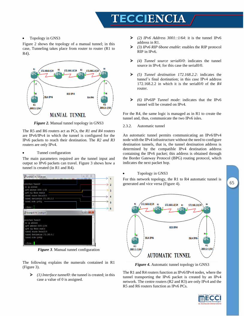
Figure 2 shows the topology of a manual tunnel; in this
case, Tunneling takes place from router to router (R1 to
R4).
Figure 2. Manual tunnel topology in GNS3
The R5 and R6 routers act as PCs, the R1 and R4 routers
are IPv6/IPv4 in which the tunnel is configured for the
IPv6 packets to reach their destination. The R2 and R3
routers are only IPv4.
Tunnel configuration
The main parameters required are the tunnel input and
output so IPv6 packets can travel. Figure 3 shows how a
tunnel is created (in R1 and R4).
Figure 3. Manual tunnel configuration
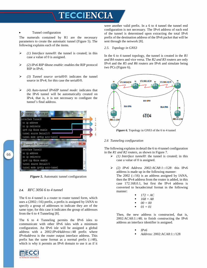
The following explains the numerals contained in R1
(Figure 3).
(1) Interface tunnel0: the tunnel is created; in this
case a value of 0 is assigned.
(2) IPv6 Address 3001::1/64: it is the tunnel IPv6
address in R1.
(3) IPv6 RIP 6bone enable: enables the RIP protocol
RIP in IPv6.
(4) Tunnel source serial0/0: indicates the tunnel
source in IPv4; for this case the serial0/0.
(5) Tunnel destination 172.168.2.2: indicates the
tunnel’s final destination; in this case IPv4 address
172.168.2.2 in which it is the serial0/0 of the R4
router.
(6) IPv6IP Tunnel mode: indicates that the IPv6
tunnel will be created on IPv4.
For the R4, the same logic is managed as in R1 to create the
tunnel and, thus, communicate the two IPv6 isles.
2.3.2. Automatic tunnel
An automatic tunnel permits communicating an IPv6/IPv4
node with the IPv4 infrastructure without the need to configure
destination tunnels, that is, the tunnel destination address is
determined by the compatible IPv4 destination address
containing the IPv6 packet; this address is obtained through
the Border Gateway Protocol (BPG) routing protocol, which
indicates the next packet hop.
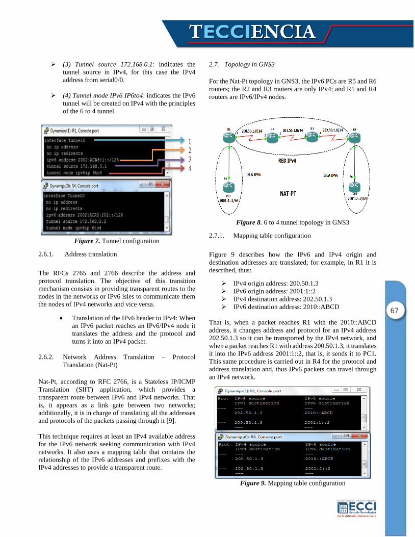
Topology in GNS3
For this network topology, the R1 to R4 automatic tunnel is
generated and vice versa (Figure 4).
Figure 4. Automatic tunnel topology in GNS3
The R1 and R4 routers function as IPv6/IPv4 nodes, where the
tunnel transporting the IPv6 packet is created by an IPv4
network. The centre routers (R2 and R3) are only IPv4 and the
R5 and R6 routers function as IPv6 PCs.
66
Tunnel configuration
The numerals contained by R1 are the necessary
parameters to create the automatic tunnel (Figure 5). The
following explains each of the items.
(1) Interface tunnel0: the tunnel is created; in this
case a value of 0 is assigned.
(2) IPv6 RIP 6bone enable: enables the RIP protocol
RIP in IPv6.
(3) Tunnel source serial0/0: indicates the tunnel
source in IPv4; for this case the serial0/0.
(4) Auto-tunnel IPv6IP tunnel mode: indicates that
the IPv6 tunnel will be automatically created on
IPv4, that is, it is not necessary to configure the
tunnel’s final address.
Figure 5. Automatic tunnel configuration
2.4. RFC 3056 6 to 4 tunnel
The 6 to 4 tunnel is a router to router tunnel form, which
uses a (2002::/16) prefix, a prefix is assigned by IANA to
specify a group of addresses to indicate they are of the
same type; for this case it indicates the group of addresses
from the 6 to 4 Tunneling [8].
The 6 to 4 Tunneling permits the IPv6 isles to
communicate with other IPv6 isles with a minimum
configuration. An IPv6 isle will be assigned a global
address with a 2002:IPv4Address::/48 prefix where
IPv4address is the router output interface address. This
prefix has the same format as a normal prefix (::/48),
which is why it permits an IPv6 domain to use it as if it
were another valid prefix. In a 6 to 4 tunnel the tunnel end
configuration is not necessary. The IPv4 address of each end
of the tunnel is determined upon extracting the total IPv6
prefix of the destination address of the IPv6 packet that will be
sent through the network [8].
2.5. Topology in GNS3
In the 6 to 4 tunnel topology, the tunnel is created in the R1
and R4 routers and vice versa. The R2 and R3 routers are only
IPv4 and the R5 and R6 routers are IPv6 and simulate being
two PCs (Figure 6).
Figure 6. Topology in GNS3 of the 6 to 4 tunnel
2.6 Tunneling configuration
The following explains in detail the 6 to 4 tunnel configuration
in the R1 and R2 routers, as shown in Figure 7.
(1) Interface tunnel0: the tunnel is created; in this
case a value of 0 is assigned.
(2) IPv6 Address 2002:ACA8:1::/128: this IPv6
address is made up in the following manner:
The 2002 (::/16) is an address assigned by IANA,
then the IPv4 address from the router is added, in this
case 172.168.0.1, but first the IPv4 address is
converted to hexadecimal format in the following
manner:
172 = AC
168 = A8
00 = 00
01 = 01
Then, the new address is constructed, that is,
2002:ACA8:1::/48; to finish constructing the IPv6
address an interface identifier is assigned.
IPv6
Address: 2002:ACA8:1::/128
67
(3) Tunnel source 172.168.0.1: indicates the
tunnel source in IPv4, for this case the IPv4
address from serial0/0.
(4) Tunnel mode IPv6 IP6to4: indicates the IPv6
tunnel will be created on IPv4 with the principles
of the 6 to 4 tunnel.
Figure 7. Tunnel configuration
2.6.1. Address translation
The RFCs 2765 and 2766 describe the address and
protocol translation. The objective of this transition
mechanism consists in providing transparent routes to the
nodes in the networks or IPv6 isles to communicate them
the nodes of IPv4 networks and vice versa.
Translation of the IPv6 header to IPv4: When
an IPv6 packet reaches an IPv6/IPv4 node it
translates the address and the protocol and
turns it into an IPv4 packet.
2.6.2. Network Address Translation – Protocol
Translation (Nat-Pt)
Nat-Pt, according to RFC 2766, is a Stateless IP/ICMP
Translation (SIIT) application, which provides a
transparent route between IPv6 and IPv4 networks. That
is, it appears as a link gate between two networks;
additionally, it is in charge of translating all the addresses
and protocols of the packets passing through it [9].
This technique requires at least an IPv4 available address
for the IPv6 network seeking communication with IPv4
networks. It also uses a mapping table that contains the
relationship of the IPv6 addresses and prefixes with the
IPv4 addresses to provide a transparent route.
2.7. Topology in GNS3
For the Nat-Pt topology in GNS3, the IPv6 PCs are R5 and R6
routers; the R2 and R3 routers are only IPv4; and R1 and R4
routers are IPv6/IPv4 nodes.
Figure 8. 6 to 4 tunnel topology in GNS3
2.7.1. Mapping table configuration
Figure 9 describes how the IPv6 and IPv4 origin and
destination addresses are translated; for example, in R1 it is
described, thus:
IPv4 origin address: 200.50.1.3
IPv6 origin address: 2001:1::2
IPv4 destination address: 202.50.1.3
IPv6 destination address: 2010::ABCD
That is, when a packet reaches R1 with the 2010::ABCD
address, it changes address and protocol for an IPv4 address
202.50.1.3 so it can be transported by the IPv4 network, and
when a packet reaches R1 with address 200.50.1.3, it translates
it into the IPv6 address 2001:1::2, that is, it sends it to PC1.
This same procedure is carried out in R4 for the protocol and
address translation and, thus IPv6 packets can travel through
an IPv4 network.
Figure 9. Mapping table configuration
68
3. Results
3.1 experimental design
A set of tests were designed to analyze the performance of
the simulations implemented. By sending 200 packets of
different length, we evaluated the network’s performance
upon transporting packets. We also examined the behavior
of the IPv6/IPv4 node memory, given that it is in charge
of making the IPv6 and IPv4 protocols compatible and can
use the IPv4 network.
For the memory tests, it must be remarked that free
memory of the tunneling-type techniques, that is, the
manual, automatic, and 6 to 4 tunnels was 69,376,000
Bytes; for the address translation technique the memory
was 46,128,512 Bytes. Stemming from these data, a
relationship is made between memory used and free
memory; likewise, a relationship is made in the percentage
of CPU consumption used by the router to send data.
The data shown ahead were obtained for the ROUND-
TRIP (ms) in R5 and for R1 memory use; the first indicates
the time spent by the packets to reach their destination and
the latter is in charge of encapsulating or translating an
IPv6 packet into IPv4.
3.2. Manual Tunneling tests in GNS3
Figure 10 shows the manual tunneling simulation latency
behavior.
Figure 10. Latency of manual tunneling
Figure 11 details the router’s (R1) memory use.
Figure 11. R1 memory use
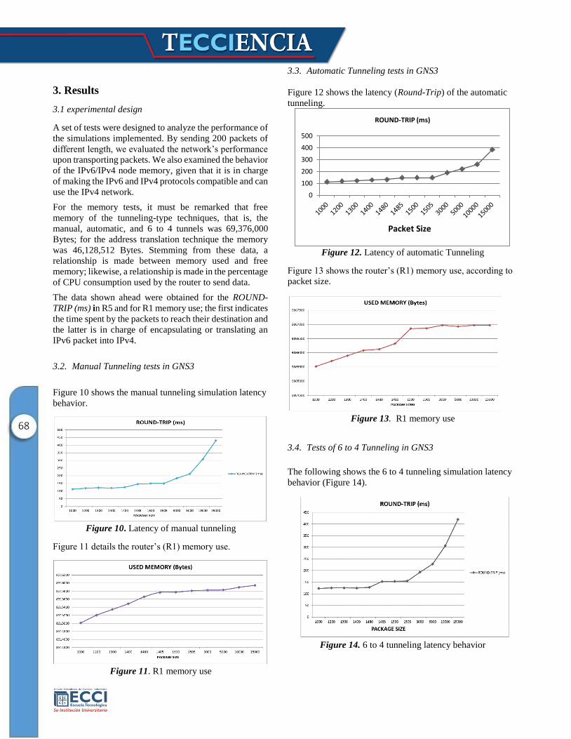
3.3. Automatic Tunneling tests in GNS3
Figure 12 shows the latency (Round-Trip) of the automatic
tunneling.
Figure 12. Latency of automatic Tunneling
Figure 13 shows the router’s (R1) memory use, according to
packet size.
Figure 13. R1 memory use
3.4. Tests of 6 to 4 Tunneling in GNS3
The following shows the 6 to 4 tunneling simulation latency
behavior (Figure 14).
Figure 14. 6 to 4 tunneling latency behavior
0
100
200
300
400
500
Packet Size
ROUND-TRIP (ms)
69
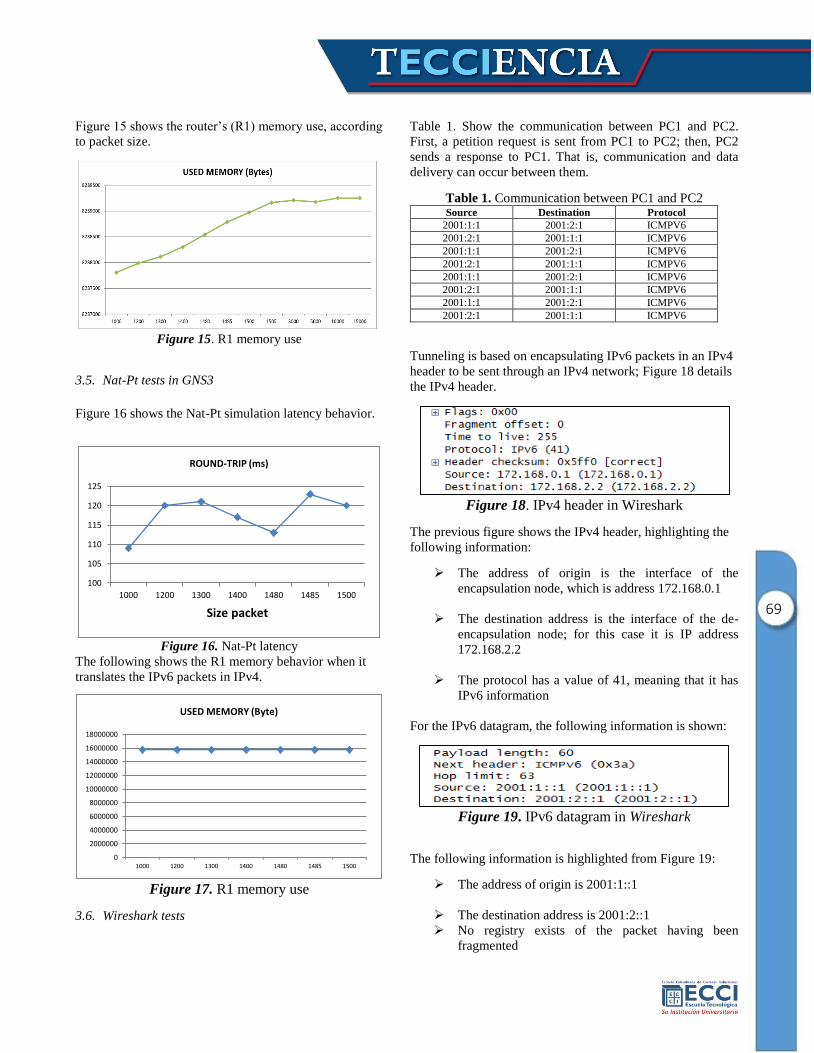
Figure 15 shows the router’s (R1) memory use, according
to packet size.
Figure 15. R1 memory use
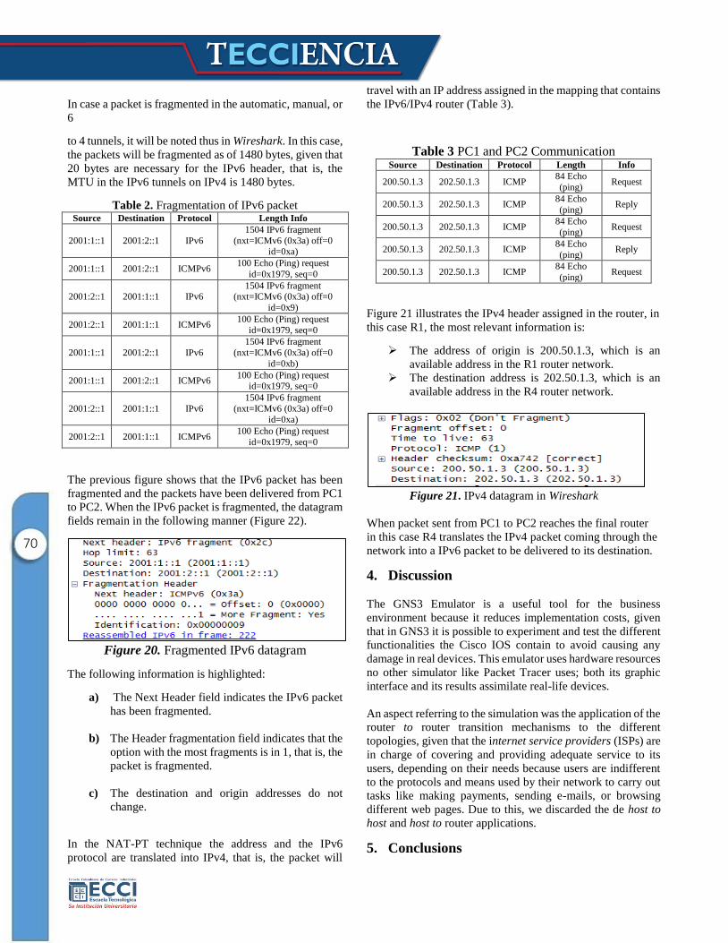
3.5. Nat-Pt tests in GNS3
Figure 16 shows the Nat-Pt simulation latency behavior.
Figure 16. Nat-Pt latency
The following shows the R1 memory behavior when it
translates the IPv6 packets in IPv4.
Figure 17. R1 memory use
3.6. Wireshark tests
Table 1. Show the communication between PC1 and PC2.
First, a petition request is sent from PC1 to PC2; then, PC2
sends a response to PC1. That is, communication and data
delivery can occur between them.
Table 1. Communication between PC1 and PC2 Source Destination Protocol
2001:1:1 2001:2:1 ICMPV6
2001:2:1 2001:1:1 ICMPV6
2001:1:1 2001:2:1 ICMPV6
2001:2:1 2001:1:1 ICMPV6
2001:1:1 2001:2:1 ICMPV6
2001:2:1 2001:1:1 ICMPV6
2001:1:1 2001:2:1 ICMPV6
2001:2:1 2001:1:1 ICMPV6
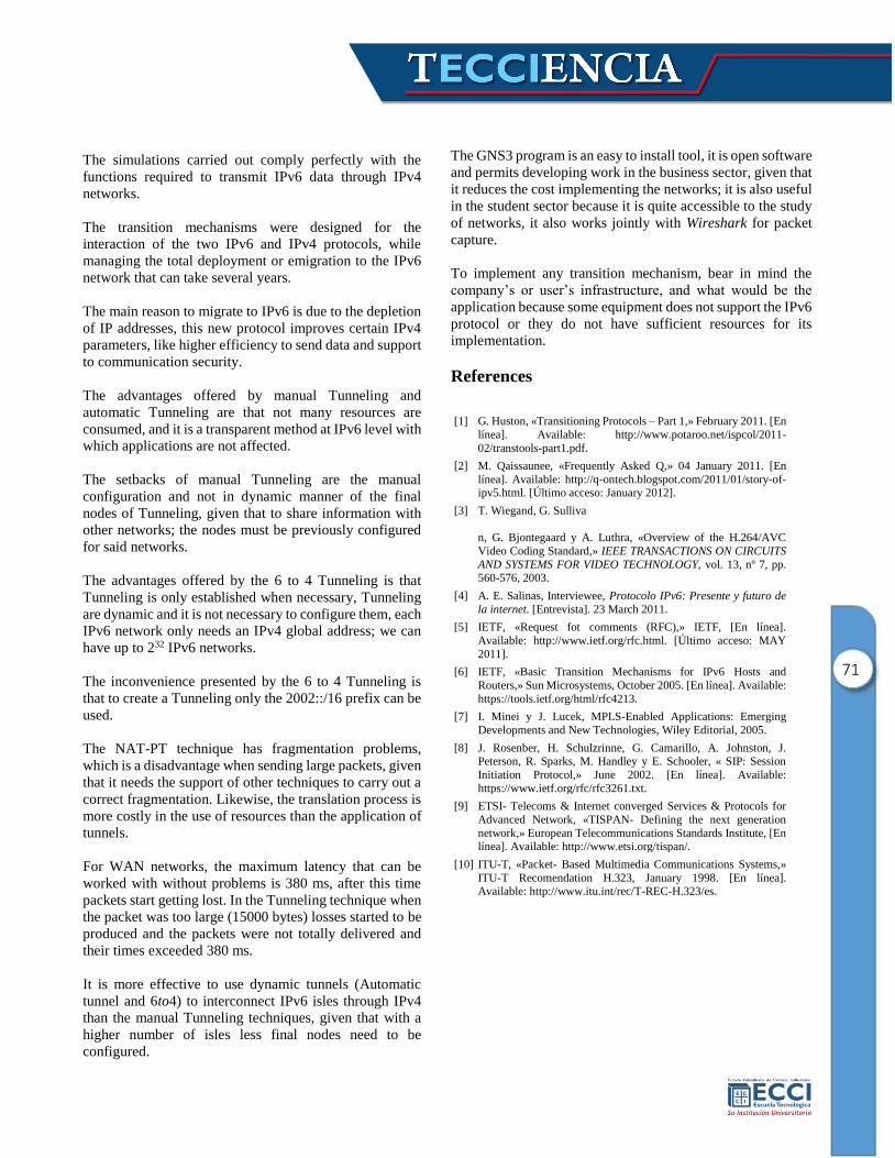
Tunneling is based on encapsulating IPv6 packets in an IPv4
header to be sent through an IPv4 network; Figure 18 details
the IPv4 header.
Figure 18. IPv4 header in Wireshark
The previous figure shows the IPv4 header, highlighting the
following information:
The address of origin is the interface of the
encapsulation node, which is address 172.168.0.1
The destination address is the interface of the de-
encapsulation node; for this case it is IP address
172.168.2.2
The protocol has a value of 41, meaning that it has
IPv6 information
For the IPv6 datagram, the following information is shown:
Figure 19. IPv6 datagram in Wireshark
The following information is highlighted from Figure 19:
The address of origin is 2001:1::1
The destination address is 2001:2::1
No registry exists of the packet having been
fragmented
100
105
110
115
120
125
1000 1200 1300 1400 1480 1485 1500
Size packet
ROUND-TRIP (ms)
0
2000000
4000000
6000000
8000000
10000000
12000000
14000000
16000000
18000000
1000 1200 1300 1400 1480 1485 1500
USED MEMORY (Byte)
70
In case a packet is fragmented in the automatic, manual, or
6
to 4 tunnels, it will be noted thus in Wireshark. In this case,
the packets will be fragmented as of 1480 bytes, given that
20 bytes are necessary for the IPv6 header, that is, the
MTU in the IPv6 tunnels on IPv4 is 1480 bytes.
Table 2. Fragmentation of IPv6 packet Source Destination Protocol Length Info
2001:1::1 2001:2::1 IPv6
1504 IPv6 fragment
(nxt=ICMv6 (0x3a) off=0 id=0xa)
2001:1::1 2001:2::1 ICMPv6 100 Echo (Ping) request
id=0x1979, seq=0
2001:2::1 2001:1::1 IPv6 1504 IPv6 fragment
(nxt=ICMv6 (0x3a) off=0
id=0x9)
2001:2::1 2001:1::1 ICMPv6 100 Echo (Ping) request
id=0x1979, seq=0
2001:1::1 2001:2::1 IPv6
1504 IPv6 fragment
(nxt=ICMv6 (0x3a) off=0
id=0xb)
2001:1::1 2001:2::1 ICMPv6 100 Echo (Ping) request
id=0x1979, seq=0
2001:2::1 2001:1::1 IPv6
1504 IPv6 fragment
(nxt=ICMv6 (0x3a) off=0 id=0xa)
2001:2::1 2001:1::1 ICMPv6 100 Echo (Ping) request
id=0x1979, seq=0
The previous figure shows that the IPv6 packet has been
fragmented and the packets have been delivered from PC1
to PC2. When the IPv6 packet is fragmented, the datagram
fields remain in the following manner (Figure 22).
Figure 20. Fragmented IPv6 datagram
The following information is highlighted:
a) The Next Header field indicates the IPv6 packet
has been fragmented.
b) The Header fragmentation field indicates that the
option with the most fragments is in 1, that is, the
packet is fragmented.
c) The destination and origin addresses do not
change.
In the NAT-PT technique the address and the IPv6
protocol are translated into IPv4, that is, the packet will
travel with an IP address assigned in the mapping that contains
the IPv6/IPv4 router (Table 3).
Table 3 PC1 and PC2 Communication Source Destination Protocol Length Info
200.50.1.3 202.50.1.3 ICMP 84 Echo
(ping) Request
200.50.1.3 202.50.1.3 ICMP 84 Echo
(ping) Reply
200.50.1.3 202.50.1.3 ICMP 84 Echo
(ping) Request
200.50.1.3 202.50.1.3 ICMP 84 Echo
(ping) Reply
200.50.1.3 202.50.1.3 ICMP 84 Echo
(ping) Request
Figure 21 illustrates the IPv4 header assigned in the router, in
this case R1, the most relevant information is:
The address of origin is 200.50.1.3, which is an
available address in the R1 router network.
The destination address is 202.50.1.3, which is an
available address in the R4 router network.
Figure 21. IPv4 datagram in Wireshark
When packet sent from PC1 to PC2 reaches the final router
in this case R4 translates the IPv4 packet coming through the
network into a IPv6 packet to be delivered to its destination.
4. Discussion
The GNS3 Emulator is a useful tool for the business
environment because it reduces implementation costs, given
that in GNS3 it is possible to experiment and test the different
functionalities the Cisco IOS contain to avoid causing any
damage in real devices. This emulator uses hardware resources
no other simulator like Packet Tracer uses; both its graphic
interface and its results assimilate real-life devices.
An aspect referring to the simulation was the application of the
router to router transition mechanisms to the different
topologies, given that the internet service providers (ISPs) are
in charge of covering and providing adequate service to its
users, depending on their needs because users are indifferent
to the protocols and means used by their network to carry out
tasks like making payments, sending e-mails, or browsing
different web pages. Due to this, we discarded the de host to
host and host to router applications.
5. Conclusions
71
The simulations carried out comply perfectly with the
functions required to transmit IPv6 data through IPv4
networks.
The transition mechanisms were designed for the
interaction of the two IPv6 and IPv4 protocols, while
managing the total deployment or emigration to the IPv6
network that can take several years.
The main reason to migrate to IPv6 is due to the depletion
of IP addresses, this new protocol improves certain IPv4
parameters, like higher efficiency to send data and support
to communication security.
The advantages offered by manual Tunneling and
automatic Tunneling are that not many resources are
consumed, and it is a transparent method at IPv6 level with
which applications are not affected.
The setbacks of manual Tunneling are the manual
configuration and not in dynamic manner of the final
nodes of Tunneling, given that to share information with
other networks; the nodes must be previously configured
for said networks.
The advantages offered by the 6 to 4 Tunneling is that
Tunneling is only established when necessary, Tunneling
are dynamic and it is not necessary to configure them, each
IPv6 network only needs an IPv4 global address; we can
have up to 232 IPv6 networks.
The inconvenience presented by the 6 to 4 Tunneling is
that to create a Tunneling only the 2002::/16 prefix can be
used.
The NAT-PT technique has fragmentation problems,
which is a disadvantage when sending large packets, given
that it needs the support of other techniques to carry out a
correct fragmentation. Likewise, the translation process is
more costly in the use of resources than the application of
tunnels.
For WAN networks, the maximum latency that can be
worked with without problems is 380 ms, after this time
packets start getting lost. In the Tunneling technique when
the packet was too large (15000 bytes) losses started to be
produced and the packets were not totally delivered and
their times exceeded 380 ms.
It is more effective to use dynamic tunnels (Automatic
tunnel and 6to4) to interconnect IPv6 isles through IPv4
than the manual Tunneling techniques, given that with a
higher number of isles less final nodes need to be
configured.
The GNS3 program is an easy to install tool, it is open software
and permits developing work in the business sector, given that
it reduces the cost implementing the networks; it is also useful
in the student sector because it is quite accessible to the study
of networks, it also works jointly with Wireshark for packet
capture.
To implement any transition mechanism, bear in mind the
company’s or user’s infrastructure, and what would be the
application because some equipment does not support the IPv6
protocol or they do not have sufficient resources for its
implementation.
References
[1] G. Huston, «Transitioning Protocols – Part 1,» February 2011. [En
línea]. Available: http://www.potaroo.net/ispcol/2011-
02/transtools-part1.pdf.
[2] M. Qaissaunee, «Frequently Asked Q,» 04 January 2011. [En
línea]. Available: http://q-ontech.blogspot.com/2011/01/story-of-ipv5.html. [Último acceso: January 2012].
[3] T. Wiegand, G. Sulliva
n, G. Bjontegaard y A. Luthra, «Overview of the H.264/AVC
Video Coding Standard,» IEEE TRANSACTIONS ON CIRCUITS
AND SYSTEMS FOR VIDEO TECHNOLOGY, vol. 13, nº 7, pp.
560-576, 2003.
[4] A. E. Salinas, Interviewee, Protocolo IPv6: Presente y futuro de
la internet. [Entrevista]. 23 March 2011.
[5] IETF, «Request fot comments (RFC),» IETF, [En línea].
Available: http://www.ietf.org/rfc.html. [Último acceso: MAY
2011].
[6] IETF, «Basic Transition Mechanisms for IPv6 Hosts and
Routers,» Sun Microsystems, October 2005. [En línea]. Available:
https://tools.ietf.org/html/rfc4213.
[7] I. Minei y J. Lucek, MPLS-Enabled Applications: Emerging
Developments and New Technologies, Wiley Editorial, 2005.
[8] J. Rosenber, H. Schulzrinne, G. Camarillo, A. Johnston, J. Peterson, R. Sparks, M. Handley y E. Schooler, « SIP: Session
Initiation Protocol,» June 2002. [En línea]. Available:
https://www.ietf.org/rfc/rfc3261.txt.
[9] ETSI- Telecoms & Internet converged Services & Protocols for
Advanced Network, «TISPAN- Defining the next generation
network,» European Telecommunications Standards Institute, [En línea]. Available: http://www.etsi.org/tispan/.
[10] ITU-T, «Packet- Based Multimedia Communications Systems,»
ITU-T Recomendation H.323, January 1998. [En línea]. Available: http://www.itu.int/rec/T-REC-H.323/es.