A shaft is a rotating machine element which is used to transmit p
20
ROHINI COLLEGE OF ENGINEERING & TECHNOLOGY ME8593 DESIGN OF MACHINE ELEMENTS UNIT II SHAFTS AND COUPLINGS CHAPTER 1 Introduction of Shafts: A shaft is a rotating machine element which is used to transmit power from one place to another. The power is delivered to the shaft by some tangential force and the resultant torque (or twisting moment) set up within the shaft permits the power to be transferred to various machines linked up to the shaft. In order to transfer the power from one shaft to another, the various members such as pulleys, gears etc., are mounted on it. These members along with the forces exerted upon them causes the shaft to bending. In other words, we may say that a shaft is used for the transmission of torque and bending moment. The various members are mounted on the shaft by means of keys or splines. The shafts are usually cylindrical, but may be square or cross-shaped in section. They are solid in cross-section but sometimes hollow shafts are also used. An axle, though similar in shape to the shaft, is a stationary machine element and is used for the transmission of bending moment only. It simply acts as a support for some rotating body such as hoisting drum, a car wheel or a rope sheave. A spindle is a short shaft that imparts motion either to a cutting tool (e.g. drill press spindles) or to a work piece (e.g. lathe spindles). Material Used for Shafts The material used for shafts should have the following properties: 1. It should have high strength. 2. It should have good machinability. 3. It should have low notch sensitivity factor. 4. It should have good heat treatment properties. 5. It should have high wear resistant properties. The material used for ordinary shafts is carbon steel of grades 40 C 8, 45 C 8, 50 C 4 and 50 C 12. The mechanical properties of these grades of carbon steel are given in the following table.
-
Upload
khangminh22 -
Category
Documents
-
view
0 -
download
0
Transcript of A shaft is a rotating machine element which is used to transmit p
ROHINI COLLEGE OF ENGINEERING & TECHNOLOGY
ME8593 DESIGN OF MACHINE ELEMENTS
UNIT II
SHAFTS AND COUPLINGS
CHAPTER 1
Introduction of Shafts:
A shaft is a rotating machine element which is used to transmit power from one
place to another. The power is delivered to the shaft by some tangential force and the
resultant torque (or twisting moment) set up within the shaft permits the power to be
transferred to various machines linked up to the shaft. In order to transfer the power from
one shaft to another, the various members such as pulleys, gears etc., are mounted on it.
These members along with the forces exerted upon them causes the shaft to bending.
In other words, we may say that a shaft is used for the transmission of torque and
bending moment. The various members are mounted on the shaft by means of keys or
splines. The shafts are usually cylindrical, but may be square or cross-shaped in section.
They are solid in cross-section but sometimes hollow shafts are also used. An axle,
though similar in shape to the shaft, is a stationary machine element and is used for the
transmission of bending moment only. It simply acts as a support for some rotating body
such as hoisting drum, a car wheel or a rope sheave. A spindle is a short shaft that imparts
motion either to a cutting tool (e.g. drill press spindles) or to a work piece (e.g. lathe
spindles).
Material Used for Shafts
The material used for shafts should have the following properties:
1. It should have high strength.
2. It should have good machinability.
3. It should have low notch sensitivity factor.
4. It should have good heat treatment properties.
5. It should have high wear resistant properties.
The material used for ordinary shafts is carbon steel of grades 40 C 8, 45 C 8, 50 C 4 and
50 C 12. The mechanical properties of these grades of carbon steel are given in the
following table.

ROHINI COLLEGE OF ENGINEERING & TECHNOLOGY
ME8593 DESIGN OF MACHINE ELEMENTS
Table 1.1 Mechanical properties of steels used for shafts.
Indian standard
designation
Ultimate tensile
strength, MPa
Yield
strength,
MPa
40 C 8 560 - 670 320
45 C 8 610 - 700 350
50 C 4 640 - 760 370
50 C 12 700 Min. 390
[Source: “A Textbook of Machine Design by R.S. Khurmi J.K. Gupta, Page: 510]
Manufacturing of Shafts
Shafts are generally manufactured by hot rolling and finished to size by cold
drawing or turning and grinding. The cold rolled shafts are stronger than hot rolled shafts
but with higher residual stresses. The residual stresses may cause distortion of the shaft
when it is machined, especially when slots or keyways are cut. Shafts of larger diameter
are usually forged and turned to size in a lathe.
Types of Shafts
The following two types of shafts are important from the subject point of view:
1.Transmission shafts. These shafts transmit power between the source and the
machines absorbing power. The counter shafts, line shafts, overhead shafts and all factory
shafts are transmission shafts. Since these shafts carry machine parts such as pulleys,
gears etc., therefore they are subjected to bending in addition to twisting.
2.Machine shafts. These shafts form an integral part of the machine itself. The
crank shaft is an example of machine shaft.
Stresses in Shafts
The following stresses are induced in the shafts:
1.Shear stresses due to the transmission of torque (i.e. due to torsional load).

ROHINI COLLEGE OF ENGINEERING & TECHNOLOGY
ME8593 DESIGN OF MACHINE ELEMENTS
2.Bending stresses (tensile or compressive) due to the forces acting upon machine
elements like gears, pulleys etc. as well as due to the weight of the shaft itself.
3.Stresses due to combined torsional and bending loads.
Design of Shafts
The shafts may be designed on the basis of
1. Strength, and
2. Rigidity and stiffness
In designing shafts on the basis of strength, the following cases may be considered:
(a) Shafts subjected to twisting moment or torque only,
(b) Shafts subjected to bending moment only,
(c) Shafts subjected to combined twisting and bending moments, and
(d) Shafts subjected to axial loads in addition to combined torsional and bending
loads.
Shafts Subjected to Twisting Moment Only a) Solid shaft:
When the shaft is subjected to a twisting moment (or torque) only, then the
diameter of the shaft may be obtained by using the torsion equation. We know that
T
J =
τ
r
where T = Twisting moment (or torque) acting upon the shaft,
J = Polar moment of inertia of the shaft about the axis of rotation,
τ = Torsional shear stress, and
r = Distance from neutral axis to the outer most fibre
= d/2 where d is the diameter of the shaft.
We know that for round solid shaft, polar moment of inertia,
J = π
4 × d4
The equation (i) may now be written as
Tπ
4 × d4
= τd
2
T = π
16 × 𝜏 × d3

ROHINI COLLEGE OF ENGINEERING & TECHNOLOGY
ME8593 DESIGN OF MACHINE ELEMENTS
From this equation, we may determine the diameter of round solid shaft (d).
We also know that for hollow shaft, polar moment of inertia,
J = 𝜋
32 [(do)
4 – (di)4]
Where, do and di = Outside and inside diameter of the shaft, and r = do / 2.
Substituting these values in equation (i), we have,
Tπ
32 ×[(do)2−(di)2]
= τ
do2
T = π
16 × τ ×
[(do)4 – (di)4]
do
Let k = Ratio of inside diameter and outside diameter of the shaft = di / do
Now the equation (iii) may be written as
T = π
16 × τ ×
(𝑑𝑜)4
𝑑𝑜[1- (
𝑑𝑖
𝑑𝑜)4]
T = π
16 × τ × do
3×(1-k4)
From the equations (iii) or (iv), the outside and inside diameter of a hollow shaft may be
determined.
It may be noted that
1. The hollow shafts are usually used in marine work. These shafts are stronger per
kg of material and they may be forged on a mandrel, thus making the material more
homogeneous than would be possible for a solid shaft.
When a hollow shaft is to be made equal in strength to a solid shaft, the twisting moment
of both the shafts must be same. In other words, for the same material of both the shafts,
T = π
16 × τ ×
[(do)4 – (di)4]
do =
π
16 × 𝜏 × d3
[(do)4 – (di)4]
do = d3 or (do)
3 (1 – k4) = d3
2.The twisting moment (T) may be obtained by using the following relation:
We know that the power transmitted (in watts) by the shaft,
P = 2πNT
60
T = P×60
2πN
where T = Twisting moment in N-m, and
N = Speed of the shaft in r.p.m.
ROHINI COLLEGE OF ENGINEERING & TECHNOLOGY
ME8593 DESIGN OF MACHINE ELEMENTS
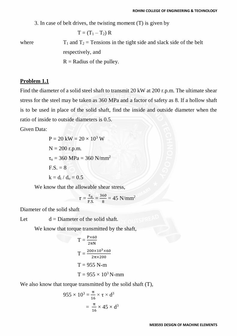
3. In case of belt drives, the twisting moment (T) is given by
T = (T1 – T2) R
where T1 and T2 = Tensions in the tight side and slack side of the belt
respectively, and
R = Radius of the pulley.
Problem 1.1
Find the diameter of a solid steel shaft to transmit 20 kW at 200 r.p.m. The ultimate shear
stress for the steel may be taken as 360 MPa and a factor of safety as 8. If a hollow shaft
is to be used in place of the solid shaft, find the inside and outside diameter when the
ratio of inside to outside diameters is 0.5.
Given Data:
P = 20 kW = 20 × 103 W
N = 200 r.p.m.
τu = 360 MPa = 360 N/mm2
F.S. = 8
k = di / do = 0.5
We know that the allowable shear stress,
𝜏 = 𝜏𝑢
F.S. =
360
8 = 45 N/mm2
Diameter of the solid shaft
Let d = Diameter of the solid shaft.
We know that torque transmitted by the shaft,
T = P×60
2πN
T = 200×103×60
2π×200
T = 955 N-m
T = 955 × 103 N-mm
We also know that torque transmitted by the solid shaft (T),
955 × 103 = π
16 × τ × d3
= π
16 × 45 × d3
ROHINI COLLEGE OF ENGINEERING & TECHNOLOGY
ME8593 DESIGN OF MACHINE ELEMENTS
= 8.84 d3
∴ d3 = 955 × 103 / 8.84 = 108032
d = 47.6 say 50 mm
Diameter of hollow shaft
Let di = Inside diameter, and
do = Outside diameter.
We know that the torque transmitted by the hollow shaft (T),
955 × 103 = π
16 × τ × (do)
3 (1 – k4)
955 × 103 = π
16 × 45 × (do)
3 (1 – 0.54)
955 × 103 = 8.3 (do)3
(do)3 = 955 × 103 / 8.3
= 115060 or
do = 48.6 say 50 mm
and di = 0.5 do = 0.5 × 50 = 25 mm
Shafts Subjected to Bending Moment Only
When the shaft is subjected to a bending moment only, then the maximum stress (tensile
or compressive) is given by the bending equation. We know that
M
I =
σb
y
Where M = Bending moment,
I = Moment of inertia of cross-sectional area of the shaft about the
axis of rotation,
σb = Bending stress, and
y = Distance from neutral axis to the outer-most fibre.
We know that for a round solid shaft, moment of inertia,
I = π
64× d4 ……………and y =
d
2
Substituting these values in equation (i), we have
Mπ
64×d4
= σbd
2

ROHINI COLLEGE OF ENGINEERING & TECHNOLOGY
ME8593 DESIGN OF MACHINE ELEMENTS
M = π
32 × σb × d3
From this equation, diameter of the solid shaft (d) may be obtained.
We also know that for a hollow shaft, moment of inertia,
I = π
64× [(do)
4 – (di)4]
= π
64× (do)
3 (1 – k4) ...(where k = di / do )
and y = do
2
Again substituting these values in equation (i), we have
Mπ
64×do
4(1− k4) =
σbdo2
M = π
32 × σb × (do)
3 (1 – k4)
From this equation, the outside diameter of the shaft (do) may be obtained.
Shafts Subjected to Combined Twisting Moment and Bending Moment
When the shaft is subjected to combined twisting moment and bending moment,
then the shaft must be designed on the basis of the two moments simultaneously. Various
theories have been suggested to account for the elastic failure of the materials when they
are subjected to various types of combined stresses. The following two theories are
important from the subject point of view:
1. Maximum shear stress theory or Guest's theory. It is used for ductile materials
such as mild steel.
2. Maximum normal stress theory or Rankine’s theory. It is used for brittle
materials such as cast iron.
Let τ = Shear stress induced due to twisting moment, and
σb = Bending stress (tensile or compressive) induced due to bending
moment.
According to maximum shear stress theory, the maximum shear stress in the shaft,
τmax = 1
2√(σb + 4τ2
Substituting the values of τ and σb

ROHINI COLLEGE OF ENGINEERING & TECHNOLOGY
ME8593 DESIGN OF MACHINE ELEMENTS
τmax = 1
2 √(
32M
πd3)2 + 4 (
16T
πd3)2
= 16
πd3 [√M2 + T2]
π
16 × τmax × d3 = √M2 + T2
The expression √M2 + T2 is known as equivalent twisting moment and is denoted by
Te. The equivalent twisting moment may be defined as that twisting moment, which when
acting alone, produces the same shear stress (τ) as the actual twisting moment. By limiting
the maximum shear stress (τmax) equal to the allowable shear stress (τ) for the material,
the equation (i) may be written as
Te = √M2 + T2 = π
16 × τ × d3
From this expression, diameter of the shaft (d) may be evaluated.
Now according to maximum normal stress theory, the maximum normal stress in the
shaft,
(σb)max = 1
2 σb +
1
2 √(σb)2 + 4τ2
= 1
2 ×
32M
πd3 +
1
2 √(
32M
π d3)2 + 4(
16T
πd3)2
= 32
πd3 [
1
2 ( M + √M2 + T2)]
32
π× (σb)max × d3 =
1
2 M + √M2 + T2
The expression 1
2 M + √M2 + T2 is known as equivalent bending moment and is denoted
by Me. The equivalent bending moment may be defined as that moment which when
acting alone produces the same tensile or compressive stress (σb) as the actual bending
moment. By limiting the maximum normal stress [σb(max)] equal to the allowable bending
stress (σb), then the equation (iv) may be written as
Me = 1
2 M + √M2 + T2 =
π
16 × σb × d3
From this expression, diameter of the shaft (d) may be evaluated.

ROHINI COLLEGE OF ENGINEERING & TECHNOLOGY
ME8593 DESIGN OF MACHINE ELEMENTS
Problem 1.2
A shaft is supported by two bearings placed 1 m apart. A 600 mm diameter pulley is
mounted at a distance of 300 mm to the right of left hand bearing and this drives a pulley
directly below it with the help of belt having maximum tension of 2.25 kN. Another
pulley 400 mm diameter is placed 200 mm to the left of right hand bearing and is driven
with the help of electric motor and belt, which is placed horizontally to the right. The
angle of contact for both the pulleys is 180° and μ = 0.24. Determine the suitable diameter
for a solid shaft, allowing working stress of 63 MPa in tension and 42 MPa in shear for
the material of shaft. Assume that the torque on one pulley is equal to that on the other
pulley.
Given Data:
AB = 1 m
DC = 600 mm or RC = 300 mm = 0.3 m
AC = 300 mm = 0.3 m
T1 = 2.25 kN = 2250 N
DD = 400 mm or RD = 200 mm = 0.2 m
BD = 200 mm = 0.2 m
θ = 180° = π rad
μ = 0.24
σb = 63 MPa = 63 N/mm2
τ = 42 MPa = 42 N/mm2
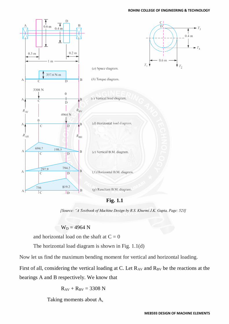
The space diagram of the shaft is shown in Fig 1.1 (a).
Let T1 = Tension in the tight side of the belt on pulley C = 2250 N ...(Given)
T2 = Tension in the slack side of the belt on pulley C.
We know that
2.3 log(T1
T2) = µθ
= 0.24 × π
= 0.754
log(T1
T2) =
0.754
2.3
ROHINI COLLEGE OF ENGINEERING & TECHNOLOGY
ME8593 DESIGN OF MACHINE ELEMENTS
T1
T2 = 2.127 ………….... (Taking antilog of 0.3278)
T2 = T1
2.127
= 2250
2.127
T2 = 1058 N
∴ Vertical load acting on the shaft at C,
WC = T1 + T2 = 2250 + 1058 = 3308 N
and vertical load on the shaft at D
= 0
The vertical load diagram is shown in Fig. 1.1 (c).
We know that torque acting on the pulley C,
T = (T1 – T2) RC
= (2250 – 1058) 0.3
T = 357.6 N-m
The torque diagram is shown in Fig. 1.1 (b).
Let T3 = Tension in the tight side of the belt on pulley D, and
T4 = Tension in the slack side of the belt on pulley D.
Since the torque on both the pulleys (i.e. C and D) is same, therefore
(T3 – T4) RD = T = 357.6 N-m or
T3 – T4 = 357.6
RD
= 357.6
0.2
T3 – T4 = 1788 N
We know that
T3
T4 =
T1
T2 = 2.127
T3 = 2.127 T4
From equations (i) and (ii), we find that
T3 = 3376 N, and T4 = 1588 N
∴ Horizontal load acting on the shaft at D,
WD = T3 + T4 = 3376 + 1588
ROHINI COLLEGE OF ENGINEERING & TECHNOLOGY
ME8593 DESIGN OF MACHINE ELEMENTS
Fig. 1.1
[Source: “A Textbook of Machine Design by R.S. Khurmi J.K. Gupta, Page: 523]
WD = 4964 N
and horizontal load on the shaft at C = 0
The horizontal load diagram is shown in Fig. 1.1(d)
Now let us find the maximum bending moment for vertical and horizontal loading.
First of all, considering the vertical loading at C. Let RAV and RBV be the reactions at the
bearings A and B respectively. We know that
RAV + RBV = 3308 N
Taking moments about A,

ROHINI COLLEGE OF ENGINEERING & TECHNOLOGY
ME8593 DESIGN OF MACHINE ELEMENTS
RBV × 1 = 3308 × 0.3 or
RBV = 992.4 N
and RAV = 3308 – 992.4 = 2315.6 N
We know that B.M. at A and B,
MAV = MBV = 0
B.M. at C, MCV = RAV × 0.3 = 2315.6 × 0.3 = 694.7 N-m
B.M. at D, MDV = RBV × 0.2 = 992.4 × 0.2 = 198.5 N-m
The bending moment diagram for vertical loading in shown in Fig. 1.1 (e).
Now considering horizontal loading at D. Let RAH and RBH be the reactions at the
bearings A and B respectively. We know that
RAH + RBH = 4964 N
Taking moments about A,
RBH × 1 = 4964 × 0.8 or
RBH = 3971 N
and RAH = 4964 – 3971 = 993 N
We know that B.M. at A and B,
MAH = MBH = 0
B.M. at C, MCH = RAH × 0.3 = 993 × 0.3 = 297.9 N-m
B.M. at D, MDH = RBH × 0.2 = 3971 × 0.2 = 794.2 N-m
The bending moment diagram for horizontal loading is shown in Fig. 1.1 ( f ).
Resultant B.M. at C,
MC = √(MCV)2 + (MCH)2
= √(694.7)2 + (297.9)2
MC = 756 N-m
and resultant B.M. at D,
ROHINI COLLEGE OF ENGINEERING & TECHNOLOGY
ME8593 DESIGN OF MACHINE ELEMENTS
MD = √(MDV)2 + (MDH)2
= √(198.5)2 + (794.2)2
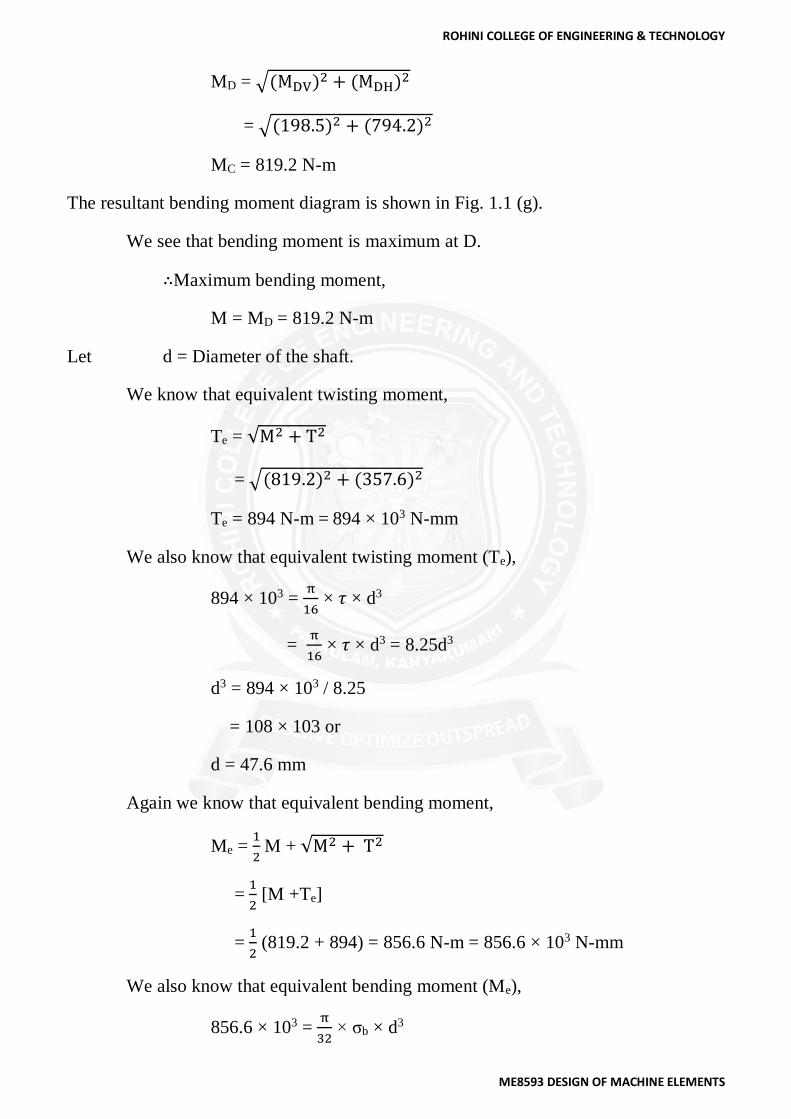
MC = 819.2 N-m
The resultant bending moment diagram is shown in Fig. 1.1 (g).
We see that bending moment is maximum at D.
∴Maximum bending moment,
M = MD = 819.2 N-m
Let d = Diameter of the shaft.
We know that equivalent twisting moment,
Te = √M2 + T2
= √(819.2)2 + (357.6)2
Te = 894 N-m = 894 × 103 N-mm
We also know that equivalent twisting moment (Te),
894 × 103 = π
16 × 𝜏 × d3
= π
16 × 𝜏 × d3 = 8.25d3
d3 = 894 × 103 / 8.25
= 108 × 103 or
d = 47.6 mm
Again we know that equivalent bending moment,
Me = 1
2 M + √M2 + T2
= 1
2 [M +Te]
= 1
2 (819.2 + 894) = 856.6 N-m = 856.6 × 10³ N-mm
We also know that equivalent bending moment (Me),
856.6 × 103 = π
32 × σb × d3

ROHINI COLLEGE OF ENGINEERING & TECHNOLOGY
ME8593 DESIGN OF MACHINE ELEMENTS
856.6 × 103 = π
32 × 63 × d3
= 6.2 d3
∴ d3 = 856.6 × 10³/6.2 = 138.2 × 10³ or
d = 51.7 mm
Taking larger of the two values, we have
d = 51.7 say 55 mm
Shafts Subjected to Fluctuating Loads
In the previous articles we have assumed that the shaft is subjected to constant torque and
bending moment. But in actual practice, the shafts are subjected to fluctuating torque and
bending moments. In order to design such shafts like line shaft and counter shafts, the
combined shock and fatigue factors must be taken into account for the computed twisting
moment (T) and bending moment (M). Thus for a shaft subjected to combined bending
and torsion, the equivalent twisting moment,
Te = √(Km + M)2 + (Kt + T)2
and equivalent bending moment,
Me = 1
2 [Km × M + √(Km + M)2 + (Kt + T)2]
where Km = Combined shock and fatigue factor for bending, and
Kt = Combined shock and fatigue factor for torsion.
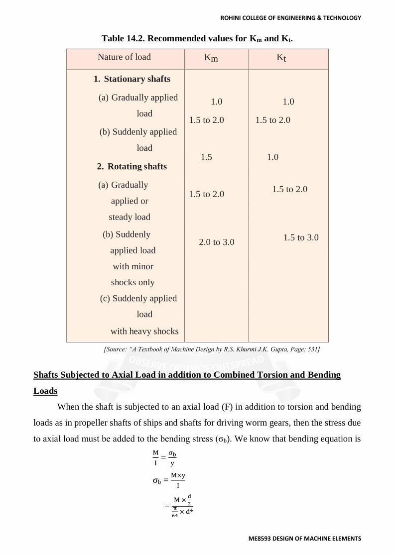
The following table shows the recommended values for Km and Kt.
ROHINI COLLEGE OF ENGINEERING & TECHNOLOGY
ME8593 DESIGN OF MACHINE ELEMENTS
Table 14.2. Recommended values for Km and Kt.
Nature of load Km Kt
1. Stationary shafts
(a) Gradually applied
load
(b) Suddenly applied
load
2. Rotating shafts
(a) Gradually
applied or
steady load
(b) Suddenly
applied load
with minor
shocks only
(c) Suddenly applied
load
with heavy shocks
1.0
1.5 to 2.0
1.5
1.5 to 2.0
2.0 to 3.0
1.0
1.5 to 2.0
1.0
1.5 to 2.0
1.5 to 3.0
[Source: “A Textbook of Machine Design by R.S. Khurmi J.K. Gupta, Page: 531]
Shafts Subjected to Axial Load in addition to Combined Torsion and Bending
Loads
When the shaft is subjected to an axial load (F) in addition to torsion and bending
loads as in propeller shafts of ships and shafts for driving worm gears, then the stress due
to axial load must be added to the bending stress (σb). We know that bending equation is
M
I =
σb
y
σb = M×y
I
= M ×
d
2π
64 × d4

ROHINI COLLEGE OF ENGINEERING & TECHNOLOGY
ME8593 DESIGN OF MACHINE ELEMENTS
= 32×M
π × d3
and stress due to axial load,
= F
π
4 ×d2
= 4F
πd2 ...(For round solid shaft)
= 4F
π[(do)2 – (di)2] ...( For hollow shaft)
= 4F
π[do2(1− k2)]
... (k = di/do)
∴ Resultant stress (tensile or compressive) for solid shaft,
σ1 = 32M
πd3 +
4F
πd3
= 32
πd3(M +
F ×d
8 )
= 32M1
πd3
In case of a hollow shaft, the resultant stress,
σ1 = 32M
πdo4(1− k4)
+ 4F
πdo2(1− k2)
σ1 = 32
πdo4(1− k4)
[ M + Fdo(1+k2)
8]
σ1 = 32M1
πdo4(1− k4)
... Substituting for hollow shaft,M1 = M + Fdo(1+k2)
8
In case of long shafts (slender shafts) subjected to compressive loads, a factor known as
column factor (α) must be introduced to take the column effect into account.
∴ Stress due to the compressive load,
σc = α×4F
π×d4
σc = α×4F
πdo2(1− k2)
The value of column factor (α) for compressive loads* may be obtained from the
following relation:
Column factor, α =1
1−0.0044(L
K)

ROHINI COLLEGE OF ENGINEERING & TECHNOLOGY
ME8593 DESIGN OF MACHINE ELEMENTS
This expression is used when the slenderness ratio (L / K) is less than 115. When the
slenderness ratio (L / K) is more than 115, then the value of column factor may be
obtained from the following relation:
Column factor, α = σy(
L
K)2
Cπ2E
where L = Length of shaft between the bearings,
K = Least radius of gyration,
σy = Compressive yield point stress of shaft material, and
C = Coefficient in Euler's formula depending upon the end conditions.
The following are the different values of C depending upon the end conditions.
C =1, for hinged ends,
= 2.25, for fixed ends,
= 1.6, for ends that are partly restrained as in bearings.
Design of Shafts on the basis of Rigidity
Sometimes the shafts are to be designed on the basis of rigidity. We shall consider
the following two types of rigidity.
1. Torsional rigidity. The torsional rigidity is important in the case of camshaft of
an I.C. engine where the timing of the valves would be effected. The
permissible amount of twist should not exceed 0.25° per metre length of such
shafts. For line shafts or transmission shafts, deflections 2.5 to 3 degree per
metre length may be used as limiting value. The widely used deflection for the
shafts is limited to 1 degree in a length equal to twenty times the diameter of
the shaft. The torsional deflection may be obtained by using the torsion
equation,
T
J =
G.θ
L
θ = T.L
J.G
where θ = Torsional deflection or angle of twist in radians,
T = Twisting moment or torque on the shaft,
J = Polar moment of inertia of the cross-sectional area about the axis

ROHINI COLLEGE OF ENGINEERING & TECHNOLOGY
ME8593 DESIGN OF MACHINE ELEMENTS
of rotation,
= π
32 × d4
= π
32 × [(do)
4 – (di)4]
G = Modulus of rigidity for the shaft material, and
L = Length of the shaft.
2. Lateral rigidity. It is important in case of transmission shafting and shafts
running at high speed, where small lateral deflection would cause huge out-of-
balance forces. The lateral rigidity is also important for maintaining proper
bearing clearances and for correct gear teeth alignment. If the shaft is of uniform
cross-section, then the lateral deflection of a shaft may be obtained by using the
deflection formulae as in Strength of Materials. But when the shaft is of variable
cross-section, then the lateral deflection may be determined from the
fundamental equation for the elastic curve of a beam, i.e.
d2y
dx2 =
M
EI
Problem 1.3
Compare the weight, strength and stiffness of a hollow shaft of the same external diameter
as that of solid shaft. The inside diameter of the hollow shaft being half the external
diameter. Both the shafts have the same material and length.
Given Data:
do = d
di = do / 2 or
k = di / do = 1 / 2 = 0.5
Comparison of weight
We know that weight of a hollow shaft,
WH = Cross-sectional area × Length × Density
= π
4 × [(do)
2 – (di)2]× Length × Density
and weight of the solid shaft,

ROHINI COLLEGE OF ENGINEERING & TECHNOLOGY
ME8593 DESIGN OF MACHINE ELEMENTS
WS = π
4 × d2 × Length × Density
Since both the shafts have the same material and length, therefore by dividing equation
(i) by equation (ii), we get,
WH
WS =
[(do)2 – (di)2]
d2
= [(do)2 – (di)2]
do2
WH
WS = 1-
(do)2
(di)2
Comparison of strength
We know that strength of the hollow shaft,
TH = 𝜋
16 × 𝜏 ×(do)
3(1-k4)
and strength of the solid shaft,
TS = 𝜋
16 × 𝜏 × d3
Dividing equation (iii) by equation (iv), we get
TH
TS =
do3(1− k4)
d3
TH
TS =
do3(1− k4)
do3 = 1- k4
= 1 – (0.5)4 = 0.9375
Comparison of stiffness
We know that stiffness,
T
θ =
G.J
L
∴ Stiffness of a hollow shaft,
SH = 𝐺
𝐿 ×
π
32× [(do)
4 – (di)4]
and stiffness of a solid shaft,
SS = 𝐺
𝐿 ×
π
32× d4
Dividing equation (v) by equation (vi), we get
SH
SS =
(do)4−(di)4
d4 =
(do)4−(di)4
do2
SH
SS = 1-
(do)4
(di)4

ROHINI COLLEGE OF ENGINEERING & TECHNOLOGY
ME8593 DESIGN OF MACHINE ELEMENTS
= 1- k4
= 1 – (0.5)4
SH
SS = 0.9375