Evaluation of a mobile IPv6-based architecture supporting user mobility QoS and AAAC in...
14
2138 IEEE JOURNAL ON SELECTED AREAS INCOMMUNICATIONS, VOL. 23, NO. 11, NOVEMBER 2005 Evaluation of a Mobile IPv6-Based Architecture Supporting User Mobility QoS and AAAC in Heterogeneous Networks Victor Marques, Xavier Pérez Costa, Rui L. Aguiar, Member, IEEE, Marco Liebsch, and A. Manuel Oliveira Duarte Abstract—This paper presents a Mobile IPv6-based overlay network architecture for heterogeneous environments, designed entirely based on IPv6, that aims to be implemented seamlessly irrespectively of the supporting network infrastructure. All trans- mission technologies are handled at the physical and data-link layers, imposing IPv6-based protocols for all higher layer commu- nications and signaling. The architecture builds on Mobile IPv6 including improved fast handover, and integrates quality-of-ser- vice and authentication, authorization, accounting, and charging control per user. The most critical issues of the proposed archi- tecture, mainly related to the handover process, were subject of a performance evaluation via ns-2 simulations. Finally, a field trial of the system was implemented, overlaying part of the GEANT infrastructure between Madrid and Stuttgart, which results are presented here. Index Terms—4G, authentication, authorization, accounting, and charging (AAAC), fast mobility, quality-of-service (QoS). I. INTRODUCTION T HE EVOLUTION toward next-generation wireless net- working brought life to the concept of technology and services integration. The success attained by the Internet, on one side, and by cell phone networks, on the other, led to visions of “next-generation networks,” integrating the two different philosophies. On one hand, Internet protocol (IP) technology has been developed in order to support a new range and variety of services, previously only possible with circuit switching technologies, due to the very low cost of Internet access. On the other hand, cellular telephony technology also boomed during this Internet evolution, bringing commodities now very keen to humans: mobility and reachability. It was then natural to associate both concepts as a universal data-based mobile access network. Current General Packet Radio Service (GPRS) [1] and Universal Mobile Telecommunications System (UMTS) [2] technologies are just the starting points on these visions. Despite these ongoing developments, there are still many technical obstacles to overcome before the common Manuscript received December 1, 2004; revised June 21, 2005. V. Marques is with the Portugal Telecom Inovação, Rua Eng. José Ferreira Pinto Basto, 3810-106 Aveiro, Portugal (e-mail: victor-m-marques@ptino vacao.pt). X. P. Costa and M. Liebsch are with NEC Network Laboratories, NEC Europe, Ltd., D-69115 Heidelberg, Germany (e-mail: [email protected]; [email protected]). R. L. Aguiar and A. M. O. Duarte are with the Department of Electronica e Telecomunicacoes and the Institute of Telecommunications, Universidade de Aveiro, 3810 Aveiro, Portugal (e-mail: [email protected]; [email protected]). Digital Object Identifier 10.1109/JSAC.2005.856825 citizen is able to achieve “multimedia communication anytime, anywhere, any style.” Although wireless transmission capabilities have steadily increased, the requirements of new applications have increased in a similar way. In this context, the fact that more resources are available does not necessarily mean that the user will have them when desired, a normal limitation with the relatively scarce radio spectrum. Specially in wireless networks, resources must be managed in an efficient way, and selected services [e.g., voice-over-IP (VoIP)] should receive better quality-of-service (QoS). This brings the need to integrate QoS support for dif- ferentiating between the traffic of different services (or users). Other control aspects, such as authentication, authorization, accounting, and charging (AAAC) systems (as traditionally considered within the Internet Engineering Task Force, but further enhanced with charging components) need also to be supported. The work presented in this paper describes our view for a future Mobile IPv6-based overlay network architecture inte- grating the above mentioned requirements, and presents both experimental and simulation results on this overlay network. Although IPv4 could be considered as a possibility, the inherent address advantages and mobility efficiency of IPv6 makes this the technology of choice for future mobile networks. This ar- chitecture is positioned in a time in future beyond the traditional “All-IP” visions of industry groups (e.g., 3GPP, which still resort to specific transport protocols at the radio access level). We present an IPv6-centered heterogeneous architecture, i.e., IPv6 is the only protocol at the network layer, supporting mo- bility, and assuring QoS per user, and all management features required to deploy advanced services in a provider’s framework (i.e., supporting AAAC functions). Security aspects are also included in this network, on the user access link. This Mobile IPv6 (MIPv6)-based architecture was implemented under the aegis of the IST Moby Dick 1 project. It supports seamless handover mechanisms across three different access networks [wideband code-division multiple access (W-CDMA), wireless local area network (LAN), and Ethernet], representative of dif- ferent types of user access; mobility-enabled end-to-end QoS; IP-layer paging signaling; and AAA mechanisms enriched with auditing, metering, and charging (AAAC). The rest of this paper is structured as follows. In Section II, we present the overall network architecture, showing access 1 IST-2000-25394, Mobility and Differentiated Services in a Future IP Net- work: http://www.ist-mobydick.org 0733-8716/$20.00 © 2005 IEEE
-
Upload
independent -
Category
Documents
-
view
0 -
download
0
Transcript of Evaluation of a mobile IPv6-based architecture supporting user mobility QoS and AAAC in...
2138 IEEE JOURNAL ON SELECTED AREAS IN COMMUNICATIONS, VOL. 23, NO. 11, NOVEMBER 2005
Evaluation of a Mobile IPv6-Based ArchitectureSupporting User Mobility QoS and AAAC in
Heterogeneous NetworksVictor Marques, Xavier Pérez Costa, Rui L. Aguiar, Member, IEEE, Marco Liebsch, and A. Manuel Oliveira Duarte
Abstract—This paper presents a Mobile IPv6-based overlaynetwork architecture for heterogeneous environments, designedentirely based on IPv6, that aims to be implemented seamlesslyirrespectively of the supporting network infrastructure. All trans-mission technologies are handled at the physical and data-linklayers, imposing IPv6-based protocols for all higher layer commu-nications and signaling. The architecture builds on Mobile IPv6including improved fast handover, and integrates quality-of-ser-vice and authentication, authorization, accounting, and chargingcontrol per user. The most critical issues of the proposed archi-tecture, mainly related to the handover process, were subject of aperformance evaluation via ns-2 simulations. Finally, a field trialof the system was implemented, overlaying part of the GEANTinfrastructure between Madrid and Stuttgart, which results arepresented here.
Index Terms—4G, authentication, authorization, accounting,and charging (AAAC), fast mobility, quality-of-service (QoS).
I. INTRODUCTION
THE EVOLUTION toward next-generation wireless net-working brought life to the concept of technology and
services integration. The success attained by the Internet, onone side, and by cell phone networks, on the other, led tovisions of “next-generation networks,” integrating the twodifferent philosophies. On one hand, Internet protocol (IP)technology has been developed in order to support a new rangeand variety of services, previously only possible with circuitswitching technologies, due to the very low cost of Internetaccess. On the other hand, cellular telephony technology alsoboomed during this Internet evolution, bringing commoditiesnow very keen to humans: mobility and reachability. It was thennatural to associate both concepts as a universal data-basedmobile access network. Current General Packet Radio Service(GPRS) [1] and Universal Mobile Telecommunications System(UMTS) [2] technologies are just the starting points on thesevisions. Despite these ongoing developments, there are stillmany technical obstacles to overcome before the common
Manuscript received December 1, 2004; revised June 21, 2005.V. Marques is with the Portugal Telecom Inovação, Rua Eng. José Ferreira
Pinto Basto, 3810-106 Aveiro, Portugal (e-mail: [email protected]).
X. P. Costa and M. Liebsch are with NEC Network Laboratories, NECEurope, Ltd., D-69115 Heidelberg, Germany (e-mail: [email protected];[email protected]).
R. L. Aguiar and A. M. O. Duarte are with the Department of Electronicae Telecomunicacoes and the Institute of Telecommunications, Universidade deAveiro, 3810 Aveiro, Portugal (e-mail: [email protected]; [email protected]).
Digital Object Identifier 10.1109/JSAC.2005.856825
citizen is able to achieve “multimedia communication anytime,anywhere, any style.”
Although wireless transmission capabilities have steadilyincreased, the requirements of new applications have increasedin a similar way. In this context, the fact that more resources areavailable does not necessarily mean that the user will have themwhen desired, a normal limitation with the relatively scarceradio spectrum. Specially in wireless networks, resources mustbe managed in an efficient way, and selected services [e.g.,voice-over-IP (VoIP)] should receive better quality-of-service(QoS). This brings the need to integrate QoS support for dif-ferentiating between the traffic of different services (or users).Other control aspects, such as authentication, authorization,accounting, and charging (AAAC) systems (as traditionallyconsidered within the Internet Engineering Task Force, butfurther enhanced with charging components) need also to besupported.
The work presented in this paper describes our view for afuture Mobile IPv6-based overlay network architecture inte-grating the above mentioned requirements, and presents bothexperimental and simulation results on this overlay network.Although IPv4 could be considered as a possibility, the inherentaddress advantages and mobility efficiency of IPv6 makes thisthe technology of choice for future mobile networks. This ar-chitecture is positioned in a time in future beyond the traditional“All-IP” visions of industry groups (e.g., 3GPP, which stillresort to specific transport protocols at the radio access level).We present an IPv6-centered heterogeneous architecture, i.e.,IPv6 is the only protocol at the network layer, supporting mo-bility, and assuring QoS per user, and all management featuresrequired to deploy advanced services in a provider’s framework(i.e., supporting AAAC functions). Security aspects are alsoincluded in this network, on the user access link. This MobileIPv6 (MIPv6)-based architecture was implemented under theaegis of the IST Moby Dick1 project. It supports seamlesshandover mechanisms across three different access networks[wideband code-division multiple access (W-CDMA), wirelesslocal area network (LAN), and Ethernet], representative of dif-ferent types of user access; mobility-enabled end-to-end QoS;IP-layer paging signaling; and AAA mechanisms enriched withauditing, metering, and charging (AAAC).
The rest of this paper is structured as follows. In Section II,we present the overall network architecture, showing access
1IST-2000-25394, Mobility and Differentiated Services in a Future IP Net-work: http://www.ist-mobydick.org
0733-8716/$20.00 © 2005 IEEE

MARQUES et al.: EVALUATION OF A MOBILE IPv6-BASED ARCHITECTURE SUPPORTING USER MOBILITY QoS AND AAAC 2139
Fig. 1. General network architecture.
technologies, architecture elements, and their functions. InSection III, mobility related aspects are presented, coveringthe deployed fast handover (FHO) mechanism and IP pagingin detail. Section IV presents the QoS framework, coveringthe main elements involved. In Section V, we present theAAAC support system. Section VI discusses the integrationof these aspects (mobility, QoS, and AAAC) and provides anoverall view of the system operation, describing basic signalingflows. Section VII discusses our simulation and experimentalvalidation results and highlights the timing limitations of thearchitecture. Finally, a summary is presented in Section VIIItogether with our main conclusions.
II. BASIC NETWORK ARCHITECTURE ELEMENTS
Our network architecture was designed to be agnostic to thetype of layer 2 technologies used, and a real implementation wasdeveloped supporting three different types of access technolo-gies (Ethernet, wireless LAN, and W-CDMA). The architectureis composed of mobile terminals (MTs, the user terminals), ac-cess routers, or gateways (ARs, the MT access point to the net-work), an AAAC system per administrative domain (supportingall AAAC functions), a home agent (HA) for IPv6 mobility, QoSbrokers (QoSBs) (managing the access networks), and IP pagingagents (PAs). These elements are depicted in Fig. 1. The systemis controlled by a Network Management System (not depicted),which configures adequately all the network devices. All sig-naling between these entities is exchanged at the IP-layer level,in order to achieve a convergence layer independent of the L2technology. We consider that in some situations, only one ac-tive connection to a wireless AR can exist, due to hardware andL2 technology limitations. The functions provided by these en-tities and their interworking build an architecture which sup-ports an efficient seamless network access on this heterogeneousenvironment.
To provide seamless mobility, i.e., the user not aware that ahandover is under progress, competitive to the existing in cur-rent cellular networks, Mobile IPv6 with FHO [3] is used withspecific QoS enhancements and associated to context transfertechniques for access link security [4]. This IP-based approachhas the advantage to increase the scope of mobility across cellsbased on different access technologies. Network access is pro-vided by a (potentially wireless) AR, which controls a single(wireless) cell: on the wireless access, an IP subnet is directlymapped to a radio cell. Changing cells becomes then a processmanaged at the IP-level, as all other handovers in our network.For achieving this, W-CDMA support (used in TDD mode) hadto be achieved by directly connecting base stations to the IPnetwork, thus eliminating several of the elements defined inthe 3GPP UMTS architecture (RNC, SGSN, GGSN) [5], sim-plifying its architecture and further achieving intertechnologyhandovers in that process.
QoS provision resorts to a differentiated services (DiffServ)-based model [6], because of its higher scalability and reducedsignaling overhead. The association of a DiffServ frameworkwith the use of localized QoSBs supports QoS on large scale,while simultaneously providing control and local optimizationof the usage of access network resources. In our model, we as-sume that the core network is overprovisioned, and no explicitQoS control is required outside of the access links. In theselinks, the QoSBs instruct the access routers (ARs) regardingwhich flows to accept, performing connection access controlbased on measurements received from the ARs.
AAAC support is based on the AAA IETF Architecture[7], enriched with charging mechanisms to provide an overallarchitecture targeted to commercial use. Access link securityis implemented based on IPSec, and adequate modifications toIPSec packages have been made to support mobility, allowingsecurity related information to be exchanged between ARsduring handover using context-transfer techniques. Further-more, a novel IP paging concept was integrated into the overall
2140 IEEE JOURNAL ON SELECTED AREAS IN COMMUNICATIONS, VOL. 23, NO. 11, NOVEMBER 2005
architecture to decrease power consumption of the MT, and tofurther optimize the usage of the (scarce) radio access medium.All these mechanisms are explained in the next sections.
III. MOBILITY SUPPORT
Mobility support inside our architecture comprises both mo-bility (Mobile IPv6 and FHO) procedures able to operate acrossmultiple networks and paging provision at the network level.
A. Fast Handover (FHO)
Mobile IPv6 [8] is used as the basic mobility managementscheme for our network. While “standard” MIPv6 is deployedfor global mobility management (i.e., inter-administrative do-main handover) extensions for local mobility management (i.e.,intra-administrative domain handover) are required in real-timeenvironments (such as voice communications) for achievingseamless handover.
Early work on Mobile IPv6 almost exclusively dealt withIPv4 networks [9], [10]. Perkins and Wang [9] used ns-1 to an-alyze the effects of route optimization and buffering (smoothhandoff), Campbell et al. provided a comparison of IPv4 micro-mobility protocols in [10]. Because of the significant differencesbetween MIPv6 and Mobile IPv4 (MIPv4) results obtained forMIPv4 do not take over for MIPv6. Regarding MIPv6 thereare several proposals to enhance handover performance whichcan be divided in hierarchical [11] and nonhierarchical [3] ap-proaches. A protocol overview of these proposals and improve-ment ideas are provided in [12]–[14]. Our analysis and simu-lation results [14], [15] concluded that a nonhierarchical FHOapproach [3] was the most suitable mechanism for our network,as the best compromise between network complexity and seam-lessness of the handover.
A handover is composed of two different types of connectionchanges: low-layer handover (which may pose rigid technologyspecific constrains) and IP-layer handover. The chosen IP FHOapproach is independent of the access technology (W-CDMA,wireless LAN, or Ethernet) and follows a “make-before-break”philosophy: layer 3 handover will be prepared via the existingcommunication channel, before layer 2 handover is performed.In this way, the handover delay is reduced to the minimumamount of time necessary for the eventual reconfiguration orchanging of the interface. During this preparation phase, thecurrent AR is informed about the “intended handover” and forthe duration of this handover process, bicasts all packets des-tined for the mobile node both to the current care-of-address(CoA) and to the new AR. This mechanism reduces packet lossduring handover: explicit signaling controls the start of the bi-casting in the access link, effectively providing seamless hand-over. Although extra bandwidth is required at the core networkfor the bicasting, this is not usually a problem in that part of thenetworks.
The detailed signal flow of this process, and the integrationof QoS and AAAC aspects, is further discussed in Section VI.
B. Paging
As a requirement of the standard MIPv6 concept used in thenetwork, an active MT acquires a different CoA in each cell,
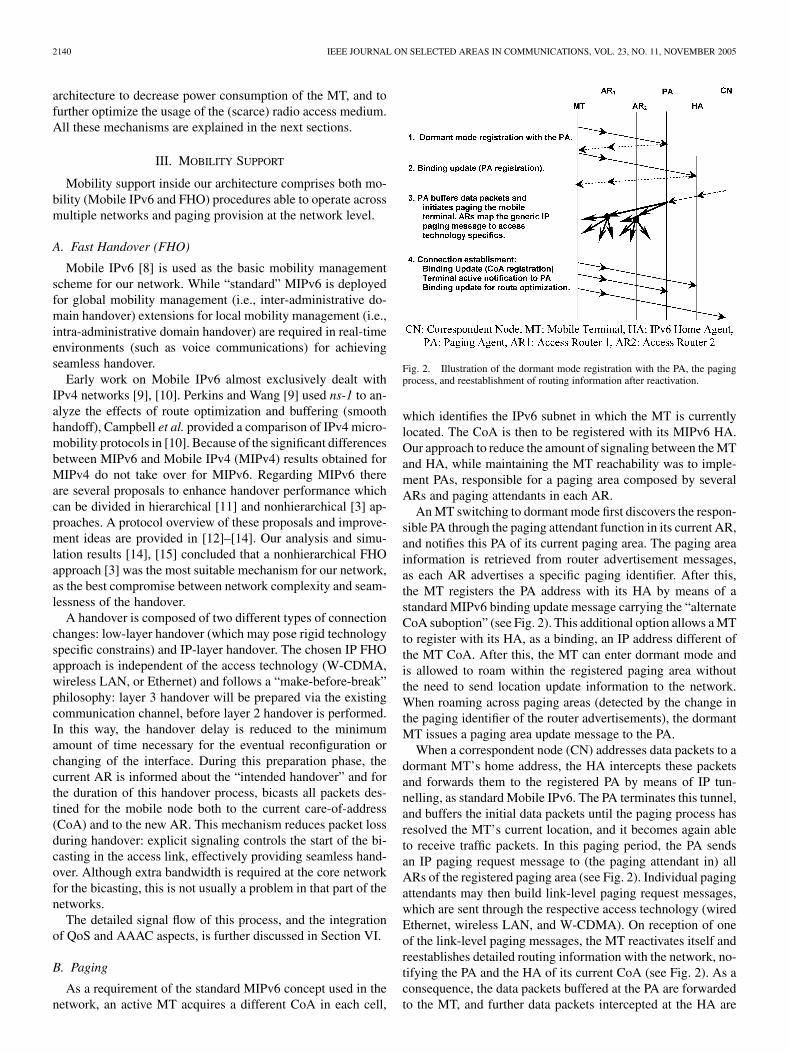
Fig. 2. Illustration of the dormant mode registration with the PA, the pagingprocess, and reestablishment of routing information after reactivation.
which identifies the IPv6 subnet in which the MT is currentlylocated. The CoA is then to be registered with its MIPv6 HA.Our approach to reduce the amount of signaling between the MTand HA, while maintaining the MT reachability was to imple-ment PAs, responsible for a paging area composed by severalARs and paging attendants in each AR.
An MT switching to dormant mode first discovers the respon-sible PA through the paging attendant function in its current AR,and notifies this PA of its current paging area. The paging areainformation is retrieved from router advertisement messages,as each AR advertises a specific paging identifier. After this,the MT registers the PA address with its HA by means of astandard MIPv6 binding update message carrying the “alternateCoA suboption” (see Fig. 2). This additional option allows a MTto register with its HA, as a binding, an IP address different ofthe MT CoA. After this, the MT can enter dormant mode andis allowed to roam within the registered paging area withoutthe need to send location update information to the network.When roaming across paging areas (detected by the change inthe paging identifier of the router advertisements), the dormantMT issues a paging area update message to the PA.
When a correspondent node (CN) addresses data packets to adormant MT’s home address, the HA intercepts these packetsand forwards them to the registered PA by means of IP tun-nelling, as standard Mobile IPv6. The PA terminates this tunnel,and buffers the initial data packets until the paging process hasresolved the MT’s current location, and it becomes again ableto receive traffic packets. In this paging period, the PA sendsan IP paging request message to (the paging attendant in) allARs of the registered paging area (see Fig. 2). Individual pagingattendants may then build link-level paging request messages,which are sent through the respective access technology (wiredEthernet, wireless LAN, and W-CDMA). On reception of oneof the link-level paging messages, the MT reactivates itself andreestablishes detailed routing information with the network, no-tifying the PA and the HA of its current CoA (see Fig. 2). As aconsequence, the data packets buffered at the PA are forwardedto the MT, and further data packets intercepted at the HA are

MARQUES et al.: EVALUATION OF A MOBILE IPv6-BASED ARCHITECTURE SUPPORTING USER MOBILITY QoS AND AAAC 2141
now directly forwarded to the reactivated MT. Route optimiza-tion, through binding update information to the CN, is then alsopossible.
This solution, as shown in [16], saves frequent location up-dating (binding updates), decreases signaling costs, and savesscarce radio bandwidth, as well as increasing MT battery powerusage efficiency.
IV. QOS ARCHITECTURES FOR MOBILE SERVICE PROVISIONING
The QoS architecture has to support end-to-end QoS, easilymanageable from an operator point of view. To achieve this ob-jective, entities and methods had to be defined for the scalableallocation and control of the resources in the access networks,able to offer and guarantee end-to-end QoS and maintaining userconnectivity and QoS, while the MT is moving.
A hard constraint to our architecture is the simultaneous sup-port of mobility and QoS. Several IETF QoS frameworks wereconsidered before designing the final QoS architecture, takingthis integration in consideration. The pros and cons of Inte-grated Services (IntServ) [17] and DiffServ [6] models havebeen widely discussed in the literature and are well known; un-fortunately, none of them has specific support for mobility. Noteven the hybrid solutions we were aware of seemed to solvethe integration of mobility and QoS. Thus, we developed an in-novative usage of QoSBs, associated with FHO, incorporatedin a traditional DiffServ approach, to be able to control andmanage available resources in an efficient way, while enablinguser mobility [4].
The architecture relies on the concept that the user will begranted with “services” previously contracted with the provider.The QoSBs are in charge of allocating resources in the accessnetwork, per user and per subscribed service, according to thecontractual information to the user. As discussed in [18], theseservices will usually be fixed transport services (e.g., “best effortwith 32 Kb/s,” or “guaranteed 64 kb/s”), but mechanisms forpotential dynamic service negotiation are also in place. QoSBsalso manage flow aggregation of resources in the core network.
For providing user-oriented QoS services, the QoSB inter-acts with the AAAC system during the (required) user regis-tration phase (see Section VI-A). When the user registers atthe network, the AAAC system dumps to the QoSB all rel-evant user-specific information for QoS provisioning. Havingthis user-specific information, the QoSB can perform serviceadmission control decisions on every service request done bythe user’s terminal. For that, the QoSB also interacts with theARs in its QoS domain. These interactions are required bothfor AR’s QoS configuration and for service authorization. Toreduce signaling overhead, the system is designed in such away that the user/terminal does not need to perform explicit re-source reservation or release (although these messages can besupported). “Services” are requested by simple DSCP markingon outgoing packets, with each DSCP corresponding to a dif-ferent contracted service. When the AR receives an incomingpacket from a user with a certain DSCP value, it sends a config-uration request to the QoSB. The QoSB, based on the informa-tion for this user, will then configure the AR with the appropriateQoS policies. Services are stopped implicitly, by an inactivity
Fig. 3. Enhanced generic AAA architecture supporting QoS-enabled mobilitymanagement.
timeout. This concept is described in greater detail in [18], anddetailed signal flows are presented in Section VI.
For each layer 2 technology supported, it is necessary tomap between IP QoS parameters and those specific of thattechnology. The IP QoS control procedures, based on DiffServcodepoints, must be also directly mapped in the physical layercontrol, at the AR. Specific middleware exists both at the MTand the AR, which perform these tasks [4].
V. MECHANISMS FOR SERVICE PROVISIONING IN A
HETEROGENEOUS MOBILE ENVIRONMENT
Our AAAC architecture (Fig. 3) is a basic IETF-based AAAarchitecture (authentication, authorization, and accounting) [7]enriched with auditing, metering and charging, and optimizedfor IPv6. The fact that the AAAC services would be used ina QoS-enabled MIPv6 environment has been considered in thearchitecture design to provide features which enable new func-tionality, as well as performance optimization of the overallsystem.
This auditing function enables further functionality in theAAAC, with respect to the evaluations of audit trails gener-ated by AAAC system and other entities. Within this context thepolicy repository is considered as being part of a policy-basedAAAC system.
The AAAC system supports multiple interfaces. An AAACattendant handles the interface with the MT: all communicationis done through a user registration protocol (URP). An applica-tion specific module (ASM) communicates with the QoSB. Theadvantage of developing ASMs is the added flexibility: a varietyof service equipment can be easily addressed with a uniformmethod from the AAAC system point of view. AAAC system toASM communications use the AAAC protocol (DIAMETER),and the ASM to service equipment communications can be doneby equipment-specific protocols (in our case, generally, eitherCOPS [19] or URP). Note that in this architecture, a clear dis-tinction is made between services offered to the user, such asQoS-enabled services, and services required for the operationof the AAAC system, such as charging. Therefore, the formerones are in general accessed and provided via an ASM and theextended AAAC protocol, while the latter ones are communi-cating directly with the AAAC system, using dedicated com-munication means if required.

2142 IEEE JOURNAL ON SELECTED AREAS IN COMMUNICATIONS, VOL. 23, NO. 11, NOVEMBER 2005
AAAC systems communicate with each other via theDIAMETER base protocol suitably enhanced with adequateextensions.
A key element for QoS provisioning and charging is a meterthat is able to account service usage. Within the IETF real-time flow measurement (RTFM) working group an IP-basedmetering framework was defined [20]. A publicly available net-work meter, NeTraMet, is commonly used for network moni-toring and measurement. The basic component of this referenceimplementation is a traffic meter (NeTraMet agent), which cap-tures IP header information according to a predefined rule andassigns this information to the different IP flows. The defini-tion of these IP flows is quite flexible according to the needs ofthe network administrator. In our IPV6 network, the meter (en-hanced to run on IPv6) is configured according with the descrip-tion of the “services” subscribed by the user, and communicatedto the QoSB.
VI. KEY SCENARIOS/MOBILITY, QOS,AND AAAC INTEGRATION
For the network, three distinct phases of operation and con-trol can be clearly identified: 1) registration—in this architec-ture, a MT/user may only start using network resources after au-thentication and authorization, as in today’s cellular networks;2) authorization—the user has to be authorized to use specificservices previous to its release by the network; and 3) hand-over—the user needs to have its existing resources reservationstransferred from one AR to another, due to its movement.
A. Registration
The registration (see Fig. 4) process (AAA and mobility)is initiated after a CoA is acquired by the MT via statelessautoconfiguration, using layer-2 identifiers; the uniqueness ofthese addresses is checked at the registration stage, when du-plicate address detection (DAD) is performed (through a com-bined process of ARP requests and special functionalities on theQoSB). Getting this uncertified CoA does not entitle the userto consume resources besides registration messages—but po-tentially allows emergency calls (ARs are configured to allowspecific connections to emergency addresses, the equivalent toa 911 call). For accessing the network otherwise, the MT has tostart the authentication process by sending the user authentica-tion information (message 1, Fig. 4) to the AR. That request willbe then forwarded to the AAAC system (message 2) responsiblefor that AR. Notice that the registration is done in function ofthe user, and not of the terminal (e.g., as happens in current cel-lular equipment).
In a roaming case, which is more complex, the Domain AAAAC will issue a registration request to the MT’s home AAAC(message w). Here, the AAAC server A is playing the role of theforeign domain AAAC server, which needs to contact the MThome AAAC. This AAAC first checks if there is a formal con-tractual relationship between the administrative domain this re-quest comes from and its own administrative domain (the equiv-alent to current roaming agreements). Then, in case of a positiveresult, the home AAAC performs authentication by verifyingthe provided credentials. Then, in the positive case, the home
AAAC sends to the HA a request for that user (message x) towhich the HA answers (y). Then, the home AAAC finally an-swers the Domain A AAAC (z).
One attribute of this positive acknowledgment is a user pro-file containing the required information to provide the servicesrequested in the foreign domain. The user profile is a centrallymanaged profile containing all relevant user-specific informa-tion for service provisioning. One section of this profile, the net-work view of the user profile (NVUP), will be forwarded fromthe AAAC server to the QoSB (message 3b) (which also per-forms DAD at this stage), and a different set of the profile willbe sent to the AAA Attendant located at the AR (3a). The NVUPcontains all required information relevant to network serviceprovisioning, while metering and security related informationwill be forwarded to the AAA attendant. The AAAC will alsoinform the MT of the successful registration, via the AR (mes-sages 3a and 4). Afterwards, the AR will initiate accountingfor that user, and informs the AAAC (message 4a). The authen-tication phase is thus completed, and the user can access thenetwork.
B. Authorization/Session Setup
Fig. 4 also shows how each network service is authorized(messages 5 to 11). First, the MT sends a packet (5) with theDSCP code marked to request a specific subscribed service (e.g.,a prioritary network access at 256 Kb/s). This trailer packet canbe either a packet with real information or just a dummy packet,depending on the configuration on the MT. If the “requested ser-vice” does not match any policy already set in the AR, the ARissues a request (6) to the QoSB, through the QoS manager (5a).Upon analyzing the request, and based on the user NVUP andon the availability of resources, the QoSB eventually decides onan answer to the AR (7). The AR QoS manager will then eitherconfigure the AR with the appropriated policy for that user/MTservice (7a), or informs the User/MT of a service denial (7b).After (7a), any other conformant packet sent from the MT thatmatches the configured policy rule will be able to cross the net-work (8). Packets with a different DSCP code will restart the au-thorization process once more. Upon reaching the end-domainwhere the other user or CN is, the marked packet starts anotherQoS authorization process (8a). The QoS manager on this ARwill send a policy query to the QoSB (9), to which the QoSBanswers (10). If there are resources, this answer is a positive an-swer and the QoS manager will configure the AR (10a) with theright policy, otherwise, the AR will send back a service denialmessage (10b). After (10a), the next packets matching the in-stalled policy will be able to reach the other terminal (11).
With this approach both access networks provide contractedlevels of QoS; core network is then monitored to check if the ex-pected performance is being provided, such that the contractedend-to-end QoS is being fulfilled.
C. QoS-Enabled Handover
One of the most difficult problems when dealing with IP mo-bility is assuring a constant level of QoS. User mobility is per-formed in our network by means of FHO techniques in combi-nation with message exchange to and between the QoSB duringthe handover, as shown in Fig. 5.

MARQUES et al.: EVALUATION OF A MOBILE IPv6-BASED ARCHITECTURE SUPPORTING USER MOBILITY QoS AND AAAC 2143
Fig. 4. End-to-end QoS support, registration, and service authorization.
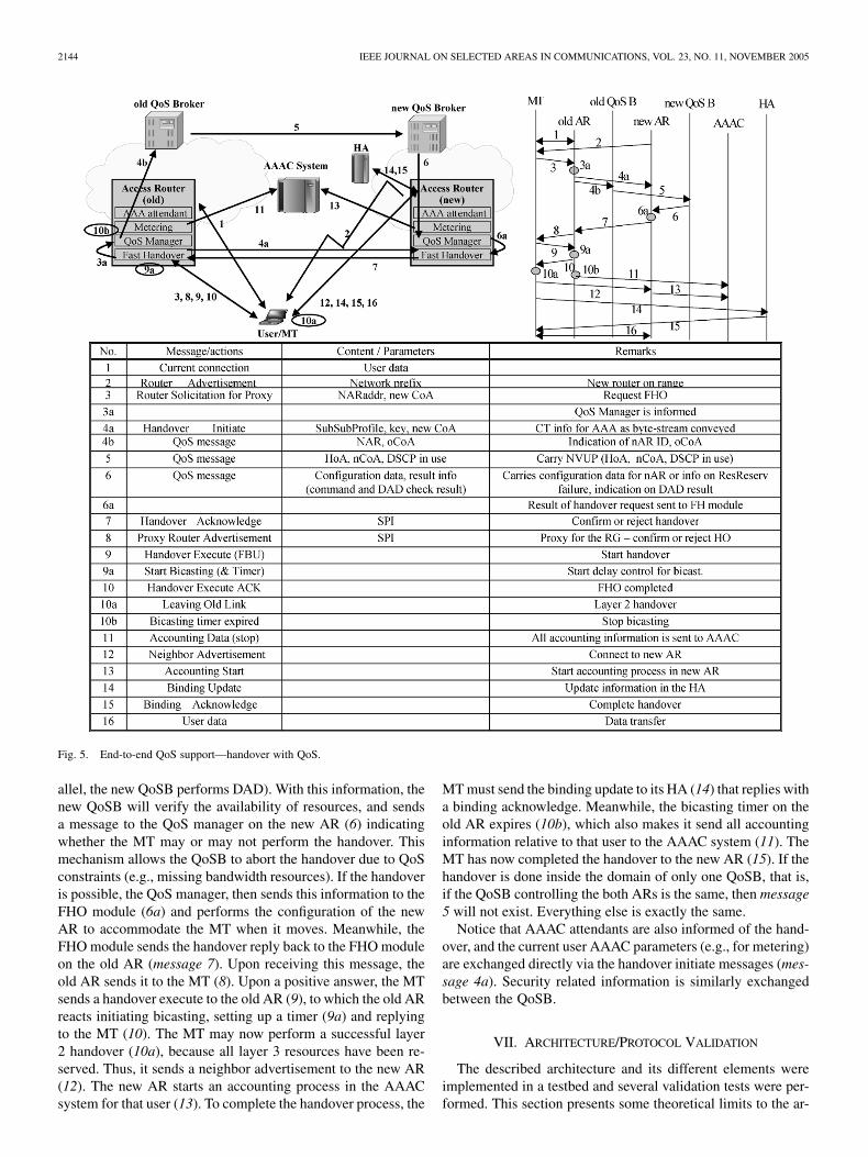
When a MT starts losing signal strength to the current AR(“old AR”) (message 1, depicted in Fig. 5), it starts a handoverprocedure to a neighboring AR (“new AR”) from which it re-ceives a beacon signal with the network prefix advertisement(2). The MT builds its CoA and initiates the handover procedure,sending an IP-handover request to its new AR, but still throughthe old AR (3). The FHO module in the old AR will forward this
request to its QoS manager (message 3a) and the FHO moduleon the new AR, known by the network prefix (4a). The QoSmanager immediately forward this request to the QoSB (4b)(“old QoSB”). The old QoSB sends a handover request to thenew QoSB (5), indicating the user’s NVUP and the list of ser-vices currently being used by this user. Basically, this acts as acontext transfer from the old QoSB to the new QoSB (in par-
2144 IEEE JOURNAL ON SELECTED AREAS IN COMMUNICATIONS, VOL. 23, NO. 11, NOVEMBER 2005
Fig. 5. End-to-end QoS support—handover with QoS.
allel, the new QoSB performs DAD). With this information, thenew QoSB will verify the availability of resources, and sendsa message to the QoS manager on the new AR (6) indicatingwhether the MT may or may not perform the handover. Thismechanism allows the QoSB to abort the handover due to QoSconstraints (e.g., missing bandwidth resources). If the handoveris possible, the QoS manager, then sends this information to theFHO module (6a) and performs the configuration of the newAR to accommodate the MT when it moves. Meanwhile, theFHO module sends the handover reply back to the FHO moduleon the old AR (message 7). Upon receiving this message, theold AR sends it to the MT (8). Upon a positive answer, the MTsends a handover execute to the old AR (9), to which the old ARreacts initiating bicasting, setting up a timer (9a) and replyingto the MT (10). The MT may now perform a successful layer2 handover (10a), because all layer 3 resources have been re-served. Thus, it sends a neighbor advertisement to the new AR(12). The new AR starts an accounting process in the AAACsystem for that user (13). To complete the handover process, the
MT must send the binding update to its HA (14) that replies witha binding acknowledge. Meanwhile, the bicasting timer on theold AR expires (10b), which also makes it send all accountinginformation relative to that user to the AAAC system (11). TheMT has now completed the handover to the new AR (15). If thehandover is done inside the domain of only one QoSB, that is,if the QoSB controlling the both ARs is the same, then message5 will not exist. Everything else is exactly the same.
Notice that AAAC attendants are also informed of the hand-over, and the current user AAAC parameters (e.g., for metering)are exchanged directly via the handover initiate messages (mes-sage 4a). Security related information is similarly exchangedbetween the QoSB.
VII. ARCHITECTURE/PROTOCOL VALIDATION
The described architecture and its different elements wereimplemented in a testbed and several validation tests were per-formed. This section presents some theoretical limits to the ar-

MARQUES et al.: EVALUATION OF A MOBILE IPv6-BASED ARCHITECTURE SUPPORTING USER MOBILITY QoS AND AAAC 2145
chitecture performance, identifying performance bottlenecks,presents simulation results for the handover procedure and alsomeasured values in a trial testbed [21]. This trial testbed wassupported by Linux-based boxes, added with specific hardwarefor the W-CDMA interface, and closely resembles the networkdepicted in Fig. 1.
There are three important performance parameters for this ar-chitecture, in terms of user perception: the setup delay (or regis-tration), the service initiation delay, and especially, the handoverdelay. This last parameter has to be kept at a minimum to guar-antee a seamless handover.
A. Registration Delay
The registration delay is the delay since the user turns on itsterminal until it becomes operational for service. There are twotypes of delays involved, the “low-layers” delay (layers 1 and 2),the delay since the terminal is enabled until is associates withone access technology; and the “high-layers” delay, the delaysince the terminal sends message 1 until message 4 arrives (inFig. 4)
The first term is technology dependent, and will not depend onthe specific network protocols or architecture used. The secondterm is dependent on the links speeds, devices performance (AR,AAAC) and, if the user is in roaming, the “electrical distance”between the foreign AAAC and the home AAAC
The first term, the link delays between the ARs and the AAACsystem, is usually negligible, as the management infrastructurehas normally overprovisioned links with dedicated resources.Processing delays in the AAAC systems (and ARs), especiallyif they are overloaded (with other requests) or subdimensioned(databases too big for the processing power of the elements) canbe dominant, but should be easily avoidable with proper com-putational and routing equipment in real-production networks.
Thus, the most restrictive factor seems to be the distance be-tween the foreign AAAC and its home AAAC (in terms of prop-agation time), when the user is roaming. In this case, the overallregistration delay will be mostly determined by this time.
This delay is not an essential performance parameter, as longas it is kept reasonably low (in human perception terms).
B. Session Setup Delay
The session setup delay is the amount of time since the userwants to start a communication until he is able to access thenetwork. In Fig. 4, the session setup delay is the time it takesfrom message 5 until message 11 goes through. This delay iscomposed by the processing time in the ARs and QoSB, thedistance between the ARs and link delays between: 1) the userterminal and the AR and 2) the ARs and the QoSB
The first term is usually very low, assuming normal networkconditions. The processing delays are the delays in both QoSBand in both ARs. Once again, the previous comments on perfor-mance can be applied, especially, as the QoSB has an architec-ture which allows for easy distribution of load (that is: the ARs)between multiple machines.
The results obtained in the field trial (see Section VII-E1)showed that the processing delays are negligible. Therefore, thedistance between the ingress AR and the egress AR may imposethe dominant delay. However, this is a network limit rather thanan architecture limitation.
C. Handover Delay
The handover delay is the critical parameter in terms of usersensitivity. The handover must be processed as fast as possibleto be seamless to the user, since otherwise no multimedia com-munication can be supported. The handover delay is composedby several independent delays that must be minimized indepen-dently: transmission delays, computational delays and layer 2handover delays. Some impose hard constraints, while othersmay be optimized or neglected
The transmission delays are composed by the sum of the delaysbetween the MT and the AR, the AR and the QoSB, betweenboth QoSB, and between both ARs. The global handover delayis the time spent between message 3 (on Fig. 5) and message12. However, the time that the user terminal is without connec-tivity and resources allocated is only the time spent in the layer2 handover (which is the time elapsed between event 10a andmessage 12). The handover behavior was simulated (see nextsection) in order to access its “seamless” feasibility. After im-plementation, the measurements done in the trial environment(see Section VII-E2) proved our architecture concept, obtainingreduced global handover delays, and negligible packet loss (dueto the bicasting process). Note that the global handover delayhas impact on the relation between the coverage (radius) of eachwireless cell and the speed the user can move itself, thus af-fecting cellular network planning.
D. QoS Enabled Handover Simulation
The most critical feature of this architecture, the handoverprocess, was subject of a simulation study using the ns-2 sim-ulator [22], to evaluate the performance of the handover sig-naling. For this, the ns-2 code was enhanced to implement thesignaling presented in this paper.
Fig. 6 presents the simulation scenario used to evaluate thehandover process. This base scenario consists on a MT (ini-tially located at [10;185]) traveling between two ARs (locatedat [50;25] and [300;25]) on an area of 350 200 m. Each ARis connected to a core router. The QoSB, programmed to intro-duce 17 ms processing delay (larger than final values attainedin real implementation), connected to the core routers, is the re-sponsible for managing the resources of both ARs. The HA anda CN are also part of this scenario. The wireless connection be-tween the base stations (ARs) and the mobile node is wireless

2146 IEEE JOURNAL ON SELECTED AREAS IN COMMUNICATIONS, VOL. 23, NO. 11, NOVEMBER 2005
Fig. 6. QoS-enabled handover simulation scenario.
LAN. The physical links are 5 Mb/s links with 2 ms delay be-tween nodes. Each simulation run had 50 s. Three seconds aftersimulation start, an application [transmission control protocol(TCP) or user datagram protocol (UDP)] is started. TCP is themost widely used transport protocol. We simulate endless FTPsources to understand the impact of this particular mobility ar-chitecture on the congestion control mechanism of TCP. TheUDP flow simulates a video call with 100 bytes data packetssent each 0.005 s (190 Kb/s average bandwidth), in line withthe expected next-generation personal services. The MT startsmoving to [340;185] with a speed of 10 m/s, 5 s after simulationstart. At s, the MT initiates the return to [10;185]. At
s, the TCP/UDP applications are stopped.The simulation study performed had two major goals:
1) to evaluate the signaling timings during the handoverperiod;
2) to evaluate the handover performance while the mobilenode is receiving data from TCP and UDP applications.
To better evaluate the handover signaling performance, some ofthe default scenario conditions were subject to variations, suchas the increase of the link delay between the two ARs and be-tween the CN and the ARs. Other variations performed werethe increase of the MT speed to 80 m/s and the variation of theQoSB processing delay to 3 and to 37 ms.
TABLE IHANDOVER SIGNALING SIMULATION RESULTS
1) Simulation Results: This section presents the simulationresults both from the base scenario and from the variations.
Table I presents the time instants (from the beginning ofthe simulation) when the handover signaling messages areexchanged.
The table analysis allowed us to conclude the following.
1) The handover preparation phase (before the actual layer2 handover) would take less than 150 ms (time differencebetween message 2 and 10).
2) The complete handover (including MT binding update)would take about 250 ms at most.

MARQUES et al.: EVALUATION OF A MOBILE IPv6-BASED ARCHITECTURE SUPPORTING USER MOBILITY QoS AND AAAC 2147
Fig. 7. Instantaneous TCP flow bandwidth.
3) When the wireless link is not congested, as it is the caseof the UDP traffic (TCP by definition tries to use thefull amount of available bandwidth), the handover timingswere even lower (130 and 230 ms, respectively).
In this simulation scenario, the signaling messages and thetraffic have exactly the same priority in every node (there is noQoS differentiation between them). This implies that, especiallyfor the TCP case, the timings may be negatively influenced bythe concurring traffic.
We may easily conclude that a MT travelling at 250 km/hneeds less than 11 m to prepare the layer 2 handover, and allthe handover process is concluded in less than 17 m. This isa reasonable value for cell overlapping and MT speed in next-generation networks.
However, to better understand how the applications are af-fected by the handover process, the next figures show the be-havior of the TCP and UDP flows in terms of bandwidth (in-stantaneous and average), latency and jitter. For the UDP flowit is further possible to show the analysis of out of order packetsat the destiny. It is also shown the impact of the variations per-formed in some of these flow characteristics. For the clarity ofthe figures, whenever it is not possible to differentiate the re-sult of the base scenario from the result of the variations, theselast are omitted (basically, meaning that the variation performeddoes not have any particular impact).
Fig. 7 presents the instantaneous TCP flow bandwidth be-tween the CN and the MT. At time 15,4 and 42,9 (approxi-mately) there were handovers. There are two small bandwidthpeaks just after the handover. The bicasting process introducesa small delay to the packets that are delivered after travellingfrom old AR to the new AR. This delay causes these packets toarrive at the MT together with others that travel directly fromthe CN to the MT (after the binding update at the new network).These packets arriving at the same time cause an increase of ac-knowledges, and the consequence is a temporary instantaneousbandwidth increase after the handover. As an overview analysisto this result, it is possible to conclude that the handover process
Fig. 8. Mean bandwidth of the TCP flow.
is seamless to the applications, since there were no packets lost(the TCP traffic did not decrease as it would in case of loss) andthe bandwidth variation is small.
Fig. 8 shows the mean bandwidth used by the TCP flowfor three different situations. The figure basically illustratesthe TCP behavior. When the CN is very close to the MT,there is an initial peak in the bandwidth used. When the CN isfarther away, we can observe the smooth increase in the meanbandwidth. The most relevant situation is when the MT movesto an AR that is 64 ms away from the old AR. In this case, wecan observe a decrease in the mean bandwidth, but this solelyhappens due to the TCP design, that it is not optimized to dealwith this type of reliable links. When the MT returns to theoriginal AR (around 43 s), we can observe a slight increase inthe mean bandwidth. For the other cases it is not possible toobserve any relevant changes during the handovers.
With respect to the latency (Fig. 9) and jitter it is clear toidentify the two handovers, since the bicasting process intro-duces some additional delay. Just after the handover, the bi-

2148 IEEE JOURNAL ON SELECTED AREAS IN COMMUNICATIONS, VOL. 23, NO. 11, NOVEMBER 2005
Fig. 9. TCP latency.
Fig. 10. Instantaneous UDP flow bandwidth.
casted packets arrive almost at the same time (sometimes after)as the packets being forwarded directly to the new AR. This jus-tifies the negative jitter values.
Fig. 10 presents the instantaneous bandwidth of the UDPflow. Apart from the initial peak, due to the IPv6 mobilityprocess (the first data packets flow through the home agent,arriving at the same time as the ones sent directly to the MT),it is possible to identify the two handovers at 15,5 and 42,6 s(except for the case when the MT travels at 80 m/s, around6 and 36 s) as there is an instantaneous peak bandwidth in thegraph. This is not due to an increase of the data at the senderside (it is a constant bit rate flow) but due to the bicastingprocess that causes the MT to receive some duplicate packets.The measurements were done at the MT side and repeatedpackets were accounted twice. By that reason, we observe thosetwo peaks when the handover occurs.
In terms of latency (Fig. 11), we may observe that, besides theinitial peak due to the IPv6 mobility (as explained before), thereis an increase, equal to the difference of the electrical distancebetween the CN and the correspondent AR, when the mobile
Fig. 11. UDP latency.
Fig. 12. Packets out of order.
node travels to the new AR network. When the CN is fartheraway the latency is obviously higher. It is also possible to iden-tify the earliest handovers when the MT travels faster (80 m/s).With respect to jitter, there exists a positive peak when the mo-bile node increases its distance to the CN and a negative peakwhen it comes closer, easily deductible by observing the latencygraphs. In this last case, when the mobile node comes from a net-work farther away from the CN, there are some packets that, dueto the bicasting will arrive after some others that were sent di-rectly from the CN to the new AR. Naturally, the peak is higherwhen the electrical distance between the ARs is also higher. Thisjitter implies that some of the packets arrive to the MT out oforder (Fig. 12). For some real time applications, packets out oforder may be considered lost packets, which is a negative ef-fect of the mobility. The amount of packets out of order is alsohigher when the ARs are more distant from each other.
The final comment is to the scenario where the QoSB pro-cessing delay was changed. The processing delay of the QoSBwas varied from 3 to 37 ms, and the results, as expected, shownthat the only effect is the proportional change in the time that the

MARQUES et al.: EVALUATION OF A MOBILE IPv6-BASED ARCHITECTURE SUPPORTING USER MOBILITY QoS AND AAAC 2149
Fig. 13. Testbed scenario.
handover preparation takes. From the values simulated (from3 to 37 ms), which are reasonable and expected values of areal-QoSB implementation, we observed that there were no im-pacts on the architecture performance. These results, since theyinclude processing delays associated with real implementationperformance, mean that the presence of a QoSB in this architec-ture does not have a major impact on the performance, while thebenefits of having it are very important from the network oper-ator point of view.
E. Critical Scenarios Testbed Evaluation
The architecture presented here was also subject to a realtestbed evaluation. The focus of this evaluation was on the sig-naling performance. As identified before, the three most criticalsituations are the registration, the service authorization and themost important, the handover.
Although our results were achieved in low load scenarios andaccordingly slightly higher values may be obtained in real loadscenarios, is should be noticed that most of the delay compo-nents are related with hardware and CPU: the field trial im-plementations were done using low-end PCs running the Linuxoperating system, that although good to achieve fast implemen-tation results, are not optimal in terms of performance. Thus,performance delays do not relate with the proposed architectureand may be easily reduced with professional equipment.
The testbed scenario, very similar to the simulation scenariopresented before, is depicted in Fig. 13.
1) Registration and Service Authorization: Table II presentsthe signaling timings obtained in the testbed for in typical au-thorization case. The messages numbers follow the conventionson Fig. 4.
TABLE IIAUTHENTICATION TIMINGS
TABLE IIISERVICE AUTHORIZATION TIMINGS
TABLE IVHANDOVER SIGNALING TIMINGS
This results show that the timings involved are similar to theones we may experience in today’s mobile networks (the timeelapsed between the moment the user tries to join to a networkand the instant it gets access).
Table III presents the signaling timings for the service autho-rization. Once more, the messages are numbered according withFig. 4.
These results show that the service authorization takes about0.8 s (message 5 to 7). Since this happens at service start, wemay consider this value as negligible from the user experiencepoint of view. Message 8 is the next application packet sent bythe MT, which could be sent just after message 7. In the case ofthe applications used for this measurement, it takes some moretime, but it is not architecture dependent.
2) Handover: Table IV presents the handover signaling tim-ings measured on the testbed. Since only one QoSB was used,message 5 on Fig. 5 does not exist (it is QoSB internal).
The results obtained show that the handover preparationphase takes about 140 ms (from message 3 to 10). If we con-sider a MT speed of 250 km/h, this means that the handoveris prepared in less than 10 m, which is a perfectly reasonablevalue for cell overlapping (usually, several dozens of meters).The complete handover takes about 250 ms (message 3 to12), which is also a very comfortable value to be used in realnetworks.
The measurements performed during the fast handover pro-cedure (with the make before break and bicasting mechanism)show that, using current UDP-based applications (typical foraudio and video) the packet loss is null most of the times. Atthe most, one or two packets may be lost and that loss onlyhappens due to the Linux driver’s availability. Other measures
2150 IEEE JOURNAL ON SELECTED AREAS IN COMMUNICATIONS, VOL. 23, NO. 11, NOVEMBER 2005
were performed to evaluate the impact of the QoS componentson the overall latency. This impact was the introduction of anincrease of 8 ms in the handover time. Since during this timethe MT is still attached to the old AR, and that the QoS compo-nent is essential to differentiate clients and services, we considerthis value an excellent compromise between latency and addedvalue.
F. Human-Based Tests
Given the delays measured in our trial network, we exper-imented multiple applications on this network, and evaluateduser perception on network behavior. The applications runwere video telephony (with netmeeting), video streaming (withVideoLan), data transfer (with mgen, ftp, and http) and mul-tiuser gaming (Quake2). Although some of the applications arehard to test while moving (e.g., playing Quake), the overall userperception on the network supported our “seamless” objectives,and the users were not able to perceive any problem due to thebehavior of the network. These good results were present inseveral audits and demonstrations.
VIII. CONCLUSION
We presented a Mobile IPv6-based overlay network architec-ture for heterogeneous networks including wired and wirelessaccess technologies. This architecture is a first approach to 4Gsystems relying on the IPv6 protocol, and replaces most tech-nology-dependent protocols by IP-oriented approaches.
This paper provides an evaluation of the architecture,showing how proposals under development in the IETF werereused and improved in order to achieve this goal, and analyzedtheir final performance in a testbed. The key problems analyzedin this paper are related with efficient handover solutions acrossdifferent cells, including an integrated approach to the threetraditionally often separated fields of QoS, AAAC, and mobilitymanagement. The architecture focuses on the use of MobileIPv6 and its fast handover optimizations, a DiffServ-based QoStransport infrastructure managed by QoS broker, and a coherentAAA management structure, all embedded with integrated sig-naling. An innovative IP paging concept was also incorporated.
The simulations performed confirm the correct design of thisarchitecture as a basis for 4G environments. It was interesting toverify that even when a mobile terminal is traveling at 80 m/s,there is no major impact on the architecture performance. Thetests conducted in a controlled trial showed excellent resultswith typical multimedia applications with response times,similar to current cellular networks and well below humanperception.
The architecture identifies similar elements across all accesstechnologies, but maintains enough flexibility to support opti-mizations for the physical layers. This architecture is conceptu-ally flexible and open, providing clear separation between thetechnology and administrative domains, while keeping the ca-pability of providing specific services to specific users. This ap-proach facilitates the deployment of multiple service provisionmodels, as it decouples the notion of service (associated withthe user contract) from the network management tasks. Thisopen architecture represents a step toward IP-dominated cellularnetworks, and will allow easy and simple integration of other
future access technologies (as, e.g., UWB [23]), since it usesonly IP-based protocols for mobility, management, QoS provi-sioning, and AAAC tasks.
In summary, this network seems to provide a potential pathto simple, flexible, architectures able to support IP-based mul-timedia service provision in future 4G networks.
ACKNOWLEDGMENT
The authors would like to acknowledge the European Com-mission support and the work developed by all partners in theMoby Dick consortium.
REFERENCES
[1] “3GPP TS 23.060 v3.3.1 General Packet Radio Service (GPRS),” Ser-vice Description, Stage 2, 2000. Release 1999.
[2] H. Kaaranen et al., UMTS Networks: Architecture, Mobility, and Ser-vices. New York: Wiley, 2001.
[3] R. Koodli, “Fast handovers for Mobile IPv6,” IETF, RFC 4068, Jul.2005.
[4] C. Beaujean, N. Chaher, V. Marques, R. L. Aguiar, C. García, J. I.Moreno, M. Wetterwald, and T. Ziegler, “Implementation and evalu-ation of an end-to-end IP QoS architecture for networks beyond 3rdgeneration,” in IST Mobile Summit 2003, Aveiro, Portugal, Jun. 2003,pp. 221–226.
[5] “3GPP TS 25.331 V3.12.0 (2002–09), Third-Generation PartnershipProject,” Tech. Spec. Group Radio Access Network; Radio resourcecontrol (RRC); protocol specification. Release 1999.
[6] D. Black et al., “An architecture for differentiated services,” InternetEngineering Task Force (IETF), RFC 2475, 1998.
[7] C. de Laat, G. Gross, L. Gommans, J. Vollbrecht, and D. Spence,“Generic AAA architecture,” IETF, Experimental RFC 2903, 2000.
[8] D. Johnson, C. Perkins, and J. Arkko, “Mobility support in IPv6,” IETF,RFC 3775, 2004.
[9] C. E. Perkins and K-Y. Wang, “Optimized smooth handoffs in mobileIP,” in Proc. IEEE Symp. Comput. Commun., 1999, pp. 340–346.
[10] A. T. Campbell et al., “Comparison of IP micro-mobility protocols,”IEEE Wireless Commun. Mag., vol. 9, pp. 72–82, Feb. 2002.
[11] H. Soliman, C. Castelluccia, K. El-Malki, and L. Bellier, HierarchicalMobile IPv6 Mobility Management, Dec. 2004. Internet Draft, Work inProgress.
[12] N. Montavont and T. Noel, “Handover management for mobile nodesin IPv6 networks,” IEEE Wireless Commun. Mag., vol. 40, no. 8, pp.38–43, Aug. 2002.
[13] R. Hsieh, Z.-G. Zhou, and A. Seneviratne, “S-MIP: A seamless handoffarchitecture for mobile IP,” in Proc. INFOCOM, San Francisco, CA,2003, pp. 1774–1784.
[14] X. Pérez-Costa, M. Torrent-Moreno, and H. Hartenstein, “A perfor-mance comparison of mobile IPv6, hierarchical mobile IPv6, fasthandovers for mobile IPv6 and their combination,” ACM SIGMOBILEMobile Comput. Commun. Rev. (MC2R), vol. 7, no. 4, pp. 5–19, Oct.2003.
[15] X. Pérez-Costa, R. Schmitz, H. Hartenstein, and M. Liebsch, “A MIPv6,FMIPv6 and HMIPv6 handover latency study: Analytical approach,” inProc. IST Mobile Wireless Telecommun. Summit, Thessaloniki, Greece,Jun. 17–19, 2002, pp. 100–105.
[16] M. Liebsch and B. Lamparter, “A generic IP paging architecture andprotocol,” in Proc. Eur. Wireless Conf., 2004, pp. 114–120.
[17] R. Braden, D. Clark, and S. Shenker, “Integrated services in the Internetarchitecture: An overview,” IETF, RFC 1633, 1994.
[18] V. Marques et al., “A simple QoS service provision framework for be-yond 3rd generation scenarios,” in Proc. 10th Int. Conf. Telecommun.,Papeete, French Polynesia, Feb. 2003, pp. 1475–1481.
[19] D. Durham, Ed., “The COPS (common open policy service) protocol,”IETF, RFC 2748, 2000.
[20] N. Brownlee, C. Mills, and G. Ruth, “Traffic flow measurement: Archi-tecture,” IETF, RFC 2722, 1999.
[21] V. Marques et al., “Second test and evaluation report,” IST-2000–25 394Project Moby Dick, Deliverable 503, 2003.
[22] Network Simulator (ns), Version 2 [Online]. Available: http://www.isi.edu/nsnam/ns
[23] M. Z. Win and R. A. Scholtz, “Impulse radio: How it works,” IEEECommun. Lett., vol. 2, no. 2, pp. 36–38, Feb. 1998.

MARQUES et al.: EVALUATION OF A MOBILE IPv6-BASED ARCHITECTURE SUPPORTING USER MOBILITY QoS AND AAAC 2151
Victor Marques received the Licenciatura and M.Sc.degrees in electronics and telecommunications andthe Ph.D. degree in electrical engineering from theUniversidade de Aveiro, Aveiro, Portugal, in 1994,1997, and 2005, respectively.
He has worked as a Researcher at the Instituto deTelecomunicações, Aveiro, Portugal, and on April2001, he started working with Portugal TelecomInovação. He is coauthor of several national andinternational publications, both in conferencesand magazines. He has been involved in several
international research projects, namely, RACE, ACTS, IST, and EURESCOM.His main interests are related to the provisioning of quality-of-service (QoS) inmultiservice, heterogeneous networks.
Xavier Pérez Costa received the Telecommunica-tions Engineering and Telematic Engineering Ph.D.degrees from the Polytechnic University of Catalonia(UPC), Catalonia, Barcelona, in 2000 and 2005,respectively.
He did his diploma thesis in 2000 at NEC Labora-tories, Heidelberg, Germany, in the area of quality-of-service (QoS) for wireless LANs and was hired afterthat to focus on IP-based mobility management is-sues in the framework of the European project MobyDick. Since then he works at NEC and is currently a
Project Manager leading a team which evaluates and configures wireless LANQoS and power saving mechanisms for NEC’s 3G/WLAN mobile terminals. Heis the author of several technical papers and patent applications in this area andparticipates in the 802.11 standardization effort, as well as in the WiFi certifi-cation program. His general research interests include, among others, wirelesstechnologies, mobile networking, and theoretical computer science.
Rui L. Aguiar (S’88–M’95) received the Licen-ciatura degree in electronics and telecommunicationsengineering, the M.Sc. degree in microelectronicsfor telecommunications, and the Ph.D. degreein electrical engineering from the University ofAveiro, Aveiro, Portugal, in 1990, 1995, and 2001,respectively.
He is currently an Auxiliary Professor in theDepartment of Electronics and Telecommunications,University of Aveiro and a Researcher at the Instituteof Telecommunications. He is currently leading
research activities in heterogeneous networking at the Institute of Telecommu-nications. His current research interests are centered on the implementation ofadvanced wireless networks, systems, and circuits, with special emphasis onhigh bit rates and quality-of-service (QoS) aspects, areas in which he has morethan 100 published papers.
Marco Liebsch received the Diploma degree incommunication electronic engineering from the Uni-versity of Applied Sciences, Mannheim, Germany,in 1997 and the M.Sc. degree from the University ofCentral England Birmingham, Birmingham, U.K.,in February 1999.
Until August 1997, he extended the work done onhis diploma thesis within the company FreudenbergWeinheim, Germany, and worked on the developmentof electronic boards for measurement of ferromag-netic quality parameters and for feedforward control.
His M.Sc. thesis on “The New Generation Internet Protocol (IPv6) Within anATM/ADSL-Based Access Network Architecture” was carried out at NEC Net-work Laboratories, NEC Europe, Ltd., Heidelberg, Germany. Then, he joinedNEC Network Laboratories as a Research Staff Member, first working on IPtelephony protocols within the EU Ten-Telecom TIPHON project (TTTnet) andon MGCP-based VOP gateway control. In September 2000, he joined the Lab-oratories’ Mobile Internet Group and is now working on IP-based mobile com-munication protocols.
A. Manuel de Oliveira Duarte is a Full Professorwith the Department of Electronics and Telecom-munications, University of Aveiro, Aveiro, Portugal,which he joined in 1978. In 1988, created the Broad-band Systems Group of the University of Aveirowhich, over the years, diversified into a series ofinterrelated research teams, acting in the areas ofbroadband technologies, optical wireless networks,teletraffic, organization and structure of telecommu-nications networks and services, and economic andsocial aspects of telecommunications. More recently,
he is in charge of an educational and vocational training program (ProgramaAveiro-Norte, www.aveiro-norte.ua.pt) at the University of Aveiro focusingin the areas of industrial design, production technologies, and management.Information and communication technologies are widely used in the contextof this program as enablers of a learning environment available to a widevariety of users (undergraduates and postgraduates, lifelong students/trainees,teachers/trainers, etc.).