Evaluation of a Central Traffic Signal System and Best ...
124
Evaluation of a Central Traffic Signal System and Best Practices for Implementation John Hourdos, Principal Investigator Minnesota Traffic Observatory Department of Civil, Environmental, and Geo- Engineering University of Minnesota March 2019 Research Project Final Report 2019-14 • mndot.gov/research
-
Upload
khangminh22 -
Category
Documents
-
view
3 -
download
0
Transcript of Evaluation of a Central Traffic Signal System and Best ...
Evaluation of a Central Traffic Signal System and Best Practices for Implementation
John Hourdos, Principal Investigator Minnesota Traffic Observatory Department of Civil, Environmental, and Geo- Engineering University of Minnesota
March 2019
Research Project Final Report 2019-14
• mndot.gov/research

To request this document in an alternative format, such as braille or large print, call 651-366-4718 or 1-800-657-3774 (Greater Minnesota) or email your request to [email protected]. Please request at least one week in advance.

Technical Report Documentation Page 1. Report No.
MN/RC 2019-14 2. 3. Recipients Accession No.
4. Title and Subtitle
Evaluation of a Central Traffic Signal System and Best Practices for Implementation
5. Report Date
March 2019 6.
7. Author(s)
Gordon Parikh and John Hourdos 8. Performing Organization Report No.
9. Performing Organization Name and Address
Minnesota Traffic Observatory Department of Civil, Environmental, and Geo- Engineering University of Minnesota 500 Pillsbury Dr. SE Minneapolis, MN 55455
10. Project/Task/Work Unit No.
CTS#2018023 11. Contract (C) or Grant (G) No.
(C) 1003325 (WO) 40
12. Sponsoring Organization Name and Address
Minnesota Department of Transportation Research Services & Library 395 John Ireland Boulevard, MS 330 St. Paul, Minnesota 55155-1899
13. Type of Report and Period Covered
Final Report 14. Sponsoring Agency Code
15. Supplementary Notes
http://mndot.gov/research/reports/2019/201914.pdf http://mndot.gov/research/reports/2019/201914A.pdf 16. Abstract (Limit: 250 words)
Detailed Intersection Control Information (ICI), including timing, phasing, geometric, and demand attributes, is an increasingly important resource for researchers, consultants, and private sector companies for many applications, including development of traffic models and technologies such as vehicle information or automation systems. While this information has historically been difficult to distribute due to variations in the availability and format across the numerous jurisdictions that operate signals, recent trends toward increased use of Central Traffic Signal Control Systems (CTSCSs) have made creation of a unified, standardized system for organizing ICI more feasible. To help work toward this, in this project researchers interviewed and surveyed signal operation engineers and transportation modelers throughout Minnesota to learn how different jurisdictions manage information relating to their signals and how this information is used for operations and planning. With this information, researchers developed a comprehensive Unified Set of Intersection Control Information (U-ICI) that contains all the information required to describe the control of an intersection in a format that is readable by both humans and machines. Along with this, researchers evaluated the availability of this information and the feasibility of using existing CTSCS applications to store this information. While the researchers conclude that it is not feasible to use these applications to store all of the U-ICI, the applications will likely make the process of implementing and populating such a system easier. Though some information may be contained in formats that will require manual effort to digitize, the up-front effort to do so will be a worthwhile pursuit.
17. Document Analysis/Descriptors
Traffic signals, Traffic signal control systems, Signalized intersection, Information processing, Traffic models
18. Availability Statement
No restrictions. Document available from: National Technical Information Services, Alexandria, Virginia 22312
19. Security Class (this report)
Unclassified 20. Security Class (this page)
Unclassified 21. No. of Pages
124 22. Price
Evaluation of a Central Traffic Signal System and Best Practices
for Implementation
Final Report
Prepared by:
Gordon Parikh
John Hourdos
Minnesota Traffic Observatory
Department of Civil, Environmental, and Geo- Engineering
University of Minnesota
March 2019
Published by:
Minnesota Department of Transportation
Research Services & Library
395 John Ireland Boulevard, MS 330
St. Paul, Minnesota 55155-1899
This report represents the results of research conducted by the authors and does not necessarily represent the views or policies
of the Minnesota Department of Transportation or the University of Minnesota. This report does not contain a standard or
specified technique.
The authors, the Minnesota Department of Transportation, and the University of Minnesota do not endorse products or
manufacturers. Trade or manufacturers’ names appear herein solely because they are considered essential to this report.

ACKNOWLEDGMENTS
Thanks to MnDOT Signal Operations, especially Kevin Schwartz and Derek Lehrke for their involvement
in the project helping researchers understand their systems and practices and providing resources to
help the project.
Thanks to Scott Carlson and his colleagues at Intelight for generously providing a trial version of
MaxView and loaning a signal controller unit.
Thanks to all the signal operators and modelers who participated in the survey that was developed for
the project.

TABLE OF CONTENTS
CHAPTER 1: Introduction ....................................................................................................................1
1.1 Project Objective ................................................................................................................................ 1
1.2 Relevant prior efforts ......................................................................................................................... 2
CHAPTER 2: Stakeholder Input ............................................................................................................4
2.1 Functional Specifications .................................................................................................................... 4
2.2 Signal Operator Systems and Practices .............................................................................................. 5
2.2.1 Information Gathering ................................................................................................................ 5
2.2.2 Summary of Findings ................................................................................................................... 6
2.3 Use of Intersection Control Information ............................................................................................ 7
2.4 Survey Instruments ............................................................................................................................. 8
2.4.1 Developing Survey ....................................................................................................................... 8
2.4.2 Information Obtained from Survey ............................................................................................. 9
CHAPTER 3: Unified Set of Intersection Control Information .............................................................. 11
3.1 Methodology .................................................................................................................................... 11
3.2 Unified Set of Intersection Control Information (ICI) ....................................................................... 13
CHAPTER 4: Existing Storage Capabilities and Expansion Needs ......................................................... 39
4.1 Methodology .................................................................................................................................... 39
4.2 Findings ............................................................................................................................................. 40
4.3 Recommendations ............................................................................................................................ 40
CHAPTER 5: Conclusions and Recommendations ............................................................................... 44
REFERENCES .................................................................................................................................... 47
APPENDIX A Survey for Traffic Signal Owners and Operators
APPENDIX B Response Data From Traffic Signal Owners and Operators Survey
APPENDIX C Survey for Designers, Modelers, and Planners
APPENDIX D Response Data From Designers, Modelers, and Planners Survey
APPENDIX E Full Example of ICI FRom Diverging Diamond Interchange at Hennepin County Road 144
and TH-101 in Rogers, MN
LIST OF FIGURES
Figure 3.1 Plan documents for the Diverging Diamond Interchange at Hennepin County Road 144 and
TH-101 in Rogers, MN, used when creating the unified set of ICI. ............................................................. 12
Figure 3.2 Graphical schema showing the organization of the unified set of intersection control
information. ................................................................................................................................................ 37
Figure 3.3 Information sources for the various components of the unified set of intersection control
information. ................................................................................................................................................ 38
Figure 4.1 Example of a human-readable report format for signal timing information (SRF Consulting
Group, Inc.) ................................................................................................................................................. 43
LIST OF TABLES
Table 2-1 Summary of signal management systems used by agencies in the Twin Cities metro area.
Based on data collected by Alliant Engineering, Inc. .................................................................................... 6
Table 2-2 Availability (by format) of intersection control information categories in jurisdictions around
Minnesota. .................................................................................................................................................. 10
Table 3-1 Information describing the intersection at a high level. ............................................................. 16
Table 3-2 Information describing the geometry of the intersection and how it relates to program
information. ................................................................................................................................................ 17
Table 3-3 Information describing the output Channels of the signal controller. ....................................... 20
Table 3-4 Information describing the detector parameters at an intersection. ......................................... 20
Table 3-5 Information describing the pedestrian detectors/buttons at an intersection. .......................... 23
Table 3-6 Information describing global parameters of the signal controller. ........................................... 24
Table 3-7 Information describing a set of phase parameters that may be used for one or more phases by
a controller. ................................................................................................................................................. 25
Table 3-8 Information describing the month/day/date program schedule for the signal controller. ....... 27

Table 3-9 Information describing the time of day program schedule for the signal controller. ................ 27
Table 3-10 Information describing a particular Pattern containing phasing information for a controller. 28
Table 3-11 Information describing a particular Split Pattern containing information about phase splits for
a controller. ................................................................................................................................................. 29
Table 3-12 Information describing a particular Sequence containing phase order, ring, and barrier
information for a controller. ....................................................................................................................... 31
Table 3-13 Information describing a particular Overlap, describing overlapping phases for a controller. 32
Table 3-14 Format of information describing Protected/Permissive Left Turn Flashing Yellow Arrow
Overlaps for a controller. ............................................................................................................................ 33
Table 3-15 Information describing a particular Preempt, describing emergency vehicle and/or railroad
preemption functionality for a controller. .................................................................................................. 33
LIST OF ABBREVIATIONS
ATSPM – Automated Traffic Signal Performance Measures
ATMS – Advanced Traffic Management System
CTSCS – Central Traffic Signal Control System
CU – Controller Unit
DDI—Diverging Diamond Interchange
GIS – Geographic Information System
ICI – Intersection control information
MnDOT – Minnesota Department of Transportation
NEMA – National Electrical Manufacturers Association
NTCIP – National Transportation Communications for Intelligent Transportation Systems Protocol
UDOT – Utah Department of Transportation

EXECUTIVE SUMMARY
Detailed Intersection Control Information (ICI), including timing, phasing, geometric, and demand
attributes, is an increasingly important resource for researchers, consultants, and private sector
companies for many applications, including development of traffic models for planning purposes and
emerging technologies such as vehicle information or automation systems. Historically, this information
has been difficult or impossible to distribute due to the wide variation in availability and storage formats
across the numerous jurisdictions that operate signals.
More recently, a number of agencies have begun to adopt Central Traffic Signal Control Systems (CTSCSs),
such as Intelight MaxView, Econolite Centracs, and Siemens TACTICS, to help streamline the management
of their traffic signals. The move toward these systems and similar systems for automating the collection
of Signal Performance Measures (SPM) has led to a growing number of agencies to digitize and standardize
the systems and formats they use for storing ICI. Despite this, the varying needs of these agencies and the
limitations of these systems mean that there is still a lack of a unified, standardized format for
representing ICI. While these systems provide good support for storing ICI that is directly related to the
intersection Controller Unit (CU) and some of the associated geometric information, obtaining the full set
of ICI for an intersection still requires use of other documents to obtain the detailed geometric
information that is required to correctly interpret the control information used by the CU. The demands
of future applications, however, require a more comprehensive ICI storage and distribution solution.
This research project was intended to work toward a solution to these problems through two tasks. First,
researchers sought to develop a comprehensive, unified set of ICI (U-ICI) that could be used to represent
all of the relevant control information at an intersection in a format that is readable by both humans and
machines and assess the availability of this information. Second, researchers evaluated the CTSCS and
Signal Performance Measures (SPM) applications in use by the Minnesota Department of Transportation
(MnDOT) to determine the feasibility of using these systems for storing or obtaining the information
required by the U-ICI. Together these two tasks were meant to inform the potential future effort of
implementing a system for storing the U-ICI from intersections owned by multiple agencies across the
Twin Cities metropolitan area, intended for the second phase of this project.
To complete Task 1 of this project, identifying the contents and developing the format of the U-ICI,
researchers worked with signal operations engineers and transportation model builders to identify the
common practices for managing, distributing, and using ICI. Through collaboration with the MnDOT signal
operators on the project’s Technical Advisory Panel (TAP), researchers developed two separate survey
instruments for soliciting this information from a large group of stakeholders. One survey, devised for
obtaining information on how signal operators manage, store, and distribute their ICI, was sent to 153
signal owners and operators, each representing a unique jurisdiction in the state of Minnesota. This survey
received 42 responses that helped describe how agencies of varying sizes and infrastructure managed
their information, informing the assessment of the availability of ICI and the degree of effort required for
implementing a regional database of ICI. A second survey, developed to obtain information about the
various uses of ICI, was sent to 68 designers, modelers, and planners who have worked frequently with
MnDOT signal information, and 25 responses were received. Along with these surveys, researchers also
interviewed a select group of signal operators and transportation modelers to obtain more detailed
information than could be obtained through the surveys.
With the information obtained from these surveys and interviews, along with researchers’ experience working with signal control systems and transportation models, researchers used a number of example
intersections of varying complexity to drive the identification and categorization of the parameters of the
U-ICI. To help readers understand the parameters and the relationships between them, a full example of
the U-ICI was developed for a Diverging Diamond Interchange (DDI), a complex type of intersection that
can be difficult to represent with traditional intersection models, located in Rogers, Minnesota. Along with
this, researchers developed a relational database schema for containing the U-ICI set in a machine-
readable format. The resulting product of this task, presented in detail in Chapter 3 of the project report,
represents a starting point for the development of a system for standardizing the management and
availability of ICI across jurisdictions in a way that is both realistic and satisfies the needs of those who
wish to use this information.
For Task 2 of this project, researchers evaluated the feasibility of using existing CTSCS or SPM applications
for storing the U-ICI and developed recommendations of best practices for implementation of such a
system. This effort focused on the applications used by MnDOT, namely Intelight MaxView (a CTSCS), and
the Automated Traffic Signal Performance Measures (ATSPM) system developed by the Utah Department
of Transportation (UDOT). To evaluate the possibility of using these systems, researchers worked to
understand not only how they work from the perspective of the users but also the underlying details of
how they manage information. This involved working with MnDOT signal operations engineers to examine
how they use these systems and what information they stored in them, reviewing the available software
documentation from the developers, and examining the relational database structure used by the
programs to store data. In the case of MaxView, researchers also worked with Intelight, the software
vendor, to obtain a trial installation of the system that was set up to administer controller units provided
for the project by MnDOT and Intelight.
Through this work and direct communication with the software developers, researchers determined that
neither MaxView nor the ATSPM system could be used to store the entire U-ICI. While both systems do
contain much of the information in the unified set in database tables in a readable format, they are missing
some of the detailed geometric information that is critical to understanding the intersection control. The
structure of each database is also very application-specific and not well suited for general purpose
information storage. Finally, and most importantly, there is a lack in both systems of readable signal
programming information of the kind used by the CU. In the case of ATSPM, much of this information is
absent simply because it is not necessary for the application to function. MaxView, by contrast, does
contain this information, as it is required to program signal controllers; however, it is not readable by
anything besides MaxView. For various reasons, the signal program information for a controller is
contained in a binary serialized object with a proprietary format, referred to as a “Binary Database.”
Reading this information would therefore require a dedicated translation tool developed by Intelight,
something that has been considered but with no immediate plans to do so.

Given these facts, researchers recommend a custom solution for implementing a centralized ICI
warehousing system. Because of the limitations of CTSCSs such as MaxView, expanding such a system to
meet the required functionality for storing the U-ICI would require active involvement from the
developers to not only add the additional information but also to develop interfaces between the systems
provided by different vendors. By contrast, a custom-built, centralized cloud repository for managing U-
ICI would only require the vendors to develop tools for exporting the information they have in the U-ICI
format, a much simpler task. A system like this would also be preferable over an existing CTSCS because
it could reside outside of any particular agency’s firewall, eliminating the complications caused by existing access restrictions that have made inter-agency ICI exchanges difficult.
The main expense in time and effort for building a cloud repository of U-ICI is in the development of the
utilities for exporting information from CTSCS applications to the cloud repository in an organized way, as
well as the user interface for this repository that allows querying information from selected intersections.
Deploying and maintaining this repository, by contrast, would be a relatively simple task. Aside from the
tools for exporting ICI, which must be developed by the vendors of the individual CTSCSs, there must also
be utilities developed to handle the automatic or scheduled synchronization of information between each
jurisdiction’s system and the cloud repository. Designing and developing such tools and their interfaces
would be the primary effort of the second phase of this project.
The other significant effort that would be required to implement a regional repository of U-ICI is in
digitizing the remaining information in the unified set that is not currently stored in a machine-readable
format. This information, which currently resides in paper records, spreadsheets, construction plans, and
similar formats, would need to be manually entered into the cloud repository. Though it might constitute
a large up-front effort, keeping the information updated would constitute a small fraction of this original
effort. In the case of larger agencies that already use a CTSCS, the only data that would need to be entered
manually are the detailed geometric attributes, not used directly by the controller or CTSCS, typically
residing in construction plans. Given recent developments in the area of connected vehicles, however,
much of this work needs to take place anyways to support the development of intersection-related
applications. Indeed, in discussions that took place during the course of the project, it was learned that
Intelight is initiating changes in MaxView to allow the input and storage of some of this information due
to customer pressure. Though these changes are largely driven by other clients in other states, meaning
that it is unknown exactly how much of the full U-ICI set from this project will be satisfied by these
changes, it is still nonetheless a good indication of the direction of the industry.
The researchers hope that the work performed in this project produced an organized and comprehensive
format for storing and transferring intersection control information that contains most, if not all, of the
information required by the various stakeholder groups and demystified the resources and effort required
to establish a repository for this information without compromising the security of any operational
system.

CHAPTER 1: INTRODUCTION
Signalized intersections are a critical component of transportation infrastructure and have a very
important role in the safety and efficiency of a road network. Because of this, detailed information
describing these intersections has become increasingly desired by researchers, consultants, and traffic
information providers for applications from modeling the impacts of construction projects on a regional
network to emerging technologies such as the display of real-time signal status information in in-vehicle
information systems. Intersection Control Information (ICI), including the geometry of intersections, the
programming of signal controllers, and the demand served by an intersection are all essential to these
applications; however, variations in the systems and practices employed by the countless number of
agencies that operate signalized intersections makes obtaining this information for even a small number
of intersections difficult or even impossible at times.
While the advancement of electronic microprocessors, vehicle detection technologies, and standards
governing the design of signal controllers and cabinets have made operating and maintaining signals
easier over recent decades, many improvements can still be made to make the distribution of ICI easier
for both those who manage signalized intersections and those who use this information. Though larger
agencies generally have well-established methods for responding to information requests that make this
process easier, the varied systems and practices used by each agency make obtaining information from
different agencies a significantly different process. Beyond this, the wide variety of geometric designs,
controller hardware, and methods for implementing control features means that even collecting
information for multiple intersections managed by the same organization can yield varied results.
Together, these issues result in information requests that typically require significant manual effort both
on the part of those providing the information and the people using it.
Despite these difficulties, recent technological trends have begun to reveal potential avenues for
addressing these issues. The widespread adoption of standards governing the design and operation of
traffic controller assemblies (NEMA TS 2 and Caltrans TEES) and device communication protocols (NTCIP
1202) have provided a workable framework for unifying how ICI is represented and implemented. Since
the development of these standards, hardware and software vendors have increasingly adapted their
technology to work within the definitions of the standards in response to demand from their customers.
In addition to this, the accelerating development and deployment of connected vehicle technologies and
consumer demand for data-driven applications have put pressure on the industry to establish
methodologies for automating the dissemination of information from infrastructure. While the
confluence of these factors has made it both realistic and necessary to do this, the large scale of the
changes required along with the relatively slow turnover of infrastructure technology means that there is
still significant work ahead.
1.1 PROJECT OBJECTIVE
The goal of this project is to develop guidance for collecting, representing, and importing intersection
control information that can be used by MnDOT and other local jurisdictions to make these processes
more efficient. This will not only benefit the users of this information, who will save time and effort by
1
having access to data in a format that is more easily read by the programs they use, but also signal
operators themselves, who will save time and effort in responding to information requests. The process
of developing this guidance falls into two main tasks. First, to understand what is needed to collect, store,
and distribute information describing any possible intersection, research must be conducted to identify a
unified set of intersection control information that is both feasible to collect and contains all information
that might be required for the wide variety of applications that needs ICI. Second, to minimize the effort
needed to develop the system that is ultimately recommended, the capabilities of existing management
tools used by MnDOT and other local agencies must be investigated to determine whether they are
sufficient for this application, or whether a custom solution will be needed.
This report describes the findings of these two tasks, as well as the work that was performed to reach
these findings. Over the course of this project, researchers obtained information from signal operators at
MnDOT and many of the cities and counties that manage large numbers of traffic signals in the Twin Cities
metropolitan area. This process involved the distribution of a survey to collect information on the
practices of these agencies, detailed interviews with a subset of these agencies, and surveying local
transportation modelers to understand how they use ICI. Along with this, researchers worked with the
developers and users of centralized signal management tools used by MnDOT and other local agencies to
understand the capabilities of these tools and determine how they might be used to satisfy the
specifications identified by this project. The result of this work includes the unified set of intersection
control information along with options for how this information could be collected and stored, providing
material for a full work plan outlining how such a system and the associated change in practices could be
implemented.
1.2 RELEVANT PRIOR EFFORTS
The first attempt that we are aware of to assemble traffic signal control information on a metro-wide
scale was made in 2009 for a project titled “Access to Destinations: Arterial Data Acquisition and Network-
Wide Travel Time Estimation (Phase II)”, led by Dr. Gary Davis. The first phase in that project had shown,
through modeling, that including signal timing information greatly increases the travel-time prediction
accuracy on arterial streets and made the case for a metro-wide Geographic Information System (GIS)
containing all the signal timing information. With the help of Minnesota Traffic Observatory (MTO)
engineers, signal timing data was harvested from most of the counties, major townships and MnDOT.
In 2009, few jurisdictions utilized the same traffic signal controllers or managed their signal information
in a similar way. For example, Hennepin as well as MnDOT utilized Econolite controller. The city of Saint
Paul utilized Safetran 170 controllers (Caltrans C1 platform), while Minneapolis used a variety of
controllers--including mechanical-analog and electro mechanical. As a result, signal-timing data was
provided in many different formats (paper, spreadsheet, software dependent-proprietary) with varying
levels of completeness in their information, and representations of signal timing characteristics. Other
strategies that made assembling a global “default” format difficult and time intensive were the protected
turning movements among many arterial intersections and the number of separate timing plans that differ
considerably throughout the day to reduce delay.
2

Each jurisdiction follows a variation of the National Electrical Manufacturers Association (NEMA) dual ring
structure. For example, Saint Paul flips the NEMA convention upside down. Saint Paul utilizes twelve
different conventions depending on the intersection approach geometry and number of phases utilized
within the controller (RS170 type controllers). Others follow the diagram with a main-LEFT, minor-RIGHT
ring barrier convention and so on. The take-away from this experience is that, because of the variety of
formats in which the signal timing data is supplied, a largely manual and expensive process is utilized to
tabulate most of the data into a unified container. Naturally, since this container is designed to serve a
specific research project, not all information was included nor were any plans implemented to keep it
updated.
The experience from the Access to Destinations project greatly highlighted the need for unified
procedures in regard to coding signals and showed that a common container where this information can
be stored and maintained is warranted. If such a resource were available, the quality of the construction
staging project for the years 2017 to 2020 would have been considerably better since a lot of effort was
spent to develop a Twin Cities Mesoscopic DTA simulation model, but none of the traffic signals simulated
had real timing information. Instead, due to the difficulties previously outlined in addition to budget/time
constraints, global defaults for the signals in the network were used. In a parallel project titled
“Framework and Guidelines for the Development of a Twin Cites Mesoscopic DTA Model” undergone by
the Minnesota Traffic Observatory (MTO), the need for easily accessible traffic signal information was
identified both by local consultants involved in modeling as well as by MnDOT engineers, on the client
side. During the course of that research project, an attempt was made to bulk load all the MnDOT traffic
signal information stored in Synchro files into another traffic simulation software package. Unfortunately,
because the method followed in the development of these Synchro files only considered the needs of the
MnDOT Metro Signal Operations unit, small pieces of information, irrelevant to the needs of the
aforementioned unit, were omitted rendering the entire cache of information not suitable for use with
traffic simulation applications. At least not without considerable manual intervention.
All of the previously mentioned cases highlight the need to establish formal guidelines controlling the
collection, archiving, storage, and dissemination of signal control information. This need will grow
exponentially as the avenues of communicating real-time information and guidance to drivers on the road
become an expected service, not the novelty it is today.
3

CHAPTER 2: STAKEHOLDER INPUT
To ensure that the end result of this project was as useful and relevant to practitioners as possible, a
significant portion of the effort expended went towards gathering information from stakeholders to
understand the practices of agencies that operate signals, the systems they use in their work, and the
needs of people who regularly need access to accurate ICI. This process was driven largely by the systems
and practices used by MnDOT signal operations and researchers’ own experience as modelers, but
additional work was performed to enhance the depth and breadth of this knowledge. This section
describes the methods that were used to obtain information, the people and organizations that helped
provide it, and the findings that influenced the later work of the project.
2.1 FUNCTIONAL SPECIFICATIONS
From the beginning of the project, researchers were aware of a number of important specifications that
the system would need to meet in order for it to be a useful resource for the variety of people who need
access to ICI. Perhaps the most significant requirement was that the system should store all the necessary
information to describe the control of any intersection, including geometric information, controller
program information, detection, and so on, in a machine-readable format in a single, centralized location.
Currently, obtaining ICI for even a single intersection is a process that requires a considerable amount of
manual effort, as there is little standardization in what formats ICI should be stored in, how the
information should be encoded, and how it can be obtained. This makes large scale development of high-
resolution models very costly and at times infeasible. If, by contrast, there was a standardized, machine-
readable format for storing ICI, it could be more easily imported into modeling programs and greatly
simplify the process of constructing or updating these models.
The other major requirement of the project was that the system must also be feasible to keep updated
with the latest information from all agencies in the state. This meant that the information going into the
system must be readily accessible by signal operators so they can be reasonably expected to put it into
the system. Information that is not typically used by signal operators, even if useful, would need to be
obtained by other means. It must be noted though that researchers did not consider a lack of digital
records to be a significant barrier to keeping the system updated. In this case, the benefit that a unified
system for storing ICI would provide was considered to outweigh the costs of manually importing
information from paper records, which would primarily be an upfront, non-recurring cost of developing
such a system.
Together, these requirements ensured that the recommendations produced by this research would be
broadly useful into the future. These requirements were considered throughout the process of soliciting
stakeholder input and were heavily influential on the ultimate formulation of recommendations. The
following sections describe the findings that resulted from the information gathering process and how
they relate to these requirements.
4
2.2 SIGNAL OPERATOR SYSTEMS AND PRACTICES
2.2.1 Information Gathering
To help researchers better understand how signal operators manage their systems and the records they
keep, several meetings were held to allow researchers the opportunity to examine the systems used by
MnDOT. Shortly before the project started, MnDOT acquired and migrated their systems to MaxView, a
Central Traffic Signal Control System (CTSCS) that is designed to ease the task of managing large numbers
of traffic signals. Because this system possesses many of the features of the system envisioned by this
project, it was important for researchers to become familiar with MaxView and how it was used by
agencies that operate signals. Though MnDOT is the largest organization using this system in the state,
agencies such as Hennepin County, Dakota County, the City of Bloomington, and others have also
migrated to this system, with others planning to follow.
As part of the information gathering process, researchers worked with MnDOT signal operators to
understand how they worked with MaxView, determine what information it contained, and what
information could be accessed via the graphical interface. Researchers also attended a MaxView Users’
Group meeting, attended by local users of the system and the software vendors, to provide further
knowledge. To explore the system more deeply, researchers also coordinated with Intelight, the company
that develops MaxView, to obtain a trial version of the software for inspection and experimentation using
real signal controller units. Throughout the process, researchers communicated extensively with Intelight
to understand how their system works with controllers and what data is currently or potentially available,
something that was very beneficial in reaching the findings presented in Chapter 4.
In addition to MaxView, MnDOT has also recently begun working with another centralized system
designed to help signal operators: the open-source Automated Traffic Signal Performance Measures
(ATSPM) system developed by the Utah Department of Transportation (UDOT). This system is more
focused on collecting real-time data from signal controllers to evaluate the performance of signal
programming, however it is still related to the goals of the project. Similar to the work done with MaxView,
researchers also worked with MnDOT signal operators to see how this system was used. Along with this,
researchers also took advantage of the numerous resources available that describe how the ATSPM
system works and how it manages data, including reports, webinars, and UDOT’s own public ATSPM
portal.
While the systems used by MnDOT were the most influential on the project, because the unified system
was envisioned to be statewide researchers made an effort to learn more about the systems used by other
agencies to operate their signals. Table 2-1 presents a summary of the systems used by several of the
largest signal-operating agencies in the Twin Cities metro area, along with the number of signals they
operate. As can be seen in the table, while many of the agencies use the same system, there is still some
variation. The most notable of these is the City of Minneapolis, which mostly uses Siemens controllers for
their signal and manages them using Siemens’ TACTICS CTSCS, and whom researchers met with specifically
to learn more about their practices in detail. A number of agencies also still use Aries, which is a closed-
loop management system released in 1996 by Econolite for managing their controllers.
5
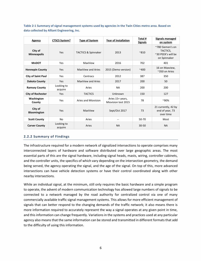
Table 2-1 Summary of signal management systems used by agencies in the Twin Cities metro area. Based on
data collected by Alliant Engineering, Inc.
Agency CTSCS System? Type of System Year of Installation Total # Signals
Signals managed on system
City of Minneapolis
Yes TACTICS & Spinnaker 2013 ~810
~780 Siemen's on TACTICS,
~30 PEEK's will be on Spinnaker
MnDOT Yes MaxView 2016 702 401
Hennepin County Yes MaxView and Aries 2015 (Demo version) ~400 16 on Maxview, ~350 on Aries
City of Saint Paul Yes Centracs 2012 387 350
Dakota County Yes MaxView and Aries 2017 200 50
Ramsey County Looking to
acquire Aries NA 200 200
City of Rochester Yes TACTICS Unknown 150 127
Washington County
Yes Aries and Miovision Aries 15+ years,
Miovision test 2015 78 ~90%
City of Bloomington
Yes MaxView Sept/Oct 2017 73 21 currently, 42 by
end of year, 73 over time
Scott County No Aries -- 50-70 Most
Carver County Looking to
acquire Aries NA 30-50 NA
2.2.2 Summary of Findings
The infrastructure required for a modern network of signalized intersections to operate comprises many
interconnected layers of hardware and software distributed over large geographic areas. The most
essential parts of this are the signal hardware, including signal heads, masts, wiring, controller cabinets,
and the controller units, the specifics of which vary depending on the intersection geometry, the demand
being served, the agency operating the signal, and the age of the signal. On top of this, more advanced
intersections can have vehicle detection systems or have their control coordinated along with other
nearby intersections.
While an individual signal, at the minimum, still only requires the basic hardware and a simple program
to operate, the advent of modern communication technology has allowed large numbers of signals to be
connected to a network managed by the road authority for centralized control via one of many
commercially available traffic signal management systems. This allows for more efficient management of
signals that can better respond to the changing demands of the traffic network; it also means there is
more information required to accurately represent the way a signal operates at any given point in time,
and this information can change frequently. Variations in the systems and practices used at any particular
agency also means that the same information can be stored and transmitted in different formats that add
to the difficulty of using this information.
6
Because of the long operating life of an intersection, along with the time scale over which an intersection
is designed and constructed, records on the current information describing an intersection can be in
several different formats distributed over a number of physical or virtual locations. Geometric
information, such as lane and crosswalk dimensions, in-pavement detector locations, pedestrian buttons,
and so on are generally set during the construction design phase, meaning that this information is often
located in construction plans. This information may also change, either temporarily if there is construction
occurring that affects the intersection layout, or permanently if the intersection is redesigned. By contrast,
program information, since it must change to adapt to the traffic using the intersection, is usually in a
different format that allows for regular modifications. For larger agencies that manage large numbers of
signals, this information is often managed by a Central Traffic Signal Control System (CTSCS) or Advanced
Traffic Management System (ATMS), software that centralizes the administration of signal controllers and
communicates with the controllers via a network. For smaller agencies, however, program information
may be entered into controllers directly either over a network or by visiting the cabinet in person. Records
of the active program information can be kept in a variety of formats including spreadsheets, PDF files,
paper records, and logs located in the cabinet. The same is also true for the locations of detectors set in
software, as is the case with vision- or radar-based detection technologies.
Finally, while signals operated by larger agencies are usually centrally managed, information security
policies often lead to access restrictions that can impeded distribution of ICI, even to other agencies that
might operate nearby signals. This presents a significant challenge to developing a more efficient
distribution system, as any system would need to conform to the requirements of the organizations
involved. There are options for working around this, however they generally involve the use of externally
hosted systems that are capable of receiving data that is “pushed” by the secure system on an agency’s network, preventing the use of existing features of the common CTSCS’s for providing controlled access
to external parties.
2.3 USE OF INTERSECTION CONTROL INFORMATION
While researchers were not as familiar with the common practices of signal operators, by contrast they
have considerable experience as transportation modelers, having spent years developing models using
several widely used commercial modeling programs. This knowledge was helpful in reducing the amount
of effort required to determine what ICI is commonly needed by modelers to do their jobs. This section
briefly summarizes these needs and how they affect the recommendations of the project.
As laid out in the functional specifications, just as important as the needs of signal operators are the needs
of those who regularly use intersection control information. A wide variety of transportation planning and
design activities rely on accurate ICI to develop computer models of transportation networks and make
key decisions regarding the scheduling of construction projects, redesigning infrastructure, and many
other activities with wide-reaching impacts. Signal retiming is often also performed by consultants who
need ICI to develop their models. Depending on the resolution of the model in question, models can
require everything from basic demand estimates to detailed descriptions of intersection geometry and
signal programming. Obtaining this information for an intersection currently requires finding the contact
information of the agency that operates the signal, manually requesting the information, and using the
7

resulting documents, typically a combination of signal timing reports, construction plans, and any number
of agency-specific document formats, to input the information into a model. These programs often include
features for importing information from common formats, such as Synchro files containing signal timing
information, providing some potential formats that could be included as options for exporting data from
the unified system.
In addition to modelers, a variety of other players are increasingly interested in obtaining intersection
control information for their purposes, largely driven by wider trends in the industry towards a more
interconnected, data-driven transportation network. These include existing travel information providers
like Google and INRIX, as well as developers of connected and autonomous vehicle applications that are
preparing for fundamental changes to the transportation network that are rapidly approaching. The
nature of these applications, many of which run in real-time, would require that ICI be provided using an
online system that is kept updated at all times.
2.4 SURVEY INSTRUMENTS
Early on in the project, it was decided that a survey should be distributed to a variety of stakeholders to
collect information about how ICI is stored and used. This was meant to help fill in any gaps in the
knowledge of researchers and the signal operators they worked with most closely, as well as to get some
idea of the feasibility of implementing the unified system envisioned by this project.
2.4.1 Developing Survey
The survey was developed by researchers with close involvement from the project’s Technical Advisory
Panel and Technical Liaison. After beginning with a rough list of the groups that might have information
relevant to the project and an outline of the questions to be asked, researchers worked to narrow the
groups down based on their common needs or the information they have. To optimize the information
obtained, it was known early on that multiple surveys would need to be developed, and after some
deliberation it was decided that two surveys would be developed: one sent to representatives of
organizations that own and operate signals, and one sent to modelers and others who frequently use ICI.
The questions in these surveys, which can be viewed in full in Appendices A and C, were developed by
researchers and MnDOT signal operations staff based on their existing understanding of signal operations
and the needs of modelers. In addition to this, the survey for modelers was also made available for
comments by members of the North Central Section of the Institute of Transportation Engineers (NCITE)
Simulation and Capacity (SimCap) Committee, which includes many experienced transportation modelers
who frequently work with ICI. The surveys were distributed to a large pool of potential respondents,
including 153 signal owner or operator contacts representing the vast majority of road authorities in the
state, and 68 modelers including people in the public, private, and academic sectors. Ultimately 42
responses to the Owners and Operators survey, and 25 responses to the Modelers survey were received.
8
2.4.2 Information Obtained from Survey
The most significant information obtained from the surveys concerned the availability and formats of
intersection control information. Table 2-2 enumerates all the formats in which each type of information
may be contained, based on the responses to the survey distributed to organizations that own and
operate traffic signals. Note that this is an attempt at a complete list, not an estimate of how common
any particular format is, as all information would need to be digitized regardless of how common it is to
keep it in a given format. As can be seen in the table, many agencies store all or most of the information
about their intersections in a CTSCS, ATMS, or closed-loop system that is already digitized. While this is
good, depending on the particular system used, what information fields it can store, and how it arranges
that information, the method for storing certain pieces of information may vary between and within
agencies. For instance, if comment fields were used to store information in a non-standard way, fitting
this information into a standardized format would still require interpretation and manual effort.
Aside from central systems, a number of agencies also store their ICI in spreadsheets, PDF files, and paper
records. Even in the case of spreadsheets, which are already digital, again the issue of how the data is
organized means that interpretation would be required to translate these records into a standardized
format. Some additional storage formats that were identified from the survey but had not occurred to
researchers include using Autoscope machine vision sensor software to store detector-phase
assignments, and using a generic asset management system or service to store information about signals
(as opposed to a CTSCS or ATMS system specific to signal operation).
In addition to the survey of signal operators, researchers also surveyed designers, modelers, and planners
that frequently work with ICI to learn what programs they use and what data they require as part of this.
Since the project researchers are already highly experienced in this area not much new information was
obtained, however the results helped to confirm what modeling programs are commonly used, what
information they typically need, and some of the experiences modelers have when requesting signal data.
There were also some suggestions for ways the process of importing signal data into their models could
be improved, such as providing Synchro files or controller databases, which many programs already have
tools to import. There were also suggestions that an online, interactive map would be convenient for
accessing data. Further discussion of researchers’ recommendations concerning how a system for
managing this information could be implemented, taking into account the responses to the surveys, can
be found in Chapter 3.
9

Table 2-2 Availability (by format) of intersection control information categories in jurisdictions around Minnesota.
Signal owner
Communication capabilities (i.e. network connection to the cabinet)
Date of last update to traffic control information
Geo-Locations
Detector-Phase Assignments
Program Schedule
Signal Timing Information
Active Signal Timing Info TSP/EVP
Type of Coordination
Asset Management System/Service ✓ ✓ ✓ ✓ ✓ ✓ ✓
Autoscope ✓ Cabinet Log (paper record located in cabinet)
✓ Central Traffic Signal Control Systems (e.g. MaxView)
✓ ✓ ✓ ✓ ✓ ✓ ✓ ✓ ✓ ✓ Closed-Loop Traffic Control System (e.g. Aries)
✓ ✓ ✓ ✓ ✓ ✓ ✓ ✓ ✓ ✓
Construction plans ✓ ✓ ✓ ✓ ✓
Database Application ✓ ✓ ✓
GIS/Geodatabase ✓ ✓ ✓ ✓
Paper records ✓ ✓ ✓ ✓ ✓ ✓ ✓ ✓ ✓ ✓ PDF files of digital documents ✓ ✓ ✓ ✓ ✓ ✓ ✓ ✓ ✓ ✓ PDF files of scanned documents ✓ ✓ ✓ ✓ ✓ ✓ ✓ ✓ ✓ ✓
Spreadsheets ✓ ✓ ✓ ✓ ✓ ✓ ✓ ✓ ✓ ✓
Synchro 9, 10 ✓
10

CHAPTER 3: UNIFIED SET OF INTERSECTION CONTROL
INFORMATION
3.1 METHODOLOGY
Researchers employed a multi-pronged approach when collecting information on the various aspects of
intersection control, incorporating information from multiple sources in an effort to make the results of
the process cover as many cases as possible. This included interviewing signal operators from multiple
agencies to understand the systems they use, their data management practices, and how they respond to
information requests, as well as their thoughts on how distribution of ICI could be improved. In addition
to this, researchers developed two surveys, one distributed to signal owners and operators around the
state requesting similar information about their practices and the systems they use, and another
distributed to designers, modelers, and planners that frequently model signalized intersections to
understand how they use this information and what data formats are most convenient for them. These
surveys are presented in full in Appendices A and C, with the full results of the surveys presented in
Appendices B and D.
Separately, researchers also reviewed information obtained from signal operators describing several
example intersections from around the metro area. This effort focused on intersections with complicated
designs, such as the Diverging Diamond Interchange (DDI) and intersections with more than four legs, to
ensure that the resulting set of intersection control information would adequately capture these cases.
To this end, researchers specifically made the point of creating a full example of the unified set of
intersection control information for the DDI at Hennepin County Road 144 and TH-101 in Rogers, MN, the
plan for which is shown in Figure 3.1, to ensure that the resulting unified set of ICI could represent this
complex intersection. This full example can be found in Appendix E. Along with these, researchers
reviewed manuals covering traffic engineering, signal operation best practices, and standards governing
the operation of signal controllers to verify that the recommended set of ICI conforms to the typical
practices and terminology of the industry. Researchers also drew upon personal experience working with
transportation modeling and traffic simulation software to ensure that the resulting ICI set would support
the majority of modeling activities.
11
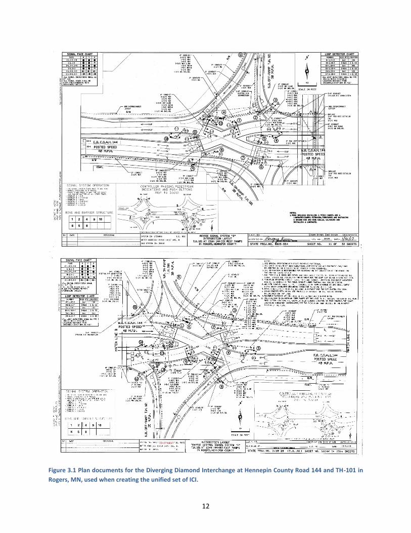
Figure 3.1 Plan documents for the Diverging Diamond Interchange at Hennepin County Road 144 and TH-101 in
Rogers, MN, used when creating the unified set of ICI.
12
In the case of ICI relating specifically to program information, researchers based this primarily on the
National Transportation Communications for Intelligent Transportation System Protocol (NTCIP) 1202
standard, Object Definitions for Actuated Traffic Signal Controller Units, version 2, published in 2005. This
standard already rigorously defines the information required to describe the control of an intersection as
seen by a signal controller at a technical level, and many commercial software vendors are already very
familiar with its contents. This also allows the unified set of ICI developed in this project to be kept updated
as intersection control technology evolves to meet the needs of a changing transportation system. Along
with this standard, researchers reviewed control information from example intersections and added,
moved, or modified certain parameters to include important parameters that were missing, and to make
the resulting set of ICI easier to follow.
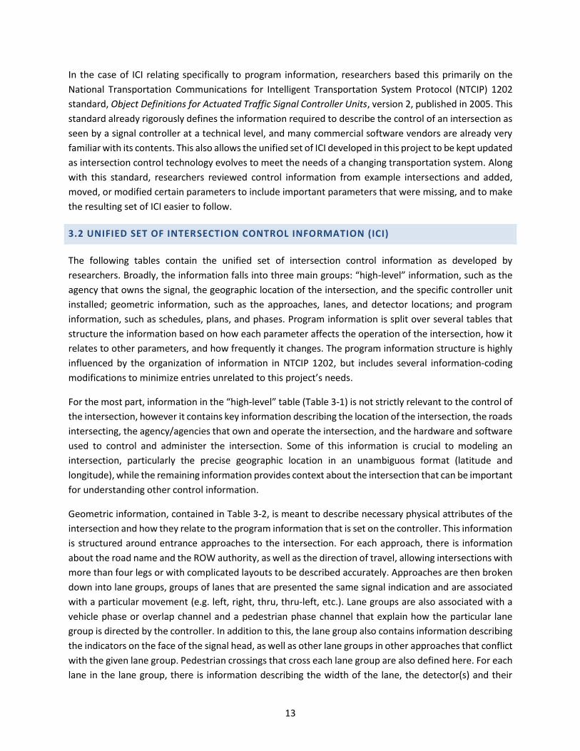
3.2 UNIFIED SET OF INTERSECTION CONTROL INFORMATION (ICI)
The following tables contain the unified set of intersection control information as developed by
researchers. Broadly, the information falls into three main groups: “high-level” information, such as the
agency that owns the signal, the geographic location of the intersection, and the specific controller unit
installed; geometric information, such as the approaches, lanes, and detector locations; and program
information, such as schedules, plans, and phases. Program information is split over several tables that
structure the information based on how each parameter affects the operation of the intersection, how it
relates to other parameters, and how frequently it changes. The program information structure is highly
influenced by the organization of information in NTCIP 1202, but includes several information-coding
modifications to minimize entries unrelated to this project’s needs.
For the most part, information in the “high-level” table (Table 3-1) is not strictly relevant to the control of
the intersection, however it contains key information describing the location of the intersection, the roads
intersecting, the agency/agencies that own and operate the intersection, and the hardware and software
used to control and administer the intersection. Some of this information is crucial to modeling an
intersection, particularly the precise geographic location in an unambiguous format (latitude and
longitude), while the remaining information provides context about the intersection that can be important
for understanding other control information.
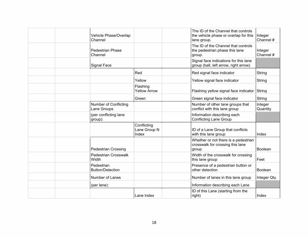
Geometric information, contained in Table 3-2, is meant to describe necessary physical attributes of the
intersection and how they relate to the program information that is set on the controller. This information
is structured around entrance approaches to the intersection. For each approach, there is information
about the road name and the ROW authority, as well as the direction of travel, allowing intersections with
more than four legs or with complicated layouts to be described accurately. Approaches are then broken
down into lane groups, groups of lanes that are presented the same signal indication and are associated
with a particular movement (e.g. left, right, thru, thru-left, etc.). Lane groups are also associated with a
vehicle phase or overlap channel and a pedestrian phase channel that explain how the particular lane
group is directed by the controller. In addition to this, the lane group also contains information describing
the indicators on the face of the signal head, as well as other lane groups in other approaches that conflict
with the given lane group. Pedestrian crossings that cross each lane group are also defined here. For each
lane in the lane group, there is information describing the width of the lane, the detector(s) and their
13
distance from the stop line, and the allowed turnings (destination lanes) that a vehicle may access from
this lane.
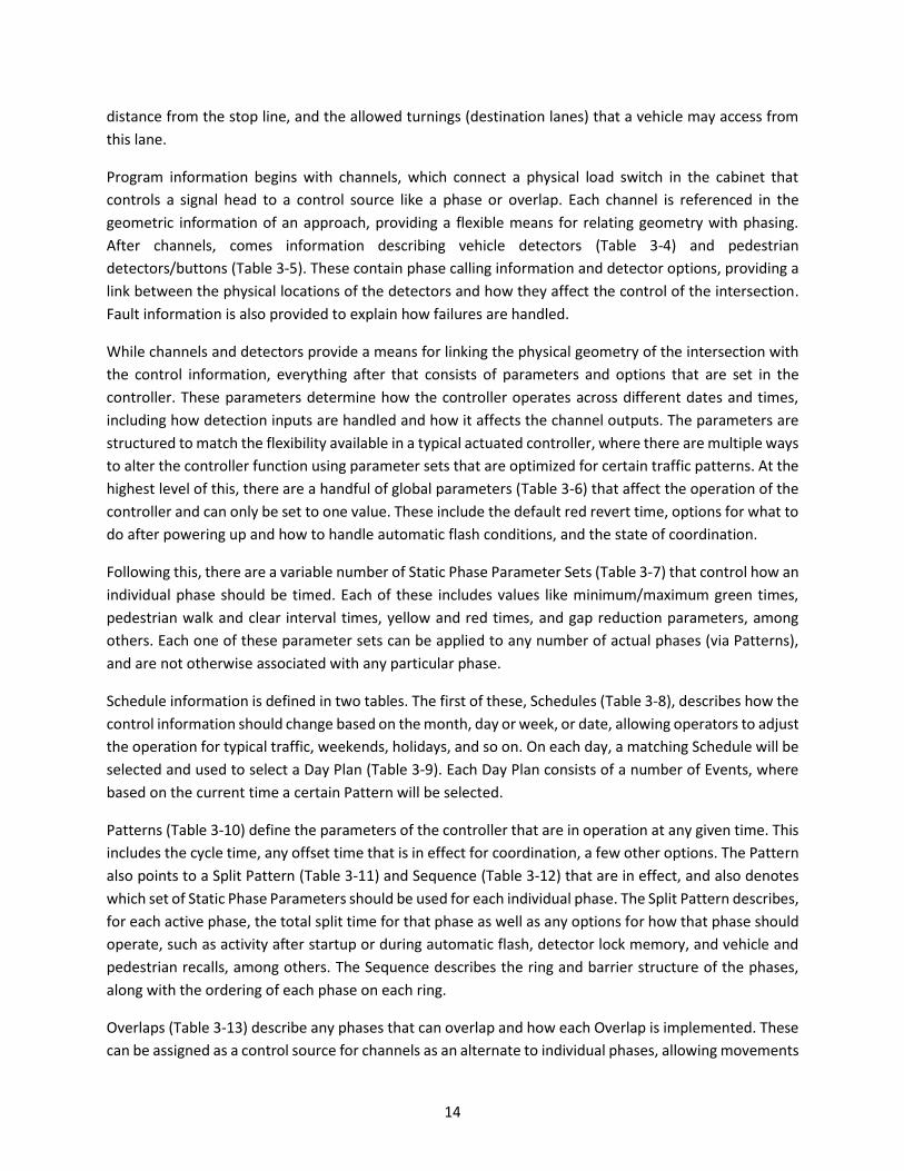
Program information begins with channels, which connect a physical load switch in the cabinet that
controls a signal head to a control source like a phase or overlap. Each channel is referenced in the
geometric information of an approach, providing a flexible means for relating geometry with phasing.
After channels, comes information describing vehicle detectors (Table 3-4) and pedestrian
detectors/buttons (Table 3-5). These contain phase calling information and detector options, providing a
link between the physical locations of the detectors and how they affect the control of the intersection.
Fault information is also provided to explain how failures are handled.
While channels and detectors provide a means for linking the physical geometry of the intersection with
the control information, everything after that consists of parameters and options that are set in the
controller. These parameters determine how the controller operates across different dates and times,
including how detection inputs are handled and how it affects the channel outputs. The parameters are
structured to match the flexibility available in a typical actuated controller, where there are multiple ways
to alter the controller function using parameter sets that are optimized for certain traffic patterns. At the
highest level of this, there are a handful of global parameters (Table 3-6) that affect the operation of the
controller and can only be set to one value. These include the default red revert time, options for what to
do after powering up and how to handle automatic flash conditions, and the state of coordination.
Following this, there are a variable number of Static Phase Parameter Sets (Table 3-7) that control how an
individual phase should be timed. Each of these includes values like minimum/maximum green times,
pedestrian walk and clear interval times, yellow and red times, and gap reduction parameters, among
others. Each one of these parameter sets can be applied to any number of actual phases (via Patterns),
and are not otherwise associated with any particular phase.
Schedule information is defined in two tables. The first of these, Schedules (Table 3-8), describes how the
control information should change based on the month, day or week, or date, allowing operators to adjust
the operation for typical traffic, weekends, holidays, and so on. On each day, a matching Schedule will be
selected and used to select a Day Plan (Table 3-9). Each Day Plan consists of a number of Events, where
based on the current time a certain Pattern will be selected.
Patterns (Table 3-10) define the parameters of the controller that are in operation at any given time. This
includes the cycle time, any offset time that is in effect for coordination, a few other options. The Pattern
also points to a Split Pattern (Table 3-11) and Sequence (Table 3-12) that are in effect, and also denotes
which set of Static Phase Parameters should be used for each individual phase. The Split Pattern describes,
for each active phase, the total split time for that phase as well as any options for how that phase should
operate, such as activity after startup or during automatic flash, detector lock memory, and vehicle and
pedestrian recalls, among others. The Sequence describes the ring and barrier structure of the phases,
along with the ordering of each phase on each ring.
Overlaps (Table 3-13) describe any phases that can overlap and how each Overlap is implemented. These
can be assigned as a control source for channels as an alternate to individual phases, allowing movements
14
that don’t conflict with one another to operate at the same time. Protected/Permissive Left Turn Flashing
Yellow Arrow (FYA) functionality (Table 3-14) can be applied to an Overlap by noting which phases
correspond to the protected left turn phase and the permissive through phase. Finally, emergency vehicle
or railroad preemption is defined in the Preempts table (Table 3-15), where each Preempt plan contains
parameters that affect how a call interrupts normal operation, how long it should remain in effect, and
how the controller returns to normal operation. To show the organization of this information, Figure 3.2
shows a high-level view of the tables with lines connecting the important fields to illustrate how the
information in each table connects to related information in other tables.
Together, these structures can be used to represent all of the information that is relevant to the control
of a signalized intersection and how that can change automatically over time. To demonstrate this,
researchers filled in all values for the intersection of Hennepin County Road 144 and TH-101 in Rogers,
MN, a DDI that controls access to and from the limited access freeway TH-101. Because of the complexity
of this novel type of interchange, it can be difficult to describe them using models built around traditional
four-leg intersections, making it a useful example case for ensuring that the unified set of ICI can
adequately represent every intersection. The full set of information for this example can be found in
Appendix E. In the tables in this section, each parameter is accompanied by a description and the units or
data type used to represent the value.
The information required to assemble this unified set for a particular intersection will come mainly from
one of three sources: the intersection controller, the construction plans showing the layout of the
intersection and how it relates to the control of the intersection, or general GIS information such as that
available from Google Maps or an agency’s records. To illustrate this, Figure 3.3 shows a high-level view
of each table and the typical sources for that information.
15
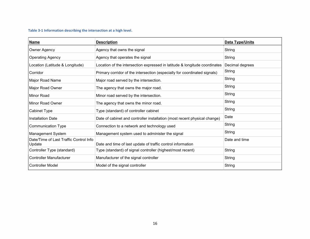
Table 3-1 Information describing the intersection at a high level.
Name Description Data Type/Units
Owner Agency Agency that owns the signal String
Operating Agency Agency that operates the signal String
Location (Latitude & Longitude) Location of the intersection expressed in latitude & longitude coordinates Decimal degrees
Corridor Primary corridor of the intersection (especially for coordinated signals) String
Major Road Name Major road served by the intersection. String
Major Road Owner The agency that owns the major road. String
Minor Road Minor road served by the intersection. String
Minor Road Owner The agency that owns the minor road. String
Cabinet Type Type (standard) of controller cabinet String
Installation Date Date of cabinet and controller installation (most recent physical change) Date
Communication Type Connection to a network and technology used String
Management System Management system used to administer the signal String
Date/Time of Last Traffic Control Info Update Date and time of last update of traffic control information
Date and time
Controller Type (standard) Type (standard) of signal controller (highest/most recent) String
Controller Manufacturer Manufacturer of the signal controller String
Controller Model Model of the signal controller String
16

Table 3-2 Information describing the geometry of the intersection and how it relates to program information.
Name Sub-Level 1 Name
Sub-Level 2 Name Sub-Level 3 Name
Sub-Level 4 Name
Description Data Type/Units
Number of Approaches
Number of approaches entering the intersection (identified by signal masts)
Integer Quantity
(per Approach):
Information describing each Approach
Approach Index ID of this Approach Index
Approach Name Name of the approach String
Owner Agency that owns this approach String
Azimuth (Direction of Travel)
Direction of travel for this approach expressed as azimuth
Decimal Degrees
Number of Lanes Number of total lanes for this approach (all lane groups)
Integer Quantity
Bicycle Lane Presence of a bicycle lane Boolean
Bicycle Detection/Button Presence of bicycle detection/button Boolean
Number of Lane Groups
Number of lane groups, i.e. one or more lanes shown the same control indicator (see "Lane Group N" below)
Integer Quantity
(per Lane Group): Information describing each Lane Group
Lane Group Index ID of this Lane Group Index
Movement Type Movement type of this lane group String
Protected/Permissive
Whether this lane group has a protected phase, permissive phase, or both String
Turn on Red Whether or not this lane group may turn on red Boolean
17
Vehicle Phase/Overlap Channel
The ID of the Channel that controls the vehicle phase or overlap for this lane group.
Integer Channel #
Pedestrian Phase Channel
The ID of the Channel that controls the pedestrian phase this lane group.
Integer Channel #
Signal Face Signal face indications for this lane group (ball, left arrow, right arrow)
Red Red signal face indicator String
Yellow Yellow signal face indicator String
Flashing Yellow Arrow Flashing yellow signal face indicator String
Green Green signal face indicator String
Number of Conflicting Lane Groups
Number of other lane groups that conflict with this lane group
Integer Quantity
(per conflicting lane group):
Information describing each Conflicting Lane Group
Conflicting Lane Group N Index
ID of a Lane Group that conflicts with this lane group Index
Pedestrian Crossing
Whether or not there is a pedestrian crosswalk for crossing this lane group Boolean
Pedestrian Crosswalk Width
Width of the crosswalk for crossing this lane group Feet
Pedestrian Button/Detection
Presence of a pedestrian button or other detection Boolean
Number of Lanes Number of lanes in this lane group Integer Qty.
(per lane): Information describing each Lane
Lane Index ID of this Lane (starting from the right) Index
18

Width
Width of the lane measured at the stop line of the intersections (in feet). Feet
Number of Detectors Number of detectors in this lane
Integer Quantity
(per detector): Information describing each Detector
Detector Index ID of this Detector Index
Detector Type Type of detector String
Distance from Stop Line
Distance of the detector from the stop line of the intersection Feet
Number of Turnings
Number of turnings (allowed destination lanes) from this lane
Integer Quantity
(per turning): Information describing each Turning
Turning Index ID of this Turning Index
Destination Approach and Lane
Destination approach and lane for this turning Index
19
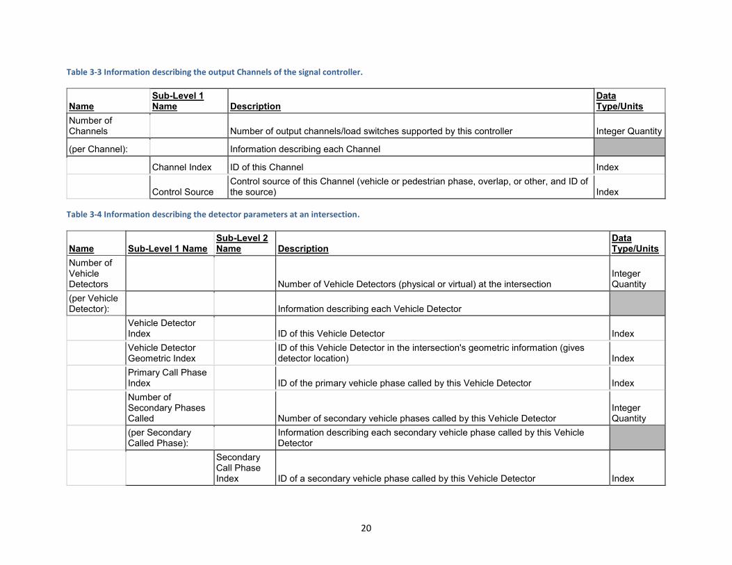
Table 3-3 Information describing the output Channels of the signal controller.
Name Sub-Level 1 Name Description
Data Type/Units
Number of Channels Number of output channels/load switches supported by this controller Integer Quantity
(per Channel): Information describing each Channel
Channel Index ID of this Channel Index
Control Source Control source of this Channel (vehicle or pedestrian phase, overlap, or other, and ID of the source) Index
Table 3-4 Information describing the detector parameters at an intersection.
Name Sub-Level 1 Name Sub-Level 2 Name Description
Data Type/Units
Number of Vehicle Detectors Number of Vehicle Detectors (physical or virtual) at the intersection
Integer Quantity
(per Vehicle Detector): Information describing each Vehicle Detector
Vehicle Detector Index ID of this Vehicle Detector Index
Vehicle Detector Geometric Index
ID of this Vehicle Detector in the intersection's geometric information (gives detector location) Index
Primary Call Phase Index ID of the primary vehicle phase called by this Vehicle Detector Index
Number of Secondary Phases Called Number of secondary vehicle phases called by this Vehicle Detector
Integer Quantity
(per Secondary Called Phase):
Information describing each secondary vehicle phase called by this Vehicle Detector
Secondary Call Phase Index ID of a secondary vehicle phase called by this Vehicle Detector Index
20
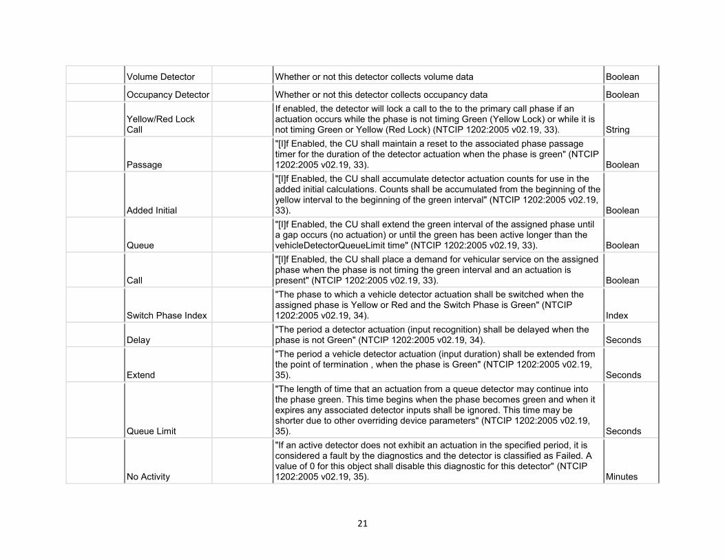
Volume Detector Whether or not this detector collects volume data Boolean
Occupancy Detector Whether or not this detector collects occupancy data Boolean
Yellow/Red Lock Call
If enabled, the detector will lock a call to the to the primary call phase if an actuation occurs while the phase is not timing Green (Yellow Lock) or while it is not timing Green or Yellow (Red Lock) (NTCIP 1202:2005 v02.19, 33). String
Passage
"[I]f Enabled, the CU shall maintain a reset to the associated phase passage timer for the duration of the detector actuation when the phase is green" (NTCIP 1202:2005 v02.19, 33). Boolean
Added Initial
"[I]f Enabled, the CU shall accumulate detector actuation counts for use in the added initial calculations. Counts shall be accumulated from the beginning of the yellow interval to the beginning of the green interval" (NTCIP 1202:2005 v02.19, 33). Boolean
Queue
"[I]f Enabled, the CU shall extend the green interval of the assigned phase until a gap occurs (no actuation) or until the green has been active longer than the vehicleDetectorQueueLimit time" (NTCIP 1202:2005 v02.19, 33). Boolean
Call
"[I]f Enabled, the CU shall place a demand for vehicular service on the assigned phase when the phase is not timing the green interval and an actuation is present" (NTCIP 1202:2005 v02.19, 33). Boolean
Switch Phase Index
"The phase to which a vehicle detector actuation shall be switched when the assigned phase is Yellow or Red and the Switch Phase is Green" (NTCIP 1202:2005 v02.19, 34). Index
Delay "The period a detector actuation (input recognition) shall be delayed when the phase is not Green" (NTCIP 1202:2005 v02.19, 34). Seconds
Extend
"The period a vehicle detector actuation (input duration) shall be extended from the point of termination , when the phase is Green" (NTCIP 1202:2005 v02.19, 35). Seconds
Queue Limit
"The length of time that an actuation from a queue detector may continue into the phase green. This time begins when the phase becomes green and when it expires any associated detector inputs shall be ignored. This time may be shorter due to other overriding device parameters" (NTCIP 1202:2005 v02.19, 35). Seconds
No Activity
"If an active detector does not exhibit an actuation in the specified period, it is considered a fault by the diagnostics and the detector is classified as Failed. A value of 0 for this object shall disable this diagnostic for this detector" (NTCIP 1202:2005 v02.19, 35). Minutes
21

Max Presence
"If an active detector exhibits continuous detection for too long a period, it is considered a fault by the diagnostics and the detector is classified as Failed. A value of 0 for this object shall disable this diagnostic for this detector" (NTCIP 1202:2005 v02.19, 36). Minutes
Erratic Counts
"If an active detector exhibits excessive actuations, it is considered a fault by the diagnostics and the detector is classified as Failed. A value of 0 for this object shall disable this diagnostic for this detector" (NTCIP 1202:2005 v02.19, 36).
Integer Count
Fail Time
"If a detector diagnostic indicates that the associated detector input is failed, then a call shall be placed on the associated phase during all non-green intervals. When each green interval begins the call shall be maintained for the length of time specified by this object and then removed" (NTCIP 1202:2005 v02.19, 36-37). Seconds
No Activity Fault "This detector has been flagged as non-operational due to lower than expected activity by the CU detector diagnostic" (NTCIP 1202:2005 v02.19, 37). Boolean
Max Presence Fault
"This detector has been flagged as non-operational due to a presence indicator that exceeded the maximum expected time by the CU detector diagnostic" (NTCIP 1202:2005 v02.19, 37). Boolean
Erratic Output Fault
"This detector has been flagged as non-operational due to erratic outputs (excessive counts) by the CU detector diagnostic" (NTCIP 1202:2005 v02.19, 37). Boolean
Communications Fault
"Communications to the device (if present) have failed" (NTCIP 1202:2005 v02.19, 37). Boolean
Configuration Fault "Detector is assigned but is not supported" (NTCIP 1202:2005 v02.19, 37). Boolean
Other Fault "The detector has failed due to some other cause" (NTCIP 1202:2005 v02.19, 37). Boolean
Other Reported Fault
"This detector has been flagged as non-operational due to some other error" (NTCIP 1202:2005 v02.19, 38). Boolean
Watchdog Fault "This detector has been flagged as non-operational due to a watchdog error" (NTCIP 1202:2005 v02.19, 38). Boolean
Open Loop Fault "This detector has been flagged as non-operational due to an open loop (broken wire)" (NTCIP 1202:2005 v02.19, 38). Boolean
Shorted Loop Fault "This detector has been flagged as non-operational due to a shorted loop wire" (NTCIP 1202:2005 v02.19, 38). Boolean
Excessive Change Fault
"This detector has been flagged as non-operational due to an inductance change that exceeded expected values" (NTCIP 1202:2005 v02.19, 38). Boolean
22

Table 3-5 Information describing the pedestrian detectors/buttons at an intersection.
Name Sub-Level 1 Name
Sub-Level 2 Name Description
Data Type/Units
Number of Pedestrian Detectors Number of Pedestrian Detectors/Buttons at the intersection
Integer Quantity
(per Pedestrian Detector): Information describing each Pedestrian Detector
Pedestrian Detector Index ID of this Pedestrian Detector Index
Primary Call Phase Index ID of the phase called by this Pedestrian Detector Index
Number of Secondary Phases Called Number of secondary phases called by this Pedestrian Detector
Integer Quantity
No Activity
"If an active detector does not exhibit an actuation in the specified period, it is considered a fault by the diagnostics and the detector is classified as Failed. A value of 0 for this object shall disable this diagnostic for this detector" (NTCIP 1202:2005 v02.19, 45). Minutes
Max Presence
"If an active detector exhibits continuous detection for too long a period, it is considered a fault by the diagnostics and the detector is classified as Failed. A value of 0 for this object shall disable this diagnostic for this detector" (NTCIP 1202:2005 v02.19, 46). Minutes
Erratic Counts
"If an active detector exhibits excessive actuations, it is considered a fault by the diagnostics and the detector is classified as Failed. A value of 0 for this object shall disable this diagnostic for this detector" (NTCIP 1202:2005 v02.19, 46).
Integer Count
No Activity Fault "This detector has been flagged as non-operational due to lower than expected activity by the CU detector diagnostic" (NTCIP 1202:2005 v02.19, 47). Boolean
Max Presence Fault
"This detector has been flagged as non-operational due to a presence indicator that exceeded the maximum expected time by the CU detector diagnostic" (NTCIP 1202:2005 v02.19, 47). Boolean
Erratic Output Fault
"This detector has been flagged as non-operational due to erratic outputs (excessive counts) by the CU detector diagnostic" (NTCIP 1202:2005 v02.19, 47). Boolean
23
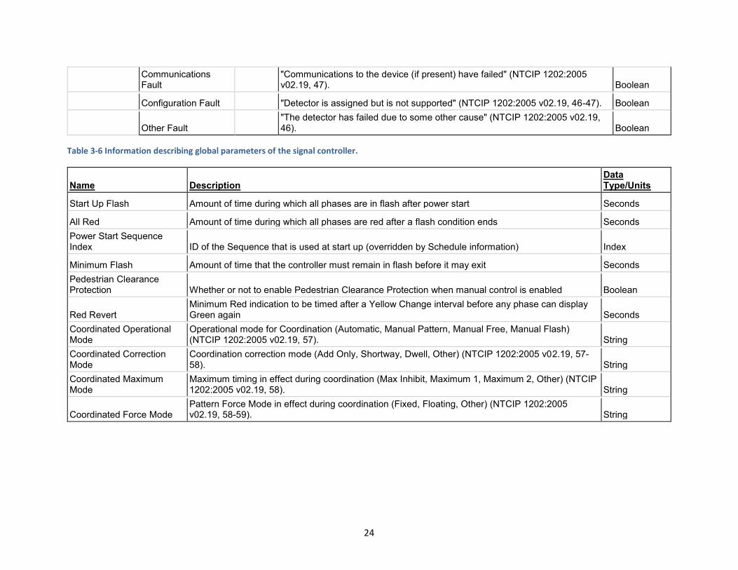
Communications Fault
"Communications to the device (if present) have failed" (NTCIP 1202:2005 v02.19, 47). Boolean
Configuration Fault "Detector is assigned but is not supported" (NTCIP 1202:2005 v02.19, 46-47). Boolean
Other Fault "The detector has failed due to some other cause" (NTCIP 1202:2005 v02.19, 46). Boolean
Table 3-6 Information describing global parameters of the signal controller.
Name Description Data Type/Units
Start Up Flash Amount of time during which all phases are in flash after power start Seconds
All Red Amount of time during which all phases are red after a flash condition ends Seconds
Power Start Sequence Index ID of the Sequence that is used at start up (overridden by Schedule information) Index
Minimum Flash Amount of time that the controller must remain in flash before it may exit Seconds
Pedestrian Clearance Protection Whether or not to enable Pedestrian Clearance Protection when manual control is enabled Boolean
Red Revert Minimum Red indication to be timed after a Yellow Change interval before any phase can display Green again Seconds
Coordinated Operational Mode
Operational mode for Coordination (Automatic, Manual Pattern, Manual Free, Manual Flash) (NTCIP 1202:2005 v02.19, 57). String
Coordinated Correction Mode
Coordination correction mode (Add Only, Shortway, Dwell, Other) (NTCIP 1202:2005 v02.19, 57-58). String
Coordinated Maximum Mode
Maximum timing in effect during coordination (Max Inhibit, Maximum 1, Maximum 2, Other) (NTCIP 1202:2005 v02.19, 58). String
Coordinated Force Mode Pattern Force Mode in effect during coordination (Fixed, Floating, Other) (NTCIP 1202:2005 v02.19, 58-59). String
24
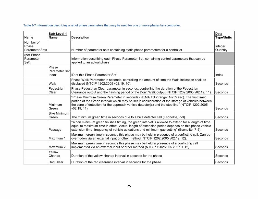
Table 3-7 Information describing a set of phase parameters that may be used for one or more phases by a controller.
Name Sub-Level 1 Name Description
Data Type/Units
Number of Phase Parameter Sets Number of parameter sets containing static phase parameters for a controller.
Integer Quantity
(per Phase Parameter Set):
Information describing each Phase Parameter Set, containing control parameters that can be applied to an actual phase
Phase Parameter Set Index ID of this Phase Parameter Set Index
Walk Phase Walk Parameter in seconds, controlling the amount of time the Walk indication shall be displayed (NTCIP 1202:2005 v02.19, 10). Seconds
Pedestrian Clear
Phase Pedestrian Clear parameter in seconds, controlling the duration of the Pedestrian Clearance output and the flashing period of the Don't Walk output (NTCIP 1202:2005 v02.19, 11). Seconds
Minimum Green
"Phase Minimum Green Parameter in seconds (NEMA TS 2 range: 1-255 sec). The first timed portion of the Green interval which may be set in consideration of the storage of vehicles between the zone of detection for the approach vehicle detector(s) and the stop line" (NTCIP 1202:2005 v02.19, 11). Seconds
Bike Minimum Green The minimum green time in seconds due to a bike detector call (Econolite, 7-3). Seconds
Passage
"When minimum green finishes timing, the green interval is allowed to extend for a length of time equal to maximum time in effect. Actual length of extension period depends on this phase vehicle extension time, frequency of vehicle actuations and minimum gap setting" (Econolite, 7-5). Seconds
Maximum 1 Maximum green time in seconds this phase may be held in presence of a conflicting call. Can be overridden via an external input or other method (NTCIP 1202:2005 v02.19, 12). Seconds
Maximum 2 Maximum green time in seconds this phase may be held in presence of a conflicting call implemented via an external input or other method (NTCIP 1202:2005 v02.19, 12). Seconds
Yellow Change Duration of the yellow change interval in seconds for the phase Seconds
Red Clear Duration of the red clearance interval in seconds for the phase Seconds
25
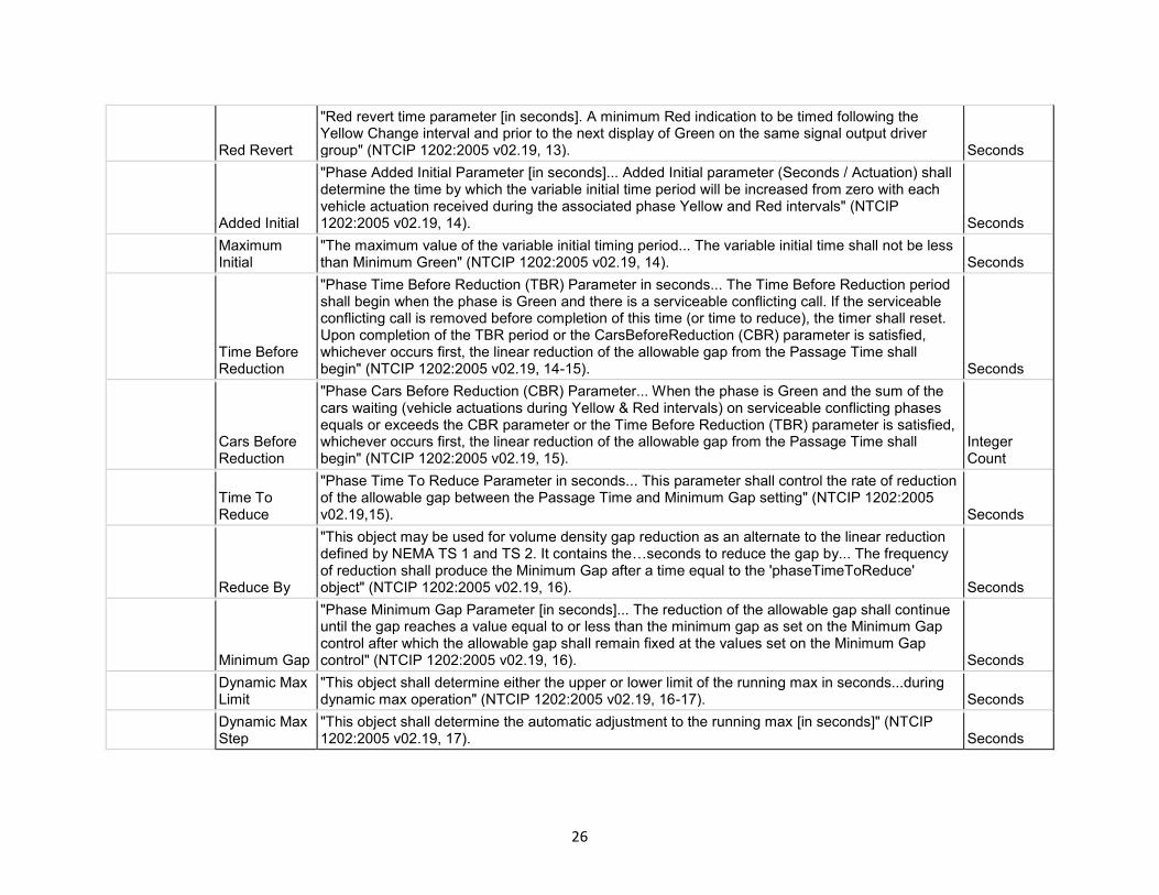
Red Revert
"Red revert time parameter [in seconds]. A minimum Red indication to be timed following the Yellow Change interval and prior to the next display of Green on the same signal output driver group" (NTCIP 1202:2005 v02.19, 13). Seconds
Added Initial
"Phase Added Initial Parameter [in seconds]... Added Initial parameter (Seconds / Actuation) shall determine the time by which the variable initial time period will be increased from zero with each vehicle actuation received during the associated phase Yellow and Red intervals" (NTCIP 1202:2005 v02.19, 14). Seconds
Maximum Initial
"The maximum value of the variable initial timing period... The variable initial time shall not be less than Minimum Green" (NTCIP 1202:2005 v02.19, 14). Seconds
Time Before Reduction
"Phase Time Before Reduction (TBR) Parameter in seconds... The Time Before Reduction period shall begin when the phase is Green and there is a serviceable conflicting call. If the serviceable conflicting call is removed before completion of this time (or time to reduce), the timer shall reset. Upon completion of the TBR period or the CarsBeforeReduction (CBR) parameter is satisfied, whichever occurs first, the linear reduction of the allowable gap from the Passage Time shall begin" (NTCIP 1202:2005 v02.19, 14-15). Seconds
Cars Before Reduction
"Phase Cars Before Reduction (CBR) Parameter... When the phase is Green and the sum of the cars waiting (vehicle actuations during Yellow & Red intervals) on serviceable conflicting phases equals or exceeds the CBR parameter or the Time Before Reduction (TBR) parameter is satisfied, whichever occurs first, the linear reduction of the allowable gap from the Passage Time shall begin" (NTCIP 1202:2005 v02.19, 15).
Integer Count
Time To Reduce
"Phase Time To Reduce Parameter in seconds... This parameter shall control the rate of reduction of the allowable gap between the Passage Time and Minimum Gap setting" (NTCIP 1202:2005 v02.19,15). Seconds
Reduce By
"This object may be used for volume density gap reduction as an alternate to the linear reduction defined by NEMA TS 1 and TS 2. It contains the…seconds to reduce the gap by... The frequency of reduction shall produce the Minimum Gap after a time equal to the 'phaseTimeToReduce' object" (NTCIP 1202:2005 v02.19, 16). Seconds
Minimum Gap
"Phase Minimum Gap Parameter [in seconds]... The reduction of the allowable gap shall continue until the gap reaches a value equal to or less than the minimum gap as set on the Minimum Gap control after which the allowable gap shall remain fixed at the values set on the Minimum Gap control" (NTCIP 1202:2005 v02.19, 16). Seconds
Dynamic Max Limit
"This object shall determine either the upper or lower limit of the running max in seconds...during dynamic max operation" (NTCIP 1202:2005 v02.19, 16-17). Seconds
Dynamic Max Step
"This object shall determine the automatic adjustment to the running max [in seconds]" (NTCIP 1202:2005 v02.19, 17). Seconds
26
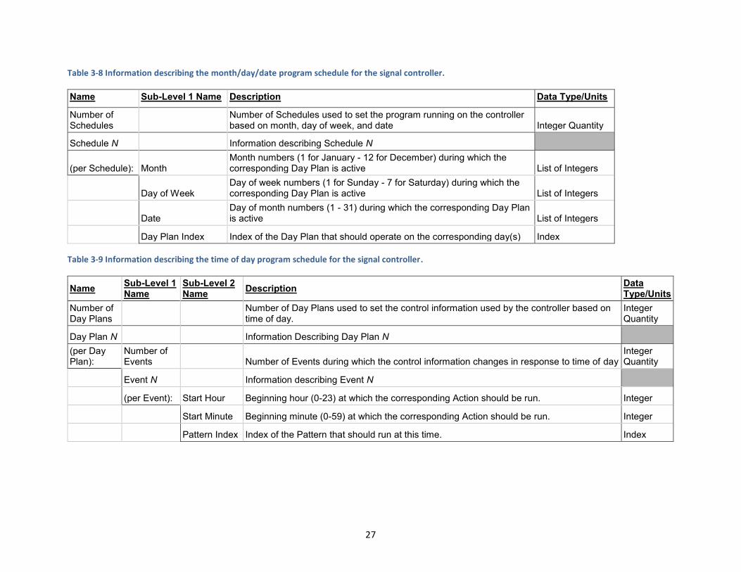
Table 3-8 Information describing the month/day/date program schedule for the signal controller.
Name Sub-Level 1 Name Description Data Type/Units
Number of Schedules
Number of Schedules used to set the program running on the controller based on month, day of week, and date Integer Quantity
Schedule N Information describing Schedule N
(per Schedule): Month Month numbers (1 for January - 12 for December) during which the corresponding Day Plan is active List of Integers
Day of Week Day of week numbers (1 for Sunday - 7 for Saturday) during which the corresponding Day Plan is active List of Integers
Date Day of month numbers (1 - 31) during which the corresponding Day Plan is active List of Integers
Day Plan Index Index of the Day Plan that should operate on the corresponding day(s) Index
Table 3-9 Information describing the time of day program schedule for the signal controller.
Name Sub-Level 1 Name
Sub-Level 2 Name
Description Data Type/Units
Number of Day Plans
Number of Day Plans used to set the control information used by the controller based on time of day.
Integer Quantity
Day Plan N Information Describing Day Plan N
(per Day Plan):
Number of Events Number of Events during which the control information changes in response to time of day
Integer Quantity
Event N Information describing Event N
(per Event): Start Hour Beginning hour (0-23) at which the corresponding Action should be run. Integer
Start Minute Beginning minute (0-59) at which the corresponding Action should be run. Integer
Pattern Index Index of the Pattern that should run at this time. Index
27
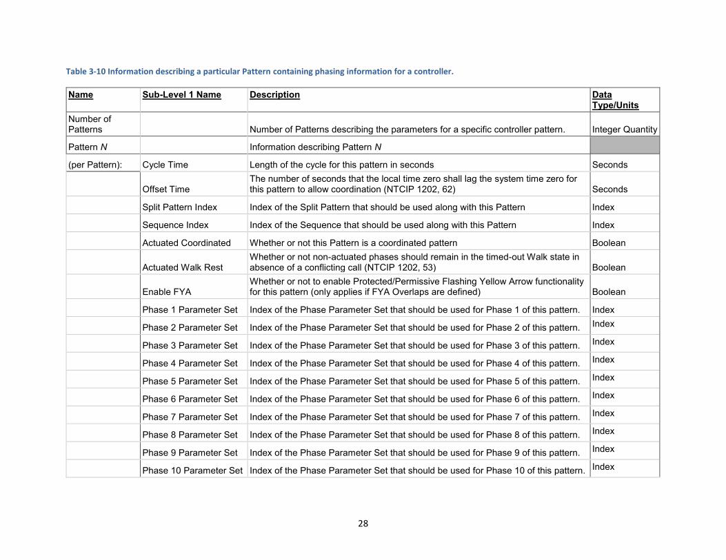
Table 3-10 Information describing a particular Pattern containing phasing information for a controller.
Name Sub-Level 1 Name Description Data Type/Units
Number of Patterns Number of Patterns describing the parameters for a specific controller pattern. Integer Quantity
Pattern N Information describing Pattern N
(per Pattern): Cycle Time Length of the cycle for this pattern in seconds Seconds
Offset Time The number of seconds that the local time zero shall lag the system time zero for this pattern to allow coordination (NTCIP 1202, 62) Seconds
Split Pattern Index Index of the Split Pattern that should be used along with this Pattern Index
Sequence Index Index of the Sequence that should be used along with this Pattern Index
Actuated Coordinated Whether or not this Pattern is a coordinated pattern Boolean
Actuated Walk Rest Whether or not non-actuated phases should remain in the timed-out Walk state in absence of a conflicting call (NTCIP 1202, 53) Boolean
Enable FYA Whether or not to enable Protected/Permissive Flashing Yellow Arrow functionality for this pattern (only applies if FYA Overlaps are defined) Boolean
Phase 1 Parameter Set Index of the Phase Parameter Set that should be used for Phase 1 of this pattern. Index
Phase 2 Parameter Set Index of the Phase Parameter Set that should be used for Phase 2 of this pattern. Index
Phase 3 Parameter Set Index of the Phase Parameter Set that should be used for Phase 3 of this pattern. Index
Phase 4 Parameter Set Index of the Phase Parameter Set that should be used for Phase 4 of this pattern. Index
Phase 5 Parameter Set Index of the Phase Parameter Set that should be used for Phase 5 of this pattern. Index
Phase 6 Parameter Set Index of the Phase Parameter Set that should be used for Phase 6 of this pattern. Index
Phase 7 Parameter Set Index of the Phase Parameter Set that should be used for Phase 7 of this pattern. Index
Phase 8 Parameter Set Index of the Phase Parameter Set that should be used for Phase 8 of this pattern. Index
Phase 9 Parameter Set Index of the Phase Parameter Set that should be used for Phase 9 of this pattern. Index
Phase 10 Parameter Set Index of the Phase Parameter Set that should be used for Phase 10 of this pattern. Index
28

Phase 11 Parameter Set Index of the Phase Parameter Set that should be used for Phase 11 of this pattern. Index
Phase 12 Parameter Set Index of the Phase Parameter Set that should be used for Phase 12 of this pattern. Index
Phase 13 Parameter Set Index of the Phase Parameter Set that should be used for Phase 13 of this pattern. Index
Phase 14 Parameter Set Index of the Phase Parameter Set that should be used for Phase 14 of this pattern. Index
Phase 15 Parameter Set Index of the Phase Parameter Set that should be used for Phase 15 of this pattern. Index
Phase 16 Parameter Set Index of the Phase Parameter Set that should be used for Phase 16 of this pattern. Index
Table 3-11 Information describing a particular Split Pattern containing information about phase splits for a controller.
Name Sub-Level 1 Name
Sub-Level 2 Name Description
Data Type/Units
Number of Split Patterns Number of coordination split parameters (Split Patterns) in this controller
Integer Quantity
(per Split Pattern): Information describing each Split Pattern
Split Pattern Index ID of this Split Pattern Index
Number of Phases Number of Phases described in this Split Pattern
Integer Quantity
(per Phase): Information describing each Phase in this Split Pattern
Phase Index ID of this Phase in this Split Pattern Index
Split Time
"The time in seconds the splitPhase is allowed to receive (i.e. before a Force Off is applied) when constant demands exist on all phases. In floating coordForceMode, this is always the maximum time a non-coordinated phase is allowed to receive. In fixed coordForceMode, the actual allowed time may be longer if a previous phase gapped out" (NTCIP 1202:2005 v02.19, 64). Seconds
Coordinated Phase Whether or not this phase is a coordinated phase. Boolean
29
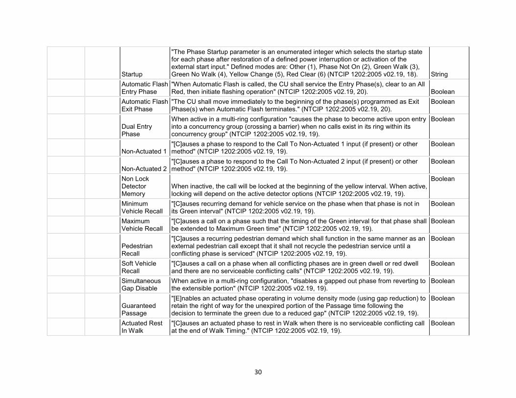
Startup
"The Phase Startup parameter is an enumerated integer which selects the startup state for each phase after restoration of a defined power interruption or activation of the external start input." Defined modes are: Other (1), Phase Not On (2), Green Walk (3), Green No Walk (4), Yellow Change (5), Red Clear (6) (NTCIP 1202:2005 v02.19, 18). String
Automatic Flash Entry Phase
"When Automatic Flash is called, the CU shall service the Entry Phase(s), clear to an All Red, then initiate flashing operation" (NTCIP 1202:2005 v02.19, 20). Boolean
Automatic Flash Exit Phase
"The CU shall move immediately to the beginning of the phase(s) programmed as Exit Phase(s) when Automatic Flash terminates." (NTCIP 1202:2005 v02.19, 20).
Boolean
Dual Entry Phase
When active in a multi-ring configuration "causes the phase to become active upon entry into a concurrency group (crossing a barrier) when no calls exist in its ring within its concurrency group" (NTCIP 1202:2005 v02.19, 19).
Boolean
Non-Actuated 1 "[C]auses a phase to respond to the Call To Non-Actuated 1 input (if present) or other method" (NTCIP 1202:2005 v02.19, 19).
Boolean
Non-Actuated 2 "[C]auses a phase to respond to the Call To Non-Actuated 2 input (if present) or other method" (NTCIP 1202:2005 v02.19, 19).
Boolean
Non Lock Detector Memory
When inactive, the call will be locked at the beginning of the yellow interval. When active, locking will depend on the active detector options (NTCIP 1202:2005 v02.19, 19).
Boolean
Minimum Vehicle Recall
"[C]auses recurring demand for vehicle service on the phase when that phase is not in its Green interval" (NTCIP 1202:2005 v02.19, 19).
Boolean
Maximum Vehicle Recall
"[C]auses a call on a phase such that the timing of the Green interval for that phase shall be extended to Maximum Green time" (NTCIP 1202:2005 v02.19, 19).
Boolean
Pedestrian Recall
"[C]auses a recurring pedestrian demand which shall function in the same manner as an external pedestrian call except that it shall not recycle the pedestrian service until a conflicting phase is serviced" (NTCIP 1202:2005 v02.19, 19).
Boolean
Soft Vehicle Recall
"[C]auses a call on a phase when all conflicting phases are in green dwell or red dwell and there are no serviceable conflicting calls" (NTCIP 1202:2005 v02.19, 19).
Boolean
Simultaneous Gap Disable
When active in a multi-ring configuration, "disables a gapped out phase from reverting to the extensible portion" (NTCIP 1202:2005 v02.19, 19).
Boolean
Guaranteed Passage
"[E]nables an actuated phase operating in volume density mode (using gap reduction) to retain the right of way for the unexpired portion of the Passage time following the decision to terminate the green due to a reduced gap" (NTCIP 1202:2005 v02.19, 19).
Boolean
Actuated Rest In Walk
"[C]auses an actuated phase to rest in Walk when there is no serviceable conflicting call at the end of Walk Timing." (NTCIP 1202:2005 v02.19, 19).
Boolean
30

Conditional Service Enable
When active in a multi-ring configuration, "causes a gapped/maxed phase to conditionally service a preceding actuated vehicle phase when sufficient time remains before max time out of the phase(s) not prepared to terminate" (NTCIP 1202:2005 v02.19, 19).
Boolean
Added Initial Calculation
When active, "the CU shall compare counts from all associated AddedInitial detectors and use the largest count value for the calculations." When inactive, "the CU shall sum all associated AddedInitial detector counts and use this sum for the calculations" (NTCIP 1202:2005 v02.19, 18).
Boolean
Phase Omitted Whether or not this phase is omitted. Boolean
Table 3-12 Information describing a particular Sequence containing phase order, ring, and barrier information for a controller.
Name Sub-Level 1 Name
Sub-Level 2 Name
Sub-Level 3 Name Description
Data Type/Units
Number of Sequences
Number of Sequence plans in the controller, controlling ring and phase order information
Integer Quantity
(per Sequences): Information describing each Sequence
Sequence Index ID of this Sequence Index
Number of Rings Number of Rings in this Sequence
Integer Quantity
(per Ring): Information describing each Ring in this Sequence
Ring Index ID of this Ring in this Sequence Index
Number of Barriers Number of Barriers in this Ring
Integer Quantity
(per Barrier): Information describing each Barrier
Barrier N Slot Position of the second Barrier in this Ring (placed after this Slot number) Index
Number of Slots Number of phase slots in this Ring
Integer Quantity
(per Slot): Information describing each Phase in this Ring
Slot 1 Phase ID of the Phase that appears first in this Ring Index
31

Slot 2 Phase ID of the Phase that appears second in this Ring Index
Slot 3 Phase ID of the Phase that appears third in this Ring Index
Slot 4 Phase ID of the Phase that appears fourth in this Ring Index
Slot 5 Phase ID of the Phase that appears fifth in this Ring Index
Table 3-13 Information describing a particular Overlap, describing overlapping phases for a controller.
Name Sub-Level 1 Name
Sub-Level 2 Name Description
Data Type/Units
Number of Overlaps Number of vehicle Overlaps
Integer Quantity
(per Overlap): Information describing each Overlap
Overlap Index ID of this Overlap Index
Overlap Type Overlap type as defined in NTCIP 1202:2005 v02.19 Section 2.10.2.2 (101) String
Number of Included Phases Number of phases included in this Overlap
Integer Quantity
(per Included Phase): Information describing each Phase included in this Overlap
Included Phase Index Number of an included phase Index
Number of Modifier Phases
Number of modifier phases included in this Overlap (only applies to Overlap Type Minus Green Yellow) (NTCIP 1202:2005 v02.19, 102)
Integer Quantity
Trailing Green Amount of time to extend the overlap green after it would normally terminate (NTCIP 1202:2005 v02.19, 102) Seconds
Trailing Yellow Change
Duration of the yellow change interval for this Overlap when the Overlap green has been extended by Trailing Green (NTCIP 1202:2005 v02.19, 103) Seconds
Trailing Red Clear
Duration of the red clear interval for this Overlap when the Overlap green has been extended by Trailing Green (NTCIP 1202:2005 v02.19, 103) Seconds
32

Table 3-14 Format of information describing Protected/Permissive Left Turn Flashing Yellow Arrow Overlaps for a controller.
Name Sub-Level 1 Name
Description Data Type/Units
Number of FYA Overlaps
Number of Protected/Permissive Left Turn Flashing Yellow Arrow Overlap Configurations
Integer Quantity
(per FYA Overlap): Information describing each FYA overlap
Overlap Index ID of the Overlap to which this FYA configuration applies Index
Protected Phase Index
ID of the Vehicle Phase corresponding to the Protected Left Turn movement (0 disables) Index
Permissive Phase Index
ID of the Vehicle Phase corresponding to the opposing Permissive Thru movement (0 disables) Index
FYA Delay Start Amount of time to delay the flashing yellow arrow output after the beginning of the opposing Permissive Thru movement Seconds
Table 3-15 Information describing a particular Preempt, describing emergency vehicle and/or railroad preemption functionality for a controller.
Name Sub-Level 1 Name Sub-Level 2
Name Description Data Type/Units
Number of Preempts Number of Preempt plans in this controller
Integer Quantity
(per Preempt): Information describing each Preempt
Preempt Index ID of this Preempt Index
Non-Locking Memory
If enabled, do NOT execute a Preempt sequence if the Preempt input terminates before the delay time expires (NTCIP 1202:2005 v02.19, 75). Boolean
Preempt Override Flash
If enabled, automatic flash will NOT be overridden by this Preempt (NTCIP 1202:2005 v02.19, 75). Boolean
Preempt Override Number + 1
If enabled, this Preempt will NOT override the next higher numbered Preempt (NTCIP 1202:2005 v02.19, 75). Boolean
Flash Dwell If enabled, Dwell Phases shall flash Yellow during the Dwell interval, and all other phases shall flash Red (NTCIP 1202:2005 v02.19, 75). Boolean
Link ID of a higher-numbered Preempt that shall be called automatically following the end of the Dwell Green of this Preempt (NTCIP 1202:2005 v02.19, 75). Index
33

Delay Amount of time (in seconds) to wait between receiving a call for this Preempt and executing it (NTCIP 1202:2005 v02.19, 76). Seconds
Minimum Duration Minimum duration (in seconds) of this Preempt (NTCIP 1202:2005 v02.19, 76). Seconds
Minimum Green Minimum duration of an existing Green on another phase that is terminated by this Preempt (NTCIP 1202:2005, v02.19, 76). Seconds
Minimum Walk Minimum duration of an existing Walk on another phase that is terminated this Preempt (NTCIP 1202:2005 v02.19, 77). Seconds
Enter Pedestrian Clear
Duration of the Pedestrian Clear interval for a Walk signal on another phase terminated by this Preempt (NTCIP 1202:2005 v02.19, 77). Seconds
Track Green Duration of the Track Clearance Green interval for this Preempt (NTCIP 1202:2005 v02.19, 77-78). Seconds
Minimum Dwell Minimum duration of the Dwell interval phases for this Preempt (NTCIP 1202:2005 v02.19, 78).
Seconds
Maximum Presence
Maximum time which this Preempt may remain active and be considered valid, after which normal operation is resumed (NTCIP 1202:2005 v02.19, 78).
Seconds
Number of Track Phases
Number of phases that should be active during the Track Clear interval of this Preempt (NTCIP 1202:2005 v02.19, 79).
Integer Quantity
(per Track Phase) Information describing each Track Phase
Track Phase Index ID of a phase to be active during the Track interval of this Preempt Index
Number of Dwell Phases
Number of vehicle phases that should be active during the Dwell interval of this Preempt (NTCIP 1202:2005 v02.19, 79).
Integer Quantity
(per Dwell Phase): Information describing each Dwell Phase
Dwell Phase Index ID of a phase to be active during the Dwell interval of this Preempt Index
Number of Dwell Pedestrian Phases
Number of pedestrian phases that should be active during the Dwell interval of this Preempt (NTCIP 1202:2005 v02.19, 79-80). 0
(per Dwell Pedestrian Phase) Information describing each Dwell Pedestrian Phase
Dwell Pedestrian Phase Index
ID of a phase to be active during the Dwell Pedestrian interval of this Preempt Index
34

Number of Exit Phases
Number of phases that should be active following this Preempt (NTCIP 1202:2005 v02.19, 80). 0
(per Exit Phase) Information describing each Exit Phase
Exit Phase Index ID of a phase to be active following this Preempt Index
Number of Track Overlaps
Number of overlaps that should be active during the Track Clear interval of this Preempt (NTCIP 1202:2005 v02.19, 81). 0
(per Track Overlap) Information describing each Track Overlap
Track Overlap Index ID of an overlap to be active during the Track interval of this Preempt Index
Number of Dwell Overlaps
Number of overlaps that should be active during the Dwell interval of this Preempt (NTCIP 1202:2005 v02.19, 81). 1
(per Dwell Overlap): Information describing each Dwell Overlap
Dwell Overlap Index ID of an overlap to be active during the Dwell interval of this Preempt 6
Number of Cycling Phases
Number of vehicle phases allowed to cycle during the Preempt Dwell interval (NTCIP 1202:2005 v02.19, 81). 0
(per Cycling Phase) Information describing each Cycling Phase
Cycling Phase Index
ID of a vehicle phase allowed to cycle during the Dwell interval of this Preempt Index
Number of Cycling Pedestrian Phases
Number of pedestrian phases allowed to cycle during the Preempt Dwell interval (NTCIP 1202:2005 v02.19, 82). 0
(per Track Phase) Information describing each Cycling Pedestrian Phase
Cycling Pedestrian Phase Index
ID of a pedestrian phase allowed to cycle during the Dwell interval of this Preempt Index
Number of Cycling Overlaps
Number of overlaps allowed to cycle during the Preempt Dwell interval (NTCIP 1202:2005 v02.19, 82). 0
(per Cycling Overlap) Information describing each Cycling Overlap
Cycling Overlap Index ID of an overlap allowed to cycle during the Dwell interval of this Preempt Index
35
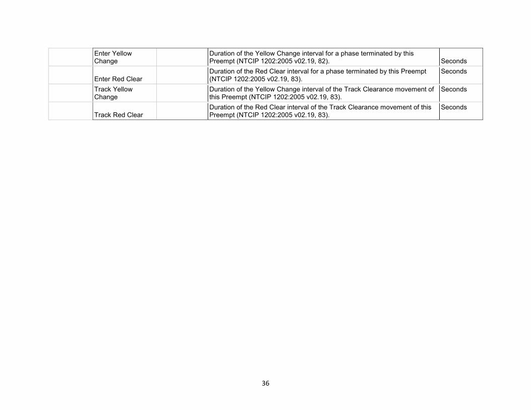
Enter Yellow Change
Duration of the Yellow Change interval for a phase terminated by this Preempt (NTCIP 1202:2005 v02.19, 82). Seconds
Enter Red Clear Duration of the Red Clear interval for a phase terminated by this Preempt (NTCIP 1202:2005 v02.19, 83).
Seconds
Track Yellow Change
Duration of the Yellow Change interval of the Track Clearance movement of this Preempt (NTCIP 1202:2005 v02.19, 83).
Seconds
Track Red Clear Duration of the Red Clear interval of the Track Clearance movement of this Preempt (NTCIP 1202:2005 v02.19, 83).
Seconds
36

Figure 3.2 Graphical schema showing the organization of the unified set of intersection control information.
37
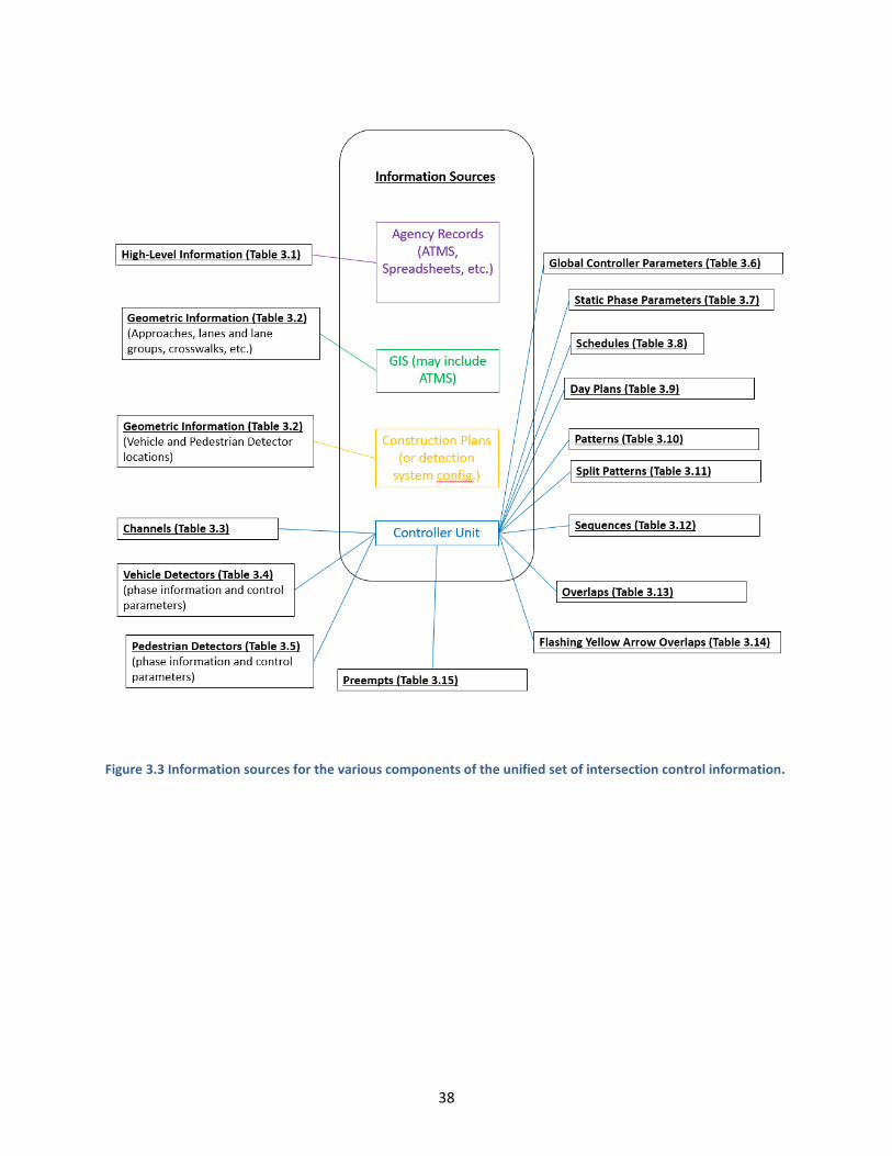
Figure 3.3 Information sources for the various components of the unified set of intersection control information.
38
CHAPTER 4: EXISTING STORAGE CAPABILITIES AND EXPANSION
NEEDS
In addition to developing the unified set of intersection control information presented in the previous
chapter, the other major task of this project involved determining the existing capabilities of management
systems already in place and whether they could be adapted to store the information they do not already
keep. This focused on the systems currently used by MnDOT for managing their traffic signals and
collecting performance measures. For managing their traffic signals, MnDOT uses Intelight MaxView, a
central traffic signal control system that provides an interface for administering signal controllers. This
system has been in place since 2016 and has already helped advance the state of data management and
collection at MnDOT. More recently, MnDOT has also begun using the open-source Automated Traffic
Signal Performance Measures (ATSPM) system developed by the Utah Department of Transportation
(UDOT) to collect high-resolution data for evaluating the performance of their traffic signals.
Both of these systems were considered as alternatives for storing the unified set of ICI that was developed
in the hopes that it could save the effort of developing a custom solution. Regardless of the direction
chosen, the proposed system had to be both centrally accessible by all agencies and approved modelers
without concerns for firewalls, and would have to store the unified set of ICI for each intersection in a
format that is easily readable by programs. These requirements strongly impacted this investigation and
are reflected in the final recommendations.
4.1 METHODOLOGY
To determine the capabilities of the systems currently in use by MnDOT for managing their traffic signals,
researchers took advantage of many resources provided by MnDOT and the developers of these systems,
as well as their experience working with information technology systems. MnDOT’s signal operations group was very open in working with researchers to explore the features of both MaxView and ATSPM,
both by examining the user interface and the underlying databases they use to store information. In
addition to this, Intelight, the developer of MaxView, very generously provided a trial version of MaxView
and a signal controller unit for the duration of the project, allowing researchers to examine the flow of
data in the program and database. Along with this MnDOT also provided an Econolite controller unit to
show how MaxView interacts with the hardware that is most commonly installed by agencies in
Minnesota (with some exceptions).
Over the course of the project, researchers worked with the MaxView server and signal controllers,
MnDOT’s signal operators, and Intelight representatives to learn how they system worked, how MnDOT
used it, and the existing and potential capabilities for data storage and software-to-software translation
tools. This involved reviewing the available technical documentation describing MaxView and attending a
users’ meeting to explore current and upcoming features, analyzing the database structure using the trial
version and materials provided by MnDOT, and discussing how certain aspects of the program worked
with Intelight developers to understand the capabilities of the system as it is currently implemented.
MnDOT signal operators also helped by walking researchers through their common practices when using
39
the system and how they use it to store information, respond to data requests, and carry out their regular
audits of signal timing.
Similar to MaxView, researchers explored UDOT’s open-source ATSPM software using similar techniques
to understand its capabilities, how it works, and how it could be expanded. This consisted of reviewing
the available documentation and presentations discussing how the system is used and reviewing the
source code itself to understand how the system currently works and how it could be expanded. Along
with this, the structure of the database used by ATSMP was analyzed using materials provided by MnDOT
to determine what information could be obtained from it. Researchers also worked with the MnDOT
engineer most involved in setting this system up to learn how they are using it and how it compares to
and compliments MaxView. The information gathered from all these activities helped form the
recommendations that are discussed in the following sections.
4.2 FINDINGS
During this project, researchers uncovered a number of important facts that affect the direction for the
implementation phase of the project. While both MaxView and ATSPM contain much of the unified set of
ICI proposed in the previous chapter, the needs of the programs are such that much of the detailed
information needed for the development of simulation models is missing or unreadable. Information like
the geographic location of an intersection, the different approaches, the number of lanes, and the position
of detectors, among other things, are plainly available in the database. However, more detailed geometric
information, such as the dimensions of lanes and crosswalks, the presence of bicycle lanes, and the curve
radius of turns, among others, are not included. In addition to this, the structure of both databases can
be convoluted at times, with many decisions likely made to benefit the organization of the programs at
the expense of readability, which is understandable given that the databases are not intended to be used
apart from the programs.
Most critically, however, is the lack of easily read signal programming information in the database. In
ATSPM, much of this data is simply not included because it is not necessary for the program, which is
more concerned with the collection of detector data and signal status information for generating
performance measures. MaxView, by contrast, since it actually programs controllers, does contain
detailed signal programming information, however it is not at all readable by anything besides MaxView
itself. In the MaxView database, all signal programming information is contained in a “BinaryDatabases”
table that holds a history of the programs that were pushed to the controllers. Each entry in this table is
a binary serialized object that contains everything needed to program the controller, but it is encoded in
a proprietary format. Because of this, any attempt to read this data would require a dedicated translation
tool developed by Intelight, something that they have considered doing but do not have any immediate
plans to do so.
4.3 RECOMMENDATIONS
Given these facts, using either MaxView or ATSPM as is to store the unified set of ICI is not feasible, as
some of the critical information needed is either missing or not readable. Because of this, the best course
40

for implementing a centralized system for warehousing ICI for multiple organizations involves the
development of a custom solution for storing this information in a standardized format, along with the
development of tools for reading this data from the available sources. What this system ultimately looks
like can vary depending on what compatibility is included, how much manual effort for working with it is
assumed, and what the interface(s) to the system are like, however some recommendations can be made
to help in the decision making process.
To start, the system will need some sort of storage backend to physically store and organize the
information. Probably the most straightforward solution for this is to use a relational database with a
schema developed based on the unified ICI set presented in the previous chapter. Alternatively, a “NoSQL” database, such as a Key-Value Store, Object Database, or Document Store could be used instead which
may provide more flexibility. Regardless, some sort of database would be an integral part of the system,
providing a means for storing and serving the information in a convenient way. To support the
requirement that multiple agencies and modelers be able to access this database, it would need to be
hosted on a public network outside of any firewalls. A controlled interface with users and privilege
management would be included to ensure the system is secure and that access can be controlled by the
system administrators.
As for importing data into the database, there are two potential directions that would need to be
discussed with stakeholders to choose the ideal solution. The issue at hand has to do with the accessibility
of data from MaxView and ATSPM as discussed in the previous section. While general information about
an intersection can be read directly from the program database, such as the geographic location,
approaches, detector information, and connection parameters for the controller, the lack of detailed
timing information in a readable format must be worked around in some way. One means for doing this
would be to go to the controllers themselves to get the controller database and parse through the
information there. This would require a custom tool that must be run from inside an agency’s firewall,
reading general information about the intersections from the MaxView or ATSPM (or a different system)
database, then using the controller connection information to download the database from each
controller individually, parse the information, and upload everything to the central database. The tool
could be run manually, be set to run periodically, or programmed to watch for changes to keep the
information in the central database updated. This could likely take advantage of some of the tools
developed by UDOT as part of the ATSPM software that contain code to handle reading the databases of
common signal controllers.
Alternatively, the information needed could be obtained from MaxView or another CTSCS/ATMS system,
without involving the controllers, if tools for exporting the data from these systems to the unified
database in a specific format are added. This would of course require involvement from the developers
of each system, which would likely come at a cost, however it would save the effort of developing the
tools to communicate with the controllers. In the case of MaxView specifically, it currently does have the
capability to export information about a signal to a spreadsheet in a flexible format, so a tool that exports
this same data to a database in a different format would likely not be very difficult, but would require
cooperation from Intelight. Discussions with Intelight representatives have shown that they are willing to
consider this, as other organizations have expressed interest in being able to obtain controller program
41
information from MaxView in a machine-friendly format. For other systems, however, the vendors may
or may not be interested. In addition to MaxView, which is used by several agencies in the metro area in
addition to MnDOT, Siemens TACTICS and Econolite Centracs are also common and used by some of the
larger municipalities, such as Minneapolis (TACTICS) and St. Paul (Centracs) who operate hundreds of
signals. Therefore, if this route were to be taken, involvement from these vendors would be essential.
There are also many smaller agencies that do not use a central system that would need to be considered,
in addition to agencies that do not store all information in their CTSCS. In the case of agencies that do not
use central systems, creating tools for importing U-ICI data directly from the controller may help ease the
process, however because of differences in the output formats from different programs/systems this
would require dedicated tools. For instance, while MaxView has the ability to export information from an
Econolite controller in a format that is generally similar to the one output directly by the controller, there
are some notable differences that would require the tools to be different. Aside from the difference in
the file formats, issues like differences in the table structures, missing controller options, and changes in
the order in which the control parameters are presented are all things that would require dedicated
handling in software to use either format.
In addition to this, the mix of formats in used by smaller agencies presents a challenge. Spreadsheets can
be easily read by an automated program, however understanding the organization of data in a
spreadsheet is not trivial and the records can often be inconsistent. For PDF files and paper records, optical
character recognition technology could be employed, however the same issues with organization and
consistency arise. Ultimately, converting these records will require a multi-step process of manual
cleaning of data to correct inconsistencies, documenting the format in a machine-readable way, and
feeding the data into the central database via some custom software application. In some cases, it may
also make sense to simply manually insert records into the database and establish provisions for regular
updates.
Finally, in addition to the tools for importing data into the central database, some tools will need to be
developed to export data from the central database into common formats and an interface for selecting
what information is to be included. As was suggested by many of the respondents to the modeler survey,
an interactive, web-based map interface is probably the most intuitive way to find the information
needed, along with some form-based tools for extracting bulk amounts of data. As for the format in which
the information will be output, the simplest thing would be a text (e.g. CSV) file that organizes the data in
a predictable format. This would at least provide input for an automated translation tool that could be
developed by modelers or the vendors of the programs they use. As an alternative that is perhaps more
easy to work with, Synchro files containing signal program information are already directly importable
into many modeling programs and would probably be a worthwhile format to make available. This leaves
out geometric information, which could be placed into a geodatabase or shapefile container, which many
programs are also able to read. Also regardless of any machine-readable formats, a clear, human-readable
report format, such as the one presented in Figure 4.1, would also be useful for signal operators and
others familiar with these types of documents.
42

Figure 4.1 Example of a human-readable report format for signal timing information (SRF Consulting Group, Inc.)
All of these factors will need to be taken into account to make an informed decision as to the best path
for implementation. While MnDOT is both the priority and the best equipped to make their ICI available
in a centrally accessible system, the nature of the transportation network and its overlapping jurisdictions
mean that the needs and practices of other agencies must also be considered. The first priority would be
deciding on the database implementation that is used, followed by what tools will be developed to
automate the data collection process, something that will be influenced by the systems and practices of
other agencies. After that, any interface and export tools that would be part of the system would need to
be decided. Once the needed development has been completed, the process for carrying out the
collection and importation into the central database can be carried out, with quality control provisions to
insure the integrity of the data in the system. A more thorough outline of this process will be provided in
the work plan that is developed as the final project deliverable.
43
CHAPTER 5: CONCLUSIONS AND RECOMMENDATIONS
The project described in this report began as part of a larger plan that included the development of the
proper container/host for the U-ICI as well as to identify, and when possible build, the interface tools
required to allow secure exchange of information between the central control systems owned by the
various jurisdictions and U-ICI repository. For efficiency and to prioritize on feasibility, the plan was split
into two phases. The first phase, this project, was to identify the ICI user needs, and based on these,
develop the U-ICI proposed structure that satisfies them. In this first phase the research team was also
tasked to investigate the feasibility of using a commercially available central control system as the U-ICI
repository, focusing primarily on the system MnDOT recently transitioned to, Maxview from Intelight.
The purpose of this chapter is to conclude the effort on Phase I by offering recommendations on how to
proceed with Phase II of the proposed effort. The ultimate goal is to allow any interested entity to retrieve
the most up-to-date and complete sets of U-ICIs for signalized intersections anywhere in the Twin Cities
metropolitan area and possibly beyond. This goal carries the following requirements:
The ICI available to external entities should be comprehensive enough to satisfy all known and
identified uses for such information. In other terms, the provided information, at a minimum,
must contain all the pieces of information described in the U-ICI developed in this project.
The transfer of U-ICI to external entities must not violate the safety and security of the
organization that owns the signals related to the requested U-ICI. This means that there is either
a secure socket providing a limited access through the institutions firewall or the U-ICI repository
resides outside any entity that owns/operates traffic signals.
The request and retrieval of the requested U-ICI must result in minimal effort by the traffic
operations group in the organization that owns the relevant signals. This can be accomplished in
two ways:
o Through dedicated interfaces that allow outside entities to send data requests to the
owner’s central control system
o Manual or scheduled “push” events initiated by each central control system directing new
or updated U-ICI to the common repository
The available U-ICI must be current and describe the operating parameters of the traffic signals
at the time of the request. This means that if the update of U-ICI is performed manually, the owner
organization needs to ensure that this happens every time something changes.
Availability of historical U-ICI. Although this can be considered an optional feature, in many cases,
especially in modeling projects, it is more important to retrieve the U-ICI that were current during
the collection of other needed information (turning moving counts, past special event data
collections, etc.) This covers the cases where the U-ICI for a particular group of intersections
changed between the time demand was measured and the time the modeler encountered the
need to retrieve U-ICI for the model under development. To cover this need, if the U-ICI are
extracted from the owners central control system, past versions of the operating parameters need
to be saved and maintained. If the U-ICI reside in an external repository, such database needs to
be designed to include a time period for which its set of U-ICI information is valid.
44

As presented in Chapter 4, without the cooperation of the software developers, it is not easy or even
feasible to expand the proprietary databases used by the current version of Maxview and the rest of the
control software used by jurisdictions in the Twin Cities metropolitan area to include the additional
information that is part of the U-ICI. Given that any piece of software can be modified to cover any new
functionality if cost and effort is not an issue, this task becomes possible if undertaken by the developers.
Indeed, in discussions that took place during the time this chapter was composed, due to customer
pressure, Intelight reportedly initiated changes in Maxview to satisfy the input and storage of some of the
missing information that constitute the difference between the ICI currently stored in Maxview and the
U-ICI as defined in this project. Naturally, because other states/clients of Intelight are driving these
developments, it is unknown as to what degree the additional information stored will come to the full U-
ICI set Minnesota’s stakeholders need.
Regardless, even if Maxview and any of the other central control systems, such as TACTICS, Spinnaker,
Aries, Centracs, and Miovision, that are currently used in Minnesota do expand their databases and user
interfaces to allow input and storage of all pieces of information included in the U-ICI, the problem of
secure and effortless data exchange remains more or less the same. Realistically, all of these products
compete in the market and it is not in their best interest to allow the users to consider them as
interchangeable applications. Case in point, even the approved NTCIP standard set of information is not
completely supported in terms of transferring information between two of the aforementioned software
applications.
In regard to the method for storing and disseminating U-ICI, it is the recommendation of this project that
a repository (database), external from that of any jurisdiction, is the most efficient, secure, and long lasting
solution. In IT jargon, such a repository is in the loud. For the less IT-savvy reader, though, let’s clarify
some potential misconceptions.
There is no such thing as the “cloud”. The Internet is comprised of billions of individual computers owned
by physical entities and residing in physical locations, all possessing the ability to communicate with each
other.
In its majority, the aforementioned computers are owned by individuals and organizations that keep
access to their data restricted and access to their machines secured to prevent unauthorized uses. These
safeguards are collectively described as firewalls. Computers that are behind such firewalls have the ability
to receive and send information to other computers outside their firewall as long as this communication
is initiated from the inside. So, from your computer, you can reach out to billions of machines around the
world but only specific machines/users from the outside, that you have specifically authorized, can access
your computer.
To maintain efficient exchange of information without compromising security, selected computers are left
open with minimal firewalls protecting them. Other computers, can exchange data by using these open
computers as the middle station. These facilities have been collectively named the “cloud”.
So to bring the subject back to the topic of this report, the Cloud repository of U-ICI is simply a database
or library residing on a computer that is outside of any particular jurisdiction’s firewall. That computer can
be leased by a cloud provider like Amazon, Google, and others or it can simply be a regular PC residing in
45

an office in MnDOT or MNIT connected to the Internet outside the MnDOT firewall. The reason services
like Amazon and others have become popular is that leasing a computer from them relieves you from the
effort of maintaining the actual machine and keeping it operational. Given that these machines are open
to the world, they have higher frequencies of malicious attacks by hackers and other bad elements so they
require more than the average maintenance effort.
Having clarified that a repository in the “cloud” is hardly different than a database on any ordinary PC,
let’s discuss required resources. Two types of computer resources are relevant in this case storage
capacity and communication bandwidth. In either case, as long as U-ICI covers only static information and
does not include dynamic information similar to that included in the SPaT messages or include traffic
measurements, the requirements for storage and bandwidth are minimal. The entire detector data from
the entire RTMC detection infrastructure updated every 30 seconds and stored in a database since 1994
only takes less than 70GB of disk space. This is less than a blue ray movie with a two-hour duration. The
collected U-ICI from every signal in the entire state of Minnesota constitutes a tiny fraction of the
aforementioned disk space. Also, given that the static U-ICI information for the average traffic signal
changes once a year or even less frequently, the number of requests for this information is similarly
sparse. In conclusion, selecting a cloud repository as the “middle man” in the exchange of U-ICI requires
little in resources.
The expense in time and effort in establishing a cloud repository of U-ICI is mainly in the development of
the utilities residing on the protected machines running the instances of Maxview, Tactics, etc. handling
the automatic/scheduled synching of information between each jurisdiction’s system and the cloud
repository, as well as the user interface of said repository that would allow querying the repository for U-
ICI from selected intersections. Figuring out the design of such utilities and interfaces is in the scope of
the second phase of this project.
We hope that the work performed in this project identified the needs of the different stakeholder groups,
produced an organized and comprehensive format for intersection control information that contains
most, if not all, the information any group needs and has demystified the resources and effort required
to establish a U-ICI repository that can form the distribution node of such information without affecting
the security of any operational system.
46
REFERENCES
AASHTO, ITE, NEMA. (2005) NTCIP 1202:2005 v02.19 Object Definitions for Actuated Traffic Signal
Controller (ASC) Units – version 2. Washington, D.C: AASHTO/ITE/NEMA.
Econolite Group, Inc. (April 2014) ASC/3 Programming Manual P/N 100-0903-001 Rev. 15.
SRF Consulting Group, Inc. (June 2018) Trunk Highway 7 2018 Signal Timing Optimization. St. Paul, MN:
Minnesota Department of Transportation.
47

APPENDIX A
SURVEY FOR TRAFFIC SIGNAL OWNERS AND OPERATORS
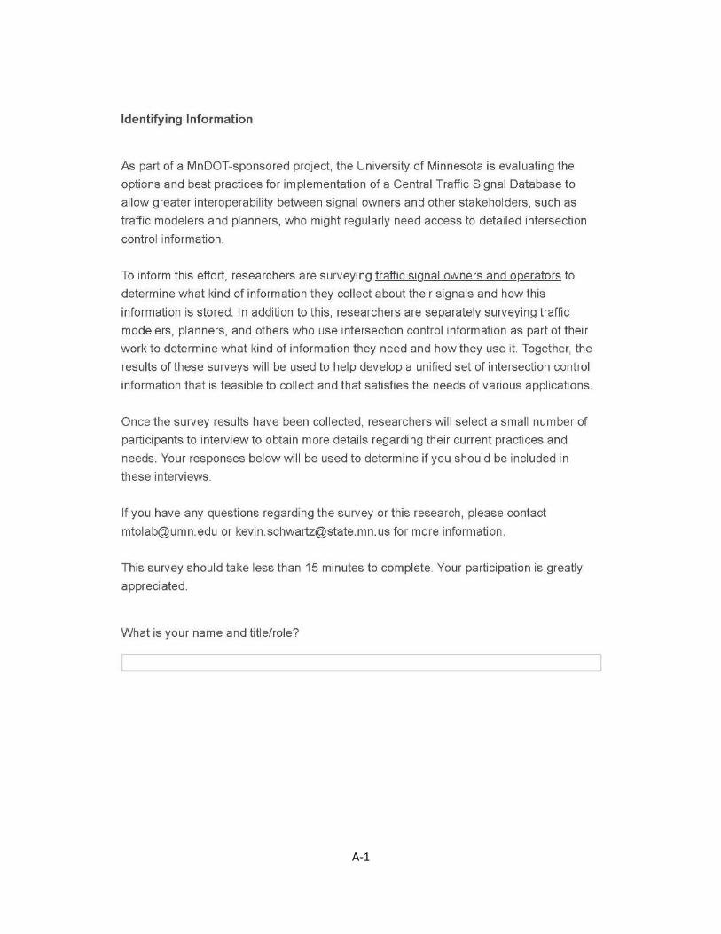
A-1
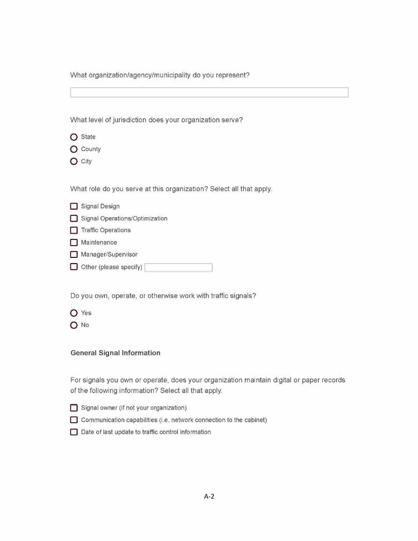
A-2

A-3

A-4

A-5
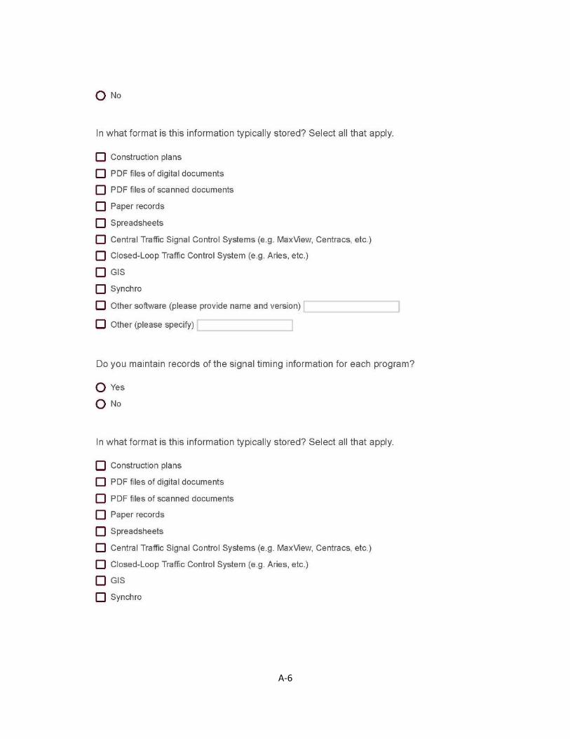
A-6
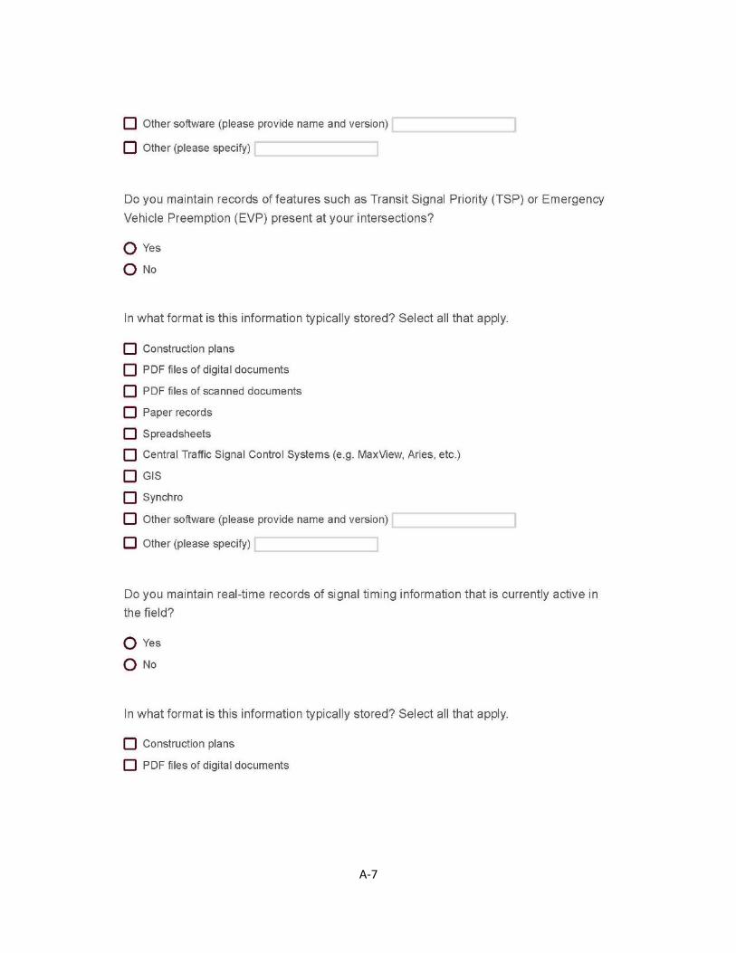
A-7
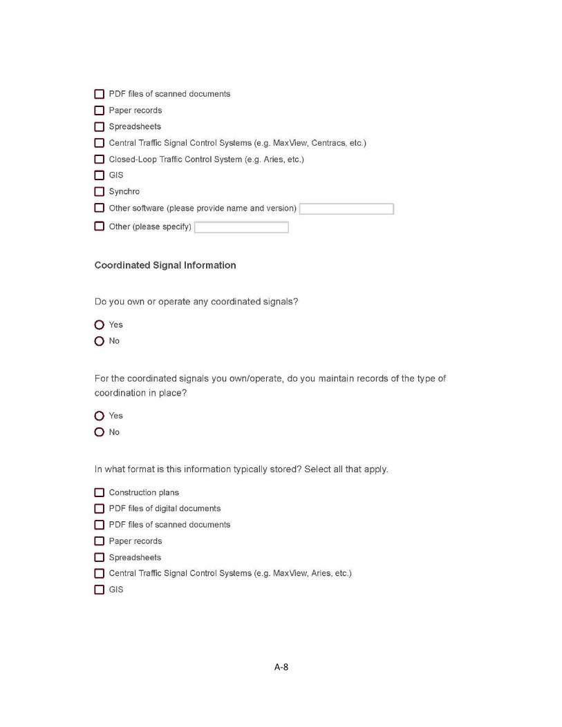
A-8
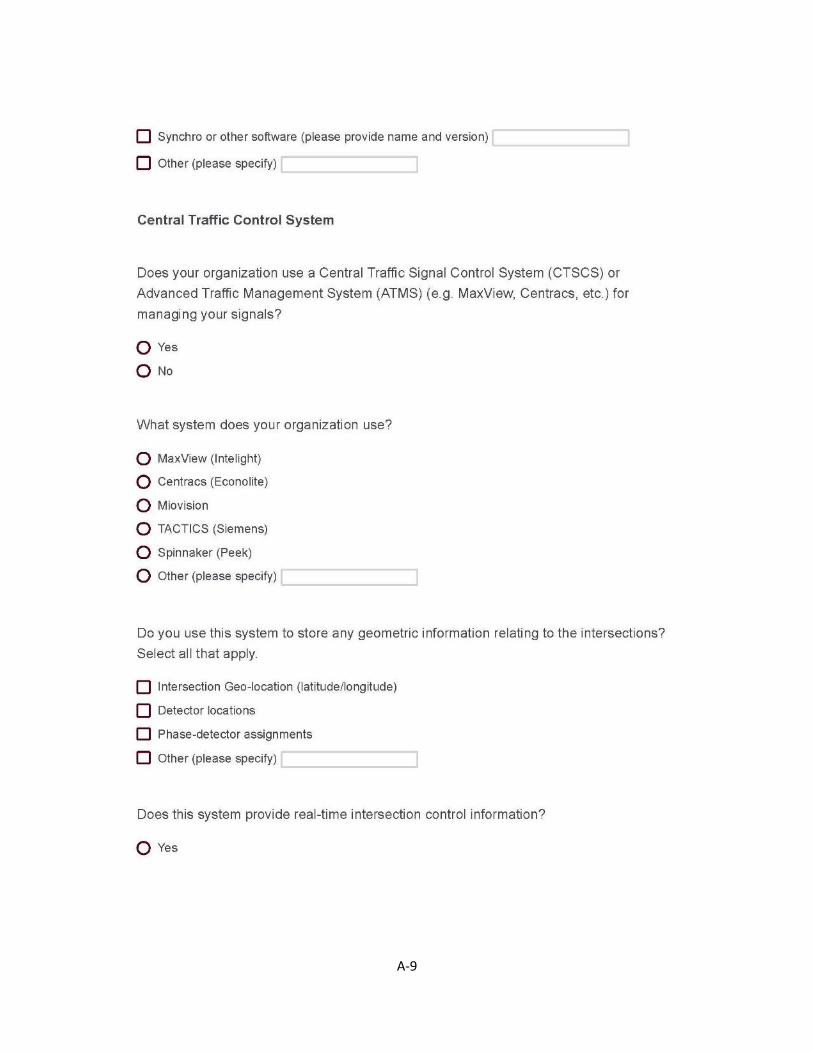
A-9

A-10

A-11

A-12

A-13

A-14

APPENDIX B
RESPONSE DATA FROM TRAFFIC SIGNAL OWNERS AND
OPERATORS SURVEY

B-1

B-2

B-3
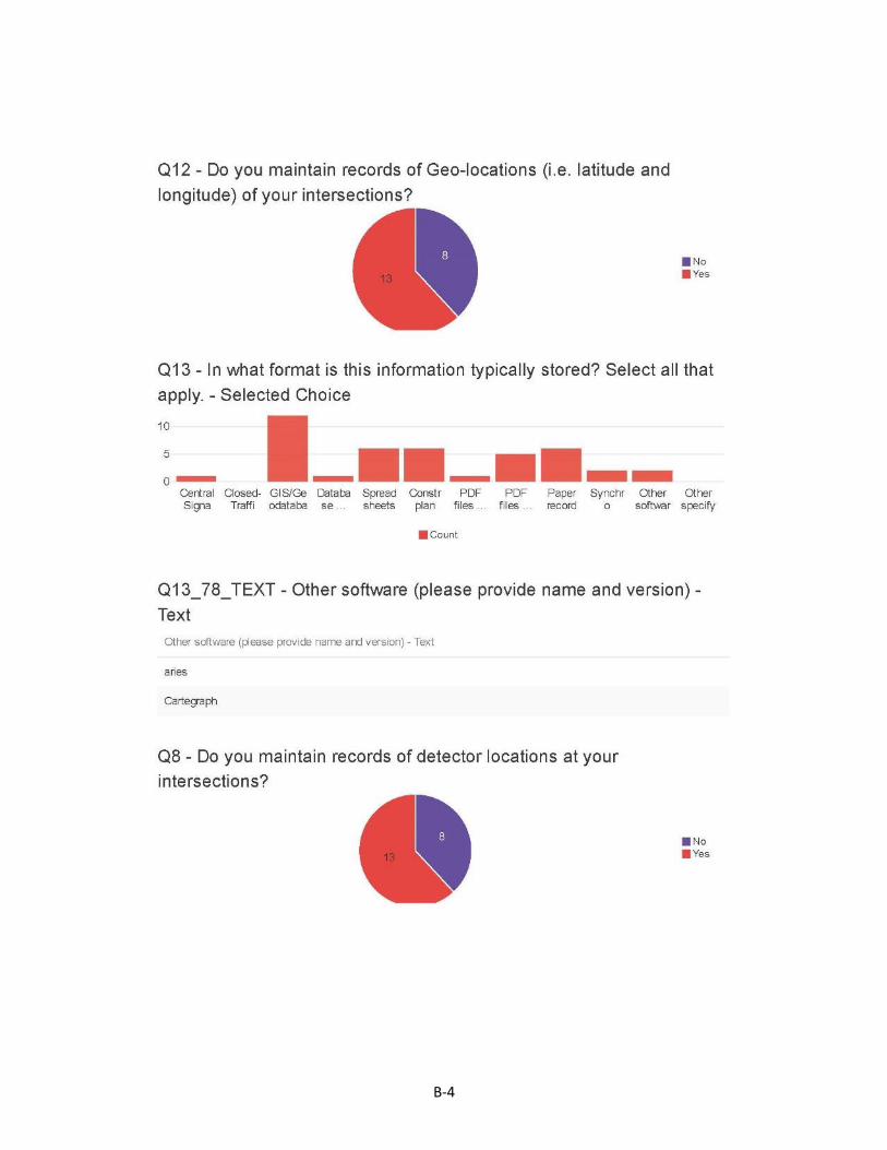
B-4

B-5
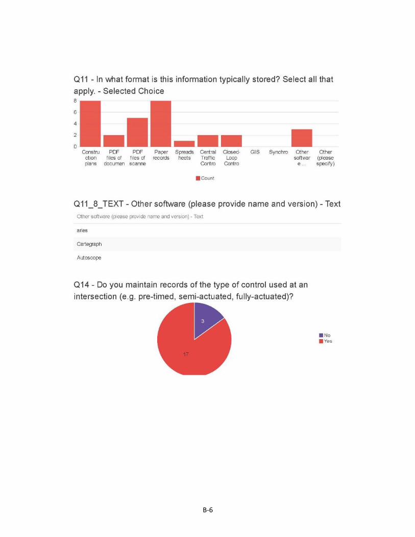
B-6
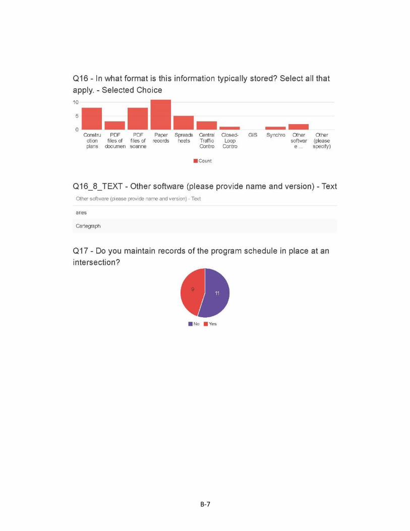
B-7

B-8
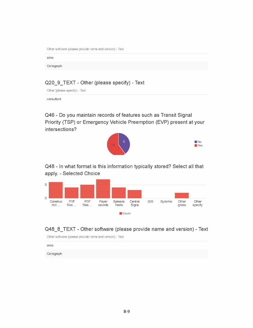
B-9
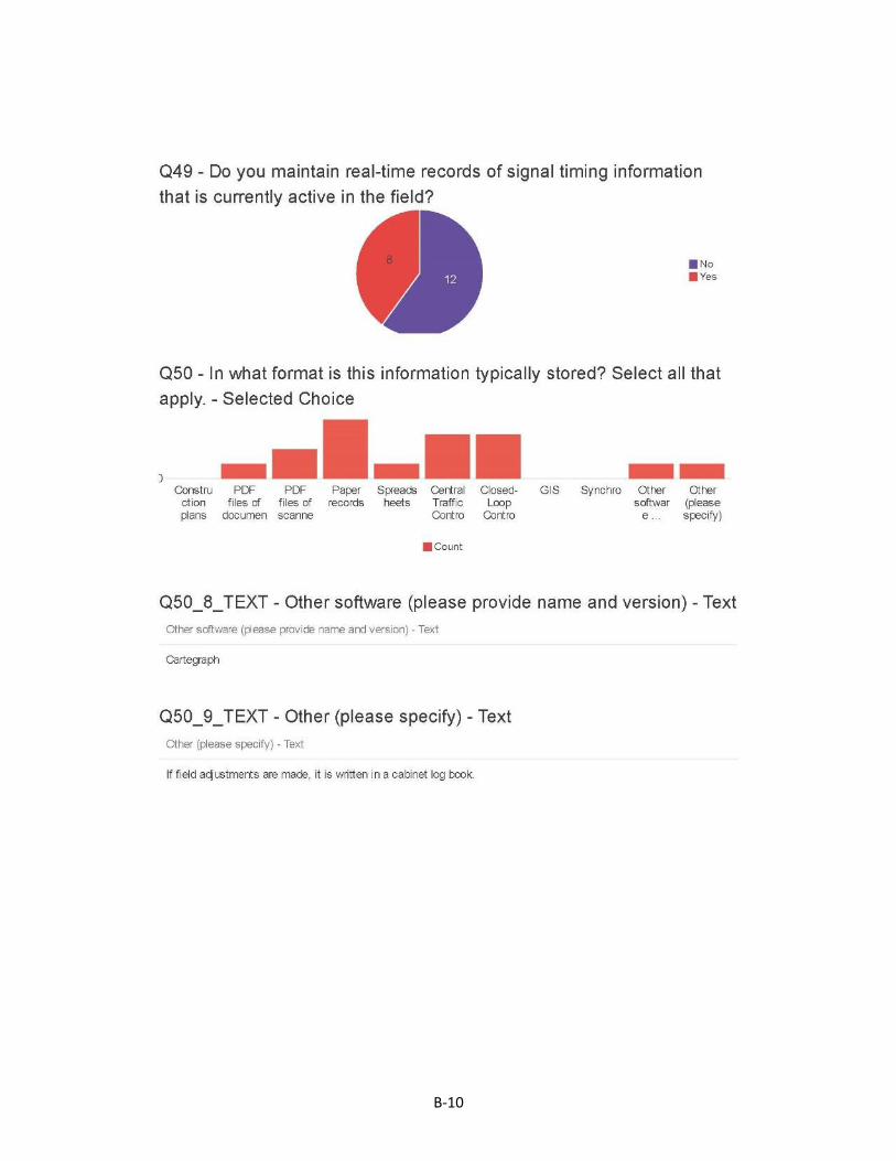
B-10
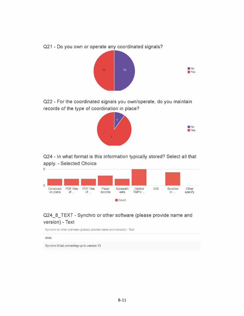
B-11

B-12

B-13
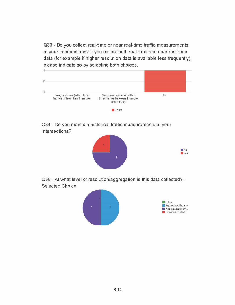
B-14

B-15
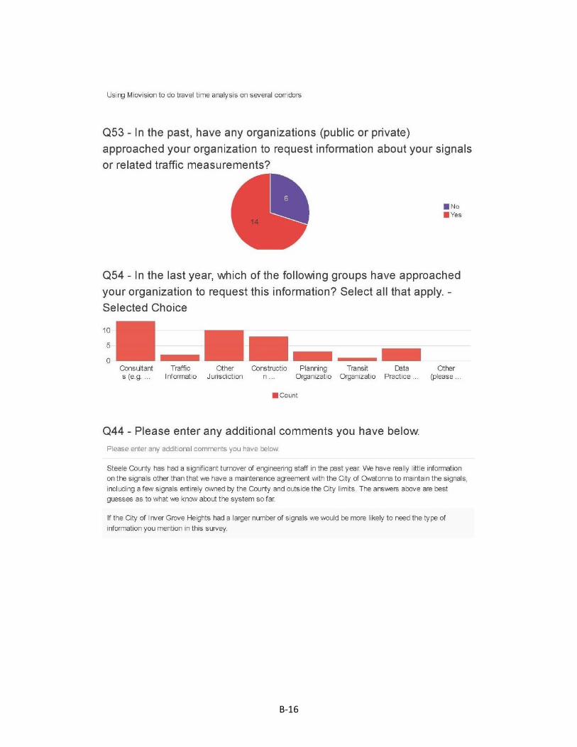
B-16

APPENDIX C
SURVEY FOR DESIGNERS, MODELERS, AND PLANNERS

C-1
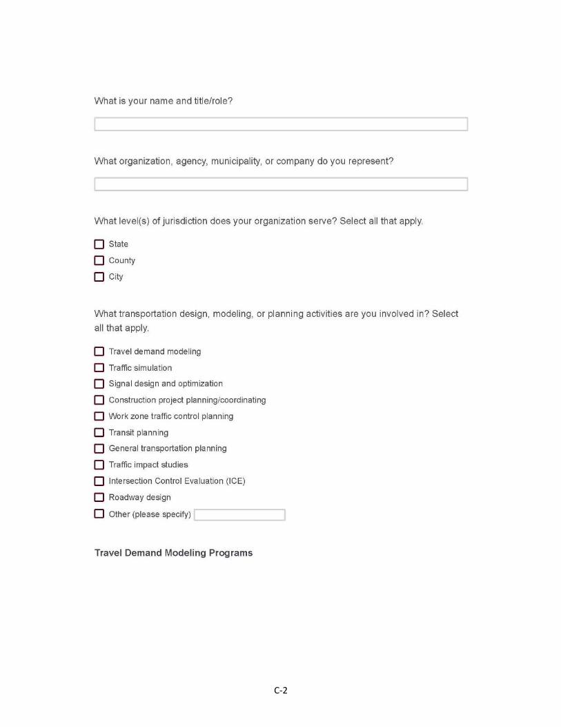
C-2
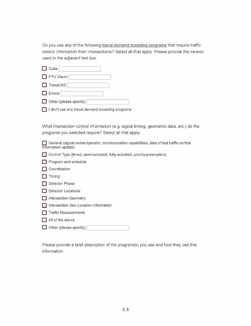
C-3

C-4

C-5
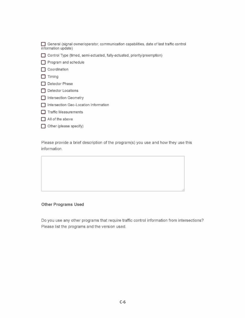
C-6
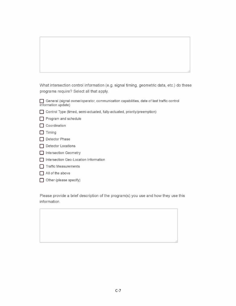
C-7
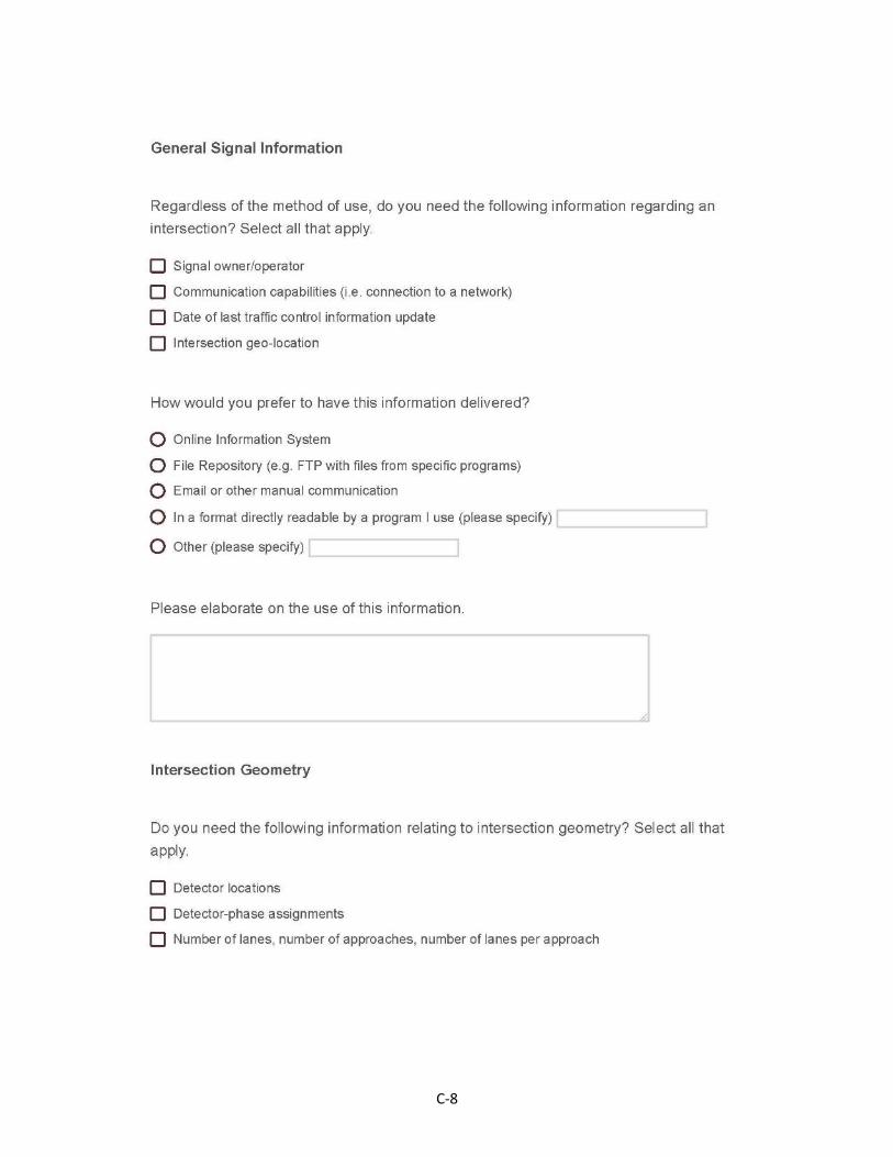
C-8
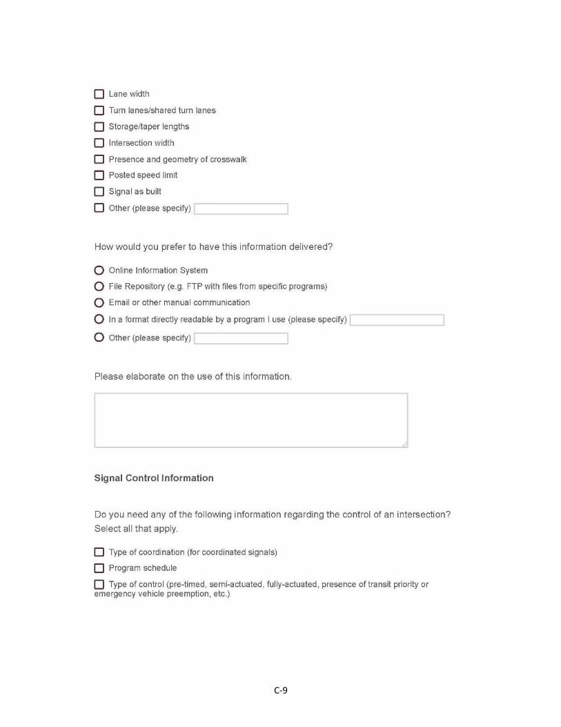
C-9

C-10
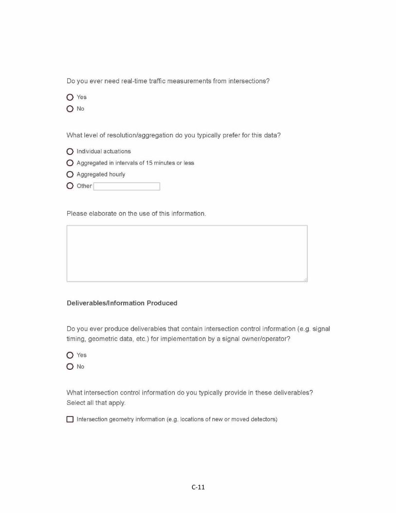
C-11

C-12

C-13

APPENDIX D
RESPONSE DATA FROM DESIGNERS, MODELERS, AND PLANNERS
SURVEY

D-1

D-2
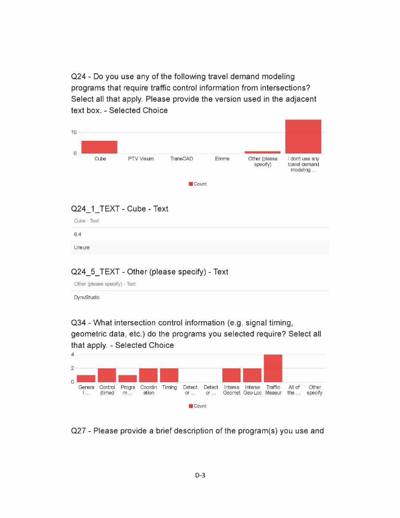
D-3

D-4

D-5
D-6
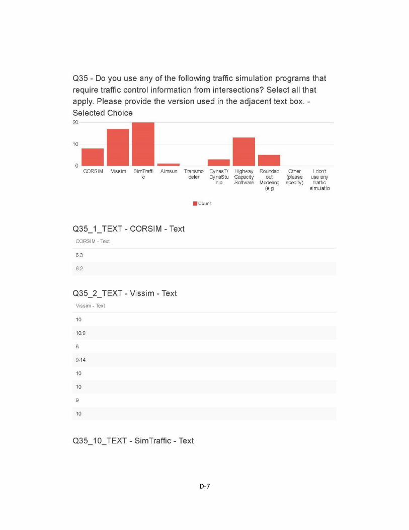
D-7
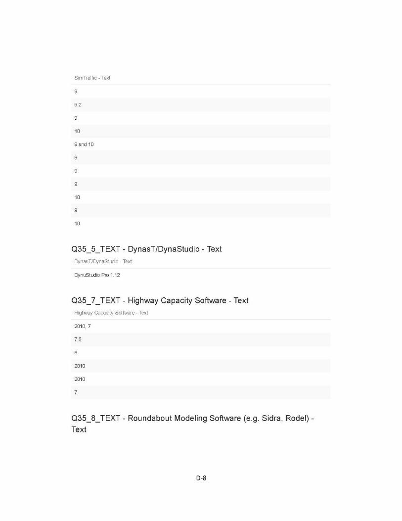
D-8

D-9

D-10

D-11

D-12

D-13
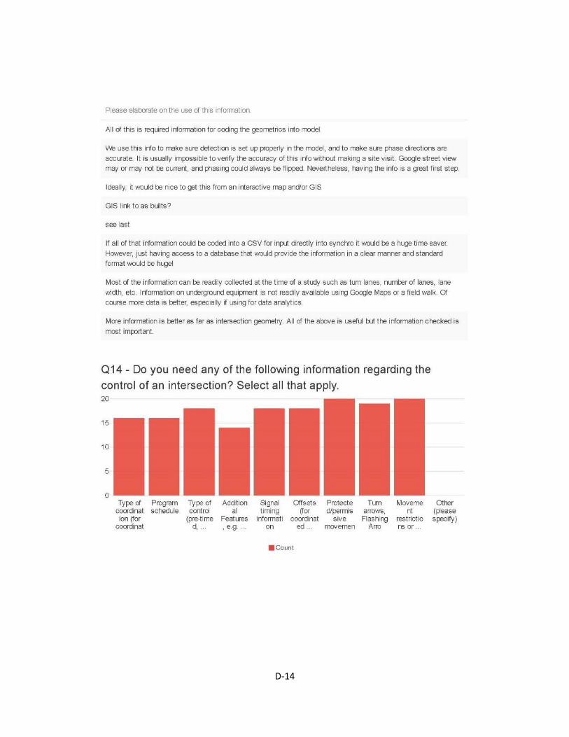
D-14
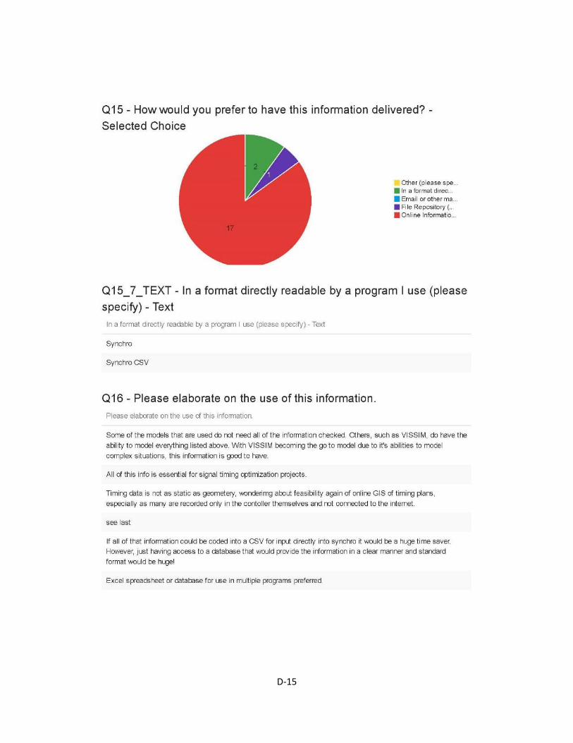
D-15

D-16
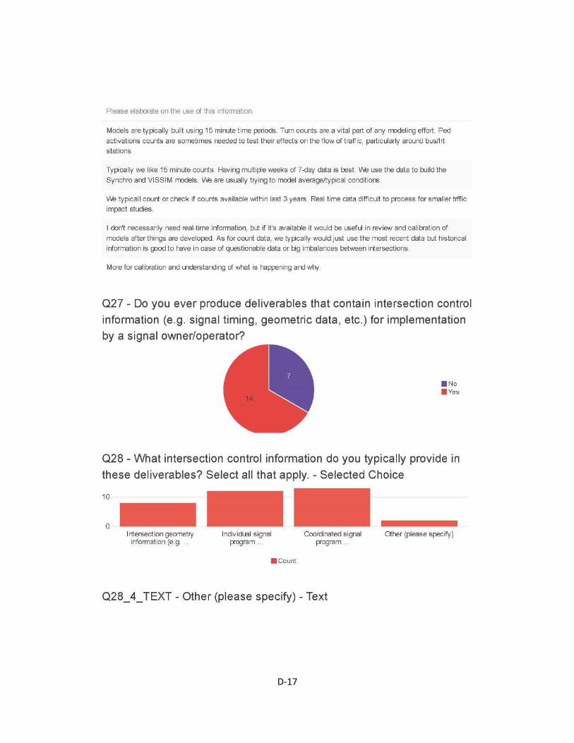
D-17
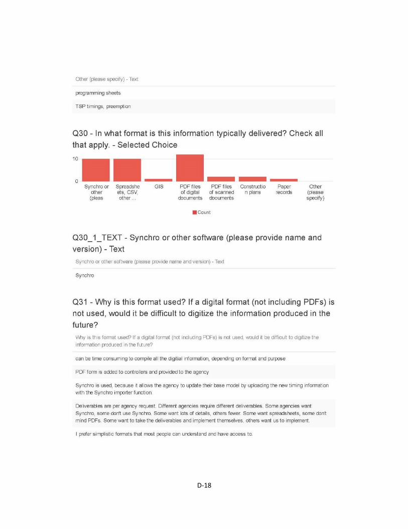
D-18
D-19