Ethanol production by enzymatic hydrolysis from sugarcane biomass–the integration with the...
14
PROCEEDINGS OF ECOS 2012 - THE 25 TH INTERNATIONAL CONFERENCE ON EFFICIENCY, COST, OPTIMIZATION, SIMULATION AND ENVIRONMENTAL IMPACT OF ENERGY SYSTEMS JUNE 26-29, 2012, PERUGIA, ITALY 189 - 1 Ethanol production by enzymatic hydrolysis from sugarcane biomass – the integration with the conventional process Reynaldo Palacios-Bereche a , Adriano Ensinas b , Marcelo Modesto c , and Silvia Nebra d a Centre of Engineering, Modelling and Social Sciences, Federal University of ABC (CECS/UFABC), Santo André, SP, Brazil, [email protected] b Centre of Engineering, Modelling and Social Sciences, Federal University of ABC (CECS/UFABC), Santo André, SP, Brazil, [email protected] c Centre of Engineering, Modelling and Social Sciences, Federal University of ABC (CECS/UFABC), Santo André, SP, Brazil, [email protected] d Centre of Engineering, Modelling and Social Sciences, Federal University of ABC (CECS/UFABC), Santo André, SP, Brazil, and Interdisciplinary Centre of Energy Planning, University of Campinas (NIPE/UNICAMP), Campinas, SP, Brazil, [email protected] Abstract: The aim of this study is to make an evaluation of the possibilities of ethanol production increase through the introduction of bagasse hydrolysis process in conventional distilleries, considering the limiting situation of bagasse use: it is the major by-product in sugar and ethanol production and is burnt in boilers to satisfy the steam and power requirements of the process. Simulations in ASPEN PLUS® software were performed, in order to evaluate the mass and energy balances, for the integrated process, considering the pre-treatment of sugarcane bagasse by steam explosion. The cogeneration system was also modelled and integrated with the ethanol production process. It consists of a steam cycle with backpressure steam turbines and parameters of live steam of 67 bar and 480°C. In all the cases studied it was considered that the steam flow used in the system was just that necessary to fulfil the process thermal needs, so, it was assumed that the surplus of bagasse was used to produce ethanol. The use of sugarcane trash was considered in order to accomplish the energetic needs of the overall process as well as lignin cake, which is a hydrolysis process residue. Several cases were evaluated, which include: the conventional ethanol production plant without hydrolysis (Case I), the conventional plant joint with hydrolysis process without thermal integration considering different solid contents in the hydrolysis reactor (Cases II, III and IV), and the conventional plant joint with the hydrolysis process considering thermal integration through Pinch method (Case V). The results shown a modest ethanol production increase of 9.7% for the situation without thermal integration and low solid content in the hydrolysis reactor, on the other hand, the case where thermal integration was applied presented an ethanol production increase of 17.4%. Keywords: Ethanol, sugarcane, enzymatic hydrolysis, thermal integration. 1. Introduction Ethanol is produced in Brazil in large scale using sugarcane as raw material by fermentation of sugars and distillation. World consumption of ethanol tends to grow in the next years because of the growing interest of many countries by biofuels use, due to factors such as: environmental damage (avoided emissions of greenhouse gases) energy security (diversification of energy sources and reducing dependence on oil) and support to farmers [1]. The sugarcane bagasse is the major by- product in sugar and ethanol production and it is burnt in boilers to satisfy the steam and power requirements of the process. Sugarcane bagasse, as well as other lignocellulosic materials, can be also used for ethanol production but, the introduction of the bagasse hydrolysis process in the current ethanol production system is a real challenge, being bagasse the fuel of the current process and at the same time, raw material for the new one. Thus, the aim of this study is to make an evaluation of the possibilities of ethanol production increase through the bagasse hydrolysis
-
Upload
independent -
Category
Documents
-
view
4 -
download
0
Transcript of Ethanol production by enzymatic hydrolysis from sugarcane biomass–the integration with the...

PROCEEDINGS OF ECOS 2012 - THE 25TH INTERNATIONAL CONFERENCE ON
EEEEFFICIENCY, CCCCOST, OOOOPTIMIZATION, SSSSIMULATION AND ENVIRONMENTAL IMPACT OF ENERGY SYSTEMS
JUNE 26-29, 2012, PERUGIA, ITALY
189 - 1
Ethanol production by enzymatic hydrolysis from sugarcane biomass – the integration with the
conventional process
Reynaldo Palacios-Berechea, Adriano Ensinas
b, Marcelo Modesto
c, and Silvia Nebra
d
a Centre of Engineering, Modelling and Social Sciences, Federal University of ABC (CECS/UFABC),
Santo André, SP, Brazil, [email protected] b Centre of Engineering, Modelling and Social Sciences, Federal University of ABC (CECS/UFABC),
Santo André, SP, Brazil, [email protected] c Centre of Engineering, Modelling and Social Sciences, Federal University of ABC (CECS/UFABC),
Santo André, SP, Brazil, [email protected] d Centre of Engineering, Modelling and Social Sciences, Federal University of ABC (CECS/UFABC),
Santo André, SP, Brazil, and Interdisciplinary Centre of Energy Planning, University of Campinas
(NIPE/UNICAMP), Campinas, SP, Brazil, [email protected]
Abstract:
The aim of this study is to make an evaluation of the possibilities of ethanol production increase through the introduction of bagasse hydrolysis process in conventional distilleries, considering the limiting situation of bagasse use: it is the major by-product in sugar and ethanol production and is burnt in boilers to satisfy the steam and power requirements of the process. Simulations in ASPEN PLUS® software were performed, in order to evaluate the mass and energy balances, for the integrated process, considering the pre-treatment of sugarcane bagasse by steam explosion. The cogeneration system was also modelled and integrated with the ethanol production process. It consists of a steam cycle with backpressure steam turbines and parameters of live steam of 67 bar and 480°C. In all the cases studied it was considered that the steam flow used in the system was just that necessary to fulfil the process thermal needs, so, it was assumed that the surplus of bagasse was used to produce ethanol. The use of sugarcane trash was considered in order to accomplish the energetic needs of the overall process as well as lignin cake, which is a hydrolysis process residue. Several cases were evaluated, which include: the conventional ethanol production plant without hydrolysis (Case I), the conventional plant joint with hydrolysis process without thermal integration considering different solid contents in the hydrolysis reactor (Cases II, III and IV), and the conventional plant joint with the hydrolysis process considering thermal integration through Pinch method (Case V). The results shown a modest ethanol production increase of 9.7% for the situation without thermal integration and low solid content in the hydrolysis reactor, on the other hand, the case where thermal integration was applied presented an ethanol production increase of 17.4%.
Keywords:
Ethanol, sugarcane, enzymatic hydrolysis, thermal integration.
1. Introduction
Ethanol is produced in Brazil in large scale using sugarcane as raw material by fermentation of
sugars and distillation. World consumption of ethanol tends to grow in the next years because of the
growing interest of many countries by biofuels use, due to factors such as: environmental damage
(avoided emissions of greenhouse gases) energy security (diversification of energy sources and
reducing dependence on oil) and support to farmers [1]. The sugarcane bagasse is the major by-
product in sugar and ethanol production and it is burnt in boilers to satisfy the steam and power
requirements of the process. Sugarcane bagasse, as well as other lignocellulosic materials, can be
also used for ethanol production but, the introduction of the bagasse hydrolysis process in the
current ethanol production system is a real challenge, being bagasse the fuel of the current process
and at the same time, raw material for the new one. Thus, the aim of this study is to make an
evaluation of the possibilities of ethanol production increase through the bagasse hydrolysis

189 - 2
process, considering the limiting situation of bagasse use. Simulations in ASPEN PLUS® software
were performed, in order to evaluate the mass and energy balances and Pinch Analysis was used to
determine the minimum hot and cold utilities required by the integrated process in order to increase
the ethanol production. The characteristics of the cogeneration system were adopted considering
devices currently used in the new industrial plants, and prioritising the increase in ethanol
production, and not electricity cogeneration.
2. Description and modelling of ethanol and electricity production process from sugarcane
2.1. Conventional ethanol and electricity production process from sugarcane
In this study, a plant producing anhydrous ethanol and electricity was considered, using sugarcane
as raw material.
Sugarcane is composed essentially of juice and fibres. The juice is an aqueous solution of sugars
(meanly sucrose and small fractions of fructose and glucose monosaccharaides) and other organic
and inorganic substances (minerals and impurities). Fibre is defined as all insoluble material in
cane. The composition of sugarcane stalks depends on a large number of factors, including the age
of the cane, growing conditions, disease, while the composition of sugarcane delivered to the
factory depends on stalk composition, cane variety, age, amount of tops and leaves and other
exogenous matter carried in harvesting operation [2].
The sugarcane composition adopted in this study is shown in Table 1. Due to the fibre components
cellulose, hemicellulose and lignin, are not in database of ASPEN PLUS® simulator, these
components were created and their properties were specified using parameters reported in [3].
Table 1. Sugarcane composition specified in simulation [4]
Component % Mass
Sucrose 13.85
Fibres 13.15
Reducing sugars 0.59
Minerals 0.20
Others non saccharides 1.79
Water 69.35
Soil 1.07
In sugarcane factory the process begins with the cleaning operation: the sugarcane that arrives to the
factory contains some amount of soil that is carried in the harvesting operation; so, it must be
cleaned upon reception. Dry cleaning was considered in the simulation. After that, cleaned
sugarcane goes to the extraction system where sugarcane juice and bagasse are obtained; an
extraction system with mills was considered. From specifications in the extraction system, the
composition of bagasse obtained was (dry basis, wt.): cellulose 36.8% wt., hemicelluloses 35% wt.,
lignin 20.3% wt. and ashes 2.3%. The moisture content of bagasse (wet basis, wt.) was 50%.
Raw sugarcane juice goes to the physical-chemical treatment while bagasse goes to the
cogeneration system. For juice treatment, the following operations were considered: screening,
heating, liming, decantation and mud filtration. After that, the clarified juice goes to the
concentration stage.
In conventional autonomous distilleries, the must for ethanol production is prepared from sugarcane
juice, its concentration is necessary in order to obtain an adequate must sugar concentration for the
fermentation process. Thus, a part of the clarified juice, with its original sucrose content of 11.8%,

189 - 3
is concentrated in an evaporation system of multiple effects to achieve a sucrose content of 55.4%.
Then, the original clarified juice is mixed with the concentrated one, resulting in a must with a
sucrose content of 17%.
In the evaporation system, part of the vapours, resulting from the concentration process, are used to
satisfy heat duties in the plant and other part is used in the next evaporator body as heating source.
The must sterilization is done using a treatment type HTST (High Temperature Short Time). In this
study it was adopted that must is heated until 130°C. After that, there is a fast cooling until a
fermentation temperature of 32°C [5].
In this study, fermentation was based on the Melle Boinot process (batch fed fermentation with cell
recycle), the most common system used in the local industry. Other fermentation by-products are
considered in the simulation, such as glycerol, succinic acid, acetic acid, isoamyl alcohol and yeast,
according to conversion data reported by [6]. At the end of the fermentation, the wine is centrifuged
to recover most of the yeast. The yeast cream obtained is submitted to an acid treatment with H2SO4
to decrease the pH [7, 8]. An absorption column is considered in order to recovery the ethanol
carried in fermentation gases.
After that, wine goes to distillation stage. A conventional distillation system was simulated
considering the distillation and rectification columns, according to [8]. Ethanol content of hydrous
ethanol is 93.7% while ethanol content of vinasse and phlegmasse is approximately 0.02%,
according to [8].
Ethanol dehydration was simulated adopting the process of extractive distillation with
monoethylene glycol (MEG), which considers the extractive column operating at atmospheric
pressure and the recovery column at 0.2 bar [5,9]. Anhydrous ethanol is obtained with ethanol
content of 99.4% mass basis.
The cogeneration system adopted in this simulation consists of a steam cycle with backpressure
steam turbines and parameters of live steam of 67 bar and 480°C. The steam cycle with
backpressure steam turbines was adopted in order to generate only the steam necessary for the
process, therefore producing surplus bagasse that can be used in enzymatic hydrolysis process.
Table 2. Parameters adopted for the simulation of conventional ethanol production process [4]
Parameter Value
Sugarcane crushing rate, t/h 500
Efficiency of soil removal in cleaning operation, % 70
Efficiency of sugar extraction in extraction system, % 97
Conversion yield from sugars to ethanol, % 89
Ethanol content in vinasse and phlegmasse, % 0.02
Ethanol content in anhydrous ethanol, wt % 99.4
Cogeneration system
Pressure of boiler live steam, bar 67
Temperature of boiler live steam, °C 480
Isentropic efficiency of electricity generation in steam turbines, % 80
Alternator efficiency of turbine generator, % 97.6
Turbine mechanical efficiency, % 98.2
Isentropic efficiency of direct drive steam turbines, % 50
Pump isentropic efficiency, % 70
Boiler thermal efficiency, % (LHV base) 85
Mechanical power demand of cane preparation and extraction system, kWh/t of
cane
16
Electric power demand of sugar and ethanol process, kWh/t of cane 12
Process steam pressure, bar 2.5
Process steam temperature, °C 127.4
189 - 4
Steam turbines have a bleed at 22 bar for mills direct drive turbines and at 6 bar for must
sterilization process and ethanol dehydration requirements. The boiler was modelled according to
previous studies [10] and [11].
Table 2 shows the mean parameters adopted in the simulation of conventional ethanol production
process.
2.2. Ethanol production through enzymatic hydrolysis
The ethanol production through enzymatic hydrolysis begins with the pre-treatment of
lignocellulosic material for the solubilisation of the hemicelluloses and for release the lignin in
order to increase the porosity and contact area of the materials to let the cellulase enzymes gain
access to the cellulose molecules [12].
There are several different pre-treatment methods proposed by researchers and engineering
companies [13]: physical, physical-chemical, chemical and biological. In this study the steam
explosion process was adopted because of its efficiency and low cost in comparison with other
chemical pre-treatments.
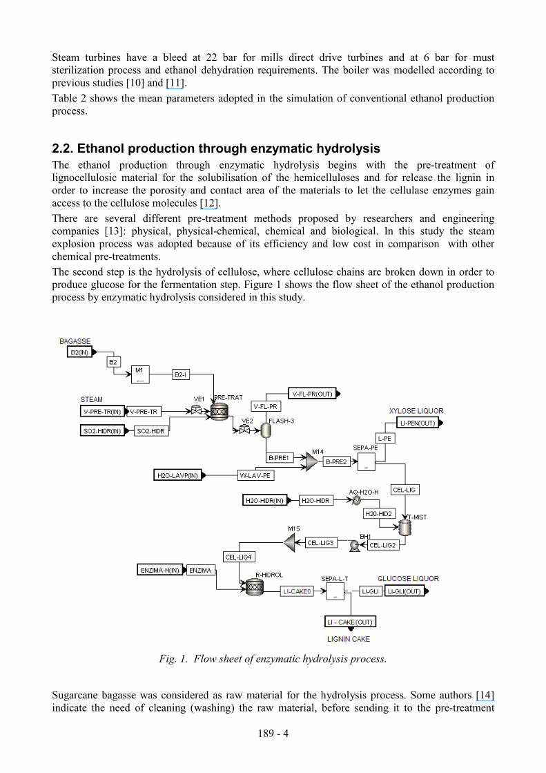
The second step is the hydrolysis of cellulose, where cellulose chains are broken down in order to
produce glucose for the fermentation step. Figure 1 shows the flow sheet of the ethanol production
process by enzymatic hydrolysis considered in this study.
Fig. 1. Flow sheet of enzymatic hydrolysis process.
Sugarcane bagasse was considered as raw material for the hydrolysis process. Some authors [14]
indicate the need of cleaning (washing) the raw material, before sending it to the pre-treatment

189 - 5
reactor, in order to remove impurities. This operation would reduce the amount of reactants in
subsequent stages. As this study is an initial assessment, previous washing of bagasse and trash was
not considered.
Thus, stream of bagasse B2 is sent to the pre-treatment reactor PRE-TRAT. Some studies indicate
that it is not necessary the addition of a catalyst in the steam explosion reactor because it is an
autocatalytic process: there is a dissociation of water molecules in their ions H+ and OH
-, which
hydrolyse hemicelluloses. The formation of acetic acid happens also, which catalyses the
subsequent reactions. On the other hand, some researchers report that the addition of acid catalyst,
such as SO2 or H2SO4, is necessary in order to achieve higher yields of hemicellulose conversion. In
this study, it was adopted the addition of SO2 catalyst in the pre-treatment reactor in a rate of 2%
w/w, according to [14].
In relation to the steam consumption by steam explosion pre-treatment, experimental data are
reported in the range of 0.55 to 0.65 kg of steam /kg moist bagasse for moisture bagasse contents in
the range of 38.6 to 65.5% [15].
In the pre-treatment reactor, the formation of xylose (C5H10O5), acetic acid (C2H4O2), furfural and
glucose (C6H12O6) was considered, according to [5]. Table 3 shows the reactions and conversion
yields considered in pre-treatment reactor, according to [14].
Table 3. Yields considered for the reactions in pre-treatment reactor
Equation Product Yield (%) From
C5H8O4 + H2O → C5H10O5 Xylose 61.4 Hemicellulose
C5H8O4 + H2O → 2.5 C2H4O2 Acetic acid 9.2 Hemicellulose
C5H10O5 → FURFURAL + 3 H2O Furfural 5.1 Xylose
C6H10O5 + H2O → C6H12O6 Glucose 4.1 Cellulose
The decompression in pre-treatment tank was represented by the expansion valve VE2 and the
unitary block FLASH-3. Hence, there are the steam flashed V-FL-PR and the pre-treated material
B-PRE1.
In order to remove xylose and other components that could inhibit the posterior processes of
enzymatic hydrolysis and fermentation, pre-treated bagasse is washed in unit block SEPA-PE. After
that, two fractions are present: the liquid fraction L-PE (xylose liquor) and the solid fraction CEL-
LIG. In this first study, the use of xylose liquor was not considered.
For the next stage, water is added to the process (stream H2O-HIDR) in tank T-MIST, in order to
achieve an appropriate concentration of water insoluble solids in the hydrolysis reactor. Three cases
were considered in this study: solid contents of 5%, 8% and 10% in the hydrolysis reactor. In the
next step, stream CEL-LIG4 goes to the hydrolysis reactor R-HIDROL, where enzymes (stream
ENZIMA) are added to catalyze the hydrolysis reactions. After hydrolysis stage, the hydrolysate
goes to a filter in order to separate the lignin cake (LI-CAKE) of the glucose hydrolysate (LI-GLI).
Table 4 shows the yields adopted in the hydrolysis reactor calculated from [14] data
Table 4. Yields considered for the reactions in the hydrolysis reactor for different solid contents in
the reactor (5%, 8% and 10%)
Reaction From Product Yield (%)
5% 8% 10%
C6H10O5 + H2O → C6H12O6 Cellulose Glucose 69.2 60.6 55.8
C5H8O4 + H2O → C5H10O5 Hemicellulose Xylose 46.9 44.4 40.6

189 - 6
2.3. Insertion of enzymatic hydrolysis plant in the conventional distillery
To integrate the enzymatic hydrolysis process with the conventional distillery, it is necessary that
the hydrolysate concentration (LI-GLI current) achieves appropriate glucose content for the
fermentation process. After the concentration, the hydrolysate can be mixed with must of sugarcane
juice to go to the fermentation process. Moreover, steam for pre-treatment (steam explosion) should
be supplied from the cogeneration system. Lignin cake (LI-CAKE) should be prepared to be burnt
in order to satisfy the heat requirements for steam generation.
Figure 2 shows the block diagram of the hydrolysis plant inserted in the conventional ethanol
production process proposed.
2.3.1. Steam explosion pre-treatment
In this study, steam for pre-treatment is taken at the desuperheater outlet of direct drive turbines, in
the cogeneration system. Then, part of the steam at 22 bar, 300°C is sent to the hydrolysis process,
while the other part goes for direct drive turbines. The steam for hydrolysis pre-treatment passes
through an expansion valve before to get into the pre-treatment reactor, to reduce its pressure until
12.5 bar, value adopted in this study [16].
2.3.2. Concentration of glucose hydrolysate
Glucose hydrolysate obtained at the outlet of the separator SEPA-L-T has very low glucose content,
in the range of 1.8% to 3.4%, depending of the solid content adopted in the hydrolysis reactor. To
match the concentration values needed in the fermentation step, this study assumed that the
hydrolysate was concentrated in an appropriate plant, showed in Fig 3.
Fig. 2. Ethanol production process-Conventional process integrated with hydrolysis process.
Table 5 shows the mean parameters adopted for simulation of enzymatic hydrolysis process.

189 - 7
Table 5. Parameters adopted for the simulation of ethanol production through enzymatic
hydrolysis
Parameter Value
Pre-treatment reactor temperature, °Ca 190
Pre-treatment reactor pressure, bar 12.5
Pre-treatment reactor steam consumption, kg of steam/kg of raw materialb 0.55
Pressure at unitary block FLASH-3, bar 1.01
Efficiency of solid in solution removal in unit block SEPA-PE, %a 90
Loss of soluble lignin in unit block SEPA-PE, %a 6.3
Moisture content of solid fraction CEL-LIG, %c 60
Water for xylose washing, l/kg of dry materialc 15
Hydrolysis reactor temperature, °Cd 50
Enzymatic load – cellulose, FPU/g dry biomassa 53
Enzymatic load – b glucosidase, IU/g dry biomassa 83
Moisture content in solid fraction TORTA-LI0, % 70
Solid content in concentrate hydrolysate, % 19
Moisture content in sugarcane trash, % e 10.05
Trash lower heating value, MJ/kg e 13.9
Energy consumption in trash shredder, kWh/t of trashe 82.03
Energy consumption in cleaner station, kWh/t of trashf 13.6
Energy consumption in bagasse feeder, kWh/t of bagasse 0.459
Energy consumption in xylose separator SEPA-PE, kWh/t of material 2.3
Energy consumption in separator SEPA-L-T, kWh/m3 0.4
Energy consumption in dewatering press of lignin cake, kWh/kg of dry matter 56.09 a Carrasco et al. (2010) [14];
b Kling et al. (1987) [15];
c Palacios-Bereche, (2011) [4];
d Galbe and Zacchi (2010) [25];
e
Hassuani et al. (2005) [20]; f Cella (2010) [26]
Fig. 3. Concentration of glucose hydrolysate.
According to the Fig. 3, glucose hydrolysate is preheated in the heat exchanger PHX with steam
flash recuperated from the pre-treatment decompression (Fig. 1) before get into the evaporation
system, which operates with exhaust steam at 2.5 bar. An evaporation system of five stages was
considered in order to reduce the steam consumption. For the simulation in Aspen Plus software,
each stage of the evaporation system was considered compounded by two unit operations: a heat
exchanger and a flash separator, [9, 17]. It was assumed that the condensate of exhaust steam from
this evaporation system C-S-EV-L returns to the cogeneration system.

189 - 8
Due to the possible presence of soluble lignin in glucose hydrolysate, as well as phenolic groups
(they were not considered in this simulation), the detoxification of glucose hydrolysate is
recommended before its mixture with must of sugarcane juice [18, 19]. In this simulation the
removal of the components acetic acid, furfural and sulphurous acid was considered, before the
mixture with must.
2.3.3. Use of lignin cake
In order to recuperate the heat value of the wet lignin cake, stream CAKE-LIG is sent to the
dewatering press, where its moisture content is reduced to 50%. After that, the lignin cake is sent to
the burner (stoichiometric reactor) where it is burned. In real installations, the lignin cake burning
will happen in the boilers of the cogeneration plant. In this case, an independent burning was
assumed with the unique purpose of simplifying the calculations. So, the gases stream of this burner
block is conducted to the boiler. As no other date is available, the efficiency adopted for lignin
boiler was the same than bagasse boilers.
2.3.4. Sugarcane trash utilization
The amount of residues from sugarcane harvesting depends on many factors such as: harvesting
system, topping height, cane variety, age of crop, climate, soil and others. In this study, an average
trash potential of 140 kg of dry residues per tonne of cane stalks was considered [1,20] and the
amount of trash left in field was assumed as 50% of total, according to [21]. Thus 50 % of total
trash was assumed available for use as fuel in the cogeneration system.
Sugarcane trash and lignin cake, are considered in order to satisfy the energetic requirements of the
integrated process. In this way, it is possible to send a higher amount of bagasse to the hydrolysis
process. Nevertheless, it is still necessary to burn part of the bagasse in the boilers to satisfy the
energy requirements. The amount of bagasse for hydrolysis is defined after an iterative process,
because the increase of raw material for hydrolysis increases the steam consumption of the plant;
thus the amount of bagasse, trash and lignin cake for steam generation should be enough to satisfy
the increase in energy requirements of the plant, and so on.
For the simulations, it was considered that trash and lignin cake are burned in the boiler with an
efficiency of 86% (LHV base) [4].
3. Thermal integration applying Pinch-Point method
The Pinch Point method was used to analyse the streams of the process that are available for
thermal integration. The minimum approach temperature difference (∆Tmin) adopted in this study
was 10°C for the process and 4°C for the evaporation systems. As vapour bleedings of the
concentration step are used to fulfil the process heating requirements, and these bleedings change
depending on the process characteristics, the thermal integration procedure was accomplished
following the next sequence:
Step 1. Calculation of the amounts of trash and bagasse to be burnt in the boiler, from an initial
assumption of the steam consumption of the overall process.
Step 2. Thermal integration of the available process streams, excluding the evaporation systems
(sugarcane juice and glucose liquor).
Step 3. Integration of both evaporation systems and calculation of the appropriate vapour bleeding
demand according to the procedure of [22] and Grand Composite Curve construction.
Step 4. Re-calculation of the steam consumption of the overall process until the convergence is
obtained.
In this study the thermal integration procedure was applied to the case of enzymatic hydrolysis with
solid content 10% in the hydrolysis reactor. This value was selected because it presents the best
results in terms of ethanol production [4].
189 - 9
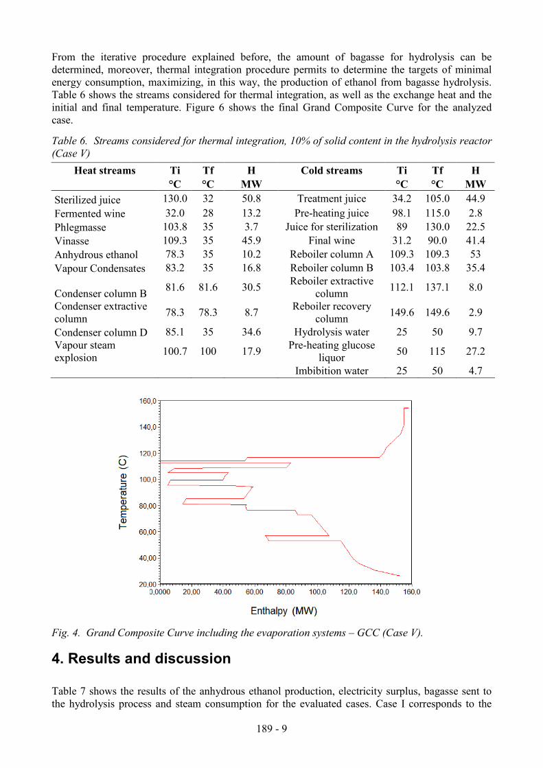
From the iterative procedure explained before, the amount of bagasse for hydrolysis can be
determined, moreover, thermal integration procedure permits to determine the targets of minimal
energy consumption, maximizing, in this way, the production of ethanol from bagasse hydrolysis.
Table 6 shows the streams considered for thermal integration, as well as the exchange heat and the
initial and final temperature. Figure 6 shows the final Grand Composite Curve for the analyzed
case.
Table 6. Streams considered for thermal integration, 10% of solid content in the hydrolysis reactor
(Case V)
Heat streams Ti Tf H Cold streams Ti Tf H
°C °C MW °C °C MW
Sterilized juice 130.0 32 50.8 Treatment juice 34.2 105.0 44.9
Fermented wine 32.0 28 13.2 Pre-heating juice 98.1 115.0 2.8
Phlegmasse 103.8 35 3.7 Juice for sterilization 89 130.0 22.5
Vinasse 109.3 35 45.9 Final wine 31.2 90.0 41.4
Anhydrous ethanol 78.3 35 10.2 Reboiler column A 109.3 109.3 53
Vapour Condensates 83.2 35 16.8 Reboiler column B 103.4 103.8 35.4
Condenser column B 81.6 81.6 30.5
Reboiler extractive
column 112.1 137.1 8.0
Condenser extractive
column 78.3 78.3 8.7
Reboiler recovery
column 149.6 149.6 2.9
Condenser column D 85.1 35 34.6 Hydrolysis water 25 50 9.7
Vapour steam
explosion 100.7 100 17.9
Pre-heating glucose
liquor 50 115 27.2
Imbibition water 25 50 4.7
Fig. 4. Grand Composite Curve including the evaporation systems – GCC (Case V).
4. Results and discussion
Table 7 shows the results of the anhydrous ethanol production, electricity surplus, bagasse sent to
the hydrolysis process and steam consumption for the evaluated cases. Case I corresponds to the

189 - 10
conventional distillery without hydrolysis, while cases II, III and IV correspond to the hydrolysis
process coupled with the conventional distillery without thermal integration. Case V corresponds to
the hydrolysis process integrated with the conventional process according to the method presented
in item 3. A higher solids concentration in the hydrolysis process means lower steam consumption
in the glucose liquor concentration step. This fact permits to assign higher amounts of bagasse for
the hydrolysis process and consequently, to obtain higher increases in the ethanol production.
About electricity surplus, there is an increase of 47.9%, 29.3%, 21.3% in Cases II, III and IV
respectively in comparison with Case I, these increases happen owing to an increase in steam
consumption in the mentioned cases. On the other hand, in Case V there is a reduction of 27.9% in
comparison with Case I, fact that is explained because in Case V, a reduction of steam consumption
happens. In general, these results are due to the turbine configuration adopted in the cogeneration
system (backpressure steam turbine) and the reduction of steam consumption for higher solid
contents in the hydrolysis step.
From the thermal integration procedure, it can be observed a significant decrease in steam
consumption in Case V. Steam consumption in Case V is 11.1% lower than the consumption in
Case IV, while ethanol production in Case V is 4.6% higher than the production obtained in Case
IV.
Table 7. Results of the simulation: Anhydrous ethanol production l/t of cane, electricity surplus
kWh/t of cane and steam consumption kg/t of cane.
Parameter Case I Case II Case III Case IV Case V
Solid content in hydrolysis reactor -- 5 8 10 10
Anhydrous ethanol, (l/t of cane) 79 86.7 88.1 88.7 92.8
Electricity surplus, (kWh/t of cane) 42.3 62.5 54.6 51.3 30.5
Bagasse for hydrolysis, (kg/t of cane) 0 110.3 149.5 172.7 239.7
Steam consumption, (kg/t of cane) 489.6 794.2 756.9 745.1 661.8
Increase in ethanol production, (%) 9.7 11.5 12.3 17.4
Increase in ethanol production, (l/t of cane) 7.7 9.1 9.7 13.7
In relation to vinasse production, there is an increase of 11.6%, 14.1%, 15.1% and 20.8% for Cases
II, III, IV and V in comparison with Case I. It is due to the higher amount of must processed in
distillation stage in comparison with Case I. In Brazilian current practice, the vinasse is used to
irrigate the fields, where the nutrients are recuperated.
Figure 5 shows the bagasse balance for each case. Bagasse for hydrolysis increases from Case II to
V, while bagasse for boiler decreases. The amount of trash for boiler is constant for all cases, 38.9
t/h considering a moisture content of 10%. The amount of lignin cake also increases from Case II to
V, being a percentage of the bagasse for hydrolysis. Thus, the amount of lignin cake at 50% of
moisture content was 0.43 and 0.46 kg/kg of bagasse for hydrolysis for Cases II and III respectively
and 0.48 kg/kg of bagasse for Cases IV and V. The lower heating value of lignin cake was
calculated through the simulator from their composition data. The lower heating values obtained for
lignin cake were: 8563 kJ/kg for Case II, 8441 kJ/kg for Case III and 8373 kJ/kg for Cases IV and
V. These differences occurred because of the conversion yields adopted in the hydrolysis reactor.

189 - 11
Fig. 5. Bagasse balance (kg/t of cane) for Cases I, II, III, IV and V.
Figure 6 shows the balance of electricity generated. A decrease in electricity surplus appear from
Cases II to V due to the reduction in electricity produced in the cogeneration system, as a
consequence of the decrease in the steam generated in boiler, and due to the consumption increase
in the hydrolysis process.
Fig. 6. Balance of electricity generated (kWh/t of cane) for Cases II, III, IV and V
The electricity consumed in the hydrolysis process was estimated from the data shown in Table 5. It
was identified a significant electricity consumption in the agitators of the hydrolysis reactors, due to
the large volume of the hydrolysis reactors. The reactor volume was calculated assuming reactors
CSRT (Continuous Stirred Tank Reactors) and residence time of 48h, in agreement with data of
Table 4. The total volume of reactors resulted in 20520 m3, 17165 m
3, 15731 m
3 and 21835 m
3
respectively for the cases II, III, IV and V. The electricity consumption in the reactor agitators was
determined from a scale up procedure based on the data reported in [23].
Results of the present study can be compared with others of the literature. Walter and Ensinas [19]
indicated an increase in ethanol production of 25.6%, but in a future scenario and considering
glucose and xylose fermentation. Dias et al. [24] indicated ethanol production increases of 18.3%
and 20.3%, but considering an Organosolv hydrolysis process with diluted acid, while Leite [1]
indicated an ethanol production increase, through enzymatic hydrolysis process, of 12.2% and
25.6%, for scenarios corresponding to the years of 2015 and 2025 respectively.

189 - 12
Dias et al. [27] also accomplished a simulation study considering the ethanol production by
enzymatic hydrolysis and pre-treatment by steam explosion, and a reduction of 30.8% in steam
consumption was obtained from thermal integration. These authors indicate an ethanol production
in the integrated process in the range of 107.5 to 120.6 l/t of cane; these values represent an increase
of 15.9% and 30% in comparison to their base case.
5. Conclusions
An evaluation of the mass balance and energy consumption for the ethanol production process by
enzymatic hydrolysis was accomplished. Moreover, this study showed the potential ethanol
production increase due to the introduction of the bagasse enzymatic hydrolysis in the conventional
ethanol production process.
The results obtained for cases II, III an IV were modest because the study considers a conservative
conventional factory with average technology, thus, in order to increase the ethanol production the
optimization of the conventional process would be recommended, aiming an energy consumption
reduction. Hence, the ethanol production increase for cases II, III and IV was 9.7%, 11.5% and
12.3%, respectively. These results showed that a higher ethanol production is obtained for higher
solids concentrations in the hydrolysis process. They show that thermal energy consumption in the
hydrolysate concentration stage is very significant, thus, other separation technologies with lower
energy consumption should be studied. Reverse osmosis membranes in combination with
evaporation systems can be tested for this application.
Case V showed the highest ethanol production of 92.8 l/t of cane, which represents an increase of
17.4%; however, this is a prospective study and pilot plant/industrial data would be necessary in
order to adjust the modelling of the plant. The Pinch Analysis applied to this case showed to be a
useful tool to evaluate the thermal integration potential.
There is an intrinsic vinasse increase due to the higher amount of must being processed with the
introduction of the hydrolysis process; the highest vinasse production was 430.8 t/h for Case V
which represents an increase of 20.8% in comparison with Case I. Currently, vinasse is used as
fertirrigation in Brazilian sugarcane fields, however this practice is being regulated. Thus, the
introduction of technologies to reduce the vinasse production becomes necessary.
The energy balance in the cogeneration system shows that the energy supplied by lignin cake is
significant to operate the integrated process. For Case V, energy supplied by lignin cake represented
44.2% of total energy supplied to the cogeneration system. Hence, the study and characterization of
lignin cake is important in order to enable the ethanol production by enzymatic hydrolysis process.
Acknowledgments
The authors wish to thank to CNPq (Process 304820/2009-1), FAPESP (Process 11/05718-1) and
FINEP (Contract FINEP – FUNCAMP Nr. 01/06/004700) for the financial support.
References
[1] Leite R.C.C., Fuel bioethanol an opportunity to Brazil. Brasilia: Centro de Gestão e Estudos
Estratégicos; 2009, (In Portuguese).
[2] Rein P., Cane Sugar Engineering. Berlin: Verlag Dr. Albert Bartens K. G.; 2007.
[3] Wooley R.J., Putsche V., Development of an ASPEN PLUS Physical Property Database for
Biofuels Components”, National Renewable Energy Laboratory, 1996. – Available at
<www.p2pays.org/ref/22/21210.pdf> [accessed 12.11. 2007].
189 - 13
[4] Palacios-Bereche R., Modeling and energy integration of the ethanol production process from
sugarcane biomass [PhD Thesis]. Campinas, Brazil: University of Campinas; 2011 (In
Portuguese).
[5] Dias M.O.S., Simulation of ethanol production processes from sugar and sugarcane bagasse,
aiming process integration and maximization of energy and bagasse surplus. [dissertation].
Campinas, Brazil: University of Campinas; 2008 (In Portuguese).
[6] Eijsberg R., The design and economic analysis of a modern bioethanol factory located in Brazil.
[dissertation]. Delft, The Netherlands: University Delft; 2006.
[7] Rossell C.E.V., Sugarcane processing to ethanol for fuel purposes, In Chemistry and Processing
of Sugarbeet and Sugarcane, edited by Clarke M. A. and Godshall M.A., Elsevier Science
Publishers B. V., Amsterdam, 1988.
[8] Finguerut, et al., Fermentation, Hydrolysis and Distillation. In: Cortes et al. editors. Biomass for
Energy. Campinas, Brazil: Ed. Unicamp. 2008. p. 436-474.
[9] Dias M.O.S., Modesto M., Ensinas A.V., Nebra S.A., Maciel Filho R., Rossell C.E.V.,
Improving bioethanol production from sugarcane: evaluation of distillation, thermal integration
and cogeneration systems. Energy 2010; 36: 3691-3703.
[10] Palacios-Bereche R., Nebra S.A. Thermodynamic modeling of a cogeneration system for a
sugarcane mill using ASPEN PLUS, difficulties and challenges. COBEM 2009: Proceedings of
the 20th International Congress of Mechanical Engineering, 2009 Nov 15-20, Gramado, Brazil.
[11] Magnusson H., Process simulation in Aspen Plus of an integrated ethanol and CHP plant.
[dissertation]. Sweden: Umea University. 2005.
[12] Sun Y., Cheng J., Hydrolysis of lignocellulosic materials for ethanol production: a review.
Bioresource Technology 2002; 83: 1–11.
[13] Efe C., Technical and economical feasibility of production of ethanol from sugar cane and
sugarcane bagasse. [dissertation], Delft, The Netherlands: TU-Delft; 2005.
[14] Carrasco C., Baudel H.M., Sendelius J., Modig T., Roslander C., Galbe M., Hahn-Hägerdal
B., Zacchi G., Lidén G. SO2-catalyzed steam pretreatment and fermentation of enzymatically
hydrolyzed sugarcane bagasse. Enzyme and Microbial Technology 2010; 46: 64–73.
[15] Kling S.H., Carvalho Neto C., Ferrara M.A., Torres J.C.R., Magalhaes D.B., Ryu D.D.Y.,
Enhancements of enzymatic hydrolysis of sugar cane bagasse by steam explosion pretreatment.
Biotechnology and Bioengineering 1987; 29: 1035 – 1039.
[16] Sanchez O.J., Cardona C.A., Trends in biotechnological production of fuel ethanol from
different feedstocks. Bioresource Technology 2008; 99: 5270–5295.
[17] Jorge L.M.M, Righetto A.R., Polli P.A., Santos O.A.A., Maciel Filho R., Simulation and
analysis of a sugarcane juice evaporation system. Journal of Food Engineering 2010; 99: 351–
359.
[18] Cardona C.A., Sanchez O.J., Energy consumption analysis of integrated flowsheets for
production of fuel ethanol from lignocellulosic biomass. Energy 2006; 31 (13): 2447-2559.
[19] Walter A., Ensinas A.V., Combined production of second – generation biofuels and
electricity from sugar-cane residues. Energy 2010; 35: 874-879.
[20] Hassuani S.J., Leal M.R.L.V., Macedo I.C., Biomass power generation: Sugarcane bagasse
and trash, Piracicaba, Brazil: Ed. PNUD and CTC, 2005.
[21] Michelazzo M.B., Sensitivity analysis of six systems for collection of sugarcane trash
(Saccharum spp.). [dissertation]. Campinas, Brazil: University of Campinas, 2005 (In
Portuguese).
[22] Westphalen D.L., Wolf Maciel M.R., Pinch Analysis of evaporation systems, Brazilian
Journal of Chemical Engineering 2000; 17: 4-7.

189 - 14
[23] Pereira L.T.C., Teixeira R.S.S.T., Bom E.P.S., Freitas S.P. Sugarcane bagasse enzymatic
hydrolysis: rheological data as criteria for impeller selection. Journal of Industrial Microbiology
& Biotechnology 2010; DOI 10.1007/s10295-010-0857-8.
[24] Dias M.O.S., Ensinas A.V., Nebra S.A., Maciel Filho R., Rossell C.E.V., Production of
bioethanol and other bio-based materials from sugarcane bagasse: Integration to conventional
bioethanol production process. Chemical Engineering Research and Design 2009, 87: 1206-
1216.
[25] Galbe, M., Zacchi, G. Ethanol production from lignocellulosic materials. In: CORTEZ,
L.A.B. (Coord.). Bioethanol from sugarcane: R&D for productivity and sustainability. Sao
Paulo: Blucher, 2010. Part. 4, Chap. 12, p. 697-716.
[26] Cella, N. Trash use as fuel in biomass boilers. Course Boilers, Environment and Renewable
Energy. Ribeirao Preto, 23-24 de june 2010.
[27] Dias, M.O.S.; Cunha, M.P., Maciel Filho, R., Bonomi, A., Jesus, C.D. F., Rossell, C.E.V.
Simulation of integrated first and second generation bioethanol production from sugarcane:
comparison between different biomass pre-treatment methods. Journal of Industrial
Microbiology & Biotechnology, 2011, 38: 955-966.