Estimation of mechanical properties of a viscoelastic medium using a laser-induced microbubble...
8
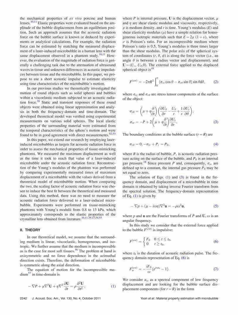
Estimation of mechanical properties of a viscoelastic medium using a laser-induced microbubble interrogated by an acoustic radiation force a) Sangpil Yoon Department of Mechanical Engineering, The University of Texas at Austin, Austin, Texas 78712-1063 Salavat R. Aglyamov, Andrei B. Karpiouk, Seungsoo Kim, and Stanislav Y. Emelianov b) Department of Biomedical Engineering, The University of Texas at Austin, Austin, Texas 78712-0238 (Received 25 October 2010; revised 2 June 2011; accepted 3 August 2011) An approach to assess the mechanical properties of a viscoelastic medium using laser-induced microbubbles is presented. To measure mechanical properties of the medium, dynamics of a laser- induced cavitation microbubble in viscoelastic medium under acoustic radiation force was investi- gated. An objective lens with a 1.13 numerical aperture and an 8.0 mm working distance was designed to focus a 532 nm wavelength nanosecond pulsed laser beam and to create a microbubble at the desired location. A 3.5 MHz ultrasound transducer was used to generate acoustic radiation force to excite a laser-induced microbubble. Motion of the microbubble was tracked using a 25 MHz imaging transducer. Agreement between a theoretical model of bubble motion in a visco- elastic medium and experimental measurements was demonstrated. Young’s modulii reconstructed using the laser-induced microbubble approach were compared with those measured using a direct uniaxial method over the range from 0.8 to 13 kPa. The results indicate good agreement between methods. Thus, the proposed approach can be used to assess the mechanical properties of a visco- elastic medium. V C 2011 Acoustical Society of America. [DOI: 10.1121/1.3628344] PACS number(s): 43.80.Ev, 43.80.Vj, 43.80.Qf [ROC] Pages: 2241–2248 I. INTRODUCTION In laser-based ophthalmic microsurgery, micrometer-size bubbles are used to precisely cut tissue in the eye. 1–5 During the laser-tissue interaction, the focused laser radiation in tis- sue is absorbed, and a microbubble is formed where the inten- sity of the electromagnetic field exceeds the threshold of optical breakdown. 5,6 One of the applications of laser- induced microbubbles in ophthalmology is refractive vision correction surgery to correct myopia, hyperopia, and astigma- tism. 5,7 Accurate corneal flaps can be created by using laser- induced microbubbles, providing a better surgery outcome. 8,9 While laser-tissue ablation and associated formation of microbubbles play an increasingly important role in laser- based microsurgery, microbubbles could also be used to obtain information about elastic properties of ocular tis- sues. 10,11 According to the most widely accepted theory of presbyopia, the age-related loss of accommodation is attrib- uted to gradual loss of lens elasticity. Furthermore, there is evidence that nuclear cataract lenses are generally harder than normal lenses. 12–14 Thus, observing the changes of tis- sue properties may be used as a tool to diagnose disease and improve the outcome of treatment. Due to high acoustic reflectivity on the bubble surface, a microbubble-based acoustic radiation force technique can provide greater radia- tion force than an absorption-based acoustic radiation force technique. 15–17 Therefore, displacement variations inside tis- sue can be effectively generated by the combined method. External local excitation permits the estimation of the local mechanical properties of tissue based on the analysis of the motion of a laser-induced microbubble because the dynam- ics of the motion of a microbubble are defined by the proper- ties of the surrounding tissue. 18 A number of methods have been developed to estimate the mechanical properties of lenses: ultrasonic characteriza- tion of the lens using ultrasound wave attenuation; 14 compres- sion tests; 19 application of radial force; 20,21 hydrostatic or automated guillotine tests; 13,22 uniaxial test; 23 cone penetra- tion test; 24 and dynamic mechanical analysis. 25–27 The results of these measurements demonstrate that elasticity of the whole lens increases with age and the nucleus becomes stiffer than the cortex. It is reported that the lens has a Young’s mod- ulus of several tens of Pa to tens of kP. 10,11,20,21,24,27 However, most of these techniques to measure lens elasticity assume direct mechanical testing and usually can be used only in vitro. Among various techniques to measure mechanical prop- erties of tissues noninvasively, radiation force has investigated greatly during last few decades as a means of a palpation tool for imaging soft tissues where external forces cannot reach. Recent applications have opened a variety of areas including shear wave elasticity imaging, 15 acoustic radiation force impulse imaging, 28–34 supersonic shear imaging, 35–37 sonorheometry, 38–42 and vibroacoustography. 43–48 By combining microbubbles created by laser-induced op- tical breakdown and acoustic radiation force, microbubble- based acoustic radiation force was introduced as a technique to remotely measure the localized viscoelastic properties of the lens. 10,11,49–51 In that approach, laser-induced microbub- bles were displaced using a long acoustic pulse to interrogate b) Author to whom correspondence should be addressed. Electronic mail: [email protected] a) Portions of this work were presented in the 158th ASA Meeting, San Anto- nio, TX, October 26, 2009. J. Acoust. Soc. Am. 130 (4), October 2011 V C 2011 Acoustical Society of America 2241 0001-4966/2011/130(4)/2241/8/$30.00
-
Upload
independent -
Category
Documents
-
view
1 -
download
0
Transcript of Estimation of mechanical properties of a viscoelastic medium using a laser-induced microbubble...
Estimation of mechanical properties of a viscoelastic mediumusing a laser-induced microbubble interrogated by an acousticradiation forcea)
Sangpil YoonDepartment of Mechanical Engineering, The University of Texas at Austin, Austin, Texas 78712-1063
Salavat R. Aglyamov, Andrei B. Karpiouk, Seungsoo Kim, and Stanislav Y. Emelianovb)
Department of Biomedical Engineering, The University of Texas at Austin, Austin, Texas 78712-0238
(Received 25 October 2010; revised 2 June 2011; accepted 3 August 2011)
An approach to assess the mechanical properties of a viscoelastic medium using laser-induced
microbubbles is presented. To measure mechanical properties of the medium, dynamics of a laser-
induced cavitation microbubble in viscoelastic medium under acoustic radiation force was investi-
gated. An objective lens with a 1.13 numerical aperture and an 8.0 mm working distance was
designed to focus a 532 nm wavelength nanosecond pulsed laser beam and to create a microbubble
at the desired location. A 3.5 MHz ultrasound transducer was used to generate acoustic radiation
force to excite a laser-induced microbubble. Motion of the microbubble was tracked using a 25
MHz imaging transducer. Agreement between a theoretical model of bubble motion in a visco-
elastic medium and experimental measurements was demonstrated. Young’s modulii reconstructed
using the laser-induced microbubble approach were compared with those measured using a direct
uniaxial method over the range from 0.8 to 13 kPa. The results indicate good agreement between
methods. Thus, the proposed approach can be used to assess the mechanical properties of a visco-
elastic medium. VC 2011 Acoustical Society of America. [DOI: 10.1121/1.3628344]
PACS number(s): 43.80.Ev, 43.80.Vj, 43.80.Qf [ROC] Pages: 2241–2248
I. INTRODUCTION
In laser-based ophthalmic microsurgery, micrometer-size
bubbles are used to precisely cut tissue in the eye.1–5 During
the laser-tissue interaction, the focused laser radiation in tis-
sue is absorbed, and a microbubble is formed where the inten-
sity of the electromagnetic field exceeds the threshold of
optical breakdown.5,6 One of the applications of laser-
induced microbubbles in ophthalmology is refractive vision
correction surgery to correct myopia, hyperopia, and astigma-
tism.5,7 Accurate corneal flaps can be created by using laser-
induced microbubbles, providing a better surgery outcome.8,9
While laser-tissue ablation and associated formation of
microbubbles play an increasingly important role in laser-
based microsurgery, microbubbles could also be used to
obtain information about elastic properties of ocular tis-
sues.10,11 According to the most widely accepted theory of
presbyopia, the age-related loss of accommodation is attrib-
uted to gradual loss of lens elasticity. Furthermore, there is
evidence that nuclear cataract lenses are generally harder
than normal lenses.12–14 Thus, observing the changes of tis-
sue properties may be used as a tool to diagnose disease and
improve the outcome of treatment. Due to high acoustic
reflectivity on the bubble surface, a microbubble-based
acoustic radiation force technique can provide greater radia-
tion force than an absorption-based acoustic radiation force
technique.15–17 Therefore, displacement variations inside tis-
sue can be effectively generated by the combined method.
External local excitation permits the estimation of the local
mechanical properties of tissue based on the analysis of the
motion of a laser-induced microbubble because the dynam-
ics of the motion of a microbubble are defined by the proper-
ties of the surrounding tissue.18
A number of methods have been developed to estimate
the mechanical properties of lenses: ultrasonic characteriza-
tion of the lens using ultrasound wave attenuation;14 compres-
sion tests;19 application of radial force;20,21 hydrostatic or
automated guillotine tests;13,22 uniaxial test;23 cone penetra-
tion test;24 and dynamic mechanical analysis.25–27 The results
of these measurements demonstrate that elasticity of the
whole lens increases with age and the nucleus becomes stiffer
than the cortex. It is reported that the lens has a Young’s mod-
ulus of several tens of Pa to tens of kP.10,11,20,21,24,27 However,
most of these techniques to measure lens elasticity assume
direct mechanical testing and usually can be used only invitro. Among various techniques to measure mechanical prop-
erties of tissues noninvasively, radiation force has investigated
greatly during last few decades as a means of a palpation
tool for imaging soft tissues where external forces cannot
reach. Recent applications have opened a variety of areas
including shear wave elasticity imaging,15 acoustic radiation
force impulse imaging,28–34 supersonic shear imaging,35–37
sonorheometry,38–42 and vibroacoustography.43–48
By combining microbubbles created by laser-induced op-
tical breakdown and acoustic radiation force, microbubble-
based acoustic radiation force was introduced as a technique
to remotely measure the localized viscoelastic properties of
the lens.10,11,49–51 In that approach, laser-induced microbub-
bles were displaced using a long acoustic pulse to interrogate
b)Author to whom correspondence should be addressed. Electronic mail:
a)Portions of this work were presented in the 158th ASA Meeting, San Anto-
nio, TX, October 26, 2009.
J. Acoust. Soc. Am. 130 (4), October 2011 VC 2011 Acoustical Society of America 22410001-4966/2011/130(4)/2241/8/$30.00
the mechanical properties of ex vivo porcine and human
lenses.10,11 Elastic properties were evaluated based on the am-
plitude of the bubble displacement from an equilibrium posi-
tion. Such an approach assumes that the acoustic radiation
force on the bubble surface is known or deduced by experi-
ments or analytical calculations. For example, the radiation
force can be estimated by matching the measured displace-
ment of a laser-induced microbubble in a human lens with the
same displacement observed in a phantom study.10,11 How-
ever, the evaluation of the magnitude of radiation force is gen-
erally a challenging task due to the attenuation of ultrasound
waves in tissue and unknown differences in acoustic impedan-
ces between tissue and the microbubble. In this paper, we pro-
pose to use a short acoustic impulse to estimate elasticity
using time characteristics of the microbubble’s motion.
In our previous studies we theoretically investigated the
motion of round objects such as solid spheres and bubbles
within a viscoelastic medium subjected to an acoustic radia-
tion force.18 Static and transient responses of these round
objects were obtained using linear approximation and analy-
sis in both the frequency-domain and time-domain. The
developed theoretical model was verified using experimental
measurements on various solid spheres. The local elastic
properties of the surrounding material were estimated from
the temporal characteristics of the sphere’s motion and were
found to be in good agreement with direct measurements.52,53
In this paper, we extend our research by employing laser-
induced microbubbles as targets for acoustic radiation force in
order to assess the mechanical properties of tissue-mimicking
phantoms. We measured the maximum displacement as well
as the time it took to reach that value of a laser-induced
microbubble under the acoustic radiation force. Reconstruc-
tion of the Young’s modulus of the phantom was performed
by comparing experimentally measured times of maximum
displacement of a microbubble with the values derived from a
theoretical model of microbubble motion. When comparing
the two, the scaling factor of acoustic radiation force was cho-
sen to induce the best fit between the theoretical and measured
data. Using this method, there was no need to measure the
acoustic radiation force delivered to a laser-induced micro-
bubble. Experiments were performed on tissue-mimicking
phantoms with Young’s modulii from 0.8 to 13 kPa, which
approximately corresponds to the elastic properties of the
crystalline lens obtained from literature.10,11,19,27,54,55
II. THEORY
In our theoretical model, we assume that the surround-
ing medium is linear, viscoelastic, homogeneous, and iso-
tropic. We further assume that the medium is incompressible
as is the case for most soft tissues.56 The problem at hand is
axisymmetric and no force dependence in the azimuthal
direction exists. Therefore, the deformation of microbubble
is symmetric along the axial direction.
The equation of motion for the incompressible me-
dium57 in time-domain is
�rPþ lr2Uþ gr2 @U
@t¼ q
@2U
@t2; (1)
where P is internal pressure, U is the displacement vector, land g are shear elastic modulus and viscousity, respectively,
q is medium density, and t is time. Young’s modulus (E) and
shear elasticity modulus (l) have a simple relation for homo-
geneous isotropic materials such that E¼ 2l (1þ �), where
� is Poisson’s ratio. For an incompressible medium where
Poisson’s ratio is 0.5, Young’s modulus is three times larger
than the shear modulus. The polar axis of the spherical sys-
tem of coordinates (r, h, /) is along the force vector (i.e., an
angle h is between a radius vector and displacement), and
U¼ (Ur, Uh,0). The external force applied to the displaced
spherical object is18
FðextÞ ¼ �2pR2
ðp
0
ðrrr cos h� rrh sin hÞ sin hdh; (2)
where rrr and rrh are stress tensor components at the surface
of the object:
rrh ¼ lþ g@
@t
� �@Uh
@r� Uh
rþ 1
r
@Ur
@h
� �;
rrr ¼ �Pþ 2 lþ g@
@t
� �@Ur
@r: (3)
The boundary conditions at the bubble surface (r¼R) are
rrh ¼ 0;�rrr þ Pr ¼ P0; (4)
where R is the radius of bubble, Pr is acoustic radiation pres-
sure acting on the surface of the bubble, and P0 is an internal
gas pressure.18 Since pressure P and, consequently, rrr are
defined up to a constant, the internal gas pressure P0 may be
set equal to zero.
The solution of Eqs. (1) and (3) is found in the fre-
quency domain, and displacement of a microbubble in time
domain is obtained by taking inverse Fourier transform from
the spectral solution. The frequency-domain representation
of Eq. (1) is given by
�rpþ ðl� ixgÞr2u ¼ �qx2u; (5)
where p and u are the Fourier transforms of P and U, x is an
angular frequency.
In this study we consider that the external force applied
to the bubble FðextÞ is impulsive:
FðextÞ ¼ F0 0 � t � t0;0 t � t0;
�(6)
where t0 is the duration of acoustic radiation pulse. The fre-
quency domain representation of Eq. (6) is
FðextÞw ¼ � iF0
xðeixt0 � 1Þ: (7)
We consider ux as a spectral component of low frequency
displacement and are looking for the bubble surface dis-
placement components (for r¼R) in the form
2242 J. Acoust. Soc. Am., Vol. 130, No. 4, October 2011 Yoon et al.: Material property estimation with microbubble
ur ¼ uw 1� 1
3ikR
� �cos h;
uh ¼ �1
2uw 1þ 1
3ikR
� �sin h; (8)
where ux ¼ � ik=Rð Þ~aeikR� �
is the low frequency displace-
ment,18 k is the wave number of the shear wave and defined
as k ¼ x=ðct
ffiffiffiffiffiffiffiffiffiffiffiffiffiffiffiffiffiffiffiffiffi1� ixg=l
pÞ and ct ¼
ffiffiffiffiffiffiffiffil=q
p. The sign of k is
defined by the condition Im(k) > 0 because displacement of
medium must approach zero away from the bubble. The con-
stant ~a is defined by the boundary conditions in Eq. (4). Tak-
ing into account the boundary conditions in Eq. (4) as well
as equations Eq. (2) and Eq. (3), the relationship between the
spectral components of the displacement and force is
FðextÞw ¼ 4pðl� ixgÞRuw 1� ikR� 1
6k2R2 þ 1
18ik3R3
� �:
(9)
By combining algebraic equations (7) and (9), the solution in
terms of ux is given by
uw ¼ �iF0ðeixt0 � 1Þ
4pxðl� ixgÞRð1� ikR� 16k2R2 þ 1
18ik3R3Þ
: (10)
By taking inverse Fourier transform, time domain compo-
nents Ur and Uh are obtained:
Ur ¼�iF0 cosh
12pRF�1 ðeixt0 �1Þð3� ikRÞ
xðl� ixgÞð1� ikR� 16k2R2þ 1
18k3R3Þ
" #;
Uh¼iF0 sinh24pR
F�1 ðeixt0 �1Þð3þ ikRÞxðl� ixgÞð1� ikR� 1
6k2R2þ 1
18k3R3Þ
" #;
(11)
where F�1½f ðxÞ� ¼ 12p
Ð 1�1f ðxÞe�ixtdx denotes inverse
Fourier transform. To compare the theoretical model and ex-
perimental data the displacements should be transformed
from spherical to Cartesian coordinates:
Uz ¼ Ur cos h� Uh sin h;
Ux ¼ Ur sin hþ Uh cos h; (12)
where h is the angle between z-axis and r-axis and increases
in the counterclockwise direction. The displacement is not
constant on the bubble surface as the bubble could be
deformed by acoustic radiation force. Thus, Ux is the dis-
placement in the normal direction with respect to the force
vector and Uz is the displacement along the force direction.
If the ultrasound imaging transducer and the excitation trans-
ducer are aligned in the z-axis, then Uz corresponds to axial
displacement of the microbubble. There is some freedom in
the choice of the angle h, but in our calculations, it is
assumed that h¼ 0. Thus, the theoretically predicted Uz of
microbubble is used to find the best fit between theory and
experimental measurements.
It is important to note that the problem has been formu-
lated in linear approximation, assuming that the displace-
ments of the bubble does not exceed one and half times the
bubble radius.18 Otherwise, the deformation of the bubble
becomes significant and the influence of surface tension
should be taken into account. Surface tension reduces the
bubble deformation, especially for small bubbles and makes
the bubble behave more like a solid sphere with zero density.
III. MATERIALS AND METHODS
To verify the theoretical model, the experiments were
performed using laser-induced microbubbles in tissue-mim-
icking phantoms, containing 3% by weight gelatin (300
Bloom, type-A, Sigma-Aldrich, Inc., St. Louis, MO). In addi-
tion, cylindrical samples of 35 mm diameter and 16�18 mm
height were made out of the same gelatin solution to be used
in direct mechanical measurements with portable benchtop
uniaxial tester In-Spec 2200 (Instron, Inc., Morwood, MA).
Prior to measurements, the phantoms and samples were kept
together and followed the same experimental protocol to min-
imize any differences between the materials.
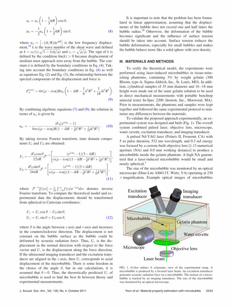
To validate the proposed approach experimentally, an ex-
perimental system was designed and built (Fig. 1). The overall
system combined pulsed laser, objective lens, microscope,
water cuvette, excitation transducer, and imaging transducer.
A pulsed Nd:YAG laser (Polaris II, Fremont, CA) with
5 ns pulse duration, 532 nm wavelength, and 0.3 mJ energy
was focused by a custom-built objective lens [1.13 numerical
aperture (NA) and 8.0 mm working distance] to produce a
microbubble inside the gelatin phantom. A high NA guaran-
teed that a laser-induced microbubble would be small and
nearly spherical.3
The size of the microbubble was monitored by an optical
microscope (Dino-Lite AM411T, Wirtz, VA) operating at 230
�magnification. Example optical images of microbubbles
FIG. 1. (Color online) A schematic view of the experimental setup. A
microbubble is produced by a focused laser beam. An excitation transducer
generates acoustic radiation force on a microbubble. The motion of a micro-
bubble is tracked by an imaging transducer. The size of the microbubble
was monitored by an optical microscope.
J. Acoust. Soc. Am., Vol. 130, No. 4, October 2011 Yoon et al.: Material property estimation with microbubble 2243
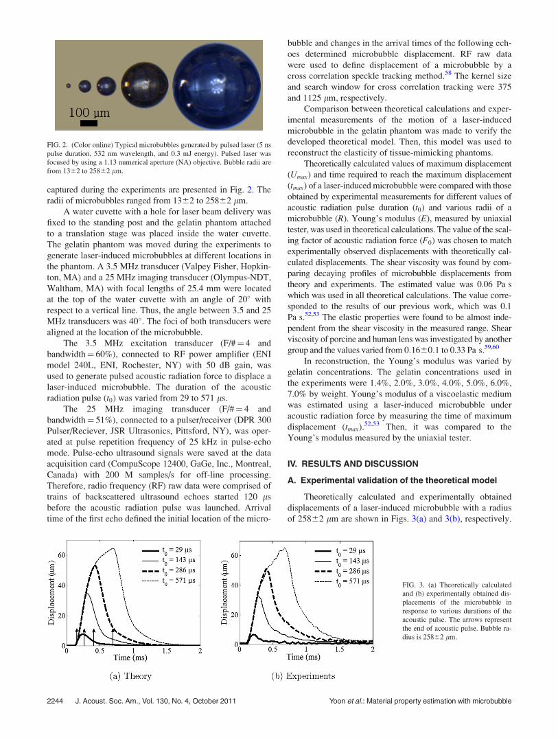
captured during the experiments are presented in Fig. 2. The
radii of microbubbles ranged from 1362 to 25862 lm.
A water cuvette with a hole for laser beam delivery was
fixed to the standing post and the gelatin phantom attached
to a translation stage was placed inside the water cuvette.
The gelatin phantom was moved during the experiments to
generate laser-induced microbubbles at different locations in
the phantom. A 3.5 MHz transducer (Valpey Fisher, Hopkin-
ton, MA) and a 25 MHz imaging transducer (Olympus-NDT,
Waltham, MA) with focal lengths of 25.4 mm were located
at the top of the water cuvette with an angle of 20� with
respect to a vertical line. Thus, the angle between 3.5 and 25
MHz transducers was 40�. The foci of both transducers were
aligned at the location of the microbubble.
The 3.5 MHz excitation transducer (F/#¼ 4 and
bandwidth¼ 60%), connected to RF power amplifier (ENI
model 240L, ENI, Rochester, NY) with 50 dB gain, was
used to generate pulsed acoustic radiation force to displace a
laser-induced microbubble. The duration of the acoustic
radiation pulse (t0) was varied from 29 to 571 ls.
The 25 MHz imaging transducer (F/#¼ 4 and
bandwidth¼ 51%), connected to a pulser/receiver (DPR 300
Pulser/Reciever, JSR Ultrasonics, Pittsford, NY), was oper-
ated at pulse repetition frequency of 25 kHz in pulse-echo
mode. Pulse-echo ultrasound signals were saved at the data
acquisition card (CompuScope 12400, GaGe, Inc., Montreal,
Canada) with 200 M samples/s for off-line processing.
Therefore, radio frequency (RF) raw data were comprised of
trains of backscattered ultrasound echoes started 120 ls
before the acoustic radiation pulse was launched. Arrival
time of the first echo defined the initial location of the micro-
bubble and changes in the arrival times of the following ech-
oes determined microbubble displacement. RF raw data
were used to define displacement of a microbubble by a
cross correlation speckle tracking method.58 The kernel size
and search window for cross correlation tracking were 375
and 1125 lm, respectively.
Comparison between theoretical calculations and exper-
imental measurements of the motion of a laser-induced
microbubble in the gelatin phantom was made to verify the
developed theoretical model. Then, this model was used to
reconstruct the elasticity of tissue-mimicking phantoms.
Theoretically calculated values of maximum displacement
(Umax) and time required to reach the maximum displacement
(tmax) of a laser-induced microbubble were compared with those
obtained by experimental measurements for different values of
acoustic radiation pulse duration (t0) and various radii of a
microbubble (R). Young’s modulus (E), measured by uniaxial
tester, was used in theoretical calculations. The value of the scal-
ing factor of acoustic radiation force (F0) was chosen to match
experimentally observed displacements with theoretically cal-
culated displacements. The shear viscosity was found by com-
paring decaying profiles of microbubble displacements from
theory and experiments. The estimated value was 0.06 Pa s
which was used in all theoretical calculations. The value corre-
sponded to the results of our previous work, which was 0.1
Pa s.52,53 The elastic properties were found to be almost inde-
pendent from the shear viscosity in the measured range. Shear
viscosity of porcine and human lens was investigated by another
group and the values varied from 0:1660:1 to 0.33 Pa s.59,60
In reconstruction, the Young’s modulus was varied by
gelatin concentrations. The gelatin concentrations used in
the experiments were 1.4%, 2.0%, 3.0%, 4.0%, 5.0%, 6.0%,
7.0% by weight. Young’s modulus of a viscoelastic medium
was estimated using a laser-induced microbubble under
acoustic radiation force by measuring the time of maximum
displacement (tmax).52,53 Then, it was compared to the
Young’s modulus measured by the uniaxial tester.
IV. RESULTS AND DISCUSSION
A. Experimental validation of the theoretical model
Theoretically calculated and experimentally obtained
displacements of a laser-induced microbubble with a radius
of 25862 lm are shown in Figs. 3(a) and 3(b), respectively.
FIG. 2. (Color online) Typical microbubbles generated by pulsed laser (5 ns
pulse duration, 532 nm wavelength, and 0.3 mJ energy). Pulsed laser was
focused by using a 1.13 numerical aperture (NA) objective. Bubble radii are
from 1362 to 25862 lm.
FIG. 3. (a) Theoretically calculated
and (b) experimentally obtained dis-
placements of the microbubble in
response to various durations of the
acoustic pulse. The arrows represent
the end of acoustic pulse. Bubble ra-
dius is 25862 lm.
2244 J. Acoust. Soc. Am., Vol. 130, No. 4, October 2011 Yoon et al.: Material property estimation with microbubble
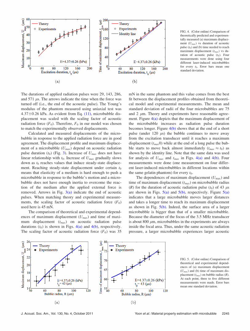
The durations of applied radiation pulses were 29, 143, 286,
and 571 ls. The arrows indicate the time when the force was
turned off (i.e., the end of the acoustic pulse). The Young’s
modulus of the phantom measured using uniaxial test was
4:3760:26 kPa. As evident from Eq. (11), microbubble dis-
placement was scaled with the scaling factor of acoustic
radiation force (F0). Therefore, F0 in our model was chosen
to match the experimentally observed displacements.
Calculated and measured displacements of the micro-
bubble in response to the applied radiation force are in good
agreement. The displacement profile and maximum displace-
ment of a microbubble (Umax) depend on acoustic radiation
pulse duration (t0) (Fig. 3). Increase of Umax does not have
linear relationship with t0. Increase of Umax gradually slows
down as t0 reaches values that induce steady-state displace-
ment. Reaching steady-state displacement under certain t0
means that elasticity of a medium is hard enough to push a
microbubble in response to the bubble’s motion and a micro-
bubble does not have enough inertia to overcome the reac-
tion of the medium after the applied external force is
removed. Arrows in Fig. 3(a) indicate the end of acoustic
pulses. When matching theory and experimental measure-
ments, the scaling factor of acoustic radiation force (F0)
used here is 45 mN.
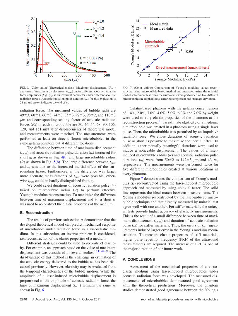
The comparison of theoretical and experimental depend-
ences of maximum displacement (Umax) and time of maxi-
mum displacement (tmax) on acoustic radiation pulse
durations (t0) is shown in Figs. 4(a) and 4(b), respectively.
The scaling factor of acoustic radiation force (F0) was 35
mN in the same phantom and this value comes from the best
fit between the displacement profiles obtained from theoreti-
cal model and experimental measurements. The mean and
standard deviation of radii of the four microbubbles are 75
and 2 lm. Theory and experiments have reasonable agree-
ment. Figure 4(a) depicts that the maximum displacement of
the microbubble increases as radiation pulse duration
becomes longer. Figure 4(b) shows that at the end of a short
pulse (under 120 ls) the bubble continues to move away
from the excitation transducer until it reaches a maximum
displacement (tmax0) while at the end of a long pulse the bub-
ble starts to move back almost immediately (tmax � t0) as
shown by the identity line. Note that the same data was used
for analysis of Umax and tmax in Figs. 4(a) and 4(b). Four
measurements were done (one measurement on four differ-
ent laser-induced microbubbles in different locations within
the same gelatin phantom) for every t0.
The dependences of maximum displacement (Umax) and
time of maximum displacement (tmax) on microbubble radius
(R) for the duration of acoustic radiation pulse (t0) of 43 ls
are shown in Figs. 5(a) and 5(b), respectively. Figure 5(a)
indicates that a large microbubble moves larger distances
and takes a longer time to reach its maximum displacement
as shown in Fig. 5(b). Indeed, the surface area of a larger
microbubble is bigger than that of a smaller microbubble.
Because the diameter of the focus of the 3.5 MHz transducer
is about 800 lm, microbubbles in the experiments are always
inside the focal area. Thus, under the same acoustic radiation
pressure, a larger microbubble experiences larger acoustic
FIG. 4. (Color online) Comparison of
theoretically predicted and experimen-
tally measured (a) maximum displace-
ment (Umax) vs duration of acoustic
pulse (t0) and (b) time needed to reach
maximum displacement (tmax) vs du-
ration of acoustic pulse (t0). Four
measurements were done using four
different laser-induced microbubbles
for every t0. Error bars mean one
standard deviation.
FIG. 5. (Color online) Comparison of
theoretical and experimental depend-
ences of (a) maximum displacement
(Umax) and (b) time of maximum dis-
placement (tmax) on bubble radius (R).
At each point, three to five different
measurements were made. Error bars
mean one standard deviation.
J. Acoust. Soc. Am., Vol. 130, No. 4, October 2011 Yoon et al.: Material property estimation with microbubble 2245
radiation force. The measured values of bubble radii are
4963, 6061, 6663, 7463, 8563, 9263, 9862, and 11063
lm and corresponding scaling factor of acoustic radiation
forces (F0) of each microbubble are 30, 46, 54, 68, 90, 106,
120, and 151 mN after displacements of theoretical model
and measurements were matched. The measurements were
performed at least on three different microbubbles in the
same gelatin phantom but at different locations.
The difference between time of maximum displacement
(tmax) and acoustic radiation pulse duration (t0) increased for
short t0 as shown in Fig. 4(b) and large microbubble radius
(R) as shown in Fig. 5(b). The large difference between tmax
and t0 was due to the increased inertial effect of the sur-
rounding tissue. Furthermore, if the difference was large,
more accurate measurements of tmax were possible, other-
wise tmax could be hardly distinguished from t0.
We could select durations of acoustic radiation pulse (t0)
based on microbubble radius (R) to perform effective
Young’s modulus reconstruction. To maximize the difference
between time of maximum displacement and t0, a short t0
was used to reconstruct the elastic properties of the medium.
B. Reconstruction
The results of previous subsection A demonstrate that the
developed theoretical model can predict mechanical response
of microbubble under radiation force in a viscoelastic me-
dium. In this subsection, an inverse problem is considered,
i.e., reconstruction of the elastic properties of a medium.
Different strategies could be used to reconstruct elastic-
ity. For example, an approach based on the value of maximum
displacement was considered in several studies.10,11,49–51 The
disadvantage of this method is the challenge in estimation of
the acoustic energy delivered to the bubble as has been dis-
cussed previously. However, elasticity may be evaluated from
the temporal characteristics of the bubble motion. While the
amplitude of a laser-induced microbubble displacement is
proportional to the amplitude of acoustic radiation force, the
time of maximum displacement (tmax) remains the same as
shown in Fig. 6.
Gelatin-based phatoms with the gelatin concentrations
of 1.4%, 2.0%, 3.0%, 4.0%, 5.0%, 6.0% and 7.0% by weight
were used to vary elastic properties of the phantoms at the
reconstruction process.61 To estimate elasticity of a medium,
a microbubble was created in a phantom using a single laser
pulse. Then, the microbubble was perturbed by an impulsive
radiation force. We chose durations of acoustic radiation
pulse as short as possible to maximize the inertial effect. In
addition, experimentally meaningful durations were used to
induce a noticeable displacement. The values of a laser-
induced microbubble radius (R) and acoustic radiation pulse
durations (t0) were from 5062 to 14265 lm and 43 ls,
respectively. The measurements were performed twice for
five different microbubbles created at various locations in
every phantom.
Figure 7 demonstrates the comparison of Young’s mod-
ulus (E) reconstructed using the laser-induced microbubble
approach and measured by using uniaxial tester. The solid
line represents the ideal match between measurements. The
Young’s modulus reconstructed by the laser-induced micro-
bubble technique and that directly measured by uniaxial test
agree well with one another. For stiffer materials, the uniax-
ial tests provide higher accuracy of elasticity measurements.
This is the result of a small difference between time of maxi-
mum displacement (tmax) and duration of acoustic radiation
pulse (t0) for stiffer materials. Thus, the errors of tmax meas-
urements induced larger error in the Young’s modulus recon-
struction. To measure elastic properties of stiff materials,
higher pulse repetition frequency (PRF) of the ultrasound
measurements are required. The increase of PRF is one of
the major direction of our future work.
V. CONCLUSIONS
Assessment of the mechanical properties of a visco-
elastic medium using laser-induced microbubbles under
acoustic radiation force was developed. The measured dis-
placements of microbubbles demonstrated good agreement
with the theoretical predictions. Moreover, the phantom
studies demonstrated good agreement between the Young’s
FIG. 6. (Color online) Theoretical analysis. Maximum displacement (Umax)
and time of maximum displacement (tmax) under different acoustic radiation
force amplitudes (F0). tmax is an invariant parameter under different acoustic
radiation forces. Acoustic radiation pulse duration (t0) for this evaluation is
28 ls and arrow indicates the end of t0.
FIG. 7. (Color online) Comparison of Young’s modulus values recon-
structed using microbubble-based method and measured using the uniaxial
load-displacement test. Two measurements were performed on five different
microbubbles in all phantoms. Error bars represent one standard deviation.
2246 J. Acoust. Soc. Am., Vol. 130, No. 4, October 2011 Yoon et al.: Material property estimation with microbubble
modulus reconstructed using remote microbubble-based
measurements and that measured using the uniaxial tests.
Thus, the Young’s modulus of a medium can be measured
using a laser-induced microbubble with typical sizes of tens
of micrometers up to a hundred micrometers using acoustic
radiation force.
ACKNOWLEDGMENTS
This work was supported in part by National Institutes
of Health under Grants Nos. EY 018081 and EB 008821.
1A. Vogel, P. Schweiger, A. Frieser, M. Asiyo, and R. Birngruber,
“Mechanism of action, scope of the damage and reduction of side effects
in intraocular Nd: YAG laser surgery,” Fortschr. Ophthalmol. 87, 675–687
(1990).2A. Vogel, “Nonlinear absorption: Intraocular microsurgery and laser lith-
otripsy,” Phys. Med. Biol. 42, 895–912 (1997).3A. Vogel, J. Noack, G. Huttman, and G. Paltauf, “Mechanisms of femto-
second laser nanosurgery of cells and tissues,” Appl. Phys. B 81,
1015–1047 (2005).4R. F. Steinert and C. A. Puliafito, The Nd:YAG Laser in Ophthalmology(Saunders, Philadelphia, 1985), pp. 1–154.
5A. Olmes, S. Lohmann, H. Lubatschowski, and W. Ertmer, “An improved
method of measuring laser induced pressure transients,” Appl. Phys. B 64,
667–682 (1997).6A. Vogel, M. R. C. Capon, M. N. Asiyo-Vogel, and R. Birngruber,
“Intraocular photodisruption with picosecond and nanosecond laser pulses:
Tissue effects in cornea, lens, and retina,” Invest. Ophthalmol. Vis. Sci.
35, 3032–3044 (1994).7T. Juhasz, F. H. Loesel, R. M. Kurtz, C. Horvath, J. F. Bille, and G.
Mourou, “Corneal refractive surgery with femtosecond lasers,” IEEE J.
Sel. Top. Quant. Electron. 5, 902–910 (1999).8S. V. Patel, L. J. Maguire, J. W. McLaren, D. O. Hodge, and W. M.
Bourne, “Femtosecond laser versus mechanical microkeratome for
LASIK,” Ophthalmology 114, 1482–1490 (2007).9R. Montes-Mico, A. Rodriguez-Galietero, and J. L. Alio, “Femtosecond
laser versus mechanical keratome LASIK for myopia,” Ophthalmology
114, 62–68 (2007).10T. N. Erpelding, K. W. Hollman, and M. O’Donnell, “Mapping age-related
elasticity changes in porcine lenses using bubble-based acoustic radiation
force,” Exp. Eye. Res. 84, 332–341 (2007).11K. W. Hollman, M. O’Donnell, and T. N. Erpelding, “Mapping elasticity
in human lenses using bubble-based acoustic radiation force,” Exp. Eye.
Res. 85, 890–893 (2007).12K. R. Heys, M. G. Friedrich, and R. J. Truscott, “Free and bound water in
normal and cataractous human lenses,” Invest. Ophthalmol. Vis. Sci. 49,
1991–1997 (2008).13P. Heyworth, G. M. Thompson, H. Tabandeh, and S. McGuigan, “The
relationship between clinical classification of cataract and lens hardness,”
Eye (London) 7, 726–230 (1993).14H. Tabandeh, M. Wilkins, G. Thompson, D. Nassiri, and A. Karim,
“Hardness and ultrasonic characteristics of the human crystalline lens,” J.
Cataract Refract. Surg. 26, 838–841 (2000).15A. P. Sarvazyan, O. V. Rudenko, S. D. Swanson, J. B. Fowlkes, and S. Y.
Emelianov, “Shear wave elsticitiy imaging: A new ultrasonic technology
of medical diagnostics,” Ultrasound Med. Biol. 24, 1419–1435 (1998).16K. Nightingale, M. S. Soo, R. Nightingale, and G. Trahey, “Acoustic radi-
ation force impulse imaging: In vivo demonstration of clinical feasibility,”
Ultrasound Med. Biol. 28, 227–235 (2002).17W. F. Walker, F. J. Fernandez, and L. A. Negron, “A method of imaging
viscoelastic parameters with acoustic radiation force,” Phys. Med. Biol.
45, 1437–1447 (2000).18Y. A. Ilinskii, G. D. Meegan, E. A. Zabolotskaya, and S. Y. Emelianov,
“Gas bubble and solid sphere motion in elastic media in response to acous-
tic radiation force,” J. Acoust. Soc. Am. 117, 2338–2346 (2005).19Y. Kikkawa and T. Sato, “Elastic properties of the lens,” Exp. Eye. Res. 2,
210–215 (1963).20R. F. Fisher, “The elastic properties of the human lens,” J. Physiol. 212,
147–180 (1971).21R. F. Fisher, “Presbyopia and the changes with age in the human crystal-
line lens,” J. Physiol. 228, 765–779 (1973).
22E. I. Assia, I. Medan, and M. Rosner, “Correlation between clinical, physi-
cal and histopathological characteristics of the cataractous lens,” Graefe’s
Arch. Clin. Exp. Ophthalmol. 235, 745–748 (1997).23G. W. H. M. van Alphen and W. P. Graebel, “Elasticity of tissues involved
in accommodation,” Vision. Res. 31, 1417–1438 (1991).24H. Pau and J. Kranz, “The increasing sclerosis of the human lens with age
and its relevance to accommodation and presbyopia,” Graefe’s Arch. Clin.
Exp. Ophthalmol. 229, 294–296 (1991).25H. A. Weeber, G. Eckert, F. Soergel, C. H. Meyer, W. Pechhold, and R.
G. van der Heijde, “Dynamic mechanical properties of human lenses,”
Exp. Eye. Res. 80, 425–434 (2005).26F. Soergel, C. Meyer, G. Eckert, B. Abele, and W. Pechhold, “Spectral
analysis of viscoelasticity of the human lens,” J. Refract. Surg. 15,
714–716 (1999).27K. R. Heys, S. L. Cram, and R. J. Truscott, “Massive increase in the stiff-
ness of the human lens nucleus with age: The basis for presbyopia?,” Mol.
Vis. 10, 956–963 (2004).28K. R. Nightingale, R. W. Nightingale, M. L. Palmeri, and G. E. Trahey,
“A finite element model of remote palpation of breast lesions using radia-
tion force: Factors affecting tissue displacement,” Ultrasonic Imaging 22,
35–54 (2000).29K. R. Nightingale, M. L. Palmeri, R. W. Nightingale, and G. E. Trahey,
“On the feasibility of remote palpation using acoustic radiation force,” J.
Acoust. Soc. Am. 110, 625–634 (2001).30G. E. Trahey, M. L. Palmeri, R. C. Bentley, and K. R. Nightingale,
“Acoustic radiation force impulse imaging of the mechanical properties of
arteries: In vino and ex vivo results,” Ultrasound Med. Biol. 30,
1163–1171 (2004).31B. J. Fahey, K. R. Nightingale, S. A. McAleavey, M. L. Palmeri, P. D.
Wolf, and G. E. Trahey, “Acoustic radiation force impulse imaging of
myocardial radiofrequency ablation: Initial in vivo results,” IEEE Trans.
Ultrason. Ferroelect. Freq. Contr. 52, 631–642 (2005).32B. J. Fahey, K. R. Nightingale, R. C. Nelson, M. L. Palmeri, and G. E.
Trahey, “Acoustic radiation force impulse imaging of the abdomen: Dem-
onstration of feasibility and utility,” Ultrasound Med. Biol. 31, 1185–1198
(2005).33B. J. Fahey, R. C. Nelson, S. J. Hsu, D. P. Bradway, D. M. Dumont, and
G. E. Trahey, “In vivo guidance and assessment of liver radio-frequency
ablation with acoustic radiation force elastography,” Ultrasound Med.
Biol. 34, 1590–1603 (2008).34M. L. Palmeri, M. H. Wang, J. J. Dahl, K. D. Frinkley, and K. R. Nightin-
gale, “Quantifying hepatic shear modulus in vivo using acoustic radiation
force,” Ultrasound Med. Biol. 34, 546–558 (2008).35J. Bercoff, M. Tanter, and M. Fink, “Supersonic shear imaging: A new
technique for soft tissue elasticity mapping,” IEEE Trans. Ultrason. Fer-
roelectr. Freq. Contr. 51, 396–409 (2004).36M. Tanter, D. Touboul, J. L. Gennisson, J. Bercoff, and M. Fink,
“High-resolution quantitative imaging of cornea elasticity using super-
sonic shear imaging,” IEEE Trans. Med. Imaging 28, 1881–1893
(2009).37T. Deffieux, G. Montaldo, M. Tanter, and M. Fink, “Shear wave spectros-
copy for in vivo quantification of human soft tissues visco-elasticity,”
IEEE Trans. Med. Imaging 28, 313–322 (2009).38K. R. Nightingale, P. J. Kornguth, W. F. Walker, B. A. McDermott, and
G. E. Trahey, “A novel ultrasonic technique for differentiating cysts from
solid lesions: Preliminary results in the breast,” Ultrasound Med. Biol. 21,
745–751 (1995).39K. R. Nightingale, P. F. Kornguth, and G. E. Trahey, “The use of acoustic
streaming in breast lesion diagnosis: A clinical study,” Ultrasound Med.
Biol. 25, 75–87 (1999).40W. F. Walker, F. J. Fernandez, and L. A. Negron, “A method of imaging
viscoelastic parameters with acoustic radiation force,” Phys. Med. Biol.
45, 1437–1447 (2000).41F. Viola, and W. F. Walker, “Radiation force imaging of viscoelastic prop-
erties with reduced artifacts,” IEEE Trans. Ultrason. Ferroeletr. Freq.
Contr. 50, 736–742 (2003).42F. Viola, M. D. Kramer, M. B. Lawrence, J. P. Oberhauser, and W. F.
Walker, “Sonorheometry: A noncontact method for the dynamic assess-
ment of thrombosis,” Ann. Biomed. Eng. 32, 696–705 (2004).43M. Fatemi and J. F. Greenleaf, “Ultrasound-stimulated vibro-acoustic
spectrography,” Science 280, 82–85 (1998).44M. Fatemi and J. F. Greenleaf, “Vibro-acoustography: an imaging modal-
ity based on ultrasound-stimulated acoustic emission,” Proc. Natl. Acad.
Sci. USA 96, 6603–6608 (1999).
J. Acoust. Soc. Am., Vol. 130, No. 4, October 2011 Yoon et al.: Material property estimation with microbubble 2247
45M. Fatemi, L. E. Wold, A. Alizad, and J. F. Greenleaf, “Vibro-acoustic tis-
sue mammography,” IEEE Trans. Med. Imaging 21, 1–8 (2002).46S. Chen, M. Fatemi, and J. F. Greenleaf, “Quantifying elasticity and vis-
cosity from measurement of shear wave speed dispersion,” J. Acoust. Soc.
Am. 115, 2781–2785 (2004).47A. Alizad, M. Walch, J. F. Greenleaf, and M. Fatemi, “Vibrational charac-
teristics of bone fracture and fracture repair: Application to excised rat
femur,” J. Biomech. Eng. 128, 300–308 (2006).48C. Pislaru, B. Kantor, R. R. Kinnick, J. L Anderson, M. C. Aubry, M. W.
Urban, M. Fatemi, and J. F. Greenleaf, “In vivo vibroacoustography of
large peripheral arteries,” Invest. Radiol. 43, 243–252 (2008).49T. N. Erpelding, K. W. Hollman, and M. O’Donnell, “Bubble-based
acoustic radiation force using chirp insonation to reduce standing wave
effects,” Ultrasond Med. Biol. 33, 263–269 (2007).50T. N. Erpelding, K. W. Hollman, and M. O’Donnell, “Spatially mapping
the elastic properties of the lens using bubble-based acoustic radiation
force,” in IEEE Ultrasonics Symposium 2005, Rotterdam, The Nether-
lands, September 18–21, 2005, pp. 613–616.51T. N. Erpelding, K. W. Hollman, and M. O’Donnell, “Bubble-based
acoustic radiation force elasticity imaging,” IEEE Trans. Ultrason. Ferroe-
lectr. Freq. Contr. 52, 971–979 (2005).52S. R. Aglyamov, A. B. Karpiouk, Y. A. Ilinskii, E. A. Zabolotskaya, and
S. Y. Emelianov, “Motion of a solid sphere in a viscoelastic medium in
response to applied acoustic radiation force: Theoretical analysis and ex-
perimental verification,” J. Acoust. Soc. Am. 122, 1927–1936 (2007).
53A. B. Karpiouk, S. R. Aglyamov, Y. A. Ilinskii, E. A. Zabolotskaya, and
S. Y. Emelianov, “Assessment of shear modulus of tissue using ultrasound
radiation force acting on a spherical acoustic inhomogeneity,” IEEE
Trans. Ultrason. Ferroelectr. Freq. Contr. 56, 2380–2387 (2009).54M. Itoi, N. Ito, and H. Kaneko, “Visco-elastic properties of the lens,” Exp.
Eye. Res. 4, 168–173 (1965).55H. A. Weeber, and R. G. L. van der Heijde, “Internal deformation of the
human crystalline lens during accommodation,” Acta. Ophthalmol. 86,
642–647 (2008).56A. P. Sarvazyan, “Low-frequency acoustic characteristics of biological
tissues,” Mech. Compos. Mater. 11, 594–597 (1975).57L. D.Landau and E. M.Lifshitz, “Section 20. Flow with small Reynolds
numbers,” in Fluid Mechanics, 2nd ed. (Pergamon, New York, 1987),
Chap. 2, pp. 58–64.58M. A. Lubinski, S. Y. Emelianov, and M. O’Donnell, “Speckle tracking
methods for ultrasonic elasticity imaging using short-time correlation,”
IEEE Trans. Ultrason. Ferroelectr. Freq. Contr. 46, 82–96 (1999).59R. A. Schachar, R. W. Chan, and M. Fu, “Viscoelastic shear properties of
the fresh porcine lens,” Br. J. Ophthalmol. 91, 366–368 (2007).60R. A. Schachar, R. W. Chan, and M. Fu, “Viscoelastic shear properties of
fresh human lenses under 40 years of age: Implications for the etiology of
presbyopia,” Br. J. Ophthalmol. 95, 1010–1013 (2011).61T. J. Hall, M. Bilgen, M. F. Insana, and T. A. Krouskop, “Phantom materi-
als for elastography,” IEEE Trans. Ultrason. Ferroelectr. Freq. Contr. 44,
1355–1365 (1997).
2248 J. Acoust. Soc. Am., Vol. 130, No. 4, October 2011 Yoon et al.: Material property estimation with microbubble