es-20-80-en103-0919.pdf - Biosan
20
-
Upload
khangminh22 -
Category
Documents
-
view
4 -
download
0
Transcript of es-20-80-en103-0919.pdf - Biosan

2
3
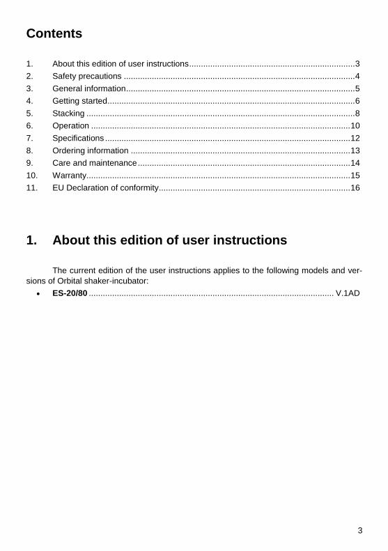
Contents
1. About this edition of user instructions ....................................................................... 3 2. Safety precautions ................................................................................................... 4 3. General information .................................................................................................. 5 4. Getting started .......................................................................................................... 6 5. Stacking ................................................................................................................... 8 6. Operation ............................................................................................................... 10 7. Specifications ......................................................................................................... 12 8. Ordering information .............................................................................................. 13 9. Care and maintenance ........................................................................................... 14 10. Warranty ................................................................................................................. 15 11. EU Declaration of conformity .................................................................................. 16
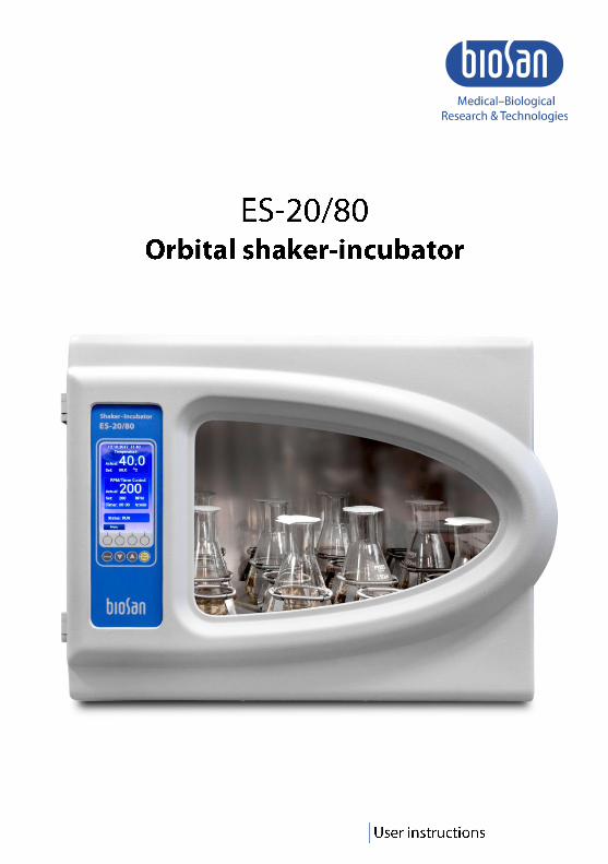
1. About this edition of user instructions
The current edition of the user instructions applies to the following models and ver-
sions of Orbital shaker-incubator:
ES-20/80 ......................................................................................................... V.1AD
4
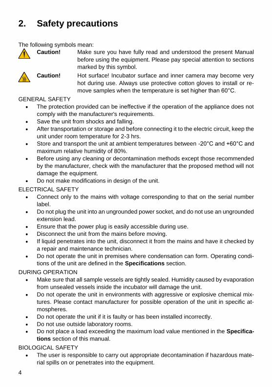
2. Safety precautions
The following symbols mean:
Caution! Make sure you have fully read and understood the present Manual
before using the equipment. Please pay special attention to sections
marked by this symbol.
Caution! Hot surface! Incubator surface and inner camera may become very
hot during use. Always use protective cotton gloves to install or re-
move samples when the temperature is set higher than 60°C.
GENERAL SAFETY
The protection provided can be ineffective if the operation of the appliance does not
comply with the manufacturer's requirements.
Save the unit from shocks and falling.
After transportation or storage and before connecting it to the electric circuit, keep the
unit under room temperature for 2-3 hrs.
Store and transport the unit at ambient temperatures between -20°C and +60°C and
maximum relative humidity of 80%.
Before using any cleaning or decontamination methods except those recommended
by the manufacturer, check with the manufacturer that the proposed method will not
damage the equipment.
Do not make modifications in design of the unit.
ELECTRICAL SAFETY
Connect only to the mains with voltage corresponding to that on the serial number
label.
Do not plug the unit into an ungrounded power socket, and do not use an ungrounded
extension lead.
Ensure that the power plug is easily accessible during use.
Disconnect the unit from the mains before moving.
If liquid penetrates into the unit, disconnect it from the mains and have it checked by
a repair and maintenance technician.
Do not operate the unit in premises where condensation can form. Operating condi-
tions of the unit are defined in the Specifications section.
DURING OPERATION
Make sure that all sample vessels are tightly sealed. Humidity caused by evaporation
from unsealed vessels inside the incubator will damage the unit.
Do not operate the unit in environments with aggressive or explosive chemical mix-
tures. Please contact manufacturer for possible operation of the unit in specific at-
mospheres.
Do not operate the unit if it is faulty or has been installed incorrectly.
Do not use outside laboratory rooms.
Do not place a load exceeding the maximum load value mentioned in the Specifica-
tions section of this manual.
BIOLOGICAL SAFETY
The user is responsible to carry out appropriate decontamination if hazardous mate-
rial spills on or penetrates into the equipment.
5
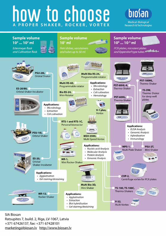
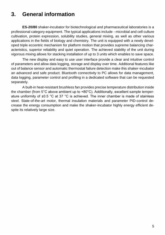
3. General information
ES-20/80 shaker-incubator for biotechnological and pharmaceutical laboratories is a
professional category equipment. The typical applications include - microbial and cell culture
cultivation, protein expression, solubility studies, general mixing, as well as other various
applications in the fields of biology and chemistry. The unit is equipped with a newly devel-
oped triple eccentric mechanism for platform motion that provides supreme balancing char-
acteristics, superior reliability and quiet operation. The achieved stability of the unit during
vigorous mixing allows for stacking installation of up to 3 units which enables to save space.
The new display and easy to use user interface provide a clear and intuitive control
of parameters and allow data logging, storage and display over time. Additional features like
out of balance sensor and automatic thermostat failure detection make this shaker-incubator
an advanced and safe product. Bluetooth connectivity to PC allows for data management,
data logging, parameter control and profiling in a dedicated software that can be requested
separately.
A built-in heat-resistant brushless fan provides precise temperature distribution inside
the chamber (from 5°C above ambient up to +80°C). Additionally, excellent sample temper-
ature uniformity of ±0.5 °C at 37 °C is achieved. The inner chamber is made of stainless
steel. State-of-the-art motor, thermal insulation materials and parameter PID-control de-
crease the energy consumption and make the shaker-incubator highly energy efficient de-
spite its relatively large size.
6
4. Getting started
4.1. Unpacking. Remove packing materials carefully and retain them for future shipment
or storage of the unit. Examine the unit carefully for any damage incurred during
transit. The warranty does not cover in-transit damage. Warranty covers only the units
transported in the original package.
Caution! Due to the high weight of the unit, its unpacking and installing must
be carried out by two persons.
4.2. Complete set. Package contents:
4.2.1. Standard set:
- ES-20/80, Orbital shaker-incubator .................................................................. 1 pce. - Power cable .................................................................................................... 1 pce. - Spare fuse (inside fuse holder) ....................................................................... 1 pce. - Four screws and a hex driver ............................................................................. 1 set - USB drive with software and software manual ................................................. 1 pce. - Operating instructions, declaration of conformity ........................................... 1 copy
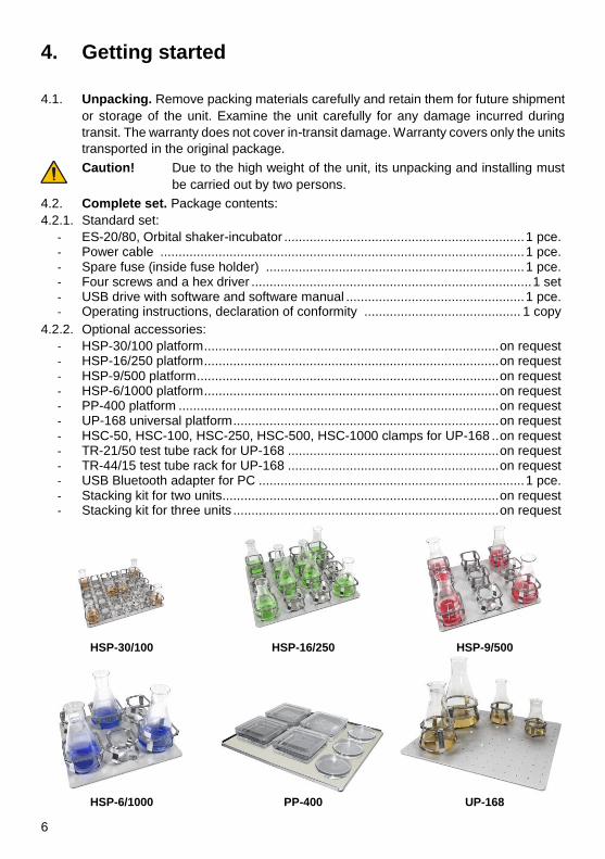
4.2.2. Optional accessories:
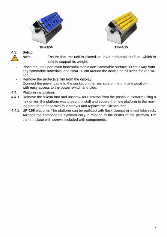
- HSP-30/100 platform ................................................................................. on request - HSP-16/250 platform ................................................................................. on request - HSP-9/500 platform ................................................................................... on request - HSP-6/1000 platform ................................................................................. on request - PP-400 platform ........................................................................................ on request - UP-168 universal platform ......................................................................... on request - HSC-50, HSC-100, HSC-250, HSC-500, HSC-1000 clamps for UP-168 .. on request - TR-21/50 test tube rack for UP-168 .......................................................... on request - TR-44/15 test tube rack for UP-168 .......................................................... on request - USB Bluetooth adapter for PC ......................................................................... 1 pce. - Stacking kit for two units............................................................................ on request - Stacking kit for three units ......................................................................... on request
HSP-30/100 HSP-16/250 HSP-9/500
HSP-6/1000 PP-400 UP-168
7
TR-21/50 TR-44/15
4.3. Setup.
Note. Ensure that the unit is placed on level horizontal surface, which is
able to support its weight.
- Place the unit upon even horizontal stable non-flammable surface 30 cm away from any flammable materials, and clear 20 cm around the device on all sides for ventila-tion.
- Remove the protective film from the display. - Connect the power cable to the socket on the rear side of the unit and position it
with easy access to the power switch and plug.
4.4. Platform installation.
4.4.1. Remove the silicon mat and unscrew four screws from the previous platform using a
hex driver, if a platform was present. Install and secure the new platform to the mov-
ing part of the base with four screws and replace the silicone mat.
4.4.2. UP-168 platform. The platform can be outfitted with flask clamps or a test tube rack.
Arrange the components symmetrically in relation to the center of the platform. Fix
them in place with screws included with components.
8
5. Stacking
Note. The following section applies to the optional stacking kit, to use with
2 or 3 shaker-incubator units.
5.1. Stacking kit contains:
Component Kit for 2 units Kit for 3 units
Catalogue number BS-0101670-OK BS-0101670-PK
Side legs – 2
Holder plate 4 8
Hex screw 6x16 16 40
Washer 16 40
Lock washer 16 40
Hex key 1 1
5.2. Aquiring a kit. To purchase the kit, contact Biosan or your local Biosan representa-
tive, with information from the section Ordering information.
5.3. Getting started.
5.3.1. Unpack the kit. Unpower the units and disconnect the power cables.
5.3.2. Prepare the working space. Ensure that the floor and the desk supports at least 150
kgF/m2 (for 2 units) or 200 kgF/m2 (for 3 units). Laminate or rubber flooring may reduce
overall stability and are generally not recommended.
5.3.3. Position the units so that the access to the mains plugs, the sockets and the power
switches is unobstructed.
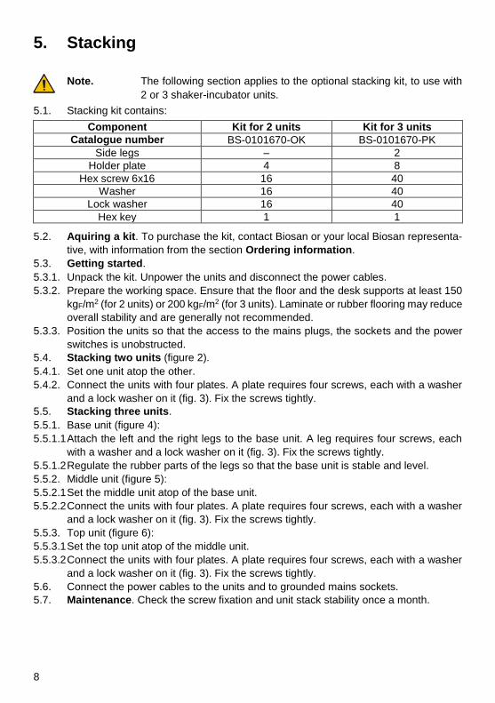
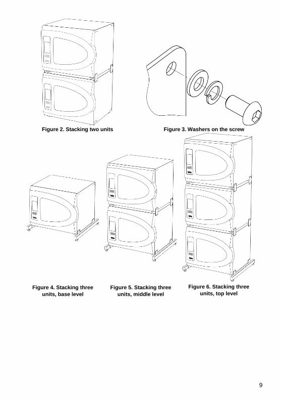
5.4. Stacking two units (figure 2).
5.4.1. Set one unit atop the other.
5.4.2. Connect the units with four plates. A plate requires four screws, each with a washer
and a lock washer on it (fig. 3). Fix the screws tightly.
5.5. Stacking three units.
5.5.1. Base unit (figure 4):
5.5.1.1 Attach the left and the right legs to the base unit. A leg requires four screws, each
with a washer and a lock washer on it (fig. 3). Fix the screws tightly.
5.5.1.2 Regulate the rubber parts of the legs so that the base unit is stable and level.
5.5.2. Middle unit (figure 5):
5.5.2.1 Set the middle unit atop of the base unit.
5.5.2.2 Connect the units with four plates. A plate requires four screws, each with a washer
and a lock washer on it (fig. 3). Fix the screws tightly.
5.5.3. Top unit (figure 6):
5.5.3.1 Set the top unit atop of the middle unit.
5.5.3.2 Connect the units with four plates. A plate requires four screws, each with a washer
and a lock washer on it (fig. 3). Fix the screws tightly.
5.6. Connect the power cables to the units and to grounded mains sockets.
5.7. Maintenance. Check the screw fixation and unit stack stability once a month.
9
Figure 2. Stacking two units Figure 3. Washers on the screw
Figure 4. Stacking three
units, base level
Figure 5. Stacking three
units, middle level
Figure 6. Stacking three
units, top level
10
6. Operation
6.1. Connect the unit to a grounded power socket. Set the
Power switch on the rear panel to position I (on).
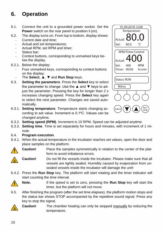
6.2. The display turns on. From top to bottom, display shows:
- Current date and time; - Actual and set temperatures; - Actual RPM, set RPM and timer; - Status bar; - Context buttons, corresponding to unmarked keys be-
low the display.
6.2.1. Below the display:
- Four unmarked keys, corresponding to context buttons on the display;
- The Select, ▲, ▼ and Run Stop keys.
6.3. Setting the parameters. Press the Select key to select
the parameter to change. Use the ▲ and ▼ keys to ad-
just the parameter. Pressing the key for longer than 2 s
increases changing speed. Press the Select key again
to select the next parameter. Changes are saved auto-
matically.
6.3.1. Setting temperature. Temperature starts changing ac-
cording to set value. Increment is 0.1ºC. Values can be
changed anytime.
6.3.2. Setting speed (RPM). Increment is 10 RPM. Speed can be adjusted anytime.
6.3.3. Setting time. Time is set separately for hours and minutes, with increment of 1 mi-
nute.
6.4. Program execution.
6.4.1. When the actual temperature in the incubator reaches set values, open the door and
place samples on the platform.
Caution! Place the samples symmetrically in relation to the center of the plat-
form to avoid imbalance errors.
Caution! Do not fill the vessels inside the incubator. Please make sure that all
vessels are tightly sealed. Humidity caused by evaporation from un-
sealed vessels inside the incubator will damage the unit!
6.4.2. Press the Run Stop key. The platform will start rotating and the timer indicator will
start counting the time interval.
Note. If the speed is set to zero, pressing the Run Stop key will start the
timer, but the platform will not move.
6.5. After finishing the program (after the set time elapses), the platform motion stops and
the status bar shows STOP accompanied by the repetitive sound signal. Press any
key to stop the signal.
Caution! The chamber heating can only be stopped manually by reducing the
temperature.
11
6.6. If the time is not set (set time is 00:00), the Run Stop key will start continuous oper-
ation of the unit until the Run Stop key is pressed again.
6.7. The platform motion can be stopped at any time by pressing the Run Stop key. In
this case, the program realisation and the platform motion will stop and the timer will
switch into the STOP mode saving previously set time. Press the Run Stop key to
restart the operation with the same time and speed.
6.8. Incubator menu. The Menu button opens incubator’s menu. Use ▲ and ▼ buttons
to navigate and Enter button to select. While browsing in the menu, select the top-
most Quit option in order to return from sub-menu to menu.
6.8.1. Incubator ID. Option GetID shows the serial number and name of the incubator and
its Bluetooth module MAC address, as well as remote PC Bluetooth module MAC
address.
6.8.2. Date & Time. To set date and time in this submenu, press Enter button to select the
parameter, then ▲ and ▼ buttons to change the value and Enter button to confirm
changes.
6.8.3. Service. This submenu has following options: Current Errors and Settings.
6.8.3.1 Current Errors. This option allows user to view and reset the list of active errors.
6.8.3.2 Settings. This option has two suboptions available – Alarm Setting and Start mode.
Alarm Setting. User can set the alarm settings based on values of temperature and
RPM. All alarms are working on the following principle, temperature taken as an ex-
ample:
If Tact < Tthr.low or Tact > Tthr.high for tdelay minutes, then an alarm will be triggered.
Where Tact is the actual temperature inside the incubator, Tthr.low is the lower threshold
limit value, Tthr.high is the higher threshold limit value and tdelay is the time delay in
minutes. Time delay is used in order to avoid false triggering of the alarms.
RPM alarm is operated using the same principle.
Start Mode. User can change the acceleration mode of the unit. In Start Mode Slow
the unit picks up speed gently to reduce the possibility of spilling. In Start Mode Fast
the unit rapidly gains speed and set RPM rate.
6.8.4. Active Alarms. This option allows user to view and reset the list of active alarms.
6.8.5. Data Logger. Data logger features following options: View Plot T(t), View Plot
RPM(t), View Plot T(t)+RPM(t), Clear log, Logger on/off.
6.8.5.1 All View Plot options use the same interface. Use Left and Right buttons to move the
plot along the x axis. Use Up and Down buttons to move the plot along the y axis.
Use <-xx-> button to choose the x axis navigational scale. Available scales are 15
minutes, 1 hour, 1 day, 1 week and 1 month.
6.8.5.2 Clear Log button clears the logger’s data.
6.8.5.3 Logger On/Off button toggles the automatic logging of the data.
6.8.5.4 Available memory indicator. When the data logger uses up all available memory, it
begins overwriting data from beginning. 100% of memory is used up in approximately
1 month.
6.9. At the end of operation, set the Power switch in position O (off). Disconnect the power
cable from electric circuit.
12
7. Specifications
The unit is designed for operation in cold rooms and closed laboratory rooms at am-
bient temperature from +4°C to +40°C in a non-condensing atmosphere and maximum rel-
ative humidity 80% for temperatures up to 31°C decreasing linearly to 50% relative humidity
at 40°C.
Biosan is committed to a continuous programme of improvement and reserves the
right to alter design and specifications of the equipment without additional notice.
7.1. Temperature specification
Setting range ................................................................. +25°C ... +80°C (increment 0.1°C)
Control range .......................................................................... 5°C above ambient ... +80°C
Uniformity1 .................................................................................................................. ±0.3°C
Accuracy1 ................................................................................................................... ±0.1°C
Stability1 ..................................................................................................................... ±0.1°C
Heat up time to +80°C inside the chamber ................................................................ 75 min
7.2. General specification
Speed control range ....................................................... 50 - 400 RPM (increment 10 RPM)
Digital time setting ............................................. 1 min - 96 hrs (increment 1 min) / non-stop
Maximum continuous operation time2 ....................................................................... 30 days
Maximum load ........................................................................................................... 10.6 kg
Orbit 20 mm
Display ................................................................................................................... TFT LCD
PC software .......................................................................................................... on request
Data transfer ...........................................................................................................Bluetooth
Dimensions .............................................................................................. 620x530x510 mm
Dimensions of the inner chamber ............................................................. 460x350x400 mm
Stacking ............................................................................................................ up to 3 units3
Operating voltage/ power consumption .............................. 230 V, 50/60 Hz / 500 W (2.2 A)
Weight4 ......................................................................................................................... 48 kg
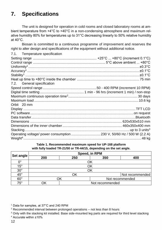
Table 1. Recommended maximum speed for UP-168 platform
with fully loaded TR-21/50 or TR-44/15, depending on the set angle.
Set angle Speed, in RPM
200 250 350 400
0° OK
15° OK
30° OK
45° OK Not recommended
60° OK Not recommended
75° OK Not recommended
1 Data for samples, at 37°C and 240 RPM 2 Recommended interval between prolonged operations – not less than 8 hours 3 Only with the stacking kit installed. Base side-mounted leg parts are required for third level stacking 4 Accurate within ±10%
13
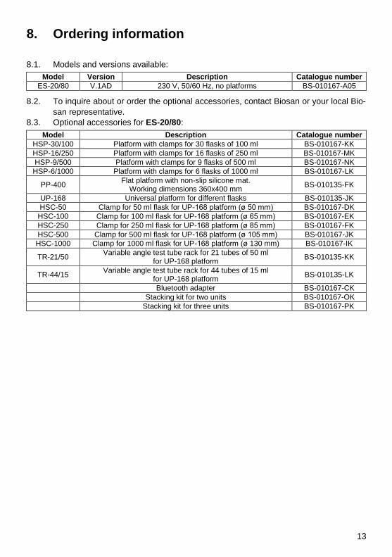
8. Ordering information
8.1. Models and versions available:
Model Version Description Catalogue number
ES-20/80 V.1AD 230 V, 50/60 Hz, no platforms BS-010167-A05
8.2. To inquire about or order the optional accessories, contact Biosan or your local Bio-
san representative.
8.3. Optional accessories for ES-20/80:
Model Description Catalogue number
HSP-30/100 Platform with clamps for 30 flasks of 100 ml BS-010167-KK
HSP-16/250 Platform with clamps for 16 flasks of 250 ml BS-010167-MK
HSP-9/500 Platform with clamps for 9 flasks of 500 ml BS-010167-NK
HSP-6/1000 Platform with clamps for 6 flasks of 1000 ml BS-010167-LK
PP-400 Flat platform with non-slip silicone mat.
Working dimensions 360x400 mm BS-010135-FK
UP-168 Universal platform for different flasks BS-010135-JK
HSC-50 Clamp for 50 ml flask for UP-168 platform (ø 50 mm) BS-010167-DK
HSC-100 Clamp for 100 ml flask for UP-168 platform (ø 65 mm) BS-010167-EK
HSC-250 Clamp for 250 ml flask for UP-168 platform (ø 85 mm) BS-010167-FK
HSC-500 Clamp for 500 ml flask for UP-168 platform (ø 105 mm) BS-010167-JK
HSC-1000 Clamp for 1000 ml flask for UP-168 platform (ø 130 mm) BS-010167-IK
TR-21/50 Variable angle test tube rack for 21 tubes of 50 ml
for UP-168 platform BS-010135-KK
TR-44/15 Variable angle test tube rack for 44 tubes of 15 ml
for UP-168 platform BS-010135-LK
Bluetooth adapter BS-010167-CK
Stacking kit for two units BS-010167-OK
Stacking kit for three units BS-010167-PK
14
9. Care and maintenance
9.1. If the unit requires maintenance, disconnect the unit from the mains and contact Bio-
san or your local Biosan representative.
9.2. All maintenance and repair operations must be performed only by qualified and spe-
cially trained personnel.
9.3. Cleaning and desinfection.
9.3.1. Standard ethanol (75%) or other cleaning agents recommended for cleaning of labor-
atory equipment can be used for cleaning and decontamination of the steel surfaces.
9.3.2. For decontamination, it is recommended to use a special DNA/RNA removing solu-
tion (e.g. Biosan PDS-250, DNA-Exitus Plus™, RNase-Exitus Plus™).
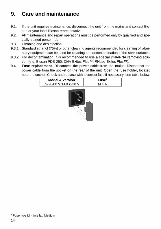
9.4. Fuse replacement. Disconnect the power cable from the mains. Disconnect the
power cable from the socket on the rear of the unit. Open the fuse holder, located
near the socket. Check and replace with a correct fuse if necessary, see table below:
Model & version Fuse1
ES-20/80 V.1AD (230 V) M 4 A
1 Fuse type M - time lag Medium
15
10. Warranty
10.1. The Manufacturer guarantees the compliance of the unit with the requirements of
Specifications, provided the Customer follows the operation, storage and transporta-
tion instructions.
10.2. The warranted service life of the unit from the date of its delivery to the Customer is
24 months. For extended warranty, see 10.5.
10.3. Warranty covers only the units transported in the original package.
10.4. If any manufacturing defects are discovered by the Customer, an unsatisfactory
equipment report shall be compiled, certified and sent to the local distributor address.
To obtain the claim form, visit Technical support page on our website at link below.
10.5. Extended warranty. For ES-20/80, the Smart class model, extended warranty is a
paid service. Contact your local Biosan representative or our service department
through the Technical support section on our website at the link below.
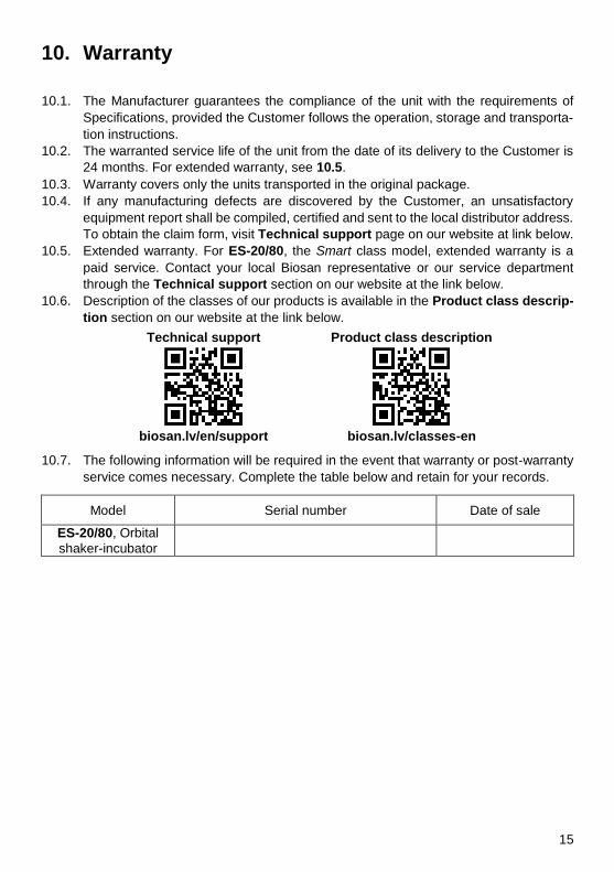
10.6. Description of the classes of our products is available in the Product class descrip-
tion section on our website at the link below.
Technical support Product class description
biosan.lv/en/support biosan.lv/classes-en
10.7. The following information will be required in the event that warranty or post-warranty
service comes necessary. Complete the table below and retain for your records.
Model Serial number Date of sale
ES-20/80, Orbital
shaker-incubator
16
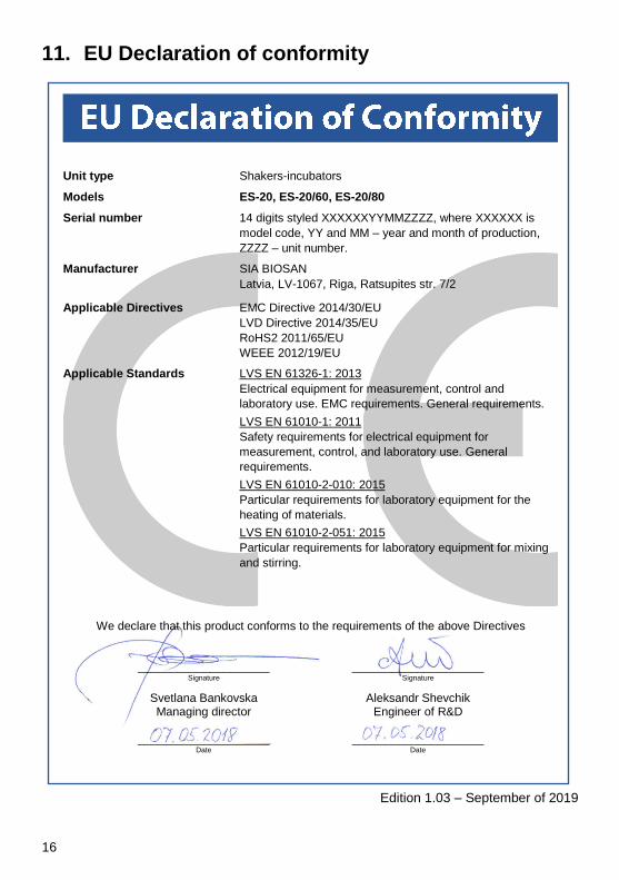
11. EU Declaration of conformity
Unit type Shakers-incubators
Models ES-20, ES-20/60, ES-20/80
Serial number 14 digits styled XXXXXXYYMMZZZZ, where XXXXXX is
model code, YY and MM – year and month of production,
ZZZZ – unit number.
Manufacturer SIA BIOSAN
Latvia, LV-1067, Riga, Ratsupites str. 7/2
Applicable Directives EMC Directive 2014/30/EU
LVD Directive 2014/35/EU
RoHS2 2011/65/EU
WEEE 2012/19/EU
Applicable Standards LVS EN 61326-1: 2013
Electrical equipment for measurement, control and
laboratory use. EMC requirements. General requirements.
LVS EN 61010-1: 2011
Safety requirements for electrical equipment for
measurement, control, and laboratory use. General
requirements.
LVS EN 61010-2-010: 2015
Particular requirements for laboratory equipment for the
heating of materials.
LVS EN 61010-2-051: 2015
Particular requirements for laboratory equipment for mixing
and stirring.
We declare that this product conforms to the requirements of the above Directives
____________________ ____________________ Signature Signature
Svetlana Bankovska Aleksandr Shevchik Managing director Engineer of R&D ____________________ ____________________ Date Date
Edition 1.03 – September of 2019

17

18

19