EPA REPORT ON CONTAMINANTS & REMEDIAL OPTIONS ...
258
EPA,5<1G, a-95/512 July 1995 n CONTAMINANTS AND REMEDIAL OPTIONS AT SELECTED METAL-CONTAMINATED SITES by Battelle Columbus Division Columbus, Ohio 43201-2693 Contract No. 68-CO-0003 Work Assignment 41 Project Officer Michael D. Royer Technical Support Branch Superfund Technology Demonstration Division _ National Risk Management Research Laboratory Edison, New Jersey 08837 NATIONAL RISK MANAGEMENT RESEARCH LABORATORY OFFICE OF RESEARCH AND DEVELOPMENT U.S. ENVIRONMENTAL PROTECTION AGENCY CINCINNATI, OHIO 45268 $& Printed on Recycled Paper
-
Upload
khangminh22 -
Category
Documents
-
view
1 -
download
0
Transcript of EPA REPORT ON CONTAMINANTS & REMEDIAL OPTIONS ...

E P A , 5 < 1 G , a - 9 5 / 5 1 2July 1995 n
CONTAMINANTS AND REMEDIAL OPTIONS AT SELECTEDMETAL-CONTAMINATED SITES
by
BattelleColumbus Division
Columbus, Ohio 43201-2693
Contract No. 68-CO-0003Work Assignment 41
Project OfficerMichael D. Royer
Technical Support BranchSuperfund Technology Demonstration Division
_ National Risk Management Research LaboratoryEdison, New Jersey 08837
NATIONAL RISK MANAGEMENT RESEARCH LABORATORYOFFICE OF RESEARCH AND DEVELOPMENT
U.S. ENVIRONMENTAL PROTECTION AGENCYCINCINNATI, OHIO 45268
$& Printed on Recycled Paper

NOTICE
This review'of contaminants and remedial options at selected metal-contaminated sites summarizesinformation collected from U.S. Environmental Protection Agency (EPA) programs, peer-reviewed journals,industry experts, vendor data, and other sources. A variety of potential candidate treatment technologiesare described as advisory guidance to assist in identifying feasible treatment technologies.
The information in this document has been funded in part by EPA under Contract No. 68-CO-0003,Work Assignment 41, to Battelle (Columbus Division). It has been subject to the Agency's peer andadministrative review, and it has been approved for publication as an EPA document. Mention of tradenames or commercial products does not constitute endorsement or recommendation for use.
Compliance with environmental and occupational safety and health laws is the responsibility of eachindividual site manager and is not the focus of this document.

FOREWORD
The U.S. Environmental Protection Agency is charged by Congress with protecting the Nation'sland, air, and water resources. Under a mandate of national environmental laws, the Agencystrives to formulate and implement actions leading to a compatible balance between humanactivities and the ability of natural systems to support and nurture life. To meet these mandates,EPA's research program is providing data and technical support for solving environmentalproblems today and building a science knowledge base necessary to manage our ecologicalresources wisely, understand how pollutants affect our health, and prevent or reduceenvironmental risks in the future.
The National Risk Management Research Laboratory is the Agency's center for investigation oftechnological and management approaches for reducing risks from threats to human health and theenvironment The focus of the Laboratory's research program is on methods for the prevention andcontrol of pollution to air, land, water, and subsurface resources; protection of water quality inpublic water systems; remediation of contaminated sites and groundwater, and prevention andcontrol of indoor air pollution. The goal of this research effort is to catalyze development andimplementation of innovative, cost-effective environmental technologies; develop scientific andengineering information needed by EPA to support regulatory and policy decisions; and providetechnical support and information transfer to ensure effective implementation of environmentalregulations and strategies.
This publication has been produced as part of the Laboratory's strategic long-term research plan. Itis published and made available by EPA's Office of Research and Development to assist the usercommunity and to link researchers with their clients.
E. Timothy Oppelt, DirectorNational Risk Management Research Laboratory

ABSTRACT
This document provides information that facilitates characterization of the site and selection oftreatment technologies at metal-contaminated sites that are capable of meeting site-specific cleanup levels.The document does not facilitate the determination of cleanup levels. This document will assist Federal.State, or private site removal and remedial managers operating under Comprehensive EnvironmentalResponse, Compensation, and Liability Act (CERCLA), Resource Conservation and Recovery Act (RCRA),or state regulations.
This document focuses mainly on the metalloid arsenic and the metals cadmium, chromium, lead,and mercury. Other metals are discussed, particularly those that have a strongly favorable or unfavorableinfluence on the performance of a treatment technology.
The remedial manager faces the challenge of selecting remedial options that meet establishedcleanup levels. A wide range of physical, chemical, and thermal process options are available forremediation of metal-contaminated sites. These options can reduce mobility, reduce toxicity, or allowseparation and concentration of metal contaminants. No single process option can remediate an entiremetal-contaminated site. The remedial manager must combine pretreatment and posttreatment componentsto achieve the best performance by the principal process option.
This document Is designed for use with other remedial guidance documents issued for RCRA,CERCLA, and/or State-mandated cleanups to accelerate the remediation of metal-contaminated sites.
Sections describing contaminants at metal-contaminated sites and the behavior, fate, and transportof metals in the environment are provided to assist the remedial manager in identifying the matrix andchemical species likely to be present. The section on remedial options outlines the arrangement oftreatment trains to achieve performance levels. Technology performance data provided can help theremedial manager narrow options to those most likely to achieve site-specific cleanup goals. Thedescriptions of remedial options cover innovative and emerging technologies, as well as proven treatments.
Some standard information sources on containment and water treatment technologies are indicated.These technology areas are not covered in this document because they are thoroughly discussed in otherdocuments.
This report was submitted in fulfillment of Contract No. 68-CO-0003, Work Assignment 41, byBattelle (Cdumbus.Division) under the sponsorship of the U.S. Environmental Protection Agency. Thisreport covers a period from October 1,1991 to January 31,1994. Work was completed in May 1995. Finalrevisions were performed by Foster Wheeler Environmental Services, Inc., under Contract 68-C9-0033 andScience Applications International Corporation under Contract No. 68-CO-0048.
IV

TABLE OF CONTENTS
Section • Page
Notice . . . . . . . . . . . . . . . . . . . . . . . . . . . . . . . . . . . . . . . . . . . . . . . . . . . . . . . . . . . . . . . . . . . . iiForeword . . . . . . . . . . . . . . . . . . . . . . . . . . . . . . . . . . . . . . . . . . . . . . . . . . . . . . . . . . . . . . . . . . iiiAbstract . . . . . . . . . . . . . . . . . . . . . . . . . . . . . . . . . . . . . . . . . . . . . . . . . . . . . . . . . . . . . . . . . . . . . ivFigures . . . . . . . . . . . . . . . . . . . . . . . . . . . . . . . . . . . . . . . . . . . . . . . . . . . . . . . . . . . . . . . . . . . . . viiiTables . . . . . . . . . . . . . . . . . . . . . . . . . . . . . . . . . . . . . . . . . . . . . . . . . . . . . . . . . . . . . . . . . . . . . . ixAbbreviations and Symbols . . . . . . . . . . . . . . . . . . . . . . . . . . . . . . . . . . . . . . . . . . . . . . . . . . . . . . xiAcknowledgments . . . . . . . . . . . . . . . . . . . . . . . . . . . . . . . . . . . . . . . . . . . . . . . . . . . . . . . . . . . . . x v i
1 Introduction . . . . . . . . . . . . . . . . . . . . . . . . . . . . . . . . . . . . . . . . . . . . . . . . . . . . . . . . . . . . . 1-1
1.1 Purpose . . . . . . . . . . . . . . . . . . . . . . . . . . . . . . . . . . . . . . . . . . . . . . . . . . . . . . . . . . 1-11.2 Scope and limitations . . . . . . . . . . . . . . . . . . . . . . . . . . . . . . . . . . . . . . . . . . . . . . . . . 1-11.3 Organization . . . . . . . . . . . . . . . . . . . . . . . . . . . . . . . . . . . . . . . . . . . . . . . . . . . . . . . 1-31.4 References . . . . . . . . . . . . . . . . . . . . . . . . . . . . . . . . . . . . . . . . . . . . . . . . . . . . . . . . 1-6
2 Origins, Uses, and Matrices of Selected Contaminants at Metal-Contaminated Sites . . . . . . . . 2-1
2.1 Origin and Major Industrial Uses of Arsenic, Cadmium, Chromium, Lead, and Mercury . . 2-1
2.1.1 Arsenic . . . . . . . . . . . . . . . . . . . . . . . . . . . . . . . . . . . . . . . . . . . . . . . . . . . . . 2-12.1.2 Cadmium . . . . . . . . . . . . . . . . . . . . . . . . . . . . . . . . . . . . . . . . . . . . . . . . . . . 2-12.1.3 Chromium . . . . . . . . . . . . . . . . . . . . . . . . . . . . . . . . . . . . . . . . . . . . . . . . . . . 2-22.1.4 Lead . . . . . . . . . . . . . . . . . . . . . . . . . . . . . . . . . . . . . . . . . . . . . . . . . . . . . . . 2-22.1.5 Mercury . . . . . . . . . . . . . . . . . . . . . . . . . . . . . . . . . . . . . . . . . . . . . . . . . . . . 2-2
2.2 Overview of Sources of Contaminants at Metal-Contaminated Sites . . . . . . . . . . . . . . . . 2-2
2.2.1 Stack Emissions . . . . . . . . . . . . . . . . . . . . . . . . . . . . . . . . . . . . . . . . . . . . . . 2-32.2.2 Fugitive Emissions . . . . . . . . . . . . . . . . . . . . . . . . . . . . . . . . . . . . . . . . . . . . . 2-32.2.3 Process Solid-Phase Waste Materials . . . . . . . . . . . . . . . . . . . . . . . . . . . . . . . 2-42.2.4 Sludges . . . . . . . . . . . . . . . . . . . . . . . . . . . . . . . . . . . . . . . . . . . . . . . . . . . . 2-62.2.5 Soils . . . . . . . . . . . . . . . . . . . . . . . . . . . . . . . . . . . . . . . . . . . . . . . . . . . . . . . 2-6
2.3 References . . . . . . . . . . . . . . . . . . . . . . . . . . . . . . . . . . . . . . . . . . . . . . . . . . . . . . . . 2-7
3 Contaminant Behavior, Fate, Transport, and Toxicity . . . . . . . . . . . . . . . . . . . . . . . . . . . . . . . 3-1
3.1 Chemical Forms and Speciations . . . . . . . . . . . . . . . . . . . . . . . . . . . . . . . . . . . . . . . . . 3-1
3.1.1 Arsenic . . . . . . . . . . . . . . . . . . . . . . . . . . . . . . . . . . . . . . . . . . . . . . . . . . . . . 3-23.1.2 Cadmium . . . . . . . . . . . . . . . . . . . . . . . . . . . . . . . . . . . . . . . . . . . . . . . . . . . 3-33.1.3 Chromium . . . . . . . . . . . . . . . . . . . . . . . . . . . . . . . . . . . . . . . . . . . . . . . . . . . 3-33.1.4 Lead . . . . . . . . . . . . . . . . . . . . . . . . . . . . . . . . . . . . . . . . . . . . . . . . . . . . . . . 3-33.1.5 Mercury . . . . . . . . . . . . . . . . . . . . . . . . . . . . . . . . . . . . . . . . . . . . . . . . . . . . 3-4

TABLE OF CONTENTS (CONTINUED)
Section Page
3.2 Environmental Fate and Transport . . . . . . . . . . . . . . . . . . . . . . . . . . . . . . . . . . . . . . 3-4
3.2.1 Arsenic . . . . . . . . . . . . . . . . . . . . . . . . . . . . . . . . . . . . . . . . . . . . . . . . . . . 3-73.2.2 Cadmium . . . . . . . . . . . . . . . . . . . . . . . . . . . . . . . . . . . . . . . . . . . . . . . . . 3-83.2.3 Chromium . . . . . . . . . . . . . . . . . . . . . . . . . . . . . . . . . . . . . . . . . . . . . . . . . 3-93.2.4 Lead . . . . . . . . . . . . . . . . . . . . . . . . . . . . . . . . . . . . . . . . . . . . . . . . . . . 3-113.2.5 Mercury . . . . . . . . . . . . . . . . . . . . . . . . . . . . . . . . . . . . . . . . . . . . . . . . . 3-12
3.3 Toxicity . . . . . . . . . . . . . . . . . . . . . . . . . . . . . . . . . . . . . . . . . . . . . . . . . . . . . . . . 3-13
3.3.1 Arsenic . . . . . . . . . . . . . . . . . . . . . . . . . . . . . . . . . . . . . . . . . . . . . . . . . . 3-153.3.2 Cadmium . . . . . . . . . . . . . . . . . . . . . . . . . . . . . . . . . . . . . . . . . . . . . . . . 3-163.3.3 Chromium . . . . . . . . . . . . . . . . . . . . . . . . . . . . . . . . . . . . . . . . . . . . . . . . 3-163.3.4 Lead . . . . . . . . . . . . . . . . . . . . . . . . . . . . . . . . . . . . . . . . . . . . . . . . . . . 3-163.3.5 Mercury . . . . . . . . . . . . . . . . . . . . . . . . . . . . . . . . . . . . . . . . . . . . . . . . . 3-17
3.4 References . . . . . . . . . . . . . . . . . . . . . . . . . . . . . . . . . . . . . . . . . . . . . . . . . . . . . 3-17
4 Remedial Options . . . . . . . . . . . . . . . . . . . . . . . . . . . . . . . . . . . . . . . . . . . . . . . . . . . . . . 4-1
4.1 Cleanup Goals . . . . . . . . . . . . . . . . . . . . . . . . . . . . . . . . . . . . . . . . . . . . . . . . . . . . 4-1
4.1.1 Major Regulatory Sources for Applicable or Relevant andAppropriate Requirements . . . . . . . . . . . . . . . . . . . . . . . . . . . . . . . . . . . . 4-1
4.1.2 Soil and Groundwater Cleanup Goals for Arsenic, Cadmium, Chromium,Lead and Mercury at Selected Superfund Sites . . . . . . . . . . . . . . . . . . . . . 4-2
4.2 Immobilization Treatment . . . . . . . . . . . . . . . . . . . . . . . . . . . . . . . . . . . . . . . . . . . . 4-2
4.2.1 Containment Technologies . . . . . . . . . . . . . . . . . . . . . . . . . . . . . . . . . . . . 4-24.2.2 Solidification/Stabilization Technologies . . . . . . . . . . . . . . . . . . . . . . . . . . . . 4-6
4.2.2.1 In Situ and Ex Situ Solidification/Stabilization . . . . . . . . . . . . . . . . 4-64.2.2.2 Cement-Based Solidification/Stabilization Technologies . . . . . . . . . 4-74.2.2.3 Polymer Microencapsulation . . . . . . . . . . . . . . . . . . . . . . . . . . . . . 4-16
- 4.2.3 " Vitrification Technologies . . . . . . . . . . . . . . . . . . . . . . . . . . . . . . . . . . . . . 4-18
4.2.3.1 Vitrification of Excavated Materials . . . . . . . . . . . . . . . . . . . . . . . . 4-184.2.3.2 Vitrification of In Situ Materials . . . . . . . . . . . . . . . . . . . . . . . . . . . 4-25
VI

TABLE OF CONTENTS (CONTINUED)
Section Page
4.3 Separation/Concentration Treatment Technologies . . . . . . . . . . . . . . . . . . . . . . . . . . . 4-29
4.3.1 Separation/Concentration Technologies to Treat Excavated Solids . . . . . . . . 4-29
4.3.1.1 Physical Separation/Concentration Technologies . . . . . . . . . . . . . . . 4-294.3.1.2 Soil Washing Technologies . . . . . . . . . . . . . . . . . . . . . . . . . . . . . . . 4-404.3.1.3 Pyrometallurgical Separation Technologies . . . . . . . . . . . . . . . . . . . 4-44
4.3.2 Description of In Situ Technologies . . . . . . . . . . . . . . . . . . . . . . . . . . . . . . . 4-50
4.3.2.1 Soil Rushing Technology . . . . . . . . . . . . . . . . . . . . . . . . . . . . . . . . 4-504.3.2.2 Electrokinetic Treatment Technology . . . . . . . . . . . . . . . . . . . . . . . . 4-54
4.4 Treatment Technologies for Ground water and Wastewater . . . . . . . . . . . . . . . . . . . . . 4-584.5 References . . . . . . . . . . . . . . . . . . . . . . . . . . . . . . . . . . . . . . . . . . . . . . . . . . . . . . . . 4-61
Appendix A: Stability Region Diagrams . . . . . . . . . . . . . . . . . . . . . . . . . . . . . . . . . . . . . . . . . . A-1Appendix B: Summary Tables of SITE Program Technologies for Metal-Contaminated Sites . . . . B-1Appendix C: Summary of Metal-Contaminated Waste Treatment Technology Vendors Shown
in VISITT Version 3.0 (1994) . . . . . . . . . . . . . . . . . . . . . . . . . . . . . . . . . . . . . . . C-1Appendix D: Selected Metal-Contaminated Sites . . . . . . . . . . . . . . . . . . . . . . . . . . . . . . . . . . . . D-1Appendix E: Summary of Best Demonstrated Available Technologies for Metal-
Contaminated Wastes . . . . . . . . . . . . . . . . . . . . . . . . . . . . . . . . . . . . . . . . . . . . E-1Appendix F: Review of Metal Recycling Options for Metal-Contaminated Wastes
from CERCLA Sites . . . . . . . . . . . . . . . . . . . . . . . . . . . . . . . . . . . . . . . . . . . . . F-1Appendix G: Summary of EPA Evaluation Criteria of Remedial Technologies . . . . . . . . . . . . . . G-1Appendix H: Guide to Information Sources . . . . . . . . . . . . . . . . . . . . . . . . . . . . . . . . . . . . . . . . H-1Appendix I: Remediation Technology Costs Estimated by the CORA Model . . . . . . . . . . . . . . . . . 1-1Appendix J: Summary of Major Regulatory Sources of Cleanup Goals . . . . . . . . . . . . . . . . . . . J-1Appendix K: Glossary . . . . . . . . . . . . . . . . . . . . . . . . . . . . . . . . . . . . . . . . . . . . . . . . . . . . . . . K-1
vii

LIST OF FIGURES
Number • Page
3-1 Relative Mobility of Cations Through Soil . . . . . . . . . . . . . . . . . . . . . . . . . . . . . . . . . . . . . . 3-6
3-2 Relative Mobility of Anions Through Soil . . . . . . . . . . . . . . . . . . . . . . . . . . . . . . . . . . . . . . . 3-6
4-1 Separation Scheme for Removal of Lead from Soil . . . . . . . . . . . . . . . . . . . . . . . . . . . . . 4-34
A-1 Approximate Position of Some Natural Environments as Characterized by Eh and pH . . . . A-2A-2 Solubilities of Metal Arsenates . . . . . . . . . . . . . . . . . . . . . . . . . . . . . . . . . . . . . . . . . . . . . . A-3A-3 Stability Regions of Arsenic Species in the Sulfur Carbonate Water System . . . . . . . . . . . . . A-3
A-4 Stability Regions of Cadmium Species in the Sulfur Carbonate Water System . . . . . . . . . . . A-4A-5 Stability Regions of Chromium Species in the Sulfur Carbonate Water System . . . . . . . . . . A~4
A-6 Stability Regions of Lead Species in the Sulfur Carbonate Water System . . . . . . . . . . . . . . . A-5
A-7 Stability Regions of Mercury Species in the Sulfur Carbonate Water System . . . . . . . . . . . . A-5
VIII

LIST OF TABLES
Number ' Page
1-1 Remedial Technologies Applicable to Metal-Contaminated Sites . . . . . . . . . . . . . . . . . . . . . 1-43-1 Representative Metal Content Typical of Soils . . . . . . . . . . . . . . . . . . . . . . . . . . . . . . . . . . . 3-13-2 Characteristics of Soil Types . . . . . . . . . . . . . . . . . . . . . . . . . . . . . . . . . . . . . . . . . . . . . . . 3-53-3 Risk Assessment Concerns: Metals . . . . . . . . . . . . . . . . . . . . . . . . . . . . . . . . . . . . . . . . . 3-143-4 Constants for Analysis of Environmental Risk from Metal Contaminants . . . . . . . . . . . . . . . 3-154-1 Soil and Groundwater Action levels and risk goals at Example Superfund
Metal-Contaminated Sites . . . . . . . . . . . . . . . . . . . . . . . . . . . . . . . . . . . . . . . . . . . . . . . 4-34-2 TCLP Limits for Metals in Characteristic Wastes . . . . . . . . . . . . . . . . . . . . . . . . . . . . . . . . . 4-54-3 Typical Treatment Trains for Cement-Based Solidification/Stabilization Treatment
at Metal-Contaminated Sites . . . . . . . . . . . . . . . . . . . . . . . . . . . . . . . . . . . . . . . . . . . . . . 4-84-4 General Properties of Raw and Treated Wastes in the Subset of the
Treatabilrty Database . . . . . . . . . . . . . . . . . . . . . . . . . . . . . . . . . . . . . . . . . . . . . . . . . . 4-104-5 Summary of Solidification/Stabilization Selections/Applications at Selected Superfund
Sites with Metal Contamination . . . . . . . . . . . . . . . . . . . . . . . . . . . . . . . . . . . . . . . . . . . 4-114-6 Solidification/Stabilization Treatment Cost Data . . . . . . . . . . . . . . . . . . . . . . . . . . . . . . . . 4-134-7 Specific Data Needs for Solidification/Stabilization Cement-Based
Treatment Technologies . . . . . . . . . . . . . . . . . . . . . . . . . . . . . . . . . . . . . . . . . . . . . . . . 4-144-8 Typical Treatment Trains for Polymer Microencapsulation Treatment at
Metal-Contaminated Sites . . . . . . . . . . . . . . . . . . . . . . . . . . . . . . . . . . . . . . . . . . . . . . 4-174-9 Estimated Total Project Costs for Microencapsulation of Soils Contaminated
with Metals Only or With VOCs and Metals . . . . . . . . . . . . . . . . . . . . . . . . . . . . . . . . . . 4-184-10 Specific Data Needs for Polymer Microencapsulation Technologies . . . . . . . . . . . . . . . . . . 4-194-11 Theoretical Energy Inputs Required to Form Various Glass Types . . . . . . . . . . . . . . . . . . . 4-204-12 Typical Treatment Trains for Ex Situ Vitrification Treatment at Metal-Contaminated Sites . . . 4-214-13 Approximate Solubility of Elements in Silicate Glasses . . . . . . . . . . . . . . . . . . . . . . . . . . . 4-214-14 Summary of Ex Situ Vitrification Technologies for Metal-Contaminated Waste . . . . . . . . . . 4-224-15 Treatment Costs for a 3.3-ton/hr Babcock & Wilcox Cyclone Vitrification Furnace
with a 60% Online Factor . . . . . . . . . . . . . . . . . . . . . . . . . . . . . . . . . . . . . . . . . . . . . . . 4-244-16 Specific Data Needs for Vitrification Technologies Applied to Excavated Materials . . . . . . . 4-254-17 Summary of In Situ Vitrification Technology Selections/Applications at Selected
Superfund Sites with Metal Contamination . . . . . . . . . . . . . . . . . . . . . . . . . . . . . . . . . . 4-274-18 Specific Data Needs for In Situ Vitrification Technologies . . . . . . . . . . . . . . . . . . . . . . . . . 4-284-19 Particle Separation Techniques . . . . . . . . . . . . . . . . . . . . . . . . . . . . . . . . . . . . . . . . . . . . 4-304-20 Partfcle Size Range for Application of Separation Techniques . . . . . . . . . . . . . . . . . . . . . . 4-314-21 Examples of Applications of Physical Separations to Waste Sites . . . . . . . . . . . . . . . . . . . 4-324-22 Illustration of Calculation of Concentration Criteria for Gravity Concentration . . . . . . . . . . . 4-364-23 Performance of Separation Unit Processes for Lead Removal . . . . . . . . . . . . . . . . . . . . . 4-374-24 Specific Data Needs for Physical Separation Technologies . . . . . . . . . . . . . . . . . . . . . . . . 4-394-25 Typical Treatment Trains for Soil Washing Treatment at Metal-Contaminated Sites . . . . . . . 4-414-26 Summary of Soil Washing Technology Applications at Selected Metal-Contaminated
Superfund Sites . . . . . . . . . . . . . . . . . . . . . . . . . . . . . . . . . . . . . . . . . . . . . . . . . . . . . 4-434-27 Example Soil Washing Cost Data ($/ton) . . . . . . . . . . . . . . . . . . . . . . . . . . . . . . . . . . . . . 4-44
IX
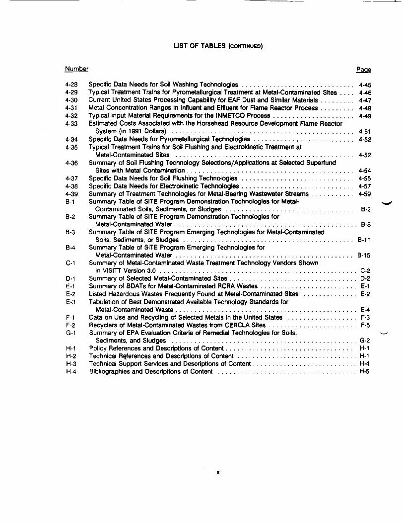
LIST OF TABLES (CONTINUED)
Number
4-28 Specific Data Needs for Soil Washing Technologies . . . . . . . . . . . . . . . . . . . . . . . . . . . . . 4-454-29 Typical Treatment Trains for Pyrometallurgical Treatment at Metal-Contaminated Sites . . . . 4-464-30 Current United States Processing Capability for EAF Dust and Similar Materials . . . . . . . . . 4-474-31 Metal Concentration Ranges in Influent and Effluent for Flame Reactor Process . . . . . . . . . 4-484-32 Typical Input Material Requirements for the INMETCO Process . . . . . . . . . . . . . . . . . . . . . 4-494-33 Estimated Costs Associated with the Horsehead Resource Development Rame Reactor
System (in 1991 Dollars) . . . . . . . . . . . . . . . . . . . . . . . . . . . . . . . . . . . . . . . . . . . . . . . 4-514-34 Specific Data Needs for Pyrometallurgical Technologies . . . . . . . . . . . . . . . . . . . . . . . . . . 4-524-35 Typical Treatment Trains for Soil Rushing and Electrokinetic Treatment at
Metal-Contaminated Sites . . . . . . . . . . . . . . . . . . . . . . . . . . . . . . . . . . . . . . . . . . . . . . 4-524-36 Summary of Soil Rushing Technology Selections/Applications at Selected Superfund
Sites with Metal Contamination . . . . . . . . . . . . . . . . . . . . . . . . . . . . . . . . . . . . . . . . . . . 4-544-37 Specific Data Needs for Soil Rushing Technologies . . . . . . . . . . . . . . . . . . . . . . . . . . . . . 4-554-38 Specific Data Needs for Electrokinetic Technologies . . . . . . . . . . . . . . . . . . . . . . . . . . . . . 4-574-39 Summary of Treatment Technologies for Metal-Bearing Wastewater Streams . . . . . . . . . . . 4-59B-1 Summary Table of SITE Program Demonstration Technologies for Metal-
Contaminated Soils, Sediments, or Sludges . . . . . . . . . . . . . . . . . . . . . . . . . . . . . . . . . B-2B-2 Summary Table of SITE Program Demonstration Technologies for
Metal-Contaminated Water . . . . . . . . . . . . . . . . . . . . . . . . . . . . . . . . . . . . . . . . . . . . . . . B-8B-3 Summary Table of SITE Program Emerging Technologies for Metal-Contaminated
Soils, Sediments, or Sludges . . . . . . . . . . . . . . . . . . . . . . . . . . . . . . . . . . . . . . . . . . . . B-11B-4 Summary Table of SITE Program Emerging Technologies for
Metal-Contaminated Water . . . . . . . . . . . . . . . . . . . . . . . . . . . . . . . . . . . . . . . . . . . . . . B-15C-1 Summary of Metal-Contaminated Waste Treatment Technology Vendors Shown
in VISITT Version 3.0 . . . . . . . . . . . . . . . . . . . . . . . . . . . . . . . . . . . . . . . . . . . . . . . . . . . C-2D-1 Summary of Selected Metal-Contaminated Sites . . . . . . . . . . . . . . . . . . . . . . . . . . . . . . . . . D-2E-1 Summary of BDATs for Metal-Contaminated RCRA Wastes . . . . . . . . . . . . . . . . . . . . . . . . . E-1E-2 Listed Hazardous Wastes Frequently Found at Metal-Contaminated Sites . . . . . . . . . . . . . . E-2E-3 Tabulation of Best Demonstrated Available Technology Standards for
Metal-Contaminated Waste . . . . . . . . . . . . . . . . . . . . . . . . . . . . . . . . . . . . . . . . . . . . . . . E-4F-1 Data on Use and Recycling of Selected Metals in the United States . . . . . . . . . . . . . . . . . . F-3F-2 Recyclers of Metal-Contaminated Wastes from CERCLA Sites . . . . . . . . . . . . . . . . . . . . . . . F-5G-1 Summary of EPA Evaluation Criteria of Remedial Technologies for Soils,
Sediments, and Sludges . . . . . . . . . . . . . . . . . . . . . . . . . . . . . . . . . . . . . . . . . . . . . . . . G-2H-1 Policy References and Descriptions of C o n t e n t . . . . . . . . . . . . . . . . . . . . . . . . . . . . . . . . . H-1H-2 Technical References and Descriptions of Content . . . . . . . . . . . . . . . . . . . . . . . . . . . . . . . H-1H-3 Technical Support Services and Descriptions of C o n t e n t . . . . . . . . . . . . . . . . . . . . . . . . . . . H-4H-4 Bibliographies and Descriptions of Content . . . . . . . . . . . . . . . . . . . . . . . . . . . . . . . . . . . . H-5

ABBREVIATIONS AND SYMBOLS
AAAERCAETSAgANCANSANSIANSI/ANS/16.1AOCAPCAPIARARsARTAsASHASTMATRATTICAVIPBACTBBSBOATBDLBESCORPBMRCSNABOMBTU, BtuCACAACALMAXCalWETCAMUCBCCBACCJCCRCdGDICEAMCECCEPCERCLACERCLIS
CFRCLP
atomic absorption spectroscopy (a microcharacterization method)Advance Environmental Recycling CorporationAcid Extraction Treatment SystemsilverAcid Neutralization Capacity (test)American Nuclear SocietyAmerican National Standards InstituteAmerican Nuclear Society test 16.1, a leaching testarea of contaminationair pollution controlAmerican Petroleum Instituteapplicable or relevant and appropriate requirementsAlternative Remedial Technologies, Inc.arsenicAir-Sparged HydrocycloneAmerican Society for Testing and MaterialsAnnotated Technical ReferenceAlternative Treatment Technology Information CenterAdvanced Vitrification/Incineration ProcessBest Available Control TechnologyBulletin Board SystemBest Demonstrated Available Technology (RCRA treatment standard)below detection limitsBrice Environmental Services CorporationBureau of Mines Research Centerbase, neutral, and acid (organic) compoundsU.S. Bureau of MinesBritish thermal unitcorrective actionClean Air ActCalifornia Materials ExchangeCalifornia Waste Extraction Test, a leaching test.Corrective Action Management Unitcement-bentoniteCoordinate, Chemical Bonding, and Adsorption (process)Campbell Centrifugal JigChromated Copper Arsenatecadmiumchronic daily intakeCenter for Exposure Assessment Modelingcation exchange capacitycatalytic extraction processComprehensive Environmental Response, Compensation, and Liability Act of 1980Comprehensive Environmental Response, Compensation, and LiabilityInformation SystemCode of Federal RegulationsContract Laboratory Procedures
XI

ABBREVIATIONS AND SYMBOLS (CONTINUED)
CLU-ln Cleanup Information (Electronic Bulletin Board)CMS Cyclone Melting SystemCNS central nervous systemCOD chemical oxygen demandCOE U.S. Army Corps of EngineersCORA Cost of Remedial Action (software package)CPS cancer potency slopeCr chromiumCr(VI) hexavalent chromiumCRN Core Research Needs for Containment SystemsCRV Counter Rotating Vortex combustorCSH Calcium Silicate HydrateCWA Clean Water ActDLT Dynamic Leach TestDOE U.S. Department of EnergyDQO Data Quality ObjectiveDRE destruction-removal efficiencyDTPA diethylenetriaminepentaacetic acidEAF electric arc furnaceEDTA ethylenediaminetetraacetic acidEDXA energy dispersive X-ray analysis, a microcharacterization method.EE/CA Economic Evaluation/Cost AnalysisEh oxidation reduction potentialELT Equilibrium Leach TestERA U.S. Environmental Protection AgencyEP Tox Extraction Procedure Toxicity TestESD electro-acoustic soil decontaminationPDA Food and Drug AdministrationFGD flue gas desulfurizationFR Federal RegisterFS Feasibility StudyFTIR Fourier transform infrared spectroscopyFY fiscal yearGC/MS gas chromatography/mass spectrometryGl gastrointestinalGW groundwaterHCB hexachlorobenzeneHELP Hydrologic Evaluation of Landfill PerformanceHg mercuryHI ~ hazard indexHQ hazard quotientHRD Horsehead Resource Development CompanyHRS Hazard Ranking SystemHSL Hazardous Substance ListHSWA Hazardous and Solid Waste Amendments of 1984HTMR high-temperature metal(s) recoveryHWSDC Hazardous Waste Superfund Data CollectionICP inductively coupled plasma atomic emission spectroscopy.ID IdentificationIGWMC International Ground Water Modeling Center
XII

ABBREVIATIONS AND SYMBOLS (CONTINUED)
INEL Idaho National Engineering LaboratoryINMETCO International Metals Reclamation CorporationIRIS Integrated Risk Information SystemIRM iron-rich materialISV in situ vitrificationIWT International Waste TechnologieskWh kilowatt hoursLAER Lowest Achievable Emission RateLDR Land Disposal RestrictionLIMB Lime Injection Multistage BurnerLRT Liquid Release TestMb molybdenumMCL maximum contaminant level; maximum concentration limitMCLG maximum contaminant limit goalMEP Multiple Extraction Proceduremeq milliequivalentMIBC methyl isobutyl carbinol (a synthetic frother)/jm micrometer(s)mm millimeter(s)mV millivolt(s)MSDS Material Safety Data SheetMSW municipal solid wasteMTRs minimum technology requirementsMWEP Monofilled Waste Extraction ProcedureNAAQS National Ambient Air Quality StandardsNAPL nonaqueous-phase liquidNCC National Computer CenterNCEL Naval Civil Engineering LaboratoryNCP National Oil and Hazardous Substances Contingency PlanNEESA Naval Energy and Environmental Support ActivityNESHAP National Emissions Standard for Hazardous Air PollutantsNIOSH National Institute for Occupational Safety and HealthNJDEP New Jersey Department of Environmental ProtectionNMR nuclear magnetic resonance spectroscopyNPDES National Pollutant Discharge Elimination SystemNPL National Priorities ListNRC National Research Council; U.S. Nuclear Regulatory CommissionNSPS New Source Performance StandardsNSR - National Smelting and Refining CompanyNYSC-HWM New York State Center for Hazardous Waste ManagementOAQPS Office of Air Quality Planning and Standards (of the U.S. EPA)O&M operations and maintenance (costs)OERR Office of Emergency and Remedial ResponseOLS Online Library System (of EPA)OR&N oxidation, reduction, and neutralizationOSHA Occupational Safety and Health Act; Occupational Safety and Health AdministrationOSW Office of Solid WasteOSWER Office of Solid Waste and Emergency ResponseOTS Office of Toxicologlcal SubstancesOU Operable Unit
xiil

ABBREVIATIONS AND SYMBOLS (CONTINUED)
PAH polycyclic aromatic hydrocarbonPb leadPCS polychlorinated biphenylPFT Paint Filter TestpH negative logarithm of hydrogen ion concentrationPIES Pollution Prevention Information Exchange SystemPOTW publicly-owned treatment worksppb part(s) per billionppm part(s) per millionPRP potentially responsible partyPSD Prevention of Significant DeteriorationQA/QC Quality Assurance/Quality ControlQAPP Quality Assurance Project Plan3Rs recovery, reuse, and recycleRAAS Remedial Action Assessment SystemRCRA Resource Conservation and Recovery Act of 1976RCRIS Resource Conservation and Recovery Information SystemRD/RA Remedial Design/Remedial ActionRfD reference doseRFI RCRA Facility InvestigationRl Remedial InvestigationRI/FS Remedial Investigation/Feasibility StudyRM Remediation ManagerRMERC BOAT technology code for retorting or roasting mercury for eventual recoveryROD Record of DecisionRP Responsible PartyRPM Remedial Project ManagerRREL Risk Reduction Engineering Laboratory (of the U.S. EPA)SACM Superfund Accelerated Cleanup ModelSARA Superfund Amendments and Reauthorization Act of 1986SB soil-bentoniteSCE sequential chemical extractionSDWA Safe Drinking Water ActSe seleniumSEM scanning electron microscopySET Sequential Extraction TestSITE Superfund Innovative Technology Evaluation ProgramSRS Separation and Recovery Systems, Inc.SRT Subsyrface Remediation Technology DatabaseS/S - solidification/stabilizationSTLC Soluble Threshold Limit ConcentrationSW surface waterTCE trichloroethyleneTCLP Toxicity Characteristic Leaching ProcedureTDS total dissolved solidsTIO Technology Innovation Office (U.S. EPA)TM TerraMetTOC total organic carbonTPH, tph ton(s) per hourTPY, tpy ton(s) per year
xiv

ABBREVIATIONS AND SYMBOLS (CONTINUED)
TRD Technical Resources DocumentTSCA Toxic Substances Control ActTSD treatment, storage, and disposal facility (RCRA)TTLC Total Threshold Limit ConcentrationTWA Total Waste AnalysisUBK uptake biokineticDCS unconfined compressive strengthUSAGE U.S. Army Corps of EngineersUSATHMA U.S. Army Toxic and Hazardous Materials AgencyU.S. DOE United States Department of EnergyU.S. DOT United States Department of TransportationU.S. ERA United States Environmental Protection AgencyUST underground storage tankVISITT Vendor Information System for Innovative Treatment TechnologiesVOC volatile organic compoundVORCE Volume Reduction/Chemical ExtractionWET see Cal WET, a leaching test
xv

ACKNOWLEDGMENTS
This report is a product of the U.S. Environmental Protection Agency (EPA) Office of Research andDevelopment. The text was prepared by Battelle under EPA Contract 68-CO-0003. Work Assignment 41.The final drafts were prepared by Foster Wheeler under EPA Contract 68-C9-0033 and Science ApplicationsInternational Corporation under EPA Contract No. 68-CO-0048. The EPA Work Assignment Manager wasMichael Royer of the EPA Risk Reduction Engineering Laboratory, Technical Support Branch. Jeffrey Meansserved as the Battelle Project Leader, and Lawrence Smith as the primary author. Professor Hsin-HsiungHuang of Montana College of Mineral Science and Technology in Butte, Montana, prepared the stabilityregion diagrams shown in Appendix A.
Other Battelle authors who contributed major portions of this report were Abraham Chen. ArunGavaskar, Bruce Alleman, Susan Brauning, and Bruce Sass. Erin Sherer, Wendy Huang, Daniel Giammar,and Christopher Voight provided valuable assistance. Christopher Chapman, John Ttxier, and Eric Crecetlusof Battelle's Pacific Northwest Laboratories, Richard Osantowskl of Radian Corporation, and Paul Oueneauof Hazen Research also wrote portions of this document.
This document benefited from discussions with and/or information provided by the followingindividuals:
Gary Adamkiewicz, EPA Region IIHarry Alien, EPA ERTDouglas Ammon, dean Sites, Inc.John Barich, EPA Region XEdwin Barth, EPA CERIGiezelle Bennett, EPA Region IVBert Bledsoe, EPA RSKERLMagalie Breville, EPA Region IIDavid Brown, EPA ERL-AthensJohn Burckle, EPA RRELHarry Compton, EPA ERTChristopher Corbett. EPA Region IIIJim Cummings, EPA TIOAnita Cummings, EPA OSWSteven Donohue, EPA Region IIIHugh Durham, EPA RRELPatricia Erickson, EPA RRELGordon Evans, EPA RRELLinda Fiedler, EPA TIORussell Fish, EPA Region IIIFrank Freestone, EPA RRELJohn Fringer, NEESAShawn Ghose, EPA Region VIKatherine Green, EPA ORD Env. Res. Lab.Joseph Greenblott, EPA Region IXRichard Griffiths, EPA RRELDouglas Grosse, EPA RREL
Patrick Haas, U.S. Air Force Center forEnvironmental Excellence
Gregory Ham, EPA Region IIIJeffery Heath, Naval Facilities Engineering
Services CenterJonathan Herrmann, EPA RRELAnthony Holoska. EPA Region VJ. Lary Jack, EPA EMSL-LVDavid Wauder, EPA OSPRE, ROSRobert Kodis, Mine Waste Pilot ProgramRichard Koustas, EPA RRELNorman Kulujian, EPA Region IIICaroline Kwan, EPA Region IIJose Labiosa, EPA OSWRobert Landreth, EPA RRELMike Magyar, U.S. Bureau of MinesShahid Mahmud, EPA OERRMcKenzie Mallary, EPA Region IVSteve Mangion, EPA Region VJohn Matthews, EPA RSKERLShaun McGarvey, EPA OSWGreg Mickey, EPA Region VFred Micku, EPA Region VRoss Miller, Air Force Center
for Environmental ExcellenceRobert Moumighan, EPA Region VIIDonald Oberacker, EPA RREL
xvi

Asim Ray, Foster Wheeler EnvironmentalServices, Inc. '
Robert Robins, Montana College of MineralScience and Technology (visitingprofessor)
Larry Rosengrant, EPA OSWSeymour'Rosenthal, Foster Wheeler
Environmental Services, Inc.David Rosoff, EPA Region IITamara Rossi, EPA Region IIAri Selvakumar, Foster Wheeler
Environmental Services, Inc.Don Sternitzke, Dynamac Corporation
Mary Stinson, EPA RRELJames Stumbar, Foster Wheeler
Environmental Services, Inc.Ronald Turner, EPA RRELJ. Jeffrey van Ee, EPA EMSL-LVJeffrey Walker, DOEAnne Wethington, U.S. Bureau of MinesChuck Wilk, EPA Region VKenneth Wilkowski, EPA RRELDavid Wilson, EPA Region VGeorge Wolf, Foster Wheeler
Environmental Services, Inc.Andre Zownir, EPA ERT
The authors express their appreciation to Lynn Copley-Graves and Carol Young for editing and toLoretta Bahn and Bonnie Snodgrass for text processing.
xvii

SECTION 1
INTRODUCTION
1.1 PURPOSE
This reference document is intended to assist site remediation managers (RMs) to select treatmenttechnologies for contaminated soils, sludges, sediments, and waste deposits at sites where inorganic arsenic(As)1, cadmium (Cd), chromium (Cr), mercury (Hg), or lead (Pb) are the primary contaminants of concern.These five metals have been addressed because of their toxicity, industrial use, and frequency of occurrenceat Comprehensive Environmental Response, Compensation, and Liability Act (CERCLA) sites and inResource Conservation and Recovery Act (RCRA) hazardous wastes. This document should prove usefulto all remediation managers, whether their efforts fall under Federal, State, or private authorities, and whetherthey are applying standards from RCRA, CERCLA, and/or State programs.
1.2 SCOPE AND LIMITATIONS
This project represents a best effort (subject to the key limitations noted below), to identify, collect,analyze, organize, and consolidate information, data, and pertinent references that a remediation managerwould find useful for identifying and selecting remedial alternatives for soils, sediments, sludges, and wastedeposits in which the principal contaminants are As, Cd, Cr, Hg, or Pb and selected inorganic compoundsof these metals.
It is assumed that the RMs are familiar with appropriate policy issues (RCRA, CERCLA, and state),site characterization, sampling methods, analytical methods, risk assessment, determination of cleanuplevels, and health and safety plans. Familiarity is assumed, as appropriate, with the references listed inAppendix H.
It is also assumed that the RMs or available support staff are familiar with widely available references(e.g., CRC Handbook of Chemistry and Physics; Merck Index) from which physical and chemical data forthe five metals of interest and their compounds can be obtained.
While this technical resource document consolidates information from the past in an attempt toaccelerate and improve decisions in the future, it is recognized that site-specific factors ultimately drive theselection of the remedial alternative for any particular site. The remedial action objectives should be clearlyestablished and cleanup levels designated. It is of particular importance to develop reasonable estimatesof the volume, distribution, and physical and chemical composition of each significant contaminant/co-contaminant/medium combination at the site that will require remediation. It is similarly important toclearly define the parameters (e.g., total metal(s) concentration, leachable metals, filtered/unfiltered aqueousmetal concentrations), test methods (e.g., Toxicity Characteristic Leaching Procedure or TCLP, ExtractionProcedure Toxicity Test or EP Tox, other leaching tests, total waste analysis), and numerical goals that willbe employed to measure treatment effectiveness. A risk assessment should consider transport and fate ofcontaminants using the best methods available including equilibrium and/or transport models whereapplicable.
For convenience this document will refer to the metalloid, arsenic, as a metal.
1-1

An emphasis was placed on keeping the document relatively brief. Therefore, technologydescriptions are presented as brief summaries. Compact data tabulations are used where possible.
Containment and water treatment technologies are primarily addressed by reference, since they arewell-described and evaluated in recent, available documents, which are referenced in Section 4.
This technical resource document does not apply to sites where the no action or interim remediesare appropriate. The user should refer to Guide to Developing Superfund No-Action, Interim Action, andContingency Remedy RODs (U.S. ERA, 1991, 9355.3-02FS-3) for more information on these remedies.
To avoid redundancy with existing or forthcoming documents, information collection and coverageof the four specific types of metal-contaminated sites listed below were intentionally limited to cases whereinnovative technologies have been selected or applied:
• Lead battery recycling sites (EPA/540/2-91/014, Selection of Control Technologies forRemediation of Lead Battery Recycling Sites)
• Wood preserving sites (As, Cr) - (EPA/600/R-92/182, Contaminants and Remedial Optionsat Wood Preserving Sites)
• Pesticide sites (As, Hg) - (Contaminants and Remedial Options at Pesticide Sites, inpreparation for U.S. EPA)
• Mining sites (the U.S. EPA Mine Waste Pilot Project, National Superfund Mine Waste AdvisoryGroup, and U.S. Department of Energy (DOE) Resource Recovery Project, various reports)
In the interests of simplicity, brevity, and limited project resources, this technical reference documentdoes not attempt to systematically address remediation of:
• organometallic compounds• organic-metal mixtures• multimetal mixtures
For example, while incineration is noted as a potential pretreatment for an organic-metal mixture, the effectsof As, Cd, Cr, Hg, or Pb on the technical and economic feasibility of incineration are not discussed. Anotherexample is that several RCRA Best Demonstrated Available Technologies (BDATs) are cited for multimetalwastes, but there is no discussion on how, in general, to select a remedial technology for a multimetalwaste.
No claims are made that this document is completely comprehensive in identifying, collecting,analyzing, or listing all pertinent information or data on remediation of metal-contaminated sites. The typesof information collected to support preparation of this document include the following.
• Background information on As, Cd, Cr, Hg, Pb, and associated inorganic compoundsregarding mineral origins, processing, uses, common matrices, chemical forms, behavior,transport, fate, and effects.
• Existing remediation performance data, listed in rough order of desirability: (a) full-scaleremediation of As-, Cd-, Cr-, Hg-, and Pb-contaminated sites; (b) technology demonstrationson As-, Cd-, Cr-, Hg-, or Pb-contaminated sites under the EPA Superfund InnovativeTechnology Evaluation Program (SITE); (c) RCRA As-, Cd-, Cr-, Hg-, and Pb-bearinghazardous wastes for which BDATs have been established; (d) waste applicability/capacityinformation for treatment technologies as described in technology guides and the EPA Vendor
1-2

Inventory of Superfund Innovative Treatment Technologies (VISITT) database; (e) feedstockspecification information for primary or secondary smelting or recycle/re-use markets; (f)Records of Decision (RODs) and corresponding summaries for As-, Cd-, Cr-, Hg-, andPb-contaminated sites; (g) Treatability test data on As-, Cd-, Cr-, Hg-, and Pb-contaminatedmatrices where the results are well-documented and in an accessible form (e.g., AlternativeTreatment Technology Information Center [ATTIC] and the Risk Reduction EngineeringLaborat9ry (RREL), treatability database; (h) Superfund National Priority List (NPL) sites whereAs-, Cd-, Cr-, Hg-, or Pb-contaminated media are a primary concern and remedial options areor will be under evaluation.
1.3 ORGANIZATION
Remedial Options and the appendices cited therein form the heart of this reference document. Thissection begins with a general discussion of the key applicable or relevant and appropriate regulations thatinfluence cleanup goals. Soil and groundwater action levels and risk goals are tabulated for 24metal-contaminated sites. TCLP limits for metals in selected metal-bearing RCRA characteristic hazardouswastes are also tabulated.
Most of Section 4 addresses the immobilization, and separation/concentration technologies that arepotentially applicable for remediating metal-contaminated solids, with the main emphasis on soils. Eachtechnology is addressed in a similar manner.
• A technology description is provided, then a discussion of typical treatment trains; next adiscussion of the applicability of the technology to various wastes, with specific reference tothe five metals of interest when applicable information is available.
• The status (e.g., bench-, pilot-, full-scale; applications to Superfund remediation) andperformance of the technologies are also discussed and, if sufficient examples exist, tabulated.
• Cost factors and costs are also discussed with cost estimates often being drawn fromapplicable SITE program Applications Analysis Reports.
• Finally, data needs for assessing the applicability of each type of technology are tabulated.
The subsection on immobilization addresses solidification/stabilization (S/S) (cement-based andpolymer microencapsulation) and vitrification (in situ and ex situ) technologies. Containment technologies(capping and vertical and horizontal barriers) are noted, but only addressed by reference since: (1) the typeof metal contaminant is not a strong influence on containment system selection, and (2) there is a recent,readily available EPA document, U.S. EPA Handbook: Stabilization Technologies for RCRA CorrectiveActions (EPA 625/6-91/026), that already addresses the topic at the desired level.
Separation/concentration technologies are subdivided into two categories:
• Technologies applicable for excavated solids:
Physical separation technologies [i.e., screening, classification, gravity separation,magnetic separation, and flotation]
Soil washing technologies [i.e., extraction via water, solvents, or solutions containingsurfactants, chelating agents, acids, or bases]
1-3

— Pyrometallurgical separation technologies (i.e., Waelz kiln, flame reactor, molten metalbath, secondary lead smelting via reverberatory and blast furnaces, submerged arcfurnace, and mercury roasting and retorting)
Technologies applied in situ (i.e., soil flushing and electrokinetics).
Water treatment options are very briefly discussed, and a summary table is provided. As withcontainment options, limited coverage is provided due to the availability of other recent, available ERAdocuments that address the topic in a suitable manner.
Table 1-1 is a general summary of the technology types which are applicable for remediation ofmetal-contaminated sites.
TABLE 1-1. REMEDIAL TECHNOLOGIES APPLICABLE TO METAL-CONTAMINATED SITES
No ActionExcavation and Off-Site DisposalContainment
CappingVertical BarriersHorizontal Barriers
Solidification/Stabilization (in situ or ex situ)Cement-Based StabilizationPolymer Microencapsulation
Vitrification (in situ or ex situ)Chemical Treatment Technologies (only addressed as a pretreatment)
OxidationReductionNeutralization
Separation/Concentration Treatment Technologies (ex situ)Physical Separation/Concentration Treatment Technologies
ScreeningGravity SeparationFloatation
Pyrometallurgical SeparationSoil Washing
Separation/Concentration Treatment Technologies (in situ)Soil FlushingElectrokinetic Treatment
Section 4, Remedial Options, is complemented by a number of key appendices, including thefollowing.
• Appendix A presents several stability region diagrams which illustrates the effects of oxidizingpotential and pH on the stability of metal compounds.
Appendix B summarizes 67 technologies applicable to metal-contaminated media that areundergoing evaluation in the SITE Program.
1-4

• Appendix C summarizes 39 innovative metal-contaminated technologies from 9 technologycategories. This information was excerpted from EPA's VISIT! database version 3.0.
• Appendix D lists and briefly describes more than 40 selected metal-contaminated NPL sites.
• Appendix E summarizes BOAT for 60 RCRA hazardous wastes that contain As, Cd, Cr, Hg,and Pb.
• Appendix F supplements the separation/concentration technology portions of Section 4 byproviding a review of metal recycling options for metal-contaminated wastes from CERCLAsites. The appendix includes a matrix that matches 37 specific recyclers to 11 lead-bearingmaterials, 5 mercury-bearing materials, and 16 RCRA metal-bearing hazardous wastes. A listof waste exchanges is also provided.
• Appendix G summarizes the technology types addressed in the document versus 7 of the EPAevaluation criteria employed during selection of Superfund remedial alternatives.
• Appendix H provides a list of key documents, databases, experts, and sources of technicalsupport relevant to remediation of As-, Cd-, Cr-, Hg-, and Pb-contaminated sites.
• Appendix I supplements the cost estimation discussions in Section 4 by providing adescription and example applications of EPA's Cost of Remedial Actions (CORA) model.CORA contains cost modules for a variety of remedial options including caps, slurry walls,surface water diversion, soil excavation, sediment excavation and dredging, pumping, soilflushing, ion exchange, off-site RCRA treatment, solidification, offsite RCRA landfill, dischargeto publicly-owned treatment works (POTW), and offsite transportation.
• Appendix J summarizes general information on the identification and determination of potentialapplicable or relevant and appropriate requirements (ARARs) for remedial actions at Superfundmetal-contaminated sites.
• Appendix K is a glossary.
Section 2 briefly identifies typical mineral origins, industrial uses, and Superfund matrices ofinorganic As, Cd, Cr, Hg, and Pb.
Section 3 addresses possible chemical forms for the five metals under various conditions. It is notedin Section 3 that solubility diagrams and Eh-pH diagrams provide useful summaries of aqueous solutionchemistry (e.g., oxidation/ reduction reactions, stability of mobile phases, and hydrolysis of different metals).Sample stability diagrams appear in Appendix A and some applicable computer models are also cited.
Also described in Section 3 are typical environmental transport, partitioning, and transformationphenomena for the five metals in air, soil and sediment, and surface water and groundwater. Factorsinfluencing transport, partitioning, and transformation that are discussed individually or in combinationinclude: airborne transport and subsequent deposition of particulates; interaction of selected stack emissionswith natural and anthropogenic compounds prior to deposition in soil; formation of selected volatilecompounds; effects of pH, oxidation reduction potential, and valence on aqueous solubility; precipitation;adsorption; ion exchange; complexation with insoluble or soluble soil organic matter; bioconcentration;biomagnification; and biotransformation. Reaction kinetics are discussed semiquantitatively for severalcases. Qualitative relative mobility rankings are provided from experimental data for As, Cd, Cr, Pb, and Hgin 11 soil types under anaerobic conditions.
1-5

Section 3 also includes a brief overview of the human and environmental toxicity of the five metalsand some of their compounds. The topics addressed include: target organs, exposure pathways, ecologicaleffects, reference doses, cancer potency slopes, EPA drinking water limits, OSHA work place air limits, anda very brief discussion of the Uptake Biokinetic model for estimating blood lead levels based on various leadsources. Key references and sources for additional details or information updates are provided.
1.4 REFERENCES
1. Guide to Developing Superfund No Action, Interim Action, and Contingency Remedy ROOs.9355.3-02FS-3, U.S. Environmental Protection Agency, Office of Solid Waste and EmergencyResponse, April 1991.
2. U.S. EPA Handbook: Stabilization Technologies for RCRA Corrective Actions. EPA/625/6-91/026, U.S. Environmental Protection Agency, Officer of Research and Development,Cincinnati, Ohio, August 1991.
3. U.S. EPA. ROD Annual Report Volumes 1 and 2. Publication 9355.6-05. PB92-963359. April1992.
4. Contaminants and Remedial Options at Wood Preserving Sites. EPA/600/R-92/182, U.S.Environmental Protection Agency, Office of Research and Development, Cincinnati, Ohio,1992.
5. Selection of Control Technologies for Remediation of Lead Battery Recycling Sites.EPA/540/2-91/014, U.S. Environmental Protection Agency, Office of Research andDevelopment, Washington, DC, 1991.
6. Guidance for Conducting Remedial Investigations and Feasibility Studies Under CERCLA,Interim Final. EPA/540/G-89/004, OSWER Directive 9355.3-01, U.S. Environmental ProtectionAgency, Office of Solid Waste and Emergency Response, Washington, DC, 1988.
1-6

SECTION 2
ORIGINS, USES, AND MATRICES OF SELECTED CONTAMINANTS ATMETAL-CONTAMINATED SITES
This section describes process sources for contaminants, historical trends, and possible chemicaland physical conditions for contaminants and waste forms at metal-contaminated sites. This description oftypical site and contaminant conditions gives the remedial project manager (RPM) a general framework ofunderstanding for the types of materials requiring treatment at metal-contaminated sites. Due to the diversityof such sites, the information is presented as general surveys indicating the range of conditions that maybe encountered.
2.1 ORIGIN AND MAJOR INDUSTRIAL USES OF ARSENIC, CADMIUM, CHROMIUM,LEAD, AND MERCURY
This section outlines the principal industrial applications of the metals discussed in this document.The brief outline for each metal discusses the main industrial uses and the chemical forms that are mostlikely to be encountered at a particular industrial site. More detail on metal processing and use can befound in standard references such as the Klrk-Othmer Encyclopedia of Chemical Technology (Kroschwitzand Howe-Grant, 1991), Metal Statistics (Espinosa, 1993), various U.S. Bureau of Mines (BOM) publications,and the BOM online database (see Appendix H, Subsection H.3.11).
2.1.1 Arsenic
Arsenic (chemical symbol As) is a semi-metallic element or metalloid. For convenience, this reportwill refer to arsenic as a metal. Arsenic has several allotropic forms. The most stable allotrope is asilver-gray, brittle, crystalline solid that tarnishes in air. Arsenic compounds, mainly As203, can be recoveredas a by-product of processing complex ores mined mainly for copper, lead, zinc, gold, and silver. Arsenicoccurs in a wide variety of mineral forms. Worldwide the main commercial ore is arsenopyrite (FeAsS4), butmuch of the former U.S. production involved copper/arsenic ores such as enargite (Cu3AsS4) and tennantite((Cu,Fe)12As4S13). Because arsenic is a by-product, its supply depends primarily on the demand for themain metals in the ores. Arsenic use in 1992 was 23,900 metric tons, of which 67% was for production ofthe wood-treatment chemical chromated copper arsenate (CCA). Agricultural use was 23% of the total in1992, but will be declining due to cancellation of approval for use of arsenic chemicals as cotton leafdeslccants (58 FR 26975). All arsenic consumed In the United States in 1991 was derived from importedsources. Arsenic is regarded as a zero-value impurity by most U.S. mine and smelter operators. As a result,operators are likely to avoid ores containing arsenic when possible (Loebenstein, 1992).
2.1.2 Cadmium
Cadmium (chemical symbol Cd) is a bluish-white, soft, ductile metal. Pure cadmium compoundsrarely are found in nature, although occurrences of greenockite (CdS) and otavite (CdC03) are known. Themain sources of cadmium are sulfide ores of lead, zinc, and copper. Cadmium is recovered as a by-productwhen these ores are processed. Because cadmium is produced as a by-product of sulfide ore refining, itsproduction rate is more closely coupled to zinc demand than to cadmium demand. Cadmium use variedfrom 3,107 to 4,096 metric tons between 1988 and 1992. The peak use was 4,096 metric tons in 1989. Theestimated apparent consumption in 1992 was 3,400 metric tons. About half of the cadmium used goes forproduction of nickel-cadmium batteries. Other uses include plating, pigments, plastics, and alloys (U.S.Bureau of Mines, 1993).
2-1

2.1.3 Chromium
Chromium (chemical symbol Cr), a lustrous, silver-gray metal, is one of the less common elementsIn the earth's crust and occurs only in compounds. The chief commercial source of chrome is the mineralchromite (FeCr204). Chromium is mined as a primary product and is not recovered as a by-product of anyother mining operation. There are no chromite ore reserves, nor is there primary production of chromitein the United States.
Total apparent chromium consumption ranged from 366,000 to 537,000 metric tons of containedchromium between 1988 and 1992. Peak consumption of 537,000 metric tons occurred in 1988. Theestimated consumption for 1992 was 435,000 metric tons of contained chromium. The consumption figuresinclude primary production and secondary sources from recycling. Chromium contained in purchasedstainless steel is estimated to account for about 26% of the consumption of recycled chromium in 1992 (U.S.Bureau of Mines, 1991).
2.1.4 Lead
Lead (chemical symbol Pb) is a bluish-white, silvery or gray metal that is highly lustrous when freshlycut, but tarnishes when exposed to air. It is very soft and malleable, has a high density (11.35 g cm'3) andlow melting point (327.4°C), and can be cast, rolled, and extruded. The estimated consumption of lead in1992 was 1,220,000 metric tons. Of this amount, 80% was used in lead-acid batteries. About 760,000 metrictons of lead was recovered from scrap batteries in 1992.
2.1.5 Mercury
Mercury (chemical symbol Hg) is a silvery liquid metal. The primary source of mercury is the sulfideore, cinnabar (HgS). In a few cases, mercury occurs as the principal ore product. Mercury is morecommonly obtained as the by-product of processing complex ores that contain mixed sulfides, oxides, andchloride minerals, which are usually associated with base and precious metals, particularly gold. Native ormetallic mercury Is found in very small quantities in some ore sites.
Mercury for United States use came from domestic mines, sales of surplus from government stocks,imports, and waste recovery. Mercury was produced as the main product of the McDermitt Mine and asa by-product of nine gold mines in Nevada, California, and Utah (U.S. Bureau of Mines, 1993). TheMcDermitt Mine is now closed. Market expectations indicate a continuing decline in mercury use andincreased reliance on recycled mercury (Espinosa, 1993).
The total use of mercury in 1992 was 621 metric tons. The main users were mercury-cell chloralkaliplants. The use of mercury is expected to decline and the supply of recycled mercury is expected toincrease. Smaller amounts of mercury are produced when secondary sources are reprocessed. In 1992,commercial secondary mercury reprocessors produced 176 metric tons of mercury (U.S. Bureau of Mines,1993). Common secondary mercury sources are spent batteries, mercury vapor and fluorescent lamps,switches, dental amalgams, measuring devices, control instruments, and laboratory and electrolytic refiningwastes. The secondary processors typically use retorting to recover mercury from compounds anddistillation to purify contaminated liquid mercury metal.
2.2 OVERVIEW OF SOURCES OF CONTAMINANTS AT METAL-CONTAMINATED SITES
Wastes at CERCLA sites are frequently heterogeneous on a macro and micro scale. Thecontaminant concentration and the physical and chemical form of the contaminant and matrix usually arecomplex and variable. Waste disposal sites collect a diverse variety of waste types causing concentrationprofiles to vary by orders of magnitude through a pit or pile. Limited volumes of high-concentration "hotspots" may develop due to variations in the historical waste disposal patterns or local transport mechanisms.
2-2

Similar radical variations frequently occur on the particle-size scale as well. The waste often consists of aphysical mixture of very different solids, for example, paint chips in spent abrasive. These variations incontaminant concentration and matrix type require that the design of sampling for analysis and treatabilitystudies be done with caution. Due to the importance of matrix effects, treatability studies should beperformed on actual site material rather than on synthetic materials whenever possible.
2.2.1 Stack Emissions
Stack emissions are point source emissions from stacks, vents, ducts, pipes, or other confined air,gas, or vapor streams. Air releases from pollution control equipment typically are considered stackemissions. Metal contaminants will be present in gas streams as fine particulates. Solids with small particlesize may be entrained in a gas stream during material handling, mixing, or size reduction. In high-temperature processing, some metals (particularly arsenic, cadmium, lead, and mercury) can volatilize.Unless a reducing atmosphere is maintained, the metal will quickly convert to an oxide and condense asa very fine paniculate typically called a "fume" or a "condensed fume."
Offgas treatment may be applied to collect the metal-bearing particulates. Depending on theprocess and application, either a wet scrubbing system or a dry filtration system may be used to collect theparticulates. Wet scrubbing produces a sludge waste, whereas filtration results in dry powder. These solidwaste material types are discussed below.
At many older plants, offgas particulate removal systems did not work well or were not used. Evenif offgas treatment systems are used, particulate removal is never complete. Particulates escaping a plant'spoint source emission release locations will be distributed by natural air currents until they settle out dueto gravity. In many cases tall stacks are used to obtain dilution. Airflow then distributes the metalcontaminants over a wide area.
The resulting contaminant deposition will distribute contaminants generally downwind from the plant.The pattern of contaminant deposition will depend on many site-specific factors such as offgas flow andcomposition, wind direction and speed, and duration of operation. The concentration of metals in the offgastypically is low, but in some cases plant operation over many years allows a buildup of measurablecontaminant levels. For example, one operable unit of the Superfund site at Palmerton, Pennsylvania, is amountainside contaminated with oxides of cadmium, lead, and zinc due to operation of a smelter.
2.2.2 Fugitive Emissions
Fugitive emissions are air emissions not covered by the point source stack emissions describedabove. Some examples of fugitive emissions include:
• Dust from loading, unloading, and equipment operation• Airborne losses due to spills• Dust carried by wind from material storage areas or waste piles• Releases from general building ventilation
As with the stack emissions, the metal contaminants typically leave the source as solid particulatesor very quickly convert to particulate form.
In general, the contaminant concentration in the fugitive emission sources will be lower than in thestack emissions, but the emissions will occur near the ground. As a result, the distribution area usually willbe smaller. As with stack emissions, the actual concentrations encountered depend on site-specificconditions.
2-3

2.2.3 Process Solid-Phase Waste Materials
Industrial processes may result in a variety of solid metal-bearing waste materials, including slags,fumes, mold sand, fly ash, abrasive wastes, spent catalysts, spent activated carbon, and refractory bricks(Zimmerman and Coles, 1992). These process solids may be deposited above ground as waste piles orbelow ground in landfills. Solid-phase wastes can be dispersed by well-intended but poorly controlled reuseprojects. For example, many slags can serve as good quality materials for construction applications suchas road subgrade, fill material, or daily landfill cover. However, slags containing teachable levels ofcadmium, lead, or other metals have been used for construction fill and have created problems. Similarly,metal-contaminated sludge has been spread as fertilizer (50 FR 658, January 4, 1985).
2.2.3.1 Waste Piles
Large volumes of dry solid-waste materials frequently are accumulated in waste piles. Because thewaste piles are exposed to weathering, they can be sources of contamination to the surrounding soil orgroundwater. In addition, waste piles can be exposed to natural disasters or accidents causing furtherdispersion. For example, a fire at a material pile belonging to Frit Industries in Walnut Ridge, Arkansas,resulted in contamination to soil and water by runoff of water used to fight the fire (50 FR 658, January 4,1985).
Slags-
Slag is a fused solid consisting mainly of inorganic oxides of silicon, iron, and calcium with metallicimpurities. Slag is a typical waste product from pyrometallurgical metal processing. The slag compositiondepends on the feed material source and the process used. Slags generally contain silica (SiO2) as themain constituent along with fluxing salts (e.g., calcium and magnesium) and metals from the ore.
Density, porosity, and leach resistance are the main properties considered in evaluating slag as acontaminated matrix. These properties vary depending on the method of producing the slag. The form ofslag produced depends on the conditions used for cooling. Testing has indicated that faster slag coolingis important to maximize formation of vitreous materials which reduces the mobility of metals.
Other Metal-Bearing Wastes--
Other metal-bearing wastes include fumes, foundry sand, fly ash, abrasives, catalysts, spentactivated carbon, refractory bricks, etc. Fumes are very fine particulates produced during high-temperaturemetal processing. Volatile metals or metal oxides evaporate and recondense to form the fume. Onecommon example is condensed silica fume, a fine paniculate consisting of over 90% silica. Condensedsilica fume is a by-product of ferroalloy production. Metal impurities may impart a hazardous wastecharacteristic. The fume is an artificial pozzolan with a very high activity due to its small particle size andamorphous structure. Volatile metals such as cadmium and zinc also are prone to fume formation. Thefine-particle fumes are difficult to transfer by conventional materials-handling techniques due to moistureabsorption and poor flow properties (Popovic et al., 1991).
Foundries use sand to make molds and cores to contain and shape metal during casting. The sandgrains are held together with additives called "binders." Mold-making techniques may use sand mixed witha small amount of clay and water or more complex binder systems such as silicates or organic resins suchas phenolic-urethane polymers.
Fly ash is fine paniculate carried in the offgas exiting processes such as smelting or coalcombustion. Fly ash particles form in a high-temperature gas stream. At the typical combustion orprocessing temperature of about 1600°C (2900 °F), the ash material is a molten sphere. As the particlescool and solidify, they retain a generally spherical shape. The particulate is collected by baghouses,
2-4

electrostatic precipitators, or similar offgas cleaning equipment. The paniculate is mainly glassy, sphericalsilicate and aluminate material with particle sizes in the range of 1 to 150 micrometers (/mi) (Gera et al.,1991). The fine paniculate may be removed from the offgas cleaning equipment as either a dry powder ora water slurry and then be sent to a storage pile for subsequent disposal or recycling.
Abrasives are powdered, granular, or solid materials used to grind, smooth, cut, or polish othersubstances. The abrasive wears down the surface of materials to alter their shape or give the desired finish.Sand, ground quartz, pumice, and corundum are commonly used natural abrasives. Synthetic abrasivessuch as Carborundum™ (silicon carbide, SiC) and alumina (aluminum oxide, AI2O3) are prepared for specialapplications. Abrasives can become contaminated with metals during use. For example, chips from a paintwith lead or chromate pigments may cause the spent abrasive to have a hazardous waste characteristic.
Catalysts for industrial process use typically are a ceramic support carrying a small quantity of metalcatalyst such as a chromium, nickel, or platinum group metal. The supporting ceramic usually is a sphereof controlled particle size consisting mainly of alumina (AI203) and silica (SiO2). In use, the catalyst becomesfouled with reactants or reaction products. Catalyst activity often can be recouped by thermal regeneration,but some of the particles break during the regeneration process. Once the catalyst particles become toosmall to be useful, they can become a waste disposal problem.
Spent activated carbon results from a variety of wastewater treatment or offgas cleaning operations.Activated carbon adsorption may be applied to offgas cleanup or to removal of metals from aqueousstreams. The carbon may become a characteristic hazardous waste due to sorbed contaminants (Dungan,1992).
Refractory bricks are high-performance ceramic materials used to line high-temperature processingequipment. Refractory bricks are made from chromite or similar chromium oxide materials. The bricksdeteriorate in use and are replaced periodically during furnace maintenance (Martin et al., 1987). Manyrefractory bricks contain percentage levels of chromium and can exhibit the D007 chromium toxicity hazardcharacteristic (see Appendix E). The bricks also may become contaminated by process materials duringuse.
Metals in Polymer Matrices--
Metals, metal salts, and organometallic compounds are incorporated in polymer matrices to act asfillers, improve mechanical properties, or provide colors. For example, organolead compounds are usedin wire and cable insulation; cadmium is used in plastics; and various lead, cadmium, and chromatepigments are used in paints and plastics.
Industrial maintenance or metals recovery operations can generate significant volumes of metal-bearing polymer waste. Examples are recovery of copper or aluminum from wire, recovery of steel fromautomobiles, and paint removal. The polymer usually is removed by shredding or abrasive blasting and thusis left as a finely divided paniculate. The residue from shredding is a finely divided polymer called "fluff."The fluff contains metals as a constituent as well as metal paniculate contaminants from the substrate. Paintremoval debris typically will be produced as an abrasive blasting medium contaminated with the paint debriscontaining metal pigments, substrate metal, and metal oxide paniculate.
2.2.3.2 Landfills
Metal-contaminated wastes are frequently deposited in landfills. Landfills are subgrade waste-holdingor disposal facilities. Landfill designs range from a simple pit to a complex lined and capped disposalfacility. The landfill may contain process solid waste or sludges or other sources of metal contaminants.Infiltrating surface water or migrating groundwater can pass through the waste material in landfills, resulting
2-5

in contaminated leachate. Surrounding soils may become contaminated due to leaching from the landfill.Uncontrolled landfills can also release contaminants via wind and surface erosion.
2.2.4 Sludges
A general definition of sludge is a thick, water-based suspension of solid particles. Sludges mayinclude metal hydroxides, carbonaceous materials, silicates, and other industrial by-products formed intoa semisolid mass. RCRA and the implementing regulations take a somewhat more specific approach,defining sludges as residues from air or wastewater treatment or other pollution control operations (50 FR618, January 4, 1985).
Many industrial metal-contaminated sludges are hydroxide or sulfide precipitates from treatment ofwastewater. In addition to the chemicals added to cause precipitation and the precipitated contaminants,the sludge may contain flocculants and filter aid. Depending on the source and age of the sludge, the wastematrix composition will range from uniform to heterogeneous.
Hydroxide or sulfide sludges derived from well-controlled treatment of a uniform wastestream willhave uniform and predictable matrix characteristics. Wastewater treatment sludges from inorganic pigmentmanufacture or plating operations are common industrial examples of such sludges. Sludges containinghigh concentrations of a single metal also can result from grinding or offgas scrubbing processes. A clean,well-controlled sludge that is contaminated with one or two metals and/or has a high metal concentrationis a good candidate for recycling.
Sludge pits at CERCLA sites typically represent the other extreme. At such sites, waste treatmentsludges were discharged to holding pits. As the wastes weather in the pits, hydroxides convert tocarbonates and various hydration reactions occur. Further, the pits become a repository for all manner offacility wastes including pallets, bricks, broken tools and equipment, and drummed wastes. Additionalmiscellaneous wastes may enter the pit from illegal offsite sources.
Many of the CERCLA waste pits have been abandoned for some period with little or no accesscontrol. Abandoned waste sites are an inviting location for disposal of wastes by parties not involved inknown use of the site. This sort of "midnight waste disposal" is suspected to have occurred at the King ofPrussia CERCLA site, Winslow Township, NJ, for example. Before any attempt at recycling, wastes fromold sludge pits almost certainly will require significant pretreatment or, at a minimum, sorting, screening, andsizing.
2.2.5 Soils
Soils can become contaminated with metals as a result of direct contact with plant wastedischarges, fugitive emissions, or leachate from waste piles; landfills; or sludge deposits. Soil consists ofweathered .mineral grains and organic materials in varying proportions. Soils typically are heterogeneousand may be stratified due to historical variations during the soil formation process. Soil layers form as aresult of interaction between the soil and groundwater, atmosphere, and vegetation. The properties of upperlayers are particularly affected by biological activity of plants and microorganisms. As a result, the surfacesoil properties are strongly influenced by soil chemistry, moisture content, and climatic conditions.
The wide variations in natural soil properties and contaminant levels encountered in site remediationcannot be overemphasized. Soil and contaminant conditions certainly will vary from site to site. Conditionsmay also vary widely within one site. The process or equipment selected to handle contaminated soilsshould typically be able to accept wide variations in soil conditions and contaminant levels.
2-6

Many systems are available for classifying soil type and constituents. Most of these classificationsinclude particle size as the primary physical parameter. Typical classifications, in order of decreasing size,are: gravel, sand, silt, and clay.
The organic content of soil can vary from <1% in dry, sandy soils to >20%. The chemistry of theorganic portion of soils is complex. The soil organic content will consist of high-molecular-weight humicmaterials and lower-molecular-weight organic acids and bases. The high-molecular-weight organic materialsin soil have low water solubility and high affinity for metals and account for most of the metal immobilizationdue to soil organic matter. These high-molecular-weight organic acids immobilize metals by complexationand chelation mainly due to acidic sites. The lower-molecular-weight organics tend to mobilize metals byforming soluble complexes with metals (Czupyrna et al., 1989).
Other characteristics that help identify soil type and behavior include structure, color, density, type,and amount of organic and inorganic colloidal materials. Typical engineering properties, such as densityand Atterberg limits, will indicate the handling properties of the soil. The solubility of metals in soil iscontrolled by factors such as pH, Eh, the ion exchange capacity, and complexing and chelation effects oforganic matter. Measurement methods and the significance of each of these factors have been describedin several documents (Bodek et al., 1988; Cameron, 1992; Sims et al., 1984).
2.3 REFERENCES
1. Bodek, I., W.J. Lyman, W.F. Reehl, and D.H. Rosenblatt. Environmental Inorganic Chemistry.Pergamon Press, New York, New York, 1988.
2. Cameron, R.E. Guide to Site and Soil Description for Hazardous Waste Site Characterization -Volume 1: Metals. EPA/600/4-91/029, U.S. EPA, Washington, DC, 1992.
3. Czupyrna, G., R.D. Levy, A.I. MacLean, and H. Gold. In Situ Immobilization of Heavy-Metal-Contaminated Soils. Noyes Data Corporation. Park Ridge, New Jersey, 1989.
4. Dungan, A.E. Development of BOAT for the Thermal Treatment of K106 and Certain D009Wastes. In: Arsenic and Mercury - Workshop on Removal, Recovery, Treatment, andDisposal, Alexandria, Virginia, August 17-20. EPA/600/R-92/105. Office of Research andDevelopment, Washington, DC, 1992. pp. 100-102.
5. Espinosa, J. (Ed.). Metal Statistics 1993: The Statistical Guide to the Metals Industries. 85th
Edition. Published annually by American Metal Market, Chilton Publications, New York City,1993.
6. . Federal Register. 50 FR 618 and 658. January 4, 1985.
7. Federal Register. 58 FR 26975. May 6, 1993.
8. Gera, F., 0. Mancini, M. Mecchia, S. Sarrocco, and A. Schneider. Utilization of Ash andGypsum Produced by Coal Burning Power Plants. In: J.J.J.M. Goumans, H.A. van der Sloot,and Th. G. Aalbers (Eds.), Waste Materials in Construction, Studies in Environmental Science48, Elsevier, New York, New York, 1991. pp. 433-440.
9. Kroschwitz, J. and M. Howe-Grant (Eds.). Kirk-Othmer Encyclopedia of Chemical Technology.John-Wiley and Sons, New York, New York, 1991.
2-7

10. Loebenstein, J.R, Arsenic: Supply, Demand, and the Environment. In: Arsenic and Mercury -Workshop on Removal, Recovery, Treatment, and Disposal, Alexandria, VA, August 17-20,1992. pp. 8-12.
11. Martin, K.E., W.A. Stephens, J.E. Vondracek, DP. Trainor, T.R. Stolzenburg, and T.R. Wirth.Constructive Use of Foundry Process Solid Wastes for Landfill Construction: A Case Study.Transactions of the American Foundrymen's Society, 95:483-492, 1987.
12. Popovic, K., N. Kamenic, B. Tkalcic-Ciboci, and V. Soukup. Technical Experience in the Useof Industrial Waste for Building Materials Production and Environmental Impact. WasteMaterials in Construction. J.J.J.M. Goumans, H.A. van der Sloot, and Th. G. Aalbers (Eds.).Elsevier, Studies in Environmental Science 48, New York, New York, 1991. pp. 479-490.
13. Sims, R.C., D.L Sorensen, J.L Sims, J.E. McLean, R. Mahmood, and R.R. Dupont. Reviewof In-Place Treatment Techniques for Contaminated Surface Soils. EPA/540/2-84-003b, U.S.Environmental Protection Agency, 1984.
14. U.S. Bureau of Mines. Mineral Commodity Summaries. Washington, DC, 1991.
15. U.S. Bureau of Mines. Mineral Industry Surveys. Washington, DC, 1993.
16. Zimmerman, L. and C. Coles. Cement Industry Solutions to Waste Management - TheUtilization of Processed Waste By-Products for Cement Manufacturing. In: Proceedings ofthe First International Conference for Cement Industry Solutions to Waste Management,Calgary, Alberta, Canada, October 7-9, 1992. pp. 533-545.
2-8

SECTION 3
CONTAMINANT BEHAVIOR, FATE, TRANSPORT, AND TOXICITY
At every metal-contaminated site, testing and analysis should be performed to measure theconcentrations of metals present, to determine the species and physical form, and to determine the extentof metals contamination. It is imperative, however, that the background concentration of the metals alsobe analyzed. It often Is assumed that all metals measured at a site are contaminants, but in reality, highconcentrations of many metals may be native to the area. As shown in Table 3-1, the common ranges ofAs, Cd, Cr, Pb, and Hg in typical soils are 1 to 50, 0.01 to 0.70, 1 to 1,000, 2 to 200, and 0.01 to 0.3 ppm,respectively. The typical background concentrations for these metals are 5, 0.06, 100, 10, and 0.03 ppm,respectively (U.S. ERA, 1987, EPA/540/P-87/001B).
TABLE 3-1. REPRESENTATIVE METAL CONTENT TYPICAL OF SOILS
Common range for Selected average______Element______________________soils (ppm)________________for soils (ppm)________
Arsenic (As) 1 -50 5Cadmium (Cd) 0.01 - 0.70 0.06Chromium (Cr) 1 - 1,000 100Lead (Pb) 2-200 10Mercury (Hg) 0.01 - 0.3 0.03Barium (Ba) 100 - 3,000 430Boron (B) 2-100 10Copper (Cu) 2-100 30Manganese (Mn) 20 - 3,000 600Nickel (Ni) 5-500 40Selenium (Se) 0 .1-2 0.3Silver (Ag) 0.01 - 5 0.05Tin (Sn) 2 -200 10
______Zinc (Zn)____________________10-300______________________50___________
Adapted from U.S. ERA, 1987, EPA/540/P-87/001B.Important sources for information on behavior, fate, and transport include Bodek et al. (1986); Dragun (1988);McLean and Bledsoe (1992); and U.S. Department of Health and Human Services (1991 a, 1991b, 1991c, 1991d, and 1992).
3.1 CHEMICAL FORMS AND SPECIATIONS
This section describes possible chemical forms for metal contaminants under typical soil and wastematrix conditions based on the background information presented in Section 2 and on geochemicalprinciples. Conditions of compounds of pure metals are emphasized. The effects of mixed metal andmetal/organic combinations are discussed when applicable.
3-1

Solubility and Eh-pH diagrams provide a useful summary of aqueous solution chemistry for a givensystem and provide a framework for evaluating oxidation/reduction reactions, stability of mobile phases, andhydrolysis for different metals. Example diagrams are provided in Appendix A to illustrate the potential forthese diagrams. Computer models such as STABCAL (Huang, 1993), MINTEQA2 (U.S. EPA, 1991,EPA/600/3-91/021), and Outokumpu (Roine, 1993), are available to allow calculation of the diagrams.
3.1.1 Arsenic
In most arsenic-contaminated sites, arsenic is present as As203 or as arsenic species leached fromAs2O3, oxidized to As(V), and then sorbed onto iron-bearing minerals in the soil. Arsenic also may bepresent as organometallic forms, such as methylarsenic acid (H^AsC^CHj) and dimethytarsenic acid((CH3)2AsO2H), which are active ingredients in many pesticides), as well as arsine (AsH3) and its methylderivatives (dimethylarsine (HAs(CH3)2) and trimethylarsine (As(CH3)3)). These arsenic forms illustrate thevarious oxidation states that arsenic commonly exhibits (-III, 0, III, and V). and the resulting complexity ofits chemistry in the environment.
The chemistry of As(V) resembles that of P(V). As(V) exhibits anionic behavior in the presence ofwater and can form insoluble metal arsenates. In aerobic environments, H3As04 predominates at pH <2and is replaced by H2AsO4", HAsO4
2", and AsO43" as pH increases to about 2, 7, and 11.5 respectively.
Under mildly reduced conditions, H3AsO3 is a predominant species at low pH, but is replaced by H2As03",HAsO3
2", and AsO33~ as pH increases. Under still more reduced conditions and in the presence of sulfide,
As2S3 can form. As2S3 is a low-solubility, stable solid. HAsS2 and AsS22" are thermodynamically unstable
with respect to As2S3 (Wagemann, 1978). Under extreme reducing conditions, elemental arsenic and arsinecan occur. Methylation of arsenic can result in highly volatile methylated arsine derivatives.
Because it forms anions in solution, arsenic does not form complexes with simple anions such asCl" and SO4
2. Anionic arsenic, such as arsenate (As043") and arsenite (AsO3
3~), behaves like a ligand andprecipitates with many metal cations (Bodek et al., 1988). As(V) is less mobile (and less toxic) than As(lll).(This phenomenon is just the opposite of Cr, where Cr(VI) is more mobile and toxic than Cr(lll).) Calciumarsenate (Ca3(AsO4)2) is the most stable metal arsenate in well-oxidized and alkaline environments, but itis unstable in acidic environments. Even under initially oxidizing and alkaline conditions, absorption of C02from the air will result in formation of CaC03. Sodium often is available, such that the mobile compoundNa3AsO4 can form. The slightly less stable manganese arsenate (Mn2(AsO4)2) forms in both acidic andalkaline environments. However, its mobility increases in well-oxygenated systems (Sadiq et al., 1983).Under acidic and moderately reducing conditions (0 to 100 mV), arsenic will coprecipitate with or adsorbonto iron oxyhydroxides [as As(V)] (Masscheleyn et al., 1991). These species are immobile as long asacidic and reducing conditions are maintained. Mobility increases with decreasing Fe/As ratio andincreasing pH. For example, the solubility varies from a minimum of <0.05 mg/L at an Fe:As mole ratio of16:1 to a maximum of 510 mg/L with equal molar amounts of Fe and As (Krause and Ettel, 1989). Thearsenic ferrihydride species has been suggested as a disposal medium for arsenic, although there is somedebate concerning its solubility (Robins, 1981; Krause and Ettel, 1989). Lead arsenate (Pb3(AsO4)2) also hasbeen suggested as a possible solid in natural environments, but it has not been established whether themechanism is precipitation or sorption onto solid surfaces (Hess and Blancher, 1977).
Arsenite also is present in aqueous systems under reduced conditions. It has a strong affinity forsulfur and readily adsorbs or coprecipitates with metal sulfides (Ferguson and Gavis, 1972). However, theadsorption of arsenite onto clays, carbonates, or other hydroxides has not been investigated.
Arsenic forms bonds with organic sulfur, nitrogen, and carbon. As(lll) reacts with sulfur andsulfhydryl groups, such as cystine, organic dithios, proteins, and enzymes, but does not react with aminegroups or organic compounds with reduced nitrogen constituents. On the contrary, As(V) reacts withreduced nitrogen groups, such as amines, but not with sulfhydryl groups. Arsenic (both III and V) formsorgano-arsenicals with carbon. The complexation of arsenic by dissolved organic matter in natural environ-
3-2

ments prevents sorption and coprecipitation with solid-phase organics and inorganics, thus increasing themobility of arsenic in aquatic systems and in the soil.
3.1.2 Cadmium
Plating operations, nickel-cadmium battery manufacturing, pigment manufacturing and applicationsand disposal of cadmium-containing wastes are the principal sources of cadmium contamination at metal-contaminated sites. Cadmium exists as Cd2* ion, Cd-CN" complexes, or Cd(OH)2 sludge at most metal-contaminated sites, depending on pH and treatments that Cd wastes receive before disposal to pits and/orlagoons. At pH <8, cadmium occurs primarily as the dissolved divalent ion, Cd2*, or aqueous sulfatespecies. As pH increases, cadmium precipitates to form Cd(OH)2 and CdC03. CdC03 is significantly lesssoluble than Cd(OH)2; its solubility increases as dissolved CO2 concentration increases. Under reducedconditions and in the presence of sulfide, a stable cadmium compound, CdS, forms. Cadmium also formsprecipitates with phosphate, selenite, selenate, arsenate, and chromate; the solubilities of these precipitatesvary under different pH and geochemical conditions.
3.1.3 Chromium
At most metal-contaminated sites, chromium is released to land, surface water, and groundwaterfrom electroplating and leather tanning operations, pigment manufacturing and applications, and textilemanufacturing, and from disposal of chromium-containing wastes. Chromium usually carries +VI or + IIIvalence. The hexavalent chromium (CrO4
2~ and Cr2O72") is the major chromium species used in industry
(except tanning), and is more toxic arid mobile. The two forms of hexavalent chromium are pH dependent.Chromate ion (Cr04
2~) predominates above pH 6 under oxidizing conditions and Cr2O72"predominates at
lower pH under moderately reducing conditions. Because of its anionic nature, Cr(VI) precipitates with metalcations, such as Ba2*, Pb2*, and Ag*. Cr(VI) also complexes with multiple sites on soil surfaces havingpositively charged sites, the number of which decrease with increasing soil pH. As a result, adsorption ofCr(VI) onto the surface of iron oxide, aluminum oxide, and other soil constituents occurs only at an acidicor neutral pH. The trivalent chromium is less toxic and tends to adsorb onto clays below pH 4. Above pH5, chromium's immobility is attributed to the formation of Cr(OH)3 solid, and, between pH 4 and 5, to bothprecipitation and adsorption (Chrotowski et al., 1991). Cr(lll) also forms complexes with fluoride, ammonia,cyanide, sulfate, and many soluble organic ligands, all of which may increase the mobility of chromium.
Cr(VI) is reduced to Cr(lll) in the presence of ferrous iron, dissolved sulfides, and organiccompounds, particularly sulfhydryl groups. The reduction reaction proceeds at a slow rate under ambientpH and temperatures; however, the rate of reaction increases with decreasing soil pH. Cr(lll) can beoxidized to Cr(VI) by a large excess of MnO2; oxidation by oxygen occurs slowly under natural waterconditions (Chrotowski et al., 1991).
3.1.4 Lead
Lead (Pb) is released to land, surface water, and groundwater primarily from ferrous and nonferrousmetal smelting and processing, secondary metals producing, lead battery manufacturing, and pigment andchemical manufacturing, as well as from the disposal of lead-containing waste. Most of the lead releasedis in the form of lead metal, lead oxides and hydroxides, and lead-metal oxy-anion complexes. The mostcommon oxidation states for lead are 0 and + II. Pb(ll) forms both mononuclear and polynuclear oxides andthe corresponding hydrates and hydroxides. However, Pb2* and hydroxy complexes are the most stablespecies under most conditions. Lead also forms stable complexes with both inorganic (e.g., CI", CO3
2") andorganic (e.g., humic and fulvic acid) ligands present in soils and aquatic systems (Bodek et al., 1988).
Soluble lead also reacts with carbonates, sulfides, sulfates, and phosphates to form low-solubilitycompounds. At pH values above 6, lead forms lead carbonate (McLean and Bledsoe, 1992). In solutionswith high concentrations of sulfide, lead precipitates to form PbS. PbS is the most stable solid in reduced
3-3

conditions with sulfur (Hem and Durum, 1972). PbS will be converted to lead hydroxide, carbonate, orsulfate when the sulfur Is oxidized to sulfate. In the presence of phosphate, stable lead phosphates and leadphosphate chlorides will form (Clever and Johnston, 1990).
3.1.5 Mercury
Mercury is released to the environment primarily from a number of industrial processes Includingchloralkali manufacturing, copper and zinc smelting operations, paint application, waste oil combustion,geothermal energy plants, municipal waste incineration, chemical manufacturing, ink manufacturing, papermills, leather tanning, pharmaceutical production, and textile manufacturing, as well as from the disposal ofindustrial and domestic products (e.g., thermometers, electrical switches, and batteries) as solid wastes inlandfills. In a metal-contaminated site, mercury exists in mercuric form (Hg2*), mercurous form (Hg2
2*),elemental form (Hg°), or alkylated form (e.g., methyl and ethyl mercury). Hg2
2* and Hg2* are more stableunder oxidizing conditions. Under mildly reducing conditions, both organically bound mercury and inorganicmercury compounds may be degraded to elemental mercury that can be converted readily to methyl or ethylmercury by biotic and abiotic processes. Methyl and ethyl mercury are the most toxic forms of mercury.The alkylated mercury compounds are volatile and soluble in water.
Mercury(ll) forms relatively strong complexes with Cl* and CO32". Stumm and Morgan (1981)
suggested that the principal dissolved Cl" complexes are HgCI42" in seawater and HgOHCI in fresh waterunder aerobic conditions. The other Cl" complexes present under aerobic conditions are HgCI*, HgCU,HgCI3", and HgCI42". Mercury(ll) also forms complexes with other inorganic ligands such as F, Br", I", SO4 ,S2~, and PO4
3'. The insoluble HgS is formed under mildly reducing conditions. Mercury(ll) forms strongcomplexes with organic ligands, such as sulfhydryl groups, amino acids, and humic and fulvic acids.
Mercury is very soluble in oxidized aquatic systems. Its solubility is greatly influenced by its strongcomplexation with inorganic and organic ligands. For example, at a Cl" concentration of 35,460 mg/L, thesolubilities of Hg(OH)2 and HgS increase by factors of 10s and 3.6 x 10⁷, respectively. At a Cl" concentrationof only 3.5 mg/L, the solubilities of these two compounds increase by factors of 55 and 408, respectively.The solubilities of HgS, HgO, and HgCI2 also increase in the presence of humic acid (Bodek et al., 1988).
3.2 ENVIRONMENTAL FATE AND TRANSPORT
This subsection describes typical environmental fate and transport mechanisms for metals incontaminated sites. As indicated in the following subsections, the descriptions include transport andpartitioning as well as transformation. Metal transformations are described according to environmentalmedia types, including air, soil and sediment, and surface water and groundwater.
Trace levels of As, Cd, Cr, Pb, and Hg may be released into the atmosphere from the off-gas ofopen-hearth furnaces in steel mills; zinc, cadmium, and lead smelters; and incinerators (Schroeder et al.,1987). The airborne particulates are present mainly as oxides or in the form of chlorides in some incineratoremissions. Significant coagulation and interaction can occur in the atmosphere between emitted speciesand ambient particles of both natural and artificial origin. The paniculate matter eventually will be removedfrom the atmosphere by wet or dry deposition and will be dispersed to a wide area of soil, causing soilcontamination or damage to plants. For example, the zinc smelters at the Palmerton Zinc (OU-1) site inCarbon County, Pennsylvania, emitted large quantities of Zn, Pb, Cd, and S02 that led to the defoliation ofapproximately 2,000 acres on Blue Mountain adjacent to the smelters (U.S. EPA, 1987, EPA/ROD/R03-87/036).
In soil and sediment, metal contaminants are dissolved in the soil solution, adsorbed or ion-exchanged on inorganic soil constituents, complexed with insoluble soil organic matter, and precipitated aspure or mixed solids. Metals in the soil solution are subject to movement with soil water, and may betransported through the vadose zone to groundwater, taken up by plants and aquatic organisms, or
3-4

volatilized. Unlike organic contaminants, metals cannot be degraded, but some metals such as As, Cr, andHg can be transformed among various oxidation states, altering their mobility and toxicity. Metalcontaminants participate in chemical reactions with the soil solid phase. Immobilization of metals byadsorption, ion exchange, complexation, and precipitation can prevent the movement of metal contaminantsto groundwater. Changes in soil conditions, such as degradation of organic matrices and changes in pH,redox potential, or soil solution composition, due to various remediation schemes or to natural weatheringprocesses, also may change metal mobility.
Metal contaminants also may be dispersed to a wide area of soil by well-intended but poorlyconsidered uses, such as using a slag with leachable Pb or Cd as a road covering or fill material. However,it must be noted that spreading slag is not necessarily a bad practice. In fact, all iron and most steel slagnow used in construction contains primarily silicate minerals with very low hazardous metal content and nearzero teachability.
The qualitative ranking of the relative mobilities of As, Cd, Cr, Pb, Hg, and 6 other metals in the 11soils listed in Table 3-2 have been ranked to indicate possible mobility of these metals under anaerobicconditions and a pH of 5 (Korte et al., 1976). Of the cationic metals studied, Cu and Pb are the least mobileand Hg(ll) is the most mobile (see Figure 3-1). The heavier textured soils with higher pH are effective inattenuating the metals, whereas sandy soils and/or soils with low pH do not retain the metals effectively.For the anionic metals studied, Cr(VI) is the most mobile anion (Figure 3-2). Clay soils containing oxideswith low pH are the most effective in retaining the anions. On the contrary, the light-textured soils are theleast effective in retaining anions. The relative mobility of nine metals through montmorillonite and kaoliniteis:
Cr(VI) > Se > As(lll) > As(V) > Cd > Zn > Pb > Cu > Cr(lll)
Table 3-2 and Figures 3-1 and 3-2 illustrate the importance of clay minerals in reducing the mobilityof cationic metals, the moderate to high mobility of mercury, and the effect of iron minerals in reducing themobility of metal- and metalloid-bearing anions.
TABLE 3-2. CHARACTERISTICS OF SOIL TYPES
Soil Type
Wag ramAvaKalkaskaDavidsonMolokaiChalmersNicholsonFannoMohaveMohave ClayAnthony
Soil Order
UltisolAlfisolSpodosolUltisol
- OxisolMollisolAlfisolAlfisolAridisolArldlsolEntlsol
pH
4.24.54.76.26.26.66.77.07.37.87.8
CECm.,/100 g
2191091426373310126
Surface aream'/Q
8.061.58.9
61.367.3
125.6120.5122.1
38.3127.5
19.8
Free Feoxides %
0.641.8
17233.15.63.71.72.51.8
Clay%
4315
6152354946114015
Texture
loamy sandsllty day loamsandclayclaysllty clay loamsilty claydaysandy loamclay loamsandy loam
Adapted from Korte et al. (1976) with permission of the authors and of the publisher, Williams & Wilklns.
3-5

Increasing Mobility -»
tIncreasingAttenuation
Capacity
Soil Typeta)
Molokai c.Nichdson si. c.
-Mohave Gay c.l.Fanno c.Mohave s.l.DavkJson c.Ava si. c.l.Kalkaska s.Anthony s.l.Wagram l.s.
Cu Pb Be Zn
M t̂tOBiLTTY
Cd Ni Hg
MODERATEMOBILITY
Ht^MbBILtTY
(a) See Table 3-2 for soil characteristics.c - day; si « silt; I = loam; and s » sand.
(b) Ranking of metal mobility based on anaerobic landfill conditions.
Adapted from Korte et al. (1976) with permission of the authors and of the publisher,Williams & Wilkins.
Figure 3-1. Relative mobility of cations through soil.(•Kb)
Increasing Mobility -»
IncreasingAttenuation
Capacity
Soil Type(a)
Molokai c.Nichdson si. c.Davidson c.Ava si. c.l.Fanno c.Mohave Clay c.l.Kalkaska s.Mohave s.l.Wagram l.s.Anthony s.l.
Se V As Cr
LOWMOBIUTY
MODERATEMOBILITY
HIGH MOBILITY
(a) See Table 3-2 for soil characteristics.c = day; si = silt; I = loam; and s = sand.
(b) Ranking of metal mobility based on anaerobic landfill conditions.
Adapted from: Korte et al. (1976) with permission of the authors and of the publisher,Williams & Wllkins.
Figure 3-2. Relative mobility of anions through soil.(•Kb)
3-6

3.2.1 Arsenic
3.2.1.1 Transport and Partitioning of Arsenic
Most arsenic at contaminated sites exists in soils. Because many arsenic compounds are stronglysorbed onto soils or sediments, leaching by rainfall or snowmelt usually results in transport of thesecompounds over only short distances in soils (Moore et al., 1988; Welch et al., 1988). Transport andpartitioning of arsenic in water depend on chemical forms (e.g., oxidation state and associated oppositecharge ion) and interactions with other materials present. Soluble forms move with water and may becarried long distances via rivers. However, arsenic may be adsorbed onto sediments or soils, especiallyclays, iron oxides, aluminum hydroxides, manganese compounds, and organic materials (Welch et al.. 1988).
Sediment-bound arsenic may be released back into the water by chemical or biologicalinterconversions. Bioconcentration of arsenic can occur in aquatic organisms, primarily in algae and thelower invertebrates. However, biomagn'rfication in aquatic food chains does not appear to be significant(Callahan et al., 1979), although some fish and invertebrates contain high levels of arsenic compounds.Terrestrial plants may accumulate arsenic by root uptake from the soil or by absorption of airborne arsenicdeposited on the leaves, and certain species may accumulate substantial levels. Arsenic in the atmosphereexists as paniculate matter, mostly as particles of less than 2 //m in diameter (Coles et al., 1979). Examplesof industrial processes that generate airborne arsenic particulates include smelting and glass making. Theseparticles are transported by wind until they are returned to earth along with precipitation or by drydeposition.
3.2.1.2 Transformations of Arsenic in the Environment
Air--
Arsenic is released into the atmosphere primarily as arsenic trioxide or arsine and its methyl deriva-tives. Arsine is rapidly oxidized in the atmosphere; trivalent arsenic and methyl arsines may be morepersistent because of their lower rates of oxidation. Trivalent arsenic and methyl arsines are oxidizedpartially to the pentavalent state and coexist with pentavalent forms as a mixture (Callahan et al., 1979).
Soils and Sediments--
Most arsenic compounds are strongly sorbed by soils and sediments and thus are relativelyimmobile. As(V) compounds predominate in aerobic soils and sediments; As(lll) compounds in slightlyreduced soils and sediments; and arsine, methylated arsines, and arsenic metal in very reduced conditions.Arsine and methylated derivatives are highly volatile and will vaporize after formation. As(V) and As(lll)compounds are sorbed through specific adsorption onto iron and aluminum hydrous oxides, clays, andcarbonates. They also can be removed from water through coprecipitation with iron oxides or byisomorphic substitution with phosphorus in minerals. Coprecipitation and adsorption with hydrous ironoxides may be the most common mechanisms under most environmental conditions.
In general, arsenates are more strongly sorbed by soils and sediments than are arsenites. Arsenatesalso are fixed to soils and sediments by adsorption, forming immobile species with soil minerals containingiron, aluminum, calcium, manganese, and other similar minerals. In fact, arsenates may be leached fromsoils if the levels of reactive iron, aluminum, and calcium in soils are low (Woolson et al., 1971). Thepresence of iron in soils and sediments can be most effective in controlling arsenate mobility (Krause andEttel, 1989; Masscheleyn et al., 1991).
3-7

Arsenic compounds in soils and sediments can undergo a complex series of transformations,including oxidation-reduction reactions, ligand exchange, and biotransformation (Callahan et al., 1979; Welchet al., 1988). The factors most strongly influencing these fate processes include oxidation-reductionconditions (Eh), pH, the presence of certain competing anions and complexing ions, clay and hydrous oxidecontents, metal sulfide and sulfide ion concentrations, salinity, and distribution and composition of the biota(Callahan et al., 1979; Wakao et al., 1988; Bodek et al., 1988). Sorbed As(V) compounds in sediments maybe remobilized if conditions become sufficiently reduced for As(lll) compounds to form. Arsenic alsoappears to be more mobile under both alkaline and more saline conditions. The presence of other ions andorganic compounds can increase arsenic mobility because of competitive sorption and the formation oforganoarsenic complexes. Arsenic may be biotransformed through methylation to form highly volatile arsineand its methyl derivatives, thus being transferred from sediments back to the water column in aquaticsystems.
Surface Water and Groundwater-
Transformations of arsenic In surface water and groundwater are similar to those occurring in soilsand sediments. The predominant form of arsenic In surface water usually Is arsenate, but aquaticmicroorganisms may reduce the arsenate to arsenite and a variety of methylated arsenicals. Arsenate alsooccurs in groundwater but typically sorbs onto iron-bearing minerals so arsenite Is often the majorcomponent in the water, depending on the characteristics of the water and the surrounding geology (Welchet al., 1988).
3.2.2 Cadmium
3.2.2.1 Transport and Partitioning of Cadmium
Cadmium and cadmium compounds may exist in air as suspended particulates derived fromindustrial emissions, combustion of fossil fuels, smelting operations, or soil erosion. Depending on particlesize, the paniculate matter may be transported from a hundred to a few thousand kilometers (with a typicalatmospheric residence time of 1 to 10 days) before deposition along with precipitation, or may be removedfrom the atmosphere by gravitational settling in the areas downwind from the pollutant source. Theparticulates also may dissolve in atmospheric water droplets and be removed by wet deposition. Cadmiumis more mobile in aquatic environments than most other heavy metals, such as lead (Callahan et al., 1979).Cadmium exists in water as hydrated ions or Cd complexes with humic substances or other organic ligands.Cadmium may be removed from water by precipitation or by sorption to mineral surfaces and organicmaterials. Studies have revealed that cadmium concentrations in sediments are at least one order ofmagnitude higher than in the overlying water (Callahan et al., 1979). However, cadmium may redissorvefrom sediments under varying ambient conditions. Cadmium In soils may leach into water, especially underacidic conditions. Cadmium does not form volatile compounds; therefore, partitioning from water to the airdoes not occur. Aquatic and terrestrial organisms bioaccumulate cadmium. Cadmium concentrations infreshwater and marine animals can be hundreds to thousands of times higher than in water (Callahan et al.,1979). Cadmium is known to accumulate in grasses, food crops, poultry, cattle, and wildlife. However,biomagnification of cadmium through the food chain is not clearly understood (Beyer, 1986).
3.2.2.2 Transformations of Cadmium In the Environment
Air--
Most cadmium compounds found in air are stable and are not subject to chemical reactions.Transformation of these compounds Is mainly through dissolution in water or In dilute acids.
3-8

Soils and Sediments--
Precipitation and adsorption onto soils and sediments are the most common mechanisms governingthe transformation and mobility of cadmium in the environment. Removal of cadmium from water increaseswith increasing pH through a critical range of 6 to 8. Below pH 6, little or no cadmium is removed. AbovepH 8 to 9, cadmium may be completely removed. Cadmium adsorption often correlates with the cationexchange capacity (CEC) of the clay minerals, carbonate minerals, oxides, and organic matter in soils andsediments. The presence of anions and ligands also affects cadmium adsorption. For example, sulfate andchloride ions often reduce cadmium adsorption by amorphous clay minerals, silica, and/or alumina. On thecontrary, ligands such as humic acids, glycine, and phosphate increase cadmium adsorption. The presenceof other cations also reduces cadmium adsorption because of competitive adsorption.
Surface Water and Groundwater-
In surface water and groundwater, cadmium is present primarily as Cd21" ions, although at highconcentrations of organic matter, a significant amount of Cd2* ions may complex with the organic matter.In the acidic environments and in the presence of chloride and sulfate, cadmium may form complexes withchloride or sulfate ions. The formation of these complexes may keep cadmium In the aqueous phase, thusincreasing its mobility. In reducing environments, cadmium precipitates with sulfide to form CdS.Precipitation of CdS provides an effective control on cadmium mobility as long as reducing conditions aremaintained.
3.2.3 Chromium
3.2.3.1 Transport and Partitioning of Chromium
Chromium is present in the atmosphere primarily as paniculate matter. Transport and partitioningof this particulate matter depend largely on particle size and density. Chromium particles of <20 /ym mayremain airborne for longer periods of time and be transported for greater distances than larger particles.These particles are deposited on land or water via dry or wet deposition. Cr(VI) at metal-contaminated sitescan be reduced to Cr(lll) by soil organic matter and Fe(ll) minerals. The rate of this reduction reaction isslow, but it increases with decreasing soil pH. Cr(lll) is readily adsorbed by soil or forms insoluble Cr(OH)3or Cr2O3 • nH20, depending on soil pH. Therefore, Cr(lll) is relatively immobile In soils in contrast to Cr(VI).Formation of complexes with soluble organic matter, however, increases the mobility of Cr(lll) in soils.
The mobility of chromium in soil also depends on the sorption characteristics of the soil; thedetermining factors are clay content, Fe2O3 content, and organic matter content. Surface runoff from soilcan transport both soluble and bulk precipitates of chromium to surface water. Soluble and unadsorbedCr(VI) and Cr(lll) complexes in soil will leach into groundwater. The leachability of Cr(VI) in the soilincreases as the soil pH increases. On the other hand, the lower pH of acid rain may enhance the leachingof acid-soluble Cr(lll) and Cr(VI) compounds in soil. Most of the chromium released into water ultimatelywill be deposited in sediment. The remaining soluble chromium is present as Cr(VI) and soluble Cr(lll)complexes. As in soils, Cr(VI) in water eventually will be reduced to Cr(lll) by organic matter in the water.It has been estimated that the residence time of total chromium in lake water ranges from 4.6 to 18 years(Fishbein, 1984; Schmidt and Andren, 1984). While bloaccumulation of chromium occurs to a limited extent,biomagnification of chromium is not expected in either the aquatic or terrestrial food chain.
3-9

3.2.3.2 Transformations of Chromium in the Environment
Air--
Cr(VI) in the atmosphere may be reduced by vanadium (V2+, V3+, and VO2*), Fe2+, HSO3-, and As3*.No other reactions are likely under most environmental conditions.
Soils and sediments-
The fate of chromium in soil is dependent partly on soil pH and redox potential. Cr(VI) exists inmore oxidized soils and sediments. Cr(lli) may be oxidized to Cr(VI) in the presence of excess Mn02(Fendorf and Zasoski, 1992). Cr(lll)-organic complexes (such as humic acid) may be more easily oxidizedthan insoluble Cr(OH)3 and Cr2O3. In deeper soils and sediments where anaerobic conditions exist, Cr(VI)is reduced to Cr(lll) in the presence of reducing agents (e.g.. organic matter, S2", Fe2*, etc.). The reductionof Cr(VI) to Cr(lll) also is possible in aerobic soils and sediments containing organic energy sourcesnecessary for the redox reaction. This reduction reaction proceeds more favorably at acidic pH values. Inmost soils and sediments, most chromium eventually will be present as Cr(lll).
Surface Water and Groundwater--
One of the most widely known cases of Cr(VI) groundwater contamination is the Nassau CountySuperfund site on Long Island, New York (Palmer and Wittbrodt, 1991), where a recharge basin used forthe disposal of 40 mg/L Cr(VI) solutions from an aircraft plant became a source of a thin and elongatedplume migrating 1,300 m downgradient from the basin at the same velocity as the groundwater. The Cr(VI)plume was then discharged into Massapequa Creek. Very high levels of groundwater contamination byCr(VI) also have taken place at the United Chrome Products site in Corvallis, Oregon, which was a hardchrome plating facility operating from 1956 until 1985. After operations ceased, It was discovered that theprocess tanks had been leaking directly to the groundwater and that a plume of 14,600 mg/L Cr(VI)migrated approximately 100 m downgradient and the contaminated water had discharged into the localdrainage system. The contaminated soils contained as much as 25,900 mg/kg of Cr(VI).
After being released into surface water and groundwater, Cr(VI) will precipitate with metal cations,such as Ba2t, Pb2*, and Ag*. Under anaerobic conditions, Cr(VI) will be reduced to Cr(lll) by S2" or Fe2+ Ionswith a reduction half-life ranging from instantaneous to a few days (Saleh et al., 1989). However, thereduction of Cr(VI) by organic energy sources is much slower, depending on the type and amount oforganic material and the redox condition of the water. The transformation of chromium in groundwaterdepends on the redox and pH conditions in the aquifer. CrfVI) usually predominates in shallow aquiferswhere aerobic conditions exist. Cr(lll) predominates in deeper groundwater under reducing conditionsbecause of Eh. Because the pH in most groundwater ranges from 6 to 8, CrO4
2" predominates.
Cr(lll), after being released into surface water and groundwater, forms complexes with dissolvedorganic matter, adsorbs onto suspended clay and oxide particles, or precipitates as Cr(OH)3 or Cr2O3 solidsat pH >5. The oxidation of Cr(lll) to Cr(VI) is insignificant, even in well-aerated water. The presence ofMn02 will accelerate this reaction, but only decreasing the oxidation half-life from 9 years to 2 years (Salehet al., 1989). The predominant Cr(lll) species in this pH range is Cr(OH)21+. This and other Cr(lll) specieswill predominate at more acidic pH values; Cr(OH)3 and Cr(OH)4
1" predominate in more alkaline pH values(Calder, 1988).
3-10

3.2.4 Lead
3.2.4.1 Transport and Partitioning of Lead
Lead exists in the atmosphere primarily in the participate form. Upon release to the atmosphere,lead particles are dispersed and ultimately are removed from the atmosphere by wet or dry deposition. Ingeneral, wet deposition is more predominant than dry deposition. Particles with diameters of >2//m settleout of the atmosphere fairly rapidly and are deposited relatively close to emission sources, whereas smallerparticles may be transported thousands of kilometers. For example, lead has been found in sediment coresof lakes in Ontario and Quebec, provinces in Canada that were far removed from any point sources of leadreleases (Evans and Rigler, 1985). Lead is removed from the atmosphere by wet deposition relativelyquickly, compared to metals such as Fe, Al, Mn, Cu, Zn, and Cd.
The fate of lead in soil is affected primarily by processes such as adsorption, Ion exchange,precipitation, and complexation. After being released to a contaminated site, most lead is retained stronglyin soil (by ion exchange, precipitation, or sorption/complexation to organic matter); very little is transportedinto surface water or groundwater. In soil with a high organic matter content and a pH of 6 to 8, lead mayform insoluble organic lead complexes; if the soil has less organic matter at the same pH, hydrous leadoxide complexes or lead carbonate or lead phosphate precipitates may f&rm. At a pH of 4 to 6, the organiclead complexes become more soluble and may leach out. Lead also may be converted, at the soil surface,to lead sulfate, which is relatively more soluble than lead carbonates or lead phosphates.
The amount of lead in water depends on water pH and the total dissolved salt content. At pH >5.4,the lead solubility is approximately 500 //g/L in soft water and only 30 fjg/L in hard water. Sulfate ions limitthe lead concentration in solution by forming lead sulfate. Above pH 5.4 or 6, lead carbonates, PbC03 andPb2(OH)2CO3, form. As a result, a significant fraction of lead carried by river water is in an undissdved form,which consists of colloidal or larger particles of lead carbonate, lead oxide, lead hydroxide, or lead sulfate.Lead also may occur as sorbed ions or surface coatings on sediment mineral particles or it may be carriedas a part of suspended living or nonliving organic matter in water.
Plants and animals may bioconcentrate lead, but biomagntfication has not been detected. Ingeneral, the highest lead concentrations are found in aquatic and terrestrial organisms that live near leadmining, smelting, and refining facilities; storage battery recycling plants; or sewage sludge and spoil disposalareas; and in lead-contaminated sites.
3.2.4.2 Transformations of Lead in the Environment
Air--
Lead particles emitted from mines and smelters are primarily in the form of PbO, PbSO4, and PbS.In the atmosphere, lead exists primarily in the form of PbS04 and PbCO3. It is not completely clear howthe chemical composition of lead changes during dispersion in the atmosphere. Several studies havesuggested that tetraalkyl and trialkyl lead are the important intermediates during lead transformation in theatmosphere (U.S. Department of Health and Human Services, 199ld). The transformation involves directphotolysis, reaction with hydroxyl radicals, and reaction with ozone.
Soils and Sediments--
Atmospheric lead enters the soil as lead sulfate or it is converted rapidly to lead sulfate at the soilsurface. Lead in the contaminated sites is strongly retained in soil and sediment in the form of divalent leadcation, lead carbonates, lead sulfate, and lead sulfide. Lead also forms complexes with soil organic matter.Tetramethyl lead, a relatively volatile organolead compound, may form as a result of biological alkylation oforganic and inorganic lead by microorganisms In anaerobic sediments. If the water over the sediments is
3-11

aerobic, volatilization of tetramethyl lead from the sediments is not considered to be important because thetetramethyl lead will be oxidized (U.S. ERA, 1979, EPA-440/4-79-029a).
Surface Water and Groundwater-
In surface water and groundwater, the divalent lead (Pb2*) is the stable ionic species of lead. Itprecipitates with hydroxide, carbonate, sulfide, and sulfate depending on the water pH and the dissolvedsalt content of the water. At pH <5.4, lead sulfate limits the concentration of lead in solution, whereas atpH >5.4, lead carbonates limit the lead concentration. Tetraalkyl lead compounds formed in the anaerobicsediment are subject to photolysis and volatilization after being released from the sediment to the surfacewater. Degradation proceeds from trialkyl lead to dialkyl lead to inorganic lead. Because triethyt andtrimethyl lead are more water-soluble, they are more persistent in water than tetraethyl or tetramethyl lead.
3.2.5 Mercury
3.2.5.1 Transport and Partitioning of Mercury
The transport and partitioning of mercury are characterized by degassing of the metal from soils andsurface waters, followed by atmospheric transport, deposition of mercury back to land and surface waters,and sorption of the compound to soil or sediment particulates. The redox potential and pH of theenvironmental medium determine the specific state and form of mercury. Metallic mercury, the mostreduced form, is a liquid at ambient temperatures but readily vaporizes. It is the principal form of mercuryin the atmosphere, which can be transported long distances before wet and dry deposition processes returnthe compound to land and surface waters. Residence time in the atmosphere ranges from 6 to 90 days(Andren and Nriagu, 1979) to 0.3 to 2.0 years (U.S. ERA, 1984, EPA/600/8-84/019F).
In soils and surface waters, volatile forms (e.g., metallic mercury and dimethylmercury) evaporateto the atmosphere, whereas solid forms partition to particulates. Mercury exists primarily in the mercuricand mercurous forms as a number of complexes with varying water solubilities. In soils and sediments,sorption is one of the most important controlling pathways for removal of mercury from solution; sorptionusually increases with increasing pH. Other removal mechanisms include flocculation, co-precipitation withsulfides, and organic complexation. Mercury is strongly sorbed to humic materials. For example, in the St.Lawrence River, the total dissolved mercury concentration was 12 mg/L, of which 70% was associated withorganic matter. Inorganic mercury sorbed to soils is not readily desorbed; therefore, freshwater and marinesediments are important repositories for inorganic mercury. In general, leaching is a relatively insignificanttransport process in soils, but surface runoff does remove mercury from soil to water, particularly for soilswith high humic content.
The most common organic form of mercury, methyl mercury, is soluble and mobile, and it quicklyenters the aquatic food chain; concentrations of methylmercury in carnivorous fish can be 10,000 to 100,000times the concentrations found in ambient waters (Callahan et al., 1979). Biomagnification has been foundalso in piscivorous fish. Aquatic macrophytes also bioconcentrate methylmercury. Bfoaccumulation ofmethylmercury in the aquatic food chain is important because it generally is the most important source ofnonoccupational human exposure to the compound. Aquatic plants also bioaccumulate mercury.
3.2.5.2 Transformations of Mercury in the Environment
Mercury is transformed in the environment by biotic and abiotic oxidation and reduction,bioconversion of organic and inorganic forms, and photolysis of organic mercurials. Inorganic mercury canbe methylated by microorganisms indigenous to soils, fresh water, and salt water. This process is mediatedby various microblal populations under both aerobic and anaerobic conditions.
3-12

Air--
The main transformation process for mercury compounds in the atmosphere is photolysis oforganomercurials. Metallic mercury vapor also may be oxidized to other forms in the removal of thecompounds from the atmosphere by precipitation. The oxidation of mercury with dissolved ozone, hydrogenperoxide, hypochlorlte entities, or organoperoxy compounds or radicals also may occur In the atmosphere.Some mercury compounds, such as mercuric sulfide, are quite stable in the atmosphere as a result of theirbinding to particles in the aerosol phase.
Soils and Sediments--
Mercury (II) usually forms various complexes with chloride and hydroxide ions In soils; the specificcomplexes formed depend on the pH, salt content, and composition of the soil solution. Formation anddegradation of organic mercurials in soils are mediated by the same types of mlcrobial processes occurringin surface waters, and also may occur through abiotic processes. Elevated levels of chloride Ions reducemethylation of mercury In river sediments, sludge, and soil, although Increased levels of organic carbon andsulfate Ions increase methylation in sediments. Mercurous and mercuric mercury also are immobilized insoils and sediments by forming precipitates with carbonate, phosphate, sulfate, and sulfide.
Surface Water and Groundwater-
The most important transformation process In the environmental fate of mercury in surface waterand groundwater is biotransformatlon. Any form of mercury entering surface water and groundwater canbe microbially converted to methylmercuric ion given favorable conditions. Sulfur-reducing bacteria areresponsible for most of the mercury methylation in the environment, with anaerobic conditions favoring theiractivity. Volatile elemental mercury may be formed through the demethylation of methylmercury or thereduction of inorganic mercury, with anaerobic conditions favoring the reactions. High pH values andincreased dissolved organic carbon levels in water reduce methylation of mercury in water. At pH 4 to 9and a normal sulfide concentration, mercury forms mercury sulfide, which precipitates out and removesmercury ions from the water. Under more acidic conditions, however, the activity of the sulfide iondecreases, thus inhibiting the formation of mercury sulfide and favoring the formation of methylmercury.Abiotic reduction of mercuric mercury to metallic mercury in aqueous systems also can occur, particularlyin the presence of soluble humic substances. This reduction process is enhanced by light, occurs underboth aerobic and anaerobic conditions, and is inhibited by the competition from chloride ions.
3.3 TOXICITY
The following is an outline of toxicity information about arsenic, cadmium, chromium, mercury, andlead. Target organs, exposure pathways, and environmental fate and ecological effects are summarized inTable 3-3. More detailed information on environmental fate and transport and toxicity for metals is availablein metal-specific toxicology profiles (U.S. Department of Health and Human Services, 1991 a. 1991b, 1991c,I99ld, and 1992). Recent updates on toxicology are available through the Integrated Risk InformationSystem (IRIS) (see Appendix H, Subsection H.3.5). Information in this subsection is derived from thesesources. Information on Center for Exposure Assessment Modeling (CEAM)-supported models is availableon line (see Appendix H, Subsection H.3.6). Information on available groundwater modeling programs isprovided in IGWMC (1993), NRC (1990), and U.S. EPA (1988, EPA/600/2-89/028). Information on availableair models is provided in U.S. EPA (1986, EPA/450/2-78-027R).
3-13

TABLE 3-3. RISK ASSESSMENT CONCERNS: METALSContaminants Target Organs/Effects Exposure Pathways Environmental Fate/Ecological EffectsArsenic'"' Human carcinogen (Group A)
by inhalation (lung cancer) andingestion (skin cancer); mayalso be associated withincreased incidence of cancerof the colon, liver, and spleen;may cause damage to nervesand adverse reproductiveeffects
Inhalation of dust, fumes;ingestion of contaminatedfood, soil, groundwater,surface water
Metals do not biodegrade andtherefore are highly persistent in theenvironment; aquatic toxicitydecreases with increased pH andhardness of water; disturbs soilmicrobial activity; affects plantmetabolism; volatilization in aquaticenvironments caused by biologicalactivity and reducing conditions
Cadmium(a) Affects cardiovascular andimmune systems, kidneys, liver;human carcinogen by inhalationcausing lung tumors andpossibly prostate cancer (B,);animal teratogen
Inhalation of dust, fumes,ingestion of contaminatedfood, soil, groundwater,surface water
Metals do not biodegrade andtherefore are highly persistent in theenvironment; aquatic toxicitydecreases with increased pH andhardness of water; disturbs soilmicrobial activity; affects plantmetabolism; volatilization in aquaticenvironments caused by biologicalactivity and reducing conditions
Chromium'8' Hexavalent form affectsgastrointestinal (Gl) tract,kidney, respiratory system, andis a human carcinogen (A); theprimary effect of the trivalentform is dermatitis
Inhalation of dust;ingestion of contaminatedfood, groundwater, surfacewater, soil
Bioaccumulates in aquatic organisms;trivalent form is more acutely toxic tofish, whereas hexavalent form is morechronically toxic
Lead Neurotoxic to children even atlow-level exposure; causesalterations in blood-formingsystem and Vitamin Dregulation; Centers for DiseaseControl determined child bloodlevels about 25 >/8/dl indicateexcessive lead absorption;probable carcinogen (B,)
Inhalation of dust, fumes;ingestion of contaminatedfood, soil, groundwater,surface water; absorptionrate highest throughinhalation
Persistent; bioaccumulates; substantialbackground levels already present inthe environment'*"'
Mercury Organic compounds moreacutely toxic than inorganic;affects central nervous system(CNS), respiratory system, liver,kidney, and Gl tract; teratogenicand embryotoxic in animals;skin/eye irritant
Inhalation of dust, fumes;ingestion of contaminatedfood, soil, groundwater,surface water
Highly bioaccumulative and toxic toaquatic biota; persistent; atmospherictransport is the primary migrationpathway
Source: Adapted from U.S. EPA, Annotated Technical Reference.
(a) Cancer potency factor currently available (see Table 3-4).(b) Because lead is a ubiquitous compound in the environment, background exposure must be considered in addition to the
exposure levels Identified for the site. Background exposure to lead is the result of atmospheric dust; lead solder from cans;metals used in grinding, crushing, and sieving; and lead in water. In urban areas, lead Is often found in lead-based paintor at elevated background levels in soil due to lead In auto emissions. The decision to clean up beyond the background levelshould be considered on a site-specific basis..
3-14

TABLE 3-4. CONSTANTS FOR ANALYSIS OF ENVIRONMENTAL RISK FROM METAL CONTAMINANTS
Reference Doses and Cancer Potency Slopes
Contaminant
Arsenic
Arsenic (as carcinogen)
Cadmium & compounds
Chromium (III) & compounds
Chromium (VI) & compounds
Lead (inorganic)
Lead (tetraethyl)
Mercury & compounds
Oral RfD(mg/kg/d)
3.006-04
ND
5.006-04
1.00e + 00
S.OOe-03
ND
1.00e-07
3.006-04
Inhaled RfD(mg/kg/d)
ND
ND
ND
5.716-07
ND
ND
ND
8.576-05
Oral PotencySlope
VtmflAfl/d)
ND
1.756 + 00
ND
ND
ND
ND
ND
ND
Inhaled PotencySlope
1 /(mg/kg/d)
ND
1.516 + 01
6.30e + 00
ND
4.20e + 01
ND
ND
ND(inorganic)
Mercury & compounds (methyl)_____ 3.00e-04________ND_______ ND ______ND
Source: Smith, 1993. Check IRIS database (see Appendix H) for updates.RfD = reference dose; ND - No data.
Potential risk from carcinogenic effects is expressed as a probability (i.e., 1E-06) which translates,in this example, to an additional cancer in an exposed population of 1 million. Risk estimates represent theincremental probability that an individual will develop cancer over a lifetime as a result of exposure to thecontaminant. The probabilities are determined by multiplying the estimated chronic daily intake (GDI), asdetermined by the exposure scenario, by the compound-specific cancer potency slope (CPS) (see Table3-4).
Potential risk from noncarcinogenic effects is characterized by the hazard quotient (HQ). The hazardquotient is the ratio of the GDI divided by a compound-specific reference dose (RfD) (see Table 3-4). TheRfD is defined as an estimate of the daily exposure level for the human population, including sensitivesubpopulations, that is likely to be without an appreciable risk of deleterious effects during a lifetime. In thecase of multiple contaminants, the HQs for each contaminant are summed to give a hazard index (HI).Generally HI values greater than one indicate cause for concern.
3.3.1 Arsenic
Arsenic is a common environmental toxicant due both to natural releases such as mineral springsand to mining^ smelting, and the use of arsenic compounds. Arsenic exists as the elemental form and intrivalent and pentavalent oxidation states. The toxicity of arsenic typically increases in the order RAs-X <As(V) < As(lll) < arsine (AsH3). The level of toxicity is generally related to the rate of clearance from thebody with the organic arsenical being eliminated most quickly.
EPA has set a limit of 50 ppb for arsenic in drinking water. EPA is currently reviewing this value andmay lower it. Finally, the Occupational Safety and Health Administration (OSHA) has established amaximum permissible exposure limit of 10 ^g/m3 for airborne arsenic in various workplaces that useinorganic arsenic.
3-15

3.3.2 Cadmium
Cadmium ranks close to lead and mercury as a metal of current lexicological concern. Cadmiumis released from industrial use. It is also present in coal and other fossil fuels and is emitted as a result offuel combustion. Cadmium is poorly absorbed in the gastrointestinal (Gl) tract but is more readily absorbedon inhalation, particularly for smokers.
The EPA now allows 10 parts per billion (ppb) of cadmium in drinking water, and plans to reducethe limit to 5 ppb. The EPA limits how much cadmium can be put into lakes, rivers, dumps, and cropland.The EPA does not allow cadmium In pesticides. The Food and Drug Administration (PDA) limits the amountof cadmium in food colors to 15 ppm.
OSHA now limits work place air to 100 fjg cadmium/m3 as cadmium fumes and 200 //gcadmium/m3 as cadmium dust. OSHA is planning to limit all cadmium compounds to either 1 or 5 //g/m3.Because breathing cadmium may cause lung cancer, the National Institute for Occupational Safety andHealth (NIOSH) wants workers to breathe as little cadmium as possible.
3.3.3 Chromium
Chromium enters the atmosphere as a result of fossil fuel burning, steel production, stainless steelwelding, and chromium manufacturing. Emissions to water and soil can result from industrial processessuch as electroplating, tanning, water treatment, or disposal of coal ash. Cr(lll) is an essential micronutrientthat helps the body use sugar, protein, and fat. Higher exposures to Cr(lll) can produce toxic effects. Theoxidized form, Cr(VI), is more toxic than Cr(lll).
EPA has set the maximum level of Cr(lll) and Cr(VI) allowed In drinking water at 0.05 mg Cr per literof water (mg/L). According to the EPA, the following levels of Cr(lll) and Cr(VI) in drinking water are notexpected to cause harmful effects: 1.4 mg Cr/L water for 10 days of exposure for children, 0.24 mg Cr/Lwater for longer-term exposure for children, 0.84 mg Cr/L for longer-term exposure for adults, and 0.12 mgCr/L water for lifetime exposure of adults.
OSHA regulates chromium levels in the work place air. The occupational exposure limits for an 8-hour workday, 40-hour workweek are 0.5 mg Cr/m3 for water-soluble chromic (Cr[lll)) or chromous (Cr[ll])salts and 1 mg Cr/m3 for metallic chromium (Cr[0], and insoluble salts). The level of chromic acid andCr(VI) compounds in the workplace air should not be higher than 0.1 mg Cr(VI)/m3 for any period of time.
For Cr(VI) compounds that do not cause cancer, NIOSH recommends an exposure limit of 0.025mg Cr(VI)/m3 for a 10-hour workday, 40-hour workweek. The levels of the Cr(VI) compounds that do notcause cancer should not be greater than 0.05 mg Cr(VI)/m3 for any 15-minute period. For Cr(VI)compounds that do cause cancer, NIOSH recommends an exposure limit of 0.001 mg Cr(VI)/m3 for a 10-hour workday, 40-hour workweek.
3.3.4 Lead
Lead enters the air, water, and soil through a variety of human activities. Until recently a majorsource was tetraethyl-lead in gasoline. Both the gastrointestinal tract and the respiratory system are majorroutes for lead absorption.
EPA requires that the concentration of lead in air that the public breathes shall not exceed 1 .averaged over 3 months. EPA now regulates the limit of level of lead in leaded gasoline to 0.1 gram pergallon (0.1 g/gal) and the level in unleaded gasoline to 0.001 g/gal.
3-16

EPA regulations also limit lead In drinking water to 0.015 milligrams per liter (mg/L). OSHAregulations limit the concentration of lead In workroom air to 50 //g/m3 for an 8-hour workday.
As shown In Table 3-4, there currently are no criteria (I.e., cancer slope factor or reference dose)available for lead. In September 1989, the U.S. EPA recommended a soil lead cleanup level of 500 to 1,000mg/kg for residential sites with a direct exposure route (U.S. EPA, 1989, OSWER Directive 9355.4-02) and,in January 1990, reiterated that these Interim soil cleanup levels were guidance, not binding regulation (U.S.EPA, 1990, OSWER Directive 9355.4-02A). There is a general trend away from using single-value criteriafor lead cleanup standards and Instead using a model that accounts for population, health, andenvironmental factors. The U.S. EPA Is developing guidance recommending the use of the Uptake Bloklnetic(UBK) model which integrates exposure from lead in air, water, soil, diet, dust, and paint withpharmacoklnetic modeling to predict blood levels of lead in the most sensitive population (children 0 to 6years old). The model does not apply to adults and It may not be appropriate If the exposure scenario Isan industrial setting. Therefore, recommended soil cleanup levels for lead at commercial or industrial sitesare not available at this time. The method for calculating a target soli/dust lead guideline concentrationproposed by the Society for Environmental Geochemistry and Health is outlined by Wlxson and Davles(1994). A copy of the 1991 Strategy for Reducing Lead Exposures can be obtained by calling the TSCAAssistance Information Service at (202) 554-1404 or faxing a request to (202) 554-5603.
3.3.5 Mercury
Mercury enters the environment through Industrial use and as a component of fossil fuels. Whenconsidering the toxlclty of mercury, three chemical forms must be recognized: (1) elemental mercury, (2)salts of mercury, (3) and organic mercurials. Elemental mercury Is the most volatile Inorganic form. Mostexposures to elemental mercury vapor are occupational. The monovalent and divalent mercuric salts arethe most Irritating and acutely toxic forms of the metal. There is a wide range of organic forms of mercury.The alkylmercury forms are the most toxic with methylmercury being the most commonly occurring example.
EPA and the PDA have set a limit of 2 parts mercury per billion (ppb) parts of water in drinkingwater. EPA also recommends that the level of inorganic mercury In rivers, lakes, and streams should beno more than 144 parts mercury per trillion (ppt) parts of water to protect human health. EPA suggests thata daily exposure to 2 ppb of mercury in drinking water for an adult of average weight is not likely to causeany significant adverse health effects.
OSHA regulates levels in the workplace. It has set a limit of 10 ̂ /g/m3 for organic mercury and 50//g/m3 for inorganic mercury In the workplace air to protect workers during an 8-hour shift and a 40-hourworkweek.
3.4 REFERENCES
1. Andren, A.W. and J.O. Nrlagu. The Global Cycle of Mercury. In: The Biogeochemistry of Mercuryin the Environmental, Nrlagu, J.O., Ed., Elsevier/North Holland Biomedical Press, New York, New York,1979.
2. Beyer, W.N. A Reexamination of Biomagnrfication of Metals in Terrestrial Food Chains, Environ. Tox.Chem., 5, 1986, pp. 863-864.
3. Bodek, I., W.J. Lyman, W.F. Reehl, and D.H. Rosenblatt. Environmental Inorganic Chemistry:Properties, Processes, and Estimation Methods. Pergamon Press, Elmsford, New York, 1988.
4. Calder, LM. Chromium Contamination of Groundwater. Adv. Environ. Sci. Technol., 20, 1988,pp. 215-229.
3-17

5. Callahan, MA, M.W. Slimak, and N.W. Gabel. Water-Related Environmental Fate of 129 PriorityPollutants. Vol. I. Introduction and Technical Background, Metals and Inorganics, Pesticides andPCBs. EPA-440/4-79-029a, Report to U.S. Environmental Protection Agency, Office of Water Planningand Standards, Washington, DC, by Versar Incorporated, Springfield, VA, 1979.
6. Chrotowskl, P.. J.L Durda, and KG. Edelmann. The Use of Natural Processes for the Control ofChromium Migration, Remediation, 1991, pp. 341-351.
7. Clever, H.L and F.J. Johnston. The Solubility of Some Sparingly Soluble Lead Salts: An Evaluationof the Solubility in Water and Aqueous Electrolyte Solution,' J. Phys. Chem. Ref. Data, 9(3), 1990.pp. 751-784.
8. Coles, D.G., R.C. Ragaini, and J.M. Ondov. Chemical Studies of Stack Fly Ash from a Coal FiredPower Plant, Environ. Sci. Technd., 13. 1979, pp. 455-459.
9. Dragun, J. The Soil Chemistry of Hazardous Materials. Hazardous Materials Control ResearchInstitute, Silver Spring, Maryland, 1988.
10. Evans R.D. and F.H. Rigler. Long Distance Transport of Anthropogenic Lead as Measured by LakeSediments, Water Air Soil Pollut., 24, 1985, pp. 141-151.
11. Fendorf, S.E. and Zasoski, R.J. Chromium (III) Oxidation by <J-MnO2", Environmental ScienceTechnology. Vol. 26, No. 1, 1992, pp. 79-85.
12. Ferguson, J.F., and G. Gavis. A Review of the Arsenic Cycle in Natural Waters, Water Research, 6,1972, pp. 1259-1274.
13. Fishbein, L Sources, Transport and Alterations of Metal Compounds: An Overview. I. Arsenic,Beryllium, Cadmium, Chromium and Nickel, Environ. Health Perspect., 40, 1984, pp. 43-46.
14. Hem, J.D. and W.H. Durum. Solubility and Occurrence of Lead in Surface Water, J. Amer. WaterWorks Assoc., 64, 1972, pp. 562-567.
15. Hess, R.E. and R.W. Blancher. Dissolution of Arsenic from Waterlogged and Aerated Soils, Soil Sci.Soc. Am. J., 41, 1977, pp. 861-65.
16. Huang, H.H. Stability Calculation for Aqueous Systems (STABCAL) - User Manual, MetallurgicalEngineering, Montana Tech, Butte, Montana, 1993..
17. International Ground Water Modeling Center (IGWMC). Software Catalog. Institute for Ground-WaterResearch and Education. Colorado School of Mines, Golden, CO, August, 1993.
18. Korte, N.E., J. Skopp, W.H. Fuller, E.E. Niebla, and B.A. Aleshii. Trace Element Movement in Soils:Influence of Soil Physical and Chemical Properties, Soil Sci., 122, 1976, pp. 350-359.
19. Krause, E. and V.A. Ettel. Solubilities and Stabilities of Ferric Arsenate Compounds, Hydrometallurgy,22. 1989, pp. 311-337.
20. Masscheleyn. P.H., R.D. Delaune, and W.H. Patrick, Jr. Effect of Redox Potential and pH on ArsenicSpeciation and Solubility in a Contaminated Soil. Environ. Sci. Technd., 25, 1991, pp. 1414-1419.
21. McLean, J.E. and B.E. Bledsoe. Behavior of Metals In Soils, EPA/540/S-92/018, U.S. EnvironmentalProtection Agency, Office of Solid Waste and Emergency Response, Washington, DC, 1992.
3-18

22. Moore, J.N., W.H. Ficklin, and C. Johns. Partitioning of Arsenic and Metals in Reducing SulfidicSediments, Environ. Sci. Technol., 22, 1988, pp. 432-437.
23. National Research Council (NRC). Ground Water Models: Scientific and Regulatory Applications.National Academy Press. Washington, DC, 1990.
24. Palmer, C.D. arid P.R. Wittbrodt. Processes Affecting the Remediation of Chromium-ContaminatedSites, Environ. Health Perspectives, 92, 1991, pp. 24-40.
25. Robins, R.G. The Solubility of Metal Arsenates. Metallurgical Transactions B, 12B, pp. 103-109,1991.
26. Roine, A. Outokumpu Enthalpy, Entropy, Heat Capacity Chemistry for Windows. OutokumpuResearch, Finland, 1993.
27. Sadiq, M., T. Zaidi, and A. Mian. Environmental Behavior of Arsenic in Soils: Theoretical, Water, Air,and Soil Pollution, 20, 1983, pp. 369-377.
28. Saleh, F. Y., T.F. Parkerton, and R.V. Lewis. Kinetics of Chromium Transformations in the Environment.Sci. Total Environ., 86, 1989, pp. 25-41.
29. Schmidt, J.A., and A.W. Andren. Deposition of Airborne Metals into the Great Lakes: An Evaluationof Past and Present Estimates. Adv. in Environ. Sci. Technol., 14, 1984, pp. 81-103.
30. Schroeder, W.H., M. Dobson, D.M. Kane, N.D. Johnson. Toxic Trace Elements Associated withAirborne Paniculate Matter: A Review. J. Air Poll. Control Assoc., 37(11), 1987, p. 1267.
31. Smith, R.L Risk-Based Concentration Table, Fourth Quarter 1993. U.S. Environmental ProtectionAgency - Region III, Philadelphia, PA, 1993.
32. Stumm, W. and J.J. Morgan. Aquatic Chemistry, 2nd ed., John Wiley & Sons, New York, New York,1981.
33. U.S. Department of Health & Human Services. Toxicological Profile for Arsenic. Prepared by ClementInternational Corporation for U.S. Department of Health & Human Services, Agency for ToxicSubstances and Disease Registry, Washington, DC., 1991 a.
34. U.S. Department of Health & Human Services. Toxicological Profile for Cadmium. Prepared byClement International Corporation for U.S. Department of Health & Human Services, Agency for ToxicSubstances and Disease Registry, Washington, DC, 1991b.
35. U.S. Department of Health & Human Services. Toxicological Profile for Chromium. Prepared byClement International Corporation for U.S. Department of Health & Human Services, Agency for ToxicSubstances and Disease Registry, Washington, DC, 1991C.
36. U.S. Department of Health & Human Services. Toxicological Profile for Lead. Prepared by ClementInternational Corporation for U.S. Department of Health & Human Services, Agency for ToxicSubstances and Disease Registry, Washington, DC, 1991d.
37. U.S. Department of Health & Human Services. Toxicological Profile for Mercury. Prepared by ClementInternational Corporation for U.S. Department of Health & Human Services, Agency for ToxicSubstances and Disease Registry, Washington, DC, 1992.
3-19

38. U.S. EPA. Water-Related Environmental Fate of 129 Priority Pollutants. Vol. 1: Introduction andTechnical Background, Metals and Inorganic Pesticides and PCBs. EPA-440/4-79-029a, U.S.Environmental Protection Agency, Washington, DC, 1979. pp. 13-1 to 13-19.
39. U.S. EPA. Mercury Health Effects Update: Health Issue Assessment. Final Report. EPA/600/8-84/019F, U.S/Environmental Protection Agency, Office of Health and Environmental Assessment,Washington, DC, 1984.
40. U.S. EPA. Guideline on Air Quality Models (Revised). EPA-450/2-78-027R, U.S. EnvironmentalProtection Agency, Office of Air Quality Planning and Standards, Research Triangle Park, NorthCarolina, July, 1986.
41. U.S. EPA. A Compendium of Superfund Field Operations Methods: Volume 2. EPA/540/P-87/001B,U.S. Environmental Protection Agency, Office of Solid Waste and Remedial Response, Washington,DC. 1987.
42. U.S. EPA. Superfund Record of Decision, EPA Region III: Palmerton Zinc Site, Palmerton,Pennsylvania. Final Report. EPA/ROD/03-87/036, U.S. Environmental Protection Agency, 1987.
43. U.S. EPA. Groundwater Modeling: An Overview and Status Report. EPA/600/2-89/028. Robert S.Kerr Environmental Research Laboratory. Ada, OK. December 1987
44. U.S. EPA. Interim Guidance on Establishing Soil Lead Cleanup Levels at Superfund Sites. OSWERDirective 9355.4-02. U.S. Environmental Protection Agency, Office of Solid Waste, Washington, DC,1989.
45. U.S. EPA. Supplement to Interim Guidance on Establishing Soil Lead Cleanup Levels at SuperfundSites. OSWER Directive 9355.4-02A, U.S. Environmental Protection Agency, Office of Solid Waste,Washington, DC, 1990.
46. U.S. EPA. MINTEQA2/PRODEFA2, A Geochemical Assessment Model for Environmental Systems:Version 3.0, User's Manual. EPA/600/3-91/021, U.S. Environmental Protection Agency, Office ofResearch and Development, Washington, DC, 1991.
47. Wagemann, R. Some Theoretical Aspects of Stability and Solubility of Inorganic Arsenic in theFreshwater Environment, Water Research, 12, pp. 139-145, 1978.
48. Wakao, J., H. Koyatsu, and Y. Komai. Microbial Oxidation of Arsenite and Occurrence of Arsenite-Oxidizing Bacteria in Acid Mine Water from a Sulfur-Pyrite Mine, Geomicrobiol. J., 6, pp. 11-24,1988.
49. Welch, A.H., M.S. Lico, and J.L Hughes. Arsenic in Groundwater of the Western United States,Groundwater, 26, pp. 333-347, 1988.
50. Wixson, B.G. and B.E. Davies. Guidelines for Lead in Soil. Environmental Science and Technology,28(1):26A-31A, 1994.
51. Wodson, E.A., J.H. Axley, and P.C. Kearney. The Chemistry and Phytotoxicrty of Arsenic in Soils. I.Contaminated Field Soils, Soil Sci. Soc. Amer. Proc., 35, pp. 938-943, 1971.
3-20

SECTION 4
REMEDIAL OPTIONS
This section details the specific considerations and issues related to the performance and applicationof technologies or particular treatment trains for remediation of metal-contaminated sites. Final decisionsfor selecting a treatment strategy will depend on technology- and site-specific issues related toimplementation, performance, costs, and the ability to achieve site remediation goals. Evaluation of eachtreatment approach will require consideration of the contaminated medium, the nature and type ofcontamination, and the remediation goals established for the site. The basic options for site treatmentselection relative to remediation objectives are discussed in Subsections 4.1 through 4.5. A summaryevaluation of the technologies with respect to the Remedial Investigation/Feasibility Study (RI/FS) evaluationcriteria is shown in Appendix G (Table G-1).
Remediation strategies for metal-contaminated sites may incorporate several distinct technologyoptions assembled into a treatment train to attain specific site cleanup goals. Discussion of metal-contaminated site remediation technologies presented in this section evaluates the performance andadequacy of each technology in achieving the desired toxicity reduction, reduction of the environmentalmobility of metal contamination, and significant volume reduction of the contaminant. Depending on thegoals and criteria for site remediation, the following control options and basic approaches to toxicrty/mobil-ity/volume reductions are available:
• Immobilization Treatment: Discussion of these processes is presented in Subsection 4.2.
• Separation/Concentration Treatment: Discussion of these processes relative to soils,sediments, and sludges is presented in Subsection 4.3. Both ex situ (Subsection 4.3.1) andin situ (Subsection 4.3.2) technologies are addressed. Literature sources describingseparation/concentration technologies for contaminated groundwater are outlined inSubsection 4.4.
In some cases, specific trade names or vendors are mentioned to assist site personnel in identifyingsources of additional information on technologies. Mention of specific sources should not be construed asan endorsement of the source or technology.
4.1 CLEANUP GOALS
4.1.1 Major Regulatory Sources for Applicable or Relevant and Appropriate Requirements
General information on the identification and determination of potential applicable or relevant andappropriate requirements (ARARs) for remedial actions at Superfund metal-contaminated sites are presentedin Appendix J. The information presented in this section is not meant to be an exhaustive discussion onthe compliance with ARARs, but rather a representative listing of potential ARARs and areas of consideration.
The following principal statutes should be examined as potential ARARs at metal sites:
• Safe Drinking Water Act• Clean Water Act• Water Quality Criteria
4-1

Comprehensive Environmental Response, Compensation, and Liability ActResource Conservation and Recovery ActClean Air ActOccupational Safety and Health ActDepartment of Transportation Rules
4.1.2 Soil and Groundwater Cleanup Goals for Arsenic, Cadmium, Chromium, Lead,and Mercury at Selected Superfund Sites
Cleanup goals are one of the most Important of the regulatory requirements that will determinewhether a treatment option is potentially acceptable. Table 4-1 summarizes the cleanup goals determinedfor a variety of metal-contaminated sites. Cleanup goals are developed based on a site-specific riskassessment. Cleanup goals may be stated either as total metal content or teachable metal contentdepending on the risk assessment and the technology selected. Treatability standards must be expressedin terms consistent with the type of treatment option. For technologies designed to reduce contaminantmobility (for example solidification/stabilization or vitrification), performance goals for the treated waste arestated as teachable metal content. Toxictty Characteristic Leaching Procedure (TCLP) (see Table 4-2) orother leaching data generally will be required to demonstrate that the treatment option immobilizes thecontaminants. Particularly when the treated waste is discarded on-site, the immobilization technologies(containment, solidification/stabilization, and vitrification) addressed in this document pose a degree of riskto human health and the environment not shared by processes that remove the toxic metals from the waste.The performance standards and monitoring requirements applied to immobilized wastes should be selected
to ensure low leaching potential in the disposal environment, physical durability, and chemical stability ofthe treated waste system. For an in-depth discussion on performance measures, see Technical ResourceDocument: Solidification/Stabilization and its Application to Waste Materials (EPA/530/R-93/012), June1993. The performance standards for technologies to remove metals (for example metal extraction) generallywill be stated as total metal concentration remaining in the treated residual.
4.2 IMMOBILIZATION TREATMENT
This subsection discusses technologies that reduce the mobility of contaminants in a solid matrixor the transport of contaminated groundwater by one or more of the following three mechanisms:
1. Reducing infiltration of fluids into the contaminated media by using barriers.2. Reducing infiltration of fluids by modifying the permeability of the contaminated matrix.3. Reducing the solubility and hence mobility of the contaminant in groundwater or other fluids
with which it is in contact.
4.2.1 Containment Technologies
Containment technologies for application at Superfund sites include capping, vertical barriers, andhorizontal barriers. Since the selection of these containment technologies is not significantly influenced bythe type of metal contaminant, and these technologies are already adequately addressed in the Handbookfor Stabilization Technologies for RCRA Corrective Actions (EPA/625/6-91 /026, August 1991); they are notdiscussed here. The Hydrologic Evaluation of Landfill Performance (HELP) computer program is availablefor computer analysis of landfill performance. The HELP program is an easy-to-use model that wasdeveloped to assist landfill designers and regulators by providing a tod to allow rapid, economical screeningof alternative designs. HELP is a quasi-two-dimensional model that computes a daily water budget for alandfill represented as a series of horizontal layers. Each layer corresponds to a given element of a landfilldesign (e.g., cap, waste cell, leachate collection system, and liner). HELP considers a broad range ofhydrologic processes including surface storage, runoff, infiltration, percolation, evapotranspiration, lateraldrainage, and soil moisture storage (EPA/625/6-91/026, 1991).
4-2

TABLE 4-1. SOIL AND GROUNDWATER ACTION LEVELS AND RISK GOALS AT EXAMPLESUPERFUND METAL-CONTAMINATED SITES
Region Site Name/ Location/TyP«(a>Contaminant/ InitialMedia Concentration Cleanup Goal Initial Risk Rnal Risk
ARSENIC
2
3
4
7
10
Ringwood Mines Landfill, NJPaint sludge disposal
Whitmoyer Laboratories, PA(OU-3 Final)Lab facility
Pepper's Steel and Alloys(OU-1 Rnal)Medley, PLGeneral industrial area
Vogel Paint and Wax(OU-1 Final)Maurice, lAPaint waste disposal
Martin Marietta, OR(OU-1 Rnal)Aluminum manufacturing
As(GW)
As (soil)
As (soil)
As (soil)
As (soil)
57ppb
No Data
1 to 200mg/kg
4.8 to 65mg/kg
No Data
SOppb
21 mg/kg
5 mg/kg
Soil treatmentwill achieveleachingstandards
65 mg/kg
(b) (b)
No Data No Data
No Data No Data
1.7 x 10-* 1 x 10'total excess totalcancer excess
cancer
10"* to 10 ' 10-*
CADMIUM
2
3
4
6
7
Waldick Aerospace (OU-1)Wall Township, NJAerospace partsmanufacturing
Palmerton Zinc, PA (OU-1)Defoliated mountainsidefrom zinc smelting
Independent Nail (OU-1)Beaufort, SCElectroplating
Pesses Chemical(OU-1 Final)Fort Worth, TXReclamation of NiCadbatteries
E.I. DuPont De Nemours(OU-1)West Point, IAPaint waste disposal
Cd (soil)
Cd (soil)
Cd (soil)
Cd (soil)
Cd (soil)
< 16,200mg/kg
1,300 mg/kg
15 mg/kg
< 2,400mg/kg
Not specified
3 mg/kg
3 Ib/acre
2.6 mg/kg
15 mg/kg
20 ppm
No Data No Data
No Data No Data
Inhalation 10*10 3
2 x 1 0 J 1x10-*
No Data No Data
CHROMIUM
1
2
Saco Tannery Waste PHs(OU-1 Final)Saco, MELeather tannery wastes
Genzale Rating Co.Franklin Square, NYElectroplating
Cr(VI) (soil)CrfVI)(sediment)
Cr (soil)
2,625 mg/kg2,297 mg/kg
37,300 mg/kg
375 mg/kghealth-basedtarget
6.7 mg/kg
5.6 x 10"* No Data(sedimentabsorption)
No Data No Data
4-3

TABLE 4-1. (continued)
Region Stta Mama/ Location/Type"'Contaminant/Media
InitialConcentration Cleanup Goal Initial Risk Rnal Risk
CHROMIUM (cent)
2
4
7
King of Pruaaia (OU-1)Wlnalow Twp., NJAbandoned waste disposalfacility
Bypass 601, NC(OU-1)Battary racycling facility andsurrounding area
Vogal Paint and Wax (OU-1Final)Maurloa, IAPaint waste disposal
Cr (soil)
Cr(GW)
Cr (soil)
Cr(lll) (soil)
< 11,300mg/kg
< 1,040>/g/L
6.5 to 52mg/kg
4.0 to 21 ,000mg/kg
483 mg/kg
50,/g/L
56 mg/kg
Soil treatmentwill achieveleachingstandards
No Data No Data
No Data No Data
1.7 x 10-* 1 x 10*total excess totalcancer excess
cancer
LEAD
2
3
4
9
Rlngwood Mines Undflll, NJ(OU-1 Final)Paint Sludge Disposal
Palmerton Zinc, PA (OU-1)Defoliated mountain-aide from zinc smelting
Bypass 801, NC(OU-1)Battery recycling facility andsurrounding area
Beckman Instalments (OU-1Rnal)Portervllle, CAManufacturer of electronicInstruments
Pb(OW)Pb (soli)
Pb (soil)
Pb (soli)
Pb (soli)
69ppb< 1300 mg/kg
6,475 mg/kg
96 to 62,250mg/kg
1,280 mg/kg
SOpob250 mg/kg
100 Ib/acre
Excavate soilover 500mg/kg andS/Sto passTCLP leachtest
200 mg/kg
M M
No Data No Data
No Data No Data
6 x IfJ4 to No Data1.6 X10"3
MERCURY
2
2
3
De Rewal Chemical (OU-1)Frerichtown. NJChemical Company
GE Wiring Devices(OU-1 Rnal)Puerto RicoAssembly of mercuryswitches
Sattville Waste DisposalPonds, VA (OU-1)Chloralkali Plant
Hg (soil)
Hg (soil)
Hg(GW)
Hg (water)
< 2.5 mg/kg
ND to 62mg/kg
ND to 7,000*/L
10 to 120 //g/L
1 mg/kg
16.4 or 21mg/kgaccording toair monitoring
0.05 ^g/L
2 x 10"3 1 x 10^to1 x 10'
No Data No Data
No Data No Data
4-4

TABLE 4-1. (continued)
Region Site Name/ Location/Type*"'Contaminant/Media
InitialConcentration Cleanup Goal Initial Risk Final Risk
MERCURY Icont)
2 King of Prussia (OU-1)Winslow Twp, NJAbandoned waste disposalfacility
Hg (soil)
Hg(GW)
1.7 to 100 1 mg/kg No Datamg/kgNot detected 2 vg/L
No Data
(a) For more site Information and Implementation status, see Appendix D.(b) Cleanup goals based on nonpromulgated New Jersey cleanup objectives.(c) NJDEPE * New Jersey Department of Environmental Protection and Energy.No Data = No data available in references as listed In Appendix D.
TABLE 4-2. TCLP LIMITS FOR METALS IN CHARACTERISTIC WASTES
California
EPA HazardousWaste No.
D004
D005
0006
D007
D008
D009
D010
D011
Metal
Arsenic
Barium
Cadmium
Chromium
Lead
Mercury
Selenium
Silver
TCLPRegulatory Limit
(mg/L)
5.0
100.0
1.0
5.0
5.0
0.2
1.0
5.0
TTLCW
(mg/L)
500
-
100
500
1,000
20
100
500
STLC(b>(mg/L)
5.0
-
1.0
5.0
5.0
0.2
1.0
5.0
(a) Total Threshold Limit Concentration(b) Soluble Threshold Limit Concentration
In addition to this document, there are a number of other EPA technical guides pertaining tocontainment technologies:
• Lining of Waste Containment and Other Impoundment Facilities (EPA/600/2-88-052), 1988
• Design, Construction, and Evaluation of Clay Unere for Waste Management Facilities(EPA/530/SW-86/007F). November 1988
• Technical Guidance Document: Final Covers on Hazardous Waste Landfills and SurfaceImpoundments (EPA/530-SW-89-047), July 1989
• Technical Guidance Document: Inspection Techniques for the Fabrication of GeomembraneField Seams (EPA/530/SW-91/051), May 1991
4-5

• Technical Guidance Document: Construction Quality Management for Remedial Action andRemedial Design Waste Containment Systems (EPA/540/R-92/073), October 1992.
4.2.2 Solidification/Stabilization Technologies
Solidification and stabilization (S/S) methods of treating contaminated wastes are applied to changethe physical or leaching characteristics of the waste or to decrease Its toxiclty. In the solidification process,waste constituents are physically locked within a solidified matrix in the form of a granular soil-like mixtureor a monolithic block. Stabilization converts waste contaminants to a more immobile form, typically bychemical reaction. S/S refers to treatment processes that mix or inject treatment agents into thecontaminated material to accomplish one or more of the following objectives:
• Improve the physical characteristics of the waste, without necessarily reducing aqueousmobility of the contaminant, by producing a solid from liquid or semiliquid wastes
• Reduce the contaminant solubility
• Decrease the exposed surface area across which mass transfer loss of contaminants mayoccur
• Limit the contact of transport fluids and contaminants
S/S treatment improves the waste handling or other physical characteristics of the waste and canreduce the mobility of contaminants. S/S treatment can be accomplished by treatment with Inorganicbinders such as cement, fly ash, and/or blast furnace slag or by organic binders such as bitumen.
S/S technology usually is applied by mixing contaminated soils or treatment residuals with aphysical binding agent to form a crystalline, glassy, or polymeric framework surrounding the waste particles.In addition to the microencapsulation, some chemical mechanisms also may improve wasteleach resistance. Other forms of S/S treatment rely on macroencapsulation in which the waste is unalteredbut macroscopic particles are encased in a relatively impermeable coating.
4.2.2.1 In Situ and Ex Situ S/S
S/S can be either an in situ or ex situ process. The following descriptions of in situ and ex situ S/Sare derived primarily from the Engineering Bulletin: Solidification and Stabilization of Organics andInorganics, EPA/540/S-92/015, and the Engineering Forum Issue, Considerations in Deciding to TreatContaminated Unsaturated Soils In Situ, EPA/540/S-94/500.
Ex situ processing involves: (1) excavation to remove the contaminated waste from the subsurface;(2) classification to remove oversize debris; (3) mixing; (4) off-gas treatment (If volatile, or dusts are present);and (5) a system for delivering the treated wastes to molds, surface trenches, or subsurface injection.
In situ treatment processing has only two steps: (1) mixing, and (2) off-gas treatment. The mostsignificant challenge in applying S/S in situ for contaminated soils is achieving complete and uniform mixingof the binder with the contaminated matrix (U.S. EPA, 1990, EPA/540/2-90/002). Three basic approachesare used for in situ mixing of the binder with the matrix: (1) vertical auger mixing; (2) in-place mixing ofbinder reagents with waste by conventional earthmoving equipment, such as draglines, backhoes, orclamshell buckets; and (3) injection grouting, which involves forcing a binder containing dissolved orsuspended treatment agents into the subsurface, allowing it to permeate the soil. Grout injection can beapplied to contaminated formations lying well below the ground surface. The Injected grout cures in placeto produce an in situ treated mass.
4-6

4.2.2.2 Cement-Based S/S Technologies
This section describes application of inorganic stabilization materials, primarily Portland-typecements and siliceous pozzolans, for treatment of wastes contaminated with metals.
Description of Cement-Based S/S Technologies-
Cement-based S/S Involves mixing contaminated materials with an appropriate ratio of cement ora similar binder/stabilizer and possibly water. The fundamental materials used to perform this technologyare Portland-type cements and pozzolanic materials. Portland cements typically are composed of calciumsilicates, aluminates, aluminoferrites, and sulfates. Pozzolans are very small spheroidal particles that areformed in combustion of coal (fly ash) and in lime and cement kilns, for example. Pozzolans of high silicacontent are found to have cement-like properties when mixed with water.
Inorganic binder systems using sodium silicate and cement/silicate systems are also used.Inorganic S/S treatment processes tie up free water by hydration reactions. Mobility of inorganiccompounds can be reduced by formation of insoluble hydroxides, carbonates, or silicates; substitution ofthe metal into a mineral structure; sorption; physical encapsulation; and other mechanisms.
S/S treatment may involve using only Portland cement, only pozzolanic materials, or blends of both.The composition of the cement or pozzolan, together with the amount of water and aggregate added,determine set time, cure time, pour characteristics, and material properties of the resulting treated waste.For example, compressive strength is one physical property of the stabilized waste that is controlled by thecomposition variables. The compositions of cements and pozzolans, including those commonly used inS/S applications, are classified according to ASTM standards. Binder addition usually results in an increasein the treated waste volume.
A variety of additives are used with cement-based S/S treatment to assist in immobilizing specificcontaminants or to improve physical characteristics. Activated carbon, organophilic day, and other sorbentsmay be added to improve immobilization of organics. Soluble silicate additives are used to speed setting,reduce free water, and can precipitate lower solubility forms of some metals. Sulfide additions will providereducing power and can form very low solubility metal sulfides.
Treatment Combinations with Cement-Based S/S Technologies-
Ex situ S/S is usually preceded by physical separation methods. Typically dry or wet screening isused to remove debris and produce a well-graded size distribution. The operations to load and mix wasteand binder result in paniculate air emissions. If the contaminated material contains organics, mixingoperations and heating due to binder hydration will release organic vapors. Control of dust typically isneeded and control of organic vapors may be needed in some applications. Pretreatment to changeoxidation state (e.g., Cr reduction) or to moderate extreme pH may be needed.
For a waste containing metals and organics, pretreatment may be used to render the material moresuitable for S/S. S/S treatment is not generally applicable to wastes with volatile organic compounds(VOCs) or high levels of semh/olatile organic compounds (SVOCs). The waste can be prepared for S/S bytechniques such as air stripping or incineration, depending on the type and concentration of the organics.
S/S treatment may be used as a pretreatment to improve the handling characteristics of a waste.For example, cement may be added to convert a sludge to a granular solid. Typical treatment combinationsare shown in Table 4-3.
4-7

TABLE 4-3. TYPICAL TREATMENT TRAINS FOR CEMENT-BASED SOLIDIFICATION/STABILIZATION TREATMENT AT METAL-CONTAMINATED SITES
Materials Handling ____________Pretreatment_____________Post-lreatment/Residuala Management
Excavation Screening for debris removal Disposal of treated solid residuals(preferably below the frost line and above
Dredging Size reduction for oversize material the water table)
Conveying Neutralization to moderate extreme pH Containment barriers
Reduction (e.g., Cr(VI) to Cr(lll)) Off-gas treatment
Oxidation (e.g., arsenite to arsenate)
Treatment to remove or destroy organic* (e.g.,incineration, soil washing, thermal desorption,bioremediation, or solvent extraction)
Physical separation to separate rich and leanfractions
S/S of Cr(VI) requires reduction pretreatment as Cr(VI) is highly toxic and mobile in soils. Treatmentconsists of reducing Cr(VI) to the less toxic Cr(lll), which is readily precipitated by hydroxide over a widepH range.
Acidification followed by reduction and neutralization is a common approach to Cr reduction. Cr(VI)is a strong oxidizing agent under acidic conditions and thus converts to Cr(lll) without strong reducingagents. Acidification can be accomplished using mineral acids. With the pH adjusted to <3, ferrous sulfatecan be added to convert Cr(VI) to Cr(lll). After chemical reduction, Cr(lll) is precipitated by increasing thepH to >7 to coprecipitate chromium with ferric and ferrous iron (Conner, 1990).
Chemical treatments are also available for chromium reduction in neutral pH ranges. Possiblechromium reduction reagents include sodium metabisulfite, sodium bisulfite, and ferrous ammonium sulfate(Jacobs, 1992). These reagents are more expensive than ferrous sulfate but may still be competitive interms of overall costs. Reduction at neutral pH generates less sludge, so the potential waste volume isreduced (Conner, 1990).
In situ chemical treatment systems have the potential for introducing oxidizing, reducing, orneutralizing chemicals into the groundwater system, but chemical addition to the in situ environment maycreate a pollution problem in itself. Also, injection of treatment chemicals may create the requirement forland disposal. In such cases, the selection of reagents for chemical treatment will be limited by the LandDisposal Restrictions (LDRs) on introducing chemicals into the soil. In situ chemical treatment agents mustbe selected for compatibility with the environment. For example, In situ chromium-reducing sulfur is apossible candidate for acidification. Possible in situ chromium-reducing agents include leaf litter and acidcompost (U.S. EPA, 1990, EPA/540/2-90/002). Formation of a crushed limestone barrier also has beenproposed as an In situ chemical treatment method for Cr(lll) (Article and Fuller, 1979).
Applicability of Cement-Based S/S Technologies-
It a single metal is the predominant contaminant in soil, sediment, or sludge, then cadmium and leadare the most amenable to cement-based S/S. The predominant mechanism for immobilization of metalsin Portland and similar cements is precipitation of hydroxides. Both lead and cadmium tend to forminsoluble hydroxides in the pH ranges commonly found in cement. They may resdubilize, however, if pHis not carefully controlled. Lead, for example, is subject to leaching and stabilization In the presence ofeven mildly acidic leaching solutions. At pHs around 10 and above, Pb tends to resolubilize as Pb(OH)3".
4-8

Metals (e.g., mercury) that do not have low solubility hydroxides, and species (e.g., Cr(VI), As(lll)or As(V)) that exist as anions can be difficult to stabilize reliably (U.S. ERA, 1990, EPA/530-SW-90-059Q).Cement-based S/S is only applicable to low levels of mercury contamination (I.e., <260 mg/kg of Hg)because of failure to form low solubility hydroxides at high concentrations and is most applicable toelemental and inorganic forms of mercury. Also note that high volatility of mercury makes thermal recoveryfeasible at relatively low concentrations compared to other metals. Arsenic does not form insolublehydroxides or carbonates and hence cement-based S/S does not apply for As. Arsenic suffldes may alsohave significant solubilities under the basic conditions typical of cement-based S/S. Cr(VI) is difficult tostabilize due to formation of cations that are soluble at high pH. Therefore, Cr(Vl) is reduced to Cr(lll), whichdoes form Insoluble hydroxides. Although cement-based S/S is difficult for Hg, As (III and V), and Cr (VI),this does not eliminate the possibility that effective S/S approaches will be identified for specific wastescontaining these metals.
Wastes containing more than one metal are not addressed in this document other than to note thatcement-based solidification/stabilization of multiple metal wastes will be particularly difficult if a set oftreatment and disposal conditions cannot be found that simultaneously produces low mobility species forall the metals of concern. On the other hand, the various metal species in a multiple metal waste mayinteract (e.g. formation of low solubility compounds by combination of cationic and anionic metal species)to reduce the mobility of the contained metals. Appendix E includes multiple metal wastes for which S/Shas been identified as RCRA BOAT. Figure 2 in Appendix A illustrates the variation in solubility of arsenatevs. pH and cationic metal species.
Organic contaminants are often present with inorganic contaminants at metal-contaminated sites.S/S treatment of organic-contaminated waste with cement-based binders is more complex than treatmentof inorganics alone. Wastes in which organics are the primary contaminant of concern generally are notsuited to S/S treatment. This is particularly true with VOCs where the mixing process and heat generatedby cement hydration reaction can increase organic vapor losses (Ponder and Schmitt, 1991; Shukla et al.,1992; U.S. ERA, 1989, EPA/600/2-89/013; Weitzman and Hamel, 1990; U.S. ERA, 1990, EPA/9-90/006).However, S/S can be applied to wastes that contain lower levels of organics, particularly when inorganicsare present and/or the organics are semK/olatile or nonvolatile. Also, recent studies indicate that additionof silicates or modified clays to the binder system may improve S/S performance with organics (U.S. ERA,1993, EPA/530/R-93/012).
S/S processes can be affected by the chemical constituents present in the waste being treated andby many other factors (e.g., binder-to-waste ratio, water content, or ambient temperature). The interferencescaused by the chemical constituents of the waste can affect the solidification processes and/or the chemicalstabilization of the treated product. Waste-specific treatability studies are needed to identify and overcomesuch interferences. General types of interference caused by the chemical constituents include (U.S. ERA,1990, Treatability Study Protocol draft):
• Inhibition of bonding of the waste material to the S/S material• Retardation of setting• Reduction of stability of the matrix resulting in Increased potential for teachability of the
waste• Reduction of physical strength of the final product.
4-9

Status and Performance of Cement-Based S/S Technologies-
Performance data of S/S measured in treatability studies were collected and analyzed by EPA. Theresults are summarized in Table 4-4. S/S with cement-based and pozzolan binders is a commerciallyavailable, established technology. Some transition metal salts, particularly Cu, Zn, and Pb, cause apronounced retardation of the early hydration of calcium silicate cements (Thomas et al., 1981). Thepredominant mechanism for immobilization of metals in Portland and slmiar cements is precipitation ofhydroxides. Metals (e.g., mercury) that do not have low-solubility hydroxides or species [e.g., Cr(Vl), As(lll),or As(V)] that exist as anions can be difficult to stabilize reliably (U.S. EPA, 1990, EPA/530-SW-90-059Q).A process to treat lead contamination by formation of anglesite (PbSO4) and apatite (Ca5CQ,F)(PO4)3) hasbeen accepted into the SITE Program (see Appendix B). As shown in Table 4-5, sites were identified whereS/S has been selected for remediating of metal-contaminated solids. At 13 of these sites, S/S has beeneither completely or partially implemented. S/S is considered BOAT for lead and cadmium contaminatedwastes. However, EPA does not preclude the use of S/S for treatment of As (particularly inorganic As)wastes, but recommends that its use be determined on a case-by-case basis. As shown in Table 4-5, thereare five sites where As S/S is selected or implemented.
Only one NPL site, DeRewal Chemical, Frenchtown, New Jersey, was identified where S/S of arpercury bearing waste was selected, and the mercury concentration is less than 2.5 mg/kg. BOAT for non-wastewater >260 mg/kg Hg is acid leaching followed by chemical precipitation.
BOAT for chromium is chromium reduction and S/S. Cr(lll) forms an insoluble hydroxide.
TABLE 4-4. GENERAL PROPERTIES OF RAW AND TREATED WASTES IN THE___________SUBSET OF THE TREATABILITY DATABASE__________
Untreated Waste
Metal
Arsenic
Barium
Cadmium
Chromium
Lead
Mercury
Selenium
Silver
No. ofRecords'"1
65
5
92
44
280
15
6
0
TotalMetal(b),mg/kg
500- 1,500
NA(e>
42 - 3,600
530 - 72,000
110-670,000
NA
NA
NA
teachableMetal(c),mg/t
6.4-580
400-1,100
1.0-400
5.0 - 4,000
5.2 - 3,400
0.21 - 8.7
3.1 - 97
NA
Ratio ofteachable to
Total Metal(d). w/w
0.11 -0.38
NA
0.19-1.60
0.01 - 0.62
0.01 - 1.40
NA
NA
NA
Reduction inteachable Metal
After Treatment, %
<0- >99.9
8.8 - >99.9
<0- >99.9
<0- >99.9
<0- >99.9
33 - >99.9
99.0 - 99.9
NA
(a) Number of records remaining after leaching test and leachability criteria were applied. The full database contains many morerecords. There are multiple records for a single waste material if the treatability study tested more than one binder or binder-to-waste ratio.
(b) Total metal concentration was not reported for all records. Therefore, this range may not reflect full range for all samples.(c) teachable metal concentration was determined by EP, TCtP, or Cal WET test procedure.(d) Ratio of leachable to total metal could not be calculated for records that did not include total metal concentration for
untreated waste. Therefore, this range may not reflect full range for all samples.(e) NA indicates not available.
Reprinted from Erickson (1992) with permission of the publisher, the Air & Waste Management Association.
4-10

TABLE 4-5. SUMMARY OF SOUDIFICATION/STABILIZATION SELECTIONS/APPLICATIONS ATSELECTED SUPERFUND SITES WITH METAL CONTAMINATION'"
Region
2
2
2
2
2
3
3
3
3
4
4
4
4
Site Name/LocationDe Rewal Chemical, French Town, NewJerseyMarathon Battery Co., Cold Spring, NewYorkNascolite, Millville, Cumberland County,New JerseyRoebling Steel, floebling, New JerseyWaldick Aerospace. Wall Township, NewJerseyAladdin Plating, darks Summit,PennsylvaniaPalmerton Zinc, Pennsylvania
Tonolli Corp., Nesquehoning, Pennsylvania
Whtlmoyer Laboratories, Pennsylvania
Bypass 601, North Carolina
Flowood, Mississippi
Independent Nail, South CarolinaPepper's Steel and Alloys, Medley, Florida
Specific Technology
Solidification
Chemical fixation (maectiteprocess, pH 11-12)Stabilization
34-acre slag area
S/S4,000 cy
Stabilization12,000 cyStabilization with fly ash,lime, potashS/S
Oxidation/fixation
S/S
S/S6,000 cyS/SS/S
Key Metal Contaminants
Cr, Cu, Hg
Cd, Ni
Pb
As.Cr, PbCr, Cd
Cr
Cd, Pb, Zn
As, Pb
As
Cr, Pb, Sb, Mn
Pb
Cd, Cr, Ni, ZnAs. Pb
Associated Technology
GW pump and treatment
Dredging, off-site disposal
Off-site facility
CappingLTTD, off-site disposal
Off-site disposal
—
In situ chemicallimestone barrierGW pump and treatment,capping, grading, andrevegetationCapping, regrading,revegetation, GW pumpand treatmentCapping
CappingOn-srte disposal
Status""
S
I
S
Sc
c
I
S
S
S
c
cc
(a) For more site information and implementation status, see Appendix 0.(b) Status codes: S * selected in ROD; I - in operation, not complete; C = completed.

TABLE 4-5. (continued)
ro
Region Site Name/Location
6 Gurley Pit, Arkansas6 Pesses Chemical, Fort Worth, Texas7 Vogel Paint and Wax, Maurice, Iowa
7 E. 1. DuPont de Nemours, West Point, Iowa
7 Mid-America Tanning, Sergeant Bluff, Iowa
7 Shaw Avenue Dump, Charles City, Iowa
10 Frontier Hard Chrome, Vancouver,Washington
10 Gould Site, Portland, Oregon
Specific Technology
In situ S/SIn situ S/S (12,400 cy)Stabilization
S/S
In situ S/S
S/S
Stabilization
S/S
Key Metal Contaminants
Ba, Pb, ZnCd, Ni
Cd, Cr(lll), Pb, As, Hg,Ni, Zn
Se, Cd, Cr, Pb
Cr, Pb
As, Cd
Cr
Pb
Associated Technology
—Concrete cappingBiotreatment, GW pumpand treatmentCapping, regrading, andrevegetationCapping, regrading, andrevegetationCapping, groundwatermonitoring
—
Capping, regrading, andrevegetation
Status""
CCI
C
S
C
S
I
(a) For more she Information and implementation status, see Appendix 0.(b) Status codes: S » selected in ROD; I » in operation, not complete; C = completed.

Estimated Costs of Cement-Based S/S Technologies-
The estimated cost of treating waste with S/S generally ranges from $50 to $250 per ton (1992dollars). Costs are highly variable due to variations in site, soil, and contaminant characteristics. One reportcites costs of in-drum, in-place, plant, and area mixing at $512.80/yd3, $38/yd3, $41.80/yd3, and $43.50/yd3,respectively. These costs include labor, equipment, monitoring and testing, reagents, and miscellaneoussupplies. Not included are costs for equipment mobilization and demobilization, engineering andadministration, and health and safety (Amiella and Blythe, 1990). Auger-type mixing systems developed byNovaterra (formerly Toxic Treatments USA); International Waste Technologies (IWT)/Geo-Con, Inc.; andS.M.W. Seiko, Inc. have been accepted for testing in the SITE Program. The reported cost for operationof a single auger machine is $194/ton. Estimated cost for treatment operations using a four-auger machineof similar design was $111/ton (U.S. ERA, 1991, EPA/540/5-91/008).
Note that some of the auger systems, particularly the Novaterra system, may inject steam (or steamand hot air) instead of binders to perform steam stripping of organics. Costs for S/S treatment developedfrom SITE Program Applications Analysis Reports are summarized in Table 4-6. Chemfix and Sdiditech areex situ treatment technologies. Cost modules for ex situ and in situ S/S with inorganic binders are availablein the CORA model (see Appendix I).
TABLE 4-6. SOLIDIFICATION/STABILIZATION TREATMENT COST DATA
IWT/Geo-Con(a>
(In situ)
Site preparationPermitting and regulatory
EquipmentStartup and fixed costLabor costs
Supplies - raw materialsSupplies - utilitiesEffluent treatmentResidual transport
Analytical
Facility modification
Demobilization
Totals
4- AugerSystem($/ton)
--
34.35
3.71
16.56
52.68
0.98
-
-
1.14
1.180.90
111.50
Hazcon(b)
(In situ)Chemflx(c)
(Ex situ)
1 -Auger 300 Ib/min 2,300 Ib/minSystem 70% on Stream 70% on Stream 37,000 tons'4'($/ton) ($/ton) ($/ton) ($/ton)
--
87.64
1.52
46.18
52.68
2.39-
-
3.28
0.45
0.31
194.45
-
-12.93
2.31
65.02
116.67'1'
1.40
-
-
6.50
0.32
0.83
205.98
-
-
7.91
2.31
8.57
116.67'1'
0.36-
-2.40
0.14
0.83
139.19
1.35
0.70
5.00
0.89
27.00
30.00
3.00
0.07
-
5.00
-
o.o'2)
73.01
Soliditech(d)
(Ex situ)
5020yd3
(S/yd3)4.98
1.99
12.56
4.18
49.98
62.53
1.72
1.29
0.0(3>
6.47
0.35
2.99
149.04
Not included in estimate.(a) U.S. ERA. 1990. EPA/540/A5-89/004(b) U.S. ERA. 1989. EPA/540/A5-89/001(c) U.S. EPA. 1989. EPA/540/A5-89/011(d) U.S. EPA. 1990. EPA/540/A5-89/005
(1) Conservative level of binder addition.(2) Included In startup.(3) On-site disposal.(4) At a treatment rate of 160 tons per day.
Cement-Based S/S Technology Data Needs-
The data needs for S/S with cement-based treatment systems are presented in Table 4-7.
4-13

TABLE 4-7. SPECIFIC DATA NEEDS FOR SOUDIFICATION/STABIUZATION CEMENT-BASEDTREATMENT TECHNOLOGIES
Factor InfluencingTechnology Selection***
Conditions FavoringSuccess of S/S Treatment Basle Data Needs
Metal speciation
pH and Eh: bufferingcapacity; apparentsolubility of metals
Leachability
Not specified
Not Specified
Depends on she cleanupgoals
Chemical form of metal determinesIts environmental behavior and likelyreactions with treatment agents.pH and Eh can identify likely solublespecies of metals (see Appendix A).Buffering capacity and apparentsolubility can identify conditionsleading to lowest solubility.Metals need to remain immobileunder expected disposal conditionsas the treated materials age.
Measurement of differentoxidation states of Cr andAs.pH, Eh; neutralizationpotential; equilibration withpH and Eh controlledsolutions.
TCLP for regulatorypurposes only. Equilibriumand/or diffusion-controlledleach tests that mimicexpected post-treatmentdisposal conditions.
Organic content
VOC content
SVOC content
Oil and grease content
Phenol content
Particle size
Halide content
Soluble salts ofmanganese, tin, zinc,copper, and leadcontent of the waste
Cyanide content
Sulfate content
<20 to 45 wt% totalorganic content<50ppb
organic* < 10,000 ppm
PAHs < 10,000 ppm<10wt% total oil andgrease content
Limited amount ofinsoluble particulatepassing through a 200mesh screenNot specified
Not specified
< 3,000 mg/kg
< 1,500 ppm for Type IPortland cement
Cements can beformulated to toleratehigher sulfate levels
Organic materials can interfere withbondingVOCs can vaporize during processor curing. Organic materials caninterfere with bondingOrganic materials can interfere withbonding
Oil and grease coat the wasteparticles and weaken the bondbetween the waste solids andcementPhenols can reduce eompressivestrength of final productRne particulate can coat the wasteparticles and weaken the bondbetween the waste solids andcementPresence of halide salts can aftercement setting rate. Halldesgenerally are soluble and can leachfrom cementSoluble satts of these metals canreduce the physical strength of thefinal product, cause large variationsin setting time, or reduce thedimensional stability of the curedmatrixCyanides Interfere with bonding ofwaste materialsRetards setting
Can cause cement to spall aftercuring
Analysis for VOCs and totalorganic carbon (TOC)Analysis for VOCs
Analysis for SVOCs andpolycydic aromatichydrocarbons (PAHs)Analysis for oil and grease
Analysis for phenol
Particle-size distribution
Analysis for total halldes
Analysis of inorganiccontent
Analysis for cyanides
Analysis for sulfate
4-14

TABLE 4-7. (continued)
Factor InfluencingTechnology Selection*11'
Conditions FavoringSuccess of S/S Treatment Basis Data Needs
Ability to obtain goodmixing of wasteparticles and binder
Binder heat ofhydration
Moisture content
Unconfinedcompressive strength
Rexurai strength
Cone index
Durability testing
PH
Alkalinity
Volume increasefollowing treatment
Not specified
Not specified
Not specified
Treated waste usually re-quires 50 psi, but higherlevels may be needed.Must exceed intended uselimits.Not specified, mustexceed intended uselimitsNot specified, mustexceed intended uselimitsNot specified, mustexceed intended uselimits
Not specified. Treatedwaste pH range about 9.0to 11.5 required for setting(cement hydration) and tominimize metal solubility.Not specified. Treatedwaste pH range about 9.0to 11.5 required for setting(cement hydration) and tominimize metal solubility.Minimum volume increaseconsistent with effectivebinder addition. Mostcritical when disposal sitespace is limited or longdistance, off-site disposalis planned.
Cement must coat particles to obtaina good S/S product
Heat generation, particularly in largemass treatment, can increasetemperature and volatilize organicand metal contaminantsQuantify the amount of wateraddition/ removal needed for S/Smixing processEvaluate changes in response tooverburden stress between treatedand untreated waste
Evaluate material's ability towithstand loads over large areas
Screening test for materialcompressive strength
Evaluate durability of treated waste
Evaluate changes In leaching as afunction of pH
Develop binder formulation
Evaluate changes in leaching as afunction of pH
Develop binder formulation
Increased treated waste volumeincreases cost of transportation,disposal, and disposalarea/volume/surface topography
Waste particle-size distri-bution
Waste moisture content
Waste viscosityTotal and time-dependentheat output of binderformulation
Waste moisture content
Unconfined compressivestrength of treated anduntreated waste
Treated waste flexuralstrength
Cone penetrometer test
Treatabllity test
Freeze-thaw cycling tests
Wet-dry cycling testspH of untreated andtreated waste
Alkalinity of untreated andtreated waste
Density and volume beforeand after treatment basedon treatability testing
4-15

TABLE 4-7. (continued)
Factor Influencing Conditions FavoringTechnology Selection'8' Success of S/S Treatment Basis _____ __ Data Needs
___________________________________For In Situ___________________________________
Subsurface conditions Not specified Presence of subsurface barriers or Subsurface geologydebris
Waste conditionsDepth to first confining layer
Contaminant depth Varies with technology In-place mixing limited to near Waste composition andsurface. Auger systems spatial distributiondemonstrated to 30 feet. With newtydeveloped equipment, treatment to
_______________________________150 feet should be possible______________________
(a) Use hazardous substance list and site historical records to plan total waste analysis
Source: Adapted from Arniella and Blythe, 1990; Conner, 1990; McGrall and CHson, 1992; U.S. ERA, 1988, EPA/540/2-88/004; U.S.EPA, 1990, EPA/540/2-90/002; U.S. EPA, 1991, EPA/540/2-91/009; U.S. EPA, 1993, EPA-823-893-001; and U.S. EPA,1993, EPA/530/R-93/012.
4.2.2.3 Polymer Microencapsulation
This subsection describes application of asphalt and similar organic binders to treatment of wastescontaminated with metals or with metals and organics.
Description of Polymer Microencapsulation Technologies-
S/S by polymer microencapsulation can Include application of thermoplastic orthermosetting resins.Thermoplastic materials are the most commonly used organic-based S/S treatment materials. Potentialcandidate resins for thermoplastic encapsulation include bitumen, polyethylene and other polydefins,paraffins, waxes, and sulfur cement. Of these candidate thermoplastic resins, bitumen (asphalt) is the leastexpensive and by far the most commonly used (Amiella and Blythe, 1990). The urea-formaldehydethermosetting resin systems experienced limited use in the solidification of low-level radioactive waste. Thisapplication has been discontinued due to poor performance of the system. Research is continuing on otherthermoset resins for waste encapsulation (Weingardt, 1993).
The process of thermoplastic encapsulation involves heating and mixing the waste material and theresin at elevated temperature, typically 130°C to 230°C, in an extrusion machine. Any water or volatileorganics in the waste boil off during extrusion and are collected for treatment or disposal. Because the finalproduct is a stiff, yet plastic resin, the treated material typically Is discharged from the extruder into a drumor other container. Asphalt-treated soils or abrasives contaminated with metals have been reused as pavingmaterial (Means et at., 1993).
Treatment Combinations With Polymer Microencapsulation Technologies-
As with cement-based S/S, polymer microencapsulation typically requires physical separation toremove debris and condition the particle-size distribution of the feed. In addition, wet feed materials mustbe dried. Typical treatment combinations are shown in Table 4-8.
4-16

TABLE 4-8. TYPICAL TREATMENT TRAINS FOR POLYMER MICROENCAPSULATION______________TREATMENT AT METAL-CONTAMINATED SITESMaterials Handling_____Pretreatment__________________Post-treatment/Reslduals Management___Excavation Screening for debris removal Disposal of treated solid residuals (preferably
below the frost line and above the water line)Dredging Size reduction for oversize material
Containment barrierConveying Dewatering for wet sludge
Reuse for onsite pavingDrying
Air pollution controlPhysical separation to separate rich andlean fractions
Applicability of Polymer Microencapsulation Technologies--
Organic binder systems have been used mainly to treat low-level radioactive wastes. However,organic binders have been tested or applied to wastes containing chemical contaminants such as arsenic,metals, inorganic salts, PCBs, and dioxins (Arniella and Blythe, 1990). Organic binder systems functionmainly by physical encapsulation in the water-insoluble organic resin. Polymer micro-encapsulation isparticularly well suited to treating water-soluble salts such as chlorides or sulfates that generally are difficultto immobilize in a cement-based system (Kalb, Holmes-Burns, and Meyer, 1993).
Characteristics of the organic binder and extrusion system impose compatibility requirements onthe waste material. The elevated operating temperature places a limit on the quantity of water and VOCsin the waste feed. Less volatile organics will be retained in the bitumen but may act as solvents causing thetreated product to be too fluid. The bitumen is a potential fuel source so the waste should not containoxidizers such as nitrates, chlorates, or perchlorates. Oxidants present the potential for rapid oxidation,causing immediate safety concerns as well as slow oxidation that results in waste form degradation.
Status and Performance of Polymer Microencapsulation Technologies-
S/S with organic binders requires more complex equipment and operations and higher energy usethan cement-based stabilization. Applications have been limited to special cases where the specificperformance features are required or the waste matrix and contaminants allow reuse of the treated wasteas a construction material (Means et al., 1993, ASTM).
Estimated Cost of Polymer Microencapsulation Technologies-
The general cost elements for a thermoplastic microencapsulation system are shown in Table 4-9.
Polymer Microencapsulation Technologies Data Needs-
The data needs for organic encapsulation technologies are shown in Table 4-10.
4-17

TABLE 4-9. ESTIMATED TOTAL PROJECT COSTS FOR MICROENCAPSULATION OF SOILSCONTAMINATED WITH METALS ONLY OR WITH VOCt AND METALS
Item
Casel10.000 TRY
(Dollar*)
Case 2100.000 TRY
(Dollars)
Subtotal
Capital (Includes Transportation and Installation)Heated Screw Dryer (for Drying and Stripping VOCs)Extruder (for Mixing Soil and Asphalt)Soil Screening, Conveying, Handling, and Other AncillaryEquipment
Operations and MaintenanceLaborEquipment RentalRaw Materials and Major Utilities
Technology ImplementationDesigns, Plans, Specifications, and Regulatory Approval (20% ofCapital)
Contingency at 25% of Summed UP Costs for Capital. O&M. andImplementation
Total Project Co«t
Subtotal
669,000488,000343.000
1,500,000
1,450,000400,000
1.800.0003,650,000
300,000
1.360.000
6.810.000
1,630,000
1,200,000
670,000
3,500,000
1,870,000685.000
16.945.00019,500,000
700,000
5.925.000
29,626,000
Notes:Total project cost assumes single use and operation for 1 year.No salvage/reuse value has been attributed to the equipment.TRY - tons per year.
Source: Roy F. Weston, Inc., 1987.
4.2.3 Vitrification Technologies
This subsection describes technologies that apply high-temperature treatment aimed primarily atreducing the mobility of metals by incorporation in a vitreous mass. These technologies also vaporize ordestroy organic contaminants In addition to immobilizing the metals in a stable oxide solid. More detailson vitrification technologies for treatment of hazardous waste are given In an EPA handbook (U.S. EPA,1992, EPA/625/R-92/002). High-temperature processing to recover metals Is discussed in Subsection4.3.1.3.
4.2.3.1 Vitrification of Excavated Materials
This section describes application of vitrification to treatment of excavated wastes contaminated withmetals or with metals and organics.
4-18

TABLE 4-10. SPECIFIC DATA NEEDS FOR POLYMER MICROENCAPSULATION TECHNOLOGIES
Factor Inflmnclng Technology Selection1'1_____Basis__________________________________Water content The processes usually require a dry solid feed so drying would be
needed to prepare a high-moisture-content wastePresence of oxidizing agents such as nitrates, Organic binder is a potential fuel source and may react violently withchlorates, or perchlorates oxldlzers
Oxidizers will causa slow deterioration of the binderPresence of organic solvents Organic solvents, particularly aromatic solvents, can dissolve the binder
Presence of oils, greases, and chelating agents Oils, greases, and chelating agents will dissolve in and migrate throughthe binder
Oils, greases, and chelating agents can coat the waste particles, thuspreventing a good bond with the binder
Presence of thermally unstable materials Hydrated salts can decompose during hot mixing with the binder, thus___________________________liberating vapor and causing poor bonding________________
(a) Use hazardous substance list and sit* historical records to plan total waste analysis
Source: Adapted from U.S. EPA, 1991, Treatment Technology Background.
Description of Technologies for Vitrification of Excavated Materlals-
The vitrification process can Incorporate oxides of nearly all the elements of the periodic table. Withthe addition of low-cost materials such as sand, clay, and/or native soil, the process can be adjusted toproduce products with specific characteristics, such as chemical durability. Waste vitrification may be ableto transform the waste Into useful, recyclable products such as clean fill, aggregate, or higher valuedmaterials such as erosion control blocks, paving blocks, and road dividers. The vitrification process canaccommodate different chemical and physical forms of matter Including liquids, slurries, sludges,combustible or noncombustible solids, and mixtures of these physlcochemlcal states, making vitrificationan attractive method of waste treatment because a single technology can process widely different materials.Vitrification, or making glass out of wastes, treats waste by destroying organic materials and immobilizingmetals and radioactive elements Into a chemically durable, leach-resistant solid. Due to the melting anddensification of minerals, combustion or volatilization of organics, and vaporization of water, the glassproduct from vitrification occupies less volume than the waste feed.
Energy input to form the glass melt is one of the significant cost elements in vitrification. Soil is atypical material requiring treatment at CERCLA sites. The theoretical heat required to melt variouscommercial glasses is presented In Table 4-11. These energy requirements indicate an approximateminimum for glass formation. The actual energy requirements for vitrification of waste must be correctedfor process losses and for the water content and exothermic energy sources present in the feed. Thetheoretical energy requirements for melting dry oxides or soil range from 560 to 680 kW-hr/ton. Processheat losses may increase heat requirements significantly when the throughput Is below 10 tons/day. Anelectrical resistance vitrification remediation process that operates near commercial glass production rateswould require an energy input of about 800 kWh/ton. Materials, such as organics, that release energy onoxidation will reduce energy input requirements. For waste with more than -18 dry wt% carbon, theelectrical power requirements can be less than 100 kW-hr/ton because oxidation of the carbon near themolten glass surface provides much of the energy needed to melt the accompanying ash or soil. Dependingon the local energy costs, different sources of energy can be used to minimize costs. For example, coalcan be added to contaminated soil to lower costs using its oxidation near the molten glass interface to offsetthe electrical cost.
4-19

TABLE 4-11. THEORETICAL ENERGY INPUTS REQUIRED TO FORM VARIOUS GLASS TYPES
Heat of Reaction, kJ/kgEnthalpy (20 to 1500-C), kJ/kgBatch gases (20 to 1500°C), kJ/kg
Theoretical Total, kJ/kg
Theoretical Total, kcal/kgTheoretical Total, btu/kgTheoretical Total, kWh/kgTheoretical Total, btu/*Theoretical Total, kWh/#Theoretical Total, kWh/ton
Soda-lime,Container Glass
4871,886289
2,662
6362,524
0.740
1.147
0.336
673
Borosilicate,Laboratory Glass
412
1,701
138
2.251
5382,134
0.626
9700.284
569
Lead Crystal Glass
4031,693164
2.260
540
2,142
0.628
974
0.286
571
In fossil, fuel-heated, glass melters with concurrent flow of waste and combustion gases, asubstantial quantity of energy is lost to the off-gas system. For example, a conventional fossil-fueled, 100ton/day glass melter that uses recuperators for efficiency consumes about 1,570 to 1,770 kWh/ton of glassproduced.
Typical Treatment Combinations with Technologies for Vitrification of Excavated Materials-
The stages in the complete remediation process may include waste excavation, pretreatment,mixing, feeding, melting, off-gas cleanup, recycle of filtered off-gas material, and casting or forming of thedischarged melted material. Most of the vitrification systems do not require any pretreatment operations.Those melter technologies that do require pretreatment typically are limited to size reduction. However,pretreatment operations also may Include drying, desorption, segregation of metal components, and sizereduction of the material. Volatile metals can be difficult to retain during the vitrification process. Arsenicis more volatile in some forms than in others. For example, arsenic oxide may be more volatile than calciumor iron arsenates. Certain waste feeds may require chemical or thermal pretreatment to convert arsenicoxide to less volatile forms before vitrification (U.S. ERA, 1992, EPA/625/R-92/002).
Off-gas cleanup systems are more strongly dependent upon the waste being treated than on thevitrification process. If the organic content is relatively high, an afterburner may be required to guaranteethe destruction of escaping organics. The balance of the off-gas system will be directed toward gasquenching, acid gas scrubbing, and removal and recycle of particuiates. Typical treatment combinationsare shown in Table 4-12.
Applicability of Technologies for Vitrification of Excavated Materials-
Vitrification can treat a wide variety of mixed organic and inorganic contaminants in slag, soil, andsludge wastes. Organics are destroyed by pyrolysls and combustion. Metals are incorporated in a leach-resistant matrix. When the silica content of the waste is sufficient to form glass with minimal additions, thewaste volume can be reduced. Despite these advantages, vitrification is not widely used. The technologyis expensive to Implement and the current commercially available capacity for hazardous waste vitrificationis limited.
4-20

TABLE 4-12. TYPICAL TREATMENT TRAINS FOR EX SITU VITRIFICATION TREATMENTAT METAL-CONTAMINATED SITES
Materials Handling Pretreatment Post-treatment/Residuals ManagementExcavation
Dredging
Conveying
Screening for debris removal
Size reduction for oversize or refractory material
Dewatering for wet sludge
Drying
Physical separation to separate contaminant-richand contaminant-lean fractions
Conversion of metals to less volatile forms[e.g.. As203 to
Disposal of treated solid residuals (preferablybelow the frostline and above the watertable)
Reuse as construction aggregate
Air pollution control
For successful treatment by vitrification, the metals must be retained in the melt during heating andincorporated into the vitrified mass that forms as the melt cools. The melt Is formed under oxidizingconditions so metals will tend to convert to oxides, silicates, or other compounds with high boiling points.Metals retained in the melt must be solubilized to minimize formation of crystalline phases that can decreasethe leach resistance of the vitrified product. The approximate solubility limits of some elements in silicateglasses are shown in Table 4-13. These are only rough guidelines of the limits for incorporation of theelements into the vitrified waste. The actual solubility depends on the waste matrix and glass formulation.As an approximation for starting melt formulation, the waste concentration should be adjusted with soil orother silica sources to decrease each metal below its solubility limit. Keeping the metal below the solubilitylimit helps ensure melt homogeneity and helps avoid accumulation of refractory sludges in the melter.
TABLE 4-13. APPROXIMATE SOLUBILITY OF ELEMENTS IN SILICATE GLASSESSolubility ElementsLess than 0.1 wt%Between 1 and 3 wt%Between 3 and 5 w1%Between 5 and 15 wt%Between 15 and 25 wt%Greater than 25 wt%
Ag, Ar, Au, Br, H, He, Hg, I, Kr, N, Ne, Pd, Pt, Rh, Rn, Ru, XeAs, C, Cd, Cr, S, Sb, Se, Sn, Tc, TeBi, Co, Cu, Mn, Mo, Ni, TiCe, F, Gd, La, Nd, Pr, Th, B, GeAl, B, Ba, Ca, Cs, Fe, Fr, K, LJ, Mg, Na, Ra, Rb, Sr, U, ZnP. Pb, Si
Source: Adapted from U.S. EPA, 1992, EPA/625/R-92/002.
Most of the high-temperature immobilization technologies rely on the natural corrosivity of themolten material and conductive heat transfer to dissolve the waste matrix and contaminants. The particlesize of the waste may need to be controlled for some of the different melting technologies. For wastescontaining refractory compounds that melt above the unit's nominal processing temperature, such as quartzor alumina, size reduction may be required to achieve reference throughputs and a homogeneous melt.Size reduction is not a major factor for the high-temperature processes using arcing or plasma technologies.For the intense melters using concurrent gas-phase melting or mechanical agitation, size reduction isneeded for feeding the system and for achieving a homogeneous melt.
4-21

Several melting technologies are being tested or applied to the treatment of nonhazardous,hazardous, radioactive, and mixed radioactive and hazardous wastes. The melting technologies may begrouped into two general categories: melters that provide either long or short residence time in the moltenstate. Within these two categories are a wide range of specific process designs. The designs are aimedat optimizing cost and performance, particularly by reducing capital and energy costs for the melter.Different melter configurations and melt homogenization methods are used. Heat can be applied througha variety of sources such as combustion of fossil fuels (coal, natural gas, and oil) in the melter or input ofelectric energy by direct joule heating, arcing, plasma torches, and microwaves. Combustion or oxidationof the waste can contribute significant energy to the melting process.
Barium, beryllium, chromium, copper, nickel, silver, thallium, and zinc typically will be incorporatedinto the oxide melt, particularly if recycle from the off-gas system is practiced. Arsenic, lead, and seleniumalso will be incorporated but with more difficulty, particularly for co-current fossil fuel-fired designs.Chlorides present in the waste in excess of about 0.5 wt % typically will not be incorporated into anddischarged with the glass, but will fume off and enter the off-gas treatment system. If chlorides areexcessively concentrated, salts of alkali, alkaline earths, and heavy metals will accumulate in solid residuescollected by off-gas treatment. Separation of the chloride salts from the other residuals may be requiredbefore or during return of residuals to the melter.
Status and Performance of Technologies for Vitrification of Excavated Materials-
A number of hazardous waste vitrification systems are under development. Characteristics of someexample vitrification technologies are summarized in Table 4-14.
TABLE 4-14. SUMMARY OF EX SITU VITRIFICATION TECHNOLOGIESFOR METAL-CONTAMINATED WASTE
Vendor/Technology Testing Sites Tested Contaminant and Matrix Scale of OperationEnergyConsumption
Long-Reeldence-Time Melters
EM&C EngineeringAssociates Vitriflux
Envitco Cold-TopMelter
Ferro Corporation1"
ClassificationInternational
PenburthyBectromelt, Inc.Penburthy glassmelter
Terra-Vrt
Vitrifix, England
Costa Mesa, CA
Sylvania, OH
Independence,OH
Steel mill In thePacificNorthwest
Seattle, WA
Richland, WA
Faslane,England
Metal-bearing sludge and slag
Metal-bearing ash andradioactive waste
Synthetic soil matrix spikedwith metals
K061 electric arc furnace dust
RCRA organics and inorganics
No data available
Asbestos-contaminated soils
Bench-scale'0'
Pilot-scale(transportable)
Bench-scale
Pilot-scale
Full-scale (50 tons perday)
No data available
Full-scale
Electricalresistance heating
Electricalresistance heating
Electricalresistance heating
Electricalresistance heating
Electricalresistance heating1,OOOkWh/ton
Electricalresistance heating
Electricalresistance heating
4-22

TABLE 4-14. (continued)
Vendor/Technology-
Allis Mineral SystemsPyrokiln ThermalEncapsulation'**
Au smellSirsomett
B&W - NuclearCyclone Furnace1*'
EETCorp.Microwaste Metter'6'
Bectropyrolysis
Plasma Energy Corp.Plasma Arc Furnace
Retech, Inc.Plasma CentrifugalReactor'*""1
Stir-Melter, IncStir-Melter
Vortec Corp.AdvancedVitrification/Incin-eration Process""6'
Westinghousa BectricCorp.Plasma CupolaProcess
Western ProductRecovery GroupCoordinate, ChemicalBonding andAdsorption'*""'
Testing Sites
Oak Creek, Wl
Denver, CO
Alliance, OH
Rocky Flats, CO
Wayne, PA
Several
Butte, Montana
Toledo, OH
Harmarville, PA
Pittsburgh, PA
Houston, TX
Tested Contaminant and Matrix
Metal-bearing slags andsludge*
Metal-bearing slags and
Synthetic soil matrix spikedwith metal*
Metal-bearing sludge
Metal-bearing sludge
HHgh hazard material* such a*radioactive or medical waste
Soil from Silver Bow CreekSuperfund site spiked with zincoxide, hexachkxobenzene, andoil
Simulated radioactive waste, flyash, fiber glass
Soil contaminated with metals,Wastewater treatmentIncinerator ash, municipal solidwaste (MSW) fry ash, andhazardous baghouse dust
Steel mill waste*, simulatedlandfill material, PCB-oontaminated waste
Soils contaminated with metal*and organic*
Scale of Operation
Bench-scale testingperformedPilot-scale equipmentavailable
Pilot-scale (In US)Full-scale (inAustralia)
SITE Demonstration
Plkrt-ecale
Pilot-*cale<c)
Bench-scale withplans for pilot scale.
Pilot-Kale
Full-scale
Pilot-scale
Full-scale
Pilot-scale testplanned
EnergyConsumption
Fossil fuel heating
Fossil fuel heating
Fossil fuel heating
Microwave energysupply
Electric archeating
Plasma archeating270 kWh/ton
Plasma archeating21, 800 to 7,260kWh/ton
Electricalresistance heating
Fossil fuel heating
Plasma archeating1,000 to 1,180kWh/ton
Fossil fuel heating
(a) SITE Program Technology, see Appendix B.(b) Listed in VISiTT, see Appendix C.(c) Both ex situ and In situ Implementations in development.
Sources: U.S. EPA, 1992, EPA/540/R-92/077; Roy F. Weston. 1987, AMXTH-TE-CR-W101; U.S. EPA, 1992,EPA/540/AR-92/017; U.S. EPA, 1993, EPA/542-R-93-001.
4-23

Estimated Costs of Technologies for Vitrification of Excavated Materials-
The challenge In vitrification Is to process wastes at competitive costs. Treatment costs forvitrification are highly dependent on the waste, throughput capacity, local energy costs, and site location.The dominant costs for conventional glass melters are capital recovery and labor. Energy costs can bereduced by mixing solid waste fuels such as waste wood, tires, and/or low-grade coal. Detailed analysisof cost elements for vitrification is presented in U.S. EPA (1992, EPA/625/R-92/002).
The Babcock & Wilcox cyclone furnace was evaluated under the SITE Program. Cost estimatesreported in the Applications Analysis Report are given in Table 4-15 (U.S. EPA, 1992, EPA/540/AR-92/017).The effect on various factors of the total amount of material processed Is shown. The cost estimatesassume that a 3.3-ton/hr furnace operates 60% of the available time. Estimates are based on transportingand setting up a furnace at a generic site 1,000 miles from Alliance, Ohio.
TABLE 4-15. TREATMENT COSTS FOR A 3.3-TON/HR BABCOCK & WILCOX CYCLONEVITRIFICATION FURNACE WITH A 60% ONLINE FACTOR
Cost Element
Site preparationPermitting and regulatory co«1»Equipment cost IncurredStartup and fixed costsLaborSuppliesConsumable*Effluent treatment and disposalResiduals shipping, handling, and transportAnalytical costsFacility modification, repair, and replacementSite demobilizationTotal operating costs
Cost10,000 Tons Total
Throughput31.37n/r
50.46
109.90
219.952.02
157.96n/rn/rn/r1.24
27.67
600.57
for Various Total Throughputs20,000 Tons Total
Throughput31.37n/r
43.8358.67
219.952.02
157.96n/rn/rn/r1.24
13.83528.88
($/ton)100,000 Tons Total
Throughput31.37n/r
38.5317.69
219.952.02
157.96n/rn/rn/r1.24
2.77
471.53
(a) Includes transportation and setup on site,n/r » Not included in cost estimate.
Source: U.S. EPA, 1992, EPA/540/AR-92/017.
Data Needs for Vitrification of Excavated Materials Technology-
The data needs for vitrification of excavated materials are shown in Table 4-16.
4-24

TABLE 4-16. SPECIFIC DATA NEEDS FOR VITRIFICATION TECHNOLOGIESAPPLIED TO EXCAVATED MATERIALS
Factor InfluencingTechnology Selection'/'
Conditions FavoringSuccess of Treatment Basis Data Needs
Silica and alkali content
Particle size
Moisture content
Metal content
Waste organic content
Volatile metals
Power availability
Sulfates, sulfides,chlorides, and fluorides
Mineral content
>30% SiO,>1.4% alkali on dryweight basisVaries with technology
< 25% water by weight
See Table 4-13
Not specified
Adequate utility supplyavailableNot specified
Not specified
Required to form melt and coolto stable treated waste form.Can be adjusted by frit addition.Preprocessing usually requiredto ensure panicle size iscompatible with feed systemand melter heat transferEnergy input is required tovaporize water
Most metal oxides havesolubility limits in glass matricesIncreases off-gas volume (notapplicable to fossil-fueledsystems)
Volatile metals such as mercuryand cadmium may exist in off-gas, thus requiring specialtreatment of off-gasVitrification requires significantenergy inputSulfates and chlorides can reactto form volatile metal species orcorrosive acidsMineral content can affect glassviscosity, corrosivity, and otherproperties
Waste matrix analysis
Material particle-size distribution
Waste moisture content
Waste composition
Organic analysisWeight loss on ignition
Complete inorganic character-ization (cations)
Local infrastructure
Complete inorganic character-ization (anions)
Weight loss on Ignition
Weight fraction of metals asoxides
(a) Use hazardous substance list and site historical records to plan total waste analysis.
Source: Adapted from U.S. EPA, 1988, EPA/540/2-88/004 and U.S. EPA, 1991, Treatment Technology Background.
4.2.3.2 Vitrification of In Situ Materials
This subsection describes the application of vitrification to in situ materials for the treatment ofwastes contaminated with metals or with metals and organics.
Description of Technologies for Vitrification of In Situ Materials-
Vitrification in situ is a thermal treatment process that converts contaminated soils to a stable glassand crystalline monolith. The in situ vitrification (ISV) technology is based on electric melter technology, andthe principle of operation is joule heating, which occurs when an electrical current Is passed through aregion that behaves like a resistive heating element. Electric current Is passed through the soil through anarray of electrodes inserted vertically into the surface of the contaminated soil zone. Because dry soil Is notconductive, a starter path of flaked graphite and glass frit is placed in a small trench between the electrodesto act as the initial flow path for electricity. Resistance heating in the starter path transfers heat to the soil,which then begins to melt. Once molten, the soil becomes conductive. The melt grows outward anddownward as power is gradually increased to the full constant operating power level. A single melt can treat
4-25

a region of up to 1,000 tons. The maximum treatment depth has been demonstrated to about 20 feet.Large contaminated areas are treated in multiple settings which fuse the blocks together to form one largemonolith.
During the ISV process, organic wastes are pyrolyzed as they are thermally contacted by the meltfront, while inorganics are incorporated into the vitreous mass. Off-gases released during the meltingprocess, containing volatile components and products of combustion and pyrolysis, are confined in a steeloff-gas hood placed over the site being treated. The off-gas is directed to a series of wet scrubbers, dryfilters, and adsorption units where it is treated before being released to the atmosphere (Buelt et al., 1987).The water from the off-gas treatment system can be treated and re-used, while solid residuals from the off-gas treatment system (e.g. activated carbon, filters, sludges) can be vitrified in a subsequent batch. Thus,only residuals from the last vitrification setting at the site need to be discarded. (U.S. ERA, 1994,EPA/540/S-94/504)
Bio-Electrics, Inc. has also developed a technology for ISV of contaminated soil by electro-gasification. The process depends on the electrical conductivity of earth strata (electrolytic conductivity)and induced conductivity generated by electropyrdysis of hydrocarbons. This technology consists ofseveral steps:
1. Hydrofracturing the soil.2. Injecting electrically conductive propants into bedrock fractures. Propants are materials that
can be used to fill the fracture to prevent it from collapsing. A typical propant is coarse sand.3. Applying electric energy through electrodes placed in wells and injecting air simultaneously for
fusing of solid material.4. Recovering the off-gas through electrode wells (U.S. ERA, 1993, EPA/542-R-93-001).
Typical Treatment Combinations With Technologies for In Situ Vitrification-
ISV technology should require little or no pretreatment or post-treatment in many instances.Exceptions include: shallow (< 5 to 7 feet) soils, in which it is advantageous to stage into deeper trenches;wet soils, for which dewatering may be necessary to reduce energy costs, steam formation, and movementof contaminants into groundwater. Also, as noted in the preceding section, off-gasses are generated andrequire treatment, but to the extent that the offgas contaminants are re-incorporated into the vitrified waste,off-gas residuals requiring post-vitrification treatment are limited to those from the last melt. (U.S. EPA, 1994,EPA/540/S-94/504).
Applicability of Technologies for Vitrification of In Situ Materials-
ISV is applicable to contaminated sludges and soils regardless of whether they are sand, silt, or clay.However, special monitoring and/or analyses must be performed when melting sflty soils or nonswellingclays due to their low permeabilities (Buelt and Thompson, 1992). ISV is applicable to soils containing acombination of hazardous organic and inorganic contaminants. High concentrations of combustible debris,concrete rubble, rock, and scrap metals are all processible by ISV; however, containers such as tanks anddrums must not be present. Volatile contaminants (e.g., mercury, arsenic, or organics) may be difficult tocapture and treat effectively or may migrate through the subsurface. Implementation costs are high (Bueltand Thompson, 1992).
The main requirement for the technology is the ability for the soil melt to carry current during heatingand then solidify to a stable mass as it cods. Because most soils and sludges are naturally composed ofglass-forming materials such as silica, they are generally processible by ISV without modification. However,a minimum alkali content (combined Na20 and K20) of 1.4 wt% is necessary to carry the electrical currentin the molten soil (Buelt and Thompson. 1992).
4-26

Status and Performance of Technologies for Vitrification of In Situ Materials-
The reported typical treatment rate is 3 to 6 tons per hour (U.S. EPA, 1991, EPA 540/2-91/009)Laboratory analysis has shown that ISV will provide long-term effectiveness as well as reduction in toxicity,mobility, and volume (U.S. EPA, 1992, EPA/625/R-92/002; Buelt et al., 1987). One vendor of technologiesfor vitrification of in situ materials is listed in VISITT (see Appendix C).
ISV has been operated at a large scale ten times, including two demonstrations on radioactivelycontaminated sites at the DOE's Hanford Nuclear Reservation (Buelt et al., 1989; Luey et al., 1992). Pilot-scale tests have been conducted at Oak Ridge National Laboratory, Idaho National Engineering Laboratory,and Arnold Engineering Development Center, in addition to the Hanford site. More than 150 tests anddemonstrations at various scales have been performed on a broad range of waste types in soils andsludges. The technology has been selected as a preferred remedy at 10 private, EPA Superfund, and DODsites (Hansen and FitzPatrick, 1991). One of these sites (the Parsons/ETM site in Grand Ledge, Michigan)has been selected for a technology demonstration of ISV in the EPA SITE Program (see Appendix B) (U.S.EPA, 1991, EPA/540/5-91/008), The demonstration was completed in April 1994 in one of the eight meltersAbout 3,000 cu yd of soil was remediated. However, some improvements are needed with melt containmentand air emission control systems. Data are being reviewed and the Applications Analysis Report will soonbe available from EPA. Table 4-17 provides a summary of ISV technology selection/application at metal-contaminated Superfund sites.
TABLE 4-17. SUMMARY OF IN SITU VITRIFICATION TECHNOLOGY SELECTIONS/APPLICATIONSAT SELECTED SUPERFUND SITES WITH METAL CONTAMINATION1"
Region
5
8
Site Name/Location/Type
Parsons Chemical/Michigan/soilRocky MountainArsenal/Colorado/soils
Specific Technology
In situ vitrification
In situ vitrification
Key MetalContaminants
Mercury (low),biocides, dioxinsArsenic andmercury
AssociatedTechnology
Not applicable
Not applicable
Status0
C
S/D
(a) For more site information and implementation status, see Appendix D.(b) Status codes: S/D - selected in ROD, subsequently de-selected, C - completed;
Estimated Cost of Technologies for Vitrification of In Situ Materials-
There have been no full-scale applications to serve as a basis for cost estimation. As with mosttechnologies, the actual cost depends largely on site-specific conditions and requirements. ISV costs havebeen estimated to range from $ 360 to $790/ton (U.S. EPA and U.S. Air Force, 1993; and U.S. EPA, 1992,EPA/625/R-92/002).
Data Needs for Technologies for Vitrification of In Situ Materials-
The data needs for ISV are discussed in Table 4-18.
4-27

TABLE 4-1S. SPECIFIC DATA NEEDS FOR IN SITU VITRIFICATION TECHNOLOGIES
Factor InfluencingTechnology Selection""
Conditions Favoring Successof In Situ Treatment Basis Data Needs
Soil composition
Contaminant depth
>30% SiO,>1.4% Na,O + K,Oon dry weight basis
>6ft and<20ft
Presence ofcombustible liquids
Presence ofcombustible solids
Presence ofgroundwater
< 1 to 7% depending on the Btucontent of the organic
< 3,200 kg combustible solidsper meter of depth and >30%soil
Groundwater control required ifcontamination is below thewater table and soil hydraulicconductivity is > 10~*cm/sec
Required to form melt and coolto stable treated waste form(technology modifications mayallow treatment of soils withlower alkali content)
Uncontaminated overburdenhelps retain volatile metals
As a batch process, economicsimprove with increasedthickness of contaminatedvolume
Treatment depth demonstratedto 20 ft
Heat removal capacity of theoff-gas hood and treatmentsystem
Can generate excessive off-gasvolumes on combustion
Water inflow increases energyrequired to vaporize water
Soil chemistry (wholerock analysis)
Contaminant distribution
Contaminantcomposition
Heat of combustion oforganic materials
Contaminantcomposition anddistribution
Contaminant distribution
Location of water table
Presence of in situ voids Void volume < 150 ft3 Can generate excessive off-gas Subsurface geology
Can cause excessivesubsidence
Conductive metalcontent
Presence of sealedcontainers
Surface slope
Location of structures
No limit demonstrated
None present
< 5%
Underground structures andutilities located >20 ft from meltzone
May cause electrical shortcircuits in situ
Containers can rupture duringheating resulting In a largepulse of off-gas generation
Melt may flow under Influenceof gravity
Hems closer than 20 ft to themelt zone must be protectedfrom heat
Contaminantcomposition anddistribution
Contaminantcomposition anddistribution
Site surface slope
Contaminantcomposition anddistribution
Subsurface conditions
(a) Use hazardous substance list and site historical records to plan total waste analysis
Source: Adapted from Buelt and Thompson (1992); Geosafe Corporation (1989); and McGrail and Olson (1992).
4-28

4.3 SEPARATION/CONCENTRATION TREATMENT TECHNOLOGIES
This subsection discusses technologies to separate and/or concentrate contaminants. Three basictypes of ex situ technologies are discussed: physical separation, pyrometallurgical separation, and soilwashing. Two in srtu technologies are discussed: soil flushing and electrokinetic extraction.
The critical issues for application of separations technology to metal-contaminated site cleanups arewhether the technology can be implemented at a reasonable cost, within the required time frame, and atthe desired level of treatment effectiveness.
Separation/concentration technologies may be used either as a pretreatment to reduce the volumeof material to treat, or to recover metals in elemental form or as marketable compounds. Recovery for reusehas the potential to improve the long-term effectiveness of the remediation. However for recovery to beviable, there must be a market for the material. Table F-1 (Appendix F) shows a tabulation of consumption,recycling, and economic data for some metals to indicate the relative strength of the recycling market forvarious metals.
4.3.1 Separation/Concentration Technologies to Treat Excavated Solids
This subsection discusses the importance, processes, advantages, and disadvantages of methodsfor separation/concentration remedial options. Many different process implementations are available withineach of the broad classes of separation technologies described in this report. Each technologyimplementation has specific performance characteristics, advantages, and disadvantages. Available spacelimits the level of detail that can be presented for these technologies. Brief descriptions of some of the lesscommon processes and equipment items are provided in the glossary (see Appendix K).
Processes that employ physical separation techniques such as gravity separation, froth flotation, andsize separation and hydroclones, followed by hydrometallurgical separation, such as acid leaching, aregenerally known as soil washing.
4.3.1.1 Physical Separation/Concentration Technologies
Description of Physical Separation/Concentration--
Physical separation/concentration techniques have been used commonly In the mining industry formany years. These techniques involve the physical separation of particles from each other based on:
• Particle size• Particle density• Surface properties of particles• Magnetic properties (magnetic separation)
The most common particle separation techniques are summarized in Table 4-19.
Physical separation has long been used in ore beneficiation to extract the desired metal from amineral ore. It usually involves a series of steps that lead to successive products containing increasingconcentrations of the desired metal. Each separation technique thus results in the feed being divided intoat least two streams-concentrate and tailings. If the separation were 100% efficient, the concentrate wouldconsist purely of the desired metal and the tailings would constitute the rest of the feed material. However,this is not achievable in practice, and concentrate and tailings each contain some fraction of the other. Theseparation efficiency sometimes is increased by isolating a third stream called middlings, which has a metalconcentration somewhere between that of the concentrate and tailings. All three streams-concentrate,middlings, and tailings-can be treated further to recover additional metal value.
4-29

TABLE 4-19. PARTICLE SEPARATION TECHNIQUES
Technique
Basic principle
Majoradvantage
Majordisadvantage
Generalequipment
Lab testequipment
ScreenSizing
Various diameteropenings allowpassage ofdifferent effectiveparticle sizes
Inexpensive
Screens canplug, fine screensare fragile, dryscreeningproduces dust
Screens, sieves,trommel (wet ordry)
Vacuum sieve/screen, trommel
Classification bySettling Velocity
Faster vs. slowersettling, due toparticle density, size,shape of particles
Continuousprocessing, longhistory, reliable,inexpensive
Difficulty with clayey,silty, and humic soils
Mechanical, non-mechanicalhydrodynamicclassifiers
Elutriation columns
GravitySeparation
Differences indensity, size,shape, and weightof particles
Economical, simpleto implement, longhistory
Ineffective for fines
Jigs, shakingtables, troughs,sluices
Jig, shaking table
MagneticSeparation
Magneticsusceptibility
Simple toimplement
High capitaland operatingcosts
Magneticseparators
Lab magnets
Rotation
Suspend fines byair agitation, addpromoter/collectoragents, fines collectin floating froth
Very effective forsome particle sizes
Contaminant mustbe small fraction oftotal volume
Rotation machines
Agitair* laboratoryunit
Adapted from: Perry and Chilton (1984) and Wills (1985).
Recently, there has been a growing interest in applying physical separation techniques to soilremediation. Physical separation is applicable to remediation primarily in two situations. First, if the metalcontamination is in the form of discrete particles in the soil, a technique can be applied to physicallyseparate the metal from the soil. Second, if the metal contamination is molecular (adsorbed onto soilparticles) and if the contamination is limited to a specific particle-size range, physical separation based onparticle size can be used as a pretreatment to reduce the total amount of contaminated soil that mustundergo final (chemical) treatment.
A slightly different mineral beneficiation method, termed comminution, often is used in the miningindustry, usually as a precursor to the physical separation techniques described above. Comminutioninvolves crushing and grinding the mineral to reduce the particle size to a range suitable for other physicaltechniques. For example, gravel-sized mineral particles can be ground down to 100 /jm so that frothflotation can be applied. In soil remediation, however, comminution may not have much use other than tobreak up soil lumps. Generally, screening is used in soil remediation to isolate the particle size amenableto treatment.
Applicability of Physical Separation Techniques-
The applicability of the physical separation techniques mentioned in Subsection 4.3.1.1 depends,to a large extent, on particle size. The size ranges suitable for the various techniques are shown in Table4-20. As seen in this table, many of these techniques have good applicability in the intermediate size range(between 100 and 1,000 //m). In the case of froth flotation, there is an upper limit on the size range basedon the size (or weight) of the particle that the air bubbles are capable of supporting. Because soil usuallycontains a wide range of particle sizes and the performance of physical separation techniques depends on
4-30

particle size, a single technique will often not achieve sufficient separation. In that case, a combination oftechniques may be able to achieve the desired separation. The particle-size ranges shown in Table 4-20can be used to determine which separation technique(s) should be used. Additional information on theapplication of these separation techniques can be obtained from U.S. ERA, 1988, EPA/540/2-88/002 andChemical Engineers' Handbook (Perry and Chilton, 1984).
TABLE 4-20. PARTICLE-SIZE RANGE FOR APPLICATION OF SEPARATION TECHNIQUES
______Separation Process_____________-__________________Particle-Size Range____________
ScreeningDry screen > 3,000 >>mWet screen >150//m*
Hydrodynamic classifiersElutriator >50>>mHydrocyclone 5 - 150pmMechanical classifier 5 - 100pm
Gravity concentratorsJig > 150pmSpiral concentrator 75 - 3,000 fimShaking table 75 - 3,000 pmBartles-Mozley table 5 - 100pm
Froth flotation____________________________________5 - 500 yen ______
Adapted from: Perry and Chilton (1984) and Wills (1985).* Wet screening at less than 75 pm reported in pilot-scale soil washing study at Sand Creek Superfund Site, Commerce City,
Colorado (URS, 1992).
Recently, physical separation techniques have been increasingly evaluated for or applied toremediating contaminated waste sites. Table 4-21 lists some of these applications. Use of such applicationscan be expected to continue to increase.
Typical Combination of Physical Separation Techniques-
A classic example of the use of physical separation techniques for soil remediation is the work beingconducted by a Bureau of Mines Research Center (BMRC) for the Naval Civil Engineering Laboratory (NCEL)(Johnson, et. al., 1993 and 1994). The NCEL is researching the remediation of lead-contaminated soilsassociated with small arms ranges. Lead is present in the form of both particulates (bullets and bulletfragments) and molecular adsorbate. Paniculate lead often is distributed across all size ranges in the soil.NCEL, in conjunction with BMRC, wanted to explore the possibility of using physical separations to removepaniculate lead before using stabilization or soil washing to treat the adsorbed lead. BMRC used itsknowledge of mining techniques to develop a separation scheme that, in pilot studies, recovered asignificant amount of lead from soils taken from various sites. In fact, for one of the sites where leadcontamination was predominantly paniculate, physical separation was able to recover lead to a level wherethe soil passed the TCLP test without having to undergo further chemical treatment. A field demonstrationwas completed in August 1993 (Jeffery Heath, Naval Facilities Engineering Services Center, Ron Hueneme,CA; personal communication, June 1993). Several problems were encountered during testing, whichincluded the disposition of residual lead from the gravity circuit, smears of once molten lead trapping soilgrains and attaching to larger particles, and fine lead trapped on wood surfaces (Johnson, et. al., 1993).
4-31

TABLE 4-21. EXAMPLES OF APPUCATIONS OF PHYSICAL SEPARATIONS TO WASTE SITES
Site ApplicationVendor/
technologySeparationequipment Performance
ro
Alaskan Battery Enterprise,SITE Demonstration Program
US. Army Corps of Engineers,Confined Disposal Facility,Saginaw Bay, Ml
Montdair/West Orange, NewJersey, Radium Site and GlenRidge Radium Site -Demonstration
Gould. Portland, Oregon,Battery site
Twin Cities Army AmmunitionPlant (TCAAP), New Brighton,Minnesota
Soil contaminated by brokenlead batteries
Soils, sediments contaminatedwith metals, RGBs, organics,radionuclides
Separately, highly radioactivecontaminated soil from lowradioactive soil
Soil and battery casingscontaminated with lead
Soil contaminated with metals
Brice Environmental ServiceCorp. (BESCORP) SoilWashing System
Bergmann USA/soil andsediment washing technology
Office of Radiation and IndoorAir/Volume Reduction/Chemical Extraction (VORCE)technology
Canonie Environmental
COGNIS/BESCORP soilwashing/soil leaching process
Wet screen, hydraulicseparators, spiral classifier,darifier
Screen, trommel screw, heavymedium separator, elutriation
Mechanical classifiers, attritionmill, trommel, hydrocydone,screen, darifier, fitter press
Attrition scrubbing, washing,gravity separation
Trommel, separation chamber,Ji0
61-85% lead removal; sandfraction passed TCLP test,gravel fraction failed TCLP test
SITE Applications AnalysisReport, EPA/540/AR-93/503
SITE Demonstration Bulletin,EPA/540/MR-92/075
54% of the total soil volumehad low level of contamina-tion (below cleanup target)and waste separated from therest of the soil
Site deanup in progress
Lead levels in soil werereduced to 100 ppm from ashigh as 86,000 ppm.
ND = no data

The final separation scheme arrived at by BMRC after trying different combinations Is shown inFigure 4-1. Although many users could probably achieve acceptable results with less complex operations,this flowchart shows how each piece of equipment was optimized to do what It does best.
The lead-contaminated soil first Is loaded Into a feed hopper through a 1-Inch grizzly. The grizzlyremoves rocks, branches, etc. The soil is fed via a conveyor belt to a two-deck (3 mesh and 20 mesh)vibrating screen. Water Is added at the screen for wet screening; alternatively, a 20% slurry of the soil inwater could be prepared separately and fed to the screen. The + 3-mesh fraction containing a combinationof bullets, bullet fragments, and pebbles is collected in a drum. This fraction can be sent to a lead smelterfor recycling. The -3+20-mesh fraction is sent to a jig, and the jig concentrate (consisting of leadfragments) is drummed for recycling. The overflow from the jig goes to chemical treatment (heap leachingin this case).
The - 20-mesh fraction from the screen goes to a spiral classifier to remove slimes. The slimes(ultra-fine paniculate) go to the thickener for dewatering. The sludge from the thickener is fed to a Bartles-Mozley table. The concentrate from the table Is dewatered in a spiral classifier and drummed for recycling.The tailings are dewatered, first in a thickener (with addition of flocculant), and then in a centrifuge. Thesolids from the centrifuge are further treated chemically.
The bulk of the - 20 mesh fraction coming out of the screen and through the first spiral classifieris collected in a sump, from which it is pumped to two spiral concentrators. The tailings from the spiral aredewatered in a hydrocyclone and sent to chemical treatment. The overflow water from the hydrocycloneis clarified and sent to a day tank for storage and reuse. The concentrate from the spirals is sent to a riffledshaking table. The table concentrate is dewatered in a spiral classifier and collected In a drum for recycling.The table tailings are recirculated back to the top of the spiral concentrators.
All the equipment in the flowchart Is expected to fit on two or three 40-ft x 8-ft trailers. Athroughput of 1.5 tons/hr of untreated soil Is possible with relatively small equipment. The advantage ofusing physical separation to remediate lead-contaminated soils is the ability to recover large amounts of leadwithout the use of large volumes of extraction fluid. Very little lead Is left In the soil that goes on to chemicaltreatment. Because the subsequent chemical treatment Is heap leaching, the use of wet separation isjustified and the water added to the soil forms part of the extractant (acetic acid) liquid.
Another example of the use of physical separation techniques for soil remediation Is the work beingconducted by MSRDI for Energy and Environmental Research Center (EERC).
The MSRDI system employs physical methods to remove elemental mercury from soil by gravityseparation, and a chemical leaching procedure to extract the remaining complexed metal. For thedemonstration, it was operated in a batch semi-continuous mode. With this process, the material Is placedin a cement mixer and slurried to a relatively uniform consistency. The slurry is passed through a 10-meshvibrating screen. Material smaller than 10 mesh is pumped to a two-stage Neffco concentrator. Theelemental mercury and other heavy materials are retained in the concentrator and then passed through aspiral concentrator.
The fine materials are collected and a flocculating agent is added to promote gravity settling. A leachantis passed through the thickened material to remove the mercury, which is subsequently precipitated out ofthe leaching solution. The precipitant and the free mercury collected during the physical separation stepare heated in a retort to produce elemental mercury (HazTech News, May 1994).
4-33

Feed
• Trash
Dewater WaterSpiral
Classifier
Water Sludye
CD/GavoihoM?"
'*> Letters designate streams In Table 4-2S.
Figure 4-1. Separation scheme for removal of lead from soil.
(Source: Jeffery Heath, Naval Facilities Engineering Services Center, Port Hueneme, CA, personal communication; June 1993).

Status and Performance of Physical Separation Techniques--
All the physical separation techniques discussed in the previous subsections are used commerciallyin the mining industry. Complex physical separation process combinations are just beginning to be appliedto separation/concentration for metal-contaminated solids. Most equipment can be purchased off the shelfin standard sizes. "However, a suitable combination based on the feed specifications must be determinedand the process units must be carefully integrated to meet cleanup goals, operate efficiently, and minimizeresiduals.
The performance of these physical separation techniques depends on the size range and densitydifference of the feed material. The feed material should be characterized to find the particle size range ofthe soil and the contaminant distribution within each size range. Size distribution can be readily determinedin a laboratory by passing a small sample of air-dried soil from the site through a series of standard sieves.Each size fraction is then subjected to a chemical (metals) analysis to determine the distribution of thecontaminants among various size fractions.
If the density difference between the soil and contaminant particles is significant, classificationfollowed by gravity concentration techniques should perform well. Actual recoveries cannot be predictedwithout tests on site-specific soils; however, the efficiency of separation can be estimated by the following"concentration criterion" (cc) (Wills, 1985):
cc -S, - S,
where, Sh = specific gravity of heavy particles (usually metal contamination)S, = specific gravity of separation fluid medium (usually water)S = specific gravity of light particles (usually soil)
If cc is greater than 2.5, gravity concentration can be expected to perform well. Between 1 .25 and2.5, concentration should still be feasible; below this the separation may not be feasible. Examples of theconcentration criteria for various elements and compounds are shown in Table 4-22. Good size controlthrough the judicious use of screens and classifiers before gravity concentration will enhance the efficiencyof the concentration. Furthermore, small particles reduce the processing rate and/or separation efficiencyof gravity concentration and should be removed prior to gravity separation.
Other equipment-related variables can be adjusted to improve performance. For example, one ofthe most important variables is the water balance in the separation scheme. Most gravity concentratorshave an optimum solids level for the feed slurry. Good solids level control is important, especially for theinitial feed. As the material travels through the separation scheme, water can be added or removed asrequired with the use of washwater lines or thickeners and hydrocyclones.
In jigs, the density effect can be accentuated compared with the size effect by using a short jiggingcycle (i.e., short, fast strokes). The short cycle allows smaller, denser particles to be affected more by initialacceleration (mass effect) rather than by terminal velocity (size effect). For coarser particle sizes, longer,slower strokes are better. Similarly, separation in spirals can be improved by selecting a spiral with asuitable channel slope. Spirals generally are manufactured with varying slopes of the spiral channel. Gentlerslopes are provided for smaller density differences, but with a concomitant drop in capacity. Steeper slopesare for larger density differences and larger throughputs. The performance of tables is most affected byparticle size. The wider the particle size range of the feed, the lower the performance. Table performancecan be affected also by adjusting the stroke. A shorter stroke and higher speed improve the separation offiner particles; a longer stroke and slower speed are suitable for coarser particles.
4-35

TABLE 4-22. ILLUSTRATION OF CALCULATION OF CONCENTRATION CRITERIA FORGRAVITY CONCENTRATION
Heavy Material Type
Arsenic element, As((a)
Arsenious oxide, As,O,
Cadmium metal, Cd
Cadmium oxide, CdO(b)
Chromium metal, Cr
Chromic oxide, Cr2O3
Chromite, FeCr2O4
Lead metal, Pb
Cerussite, PbCO3
Lead oxide, PbO(b)
Mercury metal, Hg
Mercuric oxide, HgO
Heavy MaterialSpecific Gravity'01
4.7
3.9
8.6
7.0
7.1
5.2
4.5
11.3
6.5
9.3
13.5
11.1
Concentration
Light
2.2
3.1
2.4
6.3
5.0
5.1
3.5
2.9
8.6
4.6
6.9
10.4
8.4
Criteria for Various Combinations ofSpecific Gravity
Material Specific Gravity(c)
2.4
2.6
2.1
5.4
4.3
4.4
3.0
2.5
7.4
3.9
5.9
8.9
7.2
2.6
2.3
1.8
4.8
3.8
3.8
2.6
2.2
6.4
3.4
5.2
7.8
6.3
(a) Beta form.(b) Amorphous form.(c) Specific gravity values used for illustration. In practice, measured particle specific gravities should be used.
Particle size also is important in froth flotation, because the bubbles will not carry particles large andheavy enough to overcome the forces of adhesion at the bubble-particle interface. Another factor affectingflotation performance is pH. Generally a higher pH is more suitable to flotation, because most collectorsare stable in this range. Alkalinity is maintained by the addition of lime.
If the contamination is adsorbed on matrix particles, characterization and analysis should bedesigned to indicate If contamination Is associated predominantly with a particular size fraction. Physicalseparation based on size (screening or classification) would then be suitable.
The performance of the various stages In the BMRC separation scheme shown in Figure 4-1 is givenin Table 4-25. Starting with 1.5 tons of raw contaminated soil, Table 4-23 shows the distribution of the feedinto various fractions and the amount of lead in each fraction. The "overall operation" columns show theproduct weight and lead content as a percentage of the total values in the initial feed. For example, startingwith 1.5 tons of lead-contaminated soil feed, 0.148 ton or 9.9% is retained in the jig concentrate.
Also, starting with 316.2 !b of lead in 1.5 tons of contaminated soil, 93.6 Ib or 29.6% of the lead isretained in the jig concentrate; this is determined by analyzing a sample of the jig concentrate which showed31.67% lead ("stream assay" column). The "unit operation" column shows the product weight and leadcontent as a percentage of the feed to a particular unit process. For example, 59.8% of the materialdelivered to the jig is retained in the tailings and 40.2% is retained in the concentrate. Also, 99.9% of thelead delivered to the jig is retained in the concentrate versus 0.1% in the tailings. The last two columnsindicate the water balance maintained at various stages of the operation.
4-36

TABLE 4-23. PERFORMANCE OF SEPARATION UNIT PROCESSES FOR LEAD REMOVAL
Overall Operation
Stream*"1
Feed (A)
+ 3mesh(B)(b)
-3+20 mesh (C)
-20 mesh (D)(c)
JIG T (E)
JIG C (F)
CLS SAN (G)
CLS SU (H)
SPRL C (1)
SPRL T (J)
TBLC(K)
TBL T (L)
BM C (M)
BM T (N)
DryWI.(ton)
1.5
0.127
0.368
1.005
0.22
0.148
0.7
0.305
0.026
0.674
0.002
0.024
0.016
0.289
Wl. Dist.(*)
100
8.46
24.53
67.0
14.68
9.85
46.66
20.35
1.73
44.93
0.13
1.6
1.07
19.28
Pb Dist.
100
59.44
29.64
10.92
0.03
29.61
6.38
4.54
3.57
2.81
2.98
0.59
1.56
3.04
Wl Pb in StreamStream (Ib) Assay, Pb (%)
316.2
187.95
93.72
34.53
0.09
93.63
20.17
13.36
11.29
8.89
9.42
1.87
4.74
9.61
10.54
74.07
12.73
1.72
0.036
31.67
1.44
2.35
9.35
0.283
80.8
1.3
13.65
1.53
Unit Operation
Wl. Dist.
100
8.46
24.53
67.01
59.84
40.16
69.63
30.37
3.7
96.3
7.5
92.5
5.24
94.73
Pb Dist. Percent Solids(%) of Stream
100
59.44
29.64
10.92
0.1
99.9
58.43
41.57
55.9
44.1
83.5
16.5
33.09
66.91
100
70
70
25
10
60
75
9
65
23
40
5
15
6
Water(gpm)
0
0.22
0.63
12.05
7.92
0.39
0.93
12.33
0.06
6.02
0.01
1.82
0.36
18.1
a T « tailings; C - concentrate; CLS = classifier; SAN - sands; SU = slimes; SPFU. - spiral; TBL = table; BM * Barties-Mozley table. Letters followingdescription Indicate stream location on figure 4-1.
b + * » Retained on screen size *c -t = Passes through screen size *
(Source: Jeffery Heath. Naval Facilities Engineering Services Center; Port Hueneme. CA; Personal Communication. June 1993.)
stream

Note that a simple screening step ( + 3 mesh) results in 59.4% of the lead in the original feed beingremoved into a stream that contains 74.1% lead. A second screening step (-3 + 20 mesh) removes another29.64% of the lead in the original feed. Thus, almost 90% of the original lead contamination is removed justby screening. Jigging concentrates the -3-1-20 mesh stream from the screen from 12.7% lead to 31.7% lead,making the material .easier to sell to a recycler. The classifier removes the slimes in preparation for the spiralconcentrator and table steps. The lead in the slimes is upgraded from 2.4% to 13.7% with the Bartles-Mozley table. The spiral concentrator upgrades the classifier sands from 1.4% lead to 9.4% lead. Theshaking table upgrades the spiral concentrate from 9.4% to 80.8% lead, again a lead concentration sufficientto make recycling attractive.
Preliminary data from the tests conducted by MSRDI system for EERC indicates that physicalseparation alone removed 80% of the mercury from sandy soils containing 15,370 mg/kg, but less than 30%from clays that had starting levels of 920 mg/kg. Following the leaching step, the mercury levels were 10mg/kg in the sandy soil and 33 mg/kg in the clay soils. The overall removal rate was 99.9% in the sandysoils and 96.4% in the clay soils. A total of 579.8 g of elemental mercury was recovered from the sandy soil,and 10.8 g from the clay soil (HazTech News, May 19, 1994).
Estimated Costs of Physical Separation Techniques--
Based on two SITE demonstrations conducted recently at Escambia Wood Treating site inPensqcola, Florida and Toronto Port Industrial District, the cost estimates to remediate 20,000 tons ofcontaminated soil are in the range of $68-$73/ton in 1993 dollars (U.S. EPA, 1993, EPA/540/AR-93/508 andU.S. EPA, 1993, EPA/540/AR-93/577). The Toronto Harbor Commissioners 0"HC) soil recycle treatmenttrain consisted mostly of physical separation equipment including screen, trommel, hydrodone, Lamellarseparator, and attrition scrubbers. EPA RREL's Mobile Volume Reduction Unit has a mixing chamber,trommel, and two sets of screens. (Note: Although the target compounds for these SITE Demonstrationsdid not include metals, the technologies are believed to be applicable to metals utilizing similar processingtechniques for soils.)
Physical Separation Data Needs-f
Characterization of the site soil is an important first step in determining the suitability and selectionof physical separation techniques. Table 4-24 describes some of the parameters to be measured. Not allthese parameters may be required at each site. In most cases, the two most important parameters areparticle size and contaminant metal concentrations in each size class. The other parameters, however, maybe important at specific sites. For example, at a site contaminated with lead shot, the concentration criterionmay be the most important parameter to determine. Also to be noted is that, although floatability ismentioned as a characterization parameter to determine the suitability for separability by flotation, thischaracteristic can be altered by adding flotation reagents. Following this characterization, bench-scale testscan be performed to determine the suitability of each separation technique.
For most applications, off-the-shelf equipment can be purchased; rarely, a particular piece ofequipment may have to be custom-designed. Fairly high throughputs can be obtained with relatively smallseparation equipment, and bench and pilot tests often can be combined. Care must be taken that thebench/pilot equipment simulates the field equipment as much as possible. For example, success inscreening air-dried soil in a laboratory sieve may not be indicative of the ease of screening in the field,especially at lower mesh sizes. Or, dewatering with a laboratory vacuum filter may not be indicative ofdewatering with a boVvi centrifuge in the field. If bench-scale equipment is not available or is very expensive,vendors often can perform a test on a small sample of the site soil for nominal or no fee. In fact, vendorsof separation equipment are a great source of information to be tapped. Representatives of vendors ormanufacturers can often guide potential users in the application and effectiveness of their equipment.
4-38

TABLE 4-24. SPECIFIC DATA NEEDS FOR PHYSICAL SEPARATION TECHNOLOGIES
Factor InfluencingTechnology Selection3
Conditions Favoring Successof Physical Separation Basis Data Needs
Particle size
Contaminant metal concentration ineach size class
Concentration criteria6:S..-S,cc = __'
See Table 4-20
Higher concentrations in specific sizeclasses favorable.
cc > 2.5 is favorablecc > 1.25 is acceptable
Generally, separation improves with higherparticle sizes. Minimum particle size levelacceptable shown in Table 4-20. High-slimes (ultrafines) level undesirable forgravity concentration.
Large concentrations of metalcontaminants in specific size classes makesize separations worthwhile.
The larger the density difference betweenmetal and soil, the better the separation.
Particle-size analysis
Chemical analysis for metalconcentration by size class
Specific gravities of metalcontaminant and soil
CO
Moisture content of soil
Particle shape
Waste complexity
Low moisture favorable for dryseparations, high moisture favorablefor wet separations
Variable
Fewer types of metal preferred
Spatial variation in waste composition Homogeneous waste preferred
Magnetic properties
Roatability
Ferromagnetism
Hydrophobia surface
High moisture content can interfere withdry processing such as dry screening.
Round particles (e.g., lead shot) can rolloff shaking table; flat particles (e.g., mica)may not move on table; elongatedparticles could pass through screens.
Murtimetals complicate separation unlessall metals enrich to the same separationfraction.
Variations in waste composition mayreduce removal efficiency.
Ferromagnetic fraction can be separationfrom nonmagnetic fraction.
Helps air bubble attach to particle surfacein froth flotation.
Moisture content of soil
Visual examination of particles
Waste composition
Waste composition
Ferromagnetic fraction
Surface polamy
a Use hazardous substance list and site historical records to plan total waste analysis.b Sk « specific gravity (sp. gr.) of heavy particles (element or compound), St = sp. gr. of light particles (soil), S, = sp. gr. of fluid (typically water);
assume S, = 2.5 for soil if not known.

4.3.1.2 Soil Washing Technologies
Soil washing is an ex situ soil remediation technique combining aqueous extraction and contaminantseparation to lower the residual contaminant concentration in treated soil to specified levels. Sol washingIncludes physical separation techniques (Subsection 4.3.1.1) and extraction techniques such as chemicalleaching and attrition scrubbing. Physical separation is discussed In Its own subsection (Subsection 4.3.1.1)because physical beneficlation is widely used as a pretreatment for many other treatment processes.Subsection 4.3.1.1 discusses operations In which the mechanisms are mainly physical and the goal Is todivide the wastestream into two or more size fractions. This subsection discusses operations in whichchemical mechanisms predominate and the goal Is to extract a metal contaminant from the solid matrix.The technologies discussed In this subsection rely on solubility In water or chemical leaching agents toremove metals, unlike the physical separation processes that separate metal-rich and metal-depleted phasesbased on physical properties such as size, shape, and density.
Description of Soil Washing Technologies-
Soil washing is a water-based process for mechanically scrubbing excavated soO to removecontaminants in two ways: by dissolving or suspending them in the wash solution or by concentrating theminto a smaller volume of soil through particle size separation techniques. SoH washing systems thatincorporate both techniques achieve the greatest success with soils contaminated with heavy metals andorganic contaminants. Contaminants tend to bind chemically and physically to day and sUt particles. Thesilt and clay, in turn, tend to attach physically to sand and gravel. The particle size separation aspect of soilwashing first scours and separates the silts and clays from the dean sand and gravel particles. The processthen scrubs the soluble contaminants from the particle surfaces and dissolves them Into the liquid phase.The soil washing process uses various additives (surfactants, acids, cheating agents) to Increase separationefficiencies. The washed soil, after successful testing, can be returned to the site or redalmed. Theaqueous phase and the clay/silt/sludge fraction contain high concentrations of contaminants. These twostreams become waste feed for other on- or off-site separation/concentration, recovery, or disposal.
Typical Treatment Combinations With Soil Washing Technologies--
Soil washing often Incorporates physical separation techniques (see Subsection 4.3.1.1). Physicalseparation also can reduce the volume of material needing treatment. In many soils the metal contaminantis bound to the smaller particles in a soil matrix. Physical methods will separate a dean coarse fraction froma contaminated fine fraction. Soil washing requires Intimate contact of the solid contaminated matrix withan extraction fluid. The presence of large dumps or debris interferes with good contact, so pretreatmentto remove or crush/grind oversize material normally is required.
Soil washing transfers the metal from the contaminated matrix Into solution or converts It to acompound that subsequently can be separated from the treated matrix. Processing typically requires severalvolumes of washing water or leach solution per unit volume of matrix treated. The extraction fluid typicallyrequires treatment to reduce metals to acceptable levels prior to reuse or discharge. Chemical leachingsolutions are regenerated for reuse to leach the next batch of material. Reuse is required both to recoverthe economic value of the leaching chemicals and to avoid the environmental impact associated withtreatment and discharge of waste solutions. If the goal of soH washing Is to recover metal value, furtherprocessing of the leaching solution may be required to remove impurities, increase the metal concentration,or both. The full range of classical solution processing methods are available for upgrading the leachsolution. The most commonly used methods are ion exchange and solvent extraction. The concentratedand purified metal-bearing solution is usually treated to reduce the metal salt or complex to metal or toconvert it to a marketable compound. Reduction to metal is accomplished by eiectrowinning or by usinga reducing gas such as hydrogen. Typical treatment combinations are shown in Table 4-25.
4-40

TABLE 4-25. TYPICAL TREATMENT TRAINS FOR SOIL WASHING TREATMENT___________________AT METAL-CONTAMINATED SITES__________________
Materials Handling . Pretreatment Post-treatmenVResiduals Management
Excavation Screening for debris removal Metal recovery from extraction fluid by aqueousprocessing (amalgamation, ion exchange.
Dredging Size reduction for oversize material electrowinning, etc.)
Conveying Physical separation to separate rich Pyrometallurgical recovery of metal from sludgeand lean fractions
Processing and reuse of leaching solution
S/S treatment of leached residual
Disposal of solid process residuals (preferablybelow the frostline and above the water table)
Disposal of liquid process residuals
Applicability of Soil Washing Technologies-
Soil washing is less capital-intensive and thus usually is more efficient than pyrometallurgy if themetal concentration is low (several percent to parts per million) or the quantity to treat is small. However,economies of scale still make soil washing more cost effective for larger volumes.
Soil washing solutions can range from pure water or water supplemented with surfactants orchelating agents to concentrated acids or bases. The loaded extraction fluid is then treated for removal ofcontaminants. Heavily contaminated soils are commonly treated several times in a multistagecountercurrent treatment system. A similar process for in situ treatment of soils is referred to as soilflushing (discussed in Subsection 4.3.2.1).
An extraction fluid typically can be selected to remove almost any metal contaminant. However,the dissolution action of the extraction fluid typically is specific to a limited range of chemical forms of ametal. Thus, most extraction solutions are effective only for a narrow range of contaminant and matrixcombinations. The major challenges in selecting economically viable extraction solutions are the cost ofthe solution, its compatibility with the contaminated media, possible side reactions with the mixture ofcontaminants present, and treatment or regeneration of the extraction solution.
Chelating agents can be added to the wash solution to improve metal removal. The chelating agentreacts with the metal to form a water-soluble metal-chelate complex. Ethylenediaminetetraacetic acid(EDTA), citric acid, and diethylenetriaminepentaacetic acid (DTPA) are chelation/complexing agentsconsidered for extracting metals (R.F. Weston, 1987, AMXTH-TE-CR-86101). Chelating agents can beexpensive and difficult to recover.
Soil washing with concentrated acids or bases is an option for metal contaminants bound tightly tothe solid matrix and for which less aggressive extracting solutions are not effective. The methods andequipment used are similar to those used for soil washing with milder solutions. The major requirementis to obtain good contact between the contaminated matrix and the extraction solution. Acid leaching usesthe solubility of metals in acid solutions to transfer metals from the waste to a solution. The processconcentrates the constituent(s) leached by the acid solutions. The contaminant-laden solution can then befiltered to remove residual solids and neutralized to precipitate solids containing high concentrations of theconstituents of interest, which can be further treated in metal recovery processes. Alternatively, the acid
4-41

solutions can be electrolyzed to recover relatively pure metals. An acid leaching system usually consistsof a solid/ liquid contacting unit followed by a solid/liquid separator. The most frequently used acids inindustrial leaching processes include sulfuric (I-USOJ, hydrochloric (HCI), and nitric (HNOj). Acidic solutionsdissolve basic metal salts such as hydroxides, oxides, and carbonates. Although any acidic pH theoreticallycan be used, acid leaching processes are normally run at a pH from 1 to 4. Although less common, somemetals are better leached using alkaline or carbonate leachate (U.S. ERA, 1991, Treatment TechnologyBackground). Using strong acids to treat a solid waste matrix may present problems due to the potentialhazards of the residues.
Status and Performance of Soil Washing Technologies--
Soil washing treatment methods are being actively developed for CERCLA wastes as evidencedby the large number of systems listed in VISITT (see soil washing and acid extraction in Appendix C). TheCOGNIS TerraMet® soil remediation system is being used for full-scale remediation of about 7,000 tonsof lead-contaminated soil at the Twin Cities Army Ammunition Plant, New Brighton, Minnesota. Theprocess recovers larger lead particulates by physical separation and dissolves residual lead with aproprietary solvent. The solvent is regenerated and the lead recovered (Fix and Fristad, 1993).
A process for treating soils contaminated with metals and organics was demonstrated at anindustrial site within the Toronto Port Industrial District. The process involves physical separation to reducethe volume of soil requiring treatment, acid extraction, and selective chelation to dissolve metals, andbiological treatment of organics. Metals are recovered from the extraction solution. A demonstration underthe SITE Program was completed in the spring of 1992 (U.S. EPA, 1992, EPA/540/R-92/077). TheApplications Analysis Report (U.S. EPA, 1993, EPA/540/AR-93/517) is available from EPA.
Many of the metal extraction processes are derived from processes using water-surfactant-basedsoil washing to remove organics from soil. Organic removal by soil washing is a more mature technology,but some soil washing systems have been tested for treatment of metal-contaminated solids. Moreaggressive solvent systems are under development for removal of metal contaminants. A review ofinnovative technology applications at Superfund sites based on RODs completed by FY 91 indicates thatsoil washing is the selected remedy at 20 Superfund sites. Nine of these sites are wood-treating facilities,and several others are pesticide manufacturers or battery-recycling sites. Several of the sites, assummarized in Table 4-26, include the site types and metals emphasized in this document.
Estimated Costs of Soil Washing Technologies-
As can be seen from Table 4-26, only one metal site was identified where soil washingimplementation has been completed (King of Prussia, New Jersey). At another site, Twin Cities ArmyAmmunition Plant, Minnesota, soil washing/acid extraction is in progress.
Vendor-estimated costs for a commercial soil washing system are shown in Table 4-27. The EPAVISITT Version 3.0 contains information from 20 vendors of soil washing technology and 5 vendors of acidextraction technology. The vendors reported costs for soil washing and acid extraction ranging from $6 to$300/ton and from $220 to $390/yd3, respectively (U.S. EPA, 1993, EPA/542/R-93-001). Although thesecost estimates were not reviewed for this report, it is the author's opinion that cost estimates less thanS50/ton should be regarded with extra caution.
4-42

TABLE 4-26. SUMMARY OF SOIL WASHING TECHNOLOGY APPLICATIONS AT SELECTED METAL-CONTAMINATEDSUPERFUND SITES'81
h
Region
2
2
2
5
5
Site Name/Location
Ewan PropertyNew JerseyQE Wiring DevicesPuerto RicoKing of PrussiaNew Jersey
Zanesville Well FieldOhioTwin Cities Army
Specific Technology
Water washing
Water with potassium iodidesolution as an additiveWater with washing agentsas an additiveSoil washing
Soil washing
Key Metal Contaminants
Chromium, lead, copper,bariumMercury
Chromium, copper, silver
Lead, mercury
Lead, antimony, cadmium,
Associated Technology
Pretreatment by solvent extraction toremove organicsTreated residues disposed on site andcovered with clean soilSludges to be land disposed
Pretreatment with soil vapor extraction toremove organicsSoil leaching
Status"5'
S
S
C
S
1Ammunition Plant, NewBrighton, MinnesotaSacramento Army DepotCalifornia
Soil washing
chromium, copper,mercury, nickel, silverChromium, lead Offsrte disposal of wash liquid S/D
(a) For more site Information and implementation status, see Appendix D.(b) Status Codes: S - selected in ROD; I - in operation, not complete; C - completed; S/D = selected, but subsequently De-selected.

TABLE 4-27. EXAMPLE SOIL WASHING COST DATA ($/ton)
Volume (Short tons)
Cost itemDepreciation1*'Mob and demob-"Normal" site prepMaterial handlingLaborChemicalsMaintenanceSafety equipmentUtilitiesProcess testingDisposal of residuals(10% Assumption)Management, engineering overhead,and profitNet price ($/short ton)
25,000408
12153015838
1532
70
$256
50.00030
46
152515638
1232
60
$216
100,0001534
1520154
388
32
48
$175
200,00012
12
1515152385
32
40
$150
(a) Major process equipment items included in the cost estimate are wet screen, hydrocyctone, clartfler, surfactant wash unit,froth flotation cell, lamella clarifier, and belt filter press.
Source: Alternative Remedial Technologies, Inc. (Tampa, FL) brochure.
Data Needs for Soil Washing Techndogies-
The data needs for selection and application of soil washing technologies are shown in Table 4-28.
4.3.1.3 Pyrometallurgical Separation Technologies
This subsection describes methods using high-temperature processes to treat a metal-contaminatedsolid for recovery of metals as metal, metal oxide, ceramic product, or other useful form. Some companiesproviding pyrometallurglcal metal recovery are listed in Appendix F.
Description of Pyrometallurgical Separation Technologies-
Pyrometallurgy is a broad term encompassing techniques for processing metals at elevatedtemperature. High-temperature processing increases the rate of reaction and often makes the reactionequilibrium more favorable, lowering the required reactor volume per unit output. It is the oldest type ofmetal processing dating back to the origins of extracting useful metals from ore. The earliest recorded useof pyrometallurgy was conversion of copper oxide ores to copper metal by heating with charcoal. This earlyexample of pyrometallurgy was well established by 3,000 B.C. Pyrometallurgy offers a well-developed andpowerful collection of tools for recovery of metals from waste materials.
Typical Treatment Combinations With Pyrometallurgical Separation Technologies-
Pyrometallurgical processing usually is preceded by physical separation processes to produce auniform feed material and/or upgrade the metal content. Solids treatment In a high-temperature furnacerequires efficient heat transfer between the gas and solid phases while minimizing partlculate In the off-gas.The particle-size range that meets these objectives is limited. The presence of large clumps or debris slowsheat transfer, so pretreatment to remove oversize material normally Is required. Fine particles become en-
4-44

TABLE 4-28. SPECIFIC DATA NEEDS FOR SOIL WASHING TECHNOLOGIESFactor InfluencingTechnology Selection'*1
Conditions FavoringSuccess of Treatment Basis Data Needs
Total metal concentration
Leachable metalconcentration
Particle-size distribution
Clay content
Type and size of debris
Complexity of waste mixture
Waste composition variation
Waste buffering capacityand pHPresence of cyanides,sulfides, and fluoridesCation exchange capacity(CEC)Humic acid content
Extraction fluidcharacteristics
Equilibrium partitioning ofcontaminant between matrixand extraction fluid
Contaminant solubility inwater
Not specified
Not specified
>2 mm0.25-2 mm0.063-0.25 mm< 0.063 mm
Low is preferred
No debris preferred
Less complexity isbeneficial
Homogeneous materialpreferredLow is preferred withacid extractionLow is preferred
About 50 to 100 meq/kg
Low is preferred
Ruid should have lowtoxicity, low cost, andallow for treatment andreuse economically> 1,000 rng/L metal inextractant desired
>1,OOOmg/L
Determine concentration targets orinterfering constituents, pretreatmentneeds, and extraction fluidDetermine extractability of targetconstituents and post-treatmentneedsOversize pretreatment requirementsEffective soil washingLimited soil washingClay and silt fraction-difficult soilwashing (up to 20% clay maysometimes be tolerable)Determine sorption characteristics ofthe waste matrixPresence of debris increasespretreatment requirementsComplex mixture increases difficultyin formulation of a suitable extractionfluidVariation in feed compositioncomplicates processingHigh buffering capacity or pHincreases acid consumptionDetermine potential for generatingfumes at low pHHigh CEC indicates the matrix has ahigh affinity for metal sorptionHumic content increases sorption
Toxicity increases both health risksand regulatory compliance costs.Expensive or nonreusable fluidincreases costs.Low partitioning of contaminant intothe extraction fluid increases fluidvolumes required to attain cleanupgoalSoluble compounds can be removedby water flushing
Waste composition
Waste leachability
Particle size distribution
Distribution ofcontaminants to varioussolid and liquid phases
Soil color, texture, andcompositionWaste composition
Contaminantcomposition
Waste composition
Alkalinity
Waste composition
CEC of matrix
Soil color, texture, andcompositionRuid characterization,jar testing, pilot-scaletesting
Equilibrium partitioningcoefficient, jar testing
Contaminant solubility
(a) Use hazardous substance list and site historical records to plan total waste analysis. Source: Adapted from U.S. EPA 1988,EPA/540/2-88/004; U.S. EPA 1990, EPA/600/2-90/011; U.S. EPA 1992, EPA/600/K-92/003; U.S. EPA, 1990, EPA/540/2-90/017; U.S. EPA, 1992, EPA/540/S-92/011; U.S. EPA, EPA-823-B93-001; and U.S. EPA, 1991. Treatment TechnologyBackground.
trained in the gas flow, increasing the volume of dust to be removed from the flue gas, so fine particles alsoare undesirable. The feed material often is pelletized to give a uniform size and improve gas flow in thereactor. In many cases a reducing agent and flux may be mixed in prior to pelletization to ensure goodcontact between the treatment agents and the contaminated material.
Physical separation also may be used to reduce the volume of material requiring treatment (seeSubsection 4.3.1.1). In many soils the metal contaminant is bound to the smaller particles in a soil matrix.In many cases, physical methods can be used to separate a clean coarse fraction from a contaminated finefraction. Typical treatment combinations are shown in Table 4-29.
4-45

TABLE 4-29. TYPICAL TREATMENT TRAINS FOR PYROMETALLURGICAL TREATMENTAT METAL-CONTAMINATED SITES
Materials Handling Pretreatment Post-treatment/Residuals ManagementExcavation
Dredging
Conveying
Screening for debris removal
Size reduction for oversize material
Addition of reducing agent
Palletizing
Dewatering for wet sludge
Drying
Physical separation to separate richand lean fractions
S/S treatment of slag or fly ash
Disposal of treated solid residuals(preferably below the frostline and abovethe water table)
Reuse of slag as construction aggregate
Reuse of metal or metal compound
Further processing to purify metal or metalcompound
Applicability of Pyrometallurgical Technologies--
Pyrometallurgical processes for waste treatment typically consist of:
• Primary treatment to convert compounds in the waste matrix to metal or matte and transferundesirable components to a separate slag phase
• Subsequent treatment to upgrade a metal or matte
A variety of equipment types such as rotary kilns, rotary hearth furnaces, or arc furnaces may beused for pyrometallurgical processing. Pyrometallurgical separations may be used singly, in sequence, orin combination with physical, hydrometallurgical, biological, or electrometallurgical processing dependingon the types of materials processed.
Pyrometallurgical separations typically require a reducing agent, fluxing agents to facilitate meltingand slag off impurities, and a heat source. Although the fluid mass often Is called a melt, the operatingtemperature, although quite high, is often still below the melting points of the refractory compounds beingprocessed. The fluid forms as a lower melting point material due to the presence of a fluxing agent suchas calcium. Volatile metals such as arsenic, cadmium, or lead enter the off-gas stream where they areoxidized and recovered by filtration or scrubbing. Nonvolatile metals such as nickel or chromium remainin the furnace and are purified by slagging.
Pyrometallurgical processing in conventional rotary kilns, rotary furnaces, or arc furnaces is mostlikely to be applicable to large volumes of material containing metal concentrations (particularly zinc, lead,cadmium, nickel, or chromium) higher than 5 to 20%. Lower metal concentrations can be acceptable if themetal is particularly easy to reduce and vaporize (e.g., mercury) or is particularly valuable (e.g., gold orplatinum).
Pyrometallurgical separation processing for all metals except mercury is currently carried out infixed- location facilities (see Appendix F). The flame reactor process has the potential to allow lower capitalcosts. Pyrometallurgical processing of smaller volumes in on-site facilities may be feasible with the newertechnologies. However, economies of scale still apply. For mercury recovery, both fixed-facility and mobilethermal desorption units are available.
4-46
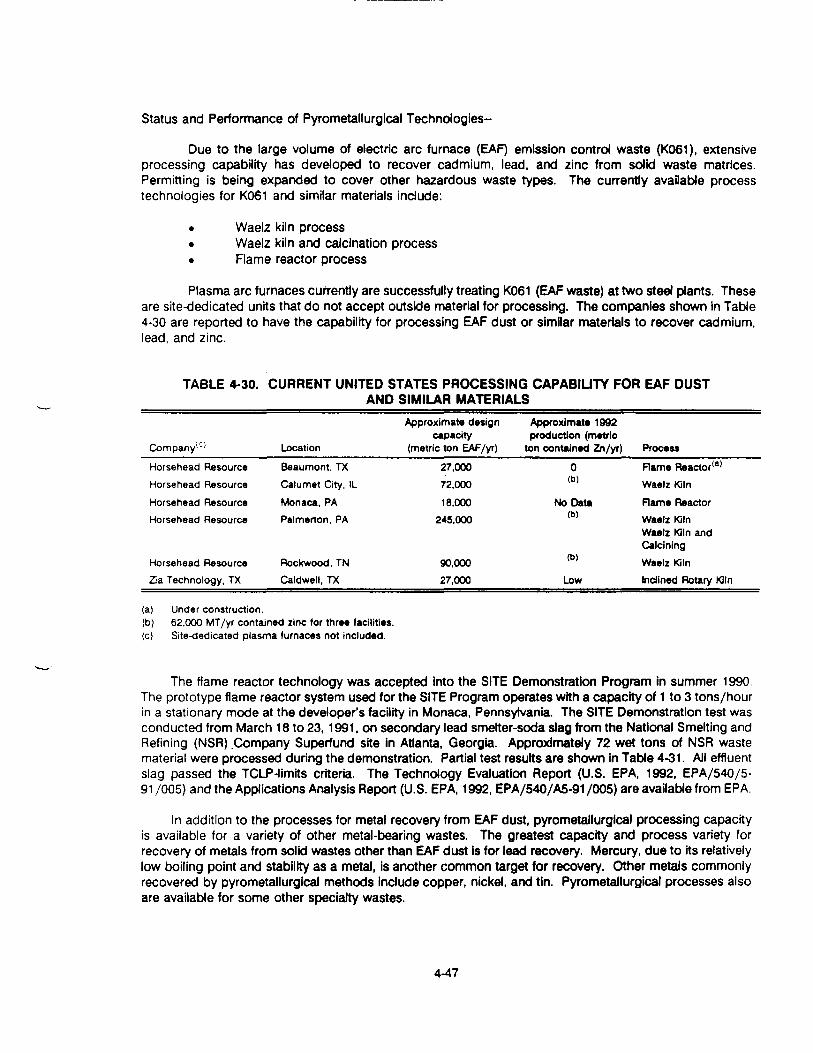
Status and Performance of Pyrometallurgical Technologies-
Due to the large volume of electric arc furnace (EAF) emission control waste (K061), extensiveprocessing capability has developed to recover cadmium, lead, and zinc from solid waste matrices.Permitting is being expanded to cover other hazardous waste types. The currently available processtechnologies for K061 and similar materials include:
• Waelz kiln process• Waelz kiln and calcination process• Flame reactor process
Plasma arc furnaces currently are successfully treating K061 (EAF waste) at two steel plants. Theseare site-dedicated units that do not accept outside material for processing. The companies shown In Table4-30 are reported to have the capability for processing EAF dust or similar materials to recover cadmium,lead, and zinc.
TABLE 4-30. CURRENT UNITED STATES PROCESSING CAPABILITY FOR EAF DUSTAND SIMILAR MATERIALS
CompanylC Location
Approximate designcapacity
(metric ton EAF/yr)
Approximate 1992production (metric
ton contained Zn/yr) ProcessHorsehead ResourceHorsehead Resource
Horsehead ResourceHorsehead Resource
Horsehead ResourceZia Technology, TX
Beaumont, IXCalumet City, IL
Monaca, PAPalmerton, PA
Rockwood, TNCaldwell, TX
27,00072,000
18,000245,000
90,00027,000
0(b)
No Data(b)
(b)
Low
Rame Reactor(a)
Waelz KilnRame ReactorWaelz KilnWaelz Kiln andCalciningWaelz KilnInclined Rotary Kiln
(a) Under construction.(b) 62,000 MT/yr contained zinc for three facilities.(c) Site-dedicated plasma furnaces not included.
The flame reactor technology was accepted into the SITE Demonstration Program in summer 1990.The prototype flame reactor system used for the SITE Program operates with a capacity of 1 to 3 tons/hourin a stationary mode at the developer's facility in Monaca, Pennsylvania. The SITE Demonstration test wasconducted from March 18 to 23,1991. on secondary lead smelter-soda slag from the National Smelting andRefining (NSR) .Company Superfund site in Atlanta. Georgia. Approximately 72 wet tons of NSR wastematerial were processed during the demonstration. Partial test results are shown in Table 4-31. All effluentslag passed the TCLP-limits criteria. The Technology Evaluation Report (U.S. EPA, 1992, EPA/540/5-91 /005) and the Applications Analysis Report (U.S. EPA, 1992, EPA/540/A5-91 /005) are available from EPA.
In addition to the processes for metal recovery from EAF dust, pyrometallurgical processing capacityis available for a variety of other metal-bearing wastes. The greatest capacity and process variety forrecovery of metals from solid wastes other than EAF dust is for lead recovery. Mercury, due to its relativelylow boiling point and stability as a metal, is another common target for recovery. Other metals commonlyrecovered by pyrometallurgical methods include copper, nickel, and tin. Pyrometallurgical processes alsoare available for some other specialty wastes.
4-47

TABLE 4-31. METAL CONCENTRATION RANGES IN INFLUENT AND EFFLUENTFOR FLAME REACTOR PROCESS
Metal
Arsenic " -
CadmiumCopperIronLead
Zinc
Waste feed(mg/kg)
428- 1,040
356-5121,460-2,590
95,600 - 130,000
48,200-61,700
3,210 - 6,810
Effluent slag(mg/kg)<«>
92.1 • 1,340
<2.3-13.52,730 • 3,890
167,000 - 228,000
1,560- 11,400711 -1,680
Product oxide(mg/kg)
1,010- 1,1701,080-1,3801.380-1,780
29,100-35,600
159,000 • 184,000
10,000 • 16,200
(a) All effluent slag passed TCLP-llmrts criteria.Source: U.S. EPA, 1992, EPA/540/R-92/077.
Catalytic Extraction Processing. Molten Metal Technology has patented a catalytic extractionprocess (CEP) that uses a high-temperature molten metal bath to process wastes contaminated withorganics and metals. The CEP dissolves the waste material Into a molten metal bath operating near3,000 °F. The high temperatures and catalytic action of the metal bath convert materials to elemental form.Organic contaminants are reportedly converted to C02 and methane, and exit as an off-gas stream forpurification and reuse. Metal impurities In the waste collect in the molten metal bath (Smith, 1991).
Secondary Lead Smelting. Secondary lead smelting Is a proven technology for reclaiming lead frommaterials that contain 40% lead or more. Commercial secondary lead smelters typically use reverberatoryand blast furnaces to heat a contaminated matrix to remove lead by a combination of melting and reduction.
The Center for Hazardous Materials Research and Exlde/General Battery Corporation aredemonstrating the use of secondary lead smelting to reclaim usable lead from waste materials containingbetween 1 and 50% lead. Waste containing 1 to 25% lead Is treated In a reverberatory furnace to produceslag containing about 70% lead. The slag and other high-lead-content materials are fed to a blast furnaceto produce lead metal products. SITE Program testing has been performed on a variety of waste materialsincluding battery cases, slags, lead dross, and lead paint chips. Materials from Superfund or othercontaminated sites could be mixed with other higher grade lead material for smelting (U.S. EPA, 1992,EPA/540/R-92/077). The reported treatment cost ranges from $150/ton to $250/ton for Superfund materials(Timm and Elliott, 1993). The process has been used to treat about 2.7 million pounds of lead-bearingmaterials from the NL Industries Superfund site (U.S. EPA, 1993, EPA/542/N-93/005).
Submerged Arc Smelting Furnace. INMETCO (Ellwood City, PA) operates a submerged arc smeltingfurnace to recover nickel, iron, and chromium. Solid wastes are palletized and fed to the Rotary HearthFurnace to reduce metal salts to the metallic form. A submerged arc furnace then processes the pretreatedwaste. The chromium, iron, and nickel are cast into ingots that are suitable as feed for stainless steelmaking. The slag Is reported to be nonhazardous and suitable for application as an aggregate. Cadmium,lead, and zinc are collected as flue dust from the submerged arc furnace. The flue dust Is sent to anothersite for metal recovery (Electrical World, 1991).
The types of waste material processed by the facility include nickel- and chromium-containingsludges, dusts, grind ings, and catalysts; nickel-cadmium and iron-nickel batteries; chromium-magnesiterefractories, ddomitic refractories, carbon brick and coke fines, waste magnesium powders and machinings;baghouse bags; and bags and filters for plating operations (Hanewald et al., 1992). The facility is reportedto hold a permit to process RCRA waste codes D001, D002. D003, D006, D007, D008, F006, K061, andK062. The typical material quality required for the process is shown In Table 4-32.
4-48

TABLE 4-32. TYPICAL INPUT MATERIAL REQUIREMENTS FOR THE INMETCO PROCESS
MetalApproximate Solid Waste Specification
(wt% on a dry basis)NickelChromiumPhosphorus'3'IronCalcium OxideMagnesium OxideSodium, Chloride, PotassiumCopperTin(a)
CadmiumSulfurLeadZincAluminaSilicaCobaltMolybdenum
>5.0<0.05
No limitNo limitNo limit<20.0<2.0<0.03<20.0<5.0
<10.0<20.0<15.0<15.0<2.0<10.0
(a) Critical limits.Source: INMETCO Brochure.
Mercury Recovery. Relatively few metal oxides convert easily to the metallic state in the presenceof oxygen. As a result, reduction reactions typically require the presence of a reducing agent such ascarbon at elevated temperatures. Mercury Is one of the few exceptions. Many mercury compounds convertto metal at atmospheric pressure and 300°C or lower temperature. With a boiling point of 357°C (Chaseet al., 1985), mercury is substantially more volatile than most metals. Thus, mercury and Its compounds canbe separated by roasting and retorting more easily than most metals, making it an ideal candidate forrecycling from a wide variety of waste materials. Two vendors of thermal desorption processes for mercuryrecovery are listed in the VISITT database (see Appendix C).
An input concentration of 5% mercury is preferred. Typical feed includes metal and glass materials.Most plastics can be processed, but polyvlnyl chloride and other halogen-containing materials must beminimized due to the potential for generation of corrosive or volatile materials during heating in the retort.Volatile or reactive metals such as lithium, arsenic, and thallium also are not allowed In the process. Quartzcontainers can be processed but must be crushed. Dirt, soils, and sludge-like materials can be processedif the water content is below about 40%. If the mercury is in solution, the mercury must be collected as asolid by precipitation or by adsorption onto activated carbon. As with the sludge feed, the collected solidusually contains less than about 40% water (Lawrence, 1992).
A portable thermal treatment (PTT) process for removing elemental mercury, mercury compounds,and amalgams from soil Is being commercialized by Mercury Recovery Services, New Brighton, PA. Thefirst full-scale system, which is designed to handle 12-18 tons/day, is scheduled to begin remediating a gasline site in 1994. The PTT system Is one of three technologies evaluated for use on mercury-contaminatedsoil by the University of North Dakota's Energy and Environmental Research Center with funding from theGas Research Institute. The other two are a physical separation/chemical leaching process developed byMountain States R&D International, Inc., Vail, AZ, and a chemical process from COGNIS, Inc., SantaRosa, CA.
4-49

Preliminary results from tests with the PIT process found that total mercury In sandy soils could bereduced from 12,720 mg/kg to 0.07 mg/kg. TCLP testing of the untreated soil found 0.346 mg/L ofmercury in the leachate, compared to 0.0005 mg/L in the leachate following treatment in the PTT unit. Inclay soils, total mercury levels of 1,090 mg/kg were lowered to 0.12 mg/kg; while the TCLP values declinedfrom 0.065 mg/L to 0.0008 mg/L
Estimated Costs of Pyrometallurgical Technologies--
The HRD Flame Reactor at Monaca, Pennsylvania, participated in a SITE Demonstration test. Theresults of the test program were the basis for developing cost estimates for several possible commercialapplications of Rame Reactor technology to site remediation. The cost analyses are summarized in Table4-33. The cost estimates are in the range of $458 to $208/ton of waste treated in 1991 dollars.
Pyrometallurgical Technology Data Needs-
The data needs for selection and application of Pyrometallurgical technologies are shown in Table4-34.
4.3.2 Description of In Situ Technologies
This section addresses two in situ technologies (soil flushing and electrokinetic) potentially applicableto the treatment of metal-contaminated soils.
4.3.2.1 Soil Rushing Technology
Soil flushing uses extraction through injection of aqueous solutions to remove contaminants fromthe subsurface without excavation of the contaminated materials. The leaching solution must be selectedto remove the contaminant while not harming the in situ environment. Use of the leaching solution mustbe consistent with LDRs and other regulatory requirements.
Description of Soil Flushing-
Soil flushing is the extraction of contaminants from the soil with an appropriate washing solution toremove organic or inorganic contaminants from the soil. Water or an aqueous solution is injected into orsprayed onto the area of contamination, and the contaminated elutriate Is collected and pumped to thesurface for removal, recirculation, or onsite treatment and reinjection.
The contaminants are mobilized by solubflization, formation of emulsions, or a chemical reaction withthe flushing solutions. After passing through the contamination zone, the contaminant-bearing fluid iscollected by strategically placed wells or trenches and brought to the surface for disposal, recirculation, oronsite treatment and reinjection. During elutriation, the flushing solution mobilizes the sorbed contaminantsby dissolution or emulslflcatlon.
Typical Treatment Combinations With Soil Flushing--
Soil flushing uses water, a solution of chemicals in water, or an organic extractant to recovercontaminants from the In situ material. One key to efficient operation of a sofl flushing system is the abilityto reuse the flushing solution. A variety of water treatment techniques can be applied to remove therecovered metals and render the extraction fluid suitable for reuse. Subsurface containment barriers shouldbe considered in conjunction with soil flushing technology to help control the flow of flushing fluids. Typicaltreatment combinations are shown in Table 4-35.
4-50

TABLE 4-33. ESTIMATED COSTS ASSOCIATED WITH THE HORSEHEAD RESOURCEDEVELOPMENT FLAME REACTOR SYSTEM (IN 1991 DOLLARS)
Scenario Number
Plant Location
Capital ($ million)
Annual capacity (tons)Cost categories
Site and waste preparationExcavation of wasteTransportation of wastePretreatment of waste
Permitting and regulatoryrequirementsCapital equipment
StartupLaborConsumables
Oxygen
Natural gasUtilitiesEffluent monitoring6
Shipping, handling, andtransporting residuals
Effluent slag
Oxide product3
Analytical test
Equipment repair and replacementSite demobilization
Total Cost Per Ton of Wa«t«
SITETesta
1Monaca,
PA2.5
6,700
Commercial Operations(Scenarios 2-6)b
2
Monaca,PA2.5
6,700
3
On-site
3.16,700
4
Monaca,PA4.5
13,400
5
On-site
6.020,000
6
On-site
10.4
50,000Estimated cost per ton of waste treated (1991 $)
c93
129
246
10
64
1
114
d
131
81
11
0f
15
-
334
0
932
c106021
10
64
1
78
d
93
5811
0f
15
-
334
0
458
c106
2110
791
93
d935811
0f
15
-
4
37
10
448
c106020
10
58
1
39
d6034
11
0
f
15
-
2
300
350
c106
1910
52
1
31d
492611
0f
15
-
2
24
7
263
c10
617
10
36
1
18
d41
2111
0f
15
-
1
15
6
208
a SITE Demonstration test on secondary lead smelter-soda slag (see Subsection 4.3.1.2).b Commercial operations assume metal content (lead and cadmium) 7.5% and moisture content 15% to 25%.c Reported separately as excavation of waste, transportation of waste, and pretreatment of waste.d Consumables costs consist of oxygen and natural gas.e Costs for effluent monitoring are included in capital and labor cost categories.f Costs for shipping, handling, and transporting residuals reported separately for slag and product.g The credits or costs for disposal of oxide product are variable depending on market conditions and are not included.
Source: U.S. EPA, 1992, EPA/540/A5-91/005.
4-51

TABLE 4-34. SPECIFIC DATA NEEDS FOR PYROMETALLURGICAL TECHNOLOGIES
Factor Influencing Conditions FavoringTechnology Selection'31 Success of Treatment Basis Data Needs
Waste volume
Particle size
Moisture content
Large quantity ofmaterial
Not specified
No free moisture
Pyrometallurgical processing typicallyoperates best with continuous feed
Specific particle-size requirements dependon the process
Presence of water increases energyrequirements
Risk-based wastedelineation
Waste materialparticle-sizedistribution
Waste moisturecontent
Metal content Concentration ofmetals levels to berecovered shouldtypically be in thepercent range
Heating value of waste Not specified
Thermal conductivity of Higher is preferredwaste
Types of metals present Not specified
Nitrates, sulfurcompounds,phosphates, and halides
Alkaline metals
Not specified
Not specified
Ash content of waste Not specified
High moisture increases material-handlingproblems
Percentage concentrations are required tomake process feasible
Lower concentrations are typically processedby hydrometallurgical methods
Combustibles in waste may provide someheating
Treatment requires the ability to transfer heatinto the waste matrix
Mixtures of volatile and nonvolatile metalsrequire multiple processing steps
May form corrosive acid gases
Sulfur forms nonvolatile sulfides
Halides can form volatile metal species
Metals such as sodium and potassiumdecrease the slag formation temperature andincrease the corrosiveness of the slag
Helps quantify expected slag volume
Waste composition
Waste composition
Thermal conductivity
Waste compositionMetals boiling point
Waste composition
Waste composition
Weight loss onignition
(a) Use hazardous substance list and site historical records to plan total waste analysis.
TABLE 4-35. TYPICAL TREATMENT TRAINS FOR SOIL FLUSHING AND ELECTROKINETICTREATMENT AT METAL-CONTAMINATED SITES
Pretreatment/Materials Handling Separation/Concentration Technology Post-treatment/Residuals Management
Rushing fluid delivery system
Groundwater extraction system
Containment barriers
Soil flushing and electrokinetic Rushing liquid/groundwater treatmentand disposalAir pollution control
In situ soil treatment containmentbarriers
4-52

Applicability of Soil Rushing-
The four major elements in application of in situ flushing are (Palmer and Wittbrodt, 1991):
• Delivery of the extraction fluid to the required subsurface volume• Interaction between the extraction fluid and the contaminant• Recovery of the contaminant and extraction fluid from the subsurface• Treatment of the recovered contaminant and fluid
Soil flushing requires a flushing solution that Is available in sufficient quantity at a reasonable cost.Flushing solutions may include water, acidic aqueous solutions (such as sulfuric, hydrochloric, nitric,phosphoric, or carbonic acids), basic solutions (such as sodium hydroxide), chelating or complexing agents,reducing agents, and surfactants. Water will extract water-soluble or water-mobile constituents. Inorganicsthat can be flushed from soil with water are soluble salts such as the carbonates of nickel, zinc, and copper.Adjusting the pH with dilute solutions of acids or bases can control inorganic mobility and removal. Acidicsolutions can be used to remove cationic metals or basic organic materials. Basic solutions may be usedfor some metals and some phenols. Chelating, complexing, and reducing agents may be needed forrecovery of some metals. Surfactants can assist in emulsification of hydrophobic organics (U.S. EPA, 1991,EPA/540/2-91/021).
The technology may be easy or difficult to apply, depending on the ability to wet the soil with theflushing solution and to install collection wells or subsurface drains to recover all the applied liquids.Provisions also must be made for ultimate disposal of the elutriate. The achievable level of treatment variesand depends on the contact of the flushing solution with contaminants, the appropriateness of the solutionfor contaminants, and the hydraulic conductivity of the soil. The extended treatment times needed toremediate metal sites by pump-and-treat methods make it worthwhile to consider addition of soil flushingchemicals to speed or enhance contaminant removal.
Status and Performance of Soil Flushing--
Soil flushing to remove organic materials has been demonstrated at both bench- and pilot-scale.Studies have been conducted to determine the appropriate solvents for mobilizing various classes and typesof chemical constituents. Several systems are in operation and many systems are being designed forremediation of Superfund sites. Most of the applications involve remediation of VOCs (U.S. EPA, 1992,EPA/542/R-92/011).
Soil flushing for inorganic treatment is less well developed than soil flushing for organics, but someapplications at Superfund sites have been reported. One system is operational at a landfill with mixedorganics and metals, and another is operational at a chromium-contaminated site (U.S. EPA, 1992,EPA/542/R-92/011). Several other inorganic treatment systems are in the design or predesign phases atSuperfund sites. Some Superfund metal-contaminated sites that have selected soil flushing as a remedyare summarized in Table 4-36.
Estimated Costs of Soil Rushing-
Estimated costs for application of soil flushing range from $75 to $200/yd3 depending on the wastequantity. These are rough estimates and are not based on field studies (U.S. EPA and U.S. Air Force, 1993).The Superfund site at Palmetto Wood, South Carolina cited costs of $3,710,000 (capital) and $300,000(annual operation and maintenance). These totals, on a unit basis, equal $185/yd for capital costs and$l5/yd3/vrfor operation and maintenance (U.S. EPA, 1990, EPA/600/2-90/011).
4-53

TABLE 4-36. SUMMARY OF SOIL FLUSHING TECHNOLOGY SELECTIONS/APPLICATIONS ATSELECTED SUPERFUNO SITES WITH METAL CONTAMINATION1"
Region
2
3
Site Name/Location
LJpari Landfill,New Jersey
U.S. Titanium,Virginia
Specific Technology
Soil flushing of a volumeof soil and wastes con-tained by a slurry wall
Dissolution of wastes
Key MetalContaminants
Chromium, lead,nickel, mercury
Ferrous sulfate
Associated Technology
Slurry wall
Not stated
Status'6'
1
S
10 United ChromeProducts, Oregon
Soil flushing with water Chromium Pilot test of electrokineticremoval conducted at site
Considering in situreduction process
(a) For more site information and implementation status, see Appendix 0.(b) Status codes: S - selected in ROD; I • in operation, not complete, C - completed.
Data Needs for Soil Flushing--
The data needs for selection and application of soil flushing options are shown in Table 4-37.
4.3.2.2 Electrokinetic Treatment Technology
Electrokinetic technology removes metals and other contaminants from soil and groundwater byapplying an electric field in the subsurface.
Description of Electrokinetic Treatment Technology--
Electrokinetic treatment uses a charged electric field to induce movement of ions, particulates, andwater through the soil (Hinchee et al., 1989). The electrokinetic phenomenon occurs when liquid migratesthrough a charged porous medium, typically clay, sand, or other mineral paniculate that normally has anegative surface charge.
The electrical field is applied through anodes and cathodes placed in the soil. Most metals formpositively charged ions that migrate toward the negatively charged electrode. Metal anions such aschromates migrate to the positively charged electrode, and concentration gradients in the soil solution areestablished between the cathode and anode. The imposed electrical field drives diffusion of metal ions fromareas of low concentration to areas of high concentration. The viscous drag due to movement of thecations also induces a net flow of water to the cathode (Marks et al.. 1992).
The spacing of wells containing the cathode and anode depends on site-specific factors. Thecathode and the anode housings can be provided with separate circulation systems filled with differentchemical solutions to maximize recovery of metals. The contaminants are captured in these solutions andbrought to the surface for treatment in a purification system.
4-54

TABLE 4-37. SPECIFIC DATA NEEDS FOR SOIL FLUSHING TECHNOLOGIES
Factor InfluencingTechnology Selection"1
Detailed understanding ofcontaminant distribution.and subsurface geology
Hydraulic conductivity
Equilibrium partitioning ofcontaminant between soiland extraction fluid
PH
Buffering capacity
Contaminant solubility inwaterComplex waste mixture
Spatial variation in wastecomposition
Total metal concentration
Conditions FavoringSuccess of In SituTreatment
Not specified
>103 cm/sec; lowclay contentNot specified
No action levelsspecified
No action levelsspecified
>1,OOOmg/L
Less complexity isbeneficialLess variation isbeneficial
Not specified
Basis
Affects the ability to deliver and recoverflushing solution effectively
Good conductivity allows efficient delivery offlushing fluidsLow partitioning of contaminant into theextraction fluid increases fluid volumerequired to attain cleanup goals
May affect treatment additives required,compatibility with materials of construction,or flushing fluid formulationIndicates matrix resistance to pH change
Soluble compounds can be removed bywater flushingComplex mixture increases difficulty informulation of a suitable extraction fluidChanges in waste composition may requirereformulation of extraction fluid
Determine concentration targets or interfering
Data Needs
Distribution of thecontaminant in relationto subsurface featuresHydrogeologic flowregime; Soil typeEquilibrium partitioningcoefficientBench- and pilot-scaletestingSoil pH
Soil buffering capacity
Contaminant solubility
ContaminantcompositionStatistical sampling ofcontaminated volume
Waste composition
Leachable metal Not specifiedconcentrationRushing fluid Fluid should have lowcharacteristics toxicity, low cost, and
allow for treatmentand reuse
Ruid should not plugor have other adverseeffects on the soil
Fluid viscosity shouldbe low
Presence of cyanides, Low is preferredsulfides. and fluoridesSpecific surface area of <0.1 m!/gmatrix
Cation exchange capacity < about SO to 10X)(CEC) meq/kg
Humic acid content Low is preferred
Waste leachability
Ruid characterization
Bench- and pilot-scaletesting
Ruid viscosity
constituents, pretreatment needs, andextraction fluidDetermine extractability of target constituentsand post-treatment needsToxicity increases health risks and increasesregulatory compliance costs
Expensive or nonreusable fluid increasescosts
If the fluid adheres to the soil or causesprecipitate formation, permeability may drop,making continued treatment difficult
Lower viscosity fluids flow through the soilmore easilyDetermine potential for generating fumes at Waste compositionlow pHHigh surface area increases sorption on soil Specific surface area of
matrixHigh CEC indicates the matrix has a high CEC of matrixaffinity for metal sorptionHumic content increases sorption Soil color, texture, and
composition
(a) Use hazardous substance list and site historical records to plan total waste analysisSource: Adapted from U.S. EPA, 1988, EPA/540/2-88/004; U.S. EPA, 1990, EPA/600/2-90/011; U.S. ERA, 1993, EPA/540/S-94/500
4-55

Typical Treatment Combinations With Electrokinetic Treatment Technology-
Electrokinetic treatment concentrates metals at the cathode to allow recovery of contaminants fromthe in situ material. Typically the solution will require subsequent treatment for metals removal prior toreinjection or discharge. A variety of water treatment techniques can be applied to remove the recoveredmetals and render'the extraction fluid suitable for reuse. Water treatment methods are referenced inSubsection 4.5. Typical treatment combinations were shown in Table 4-35 (see page 4-52).
Applicability of Electrokinetic Treatment Technology-
Electrokinetic separation may be applied to enhance phase separation, concentrate Ionic species,or both. Chemical species that form ions in solution that can migrate under the influence of the electricalfield can be effectively concentrated. Mobility of fluids also is enhanced by the electroosmosis so theelectrokinetic method can be applied to improve dewatering of a material.
Electrokinetic treatment is most applicable to saturated soil with nearly static groundwater flow andmoderate to low permeability. A low groundwater flow rate Is required so that ionic diffusion rather thanadvective flow is the main transport mechanism. Water is required to provide a polar medium for ion flow.Electrokinetic treatment is less dependent on high soil permeability than are the in situ metals extractiontechnologies such as soil flushing. The electrokinetic separation occurs due to Ionic migration rather thanbulk fluid flow. Fine-grained clay soils are reported to be an ideal medium for electrokinetic treatment (U.S.EPA, 1992, EPA/540/R-92/077). As a result, electrokinetic separation can be applied in soils where soilflushing flow rates are too low for soil flushing to be practical.
Electrochemical reactions at the electrodes are unavoidable side effects of electrokinetic separationtechniques. The most likely reaction is electrolysis of the water. The reaction at the cathode Is productionof hydrogen gas and hydroxide Ions. The hydrogen gas escapes, causing the pH to rise. Increases of pHto above 13 have been reported in the vicinity of the cathode (U.S. EPA, 1990, EPA/540/2-90/002).Similarly, evolution of oxygen and production of hydrogen Ions occurs at the anode causing acidificationof the anode area. During operation of electrokinetic treatment, the acid front migrates away from the anodeand can contribute to dissolution and mobilization of metal contaminants (Probstein and Hicks, 1993).
Other electrochemical reactions also may occur. Chloride ions, which are often present in naturalwaters, may be reduced to form chlorine gas. Chemical and electrochemical processes may result inprecipitation of solid materials, such as iron or chromium hydroxides, that plug pores In the formation andreduce permeability to unacceptable levels (U.S. EPA, 1991, EPA/540/2-91/009).
Status and Performance of Electrokinetic Treatment Technology-
Commercial application of electrokinetic treatment has been pioneered In Europe by Geokineticsof Rotterdam, The Netherlands, and is ongoing in the U'.S. (Acar and Alshawabkeh, 1993). Field testing isreported to Indicate that soil type is an important parameter in successful application of electrokinetics.Geokinetics has reported 90% contaminant removal from clayey soils but only 65% from porous soils(Steimle, 1992).
There are two major laboratory programs studying electrokinetic treatment processes. Researchat the University of Colorado is currently funded by the Electric Power Research Institute. The experimentalresults indicate a 450% concentration factor for metal contaminants In water adjacent to the electrodes.Researchers at the Massachusetts Institute of Technology are studying electrode emplacement geometriesand electrical field strengths under a grant for the Northeast Hazardous Substance Research Center(Steimle, 1992).
4-56

A field test of electrokinetic treatment was conducted at the United Chrome Products Superfund Sitein Corvallls. Oregon. Groundwater chromium concentrations at the site ranged from 651 mg/L to 1 mg/L.A series of experiments compared chromium removal by water flushing alone to (1) electrokinetic migrationand (2) electrokinetic migration In combination with water flow. The testing Indicated that electric potentialcan induce migration of chromium. The process of ion migration was, however, found to be slow and couldbe enhanced or suppressed depending on the direction of water flow (Banerjee, 1992).
Electroacoustic soil decontamination was evaluated as an emerging technology under the SITEProgram. Bench-scale testing indicated the feasibility of removing Inorganic species such as zinc andcadmium from clay soils. A report describing the test results has been published (U.S. EPA, 1990,EPA/540/5-90/004).
The Electrokinetics, Inc. electrokinetic remediation system has been accepted for demonstrationunder the SITE Program. Bench-scale tests of soil treatment to remove arsenic, benzene, cadmium,chromium, copper, ethylbenzene, lead, nickel, phenol, trichloroethylene, toluene, xyiene, uranium, and zincwere completed under various programs Including the SITE Emerging Technology Program. Pilot testingand field testing are ongoing (Acar, 1992; U.S. EPA, 1992, EPA/540/R-92/077).
Estimated Costs of Electrokinetic Treatment Technology-
Electrokinetic treatment is still in the early development stage. This study found no reliable basisfor estimating costs for using electrokinetic technology to treat metal-contaminated solid materials.
Data Needs for Electrokinetic Treatment Technology-
The critical factors for selection of electrokinetic treatment technologies are shown in Table 4-38.
Because electrokinetic treatment of metal-contaminated solid materials is in early stages of pilottesting, no action levels or more specific data requirements can be specified, as was done for othertechnologies in this document.
TABLE 4-38. SPECIFIC DATA NEEDS FOR ELECTROKINETIC TECHNOLOGIESFactor InfluencingTechnology Selection'31___________Basis_____ _________ _____________
Hydraulic conductivity Technology applicable in zones of low hydraulic conductivity, particularly withhigh clay content.
Depth to water table Technology applicable in saturated soils.Area! extent of contamination To assess electrode and recovery well placement.
Electroosmotic permeability To estimate the rate of contaminant and water flow that can be induced.Cation exchange capacity (CEC) Technology most efficient when CEC is low.Metals analysis Technology applicable to acid soluble polar compounds, but not to nonpolar
organic* and acid insoluble metals.
Salinity Technology most efficient when salinity Is low. Chlorine gas can be produced byreduction of chloride ions at the anode.
Identification of half cell potentials ___Characterizes possible reactions.__________ ______________
(a) Use hazardous substance list and site historical records to plan total waste analysis.
Source: U.S. EPA, 1991, EPA 540/2-91/009.
4-57

4.4 TREATMENT TECHNOLOGIES FOR GROUNDWATER AND WASTEWATER
Chapter 4 of the Handbook: Stabilization Technologies for ROM Corrective Actions describes datacollection, implementation, and technology application for groundwater pump-and-treat systems (U.S. EPA,1991, EPA/625/6-91/026). A general review of methods to treat metals in groundwater is presented inResource Recovery Project Technology Characterization Interim Report (MSE, 1993). Specific informationon precipitation is available in Precipitation of Metals from Ground Water (NEESA, 1993). Bioremediationtechnologies are detailed in Bioremediation of Metals (Mattison, 1993). A summary of water treatmenttechnologies is presented in Table 4-39. SITE Program technologies applicable to metal treatment aresummarized In Appendix B (Tables B-2 and B-4).
4-58

TABLE 4-39. SUMMARY OF TREATMENT TECHNOLOGIES FOR METAL-BEARING WASTEWATER STREAMS
Process Applicable Waste Streams Stage of Development Performance Residuals Generated
Physical Treatment Technologies
Membraneseparation
Liquid-liquidextraction
Carbon adsorption
01CD
Ion exchange
OeVoe-Holbein
Sorption oninactive biomass
Electrolytictreatment
Aqueous wastestreams containing 10-20% metals depending on thetechnology used.Aqueous, sludge, and solid wastes.
Aqueous wastestreams containingmetal ions at low pH. Effective intreating chelated metals as well asmetal cations.
Effective for treating dilute aqueouswastestreams as an end-of-pipe orpolishing treatment.
Similar to ion exchange exceptcapable of treating both dilute andconcentrated solutions.
Similar to ion exchange.
Aqueous streams; high concentrations(greater than 1,000 ppm) are mostefficiently removed.
Demonstrated technology formany process and wastestreams.
Limited use in hazardous wastefield but widespread in miningand smelting industries.
Largely experimental with somefield applications for treatinghexavalent chromium andmercury-containing wastestreams.
Used in metal finishing andelectroplating industries forrecycling rinse solutions andconcentrating waste metalsolutions for efficient treatment.Newly developed process used inmetal finishing industries, orebeneficiation, precious metalsrecovery, and chloralkali plants.
Several products commerciallyavailable.
Well developed and readilyavailable from commercialvendors.
Greater than 99% removal ifproperly used.
Capable of yielding a solutionthat is 20 to 30 times moreconcentrated than feed.
Used as a primary treatmentfor removal of hexavalentchromium. With a Cr'*influent concentration of 6ppm, effluent concentration ofCr" * remained below 0.05ppm.Performance influenced bynature of functional group, ionsavailable for exchange, andsolution pH.
Performance reportedly showshigh specificity; however, moredata are needed to assessutility.
Similar to ion exchange butmore efficient at lowcontaminant concentrations.Performance varies greatlydepending on the applicationand the particular electrolyticunit used; some units mayremove over 90% of metalssuch as Cu, Pb, Zn, Au, Ag,and Cd.
Concentrated brinerequires treatment ordisposal.
Raffinate and regenerantstream may require post-treatment to removeresidual extractant andmetal.Spent carbon requiresdisposal or reactivation.
Regeneration solutionrequires treatment ordisposal.
Regenerant required buthas good potential forrecycling becausetypically high in metalscontent.
Regeneration solution
Generally the metal isrecovered in a usableform and no residualsolids are generated.

TABLE 4-39. (continued)Process Applicable Waste Streams Stage of Development Performance Residuals Generated
Chemical Treatment Method*
Precipitation(hydroxide &suffide)
Coagulation/flocculation
Reduction
Flotation
Aqueous streams; restrictions basedon physical form, viscosity, and metalsolubility.
Aqueous streams; for ppbconcentrations, two-stage processrequired; not readily applied to small,intermittent flows.Primarily, aqueous chrome-bearingwastestreama although sodiumborohydride can treat most metals.
Aqueous streams containing 100mg/L or less of metals. Restrictionsbased on physical form, oil andgrease content.
Well-developed, reliable process,suitable for automatic control.
Well developed and readilyavailable from commercialvendors.
Well developed.
Not fully developed for metalsremoval; primarily at pilot plantstage of development.
Heavy metals: Cd, Cu. Pb, Hg,Ml, Afl, and Zn removed to 0.01to 0.5 mg/L.
Not considered a primarytreatment but can achieve lowresidual levels.
Chromium removal to 0.01mg/L. Sodium borohydrideable to remove Cu, Nl, Pb, Zn,Hg, Ag, Cd In the 0.01 to 1.0mg/L range.
Heavy metals Pb, Cu. Zn. Cr3*removed to 0.03 to 0.4 mg/L.
Effluent stream will requirefurther processing toremove and dispose ofprecipitated solids.Sludge requires secondaryprocessing and disposal.
Effluent stream will requirefurther processing toremove and dispose ofreduced metal. Sodiumborohydride Introducesboron Into the effluentstream.Requires post-treatment ofmetal-laden foam.
Biological Treatment Method*
Wetlands Constructed wetlands remove metals Pilot-scaletreatment by partitioning or precipitation.
Bloreduction Bioreduction Bench-scale
May be used as final treatmentfor low concentrations of heavymetals (10 mg/L or less).Tested for conversion ofmercury salts to metal andCr(VI) reduction.
Metals remainImmobilized In wetland.
Reduced metal requirespost-treatment forrecovery orimmobilization.
Therm*! Treatment Method*Evaporation Aqueous wastes with low nonvolatile
metals content, or wastes with highlyvolatile metals content.
Well developed and widelyavailable.
Can effect high-level recoveryof volatile metals or significantvolume reduction of aqueouswastes.
Brine.
Crystallization Primarily used for wastes fromelectroplating and pickling thatcontain high levels of acids, water, orlow-molecular-weight organic*.
Well developed. Often used Inconjunction with evaporation.
Can effect high-level recovery. Sludges.

4.5 REFERENCES
1. Acar, Y.B. Electrokinetic Soil Processing (A Review of the State of the Art). American Society ofCivil Engineers Specialty Conference - Ground Improvement and Grouting, New Orleans, Louisiana,February 1992.
2. Acar, Y.B. and A.M. Alshawabkeh. Principles of Electrokinetic Remediation. Environ. Sci. Technol.,27(13):2638-2647, 1993.
3. Arniella, E.F. and LJ. Blythe. Solidifying Traps Hazardous Waste. Chemical Engineering, 97(2):92-102, 1990.
4. Article, J. and W.H. Fuller. Effect of Crushed Limestone Barriers on Chromium Attenuation in Soils.Journal of Environmental Quality, 8(4):503-510 (as cited in Palmer and Wittbrodt, 1991), 1979.
5. Banerjee, S. Application of Electrokinetic Transport Processes to In-Situ Remediation. VIP-24. In:Proceedings of the 1992 International Symposium - In Situ Treatment of Contaminated Soil andWater, Risk Reduction Engineering Laboratory and the Air and Waste Management Association,Pittsburgh, Pennsylvania, 1992. pp. 370-383.
6. Buelt, J.L and LE. Thompson. The In Situ Vitrification Integrated Program: Focusing an InnovativeSolution on Environmental Restoration Needs. PNL-SA-20853, Pacific Northwest Laboratory,Richland, Washington, 1992.
7. Buelt, J.L, C.L Timmerman, K.H. Oma, V.F. FitzPatrick, and J.G. Carter. In Situ Vitrification ofTransuranic Waste: An Updated Systems Evaluation and Applications Assessment. PNL-4800,Pacific Northwest Laboratory, Richland, Washington, 1987.
8. Buelt, J.L, C.L Timmerman, and J.H. Westsik Jr. In Situ Vitrification: Test Results for aContaminated Soil-Melting Process. PNL-SA-15767, Pacific Northwest Laboratory, Richland,Washington, 1989.
9. Chase, Jr., M.W., C.A. Davies, J.R. Downey, Jr., D.J. Frurip, R.A. McDonald, and A.N. Syverud.JANAF Thermochemical Tables. Journal of Physical and Chemical Reference Data. Volume 14Supplement. American Chemical Society, American Institute for Physics, and National StandardReference Data Series. U.S. Department of Commerce, National Bureau of Standards, Washington,DC, 1985.
10. Conner, J.R. Chemical Fixation and Solidification of Hazardous Wastes. Van Nostrand Reinhold,New York, New York, 1990.
11. Electrical World. Dispose of Nickel/Cadmium Batteries by Recycling. Electrical World, 205(3):S-39,1991.
12. Erickson, P.M. Waste Treatability by Solidification/Stabilization Technology. In: Proceedings of the1992 International Symposium - In Situ Treatment of Contaminated Soil and Water, 1992. pp. 331-343.
13. Fix, M. and B. Fristad. Lead Is Washed from Soil at Twin Cities Army Ammunition Plant Site.Superfund Week, 7(44):2-3, 1993.
4-61

14. Geosafe Corporation. Application and Evaluation Considerations for In Situ Vitrification Technology:A Treatment Process for Destruction and/or Permanent Immobilization of Hazardous Materials.GSC 1901, Richland, Washington, 1989.
15. Hanewald, R.H.. W.A. Munson, and D.L Schweyer. Processing EAF Dusts and Other MaterialsPyrometallurgically at INMETCO. Minerals and Metallurgical Processing, 9(4): 169-173, November1992.
16. Hansen, C.L and O.K. Stevens. Biological and Physico-Chemical Remediation of Mercury-Contaminated Hazardous Waste. Arsenic and Mercury: Workshop on Removal, Recovery,Treatment, and Disposal. EPA/600/R-92/105, 1992, pp. 121-125.
17. Hansen, J.E. and V.F. FitzPatrick. In Situ Vitrification Applications. Geosafe Corporation, Richland,Washington, 1991.
18. HazTech News. Volume 9 and 10, May 1994.
19. Hinchee, R.E., H.S. Muralkjhara, F.B. Stulen, G.B. Wickramanayke. and B.F. Jirjis. ElectroacousticSoil Decontamination Process for In Situ Treatment of Contaminated Soils. In: Solid /LiquidSeparation, H.S. Muralkjhara (Ed.). Battelle Press, Columbus, Ohio, 1989. pp. 370-383. '
20. Horn, J.M.. M. Brunke, W.D. Deckwer, and K.N. Timmis. Development of Bacterial Strains for theRemediation of Mercurial Wastes. Arsenic and Mercury: Workshop on Removal, Recovery,Treatment, and Disposal. EPA/600/R-92/105, 1992, pp. 106-109.
21. Huang, H.H. STABCAL User Manual. Montana Tech, Butte, Montana, 1993.
22. Jacobs, J.H. Treatment and Stabilization of a Hexavalent Chromium Containing Waste Material.Environmental Progress, 11 (2): 123-126, 1992.
23. Johnson, J.L, et. al. Heavy Metals Removal from Small-arms Firing Ranges. EPA Congress 93, AMinerals, Metals and Materials Society Publication, Warrendale, PA, 1993.
24. Johnson, J.L, et. al. Application of Mineral Beneficiation Processes for Lead Removal at a CampPendleton, CA Small-Arms Firing Range, 5th Form on Innovative Hazardous Waste Treatment, 1994.
25. Jolly, J. Zinc Yearbook-1992. U.S. Bureau of Mines. Washington, DC, 1993.
26. Kalb, P.O., H.H. Burns, and M. Meyer. Thermoplastic Encapsulation Treatability Study for a MixedWaste Incinerator Off-Gas Scrubbing Solution. In: T.M. Gilliam (Ed.), Third International Symposiumon Stabilization/Solidification of Hazardous, Radioactive, and Mixed Wastes. ASTM STP 1240,American Society for Testing and Materials, Philadelphia, Pennsylvania, 1993.
27. Lawrence, B. High Vacuum Mercury Retort Recovery Still for Processing EPA D-009 HazardousWaste. In: Arsenic aad Mercury - Workshop on Removal, Recovery, Treatment, and Disposal,Alexandria, Virginia. August 17-20, 1992. pp. 113-116.
28. Luey, J., S.S. Koegler, W.L Kuhn, P.S. Lowery, and R.G. Winkelman. In Situ Vitrification of a Mixed-Waste Contaminated Soil Site: The 116-B-6A Crib at Hanford. PNL-8281, Pacific NorthwestLaboratory, Richland, Washington, 1992.
4-62

29. Marks, R.E., Y.B. Acar, and R.J. Gale. Electrokinetic Soil Processing: An Emerging Technology.In: Proceedings of 47th Purdue Industrial Waste Conference, Lewis Publishers, Inc., Chelsea,Michigan, 1992.
30. Mattison, P.L Bioremediation of Metals - Putting It To Work. COGNIS, Santa Rosa, CA, 1993.
31. McGrail, B.P. and K.M. Olson. Evaluating Long-Term Performance of In Situ Vitrified Waste Forms:Methodology and Results. PNL-835, 8/UC-602, Report prepared for the U.S. Department of Energyby Battelle Pacific Northwest Laboratory, 1992.
32. Means, J.L, K.W. Nehring, and J.C. Heath. Abrasive Blast Material Utilization in Asphalt RoadbedMaterial. In: T.M. Gilliam (Ed.), Third International Symposium on Stabilization/Solidification ofHazardous, Radioactive, and Mixed Wastes. ASTM STP 1240, American Society for Testing andMaterials, Philadelphia, Pennsylvania, 1993.
33. MSE, Inc. Resource Recovery Project Technology Characterization Interim Report. Prepared forU.S. Department of Energy, NEWTTEC-5, Butte, Montana, 1993.
34. Naval Energy and Environmental Support Activity (NEESA). Precipitation of Metals from GroundWater. Remedial Action Tech Data Sheet. NEESA Document No. 20.2-051.6, 1993.
35. Palmer, C.D. and P.R. Wittbrodt. Processes Affecting the Remediation of Chromium-ContaminatedSites. Environmental Health Perspectives, 92:25-40, 1991.
36. Peer Consultants. Physical/Chemical Treatment of Hazardous Wastes, Speaker Slide Copies andSupporting Information. CERI-90-16, Prepared for the U.S. Environmental Protection Agency, 1990.
37. Perry, R.H. and C.H. Chilton. Chemical Engineers'Handbook, 6th ed. McGraw-Hill Book Company,New York, New York. 1984.
38. Ponder, T.G. and D. Schmitt. Field Assessment of Air Emission from Hazardous Waste StabilizationOperation. In: Proceedings of the 17th Annual Hazardous Waste Research Symposium, Cincinnati,Ohio, 1991. EPA/600/9-91/002.
39. Probstein, R.F. and R.E. Hicks. Removal of Contaminants from Soils by Electrical Fields. Science,260:498-503, 1993.
40. Queneau, P.B., B.J. Hansen, and D.E. Spiller. Recycling Lead and Zinc in the United States:Hydrometallurgy and Physical Concentration Become Important Parts of the Secondary Smelter.Paper prepared for the Fourth International Hydrometallurgy Symposium, Salt Lake City, Utah,August 1993.
41. Robins, R.G. Arsenic Chemistry in Relation to the Disposal and Stability of Metallurgical Wastes.Arsenic and Mercury - Workshop on Removal, Recovery, Treatment, and Disposal, Alexandria,Virginia, August 17-20. EPA/600/R-92/105, Office of Research and Development, Washington, DC,1992. pp. 4-7.
42. Roine, A. Outokumpu Enthalpy, Entropy, and Heat Capacity for Windows - Users Guide.Outokumpu Research, Finland, 1993.
43. Roy F. Weston, Inc. Installation Restoration Program Environmental Technology Department.AMXTH-TE-CR-86101, U.S. Army Toxic and Hazardous Materials Agency, Edgewood Area,Aberdeen Proving Ground, Maryland, 1987.
4-63

44. Shukla, S.S., A.S. Shukla, and K.C. Lee. Solidification/Stabilization Study for the Disposal ofPentachlorophenol. J. of Hazardous Materials, 30:317-331.
45. Smith, J.D. Molten Metal Technology. Environmental Information Digest, Environmental InformationLtd., Minneapolis, Minnesota, pp. 8-13.
46. Steimle, R. Inventory of Research, Laboratory Studies and Field Demonstrations of In SituTreatment of Contaminated Groundwater. In: Proceedings of the 1992 International Symposium -In Situ Treatment of Contaminated Soil and Water, VIP-24, Risk Reduction Engineering Laboratoryand the Air and Waste Management Association, Pittsburgh, Pennsylvania, 1992. pp. 84-95.
47. Superfund Week. Debris Land Disposal Exemptions Extended. Superfund Week, 7(20):3-4, 1993.
48. Thomas, N.L, D.A. Jameson, and D.D. Double. The Effect of Lead Nitrate on the Early Hydrationof Portland Cement. Cement and Concrete Research, 11:143-153, Pergamon Press, New York, NewYork, 1981.
49. Timm, S. and K. Elliott. Secondary Lead Smelting Doubles as Recycling, Site Cleanup Tool.Hazmat World, 6(4):64&66. 1993.
50. URS Consultants, Inc. Pilot-Scale Soil Washing Study, Sand Creek Superfund Site, Commerce City,Colorado. Draft, November 1992.
51. U.S. EPA. Review of In-Place Treatment Techniques for Contaminated Surface Soils. EPA/540/2-84-003, U.S. Environmental Protection Agency, Municipal Environmental Research Laboratory,Cincinnati, Ohio, 1984.
52. U.S. EPA. Technological Approaches to the Cleanup of Radiologlcally Contaminated SuperfundSites. EPA/540/2-88/002, U.S. Environmental Protection Agency, Office of Research andDevelopment, Washington, DC, 1988.
53. U.S. EPA. Technology Screening Guide for Treatment of CERCLA Soils and Sludges. EPA/540/2-88/004, U.S. Environmental Protection Agency, Office of Solid Waste and Emergency Response,Washington, DC, 1988.
54. U.S. EPA. Lining of Waste Containment and Other Impoundment Facilities. EPA/600/2-88-052, U.S.Environmental Protection Agency. Risk Reduction Engineering Laboratory, Cincinnati, Ohio, 1988.
55. U.S. EPA. Design, Construction, and Evaluation of Clay Liners for Waste Management Facilities.EPA/530/SW-86/007-F, U.S. Environmental Protection Agency. Office of Solid Waste andEmergency Response, Washington, DC, 1988.
56. U.S. EPA. Applications Analysis Report: HAZCON Solidification Process, Douglassvllle,Pennsylvania. EPA/540/A5-89/001. Report prepared under the U.S. EPA SITE Program, 1989.
57. U.S. EPA. Evaluation of Solidification/Stabilization as a Best Demonstrated Available Technologyfor Contaminated Soils. EPA/600/2-89/013. U.S. Environmental Protection Agency, Cincinnati,Ohio. 1989.
58. U.S. EPA. Final Covers on Hazardous Waste Landfills and Surface Impoundments. EPA/530/SW-89/047, U.S. Environmental Protection Agency, Office of Research and Development, Cincinnati,Ohio, 1989.
4-64

59. U.S. EPA. Applications Analysis Report: International Waste Technologies/Geo-Con In SituStabilization/Solidification. EPA/540/A5-89/004, Report prepared under the U.S. EPA SITEProgram, PB90-269085. 1989.
60. U.S. EPA'. -Applications Analysis Report: Solldltech, Inc. Solidification/Stabilization Process.EPA/540/A5-89/005, Report prepared under the U.S. EPA SITE Program, PB91-129817, 1990.
61. U.S. EPA. Assessing UST Corrective Action Technologies: Site Assessment and Selection ofUnsaturated Zone Treatment Technologies. EPA/600/2-90/011, U.S. Environmental ProtectionAgency, Risk Reduction Engineering Laboratory, Cincinnati, Ohio, 1990.
62. U.S. EPA. Best Demonstrated Available Technology (BOAT) Background Document for K031, K084,K101, K102, Characteristic Arsenic Wastes (D004), Characteristic Selenium Wastes (D010), and Pand U Wastes Containing Arsenic and Selenium Listing Constituents. EPA/530-SW-90-059A, 1990.
63. U.S. EPA. Development of Electroacoustic Soil Decontamination (ESD) for In-Situ Applications.EPA/540/5-90/004, 1990.
64. U.S. EPA. Engineering Bulletin: Soil Washing Treatment. EPA/540/2-90/017, U.S. EnvironmentalProtection Agency, Office of Research and Development, Cincinnati, Ohio, 1990.
65. U.S. EPA. Final Best Demonstrated Available Technology (BOAT) Background Document forMercury-Containing Wastes D009, K106, P065, P092, and U151. EPA/530-SW-90-059Q; PB90-234170, Report prepared for the U.S. Environmental Protection Agency, Office of Solid Waste andEmergency Response, Washington, D.C, 1990.
66. U.S. EPA. Handbook on In Situ Treatment of Hazardous Waste-Contaminated Soils. EPA/540/2-90/002, U.S. Environmental Protection Agency, Risk Reduction Engineering Laboratory, Cincinnati,Ohio, 1990.
67. U.S. EPA. Appendix A - Summary of S/S Interferences, Inhibitors, and Undesirable ChemicalReactions. In: Superfund Treatability Study Protocol: Solidification/Stabilization of Soils ContainingMetals. Phase II Review Draft. U.S. Environmental Protection Agency, Office of Research andDevelopment, Cincinnati, Ohio, and Office of Emergency and Remedial Response, Washington, DC,1990.
68. U.S. EPA. Evaluation of Solidification/Stabilization as a Best Demonstrated Available Technologyfor Contaminated Soils. EPA/600/S2-89/013, U.S. Environmental Protection Agency, Cincinnati,Ohio, 1990.
69. U.S. EPA. Applications Analysis Report: Chemfix Technologies, Inc. Solidification/StabilizationProcess. EPA/540/A5-89/011, Report prepared under the U.S. EPA SITE Program, PB91-187054,1991.
70. U.S. EPA. Engineering Bulletin: Soil Rushing. EPA/540/2-91/021, U.S. Environmental ProtectionAgency, Office of Emergency and Remedial Response, Washington, D.C, 1991.
71. U.S. EPA. The Superfund Innovative Technology Evaluation Program: Technology Profiles, FourthEdition. EPA/540/5-91/008. U.S. Environmental Protection Agency, Office of Solid Waste andEmergency Response, Washington, D.C, 1991.
4-65

72. U.S. EPA. Inspection Techniques for the Fabrication of Geomembrane Field Seams. EPA/530/SW-91/051, U.S. Environmental Protection Agency, Office of Solid Waste and Emergency Response,Cincinnati, Ohio, 1991.
73. U.S. EPA. Handbook - Stabilization Technologies for RCRA Corrective Actions. EPA/625/6-91/026, U.S. Environmental Protection Agency, Office of Research and Development, Washington,DC, 1991".
74. U.S. EPA. Superfund Engineering Issue - Treatment of Lead-Contaminated Soils. EPA 540/2-91/009, U.S. Environmental Protection Agency. Office of Solid Waste and Emergency Response,Washington, DC, 1991.
75. U.S. EPA. Treatment Technology Background. Unpublished Report. U.S. Environmental ProtectionAgency, Office of Solid Waste and Emergency Response. Washington D.C. 1991.
76. U.S. EPA. Engineering Bulletin: Selection of Control Technologies for Remediation of Lead BatteryRecycling Sites. EPA/540/S-92/011, 1992.
77. U.S. EPA. Seminar on the Use of TreatabHlty Guidelines In Site Remediation. EPA/600/K-92/003,1992.
78. U.S. EPA. Innovative Treatment Technologies. EPA/542/R-92/011, Number 4, U.S. EnvironmentalProtection Agency, Office of Solid Waste and Emergency Response, Washington, DC, 1992.
79. U.S. EPA. Babcock & WHcox Cyclone Furnace vitrification Technology - Applications AnalysisReport. EPA/540/AR-92/017, U.S. Environmental Protection Agency, Risk Reduction EngineeringLaboratory, Cincinnati, Ohio, 1992.
80. U.S. EPA. Technical Guidance Document: Construction Quality Management for Remedial Actionand Remedial Design Waste Containment Systems. EPA/540/R-92/073, U.S. EnvironmentalProtection Agency. 1992.
81. U.S. EPA. Demonstration Bulletin: Soil/Sediment Washing System: Bergmann USA. EPA/540/MR-92/075, 1992.
82. U.S. EPA. The Superfund Innovative Technology Evaluation Program: Technology Profiles FifthEdition. EPA/540/R-92/077, U.S. Environmental Protection Agency, Office of Solid Waste andEmergency Response, Washington. D.C., 1992. [Note: The 1993 edition is to be published asEPA/540/R-93/526 in early 1994.]
83. U.S. EPA. Vitrification Technologies for Treatment of Hazardous and Radioactive Waste,EPA/625/R-92/002, U.S. Environmental Protection Agency, Office of Solid Waste and EmergencyResponse. Washington, DC, 1992.
84. U.S. EPA. Handbook: Vitrification Technologies for Treatment of Hazardous and Radioactive Waste.EPA/625/R-92/002, U.S. Environmental Protection Agency, Office of Research and Development,Cincinnati, Ohio, 1992.
85. U.S. EPA. Horsehead Resource Development Company, Inc. Rame Reactor Technology EvaluationReport (Vds. I and II). EPA/540/5-91 /005, U.S. Environmental Protection Agency, Office ofResearch and Development. Washington, DC, 1992.
4-66

86. U.S. EPA. Horsehead Resource Development Company, Inc. Flame Reactor Technology -Applications Analysis Report. EPA/540/A5-91 /005, U.S. Environmental Protection Agency, Officeof Research and Development. Washington, DC, 1992.
87. U.S. EPA. Engineering Forum Issue: Considerations in Deciding to Treat ContaminatedUnsaturated Soils In Situ. EPA/540/S-94/500, U.S. Environmental Protection Agency, Office of SolidWaste and Emergency Response, and Office of Research and Development, Washington, DC, 1993.
88. U.S. EPA. Handbook for Constructed Wetlands Receiving Acid Mine Drainage. EPA/540/SR-93/523, U.S. Environmental Protection Agency, Risk Reduction Engineering Laboratory, Cincinnati,Ohio, 1993.
89. U.S. EPA. Innovative Remediation of Chromium. Ground Water Currents. EPA/542/N-93/006, U.S.Environmental Protection Agency, Office of Solid Waste and Emergency Response, Washington,D.C, 1993.
90. U.S. EPA. Recycling Superfund Lead Waste Proves Cost-Effective Alternative to Treatment and LandDisposal. Tech Trends. EPA/542/N-93/005, U.S. Environmental Protection Agency, Office of SolidWaste and Emergency Response, Washington, DC, 1993. pp. 3-4.
91 U.S. EPA. Selecting Remediation Techniques for Contaminated Sediment. EPA-823-B93-001, U.S.Environmental Protection Agency, Risk Reduction Engineering Laboratory, Cincinnati, Ohio, 1993.
92. U.S. EPA. Vendor Information System for Innovative Treatment Technologies. VISITT Version 3.EPA/542-R-94-003, U.S. Environmental Protection Agency, Office of Solid Waste and EmergencyResponse, Washington, DC, 1993.
93. U.S. EPA. Technical Resource Document: Solidification/Stabilization and its Application to WasteMaterials. U.S. Environmental Protection Agency, Office of Research and Development, Washington,DC, 1993.
94. U.S. EPA and U.S. Air Force. Remediation Technologies Matrix - Reference Guide. Joint Projectof the U.S. EPA Solid and Emergency Response (Washington, DC) and the U.S. Air Force (TyndallAFB, Florida). EPA/542-B-93-005, 1993.
95. U.S. EPA. RREL's Mobile Volume Reduction Unit Applications Analysis Report. EPA/540/AR-93/508, U.S. Environmental Protection Agency, Office of Research and Development, Washington,DC, 1993.
96. U.S. EPA. Toronto Harbor Commission (THC) Soil Recycle Treatment Train Applications AnalysisReport. EPA/540/AR-93/517, U.S. Environmental Protection Agency, Office of Research andDevelopment, Washington, DC, 1993.
97. U.S. EPA. Engineering Bulletin: In Situ Vitrification Treatment, EPA/540/S-94/504, U.S.Environmental Protection Agency, Office of Emergency and Remedial Response, Washington, DC,and Office of Research and Development, Cincinnati, Ohio, 1994.
98. Weingardt, K.M. Mixed Waste Solidification Testing Results on Thermosetting Polymer and CementBased Waste Forms in Support of Hanford's WRAP 2A Facility. In: T.M. Gilliam (Ed.), ThirdInternational Symposium on Stabilization/Solidification of Hazardous, Radioactive, and MixedWastes. ASTM STP 1240, American Society for Testing and Materials, Philadelphia, Pennsylvania,1994.
4-67

99. Weitzman, L and LE. Hame). Volatile Emissions from Stabilized Waste. In: Proceedings of theFifteenth Annual Research Symposium. EPA/600/9-90/006. U.S. Environmental Protection Agency,Cincinnati, Ohio, 1990.
100. Wills, B.A. Mineral Processing Technology (3rd ed.). Pergamon Press, New York, New York, 1985.
4-68

APPENDIX A
STABILITY REGION DIAGRAMS
Phase relationships can be presented in a variety of formats. Two formats that are particularly usefulfor evaluating the potential for metal mobility under conditions either present In situ or after treatment arediagrams of solubility versus pH and stability region diagrams such as Eh-pH diagrams. Solubility diagramsindicate the total dissolved metal concentration in equilibrium with a metal compound. Stability regiondiagrams show the thermodynamlcally stable chemical species In liquid form in muftlcomponent systemsunder all possible combinations of Eh-pH. Data from solubility and stability region diagrams can assist ininterpreting and validating site characterization data, evaluating environmental fate and transport, andselecting treatment technologies.
Eh-pH diagrams are useful primarily for conceptual purposes in remediation, due to the complexityof the systems and the fact that the boundary lines are regions of transition rather than sharp delineations.Also, the diagram presupposes that the anionic species shown are in fact available In the system. Eh-pHdiagrams give important information regarding the potential fixation of an element In soil. For example,below pH 2 and relatively high Eh, As will exist predominantly as H3AsO4 (Figure A-3). By utilizing Eh-pHdiagrams, one can qualitatively estimate if soil conditions are conducive to the fixation. One must verify thatthe conditions assumed during the preparation of the diagrams are applicable to the conditions present atthe site of concern. If the conditions are not applicable, one can construct a diagram that Is applicable toa specific site (Dragun, 1988). The dotted lines in the Eh-pH diagrams represent the lower and upper limitsof water stability.
Several diagrams are presented to Illustrate the effects of oxidizing potential and pH on the stabilityof metal compounds. Figure A-1 illustrates the Eh-pH typical of water in a variety of natural settings (Garrelsand Christ, 1965). All solubility and stability diagrams were prepared for this document by Professor H.H.Huang of Montana Tech, Butte, Montana, using the STABCAL computer model. The arsenate solubilitygraph (Figure A-2) uses data from Robins (1987) and MINTEQA2. Conditions are as follows: arsenate, 0.1m; divalent metals, 0.15 m; trivalent metals, 0.1 m. Note that the solubility of arsenic in the As/Fe systemis very sensitive to the ratio of arsenic to iron. For more detail, see Krause and Ettel (1989). The Eh-pHdiagrams for arsenic, cadmium, chromium, lead, and mercury (Figures A-3 to A-7) use data from MINTEQA2.Conditions are as follows: metals, 0.001 m; S, 0.1 m; and carbonate, 0.1 m. The sulfur component includedall sulfur species. The carbon component included only carbonate (i.e., no elemental carbon, acetate, etc.).
REFERENCES
Dragun, J. The Soil Chemistry of Hazardous Materials. The Hazardous Materials Control ResearchInstitute. SBver Spring, Maryland, 1988.
Garrels, R.M. and C.L Christ. Minerals, Solutions, and Equilibria. Harper & Row Publishers, Inc.,New York, NY. 1965..
Krause, E. and V.A. Ettel. Solubilities and Stabilities of Ferric Arsenate Compounds. Hydrometallurgy,22:311-337, 1989.
Robins, R.G. Arsenic Hydrometallurgy. In: Arsenic Metallurgy Fundamentals and Applications. TheMetallurgical Society, American Institute of Mining Engineers, 1987.
A-1

1.5
1.0
£ 0.5O
£Ul
0
-0.5
-1.0
*S *""""4£...
Oxygen Pressure = 1 atm.
MineWaters
Sulfates
•Reduced SulfurSpecies ••••....
Rain/Streams NormalOceanWater
GroundwaterWater- -^....Logged Soils
Hydrogen Pressure = 1 atmr
' Organic-RichSaline Waters.
0 8 10 12 14
PH
Figure A-1. Approximate position of some natural environments as characterized by Eh and pH.

Figure A-2. Solubilities of metal arsenates.
Figure A-3. Stability regions of arsenic species in the sulfur carbonate water system.
A-3

0>
' 4-
Figure A-4. Stability regions of cadmium species in the sulfur carbonate water system.
Figure A-5. Stability regions of chromium species in the sulfur carbonate water system.
A-4

o-
Figure A-6. Stability regions of lead species in the sulfur carbonate water system.
Figure A-7. Stability regions of mercury species in the sulfur carbonate water system.
A-5

APPENDIX B
SUMMARY TABLES OF SITE PROGRAMTECHNOLOGIES FOR METAL-CONTAMINATED SITES
The following tables summarize remediation technologies in the SITE Demonstration Program thatinvolve metals. Tables B-1 and B-2 include metal-remediating technologies that are part of the DemonstratedTechnologies Program, having undergone or scheduled a demonstration. Tables B-3 and 8-4 summarizethe technologies that are part of the Emerging Technologies Program. These tables can act as a quickreference for gaining a broad perception of the technologies available for metals remediation.
Technologies are listed alphabetically by the vendor's name. A brief technology summary presentsan overview of the technology. The test location is listed separately because often it is a site located awayfrom the vendor's location. Where available, the initial and treated contaminants and concentrations aregiven. Because the waste matrix is an important factor in determining the applicability of a technology, itis included. Reference documents are listed that can be accessed for more detail.
The SITE technology summary tables serve as a valuable tool in gaining familiarity with availabletechnologies. The tables do not enumerate all available technologies, but they do provide a broad rangeof example treatment techniques.
B-1

TABLE B-1. SUMMARY TABLE OF SITE PROGRAM DEMONSTRATION TECHNOLOGIES FORMETAL-CONTAMINATED SOILS, SEDIMENTS, OR SLUDGES
Vendor/Technology
Babcock & Wilcox Co.Alliance, OH
Cyclone Furnace
Bergmann USAGallalin, TN
Soil and SedimentWashing Technology
BioTrol, Inc.Chaska, MN
Soil Washing System
Brtee Env. Services Corp.Fairbanks, AK
Soil Washing Plant
Chemfix Technologies, Inc.St. Rose, LA
Solidification and Stabiliza-tion
Technology Summary
Contaminated solid is injected into acyclone furnace to burn organics inhigh-ash content wastes. The ashresidue exits the furnace as vitrifiedslag.
Contaminated soil is separated ac-cording to density and grain size.Soil is then screened and mixed withwater and chemical additives to forma slurry feed. The slurry feed flowsto an attrition scrubbing machine,removing contaminated silts andclay.
Contaminated soil is treated in anintensive scrubbing circuit freeingcontaminated fine particles. In addi-tion, surfitial contamination isremoved from the coarse fraction bythe abrasive scouring of the particlesthemselves.
High attrition water washing parti-tions soil into fine and coarse frac-tions and remove metal contami-nants from the coarse particles.Water is treated to remove contami-nants and fine soil fraction is con-tainerized.
Pozzolanic materials react with metalions to produce a stable solidmaterial. The metals are then immo-bilized in a silicate matrix.
DemonstrationSite Location
Alliance, OH
Toronto, Ontarioand Saginaw BayConfined DisposalFacility, Saginaw,Ml
MacGillis and GibbsSuperfund site InNew Brighton. MN
Alaskan Battery En-terprises Superfundsite in Fairbanks,AK
Portable EquipmentSalvage Co. inCUckamas, OR
TypicalApplications
Non-specific in-organics 7000 ppmPb, 1000 ppm Cd,1500 ppm Cr
Metals (i.e., Cd, Cr,Pb, Cu, Hg, Ni, Zn).radtonudktos
As, Cu, Cr removedfrom 50-70%
Radloisotopes andmetals
Metals (I.e., Sb, As,Pb. Cd, O. Hg. Cu.Zn)
Matrix
Soils, sludges, inor-ganic hazardous waste
Soil, sediments
Soil
Soil
Solid wastes, soils,sludges, ashes
Sources of AdditionalInformation'**
AAR EPA/540/AR-92/017OB EPA/540/MR-92/011ETB EPA/540/F-92/010TDS EPA/540/SR-92/017
DB EPA/540/MR-92/075
OB EPA/540/M5-91/003AAR EPA/540/5-91/003TDS EPA/540/S5-91/003
DB EPA/540/MR-93/503AAR EPA/540/AR-93/503
DB EPA/540/M5-89/011AAR EPA/S40/A5-89/01 1TEREPA/540/5-89/011TDS EPA/540/S5^9/01 1
CDro
(a) AAR « Applications Analysis Report; DB - Demonstration Bulletin; ETB = Emerging Technology Bulletin;SITE TP » SITE Technology Profiles EPA/540/R-92/077; TDS - Technology Demonstration Summary;TER = Technology Evaluation Report.EPA Project Manager and vendor contacts are listed in SITE Technology Profiles.

TABLE B-1. (continued)
Vendor/Technology
Ensotech, Inc.,Sun Valley. CA
Chemical Oxidation/Chemical Fixation
Funderburk & Associates,Fairfield, TX(formerly HAZCON)
Oechlorination and Immo-bilization
Geosafe Corp.Richland, WA
In Situ Vitrification
Horsehead Resource Devel-opment Co., Inc.,Monaca, PA
Rame Reactor
International WasteTechnologies/Geo-Con,Inc.Wichita, KS andMonroeville, PA
In Situ Solidification andStabilization
Technology Summary
A trailer-mounted unit treats con-taminated soil with a chemical fixingagent.
Hazardous waste is mixed with waterand a Chkxanan reagent. Cement isthen added, solidifying the mixtureand immobilizing metal contami-nants.
An electric current Is used to meltsoil or sludge in situ. Electrodesplaced in contaminated zones passa current that generates meltingtemperatures. The soil results in amonolith with a silicate glass struc-ture.
Wastes are processed in a flash-smelting system, the flame reactor.The waste is separated into slag andheavy metal-enriched oxide product(or in some cases, a metal alloy).
A deep soil mixing system me-chanically mixes solidifying additivesto contaminated soil. Solidifyingadditives from IWT and equipmentfrom Geo-Con.
DemonstrationSite Location
No site selected
Former OilProcessing Plant,Douglassville, PA
Demonstrated at 10sites
Material from theNational Smeltingand Refining Com-pany Superfund sitein Atlanta, GA
A PCB and metal-contaminated site inHialeah, FLContamination withmetals was low: Cr,Cu, Pb, Zn
TypicalApplications
Metals
Metals
Non-specific in-organics
Metals (i.e., Zn, Pb,Cr, Cd, As, Cu, Ni)
Inorganic metals,nonvolatile organics
Matrix
Soils
Soils, sludges, sedi-ments
Soil or sludge
Granular solids, soil,flue dusts, slags, andsludges
Soil, sediments,sludge-pond bottoms
Sources of AdditionalInformation1"'
SITE TP
AAR EPA/540/A5-89/001TER EPA/540/5-89/0018TDS EPA/540/S&-89/001
SITE TPTC 540/R-94/520a
DB EPA/540/M5-91/005AAR EPA/540/A5-91/OO6TDS EPA/540/S5-9 1/005
TDS EPA/540/S5-89/004AAR EPA/540/A5-89/OO4TER EPA/540/5-89/0048
CD
(a) AAR = Applications Analysis Report; DB = Demonstration Bulletin; ETB = Emerging Technology Bulletin;SITE TP - SITE Technology Profiles EPA/540/R-92/077; TDS = Technology Demonstration Summary;TC = Technology Capsule; TER = Technology Evaluation Report.EPA Project Manager and vendor contacts are listed in SITE Technology Profiles.

TABLE B-1. (continued)
Vendor/Technology
MAECORP Inc..Chicago. IL
MAECTITE Treatment Pro-cess
Ogden Env. Services,Houston. TX
Circulating Bed Combustor
Recycling Sciences Interna-tional, Inc., Chicago, IL
Oesorption and Vapor Ex-traction System
Remediation TechnologiesInc., Concord, MA
High Temperature ThermalProcessor
Retech. Inc.. Ukiah. CA
Plasma Arc Vitrification
Technology Summary
A proprietary powder is blended witha lead-contaminated material. A re-agent is added to this mixture tocreate Insoluble mineral crystals.
Waste is ted into the chamber of theCirculating Bed Combustor. A high-ly turbulent combustion zone mixesthe waste and produces a uniformtemperature. Metals are incorporat-ed In slag.
Contaminated materials are mixedwith hot air which forces water andcontaminants into vapor phase. Thevapors are then processed in a gastreatment system.
Waste is fed into the system where acounter-rotational screw conveyormoves waste through the thermalprocessor. A molten salt eutecticserves as the heat transfer medium.
Waste material is fed into a centri-fuge where tt Is heated by a plasmatorch. The inorganic material is re-duced to a molten phase that is dis-charged as a homogeneous, glassyslag.
DemonstrationSite Location
Sioux Falls, SO
pilot-scale demon-stration at Ogden'sResearch Facility inSan Diego, CA
No site selected
Proposed site at theNiagara-MohawkPower Company inHarbour Point, NY
ComponentDevelopment andIntegration Facilityof the U.S. DOE inButte. MT
TypicalApplications
Lead
Metals
Volatile inorganics
Mercury
Metals
Matrix
Soil, sludge, baghousedusts
Soil, liquids, slurries,sludges
Soils, sediments, andsludges
Soils, sludges, sedi-ment
Soil, sludge
Sources of AdditionalInformation1"1
SITE TP
DB EPA/540/MR-92/001TER EPA/540/R-92/001
SITETP
SITETP
DB EPA/540/M-9 1/007AAR EPA/540/A5-9 1/007TDS EPA/540/S5-91/007
00
(a) AAR - Applications Analysis Report; DB = Demonstration Bulletin; ETB - Emerging Technology Bulletin;SITE TP = SITE Technology Profiles EPA/540/R-92/077; TDS = Technology Demonstration Summary;TER « Technology Evaluation Report.EPA Project Manager and vendor contacts are listed in SITE Technology Profiles.

TABLE B-1. (continued)
Vendor /Technology
Risk Reduction EngineeringLaboratory, Cincinnati, OH
Volume Reduction Unit
Risk Reduction EngineeringLaboratory, Cincinnati, OH
Debris Washing System
Risk Reduction EngineeringLaboratory. Cincinnati, OH
Hydraulic Fracturing
S.M.W. Seiko, Inc..Hayward, CA
In Situ Solidification andStabilization
Separation and RecoverySystems, Inc., Irvine, CA
SAREX Chemical RxationProcess
Technology Summary
The process includes soil handlingand conveying, soil washing andcoarse screening, fine particle sepa-ration, flocculation/darification,water treatment, and utilities.
A basket of debris is placed In atank where It Is sprayed with anaqueous detergent. High-pressurewater jets then blast contaminantsfrom the debris.
Water is injected into a borehole.The water pressure is raised to alevel where it begins creating sub-surface fractures. These fracturescreate pathways for vapors andfluids.
Hollow augers mounted on acrawler-type base machine mix andinject solidification and stabilizationreagents into contaminated soils insitu.
Contaminated material is excavatedand neutralized. The material Ismixed with reagents to chemicallyand thermally stabilize contami-nants.
DemonstrationSite Location
Escambia WoodTreating Company,Pensacola, FL
Scheduled for theEPA's EvaluationFacility in Cin-cinnati, OH
No full-scale site se-lected
no site selected
No site selected
TypicalApplications
Metals
Non-specific in-organics (i.e., Pt>)
Non-specific in-organics
Metals
Low concentrationmetals
Matrix
Soils
Metafiles, masonry,other solid debris
Soil, groundwater
Soils
Sludges, soils
Sources of AdditionalInformation'*'
DB EPA/540/MR-93/508AAR EPA/540/AR-93/508
TER EPA/540/5-91/006a
SITE TP
SITE TP
SITE TP
CD
(a) AAR = Applications Analysis Report; DB = Demonstration Bulletin; ETB = Emerging Technology Bulletin;SITE TP «= SITE Technology Profiles EPA/540/R-92/077; TDS = Technology Demonstration Summary;TER = Technology Evaluation Report.EPA Project Manager and vendor contacts are listed in SITE Technology Profiles.

TABLE B-1. (continued)
Vendor/Technology
Silicate Technology Corp.,ScottsdaJe, AZ
Solidification andStabilization Treatment
SoHdtach. he.Houston.TX
Solidification andStabilization
Sonotach, Inc.Atlanta, GA
Frequency Tunable PulseCombustion System
Texaco Syngas, Inc.,White Plains, NJ
Entrained-Bed Desorption
TEXAROME, he.Lsakey. TX
Solid Waste Desorption
Toronto HarbourCommission,Toronto, Canada
Soil Recycling
Technology Summary
Contaminated material is pretreated,separated then tad into a mixerwhere a predetermined amount ofreagent is added. These reactionsresult in the formation of insolublechemical compounds.
screened, and mixed with a varietyof substances rendering a solidifiedmass.
The frequency tunable combustionsystem is applied to the incinerationof wastes. The system promotescomplete mixing along with heatand mass transfer, increasing theoperational efficiency.
A slurry waste fee Is passed through
synthesis gas. Metal contaminantsare immobilized in a glass-like slag.
Superheated steam is used as astripping gas to treat contaminatedsolids. The gas may be condensedand decanted to removecontaminants.
Three technologies are used inseries to treat contaminants: soilwashing, metal dissolution, andchemical hydrolysis.
DemonstrationSite Location
Selma PressureTreating wood-preserving site inSelma, CA
Imperial OilCo /ChampionChemical Co.Superfund site InMorganville, NJ
Scheduled for theEPA's IncineratorResearch Facility inJefferson, AK
Completed atTexaco's MontebelloResearch Laboratory,S. Bmonte, CA
No site selected.
A site within theToronto PortIndustrial District,Toronto, Ontario
TypicalApplications
Metals
Metals, non-specrficinorganics
Inorganics
Non-specificinorganics
Volatile inorganics
Non-specificinorganics
Matrix
Soils, sluges,wastewaters
Soils, sludges
Soils, or any materialwhich can be treatedIn an Incinerator
Soils, sludges,sediments
Soils, sludges,sediments
Soils
Sources of AdditionalInformation (a)
DB EPA/540/MR-92/010AAR EPA/540/AR-92/010
DB EPA/540/M5-89/005AAR EPA/540/AM9/006TER EPA/540/S«/006TDS EPA/540/SW9/005
SfTETP
SITETP
SITETP
DB EPA/540/MR-92/015
CD
(a) AAR » Applications Analysis Report; DB = Demonstration Bulletin; ETB * Emerging Technology Bulletin;SITE TP « SITE Technology Profiles EPA/540/R-92/077; TDS = Technology Demonstration Summary;TER * Technology Evaluation Report.EPA Project Manager and vendor contacts are listed in SITE Technology Profiles.

TABLE B-1. (continued)
Vendor/Technology
WASTECH, he.Oak Ridge, TN
Solidification andStabilization
Technology Summary
Waale It excavated, then mixed witha proprietary agent and cementitiousmaterials.
DemonstrationSite Location
Robins Air ForceBase in WarnerRobins. QA
TypicalApplications
Non-specificinorganics,radionudides
Matrix
Soils, sludges,liquid wastes
Sources of AdditionalInformation (a)
SITETP
SITE TP * SITE Technology ProMw EPA/540/R-92/077; TDS = Technology Demonstration Summary;TER - Technology Evaluation Report.EPA Project Manager and vendor contactt are listed In SITE Technology Profiles.
09

TABLE B-2. SUMMARY TABLE OF SITE PROGRAM DEMONSTRATION TECHNOLOGIES FORMETAL-CONTAMINATED WATER
Vendor/Technology
Andco Env. Processes Inc.Amherst. NY
Electrochemical In SituOhromate Reduction andHeavy Metal Immobilization
Bio-Recovery Systems Inc.LasCruoes. NM
Biological Sorption
Chemical Wast*Management Inc., Geneva,IL
PO*WW*ER Technology
Colorado Dept. of HealthDenver, CO
Wetlands-Bated Treatment
Dynaphore, Inc.Richmond. VA
FORAGER Sponge
Technology Summary
Thl» process uses electrochemicalreactions to generate ions for the re-moval of chromium and other metalsfrom the groundwater.
A contaminated solution is passedthrough an algae system to sort*metals. The metals can then beremoved from the algae sorb withreagents.
Wastewater is vaporized to con-centrate contaminants in a brine.Contaminant vapors are then oxi-dized and destroyed, or treated in ascrubber.
A man-made wetland ecosystemuses natural geochemical and bio-logical processes to remove metals.Metals are removed by filtration, ionexchange, adsorption, absorption,and precipitation.
Wastewater is passed through acellulose sponge with an amine-containing polymer that has anaffinity for metal Ions. The absorbedIons can then be eluted from thesponge, or the sponge can beIncinerated or dried depending onpreferred means of disposal.
DemonstrationSite Location
No site selected
Tested in 1989Oakland. CA
.Chemical WasteManagement's pilotfacility in LakeCharles, LA
Proposed site at theBurleigh Tunnelnear Silver Plume,CO
Proposed site at theNL Industries site inPedricktown, NJ
Typical Applications
Hexavalent chromi-um 1-50 ppm, andother heavy metals 2-10 ppm (Zn, Cu, Ni,Pb. Sb)
Metals
Radioactive isotopesand metals
Metals from acidmine drainage
Various metals atppm or ppb concen-trations
Matrix
Qroundwater
Groundwater, processwastewaters
Industrial and hazard-ous wastewater
Influent waters
Industrial effluent, mu-nicipal sewage, pro-cess streams, acidmine drainage waters
Sources of AdditionalInformation1')
SITE TP
ETB EPA/540/5-90/005a
AAR EPA/540/AR-93/506
SITE TP
SITE TP
CO
(a) AAR = Applications Analysis Report; DB = Demonstration Bulletin; ETB = Emerging Technology Bulletin;SITE TP = SITE Technology Profiles EPA/540/R-92/077; TDS = Technology Demonstration Summary;TER = Technology Evaluation Report.EPA Project Manager and vendor contacts are listed in SITE Technology Profiles.

TABLE B-2. (continued)
Vendor/Technology
E.I. Dupont de Nemoursand Co. and Oberiin FilterCo.,Newark, DE and Waukesha,Wl
Membrane Microfiltration
EPOC Water Inc..Fresno, CA
Precipitation,Microfiltration, and SludgeDowatering
Rlter Flow Technology,Inc.,League City, TX
Heavy Metals andRadionuclide SorptionMethod
GEOCHEM, A Division ofTerra Vac, Lake wood, CO
In Situ Remediation ofChromium in Groundwater
Hazardous Waste Control,Fairfield, CT
NOMIX Technology
Technology Summary
Solid partidet are removed fromliquid wastes by passing themthrough a microfittration system,leaving a filter cake containing thecontaminants.
Contaminated water is treated toprecipitate metals. The stream isthen dewatered In a tubular finerpress. Soils can be treated by acidleaching of metals followed by pre-cipitation and filtration.
Contaminated water is pumped to amixing vessel for pH adjustment andchemical treatment. The mixture isthen passed through the ColloidSorption Unit, a specially designedfiltration apparatus.
Contaminated groundwater ispumped to the surface and treatedusing conventional methods. Next areductant is added and the treatedwater is reinjected. This allows for insitu reduction and subsequentfixation of residual chromium.
A solidifying compound is added tothe waste fluid to promote solidifi-cation. The process requires nomixing between the waste and thesolidifying compound.
DemonstrationSite Location
Palmerton ZincSuperfund site inPalmerton, PA
Iron MountainSuperfund site atRedding, CA
No site selected
Will be demon-strated at the ValleyWood Treating sitein Turlock, CA
No site selected
Typical Applications
Metals at concentra-tions < 5000 ppm(I.e., Cd, Pb, Zn)
Metals
Metals and radionu-dides
Primarily hexavalentchromium, In addi-tion (i.e., U, As, Se)
Metal compounds
Matrix
Wastewater
Wastewater, soil, orsludge
Groundwater, pondwater, industrial waste-water
Groundwater
Primarily aqueoussolutions of drumwaste, minor spills insitu, waste lagoons
Sources of AdditionalInformation'8'
AAR EPA/540/A5-90/007TER EPA/540/5-90/007DB EPA/540/M5-90/007TDS'EPA/MO/S-gO/OO/
SITE TP
SITE TP
SITE TP
SITE TP
CD<b
(a) AAR = Applications Analysis Report; DB - Demonstration Bulletin; ETB - Emerging Technology Bulletin;SITE TP = SITE Technology Profiles EPA/540/R-92/077; TDS = Technology Demonstration Summary;TER = Technology Evaluation Report.EPA Project Manager and vendor contacts are listed in SITE Technology Profiles.

TABLE B-2. (continued)
Vendor /Technology
Rochem SeparationSystems, Inc., Torrance, CA
Rochem DiscTub* Module System
TechTran Env. Inc.,Houston, TX
Combined ChemicalPrecipitation, PhysicalSeparation, and BindingProcess
QUAD Env. TechnologiesCorp., Northbrook, IL
Chemtact Gaseous WasteTreatment
Technology Summary
A reverse osmosis membrane sys-tem is used in conjunction with anuttraflttration process to removecontaminants.
A contaminated water stream iscombined and mixed with the pro-prietary RHM-100 powder along witha complex mixture of oxides,silicates, and other reactive bindingagents.
A gas scrubber removes contami-nants from gaseous waste-streams.This process produces low volumesof liquid residuals which are treatedby conventional techniques.
DemonstrationSite Location
Planned forCasmalia Resourcesin Santa BarbaraCounty, CA
Scheduled for auranium mine inTexas
No site selected
Typical Applications
Non-specific in-organics
Metals and radioac-tive isotopes
Non-specific in-organics
Matrix
Wastewaters
Wastewater, ground-water, soils, sludges
Gaseous wastestream
Sources of AdditionalInformation'81
SITE TP
SITE TP
SITE TP
00
o
(a) AAR - Applications Analysis Report; DB = Demonstration Bulletin; ETB * Emerging Technology Bulletin;SITE TP = SITE Technology Profiles EPA/540/R-92/077; TDS = Technology Demonstration Summary;TER = Technology Evaluation Report.EPA Project Manager and vendor contacts are listed in SITE Technology Profiles.

TABLE B-3. SUMMARY TABLE OF SITE PROGRAM EMERGING TECHNOLOGIES FOR METAL-CONTAMINATED SOILS,SEDIMENTS, OR SLUDGES————————————————
Vendor/Technology
Allis Mineral System*, Inc.Oak Creek, Wl
Pyrokiln Thermal EncapsulationProcess
Babcock & Wllcox Co., Alliance,OH
Cyclone Furnace
BatteUe Memorial Institute,Columbus. OH
hi Situ Bectroacoustfc SoilDecontamination
Center (or Hazardous MaterialsResearch, Pittsburgh, PA
Acid Extraction Treatment System
Center for Hazardous Materials
Lead Smelting
Center for Hazardous MaterialsResearch, Pittsburgh, PA
Organic* Destruction and MetalsStabilization
Technology Summary
The process modifies conventionalrotary Win hazardous waste Incinerationby adding fluxing agents to the waste topromote Incipient slagging or thermalencapsulating."
Contaminated solid is injected Into a cy-clone furnace to burn organic* in high-aah-content waste*. The ash residueexits «w furnace a* vitrified slag.
An electric potential Is applied to soils todisplace ton* to their respective•liotroder Acoustic field* increaseleaching and dswatering.
A aofl washing process that uses HOI(pH of 2} for extraction of contaminants.Fottowing extraction the soil is rinsed,neutralized, and de watered.
Contaminated mixtures are added to
heat the mixtures and remove the leadby a combination of melting, reduction,and volatilization
Elemental sulfur is combined with acontaminated solid in a process whichstabilize* metals and metal ions.Treatment Involves mixing and heating.
Test Location
Test Center inOak Creek, Wl
Alliance. OH
Pittsburgh, PA
Exide secondarylead smelter inReading, PA
Pittsburgh, PA
Typically ApplicableContaminants
Metals (Sb, As, Ba,Be, Cd, Cr, Cu, Pb,Mi, Se. Ag. Ta, Zn)
Inorganics (7000ppm Pb, 1000 ppmCd. and 1500 ppmCr)
»j— »_ |_ a _ -»_ f^j4\
Metals (i.e., As, Cd,Cr, Cu, Pb, M, Zn)
Lead
Metals
Matrix
Soils, sludges
Soils, sludges,in-organic haz-ardous wastes
Fine-grainedday soils
Soils
Lead-bearingmaterials
Soils, sediments
Sources of AdditionalInformation'*'
SITETP
ETB EPA/540/F-92/010
SITE TP
SITE TP
SITE TP
SITE TP
(a) AAR * Applications Analysis Report; OB « Demonstration Bulletin; ETB = Emerging Technology Bulletin;SITE TP - SITE Technology Profiles EPA/5W/R-92/077; TDS - Technology Demonstration Summary;TER = Technology Evaluation Report.EPA Project Manager and vendor contacts are listed in SITE Technology Profiles.

TABLE B-3. (continued)
Vendor/Technology
COGNIS, Inc.,Santa Rosa, CA
Biological/Chemical Treatment
COGNIS, Inc..Santa Rosa, CA
Chemical Treatment
Davy Research andDevelopment, Ltd.,Cleveland, England
Chemical Treatment
Electrokinetics, Inc.,Baton Rouge, LA
Electrokinetic Remediation
Energy and EnvironmentalResearch Corporation,Irvine, CA
Hybrid Fluidized Bed System
Ferro CorporationIndependence, OH
Waste Vitrification ThroughElectric Melting
Technology Summary
Treatment of soil for both organics andmetals, can be performedsimultaneously. Metals are exposed toa leachant which is then treated forremoval of metals. Following metalremoval, organics are treated by bio-logical action.
Contaminated material 1* dry screenedand exposed to a leachant whichremoves metals. Metal* can then berecovered through liquid ion exchange,resin ion exchange, or reduction.
Contaminated soils are screened andleached. Contaminants are removedfrom the leachant in a resin-in-pulp or acarbon-in-pulp system using ionexchange resins or activated carbon,respectively.
Electrodes and pore fluids are placed ina contaminated area. An acid front iscreated by electrolytic action to desorbcontaminants. The contaminantsmigrate to the electrodes for recovery.
Contaminated soils are heated on aspouted bed. Clean soil is thenremoved and off-gases are treated.
An electric meter vitrifies contaminatedmaterials converting them into oxideglasses.
Test Location
Santa Rosa, CA
Santa Rosa, CA
site selectionunderway
Baton Rouge, LA
Irvine, CA
Independence,OH
Typically ApplicableContaminants
Metals (Cd, Cu, Hg,Pb. Zn)
Metals, particularlylead
Metals (i.e., Cu. Cr,Zn. Hg. As)
Metals or radionu-clides (i.e., Pb, As,Cd, Cr, Cu. Ni. Zn,U)
Volatile inorganics
Non-specificinorganics
Matrix
Soils
Soils, sludges,sediments
Soils,sediments,dredgings, solidresidues
Soils, sediments
Soils, sludges
Soils, sludges,sediments
Sources of AdditionalInformation1''
SITE TP
SITE TP
SITE TP
SITE TP
SITE TP
SITE TP
00
ro
(a) AAR = Applications Analysis Report; DB = Demonstration Bulletin; ETB = Emerging Technology Bulletin;SITE TP = SITE Technology Profiles EPA/540/R-92/077; TDS * Technology Demonstration Summary;TER = Technology Evaluation Report.EPA Project Manager and vendor contacts ar» <»d in SITE Technology Profiles.

TABLE B-3. (continued)
Vendor/Technology
IT Corporation, KnoxvUte, TN
Batch Steam Distillation and MetalExtraction
IT Corporation. Knoxville, TN
Mixed Waste Treatment Process
Montana College of MineralScience & Technology, Butte, MT
Campbell Centrifugal Jig
New Jersey Institute of Technology,Newark, NJ
GHEA Associates Process
PSI Technology Company,Andover, MA
Metals Immobilization andDecontamination of AggregateSolids
Technology Summary
Waste son slurried in water is heated to100»C to vaporize the VOCs. Metalsare then removed by HO extraction.Add extract Is treated in a bathdMMatton system, where the add isrecovered and a metal concentrate•fudge to drawn off.
the process begins with thermaltreatment to remove volatile*.Inorganics are removed by gravityeeparaion, chemical precipitation, andohetont extraction.
Skirted material Is fed Into theCampbel Centrifugal Jg. Heavy
to become concentrates, while particleswtth a lower specific gravity are flushedoff the Jig head as tailings.
Sol la excavated, washed withsurfactants, and rinsed. Contaminantsarc eeparated from the surfactants byJseoiptlcin and are isolated asconcentrate.
Contaminated material is incineratedcausing metals to concentrate in the flyash. The fly ash is then treated with asorbent to Immobilize the metals.
Test Location
Knoxville, TN
Pilot scale atJohnston Atoll inthe South Pacific
Butte. MT
Newark, NJ
Andover, MA
Typically ApplicableContaminants
Metals
Non-specific in-organics,radioactive mate-rials
Metals
Metals
Metals (particularlyAs, Cd, Cr. Pb, Ni,and Zn)
Matrix
Soils
Soils
Soils
Soils, sludges,sediments,groundwater,surface water,point source in-dustrial effluent
Soils, sedi-ments, sludges
Sources of AdditionalInformation'8'
SITE TP
SITE TP
SITE TP
SITETP
SITE TP
00
CJ
(a) AAR =• Applications Analysis Report; DB - Demonstration Bulletin; ETB = Emerging Technology Bulletin;SITE TP = SITE Technology Profiles EPA/540/R-92/077; TDS - Technology Demonstration Summary;TER = Technology Evaluation Report.EPA Project Manager and vendor contacts are listed in SITE Technology Profiles.

TABLE B-3. (continued)
Vendor/Technology
Vortec Corporation, CoHegevMe. PA
Oxidation and Vitrification Process
Warren Spring Laboratory(changed to NationalEnvironmental Technology Centre)Hertafordshire. United Kingdom
Physical and Chemical Treatment
Technology Summary
Contaminated sou is introduced to aprecombustor where moisture vaporizesand organic* oxidize. The material thenmoves to a fossil-fueled combustorwhere tt is heated to form a moltenglass product. This end product Istapped into a slag tank.
Feed material is screened, scrubbedwith water, and sized into 10-60 mm. 1-10 mm, and < 1 mm. Less than 1 mmfraction undergoes removal of days(<0 1 mm), density separation,magnetic separation, fresh flotation, ormulti-gravity separator separation.Several dean and contaminatedstreams result. Water is treated andrecycled
Test Location
Collegeville. PA
Hertsfordshire,United Kingdom(Don facility)
Typically ApplicableContaminants
Metals (As. Cd. Cr.Cu, Pb, Ni. Zn)
Organics andmetals As. Cd. Zn.Pb. and cyanide
Matrix
Soils, sedi-ments, sludges,mill tailings
Soils, sedi-ments, sludges
Sources of AdditionalInformation'*'
SITETP
SITETP
00
(a) AAR * Applications Analysis Report; DB = Demonstration Bulletin; ETB * Emerging Technology Bulletin;SITE TP > SITE Technology Profiles EPA/540/R-92/077; TDS - Technology Demonstration Summary;TER « Technology Evaluation ReportEPA Project Manager and vendor contacts are listed in SITE Technology Profiles.

TABLE B-4. SUMMARY TABLE OF SITE PROGRAM EMERGING TECHNOLOGIES FOR METAL-CONTAMINATED WATER
Vendor/Technology
Atomic Energy of Canada. Ltd.Chalk «ver. Ontario
Chemical Treatment andUttrafiltration
Bio-Recovery Systems, he.,LasCruces, NM
Biological Sorption
Colorado School of line*.Golden, CO
Wetlands-Baaed Treatment
Bectro-Pure Systems. Inc..Amherst. NY
Attemating Current Bectro-coagulation Technology
Montana College of MneralSconce & Technology. Butta, MT
Air-Sparged Hydrocydone
University of South Carolina,Columbia, SC
In Situ Mitigation of Acid Water
Technology Summary
Selective removal of metal contaminantstram water occurs through the use ofpreMars, two banks of filters, andputyetectrolyte addition.
A contaminated solution is passedthrough an algae based sorbent system.The algae matrix becomes saturatedwWi metals which can then be removedwMh reagents.
zonee of a man-made wetlandecosystem. The metals are removed by•kaftan. Ion exchange, adsorption,abaorpHon, and precipitation.
Highly charged potyhydroxidealuminum species are introduced to acontaminated solution. An alternatingoutran! <Md Is applied to form a floc-culant to trap contaminants.
The aJr-aparged hydrocyclone uses aporaue air cylinder with a traditionalcyotone header to separatecontaminated materials by flotation.
During mine construction, surfacedepressions are installed to collectrunoff. These funnel and divert thewater into the waste rock dump throughchimneys constructed of limestone.Thte attain* source material serves tobuffer adds In the water.
Test Location
Cha* FiverLaboratories, anda uranium minetailings site inOntario
A hazardouswaste she inOakland. CA
Proposed for theBurieigh Tunnelnear Slvar Plume.CO
Amherst, NY
Bune.MT
University ofSouth Caroina
Typicafty Applicable(xmtarmnants
Metals (Le.. Cd. Pb.Hg. U, Mn. M. Cr.M)
Metals
Metals typtcaiy acid-ic
Metals
Low concentrationmetals, generally sul-fide materials
Most metals
Matrix
Ground water,leachate, surfacerunoff, industrialeffluent
Ground water,process waste-waters
Acid mine drain-age
Aqueous solu-tions and sus-pensions
Aqueous solu-tions
Acid drainage
Sources of AdditionalInformation'*1
ETB EPA/540/F-92/002
ETB EPA/540/F-92/003
ETB EPA/540/F-92/001
ETB EPA/540/F-92/01 1
SITE TP
SITE TP
09
Ul
(a) ETB = Emerging Technology Duletto; SITE TP - SITE Technology Profiles EPA/540/FV92/077.EPA Project Manager and vendor contacts are listed in SITE Technology Profiles.

TABLE B-4. (continued)
Vendor /Technology
University of Washington,Seattle. WA
Absorptive Filtration
Western Product RecoveryGroup, Inc.Houston, TX
CC8A Physical and ChemicalTreatment
Technology Summary
A contaminated solution is adjusted to apH of 9 to 10 and passed through acolumn of sand with adsorbent coating.When adsorbed capacity is reached,contaminants may be recovered inconcentrate with an acid.
Contaminated material is mixed withdays and formed Into pellet*. Thepellets are fired in a rotary kiln wheresilica in the day bonds to metals toform a metal silicate product.
Test Location
Seattle, WA
Houston, TX
Typically ApplicableContaminants
Metals (Cd, Cu, Pbat O.S ppm)
Metals
Matrix
Aqueouswastestreams
Wastewaters,sludges,sediments, soils
Source* of AdditionalInformation'*1
ETB EPA/540/F-92/008
SITE TP
o>(a) ETB - Emerging Technology Bulletin; SITE TP « SITE Technology Profiles EPA/540/R-92/077.
EPA Project Manager and vendor contacts are listed in SITE Technology Profiles.

APPENDIX C
SUMMARY OF METAL-CONTAMINATED WASTE TREATMENT TECHNOLOGY VENDORS SHOWNIN VISITT VERSION 3.0 (1994)
Notes: 1. Inclusion in the U.S. Environmental Protection Agency's VISITT (Vendor InformationSystem for Innovative Treatment Technologies) database does not mean that theEPA approves, recommends, licenses, certifies, or authorizes the use of any of thetechnologies. Nor does EPA certify the accuracy of the data. Listing in thisdatabase means only that the vendor has provided information on a technology thatEPA considers to be eligible.
2. VISITT is updated periodically. For information on availability and updates, call theVISITT Hotline at (800) 245-4505 or (703) 883-8448.
3. This Appendix includes only those companies that have identified metals as thecontaminant of treatment, except for the Materials Handling/Physical SeparationTechnology category which is not contaminant-specific.
C-1

TABLE C-1. SUMMARY OF METAL-CONTAMINATED WASTE TREATMENT TECHNOLOGYVENDORS SHOWN IN VISITT VERSION 3.0
TechnologyVitrification
VendorB&W-Nuctea/Environmental Services,Inc. (ex situ)EETCorp.(ex situ)
BatteUe Pacific NWLaboratories (ex situ)
Bectro-Pyrolysis, Inc. (exsitu)Geosafe Corp.(In situ)
ReTech (ex situ)
Vortec Corp.(ex situ)
Cost($/ton)<s>
460-530/wetton
No Data
50-300/wetton
No Data
300-500
600-1,200
40-100
MediaSoU
Sludge
SoUSoU
Soil, Slag,SedimentSoil, SedimentSludgeSoil, Slag.Sludge
Slag, Off-Gas
Slag
ContaminantsUranium
CrNi
PbCdAg
No DataBaCdPb
Heavy metals
HgNo Data
CdCuNiPb
CdAsBaCd
UntreatedCone. Range(mg/kg)"'
30-150 pCi/g
500 ppm100-500 pom250-500 ppm15-500 ppm200-500 ppm
No Data0.76 ppm0.23 ppm0.73 ppm
0-500
60 ppmNo Data0.0674.6
0.22
8.4-14.1
ND-8.9
3,000
3,000
3,000
TreatedCone. Range(mgAg)(a>
< 10-30 pCI/g
0.01S0.054 ppm
0.015-O.039 ppm0.05-0.219 ppm0.01W.339 ppm
Not DetectedNo Data
<0.05ppm0.05 ppm< 0.05 ppm
Not Detected
<0.1 ppmNo Data
< 0.039 mg/L0.15 mg/L
<0.11 mg/L
<0.3-0.73
Not DetectedNo Data
No DataNo Data
Scale ofOperation
Pilot
Pilot
BenchPilot
Pilot
FullFullRiot
Pilot
Full
oro
(a) Unless other units are stated with the value.

TABLE C-1. (continued)
Technology
Vitrification(cont)
Soil Washing
Vendor
Vortec Corp. (cont)
AlternativeRemedialTechnologies, Inc.(ex situ)
B&W-NuclearEnvironmentalServices, Inc. (exsitu)
Bergman(ex situ)
Cost($/ton)(a)
40-100
85-225
6-12/ft3
75-125
Media
Slag (cont)
Soil (ex situ)
Soil
Soil
Sediment
ContaminantsCr
PbCesiumCerium
As
PbCdCrPb
Zn
CN
Cr
Ni
Cu
As
CrU
CdCr
HgNi
Pb
Zn
UntreatedCone. Range(mg/kg)(al
3,000
3,000
3,000
3,000
NO-274
ND-2,025
NO-181
NO-842
500-1,000
6,040
200-1,000
500-5,000
300-3,500
800-8,500
15-455
20-590
30-150 pCi/g
0.50
23.9
0.061
11.5
20.4
96.1
TreatedCone. Range(mg/kg)(a>No Data
5
No DataNo Data
Not DetectedN 0-0.087
ND-0.008
ND-0.063
90
90
5
73
25
110
20
16
10-30 pCi/g
0.06
10.8
0.008
3.3
7.42
17.1
Scale ofOperation
Full
Pilot
Full
Full
Pilot
Pilot
(a) Unless other units are stated with the value.

TABLE C-1. (continued)
TechnologySoil Washing (cont)
Vendor
Bergman (cont)
Bio-Recovery
CanonieEarthDecontaminatorsInc. (ex situ)GeochemNUKEM
On-SiteTechnologies
Scientific Ecology
Tuboscope Vetco
Cost($/ton)<a>
75-125
No Data
50-100
110-170
No Data
70-300
40-120
100-300
30-200/yd3
Media
Soil, Sediment
No Data
Soil, Sediment
Soil
SoilSoil, Sediment
Soil, Sediment
Soil
Soil
Contaminants
CuPbPbCu
No Data
Pb
PbPb
HgCu
PbAsCrPb
Radium
Cu
U
Hg
Radium SulfatePbBa
CrPb
UntreatedCone. Range
(mg/kg)<a>
9.2-42.2
63-127
280-14,000
190-9,500
No Data2,700
8,000 ppm
500-700
80-120
1.0-100
1.0-100
250
150
12,000
3-21 pCi/g
1,000-2,000 ppm
100-200
1,000-5,000
50-225
3,300
2,000
1,000
500
TreatedCone. Range(mg/kg)'8'
13.8
23-82
0.1-1.5
0.1-4
No Data
5.8
< 30 ppm
200-240
20-24
0.01-1.0
0.01-1.0
20
15
500
4pCi/g
100-250 ppm
40-80
100-300
2-5
204
200
250
100
Scale ofOperation
Full
Bench
Full
Pilot
BenchBench
Full
Full
Bench
Pilot
Full
(a) Unless other units are stated with the value.

TABLE C-1. (continued)
Technology
Acid Extraction
Vendor
Center forHazardousMaterials Research
COGNIS
Earth TreatmentTechnologies, Inc.
IT Corporation
Cost($/ton)(a)
60-160
100-200
100-250
No Data
Media
Soil, Slag,Sludge,Sediment
Soil
Soil
Slag
Soil
Contaminants
PbCdZnPbZn
Hg
Pb, Hg. Cu, Cd,Sb, Ag, Cr, Ni
PbCuPb
HgHg-Soluble
Ni
Pb
Cr
CdCu
Vanadium
As
Ba
Cd
Cr
UntreatedCone. Range(mg/kg)<a'
900-30,000
200-2,000
1,000-30,000
1,000-100,000
1,000-100,000
5,000-15,000
500-86,000
780-5.700 ppm
2,000-7,300
470-130,000
32-1,200
32-1,200
315-1,520
1,0004,900 ppm
400-1, 000 ppm
400-1,200
500-2,200 ppm
27.8
8.5
417
5.2
224
TreatedCone. Range
(mg/kg)<a>
500-1.000
20-100
50-1,000
50-50,000
50-50,000
<50
30-300
70-170 ppm
50-180
NO-162
2-14
ND-0.16
NO-2.2 '
ND-1.3ppm
Not Detected
NO-1
10-28 ppm
0.8
<0.12
4.7
0.017
5.1
Scale ofOperation
Pilot
Bench
Full
Bench
Full
Bench
Pilot
8
(a) Unless other units are stated with the value.

TABLE C-1. (continued)
Technology
Add Extraction(cont)
ElectricalSeparation
MagneticSeparationTreatment
MaterialsHandling/Physical Separation
Vendor(T Cofpotakun(com)
Etoctfofunotics, Inc.(ex situ)
S.G. Frantz Co.,Inc. (ex situ)
Canonie
ECOVACorp.
Mterofluidics Corp.(exsHu)
Onsrte/OHsrteIna/BattoHePortec, he. fm situor ex situ)
Recra Environ-mental, Inc. (exsitu)
Cost($/ton)(a>No Data
20-100/yd3
60 ,̂000
100-150
50-150
No Data
No Data
20-200
1-5
Media
Soil
Soil
SedimentSlagSoil, Sediment
Soil, Sludge,Sediment
Slag
SlagSlagSludge
SludgeSoil, Sludge
Sludge
Soil, Slag,Sludge,SedimentSoil, Slag,Sludge,Sediment
ContaminantsPb
HgAgZhPb
UHeavy metals
PlutoniumContaminating
mineralsU
PbNo DataNo DataNo DataNo DataNo Data
No Data
No Data
No Data
UntreatedCone. Range(mg/kg)<a>
2,300
1.2
3.3
979
500-130,000
1.000 pQ/g
No Data
15,500-15.700
10,000-50,000
4.000-14,000
100-200
No Data
No DataNo DataNo DataNo Data
No Data
No Data
No Data
TreatedCone. Range(mg/kgjC)
7.8
0.8
<0.015
2.7
20-50,000
1040 pQ/g
No Data
5.1004.600
5-20
300-3,900
Nf>5
No Data
No DataNo DataNo DataNo Data
No Data
No Data
No Data
Scale ofOperation
Pilot
Pilot
Bench
Full
Bench
Pilot
Pilot
Full
Pilot
Bench
Full
Full
o
(a) Unless other units are stated with the value.

TABLE C-1. (continued)
Technology
ChemicalTreatment-Other
Slagging
Vendor
DAVY Research &Development, Ltd.(ex situ)
EPSEnvironmental, Inc.
IntegratedChemistries, Inc.
Viking Industries
ETUS, Inc.(in situ orex situ)
HorseheadResourceDevelopment Co.
Cost($/ton)(a)
No Data
No Data
0.2/ft2
0.05/gal
20-50
150-300
MediaSoil
Slag
Slag
Sludge
Soil, GW,Sediment
Soil, Sludge
Sludge
Soil, Slag,Sludge, GW,Sediment
Soil
Slag
Sludge
Contaminants
As
Cr
Pb
HgZn
Hg
Cr
Zinc CyanideNickel Cyanide
Cadmium Cyanide
As
Organic Pb
Ni
Pb
Cr (VI and total)
Pb
Pb
Cd
Pb
Cd
UntreatedCone. Range
<mg/kg)<a>1,204
612
156
10-100
414
0.022-0.697
569
8.14 mg/L
808mg/L
605 mg/L
1-5 ppm
5-200
100-5,000
10-10,000 ppm
100-10,000 ppm
118,000
48,200-61,700
356-512
8.2%
0.7%
TreatedCone. Range(mg/kg)(a)
112
74
10
0.4-2.0
68
ND-0.003
175
0.1 mg/L
3.4 mg/L
0.2 mg/L
0.001-0.005 ppm
0.01-1.0
1.0-5.0
0.01 -5.0 ppm
0.1-2.0 ppm
2,100-8,900
1,560-11,400
<2.3-13.5
0.15%
0.005%
Scale ofOperation
Bench
Full
Full
Bench
Full
Full
Full
Full
Pilot
Full
Full
Full
o
(a) Unless other units are stated with the value.

TABLE C-1. (continued)
Technology
Thermal Desorption
VendorHazen Research,Inc.Pittsburgh Mineral& EnvironmentalTech.
Cost($/ton)<a)
No Data
400-700
MediaSoil, Slag, Off-gas, SludgeSlag, Sludge
Soil
Contaminants
Hg
HgHg
UntreatedCone. Range
(mg/kg)(a>1,000-300,000
4-25,000 ppm
1 ,000-15,000 ppm
TreatedCone. Range
(mg/kg)<a>0.001-0.023
0.05-1 ppm
0.05-0.8 ppm
Scale ofOperation
Pilot
Bench
Pilot
(a) Unless other units are stated with the value.

METAL-TREATMENT VENDORS, ADDRESSES, AND CONTACTS
Alternative Remedial Technologies, Inc.Michael J. Mann, P.E.14497 North Dale Mabry Hwy.Tampa, FL 33618(813) 264-3506
B&W-Nuclear Environmental ServicesLP. Williams2220 Langhorne Rd.Lynchburg, VA 24501(804) 948-4610
Battelle Pacific NW LaboratoriesChris JohnsonBattelle Blvd.P.O. Box 999Richland, WA 99352(509) 372-2273
Berg ma nnRichard P. Traver, P.E.1550 Airport Rd.Gallatin, TN 37066-3739(615) 452-5500
Bio-RecoveryGodfrey A. Crane2001 Cooper Ave.Las Cruces, NM 88005-7105(505) 523-0405
CanonieAlistair H. Montgomery94 Iverness Terrace EastSuite 100Englewood, CO 80112(303) 790-1747
Center for Hazardous Materials ResearchStephen W. Paff320 William Pitt WayPittsburgh, PA 15238(412) 426-5320
COGNISBill Fristad2330 Orcadian WaySanta Rosa, CA 95407(707) 575-7155
DAVY Research & Development, Ltd.Dr. Graham WightmanP.O. Box 37, Bowesfield LaneStockton-on-TeesTS18 3HA England44-642-607-108
Earth Decontaminators, Inc.Steve Sawdon2803 Barranca Pkwy.Irvine, CA 92714(714) 262-2290
Earth Treatment Technologies, Inc.Troy DuGuayDutton Mill Industrial Park396 Turner WayAston, PA 19014(610) 497-6729
EET CorporationRobert D. Peterson11217 Outlet Dr.Knoxville, TN 37932(615) 671-7800
Electrokinetics, Inc.Robert Marks/Yalcin Acar/Robert GaleLA Business and Technology CenterSouth Stadium Drive, Suite 155Baton Rouge, LA 70803-6100(504) 388-3992
Electro-Pyrolsis, Inc.Dr. J. Kenneth Wittle996 Old Eagle School Rd.Suite 118Wayne, PA 19087(610) 687-9070
EPS Environmental, Inc.Noel Spindler520 Victor StreetSaddle Brook, NJ 07662(201) 368-7902
C-9

ETUS, Inc.Mark Wemhoff1511 Kastner PlaceSanford, FL 32771(407)321-7910
GAIA Services, Inc.T.J. LowranceLoop Sta., P.O. Box 314Chicago, IL 60690(312) 329-0368
GeochemDr. Roman Z. Pyrih12596 W. Bayaud Ave., Suite 205Lakewood, CO 80228(303) 988-8902
Geosafe Corp.James E. Hansen2950 George Washington WayRichland, WA 99352(509) 375-0710
Hazen Research, Inc.Barry J. Jansen4601 Indiana StreetGolden, CO 80403(303) 279-4501
Horsehead Resource Development Co.Regis J. Zagrocki300 Frankfort Rd.Monaca, PA 15061(412) 773-2289
Integrated Chemistries, Inc.Cathy Iverson1970 Oakcrest Ave.Suite 215St. Paul, MN 55113(612) 636-2380
IT CorporationEdward Alperin304 Directors DriveKnoxville, TN 37933(615) 690-3211
Microfluidics Corp.Irwin Gruverman90 Oak StreetNewton, MA 02164-9101(617)969-5452
NUKEMJohn R. Weber3000 Richmond Ave.Houston, TX 77098(713) 520-9494
On-Stte TechnologiesBenjamin Roberts, Ph.D.1715 South Bascom Ave.Campbell, CA 95008(408) 371-4810
Onsite * Offsite Inc./Battelle PNLNorman Banns2042 Central AveDuarte, CA 91010(818) 303-2229
Pittsburgh Mineral & Environmental Tech.William F. Sutton700 Fifth AvenueNew Brighton, PA 15066(412) 843-5000
Portec, Inc.Mark Mulloy904 West 23rd StreetP.O. Box 220Yankton, SD 57078-0220(605) 665-8770
Recra Environmental, Inc.James F. LaDue10 Hazelwood Drive, Suite 110Amherst, NY 14228-2298(716) 691-2600
ReTechRonald K. Womack100 Henry Station RoadP.O. Box 997Ukiah, CA 95482(707)462-6522
C-10

Scientific Ecology Viking IndustriesPatrick Keegan/DavkJ Grant Don T. PearsonNudear Waste Technology Dept. 1015 Old Lascassas Rd.1501 Ardmore Blvd. Murfreesboro, TN 37130Pittsburgh, PA 15221 (615) 890-1018(412) 247-6255
Vortec CorporationS.G. Frarrtz Co., Inc. James G. HnatThomas D. Wellington 3370 Ridge Pike31 East Darrah Lane Collegeville. PA 19426-3158Lawrence Township, NJ 08648 (610)489-2255(609) 882-7100
Tuboscope VetcoDr. Myron I. Kuhlman2835 Holmes Rd.Houston, TX 77051(713) 799-5289
C-11

APPENDIX D
SELECTED METAL-CONTAMINATED SITES
This appendix summarizes contaminant type, waste matrix, cleanup goals, remedial options, andstatus at selected sites where metals are key contaminants of concern. The sites were selected based onexamination of Record of Decision (ROD), remedial investigation/feasibility study (RI/FS), RemedialDesign/Remedial Action (RD/RA), and RCRA corrective action information for metal-contaminated sites, withemphasis on those having arsenic, cadmium, chromium, lead, or mercury contamination. These data arecompiled to indicate the range of conditions and types of remedial options selected for metal-contaminatedsites. The compilation Is neither complete nor representative of all sites where metals are the primecontaminants of concern. The selection of sites generally avoids lead-acid battery recycling sites, woodpreserving sites, pesticide sites, and mining and primary mineral sites because these sites are covered byother technical resources documents. However, sites that have recently issued RODs selecting innovativetechnologies are included. The sites cover the range of commercial and innovative technologies for metalsremediation with an emphasis on innovative technologies.
D-1

TABLE D-1. SUMMARY OF SELECTED METAL-CONTAMINATED SITES
oto
Site Name/Region Location/Site Type
1 Saco Tannery WastePits (OU-1 Final)
Saco, Maine
Leather tanneryprocess wastesdisposed to two 2-acrelagoons and 53smaller disposal pits
2 De Rewal Chemical(OU-1)
Frenchtown, NewJersey
Chemical companymanufacturing textilepreservative andfungicide
Contaminantsand InitialCone. Range
Cr(lll) (soil)57,000 mg/kg
Cr(lll) (sediment)50,000 mg/kg
Cr(VI) (soil)2,625 mg/kg
Cr(VI) (sediment)2,297 mg/kg
As (soil)33 mg/kg
As (sediment)1,210 mg/kg
As(GW)79,/g/L
Cr (soil)< 1 ,270 mg/kg
Cu (soil)<4,160 mg/kg
Hg (soil)<2.5 mg/kg
Cyanide (soil)< 304 mg/kg
organics
Matrix Cleanup Goal
Soil, sediment, Total Cr,sludge, GW, 2,000 mg/kgand SW based on
ecologicalriskassessment
Pb, 125mg/Kg
As60 mg/kg
Soil Cr (soil)8,000 yd3 100 mg/kg
Cr(GW)50/yg/L
Cu170 mg/kg
Hg1 mg/kg
Cyanide12 mg/kg
Technology Status
Contingent upon the state desig- ROD datenatlng the site a permanent conser- 09/27/89vation area: Groundwater pump andtreatment, revegetation, wetland Constructioncompensation, institutional controls complete1*'
10/26/93
Excavation and onsite incineration of ROD dateorganics 09/29/89
Solidification of metal-contaminatedsoils and ash from incineration
GW pumping and offsite treatment ata wastewater treatment plant
Land use restrictions
Source
EPA/625/6-89/022,
ROD Annual ReportEPA 9355.6-05
Annotated Tech-nical Reference
Annotated Tech-nical Reference
ROD Annual ReportEPA 9355.&O5
(a) "Construction complete" indicates sites where all construction of cleanup remedies is complete but the site cannot yet be deleted from the NPL because long-term effortssuch as groundwater cleanup may be required.

TABLE D-1. (continued)
Site Name/Region Location/Site Type
2 Ewan Property (OU-2Rnal)
Shamong Township,New Jersey
43-acre industrialwaste disposalarea
2 GE Wiring Devices(OU-1 Rnal)
Puerto Rico
5-acre site forassembly of mercuryswitches
2 Genzale Plating Co.
Franklin Square, NewYork
0 5-acre electroplatingsite
Contaminantsand InitialCone. Range
Cr8 - 208 mg/L
Pb3 - 292 mg/L
Cu4.5 - 4,920 mg/L
Pb2 - 56,600 mg/kg
Organics
Hg (soil)ND to 62 mg/kg
Hg(GW)ND to 7,000 //g/L
Ba36,400 mg/kg
Cr37,300 mg/kg
Ni58,000 mg/kg
TCE53 mg/kg
Matrix
Soil and GW34,000 yd3
22,000yd3
(soil)
Soil, debris,and GW1,500yd3
(soil)
500,000 gal(GW)
Soil andgroundwater2,080yd3
(soil and leachpit material)
Cleanup Goal
Cr(GW)50//g/L
Pb(GW)50,/g/L
Treated soilto meet StateSolid WasteRegulations
Treated waterto meet statewater qualitycriteria andMCLs
Hg16.4 mg/kgor 21 ppbaccording toair monitoring(soil, GW,wastefill)
Ba3,500 mg/kg
Cr6.7 mg/kg
Ni30 mg/kg
TCE1 mg/kg
Technology
Excavating and treating soil with sol-vent extraction and soil washing fol-lowed by redeposiling treated soil onsite as dean fill
Treating and disposing of spentsolvent off site
Treating spent washwater on siteusing GW treatment system
Regrading and revegetation
GW pumping and treatment followedby reinjection into the aquifer
Environmental monitoring
Onsite hydrometallurgical treatmentof the soil, perched GW, andresidues with treated materialdisposed of in former waste-fill areafollowed by cover with a clean soil
Onsite treatment of leaching agentwith residual discharge to POTW
GW monitoring
In situ vacuum extraction to removeorganics, excavation, and offsitetreatment and disposal, backfill withdean offsite soil
Pumping and treatment of GW onsite using precipitation and airstripping, GW reinjection, residualstreated off site
Status
ROD date09/29/89
Currentlypreparing toperform drumremoval andGW pump andtreat
Metals soilwashing demoon hold
Predesigncompletionplanned 1995ROD date09/30/88
In design
Completionplanned 1993
ROD date03/29/91
Constructionscheduled tobegin late1993
Source
ROD Annual ReportEPA 9355.6-05
Innovative Treat-ment TechnologiesAnnual StatusReport EPA/542-R-93-003
Annotated Tech-nical Reference
ROD Annual ReportEPA 9355.6-05
93/94 Guide toSuperfund Sites,Pasha Publications,Inc., 1993

TABLE D-1. (continued)Contaminants and
Site Name/ InitialRegion Location/Site Type Cone. Range
2 King of Prussia Cr (soil, sludge, and(OU-1) sediment 0 to 2 ft)
< 8,010 mg/kgWinslow Township, Cr (soil, sludge, andNew Jersey sediment 2 to 10 ft)
< 11, 300 mg/kg10-acre abandoned Cr (GW)waste disposal/ < 1 ,040 /yg/Lrecycling facility
Cu (soil, sludge, andsediment 0 to 2 ft)< 9,070 mg/kgCu (soil, sludge, andsediment 2 to 10 ft)< 16,300 mg/kgCu(GW)<1 2,500 //g/L
Pta (soil, sludge, andsediment 0 to 2 ft)<87 mg/kgPb (soil, sludge, andsediment 2 to 10 ft)<389 mg/kgPb(GW)No data
Hg (soil, sludge, andsediment 0 to 2 ft)< 100 mg/kgHg (soil, sludge, andsediment 2 to 10 ft)<1.7 mg/kgHg(GW)Not detected
Matrix Cleanup GoalSoil, sediment, Cr (soil)debris, and 483 mg/kgGW
Cr(GW)50,/g/L
Cu (soil)3,571 mg/kg
Cu (GW)1,000//g/L
Pb (soil)250•1000 mg/kgtarget500 mg/kg
Hg (soil)1 mg/kg
Hg (GW)2//g/L
Technology
Excavating lagoon sludge, soiladjacent to the lagoons, andsediment in the swale; treatingthese materials by soil washingfor metals removal (using bothphysical separation and polishingwith surfactants); andredepositing the residualmaterials in their original locationon site
Excavating and disposing ofburied drums, their contents, andvisibly contaminated soil on site
Removing deteriorating tanktrucks containing waste materialsfor offsite disposal
GW pumping, treatment by airstripping, followed by reinjectingof GW and offsite disposal ofresiduals
Environmental monitoring
Institutional controls includingGW use restrictions
StatusROD date09/28/90
Designcompleted
ART performedfull-scale soilwashing fromJune to October1993. 19.200tons of soilswereremediated.Approximately85% of the soilswere redepositedto their originallocation.
Source
ROD AnnualReport EPA9356.6-05
AlternativeRemedialTechnologies(ART), Inc. NewsRelease

TABLE D-1. (continued)
a61
Site Name/Region Location/Site Type
2 King of Prussia(continued)
2 Marathon BatteryCompany (OU-3Final)
Cold Spring, NewYork
Nickel cadmiumbattery maker
2 Nascolite(OU-2 Final)
Millville,CumberlandCounty, New Jersey
17.5-acre formerplexiglas makingfacility
Contaminants andInitialCone. Range Matrix
Ni (soil, sludge,and sediment 0 to2ft) < 387 mg/kg
Ni (soil, sludge,and sediment 2 to10ft) <11,100mg/kg
Ni (GW) < 4,670^9/LCd Sediment0.3-3,000 mg/kg 30,083 yd3
Ni 6,100yd3
16- 1,260 mg/kg (soil)
VOCs including 5,000 yd3
PCE and TCE (sediment)
Pb (Soil) Soil< 4 1,800 mg/kg 8,000yd3
Cleanup GoalNi (soil)1 ,935 mg/kg
Ni (GW)210 fjg/l
Cd10 mg/kg
NiNo ARARsforsediments
All unsaturatedsoil containingmore than 500mg/kg Pb willbe excavatedand stabilizedon site
Technology
Dredge sediments to a depth of 1 foot,followed by onsite chemical fixation, andoffsite disposal at a sanitary landfill
Sediment monitoring
Excavating, treating, and stabilizingunsaturated and wetlands soil containinglead above 500 mg/kg; backfillingexcavation pits using treated soil;transporting wetland sediment notsuitable for stabilization to an offsitefacility; restoring any affected wetlands
Conducting asbestos abatement andoffsite disposal
Demolishing site structures inaccordance with asbestos regulations;decontamination, onsite treatment,recycling, or offsite disposal ofassociated debris
Institutional controls
Status Source
ROD date Annotated09/29/89 Technical
ReferenceOperational RQD ̂ ^Completion _ . _,_..
H t Report EPA1995 9355.6X35
93/94 Guideto SuperfundSites, PashaPublications,Inc., 1993
ROD date ROD Annual06/28/91 Report EPA
9355.6-05Construction „„,„..« .... . _ _ , 93/94 Guideplanned 1994 ' . .r to Superfund
Sites, PashaPublications,Inc., 1993

TABLE D-1. (continued)
Region
2
2
2
Site Name/Location/Site TypePreferred Plating Corp
(OU-1)
Farmingdal*, NewYork
0.5-acre plating facility
Rirtgwood MinesLandfW (OU-1 Rnal)
New Jersey
Paint sludge disposal
Roebling Steel (OU-2)
Roebling, New Jersey
34-acre slag area
Contaminantsand InitialCone. Range MatrixCr 56.3 • 5,850 GWmg/L
Pb 4.6 - 437mgA
Cd 8.4 - 399mg/L
organics
Pb (soil) Soil<1,300mg/kg
Pb(GW)85ppb
As(GW)57ppb
PetroleumhydrocarbonsAs 1.4 -64.3 Soil and slagmg/kg
Cd 0.84 - 9.7mg/kg
Cr 94.8-2,210mg/kg
Hg 0.09 - 458mg/kg
Pb 10.3 - 10,400mg/kg
Cleanup GoalGW cleanupgoals basedonSDWA,MCLs. andState waterqualityregulations
Pb(soil)250 mg/kg
Pb(GW)SOppb
As(GW)SOppb
Technology
GW pumping and treatment usingprecipitation, carbon adsorption, andion exchange; GW reinjection; offsttedisposal of treatment residues
Soil sampling and excavation ifneeded, with offsite disposal, back-filling, regrading, and revegetation
Groundwater and surface watermonitoring
Solidification of highly contaminatedslag material. Grading and cappingthe entire slag area with a singlelayer soil cover and vegetation.Excavation of 160 yd3 ofcontaminated soil and disposal at anappropriate off-site facility.
StatusROD date09/22/89
To start 9/93
To completesummer 94
ROD date09/29/88
Constructioncomplete"10/26/93
Scheduled todelete fromNPL in 1996
ROD date9/26/91
SourceROD Annual ReportERA 9355.6-05
Superfund Week7(33):6
93/94 Guide toSuperfund Sites,Pasha Publications,Inc., 1993
Annotated Tech-nical Reference
93/94 Guide toSuperfund Sites,Pasha Publications,Inc., 1993
93/94 Guide toSuperfund Sites
c

TABLE D-1. (continued)
Site Name/Region Location/Site Type
2 Waldick Aerospace(OU-1)
Wall Township, NewJersey
2-acre aerospace partsmanufacturing facility
3 Aladdin Plating (OU-1)
Qarks Summit,Pennsylvania
2-acre electroplatingfacility
3 Brown's BatteryBreaking Site (OU-2)
Pennsylvania
Lead acid batterybreaking
Contaminantsand InitialCone. Range
Cd (soil)< 16,200 mg/kg
Cr (soil)< 4,390 mg/kg
Zn (soil)< 3,840 mg/kg
Ni (soil)< 140 mg/kg
organics
Cr (soil)1 ,000 mg/kg
PbNo data
Sulfates
Acids
Organics
Matrix Cleanup Goal
Soil Cd (soil)3.0 mg/kg
Cr (soil)100 mg/kg
Zn (soil)350 mg/kg
Ni (soil)100 mg/kg
Soil Cr (soil)12,000yd3 50 mg/kg
Soil, GW, and Pbbattery casings No data
Technology
Air stripping of saturated zone (8,000yd3)
Excavation and offsite disposal of2,500 yd3 of residuals
Demolition or decontamination of abuilding selected depending on thevolume of contaminated soil belowthe building
Institutional controls
Excavation and offsite stabilization,followed by offsite disposal in alandfill, and replacement by clean fill
Treatment of casings and soil off siteby innovative high-temperature leadrecovery
Pumping of GW with on-sitetreatment and disposal
Status
ROD date09/29/87
ROD date09/27/88
Remedialaction (S/S)completed
ROD date07/02/92
Predesigncompletionplanned late1993
Source
AnnotatedTechnical Reference
ROD Annual ReportEPA 9355.&05
Annotated Tech-nical Reference
ROD Annual ReportEPA 9355.6-05
93/94 Guide toSuperfund Sites,Pasha Publications,Inc., 1993
Innovative Treat-ment TechnologiesAnnual StatusReport EPA/542-R-93-003
93/94 Guide toSuperfund Sites,Pasha Publications,Inc., 1993

TABLE D-1. (continued)
Region
3
Site Name/Location/Site Type
Eastern DiversifiedMetals (OU-3)
Pennsylvania
Metals reclamation forwire and cable
Lead as additive inelectrical insulation -chemical form leadphthalate in plasticchips
Contaminantsand InitialCone. RangePb (fluff)1,490mg/kg -> 40,000 mg/kg
Matrix
Waste in-sulation fromwire (fluff)consisting pri-marily of poly-vinyl chlorideand poly-ethylene chips(-60%),fibrousmaterial,paper, soil,and metal
6.140 yd3
(fluff, soil)
Cleanup Goal Technology StatusRemoval and Recycling of the fluff at an offsite ROD daterecycling facility by direct formation into 07/02/92
products such as flooring, plasticlumber, or bumpers or recycling offsite by separation and processing toproduce usable plastic chip product
Residuals not suitable for recyclingwill be tested for RCRA waste char-acteristics. Nonhazardous residualswill be disposed of to an offsite land-fill. Hazardous residuals will betreated to remove the hazardouscharacteristic and disposed of to anoffsite landfill
Source
ROD Annual Report,ERA 9355.6O5
93/94 Guide toSuperfund Sites,Pasha Publications,Inc. 1993
Exposed soils will be sampled andanalyzed
erosion ana seaimenaraon comroiswill be implemented
3 Halby Chemical (OU- As1) No data
New Castle, Delaware organic*
Production of sulfurcompounds andchemical storage
Soil and debrisin processplant area
10,300 yd3
(soil)
Backgroundlevelsestablishedby samplingand analysis
Asabout 10mgAfl
Consolidate all debris on site Intoone area with possible offsitedisposal
Perform treatabiltty study to deter-mine proper S/S formulation, ex-cavate the top 6 Inches of surfacesoil, treat excavated soil by S/S,return treated soil to the excavation,cover with asphalt cap
ROD date06/28/91
In design
ROD Database
93/94 Guide toSuperfund Sites,Pasha Publications,Inc., 1993
Long-term soil monitoring
Deed restrictions

TABLE D-1. (continued)
ocb
Site Name/Region Location/Site Type
3 Palmerton Zinc (OU-1)
Pennsylvania
Defoliatedmountainside due tozinc smelting
3 Palmerton Zinc (OU-2)
Pennsylvania
Zinc smelting
3 Saltville WasteDisposal Ponds (OU-1)
Virginia
Chloralkali plant
Contaminantsand InitialCone. Range
Cd (soil)1,300mg/kg
Pb (soil)6,475 mg/kg
Zn (soil)35,000 mg/kg
Cd (slag)420mg/LCd(GW)24,/g/L
Zn (slag)42,000 mg/LZn (GW)3,200 fjg/L
Hg10 to 120 //g/L
Matrix Cleanup Goal
Soil around Cdzinc smelter 3 Ib/acre
27,500,000 Pbtons 100 Ib/acre
Zn200 Ib/acre
Cr100 Ib/acre
Hg
3 Ib/acre
Slag from zinc Notsmelting, applicablesediment, GW
Waste ponds Hg (water)0.05 >yg/L
Technology
Onsite installation of concrete padwith berms to mix offsite sewagesludge and fly ash; application oflime and potash on target areas;application of fly ash and offsitesludge on target areas; application ofgrass seed, seedlings, and mulch
Interim remedy
Limited excavations In high-riskareas planned 4/93
Slope modification, non-RCRASubtitle C cap, and revegetation
Surface water diversion and treat-ment with lime-activated filtrationlagoons and/or construction ofwetlands
Inspection, monitoring, andmaintenance
Wetlands restoration if needed
Upgrade run-on control
Treat pond outfall with sulfideprecipitation or carbon adsorption
Institutional controls
Interim remedy
Status
ROD date09/14/87
Stabilization inprogress
Constructionexpected tobe completedin 1999
ROD date06/29/88
ROD date06/30/87
Constructioncompleted
Source
Annotated Tech-nical Reference
ROD Annual ReportEPA 9355.6-05
93/94 Guide toSuperfund Sites,Pasha Publications,Inc., 1993
Superfund Week7(13):4
Annotated Tech-nical Reference
ROD Annual ReportEPA 9355.6-05
AnnotatedTechnical Reference
ROD Annual ReportEPA 9355.6-05
93/94 Guide toSuperfund Sites,Pasha Publications,Inc., 1993

TABLE D-1. (continued)
oo
Site Name/Region Location/She Type
3 Tonolli Corporation
Nesquehoning,Pennsylvania
Battery recycling
3 WhitmoyerLaboratories (OU-1Interim)
Pennsylvania
Laboratory facility
Contaminantsand InitialCone. Range MatrixPb 8,300 mg/kg Soil, sludge.
GW, SWAs 61 mg/kg
Cd 10.6 mg/kg
As Liquid< 30,000 mg/kg chemicals,
tanks, andorganics vessels
69,000 gallons ofconcentratedliquid waste
Cleanup Goal
PbSOOmg/kg, nearresidentialarea
Pb 1,000mg/kg innon-residentialarea
Removal
TechnologyOffsite recycling of battery scrap
Excavation and consolidation of soil.S/S treatment for soil with Pb >1,000 mg/kg, onsite landfill disposal
In situ groundwater treatment -construct limestone barrier and injectpH-adjusted water to enhancegroundwater flow to barrier
Decontaminate onsite buildingConsolidating waste liquids intothree categories, transporting wastesoff site for treatment, disposingtreated liquids into offsite surfacewater, and disposing of solidresiduals in an offsite landfill.
Organic compounds in the liquids
StatusROD date09/30/92
In predesign1993
Federalapproval butState has notyet acceptedremedialalternative
ROD date06/30/89
Remedialactioncompleted
Source
93/94 Guide toSuperfund Sites,Pasha Publications,Inc., 1993
ROD Annual ReportEPA 9355.6-05
93/94 Guide toSuperfund Sites,Pasha Publications,Inc., 1993
will be destroyed by thermal treat-ment or biodegradation, or will berecycled.
Decontamination tanks and vesselswill be left on site.

TABLE D-1. (continued)
Site Name/Region Location/Site Type
Contaminantsand InitialCone. Range Matrix Cleanup Goal Technology Status Source
WhhmoyerLaboratories (CXWFinal)
Pennsylvania
Laboratory facility
As21 -10,000
Soil, sediment,debris, andGW
Targetcleanup goal
As (surfacesoil)21 mg/kg
As (unsatur-ated soil)450 mg/kg
As (saturatedsoil)
As (principalthreat)1,000 mg/kg
As(GW)50
Excavation and fixation ofsoil/sediment using an iron-based orother fixation process
Biological treatment of organics priorto or after fixation
Action levels Offstte disposal
ROD date12/31/90
Designschedule to becompletedSpring of 1995
ROD Annual ReportERA 9355.6-05
93/94 Guide toSuperfund Sites,Pasha Publications,Inc., 1993
Excavating and consolidating in thevadose zone lightly contaminatedsoil or sediment foOowed bycapaping
Capping any remaining surface soilswith arsenic levels over 21 mg/kganad other areas as needed
Grading and revegetation
Demolish surface structures
GW pump and treat followed by on-site discharge, reinfection into theaquifer, or both
Monitoring
Institutional controls

TABLE D-1. (continued)
oro
Region4
Site Name/Location/Site TypeBypass 601 (OU-1)
North Carolina
2-acre batteryrecycling facility
Contaminantsand InitialCone. RangePb (surface soil)18-110,000mg/kgPb (subsurfacesoil)2.8 - 136,000mg/kgPb(GW)5- 2,300 ̂ /L
SO, (surface soil)46 - 10.800mg/kgSO, (GW)24.4-21,000//fl/L
Cr(GW)15-1. 000 /wg/L
Matrix Cleanup GoalSoil and debris Remedial
objectives for57,000 yd3 soil(soil) excavation
Pb(soil)500 mg/kgPb (sedi-ment) 35mg/kg
Sb 24 mg/kg(residentialrisk scenario)820 mg/kg(industrial riskscenario)
Cr 56 mg/kg
Technology StatusDemolish onsite buildings ROD date
08/31/90Excavate and consolidatecontaminated surface soils; treat by amendedS/S on she; onsite disposal of 04/20/93solidified materials; fill, regrade, andrevegetate excavated area
Source' ROD Annual ReportEPA 9355.6-05
Organics Mn 4,200mg/kQ
S/S treatedmaterial topass TCLPleach test

TABLE D-1. (continued)
oCO
ContaminantsSite Name/ and Initial
Region Location/Site Type Cone. Range
4 Bypass 601 (OU-2) Pb (soil)96-62,250
North Carolina mg/kg
Industrial area Sb (soil)adjacent to a battery 21 - 140 mg/kgrecycling facility
Cr (soil)6.5 - 52 mg/kg
Mn (soil)481 - 3.100mg/kg
Matrix Cleanup Goal
Soil and debris Pb (soil)500 mg/kgPb (sedi-ment) 35mg/kgPb(GW)15//g/L
Sb 24 mg/kg(residentialrisk scenario)820 mg/kg(industrial riskscenario)
Cr (soil)56 mg/kgCr(GW)50/yg/L
Mn (soil)4,200 mg/kgMn (GW)1,900//g/L
Soil ex-cavated tolevels statedabove andS/S treatedto pass TCLPleach test
Technology Status SourceDemolish onsite buildings ROD date ROD Annual Report
04/20/93 ERA 9355.6-05Excavate and consolidatecontaminated surface soils; treat byS/S on site; onsite disposal ofsolidified materials; fill, regrade, andrevegetate excavated areaInstitutional and access controls
Pump and treat GW on site byprecipitation and air stripping anddischarge treated GW to the POTW
Continued GW monitoring

TABLE D-1. (continued)Contaminants
Site Name/ and InitialRegion Location/Site Type Cone. Range Matrix
4 Rowood (OU-1 Final) Pb (surface soil) Soil and3 to 30 mg/kg sediment
Mississippi with hot spots to4,000 mg/kg 6,000 yd3
Ceramic manufacturePb (subsurfacesoil)2.7 to 12 mg/kgwith hot spots to3,620 mg/kg
Pb (sediments)4.5 to 141,000mg/kg
Pb (GW)0.016- 11.0mg/l_
Pb(SW)0.007 - 3.0 mg/L
Cleanup Goal Technology Status ' SourcePb (soil and Excavation and S/S of contaminated ROD date Annotated Tech-sediment) soil and sediments followed by 09/30/88 nical Reference500 mg/kg backfilling and capping with clean
fill, as necessary (ATR) Construction ROD Annual Reportcomplete1" EPA 9355.&O5
GW monitoring (ATR) 10/26/93

TABLE D-1. (continued)
oen
ContaminantsSite Name/ and Initial
Region Location/Site Type Cone. Range Matrix4 Independent Nail (OU- Cd (soil) Soil and
1) 15 mg/kg sediment
Beaufort, South Cd (sediment)Carolina 65 mg/kg
24.6-acre Cr (soil)electroplating facility 130 mg/kg
Cr (sediment)2,000 mg/kg
Ni (soil)30 mg/kg
Ni (sediment)1 ,800 mg/kg
Zn (soil)230 mg/kg
Zn (sediment)15,000 mg/kg
cyanide (soil)0.8 mg/kg
cyanide(sediment)77 mg/kg
Cleanup Goal Technology Status SourceCd (soil) Excavation of metal-contaminated ROD date EPA/625/6-89/0222.6 mg/kg soil and lagoon sediments, treatment 09/28/87
with S/S, backfilling with a layer of Annotated Tech-Cr (soil) clean soil, placement of treated soil Remedial nical Reference5.3 mg/kg about 2 feet above the high GW action
level, and soil covering completed in ROD Annual ReportM(soil) 1988 ERA 9355.6-0518.0 mg/kg
93/94 Guide toZn (soil) (delisting in Superfund Sites,1,785 mg/kg progress 1989) Pasha Publications,
Inc., 1993

TABLE D-1. (continued)
OO)
Site Name/Region Location/Sit* Type
4 Palmetto WoodPreserving (OU-1)
South Carolina
Wood preservingtreatment facility
4 Pepper's Steel andAlloys (OU-1 Final)
Medley, Rorida
30-acre generalindustrial area
5 Northernaire Plating(OU-1)
Cadillac, Michigan
Former electroplatingfacility
Contaminantsand InitialCone. Range
CrNo data
AsNo data
Pb (soil)1,000mg/kg
As1-200 mg/kg
organicsincluding PCS
Cr10-499 mg/kg
Cd10-460 mg/kg
Matrix
Soil and GW
19,895yd3
(soil)
10,500,000 gal(GW)
Soil, sediment,GW
9,000yd3
(As)
21,500yd3
(Pb soil)amounts notadditiveGW, soil, andsewer sedi-ment
Cleanup Goal
Soil cleanupwill attainpublic healthlevels whichinclude Cr627 mg/kgand As 200mg/kg. GWwill attainMCL valueswhich includeCr 50.0 ,/g/L,Cu 1,000vg/L, and As50.0 fig/LPb (soil)1 ,000 mg/kg
As (soil)5 mg/kg
Cr< 50 mg/kg
Cd< 10 mg/kg
Technology
Excavation of contaminated soil withonsite washing and backfilling oftreated soil
Pumping wastewater to onsitetreatment facility
GW pumping and treatment withoffsite discharge to SW
Installation of municipal water line ordrilling new wells for affectedresidents
Excavation, S/S, onsite disposal forsoils
Collection and offsite disposal forfree oil
Land use restrictions
Excavation and offsite disposal ofsoil and sewer line to a privatelyowned RCRA facility
Cleaning dust and hazardous residuefrom building floor, breaking up offloor and drywell, sampling ofexposed soil, disposal of anycontaminated debris and soil at aRCRA Subtitle C facility
Status
ROD date09/30/87
Remedialactioncompleted
ROD date03/12/86
S/Scompleted
ROD date09/11/85
Remedialactioncompleted
Source
ROD Annual ReportEPA 9355.6-05'
93/94 Guide toSuperfund Sites,Pasha Publications,Inc., 1993
EPA/625/6-89/022
ROD Annual ReportEPA 9355.6-05
ROD Annual ReportEPA 9355.6-05
93/94 Guide toSuperfund Sites,Pasha Publications,Inc., 1993
Backfilling of excavations with cleansoil

TABLE D-1. (continued)
Site Name/Region Location/Site Type
5 Northernaire Plating(OU-2)
Cadillac, Michigan
Former electroplatingfacility
5 MacGillis & GibbsCo. /Bell Lumber andPole
New Brighton, MN
Wood treating facility
5 Twin Cities ArmyAmmunition Plant,New Brighton, MN
Contaminantsand InitialCone. Range
CrNo data
organics
Cr 146 mg/kg
As 221 mg/kg
Cr 5,830 ug/L
As 293 ug/L
PAHs
PCP
Pb 86,000 ppmHg 15 ppmCr 350 ppmCd 20 ppm
Matrix Cleanup Goal
GW Cr<50//g/L
GW will meetor exceedstate andSDWA MCLstandards.
Soil, sedi- No dataments, obtainedgroundwater
Soil 5,000 yd3 Pb 300 ppmHg 0.3 ppmCr 100 ppmCd 4 ppm
Technology
Two-stage GW pumping and treat-ment using carbon adsorption to re-move metals and air stripping withvapor-phase carbon adsorption to re-move VOCs, treated water dischargeto SW
GW monitoring
Access and land use restrictions
SITE Demonstration of BioTrol, Inc.biological aqueous treatment system
Soil washing/soil leaching
StatusROD date09/29/89
In design
Completed in1989
AAR publishedEPA/540/A5-91/001
Scheduled tocompleteSummer 1994
Source
ROD Annual ReportEPA 9355.6-05
93/94 Guide toSuperfund Sites,Pasha Publications,Inc., 1993
93/94 Guide toSuperfund Sites,Pasha Publications,Inc.. 1993
SITE TechnologyProfiles
Fact Sheet No. 94-14

TABLE D-1. (continued)
9CD
Site Name/Ftegion Location/Site Type
5 ZanesvNto WaM Field(OU-1 Hnal)
ZanesvHIe, Ohio
6 Guriey Pit (OU-1)
Edmondson. Arkansas
Pits used for disposalof sludge from refin-ing of used motor oU
Contaminantsand InitialCone. Range
PbNo data
AaNo daftA
CrNo data
HgNo data
Inorganics
VOCs
Pb (sludge)14.000 mg/kgPb (oil) 80 mg/kg
Ba (sludge)936 mg/kg
Zh (sludge)1.530 mg/kg
Matrix
Soil and GW
37.800 yd3
(soil)
Soil, sludge,sediments, oil,and water
432,470 ft3(soil, sludge,sediment)
4,100,000 gal(water)
Cleanup Goal
Pb 12 mg/kg
Chemical-specific soilcleanup goatsbased onrisk- basedlevels forcumu-lativeexcesslifetime can-cer risk <10~*and an HI < 1
Chemicalspecific GWcleanup goalsbased onSDWAandMCLNo dataobtained
Technologyhi situ sofl vapor extraction for about36.000 yd3 soi and source areascontaminalBd with VAX*
1.800 yd3 of inorganic contaminatedsoil, treated soH replaced on she,
residuals disposed of off site, withfurther treatment, if needed
GW pumping and treatment by airstripping
Site access restrictions
Orate water treatment to meetNPDES dwcharge criteria
Stabilization of pit sludge.seaunems, ana contaminateu soilfotowad by onsne disposal in aRCRAcel
Incinerate ois in a PCS approvedincinerator
Status SourceROD date • ROD Annual Report09/30/91 ERA 9355.6-05
Predesigntobe completedlate 1993
ROD date Annotated Tech-10/06/86 nical Reference
(interim) 93/94 Guide toSuperfund Sites,
Remedial Pasha Publications,action Inc., 1993completed
PCBsLimit site

TABLE D-1. (continued)
o(O
Site Name/Region Location/Site Type
6 Odessa Chromium(OU-2)
Odessa, Texas
Groundwater probablycontaminated by elec-troplating operations
6 Pesses Chemical(OU-1 Final)
Fort Worth, Texas
Reclamation of nickelcadmium batteriesand sludges
7 Shaw Avenue DumpSite (OU-1) CharlesCity, Iowa
Contaminantsand InitialCone. Range
Cr(GW)5.5 mg/L
Cd(soil)< 2,400 mg/kg
Ni (soil)< 3,200 mg/kg
PbNo data
As (up to 50,000mg/kg), PAHs
Matrix Cleanup Goal
GW and debris Cr (GW)<0.05 mg/Lor the MCLpromulgatedprior todesign
Soil, sludge, Cdand debris 15 mg/kg
16.6 yd3 Ni(sludge) 100 mg/kg
Soil As (soil) 50ppm
Technology
Extraction of GW from a perchedwater-bearing zone and the Trinityaquifer, treatment with electro-chemical methods, reinfection oftreated GW to the aquifer
Demolition and disposal of building
Site monitoring for at least 30 years
Consolidate offsite contaminatedsoils with onsite contaminated soils,treat soils by in situ S/S, concretecap within fenced area, subtitle Cday cap (or equivalent) on southfield
Metal warehouse and equipmentcleaned and left in place
Site maintained and inspected every5 years
Rxation/stabilization of chemical filland contaminated soil.
Installation of a low permeability capto protect fixed/stabilized material.
Groundwater monitoring
Status
ROD date03/18/88
Constructionunderway
ROD date12/22/88
S/S of 12,500cu.yd soilcompleted
ROD date9/27/91
S/S com-pleted Feb.1994
Source
ROD Annual ReportEPA 9355.6-05
93/94 Guide toSuperfund Sites,Pasha Publications,Inc., 1993
Annotated Tech-nical Reference
ROD Annual ReportEPA 9355.&05
93/94 Guide toSuperfund Sites,Pasha Publications,Inc., 1993
ROD Annual ReportEPA 9355.6-05
93/94 Guide toSuperfund Sites,Pasha Publications,Inc.. 1993

TABLE D-1. (continued)Contaminants
Site Name/ and InitialRegion Location/Sit* Type Cone. Range Matrix
7 Vogel Paint and Wax Cd (soil) Soil, GW, and(OU-1 Final) 0.2-6.4 mg/kg SW
Maurice. Iowa Cr(lll) (soil) 3,000 yd3
4.9-21, 000 mg/kg (soil)2-acre paint waste Cr(lll) (GW)disposal facility BDL-80//g/L Cr (GW) 0.10
Cr(lll) (SW) mg/LBDL-12 pg/L
Pb (GW) 0.005Pb (soil) mg/L5.2-4,000 mg/kgPb(GW)BDL-320j/g/LPb(SW)BDL-26 >/g/L
As (soil)4.8-65 mg/kg
Hg(soil)BDL-65 mg/kgHg(GW)BDL-110mg/L
Mi (soil)10.3-25.9 mg/kg
Zn (soil)15.5-12.000mg/kgZn (GW)BDL-240//g/LZn (SW)3<MO>/g/L
organ ics
Cleanup Goal Technology Status SourceSoil treat- Biotreatment of low metal content ROD date Annotatedment will soils in a fully contained surface unit 09/20/89 Technical Referenceachieveleaching Incineration of high metals soils Construction ROD Annual Reportstandards underway EPA 9355.6-05
Stabilization and onsite disposal oftreated soils 93/94 Guide to
Superfund Sites,Offstte incineration and recycling of Pasha Publications,leachate and offstte treatment of Inc., 1993excess leachate at POTW
Pump and treat groundwater by airstripping followed by discharge
Groundwater and air monitoring

TABLE 0-1. (continued)
oto
Site Name/Region Location/Site Type
7 E.I. DuPont DeNemours (OU-1)
West Point, Iowa
Paint waste disposal
7 Mid-America Tanning(OU-1)
Sergeant Bluff, Iowa
Leather tanning waste-water and debris dis-charge to surface soilor disposal trenches
Contaminantsand InitialCone. RangeAs2.7 - 23.40 mg/kg
Cd5.4 - 510 mg/kg
Cr15.10- 1,830mgA9
Pb60 - 38,950mg/kg
organ ics
CrNo data
PbNo data
Matrix Cleanup Goal
Soil and debris AsNo dataobtained
Cd (soil)20 //g/kg
Cr (soil)No data
Pb (soil)350 ,/g/kg
Soil, sludge, Crsediment, 2,490 mg/kgdebris, andSW
8,300yd3
(soil)
44,500 yd3
(sediment)
1 ,293 yd3
(sludge)
Technology Status Source
S/S treatment of soil followed by ROD date ROD Annual Reportcovering the stabilized mass with 05/28/91 EPA 9355.6-05clean soil and vegetation
ConstructionRemoving and disposing off site any complete1*1
debris not amenable to S/S 10/26/93treatment at an authorized RCRAlandfill
GW monitoring
Institutional controls
In situ S/S of contaminated soil and ROD date ROD Annual Reportimpoundment sediment 09/24/91 EPA 9355.6-05
Immobilizing consolidated trench In design 93/94 Guide tosludge on site followed by disposal Superfund Sites,off site or on site Pasha Publications,
Inc., 1993Removing and disposing of debrisoff site
Discharging impoundment water onsite through an NPDES-permittedoutfall or treatment, if needed, withoffsite discharge to a POTW
Capping, grading, and seedingcontaminated areas
GW monitoring
Institutional controls

TABLE D-1. (continued)
Site Name/Region Location/Sit* Type
9 Beckman Instruments(OU-1 Rnal)
Porterville. CalHomla
Manufacture andrepair of electronicinstruments
9 Selma Treating Co.
Selma, CalHomla
Wood treatmentfacility
10 Alaskan BatteryEnterprises
Fairbanks, Alaska
Battery recycling
Contaminantsand InitialCone. Range MatrixPb(soil) Soil and QW1.280mg/kg
740 yd'chlorinated (soil)orgnics (GW)
As 4,120 mg/kg GW and soil
Cr 3,910 mg/kg
Cu 1,870 mg/kg
Pentachlorphenol
Pb SoilNo data obtained
Cleanup GoalPb(soil)200 mg/kg
As (soil) 50mg/kg
Cr (GW)50/*Afl
No dataobtained
TechnologyExcavation and offstte disposal oflead-contaminated soil
Groundwater pump and treat anddischarge to infiltration basins orirrigation canals
Groundwater monitoringExcavation of soil, on-stta treatmentusing S/S; cm-site disposal, RCRAcap. GW pumping and treatmentwtth precipitation, coagulation, andflocculatton; reinjection into theaquifer or off-site discharge. SITEDemonstration of Silicate Tech-nology Corporation Chemical Rxa-tion/Solidfflcation Treatment Tech-nologySITE Demonstration of Brice Environ-mental Services (BESCORP) USA soilwashing technology
StatusROD date09/26/89
Constructioncomplete1*1
10/26/93
ROD date09/24/88
SITE Demo
AARcompletedEPA/540/AR-92/010
SITE DemoAAR inpreparation
Constructioncomplete1*'10/26/93
Source
Annotated Tech-nical Reference
ROD Annual ReportEPA 9355.6-O5
93/94 Guide toSuperfund Sites,Pasha Publications,Inc., 1993
SITE TechnologyProfiles
SITE TechnologySummary

TABLE D-1. (continued)
tou
ContaminantsSite Name/ and Initial
Region Location/Site Type Cone. Range Matrix
10 Frontier Hard Chrome Cr Soil and(OU-1) No data obtained structures
Vancouver, Soil 7,40X1 yd3
Washington
Chromium plating10 Frontier Hard Chrome Cr GW
(OU-2) No data obtained45,000ft2
Vancouver, organics (plume area)Washington
Chromium plating
Cleanup Goal
Soil withchromium>550 mg/kgwill be treated
Cr< 0.050 mg/L
Remedy pre-vents publicexposure todrinkingwater whichexceedsMCLs
Treated watermust alsomeet NPDESand otherapplicablelimits
Technology Status
Excavation of soil, onsite treatment ROD dateusing chemical stabilization, onsite 12/30/87disposal of treated materials
Demolition of site buildings
Placement of final cover
GW pumping and treatment using ROD dateselective media ion exchange to re- 07/05/88move chromium followed by carbonadsorption to remove VOCs, treatedwater discharged to river or citysewer system
Institutional controls on GW usageand new well drilling
Source
ROD Annual ReportERA 9355.6-05
'
93/94 Guide toSuperfund Sites,Pasha Publications,Inc., 1993
ROD Annual ReportEPA 9355.6-05

TABLE D-1. (continued)
Sits Name/Region Location/Site Type
Contaminantsand InitialCone. Range Matrix Cleanup Goal Technology Status Source
10 Gould Site (OU-1)
Portland. Oregon
Lead smelter
Pb (soil)14-19,000mg/kg
Pb(GW)<0.05 mg/L
Pb(SW)
Soil andsediment
80,800yd3
(batterycasings)3,370 yd3
(surface soil)
Pb (surfacesoil)1000 mg/kg
Pb(subsurfacesoil)EPTox
Excavation and separation of batterycasings and matte, recycling of thosecomponents that can be recycled,offsite RCRA landfill disposal ofhazardous nonrecydable compo-nents; and onsite disposal of non-hazardous nonrecydablecomponents.
ROD date03/31/88
Operational
Completionplanned 1995
ROD Annual ReportEPA 9355.&O5
AnnotatedTechnical Reference
<0.28 mg/L
Pb (sediment)16- 12,000
13,650 yd3
(subsurfacesoil)5,500 yd3
(sediment)6,000yd3
(matte)
Pb (air)1.5>/g/m3
Dto
Excavation, S/S treatment, and on-site disposal of contaminated soils,sediment
Construction of soil cover andrevegetation
Decontamination of buildings anddebris with offsite disposal ofresidues
Drainage control
Installation of new residential well
Deed restrictions
GW and SW monitoring

TABLE D-1. (Continued)
Site Name/Region Location/Site Type
Contaminantsand InitialCone. Range Matrix Cleanup Goal Technology Status Source
10 Martin Marietta (OU-1Final)
The Dalles, Oregon
Aluminummanufacturing potlinerand cathode wastesused as fill
roen
As (soil)no data
fluoride (soil)< 2,880 mg/kg
SO. (landfillleachate)< 2,660 mg/L
PAHs
Soil, GW, anddebris
64,870 yd3
As (soil)65 mg/kg
Ruoride (GW)9.7 mg/L
SO, (GW)3,020 mg/L
Consolidation of cathode wastematerial into an existing landfillfollowed by capping
Soil cover over scrubber/sludgeponds
Plugging abandoning wells and con-necting users to municipal watersupply
Collection and treatment of leachateand perched water by oxidation/reduction with discharge to existingsewer ATR or onsite recycling pondROD Summary
Recover contaminated GW
GW monitoring and institutionalcontrols
ROD date09/29/88
Operational
Annotated Tech-nical Reference
93/94 Guide toSuperfund Sites,Pasha Publications,Inc., 1993
ROD Annual ReportEPA 9355.6-05
10 United ChromeProducts (OU-1)
Corvallis, Oregon
Electroplating
Cr Soil and GW Cr (confined142 -689 mg/L aquifer)
350 tons 0.05 mg/L(offsitedisposal) Cr (uncon-
fined aquifer)10 mg/L
Cr (treatedwater dis-charge)0.3 to 0.4mg/L typicalexpected
In situ soil flushing in unsaturatedzone
Excavation and offsite disposal forsoils in the saturated zone
Groundwater pump and treat usingchemical reduction and precipitationwith discharge to POTW or SW
ROD date09/12/86
Constructioncomplete1"1
10/26/93
Operationstartedsummer 1988and willcontinueindefinitely
Innovative Treat-ment TechnologiesAnnual StatusReport EPA/542-R-93-003
ROD Annual ReportEPA 9355.6-05
"Construction complete" indicates sites where all construction of cleanup remedies is complete but the site cannot yet be deleted from the NPL because long-termefforts such as groundwater cleanup may be required.

APPENDIX E
SUMMARY OF BEST DEMONSTRATED AVAILABLE TECHNOLOGIES FORMETAL-CONTAMINATED WASTES
In the mid-1980s to early 1990, U.S. EPA collected and evaluated performance data to identifyBest Demonstrated Available Technologies (BDATs) for treatment of RCRA wastes (McCoy andAssociates, Inc., 1993). The EPA has proposed modifications to the hazardous waste recyclingregulations to streamline regulatory decisions regarding certain types of recycling (58 FR 48092,September 14, 1993). These studies included critical analysis of treatability data for metal-contaminatedwastes. The following subsections summarize conclusions about treatment options for metal-contaminated wastes. The regulatory basis for BOAT standards development requires application ofproven, commercially available technology. These requirements focus the BDATs on conventionaltechnology. The technologies provide a good starting basis for review of treatment of wastes atCERCLA sites. However, technology selection at CERCLA sites should be developed based on site-specific characteristics and risks and should consider innovative technologies. Space is not available todescribe all of the material the U.S. EPA considered in developing the BOAT standards for metal wastes.This appendix contains tables showing the treatment standards and BDATs for RCRA waste codeshaving arsenic, cadmium, chromium, lead, or mercury as a constituent of concern. In addition to thefinal BOAT documents, references in this section contain detailed tabulations of treatability data forRCRA wastestreams. Typical types of BDATs for metal-contaminated waste are summarized in Table E-1. Examples of RCRA wastes that often can be found at Superfund sites are shown in Table E-2.BDATs for a variety of RCRA wastes are summarized in Table E-3.
TABLE E-1. SUMMARY OF BDATs FOR METAL-CONTAMINATED RCRA WASTES
Example BDATs for Metal Wastes
Metal Contaminant______________Nonwastewater_________________Wastewater__________
Arsenic Vitrification Chemical precipitation
Cadmium Stabilization or metal recovery Chemical precipitation
Chromium Chromium reduction and S/S Chromium reduction and S/S
Mercury Metal recovery (>260 mg/kg) or acid Chemical precipitation withleaching followed by chemical precipitation sulfide
Lead Stabilization or metal recovery Chemical precipitation
E-1

TABLE E-2. USTED HAZARDOUS WASTES FREQUENTLY FOUND AT METAL-CONTAMINATEDSITES (FROM PART 251 SUBPART D, LISTS OF HAZARDOUS WASTES'"_______
Section 261.31 Haiardoue Waetee from Nonspecific Sources__________________________________F006 Wastewater treatment sludge* from electroplating operation except from the following processes: (1)
sulfuric acid anodizing of aluminum; (2) tin plating on carbon steel; (3) zinc plating (segregated basis) oncarbon steel; (4) aluminum or zinc-aluminum plating on carbon steel; (5) cleaning/stripping associated
__________with tin, zinc, and aluminum plating on carbon steel; and (6) chemical etching and milling of aluminum.Section 261.32 Hazardous Waetee from Specific Sourcee
The following inorganic pigments are listed wastes because hexavalent chromium and/or lead are the hazardousconstituents._____________________________________________________________
K002 Wastewater treatment sludge from the production of chrome yellow and orange pigmentsK003 Wastewater treatment sludge from the production of molybdate orange pigmentsK004 Wastewater treatment sludge from the production of zinc yellow pigmentsK005 Wastewater treatment sludge from the production of chrome green pigmentsK006 Wastewater treatment sludge from the production of chrome oxide green pigments (anhydrous and
hydrated)K007 Wastewater treatment sludge from the production of iron blue pigmentsK008____Oven residue from the production of chrome oxide green pigments___________________
The following wastes from petroleum and metals refining are listed wastes because hexavalent chromium, lead, and/orcadmium are the hazardous constituents.
K048 Dissolved air flotation (OAF) float from the petroleum refining industryK049 Slop oil emulsion solids from the petroleum refining IndustryK050 Heat exchanger bundle cleaning sludge from the petroleum refining industryK051 API separator sludge from the petroleum refining industryK052 Tank bottoms (leaded) from the petroleum refining industryK061 Emission control dust/sludge from the primary production of steel in electric furnacesK062 Spent pickle liquor generated by steel finishing operation of facilities within the iron and steel industryK069 Emission control dust/sludge from secondary lead smeltingK100 Waste leaching solution from acid leaching of emissions control dust/sludge from secondary lead
smeltingK086 Solvent washes and sludges, caustic washes and sludges, or water washes and sludges from cleaning
tubs and equipment used in the formulation of ink from pigments, driers, soaps, and stabilizers___________containing chromium and lead__________________________________________
The following are listed wastes because arsenic is the hazardous constituent.___________________________
K084 Wastewater treatment sludges generated during the production of veterinary pharmaceuticals fromarsenic or organoarsenic compounds
K101 Distillation tar residues from the distillation or aniline-based compounds in the production of veterinarypharmaceuticals from arsenic or organoarsenic compounds
K102 Residue from the use of activated carbon for decolorization in the production of veterinarypharmaceuticals from arsenic or organoarsenic compounds
K031_____By-product salts generated in the production of MSMA and cacodyllc acid__________________
The following are listed wastes because mercury is the hazardous constituent._________________________K071 Brine purification muds from the mercury cell process in chlorine production, where separately prepurified
brine is not usedK106 Wastewater treatment sludge from the mercury cell process in chlorine production
E-2

TABLE E-2. (continued)
The following are listed wastes because lead is the hazardous constituent
K046 Wastewater treatment sludges from the manufacturing, formulation, and loading of lead-based initiatingcompounds
Section 261.33 Discarded Commercial Chemical Products, Off-Specification Specie*. Container Residue*, and SpillResidues Thereof ___
U15134____Mercury_______________________________________________________
(a) The listed hazardous wastes are included for reference purposes and to provide a familiarity with the type of wastes thatare listed. Even if listed, certain wastes may be excluded from regulation (40 CFR 261.4).
Source: U.S. ERA, Annotated Technical Reference.
Different BDATs and treatment standards are usually assigned for nonwastewater and waste-water. Nonwastewater is the U.S. EPA designation for solid or high-solids-content materials such assoils, slags, sludges, slurries, or organic liquids. Wastewaters are low-solids-content aqueous wastes.
E.1 BEST DEMONSTRATED AVAILABLE TECHNOLOGIES FOR ARSENIC WASTES
The U.S. EPA established vitrification as the BOAT for the nonwastewater from a variety ofarsenic-containing wastes including:
• K031 (by-product salts generated in the production of MSMA and cacodylic acid)
• K084 (wastewater treatment sludges generated during the making of veterinary pharma-ceuticals from arsenic and organoarsenic compounds)
• K101 (distillation tar residues from the distillation of aniline-based compounds in theproduction of veterinary pharmaceuticals from arsenic and organoarsenic compounds)
e K102 (residue from the use of activated carbon for decolorization in the production ofveterinary pharmaceuticals from arsenic and organoarsenic compounds)
• D004 (arsenic characteristic)
• Arsenic-containing P and U wastes
E-3

TABLE E-3. TABULATION OF BEST DEMONSTRATED AVAILABLE TECHNOLOGYSTANDARDS FOR METAL-CONTAMINATED WASTE
Hazardous WasteDescription/Coda
0004 - Arsenic
D006 - Cadmium
0006 - Cadmiumbatteries sub-category
0007 - Chromium
0008 - Lead
D008 - Lead acidbatteries"
0009 - Mercury• High-mercurysubcategory
• Low-mercurysubcategory
F006 - Wastewatertreatment sludgesfrom electroplatingoperations
F007 - Spentcyanide platingbath solutions fromelectroplatingoperations
Constituents ofConcern (Remaining
Constituents)
Arsenic
Cadmium
Chromium (total)
Lead
Mercury
CadmiumChromium (total)Lead(Cyanides, othermetals)
CadmiumChromium (total)Lead(Cyanides, othermetals)
Concentration-Based Standardfor Nonwastewater
TCLP(mg/L)
5.0
1.0
-
5.0
5.0
-
0.20
0.0665.20.51
0.0665.20.51
BOAT
Vitrification
Stabilization or metalrecovery
(Treatment methodspecified)
Chromium reduction,stabilization
Stabilization
(Treatment methodspecified)
(Treatment methodspecified)
Acid leaching followedby chemicalprecipitation, dewatering
Chemical precipitation,settling, filtration, andstabilization (metals);alkaline chlorination(cyanides)
Chemical precipitation,settling, filtration, andstabilization (metals);alkaline chlorination(cyanides)
Concentration-Based Standardfor Wastewater
TotalComposition
(mg/L)
5.0
1.0
-
5.0
5.0
-
0.20
0.20
1.60.320.040
0.320.04
BOAT
Chemical precipitation
Chemical precipitation
-
Chromium reduction,precipitation
Chemical precipitation,sludge dewatering
-
Chemical precipitationwith sulfideChemical precipitationwith sulfide
Chromium reduction,precipitation with limeand sulfides, sludgedewatering (metals);alkaline chlorination(cyanides)
Chemical precipitation,settling, sludgedewatering (metals);alkaline chlorination(cyanides)
Treatment MethodSpecified for
Technology-BasedStandard
Thermal recovery ofmetal in an industrialfurnace
Thermal recovery oflead
Thermal recovery*1

TABLE E-3. (continued)
Hazardous WasteDescription/Code
F008 - Platingbath sludges fromthe bottom ofplating baths fromelectroplatingoperations wherecyanides are usedin the process
F009 - Spent strip-ping and cleaningbath solutions fromelectroplatingoperations wherecyanides are usedin the process
F011 - Spentcyanide solutionsfrom salt bath potcleaning from metalheat treatingoperations
F012 - Quenchingwastewater treat-ment sludges frommetal heat treatingoperations wherecyanides are usedin the process
Constituents ofConcern (Remaining
Constituents)
CadmiumChromium (total)Lead(Cyanides, othermetals)
CadmiumChromium (total)Lead(Cyanides, othermetals)
CadmiumChromium (total)Lead(Cyanides, othermetals)
CadmiumChromium (total)Lead(Cyanides, othermetals)
Concentration-Based Standardfor Nonwastewater
TCLP(mg/L)
0.0665.20.51
0.0665.20.51
0.0665.20.51
0.0665.20.51
BOAT
Chemical precipitation,settling, filtration, andstabilization (metals);alkaline chlorination(cyanides)
Chemical precipitation,settling, filtration, andstabilization (metals),alkaline chlorination(cyanides)
Chemical precipitation,settling, filtration, andstabilization (metals);electrolytic oxidationfollowed by alkalinechlorination (cyanides)
Chemical precipitation,settling, filtration, andstabilization (metals);electrolytic oxidationfollowed by alkalinechlorination (cyanides)
Concentration-Based Standardfor Wastewater
TotalComposition
(mg/L)
0.320.04
0.320.04
0.320.04
0.320.04
BOAT
Chemical precipitation,setting, sludge,dewatering (metals);alkaline chlorination(cyanides)
Chemical precipitation,settling, sludgedewatering (metals);alkaline chlorination(cyanides)
Chemical precipitation,settling, sludgedewatering (metals);alkaline chlorination(cyanides)
Chemical precipitation,settling, sludgedewatering (metals);alkaline chlorination(cyanides)
Treatment MethodSpecified for
Technology-BasedStandard
Ol

TABLE E-3. (continued)
Hazardous WasteDescription/Code
F019 - Wastewatertreatment sludgesfrom the chemicalconversion coatingof aluminum
F024 - Wastesfrom the productionof chlorinatedaliphatichydrocarbons
F039 - Moltisourceleachate organics
K001 - Bottomsediment sludgefrom the treatmentof wastewaters fromwood -preservingprocesses that usecreosote and/orpentachlorophenol
Constituents ofConcern (Remaining
Constituents)
Chromium (total)(Cyanides)
Chromium (total)Lead(Organics, nickel)
ArsenicCadmiumChromium (total)LeadMercury(Organics, othermetals)
Lead(Organics)
Concentration-Based Standardfor Nonwastewater
TCLP(mg/L)
5.2
0.073[Reserved]
5.00.0665.20.510.025
0.51
BOAT
Stabilization (chromium);alkaline chlorination(cyanides)
Rotary kiln incineration;stabilization ofincinerator ash (metals)
Stabilization (metals);incineration (organics)
Rotary kiln incineration,followed by stabilizationof the ash
Concentration-Based Standardfor Wastewater
TotalComposition
(mg/L)
0.32
0.35
1.40.200.370.280.15
0.037
BOAT
Chromium reduction,chemical precipitationwith lime and sulfides,sludge dewatering(metals); alkalinechlorination (cyanides)
Incineration for organics(treatment methodspecified)
Biological treatmentfollowed by chemicalprecipitation; or wet-airoxidation followed bycarbon adsorptionfollowed by chemicalprecipitation
Chemical precipitation
Treatment MethodSpecified for
Technology-BasedStandard
m

TABLE E-3. (continued)
Hazardous WasteDescription/Code
K002 - Wastewatertreatment sludgefrom the productionof chrome yellowand orangepigments
K003 - Wastewatertreatment sludgefrom the productionof molybdateorange pigments
K004 - Wastewatertreatment sludgefrom the productionof zinc yellowpigments
K005 - Wastewatertreatment sludgefrom the productionof chrome greenpigments
K006 - Wastewatertreatment sludgefrom the productionof chrome oxidegreen pigments
• Anhydrous
• Hyd rated
Constituents ofConcern (Remaining
Constituents)
Chromium (total)Lead
Chromium (total)Lead
Chromium (total)Lead
Chromium (total)Lead(Cyanides)
Chromium (total)Lead
Chromium (total)Lead
Concentration-Based Standardfor Nonwastewater
TCLP(m9/U
0.0940.37
0.0940.37
0.0940.37
0.0940.37
0.0940.37
5.2
BOAT
Chemical precipitation,filtration, sludgedewatering (metals)
Chemical precipitation,filtration, sludgedewatering (metals)
Chemical precipitation,filtration, sludgedewatering (metals)
Chemical precipitation,filtration, sludgedewatering (metals)
Chemical precipitation,filtration; stabilization(chromium)Chemical precipitation,filtration; stabilization(chromium)
Concentration-Based Standardfor Wastewater
TotalComposition
(mg/L)
0.93.4
0.93.4
0.93.4
0.93.4
0.93.4
0.93.4
BOAT
Chromium reduction,precipitation, sludgedewatering (metals)
Chromium reduction,precipitation, sludgedewatering (metals)
Chromium reduction,precipitation, sludgedewatering (metals)
Chromium reduction,precipitation, sludge,dewatering (metals);alkaline chlorination(cyanides)
Chromium reduction,precipitation, sludgedewatering (metals)Chromium reduction,precipitation, sludgedewatering (metals)
Treatment MethodSpecified for
Technology-BasedStandard
m

TABLE E-3. (continued)
Hazardous WasteDescription/Code
K007 - Wastewatertreatment sludgefrom the productionof iron bluepigments
K008 - Ovenresidue from theproduction ofchrome oxide greenpigments
K015 - Stillbottoms from thedistillation ofbenzyl chloride
K022 - Distillationbottom tars fromthe production ofphenol/acetonefrom cumene
K028 - Spentcatalyst from thehydrochlorinatorreactor inproduction of 1,1,1-trichloroe thane
K031 - By-productsalts generated inproducing MSMAand cacodylic acid
Constituents ofConcern (Remaining
Constituents)
Chromium (total)Lead(Cyanides)
Chromium (total)Lead
Chromium (total)(Organics, Nickel)
Chromium (total)(Organics, Nickel)
CadmiumChromium (total)Lead(Organics, Nickel)
Arsenic
Concentration-Based Standardfor Nonwastewater
TCLP(mg/L)
0.0940.37
0.0940.37
1.7
5.2
0.0730.021
5.6
BOAT
Ghemical precipitation,filtration; sludgedewatering (metals)
Chemical precipitation,filtration, sludgedewatering (metals)
Stabilization (metals);incineration (organics)
Incineration or fuelsubstitution,solidification of ash
Stabilization (metals);rotary kiln incineration(organics)
Vitrification
Concentration-Based Standardfor Wastewater
TotalComposition
(mg/L)
0.93.4
0.93.4
0.32
0.35
6.40.350.037
0.79
BOAT
Chromium reduction,precipitation, sludgedewatering (metals);alkaline chlorination(cyanides)
Chromium reduction,precipitation, sludgedewatering (metals)
Separate BOAT forwastewaters not specified
Biological treatment,steam stripping, carbonadsorption, or liquidextraction (organics);chemical precipitation(metals)
Sulfide precipitationfollowed by settling,filtration, and dewateringfor metals removal
Chemical precipitation
Treatment MethodSpecified for
Technology-BasedStandard
CD

TABLE E-3. (continued)
Hazardous WasteDescription/Code
K046 - Wastewatertreatment sludgesfrom the manufac-turing, formulation,and loading of lead-based initiatingcompounds
K048 - Dissolvedair flotation floatfrom the petroleumrefining industry
K049 - Slop oilemulsion solidsfrom the petroleumrefining industry
K050 - Heatexchanger bundlecleaning sludgefrom petroleumrefining industry
K051 - APIseparator sludgefrom the petroleumrefining industry
K052 - Tankbottoms (leaded)from the petroleumrefining industry
Constituents ofConcern (Remaining
Constituents)
Lead
Chromium (total)Lead(Organics, Nickel)
Chromium (total)Lead(Organics, Nickel)
Chromium (total)Lead(Organics, Nickel,Cyanides)
Chromium (total)Lead(Organics, Nickel,Cyanides)
Chromium (total)Lead(Organics, Nickel,Cyanides)
Concentration-Based Standardfor Nonwastewater
TCLP(mg/L)
0.18
1.7
1.7
1.7
1.7
1.7
BOAT
Deactivation, if reactive,followed by stabilization
Solvent extraction orincineration (organics);stabilization of ash
Solvent extraction orincineration (organics);stabilization of ash
Solvent extraction orincineration (organics);stabilization of ash
Stabilization (lead);solvent extraction orincineration (organics)
Solvent extraction orincineration (organics);stabilization of ash
Concentration-Based Standardfor Wastewater
TotalComposition
(mg/L)
0.037
0.200.037
0.200.037
0.200.037
0.200.037
0.200.037
BOAT
Alkaline precipitation,settling, and filtration
Chromium reduction,chemical precipitation,vacuum filtration(metals); incineration(cyanides)
Chromium reduction,chemical precipitation,vacuum filtration(metals); incineration(cyanides)
Chromium reduction,chemical precipitation,vacuum filtration(metals); incineration(cyanides)
Chemical precipitation(lead); chromiumreduction, chemicalprecipitation, vacuumfiltration (chromium);incineration (organics)
Chromium reduction,chemical precipitation,vacuum filtration(metals); incineration(cyanides)
Treatment MethodSpecified for
Technology-BasedStandard
m<b

TABLE E-3. (continued)
Hazardous WasteDescription/Code
K061 - Emissioncontrol dust/sludgefrom the primaryproduction of steelin electric furnaces
• High zincsubcategory(2 15% zinc)
• Low zincsubcategory(< 15% zinc)1"
K062 - Spentpickle liquorgenerated by steelfinishing operationsat facilities withinthe iron and steelindustry (SIC codes331 and 332)
K069 - Emissioncontrol dust/sludgefrom secondarylead smelting
• Calcium sutfatesubcategory
• Non-calciumsulfate sub-category
Constituents ofConcern (Remaining
Constituents)
CadmiumChromium (total)Lead(Nickel)
CadmiumChromium (total)Lead(Nickel)
Chromium (total)Lead(Nickel)
CadmiumLead
CadmiumLead
Concentration-Based Standardfor Nonwastewater
TCLP(mg/L)
0.145.20.24
0.145.20.24
0.0940.37
0.140.24
BOAT
(Treatment methodspecified)
Stabilization
Chromium reduction,chemical precipitation,filtration, sludgedewatering
Stabilization
(Treatment methodspecified)
Concentration-Based Standardfor Wastewater
TotalComposition
(mg/L)
1.610.320.51
1.610.320.51
0.320.04
1.60.51
1.60.51
BOAT
Chromium reduction,chemical precipitation withlime and sulfides, sludgedewatering; chemicalprecipitation with magnesiumhydroxide, filtration (lead)
Chromium reduction,chemical precipitation withlime and sulfides, sludgedewatering; chemicalprecipitation with magnesiumhydroxide, filtration (lead)
Separate BOAT forwastewaters not specified
Chemical precipitation withlime and sulfides (cadmium);chemical precipitation withmagnesium hydroxide (lead)
Chemical precipitation withlime and sulfides (cadmium);chemical precipitation withmagnesium hydroxide (lead)
Treatment MethodSpecified for
Technology-BasedStandard
.
Thermal recovery
Thermal recovery
mo

TABLE E-3. (continued)
Hazardous WasteDescription/Code
K071 - Brine puri-fication muds fromthe mercury cellprocess in chlorineproduction, whereseparately purifiedbrine is used
K084 - Wastewatertreatment sludgesgenerated duringthe production ofveterinary pharma-ceuticals fromarsenic or organo-arsenic compounds
K086 - Solventwashes andsludges; causticwashes andsludges, or waterwashes and sludgesfrom cleaning tubsand equipmentused to formulateink from pigments,driers, soaps, andstabilizerscontainingchromium and lead
K087 - Decantertank tar sludge fromcoking operations
Constituents ofConcern (Remaining
Constituents)
Mercury
Arsenic
Chromium (total)Lead(Organics, Cyanides)
Lead(Organics)
Concentration-Based Standardfor Nonwastewater
TCLP(mg/L)
0.025
5.6
0.0940.37
0.51
BOAT
Acid leaching, chemicaloxidation, dewatering
Vitrification
Chromium reduction,lime precipitation,filtration (metals);incineration (organics)
Rotary kiln incineration,stabilization of ashes
Concentrat on-Based Standardfor Wastewater
TotalComposition
(mg/L)
0.030
0.79
0.320.037
0.037
BOAT
Sulfide precipitation,filtration
Chemical precipitation
Chromium reduction,lime precipitation,filtration (metals); alkalinechlorination (cyanides)
Chemical precipitation,filtration
Treatment MethodSpecified for
Technology-BasedStandard
m

TABLE E-3. (continued)
Hazardous WasteDescription/Code
K100 - Wasteleaching solutionfrom acid leachingof emission controldust/sludge fromsecondary leadsmelting
K101 - Distillationtar residues fromthe distillation ofaniline-basedcompounds in theproduction ofveterinary pharma-ceuticals fromarsenic or organo-arsenic compounds
K102 - Residuefrom the use ofactivated carbon fordecolorizatJon in theproduction ofveterinary pharma-ceuticals fromarsenic or organo-areenic compounds
Constituents ofConcern (Remaining
Constituents)
CadmiumChromium (total)Lead
ArsenicCadmiumLeadMercury(o-Nitroanaline)
ArsenicCadmiumLeadMercury(o-NHrophenol)
Concentration-Based Standardfor Nonwastewater
TCLP(mg/L)
0.0665.20.51
5.6-_-
5.6
BOAT
Stabilization
Vitrification
Vitrification
Concentration-Based Standardfor Wastewater
TotalComposition
(mg/L)
1.60.320.51
0.790.240.170.082
0.790.240.170.082
BOAT
Chromium reduction,lime and sulfideprecipitation (cadmiumand chromium); chemicalprecipitation withmagnesium hydroxide(lead)
Chemical precipitation
Chemical precipitation
Treatment MethodSpecified for
Technology-BasedStandard
mto

TABLE E-3. (continued)
Hazardous WasteDescription/Code
K106 - Wastewatertreatment sludgefrom the mercurycell process inchlorine production• High-mercury
subcategory(a 260 mg/kg)
• Low-mercurysubcategory(< 260 mg/kg)
P010 - Arsenicacid (HjAsOJ
P011 - Arsenicoxide (As,O5)
P012 - Arsenicoxide (As,O3)
P036 - Dichloro-phenylarsine
P038 - Diethyl-arsine
P065 - Mercuryfulminate
• High-mercurysubcategory(;» 260 mg/kg)
• Low-mercurysubcategory(< 260 mg/kg)
Constituents ofConcern (Remaining
Constituents)
Mercury
Mercury
Arsenic
Arsenic
Arsenic
Arsenic
Arsenic
Mercury
Mercury
Concentration-Based Standardfor Nonwastewater
TCLP(mg/L)
0.025M
0.020""'
5.6
5.6
5.6
5.6
5.6
0.20""0.025'*
BOAT
(Treatment methodspecified)
Acid leaching andchemical precipitation
Vitrification
Vitrification
Vitrification
Vitrification
Vitrification
(Treatment methodspecified)
Acid leachingChemical precipitation
Concentration-Based Standardfor Wastewater
TotalComposition
(mg/L)
0.030
0.030
0.79
0.79
0.79
0.79
0.79
0.030
0.030
BOAT
Chemical precipitationwith sulfides
Chemical precipitationwith sulfides
Chemical precipitation
Chemical precipitation
Chemical precipitation
Chemical precipitation
Chemical precipitation
Chemical precipitationwith sulfides
Chemical precipitationwith sulfides
Treatment MethodSpecified for
Technology-BasedStandard
Thermal recovery""'
Thermal recovery*'
mCO

TABLE E-3. (continued)
Hazardous WasteDescription/Code
P092 - Phenyl-mercuric acetate• High-mercury
subcategory(£ 260mg/kg)
• Low-mercurysubcategory(< 260 mg/kg)
P110 - Tetraethyllead
U032 - Calciumchromate
U051 - Creosote
U136 - Cacodylicacid
U144 - Leadacetate
U145 - Leadphosphate
U146 - Leadsubacetate
Constituents ofConcern (Remaining
Constituents)
Mercury
Mercury
Lead(Organics)
Chromium (total)
Lead(Organics)
Arsenic
Lead
Lead
Lead
Concentration-Based Standardfor Nonwastewater
TCLP(mg/L)
0.20""0.025""
0.51
0.094
0.51
5.6
0.51
0.51
0.51
BOAT
(Treatment methodspecified)
Acid leachingChemical precipitation
Stabilization (lead);incineration organics)
Chromium reduction,lime or sulfideprecipitation, sludgedewatering
Stabilization (lead);incineration (organics)
Vitrification
Incineration followed bystabilization
Incineration followed bystabilization
Incineration followed bystabilization
Concentrat on-Based Standardfor Wastewater
TotalComposition
(mg/L)
0.030
0.030
0.040
0.32
0.037
0.79
0.040
0.040
0.040
BOAT
Chemical precipitationwith sulfides
Chemical precipitationwith sulfides
Chemical precipitation,filtration, settling
Chromium reduction,lime or sulfideprecipitation, sludgedewatering
Chemical precipitation(lead); incineration(organics)
Chemical precipitation
Chemical oxidationfollowed by chemicalprecipitation
Chemical oxidationfollowed by chemicalprecipitation
Chemical reduction, limeor sulfide precipitation,sludge dewatering
Treatment MethodSpecified for
Technology-BasedStandard
Thermal recovery"1'
m

TABLE E-3. (continued)
Hazardous WasteDescription/Code
U151 - Mercury• High-mercury
subcategory(2 260mg/kg)
• Low-mercurysubcategory(< 260 mg/kg)
Constituents ofConcern (Remaining
Constituents)
Mercury
Mercury
Concentration-Based Standardfor Nonwastewater
TCLP(mg/L)
0.20'*0.0251*
BOAT
(Treatment methodspecified)
Acid leaching, chemicalprecipitation
Concentration-Based Standardfor Wastewater
TotalComposition
(mg/L)
0.030
0.030
BOAT
Chemical precipitationwith surfides
Chemical precipitationwith surfides
Treatment MethodSpecified for
Technology-BasedStandard
Thermal recovery*1
mWl
(a) 0008 lead acid battery standard only applies to lead acid batteries that are identified as RCRA hazardous wastes and that are not excluded elsewhere fromregulation under the LDRs of 40 CFR Part 268 or exempted under other EPA regulations (see 40 CFR 266.80).
(b) Mercury-containing nonwastewaters are subject to two specified treatment methods if they are in the high-mercury subcategory (i.e., a 260 mg/kg total mercury).If the nonwastewaters are inorganic, they must be roasted or retorted. If they contain organics, one additional option of incineration is allowed; the incineratorresidues would have to be roasted/retorted if they contain a 260 mg/kg total mercury. P065 nonwastewaters must be incinerated; if the incinerator residuescontain 2 260 mg/kg total mercury, they must be roasted or retorted. P092 nonwastewaters may be incinerated (if they contain organics) or roasted /retorted;residues from either process must be roasted/retorted H they contain £ 260 mg/kg total mercury. Incinerator residues (not retorting/roasting residues) containing< 260 mg/kg total mercury must meet a TCLP mercury standard of 0.025 mg/L. Roasting/retorting residues containing < 260 mg/kg total mercury must meet aTCLP mercury standard of 0.20 mg/L
(c) The EPA has proposed combining high- and low-zinc subcategories with metal recovery as BOAT, see 57 FR 958, January 9, 1992.(d) Low-mercury subcategory - less than 260 mg/kg Hg [K106, P065, P092, and U151]. For low-mercury subcategory, the nonwastewater standard of 0.025 mg/L
applies to nonwastewaters that are not residues from mercury retorting or roasting. The 0.20 mg/L standard applies to nonwastewater residues from retorting orroasting.
(e) The mercury standard of 0.020 established by the 1/31/91 technical amendment (56 fR 3882) appears to be a typographical error. The correct value is believed tobe 0.20 mg/L [K106].

Prior to land ban, most arsenic wastes were managed by disposal to a hazardous waste landfill.The U.S. ERA considered incineration, stabilization, and vitrification as demonstrated technologies forarsenic-bearing nonwastewaters. Incineration would transfer arsenic to ash or slag that would probablyrequire further treatment. A variety of stabilization techniques including cement, silicate, and pozzolanand ferric coprecipitation were evaluated. Due to concerns about long-term stability and the wastevolume increase, particularly with ferric coprecipitation, stabilization was not accepted as BOAT.
The U.S. EPA BOAT analysis recognized the theoretical possibility of recovering arsenic trioxidefrom incineration or other thermal processes due to its low sublimation temperature of 193°C (380 °F).The U.S. EPA identified a copper smelter in Canada that was being considered for accepting wastesfrom the wood-preserving industry. The wastes would be processed in the smelter to recover, for sale,arsenic trioxide. One wood-preserving plant was identified that used arsenic-bearing lead smelter fluedust containing about 50% arsenic to produce arsenic acid. However, the U.S. EPA determined that,although possible, arsenic recovery is not sufficiently attractive economically to be generally available(U.S. EPA, 1990, EPA/530-SW-90-059A).
The U.S. EPA considered chemical precipitation, Ion exchange, and carbon adsorption asdemonstrated technologies for removal of arsenic from wastewaters. Reliable performance data wereavailable only for precipitation processes. The U.S. EPA did not believe that ion exchange or carbonadsorption would offer Improved performance. Therefore, treatment standards for the wastewater formsof arsenic wastes are established based on chemical precipitation. The concentration-based standard isset at the toxlcity characteristic concentration level (5.0 mg/L) (U.S. EPA, 1990, EPA/530-SW-90-59A).
E.2 BEST DEMONSTRATED AVAILABLE TECHNOLOGIES FOR CADMIUM WASTES
Cadmium nonwastewaters are regulated at the toxicity characteristic level (1.0 mg/L) based onmetal recovery or stabilization depending on the waste type. BDATs are identified for two subcategoriesof D006 (cadmium characteristic) nonwastewaters:
• cadmium-containing batteries• nonwastewater (other than cadmium-containing batteries).
The U.S. EPA considered stabilization and incineration as demonstrated technologies forcadmium nonwastewaters. Stabilization was selected as BDAT for all cadmium nonwastewaters otherthan cadmium-containing batteries (U.S. EPA, 1990, EPA/SW/530/90-059U).
The BDAT for cadmium-containing batteries is thermal recovery (55 FR 22562 June 1, 1990).The U.S. EPA determined that a well-designed and well-operated pyrometallurgical recovery process cantreat D006 wastes such that the concentration levels of cadmium in the furnace residues are allowablefor land disposal under Section 3004(m) of the Hazardous and Solid Waste Amendments (HSWA). Airpollution control for the process may produce wastewater and nonwastewater forms of D006 wastes.Any such wastes that have the TCLP toxlcity levels for D006 wastes are not considered to be in thebattery subcategory. These air pollution control wastes are instead considered D006 wastes other thanbatteries and must meet the applicable treatment standards (U.S. EPA, 1990, EPA/SW/530/90-059U).
The U.S. EPA found data indicating that pyrometallurgical recovery could be applied to forms ofcadmium nonwastewaters in addition to the battery subcategory. Recovery is preferred over treatmentfor wastes with cadmium concentrations similar to the concentrations in batteries. The U.S. EPA was,however, unable to establish a concentration level for economic high-temperature cadmium recoveryfrom nonbattery nonwastewaters. In the absence of an established limit, stabilization was determined tobe the best technology for all D006 nonwastewaters other than batteries.
E-16

Both pyrometallurgical and hydrometallurgical processes for recovery of cadmium are describedin the literature. Despite the availability of hydrometallurgical processes, established commercialprocesses rely mainly on pyrometallurgy to recover cadmium. Pyrometallurgical processing of cadmiumpresents several challenges. Molten cadmium metal is corrosive and tends to form a finely divided oxidefume that is difficult- to remove from the process off-gas. The hydrometallurgical processes avoidhandling molten cadmium metal but also have limitations. Hydrometallurgical processing requires asequence of processing operation in separate vessels and produces a variety of wastewater streamsrequiring special treatment.
Cadmium can be recovered from solid wastes by heating the waste material to vaporizecadmium. The operating temperature is typically about 800 to 1200°C (1470 to 2200°F). A reducingagent Is supplied in the melt to release cadmium metal. The atmosphere over the melt may be operatedin the oxidizing mode to give cadmium oxide or in the reducing mode to give cadmium metal. If thestarting material is whole batteries, the residue will have high iron and nickel levels and may be marketedas high-grade metal scrap (Cole and Carr, 1986).
For large rectangular cells it may be economical to disassemble the battery prior to feeding it tothe furnace. The positive plates contain about 18% nickel and less than 0.5% cadmium. It may bepossible to remove the positive plates for disposition as scrap without additional processing. Thenegative plates, which contain 10 to 25% cadmium, can be fed to the processing furnace.
Smaller sealed cells typically are fed directly to the furnace. The furnace Is held at 400 °C(750°F) to destroy the plastic in the cases before proceeding with the higher temperature processing torecover the cadmium (Anulf, 1989).
Treatment standards for the wastewater forms of cadmium wastes are established based onchemical precipitation. The concentration-based standard is set at the toxlcity characteristicconcentration level (1.0 mg/L).
E.3 BEST DEMONSTRATED AVAILABLE TECHNOLOGIES FOR CHROMIUM WASTES
Both trivalent and hexavalent chromium are regulated for wastes with a total TCLP chromiumlevel over 5.0 mg/L The treatment standard is established as the toxicity characteristic concentrationlevel (5.0 mg/L).
The U.S. EPA considered stabilization and metal recovery as demonstrated technologies forchromium nonwastewaters. Stabilization was established as the BOAT for chromium nonwastewaterssuch as D007 (chromium characteristic) and U032 (chromic acid).
The U.S. EPA considered thermal processing to recover chromium as a possible BOAT for therefractory bricks subcategory of D007 wastes. The U.S. EPA determined that the International MetalsReclamation Corporation (INMETCO) recovers chromium from refractories by high-temperature thermalprocessing. The U.S. EPA reports that recovery technology Is used for bricks containing up to 20%chromium and believes It can treat bricks containing up to 40% chromium. The presence of phosphateimpurities reduces the quality of the recovered chromium product. (See the discussion of pyrometallurgi-cal processing in Subsection 4.4.1.2 for more detail on the INMETCO process.) The U.S. EPAdetermined that thermal recovery is an alternative for some forms of refractory bricks. However, theagency was unable to establish the general applicability of thermal recovery to all types of refractorybricks and, therefore, did not establish thermal recovery as the BOAT (U.S. EPA, 1990, EPA/530-SW-90-59V).
Treatment standards for the wastewater forms of chromium wastes are established based onchromium reduction followed by chemical precipitation (U.S. EPA, 1990, EPA/530-SW-90-59V).
E-17

E.4 BEST DEMONSTRATED AVAILABLE TECHNOLOGIES FOR LEAD WASTES
The BOAT standards for D008 (lead characteristic) nonwastewaters, except explosivecompounds and wastes from the recycling of lead-acid batteries, are based on stabilization orvitrification. For the lead-acid battery subcategory of D008, where the batteries are hazardous waste andare not exempt, the BOAT standard is thermal recovery In secondary lead smelters.
The BOAT for P110 (tetraethyl lead), U144 (lead acetate), U145 (lead phosphate), and U146 (leadsubacetate) nonwastewaters is stabilization for Inorganics and incineration (and stabilization of the ash ifneeded) for organdead wastes.
The BOAT for K069 (emission control dust/sludge from secondary lead smelting)nonwastewaters in the noncalclum sutfate subcategory Is thermal recovery In secondary lead smelters(55 PR 22573, June 1, 1990). The noncalcium sulfate subcategory is defined as those emission controlsludges from secondary lead smelting that are not generated as calcium sulfate from secondary wetscrubbers using lime neutralization (53 FR 31165, August 17, 1988).
Selection of BOAT for lead nonwastewater was based on lead recovery, incineration, andstabilization as demonstrated technologies. The U.S. EPA noted that a variety of nonwastewater formsof D008 as well as K061 wastes with up to 50,000 mg/kg of lead can be treated by thermal recoverymethods. The resulting residues have a leachate concentration of lead below the characteristic level of 5mg/L Some consideration was given to establishing recovery as the BOAT for Inorganic nonwastewaterlead wastes containing 2.5% or more lead. Commentors on the proposal indicated that a leadconcentration of 25% would be required for lead recovery to be economical (55 FR 22565, June 1,1990). Most feedstocks are >65% for economical lead recovery. The agency also noted that not allforms of D008 are readily amenable to recovery processes. Lead may be present in refractory solidmatrices making extraction difficult (U.S. EPA, 1990, EPA/530-SW-90-059W). As a result, lead recoverywas established as BOAT only for the D008 lead acid battery subcategory.
Treatment standards for the wastewater forms of lead wastes are established based on chemicalprecipitation. The concentration-based standard is set at the toxicity characteristic concentration level(5.0 mg/L) (U.S. EPA, 1990, EPA/530-SW-90-059W).
E.5 BEST DEMONSTRATED AVAILABLE TECHNOLOGIES FOR MERCURY WASTES
Different BDATs were Identified as applicable In four general types of mercury wastes:
• high-mercury nonwastewaters• low-mercury nonwastewaters• organic mercury nonwastewaters• mercury wastewaters.
The U.S. EPA study Indicated that mercury is difficult to reliably stabilize when present either athigh concentration or in elemental form. The analysis of treatabOity data did, however, Indicate that lowconcentrations of elemental mercury could be stabilized to meet the teachability levels acceptable forland disposal.
Due to the concerns about the ability to stabilize wastes containing high levels of mercury, theU.S. EPA examined a range of extraction and concentration techniques for recovery of mercury forreuse. The classical technologies for recovery of mercury from sludges are roasting or retorting. Theseare thermal processes that sublimate mercury from metal-bearing wastes and capture mercury for furtherrefining prior to reuse. Aqueous-based mercury recovery methods also were considered, including acidleaching to form a solution which Is then further concentrated by amalgamation, ion exchange,
E-18

electrodialysis, or electrowinning. Mercury concentrated by the amalgamation or ion exchange unit willrequire further treatment such as roasting followed by triple vacuum distillation to produce a refinedproduct (U.S. ERA, 1990, EPA/530-SW-90-59Q).
Due to a lack of data on mercury waste treatment by acid leaching followed by solutionprocessing, the U.S. EPA established roasting and retorting as the BOAT for all mercury nonwastewatershaving total mercury concentrations above 260 mg/kg, except for radioactive mixed wastes. Theaffected RCRA wastes are D009 (mercury characteristic), P065 (mercury fulminate), P092(phenylmercuric acetate), U151 (mercury), and K106 (wastewater treatment sludge from the mercury cellprocess in chlorine production). The U.S. EPA also established incineration as a pretreatment step forP065, P092, and D009 (organics) prior to retorting in its June 1, 1990 rule (June 1, 1990, 55 FR 22572and 22626).
The BOAT technology code RMERC Is defined as retorting or roasting in a thermal processingunit capable of volatilizing mercury and subsequently condensing the volatilized mercury for recovery.The retorting or roasting unit (or facility) must be subject to one or more of the following:
• a National Emissions Standard for Hazardous Air Pollutants (NESHAP) for mercury
• a Best Available Control Technology (BACT) or a Lowest Achievable Emission Rate (LAER)standard for mercury imposed pursuant to a Prevention of Significant Deterioration (PSD)permit
• a state permit that establishes emission limitations (within the meaning of section 302 ofthe Clean Air Act) for mercury.
All wastewater and nonwastewater residues derived from this process must then comply with thecorresponding treatment standards per waste code with consideration of any applicable subcategories(e.g., high- or low-mercury subcategories).
The U.S. EPA determined that acid leaching is the only demonstrated treatment technologyavailable for inorganic mercury nonwastewaters with a total mercury content below the thermal recoverylimit. Acid leaching sdubilizes low concentrations of mercury in wastes, reducing the concentration ofmercury in the nonwastewater residuals. The mercury in the acid leachate must then be treated toprecipitate mercury as In the mercury wastewater category.
BDAT treatment standards for organomercury nonwastewaters require pretreatment to remove ordestroy the organic material. The organic constituents may Interfere with the recovery or treatment ofmercury-bearing wastes. Ash and off-gas treatment residuals from the incinerator must be treated by theBDAT specified. These residuals may be Inorganic high- or low-mercury nonwastewaters (depending onthe mercury concentration) and/or mercury-containing wastewaters.
The U.S. EPA identified chemical precipitation followed by filtration, carbon adsorption, and ionexchange as demonstrated technologies for treatment of mercury-containing wastewaters where themercury content is In an inorganic form. The U.S. EPA identified chemical oxidation followed bychemical precipitation followed by filtration, carbon adsorption, and Ion exchange as demonstratedtechnologies for treatment of mercury-containing wastewaters containing organomercury content orinorganic mercury in an organic matrix. Mercury typically is precipitated as the sulfide at an alkaline pH(U.S. EPA, 1990, EPA/530-SW-90-59Q).
E-19

E.6 BEST DEMONSTRATED AVAILABLE TECHNOLOGIES FOR STEELMAKING WASTE
The approximate annual production of dust from steelmaking is 1.8 x 10⁶ metric tons (2 x 10⁶
tons). The dust comes from one of three furnace types:
• basic oxygen furnace• electric arc furnace• open hearth furnace.
About 0.45 x 10⁶ metric tons (0.5 x 10⁶ tons) of the dust is produced by electric arc furnaces(Collins, 1991). In the electric arc furnace, less than 2% of the input is converted to dust. An off-gastreatment system, typically using scrubbers and baghouse filters, captures the dust. Furnacesprocessing carbon and low-alloy steels recycle more galvanized or terne-coated scrap than do furnacesprocessing stainless or high-alloy steels. The dust from furnaces processing lower alloy, therefore, tendsto have higher zinc and lead concentrations. The dust from carbon and low alloy steel contains about11 to 30% zinc and about 1 to 4% lead. The zinc and lead levels in electric arc furnace (EAF) dust fromhigher alloy steels typically are 2 to 6% and 0.23 to 0.78%, respectively (Krishnan, 1983). EAF dust islisted as a RCRA hazardous waste and is covered by BOAT standards.
Nonwastewaters listed as K061 (emission control dust/sludge from the primary production ofsteel in electric furnaces) are divided Into two subcategories (U.S. ERA, 1988, EPA/350-SW-88-031D):
• low zinc (<15% zinc)• high zinc (> 15% zinc).
The BOAT for the high zinc subcategory Is high-temperature metals recovery (HTMR). Non-wastewater residuals from HTMR of K061 waste are granted a generic exclusion from land banrestrictions as long as they meet concentration requirements, are disposed of in units as specified InSubtitle D, and do not exhibit hazardous characteristics (56 FR 41164, August, 1991). The U.S. EPAreports that a significant fraction of the emission control nonwastewaters Is In the high-zinc subcategory.The BOAT for the low-zinc subcategory Is stabilization (55 FR 22599, June 1, 1990).
After the First Third rulemaking, the U.S. EPA received data and comments concerning thedecision to divide K061 based on zinc content. Commentors Indicated that K061 wastes with zinccontents less than 15% were processed for zinc recovery. In addition, data were submitted indicatingthat other metals such as chromium or nickel could be recovered from K061 wastes. As a result, theU.S. EPA has proposed eliminating the 15% cutoff for K061 wastes (57 FR 974, January 9, 1992).
Metal-bearing wastes also are generated by acid conditioning of steel. Wastes from spent pickleliquor generated by steel finishing operations of facilities within the iron and steel industry (SIC 331 and332) are listed as K062. The U.S. EPA received a comment indicating that K062 nonwastewaters can betreated by HTMR. The U.S. EPA was unable to sufficiently verify the applicability of metals recovery fromK062 nonwastewater to allow development of treatment standards (53 FR 31164, August 17, 1988).Standards for nonwastewater K062 wastes are developed on the basis of chromium reduction, sulfideprecipitation, settling, filtering, and dewatering (U.S. EPA, 1988. EPA/530-SW-88-031E).
Based on additional data, the U.S. EPA has proposed HTMR as an alternative standard for K062nonwastewaters. The metal recovery standard Is not proposed as a replacement for the existingstabilization standard. The U.S. EPA also has proposed a generic exclusion of nonwastewater residualsfrom HTMR of K062 wastes similar to the exclusion for K061 residuals (57 FR 960, January 9, 1992).
E-20

E.7 BEST DEMONSTRATED AVAILABLE TECHNOLOGIES FOR PLATING WASTES
Treatment standards for F006 nonwastewaters were derived from performance data for stabiliza-tion. The U.S. EPA examined recycling as a candidate BOAT for F006 (wastewater treatment sludgesfrom nonexempted electroplating operations). Stabilization and metal recovery were considered asdemonstrated technologies for plating wastes (U.S. EPA, 1988, EPA/530-SW-88-031L). The U.S. EPAreports some Indications of success in recovery of metals from metal-bearing sludges. However, theAgency noted that the metal concentrations and form and matrix composition vary depending on theplating process. Recovery is unlikely to be generally applicable to all electroplating sludges. The U.S.EPA was not able to define a subcategory of electroplating wastes that would be amenable to recoveryand, therefore, did not establish metals recovery as the BOAT (53 FR 31153. August 17, 1988). However,comments and data submitted to the U.S. EPA indicate that HTMR is applicable to certain electroplatingsludges. Therefore. HTMR was proposed as an alternative standard for F006 nonwastewaters. Themetal recovery standard is not proposed as a replacement for the existing stabilization standard. TheU.S. EPA also has proposed a generic exclusion of nonwastewater residuals from HTMR of F006 wastessimilar to the exclusion for K061 residuals (57 FR 960, January 9, 1992).
Treatment standards for cadmium, total chromium, lead, and nickel in F006 wastewaters weredeveloped based on treatabillty data for chromium reduction followed first by chemical precipitationusing lime and suffide and then by sludge dewatering (U.S. EPA, 1990, EPA/530-SW-90-059M).
E.8 BEST DEMONSTRATED AVAILABLE TECHNOLOGIES FOR PIGMENT WASTES
Wastes listed as K002, K003, K004, K005, K006, K007, and K008 are generated from theproduction of Inorganic pigments. These wastes are designated as:
K002 Wastewater treatment sludge from the production of chrome yellow and orange pigments
K003 Wastewater treatment sludge from the production of molybdate orange pigments
K004 Wastewater treatment sludge from the production of zinc yellow pigments
K005 Wastewater treatment sludge from the production of chrome green pigments
K006 Wastewater treatment sludge from the production of chrome oxide green pigments(anhydrous and hydrated)
K007 Wastewater treatment sludge from the production of iron blue pigments
K008 Oven residues from the production of chrome oxide green pigments.
The K002, K003, K004, K005, K006, K007, and K008 wastes contain chromium and some of thewastes, such as K002, K003, and K005, also contain lead. The BOAT standards for metal constituents inK002, K003, K004, K005, K006 (anhydrous), K007, and K008 nonwastewaters are based on theperformance of chemical precipitation, sludge dewatering, and filtration. BOAT for chromium in hydratedK006 is based on the performance of stabilization of F006 wastes. The treatment standards for cyanidein K005 and K007 nonwastewaters are being developed (55 FR 22583, June 1, 1990).
The U.S. EPA identified one facility recycling a mixed K002/K003 waste. The recycle processinvolves the addition of lead salts to the process wastewater to precipitate a high lead sludge. Thesludge contains lead chromate and lead carbonate forming a synthetic analog of the natural lead-bearingminerals crocolte and cerussite. A lead smelter buys the sludge as a substitute for its normal lead-bearing scrap feedstock. The BOAT review also noted that the chromium hydroxide solids generated by
E-21

wastewater treatment wastestreams from chrome green pigments can be recycled directly back to thepigment production process. However, the U.S. EPA believed that recycling opportunities would bewaste- and plant-specific and did not give a sufficient basis for establishing recycling as the BOAT (U.S.EPA, 1990. EPA/530-SW-90-059Y).
E.9 REFERENCES
Anulf, T. SAB NIFE Recycling Concept for Nickel-Cadmium Batteries - An Industrialized and Environ-mentally Safe Process. In: Proceedings of the Sixth International Cadmium Conference. Sidney A.Hiscock and Rosalind A. Volpe (Eds.), Paris, France, April 19-21, 1989. pp. 161-163.
Cole, J.F. and D.S. Carr. New Cadmium Technology. In: Proceedings of the Fifth InternationalCadmium Conference. Edited by David Wilson and Rosalind A. Volpe, San Francisco, California,February 4-6, 1986. pp. 17-22.
Cdlins, J.F. Waste Movement Issues Raised. American Metal Market, November 7, 1991. p. 10.
Horn, G. and G. Holt. The Recycling of Nickel-Cadmium Batteries - Experimental Studies. In:Proceedings of the Sixth International Cadmium Conference. Sidney A. Hiscock and Rosalind A. Volpe(Eds.), Paris. April 19-21, 1989. pp. 7-11.
Krishnan, E.R. Recovery of Heavy Metals from Steelmaking Dust. Environmental Progress, 2(3):184-187,1983.
McCoy and Associates, Inc. The RCRA Land Disposal Restrictions: A Guide to Compliance. Lakewood,Colorado. 1993.
U.S. EPA. Final Best Demonstrated Available Technology (BDAT) Background Document forCharacteristic Arsenic Wastes (D004), Characteristic Selenium Wastes (D010), and P and U WastesContaining Arsenic and Selenium. EPA/530-SW-90-059A, Office of Solid Waste, Washington, DC, 1990.
U.S. EPA. Final Best Demonstrated Available Technology (BDAT) Background Document for K061.EPA/530-SW-88-031D, Office of Solid Waste, Washington, DC, 1988.
U.S. EPA. Final Best Demonstrated Available Technology (BDAT) Background Document for K062.EPA/530-SW-88-031E, Office of Solid Waste, Washington, DC, 1988.
U.S. EPA. Final Best Demonstrated Available Technology (BDAT) Background Document for F006.EPA/530-SW-88-031L, Office of Solid Waste, Washington, DC, 1988.
U.S. EPA. Final Best Demonstrated Available Technology (BDAT) Background Document for F006Wastewaters. EPA/530-SW-90-059M, Office of Solid Waste, Washington. DC, 1990.
U.S. EPA. Final Best Demonstrated Available Technology (BDAT) Background Document for Mercury-Containing Wastes D009, K106, P065, P092, and U151. EPA/530-SW-90-059Q, Office of Solid Waste,Washington, DC, 1990.
U.S. EPA. Final Best Demonstrated Available Technology (BDAT) Background Document for D006Cadmium Wastes. EPA/530-SW-90-059U, Office of Solid Waste, Washington, DC, 1990.
U.S. EPA. Final Best Demonstrated Available Technology (BDAT) Background Document for ChromiumWastes D007 and U032 Volume 22. EPA/530-SW-90-059V. Office of Solid Waste. Washington. DC, 1990.
E-22

U.S. EPA. Final Best Demonstrated Available Technology (BOAT) Background Document for D008 andP and U Lead Wastes Volume 23. EPA/530-SW-90-059W, Office of Solid Waste, Washington, DC, 1990.
U.S. EPA. Final Best Demonstrated Available Technology (BOAT) Background Document for InorganicPigment Wastes. EPA/530-SW-90-059Y, Office of Solid Waste, Washington, DC, 1990.
E-23

APPENDIX F
REVIEW OF METAL RECYCLING OPTIONS FOR METAL-CONTAMINATEDWASTES FROM CERCLA SITES
A variety of options are available to recycle solid materials contaminated with metals. Theserecycling options will be In competition with conventional and innovative offsite and onstte treatmentmethods. The site logistics, waste matrix type, waste composition, economics, and regulatory requirementsall influence the attractiveness of recycling alternatives (Bishop and Melody, 1993). Recycling usually entailsa creative search of users for what would otherwise be waste materials.
F.1 CONTAMINANT COMPOSITION
The contaminant composition Is a major consideration in selection of a recycling option. The criticalfeatures of waste composition are:
The type and concentration of metalAdditional processing that may make waste suitable for reuseOther metals In the waste that may complicate recovery or reuseInorganic salts in the waste that may complicate recovery or reuseOrganics in the waste that may complicate recovery or reuse
F.2 WASTE MATRIX EFFECTS
Review of waste matrix effects should consider:
• Waste matrix compatibility with the existing recycling processing techniques and equipment• Waste matrix compatibility with the Intended end use• Waste matrix effects on contaminant mobility• Value of the matrix as a bulk commodity
F.3 SITE CHARACTERISTICS
Some site characteristics may favor or hinder recycling Independent of the contaminant or matrix.These factors can be generally characterized as removal logistics. Removal logistics considers the feasibilityof excavation, handling, and transporting the contaminated solid. Examination of removal logistics Isdirected at answering questions such as:
• Accessibility of the materials for excavation
• Ability to move the contaminated solid efficiently by conventional bulk material handlingequipment and techniques
• Availability of onsite and offsite infrastructure for transportation of waste materials
F.4 ECONOMIC FACTORS
Economic factors play a major role In the identification and selection of recycling options.
F-1

F.4.1 Operating and Capital Costs
The selection of a recycling option will be based on economics. The economic analysis will needto consider the overall cost of the recycling versus treatment and disposal.
• Potential cost recovery of recycling option• Consideration of life-cycle factors can improve the competitive position of recycling• Intangible factors may be favorable to recycling• Recycling can require major investment of capital
If a paying recycling market is identified for the metal-bearing material, treatment and disposalshould not be considered. The value or cost of recycling a metal-bearing material will be determined bycompetition with other raw materials in the marketplace.
For most of the materials covered in the scope of this document there will be a fee associated withrecycling. Recycling options will then need to be evaluated In competition with treatment and disposalalternatives, except where treatment and disposal is precluded by land ban requirements. The economicanalysis should include both direct costs and avoided expenses through the life-cycle of the alternativeconsidered. In addition, intangible factors such as improved public image or the potential for liability shouldbe considered.
The relative capital costs can also influence a decision. Even if one option if favorable overall, amore costly option with lower capital cost may be chosen due to limited availability of capital.
F.4.2 Recycling Market
Potentially recyclable material must face competition from conventional materials filling the sameneeds. The competitive position of the contaminated material needs to be considered to address questionssuch as:
• Shipping distance between site and markets• The volume of material available in relation to market supply and demand
The location of the site and the volume of material can influence the economic viability of recycling.Location near an end user will reduce shipping costs.
Both the matrix composition and the contaminant levels in the wastestreams can be highly variable.Industrial users prefer a steady supply of consistent materials. The desire for a homogeneous feedstockis often not consistent with the realities of waste production. If possible, preprocessing the waste to improvehomogeneity Is one approach to Improving market acceptance. Table F-1 tabulates the apparentconsumption and amounts of recycling for some metals In the U.S. economy.
F.5 APPROACH TO SELECTION OF RECYCLING OPTIONS
The following discussion of recycling options and how to identify and evaluate them is intended toset a few guidelines. These discussions can give a preliminary idea of the possible markets for metal-bearing material and start the search for recycling options. The analysis is a complex task which must beprepared for a specific waste type. Due to the lack of dear definition of what constitutes valid recycling,the user needs to be particularly careful when identifying options for hazardous material recycling. Theultimate interpretation rests with the Federal, State, and local regulators.
F-2

TABLE F-1. DATA ON USE AND RECYCLING OF SELECTED METALS IN THE UNITED STATES
New Scrap Old Scrap ApparentRecycle'8' Recycle(b) Total Recycle Consumption (c)
Metal (metric tons) (metric tons) (metric Tons) (metric tons)
Arsenic None None None 20,700
Cadmium No Data No Data Small 3,100
Chromium No Data No Data No Data 423,000
Copper 679,882 533,338 1,213,220 2,783,000
Lead 54,172 829,563 883,735 1,246,000
Mercury No Data 217(f> No Data 720
Nickel No Data No Data 32,520 128,050
Zinc 233,000 120,000 353,000 1,134,000
Recycle(%)
0
Small(e)
44
71
14«
25
31
Metal Price Rangein Reporting Year
($/metric ton)(d)
5,950
7,830
2,650 to 2,100
770 to 700
8,490 to 5,295
9,2 15 to 7,030
1,540 to 1,370
Reporting Year
1990
1990
1990
1991
1991
1990
1991
1991
(a) New scrap is scrap resulting from the manufacturing process including metal and alloy production,(b) Old scrap Is scrap resulting from consumer products,(c) Apparent consumption is production plus imports plus stock changes,(d) Arsenic prices are not easily available from published sources. Mexican arsenic trioxide cost in 1990 was about $500/metric ton and has been generally
declining. The cost spread between high and low grade oxide is typically about $220/metric ton. Chinese metal supply (for lead alloys) has fluctuatedresulting in large price savings for arsenic metal,
(e) Recycling of chromium in stainless steel filled about 21 percent of the total chromium demand,(f) Average annual recycling between 1985 and 1989.No Data = No data available.
Source: Compiled from Jolly et al., 1993; Espinosa, 1993; Bureau of Mines, 1993; and Bureau of Mines, 1991.

Once the potential markets are identified, some basis must be found for establishing specificationsfor materials. Reliable materials commerce requires some acceptable standards describing the composition,quality, and properties of recycled materials. The specifications may be based on the material origin,composition, end use performance, or other characteristics. Potential end users may avoid recycled materialif they are uncertain about the impurity levels or how well the quality of the material will be controlled (vanden Berg, 1991).
In general, developing a specification will require negotiation between the supplier and user. Someguidance is available. ASTM or other specifications include or can be applied to recycled materials. EPAunder the provisions of RCRA are encouraging government agencies to allow use of recycled materials.However, most existing specifications are written to Ignore or possibly even preclude recycled materials.Creative use of existing specifications may be needed to reach a definition of material composition andproperties that is acceptable to the buyer and seller.
Material characterization for recycling requires a somewhat different outlook and approach than istypical for waste treatment studies. Waste characterization for waste treatment and disposal usually focusesmainly on the amount of contaminant present. The mineral form of the contaminant and the compositionand form of the matrix are considered only in light of how they may affect performance of treatment ordisposal options. Recycling requires thinking of the entire body of waste material as a product. As a result,its total composition, chemical speciation, and physical form need to be established early in thecharacterization process.
Waste materials, particularly those from CERCLA sites, usually have highly variable compositions.End users prefer a reliable stream of materials with predictable composition. The waste supplier may,therefore, need to provide pretreatment to homogenize and sample the material to prepare a product thatis acceptable for the user.
In the face of competition from traditional raw materials sources, the waste generator or supplieroften needs to take an active role to seek out uses for the waste material. Recycling can succeed only ifthere are markets for the waste material. In general, users of recycled materials are in a buyer's market.A large new source of waste materials available for recycling can saturate end-use markets. Elements thatcan help in finding uses for waste materials are:
• Established and effective specifications• Creative effort to identify possible uses• Providing a reliable supply of consistent material• Programs to improve public awareness of recycling potential
Table F-2 provides a review of recyders of metal-contaminated wastes from CERCLA sites.Following the table is a list of the names and addresses of the recyders given in the headings in Table F-2.Vendors of recycling services were surveyed to provide RMs with specific information sources on possiblealternatives. The listing is as complete as possible. Due to the extent and dynamic nature of the wastetreatment field, some recyding companies probably have been overlooked in this survey. Mention ofspecific companies is not intended as an endorsement. The permit or environmental compliance status ofthe listed companies was not investigated by the authors of this report. Superfund site wastes sent offsitemust be sent to properly permitted and compliant facilities.
F-4

TABLE F-2. RECYCLERS OF METAL-CONTAMINATED WASTES FROM CERCLA SITES
Pb-Baaring Material*Baghouse FiltrateSludgeSlagGlassCeramicsPigmentsPaint Removal DebrisProjectiles from SoilsSuperfund SoilsFiring Range SoilsSuperfund Wastes
Hq-Bearinq MaterialsLiquid Hg RefiningContaminated SolidsSpill Collection KitsDevices Made with HgAmalgams
RCRA WastaaD001D002D003D004D005D006D007D008D009D010D011F006F019K061K062
U151
D Metala Charactaristk^CatalystaOther/Mixed Metals
IASAR
CO
IEa
st He
lena,
MT
|
»•••*•
••
(Adva
nce
Envir
onme
ntal R
ecyc
ling
Corp.
1
ABen
town,
PA
|
»
»
*a
Alpha
Ome
ga R
ecyc
ling, I
nc.
1| W
hite
Oak
. TX
|
••••••••••
,fM $s-stn 2
»
1Bethl
ehem
App
aratu
s Co
mpan
yHe
Uerto
wn. P
A ||
»
•
ICP C
hemi
cals
Fort
Lee,
NJ
*e
Cano
nie E
nviro
nmen
talEn
glowo
od, C
Ot
11»•
1Ceram
ic Bo
nding
1
Mou
ntain
View
, CA
|
•
ICRI-M
ET
IIBr
aithw
aite,
I_A
||
V*"
zIs.
»»•••»•••••
Doe
Run
Co.
||Bo
ss, M
O
I
+•••••••»•»
Doe
Run
Co.
1He
rculan
eum,
MO
||
•
»»
*
East
Penn
Man
ulactu
ring
Co.,
Inc
||Ly
on S
tation
, PA
||
•
•
•
[Ency
de T
exas
, Inc
. ||
Corp
us C
hrisl
i, TX
||
»••»•
•
*•
•
»
>
I£S
WOL
•
•
•
•
•
»
•
-X
**3fa-9^ Sx oLLJCC
•
»
•
•
•
•
•
•
C3
Jl
if00
•
•
cr
1
If
C3UJ
•
•
(a) Not including soils & sludges (b) Cr-beanng sludges only (c) Recovers Ni or Cu; permitted for all D,F, or K wastesAdapted from: Lead Recycling Directory-199?, used with permission of the publisher, Lead Industries Association, New York, New York.
F-5

TABLE F-2. (Continued)
Pb̂ Mring MaterialsBaghouse FiltrateSludgeSlagGlassCeramicsPigmentsPaint Removal DebrisProjectiles from SoilsSuperfund SoilsFiring Range SoilsSuperfund Wastes
Hq-B«arinq MaterialsLiquid Hq RefiningContaminated SolidsSpM Collection titsDevices Made with HqAmalgams
RCRA Wastes00010002000300040005000600070008000900100011F006F019K061K062
U1S1D Metals ChmcterMto-Catah/stsOther/Mixed Metato
I GuH
Che
mica
l and
Meta
Hurgi
cal
1[F
reep
ort,
TX
J
•
1 Hors
ehea
d Re
sourc
e De
velop
ment
Co.
|| P
lants
nIL,
PA,
TN,
and
TX
J
+
»•
1
»d
»d
1 INME
TCO
- Int
l Meta
ls Re
clama
tion
Co 1
| EUw
ood
City.
PA
J
*•*
•••
•
•»
££
2_j
•
«
*
•
Noran
da M
ineral
s |
| BeV
edun
e. Ne
w B
runsw
ick, C
anad
a |
•
••••*••••
1 Nov
a Le
ad, I
nc.
|1 V
ide S
le. •
Cathe
rine,
Que
bec,
Cana
da
j
•
••**•
•NS
SI/So
urces
and
Servi
ces
IIHo
uston
, TX
|
•
»'
1 Park
ans
Intl
||| H
ousto
n, TX
|
•
Pitts
burg
h M
inera
l and
Env
. Tec
hnolo
gy 1
1Ne
w Bi
ighlon
. PA
||
»d
*d
Quick
iJver
Prod
ucts
IIBr
isban
e, C
A ||
••
•Re
fined
Meta
ls Co
rporat
ion
]|Me
mphis
, TN;
Bee
ch G
rove,
IN
||
•*•••«•
t•
Schu
ykil M
etals
Corpo
ration
II
Baton
Rou
ge, L
A; F
ores
t City
, MO
J|
•
•••
•
•
ISeav
iew T
herm
al Sy
stem
||Blu
e Be
ll. PA
||
•
Vulca
n Le
ad R
esou
rces
IIMi
lwau
kee,
Wl
||
•
Wes
tingh
ouse
Elec
tric
IIPit
tsburg
h, PA
||
*d
Zia T
echn
ology
of T
exas
II
Caldw
ell, T
X ||
*
(d) Provides on-site recycling system, (e) Recovers Cd. Pb, and Zn. (f) Accepts a wide range of RCRA wastes for recycling.Adapted from: Lead Recycling Directory-1992; used with permission of the publisher, Lead Industries Association, New York, New York.
F-6

RECYCLERS OF METAL-BEARING WASTES
ASARCO, Inc.Headquarters180 Maiden LaneNew York, NY 10038Glendon Archer(212) 510-2215Plant is in E. Helena, MT
Advance EnvironmentalRecycling Corporation2591 Mitchell AvenueAllentown, PA 18103Jane E. Buzzard(215) 797-7608(215) 797-7696
Alpha Omega Recycling, Inc.315 South Whatley RoadWhite Oak, TX 75693(903) 297-7272
Bay ZincMoxee, WA 98936Robert Chase(509) 248-4911
Bethlehem Apparatus Co.890 Front StreetHellertown, PA 18055Bruce Lawrence(215) 838-7034
CP ChemicalsEPS Division1 Parker PlazaFort Lee, NJ 07024(800) 777-1850(201) 944-7916 FaxPlants in CA, IL, SC, and TX
Canonie Environmental94 Iverness Terrace EastSuite 100Englewood, CO 80112John A. Meardon(303) 790-1747(303) 799-0186 Fax
Ceramic Bonding939 San Rafael AvenueSuite CMountain View, CA 94043(415) 940-1146(415) 940-1634 Fax
CRI-METRecycle Facility, BralthwaiteLA 70040Sales Office, 101 Merritt 7Corporate ParkP.O. Box 5113Norwalk, CT 06856-5113(203) 854-2958
Cyprus Miami MiningHighway 60Claypool, AZ 85532(602) 473-7100
The Doe Run Co.Highway KKBoss, MO 65440Louis J. Magdits(314) 626-3476
The Doe Run Co.881 Main StreetHerculaneum, MO 63048Anthony Worchester(314) 933-3107
East Penn Mfg. Co., Inc.Deka RoadLyon Station, PA 19536Dan Breidegam, Rick Leiby(215) 682-6361
Encycle Texas, Inc.5500 Up River RoadCorpus Christ!, TX 78407R.N. George, Jill Albert(512) 289-0300(800) 443-0144
Eticam - East Coast410 South Main StreetProvidence, Rl 02903(800) 541-8673(401) 738-3261(401) 738-1073 Fax
Eticam - West Coast2095 Newlands Drive, EastFernley, NV 89408(800) 648-9963(702) 575-2760(702) 575-2803 Fax
Exide Corp.P.O. Box 14205Reading, PA 19612-4205Robert Jordan*800) 437-84952nd plant in Muncie, IN
GNB, Inc.Box 2165, Joy RoadColumbus, GA31902Kenneth H. Strunk(404) 689-1701
Gopher Smelting & Refining3385 Highway 149Eagan, MN 55121Maier Kutoff(612) 454-3310
Gulf Chemical andMetallurgical Corp.302 Midway RoadP.O. Box 2290Freeport, TX 77541(409) 233-7882(409) 233-7171
Horsehead ResourceDevelopment Company613 Third StreetPalmerton, PA 18071Jerry C. Odenwelder(800) 253-5579(610) 826-8835(610) 926-8993 FaxPlants in IL, PA, TN, and TX
F-7

Inorganic ServiceCorporation4374 "Fuller RoadDublin, OH 43017Alan B. Sarko(614) 798-1890(614) 798-1895 Fax
INMETCO - The InternationalMetals Reclamation Co.P.O. Box 720245 Portersville RoadEllwood City, PA 16117John J. Liotta(412) 758-5515(412) 758-9311 Fax
Mercury Refining Company790 Watervllet-Shaker RoadLatham NY 12009Vlcki Hart(518) 785-1703
Noranda MineralsBrunswick Mining & SmeltingCorp. Ltd.Belledune, New BrunswickCanada EOB 1GOP. Evans (506) 522-2100K. McGuire (416) 982-7495
Nova Lead, Inc.1200 GamierVllle Ste.-CatherlneQuebec, Canada JOL 1EOBrian Mclver(514) 632-9910
NSSI/Sources and ServicesP.O. Box 34042Houston, TX 77234(713) 641-0391
Parkans International5521 Armour DriveHouston, TX 77220(713) 675-9141(713) 675-4771 Fax
Pittsburgh Mineral andEnvironmental Technology700 Fifth AvenueNew Brighton, PA 15066-1837William F. Sutton(412)843-5000(412) 843-5353 Fax
Quicksilver Products200 Valley Drive, Suite #1Brisbane, CA 94005(415) 468-2000(800) 275-2554
Refined Metals Corp.257 W. MalloryMemphis. TN 38109Bill Freudlger(901) 775-37702nd plant in Beech Grove, IN
Schuylklll Metals Corp.Baton RougeBox 74040Baton Rouge, LA 70874Glen Krause(800) 621-8236
Schuylklll Metals Corp.Canon HollowP.O. Box 156Forest City, MO 64451Ken Fisher(816) 446-3321
Seavlew Thermal SystemP.O. Box3015Blue Bell, PA 19422Cheryl Camuso(215) 654-9800
Vulcan Lead Resources1400 W. PierceMilwaukee, Wl 53204Paul See(800) 776-7152
Westlnghouse ElectricPittsburgh, PARobert J. Benke(412) 642-3321(412) 642-4985 Fax
Zia Technology of TexasBurleson County Road 105P.O. Box 690Caldwell, TX 75240(409) 567-7777
F-8

WASTE EXCHANGES
Waste exchanges are information clearinghouses with the goal of matching waste generators andwaste users. The waste exchanges typically publish catalogs on a quarterly or bimonthly basis describingwastes available and desired. The catalogs contain brief descriptions of the type and quantity of materialwanted or available. The listings typically are classified by waste type. In addition to the paper copy, manyexchanges maintain an online computer database.
To ensure confidentially, listings are assigned a unique code number. The waste description in thecatalog or online listing is associated with a code rather than a company name or phone number. Alllistings are identified by code but may be either confidential or nonconfidential. The exchange forwards anyinquiries about confidential listings to the listing company. That company then chooses the respondentswith whom It wishes to negotiate. To expedite inquiries about nonconfidential listings, the exchange willsend a company name directly in response to requests about a waste listing.
North American Waste Exchanges
Alabama Waste MaterialsExchangeMs. Linda Quinn404 Wilson Dam AvenueSheffield, AL 35660(205) 760-4623
Alberta Waste MaterialsExchangeAlberta Research CouncilMs. Cindy Jensen6815 Eight Street NorthDigital Building, 3rd FloorCalgary, AlbertaCanada T2E 7H7(403) 297-7505(403) 340-7982 Fax
Arizona Waste ExchangeMr. Barrie Herr4725 East Sunrise DriveSuite 215Tucson, AZ 85718(602) 299-7716(602) 299-7716 Fax
Arkansas IndustrialDevelopment Council (b)Mr. Ed Davis#1 Capitol HillLittle Rock, AR 72201(510) 682-1370
B.A.R.T.E.R. WasteExchangeMr. Jamie AndersonMPIRG2512 Delaware Street, SEMinneapolis, MN 55414(612)627-6811
Bourse Quebecolse desMatrleres SecondairesMr. Francois Lafortune14 Place Du CommerceBureau 350Le-Des-Squeurs, QuebecCanada H3E 1T5(514) 762-9012(514) 873-6542
British Columbia WasteExchangeMs Jill Gillet1525 West 8th Ave., Suite 102Vancouver, BC,Canada V6J 1T5(604) 731-7222-Gen. Info(604) 734-7223 Fax
Bureau of Solid WasteManagement (b)Ms. Lynn PerssonP.O. Box 7921Madison, Wl 53707(608) 276-3763
California MaterialsExchange (CALMAX)Ms. Joyce L MasonIntegrated Waste ManagementBoard8800 Cal Center DriveSacramento, CA 95826(916) 255-2369(916) 255-2221 Fax
California Waste ExchangeMs. Claudia MooreHazardous Waste Manage-ment ProgramDepartment of ToxicSubstances ControlP.O. Box 806Sacramento, CA 95812-0806(916) 322-4742
Canadian ChemicalExchange (a)Mr. Philippe LaRocheP.O. Box 1135Ste-Adele, QuebecCanada JOR 1LO(514) 229-6511 or(800) 561-6511(514) 229-5344 Fax
F-9

Canadian Waste MaterialsExchangeORTECH InternationalDr. Robert Laughlin2395 Speakman DriveMississauga, OntarioCanada L5K 1B3(416)822-4111,6X1.265(416) 823-1446 Fax
Department of Environ-mental Protection (b)Mr. Charles Peters18Riley Road(502) 564-6761
Durham Region WasteExchangeMr. Elaine CollisRegion of DurhamWorks DepartmentBox 603. 105 Conaumers Dr.Whitby, OntarioCanada L1N8A3(416) 668-7721(416) 668-2051 Fax
Essex-Windsor WasteExchangeMr. Steve StephensonEssex-Windsor WasteManagement Committee360 Fairview Avenue WestEssex, OntarioCanada N8M 1Y6(519) 776-6441(519) 776-4455 Fax
Hawaii Materials ExchangeMr. Jeff StarkP.O. Box 1048Paia, Hawaii 96779(808) 579-9109(808) 579-9109 Fax
Hudson Valley MaterialsExchangeMs. Jill GruberP.O. Box 550New Paltz, NY 12561(914) 255-3749(914) 255-4084 Fax
Indiana Waste ExchangeMr. Jim Brittc/o Recyclers Trade Network,Inc.P.O. Box 454Carmel, IN 46032(317) 574-6505 or(317) 844-8764
Industrial MaterialsExchange (IMEX)Mr. Bill Lawrence110 Prefontalne Place, SouthSuite 210Seattle, WA 98104(206) 296-4899(206) 296-3997 Fax
Industrial MaterialsExchange ServiceMs. Diane ShockeyP.O. Box 19276, #34Springfield, IL 62794-9276(217) 782-0450(217) 782-9142 Fax
Intercontinental WasteExchangeMr. Kenneth J. Jucker5200 Town Center CircleSuite 303Boca Raton, FL 33486(800) 541-0400(407) 393-6164 Fax
Iowa Waste ReductionCenter By-Product andWaste Search Service(BAWSS)Ms. Susan SalterbergUniversity of Northern IowaCedar Falls, IA 50614-0185(800) 422-3109(319) 273-2079(319) 273-2893 Fax
Louisiana/Gulf Coast WasteExchangeMs. Rita Czek1419 CEBABaton Rouge, OA 70803(504)388-8650(504) 388-4945 Fax
Manitoba Waste ExchangeMr. Todd Lohvinenkoc/o Recycling Council ofManitoba, Inc.1812-330 Portage Ave.Winnipeg, ManitobaCanada R3C OC4(204) 942-7781(204) 942-4207 Fax
MISSTAPMs. Caroline HillP.O. Drawer CNMississippi State, MS 39762(601) 325-8454(601) 325-2482 Fax
Missouri EnvironmentalImprovement Authority (b)Mr. Thomas Welch325 Jefferson StreetJefferson City, MO 65101(314) 751-4919
Minnesota TechnicalAssistance Program (b)Ms. Helen Addy1313 Fifth Street, Suite 307Minneapolis, MN 55414(612) 627-4555
Montana Industrial WasteExchangeMontana Chamber ofCommerceP.O. Box 1730Helena, MT 59624(406) 442-2405
F-10

New Hampshire WasteExchangeMs. Emily Hess122 N. Main StreetConcord, NH 03301(603) 224-5388(603) 224-2872 Fax
New Jersey IndustrialWaste Information ExchangeMr. William Payne50 West State StreetSuite 1110Trenton, NJ 08608(609) 989-7888(609) 989-9696 Fax
New Mexico MaterialExchangeMr. Dwight LongFour Corners RecyclingP.O. Box 904Farmington, NM 87499(505) 325-2157(505) 326-0015 Fax
New York City Departmentof SanitationMs. Patty Tobin44 Beaver Street, 6th FloorNew York, NY 10004
Northeast Industrial WasteExchange, Inc.Ms. Carrie Mauhs-Pugh620 Erie Boulevard WestSuite 211Syracuse, NY 13204-2442(315) 422-6572(315) 422-4005 Fax
Oklahoma Waste ExchangeProgramMr. Fenton RudeP.O. box 53551Oklahoma City, OK 73152(405) 271-5338
Olmsted County MaterialsExchangeMr. Jack StansfieldOlmsted County Public Works2122 Campus DriveRochester, MN 55904(507) 285-8231(507) 287-2320 Fax
Ontario Waste ExchangeORTECH InternationalMs. Mary Jane Hanley2395 Speakman DriveMississauga, OntarioCanada L5K1B3(416) 822-4111, ext. 512(416) 823-1446 Fax
Peel Regional RecyclingAssistance(Publishes Directory of LocalRecyclers)Mr. Glen MilburyRegional Municipality of Peel10 Peel Center DriveBrampton, OntarioCanada L6T 4B9(416) 791-9400
PenCycleManagerPA Recycling Council25 West Third StreetMedia, PA 19063(215) 892-9940(215) 892-0504 Fax
Portland ChemicalConsortiumDr. Bruce BrownP.O. Box 751Portland, OR 97207-0751(503) 725-4270(503) 725-3888 Fax
RENEWMs. Hope CastilloTexas Natural ResourceConservation CommissionP.O. Box 13087Austin, TX 78711-3087(512) 463-7773
Review Materials ExchangeMr. Adam Haecker345 Cedar Street, Suite 800St. Paul, MN 55101(612) 222-2508(612) 222-8212 Fax
ResourceExchange ServicesMr. Brendan Prebo orMr. Howard Hampton213 East Saint JosephLansing, Ml 48933(517) 371-7171(517) 485-4488
Rhode Island Departmentof EnvironmentalManagementMs. Marya CarrBrown UniversityP.O. Box 1943Providence, Rl 02912(410) 863-2715
Rocky Mountain MaterialsExchangeMr. John Weight812 South Vine StreetDenver, CO 80209(303) 692-3009(303) 744-2153 Fax
SEMREXMs. Anne Morse171 West Third StreetWinona, MN 55987(507) 457-6460
South Carolina WasteExchangeMr. Doug Woodson155 Wilton Hill RoadColumbia, SC 29212(803) 755-3325(803) 755-3833 Fax
Southeast Waste ExchangeMs. Maxie MayUrban InstituteUNCC StationCharlotte, NC 28223(704) 547-2307
F-11

Southern Waste InformationExchangeMr. Eugene B. JonesP.O. Box 960Tallahassee, FL 32302(800) 441-SWIX (7949)(904) 644-5516 '(904) 574-6704 Fax
Vermont Business MaterialsExchangeMs. Connie Leach Bisson orMr. Muriel DurginPost Office Box 630Montpelier, VT 05601(802) 223-3441(802) 223-2345 Fax
Wastelink, Division ofTecon, Inc.Ms. Mary E. Malotke140 Wooster PikeMilford, OH 45150(513) 248-0012(513) 248-1094 Fax
Waterloo Waste ExchangeMr. Mike BirettRegion of Waterloo925 Erb Street WestWaterloo, OntarioCanada N2J 3Z4(519) 883-5137(519) 747-4944 Fax
(a) For profit waste information exchange(b) Industrial materials exchange service distributors
F-12

OTHER SOURCES OF INFORMATION ON RECYLCING TECHNOLOGIES AND MARKETS
American Metals MarketP.O. Box 1085Southeastern, PA 19398-1085
Publishes newspapers and books providing informationon the metals market and traditional scrap and bulkmetals recyclers.
California Waste ExchangeDepartment of ToxicSubstances ControlP.O. Box 806Sacramento, CA 9812-0806
Directory of Industrial Recvclers - Classified listing ofbusinesses in and around California providing recyclingservices for acids, antifreeze, catalysts, caustics, metal-working coolants, dry cleaning wastes, metals andmetal salts, lead, mercury, precious metals, oils, oilfilters, solvents, transformers, and miscellaneous andsurplus supplies.
Citizen's Clearinghouse for Hazardous WastesP.O. Box 6806Falls Church, VA 22040(703) 237-2249
Fact Packs - News clippings and other informationgiving the grassroots view of hazardous waste topics,including information on recycling.
Lead Industries Association295 Madison Ave.New York, NY(212) 578-4750
Lead Recycling Directory - 1992 - This directory givesinformation on the types of lead-bearing materialsprocessed by 35 facilities in 15 states and Canada.Forms of lead range from near pure lead sheeting,through lead alloys and drosses, to firing-range soilsand paint removal debris.
Minnesota Trade OfficeDepartment of Trade and Economic Development1000 Minnesota World Trade Center30 East Seventh StreetSt. Paul, MN 55101-4902(612) 297-4222 or (800) 657-3858(612) 296-3555 Fax
Minnesota Environmental Protection Industry -Classified directory for Minnesota companies providinga wide range of environmental services.
Texas Water CommissionRecycle TexasP.O. Box 13087Austin, TX 78711(512) 463-7761
Recycle Texas - A Reuse, Recycling, and ProductsDirectory - This comprehensive- guide describesrecyclers of industrial materials and suppliers ofproducts with recycled content. Over 300 recyclingcompanies are profiled. Directory of material acceptedand RCRA waste code accepted allow identification ofrecyclers for a wide range of materials. Emphasis is onTexas vendors, but there are entries from all of NorthAmerica.
U.S. Bureau of MinesWashington, DC
MINES-DATA database -system operator (202) 501-0406,modem (202) 501-0373 (1,200 or 2,400 baud,8 data bits, no parity, 1 stop bit)This bulletin board system allows a user online accessto Bureau of Mines reports on mining and mineral use,such as Mineral Industry Surveys.
U.S. Environmental Protection Agency401 M Street, S.W.Washington, DC
RCRA/Superfund/UST - (800) 424-9346Hotline providing information on RCRA, Superfund, andunderground storage tank regulations.
Solid Waste Information Clearinghouse -(800) 677-9424Hotline providing information on recycling of solidwaste (mainly municipal wastes).
Toxic Substances Control Act Hotline -(202) 554-1404Hotline providing information on TSCA regulators.
yiSITT - Vendor Information System for InnovativeTreatment TechnologiesVlSirr Hotline (80) 245-4505 or (703) 883-8448Document Number: EPA/542/R-93/001VISITT is an IBM PC-compatible database of treatmenttechnology vendors. The main focus is on wastetreatment but a number of recycling systems arediscussed.
F-13

F.6 REFERENCES
Mineral Commodity Summaries. U.S. Bureau of Mines, Washington, DC, 1991.
Mineral Yearbook. U.S. Bureau of Mines, Washington, DC, 1993.
Bishop, J. and M. Melody. Inorganics Treatment and Recovery - Using Old Technologies in New Ways.Hazmat Work, 6(2):20-30, 1993.
Espinosa, J (Ed.). Metal Statistics 1993: The Statistical Guide to the Metals Industries. 85th edition,Published annually by American Metal Market, Chilton Publications, New York, NY, 1993.
Jolly, J.L.W., J.F. Papp, and P.A. Plunkert. Recycling - Nonferrous Metals. U.S. Bureau of Mines,Washington, DC, 1993.
Van der Berg, J.W. Quality of Environmental Aspects in Relation to the Application of Pulverized Fuel Ash.In: J. J.J.M. Goumans, H.A. van der Sloot, and Th. G. Aalbers (Eds.), Waste Materials in Construction, Studiesin Environmental Science 48. Elsevier, New York, NY, 1991. pp. 441-450.
F-14

APPENDIX G
SUMMARY OF EPA EVALUATION CRITERIA OF REMEDIAL TECHNOLOGIESFOR SOILS, SEDIMENTS, AND SLUDGES
The following table (Table G-1) summarizes remedial technologies applicable to metal-contaminated sites. Each technology is evaluated for six of the nine evaluation criteria developed byEPA: Long-term Effectiveness and Permanence; Reduction of Toxicity, Mobility, or Volume; Short-termEffectiveness; Implementability; Cost; and Protection of Human Health and the Environment. They arenot, however, evaluated against compliance with ARARs, and State and community acceptance becausethey must be determined based on site-specific evaluations.
G-1

TABLE G-1. SUMMARY OF EPA EVALUATION CRITERIA OF REMEDIAL TECHNOLOGIES FOR SOILS, SEDIMENTS, AND SLUDGES(Adapted from U.S. EPA, 1991, EPA/540/2-91/014)
RemedialTechnology
No action
Excavationand offsitedisposal
Barriers/containment(Sec. 4.2.1)
Protection of HumanHealth and theEnvironment'*'
Threat is not mitigated.
This alternative involvesmoving the waste fromone site to another. Canbe protective if the wasteis disposed of in aRCRA-permitted landfill.
Can significantly reducerelease rates, but not apermanent remedy.Frequently used inconjunction with atreatment technology(e.g., cap employed tocover S/S waste or tocontrol groundwater flowduring a pump-and-treatprocess).
Long-term Effectivenessand Permanence
Contaminants would con-tinue to migrate offsiteand downward throughthe subsurface soil.Ground-water monitoringwould determine degreeof contaminant leachingand provide a warningmechanism.
Long-term effectivenessfor the waste site isexcellent because thewaste is being removed;however, the contaminanthas not been treated orremoved from the waste.
Provides protection ofpublic health fromexposure to onsite soilcontamination and con-trols offsite migrations ofcontaminants. Not con-sidered a permanentremedy. Groundwatermonitoring required toverify that no leaching ofcontaminants occurs atdowngradient locations.
Reduction of Toxicity,Mobility, or Volume
Does not reduce toxicity,mobility, or volume ofcontamination in the soil.
Does not reduce toxicityor volume of contami-nants in the soil.Mobility is reduced byplacing contaminants ina permitted landfill.
Does not reduce toxicityor volume of contamina-tion at the site. Reducesdownward and lateralmobility of contaminantsand reduces offsitemigration of contam-inants due to winderosion, surface waterrun-off, and leaching.
Short-Term Effectiveness
Remedial action notinvolved. Protection ofworkers, community, andenvironment duringremediation activities isnot a consideration. Mini-mal protection of publichealth from exposure toon-site surface soils.
Dust may be generatedduring excavation andhandling activities.Respiratory protection,fugitive dust controlprocedures, and airmonitoring may berequired to protectworkers and community.
Depending on thevolume, large amounts oftraffic may be generated.
Dust may be generatedduring excavation andhandling activities.Respiratory protection,fugitive dust controlprocedures, and airmonitoring may berequired to protectworkers and community.
Implementability
No implementabilityconsiderations. Wouldnot interfere with futureremedial actions.
Technologies aredemonstrated andcommercially available.Land disposal restric-tions may apply.Would not interferewith future remediationactions at the site.Uses standardconstruction equipmentand labor.
Readily implemented,except for horizontalbarriers under in situmaterials.Technologies arereliable and commer-cially available. Usesstandard constructionequipment and labor.
Cost
No capital costs.There will be costsassociated withsampling andanalysis.
Typically $300-$500/ton, or more.
Generally lessexpensive thanmost forms oftreatment.
o
(a) Technology compliance with ARARs, and State and community acceptance must be determined based on site-specific evaluation.

TABLE G-1. (continued)
RemedialTechnology
Solidification/stabilization(ex situ or insitu) (Sec.4.2.2)
Vitrification(ex situ orin situ) (Sec.4.2.3)
Protection ofHuman Health andthe Environment'8'
Potentially protectivebecause it reduces thepotential for release ofthe contaminant towater or air. However,contaminant is notremoved.
If successful.permanent remedywith good long-termeffectiveness. Cansimultaneously treat awide variety ofcontaminants, bothorganic and inorganic.
Long-Term Effectivenessand Permanence
Data on long-termeffectiveness of S/S arelimited. Contaminant isnot removed from thewaste.
If successful, yields inertproduct, with low leach-ability. Data on long-term effectiveness ofvitrification are limited.Products have potentialreuse options.
Reduction of Toxicity,Mobility, or Volume
Increases volume ofcontaminated soil(approximately 10 to100%). Can reduce themobility of many metalsin the soil.
Pretreatment such asreduction of Cr (VI) toCr(lll) or oxidation ofarsenite to arsenate maybe needed.
Metals are immobilizedin vitrified solid. Volumereduction occurs.Volatile metals (e.g.,arsenic oxide), which canbe difficult to retain invitrified solid requirespretreatment to convertto less volatile forms.
Short-Term Effectiveness
Dust may be generatedduring excavation andhandling activities. Respira-tory protection, fugitive dustcontrol procedures, and airmonitoring may be requiredto protect workers and com-munity.
Dust may be generated dur-ing excavation and handlingactivities (ex situ only). Res-piratory protection, fugitivedust control procedures, andair monitoring may be re-quired to protect workersand community. Dust con-trol, respiratory protection,and air monitoring usuallywarranted. Significant off-gas control issues.
Implementability
Widely implementedand reliable. Largestaging area required.Many vendors, mobilesystems available forprocessing excavatedsoil. Bench-scaletesting usuallyrecommended.Presence of interferingcompounds such asorganics may inhibitsolidification process.Effective binder isdifficult to formulatewhen many contaminanttypes are present.
Significant off-gasproduction. Volatilemetals such as mercuryand cadmium may existin off-gas. Extensivepilot-scale testingrequired. Labor-intensive; requireshighly skilled personneland sophisticated facili-ties and instrumentation.Significant interferencesand incompatibilities.Limited commercialavailability. High energyintensive
Cost
Generally $50-$150/ton.
High cost andenergy intensive,usually > $500/ton. Probablyeconomicallypractical for only asmall portion ofexisting metalwaste sites.
oCO
(a) Technology compliance with ARARs, and State and community acceptance must be determined based on site-specific evaluation.

TABLE G-1. (continued)
RemedialTechnology
Physicalseparation(e.g..screening,gravityseparation, orflotation) (Sec.4.3.1.1)
Pyrometal-lurgicaltreatment(Sec. 4.3.1.3)
Protection ofHuman Health andthe Environment'8'
Can be protective ifseparation processproduces outputstream with metalconcentrations belowhealth risk concernsand if metal concen-trate is properlyrecycled or disposed.Typically additionaltreatment (e.g.,leaching, S/S) isrequired to meet thecleanup goal withsome fractions.
Can be protective if itrecovers metals fromwaste materials.
Long-Term Effectivenessand Permanence
Excellent if high removalefficiencies are attainedand if the metal concen-trate is properly recycledor disposed.
Very high if high removalefficiencies are attained.Enriched products canbe reused or recycled.
Reduction of Toxicity,Mobility, or Volume
Permanently reducestoxicity of soil byremoving metals.Concentrations of metalsinto much smallervolumes is a requirementfor a successful system.
Permanently removesmajority of metals andeffectively immobilizesremainder of metals inthe slag or residue.
Short-Term Effectiveness
Dust may be generatedduring excavation andhandling activities. Dustcontrol, respiratoryprotection, and airmonitoring usuallywarranted.
Dust due to excavation.Thermal air emissionsrequire treatment.
Implementability
Bench- and pilot-scaletesting required toassess all implement-ability considerations.Large staging arearequired. High removalefficiencies may be diffi-cult to achieve and/orresult in complexprocess. Requires spe-cialized (but notnecessarily expensive)facilities and equipment.
Many commercial smelt-ing facilities do not havepermits for hazardouswaste. Requires special-ized facilities and highlytrained labor.Significant off-gas andneed for air emissionsscrubbing.
Cost
Varies greatly, from$10 to severalhundred dollars perton, depending onthe complexity ofthe process.
Variable; dependson metal concen-tration, distance toprocessor, marketfor the metal, andthe marketability ofthe form of themetal in the waste.
G>
(a) Technology compliance with ARARs, and state and community acceptance must be determined based on site-specific evaluation.

TABLE G-1. (continued)
RemedialTechnology
Soil washing(ex situ or insitu) (e.g.,aqueous orchemicalleaching) (Sec.4.3. 1.2 and4.3.2.1)
Electrokinetics(Sec. 4.3.2.2)
Protection ofHuman Health andthe Environment'8'
Very protective if highremoval efficienciesare attained. Requiressubsequent treatmentof washing fluid.
Contaminants can bepermanently removedfrom waste.
Long-Term Effectivenessand Permanence
Excellent if high removalefficiencies are attained.
Very permanent, in thatmetals are recovered andrecycled.
Reduction of Toxicity,Mobility, or Volume
Permanently reducestoxicity of soil byremoving metals. Con-centrates contaminantsinto a much smaller vol-ume. In order to reducevolume, process mustprovide a satisfactorymethod for treatingwashing fluids.
Permanently reducestoxicity of soil byremoving metals andconcentrating them.
Short-Term Effectiveness
Dust may be generated dur-ing excavation and handlingactivities (note: applies onlyto ex situ processing). Res-piratory protection, fugitivedust control procedures,and air monitoring may berequired to protect workersand community.
Air emissions can be aconcern. Can releasegasses at electrodes.
Implementability
Subject to a number ofincompatibilities andinterferences. Soilswhich are high in clay,silt, or fines have provendifficult to treat. Mostextraction solutions areeffective only for anarrow range of metalsand matrix combination.Bench- and pilot-scaletesting required toassess all implement-ability considerations.High removal efficien-cies can be very difficultto achieve and/or resultin complex process.Requires fairly simplefacilities and equipmentand unspecialized labor.Large staging arearequired.
Bench- and pilot-scaletesting required. Highremoval efficienciesdifficult to achieve.Requires specializedfacilities. Multimetal-contaminated sites posecomplications.Applicable to clayeysoils.
Cost
Generally severalhundred dollars perton. Value ofrecovered metalmay partially offsettreatment costs if asuitable concentratecan be produced.
Relativelyexpensive. Limiteddata on full-scaleprojects.
(a) Technology compliance with ARARs, and state and community acceptance must be determined based on site-specific evaluation.

APPENDIX H
GUIDE TO INFORMATION SOURCES
H.1 Purpose
This section gives brief descriptions of several information sources that were selected for theirrelevance to planning and conducting a site remediation project. Subsection H.2 is a tabulation ofessential references for metal-contaminated sites. EPA-produced online and PC-based databases aredescribed in Subsections H.3 and H.4. Subsection H.5 is a brief description of two PC-based databases(ReOpt and Hazrisk) from non-EPA sources.
H.2 TABULATION OF ESSENTIAL REFERENCES FOR METAL-CONTAMINATED SITES
TABLE H-1. POLICY REFERENCES AND DESCRIPTIONS OF CONTENT
Policy Reference Description
Corrective Action for Solid Waste Management Units atHazardous Waste Management Facilities: Proposed Rule. 55FR 30798, July 27, 1990
Revised Interim Soil Lead Guidance for CERCLA Sites andRCRA Corrective Action Facilities: OSWER Directive 9355.4-12, July 14, 1994, 25 pp.
This is the proposed Subpart S rule that definesrequirements for conducting remedial investigations andselecting and implementing remedies at RCRA sites.
This interim directive establishes a streamlined approach fordetermining protective levels for lead in soil at CERCLA andRCRA sites. It recommends screening levels for lead in soilfor residential land use (400 ppm); describes how to developsite-specific preliminary remediation goals; and, describes aplan for soil lead cleanup at sites that have multiple sourcesof lead.
TABLE H-2. TECHNICAL REFERENCES AND DESCRIPTIONS OF CONTENT
Technical Reference Description
Guidance for Conducting Remedial Investigations andFeasibility Studies under CERCLA (U.S. ERA, 1988,EPA/540/G-89/004)
RCRA Facility Investigations (RFI) Guidance, Volumes 1-4(U.S. ERA, 1989, ERA 530/SW-89-031)
Guide for Conducting Treatability Studies Under CERCLA(U.S. ERA, 1992, EPA/540/R-92/071a)
This document provides the user with an overallunderstanding of the remedial investigation/feasibility study(RI/FS) process.
These documents recommend procedures for conducting aninvestigation and for gathering and interpreting the datafrom the investigation.
This report describes the necessary studies that determine atechnology's effectiveness in remediating a CERCLA site.
Guide for Conducting Treatability Studies Under CERCLASoil Washing (U.S. EPA, 1991, EPA/ 540/2-91/020A)
Engineering Forum Issue: Considerations in Deciding toTreat Contaminated Unsaturated Soils In Situ (U.S. EPA,1993, EPA/540/S-94/500)
This document provides guidance for planning,implementing, and evaluating soil washing treatability teststo support the remedy evaluation process for CERCLA sites
This paper assists the user in deciding if in situ treatment ofcontaminated soil is a potentially feasible remedialalternative and to assist In the process of reviewing andscreening in situ technologies.
H-1

TABLE H-2. (continued)
Technical Reference Description
Summary of Treatment Technology Effectiveness forContaminated Soil (US. EPA, 1989, EPA/540/2-89/053)
Technology Screening Guide for Treatment of CERCLA Soilsand Sludges (U.S. EPA, 1986, EPA/540/2-88/004)
Innovative Treatment Technologies: Annual Status Report(Fifth Edition) (U.S. EPA, 1993, EPA/542/R-93/003)
Guide to Treatment Technologies for Hazardous Wastes atSuperfund Sites (U.S. EPA, 1989, EPA/540/2-89/052)
The Superfund Innovative Technology Evaluation Program:Technology Profiles, Sixth Edition (U.S. EPA, 1993,EPA/540/R-93/526)
Arsenic and Mercury - Workshop on Removal, Recovery,Treatment, and Disposal (U.S. EPA. 1992, EPA/600/R-92/105)
A Review of Remediation Technologies Applicable toMercury Contamination at Natural Gas Industry Sites (GasResearch Institute, 1993, GRI-93/0099)
Selection of Control Technologies for Remediation of LeadBattery Recycling Sites (U.S. EPA, 1991, EPA/540/2-91/014)
Contaminants and Remedial Actions at Wood PreservingSites (U.S. EPA, 1992, EPA/600/R-92/182)
Engineering Bulletin: In Situ Soil Rushing (U.S. EPA, 1991,EPA/540/2-91/021)
Engineering Bulletin: Landfill Covers (U.S. EPA, 1993,EPA/540/S-93/500)
Engineering Bulletin: Selection of Control Technologies forRemediation of Lead Battery Recycling Sites (U.S. EPA,1992. EPA/540/S-92/011)
Engineering Bulletin: Solidification/Stabilization of Organicsand Inorganics (U.S. EPA, 1993, EPA/540/S-92/015)
Engineering Bulletin: In Situ vitrification Treatment (U.S.EPA,1994, EPA/540/S-94/504)
Engineering Bulletin: Slurry Walls (U.S. EPA, 1992,EPA/540/S-92/008)
Engineering Bulletin: Technology Preselection DataRequirements (U.S. EPA, 1992, EPA/540/S-92/009)
Engineering Bulletin: Granular Activated Carbon Treatment(U.S. EPA, 1991, EPA/540/2-91/024)
Engineering Bulletin: Chemical Oxidation Treatment (U.S.EPA, 1991, EPA/540/2-91/025)
This report presents information on a number of treatmentoptions that apply to excavated soils and explains the BOATcontaminant classifications.
This guide contains information on technologies that may besuitable for managing soil and sludge containing CERCLAwaste.
This report documents the status of innovative treatmenttechnology use in the Superfund Program.
This guide addresses alternative technologies that can beused to treat wastes at Superfund sites.
This document profiles 170 demonstration, emerging, andmonitoring and measurement technologies being evaluatedunder the SITE Program.
This document describes a broad range of issues andtechnologies related to arsenic and mercury recovery,treatment, and disposal.
This report describes remediation technologies that mayhave application for use at mercury-contaminated naturalgas metering sites.
This document provides information to facilitate the selectionof treatment alternatives and cleanup services at lead batteryrecycling sites.
This document provides information that facilitatescharacterization of the site and selection of treatmenttechnologies at wood preserving sites.
This provides the latest information available on soil flushingtechnology and related issues.
This provides the latest information on landfill covers andrelated issues.
This provides the latest information on selected treatmenttechnologies for remediation of lead battery recycling sites.
This provides the latest Information onsolidification/stabilization and related issues.
This summarizes (8 pp.) in situ vitrification technologydescription, performance, status, and references.
This summarizes the latest information available on slurrywalls and related issues.
This provides a listing of soil, water, and contaminant dataelements needed to evaluate the potential applicability oftechnologies for treating contaminated soils and water.
This summarizes the latest information on granular activatedcarbon treatment and related Issues.
This provides the latest information available on chemicaloxidation treatment and related issues.
H-2

TABLE H-2. (continued)
Technical Reference Description
Engineering Bulletin: Soil Washing Treatment (U.S. ERA,1990, EPA/540/2-90/017)
Handbook for Stabilization/Solidification of HazardousWastes (U.S. ERA, 1986, EPA/540/2-86/001)
Technical Resource Document: Solidification/ Stabilizationand its Application to Waste Materials (U.S. ERA, 1993,EPA/530/R-93/012)
Vitrification Technologies for Treatment of Hazardous andRadioactive Wastes (U.S. ERA, 1992, EPA/625/R-92/002)
Handbook: Stabilization Technologies for RCRA CorrectiveActions (U.S. ERA, 1991, EPA/625/6-91/026)
Handbook on In Situ Treatment of Hazardous WasteContaminated Soils (U.S. ERA, 1990, EPA/540/2-90/001)
This provides the latest Information available on soil washingtreatment and related Issues.
This handbook provides remedial action plans for hazardouswaste disposal sites with the Information and generalguidance necessary to judge the feasibility ofstabilization/solidification technology for the control ofpollutant migration from hazardous wastes disposed of onland.
This document promotes the best future application of S/Sprocesses.
This document presents applications and limitation ofvitrification technologies for treating hazardous andradioactive wastes.
This document provides guidance on identification of thetypes of environmental settings that should be the focus ofstabilization actions, on technical approaches to acceleratedata gathering in support of decisions on appropriatestabilization measures, and on phasing the RCRA FacilityInvestigation process to gather the necessary data to maketimely decisions within the frame work of the existingcorrective action program.
This handbook provides state-of-the-art information on in situtechnologies for use on contaminated soils.
Final Covers on Hazardous Waste Landfills and SurfaceImpoundments (U.S. ERA, 1989, EPA/530/SW-89/047)
Lining of Waste Containment and Other ImpoundmentFacilities (U.S. ERA, 1988, EPA/600/2-88-052)
Design, Construction, and Evaluation of Clay Liners forWaste Management Facilities (U.S. ERA, 1988,EPA/530/SW-86/007F)
Technical Guidance Document: Inspection Techniques forthe Fabrication of Geomembrane Reld Seams (U.S. ERA,1991, EPA/530/SW-91/0151)
Technical Guidance Document: Construction QualityManagement for Remedial Action and Remedial DesignWaste Containment Systems (U.S. ERA, 1992, EPA/540/R-92/073)
This document recommends and describes a design forlandfill covers that will meet the requirements of RCRAregulations
This report provides technological Information on liner andcover systems for waste storage and disposal units withparticular emphasis on polymeric flexible membrane liners.
This Technical Resource Document (TRD) is a compilation ofavailable information on the design, construction, andevaluation of clay liners for waste landfills, surfaceimpoundments, and wastepiles.
This document is focused on all current methods ofproducing geomembrane seams including HDPE andVLDPE, PVC. PVC-R. CSPE, CSPE-R, CPE, EIA and EIA-R.
This document reviews the significant physical propertiesassociated with the construction materials used in wastecontainment designs and reviews the sampling andacceptance stategies required for Construction QualityManagement.
H-3

TABLE H-3. TECHNICAL SUPPORT SERVICES AND DESCRIPTION OF CONTENT
THI« Description
Engineering Technical Support Center (ETSC)Contact: Ben Blanay
(513) 569-7406
Treatability Study Assistance Program (TSAP)Contact: Ben Blaney
513-569-7406
Superfund Technical Assistance Response Team (START)Contact: Ben Blaney
(513) 569-7406
Environmental Monitoring Systems Laboratory, Las Vegas(EMSL-LV)Contact: Ken Brown
(702) 798-2270
Robert S. Kerr Environmental Research Laboratory (RSKERL)Contact: Don Draper
(405)332-8600
Environmental Response Team (ERT)Contact: Joseph Lafornara
(908) 321-6740
Environmental Research Laboratory, Athens (ERL-Athens)Contact: Darmont Bouchard
(404) 546-3130
The ETSC provides quick-response technical assistance toRemedial Project Managers, on focused, site-specificproblems on Superfund and RCRA sites through the use oftechnology teams from RREL
The TSAP consults on and conducts treatabillty studies forRegional Remedial Project Managers.
The START provides technical support on Superfund siteremediation from the point of initial site evaluation throughpost-ROD design phases of remedial actions.
The EMSL-LV provides scientific and technical assistance incontaminant detection, hydrologic monitoring, sitecharacterization, sample analysis, data interpretation, andgeophysics. Services include X-ray fluorescence field surveymethods and saturated and unsarurated zone monitoring.
The RSKERL provides technical assistance such asevaluating remedial alternatives, reviewing RI/FS and RA/RDwork plans, and providing technical Information.
The ERT, Edison, New Jersey provides support Inresponding to releases of hazardous waste, chemicals, andoil.
The ERL, Athens emphasizes multimedia exposure and riskassessment modeling (eg., MINTEQA2) of remedial actionalternatives.
H-4

TABLE H-4. BIBUOGRAPHIES AND DESCRIPTIONS OF CONTENT
Title Description
The Federal Data Bat* Finder (Information USA, 1990)
Technical Support Services for Superfund Site Remediationand RCRA Corrective Action (U.S. EPA, 1991, EPA/540/8-91/091)
Bibliography of Federal Reports and Publications DescribingAlternative and Treatment Technologies for Corrective Actionand Site Remediation (U.S. EPA, 1991, EPA/540/8-91/007)
Compendium of Superfund Program Publications (U.S. EPA,1991.EPA/540/F-91/014)
Catalogue of Hazardous and Solid Waste Publications (U.S.EPA, 1992, EPA/530-8-92-001)
Bibliography of Articles from Commercial Online DatabasesDescribing Alternative and Innovative Technologies forCorrective Action and Site Remediation (U.S. EPA, 1991)
Bibliography of Articles from the NTIS Database DescribingAlternative and Innovative Technologies for Corrective Actionand Site Remediation (U.S. EPA, 1991)
Superfund Information Access Series (U.S. EPA, 1993.EPA/220-B-91-027 - EPA/220-B-92-033)
A comprehensive listing of Federal databases and data flies.
Discussion of technical support services available to fieldstaff.
Information for EPA remedial managers and contractors whoare evaluating cleanup remedies.
A comprehensive catalog of documents on the Superfundprogram.
A selected list of documents produced by EPA's Office ofSolid Waste (OSW) on hazardous and solid wastes.
Compiled by EPA's Hazardous Waste Superfund Collectionfor use by EPA remedial managers and contractors who areevaluating cleanup options.
Compiled by EPA Library's Hazardous Waste SuperfundCollection for use by EPA remedial managers andcontractors who are evaluating cleanup options.
A series of handbooks prepared by EPA Library's HazardousWaste Superfund Collection to provide Information to assistEPA staff and promote technology transfer. Covers variouscategories of publications and databases.
H.3 ONLINE (DIAL-UP) DATABASES
The databases described In this section can be accessed via modem. Most are bibliographic Innature and have some messaging or bulletin board system (BBS) capabilities. Information needed toaccess these databases Is provided. Most can be used free of charge, except for telecommunicationscosts. Several have toll-free (800) numbers or Internet access codes, which essentially eliminate thetelecommunication cost.
H.3.1 Alternative Treatment Technology Information Center (ATTIC)
The ATTIC network Is maintained by the Technical Support Branch of EPA's Risk ReductionEngineering Laboratory (RREL). ATTIC Includes: databases (e.g., Treatment Technology Database,RREL Treatability Database, The Underground Storage Tank (LIST) abstracts database (available In Fall1994); full text documents (e.g., EPA Engineering Bulletins); and a calendar of events that contains asextensive list of conferences, seminars, and workshops on treatment of hazardous waste.
The Technical Assistance Directory lists experts from government, universities, and consultingfirms who can provide guidance on technical Issues or policy questions.
There is no charge for the ATTIC service. It Is available via modem over standard telephonelines. The phone number for the ATTIC modem contact is (703) 908-2138 (1200 or 2400 baud) and themodem settings are no parity, 8 data bits, 1 stop bit, and full duplex. For more information on ATTIC,call Dan Sullivan, EPA, (908) 321-6677 or FAX (908) 906-6990.
H-5

Alternative Treatment Technology Information Center (ATTIC): User's Manual, Version 1.0. Prepared bythe U.S. ERA Risk Reduction Engineering Laboratory, Technical Support Branch. EPA/600/R-92/130.
H.3.2 Clean-Up Information Bulletin Board System (CLU-IN)
CLU-IN is run by the Technology Innovation Office, which is part of ERA OSWER. Its scope ishazardous waste 'cleanup technologies and activities. It provides an online messaging and BBS andseveral Special Interest Groups (SIGs) to facilitate communication and information sharing. There arealso a number of bulletins that can be searched and downloaded. They include certain publicationsprepared by the Hazardous Waste Superfund Collection, abstracts of Federal Register notices onhazardous waste, information on training programs, and directories of ERA contacts for questions relatedto hazardous waste cleanup.
Access to CLU-IN is available to the public, and a user ID can be obtained simply by dialing upand registering. However, access to a few special interest groups is restricted to ERA employees. Thedial-in number is (301) 589-8366 (1200/2400/9600 baud), and the modem settings are 8 data bits, 1 stopbit, no parity, and full duplex.
CLU-IN: Cleanup Information Electronic Bulletin Board - User's Guide. Can be obtained by calling thesystem operator at (301) 589-8368 or sending an online message to the designation topic "SYSOP."
H.3.3 Comprehensive Environmental Response, Compensation, and Liability InformationSystem (CERCUS)
The CERCUS database provides access to information on more than 37,000 waste sites fromtheir initial identification as potentially hazardous to being listed on the National Priorities List. Dataprovided for each site include location, classification, assessment data, remedial Information, and pointsof contact. CERCUS is sponsored by EPA's Office of Emergency and Remedial Response.
The CERCUS database Is maintained on EPA's central computing system, the National ComputerCenter (NCC), In Research Triangle Park, North Carolina. Employees of ERA, other Federal agencies,State agencies, and contractors working on ERA projects first must obtain an NCC user ID and thenregister for the CERCUS database by contacting the CERCUS staff at (703) 603-9091. Others may callthe CERCUS Hotline at (703) 538-7234 to request a search of the database.
H.3.4 ERA Online Library System (OLS)
The ERA library network maintains ERA OLS, which contains bibliographic citations to EPAreports as well as book and articles. These citations are received from NTIS and the Regional EPAlibraries. OLS has several databases, of which the most applicable for readers of this document aredescribed below. Records can be searched by title, authors, corporate sources, keywords, year ofpublication, and EPA, NTIS, or other report number.
The National Catalog contains bibliographic data and holdings information on EPA reports listedIn the NTIS database and the National Catalog.
The Hazardous Waste Superfund Data Collection contains bibliographic citations to hazardouswaste materials that are available in the Hazardous Waste Superfund Collection at EPA's HeadquartersLibrary. (Note: HWSDC is also available on diskette; see following section on PC-based products.)
The Chemical Collection System has citations to copies of articles in the Office of ToxicologicalSubstances (OTS) Chemical Collection System.
H-6

OLS resides on the mainframe at EPA's National Computer Center. Access is available throughthe Federal BBS. (202) 512-1387; via Internet (EPAIBM.RTPNC.EPA.GOV - Public Access OLSA); orthrough the Library Online System, (919) 549-0720, 9600 baud, and the modem settings are 7 data bits,1 stop bit, even parity, and half duplex.
Public Access to EPA's Online Library System (OLS) and Public Access Online Library System (OLS),ERA 220-F-92-006 and ERA 220-B-92-017, respectively, can be obtained by calling the Public InformationCenter at (202) 260-2080.
H.3.5 Integrated Risk Information System (IRIS)
IRIS contains health risk and EPA regulatory information on more than 500 chemicals, along withmore than 600 risk summaries. It summarizes chemical hazard identification and dose-responseassessment, and presents EPA's consensus opinion on human health hazards associated with thereferenced chemicals. In addition to bibliographic citations, IRIS contains data on and EPA scientificpoints of contact for oral and inhalation dose reference concentrations for noncarcinogenic effects andrisk factors for chronic exposure to carcinogens.
IRIS is also available to EPA staff on diskette and then can be updated online through the EPAmainframe. Public access to IRIS is through the National Library of Medicine's Toxicology NetworkCTOXNET) or NTIS.
For more information, contact the IRIS User Support Unit at (513) 569-7254.
H.3.6 Center for Exposure Assessment Modeling (CEAM)
CEAM has implemented an electronic bulletin board for CEAM-supported models. The CEAMbulletin board serves four main purposes.
1. The downloading of CEAM-supported models2. The uploading of user input datasets for staff review and troubleshooting assistance3. The dissemination of current information concerning CEAM software, actrv'rties.a nd events
(this includes announcements for CEAM workshops and training sessions, model versionand update information, helpful hints for model use, and model documentation)
4. The ability to exchange information quickly between users and CEAM personnelconcerning model use, problems, and enhancements.
The number to call for more information is (706) 546-3549. The phone number for dial-up accessis (706) 546-3402. Modem settings are no parity, 8 data bits, and 1 stop bit.
H.3.7 Resource Conservation and Recovery Information System (RCRIS)
RCRIS contains information on facilities that handle hazardous waste and corrective-actionInformation that supports the permit-writing and enforcement activities of the corrective-action program.The information contained in RCRIS is collected by the EPA Regional Offices and the states from permitapplications, notification forms, and inspection reports.
The RCRIS database is maintained on EPA's central computing system, the National ComputerCenter (NCC), in Research Triangle Park. Employees of EPA, other federal agencies, state agencies,and contractors working on EPA projects first must obtain an NCC user ID and then register for theRCRIS database by contacting Patricia Murray at (202) 260-4697.
H-7

H.3.8 RODs Database
The RODs database contains the full text of all Superfund Records of Decision (RODs) that havebeen signed and published. It is sponsored by the EPA's Office of Emergency and Remedial Response.(Note: CERCLJS contains abstracts of all RODs prepared, whether or not they have been signed andpublished.) RODs can be searched by various Indexed fields as well as by strings of words in theabstract and the full text of the Records of Decision. Indexed fields include site location, contaminatedmedia, key contaminants, and selected remedy.
The RODs database is maintained on EPA's central computing system, the National ComputerCenter (NCC), In Research Triangle Park. Employees of EPA, other federal agencies, state agencies,and contractors working on EPA projects first must obtain an NCC user ID and then register for theRODs database by contacting the RODs staff at (703) 603-9091. Others may call the CERCUS Hotlineat (703) 538-7234 to request a search of the RODs database.
Records of Decision System: The Training Manual - Published in 1990, this document can be obtainedby calling the RODs staff at the number given above.
Superfund Automated Records of Decision System (RODs): User Manual - Published in 1988 asEPA/540/G-89/005, this can be purchased through NTIS. The NTIS number is PB90-193004.
H.3.9 Subsurface Remediation Technology (SRT) Database
The SRT Database is a program designed to provide site-specific information concerningsubsurface contamination and remediation activities presently being conducted or proposed atSuperfund sites throughout the United States. The purpose of the database is to provide a singlecomprehensive source of information that can be shared and compared to other sites having similarproblems or scenarios. The SRT Database consists of five related components: site characterization,methods of remediation, contaminants, consulting firms, and references cited.
The SRT Database allows searching for more than 60 contaminants that are most frequentlyfound at hazardous waste sites. These represent contaminant classes, including metals, pesticides,chlorinated solvents, polycyclic aromatic hydrocarbons (PAHs), hydrocarbons and derivatives, and ageneral class composed of such contaminants as cyanide, pentachlorophend, and vinyl chloride.
The SRT Database also allows searching based on the type or types of remediation technologybeing applied at a site. The technologies included range from the passive, such as barriers, drains, andcovers, to the active, such as pump and treat, in situ biological, and soil vacuum extraction.
The SRT Database will be accessible through an online BBS located at the R.S. KerrEnvironmental Research Laboratory in Ada, Oklahoma. The BBS should be in place approximately June,1994. Contact Dr. David S. Burden, (405) 436-8606, for further information.
H.3.10 U.S. Bureau of Mines Database
The U.S. Bureau of Mines produces a wide range of documents on metals processing andeconomics. The latest information is available through the MINES FaxBack Document-on-DemandSystem. MINES FaxBack Is a simple to operate automated fax response system, a service provided tofacilitate rapid dissemination of publications produced by the U.S. Bureau of Mines. MINES FaxBackcan be used to order documents to be delivered to your fax machine in minutes, 24 hours a day, 7 daysa week by dialing (412) 892-4088 from a touch-tone telephone attached to a fax machine. Using MINESFaxBack, callers can retrieve the Bureau's monthly and quarterly Mineral Industry Surveys as soon asthey are ready for printing, 2 to 3 weeks before the date of their public distribution. Comments or
H-8

suggestions regarding the MINES FaxBack system can be faxed to (202) 501-3751. To learn moreabout the technology behind FaxBack, request document #999 from MINES FaxBack.
H.3.11 Air Model Clearinghouse Bulletin Board
This is an information exchange providing updates on regional air quality regulations and updateson air model status. -For on-line access dial (919) 541-5742 with modem setting no parity, 8 data bits,and 1 stop bit. Baud rates of 1,200 to 14,400 are supported.
H.3.12 Pollution Prevention Information Exchange System (PIES)
PIES is a bulletin board system that links to several databases and provides messagingcapabilities and forums on various topics related to pollution prevention. Through its link to the UnitedNation's International Cleaner Production Information Clearinghouse, it provides a communication linkwith International users. PIES Is part of the Pollution Prevention Information Center (PPIC), which issupported by EPA's Office of Environmental Engineering and Technology Demonstration and Office ofPollution Prevention and Toxics.
PIES contains information about current events and recent publications relating to pollutionprevention. Summaries of Federal, State, and corporate pollution prevention programs are provided.The two sections of the database cover case studies and general publications and can be searched bykeywords related to specific contaminants, pollution prevention technologies, or industries.
The phone number for dial-up access is (703) 506-1025; qualified state and local officials canobtain a toll-free number by calling PPIC at (703) 821-4800. Modem settings are 2400 baud, no parity, 8data bits, 1 stop bit, and full duplex.
H.4 PC-BASED DATABASES PRODUCED BY EPA
H.4.1 Cost of Remedial Action (CORA)
CORA was developed by the EPA to guide technology screening and assist in remedial actioncosting for Superfund sites. It also can be used for RCRA corrective actions. CORA has two separatemodules.
The expert system is used for technology screening. It guides the user through technology bymeans of a series of questions, mostly of the yes/no and true/false type, and allows the user to entersite information of the type that Is usually available at the remedial investigation stage. It thenrecommends remedial actions from a range of technologies.
The cost system is the better known of the CORA modules and is one of the most widely usedcost estimating programs for remediation projects. Users can enter available information about a site,such as extent of contamination, types of contaminants, and the contaminated matrix. This informationis then used by CORA to calculate the cost of remediation.
CORA is MS-DOS compatible. It is available at no cost to EPA offices, and can be purchased byothers. Contact Jaya Zieman of CH2M Hill at (703) 478-3566.
H.4.2 Hazardous Waste Superfund Data Collection (HWSDC)
The content of this database Is described In a previous paragaraph under dial-in databases. ThePC version is available at EPA's Headquarters Library and at a few Region libraries. For informationabout obtaining the PC version, call Felice Sacks at (202) 260-3121.
H-9

H.4.3 Integrated Risk Information System (IRIS)
This database is described above, in the section on dial-in databases. For information about thePC-based version, contact the IRIS User Support Unit at (513) 569-7254.
H.4.4 RREL Treatabilitv Database
This database is produced by the Risk Reduction Engineering Laboratory (RREL) within EPA'sOffice of Research and Development. The purpose of the database is to provide information on theremoval and destruction of chemicals in such media as soil, water, sludge, sediment, and debris. Itprovides physical/chemical properties for each chemical along with treatability data. The types oftreatment available for a specific compound are given, along with the type of waste treated, the size ofthe study/plant, and the treatment levels achieved.
As mentioned above, the RREL Treatability Database is available online through ATTIC. The PCversion is distributed to a wide range of users at no cost. Requests for copies of the database shouldbe addressed to: Glenn M. Shaul, Water and Hazardous Waste Treatment Research Division,EPA/RREL, 26 West Martin Luther King Drive, Cincinnati, OH, 45268. Requests can be faxed to Mr.Shaul at (513) 569-7787 [voice number (513) 569-7589].
H.4.5 Vendor Information System for Innovative Treatment Technologies (VISITT)
VISITT was assembled by the EPA OSWER to provide current information on innovative treatmenttechnologies. Users of VISITT can screen innovative technologies for engineering feasibility and identifyvendors who provide treatability studies and cleanup services for candidate technologies.
VISITT can be searched by waste, technology, vendor, or site. Within each category, a submenuallows identification of specific parameters that can be used to refine the search.
Information on VISITT availability and updates can be obtained by calling the VISITT Hotline at(800) 245-4505 or (703) 883-8448.
H.5 PC-BASED DATABASES FROM NON-EPA SOURCES
H.5.1 REOPT/RAAS Databases
ReOpt is a stand-alone PC database developed for the U.S. Department of Energy (DOE) at thePacific Northwest Laboratory (PNL) as a part of the Remedial Action Assessment System (RAAS). DOEintends that RAAS will become a full-scale expert system on hazardous and radioactive wasteremediation. Currently, RAAS exists in prototype form that is being beta-tested and refined. Whencomplete, RAAS will serve as a computerized guide to the complete RI/FS process.
ReOpt, which is available both commercially from Sierra Geophysics and under governmentlicense from PNL, is a subset of RAAS that contains information about technologies that potentially couldbe used for cleanup at DOE or other waste sites, auxiliary information about possible hazardous orradioactive contaminants at such sites, and the Federal regulations that govern disposal of wastescontaining these contaminants. The ReOpt user can view information on the screen, print specificinformation about a particular technology, or print complete ReOpt technology information for referenceuse.
H-10

ReOpt is a self-contained software package that requires no additional software to run. It Isavailable for both Apple Macintosh (Macintosh II series running System 6.0 or higher, with a minimum of5 MB of RAM, 12 MB disk storage, and a 13" color monitor) and IBM-compatible computers (386 seriesor higher running Microsoft Windows, minimum of 4 MB RAM, 12 MB of disk storage, and a VGAmonitor). The government licensing agreement specifies that ReOpt may be used only for governmentprojects - a contract number must be filed with PNL for each copy received. For industrial projects, thecommercial version of ReOpt must be purchased from Sierra Geophysics, Inc.
H.5.2 HAZRISK Models
The HAZRISK Models are a commercially available PC-based database system for generatingcost estimates and project cleanup schedules and identifying possible risks and contingencies. Themodels apply statistical analysis of actual cost data for completed projects. For more information,contact Jennifer Painter, Independent Project Analysis, Inc., at (703) 709-0777.
H-11

APPENDIX I
REMEDIATION TECHNOLOGY COSTS ESTIMATED BY THE CORA MODEL
The Cost of Remedial Options (CORA) computer code contains an expert system to evaluatetechnical feasibility of remedial options and a cost estimation module. The types of metal siteremediation technologies Included and the required Input data are summarized In this appendix. Also,example estimates for four technologies are presented to Indicate the application of CORA for costestimating.
The cost model will prepare budget cost estimates for capital and first year operations andmaintenance costs. The model Is Intended for preliminary cost estimates to Identify major cost elementsand allow comparison of technologies on a consistent basis. The detail and accuracy Is not sufficientfor feasibility study cost estimates.
CORA Is an MS-DOS compatible program, available at no cost to EPA offices and can bepurchased by others. For more Information, call the CORA Hotline (703) 478-3566.
1-1

ro
Reglo
Scenai
CORA VERSION 3.0COST MODULE INPUT PARAMETERS (METALS REMEDIAIION TECHNOLOGIES)
n Slle Name Operable Unit
io Year of Start (FY) EPA Contact
Cost Module
101
102
103
104
105
Soil Cap
Asphalt Cap
Multilayered RCRA Cap
Soil Benlonile Slurry Wall
Surface Water Diversion
Input Parameters
Site area (AC) .25 100 , Soil type (1-4) 1. gravel; 2. lopsoil; 3. loam; 4. clay . Soil leveling layerthickness (ft) 0-1 , Soil protective layer thickness (ft) 01 , Topsoil layer thickness (ft) 02Level of protection (A,B,C,D,N) , Avg. temp. (F) , Level of confidence (M.M.L)
Site area (AC) .25-100 . Soil leveling layer thickness (ft) .5-1 . Level of protection(A,B,C,D,N) , Avg. temp. (F) , Level of confidence (H.M.L)
Site Area (AC) .25 100 . Soil type (1-4) 1. gravel; 2. lopsoil; 3. loam; 4. clay , Soil leveling layerthickness (ft) 0-1 (Def 1) ___ , Clay barrier thickness (ft) 2-4 (Def 2) ___ , Synthetic membrane thickness(mils) 0-80 (Def 60) , Drainage layer thickness (ft) 1-2 (Def 1) , Filler fabric thickness (oz) 4. 6.8 or 10 . Soil protection layer thickness (ft) .5-3.5 (Def 5) , Topsoil layer thickness (ft) .5-2(Def 2) ___ , Above membrane protection (A,B,C,D,N) ___ , Below membrane protection(A.B.C.D.N) , Avg. temp. (F) . Level of confidence (H.M.L)
Slurry trench length (ft) 100 9,000 . width (ft) 2-4 . depth (ft) 1-1 15 . Excavatingconditions (easy (E). difficult (D)| ___ , Key wall inlo bedrock? (Y.N) ___ , % Contaminated soil (0-100) ,% Unsuitable soil (0100) , Miles Io bentonile mix site . Miles to disposalarea , Distance from Wyoming (Ml) , % Benlonile for slurry (5-100) , % Slurry loss (10-100) , l^evel of protection (A.B.C.D.N) , Avg. temp. (F) . Level of confidence(H.M.L)
Site type (1-3) 1. Raised ground above floodplain; 2. Base of hill, above floodplain: 3. In floodplain .Avg. site length (fl) 1-9.999 . Collection avg site width (ft) 1-9.999 . If type 3: 25 yr. 24 hr slorm(in) 0 12 , Avg. temp. (F) , Level of protection (A.B.C.D.N) , Level of confidence(M.M.L)

Cost Module Input Parameters
201 Soil Excavation , If depth >5' pick, For each excavation, excavation length at max depth (ft) ___, Width
Soil type (1-4) I. gravel; 2. topsoil; 3. loam; 4. clay, Excavation depth (ft) max 25I. steel sheet or 2. side slopeat max depth (ft) ___, Cover dep'h above contaminated materials (ft) ___, In this operablecontaminated excavation depth, continuous sampling (ft) ___, Sampling lift thickness (in) 6, 12, or24 ___, If drums present: (unit) number of drums ___ or % contaminated zone occupied bydrums ___, Base air monitoring? (Y/N) ___, Avg. temp. (F) ___, Protection level (A,B,C,D,N) -unconlaminated materials , contaminated materials ___, Level of confidence (H.M.L)
202 Sediment Excavation andDredging
Avg. excavation length (ft) __, width (ft) ___, depth (ft) 1-15 __0-9 ___, Materials submerged? (Y/N) ___, Submerged depth (ft) _50) __, Sediment contain a lot of oil/non-dissolvcd organics (Y/N)volume ___, Avg. temp. (F) __, Level of protection (A,B,C,D,N)(H.M.L) ___
_, Excavation side slope ratio (X:l)_, % Solids in sediment (1-__, If yes, % organics by
_, Level of confidence
203 Pumping Contained Wastes Gallons water between .01 % and 7% solids ___, Cone, of solids in this range (%) ___, Volumeorganics (gal) ___, gal. sludge between >7% and 20% solids ___, Cone, of solids in this range(%) __, Onsite treatment feasible (Y/N) ___, Treat sludge to 50% solids? (Y/N) ___, Followingtests required (Y/N): water cation ___, water organic ___, water anion ___, general water ___organic phase ___, sludge phase __, Vol. batches to analyze (gal) __, Level of protection(A.B.C.D.N) ___, Avg. temp. (F) ___, Level of confidence (H.M.L) ___
204 Drum Removal No. of drums ready for transport __, No. of drums requiring: removing£laging (10 or greater) _Overpacks ___, Consolidation __, Waste compatibility characterization ___, Avg. % for alldrums __, Level of protection (A.B.C.D.N) ___, Avg. temp. (F) __, Level of confidence(H.M.L) ___
206 Groundwater Extraction No. of wells known? (Y/N) ___, Depth to top of target vol (ft) (1-2,000) ___, Width of target vol. (ft)(1-999,999) ___, Length of target vol. (ft)( 1-999,999) ___, Thickness of target volume (ft) (1-500) ___, Porosity of aquifer (0.01-0.5) ___, Aquifer transmissivity (fl2/day) (10-1,000,000) ___,Aquifer thickness (ft) (10 2,000) ___, Depth to top of aquifer (ft) ___, Depth to static GW level(ft) ___, Hydraulic gradient (0.0-0.1) ___, GW recharge into target volume (in/yr)(0-100) ___ (ifunknown, assume 20% of annual avg. precipitation), Aquifer flushing factor (0.01-1.0) ___, Min. wellspacing allowable (ft) (5-9,999) ___, Primary contaminant name ___. Initial concentration (ug/1) ___Target concentration (ug/1) ___: Dist. coefficient |kd| (ml/g) ___, Time to clean (yrs) (0 100,000) __If full containment is desired, enier 0, Bulk Density (g/cm')(1.6-2.l) ___, Will wells be gravel-packed(Y/N) ___, Length of transfer piping (ft) ___, Avg. temp. (F) ___, Level of confidence(H.M.L) ___, Protection during active drilling operations (A,B,C,D,N) ___, During setup of drill rigand installation above-grade piping (A,B,C,D,N) ___

Cost Module
303
311
312
313
315
316
317
Soil Flushing
Metals Precipitation
Ion Exchange
Pressure Filtration
Oflsile RCRA Treatment
Solidification
In Situ Stabilization
Input Parameters
Flush area lenplh (ft) . width (ft) . Municipal water available within 100 feel? (Y/N) __ , Avg.temp. (F) , Level of protection (A.B.C.D.N) . Level of confidence (H.M.L)
Flow (gpm) 20-1,000 __ , pH (1-14) ___ , Adjust pH with lime or caustic (L/C) ___ , Avg. temp.(F) , Level of confidence (H.M.L) , Level of protection (A,B,C,D,N) ___ , Concentrations(m*/l)--TSS (50- 1.000) . * Acidity (0-1.000) . 'Alkalinity fO- 1.000) . Cd (.1-10)Zn (.5-500) . N» (.5-100) . Pb (.5-5) . Cu (.5-75) . HtL (.01-10) . Cr6 (.5-50) . Cr3f.5-50) .Bad 5) . Al (1-1.000) . Ca (1-1.000) . Fe (1-10.000)M*(l-50) . Mn (1-500) . SO4 (10-10.000)
•If unknown, see Scope Definition Section of Users Manual for estimating procedure.
Flow (gpm) 50-600 ___ , Level of protection (A,B,C.D.N) ___ , Avg. temp. (F) ___ , Level ofconfidence (H.M.L) , Concentrations (mr/l) -Cd . Zn , Ni . Pb . CuNOTE: If ion exchange follows metals precipitation system, metals concentrations to ion exchange can beestimated from solubilities at pH 10 shown in the metals precipitation fact sheet.
Flow (gpm) 30-1,000 , TSS (mg/l) 5-50 ___ , Level of protection (A.B.C.D.N) , Avg. temp.(F) _ _ _ _ _ _ Level of confidence (H.M.L) __ _
RCRA treatment-Metals and/or cyanides waste vol. (drums or gal) __ ; Melab only waste vol. ____ ;Miles to facility __ ; Recycling and recycling volume (drums or gal) __ ; Cost per gal or drum (S)-neg.no. is recyc. credit ___ ; Miles to facility ___ , Level of confidence (H.M.L) ___ , Cost for oflsiletreatment a capital or O&M cost (C or O)7 , Cost for transportation a capital or O&M cost (C or0)7 ___
Waste volume (cy) ___ , Unit weight of waste (pel) 80-1 10 ___ , Agent/waste proportion (tons agcntAonswaste) 1-3 . % by weight of: Flyash (0-90) . Cement kiln dust (0-90) , Portland cement (0-100) __ , Hydraled lime (0-20) __ , Level of protection (A,B,C,D,N) ___ , Avg. temp. (F) ___ ,Level of confidence (H.M.L) _
Volume to be solidified (cy)(500- 200,000) ___ , Proportion stabilizing agent to contaminated material(ions agent/tons waste) (1-3), Total unit weight of waste (Ib/fl3)(8-ll0 solids/63-80 liquids), Stabilizingformulation; Flyash (wt %) (0-90) , Cement kiln dust (wt %)(0-90) . Portland cement (wt %)(0-100) , Hydraled lime (wt %)(0-20) ; Site conditions: easy, moderate, difficult (E.M.D) ;Level of protection (A.B.C.D.N) __ , Avg. temp. (F) ___ , Level of confidence (H.M.L)

Cost Module
401
402
403
404
405
406
407
408
501
Offsilc RCRA Landfill
Onsite RCRA Landfill(above grade)
Onsile RCRA Landfill(below grade)
Oflsile Solid Waste Landfill
Discharge to POTW
Discharge to Surface Water
Water Reinjeclion
Water Infiltration
Transportation
Input Parameters
Volume of waste containing metals and organic* (drums or cy) , Volume of waste containing PCBs(<500 ppm) , Miles to facility , Level of confidence (H.M.L) . Is landfill cost a capital orO&M cost (C or O)? . Is transportation cost a capital or O&M cost (C or O)?
Contaminated material (cy) 7,000-220.000 , Avg. annual rainfall (in) 0-100 , 25' Yr, 24-hr rainfall(in) 012 . Time to treat above grade stormwater (hrs) 8-120 , Level of protection (A,B.C,D,N)for: Cell construction , Filling and cap placement , Avg. temp. (F) , Level of confidence(H.M.L)
Contaminated material (cy) 7,000-220.000 , Avg. annual rainfall (in) 0 100 , 25-Yr, 24-hr rainfall(in) 0 12 , Time to treat above grade slormwaler (hrs) 8-120 , Level of protection (A,B,C,D,N)for: Cell construction , Filling and cap placement , Avg. temp. (F) , Level of confidence(H.M.L)
Waste volume (cy) , Landfill cost (S/cy) , Miles to facility , Avg. demurrage time period(hrs) , Level of confidence (H.M.L) , Is landfill cost a capital or O&M cost (C or O)? . Istransportation cost a capital or O&M cost (C or O)?
Will the transmission be gravity flow or pressure (G or P)? . Row (gpm) 20-2,000 , Pipe length(ft) 20 999.999 , Avg. trench depth (ft) 6-15 for gravity, 4-8 for pressure , Sewer use fee (S/1,000gal) .42-1.78 . AVE. temp. (F) , Level of protection f A.B.C.D.N) . Level of confidence(H.M.L)
Will the transmission be eravity now or pressure (G or P)? , Row (epm) 20-2.000. Pipe length (ft) 1-999.999 . Avg. trench depth (ft) 6-15 for eravity; 4-8 for pressure , Diffuser required? (gravityonly) (Y/N) , NPDES permit cost , Avg. temp. (F) , Level of protection(A.B.C.D.N) , Level of confidence (H.M.L)
Number of wells , Avg. well depth (ft) , Longest site dimension (ft) , Groundwalerextraction rate (epm) , Level of protection (A,B,C,D,N) above grade ; below grade, AVR. temp.(F) , Level of confidence (H.M.L)
Row (gpm) 100-2.000 . Depth to water table (ft in multiples of 5) 10-25 , Soil permeability (1-3): 1. high; 2. mid; 3. low . Level of protection (A.B.CD.N) . Avg. temp. (F) . Level ofconfidence (H.M.L)
Miles to offsite facility ___ , Containerized wastes (drums) __ , Volume of bulk liquids (gal) ___ ,Volume of bulk solids (cy): Hazardous ; Non-hazardous , Bulk sludges (cy) . Level ofconfidence (H.M.L)

Muitilayered RCRA Cap Cast ModuleInout Parameters
Sice area lacrc): 0.22 1060 30
Soil leveling layer thickness (ft): 0.5Soil procecnve layer thickness (ft): 0.5Topsoil layer thickness (ft): 0.5Drainage layer thickness (ft): 1.0Synthetic membrane thickness (mis):_______
401001.03.5102.0
60.0
Clay bamer thickness (ft):FUtcr fabric thickness (ft):Above membrane protection:Below membrane protection:Average temperature:Level of confidence:Soil cvoe:
3nonenone70 Fhigh
toosoil
OutwitOoitalCostdOOOSI
Ana (acre)0.5/1.0/0.5/0.51.0/1.0/0.5/0.50.5/2.0/0-5/0.5OJ/1.0/0.5/ZO0.5/1 .0/3-5/0.51.0/2.0/0 J/OJt.o/i.0/0.5/2.00.5/2.0/0.5/2.01.0/1.0/3 -5/0.50.5/2.0/3.5/0.50.5/1.0/3.5/2.01.0/2,0/0.5/2.01.0/2.0/3-5/0.51.0/1.0/3.5/2.0OJ/2.0/3.5/2.01.0/2.0/3-5/2,0
0.25130140150170190150180190190200230190200230240240
203800410044005000550046005200550058006100670058006300690072007500
40
770031003800990011000930010000110001100012000130001200013000140001400015000
6012000120001300015000170001400016000170001700018000200001700019000210002200022000
SO15000160001800020000220001900021000220002300024000270002300025000270002900030000
10019000210002200022000280002400026000280002900031000330002900032000340003600037000
O&M Cast (10005)(all (he same) 15 36 •U) 43 45 47
a/b/c/d i: soil leveiing layerb: dnmage layer thickness (ft)
(ft) c: soil proteccon layer thickness (ft)d: copsoil layer thickness (ft)
CORA: Muitilayered Cap
0-S/t.O/0_5/0-5
1.0/1.0/0.5/0_5
OJ/2.0/0-5/0.5
OJ/1.0/0.5/2.0
0.5/1.0/3..5/0.3
0.25 20 40 60 SOArea (acre)
1-6

Soil Flushing Cost ModuleInput Parameters
Rush area (K2): 100 200700 3001300 1400
Availability of municipal water within 100 ftLevel of protection: noneAverage temperature: 70 FLevel of confidence: ' Irizh
3009001600yes
40010001300
50011002000
6001200
OutmitLength(ft)10001000100010001000100010001000100010001000100010001000100010001000
Width(ft)10020030040050060070030090010001100120013001400160018002000
Areariooo ftz)
10020030040050060070080090010001100120013001400160018002000
Capital Cost(10001)470360130017002100250029003300370040004500480053005600640072008000
O & M Costnooos)5811017022028033039045050055061067072078039010001100
CORA: SoU Flushing
8000
500 1000 1500
Area (x 1000 ft2)_.
2000

Solidification Cost ModuleInout Parameters
Waste volume (cy):
Agent/waste proportion (w/w):% by weight ot Portland cement:Unit weight of waste (pa):Level of protection:Average tempenoire:Level of confidence:
50075000150000
I
95none70 Fhigh
15000100000175000
2100
iOOO125000200000
3
OutputInitial Wute
Volume(xlOOOcy)
OJ23SO75100122150175200
A/W-l120
3100610091001200015000180002100024000
Capital Cost(1000$)A/W«2
180590012000180002400029000350004.100047000
A/W»3240880018000260003500044000530006100070000
A/W. I1005
50265100531150796201061251326.301592"351857402122
StabilizedWaste (cy)A/W.2
151175531151061226592302122377653453183528714604294
A/W. 32016
100796201592302387403183503979604775705570306366
A/W: agent to waste weight ratio
CORA: Solidification
70000
50 100 120 200Initial Waste Volume (x 1000 cy)
High binder to waste ratio required by model input1-8

In Situ Stabilization Cost ModuleInput Parameters
Volume to be solidified (cy):
.Agent/waste proportion (w/w):<% by weignt 01 Portland cement:Total unit weigfat of waste (pcf):
50010000150000
110095
100050000200000
i
5000100000
3
Site conditions:
Level of protection:Average temperature:Level of confidence:
Easy (E)Medium (M)Difficult (D)
none70 Fhigh
OutoutInitial WasteVolume
(x 1000 cv)0-5151050100150200
Capital CoseOclOOQS)
t/E 1/M 1/D38 38 98130 130 160580 600 7101100 1200 14005200 5400 620010000 11000 1200015000 16000 1800020000 21000 23000
2/E 2/M 2/D130 130 140220 220 2501000 1000 11002000 2000 22009500 9700 1100019000 19000 2100028000 29000 3100037000 38000 -tlOOO
3/E 3/M 3/D170 170 180300 310 3301400 1500 16002800 2900 310014000 14000 1500027000 28000 2900041000 42000 4400055000 55000 58000
1: agent/waste (w/w)» IE: site condition a easy
2: agent/waste (w/w) » 2M: site condition = moderate
3: agent/waste (w/w) = 30: sice condition = difficult
CORA: In-Sitn Stabilization
60000
50000 h
3:1 binder to waste*
l/E
1/M
1/D
2/Ej
ITM !!
3/E
3/M
3/D
50 100 150 200
Waste Volume (x 1000 cy)
* High binder to waste ratio required by model input1-9

APPENDIX J
SUMMARY OF MAJOR REGULATORY SOURCES OFCLEANUP GOALS
J.1 THE SAFE DRINKING WATER ACT (40 USC 300)
This act promulgated National Primary Drinking Water Regulations (40 CFR Part 141) andNational Secondary Drinking Water Regulations (40 CFR Part 143). Primary maximum contaminant limits(MCLs) are enforceable standards for contaminants in public drinking water supply systems. Theyconsider health factors, economic feasibility, and technical feasibility of removing a contaminant from awater supply system. Secondary MCLs are Intended as guidelines to protect the public welfare.Contaminants covered are those that may adversely affect the aesthetic quality of drinking water, suchas taste, odor, color, and appearance, arid may deter public acceptance of drinking water provided bypublic water systems.
Maximum contaminant limit goals (MCLGs) exist for several organic and inorganic compoundsfound in drinking water. MCLGs are non-enforceable guidelines that consider only health factors.
During the Feasibility Study, MCLs or MCLGs may be used to determine remedial actions forgroundwater and surface waters that are current or potential sources of drinking water. The NCPrequires that MCLGs set at levels above zero (i.e., non-zero MCLGs) be attained during a CERCLAcleanup. In cases where the MCLG equals zero, the corresponding MCL is applicable (40 CFR 300.430(e)(2)(i)(B) and (Q).
Underground injection control regulations (40 CFR Parts 144-147) provide for the protection ofunderground sources of drinking water. These may apply if remedial design includes reinjection ofwater.
J.2 CLEAN WATER ACT (33 USC 1251-1376)
This act sets standards and requirements for pollutant discharge. The National PollutantDischarge Elimination System (NPDES) (40 CFR Parts 122 and 125) requires permits for the discharge ofpollutants from any point source into the waters of the United States. General Pre-TreatmentRegulations are enforceable standards promulgated under 40 CFR Part 403 for discharge to a publiclyowned treatment works (POTW). They can be ARARs if groundwater remediation results in discharge toaPOTW.
J.3 U.S. WATER QUALITY CRITERIA, 1986
The water quality criteria are standards for ambient surface water quality. The water qualitycriteria apply to specific bodies of water and typically are set by the states (40 CFR Part 131). They arenot rules and they do not have regulatory impact. Rather, these criteria present guidance on theenvironmental effects of pollutants that can be a useful reference in environmental work. These waterquality criteria may be included as "to be considered" conditions when setting cleanup goals.
J.4 RESOURCE CONSERVATION AND RECOVERY ACT
For RCRA requirements to be applicable or relevant and appropriate to CERCLA actions, aRCRA hazardous waste or a waste sufficiently similar to a RCRA hazardous waste must be present at thesite. A review of site records and information may help determine if a RCRA hazardous waste is present.
J-1

There are several listed hazardous wastes from nonspecific sources (40 CFR 261.31), specific sources(40 CFR 261.32), and discarded commercial chemical products, off-specification species, containerresidues, and spBI residues thereof (40 CFR 261.33) that are regulated under RCRA. RCRA waste typesand Land Disposal Restrictions (LDRs) required treatment standards are summarized in Appendix E.
Wastes contaminated with metals may be determined to be characteristic RCRA wastes asdefined In 40 CFR Part 261, Subpart C, if the waste exhibits one of the following characteristics:ignttability, corrosivity, reactivity, or toxlclty.
J.4.1 Land Disposal Restrictions
RCRA prohibits land disposal of untreated hazardous wastes. For treated hazardous waste to bedisposed on land (e.g., in a landfill or by deep-well Injection), Hazardous and Solid Waste Amendments(HSWA) required EPA to develop, on a phased schedule, contaminant concentration levels or wastetreatment methods that would reduce substantially the toxiclty or mobility of hazardous constituents.Alternatively, untreated hazardous waste could be disposed in a unit from which there would be "nomigration." By May 1990, EPA had developed restrictions and waste treatment standards for all wasteslisted or identified as hazardous at the time that HSWA became law in 1984. Requirements to complywith these restrictions and standards were phased in over a period of several years; the last becameeffective in May 1993. In addition, on August 8, 1992, EPA published a final rule establishing treatmentand recycling standards for 20 "newly listed" wastes that were identified or listed after HSWA was signedinto law.
In addition to normal wastes or contaminated soils and water, debris such as wood, rocks, ormanmade materials that has been contaminated may be present at CERCLA sites and pose difficultiesfor cleanup. Under RCRA, debris contaminated with hazardous wastes is treated as hazardous wasteand Is regulated under the land disposal regulations. EPA finalized the treatment standards for debris in57 FR 37194 (August 18, 1992).
Hazardous debris Is prohibited from land disposal (40 CFR 268.35) unless it has been treated tothe standards specified in 40 CFR 268.45. Under 40 CFR 268.45, hazardous debris must be treated foreach "contaminant subject to treatment" as defined in the regulation using the technology ortechnologies specified in the regulations (see Table 1 in 40 CFR 268.45). "Contaminants subject totreatment" include toxicity characteristic debris, debris contaminated with listed waste, and cyanide-reactive debris. Hazardous debris that has been treated using one of the specified extraction ordestruction technologies and that does not exhibit a characteristic of hazardous waste after treatment isnot a hazardous waste and does not need to be managed In a Subtitle C hazardous waste facility.However, hazardous debris that is treated with an immobilization technology specified in the regulationsis considered hazardous waste and must be handled in a permitted facility. Residue from treatment ofhazardous debris must be separated from the treated debris using simple physical or mechanical meansand generally is subject to the waste-specific treatment standards for the waste contaminating thedebris, with a few minor exceptions.
The EPA renewed the exemptions of debris contaminated with hazardous wastes from LDRsbeyond the May 8, 1993 expiration. The extension was granted due to limited capacity availability. Touse the exemption, the generator must show that a genuine effort was made to locate treatmentcapacity. The estimated volume of hazardous debris generation in 1994 was 1.2 to 1.8 million tons.About 30% of this amount would come from Superfund sites (Superfund Week, 1993).
The EPA has proposed alternative treatment standards for soil contaminated with LDR-prohibitedhazardous wastes. The proposed standards are intended to encourage consideration of the full range ofinnovative technologies available to treat contaminated soil. Several approaches are proposed as abasis for review and comment (58 FR 48092, September 14, 1993).
J-2

APPENDIX K
GLOSSARY
Abrasives - powdered, granular, or solid materials used to grind, smooth, cut, or polish othersubstances.
Absorption - assimilation of fluids into interstices.
Acidity - the quantitative capacity of materials to react with hydroxyl ions.
Active Biomass - living plants, animals, or microorganisms.
Additives - materials included in the binder to Improve the S/S process. Examples of some types ofadditives are (1) silicates or other materials that alter the rate of hardening, (2) clays or other sorbents toimprove retention of water or contaminants, or (3) emulsifiers and surfactants that Improve theincorporation of organic compounds.
Administrative Record - material documenting EPA's selection of cleanup remedies at Superfund sites,usually placed in the information repository near the site.
Adsorption - attraction of solid, liquid, or gas molecules, ions, or atoms to particle surfaces byphysicochemlcal forces. The adsorbed material may have different properties from those of the materialin the pore space at the same temperature and pressure due to altered molecular arrangements.
Advection - unidirectional, progressive bulk movement, such as water under the influence of a hydraulicgradient.
Alkalinity - the quantitative capacity of aqueous media to react with hydrogen ions.
Amalgamation - in general, the formation of a solid solution of two dissimilar metals. As used inmineral processing, a method for recovering metals from solids or sludges by treatment with mercury toform a metal/mercury alloy.
Anion - an ion that is negatively charged.
Applicable or Relevant and Appropriate Requirements (ARARs) - Cleanup standards, standards ofcontrol, and other substantive requirements, criteria, or limitations promulgated under Federal, State, orlocal environmental laws or facility siting laws that are applicable, that specifically address a hazardoussubstance, pollutant, contaminant, remedial action, location, or other circumstance found at CERCLAsites, or are relevant and appropriate, that address problems or situations similar to those encounteredat CERCLA sites (40 CFR 300.5, pp. 7 and 12).
Aquifer - underground formation of sand, soil, rock, or gravel that can store and supply groundwater towells or springs.
Asphalt - a brown, black, hard, brittle, or plastic bituminous material composed principally ofhydrocarbons. It is found in nature or can be prepared by pyrolysis of coal tar, certain petroleums, andlignite tar. It melts on heating and is insoluble in water but soluble in gasoline.
Bartles-Mozley Table - a multideck gravity concentration shaker table using an orbital motion ratherthan pure horizontal motion to develop shear in the layer of particles on the table.
K-1

Bentonite - a day formed from volcanic ash decomposition and largely composed of montmorilloniteand beidelllte. Usually characterized by high swelling on wetting.
Best Demonstrated Available Technology (BOAT) - a concentration or technology-based treatmentstandard applied to RCRA waste under the Land Disposal Restrictions.
Binder - a cement, cement-like material, or resin (possibly in conjunction with water, extender, or otheradditives) used to hold particles together.
Bioaccumulatlon - the transfer of metal from a contaminated matrix to biomass.
Biobeneficiation - chemical action or particle surface modification by microorganisms to Improvephysical separation of a contaminated solid matrix into contaminant-rich and contaminant-poor streams.
Bloconcentratlon - increase of metal contaminant concentration by the metabolic activity of a suitableanimal, plant, or microorganism.
Bioleaching - a process developed in the mining industry as an inexpensive method to recover metals.The technology involves microbial solubilization of metals from a solid or semisolkj matrix.
Biomagnification - a process whereby certain substances such as pesticides or heavy metals move upthe food chain, work their way into a river or lake and are eaten by aquatic organisms such as fishwhich in turn are eaten by birds, other animals, or humans. The substances become concentrated intissues or internal organs as they move up the chain.
Biological Treatment Options - the application of biological metabolism or materials to the treatment ofmetals.
Bitumen - naturally occurring or pyrolytically-obtained dark or black colored, tarry hydrocarbonsconsisting almost entirely of carbon and hydrogen, with very little oxygen, nitrogen, or sulfur.
BNA - base, neutral, and acid (organic) compounds, a chemical analysis Identification for organiccompounds based on extraction properties.
Buffer - a solution selected or prepared to minimize changes in pH (hydrogen ion concentration). Alsoknown as buffer solution.
Calcination - in general, heating a material to a temperature below its melting point to cause chemicaldecomposition or phase transition other than melting. Used in this document to designate a process forfurther refining the mixed cadmium, lead, and zinc oxide product from a Waelz kiln. By controlling thetemperature profile in the kiln and using oxidizing conditions, the cadmium and lead are volatilized andoxidized while zinc oxide remains as a solid. The cadmium and lead fumes are collected for furtherrefining to separate cadmium and lead for reuse.
Capping Systems - capping systems are designed to reduce surface water infiltration, control gas andodor emissions, improve aesthetics, and provide a stable surface over the waste.
Cation - a positively-charged atom or group of atoms.
Cation Exchange Capacity - quantity of available hydrated cation exchange sites, usually expressed asmilliequivalents per unit mass of volume.
Cement - a mixture of calcium aluminates and silicates made by combining lime and clay under heating.
K-2

J.4.2 Corrective Action Management Units
EPA recently amended the regulations for RCRA facilities to allow more flexibility in treatment ofwaste generated during corrective actions (58 FR 8658, February 16, 1993). These regulations allow theEPA Regional Administrator to designate Corrective Action Management Units (CAMUs) at a RCRAfacility for treatment of remediation wastes; however, the regulations specifically exclude using CAMUs totreat normal "as-generated" wastes. Although these regulations were developed specifically forcorrective actions at RCRA hazardous waste facilities, the regulations also may be applied as ARARs toCERCLA sites, particularly where CERCLA remediation involves management of RCRA hazardouswastes. In the past, wastes that were removed from the ground (e.g., excavation of contaminated soils)were required to comply with the treatment standards established under the LOR. An Importantprovision of the new regulations is the specification In 40 CFR 264.552(a)(1) and (2) that:
1. Placement of remediation wastes into or within a CAMU does not constitute land disposalof hazardous wastes
2. Consolidation or placement of remediation wastes into or within a CAMU does notconstitute creation of a unit subject to MTRs (minimum technology requirements)
As a result, an area or several areas at a RCRA facility (or CERCLA site) can be designated as aCAMU and the wastes can be removed from the ground, treated, and replaced within the boundaries ofthat CAMU without being required to comply with the LDR treatment standards. EPA's goal in Issuingthese regulations is to encourage the use of more effective treatment technologies at a specific site. Theregulatory impact analysis of the CAMU regulation indicated that the regulation will result in more onsltewaste management, less reliance on Incineration, greater reliance on Innovative technologies, and alower Incidence of capping waste in place without treatment.
J.5 THE CLEAN AIR ACT (CAA) OF 1990 (42 USC 7401-7642)
The CAA promulgated the following standards that may or may not be ARAR at the site due tothe following reasons:
• National Ambient Air Quality Standards (NAAQS). NAAQS apply to total suspendedpaniculate, sulfur dioxide, nitrogen dioxide, carbon monoxide, ozone, and leadconcentrations in ambient air, and are not applicable to individual emission sources."Prevention of significant deterioration" (PSD) regulations may apply preconstructionguidelines and monitoring to statutory sources.
• New Source Performance Standards (NSPS) were developed for specific industrialcategories to provide a ceiling for emissions from new sources.
• National Emission Standards for Hazardous Air Pollutants (NESHAPS) regulate asbestos,beryllium, mercury, vinyl chloride, coke oven emissions, benzene, radionuclldes, andinorganic arsenic.
J.6 OCCUPATIONAL SAFETY AND HEALTH ACT (OSHA) (29 USC 651-678 AND 29 CFR PARTS1904, 1910, AND 1926)
This act provides occupational safety and health requirements applicable to workers engaged inonsite field activities. The regulations are applicable to onsite work performed during implementation ofa remedial action. They are applicable to nearly all remedial action options.
J-3

J.7 DOT RULES FOR HAZARDOUS MATERIALS TRANSPORT (49 USC 1801-1813) (49 CFRPARTS 107 AND 171-177)
These rules regulate the transport of hazardous materials including packaging, shippingequipment, and placarding. These rules are considered applicable to hazardous and nonhazardouswastes shipped oftsite for laboratory analysis, treatment, or disposal.
J-4

Centrifugation - uses centrifugal force created by a rotating bowl Instead of gravity to bring aboutseparation.
CERCLA Hazardous Substance - any substance, pollutant, or contaminant as defined In CERCLAsections 101(14) and 101(33), except where otherwise noted In the Hazard Ranking System (see 40 CFR302.4).
CERCLA Hazardous Wastestream - any material containing CERCLA hazardous substances that wasdeposited, stored, disposed, or placed in or migrated to a site being evaluated by the HRS; any materiallisted in the NPL
CERCLA Waste - a term with no regulatory meaning that Is often used as a shortened form of CERCLAhazardous wastestream.
Characteristic Waste - see RCRA characteristic waste
Chemical Leaching - an option for metal contaminants bound so tightly to the solid matrix that soilwashing is not effective. The methods and equipment used In chemical leaching are similar to thoseused for soil washing. The major requirement is to obtain good contact between the contaminatedmatrix and the extraction solution.
Chemical Reduction - a process In which the oxidation state of an atom Is decreased.
Chemical Oxidation - alters the oxidation state of an atom through loss of electrons.
Chemical Neutralization - Involves equalizing the concentrations of hydrogen and hydroxide ions In asolution.
Chemical Treatment Options - various treatment agents that may be added to the contaminated matrixto adjust conditions to favor less toxic or less mobile forms of metal contaminants.
Classification - a technique of separating particles into two or more fractions based on the velocity withwhich the particles fall through air (air classification) or a water medium (hydroclassification).
Clay - fine-grained soil or the fine-grained portion of soil that can be made to exhibit plasticity (putty-likeproperties) within a range of water contents and that exhibits considerable strength when air-dried.
Colloid - the phase of a colloidal system made up of particles having dimensions of 1 to 1000nanometers and which is dispersed in a different phase.
Colloidal System - an intimate mixture of two substances, one of which, the dispersed phase (orcolloid), is uniformly distributed in a finely divided state through the second substance, the dispersionmedium.
Combustion - rapid reaction of a gas, liquid, or solid fuel with an oxidlzer, which releases heat andusually light.
Compressive Strength (unconfined or unlaxlal compressive strength) - the load per unit area at whichan unconfined cylindrical specimen of soil or rock will faH in a simple compression test. Commonly thefailure load Is the maximum that the specimen can withstand in the test.
K-3

Containment Technologies - reduce the mobility of metal contamination through construction ofphysical barriers (containment) to reduce the flow of water through contaminated media or the flow ofcontaminated groundwater.
Contaminant - typically undesirable minor constituent that renders another substance impure.
Corrosiveness Characteristic - exhibiting the hazardous characteristic of corroslvity due to extreme pHor failing under the test conditions defined in 40 CFR 261.22.
Cost - refers to the initial capital cost to design, purchase, and install the remediation option as well asthe cost of operating and maintaining the option.
Data Quality Objective (DQO) - a planned quantitative measure of precision, accuracy, andcompleteness of data.
Density, Apparent (of solids and liquids) - the mass of a unit volume of a material at a specifiedtemperature. Only the volume that is impermeable is considered.
Density, Bulk (of solids) - the mass of a unit volume of the material at a specified temperature.
Destruction-removal Efficiency (ORE) - The combined efficiencies of one or more processes intendedto reduce the target contaminant(s). The ORE may be expressed as a ratio or percentage.
Dewatering - reducing the water content of a slurry.
Diffusion - movement of molecules towards an equilibrium driven by heat or concentration gradients(mass transfer without bulk fluid flow).
Diffusivity - diffusion coefficient, the weight of material, in grams, diffusing across an area of 1 squarecentimeter in 1 second due to a unit concentration gradient.
Dimensional Stability - the ability of the S/S waste to retain its shape.
Direct Capital Costs - include costs for remedial action construction, component equipment, land andsite development, buildings and services, relocation of affected populations, and disposal of wastematerials.
Disposal Facility - a facility or part of a facility at which waste is intentionally placed into or on any landor water, and at which waste will remain after closure.
Durability - the ability of S/S wastes to resist physical wear and chemical attack over time.
Dynamic Leach Test (DLT) - a leaching test where the specimen is exposed to an actual or simulatedflow of the leachant.
Economic Evaluation/Cost Analysis (EE/CA) - CERCLA technology screening process for a removalaction per 40 CFR 300.415.
Electrokinetics - removes metals and other contaminants from soB and groundwater by applying anelectric field in the subsurface.
Electrowinnlng - recovery of elemental metal from water solution by application of electrical potential.
K-4

Embedment - the incorporation of waste masses into a solid matrix before disposal.
Emerging Technologies - technologies that are still being designed, modified, and tested in thelaboratory and are not available for full-scale implementation (e.g., plasma-arc ultrahigh-temperatureprocess, or hydrodehalogenation with atomic or molecular hydrogen under the presence of heat,pressure, and catalyst).
Emulsifier - a substance used to produce an emulsion of two liquids which do not naturally mix.
Emulsion - a colloidal mixture of two immiscible fluids, one being dispersed in the other in the form offine droplets.
Equilibrium Leach Test (ELT) - a leaching test in which, under the conditions of the test, an equilibriumbetween the specimen and the leachant is attained.
Ettring'rte - a mineral composed of hydrous basic calcium and aluminum sulfate. The formula forettringite is Ca6AI2(SO4)3(OH)12'26 H2O.
Expression - physical removal of liquid from a solid/liquid mixture by application of pressure.
Extender - an additive the primary function of which is to increase the total bulk of the S/S-treatedwaste.
Extraction Procedure Toxictty Test (EP Tox) - a regulatory leaching test used since 1980 to determineif a waste is toxic (40 CFR Part 261, Appendix II).
Fate and Transport - analysis of movements and transformations of contaminants through theenvironment from a source to a receptor.
Feasibility Study (FS) - a study undertaken to develop and evaluate options for a treatment process.
Filtration - a process that involves passing a slurry through a porous medium in which the solids aretrapped and the liquid passes through.
Flame Reactor - a treatment method developed by the Horsehead Resource Development Company(HRD) to recover cadmium, lead, and zinc from complex solid materials. The HRD Flame Reactortechnology is a two-stage treatment method. In the first stage, carbonaceous fuel is combusted withoxygen-enriched air under fuel-rich conditions (burner section). The combusted waste is pneumaticallyinjected into the hot (2,200 to 2,500°C) reducing flame in the second stage (reactor section). Theintensive process conditions allow reaction times to be short (less than one-half second) and permit ahigh waste throughput. Close control of the operating parameters enables extraction of valuable metalsand destruction of hazardous organic constituents.
Flue Gas Desutfurization (FGO) - a pollution abatement process.
Fly Ash - the finely divided residue from the combustion of ground or powdered coal which istransported from the firebox through the boiler by flue gas.
Fourier Transform Infrared Spectroscopy (FTIR) - a microcharacterization method.
Free Water - water that is free to move through a soil or rock mass under the influence of gravity.
K-5

Freeze/Thaw Cycle - alternation of a sample temperature to allow determination of weight loss andvisual observation of sample disintegration resulting from phase change from water to ice.
Froth Flotation - involves more chemistry than the other physical separation techniques and is basedon the fact that different minerals have different surface properties. These differences in surfaceproperties can be accentuated by adding suitable chemicals to a slurry containing the minerals. Air issparged from the bottom of a tank or column containing the slurry. The desired metal selectivelyattaches to the air bubbles and rises to the top, and the froth that forms at the top is collected torecover the metal.
Fumes - fine particulates that evaporate and recondense to form the fume.
Geomembrane Curtains - vertical barriers used in applications where chemical degradation ofconventional grouts is anticipated. Geomembranes can be useful as liners In lagoons and landfills wherecontaminant levels in the leachate may be high.
Gravity Concentration - a physical separation technique based on particle density.
Groundwater - water found beneath the earth's surface that fills the pores between materials such assand, soil, or gravel.
Grout - as used in soil and rock grouting, a material injected into a soil or rock formation to change thephysical characteristics of the formation. The term "grout" is not used in this document but is frequentlyencountered in the S/S industry as a synonym for the term "binder."
Grout Curtains - containment barriers formed by grout Injection.
Hazardous Characteristics - ignitable, corrosive, reactive, and toxic as defined in 40 CFR Part 261.10.
Hazard Ranking System (HRS) - the primary mechanism for considering sites for Inclusion on the NPL
Hazardous Substance List (HSL) - a list of designated CERCLA hazardous substances as presented in40 CFR 302.4.
Hazardous Waste - see RCRA hazardous waste, CERCLA hazardous substance, and CERCLAhazardous wastestream.
Heat of Hydration (in S/S reactions) - the heat generated due to the reaction of cementitious orpozzolanic materials with water.
Heavy Medium Separation - heavy medium separation Is based on a density separation of particles asthey settle in a liquid (heavier than water) the density of which Is between that of the two minerals to beseparated.
Horizontal Barriers - low-permeability structures placed horizontally, typically under the contaminatedvolume, to contain the contaminants.
Hydrate - a compound containing structural water.
Hydrocyclone - the hydrocydone consists of a vertical cone Into which the feed (In the form of a slurry)Is introduced tangentially at the top. A vortex is created with a low-pressure zone along the vertical axisof the cone. Faster settling particles (those having larger size or higher density) are accelerated to the
K-6

wall of the cyclone by centrifugal force, and move in spiral form along the wall down to the bottomopening.
Hydrometallurgical Separation - a process in which aqueous or organic solutions are used tochemically extract metals from a solid matrix.
Hydrotreating - a catalytic process used in oil refining to remove impurities such as oxygen, sulfur,nitrogen, or unsaturated hydrocarbons.
Ignftability Characteristic - exhibiting the hazardous characteristic of ignttability as defined in 40 CFR261.21.
Immobilization - the reduction in the ability of contaminants to move through or escape from S/S-treated waste.
Immobilization Treatment Options - immobilization treatment options reduce contaminant mobility bycontainment or by S/S.
Implementabilfty - The feasibility of implementing a technology from a technical and administrativestandpoint must be determined, and the availability of various goods and services as well as monitoringrequirements should be considered.
Inactive Biomass - non-living plants, animals, or microorganisms.
Incineration - a treatment technology involving destruction of waste by controlled burning at hightemperatures.
Indirect Capital Costs - include costs for engineering expenses, contingencies, and projectmanagement.
Information Repository - file of data and documents located near a Superfund site.
Inhibitor - a material that stops or slows a chemical reaction from occurring. Used In this document toapply to stopping or slowing the setting of S/S-treated material.
Innovative Treatment Technologies - alternative treatment technologies (i.e., those "alternative" to landdisposal) for which use at Superfund-type sites is inhibited by lack of data on cost and performance.
Interference (S/S) - an undesirable change in the setting of the S/S material resulting in lower strength,poorer leach resistance, or evolution of noxious or hazardous gases, or other degradation of the S/S-treated material.
Interstitial - see pore water.
Ion - an atom or molecule which by loss or gain of one or more electrons has acquired a net electriccharge.
Ion Exchange - a chemical reaction in which ions associated with charged sites in a solid matrix areexchanged, mole for mole, with ions of like charge in solution.
Ion Partitioning - ions partition from the water phase to a solid mineral surface by physical adsorption,chemical adsorption, and incorporation into a mineral phase.
K-7

Jig - one of the oldest gravity separation devices, this device achieves particle stratification byintroducing the feed particles into a pulsating water column.
Kaolin - a variety of clay containing a high percentage of kaolinite.
Kaolinite - a common day mineral having the general formula AI2(Si2O5)(OH4).
Kiln - a heated and usually rotating enclosure used for drying, burning, or firing materials such as ore orceramics. In this document kiln typically refers to a kiln used for production of lime or cement.
Kiln Dust - fine paniculate by-product of cement production or lime calcination.
Landfill - a subgrade waste-holding or disposal facility.
teachability - a measure of release of constituents from a waste or S/S waste. Leachability is onemeasure of the mobility of a constituent. High teachability means high constituent mobility.
Leachant - liquid that comes in contact with a material either from natural exposure (e.g., water in adisposal site) or in a planned test of leachability. The typically used leachants are pure distilled water orwater containing salts, acids, or both.
Leachate - any liquid, including any suspended components in the liquid, that has soaked, percolatedthrough, or drained from material during leaching.
teaching - the release of constituents from a solid through contact with the leachant. The leachingmay occur by either natural mechanisms at waste sites or as part of a laboratory leaching test.
Leaching Agent - leachant.
Leaching Rate - the amount of a constituent of a specimen or solid waste form which is leached duringa unit of time (usually normalized by sample volume, area, or weight).
Leaching Resistance - the inverse of leachability. High leach resistance means low contaminantmobility.
Leaching Test - exposure of a representative sample of contaminated waste, S/S-treated waste, orother material to a leachant under controlled conditions to measure the release of constituents.
Lime - specifically, calcium oxide (CaO); also, loosely, a general term for the various chemical andphysical forms of quicklime, hydrated lime, and hydraulic hydrated lime.
Listed Waste - see RCRA listed waste.
Long-Residence-Time Melters - these waste vitrification melters use a molten reservoir that allows arelatively long residence time for the waste to mix and blend with previously fed material and allowgreater time average variability in the feed stream for longer times without adversely influencing theuniformity of the discharged material.
Long-Term Effectiveness - refers to the ability of an alternative to maintain reliable protection of humanhealth and the environment over time once the cleanup levels have been met.
Long-Term Stability - the ability of S/S wastes to maintain their properties over time while exposed tothe environment.
K-8

Macroencapsulatlon - a process of encasing a mass of solid or S/S-treated waste In a protective layer,such as bitumen (thermoplastic).
Magnetic Separation - magnetic separation is based on the differences in magnetic properties of thevarious minerals, especially for separating ferrous from nonferrous materials.
Matte - a mixture of metal sulfides produced by pyrometallurgical processing of sulflde ores.
Mercury Cell Chloralkali Process Sludge (K106) - a mercury-bearing sludge resulting from treatmentof effluents from electrolytic processing to generate chlorine gas and sodium hydroxide.
Metals In Polymer Matrices - metals incorporated in polymer matrices to act as fillers, improvemechanical properties, or provide colors.
Microencapsulation - containment of the contaminants on a microscopic or molecular scale.
Microstructure - the structure of an object or material as revealed by a microscope at a magnificationgreater than 10 times.
Mixer - machine employed for blending the constituents of grout, mortar, or other mixtures.
Modified Clays - clays (such as bentonite) that have been modified by ion exchange with selectedorganic compounds that have a positive charged site (often a quaternary amine), hence rendering theclay/organo complex hydrophobic.
Monitoring - collection of data on contaminants in different environmental media (air, surface orgroundwater, sediments, soils) to determine extent and impact or effectiveness of a cleanup action.
Monofilled Waste Extraction Procedure (MWEP) - a leaching test.
Monolith - a free standing solid consisting of one piece.
Monomer - a simple molecule which is capable of combining with a number of like or unlike moleculesto form a polymer.
MontmorillonHe - a group of clay minerals characterized by a weakly bonded sheet-like internalmolecular structure; consisting of extremely finely divided hydrous aluminum or magnesium silicates thatswell on wetting, shrink on drying, and have ion exchange capacity.
Multimedia - air, land, and water.
Multiple Extraction Procedure (FMEP) - a leaching test in which the sample is repeatedly leached withfresh batches of leachant.
National Oil and Hazardous Substances Contingency Plan (NCP) - provides the organizationalstructure and procedures for preparing and responding to discharges of oil and releases of hazardoussubstances, pollutants, and contaminants (40 CFR 300.1).
National Priorities List (NPL) - list of CERCLA sites (40 CFR Part 300, Appendix B).
Nonaqueous-phase Liquids (NAPLs) - organic fluids that will partition to a separate organic phase orto the vapor, water, or sorbed phases depending on the volume of organic present and the site andcontaminant properties.
K-9

Nuclear Magnetic Resonance Spectroscopy (NMR) - a mlcrocharactertzation method.
Operation and Maintenance (O&M) - O&M costs are those that must be incurred after construction,but during the remediation phase, to ensure continued efficiency of the treatment process. The majorcomponents of O&M costs include: operating labor; maintenance materials and labor; auxiliary materialsand energy; purchased services; administrative costs; insurance, taxes, and licenses; and maintenancereserve and contingency costs.
Oxidation/Reduction (Biological) - the oxidation or reduction of a metal as a result of a reducingagent produced by the organism.
Oxidation/Reduction (Chemical) - the oxidation (or reduction) of a metal due to chemical action.
Paint Filter Test (PFT) - a physical characterization test.
Partitioning - equilibrium distribution of a solute between two material phases.
parts per billion (ppb) - units commonly used to express concentrations of chemicals In environmentalmedia. For example, 1 ounce of a chemical or substance In 1 billion ounces of soil or water is 1 ppb.
parts per million (ppm) - units commonly used to express concentrations of chemicals inenvironmental media. For example, 1 ounce of a chemical or substance in 1 million ounces of soil orwater is 1 ppm.
Percolation - movement of water under hydrostatic pressure or gravity through the smaller interstices ofrock, soil, wastes, or S/8-treated wastes.
Performance Criterion - a measurable performance standard set for an individual property orparameter.
Performance Indicator - an easy-to-measure property or parameter selected to characterize the S/Sprocess or S/S-treated waste.
Permeability - a measure of flow of a fluid through the tortuous pore structure of the waste or S/S-treated waste. It is expressed as the proportionality constant between flow velocity and the hydraulicgradient. It is a function of both the fluid and solid media. If the permeating fluid is water, thepermeability is termed as hydraulic conductivity.
Phase (of a material) - a region of a material that is physically distinct and is homogeneous incomposition and morphology.
Physical Separation/Beneficiation - these techniques involve the physical separation of particles fromeach other based on size, weight, density, surface condition, or other physical characteristics.
Plume - area of or extent of contamination in groundwater.
Polymer - a chemical with repetitive structure formed by the chemical linking of single molecules(monomers).
Pore - a small cavity or void in a solid.
Pore Size Distribution - variations in pore sizes in solids; each material has Its own typical pore sizedistribution and related permeability.
K-10

Pore Water - water contained in voids in the solid material.
Porosity - the ratio of the aggregate volume of voids or interstices to the total volume of the medium.
Portland Cement - a hydraulic cement produced by pulverizing clinker consisting essentially ofhydraulic calcium silicates, usually containing one or more of the forms of calcium sulfate.
Potentially Responsible Party (PRP) - potentially liable for the contamination and cleanup of CERCLAsites.
Pozzolan - a siliceous or siliceous and aluminous material, which In Itself possesses little or nocementltious value but will, In finely divided form and In the presence of moisture, chemically react withcalcium hydroxide at ordinary temperatures to form compounds with cementltious properties. The termIs derived from an early source of natural pozzdanlc material, Pozzuoll, Italy.
Proposed Plan - Superfund public participation fact sheet that summarizes the preferred cleanupstrategy, the rationale, and the RI/FS.
Proven (or Established) Technologies - technologies that have been used on a commercial scale andestablished for use In full-scale remedlatlons (e.g., on-slte or off-site Incineration, capping, S/S.
Pyrometallurglcal Separation - methods using high-temperature processes to treat a metal-contaminated solid for recovery of metals as metal, metal oxide, ceramic product, or other useful form.
RCRA Characteristic Waste - any solid waste exhibiting a characteristic of Ignttabillty, corrostvlty,reactivity or toxlclty, as defined In 40 CFR 261, Subpart C.
RCRA Hazardous Waste - any RCRA solid waste, as defined by 40 CFR 261.3, that is not excludedfrom regulation under 40 CFR 261.4 and that meets any one of the characteristic or listing criteria(including mixtures) described in 40 CFR 261.3(a)(2).
RCRA-Llsted Waste - any solid waste listed In 40 CFR 261, Subpart D; or a mixture that contains asolid waste listed In 40 CFR 261, Subpart D that has not been excluded under the provisions of 40 CFR261.3 In accordance with 40 CFR 260.20 or 40 CFR 260.22.
RCRA Solid Waste - any garbage, refuse, or sludge; or any solid, liquid, semi-solid or containedgaseous material that Is: (1) discarded, (2) no longer to be used for Its original purpose, or (3) amanufacturing or mining by-product and Is not excluded by the provisions of 40 CFR 261.4(a). Formore detail, see 40 CFR 260, Appendix I. Also note that the definition of solid waste Includes materialsthat are not 'solids" In the normal sense of the word.
Reactivity Characteristic - exhibiting the hazardous characteristic of reactivity as defined In 40 CFR261.23.
Record of Decision (ROD) - a document prepared to explain and define the final remedy selected for aCERCLA site (40 CFR 300.430 (f)(4)(l)).
Redox - abbreviation for oxidation-reduction, now accepted as a word.
Reduction of Toxlclty, Mobility, and Volume - the three principal measures of the overall performanceof a remediation option. The 1986 amendments to the Superfund statute emphasize that, wheneverpossible, the EPA should select a remedy that uses a treatment process to permanently reduce the levelof toxlcity of contaminants at the site, the spread of contaminants away from the source, and the volume
K-11

or amount of contaminants at the site. The primary goal of any treatment technology should be toadequately safeguard human health and the environment.
Refractory Bricks - high-performance ceramic materials used to line high-temperature processingequipment.
Remedial Investigation/Feasibility Study (RI/FS) - see Remedial Investigation (Rl) or Feasibility Study(FS).
Remedial Investigation (Rl) - a process undertaken by the lead agency to determine the nature andextent of the problem presented by a CERCLA site (40 CFR 300.430(d)).
Remediation Manager (RM) - the official designated by the lead agency to coordinate, monitor, ordirect remedial or other response actions under subpart E of the NCP (40 CFR 300.5).
Residual Liquid - free liquid remaining in the S/S-treated waste after treatment
Responsible Party (RP) - persons or corporate entities found to be responsible for contamination andcleanup at a CERCLA site.
Retorting - thermal treatment to extract a metal from a solid matrix by vaporization.
Roasting - thermal treatment to effect a chemical change prior to smelting. For example, heatingmercury compounds to form mercury metal or heating metal sulfides in air to form metal oxides.
ROD - see Record of Decision.
Rotary Kiln - a cylindrical kiln with the axis Inclined at a slight angle. The kiln rotates around the axis.
Scanning Electron Microscopy (SEM) - a microcharacterization method.
Screening - the process of segregating solids according to particle size by passing the solids through asieve with specifically sized openings.
Sedimentation - the settling of solid particles In water.
Separation/Concentration Treatment Options - separation/concentration technologies employphysical, chemical, or thermal processes to separate contaminants from the associated medium. Thesetechnologies do not alter the fundamental nature of the contaminant toxicity or mobility, but ratherfunction to collect contaminants Into a concentrated form and smaller volume or to transform them intoa different medium (such as by soil washing) that is easier to handle for further treatment and disposal.
Sequential Chemical Extraction (SCE) - a leaching test with a variety of aqueous chemicals usedsequentially to characterize the contaminant bonding.
Sequential Extraction Test (SET) - a leaching test with a series of sequential acid extractions used todetermine the sample buffering capacity.
Shaking Table - the shaking table operates according to a principle similar to that of the spiralconcentrator. This device consists of a slightly inclined deck to which a 25% solids slurry is Introducedat the higher comer. The flowing ffim separates the small dense particles (which move quickly to thelower, slower-moving layer of the film) from the coarse, light particles as shown in Figure 4-14. Theeffect Is enhanced by vibrating the table at right angles to the water flow In a slow forward stroke and a
K-12

fast return stroke. The net effect is that the particles move diagonally across the table. Stratification isenhanced by riffles that run along the long axis of the table parallel to the vibrations. The small, denseparticles settle down quickly into the riffles near the feed end. These particles travel along the riffles tothe side of the table. The coarser, lighter particles go over the riffles to the front of the table.Concentrate, middlings, and tailings can be isolated as required by adjustable splitters placed along theedges of the table.
Sheet Piles - vertical groundwater barriers constructed by driving pilings into the formations.
Short-Residence-Time, Intensive Metiers - these waste vitrification melters provide more intensivemixing, allowing the metter to be smaller.
Short-Term Effectiveness - refers to the control of adverse impacts on human health and theenvironment posed during the construction and implementation of an alternative until cleanup goals areachieved.
Silica Fume - very fine silica dust produced by condensation of silica fumes.
Sludge - in this document, sludge means a viscous semisolid or fluid containing contaminants requiringtreatment. The regulatory definition is any solid, semisolid, or liquid waste generated from a municipal,commercial, or industrial wastewater treatment plant, water supply treatment plant, or air pollutioncontrol facility with the exception of specific exclusions such as the treated effluent from a wastewatertreatment plant (40 CFR 260.10).
Slurry Walls - are constructed in a vertical trench excavated under a slurry.
Soil - loose material on the surface of the earth, as distinguished from solid rock, consisting of mineralgrains and organic materials in varying proportions.
Soil Flushing - involves extraction and injection of aqueous solutions to remove contaminants from thesubsurface without excavation of the contaminated materials.
Soil Washing - a broad term often used to describe any system that effects a physical or chemicalseparation/concentration of contaminants using a fluid.
Solid Waste - see RCRA solid waste.
Solidification - a process in which materials are added to the waste to convert it to a solid or to simplyimprove its handling and physical properties. The process may or may not involve a chemical bondingbetween the waste, Its contaminants, and the binder. In solidification, the mechanical binding ofcontaminants can be on the microscale (microencapsulation, absorption, or adsorption) or themacroscale (macroencapsulation).
Solidification/Stabilization (S/S) - used in this document to encompass the variety of processes thatmay contribute to increased physical strength and/or contaminant immobilization.
Solubility - the maximum concentration of a substance dissolved in a solvent at a given temperature.
Solubility Product - a type of simplified equilibrium constant defined for and useful for equilibriabetween solids and their respective ions in solution.
Soluble Threshold Limit Concentration (STLC) - limit applied to Cal WET leaching results (Ca 22California Code of Regulations 66699).
K-13

Solution - a single, homogeneous phase of liquid, solid, or gas in which a solute is uniformlydistributed.
Sorption - a general term used to encompass the processes of adsorption, absorption, desorption, ionexchange, ion exclusion, ion retardation, chemisorption, and dialysis.
Spiral Concentrator - another popular type of gravity separator, this device consists of a helicalchannel that winds down a central pole. Feed is Introduced at the top of the spiral as a 10 to 40%solids slurry. As the slurry flows down the spiral, a velocity gradient is created along the thickness of thewater film. The water closest to the channel surface flows very slowly due to friction, whereas thevelocity increases toward the top of the water film. The smallest particles submerge in the slowermoving layer of the film. The larger particles and the bulk of the fluid are faster moving and are subjectto centrifugal force along the curved path, which causes them to move outward.
S/S Technologies - inhibit mobility or interaction in the environment through chemical reactions and/orphysical interactions to retain or stabilize the contaminants.
S/S Treated Waste - a waste liquid, solution, slurry, sludge, or powder that has been converted to astable solid (granular or monolithic) by an S/S treatment process.
Stability - the stabilization and solidification provided by an S/S process.Stabilization - a process by which a waste is converted to a more chemically stable form. The termmay include solidification, but also includes chemical changes to reduce contaminant mobility.
Storage - the holding of hazardous waste for a temporary period, at the end of which the hazardouswaste is treated, disposed of, or stored elsewhere (40 CFR 260.10).
Superfund - common name used for Comprehensive Environmental Response, Compensation, andLiability Act (CERCLA), as amended by the Superfund Authorization Act (SARA) and also used to refer tosites listed on the National Priorities list (NPL) and the Trust Fund established by the Act to fundresponse to releases of hazardous substances and cleanup of hazardous waste sites.
Surface Water - bodies of water that are directly accessible at the ground surface, such as rivers, lakes,streams, and ponds.
Surfactant - surface-active agent, a soluble compound that reduces the surface tension of liquids, orreduces interfacial tension between two liquids or a liquid and a solid.
Thermoplastic Resin - an organic polymer with a linear macromolecular structure that will repeatedlysoften when heated and harden when cooled; for example styrenes, acrylics, cellulosics, polyethylenes,vinyls, nylons, and fluorocarbons.
Thermosetting Resin - an organic polymer that solidifies when first heated under pressure, and whichcannot be remelted or remolded without destroying its original characteristics; for example epoxies,melamines, phendics, and ureas.
Tortuosity - the ratio of the length of a sinuous pathway between two points and the length of a straightline between the points.
Total Organic Carbon (TOC) - a chemical analysis.
Total Threshold Limit Concentration (TTLC) - limit applied to Cal WET leaching results (Ca 22California Code of Regulations 66699).
K-14

Total Waste Analysis (TWA) - total concentration of priority pollutants, organics, and metals in thewaste
Toxlclty Characteristic - exhibiting the hazardous characteristic of toxicity as defined in 40 CFR 261.24.
Toxicity Characteristic Leaching Procedure (TCLP) - the primary leach testing procedure required by40 CFR 261.24 and the most commonly used test for degree of immobilization offered by an S/Sprocess.
Transportation - the movement of hazardous waste by air, rail, highway, or water (40 CFR 260.10).
Treatabilfty Study - a study In which hazardous waste is subjected to a treatment process to determine:(1) whether the waste Is amenable to the treatment process, (2) what pretreatment (if any) is required,(3) the optimal process conditions needed to achieve the desired treatment, (4) the efficiency of atreatment process for a specific waste or wastes, or (5) the characteristics and volumes of residuals froma particular treatment process (40 CFR 260.10).
Treatment - any method, technique, or process, including neutralization, designed to change thephysical, chemical, or biological character or composition of any hazardous waste so as to neutralizesuch waste, or so as to recover energy or material resources from the waste, or so as to render suchwaste nonhazardous, or less hazardous; safer to transport, store, or dispose of; or amenable forrecovery, amenable for storage, or reduced in volume (40 CFR 260.10).
Triaxial Compression - compression caused by the application of normal stress in lateral directions(ASTMD653, p. 152).
Triaxial Shear Test (triaxial compression test) - a test in which a cylindrical specimen encased in animpervious membrane is subjected to a confining pressure and then loaded axially to failure.
Trommel - cylindrical screen rotated around Its centeriine, used to attrition scrub and physically gradecoarse particulates.
Unconfined Compressive Strength (UCS) - the load per unit area at which an unconfined cube orcylindrical specimen of material will fail in a simple compression test without lateral support.
Vertical Barriers - when placed at the perimeter of a metal-contaminated site, can reduce movement ofcontaminated groundwater off site or limit the flow of uncontaminated groundwater through the site.
Vitrification Technologies - technologies that apply high-temperature treatment aimed primarily atreducing the mobility of metals by Incorporation in a vitreous material.
Vegetative Uptake - metals are concentrated as they are taken up through the root systems of plantsand deposited in the leaves.
Volatile Organic Compound (VOC) - an organic compound with a low boiling point.
Waelz Kiln - a rotary kiln used to vaporize cadmium, lead, and zinc from a complex oxide/silicatematrix and recover the vaporized metals as mixed oxide condensed fume.
Wastewater - the water media group includes groundwater, surface water, and contaminated washwateror process water from soils, sediments, and sludge treatment processes.
K-15

Wastewater Treatment Sludge - hydroxide or hydroxide/sulfkje precipitates from treatment ofwastewater.
Wet/Dry Cycle - alternation of soaking and drying a sample to allow determination of material loss andvisual observation of sample disintegration resulting from repeated soaking and drying cycles.
•U.S . GOVERNMENT P R I N T I N G OFFICE: 1 9 9 5-6 5 0 - 0 0 6 / 2 2 04 9
K-16