Enterprise Library Software - Oracle Help Center
455
Submit comments about this document to [email protected] Enterprise Library Software Configuring HSC and VTCS Version 7.0 E21046-06 Revision 06
-
Upload
khangminh22 -
Category
Documents
-
view
1 -
download
0
Transcript of Enterprise Library Software - Oracle Help Center

Submit comments about this document to [email protected]
Enterprise Library Software
Configuring HSC and VTCS
Version 7.0
E21046-06
Revision 06

ii Configuring HSC and VTCS • Revision 06 • E21046-06
Copyright © 2009, 2010, 2012 Oracle and/or its affiliates. All rights reserved.
This software and related documentation are provided under a license agreement containing restrictions on use and disclosure and are protected by intellectual property laws. Except as expressly permitted in your license agreement or allowed by law, you may not use, copy, reproduce, translate, broadcast, modify, license, transmit, distribute, exhibit, perform, publish, or display any part, in any form, or by any means. Reverse engineering, disassembly, or decompilation of this software, unless required by law for interoperability, is prohibited.
The information contained herein is subject to change without notice and is not warranted to be error-free. If you find any errors, please report them to us in writing.
If this is software or related software documentation that is delivered to the U.S. Government or anyone licensing it on behalf of the U.S. Government, the following notice is applicable:
U.S. GOVERNMENT RIGHTS Programs, software, databases, and related documentation and technical data delivered to U.S. Government customers are "commercial computer software" or "commercial technical data" pursuant to the applicable Federal Acquisition Regulation and agency-specific supplemental regulations. As such, the use, duplication, disclosure, modification, and adaptation shall be subject to the restrictions and license terms set forth in the applicable Government contract, and, to the extent applicable by the terms of the Government contract, the additional rights set forth in FAR 52.227-19, Commercial Computer Software License (December 2007). Oracle USA, Inc., 500 Oracle Parkway, Redwood City, CA 94065.
This software or hardware is developed for general use in a variety of information management applications. It is not developed or intended for use in any inherently dangerous applications, including applications which may create a risk of personal injury. If you use this software or hardware in dangerous applications, then you shall be responsible to take all appropriate fail-safe, backup, redundancy, and other measures to ensure the safe use. Oracle Corporation and its affiliates disclaim any liability for any damages caused by use of this software or hardware in dangerous applications.
Oracle is a registered trademark of Oracle Corporation and/or its affiliates. Oracle and Java are registered trademarks of Oracle and/or its affiliates. Other names may be trademarks of their respective owners.
AMD, Opteron, the AMD logo, and the AMD Opteron logo are trademarks or registered trademarks of Advanced Micro Devices. Intel and Intel Xeon are trademarks or registered trademarks of Intel Corporation. All SPARC trademarks are used under license and are trademarks or registered trademarks of SPARC International, Inc. UNIX is a registered trademark licensed through X/Open Company, Ltd.
This software or hardware and documentation may provide access to or information on content, products, and services from third parties. Oracle Corporation and its affiliates are not responsible for and expressly disclaim all warranties of any kind with respect to third-party content, products, and services. Oracle Corporation and its affiliates will not be responsible for any loss, costs, or damages incurred due to your access to or use of third-party content, products, or services.

E21046-06 • Revision 06 iii
Preface
Oracle’s StorageTekTM Enterprise Library Software (ELS) is a solution consisting of the following base software:
? StorageTekTM Storage Management Component (SMC) (includes the product formerly known as StorageTek HTTP Server)
? StorageTekTM Host Software Component (HSC)
? StorageTekTM Virtual Tape Control Software (VTCS)
? StorageTekTM Concurrent Disaster Recovery Test (CDRT)
Additionally, the following software is provided with the ELS package:
? StorageTekTM Library Content Manager (LCM) (formerly ExLM). LCM 7.0 includes an enhanced version of the product formerly known as Offsite Vault Feature.
? StorageTekTM Client System Component for MVS Environments (MVS/CSC)
? StorageTekTM LibraryStation
Refer to the publication Introducing ELS for an overview of the ELS solution.
AudienceThis guide is for StorageTek or customer personnel who are responsible for configuring HSC and VTCS. See Introducing ELS for an overview of the ELS solution. See ELS Command, Control Statement, and Utility Reference for information about VTCS, SMC, and HSC commands, control statements, and utilities. See Configuring and Managing SMC for information about configuring SMC. See Installing ELS for information about installing ELS.
Prerequisites
To perform the tasks described in this guide, you should understand the following:
? z/OS operating system
? JES2 or JES3

iv Configuring HSC and VTCS • Revision 06 • E21046-06
About This BookConfiguring HSC and VTCS is a new book for VTCS 7.0, about configuring only, because all the ELS software installation is now handled in Installing ELS. Because Configuring HSC and VTCS is now about configuring both software components, you now only have to read about many operations, such as configuring a Real Tape Device (RTD), one time, in one book.
Note – However, there is one other important component in the ELS solution that you need to configure, preferably before HSC and VTCS. That component is SMC, and for that information, see Configuring and Managing SMC .
This guide now contains the following sections:
? Chapter 1, “Planning for HSC/VTCS Configuration”
? Chapter 2, “Planning VTCS Operating Policies”
? Chapter 3, “Preparing for Configuration”
? Chapter 4, “Configuring HSC”
? Chapter 5, “Reconfiguring a TapePlex”
Note – Chapter 4, “Configuring HSC” is for first-time customers, Chapter 5, “Reconfiguring a TapePlex” is for existing customers doing a hardware upgrade.
? Chapter 6, “Configuring VTCS”...for customers who license VTCS; if not, skip to Chapter 8, “Starting and Stopping HSC”.
? Chapter 7, “Configuring the Host Software for VLE 1.0”, for customers who have VLE appliances attached.
? Appendix A, “ELS Configuration Record”
? Appendix A, “HSC LIBGEN Macros”
? Appendix B, “LIBGEN Macro Samples”
? Appendix C, “Special Cases: A Gallery of Advanced Uses of CONFIG”
? Appendix D, “Configuring SL8500 Library Communications”
? Appendix E, “Configuring SL3000 Library Communications”
? Appendix F, “VSM4 ESCON Configuration”
? Appendix G, “VSM4 FICON Front-End and Back-End Configuration”
? Appendix H, “VSM5 FICON Configuration”

E21046-06 • Revision 06 v
What’s New in This Guide?
Revision 06Revision 06 of this guide contains technical updates and corrections, including information about the enhancements described in TABLE P-4.
Revisions 04 and 05Revisions 04 and 05 of this guide contain technical updates and corrections.
Revision 03Revision 03 of this guide contains technical updates and corrections.
Revision 02Revision 02 of this guide contains technical updates and corrections, including “Deleting Scratched VTVs” on page 43, which requires PTF L1H16AZ.
Revision 01Revision 01 of this guide contains technical updates and corrections, including information about the enhancements described in TABLE P-4.
TABLE P-1 Updates to Configuring HSC and VTCS 7.0, Revision 06
This Enhancement... ...is described in...
change to RECALWER default “Recall VTVs with Read Data Checks” on page 52
Troubleshooting Library Connectivity Problems ? “Troubleshooting Library Connectivity Problems” on page 313? “Troubleshooting Library Connectivity Problems” on page 339
TABLE P-2 Updates to Configuring HSC and VTCS 7.0, Revision 01
This Enhancement... ...is described in... ...and requires the following PTFs...
Support for T10000C ? “VTCS Considerations to Correctly Specify MVC Media” on page 30
? “Using the STORclas MEDIA Parameter for MVC Media Preferencing” on page 33
L1H15T3, L1H15I7

vi Configuring HSC and VTCS • Revision 06 • E21046-06
Revision AKThis revision contains technical updates and corrections.
Revision AJRevision AJ of this guide contains technical updates and corrections, including information about the enhancements described in TABLE P-4.
Revision AIRevision AI of this guide contains technical updates and corrections, including information about the enhancements described in TABLE P-4.
Revision AHThis revision contains technical updates and corrections.
TABLE P-3 Updates to Configuring HSC and VTCS 7.0, Revision AJ
This Enhancement... ...is described in... ...and requires the following PTFs...
Support for VLE 1.0 ? “VMVC Fragmented Space Threshold - Determines VMVC Eligibility for Reclamation” on page 73
? “Configuring the Host Software for VLE 1.0” on page 205
? L1H158I? L1H15EX? L1H15TT? L1H155W? L1H15IA? L1H15CY? L1H15DD? L1H15E8? L1H15FP? L1H15G8? L1H15H4? L1H15H8? L1H15QM
TABLE P-4 Updates to Configuring HSC and VTCS 7.0, Revision AI
This Enhancement... ...is described in... ...and requires the following...
SL8500 Redundant Electronics “Multiple TCP/IP Redundant Electronics” on page 306
For ELS 7.0, PTF L1H15MH. Note: If you do not install this PTF and you have installed the Redundant Electronics hardware, you must install toleration PTF L1H15HB.

E21046-06 • Revision 06 vii
Revision AGRevision AG of this guide contains the updates described in “Running Multiple HSC Tapeplexes on One LPAR (MULT Mode)” on page 96, which requires PTF L1H15JP.
Revision AFThis revision contains technical updates and corrections.
Revision AERevision AE of this guide contains technical updates and corrections, including information about the enhancements described in TABLE P-6.
Revisions AC and ADThese revisions contain technical updates and corrections.
Revision ABRevision AB of this guide contains information about the enhancements described in TABLE P-6.
TABLE P-5 Updates to Configuring HSC and VTCS 7.0, Revision AE
This Enhancement... ...is described in... ...and requires the following...
CONFIG GLOBAL MAXVTVSZ
“Maximum VTV Size” on page 45 ? MAXVTVSZ(2000 | 4000) requires VSM4/VSM5 microcode D02.02.00.00 or VSM3 microcode N01.00.77.00. No installed option is required.
? For ELS 7.0, PTF L1H153N.
TABLE P-6 Updates to Configuring HSC and VTCS 7.0, Revision AB
This Enhancement... ...is described in... ...and requires the following...
VSM5 ESCON channel support “VSM5 ESCON/FICON Configurations” on page 399
VTSS microcode level D02.07.00.00 or H01.07.00.00.
new VSM5 models “VSM5 New Models” on page 411 See “VSM5 New Models” on page 411
“Tapeless” VSM “Tapeless VSM” on page 413 L1H150Z - SES7000

viii Configuring HSC and VTCS • Revision 06 • E21046-06

E21046-06 • Revision 06 ix
Contents
Preface iii
Audience iii
Prerequisites iii
About This Book iv
What’s New in This Guide? v
Revision 06 v
Revisions 04 and 05 v
Revision 03 v
Revision 02 v
Revision 01 v
Revision AK vi
Revision AJ vi
Revision AI vi
Revision AH vi
Revision AG vii
Revision AF vii
Revision AE vii
Revisions AC and AD vii
Revision AB vii

E21046-06 • Revision 06 x
Chapter 1.Planning for HSC/VTCS Configuration 1
How VSM Measures Sizes and Capacities 4
Determining HSC/VTCS Configuration Values 5
Control Data Sets 5
Control Data Set Placement 6
Control Data Set Sharing 6
Sharing Requirements 6
Sharing Recommendations 7
Additional Recommendations when HSC runs on an MVS guest under VM 8
Additional Recommendations when the CDS is shared between MVS and VM 8
Serializing CDSs 9
Set Utility Serialization 9
GRS Serialization 10
Multiple HSC TapePlex Considerations 10
HSC CDS Performance and Sharing Tips 11
Unicenter CA-MIM/MII Considerations 12
GRS Considerations 12
When HSC RESERVEs Must Remain as RESERVEs (All Environments) 12
When You May Want to Leave HSC RESERVEs as RESERVEs 13
When HSC RESERVEs Must be Converted to Global Enqueues 14
How to Leave HSC RESERVEs as RESERVEs in a GRS Environment 14
How to Leave HSC RESERVEs as RESERVEs in an MIM/MII Environment 15
How to Convert HSC RESERVEs to Global Enqueues in a GRS Environment 16
How to Convert HSC RESERVEs to Global Enqueues in an MIM/MII Environment 16
CDS DASD Space Requirements 18
Calculating minimum DASD space for HSC using SLICREAT 18
Calculating DASD Space Requirements for POOLPARM/VOLPARM 18
Calculating DASD Space Requirements for VTCS 19
Calculating DASD Space Requirements for VAULTVOL 19
CDS VTCS Level Requirements 20
Using CDS Logging to Help Recover the CDS 23
Planning for LSMs 24
Placement of ACS network connections on your network 24

E21046-06 • Revision 06 xi
LSM Unit address requirements 24
LSM Pass-Thru Port (PTP) relationships 24
Host-to-Host Communication options 24
Calculating Cartridge Capacity - SL8500 and SL3000 25
Planning for the SL8500 26
Planning for Library-Attached Transports 27
Planning for library-attached transports as RTDs 28
Planning for Library Volumes 29
Guidelines for MVCs 29
VTCS Considerations to Correctly Specify MVC Media 30
Using the STORclas MEDIA Parameter for MVC Media Preferencing 33
Planning for VTSSs 35
Planning for VTDs 36
Planning for VTVs 37
Data Chaining a VTD Read Forward or Write Command 38
Chapter 2.Planning VTCS Operating Policies 39
Making CDS Logging Required 40
Usage Notes 40
Running IMPORT/EXPORT When Logging Required is Enabled 40
VTSS Policies 41
AMT Settings 42
Deleting Scratched VTVs 43
Usage Notes 43
VTV Page Size 44
Usage Notes 44
Maximum VTV Size 45
Usage Notes 45
Maximum RTDs per VTSS 46
Usage Notes 46
RTD/CLINK Addresses - Maximum 32 RTDs 47
General VTV Policies 50
Maximum VTVs per MVC 50
Usage Notes 50

E21046-06 • Revision 06 xii
Hosts Disabled from Migration, Consolidation and Export by VTV or Management Class 51
Usage Notes 51
Recall VTVs with Read Data Checks 52
Usage Notes 52
Early Time to First Byte (ETTFB) 53
Usage Notes 53
VTV Migration Policies 54
Stacked Migrates 55
Usage Notes 55
Minimum Residency Time before Automatic Migration Candidacy 55
Usage Notes 55
Maximum Residency Interval before Deletion 56
Usage Notes 56
Immediate Migration Delay Interval 57
Usage Notes 57
Maximum and Minimum Concurrent Migration Tasks 58
Usage Notes 58
Prioritizing Automatic and Immediate Migration Workloads 59
Usage Notes 59
Controlling Migration Workloads 60
Usage Notes 60
Conditionally Change Migration Preferencing/Depreferencing 61
Usage Notes 61
Putting It All Together: VTV Migration Control Example for an Enterprise 62
Enabling the Remote and Local ACS Migrations 63
Migration Policies for a Vault Solution 65
Enabling the “Other Data” Migrations 66
VTV Replication Policies 67
VTCS Replication - Always or Changed VTV Only 68
Usage Notes 68
VTCS Replication - Synchronous or Asynchronous 69
Usage Notes 69
MVC Policies 70

E21046-06 • Revision 06 xiii
MVC Fragmented Space Threshold - Determines MVC Eligibility for Reclamation 72
Usage Notes 72
VMVC Fragmented Space Threshold - Determines VMVC Eligibility for Reclamation 73
Usage Notes 73
Free MVCs Threshold - Starts Automatic Space Reclamation 73
Usage Notes 73
Eligible/Total MVCs Threshold - Starts Automatic Space Reclamation 75
Usage Notes 75
Maximum MVCs Processed Per Reclaim 76
Usage Notes 76
Maximum MVCs Concurrently Processed for Reclamation and Drain 77
Hosts Disabled from Reclamation 77
Usage Notes 77
MVC Retain Interval 78
Usage Notes 78
MVC Mount Timeout Interval 78
Non-Library Resident MVC Policies 79
79
MVC Initialization on First Mount 80
Chapter 3.Preparing for Configuration 81
Defining A Security System User ID for HSC and VTCS 82
Configuring MVS Device Numbers and Esoterics 83
Assigning MVS Device Numbers to VTDs and Library Drives 83
Assigning MVS Device Numbers to RTDs 83
Setting the MVS Missing Interrupt Handler (MIH) Value 83
Chapter 4.Configuring HSC 85
Creating the HSC CDS 86
Coding the LIBGEN Macros 87
Running the SLICREAT Utility To Format the New CDS 93
Defining and Creating CDS Log Files 95
Running Multiple HSC Tapeplexes on One LPAR (MULT Mode) 96

E21046-06 • Revision 06 xiv
Defining Volumes to ELS 97
Why Should I Use POOLPARM/VOLPARM? 97
Some Caveats with POOLPARM/VOLPARM 99
Defining Library Volumes 99
Defining Cleaning Cartridges 100
Defining MVCs 100
Defining VTVs 101
Validating and Applying the Volume Definitions 101
Adding Definitions for ACF/VTAM Communications 102
Defining the SYS1.PARMLIB Member SMFPRMxx 103
Creating the HSC PARMLIB Member 104
EXECPARM Statement 106
Syntax 106
Parameters 106
Defining Command Authority 107
Updating HSM 107
Creating and Cataloging the HSC Startup Procedure 108
Running Multiple HSC Tapeplexes on One LPAR (MULT Mode) 109
EXEC Statement 110
Syntax 110
Parameters 110
Sample HSC Startup Procedure 113
DD Statements for the HSC Startup Procedure 113
Performance Considerations 114
Define Dispatching Priority for ELS Software 114
Reduce Pass-Thrus 114
Unavoidable Pass-Thrus 114
Unnecessary Pass-Thrus 114
Scheduled Pass-Thrus 115
Methods to Reduce Pass-Thru Activity 115
Reduce Operator Intervention 116
Reduce Scheduling Contention 118
118

E21046-06 • Revision 06 xv
Chapter 5.Reconfiguring a TapePlex 119
When Do You Need to Reconfigure Your TapePlex? 120
The MERGEcds Utility 121
Basic MERGEcds Procedure 121
? Create a New, Empty CDS 122
? Prepare to Run MERGEcds 126
? Run the MERGEcds utility 128
Ensure the Merge was Successful 128
? Consolidating Two Data Centers 130
? Combining Two Separate ACSs into One ACS 131
? Combining Two Separate Streamline Libraries 132
Configurations for ACSs Numbered Right to Left 132
Configurations for ACSs Numbered Left to Right 133
? Removing PTPs and Splitting an ACS Using MERGEcds 135
? Renaming a VTSS 137
? Removing Vaulted Volume Information 138
Reconfiguring a Tapeplex Without MERGEcds 139
Using Dynamic Reconfiguration 139
? Adding LSMs 139
? Dynamically Reconfiguring Streamline Library Transports 140
Adding Transports 141
Removing Transports 142
Replacing Transports 143
Changing Transport Unit Addresses 144
? Adding and Removing SL8500 or SL3000 Expansion Modules 145
? Using Audit Instead of MERGEcds for Streamline Libraries 147
Adding a New VTSS 148
HSC SET VAULTVOL and SET VAULT Utilities 149
Partitioning Streamline Libraries 150
Overview 150
Partitioning Requirements and Prerequisites 150
Restrictions 151
CAP Considerations 151

E21046-06 • Revision 06 xvi
LibraryStation Considerations 152
Definitions 153
Host Group 153
SL8500 Enhanced Partition 153
SL3000 Partition 154
Partitioning Procedures 157
Start from Scratch – LIBGEN, SLICREAT 157
Convert a Non-partitioned Library to a Partitioned Library 159
Convert a Partitioned Library to a Non-partitioned Library 162
Add a Library to the HSC Complex 166
Remove a Library from the HSC Complex 169
Adding a Partition to the Library 172
Removing a Partition from the Library 176
Moving a Partition from One Host Group to another Host Group 179
Adding Resources to a Library 183
Removing Resources from a Library 187
Varying the ACS Online After a Configuration Change 191
Chapter 6.Configuring VTCS 193
Building a Simple CONFIG Deck 195
? To build a simple CONFIG deck: 195
Updating the Tape Management System for VSM 198
Defining MVC Pool Volser Authority 199
Storing VTCS Locks in a Coupling Facility (Optional) 201
When to implement VTCS locks in a Coupling Facility Structure 201
Requirements 202
Sizing the Coupling Facility Structure 202
? Defining the Coupling Facility Structure to MVS 203
? Reverting to Storing VTCS Lock Data in the CDS 204
? Managing Failures/Unavailability of the VTCS lock structure 204
? Managing Notification of Resource Contention 204
Chapter 7.Configuring the Host Software for VLE 1.0 205
Subsystem Name 206

E21046-06 • Revision 06 xvii
VLE Data Port and VSM5 IFF3 Card Target IP Addresses 206
IP Addresses of VLE Ports for Host (UUI) Communication 206
VMVC Volsers 206
VMVC Reclamation Threshold 206
Updating the SMC OMVS RACF Security Entry 207
Specifying the Reclamation Policy for VMVCS 209
? Creating VMVC Volume Pools (7.0 and Above) 210
Creating Storage and Management Classes for ELS 211
Routing Data to ELS 212
Chapter 8.Starting and Stopping HSC 213
Starting HSC 214
HSC Startup Scenarios 215
IPLing the System 215
Preinitializing HSC as an MVS Subsystem 216
Starting HSC with PARM=‘INIT’ 216
Initializing HSC Under the Master Subsystem 216
Starting HSC As a Subsystem 217
Specifying the HSC Service Level at Startup 217
Starting the HSC Behavior Change 218
Configuration Mismatches 219
Stopping HSC 220
Appendix A.HSC LIBGEN Macros 221
SLIACS 222
Syntax 222
Parameters 222
SLIALIST 225
Syntax 225
Parameters 225
SLIDLIST 226
Syntax 226
Parameters 226
SLIDRIVS 227

E21046-06 • Revision 06 xviii
Syntax 227
Parameters 227
SLIENDGN 231
Syntax 231
Parameters 231
SLILIBRY 232
Syntax 232
Parameters 232
SLILSM 238
Syntax 239
Parameters 240
SLIRCVRY 245
Syntax 245
Parameters 245
SLISTATN 247
Syntax 247
Parameters 248
Appendix B.LIBGEN Macro Samples 249
One Host, Two ACSs, One 9310 LSM, One SL8500 Library Configuration 250
Four Host, Two ACSs, Two SL8500 Libraries Configuration 255
Three Host, Three ACSs, Two SL8500 Libraries, One SL3000 Library Configuration 262
Three Host, Two ACSs, Two SL3000 Libraries Configuration 266
One Host, One ACS, One 9310 LSM, Dual LMU Configuration 268
Two Host, One ACS, Two 9310 LSM Configuration 271
Appendix C.Special Cases: A Gallery of Advanced Uses of CONFIG 275
CONFIG Example: All Hosts Access VTDs in One VTSS, Only Selected Hosts Access VTDs in Second VTSS 276
CONFIG Example: Update Configuration to Add RTDs 277
CONFIG Example: Update Configuration to Add MVCs and VTVs and Change AMTs 278
CONFIG Example: Denying Host Access to a Physically Removed VTSS 279
CONFIG Examples: Using the Maximum 32 RTDs Feature 280
? Implementing Support for Maximum of 32 RTDs 280

E21046-06 • Revision 06 xix
Appendix D.Configuring SL8500 Library Communications 281
TCP/IP Communications - Important Considerations 282
SL8500 TCP/IP Connections 282
Shared Networks 283
Dual IP Connections 284
Two SL8500 Network Connections - Two Mainframe IP Addresses 284
Sample Configuration - Two Dedicated Routes 289
Setup Statements and Displays 290
Two SL8500 Network Connections - One Mainframe IP Address 295
Sample Configuration - One Host IP, Two SL8500 Network Connections 299
Setup Statements and Displays 300
Multiple SL8500 Library Connections 303
Connecting to Multiple SL8500 Libraries in an ACS 303
Sample Configuration - Four SL8500 Network Connections, Four Mainframe IP Addresses 304
Powering Down the SL8500 - HSC Requirements 305
Multiple TCP/IP Redundant Electronics 306
Sample Configuration #1 - One SL8500 Network Single Redundant Pair Connections, Four Mainframe IP Addresses 307
Sample Configuration #2 - One SL8500 Network Dual Redundant Pair Connections, Four Mainframe IP Addresses 309
Sample Configuration #3 - One SL8500 Network Dual Redundant Pair and 2 Dual TCP/IP Connections, Four Mainframe IP Addresses 311
Troubleshooting Library Connectivity Problems 313
Basic Tracing 313
Packet Tracing 315
Appendix E.Configuring SL3000 Library Communications 317
TCP/IP Communications - Important Considerations 318
Shared Networks 318
SL3000 Dual IP Connections 319
Two SL3000 Network Connections - Two Mainframe IP Addresses 319
Sample Configuration - Two Dedicated Routes 324
Setup Statements and Displays 326
Two SL3000 Network Connections - One Mainframe IP Address 330
E21046-06 • Revision 06 xx
Sample Configuration - One Host IP, Two SL3000 Network Connections 334
Setup Statements and Displays 335
Troubleshooting Library Connectivity Problems 339
Appendix F.VSM4 ESCON Configuration 341
VSM4 with 32 Ports 342
VSM4 Configuration Examples - 32 Ports 345
VSM4 Configuration Example: 16 Host Ports, 16 RTD Ports 346
VSM 4 Configuration Example: 20 Host Ports, 12 RTD Ports 348
VSM4 with 16 Ports 350
VSM4 Configuration Examples - 16 Ports 352
VSM4 Configuration Example: 8 Host Ports, 8 RTD Ports 353
VSM 4 Configuration Example: 10 Host Ports, 6 RTD Ports 355
CONFIG Example for VSM4 with 10 Host Ports, 6 RTD Ports 356
IOCP Example for Single MVS Host Connected to a VSM4 Via ESCON Directors 357
Logical Paths for VSM 4 with 32 Ports 360
Appendix G.VSM4 FICON Front-End and Back-End Configuration 361
VSM4 FICON VCF Card Options 362
VSM4 FICON Front-End and Back-End Configuration Examples 368
VSM4 Configuration Example: 8 VCF Cards, FICON Directors, 16 RTDs 369
CONFIG Example for VSM4 FICON with 8 VCF Cards, FICON Directors, 16 RTDs 370
VSM4 Configuration Example: 8 VCF Cards, 4 CLINKs, FICON Directors for 8 RTDs 371
CONFIG Example for Bi-Directional Clustered VSM4 FICON Back-End 372
IOCP Example for Single MVS Host Connected to a VSM4 Via FICON Directors 374
Appendix H.VSM5 FICON Configuration 379
VSM5 FICON VCF Card Options - Maximum 16 RTDs 380
VSM5 FICON VCF Card Options - Maximum 32 RTDs 383
FICON Port Processing 384
FICON Port Operations Best Practices 385
VSM5 FICON Front-End and Back-End Configuration Examples 386
? Implementing Support for Maximum of 32 RTDs 386

E21046-06 • Revision 06 xxi
VSM5 Configuration Example: 8 VCF Cards, FICON Directors, 32 RTDs 387
CONFIG Example for VSM5 FICON with 8 VCF Cards, FICON Directors, 32 RTDs 388
VSM5 DOP Panels for Maximum 32 RTDs 390
IOCP Example for Single MVS Host Connected to a VSM5 Via FICON Directors 393
Appendix I.VSM5 ESCON/FICON Configurations 399
VSM5 ICE/VCF Card Options 400
VSM5 Configuration Example: 8 ICE Cards, 16 Host Ports, 16 RTD Ports 405
IOCP Example for Single MVS Host Connected to a VSM5 Via ESCON Directors 407
Appendix J.VSM5 New Models 411
Appendix K.Tapeless VSM 413
How Does Tapeless VSM Work? 414
Tapeless VSM Example 415
? Configuring the System 416
? Defining Policies 417
Using CTR in “Tapeless” and “With Tape” Environments 418
LIBGEN Example for Tapeless ACS 419

xxii Configuring HSC and VTCS • Revision 06 • E21046-06

E21046-06 • Revision 06 1
CHAPTER
1
Planning for HSC/VTCS Configuration
TABLE 1-1 is designed to help plan and verify completion of your system’s configuration tasks, and if you look at the notes, you’ll see that, depending on your situation (new or upgrade install, adding hardware or not, etc.), you may not have to do anything for a specific task except check it off...
TABLE 1-1 HSC/VTCS Configuration Checklist
TaskRequired or Optional? Notes
to Verify Completion
“Determining HSC/VTCS Configuration Values” on page 5
Required Plan configuration values...a must do, because you can’t just take defaults here.
“Planning VTCS Operating Policies” on page 39
Optional You have a choice...that is, you can take the defaults and worry about changing them later.If you take that route, it’s not a bad idea to take a high level pass through this chapter with an eye toward reading it thoroughly when you have the time...

2 Configuring HSC and VTCS • Revision 06 • E21046-06
Chapter 3, “Preparing for Configuration”
None of these tasks is difficult, but they are all critical. For example, Depending on the default settings of your security system, VSM may not be able to mount and write to MVCs until you have defined a security system user ID for HSC and tape volume security profiles for the MVCs!
“Defining A Security System User ID for HSC and VTCS” on page 82
Required
“Configuring MVS Device Numbers and Esoterics” on page 83
“Setting the MVS Missing Interrupt Handler (MIH) Value” on page 83
Chapter 4, “Configuring HSC”Note: This chapter is for first time customers. If you are an existing customer, do the tasks in Chapter 5, “Reconfiguring a TapePlex”
“Creating the HSC CDS” on page 86 Required Here, you define the ACSs, LSMs, and drives so ELS can use them.
“Defining Volumes to ELS” on page 97
The new and improved ELS 7.0 lets you define all volumes--Library Volumes, MVCs, VTVs, and cleaning cartridge--one time only with the POOLPARM/VOLPARM statements and SET VOLPARM utility.
“Adding Definitions for ACF/VTAM Communications” on page 102
If you set COMMPath METHod to VTAM, you must define the appropriate values to VTAM.
“Defining the SYS1.PARMLIB Member SMFPRMxx” on page 103
Technically speaking, this is optional...but highly recommended, because you need the SMF information to know how your system is performing.
“Creating the HSC PARMLIB Member” on page 104
The HSC PARMLIB is where critical items such as the COMMPATH and FEATURES statements reside.
“Defining Command Authority” on page 107
This is required to ensure that the correct personnel and applications have access to the ELS resources required.
“Updating HSM” on page 107 This is required if you’re an HSM user, and are routing HSM jobs to VSM.
“Creating and Cataloging the HSC Startup Procedure” on page 108
As you probably already know, an HSC startup proc is required...
TABLE 1-1 HSC/VTCS Configuration Checklist
TaskRequired or Optional? Notes
to Verify Completion

E21046-06 • Revision 06 Chapter 1 3
Chapter 5, “Reconfiguring a TapePlex”
Optional How much of reconfiguring a TapePlex you actually have to do depends on whether you’re adding any hardware or changing values in the PARMLIB data sets.
Chapter 6, “Configuring VTCS”Note: This chapter is for customers who license VTCS. If you do not, skip on down to Chapter 8, “Starting and Stopping HSC”.
“Building a Simple CONFIG Deck” on page 195
Required if you license VTCS
A step procedure to create a basic CONFIG deck.
“Updating the Tape Management System for VSM” on page 198
Required to give your TMS access to VTVs and keep the TMS from stepping on MVCs.
“Defining MVC Pool Volser Authority” on page 199
Updating your security package to give the HSC user update authority to MVCs.
“Storing VTCS Locks in a Coupling Facility (Optional)” on page 201
Optional, but recommended in some instances for performance reasons.
Chapter 8, “Starting and Stopping HSC”
Starting and stopping HSC (required)
TABLE 1-1 HSC/VTCS Configuration Checklist
TaskRequired or Optional? Notes
to Verify Completion

4 Configuring HSC and VTCS • Revision 06 • E21046-06
How VSM Measures Sizes and CapacitiesVTCS uses the binary standard rather than the decimal standard in displaying and calculating sizes and capacities for VTVs and MVCs. Thus:
? 1 kilobyte(KB)=1024 bytes
? 1 megabyte(MB)=1000 kilobytes or 1000*1024 byte
? 1 gigabyte(GB)=1000 megabytes or 1000*1000*1024 bytes
Note, however, that VTCS uses the decimal standard in displaying and calculating sizes and capacities for VTSSs. Thus:
? 1 kilobyte(KB)=1000 bytes
? 1 megabyte(MB)=1000 kilobytes or 1000*1000 bytes
? 1 gigabyte(GB)=1000 megabytes or 1000*1000*1000 bytes

E21046-06 • Revision 06 Chapter 1 5
Determining HSC/VTCS Configuration ValuesThe following sections tell how to determine configuration values for the HSC/VTCS system. Many of the following sections provide configuration planning information for HSC followed by planning information for VTCS. For example, to define RTDs, you must first define them as library-attached transports, then as RTDs. If you want transports to function as “native Nearline only” you define them as library-attached transports only, not as RTDs. The following sections are ordered as “both HSC and VTCS” followed by “VTCS only.”
Note that if you are configuring devices for VTCS, unless otherwise noted, in each of the following sections, the values you determine must match wherever you use them. For example, the unit addresses described in “Planning for Library-Attached Transports” on page 27 must match the following:
? The device addresses on the HSC SLIDRIVS macro.
? The MVS device addresses you assign via the HCD facility (if you will share these transports with MVS).
Control Data SetsThe control data sets (CDSs) contain:
? inventory information on all volumes (real, virtual, and vaulted)
? configuration information, including how many ACSs, LSMs, tape transports, etc.
? information about library hardware resource ownership across multiple processors.
The control data sets are:
Primary CDS (required)
The primary CDS resides on a DASD. The primary CDS must be accessible by all CPUs configured with the library. All configuration information about the TapePlex is stored in this data set, and it is continuously updated to reflect changes in the library.
Secondary CDS (optional, but strongly recommended)
This data set is an exact duplicate of the primary CDS and is also continuously updated to reflect changes in the library. In general, if the primary CDS becomes corrupted, the HSC continues to operate by automatically switching to the secondary CDS. The secondary CDS then becomes the new primary CDS, but the data set name remains unchanged.

6 Configuring HSC and VTCS • Revision 06 • E21046-06
Standby CDS (optional, but strongly recommended)
This data set is a formatted CDS containing only the first CDS record and cannot be used as is to continue normal operations. In general, if the primary CDS becomes corrupted, and a switch to the secondary occurs, the contents of the secondary CDS are copied to the standby. The standby CDS then becomes the new secondary data set, but the data set name remains unchanged.
Control Data Set Placement For performance and recovery considerations, each copy of the CDS should reside on a separate disk volume. Separate control units and channel paths are also recommended to provide adequate recovery conditions.
If possible, place each control data set on its own dedicated volume. Do not place HSC control data sets on any volumes containing HSC journal data sets.
The following restrictions also apply:
1. VSM does not support copies of the CDS at multiple sites (for example, Primary CDS at one site and Secondary at another). A link failure would allow the two sites to run independently, and VSM cannot enforce separation of all resources. This prevents reconciliation of the two divergent CDSs as can be accomplished in a pure non-VSM environment.
2. Similarly, copies of the entire CDS at two sites where a link failure may occur is not recommended. For more information, see ELS Legacy Interfaces Reference.
3. Copies of the entire CDS at two sites that are not linked is not allowed.
4. The client-server approach of using HSC on only one host and SMC on all other hosts is recommended for TapePlexes spanning multiple geographic locations.
Control Data Set Sharing
Sharing Requirements
Sharing CDS devices between multiple host systems and processors requires that the CDS devices be defined with the SHARED=YES attribute using the IBM Hardware Configuration Definition (HCD) facility.
Note – Unit Control Blocks (UCBs) for HSC CDS volumes can be defined either as LOCANY=NO or LOCANY=YES using the IBM Hardware Configuration Definition (HCD) facility.
If the control data sets are required by more than one system, then the primary, secondary, and standby control data sets must be capable of being shared in read/write mode by all host systems that share the devices.

E21046-06 • Revision 06 Chapter 1 7
Sharing Recommendations
Several HSC functions use the MVS RESERVE/RELEASE service to serialize CDS access between multiple hosts. If your MVS system is configured to issue device reserves in support of the RESERVE/RELEASE service, I/O contention to the device can be noticed from other systems. This is because the device will appear busy to any system not holding the reserve, and cause those I/O operations to be queued. If queued long enough, IOS start pending messages will begin to appear on those systems.
The dynamic nature of the MVS operating environment makes it impossible to predict a maximum length of time that the HSC, or any other authorized program, will hold a RESERVE. The vast majority of HSC functions hold a RESERVE for a short interval, generally only a few I/O operations to the CDS. However, some functions require a longer interval to perform the work. For example, the BACKUP utility can take several minutes to finish; the RESERVE must be held for the duration to guarantee the integrity of the backup.
Given the above, consider these recommendations:
1. Do not place copies of the HSC control data set on the same volume(s) as other data sets that generate high I/O activity to that volume during normal processing. This applies to all control data set copies including the secondary (shadow) and the standby. If possible, place each control data set on its own dedicated volume (no other data sets on the volume)
2. Do not place other datasets that require RESERVE/RELEASE functions on the same volume as the HSC control data sets. You must ensure programs that interact with each other do not access multiple CDS volumes concurrently, or a deadly embrace scenario can occur.
For example, TMS catalog and audit data sets, JES Checkpoint, RACF databases, and DFSMShsm journals are known to cause contention and lockout problems when on the same volume as HSC CDSs. Backup copy of a data set that is used only occasionally for restore purposes normally does not cause a significant problem. However, if response problems or lockouts do occur, an examination should be made of all ENQ and I/O activity related to that volume.
3. The default or recommended missing interrupt handler time interval for most disk devices should be high enough to avoid problems with the HSC reserves. However, if I/O contention due to HSC reserves begins to cause significant problems, consider increasing the missing interrupt handler time interval. Specific recommendations are detailed in the following sections.
4. Do not use the I/O Timing facility (the MIH IOTIMING parameter in the IECIOSxx member of the system PARMLIB on MVS systems) for devices containing the HSC control data sets.
5. Do not use the RECOVERY statement (in the IECIOSxx member) for devices containing the HSC control data sets.
6. Do not specify IOTHSWAP=YES (in the IECIOSxx member) for devices containing the HSC control data sets, and do not define devices containing the HSC control data sets as eligible for GDPS and/or HyperSwap monitoring/management.

8 Configuring HSC and VTCS • Revision 06 • E21046-06
Additional Recommendations when HSC runs on an MVS guest under VM
In order to prevent errors caused by contention lockout situations with other hosts when an MVS system is running as a guest under VM, it is strongly recommended that the VM missing interrupt interval for each disk device containing the primary, secondary, and standby control data sets be set to a value greater (at least 1 minute) than the value of the MVS missing interrupt interval.
Note – If using SLUADMIN utility to backup and restore the CDS, set the MVS missing interrupt interval value higher than the time it usually takes to complete the backup or restore.
The VM missing interrupt interval is specified on the SET MITIME command or on the INIT_MITIME statement. The MVS missing interrupt interval is specified on the TIME parameter of the MIH statement. Refer to the appropriate IBM publications for more information about setting these values.
Additional Recommendations when the CDS is shared between MVS and VM
When there are no MVS guest systems running under VM, but only “native” MVS systems that share the CDS with VM systems, the MVS and VM missing interrupt intervals act independently of each other, however, for long-term ease of management, you may want to follow the same recommendations for when HSC runs on an MVS guest under VM in case you ever change a native MVS system to run as an MVS guest under VM:
1. It is strongly recommended that the VM missing interrupt interval for each disk device containing the primary, secondary, and standby control data sets be set to a value greater (at least 1 minute) than the value of the MVS missing interrupt interval.
2. If using SLUADMIN utility to backup and restore the CDS, set the MVS missing interrupt interval value higher than the time it usually takes to complete the backup or restore.
The VM missing interrupt interval is specified on the SET MITIME command or on the INIT_MITIME statement. The MVS missing interrupt interval is specified on the TIME parameter of the MIH statement. Refer to the appropriate IBM publications for more information about setting these values.
Other considerations that apply to sharing a CDS between MVS and VM systems include, but are not limited to, the following:
? DFSMSdss DEFRAG running on MVS can cause lockout conditions on VM. Also, because DEFRAG can move data sets, control data set integrity can be compromised. Avoid running a DEFRAG on CDS volumes while the HSC is in operation on any shared system
? DFSMShsm processing of CDS volumes has also been known to cause lockout conditions. If possible, avoid DFSMShsm COMPRESS, COPY, DEFRAG, DUMP, PRINT, RELEASE, and RESTORE operations on CDS volumes during peak periods of HSC operation
Make sure the HSC command prefix does not conflict with any of the VM facilities, such as the CP line editing symbol.

E21046-06 • Revision 06 Chapter 1 9
Serializing CDSsResource serialization in the IBM z/OS operating system is generally accomplished using either the IBM Global Resource Serialization (GRS) facility or a third-party software product such as Unicenter CA-MIM/MII.
A resource is identified by two names:
? An 8-character QNAME
? A 1-255 character RNAME
The relationship between the two names is hierarchical; different RNAMEs can be used to describe specific different resources that are generically related to a single QNAME.
The HSC and HSC utilities use two principal QNAMES:
1. The default QNAME of STKALSQN can be changed and is used by the HSC to serialize access to the HSC CDS and by LCM to serialize LSM-related processing.
Note – If you have changed STKALSQN to a different QNAME, just substitute your name for the STKALSQN references in this documentation.
2. The StorageTek-defined QNAME of STKENQNM cannot be changed and is used to serialize HSC utilities, such as the SET utility.
Set Utility Serialization
One of the facilities provided by the SET utility is to change the QNAME that was defined during LIBGEN (the STKALSQN default or customer-defined QNAME) and stored in the CDS. The SET utility and HSC also use the STKENQNM QNAME to maintain serialization while the customer-defined QNAME is being changed.
The SET utility issues two RESERVEs against the CDS prior to an update:
1. a RESERVE with the StorageTek-defined QNAME ‘‘STKENQNM’’
2. a RESERVE using the existing customer-defined QNAME (or the default value of ‘‘STKALSQN’’)
When the HSC is started on any host, it initially serializes on the CDS using the StorageTek-defined QNAME. This prevents the HSC from being started while the customer-defined QNAME is potentially in the process of being changed. If the serialization is successful (no SET utility in progress), the customer-defined QNAME is read from the CDS and is used for future serialization requests.

10 Configuring HSC and VTCS • Revision 06 • E21046-06
GRS Serialization
In GRS environments only, resources can be serialized across multiple systems by global (SCOPE=SYSTEMS) requests or serialized on individual systems only by local (SCOPE=SYSTEM) requests. GRS provides three ways (Resource Name Lists) to change how a request is to be processed:
? The Systems Exclusion Resource Name List (referred to as the Systems Exclusion List) allows global requests to be converted to local requests
? The Systems Inclusion Resource Name List allows local requests to be converted to global requests
? The Resource Conversion Resource Name List (referred to as the Reserve Conversion List) allows RESERVE requests to be suppressed.
These three lists are built from RNLDEF statements specified in the GRSRNLxx member of the system PARMLIB in GRS environments.
Note when a RESERVE is issued, there is also an enqueue associated with the RESERVE. If a matching entry is found in the Systems Exclusion List, the RESERVE is issued, and the enqueue associated with a RESERVE is issued as a local enqueue request. If a matching entry is not found in the Systems Exclusion List, the RESERVE is issued and the enqueue associated with a RESERVE is issued as global enqueue request.
Caution – If no matching entry is found in the Systems Exclusion List and the Reserve Conversion List, double serialization occurs. Avoid this at all costs. The IBM z/OS MVS Planning: Global Resource Serialization publication shows a diagram of this process.
Multiple HSC TapePlex Considerations
If you have multiple HSC TapePlexes (each TapePlex must use a different set of primary, secondary, and standby CDSs) within the same GRS or MIM/MII serialization complex, make sure you change the default HSC QNAME STKALSQN to a different value for each HSC TapePlex. This ensures the serialization resources for one TapePlex does not delay the serialization of resources for the other TapePlexes. The default name can be changed either through the MAJNAME parameter on the SLILIBRY macro in LIBGEN or through the SET MAJNAME command of the SLUADMIN utility.
Note – With multiple TapePlexes, remember to replicate the STKALSQN examples shown in this documentation as many times as necessary and change STKALSQN to the different values you chose for each TapePlex.
E21046-06 • Revision 06 Chapter 1 11
Example
For two HSC TapePlexes, you could change the default HSC QNAME of STKALSQN to HSCPLEX1 for one TapePlex and HSCPLEX2 for the other. This allows the two TapePlexes to operate simultaneously without interfering with each other.
As a specific case, LCM management runs issue global enqueues for the HSC QNAME and an RNAME of PROCESSLSMaa:ll, where aa is the ACSid and ll is the LSMid. In a configuration of two HSC TapePlexes, there is an LSM 00 in an ACS 00 for each TapePlex, which results in the same RNAME of PROCESSLSM00:00. Two simultaneous LCM management runs for LSM 00 in ACS 00. Two simultaneous LCM management runs for LSM 00 in ACS 00 will conflict unless the HSC QNAMEs are different for the two TapePlexes.
HSC CDS Performance and Sharing Tips
Follow these tips for optimal CDS performance and sharing:
1. Place each copy of the HSC CDS (primary, secondary, and standby) on its own dedicated volume with no other data sets on those volumes. This is especially important when you do not convert HSC RESERVEs. A RESERVE issued by one system locks out access to all data on the volume for all other systems, so if you put a catalog or the TMC on the same volume as an HSC CDS, you will create a performance problem. Isolating the HSC CDSs to dedicated volumes can also simplify recovery after an outage.
2. Make sure all HSC CDS devices are genned as SHARED in your I/O device definitions. To do this, assign a value of YES to the SHARED feature for the device on the HCD View Device Parameter/Feature Definition panel and then activate the Input/Output Definition File (IODF) containing the change.
3. Make sure you use the VTAM communication method for all HSC host-to-host communication. This is specified by the METHOD parameter on the COMMPath command and control statement.
4. If you use both HSC and VTCS software, and all hosts are running on release 6.1 or later, consider converting the CDS to the “F” level format (or later), which reduces CDS I/O during HSC/VTCS initialization and periodically thereafter when VTCS refreshes its cache.
5. If you use VTCS in a sysplex configuration and you believe you have a CDS performance problem because of VTCS, contact StorageTek Software Support to have the problem analyzed before implementing VTCS lock data in a Coupling Facility structure.

12 Configuring HSC and VTCS • Revision 06 • E21046-06
Unicenter CA-MIM/MII Considerations
Start the HSC only after the CA-MII address space has fully initialized.
Follow Computer Associates’ recommendations to start the CA-MII address space using their MIMASC utility, make sure the CA-MII address space is in the WLM SYSTEM service class so that it runs with a dispatching priority of FF, and add a PPT entry in the SYS1.PARMLIB(SCHEDxx) member on all systems in the MIM/MII serialization complex for the MIMDRBGN program. Refer to the CA documentation for other tuning recommendations.
Whenever you need to add a QNAME statement for the HSC, you must specify SCOPE=SYSTEMS and not SCOPE=RESERVES on the QNAME statement, since other NCS products (LCM and LibraryStation) issue global enqueues that must be propagated to all systems. Specifying SCOPE=RESERVES prevents these enqueues from being propagated and will cause problems.
GRS Considerations
For GRS ring configurations, the ACCELSYS and RESMIL parameters (specified on GRSDEF statements in the GRSCNFxx member of the system PARMLIB) can influence ring performance. Refer to IBM z/OS MVS Planning: Global Resource Serialization for information about how best to set these values.
When HSC RESERVEs Must Remain as RESERVEs (All Environments)
Caution – Do not convert HSC RESERVEs to global enqueues in the following configurations and environments, or CDS data integrity will be compromised and CDS damage will occur.
? No serialization facility or product (e.g., GRS or CA-MIM/MII) is used, and the HSC CDSs are on devices that are shared by multiple systems.
? Even unconverted RESERVEs are insufficient to guarantee data integrity in this case. You should consider why you are trying to share data without a serialization product.
? A serialization facility or product is used, but the HSC CDSs are on devices shared by multiple serialization complexes (GRS or MIM/MII).
? Even unconverted RESERVEs are insufficient to guarantee data integrity in this case. The IBM z/OS MVS Planning: Global Resource Serialization publication indicates that multiple serialization complexes cannot share resources.
? Computer Associates cites this restriction in their paper Unicenter CA-MII Data Sharing for z/OS.
? The environment consists of a GRS star configuration that attempts to share the HSC CDSs between a sysplex and a system that is not part of the sysplex.
? IBM cites this restriction in z/OS MVS Planning: Global Resource Serialization.
? The HSC CDSs reside on devices shared by z/OS and z/VM systems.
? IBM cites this restriction in z/OS MVS Planning: Global Resource Serialization.
? Computer Associates cites this restriction in their paper Unicenter CA-MII Data Sharing for z/OS.

E21046-06 • Revision 06 Chapter 1 13
When You May Want to Leave HSC RESERVEs as RESERVEs
You may not want to convert HSC RESERVEs to global enqueues in the following configurations and environments.
? You use GRS in a ring configuration and converting HSC RESERVEs affects ring performance.
? IBM cites this consideration in z/OS MVS Planning: Global Resource Serialization.
? Performance can suffer due to propagation delays in GRS ring configurations. Deciding whether or not to convert RESERVEs is best determined by actual experience, but as an arbitrary rule, do not convert RESERVEs if there are more than three or four systems in your GRS ring.
? You use GRS in a ring configuration and converting HSC RESERVEs affects HSC/VTCS performance.
? Because of ring propagation delays for global enqueues, HSC and VTCS throughput may significantly degrade during periods of high HSC and/or VTCS activity.
? You have a large virtual tape configuration. For example, if you have several million Virtual Tape Volumes (VTVs) defined and have not yet migrated the CDS to the “F” level format, you may experience slow HSC/VTCS initialization times and higher CDS I/O activity due to the need for VTCS to initialize and periodically refresh its cache of VTV information.
? You use GDPS HyperSwap, which requires specifying a pattern RNL to convert all RESERVEs, but you do not want to convert the HSC RESERVEs. These competing goals can be accommodated in a GRS environment by performing the following tasks:
? Ensure that no device defined to GDPS can have a RESERVE issued to it.
? Place the HSC CDSs on devices that are outside the scope of GDPS and HyperSwap control (i.e., not defined to GDPS) and therefore are not HyperSwap eligible.
? Specify the following RNLDEF statements in the GRSRNLxx member of the system.PARMLIB on all systems:
The Reserve Conversion List is not searched if an entry is found in the Systems Exclusion List, thus GDPS is unaware of the RESERVEs processed by GRS. The net effect is that the GDPS HyperSwap requirement of a pattern RNL to convert all RESERVEs is satisfied, but the HSC RESERVEs are not converted.
RNLDEF RNL(EXCL) TYPE(GENERIC) QNAME(STKALSQN) RNAME(hsc.primarycds.datasetname)RNLDEF RNL(EXCL) TYPE(GENERIC) QNAME(STKALSQN) RNAME(hsc.secondarycds.datasetname)RNLDEF RNL(EXCL) TYPE(GENERIC) QNAME(STKALSQN) RNAME(hsc.standbycds.datasetname)RNLDEF RNL(CON) TYPE(GENERIC) QNAME(*)

14 Configuring HSC and VTCS • Revision 06 • E21046-06
When HSC RESERVEs Must be Converted to Global Enqueues
Convert HSC RESERVEs to global enqueues if the HSC CDSs are on devices that are defined to GDPS, however note that it is not recommended to define CDS devices as GDPS and/or HyperSwap managed/monitored.
How to Leave HSC RESERVEs as RESERVEs in a GRS Environment
If you do not convert HSC RESERVEs, remove all RNLDEF RNL(CON) statements for the HSC from the GRSRNLxx member on all systems. Even though the Reserve Conversion List is not searched if an entry is found for the HSC RESERVE in the Systems Exclusion List, it is good practice to keep your GRSRNLxx definitions up to date.
More importantly, if there are no RNL(EXCL) or RNL(CON) statements at all for the HSC, both a SYSTEMS ENQ and a RESERVE are issued for the HSC CDS. This results in double serialization and reduced performance. Refer to IBM z/OS MVS Planning: Global Resource Serialization for a diagram showing how RESERVEs are processed by GRS.
To avoid double serialization, perform only one of the following tasks:
? Do not convert HSC RESERVEs by adding the recommended RNL(EXCL) statements for the HSC.
? Convert HSC RESERVEs by adding the recommended RNLDEF(CON) statements for the HSC.
To not convert HSC RESERVEs, include one RNL(EXCL) statement for the STKALSQN resource for each copy of the CDS (primary, secondary, and standby) and one statement for the STKENQNM resource as follows:
? Do not specify TYPE(SPECIFIC) on the RNLDEF statements for the STKALSQN resource.
The HSC code uses an RNAME 44 bytes long with blank fill on the right, so a TYPE(SPECIFIC) statement as shown will not be matched and will not produce the desired results.
? Do not remove the RNAME parameter from the RNLDEF statements for the STKALSQN resource.
The RNLDEF RNL(EXCL) statements tell GRS a RESERVE for the HSC CDS should be issued as a RESERVE and a global (SCOPE=SYSTEMS) enqueue issued for STKALSQN (including the enqueue associated with the RESERVE) should be changed to a local (SCOPE=SYSTEM) enqueue. The RNAME parameter limits these changes in scope to the CDS only.
Using a generic QNAME statement without an RNAME parameter tells GRS to change all global enqueues for STKALSQN to local enqueues. Since other NCS products (LCM and LibraryStation) issue global enqueues with the expectation that they will be propagated to other systems and not reduced in scope, using a generic QNAME statement for STKALSQN
RNLDEF RNL(EXCL) TYPE(GENERIC) QNAME(STKALSQN) RNAME(hsc.primarycds.datasetname)RNLDEF RNL(EXCL) TYPE(GENERIC) QNAME(STKALSQN) RNAME(hsc.secondarycds.datasetname)RNLDEF RNL(EXCL) TYPE(GENERIC) QNAME(STKALSQN) RNAME(hsc.standbycds.datasetname)RNLDEF RNL(EXCL) TYPE(GENERIC) QNAME(STKENQNM)

E21046-06 • Revision 06 Chapter 1 15
without an RNAME parameter will cause problems. The RNAME parameter must be explicitly specified for each copy of the CDS as in the example above. The STKENQNM resource can continue to be defined using a generic QNAME only.
How to Leave HSC RESERVEs as RESERVEs in an MIM/MII Environment
For PROCESS=SELECT and PROCESS=ALLSYSTEMS environments:
? Whenever you need to add a QNAME statement for the HSC, specify SCOPE=SYSTEMS and not SCOPE=RESERVES on the QNAME statement, since other NCS products (LCM and LibraryStation) issue global enqueues that must be propagated to all systems. Specifying SCOPE=RESERVES prevents enqueues from being propagated and causes problems.
For PROCESS=SELECT and PROCESS=ALLSYSTEMS environments with LCM and/or LibraryStation:
? To not convert the CDS RESERVEs but propagate the other STKALSQN global enqueue requests, use an Exempt List and specify the QNAME statements as follows:
? Make sure an Exempt List can be used. If the GDIINIT statement specifies EXEMPT=NONE, either change it to specify EXEMPT=membername, or remove the EXEMPT parameter to cause the default member name of GDIEXEMPT to be used.
? In the GDIEXEMPT member (or whatever you named it) of the MIM parameter data set, specify:
? Enter the following in the MIM commands member for every system in the MIM/MII serialization complex.
Caution – The same value of EXEMPTRESERVES=YES must be specified and in effect on all systems in the MIM/MII serialization complex at the same time, otherwise, a data integrity exposure will exist for all shared data. If you have any questions about changing to EXEMPTRESERVES=YES, contact Computer Associates before making the change.
STKALSQN EXEMPT=YES,GDIF=YES,RESERVES=KEEP,SCOPE=SYSTEMSSTKENQNM EXEMPT=NO,GDIF=NO,RESERVES=KEEP,SCOPE=SYSTEMS
LOCAL QNAME=STKALSQN RNAME=hsc.primarycds.datasetnameLOCAL QNAME=STKALSQN RNAME=hsc.secondarycds.datasetnameLOCAL QNAME=STKALSQN RNAME=hsc.standbycds.datasetnameGLOBAL QNAME=STKALSQN
SET GDIF EXEMPTRESERVES=YES

16 Configuring HSC and VTCS • Revision 06 • E21046-06
For PROCESS=SELECT environments without LCM and LibraryStation:
? You have a choice. PROCESS=SELECT implies that only those resources that are explicitly defined with QNAME statements will be processed by CA-MIM/MII, so you can do one of the following:
? Make sure there are no QNAME statements or Exempt List entries for the HSC, and CA-MIM/MII will leave all HSC RESERVEs alone.
? Explicitly add and enable new QNAME statements for the HSC, and make sure that Exempt List entries do not exist for the HSC. If you choose this option, you must specify GDIF=NO, RESERVES=KEEP, and SCOPE=SYSTEMS on the QNAME statements for the HSC. As a precaution, also specify EXEMPT=NO on the QNAME statements to prevent the Exempt List from overriding any QNAME statement values. For example:
For PROCESS=ALLSYSTEMS environments without LCM and LibraryStation:
? Add and enable new QNAME statements for the HSC and make sure Exempt List entries do not exist for the HSC.
Specify GDIF=NO, RESERVES=KEEP and SCOPE=SYSTEMS on the QNAME statements for the HSC. As a precaution, also specify EXEMPT=NO on the QNAME statements to prevent the Exempt List from overriding any QNAME statement values. You must code your HSC QNAME statements as shown below, since the dynamic addition of HSC resources by PROCESS=ALLSYSTEMS inappropriately defaults to assign the EXEMPT=YES and GDIF=YES attributes. For example:
How to Convert HSC RESERVEs to Global Enqueues in a GRS Environment
For both GRS ring and star configurations:
? Include one RNL(CON) statement for the STKALSQN resource and one RNL(CON) statement for the STKENQNM resource:
? Remove all RNLDEF RNL(EXCL) statements for the HSC from the GRSRNLxx member on all systems, otherwise, the HSC RESERVEs will not be converted to global enqueues. The Reserve Conversion List is not searched if an entry is found for the HSC RESERVE in the Systems Exclusion List.
How to Convert HSC RESERVEs to Global Enqueues in an MIM/MII Environment
For both PROCESS=SELECT and PROCESS=ALLSYSTEMS environments:
STKALSQN EXEMPT=NO,GDIF=NO,RESERVES=KEEP,SCOPE=SYSTEMSSTKENQNM EXEMPT=NO,GDIF=NO,RESERVES=KEEP,SCOPE=SYSTEMS
STKALSQN EXEMPT=NO,GDIF=NO,RESERVES=KEEP,SCOPE=SYSTEMSSTKENQNM EXEMPT=NO,GDIF=NO,RESERVES=KEEP,SCOPE=SYSTEMS
RNLDEF RNL(CON) TYPE(GENERIC) QNAME(STKALSQN)RNLDEF RNL(CON) TYPE(GENERIC) QNAME(STKENQNM)

E21046-06 • Revision 06 Chapter 1 17
? Specify GRSRNL=EXCLUDE in the IEASYSxx member of the system PARMLIB on all systems to prevent RNL processing by GRS.
? If any systems are in a sysplex, refer to “Sysplex Considerations” in the “Advanced Topics” chapter of the MII System Programmer’s Guide for other IEASYSxx requirements.
? Whenever you need to add a QNAME statement for the HSC, specify SCOPE=SYSTEMS and not SCOPE=RESERVES on the QNAME statement since other NCS products (LCM and LibraryStation) issue global enqueues that must be propagated to all systems. Specifying SCOPE=RESERVES prevents these enqueues from being propagated and causes problems.
For PROCESS=SELECT environments:
? Specify GDIF=YES, RESERVES=CONVERT, and SCOPE=SYSTEMS on the QNAME statements for the HSC. Make sure Exempt List entries do not exist for the HSC, and as a precaution, also specify EXEMPT=NO to prevent the Exempt List from overriding any QNAME statement values. For example:
For PROCESS=ALLSYSTEMS environments:
? If the GDIINIT statement specifies RESERVES=KEEP, you must specify the same QNAME statements as required for PROCESS=SELECT environments since the dynamic addition of HSC resources by PROCESS=ALLSYSTEMS will not (by default) assign the RESERVES=CONVERT attribute needed to convert the RESERVE:
If the GDIINIT statement specifies or is defaulted to RESERVES=CONVERT, you do not need to specify any QNAME statements unless you have special requirements that conflict with the defaults assigned to dynamically added QNAMEs. See “Selecting the GDIF Processing Mode” in the Unicenter CA-MII Systems Programming Guide for the defaults assigned to dynamically added QNAMEs.
STKALSQN EXEMPT=NO,GDIF=YES,RESERVES=CONVERT,SCOPE=SYSTEMSSTKENQNM EXEMPT=NO,GDIF=YES,RESERVES=CONVERT,SCOPE=SYSTEMS
STKALSQN EXEMPT=NO,GDIF=YES,RESERVES=CONVERT,SCOPE=SYSTEMSSTKENQNM EXEMPT=NO,GDIF=YES,RESERVES=CONVERT,SCOPE=SYSTEMS

18 Configuring HSC and VTCS • Revision 06 • E21046-06
CDS DASD Space RequirementsThis section tells how to calculate the CDS DASD space required for ELS. The space in the CDS supports the following areas:
? HSC - Library hardware configuration and library volumes
? VTCS - VSM hardware configuration and VSM volumes (VTV/MVC)
? HSC SET VOLPARM - VOLPARM input card images
? HSC SET VAULTVOL - Vault volumes
SLICREAT creates the HSC area from the HSC LIBGEN process. The other areas are created dynamically. The space for the dynamic areas must be initially allocated by SLICREAT; however, if insufficient space is allocated by SLICREAT, you can use CDS EXPAND procedure to dynamically expand the CDS. See Managing HSC and VTCS for more information.
Calculating minimum DASD space for HSC using SLICREAT
You can determine the minimum DASD space required for the CDSs by executing SLICREAT without specifying the SLSCNTL and SLSJRNnn DD statements. The HSC generates a message that indicates the minimum space requirements in 4096-byte blocks. When you execute SLICREAT to crate the CDS, you must specify the number of blocks for each of the CDS data sets that is at least as large as the minimum. Space requirements for the other CDS areas will affect the size of the CDS.
NOTE - If you are specifying multiple CDSs (SLSCNTL2, SLSSTBY), StorageTek recommends that you allocate the same amount of space (in blocks) for all your data sets when you define them.
Note – If the data sets are defined with different space allocations, the HSC uses the size of the smallest data set to determine the number of 4K blocks that it will use for the CDS. The additional space in the other CDS data sets, if any, will not be used by the HSC.
The difference in the space between the minimum space required (returned by SLICREAT) and the size of the smallest CDS data set is formatted as CDS free blocks. These free blocks are available to create the dynamic areas (VTCS, and so forth).
Calculating DASD Space Requirements for POOLPARM/VOLPARM
The HSC SET VOLPARM utility uses CDS space to store the input card images. The number of blocks required for this function can be calculated by the following formula:
(input / 50)
where input is the number of input records in the SET VOLPARM utility.
Note - When the SET VOLPARM utility is used to specify VTV and MVC volumes, the VTCS areas for these are built when the SET VOLPARM data is applied. See the following section for information on calculating space for VTVs and MVCs.
E21046-06 • Revision 06 Chapter 1 19
Calculating DASD Space Requirements for VTCS
This section tells how to calculate the additional CDS DASD space required for VTCS. The additional number of 4K blocks required in the CDS for VTCS is expressed as:
? For B format CDSs:
(number of VTVs /58) + (number of MVCs/71) + 17(number of VTSS) + number of configured MVC ranges + number of configured VTV ranges + 13
? For C, D, and E CDSs:
(number of VTVs /23) + (number of MVCs/37) + 17(number of VTSS) + number of configured MVC ranges + number of configured VTV ranges + 13
? For F and G format CDSs:
(# VTV ranges) + (# VTV ranges)/862 + (# VTVs defined)/23 + (# VTVs defined)/19826 + (# MVC ranges) + (# MVCs defined)/37 + 18*(# of VTSSs) + 14
Your StorageTek representative will run the VSM pre-sales planning tool to identify VSM candidate data sets. This will assist you in estimating the number of VTVs and MVCs required.
Calculating DASD Space Requirements for VAULTVOL
The HSC VAULT facility uses the CDS to store information on Vaulted Volumes. The number of blocks required for this function can be calculated by the following formula:
(nnnn * 1.2 / 99)
where nnnn is the number of Vaulted Volumes specified in the SET VAULTVOL utility.
To increase/decrease the number of Vaulted Volumes, the CDS MERGE procedure must be run.

20 Configuring HSC and VTCS • Revision 06 • E21046-06
CDS VTCS Level RequirementsYou can determine what level CDS you currently have with the HSC D CDS command as shown in the example in FIGURE 1-1. In this example:
? The HSC CDS level is 6.1
Note – The HSC CDS level is the same for HSC 6.1, 6.2, and 7.0, so D CDS shows CDS LEVEL = 060100 for all three releases.
? The VTCS CDS level is G
FIGURE 1-1 Example Output from the HSC D CDS Command
.SLS2716I Database Information 029 029
SYS00001 = VTCS.HARDWARE.CFG16Y.CDS PRIVOL = ENG001 FLAGS(40) ACTIVE
JOURNALING NOT ACTIVE FOR THIS SUB-SYSTEM
LOG DATA SET STATUS:SYS00013 = VTCS.HARDWARE.CFG16Y.HSCLOG1 ACTIVESYS00014 = VTCS.HARDWARE.CFG16Y.HSCLOG2 ACTIVEUTILIZATION = .76%
CDS LEVEL = 060100 DATE = 20090313CREATE = I813156 TIME = 14:53:37VSM CDS LEVEL = G
LAST CDS BACKUP = NONELAST CDS RESTORE = NONELAST NCO ON
ENQNAME = STKALSQN - SMFTYPE = 255CLEAN PREFIX = CLN - LABTYPE = (00) SLRECOVERY = (00) NO RECOVERYTHIS HOST IS = ECCL - CDS BLOCK COUNT = 12,060

E21046-06 • Revision 06 Chapter 1 21
As described in TABLE 1-2, each supported VTCS version supports only a subset of these VTCS Levels. If you are, therefore, running with multiple versions of VTCS against a CDS, it is important to ensure that the CDS is set at a level that is supported by all the versions being run. Also note that VTCS functions are only by running the CDS at a certain level.
TABLE 1-2 CDS Levels for Supported VTCS Versions
This VTCS CDS Level...
...is valid for these VTCS/NCS versions... ...and this VTSS hardware...
...and provides these enhancements
E 6.0, 6.1, 6.2, 7.0
VSM2 and VSM3VSM4/VSM5 with up to 256 VTDs per VTSS and/or up to 16 RTDs per VTSS.RTD sharing except for paired RTDs (a paired RTD shares a CIP with another Nearlink connection, either an RTD or a CLINK).
? 4 MVC copies? 800 Mb VTVs
F 6.1, 6.2, 7.0 ? Near Continuous Operations (NCO)? Bi-directional clustering? Improved CDS I/O performances -
reduces the I/O required to manage virtual scratch sub-pools
G 6.2, 7.0 ? 400Mb/800Mb/2Gb/4Gb VTVs? Standard/Large VTV Pages? 65000 VTVs per MVC

22 Configuring HSC and VTCS • Revision 06 • E21046-06
Guidelines for Changing CDS VTCS Levels
Note the following:
? TABLE 1-3 describes the supported CDS levels for VTCS 7.0 and the corresponding CONFIG CDSLEVEL values.
? E, F, and G formats are considered “VSM Extended Format CDSs.” The VSM Extended Format CDS is required for VTCS 7.0. If you are a new VTCS 7.0 customer, VSM Extended Format is the default, so no conversion if required.
? “Building a Simple CONFIG Deck” on page 195 tells how to specify the CDS Level. Note that VTCS will not start with an unsupported CDS Level.
? Regressing from a E, F, or G Level CDS can cause unpredictable results if the 4 VTV copy feature has been used. Any copies above the maximum of two allowed on a 'B' to 'D' Level CDS will be dropped! In addition, the 'D' Level CDS does not support VSM5s and cannot be created with VTCS 7.0. D level, therefore, is supported but not recommended.
? To regress for a G Level CDS:
? No MVCs can contain greater than 32000 migrated VTVs. This not the same as the count reported on the MVC displays and reports. Any MVCs greater the 32000 migrated VTVs must then be drained.
? Any VTVs written in large page format and/or any VTVs written in either 2Gb or 4Gb sizes must be deleted, which can be done by changing the VTV's Management Class to a Management Class with DELSCR(YES) and then scratching the VTV.
Therefore, you may want to install E, F, G in a test system only, or run it in production without using the E, F, G feature until you are sure the environment is stable.
? The upgrade to an H level is non-disruptive (can be done without bringing HSC/VTCS down), but all hosts running the full HSC/VTCS (or ELS) product must be at 7.1 or above and the CDS must be at F Level or above. SMC only clients can continue to operate at 6.1 or above.
? Upgrades to/downgrades from G Level typically takes less time than upgrades to/downgrades from previous levels.
TABLE 1-3 Valid CONFIG CDSLEVEL Values for VTCS 7.0
CDS VTCS Level CDSLEVEL Value
E V6ABOVE
F V61ABOVE
G V62ABOVE

E21046-06 • Revision 06 Chapter 1 23
Using CDS Logging to Help Recover the CDSThe HSC Transaction Logging Service is an internal HSC service that records information into one or, optionally, two Log Files. If all copies of the CDS fail (that is, you lose the Primary, Secondary, and Standby copies), recovery from a backup can be time consuming. When recovering from a backup, CDS logging can aid in resynchronizing the CDS with the data content of the VSM subsystem.
Planning for CDS logging includes the following:
? Do you want one or two copies of the log file? Two copies gives more redundancy but takes up additional DASD space.
? How much DASD space do you need for logging? It is dependent on the activity on your system and the frequency with which you do backups. Log file space requirements depend on the number of VTVs mounted between log file off loads. Use TABLE 1-4 to size your log file space allocation.
? Where do I place the log files? Basically, each log file should reside on different volumes and not on the same volume as any of the CDS copies.
TABLE 1-4 Log file Sizing
Log file size (Mb) VTV Mounts
1 10,000
2 20,000
4 40,000
8 80,000
16 160,000
32 320,000
64 640,000

24 Configuring HSC and VTCS • Revision 06 • E21046-06
Planning for LSMsPlanning for LSMs is an important phase of the installation process. Effective planning for StorageTek automated tape libraries is part of a smooth ACS installation process. Ensure that planning considerations are reviewed for:
? Placement of ACS network connections on your network
? LSM Unit address requirements
? LSM/Pass-thru Port (PTP) relationships
? Host-to-Host communication options
? SL8500 libraries
? SL3000 libraries
Placement of ACS network connections on your network
TCP/IP Network attached libraries should be attached to a separate subnet or a controlled network to protect it from floods of ARP broadcasts. All Streamline libraries are TCP/IP network attached. In addition, some legacy LSM hardware can also be attached via TCP/IP network.
LSM Unit address requirements
Some legacy hardware LSMs may use a LMU Station that emulates a 3278-2 terminal attached to a local controller. This LMU station must be assigned an MVS unit address. The LMU must be defined as a 3x74 local controller. The HCD facility is used to assign MVS unit addresses as a 3278-2 terminal to the LMU station.
LSM Pass-Thru Port (PTP) relationships
If your ACS contains two or more connected LSMs, you must define the LSM/PTP relationships. The Master LSM controls the PTP; the Slave LSM does not. You define the Master/Slave LSM relationships in the SLILSM Macro. Legacy LSMs (e.g. 9310 Powderhorn) can be a master of a maximum of two PTPs. Even though a Legacy LSM may have more than two PTPs, it can control only two PTPs; it is possible for one LSM to be both a master and a slave. Streamline libraries are different. The SL8500 can control 8 PTPs. The SL3000 has no PTPs
Host-to-Host Communication options
To optimize performance, StorageTek recommends that you set the HSC COMMPath METHod parameter to VTAM to allow even sharing of resources in a multi-host configuration as shown in the example in“Creating the HSC PARMLIB Member” on page 104.

E21046-06 • Revision 06 Chapter 1 25
Calculating Cartridge Capacity - SL8500 and SL3000
Message SLS0557I displays the total cartridge capacity for the library. For the SL8500 and SL3000 libraries, you must first vary the library online (Vary ACS command) to see the actual capacity of the library rather than the maximum capacity of the library. Before you vary the library, the maximum capacity is based on the highest possible number of panels that the HSC allows to be defined, not the number you defined in LIBGEN.
After you vary the library online, enter the Display Acs or Display Lsm command to show the actual library capacity. Refer to ELS Command, Control Statement, and Utility Reference for information about the Vary and Display commands.

26 Configuring HSC and VTCS • Revision 06 • E21046-06
Planning for the SL8500
Configuring and managing an SL8500 Library is significantly different than the other supported LSMs. Therefore, the SL8500 warrants some separate planning considerations, which are shown in the example SL8500 configuration in Step 8 on page 91 through Step 10 on page 92:
? The SL8500 library contains four rails on which four handbots travel, and HSC sees each rail in an SL8500 as an entire LSM. When you configure an SL8500, the SLIACS macro LSM parameter specifies the assembler labels of the 4 SLILSM macros for each SL8500 rail, where the first label corresponds to the first rail, the second label to the second rail, and so forth.
When you are defining the adjacent LSMs in an SL8500 with only internal passthru ports (elevators), the adjacent LSMs are the other rails, as shown in Step 9 on page 91.
? Each SL8500 has 3 “internal PTPs” (elevators) and can also have actual PTPs that connect two SL8500s. On the SLILSM PASSTHRU parameter, 0 denotes and internal PTP, 1 an external PTP. The first LSM (rail) in an SL8500 is always the PTP master.
? For an SL8500 with no external PTPs, the adjacent LSMs are the other rails, as specified on the SLILSM ADJACNT parameter.
? HSC sees SL8500 panels as follows:
? Panel 0 = CAP panel
? Panel 1 = drive panel (Note: this is the only drive panel)
? Panels 2 through n = cell storage panels. The total number of panels depends on the configuration of the library.
? base library — 2-10
? With one expansion module — 2-18 (expansion module is 8-15)
? With two expansion modules — 2-26 (expansion modules are 8-23)
? With three expansion modules — 2-34 (expansion modules are 8-31).
When you are configuring SL8500 panels, this translates into the following:
? Specify SLILSM DRIVE=(1) for the single drive panel.
? Specify DOOR=SL8500-1 for a single SL8500 CAP, specify DOOR=SL8500-2 for two SL8500 CAPs
? To HSC, as viewed from inside the library, SL8500 column numbers are positive starting with +1 to the right of the center line of the drive bays. They are negative starting with -1 to the left of the drive bays. HSC reports two columns for each cell storage panel (columns 0 and 1).
? To HSC, the SL8500 outer wall = 1 and the inner wall = 2.
? SL8500 row numbers: within each LSM (rail), rows are numbered consecutively from the top down. Row numbers start with 1 for the SL8500 and 0 for HSC.
Note – The SL8500 library uses TCP/IP protocol over an Ethernet physical interface to communicate with the host and HSC. Note the following:
? When SL8500s are connected via passthru ports, all hosts must communicate with only one SL8500; preferably the first or rightmost one.
? The SL8500 library should be attached to a separate subnet or a controlled network to protect it from floods of ARP broadcasts.

E21046-06 • Revision 06 Chapter 1 27
Planning for Library-Attached TransportsDetermine 4-digit hexadecimal MVS unit addresses for your system’s library-attached transports. You will use these addresses to:
? Add a SLIDRIVS macro (ADDRESS parameter) to define RTD device addresses during the HSC LIBGEN process as described in “Coding the LIBGEN Macros” on page 87.
? Use the HCD facility to assign MVS device numbers to these transports as described in “Configuring MVS Device Numbers and Esoterics” on page 83.
Note –
? LTO and SDLT transports are not supported as direct-attach devices in an MVS environment. These transports are recognized by HSC but are accessible only to open systems clients using LibraryStation.
? Nonexistent devices can be defined in LIBGEN SLIDRIVS macro only if the LIBGEN and LSM panel types match. Changing an LSM panel type can only be done by a qualified service provider. Nonexistent drives are treated by HSC as incompatible with any media type.
When the new devices are actually installed, be sure to reconfigure your MVS unit address and esoteric definitions to accurately reflect the changes.
? StorageTek recommends specifying unit addresses for devices not defined on a host if that host may be used as a server for another host where device addresses have been configured.
? After you define library-attached transports to HSC, you can define them as RTDs as described in “Planning for library-attached transports as RTDs” on page 28.
? See Configuring and Managing SMC for defining different unit addresses for client server.

28 Configuring HSC and VTCS • Revision 06 • E21046-06
Planning for library-attached transports as RTDs
After you define library-attached transports to HSC as described in “Planning for Library-Attached Transports” on page 27, you can define them as RTDs as follows:
? Specify the MVS device numbers on the CONFIG VTSS RTD DEVNO parameter.
You also specify the RTD identifier on the CONFIG VTSS RTD NAME parameter. To help identify the RTDs connected to each VTSS, StorageTek recommends that you choose RTD identifiers that reflect the VTSS name (specified on the VTSS NAME parameter) and the RTD’s MVS device number (specified on the RTD DEVNO parameter).
In configurations where multiple VTSSs are connected to and dynamically share the same RTD, in each VTSS definition you can either assign unique RTD identifiers or use the same RTD identifier.
? StorageTek strongly recommends that you define your RTDs to MVS via HCD (as normal 3490 tape drives), even if you do not intend to vary them online to MVS. This prevents the RTD addresses used in CONFIG and LIBGEN from accidentally being used for other devices. If you do not do this, and subsequently use the addresses for other MVS devices, you will cause problems with LOGREC processing, because VTCS will write records using the RTD addresses, and MVS will write records for other devices with those same addresses.
? You can specify that library-attached transports can only be used as RTDs. For more information, see “Creating the HSC CDS” on page 86.
? Ensure that you use the drive operator’s panel or T10000 Virtual Operator Panel (VOP) to enable the SL PROT (Standard Label Protect) function on the RTDs (ESCON or FICON).

E21046-06 • Revision 06 Chapter 1 29
Planning for Library VolumesDetermine the volume serial ranges and media types for VTVs and for all cartridges that will reside in the ACS. You will use these VOLSER ranges to create POOLPARM/VOLPARM statements to define real, virtual, scratch, MVC, and cleaning tape pools.
Guidelines for MVCs? Create separate volser range for MVCs to prevent HSC from writing to MVCs and to prevent
VSM from writing to conventional Library Volumes. If you use POOLPARM/VOLPARM, VOLSER range validation is automatic.
? VTCS, not MVS, controls access to MVCs. The tape management system does not control VSM access to an MVC volume and does not record its usage. If you choose to define MVCs to the tape management system, to ensure that the tape management system does not accidentally access MVCs, follow the guidelines in “Updating the Tape Management System for VSM” on page 198.
? Use your security system to restrict access to MVCs as described in “Defining MVC Pool Volser Authority” on page 199.
? HSC automatically marks newly entered MVC volumes as non-scratch. If you define existing Library Volumes as MVCs, ensure that these volumes do not contain data you need, then run the HSC UNSCratch Utility to unscratch them. For more information, see ELS Command, Control Statement, and Utility Reference.
? You define MVC media and recording technique as described in “VTCS Considerations to Correctly Specify MVC Media” on page 30. Note that VTCS requires a unique value for the MEDIA parameter on the STORCLAS statement!

30 Configuring HSC and VTCS • Revision 06 • E21046-06
VTCS Considerations to Correctly Specify MVC Media
TABLE 1-5 describes the values required to specify the desired media and recording technique on the HSC VOLPARM/POOLARM statements and HSC STORCLAS statement to correctly specify the desired MVC media.
TABLE 1-5 RTD Model/MVC Media Values
Transport Model
TAPEREQ/VOLPARM MEDIA RECTECH
STORCLAS MEDIA
Cartridge Type - Specified by STORCLAS MEDIA Density Encrypted?
4490 STANDARD STANDARD STANDARD standard length 3480 cartridge
single N/A
9490, 9490EE
ECART ECART ECART 3490E cartridge
single N/A
9490EE ZCART ZCART ZCART 3490EE cartridge
single N/A
9840 STK1R STK1RA STK1RAB T9840A or T9840B cartridge
single N/A
T9840B STK1RB STK1RAB T9840A or T9840B cartridge
single N/A
T9840C STK1RC STK1RC T9840C cartridge
double N/A
T9840D - T9840D Non- Encrypting Transport
STK1RD STK1RD T9840D cartridge
triple no
T9840DE - T9840D Encrypting Transport
STK1RDE STK1RDE T9840D cartridge for encryption
triple yes
T9940A STK2P STK2PA STK2PA T9940A cartridge
single N/A
T9940B STK2PB STK2PB T9940B cartridge
double N/A
T1A34 -T10000A Non-Encrypting Transport
T10000T1 T1A34 T1A000T1 T10000 full capacity cartridge
single no
T1AE34 -T10000A Encrypting Transport
T1AE34 T1A000E1 T10000 full capacity cartridge for encryption
single yes
T1A34 -T10000A Non-Encrypting Transport
T10000TS T1A34 T1A000TS T10000 sport cartridge
single no
T1AE34 -T10000A Encrypting Transport
T1AE34 T1A000ES T10000 sport cartridgefor encryption
single yes

E21046-06 • Revision 06 Chapter 1 31
Use TABLE 1-5 on page 30 as a guideline to:
? Create VOLPARM/POOLARM statements that segregate single/double density media or encrypted/non-encrypted media.
? Specify the correct STORCLAS MEDIA values to assign the desired cartridge type and recording technique to MVCs.
? Determine which transport models can write to/read from which media. A higher capability transport (double density vs. single, or encryption vs. non-encryption) can read from media written by a lower capability transport but can only write to that media from the beginning of the tape. A lower capability transport, however, cannot read from media written by a higher capability transport but can write to that media from the beginning of the tape.
T1B34 -T10000B Non-Encrypting Transport
T10000T1 T1B34 T1B000T1 T10000 full capacity cartridge
double no
T1BE34 -T10000B Encrypting Transport
T1BE34 T1B000E1 T10000 full capacity cartridge for encryption
double yes
T1B34 -T10000B Non-Encrypting Transport
T10000TS T1B34 T1B000TS T10000 sport cartridge
double no
T1BE34 -T10000B Encrypting Transport
T1BE34 T1B000ES T10000 sport cartridgefor encryption
double yes
T1C34 -T10000C Non-Encrypting Transport
T10000T2 T1C34 T1C000T2 T10000C full capacity cartridge
triple no
T1CE34 -T10000C Encrypting Transport
T1CE34 T1C000E2 T10000C full capacity cartridge for encryption
triple yes
T1C34 -T10000C Non-Encrypting Transport
T10000TT T1C34 T1C000TT T10000C sport cartridge
triple no
T1CE34 -T10000C Encrypting Transport
T1CE34 T1C000ET T10000C sport cartridgefor encryption
triple yes
TABLE 1-5 RTD Model/MVC Media Values
Transport Model
TAPEREQ/VOLPARM MEDIA RECTECH
STORCLAS MEDIA
Cartridge Type - Specified by STORCLAS MEDIA Density Encrypted?

32 Configuring HSC and VTCS • Revision 06 • E21046-06
Examples? If you are adding T10000C encrypting transports and new media to encrypt, create new
POOLPARM/VOLPARM statements for the new media and STORCLAS statements to allow VTCS to select this media. For example:
POOLPARM NAME(SYS1MVC10C)TYPE(MVC)MVCFREE(40) MAXMVC(4) THRESH(60) START(70)VOLPARM VOLSER(MVC900-MVC999) MEDIA(T10000T2) RECTECH(T1CE34)STORCLAS NAME(10CENCRYPT) MEDIA(T1C000E2)
? If you are adding T10000C encrypting transports and want to convert existing media to encryption media, change existing VOLPARMs to specify encryption and change existing STORCLAS statements to request encryption. For example:
POOLPARM NAME(SYS1MVC10C)TYPE(MVC)MVCFREE(40) MAXMVC(4) THRESH(60) START(70)VOLPARM VOLSER(MVC900-MVC999) MEDIA(T10000T2) RECTECH(T1CE34)STORCLAS NAME(T10K) MEDIA(T1C000E2)
Here’s how it works: If you have MVCs that already contain data, you cannot add “encrypted” VTVs to these MVCs. You can, however, encrypt data on initialized MVCs that do not contain data. To make this strategy work, therefore, ensure that you have sufficient free T10000 MVCs and also consider doing demand drains on MVCs that contain data to free them up.

E21046-06 • Revision 06 Chapter 1 33
Using the STORclas MEDIA Parameter for MVC Media Preferencing
By default, in mixed-media VSM systems, VTV automatic and demand migrations (and consolidations) attempt to go to MVCs by media type in this order:
1. Standard length 3480 cartridge
2. 3490E cartridge
3. 3490EE cartridge
4. T9840A/B cartridge
5. T9840C cartridge
6. T9940A cartridge
7. T9840D cartridge
8. T10000A/B sport cartridge
9. T9940B cartridge
10. T10000A/B full capacity cartridge
11. T10000C sport cartridge
12. T10000C full capacity cartridge
By default, for automatic and demand space reclamations, VSM attempts to write VTVs to output MVCs by media type in this order:
1. T10000C full capacity cartridge
2. T10000C sport cartridge
3. T10000A/B full capacity cartridge
4. T9940B cartridge
5. T10000A/B sport cartridge
6. T9840D cartridge
7. T9940A cartridge
8. T9840C cartridge
9. T9840A/B cartridge
10. 3490EE cartridge
11. 3490E cartridge
12. Standard length 3480 cartridge
The MEDIA parameter of the STORclas statement specifies a preference list of MVC media types. This list supersedes the default media selection list. Note that for reclamation, VTCS attempts to write VTVs back to MVCs in the reverse of the order specified on the MEDIA parameter. for more information about STORCLAS MEDIA values, see “VTCS Considerations to Correctly Specify MVC Media” on page 30.

34 Configuring HSC and VTCS • Revision 06 • E21046-06
For example, if you specify the following on the MEDIA parameter of the STORclas statement...
MEDIA(STK1RAB,STK1RC,STK2PB)
? ...to select an MVC for migration to this Storage Class, VTCS searches for a usable MVC in the order STK1RAB, STK1RC, STK2PB.
? ...to select an MVC for the output of reclaim to this Storage Class, VTCS searches for a usable MVC in the order STK2PB, STK1RC, STK1RAB.
You can specify the media and ACS preferencing via the Storage Class(es) specified on the MIGpol parameter of the MGMTclas control statement.
To optimize recall processing in mixed-media systems, ensure that your MVC pool has at least one media type compatible with each RTD type.

E21046-06 • Revision 06 Chapter 1 35
Planning for VTSSsDetermine your system’s 1 to 8 character VTSS IDs, which you specify when you run VTCS CONFIG to install and configure your VSM system as described in Chapter 6, “Configuring VTCS”.
Caution – Note the following:
? The VTSS ID can consist of the characters “A-Z”, “0-9”, “@”, “$”, and “#”.
? You specify the VTSS ID only via the NAME parameter, which sets the VTSS ID in both the VTSS microcode (as displayed in the Subsystem Name field in the LOP or VOP) and in the configuration area of the HSC CDS. After VSM is put into operation, the VTSS ID is also stored in each VTV record in the CDS. Each VTV record contains either:
? The VTSS ID on which that VTV is resident.
? The VTSS ID from which the VTV was migrated.
? Once you set the VTSS ID via the NAME parameter, you cannot change this identifier in the HSC CDS. That is, the CONFIG utility will not let you change the NAME parameter after an initial setting. Moreover, changing the VTSS ID using the Subsystem Name field of the LOP, VOP, or DOP cannot change the VTSS ID in the HSC CDS.
? It is especially critical that you do not attempt to rename a VTSS that contains data on VTVs, which includes VTSS-resident VTVs and migrated VTVs!
? For an initial setting only (not a change), you can set the VTSS ID in the NAME parameter only if the VTSS ID value in the VTSS microcode is:
? The factory setting (all blanks).
? A value of 99999999 (eight 9s).
? Therefore, for an initial setting only, if the name in the VTSS microcode is not all blanks or 99999999, your StorageTek hardware representative must use the VTSS LOP, VOP, or DOP to set the VTSS ID to 99999999. This will enable you to set the VTSS ID to the value you want via the NAME parameter.

36 Configuring HSC and VTCS • Revision 06 • E21046-06
Planning for VTDsDetermine MVS unit addresses for your system’s VTDs as follows:
? For each VTSS in your VSM configuration, determine a unique unit address range for the VTDs in that VTSS. Do not use duplicate addresses or overlapping address ranges, either within the VTDs in a VTSS or across VTSSs.
? For each VTSS in your VSM configuration, define its VTD unit addresses to VTCS via CONFIG.
In a multi-host, multi-VTSS configuration, you can configure your VTD unit addresses to restrict host access to VTSSs. Note that the VTVs created and MVCs initially written to from a VTSS are considered that VTSS’s resources, so only hosts with access to a VTSS also have access to its VTVs and MVCs. For more information, see Chapter 6, “Configuring VTCS”. Also note, however, that restricting access by host restricts your ability to use the client/server feature. Also, if you are using client/server, you will need to define host access to VTDs that do not have data path access to some drives (as these drives will be used by client hosts). In that case, you need to use the NOVERIFY parameter when the VTDs are defined to server hosts.
? For each SMC host, use the HCD facility to define to MVS the VTDs that host can access as described in “Configuring MVS Device Numbers and Esoterics” on page 83. The unit addresses you specify via the HCD facility must match the unit address range you specified for that host via CONFIG, or use the SMC unit address mapping facility to use different addresses. See Configuring and Managing SMC for more details.
? If you use CA-MIA or MVS shared tape feature, add VTDs to the list of managed devices.

E21046-06 • Revision 06 Chapter 1 37
Planning for VTVsUse these guidelines to plan for VTVs:
? Depending on the VTV size you choose and the media your volumes were previously written on, you may need to update the JCL volume count. You can do this without changing the JCL. For more information, see the IDAXVOLCNT parameter in Configuring and Managing SMC .
? HSC/VTCS does not allow allocation of unlabeled tapes to VTVs. Unlabeled VTVs can cause the following for scratch VTV allocation requests:
? If your JCL specifies a virtual esoteric, SMC fails the allocation.
? If you have a default esoteric such as CART and specify allocation to virtual (via SMC policy), the allocation will go to a non-virtual device.
? You must define VTV volsers to your tape management system; for more information, see “Updating the Tape Management System for VSM” on page 198.
? Ensure that VTV volser ranges do not duplicate or overlap existing TMS ranges or volsers of real tape volumes, including Library Volumes, including MVCs and Library Volumes that are regularly entered and ejected from the ACS!
? If VTDs are being used across multiple MVS images and VTV volsers are unique, add a generic entry for SYSZVOLS to the SYSTEM inclusion RNL to insure that a VTV is used by only one job at a time. If you are using automatic tape switching, also add a generic entry for SYSZVOLS to the SYSTEM inclusion RNL to prevent a system from holding a tape device while it waits for a mount of a volume that is being used by another system.
For more information, see the IBM publication z/OS MVS Planning: Global Resource Serialization.
? HSC support lets you mix VTV and real volume types in the same scratch pool. In this case, ensure that the mount request specifies a VTD as transport type (for example, via POLICY MEDIA (VIRTUAL). In addition, if you are routing data to a specific VTSS (for example, by using esoteric substitution) and the request specifies a subpool, ensure that the subpool contains scratch VTVs.
See Managing HSC and VTCS for information about displaying and managing scratch subpools.
? By default, VTCS assigns a Management Class to VTVs only on scratch mounts. You can, however, specify that VTCS assigns a Management Class whenever VTCS mounts a VTV (for read or write).

38 Configuring HSC and VTCS • Revision 06 • E21046-06
Caution – If you specify that VTCS assigns a Management Class whenever VTCS mounts a VTV, these attributes can change, which can cause undesirable or unpredictable results. For example, if an application writes data set PROD.DATA to VTV100 with a Management Class of PROD, then writes data set TEST.DATA to VTV100 with a Management Class of TEST, then the VTV (and both data sets) has a Management Class of TEST. Similarly, it is possible to write SMC POLICY statements that assign different management classes to the same data set (for example, based on jobname), which can also cause a VTV’s Management Class to change.
? To accommodate your VSM system’s VTVs, you may need to increase the DASD space for your tape management system. After you determine the number and range of VTVs your VSM system requires, see your tape management system documentation for specific information on calculating the DASD space requirements.
Data Chaining a VTD Read Forward or Write CommandNote that when data chaining a Read Forward or Write command, the VTSS requires the minimum data chained update count.

CHAPTER 2
Planning VTCS Operating Policies
This chapter describes the VTCS operating policies. You must set your VTSS AMTs, as described in “AMT Settings” on page 42. Otherwise, you can just take the defaults, let the system run for a while, and see what’s working/not working and adjust accordingly.
The following sections describe VTCS operating policies:
? “Making CDS Logging Required” on page 40
? “VTSS Policies” on page 41
? “General VTV Policies” on page 50
? “VTV Migration Policies” on page 54
? “VTV Replication Policies” on page 67
? “MVC Policies” on page 70
Note that these are rough groupings only. All the pieces and parts of VSM interact with each other constantly, so it’s impossible to talk VTVs without thinking about MVCs, and vice versa. These policies are set globally on the CONFIG statement1, some of which you can override on a per job basis.
1.There is one exception, and that’s VTV size (MAXVtvsz on MGMTclas).
E21046-06 • Revision 06 39

Making CDS Logging Required
Usage Notes? If all copies of the CDS fail, recovery can be time consuming. CDS logging can aid in re-
synchronizing the CDS with the data content of the VSM subsystem. Note that recovery using logs will recreate a usable CDS but it may not fully restore VTV and MVC metadata.
? Note that the CONFIG GLOBAL LOGPOL setting merely specifies whether logging is required or optional. For information on setting up logging, see “Defining and Creating CDS Log Files” on page 95. For information on Managing HSC and VTCS. For your initial configuration, you may want to go with the default (LOGPOL=OPT) and change this value, if desired, when you actually decide to implement logging.
? Logging works as follows:
? If you specify LOGPOL=REQ and all hosts sharing the CDS are at 7.0 or above, logging is enabled for all systems, which aids recreation of a CDS.
? If you specify LOGPOL=REQ and some hosts sharing the CDS are at below 7.0, logging is enabled for only 7.0 and above systems, so recovery is from logs for only those hosts. On hosts below 7.0, VTCS does not initialize.
? If you specify LOGPOL=OPT and some hosts sharing the CDS are at below 7.0, logging is enabled for only 7.0 and above systems, so recovery is from logs for only those hosts. Hosts below 7.0 initialize but do not do logging.
Running IMPORT/EXPORT When Logging Required is Enabled
To run IMPORT/EXPORT when Logging Required is enabled:
1. Back up the CDS
2. Run CONFIG to turn off logging required.
3. Run the utility.
4. Run CONFIG to re-enable logging required.
5. Back up the CDS.
6. Resume normal activity.
TABLE 2-1 Enable CDS Logging
This policy does the following...
Valid values are... The default is... To set the policy, use...
Makes CDS logging required. ? LOGPOL=REQuired
? LOGPOL=OPTional
LOGPOL=OPTional CONFIG GLOBAL LOGPOL parameter
40 Configuring HSC and VTCS • Revision 06 • E21046-06

VTSS PoliciesThe following sections describe these VTSS policies:
? “AMT Settings” on page 42. AMT settings are critical because they start and stop automatic migration and all its attendant functions. On this one, you have CONFIG settings that you can override with the SET MIGOPT command.
? “Deleting Scratched VTVs” on page 43. Deleting scratched VTVs can free buffer space but has some associated potential risks, so read the usage notes before enabling this feature.
? “VTV Page Size” on page 44 and “Maximum VTV Size” on page 45. These two are linked, and even though they are VTV policies, they are more about optimizing VTSS usage, so they’re discussed here. Large VTV page sizes, when matched with the appropriate VTSS model, can optimize performance within the VTSS. VTV page sizes are about the page data size within the VTSS, not the actual VTV size. VTV page sizes, however, are actively linked to VTV sizes, which can improve performance in high-capacity VTSSs. In fact, selecting VTV sizes of 2 or 4 GB enforces a Large VTV Page.
? “Maximum RTDs per VTSS” on page 46. Your choices are 16 or 32 maximum, and it’s a CONFIG GLOBAL setting.
E21046-06 • Revision 06 Chapter 2 41

AMT Settings
Usage Notes
? With CONFIG, AMT settings take effect when you start HSC and apply to the specified VTSS.
? With SET MIGOPT:
? AMT settings take effect immediately and apply to the specified VTSS or if no VTSS is specified, to all VTSSs. If you try to set global values (no VTSS specified) and the values are not valid for one VTSS (for example, MAXMIG(5) and one VTSS only has 4 RTDs connected), VTCS will not set values for any VTSSs
? You can set the LAMT, the HAMT, or both.
? The following are general guidelines for changing the defaults:
? The difference between the high and low AMTs affects the duration of the space management/migration cycle.
? Lowering the HAMT tends to trigger more frequent space management/migration cycles.
? Raising the HAMT tends to trigger less frequent space management/migration cycles.
? Lowering the LAMT tends to free more VTSS space and migrate more VTVs.
? Raising the LAMT tends to keep more VTVs resident in VTSS space and migrate fewer VTVs.
Tip – You can use Display VTSS to display the DBU, HAMT, and LAMT for each VTSS in your system. You can also use Display MIGrate to display migration status.
TABLE 2-2 AMT Settings
This policy does the following...
Valid values are... The default is... To set the policy, use...
Controls the automatic space management/migration cycle. This cycle begins when DBU (Disk Buffer Utilization) exceeds the high AMT (HAMT) or as described in TABLE 2-3. AMTs are a percentage of DBU.
? LAMT - 5 - 95, must be one less than HAMT.
? HAMT - 5 - 95, must be one greater than LAMT.
? LAMT - 70? HAMT - 80
? CONFIG VTSS LOW and HIGH parameters
? SET MIGOPT HIGHthld and LOWthld parameters.
TABLE 2-3 VTSS Models Maximum VTVs and Automigration Thresholds
VSM Model Maximum VTVsAutmigration Starts Above...
VSM2/VSM3 100,000 97,000
VSM4/VSM5 300,000 291,000
VSMc Models:
? VSM5-45TB-IFF3? VSM5-68TB-IFF3? VSM5-90TB-IFF3
500,000 485,000
42 Configuring HSC and VTCS • Revision 06 • E21046-06

Deleting Scratched VTVs
Usage Notes? Specifying DELSCR(YES) deletes scratch VTVs unless this would cause a processing delay
due to unavailable resources.
? Specifying DELSCR(FORCE)waits for access to any resources that are required and deletes scratch VTVs, which may cause a processing delay.
? Specifying DELSCR(YES) or DELSCR(FORCE) causes VSM to delete scratched VTVs, which frees VTSS buffer space and (logically) deletes any VTV copies from MVCs so that MVC space can be reclaimed.
Note – As an alternative, you can take the default DELSCR(NO) and, as needed, run the DELETSCR NOTREF command to delete scratch VTVs (from the VTSS and MVCs) n days after the VTV was last referenced. For more information, see ELS Command, Control Statement, and Utility Reference.
Caution –
? When you scratch a VTV with DELSCR YES or FORCE attribute, VSM erases the VTV data at scratch synchronization time, which eliminates the ability to “unscratch” a VTV to recover data!
? When using SLUCONDB to synchronize scratches, it is important to avoid the following to avoid inadvertently scratching a VTV resulting in data loss at scratch synchronization time:
? Running the HSC SLUADMIN Scratch Update Utility at the same time that SLUCONDB is running.
? Not specifying the current TMS database and/or the current HSC CDS when using SLUCONDB.
For more information about HSC scratch synchronization with the Scratch Conversion Utility (SLUCONDB), see ELS Command, Control Statement, and Utility Reference.
Also note that for HSC and MVS/CSC, the DELDISP parameter has two values that affect how HSC manages the scratch status of VTVs and real volumes that were mounted scratch and the delete disposition on the dismount message is delete ('D').
? For more information about LCM scratch synchronization with the SYNCVTV function, see the LCM User’s Guide.
TABLE 2-4 Delete Scratched VTVs Settings
This policy does the following...
Valid values are... The default is... To set the policy, use...
Specifies whether VSM deletes scratched VTVs.
NO, YES, FORCE NO MGMTCLAS DELSCR
E21046-06 • Revision 06 Chapter 2 43

VTV Page Size
Usage Notes
? Large page size (which requires that the CDS is at a G level or above) can provide improved performance within the VTSS and for migrates and recalls. For more information about CDS levels, see “CDS VTCS Level Requirements” on page 20.
Caution –
? The page size of a VTV can only be changed by a VTV scratch mount. Additional restrictions may also apply for scratch VTVs that were previously resident in a VTSS.
? VTVPAGE does not apply to VSM2s. The VTSS microcode requirements are as follows:
? For VSM3s: microcode level N01.00.77.00 or higher
? For VSM4s/VSM5s: microcode level D02.02.00.00 or higher
? If you specify LARGE and the CDS level and/or VTSS microcode do not support LARGE, VTCS issues warning messages and VTVPAGE defaults to STANDARD.
? Creating VTVs with large pages makes these VTVs unreadable in configurations that do not support large VTV pages.
TABLE 2-5 VTV Page Size
This policy does the following...
Valid values are... The default is... To set the policy, use...
Specifies the default page size used to store VTV data in the VTSS and on the MVCs for 400 and 800 MB VTVs only. For 2 and 4 GB VTVs (MAXVtvsz 2000 or 4000) a VTVPAGE setting of LARGE is always used.
STANDARD or LARGE STANDARD CONFIG GLOBAL VTVPAGE MGMTclas VTVPAGE
44 Configuring HSC and VTCS • Revision 06 • E21046-06

Maximum VTV Size
Usage Notes
? The size of a VTV changes only after it goes through a scratch cycle. Therefore, if you change the Management Class and DISP=MOD, then it will still retain the original size.
? If you specify a VTV size that is not supported by the configuration, VTCS issues warning messages and MAXVtvsz defaults to the largest VTV size supported by the configuration.
? MAXVtvsz does not apply to VSM2s. MAXVTVSZ has the CDS level and VTSS microcode level prerequisites describes in TABLE P-5 on page vii.
Caution – Specifying 2GB or 4GB VTVs:
? Increases MVC usage.
? May degrade space management of smaller-capacity VTSSs, which have relatively small cache and buffer sizes.
? Increases delays to jobs waiting recalls. Although the actual data transfer time from an MVC is the same and there may be fewer interruptions, each interruption lasts longer, which can cause job time-outs.
? The CONFIG GLOBAL and MGMTCLAS MAXVTVSZ parameters interact as follows:
? If MAXVTVSZ is specified on MGMTCLAS, this value overrides the CONFIG GLOBAL MAXVTVSZ value.
? If MAXVTVSZ is not specified on MGMTCLAS, the CONFIG GLOBAL MAXVTVSZ value, if specified, is used. Otherwise, MAXVTVSZ defaults to 400MB.
? If MAXVTVSZ is not specified on MGMTCLAS or on CONFIG GLOBAL, MAXVTVSZ defaults to 400MB.
TABLE 2-6 Maximum VTV Size
This policy does the following... Valid values are... The default is... To set the policy, use...
Specifies the maximum size of a VTV.
400 - 400 Mb.800 - 800 Mb. The CDS must be at a D level or above.2000 - 2 Gb. The CDS must be at a G level or above.4000 - 4 Gb. The CDS must be at a G level or above.
400 CONFIG GLOBAL MAXVTVSZ,MGMTCLAS MAXVTVSZ
E21046-06 • Revision 06 Chapter 2 45

Maximum RTDs per VTSSYou can connect up to 32 RTDs per VTSS.
Usage Notes? For maximum 32 RTDs support, you must fulfill the requirements described in TABLE H-3
on page 386.
? The VTCS addressing scheme for maximum 32 RTDs is different than that for maximum 16 RTDs. For more information, see “RTD/CLINK Addresses - Maximum 32 RTDs” on page 47.
TABLE 2-7 Maximum RTDS per VTSS - 16 or 32
This policy does the following...
Valid values are... The default is... To set the policy, use...
Specifies the maximum RTDs per VTSS.
16, 32 16 CONFIG GLOBAL MAXRTDs
46 Configuring HSC and VTCS • Revision 06 • E21046-06

RTD/CLINK Addresses - Maximum 32 RTDs
VSM5 is available only with 8 VCF (FICON) cards in the configuration for a maximum of 32 RTDs shown in FIGURE 2-1.
FIGURE 2-1 VSM5 with 8 VCF cards - Max 32 RTDs
As FIGURE 2-1 shows, each FICON interface supports 4 devices attached via FICON directors. Note that the addressing scheme used by VTCS is different from that used for support of 2 devices per interface. The device addresses are now in the format CI:R, where:
? C is the cluster number (0 or 1)
? I is the interface number (A, C, E, G, I, K, M, or O)
? R is the device number on the interface (0, 1, 2, or 3).
TABLE 2-8 on page 48 shows the “old” address (maximum 16 RTDs) and its corresponding “new” address (maximum 32 RTDs).
Note – If you upgrade an existing configuration from maximum 16 to maximum 32 RTDs, you have to change the addresses in your CONFIG deck on your RTD statements, your CLINK statements, or both.
VSM5 with 8 VCF Cards –Maximum 32 RTDs
Storage Cluster 0
Port 0
Port 1
Card Slot2
VCF00
0A:00A:10A:20A:3
0C:00C:10C:20C:3
3
VCF01
0E:00E:10E:20E:3
0G:00G:10G:20G:3
4
VCF02
0I:00I:10I:20I:3
0K:00K:10K:20K:3
5
VCF03
0M:00M:10M:20M:3
0O:00O:10O:20O:3
12
VCF10
1A:01A:11A:21A:3
1C:01C:11C:21C:3
13
VCF11
1E:01E:11E:21E:3
1G:01G:11G:21G:3
14
VCF12
1I:01I:11I:21I:3
1K:01K:11K:21K:3
15
VCF13
1M:01M:11M:21M:3
1O:01O:11O:21O:3
Storage Cluster 1
E21046-06 • Revision 06 Chapter 2 47

TABLE 2-8 RTD/CLINK Addresses - Maximum 32 RTDs
Cluster Number Interface RTD/CLINK
Old Address (Maximum 16
RTDs)
New Address(Maximum 32
RTDs)
0 A 0 0A 0A:0
0 A 1 0B 0A:1
0 A 2 - 0A:2
0 A 3 - 0A:3
0 C 0 0C 0C:0
0 C 1 0D 0C:1
0 C 2 - 0C:2
0 C 3 - 0C:3
0 E 0 0E 0E:0
0 E 1 0F 0E:1
0 E 2 - 0E:2
0 E 3 - 0E:3
0 G 0 0G 0G:0
0 G 1 0H 0G:1
0 G 2 - 0G:2
0 G 3 - 0G:3
0 I 0 0I 0I:0
0 I 1 0J 0I:1
0 I 2 - 0I:2
0 I 3 - 0I:3
0 K 0 0K 0K:0
0 K 1 0L 0K:1
0 K 2 - 0K:2
0 K 3 - 0K:3
0 M 0 0M 0M:0
0 M 1 0N 0M:1
0 M 2 - 0M:2
0 M 3 - 0M:3
0 O 0 0O 0O:0
0 O 1 0P 0O:1
0 O 2 - 0O:2
0 O 3 - 0O:3
1 A 0 1A 1A:0
1 A 1 1B 1A:1
1 A 2 - 1A:2
1 A 3 - 1A:3
1 C 0 1C 1C:0
48 Configuring HSC and VTCS • Revision 06 • E21046-06

1 C 1 1D 1C:1
1 C 2 - 1C:2
1 C 3 - 1C:3
1 E 0 1E 1E:0
1 E 1 1F 1E:1
1 E 2 - 1E:2
1 E 3 - 1E:3
1 G 0 1G 1G:0
1 G 1 1H 1G:1
1 G 2 - 1G:2
1 G 3 - 1G:3
1 I 0 1I 1I:0
1 I 1 1J 1I:1
1 I 2 - 1I:2
1 I 3 - 1I:3
1 K 0 1K 1K:0
1 K 1 1L 1K:1
1 K 2 - 1K:2
1 K 3 - 1K:3
1 M 0 1M 1M:0
1 M 1 1N 1M:1
1 M 2 - 1M:2
1 M 3 - 1M:3
1 O 0 1O 1O:0
1 O 1 1P 1O:1
1 O 2 - 1O:2
1 O 3 - 1O:3
TABLE 2-8 RTD/CLINK Addresses - Maximum 32 RTDs
E21046-06 • Revision 06 Chapter 2 49

General VTV PoliciesThe following sections describe these VTV policies, roughly in order of importance:
? Maximum VTVs per MVC. Take the default, unless...well, see the discussion about high-capacity media.
? “Hosts Disabled from Migration, Consolidation and Export by VTV or Management Class” on page 51. I don’t really have a “for instance” for this one. If, for whatever reason, you don’t want a host to do these things you can explicitly turn them off. The default is not to disable any hosts, so if this isn’t an issue, don’t worry about it.
? “Recall VTVs with Read Data Checks” on page 52. The default is to recall VTVs with Read Data Checks...might as well try, right? If this doesn’t suit you, you can turn it off either globally or per specific operation.
? “Early Time to First Byte (ETTFB)” on page 53. ETTFB (also known as the concurrent tape recall/mount feature) allows host applications to read data while VTVs are being recalled from RTDs.
Maximum VTVs per MVC
Usage Notes
? This policy applies to all MVCs and, at the time you set the policy, applies only to future migrations. That is, it will not lower the number of VTVs already migrated to an MVC. If the policy is not specified, the default is as shown in TABLE 2-9 unless the available MVC space is less than any remaining current VTSS resident VTV.
? Generally, use the default to allow VSM to automatically manage VTV stacking. However, with high-capacity media (for example, in a VSM system where all MVCs are type STK2P), specifying a value lower than the maximum may improve recall performance in some situations. Note, however, that a very low value can reduce that percentage of usable MVC space. If the maximum VTVs per MVC is exceeded, then usable space is reported as 0%.
? For more information about CDS levels, see “CDS VTCS Level Requirements” on page 20.
TABLE 2-9 Maximum VTVs per MVC
This policy does the following...
Valid values are... The default is... To set the policy, use...
Specifies the maximum number of VTVs that can be migrated to a single MVC.
? 4 to 32000 for a D, E or F level CDS.
? 4 to 65000 for a G level CDS.
? 32000 for a D, E or F level CDS.
? 65000 for a G level CDS.
CONFIG GLOBAL MAXVTV parameter
50 Configuring HSC and VTCS • Revision 06 • E21046-06

Hosts Disabled from Migration, Consolidation and Export by VTV or Management Class
Usage Notes
? Specifying NOMIGRAT also causes NORECLAM to be set; for more information, see “Hosts Disabled from Reclamation” on page 77.
? MGMTclas IMMEDmig KEEP and IMMEDmig DELETE are mutually exclusive with CONFIG HOST NOMIGRAT. If you specify both, the IMMEDmig value overrides NOMIGRAT (for only those VTVs with the IMMEDmig value), and VTCS does not issue a message about this override.
TABLE 2-10 Hosts Disabled from Migration, Consolidation, or Export by VTV or MGMTclas
This policy does the following...
Valid values are... The default is... To set the policy, use...
Specifies that a host cannot initiate automatic and demand migration and consolidation processing, or export by VTV or Management Class.
NOMIGRAT, if not specified, migration, etc., is not disabled
do not disable CONFIG HOST
E21046-06 • Revision 06 Chapter 2 51

Recall VTVs with Read Data Checks
Usage Notes? The global default is RECALWER=NO, and cannot be overriden at the global level. It can be
overridden by specifying RECALWER=YES at the command level as described in TABLE 2-11.
? During MVC reclaims, VTCS will never recall VTVs with read data checks, regardless of the RECALWER setting.
? If a recall fails with a data check, and RECALWER=YES, VTCS attempts to recover the data, which includes both swapping to alternative MVC volumes (if more than one copy of the VTV was migrated) and swapping to other RTDs. If all attempts to recover the data has failed, VTCS has two options:
1. Recall the VTV with the data check. This means that when the application attempts to read the data, a data check is presented to the application and the application can take what ever recovery steps are required (for example, try to operate just like a real tape).
2. Fail the recall, in which case the VTV will not mount and the application will time out.
TABLE 2-11 Recall VTVs with Read Data Checks
This policy does the following...
Valid values are...
The default is... To set the policy, use...
Specifies whether VTCS recalls VTVs with read data checks.
YES - Recall VTVs with Read Data Checks.NO - Do not recall VTVs with Read Data Checks.
NO CONsolid RECALWEREEXPORT RECALWERMVCDRAIN RECALWERRECALL RECALWER
52 Configuring HSC and VTCS • Revision 06 • E21046-06

Early Time to First Byte (ETTFB)
Usage Notes
ETTFB (also known as the concurrent tape recall/mount feature) allows host applications to read data while VTVs are being recalled from RTDs. ETTFB is done by overlapping the VTV recall and mount phases, which allows the application to read the VTV data sooner. If the application attempts to read part of the VTV that has not been recalled, the application's I/O request is blocked until the required VTV data is been recalled.
ETTFB is a good choice for applications that serially access the VTV data. ETTFB is generally not a benefit for those applications that stack multiple files on a single VTV, including HSM and image management applications. In these types of applications, the desired data is usually not at the beginning of the VTV, but rather at some random location in the VTV
CONFIG GLOBAL FASTRECL=YES is the global setting to enable ETTFB, which you can override on a per VTSS basis via the CONFIG VTSS NOERLYMT parameter.
VTVs that have incurred an ETTFB recall error have an error flag set in their VTV record in the CDS. These VTVS are subsequently not selected for ETTFB. If you want to reset the error flag, do the following:
1. Enter a VTVMAINT SCRATCH(ON) command for the VTV.
2. Migrate the VTV to a new MVC copy.
3. Import the VTV.
4. Create a new version of the VTV.
5. Scratch the VTV.
TABLE 2-12 ETTFB Policy
This policy does the following...
Valid values are... The default is...
To set this policy, use...
Reduces time to first byte for recalled VTVs
YES, NO NO CONFIG GLOBAL FASTRECL
E21046-06 • Revision 06 Chapter 2 53

VTV Migration PoliciesThe following sections describe VTV Migration policies, and end with a comprehensive example in “Putting It All Together: VTV Migration Control Example for an Enterprise” on page 62:
? “Stacked Migrates” on page 55. Enabling stacked migrates can improve migration performance, and it’s a CONFIG GLOBAL setting.
? “Minimum Residency Time before Automatic Migration Candidacy” on page 55. A method to influence VTV availability. You can also influence how quickly VTVs are automigrated after the interval expires per “Maximum Residency Interval before Deletion” on page 56
? “Maximum Residency Interval before Deletion” on page 56. The opposite of the above bullet, a method to quickly safeguard your data and conserve VTSS space.
? “Immediate Migration Delay Interval” on page 57 This specifies the amount of time in minutes to wait until immediate migrate selects VTVs for migration.
? “Maximum and Minimum Concurrent Migration Tasks” on page 58. Something to pay attention to because a thoughtful setting can help optimize your VSM resources. Again, you have a global setting that you can override with the SET MIGOPT command.
? “Prioritizing Automatic and Immediate Migration Workloads” on page 59. A carefully planned setting can help optimize your VSM resources. Higher values may speed up migration, lower values optimize cartridge use for volumes being sent offsite.
? “Controlling Migration Workloads” on page 60, which is the inverse of the above bullet, and applies to the full range of migration types.
? “Conditionally Change Migration Preferencing/Depreferencing” on page 61.
Tip – You can use Display MIGrate to display migration status.
54 Configuring HSC and VTCS • Revision 06 • E21046-06

Stacked MigratesWith the prerequisites described in TABLE H-3 on page 386, you can enable stacked migrates.
Usage Notes
Enabling the stacked migrates feature can improve migration performance by allowing multiple migrations concurrently to an RTD.
Minimum Residency Time before Automatic Migration Candidacy
Usage Notes? The RESTIME value in a VTV’s Management Class sets the recommended interval that the
VTV remains VTSS-resident from the time that instance of the VTV is created, which is a method to influence VTV availability. A new instance of the VTV is created whenever the VTV is updated. At automigration time, the creation date and time of the VTV instance plus the RESTIME value is compared to the TOD clock to determine if the VTV is an automatic migration candidate.
? Note the following:
? A VTV’s Management Class (and attributes, such as RESTIME) is set after a scratch mount or optionally after a specific mount if VTVattr = ALLmount.
? The RESTIME value is only a recommendation. VTCS can migrate a VTV before its residency interval expires if the DBU has not reached the LAMT or the specified migrate-to-threshold value and no VTVs have expired their residency intervals.
? You can do a demand migrate of a VTV and delete it from the VTSS even if its residency interval has not expired.
The following scenario shows how the RESTIME parameter works:
1. You create Management Class with a RESTIME of 10 hours.
TABLE 2-13 Stacked Migrates Policy
This policy does the following...
Valid values are... The default is... To set the policy, use...
Specifies whether stacked migrates is enabled
YES, NO NO CONFIG GLOBAL FASTMIGR
TABLE 2-14 Minimum VTV Residency Interval
This policy does the following...
Valid values are... The default is... To set the policy, use...
By default, VSM selects VTVs for automatic migration based on size and usage. You can, however, specify a VTV’s minimum residency time before automatic migration candidacy.
1 - 9999 none MGMTCLAS RESTIME
E21046-06 • Revision 06 Chapter 2 55

2. A job requests a scratch mount for the Management Class you created in Step 1 VTCS selects and mounts a scratch VTV. The VTV is updated, so at dismount time, its RESTIME value is set to 10 hours (which began when VTCS mounted the VTV).
3. VTCS migrates the VTV after 3 hours, then recalls the VTV 2 hours later for a read. The RESTIME value is not reset, and there are now 5 hours of residency remaining.
4. 2 hours later, a job updates the VTV, which was 7 hours old. The update creates a new instance of the VTV and the residency interval will restart from the time the VTV was mounted for update.
5. 24 hours later, VTCS migrates the VTV, then recalls it 2 days later for a read. VTCS does not create a new instance of the VTV because it is not updated. The residency interval has expired and the VTV is therefore an automatic migration candidate based only on least-recently-used/size criteria.
6. A week later, the VTV is scratched. VTCS eventually selects and mounts the VTV to satisfy a scratch mount request. If the VTV is updated, its residency interval is set to the RESTIME value of the Management Class being used.
Maximum Residency Interval before Deletion
Usage Notes
DISCARD lets you improve VTSS buffer management by requesting that VTVs that will not be used after a known time interval are preferenced for auto migration. DISCARD applies to automatic and immediate migration requests as follows:
? At the start of auto migration, VTVs are preferenced for deletion from the VTSS if the DISCARD value is expired and all required migrated copies exist on MVCs. If the DISCARD value is not expired, the VTV is treated the same as a VTV that does not have a DISCARD value assigned.
? For immediate migrate requests, whether a VTV is deleted is based on comparisons of the IMMDELAY and DISCARD times when the VTV is initially placed on the immediate or delayed migration queues. For example, if a class of data is created and referenced immediately and you set both IMMDELAY and DISCARD to 2 hours, the VTVs are immediate migrated and deleted from the VTSS after 2 hours.
? At the start of auto migration, DISCARD is ignored if RESTIME has not expired. If RESTIME has expired, then DISCARD is honored.
TABLE 2-15 Maximum Residency Interval before Deletion
This policy does the following...
Valid values are... The default is... To set the policy, use...
Specifies the maximum residency interval for migrated VTVs before deletion from the VTSS.
0 - 9999 hours 9999 MGMTCLAS DISCARD
56 Configuring HSC and VTCS • Revision 06 • E21046-06

Immediate Migration Delay Interval
Usage Notes? IMMDELAY lets you control the interval when immediate migration is done. For example,
you may want some copies of a VTV migrated immediately while other copies are migrated at a later time, such as when the VTV meets the criteria for auto migration. The IMMDELAY parameter specifies the immediate migration delay time, which is the time in minutes to wait until immediate migrate selects VTVs for migration. Higher values preference VTV residency, which allows VTVs used in multi-step jobs to remain resident so that the jobs can complete before the VTVs are processed for migration. A value of zero equals migrate immediate.
A default strategy is to consider IMMDELAY as a switch:
? A value of 0 means migrate this VTV copy as quickly as possible.
? A value of 9999 indicates no immediate migrate (the default) and indicates that this VTV copy is migrated only when selected for auto migration.
StorageTek recommends that you do not use any other values until you evaluate using IMMDELAY as a switch. Then you might want to specify some other values to “spread out” your migration activity.
? If the VTV requires replication, a value of 0 (immediate migrate) will be assigned. This can be overridden by MGMTCLAS or MIGRVTV IMMDELAY settings.
TABLE 2-16 Immediate Migration Delay Interval
This policy does the following...
Valid values are... The default is... To set the policy, use...
Specifies the immediate migration delay time in minutes.
0 to 9999 9999 MGMTCLAS IMMDELAY,MIGRVTV IMMDELAY
E21046-06 • Revision 06 Chapter 2 57

Maximum and Minimum Concurrent Migration Tasks
Usage Notes? Use these parameters to balance migration tasks with other tasks (such as recall and reclaim)
for the RTDs you have defined for each VTSS.
? In some situations, VTCS may not be able to activate all the migration tasks specified by the MAXMIG parameter. For example:
? The VSM-wide RTD configuration consists of four 9840 and four 9490 transports.
? No Storage Classes with STK1R as the primary media have been defined.
? There is sufficient MVC media for the 9490 transports.
In this configuration, because only the 9490 media is used, only a maximum of four migration tasks are activated using the 9490 RTDs.
? Similarly, there are circumstances when VTCS will start less than the number of migration tasks specified by the MINMIG parameter. For example:
? The configuration consists of a single VTSS with 4 RTDs in ACS 0 and 4 RTDs in ACS 1. All RTD device types are identical.
? MINMIG and MAXMIG are both set to 8.
? Two Storage Classes are defined, which point, respectively, to ACS 0 and ACS 1.
In this configuration, if there are migrates queued for both Storage Classes, then VTCS will start 8 requests. If however, there are only migrations queued for one Storage Class, then VTCS will not start 8 requests because the workload can only be serviced by one Storage Class and this class can only run on 4 RTDs.
? Finally, also note that when you reset the MINMIG and/or MAXMIG values, the actual number of migration tasks may not be immediately affected because of the way that VTCS manages migration tasks.
Tip – You can use Display MIGrate to display migration status.
TABLE 2-17 Maximum and Minimum Concurrent Migration Tasks
This policy does the following...
Valid values are... The default is... To set the policy, use...
Specifies the maximum and minimum number of concurrent automatic migration, immediate migration, and migrate-to-threshold tasks for each VTSS.
MAXMIG - 1 to the number of RTDs connected to the VTSS. See “Maximum RTDs per VTSS” on page 46 for more information.
Half the number of VTDs connected to the VTSS.
CONFIG VTSS MAXMIG or SET MIGOPT
MINMIG - 1 to the MAXMIG setting.
1 CONFIG VTSS MINMIG or SET MIGOPT
58 Configuring HSC and VTCS • Revision 06 • E21046-06

Prioritizing Automatic and Immediate Migration Workloads
Usage Notes
In general, MIGRSEL SCHPREF provides finer control over how Storage Classes are treated for migration. Via the MIGPOL parameter, a Management Class can request that multiple VTV copies are migrated to multiple Storage Class destinations. By default, all migrated copies are treated equally. With MIGRSEL SCHPREF, however, you can request that VTCS preferences one or more Storage Classes and the accompanying migrations.
For example, a Management Class requests two MVC copies, where one copy is business critical (perhaps for DR purposes) and the other is not. In this case, you can assign a higher preference to your business critical copy. This preferencing requests that more resources (RTDs/MVCs) are used to service the business critical copy.
MIGRSEL SCHPREF is the tool to preference Storage Classes and their accompanying migrations and MIGRSEL SCHPREF also provides the ability to set a scheduling preference for a narrow and specific set of conditions. For example, if I am migrating on a specific host from a specific VTSS and my immediate wait time has reached a specified threshold, I can then apply the specified preference value.
With that framework in mind, use MIGRSEL SCHPREF as follows:
? Use MIGRSEL SCHPREF to preference automatic and immediate migration per Storage Class. Higher values can produce quicker migration times but may not optimize MVC usage. Lower values may produce slower migration times but may optimize MVC usage.
? MIGRSEL SCHPREF allows you to specify the VTSS and host to which the preferencing applies.
? You can also specify MIGRSEL IMMWAIT, which specifies the age of the queued migrate request in minutes that the MIGRSEL rule applies to. Valid values are 0-999, the default is 999. The search criteria is considered true if the IMMWAIT value is greater than or equal to the search value.
? The MIGRSEL SCHPREF setting may be affected by the number of RTDs available, the SCHLIMIT setting, and the GLOBAL MAXMIG parameter for the VTSS.
You can also specify MIGRSEL IMMWAIT, which specifies the age of the queued migrate request in minutes that the MIGRSEL rule applies to. Valid values are 0-999, the default is 999. The search criteria is considered true if the IMMWAIT value is greater than or equal to the search value. An IMMWAIT value of zero will only match to a search value of zero.
TABLE 2-18 Prioritizing Automatic and Immediate Migration Workloads
This policy does the following...
Valid values are... The default is... To set the policy, use...
Prioritizes Automatic and Immediate Migration Workloads
0-9 0 MIGRSEL SCHPREF
E21046-06 • Revision 06 Chapter 2 59

Controlling Migration Workloads
Usage Notes
MIGRSEL SCHLIMIT, like MIGRSEL SCHPREF, provides finer control over how Storage Classes are treated for migration but in the opposite direction. That is, MIGRSEL SCHLIMIT, applies limits on migration resources (RTDs/MVCs) per Storage Class, and you can do so on a VTSS and/or host basis. Use MIGRSEL SCHLIMIT as follows:
? Use MIGRSEL SCHLIMIT to depreference migration per Storage Class. Lower values depreference migration, and you can specify automatic, immediate, demand, and reclaim migrates. Lower values can do the following:
? Optimize MVC usage. You can use this strategy where you want to limit the number of MVCs used. Example: a workload migrated to a Storage Class that is subsequently used for offsite vaulting.
? Preference migration to other Storage Classes.
? Restricts migration concurrency to better use MVCs.
? Limits migration to keep RTDs available for auto recalls.
? Reduce MVC swapping when workloads change.
? MIGRSEL SCHLIMIT allows you to specify the VTSS and host to which the preferencing applies.
? For auto and immediate migration processing, MIGRSEL SCHLIMIT depreferences migration for the VTSS to Storage Class relationship. This comparison is not global and only effects requests driven by the individual VTCS host
? For demand migration requests, MIGRSEL SCHLIMIT it will cause the request to be held if the scheduling of it would cause the number of globally active migration requests on the VTSS that satisfy the same FUNCTION and STORCLAS selection criteria to be exceeded. The migration requests will be released and a MVC picked once the constraint subsides.
TABLE 2-19 Controlling Migration Workloads
This policy does the following...
Valid values are... The default is... To set the policy, use...
Controls migration workloads. 0-99 99 (no limit up to the VTSS MAXMIG value)
MIGRSEL SCHLIMIT
60 Configuring HSC and VTCS • Revision 06 • E21046-06

Conditionally Change Migration Preferencing/Depreferencing
Usage Notes
In the world of VTV migration, things change. VTCS puts VTV migration candidates on migration wait queues, where they wait until resources are available. Some days, VTVs are on a wait queue longer than others, so VTVs aren’t migrated in a timely fashion. You can use MIGRSEL IMMWAIT to conditionally manage variations in wait queue times. MIGRSEL IMMWAIT essentially sets a wait time limit, and if the wait time is less than or equal to this limit, VTCS starts the condition specified on the MIGRSEL statement to which the IMMWAIT value applies.
For example, I have a “local” Storage Class that I want where I want to limit/depreference the immediate migration resources:
MIGRSEL STOR(LOCAL)FUNCTION(IMMED)SCHLIMIT(1)
I know from consulting the VTV dashboard that the normal immediate queue wait time for this Storage Class is 15 minutes. I can live with 15 minutes, any more and my immediate migrations are no longer immediate. So to ratchet down some of the limiting, I do the following:
MIGRSEL STOR(LOCAL)FUNCTION(IMMED)IMMWAIT(15) SCHLIMIT(2)
Again, more granularity of control: set a basic preferencing/depreferencing, and automatically adjust it based on changes in queue wait times.
TABLE 2-20 Conditionally Change Migration Preferencing/Depreferencing
This policy does the following...
Valid values are... The default is... To set the policy, use...
Conditionally changes migration preferencing/depreferencing
0-999 minutes 999 MIGRSEL IMMWAIT
E21046-06 • Revision 06 Chapter 2 61
Putting It All Together: VTV Migration Control Example for an EnterpriseWith VTV migration control, we have gained finer control over:
? VTSS space management.
? Speedy migration of critical data (for example, to MVCs destined for a remote ACS).
? MVC usage (for example, to ensure maximum space usage for MVCs destined for offsite vaulting).
The good part is that you can do all of the above concurrently. For example, if you want two VTV copies, one local and one remote, you can preference migration for the “remote” Storage Class and specify that VTVs are deleted from the VTSS ASAP after migration completes. Similarly, you can depreference migration for the “local” Storage Class and specify relatively long VTSS residency so that VTV availability is enhanced.
Let’s demonstrate Enhanced Migration Control for an enterprise that has four typical classes of data, and name their corresponding Storage Classes accordingly:
? The REMOTE Storage Class is for MVCs going to a remote ACS. They are the primary backup for critical data so they require high migration preferencing to ensure speedy migration as described in “Enabling the Remote and Local ACS Migrations” on page 63.
? The LOCAL Storage Class is for the local VTV copy of critical data. As described above, I will depreference migration to these MVCs (but optimize data availability) as shown in “Enabling the Remote and Local ACS Migrations” on page 63.
? The LTRVLT1 Storage Class is for MVCs destined for long term retention in an offsite vaulting. You can also do vaulting for DR, and you can do both of these (and manage “floor” volumes) with the ELS Vault Solution. For more information on this scenario, see Managing HSC and VTCS. In “Migration Policies for a Vault Solution” on page 65, we’re just going to show the code to achieve the above business objectives for vaulting volumes.
? The OTHER Storage Class is for temporary data sets and other things I need to safeguard...but as cheaply as possible. I want this data out of the VTSS buffer as quickly as possible, which I do via DISCARD and DELSCR as described in “Enabling the “Other Data” Migrations” on page 66.
Note – For all of the following scenarios, you must enable the VSM Advanced Management Feature via the HSC FEATures control statement. Using Storage Classes, among other things, requires Advanced Management.
62 Configuring HSC and VTCS • Revision 06 • E21046-06

Enabling the Remote and Local ACS Migrations
In this scenario, we have the overall business goals of optimizing VTSS buffer use, ensuring speedy migration of critical data, while maintaining data availability. We want two MVC copies of each VTV, which are represented by these two Storage Classes:
? The REMOTE Storage Class is for MVCs going to a remote ACS. They are the primary backup for critical data so they require high migration preferencing to ensure speedy migration. We’ve chosen T10K media for the REMOTE Storage Class, so we want to optimize media use.
? The LOCAL Storage Class is for the local VTV copy of critical data. The goal here is to depreference migration to these MVCs...but optimize data availability, which includes specifying T98490D media.
And, of course, we want to use VTSS space as efficiently as possible.
To (efficiently) enable both remote and local ACS migrations:
1. Create the LOCAL and REMOTE Storage Classes with the appropriate media and ACS values:
STOR NAME(LOCAL) ACS(00)MEDIA(STK1R)STOR NAME(REMOTE) ACS(01) MEDIA(T1B000E1)
2. Create MIGRSEL statements corresponding to the LOCAL and REMOTE Storage Classes:
MIGRSEL STOR(LOCAL)FUNCTION(IMMED)SCHLIMIT(1)MIGRSEL STOR(REMOTE) FUNCTION(IMMED)SCHPREF(9)
In this example:
? The LOCAL Storage Class throttles down immediate migration tasks severely, because I figure that auto migration will get the data migrated soon enough.
? The REMOTE Storage Class gives immediate migration tasks the highest priority possible, because I want these VTVs on MVC space ASAP.
This step sets the priorities for the immediate migrate speed. Data availability/VTSS buffer management is addressed in the next step.
E21046-06 • Revision 06 Chapter 2 63

3. Create MIGRVTV statements corresponding to the LOCAL and REMOTE Storage Classes:
MIGRVTV STOR(LOCAL)IMMDELAY(9999)MIGRVTV STOR(REMOTE)IMMDELAY(0)
These statements used the “switch” philosophy for IMMDELAY:
? REMOTE is set to 0, so migrate VTV copies to it ASAP.
? LOCAL is set to 9999, so migrate VTV copies to it only when you select the VTV for auto-migration.
As you can see, you’ve gained more and more granularity, finer and finer control, which will continue in the next step.
4. ...create a MGMTCLAS statement that points to the LOCAL and REMOTE Storage Classes:
MGMT NAME(COMPLY) MIGPOL(LOCAL,REMOTE)DISCARD(0)DELSCR(YES)
The above example provides this additional fine tuning for both Storage Classes:
? After the VTVs are successfully immediately migrated, they’re not likely to be re-referenced again, so delete them from the VTSS to optimize VTSS buffer space.
? If the VTV is scratched, and you run LCM (best practices) scratch synchronization, delete the VTV from the VTSS, which is more good VTSS buffer management.
5. Create and activate an SMC POLICY statement to point to the COMPLY Management Class and specify virtual media:
POLICY NAME(CPLY) MEDIA(VIRTUAL) MGMT(COMPLY)
6. Create a TAPEREQ statement that points to the CPLY Policy:
TAPEREQ DSN(LOVEDONES.**) POLICY(CPLY)
7. Activate the new TAPEREQ set by issuing the SMC TREQDEF command.
64 Configuring HSC and VTCS • Revision 06 • E21046-06

Migration Policies for a Vault Solution
As we said in “Putting It All Together: VTV Migration Control Example for an Enterprise” on page 62, you can do vaulting for a variety of reasons and using a range of different methods. For more information on the ELS Vault Solution, see Managing HSC and VTCS. Here’s we’re just going to show the code for the migration policies that control the data management, using a Long Term Vault (LTR) vault as an example.
To implement migration policies for vaulting:
1. Create the LTRVLT Storage Class.
For example:
2. Create a MIGRSEL statement corresponding to the DRLOC and DRVLT Storage Classes:
MIGRSEL STOR(LTRVLT1) FUNCTION(IMMED)SCHPREF(9)
So for the LTRVLT1 Storage Class, I’m going to give immediate migration tasks the highest priority possible, because I want this data protected on an MVC ASAP.
3. Create a MIGRVTV statement corresponding to the LTRVLT1 Storage Class:
MIGRVTV STOR(LTRVLT1)IMMDELAY(0)
LTRVLT1 IMMDELAY is set to 0, so migrate VTV copies to it ASAP.
4. Create a Management Class that points to the Storage Class in Step 1.
For example:
This Management Class says:
? After the VTVs are successfully immediately migrated, they’re not likely to be re referenced again, so delete ‘em from the VTSS to optimize VTSS buffer space.
? If the VTV is scratched, and you run LCM (best practices) scratch synchronization, delete the VTV from the VTSS...more good VTSS buffer management.
5. Use the SMC POLICY command to point to the Management Class in Step 4.
For example:
6. Create a TAPEREQ statement to route the LTR data to VSM and assign the corresponding Policy/Management Class to the data.
For example:
7. Activate the new TAPEREQ set by issuing the SMC TREQDEF command.
STOR NAME (LTRVLT1) ACS(00) MEDIA(STK2PB)
MGMT NAME(LTRV) DISCARD(0) DELSCR(YES) MIGPOL(LTRVLT1)
POLICY NAME(VLTRV1) MGMT(LTRV1)
TAPEREQ DSN(COMPLY*) POLICY(VLTRV1)
E21046-06 • Revision 06 Chapter 2 65

Enabling the “Other Data” Migrations
As we said, the OTHER Storage Class is for temporary data sets and other things I need to safeguard...but as cheaply as possible. I want this data out of the VTSS buffer as quickly as possible, which I do via DISCARD and DELSCR.
To enable the “other data” migrations:
1. Create the OTHER Storage Class:
STOR NAME(OTHER) ACS(00)MEDIA(STK1R)
So OTHER goes to the local ACS only, 9840D media in case I need it back quickly. For “Other Data” I’m pretty much going to let automigration run as is, and not worry about using MIGRSEL/MIGRVTV to fine tune things.
2. Create a MGMTCLAS statement that points to the OTHER Storage Class:
MGMT NAME(TEMPS) MIGPOL(OTHER)DISCARD(0)DELSCR(YES)
This statement specifies the following:
? After the VTVs are successfully immediately migrated, delete them from the VTSS to optimize VTSS buffer space.
? If the VTV is scratched, and you run LCM (best practices) scratch synchronization, delete the VTV from the VTSS...more good VTSS buffer management.
3. Create and activate an SMC POLICY statement to point to the TEMPS Management Class and specify virtual media:
POLICY NAME(TDATA) MEDIA(VIRTUAL) MGMT(TEMPS)
4. ...create a TAPEREQ statement that points to the CPLY Policy:
TAPEREQ DSN(TEMP*.**) POLICY(TDATA)
5. Activate the new TAPEREQ set by issuing the SMC TREQDEF command.
66 Configuring HSC and VTCS • Revision 06 • E21046-06

VTV Replication PoliciesVTSS CLINKs are capable of replication, which is copying VTVs from one VTSS to another. The following sections describe VTSS replication policies...
? “VTCS Replication - Always or Changed VTV Only” on page 68. Here, the concept is simple but read the section so that you understand how “changed VTVs” are defined.
? “VTCS Replication - Synchronous or Asynchronous” on page 69. You have another choice with replication (assuming that you have satisfied all the requirements), which is synchronous or asynchronous processing.
E21046-06 • Revision 06 Chapter 2 67

VTCS Replication - Always or Changed VTV Only
Usage Notes
? ALWAYS means the replicate request is added to the VTCS replication queue every time the VTV is dismounted, regardless of whether the VTV was changed while it was mounted (the default).
? CHANGED means the replicate request is added to the VTCS replication queue if the VTV:
Was changed while it was mounted or
Was only read while mounted but less than the expected number of MVC copies of the VTV exist.
Note – Regardless of the CONFIG GLOBAL REPlicat setting, replication also requires that:
? The VTV must be dismounted in a VTSS that supports replication and there cannot be an identical copy of the VTV in the other VTSS in the Cluster.
? In addition to the CONFIG GLOBAL REPlicat value, you must specify REPlicat(YES) on a VTV’s Management Class for replication to occur.
TABLE 2-21 VTV Replication - Always or Changed VTV Only
This policy does the following...
Valid values are... The default is... To set the policy, use...
Specifies whether a VTV is always replicated or only when changed.
ALWAYS, CHANGED ALWAYS CONFIG GLOBAL REPlicat
68 Configuring HSC and VTCS • Revision 06 • E21046-06

VTCS Replication - Synchronous or Asynchronous
Usage Notes
YES means that synchronous replication is enabled...but make sure you have all the requirements lined up as described in Creating ELS Disaster Recovery Solutions.
Note –
? Regardless of the CONFIG GLOBAL SYNCHREP setting, replication also requires that you must specify REPlicat(YES) on a VTV’s Management Class for replication to occur.
? Synchronous replication does incur a performance penalty. That is, when synchronous replication is specified, the replication of the new or modified VTV to the other VTSS is made prior to the completion of the rewind/unload of the original VTV. When the virtual volume completes close processing, VTSS has completed performing the replication of the volume. Synchronous replication ensures that, under normal conditions, two identical copies of a virtual volume exist, as soon as the rewind/unload command has completed. You should consider using synchronous replication if it is mandatory for your operation to have the highest level of protection for your tape data. With synchronous replication in an unconstrained environment, the time required to replicate a virtual volume can significantly delay the completion of the rewind/unload command. This time will increase in a constrained environment and for larger VTV sizes.
If a synchronous replication cannot be completed immediately (likely caused by the failure of the connections between the VTSSs), the synchronous replications will operate as asynchronous replications until the failure has been corrected. If a synchronous replication is changed to an asynchronous replication, the system is notified with a warning message.
TABLE 2-22 VTV Replication - Synchronous or Asynchronous
This policy does the following...
Valid values are... The default is... To set the policy, use...
Specifies whether synchronous replication is enabled.
YES, NO NO CONFIG GLOBAL SYNCHREP
E21046-06 • Revision 06 Chapter 2 69

MVC PoliciesThe following sections describe these MVC policies...and some of these take some thought, so take your time, and remember, it’s usually a good idea to supplement automatic reclamation with demand reclamation as described in ...
? “MVC Fragmented Space Threshold - Determines MVC Eligibility for Reclamation” on page 72. It makes sense that you want to maximize results when you do reclamation, because reclamation costs you resources that you could be otherwise using for migrates and recalls. This is the threshold value you can use to specify how fragmented an MVC must be to make it a reclaim candidate.
? “VMVC Fragmented Space Threshold - Determines VMVC Eligibility for Reclamation” on page 73, a policy for reclaiming fragmented space on VMVCs on a VLE appliance.
Note that these value only dictate when an MVC or VMVC becomes a reclaim candidate. It does not start automatic reclamation; see the next two bullets.
? “Free MVCs Threshold - Starts Automatic Space Reclamation” on page 73 and “Eligible/Total MVCs Threshold - Starts Automatic Space Reclamation” on page 75.
There are two different triggers that start automatic reclamation. More fine tuning, more granularity. You’ll see that these triggers supplement rather than compete with each other. If either you run low on Free MVCs or your ratio of eligible to total MVCs gets too low, automatic reclamation starts.
? “Maximum MVCs Processed Per Reclaim” on page 76. VTCS reclaims MVCs one at a time. You can, however, specify the maximum number you want to reclaim in one run, either automatic or demand. More fine tuning...you can say that when reclamation starts, run it to reclaim this number of MVCs, because that’s the value that will allow me to have sufficient free MVCs.
? “Maximum MVCs Concurrently Processed for Reclamation and Drain” on page 77. A reasonable question is, what’s the difference between this and maximum MVCs processed per reclaim, especially since you can only reclaim one MVC at a time? It turns out that reclaim and drain are separate but related processes that can be processing multiple MVCs, and you get to say how many.
? “Hosts Disabled from Reclamation” on page 77. If you don’t want a host to initiate reclamation, you can explicitly turn it off. The default is not to disable any hosts, so if this isn’t an issue, don’t worry about it.
? “MVC Retain Interval” on page 78. The idea is pretty simple: if you think you’re going to write more data to an MVC once it’s mounted and initially written to, you can specify a value that will keep it available. A similar control is the MVC mount timeout interval, see “MVC Mount Timeout Interval” on page 78.
70 Configuring HSC and VTCS • Revision 06 • E21046-06

? “Non-Library Resident MVC Policies” on page 79. The non-library resident MVC policies specify how VTCS processes MVCs that are not in the ACS.
? “MVC Initialization on First Mount” on page 80. Initializing MVCs before they’re used is no longer required, thanks to this global and MVC Pool parameter: you can now specify that the MVC is initialized at first mount.
E21046-06 • Revision 06 Chapter 2 71

Note – Reclamation turns fragmented MVC space (space that contains non-current VTVs) into usable space (writable MVC space). MVC reports and Display MVCpool show the percentages of MVC space that is fragmented, used (space that contains current VTVs), available, and usable. Note that usable space may be zero even if there is still space physically available. For example, if the maximum VTVs per MVC is exceeded, then usable space is reported as 0%. You set maximum VTVs per MVC as described in “Maximum VTVs per MVC” on page 50. Similarly, if a data check error has been reported against an MVC, VTCS will not use this MVC for output and usable space is reported as 0%.
MVC Fragmented Space Threshold - Determines MVC Eligibility for Reclamation
Usage Notes
? If fragmented space on an MVC exceeds the value specified on THRESHLD, VTCS makes the MVC eligible for reclamation. Regardless of the percentage of fragmented space on an MVC versus this value, however, VTCS also considers where fragmented space occurs. For example, if the first fragmented space is near the end of the MVC, VTCS may process the MVC before an MVC with more total fragmented space.
? You can use Display MVCpool to display the MVCs eligible for reclamation in your MVC pool, as well as information about MVC status and space.
TABLE 2-23 MVC Fragmented Space Threshold
This policy does the following...
Valid values are... The default is... To set the policy, use...
Specifies the fragmented space threshold (as a percentage) that determines when an MVC is eligible for demand or automatic reclamation.
4 - 98 40 CONFIG RECLAIM THRESHLDRECLAIM THRESHLD
72 Configuring HSC and VTCS • Revision 06 • E21046-06

VMVC Fragmented Space Threshold - Determines VMVC Eligibility for Reclamation
Usage Notes
? Reclaim on a VMVC consists of simply deleting the expired VTV images from the VMVC. That is, no recall and re-migrate of the VTV is required. VMVC reclaim is therefore much faster than MVC reclaim, and you can set VLTHRES lower (more aggressive) than THRESHLD.
? You can use Display MVCpool to display the VMVCs eligible for reclamation in your VMVC pools, as well as information about VMVC status and space.
Free MVCs Threshold - Starts Automatic Space Reclamation
Usage Notes
? A free MVC has 100% usable space and does not contain any migrated VTVs.
? VTCS checks the MVCFREE value for each ACS. VTCS issues message SLS6616I and starts an automatic space reclamation if both of the following occurs:
? Free MVCs is equal to or less than the value specified on CONFIG MVCFREE.
? There is at least one eligible MVC as defined by the CONFIG RECLAIM THRESHLD parameter; for more information, see “Eligible/Total MVCs Threshold - Starts Automatic Space Reclamation” on page 75.
? If you set MVCFREE=0, VTCS actually uses the default value (40).
TABLE 2-24 MVC Fragmented Space Threshold
This policy does the following...
Valid values are... The default is... To set the policy, use...
Specifies the fragmented space threshold (as a percentage) that determines when a VMVC on a VLE appliance is eligible for demand or automatic reclamation.
4 - 98 30 CONFIG RECLAIM VLTHRES
TABLE 2-25 Free MVCs Threshold
This policy does the following...
Valid values are... The default is... To set the policy, use...
Specifies the minimum number of free MVCs. If the actual number drops below this value, automatic reclamation starts.
0 - 255 40 CONFIG GLOBAL MVCFREE
E21046-06 • Revision 06 Chapter 2 73

? StorageTek strongly recommends that you ensure that your MVC pool always has at least one eligible MVC for each MVC media type.
Otherwise, you may need to change the CONFIG GLOBAL MVCFREE value, add more MVCs to the pool, or both. You can use Display to display the number of free MVCs in your MVC pool.
74 Configuring HSC and VTCS • Revision 06 • E21046-06

Eligible/Total MVCs Threshold - Starts Automatic Space Reclamation
Usage Notes? CONFIG RECLAIM START specifies a percentage value, which is equal to:
(Reclaim Candidates/Reclaim Candidates + Free MVCs) * 100
Where:
Reclaim Candidates
is the number of Reclaim Candidates determined by the CONFIG RECLAIM THRESHLD parameter. For more information, see “Eligible/Total MVCs Threshold - Starts Automatic Space Reclamation” on page 75.
Reclaim Candidates + Free MVCs
equals the number of Reclaim Candidates plus the number of free MVCs. A free MVC:
? Has 100% usable space and does not contain any migrated VTVs.
? Is defined as described in “Defining MVCs” on page 100.
? Is writeable.
? Is resident in the ACS.
? For each ACS (not globally for all ACSs), VTCS issues message SLS6616I and starts an automatic space reclamation if both of the following occurs:
? The actual value of (Reclaim Candidates/Reclaim Candidates + Free MVCs) * 100 exceeds the value specified on CONFIG RECLAIM START parameter.
? The number of eligible MVCs exceeds the value specified on the MAXMVC parameter; for more information, see “Maximum MVCs Processed Per Reclaim” on page 76.
Note – The only exception to the above two conditions occurs if an SLS6699 message indicates a critical shortage of free MVCs, in which case automatic reclamation will start anyway.
? The following are general guidelines for specifying values for the START parameter:
? A low value (for example, 5%), starts automatic space reclamation when there are few eligible MVCs compared to free MVCs unless you set the MAXMVC value high compared to the number of eligible MVCs.
? A high value (for example, 95%), starts automatic space reclamation when there are many eligible MVCs compared to free MVCs unless you set the MAXMVC value very high and your MVC pool is very small.
? You can use Display MVCPOOL to display eligible and free MVCs.
TABLE 2-26 Eligible/Total MVCs Threshold
This policy does the following... Valid values are... The default is... To set the policy, use...
Specifies a percentage value that represents the ratio of reclaim candidates to total MVCs, which triggers automatic space reclamation as described in “Usage Notes” on page 75
1 - 98 35 CONFIG RECLAIM START
E21046-06 • Revision 06 Chapter 2 75
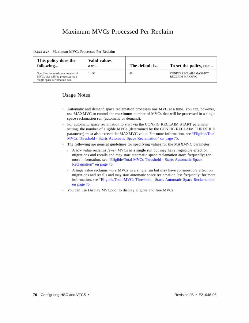
Maximum MVCs Processed Per Reclaim
Usage Notes
? Automatic and demand space reclamation processes one MVC at a time. You can, however, use MAXMVC to control the maximum number of MVCs that will be processed in a single space reclamation run (automatic or demand).
? For automatic space reclamation to start via the CONFIG RECLAIM START parameter setting, the number of eligible MVCs (determined by the CONFIG RECLAIM THRESHLD parameter) must also exceed the MAXMVC value. For more information, see “Eligible/Total MVCs Threshold - Starts Automatic Space Reclamation” on page 75.
? The following are general guidelines for specifying values for the MAXMVC parameter:
? A low value reclaims fewer MVCs in a single run but may have negligible effect on migrations and recalls and may start automatic space reclamation more frequently; for more information, see “Eligible/Total MVCs Threshold - Starts Automatic Space Reclamation” on page 75.
? A high value reclaims more MVCs in a single run but may have considerable effect on migrations and recalls and may start automatic space reclamation less frequently; for more information, see “Eligible/Total MVCs Threshold - Starts Automatic Space Reclamation” on page 75.
? You can use Display MVCpool to display eligible and free MVCs.
TABLE 2-27 Maximum MVCs Processed Per Reclaim
This policy does the following...
Valid values are... The default is... To set the policy, use...
Specifies the maximum number of MVCs that will be processed in a single space reclamation run.
1 - 98 40 CONFIG RECLAIM MAXMVCRECLAIM MAXMVC
76 Configuring HSC and VTCS • Revision 06 • E21046-06

Maximum MVCs Concurrently Processed for Reclamation and Drain
Hosts Disabled from Reclamation
Usage Notes
? Specifying NOMIGRAT also causes NORECLAM to be set; for more information, see “Hosts Disabled from Migration, Consolidation and Export by VTV or Management Class” on page 51.
? Disabled hosts can still do demand MVC drains via MVCDRain.
TABLE 2-28 Maximum MVCs Concurrently Processed for Reclamation and Drain
This policy does the following...
Valid values are... The default is... To set the policy, use...
Specifies the maximum number of MVCs concurrently processed for reclamation and drain.
1 - 99 1 ? CONFIG RECLAIM CONMVC
? MVCDRAIN CONMVC? RECLAIM CONMVC
TABLE 2-29 Hosts Disabled from Reclamation
This policy does the following...
Valid values are... The default is... To set the policy, use...
Specifies that a host cannot initiate automatic and demand reclamation.
NOMIRECLAM, if not specified, reclamation is not disabled
do not disable CONFIG HOST NORECLAM
E21046-06 • Revision 06 Chapter 2 77

MVC Retain Interval
Usage Notes? Retaining the MVC can reduce MVC mounts.
? When VTCS shuts down, VTCS dismounts all MVCs regardless of the MVC retain interval.
MVC Mount Timeout Interval
TABLE 2-30 MVC Retain Interval
This policy does the following...
Valid values are... The default is...
To set the policy, use...
Specifies how long VTCS will retain an MVC on an RTD in idle mode after a migration.
1 - 60 minutes 10 CONFIG VTSS RETAIN parameter
TABLE 2-31 MVC Mount Timeout Interval
This policy does the following...
Valid values are... The default is...
To set the policy, use...
Specifies the interval before MVC mount timeout.
5 - 30 minutes 15 CONFIG GLOBAL MVCMNTTO=nn parameter
78 Configuring HSC and VTCS • Revision 06 • E21046-06

Non-Library Resident MVC PoliciesThe non-library resident MVC policies specify how VTCS processes MVCs that are not in the ACS.
This policy does the following...
Valid values are... The default is... To set the policy, use...
Specifies whether non-library resident MVCs are selected for drain/reclaim processing.
YES, NO YES (select non-library resident MVCs for drain/reclaim)
CONFIG GLOBAL NLIBDRNR
This policy does the following...
Valid values are... The default is... To set the policy, use...
Specifies whether non-library resident MVCs are selected for migration processing.
YES, NO YES (select non-library resident MVCs for migration)
CONFIG GLOBAL NLIBMIGR
This policy does the following...
Valid values are... The default is... To set the policy, use...
Specifies whether non-library resident MVCs are selected for reclamation processing.
YES, NO YES (select non-library resident MVCs for reclamation)
CONFIG GLOBAL NLIBRECL
E21046-06 • Revision 06 Chapter 2 79

MVC Initialization on First Mount
Note –
? MVCPOOL INITMVC overrides GLOBAL INITMVC. There is no default for MVCPOOL INITMVC; if not specified for a named MVC Pool the CONFIG GLOBAL value (or default) is used.
? Initialization of MVCs in the DEFAULTPOOL is controlled by the GLOBAL INITMVC specification (or default).
? MVC Initialization applies only to VSM4/5 and requires microcode level D02.05.00.00 or higher. If this level of microcode is not installed on all VTSSs in the configuration, MVC initialization will be limited to the VTSSs that have it installed.
TABLE 2-32 MVC Initialization on First Mount
This policy does the following...
Valid values are... The default is...
To set the policy, use...
Specifies whether uninitialized MVCs are initialized when first mounted.
NO, YES NO for CONFIG GLOBAL, none for MVCPOOL
CONFIG GLOBAL INITMVC parameter,MVCPOOL NAME INITMVC parameter
80 Configuring HSC and VTCS • Revision 06 • E21046-06

E21046-06 • Revision 06 81
CHAPTER
3
Preparing for Configuration
In the next chapter, we start configuring the ELS software. But first, there are several items you need to get done in MVS to ensure a successful configuration. So before configuring HSC/VTCS, complete the preparation tasks described in the following sections:
? “Defining A Security System User ID for HSC and VTCS” on page 82
? “Configuring MVS Device Numbers and Esoterics” on page 83
? “Setting the MVS Missing Interrupt Handler (MIH) Value” on page 83
Note – See Installing ELS for information on installing the ELS software.

82 Configuring HSC and VTCS • Revision 06 • E21046-06
Defining A Security System User ID for HSC and VTCS ELS software (HSC and VTCS) uses the MVS System Authorization Facility (SAF) to control the usage of MVCs. Before mounting an MVC and before issuing writes to an MVC, VSM issues a SAF query to verify that the HSC user has UPDATE authority for the MVC.
You must define a security system user ID to be used by the SAF queries. All all VSM SAF queries are issued by HSC, so the security system user ID must be associated with the HSC started task. Refer to your security system documentation for details on how to associate a security system user ID with the HSC started task.
You must also set up tape volume security profiles to ensure that VSM is authorized to mount MVCs, to ensure that VSM is authorized to update MVCs, and to guard against accidental overwrites of MVCs; for more information, see “Defining MVC Pool Volser Authority” on page 199.
Caution – Depending on the default settings of your security system, VSM may not be able to mount and to write to MVCs until you have defined a security system user ID for HSC and tape volume security profiles for the MVCs.

E21046-06 • Revision 06 Chapter 3 83
Configuring MVS Device Numbers and EsotericsThe following sections tell how to use the HCD facility to do the following:
? Assign MVS device numbers to VTDs, library drives, and RTDs.
? Associate these MVS device numbers and esoterics.
You determined these values in “Determining HSC/VTCS Configuration Values” on page 5. See your IBM documentation for more information on the HCD facility.
Assigning MVS Device Numbers to VTDs and Library DrivesUse the HCD facility to assign MVS device numbers to these devices (VTDs are seen as 3490E devices)
Note – You do not need to define any specific esoterics (except in JES3) but you may want to define any number of esoterics to be referenced by SMC policies.For considerations for defining esoterics for ELS, see Configuring and Managing SMC .
Assigning MVS Device Numbers to RTDsUse the HCD facility to assign MVS device numbers to these RTDs.
Tip – You must use the same unit addresses you determined for these transports for LIBGEN updates as described in “Planning for Library-Attached Transports” on page 27.
Setting the MVS Missing Interrupt Handler (MIH) Value The VTSS’s internal error recovery procedures requires the MVS missing-interrupt handler (MIH) value to be 20 minutes. You set this value by modifying the MIH parameter in SYS1.PARMLIB member IECIOSxx.

84 Configuring HSC and VTCS • Revision 06 • E21046-06

E21046-06 • Revision 06 85
CHAPTER
4
Configuring HSC
Before you configure VTCS, you must configure HSC...if you are a new customer. If you are an existing customer, go to Chapter 5, “Reconfiguring a TapePlex”.
Your task list for configuring HSC is as follows:
? “Creating the HSC CDS” on page 86
? “Defining Volumes to ELS” on page 97
? “Adding Definitions for ACF/VTAM Communications” on page 102
? “Defining the SYS1.PARMLIB Member SMFPRMxx” on page 103
? “Creating the HSC PARMLIB Member” on page 104
? “Defining Command Authority” on page 107
? “Updating HSM” on page 107
? “Creating and Cataloging the HSC Startup Procedure” on page 108
? “Performance Considerations” on page 114
Note – For information on routing data sets to VSM, see Configuring and Managing SMC .

86 Configuring HSC and VTCS • Revision 06 • E21046-06
Creating the HSC CDSCreating the CDS consists of the following:
? “Coding the LIBGEN Macros” on page 87
? “Running the SLICREAT Utility To Format the New CDS” on page 93
For more information on the LIBGEN macros, see Appendix A, “HSC LIBGEN Macros”.

E21046-06 • Revision 06 Chapter 4 87
Coding the LIBGEN MacrosThe LIBGEN macros specify the library configuration. You code the LIBGEN macros in a data set pointed to by the assembler JCL SYSIN DD statement. TABLE 4-1 describes the LIBGEN macros and shows their required order in the input data set. “LIBGEN Macro Samples” on page 249 shows examples of LIBGEN input data sets. For more information on the LIBGEN utility, see ELS Command, Control Statement, and Utility Reference. For more information on the LIBGEN macros, see Appendix A, “HSC LIBGEN Macros”.
TABLE 4-1 LIBGEN Macros
Macro Description
SLIRCVRY Specifies HSC recovery values.
SLILIBRY Specifies global settings. You can also define future ACSs with SLILIBRY.
SLIALIST Specifies the list of ACSs.
SLIACS To define the ACSs, create one SLIACS macro for each ACS listed in the SLIALIST macro.
SLISTATN Specifies the list of the stations (LMU interfaces) that connect a host to an ACS. Specify one SLISTATN macro for each station entry listed in the SLIACS macro.
SLILSM To define each LSM, create one SLILSM macro for each LSM listed in the SLIACS macro LSM, LSM2, LSM3, and LSM4 parameters.
SLIDLIST To define the transport list for each LSM, create one SLIDLIST macro for each DRVELST parameter entry in the SLILSM macro. This SLIDLIST macro lists the SLIDRIVS macros for each host.
SLIDRIVS Specifies the transport device addresses used by each host attached to an LSM.
SLIENDGN Specifies the end of the LIBGEN macros.

88 Configuring HSC and VTCS • Revision 06 • E21046-06
To make this LIBGEN procedure real-world, let’s create an input file step by step that ends up looking like the example file shown in “One Host, Two ACSs, One 9310 LSM, One SL8500 Library Configuration” on page 250.
To create an example LIBGEN input file:
1. Create the SLIRCVRY macro:
In this macro, we specified the label for the generated CSECT, and specified all 3 copies of the CDS plus journaling.
The TCHNIQE parameter on the SLIRCVRY LIBGEN macro determines how many CDS copies will be initialized by the SLICREAT program and whether or not journals will be initialized by SLICREAT. If journaling is specified by the TCHNIQE parameter, journals must be defined before HSC will successfully initialize.
2. Create the SLILIBRY macro:
In this macro, we specified the following:
? Only host HSC1 accesses the configuration.
? The SMF record type, here 255, which must match the type specified in “Defining the SYS1.PARMLIB Member SMFPRMxx” on page 103.
? # is the operator command prefix character.
? NAMEACS is the assembler label of the SLIALIST macro.
? STKALSQN is the ENQ/DEQ/QNAME used by host software for serialization.
? Put Standard Labels on scratch volumes.
? GOODAY is the eject password.
? CLN is the cleaning cartridge prefix.
3. Create the SLIALIST macro:
In this macro, we specified the following:
? The assembler label is indeed NAMEACS, as specified in the SLILIBRY macro.
? ACS00 and ACS01 are the two ACSs.
LIBGEN01 SLIRCVRY TCHNIQE=ALL
SLILIBRY HOSTID=HSC1, X SMF=255, X COMPRFX=#, X ACSLIST=NAMEACS, X MAJNAME=STKALSQN, X SCRLABL=SL, X EJCTPAS=GOODAY, X CLNPRFX=CLN, X
NAMEACS SLIALIST ACS00,ACS01

E21046-06 • Revision 06 Chapter 4 89
4. Create the SLIACS macro for ACS00:
In this macro, we specified the following:
? The assembler label is indeed ACS00, as specified in the SLIALIST macro.
? The STATION parameter specifies ST000 as the assembler label of the SLISTATN macro.
? The LSM parameter specifies LSM0000 as the assembler label of the (single) SLILSM macro for the 9310 LSM.
5. Create the succeeding macros referenced by the ACS00 SLIACS macro, starting with SLISTATN:
In this macro, we specified the following:
? The assembler label is indeed ST000, as specified in the SLIACS macro.
? The ADDRESS parameter specifies 0A0 and 0A1 as the device addresses of the two LMUs that control the 9310 LSM.
6. Create the SLILSM macro for the 9310 LSM:
In this macro, we specified the following:
? The assembler label is indeed LSM0000, as specified in the SLIACS macro.
? The DRVELST parameter specifies P0000001, P0000002, P0000009, and P000010 as the assembler labels of the SLIDLIST macros that define the transports in each transport panel.
? The LSM type is 9310.
? The access door has an Extended CAP.
ACS00 SLIACS STATION=(ST000), XLSM=(LSM0000)
ST000 SLISTATN ADDRESS=(0A0,0A1)
LSM0000 SLILSM DRIVE=(1,2,9,10), X DRVELST=(P000001,P000002,P000009,P000010), X TYPE=9310, X DOOR=ECAP

90 Configuring HSC and VTCS • Revision 06 • E21046-06
7. Create the SLIDLIST and SLIDRVS macros for the 9310 LSM:
In these macros, we specified the following:
? The assembler labels of the SLIDLIST macros that define the drive panels are indeed P0000001, P0000002, P0000009, and P0000010 as specified on the SLILSM macro.
? Each SLIDLIST HOSTDRV parameter specifies the assembler label of the corresponding SLIDRIVS macro.
? The assembler labels on the SLIDRVS macros match, and the ADDRESS parameters specify the unit addresses of each drive on each panel.
Note –
? These are the device addresses you determined in “Planning for Library-Attached Transports” on page 27.
? We did not specify drive addresses for panel P000010, so we can add drives there later if necessary.
Tip – This example shows a single host. For additional information on defining device addresses in a client/server environment, see Configuring and Managing SMC .
P000001 SLIDLIST HOSTDRV=D0000010*D0000010 SLIDRIVS ADDRESS=(410,411,412,413)*P000002 SLIDLIST HOSTDRV=D0000020*D0000020 SLIDRIVS ADDRESS=(414,415,416,417)*P000009 SLIDLIST HOSTDRV=D0000090*D0000090 SLIDRIVS ADDRESS=(510,511,512,513)*P000010 SLIDLIST HOSTDRV=D000100*D000100 SLIDRIVS ADDRESS=(,,,)

E21046-06 • Revision 06 Chapter 4 91
8. Create the SLIACS macro for ACS01:
Note – Before you configure HSC for the SL8500, verify that all components of the SL8500 are operational. HSC builds its library configuration from the information reported by the library. If SL8500 components are not operational, the library information may not be reported to HSC, and the HSC configuration of the SL8500 is incomplete.
To verify that all the components of the SL8500 are operational, use the SLConsole (either the panel on the SL8500 or a remote SLConsole). Select Tools, then select System Detail. ? All SL8500 components should be green. If the components are not green, and you have
already configured the SL8500 to HSC, the missing components probably have not been configured.
? If the drives are red, the drive configuration can be updated dynamically using the SET SLIDRIVS utility (refer to ELS Command, Control Statement, and Utility Reference) and the MODify CONFIG command. If only the drives are red, you can proceed with the HSC configuration.
? The elevators (Elevator Folder) must be green. If the elevators are not green, do not configure the SL8500 to HSC. The elevators are the logical PTPs. Without PTPs, HSC will not know that the SL8500 rails are connected.
In this macro, we specified the following:
? The assembler label is indeed ACS01, as specified in the SLIALIST macro.
? The FUTRLSM parameter defines four SL8500s that will later be physically added to the configuration. HSC sees each rail in an SL8500 as an entire LSM. An SL8500 library contains four rails (LSMs), thus the lsmnum value must be in multiples of four, so in this example 16 LSMs equals 4 future SL8500s.
? The LSM parameter specifies the assembler labels of the 4 SLILSM macros for each SL8500 rail (starting with the first).
9. Create the SLILSM macro for the first SL8500 rail/LSM:
In this macro, we specified the following:
? The assembler label is indeed LSM0100, as specified in the SLIACS macro.
? The PASTHRU parameter specifies:
? 0, which is the value for SL8500 internal PTPs (elevators), repeated three times because the SL8500 has 4 LSMs and each LSM needs to pass thru to the other 3 LSMs.
? M designates this LSM as the master. In an SL8500, the lowest numbered LSM is always the master.
ACS01 SLIACS FUTRLSM=(SL8500,16), X LSM=(LSM0100,LSM0101,LSM0102,LSM0103)
LSM0100 SLILSM PASTHRU=((0,M),(0,M),(0,M)), X ADJACNT=(LSM0101,LSM0102,LSM0103), X DRIVE=(1), X DRVELST=(P010001), X TYPE=8500, X DOOR=8500-1

92 Configuring HSC and VTCS • Revision 06 • E21046-06
? The ADJACNT parameter specifies the assembler labels of the other 3 rails (LSMs) in the SL8500.
? The DRIVE parameter specifies only one transport panel, which is always the case for SL8500 rails/LSMs, and the DRVELST parameter specifies P010001 as the assembler label of the SLID LIST macro that defines the transports in the single drive panel.
? The LSM type is 8500.
? DOOR=SL8500-1 means that there is a single SL8500 CAP.
10. Create the SLIDLIST and SLIDRVS macros for the first SL8500 rail/LSM:
In these macros, we specified the following:
? The assembler labels of the SLIDLIST macro that defines the single SL8500 drive panel is indeed P010001 as specified on the SLILSM macro.
? Each SLIDLIST HOSTDRV parameter specifies the assembler label of the corresponding SLIDRIVS macro.
? The assembler labels on the SLIDRVS macros match, and the ADDRESS parameters specify the unit addresses of each drive on each panel.
Note –
? These are the device addresses you determined in “Planning for Library-Attached Transports” on page 27.
? This example shows a drive panel for each of the two hosts. For more information on defining device addresses in a client/server environment, see Configuring and Managing SMC .
11. Repeat Step 8 on page 91 through Step 10 on page 92 for the other 3 SL8500 rails/LSMs.
The numbers will change but the basic coding does not except that these LSMs, in terms of PTP control, are Slave LSMs, which is always the case with SL8500s.
12. Finally, create the SLIENDGN macro...
...and you’re done!
P010001 SLIDLIST HOSTDRV=(D0100010,D0100011)*D0100010 SLIDRIVS ADDRESS=(,,,9400,,,,9401,,,,,,,,)D0100011 SLIDRIVS ADDRESS=(,,,9400,,,,9401,,,,,,,,)

E21046-06 • Revision 06 Chapter 4 93
Running the SLICREAT Utility To Format the New CDSAfter you code the LIBGEN macros as described in “Coding the LIBGEN Macros” on page 87, assemble and link-edit the LIBGEN macros and run the SLICREAT utility to format the new CDS:
1. Assemble and link–edit the LIBGEN macros.
FIGURE 4-1 shows example LIBGEN assembler and linkage editor JCL. Update this example with your LIBGEN macros and run the job.
FIGURE 4-1 Assembler and Linkage Editor LIBGEN Example JCL
//*//ASM EXEC PGM=ASMA90//SYSPRINT DD SYSOUT=*//SYSTERM DD SYSOUT=* (optional)//SYSLIB DD DSN=SYS1.MACLIB,DISP=SHR// DD DSN=SLS.SLSMAC,DISP=SHR//SYSUT1 DD UNIT=SYSDA,SPACE=(CYL,(3,1))//SYSLIN DD DSN=&&OBJ,UNIT=SYSDA,// SPACE=(CYL,(1,1)),DISP=(,PASS)//SYSIN DD * LIBGEN deck goes here/*//LKED EXEC PGM=IEWL,PARM=’LIST,XREF,RENT,REUS,REFR,RMODE=24’,// COND=(0,NE)//SYSPRINT DD SYSOUT=*//SYSLMOD DD DSN=SLS.your.hsc.linklib(lgenname),DISP=SHR//SYSUT1 DD UNIT=SYSDA,SPACE=(CYL,(3,1))//SYSLIN DD DSN=&&OBJ,DISP=(OLD,DELETE)//*

94 Configuring HSC and VTCS • Revision 06 • E21046-06
2. Run SLICREAT to format the New CDS.
FIGURE 4-1 shows example JCL for the SLICREAT program. This sample is also included in the HSC SAMPLIB as member JCLCRT.
FIGURE 4-2 SLICREAT Example JCL
In “CDS DASD Space Requirements” on page 18, you determined the size of the CDS to support your ELS system.
Note –
? For an example of using SLICREAT to format journals, see ELS Legacy Interfaces Reference.
? Run SLICREAT with the highest level of the software that you are running on any LPAR.
//SLICREAT JOB (account),’programmer’,CLASS=A //CREATE EXEC PGM=SLICREAT, CDS CREATE MODULE // PARM=’libgen-load-module-name’, // REGION=0M //*//STEPLIB DD DSN=your.hsc.linklib,DISP=SHR //SYSPRINT DD SYSOUT=* MESSAGES //*//******************************************************************//* LIBRARY PRIMARY CONTROL DATASET (CDS) //******************************************************************//SLSCNTL DD DSN=SLS.SLSCNTL, PRIMARY CDS // SPACE=(4096,s,,CONTIG,ROUND), REPLACE ’s’ WITH YOUR// DISP=(NEW,CATLG,DELETE), SPACE CALCULATIONS // UNIT=SYSDA //******************************************************************//* LIBRARY SECONDARY CONTROL DATASET (CDS) //******************************************************************//SLSCNTL2 DD DSN=SLS.SLSCNTL2, SECONDARY CDS // SPACE=(4096,s,,CONTIG,ROUND), REPLACE ’s’ WITH YOUR// DISP=(NEW,CATLG,DELETE), SPACE CALCULATIONS // UNIT=SYSDA //******************************************************************//* LIBRARY STANDBY CONTROL DATASET (CDS) //******************************************************************//SLSSTBY DD DSN=SLS.SLSSTBY, STANDBY CDS // SPACE=(4096,s,,CONTIG,ROUND), REPLACE ’s’ WITH YOUR// DISP=(NEW,CATLG,DELETE), SPACE CALCULATIONS// UNIT=SYSDA //******************************************************************

E21046-06 • Revision 06 Chapter 4 95
Defining and Creating CDS Log FilesTo define and create CDS log files:
1. Use the FMTLOG utility to pre-format the log files.
The size of the allocated log files depends on the number of transactions your system generates, as well as the frequency of performing the offload. StorageTek suggests you allocate and activate some test log files and determine the rate at which they fill before determining the size of the production log files.
Sample JCL:
Note – Data sets must be cataloged, so that they can be located by dynamic allocation. You can assign either one or two log files. If you assign two log files, the second is a copy of the first. There is no “automatic switching” between log files. If an error occurs on a file, it is disabled and logging continues on the other file.
2. Use the SET LOGFILE utility to activate the log files.
Sample JCL:
//FMTLOG JOB (account),REGION=1024K//S1 EXEC PGM=SLUADMIN,PARM=MIXED//STEPLIB DD DSN=hlq.SEALINK,DISP=SHR//SLSLOG1 DD DSN=hlq.CDSLOG1,DISP=(,CATLG,DELETE),// UNIT=SYSDA,SPACE=(CYL,100)//SLSLOG2 DD DSN=hlq.CDSLOG2,DISP=(,CATLG,DELETE),// UNIT=SYSDA,SPACE=(CYL,100)//SLSPRINT DD SYSOUT=*//SLSIN DD *FMTLOG/*
//SETLOG JOB (account),REGION=1024K//S1 EXEC PGM=SLUADMIN,PARM=MIXED//STEPLIB DD DSN=hlq.SEALINK,DISP=SHR//SLSPRINT DD SYSOUT=*//SLSIN DD *SET LOGFILE(hlq.CDSLOG1,hlq.CDSLOG2)/*

96 Configuring HSC and VTCS • Revision 06 • E21046-06
Running Multiple HSC Tapeplexes on One LPAR (MULT Mode)ELS now supports the ability to run multiple instances of HSC on the same LPAR. The following restrictions apply when HSC is started in MULT mode:
? If any HSC on the LPAR specifies the MULT parameter, then all HSC subsystems on that LPAR must specify the MULT parameter.
? Two HSC subsystems on the same LPAR must represent separate tapeplexes, that is, each HSC must point to a different set of CDSs.
? ExPR started task is not supported on any LPAR where HSC is running in MULT mode.
? A new parameter, SSYS, is required on any SLUADMIN step running on an LPAR where HSC is in MULT mode.
? The SLIEXERS installation utility cannot be run on an LPAR where HSC is in MULT mode.
? Any application using the HSC Significant Event Notification (SEN) facility on an LPAR where HSC is running in MULT mode must be modified to pass a subsystem name parameter. See ELS Programming Reference for more detail on the SEN facility.
The following are recommendations for running multiple HSCs on one LPAR:
? Each HSC subsystem should specify a unique command prefix.
? Each HSC subsystem should specify MSGPRFX(YES) in its EXECPARM parameter. Using this parameter, along with a unique command prefix, identifies the HSC subsystem source for HSC console EXEC JCL parameters. Using this parameter, along with a unique command prefix, identifies the HSC subsystem source for HSC console messages.
? Each HSC subsystem should use a unique SMF record ID. This allows statistics to be collected for individual HSC subsystems.
? Each HSC subsystem should use a unique ENQUEUE name. This can be done by using the SLUADMIN SET MAJNAME utility. Specifying the same enqueue name for multiple CDSs can lead to performance issues.
? MULT mode and VTCS Coupling Facility:
? If the VTCS Coupling Facility is used, StorageTek recommends that it should be used only on one HSC/VTCS system on an LPAR.
? If the VTCS Coupling Facility is used on more than one HSC/VTCS subsystems within a single Sysplex, each system MUST specify a unique LOCKSTR value. See ELS Command, Control Statement, and Utility Reference for more information on the VTCS CONFIG utility.

E21046-06 • Revision 06 Chapter 4 97
Defining Volumes to ELSWith ELS 7.0, you now use the HSC POOLPARM and VOLPARM statements to define all volumes and their pools...native Library Volumes, cleaning cartridges, MVCs, and VTVs...and the HSC SET VOLPARM utility to load them. For more information, see ELS Command, Control Statement, and Utility Reference.
Tip – Do you want to switch to POOLPARM/VOLPARM way but don’t know how to do the conversion? The VOLPCONV utility helps to convert existing VOLDEF, SCRPDEF, MVCDEF, CONFIG VTVVOL, and CONFIG MVCVOL statements to SET VOLPARM statements. For more information, see ELS Command, Control Statement, and Utility Reference.
So in the following sections, you’ll use the same basic procedure, with variations for the type of volume and its pool. But first, a discussion of the benefits of converting to POOLPARM/VOLPARM and some caveats about their use.
Why Should I Use POOLPARM/VOLPARM? POOLPARM/VOLPARM provides the following advantages over the legacy method of defining volumes:
? Reduce system outages.
Using POOLPARM/VOLPARM allows you to dynamically delete VTV or MVC ranges from the CDS, without requiring a CDS MERGE process. Deleting VTV or MVC ranges dynamically requires CDS level G or above (CDSLEVEL=V62ABOVE) and also requires that none of the volumes in the deleted range be currently in use.
? Simplify maintenance of volume parameters.
? All POOLPARM/VOLPARM parameters are maintained in the CDS.
? Edits ensure that all volsers in your environment are defined only once and belong to only one pool.
? Current contents of POOLPARM/VOLPARM is available by running the LIBGEN utility (see CU Ref for details)
? When the SET VOLPARM utility is run with APPLY=YES, all updates occur immediately on all hosts.
? Improved management of scratch subpool allocation.
? POOLPARM/VOLPARM allows only non-subpool scratch volumes to be selected when no scratch subpool is specified. Non-subpool scratch volumes are those volumes defined before any pool definition.
? Using POOLPARM/VOLPARM rejects mount requests for undefined subpool names from SMC.
? POOLPARM/VOLPARM provides the ability to limit access to scratch subpools based on client host ID in a client/server environment.

98 Configuring HSC and VTCS • Revision 06 • E21046-06
? Improved reporting.
? Your VOLRPT will automatically pick up subpool definitions, flag MVCs, and show volumes in DR test scratch subpools, as well as flagging undefined volumes.
? HSC D VOLUME DETAIL shows pool residency.
? Pre-validation.
? You can use the SLUADMIN utility to pre-validate your POOLPARM/VOLPARM statements before activating them.
? You can use the SMC POLICY VALIDATE in the SMC subsystem or SMCUSIM utility to ensure that all SMC POLICY statements specify valid subpools.
? POOLPARM/VOLPARM supports volume segregation in the Concurrent Disaster Recovery Test utility.
? Using POOLPARM/VOLPARM automatically segregates DR test scratch subpools and MVC pools from production. When POOLPARM/VOLPARM is in effect, DR test systems can use only volumes defined in DRTEST pools.
? In a DR test environment, you can scratch volumes defined as part of DRTEST scratch subpools.
? Using POOLPARM/VOLPARM supports volume segregation in a Cross TapePlex Replication environment.
? Defining POOLPARM with TYPE=EXTERNAL and OWNRPLEX name ensures that the receiving TapePlex cannot use a VTV as scratch and can receive a VTV only from the specified OWNRPLEX
? Changing a POOLPARM from TYPE=EXTERNAL to TYPE=SCRATCH allows the receiving TapePlex to scratch VTVs received from another TapePlex in case of an actual disaster.
? A utility is provided to assist in converting existing volume definitions to POOLPARM (for more information, see ELS Command, Control Statement, and Utility Reference).
? Input includes existing VOLDEF, SCRPDEF, MVCPOOL, and VTCS CONFIG definitions
? Note that the conversion utility cannot convert “wildcard” characters in VOLATTR statements. You must manually convert wildcard specifications to volume ranges.

E21046-06 • Revision 06 Chapter 4 99
Some Caveats with POOLPARM/VOLPARMA few things to remember when using POOLPARM/VOLPARM:
? VTCS CONFIG MVCVOL and VTVVOL definitions are no longer honored.
? HSC control commands SCRPDEF, VOLDEF and MVCDEF are no longer honored.
? Your pool definitions are the same on all hosts. You can, however, use the HOSTID parameter to limit access to scratch subpools.
? Mounts for invalid subpools will be rejected.
? Mounts with no specified subpool can be satisfied only by non-subpool volumes.
? You can disable POOLPARM/VOLPARM by running the SET VOLPARM utility with an empty SLSPARM input file. Once POOLPARM/VOLPARM is disabled, the previous version of POOLPARM/VOLPARM remains in effect for MVC and VTV definitions until you run VTCS CONFIG, and the previous POOLPARM/VOLPARM POOL definitions remain in effect until you run the VOLDEF, SCRPDEF and MVCDEF commands on the HSC host(s).
? If you run CDRT with POOLPARM/VOLPARM in effect you must have DRTEST pools defined or scratch mounts will not be satisfied, and no MVCs can be used.
Defining Library VolumesTo define Library Volumes:
1. Create a POOLPARM statement to define volume scratch pools.
For example, to define a scratch pool for use by hosts MVS1 and MVS2:
POOLPARM NAME(SYS19840P1)TYPE(SCRATCH)HOSTID(MVS1,MVS2)LABEL(SL)
2. Create a VOLPARM statement to define the volumes.
For example, to define a range of 9840C volumes:
VOLPARM VOLSER(C1000-C1999)MEDIA(STK1R)RECTECH(STK1RC)
3. Ensure that you define sufficient cleaning cartridges.
Go to “Defining Cleaning Cartridges” on page 100.
Note – Once you install higher density (or encryption-capable) drives for existing media, note that if you eject and re-enter an existing cartridge, HSC sets the density to “unknown” whenever the ACS contains drives other than the lowest density for the media, and sets the encryption status to “unknown” whenever the ACS contains encrypting drives for the media. This means that in the allocation process, SMC attempts to allocate the specific volume to the highest density drives and to encrypting drives, whenever the volume is flagged as “unknown.”
To manage this situation, do one of the following:
? You can use VOLPARMs for the volume to indicate its actual density (encryption status), and then, once it is scratched, reset the VOLPARM to the desired recording technique.
? You can use the 7.0 vaulted volume feature to manage the ejected cartridge as a non-library volume, using LCM. When you use this feature, the HSC CDS records the recording technique at the time of the eject and restores it at the time of the enter.

100 Configuring HSC and VTCS • Revision 06 • E21046-06
Defining Cleaning CartridgesTo define cleaning cartridges:
1. Create a POOLPARM statement to define the cleaning cartridge pool.
For example, to define the 9840 cleaning cartridge Pool with cleaning parameters:
POOLPARM TYPE(CLEAN)MAXCLEAN(25)
2. Create a VOLPARM statement to define the cleaning cartridges.
For example, to define a range of 9840 cleaning cartridges:
VOLPARM VOLSER(CLN300-CLN310)MEDIA(STK1U)
3. Do you need to define MVCs?
If so, go to “Defining MVCs” on page 100. Otherwise, go to “Validating and Applying the Volume Definitions” on page 101.
Defining MVCs
Note – POOLPARM/VOLPARM is the preferred method for defining MVCs for ELS 7.0 but you can still use CONFIG to define MVCs. For more information, see ELS Legacy Interfaces Reference. Also note that if you have existing volsers defined via CONFIG, you must run DECOM against your CONFIG deck, remove the CONFIG definitions, and rerun CONFIG before you create POOLPARM/VOLPARM definitions.
To define MVCs:
1. Create a POOLPARM statement to define the MVC pool.
For example, to define the T10000 MVC Pool with reclaim parameters:
POOLPARM NAME(SYS1MVCT1)TYPE(MVC)MVCFREE(40) MAXMVC(4) THRESH(60) START(70)
2. Create a VOLPARM statement to define the MVCs.
For example, to define a range of T10000 Full volumes to be encrypted:
VOLPARM VOLSER(T2000-T2999)MEDIA(T10000T1)RECTECH(T1AE)
3. Define VTVs.
Go to “Defining VTVs” on page 101.

E21046-06 • Revision 06 Chapter 4 101
Defining VTVs
Note – POOLPARM/VOLPARM is the preferred method for defining VTVs for ELS 7.0 but you can still use CONFIG to define MVCs. For more information, see ELS Legacy Interfaces Reference. Also note that if you have existing volsers defined via CONFIG, you must run DECOM against your CONFIG deck, remove the CONFIG definitions, and rerun CONFIG before you create POOLPARM/VOLPARM definitions.
To define VTVs:
1. Create a POOLPARM statement to define the volume scratch pool.
For example, to define a VTV scratch pool for use by hosts MVS1 and MVS2:
POOLPARM NAME(SYS1VTV1)TYPE(SCRATCH)HOSTID(MVS1,MVS2)LABEL(SL)
2. Create a VOLPARM statement to define the VTVs.
For example, to define a range of VTVs initialized as scratch:
VOLPARM VOLSER(V5000-V5999)MEDIA(VIRTUAL)INITSCR
Validating and Applying the Volume Definitions1. Run SET VOLPARM to validate the POOLPARM/VOLPARM statements.
SET VOLPARM APPLY(NO)
APPLY(NO) validates the statements without loading them. If you like the results, go to Step 2. Otherwise, rework your volume definitions, then go to Step 2.
2. Run SET VOLPARM to load the POOLPARM/VOLPARM statements.
SET VOLPARM APPLY(YES)
3. Physically enter the cartridges into the ACS.
For more information, see Managing HSC and VTCS.

102 Configuring HSC and VTCS • Revision 06 • E21046-06
Adding Definitions for ACF/VTAM Communications To optimize performance, StorageTek recommends that you set the HSC COMMPath METHod parameter to VTAM, which does not place a performance burden on HSC, as shown in the example in “Creating the HSC PARMLIB Member” on page 104.
If you set COMMPath METHod to VTAM, you must define the following to VTAM:
? APPL
? CDRSC
? CDRM (if not using existing CDRMs)
? LOGMODE table entry for SNASVCMG (contained in the IBM-supplied logon mode table).
? LOGMODE table entry for SLSSVCMG. This can be defined the same as SNASVCMG. If not defined, the default logmode entry is used.
A sample APPL statement is contained in the HSC SAMPLIB member HSCAPPL, shown below, with the HSC application program minor node (APPLID) as APHSC1:
HSCAPPL VBUILD TYPE=APPLAPHSC1 APPL APPC=YES, AUTOSES=1, + DMINWNL=1, + DMINWNR=1, + DESESLIM=2, + EAS=10
where:
APPC=YES
must be coded because HSC uses VTAM LU 6.2 services.
AUTOSES=1
defines the number of contention-winner sessions VTAM is to establish automatically with the first CNOS request.
DMINWNL=1
defines the minimum number of parallel sessions with the local LU as the contention-winner. HSC only requires and uses one local contention-winner session.
DMINWNR=1
defines the minimum number of parallel sessions with the remote LU as the contention-winner. HSC only requires and uses one remote contention-winner session.
DSESLIM=2
defines the maximum number of sessions allowed between the local LU and a remote LU. This should be 2 because the HSC only establishes two sessions between each HSC: one local contention-winner session and one remote contention-winner session.
EAS=10
sets an estimated number of concurrent sessions this APPLID will have with other LUs. Refer to the IBM ACF/VTAM manuals for definitions and explanations.

E21046-06 • Revision 06 Chapter 4 103
Defining the SYS1.PARMLIB Member SMFPRMxxHSC can produce SMF record subtypes for HSC and VTCS events. To produce these record subtypes, you must add two statements to your SMF parameters in SYS1.PARMLIB member SMFPRMxx to specify the following:
? HSC subsystem for which records are produced
? Recording interval in seconds
? SMF record subtypes. The record subtypes must be specified as a list (subtype1, subtype2,...subtypen), as a range (subtype1-subtypen), or as a combination (subtype1, subtype2-subtypen). A range must be specified using a dash; a colon is invalid for a range.
Note – The TYPE parameter in the SMFPRMxx member must match the SLILIBRY SMF= parameter specified in “Coding the LIBGEN Macros” on page 87.
Tip – StorageTek recommends that you specify that your system produces the HSC SMF record subtypes 1 through 8 and 10, 11, 13, 14, 15, 16, 17, 18, 19, 20, 21, 25, 26, 27, 28, 29, 30, and 31 as shown in FIGURE 4-3. For more information on SMF record layouts, see ELS Programming Reference.
FIGURE 4-3 shows example statements that produce record subtypes 1 through 8 and 10, 11, 13, 14, 15, 16, 17, 18, 19, 20, 21, 25, 26, 27, 28, 29, 30, and 31at 15 minute intervals for HSC subsystem SLS0.
FIGURE 4-3 SYS1.PARMLIB member SMFPRMxx example for VTCS SMF records
SUBSYS(SLS0,INTERVAL(001500),TYPE(255))SUBPARM(SLS0(SUBTYPE, (1-8, 10, 11, 13, 14, 15, 16, 17, 18, 19, 20, 21, 25, 26, 27, 28, 29, 30, 31)))

104 Configuring HSC and VTCS • Revision 06 • E21046-06
Creating the HSC PARMLIB MemberThe HSC PARMLIB member is where you specify any commands that you want executed at HSC startup as shown in the example in FIGURE 4-4.
FIGURE 4-4 Example: Updating the HSC PARMLIB Member
In FIGURE 4-4:
CDSDEF
The CDSDEF control statement in the HSC PARMLIB determines how many CDS copies are allocated by the HSC.These definitions are invoked at HSC initialization and remain set until HSC termination. The definitions cannot be altered without HSC shutdown and restart.
Caution – The number of CDS copies implied by the TCHNIQE parameter must be the same as the number of CDS copies implied by the CDSDEF control statement otherwise the HSC will not initialize.
? If the number of CDS copies defined on the CDSDEF control statement is more than are specified by the TCHNIQE parameter, do the following:
? Stop the HSC on all hosts
? Run a SLUADMIN SET TCHNIQUE to increase the number of copies to match the number implied by the CDSDEF control statement
? Restart HSC
? If the number of CDS copies defined on the CDSDEF control statement is less than are specified by the TCHNIQE parameter, do the following:
? Stop the HSC on all hosts
? Run a SLUADMIN SET TCHNIQUE to decrease the number of copies to match the number implied by the CDSDEF control statement
? Restart HSC
The control data set names are recorded in the Database Heartbeat (DHB) record. During HSC initialization, the data set names in the DHB are compared with the data set names specified on the CDSDEF control statement in the HSC PARMLIB.
If a data set name specified on the CDSDEF statement does not match any of the control data set names recorded in the DHB, that control data set is disabled. If all the specified control data sets are disabled, the HSC will not initialize. The specific assignment of enabled control data sets to the primary, secondary, and standby control data set(s) is made based on the control data set assignments recorded in the Database Heartbeat record.
HSC.PARMS
CDSDEF DSN1(HSC1.PRIM),DSN2(HSC1.BKUP),DSN3(HSC1.STDBY)MGMTDEF DSN(HSC.PARMS)COMMP METH VTAMFEAT VSM(ADVMGMT)CAPP 9,01:00:00,AUTOMNTD AUTOCLN(ON) EJCTAUTO(ON)

E21046-06 • Revision 06 Chapter 4 105
is the data set that contains your system’s MGMTclas and STORclas statements.
COMMP METH VTAM
specifies that VTAM is the communications method. StorageTek recommends that you specify VTAM to allow even sharing of resources in a multi-host environment.
FEAT VSM(ADVMGMT)
enables the Advanced Management Feature.
CAPP 9,01:00:00,AUTO
specifies CAP preferences.
MNTD AUTOCLN(ON) EJCTAUTO(ON)
specifies automatic drive cleaning and automatic ejection of spent cleaning cartridges.

106 Configuring HSC and VTCS • Revision 06 • E21046-06
EXECPARM StatementThe EXECPARM statement provides an alternative method of specifying GTF Eid and Fid parameters.
Syntax
FIGURE 4-5 EXECPARM Syntax
Parameters
MSGPRFX
optionally, specifies control of whether the command prefix is to precede WTO or WTOR messages to the operator.
Yes
indicates that the command prefix is to display preceding WTO or WTOR messages to the operator.
No
indicates that the command prefix is not to display preceding WTO or WTOR messages to the operator.
Eid
optionally, gtfeid specifies a GTF event ID.
PARM=’Eid(user-specified-event-id)’ parameter is valid for use in the HSC initialization procedure as an alternative method of specifying the GTF event ID.
Fid
optionally, gtffid specifies a GTF format ID.
PARM=’Fid(user-specified-format-id)’ parameter is valid for use in the HSC initialization procedure as an alternative method of specifying the GTF format ID.
HOSTID
optionally, host-id specifies the system ID associated with the request to process the EXECParm control statement.
Note – If the hostid specified does not match the host executing the command, the command is ignored and no message is issued.
EXECPar m
MSGPRFX( No
Yes
)
, Ei d( gt f ei d) , Fi d( gt f f i d)
, HOSTI D( host - i d) MULT

E21046-06 • Revision 06 Chapter 4 107
Defining Command AuthorityIf HSC user exit SLSUX15 sets a return code of UX15CHKA, the exit issues a command authorization request to the system security product. FIGURE 4-6 shows an example of RACF profile and permissions commands to give user SAM15 update access to all HSC/VTCS commands and user JOE13 query access to all HSC/VTCS commands. Note that you can no longer specify the .VT prefix for VTCS commands, which is no longer passed to SLSUX15. See ELS Programming Reference for a sample of how to define command security based on the originating host ID of the command.
FIGURE 4-6 Example RACF ELS command authorization file
Updating HSMHSM users that have mixed devices that were “logically” defined as the same type of device, such as 3490E but are “physically” different, such as T9940, virtual (VTD), or 9490 must set the following parameter in HSM:
SETSYS RECYCLEINPUTDEALLOCFREQUENCY(MIGRATION(1))
By setting this parameter, when HSM is “recycling”, it will deallocate the input drive after it processes each input tape. This is required where the tapes being recycled are “physically” mixed as described above.
If you do not set this parameter, it is possible that you could allocate a 9490 transport for the first tape, then if the second tape was virtual (VTV) or STK2P, the job would fail due to media incompatibility. That is, you could not physically mount the second tape (virtual or STK2P media) on the 9490 drive that had been allocated for the first tape.
********************************************************************************* Define a profile in the OPERCMDS class for all HSC and VTCS commands *********************************************************************************RDEFINE OPERCMDS subsysname.* UACC (NONE)******************************************************************************************** Allow user JOE13 access to all query HSC/VTCS commands******************************************************************************************PERMIT subsysname.command CLASS(OPERCMDS) ID(JOE13) ACCESS (QUERY)******************************************************************************************** Allow user SAM15 update access to all HSC/VTCS commands******************************************************************************************PERMIT subsysname.command CLASS(OPERCMDS) ID(SAM15) ACCESS (UPDATE)********************************************************************************

108 Configuring HSC and VTCS • Revision 06 • E21046-06
Creating and Cataloging the HSC Startup Procedure You start HSC by entering the MVS START command that invokes the HSC startup procedure, which resides in the cataloged procedure library of the host system. For more information, see:
? “Running Multiple HSC Tapeplexes on One LPAR (MULT Mode)” on page 109
? “EXEC Statement” on page 110.
? “Sample HSC Startup Procedure” on page 113
? “EXECPARM Statement” on page 106 for an alternative method of specifying GTF Eid and Fid parameters.
Note – If you previously controlled which hosts started VTCS by referencing or not referencing the VTCS software in your JCL concatenation, this capability is provided in ELS 7.0 by using the NOVTCS parameter on the HSC startup PARM. For more information, see “EXEC Statement” on page 110.

E21046-06 • Revision 06 Chapter 4 109
Running Multiple HSC Tapeplexes on One LPAR (MULT Mode)ELS now supports the ability to run multiple instances of HSC on the same LPAR. The following restrictions apply when HSC is started in MULT mode:
? If any HSC on the LPAR specifies the MULT parameter, then all HSC subsystems on that LPAR must specify the MULT parameter.
? Two HSC subsystems on the same LPAR must represent separate tapeplexes, that is, each HSC must point to a different set of CDSs.
? The ExPR started task is not supported on any LPAR where HSC is running in MULT mode.
? A new parameter, SSYS, is required on any SLUADMIN step running on an LPAR where HSC is in MULT mode.
? The SLIEXERS installation utility cannot be run on an LPAR where HSC is in MULT mode.
? Any application using the HSC Significant Event Notification (SEN) facility on an LPAR where HSC is running in MULT mode must be modified to pass a subsystem name parameter. See ELS Programming Reference for more detail on the SEN facility.
The following are recommendations for running multiple HSCs on one LPAR:
? Each HSC subsystem should specify a unique command prefix.
? Each HSC subsystem should specify MSGPRFX(YES) in its EXECPARM or EXEC JCL parameters. Using this parameter, along with a unique command prefix, identifies the HSC subsystem source for HSC console EXEC JCL parameters. Using this parameter, along with a unique command prefix, identifies the HSC subsystem source for HSC console messages.
? .Each HSC subsystem should use a unique SMF record ID. This allows statistics to be collected for individual HSC subsystems.
? .Each HSC subsystem should use a unique ENQUEUE name. This can be done by using the SLUADMIN SET MAJNAME utility. Specifying the same enqueue name for multiple CDSs can lead to performance issues.
? MULT mode and VTCS Coupling Facility.
? If the VTCS Coupling Facility is used, Sun StorageTek recommends that it should be used only on one HSC/VTCS system on an LPAR.
? If the VTCS Coupling Facility is used on more than one HSC/VTCS subsystems within a single Sysplex, each system must specify a unique LOCKSTR value. See ELS Command, Control Statement, and Utility Reference for more information on the VTCS CONFIG utility.

110 Configuring HSC and VTCS • Revision 06 • E21046-06
EXEC Statement The EXEC statement specifies HSC startup options.
Syntax
FIGURE 4-7 EXEC Statement Syntax
Parameters
PARM=
defines the list of parameters passed to the HSC initialization routine.
Note – If you enter more than one of the following parameters, you must separate them with a blank space (e.g., BASE SSYS(subsystem) RESET).
BASE
specifies that the HSC initialize and execute at the base service level.
SSYS
specifies that HSC initialization search for the subsystem name specified. If the name is not found or is not a valid name, the subsystem terminates. subsystem must be a 1- to 4-character name or problems can occur when initializing the HSC.
This parameter permits you to symbolically specify the subsystem and retain the same startup procedure whether starting the HSC before or after JES.
INIT
specifies that only preinitialization of the HSC occurs.
/ / st epname EXEC PGM=SLSBI NI T
', PARM=' BASE
SSYS( subsyst em)
I NI T
COLD
RESET
Ei d( xxxx)
Fi d( xx)
Member ( xx)
Di al og( Of fBot hConsol eLog
)
NOVTCS

E21046-06 • Revision 06 Chapter 4 111
Note – If PARM=INIT is specified, the HSC subsystem is only initialized. It is still necessary to issue a HSC Start command to start the HSC. If any other parameters are specified with INIT (except for SSYS), they are ignored.
COLD
specifies that any permanent in-memory data structures previously allocated by HSC are reallocated and reinitialized.
This parameter should be used only when absolutely necessary. (The installation instructions for some HSC maintenance may direct you to perform a COLD start.)
Note – You do not need to include the COLD parameter when you are initializing a HSC that is at a different release level than the HSC that was previously running on a host. When an initializing HSC detects a release level difference, it performs an automatic internal cold start.
RESET
specifies that all subsystem status flags in the MVS Subsystem Communications Vector Table (SSCVT) for the HSC are unconditionally reset. Use of this option may correct a situation in which the HSC was terminated abnormally without resetting the status flags; for example, if the HSC was terminated with the MVS FORCE command.
These messages are possible symptoms of this situation:
... ACS subsystem CCCC is ACTIVE
or
... ACS subsystem CCCC is TERMINATING
or
... ACS subsystem CCCC is INITIALIZING
at HSC startup, when a display of active jobs indicates that the subsystem is not, in fact, active.
This parameter should only be used in extreme situations and may not correct all error conditions. Contact StorageTek Software Support before using this parameter.
Eid
xxxx is 1 to 4 hex characters specifying the GTF event ID used for the duration of this subsystem. ‘‘E’’ is the abbreviation for this parameter. The default Eid value is E086.
Fid
xx is 1 to 2 hex characters specifying the GTF format ID used for the duration of this subsystem. ‘‘F’’ is the abbreviation for this parameter. The default Fid value is 17.
Note – See “EXECPARM Statement” on page 106 for an alternate method of specifying GTF, EID, and FID parameters.
Member
For MVS, xx is the suffix of the SLSSYSxx member in SYS1.PARMLIB, or an SLSSYSxx DD statement in the startup procedure used as the automatic commands (PARMLIB control statements) data set. ‘‘M’’ is the abbreviation for this parameter.
Dialog

112 Configuring HSC and VTCS • Revision 06 • E21046-06
specifies that messages can be displayed on the operator console and/or written to the system log. This option can be used to further restrict where messages are displayed based on the ROUTCDE. These messages indicate that the HSC is waiting for an active task to complete before the HSC terminates.
For more information on Dialog, see “OPTION Command and Control Statement” in the ELS Command, Control Statement, and Utility Reference.
If Dialog is specified, one of the options must be selected. There is no default. The options for Dialog include:
Off
specifies that you do not want active task termination messages displayed on the operator console or written to the system log.
Both
specifies that messages are displayed on the operator console and written to the system log.
Console
specifies that messages are displayed on the operator console only.
Log
specifies that messages are written to the system log only.
NOVTCS
specifies that VTCS should not initialize on a host even though VTCS data is present in the CDS.

E21046-06 • Revision 06 Chapter 4 113
Sample HSC Startup ProcedureFIGURE 4-8 shows HSC SAMPLIB member JCLPROC, which is a sample HSC startup procedure.
FIGURE 4-8 Sample HSC Startup Procedure
In FIGURE 4-8:
? In the example PROC shown above, SLS0 is used as both the name of the startup procedure (line 1) and as the subsystem name defined in the SSYS parameter ‘‘SSYS(SLS0)’’ in line 4. This is just an example, you can code any values that work for your site but note the following:
? HSC subsystem names must be 4 characters in length and must be defined in your IEFSSNxx member.
? If the startup procedure name and the subsystem name are identical, the SSYS parameter is not required in the startup procedure. If the startup procedure name is not identical to the subsystem name, then the SSYS parameter must point the startup procedure to the required HSC subsystem.
? TIME=1440 or TIME=NOLIMIT must be specified to ensure that HSC does not time out and terminate.
? StorageTek recommends that you run HSC/VTCS with a region size of at least 6 MB except if you are running utilities or commands that manipulate manifest files, in which case you need the maximum region size your system will allow.
DD Statements for the HSC Startup Procedure
SLSSYSxx
statement that defines the data set containing the HSC PARMLIB. In the example procedure above, xx is replaced by the suffix ‘‘00’’. The SLSSYS00 DD statement matches the M(00) declaration and points to the PARMLIB member ‘‘00’’ that contains your start-up parameters.
SLSUEXIT
statement that defines the data set containing HSC user exits.
Specifying TCPIP Options
The SYSTCPD DD statement can be used to specify TCP/IP options for the HSC job.
This DD statement identifies the data set used to obtain parameters defined by theIBM TCPIP.DATA configuration data set. Refer to the IBM TCP/IP Customization and Administration Guide for more information
//SLS0 PROC PROG=SLSBINIT,PRM=’ ‘ //* //IEFPROC EXEC PGM=&PROG,TIME=1440, // PARM=’&PRM E(E086) F(23) M(00) SSYS(SLS0)’,REGION=6M //* //STEPLIB DD DSN=SEA700.SEALINK,DISP=SHR //* //SLSSYS00 DD DSN=SLS.PARMS,DISP=SHR //SYSTCPD DD DSN=ddd.eee.fff(anyname) /* Optional TCPIP parameters) */

114 Configuring HSC and VTCS • Revision 06 • E21046-06
Performance Considerations
Define Dispatching Priority for ELS SoftwareDepending on your requirements, set these software components so the amount of resources available to them is as follows:
? HSC/VTCS — greater than batch and any started task or application requiring quick access to tape but less than an online system
? SMC/HTTP server— greater than the HSC, or if the HSC is inactive, greater than batch and any started task or application requiring quick access to tape but less than an online system
Your requirements may dictate that these products be given access to greater or lesser resources than we recommend here but you must determine this for your environment. The information above is meant only to serve as a guideline.
During initialization, the HSC uses SYSEVENT TRANSWAP to make its address space non-swappable. The HSC address space cannot be swapped out once this has been accomplished.
Reduce Pass-Thrus The number of pass-thrus required to mount, dismount, and replace cartridges in LSMs can impact library performance. In a large or busy ACS, this impact may be significant especially during periods of heavy mount activity. There are three types of pass-thrus:
? unavoidable
? unnecessary
? scheduled.
Unavoidable Pass-Thrus
The HSC attempts to minimize the number of pass-thrus required; however, depending upon available tape transports and locations of cartridges, pass-thrus often cannot be avoided. By running Activities Reports on a regular basis and examining the results, you can see that mounts for different LSMs take longer than mounts for the same LSM.
Unnecessary Pass-Thrus
Scratch mounts, dismounts, enters, and ejects that require pass-thrus are unnecessary and should be avoided. These types of activities divert the robotics from productive work especially during periods of peak activity.
If scratch subpools are properly defined and managed, scratch cartridges normally are not involved in pass-thrus. Scratch mounts are the same as specific mounts as far as pass-thrus that cannot be avoided.

E21046-06 • Revision 06 Chapter 4 115
The effect of unnecessary pass-thrus is not obvious in the Activities Report. You must compare their number with average mount times to see the effect on performance.
Scheduled Pass-Thrus
Using the Scratch Redistribution utility to balance scratch cartridges involves moving cartridges to various LSMs to achieve scratch balancing. This type of activity involves heavy pass-thru usage. If you must balance scratch volumes across your library, schedule such activity during off peak hours. This approach will make sure that the pass-thru activity involved does not directly interfere with mounts and dismounts for high-priority production.
You can use LCM to schedule pass-thrus.See LCM User’s Guide for more information.
Methods to Reduce Pass-Thru Activity
There are various methods to reduce pass-thru activity:
Set MNTD Float to ON
The Float option of the MNTD command specifies whether the HSC is to select a new home cell location when it dismounts a volume that requires a pass-thru when it is dismounted.
When MNTD Float is set to ON, cartridges are not passed back to their original LSM. The cartridges are assigned new cells in the LSM where they are dismounted. This action eliminates most unnecessary pass-thrus.
Set MNTD SCRDISM to CURRENT
When MNTD SCRDISM is set to CURRENT, scratch cartridges mounted in a 9360 (WolfCreek) LSM are dismounted in the same device rather than being archived in the next largest storage device.
Provide adequate free cells
Setting MNTD Float to ON can be overridden if there are no free cells in the dismounting LSM. Dismounted cartridges are passed to other LSMs to find a new home cell.
Use the Display Lsm command to determine the number of free cells in each LSM. Use MOVe or EJect to create free cells if they are needed.
Eject through the CAP closest to the cartridge
If you eject a cartridge through the CAP of the LSM where it resides, no pass-thrus are required.
If you eject a cartridge without specifying a CAPid, the cartridge is ejected through the highest priority CAP that is not busy. This type of activity may cause one or more unnecessary, nonproductive pass-thrus.
The recommended way to accomplish ejects without affecting performance with pass-thrus, is to use multiple CAP option on the EJECt utility. By specifying multiple CAPs (i.e., CAP(00:00:00,00:00:01,00:00:02)), the desired effect (i.e., no pass-thrus) is achieved.
Redistribute cartridges during off-peak times
You can use the MOVe command and utility to move cartridges within an LSM or between LSMs. The Scratch Redistribution utility can be used to move scratch cartridges between LSMs until an equilibrium is reached. Each inter-LSM movement of cartridges causes pass-thrus which delay robot movement in mounting a cartridge.

116 Configuring HSC and VTCS • Revision 06 • E21046-06
Depending on the number of cartridges to be redistributed, you may prefer to schedule moves and scratch redistribution during periods of low data center activity. The redistribution runs faster and performance is not affected during off peak times.
Reduce Operator Intervention Although the ACS runs mostly unattended, situations occur where operator intervention is required. Excessive and unnecessary operator intervention impacts library performance. There are specific ways in which operator intervention can be reduced. These include:
Set SMC ALLOCDef DEFer(ON)
If a keep is issued for a cartridge while it is being mounted, the HSC issues a message indicating that the robot cannot dismount the volume. An operator must unload the tape transport and then reply ‘‘R’’ to the message.
This situation is caused by programs allocating cartridges through JCL, not opening the data set on the cartridge, and terminating before the mount completes. It causes unnecessary mounts, extends dismount time, and delays the availability of cartridges and transports.
If a message requiring operator intervention occurs frequently, you may want to set ALLOCDef DEFer(ON) so ACS mounts are deferred until the data set is opened. Alternatively, you can code User Exit 09 for JES2 or User Exit 11 for JES3 with SETUP processing to selectively defer a subset of ACS mounts.
Set CAP Preference
In a multiple-LSM ACS, the CAPPref command establishes an ordered list of CAPs to use should the operator or HSC start an activity that requires a CAP without specifying a CAPid.
To enter or eject cartridges faster, set CAPPref such that the CAP closest to the cartridge racks is preferred. This minimizes operator travel distance.
In large ACS configurations, of five or more LSMs, consider setting CAPPref such that a CAP in the middle of the ACS has the highest priority. This may make the operators walk further but it reduces the number of pass-thrus should the default (highest priority) CAPid be used for ejecting cartridges.
Prefetch Enters
Nonlibrary cartridges that are mounted on library transports are delayed while the operator fetches and enters them. This is a common occurrence for HSC sites with all transports attached to the library.
If you or your scheduling system can predict which nonlibrary cartridges will be mounted in the library before a mount message appears, your operator can improve performance by entering those cartridges in advance.

E21046-06 • Revision 06 Chapter 4 117
Avoid Crashing Test Systems
Library attached hosts own library resources, including CAPs, tape drives, and cartridges. If a host fails, another host must clean up the resources held by the failing host. This delays mounts and dismounts on the recovering host while recovery takes place.
You should attempt to shut down the HSC properly before IPLing a system. This is especially important for test systems that may be restarted several times a day.
Use Unit Affinity Separation
Unit affinity separation can improve library performance by eliminating the need for operators to enter or eject tape cartridges when volumes are requested with unit affinity. Without unit affinity separation, a tape transport is selected based on the location of the first volume.
Refer to the SMC Configuration and Administration Guide for information about the ALLOCDef command SEPLvl parameter, which specifies the exclusion level at which affinity chains are separated.
Reduce Tape Transport Contention
Balanced use of library tape transports results in better robotic and system performance. In a multiple LSM library, you want the workload to be spread evenly among the robots rather than overloading one robot while the others are idle. Within each LSM, you want mounts to be evenly distributed among transports rather than having the robot wait for a cartridge to be rewound so it can mount the next cartridge on the same tape transport.
Tape transport contention can be reduced by:
? ensuring scratch cartridge balance
? managing multi-host tape transports
? avoiding dedicating tape transports
? using two tape transports for multi-volume files.

118 Configuring HSC and VTCS • Revision 06 • E21046-06
Reduce Scheduling Contention Effective scheduling can increase library performance. Controlling the following scheduling related areas can help significantly in further increasing library performance:
? strive for a balanced workload
? schedule nonproductive library activities during low-demand times.
Balancing the Workload
If you experience higher than expected average mount times but at the same time experience an improvement in production throughput, it could be an indication that your system is periodically flooded with work rather than having a balanced workload.
For example, all of your production jobs may be getting submitted at the beginning of a shift so that the library robots are overworked for the first few hours of the shift. Then, the robots may remain idle for the remainder of the shift. If you are using a scheduling software package and it releases jobs every hour on the hour, there may be tremendous tape transport contention for the first few minutes of each hour while the transports are unused for the remainder of each hour.
These situations tend to elevate average mount times; however, as long as the work is performed on time, there is probably no need to change conditions. However, if the work is not getting performed on schedule, you can improve performance by balancing your production workload.
Scheduling Nonproductive Activities During Low-Demand Times
There are several library utilities, which, though very essential, severely impact the library’s ability to mount and dismount cartridges. The following utilities should not be run when high-priority production jobs are pending:
• AUDIt • EJECt • Initialize Cartridge • MOVe • Scratch Redistribution • Scratch Update.
These utilities should be scheduled during quiet periods so they do not contend with mounts and dismounts. Running these activities during quiet periods also makes sure that the tasks complete faster. In the case of mass enters or ejects, operator’s time can also be optimized.

E21046-06 • Revision 06 119
CHAPTER
5
Reconfiguring a TapePlex
“Configuring HSC” on page 85 explained how to configure HSC, which includes performing a LIBGEN, which is how you initially define hardware to HSC. “Reconfiguring a TapePlex” is for existing customers who want to add hardware to their systems either on release boundaries or between release boundaries. The idea being that adding hardware to an existing system is usually easier, because you don’t have to redefine each and every piece of hardware, and also because adding hardware is an easier path...for example, to add transports, you don’t have to stop HSC, recreate your entire LIBGEN, and so forth...you can just use SET SLIDRVS and dynamic reconfiguration (via MODIFY CONFIG) to make it happen.

120 Configuring HSC and VTCS • Revision 06 • E21046-06
When Do You Need to Reconfigure Your TapePlex?Whenever the hardware components that make up your tapeplex change, you need to perform a reconfiguration task to synchronize the HSC CDS with the physical tape hardware. Some reasons for reconfiguring a tapeplex include:
? Consolidating two data centers
? Splitting a single data center into two tapeplexes
? Adding, changing or removing physical tape hardware, including drives, LSMs, and ACSs.
? Adding, changing or removing VTSSs.
? Adding, changing or removing VAULT information.
Depending on the existing configuration and the type of change being done, you will need to use one of the following tools/procedures:
? HSC MERGEcds utility
? HSC dynamic reconfiguration process
? VTCS CONFIG utility
? HSC SET VOLPARM utility
? HSC SET VAULT and/or SET VAULTVOL utility
? HSC AUDIT utility

E21046-06 • Revision 06 Chapter 5 121
The MERGEcds UtilityThe MERGEcds utility is used to migrate information from an existing CDS into a new, formatted CDS. The MERGEcds utility is normally used for the following types of changes:
? Consolidating or splitting data centers
? Adding LSMs or ACSs to a configuration when FUTRLSM or FUTRACS was not specified or was insufficient for the new configuration.
? Deleting LSMs or ACSs from a configuration
? Changing panel types in a non-Streamline library
? Deleting or renaming VTSSs
? Changing the number of vaulted volumes in a CDS where the reserved number of vaulted volumes is too small (or, when the number of vaulted volumes is larger than needed and you want to decrease the size of the CDS)
Basic MERGEcds ProcedureThe following sections describe how to use the MERGEcds utility to add an ACS to an existing HSC. This procedure is the basis for using MERGEcds for the examples in the other section, such as merging data centers.

122 Configuring HSC and VTCS • Revision 06 • E21046-06
? Create a New, Empty CDS
Note – This procedure can be run at any time before the actual MERGEcds operation.
To create a new, empty CDS:
1. Run the HSC LIBGEN utility to create LIBGEN macros that reflect your current real hardware configuration (and, optionally, your VOLPARM and vaulted volume data).
For example:
2. Update the SLSLIBGN output file to add the new ACS to your configuration.
See Chapter 4, “Configuring HSC” and samples in Appendix B, “LIBGEN Macro Samples” for more information on updating LIBGEN macros.
3. If necessary, update your VOLPARM and POOLPARM statements to reflect new volume ranges.
4. If necessary, update the SET VAULTVOL and SET VAULT statements to reflect your desired new configuration.
//SLSLIBGN JOB (ACCT),'LIBGEN',NOTIFY=&SYSUID//SLSLIBGN EXEC PGM=SLUADMIN,PARM='MIXED'//STEPLIB DD DSN=hlq.SEALINK,DISP=SHR//* NOTE: CDS DD STATEMENTS NOT NEEDED IF HSC ACTIVE//SLSPRINT DD SYSOUT=*//* NOTE: SET VOLPARM, SET VAULTVOL, SET VAULT ARE//* OUTPUT IN THE DATASET BELOW//SLSSET DD DSN=hlq.SLSSET,DISP=(NEW,CATLG,DELETE),// SPACE=(CYL,1)//* NOTE: SET VOLPARM POOLPARM/VOLPARM CONTROL STATEMENTS//* ARE IN THE DATA SET BELOW.//SLSPARM DD DSN=hlq.SLSPARM,DISP=(NEW,CATLG,DELETE),// SPACE=(CYL,1)//* NOTE: LIBGEN MACROS ARE OUTPUT IN THE DATA SET//* BELOW//SLSLIBGN DD DSN=hlq.SLSLIBGN,DISP=(NEW,CATLG,DELETE), SPACE=(CYL,1) //SLSIN DD * LIBGEN//

E21046-06 • Revision 06 Chapter 5 123
5. Assemble the updated LIBGEN module.
For example:
6. If your configuration includes VSM data, run the VTCS DECOM utility to create the current source for your VSM configuration.
For example:
//SLSASSML JOB (ACCT),'ASSM LIBGEN',NOTIFY=&SYSUID//ASM EXEC PGM=ASMA90,// PARM='XREF(SHORT),TERM,TEST,RENT'//SYSLIB DD DSN=hlq.SEAMAC,DISP=SHR// DD DSN=SYS1.MACLIB,DISP=SHR//SYSPRINT DD SYSOUT=*//SYSTERM DD SYSOUT=*//* NOTE: UPDATED LIBGEN MACROS ARE IN THE DATA SET//* BELOW//SYSIN DD DSN=hlq.LIBGEN,DISP=SHR//SYSLIN DD DSN=&&TMPOBJ,DISP=(,PASS,DELETE),// UNIT=SYSDA,SPACE=(CYL,(1,1)),// DCB=(LRECL=80,BLKSIZE=3040,RECFM=FB)//SYSUT1 DD DSN=&SYSUT1,UNIT=VIO,SPACE=(CYL,(1,1))//*//LKED EXEC PGM=IEWL,COND=(0,LT,ASM),REGION=512K,// PARM='LIST,LET,XREF,TEST,RENT'//SYSLIN DD DSN=&&TMPOBJ,DISP=(OLD,DELETE)//SYSPRINT DD SYSOUT=*//SYSLMOD DD DSN=hlq.LIBGNLIB(LGYYMMDD),DISP=SHR//SYSUT1 DD UNIT=VIO,SPACE=(CYL,(1,1))//
//SLSDECOM JOB (ACCT),'VTCS DECOMP',NOTIFY=&SYSUID//SLSDECOM EXEC PGM=SLUADMIN,PARM='MIXED'//STEPLIB DD DSN=hlq.SEALINK,DISP=SHR//* NOTE: CDS DD STATEMENTS NOT NEEDED IF HSC ACTIVE//SLSPRINT DD SYSOUT=*//* NOTE: CONFIG CONTROL CARDS ARE OUTPUT IN THE DATA SET//* BELOW//CONFIG DD DSN=hlq.CONFIG,DISP=(NEW,CATLG,DELETE),// SPACE=(CYL,1) //SLSIN DD * DECOMP FLATDD(CONFIG)//

124 Configuring HSC and VTCS • Revision 06 • E21046-06
7. Run the SLICREAT utility to determine the number of blocks needed for real tape processing, using the output of the LIBGEN assembly.
For example:
8. If your configuration includes VSM data, vaulted volume data, and/or VOLPARM control statements, see “CDS DASD Space Requirements” on page 18 to calculate the additional space needed.
9. Run the SLICREAT utility to create the new CDS, using the your block calculation for the new CDS size.
For example:
//SLICREA1 JOB (ACCT),'SLICREAT SIZE',NOTIFY=&SYSUID//SLICREA1 EXEC PGM=SLICREAT,PARM=LGYYMMDD,REGION=1M//STEPLIB DD DSN=hlq.SEALINK,DISP=SHR// DD DSN=hlq.LIBGNLIB,DISP=SHR//SYSPRINT DD SYSOUT=*//
//SLICREA2 JOB (ACCT),'SLICREAT CDS',NOTIFY=&SYSUID//SLICREA1 EXEC PGM=SLICREAT,PARM=LGYYMMDD,REGION=1M//STEPLIB DD DSN=hlq.SEALINK,DISP=SHR// DD DSN=hlq.LIBGNLIB,DISP=SHR//SLSCNTL DD DSN=hlq.DBASEPRM.NEW,DISP=(NEW,CATLG,DELETE),// UNIT=SYSDA,SPACE=(4096,xxxx,,CONTIG)//SLSCNTL2 DD DSN=hlq.DBASESEC.NEW,DISP=(NEW,CATLG,DELETE),// UNIT=SYSDA,SPACE=(4096,xxxx,,CONTIG)//SLSSTBY DD DSN=hlq.DBASESBY.NEW,DISP=(NEW,CATLG,DELETE),// UNIT=SYSDA,SPACE=(4096,xxxx,,CONTIG)//SYSPRINT DD SYSOUT=*//

E21046-06 • Revision 06 Chapter 5 125
10. Run the SLUADMIN SET utility to add the VOLPARM definitions, vaulted volume count, and vault information to the new CDS.
For example:
11. Run the VTCS CONFIG utility to create the CDS VSM data areas.
For example:
//SLSSETCD JOB (ACCT),'SET CDS',NOTIFY=&SYSUID//SLSLIBGN EXEC PGM=SLUADMIN,PARM='MIXED'//STEPLIB DD DSN=hlq.SEALINK,DISP=SHR//SLSCNTL DD DSN=hlq.DBASEPRM.NEW,DISP=SHR//SLSCNTL2 DD DSN=hlq.DBASESEC.NEW,DISP=SHR//SLSSTBY DD DSN=hlq.DBASESBY.NEW,DISP=SHR//SLSPRINT DD SYSOUT=*//* NOTE: ORIGINAL OR MODIFIED POOLPARM/VOLPARM CONTROL//* STATEMENTS ARE IN THE DATA SET BELOW//SLSPARM DD DSN=hlq.SLSPARM,DISP=SHR//* NOTE: ORIGINAL OR MODIFIED SET COMMANDS FOR//* VOLPARM, VAULTVOL, AND VAULT ARE IN THE DATA SET//* BELOW //SLSIN DD DSN=hlq.SLSSET,DISP=SHR //
//SLSCONFG JOB (ACCT),'VTCS CONFIG',NOTIFY=&SYSUID//SLSCONFG EXEC PGM=SLUADMIN,PARM='MIXED'//STEPLIB DD DSN=hlq.SEALINK,DISP=SHR//SLSCNTL DD DSN=hlq.DBASEPRM.NEW,DISP=SHR//SLSCNTL2 DD DSN=hlq.DBASESEC.NEW,DISP=SHR//SLSSTBY DD DSN=hlq.DBASESBY.NEW,DISP=SHR//SLSPRINT DD SYSOUT=*//* NOTE: ORIGINAL OR MODIFIED VTCS CONFIG CONTROL//* STATEMENTS ARE IN THE DATA SET BELOW //SLSIN DD DSN=hlq.CONFIG,DISP=SHR //

126 Configuring HSC and VTCS • Revision 06 • E21046-06
? Prepare to Run MERGEcds
To prepare to run MERGEcds:
1. Issue the Display CDS command to determine the primary CDS.
2. Quiesce tape activity on all HSC and client hosts.
3. Stop HSC on all active hosts.
4. Run the SLUADMIN BACKUP utility to back up your current production CDS.
For example:
//SLSBKUP JOB (ACCT),'CDS BKUP',NOTIFY=&SYSUID//SLSBKUP EXEC PGM=SLUADMIN,PARM='MIXED'//STEPLIB DD DSN=hlq.SEALINK,DISP=SHR//SLSCNTL DD DSN=hlq.DBASEPRM,DISP=SHR//SLSCNTL2 DD DSN=hlq.DBASESEC,DISP=SHR//SLSSTBY DD DSN=hlq.DBASESBY,DISP=SHR//SLSBKUP DD DSN=hlq.CDSBKUP,// DISP=(NEW,CATLG,DELETE),// UNIT=SYSDA,SPACE=(CYL,xxx),// DCB=(LRECL=4096,BLKSIZE=4096,RECFM=F)//SLSPRINT DD SYSOUT=* //SLSIN DD * BACKUP //

E21046-06 • Revision 06 Chapter 5 127
5. Run the SLUADMIN RESTORE utility to restore your production CDS to a new name.
For example:
Note – Instead of backing up and restoring the production CDS, you can rename the primary CDS (from your Display CDS command) to a new name, and use that CDS as input to the MERGEcds.
6. Rename your new CDS(s) to the production names.
Using the names in the above JCL samples, rename hlq.DBASEPRM.NEW to hlq.DBASEPRM, rename hlq.DBASESEC.NEW to hlq.DBASESEC, and rename hlq.DBASESBY.NEW to hlq.DBASESBY.
7. Modify your HSC PARMLIB CAPPREF statement to reflect CAPs in the new ACS.
For example, to set priority to 9 (highest), mode to automatic to CAP 00, LSM 00 in new ACS 01:
//SLSRESTR JOB (ACCT),'CDS RESTORE',NOTIFY=&SYSUID//SLSRESTR EXEC PGM=SLUADMIN,PARM='MIXED'//STEPLIB DD DSN=hlq.SEALINK,DISP=SHR//SLSCNTL DD DSN=hlq.DBASEPRM.OLD,DISP=SHR//SLSCNTL2 DD DSN=hlq.DBASESEC.OLD,DISP=SHR//SLSSTBY DD DSN=hlq.DBASESBY.OLD,DISP=SHR//SLSBKUP DD DSN=hlq.CDSBKUP,DISP=SHR//SLSPRINT DD SYSOUT=* //SLSIN DD * RESTORE //
CAPP 9,01:00:00,AUTO

128 Configuring HSC and VTCS • Revision 06 • E21046-06
? Run the MERGEcds utility
To run the MERGEcds utility:
1. Start HSC at BASE level, specifying the new CDS(s) in the CDSDEF statement.
2. Run the SLUADMIN MERGECDS utility.
For example, MERGEcds VALIDATE:
For example, actual merge:
Ensure the Merge was Successful
To ensure that the merge was successful:
1. Review the merge output to ensure that all the CDS pieces were successfully merged.
2. Run the SLUADMIN BACKUP utility to back up the new CDS.
3. Bring HSC to FULL service level, issuing the command:
SRVLEV FULL
4. Connect the new ACS to the HSC, issuing the command:
Vary ACS acs-id Online
5. Modify the new LSMs online, issuing the command:
F LSM acs-id:lsm-id Online
6. Resume normal tape activity
7. If the merge output showed duplicate volumes or errant or in-transit volumes, use the SLUADMIN AUDIT utility to audit the home cells of these cartridges.
//SLSMERGV JOB (ACCT),'CDS MERGE VALIDATE',NOTIFY=&SYSUID//SLSMERGV EXEC PGM=SLUADMIN,PARM='MIXED'//STEPLIB DD DSN=hlq.SEALINK,DISP=SHR//SLSFCNTL DD DSN=hlq.DBASEPRM.OLD,DISP=SHR//SLSPRINT DD SYSOUT=* //SLSIN DD * MERGECDS ALL VALIDATE//
//SLSMERGE JOB (ACCT),'CDS MERGE',NOTIFY=&SYSUID//SLSMERGE EXEC PGM=SLUADMIN,PARM='MIXED'//STEPLIB DD DSN=hlq.SEALINK,DISP=SHR//SLSFCNTL DD DSN=hlq.DBASEPRM.OLD,DISP=SHR//SLSPRINT DD SYSOUT=* //SLSIN DD * MERGECDS ALL //

E21046-06 • Revision 06 Chapter 5 129
In the following examples, the basic steps for executing the MERGEcds procedure are identical to the process described above. These examples illustrate additional steps and MERGE control cards that are needed for other scenarios.

130 Configuring HSC and VTCS • Revision 06 • E21046-06
? Consolidating Two Data CentersIn consolidating two data centers, we assume that each data center has its own CDS.
To merge the two CDSs:
1. Create a new CDS that reflects the library, virtual, and vaulted volume sections of both input CDSs...
...as described in “Create a New, Empty CDS” on page 122.
2. Next, put data from the first CDS into the new CDS...
...as described in “Prepare to Run MERGEcds” on page 126 and “Run the MERGEcds utility” on page 128.
3. To merge data from the second CDS, you need to run an additional MERGEcds step. For example, actual merge:
4. Ensure that the merge was successful...
...as described in “Ensure the Merge was Successful” on page 128.
//SLSMERG2 JOB (ACCT),'CDS MERGE 2',NOTIFY=&SYSUID//SLSMERG2 EXEC PGM=SLUADMIN,PARM='MIXED'//STEPLIB DD DSN=hlq.SEALINK,DISP=SHR//SLSFCNTL DD DSN=hlq.DBASEPRM.CDS2,DISP=SHR//SLSFCTL2 DD DSN=hlq.DBASESEC.CDS2,DISP=SHR//SLSFSBY DD DSN=hlq.DBASESBY.CDS2,DISP=SHR//SLSPRINT DD SYSOUT=* //SLSIN DD * MERGECDS//* NOTE: In THE FOLLOWING EXAMPLE, DATA CENTER 1//* HAD 4 ACSS AND DATA CENTER 2 HAD 2 ACSS //* DATA CENTER 1 HAD A VAULT NAMED VAULT1, AND//* DATA CENTER 2 ALSO HAD A VAULT NAMED VAULT1. //SLSMERGE DD * MERGE FACS(00) TACS(04) MERGE FACS(01) TACS(05) ALLVIRT /* NO VTSS NAME CONFLICT */ MERGE FVALT(VAULT1) TVALT(VAULT5)//

E21046-06 • Revision 06 Chapter 5 131
? Combining Two Separate ACSs into One ACS The process of combining two ACSs into a single ACS requires a MERGEcds to change the definition of LSMs in the ACS being merged.
To combine two separate ACSs into one:
1. Create a new CDS that reflects the existing library hardware plus the new combined ACS, and the virtual and vaulted volume data...
...as described in “Create a New, Empty CDS” on page 122.
2. Next, put data into the new CDS...
...as described in “Prepare to Run MERGEcds” on page 126 and “Run the MERGEcds utility” on page 128, using the following sample JCL:
3. Check for warning messages if panel types in either ACS have changed.
If any panel types are changed, run the SLUADMIN AUDIT utility to audit the contents of the changed panels.
4. Ensure that the merge was successful...
...as described in “Ensure the Merge was Successful” on page 128.
Merging two ACSs://SLSMERG3 JOB (ACCT),'CDS MERGE 3',NOTIFY=&SYSUID//SLSMERG3 EXEC PGM=SLUADMIN,PARM='MIXED'//STEPLIB DD DSN=hlq.SEALINK,DISP=SHR//SLSFCNTL DD DSN=hlq.DBASEPRM.OLD,DISP=SHR//SLSPRINT DD SYSOUT=* //SLSIN DD * MERGECDS//* NOTE: In THE FOLLOWING EXAMPLE, ACSS 02 (4 LSMS)//* AND 03 (4 LSMS) ARE COMBINED INTO A SINGLE ACS. //SLSMERGE DD * MERGE FLSM(03:00) TLSM(02:04) MERGE FSLM(03:01) TLSM(02:05) MERGE FLSM(03:02) TLSM(02:06) MERGE FLSM(03:03) TLSM(02:07) ALLVIRT ALLVALT//

132 Configuring HSC and VTCS • Revision 06 • E21046-06
? Combining Two Separate Streamline LibrariesSL8500 PTP support allows multiple, separate SL8500s to be combined into a single ACS by running the MERGEcds utility. To minimize losing information about cartridges and to reduce operational downtime, follow the procedures described in this section.
Two configurations are shown below. In the first configuration (see FIGURE 5-1 and FIGURE 5-2), the ACSs to be merged are numbered from right to left (as you face them from the CAP side). In the second, they are numbered from left to right. It is assumed that the resulting ACS uses the lower or lowest ACSid, which is ACS0. The placement and numbering of the pre-merge ACSs determines how volume data is mapped from the original ACSs' LSMs into the merged ACS' LSMs. In an ACS with multiple SL8500s, the LSMs are always numbered from right to left, so volumes in the left most SL8500 must be in the four highest numbered LSMs. Conversely volumes in the right most LSM must be in the four lowest numbered LSMs. Once the individual ACSs are physically merged into a single ACS, the MERGEcds utility is used to map each LSM of the pre-merge ACSs into an LSM in the merged, single ACS. The physical location of the volumes within the merged ACS is identical to what it was prior to the merge but their location designator, their LSMid, has probably changed.
Configurations for ACSs Numbered Right to Left
FIGURE 5-1 and FIGURE 5-2 illustrate merging three ACSs numbered right to left, as you face them from the CAP side.
FIGURE 5-1 Existing Right to Left Configuration - Three Separate ACSs
FIGURE 5-2 Desired Configuration - Single ACS
LSM 02:03
LSM 00:02
LSM 01:01 LSM 00:01
LSM 01:02
LSM 00:00LSM 01:00
LSM 01:03 LSM 00:03
LSM 02:00
LSM 02:01
LSM 02:02
ACS2 ACS0ACS1
LSM 00:0B
LSM 00:02
LSM 00:05 LSM 00:01
LSM 00:06
LSM 00:00LSM 00:04
LSM 00:07 LSM 00:03
LSM 00:08
LSM 00:09
LSM 00:0A
ACS0
PTP
PTP

E21046-06 • Revision 06 Chapter 5 133
Configurations for ACSs Numbered Left to Right
FIGURE 5-3 and FIGURE 5-4 illustrate merging three ACSs numbered left to right, as you face them from the CAP side.
FIGURE 5-3 Existing Left to Right Configuration - Three Separate ACSs
FIGURE 5-4 Desired Configuration - Single ACS
To combine two Separate Streamline libraries:
1. Create a new CDS for the two libraries...
...as described in “Create a New, Empty CDS” on page 122.
LSM 00:03
LSM 02:02
LSM 01:01 LSM 02:01
LSM 01:02
LSM 02:00LSM 01:00
LSM 01:03 LSM 02:03
LSM 00:00
LSM 00:01
LSM 00:02
ACS0 ACS2ACS1
LSM 00:0B
LSM 00:02
LSM 00:05 LSM 00:01
LSM 00:06
LSM 00:00LSM 00:04
LSM 00:07 LSM 00:03
LSM 00:08
LSM 00:09
LSM 00:0A
ACS0
PTP
PTP

134 Configuring HSC and VTCS • Revision 06 • E21046-06
2. Next, put data into the new CDS...
...as described in “Prepare to Run MERGEcds” on page 126 and “Run the MERGEcds utility” on page 128. The following JCL examples show control cards for this example, using right to left numbering of ACSs and next left to right numbering.
SLSMERGE Statements - ACSs Numbered Right to LeftWhen you merge LSMs numbered right to left, the LSM numbers of the “from” LSM and the “to” LSM in the MERGE statements both increase regularly as you move from right to left merging individual LSMs. See the set of MERGE statements below.
SLSMERGE Statements - ACSs Numbered Left to RightWhen you merge LSMs numbered left to right, the LSM numbers of the original ACSs are increasing in the opposite direction from those in the merged ACS, where LSMs are number right to left. Therefore, as you merge LSMs moving right to left, the LSM numbers of the “to” LSMs increase regularly but the LSM numbers of the “from” LSMs decrease (in blocks of four increasing numbers). See the set of MERGE statements below.
MERGE FLSM( 02: 02) TLSM( 00: 0A)
MERGE FLSM( 01: 00) TLSM( 00: 04)MERGE FLSM( 01: 01) TLSM( 00: 05)MERGE FLSM( 01: 02) TLSM( 00: 06)MERGE FLSM( 01: 03) TLSM( 00: 07)MERGE FLSM( 02: 00) TLSM( 00: 08)MERGE FLSM( 02: 01) TLSM( 00: 09)
MERGE FLSM( 02: 03) TLSM( 00: 0B)
MERGE FLSM( 00: 00) TLSM( 00: 00)MERGE FLSM( 00: 01) TLSM( 00: 01)MERGE FLSM( 00: 02) TLSM( 00: 02)MERGE FLSM( 00: 03) TLSM( 00: 03)
MERGE FLSM( 01: 02) TLSM( 00: 06)
Thes e updat es mus t oc c ur f i r s t
Thes e updat es mus t oc c ur l as t
MERGE FLSM( 00: 00) TLSM( 00: 08)MERGE FLSM( 00: 01) TLSM( 00: 09)MERGE FLSM( 00: 02) TLSM( 00: 0A)MERGE FLSM( 00: 03) TLSM( 00: 0B)MERGE FLSM( 01: 00) TLSM( 00: 04)MERGE FLSM( 01: 01) TLSM( 00: 05)
MERGE FLSM( 01: 03) TLSM( 00: 07)MERGE FLSM( 02: 00) TLSM( 00: 00)MERGE FLSM( 02: 01) TLSM( 00: 01)MERGE FLSM( 02: 02) TLSM( 00: 02)MERGE FLSM( 02: 03) TLSM( 00: 03)

E21046-06 • Revision 06 Chapter 5 135
Note – When you merge LSMs numbered from left to right, the order the SLSMERGE statements are processed is important. In the example below, the “to” LSMs for the pre-existing ACS 2 (02:00-02:03) become the “from” LSMs 00:00-00:03. You must first update ACS 0, LSMs 00:00-00:03 to be “from” LSMs 00:08-00:0B. Otherwise, the volumes from both “from” LSMs 00:00-00:03 and 02:00-02:03 will be assigned to 00:08-00:0B.
3. Ensure that the merge was successful...
...as described in “Ensure the Merge was Successful” on page 128.
? Removing PTPs and Splitting an ACS Using MERGEcdsStorageTek recommends you locate the new ACS to the left side of the split, which ensures that HSC assigns higher-numbered LSMs to the new ACS and avoids renumbering the LSMs that remain in the existing LSM.
If you create a new ACS to the right side of the split, all volume addresses must be remapped using MERGEcds. The procedures below do not discuss creating the new ACS to the right of the split.
To remove PTPs and split an ACS using MERGEcds:
1. Create a new CDS...
...as described in “Create a New, Empty CDS” on page 122.
2. Next, put data into the new CDS...
...as described in “Prepare to Run MERGEcds” on page 126 and “Run the MERGEcds utility” on page 128. using the following sample JCL.
//SLSMERG7 JOB (ACCT),'CDS MERGE 7',NOTIFY=&SYSUID//SLSMERG7 EXEC PGM=SLUADMIN,PARM='MIXED'//STEPLIB DD DSN=hlq.SEALINK,DISP=SHR//SLSFCNTL DD DSN=hlq.DBASEPRM.OLD,DISP=SHR//SLSPRINT DD SYSOUT=* //SLSIN DD * MERGECDS //* NOTE: SLSMERGE STATEMENTS, ACS NUMBERED RIGHT//* TO LEFT//SLSMERGE DD * MERGE FLSM(00:08) TLSM(01:00) MERGE FLSM(00:09) TLSM(01:01) MERGE FLSM(00:0A) TLSM(01:02) MERGE FLSM(00:0B) TLSM(01:03) MERGE FLSM(00:0C) TLSM(01:04) MERGE FLSM(00:0D) TLSM(01:05) MERGE FLSM(00:0E) TLSM(01:06) MERGE FLSM(00:0F) TLSM(01:07) //

136 Configuring HSC and VTCS • Revision 06 • E21046-06
3. Ensure that the merge was successful...
...as described in “Ensure the Merge was Successful” on page 128.

E21046-06 • Revision 06 Chapter 5 137
? Renaming a VTSSA VTSS rename can be done only by using the MERGEcds utility, which allows VTV and MVC data in the CDS to reflect the new VTSS name.
To rename a VTSS using MERGEcds:
1. Create a new CDS...
...as described in “Create a New, Empty CDS” on page 122.
2. Next, put data into the new CDS...
...as described in “Prepare to Run MERGEcds” on page 126 and “Run the MERGEcds utility” on page 128, using the following sample JCL:
3. Ensure that the merge was successful...
...as described in “Ensure the Merge was Successful” on page 128.
//SLSMERG4 JOB (ACCT),'CDS MERGE 4',NOTIFY=&SYSUID//SLSMERG4 EXEC PGM=SLUADMIN,PARM='MIXED'//STEPLIB DD DSN=hlq.SEALINK,DISP=SHR//SLSFCNTL DD DSN=hlq.DBASEPRM.OLD,DISP=SHR//SLSPRINT DD SYSOUT=* //SLSIN DD * MERGECDS//SLSMERGE DD * ALLREAL MERGE FVTSS(VTSS1) TVTSS(VTSSA) ALLVALT//

138 Configuring HSC and VTCS • Revision 06 • E21046-06
? Removing Vaulted Volume InformationTo remove vaulted volume information from the CDS, you must run the Merge process.
To remove vaulted volume information:
1. Create a new CDS, removing the SET VAULTVOL and SET VAULT control cards from the LIBGEN SLSSET output file...
...as described in “Create a New, Empty CDS” on page 122.
2. Next, put data into the new CDS...
...as described in “Prepare to Run MERGEcds” on page 126 and “Run the MERGEcds utility” on page 128, using the following sample JCL:
3. Ensure that the merge was successful...
...as described in “Ensure the Merge was Successful” on page 128.
//SLSMERG5 JOB (ACCT),'CDS MERGE 5',NOTIFY=&SYSUID//SLSMERG5 EXEC PGM=SLUADMIN,PARM='MIXED'//STEPLIB DD DSN=hlq.SEALINK,DISP=SHR//SLSFCNTL DD DSN=hlq.DBASEPRM.OLD,DISP=SHR//SLSPRINT DD SYSOUT=* //SLSIN DD * MERGECDS//SLSMERGE DD * ALLREAL ALLVIRT NOVALT//

E21046-06 • Revision 06 Chapter 5 139
Reconfiguring a Tapeplex Without MERGEcds
Using Dynamic ReconfigurationDynamic reconfiguration, which you do via MODIFY CONFIG, is a key tool for NCO, the idea being that MODIFY CONFIG lets you change your hardware configuration without having to recycle HSC. There are some guidelines for dynamic reconfiguration, however, see below.
Caution – :
? Do not run any CDS-related commands or utilities while making NCO changes.
? Back up the CDS before and after you perform a hardware reconfiguration.
? For any active HSC that accesses the CDS being modified by dynamic reconfiguration, all ACSs and LSMs must be varied online to maintain configuration integrity across hosts. An inactive HSC can be started after dynamic reconfiguration has completed on another host but once an HSC becomes active, it must be at the full service level, and all ACSs and LSMs must be varied online.
? In a multi-host environment, StorageTek recommends that all active hosts run HSC 6.2-level or above software. Any hosts not at 6.2 level or above must be brought down before initiating dynamic hardware reconfiguration and brought back up after the hardware reconfiguration is complete. The non-6.2 hosts recognize the hardware changes at this time.
? Adding LSMs
Adding LSMs without FUTRLSM defined requires running the MERGEcds utility as described in “Basic MERGEcds Procedure” on page 121. If you have defined FUTRLSM, you can use Dynamic Reconfiguration to add a new LSM as follows:
1. Use dynamic reconfiguration to bring the new LSM online:
MODIFY CONFIG
2. If necessary, add transports and volumes.
For more information, see:
? “Defining Volumes to ELS” on page 97
? “Adding Transports” on page 141
3. If necessary, populate LSM by any of the following:
? Entering volumes through CAPs.
? Opening the access door, manually populating storage cells, then doing an audit of all cells.
? Let PTPs move volumes from attached LSMs.

140 Configuring HSC and VTCS • Revision 06 • E21046-06
? Dynamically Reconfiguring Streamline Library Transports
This section tells how to do the following:
? “Adding Transports” on page 141
? “Removing Transports” on page 142
? “Replacing Transports” on page 143

E21046-06 • Revision 06 Chapter 5 141
Adding Transports
Note –
? If you enter new cartridges into the library, update your SET VOLPARM definitions to include the new volumes. Then review SMC POLICY statements to determine if you want to add or modify policies if you are adding a new type of transport to your environment.
? If your new transports will be RTDs, then update your VTCS CONFIG.
? If you are adding a new RTD device type, update the STORCLAS definitions for the storage classes that will be directed to the new device type.
This section provides a procedure to add drives to an Streamline Library and HSC configuration. In this case, the Streamline Library panel already contains operational transports, and the HSC remains active during this time, so NCO is used to add the transports.
To dynamically add transports to a Streamline Library:
1. Install the new transports and power them on.
2. Use the SET SLIDRIVS utility to add the MVS drive address and drive location to the CDS.
For example:
In this example, we are adding two transports to fill the 16-drive panel for LSM 00 (rail 01). A14 and A15 represent the new drives being added; A00-A13 are the existing operational drives.
3. Use dynamic reconfiguration to bring the new transports online:
MODIFY CONFIG
4. Back up the CDS.
//DRVADD EXEC PGM=SLUADMIN//*//STEPLIB DD DSN=SYS1.SEALINK//*//SLSCNTL DD DISP=SHR,DSN=SYS1.DBASEPRM//SLSCNTL2 DD DISP=SHR,DSN=SYS1.DBASESEC//SLSPRINT DD SYSOUT=*//SLSIN DD * SET SLIDRIVS(A00,A01,A02,A03,A04,A05,A06,A07,A08,A09,+ A10,A11,A12,A13,A14,A15),FORLSMID(00:00),FORPANEL(01)/*

142 Configuring HSC and VTCS • Revision 06 • E21046-06
Removing Transports
This section provides a procedure to remove transports from a Streamline Library and HSC configuration. In this case, the Streamline Library panel already contains operational transports, and the HSC remains active during this time, so NCO is used to remove the transports.
To dynamically remove transports from a Streamline Library:
1. Power off the transports and deinstall them.
2. Use the SET SLIDRIVS utility to remove the MVS drive address and drive location to the CDS.
For example:
In this example, we are removing two drives and specifying a primary and secondary CDS. B14 and B15 represent the drives being removed; B00-B13 represent the remaining operational drives.
3. Use dynamic reconfiguration to remove the transports:
MODIFY CONFIG
4. Back up the CDS.
//DRVREM EXEC PGM=SLUADMIN//*//STEPLIB DD DSN=SYS1.SEALINK//*//SLSCNTL DD DISP=SHR,DSN=SYS1.DBASEPRM//SLSCNTL2 DD DISP=SHR,DSN=SYS1.DBASESEC//SLSPRINT DD SYSOUT=*//SLSIN DD * SET SLIDRIVS(B00,B01,B02,B03,B04,B05,B06,B07,B08,B09,+ B10,B11,B12,B13,,),FORLSMID(00:01),FORPANEL(01)/*

E21046-06 • Revision 06 Chapter 5 143
Replacing Transports
The following procedure tells how to replace transports on a Streamline Library panel, while retaining the same unit addresses. The HSC remains active during this time, so NCO is used to replace the transports. See also the note on page 141.
To dynamically replace transports in a Streamline Library:
1. Power off the old transports and deinstall them.
2. Install and power on the new transports.
3. Enter MODify CONFIG to replace the transports.
...if you are changing transport types. Otherwise, continue with Step 4.
4. Back up the CDS.

144 Configuring HSC and VTCS • Revision 06 • E21046-06
Changing Transport Unit Addresses
The following procedure tells how to change the unit addresses for transports on a Streamline Library panel that contains operational drives. The HSC remains active during this time, so NCO is used to change the transport unit addresses.
To dynamically change transport addresses in a Streamline Library:
1. Use the SET SLIDRIVS utility to change the MVS unit address and drive location in the CDS.
For example:
In this example, we are changing unit addresses on all transports on a 16-drive panel and specifying a primary and secondary CDS.
2. Use dynamic reconfiguration to activate the new transport unit addresses:
MODIFY CONFIG
3. Back up the CDS.
//UNITADDR EXEC PGM=SLUADMIN//*//STEPLIB DD DSN=SYS1.SEALINK//*//SLSCNTL DD DISP=SHR,DSN=SYS1.DBASEPRM//SLSCNTL2 DD DISP=SHR,DSN=SYS1.DBASESEC//SLSPRINT DD SYSOUT=*//SYSOUT DD SYSOUT=*//SYSUDUMP DD SYSOUT=*//SLSIN DD * SET SLIDRIVS(F00,F01,F02,F03,F04,F05,F06,F07,F08,F09,+ F10,F11,F12,F13,F14,F15),FORLSMID(00:02),FORPANEL(01)/*

E21046-06 • Revision 06 Chapter 5 145
? Adding and Removing SL8500 or SL3000 Expansion Modules
Adding and removing expansion modules is a hardware-disruptive process. However, HSC can dynamically recognize changes and continue to support other libraries without the need to recycle the HSC.
The following procedure describes how to add or remove expansion modules. The HSC remains active during this time, so NCO is used to make the changes.
To dynamically add or remove SL8500 or SL3000 expansion modules:
1. Enter the MODify LSM OFFline command to modify all Streamline Libraries offline to all HSC hosts in the affected library.
All drives and cartridges in the Streamline Libraries are now unavailable.
2. Physically add or remove the expansion modules.
3. Enter the MODify LSM ONline command to modify the Streamline Libraries online to the HSC.
During the modify online process, HSC automatically discovers the panel configuration changes. A WTOR is issued to the operator describing the change and requesting confirmation to make the changes permanent to the CDS.
? Replying “NO” aborts the configuration change. The CDS is not updated and the old configuration is preserved.This means you could attempt to access a cell that's been removed and any new cell will not be recognized by the HSC.
? Replying “YES” causes the CDS to be updated with the new configuration and also propagates the changes to all other active hosts in the complex. The HSC updates its in-memory control blocks.
4. Back up the CDS.
5. Use dynamic reconfiguration to add the expansion modules:
MODIFY CONFIG
For SL8500s, continue with Step 6. There are no special issues with the SL3000. Run the normal HSC audit, then back up the CDS.
6. Determine the highest panel number in the expanded SL8500.
In an SL8500 library without expansion modules, the highest panel number is 10. Each additional expansion module adds eight panels, so for an SL8500 with one expansion module, the highest panel number is 18; for two expansion modules the highest panel number is 26; and so forth.The three highest panel numbers are in the CEM, so in an SL8500 containing one expansion module, panels 16, 17, and 18 are located in the CEM.

146 Configuring HSC and VTCS • Revision 06 • E21046-06
7. Audit the three panels containing the highest panel numbers in each LSM (rail) in the expanded SL8500.
8. Audit any panel that includes cartridges that may have been moved during installation of the Storage Expansion Module.
9. Audit each LSM in the expanded SL8500.
10. Back up the CDS again.

E21046-06 • Revision 06 Chapter 5 147
? Using Audit Instead of MERGEcds for Streamline LibrariesIf your environment contains only Streamline Libraries and no virtual or vaulted volume data, you can elect to use the SLUADMIN AUDIT utility to populate the CDS when combining or splitting ACSs instead of using the MERGEcds utility.
The following procedure explains how to use the AUDIt utility to add volumes to a new CDS:
1. Create a new CDS...
...as described in “Create a New, Empty CDS” on page 122. Place all LSMs in a single ACS.
2. Next, put data into the new CDS...
...as described in “Prepare to Run MERGEcds” on page 126 and “Run the MERGEcds utility” on page 128.
3. Ensure that the merge was successful...
...as described in “Ensure the Merge was Successful” on page 128.
4. Start HSC with the new CDS on only one host.
Keep the drives offline to MVS, since there is no reason to support automated mounts until AUDIt has added the volumes to the new CDS.
5. Run the AUDIt utility to audit the newly configured LSMs. The order in which the LSMs are audited does not matter, and the entire ACS or all LSMs can be audited at the same time. AUDIt adds the volumes to the new CDS.
6. Run the BACKup utility to back up the CDS after the audits.
7. Restart HSC on all hosts. Vary the drives online to MVS.
8. Run the Database Decompile (LIBGEN) utility to generate LIBGEN macro statements from a modified CDS.
9. You should then perform a scratch synchronization using either the LCM scratch synchronization function or the SLUCONDB utility.
Note – If your environment includes virtual or vaulted volume data, you must use the MERGEcds utility to put this data into the new CDS. You can, however, elect to bypass merging the real volumes by using the NOREAL control statement in the SLSMERGE input, and use the SLUADMIN AUDIT utility to populate the real volume data. Using this procedure will result in loss of volume metadata.

148 Configuring HSC and VTCS • Revision 06 • E21046-06
Adding a New VTSSTo add VTSSs:
1. Install the new VTSS.
2. Run the DECOM utility to decompile your CONFIG deck.
For more information, see ELS Command, Control Statement, and Utility Reference.
3. Update the CONFIG deck with the appropriate VTSS and VTD statements.
For more information, see ELS Command, Control Statement, and Utility Reference and “Configuring VTCS” on page 193.
4. Run the CONFIG utility.
5. If necessary, add volumes.
VTVs and MVCs can be dynamically added or deleted from your configuration by using the SET VOLPARM utility.

E21046-06 • Revision 06 Chapter 5 149
HSC SET VAULTVOL and SET VAULT UtilitiesThe HSC SET VAULTVOL utility can be used to reserve a section of an existing HSC CDS for vaulted volumes. You must ensure that your existing CDS is large enough to hold the projected vault data, using the following formula: The HSC SET VAULT utility can be used to dynamically add, rename, or delete vaults.
If your CDS contains VAULT information, you must specify whether or not this data is to be merged into the new CDS during a CDS merge process.

150 Configuring HSC and VTCS • Revision 06 • E21046-06
Partitioning Streamline Libraries
OverviewThere are many businesses uses for partitioning your Streamline libraries, for example:
? Enabling service centers to keep a client from accessing another client’s tapes,
? Keeping various departments within the same company separate, and
? Dividing a library between production and test environments.
The SL3000 and SL8500 Libraries can be configured with one to eight partitions as ACSs with cell, drive, and CAP assignments. Both Libraries use the StreamLine Library Console (SLC) to perform partition and resource assignment functions.
The following procedures describe how to configure HSC partitioning on the SL3000 or SL8500 library.
? starting from scratch – LIBGEN, SLICREAT
? converting a non-partitioned ACS to a partitioned ACS
? converting a partitioned ACS to a non-partitioned ACS
? adding a library to the HSC Complex
? removing a library from the HSC Complex
? adding a partition to the library
? removing a partition from the library
? moving a partition from one host group to another host group
? adding resources to the library
? removing resources from the library
Partitioning Requirements and Prerequisites? Read the SL8500 Best Practices Guide or SL3000 User’s Guide.
? Call StorageTek Software Support to schedule a CSE to configure the Streamline Library. This is required.
? For SL3000s: Make sure you have installed firmware Version 2.00 or higher and SLConsole version FRS 4.00 or higher
? For SL8500 enhanced partitioning support (dynamically adding and removing library resources of partitions and so forth), ensure that you have the following prerequisites:
? SL8500 firmware Compatibility 23 level –Release 7.0x.
? SLC release level 5.55 or higher
Note – Customers MUST be current on maintenance.
? HSC 6.2 (MVS) – L1H16EN and subsequent PTFs ? HSC 6.2 (VM) – L1H16EM and subsequent PTFs ? ELS 7.0 (MVS) – L1H16EO and subsequent PTFs ? ELS 7.1 (MVS) – L1H16EP and subsequent PTFs ? LibraryStation 6.2 - L1S1076 ? MVS-CSC 6.2 - 1C109C

E21046-06 • Revision 06 Chapter 5 151
Restrictions? Hosts prior to HSC 6.1, or hosts without the partitioning PTF, cannot bring the partitioned
ACS online.
? If the Library being partitioned is not part of the CDS (either as a real or future library), it cannot be dynamically added to the CDS. A LIBGEN/SLICREAT/MergeCDS process must be performed. For more information, see “Creating the HSC CDS” on page 86.
? Volumes remaining in a partition being removed from one host group will be deleted from that CDS when the ACS is deleted using the HSC command Modify Config Delete acs-id.
? Volumes located in a partition that is added to a host group will be available to that CDS after an AUDIt or MERGEcds.
? Volume history will only be preserved if MERGEcds is run.
? When converting a partitioned library to non-partitioned library, a MERGEcds is possible to retain volume history from previously defined partitions.
? If a volume is mounted on a drive in a partition that is removed before the drive goes OFFLINE, the volume will be deleted from the CDS, and any future MOUNT activity to that drive will end in an error.
? When moving volumes from one partition to another, neither the HSC CDS nor the library support duplicate volumes.
? Prior to backing up the CDS described in the procedures below, NCS and VTCS systems must be in an idle state. This means draining all batch tape initiators, varying all automated MVS tape devices offline (real and virtual) and varying all RTDs defined in the VTCS configuration offline to VTCS.
? When a VTCS CONFIG RESET is required, all host systems must be down.
? If an HSC group owns multiple partitions within a Streamline library, anything done to that partition is considered disruptive and will affect all partitions connected to an HSC group. For any changes that involve adding or removing partitions or adding or removing partition resources, all activity (i.e., drive(s), cap(s), etc.) must be stopped for all ACSs connected to the library. All ACSs connected to the library must be varied offline. Perform the specific activity and then vary the ACSs online. Activity can now be started for all ACSs.
CAP ConsiderationsPartitioning affects CAP usage. Consider two situations that can be a common occurrence:
? AUTO CAP – In partitioning mode, AUTO CAP is disabled. If you are using AUTO CAP prior to partitioning the library, change it to manual. If it is not changed, HSC changes it.
? Release CAP – A CAP can only be released from the owning host.
? Overriding a CAP Reservation – See the SL8500 Best Practices Guide or SL3000 User’s Guide.

152 Configuring HSC and VTCS • Revision 06 • E21046-06
LibraryStation ConsiderationsLibraryStation must be recycled to pick up the new drive configuration for the following conditions:
? adding ACSs
? deleting ACSs
? adding LSMs
? deleting LSMs
? adding drives
? deleting drives.
Caution – LibraryStation does not support Near Continuous Operation (NCO). If LibraryStation is running during NCO, results will be unpredictable.
LibraryStation should not be running when NCO is started or is anticipated to start, for example, when you are varying a newly reconfigured library online. This includes changes to drives that are configured to LibraryStation.

E21046-06 • Revision 06 Chapter 5 153
Definitions
Host Group
A set of hosts connected to an ACS and sharing one CDS. For HSC, there can be up to 16 hosts in a host group.
SL8500 Enhanced Partition
For an SL8500 library, a partition is a segment of one SL8500 unit consisting of cells with a minimum of 1 to n magazines (13 or 14 cells to a magazine), maximum of 2 shared CAPs, and 1 to n drives for a maximum of 8 partitions. A partition is an ACS. A partition has exclusive control of cells and drives. Installed CAPs are shared amongst all defined partitions. FIGURE 5-5 shows an SL8500 divided into 2 partitions.
FIGURE 5-5 SL8500 Partitioning Example

154 Configuring HSC and VTCS • Revision 06 • E21046-06
SL3000 Partition
For an SL3000 library, a partition is a segment of one SL3000 unit consisting of cells with a minimum of 1 to n in increments of 100, CAPs, and drives for a maximum of 8 partitions. A partition is an ACS. A partition has exclusive control of cells and drives. Installed CAPs may be assigned to one partition (exclusive), assigned to multiple partitions (shared), or unassigned.
FIGURE 5-6 on page 155 and FIGURE 5-7 on page 156 illustrate an SL3000 divided into 4 partitions:
? Partition 1 assigned to ACSLS:
? 200 cells
? 1st and 2nd CAPs shared
? 24 drives
? Partitions 2 and 3 assigned to HSC Host Group A:
? 200 cells each
? 1st and 2nd CAPs shared for each
? 6 drives each
? Partition 4 assigned to HSC Host Group B:
? 200 cells
? 1st and 2nd CAPs shared, 3rd and 4th CAPs exclusively assigned
? 12 drives

E21046-06 • Revision 06 Chapter 5 155
FIGURE 5-6 SL3000 Partition and Host Group Example for Cells and CAPs

156 Configuring HSC and VTCS • Revision 06 • E21046-06
FIGURE 5-7 SL3000 Partition and Host Group Example for Drives

E21046-06 • Revision 06 Chapter 5 157
Partitioning Procedures
Start from Scratch – LIBGEN, SLICREAT
This procedure creates a partitioned Streamline library from scratch. No LIBGEN changes are required.
1. Run an HSC 7.0 or later LIBGEN assemble and the SLICREAT program.
Create a new CDS using the procedures in “Creating the HSC CDS” on page 86. HSC must use HSC 7.0 or later SMP/E libraries. After running the SLICREAT program, a standard CDS is created.
Note –
? If there are plans to add SL3000 or SL8500 ACSes (partitions) in the HSC Complex in the future, it is important to add FUTRACS to the SLILIBRY LIBGEN macro. FIGURE 5-8 shows a LIBGEN example for an SL3000 library and FIGURE 5-9 shows shows a LIBGEN example for an SL8500 library.
FIGURE 5-8 FUTRACS Example for SL3000 Library
*LIBGEN SLIRCVRY TCHNIQE=SHADOW* SLILIBRY SMF=245, X ACSLIST=ACSLIST, X HOSTID=(HST1,HST2), X DELDISP=SCRTCH, X MAJNAME=STKASBADD, X CLNPRFX=CLN, X COMPRFX=/, X FUTRACS=(2), X SCRLABL=SL X*ACSLIST SLIALIST ACS00*ACS00 SLIACS ACSDRV=(TACS0,TACS0), X LSM=(LSM0000)*LSM0000 SLILSM TYPE=3000** SLIENDGN ,

158 Configuring HSC and VTCS • Revision 06 • E21046-06
FIGURE 5-9 FUTRACS Example for SL8500 Library
? If virtual tape is being implemented, VTCS CONFIG must be run to define the configuration to VTCS.
2. Run the “Convert a Non-partitioned Library to a Partitioned Library” on page 159 to partition the library.
Note – After the HSC starts for the first time for a newly added SL8500 library, modify all LSMs online even though a partition may not have all the LSMs allocated/defined. For example:
MODIFY LSM lsm-id ONLINE
The Streamline library is now partitioned and is available for use. Start HSC as usual.
*LIBGEN SLIRCVRY TCHNIQE=SHADOW* SLILIBRY SMF=245, X ACSLIST=ACSLIST, X HOSTID=(HST1,HST2), X DELDISP=SCRTCH, X MAJNAME=STKASBADD, X CLNPRFX=CLN, X COMPRFX=/, X FUTRACS=(2), X SCRLABL=SL X*ACSLIST SLIALIST ACS00*ACS00 SLIACS ACSDRV=(TACS0,TACS0), X LSM=(LSM0000,LSM0001,LSM0002,LSM0003, X LSM0004,LSM0005,LSM0006,LSM0007)*LSM0000 SLILSM TYPE=8500LSM0001 SLILSM TYPE=8500LSM0002 SLILSM TYPE=8500LSM0003 SLILSM TYPE=8500LSM0004 SLILSM TYPE=8500LSM0005 SLILSM TYPE=8500LSM0006 SLILSM TYPE=8500LSM0007 SLILSM TYPE=8500* SLIENDGN ,

E21046-06 • Revision 06 Chapter 5 159
Convert a Non-partitioned Library to a Partitioned Library
This procedure converts an existing non-partitioned Library to a partitioned Library. For SL8500s, the ACS must contain only one SL8500.
After completing the following steps, you will create a partitioned Streamline library.
1. Stop activity for the ACS connected to the library.
In preparation for reconfiguring the partition, stop all CAP and tape activity (both real and virtual) from all active hosts in that library, including RTD tape processing. Failure to do this will result in lost cartridges and errors on dismount.
Vary drives offline to ALL MVS hosts that will no longer have access to the drives. From the MVS console, issue the following command to see if the drives in the affected LSM are offline to MVS:
D U,,,xxx-yyy
where xxx-yyy is the drive ID or UCB range. If the drives are not offline to MVS, vary the drives offline with the MVS command:
VARY xxx-yyy OFFLINE
Additionally, any RTDs that reside on the affected LSM will need to be varied offline. To do this, issue the VTCS command:
V RTD(rtd_id) OFF
2. Issue the Display Cap command.
Issue the Display Cap command to verify the CAP is in manual status since this procedure does not go through the NCO process. If the CAP status is AUTOMATIC, issue the CAP Preference command to change the CAP to MANUAL:
CAPP prefval cap-id MANUAL
3. Vary the affected ACS offline to all hosts.
The ACS to be partitioned must be offline to all hosts. Issue the HSC command:
VARY ACS acs-id OFFLINE
4. Back up the CDS.
Before making changes to the CDS, it is best practice to create a backup copy for recovery purposes. This backup copy can be restored, if problems are encountered, to recover to a known CDS state using documented HSC recovery procedures.
Use the HSC BACKup utility to create the backup CDS copy.
Note – If VTCS is involved, all tape activity (real and virtual) must be stopped. All VTDs must be varied offline to MVS. All RTDs defined in the VTCS configuration must be varied offline to VTCS. It is highly recommended that all initiators be drained that feed both real and VTD processing. NCS and VTCS must be in an idle state prior to creating the backup copy of the CDS to avoid possibility of data loss.

160 Configuring HSC and VTCS • Revision 06 • E21046-06
5. Change the Streamline library configuration file to partition the ACS.
The internal configuration file in the Streamline library must be changed must be changed to partition the LSM, assign cell, drive, and CAP resources to that partition. This change is made through the SLConsole.
6. Run the SET SLIDRIVS utility on the host group (optional).
If not all the drives need to be configured to the partitioned ACS, modify drives to the LSM of the ACS by running the SLUADMIN utility for SET SLIDRIVS.
SET SLIDRIVS(drv1,drv2,drv3,,,,,,,,,,,,,) + FORLSMID(lsm-id),FORPANEL(12)
7. Modify the HSC LMUPATH parameter in PARMLIB.
Add the PARTID(00n) keyword to the LMUPATH HSC parameter in PARMLIB. The ID(n) is obtained from the SLConsole.
Example:
LMUPATH ACS(acs-id) LMUADDR(ip-address) PARTID(00n)
8. Issue the HSC LMUPDEF command on all hosts.
To activate the modified LMUPATH statement, issue the HSC command:
LMUPDEF DATASET(dataset.name)
9. Vary the affected ACS online to all Hosts.
Issue the HSC command:
VARY ACS acs-id ONLINE
HSC retains the online/offline status of each pre-existing LSM. If the LSMs do not modify online when the ACS is varied online, issue the HSC command:
MODIFY LSM lsm-id ONLINE
No additional mounts occur to the ACS until the ACS is varied online.
Note – Virtual tape environments are required to vary any RTDs online to VTCS. Additionally, any VTDs varied offline need to be varied online to MVS.
10. Vary drives ONLINE to MVS (if necessary).
From the MVS console, issue
D U,,,xxx-yyy
where xxx-yyy is the drive ID range (both real and virtual), to see if the new drives are online to MVS. If they are not, bring the real drives online with the MVS command:
VARY xxx-yyy ONLINE
11. Vary RTDs ONLINE to VTCS (if necessary).
From the MVS console, issue
V RTD(rtd_id) ON
for the RTDs that reside on the LSMs being allocated.

E21046-06 • Revision 06 Chapter 5 161
12. Re-establish connections to all defined libraries (if necessary).
Re-establish connections to all defined libraries to acquire drive configuration information from these libraries. To re-drive any outstanding mounts that may have been lost due to hardware or communication errors, issue the SMC RESYNCHRONIZE command.
The ACS is now partitioned and available for use with all four LSMs in a single partition. If you are running multiple HSC hosts, the new configuration is propagated automatically to all hosts.

162 Configuring HSC and VTCS • Revision 06 • E21046-06
Convert a Partitioned Library to a Non-partitioned Library
This procedure converts an existing partitioned Library to a non-partitioned Library. For SL8500s, the ACS must contain only one SL8500.
1. Stop activity for the ACS connected to the library.
In preparation for reconfiguring the partition, stop all CAP and tape activity (both real and virtual) from all active hosts in that library, including RTD tape processing. Failure to do this will result in lost cartridges and errors on dismount.
Vary drives offline to ALL MVS hosts that will no longer have access to the drives. From the MVS console, issue the following command to see if the drives in the affected LSM are offline to MVS:
D U,,,xxx-yyy
where xxx-yyy is the drive ID or UCB range. If the drives are not offline to MVS, vary the drives offline with the MVS command:
VARY xxx-yyy OFFLINE
Additionally, any RTDs that reside on the affected LSM will need to be varied offline. To do this, issue the VTCS command:
V RTD(rtd_id) OFF
Caution – Failure to perform this step may result in the devices being removed becoming allocated. This may cause severe operational consequences including loss of access for any cartridge mounted at the time of the non-partitioning.
Note – If VTCS is involved, any RTDs moving out of the CDS of the host groups affected will require a VTCS CONFIG RESET to be run to remove the specific RTDs from the VTCS configuration.
2. Run the Volume Report utility.
Run a volume report on the affected ACS(s) and keep the output. This data can be used later to verify where volumes were in the ACS(s) before it was removed.
Note – Systems with VTCS should run an MVC report for cross reference purposes.
3. Back up the CDS.
Before making changes to the CDS, it is best practice to create a backup copy for recovery purposes. This backup copy can be restored, if problems are encountered, to recover to a known CDS state using documented HSC recovery procedures.
Use the HSC BACKUP utility to create the backup CDS copy.
Note – If VTCS is involved, all tape activity (real and virtual) must be stopped. All VTDs must be varied offline to MVS. All RTDs defined in the VTCS configuration must be varied offline to VTCS. It is highly recommended that all initiators be drained that feed both real and VTD processing. NCS and VTCS must be in an idle state prior to creating the backup copy of the CDS to avoid the possibility of data loss.

E21046-06 • Revision 06 Chapter 5 163
4. Vary all ACSs connected to the library OFFLINE to all host groups.
The ACS(s) to be un-partitioned must be offline to all hosts. Issue the HSC command:
VARY ACS acs-id OFFLINE
5. Change the Streamline library configuration file to unpartition the ACS.
The internal configuration file in must be changed to delete all partitions. This change is made through the SLConsole.
6. Issue the HSC F CONFIG DELete ACS command.
To delete an ACS from an HSC host group, issue the HSC command as in the examples below:
F CONFIG DELETE ACS(03)F CONFIG DELETE ACS(04)F CONFIG DELETE ACS(05)
Note –
? If running multiple HSC hosts, the new configuration will be propagated automatically to all hosts.
? Deleting an ACS deletes its volumes from the CDS.
? If this is the last ACS in the HSC host group, the following steps may apply. At this time, the HSC can be stopped.
? Run a volume report on the affected ACS and keep the output. This data can be used later to verify where volumes were in the ACS before it was removed.
? Eject all cartridges from the affected ACS.
7. Run the SET SLIDRIVS utility on the remaining host group.
Add drives to the new LSM of the ACS by running the SLUADMIN utility or command for SET SLIDRIVS.
SET SLIDRIVS(drv1,drv2,drv3,,,,,,,,,,,,,) + FORLSMID(lsm-id),FORPANEL(12)
8. Modify LMUPDEF in PARMLIB for all host groups.
Remove all the LMUPATH statements referencing the ACSs previously defined to all LMUPDEF HSC parameter files of all affected host groups. If a particular host group will have ownership of the library after it becomes un-partitioned, add or change the LMUPATH statement using the following example:
LMUPATH ACS(03) LMUADDR(ip-address)

164 Configuring HSC and VTCS • Revision 06 • E21046-06
9. Issue the HSC LMUPDEF command on all host groups.
To activate the modified HSC LMUPATH statement, issue the HSC command:
LMUPDEF DATASET(dataset.name)
10. Vary the ACS ONLINE to the remaining host group.
Issue the HSC command for the host group taking ownership of library:
VARY ACS acs-id ONLINE
The HSC retains the online/offline status of each pre-existing LSM. If the LSM does not modify online when the ACS is varied online, issue the HSC command:
MODIFY LSM lsm-id ONLINE
No additional mounts will occur to the ACS until the ACS is varied online. All other hosts will complete their configuration process when the ACS is varied online.
Note – When an ACS is varied online, the panels are discovered to complete the configuration process. During this time, if any cartridges are discovered, an SLS4416E message will be displayed. It is important to follow the user response section of this message before proceeding to the next step. This section will instruct the user to perform the following step in the order listed:
? Run the HSC SLUADMIN Audit utility with APPLY(NO) for the panels indicated to discover and resolve issues.
? Run the HSC SLUADMIN Volume Report utility if necessary to gather volume information.
? Run the HSC SLUADMIN Audit utility with APPLY(YES) to apply updates to the CDS.
? Run the HSC SLUADMIN SET Utility specifying FREEZE OFF for any panels in the frozen state.
Refer to “Varying the ACS Online After a Configuration Change” on page 191 for further details of this process.
Note – Virtual tape environments will be required to vary any RTDs online to VTCS.
11. Vary drives ONLINE to MVS (if necessary).
From the MVS console, issue the following command to see if the new drives are online to MVS:
D U,,,xxx-yyy
where xxx-yyy is the drive ID range (both real and virtual). If they are not, bring the real drives online with the MVS command:
VARY xxx-yyy ONLINE
12. Vary RTDs ONLINE to VTCS (if necessary).
From the MVS console, issue
V RTD(rtd_id) ON
for the RTDs that reside on the LSMs being allocated.
13. Run the HSC Scratch Update utility (if necessary).

E21046-06 • Revision 06 Chapter 5 165
Run the HSC Scratch Update utility.
This step may be bypassed if no volumes have been added, deleted, or moved. It must be run if new LSMs have been added to the configuration.
14. Re-establish connections to all defined libraries (if necessary).
Re-establish connections to all defined libraries to acquire drive configuration information from these libraries. To re-drive any outstanding mounts that may have been lost due to hardware or communication errors, issue the SMC RESYNCHRONIZE command.
The ACS is now unpartitioned and available for use. If you are running multiple HSC hosts, the new configuration is propagated automatically to all hosts.

166 Configuring HSC and VTCS • Revision 06 • E21046-06
Add a Library to the HSC Complex
This procedure adds a SL3000 or SL8500 Library for either an existing or new configuration.
After completion of the following steps, a SL3000 or SL8500 library is ready for use.
If adding more libraries to the complex than what currently exist, the FUTRACS parameter in SLILIBRY must be coded in the LIBGEN with enough ACSs to accommodate the total number of libraries planned for access.
To add a library to the HSC Complex:
1. Back up the CDS (if necessary).
Before making changes to the CDS, it is best practice to create a backup copy for recovery purposes. This backup copy can be restored if problems are encountered to recover to a known CDS state using documented HSC recovery procedures.
Use the HSC BACKUP utility to create the backup CDS copy.
Note –
? This step is necessary if you are adding partitions other than the first time.
? If VTCS is involved, ALL tape activity (real and virtual) must be stopped. All virtual tape drives must be varied offline to MVS. All RTDs defined in the VTCS configuration must be varied offline to VTCS. It is highly recommended that all initiators be drained that feed both real and virtual tape drive processing. NCS and VTCS must be in an idle state prior to creating the backup copy of the CDS to avoid possibility of data loss.

E21046-06 • Revision 06 Chapter 5 167
2. Issue the HSC F CONFIG ADD ACSType command (Optional).
If adding more Libraries to HSC than what currently exist, issue the HSC command as in the examples below:
F CONFIG ADD ACST(SL3000)F CONFIG ADD ACST(SL8500)
3. Add the HSC LMUPATH statement in PARMLIB.
For a new ACS, add an HSC LMUPATH statement in LMUPDEF in PARMLIB.
Example:LMUPATH ACS(acs-id) LMUADDR(ip-address)
Note – Refer to the LMUPATH Control Statement in ELS Command, Control Statement, and Utility Reference.
4. Issue the HSC LMUPDEF command on all hosts.
To activate the modified HSC LMUPATH statement, issue the HSC command:
LMUPDEF DATASET(dataset.name)
5. Run the SET SLIDRIVS utility (match CDS drive configuration to the library).
Add drives to an LSM of an added ACS by running the SLUADMIN utility or command for SET SLIDRIVS.
SET SLIDRIVS(drv1,drv2,drv3,,,,,,,,,,,,,) +
FORLSMID(lsm_id),FORPANEL(12)
Note – If VTCS is involved any RTDs moving into the CDS will require a VTCS CONFIG RESET to be run to add the specific RTDs to the VTCS configuration.
6. Vary the new Library (ACS) ONLINE to all hosts.
Issue the HSC command:
VARY ACS acs-id ONLINE
Issue the following command to modify the LSM online:
MODIFY LSM lsm-id ONLINE
All other hosts will complete their configuration process when the ACS is varied online.
7. Audit LSM of ACS (Optional).
From Step 6, when an SLS4416E message is displayed, some panels are populated with cartridges that are not cataloged to HSC. These panels must be audited for HSC to be aware of these cartridges. To audit the panel, run the HSC SLUADMIN AUDIT utility as follows:
AUDIT ACS(xx) LSM(yy) PANEL(zz)
8. Unfreeze panels/LSM (Optional).
If the panels were audited in Step 7, the panels can now be unfrozen. To unfreeze the panels/LSM, run the HSC SLUADMIN utility for SET FREEZE as follows:
SET FREEZE (OFF) FORLSMID(lsm-id) FORPANEL(panel-id)

168 Configuring HSC and VTCS • Revision 06 • E21046-06
9. Run the HSC SCRATCH Update utility (if necessary).
Run an HSC SCRATCH Update utility.
This step may be bypassed if no volumes have been added, deleted, or moved. It must be run if new LSMs have been added to the configuration.
10. Vary drives ONLINE to MVS (if necessary).
From the MVS console, issue
D U,,,xxx-yyy
where xxx-yyy is the drive id range (both real and virtual), to see if the new drives are online to MVS. If they are not, bring the real drives online with the MVS command:
VARY xxx-yyy ONLINE
11. Vary RTDs ONLINE to VTCS (if necessary).
From the MVS console, issue
V RTD(rtd_id) ON
for the RTDs that reside on the LSMs being allocated.
Note –
? Virtual tape environments will be required to vary any RTDs online to VTCS. Additionally, any virtual tape drives varied offline will need to be varied online to MVS.
? Prior to performing this step, ensure that SET SLIDRIVS (Step 5) is performed so that the CDS drive configuration matches EXACTLY to the new drive configuration on the SL3000 Library.
12. Re-synchronize SMC.
To add drives for SMC, issue the SMC RESYNCHRONIZE command.
The Library is now added to the HSC complex and is available for use to all HSC hosts. If running multiple HSC hosts, the new configuration will be propagated automatically to all hosts.

E21046-06 • Revision 06 Chapter 5 169
Remove a Library from the HSC Complex
This procedure removes a Library from the HSC Complex.
Note – If this is the last ACS in the HSC host group, only steps 1 through 6 may apply. At this time, HSC can be stopped.
To remove a library from the HSC Complex:
1. Stop activity for affected ACS connected to HSC.
In preparation for removing a Library from HSC, stop all affected ACS CAP and tape activity (both real and virtual) from all active hosts, including RTD tape processing, in that ACS. Failure to do so will result in lost cartridges and errors on dismount.
Vary drives (both real and virtual) offline to all MVS hosts that will no longer have access to the drives. From the MVS console, issue
D U,,,xxx-yyy
where xxx-yyy is the drive ID or UCB range, to see if the drives in the affected ACS are offline to MVS. If not, vary the drives offline with the MVS command:
VARY xxx-yyy OFFLINE
Additionally, any RTDs that reside on the affected ACS will need to be varied offline. To do this, issue the VTCS command:
V RTD(rtd_id) OFF
Caution – Failure to perform this step may result in the devices being removed becoming allocated. This may cause severe operational consequences including loss of access for any cartridge mounted at the time of the partitioning.
Note – If VTCS is involved any RTDs moving out of the CDS will require a VTCS CONFIG RESET to be run to remove the specific RTDs from the VTCS configuration.

170 Configuring HSC and VTCS • Revision 06 • E21046-06
2. Run the SET Freeze utility to freeze affected LSM.
To stop cartridges from migrating to the LSM of the partition being removed, run the HSC SLUADMIN SET FREEZE utility:
SET FREEZE(ON) FORLSMID(lsm-id)
Note –
? When an LSM is frozen, no new cell allocations will occur, however, any cartridge from the LSM that is currently mounted on a drive will return to its home cell.
? Since there is one LSM to an SL3000 Library, freezing the LSM is freezing the ACS.
3. Run the Volume Report utility.
Run a volume report on the affected ACS and keep the output. This data can be used later to verify where volumes were in the ACS before it was removed.
Note – Systems with VTCS should run an MVC report for cross reference purposes.
4. Eject cartridges out of the affected ACS (Optional).
Eject all cartridges from the affected ACS.
5. Vary affected ACS connected to HSC OFFLINE to all hosts.
The affected ACS connected to HSC must be offline to all hosts. Issue the HSC command:
VARY ACS acs-id OFFLINE
6. Back up the CDS.
Before making changes to the CDS, it is best practice to create a backup copy for recovery purposes. This backup copy can be restored if problems are encountered to recover to a known CDS state using documented HSC recovery procedures.
Use the HSC BACKUP utility to create the backup CDS copy.
Note – If VTCS is involved, ALL tape activity (real and virtual) must be stopped. All virtual tape drives must be varied offline to MVS. All RTDs defined in the VTCS configuration must be varied offline to VTCS. It is highly recommended that all initiators be drained that feed both real and virtual tape drive processing. NCS and VTCS must be in an idle state prior to creating the backup copy of the CDS to avoid possibility of data loss.
7. Issue the HSC F CONFIG DELete ACS command.
To delete a partition(s) in an HSC Host Group, issue the HSC command as the examples below show:
F CONFIG DELETE ACS(03)
F CONFIG DELETE ACS(04)
F CONFIG DELETE ACS(05)

E21046-06 • Revision 06 Chapter 5 171
Note –
? If running multiple HSC hosts, the new configuration will be propagated automatically to all hosts.
? Deleting an ACS deletes its volumes from the CDS.Remove the HSC LMUPATH parameter in PARMLIB.
8. Remove the LMUPATH statements referencing the ACS previously defined to the LMUPDEF HSC parameter file of the affected host group.
9. Issue the HSC LMUPDEF command on all hosts.
To refresh the modified HSC LMUPDEF HSC parameter file within a host group, issue the HSC command to all hosts:
LMUPDEF DATASET(dataset.name)
10. Re-synchronize SMC.
Issue the SMC RESYNCHRONIZE command.
The Library is removed from the HSC Complex.

172 Configuring HSC and VTCS • Revision 06 • E21046-06
Adding a Partition to the Library
This procedure adds a partition to the library for either an existing or new configuration.
After completing the following steps, a partitioned SL3000 or SL8500 with up to eight partitions may be created. At a later time, remove any partitions from this library using “Removing a Partition from the Library” on page 176.
If you are adding more partitions to an ACS than what currently exist, the FUTRACS parameter in the SLILIBRY macro must be coded in the LIBGEN with enough ACSs to accommodate the total number of partitions being accessed within a SL3000 or SL8500 library.
1. Stop activity for all ACSs connected to the library.
In preparation for adding a partition to the library, stop all CAP and tape activity (both real and virtual) from all active hosts, including RTD tape processing, in that ACS. Failure to do so will result in lost cartridges and errors on dismount.
Vary drives (both real and virtual) offline to all MVS hosts that will no longer have access to the drives. From the MVS console, issue
D U,,,xxx-yyy
where xxx-yyy is the drive ID or UCB range, to see if the drives in the affected ACS are offline to MVS. If not, vary the drives offline with the MVS command:
VARY xxx-yyy OFFLINE
Additionally, any RTDs that reside on the affected ACS will need to be varied offline. To do this, issue the VTCS command:
V RTD(rtd_id) OFF
Note –
? This step is necessary if you are adding partitions other than the first time.
? If VTCS is involved, any RTDs moving out of the CDS will require a VTCS CONFIG RESET to be run to remove the specific RTDs from the VTCS configuration.
2. Vary all ACSs connected to the library OFFLINE to all hosts.
ALL ACSs connected to the library must be offline to all hosts. Issue the HSC command:
VARY ACS acs-id OFFLINE

E21046-06 • Revision 06 Chapter 5 173
3. Back up the CDS (if necessary).
Before making changes to the CDS, it is best practice to create a backup copy for recovery purposes. This backup copy can be restored if problems are encountered to recover to a known CDS state using documented HSC recovery procedures.
Use the HSC BACKUP utility to create the backup CDS copy.
Note –
? This step is necessary if you are adding partitions other than the first time.
? If VTCS is involved, ALL tape activity (real and virtual) must be stopped. All virtual tape drives must be varied offline to MVS. All RTDs defined in the VTCS configuration must be varied offline to VTCS. It is highly recommended that all initiators be drained that feed both real and virtual tape drive processing. NCS and VTCS must be in an idle state prior to creating the backup copy of the CDS to avoid possibility of data loss.
4. Change the SL3000 or SL8500 configuration to add the partition and assign resources to the partition.
The internal configuration file in the SL3000 or SL8500 must be changed to show the newly added partition(s) to a library. This change is made through the SLConsole.
Note – If scratch volumes exist, update and reload SCRPDEF, VOLDEF, and TAPEREQ PARMLIB members accordingly. This must be done prior to executing step 5.
5. Issue the HSC F CONFIG ADD ACSType command (optional).
If you are adding more partitions to an ACS than currently exist, issue the HSC command as in the examples below:
F CONFIG ADD ACST(SL3000)F CONFIG ADD ACST(SL8500)
6. Change or add the HSC LMUPATH statement in PARMLIB.
If an LMUPATH statement was defined for an SL3000 or SL8500 using “Start from Scratch – LIBGEN, SLICREAT” on page 157, change the HSC LMUPATH statement to add the PARTID keyword in LMUPDEF in PARMLIB. Verify the partition ID defined from the SLConsole is the same as the PARTID in the HSC LMUPDEF. For a new partition, add an HSC LMUPATH statement in LMUPDEF in PARMLIB.
Example:LMUPATH ACS(acs-id) LMUADDR(ip-address) PARTID(nnn)
7. Issue the HSC LMUPDEF command on all hosts.
To activate the modified HSC LMUPATH statement, issue the HSC command:
LMUPDEF DATASET(dataset.name)

174 Configuring HSC and VTCS • Revision 06 • E21046-06
8. Run the SET SLIDRIVS utility (match CDS drive configuration to the library).
Add drives to an LSM of an added ACS by running the SLUADMIN utility or command for SET SLIDRIVS.
SET SLIDRIVS(drv1,drv2,drv3,,,,,,,,,,,,,) +FORLSMID(lsm-id),FORPANEL(12)
Note – If VTCS is involved, any RTDs moving into the CDS will require a VTCS CONFIG RESET to be run to add the specific RTDs to the VTCS configuration.
9. Vary all ACSs connected to the library ONLINE to all hosts.
Issue the HSC command:
VARY ACS acs-id ONLINE
The HSC retains the online/offline status of each pre-existing LSM. If the LSM is not modified online when the ACS is varied online, issue the HSC command:
MODIFY LSM lsm-id ONLINE
No additional mounts will occur to the ACS until the ACS is varied online. All other hosts will complete their configuration process when the ACS is varied online.
10. Audit LSM of ACS (optional).
From step 9, when an SLS4416E message is displayed, some panels are populated with cartridges that are not cataloged to HSC. These panels must be audited for the HSC to be aware of these cartridges. To audit the panel, run the HSC AUDIt utility as follows:
AUDIT ACS(xx) LSM(yy) PANEL(zz)
11. Unfreeze panels/LSM (optional).
If the panels were audited in step 10, the panels can now be unfrozen. To unfreeze the panels/LSM, run the HSC SLUADMIN SET FREEZE utility as follows:
SET FREEZE (OFF) FORLSMID(lsm-id) FORPANEL(panel-id)
12. Run the HSC Scratch Update utility (if necessary).
Run an HSC Scratch Update utility.
This step may be bypassed if no volumes have been added, deleted, or moved. It must be run if new LSMs have been added to the configuration.
13. Vary drives ONLINE to MVS (if necessary).
From the MVS console, issue the following command to see if the new drives are online to MVS:
D U,,,xxx-yyy
where xxx-yyy is the drive ID range (both real and virtual). If they are not, bring the real drives online with the MVS command:
VARY xxx-yyy ONLINE

E21046-06 • Revision 06 Chapter 5 175
14. Vary RTDs ONLINE to VTCS (if necessary).
From the MVS console, issue
V RTD(rtd_id) ON
for the RTDs that reside on the LSMs being allocated.
Note –
? Virtual tape environments will be required to vary any RTDs online to VTCS. Additionally, any virtual tape drives varied offline will need to be varied online to MVS.
? Prior to performing this step, ensure that SET SLIDRIVS (step 8) is performed so that the CDS drive configuration matches EXACTLY to the new drive configuration on the SL3000 library.
15. Re-synchronize the SMC.
To add drives for the SMC, issue the SMC RESYNCHRONIZE command.
The partition is now added to the library and is available for use. If running multiple HSC hosts, the new configuration will be propagated automatically to all hosts.

176 Configuring HSC and VTCS • Revision 06 • E21046-06
Removing a Partition from the Library
Note – If this is the last ACS in the HSC host group, only steps 1 through 6 may apply. At this time, the HSC can be stopped.
This procedure removes a partition from an existing library.
1. Stop activity for affected ACSs being deleted.
In preparation for removing a partition from the library, stop all CAP and tape activity (both real and virtual) from all active hosts, including RTD tape processing, in that ACS. Failure to do so will result in lost cartridges and errors on dismount.
Vary drives (both real and virtual) offline to all MVS hosts that will no longer have access to the drives. From the MVS console, issue the following command to see if the drives in the affected ACS are offline to MVS:
D U,,,xxx-yyy
where xxx-yyy is the drive ID or UCB range. If not, vary the drives offline with the MVS command:
VARY xxx-yyy OFFLINE
Additionally, any RTDs that reside on the affected ACS will need to be varied offline. To do this, issue the VTCS command:
V RTD(rtd_id) OFF
Caution – Failure to perform this step may result in the devices being removed becoming allocated. This may cause severe operational consequences including loss of access for any cartridge mounted at the time of the partitioning.
Note – If VTCS is involved, any RTDs moving out of the CDS will require a VTCS CONFIG RESET to be run to remove the specific RTDs from the VTCS configuration.
2. Run the SET Freeze utility to freeze affected LSM.
To stop cartridges from migrating to the LSM of the partition being removed, run the HSC SLUADMIN SET FREEZE utility:
SET FREEZE(ON) FORLSMID(lsm-id)
Note –
? When an LSM is frozen, no new cell allocations will occur, however, any cartridge from the LSM that is currently mounted on a drive will return to its home cell.
? Since there is one LSM in an SL3000 library, freezing the LSM is freezing the ACS.
3. Run the Volume Report utility.
Run a volume report on the affected ACS and keep the output. This data can be used later to verify where volumes were in the ACS before it was removed.
Note – Systems with VTCS should run an MVC report for cross reference purposes.

E21046-06 • Revision 06 Chapter 5 177
4. Eject cartridges out of the affected ACS (optional).
Eject all cartridges from the affected ACS.
5. Vary the affected ACS OFFLINE to all hosts.
ACSs being deleted must be offline to all hosts. Issue the HSC command:
VARY ACS acs-id OFFLINE
6. Back up the CDS.
Before making changes to the CDS, it is best practice to create a backup copy for recovery purposes. This backup copy can be restored if problems are encountered to recover to a known CDS state using documented HSC recovery procedures.
Use the HSC BACKUP utility to create the backup CDS copy.
Note – If VTCS is involved, ALL tape activity (real and virtual) must be stopped. All virtual tape drives must be varied offline to MVS. All RTDs defined in the VTCS configuration must be varied offline to VTCS. It is highly recommended that all initiators be drained that feed both real and virtual tape drive processing. HSC and VTCS must be in an idle state prior to creating the backup copy of the CDS to avoid possibility of data loss.
7. Issue the HSC F CONFIG DELete ACS command.
To delete a partition(s) in an HSC Host Group, issue the HSC command as the examples below show:
F CONFIG DELETE ACS(03)F CONFIG DELETE ACS(04)F CONFIG DELETE ACS(05)
Note –
? If running multiple HSC hosts, the new configuration will be propagated automatically to all hosts.
? Deleting an ACS deletes its volumes from the CDS.
? If the last allocated ACS is deleted, the HSC no longer has connections to any library and can be stopped. Steps 8 through 10 can be ignored.
8. Remove the HSC LMUPATH parameter in PARMLIB.
Remove the LMUPATH statements referencing the ACS previously defined to the LMUPDEF HSC parameter file of the affected host group.
9. Issue the HSC LMUPDEF command on all hosts.
To refresh the modified HSC LMUPDEF HSC parameter file within a host group, issue the HSC command to all hosts:
LMUPDEF DATASET(dataset.name)
10. Change the SL3000 configuration to remove the affected partition from the library (optional).
The internal configuration file in the SL3000 may be changed to remove the partition. This change happens through the SLConsole.

178 Configuring HSC and VTCS • Revision 06 • E21046-06
11. Vary all ACSs connected to the library ONLINE to all hosts.
Issue the HSC command:
VARY ACS acs-id ONLINE
The HSC retains the online/offline status of each pre-existing LSM. If the LSM is not modified online when the ACS is varied online, issue the HSC command:
MODIFY LSM lsm-id ONLINE
No additional mounts will occur to the ACS until the ACS is varied online. All other hosts will complete their configuration process when the ACS is varied online.
12. Vary drives ONLINE to MVS (if necessary).
From the MVS console, issue the following command to see if the new drives are online to MVS:
D U,,,xxx-yyy
where xxx-yyy is the drive ID range (both real and virtual). If they are not, bring the real drives online with the MVS command:
VARY xxx-yyy ONLINE
13. Vary RTDs ONLINE to VTCS (if necessary).
From the MVS console, issue
V RTD(rtd_id) ON
for the RTDs that reside on the LSMs being allocated.
Note – Virtual tape environments will be required to vary any RTDs online to VTCS. Additionally, any virtual tape drives varied offline will need to be varied online to MVS
14. Re-synchronize the SMC.
Issue the SMC RESYNCHRONIZE command.
The partition is removed from the library, and the remaining library resources are available for use.

E21046-06 • Revision 06 Chapter 5 179
Moving a Partition from One Host Group to another Host Group
This procedure moves a partition from one host group to another and preserves the history of the partition volumes being allocated.
Note – If this is the last ACS in the “from” HSC host group, only steps 1 through 4 may apply. At this time, the “from” HSC can be stopped. Proceed with steps 9 through 20.
“From” Host Group:
1. Stop activity for all ACSs connected to the library.
In preparation for moving the partition, you must stop all CAP and tape activity (both real and virtual), from all active hosts, including virtual tape processing, in that ACS of the host group of where the partition is moving from. Failure to do this will result in lost cartridges and errors on dismount.
Vary drives offline to all MVS hosts that will no longer have access to the drives. From the MVS console, issue the following command to see if the drives in the affected LSM are offline to MVS.
D U,,,xxx-yyy
where xxx-yyy is the drive ID or UCB range. If they are not, bring them offline with the MVS command:
VARY xxx-yyy OFFLINE
Additionally, any RTDs that reside on the affected LSM will need to be varied offline. To do this issue the VTCS command:
V RTD(rtd_id) OFF
Caution – Failure to perform this step to vary these drives offline from MVS will result in these devices becoming allocated while removing the LSM from the partition. This may cause severe operational consequences including loss of access for any cartridge that was mounted at the time of the partitioning.
Note – If VTCS is involved, any RTDs moving out of the CDS of the “from host group” will require a VTCS CONFIG RESET to be run to remove the specific RTDs from the VTCS configuration.
2. Run the Volume Report utility.
Run a volume report on the affected ACS and keep the output. This data can be used later to verify where volumes were in the ACS before it was relocated.
Note – Systems with VTCS should run an MVC report for cross reference purposes.
3. Vary the ACS being removed OFFLINE to all hosts.
The ACS must be offline to all hosts. Issue the HSC command:
VARY ACS acs-id OFFLINE

180 Configuring HSC and VTCS • Revision 06 • E21046-06
4. Back up the CDS (CDS01).
Use the HSC BACKUP utility to create the backup CDS copy as CDS01.
5. Remove the HSC LMUPATH parameter in PARMLIB.
Remove the LMUPATH statements referencing the partition previously defined to the LMUPDEF HSC parameter file.
6. Issue the HSC LMUPDEF command on all hosts.
To refresh the modified HSC LMUPDEF HSC parameter file within a host group, issue the HSC command to all hosts:
LMUPDEF DATASET(dataset.name)
7. Issue the HSC F CONFIG DELete ACS command.
To delete a partition from a HSC Host Group, issue the HSC command as in the examples below:
F CONFIG DELETE ACS(03)F CONFIG DELETE ACS(04)F CONFIG DELETE ACS(05)
Note –
? If running multiple HSC hosts, the new configuration will be propagated automatically to all hosts.
? Deleting an ACS deletes its volumes from the CDS.
8. Re-synchronize the SMC.
To add drives for the SMC, issue the SMC RESYNCHRONIZE command.
“To” Host Group:
9. Back up the CDS (CDS02).
Use the HSC BACKUP utility to create the backup CDS copy as CDS02.
10. Issue the HSC F CONFIG ADD ACSType command.
To add a partition to an HSC Host Group, issue the HSC command as in the examples below:
F CONFIG ADD ACST(SL3000)F CONFIG ADD ACST(SL8500)
Note – If running multiple HSC hosts, the new configuration will be propagated automatically to all hosts.
11. Add the HSC LMUPATH statement in PARMLIB.
Add an HSC LMUPATH statement in LMUPDEF in PARMLIB.
Example: LMUPATH ACS(acs-id) LMUADDR(ip-address) PARTID(nnn)

E21046-06 • Revision 06 Chapter 5 181
12. Issue the HSC LMUPDEF command on all hosts.
To activate the modified HSC LMUPATH statement, issue the HSC command:
LMUPDEF DATASET(dataset.name)
13. Set the Service Level to BASE for all hosts.
Set the service level to BASE for the host group to allow a MERGEcds to be started. Issue the HSC command:
SRVLEV BASE
14. Run the MERGEcds utility.
Input will be CDS01. Output will be an updated CDS02. This example will move the ACS volume history from ACS 00 (CDS01) to ACS 04.
Note –
? If merging a non-VTCS ACS into a VTCS ACS, the REALonly parameter is necessary on the MERGEcds.
? After MERGEcds, if scratch volumes exist, update and reload the SCRPDEF, VOLDEF, and TAPEREQ PARMLIB members accordingly.
15. Run the SET SLIDRIVS utility.
Add drives to the new ACS of the “to host group” by running the SLUADMIN utility or command for SET SLIDRIVS.
SET SLIDRIVS(drv1,drv2,drv3,,,,,,,,,,,,,) + FORLSMID(lsm-id),FORPANEL(12)
Note – If VTCS is involved, any RTDs moving into the CDS will require a VTCS CONFIG RESET to be run to add the specific RTDs to the VTCS configuration.
16. Set the Service Level to FULL for all hosts.
Set the service level to FULL for the host group after the MERGEcds has completed. Issue the HSC command:
SRVLEV FULL
//jobcard//STEP1 EXEC PGM=SLUADMIN,PARM='MIXED'//STEPLIB DD DISP=SHR,DSN=dataset.name//*//SLSPRINT DD SYSOUT=* //*//SLSFCNTL DD DSN=CDS01.primary,DISP=SHR//*//SLSIN DD * MERGECDS//SLSMERGE DD * MERGE FACS(00) TACS(04)/*//

182 Configuring HSC and VTCS • Revision 06 • E21046-06
17. Run the HSC Scratch Update utility (if necessary).
Run an HSC Scratch Update utility.
This step may be bypassed if no volumes have been added, deleted, or moved. It must be run if new LSMs have been added to the configuration.

E21046-06 • Revision 06 Chapter 5 183
Adding Resources to a Library
This procedure allows resources to be added to an existing library Library or partition within the Library defined as an ACS. Resource additions can consist of cells, drives, drive bays, CAPs, expansion module and the SL3000 dual Tallbot.
Caution –
? If you are changing the library configuration, for example, changing UPC labels, the cartridges in the cells being removed must be ejected or moved, and the cells being removed must be unassigned to all partitions using the SLConsole prior to physically adding the library resources.
? When you are using the SLConsole to add ACS resources, make all necessary changes at the same time and issue one APPLY. The HSC performs a reconfiguration every time an SLConsole partition APPLY occurs.
1. Stop activity for all ACSs connected to the library.
In preparation for adding resources to the library, stop all CAP and tape activity (both real and virtual) from all active hosts in that library, including RTD tape processing. Failure to do this will result in lost cartridges and errors on dismount.
Vary drives offline to ALL MVS hosts that will no longer have access to the drives. From the MVS console, issue the following command to see if the drives in the affected LSM are offline to MVS.
D U,,,xxx-yyy
where xxx-yyy is the drive ID or UCB range. If not, vary the drives offline with the MVS command:
VARY xxx-yyy OFFLINE
Additionally, any RTDs that reside on the affected LSM will need to be varied offline. To do this, issue the VTCS command:
V RTD(rtd_id) OFF
Caution – Failure to perform this step may result in the devices being removed becoming allocated. This may cause severe operational consequences including loss of access for any cartridge mounted at the time of the non-partitioning.
Note – If VTCS is involved, any RTDs moving out of the CDS of the host groups affected will require a VTCS CONFIG RESET to be run to remove the specific RTDs from the VTCS configuration.

184 Configuring HSC and VTCS • Revision 06 • E21046-06
2. Back up the CDS containing the ACS to be changed.
Use the HSC BACKUP utility to create the backup CDS copy.
Note – If VTCS is involved, all CAP and tape activity (real and virtual) must be stopped. All virtual tape drives must be varied offline to MVS. All RTDs defined in the VTCS configuration must be varied offline to VTCS. It is highly recommended that all initiators be drained that feed both real and virtual tape drive processing. NCS and VTCS must be in an idle state prior to creating the backup copy of the CDS to avoid possibility of data loss.
3. Vary all ACSs connected to the library OFFLINE to all hosts.
ALL ACSs connected to the library must be offline to all hosts. Issue the HSC command:
VARY ACS acs-id OFFLINE
4. Change the Library configuration to the affected ACS.
The internal configuration file in the Library is changed to reconfigure the ACS, i.e., adding or deleting cell allocations or changing the exclusivity status of a CAP. This change is accomplished through the SLConsole.
Note –
? CAPs:
? If assigning a CAP, use the SLConsole to assign the CAP to only one partition (dedicated) or a set of partitions (shared).
? Only dedicated SL3000 CAPs can be set to auto. All SL8500 CAPs in a partitioned library are shared.
? Prior to reassigning a CAP, it must be set to manual.
? If installing a CAP, verify the cells that occupied the CAP space are unassigned to any partition. Assign the CAP as described in the previous bullet.
? Drives – If installing or assigning a drive, use the SLConsole to assign the drive to a partition.
? Drive Bays – If installing a drive bay, after verifying the cells are unassigned to any partition, use the SLConsole to assign the drive slots to a partition.
? Cells – If assigning cells, use the SLConsole to assign cells to a partition.

E21046-06 • Revision 06 Chapter 5 185
SL3000 Note –
? Dual Tallbots – If installing a second robot, verify the outermost three columns (front and back) of each outermost Cartridge Expansion Module (CEM) are unassigned to any partition .
? Outermost CEMs must be transformed into Parking Expansion Modules (PEMs) when installing the second robot.
? Expansion Modules
? If installing a Drive Expansion Module (DEM) no additional setup is needed.
? If installing a CEM to either end, no additional setup is needed
? Prior to installing a CEM to a location other than to either end of the library (i.e., between a PEM and either a CEM, DEM, or Base Drive Module) the volumes in the PEM must be either moved to available space within the partition or ejected if no space is available. After the volumes are removed from the PEM, the partitions need to unassign the cell locations.
5. Run the SET SLIDRIVS utility if adding drives (optional).
Add drives to the changed ACS by running the SLUADMIN utility or command for SET SLIDRIVS
SET SLIDRIVS(drv1,drv2,drv3,,,,,,,,,,,,,) +FORLSMID(lsm-id),FORPANEL(12)
Note – If VTCS is involved, any RTDs moving into the CDS will require a VTCS CONFIG RESET to be run to add the specific RTDs to the VTCS configuration.
6. Vary all ACSs connected to the library ONLINE to all hosts.
Issue the HSC command:
VARY ACS acs-id ONLINE
The HSC retains the online/offline status of each pre-existing LSM. If the LSMs do not modify online when the ACS is varied online, issue the HSC command:
MODIFY LSM lsm-id ONLINE
No additional mounts will occur to the ACS until the ACS is varied online.
All other hosts will complete their configuration process when the ACS is varied online.

186 Configuring HSC and VTCS • Revision 06 • E21046-06
Note – When an ACS is varied online, the panels are discovered to complete the configuration process. During this time, if any cartridges are discovered, an SLS4416E message will be displayed. It is important to follow the user response section of this message before proceeding to the next step. This section will instruct the user to perform the following step in the order listed:
? Run the HSC SLUADMIN Audit utility with APPLY(NO) for the panels indicated to discover and resolve issues.
? Run the HSC SLUADMIN Volume Report utility if necessary to gather volume information.
? Run the HSC SLUADMIN Audit utility with APPLY(YES) to apply updates to the CDS.
? Run the HSC SLUADMIN SET Utility specifying FREEZE OFF for any panels in the frozen state. See “Varying the ACS Online After a Configuration Change” on page 191 for further details of this process.
Note – Virtual tape environments will be required to vary any RTDs online to VTCS. Additionally, any virtual tape drives varied offline will need to be varied online to MVS.
7. Modify CAPs ONLINE (optional).
Issue the following HSC command to use CAPs that are added to the partition.
MODIFY CAP cap-id ONLINE
8. Update the ACS Configuration for drives (optional).
From the MVS console, issue the following command to add drives for the affected ACS to HSC.
F CONFIG UPDATE ACS(acs-id)
where acs-id is the ID of the affected ACS.
9. Vary drives ONLINE to MVS if adding drives (optional).
From the MVS console, issue the following command to see if the new drives are online to MVS.
D U,,,xxx-yyy
where xxx-yyy is the drive ID range (both real and virtual). If they are not, bring the real drives online with the MVS command:
VARY xxx-yyy ONLINE
10. Vary drives ONLINE to VTCS if adding RTDs (optional).
From the MVS console, issue
V RTD(rtd_id) ON
for the RTDs that reside on the LSMs being allocated.
11. Re-synchronize the SMC.
Issue the SMC RESYNCHRONIZE command.
If you are running multiple HSC hosts, the new configuration will be propagated automatically to all hosts in the affected host group.

E21046-06 • Revision 06 Chapter 5 187
Removing Resources from a Library
This procedure allows resources to be removed from an existing Library or partition of a Library defined as an ACS. Resource removal can consist of cells, drives, drive bays, CAPs, expansion modules and SL3000 dual Tallbot.
Note – When you are using the SLConsole to remove ACS resources, make all necessary changes at the same time and issue one APPLY. The HSC performs a reconfiguration every time an SLConsole partition APPLY occurs.
1. Back up the CDS containing the ACS to be changed.
Use the HSC BACKUP utility to create the backup CDS copy.
Note – If VTCS is involved, ALL CAP and tape activity (real and virtual) must be stopped. All virtual tape drives must be varied offline to MVS. All RTDs defined in the VTCS configuration must be varied offline to VTCS. It is highly recommended that all initiators be drained that feed both real and virtual tape drive processing. HSC and VTCS must be in an idle state prior to creating the backup copy of the CDS to avoid possibility of data loss.
2. Stop activity for all ACSs connected to the library.
In preparation for removing resources from the library, stop all CAP and tape activity (both real and virtual) from all active hosts in that ACS, including RTD tape processing. Failure to do this will result in lost cartridges and errors on dismount.
Vary drives offline to ALL MVS hosts that will no longer have access to the drives. From the MVS console, issue the following command to see if the drives in the affected LSM are offline to MVS.
D U,,,xxx-yyy
where xxx-yyy is the drive ID or UCB range. If not, vary the drives offline with the MVS command:
VARY xxx-yyy OFFLINE
Additionally, any RTDs that reside on the affected LSM will need to be varied offline. To do this, issue the VTCS command:
V RTD(rtd_id) OFF
Caution – Failure to perform this step may result in the devices being removed becoming allocated. This may cause severe operational consequences including loss of access for any cartridge mounted at the time of the partitioning.
Note – If VTCS is involved, any RTDs moving out of the CDS will require a VTCS CONFIG RESET to be run to add the specific RTDs from the VTCS configuration.
3. Eject cartridges out of the affected cells to be removed (optional).
If cells to be removed contain cartridges, optionally eject all cartridges from the affected ACS.

188 Configuring HSC and VTCS • Revision 06 • E21046-06
4. Vary drives OFFLINE to MVS if removing drives (optional).
From the MVS console, issue the following command to see if the new drives are offline to MVS.
D U,,,xxx-yyy
where xxx-yyy is the drive ID range (both real and virtual). If they are not, vary the real drives offline with the MVS command:
VARY xxx-yyy OFFLINE
5. Vary drives OFFLINE to VTCS if removing RTDs (optional).
From the MVS console, issue
V RTD(rtd_id) OFF
for the RTDs that reside in the LSMs being unallocated.
6. Modify affected CAPs OFFLINE (optional).
Issue the following HSC command to no longer use CAPs that are removed from the partition.
MODIFY CAP cap-id OFFLINE
7. Vary all ACSs connected to the library OFFLINE to all hosts.
All ACSs must be offline to all hosts. Issue the HSC command:
VARY ACS acs-id OFFLINE
8. Run the SET SLIDRIVS utility if deleting drives (optional).
Delete drives to the changed partition (ACS) by running the SLUADMIN utility or command for SET SLIDRIVS
SET SLIDRIVS(,,,,,,,,,,,,,,,,) +FORLSMID(lsm-id),FORPANEL(12)
Note – If VTCS is involved, any RTDs moving out of the CDS will require a VTCS CONFIG RESET to be run to remove the specific RTDs from the VTCS configuration.

E21046-06 • Revision 06 Chapter 5 189
9. Change the Library configuration.
The internal configuration file in the SL3000 must be changed to reconfigure the ACS. This change is made through the SLConsole.
Note –
? CAPs
? If removing a CAP, use the SLConsole to unassign the CAP from all partitions.
? If unassigning a CAP,verify the CAP is in manual mode. Use the SLConsole to unassign the CAP from one or more partitions.
? Drives – If removing or unassigning a drive, use the SLConsole to unassign the drive from the partition.
? Drive Bays – If removing a drive bay, use the SLConsole to unassign the drive slots from their partition.
? Cells – If unassigning cells, use the SLConsole to unassign cells from the partition.
? Cartridges left in unassigned cells will become orphaned.
SL3000 Note –
? Dual Tallbots:
? If removing a second robot, no additional setup is needed.
? Outermost PEMs must be transformed into CEMs when removing the second robot.
? Outermost PEMs must be transformed into CEMs when removing the second robot.
? Expansion Modules:
? ATTENTION: Prior to removing a DEM, cartridges must be either moved to available space or ejected if space is not available. After the volumes are removed from the DEM, the partitions need to unassign the cell locations.
? ATTENTION: Prior to removing a CEM from the library, cartridges must be either moved to available space or ejected if space is not available. After the volumes are removed from the CEM, the partitions need to unassign the cell locations.
? ATTENTION: Prior to removing a CEM from a location other than from either end of the library (i.e., between a PEM and either a CEM, DEM or Base Drive Module) the volumes in the PEM must be either moved to available space within the partition or ejected if no space is available. After the volumes are removed from the PEM, the partitions need to unassign the cell locations.
10. Vary all ACSs connected to the library ONLINE to all hosts.
Issue the HSC command:
VARY ACS acs-id ONLINE
The HSC retains the online/offline status of each pre-existing LSM. If the LSMs do not modify online when the ACS is varied online, issue the HSC command:
MODIFY LSM lsm-id ONLINE
No additional mounts will occur to the ACS until the ACS is varied online.
All other hosts will complete their configuration process when the ACS is varied online.

190 Configuring HSC and VTCS • Revision 06 • E21046-06
Note –
? Virtual tape environments will be required to vary any RTDs online to VTCS. Additionally, any virtual tape drives varied offline will need to be varied online to MVS.
? Refer to “Varying the ACS Online After a Configuration Change” on page 191 for further details of this process.
11. Re-synchronize the SMC.
Issue the SMC RESYNCHRONIZE command.
If you are running multiple HSC hosts, the new configuration will be propagated automatically to all hosts.
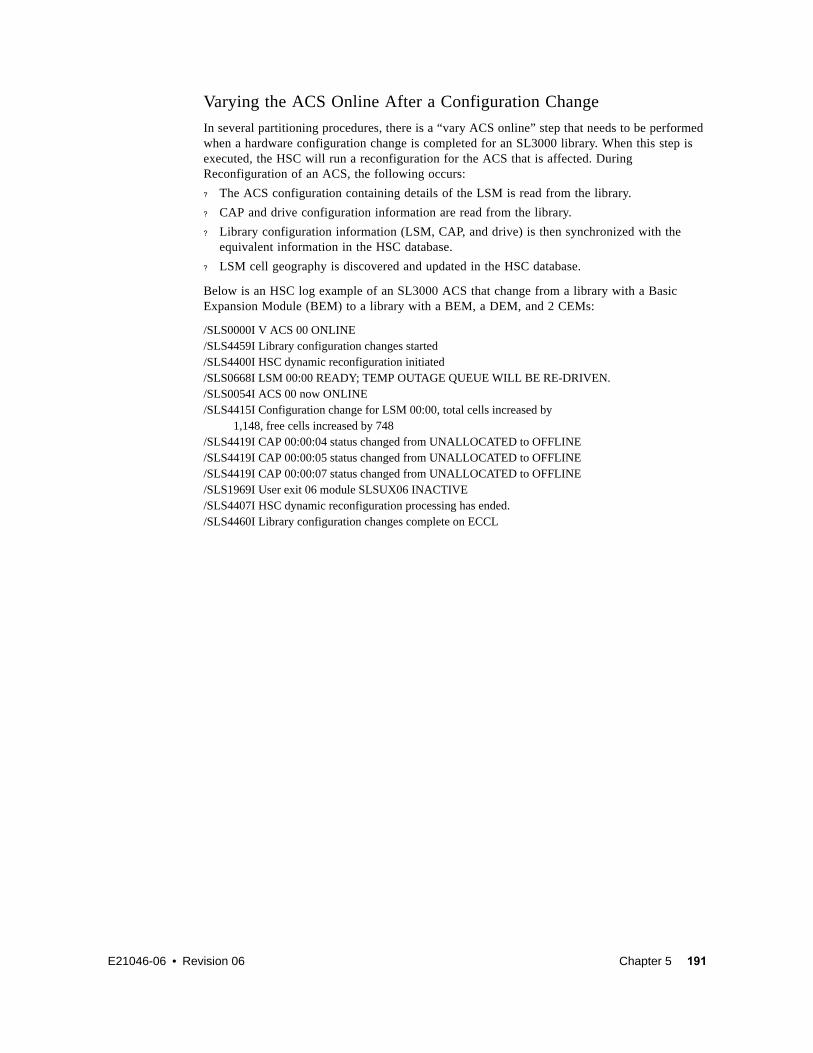
E21046-06 • Revision 06 Chapter 5 191
Varying the ACS Online After a Configuration Change
In several partitioning procedures, there is a “vary ACS online” step that needs to be performed when a hardware configuration change is completed for an SL3000 library. When this step is executed, the HSC will run a reconfiguration for the ACS that is affected. During Reconfiguration of an ACS, the following occurs:
? The ACS configuration containing details of the LSM is read from the library.
? CAP and drive configuration information are read from the library.
? Library configuration information (LSM, CAP, and drive) is then synchronized with the equivalent information in the HSC database.
? LSM cell geography is discovered and updated in the HSC database.
Below is an HSC log example of an SL3000 ACS that change from a library with a Basic Expansion Module (BEM) to a library with a BEM, a DEM, and 2 CEMs:
/SLS0000I V ACS 00 ONLINE/SLS4459I Library configuration changes started/SLS4400I HSC dynamic reconfiguration initiated/SLS0668I LSM 00:00 READY; TEMP OUTAGE QUEUE WILL BE RE-DRIVEN./SLS0054I ACS 00 now ONLINE/SLS4415I Configuration change for LSM 00:00, total cells increased by 1,148, free cells increased by 748/SLS4419I CAP 00:00:04 status changed from UNALLOCATED to OFFLINE/SLS4419I CAP 00:00:05 status changed from UNALLOCATED to OFFLINE/SLS4419I CAP 00:00:07 status changed from UNALLOCATED to OFFLINE/SLS1969I User exit 06 module SLSUX06 INACTIVE/SLS4407I HSC dynamic reconfiguration processing has ended./SLS4460I Library configuration changes complete on ECCL

192 Configuring HSC and VTCS • Revision 06 • E21046-06
E21046-06 • Revision 06 193
CHAPTER
6
Configuring VTCS
If you license VTCS, it’s now time to configure VTCS, which you do with the VTCS CONFIG utility...so now would be a good time to open up your ELS Command, Control Statement, and Utility Reference.
Much of the CONFIG deck is devoted to what you would expect...defining to VTCS the essential virtual/hardware parts of the VSM solution...VTSSs, VTVs, VTDs, and RTDs. What you also have the option of doing is setting non-default operating values, which we discussed in Chapter 2, “Planning VTCS Operating Policies”.
Tip – One of the big pluses of ELS 7.0 is that you no longer have to define VTVs and MVCs via CONFIG...now, it’s all done via the POOLPARM/VOLPARM statements, which you created in “Defining MVCs” on page 100 and “Defining VTVs” on page 101.

194 Configuring HSC and VTCS • Revision 06 • E21046-06
This chapter has two major CONFIG sections:
? “Building a Simple CONFIG Deck” on page 195 is basically a procedure where we build an example basic CONFIG deck step by step. To lead you through this, we’ll do it in ordered fashion, building the CONFIG deck as we go, as described in TABLE 6-1.
? “Special Cases: A Gallery of Advanced Uses of CONFIG” on page 275 shows variations of the CONFIG deck beyond the basic model, such as the deck where you disable a host from initiating migrations.
TABLE 6-1 VTCS Configuration Tasks
Step Notes Planning Information
Step 1 on page 195 Are you doing an upgrade install? Then you want to run DECOM to get a true picture of your current configuration. You can then update the DECOM listing and resubmit it to CONFIG to update your configuration. Typically, you run DECOM with the highest level of the VTCS (6.0 or 6.1) that supports the CDS ‘from’ level. First time install? Skip on down to Step 2 on page 195.
Step 2 on page 195 The actual CDS level specification is pretty easy but deciding which level takes some Deep Thought, so please study carefully the planning section before you begin coding...
“CDS VTCS Level Requirements” on page 20
Step 3 on page 196 This is where you specify global operating policies, such as the number of free MVCs...if you want to. Remember, you can always take the defaults, and tune things up later...
“Planning VTCS Operating Policies” on page 39
Step 4 on page 196 Moving right along to the MVC reclamation policies... “MVC Policies” on page 70
Step 5 on page 197 ...and, to complete the hardware definitions, CONFIG statements for the system’s VTSSs, the RTDs attached to the VTSSs, and the VTDs in each VTSS.
? “Planning for VTSSs” on page 35
? “Planning for Library-Attached Transports” on page 27
? “Planning for VTDs” on page 36

E21046-06 • Revision 06 Chapter 6 195
Building a Simple CONFIG DeckThe following procedure shows how to build a simple CONFIG deck. For more complex examples, see “Special Cases: A Gallery of Advanced Uses of CONFIG” on page 275.
? To build a simple CONFIG deck:1. Run the VTCS DECOM Utility...
...if you’re doing an upgrade install. Otherwise, skip to Step 2.
FIGURE 6-1 shows example JCL to run the DECOM utility with output to flat file CFG22202.
FIGURE 6-1 Example JCL for the DECOM utility
2. Start the CONFIG deck by specifying the CDS Level.
FIGURE 6-2 shows CONFIG JCL example to specify CDS level G.
FIGURE 6-2 CONFIG Example: CDSLEVEL(V62ABOVE) to Specify Level G
Note – In FIGURE 6-2, per VTCS NCO support, we do not have to specify RESET. RESET is not required when going from F to G level but all hosts accessing the CDS must be at VTCS/NCS 7.0 during the CDS level change. See ELS Command, Control Statement, and Utility Reference for details about when RESET is required.
//DECOM EXEC PGM=SLUADMIN,PARM='MIXED'//STEPLIB DD DSN=hlq.SEALINK,DISP=SHR//SLSCNTL DD DSN=hlq.DBASEPRM,DISP=SHR//SLSCNTL2 DD DSN=hlq.DBASESEC,DISP=SHR//SLSSTBY DD DSN=hlq.DBASETBY,DISP=SHR//CFG22202 DD DSN=hlq.CFG22202,DISP=SHR //SLSPRINT DD SYSOUT=*//SLSIN DD * DECOM FLATDD(CFG22202)
//CREATECF EXEC PGM=SLUADMIN,PARM='MIXED'//STEPLIB DD DSN=hlq.SEALINK,DISP=SHR//SLSCNTL DD DSN=hlq.DBASEPRM,DISP=SHR//SLSCNTL2 DD DSN=hlq.DBASESEC,DISP=SHR//SLSSTBY DD DSN=hlq.DBASETBY,DISP=SHR//SLSPRINT DD SYSOUT=*//SLSIN DD * CONFIG CDSLEVEL(V62ABOVE)

196 Configuring HSC and VTCS • Revision 06 • E21046-06
3. Specify global values.
FIGURE 6-3 shows our example CONFIG deck all spruced up with global values. Note that we’ve specified a Coupling Facility Structure to hold VTCS Lock Data:
? The Structure must be predefined as shown in “Defining the Coupling Facility Structure to MVS” on page 203.
? We now have to specify RESET and all hosts must be down to implement or remove a VTCS Lock Structure within a Coupling Facility.
FIGURE 6-3 CONFIG example: Specifying Global Values
Tip – If a Lock Structure is already defined to VTCS, you can use DECOM, Display CONFIG, and Display LOCKS to display information about the Lock Structure.
4. Specify reclamation policy values.
FIGURE 6-4 shows our example CONFIG deck, now sporting reclamation policy values.
FIGURE 6-4 CONFIG example: Specifying Reclamation Values
//CREATECF EXEC PGM=SLUADMIN,PARM='MIXED'//STEPLIB DD DSN=hlq.SEALINK,DISP=SHR//SLSCNTL DD DSN=hlq.DBASEPRM,DISP=SHR//SLSCNTL2 DD DSN=hlq.DBASESEC,DISP=SHR//SLSSTBY DD DSN=hlq.DBASETBY,DISP=SHR//SLSPRINT DD SYSOUT=*//SLSIN DD * CONFIG RESET CDSLEVEL(V62ABOVE) GLOBAL MAXVTV=65000 MVCFREE=60 VTVATTR=SCRATCH RECALWER=YES LOCKSTR=STK_VTCS_LOCKS VTVPAGE=LARGE MAXRTDS=32 FASTMIGR=YES
//CREATECF EXEC PGM=SLUADMIN,PARM='MIXED'//STEPLIB DD DSN=hlq.SEALINK,DISP=SHR//SLSCNTL DD DSN=hlq.DBASEPRM,DISP=SHR//SLSCNTL2 DD DSN=hlq.DBASESEC,DISP=SHR//SLSSTBY DD DSN=hlq.DBASETBY,DISP=SHR//SLSPRINT DD SYSOUT=*//SLSIN DD * CONFIG RESET CDSLEVEL(V62ABOVE) GLOBAL MAXVTV=65000 MVCFREE=60 VTVATTR=SCRATCH RECALWER=YES LOCKSTR=STK_VTCS_LOCKS VTVPAGE=LARGE MAXRTDS=32 FASTMIGR=YES RECLAIM THRESHLD=70 MAXMVC=30 START=40 CONMVC=5

E21046-06 • Revision 06 Chapter 6 197
5. Define VTSSs, RTDs, and VTDs.
FIGURE 6-5 shows our example CONFIG deck that next defines our VTSSs, the RTDs attached to each VTSS (both VSM4s), and the VTDs in each VTSS. Note that the RTD and VTD definitions immediately follow the VTSS statement.
FIGURE 6-5 CONFIG example: Defining VTSSs
//CREATECF EXEC PGM=SLUADMIN,PARM='MIXED'//STEPLIB DD DSN=hlq.SEALINK,DISP=SHR//SLSCNTL DD DSN=hlq.DBASEPRM,DISP=SHR//SLSCNTL2 DD DSN=hlq.DBASESEC,DISP=SHR//SLSSTBY DD DSN=hlq.DBASETBY,DISP=SHR//SLSPRINT DD SYSOUT=*//SLSIN DD * CONFIG RESET CDSLEVEL(V62ABOVE) GLOBAL MAXVTV=65000 MVCFREE=60 VTVATTR=SCRATCH RECALWER=YES LOCKSTR=STK_VTCS_LOCKS VTVPAGE=LARGE MAXRTDS=32 FASTMIGR=YES RECLAIM THRESHLD=70 MAXMVC=30 START=40 CONMVC=5VTSS NAME=VSM41 LOW=70 HIGH=80 MAXMIG=8 MINMIG=4 RETAIN=5 RTD NAME=PR11A00 DEVNO=1A00 CHANIF=0C RTD NAME=PR11A01 DEVNO=1A01 CHANIF=0D RTD NAME=PR11A02 DEVNO=1A02 CHANIF=0K RTD NAME=PR11A03 DEVNO=1A03 CHANIF=0L RTD NAME=PR12A08 DEVNO=2A08 CHANIF=1C RTD NAME=PR12A09 DEVNO=2A09 CHANIF=1D RTD NAME=PR12A0A DEVNO=2A0A CHANIF=1K RTD NAME=PR12A0B DEVNO=2A0B CHANIF=1L VTD LOW=9900 HIGH=99FF VTSS NAME=VSM42 LOW=70 HIGH=80 MAXMIG=8 MINMIG=4 RETAIN=5 RTD NAME=PR23A00 DEVNO=3A00 CHANIF=0C RTD NAME=PR23A01 DEVNO=3A01 CHANIF=0D RTD NAME=PR23A02 DEVNO=3A02 CHANIF=0K RTD NAME=PR23A03 DEVNO=3A03 CHANIF=0L RTD NAME=PR24A08 DEVNO=4A08 CHANIF=1C RTD NAME=PR24A09 DEVNO=4A09 CHANIF=1D RTD NAME=PR24A0A DEVNO=4A0A CHANIF=1K RTD NAME=PR24A0B DEVNO=4A0B CHANIF=1L VTD LOW=9900 HIGH=99FF

198 Configuring HSC and VTCS • Revision 06 • E21046-06
Updating the Tape Management System for VSMTo update your tape management system (such as CA-1, CA-Dynam/TLMS, and DFSMSrmm), do the following:
? Add volser ranges for VTVs to your tape management system. Ensure that you do not assign vault codes to VTVs.
? Access to the MVCs via an RTD bypasses the MVS intercepts put in place by the tape management system so that it does not record within its database any access to the MVCs by VSM and does not automatically provide protection against inadvertent overwrites of non-expired data on MVCs. Therefore, if you choose to define MVCs to the tape management system, StorageTek strongly recommends that you define them as non-scratch, non-expiring volumes.
? The tape management system requires an entry in the MVS Subsystem Name Table; this entry must precede the entry for SMC.
Note – If you are using AutoMedia for MVS, ensure that VTVs are defined as virtual volumes to direct AutoMedia to bypass DSN checking, which allows AutoMedia to recall, mount, and reuse non-resident scratch VTVs.
Caution – Note the following:
? VTCS has an automatic interface to notify RMM when a VTV becomes scratch but RMM does not notify VTCS when you unscratch a VTV by changing the CV status to non-scratch. If this is done, you must also run the HSC SLUADMIN utility to unscratch the VTV for VTCS. Otherwise, you may encounter a mount failure when VTCS attempts to select the VTV to service a scratch mount request.
? RMM (DFSMS/RMM) has additional integrity checks at mount time to ensure that the correct volume has been mounted. Because VTCS has features and optimizations that sometimes present a new initialized version of a VTV rather than the current copy of a VTV, it is necessary for VTCS to override these RMM integrity checks. VTCS does these overrides via the LISTVOLUME and CHANGEVOLUME API calls to update the RMM database. You must therefore ensure that HSC has been given the appropriate security access to the RMM API. For more information, see your RMM documentation.

E21046-06 • Revision 06 Chapter 6 199
Defining MVC Pool Volser AuthorityWhen VSM needs to mount an MVC and to write to an MVC, a SAF query is issued to verify that the HSC user (see “Defining A Security System User ID for HSC and VTCS” on page 82) has UPDATE authority for the MVC. The SAF query is issued on behalf of HSC and passed to the system security product (such as RACF, CA-ACF2, or CA-Top Secret).
VSM requires UPDATE authority for the volsers in the MVC pool. All other users should have an access of NONE for these volsers. Similarly, VSM should not have UPDATE authority for any volsers that are not in the MVC pool. See the documentation for your security product for procedures to add the appropriate tape volume security for VSM. TABLE 6-2 summarizes these definitions.
FIGURE 6-6 shows an example of a RACF profile and permissions commands to give the user ID VSM8HSC update access to MVC volser CVC024.
FIGURE 6-6 Example RACF MVC volser access file
TABLE 6-2 Security Class, Resource Class, and Access Values for MVC Pool Volser Authority
Class Resource Name Recommended User Access Levels
tape volume security MVC Pool Volume Serials UPDATE - allows VSM to write on MVC
********************************************************************************* Define a profile in the TAPEVOL security class for MVC CVC024 *********************************************************************************RDEFINE TAPEVOL security CVC024 UACC(NONE) ******************************************************************************************** Allow user ID VSM8HSC update access to MVC CVC024 *******************************************************************************************PERMIT CVC024 CLASS(TAPEVOL) ACCESS(UPDATE) ID(VSM8HSC)********************************************************************************

200 Configuring HSC and VTCS • Revision 06 • E21046-06
Caution – Note the following:
? To ensure that MVCs are not accidentally overwritten, for each MVC volser, you must update your TAPEVOL security as described above and your tape management system. For more information, see “Updating the Tape Management System for VSM” on page 198.
? You must also run the HSC UNSCratch Utility to unscratch any current scratch cartridges in the MVC range. For more information, see Managing HSC and VTCS.
? Depending on the default settings of your security system, VSM may not be able to mount and to write to MVCs until you have defined a security system user ID for HSC and TAPEVOL profiles for the MVCs.
? If you add new ranges of MVCs to your VSM system, remember to update the TAPEVOL profiles to include the new ranges.

E21046-06 • Revision 06 Chapter 6 201
Storing VTCS Locks in a Coupling Facility (Optional)Before VTCS updates a CDS record (for example, a VTV record) it locks the record to avoid contention from concurrent updates from multiple hosts. VTCS releases the CDS lock record once the CDS record has been updated.
Customers with large VTCS configurations experience high CDS I/O rates, part of which is due to the need to access CDS lock records. As configurations grow in size, (for example, by adding more hosts), CDS performance becomes a bottleneck.
An MVS Coupling Facility is a suitable alternative medium for VTCS Lock data because:
? A Coupling Facility provides very fast data transfer speeds, so the new I/O to the Coupling Facility with Lock records is less than the corresponding I/O to a CDS with Lock records.
? MVS provides a technique that allows data stored in a failing Coupling Facility to be re-built in another Coupling Facility (if one exists) without terminating the application.
Note – If VTCS locks are held in a coupling facility structure, VTCS uses the Structure (rather than the HSC mechanism) for sending/receiving Host-to-Host messages.
When to implement VTCS locks in a Coupling Facility Structure
Storing VTCS lock data in a Coupling Facility Structure is a solution to the specific problem of VTCS causing high I/O demand to the CDS in some configurations.
Note –
? VTCS locks in a Coupling Facility Structure only works if all your hosts are within the same sysplex! Using SMC client/server feature is another solution to the problem that does not require all hosts to be within the same sysplex. For more information, see Configuring and Managing SMC .
? Using a Coupling Facility Structure is not a solution to all CDS performance issues. For this reason, StorageTek recommends that if you believe you have a CDS performance problem, contact StorageTek Software support to have the problem analyzed before considering implementing VTCS lock data in a Coupling Facility.
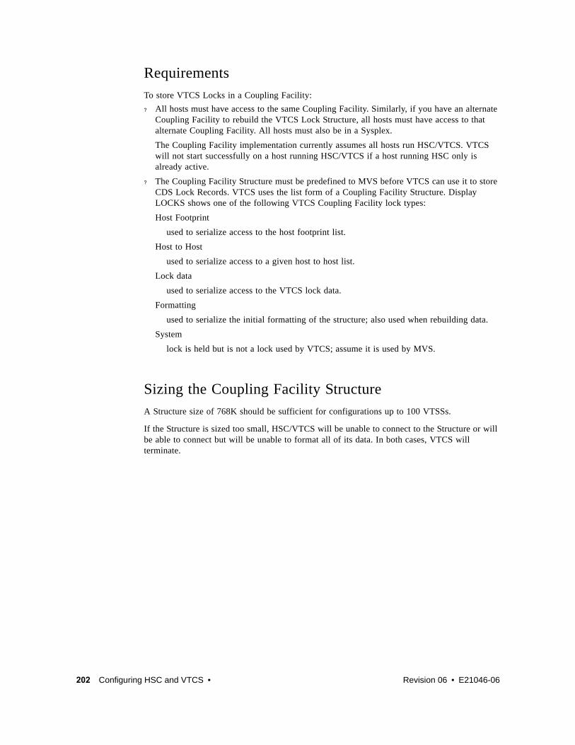
202 Configuring HSC and VTCS • Revision 06 • E21046-06
RequirementsTo store VTCS Locks in a Coupling Facility:
? All hosts must have access to the same Coupling Facility. Similarly, if you have an alternate Coupling Facility to rebuild the VTCS Lock Structure, all hosts must have access to that alternate Coupling Facility. All hosts must also be in a Sysplex.
The Coupling Facility implementation currently assumes all hosts run HSC/VTCS. VTCS will not start successfully on a host running HSC/VTCS if a host running HSC only is already active.
? The Coupling Facility Structure must be predefined to MVS before VTCS can use it to store CDS Lock Records. VTCS uses the list form of a Coupling Facility Structure. Display LOCKS shows one of the following VTCS Coupling Facility lock types:
Host Footprint
used to serialize access to the host footprint list.
Host to Host
used to serialize access to a given host to host list.
Lock data
used to serialize access to the VTCS lock data.
Formatting
used to serialize the initial formatting of the structure; also used when rebuilding data.
System
lock is held but is not a lock used by VTCS; assume it is used by MVS.
Sizing the Coupling Facility StructureA Structure size of 768K should be sufficient for configurations up to 100 VTSSs.
If the Structure is sized too small, HSC/VTCS will be unable to connect to the Structure or will be able to connect but will be unable to format all of its data. In both cases, VTCS will terminate.

E21046-06 • Revision 06 Chapter 6 203
? Defining the Coupling Facility Structure to MVSFIGURE 6-7 shows an example of an IXCMIAPU job to define a VTCS Lock Structure within a Coupling Facility Resource Manager (CRFM). In this example, note that:
? There are two Coupling Facilities, FACIL01 and FACIL02.
? There is a 768K Structure called STK_VTCS_LOCKS to store VTCS Lock Records.
? Structure STK_VTCS_LOCKS can exist in either Coupling Facility but FACIL01 is preferred over FACIL02. If VTCS starts to store lock data in FACIL01 and FACIL01 then becomes unavailable, VTCS attempts to build the STK_VTCS_LOCKS in FACIL02 to ensure continuous operations.
Note – If you define only one Coupling Facility, and it becomes unavailable, VTCS terminates on all hosts but HSC will still be running. If this occurs, do one of the following:
? Fix the Coupling Facility error, then recycle HSC/VTCS on all hosts; you can resume without changing the configuration.
? Use the procedure in “VSM5 Configuration Example: 8 VCF Cards, FICON Directors, 32 RTDs” on page 387.
FIGURE 6-7 Example IXCMIAPU Job to Define a Coupling Facility Structure
//SYSPRINT DD SYSOUT=*//SYSIN DD * DATA TYPE(CFRM) REPORT(YES) DEFINE POLICY NAME(POLICY1) REPLACE(YES) CF NAME(FACIL01)
T YPE(123456) MFG(IBM) PLANT(02)
SEQUENCE(123456789012) PARTITION(1) CPCID(00) SIDE(0) DUMPSPACE(2000)
CF NAME(FACIL02) TYPE(123456) MFG(IBM) PLANT(02) SEQUENCE(123456789012) PARTITION(2) CPCID(00) SIDE(1) DUMPSPACE(2000)
STRUCTURE NAME(STK_VTCS_LOCKS) SIZE(768) PREFLIST(FACIL01,FACIL02)

204 Configuring HSC and VTCS • Revision 06 • E21046-06
? Reverting to Storing VTCS Lock Data in the CDSTo revert to storing VTCS Lock Data in the CDS:
1. Stop HSC on all hosts.
2. Run CONFIG RESET without the LOCKSTR parameter so VTCS can store VTCS Locks in the CDS.
3. Restart HSC/VTCS on all hosts.
For more information, see VTCS Command and Utility Reference.
? Managing Failures/Unavailability of the VTCS lock structureVTCS supports Structure Rebuild to allow for failures/unavailability of the Structure or the Coupling Facility containing the Structure.
Structure rebuild can be initiated by:
? Operator command (SETXCF START,REBUILD,xxx) for a planned outage of the Structure or the Coupling Facility, and/or
? MVS or VTCS detecting an error in, or failure of, the Structure or the Coupling Facility.
Note that VTCS does not support System Managed Duplexing.
If the Structure used by VTCS can only be allocated in one Coupling Facility, VTCS will terminate on all Hosts if the Structure (or the Coupling Facility containing the Structure) fails or becomes unavailable.
If the Structure can be allocated in more than one Coupling Facility, VTCS’s Structure Rebuild code will attempt to rebuild the data in an alternate Coupling Facility Structure. VTCS will only terminate if the rebuild fails.
? Managing Notification of Resource ContentionIf a resource is locked (not available), the request cannot be processed and is retried later. At present, error message SLS6946E is issued to provide information about resources that are not available for a period of ten minutes or more because they are locked by another host or task in the system.
The optional GLOBAL CONFIG LOCKTOUT=nnn parameter specifies a value of 0 or a value between 5 and 240. If a value of 0 is specified, message SLS6946E is not issued when a required resource is locked. A value between 5 and 240 specifies the minimum number of minutes that a resource is locked before message SLS6946E is issued. If the parameter is not specified, the default value is 10 minutes. The LOCKTOUT parameter requires F level CDS (V61ABOVE) and above and ELS 7.0 PTF L1H1665 or ELS 7.1 PTF L1H166E.

E21046-06 • Revision 06 205
CHAPTER
7
Configuring the Host Software for VLE 1.0
This chapter provides the software configuration for VLE 1.0 appliances as described in the following sections:
? “Key Configuration Values” on page 206
? “MVS Host Software Configuration Tasks” on page 207

206 Configuring HSC and VTCS • Revision 06 • E21046-06
Key Configuration ValuesThe following sections describes values required for software configuration that must match values that are typically already set in the hardware configuration and recorded in the IP_and VMVC_Configuration.xls worksheet.
Subsystem Name
The subsystem name of the VLE appliance (or entire grid, for a multi-node configuration), which is set by the VLE GUI, is specified in the following:
• Either the VTCS CONFIG TAPEPLEX STORMNGR parameter or the CONFIG STORMNGR NAME parameter.
• The VTCS CONFIG RTD STORMNGR parameter.
• The SMC STORMNGR NAME parameter.
• The SMC SERVER STORMNGR parameter.
• The HSC STORCLAS STORMNGR parameter.
VLE Data Port and VSM5 IFF3 Card Target IP Addresses
These IP addresses are initially set on the VSM5 DOP IFF IP Configuration Status panel and at the VLE GUI and the values must match. On the DOP panel, they are set as IP addresses with their equivalent c:ip addresses shown, which are required for the CONFIG RTD IPIF parameter.
IP Addresses of VLE Ports for Host (UUI) Communication
These addresses are required for the SMC SERVER IP parameter.
VMVC Volsers
Required to define VMVCs to SMC/VTCS, method of definition depends on the software version, see “Defining the VLE VMVCs to the MVS Host Software and Including VMVCs in an MVC Pool” on page 210.
VMVC Reclamation Threshold
For more information, see“VMVC Reclamation Threshold” on page 206.

E21046-06 • Revision 06 Chapter 7 207
MVS Host Software Configuration TasksAdding ELS to a VSM system requires the tasks described in the following sections:
• “Updating the SMC OMVS RACF Security Entry” on page 207
• “Modifying the SMC SCMDS file” on page 208
• “Updating the VTCS CONFIG Deck to Define ELS” on page 209
• “Defining the VLE VMVCs to the MVS Host Software and Including VMVCs in an MVC Pool” on page 210
• “Updating the MVS Host Software Policies” on page 211
Updating the SMC OMVS RACF Security Entry
The VLE requires SMC to have an OMVS RACF security entry in order to have a TCP/IP connection to the host.
OMVS is a segment associated with the RACF userid. The SMC started task must have a userid associated with OMVS, either in the RACF STARTED class definition or the ICHRIN03 LNKLST module. The userid associated with the SMC task needs to have an OMVS segment defined to it within RACF as follows:
ADDUSER userid DFLTGRP(groupname)OWNER(owner)OMVS(UID(uidnumber))
Or, if the userid already exists but does not have an OMVS segment:
ALTUSER userid OMVS(UID(uidnumber))

208 Configuring HSC and VTCS • Revision 06 • E21046-06
Modifying the SMC SCMDS file
SMC manages all communication between VTCS and ELS, so SMC must know how to connect to the ELS server. You do so by adding an SMC STORMNGR statement for each VLE system plus one or more SMC SERVER statements that define the TCP/IP control paths for the ELS. For 7.0 and above, you may want to do this in your SMC CMDS file as shown in CODE EXAMPLE 7-1.
CODE EXAMPLE 7-1 SMC Commands for ELS
CODE EXAMPLE 7-1 contains:
• A TAPEPLEX statement, which defines a single TapePlex, TMVSA, with an HSC/VTCS running on the same MVS host (SLS0).
• A SERVER statement, which defines a backup HSC/VTCS subsystem (ALTSERV) running on another host.
• A STORMNGR command that defines a VLE appliance (VLE1).
• A second SERVER command that defines a UUI communication path to the VLE appliance, where:
• The server name is VLESERV1.
• The STORMNGR parameter value is VLE1.
• The IP parameter value is the ELS port IP address of 192.168.1.10 for UUI communications.
• The PORT parameter value is 60000; this value is always used for the SERVER PORT parameter for SMC communication with a ELS appliance.
TAPEPLEX NAME(TMVSA)LOCSUB(SLS0)
SERVER NAME(ALTSERV) TAPEPLEX(TMVSA) +
HOSTNAME(MVSX) PORT(8888)
STORMNGR NAME(VLE1)
SERVER NAME(VLESERV1)+ STORMNGR(VLE1)IP(192.168.1.10)PORT(60000)

E21046-06 • Revision 06 Chapter 7 209
Updating the VTCS CONFIG Deck to Define ELS
You must update VTCS CONFIG deck to define the ELS and the connectivity from the VTSS systems to the ELS. ELS 1.0 provides a single method of defining the ELS system to VTCS, which is via a CONFIG TAPEPLEX statement. This CONFIG TAPEPLEX statement defines the TapePlex that VTCS is running under and provides the list of defined VLEs on the STORMNGR parameter as shown in CODE EXAMPLE 7-2.
CODE EXAMPLE 7-2 CONFIG Example for Toleration (1.0) Mode
In CODE EXAMPLE 7-2, note:
• The CONFIG TAPEPLEX statement, which defines TMVSA as the TapePlex that VTCS is running under and the connection to VLE1.
• The CONFIG RTD statements for VTSS1, which specify:
• The connections to VLE1.
• The IPIF value and an RTD name for each IFF target to ELS port connection.
Specifying the Reclamation Policy for VMVCS
ELS MVC media (VMVCs) is subject to fragmentation and must be reclaimed just like real MVCs. The VMVC reclaim process, however, uses far fewer resources than a standard reclaim. The reclaim threshold for a VMVC is specified via the CONFIG RECLAIM VLTHRES parameter. The lower that you set VLTHRES, the more frequent VTCS will run reclaim on the VMVCs and the greater the effective capacity of the VMVS (less fragmentation).
TAPEPLEX THISPLEX=TMVSA STORMNGR=VLE1
VTSS NAME=VTSS1 LOW=70 HIGH=80 MAXMIG=8 MINMIG=4 RETAIN=5
RTD NAME=VL1RTD1 STORMNGR=VLE1 IPIF=0A:0
RTD NAME=VL1RTD2 STORMNGR=VLE1 IPIF=0A:1
RTD NAME=VL1RTD3 STORMNGR=VLE1 IPIF=0I:0
RTD NAME=VL1RTD4 STORMNGR=VLE1 IPIF=0I:1
RTD NAME=VL1RTD5 STORMNGR=VLE1 IPIF=1A:0
RTD NAME=VL1RTD6 STORMNGR=VLE1 IPIF=1A:1
RTD NAME=VL1RTD7 STORMNGR=VLE1 IPIF=1I:0
RTD NAME=VL1RTD8 STORMNGR=VLE1 IPIF=1I:1
VTD LOW=6900 HIGH=69FF

210 Configuring HSC and VTCS • Revision 06 • E21046-06
Defining the VLE VMVCs to the MVS Host Software and Including VMVCs in an MVC Pool
VMVC volsers must be defined both to the MVS host software and to the VLE. The VMVCs are defined to the VLE as part of the ELS appliance configuration. The following sections tell how to define the VMVCs to the MVS host software.
▼ Creating VMVC Volume Pools (7.0 and Above)
1. Code HSC POOLPARM/VOLPARM statements to define the VMVC pools.
For example, to define two separate pools for VLE1 and VLE2:
POOLPARM NAME(LEPOOL1)TYPE(MVC)VOLPARM VOLSER(VL0000-VL880)
POOLPARM NAME(LEPOOL2)TYPE(MVC)VOLPARM VOLSER(VL2000-VL2880)
2. Run SET VOLPARM to validate the POOLPARM/VOLPARM statements.
SET VOLPARM APPLY(NO)
APPLY(NO) validates the statements without loading them. If you like the results, go to Step 3. Otherwise, rework your volume definitions, rerun this step, and if the definitions are valid, then go to Step 3.
3. Run SET VOLPARM to load the POOLPARM/VOLPARM statements.
SET VOLPARM APPLY(YES)

E21046-06 • Revision 06 Chapter 7 211
Updating the MVS Host Software Policies
The following sections tell how to update the MVS host software policies to direct data to the ELS system.
Creating Storage and Management Classes for ELS
Management Classes specify how VTCS manages VTVs. The HSC MGMTclas control statement defines a Management Class and its attributes. For example, the DELSCR parameter of the MGMTclas statement specifies whether VTCS deletes scratched VTVs from the VTSS. Management Classes can also point to Storage Classes, which specify where migrated VTVs reside. The HSC STORclas control statement defines a Storage Class and its attributes.
You specify the ELS system as the destination for migrated VTVs via the STORCLAS STORMNGR keyword. For example:
STOR NAME(VLOCAL) STORMNGR(VLESERV1)STOR NAME(VREMOTE) STORMNGR(VLESERV2)
The preceding statements define a “local” Storage Class (VLOCAL) on the VLSERV1 node or grid and a “remote” Storage Class (VREMOTE) on the on the VLSERV2 node or grid. As these STORCLAS state-ments specify, all migrations to storage class VLOCLAL or VREMOTE must go to the specified ELSs. You can be less restrictive than this if desired. For example, if you define an MVCPOOL that contains both VMVCs and MVCs you can set up the migration policies to migrate to a ELS but if the ELS becomes full or not available, to continue to migrate to real tape media (MVCs). For example the MVC pool DR is defined as follows:
POOLPARM NAME(DR)TYPE(MVC)VOLPARM VOLSER(VL0000-VL0100)VOLPARM VOLSER(ACS000-ACS099)
Pool DR, therefore, contains both MVCs and VMVCs. A Storage Class that specifies pool DR will migrate first to VMVCs and only use MVCs if VMVCs are not available. For example:
STOR NAME(DRCLASS) MVCPOOL(DR)
This method is valuable if you have a configuration where both an ACS and a ELS are connected to the VTSS systems.
Next, to specify migration to ELS, you specify the ELS Storage Classes you defined via the MGMTCLAS MIGPOL parameter. For example:
MGMT NAME(M1) MIGPOL(VLOCAL,VREMOTE)MGMT NAME(M2) MIGPOL(DRCLASS)
Management Class M1 migrates one VTV copy to the “remote” ELS, one copy to the “local” ELS. Management Class M2 migrates a single VTV copy to the Storage Class that points to the “mixed” MVC pool that contains both MVCs and VMVCs.

212 Configuring HSC and VTCS • Revision 06 • E21046-06
Note – In addition to directing migration to a ELS also consider:
1. You can use the ARCHAge and ARCHPol parameters of the MGMTclas statement to set an Archive Policy for VTVs in a Management Class. When the VTV’s age exceeds the ARCHAge value, the VTV is eligible for archive per the Storage Class(es) specified on the ARCHPol parameter. You can use Archive Policies to archive (move) VTVs from VMVCs to MVCs as the VTVs age. For more information, see Managing HSC and VTCS.
2. You can use STORSEL statements to cause VTCS to preference recalls from ELS media. For more information, see Managing HSC and VTCS.
3. If you are running at ELS 7.0 or above, you can use HSC MIGRSEL and MIGRVTV to fine tune migration to ELS. Using these statements, you can cause migration of data in a Management Class to start to one Storage Class before another. This method is typically used to ensure that a critical DR copy is made as soon as possible. For more information, see Configuring HSC and VTCS
Routing Data to ELS
To route data to ELS, first create an SMC POLICY command that specifies a ELS Management Class. Next, create SMC TAPEREQ statements that route the desired workload to the SMC ELS policy. For example
POLICY NAME(VLEWORK) MEDIA(VIRTUAL) MGMT(VLECLASS)TAPEREQ DSN(VLETEST.**) POLICY(VLEMIGR)
The preceding example assigns he VLEWORK policy to all tape datasets with an HLQ of VLETEST.

E21046-06 • Revision 06 213
CHAPTER
8
Starting and Stopping HSC
If you’re a new customer, you have to start HSC. If you’re an existing customer doing an upgrade and all of your configuration changes are non-disruptive, you will not have to restart HSC.
Note – HSC and SMC do not support the z/OS reusable ASID feature.

214 Configuring HSC and VTCS • Revision 06 • E21046-06
Starting HSCTo start HSC:
1. Ensure that you have completed ELS installation and configuration...
...as described in Installing ELS and Configuring HSC and VTCS (this book).
2. Modify your HSC start-up JCL procedure as required.
For more information, see “Creating and Cataloging the HSC Startup Procedure” on page 108.
3. Enter the MVS START command to run HSC startup procedure:
For example:
S SLSO
If your CDS configuration contains VTCS configuration data, VTCS starts automatically unless you specify the startup parameter NOVTCS (for more information, see “Creating and Cataloging the HSC Startup Procedure” on page 108). For more information on startup scenarios, see “HSC Startup Scenarios” on page 215.
Note –
? If your SMF options for HSC did not specify the SUBTYPE parameter, HSC issues a message that SMF record subtypes 1 through 6 are being recorded.
? If you did not specify GTF EID and FID parameters on the PARM operand in HSC start procedure, HSC issues a message indicating that default EID and FID values are being used.
? HSC can be started prior to hardware arrival to make sure that it has been installed properly. HSC subsystem comes up with the LMU stations offline. HSC operator commands may be entered but any functions requiring interaction with the ACS hardware result in error messages.
? Alternately, a JCL substitution symbol may be specified in HSC cataloged procedure, and additional parameters passed via the START command using the substitution symbol.
? HSC can be initialized to a full or base service level by issuing the MVS START command. HSC can also be preinitialized or initialized under the MVS Master subsystem (MSTR) through the START command.
? In a multiple-host configuration, start one host at a time. Do not bring up multiple hosts simultaneously.
4. Start SMC.
For more information, see Configuring and Managing SMC .
5. If necessary, do post-startup tasks.
These are required only when the CDS is first initialized:
? All LSMs are offline, so vary them online with HSC MODify ONline. For subsequent executions of HSC, the last recorded status of the LSMs is obtained from the CDS.
? All CAP preferences are zero (never selected), so use the CAPPREF command to set CAP preferences.

E21046-06 • Revision 06 Chapter 8 215
HSC Startup ScenariosTABLE 8-1 shows examples of the START command options, which are further described in the following sections.
IPLing the System
A system IPL is required after defining HSC as a subsystem via the Subsystem Name Table entry IEFSSNxx for the first time. Once HSC has been defined, you do not need to re-IPL to stop and start HSC. If you are migrating from a previous HSC release and HSC is defined in the IEFSSNxx member, then a system IPL is not required. You must perform a COLD start at the first HSC startup. Subsequent HSC startups should not require a COLD start unless a problem is encountered.
If you are using SLSBPREI to initialize HSC under JES, see “Preinitializing HSC as an MVS Subsystem” on page 216 for additional information about starting HSC.
If you are not using SLSBPREI, refer to “Starting HSC with PARM=‘INIT’” on page 216 and “Initializing HSC Under the Master Subsystem” on page 216 for additional information about starting HSC without SLSBPREI.
TABLE 8-1 HSC Initialization
HSC Start Command
Proc Name Same as IEFSSNxx Entry
SLSBPREI in IEFSSNxx or Previous HSC Start With PARM=’INIT’
HSC Started Under MSTR and PROC in SYS1.PROCLIB
S SLS0 Yes No
S SLS0,SUB=MSTR Yes Ignored
S SLS0,PARM=’SSYS(SLS0)’,SUB=MSTR No Ignored
HSC Started Under JES and PROC in Any PROCLIB
S SLS0 Yes Yes
S SLS0,PARM=’INIT’ Yes No
S SLS0,PARM=’SSYS(SLS0)’ No Yes
S SLS0,PARM=’INIT,SSYS(SLS0)’ S SLS0,PARM=’SSYS(SLS0)’
No No

216 Configuring HSC and VTCS • Revision 06 • E21046-06
Preinitializing HSC as an MVS Subsystem
HSC must be initialized as an MVS Subsystem. There are two ways to preinitialize HSC:
? specifying SLSBPREI as HSC subsystem initialization routine in the IEFSSNxx member of the system PARMLIB and IPLing MVS as follows:
SUBSYS SUBNAME(SLS0) INITRTN(SLSBPREI) /* keyword format */
Note – SLSBPREI must reside in SYS1.LINKLIB or its link list. After installation, copy the SLSBPREI module from HSC SEALINK to a library in the MVS link list.
? “Starting HSC with PARM=‘INIT’” .
Starting HSC with PARM=‘INIT’
Instead of using SLSBPREI for HSC subsystem initialization routine, you can specify PARM=’INIT’ in a START command for a preinitialization startup followed by a START command for the actual startup of HSC. This eliminates the need for HSC’s subsystem Master Scheduler Initialization (MSI) routine. MSI functions are taken over by the main HSC address space initialization routines. The use of any subsystem MSI exit routine imposes a restriction that it must be in a data set that is cataloged in the master catalog, and included in the linklist. Previous HSC versions have distributed this module to install in SYS1.LINKLIB. This preinitialization of HSC is for initializing HSC under the primary Job Entry Subsystem (JES).
For example, to preinitialize HSC:
S SLS0,PARM=’INIT’
To then start HSC:
S SLS0
Initializing HSC Under the Master Subsystem
If you want to initialize HSC under the Master subsystem (MSTR), consider the following:
? If SLSBPREI is not part of the subsystem definition in IEFSSNxx or a previous initialization of the subsystem occurred using the INIT parameter, then enter the following to start HSC under Master subsystem control:
S SLS0,SUB=MSTR
? If SLSBPREI is not part of the subsystem definition in IEFSSNxx and the subsystem name is the same as the startup procedure name, then no preinitialization or SUB=MSTR is necessary:
S SLS0
? If you want to initialize HSC under JES later, you can use the INIT parameter to preinitialize HSC.
? When running HSC under the Master subsystem, JES services are not used. It is also possible to receive duplicate messages in the system log.

E21046-06 • Revision 06 Chapter 8 217
Starting HSC As a Subsystem
If the EXEC statement PARM parameter specifies a subsystem, you can start HSC as a subsystem. For more information, see “EXEC Statement” on page 110. For example:
S SLS0,PARM=’SSYS(SLS0)’
Specifying the HSC Service Level at Startup
To start HSC at Full Service Level:
S SLS0
To start HSC at Base Service Level:
S SLS0,PARM=’BASE’
The BASE parameter should be used with other parameters in the START command since these parameters override whatever is specified in HSC START Procedure. A sample START command with parameters is:
S SLS0,PARM=’BASE E(086) F(23) M(00) SSYS(SLS0)’

218 Configuring HSC and VTCS • Revision 06 • E21046-06
Starting the HSC Behavior Change
For a partitioned SL8500 and SL3000 libraries, NCO will automatically be invoked at HSC startup. This must be done for HSC to update these libraries' configuration for HSC to operate properly. Below is an example of new messages seen during HSC startup:
SLS0054I ACS 00 now ONLINESLS0668I LSM 00:00 IS OFFLINE; TEMP OUTAGE QUEUE HAS BEEN PURGED.SLS0054I ACS 01 now ONLINESLS0668I LSM 01:00 IS OFFLINE; TEMP OUTAGE QUEUE HAS BEEN PURGED.SLS2256I Automatic CAP Service AVAILABLESLS1505I HSC service level FULL initialization completeSLS4459I Library configuration changes startedSLS0668I LSM 01:01 IS OFFLINE; TEMP OUTAGE QUEUE HAS BEEN PURGED.SLS0668I LSM 01:02 IS OFFLINE; TEMP OUTAGE QUEUE HAS BEEN PURGED.SLS0668I LSM 01:03 IS OFFLINE; TEMP OUTAGE QUEUE HAS BEEN PURGED.SLS4400I HSC dynamic reconfiguration initiatedSLS4402I CDS drive record not found for existing transport; id = 00:00:10:00SLS4402I CDS drive record not found for existing transport; id = 00:00:10:02SLS4405D CDS / LMU conflicts exist; allow dynamic reconfig to proceed; Reply 'Y' or 'N'SLS4419I CAP 00:00:01 status changed from UNALLOCATED to OFFLINESLS4419I CAP 00:00:03 status changed from UNALLOCATED to OFFLINESLS4419I CAP 00:00:04 status changed from UNALLOCATED to OFFLINESLS4414I Initial configuration for LSM 00:00, total cells 2,710, free cells 2,710SLS4407I HSC dynamic reconfiguration processing has ended.SLS4460I Library configuration changes complete on ECCLSLS4459I Library configuration changes startedSLS4400I HSC dynamic reconfiguration initiatedSLS4402I CDS drive record not found for existing transport; id = 01:00:01:00SLS4402I CDS drive record not found for existing transport; id = 01:00:01:01SLS4402I CDS drive record not found for existing transport; id = 01:00:01:02SLS4402I CDS drive record not found for existing transport; id = 01:00:01:03SLS4405D CDS / LMU conflicts exist; allow dynamic reconfig to proceed; Reply 'Y' or 'N'SLS4401I LSM/Rail 01:02 successfully unallocated from current HSC configurationSLS4401I LSM/Rail 01:03 successfully unallocated from current HSC configurationSLS4407I HSC dynamic reconfiguration processing has ended.SLS4460I Library configuration changes complete on ECCL

E21046-06 • Revision 06 Chapter 8 219
Configuration Mismatches During HSC initialization, HSC remains active if LSM or panel type configuration mismatches occur between the CDS and LMU. Specifically, these mismatches include different:
? Numbers of LSMs ? Or unknown types of LSMs ? Or unknown panel types in an LSM.
In these cases, the affected ACS(s) are forced offline. HSC continues to support the unaffected ACS(s), and you can correct the configuration problems and bring the affected ACSs back online.

220 Configuring HSC and VTCS • Revision 06 • E21046-06
Stopping HSC You can stop HSC in either of two ways:
? By first quiescing HSC, which you do with the MVS STOP command, where:
1. HSC waits for pending work to complete. This includes actions against the LMU such as current mounts and dismounts, utilities, active CAPs, operator commands, and station termination(s).
2. HSC updates the CDS and journals as pending work completes.
3. HSC cleans up resources, terminates, and displays a termination message on the system console.
? By forcing HSC termination with the MVS Cancel command.
If this doesn’t stop HSC, enter another Cancel command. If this doesn’t work, use the MVS FORCE command.
Caution – StorageTek does not recommend forced termination of HSC because unpredictable results may occur on startups following forced terminations.
A forced termination of HSC causes all HSC processes to abort immediately and termination occurs. Any of the following can occur:
? Volumes can be left in-transit, however, mounted volumes are not affected by forced HSC termination.
? Outstanding utilities can abend.? The CDS and journals can lose synchronization.
If you do choose to force HSC termination:
1. Before forcing termination, verify that alternative library paths exist for the active SMC to continue performing allocation influencing and mount automation.
2. Errant volume records are created for volumes left in the playground, CAPs, or passthru ports. Operator intervention may be required to resolve the status of errant volumes when HSC execution is resumed. Transports may require operator intervention to satisfy mount requests.
E21046-06 • Revision 06 221
APPENDIX
A
HSC LIBGEN Macros
This appendix describes the HSC LIBGEN macros.

222 Configuring HSC and VTCS • Revision 06 • E21046-06
SLIACSThe SLIACS macro defines the following items:
? the communication paths between a host (or hosts) and an ACS
? the LSMs attached to an ACS
? preallocating space in the CDS for additional SL8500 LSMs.
There must be one and only one SLIACS macro for each ACS.
The SLIACS macro for the first ACS must appear immediately after the SLIALIST macro. The SLIACS macro for each subsequent ACS must appear immediately after the last SLIDRIVS macro for the prior ACS definition.
Syntax
FIGURE 8-1 SLIACS Syntax
Parametersacs0
assembler label referred to by the SLIALIST macro ACS positional parameter.
SLIACS
name of this macro.
STATION=
station0, ...,station15 are the assembler labels of the SLISTATN macro. They define the station numbers used to communicate between a host and an ACS. Multiple hosts (maximum of 16) may refer to the same SLISTATN macro.
acs0 SLI ACS Addi t i onal Par amet er s
Additional Parameters:
, STATI ON=( st at i on0, . . . , st at i on15)
, LSM=( l sm0, l sm1, . . . , l sm23)
, FUTRLSM=( 8500, l smnum)
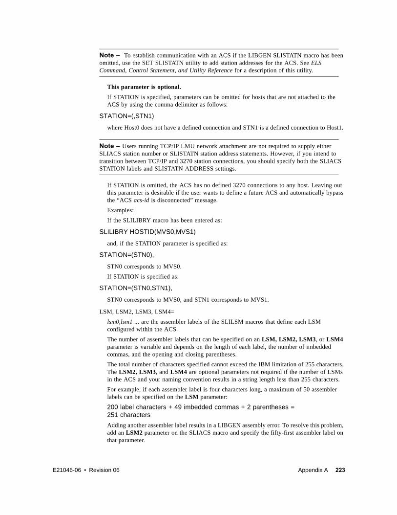
E21046-06 • Revision 06 Appendix A 223
Note – To establish communication with an ACS if the LIBGEN SLISTATN macro has been omitted, use the SET SLISTATN utility to add station addresses for the ACS. See ELS Command, Control Statement, and Utility Reference for a description of this utility.
This parameter is optional.
If STATION is specified, parameters can be omitted for hosts that are not attached to the ACS by using the comma delimiter as follows:
STATION=(,STN1)
where Host0 does not have a defined connection and STN1 is a defined connection to Host1.
Note – Users running TCP/IP LMU network attachment are not required to supply either SLIACS station number or SLISTATN station address statements. However, if you intend to transition between TCP/IP and 3270 station connections, you should specify both the SLIACS STATION labels and SLISTATN ADDRESS settings.
If STATION is omitted, the ACS has no defined 3270 connections to any host. Leaving out this parameter is desirable if the user wants to define a future ACS and automatically bypass the “ACS acs-id is disconnected” message.
Examples:
If the SLILIBRY macro has been entered as:
SLILIBRY HOSTID(MVS0,MVS1)
and, if the STATION parameter is specified as:
STATION=(STN0),
STN0 corresponds to MVS0.
If STATION is specified as:
STATION=(STN0,STN1),
STN0 corresponds to MVS0, and STN1 corresponds to MVS1.
LSM, LSM2, LSM3, LSM4=
lsm0,lsm1 ... are the assembler labels of the SLILSM macros that define each LSM configured within the ACS.
The number of assembler labels that can be specified on an LSM, LSM2, LSM3, or LSM4 parameter is variable and depends on the length of each label, the number of imbedded commas, and the opening and closing parentheses.
The total number of characters specified cannot exceed the IBM limitation of 255 characters. The LSM2, LSM3, and LSM4 are optional parameters not required if the number of LSMs in the ACS and your naming convention results in a string length less than 255 characters.
For example, if each assembler label is four characters long, a maximum of 50 assembler labels can be specified on the LSM parameter:
200 label characters + 49 imbedded commas + 2 parentheses = 251 characters
Adding another assembler label results in a LIBGEN assembly error. To resolve this problem, add an LSM2 parameter on the SLIACS macro and specify the fifty-first assembler label on that parameter.

224 Configuring HSC and VTCS • Revision 06 • E21046-06
In general, if the ACS contains more LSMs (assembler labels) than can be supported by the LSM parameter, you must code LSM2, LSM3, or LSM4 parameters, as necessary, for the other LSMs. It is recommended that you code additional LSMx parameters in ascending order for easier maintainability. Also, note that there is an architectural limit of 256 LSMs for each ACS.
Examples:
LSM=(L000) LSM=(L000,L001,L002)
FUTRLSM=
8500 indicates to preallocate space in the CDS for SL8500 LSMs. This space is used when new LSMs are to be added to the ACS through PTP connections.
lsmnum defines the number of future preformatted LSM records written to the CDS. The number specified must be between 4 and 124.
This parameter is optional.
Note –
? An SL8500 library contains four rails (LSMs), thus the lsmnum value must be in multiples of four (4, 8, 12, 16, and so on).
? If the number specified in lsmnum is too small, another LIBGEN will be required to add additional LSMs. If the number entered for lsmnum is too large, the result is unused CDS space reserved for future expansion.

E21046-06 • Revision 06 Appendix A 225
SLIALISTThe SLIALIST macro contains the assembler labels of the SLIACS macro(s). The first ACS listed has an ACSid of 00, the second 01, etc.
Syntax
FIGURE 8-2 SLIALIST Syntax
Parameters acslist
assembler label referred to by the SLILIBRY macro ACSLIST parameter.
SLIALIST
name of this macro.
acs0,acs1,...,acs255
label name used by the SLIACS macro(s). One label name is specified for each ACS, and at least one label name is required.
acsl i st SLI ALI ST acs0, acs1, . . . . . acs255

226 Configuring HSC and VTCS • Revision 06 • E21046-06
SLIDLISTEach SLIDLIST macro specifies an assembler label corresponding to a SLIDRIVS macro which identifies the unique host addresses associated with the transports residing on a cartridge drive panel.
The first SLIDLIST macro for an LSM must appear immediately after the SLILSM macro which refers to it. Subsequent SLIDLIST macros for the LSM must appear immediately after the last SLIDRIVS macro for the preceding SLIDLIST macro.
Syntax
FIGURE 8-3 SLIDLIST Syntax
Parametersdrvelst0
specifies the assembler label that is referred to by the SLILSM macro DRVELST parameter.
SLIDLIST
name of this macro.
HOSTDRV=
(drives0,...,drives15) specifies the assembler label name of each SLIDRIVS macro which defines transport addresses.
Note – The HOSTDRV operands are positional. The SLILIBRY macro HOSTID parameter determines the positional ordering of the operands specified in the HOSTDRV parameter. The first operand specified in the HOSTDRV parameter corresponds to the first host specified in the SLILIBRY macro HOSTID parameter, etc.
Examples:
HOSTDRV=(DRV0)
where DRV0 is for Host0
HOSTDRV=(DRV0,DRV1)
where DRV0 is for Host0 and DRV1 is for Host1
HOSTDRV=(DRV0,DRV0)
where DRV0 is for Host0 and DRV0 is for Host1
drvel st 0 SLI DLI ST HOSTDRV=( dri ves0, . . . , dri ves15)

E21046-06 • Revision 06 Appendix A 227
SLIDRIVSThe SLIDRIVS macro lists the transport device addresses used by a host, which correspond to a specific cartridge drive panel. A SLIDRIVS macro must be specified for each unique operand coded in the SLIDLIST macro HOSTDRV parameter. The SLIDRIVS macro(s) must appear immediately following the SLIDLIST macro which references it.
Syntax
FIGURE 8-4 SLIDRIVS Syntax
Parametersdrives0
specifies the assembler label that is referenced by the SLIDLIST macro HOSTDRV parameter.
SLIDRIVS
name of this macro.
ADDRESS=
addr0,addr1,... specifies the host-unique device addresses associated with transports residing in a cartridge drive panel. Nonexistent transports are indicated by position-holding commas. Duplicate unit addresses are not allowed for a given host.
Note – If addresses exceed more than one line, place a comma after the last address and a nonblank character in column 72 (e.g., an X). Continue on the next line starting in column 16. Unlike control statements, no plus (+) or minus (-) continuation characters are required after the last parameter value.
Drives on a panel are defined from top to bottom. When multiple drive columns are present on a 9310 panel, the drive column on the left is defined first, followed by the drive column on the right (as viewed from outside the LSM). The HSC considers these addresses to be attached to an LSM. Verify the addresses you use with your Customer Service Engineer (CSE).
dri ves0 SLI DRI VS ADDRESS=( addr0, addr1. . . )

228 Configuring HSC and VTCS • Revision 06 • E21046-06
Examples:
Note –
? If you are executing the HSC as a remote server for the SMC, and drive addresses are defined differently on different HSC server hosts, you may need to specify either or both the HSC SET DRVHOST utility or the SMC DRIVEMAP command to define client/server drive mapping. Refer to the SMC DRIVEMAP command in the Configuring and Managing SMC and the SET DRVHOST utility in the ELS Command, Control Statement, and Utility Reference.
? You must specify at least one drive address for each ACS. For example, you cannot specify
ADDRESS=(,,,)
for all drive addresses in an ACS.
Caution – If you fail to enter at least one drive address, the Database Decompile utility will fail against this CDS.
? The total number of drive positions, including position-holding commas, must be 4, 10, 16, or 20 depending on the LSM type:
? 4410 or 9360 LSM, 4-drive panels are supported.
? 9740 LSM, 4-drive or 10-drive panels are supported.
? 9310 LSM, 4-drive, 10-drive, and 20-drive panels are supported.
ADDRESS=(410,411,412,413) for a 4480 M24, 4490 M34, 9490 M34, 9490EE M34, or SD-3 H34 device
ADDRESS=(410,,412,) for a 4480 M22 or 4490 M32 device
ADDRESS=(,B75,,B76) for a 9490 or 9490EE M32 or SD-3 H32 device
ADDRESS=(,B75,,) for an SD-3 H31 device
ADDRESS=(,B75,B76,B77) for an SD-3 H33 device
ADDRESS=(C10,C11,C12,C13,C14, XC15,C16,C17,C18,C19)
for a 9840, T9840B, T9840C, T9940A, or T9940B device (10-drive panel)
ADDRESS=(C10,C11,C12,C13,C14, XC15,C16,C17,C18,C19,C1A,C1B, XC1C,C1D,C1E,C1F,C20,C21,C22, XC23)
for a 9840, T9840B, T9840C, T9940A, or T9940B device (20-drive panel)
ADDRESS=(,,,9A01,,,9A02,,,9A03,,,9A04) for an SL8500 device (16-drive panel)
ADDRESS=(,,,,00CA,,,,00CB,,,,00CC,,,, X00CD,,,,00CE,,,)
for an SL3000 device (24-drive panel)

E21046-06 • Revision 06 Appendix A 229
? SL3000: 32 drives per panel are supported for panel 10; 24 drives per panel are supported for panel 12
Outside and back of the SL3000 library, drive panel numbering proceeds from top to bottom, right to left. FIGURE A-1 shows an example of drive numbering for drive addresses on panels 12 and 10.
FIGURE A-1 SL3000 Drive Panel Layout
4 3 2 1
8 7 6 5
12 11 10 9
16 15 14 13
20 19 18 17
24 23 22 21
28 27 26 25
32 31 30 29
36 35 34 33
40 39 38 37
44 43 42 41
48 47 46 45
52 51 50 49
56 55 54 53
Panel 12 Panel 10
SL3000 Drive Panels as vewed from the outside back

230 Configuring HSC and VTCS • Revision 06 • E21046-06
? SL8500, 16-drive panels are supported.
? Outside the SL8500 library, drive panel numbering proceeds from top to bottom, right to left, as viewed outside the structure from the drive end. TABLE 8-2 shows an example of drive numbering for drives on one LSM (LSM0) and drive addresses on drives 3 and 15.
Inside the library, drive panel numbering is top to bottom, left to right, as viewed inside the library from the CAP end. TABLE 8-3 shows the same drive configuration as TABLE 8-2.
To specify the drives above, the SLIDRIVs statement is:
SLIDRIVS ADDRESS=(,,,1621,,,,,,,,,,,1624)
Refer to Configuring HSC and VTCS for more information.
? The total number of drive positions specified by all SLIDRIVS statements for a single panel must be the same.
? For an ExtendedStore library, panel 10 must be defined using commas to indicate nonexistent transports. Example:
ADDRESS=(,,,)
? On all LSMs except the 9740, drives are defined to the HSC from top to bottom, with addr0 representing the topmost drive and addrn the bottommost drive.
On a 9740 10-drive panel LSM, the drives are populated and configured in the 9740 LSM from bottom to top. (9740 4-drive panels are configured to the 9740 LSM from top to bottom, as are all other LSM drive panels.)
An example showing how to define a 9740 10-drive panel containing five 9840 drives is:
ADDRESS=(,,,,,BD4,BD3,BD2,BD1,BD0)
TABLE 8-2 SL8500 Drive Panel Layout Example - Outside Library
LSM
Drive Panel
Row+2 +1 -1 -2
LSM0(Rail 1)
12 8 4 0 1
13 9 5 1 2
14 10 6 2 3
15(1624)
11 7 3(1621)
4
TABLE 8-3 SL8500 Drive Panel Layout Example - Inside Library
LSM
Drive Panel
Row-2 -1 +1 +2
LSM0(Rail 1)
0 4 8 12 1
1 5 9 13 2
2 6 10 14 3
3(1621)
7 11 15(1624)
4

E21046-06 • Revision 06 Appendix A 231
SLIENDGNThe SLIENDGN macro specifies the end of the LIBGEN macros. It must appear as the last statement of the LIBGEN. No comments or other statements can follow this macro because they generate assembler warning messages.
Syntax
FIGURE 8-5 SLIENDGN Syntax
ParametersSLIENDGN
name of this macro. The SLIENDGN macro has no parameters.
SLI ENDGN

232 Configuring HSC and VTCS • Revision 06 • E21046-06
SLILIBRYThe SLILIBRY macro defines the global characteristics of the library. Only one SLILIBRY macro is specified and immediately follows the SLIRCVRY macro.
Syntax
FIGURE 8-6 SLILIBRY Syntax
ParametersSLILIBRY
name of this macro.
HOSTID=
host-id0, host-id1, ..., host-id15 identifies each host that accesses the library. This represents the SMF system ID for both JES2 and JES3. Valid characters for a HOSTID are A-Z, 0-9, #, $, and @.
Example:
HOSTID=(MVSA,MVSB)
where MVSA is Host0 and MVSB is Host1.
SLI LI BRY HOSTI D=( host - i d0, host - i d1, . . . , host - i d15) , ACSLI ST=acsl i st
Opt i onal Par amet er s
Optional Parameters:
, CLNPRFX= pr ef i x
CLN
, SMF= l i bt ype
255
, MAJNAME= qname
STKALSQN
, COMPRFX= commandchar
.
, SCRLABL=
NL
NSL
SL
AL
, EJCTPAS=passwor d , DRVHOST=( host - i d) FUTRACS=( x, y)

E21046-06 • Revision 06 Appendix A 233
Note – The order of the hosts specified is positional. This information is used by other LIBGEN macros. Any changes in host order here may affect other areas of your LIBGEN configuration.
ACSLIST=
acslist is the assembler label of the SLIALIST macro that defines ACSs in the configuration.
Example:
ACSLIST=LACSLIST
CLNPRFX=
prefix is the three-character prefix that applies to all types of cleaning cartridges. Valid characters are A-Z, 0-9, $, #, and @. All cartridges having this prefix followed by numerics on their external labels are treated as cleaning cartridges. CLN is the default.
Examples:
CLNPRFX=CLN CLNPRFX=KCR
Note – Cleaning cartridges defined by VOLATTR control statements must still use the cleaning prefix established in the LIBGEN.
SMF=
libtype is the System Management Facility (SMF) record type used by the HSC to record cartridge movement and library performance. The value specified must match the SUBSYS type specified for the HSC in SMFPRMxx. The default is 255.
Example:
SMF=235
MAJNAME=
qname specifies the ENQ/DEQ/QNAME used by host software for serialization. It must conform to the requirements for an ENQ/RESERVE/DEQ QNAME as defined by the IBM publication MVS Supervisor Services and Macros. The default is STKALSQN.
Example:
MAJNAME=STKALSQN
COMPRFX=
commandchar specifies the command prefix character used to direct operator commands to the HSC. It is a single character. The default command prefix character is a period (.).
Example command prefixes are: ¢, #, !
Note – Make sure that the prefix character used does not conflict with any of the following:
? another subsystem’s command prefix character (such as “$’’ for JES2, “*’’ for JES3, or “;’’ the delimiter for TSO)
? the command delimiter for MVS — specified as the value for the CMDDELIM keyword in SYS1.PARMLIB (CONSOLxx) and described in the IBM publication Installation and Tuning Guide for MVS

234 Configuring HSC and VTCS • Revision 06 • E21046-06
? a JES line editing character as specified in the JES initialization statements or default. For JES2 the initialization statement is CONDEF.
For JES3 the initialization statement is CONSTD. Descriptions of these statements and default values can be found in the IBM MVS publication Initialization and Tuning Guide.
? If you are running the HSC on a VM host that shares the CDS with an HSC running on MVS, make sure that your command prefix does not conflict with any of the VM facilities, such as the CP line editing symbol.
A null character can be specified as the command prefix character. During library operation, to specify an HSC command when the command prefix is a null character, you must use the MVS MODIFY command to issue commands to the HSC.
Even if you have specified a command prefix, you may use either method for issuing commands to the HSC:
? Specify an HSC command with the command prefix preceding the command.
? Specify an HSC command using the MVS MODIFY command. The following formats for the MVS MODIFY command may be used:
Example:
MODIFY HSC-subsystem-name,HSC-command
or
F HSC-subsystem-name,HSC-command
where HSC-subsystem-name is the HSC subsystem name specified in the HSC startup proc.
Examples of how a specific HSC command can be issued are:
MODIFY HSC-subsystem-name,DISPLAY CDS
or
F HSC-subsystem-name,DISPLAY CDS
TABLE 8-4 Mapping of Command Prefix Codes to Characters
Hex Character Description
40 null blank
4A ¢ cent
4B . period
4C < less than
4D ( left parenthesis
4E + plus
4F | vertical bar
50 & ampersand
5A ! exclamation point
5B $ dollar sign
5C * asterisk
5D ) right parenthesis
5E ; semicolon

E21046-06 • Revision 06 Appendix A 235
Note – If you specify a null command prefix (hex 40), you must use the MVS MODIFY command to perform any HSC operator command.
Example:
F SLS0, MOUNT EDU050, B30
where
F
an abbreviation for the MVS MODIFY command
SLS0
an HSC subsystem
MOUNT
an HSC operator command
EDU050
a VOLSER
B30
a designated tape drive
Because of IBM assembler restrictions, a single ampersand (&) cannot be specified as a command prefix. However, if you want to use an ampersand (&) as the command prefix, specify two ampersands (&&). When the LIBGEN file is assembled, the assembler strips off the first ampersand and leaves the second one. The result is that the valid command prefix is a single ampersand.
Example:
COMPRFX=&&
If specifying a left parenthesis (4D) or right parenthesis (5D), the prefix character must be enclosed in single quotes. For example:
5F ¬ not symbol
60 - minus
61 / slash
6B , comma
6C % percent
6D _ underscore
6E > greater than
6F ? question mark
7A : colon
7B # crosshatch
7C @ at sign
7E = equals sign
7F “ double quote
TABLE 8-4 Mapping of Command Prefix Codes to Characters (Continued)
Hex Character Description

236 Configuring HSC and VTCS • Revision 06 • E21046-06
COMPRFX=’(‘
COMPRFX=’)’
Another example of specifying a valid command prefix is:
COMPRFX=@
SCRLABL=
specifies the magnetic label type of a library controlled scratch volume. The HSC assumes nonspecific requests with other than the SCRLABL label type are outside the library. If a nonspecific volume is requested with the label type specified, it is considered a scratch volume. Parameter options are:
SL
standard label. The default is SL.
AL
ANSI label
NL
nonlabeled
NSL
nonstandard label.
Automated mounts of scratch volumes other than the SCRLABL label type can be performed by using user exits.
Example:
SCRLABL=NSL
EJCTPAS=
password specifies that a password is required for the EJect operator command. The password is one to eight alphanumeric characters. Acceptable characters include A-Z (must be capitalized) and numbers 0-9.
Note – Existing passwords do not need to be changed to conform to these restrictions but any new passwords must follow the guidelines described above. If EJCTPAS is not specified, no password is used. An encrypted form of the password is maintained in the control data set.
Example:
EJCTPAS=GOODDAY
DRVHOST
hostid specifies a host ID to be used as the “master” host for drive address definitions in a client/server environment. This parameter provides a consistent server environment when a single SMC can communicate with multiple servers that have different defined drive addresses. DRVHOST is used in conjunction with the SMC DRIVEMAP command (refer to Configuring and Managing SMC ).
If DRVHOST is not specified, each HSC host reports its defined drive configuration to the SMC.
Example: DRVHOST=MVSA
FUTRACS=(x,y)

E21046-06 • Revision 06 Appendix A 237
This parameter is used when new ACSs are to be added to the library complex. x specifies the number of ACSs, and y optionally specifies the number of LSMs to add for each added ACS.
Caution – The additional CDS records you create can cause your system to generate an 878-10 ABEND error if there is not enough space to hold the internal records for some operations. If you run out of space during the HSC INIT, you need to re-create your LIBGEN and lower these numbers.
Note –
? The number of ACSs specified can be between 1 and 255 but the total number of real ACSs and FUTRACS must not exceed 255.
? The number of LSMs for each FUTRACS must be a multiple of 4 and range between 4 and 40.
? If you do not specify LSMs (y), it defaults to 12.
? The FUTRACSs are generic, meaning you can use them to dynamically add an SL3000 or a string of SL8500s, not to exceed the number of LSMs generated.
? You must specify REGION=0M on your HSC start JCL.

238 Configuring HSC and VTCS • Revision 06 • E21046-06
SLILSMThis macro defines the panel numbers and relative position of cartridge drive panels around an LSM, the assembler labels for the SLIDLIST macro, the panel number for each pass-thru port in an LSM, and the assembler labels of SLILSM macros.
The first SLILSM macro for an ACS must appear immediately after the last SLISTATN macro for an ACS. Subsequent SLILSM macros for the ACS must appear immediately after the last SLIDRIVS macro referred to by the preceding SLILSM macro. The SLILSM macros are coded in the same order as specified in the SLIACS macro LSM, LSM2, LSM3, and LSM4 parameters.
Note –
? For the SL3000 library, the only required parameter is TYPE=3000, although the other parameters are still valid. If you specify only TYPE=3000 and decompile the CDS, the other relevant parameters are shown in the decompile output.
? For the SL8500 library with the enhanced partitioning feature, the only required parameter is TYPE=8500, although the other parameters are still valid. If you specify only TYPE=8500 and decompile the CDS, the other relevant parameters are shown in the decompile output.
? It important to follow the Start from Scratch procedure even if you do not partition the library after completing the LIBGEN. For more information, see “Start from Scratch – LIBGEN, SLICREAT” on page 157.
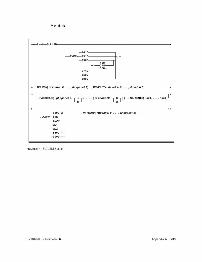
E21046-06 • Revision 06 Appendix A 239
Syntax
FIGURE 8-7 SLILSM Syntax
S ( pt ppane18, S
M
) ) , ADJACNT=( l sm1, . . . , l sm4)
, DOOR= STD
, WI NDOW=( wndpanel 0, . . . , wndpanel 3)
100
TYPE=
4410
9310
9360
075050
,
-
9740
SLI LSMl sm0
, PASTHRU=( ( pt ppane10,
M
) , . . . ,
WC1
ECAP
WC2
8500- 1
8500- 2
8500
, DRVELST=( dr vel st 0, . . . , dr vel st 3)DRI VE=( dr vpanel 0, . . . , dr vpanel 3)
3000
3000

240 Configuring HSC and VTCS • Revision 06 • E21046-06
Parameterslsm0
assembler label referred to by the SLIACS macro LSM, LSM2, LSM3, and LSM4 parameters.
SLILSM
specifies the name of this macro.
TYPE=
specifies the LSM type.
Caution – The value specified must match both the physical hardware configuration and the value coded by the StorageTek CSE or panel mismatch errors appear at startup. Confirm the value you are specifying on the TYPE parameter with your CSE.
Options include:
4410
standard LSM. 4410 is the default.
9310
specifies a PowderHornTM LSM.
9360-xxx
specifies a WolfCreekTM LSM with a distinct cartridge capacity. Allowable values for xxx are:
050500 cartridge capacity WolfCreek. This is a WolfCreek LSM without cell arrays on panels 3 and 4.
075750 cartridge capacity WolfCreek. This is a WolfCreek LSM without cell arrays on panel 4.
1001000 cartridge capacity WolfCreek. This is the default value.
9740
specifies a TimberWolf LSM.
8500
specifies an SL8500 library.
3000
specifies an SL3000 library.
Note – For the SL3000 library, the DRIVE and DRVELST parameters are optional. If you do not specify them, you must run the SET SLIDRIVS utility to add the MVS drive unit addresses.

E21046-06 • Revision 06 Appendix A 241
DRIVE=
drvpanel0,...,drvpanel3 specifies the range of panel numbers. drvpanel0 specifies the panel number of the first cartridge drive panel moving clockwise from the door; drvpanel1 specifies the second cartridge drive panel, etc. The following are LSM-specific panel requirements:
? For the 4410 standard LSM and the 9310 PowderHorn LSM, drvpanel must be in the range from 1 through 10, with a maximum of four panels specified. For the ExtendedStoreTM LSM, panel 10 must be defined as a drive panel because the SLIDRIVS macro requires a definition for panel 10 (see “SLIDRIVS” on page 227 for additional information).
? 9360 (WolfCreek) LSMs must have one drive defined in panel 1, with the optional drive/viewing window available in panel 3.
? In 9740 (TimberWolf) LSMs, panel 1 is the drive panel (up to 10 drives can be specified), and panel 3 includes a viewing window if optional cells are not requested.
? For SL8500 libraries, panel 1 is the only drive panel.
? For SL3000 libraries, panels 10 and 12 are the only drive panels.
Examples:
DRIVE=(9,10) DRIVE=(1,2,9,10) DRIVE=(7,8,9,10) DRIVE=(1) (WolfCreek or TimberWolf DRIVE example)
DRVELST=
drvelst0,...,drvelst3 defines the assembler labels for the SLIDLIST macros. The positional ordering of the DRVELST parameter is determined by the DRIVE parameter.
Example:
DRVELST=(PANEL1,PANEL2,PANEL9,PANEL10)
PASTHRU=
ptppanel0 specifies the panel number for each pass-thru port in the LSM.
? For 4410 Standard, and 9310 PowderHorn LSMs, ptppanel0 is a decimal number in the range from 1 through 9 and identifies the panel number of a pass-thru port (PTP).
? For the 9360 WolfCreek and 9740 TimberWolf LSMs, the only valid values for ptppanel0 are 0 and 2.
? For SL8500, valid values for ptppanel0 are 0 (internal elevator) and 1 (external PTPs).
Note – The SL8500 contains 3 internal PTPs (elevator) that move cartridges between LSMs (rails).
? For SL3000, this parameter is invalid.
The S or M specification defines LSM/PTP relationship.
S
indicates this LSM does not control the PTP (slave).
M
indicates this LSM controls the PTP (master).
There can be a total of four pass-thru port panels per 4410 and 9310 LSMs and a total of two pass-thru ports for the 9360, 9740, and SL8500 LSMs.

242 Configuring HSC and VTCS • Revision 06 • E21046-06
A maximum of two master (M) pass-thru ports are allowed per LSM as shown in FIGURE 8-8
on page 242.
For 9360 WolfCreek LSMs, panel zero (0) is always a master PTP. When a 9360 WolfCreek LSM is connected to a 4410 or 9310 LSM, the panel of the 9360 (panel 0 and or 2) connected to the 4410 or 9310 LSM is always a master. When 9360s are connected in a series with other 9360s, panel 0 is always a master and panel 2 is always a slave.
For 9740 TimberWolf LSMs, panel 2 is the master PTP and panel 0 is the slave. 9740 LSMs can attach only to other 9740s.
For SL8500 libraries, the lowest numbered LSM is always the master PTP.
If the PASTHRU parameter is specified, the ADJACNT parameter must also be specified. The order of PTPs listed must correspond to that specified in the ADJACNT parameter.
Examples:
PASTHRU=((5,M)) PASTHRU=((5,M),(7,S)) PASTHRU=((1,M),(3,M),(5,S)) PASTHRU=((0,M),(2,S)) (WolfCreek Example) PASTHRU=((2,M),(0,S)) (9740 Example) PASTHRU=((0,M),(0,M),(0,M)) (SL8500 Example)
Note – All of parentheses delimiters must be included in the macro statement even if only one PTP is specified. For example, if only one PTP is specified, the double parentheses must be indicated as shown in the following example.
Example:
LSM 1 LSM 5
LSM 0
5 5 5
7
7 7
71
1 1
1
5 5 53 3
3 3
LSM 4LSM 2
LSM 3
C29360
S
S S
S S
S
M
M
M M
M M
M
S
MS S M
GURE 8-8 Example of Pass-thru Port Relationships

E21046-06 • Revision 06 Appendix A 243
PASTHRU=((6,M))
ADJACNT=
lsm0,lsm1,lsm2,lsm3 specifies the assembler labels of SLILSM macros, as coded in the SLILSM macro, which are connected via PTPs to this LSM. If the ADJACNT parameter is specified, the PASTHRU parameter must also be specified. The order listed must correspond to that specified in the PASTHRU parameter.
Examples:
ADJACNT=(LSM1)
where LSM1 is ptppanel0
ADJACNT=(LSM2,LSM0)
where LSM2 is ptppanel0 and LSM0 is ptppanel2
Note – For the SL3000 library, this parameter is invalid.
DOOR=
optionally specifies the CAP configuration in the LSM access door.
Note – The 9740 TimberWolf LSM contains either a 10-cell removable magazine or a 14-cell permanent rack. The HSC receives CAP configuration information directly from the LMU, so it is not necessary to specify this parameter for the 9740.
STD
indicates the LSM access door contains a standard CAP (capacity of twenty-one cartridges). Default is STD.
ECAP
indicates the LSM access door contains an enhanced CAP. The enhanced CAP door features two large CAPs (capacity of forty cartridges each), and one small CAP, referred to as the priority CAP or PCAP (capacity of one cartridge).
WC1
indicates the LSM access door contains a WolfCreek CAP having a 20-cell capacity and a PCAP.
WC2
indicates the LSM access door contains an optional WolfCreek CAP having a 30-cell capacity. This is in addition to the capacity provided by the WC1 CAP door. Thus a WolfCreek with an optional WC2 CAP has the following configuration: WC1 with 20-cell capacity and a PCAP plus a WC2 with 30-cell capacity.
8500-1
indicates an SL8500 configured with one CAP (capacity of 39 cartridges).
8500-2
indicates an SL8500 configured with two CAPs (capacity of 39 cartridges each).
3000
indicates an SL3000.
WINDOW=

244 Configuring HSC and VTCS • Revision 06 • E21046-06
wndpanel0,...,wndpanel3 specifies one or more panel numbers containing a viewing window. wndpanel0 specifies the panel number of the first window panel moving clockwise from the access door; wndpanel1 specifies the second window panel, etc. The panel number(s) designated for the viewing window(s) must be enclosed in parentheses. Viewing windows are an available option on the following LSM types:
? PowderHorn (9310)
? WolfCreek (9360)
? TimberWolf (9740).
? SL3000 - available only on panel 13. If not specified, the HSC self-discovers the window at HSC INIT.
Note – The standard LSM (TYPE=4410) does not allow the replacement of a panel with a viewing window. TYPE=4410 is the default LSM type. You must enter an LSM type of TYPE=9310 (PowderHorn), TYPE=9360-xxx (WolfCreek), or TYPE=9740 (TimberWolf) in order to specify a viewing window.
Only one viewing window can be specified for a WolfCreek or a TimberWolf LSM, and it must be defined in panel number three (3). Selecting any panel number other than three causes an error message to be displayed. If the viewing window is defined for the WolfCreek LSM, panel three may not be designated as a DRIVE panel.
The following example shows the WolfCreek and TimberWolf LSM viewing window selection:
Example:
WINDOW=(3)
The PowderHorn LSM supports from one to four viewing windows. Panel numbers one (1) through nine (9) are eligible for designations as viewing windows. Panel numbers zero (0), ten (10), and eleven (11), are not eligible as viewing windows. If panels zero, ten, or eleven are designated as viewing windows, an error message is issued describing their ineligibility.
The following examples show PowderHorn LSM viewing window selections:
Examples:
WINDOW=(2) WINDOW=(2,5,7,9)
If more than one panel is designated as a viewing window, the panel numbers must be separated by commas and the entire list must be enclosed in parentheses. Panel numbers selected for viewing windows may not be designated as DRIVE panels or as PASTHRU panels.

E21046-06 • Revision 06 Appendix A 245
SLIRCVRY The SLIRCVRY macro defines criteria to determine when a control data set has become inoperable and requires recovery processing. Only one SLIRCVRY macro is specified, and it is the first macro in the LIBGEN.
Syntax
FIGURE 8-9 SLICVRY Syntax
Parameterslabel
name of the CSECT generated by LIBGEN. If not specified, an unnamed CSECT is generated.
SLIRCVRY
name of this macro.
TCHNIQE
parameter that selects the form of recovery from a CDS failure.
BOTH
specifies that two distinct copies of the control data set (primary and secondary) and journals are specified for recovery purposes. The default is BOTH.
NONE
specifies no form of recovery is used for the control data set. Thus, the primary control data set must be rebuilt, if inaccessible.
SHADOW
specifies that there is to be two distinct copies of the control data set (primary and secondary) for recovery purposes. It is recommended that these data sets reside on separate HDAs and separate strings. A journal is not recorded.
l abel
SLI RCVRY
TCHNI QE=
BOTH
NONE
SHADOW
STANDBY
ALL
JOURNAL

246 Configuring HSC and VTCS • Revision 06 • E21046-06
JOURNAL
specifies that there is to be only one primary control data set and that journals are kept. These data sets are to be used for recovery purposes.
The journals contain a record of all transactions that update the control data set. There are two journals per host. It is recommended that they are placed on separate HDAs from the primary control data set DASD volume.
STANDBY
specifies that primary, secondary, and standby control data sets are to be recorded for recovery purposes. No journals are recorded during HSC operation.
ALL
specifies that all control data sets (primary, secondary, and standby) and journals are to be kept and available for recovery purposes.
Note –
? The SLIRCVRY LIBGEN macro TCHNIQE parameter determines how many CDS copies will be initialized by the SLICREAT program and whether or not journals will be initialized by SLICREAT.
? The number of CDS copies used by the HSC is dependent on the number of CDS copies defined in the CDSDEF PARMLIB control statement. It is not determined by the TCHNIQE parameter.
? The HSC uses all of the CDS copies defined in the CDSDEF control statement (whether this includes more or less CDS copies than are specified by the TCHNIQE parameter). However, if journaling is specified by the TCHNIQE parameter, journals must be defined for successful HSC initialization.
? If you are adding a new CDS copy to an existing configuration, you must do the following:
1. Backup and restore existing CDS copies.
2. Use SET TCHNIQE to set the recovery technique.

E21046-06 • Revision 06 Appendix A 247
SLISTATNThe SLISTATN macro contains LMU station addresses that connect a host system to an ACS. One SLISTATN macro is used for each station label coded in the SLIACS macro STATION parameter. The SLISTATN macro must appear immediately following the SLIACS macro which references them and in the order specified on the SLIACS macro STATION parameter.
Normally, the HSC waits for offline stations when it attempts to initiate communication. This means message IEF238D is issued when the HSC allocates the station.
However, if the HSC has already established communication with at least one station, the HSC does not wait for other stations to come on during initialization. Therefore, list the stations that are designated for backup usage last. These backup stations are normally offline.
Note – If you are using only TCP/IP LMU connections, you can omit this macro statement but if you are using 3270 or a combination of 3270 with TCP/IP, then you need to include the SLISTATN macro.
Syntax
FIGURE 8-10 SLISTATN Syntax
st at i on0 SLI STATN ADDRESS=( addr0, . . . , addr15)

248 Configuring HSC and VTCS • Revision 06 • E21046-06
Parametersstation0
assembler label referred to by the SLIACS macro STATION parameter.
SLISTATN
name of this macro.
ADDRESS=
addr0,...,addr15 specifies the LMU addresses that connect the ACS to the host system. A minimum of one and a maximum of 16 station addresses may be used by a single host to communicate with an ACS. A maximum of 16 connections per ACS is allowed. In a dual LMU configuration the maximum is 32 connections per ACS; 16 to each LMU in the dual LMU configuration.
Examples:
ADDRESS=(0A0) ADDRESS=(0A0,0A1)

E21046-06 • Revision 06 249
APPENDIX
B
LIBGEN Macro Samples
This appendix contains the following examples of library configurations and the corresponding LIBGEN files:
? “One Host, Two ACSs, One 9310 LSM, One SL8500 Library Configuration” on page 250
? “Four Host, Two ACSs, Two SL8500 Libraries Configuration” on page 255
? “Three Host, Three ACSs, Two SL8500 Libraries, One SL3000 Library Configuration” on page 262
? “Three Host, Two ACSs, Two SL3000 Libraries Configuration” on page 266
? “One Host, One ACS, One 9310 LSM, Dual LMU Configuration” on page 268
? “Two Host, One ACS, Two 9310 LSM Configuration” on page 271
Note –
? For two host configurations, it is required that host IDs be included in the LIBGEN for each host having access to the library CDS. An example is:
SLILIBRY ... HOSTID=(HSC1,HSC2)
? HSC does not distinguish the type of host; that is, production or test machine.
? The source code for the sample LIBGENs shown in this appendix is included in the SAMPLIB as members LIBGENnn, where nn is the corresponding LIBGEN example number.

250 Configuring HSC and VTCS • Revision 06 • E21046-06
One Host, Two ACSs, One 9310 LSM, One SL8500 Library Configuration The configuration shown in FIGURE B-1 on page 251, which is defined by the LIBGEN01 sample shown in FIGURE B-2 on page 253 and FIGURE B-3 on page 254, consists of the following:
? One host (HSC1)
? Two ACSs (ACS00 and ACS01)
? One 9310 LSM with:
? 4 transport panels (P000001, P000002, P000009, P000010) and an enhanced CAP
? Two LMU station addresses (0A0,0A1)
? 16 transports (410-417 and 510-517)
? One SL8500 standalone library containing 4 LSMs (LSM0100, LSM0101, LSM0102, LSM0103) with:
? 4 transport panels (P010001, P010101, P010201, P010301)
? 8 transports (9400-9407).

E21046-06 • Revision 06 Appendix B 251
FIGURE B-1 One Host, Two ACSs, One 9310 LSM, One SL8500 Library Configuration
STANDALONESL8500(ACS01)
LSM 01
2
3
45
6
7
8
910
11PANEL 0
CDDRV1
414‐417
CD
DRV0
410
‐413
LCU
LAN 0
LAN 1
CD
DRV3514‐517
CD
DRV2
510‐5
13
OPERATING
SYSTEM
CDCU
= PASS‐THRU PORT
C27927
HSC
LMU LMU
3274
9310 CLUSTER(ACS00)
LMU
Drive Panel
ESCD
Data PathTo LSM 01:00‐01:03
Control Path (TCP/IP Only)
∙ In an SL8500 library, one data pathconnection exists for each drive.
9400‐9401 LSM 01:00,9402‐9403 LSM 01:01,9406‐9407 LSM 01:02,9404‐9405 LSM 01:03
∙ There are four LSMs (rails) in anSL8500 library.
∙ ESCD = ESCON Director
LEGEND:
DRIVES:

252 Configuring HSC and VTCS • Revision 06 • E21046-06
* Label definitions:** ACS- 'ACSxx'where 'xx' is the ACS number in printable hex.* LSM- 'LSMxxyy'where 'xx' is the ACS number in printable hex, and 'yy'* is the LSM number within the ACS in printable hex.* STATION- 'STxxh'where 'xx' is the ACS number in printable hex, and 'h'* is the host index in printable hex.* PANEL- 'Pxxyypp'where 'xx' is the ACS number in printable hex,’yy’ is* the LSM number in printable hex, and 'pp' is the panel* number in decimal.* DRIVE- 'Dxxyypph'where 'xx' is the ACS number in printable hex, 'yy' is * the LSM number in printable hex, 'pp' is the panel* number in printable hex, and 'h' is the host index in * printable hex.***********************************************************************************LIBGEN01 SLIRCVRY TCHNIQE=BOTH* SLILIBRY HOSTID=HSC1, X SMF=235, X COMPRFX=#, X ACSLIST=NAMEACS, X MAJNAME=STKALSQN, X SCRLABL=SL, X EJCTPAS=GOODAY, X CLNPRFX=CLN, X*NAMEACS SLIALIST ACS00,ACS01*ACS00 SLIACS STATION=ST000, X LSM=(LSM0000)*ST000 SLISTATN ADDRESS=(0A0,0A1)*LSM0000 SLILSM DRIVE=(1,2,9,10), X DRVELST=(P000001,P000002,P000009,P000010), X TYPE=9310, X DOOR=ECAP*P000001 SLIDLIST HOSTDRV=D0000010*D0000010 SLIDRIVS ADDRESS=(410,411,412,413)*P000002 SLIDLIST HOSTDRV=D0000020*D0000020 SLIDRIVS ADDRESS=(414,415,416,417)*P000009 SLIDLIST HOSTDRV=D0000090*D0000090 SLIDRIVS ADDRESS=(510,511,512,513)

E21046-06 • Revision 06 Appendix B 253
FIGURE B-2 LIBGEN01 for One Host, Two ACSs, One 9310 LSM, One SL8500 Library (Part 1)
P000010 SLIDLIST HOSTDRV=D0000100*D0000100 SLIDRIVS ADDRESS=(514,515,516,517)*ACS01 SLIACS FUTRLSM=(SL8500,16), X LSM=(LSM0100,LSM0101,LSM0102,LSM0103)*LSM0100 SLILSM PASTHRU=((0,M),(0,M),(0,M)), X ADJACNT=(LSM0101,LSM0102,LSM0103), X DRIVE=(1), X DRVELST=(P010001), X TYPE=8500, X DOOR=8500-1*P010001 SLIDLIST HOSTDRV=(D0100010,D0100011)*D0100010 SLIDRIVS ADDRESS=(,,,9400,,,,9401,,,,,,,,)D0100011 SLIDRIVS ADDRESS=(,,,9400,,,,9401,,,,,,,,)*LSM0101 SLILSM PASTHRU=((0,S),(0,M),(0,M)), X ADJACNT=(LSM0100,LSM0102,LSM0103), X DRIVE=(1), X DRVELST=(P010101), X TYPE=8500, X DOOR=8500-1*P010101 SLIDLIST HOSTDRV=(D0101010,D0101011)*D0101010 SLIDRIVS ADDRESS=(,,,,,,,,,,,9402,,,,9403)D0101011 SLIDRIVS ADDRESS=(,,,,,,,,,,,9402,,,,9403)*LSM0102 SLILSM PASTHRU=((0,S),(0,S),(0,M)), X ADJACNT=(LSM0100,LSM0101,LSM0103), X DRIVE=(1), X DRVELST=(P010201), X TYPE=8500, X DOOR=8500-1*P010201 SLIDLIST HOSTDRV=(D0102010,D0102011)*D0102010 SLIDRIVS ADDRESS=(,,,,,,,,,,,9406,,,,9407)D0102011 SLIDRIVS ADDRESS=(,,,,,,,,,,,9406,,,,9407)*LSM0103 SLILSM PASTHRU=((0,S),(0,S),(0,S)), X ADJACNT=(LSM0100,LSM0101,LSM0102), X DRIVE=(1), X DRVELST=(P010301), TYPE=8500, X DOOR=8500-1*P010301 SLIDLIST HOSTDRV=(D0103010,D0103011)*D0103010 SLIDRIVS ADDRESS=(,,,9404,,,,9405,,,,,,,,)D0103011 SLIDRIVS ADDRESS=(,,,9404,,,,9405,,,,,,,,)* SLIENDGN

254 Configuring HSC and VTCS • Revision 06 • E21046-06
FIGURE B-3 LIBGEN01 for One Host, Two ACSs, One 9310 LSM, One SL8500 Library (Part 2)

E21046-06 • Revision 06 Appendix B 255
Four Host, Two ACSs, Two SL8500 Libraries Configuration The configuration which is defined by the LIBGEN851 sample shown in FIGURE B-4 on page 258 through FIGURE B-7 on page 261, consists of the following:
? Four hosts (EC20,EC21,EC22,ECCY)
? Two ACSs (ACS00 and ACS01)
? Two SL8500 libraries connected by PTPs, each containing 4 LSMs with 4 transport panels and transports per panel.

256 Configuring HSC and VTCS • Revision 06 • E21046-06

E21046-06 • Revision 06 Appendix B 257
* Label definitions:** ACS- 'ACSxx'where 'xx' is the ACS number in printable hex.* LSM- 'LSMxxyy'where 'xx' is the ACS number in printable hex, and 'yy'* is the LSM number within the ACS in printable hex.* STATION- 'STxxh'where 'xx' is the ACS number in printable hex, and 'h'* is the host index in printable hex.* PANEL- 'Pxxyypp'where 'xx' is the ACS number in printable hex,’yy’ is* the LSM number in printable hex, and 'pp' is the panel* number in decimal.* DRIVE- 'Dxxyypph'where 'xx' is the ACS number in printable hex, 'yy' is * the LSM number in printable hex, 'pp' is the panel* number in printable hex, and 'h' is the host index in * printable hex.********************************************************************************* THIS SAMPLE IS A 2-ACS CONFIGURATION, EACH WITH A SINGLE 8500.*LIBGEN851 SLIRCVRY TCHNIQE=SHADOW* SLILIBRY SMF=245, X ACSLIST=ACSLIST, X HOSTID=(EC20,EC21,EC22,ECCY), X DELDISP=SCRTCH, X MAJNAME=ARVID, X CLNPRFX=CLN, X COMPRFX=-, X SCRLABL=SL*ACSLIST SLIALIST ACS00,ACS01** NEXT ACS*ACS00 SLIACS LSM=(LSM0000,LSM0001,LSM0002,LSM0003)*LSM0000 SLILSM PASTHRU=((0,M),(0,M),(0,M)), X ADJACNT=(LSM0001,LSM0002,LSM0003), X DRIVE=(1), X DRVELST=(P00001), X TYPE=8500, X DOOR=8500-1*P00001 SLIDLIST HOSTDRV=(D000010,D000010,D000010,D000010)*D000010 SLIDRIVS ADDRESS=(9000,9001,9002,9003)*LSM0001 SLILSM PASTHRU=((0,S),(0,M),(0,M)), X ADJACNT=(LSM0000,LSM0002,LSM0003), X DRIVE=(1), X DRVELST=(P00101), X TYPE=8500, X DOOR=8500-1

258 Configuring HSC and VTCS • Revision 06 • E21046-06
FIGURE B-4 LIBGEN851 for Four Hosts, Two ACSs, Two SL8500 Libraries (Part 1)

E21046-06 • Revision 06 Appendix B 259
*P00101 SLIDLIST HOSTDRV=(D001010,D001010,D001010,D001010)*D001010 SLIDRIVS ADDRESS=(9010,9011,9012,9013)*LSM0002 SLILSM PASTHRU=((0,S),(0,S),(0,M)), X ADJACNT=(LSM0000,LSM0001,LSM0003), X DRIVE=(1), X DRVELST=(P00201), X TYPE=8500, X DOOR=8500-1*P00201 SLIDLIST HOSTDRV=(D002010,D002010,D002010,D002010)*D002010 SLIDRIVS ADDRESS=(9020,9021,9022,9023)*LSM0003 SLILSM PASTHRU=((0,S),(0,S),(0,S)), X ADJACNT=(LSM0000,LSM0001,LSM0002), X DRIVE=(1), X DRVELST=(P00301), X TYPE=8500, X DOOR=8500-1*P00301 SLIDLIST HOSTDRV=(D003010,D003010,D003010,D003010)*D003010 SLIDRIVS ADDRESS=(9030,9031,9032,9033)** NEXT ACS*ACS01 SLIACS LSM=(LSM0100,LSM0101,LSM0102,LSM0103)*LSM0100 SLILSM PASTHRU=((0,M),(0,M),(0,M)), X ADJACNT=(LSM0101,LSM0102,LSM0103), X DRIVE=(1), X DRVELST=(P01001), X TYPE=8500, X DOOR=8500-1*P01001 SLIDLIST HOSTDRV=(D010010,D010010,D010010,D010010)*D010010 SLIDRIVS ADDRESS=(9100,9101,9102,9103)*LSM0101 SLILSM PASTHRU=((0,S),(0,M),(0,M)), X ADJACNT=(LSM0100,LSM0102,LSM0103), X DRIVE=(1), X DRVELST=(P01101), X TYPE=8500, X DOOR=8500-1

260 Configuring HSC and VTCS • Revision 06 • E21046-06
FIGURE B-5 LIBGEN851 for Four Hosts, Two ACSs, Two SL8500 Libraries (Part 2)
FIGURE B-6 LIBGEN851 for Four Hosts, Two ACSs, Two SL8500 Libraries (Part 3)
*P00101 SLIDLIST HOSTDRV=(D001010,D001010,D001010,D001010)*D001010 SLIDRIVS ADDRESS=(9010,9011,9012,9013)*LSM0002 SLILSM PASTHRU=((0,S),(0,S),(0,M)), X ADJACNT=(LSM0000,LSM0001,LSM0003), X DRIVE=(1), X DRVELST=(P00201), X TYPE=8500, X DOOR=8500-1*P00201 SLIDLIST HOSTDRV=(D002010,D002010,D002010,D002010)*D002010 SLIDRIVS ADDRESS=(9020,9021,9022,9023)*LSM0003 SLILSM PASTHRU=((0,S),(0,S),(0,S)), X ADJACNT=(LSM0000,LSM0001,LSM0002), X DRIVE=(1), X DRVELST=(P00301), X TYPE=8500, X DOOR=8500-1*P00301 SLIDLIST HOSTDRV=(D003010,D003010,D003010,D003010)*D003010 SLIDRIVS ADDRESS=(9030,9031,9032,9033)** NEXT ACS*ACS01 SLIACS LSM=(LSM0100,LSM0101,LSM0102,LSM0103)*LSM0100 SLILSM PASTHRU=((0,M),(0,M),(0,M)), X ADJACNT=(LSM0101,LSM0102,LSM0103), X DRIVE=(1), X DRVELST=(P01001), X TYPE=8500, X DOOR=8500-1*P01001 SLIDLIST HOSTDRV=(D010010,D010010,D010010,D010010)*D010010 SLIDRIVS ADDRESS=(9100,9101,9102,9103)*LSM0101 SLILSM PASTHRU=((0,S),(0,M),(0,M)), X ADJACNT=(LSM0100,LSM0102,LSM0103), X DRIVE=(1), X DRVELST=(P01101), X TYPE=8500, X DOOR=8500-1

E21046-06 • Revision 06 Appendix B 261
FIGURE B-7 LIBGEN851 for Four Hosts, Two ACSs, Two SL8500 Libraries (Part 4)
*P01101 SLIDLIST HOSTDRV=(D011010,D011010,D011010,D011010)*D011010 SLIDRIVS ADDRESS=(9110,9111,9112,9113)*LSM0102 SLILSM PASTHRU=((0,S),(0,S),(0,M)), X ADJACNT=(LSM0100,LSM0101,LSM0103), X DRIVE=(1), X DRVELST=(P01201), X TYPE=8500, X DOOR=8500-1*P01201 SLIDLIST HOSTDRV=(D012010,D012010,D012010,D012010)*D012010 SLIDRIVS ADDRESS=(9120,9121,9122,9123)*LSM0103 SLILSM PASTHRU=((0,S),(0,S),(0,S)), X ADJACNT=(LSM0100,LSM0101,LSM0102), X DRIVE=(1), X DRVELST=(P01301), X TYPE=8500, X DOOR=8500-1*P01301 SLIDLIST HOSTDRV=(D013010,D013010,D013010,D013010)*D013010 SLIDRIVS ADDRESS=(9130,9131,9132,9133)* SLIENDGN ,

262 Configuring HSC and VTCS • Revision 06 • E21046-06
Three Host, Three ACSs, Two SL8500 Libraries, One SL3000 Library Configuration The configuration which is defined by the LIBGEN853 sample shown in FIGURE B-8 on page 263 through FIGURE B-10 on page 265, consists of the following:
? Three hosts (EC20,EC21,EC22)
? Three ACSs (ACS00, ACS01, and ACS02)
? Two SL8500 libraries connected by PTPs, each containing 4 LSMs with 4 transport panels and transports per panel.
? One SL3000 library whose drives must be defined via SLIDRIVS.

E21046-06 • Revision 06 Appendix B 263
FIGURE B-8 LIBGEN853 for Three Hosts, Three ACSs, Two SL8500s, One SL3000 (Part 1)
* Label definitions:** ACS - 'ACSxx'where 'xx' is the ACS number in printable hex.* LSM - 'LSMxxyy'where 'xx' is the ACS number in printable hex, and 'yy'* is the LSM number within the ACS in printable hex.* STATION- 'STxxh'where 'xx' is the ACS number in printable hex, and 'h'* is the host index in printable hex.* PANEL- 'Pxxyypp'where 'xx' is the ACS number in printable hex,’yy’ is* the LSM number in printable hex, and 'pp' is the panel* number in decimal.* DRIVE- 'Dxxyypph'where 'xx' is the ACS number in printable hex, 'yy' is * the LSM number in printable hex, 'pp' is the panel* number in printable hex, and 'h' is the host index in * printable hex.********************************************************************************** THIS SAMPLE IS A 3-ACS CONFIGURATION WITH TWO SL8500S AND A* SINGLE SL3000.** NOTE: FOR THE SL3000, YOU MUST RUN SLIDRIVS TO ADD THE* MVS UNIT ADDRESSES FOR THE TAPE DRIVES.*LIBGEN853 SLIRCVRY TCHNIQE=SHADOW* SLILIBRY SMF=245, X ACSLIST=ACSLIST, X HOSTID=(EC20,EC21,EC22), X DELDISP=SCRTCH, X MAJNAME=ARVID, X CLNPRFX=CLN, X COMPRFX=-, X SCRLABL=SL*ACSLIST SLIALIST ACS00,ACS01,ACS02** FIRST ACS*ACS00 SLIACS LSM=(LSM0000,LSM0001,LSM0002,LSM0003)*LSM0000 SLILSM PASTHRU=((0,M),(0,M),(0,M)), X ADJACNT=(LSM0001,LSM0002,LSM0003), X DRIVE=(1), X DRVELST=(P00001), X TYPE=8500, X DOOR=8500-2*P00001 SLIDLIST HOSTDRV=(D000010,D000010,D000010)*D000010 SLIDRIVS ADDRESS=(9000,9001,9002,9003)*LSM0001 SLILSM PASTHRU=((0,S),(0,M),(0,M)), X ADJACNT=(LSM0000,LSM0002,LSM0003), X DRIVE=(1), X DRVELST=(P00101), X TYPE=8500, X DOOR=8500-2*P00101 SLIDLIST HOSTDRV=(D001010,D001010,D001010)*D001010 SLIDRIVS ADDRESS=(9010,9011,9012,9013)
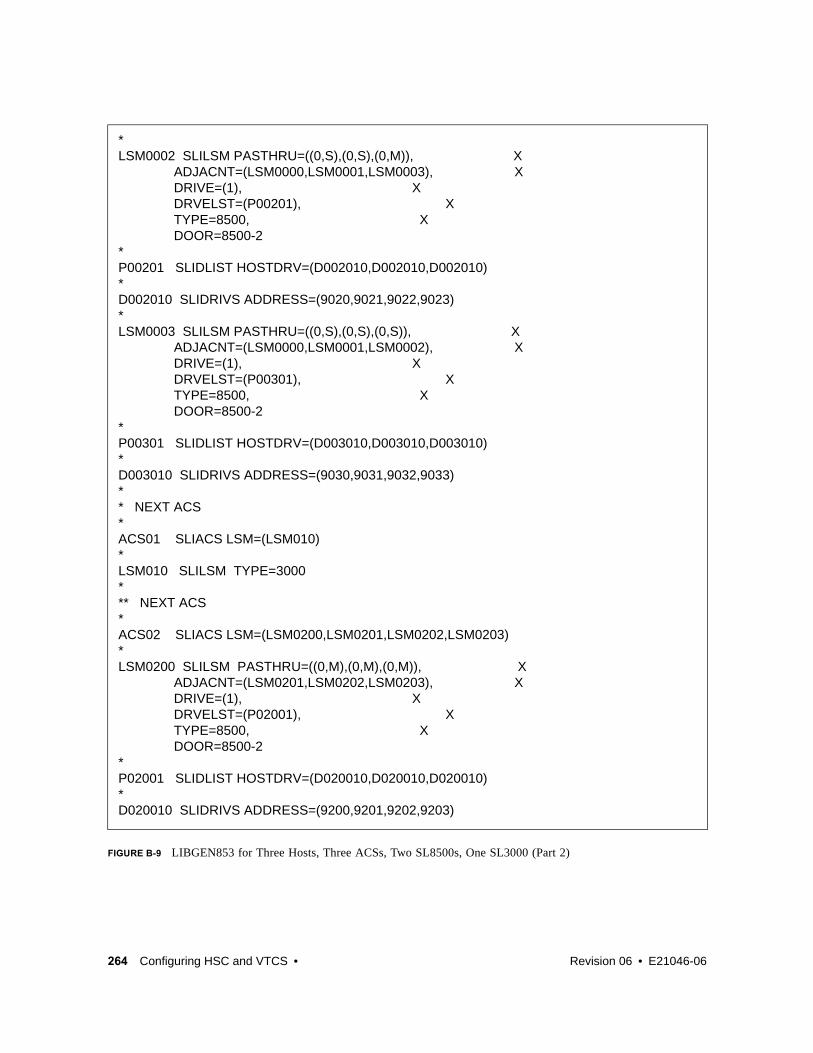
264 Configuring HSC and VTCS • Revision 06 • E21046-06
FIGURE B-9 LIBGEN853 for Three Hosts, Three ACSs, Two SL8500s, One SL3000 (Part 2)
*LSM0002 SLILSM PASTHRU=((0,S),(0,S),(0,M)), X ADJACNT=(LSM0000,LSM0001,LSM0003), X DRIVE=(1), X DRVELST=(P00201), X TYPE=8500, X DOOR=8500-2*P00201 SLIDLIST HOSTDRV=(D002010,D002010,D002010)*D002010 SLIDRIVS ADDRESS=(9020,9021,9022,9023)*LSM0003 SLILSM PASTHRU=((0,S),(0,S),(0,S)), X ADJACNT=(LSM0000,LSM0001,LSM0002), X DRIVE=(1), X DRVELST=(P00301), X TYPE=8500, X DOOR=8500-2*P00301 SLIDLIST HOSTDRV=(D003010,D003010,D003010)*D003010 SLIDRIVS ADDRESS=(9030,9031,9032,9033)** NEXT ACS*ACS01 SLIACS LSM=(LSM010)*LSM010 SLILSM TYPE=3000*** NEXT ACS*ACS02 SLIACS LSM=(LSM0200,LSM0201,LSM0202,LSM0203)*LSM0200 SLILSM PASTHRU=((0,M),(0,M),(0,M)), X ADJACNT=(LSM0201,LSM0202,LSM0203), X DRIVE=(1), X DRVELST=(P02001), X TYPE=8500, X DOOR=8500-2*P02001 SLIDLIST HOSTDRV=(D020010,D020010,D020010)*D020010 SLIDRIVS ADDRESS=(9200,9201,9202,9203)

E21046-06 • Revision 06 Appendix B 265
FIGURE B-10 LIBGEN853 for Three Hosts, Three ACSs, Two SL8500s, One SL3000 (Part 3)
LSM0201 SLILSM PASTHRU=((0,S),(0,M),(0,M)), X ADJACNT=(LSM0200,LSM0202,LSM0203), X DRIVE=(1), X DRVELST=(P02101), X TYPE=8500, X DOOR=8500-2*P02101 SLIDLIST HOSTDRV=(D021010,D021010,D021010)*D021010 SLIDRIVS ADDRESS=(9210,9211,9212,9213)*LSM0202 SLILSM PASTHRU=((0,S),(0,S),(0,M)), X ADJACNT=(LSM0200,LSM0201,LSM0203), X DRIVE=(1), X DRVELST=(P02201), X TYPE=8500, X DOOR=8500-2*P02201 SLIDLIST HOSTDRV=(D022010,D022010,D022010)*D022010 SLIDRIVS ADDRESS=(9220,9221,9222,9223)*LSM0203 SLILSM PASTHRU=((0,S),(0,S),(0,S)), X ADJACNT=(LSM0200,LSM0201,LSM0202), X DRIVE=(1), X DRVELST=(P02301), X TYPE=8500, X DOOR=8500-2*P02301 SLIDLIST HOSTDRV=(D023010,D023010,D023010)*D023010 SLIDRIVS ADDRESS=(9230,9231,9232,9233)** SLIENDGN ,

266 Configuring HSC and VTCS • Revision 06 • E21046-06
Three Host, Two ACSs, Two SL3000 Libraries Configuration The configuration which is defined by the LIBGEN33 sample shown in FIGURE B-8 on page 263, consists of the following:
? Three hosts (EC20,EC21,9999)
? Two ACSs (ACS00, ACS01)
? Two SL3000 libraries whose drives must be defined via SLIDRIVS.
? The FUTRACS parameter allows you to add two SL8500s or two SL3000s in the future.

E21046-06 • Revision 06 Appendix B 267
FIGURE B-11 LIBGEN33 for Three Hosts, Two ACSs, Two SL3000s
* Label definitions:** ACS - 'ACSxx'where 'xx' is the ACS number in printable hex.* LSM - 'LSMxxyy'where 'xx' is the ACS number in printable hex, and 'yy'* is the LSM number within the ACS in printable hex.* STATION- 'STxxh'where 'xx' is the ACS number in printable hex, and 'h'* is the host index in printable hex.* PANEL- 'Pxxyypp'where 'xx' is the ACS number in printable hex,’yy’ is* the LSM number in printable hex, and 'pp' is the panel* number in decimal.* DRIVE- 'Dxxyypph'where 'xx' is the ACS number in printable hex, 'yy' is * the LSM number in printable hex, 'pp' is the panel* number in printable hex, and 'h' is the host index in * printable hex.********************************************************************************** * This sample is a 2-ACS configuration, each with a single SL3000. * It also allows for 2 more SL3000's or 2 SL8500's to be added * in the future. * * NOTE: For the second SL3000, you must run SLIDRIVS to add the * MVS unit addresses for the tape drives. * LIBGEN33 SLIRCVRY TCHNIQE=SHADOW * SLILIBRY SMF=245, X FUTRACS=(2,4), X ACSLIST=ACSLIST, X HOSTID=(EC20,EC21,9999), X MAJNAME=SUNENQ, X CLNPRFX=CLN, X COMPRFX=-, X SCRLABL=SL * ACSLIST SLIALIST ACS00,ACS01 * * First ACS (SL3000) * ACS00 SLIACS LSM=(LSM000) * LSM000 SLILSM TYPE=3000, X DRIVE=(12), X DRVELST=(P000012) * P000012 SLIDLIST HOSTDRV=(D0000120,D0000120,D0000120) * D0000120 SLIDRIVS ADDRESS=(3001,3002,3003,3004,3005,3006,3007,3008, X 3009,3010,3011,3012,3013,3014,3015,3016, X 3017,3018,3019,3020,3021,3022,3023,3024, X 3025,3026,3027,3028,3029,3030,3031,3032) * * * Second ACS (SL3000) * ACS01 SLIACS LSM=(LSM001) * LSM001 SLILSM TYPE=3000 * SLIENDGN ,

268 Configuring HSC and VTCS • Revision 06 • E21046-06
One Host, One ACS, One 9310 LSM, Dual LMU ConfigurationThe configuration shown in FIGURE B-12 on page 269, which is defined by the LIBGEN04 sample shown in FIGURE B-13 on page 270, consists of the following:
? One host (HSC1)
? One 9310 LSM (LSM0000)
? 4 LMU station addresses (0A0,0A1,0C0,0C1)
? 4 transport panels (1,2,9,10)
? 16 transports (410-417 and 510-517).

E21046-06 • Revision 06 Appendix B 269
FIGURE B-12 One Host, One ACS, One 9310 LSM, Dual LMU Configuration
EXPANSION
LSM
EXPANSION
LSM
LSM 01
2
3
45
6
7
8
9
10
11
PA
NE
L0
CD
DR
V1
414-4
17
CD
DR
V0
41
0-4
13
LC
U
LAN0
LAN1
CD
DRV3
514-517
CD
DR
V2
510-513
ACSDRV=CTAPE
ACSDRV=CTAPE
LMU
A
LMU
B
3274 3274
OPERATING
SYSTEM
CD CU
CU CU
HOSTID=HSC1
ACSLIST=ACS0
LSM=LSM0
= PASS-THRU PORT
C27932
HSC
HOSTID
HSC1
S M
S
M

270 Configuring HSC and VTCS • Revision 06 • E21046-06
FIGURE B-13 LIBGEN04 forOne Host, One ACS, One 9310 LSM, Dual LMU Configuration
* Label definitions:** ACS- 'ACSxx'where 'xx' is the ACS number in printable hex.* LSM- 'LSMxxyy'where 'xx' is the ACS number in printable hex, and 'yy'* is the LSM number within the ACS in printable hex.* STATION- 'STxxh'where 'xx' is the ACS number in printable hex, and 'h'* is the host index in printable hex.* PANEL- 'Pxxyypp'where 'xx' is the ACS number in printable hex,’yy’ is* the LSM number in printable hex, and 'pp' is the panel* number in decimal.* DRIVE- 'Dxxyypph'where 'xx' is the ACS number in printable hex, 'yy' is * the LSM number in printable hex, 'pp' is the panel* number in printable hex, and 'h' is the host index in * printable hex.***********************************************************************************
LIBGEN04 SLIRCVRY TCHNIQE=BOTH* SLILIBRY HOSTID=HSC1, X SMF=235, X COMPRFX=#, X ACSLIST=NAMEACS, X MAJNAME=STKALSQN, X SCRLABL=SL, X EJCTPAS=GOODDAY, X CLNPRFX=CLN, X*NAMEACS SLIALIST ACS00*ST000 SLISTATN ADDRESS=(0A0,0A1,0C0,0C1)*LSM0000 SLILSM DRIVE=(1,2,9,10), X DRVELST=(P000001,P000002,P000009,P000010), X TYPE=9310, X DOOR=STD*P000001 SLIDLIST HOSTDRV=D0000000D0000000 SLIDRIVS ADDRESS=(410,411,412,413)P000002 SLIDLIST HOSTDRV=D0000010D0000010 SLIDRIVS ADDRESS=(414,415,416,417)P000009 SLIDLIST HOSTDRV=D0000020D0000020 SLIDRIVS ADDRESS=(510,511,512,513)P000010 SLIDLIST HOSTDRV=D0000030D0000030 SLIDRIVS ADDRESS=(514,515,516,517)* SLIENDGN

E21046-06 • Revision 06 Appendix B 271
Two Host, One ACS, Two 9310 LSM ConfigurationThe configuration shown in FIGURE B-14 on page 272, which is defined by the LIBGEN05 sample shown in FIGURE B-15 on page 273 and FIGURE B-16 on page 274, consists of the following:
? Two hosts (HSC1,HSC2)
? One Automated Cartridge System (ACS00)
? One 9310 LSM designated as LSM0000 with four transport panels (1,2,9,10) and a standard CAP.
? One 9310 LSM designated as LSM0001 with four transport panels (7,8,9,10) and an enhanced CAP.
? 4 LMU station addresses (0A0,0A1,0A2,0A3)
? 32 transports (410-41F and 510-51F).

272 Configuring HSC and VTCS • Revision 06 • E21046-06
FIGURE B-14 Two Host, One ACS, Two 9310 LSM Configuration
C27928
9
3
10
4
LSM 1
LSM 0EXPANSION
LSM
LC
U
11
5
0
6
1
7
2
8
3
9
4
10
5
11
M
S
6
PA
NE
L0
LC
U
7
1
8
2
CD
DR
V4
510-5
13
CD
DR
V0
41
0-4
13
CD
DR
V5
514-5
17
CD
DR
V1
414-4
17
CD
DRV6
518-51B
CD
DRV7
51C-51F
CD
DRV3
41C-41F
CD
DRV2
418-41B
ACSDRV=CTAPEA
ACSLIST=ACS0
ACSDRV=CTAPEB
ACSDRV=CTAPEA
LAN0
LAN1
OPERATING
SYSTEM
HSC1
HSC
HOSTID
CU
CU
CU
CU
CU
CD
3274 LMU 3274
HSC
HOSTID
OPERATING
SYSTEM
HSC2
CD CU
0A0
0A1
0A2
0A3

E21046-06 • Revision 06 Appendix B 273
FIGURE B-15 LIBGEN05 for Two Host, One ACS, Two 9310 LSM Configuration (Part 1)
* Label definitions:** ACS - 'ACSxx'where 'xx' is the ACS number in printable hex.* LSM - 'LSMxxyy'where 'xx' is the ACS number in printable hex, and 'yy'* is the LSM number within the ACS in printable hex.* STATION- 'STxxh'where 'xx' is the ACS number in printable hex, and 'h'* is the host index in printable hex.* PANEL- 'Pxxyypp'where 'xx' is the ACS number in printable hex,’yy’ is* the LSM number in printable hex, and 'pp' is the panel* number in decimal.* DRIVE- 'Dxxyypph'where 'xx' is the ACS number in printable hex, 'yy' is * the LSM number in printable hex, 'pp' is the panel* number in printable hex, and 'h' is the host index in * printable hex.***********************************************************************************LIBGEN05 SLIRCVRY TCHNIQE=SHADOW* SLILIBRY SMF=235, X HOSTID=(HSC1,HSC2), X ACSLIST=NAMEACS, X MAJNAME=STKALSQN, X COMPRFX=#, X SCRLABL=SL, X EJCTPAS=GOODDAY, X CLNPRFX=CLN, X*NAMEACS SLIALIST ACS00*ST000 SLISTATN ADDRESS=(0A0,0A1)ST001 SLISTATN ADDRESS=(0A2,0A3)*LSM0000 SLILSM DRIVE=(1,2,9,10), X DRVELST=(P000001,P000002,P000009,P000010), X PASTHRU=((5,M)), X ADJACNT=(LSM0001), X TYPE=9310, X DOOR=STD*P000001 SLIDLIST HOSTDRV=(D0000000,D0000000)D0000000 SLIDRIVS ADDRESS=(410,411,412,413)P000002 SLIDLIST HOSTDRV=(D0000010,D0000010)D0000010 SLIDRIVS ADDRESS=(414,415,416,417)P000009 SLIDLIST HOSTDRV=(D0000020,D0000020)D0000020 SLIDRIVS ADDRESS=(418,419,41A,41B)P000010 SLIDLIST HOSTDRV=(D0000030,D0000030)D0000030 SLIDRIVS ADDRESS=(41C,41D,41E,41F)*LSM0001 SLILSM DRIVE=(7,8,9,10), X DRVELST=(P000107,P000108,P000109,P000110), X PASTHRU=((5,S)), X ADJACNT=(LSM0000), X TYPE=9310, X DOOR=ECAP

274 Configuring HSC and VTCS • Revision 06 • E21046-06
FIGURE B-16 LIBGEN05 for Two Host, One ACS, Two 9310 LSM Configuration (Part 2)
*P000107 SLIDLIST HOSTDRV=(D0000040,D0000040)D0000040 SLIDRIVS ADDRESS=(510,511,512,513)P000108 SLIDLIST HOSTDRV=(D0000050,D0000050)D0000050 SLIDRIVS ADDRESS=(514,515,516,517)P000109 SLIDLIST HOSTDRV=(D0000060,D0000060)D0000060 SLIDRIVS ADDRESS=(518,519,51A,51B)P000110 SLIDLIST HOSTDRV=(D0000070,D0000070)D0000070 SLIDRIVS ADDRESS=(51C,51D,51E,51F)*
SLIENDGN

E21046-06 • Revision 06 275
APPENDIX
C
Special Cases: A Gallery of Advanced Uses of CONFIG
In this section, you’re going to learn everything you ever wanted to know about wringing every last bit of functionality out of the CONFIG utility. Note that in many of these examples, you’re changing the configuration, which is something you typically do when you’re doing an upgrade install: upgrade the hardware configuration, run DECOM, then update the CONFIG deck to match the hardware changes at a release boundary.
Note that when you’re doing something like adding RTDs, there’s more to it than just plugging in the hardware and updating the CONFIG deck...you need to do all the tasks discussed in “Planning for Library-Attached Transports” on page 27.

276 Configuring HSC and VTCS • Revision 06 • E21046-06
CONFIG Example: All Hosts Access VTDs in One VTSS, Only Selected Hosts Access VTDs in Second VTSSFIGURE C-1 shows example CONFIG JCL to define a VSM configuration as follows:
? The VTD statement specifies default VTD addresses 8900 - 893F for VTSS1. All hosts have access to these VTDs by their default addresses.
? No default VTD addresses are specified for VTSS2. The VTD statements that immediately follow the HOST statements for MVS1 and MVS2 specify that only these hosts can access the VTDs in VTSS2 by the addresses 9900 - 993F. HOST statement MVS3 is a placeholder; this host cannot access the VTDs in VTSS2, and is disabled from initiating migrates and reclaims.
FIGURE C-1 CONFIG example: All hosts access VTDs in one VTSS, selected hosts access VTDs in second VTSS
//UPDATECFG EXEC PGM=SLUADMIN,PARM='MIXED'//STEPLIB DD DSN=hlq.SEALINK,DISP=SHR//SLSCNTL DD DSN=hlq.DBASEPRM,DISP=SHR//SLSCNTL2 DD DSN=hlq.DBASESEC,DISP=SHR//SLSSTBY DD DSN=hlq.DBASETBY,DISP=SHR//CFG22202 DD DSN=hlq.CFG22202,DISP=SHR //SLSPRINT DD SYSOUT=*//SLSIN DD * CONFIG CDSLEVEL(V62ABOVE) GLOBAL MAXVTV=65000 MVCFREE=60 VTVATTR=SCRATCH RECALWER=YES LOCKSTR=STK_VTCS_LOCKS VTVPAGE=LARGE MAXRTDS=32 FASTMIGR=YES RECLAIM THRESHLD=70 MAXMVC=30 START=40 CONMVC=5VTSS NAME=VTSS1 LOW=70 HIGH=80 MAXMIG=3 RETAIN=5 RTDNAME=VT128800 DEVNO=8800 CHANIF=0A RTDNAME=VTS18801 DEVNO=8801 CHANIF=0I RTDNAME=VTS18802 DEVNO=8802 CHANIF=1A RTDNAME=VTS18803 DEVNO=8803 CHANIF=1I VTDLOW=8900 HIGH=893F VTSS NAME=VTSS2 LOW=70 HIGH=80 MAXMIG=3 RETAIN=5 RTDNAME=VTS28804 DEVNO=8804 CHANIF=0A RTDNAME=VTS28805 DEVNO=8805 CHANIF=0I RTDNAME=VTS28806 DEVNO=8806 CHANIF=1A RTDNAME=VTS28807 DEVNO=8807 CHANIF=1I HOST NAME=MVS1 VTD LOW=9900 HIGH=993F HOST NAME=MVS2 VTD LOW=9900 HIGH=993F HOST NAME=MVS3 NOMIGRAT NORECLAM

E21046-06 • Revision 06 Appendix C 277
CONFIG Example: Update Configuration to Add RTDs FIGURE C-2 shows example JCL to run CONFIG to add RTDs VTS18811 and VTS18813 (connected to VTSS1) to the configuration shown in Figure 19 on page 98. Because of NCO, you can add the RTDs dynamically (no RESET required), by simply adding new definitions for RTDs VTS18811 and VTS18813.
FIGURE C-2 CONFIG example: updating configuration to add RTDs
//UPDATECFG EXEC PGM=SLUADMIN,PARM='MIXED'//STEPLIB DD DSN=hlq.SEALINK,DISP=SHR//SLSCNTL DD DSN=hlq.DBASEPRM,DISP=SHR//SLSCNTL2 DD DSN=hlq.DBASESEC,DISP=SHR//SLSSTBY DD DSN=hlq.DBASETBY,DISP=SHR//CFG22202 DD DSN=hlq.CFG22202,DISP=SHR //SLSPRINT DD SYSOUT=*//SLSIN DD * CONFIG CDSLEVEL(V62ABOVE) GLOBAL MAXVTV=65000 MVCFREE=60 VTVATTR=SCRATCH RECALWER=YES LOCKSTR=STK_VTCS_LOCKS VTVPAGE=LARGE MAXRTDS=32 FASTMIGR=YES RECLAIM THRESHLD=70 MAXMVC=30 START=40 CONMVC=5VTSS NAME=VTSS1 LOW=70 HIGH=80 MAXMIG=3 RETAIN=5 RTDNAME=VTS18800 DEVNO=8800 CHANIF=0A RTDNAME=VTS18801 DEVNO=8801 CHANIF=0I RTDNAME=VTS18802 DEVNO=8802 CHANIF=1A RTDNAME=VTS18803 DEVNO=8803 CHANIF=1I RTDNAME=VTS18811 DEVNO=8811 CHANIF=0E RTDNAME=VTS18813 DEVNO=8813 CHANIF=1E VTDLOW=8900 HIGH=893F VTSS NAME=VTSS2 LOW=70 HIGH=80 MAXMIG=3 RETAIN=5 RTDNAME=VTS28804 DEVNO=8804 CHANIF=0A RTDNAME=VTS28805 DEVNO=8805 CHANIF=0I RTDNAME=VTS28806 DEVNO=8806 CHANIF=1A RTDNAME=VTS28807 DEVNO=8807 CHANIF=1I HOST NAME=MVS1 VTD LOW=9900 HIGH=993F HOST NAME=MVS2 VTD LOW=9900 HIGH=993F HOST NAME=MVS3

278 Configuring HSC and VTCS • Revision 06 • E21046-06
CONFIG Example: Update Configuration to Add MVCs and VTVs and Change AMTsFIGURE C-3 shows example JCL to run CONFIG to modify the configuration shown in FIGURE C-2 on page 277 by:
? Adding VTVs C25001 to C50000 as scratch.
? Adding MVCs N45000 to N45999.
? Changing the LAMT to 50 and the HAMT to 85 on both VTSS1 and VTSS2.
FIGURE C-3 CONFIG example: updating configuration to add MVCs and VTVs and change AMTs
//UPDATECFG EXEC PGM=SLUADMIN,PARM='MIXED'//STEPLIB DD DSN=hlq.SEALINK,DISP=SHR//SLSCNTL DD DSN=hlq.DBASEPRM,DISP=SHR//SLSCNTL2 DD DSN=hlq.DBASESEC,DISP=SHR//SLSSTBY DD DSN=hlq.DBASETBY,DISP=SHR//CFG22202 DD DSN=hlq.CFG22202,DISP=SHR //SLSPRINT DD SYSOUT=*//SLSIN DD * CONFIG CDSLEVEL(V62ABOVE) GLOBAL MAXVTV=65000 MVCFREE=60 VTVATTR=SCRATCH RECALWER=YES LOCKSTR=STK_VTCS_LOCKS VTVPAGE=LARGE MAXRTDS=32 FASTMIGR=YES RECLAIM THRESHLD=70 MAXMVC=30 START=40 CONMVC=5VTSS NAME=VTSS1 LOW=50 HIGH=85 MAXMIG=3 RETAIN=5 RTDNAME=VTS18800 DEVNO=8800 CHANIF=0A RTDNAME=VTS18801 DEVNO=8801 CHANIF=0I RTDNAME=VTS18802 DEVNO=8802 CHANIF=1A RTDNAME=VTS18803 DEVNO=8803 CHANIF=1I RTDNAME=VTS18811 DEVNO=8811 CHANIF=0E RTDNAME=VTS18813 DEVNO=8813 CHANIF=1E VTDLOW=8900 HIGH=893F VTSS NAME=VTSS2 LOW=50 HIGH=85 MAXMIG=3 RETAIN=5 RTDNAME=VTS28804 DEVNO=8804 CHANIF=0A RTDNAME=VTS28805 DEVNO=8805 CHANIF=0I RTDNAME=VTS28806 DEVNO=8806 CHANIF=1A RTDNAME=VTS28807 DEVNO=8807 CHANIF=1I HOST NAME=MVS1 VTD LOW=9900 HIGH=993F HOST NAME=MVS2 VTD LOW=9900 HIGH=993F HOST NAME=MVS3

E21046-06 • Revision 06 Appendix C 279
CONFIG Example: Denying Host Access to a Physically Removed VTSSIf you remove a VTSS, you need a way to let the hosts know the VTSS is no longer in the configuration. FIGURE C-4 shows JCL to run CONFIG to deny host access to VTSS2 that you physically removed from your configuration. In this example, you simply respecify the VTSS statement for VTSS2 with no parameters to deny host access to this VTSS.
FIGURE C-4 CONFIG example: updating configuration to deny host access to a physically removed VTSS
//UPDATECFG EXEC PGM=SLUADMIN,PARM='MIXED'//STEPLIB DD DSN=hlq.SEALINK,DISP=SHR//SLSCNTL DD DSN=hlq.DBASEPRM,DISP=SHR//SLSCNTL2 DD DSN=hlq.DBASESEC,DISP=SHR//SLSSTBY DD DSN=hlq.DBASETBY,DISP=SHR//CFG22202 DD DSN=hlq.CFG22202,DISP=SHR //SLSPRINT DD SYSOUT=*//SLSIN DD * CONFIG CDSLEVEL(V62ABOVE) GLOBAL MAXVTV=65000 MVCFREE=60 VTVATTR=SCRATCH RECALWER=YES LOCKSTR=STK_VTCS_LOCKS VTVPAGE=LARGE MAXRTDS=32 FASTMIGR=YES RECLAIM THRESHLD=70 MAXMVC=30 START=40 CONMVC=5 VTSS NAME=VTSS1 LOW=70 HIGH=80 MAXMIG=3 RETAIN=5 RTDNAME=VTS18800 DEVNO=8800 CHANIF=0A RTDNAME=VTS18801 DEVNO=8801 CHANIF=0I RTDNAME=VTS18802 DEVNO=8802 CHANIF=1A RTDNAME=VTS18803 DEVNO=8803 CHANIF=1I RTDNAME=VTS18811 DEVNO=8811 CHANIF=0E RTDNAME=VTS18813 DEVNO=8813 CHANIF=1E VTDLOW=8900 HIGH=893F VTSS NAME=VTSS2

280 Configuring HSC and VTCS • Revision 06 • E21046-06
CONFIG Examples: Using the Maximum 32 RTDs FeatureAs described in “Maximum RTDs per VTSS” on page 46, you can specify up to 32 RTDs attached to a VTSS. With this feature enabled, it turns out you can also attach greater than 16 RTDs and have some ports left for CLINK originators and terminators. What follows is a general procedure for implementing Maximum 32 RTDs with links to two examples with CONFIG decks.
? Implementing Support for Maximum of 32 RTDs1. Ensure that your system has the Synchronous Replication requirements described in
TABLE H-3 on page 386.
2. Use CONFIG GLOBAL to enable support for maximum of 32 RTDs
CONFIG GLOBAL MAXRTDS=32
Note – Enabling support for a maximum of 32 RTDs does not require CONFIG RESET. However, regressing from 32 RTDs supported to 16 RTDs supported does require CONFIG RESET.
3. Update your CONFIG RTD and CONFIG CLINK statements as required.

APPENDIX D
Configuring SL8500 Library Communications
The SL8500 is different from other LSMs, and the way it communicates with HSC is also different...as explained in this appendix.
E21046-06 • Revision 06 281

TCP/IP Communications - Important Considerations
SL8500 TCP/IP ConnectionsWhen you create an SL8500 library complex by connecting libraries together with passthru ports, all hosts must connect to only one library in the complex— preferably to the first or rightmost library.
For the complex, there are three types of TCP/IP connections for SL8500 discussed in the following sections:
? “Dual IP Connections” on page 284 - A redundancy feature to allow up to two connections to the first library of a complex.
? “Multiple SL8500 Library Connections” on page 303 - Starting with the SL8500 3.9x firmware release, an SL8500 complex is capable of network connecting up to 4 libraries to HSC. This enhances connecting redundancy to the complex compared to dual TCP/IP.
? “Multiple TCP/IP Redundant Electronics” on page 306 - Starting with the SL8500 6.x firmware release, an SL8500 complex is capable of redundant electronics of the library controller with network connecting up to 16 libraries in pairs (one active and one standby) to HSC. This enhances hardware reliability to the complex compared to the other 2 types.
Note – It is crucial that you read completely these sections to understand these procedures.
282 Configuring HSC and VTCS • Revision 06 • E21046-06

Shared NetworksThe following are some examples of issues that can arise when you connect an SL8500 to a shared network.
? A TCP/IP-connected library can handle standard host traffic but it cannot resolve floods of Address Resolution Protocol (ARP) broadcasts. For this reason, it is best to attach the library on a controlled network, such as behind a switch or router.
Later generation networks, such as 1000Base-T and Gig-E, support earlier communication modes; however, devices that are communicating with the library may transmit data at bandwidths that could overwhelm the library.
It is best to attach the library on a controlled network, such as with a switch that can isolate the library from network broadcasts.
? When you connect the library on shared networks and broadcasts are sent to all network nodes, they may also be directed to the library (even though it does not need them).
During the time the library is receiving these irrelevant broadcasts, it cannot receive from or respond to other requests in a timely fashion. This heavy broadcast traffic on the network can saturate the library to the point that, to the host, it may appear that the TCP/IP connection has been lost. It may also result in Overdue Response Handler (ORH) messages on the host system.
? Heavy network traffic can also overwhelm the Ethernet controller causing the processor to continuously reset and re-initialize the controller, then recover the host-to-library communications.
E21046-06 • Revision 06 Appendix D 283

Dual IP ConnectionsThe LMUPATH control statement allows users to define network LMU attachments (see ELS Command, Control Statement, and Utility Reference). In a dual IP connection environment for an SL8500, specify a second LMUADDR parameter to define dual IP. HSC automatically determines whether or not the connection is dual IP or dual LMU.
Note – Vary the ACS offline and back online to pick up the revised LMUPATH statement that includes the second connection.
FIGURE D-1 on page 285 and FIGURE D-2 show examples of a dual IP connection for the HSC.
Two SL8500 Network Connections - Two Mainframe IP AddressesTo establish two dedicated routes on different subnetworks from the HSC to two dedicated routes to the SL8500, use the process described in this section. To configure the SL8500 dual TCP/IP feature, refer to StreamLine SL8500 Modular Library System Dual TCP/IP Feature or StreamLine SL3000 Modular Library System Installation Guide.
FIGURE D-1 on page 285 shows dual IP connections with two SL8500 network connections.
284 Configuring HSC and VTCS • Revision 06 • E21046-06

FIGURE D-1 Dual IP Connection with two SL8500 Connections
E21046-06 • Revision 06 Appendix D 285

Note – In the following examples, the entries in italics represent the second connection.
1. Complete the Network Entries Worksheet (see TABLE D-1 for a sample) for each set of two dedicated routes to the SL8500. The worksheet can be found in the StreamLine SL8500 Modular Library System Dual TCP/IP Feature document.
2. Define a second DEVICE and LINK statement in your TCP/IP profile data set for a second mainframe network connection:
Example:
3. Define a second home address in your TCP/IP profile data set.
Example:
TABLE D-1 Network Entries Worksheet
Description IP Address
Port 2A
HBC Card Port 2A 172.27.2.5
Gateway Port 2A 172.27.3.254
Netmask /23
Host to Port 2A 129.80.16.239
Port 2B
HBC Car Port 2B 129.80.71.83
Gateway Port 2B 129.80.71.254
Netmask /23
Host to Port 2B 129.80.65.203
; OSA CARD #1DEVICE ECCQD01 MPCIPA NONROUTER AUTORESTARTLINK ZIPBMVS IPAQENET ECCQD01
; OSA CARD #2DEVICE ECCQA01 MPCIPA NONROUTER AUTORESTARTLINK ZIPB2MVS IPAQENET ECCQA01
HOME 129.80.16.239 ZIPBMVS129.80.65.203 ZIPB2MVS
286 Configuring HSC and VTCS • Revision 06 • E21046-06

4. Define a second router on the second subnetwork in the routing paragraph of your TCP/IP profile data set. Remember that you must also configure the SL8500 routing tables according to the instructions described in the StreamLine SL8500 Modular Library System Dual TCP/IP Feature document.
Example:
5. Define two dedicated static routes to the SL8500 destination port (2A and 2B) IP addresses over two different routers.
Example:
6. Start the second mainframe network connection device.
BEGINROUTES ; NETWORK MASK FIRSTHOP LINKNAME PACKETSIZE
ROUTE 129.80.16.0/24 = ZIPBMVS MTU 1492ROUTE 129.80.65.0/24 = ZIPB2MVS MTU 1492ROUTE 172.27.2.5 HOST 129.80.16.254 ZIPBMVS MTU 1492ROUTE 129.80.71.83 HOST 129.80.65.254 ZIPB2MVS MTU 1492ROUTE DEFAULT 129.80.16.254 ZIPBMVS MTU 1492ROUTE DEFAULT 129.80.65.254 ZIPB2MVS MTU 1492ENDROUTES
; NETWORK MASK ROUTER LINKNAME PACKETSIZEROUTE Sl8500-port-2A-IP-Address HOST 129.80.16.254 MVSHOST1 MTU 1492ROUTE Sl8500-port-2B-IP-Address HOST 129.80.64.254 MVSHOST2 MTU 1492
BEGINROUTES; NETWORK MASK FIRSTHOP LINKNAME PACKETSIZEROUTE 129.80.16.0/24 = ZIPBMVS MTU 1492ROUTE 129.80.65.0/24 = ZIPB2MVS MTU 1492ROUTE 172.27.2.5 HOST 129.80.16.254 ZIPBMVS MTU 1492ROUTE 129.80.71.83 HOST 129.80.65.254 ZIPB2MVS MTU 1492ROUTE DEFAULT 129.80.16.254 ZIPBMVS MTU 1492ROUTE DEFAULT 129.80.65.254 ZIPB2MVS MTU 1492ENDROUTES
V TCPIP,tcp-stc-name,START,device_name
E21046-06 • Revision 06 Appendix D 287

7. Define a second LMUADDR parameter for the port 2A IP address on the SL8500.
Example:
8. Enter the LMUPDEF command containing the LMUPATH statements that define the host name or IP address for each ACS.
In the following example, LMUPDEF loads LMUPATH parameters from YOUR.DSN(MEMBER).
9. Allow the trained SL8500 service representative to enter the network connections to the SL8500 library for either port 2A and 2B, whichever is applicable.
10. Vary the ACS offline and back online to pick up the revised LMUPATH statement that includes the second connection. This can be done one host at a time to minimize down time.
LMUPATH ACS(00) LMUADDR(129.80.71.83,172.27.2.5)
LMUPDEF DSN(‘xxx.xxx.xxx(xxx)’)
LMUPDEF DSN(‘YOUR.DSN(MEMBER)’)
288 Configuring HSC and VTCS • Revision 06 • E21046-06

Sample Configuration - Two Dedicated RoutesFIGURE D-2 shows a sample configuration with two dedicated routes, followed by the statements that apply to it.
FIGURE D-2 Dual IP Configuration Sample - Different Subnetworks
E21046-06 • Revision 06 Appendix D 289

Setup Statements and Displays
The following information shows the statements and displays used in FIGURE D-2 on page 289.
HSC LMUPDEF PARMLIB Member
TCP/IP Profile Data Set
OPTION TITLE('DUAL TCPIP CONNECTING TO SL8500')LMUPATH ACS(00) LMUADDR(129.80.71.83,172.27.2.5)
; OSA CARD #1DEVICE ECCQD01 MPCIPA NONROUTER AUTORESTARTLINK ZIPBMVS IPAQENET ECCQD01 ; OSA CARD #2DEVICE ECCQA01 MPCIPA NONROUTER AUTORESTARTLINK ZIPB2MVS IPAQENET ECCQA01
HOME 129.80.16.239 ZIPBMVS 129.80.65.203 ZIPB2MVS
BEGINROUTES; NETWORK MASK FIRSTHOP LINKNAME PACKETSIZEROUTE 129.80.16.0/24 = ZIPBMVS MTU 1492ROUTE 129.80.65.0/24 = ZIPB2MVS MTU 1492ROUTE 172.27.2.5 HOST 129.80.16.254 ZIPBMVS MTU 1492ROUTE 129.80.71.83 HOST 129.80.65.254 ZIPB2MVS MTU 1492ROUTE DEFAULT 129.80.16.254 ZIPBMVS MTU 1492ROUTE DEFAULT 129.80.65.254 ZIPB2MVS MTU 1492
ENDROUTES
INCLUDE ZIP.TCPIP.PROFILES(COMMON)
START ECCQD01START ECCQA01
290 Configuring HSC and VTCS • Revision 06 • E21046-06

TCP/IP Console Displays
E21046-06 • Revision 06 Appendix D 291

D TCPIP,TCPIP,NETSTAT,DEVEZZ2500I NETSTAT CS V1R4 TCPIP 229DEVNAME: LOOPBACK DEVTYPE: LOOPBACK DEVSTATUS: READY LNKNAME: LOOPBACK LNKTYPE: LOOPBACK LNKSTATUS: READY NETNUM: 0 QUESIZE: 0 BYTESIN: 1781074 BYTESOUT: 1781074 ACTMTU: 65535 BSD ROUTING PARAMETERS: MTU SIZE: 00000 METRIC: 00 DESTADDR: 0.0.0.0 SUBNETMASK: 0.0.0.0 MULTICAST SPECIFIC: MULTICAST CAPABILITY: NO
DEVNAME: ECCQD01 DEVTYPE: MPCIPA DEVSTATUS: READY CFGROUTER: NON ACTROUTER: NON LNKNAME: ZIPBMVS LNKTYPE: IPAQENET LNKSTATUS: READY NETNUM: 0 QUESIZE: 0 SPEED: 0000001000 BYTESIN: 34704496 BYTESOUT: 11207410 IPBROADCASTCAPABILITY: NO ARPOFFLOAD: YES ARPOFFLOADINFO: YES ACTMTU: 8992 INBPERF: BALANCED BSD ROUTING PARAMETERS: MTU SIZE: 00000 METRIC: 00 DESTADDR: 0.0.0.0 SUBNETMASK: 255.255.255.0 MULTICAST SPECIFIC: MULTICAST CAPABILITY: YES GROUP REFCNT ----- ------ 224.0.0.1 0000000001
DEVNAME: ECCQA01 DEVTYPE: MPCIPA DEVSTATUS: READY CFGROUTER: NON ACTROUTER: NON LNKNAME: ZIPB2MVS LNKTYPE: IPAQENET LNKSTATUS: READY NETNUM: 0 QUESIZE: 0 SPEED: 0000000100 BYTESIN: 147508801 BYTESOUT: 2188246 IPBROADCASTCAPABILITY: NO ARPOFFLOAD: YES ARPOFFLOADINFO: YES ACTMTU: 1492 INBPERF: BALANCED BSD ROUTING PARAMETERS: MTU SIZE: 00000 METRIC: 00 DESTADDR: 0.0.0.0 SUBNETMASK: 255.255.255.0 MULTICAST SPECIFIC: MULTICAST CAPABILITY: YES GROUP REFCNT ----- ------ 224.0.0.1 00000000013 OF 3 RECORDS DISPLAYEDD TCPIP,TCPIP,NETSTAT,ROUTEEZZ2500I NETSTAT CS V1R4 TCPIP 250DESTINATION GATEWAY FLAGS REFCNT INTERFACEDEFAULT 129.80.16.254 UGS 000003 ZIPBMVSDEFAULT 129.80.65.254 UGS 000002 ZIPB2MVS127.0.0.1 0.0.0.0 UH 000003 LOOPBACK129.80.16.0 0.0.0.0 US 000002 ZIPBMVS129.80.16.239 0.0.0.0 UH 000000 ZIPBMVS129.80.65.0 0.0.0.0 US 000000 ZIPB2MVS129.80.65.203 0.0.0.0 UH 000000 ZIPB2MVS129.80.71.83 129.80.65.254 UGHS 000001 ZIPB2MVS
292 Configuring HSC and VTCS • Revision 06 • E21046-06172.27.2.5 129.80.16.254 UGHS 000001 ZIPBMVS9 OF 9 RECORDS DISPLAYED

HSC Display Showing SL8500 Connection
D ACSSLS0000I D ACSSLS1000I ACS 00 STATUS: CONNECTED 334ACTIVE QUEUE ELEMENTS 2COMPATIBILITY LEVELS: HSC=13, LMU=13DUAL LMU NOT CONFIGUREDIP ADDR 129.80.71.83 ONLINEIP ADDR 172.27.2.5 ONLINESCRATCH VOLUMES AVAILABLE...... 210FREE CELLS AVAILABLE........... 2008D TCPIP,TCPIP,NETSTAT,HOMEEZZ2500I NETSTAT CS V1R4 TCPIP 252HOME ADDRESS LIST:ADDRESS LINK FLG129.80.16.239 ZIPBMVS P129.80.65.203 ZIPB2MVS127.0.0.1 LOOPBACK3 OF 3 RECORDS DISPLAYED
E21046-06 • Revision 06 Appendix D 293

SLConsole Display of SL8500 Ports 2A/2B IP Addresses
294 Configuring HSC and VTCS • Revision 06 • E21046-06

Two SL8500 Network Connections - One Mainframe IP AddressTo establish one host IP route from the HSC to two routes to the SL8500, use the process described in this section. To configure the SL8500 dual TCP/IP feature, refer to the StreamLine SL8500 Modular Library System Dual TCP/IP Feature document.
FIGURE D-3 on page 296 shows dual IP (one host IP) with two SL8500 network connections.
E21046-06 • Revision 06 Appendix D 295

FIGURE D-3 Dual IP (one host IP) with Two SL8500 Network Connections
296 Configuring HSC and VTCS • Revision 06 • E21046-06

In the following examples, the entries in italics represent the second connection.
1. Complete the Network Entries Worksheet (see TABLE D-2 for a sample) for each set of routes to the SL8500. The worksheet can be found in the StreamLine SL8500 Modular Library System Dual TCP/IP Feature document.
2. Define two dedicated static routes to the SL8500 destination port (2A and 2B) IP addresses over one router.
Example:
3. Define a second LMUADDR parameter for the port 2A IP address on the SL8500.
Example:
4. Enter the LMUPDEF command containing the LMUPATH statements that define the host name or IP address for each ACS.
In the following example, LMUPDEF loads LMUPATH parameters from YOUR.DSN(MEMBER).
TABLE D-2 Network Entries Worksheet
Description IP Address
Port 2A
HBC Card Port 2A 172.27.2.5
Gateway Port 2A 172.27.3.254
Netmask /23
Host to Port 2A 129.80.16.239
Port 2B
HBC Car Port 2B 129.80.71.83
Gateway Port 2B 129.80.71.254
Netmask /23
Host to Port 2B 129.80.16.239
BEGINROUTES; DESTINATION FIRSTHOP LINKNAME PACKETSIZEROUTE 129.80.16.0/24 = &SYSNAME.MVS MTU 1492ROUTE 172.27.2.5 HOST 129.80.16.254 &SYSNAME.MVS MTU 1492ROUTE 129.80.71.83 HOST 129.80.16.254 &SYSNAME.MVS MTU 1492ROUTE DEFAULT 129.80.16.254 &SYSNAME.MVS MTU 1492
ENDROUTES
LMUPATH ACS(00) LMUADDR(129.80.71.83,172.27.2.5)
LMUPDEF DSN(‘xxx.xxx.xxx(xxx)’)
LMUPDEF DSN(‘YOUR.DSN(MEMBER)’)
E21046-06 • Revision 06 Appendix D 297

5. Allow the trained SL8500 service representative to enter the network connections to the SL8500 library for either port 2A and 2B, whichever is applicable.
6. Vary the ACS offline and back online to pick up the revised LMUPATH statement that includes the second connection. This can be done one host at a time to minimize down time.
298 Configuring HSC and VTCS • Revision 06 • E21046-06

Sample Configuration - One Host IP, Two SL8500 Network ConnectionsFIGURE D-4 shows a sample dual IP (one host IP) configuration with two SL8500 network connections, followed by the statements that apply to it.
FIGURE D-4 Dual IP (one host IP) with Two SL8500 Network Connections
E21046-06 • Revision 06 Appendix D 299

Setup Statements and Displays
The following information shows the statements and displays used in FIGURE D-4.
HSC LMUPDEF PARMLIB Member
TCP/IP Profile Data Set
OPTION TITLE('DUAL TCPIP CONNECTING TO SL85001')LMUPATH ACS(00) LMUADDR(129.80.71.83,172.27.2.5)
; OSA CARD #1DEVICE ECCQD01 MPCIPA NONROUTER AUTORESTARTLINK ZIPBMVS IPAQENET ECCQD01 HOME 129.80.&IPADDR1 &SYSNAME.MVS
BEGINROUTES; NETWORK MASK FIRSTHOP LINKNAME PACKETSIZEROUTE 129.80.16.0/24 = &SYSNAME.MVS MTU 1492ROUTE 172.27.2.5 HOST 129.80.16.254 &SYSNAME.MVS MTU 1492ROUTE 129.80.71.83 HOST 129.80.16.254 &SYSNAME.MVS MTU 1492ROUTE DEFAULT
ENDROUTES
INCLUDE ZIP.TCPIP.PROFILES(COMMON)
START ECCQD01
300 Configuring HSC and VTCS • Revision 06 • E21046-06

TCP/IP Console Displays
D TCPIP,,N,DEVEZZ2500I NETSTAT CS V1R4 TCPIP 931DEVNAME: LOOPBACK DEVTYPE: LOOPBACK DEVSTATUS: READY LNKNAME: LOOPBACK LNKTYPE: LOOPBACK LNKSTATUS: READY NETNUM: 0 QUESIZE: 0 BYTESIN: 2136824 BYTESOUT: 2136824 ACTMTU: 65535 BSD ROUTING PARAMETERS: MTU SIZE: 00000 METRIC: 00 DESTADDR: 0.0.0.0 SUBNETMASK: 0.0.0.0 MULTICAST SPECIFIC: MULTICAST CAPABILITY: NODEVNAME: ECCQD01 DEVTYPE: MPCIPA DEVSTATUS: READY CFGROUTER: NON ACTROUTER: NON LNKNAME: ZIPBMVS LNKTYPE: IPAQENET LNKSTATUS: READY NETNUM: 0 QUESIZE: 0 SPEED: 0000001000 BYTESIN: 48605838 BYTESOUT: 9790950 IPBROADCASTCAPABILITY: NO ARPOFFLOAD: YES ARPOFFLOADINFO: YES ACTMTU: 8992 INBPERF: BALANCED BSD ROUTING PARAMETERS: MTU SIZE: 00000 METRIC: 00 DESTADDR: 0.0.0.0 SUBNETMASK: 255.255.255.0 MULTICAST SPECIFIC: MULTICAST CAPABILITY: YES GROUP REFCNT ----- ------ 224.0.0.1 00000000012 OF 2 RECORDS DISPLAYED
D TCPIP,,N,ROUTEEZZ2500I NETSTAT CS V1R4 TCPIP 933DESTINATION GATEWAY FLAGS REFCNT INTERFACEDEFAULT 129.80.16.254 UGS 000001 ZIPBMVS127.0.0.1 0.0.0.0 UH 000004 LOOPBACK129.80.16.0 0.0.0.0 US 000000 ZIPBMVS129.80.16.239 0.0.0.0 UH 000000 ZIPBMVS129.80.71.83 129.80.16.254 UGHS 000001 ZIPBMVS172.27.2.5 129.80.16.254 UGHS 000001 ZIPBMVS6 OF 6 RECORDS DISPLAYED
D TCPIP,,N,HOMEEZZ2500I NETSTAT CS V1R4 TCPIP 935HOME ADDRESS LIST:ADDRESS LINK FLG129.80.16.239 ZIPBMVS P127.0.0.1 LOOPBACK2 OF 2 RECORDS DISPLAYED
E21046-06 • Revision 06 Appendix D 301
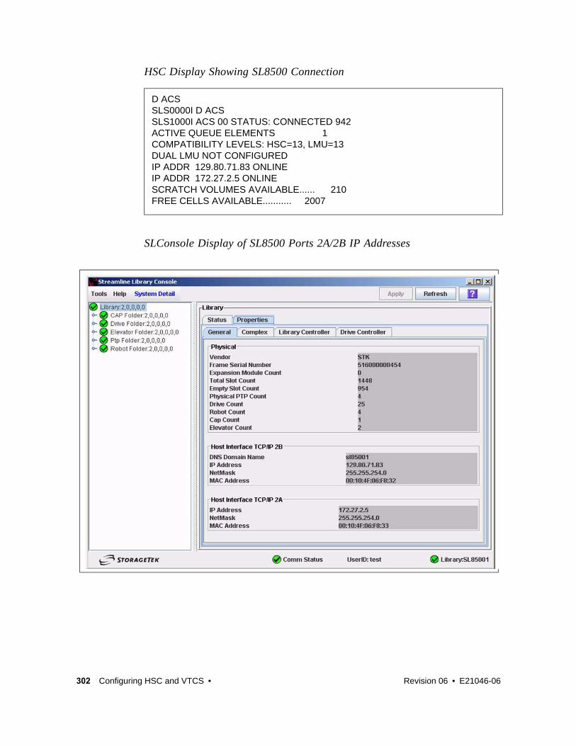
HSC Display Showing SL8500 Connection
SLConsole Display of SL8500 Ports 2A/2B IP Addresses
D ACSSLS0000I D ACSSLS1000I ACS 00 STATUS: CONNECTED 942ACTIVE QUEUE ELEMENTS 1COMPATIBILITY LEVELS: HSC=13, LMU=13DUAL LMU NOT CONFIGUREDIP ADDR 129.80.71.83 ONLINEIP ADDR 172.27.2.5 ONLINESCRATCH VOLUMES AVAILABLE...... 210FREE CELLS AVAILABLE........... 2007
302 Configuring HSC and VTCS • Revision 06 • E21046-06

Multiple SL8500 Library Connections
Connecting to Multiple SL8500 Libraries in an ACSWhen SL8500 3.9x or higher firmware is installed, the HSC can connect to more than one SL8500 in an ACS (library complex).
The HSC supports up to four connections to an ACS. Some possible connections are:
? four connections to four SL8500s
? two connections to each of two SL8500s
? two connections to one SL8500 and two connections to two other SL8500s.
When the HSC establishes two connections to one SL8500, the HSC provides dual TCP/IP or multiple TCP/IP connectivity. Refer to the “TCP/IP Communications - Important Considerations” on page 282 discussion for more information.
Note –
? To optimize library performance and minimize inter-library communication among SL8500s, connect to the libraries with the most activity. The HSC distributes communications to the libraries evenly.
? LMUPATH control statements are used to define network LMU attachments.
The following example shows multiple LMUADDR parameters consisting of four IP addresses. In this case, the first, second, third, and fourth IP addresses indicate a TCP/IP connection to each of four separate SL8500 libraries connected in ACS 00:
LMUPATH ACS(00)+ LMUADDR(123.456.789.012,123.456.789.013,123.456.789.014,123.456.789.015)
E21046-06 • Revision 06 Appendix D 303

Sample Configuration - Four SL8500 Network Connections, Four Mainframe IP AddressesFIGURE D-5 on page 304 shows a sample of a four IP (four host IPs) configuration with four SL8500 network connections. This configuration applies to SL8500 3.x or higher firmware.
FIGURE D-5 Four IP Addresses (four host IPs) with Four SL8500 Network Connections
304 Configuring HSC and VTCS • Revision 06 • E21046-06

Powering Down the SL8500 - HSC RequirementsPrior to powering down the SL8500, the HSC requires that the following procedure must be followed:
1. Vary the drives offline at the MVS host level.
2. Modify the LSM(s) offline (see the MODify Command in the ELS Command, Control Statement, and Utility Reference).
For specific information about powering off the SL8500, refer to the SL8500 User’s Guide.
E21046-06 • Revision 06 Appendix D 305

Multiple TCP/IP Redundant ElectronicsThe LMUPATH control statement allows users to define network Library Controller attachments. In a Multiple TCP/IP redundant electronics environment for an SL8500 complex, specify up to 32 network connections using the LMUADDR parameter. When specified, HSC automatically adjusts when Redundant Electronics is installed.
Note – Vary the ACS offline, updating the LMUPDEF file to accommodate redundant electronics, read the new LMUPDEF file, and vary the ACS back online to pick up the revised LMUPATH statement that includes the added connections.
306 Configuring HSC and VTCS • Revision 06 • E21046-06

Sample Configuration #1 - One SL8500 Network Single Redundant Pair Connections, Four Mainframe IP AddressesFIGURE D-6 on page 308 shows a sample four IP (four host IPs) configuration with one single redundant pair SL8500 network connections. This configuration applies to SL8500 6.0 or higher firmware.
E21046-06 • Revision 06 Appendix D 307

FIGURE D-6 Four IP (four host IPs) with One Single Redundant Pair SL8500 Network Connections
308 Configuring HSC and VTCS • Revision 06 • E21046-06

Sample Configuration #2 - One SL8500 Network Dual Redundant Pair Connections, Four Mainframe IP AddressesFIGURE D-7 on page 310 shows a sample four IP (four host IPs) configuration with one dual redundant pair SL8500 network connections. This configuration applies to SL8500 6.0 or higher firmware.
E21046-06 • Revision 06 Appendix D 309

FIGURE D-7 Four IP (four host IPs) with One Dual Redundant Pair SL8500 Network Connections
310 Configuring HSC and VTCS • Revision 06 • E21046-06

Sample Configuration #3 - One SL8500 Network Dual Redundant Pair and 2 Dual TCP/IP Connections, Four Mainframe IP AddressesFIGURE D-8 on page 312 shows a sample four IP (four host IPs) configuration with one dual redundant pair SL8500 and two dual TCP/IP network connections. This configuration applies to SL8500 6.0 or higher firmware.
E21046-06 • Revision 06 Appendix D 311

FIGURE D-8 Four IP (four host IPs) with One Dual Redundant Pair SL8500 and 2 Dual TCP/IP Network Connections
312 Configuring HSC and VTCS • Revision 06 • E21046-06

Troubleshooting Library Connectivity ProblemsThis section covers procedures on helping you to provide important data to StorageTek/Oracle support when Library connectivity problems occur.
Basic TracingThe following procedure tells how to produce diagnostic data for basic SL3000/SL8500 host connectivity problems.
1. Using the SLConsole, start a monitor trace (select All) and start spooling to an output file as shown in the example in FIGURE D-9.
FIGURE D-9 Example SLC Console (Monitor Trace)
E21046-06 • Revision 06 Appendix D 313

2. Update the HSC PARMLIB member (in bold) to add LMU tracing on as shown in the example.
3. Start GTF to trace the HSC job as shown in the JCL example below.
OR, via a GTF SYSLIB member shown in the following example.
4. After problem occurs:
a. Stop GTF.
b. Stop the spooling in the monitor trace.
c. Stop HSC.
5. Send to the monitor trace, GTF output files, and HSC log to StorageTek/Oracle support.
CDSDEF DSN1(HSC1.PRIM),DSN2(HSC1.BKUP),DSN3(HSC1.STDBY)MGMTDEF DSN(HSC.PARMS)COMMP METH VTAMFEAT VSM(ADVMGMT)CAPP 9,01:00:00,AUTOMNTD AUTOCLN(ON) EJCTAUTO(ON)/* turn LMU trace on */TR LMU
//GTFTEST PROC MEMBER=GTFTST//IEFPROC EXEC PGM=AHLGTF,PARM='MODE=EXT,DEBUG=NO,TIME=YES',// REGION=2880K,ACCT=505341SPKC//IEFRDER DD DSNAME=GTF.OUTPUT,DISP=SHR /* output trace file *///SYSLIB DD DSNAME=TEST.PARMLIB(&MEMBER),DISP=SHR
TRACE=USR,JOBNAMEPJOBNAME=(HSCT*) /* HSCT* = HSC jobname prefix (jobname example: HSCT1234) */END
314 Configuring HSC and VTCS • Revision 06 • E21046-06

Packet TracingA packet trace, which traces the actual data packets that are being transferred across the line, can be helpful when trying to determine if data is actually being sent across properly. The following procedure tells how to run a packet trace.
1. Create an external writer proc in SYS1.PROCLIB(CTTCP) as shown in the following example.
2. Enter the following MVS commands:
TRACE CT,WTRSTART=CTTCP
TRACE CT,ON,COMP=SYSTCPDA,SUB=(your TCP/IP started task name)
R n,WTR=CTTCP,END
D TRACE,COMP=SYSTCPDA,SUB=(your TCP/IP started task name)
Note – This will verify that trace was started successfully.
V TCPIP,your TCP/IP started task name,PKT,ON,IP=xx.xx.xx.xx
Where xx.xx.xx.xx is the IP address you want to trace.
3. Run the trace until the error occurs.
4. Enter the following MVS commands:
V TCPIP,your TCP/IP started task name,PKT,OFF
TRACE CT,ON,COMP=SYSTCPDA,SUB=(your TCP/IP started task name)
R n,WTR=DISCONNECT,END
TRACE CT,OFF,COMP=SYSTCPDA,SUB=(your TCP/IP started task name)
TRACE CT,WTRSTOP=CTTCP,FLUSH
5. To format the trace, use IPCS and the following command:
CTRACE COMP(SYSTCPDA) FULL
OR use IPCS menu option 2, Option 7, Option 1, Option D and then enter component name SYSTCPDA and report type FULL.
//CTTCP PROC //CTTCP EXEC PGM=ITTTRCWR //TRCOUT01 DD DSN=Your_data_set,UNIT=SYSDA, // SPACE=(CYL,(100),,CONTIG),DISP=(NEW,CATLG)
E21046-06 • Revision 06 Appendix D 315

316 Configuring HSC and VTCS • Revision 06 • E21046-06

APPENDIX E
Configuring SL3000 Library Communications
The SL3000 is different from other LSMs, and the way it communicates with HSC is also different...as explained in this appendix.
E21046-06 • Revision 06 317

TCP/IP Communications - Important ConsiderationsThere are two types of TCP/IP connections for SL3000 discussed in this appendix:
? “SL3000 Dual IP Connections” on page 319 - A connecting redundancy feature to allow up to two connections to the library.
Note – It is crucial that you read completely this section to understand these procedures.
Shared NetworksThe following are some examples of issues that can arise when you connect a Streamline library to a shared network.
? A TCP/IP-connected library can handle standard host traffic but it cannot resolve floods of Address Resolution Protocol (ARP) broadcasts. For this reason, it is best to attach the library on a controlled network, such as behind a switch or router.
Later generation networks, such as 1000Base-T and Gig-E, support earlier communication modes; however, devices that are communicating with the library may transmit data at bandwidths that could overwhelm the library.
It is best to attach the library on a controlled network, such as with a switch that can isolate the library from network broadcasts.
? When you connect the library on shared networks and broadcasts are sent to all network nodes, they may also be directed to the library (even though it does not need them).
During the time the library is receiving these irrelevant broadcasts, it cannot receive from or respond to other requests in a timely fashion. This heavy broadcast traffic on the network can saturate the library to the point that, to the host, it may appear that the TCP/IP connection has been lost. It may also result in Overdue Response Handler (ORH) messages on the host system.
? Heavy network traffic can also overwhelm the Ethernet controller causing the processor to continuously reset and re-initialize the controller, then recover the host-to-library communications.
318 Configuring HSC and VTCS • Revision 06 • E21046-06

SL3000 Dual IP ConnectionsThe LMUPATH control statement allows users to define network LMU attachments. In a dual IP connection environment for an SL3000, specify a second LMUADDR parameter to define dual IP. The HSC automatically determines whether or not the connection is dual IP or dual LMU.
Note – Vary the ACS offline and back online to pick up the revised LMUPATH statement that includes the second connection.
FIGURE E-1 on page 320 and FIGURE E-2 on page 325 show examples of a dual IP connection for HSC.
Two SL3000 Network Connections - Two Mainframe IP AddressesTo establish two dedicated routes on different subnetworks from the HSC to two dedicated routes to the SL3000, use the process described in this section. To configure the SL3000 dual TCP/IP feature, refer to chapter 4 of the StreamLine SL3000 Modular Library System Installation Guide.
FIGURE E-1 on page 320 shows dual IP connections with two SL3000 network connections.
E21046-06 • Revision 06 Appendix E 319

FIGURE E-1 Dual IP with Two SL3000 Network Connections - Different Subnetworks
320 Configuring HSC and VTCS • Revision 06 • E21046-06

In the following examples, the entries in italics represent the second connection.
1. Create and complete the Network Entries Worksheet (see TABLE E-1 for a sample) for each set of two dedicated routes to the SL3000. The worksheet can be found in chapter 4 of the SL3000 Modular Library System Installation Guide.
2. Define a second DEVICE and LINK statement in your TCP/IP profile data set for a second mainframe network connection.
For example:
3. Define a second home address in your TCP/IP profile data set.
For example:
TABLE E-1 Network Entries Worksheet
Description IP Address
Port 2A
HBC Card Port 2A 172.27.2.5
Gateway Port 2A 172.27.3.254
Netmask /23
Host to Port 2A 129.80.16.239
Port 2B
HBC Car Port 2B 129.80.71.83
Gateway Port 2B 129.80.71.254
Netmask /23
Host to Port 2B 129.80.65.203
; OSA CARD #1DEVICE ECCQD01 MPCIPA NONROUTER AUTORESTARTLINK ZIPBMVS IPAQENET ECCQD01
; OSA CARD #2DEVICE ECCQA01 MPCIPA NONROUTER AUTORESTARTLINK ZIPB2MVS IPAQENET ECCQA01
HOME 129.80.16.239 ZIPBMVS129.80.65.203 ZIPB2MVS
E21046-06 • Revision 06 Appendix E 321

4. Define a second router on the second subnetwork in the routing paragraph of your TCP/IP profile data set.
Remember that you must also configure the SL3000 routing tables according to the instructions described in chapter 4 of the SL3000 Modular Library System Installation Guide.
For example:
5. Optionally, define two dedicated static routes to the SL3000 destination port (2A and 2B) IP addresses over two different routers.
For example:
BEGINROUTES ; NETWORK MASK FIRSTHOP LINKNAME PACKETSIZE
ROUTE 129.80.16.0/24 = ZIPBMVS MTU 1492ROUTE 129.80.65.0/24 = ZIPB2MVS MTU 1492ROUTE 172.27.2.5 HOST 129.80.16.254 ZIPBMVS MTU 1492ROUTE 129.80.71.83 HOST 129.80.65.254 ZIPB2MVS MTU 1492ROUTE DEFAULT 129.80.16.254 ZIPBMVS MTU 1492ROUTE DEFAULT 129.80.65.254 ZIPB2MVS MTU 1492ENDROUTES
; NETWORK MASK ROUTER LINKNAME PACKETSIZEROUTE Sl3000-port-2A-IP-Address HOST 129.80.16.254 MVSHOST1 MTU 1492ROUTE Sl3000-port-2B-IP-Address HOST 129.80.64.254 MVSHOST2 MTU 1492
BEGINROUTES; NETWORK MASK FIRSTHOP LINKNAME PACKETSIZEROUTE 129.80.16.0/24 = ZIPBMVS MTU 1492ROUTE 129.80.65.0/24 = ZIPB2MVS MTU 1492ROUTE 172.27.2.5 HOST 129.80.16.254 ZIPBMVS MTU 1492ROUTE 129.80.71.83 HOST 129.80.65.254 ZIPB2MVS MTU 1492ROUTE DEFAULT 129.80.16.254 ZIPBMVS MTU 1492ROUTE DEFAULT 129.80.65.254 ZIPB2MVS MTU 1492ENDROUTES
322 Configuring HSC and VTCS • Revision 06 • E21046-06

6. Start the second mainframe network connection device.
7. Define a second LMUADDR parameter for the port 2A IP address on the SL3000.
For example:
8. Enter the LMUPDEF command containing the LMUPATH statements that define the host name or IP address for each ACS.
In the following example, LMUPDEF loads LMUPATH parameters from YOUR.DSN(MEMBER).
9. Allow the trained SL3000 service representative to enter the network connections to the SL3000 library for either port 2A and 2B, whichever is applicable.
10. Vary the ACS offline and back online to pick up the revised LMUPATH statement that includes the second connection. This can be done one host at a time to minimize down time.
V TCPIP,tcp-stc-name,START,device_name
V TCPIP,tcp-stc-name,START,device_name
LMUPDEF DSN(‘xxx.xxx.xxx(xxx)’)
LMUPDEF DSN(‘YOUR.DSN(MEMBER)’)
E21046-06 • Revision 06 Appendix E 323

Sample Configuration - Two Dedicated RoutesFIGURE E-2 on page 325 shows a sample configuration with two dedicated routes, followed by the statements that apply to it.
324 Configuring HSC and VTCS • Revision 06 • E21046-06

FIGURE E-2 Dual IP Configuration Sample - Different Subnetworks
E21046-06 • Revision 06 Appendix E 325

Setup Statements and Displays
The following information shows the statements and displays used in FIGURE E-2 on page 325.
HSC LMUPDEF PARMLIB Member
TCP/IP Profile Data Set
OPTION TITLE('DUAL TCPIP CONNECTING TO SL3000')LMUPATH ACS(00) LMUADDR(129.80.71.83,172.27.2.5)
; OSA CARD #1DEVICE ECCQD01 MPCIPA NONROUTER AUTORESTARTLINK ZIPBMVS IPAQENET ECCQD01 ; OSA CARD #2DEVICE ECCQA01 MPCIPA NONROUTER AUTORESTARTLINK ZIPB2MVS IPAQENET ECCQA01
HOME 129.80.16.239 ZIPBMVS 129.80.65.203 ZIPB2MVS
BEGINROUTES; NETWORK MASK FIRSTHOP LINKNAME PACKETSIZEROUTE 129.80.16.0/24 = ZIPBMVS MTU 1492ROUTE 129.80.65.0/24 = ZIPB2MVS MTU 1492ROUTE 172.27.2.5 HOST 129.80.16.254 ZIPBMVS MTU 1492ROUTE 129.80.71.83 HOST 129.80.65.254 ZIPB2MVS MTU 1492ROUTE DEFAULT 129.80.16.254 ZIPBMVS MTU 1492ROUTE DEFAULT 129.80.65.254 ZIPB2MVS MTU 1492
ENDROUTES
INCLUDE ZIP.TCPIP.PROFILES(COMMON)
START ECCQD01START ECCQA01
326 Configuring HSC and VTCS • Revision 06 • E21046-06

TCP/IP Console Displays
D TCPIP,TCPIP,NETSTAT,DEVEZZ2500I NETSTAT CS V1R4 TCPIP 229DEVNAME: LOOPBACK DEVTYPE: LOOPBACK DEVSTATUS: READY LNKNAME: LOOPBACK LNKTYPE: LOOPBACK LNKSTATUS: READY NETNUM: 0 QUESIZE: 0 BYTESIN: 1781074 BYTESOUT: 1781074 ACTMTU: 65535 BSD ROUTING PARAMETERS: MTU SIZE: 00000 METRIC: 00 DESTADDR: 0.0.0.0 SUBNETMASK: 0.0.0.0 MULTICAST SPECIFIC: MULTICAST CAPABILITY: NO
DEVNAME: ECCQD01 DEVTYPE: MPCIPA DEVSTATUS: READY CFGROUTER: NON ACTROUTER: NON LNKNAME: ZIPBMVS LNKTYPE: IPAQENET LNKSTATUS: READY NETNUM: 0 QUESIZE: 0 SPEED: 0000001000 BYTESIN: 34704496 BYTESOUT: 11207410 IPBROADCASTCAPABILITY: NO ARPOFFLOAD: YES ARPOFFLOADINFO: YES ACTMTU: 8992 INBPERF: BALANCED BSD ROUTING PARAMETERS: MTU SIZE: 00000 METRIC: 00 DESTADDR: 0.0.0.0 SUBNETMASK: 255.255.255.0 MULTICAST SPECIFIC: MULTICAST CAPABILITY: YES GROUP REFCNT ----- ------ 224.0.0.1 0000000001
DEVNAME: ECCQA01 DEVTYPE: MPCIPA DEVSTATUS: READY CFGROUTER: NON ACTROUTER: NON LNKNAME: ZIPB2MVS LNKTYPE: IPAQENET LNKSTATUS: READY NETNUM: 0 QUESIZE: 0 SPEED: 0000000100 BYTESIN: 147508801 BYTESOUT: 2188246 IPBROADCASTCAPABILITY: NO ARPOFFLOAD: YES ARPOFFLOADINFO: YES ACTMTU: 1492 INBPERF: BALANCED BSD ROUTING PARAMETERS: MTU SIZE: 00000 METRIC: 00 DESTADDR: 0.0.0.0 SUBNETMASK: 255.255.255.0 MULTICAST SPECIFIC: MULTICAST CAPABILITY: YES GROUP REFCNT ----- ------ 224.0.0.1 00000000013 OF 3 RECORDS DISPLAYEDD TCPIP,TCPIP,NETSTAT,ROUTEEZZ2500I NETSTAT CS V1R4 TCPIP 250DESTINATION GATEWAY FLAGS REFCNT INTERFACEDEFAULT 129.80.16.254 UGS 000003 ZIPBMVSDEFAULT 129.80.65.254 UGS 000002 ZIPB2MVS127.0.0.1 0.0.0.0 UH 000003 LOOPBACK129.80.16.0 0.0.0.0 US 000002 ZIPBMVS129.80.16.239 0.0.0.0 UH 000000 ZIPBMVS129.80.65.0 0.0.0.0 US 000000 ZIPB2MVS129.80.65.203 0.0.0.0 UH 000000 ZIPB2MVS129.80.71.83 129.80.65.254 UGHS 000001 ZIPB2MVS172.27.2.5 129.80.16.254 UGHS 000001 ZIPBMVS9 OF 9 RECORDS DISPLAYED
E21046-06 • Revision 06 Appendix E 327

HSC Display Showing SL3000 Connection
D ACSSLS0000I D ACSSLS1000I ACS 00 STATUS: CONNECTED 334ACTIVE QUEUE ELEMENTS 2COMPATIBILITY LEVELS: HSC=13, LMU=13DUAL LMU NOT CONFIGUREDIP ADDR 129.80.71.83 ONLINEIP ADDR 172.27.2.5 ONLINESCRATCH VOLUMES AVAILABLE...... 210FREE CELLS AVAILABLE........... 2008D TCPIP,TCPIP,NETSTAT,HOMEEZZ2500I NETSTAT CS V1R4 TCPIP 252HOME ADDRESS LIST:ADDRESS LINK FLG129.80.16.239 ZIPBMVS P129.80.65.203 ZIPB2MVS127.0.0.1 LOOPBACK3 OF 3 RECORDS DISPLAYED
328 Configuring HSC and VTCS • Revision 06 • E21046-06

SLConsole Display of SL3000 Ports 2A/2B IP Addresses
E21046-06 • Revision 06 Appendix E 329

Two SL3000 Network Connections - One Mainframe IP AddressTo establish one host IP route from the HSC to two routes to the SL3000, use the process described in this section. To configure the SL3000 dual TCP/IP feature, refer to chapter 4 of the SL3000 Modular Library System Installation Guide.
FIGURE E-3 on page 331 shows dual IP (one host IP) with two SL3000 network connections.
330 Configuring HSC and VTCS • Revision 06 • E21046-06

FIGURE E-3 Dual IP (one host IP) with Two SL3000 Network Connections
In the following examples, the entries in italics represent the second connection.
E21046-06 • Revision 06 Appendix E 331

1. Complete the Network Entries Worksheet (see TABLE E-2 for a sample) for each set of routes to the SL3000. The worksheet can be found in chapter 4 of the SL3000 Modular Library System Installation Guide.
2. Optionally, define two dedicated static routes to the SL3000 destination port (2A and 2B) IP addresses over one router.
For example:
3. Define a second LMUADDR parameter for the port 2A IP address on the SL3000.
For example:
4. Enter the LMUPDEF command containing the LMUPATH statements that define the host name or IP address for each ACS.
In the following example, LMUPDEF loads LMUPATH parameters from YOUR.DSN(MEMBER).
5. Allow the trained SL3000 service representative to enter the network connections to the SL3000 library for either port 2A and 2B, whichever is applicable.
TABLE E-2 Network Entries Worksheet
Description IP Address
Port 2A
HBC Card Port 2A 172.27.2.5
Gateway Port 2A 172.27.3.254
Netmask /23
Host to Port 2A 129.80.16.239
Port 2B
HBC Car Port 2B 129.80.71.83
Gateway Port 2B 129.80.71.254
Netmask /23
Host to Port 2B 129.80.16.239
BEGINROUTES; DESTINATION FIRSTHOP LINKNAME PACKETSIZEROUTE 129.80.16.0/24 = &SYSNAME.MVS MTU 1492ROUTE 172.27.2.5 HOST 129.80.16.254 &SYSNAME.MVS MTU 1492ROUTE 129.80.71.83 HOST 129.80.16.254 &SYSNAME.MVS MTU 1492ROUTE DEFAULT 129.80.16.254 &SYSNAME.MVS MTU 1492
ENDROUTES
LMUPATH ACS(00) LMUADDR(129.80.71.83,172.27.2.5)
LMUPDEF DSN(‘xxx.xxx.xxx(xxx)’)
LMUPDEF DSN(‘YOUR.DSN(MEMBER)’)
332 Configuring HSC and VTCS • Revision 06 • E21046-06

6. Vary the ACS offline and back online to pick up the revised LMUPATH statement that includes the second connection. This can be done one host at a time to minimize down time.
E21046-06 • Revision 06 Appendix E 333

Sample Configuration - One Host IP, Two SL3000 Network ConnectionsFIGURE E-4 shows a sample dual IP (one host IP) configuration with two SL3000 network connections, followed by the statements that apply to it.
FIGURE E-4 Dual IP (one host IP) with Two SL3000 Network Connections
334 Configuring HSC and VTCS • Revision 06 • E21046-06

Setup Statements and Displays
The following information shows the statements and displays used in FIGURE E-4 on page 334.
E21046-06 • Revision 06 Appendix E 335
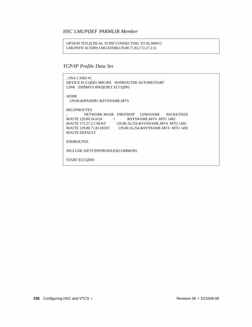
HSC LMUPDEF PARMLIB Member
TCP/IP Profile Data Set
OPTION TITLE('DUAL TCPIP CONNECTING TO SL30001')LMUPATH ACS(00) LMUADDR(129.80.71.83,172.27.2.5)
; OSA CARD #1DEVICE ECCQD01 MPCIPA NONROUTER AUTORESTARTLINK ZIPBMVS IPAQENET ECCQD01 HOME 129.80.&IPADDR1 &SYSNAME.MVS
BEGINROUTES; NETWORK MASK FIRSTHOP LINKNAME PACKETSIZEROUTE 129.80.16.0/24 = &SYSNAME.MVS MTU 1492ROUTE 172.27.2.5 HOST 129.80.16.254 &SYSNAME.MVS MTU 1492ROUTE 129.80.71.83 HOST 129.80.16.254 &SYSNAME.MVS MTU 1492ROUTE DEFAULT
ENDROUTES
INCLUDE ZIP.TCPIP.PROFILES(COMMON)
START ECCQD01
336 Configuring HSC and VTCS • Revision 06 • E21046-06

TCP/IP Console Displays
D TCPIP,,N,DEVEZZ2500I NETSTAT CS V1R4 TCPIP 931DEVNAME: LOOPBACK DEVTYPE: LOOPBACK DEVSTATUS: READY LNKNAME: LOOPBACK LNKTYPE: LOOPBACK LNKSTATUS: READY NETNUM: 0 QUESIZE: 0 BYTESIN: 2136824 BYTESOUT: 2136824 ACTMTU: 65535 BSD ROUTING PARAMETERS: MTU SIZE: 00000 METRIC: 00 DESTADDR: 0.0.0.0 SUBNETMASK: 0.0.0.0 MULTICAST SPECIFIC: MULTICAST CAPABILITY: NODEVNAME: ECCQD01 DEVTYPE: MPCIPA DEVSTATUS: READY CFGROUTER: NON ACTROUTER: NON LNKNAME: ZIPBMVS LNKTYPE: IPAQENET LNKSTATUS: READY NETNUM: 0 QUESIZE: 0 SPEED: 0000001000 BYTESIN: 48605838 BYTESOUT: 9790950 IPBROADCASTCAPABILITY: NO ARPOFFLOAD: YES ARPOFFLOADINFO: YES ACTMTU: 8992 INBPERF: BALANCED BSD ROUTING PARAMETERS: MTU SIZE: 00000 METRIC: 00 DESTADDR: 0.0.0.0 SUBNETMASK: 255.255.255.0 MULTICAST SPECIFIC: MULTICAST CAPABILITY: YES GROUP REFCNT ----- ------ 224.0.0.1 00000000012 OF 2 RECORDS DISPLAYED
D TCPIP,,N,ROUTEEZZ2500I NETSTAT CS V1R4 TCPIP 933DESTINATION GATEWAY FLAGS REFCNT INTERFACEDEFAULT 129.80.16.254 UGS 000001 ZIPBMVS127.0.0.1 0.0.0.0 UH 000004 LOOPBACK129.80.16.0 0.0.0.0 US 000000 ZIPBMVS129.80.16.239 0.0.0.0 UH 000000 ZIPBMVS129.80.71.83 129.80.16.254 UGHS 000001 ZIPBMVS172.27.2.5 129.80.16.254 UGHS 000001 ZIPBMVS6 OF 6 RECORDS DISPLAYED
D TCPIP,,N,HOMEEZZ2500I NETSTAT CS V1R4 TCPIP 935HOME ADDRESS LIST:ADDRESS LINK FLG129.80.16.239 ZIPBMVS P127.0.0.1 LOOPBACK2 OF 2 RECORDS DISPLAYED
E21046-06 • Revision 06 Appendix E 337

HSC Display Showing SL3000 Connection
SLConsole Display of SL3000 Ports 2A/2B IP Addresses
D ACSSLS0000I D ACSSLS1000I ACS 00 STATUS: CONNECTED 942ACTIVE QUEUE ELEMENTS 1COMPATIBILITY LEVELS: HSC=13, LMU=13DUAL LMU NOT CONFIGUREDIP ADDR 129.80.71.83 ONLINEIP ADDR 172.27.2.5 ONLINESCRATCH VOLUMES AVAILABLE...... 210FREE CELLS AVAILABLE........... 2007
338 Configuring HSC and VTCS • Revision 06 • E21046-06

Troubleshooting Library Connectivity ProblemsFor more information, see“Troubleshooting Library Connectivity Problems” on page 313.
E21046-06 • Revision 06 Appendix E 339

340 Configuring HSC and VTCS • Revision 06 • E21046-06

E21046-06 • Revision 06 341
APPENDIX
F
VSM4 ESCON Configuration
The newest generation VTSS is the VSM4, which provides the following advantages over its predecessors:
? Enhanced connectivity options
? Greater throughput
? Greater VTSS capacity
? 4x the number of VTDs and 3x the maximum number of VTVs per VTSS
? Improved reliability and serviceability
TABLE F-1 summarizes the VSM3 to VSM4 ESCON enhancements that you see from a software and system configuration perspective.
TABLE F-1 VSM3 to VSM4 Comparison: Software and System Configuration ESCON Enhancements
Product Feature VSM3 VSM4
ESCON Interfaces 16 total where:
? 2 to 14 can be host channels? 2 to 8 can be Nearlink/CLINK
connections
32 total where:
? 2 to 28 can be host channels? 2 to 16 can be Nearlink/CLINK
connectionsNote: VSM4s are shipped with 16 ports enabled.With the 16 ports enabled option, only the top port on each CIP is enabled (Port 0 or Port 2). 32 ports enabled is an optional, separately priced feature that is activated via microcode diskette. On a VSM4 with 32 ports enabled, each ICE3 ESCON interface card contains two pairs of ESCON ports.
Maximum Logical Paths 128 16 per port for the 16 port standard configuration = 256 logical paths16 per port for the 32 port optional configuration= 512 logical pathsNote: VSM4 provides a theoretical maximum of 512 logical paths per VTSS but you cannot allocate all 512 logical paths for host-to-VTSS connections.
VTDs per VTSS 64 256
Maximum resident VTVs per VTSS 100,000 300,000

342 Configuring HSC and VTCS • Revision 06 • E21046-06
VSM4 with 32 PortsFor the 32 port option, the 8 ICE3 cards have four ESCON ports per card as shown in FIGURE F-1.
FIGURE F-1 VSM4 with 32 Ports
Note – In FIGURE F-1 and all the other figures in this appendix, the ports are shown with their channel interface identifiers for enabled ports (32 in FIGURE F-1). These channel interface identifiers are the values that are required for the CHANIF values that you code for the CONFIG utility. Each value is two characters in length and has a value from 0A to 1P. The first digit is the VTSS cluster ID (valid values are 0 or 1). The second digit is the group or adapter ID (valid values are A to P).
In FIGURE F-1, note the following:
? Each ICE3 card contains two pairs of ESCON ports. Each pair is controlled by its own Channel Interface Processor (CIP).
Note – With microcode level D02.06.00.00 or higher, multiple Nearlink device connections via a ESCON switch or Director on the same port now allow:
? Up to a total of 16 simultaneous NearLink I/O transfers, which can be spread across multiple targets on as many as 14 NearLink ports.
? Up to a total of 2 simultaneous NearLink I/O transfers are allowed per port.
ICE00 ICE03 ICE10 ICE11 ICE12 ICE13ICE02
2 3 4 5
ICE01
12 13 14 15Card Slot
Port 0
Port 1
Port 2
Port 3
CIP 0
CIP 1
Storage Cluster 0 Storage Cluster 1
0A
0C
0D
0E
0F
0G
0H 0L
0J
0I 0M
0N
0O
0P
0B
1A
1C
1D
1E
1F
1G
1H 1L
1K
1J
1I 1M
1N
1O
1P
1B
0K0K
3
ICE01
0E
0F
06
0H
VSM4 with 8 ICE3 Cards, 32 Ports

E21046-06 • Revision 06 Appendix F 343
Note –
? For a VSM4, each CIP can operate with only one of two modes, which is set at the VTSS LOP:
? Host Mode. In Host Mode, either or both ESCON ports can connect to host CPU channels, including via ESCON Director(s) or channel extenders. Ports of a CIP in Host mode cannot connect to RTDs or to Secondary VTSSs via CLINKS. Note, however, that Secondary VTSSs must have an ESCON port in Host Mode to connect via a CLINK from an ESCON port in Nearlink Mode in a Primary VTSS.
Also note that you can have two physical paths from the same LPAR to the same CIP, as long as the two physical paths address different (not overlapping) logical control units. For example, a single host LPAR can address logical control units 0-7 on one CIP port, and 8-F on the other CIP port of the same CIP.
? Nearlink Mode. In Nearlink Mode, either or both ESCON ports can connect to an RTD or via a CLINK to a Secondary VTSS. Ports of a CIP in Nearlink mode cannot connect to host CPU channels.You can set a maximum of 8 CIPs to Nearlink Mode, and here's the important discussion: only one Nearlink port per CIP is active at one time. What are Best Practices for optimizing port operations? See TABLE F-2...
? On a VSM4 with 32 ports enabled, you have a theoretical maximum of 512 logical paths on the VSM4. However, you must have some RTD connections so you cannot allocate all 512 logical paths for host-to-VTSS connections. What’s the minimum number of RTDs? Well, it's like this: (1) CONFIG will not allow fewer than 2 RTDS per VTSS. (2) CONFIG cannot check device type but StorageTek strongly recommends at least two RTDS of each device type in each ACS to which the VTSS is attached....otherwise, you can seriously compromise error recovery, and also impact the efficiency of space reclamation. If you had only two RTDs, Best Practices would suggest that you connect them to different ICE3 cards...and once you’ve done that, you’ve effectively used up 4 Nearlink ports due to the CIP mode nature of the ICE3 card. Therefore, in an 8 ICE card configuration, this leaves 28 available ports for
TABLE F-2 Optimizing VSM4 Port Operations
Configuration - Two Ports on a CIP Best Practices
Two CLINKs Attach a maximum of 2 ....because each port allows two active operations. Note, however, that these operations share the bandwidth of the port.
CLINK and RTD An advantage if you attach one CLINK originator/one RTD per director, because both can be active.
Two RTDs An advantage for the following:
Optimize use of local and remote RTDs. During busy shifts, use only local RTDs on the FIP. During quiet periods, switch to remote RTDs for deep archive and DR work. Because you can have two active devices, you can also simultaneously run one local and one remote RTD. Note, however, that these operations share the bandwidth of the port.
Optimize use of different drive technologies. As described in the previous bullet, use a T9840 as a local RTD, then switch to a T9940 for deep archive. You can also use this feature to migrate from older drive technology (such as 9490) to newer technology (such as 9840). Use Management and Storage Classes to read in data from older media, then switch to the newer technology drive to place data on new media. This technique effectively gives you greater physical connectivity to different drive technologies without incurring the overhead of full time, real time FICON connections to each drive type. Also as above, because you can have two active devices, you can also simultaneously run two RTDs with different drive technologies. Note, however, that these operations share the bandwidth of the port.

344 Configuring HSC and VTCS • Revision 06 • E21046-06
host-to-VTSS ESCON channel connections, which equals a maximum of 16 x 28 or 448 logical paths. For more information, see “Logical Paths for VSM 4 with 32 Ports” on page 360.
? A host logical path is the communication path between a host and all of the 256 VTDs within the VSM4. TABLE F-3 summarizes the configuration options and maximum host logical paths for a VSM4 with 32 enabled ports.
? In HCD:
? From a single MVS host, you can only define 8 channels (CHPIDs) running to a single control unit (single VSM4). Also note that ICE3 cards cannot have 2 paths from the same LPAR connected to two ports with a common CIP.
? You use the CNTLUNIT statement to define each VSM4 as 16 3490 images.
? You use the IODEVICE statement to define the 16 VTDs that are associated with each 3490 image.
TABLE F-3 VSM4 Configuration Options - 32 Ports
HostCIPs
Maximum HostConnections
NearlinkCIPs
Max NearlinkConnections
Maximum HostLogical Paths
8 16 8 16 256
9 18 7 14 288
10 20 6 12 320
11 22 5 10 352
12 24 4 8 384
14 28 2 4 448

E21046-06 • Revision 06 Appendix F 345
VSM4 Configuration Examples - 32 PortsFor VSM4s with 32 ports, let’s look at two examples of port configurations:
? “VSM4 Configuration Example: 16 Host Ports, 16 RTD Ports” on page 346
? ““VSM 4 Configuration Example: 20 Host Ports, 12 RTD Ports” on page 348
For a VSM4 host gen example, see “IOCP Example for Single MVS Host Connected to a VSM4 Via ESCON Directors” on page 357.

346 Configuring HSC and VTCS • Revision 06 • E21046-06
VSM4 Configuration Example: 16 Host Ports, 16 RTD Ports
FIGURE F-2 shows CONFIG channel interface identifiers of 16 for hosts, 16 for RTDs for a VSM4.
FIGURE F-2 VSM4 with 16 Host Ports, 16 RTD Ports
ICE00 ICE03 ICE10 ICE11 ICE12 ICE13ICE02
2 3 4 5
ICE01
12 13 14 15Card Slot
Port 0
Port 1
Port 2
Port 3
CIP 0
CIP 1
Storage Cluster 0 Storage Cluster 1
0A
0C
0D
0E
0F
0G
0H 0L
0J
0I 0M
0N
0O
0P
0B
1A
1C
1D
1E
1F
1G
1H 1L
1K
1J
1I 1M
1N
1O
1P
1B
0K0K
3
ICE01
0E
0F
06
0H
VSM4 with 16 Host Ports, 16 RTD Ports
RTD Ports
Host Ports

E21046-06 • Revision 06 Appendix F 347
CONFIG Example for VSM4 with 16 Host Ports, 16 RTD Ports
FIGURE F-3 shows example CONFIG JCL to define the VSM4 configuration shown in FIGURE F-2 on page 346.
FIGURE F-3 CONFIG example: VSM4 with 16 Host Ports, 16 RTD Ports
//CREATECF EXEC PGM=SLUADMIN,PARM='MIXED'//STEPLIB DD DSN=hlq.SEALINK,DISP=SHR//SLSCNTL DD DSN=hlq.DBASEPRM,DISP=SHR//SLSCNTL2 DD DSN=hlq.DBASESEC,DISP=SHR//SLSSTBY DD DSN=hlq.DBASETBY,DISP=SHR//SLSPRINT DD SYSOUT=*//SLSIN DD * CONFIG GLOBAL MAXVTV=32000MVCFREE=40 RECLAIM THRESHLD=70MAXMVC=40 START=35VTSS NAME=VSM401 LOW=70 HIGH=80 MAXMIG=8 RETAIN=5 RTD NAME=VSM42A00 DEVNO=2A00 CHANIF=0C RTD NAME=VSM42A01 DEVNO=2A01 CHANIF=0D RTD NAME=VSM42A02 DEVNO=2A02 CHANIF=0G RTD NAME=VSM42A03 DEVNO=2A03 CHANIF=0H RTD NAME=VSM42A04 DEVNO=2A04 CHANIF=0K RTD NAME=VSM42A05 DEVNO=2A05 CHANIF=0L RTD NAME=VSM42A06 DEVNO=2A06 CHANIF=0O RTD NAME=VSM42A07 DEVNO=2A07 CHANIF=0P RTD NAME=VSM42A08 DEVNO=2A08 CHANIF=1C RTD NAME=VSM42A09 DEVNO=2A09 CHANIF=1D RTD NAME=VSM42A0A DEVNO=2A0A CHANIF=1G RTD NAME=VSM42A0B DEVNO=2A0B CHANIF=1H RTD NAME=VSM42A0C DEVNO=2A0C CHANIF=1K RTD NAME=VSM42A0D DEVNO=2A0D CHANIF=1L RTD NAME=VSM42A0E DEVNO=2A0E CHANIF=1O RTD NAME=VSM42A0F DEVNO=2A0F CHANIF=1P VTD LOW=9900 HIGH=99FF
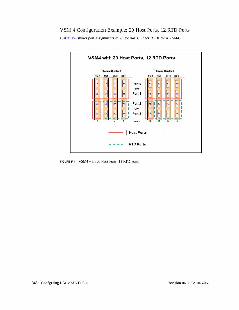
348 Configuring HSC and VTCS • Revision 06 • E21046-06
VSM 4 Configuration Example: 20 Host Ports, 12 RTD Ports
FIGURE F-4 shows port assignments of 20 for hosts, 12 for RTDs for a VSM4.
FIGURE F-4 VSM4 with 20 Host Ports, 12 RTD Ports
ICE00 ICE03 ICE10 ICE11 ICE12 ICE13ICE02
2 3 4 5
ICE01
12 13 14 15Card Slot
Port 0
Port 1
Port 2
Port 3
CIP 0
CIP 1
Storage Cluster 0 Storage Cluster 1
0A
0C
0D
0E
0F
0G
0H 0L
0J
0I 0M
0N
0O
0P
0B
1A
1C
1D
1E
1F
1G
1H 1L
1K
1J
1I 1M
1N
1O
1P
1B
0K0K
3
ICE01
0E
0F
06
0H
VSM4 with 20 Host Ports, 12 RTD Ports
RTD Ports
Host Ports

E21046-06 • Revision 06 Appendix F 349
CONFIG Example for VSM4 with 20 Host Ports, 12 RTD Ports
FIGURE F-5 shows example CONFIG JCL to define the VSM4 configuration shown in FIGURE F-4 on page 348.
FIGURE F-5 CONFIG example: VSM4 with 20 Host Ports, 12 RTD Ports
//CREATECF EXEC PGM=SLUADMIN,PARM='MIXED'//STEPLIB DD DSN=hlq.SEALINK,DISP=SHR//SLSCNTL DD DSN=hlq.DBASEPRM,DISP=SHR//SLSCNTL2 DD DSN=hlq.DBASESEC,DISP=SHR//SLSSTBY DD DSN=hlq.DBASETBY,DISP=SHR//SLSPRINT DD SYSOUT=*//SLSIN DD * CONFIG GLOBAL MAXVTV=32000 MVCFREE=40 RECLAIM THRESHLD=70 MAXMVC=40 START=35VTSS NAME=VSM401 LOW=70 HIGH=80 MAXMIG=6 RETAIN=5 RTD NAME=VSM42A00 DEVNO=2A00 CHANIF=0G RTD NAME=VSM42A01 DEVNO=2A01 CHANIF=0H RTD NAME=VSM42A02 DEVNO=2A02 CHANIF=0K RTD NAME=VSM42A03 DEVNO=2A03 CHANIF=0L RTD NAME=VSM42A04 DEVNO=2A04 CHANIF=0O RTD NAME=VSM42A05 DEVNO=2A05 CHANIF=0P RTD NAME=VSM42A06 DEVNO=2A06 CHANIF=1G RTD NAME=VSM42A07 DEVNO=2A07 CHANIF=1H RTD NAME=VSM42A08 DEVNO=2A08 CHANIF=1K RTD NAME=VSM42A09 DEVNO=2A09 CHANIF=1L RTD NAME=VSM42A0A DEVNO=2A0A CHANIF=1O RTD NAME=VSM42A0B DEVNO=2A0B CHANIF=1P VTD LOW=9900 HIGH=99FF

350 Configuring HSC and VTCS • Revision 06 • E21046-06
VSM4 with 16 PortsFor the 16 port option, the 8 ICE3 cards have two ESCON ports per card as shown in FIGURE F-6.
FIGURE F-6 VSM4 with 16 Ports
Note – In FIGURE F-6 and all the other figures in this appendix, the ports are shown with their channel interface identifiers for enabled ports (16 in FIGURE F-6). These channel interface identifiers are the values that are required for the CHANIF values that you code for the CONFIG utility. Each value is two characters in length and has a value from 0A to 1P. The first digit is the VTSS cluster ID (valid values are 0 or 1). The second digit is the group or adapter ID (valid values are A to P).
In FIGURE F-6, note the following:
? Each ICE3 card has two CIPs with a single port enabled on each CIP. As with the 32 port option, each CIP can operate with only one of two modes, which is set at the VTSS LOP:
? Host Mode. In Host Mode, the single ESCON port can connect to host CPU channels, including via ESCON Director(s) or channel extenders. Ports of a CIP in Host mode cannot connect to RTDs or to Secondary VTSSs via CLINKS. Note, however, that Secondary VTSSs must have an ESCON port in Host Mode to connect via a CLINK from an ESCON port in Nearlink Mode in a Primary VTSS.
ICE00 ICE03 ICE10 ICE11 ICE12 ICE13ICE02
2 3 4 5
ICE01
12 13 14 15Card Slot
Port 0
Port 1
Port 2
Port 3
CIP 0
CIP 1
Storage Cluster 0 Storage Cluster 1
0A
0C
0E
0F
0G
0H
0I 0M
0O
1A
1C
1E
1G 1K
1I 1M
1O0K0K
3
ICE01
0E
06
VSM4 with 8 ICE3 Cards, 16 Ports

E21046-06 • Revision 06 Appendix F 351
? Nearlink Mode. In Nearlink Mode, the single ESCON port can connect to an RTD or via a CLINK to a Secondary VTSS. Ports of a CIP in Nearlink mode cannot connect to host CPU channels.
You can set a maximum of 8 CIPs to Nearlink Mode. Therefore, in a 16 port configuration, the single port on a CIP can be either a CLINK or an RTD connection.
? On a VSM4 with 16 ports enabled, you have a theoretical maximum of 256 logical paths on the VSM4. However, you must have some RTD connections so you cannot allocate all 256 logical paths for host-to-VTSS connections. What’s the minimum number of RTDs? Well, it's like this: (1) CONFIG will not allow fewer than 2 RTDS per VTSS. (2) CONFIG cannot check device type but StorageTek strongly recommends at least two RTDS of each device type in each ACS to which the VTSS is attached....otherwise, you can seriously compromise error recovery and also impact the efficiency of space reclamation. If you had only two RTDs, Best Practices would suggest that you connect them to different ICE3 cards...and once you’ve done that, you’ve effectively used up 4 Nearlink ports. Therefore, in an 8 ICE card 16 port configuration, this leaves 12 available ports for host-to-VTSS ESCON channel connections, which equals a maximum of 16 x 12 or 192 logical paths. For more information, see “Logical Paths for VSM 4 with 32 Ports” on page 360.
? A host logical path is the communication path between a host and all of the 256 VTDs within the VSM4. TABLE F-4 summarizes the configuration options and maximum host logical paths for a VSM4 with 16 enabled ports.
? In HCD:
? From a single MVS host, you can only define 8 channels (CHPIDs) running to a single control unit (single VSM4). Also note that ICE3 cards cannot have 2 paths from the same LPAR connected to two ports with a common CIP.
? You use the CNTLUNIT statement to define each VSM4 as 16 3490 images.
? You use the IODEVICE statement to define the 16 VTDs that are associated with each 3490 image.
TABLE F-4 VSM4 Configuration Options - 16 Ports
HostCIPs
Maximum HostConnections
NearlinkCIPs
Max NearlinkConnections
Maximum HostLogical Paths
8 8 8 8 128
9 9 7 7 144
10 10 6 6 160
11 11 5 5 176
12 12 4 4 192
14 14 2 2 224

352 Configuring HSC and VTCS • Revision 06 • E21046-06
VSM4 Configuration Examples - 16 PortsFor VSM4s with 16 ports, let’s look at two examples of port configurations:
? “VSM4 Configuration Example: 8 Host Ports, 8 RTD Ports” on page 353
? “VSM 4 Configuration Example: 10 Host Ports, 6 RTD Ports” on page 355
For a VSM4 host gen example, see“IOCP Example for Single MVS Host Connected to a VSM4 Via ESCON Directors” on page 357.

E21046-06 • Revision 06 Appendix F 353
VSM4 Configuration Example: 8 Host Ports, 8 RTD Ports
FIGURE F-7 shows CONFIG channel interface identifiers of 8 for hosts, 8 for RTDs for an 8 ICE3 card VSM4 with 16 ports.
FIGURE F-7 VSM4 with 8 Host Ports, 8 RTD Ports
ICE00 ICE03 ICE10 ICE11 ICE12 ICE13ICE02
2 3 4 5
ICE01
12 13 14 15Card Slot
Port 0
Port 2
CIP 0
CIP 1
Storage Cluster 0 Storage Cluster 1
0A
0C
0E
0F
0G
0H
0I 0M
0O
1A
1C
1E
1G 1K
1I 1M
1O0K0K
3
ICE01
0E
06
VSM4 with 8 ICE3 Cards, 8 Host Ports, 8 RTD Ports
RTD Ports
Host Ports

354 Configuring HSC and VTCS • Revision 06 • E21046-06
CONFIG Example for VSM4 with 8 Host Ports, 8 RTD Ports
FIGURE F-8 shows CONFIG JCL to define the VSM4 configuration shown in FIGURE F-7 on page
353.
FIGURE F-8 CONFIG example: VSM4 with 8 Host Ports, 8 RTD Ports
//CREATECF EXEC PGM=SLUADMIN,PARM='MIXED'//STEPLIB DD DSN=hlq.SEALINK,DISP=SHR//SLSCNTL DD DSN=hlq.DBASEPRM,DISP=SHR//SLSCNTL2 DD DSN=hlq.DBASESEC,DISP=SHR//SLSSTBY DD DSN=hlq.DBASETBY,DISP=SHR//SLSPRINT DD SYSOUT=*//SLSIN DD * CONFIG GLOBAL MAXVTV=32000MVCFREE=40 RECLAIM THRESHLD=70MAXMVC=40 START=35VTSS NAME=VSM401 LOW=70 HIGH=80 MAXMIG=8 RETAIN=5 RTD NAME=VSM42A00 DEVNO=2A00 CHANIF=0C RTD NAME=VSM42A02 DEVNO=2A02 CHANIF=0G RTD NAME=VSM42A04 DEVNO=2A04 CHANIF=0K RTD NAME=VSM42A06 DEVNO=2A06 CHANIF=0O RTD NAME=VSM42A08 DEVNO=2A08 CHANIF=1C RTD NAME=VSM42A0A DEVNO=2A0A CHANIF=1G RTD NAME=VSM42A0C DEVNO=2A0C CHANIF=1K RTD NAME=VSM42A0E DEVNO=2A0E CHANIF=1O VTD LOW=9900 HIGH=99FF

E21046-06 • Revision 06 Appendix F 355
VSM 4 Configuration Example: 10 Host Ports, 6 RTD Ports
FIGURE F-9 shows port assignments of 10 for hosts, 6 for RTDs for a VSM4 with 16 ports.
FIGURE F-9 VSM4 with 10 Host Ports, 6 RTD Ports
ICE00 ICE03 ICE10 ICE11 ICE12 ICE13ICE02
2 3 4 5
ICE01
12 13 14 15Card Slot
Port 0
Port 2
CIP 0
CIP 1
Storage Cluster 0 Storage Cluster 1
0A
0C
0E
0F
0G
0H
0I 0M
0O
1A
1C
1E
1G 1K
1I 1M
1O0K0K
3
ICE01
0E
06
VSM4 with 8 ICE3 Cards, 10 Host Ports, 6 RTD Ports
RTD Ports
Host Ports

356 Configuring HSC and VTCS • Revision 06 • E21046-06
CONFIG Example for VSM4 with 10 Host Ports, 6 RTD Ports
FIGURE F-10 shows example CONFIG JCL to define the VSM4 configuration shown in FIGURE F-9 on page 355.
FIGURE F-10 CONFIG example: VSM4 with 10 Host Ports, 6 RTD Ports
//CREATECF EXEC PGM=SLUADMIN,PARM='MIXED'//STEPLIB DD DSN=hlq.SEALINK,DISP=SHR//SLSCNTL DD DSN=hlq.DBASEPRM,DISP=SHR//SLSCNTL2 DD DSN=hlq.DBASESEC,DISP=SHR//SLSSTBY DD DSN=hlq.DBASETBY,DISP=SHR//SLSPRINT DD SYSOUT=*//SLSIN DD * CONFIG GLOBAL MAXVTV=32000MVCFREE=40 RECLAIM THRESHLD=70MAXMVC=40 START=35VTSS NAME=VSM401 LOW=70 HIGH=80 MAXMIG=8 RETAIN=5 RTD NAME=VSM42A02 DEVNO=2A02 CHANIF=0G RTD NAME=VSM42A04 DEVNO=2A04 CHANIF=0K RTD NAME=VSM42A06 DEVNO=2A06 CHANIF=0O RTD NAME=VSM42A0A DEVNO=2A0A CHANIF=1G RTD NAME=VSM42A0C DEVNO=2A0C CHANIF=1K RTD NAME=VSM42A0E DEVNO=2A0E CHANIF=1O VTD LOW=9900 HIGH=99FF

E21046-06 • Revision 06 Appendix F 357
IOCP Example for Single MVS Host Connected to a VSM4 Via ESCON DirectorsFIGURE F-11 shows a configuration diagram for a single MVS host connected to a VSM4 via ESCON Directors, and FIGURE F-12 on page 360 shows example IOCP statements for this configuration. Note that:
? From MVSA, you define 8 CHPIDs, with each path switched in the ESCON Director, for a total of 8 channels running to the VSM4.
? You code 16 CNTLUNIT statements to define the VSM4 as 16 3490 images.
? You code IODEVICE statement to define the 16 VTDs that are associated with each 3490 image.
FIGURE F-11 Configuration Diagram: Single MVS Host Connected to a VSM4 via ESCON Directors
20 21 30 31 70 71 80 81
4C
DO DO DO DOD4 D4 D4 D4
4D 4E 4F
MVS A
Storage Cluster 0 Storage Cluster1

358 Configuring HSC and VTCS • Revision 06 • E21046-06

E21046-06 • Revision 06 Appendix F 359
ESCD4CCHPID PATH=(20,70),TYPE=CNC,SWITCH=4CESCD4DCHPID PATH=(21,71),TYPE=CNC,SWITCH=4DESCD4ECHPID PATH=(30,80),TYPE=CNC,SWITCH=4EESCD4F CHPID PATH=(31,81),TYPE=CNC,SWITCH=4F
CU1 CNTLUNIT CUNUMBR=001, PATH=(20,21,30,31,70,71,80,81), LINK=(D0,D4,D0,D4,D4,D0,D4,D0), UNIT=3490,CUADD=0, UNITADD=((00,16))
STRING1 IODEVICE ADDRESS=(0500,16), CUNUMBER=(001),
UNIT=3490,UNITADD=00,STADET=Y
CU2 CNTLUNIT CUNUMBR=002, PATH=(20,21,30,31,70,71,80,81), LINK=(D0,D4,D0,D4,D4,D0,D4,D0), UNIT=3490,CUADD=1, UNITADD=((00,16))
STRING2 IODEVICE ADDRESS=(0510,16), CUNUMBER=(002),
UNIT=3490,UNITADD=00,STADET=Y...
CU15 CNTLUNIT CUNUMBR=015, PATH=(20,21,30,31,70,71,80,81), LINK=(D0,D4,D0,D4,D4,D0,D4,D0), UNIT=3490,CUADD=E, UNITADD=((00,16))
STRING15 IODEVICE ADDRESS=(05E0,16), CUNUMBER=(015),
UNIT=3490,UNITADD=00,STADET=Y
CU16 CNTLUNIT CUNUMBR=016, PATH=(20,21,30,31,70,71,80,81), LINK=(D0,D4,D0,D4,D4,D0,D4,D0), UNIT=3490,CUADD=F, UNITADD=((00,16))
STRING16 IODEVICE ADDRESS=(05F0,16), CUNUMBER=(016),
UNIT=3490,UNITADD=00,STADET=Y

360 Configuring HSC and VTCS • Revision 06 • E21046-06
FIGURE F-12 IOCP Example: Single MVS Host Connected to a VSM4 via ESCON Directors
Logical Paths for VSM 4 with 32 PortsA VSM4 with 32 ports has 4x the number of logical paths available to VSM2s and VSM3s. Does this mean that a VSM4 has enough logical paths for connectivity, redundancy, and throughput for all attached hosts? Even with 16 RTDs and 31 hosts attached, the answer is “yes” as shown in FIGURE F-13.
FIGURE F-13 Logical Paths for VSM 4 with 32 Ports, 31 Hosts, 16 RTDs
In FIGURE F-13:
? The 16 RTDs consume 16 x 16 or 256 logical paths.
? The maximum logical paths we allocated for a VSM2/3 was 4 to a host requiring maximum throughput (which also satisfied the redundancy/connectivity requirements). Therefore, if we allocated double that number, or 8 logical paths, for each of the 31 hosts in this configuration, we only consume 248, or 8 less than the logical paths remaining for host connections.
Therefore, logical path allocation isn’t an issue, as it was with VSM2s and VSM3s.
Logical Paths 32 PortsLogical Paths 32 Ports
16RTDS16
(256)
VTSS16 host
16 Nearlink
MVS 1 - 16 MVS 17 – 31
8 8
4
4
4
4
31 hosts X 8 = 248 (256)

E21046-06 • Revision 06 361
APPENDIX
G
VSM4 FICON Front-End and Back-End Configuration
The VSM4 FICON Back-End connectivity feature adds value to the previously available FICON front-end connectivity. TABLE G-1 summarizes the supported card configurations for VSM4 FICON Front-End plus Back-End connectivity.
TABLE G-1 Supported Card Configurations for VSM4 FICON Front-End plus Back-End Connectivity
VCF Cards FICON Ports ICE Cards
ESCON Ports Total Ports
Total Logical Paths (16 per ICE Port, 64 per VCF Port)
2 4 6 24 28 640
4 8 4 16 24 768
6 12 2 8 20 896
8 16 0 0 16 1024

362 Configuring HSC and VTCS • Revision 06 • E21046-06
VSM4 FICON VCF Card OptionsVSM4 supports the following FICON VCF card options:
? FIGURE G-1 shows a VSM4 with 6 ICE cards, 2 VCF cards.
? FIGURE G-2 on page 363 shows a VSM4 with 4 ICE cards, 4 VCF cards.
? FIGURE G-3 on page 364 shows a VSM4 with 2 ICE cards, 6 VCF cards.
? FIGURE G-4 on page 365 shows a VSM4 with 8 VCF cards.
FIGURE G-1 VSM4 with 6 ICE cards, 2 VCF cards
Storage Cluster 0 Storage Cluster 1
0A
0C
0D
0E
0F
0G
0H 0L
0J
0I 0M0N
0O0P
0B
1A
1C
1D
1E
1F
1G
1H 1L
1K
1J
1I 1M1N
1O1P
1B
0K0K
0E
0F
0G
0H
VSM4 with 6 ICE Cards, 2 VCF Cards
ICE00 VCF03 ICE10 ICE11 ICE12 VCF13ICE02ICE01
Port 0
Port 1
Port 2
Port 3
CIP 0
CIP 1
2 4 5 12 13 14 153 Card Slot

E21046-06 • Revision 06 Appendix G 363
FIGURE G-2 VSM4 with 4 ICE cards, 4 VCF cards
ICE00 VCF03 ICE10 VCF11 ICE12 VCF13ICE02VCF01
Storage Cluster 0 Storage Cluster 1
0A
0C
0D
0E
0F
0G
0H 0L
0J
0I 0M0N
0O0P
0B
1A
1C
1D
1E1F
1G1H
1L
1K
1J
1I 1M1N
1O1P
1B
0K0K
0E0F
0G0H
VSM4 with 4 ICE Cards, 4 VCF Cards
Port 0
Port 1
Port 2
Port 3
CIP 0
CIP 1
2 4 5 12 13 14 153 Card Slot

364 Configuring HSC and VTCS • Revision 06 • E21046-06
FIGURE G-3 VSM4 with 2 ICE cards, 6 VCF cards
ICE00 VCF03 ICE10 VCF11 IVCF12 VCF13VCF02VCF01
Storage Cluster 0 Storage Cluster 1
0A
0C
0D
0E
0F
0G
0H
0I0J
0M0N
0O0P
0B
1A
1C
1D
1E1F
1G1H
1K1L
1I1J
1M1N
1O1P
1B
0K0K0L
0E0F
0G0H
VSM4 with 2 ICE Cards, 6 VCF Cards
Port 0
Port 1
Port 2
Port 3
CIP 0
CIP 1
2 4 5 12 13 14 153 Card Slot

E21046-06 • Revision 06 Appendix G 365
FIGURE G-4 VSM4 with 8 VCF cards
Note –
? In FIGURE G-1 on page 362 through FIGURE G-4 on page 365, the VCF cards must go in:
? Slots 5 and 15 in a two-VCF card configuration
? Slots 3, 5, 13, and 15 in a four-VCF card configuration.
? Slots 3, 4, 5, 13, 14, and 15 in a six-VCF card configuration.
? All slots in an eight-VCF card configuration.
? FICON ports are controlled by a FICON Interface processor (FIP), ESCON ports are controlled by a CIP. Regardless of the card configuration, there can be only a total of 14 Nearlink FIPs and/or CIPs.
Note – With microcode level D02.06.00.00 or higher, multiple Nearlink device connections via a FICON or ESCON switch or Director on the same port now allow:
? Up to a total of 16 simultaneous NearLink I/O transfers, which can be spread across multiple targets on as many as 14 NearLink ports.
? Up to a total of 2 simultaneous NearLink I/O transfers are allowed per port.
? All FICON ports can be configured as either a Host port or Nearlink (RTD/CLINK origination) port. All ESCON ports continue to be configurable as host or Nearlink ports in pairs on a per CIP basis.
? As shown in FIGURE G-1 on page 362 through FIGURE G-4 on page 365, the ports are shown with their channel interface identifiers where all ports are enabled. These channel interface identifiers are the values that are required for the CHANIF values that you code for the
VCF00 VCF03 VCF10 VCF11 IVCF12 VCF13VCF02VCF01
Storage Cluster 0 Storage Cluster 1
0A0B
0C0D
0E
0F
0G
0H
0I0J
0M0N
0O0P
1A1B
1C1D
1E1F
1G1H
1K1L
1I1J
1M1N
1O1P
0K0K0L
0E0F
0G0H
VSM4 with 8 VCF Cards
Port 0
Port 1
2 4 5 12 13 14 153 Card Slot

366 Configuring HSC and VTCS • Revision 06 • E21046-06
CONFIG utility. Each value is two characters in length and has a value from 0A to 1O. The first digit is the VTSS cluster ID (valid values are 0 or 1). The second digit is the group or adapter ID (valid values are A to P).
Each FICON port can attach to two RTDs, or two CLINKs, or an RTD/CLINK combination via a FICON director or supported switch (in FICON mode). Note that, as shown in these figures, for RTDs only, each FICON port has two CHANIF values only if the port is connected to a FICON director which is then connected to two RTDs. Nearlink RTD connections that are paired via a FICON switch or director on the same port dynamically alternate between both RTDs for atomic operations such as mount, migrate VTV, recall VTV, etc.
? Each ICE card contains two pairs of ESCON ports. Each pair is controlled by its own Channel Interface Processor (CIP). Each CIP switches between the two ports, so that only one port can transfer data at a time, which emulates a FICON port attached to a director attached to RTDs.
? Each host FICON channel supports 64 logical paths (times 16 logical units). However, in HCD:
? From a single MVS host, you can only define 8 channels (CHPIDs) running to a single control unit (single VSM4).
? You use the CNTLUNIT statement to define each VSM4 as 16 3490 control unit images.
? You use the IODEVICE statement to define the 16 VTDs that are associated with each 3490 control unit image.
? For a VSM4, each ESCON CIP or FICON FIP can operate with only one of two modes, which is set at the VTSS LOP:
? Host Mode. In Host Mode, ports can connect to the host CPU channels, including via Director(s) or channel extenders. A port in Host Mode can also serve as a CLINK terminator.
Also note that for ESCON ports, you can have two physical paths from the same LPAR to the same CIP, as long as the two physical paths address different (not overlapping) logical control units. For example, a single host LPAR can address logical control units 0-7 on one CIP port, and 8-F on the other CIP port of the same CIP.
? Nearlink Mode. In Nearlink Mode, ports can connect to an RTD. A port in Nearlink Mode can also serve as a CLINK originator.
? For clustering, you need an originator port in Nearlink mode on one VTSS connected via a CLINK to a terminator port in Host mode on the other VTSS.
Caution – In bi-directional clustering, each CLINK must be attached to the same Storage Cluster on each VTSS, which is a requirement. Failure to configure in this manner can produce Replicate, Channel, and Communication errors! For more information and examples, see ELS Disaster Recovery and Offsite Data Management Guide.

E21046-06 • Revision 06 Appendix G 367
In both FICON and ESCON, what are Best Practices for optimizing port operations? See TABLE G-2...
TABLE G-2 Optimizing VSM4 FICON/ESCON Port Operations
Configuration - Two ESCON Ports on a CIP (ICE) or FICON port attached to a FICON Director (VCF) Best Practices
Two CLINKs Attach a maximum of 2 ....because each port allows two active operations. Note, however, that these operations share the bandwidth of the port.
CLINK and RTD An advantage if you attach one CLINK originator/one RTD per director, because both can be active.
Two RTDs An advantage for the following:
Optimize use of local and remote RTDs. During busy shifts, use only local RTDs on the FIP. During quiet periods, switch to remote RTDs for deep archive and DR work. Because you can have two active devices, you can also simultaneously run one local and one remote RTD. Note, however, that these operations share the bandwidth of the port.
Optimize use of different drive technologies. As described in the previous bullet, use a T9840 as a local RTD, then switch to a T9940 for deep archive. You can also use this feature to migrate from older drive technology (such as 9490) to newer technology (such as 9840). Use Management and Storage Classes to read in data from older media, then switch to the newer technology drive to place data on new media. This technique effectively gives you greater physical connectivity to different drive technologies without incurring the overhead of full time, real time FICON connections to each drive type. Also as above, because you can have two active devices, you can also simultaneously run two RTDs with different drive technologies. Note, however, that these operations share the bandwidth of the port.

368 Configuring HSC and VTCS • Revision 06 • E21046-06
VSM4 FICON Front-End and Back-End Configuration ExamplesFor VSM4s with both FICON Front-End and Back-End connectivity, let’s look at two examples of VCF card configurations and implementation:
? “VSM4 Configuration Example: 8 VCF Cards, FICON Directors, 16 RTDs” on page 369
? “VSM4 Configuration Example: 8 VCF Cards, 4 CLINKs, FICON Directors for 8 RTDs” on page 371
For a VSM4 host gen example, see “IOCP Example for Single MVS Host Connected to a VSM4 Via FICON Directors” on page 374.

E21046-06 • Revision 06 Appendix G 369
VSM4 Configuration Example: 8 VCF Cards, FICON Directors, 16 RTDsFIGURE G-5 shows CONFIG channel interface identifiers for a VSM4 with 8 VCF cards. In this configuration, we’ve allocated 8 ports to RTDs and 8 ports to host connections. The RTD ports are all connected to FICON directors, each of which is attached to RTDs, so the CHANIF identifiers for both RTDs are shown on each port. This allows Back-End connection to 16 RTDs, although, as with ESCON, only one RTD per port/Director can be active at a time.
FIGURE G-5 VSM4 with 8 VCF Cards, FICON Directors for 16 RTDs
VCF00 VCF03 VCF10 VCF11 IVCF12 VCF13VCF02VCF01
Storage Cluster 0 Storage Cluster 1
0A
0C0D
0E
0F
0G
0H
0I 0M
0O0P
1A
1C1D
1E
1G1H
1K1L
1I 1M
1O1P
0K0K0L
0E
0G0H
VSM4 with 8 VCF Cards –FICON Directors for 16 RTDs
Port 0
Port 1
2 4 5 12 13 14 153 Card Slot
RTD Ports
Host Ports

370 Configuring HSC and VTCS • Revision 06 • E21046-06
CONFIG Example for VSM4 FICON with 8 VCF Cards, FICON Directors, 16 RTDs
FIGURE G-6 shows example CONFIG JCL to define the VSM4 configuration shown in FIGURE G-5 on page 369.
FIGURE G-6 CONFIG example: VSM4 with 8 VCF cards, FICON Directors, 16 RTDs
//CREATECF EXEC PGM=SLUADMIN,PARM='MIXED'//STEPLIB DD DSN=hlq.SEALINK,DISP=SHR//SLSCNTL DD DSN=hlq.DBASEPRM,DISP=SHR//SLSCNTL2 DD DSN=hlq.DBASESEC,DISP=SHR//SLSSTBY DD DSN=hlq.DBASETBY,DISP=SHR//SLSPRINT DD SYSOUT=*//SLSIN DD * CONFIG GLOBAL MAXVTV=32000 MVCFREE=40 RECLAIM THRESHLD=70 MAXMVC=40 START=35VTSS NAME=VSM401 LOW=70 HIGH=80 MAXMIG=8 RETAIN=5 RTD NAME=VSM42A00 DEVNO=2A00 CHANIF=0C RTD NAME=VSM42A01 DEVNO=2A01 CHANIF=0D RTD NAME=VSM42A02 DEVNO=2A02 CHANIF=0G RTD NAME=VSM42A03 DEVNO=2A03 CHANIF=0H RTD NAME=VSM42A04 DEVNO=2A04 CHANIF=0K RTD NAME=VSM42A05 DEVNO=2A05 CHANIF=0L RTD NAME=VSM42A06 DEVNO=2A06 CHANIF=0O RTD NAME=VSM42A07 DEVNO=2A07 CHANIF=0P RTD NAME=VSM42A08 DEVNO=2A08 CHANIF=1C RTD NAME=VSM42A09 DEVNO=2A09 CHANIF=1D RTD NAME=VSM42A0A DEVNO=2A0A CHANIF=1G RTD NAME=VSM42A0B DEVNO=2A0B CHANIF=1H RTD NAME=VSM42A0C DEVNO=2A0C CHANIF=1K RTD NAME=VSM42A0D DEVNO=2A0D CHANIF=1L RTD NAME=VSM42A0E DEVNO=2A0E CHANIF=1O RTD NAME=VSM42A0F DEVNO=2A0F CHANIF=1P VTD LOW=9900 HIGH=99FF

E21046-06 • Revision 06 Appendix G 371
VSM4 Configuration Example: 8 VCF Cards, 4 CLINKs, FICON Directors for 8 RTDsFIGURE G-7 shows CONFIG channel interface identifiers for a VSM4 with 8 VCF cards. In this configuration, we’ve allocated:
? 8 Host ports.
? 4 ports for RTDs. The RTD ports are all connected to FICON directors, each of which is attached to RTDs, so the CHANIF identifiers for both RTDs are shown on each port. This allows Back-End connection to 8 RTDs. As with ESCON, only one RTD per port/Director can be active at a time.
? 4 ports for CLINK connections to form a Bi-Directional VTSS Cluster, and 8 ports to host connections. To form the clustered VTSS, we’ll have two VSM4s (VSMPR1 and VSMPR2) configured identically as shown in FIGURE G-7. As shown in Figure 46 on page 150, Bi-Directional Clustering requires pairs of Uni-Directional CLINKs with the FIPSs configured so that the data flows in opposite directions on the CLINKs. To make that happen, let’s make 0G and 1G the sending (Nearlink Mode) ports on both VTSSs and 0O and 1O the receiving (Host Mode) on both VTSSs.
FIGURE G-7 VSM4 with 8 VCF Cards, 8 Host Ports, FICON Directors for 8 RTDs, 4 CLINK Ports
VSM4 with 8 VCF Cards –FICON Directors for 8 RTDs, 4 CLINK Ports
Port 0
Port 1
Card Slot
Storage Cluster 0
2
0A
0C0D
VCF00
3
0E
0G
VCF01
4
0I
0K
VCF02
5
0M
0O
VCF03
Storage Cluster 1
12
1A
1C1D
VCF10
13
1E
1G
VCF11
14
1I
1K1L
VCF12
15
1M
1O
VCF13
Ports for inbound CLINKs (Host mode)
RTD Ports
Host PortsPorts for outbound CLINKs (Nearlink mode)

372 Configuring HSC and VTCS • Revision 06 • E21046-06
CONFIG Example for Bi-Directional Clustered VSM4 FICON Back-End
FIGURE G-8 shows example CONFIG JCL to define a Bi-Directional Cluster of two VSM4s (VSMPR1 and VSMPR2) with identical VCF card configurations shown in FIGURE G-7 on page
371.
Caution – Bi-Directional Clustering requires VTCS 6.1! You cannot configure a Bi-Directional Cluster at releases lower than VTCS 6.1! Also note that the Clustered VTSSs require the Advanced Management Feature.
FIGURE G-8 Dual ACS Bi-Directional Clustered VTSS Configuration

E21046-06 • Revision 06 Appendix G 373
FIGURE G-9 shows example CONFIG JCL to define a Bi-Directional Cluster of two VSM4s (VSMPR1 and VSMPR2) as shown in FIGURE G-8 on page 372. Note that:
? The CLUSTER statement defines the Cluster as consisting of VSMPR1 and VSMPR2.
? There are CLINK statements using the sending (Nearlink Mode) ports of both VTSSs to enable the Cluster as Bi-Directional. As described on page 156, the Nearlink ports are 0G and 1G on both VTSSs.
FIGURE G-9 CONFIG example: Dual ACS Bi-Directional Clustered VTSS System, VSM4 FICON Back-End
//CREATECF EXEC PGM=SLUADMIN,PARM='MIXED'//STEPLIB DD DSN=hlq.SEALINK,DISP=SHR//SLSCNTL DD DSN=hlq.DBASEPRM,DISP=SHR//SLSCNTL2 DD DSN=hlq.DBASESEC,DISP=SHR//SLSSTBY DD DSN=hlq.DBASETBY,DISP=SHR//SLSPRINT DD SYSOUT=*//SLSIN DD * CONFIG RESET CDSLEVEL(V61ABOVE) GLOBAL MAXVTV=32000MVCFREE=40 RECLAIM THRESHLD=70MAXMVC=40 START=35VTSS NAME=VSMPR1 LOW=70 HIGH=80 MAXMIG=8 MINMIG=4 RETAIN=5 RTD NAME=PR11A00 DEVNO=1A00 CHANIF=0C RTD NAME=PR11A01 DEVNO=1A01 CHANIF=0D RTD NAME=PR11A02 DEVNO=1A02 CHANIF=0K RTD NAME=PR11A03 DEVNO=1A03 CHANIF=0L RTD NAME=PR12A08 DEVNO=2A08 CHANIF=1C RTD NAME=PR12A09 DEVNO=2A09 CHANIF=1D RTD NAME=PR12A0A DEVNO=2A0A CHANIF=1K RTD NAME=PR12A0B DEVNO=2A0B CHANIF=1L VTD LOW=9900 HIGH=99FF VTSS NAME=VSMPR2 LOW=70 HIGH=80 MAXMIG=8 MINMIG=4 RETAIN=5 RTD NAME=PR23A00 DEVNO=3A00 CHANIF=0C RTD NAME=PR23A01 DEVNO=3A01 CHANIF=0D RTD NAME=PR23A02 DEVNO=3A02 CHANIF=0K RTD NAME=PR23A03 DEVNO=3A03 CHANIF=0L RTD NAME=PR24A08 DEVNO=4A08 CHANIF=1C RTD NAME=PR24A09 DEVNO=4A09 CHANIF=1D RTD NAME=PR24A0A DEVNO=4A0A CHANIF=1K RTD NAME=PR24A0B DEVNO=4A0B CHANIF=1L VTD LOW=9900 HIGH=99FF CLUSTER NAME=CLUSTER1 VTSSs(VSMPR1,VSMPR2) CLINK VTSS=VSMPR1 CHANIF=0G CLINK VTSS=VSMPR1 CHANIF=1G CLINK VTSS=VSMPR2 CHANIF=0G CLINK VTSS=VSMPR2 CHANIF=1G

374 Configuring HSC and VTCS • Revision 06 • E21046-06
IOCP Example for Single MVS Host Connected to a VSM4 Via FICON DirectorsFIGURE G-10 shows a configuration diagram for a single MVS host connected to a VSM4 via FICON Directors, and FIGURE G-11 on page 377 shows example IOCP statements for this configuration. Note that:
? From MVSA, you define 8 CHPIDs, with each path switched in the FICON Director, for a total of 8 channels running to the VSM4.
? You code 16 CNTLUNIT statements to define the VSM4 as 16 3490 images.
? You code IODEVICE statement to define the 16 VTDs that are associated with each 3490 image.
? If ESCON and FICON channels are configured to the same logical control unit, MVS issues message CBDG489I, which indicates that mixing ESCON and FICON channel paths on a logical control unit should be used only for the migration from ESCON to native FICON but should not be used permanently. This is a warning message only, and does not indicate an error.
FIGURE G-10 Configuration Diagram: Single MVS Host Connected to a VSM4 via FICON Directors
20 21 30 31 70 71 80 81
4C
DO DO DO DOD4 D4 D4 D4
4D 4E 4F
MVS A
Storage Cluster 0 Storage Cluster1

E21046-06 • Revision 06 Appendix G 375

376 Configuring HSC and VTCS • Revision 06 • E21046-06
ESCD4CCHPID PATH=(20,70),TYPE=FC,SWITCH=4CESCD4DCHPID PATH=(21,71),TYPE=FC,SWITCH=4DESCD4ECHPID PATH=(30,80),TYPE=FC,SWITCH=4EESCD4F CHPID PATH=(31,81),TYPE=FC,SWITCH=4F
CU1 CNTLUNIT CUNUMBR=001, PATH=(20,21,30,31,70,71,80,81), LINK=(D0,D4,D0,D4,D4,D0,D4,D0), UNIT=3490,CUADD=0, UNITADD=((00,16))
STRING1 IODEVICE ADDRESS=(0500,16), CUNUMBER=(001),
UNIT=3490,UNITADD=00,STADET=Y
CU2 CNTLUNIT CUNUMBR=002, PATH=(20,21,30,31,70,71,80,81), LINK=(D0,D4,D0,D4,D4,D0,D4,D0), UNIT=3490,CUADD=1, UNITADD=((00,16))
STRING2 IODEVICE ADDRESS=(0510,16), CUNUMBER=(002),
UNIT=3490,UNITADD=00,STADET=Y...
CU15 CNTLUNIT CUNUMBR=015, PATH=(20,21,30,31,70,71,80,81), LINK=(D0,D4,D0,D4,D4,D0,D4,D0), UNIT=3490,CUADD=E, UNITADD=((00,16))
STRING15 IODEVICE ADDRESS=(05E0,16), CUNUMBER=(015),
UNIT=3490,UNITADD=00,STADET=Y
CU16 CNTLUNIT CUNUMBR=016, PATH=(20,21,30,31,70,71,80,81), LINK=(D0,D4,D0,D4,D4,D0,D4,D0), UNIT=3490,CUADD=F, UNITADD=((00,16))
STRING16 IODEVICE ADDRESS=(05F0,16), CUNUMBER=(016),
UNIT=3490,UNITADD=00,STADET=Y

E21046-06 • Revision 06 Appendix G 377
FIGURE G-11 IOCP Example: Single MVS Host Connected to a VSM4 via FICON Directors
Tip – Unlike ESCON, FICON supports multiple active I/Os per channel. If the number of active VTDs is less than the number of channels configured to the VTSS, the I/Os to those VTDs may not be evenly spread across all the channels. As the number of active VTDs increases to be greater than the number of channels configured to the VTSS, the channel subsystem will spread the I/Os across all the channels. If it is desired to spread the I/Os across all of the channels even when only a few VTDs are active, it is necessary to use the preferred path feature to force the channel subsystem to spread the I/Os across the channels. The preferred path feature is specified via the PATH= parameter on the IODEVICE statement. When you specify preferred path on the IODEVICE statement, the channel subsystem always tries the preferred path first. If it is busy or unavailable, the channel subsystem next tries the channel path following the preferred path in the rotation order, and so on.
FIGURE G-11 on page 377 (repeated in FIGURE G-12) shows IODEVICE statements for STRING1 without using preferred pathing.
FIGURE G-12 IODEVICE Statements for STRING 1 without Preferred Pathing
FIGURE G-13 shows IODEVICE statements for STRING1 using preferred pathing. If you’re using preferred pathing, you need to use these kind of IODEVICE statements for all paths, such as STRING2 through STRING16 in FIGURE G-11 on page 377.
STRING1 IODEVICE ADDRESS=(0500,16), CUNUMBER=(001),
UNIT=3490,UNITADD=00,STADET=Y

378 Configuring HSC and VTCS • Revision 06 • E21046-06
FIGURE G-13 IODEVICE Statements for STRING 1 Using Preferred Pathing
STRING10 IODEVICE ADDRESS=(0500,2),CUNUMBER=(001),UNIT=3490,UNITADD=00,STADET=Y,PATH=20
STRING12 IODEVICE ADDRESS=(0502,2),CUNUMBER=(001),UNIT=3490,UNITADD=00,STADET=Y,PATH=21
STRING14 IODEVICE ADDRESS=(0504,2),CUNUMBER=(001),UNIT=3490,UNITADD=00,STADET=Y,PATH=30
STRING16 IODEVICE ADDRESS=(0506,2),CUNUMBER=(001),UNIT=3490,UNITADD=00,STADET=Y,PATH=31
STRING18 IODEVICE ADDRESS=(0508,2),CUNUMBER=(001),UNIT=3490,UNITADD=00,STADET=Y,PATH=70
STRING1A IODEVICE ADDRESS=(050A,2),CUNUMBER=(001),UNIT=3490,UNITADD=00,STADET=Y,PATH=71
STRING1C IODEVICE ADDRESS=(050C,2),CUNUMBER=(001),UNIT=3490,UNITADD=00,STADET=Y,PATH=80
STRING1E IODEVICE ADDRESS=(050E,2),CUNUMBER=(001),UNIT=3490,UNITADD=00,STADET=Y,PATH=81

E21046-06 • Revision 06 379
APPENDIX
H
VSM5 FICON Configuration
The VSM5, provides greater capacity and throughput than the VSM4, while retaining its advantages over the VSM3. TABLE H-1 summarizes the VSM5 features.
TABLE H-1 VSM5 Features
Feature Description
Host/Nearlink Interfaces Up to 16 (FICON only)
RTDs supported Up to 32 via FICON directors (in 3490-emulation mode only), can be a mixture of the following: 9840B, 9840C, 9940B, T10000.
LSMs supported 9740, 9360, 4410, 9310, SL8500 , SL3000
Maximum VTDs per VTSS 256
Maximum VTVs per VTSS 300,000

380 Configuring HSC and VTCS • Revision 06 • E21046-06
VSM5 FICON VCF Card Options - Maximum 16 RTDsVSM5 is available only with VCF (FICON) cards in the following configurations for a maximum of 16 RTDs:
? FIGURE H-1 shows a VSM5 with 8 VCF cards.
? FIGURE H-2 on page 381 shows a VSM5 with 6 VCF cards, 2 empty card slots.
? FIGURE H-3 on page 382 shows a VSM5 with 4 VCF cards, 4 empty card slots.
FIGURE H-1 VSM5 with 8 VCF cards - Max 16 RTDs
VSM5 with 8 VCF Cards –Maximum 16 RTDs
Port 0
Port 1
Card Slot
Storage Cluster 0
2
0A0B
0C0D
VCF00
3
0E0F
0G0H
VCF01
4
0I0J
0K0L
VCF02
5
0M0N
0O0P
VCF03
Storage Cluster 1
12
1A1B
1C1D
VCF10
13
1E1F
1G1H
VCF11
14
1I1J
1K1L
VCF12
15
1M1N
1O1P
VCF13

E21046-06 • Revision 06 Appendix H 381
FIGURE H-2 VSM5 with 6 VCF cards, 2 empty card slots
VSM5 with 6 VCF Cards
Port 0
Port 1
Card Slot
Storage Cluster 0
2
0A0B
0C0D
VCF00
3
0E0F
0G0H
VCF01
4
VCF02
0I0J
0K0L
BlankSlot
5
Storage Cluster 1
12
1A1B
1C1D
VCF10
13
1E1F
1G1H
VCF11
14
1I1J
1K1L
VCF12BlankSlot
15

382 Configuring HSC and VTCS • Revision 06 • E21046-06
FIGURE H-3 VSM5 with 4 VCF cards, 4 empty card slots
Note –
? In FIGURE H-1 on page 380 through FIGURE H-3 on page 382, the VCF cards must go in:
? All slots in an eight-VCF card configuration.
? Slots 2, 3, 4, 13, 14, and 15 in a six-VCF card configuration.
? Slots 2, 4, 14, and 15 in a four-VCF card configuration.
Storage Cluster 0
5
Storage Cluster 1
VSM5 with 4 VCF Cards
Port 0
Port 1
Card Slot2
0A0B
0C0D
VCF00
4
VCF02
0I0J
0K0L
BlankSlot
3
BlankSlot
12
1A1B
1C1D
VCF10
14
1I1J
1K1L
VCF12BlankSlot
1513
BlankSlot

E21046-06 • Revision 06 Appendix H 383
VSM5 FICON VCF Card Options - Maximum 32 RTDsVSM5 is available only with 8 VCF (FICON) cards in the configuration for a maximum of 32 RTDs shown in FIGURE H-4. For more information on device addressing, see “RTD/CLINK Addresses - Maximum 32 RTDs” on page 47.
FIGURE H-4 VSM5 with 8 VCF cards - Max 32 RTDs
VSM5 with 8 VCF Cards –Maximum 32 RTDs
Storage Cluster 0
Port 0
Port 1
Card Slot2
VCF00
0A:00A:10A:20A:3
0C:00C:10C:20C:3
3
VCF01
0E:00E:10E:20E:3
0G:00G:10G:20G:3
4
VCF02
0I:00I:10I:20I:3
0K:00K:10K:20K:3
5
VCF03
0M:00M:10M:20M:3
0O:00O:10O:20O:3
12
VCF10
1A:01A:11A:21A:3
1C:01C:11C:21C:3
13
VCF11
1E:01E:11E:21E:3
1G:01G:11G:21G:3
14
VCF12
1I:01I:11I:21I:3
1K:01K:11K:21K:3
15
VCF13
1M:01M:11M:21M:3
1O:01O:11O:21O:3
Storage Cluster 1

384 Configuring HSC and VTCS • Revision 06 • E21046-06
FICON Port ProcessingFICON ports processing is as follows:
? FICON ports are controlled by a FICON Interface processor (FIP) and there can be only a total of 14 Nearlink FIPs (for maximum of 16 RTDs supported) or 28 Nearlink FIPs (for maximum of 32 RTDs supported).
? For a VSM5, each FIP can operate with only one of two modes, which is set at the VTSS DOP:
? Host Mode. In Host Mode, ports can connect to the host CPU channels, including via Director(s) or channel extenders. A port in Host Mode can also serve as a CLINK terminator.
? Nearlink Mode. In Nearlink Mode, ports can connect to an RTD. A port in Nearlink Mode can also serve as a CLINK originator.
? For clustering, you need an originator port in Nearlink mode on one VTSS connected via a CLINK to a terminator port in Host mode on the other VTSS.
? In FIGURE H-1 on page 380 through FIGURE H-4 on page 383, the ports are shown with their channel interface identifiers where all ports are enabled. For more information on device addressing, see “RTD/CLINK Addresses - Maximum 32 RTDs” on page 47.
Each FICON port can attach to up to 4 RTDs, or up to 4 CLINKs, or up to 4 RTD/CLINK combinations via a FICON director or supported switch (in FICON mode). Note that, as shown in these figures, each FICON port has multiple device addresses only if the port is connected to a FICON director which is then connected to multiple devices.
Note – With microcode level D02.06.00.00 or higher, multiple Nearlink device connections via a FICON switch or Director on the same port now allow:
? Up to a total of 16 simultaneous NearLink I/O transfers, which can be spread across multiple targets on as many as 14 NearLink ports.
? Up to a total of 2 simultaneous NearLink I/O transfers are allowed per port.
? Each host FICON channel supports 64 logical paths (times 16 logical units). However, in HCD:
? From a single MVS host, you can only define 8 channels (CHPIDs) running to a single control unit (single VSM5).
? You use the CNTLUNIT statement to define each VSM5 as 16 3490 control unit images.
? You use the IODEVICE statement to define the 16 VTDs that are associated with each 3490 control unit image.
Caution – In bi-directional clustering, each CLINK must be attached to the same Storage Cluster on each VTSS, which is a requirement. Failure to configure in this manner can produce Replicate, Channel, and Communication errors! For more information and examples, see ELS Disaster Recovery and Offsite Data Management Guide.

E21046-06 • Revision 06 Appendix H 385
FICON Port Operations Best PracticesFor FICON, what are Best Practices for optimizing port operations? See TABLE H-2...
TABLE H-2 Optimizing VSM5 FICON Port Operations
Configuration - FICON port attached to a FICON Director Best Practices
Multiple CLINKs (up to 4) Attach a maximum of 2 ....because each port allows two active operations. Note, however, that these operations share the bandwidth of the port.
CLINK and RTD combinations An advantage if you attach one CLINK originator/one RTD per director, because both can be active.
Up to 4 RTDs An advantage for the following:
Optimize use of local and remote RTDs. During busy shifts, use only local RTDs on the FIP. During quiet periods, switch to remote RTDs for deep archive and DR work. Because you can have two active devices, you can also simultaneously run one local and one remote RTD. Note, however, that these operations share the bandwidth of the port.
Optimize use of different drive technologies. As described in the previous bullet, use a T9840 as a local RTD, then switch to a T9940 for deep archive. You can also use this feature to migrate from older drive technology (such as 9490) to newer technology (such as 9840). Use Management and Storage Classes to read in data from older media, then switch to the newer technology drive to place data on new media. This technique effectively gives you greater physical connectivity to different drive technologies without incurring the overhead of full time, real time FICON connections to each drive type. Also as above, because you can have two active devices, you can also simultaneously run two RTDs with different drive technologies. Note, however, that these operations share the bandwidth of the port.

386 Configuring HSC and VTCS • Revision 06 • E21046-06
VSM5 FICON Front-End and Back-End Configuration ExamplesFor VSM5s, let’s look at an examples of VCF card configurations and implementation in “VSM5 Configuration Example: 8 VCF Cards, FICON Directors, 32 RTDs” on page 387.
For a VSM5 host gen example, see “IOCP Example for Single MVS Host Connected to a VSM5 Via FICON Directors” on page 393.
? Implementing Support for Maximum of 32 RTDs
1. Ensure that your system has the Maximum 32 RTDs requirements described in TABLE H-3.
2. Use CONFIG GLOBAL to enable support for maximum of 32 RTDs.
CONFIG GLOBAL MAXRTDS=32
Note – Enabling support for a maximum of 32 RTDs does not require CONFIG RESET. However, regressing from 32 RTDs supported to 16 RTDs supported does require CONFIG RESET.
3. Update your CONFIG RTD and CONFIG CLINK statements as required.
For more information, see:
? “Maximum RTDs per VTSS” on page 46
? “VSM5 Configuration Example: 8 VCF Cards, FICON Directors, 32 RTDs” on page 387
Note – The CONFIG utility RTD statement defines the RTDs connected to the VTSS. Specifically, the CONFIG RTD CHANIF parameter specifies the channel interface on the VTSS that communicates with the RTD.
Similarly, the The CONFIG utility CLINK statement defines the channel interface for a CLINK originator via the CONFIG CLINK CHANIF parameter.
Code values for the CHANIF parameter as follows:
? Regardless of whether the Maximum 32 RTDs feature is enabled, if you do not have a total of greater than 16 (RTDs, CLINK originators, or a combination of RTDs and CLINK originators) on that VTSS, you can use the “old” addressing scheme on the CHANIF parameters.
? If, however, the Maximum 32 RTDs feature is enabled and you have total of greater than 16 (RTDs, CLINK originators, or a combination of RTDs and CLINK originators) on that VTSS, you must use the “new” addressing scheme on the corresponding CHANIF parameters.
TABLE H-3 32 RTDs/Stacked Migrates Support Requirements for VTCS/NCS 7.0
32 RTDs/Stacked Migrates Support requires...
..the following VSM4/VSM5 microcode... ...and CDS level...
FICON RTDs and FICON ports for the CLINKs
D02.05.00.00 or higher “F” or higher

E21046-06 • Revision 06 Appendix H 387
For more information, see “Maximum RTDs per VTSS” on page 46.
4. Use the VSM5 DOP to reenter your RTD device addresses.
See “VSM5 DOP Panels for Maximum 32 RTDs” on page 390.
VSM5 Configuration Example: 8 VCF Cards, FICON Directors, 32 RTDsFIGURE H-5 shows CONFIG channel interface identifiers for a VSM5 with 8 VCF cards and the Maximum 32 RTDs feature enabled. In this configuration, we’ve allocated 8 ports to RTDs and 8 ports to host connections. The RTD ports are all connected to FICON directors, each of which is attached to 4 RTDs, so the CHANIF identifiers for all 4 RTDs are shown on each port. This allows Back-End connection to 32 RTDs, although only one RTD per port/Director can be active at a time.
FIGURE H-5 VSM5 with 8 VCF Cards, FICON Directors for 32 RTDs
VSM5 with 8 VCF Cards –FICON Directors for 32 RTDs
Storage Cluster 0
Port 0
Port 1
Card Slot2
VCF00
0A:0
0C:00C:10C:20C:3
3
VCF01
0E:0
0G:00G:10G:20G:3
4
VCF02
0I:0
0K:00K:10K:20K:3
5
VCF03
0M:0
0O:00O:10O:20O:3
12
VCF10
1A:0
1C:01C:11C:21C:3
13
VCF11
1E:0
1G:01G:11G:21G:3
14
VCF12
1I:0
1K:01K:11K:21K:3
15
VCF13
1M:0
1O:01O:11O:21O:3
Storage Cluster 1
RTD PortsHost Ports
388 Configuring HSC and VTCS • Revision 06 • E21046-06
CONFIG Example for VSM5 FICON with 8 VCF Cards, FICON Directors, 32 RTDs
FIGURE H-6 shows example CONFIG JCL to define the VSM5 configuration shown in

E21046-06 • Revision 06 Appendix H 389
FIGURE H-5 on page 387.
FIGURE H-6 CONFIG example: VSM5 with 8 VCF cards, FICON Directors, 32 RTDs
//CREATECF EXEC PGM=SLUADMIN,PARM='MIXED'//STEPLIB DD DSN=hlq.SEALINK,DISP=SHR//SLSCNTL DD DSN=hlq.DBASEPRM,DISP=SHR//SLSCNTL2 DD DSN=hlq.DBASESEC,DISP=SHR//SLSSTBY DD DSN=hlq.DBASETBY,DISP=SHR//SLSPRINT DD SYSOUT=*//SLSIN DD * CONFIGGLOBAL MAXVTV=32000 MVCFREE=40 VTVATTR=SCRATCH RECALWER=YES LOCKSTR=VTCS_LOCKSREPLICAT=ALWAYS VTVPAGE=LARGE SYNCHREP=YES MAXRTDS=32RECLAIM THRESHLD=70 MAXMVC=40 START=35VTSS NAME=VSM501 LOW=70 HIGH=80 MAXMIG=8 RETAIN=5 RTD NAME=VSM52A00 DEVNO=2A00 CHANIF=0C:0 RTD NAME=VSM52A01 DEVNO=2A01 CHANIF=0C:1 RTD NAME=VSM52A02 DEVNO=2A02 CHANIF=0C:2 RTD NAME=VSM52A03 DEVNO=2A03 CHANIF=0C:3 RTD NAME=VSM52A04 DEVNO=2A04 CHANIF=0G:0 RTD NAME=VSM52A05 DEVNO=2A05 CHANIF=0G:1 RTD NAME=VSM52A06 DEVNO=2A06 CHANIF=0G:2 RTD NAME=VSM52A07 DEVNO=2A07 CHANIF=0G:3 RTD NAME=VSM52A08 DEVNO=2A08 CHANIF=0K:0 RTD NAME=VSM52A09 DEVNO=2A09 CHANIF=0K:1 RTD NAME=VSM52A0A DEVNO=2A0A CHANIF=0K:2 RTD NAME=VSM52A0B DEVNO=2A0B CHANIF=0K:3 RTD NAME=VSM52A0C DEVNO=2A0C CHANIF=0O:0 RTD NAME=VSM52A0D DEVNO=2A0D CHANIF=0O:1 RTD NAME=VSM52A0E DEVNO=2A0E CHANIF=0O:2RTD NAME=VSM52A0F DEVNO=2A0F CHANIF=0O:3RTD NAME=VSM53A00 DEVNO=3A00 CHANIF=1C:0 RTD NAME=VSM53A01 DEVNO=3A01 CHANIF=1C:1RTD NAME=VSM53A02 DEVNO=3A02 CHANIF=1C:2 RTD NAME=VSM53A03 DEVNO=3A03 CHANIF=1C:3 RTD NAME=VSM53A04 DEVNO=3A04 CHANIF=1G:0 RTD NAME=VSM53A05 DEVNO=3A05 CHANIF=1G:1 RTD NAME=VSM53A06 DEVNO=3A06 CHANIF=1G:2 RTD NAME=VSM53A07 DEVNO=3A07 CHANIF=1G:3 RTD NAME=VSM53A08 DEVNO=3A08 CHANIF=1K:0 RTD NAME=VSM53A09 DEVNO=3A09 CHANIF=1K:1 RTD NAME=VSM53A0A DEVNO=3A0A CHANIF=1K:2 RTD NAME=VSM53A0B DEVNO=3A0B CHANIF=1K:3 RTD NAME=VSM53A0C DEVNO=3A0C CHANIF=1O:0 RTD NAME=VSM53A0D DEVNO=3A0D CHANIF=1O:1 RTD NAME=VSM53A0E DEVNO=3A0E CHANIF=1O:2 RTD NAME=VSM53A0F DEVNO=3A0F CHANIF=1O:3 VTD LOW=9900 HIGH=99FF

390 Configuring HSC and VTCS • Revision 06 • E21046-06
VSM5 DOP Panels for Maximum 32 RTDs
Channel Configuration Status Screen
To access the Channel Configuration Status screen, click the active Channel Status text field on the Configuration / Status Menu screen.
FIGURE H-7 Channel Configuration Status Screen

E21046-06 • Revision 06 Appendix H 391
Channel Configuration and RTD Path Validation Screen
To access the Channel Configuration and RTD Path Validation screen, click on a VCF card shown on the Channel Configuration Status screen.
To set the configuration of a VCF card channel for host or Nearlink use, select the channel (0 or 1) and type from the pull-down lists, then click Continue to display a subscreen with the message Success, indicating the configuration change completed successfully. Click Cancel to undo changed settings and return to the Channel Configuration Status screen.
To validate a RTD path, select a validation path (0 or 1) from the pull-down list, then click Validate RTD Path to display a subscreen with the message Channel path n was successfully validated, indicating the selected RTD path is operational.
FIGURE H-8 Channel Configuration and RTD Path Validation Screen
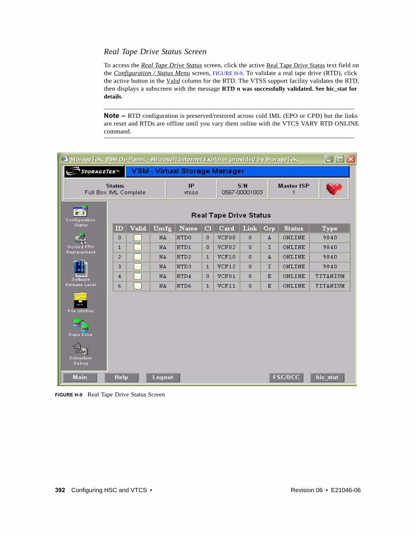
392 Configuring HSC and VTCS • Revision 06 • E21046-06
Real Tape Drive Status Screen
To access the Real Tape Drive Status screen, click the active Real Tape Drive Status text field on the Configuration / Status Menu screen, FIGURE H-9. To validate a real tape drive (RTD), click the active button in the Valid column for the RTD. The VTSS support facility validates the RTD, then displays a subscreen with the message RTD n was successfully validated. See hic_stat for details.
Note – RTD configuration is preserved/restored across cold IML (EPO or CPD) but the links are reset and RTDs are offline until you vary them online with the VTCS VARY RTD ONLINE command.
FIGURE H-9 Real Tape Drive Status Screen

E21046-06 • Revision 06 Appendix H 393
IOCP Example for Single MVS Host Connected to a VSM5 Via FICON DirectorsFIGURE H-10 shows a configuration diagram for a single MVS host connected to a VSM5 via FICON Directors, and FIGURE H-11 on page 396 shows example IOCP statements for this configuration. Note that:
? From MVSA, you define 8 CHPIDs, with each path switched in the FICON Director, for a total of 8 channels running to the VSM5.
? You code 16 CNTLUNIT statements to define the VSM5 as 16 3490 images.
? You code IODEVICE statement to define the 16 VTDs that are associated with each 3490 image.
? If ESCON and FICON channels are configured to the same logical control unit, MVS issues message CBDG489I, which indicates that mixing ESCON and FICON channel paths on a logical control unit should be used only for the migration from ESCON to native FICON but should not be used permanently. This is a warning message only, and does not indicate an error.
FIGURE H-10 Configuration Diagram: Single MVS Host Connected to a VSM5 via FICON Directors
20 21 30 31 70 71 80 81
4C
DO DO DO DOD4 D4 D4 D4
4D 4E 4F
MVS A
Storage Cluster 0 Storage Cluster1

394 Configuring HSC and VTCS • Revision 06 • E21046-06

E21046-06 • Revision 06 Appendix H 395
ESCD4CCHPID PATH=(20,70),TYPE=FC,SWITCH=4CESCD4DCHPID PATH=(21,71),TYPE=FC,SWITCH=4DESCD4ECHPID PATH=(30,80),TYPE=FC,SWITCH=4EESCD4F CHPID PATH=(31,81),TYPE=FC,SWITCH=4F
CU1 CNTLUNIT CUNUMBR=001, PATH=(20,21,30,31,70,71,80,81), LINK=(D0,D4,D0,D4,D4,D0,D4,D0), UNIT=3490,CUADD=0, UNITADD=((00,16))
STRING1 IODEVICE ADDRESS=(0500,16), CUNUMBER=(001),
UNIT=3490,UNITADD=00,STADET=Y
CU2 CNTLUNIT CUNUMBR=002, PATH=(20,21,30,31,70,71,80,81), LINK=(D0,D4,D0,D4,D4,D0,D4,D0), UNIT=3490,CUADD=1, UNITADD=((00,16))
STRING2 IODEVICE ADDRESS=(0510,16), CUNUMBER=(002),
UNIT=3490,UNITADD=00,STADET=Y...
CU15 CNTLUNIT CUNUMBR=015, PATH=(20,21,30,31,70,71,80,81), LINK=(D0,D4,D0,D4,D4,D0,D4,D0), UNIT=3490,CUADD=E, UNITADD=((00,16))
STRING15 IODEVICE ADDRESS=(05E0,16), CUNUMBER=(015),
UNIT=3490,UNITADD=00,STADET=Y
CU16 CNTLUNIT CUNUMBR=016, PATH=(20,21,30,31,70,71,80,81), LINK=(D0,D4,D0,D4,D4,D0,D4,D0), UNIT=3490,CUADD=F, UNITADD=((00,16))
STRING16 IODEVICE ADDRESS=(05F0,16), CUNUMBER=(016),
UNIT=3490,UNITADD=00,STADET=Y
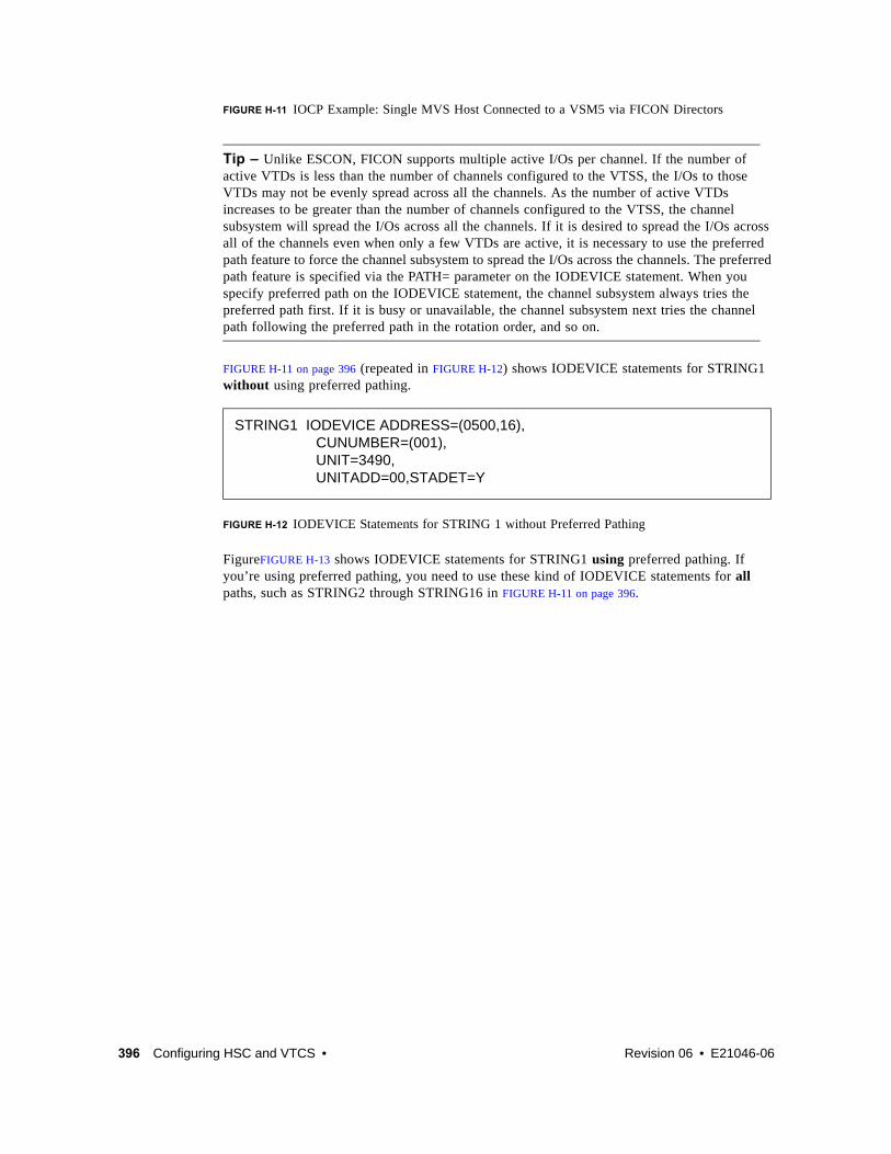
396 Configuring HSC and VTCS • Revision 06 • E21046-06
FIGURE H-11 IOCP Example: Single MVS Host Connected to a VSM5 via FICON Directors
Tip – Unlike ESCON, FICON supports multiple active I/Os per channel. If the number of active VTDs is less than the number of channels configured to the VTSS, the I/Os to those VTDs may not be evenly spread across all the channels. As the number of active VTDs increases to be greater than the number of channels configured to the VTSS, the channel subsystem will spread the I/Os across all the channels. If it is desired to spread the I/Os across all of the channels even when only a few VTDs are active, it is necessary to use the preferred path feature to force the channel subsystem to spread the I/Os across the channels. The preferred path feature is specified via the PATH= parameter on the IODEVICE statement. When you specify preferred path on the IODEVICE statement, the channel subsystem always tries the preferred path first. If it is busy or unavailable, the channel subsystem next tries the channel path following the preferred path in the rotation order, and so on.
FIGURE H-11 on page 396 (repeated in FIGURE H-12) shows IODEVICE statements for STRING1 without using preferred pathing.
FIGURE H-12 IODEVICE Statements for STRING 1 without Preferred Pathing
FigureFIGURE H-13 shows IODEVICE statements for STRING1 using preferred pathing. If you’re using preferred pathing, you need to use these kind of IODEVICE statements for all paths, such as STRING2 through STRING16 in FIGURE H-11 on page 396.
STRING1 IODEVICE ADDRESS=(0500,16), CUNUMBER=(001),
UNIT=3490,UNITADD=00,STADET=Y
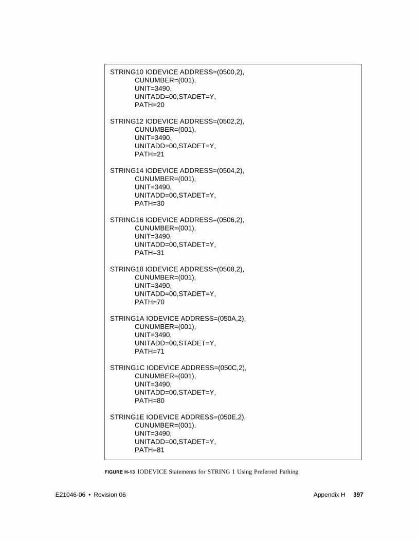
E21046-06 • Revision 06 Appendix H 397
FIGURE H-13 IODEVICE Statements for STRING 1 Using Preferred Pathing
STRING10 IODEVICE ADDRESS=(0500,2),CUNUMBER=(001),UNIT=3490,UNITADD=00,STADET=Y,PATH=20
STRING12 IODEVICE ADDRESS=(0502,2),CUNUMBER=(001),UNIT=3490,UNITADD=00,STADET=Y,PATH=21
STRING14 IODEVICE ADDRESS=(0504,2),CUNUMBER=(001),UNIT=3490,UNITADD=00,STADET=Y,PATH=30
STRING16 IODEVICE ADDRESS=(0506,2),CUNUMBER=(001),UNIT=3490,UNITADD=00,STADET=Y,PATH=31
STRING18 IODEVICE ADDRESS=(0508,2),CUNUMBER=(001),UNIT=3490,UNITADD=00,STADET=Y,PATH=70
STRING1A IODEVICE ADDRESS=(050A,2),CUNUMBER=(001),UNIT=3490,UNITADD=00,STADET=Y,PATH=71
STRING1C IODEVICE ADDRESS=(050C,2),CUNUMBER=(001),UNIT=3490,UNITADD=00,STADET=Y,PATH=80
STRING1E IODEVICE ADDRESS=(050E,2),CUNUMBER=(001),UNIT=3490,UNITADD=00,STADET=Y,PATH=81

398 Configuring HSC and VTCS • Revision 06 • E21046-06

E21046-06 • Revision 06 399
APPENDIX
I
VSM5 ESCON/FICON Configurations
TABLE I-1 summarizes the supported VCF (FICON) and ICE (ESCON) card configurations for VSM5. VSM5 ESCON support requires microcode level D02.07.00.00 or H01.07.00.00.
TABLE I-1 Supported Card Configurations for VSM5 ESCON/FICON
VCF Cards FICON Ports ICE Cards
ESCON Ports Total Ports
Total Logical Paths (16 per ICE Port, 64 per VCF Port)
0 0 8 32 32 512
4 8 4 16 24 768

400 Configuring HSC and VTCS • Revision 06 • E21046-06
VSM5 ICE/VCF Card OptionsVSM5 supports the following ICE/VCF card options:
? FIGURE I-1 shows a VSM5 with 8 ICE cards.
? FIGURE I-2 on page 401 shows a VSM5 with 4 ICE cards, 4 VCF cards.
FIGURE I-1 VSM5 with 8 ICE cards

E21046-06 • Revision 06 Appendix I 401
FIGURE I-2 VSM5 with 4 ICE cards, 4 VCF cards

402 Configuring HSC and VTCS • Revision 06 • E21046-06
Note –
? In FIGURE I-2 on page 401, the VCF cards must go in: Slots 3, 4, 13, and 14 in a four-VCF card configuration.
? FICON ports are controlled by a FICON Interface processor (FIP), ESCON ports are controlled by a CIP. Regardless of the card configuration, there can be only a total of 14 Nearlink FIPs and/or CIPs.
Note – With microcode level D02.06.00.00 or higher, multiple Nearlink device connections via a FICON or ESCON switch or Director on the same port now allow:
? Up to a total of 16 simultaneous NearLink I/O transfers, which can be spread across multiple targets on as many as 14 NearLink ports.
? Up to a total of 2 simultaneous NearLink I/O transfers are allowed per port.
? All FICON ports can be configured as either a Host port or Nearlink (RTD/CLINK origination) port. All ESCON ports continue to be configurable as host or Nearlink ports in pairs on a per CIP basis.
? As shown in FIGURE I-1 on page 400 and FIGURE I-2 on page 401, the ports are shown with their channel interface identifiers. These channel interface identifiers are the values that are required for the CHANIF values that you code for the CONFIG utility. Each value is two characters in length and has a value from 0A to 1O. The first digit is the VTSS cluster ID (valid values are 0 or 1). The second digit is the group or adapter ID (valid values are A to P).
Each FICON port can attach to four RTDs, or two CLINKs, or an RTD/CLINK combination via a FICON director or supported switch (in FICON mode). Note that, as shown in these figures, for RTDs only, each FICON port has two CHANIF values only if the port is connected to a FICON director which is then connected to two RTDs. Nearlink RTD connections that are paired via a FICON switch or director on the same port dynamically alternate between both RTDs for atomic operations such as mount, migrate VTV, recall VTV, etc.
? Each ICE card contains two pairs of ESCON ports. Each pair is controlled by its own Channel Interface Processor (CIP). Each CIP switches between the two ports, so that only one port can transfer data at a time, which emulates a FICON port attached to a director attached to RTDs.
? Each host FICON channel supports 64 logical paths (times 16 logical units). However, in HCD:
? From a single MVS host, you can only define 8 channels (CHPIDs) running to a single control unit (single VSM5).
? You use the CNTLUNIT statement to define each VSM5 as 16 3490 control unit images.
? You use the IODEVICE statement to define the 16 VTDs that are associated with each 3490 control unit image.
? For a VSM5, each ESCON CIP or FICON FIP can operate with only one of two modes, which is set at the VTSS DOP:
? Host Mode. In Host Mode, ports can connect to the host CPU channels, including via Director(s) or channel extenders. A port in Host Mode can also serve as a CLINK terminator.

E21046-06 • Revision 06 Appendix I 403
Also note that for ESCON ports, you can have two physical paths from the same LPAR to the same CIP, as long as the two physical paths address different (not overlapping) logical control units. For example, a single host LPAR can address logical control units 0-7 on one CIP port, and 8-F on the other CIP port of the same CIP.
? Nearlink Mode. In Nearlink Mode, ports can connect to an RTD. A port in Nearlink Mode can also serve as a CLINK originator.
Caution – In bi-directional clustering, each CLINK must be attached to the same Storage Cluster on each VTSS, which is a requirement. Failure to configure in this manner can produce Replicate, Channel, and Communication errors!

404 Configuring HSC and VTCS • Revision 06 • E21046-06
In both FICON and ESCON, what are Best Practices for optimizing port operations? See TABLE I-2...
TABLE I-2 Optimizing VSM5 FICON/ESCON Port Operations
Configuration - Two ESCON Ports on a CIP (ICE) or FICON port attached to a FICON Director (VCF) Best Practices
Multiple CLINKs (up to 4) Attach a maximum of 2....because each port allows two active operations. Note, however, that these operations share the bandwidth of the port.
CLINK and RTD combinations An advantage if you attach one CLINK originator/one RTD per director, because both can be active.
Up to 4 RTDs An advantage for the following:
Optimize use of local and remote RTDs. During busy shifts, use only local RTDs on the FIP. During quiet periods, switch to remote RTDs for deep archive and DR work. Because you can have two active devices, you can also simultaneously run one local and one remote RTD. Note, however, that these operations share the bandwidth of the port.
Optimize use of different drive technologies. As described in the previous bullet, use a T9840 as a local RTD, then switch to a T9940 for deep archive. You can also use this feature to migrate from older drive technology (such as 9490) to newer technology (such as 9840). Use Management and Storage Classes to read in data from older media, then switch to the newer technology drive to place data on new media. This technique effectively gives you greater physical connectivity to different drive technologies without incurring the overhead of full time, real time FICON connections to each drive type. Also as above, because you can have two active devices, you can also simultaneously run two RTDs with different drive technologies. Note, however, that these operations share the bandwidth of the port.

E21046-06 • Revision 06 Appendix I 405
VSM5 Configuration Example: 8 ICE Cards, 16 Host Ports, 16 RTD PortsFIGURE I-3 shows CONFIG channel interface identifiers of 16 for hosts, 16 for RTDs for a VSM5.
FIGURE I-3 VSM5 with 16 Host Ports, 16 RTD Ports

406 Configuring HSC and VTCS • Revision 06 • E21046-06
CONFIG Example for VSM5 with 16 Host Ports, 16 RTD Ports
FIGURE I-4 shows example CONFIG JCL to define the VSM5 configuration shown in FIGURE I-3
on page 405.
FIGURE I-4 CONFIG example: VSM5 with 16 Host Ports, 16 RTD Ports
//CREATECF EXEC PGM=SLUADMIN,PARM='MIXED'//STEPLIB DD DSN=hlq.SEALINK,DISP=SHR//SLSCNTL DD DSN=hlq.DBASEPRM,DISP=SHR//SLSCNTL2 DD DSN=hlq.DBASESEC,DISP=SHR//SLSSTBY DD DSN=hlq.DBASETBY,DISP=SHR//SLSPRINT DD SYSOUT=*//SLSIN DD * CONFIG GLOBAL MAXVTV=32000MVCFREE=40 RECLAIM THRESHLD=70MAXMVC=40 START=35VTSS NAME=VSM501 LOW=70 HIGH=80 MAXMIG=8 RETAIN=5 RTD NAME=VSM52A00 DEVNO=2A00 CHANIF=0C RTD NAME=VSM52A01 DEVNO=2A01 CHANIF=0D RTD NAME=VSM52A02 DEVNO=2A02 CHANIF=0G RTD NAME=VSM52A03 DEVNO=2A03 CHANIF=0H RTD NAME=VSM52A04 DEVNO=2A04 CHANIF=0K RTD NAME=VSM52A05 DEVNO=2A05 CHANIF=0L RTD NAME=VSM52A06 DEVNO=2A06 CHANIF=0O RTD NAME=VSM52A07 DEVNO=2A07 CHANIF=0P RTD NAME=VSM52A08 DEVNO=2A08 CHANIF=1C RTD NAME=VSM52A09 DEVNO=2A09 CHANIF=1D RTD NAME=VSM52A0A DEVNO=2A0A CHANIF=1G RTD NAME=VSM52A0B DEVNO=2A0B CHANIF=1H RTD NAME=VSM52A0C DEVNO=2A0C CHANIF=1K RTD NAME=VSM52A0D DEVNO=2A0D CHANIF=1L RTD NAME=VSM52A0E DEVNO=2A0E CHANIF=1O RTD NAME=VSM52A0F DEVNO=2A0F CHANIF=1P VTD LOW=9900 HIGH=99FF

E21046-06 • Revision 06 Appendix I 407
IOCP Example for Single MVS Host Connected to a VSM5 Via ESCON DirectorsFIGURE I-5 shows a configuration diagram for a single MVS host connected to a VSM5 via ESCON Directors, and FIGURE I-6 on page 410 shows example IOCP statements for this configuration. Note that:
? From MVSA, you define 8 CHPIDs, with each path switched in the ESCON Director, for a total of 8 channels running to the VSM5.
? You code 16 CNTLUNIT statements to define the VSM5 as 16 3490 images.
? You code IODEVICE statement to define the 16 VTDs that are associated with each 3490 image.
FIGURE I-5 Configuration Diagram: Single MVS Host Connected to a VSM5 via ESCON Directors
20 21 30 31 70 71 80 81
4C
DO DO DO DOD4 D4 D4 D4
4D 4E 4F
MVS A
Storage Cluster 0 Storage Cluster1

408 Configuring HSC and VTCS • Revision 06 • E21046-06

E21046-06 • Revision 06 Appendix I 409
ESCD4CCHPID PATH=(20,70),TYPE=CNC,SWITCH=4CESCD4DCHPID PATH=(21,71),TYPE=CNC,SWITCH=4DESCD4ECHPID PATH=(30,80),TYPE=CNC,SWITCH=4EESCD4F CHPID PATH=(31,81),TYPE=CNC,SWITCH=4F
CU1 CNTLUNIT CUNUMBR=001, PATH=(20,21,30,31,70,71,80,81), LINK=(D0,D4,D0,D4,D4,D0,D4,D0), UNIT=3490,CUADD=0, UNITADD=((00,16))
STRING1 IODEVICE ADDRESS=(0500,16), CUNUMBER=(001),
UNIT=3490,UNITADD=00,STADET=Y
CU2 CNTLUNIT CUNUMBR=002, PATH=(20,21,30,31,70,71,80,81), LINK=(D0,D4,D0,D4,D4,D0,D4,D0), UNIT=3490,CUADD=1, UNITADD=((00,16))
STRING2 IODEVICE ADDRESS=(0510,16), CUNUMBER=(002),
UNIT=3490,UNITADD=00,STADET=Y...
CU15 CNTLUNIT CUNUMBR=015, PATH=(20,21,30,31,70,71,80,81), LINK=(D0,D4,D0,D4,D4,D0,D4,D0), UNIT=3490,CUADD=E, UNITADD=((00,16))
STRING15 IODEVICE ADDRESS=(05E0,16), CUNUMBER=(015),
UNIT=3490,UNITADD=00,STADET=Y
CU16 CNTLUNIT CUNUMBR=016, PATH=(20,21,30,31,70,71,80,81), LINK=(D0,D4,D0,D4,D4,D0,D4,D0), UNIT=3490,CUADD=F, UNITADD=((00,16))
STRING16 IODEVICE ADDRESS=(05F0,16), CUNUMBER=(016),
UNIT=3490,UNITADD=00,STADET=Y

410 Configuring HSC and VTCS • Revision 06 • E21046-06
FIGURE I-6 IOCP Example: Single MVS Host Connected to a VSM5 via ESCON Directors

E21046-06 • Revision 06 411
APPENDIX
J
VSM5 New Models
The VSM5 provides new models that offer the capacities shown in TABLE J-1.
Note –
? TBE =The approximate maximum effective capacity in Terabytes (TB).
? Models VSM5-45TB-IFF3, VSM5-68TB-IFF3, and VSM5-90TB-IFF3 require PTF L1H14UN (SES7000).
? These models can contain a maximum of 500,000 VTVs
? VSM5 new models require the following VTSS microcode:
? For Models VSM5-45TB-IFF3, VSM5-68TB-IFF3, and VSM5-90TB-IFF3 only, VTSS microcode level H02.07.
? For all other Models, VTSS microcode level D02.07.
? Models VSM5-1.25TB-IFF3, VSM5-16TB-IFF3, and VSM5-23TB-IFF3 support ESCON channel cards. For more information, see “VSM5 ESCON/FICON Configurations” on page 399.
TABLE J-1 VSM5 New Model Capacities
Drive Capacity
1-ArrayTBE
2-Arrays TBE
3-Arrays TBE
4-Arrays TBE VSM Model
Product Family ID
450GB 45 VSM5-45TB-IFF3 580
450GB 68 VSM5-68TB-IFF3 580
450GB 90 VSM5-90TB-IFF3 580
146GB 7.5/11/14 VSM5-1.25TB-IFF3 567
146GB 16/18/21 VSM5-16TB-IFF3 567
146GB 23/25/28 VSM5-23TB-IFF3 567
146GB .8/1.25 VSM5E -.8TB 567

412 Configuring HSC and VTCS • Revision 06 • E21046-06
TABLE J-2 shows the supported channel card configurations for:
? VSM5 - All models including VSM5c but not including VSM5e and VSM5escon. For information on VSM5escon, see “VSM5 ESCON/FICON Configurations” on page 399.
? VSM5e.
TABLE J-2 VSM5 New Model Supported Channel Card Configurations
VSM Model
Storage Cluster 0 Storage Cluster 1
2 3 4 5 12 13 14 15
5 VCF VCF VCF VCF
VCF VCF VCF VCF VCF VCF
VCF VCF VCF VCF VCF VCF VCF VCF
5e VCF VCF VCF VCF
ICE ICE ICE ICE

E21046-06 • Revision 06 413
APPENDIX
K
Tapeless VSM
“Tapeless VSM” basically means that you can have a VTSS without any RTDs directly attached to the VTSS; in the CONFIG deck, there are no RTD statements for the tapeless VTSS. Tapeless VSM applies to VSM4s and VSM5s.

414 Configuring HSC and VTCS • Revision 06 • E21046-06
How Does Tapeless VSM Work?Configuring and managing a Tapeless VSM works as follows:
1. In the CONFIG deck, there are no RTD statements for the Tapeless VTSS.
Note – For clustered VTSS configurations, all VTSSs in the cluster must be Tapeless or all VTSSs in the cluster must have RTDs attached. You cannot mix Tapeless VTSSs and VTSSs with RTDs attached within a cluster.
2. The new MGMTCLAS NOMIGRAT parameter specifies that VTVs in the Management Class are not candidates for migration, consolidation or export, but are candidates to reside on a tapeless VTSS.
VTSS selection is changed to prefer Tapeless VTSSs for VTVs in Management Classes with NOMIGRAT, and to disallow VTVs without NOMIGRAT from VTSSs with no RTDs.
NOMIGRAT parameter is mutually exclusive with the ACSLIST, IMMEDMIG, DUPLEX, MIGPOL, ARCHAGE, ARCHPOL, RESTIME, CONSRC and CONTGT parameters.
3. A Management Class can specify DELSCR(YES), which is a proactive method to cause VSM to delete scratched VTVs, which frees VTSS buffer space and (logically) deletes any VTV copies from MVCs so that MVC space can be reclaimed. As an alternative, you can specify DELSCR(NO) and use the DELETSCR utility (which now provides a VTSS parameter to scratch VTVs on a per VTSS basis) to do demand deletes of scratched VTVs.
For a sample configuration, see “Tapeless VSM Example” on page 415.
Note – If you have an environment that is completely Tapeless (no RTDs attached to any VTSS system), then in your LIBGEN you need to code a dummy ACS as shown in the example in “LIBGEN Example for Tapeless ACS” on page 419.

E21046-06 • Revision 06 Appendix K 415
Tapeless VSM ExampleFIGURE K-1 shows a simple Tapeless VSM copnfiguration where VTSSA has no RTDs attached.
FIGURE K-1 Tapeless VSM
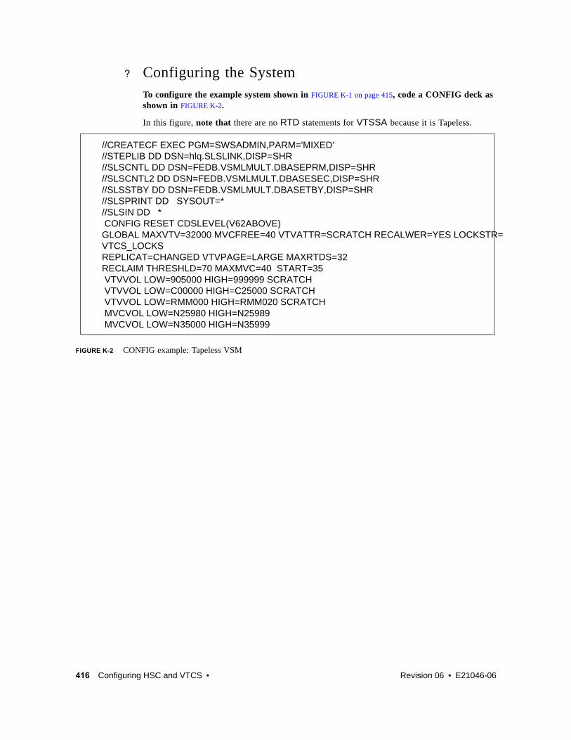
416 Configuring HSC and VTCS • Revision 06 • E21046-06
? Configuring the SystemTo configure the example system shown in FIGURE K-1 on page 415, code a CONFIG deck as shown in FIGURE K-2.
In this figure, note that there are no RTD statements for VTSSA because it is Tapeless.
FIGURE K-2 CONFIG example: Tapeless VSM
//CREATECF EXEC PGM=SWSADMIN,PARM='MIXED'//STEPLIB DD DSN=hlq.SLSLINK,DISP=SHR//SLSCNTL DD DSN=FEDB.VSMLMULT.DBASEPRM,DISP=SHR//SLSCNTL2 DD DSN=FEDB.VSMLMULT.DBASESEC,DISP=SHR//SLSSTBY DD DSN=FEDB.VSMLMULT.DBASETBY,DISP=SHR//SLSPRINT DD SYSOUT=*//SLSIN DD * CONFIG RESET CDSLEVEL(V62ABOVE)GLOBAL MAXVTV=32000 MVCFREE=40 VTVATTR=SCRATCH RECALWER=YES LOCKSTR=VTCS_LOCKSREPLICAT=CHANGED VTVPAGE=LARGE MAXRTDS=32RECLAIM THRESHLD=70 MAXMVC=40 START=35 VTVVOL LOW=905000 HIGH=999999 SCRATCH VTVVOL LOW=C00000 HIGH=C25000 SCRATCH VTVVOL LOW=RMM000 HIGH=RMM020 SCRATCH MVCVOL LOW=N25980 HIGH=N25989 MVCVOL LOW=N35000 HIGH=N35999

E21046-06 • Revision 06 Appendix K 417
? Defining PoliciesTo define policies for the example system shown in FIGURE K-7 on page 418, do the following:
1. Enable the Advanced Management Feature.
2. Create a Storage Class for VTSSA.
FIGURE K-3 “Tapeless” Storage Class
3. Create the Management Classes that point to the Storage Classes in Step 2.
FIGURE K-4 “Tapeless” Management Class
In FIGURE K-4 we created a Management Class that points to the corresponding Storage Class created in Step 2.
Note – In addition to NOMIGRAT, the Management Class in FIGURE K-4 specifies DELSCR(YES), which is a proactive method to cause VSM to delete scratched VTVs, which frees VTSS buffer space and (logically) deletes any VTV copies from MVCs so that MVC space can be reclaimed. As an alternative, you can specify DELSCR(NO) and use the DELETSCR utility (which now provides a VTSS parameter to scratch VTVs on a per VTSS basis) to do demand deletes of scratched VTVs.
4. Create an SMC Policy that specifies virtual media and assigns the Management Class created in Step 3.
FIGURE K-5 “Tapeless” Policy
5. Create a TAPEREQ statement to route data to VSM and assign the “Tapeless” Policy to the data.
FIGURE K-6 TAPEREQ Statement to Route Data, Assign Policy
In FIGURE K-6, the TAPEREQ statement specifies to route data sets with HLQ mask *.HR.** to VSM and assign Policy PTAPEL.
Note – Although you can use SMC policies to direct your migrations to a specific esoteric, StorageTek recommends using only MGMTCLAS so that the SMC/VTCS allocation influencing can use any VTSS that supports the MGMTCLAS requirements.
STOR NAME(TAPEL)
MGMT NAME(TAPEL) NOMIGRAT DELSCR(YES)
POLICY NAME(PTAPEL) MEDIA(VIRTUAL) MGMT(TAPEL)
TAPEREQ DSN(*.HR.**) POLICY(PTAPEL)

418 Configuring HSC and VTCS • Revision 06 • E21046-06
Using CTR in “Tapeless” and “With Tape” EnvironmentsFIGURE K-7 shows two non-clustered VTSSs (VTSSA and VTSSB in separate TapePlexes) where VTSSA has no RTDs attached. VTSSA sends VTVs to VTSSB via CTR so that VTSSB can migrate the VTVs to tape in ACS00.
FIGURE K-7 Mixed Tapeless VSM
As shown in FIGURE K-7, therefore, you can construct a “Tapeless” TapePlex, use CTR to connect this TapePlex to another TapePlex that has RTDs attached. With this configuration, you can make a “TapeLess” copy in the first TapePlex and replicate it to the second TapePlex where it can be migrated to tape. For more information on DTR, see ELS Disaster Recovery and Offsite Data Management Guide.

E21046-06 • Revision 06 Appendix K 419
LIBGEN Example for Tapeless ACSFIGURE K-8 and FIGURE K-9 on page 420 show a LIBGEN example for a Tapeless ACS, where the SLISTATN ADDRESS=(0032) statement denotes a dummy ACS.
** LABELS WILL BE GENERATED IN THE OUTPUT LIBGEN AS FOLLOWS:* ACS - "ACSXX" WHERE "XX" IS THE HEX ACS NUMBER 00-FF* STARTING WITH ZERO* LSM - "LSMXXYY" WHERE "XX" IS THE HEX ACS NUMBER OF THIS LSM* AND "YY" IS THE HEX LSM NUMBER (00-FF) IN THAT* ACS, STARTING AT ZERO FOR EACH NEW ACS* STATION - "STXXH" WHERE "XX" IS THE HEX ACS NUMBER AND H IS THE* HOST INDEX IN HEX (0-F)* PANEL - "PXXYYPP" WHERE "XX" IS THE HEX ACS NUMBER, YY IS THE HEX* LSM NUMBER, AND PP IS THE DECIMAL PANEL NUMBER* OF THE DRIVE PANEL* DRIVE - "DXXYYPPH" WHERE "XX" IS THE HEX ACS NUMBER, YY IS THE HEX* LSM NUMBER, PP IS THE DRIVE PANEL NUMBER IN DEC* IMAL, AND H IS THE HOST INDEX IN HEX*LIBGEN SLIRCVRY TCHNIQE=NONE* SLILIBRY SMF=231, X ACSLIST=ACSLIST, X HOSTID=(EC20,EC21), X MAJNAME=STKALSQN, X CLNPRFX=CLN, X COMPRFX=!, X DRVHOST=, X SCRLABL=SL*ACSLIST SLIALIST ACS00*ACS00 SLIACS LSM=(LSM0000,LSM0001,LSM0002,LSM0003), X STATION=(ST000,ST001)*ST000 SLISTATN ADDRESS=(0032)ST001 SLISTATN ADDRESS=(0032)*LSM0000 SLILSM PASTHRU=((0,M),(0,M),(0,M)), X ADJACNT=(LSM0001,LSM0002,LSM0003), X DRIVE=(1), X DRVELST=(P000001), X TYPE=8500, X DOOR=8500-2*

420 Configuring HSC and VTCS • Revision 06 • E21046-06
FIGURE K-8 LIBGEN Example for Tapeless ACS (Part 1)
FIGURE K-9 LIBGEN Example for Tapeless ACS (Part 2)
P000001 SLIDLIST HOSTDRV=(D0000010,D0000010)*D0000010 SLIDRIVS ADDRESS=(,,,,,,,,,,,,,,,)*LSM0001 SLILSM PASTHRU=((0,S),(0,M),(0,M)), X ADJACNT=(LSM0000,LSM0002,LSM0003), X DRIVE=(1), X DRVELST=(P000101), X TYPE=8500, X DOOR=8500-2*P000101 SLIDLIST HOSTDRV=(D0001010,D0001010)*D0001010 SLIDRIVS ADDRESS=(,,,,,,,,,,,,,,,)*LSM0002 SLILSM PASTHRU=((0,S),(0,S),(0,M)), X ADJACNT=(LSM0000,LSM0001,LSM0003), X DRIVE=(1), X DRVELST=(P000201), X TYPE=8500, X DOOR=8500-2*P000201 SLIDLIST HOSTDRV=(D0002010,D0002010)*D0002010 SLIDRIVS ADDRESS=(,,,,,,,,,,,,,,,)*LSM0003 SLILSM PASTHRU=((0,S),(0,S),(0,S)), X ADJACNT=(LSM0001,LSM0002,LSM0000), X DRIVE=(1), X DRVELST=(P000301), X TYPE=8500, X DOOR=8500-2*P000301 SLIDLIST HOSTDRV=(D0003010,D0003010)*D0003010 SLIDRIVS ADDRESS=(,,,,,,,,,,,,,,,)* SLIENDGN ,

E21046-06 • Revision 06 421
Index
AACF/VTAM, VTAM requirements 2, 102
ACSLIST 233
adding tape drives, dynamic hardware reconfiguration 141
ADDRESS 227
ADJACNT 243
AL 236
ALL 246
ALLOCDef SMC command, setting to ON, performance consideration 116
AMTspolicies 42
archiving, stopping 115
Bbalancing
library workload 118
Ccalculating SL3000 library cartridge capacity 25
calculating SL8500 library cartridge capacity 25
CAP See Cartridge Access Port
cartridgecapacity, calculating for SL3000 library 25capacity, calculating for SL8500 library 25
Cartridge Access Port (CAP)ejecting cartridges through closest 115setting CAP preference 116
cartridgesejecting through closest CAP 115entering
in advance of mount message 116redistributing during off-peak times 115
CDSformatting 94
changing unit addresses for tape drives, dynamic hardware reconfiguration 144
client/server drive mapping, defining 228
CLNPRFX 233
COMPRFX 233
CONFIG utility 28, 35
configurations, library 249
Configuring VSMstarting VTCS 213
control data setdefinition of types 5primary 5secondary 5standby CDS 6
control data set (CDS)HSC performance and sharing in multiple library
complex 11
crashing test systems, avoiding 117
DDD statements, descriptions for START PROC 113
definingdrives on a panel 227VTAM parameters for ACF/VTAM 2, 102
DOOR 243
DRIVE 241
DRVELST 241
drvelst 226
DRVHOST 236
dual IP connection 284
dual IP connections 319
duplicate copy, control data set 5
dynamic hardware reconfigurationadding tape drives 141changing unit addresses for tape drives 144removing tape drives 142replacing tape drives 143
EEJCTPAS 236
ejecting cartridgesthrough closest CAP, performance consideration 115
esotericsconfiguring 83
examples

E21046-06 • Revision 06 422
HOSTID parameter in SLILBRY 232library
configurations 249
EXECParm control statementparameters
Eid 106Fid 106HOSTID 106MSGPRFX 106
ExLMSYNCVTV function 43
FFUTRACS 236
FUTRLSM 224
GGRS serialization 9
GRS serialization, considerations 12
HHCD facility 36
high AMTpolicies 42
Host Software Component (HSC)CDS performance and sharing in a multiple library
complex 11defining client/server drive mapping 228forced termination, SMC consideration 220initializing under the master subsystem 216multiple library considerations 10preinitializing as an MVS subsystem 216RESERVEs, converting to global enqueues 14RESERVEs, converting to global enqueues in a GRS
environment 16RESERVEs, leaving in a GRS environment 14RESERVEs, leaving in an MIM/MII environment 15RESERVEs, maintaining 12, 13start task procedure 108starting
using the SSYS parameter 217with PARM=INIT 216
terminating the HSC 220
HOSTID 232
host-id 232
hostsenabled for migration 51
HSCdefining a security system user ID 82reconfiguration
formatting the new CDS 94LIBGEN definitions for RTDs 27overview 85updating the LIBGEN 87
SLUADMIN utility 200
user exitsSLSUX15 107
II/O Device Reserve Considerations 9
IEFSSNxx member 216
installationIPLing the system 108parameters for START command 110proc for START command 110
IP connection, dual 284
IP connectionsdual 319multiple 303
IPL requirements 108
IPLing the System 108
JJOURNAL 246
Llabel 245
LIBGENupdating 87
librarybalancing workload 118modifications 119multiple HSC library complexes, serializing 10reducing scheduling contention 117
library configurations 249
library scheduling contention, reducing 118
Library Storage Module (LSM)preallocating CDS space for SL8500 LSMs 224SLIACS parameter 223SLILSM parameter 240
libtype 233
low AMTpolicies 42
lsm0 240
MMAJNAME 233
migrationpolicies 58
MIH, setting 83
MIM/MII serialization, considerations 12
MNTDFloat, setting to ON, performance consideration 115
modifying library 119
multiple IP connections 303
MVCsdefining and selecting 37maximum retain interval 78, 80

E21046-06 • Revision 06 423
policiesspace reclamation 73
RTV access 200space reclamation
policies 75, 76, 77unscratching current scratch cartridges 200
NNCO See Near Continuous Operation
Near Continuous Operation (NCO)adding tape drives 141changing unit addresses for tape drives 144preallocating CDS space for SL8500 LSMs 224removing tape drives 142replacing tape drives 143
NL 236
NONE 245
nonlibrary cartridges, entering before a mount message is issued 116
nonproductive activities, scheduling 118
NSL 236
Pparameters
050 240075 240100 2404410 2409310 2409360 2409740 240ACSLIST 225, 233ADDRESS 227, 248ADJACNT 243AL 236ALL 246BASE 110BOTH 245CLN 233CLNPRFX 233COLD 111COMPRFX 233Dialog 111DOOR 243DRIVE 241DRVELST 241drvelst 226DRVHOST 236Eid 106, 111EJCTPAS 236Fid 106, 111FUTRACS 236FUTRLSM 224gtfeid 106gtffid 106HOSTDRV 226
HOSTID 106, 232INIT 110JOURNAL 246label 245LSM 223, 240MAJNAME 233Member 111MSGPRFX 106NL 236NONE 245NSL 236PARM= 110PASTHRU 241RESET 111SCRLABL 236SHADOW 245SL 236SL3000 240SL8500 240SMF 233SSYS 110STANDBY 246STATION 222station 248TCHNIQE 245TYPE 240WINDOW 243
PARMLIB control statementsIEFSSNxx member 216
partitioningSL3000
adding a partition to the library procedure 172adding resources to a library procedure 183moving a partition from one host group to another
host group 179partition description 154removing a partition from the library procedure 176removing resources from a library procedure 187varying the ACS online after a configuration change
191
pass-thrusreducing 114scheduled 115unavoidable 114unnecessary 114
PASTHRU 241
performance considerationsbalancing library workload 118
prefix 233
preinitializing the HSC as an MVS subsystem 216
primary control data set 5
procedures, dynamic hardware reconfigurationadding tape drives 141adding/removing expansion modules 145changing unit addresses for tape drives 144removing tape drives 142

E21046-06 • Revision 06 424
replacing tape drives 143
ptppanel0 241
Rreconfiguring the library 119
recovery utilityMVC access 200VTV access 200
redistributing cartridges during off-peak times, performance consideration 115
reducingoperator intervention 116pass-thru activity 115pass-thrus 114scheduling contention 117
removing tape drives, dynamic hardware reconfiguration 142
replacing tape drives, dynamic hardware reconfiguration 143
resource serialization 9
RTDsdefining for sharing with MVS 27LIBGEN definitions 27planning for 27policies 78, 80UNITATTR control statement 27
RTV utilityMVC access 200VTV access 200
Sscheduled pass-thrus 115
SCRLABL 236
secondary control data set 5
securitydefining for VSM 200
serializationCA-MIM/MII considerations 12GRS considerations 12HSC CDS performance and sharing tips 11HSC RESERVEs, converting to global enqueues 14HSC RESERVEs, converting to global enqueues in a
GRS environment 16HSC RESERVEs, leaving in a GRS environment 14HSC RESERVEs, leaving in an MIM/MII environment
15HSC RESERVEs, maintaining 13HSC RESERVEs,maintaining 12multiple HSC library complex 10resource 9
setting CAP preference, performance consideration 116
setting MNTD SCRDISM to CURRENT, performance consideration 115
SL 236
SL3000 librarycalculating cartridge capacity 25drive panel numbering 229dual IP connections 319partitioning
adding a partition to a library procedure 172adding resources to a library procedure 183definition 154moving a partition from one host group to another
host group procedure 179removing a partition from a library procedure 176removing resources from a library procedure 187varying the ACS online after a configuration change
191
SL8500 librarybefore configuring the HSC for the SL8500 91calculating cartridge capacity 25connecting to multiple SL8500s in an ACS 303drive panel numbering 230dual IP connection 284merging ACSs
configuring ACSs numbered left to right 133configuring ACSs numbered right to left 132
multiple IP connections 303Near Continuous Operation (NCO)
adding tape drives 141adding/removing expansion modules 145changing unit addresses for tape drives 144removing tape drives 142swapping tape drives 143
Near Continuous Operation (NCO), SLIACS FUTURLSM parameter 224
partitioningCAP considerations 151converting a non-partitioned ACS to a partitioned
ACS 159converting a partitioned ACS to a non-partitioned
ACS 162definitions 153LibraryStation considerations 152overview 150requirements and prerequisites 150restrictions 151start from scratch procedure 157
powering down the SL8500 305row numbering 26sample configuration - one host IP, two network
connections 299sample configuration - two dedicated routes 289side numbering 26TCP/IP communications
connections 282, 318shared networks 282, 318
two network connections - one mainframe IP address 295
two network connections - two mainframe IP addresses 284

E21046-06 • Revision 06 425
SLIACSparameters
FUTRLSM 224LSM 223STATION 222
purpose 222
SLIALISTparameters 225
acslist 225purpose 225syntax 225
SLIDLISTparameters
drvelst0 226HOSTDRV 226
purpose 226
SLIDRIVSparameters
ADDRESS 227purpose 227SL3000 library drive panel numbering 229SL8500 library drive panel numbering 230
SLIENDGNpurpose 231
SLILIBRYparameters 233
ACSLIST 233CLNPRFX 233COMPRFX 233DRVHOST 236EJECTPAS 236FUTRACS 236HOSTID 232MAJNAME 233SCRLABL 236
purpose 232
SLILSMparameters
050 240075 240100 2403000 2404410 2408500 2409310 2409360 2409740 240ADJACNT 243DOOR 243DRIVE 241DRVELST 241LSM 240PASTHRU 241TYPE 240WINDOW 243
purpose 238
SLIRCVRYparameters
ALL 246BOTH 245JOURNAL 246label 245NONE 245SHADOW 245STANDBY 246TCHNIQE 245
purpose 245
SLISTATNparameters
ADDRESS 248station 248
purpose 247
SLSBPREI subsystem initialization routine 216
SLSSYS DD statement for START PROC 113
SLSUEXIT DD statement for START PROC 113
SLSUX15 user exitissuing command authorization request to security
product 107
SLUADMIN utilityunscratching current scratch cartridges 200
SMF 233
SMF record formats 103
SMFPRMxx, producing SMF records 103
space reclamationMVCs 73, 75, 76, 77
specifyingGTF event ID 106GTF format ID 106
SSYS parameter, starting the HSC using 217
STANDBY 246
standby control data set 6
START procedureDD statement descriptions 113parameters 110SLSSYS DD statement 113SLSUEXIT DD statement 113syntax 110
start task procedureHSC
coding and cataloging 108
STATION 222
stopping the HSC 220
syntaxHSC START procedure 214
Ttape management system
planning for 37, 38updating 198
tape transport
E21046-06 • Revision 06 426
contention, reducing 118
TAPEVOL security class 199
TCHNIQE 245
terminating, the HSC 220
TYPE 240
Uunavoidable pass-thrus 114
Unicenter CA-MIM/MII serialization 9
UNITATTR control statement 27, 35
unnecessary pass-thrus 114
VVSM
configurationdefining VSM security 200updating the tape management system 198values 5
policiesAMTs 42hosts enabled for migration 51maximum concurrent migration tasks 58maximum VTVs per MVC 50migration 51MVC space reclamation 76RTDs 78, 80space reclamation 73
security 200
VTCSconfiguration values 5pre-installation
configuring MVS unit addresses/esoterics 83defining a security system user ID 82setting the MIH value 83
SMF record formats 103
VTDsconfiguring
esoterics 83MVS device numbers 83
data chaining a read forward or write command 38MVS device numbers 36planning for 36UNITATTR control statement 35
VTSSsplanning for 35
VTVsdefining to tape management system 37migration
policies 51, 58RTV access 200
WWINDOW 243

E21046-06 • Revision 06 427

E21046-06 • Revision 06 428

E21046-06 • Revision 06 429

E21046-06 • Revision 06 430

E21046-06 • Revision 06 431

E21046-06 • Revision 06 432

E21046-06 • Revision 06 433