Enhancing Wireless Local Area Networks by leveraging ... - CORE
170
UNIVERSIDAD CARLOS III DE MADRID TESIS DOCTORAL E NHANCING WIRELESS L OCAL AREA NETWORKS BY L EVERAGING DIVERSE F REQUENCY R ESOURCES Autor: Thomas Nitsche, Universidad Carlos III de Madrid and IMDEA Networks Institute Director: Dr. Joerg Widmer, IMDEA Networks Institute DEPARTAMENTO DE INGENIER ´ IA TELEM ´ ATICA Legan´ es (Madrid), 2015
-
Upload
khangminh22 -
Category
Documents
-
view
3 -
download
0
Transcript of Enhancing Wireless Local Area Networks by leveraging ... - CORE

UNIVERSIDAD CARLOS III DE MADRID
TESIS DOCTORAL
ENHANCING WIRELESS LOCAL AREA NETWORKS BY LEVERAGINGDIVERSE FREQUENCY RESOURCES
Autor: Thomas Nitsche, Universidad Carlos III de Madrid and IMDEA NetworksInstitute
Director: Dr. Joerg Widmer, IMDEA Networks Institute
DEPARTAMENTO DE INGENIERIA TELEMATICA
Leganes (Madrid), 2015

UNIVERSIDAD CARLOS III DE MADRID
Ph.D Thesis
ENHANCING WIRELESS LOCAL AREA NETWORKS BY LEVERAGINGDIVERSE FREQUENCY RESOURCES
Author: Thomas Nitsche, Universidad Carlos III de Madrid and IMDEA NetworksInstitute
Director: Dr. Joerg Widmer, IMDEA Networks Institute
DEPARTMENT OF TELEMATIC ENGINEERING
Leganes (Madrid), 2015


Enhancing Wireless Local Area Networks by Leveraging Diverse Frequency Resources
A dissertation submitted in partial fulfillment of the requirements for the degree of Doctor of
Philosophy
Prepared by
Thomas Nitsche, Universidad Carlos III de Madrid and IMDEA Networks Institute
Under the advice of
Dr. Joerg Widmer, IMDEA Networks Institute
Departamento de Ingenierıa Telematica, Universidad Carlos III de Madrid
Date: January, 2015
Web/contact: [email protected]
This work has been supported by IMDEA Networks Institute.
TESIS DOCTORAL
ENHANCING WIRELESS LOCAL AREA NETWORKS BY LEVERAGING DIVERSE
FREQUENCY RESOURCES
Autor: Thomas Nitsche, Universidad Carlos III de Madrid and IMDEA Networks Institute
Director: Dr. Joerg Widmer, IMDEA Networks Institute

vi
Firma del tribunal calificador:
Firma:
Presidente:
Vocal:
Secretario:
Calificacion:
Leganes, de de

Acknowledgements
I would like to express my sincere thanks to all those who made this thesis possible and
provided help and support. First of all to my supervisor Dr. Jorg Widmer for his guidance and
profound advice on writing this thesis as well as his academic mentoring. Further, thanks are
owed to Dr. Thomas Fuhrmann and Dr. Edward Knightly, who also took their share in guiding
my academic work.
Along the same lines, I would like to thank all those people that I met along the way at
Technische Universitat Munchen, IMDEA Networks Institute and Rice University for discussion,
advice and encouragements: Michael Weiss, Dr. Bjorn Saballus, Dr. Johanna Amann, Allyson
Sim, Arash Asadi, Ignacio de Castro Arribas, Qing Wang, Dr. Jose Felix Kukielka, Dr. Adrian
Loch, Dr. Mathias Hollick, Dr. Alexander Kuhne, Dr. Kyle Jamieson, Jie Xiong, Jon Gjengset,
Pablo Salvador, Maria Isabel Sanchez, Adriana Flores Middelton, Dr. Narendra Anand, Dr. Oscar
Bejarano, Ryan E. Guerra, Sadia Quadri, Irene Tejado and Guillermo Bielsa. Special thanks
belong to Dr. Benedikt Elser and Dr. Georg Acher for their ’unofficial’ academic mentoring.
Finally, I want to express my profound gratitude to my beloved parents, my family and to
Daniela for their love and continuous support.
vii

Abstract
In this thesis, signal propagation variations, that are experience over the frequency resources
of IEEE 802.11 Wireless Local Area Networks (WLANs) are studied. It is found that exploitation
of these variations can improve several aspects of wireless communication systems. To this aim,
frequency varying behavior is addressed at two different levels.
First, the intra-channel scale is considered, i.e. variations over the continuous frequency block
that a device uses for a cohesive transmission. Variations at this level are well known but cur-
rent wireless systems restrict to basic equalization techniques to balance the received signal. In
contrast, this work shows that more fine grained adaptation to these differences can accomplish
throughput and connection range gains.
Second, multi-frequency band enabled devices that access widely differing frequency re-
sources in the millimeter wave range as well as in the microwave range are analyzed. These
devices that are expected to follow the IEEE 802.11ad specification experience intense propaga-
tion variations over their frequency resources. Thus, a part of this thesis revises, the theoretical
specification of the IEEE 802.11ad standard and complements it by a measurement study of first
generation millimeter wave devices. This study reveals deficiencies of first generation millime-
ter wave systems, whose improvement will pose new challenges to the protocol design of future
generation systems. These challenges are than addressed by novel methods that leverage from
frequency varying propagation characteristics.
The first method, improves the beam training process of millimeter wave networks, that need
highly directional, though electronically steered, transmissions to overcome increased free space
attenuation. By leveraging from omni-directional signal propagation at the microwave bands,
efficient direction interference is utilized to provide information to millimeter wave interfaces
and replace brute force direction testing. Second, deafness effects at the millimeter wave band,
which impact IEEE 802.11 channel access methods are addressed. As directional communication
on these bands complicates sensing the medium to be busy or idle, inefficiencies and unfairness
are implied. By using coordination message exchange on the legacy Wi-Fi frequencies with omni-
directional communication properties, these effects are countered. The millimeter wave bands can
thus unfold their full potential, being exclusively used for high speed data frame transmission.
ix


Table of Contents
Acknowledgements vii
Abstract ix
Table of Contents xi
List of Tables xv
List of Figures xix
List of Acronyms xxi
Introduction 1Motivation . . . . . . . . . . . . . . . . . . . . . . . . . . . . . . . . . . . . . . . . . 2
Scope . . . . . . . . . . . . . . . . . . . . . . . . . . . . . . . . . . . . . . . . . . . 4
Contributions . . . . . . . . . . . . . . . . . . . . . . . . . . . . . . . . . . . . . . . 5
I Adapting IEEE 802.11 to Intra-Channel Propagation Variations 7
1 Background on IEEE 802.11 Communication 111.1 Radio Wave Propagation . . . . . . . . . . . . . . . . . . . . . . . . . . . . . . 11
1.1.1 Free Space . . . . . . . . . . . . . . . . . . . . . . . . . . . . . . . . . 12
1.1.2 Atmospheric Absorption . . . . . . . . . . . . . . . . . . . . . . . . . . 12
1.1.3 Multipath Propagation . . . . . . . . . . . . . . . . . . . . . . . . . . . 13
1.2 IEEE 802.11 . . . . . . . . . . . . . . . . . . . . . . . . . . . . . . . . . . . . . 17
1.2.1 Standardization History . . . . . . . . . . . . . . . . . . . . . . . . . . 17
1.2.2 Channelization and Frequency Bands . . . . . . . . . . . . . . . . . . . 18
1.2.3 Network Structures . . . . . . . . . . . . . . . . . . . . . . . . . . . . . 20
1.3 MAC-Layer . . . . . . . . . . . . . . . . . . . . . . . . . . . . . . . . . . . . . 20
1.3.1 Medium Access Techniques . . . . . . . . . . . . . . . . . . . . . . . . 21
1.3.2 Hidden Node Problem . . . . . . . . . . . . . . . . . . . . . . . . . . . 23
1.3.3 Frame Aggregation . . . . . . . . . . . . . . . . . . . . . . . . . . . . . 25
xi

xii TABLE OF CONTENTS
1.4 PHY-Layer . . . . . . . . . . . . . . . . . . . . . . . . . . . . . . . . . . . . . 25
1.4.1 Frame Format . . . . . . . . . . . . . . . . . . . . . . . . . . . . . . . . 26
1.4.2 Modulation . . . . . . . . . . . . . . . . . . . . . . . . . . . . . . . . . 27
1.4.3 MIMO . . . . . . . . . . . . . . . . . . . . . . . . . . . . . . . . . . . 30
2 OFDM Sub-Carrier Switch Off 332.1 Mechanism . . . . . . . . . . . . . . . . . . . . . . . . . . . . . . . . . . . . . 34
2.1.1 Adaptive Sub-Carrier Switch Off . . . . . . . . . . . . . . . . . . . . . . 36
2.1.2 Threshold-Based Adaptive Sub-Carrier Switch Off . . . . . . . . . . . . 36
2.2 Hardware Platform and Experimental Setup . . . . . . . . . . . . . . . . . . . . 37
2.2.1 PHY-Layer Structure . . . . . . . . . . . . . . . . . . . . . . . . . . . . 38
2.2.2 WARPnet Measurement Setup . . . . . . . . . . . . . . . . . . . . . . . 39
2.2.3 Measured Values . . . . . . . . . . . . . . . . . . . . . . . . . . . . . . 40
2.2.4 General Measurement Setup . . . . . . . . . . . . . . . . . . . . . . . . 41
2.2.5 Feedback Mechanism . . . . . . . . . . . . . . . . . . . . . . . . . . . . 42
2.3 Results . . . . . . . . . . . . . . . . . . . . . . . . . . . . . . . . . . . . . . . . 42
2.3.1 Throughput Gain for SSO . . . . . . . . . . . . . . . . . . . . . . . . . 42
2.3.2 Parameter Configuration for SSO . . . . . . . . . . . . . . . . . . . . . 44
2.3.3 Adaptive Sub-Carrier Switch Off . . . . . . . . . . . . . . . . . . . . . . 46
2.4 Related Work . . . . . . . . . . . . . . . . . . . . . . . . . . . . . . . . . . . . 47
2.5 Conclusion . . . . . . . . . . . . . . . . . . . . . . . . . . . . . . . . . . . . . 48
II Leveraging from Varying Multi-Frequency Band Propagation 51
3 Background on Multi-band WiFi 553.1 IEEE 802.11ad . . . . . . . . . . . . . . . . . . . . . . . . . . . . . . . . . . . 56
3.1.1 Directional Communication . . . . . . . . . . . . . . . . . . . . . . . . 57
3.1.2 IEEE 802.11ad Device Classes and Use Cases . . . . . . . . . . . . . . . 58
3.1.3 Design Assumptions . . . . . . . . . . . . . . . . . . . . . . . . . . . . 58
3.1.4 Physical Layer . . . . . . . . . . . . . . . . . . . . . . . . . . . . . . . 60
3.1.5 Network Architecture . . . . . . . . . . . . . . . . . . . . . . . . . . . . 61
3.1.6 IEEE 802.11ad Medium Access Control Layer . . . . . . . . . . . . . . 64
3.1.7 Beamforming Concept . . . . . . . . . . . . . . . . . . . . . . . . . . . 67
3.1.8 Beamforming Protocol . . . . . . . . . . . . . . . . . . . . . . . . . . . 70
3.2 Performance Analysis of Millimeter Wave Networks . . . . . . . . . . . . . . . 73
3.2.1 Measurement Setup . . . . . . . . . . . . . . . . . . . . . . . . . . . . . 74
3.2.2 Results . . . . . . . . . . . . . . . . . . . . . . . . . . . . . . . . . . . 79
3.2.3 Discussion . . . . . . . . . . . . . . . . . . . . . . . . . . . . . . . . . 90
3.3 Conclusion . . . . . . . . . . . . . . . . . . . . . . . . . . . . . . . . . . . . . 92

TABLE OF CONTENTS xiii
4 Multi-Frequency Band Beam Steering 954.1 System Architecture . . . . . . . . . . . . . . . . . . . . . . . . . . . . . . . . . 97
4.1.1 IEEE 802.11ad and mm-Wave Wi-Fi . . . . . . . . . . . . . . . . . . . 97
4.1.2 Node and System Architecture . . . . . . . . . . . . . . . . . . . . . . . 98
4.2 Mechanism . . . . . . . . . . . . . . . . . . . . . . . . . . . . . . . . . . . . . 100
4.2.1 Out-of-Band Sector Inference and Profile History . . . . . . . . . . . . . 101
4.2.2 Profile History Aggregation . . . . . . . . . . . . . . . . . . . . . . . . 101
4.2.3 Line-Of Sight Inference and Reflected Path Rejection . . . . . . . . . . . 102
4.2.4 Sector Mapping . . . . . . . . . . . . . . . . . . . . . . . . . . . . . . . 102
4.2.5 Optional Sector Refinement . . . . . . . . . . . . . . . . . . . . . . . . 103
4.3 Implementation and Evaluation . . . . . . . . . . . . . . . . . . . . . . . . . . . 104
4.3.1 Blind Beam Steering (BBS ) Prototype . . . . . . . . . . . . . . . . . . 104
4.3.2 Direct Path Detection Accuracy . . . . . . . . . . . . . . . . . . . . . . 105
4.3.3 Robustness to Multipath and Signal Blockage . . . . . . . . . . . . . . . 106
4.3.4 Training Overhead . . . . . . . . . . . . . . . . . . . . . . . . . . . . . 108
4.3.5 Time of Directional Link Establishment . . . . . . . . . . . . . . . . . . 109
4.3.6 Direct Path Detection under Mobility . . . . . . . . . . . . . . . . . . . 110
4.4 Related Work . . . . . . . . . . . . . . . . . . . . . . . . . . . . . . . . . . . . 110
4.5 Conclusion . . . . . . . . . . . . . . . . . . . . . . . . . . . . . . . . . . . . . 111
5 Multi-Frequency Band MAC Enhancements for Fairness and Efficiency 1135.1 Fairness Impairments in Directional CSMA/CA . . . . . . . . . . . . . . . . . . 115
5.1.1 IEEE 802.11ad CSMA/CA . . . . . . . . . . . . . . . . . . . . . . . . . 116
5.1.2 Centralized CSMA/CA . . . . . . . . . . . . . . . . . . . . . . . . . . . 117
5.2 Dual-Band CSMA/CA . . . . . . . . . . . . . . . . . . . . . . . . . . . . . . . 117
5.2.1 Dual-Band CSMA/CA Protocol . . . . . . . . . . . . . . . . . . . . . . 118
5.2.2 Fairness and Throughput . . . . . . . . . . . . . . . . . . . . . . . . . . 119
5.3 Simulation Models . . . . . . . . . . . . . . . . . . . . . . . . . . . . . . . . . 119
5.4 Results . . . . . . . . . . . . . . . . . . . . . . . . . . . . . . . . . . . . . . . . 120
5.4.1 Homogeneous scenario . . . . . . . . . . . . . . . . . . . . . . . . . . . 121
5.4.2 Heterogeneous scenario. . . . . . . . . . . . . . . . . . . . . . . . . . . 126
5.5 Related Work . . . . . . . . . . . . . . . . . . . . . . . . . . . . . . . . . . . . 127
5.6 Conclusion . . . . . . . . . . . . . . . . . . . . . . . . . . . . . . . . . . . . . 128
Summary and Future Work 128
References 142

xiv TABLE OF CONTENTS

List of Tables
2.1 WARP: Sub-carrier assignment. . . . . . . . . . . . . . . . . . . . . . . . . . . 38
2.2 WARP: Modulation base rates. . . . . . . . . . . . . . . . . . . . . . . . . . . . 40
2.3 WARP: Throughput reduction due to FEC. . . . . . . . . . . . . . . . . . . . . . 40
3.1 IEEE 802.11ad: Typical device configurations. . . . . . . . . . . . . . . . . . . 59
3.2 D5000 and WiHD frame periodicity. . . . . . . . . . . . . . . . . . . . . . . . . 80
4.1 BBS and IEEE 802.11ad time comparison for directional link establishment. . . . 109
5.1 Dual-Band CSMA/CA: Parameters in 60 GHz and 5 GHz frequency bands. . . . 121
xv

xvi LIST OF TABLES

List of Figures
1.1 Free space attenuation . . . . . . . . . . . . . . . . . . . . . . . . . . . . . . . . 13
1.2 Attenuation due to atmospheric absorption. . . . . . . . . . . . . . . . . . . . . 13
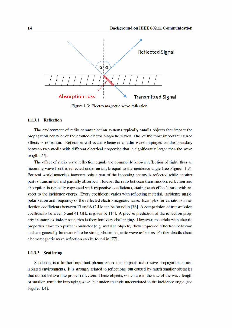
1.3 Electro magnetic wave reflection. . . . . . . . . . . . . . . . . . . . . . . . . . . 14
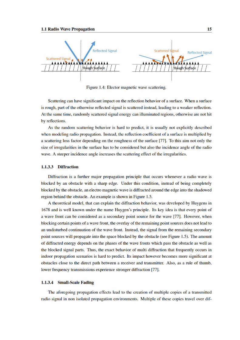
1.4 Elector magnetic wave scattering. . . . . . . . . . . . . . . . . . . . . . . . . . 15
1.5 Elector magnetic wave diffraction. . . . . . . . . . . . . . . . . . . . . . . . . . 16
1.6 Channel state example. . . . . . . . . . . . . . . . . . . . . . . . . . . . . . . . 16
1.7 IEEE 802.11 DCF operation. . . . . . . . . . . . . . . . . . . . . . . . . . . . . 22
1.8 Hidden node problem. . . . . . . . . . . . . . . . . . . . . . . . . . . . . . . . 23
1.9 PCF beacon interval structure. . . . . . . . . . . . . . . . . . . . . . . . . . . . 24
1.10 IEEE 802.11 frame structure. . . . . . . . . . . . . . . . . . . . . . . . . . . . . 27
1.11 DSSS signal characteristics. . . . . . . . . . . . . . . . . . . . . . . . . . . . . 28
1.12 IEEE 802.11 MIMO frame structure. . . . . . . . . . . . . . . . . . . . . . . . . 31
2.1 Sub-carrier allocation of the WARP OFDM PHY-layer. . . . . . . . . . . . . . . 38
2.2 WARP OFDM PHY-layer frame format. . . . . . . . . . . . . . . . . . . . . . . 39
2.3 SSO experimental setup. . . . . . . . . . . . . . . . . . . . . . . . . . . . . . . 40
2.4 SSO throughput evaluation: Channel coefficients. . . . . . . . . . . . . . . . . . 43
2.5 SSO throughput evaluation: QPSK throughput. . . . . . . . . . . . . . . . . . . 43
2.6 SSO throughput evaluation: 16-QAM throughput. . . . . . . . . . . . . . . . . . 43
2.7 SSO throughput gain. . . . . . . . . . . . . . . . . . . . . . . . . . . . . . . . . 44
2.8 SSO threshold determination: Channel coefficients. . . . . . . . . . . . . . . . . 45
2.9 SSO threshold determination: Throughput comparision. . . . . . . . . . . . . . . 45
2.10 Adaptive SSO evaluation: Throughput comparision. . . . . . . . . . . . . . . . . 46
2.11 Adaptive SSO evaluation: Channel coefficients. . . . . . . . . . . . . . . . . . . 47
2.12 Adaptive SSO evaluation: Throughput. . . . . . . . . . . . . . . . . . . . . . . . 47
3.1 Virtual antenna sectors. . . . . . . . . . . . . . . . . . . . . . . . . . . . . . . . 57
3.2 IEEE 802.11ad packet structure. . . . . . . . . . . . . . . . . . . . . . . . . . . 61
3.3 IEEE 802.11ad beacon interval structure. . . . . . . . . . . . . . . . . . . . . . 62
3.4 Dynamic channel allocation example. . . . . . . . . . . . . . . . . . . . . . . . 66
3.5 Sector level sweep structure. . . . . . . . . . . . . . . . . . . . . . . . . . . . . 68
xvii

xviii LIST OF FIGURES
3.6 Transmit and receive sector training. . . . . . . . . . . . . . . . . . . . . . . . . 68
3.7 Beam refinement transactions. . . . . . . . . . . . . . . . . . . . . . . . . . . . 70
3.8 Association beamforming training. . . . . . . . . . . . . . . . . . . . . . . . . . 71
3.9 Beam pattern analysis setup. . . . . . . . . . . . . . . . . . . . . . . . . . . . . 76
3.10 Dell D5000 device discovery frame. . . . . . . . . . . . . . . . . . . . . . . . . 76
3.11 Reflection analysis setup. . . . . . . . . . . . . . . . . . . . . . . . . . . . . . . 77
3.12 Interference analysis setup. . . . . . . . . . . . . . . . . . . . . . . . . . . . . . 78
3.13 Reflected interference: Measurement setup. . . . . . . . . . . . . . . . . . . . . 79
3.14 Dell D5000 frame flow. . . . . . . . . . . . . . . . . . . . . . . . . . . . . . . . 80
3.15 WiGig data frame length. . . . . . . . . . . . . . . . . . . . . . . . . . . . . . . 81
3.16 Percentage of long frames in WiGig. . . . . . . . . . . . . . . . . . . . . . . . . 81
3.17 WiGig medium usage. . . . . . . . . . . . . . . . . . . . . . . . . . . . . . . . 81
3.18 MCS with low traffic. . . . . . . . . . . . . . . . . . . . . . . . . . . . . . . . . 82
3.19 Dell D5000 frame amplitudes and rate. . . . . . . . . . . . . . . . . . . . . . . . 83
3.20 DVDO Air-3c WiHD frame flow. . . . . . . . . . . . . . . . . . . . . . . . . . . 83
3.21 Quasi omni-directional beam patterns swept by the Dell D5000. . . . . . . . . . 84
3.22 Direction beam pattern measurement results. . . . . . . . . . . . . . . . . . . . . 85
3.23 Reflections for Dell D5000. . . . . . . . . . . . . . . . . . . . . . . . . . . . . . 86
3.24 Reflections for DVDO Air-3c WiHD. . . . . . . . . . . . . . . . . . . . . . . . 86
3.25 Inter system interference effects. . . . . . . . . . . . . . . . . . . . . . . . . . . 87
3.26 Side lobe interference impact. . . . . . . . . . . . . . . . . . . . . . . . . . . . 89
3.27 Reflection interference impact. . . . . . . . . . . . . . . . . . . . . . . . . . . . 90
4.1 Blind Beam Steering (BBS )system architecture. . . . . . . . . . . . . . . . . . 99
4.2 Angular profile: Unobstructed direct path. . . . . . . . . . . . . . . . . . . . . . 103
4.3 Angular profile: Multipath and blockage. . . . . . . . . . . . . . . . . . . . . . 103
4.4 BBS measurement floor plan. . . . . . . . . . . . . . . . . . . . . . . . . . . . . 105
4.5 BBS prototype platform. . . . . . . . . . . . . . . . . . . . . . . . . . . . . . . 105
4.6 BBS: Detection accuracy results. . . . . . . . . . . . . . . . . . . . . . . . . . . 106
4.7 BBS: Peak to average ratio in relation to accuracy. . . . . . . . . . . . . . . . . . 107
4.8 BBS: Blockage impact . . . . . . . . . . . . . . . . . . . . . . . . . . . . . . . 107
4.9 BBS: Overhead Results . . . . . . . . . . . . . . . . . . . . . . . . . . . . . . . 108
5.1 RTS collision due directional transmit focus on Access Point (AP). . . . . . . . . 114
5.2 Missed RTS due to receive sector misalignment. . . . . . . . . . . . . . . . . . . 114
5.3 Excessive backoff behavior of CSMA/CA in IEEE802.11ad . . . . . . . . . . . . 116
5.4 Excessive deferral with colliding RTS messages in CSMA/CA with broadcast CTS 116
5.5 Channel access mechanism of the dual-band approach. . . . . . . . . . . . . . . 119
5.6 Interference in a directional transmission network. . . . . . . . . . . . . . . . . . 120
5.7 Dual-Band CSMA/CA: Throughput results. . . . . . . . . . . . . . . . . . . . . 122
LIST OF FIGURES xix
5.8 Dual-Band CSMA/CA: RTS-RTS collisions. . . . . . . . . . . . . . . . . . . . . 122
5.9 Dual-Band CSMA/CA: Channel time distribution. . . . . . . . . . . . . . . . . . 123
5.10 Dual-Band CSMA/CA: Short term fairness. . . . . . . . . . . . . . . . . . . . . 124
5.11 Dual-Band CSMA/CA: Long term fairness. . . . . . . . . . . . . . . . . . . . . 124
5.12 Dual-Band CSMA/CA: Maximum frame transmission delay (4 nodes). . . . . . . 125
5.13 Dual-Band CSMA/CA: Maximum frame transmission delay (16 nodes). . . . . . 125
5.14 Dual-Band CSMA/CA: Frame size impact. . . . . . . . . . . . . . . . . . . . . 126
5.15 Dual-Band CSMA/CA: Frame size impact (long term). . . . . . . . . . . . . . . 126


Acronyms
A-BFT Association Beamforming Training.
AP Access Point.
ATI Announcement Transmission Interval.
BBS Blind Beam Steering.
BER Bit Error Rate.
BF Beam Forming.
BHI Beacon Header Interval.
BI Beacon Interval.
BPSK Binary Phase Shift Keying.
BRP Beam Refinement Protocol.
BSS Basic Service Set.
CBAP Contention Based Access Period.
CCK Complementary Code Keying.
CDF Cumulative Distribution Function.
CDMA Code Division Multiple Access.
CFP Contention Free Period.
CP Contention Period.
CRC Cyclic Redundancy Check.
CSMA/CA Carrier Sense Multiple Access with
Collision Avoidance.
CTS Clear To Send.
CW Contention Window.
DCF Distributed Coordination Function.
DIFS DCF Inter Frame Spacing.
DMG Directional Multi-Gigabit.
DSSS Direct Sequence Spread Spectrum.
DTI Data Transmission Interval.
EDCF Enhanced Distributed Coordination
Function.
EIRP Equivalent Isotropically Radiated Power.
ESS Extended Service Set.
FCC Federal Communication Commission.
FEC Forward Error Correction.
FPGA Field Programmable Gate Array.
FST Fast Session Transfer.
HCF Hybrid Coordination Function.
HDMI High-Definition Multimedia Interface.
HPBW Half Power Beam Width.
IBSS Independent Basic Service Set.
IDFT Inverse Discrete Fourier Transformation.
ISI Inter-Symbol Interference.
ISM Industrial Scientific Medical.
LDPC Low Density Parity Code.
LOS Line of Sight.
LOS non-Line of Sight.
LTE Long Term Evolution.
MAC Medium Access Control.
MAC-layer Medium Access Control Layer.
MCS Modulation Coding Scheme.
MIMO Multiple Input Multiple Output.
mm-wave Millimeter Wave.
MPDU MAC Protocol Data Unit.
MSDU MAC Service Data Unit.
xxi
xxii Acronyms
MU-MIMO Multi-User Multiple Input Multi-
ple Output.
NAV Network Allocation Vector.
OFDM Orthogonal Frequency Division Multi-
plexing.
PBSS Personal Basic Service Set.
PC Point Coordinator.
PCF Point Coordination Function.
PCP PBSS Control Point.
PER Packet Error Rate.
PHY-layer Physical Layer.
PIFS Point Coordination Inter Frame Spacing.
PNC Personal Network Coordinator.
QAM Quadrature Amplitude Modulation.
QPSK Quadrature Phase Shift Keying.
RTS Ready To Send.
RXSS Receive Sector Sweep.
SC Single Carrier.
SDM Spatial Division Multiplexing.
SIFS Short Inter Frame Spacing.
SINR Signal to Interference and Noise Ration.
SLS Sector Level Sweep.
SNR Signal To Noise Ration.
SP Service Period.
SPR Service Period Request.
SSO Sub-Carrier Switch Off.
SSW Sector Sweep.
TC Traffic Category.
TCP Transmit Control Protocol.
TDMA Time Division Multiple Access.
TXOP Transmit Opportunity.
TXSS Transmit Sector Sweep.
WARP Wireless open Access Research Plat-
form.
WLAN Wireless Local Area Network.
WPAN Wireless Personal Area Network.

Introduction
IEEE 802.11 Wi-Fi communication is continuously gaining popularity since its first ratified
standard in 1997. This surge in popularity results from rapid technological advances and a change
in live style towards omnipresent connectivity to telecommunication networks and above all the
Internet. With the trend towards more powerful mobile communication devices, also the user’s
demand for high throughput data connectivity increases. Streaming of high definition video and
audio data towards mobile devices is just one shape of this development. However, as cellular
data connectivity is limited due to high frequency licensing costs, Wi-Fi communication has been
willingly accepted by the users to fill the gap.
With its surge in popularity, also Wi-Fi systems repeatedly came to their limits in terms of
available channel resources and throughput. For this reason, continuous enhancements to the
IEEE 802.11 standard have been provided. This included continuous advancement of IEEE
802.11 signal encoding mechanisms and optimization of inefficiencies in first generation stan-
dards as well as usage of additional channel resources and addition of radically new transmission
techniques, e.g. efficient multi-antenna usage.
Nonetheless, the ever increasing use of Wi-Fi and growing network densities have once again
brought networks to their capacity limits. This has ultimately lead to the addition of the Millimeter
Wave (mm-wave) frequency band, which provides almost ten times as much frequency resources
as all legacy bands combined. Further, a radically differing signal propagation behavior compared
to currently used frequencies is experienced. This, promises significantly reduced interference
and the possibility of parallel data streams even in dense networks. Thus, with the IEEE 802.11ad
amendment the next step towards mm-wave communication is taken, which promises to provide
the performance for the upcoming technological advancements.
Further, IEEE 802.11 networks will be able to access widely differing frequency resources at
the same time. Thus, significant differences in signal propagation behavior will be experienced
over the range of accessible frequencies. This thesis exploits these variation of signal propagation,
which can hinder but at the same time benefit communication. As a result, novel methods to
mitigate and leverage from varying propagation behavior are contributed. In particular, challenges
of the upcoming mm-wave technology are identified and approached with novel transmission
techniques that are enabled through multi-frequency band access.
1

2 Motivation
Motivation
Wireless transmissions vary significantly with the frequency of the emitted signal. This entails
two important facts for wireless communication. First, transmission technology has to account
for the varying conditions found over its used frequency range. Second, different frequencies are
more suitable for specific types of wireless communication than others. This becomes obvious,
e.g. when comparing Long Term Evolution (LTE) cellular networks operating below 1 GHz to
60 GHz backhaul links. While the first provides almost pervasive coverage, even with moving re-
ceivers located inside buildings, the usage of the latter is of completely different nature. For these
links highly directional antennas are used to overcome strong free space attenuation, which re-
quires precise alignment and a free line of sight. Slight blockage or misalignment easily interrupts
transmission of these systems.
Rethinking modern wireless communication, three important aspects determine the user ex-
pectation towards theses systems: communication range, reliability and achievable throughput.
The latter two are expected even in dense networks. All three characteristics are intrinsically
related to the underlying frequency resources.
Communication range almost directly coincides with the free space attenuation of the used
transmission frequencies. While in theory, the transmission range can be increased arbitrarily
with the used transmit power, this is bounded by physical and regulatory limits. Effectively, the
achievable range is thus determined by the frequency of wireless transmissions. While lower fre-
quencies generally receive less attenuation, and allow higher transmission ranges, this property is
also impacted by blockages in the path between receiver and transmitter and atmospheric effects.
For rather short range indoor communication as prevalent in IEEE 802.11 WLAN, the frequency
of a transmission becomes the decisive factor.
The reliability of wireless communication is very much related to the interaction of the radio
signal with the environment. When impacting an obstacle, part of the signal energy is reflected,
while the remaining part continues its way and penetrates the obstacle. This behavior is strongly
frequency dependent, leading to high amounts of reflections or extreme signal attenuation by
blockage for certain frequencies. When high reflectivity prevails for a frequency, a multipath
propagation environment is created, leading to self interference by multiple copies of the same
signal at the receiver. This causes extremely differing reception variations, both over small fre-
quency and location differences. Wireless networks have to cope with these effects and equalize
the signal over the used frequency range. Multipath propagation can however also have bene-
ficial effects, e.g. providing coverage behind blocking obstacles, or laying the fundamental for
efficient multi-antenna transmission techniques. These Multiple Input Multiple Output (MIMO)
approaches leverage from the differing channel conditions at varying antenna positions. When
these variations are known, it is possible to separate multiple parallel signal streams at the receiver
and potentially multiply throughput by the number of additional transmit and receive antennas.
Throughput and performance under dense network conditions are associated with interfer-

Motivation 3
ence effects between transmitters. The impact of interference depends on the coverage area of
devices which in turn relates to the communication frequency. Thus, the supported network den-
sity depends on the signal frequency, making some frequency ranges more suitable for crowded
networks than others. Preventing interference among devices can also be achieved by sharing the
transmission medium and limiting the throughput of each user. Medium sharing can happen in
different domains, with the most popular being time or frequency. When looking at frequency
resource sharing, two different levels have to be distinguished. First, official entities as for exam-
ple the Federal Communication Commission (FCC) divide the frequency spectrum into different
bands. Frequency bands are assigned to specific usages and wireless transmissions in that range
need to be licensed. An exception to this rule are the Industrial Scientific Medical (ISM) Bands
where Wi-Fi communication takes place in an unlicensed manner. As a drawback, communica-
tion at this frequency has to expect unforeseen interference from other spectrum users. Second,
frequency bands can further be divided into channels, which confine the amount of spectrum re-
sources that a single transceiver uses. Thus, by subdividing a band into multiple channels, several
users can communicate in a band at the same time without interference, but at the cost of utilizing
smaller chunks of frequency resources.
As pointed out, performance and behavior of communication systems are strongly influenced
by the used frequencies. Generally speaking, different parts of the spectrum are suited towards
specific use cases. This has lead to assignment of matching frequencies to different types of wire-
less communication systems by regulatory entities. For example maritime radio, television and
radio broadcasting are located at rather low frequencies with modest reflection and far transmis-
sion range. On the contrary, cellular communication systems and local area networking commu-
nicate at frequencies above 1 GHz, where spatial reuse of the same frequency is possible due
to limited range. However, strong multipath propagation in this range requires careful adapta-
tion to varying transmission conditions. On the other hand, the same multipath effects also open
the way for novel transmission techniques and increases the coverage area around blocking ob-
stacles. With technological advances wireless communication is now conquering the millimeter
wave frequency range, with frequencies between 30 and 300 GHz. The propagation behavior for
such systems significantly differs from systems in use today. Blockage by almost any obstacle
poses extreme signal energy loss and even in free space coverage range is severely reduced. E.g.
for the IEEE 802.11ad millimeter wave amendment expected range is reduced by a factor of 10
with respect to legacy Wi-Fi. While theses characteristics seems to be a drawback at first, they
also form the basis for the vision of extreme spatial reuse due to reduced interference. In fact,
due to advanced antenna techniques, strong signal energy focussing is envisioned, which enables
multiple non interfering pencil-beam transmissions in the same room.
While the millimeter wave revolution in itself promises significant advances for wireless com-
munication, it possesses particularly stunning opportunities for future IEEE 802.11 networks.
These systems will be multi-band enabled and thus capable of able to accessing multiple fre-
quency bands with varying propagation behavior. While this is already the case for current devices

4 Scope
which communicate at 2.4 and 5 GHz, for these bands propagation properties were still relatively
alike. With the addition of frequency resources at 60 GHz this however changes, and combination
of transmissions with radically differing behavior becomes possible. This allows for completely
new transmission techniques that leverage from the individual strength of each frequency band.
Scope
This thesis explores novel ways to enhance WLAN performance considering frequency vary-
ing propagation conditions and proposes solutions to leverage from spectrum access at different
frequency bands. To this end, this work is divided into two parts.
At first, frequency varying propagation characteristics are investigated at the intra-channel
level for classical IEEE 802.11g compliant communication. For these systems, throughput and
reliability are increased, adding a minimal feedback loop for channel state information. This
information is used to prevent the usage of strongly attenuated parts of the channel, reducing
transmission error probability and increasing throughput. Due to the benefits of an adaptation to
frequency dependent variations, we then explore multi-band systems, which feature even stronger
variations in propagation behavior.
The second part of this thesis therefore studies the benefit of frequency varying behavior
for multi-band systems that operate on millimeter wave frequencies. It begins with an in-depth
analysis of multi-band capable Wi-Fi networks, which is twofold. First an introduction to the
IEEE 802.11ad amendment with focus on the beamforming aspects at the millimeter-wave band
is given. As high throughput on millimeter wave frequencies can only be achieved with direc-
tional communication, these beamforming mechanisms are the most critical addition to the IEEE
802.11 protocol. Second, the theoretical evaluation is complemented by a practical measurement
campaign of first generation millimeter wave networks that rely on electronic beam steering.
This study reveals, that devices are still limited in terms of interference reduction through di-
rectional antenna patterns. In the azimuthal range, where highly directional gain can be achieved
also strong side lobes exist even when aiming for the optimal beamforming direction. This beha-
vior worsens when beamforming towards the boundary of an antenna arrays serviceable area. As
a result the device’s coverage area is increased, which benefits current systems as communication
protocols still can behave close to legacy Wi-Fi communication. The observed shortcomings are
expected to be resolved by further advancement of antenna technology with resulting reduction in
coverage area. Thus, for directionally communicating future millimeter wave systems, two main
challenges are identified.
• The setup of highly directional millimeter wave links is a high overhead process,
which also leads to network wide interference due to the sweeping of all possible transmit
directions. Due to decreased coverage area and higher directivity, more antenna configura-
tion have to be tested, resulting in increased interference and overhead.

Contributions 5
• Carrier sensing, the process of detecting ongoing transmissions, becomes less and
less reliable when the signal coverage area is reduced. This effect, known as deafness
problem, negatively impacts IEEE 802.11’s most popular medium access scheme leading
to efficiency loss and increased medium access delay [10].
To theses challenges, solutions that benefit from the variation of propagation characteristics over
frequency are presented. The first mechanism leverages omni-directional communication and di-
rection estimation capabilities in the micro-wave band to align directional high speed throughput
at the mm-wave frequencies. This reduces the need for sweeping communication that is orig-
inially used in IEEE 802.11ad for direction estimation, thus reducing interference and leading
to an overall throughput increase. Second, omni-directional communication at lower frequen-
cies is exploited to improve carrier sensing in directional mm-wave networks. This resolves the
deafness effects created by directional communication, reduces collision probability and ensures
correct medium access behavior.
Contributions
This thesis studies the impact of frequency varying propagation behavior on IEEE 802.11
networks with a focus on the recently evolving millimeter wave Wi-Fi systems. Further, through
analysis of first generation millimeter wave devices, research questions arise for the challenges
of upcoming millimeter wave systems. Solutions to these questions, as well as to challenges for
classic microwave Wi-Fi communication experiencing frequency varying propagation behavior,
are proposed. In particular, the contributions of this thesis are as follows:
1. First, Sub-Carrier Switch Off (SSO) for Orthogonal Frequency Division Multiplexing
(OFDM) modulated microwave wireless local area networks is presented. SSO addresses
frequency selective behavior, which effects the transmission over a single wireless chan-
nel. As certain OFDM sub-carriers are attenuated more than others, using only a subset
of possible carriers increases throughput and frame delivery rate. Further, an optimization
problem for SSO is identified, namely how many sub-carriers to switch-off. Removing a
higher number of attenuated carriers allows to drive the remaining ones with less robust
encoding which provides higher throughput. However, data of the switched off sub-carriers
has to be transmitted over the remaining ones, resulting in longer frames. A threshold
based solution is derived from experimental evaluation of SSO and the performance of a
dynamic SSO algorithm is shown. Unfortunately, applying SSO to millimeter wave net-
works is not promising, as the used directional antenna technology at these frequencies
suppresses frequency varying propagation effects [16, 103]. Thus, for the strong frequency
dependent propagation variations of millimeter wave enabled multi-band Wi-Fi, alternative
approaches are explored.

6 Contributions
2. Second, to the best of our knowledge the first beamforming and interference evaluation of
off-the-shelf millimeter wave networks is presented. As a key finding, first generation mil-
limeter wave systems are shown to suffer from interference through imperfect beamforming
and reflections, as well as difficulties to implement omni-directional antenna patterns. The
latter results in the need to sweep multiple antenna patterns with the same replicated signal
for proper reception, thus increasing interference and overhead. These findings are comple-
mented by a reassessment of the IEEE 802.11ad amendment for millimeter wave enabled
multi-band Wi-Fi. Form this, next generation networks are expected to implement even
stronger directionality as the vision of highly directional parallel antenna beams can not
be achieved otherwise. This however complicates the communication principles for these
networks. A further key observation is, that the theoretical assumption of strongly focused
and side lobe free beams, found in almost all theoretical work on millimeter wave networks,
has to be revalidated.
3. Third, the BBS mechanism is presented, which enhances the beamforming training process
for high speed data transmissions at mm-wave frequencies. To this aim, the differing sig-
nal propagation characteristics for multi-band Wi-Fi systems following the IEEE 802.11ad
amendment are exploited. As lower frequencies offer the possibility of omni-directional
signal propagation, incidence angle estimation can be performed with high efficiency. The
retrieved direction information is then used on mm-wave frequencies, where directional
communication needs complex link setup procedures otherwise. As a result, no sweep-
ing of probing frames into all possible directions is required, which prevents interference
and breakage of parallel directional transmission. Also less overhead on the high speed
millimeter wave band promises increased throughput rates, especially for mobile use cases.
4. Last, a mechanism for improvement of Carrier Sense Multiple Access with Collision Avoid-
ance (CSMA/CA) channel access in mm-wave band Wi-Fi is proposed. This mechanism
also leverages from the difference in signal propagation between microwave and mm-wave
bands. As directional high throughput communication lacks efficient ways of sensing the
usage of a channel, unfairness is introduced in a network. By exploiting omni-directional
propagation at lower frequencies for multi-band traffic flow coordination, significant fair-
ness improvements can be achieved. Also link initialization frames that are transmitted
in vain to already transmitting stations are prevented removing interference into directions
differing from established directional links.

Part I
Adapting IEEE 802.11 toIntra-Channel Propagation Variations
7


9
The first part of this thesis focuses on improvement of IEEE 802.11 networking by lever-
aging from frequency varying propagation behavior at the intra-channel level. The contribution
presented in this part is a feed-back mechanisms that enables fine grained adaptation to the expe-
rienced channel variations. The level of adaptation is beyond the one found in current commercial
communication systems while the required signaling overhead is negligible. Further, this part of
the thesis is divided into two chapters. First, a background chapter explains the fundamentals of
the presented intra-channel optimization. This chapter also forms the basis for Part II of this the-
sis that focuses on multi-band millimeter wave Wi-Fi, as these systems build on the IEEE 802.11
networks described in the following.
Frequency varying signal propagation behavior can be observed at two levels. First, signifi-
cant difference can be found between widely separated frequency ranges in the order of multiple
hundred MHz or even GHz. These differences mainly results from free space attenuation, de-
scribed in Section 1.1.1 and 1.1.2, and differences in material reflection and transmission proper-
ties (see Section 1.1.3.1). Second, multipath propagation can lead to frequency varying behavior
at a much smaller frequency scale. This can lead to diverse effects on the frequency resources
used by a single device for one cohesive transmission, which is referred to as the intra-channel
level in the following. Multipath propagation, described in Section 1.1.3 results from a signal’s
interaction with objects in the vicinity of transceivers, leading to multiple copies of a signal over-
laying at the receiver.
This part of the thesis focuses on the adaptation of IEEE 802.11 systems to intra-channel
propagation variations caused by multipath. These variations result in varying signal reception
qualities in terms of amplitude and phase as described in Section 1.1.3.4. High throughput IEEE
802.11 systems identify these variations through a channel estimation preamble prepended to
every transmission as described in Section 1.4.1, and perform basic channel equalization (see
Section 2.1.2). The presented adaptation mechanism targets IEEE 802.11 systems that rely on
an OFDM Physical Layer (PHY-layer). In-depth background information about the PHY-layer
definition of IEEE 802.11 and OFDM modulation are given in Section 1.4. The basic principle
of OFDM is to separate the used channel in multiple smaller frequency blocks to realize multiple
transmissions, parallel in frequency, with lower transmit speed. The parallel transmitted signals
on these sub-divided resource blocks are also known as sub-carriers.
The presented improvement for IEEE 802.11 networks is called Sub-Carrier Switch Off. It
identifies sub-carriers with low signal quality and disables them, transmitting the excessive data
from switched off sub-carriers through the remaining strong sub-carrier. While this mechanism
has been mentioned by other works before [72, 73] and [24] it has not been considered to be
an independent mechanism but as a borderline case for more complex mechanisms that also re-
quire higher amount of signaling overhead. We find from the experimental evaluation, presented
in Section 2.3 that SSO can achieve significant throughput and link robustness increases by it
self. Further, we present an optimization problem that SSO needs to solve to balance between
longer transmission length through sub-carrier switch off and higher throughput encoding on the

10
remaining sub-carriers. From the experimental evaluation, a threshold based solution to this op-
timization problem is derived that leads to a dynamic SSO algorithm, which is experimentally
shown to select configurations close to the optimum on arbitrary channels.
SSO proves that fine grained adaptation to the frequency varying behavior of wireless systems
on the intra-channel level is a profitable approach. It also points to additional research directions
that promise to yield further potential at the intra-channel level. With the upcoming consumer
millimeter wave technology, multi-band Wi-Fi devices can access frequency resources with strong
frequency varying behavior. These systems, which are studied in Part II of this thesis, promise
even higher potential for leveraging from said behavior. The SSO mechanism itself is however
not suitable for these device class. As highly directive antenna technology is used for millimeter
wave systems, much smaller multipath impact is expected. The intra-channel variations, central
for SSO, are thus not as strong on millimeter wave frequencies [16, 103].

Chapter 1
Background on IEEE 802.11Communication
This chapter summarizes the relevant background for Part I of this thesis which details on
adaptation to frequency varying propagation behavior at the intra-channel level. First, a brief
introduction into the most relevant signal propagation effects is presented, that lead to frequency
varying behavior of wireless transmission. Second, an introduction to the IEEE 802.11 standard is
given, which is subject to improvement in this thesis. The IEEE 802.11 standard is presented with
respect to its standardization history as well as general network and channel architecture followed
by a description of its PHY and Medium Access Control Layer (MAC-layer) features relevant
for this thesis. The background information given in this chapter also forms the basis for the
description of millimeter wave enabled multi-band IEEE 802.11ad networks that are discussed in
Part II of this work.
1.1 Radio Wave Propagation
Radio communication has formed the foundation for several technologies, that have revolu-
tionized the society throughout the 20th and 21th century. While the speed of evolutionary steps
for wireless communication systems has steadily increased, their basic physical principles remain
the same. Every radio communication system emits electro magnetic waves from a transmitter
towards a receiver. At both devices, antennas are used to convert between an electric signal and
electromagnetic waves. While these waves propagate towards the receiver, they interact with
obstacles and spread out over space. Thus, they experience several propagation effects, as for
example, attenuation, reflection, refraction, diffraction and scattering. In this section the basic
effects, that are relevant for the topics described in this thesis, are explained.
11

12 Background on IEEE 802.11 Communication
1.1.1 Free Space
When propagating through free space from an isotropic antenna (i.e. uniform radiation into
all three dimensions of space), an electro magnetic wave gets attenuated. This results from the
fact, that the originally transmitted energy Pt is spread over the complete area covered by the
wave. According to the Friis free space equation [77] the received power Pr at a distance d from
the transmitter can be formulated as in Equation 1.1. Hereby, L is a system loss factor, related to
effects in the transmitter and receiver devices and λ the wave length of the transmitted signal. The
wavelength is related to a signal’s frequency f as shown in equation 1.2, with c being the speed
of light.
Pr(d) =Ptλ
2
(4π)2d2L(1.1)
λ =c
f(1.2)
Eq. 1.1 points to an important insight with respect to this thesis. The received signal power in
free space scales with the frequency of a transmitted signal. Thus, lower frequencies suffer less
attenuation than high frequencies, making low frequency communication especially attractive for
long distance communication. The increased attenuation with frequency results from the reducing
antenna aperture Ae, which is the antenna’s perpendicular area to the received radio wave. The
antenna aperture for an isotropic antenna scales with the wavelength as shown in equation 1.3.
Ae =λ2
4π(1.3)
Figure 1.1 depicts the free space attenuation over distance for various frequencies. It can be
clearly seen that the frequency can induce a major attenuation difference at the same distance.
E.g. while transmissions at 2.4 GHz experience an attenuation of -60 dB at a distance of 15m,
transmissions at 60 GHz suffer almost -30 dB more attenuation. In contrast, frequencies at 2.412
GHz and 2.462 GHz, corresponding to Wi-Fi channel 1 and 11 show almost negligible attenuation
differences. To account for practical antennas, equation 1.1 is generalized to include varying gain
for transmitter Gt and receiver Gr leading to equation 1.4 (see e.g. [77]). An antenna’s gain
depends on its effective aperture Ae can be described as in equation 1.5.
Pr(d) =PtGtGrλ
2
(4π)2d2L(1.4)
G =4πAeλ2
(1.5)
1.1.2 Atmospheric Absorption
A second attenuation effect that varies with frequency is atmospheric absorption. Figure
1.2 shows the attenuation in excess of free space attenuation due to atmospheric components.
Notable peaks in the attenuation are observed, that result from absorption by specific molecules


1.2 IEEE 802.11 17
in terms of attenuation and phase. Over the frequency range of a band pass signal this causes
frequency selective fading. Practical systems have to address these differences that vary consid-
erably depending on the dynamics of the propagation scenario. When not addressed, frequency
selective fading results in significant distortions in the received signal. An example for the atten-
uation and phase variations introduced by a indoor multipath channel are shown in Figure 1.6.
It can be seen that phase and amplitude vary significantly over the channel average. The gap
for both measurements at the center frequency of channel 6 is not due to strong attenuation but
results from the fact that this range is not used for signal transmission. At this frequency range,
the transceiver architecture requires the signal to be filtered.
1.2 IEEE 802.11
IEEE 802.11 is the most popular protocol family for wireless local area networks and widely
adopted by industry. The 802.11 standards are developed by the IEEE LAN/MAN Standards
Committee, with the first version of the standard released in 1997. From there on, several amend-
ments to the standard have been ratified to introduce new features as well as maintain previous
parts of the standard. 802.11 defines a set of media access control (Medium Access Control
(MAC)) and physical PHY-layer specifications, that ensure interoperability between devices fol-
lowing the standards.
This thesis addresses the improvement of IEEE 802.11 compatible WLAN networks. Thus,
this section addresses the key aspects of the 802.11 communication standard, relevant for the
understanding of the thesis. First, a general overview of the standardization history together with
a description of the used frequency resources is given. Then, the basic network architectures
defined by the 802.11 standard are explained. Finally, an overview of the PHY and MAC-layer
specifications is given, with a focus on the OFDM PHY-layer, which is subject to improvement
in Chapter 2.
1.2.1 Standardization History
IEEE 802.11 has significantly evolved over time, adding new communication features and
adopting addition frequency ranges not specified by the initial standard. In the following an
overview of the significant evolution steps is given.
The initial standard [31] defined two PHY-layers operating in the license free ISM frequency
band at 2.4 GHz. The two PHY-layers used frequency-hopping spread spectrum and direct-
sequence spread spectrum modulations supporting throughput rates of up to 2 Mbps. While this
version of the standard was not very popular, it was quickly superseeded by the IEEE 802.11a [32]
and 802.11b [33] amendments in 1999, which became widely adopted. 802.11a added a PHY-
layer definition for OFDM modulation at the 5 GHz ISM band and increased throughput rates
to 54 Mbps. The 802.11b amendment continued using the 2.4 GHz frequency, but increased
throughput rates to 11 Mbps by application of Complementary Code Keying (CCK) modulation.

18 Background on IEEE 802.11 Communication
As the propagation range at 2.4 GHz is higher compared to 5 GHz and also higher connection
reliability is provided, 802.11b became the more popular amendment among the two. Finally,
in 2003 the 802.11g [34] amendment defined OFDM PHY-layer operation with up to 54 Mbps
throughput also for the 2.4 GHz frequencies.
In 2007 an updated standard [36] was ratified, that merged the formerly mentioned documents
together with several maintenance amendments, making the original documents obsolete. Among
the maintenance amendments, particularly IEEE 802.11e [35] deserves to be highlighted, as it
introduced advanced quality of service mechanisms at the MAC-layer. The next important evo-
lutionary step took place in 2009 with the IEEE 802.11n [37] amendment. It introduced MIMO
techniques to the IEEE 802.11 PHY-layer and added a new channel aggregation feature allowing
802.11n compliant devices to use up to twice the bandwidth as before. Also, a modification to
the MAC-layer introduced frame aggregation and significantly reduced the per frame overhead,
overall leading to increased throughput of up to 600 Mbps. IEEE 802.11n was super seeded
in 2014 by the 802.11ac [40] amendment, which further increases the performance introducing
higher MIMO degrees (up to 8 parallel streams), channel aggregation up to 160 MHz, Multi-User
Multiple Input Multiple Output (MU-MIMO) and beamforming. At the time of writing, the first
high end Wi-Fi products compliant with the IEEE 802.11ac specification, supporting throughput
rates of up 1.7 Gbps, are commercially available.
In parallel to the 802.11 main development branch targeting the 2.4 and 5 GHz bands, sev-
eral amendments introduce novel PHY-layers for different bands. This development has recently
accelerated with 802,11ad, af, ah and aj, that target a broad range of new frequency resources,
from coexistence with TV transmissions below 1 GHz to transmission in the 45 and 60 GHz mil-
limeter wave bands. Further details about the evolution of the IEEE 802.11 standard can be found
in [18–20].
1.2.2 Channelization and Frequency Bands
For radio communication, typically a base band signal with a given frequency bandwidth is
modulated onto a carrier frequency before transmission over the air. The amount of information
which can be transmitted with a signal depends on its bandwidth and the signal to noise ratio at the
receiver. This relation can mathematically be calculated according to the Shannon theorem [77].
The benefit of modulating a base band signal onto a carrier frequency lies in the fact that it can
be transmitted on different regions of the frequency spectrum. This allows to modulate several
signals onto different carriers without their bandwidth overlapping and thus parallel transmission
of multiple signals over the same medium. Otherwise, if signals overlap in frequency and time
they sum up at the receiver and distort the final reception, an effect called interference.
In order to prevent interference, the frequency spectrum is managed by national regulation
agencies. For example in the United States the FCC is in charge of this task, the respective entity
in the United Kingdom is the office of communications (Ofcom) and in China the Ministry of In-
formation Industry (MII). To homogenize the use of frequency spectrum superordinate institutions

1.2 IEEE 802.11 19
like the international telecommunication union (ITU) or European telecommunications standards
institute (ETSI) issue recommendations to the national entities. Certain frequency ranges (also
called frequency bands) are hereby assigned to specific use cases and users. These differ widely,
including for example commercial use cases (e.g. cellular networks), scientific usage (e.g. ra-
dio astronomy) or military applications. While licensing a frequency band is an effective way to
prevent interference, acquiring it is cumbersome and expensive.
As an alternative, certain frequency bands are assigned for unlicensed use. This opens the
way for inexpensive wireless consumer devices, which do not require the manufacturer to spend
high amounts of money on frequency licensing. Unlicensed frequency bands also enable wire-
less communication systems deployed by small institutions incapable of obtaining a licensed
frequency block. Particularly popular unlicensed frequency blocks are the ISM bands around 2.4
and 5 GHz. As a drawback, communication on these frequencies always has to expect unforeseen
interference from other users. It is further important to highlight that the users of unlicensed fre-
quency resources do not necessarily use the same communication protocols. In case of different
communication systems working in the same frequency range, inter-system interference problems
arise. These are especially severe, as coordination among users with different communication be-
havior is difficult and time sharing the channel resources may fail.
The popular IEEE 802.11 amendments operate on the 2.4 and 5 GHz ISM bands, which are
further subdivided into several channels. Separation into channels allows multiple Wi-Fi users to
transmit at the same time by using different frequency resources. At the 2.4 GHz band, however,
the channels partially overlap, resulting in remaining interference effects between adjacent chan-
nels. Overall, the 2.4 GHz band has 14 channels between 2.412 and 2.484 GHz, with three non
overlapping channels. At the 5 GHz band, significantly more frequency resources between 4.980
GHz to 5.825 GHz are available. However, this spectrum is undergoing widely differing national
regulations, prohibiting the use of several channels depending on the region and also requiring dy-
namic frequency selection and transmit power control adaptation at many channels. The last two
methods are required to minimize the interference impact on coexisting communication systems.
To increase throughput, the popular amendments 802.11n and 802.11ac propose a channel
bonding feature. This technique combines multiple channels for transmission of wider bandwidth
signals. Bonding channels does not only benefit the throughput rate because of the increased
bandwidth but also because mandatory frequency guard intervals between the smaller channels
can be used for data transmission instead [17]. While 802.11n supports only bonding of two
channels resulting in 40 MHz signal bandwidth, 802.11ac relaxes this limit up to 160 MHz and
allows bonding of non consecutive channels [3, 40]. Usage of bonded channels however still
increases the load on the available frequency band, thus leaving less channel resources for other
devices. Also, for the use of channel bonding, the channel resources have to be idle at the same
period of time, which can lead to inefficient channel usage in combination with legacy devices
[65].

20 Background on IEEE 802.11 Communication
1.2.3 Network Structures
In its basic definition, IEEE 802.11 allows two different network architectures. These differ
by the existence of a so called Access Point (AP) that is responsible for management of a set of
communicating stations. When an AP exists, a set of nodes communicating with coordination by
the AP is called infrastructure based Basic Service Set (BSS). This may not be confused with an
Independent Basic Service Set (IBSS) which is a set of nodes that communicate directly, without
an access point. The IBSS network architecture is also known as ad-hoc network.
In infrastructure mode, the AP is among other tasks responsible for announcement of the
network and time synchronization. To this aim, a beacon frame is transmitted at certain time
intervals. Stations that receive the beacon frame and wish to join the network have to associate
with the AP first. After that, all communication between stations is relayed by the AP, which
resolves the hidden terminal problem [102] for nodes in the network but also reduces throughput
by half, as every frame is transmitted twice.
In IBSS mode the stations themselves are responsible for network announcement and time
synchronization. To this aim every node tries to transmit a beacon frame with a slight random
time offset around the beacon timing given by the beacon frequency. The node with the earliest
beacon transmission time will effectively announce the network while all other nodes overhear the
frame and refrain from their transmission. Despite the higher throughput of the ad-hoc network
structure because of direct frame transmission without relaying by the AP, the infrastructure mode
has become by far more popular.
In addition to the two basic network architectures the more complex structure of intercon-
nected infrastructure BSS is also characterized by the IEEE 802.11 standard. Many of the details
regarding the implementation of these architectures are however implementation dependent and
not specified by the standard. The architecture of multiple BSS that are connected via cabled APs
is known as an Extended Service Set (ESS).
1.3 MAC-Layer
In this section aspects of the IEEE 802.11 MAC-layer, that are relevant for the understand-
ing of this thesis are explained. The purpose of the MAC-layer is to organize multiple stations
in a network to exchange data in a non interfering manner. This includes several aspects, from
frame addressing (each transceiver has its unique MAC-address) over rules to share the medium
(medium access schemes), to special frame exchanges to manage the network. In an IEEE 802.11
network, the last point for example comprises association in an infrastructure network or negoti-
ating quality of service parameters.

1.3 MAC-Layer 21
1.3.1 Medium Access Techniques
The IEEE 802.11 evolution stages until the release of the 802.11-2007 standard support two
different medium access schemes. These are CSMA/CA and polling based access with a central
controller. The first technique is described by 802.11 under the name Distributed Coordination
Function (DCF) while the later is referred to as Point Coordination Function (PCF). In addition to
CSMA/CA access, an optional protection frame exchange is defined which is especially effective
against the hidden node problem [91]. However, the only access mode, that received wide spread
popularity was the CSMA/CA approach. Both other techniques incur additional overhead that is
only justifiable under specific traffic conditions.
With the addition of the IEEE 802.11e amendment to the 802.11-2007 standard, additions to
the original access methods have been defined, that enable quality of service (QoA) [52]. First,
the Enhanced Distributed Coordination Function (EDCF) improves the Distributed Coordination
Function (DCF) access, allowing prioritization of frames. Also definition of different Traffic Cat-
egories (TCs) is supported, resulting in different sized shares of the available channel resources
being allocated to each TC. Second, the Hybrid Coordination Function (HCF) extends Point Coor-
dination Function (PCF) coordinated channel access, also allowing traffic categories to prioritize
certain types of traffic. Further, the Hybrid Coordination Function (HCF) allows stations to broad-
cast the state of their packet queues and the controller to modify the polling strategy according
to a station’s load and traffic type. In the following section the basic MAC techniques defined by
IEEE 802.11 are explained.
1.3.1.1 DCF
802.11 defines CSMA/CA access with exponential backoff, where coordinated access of the
shared medium is reached through stations sensing the medium to be idle before transmission.
By choosing random backoff times after every frame transmission an alternation between the
transmitting nodes can be reached, which leads to a coordinated shared medium access without a
central controller. The steps that every node follows when transmitting a frame according to DCF
access are as follows:
• Backoff Procedure. Every node maintains a backoff interval, from where it draws its
waiting time to initialize its backoff counter. This counter has to decrease to zero before the
next transmission is attempted. The backoff interval is defined as the range from one to the
nodes current maximum backoff which changes depending on successful or unsuccessful
transmissions. When currently in backoff state, a node senses the channel for other frame
transmissions. If the channel is found to be idle, the node reduces its backoff counter on a
time slot basis. The uniform slot length varies over the different 802.11 amendments. When
another frame is overheard, its length is decoded from the PHY header and decreasing the
backoff counter is paused for the duration of the frame plus a DCF Inter Frame Spacing
(DIFS). This process is also known as virtual carrier sensing.


1.3 MAC-Layer 23
✗
A
B
C
Unaware of Station C
Frames from Station A and C collide
Figure 1.8: Hidden node problem.
1.3.2 Hidden Node Problem
A common problem in CSMA/CA networks is the interference between nodes that are not in
communication range but are received by a third station. This phenomenon is known as the hidden
node problem [91] and is depicted in Figure 1.8. The IEEE 802.11 standards propose an optional
collision avoidance mechanism to protect wireless communication against the hidden node prob-
lem. Therefore, the twofold message exchange between two stations (data and acknowledgment)
is expanded, adding Ready To Send (RTS) and Clear To Send (CTS) messages before the data
transmission. Both frames inform about the upcoming data frame and ensure that stations out of
the reception area of one of the stations receive the information. All stations will thus refrain from
using the medium throughout the following transmission except for the two stations engaged in
the data exchange. Further, in case of the RTS colliding with a hidden interferer, the loss of the
short RTS frame wastes less channel time compared to the loss of the entire data frame.
The RTS/CTS exchange has not gained much popularity in IEEE 802.11 networks, because of
two reasons. First, it implies additional per frame overhead that reduces overall network through-
put. Especially for small data frames the overhead created by RTS and CTS frames often is
excessive. Further, IEEE 802.11 networks operation in infrastructure mode already reduces hid-
den terminal situations between nodes in the network. This is due to the fact, that the AP relays
every frame that is to be transmitted between two stations. As every connected station is in the
reception area of the AP no hidden terminal situation can arise. Thus, hidden terminal issues are
limited to interference from outside of the network or networks operating in the rather unpopular
ad hoc network mode. The RTS/CTS exchange thus has not been widely adopted into commercial
devices.

24 Background on IEEE 802.11 Communication
Beacon CFP (Polling) CP (CSMA/CA)
Target Beacon Transmission Time
Beacon CFP (Polling) CP (CSMA/CA) Beacon CFP (Polling) CP (CSMA/CA)
Figure 1.9: PCF beacon interval structure.
1.3.2.1 PCF
The Point Coordination Function (PCF) defined by 802.11 uses a central coordinator or Point
Coordinator (PC). This station, which is usually the AP, has higher priority to access the medium
and polls other stations to transmit data. The increased priority is achieved by allowing the Point
Coordinator (PC) to transmit frames after a Point Coordination Inter Frame Spacing (PIFS) which
is shorter than the usual DIFS. Thus, other stations do only access the medium after the PC and
refrain from transmission when the PC is active.
When PCF channel access is enabled in an IEEE 802.11 network, the transmission time be-
tween transmitted beacon frames is divided into two. Directly following the beacon a Contention
Free Period (CFP) is established by the PC using its prioritized channel access. During this pe-
riod, stations are polled for pending frames and the PC can coordinate channel access such that
stations can comply with formerly solicited delay constraints. Following the PCF a Contention
Period (CP) occupies the remaining time until the next beacon. During the CP all stations can
communicate according to the DCF. An example for the beacon interval structure during PCF ac-
cess is shown in Figure 1.9. It can be seen, that the channel access between the beacon frames is
divided between CFP and CP. Further, at the second target beacon transmission time, a station is
still transmitting according to the DCF. This prevents the transmission of the beacon and delays
it until the active frame transmission is finished. The following beacon thus is delayed, which
also effects the following CFP and CP. While the PCF mode allows to enable basic QoS features,
equally to the RTS/CTS exchange, it did not gain much popularity. This is due to several draw-
backs that PCF operation brings [9]. First, additional overhead is caused when the polled stations
do not have any data to transmit, as the polling request is transmitted in vain. Second, the length
of the transmission of a polled station can not be controlled by the PC. This makes it difficult to
comply with guaranteed QoS for other stations, as the PC can not integrate this information into
its access strategy. Last, the beginning of the CFP follows directly after a beacon, which however
might be delayed as it requires an idle medium. A long frame transmission at the end of the
previous CP can thus result in additional delay for the next CFP which is not controllable by the
PC.

1.4 PHY-Layer 25
1.3.3 Frame Aggregation
IEEE 802.11 communication until the 802.11-2007 standard suffered from high per frame
overhead, especially for bursts of short MAC-layer payloads. In order to improve throughput per-
formance, the IEEE 802.11n amendment added frame aggregation as an optional feature. Frame
aggregation allows a transmitter to concatenate multiple frames dedicated to a single receiver to
reduce per frame overhead. This reduces the number of PHY preambles and headers to just one
for an aggregated frame.
Two different types of frame aggregation are enabled by 802.11n [87]. Hereby, the actual ag-
gregation strategy is not specified, but the frame structures for both mechanisms are defined. First,
MAC Service Data Unit (MSDU) aggregation allows to package multiple data chunks received
for transmission from higher protocol layers. While MSDU aggregation is the more efficient me-
chanism (only one MAC header required), aggregated data in MSDU frames are more sensitive
to noisy channels due to their length [50]. The number of aggregated MSDUss thus has to be
chosen carefully to prevent costly retransmissions. Second, aggregation of MAC Protocol Data
Units (MPDUs) is defined. MPDU aggregation concatenates multiple MAC payloads separated
by reduced delimiters which are shorter than a full PHY preamble. While this form of aggregation
causes a higher amount of overhead compared to MSDU aggregation, each MPDU is separately
acknowledged in a block acknowledgement frame. In case of retransmissions this reduces the
amount of repeated data to the MPDUs that were actually corrupted. Last, a mix of both aggre-
gation techniques is possible, combining multiple MPDUs that contain aggregated MSDUs.
With IEEE 802.11ac a significant change has been introduced, requiring that every MSDU is
transmitted in the MPDU aggregation format. This is even the case when only one MSDU is to
be transmitted. The reason lies in the header structure which is more efficiently encoded at higher
throughput rate in the MPDU delimiter than in a normal unaggregated frame [20].
1.4 PHY-Layer
The PHY-layer specification in the IEEE 802.11 standard defines the transmission of data pay-
load provided from the MAC-layer over the wireless medium. Hereby, data from the MAC-layer
is provided in chunks, which are prepared for transmission in one uninterrupted transmission,
known as MPDU. For such a MPDU the PHY-layer defines the parameters for conversion into
the physical signal, that is emitted onto the medium. The conversion process comprises several
aspects, from scrambling the data bits over forward error correction coding to modulation and
addition of preambles and PHY header information.
IEEE 802.11 defines a variety of different PHY-layer specifications using different transmis-
sion techniques and targeting various frequency bands. In the following, a general overview over
the common characteristics is given. Finally, the relevant internals of the most popular PHY-layer
clauses, that are necessary for the understanding of this thesis, are explained.

26 Background on IEEE 802.11 Communication
1.4.1 Frame Format
IEEE 802.11 networks are packet switched networks and exchange data on a frame basis.
Every station encapsulate higher protocol layer payload data into frames and tries to send these
whenever the medium is idle. Hereby, the mechanisms described in Section 1.3 ensure that frames
do not overlap in time and interfere. A frame needs to be structured, such that a receiver with suffi-
cient Signal To Noise Ration (SNR) can decode the transmitted data without additional signaling.
While the details of the frame design change over the evolutionary stages of IEEE 802.11,
a general common structure is found. Figure 1.10 shows this structure. Overall, frames are
characterized by a separation of MAC-layer data and preceding PHY-layer additions.
Each frame starts with a PHY-layer preamble needed for synchronization and frame detection.
This preamble is split in two different parts, first a known preamble for timing and frame offset
synchronization (SYNC) followed by a channel estimation field (CEF). The second part is not
present for the original 802.11 and 802.11b amendments. Following the preambles, a PHY header
is transmitted, which contains basic information about the frame which allow the receiver to
decode the following payload. The most important information in this header is the signal field,
which indicates the bit rate and the PHY-layer used to transmit the payload. It is followed by a
service field which is reserved for future use and a length field indicating the length of the payload
part of the frame. Last, the PHY header is protected against corruption by an CRC sum. The PHY
header of IEEE 802.11 frames is transmitted with the most robust PHY-layer, which is the direct
sequence spread spectrum described in Section 1.4.2.1. 1
With 802.11n and 802.11ac, modifications to the preamble structure have been introduced.
These modifications shorten the preamble in order to reduce the per frame overhead. In order
to keep backward compatibility, parts of the preamble however were kept unchanged, allowing
legacy devices to detect frames and infer their length from the PHY header. This allows the
devices to detect a busy channel and reduce interference effects, even though they can not decode
the full frame. For this purpose the PHY header of 802.11n and ac devices is split into two
sections. One compatible with legacy devices and a second one carrying additional information
needed to decode the advanced frames [71]. The PHY-layer prefix is followed by the payload
which is transmitted using the data PHY-layer indicated in the PHY header. To protect the PHY
payload, another CRC sum is added at the end of the payload. Further, the payload is separated
into a header and the actual MAC payload, which is formed by higher layer protocol data. The
MAC header depends on the transmitted frame type, which can be one out of three general groups:
Management, control or data. These groups are further sub-divided, a detailed description can be
found in [18, 71].
1An exception is found in the 802.11a amendment which only supports OFDM PHY-layers. Thus, headers aretransmitted with the most robust 6 Mbps OFDM PHY-layer.

1.4 PHY-Layer 27
SYNC CEFPHY
HeaderMAC
HeaderMAC Payload CRC
PHY Payload
Signal Service Length CRC
PHY Prefix
Figure 1.10: IEEE 802.11 frame structure.
1.4.2 Modulation
IEEE 802.11 defines several different PHY-layers that can be used to encode and modulate
MPDUs before transmission over the air. The popular amendments for communication on the 2.4
and 5 GHz band rely on a subset of these PHY-layers that make use of 3 different modulation
techniques. The initial 802.11-1997 [31] standard, relied on direct sequence spread spectrum
modulation supporting throughput of up to 2 Mbps. For the follow up 802.11b [33], throughput
was increased by applying complementary codes to the spread spectrum technique. From there on
all following standards used OFDM. In the following an overview is given of the three modulation
schemes, with focus on OFDM modulations, that is subject to improvement in Chapter 2.
1.4.2.1 Direct Sequence Spread Spectrum
The most basic modulation used for IEEE 802.11 transmissions at 1 and 2 Mbps is Direct
Sequence Spread Spectrum (DSSS). DSSS modulated PHY rates implemented by 802.11 achieve
transmission with high range and robust signals. Further, this modulation is used to encode the
frame header of 802.11 frames that needs to be received reliably by as many nodes in the network
as possible.
DSSS modulation spreads the bandwidth of a digital data signal (i.e. stream of data bits)
by modulating it with a spreading sequence that has a higher frequency rate [27, 77]. In fact,
this leads to a higher bandwidth used for signal transmission than is actually needed to transmit
the data signal. As the amplitude of the data signal is not increased throughout this process, the
spread signal has a very low amplitude close or even below the noise level. A frequency spectrum
example for DSSS modulation is shown in Figure 1.11. The bandwidth of the outlined signal
is inversely proportional to the fraction of data symbol length T over chip length Tc. By the
use of specifically designed spreading sequences it is possible to recuperate the signal at the re-
ceiver. For this, strong autocorrelation properties of a spreading sequence are needed, that allow
a receiver to restore the signal when it knows the same sequence used for transmission. DSSS
modulation has a variety of properties that made it interesting for military usage, as for example


1.4 PHY-Layer 29
1.4.2.3 OFDM
Current high speed 802.11 PHY-layer designs are based on OFDM modulation. OFDM has
become very popular especially for a wide range of wireless communication systems including
cellular networks and digital video broadcasts. In the following, the concept of OFDM is dis-
cussed, followed by details of its application in 802.11 systems.
OFDM Concept. OFDM systems place closely spaced orthogonal sub-carriers inside the fre-
quency range of the communication channel. Usually, signals have to be spaced sufficiently far
apart to allow them to be filtered properly by the receiver. Additionally, the sidebands of every
carrier will overlap and corrupt signal quality if insufficient spacing is applied. OFDM circum-
vents these difficulties by spacing its sub-carriers reciprocal to the symbol period. With this, the
sub-carriers are orthogonal to each other and do not interfere, although being placed very closely
in the spectrum. The baseband representation of the OFDM signal can be expressed using the
Inverse Discrete Fourier Transformation (IDFT) [43].2
xt(n) = IDFT{X(m+ tN)} =N−1∑k=0
X(k + tN)ej2πkn/N
m = 0, 1, ..., N − 1
n = 0, 1, ..., N − 1
t = 0, 1, ...,
⌈D
N
⌉− 1
(1.8)
Here, N is the number of available sub-carriers, X(k), k = 0, ..., D − 1 is a sequence of D data
symbols to be modulated onto these sub-carriers, and xt(n) is the time domain representation of
the t-th symbol, which is a series of N − 1 consecutive samples in time denoted by n. Accord-
ingly, m denotes the current sub-carrier in the frequency domain, with the number of sub-carriers
equaling the number of time domain samples per symbol. If necessary, zero-padding is added,
i.e., X(k) = 0, ∀k ≥ D. On the receiver side, the received signal yt(n) is demodulated using
discrete Fourier transformation to regain the per sub-carrier data symbols.
Y (k + tN) =1
N
N−1∑n=0
yt(n)e−j2πkn/N
k = 0, 1, ..., N − 1
t = 0, 1, ...,
⌈D
N
⌉− 1
(1.9)
The parallel transmission structure of an OFDM systems is its key advantage. In a typical wire-
less channel, the received signal consists of overlapping arbitrarily delayed copies of the original
message due to multipath effects. Therefore, energy from one symbol may bleed into other sym-
2For simplicity, we omit guard interval, packet header, and pilot carriers.
30 Background on IEEE 802.11 Communication
bols; this effect is known as Inter-Symbol Interference (ISI) and lowers reception quality. The
parallel transmission structure of OFDM with its increased symbol duration lessens this effect, as
explained in the following subsection.
In a frequency selective fading channel, the different OFDM sub-carriers may experience
different channel qualities. This results in certain sub-carriers being more or less error prone. It
is important to take these differences in sub-carrier qualities into account. Neglecting the higher
error probability of weak sub-carriers easily leads to packet loss and hence throughput degradation
due to retransmissions.
OFDM in IEEE 802.11. The 802.11a and g amendments, which defined the first OFDM based
PHY-layers, are limited to single channel usage and thus a maximum bandwidth of 20 MHz.
Both amendments define the same OFDM modulation parameters which result in a 16.66 MHz
signal to be transmitted over a channel. The remaining 3.34 MHz separate adjacent channels
from the signal. The amendments define 52 sub-carriers with a signal spacing of 312.5 KHz and
a symbol duration of 4 µs. From these 52 sub-carriers, 4 are used for pilot signals, which are used
to compensate for remaining frequency offsets, as well as inaccuracies introduced through clock
drift between devices. Depending on sub-carrier modulation and coding, data rates between 6 and
54 Mbps are achieved.
In order to counter multipath reflection, the 802.11 OFDM PHYs define a guard interval to
be added to the beginning of every OFDM symbol. The duration of this interval is 800 ns for
the basic OFDM PHY-layers. Throughout the guard interval, a transmitter cyclically repeats the
beginning of the ofdm signal, which does not alter the signal in the frequency range. It however
allows possible reflection from the previous symbol, that arrive with a delay inside the guard
interval, to settle. By discarding the signal part received during the guard interval in front of
every symbol, inter symbol interference from multipath propagation can be severely reduced.
With the 802.11n and 802.11ac amendments several modifications to the OFDM PHY-layer
have been introduced. For 20 MHz single channel operation, 802.11n compliant OFDM wave-
forms add 4 more data sub-carriers and allow optional reduction of the guard interval to 400 ns.
When channel aggregation of two channels is applied, the frequency guard interval between the
two channels can be used for data transmission. Further, the number of pilot symbols is set to
6 for the combined channels, resulting in 108 sub-carriers available for data transmission [58].
With 802.11ac channel bonding of up to 8 channels becomes possible and the relative number of
pilot sub-carriers is further reduced. This leads to an increase in the number of usable sub-carriers
to 468 [20].
1.4.3 MIMO
MIMO techniques have revolutionized IEEE 802.11 WLAN communication in terms of
throughput and reliability. First introduced with the 802.11n amendment in 2009, MIMO tech-
niques have increased throughput by a factor of approximately 30. The basic idea leading to this
increase is to use multiple transmit respectively receive chains with spatially separated antennas
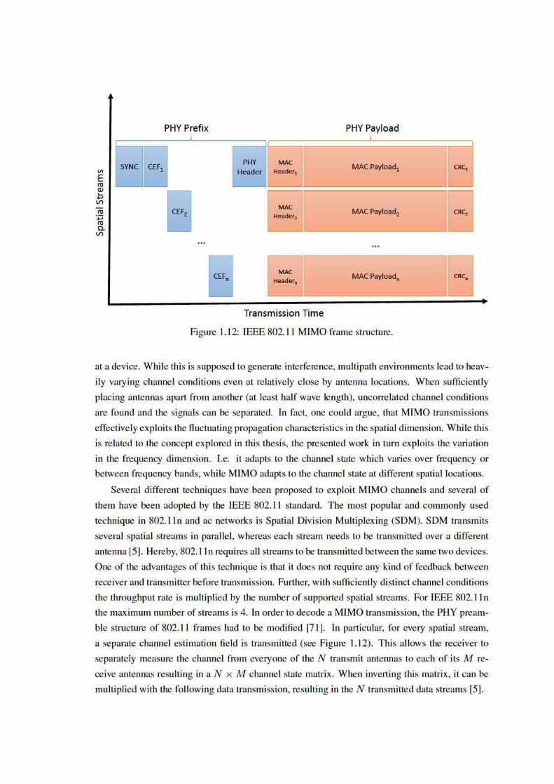
32 Background on IEEE 802.11 Communication
In addition to SDM, further MIMO techniques have been adopted by the IEEE 802.11 stan-
dards. A technique to increase resilience of transmissions, space time block coding (STBC), was
introduced by 802.11n. STBC also combines multiple spatial streams without prior feedback,
however it does not increase throughput but adds resilience. IEEE 802.11ac introduces MU-
MIMO [3] which allows to transmit several spatial streams with multiple devices. This however
requires the receiving devices to feedback their channel state before data transmission which cre-
ates significant overhead. With the knowledge of the channel state for every receiver, the trans-
mitter can weight (in terms of amplitude and phase) the signal transmitted from every antenna to
reduce interference between the spacial streams. Further, transmit beamforming was introduced
by 802.11ac. 3 Transmit beamforming also requires explicit feedback and allows the transmitter
to weight every antenna’s signal to increase the received signal strength at multiple receivers. In
contrast to MU-MIMO, transmit beamforming does not cancel out interference between multi-
ple spatial streams, which makes it more robust to channel state estimation errors [40]. Overall,
802.11ac severely increases the throughput, by increasing the number of spatial streams for SDM
to 9 and also implementing up to 4 spatial streams for MU-MIMO which benefits low complexity
receivers with low number of antennas.
3In fact it was already an optional part of 802.11n which however was not adopted by implementors [3, 71].
Chapter 2
OFDM Sub-Carrier Switch Off
Since the IEEE 802.11a/g amendments to the IEEE 802.11 standard, OFDM has become the
most used PHY-layer modulation for high speed data transmission (see Section 1.2.1). As de-
scribed in Section 1.4.2.3, OFDM divides the available frequency spectrum of a channel into sev-
eral sub-carriers. These sub-carriers allow for the parallel transmission of multiple data streams
with longer symbol duration compared to single channel schemes. In combination with a guard
interval between symbols, this reduces Inter-Symbol Interference (ISI) and thus lowers sensitiv-
ity to complex multipath environments. Additionally, while single carrier modulation uses more
bandwidth compared to an OFDM sub-carrier, the same throughput is achieved due to multiple
simultaneous data streams.
In typical IEEE 802.11 indoor scenarios, the signal transmission undergoes frequency selec-
tive fading as explained in Section 1.1.3.4. As every sub-carrier is located on a slightly different
portion of the frequency spectrum, varying propagation behavior results in different fading char-
acteristics. Adapting to these frequency variations is typically done in two steps by IEEE 802.11
systems. The first step requires phase and amplitude of each sub-carrier to be measured from the
channel estimation field in the frame preamble (see Section 1.4.1). This information is used to
equalized all sub-carriers to a common mean amplitude and phase offset. While this is sufficient
to map the transmitted signal into the quantization range of known symbols, equalization can
significantly increase noise induced distortion of strongly faded sub-carriers. Demodulation of
weak sub-carriers results in bit errors when their modulation is not robust enough to account for
equalization exacerbated noise effects. Thus, as a second step sub-carrier modulation has to be
adapted to the respective signal quality.
Adapting the Modulation Coding Scheme (MCS) on a per sub-carrier basis is one option to
counter this effect. This method ensures high throughput while maintaining acceptable bit error
rates but at the same time comes at an increase in transceiver complexity. In addition to the signal
processing and computational overhead of such so-called loading algorithms [24], they also incur
a considerable signaling overhead for the feedback of channel states and preferred MCS per sub-
carrier. As a consequence, no current wireless system adapts the MCS at such a fine granularity.
33

34 OFDM Sub-Carrier Switch Off
WLAN as standardized by IEEE 802.11, including the most recent 802.11ac amendment, use the
same MCS for each sub-carrier. Even sophisticated OFDMA based systems such as LTE only
allow to adapt the MCS per user, but use the same MCS on all the sub-carriers of a given user.
This however unnecessarily reduces the throughput of strongly received sub-carriers, as they are
encoded with a low throughput but robust modulation coding scheme.
A simple but powerful alternative to adaptive MCS is to simply deactivate sub-carriers with
severe fading. Such Sub-Carrier Switch Off (SSO) very effectively combats frequency selective
fading and at the same time has much lower computational complexity and feedback overhead.
Using SSO to deal with frequency selective fading has been first proposed in [73], [72] and [24].
These works investigate the merits of SSO in conjunction with power loading approaches by
means of simulation.
In this chapter, we present our implementation and experimental results of SSO. SSO lowers
the average bit error probability and thus increases the packet reception probability, by adapting
to frequency varying propagation characteristics in a more elaborate way than any commercial
wireless communication system before. However, at the same time the data that formerly was to
be transmitted on the disabled sub-carriers will be appended to the remaining sub-carriers, result-
ing in longer packets. An efficient SSO mechanism needs to carefully balance these two effects.
We design an SSO scheme that enables or disables sub-carriers with respect to the sub-carrier
channel estimation. Our implementation is based on Wireless open Access Research Platform
(WARP) [68], a Field Programmable Gate Array (FPGA) based software defined radio system.
To the best of our knowledge, our implementation is the first to analyze the effect of SSO in an
actual IEEE 802.11 style Wi-Fi system.
From our measurements we observe that SSO provides throughput gains of up to 250%. Also,
we found that SSO can decrease the necessary signal strength for successful data transmission.
Under certain fading conditions we noticed a difference in the necessary signal strength of up to 5
dB. Thus, we consider SSO a highly promising mechanism to improve future wireless local area
networks while maintaining low complexity.
The rest of this chapter is structured as follows. A detailed description of SSO for OFDM
modulated wireless systems is given in Section 2.1. In Section 2.2 we outline the experimental
setup used to evaluate SSO. Then, experimental results are presented in Section 2.3. Finally, we
give an overview over related work in Section 2.4.
2.1 Mechanism
SSO provides throughput gains through adequate reaction to frequency selective fading which
is caused by varying propagation behavior through multipath propagation over the frequency
range of the channel. It operates on the basis of sub-carriers, which are a consecutive series
of frequency blocks that a wireless channel is split into when OFDM modulation is used by a
wireless system (see Section 1.4.2.3). SSO shares some characteristics with adaptive modulation

2.1 Mechanism 35
and coding, however instead of choosing a different MCS for every sub-carrier, SSO just has
two options: it either transmits data on a sub-carrier using the MCS chosen for the packet or it
makes no use of the sub-carrier. In the latter case, data that would have been transmitted on the
deactivated sub-carriers is appended to the other active sub-carriers. This lowers the throughput
of the transmission as it takes more time to transmit all the payload data on the remaining active
sub-carriers. At the same time, it is possible to use higher order MCSs on the active sub-carriers,
while maintaining a low Packet Error Rate (PER) respectively Bit Error Rate (BER). In contrast
to adaptive modulation and coding, the feedback overhead consists of only one bit per sub-carrier
to signal whether it is active.1
The main principle of SSO is to insert a complex zero whenever a data symbol falls onto a
deactivated sub-carrier. With χ as the set of deactivated sub-carriers, the base-band representation
of SSO-enabled OFDM transmission can be expressed as:
xssot (n) = IDFT{Xsso(m+ tN)}
m = 0, 1, ..., N − 1
n = 0, 1, ..., N − 1
t = 0, 1, ...,
⌈D
N − |χ|
⌉− 1
(2.1)
Hereby, the notation from Section 1.4.2.3 is used, with N being the number of available sub-
carriers and X a sequence of D data symbols. Accordingly, xssot (n) is the time domain represen-
tation of the t-th symbol, having N − 1 consecutive samples in time (denoted by n), which also
corresponds to the number of sub-carriers in the frequency domain (denoted by m). The number
of symbols t that are needed to transmit the complete data stream increases with the number of
deactivated sub-carriers. The data symbol stream modified for SSO can be expressed as follows.
Xsso(l) =
X(γ(l)), if l mod N 6∈ χ
0, otherwise(2.2)
Here, γ(l) maps from a sub-carrier index in the SSO encoded OFDM transmission to the corre-
sponding data symbol index that is to be placed in this sub-carrier.
γ(l) = l − ((bl/Nc)|χ|+ |{x ∈ χ |x < l mod N}|) (2.3)
1For example, 802.11ac supports at most 512 sub-carriers corresponding for the maximum bandwidth of 160MHz(see Section 1.2.1), resulting in a signaling overhead of only 64 bytes. Certain of these sub-carriers are not used for datatransmission and therefore do not need to be included in the signaling. In addition, this overhead can be reduced furtherdue to the fact that neighboring sub-carriers tend to have similar channel quality, allowing for efficient aggregation ofstate information for neighboring sub-carriers.

36 OFDM Sub-Carrier Switch Off
2.1.1 Adaptive Sub-Carrier Switch Off
When determining χ, the set of sub-carriers to deactivate for SSO, we aim to improve trans-
mission quality and performance. This can be seen as a optimization problem. Therefore, we
formulate the packet error rate P of a SSO enabled OFDM link as follows:
P (M, c) = 1−N∏k=1
(1− p(M, c, h(k), w(k))) (2.4)
Here, p(M, c, h(k), w(k)) is the error probability for sub-carrier k with channel h(k) and AWGN
noise w(k), given modulation scheme M and coding scheme c. Furthermore, we define the
throughput for a channel with conditions h and w as follows:
Th,w(M, c, χ) = b(M) · rfec(c) · rsso(χ) · (1− P (M, c)) (2.5)
The rate of the convolutional coder is given by rfec, the reduction caused by switching of the
sub-carriers in χ is rsso(χ) = 1− |χ|N , and the throughput rate for modulationM is denoted b(M).
The SSO optimization problem to be solved is thus to select the set of sub-carriers to switch
off together with a modulation and coding scheme that maximizes throughput, given channel
conditions h(k) and w(k).
arg maxM,c,χ
(Th,w(M, c, χ)) (2.6)
2.1.2 Threshold-Based Adaptive Sub-Carrier Switch Off
For a practical solution, we simplify the general optimization problem given by Equation 2.6
by splitting the joint optimization of MCS and SSO into two separate optimization problems.
On the one hand, we adapt the number of sub-carriers to be deactivated in order to increase
the throughput given a MCS. On the other hand, we select the modulation and coding scheme
that best utilizes the available channel. For the latter, we use one of the existing rate adaptation
mechanisms, e.g., [44], [82]. When continuously running these mechanisms on a SSO enabled
system, the used MCS will adapt to the deactivated weak sub-carriers by successively increasing
the MCS of the remaining sub-carriers.
To decide on the quality of a sub-carrier, we make use of the channel estimation techniques of
OFDM systems that are used to handle frequency selective fading. This mechanism uses part of
a wireless packet’s preamble to predict the channel state of every sub-carrier (see Section 1.4.1).
For the decoding of the payload, every symbol transmitted on a sub-carrier is equalized based on
this estimate. This is done e.g. by multiplication with the inverse channel estimate H(k) [30].
X(k) =Y (k)
H(k), k = 0, 1, ..., N − 1 (2.7)
The influence of the multipath fading channel that causes frequency varying behavior and leads

2.2 Hardware Platform and Experimental Setup 37
to selective fading can be described as (see also Section 1.1.3.4):
y(n) = x(n)⊗ h(n) + w(n), (2.8)
Here, w(n) is the additive white Gaussian noise (AWGN) and h(n) is the channel impulse re-
sponse. From the equalization process given in Equation 2.7, it can be seen that the AWGN noise
w(n) affecting a sub-carrier is scaled by the inverse of the channel estimate H(n) in the same
way as the transmitted signal. This means a low magnitude of the channel estimate (highly atten-
uated channel) will result in amplification of w(n) during equalization. By this, even in case of
perfect channel estimation and presence of AWGN noise, a low magnitude for H(n) may lead to
a significant distortion in the received sub-carrier signal. For this reason we consider |H(n)| as a
suitable measure for the decision whether to deactivate a sub-carrier or not.
As all the sub-carriers are independent and their error rate only depends on the sub-channel
quality, they will be switched off in the order of their channel qualities. The resulting optimization
problem for adaptive sub-carrier switch off of the ξ weakest sub-carriers is:
arg maxξ
(Th,w(M, c,min(N , ξ))) (2.9)
WithN as set of sub-carriers andmin(N , ξ) describing the ξ weakest sub-carriers fromN . With
a measure for the sub-carrier channel quality we now propose a threshold-based heuristic solution
to Equation 2.9. We define a channel quality threshold τ to decide whether a sub-carrier should
be added to χ. This threshold specifies the sub-carrier quality at which the loss in throughput due
to deactivating the sub-carrier equals the loss introduced due to the carrier’s contribution to the
error rate. The value for τ is equal for every sub-carrier but is MCS dependent. Therefore, for a
channel estimate |H(k)| we define as a solution to Equation 2.9:
ξ = |{k, |H(k)| < τ}| (2.10)
It is obvious that SSO can not provide any gains for flat fading channels. Under this special
condition, it is possible that all sub-carriers will be switched off. However, this can be easily
detected and the SSO functionality could be disabled for this extreme case.
2.2 Hardware Platform and Experimental Setup
For the experimental evaluation of OFDM sub-carrier switch-off we use the Wireless open
Access Research Platform (WARP). WARP provides an open source FPGA driven software de-
fined radio platform, where the MAC and PHY-layers can be modified in software. Our work
builds upon the WARP reference implementation of an IEEE 802.11a-style OFDM PHY-layer
implementation that allows for real-time frame encoding and decoding.

38 OFDM Sub-Carrier Switch Off
Index Utilization0 (DC) Must be empty
7,21,43,57 BPSK pilot tones1-6, 8-20, 21-26, Data Carriers
38-42, 44-56, 58-6327-37 Must be empty
Table 2.1: WARP: Sub-carrier assignment.
2.2.1 PHY-Layer Structure
WARP’s OFDM PHY-layer provides a 10MHz bandwidth OFDM channel that consists of
64 sub-carriers as shown in Figure 2.1.2 When comparing to the IEEE 802.11a PHY-layer as de-
scribed in Section 1.4.2.3, it can be seen that our test implementation supports less bandwidth than
standard compliant devices. This however only limits the impact of frequency selective fading, as
higher channel state fluctuations can be found over wider frequency spacing [73]. Out of the 64
used sub-carriers, 49 can be used for actual data transmission. The rest are assigned to the DC car-
rier, pilot carriers, or are left empty according to the IEEE 802.11a specification (see Table 2.1).
Figure 2.1: Sub-carrier allocation of the WARP OFDM PHY-layer.
The data packets generated by the WARP OFDM implementation have the packet structure given
in Figure 2.2, that is similar to the one of the IEEE 802.11 protocol family as described in Section
1.4.1. It starts with a predefined preamble and training symbol sequence. These parts are needed
to correct the carrier frequency offset, determine the signal strength and estimate the channel co-
efficients. After the training sequence follows a packet header. It is encoded with a robust MCS
in order to transmit basic parameters for the packet, such as for example source and destination
addresses, packet length or CRC. The rest of the packet contains the payload data. It is encoded
with the full rate MCS that is a combination of one of the modulation schemes Binary Phase Shift
Keying (BPSK), Quadrature Phase Shift Keying (QPSK), or 16-Quadrature Amplitude Modula-
tion (QAM) together with rate 1/2, 2/3 or 3/4 punctured convolutional coding. Additionally, the
convolutional coding can be deactivated. While the base rate is fixed and known to both sender
and receiver, the full rate is signaled in the packet header and can vary. Therefore, the sender can
decide on a full rate MCS while the receiver adapts to it during header decoding. In our experi-
2Note that we use the sub-carrier numbering from 1 to 64 as given in Figure 2.1 for all sub-carrier related figures,i.e., the empty sub-carriers at the left and right border of the frequency spectrum appear in the middle of these figure.

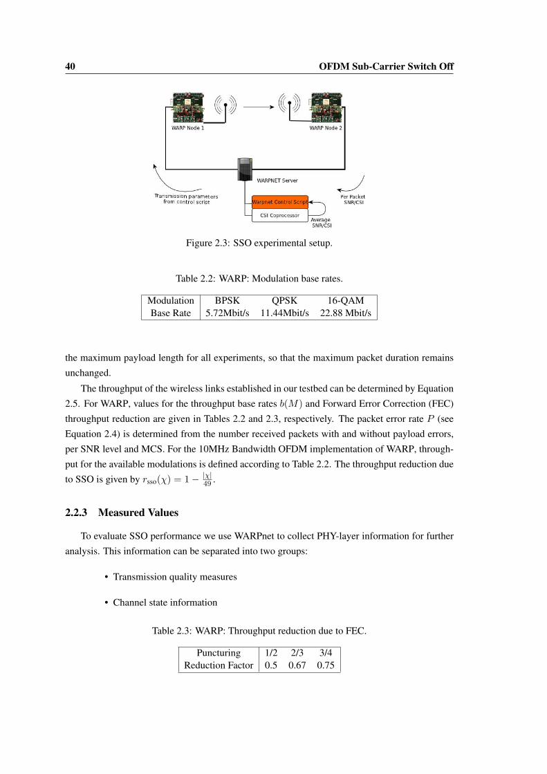
40 OFDM Sub-Carrier Switch Off
Figure 2.3: SSO experimental setup.
Table 2.2: WARP: Modulation base rates.
Modulation BPSK QPSK 16-QAMBase Rate 5.72Mbit/s 11.44Mbit/s 22.88 Mbit/s
the maximum payload length for all experiments, so that the maximum packet duration remains
unchanged.
The throughput of the wireless links established in our testbed can be determined by Equation
2.5. For WARP, values for the throughput base rates b(M) and Forward Error Correction (FEC)
throughput reduction are given in Tables 2.2 and 2.3, respectively. The packet error rate P (see
Equation 2.4) is determined from the number received packets with and without payload errors,
per SNR level and MCS. For the 10MHz Bandwidth OFDM implementation of WARP, through-
put for the available modulations is defined according to Table 2.2. The throughput reduction due
to SSO is given by rsso(χ) = 1− |χ|49 .
2.2.3 Measured Values
To evaluate SSO performance we use WARPnet to collect PHY-layer information for further
analysis. This information can be separated into two groups:
• Transmission quality measures
• Channel state information
Table 2.3: WARP: Throughput reduction due to FEC.
Puncturing 1/2 2/3 3/4Reduction Factor 0.5 0.67 0.75

2.2 Hardware Platform and Experimental Setup 41
Transmission quality measures are used to determine throughput, and in particular the
throughput gain achieved by SSO. Packets that are lost due to a corrupted header will be lost
with or without SSO. Therefore, we ignore them in the performance comparison. We thus in-
vestigate the PER as the ratio between the successfully received packets and packets with an
erroneous payload, given a certain payload MCS. Additionally, we measure every packet’s signal
strength. The WARP platform measures this value during packet preamble detection. Equal to
Camp et al. in [7] we consider this factor as a proxy to the SNR value, and in the following refer
to it as the packet’s SNR value.
The channel state information describes the characteristics of the channel and is used to decide
on a suitable link configuration, including SSO. The channel state consists of two values. First, we
consider the average signal strength of recently received packets as an indicator of the channel’s
overall attenuation. The second value that forms the channel state are the channel coefficients
estimated from the preamble and training sequence. They consist of a complex fixed point number
for every sub-carrier describing the magnitude of the channel estimation for this sub-carrier.
2.2.4 General Measurement Setup
Our basic test setup consists of two WARP boards running the OFDM PHY-layer with the
modified WARPnet MAC-layer implementation. The nodes are placed in two neighboring testbed
rooms so that no line of sight path exists. In order to analyze the behavior of SSO in a frequency
faded channel we investigated a range of antenna configurations. Here, we report results that were
obtained for experiments where live monitoring of the channel estimation showed heavily faded
carriers.
This kind of fading can be found in around 30%-40% of antenna settings. We also remark that
WARPnet’s bandwidth is limited to 10MHz, which is considerably less compared to current Wi-
Fi standards. IEEE 802.11ac for example uses channels with a bandwidth of up to 160MHz (see
Section 1.4.2.3). For comparable indoor scenarios, channels with this bandwidth have a higher
probability of deep faded sub-carriers.
The measurements were performed during night time to avoid that moving persons lead to
varying channel conditions. Through continued logging of the channel estimation we verified
that the channel conditions were relatively stable. An experiment configuration is given by the
transmit gain, modulation and coding scheme, set of deactivated sub-carriers χ, and packet length.
For each such configuration we run an experiment for a duration of 20 seconds, and average the
results over all of the packets transmitted during that time interval. This is necessary, as the
estimated channel coefficients and detected SNR might vary slightly due to noise that affects the
preamble detection process.
42 OFDM Sub-Carrier Switch Off
2.2.5 Feedback Mechanism
As we consider a pseudo-static channel (see 2.2.2) we use an implicit feedback mechanism.
The WARPnet control script decides which sub-carriers to switch off and sets the transmission
parameters accordingly for the next time slot. An explicit feedback mechanism for a 802.11
like system could for example included the feedback in the acknowledgment packet that follows
every received data packet. This way, no additional signaling packets need to be transmitted,
reducing the feedback overhead solely to the bits added to the acknowledgment. For systems
with 64 sub-carriers comparable to the WARP setup, this amounts to an additional overhead of
only 8B/1460B = 0.5%, assuming maximum length data packets.
2.3 Results
In this section we present the results for the SSO measurements that we conducted on our
WARP testbed. The results are separated threefold. First we present throughput measurements
that give insights into the gains achievable with SSO. Next we report on a series of measurements
to determine the threshold described in section 2.1.2. Finally these findings are validated with
additional adaptive throughput measurements.
2.3.1 Throughput Gain for SSO
To determine the gains that SSO can achieve in different settings, we measure the transmis-
sion quality for the same frequency faded channel with different transmission configurations. To
this end, we compare the throughput for the best performing MCS with and without SSO. In
addition, this analysis provides us with insights about the influence of channel conditions on the
performance of SSO.
As measuring the transmission quality for all possible configurations is cumbersome, we re-
strict ourselves to measuring a representative subset of channel configurations. For a first insight
into the effect of SSO, we use different values for ξ and conduct experiments for all four possible
coding rates in conjunction with WARP’s three available modulation schemes. Furthermore, to
determine the behavior over a range of signal reception strengths, we perform measurements for
different transmit power settings.
In the following, we present the results of the throughput measurement for a frequency selec-
tive channel where SSO shows a significant throughput gain. In this experiment, we deactivate
the 6, respectively 12, weakest sub-carriers. As a reference, the performance of the transmit
configuration with all sub-carriers active is measured.
Figure 2.4 shows the corresponding channel coefficients over time according to the sub-carrier
order described in Section 2.2. As can be seen from the figure, the basic fading pattern remains
stable throughout the complete experiment run. Note that the spectrum shows considerable fading
for the sub-carriers around sub-carrier number 15. The gap comprises more than 6 heavily faded

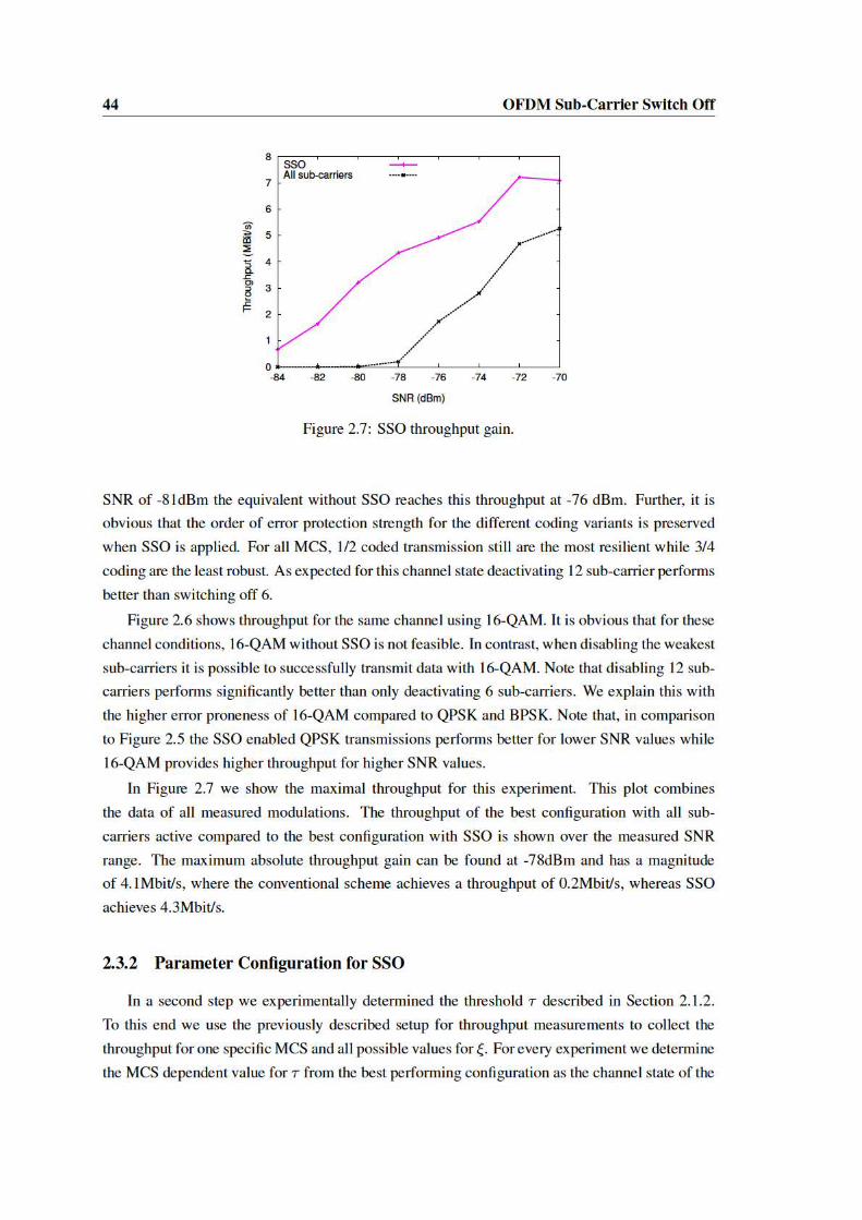


48 OFDM Sub-Carrier Switch Off
achieved by bit loading.
Our results from a real testbed confirm and extend the findings on SSO that were investi-
gated by Punal et. al. by means of simulation. We show that in case of deeply faded sub carriers,
SSO can archive significant performance gains even for a far smaller bandwidth of only 10 MHz
and without the complexity of power loading or bit loading techniques. As the simulation re-
sults presented in the works [73], [72] and [24] do not include pure SSO results but results for a
combination of SSO and powerloading, and the simulated packets are modulated using a higher
modulation scheme (256-QAM), the simulation results are unfortunately not directly comparable
to our measurements.
The idea to switch off certain sub-carriers of a OFDM transmission can also be beneficial to
cognitive radio (CR) systems [51]. Here however, the idea is to disable sub-carriers that coin-
cide with used parts of the spectrum, thus decreasing interference between CR transmitters and
incumbent transmitters.
2.5 Conclusion
In this chapter we analyzed the performance of Sub-Carrier Switch Off in IEEE 802.11 style
OFDM wireless local area networks. We designed a light-weight mechanism to select the set
of sub-carriers to switch off, based on the channel coefficients. This technique allows to adapt
wireless transmission to the variations in signal propagation over the used frequency resources,
in which SSO operates at the intra-channel level. The variations found over the frequency range
of a single channel result from multipath propagation as detailed in section 1.1.3.4. In contrast to
existing techniques, SSO is the most elaborate, yet low overhead involving, way of adapting to
these variations.
SSO was implemented on the WARP software-defined radio platform to conduct a range of
performance measurements. With the help of extensive channel state analysis for all possible
SSO configurations, we developed a simple but effective method to decide which sub-carriers to
switch off. This method maximizes throughput, while having very low computational complexity
and feedback overhead.
In case of frequency selective fading, SSO turns out to be a very efficient measure to increase
throughput and link stability. Under certain fading conditions we were able to transmit packets
with a SNR range increase of up to 5 dBm, with corresponding significant increases in throughput
from 0.2 Mbit/s without SSO to 4.3 Mbit/s with SSO. In summary, our analysis indicates that SSO
is a very promising method to improve performance and resilience of future IEEE 802.11-style
networks.
Our findings also open interesting questions for future work. At the intra-channel level, the
combination of rate selection and SSO leaves room for additional improvements and measure-
ments. Further, SSO can be applied to the packet headers with the goal of further improving the
packet detection rate. These ideas promise modest improvement gains, when leveraging from
2.5 Conclusion 49
frequency varying propagation characteristics.
However, with the upcoming multi-band millimeter wave technology for consumer wireless
networks, the propagation variations over the range of used frequency resources become signif-
icantly higher. Thus, future millimeter wave Wi-Fi systems, promise increased opportunities to
exploit such variations. Therefore, the second part of this thesis shifts the focus from the intra-
channel level perspective to multi-band systems, where channel resources with frequency diffe-
rences of multiple tens of GHz can be accessed. At this level, entirely new approaches to exploit
varying frequency resources become possible. Expansion of the SSO principle itself to millimeter
wave communication however is not promising. This is due to the directional antenna technol-
ogy which is commonly used at millimeter wave frequencies (see Section 3.1.3) and significantly
reduces multipath [16, 103]. Thus, also the intra-channel signal quality variations, which SSO
addresses are not as expressed as on legacy Wi-Fi frequencies.

50 OFDM Sub-Carrier Switch Off

Part II
Leveraging from VaryingMulti-Frequency Band Propagation
51


53
The second part of this thesis expands the idea of adapting wireless communication to fre-
quency varying propagation characteristics on the level of different frequency bands. An espe-
cially promising candidate technology to profit from this approach is multi-frequency band mil-
limeter wave Wi-Fi. This technology emanates from the recent development of millimeter wave
Wi-Fi that is complemented by legacy microwave Wi-Fi at 2.4 and 5 GHz. Multi-band millimeter
wave Wi-Fi is supposed to gain momentum with the ratification of the IEEE 802.11ad amendment,
which has been ratified in late 2013. Millimeter wave communication is expected to not fulfill
traditional customer expectations towards Wi-Fi systems on stability and range. Thus, the IEEE
802.11ad amendment defines multi-frequency band features for range extension and increase in
reliability. The trend towards accessing multiple frequency bands from one Wi-Fi device is thus
continuing, with chip set manufacturers already announcing tri-band (2.4/5/60 GHz) chipsets for
multi-gigabit streaming [6].
With the anticipated availability of these chipsets, new possibilities to leverage frequency
varying propagation arise. The main differences between the two frequency bands is the signifi-
cantly increased attenuation at millimeter wave frequencies (see Section 1.1.1), that requires the
use of directional transmissions. Thus, millimeter wave systems are expected to experience much
less interference, enabling parallel transmission over pencil-beam antenna patterns, which is a sig-
nificant advantage for dense networks. On the other hand, the reception area of millimeter wave
transmissions is much smaller than in the micro wave range and omni-directional communication
is extremely difficult to realize (see Section 3.2.2.2 and [28]). Further, achievable transmission
ranges as well as impact of Line of Sight (LOS) blockage varies widely between the two bands.
This renders the microwave band suitable for longer link distances and resilient to blockage while
millimeter wave communication best suits in-room LOS applications. The behavior of the used
frequency resources thus varies more strongly than the intra-channel variations explored in Part I
of this thesis. As the behavior of millimeter wave and microwave frequencies is complementary,
upcoming multi-band millimeter wave devices are promising candidates to exploit the diverse
behavior.
The second part of this thesis is subdivided into three chapters. First, Chapter 3 gives in-depth
background information on multi-frequency band millimeter wave Wi-Fi to identify perspectives
and challenges of this new technology. This discussion particularly focuses on the changes in-
troduced to adapt IEEE 802.11 communication to the novel communication characteristics at
60 GHz frequencies. Among the most relevant additions is an elaborate beamforming protocol
that facilitates directional communication and a multi-MAC-layer that allows to choose between
three different medium access schemes. Further, modifications to network architectures, associ-
ation and network announcement are described. The discussion on the concepts incorporated in
the IEEE 802.11ad amendment is complemented by a practical analysis of millimeter wave com-
munication systems. As at the time of writing no IEEE 802.11ad compliant devices are available,
this analysis targets first generation millimeter wave systems (WiGig,WiHD) with commercially
available hardware. IEEE 802.11ad has its origin in these standards (the WiGig Alliance merged
54
into the IEEE 802.11ad consortium [59]), which suggest that the studied devices will show perfor-
mance comparable to first upcoming IEEE 802.11ad devices. The results of this study thus reveal
challenges to next generation millimeter wave Wi-Fi communication, which this thesis addresses
by leveraging frequency varying propagation behavior of the announced multi-band systems. In
particular, the beamforming capabilities and interference impact are analyzed. The measurement
results show, that the vision of interference free pencil-shaped antenna beams does not hold for
first generation devices. Strong side lobes and interference created by reflections still contradict
with the expected behavior. Thus, first generation devices still can rely on some of legacy Wi-Fi’s
omni-directional communication principles, as directionality is still limited. With next generation
devices, this is about to change with particular challenges arising for the beam training process
between devices and the operation of CSMA/CA medium access, which is well established for
Wi-Fi networks.
Second BBS , a novel multi-frequency band approach, is presented in Chapter 4. It utilizes
indoor localization at 2.4 GHz to improve the beam steering process in highly directional 60 GHz
Wi-Fi networks. This improvement benefits future millimeter wave networks in several ways.
First, the beam training overhead is reduced as less in-band probing is required. The overhead
is problematic at highly directional millimeter wave devices as the amount of directions to probe
increases. Further, especially for the mobile use-case of the IEEE 802.11ad amendment, fre-
quent retraining of beam directions becomes necessary. Second, beam training resembles omni-
directional transmissions, as all possible directions are probed in a brute force approach. There-
fore, each beam training creates interference in all directions, which potentially breaks parallel
transmissions. The proposed approach significantly reduces this problem.
Finally, directionality is known to pose a problem for the well established CSMA/CA car-
rier sensing mechanisms of IEEE 802.11 networks. Chapter 5 therefore analyzes the impact of
this impairment on a simulation basis and finds that unfairness effects can be caused by that
phenomenon. Therefor, a dual-band communication scheme is proposed that benefits from the
combination of millimeter and microwave bands. It resolves the deficiencies of CSMA/CA in
millimeter wave Wi-Fi, by moving RTS/CTS message exchanges from the 60 GHz interface to
the legacy bands. Using the dual-band approach does not only achieve throughput improvements,
but also prevents RTS frames that are mistakenly sent to busy stations. This reduces interference
from transmission outside of established data streams and helps to enable parallel non interfering
transmissions on the 60 GHz band.

Chapter 3
Background on Multi-band WiFi
Communication in the millimeter wave frequency range has not been used for consumer-grade
wireless communication until very recently. In fact, very few devices compliant with the WiHD
and WiGig haven been made available so far, and they have not reached wide consumer attention.
This is supposed to change with the IEEE 802.11ad amendment, which merges the standardization
efforts from the WiGig consortium into the popular IEEE 802.11 protocol stack that is widely
accepted. While this promises a wide leap for consumer millimeter communication, a second
trend is implied. Next generation millimeter wave networks are likely to be multi-frequency band
capable. This is supported by the fact that first tri-band chips supporting the 802.11ad amendment
have been announced [6]. Further, the 802.11ad amendment incorporates mechanisms that make
use of these multi-band capabilities for range extension.
Due to the novelty of millimeter wave capable multi-band wireless transceiver technology,
this background chapter is sub-divided into two main sections. The first gives a detailed analysis
and background information on the IEEE 802.11ad amendment. It details the modifications made
by the IEEE 802.11ad protocol to adapt Wi-Fi communication to frequencies in the millimeter
wave range. These changes mainly result from the need for directional communication and target
several key aspects of IEEE 802.11 networking. First, an elaborate beam training protocol is in-
troduced that communicating stations use to focus signal energy between them. This also brings
several changes to the network announcement and association process, which are impacted by
the lack of long range omni-directional communication. Second, an enhancement of the MAC
access schemes (see Section 1.3.1) allows IEEE 802.11ad devices to choose between three dif-
ferent schemes (CSMA/CA, Polling and Time Division Multiple Access (TDMA)). This enables
adaptation with regard to the diverse 802.11ad use cases.
As little is publicly known about practical challenges and behavior of upcoming IEEE
802.11ad devices, the second part of this chapter contains a practical study of first generation
millimeter wave devices. This performance analysis focuses especially on the aspects related to
the application of antenna array techniques which is a key enabler for millimeter wave commu-
nication as it is required to overcome increased attenuation (see Section 1.1.1). Thus, achievable
55

56 Background on Multi-band WiFi
directionality of first generation devices is analyzed, as well as antenna array performance when
wide coverage is necessary, for example during device discovery. Last, as high directionality and
attenuation at millimeter wave frequencies promise extremely low interference, the potential for
spacial frequency reuse and interference effects is analyzed.
Finally, this chapter combines the results from first generation device analysis with the pre-
sented information on the upcoming IEEE 802.11ad amendment. This allows to identify chal-
lenges for millimeter wave communication that arise from practical limitations and problems that
next generation networks will face.
3.1 IEEE 802.11ad
With the worldwide availability of a large swath of spectrum at the 60 GHz band for unli-
censed use, we start to see an emergence of new technologies enabling Wi-Fi communication in
this frequency band. However, signal propagation at the 60 GHz band significantly differs from
that at the 2.4 and 5 GHz bands. Therefore, efficient use of this vast spectrum resource requires
a fundamental rethinking of the operation of Wi-Fi and a transition from omni-directional to di-
rectional wireless medium usage. The IEEE 802.11ad amendment addresses these challenges,
bringing multi-Gbps throughput and new application scenarios to Wi-Fi users. These new us-
ages include instant wireless synchronization, high speed media file exchange between mobile
devices without fixed network infrastructure, and wireless cable replacement, e.g., to connect to
high definition wireless displays. The most significant difference in 60 GHz propagation beha-
vior is increased signal attenuation. At a typical IEEE 802.11ad range of 10 meters, additional
attenuation of 22 dB compared to the 5 GHz band is experienced according to the Friis transmis-
sion equation, resulting from the frequency dependent difference in antenna aperture (cp Section
1.1.1). In contrast, oxygen absorption plays a minor role over short distances, even though it
peaks at 60 GHz [81]. Further, compared to legacy Wi-Fi frequencies, reflection, absorption
and transmission characteristics of materials vary between frequency bands (see Section 1.1.3.1).
60 GHz communication has been found to be characterized by a quasi-optical propagation beha-
vior [100] where the received signal is dominated by the LOS path and first order reflections from
strong reflecting materials. As an example, metallic surfaces were found to be strong reflectors
and allow non-Line of Sight (LOS) communication [100]. Concrete materials, on the other hand,
cause large signal attenuation and can easily create a blockage. Thus, 60 GHz communication
is more suitable to in-room environments where sufficient reflectors are present. This section
discusses the design assumptions resulting from the mm-wave propagation characteristics and re-
sulting changes to the 802.11 architecture. We further present typical device configurations, an
overview of the IEEE 802.11ad physical PHY-layer, and the newly introduced personal basic ser-
vice set network architecture. This is followed by an in depth description of the IEEE 802.11ad
Beam Forming (BF) mechanism and hybrid medium access control (MAC) design, which are the
central elements to facilitate directional communication.


58 Background on Multi-band WiFi
3.1.2 IEEE 802.11ad Device Classes and Use Cases
Communication in the mm-wave band enables extremely high throughput at short-ranges
(≤ 10m), and promises high potential for spatial reuse. Thus, not only does it suit typical Wi-Fi
usage, but it also expands the uses of Wi-Fi into other application areas. Among these areas are
wireless transmission of high definition video, wireless docking stations, connection to wireless
peripherals or high speed download of large media files. To meet the requirements for these novel
use cases, the IEEE 802.11ad amendment allows for a broad variety of Directional Multi-Gigabit
(DMG) devices ranging from energy constrained handheld equipment with low complexity an-
tennas (1-4 antenna elements) to stationary access points with multiple antenna arrays and per-
manent power supply. Table 3.1 shows typical configurations for several device classes. It states
the number of sectors that correlates with range and throughput, differences between receive and
transmit direction and special traffic characteristics for every class. Further, the expected number
of antenna arrays is given for every device class. Multiple phased antenna arrays enable high
gain coverage in all directions. They are not used in a MIMO fashion, but treated like a set of
additional sectors with only one antenna array used at a time.
3.1.3 Design Assumptions
Communication in the mm-wave frequency band has different characteristics compared to
legacy 2.4/5 GHz Wi-Fi frequencies. Thus, the development of the IEEE 802.11ad amendment
followed a number of design assumptions that result from the change of frequency band.
Highly directional transmissions. Increased transmission loss and the application of high gain
beamforming techniques lead to a strong directional signal focus. In contrast to omni-directional
legacy Wi-Fi signal propagation, IEEE 802.11ad communicates over narrow beams that follow
quasi-optical propagation characteristics.
Quasi-omni-directional antenna patterns. Implementation of truly omni-directional mm-wave
antenna patterns is not practical, as signal blockage and deviation by device components in the
vicinity of the antenna have a much stronger effect than on legacy Wi-Fi frequencies. Therefore,
IEEE 802.11ad introduces quasi-omni-directional patterns that allow gain fluctuations over the
pattern. Further measures are taken to cope with the resulting effects.
Inefficient omni-directional communication. The increased attenuation in the mm-wave
band leads to severely reduced transmission range and throughput when quasi-omni-directional
antenna patterns are used. However, when the direction to a communication partner is unknown
(e.g. during beamforming training) quasi-omni patterns are still needed. Thus, directional
antenna gain is added at least at one side of a link to achieve a sufficient communication range.
Typically, quasi-omni-directional antenna configurations are used at the receiver side. Only de-

3.1 IEEE 802.11ad 59
Device AntennaSectors
ExpectedRange(m)
Max. Throughput(Gbps) Traffic Type Antenna
Arrays
AP, DockingStation
32 to 64 20 7Bursty Trafficon Downlink
≤ 3
WirelessPeripheral(Hard drive,MemoryStick)
≤ 4 0.5 to 2 4.6 Bursty 1
Wireless Dis-play, TV 32 to 64 5 to 10 7
Continuous, RXmore important ≤ 2
Notebook 16 to 32 5 to 10 4.6 - 7Various, sym-metric TX andRX
1
Tablets 2 to 16 2 to 5 4.6Various, sym-metric TX andRX
1
Smartphone,Handheld,Camcorder,Camera
≤ 4 0.5 to 2 1.2 - 4.6
Various, sym-metric TX andRX, TX moreimportant forvideo streamingdevices
1
Table 3.1: IEEE 802.11ad: Typical device configurations.
60 Background on Multi-band WiFi
vices with extreme space or energy restrictions are expected to implement quasi-omni-directional
transmit modes. These devices will be severely limited in range and throughput (see Table 1).
Extreme efficiency loss on poorly trained beams. The throughput difference between the
highest and lowest transmission scheme defined by IEEE 802.11ad lies in the range of 6.5
Gbps. A poorly trained beam that uses a low throughput scheme severely reduces the system
performance and should be avoided at all costs.
Reduced interference. Directional transmission properties of IEEE 802.11ad devices have the
potential to reduce interference outside of the beam direction. Applying transmit and receive
beamforming allows in many cases to reuse the same frequency band and significantly increase
the system’s overall throughput.
Deafness and directional communication drawbacks. Highly directional IEEE 802.11ad trans-
missions have hindering effects on common Wi-Fi MAC mechanisms. Directional transmit pat-
terns prevent devices from passively overhearing ongoing transmissions, leading to additional
collisions during channel access. Further, the deafness effect caused by misaligned transmit or
receive antenna patterns may lead to frame loss, unnecessary long contention back-off and lower
throughput. An in depth discussion of these impairments can be found in [10]. IEEE 802.11ad
adapts the 802.11 CSMA/CA mechanism and further introduces a multi-MAC architecture, with
alternative medium access schemes suited to directional communication.
3.1.4 Physical Layer
IEEE 802.11ad introduces three different PHY-layers dedicated to different application sce-
narios. The Control PHY is designed for low SNR operation prior to beamforming. The Single
Carrier (SC) PHY enables power efficient and low complexity transceiver implementation. The
low-power SC PHY option replaces the Low Density Parity Code (LDPC) encoder by a Reed-
Solomon encoder for further processing power reduction. The OFDM PHY provides high per-
formance in frequency selective channels achieving the maximum 802.11ad data rates. Despite
having different PHYs, all of them share the same packet structure with common preamble prop-
erties. Specifically, the same Golay sequences are used for the preamble training fields. Also,
a common rate LDPC structure is used for channel encoding. Moreover, 802.11ad defines a
single bandwidth of 2.16 GHz, which is 50 times wider than the channels available in 802.11n
and roughly 14 times wider than the channels defined in 802.11ac. The IEEE 802.11ad packet
structure is shown in Figure 3.2. The packet consists of typical IEEE 802.11 elements (compare
Section 1.4.1), e.g., a short training field (STF) and a channel estimation field (CEF) that is also
used for auto-detection of the PHY type. They are followed by the PHY header and the PHY
payload that is protected by a CRC. Finally optional automatic gain control (AGC) and training
(TRN) fields, unique to IEEE 802.11ad, might be appended. These are used for the beamforming
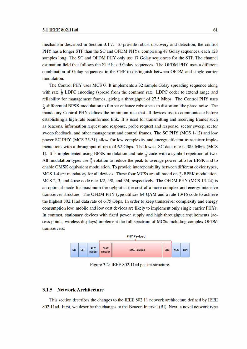
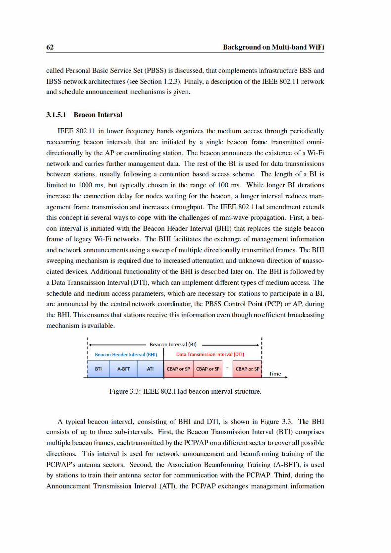

3.1 IEEE 802.11ad 63
with associated and beam-trained stations. While communication during BTI and A-BFT uses
MCS 0 to increase range for untrained beams, communication during the ATI takes place with
beam-trained stations and thus is more efficient. The DTI comprises one or more Contention
Based Access Periods (CBAPs) and scheduled Service Periods (SPs) where stations exchange
data frames. While in CBAP multiple stations can contend for the channel according to the IEEE
802.11e EDCF (see Sections 1.2.1 and 1.3.1), an SP is assigned for communication between a
dedicated pair of nodes as a contention free period.
3.1.5.2 Personal Basic Service Set
IEEE 802.11ad introduces the PBSS, where nodes communicate in an ad-hoc like manner.
However, one of the participating nodes takes the role of the PBSS Control Point. This PCP
acts similar to an AP, announcing the network and organizing medium access. This centralized
approach allows the directional network and schedule announcement process described in the
next section to be used for an ad-hoc like network. The PBSS network has been introduced to
satisfy new applications targeted by IEEE 802.11ad such as, for example, wireless storage and
peripherals or wireless display usage. For these applications, usually no preinstalled infrastructure
exists and communication takes place between a set of personal devices. An ad-hoc like network
with a centralized controller poses two main challenges. First, for energy-constrained devices,
increased power consumption at the PCP penalizes a single device while a fair sharing of the
energy costs is desirable. Second, outage of the PCP paralyzes the entire PBSS. To respond to
these challenges, a PCP Handover procedure is defined [39]. This procedure can be used for
explicit (initiated by the current PCP) or implicit (after PCP becomes unavailable) handovers.
Further, when selecting between a set of possible PCPs, the unique capabilities of PCP candidate
stations are considered to choose the PCP providing the most complete set of services to the
network.
3.1.5.3 Network and Schedule Announcements
Network announcements in legacy IEEE 802.11 are traditionally propagated periodically, us-
ing beacon frames by the AP. Due to the limited antenna gain of quasi-omni-directional mm-wave
transmissions the coverage range is severely restricted. Consequently, the beacon is sent as a se-
ries of directionally transmitted beacon frames. To have the largest possible range, the beacon
frames are transmitted at the most robust MCS (MCS 0). IEEE 802.11ad also specifies additional
signaling for network scheduling and beam training appended to every beacon frame. Collec-
tively, this results in a significantly increased overhead in comparison to legacy Wi-Fi. Thus, it
becomes critical to control the amount of information that is transmitted in each BTI. In addition,
transmissions during the A-BFT, which also use MCS 0, create overhead reoccurring with every
BI where the A-BFT is present. The overhead becomes especially problematic when short BI
durations are applied for delay critical application as, for example, video streaming. The IEEE

64 Background on Multi-band WiFi
802.11ad amendment defines a number of counter strategies. First, it is possible to split a bea-
con sweep over several BIs. This, however, increases the time a node needs to set up its link to
the PCP/AP, as not every direction is served at every BI. The result is an increased association
delay. Second, it is possible to periodically schedule BIs without A-BFT, which also results in
additional association delays. Third, IEEE 802.11ad introduces the ATI. During the ATI, beam-
trained and associated nodes can be served with management data using individually addressed
directional transmitted frames encoded with a more efficient MCS. Thus, it is possible to move in-
formation from the spectrally inefficient beacon frames to the frames transmitted during the ATI,
limiting beacons to the minimal information necessary. Also, for beacon intervals with split bea-
con sweeps, stations that do not receive a beacon miss network and timing information. Without
this information, stations cannot participate in a BI. Implementing an ATI solves this problem, as
scheduling and management information is transmitted individually to associated stations.
3.1.6 IEEE 802.11ad Medium Access Control Layer
In contrast to legacy Wi-Fi, IEEE 802.11ad uses a hybrid MAC approach to address its various
use cases [39], [13]. The standard supports contention based access, scheduled channel time al-
location and dynamic channel time allocation. The latter two schemes correspond to TDMA and
polling mechanisms. The polling based access shares similarities with the IEEE 802.11 point co-
ordination function (PCF) mode (see Section 1.3.2.1), but is adapted to directional transmissions
and provides a higher flexibility when it comes to distribution of resources among the nodes. The
scheduled allocation mechanism extends the traffic stream concept known from the IEEE 802.11
HCF (see Section 1.3.1) to request time shares of the DTI for TDMA like medium access. Next,
the three methods are described.
3.1.6.1 Contention Based Medium Access
Medium access in CBAPs follows IEEE 802.11 enhanced distributed channel access (EDCA),
including traffic categories to support quality of service, frame aggregation and block acknowl-
edgments. However, when using contention based access with directional antennas, the problem
of deafness arises. A deaf node does not receive directionally transmitted information due to
misaligned antenna patterns. A detailed description of the effect can be found in [10]. While the
beam training process in IEEE 802.11ad prevents deafness for intended transmissions, it poses a
problem for carrier sensing during contention based access and can lead to increased collisions.
A further problem for contention based access is that a receiver typically does not know where
a signal comes from. Thus, usage of quasi-omni-directional beam patterns is necessary, which
reduces link budget and throughput.
IEEE 802.11ad EDCA equals the basic DCF access, described in Section 1.3.1.1 in many
aspects. In general, stations start (or resume) a random back off counter a DIFS interval after the
end of the acknowledgment of a data frame. The backoff counter decreases at each slot which

3.1 IEEE 802.11ad 65
equals 5µs. Once a backoff counter reaches zero, the corresponding station wins a Transmit Op-
portunity (TXOP), where it can exclusively transmit one or more frames to another station. This
mechanism is not present in the basic DCF description, but was inherited form the IEEE 802.11e
enhancement [35]. Further, in accordance with legacy DCF, stations overhearing ongoing frames,
track their duration to maintain a Network Allocation Vector (NAV) and defer from decreasing
their backoff counter. If a station senses the channel to be busy (either by virtual or physical
sensing see Section 1.3.1.1) or a frame transmission fails, it doubles its contention window until
the maximum contention window size of 1023 slots is reached. After successfully accessing the
channel, a station resets its maximum contention window to the minimum value of 15 slots.
IEEE 802.11ad adapts the CSMA/CA mechanism to directional medium usage. Idle stations
generally listen with a quasi-omni-directional receive pattern as the direction of the next incom-
ing transmission is unknown. Thus, directional antenna gain is only achieved at the transmitter
side, requiring a robust modulation coding scheme. Therefore, the first frames exchanged are a
directional RTS/CTS pair at the most robust coding modulation scheme. The RTS/CTS exchange
further increases the chance of main interferers within the antenna’s boresight to sense the on-
going transmission and refrain from interfering. Further, support for multiple NAV timers (one
per peer station) is supported. This allows a transmission to be initiated to a peer device where
the NAV for that device is zero, even though the NAV for another peer device might be nonzero.
Additional, details about 802.11 EDCA and its use in 802.11ad can be found in [39], [38].
IEEE 802.11ad enables spatial sharing during CBAPs by modifying the deferral behavior.
Instead of deferring whenever a frame is overheard, a station might still initiate transmission
when the receiver is known to be idle. This leads to multiple transmissions at the same time,
when multiple pairs of stations intend to transmit at the same time.
3.1.6.2 Dynamic Channel Time Allocation
IEEE 802.11ad defines a dynamic channel time allocation mechanism that implements polling
based channel access. Dynamic channel time allocation is an extension of the IEEE 802.11 PCF
mode. It provides higher flexibility in resource allocation (polled stations request channel time in-
stead of just transmitting one frame) and adaptation to directional communication. Polling based
channel access brings several advantages for mm-wave communication. First, due to the cen-
tralized approach with a PCP/AP, stations are aware of the direction of incoming signals. Thus,
the deafness problem that affects contention based access is prevented and quasi-omni directional
receive patterns can be avoided. Second, centralized scheduling at a PCP/AP also helps to effi-
ciently react to bursty downstream traffic, as dynamic scheduling can be adapted over the course
of a BI. In contrast, pseudo-static scheduling described in the following section can only announce
modified allocation parameters with the beginning of every BI. When applying the dynamic allo-
cation mechanism, the medium access during DTI is organized as follows. The PCP/AP acquires
the medium and sends a series of polling frames to associated stations. This is answered with
a block of Service Period Requests (SPRs) used by the polled stations to request channel time.
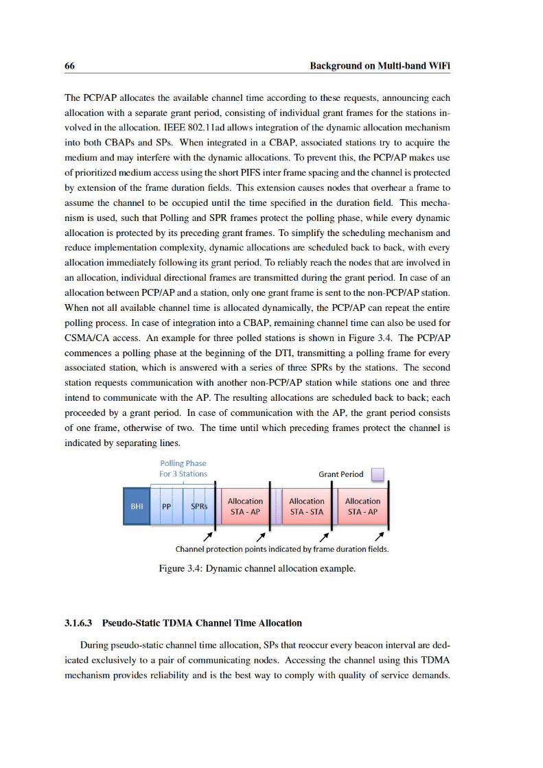

3.1 IEEE 802.11ad 67
Further, the schedule of SPs is propagated by the PCP/AP to all associated stations. Thus, every
node that is not communicating during a SP can go into sleep mode, which allows for efficient
power saving. For pseudo-static medium allocation, the concept of traffic streams for IEEE 802.11
HCF, as described in [38], is extended. A traffic stream is defined as a flow of MAC service
data units that is to be delivered subject to certain quality-of-service parameters, characterized
by a traffic specification. The IEEE 802.11ad amendment defines stations to use traffic specifi-
cations to request scheduling of pseudo-static channel allocations at the PCP/AP. A requesting
station defines the properties of its traffic demand in terms of allocation duration and isochronous
or asynchronous traffic characteristic. Calculating the allocation duration requires a completely
beam-trained link with known rate between source and destination. Otherwise, the traffic spec-
ification has to be modified after beam training when the link’s throughput rate is known. An
isochronous traffic stream results in pseudo static SP allocations that satisfy a constant rate of re-
occurring payload (typical, e.g., for wireless display applications) with certain latency demands.
Asynchronous traffic streams, in contrast, satisfy non reoccurring payload demand. A typical
example application are rapid file downloads. The actual schedule that includes the requested
allocations is broadcasted by the PCP/AP in an extended schedule element in the next BTI or
ATI.
3.1.7 Beamforming Concept
Beamforming training determines the appropriate receive and transmit antenna sectors for
a pair of stations. This is achieved by transmission of a bidirectional training frame sequence.
Throughout the training process, transmission with quasi-omni directional beam patterns at re-
ceiver and transmitter are avoided as they are severely limited in range. The beamforming phase
is split into two sub-phases. First, during the Sector Level Sweep (SLS) an initial coarse-grain
antenna sector configuration is determined. This information is used in a subsequent optional
Beam Refinement Protocol (BRP), which fine-tunes the selected sectors. During SLS, each of the
two stations either trains its transmit antenna sector or the receive antenna sector. When devices
are equipped with antenna arrays capable of reasonable transmit antenna gain, the most common
choice is to train only transmit sectors during SLS and derive receive antenna configuration dur-
ing a following BRP. Fully refined transmit and receive sectors at both sides of a link allow to
reach multi-Gbps speeds over ranges of up to 10 m. This section explains the general approach
to beamforming introduced in the IEEE 802.11ad amendment. The beamforming concept allows
a significant amount of implementation dependent customization and has a variety of optional
features. Therefore, we first focus on the mandatory SLS phase followed by a description of the
mandatory parts of the BRP.


3.1 IEEE 802.11ad 69
ensures reception under still unknown optimum antenna configuration. The feedback for the
responder is transmitted with a single SSW feedback frame, on the determined optimum antenna
configuration. Finally, the SSW feedback frame is acknowledged with an SSW-ACK by the
responder. The last frame is further used to negotiate the details of a following BRP. In case two
stations have sufficient transmit antenna gain, their SLS phase can be realized as pure transmit
sector training, with the receive sector training postponed to a following BRP. Devices with few
antenna elements have to add antenna gain at the receiver side in order to achieve sufficient link
budget to establish a link. Thus, these devices are likely to include a receive sector sweep in their
part of the SLS. The initiator can request the responder to do a receive sector sweep by specifying
the number of receive sectors to train during the initiator sweep. When the initiator sweep is a
receive sector training, additional signaling has to precede the SLS as will be described in Section
3.1.8.
3.1.7.2 BRP - Beam Refinement Protocol Phase
The BRP refines the sectors found in the SLS phase. These sectors are determined using
inhomogeneous quasi-omni directional receive antenna patterns and may have sub-optimal sig-
nal quality. Further, the BRP foresees optimization of antenna weight vectors, independent of the
pre-defined sector patterns, for phased antenna arrays. This can yield additional throughput gains,
while increasing the beam training search space. Even though free variation of the antenna weight
vectors can result in arbitrary antenna patterns, the directional focus remains for antenna config-
urations that yield high throughput. Thus, the training process for pre-defined directional sectors
and antenna weight vectors optimization remains the same. Finally, the BRP is used to train re-
ceive antenna configurations in case this was not part of the preceding SLS. Multiple optional
pattern refinement mechanisms are defined for the BRP and are out of scope of this background
chapter. We focus on the mandatory beam refinement transactions, an iterative process in which
both initiator and responder can request training for receive or transmit antenna patterns. A BRP
transaction evaluates a set of directional transmit or receive patterns against the best known direc-
tional configuration at the pairing node. Thus, the imperfection of quasi-omni-directional patterns
is avoided. As the BRP relies on a preceding SLS phase, a reliable frame exchange is ensured and
different antenna configurations can be tested throughout the same frame. This severely reduces
transmission overhead in contrast to the SLS, where a full frame is necessary to test a sector. To
sweep antenna configurations throughout a frame, transmit and receive training fields (TRN-T/R)
are appended to the frames exchanged during BRP transactions (see Section 3.1.4). Each field
is transmitted or received with an antenna configuration that is to be tested for its signal qual-
ity. The remaining portion of the frame is transmitted and received with the best known antenna
configuration.
BRP receive antenna training is requested by specifying the number of configurations to be
tested in a frame’s L-RX header field. The pairing node will append the according number of
TRN-R fields to its next frame. A transmit training is requested by setting the TX-TRN-REQ


72 Background on Multi-band WiFi
following BI. To resolve congestion of the association beamforming training interval, a station
has to wait for an additional number of back off slots when its retries exceed a given limit. Also,
the beam training can be moved into a dedicated SP by the PCP/AP, according to the procedures
described in Section 3.1.8.2. BRPs for the links between the PCP/AP and stations are scheduled
in the DTI, as indicated in the upper right part of Figure 3.8. A PCP/AP can announce an A-BFT
for receive sector training. Hereby, the slot size indicates the number of receive sectors that the
PCP/AP trains and associating stations transmit the according number of SSW frames.
3.1.8.2 Beam Training in the Data Transmission Interval
Beamforming training during the DTI can be initialized following two different methods.
First, the initiator can directly begin a sector level sweep when it gains control over the channel.
This method is required during CSMA/CA access. Second, the PCP/AP can convey beam train-
ing parameters between two nodes, during dynamic or pseudo-static channel allocation. Using the
second mechanism, the PCP/AP learns about the pending beam training and can integrate that in-
formation into the scheduling process. For direct beam training initialization, a station that seized
the channel initiates the beamforming process with a transmit sector sweep to the responder. Ho-
wever, if the initiator intends to start a receive antenna training, additional signaling is necessary.
In that case, the initiator inquires the number of receive sectors at the responder via the PCP/AP
or higher level protocols. Then, to initialize the SLS, a Grant/Grant-ACK exchange is used to
request a receive sector sweep. Following that, both nodes start the training after the Grant-ACK
frame. During contention based access, short inter frame spacing between beamforming frames
ensures no other node wins a transmit opportunity and causes interference. Beam training via the
PCP/AP during pseudo static channel allocation is requested with the initial traffic specification
that is transmitted. The beam training parameters are included by the PCP/AP in the extended
schedule element that announces the first allocation, which causes both nodes of a traffic stream
to commence training at the beginning of their first allocation. To initiate beam training via the
PCP/AP during dynamic channel allocation, a node requests an allocation to the beam training
partner. In its corresponding SPR frame, the initiator indicates the parameters for the intended
training. When granting the corresponding allocation request, the PCP/AP includes the beam
training parameters into the Grant frames sent to both stations involved in the allocation. Beam
refinement during the DTI typically follows immediately after a SLS. The initiator uses the SSW
ACK frame to request transmit or receive training as described in Section 3.1.7.2. A station that
seized the channel can also initiate a standalone BRP using a BRP setup phase. To request manda-
tory beam refinement transactions only, the setup phase comprises a single BRP frame initiating
the refinement sequence.

3.2 Performance Analysis of Millimeter Wave Networks 73
3.2 Performance Analysis of Millimeter Wave Networks
Consumer-grade devices for millimeter wave wireless networks require significant technolog-
ical advances compared to 802.11n/ac networks operating in the traditional 2.4 and 5 GHz ranges.
Devices based on the recent 802.11ad amendment [39] for operation in the unlicensed 60 GHz
band must be able to handle 2.16 GHz wide channels and use directional beamforming antennas
to overcome the increased attenuation at these frequencies. With the central role of directional
communication in millimeter wave systems, the ability to steer its directional beams becomes es-
sential. As the size of antennas scales with the wave length, millimeter wave systems can integrate
antenna arrays with a high number of elements even into small handheld devices. Theses antenna
arrays allow electronic configuration of the antennas’ beam direction and provide very high direc-
tional gain. In contrast to lower frequency beamforming mechanisms, millimeter wave systems
usually rely on beam steering via codebooks of predefined beam patterns that implement different
directions, which reduces the complexity of transceivers and of the beam training process.
As at the moment no 802.11ad compliant devices are comercially available, it is unclear to
which degree such systems will cope with the challenges implied by millimeter wave communi-
cation. This especially applies to the beamforming capabilities of millimeter wave antenna arrays.
While arrays with a modest number of elements have been in use since first generation devices,
little is known about their impact on system level network performance. That is, while the trans-
mitters use directional beam patterns, they might not fully achieve the 60 GHz vision of extreme
pencil-beam focusing. Thus, it is unclear to what degree practical millimeter wave systems will
be able to satisfy the high expectations towards millimeter wave communications. Among these
expectations, particularly the vision of high spatial reuse and imperceptible interference (see Sec-
tion 3.1) is of high interest.
In this section, we investigate the practical limitations of millimeter wave devices to gain
insights on challanges and perspectives of IEEE 802.11ad communication. To this aim, first
generation millimeter wave devices are analyzed. These systems target mainly static or pseudo
static application scenarios like backhaul links (for example the HXI Gigalink 6451 system used
in [107]) or transmission of uncompressed high definition video data [90]. With formation of
the WiGig Alliance [26], the latter use case broadened to docking station applications and finally
incorporated general Wi-Fi use cases when, in 2012, WiGig was merged into the IEEE 802.11ad
amendment. Our analysis focuses on devices compliant with the WiHD [12] and WiGig [26]
standard. Thus, as the tested systems are based on predecessor standards to the IEEE 802.11ad
[59], the presented results are expected to also hold for upcoming 802.11ad devices.
Existing work studied several individual factors that millimeter wave system address regard-
ing both the characteristics of 60 GHz communication—fading [54], reflections [100], frequency
selectivity [103], and multipath effects [106, 108]—as well as the design of hardware such as
phased antenna arrays [8, 28, 48, 104]. However, little is known about the performance of entire
millimeter wave networks with electronic beam steering. Available literature is basically lim-

74 Background on Multi-band WiFi
ited to anlysis of consumer-grade 60 GHz devices in terms of impact of human blockage [90]
and transmission range [107]. Thus, many open questions remain, with the following being of
particular interest for the 60 GHz vision:
A. Directional communication. How directional are consumer-grade phased antenna
arrays? How large is the actual impact of side lobes?
B. High spatial reuse. How close can devices operate without experiencing collisions?
How strong is the impact of interfering reflections?
C. High data rates. Which coding and modulation schemes are feasible? How efficient
is aggregation?
In the following, we provide answers to these central questions. To this end, we use a down-
converter to overhear and analyze the communication of 60 GHz devices. This gives us unprece-
dented insights into link utilization, beam patterns, and frame level operation. Otherwise such
details are unavailable since existing devices behave as black box devices.
The remainder of this section is structured as follows. First, details on the tested devices
and our measurement setup are provided. Then the details of our measurement campaign are
presentend together with the obtained results. Finally, a discussion about the findings relates
them to the millimeter wave vision and presents expected challenges and trends for IEEE 802.11
networks.
3.2.1 Measurement Setup
In this section we present details of the evaluated 60 GHz systems and our measurement
equipment. Further, we describe the setups for the frame level analysis, beamforming, reflection
and interference measurements.
3.2.1.1 Devices and Measurement Equipment
We evaluate two different millimeter wave systems in order to analyze their behavior and per-
formance in real-world settings and investigate inter-system interference. At the time of writing,
none of the off-the-shelf 60 GHz system allows access to any significant MAC or PHY level in-
formation. Hence, we use a 60 GHz down-converter together with an oscilloscope to overhear the
communication.
Devices Under Test. Our first device under test is the Dell D5000 wireless docking station, which
follows the WiGig standard. The docking station allows connections by Dell notebooks equipped
with a compatible WiGig network card and antenna module. We use Latitude E7440 notebooks as
remote stations. The system can connect multiple USB3 devices using the wireless bus extension
(WBE) protocol, as well as multiple monitors. The serviced area with best reception is in a cone of
120 degree width in front of the docking station. In indoor environments, over short link distances,

3.2 Performance Analysis of Millimeter Wave Networks 75
and with reflecting obstacles, we found it, however, to perform over a much wider angular range.
The maximum achievable distance depends on the environment and fluctuates between 12 and
18 meters. During disassembly, we found that both docking station and notebook module are
manufactured by Wilocity. Both, receiver and transmitter comprise a baseband processing chip
connected to a 2x8 element antenna array that itself is directly connected to another chip, which
is most probably responsible for PHY processing. The docking station comes with an application
that provides limited configurability (e.g., channel selection) as well as PHY data rate readings.
The second evaluated system is a WiHD-compatible DVDO Air-3c system for the transmis-
sion of High-Definition Multimedia Interface (HDMI) data streams. The system has transmitter
and receiver modules that do not allow for any configuration and do not provide link state infor-
mation. When testing the transmission range and link stability, we found that it performs much
better than the D5000 docking station. In an indoor environment, we could transmit video over a
distance of 20 meters, with a 90 degree misalignment and blockage on the direct path. Upon dis-
assembly, we found on both sides of the link a 24 element antenna array with irregular alignment
in rectangular shape.
Measurement Equipment. To collect data for frame level analysis and received signal power
measurements, we use a Vubiq 60 GHz development system in conjunction with an Agilent
MSO-X 3034A oscilloscope. We use this setup to obtain traces of the analog I/Q output of
the Vubiq receiver. These traces allow us to extract the timing and amplitude of different frames.
The frontend supports down conversion of 1.8 GHz modulated bandwidth at the common IEEE
802.11ad/aj frequencies [67]. Different horn antennas can be attached to the WR-15 wave guide
connector of the Vubiq system to achieve different levels of directivity compared to the wide beam
pattern of the system when used with an open wave guide. While we use the open wave guide for
protocol analysis, for beam pattern measurements we use a 25 dBi standard gain horn antenna.
3.2.1.2 Measurement Setup
In the following, we explain the setup of the four measurement studies that we present in this
chapter, namely, the analysis of the frame level protocol operation, beam patterns, interference,
and reflections.
Frame Level Protocol Analysis. In order to gain insights into the protocol operation of the
devices under test, we down-convert their signals to base-band frequencies and analyze them in
Matlab. To this end, we use the wide reception pattern of the open wave-guide of the Vubiq
system. This allows us to overhear the frames of both the transmitter and the receiver.
For the Dell D5000 case, we use the laptop as the transmitter and the docking station as the
receiver. To identify which frames come from which device, we place the Vubiq down-converter
behind the docking station and point it towards the notebook’s lid. As a result, the down-converter
receives the frames of the notebook via a direct path, and the frames of the docking station via a
reflection from the notebook’s lid. Thus, the average amplitude of the notebook frames is larger

76 Background on Multi-band WiFi
TX
RX
Figure 3.9: Beam pattern analysis setup.
Time (ms)0 0.2 0.4 0.6 0.8 1
−1
0
1
Volts
(V)
321 2 3 ... Sub−elements
Figure 3.10: Dell D5000 device discovery frame.
than the one of the docking station frames, and we can easily separate them. We use Iperf1 to
generate Transmit Control Protocol (TCP) traffic on the WiGig link that connects the laptop with
the Ethernet adapter at the docking station. We run the Iperf server on the laptop and the Iperf
client on a second system connected via Ethernet to the docking station.
For the wireless HDMI case, we place the Vubiq down-converter close to the transmitter.
No reflector setup is needed since the frames of the receiver inherently have a larger amplitude.
Again, we post-process the collected signal traces in Matlab to analyze their structure. We carry
out most of the trace analysis using automated algorithms. However, we also use manual inspec-
tion to draw some of our conclusions in Section 3.2.2.1.
Beam Pattern Analysis. To analyze the directivity and side lobes of the antenna patterns, we
use the Vubiq system with a highly directional horn antenna as described in Section 3.2.1.1. By
aligning this setup to the device under test, the impact of the second device in an active link is
almost imperceptible, which allows for accurate beam pattern measurement. As beam patterns
change once data transmission starts after link initialization, we also measure the patterns of
trained links.
We measure the beam pattern in the azimuthal plane on 100 equally spaced positions on a
semicircle with radius 3.2 m. To this aim, we rotate the complete measurement setup, which
consists of the Vubiq frontend and the oscilloscope, along all measurement locations, and collect
signal traces at each position. Figure 3.9 shows our setup. We place the device under test in
the center of the semicircle, and ensure a clear line of sight between transmitter and receiver
throughout the experiment to prevent unwanted beam training. Due to the high directivity of the
1https://iperf.fr/


78 Background on Multi-band WiFi
Laptop A Laptop B
Dock A Dock B
HDMI TX
HDMI RX
6 m
eter
s
6 m
eter
s
8 meters
HDMI TX
HDMI RX
We vary the distance of the docking station to the HDMI system from
0 to 3 meters
Inter-System Interference
1m
Figure 3.12: Interference analysis setup.
At each location, we then measure the incident signal strength in each direction and assemble the
result to an angular profile.
Interference Analysis. To analyze how interference affects 60 GHz communication, we operate
multiple 60 GHz systems in parallel on the same channel. In particular, we use two pairs of note-
books connected to D5000 docking stations and the DVDO Air-3c WiHD system, as shown in
Figure 3.12. The Dell D5000 systems do not interfere with each other since they use CSMA/CA
to share the medium. However, we use two of them in parallel to increase wireless medium uti-
lization, and thus raise the probability of observing interference with the WiHD system. Since
the WiHD system does not use CSMA/CA, it blindly transmits data causing collisions and re-
transmissions at the D5000 systems. That is, the inter-system interference in Figure 3.12 is due
to the impact of the “HDMI TX” on “Dock A” and “Dock B”. We set the distance between the
WiHD transmitter and receiver to eight meters to ensure that the transmitter transmits frames with
sufficiently high power. A scenario comparable to this setup could be caused for example by two
close-by mm-wave systems connected to different access points in a multi-AP network. Further,
we vary the horizontal distance between the D5000 and the WiHD system in the range from 0 to
3 meters to analyze the impact of the interference incident angle. As we found that the WiHD
system transmits with a much wider antenna pattern than the D5000, this procedure creates inter-
ference whenever a side lobe of the D5000 system matches the interferers direction. To measure
the effect of interference we measure link utilization, reported link rate and the time of transmis-
sion of a file with a size of 1 GB. To obtain link utilization measurements we collect seven minutes
of channel traces and use a threshold based detection approach to calculate the ratio of idle chan-
nel time. While the formerly described reflection analysis allows us to assess the existence and
strength of reflections, we use a second setup to determine the impact of those reflections on data
transmissions. In particular, we set up two geometrically non-interfering 60 GHz links close to a
metal reflector, as shown in Figure 3.13. To eliminate the influence of side lobes on the measure-
ment, we position shielding elements close to the WiGig devices. Further, we make sure that we


3.2 Performance Analysis of Millimeter Wave Networks 81
0.8
0.6
0.4
0.2
0.0
1.0
CD
F
0 5 10 15 20 25Frame length (μs)
9.7 kbps171 mbps372 mbps601 mbps806 mbps930 mbps
Figure 3.15: WiGig data frame length.
80
60
40
20
100
Lon
g fr
ames
[%
]
0
9.7 kb
ps
40 kb
ps
171 m
bps
183 m
bps
372 m
bps
601 m
bps
806 m
bps
831 m
bps
930 m
bps
934 m
bps
TCP Throughput
Figure 3.16: Percentage of long frames inWiGig.
100
80
60
40
20
0
9.7 kb
ps
40 kb
ps
171 m
bps
183 m
bps
372 m
bps
601 m
bps
806 m
bps
831 m
bps
930 m
bps
934 m
bps
TCP Throughput
Med
ium
usa
ge [
%]
Figure 3.17: WiGig medium usage.
shows the raw physical layer data rate reported by the D5000 driver over a timespan of ten min-
utes. For short links, Figure 3.18 shows that WiGig uses a very high MCS. This explains the
low link usage for 9.7 and 40 kbps in Figure 3.17, which were also measured at a short distance.
Further, it suggests that the MCS is not adapted to the link load. Hence, it is most likely that
high throughput values are achieved exclusively by means of data aggregation, as the MCS only
depends on the signal strength. At the same time, this comes at the expense of continuously using
the medium even for medium throughput values as aggregation is only increased under heavy
load. We expect the reason for this behavior to be to limit delay for the higher level protocols. Es-
pecially, as TCP is sensitive to long transmission delays, excessive aggregation of frames might
reduces TCP performance. Further, as described in Section 1.3.3 frame aggregation increases
chances for bit errors in long frames and can cause significant retransmission overhead. Adapting
the amount of frame aggregation to the link load, is thus an important measure to balance 60 GHz
communication between throughput and reliability. Figure 3.18 also shows the impact of the link
length on the physical layer rate. As expected, the longer the link, the lower and unstable the
data rate. Unless indicated otherwise, we carry out all of our experiments for links below two
meters. Interestingly, the rate reported by the WiGig driver matches the MCS levels defined in

82 Background on Multi-band WiFi
0 2 4 6 8 101
2
3
4
PH
Y L
ink
Rat
e (g
bps)
Time (minutes)
2 m 8 m 14 m16-QAM, 5/8
QPSK, 3/4QPSK, 5/8
BPSK, 3/4QPSK, 1/2
Figure 3.18: MCS with low traffic.
the standard for single-carrier mode (see [26] and Section 3.1.4), which suggests a direct rela-
tion. Figure 3.18 includes the MCS that corresponds to each of the rates we measure. While we
reach 16-QAM with 5/8 coding—the second highest MCS in the standard—we never observed
the highest MCS. We measure the rates in Figure 3.18 in a stable environment without mobility.
Naturally, our results are mostly constant for short link lengths. Still, Figure 3.18 only shows a
relatively short time interval. Figure 3.19 depicts the rate and amplitude under similar conditions
for roughly one hour. In this case, we observe that the link rate varies occasionally. Moreover,
this occurs precisely when the signal amplitude changes. Since the environment is constant, such
amplitude variations are most probably due to a beam pattern realignment. This suggests that
rate adaptation and beam pattern selection are implemented as a joint process in the Dell D5000
system.
DVDO Air-3c. Next, we analyze the frame flow for the DVDO Air-3c WiHD system. We observe
the same communication stages as for the Dell D5000 system. The frequency of device discovery
frames transmitted by the WiHD devices is given in Table 3.2. When analyzing the data transmis-
sion stage, we found the beacon frame frequency to be much higher than for the D5000 system.
Also the data transmission process significantly differs. Figure 3.20 shows an example frame flow
for the WiHD system. In contrast to the D5000, there is no clear data/acknowledgement frame
exchange. Instead, the transmitting device emits data frames of variable length following periodic
beacons of the receiver. Whenever no data is queued for transmission, we only observe beacon
frames. The trace shows the transition from an active video data transmission period to an idle
period. The WiHD system does not seem to perform channel sensing, which has a significant
impact regarding interference (c.f. Sections 3.2.2.3 and 3.2.2.4).
Our results show that data aggregation is key for 60 GHz communication. In particular, we
observe that aggregation improves throughput from 170 mbps to 930 mbps, i.e., a 5.4× gain.
Our measurements also suggest that links become unstable and often break before the transmitter
switches to the lower MCSs defined in the standard. Finally, link rates may fluctuate even in static
scenarios due to beam pattern realignments.

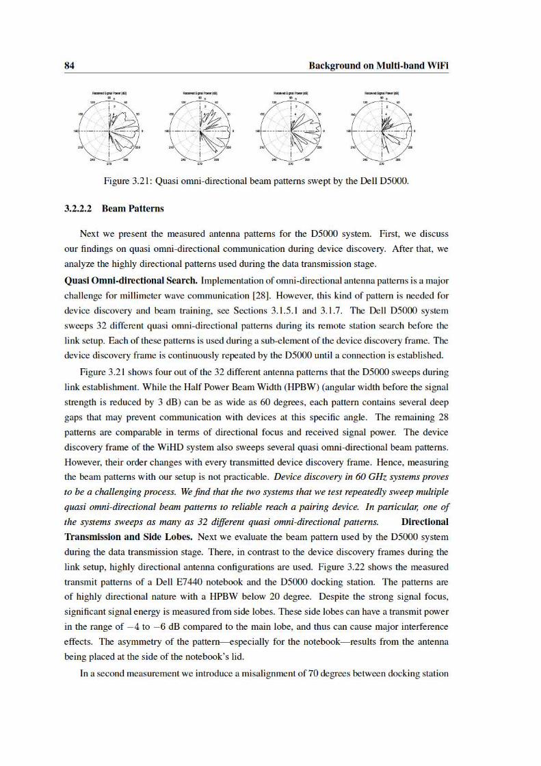


88 Background on Multi-band WiFi
ence. The impact is evaluated in terms of observed link utilization, time for transmission of a file
on the Dell 5000 system and the link rate reported by the D5000 WiGig driver application.
Figure 3.26 depicts the results for two setups: 1) an aligned D5000 link interfering with the
WiHD system and 2) the same setup with the docking station misaligned by 70 degrees (denoted
by ‘rotated’). In the second setup, the docking station is beam-forming towards the outer limit of
its serviceable transmission area and beam-forming performance is significantly worse as shown
in Section 3.2.2.2. When comparing link utilization percentages, we find them to be significantly
increased in both interference scenarios. We measure the interference free link utilization to be
38% and 42% in the aligned and rotated setup, respectively. Thus, we find a maximum link
utilization increase of 62% and 58% for the two interference scenarios, which is significantly
higher than the link utilization of the WiHD link alone, that we found to be 46%. The additional
increase results from the frame collisions and retransmissions as described earlier in this section.
Even though we use two parallel Dell D5000 docking station links, the link utilization never
saturates the channel. Thus, the measured transmission time stayed approximately constant de-
spite retransmissions and carrier sensing induced delays. Therefore, we rely on the link utilization
to asses the impact of interference. For higher network densities that saturate the channel and/or
higher rate requirements of the wireless applications, interference is expected to have a significant
impact on the throughput rate.
The difference of link utilization over the measured interference distances reveals a high in-
terference regime for distances of up to two meters. When further increasing the distance of the
second link, utilization reduces but only reaches interference free levels at distances beyond 5
meters. In the high interference regime, link utilization in the misaligned docking station setup is
higher by around 10% compared to the between aligned setup. At some measurement locations
it reaches values of up to 100% and also shows a strongly varying pattern. For the aligned link
we find a strong utilization increase to 97% at an interferer distance of 1.6 meters. We conjec-
ture that this behavior is due to the side lobes that we observe for the data transmission antenna
patterns of the D5000 link (compare Section 3.2.2.2). The fluctuating link utilization in the high
interference regime for the misaligned link correlates well with its measured beam pattern that
shows many strong side lobes. Unfortunately, we can not directly compare measured side lobes
to the interference impact as it is not possible to measure receive antenna patterns. Also, since
we cannot influence the selection of antenna patterns, it is not possible to ensure that the docking
station uses the same pattern for both measurements.
From the reported link rates it can be clearly seen that the misaligned link performs worse
due to the reduced beamforming capability at the limit of the antenna arrays transmission area,
as explained in Section 3.2.2.2. Further, in the high interference regime below two meters link
distance, an inverse correlation between link rate and link utilization is found. We assume the
docking station link to adjust the link rate according to Signal to Interference and Noise Ration
(SINR) measurements and packet loss statistics, thus the rate decreases under high link utilization
that leads to an increase in collisions.


90 Background on Multi-band WiFi
TC
P T
hrou
ghpu
t (m
bps)
500
600
700
800
900
1000 20 40 60 80 120Time (s)
WiHD on WiHD off
Figure 3.27: Reflection interference impact.
When analyzing the effect of reflections on 60 GHz communication, we find that, apart from an
increase of the coverage area, also interference increases. For an isolated experiment setup with
direct path blockage between links we find a severe impact on TCP throughput due to inter-system
interference. The average throughput reduction was about 20%, and reached up to 33%.
3.2.3 Discussion
In Section 3.2, we formulated a number of unanswered questions regarding the performance
of consumer-grade 60 GHz devices. Our measurements in Section 3.2.2 provide insights which
we now use to answer those questions.
3.2.3.1 Findings on First Generation Millimeter Wave Networks
Directional Communication. How directional are consumer-grade phased antenna arrays? We
show that such antennas suffer from significant side lobes. This means that MAC protocols for
60 GHz networks can not rely on pencil-beam focusing—the actual behavior lies somewhere
between a wide and a highly directional pattern. This is challenging, since we can neither resort
to existing protocols designed for omni-directional communication nor can we assume that no
interference occurs as long as links are not aligned. This hinders protocol designs that would
only use location information to determine whether a node can transmit. How large is the actual
impact of side lobes? Our measurements show that side lobes can be as strong as−1 dB compared
to the main lobe for certain beamforming directions. This worsens the above impact on MAC
protocol design. In particular, the MAC protocol may need to adapt its operation to the intended
beamforming direction. In some cases, a node may even need to switch to a different MAC
protocol.
High Spatial Reuse. How close can devices operate without experiencing collisions? The min-
imum distance for our test devices was two meters. Shorter distances are feasible but require

3.2 Performance Analysis of Millimeter Wave Networks 91
precise receiver positioning between the side lobes of potential interferers, or a MAC protocol
that allows nodes to perform TDMA. In other words, the vision of extremely dense networks
where nodes can communicate without interference is not feasible with current off-the-shelf de-
vices. To enable this, better consumer-grade antenna arrays are needed. How strong is the impact
of interfering reflections? We measured up to a 33% TCP throughput loss due to interfering re-
flections. While this shows the strong detrimental effects, it also hints at the underlying potential.
For instance, a network layer protocol may exploit such reflectors in a multi-hop scenario in order
to adapt the connectivity graph to the network load. Further, passive reflectors deployed in an
indoor environment could help nodes to establish reflected beams that circumvent obstacles. This
highlights the importance of 60 GHz protocols being aware of their physical environment.
High Data Rates. Which coding/modulation schemes are feasible? We observe physical layer
rates up to 3850 mbps, which corresponds to 16-QAM with 5/8 coding. In contrast, 802.11n/ac
supports up to 256-QAM. Most probably, this limitation is due to physical layer challenges such
as synchronization, which may lead to significant phase noise. How efficient is aggregation? Our
results show that aggregation is highly efficient, achieving up to a 5.4× gain. While our test device
only aggregates data if needed to minimize delay, a better approach may be to vary the level of
aggregation depending on the individual requirements of each connection. This would reduce
medium usage and thus ease medium access for other devices potentially following a different
standard based on a different MAC protocol.
3.2.3.2 Challenges for Future Millimeter Wave Systems
Section 3.2.3.1 discusses our findings on first generation millimeter wave networks and con-
cludes that the visions of pencil-beam communication and extreme spatial reuse as presented in
Section 3.1 does not hold without further technological advances. These advances are particularly
required at the level of millimeter wave antenna arrays, which still come with a modest number
of antenna elements. This results in imperfect beam patterns, which suffer from side lobes and
significantly increased interference effects compared to the envisioned millimeter wave scenarios.
However, as a side effect, these imperfections result in an expansion of the reception area, which
benefits first generation low complexity devices in several ways. First, setup of directional com-
munication between two nodes becomes significantly easier, as initial probing frames have higher
chances to reach the pairing devices. In addition to reception over the main lobe, this can happen
via a matching side lobe in direction of the receiver or through a reflected paths. Second, due to
increased reception area, CSMA/CA mechanisms suffer significantly less from deafness, and can
operate close to the behavior of legacy 802.11 networks. As a draw back, parallel transmissions
are only possible with widely separated transceiver pairs.
To effectively enable the millimeter wave vision, more advanced antenna arrays are needed
which will change the communication conditions in the following ways. Directional patterns
will get even narrower and strength of side lobes will be further reduced. While this reduces
direct interference effects between devices, it will also further reduce the number of reflections

92 Background on Multi-band WiFi
that are created as byproduct of directional transmissions. Because of this, the coexistence of
parallel non interfering wireless links is boosted even for close by devices. Unfortunately, this
will remove the earlier mentioned coordination benefits resulting from an increased coverage
area which complicates millimeter wave protocol design. From our findings on first generation
devices, we identify two key challenges that need to be addressed, namely the setup of directional
links and the impact of deafness on the CSMA/CA mechanism.
Setup of Highly Directional Links. Stronger directional focus is required to reach the 60 GHz
vision of extreme spatial reuse. This will result in increased beam training overhead as first
generation devices rely on beam pattern imperfections and reflections to increase the chances of
probing frame reception. For next generation millimeter wave networks with highly directional
focus, establishment of directional communication links will become more challenging. This will
manifest in two ways. First, due to higher directionality, more virtual antenna sectors will have
to be defined to cover the entire service area of an antenna array. Each of theses sectors needs
to be probed during the link setup phase causing increased signaling overhead. While defining
wider patterns could be an alternative for initial link setup, this will later on require increased
refinement overhead. Also, wider patterns will not bring sufficient antenna gain to reach distant
devices. Second, the increased beam training messaging creates higher interference impact on
parallel transmissions. This intensifies, when less reflections and side lobes of highly directional
networks reduce link stability in mobile networks and require constant retraining.
CSMA/CA Deafness Effects. Higher directional focus will significantly increase the deafness
effect on CSMA/CA coordinated millimeter wave networks. While this is required to increase the
number of parallel operating stations in a network, particular attention has to be taken to maintain
operability of the most popular medium access scheme for Wi-Fi communication. Our study
shows that side lobes and reflections play an important role for first generation millimeter wave
networks. These effects lead to significant interference problems but also increase the reception
area of frames outside the expected main beam areas of directional links. With the evolution
of millimeter wave antenna arrays this behavior will change towards the envisioned pencil-beam
communication paradigm. This severely impacts the performance of CSMA/CA networks, as
deafness increases. As has been shown for lower frequency communication [10], deafness causes
significant problems for CSMA/CA networks, including excessive backoff behavior. Together
with the effects of frame aggregation, which we found to play a central role for millimeter wave
networks (see Section 3.2.2.1), we expect significant modifications required to efficiently enable
CSMA/CA communication in future highly directional millimeter wave networks.
3.3 Conclusion
In this section we provide in-depth information on the IEEE 802.11ad amendment, which is
supposed to become the de facto standard for consumer grade mm-wave networks, which will
operate at multiple frequency bands. We highlighted the amendment’s hybrid MAC-layer de-
3.3 Conclusion 93
sign that defines three different medium access schemes, CSMA/CA, Polling and TDMA. Each
scheme addresses different aspects of mm-wave communication and supports varying quality of
service mechanisms, making it suitable for different IEEE 802.11ad use cases. Further, we ad-
dressed the elaborate beam training protocol, which enables highly directional communication.
The association beamforming training and two level beam training are the fundamental elements
of this protocol. First, the association beam training aligns antenna beams between a station and
a central network controller when the direction between the two devices is unknown. Second, the
two level training reduces the beam training search space using its primary coarse-grained train-
ing stage that relies on predetermined virtual antenna sectors. Its second stage further refines the
found antenna configuration, varying from predefined sectors and also addresses the challenges
of imperfect omni-directional antenna patterns. With fully trained transmit and receive antenna
configurations, IEEE 802.11ad reaches its maximum throughput of up to 7 Gbps. In addition,
the beamforming protocol supports a training procedure for low antenna gain devices and can
convey training parameters to a central network coordinator for channel access scheduling. The
combination of the hybrid MAC-layer and the novel beam training protocol is key to satisfying
new IEEE 802.11ad use cases and addressing specific device and millimeter wave propagation
characteristics.
The newly introduced IEEE 802.11ad mechanisms aim towards a novel communication
paradigm for wireless communication. That is, due to high directionality and the adverse prop-
agation effects at 60 GHz significant reduction of interference can be achieved. Under this as-
sumption increased aggregated network throughput can be achieved by parallel transmission with
non interfering pencil-beam antenna patterns. In order to compare this vision to current millime-
ter wave networks the second part of this section presented an in depth study of first generation
off-the shelf millimeter wave devices. This identifies challenges for next generation devices and
future protocol design. To this aim we focus particularly on frame level protocol analysis, beam
pattern measurements and interference studies. Using a 60 GHz down converter we retrieved
baseband traces of black box millimeter wave systems that were used to gain insights about the
used protocol. This also allowed us to observe frame level effects caused by interference and infer
the beam patterns used for several protocol features. Further, we found that the beam patterns ap-
plied by the tested devices change significantly throughout the different states of communication.
The observed beam patterns reveal three challenges for current millimeter wave communication.
First, during the device discovery several quasi omni-directional antenna patterns have to be used,
transmitted repeatedly in probing frames. Otherwise reception in the entire transmission area can
not be ensured as these patterns suffer from deep gaps in the antenna gain. Second, we find that
during highly directional data transmission the antenna patterns include side lobes as strong as -4
dB compared to the main beam. These patterns enable reception in more than just the intended
communication direction and increase susceptibility to interference. Last, we found reduced di-
rectionality and increased amounts of strong side lobes when focusing the antenna beam at the
boundary of the transmission area of an antenna array. These effects, were also confirmed by
94 Background on Multi-band WiFi
measurements to analyze the impact from an interferer using a wide communication pattern.
We conclude that next generation devices will need advanced antenna arrays, to reduce side
lobes and reflections, which have an intensified impact due to imperfect beam patterns. Only
by these measures, the pencil-beam 60 GHz vision that achieves increased aggregated network
throughput by spatial reuse can be realised. Unfortunately, this will come at the cost of a signif-
icantly reduced reception area for directional beam patterns. While current systems exploit this
effect for stable communication links and reliable coordination message exchange, future systems
will not be able to benefit from them. In the discussion in Section 3.2.3.2 we identify two main
aspects of 60 GHz communication where this change will have its main impact, the directional
link setup and performance of the CSMA/CA access scheme.

Chapter 4
Multi-Frequency Band Beam Steering
The IEEE 802.11ad millimeter-wave Wi-Fi amendmend promises data rates of up to 7 Gbps
via high gain antenna arrays used to overcome the increased attenuation of 20-40 dB at the mm-
wave band (see [15, 39, 61] and Section 3.1). In order to achieve the millimeter wave vision of
parallel interference free transmissions, extreme antenna directionality is required, as our mea-
surement campaign in Section 3.2 revealed. Thus, in next generation networks, sender and re-
ceiver must match the potentially narrow directions of their respective beams. Hereby, IEEE
802.11ad discretizes the search space and divides the antenna radiation sphere into as many as
128 virtual sectors supporting beamwidths of less than 3 degrees. A two stage process is used to
select the best sector: first, an exhaustive search to select the best transmit sector is performed by
both transmitter and receiver. This first stage is required to established a low throughput but robust
link between the pairing devices which is used for further coordination message exchange. As
described in Section 3.2.3.2, current millimeter wave devices use relatively wide beam patterns
and rely on side lobes and reflections to facilitate the inital link establishment. Future devices ho-
wever have to remedy these reception area increasing effects as they stand in direct opposition to
interference free communication. Instead, the maximum amount of directional sectors has to be
probed to ensure connectivity in all possible transmit directions at high distances. Second, after
an initial connection has been established between pairing devices, directionality gain is increased
by fine-tuning antenna settings at both the transmitter and receiver as described in Section 3.1.7.
The search space and overhead of the beam training process directly scales with the product of
the number of nodes and their transmit and receive sectors. While this is acceptable for mm-wave
use cases like wireless HDMI with mostly static transmitters, the next generation of mm-wave
systems targets the mobile device [39, 53, 107]. Device mobility breaks the beam adjustment
and requires constant retraining, significantly increasing the beamforming overhead. This holds
especially for device rotation. From experiments with a 7 degree beam width system we found
that a mere misalignment of 18 degree reduces the link budget by around 17 dB. According to
IEEE 802.11ad coding sensitivities [39], this drop can reduce the maximum throughput by up to
6 Gbps or break the link entirely. This misalignment is easily reached multiple times per second
95
96 Multi-Frequency Band Beam Steering
by a user holding the device, causing substantial beam training overhead to enable multi-Gbps
throughput for mm-wave Wi-Fi.
This chapter, presents design, implementation, and experimental evaluation of Blind Beam
Steering (BBS), a system to steer mm-wave beams by replacing in-band trial-and-error testing of
virtual sector pairs with “blind” out-of-band direction acquisition. BBS thus provides a novel ap-
proach to reduce beamforming training overhead for highly directional future millimeter wave
networks, bringing the millimeter wave vision into reach. BBS exploits diverse propagation
characteristics of the accessible frequency bands of devices compliant with the IEEE 802.11ad
amendmend. To this aim, it utilizes legacy 2.4/5 GHz bands to estimate the direction for pairing
nodes from passively overheard frames, which does not incur any additional protocol overhead or
signaling. BBS uses out-of-band direction interference mechanisms that list received signal en-
ergy over an azimuthal receive spectrum. A history of these direction estimates is maintained for
every potential pairing device in the network. Whenever a link is to be beam trained, the history
is queried first for a valid direction estimate that can replace in-band training.
However, the direction information derived from the legacy band does not always correspond
to the best mm-wave band direction due to multipath and noise effects. Further, frequency depen-
dent transmission coefficients may lead to direction estimates that steer the beam into an obstacle,
causing high mm-wave attenuation. BBS evaluates the ratio of multipath reflections observed in
the out-of-band direction information to prevent erroneous mappings. Further, BBS aggregates
the direction estimates retrieved from frames under small scale mobility. As reflections fluctu-
ate under small movements [97, 98] while the direct path does not, this improves the direction
mapping precision. BBS further extracts the angular spread of the direct path estimate from the
aggregated information. This gives an indicator for the estimation precision and whether multi-
ple mm-wave antenna sectors come into consideration for mapping. If this is the case, a highly
efficient refinement process that uses the already obtained coarse grained direction estimate, deter-
mines the optimum sector. This refinement further probes antenna configurations with directivity
close to the LOS path. Interference in other directions is thus prevented as no sweeping probes
are emitted. The BBS mechanism combines the above techniques to transfer precise and reliable
direction estimates to a mm-wave interface to reduce and in many cases eliminate in-band beam
training overhead.
We implement the key components of BBS on a multi-band testbed that combines 2.4 GHz
direction inference based on the software defined radio platform WARP [56] and a mechanically
steerable 60 GHz RF-frontend used to obtain signal strength measurements. Our evaluation tar-
gets three key aspects of BBS. First, combining out-of-band direction inference results and mm-
wave received signal strength analysis, we evaluate mapping precision for multiple locations. We
find BBS achieves excellent direction estimation accuracy for short range line-of-sight links that
are typical for IEEE 802.11ad. Second, we evaluate the suitability of the multipath reflection
ratio to predict a reflected or blocked path and find that it is a very good indicator for both ad-
verse conditions. Lastly, we analyze the trade-off between overhead reduction and achievable
4.1 System Architecture 97
maximum receive power for BBS trained directional links. Our analysis shows that while achiev-
ing optimum sector selection, BBS eliminates more than 80% of IEEE 802.11ad beamforming
overhead.
4.1 System Architecture
In this section, we describe the BBS architecture, its integration with IEEE 802.11ad and
the specific mm-wave characteristics addressed by BBS. Particularly, the BBS architecture that
combines multiple radio interfaces at different frequencies for out-of-band direction inference is
introduced.
4.1.1 IEEE 802.11ad and mm-Wave Wi-Fi
Directional Communication. To reach the necessary link budget for Gbps throughput mm-
wave communication requires high-gain directional antenna arrays or switched directional anten-
nas (see Section 3.2). In contrast to 2.4/5 GHz frequencies, a higher number of mm-wave antenna
elements fits into the same space due to the smaller wave length, which yields higher directional
gain [61, 66]. Usage of directional antenna solutions however requires transmitter and receiver
to be aligned [15, 61]. In case of mm-wave communication the propagation behavior is quasi-
optical, due to high free space attenuation and strong first order reflections [101]. For extremely
directional future millimeter wave networks, with limited impact of antenna side lobes, alignment
of antenna patterns equals a geometrical matching of transmit and receive focus on the direct
path. To this aim, IEEE 802.11ad implements code books of predefined beam patterns, with each
pattern focusing signal energy into a specific azimuthal direction.
The establishment of directional links or Beam Forming (BF) training in IEEE 802.11ad is
a two stage process [39, 62]. During the first stage, the Sector Level Sweep (SLS) stations train
their transmit patterns by probing every possible predefined beam pattern for its signal quality
(see Section 3.1.7.1). The SLS phase is a high overhead procedure, where a complete frame has
to be transmitted at each sector at the lowest PHY rate. BBS completely removes the SLS phase
from directional link establishment. Instead of performing exhaustive sector search, our system
utilizes out-of-band direction information to select appropriate antenna sectors.
In the BRP phase, antenna settings found during SLS using quasi-omni reception are fine-
tuned. Also, receive antenna training is added to achieve highest directional gain and multi-Gbps
throughput as described in Section 3.1.7.2. In contrast to the SLS, the BRP phase can already
rely on an established directional link and probing of antenna configurations close to the initially
found direction can happen throughout one frame. Thus, a BRP refinement adds significantly less
overhead to the beam training than a SLS. The BRP phase can be a complementary procedure
to BBS when the provided direction information by BBS needs further refinement. However, as
shown in our evaluation (Section 4.3.5) our system reduces the BRP search space and further
reduces overhead.
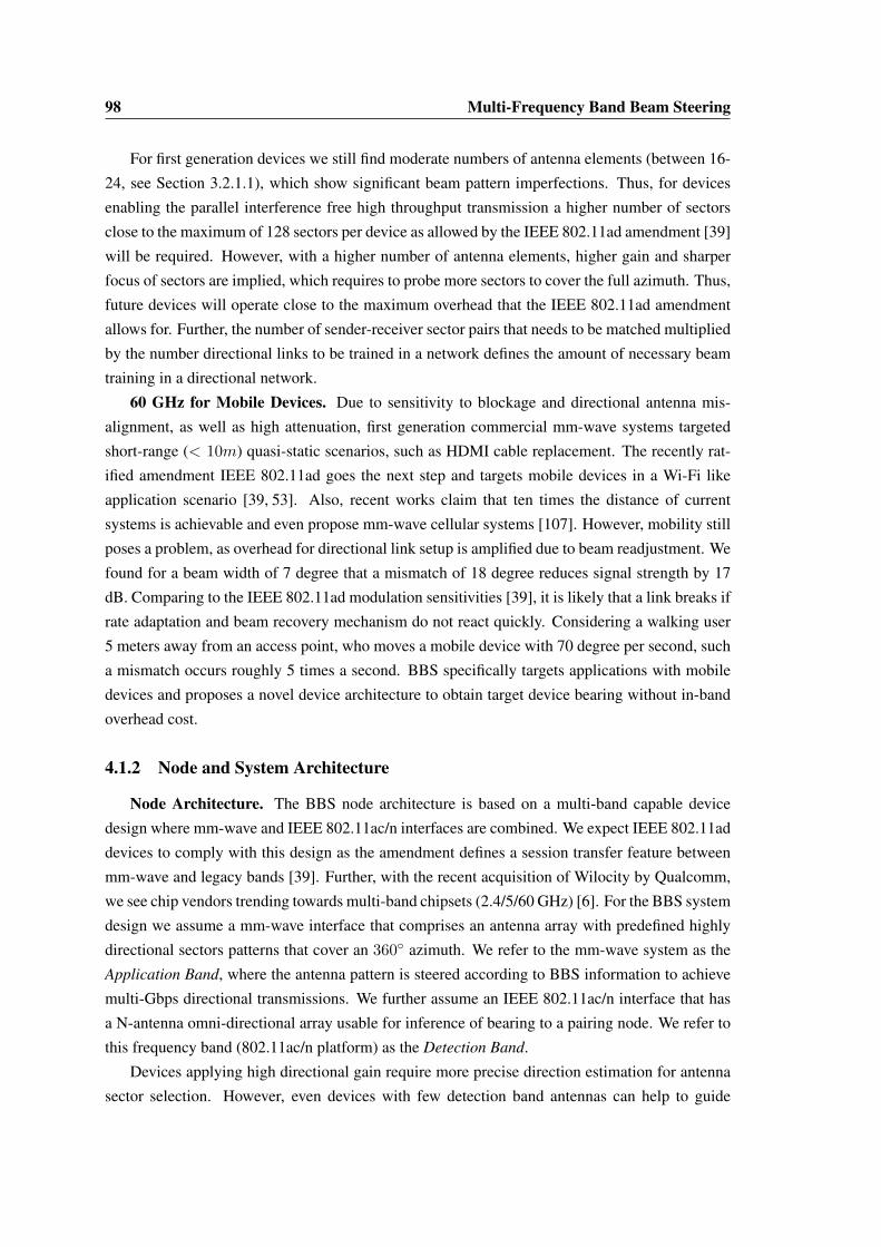
98 Multi-Frequency Band Beam Steering
For first generation devices we still find moderate numbers of antenna elements (between 16-
24, see Section 3.2.1.1), which show significant beam pattern imperfections. Thus, for devices
enabling the parallel interference free high throughput transmission a higher number of sectors
close to the maximum of 128 sectors per device as allowed by the IEEE 802.11ad amendment [39]
will be required. However, with a higher number of antenna elements, higher gain and sharper
focus of sectors are implied, which requires to probe more sectors to cover the full azimuth. Thus,
future devices will operate close to the maximum overhead that the IEEE 802.11ad amendment
allows for. Further, the number of sender-receiver sector pairs that needs to be matched multiplied
by the number directional links to be trained in a network defines the amount of necessary beam
training in a directional network.
60 GHz for Mobile Devices. Due to sensitivity to blockage and directional antenna mis-
alignment, as well as high attenuation, first generation commercial mm-wave systems targeted
short-range (< 10m) quasi-static scenarios, such as HDMI cable replacement. The recently rat-
ified amendment IEEE 802.11ad goes the next step and targets mobile devices in a Wi-Fi like
application scenario [39, 53]. Also, recent works claim that ten times the distance of current
systems is achievable and even propose mm-wave cellular systems [107]. However, mobility still
poses a problem, as overhead for directional link setup is amplified due to beam readjustment. We
found for a beam width of 7 degree that a mismatch of 18 degree reduces signal strength by 17
dB. Comparing to the IEEE 802.11ad modulation sensitivities [39], it is likely that a link breaks if
rate adaptation and beam recovery mechanism do not react quickly. Considering a walking user
5 meters away from an access point, who moves a mobile device with 70 degree per second, such
a mismatch occurs roughly 5 times a second. BBS specifically targets applications with mobile
devices and proposes a novel device architecture to obtain target device bearing without in-band
overhead cost.
4.1.2 Node and System Architecture
Node Architecture. The BBS node architecture is based on a multi-band capable device
design where mm-wave and IEEE 802.11ac/n interfaces are combined. We expect IEEE 802.11ad
devices to comply with this design as the amendment defines a session transfer feature between
mm-wave and legacy bands [39]. Further, with the recent acquisition of Wilocity by Qualcomm,
we see chip vendors trending towards multi-band chipsets (2.4/5/60 GHz) [6]. For the BBS system
design we assume a mm-wave interface that comprises an antenna array with predefined highly
directional sectors patterns that cover an 360◦ azimuth. We refer to the mm-wave system as the
Application Band, where the antenna pattern is steered according to BBS information to achieve
multi-Gbps directional transmissions. We further assume an IEEE 802.11ac/n interface that has
a N-antenna omni-directional array usable for inference of bearing to a pairing node. We refer to
this frequency band (802.11ac/n platform) as the Detection Band.
Devices applying high directional gain require more precise direction estimation for antenna
sector selection. However, even devices with few detection band antennas can help to guide
4.1 System Architecture 99
Figure 4.1: BBS system architecture.
high gain application bands. BBS applies a final sector refinement when the direction inference
is not accurate enough. A low number of detection band antennas increases the search space
for this refinement but still prevents the high overhead sector level sweep phase. Even when
equipped with a single antenna in the detection band, a device can still be traced by a multi-
antenna BBS detection device, increasing the link training efficiency at one side of the link.
System Architecture. Figure 4.1 depicts the BBS system architecture. The IEEE 802.11ad
compliant application band is on the top part of Figure 4.1. At the application band, beamforming
overhead is removed by applying direction estimates provided by BBS , shown in the middle
block. BBS obtains preamble sample frames from the detection band (depicted in the bottom
block). It infers the pairing node’s bearing from frames received at lower frequencies (2.4/5 GHz),
taking into consideration the antenna geometry of the detection band.
BBS runs a background process that infers other devices’ direction by passively overhearing
detection band frames. This comes without further overhead and does not require any changes
to the detection band protocol. As discussed in section 4.3.6, even idle nodes generate sufficient
traffic (e.g. through power management or AP roaming) for at least coarse grained direction
inference. While BBS is independent of the technique used to infer a pairing device’s bearing,
it requires information about the received signal strength in relation to the azimuthal incidence
angle θ. We refer to this information as an angular profile P (θ). These angular profiles are further
analyzed to ensure robustness to mobility, multipath and signal blockage, to then perform reliable
mm-wave sector selection. An example for angular profiles can be found in Section 4.2.3. The
BBS architecture gathers angular profiles in a history, that is queried whenever a beam training
request occurs.

100 Multi-Frequency Band Beam Steering
4.2 Mechanism
BBS integrates into an IEEE 802.11ad implementation at the point of beam training. Both,
link initialization as well as link retraining profit from BBS sector selection. The mechanism in
Algorithm 1 ensures that BBS delivers reliable direction information from the detection to the ap-
plication band. Starting from a beam training request, the angular profile collecting background
process (see Section 4.2.1) is queried (line 1). If available, a profile history from frames received
under differing multipath conditions is returned for the beam training partner. Profiles are com-
bined to increase resilience against multipath (line 3). The aggregated profile is further analyzed
for a blocked direct path or remaining multipath effects (line 4). If neither are detected (line 5),
the strongest incidence angle is assumed to match the direct path to the training partner and is
mapped to application band sectors. As direction estimation uncertainty due to noise is taken into
consideration, it is possible that multiple sectors fall into the range of the estimated direct path.
To select among these, a low overhead stand-alone BRP is performed (see line 9). The selected
sector is then returned to the IEEE 802.11ad implementation. In case BBS can not provide a
sector estimation, legacy beam training is initiated. The remainder of this section explains the
details of Algorithm 1.
Algorithm 1: BBS Sector SelectionInput: beam training request to pairing node dResult: application band sector at θ∗
1 H(d) = {Pt(θ)|s(Pt(θ)) = d} ∀Pt, Pv ∈ H(d) : Pt 6= Pv, |t− v| > Tc2 if |H(d)| > 0 then3 Ad(θ) =
∑P∈H(d) P (θ)
|H(d)|
4 Ψ(Ad) = maxθ(Ad(θ))1|Ad|
∑2πφ=0 Ad(φ)
5 if Ψ(Ad) > TΨ then6 θ∗ = argmaxθ(Ad(θ))
7 Wθ∗ = argminx
(Ad(θ∗±x)Ad(θ∗) ≤ Tpeak
)8 if 2 ·Wθ∗ > Ws then9 BRP(θ∗ ±Wθ∗)
10 end11 else12 θ∗ = legacy beam training13 end14 else15 θ∗ = legacy beam training16 end

4.2 Mechanism 101
4.2.1 Out-of-Band Sector Inference and Profile History
BBS performs out-of-band direction inference, using passively overheard detection band
frames to calculate angular profiles P (θ). A profile specifies received signal energy with re-
spect to the azimuthal incidence angel θ (see Section 4.1.2). The retrieved profiles are organized
in a history for every overheard device d as defined in Eq. 4.1. Hereby, Pt(θ) is an angular profile
obtained from a frame overheard at time t and s(P ) denotes the node id for the device that trans-
mitted the frame. Each pair of profiles inH(d) is spaced by more than the channel coherence time
Tc. This ensures the multipath characteristics vary between all profiles. Without this additional
constraint, the frame aggregation process described in the following subsection could be biased
negatively towards a certain reflected path.
H(d) = {Pt(θ)|s(Pt(θ)) = d}
∀Pt, Pv ∈ H(d) : Pt 6= Pv, |t− v| > Tc(4.1)
Further, the background process ensures that outdated profiles, retrieved from obsolete transmitter
positions are removed from the history in a first in first out buffer like process. To this aim, a time
weighted average over the profile’s main direction component can be used to identify the last
accurate frame and crop the history accordingly. Weighting by time prioritizes newer frames as
they are more likely to reflect the current position of the target. We find from our experiments,
that a small number of frame preamble samples is sufficient to generate a reliable profile. Thus,
even acknowledgment or null data frames can be used to retrieve profiles.
4.2.2 Profile History Aggregation
When receiving a beam training request, BBS queries the profile history H(d) matching the
beam training target d. This history contains profiles obtained under varying multipath conditions
and from the latest known position of the pairing node, as described in Section 4.2.1. For the
history we found the following two conditions to hold:
• An unblocked LOS path is reflected in every profile by a peak at the same angle.
• Peaks resulting from reflections vary among profiles.
We exploit this by averaging the profiles of the history and define the aggregated angle profile as
follows.
Ad(θ) =
∑P∈H(d) P (θ)
|H(d)|(4.2)
By aggregating over measurements taken under varying multipath conditions, alternating re-
flection peaks are attenuated and the remaining strongest peak likely corresponds to the direct
path. A second effect that we observe is that noise and multipath affected frames slightly deviate
the direct path angle. Thus, spectra aggregation spreads the direct path peak according to the
amount of noise. The spreading gives an estimate of the uncertainty for the direct path estimate.
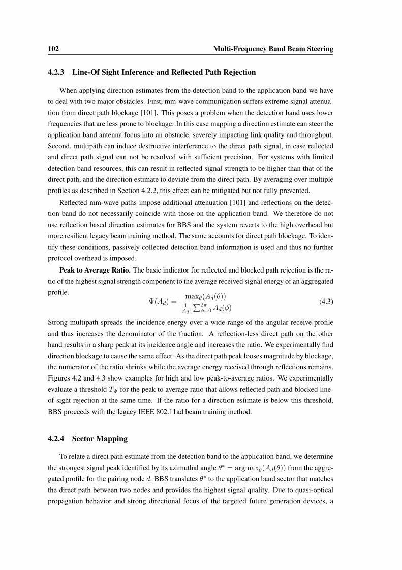
102 Multi-Frequency Band Beam Steering
4.2.3 Line-Of Sight Inference and Reflected Path Rejection
When applying direction estimates from the detection band to the application band we have
to deal with two major obstacles. First, mm-wave communication suffers extreme signal attenua-
tion from direct path blockage [101]. This poses a problem when the detection band uses lower
frequencies that are less prone to blockage. In this case mapping a direction estimate can steer the
application band antenna focus into an obstacle, severely impacting link quality and throughput.
Second, multipath can induce destructive interference to the direct path signal, in case reflected
and direct path signal can not be resolved with sufficient precision. For systems with limited
detection band resources, this can result in reflected signal strength to be higher than that of the
direct path, and the direction estimate to deviate from the direct path. By averaging over multiple
profiles as described in Section 4.2.2, this effect can be mitigated but not fully prevented.
Reflected mm-wave paths impose additional attenuation [101] and reflections on the detec-
tion band do not necessarily coincide with those on the application band. We therefore do not
use reflection based direction estimates for BBS and the system reverts to the high overhead but
more resilient legacy beam training method. The same accounts for direct path blockage. To iden-
tify these conditions, passively collected detection band information is used and thus no further
protocol overhead is imposed.
Peak to Average Ratio. The basic indicator for reflected and blocked path rejection is the ra-
tio of the highest signal strength component to the average received signal energy of an aggregated
profile.Ψ(Ad) =
maxθ(Ad(θ))1|Ad|
∑2πφ=0Ad(φ)
(4.3)
Strong multipath spreads the incidence energy over a wide range of the angular receive profile
and thus increases the denominator of the fraction. A reflection-less direct path on the other
hand results in a sharp peak at its incidence angle and increases the ratio. We experimentally find
direction blockage to cause the same effect. As the direct path peak looses magnitude by blockage,
the numerator of the ratio shrinks while the average energy received through reflections remains.
Figures 4.2 and 4.3 show examples for high and low peak-to-average ratios. We experimentally
evaluate a threshold TΨ for the peak to average ratio that allows reflected path and blocked line-
of sight rejection at the same time. If the ratio for a direction estimate is below this threshold,
BBS proceeds with the legacy IEEE 802.11ad beam training method.
4.2.4 Sector Mapping
To relate a direct path estimate from the detection band to the application band, we determine
the strongest signal peak identified by its azimuthal angle θ∗ = argmaxθ(Ad(θ)) from the aggre-
gated profile for the pairing node d. BBS translates θ∗ to the application band sector that matches
the direct path between two nodes and provides the highest signal quality. Due to quasi-optical
propagation behavior and strong directional focus of the targeted future generation devices, a


104 Multi-Frequency Band Beam Steering
We experimentally evaluate the overhead reduction achieved by BBS , finding that applying a
standalone BRPis a highly efficient method to refine the remaining set of antenna sectors.
4.3 Implementation and Evaluation
In this section we describe our implementation, the testbed setup, and the performance eva-
luation of the BBS system.
4.3.1 Blind Beam Steering (BBS ) Prototype
We prototype BBS using the FPGA-based software defined radio platform WARP for direc-
tion inference in the detection band at 2.4 GHz, and combine this system with a Vubiq 60 GHz
waveguide development system [67] for directional communication in the application band.
4.3.1.1 Implementation of the Detection Band
For our experiments, we use WARPLab [56], a programming environment capable of proto-
typing physical layer algorithms in MATLAB that permits over-the air channel characterization
with WARP nodes. For out-of-band sector inference, we use eigenvector analysis based on the
MUSIC algorithm [80]. To collect data for the calculation of angular profiles, we use two WARP
boards with 8 transceiver chains with synchronized baseband and radio clocks. The setup is
shown in Figure 4.5. We implement a linear array geometry and refine angle profiles by apply-
ing the spatial smoothing and antenna sub-grouping mechanisms proposed in [98] with grouping
factor NG = 2. Through spatial smoothing, the angular profiles are averaged over multiple an-
tenna sub-groups. This further reduces the likelihood of destructive interference on the direct
path through adverse multipath conditions in certain locations. As sub-dividing a 4 antenna con-
figuration leaves our profile calculation with 3 sample streams a maximum of two reflections can
be resolved. Thus, to evaluate the performance for devices with few detection band antennas
we disable the spatial smoothing mechanism. Further, the spectrum history length is fixed to a
value of 50 IEEE 802.11 frames. All angular profiles obtained for one location comply with the
requirements for the profile history described in 4.2.1. To generate the angular profile, for every
frame three short preamble sequences (corresponding to 192 samples) are averaged. Further, the
direct path estimate for every receiver location and its mean error are averaged over 500 histories
with 50 frames each. The tracked device is a WARP board with one radio interface.
4.3.1.2 Implementation of the Application Band
We implement the application band for directional multi-Gbps data transmission using a mm-
wave development platform from Vubiq [67]. This platform consists of transmitter and receiver
waveguide modules that provide 1.8 GHz modulation bandwidth in the 58 to 64 GHz unlicensed
bands. We feed a 16-QAM modulated multi-tone baseband signal with 15 MHz bandwidth from
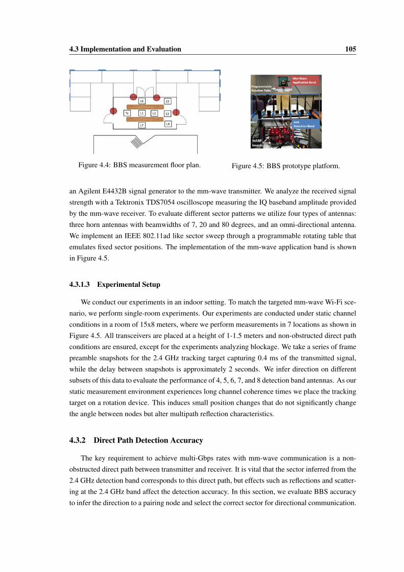
4.3 Implementation and Evaluation 105
Figure 4.4: BBS measurement floor plan. Figure 4.5: BBS prototype platform.
an Agilent E4432B signal generator to the mm-wave transmitter. We analyze the received signal
strength with a Tektronix TDS7054 oscilloscope measuring the IQ baseband amplitude provided
by the mm-wave receiver. To evaluate different sector patterns we utilize four types of antennas:
three horn antennas with beamwidths of 7, 20 and 80 degrees, and an omni-directional antenna.
We implement an IEEE 802.11ad like sector sweep through a programmable rotating table that
emulates fixed sector positions. The implementation of the mm-wave application band is shown
in Figure 4.5.
4.3.1.3 Experimental Setup
We conduct our experiments in an indoor setting. To match the targeted mm-wave Wi-Fi sce-
nario, we perform single-room experiments. Our experiments are conducted under static channel
conditions in a room of 15x8 meters, where we perform measurements in 7 locations as shown in
Figure 4.5. All transceivers are placed at a height of 1-1.5 meters and non-obstructed direct path
conditions are ensured, except for the experiments analyzing blockage. We take a series of frame
preamble snapshots for the 2.4 GHz tracking target capturing 0.4 ms of the transmitted signal,
while the delay between snapshots is approximately 2 seconds. We infer direction on different
subsets of this data to evaluate the performance of 4, 5, 6, 7, and 8 detection band antennas. As our
static measurement environment experiences long channel coherence times we place the tracking
target on a rotation device. This induces small position changes that do not significantly change
the angle between nodes but alter multipath reflection characteristics.
4.3.2 Direct Path Detection Accuracy
The key requirement to achieve multi-Gbps rates with mm-wave communication is a non-
obstructed direct path between transmitter and receiver. It is vital that the sector inferred from the
2.4 GHz detection band corresponds to this direct path, but effects such as reflections and scatter-
ing at the 2.4 GHz band affect the detection accuracy. In this section, we evaluate BBS accuracy
to infer the direction to a pairing node and select the correct sector for directional communication.


4.3 Implementation and Evaluation 109
In-Band Sector Refinement7 Degrees 20 Degrees 80 Degrees
IEEE 802.11ad SLS+BRP time = 1.54 ms IEEE 802.11ad SLS+BRP time = 0.88 ms IEEE 802.11ad SLS+BRP time = 0.63 msBBS (ms) Time Savings (ms) % Reduction BBS (ms) Time Savings (ms) % Reduction BBS (ms) Time Savings (ms) % Reduction
0 0 1.54 100 0 0.88 100 0 0.63 1002 0.28 1.26 81.42 0.28 0.6 67.55 0.28 0.35 54.664 0.29 1.25 81.03 0.29 0.59 67.21 0.29 0.34 53.7210 0.31 1.23 79.87 0.31 0.57 64.85 -20 0.34 1.20 77.94 - -
Table 4.1: BBS and IEEE 802.11ad time comparison for directional link establishment.
13% of the maximum possible search space. The smallest amount of required in-band refinement
can be found in location 3 where only 2 sectors are required for a 52 sector system and no over-
head is imposed for the other two antenna configurations. These findings correlate with the high
detection accuracy found in 4.3.2. BBS can achieve perfect sector selection with only 0 to 13%
remaining in-band training.
4.3.5 Time of Directional Link Establishment
As shown in Section 4.3.4, BBS provides perfect sector matching, and thus optimum link
budget. In order to achieve a perfect sector matching, there are cases in which BBS requires
beam-refinement for a small number of sectors. Nevertheless, BBS removes the IEEE 802.11ad
sector level sweep phase and reduces the BRP search space, thus significantly reducing the amount
of time required to establish directional links. This directly leads to an increase in spectrum effi-
ciency by allowing more time for data transmissions. Also, wide spread probing frames to cover
all necessary directions can be avoided, which otherwise can act as omni-directional interference
signal, hindering parallel transmission. In this experiment we evaluate the BBS overhead reduc-
tion by comparing the link setup time of IEEE 802.11ad to our proposed method. Specifically,
we compare the time BBS takes to perform a standalone BRP on the remaining sector set after
out-of-band direction inference compared to the full IEEE 802.11ad legacy beamforming training
procedure comprising SLS and BRP.
In case the BBS refinement sector set is determined by the method described in Section 4.2.4,
we assume the search space for the legacy method to be fixed to one fourth of the total number
of sectors. For the BRP procedure, we assume a three step message exchange for both BBS and
IEEE 802.11ad. During the BRP, first initiator and receiver realize a receive training transmitting
one frame with the number of requested training fields. Second, two interleaved receive and
transmit BRP transactions are performed which include feedback for identified strongest sectors.
For all calculations a pairing node with 16 sectors is assumed.
Table 4.1 lists the BBS and IEEE 802.11ad time comparison for directional link establishment
for the evaluated antenna configuration of BBS. We extract the average BRP search space size for
the three antenna configurations from Figure 4.9 (0 sectors, 2 sectors and 4 sectors) and evaluate
the corresponding training time reduction. We find that the BBS guided beamforming training
achieves an average channel usage reduction of 1.24 ms, 0.59 ms and 0.35 ms per link setup for
sector widths of 7, 20 and 80 degrees respectively. The corresponding values are highlighted in
Table 4.1. This performance increase scales with the number of nodes in a network and link re-

110 Multi-Frequency Band Beam Steering
training caused by device mobility. Further, for highly directional systems a notable setup delay
reduction is achieved by BBS. For example, to set up a link that needs in-band refinement of 4
sectors, only 0.29 ms are required compared to 1.54 ms for a 7 degree beam width system. Sum-
ming up, BBS achieves perfect sector selection, while reducing beamforming training overhead
for every link setup by up to 1.24 ms (81%) for highly directional systems with sector widths as
narrow as 7 degrees.
4.3.6 Direct Path Detection under Mobility
Due to the lack of commercially available mm-wave antenna arrays that support controllable
real-time beam steering, it is difficult to directly evaluate BBS under mobility. Nonetheless, by
reducing the frame history length in our static setup we can deduce the behavior for mobile nodes,
where direction information becomes obsolete fast. We observe that the high average accuracy
above 95% can be maintained for frame histories as small as 8 frames, when at least 5 detection
band antennas are available. Further, we measured the number of frames transmitted by a range
of different idle IEEE 802.11n/ac devices (notebooks and smartphones). We found a substantial
amount of null data frames to be transmitted and their number to increase with the expected
device mobility. This renders coarse-grained direction estimation under mobility possible, given
BBS small frame history length requirements. Null data frames serve for several implementation
dependent features, e.g., power management, channel scanning, keep alive mechanisms and AP
roaming.
Additionally, IEEE 802.11ad defines a seamless session transfer from mm-wave to legacy
frequencies in case of link breakage at the mm-wave band. This feature creates traffic on the lower
frequency band, which allows BBS to derive a high accuracy direction estimate and reestablish
the link.
4.4 Related Work
Prior work on 60 GHz communication mainly focused on channel measurements and model-
ing, as well as hardware design. To the best of our knowledge, BBS is the first work to introduce
multi-band coupling to remove overhead for beam-training in directional mm-wave communica-
tion. However, there exists complementary work on the key components of our system: multi-
band coupling and direction inference.
Multi-band Systems. Various previous systems and hardware architectures concurrently use
multiple bands for purposes other than directional link establishment. For example, Wake on
Wireless [84] uses multiple interfaces on battery operated devices to save energy. It puts devices
on standby mode and utilizes a second very low-power radio on a different frequency band to
wake up the primary device when required. Other works combine 3G, WiMAX and Wi-Fi radios
to increase capacity or offload traffic [29, 42]. Protocols for opportunistic usage of multi-band
spectrum were studied in [79]. The 802.11ad amendment [39] itself supports seamless integration

4.5 Conclusion 111
with 802.11a/b/g/n/ac, through a mechanism called transparent Fast Session Transfer (FST). This
mechanism allows real-time transition of communication from any band/channel to any other
band/channel. As a consequence, we expect a large fraction of IEEE 802.11ad transceivers to
operate on multiple bands and thus directly support our BBS mechanism.
Direction Inference. The techniques utilized for out-of-band detection inference in this chap-
ter are based on [21,97,98]. These mechanisms have primarily evolved from MUSIC [80], which
was the first work to analyze incident waveforms: quantity, direction of arrival, strength and
cross correlation among them. Direction inference in combination with various multi-antenna or
MIMO techniques and channel impulse response measurements is often used for indoor local-
ization [21, 95, 97, 98]. Incidence angle based localization techniques have further been used in
ad-hoc mesh networks [60], CDMA mobile cellular systems [11, 99] and in combination with
ToA using antenna arrays and interference cancellation for LOS environments and wide-band
CDMA [11]. In contrast, BBS utilizes bearing inference in a multi-band system with the purpose
of guiding 60 GHz directional communication.
60 GHz Beamforming Overhead. In [49] beam training is considered as optimization of a 2-
D signal strength function defined over finite codebooks of transmit and receive antenna sectors.
The proposed algorithm, based on a numerical Rosenbrock search, probes a reduced number
of sector combinations compared to the exhaustive searches that are currently state of the art.
However, probing specific sector pairs requires coordination between the involved nodes and
reliable communication on untrained links is not possible in IEEE 802.11ad networks. Thus, the
method proposed in [49] is not applicable to this type of network. In contrast, the IEEE 802.11ad
amendment [39] uses a sector level sweep to find antenna sectors for initial communication and
BBS efficiently solves the problem by out-of-band direction inference.
4.5 Conclusion
In this section, we presented the design and experimental evaluation of a novel architecture
and framework for mm-wave directional communication, named Blind Beam Steering (BBS ).
BBS addresses the overhead and interference problem for directional mm-wave link establish-
ment. As described in Section 3.2.3.2 beam training for future highly directional mm-wave net-
works becomes significantly more complex, posing a limit to mm-wave’s very high throughput
capabilities and beam-width scalability. Further, due to its probing frame transmission in a sweep-
ing manner (see Section 3.1.7), interference unaligned with established transmissions, is created
that hinders the millimeter wave vision of parallel high throughput transmissions. We further
highlighted the fact that mobile network scenarios, like IEEE 802.11 communication, increase
the problem as frequent beam readjustment is required.
The proposed system architecture couples 60 GHz mm-wave with legacy 2.4/5 GHz bands
to exploit the propagation properties of each. We infer the line-of-sight direction between the
communicating devices from omni-directional transmissions at low frequencies in the Detection
112 Multi-Frequency Band Beam Steering
Band. The information is further processed to ensure robustness to multipath and signal blockage,
to then perform mm-wave sector selection. The sector selected by the BBS framework is passed
to the Application Band which implements IEEE 802.11ad compliant mm-wave directional com-
munication.
Thus, by exploiting the multi-band architecture of upcoming IEEE 802.11ad devices, BBS re-
moves significant amounts of mm-wave in-band probing. The aforementioned drawbacks for fu-
ture mm-wave networks are thus alleviated, allowing robust link setup with reduced overhead
and interference. Our experimental evaluation demonstrates that BBS achieves on average 97.8%
accuracy for direction estimation when 5 or more antennas are used at the detection band. This ac-
curacy in direction estimation results in IEEE 802.11ad beamforming training overhead reduced
by 81% for a highly directional transceiver with 7 degree beam width. Further, in our typical
office-style testbed environment BBS successfully detects unblocked direct path conditions for
highest throughput mm-wave transmissions with a rate of 96.5%.

Chapter 5
Multi-Frequency Band MACEnhancements for Fairness andEfficiency
Communication in the 60 GHz band is a promising next step for the evolution of high speed
Wi-Fi and is considered a key technology for 5G networks. Beside the vast amount of spec-
trum (7 GHz available bandwidth for unlicensed use in the 60 GHz band), its potential for high
spatial reuse of frequency resources makes it very attractive for future dense networks. This is
due to the envisioned highly directional pencil-beam antenna patterns which reduce interference
between devices to a minimum and also contribute to overcome the high free space attenuation
found at mm-wave frequencies (see Section 1.1.1 and 3.1.3). As we describe in Chapter 3.2,
currently available millimeter wave devices still apply imperfect beam patterns, due to deficien-
cies in available consumer-class antenna technology. This leads to increased interference through
antenna side lobes but also expands the reception area of transmissions. As a result current de-
vices still can utilize established medium access schemes and communication protocols without
experiencing too much impact from directionality. This however will change when future devices
improve their beamforming capabilities (see Section 3.2.3.2). The resulting reduction in signal
reception area will raise new challenges for the MAC-layer design of future Wi-Fi systems. In
particular, the deafness problem – stations that are located outside of the transmitter antenna’s
boresight cannot overhear or sense the transmission – has to be considered for protocol design.
As we show in this chapter this problem impacts mm-wave CSMA/CA mechanisms, which expe-
rience reduced efficiency and fairness.
Figure 5.1 depicts an RTS collision caused by two stations being deaf towards each other
given their beams directed towards the AP. In Figure 5.2, an RTS is lost because the AP focuses
its receive beam away from the deaf station, towards a data transmission.
The IEEE 802.11ad amendment for 60 GHz Wi-Fi [39] addresses these challenges by defining
a hybrid medium access mechanism. This includes polling and TDMA as well as the well known
113


5.1 Fairness Impairments in Directional CSMA/CA 115
Efficiency and fair channel access, i.e., low per packet delay and high throughput, play a
major role for a satisfying user experience and current state of the art CSMA/CA schemes exhibit
rather suboptimal performance in this respect.
In this chapter, we address the deafness problem for uplink channels, while maintaining high
fairness through a combination of 60 GHz communication with control messages on legacy Wi-
Fi frequencies. Thus, the benefits of multi-band capable devices are exploited, to leverage from
the difference in propagation behavior between 60 GHz frequencies and legacy Wi-Fi bands at
2.4/5 GHz. When contending for the channel, stations exchange omni-directional RTS/CTS mes-
sages on the lower frequency band to set up a data transmission. The source and destination
stations then exchange data frames on the 60 GHz band. The advantage of the presented ap-
proach is twofold. First, control message exchange on frequencies of 2.4 or 5 GHz is highly
reliable over the typically short IEEE 802.11ad communication distances. Thus, every station
overhears the control messages, and can correctly defer, avoiding the IEEE 802.11ad unfairness
problem. Second, by parallelizing control and data transmission, we free resources on the 60 GHz
band for high speed data transmission. Thus, the dual frequency approach enhances throughput
and MAC efficiency. Further, the number of RTS messages sent in vain to already transmitting
devices is reduced. This prevents interference into random directions, different from already es-
tablished links. Last, as the IEEE 802.11ad amendment foresees transition between the two bands
for seamless failover (so called Fast Session Transfer) and range extension [39], we expect most
IEEE 802.11ad devices to be suitable for the dual band approach.
The contributions presented in this chapter are as follows. First, we analyze the deafness prob-
lem in 60 GHz CSMA/CA networks and propose a dual-band solution to it. This approach couples
interfaces on the 60 GHz band with the ones on legacy Wi-Fi frequencies. Second, our mecha-
nism shifts control messages onto a legacy IEEE 802.11 channel with lower bandwidth, freeing
up channel time for high throughput transmissions on 60 GHz. By this, we achieve a throughput
increase of up to 65.3% over IEEE 802.11ad CSMA/CA. Last, exploiting omni-directional trans-
missions on legacy Wi-Fi frequencies we solve the deafness problem and increase MAC fairness
by up to 42.8% compared to IEEE 802.11ad.
The chapter is structured as follows: Sections 5.5 and 5.1 present the past proposals on solving
the deafness problem, as well as a description of 60 GHz CSMA/CA impairments due to the
deafness problem. Our dual-band CSMA/CA approach is described in Section 5.2. Section 5.3
provides the channel and transmission model used to simulate the numerical results shown in
Section 5.4. Section 5.6 concludes the presented work on fairness in IEEE 802.11ad networks.
5.1 Fairness Impairments in Directional CSMA/CA
This section describes the impact of deafness on the two most relevant CSMA/CA mech-
anisms for directional networks, IEEE 802.11ad and the centralized approaches proposed in
[22, 23].


5.2 Dual-Band CSMA/CA 117
access. This effect primarily impacts short term fairness and over longer time scales, the identity
of the active station changes sufficiently often to achieve some level of fairness.
5.1.2 Centralized CSMA/CA
The centralized CSMA/CA schemes [22, 23] partially solves the aforementioned problems
through an omni-directional CTS sent by the AP.
However, an omni-directional CTS only ensures correct deferral of overhearing stations in
the subsequent data transmission phase. The increased RTS collisions rate due to lack of carrier
sensing and the resulting long backoff times remain.
As the duration of an RTS comprises 2 slots, chances for collision are very high especially at
network initialization when stations use the minimum contention window of 15 slots. Even for
moderate network densities, it is not uncommon that multiple RTS messages collide, resulting in
more than two stations increasing their backoff windows in the same contention phase. Interest-
ingly, here IEEE 802.11ad benefits from a significantly lower RTS to RTS collision rate, since
RTS messages are often uselessly sent during an ongoing data transmission rather than during the
contention phase.
The high RTS collision probability may lead to a rapid increase of the contention windows
after network initialization. At the same time, in a highly loaded network, the contention period is
relatively small (drawn from the 15 slot minimum contention window). As all stations freeze their
contention timer during deferral, a high back off counter needs a significant amount of contention
periods to reach 0. This again gives an unfair advantage to currently active nodes with small
contention windows to win channel contention. As for networks with deaf stations, it is likely
that a small set of active nodes alternately uses the channel, while other stations remain in long
periods of repeated maximum backoff. The effect is shown in Figure 5.4. Due to an overlapping
RTS collision, three stations will increase their contention windows. During the following data
transmission the collided stations correctly defer. As a result, their large backoff time is reduced
only slowly over the coming short contention intervals (the active station draws its backoff time
from the minimum contention window). The active station thus dominates the channel access for
a long period. This effect is more pronounced than for IEEE 802.11ad, as with IEEE 802.11ad
even stations with a small contention window are likely to uselessly transmit an RTS during an
ongoing data phase and then increase their contention window.
5.2 Dual-Band CSMA/CA
In this section, we propose a dual-band CSMA/CA scheme that mitigates the deafness prob-
lem for uplink communication while achieving low overhead and high fairness. Our approach
leverages omni-directional transmissions on legacy Wi-Fi frequencies to coordinate high through-
put transmissions in the 60 GHz band. As control messages are received by all stations, our
approach ensures correct deferral behavior and a low frame collision probability.

118 Multi-Frequency Band MAC Enhancements for Fairness and Efficiency
We assume an IEEE 802.11ad compatible transceiver design and an infrastructure based net-
work architecture with AP. Further, we require all stations to be able to communicate over a
60 GHz interface as well as over a legacy Wi-Fi interface. This type of transceiver architecture is
very likely, as IEEE 802.11ad makes use of a multi-band fast session transfer for range extension
and seamless failover in case of link breaks. Thus, we expect typical IEEE 802.11ad devices to
be compliant with the requirements of our dual-band CSMA/CA scheme. For simplicity we omit
details about beam training on the directional 60 GHz interface and assume pre-trained directional
links for all stations to the AP. In general, this assumption is satisfied by the association beam
training process described in Section 3.1.7. Dual-band CSMA/CA access can then be enabled as
an addition to the IEEE 802.11ad hybrid MAC architecture of Section 3.1.6.
5.2.1 Dual-Band CSMA/CA Protocol
Our dual band CSMA/CA protocol follows the basic IEEE 802.11 scheme, including random
backoff and deferral mechanism, as well as RTS/CTS exchanges as defined for IEEE 802.11ad
(compare Section 3.1.6.1). However, the contention mechanism together with the RTS/CTS ex-
change are realized on omni-directional legacy Wi-Fi bands. The IEEE 802.11ad interface of the
dual-band devices is exclusively used for data transmission (and acknowledgments).
When applying the contention mechanism on legacy Wi-Fi interfaces, only one message can
be exchanged over the medium at a time. Thus, for our approach, it is essential to have data
frame sizes that exceed the duration of the RTS/CTS exchange consumed on the lower frequency.
Otherwise, the data transmission would be delayed by the exchange of control frames. This is
especially important considering that lower frequency IEEE 802.11 has longer frame duration of
RTS/CTS control messages compared to the 60 GHz band. In addition, since the duration of a
data frame is known, it is possible to use in-band RTS/CTS as in conventional IEEE 802.11ad for
small data frames for which dual-band RTS/CTS creates too much overhead.
When frames are transmitted according to the dual-band mechanism, stations need to sense
the lower frequency band to be idle for at least a DIFS time before starting the contention me-
chanism. The transmitted RTS frame will reference the end of the latest known transmission on
the 60 GHz band plus a SIFS interval. Receiving RTS and CTS messages omni-directionally
ensures that the latest transmission is known to everybody. Note that the RTS/CTS exchange can
already occur during the transmission of some previous data frame on the 60 GHz band to avoid
unnecessary delay.
Figure 5.5 shows an example frame flow for our dual-band approach. Three stations (distin-
guishable by the subscript in frame descriptions) intend to transmit a frame to the AP at the same
time. In contrast to deaf IEEE 802.11ad CSMA/CA, backoff happens on the legacy frequency
band and the RTS/CTS messages are overheard. As can be seen from frames Data1 and RTS2,
data frame transmission and backoff procedure happen in parallel on two bands.

5.3 Simulation Models 119
Figure 5.5: Channel access mechanism of the dual-band approach.
5.2.2 Fairness and Throughput
A fundamental advantage of our dual-band approach is that all stations can overhear the
RTS/CTS exchange on lower omni-directional frequencies, thus solving the deafness problem.
As a result, dual-band CSMA/CA does not suffer from the impairments described in Section 5.1.
Our approach achieves a flawless deferral behavior, avoids excessive contention windows, and
increases the fairness of medium access.
A second benefit results from the parallelization of RTS/CTS exchanges and data transmis-
sions on two separate frequency bands. This removes idle time and RTS/CTS transmissions from
the 60 GHz frequency band. As RTS/CTS exchanges are transmitted with the most robust and
thus lowest rate coding and modulation scheme, inefficient use of the 60 GHz channel is avoided.
Instead, all available channel time with only a SIFS interval between data frames (and acknowl-
edgements) can be utilized for very high throughput transmissions on the 60 GHz channel. Sac-
rificing transmission time on the legacy Wi-Fi band for control traffic improves efficiency as the
band supports much lower transmit rates compared to the 60 GHz band.
5.3 Simulation Models
This section elaborates the simulation models that are used to produce the numerical results
in Section 5.4. We consider an indoor wireless network with a single AP and a set of S non-AP
stations that are randomly distributed within a cell area. The total number of stations is |S| = Ns.
Let {s, d} represent a transmission pair. We denote the source station as s and the destination
station as d.
Channel model. The received power at d when receiving from s is
Pr(s, d)(dBm) = Pt(dBm) + Gs(dBi) + Gd(dBi)− PL(ls,d), (5.1)
where Gs and Gd are the antenna gains at station s and station d, respectively. The path loss
PL(ls,d) including oxygen absorption of stations that are ls,d apart is
PL(ls,d) = 20 log10
4πls,d(m)λ
+ αls,d (dB)
as presented by Zhu et al. [107] (compare also Sections 1.1.1 and 1.1.2). The oxygen absorption is
α = 0.02dB/m and the wavelength λ at 60 GHz frequency band is 5mm. Pt is the transmit power

120 Multi-Frequency Band MAC Enhancements for Fairness and Efficiency
and ranges from 10dBm to 27dBm, the maximum value specified by IEEE 802.11ad. The maxi-
mum Equivalent Isotropically Radiated Power (EIRP) permitted by the FCC for IEEE 803.11ad
is 40dBm hence Gs ≤ EIRP− Pt.
Interference model. Figure 5.6 illustrates the interference scenario in a directional transmission
network. A station can only interfere with a receiving station if it is located within the antenna
boresight of the receiving station. For instance, when the AP is receiving data from STA1 in
Figure 5.6 and thus beamforms to STA1, only STA2 is as a potential interferer (if it fails to
overhear any previous messages) but not STA3 (as it is not in the boresight of the AP).
Figure 5.6: Interference in a directional transmission network.
In the presence of interference, the total interference power Pint(s, d) at the a receiving station
d is
Pint(s, d) =∑
n∈{S∪AP,n6=d,n6=s}
Pr(n, d). (5.2)
As mentioned, not all interference causes packet loss. A packet is only lost if the interference
signal causes the resulting SINR degrades below the threshold needed to decode a message coded
with a certain coding and modulation scheme. The corresponding thresholds are obtained from
[39].
5.4 Results
This section evaluates the performance of our Dual-band scheme. We investigate the impact
of the number of stations (Ns), time interval τ over which fairness is measured (called “fairness
interval”), and frame size (f ).
We consider an uplink scenario, where all stations contend for the channel to transmit data
frames to the AP. Since all stations are attempting to transmit to the AP, their beams are always
directed towards the AP. At a time instant, only one station can win a TXOP with the AP. Upon
winning a TXOPs, a station transmits only one data frame and it needs to recontend for the
channel to transmit another data frame.
Network topology and configuration. For all the scenarios, the stations are randomly dis-
tributed within a cell area with a radius of 23m. This range is the same as the maximum range
we measured on first generation devices during our measurement campaign presented in sec-
tion 3.2, a Dell E7440 laptop and D5000 docking system, operating at 60 GHz with 13◦ sector

5.4 Results 121
width. The fairness intervals over which fairness is evaluated (τ = 5ms and τ = 80ms) are
chosen to reflect short term and long term fairness, respectively. We also use different frame sizes
f = {1.5, 15, 30, 45, 60, 75}KB to study the impact of different levels of frame aggregation on
performance. For data frame transmission at 60 GHz, we consider the 12 single carrier MCSs
defined in IEEE 802.11ad [39], with modulation schemes π/2-BPSK, π/2-QPSK, and π/2 16-
QAM. The corresponding transmit rate ranges from 389Mbps to 4620Mbps. The transmission
rate of the control messages (MCS 0) depends on the band at which it is transmitted as shown
in Table 5.1. Table 5.1 also shows the timing information for the key parameters used in the
simulations.
Table 5.1: Dual-Band CSMA/CA: Parameters in 60 GHz and 5 GHz frequency bands.
Item IEEE 802.11ad (60GHz) IEEE 802.11ac (5 GHz, 80MHz bandwidth)aDIFSTime 13µs 34µsaSIFSTime 3µs 3µsaSlotTime 5µs 9µs
MCS0 27.5Mbps 32.5MbpsaRTSTime = aCTSTime 8.19µs 7.30µs
Performance metrics. Our main performance metrics are throughput, fairness, and delay.
Throughput is the total amount of data bits successfully received at the destination station over
the transmission time. To ensure fair comparison, we take into account the throughput loss on
the lower frequency band that our scheme incurs, by summing up the throughput on both the
low and high frequency band for all schemes. The achievable throughput on the lower band is
set to 433Mbps, the maximum rate supported by IEEE 802.11ac devices without MIMO. Lastly,
fairness is computed based on Jain’s fairness index [41].
Performance comparison. We compare the performance of the proposed approach against two
other schemes. The first approach, IEEE 802.11ad, resembles the IEEE 802.11ad amendment [39]
where all messages are transmitted directionally between the source and the destination stations.
The second scheme is the one proposed by Gong et al. in [23], where an RTS message is transmit-
ted directionally from a source station to the central controller (i.e., AP), which broadcasts a CTS
message to all stations in the system.1 We denote this centrally coordinated scheme as Central.
5.4.1 Homogeneous scenario
Figure 5.7 illustrates the impact of increasing the number of stations Ns on the system
throughput. As mentioned before, we also take into account the throughput obtained on the
lower frequency band for all the schemes. As Ns increases, so does the probability of RTS frame
collision, as shown in Figure 5.8. In the Central schemes, since all stations can overhear CTS
messages broadcasted by the AP, this removes any collisions of frames with ongoing data trans-
1Note that this is in contrast to IEEE 802.11ad operation which only permits quasi-omni directional reception, butnot transmission.
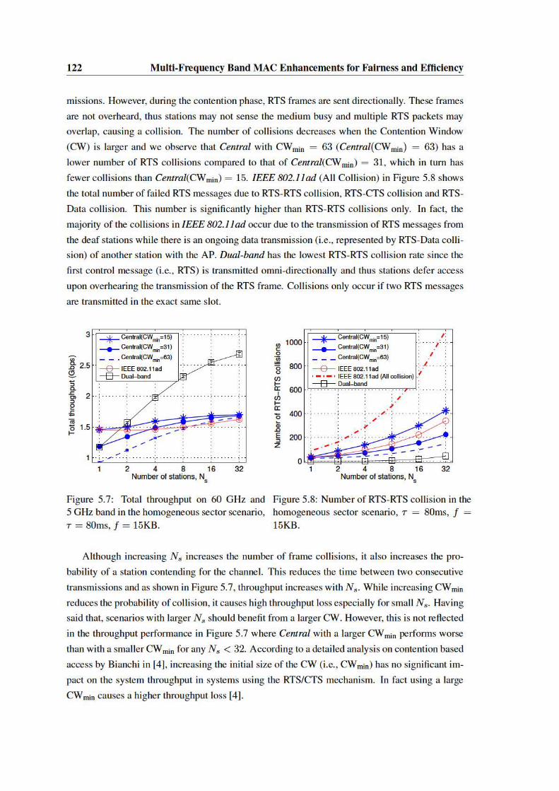
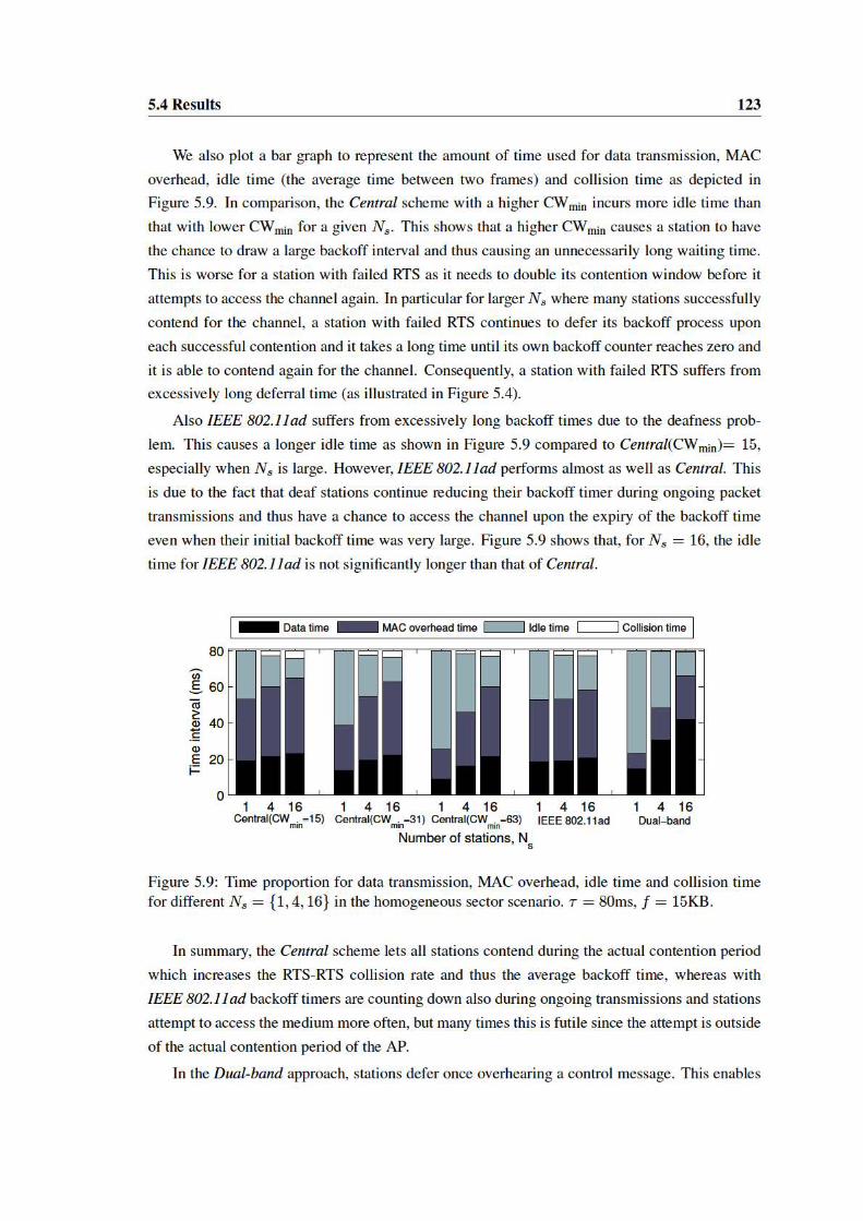


5.5 Related Work 127
5.5 Related Work
The deafness problem due to misaligned directional antennas was first addressed in the context
of microwave communication (i.e., 2.4 GHz and 5 GHz frequency band) [1, 25, 46, 47, 57, 74,
89, 94]. [46] and [57] solve the deafness problem for CSMA/CA systems by omni-directionally
transmitting control messages (i.e., RTS and CTS). However, by doing so all overhearing nodes
will defer their transmission, preventing spatial reuse. In the same vein, Takai et al. [89] propose
directional frame transmission while listening omni-directionally. This only partially solves the
deafness problem as frames might not reach all receivers due to directionality of the transmission.
Korakis et al. [47] propose a directional system that emulates omni-directional RTS transmission
by sweeping transmit directions, i.e., transmitting an RTS in each possible direction. While this
technique effectively deals with deaf stations, it has high overhead, especially for systems with
many narrow directional sectors. The works in [1, 25] address the deafness problem by omni-
directionally transmitting control messages but they require additional mechanisms to prevent
interfering transmissions. Arora et al. [1] use separate channels to reduce collisions by adjusting
the transmit power such that interference at the receiver is avoided. In [25], an additional GPS
receiver is used to provide location information to create a coordination map to avoid interference.
Due to increased attenuation at the 60 GHz band, the gain resulting from a directional antenna
is needed at least at one side of the wireless link (given the currently achievable receiver sensitivity
and the regulatory transmit power limitations). For this reason, the aforementioned methods
that rely on fully omni-directional communication may not work for 60 GHz. Only few works
address the deafness problem while taking this additional challenge into consideration. Gong et
al. [22, 23] use the Personal Network Coordinator (PNC) in a WPAN (i.e., similar to an AP in
WLAN) to coordinate each transmission. Instead of exchanging RTS and CTS messages between
the communicating devices, the source device transmits a directional RTS to the PNC. In response,
the PNC broadcast the CTS message omni-directionally. All devices focus their receive antenna
in the direction of the PNC and can thus receive the transmission. In case of an uplink channel,
this results in a directional RTS transmitted by the station and the PNC broadcasting an omni-
directional CTS. This technique partially solves the deafness problem (RTS messages can still
collide), but may create a bottleneck at the central PNC. [55, 85, 86] highlight the importance
of solving the deafness problem to avoid collisions in directional 60 GHz networks. However,
their solutions are based on TDMA-like scheduling and do not support random access which
this section focuses on. The IEEE 802.11ad amendment itself proposes a directional MAC-layer
mechanism but does address the deafness problem. We discuss the details of this mechanism in
Section 3.1.6.1 and Section 5.1.
Similar to our approach, [63, 64, 75] exploit the coexistence of a microwave interface. Ho-
wever, there the dual-band approach is used for neighbor discovery, as a fall-back mechanism
for range extension, and for beamforming training optimization rather than solving the deafness
problem.

128 Multi-Frequency Band MAC Enhancements for Fairness and Efficiency
5.6 Conclusion
In this section, we address the deafness problem that affects throughput and fairness for the
next generation of highly directional 60 GHz transmissions with CSMA/CA channel access. To
the best of our knowledge, our work is the first to design and analyze a multi-frequency band
approach which leverages from varying propagation characteristics to mitigate the deafness prob-
lem. Our approach takes advantage of a coexisting 5 GHz band to coordinate the data transmission
at 60 GHz. This is beneficial in two ways. First, due to omni-directional transmission on 5 GHz
the deafness problem is solved for communication between stations and an AP, preventing fair-
ness impairments. This scenario is the most relevant for Wi-Fi communication and predestined
for application of CSMA/CA access. Second, moving robust low rate control messages to 5 GHz
allows to use the 60 GHz band exclusively for high throughput data transmission.
Overall, the proposed scheme reduces the number of unnecessary transmitted frames, result-
ing from connection attempts to already receiving stations. This helps to realize the millimeter
wave vision of parallel data streams, as unnecessary randomly directed interference outside the
established directional beams is prevented. Further, usage of quasi-omni directional antenna pat-
terns to listen for CSMA/CA transmission setup frames can be avoided. As shown in Section
3.2.2.2, these patterns suffer imperfections on first generation devices which can lead to deafness
in certain directions. The proposed dual band scheme leverages from the difference in propa-
gation characteristics of the targeted IEEE 802.11ad devices to use good omni-directionality at
lower frequencies to overcome the limitations at the millimeter wave band. Thus, interference is
reduced, throughput is boosted and connection reliability is increased to improve performance for
future millimeter wave systems.
We analyze throughput and fairness of our proposed scheme through extensive simulations to
compare it against IEEE 802.11ad and an alternative scheme that broadcasts CTS messages from
a central controller. In terms of fairness, we improve by up to 42.8% over IEEE 802.11ad and
34.5% over the centralized scheme. Despite using air time on the 5 GHz band due to broadcasting
of control messages, our approach still achieves significant overall throughput gain. Considering
both bands jointly, we gain 65.3% and 61.8% over IEEE 802.11ad, respectively the centralized
scheme.
Summary and Future Work
This thesis explores mechanisms to improve IEEE 802.11 communication that experiences
varying propagation characteristics over the used frequency resources. These variations are ad-
dressed at two different levels. First, the intra-channel level is considered, i.e. differing behavior
over a continuous frequency block used by a device for a cohesive transmission. While it is
widely known that channel variations exist, current wireless systems apply rather basic equaliza-
tion methods to remove these effects. In contrast, the presented work shows that differentiated
adaptation can outperform these methods. Second, frequency varying behavior of the frequency
bands accessible by multi-frequency band enabled IEEE 802.11ad devices is exploited. These
devices combine interfaces for communication at millimeter wave frequencies with legacy Wi-Fi
communication at 2.4 and 5 GHz. The resulting propagation differences are significantly more
pronounced than at the intra-channel level and bear strong potential for entirely novel approaches
to improve IEEE 802.11 networks.
The approach to investigate the potential of leveraging from frequency varying behavior
evolved throughout the work on this thesis. First, investigation of intra-channel variations led
to the recognition of the potential of the paradigm. With the rise of millimeter wave communi-
cation for commercial wireless systems, it became apparent that transfer of the principle to mm-
wave systems bears high potential. Thus, an in-depth analysis of the IEEE 802.11ad amendment
with focus on its beam forming capabilities is combined with a practical performance analysis
of first generation mm-wave devices. This study identifies deficits of first generation systems,
resulting in reduced directionality. However removal of these deficits will result in challenges for
future systems’ protocol design. While this study is a contribution on its own, it further identifies
challenges for mm-wave communication that can be solved by methods exploiting the frequency
variations of the accessible frequency resources.
Thus, this thesis presents three different methods that leverage frequency varying propagation
behavior. First, Sub-Carrier Switch Off is an improvement to OFDM modulated IEEE 802.11
systems that utilizes a minimum feedback loop to decide which blocks of the frequency resources
to use. SSO in practical networks requires to solve an optimization problem, namely how many
of the available frequency blocks to use. Every excluded block potentially facilitates higher trans-
mission rates at the remaining ones. At the same time redistribution of the payload of excluded
blocks can lead to increased frame length. This work presents a threshold based solution to this
129
130 Summary and Future Work
problem, derived from experiments conducted on a software defined radio testbed. Further, the
solution is shown to achieve close to optimum behavior, significant throughput gains and extended
transmission ranges.
Second, BBS is proposed, which is a mechanism to improve the beam training process of
IEEE 802.11ad compliant millimeter wave communication. It leverages efficient direction infer-
ence at legacy Wi-Fi bands at 2.4 GHz, possible on future multi-band enabled devices. These
inference methods are based on reliable omni-directional communication which is not feasible on
the millimeter wave frequencies. BBS thus combines the strength of both bands. As a result,
beam training overhead especially for mobile networks is reduced. In this type of network, beam
training overhead occurs frequently, whenever the position between devices changes. Further, a
reduction of interference from sweeping communication is achieved as the normal beam training
has to cover all possible directions with probing frames to ensure connectivity. This process easily
interferes with the principle of parallel directional transmissions that is envisioned for millimeter
wave systems.
Last, a fairness and throughput improving adaptation for CSMA/CA channel access in IEEE
802.11ad networks is proposed. By means of simulation, directionality of millimeter wave com-
munication is found to cause impairments to the carrier sensing mechanism, which is central to
this access method. This phenomenon, also known as deafness problem, especially impacts fair-
ness of CSMA/CA. The proposed method utilizes omni-directional transmission at legacy Wi-Fi
bands at 2.4 or 5 GHz to exchange coordination messages for millimeter wave channel access.
As a result, connection attempts to busy stations are prevented, as global knowledge about ac-
tive transmissions is ensured. This reduces interference in directions not aligned with already
established communication flows. Further, low throughput control messages are moved to legacy
frequency bands and the millimeter wave link can be entirely used for high throughput communi-
cation, which leads to further throughput enhancements.
Future Work
Overall, this thesis shows, that adaptation to frequency varying behavior is a powerful ap-
proach that can be applied to improve several aspects of wireless communication. The SSO
method presented in Chapter 2, applies said approach on an intra-channel level to early IEEE
802.11 systems. By enabling fine grained adaptation to frequency variations, modest performance
gains are achieved. The offered potential of the method is expected to increase with every evolu-
tionary step of wireless communication, as authors show in [73] by means of simulation. Howe-
ver, practical work that applies SSO to IEEE 802.11 standards with wider channel size is required
to support theses claims. Also, a practical comparison of SSO to power loading and adaptive cod-
ing modulation could reveal trade-offs between complexity and benefits of the mechanisms. Last,
several technical aspects of SSO deserve further investigation, e.g., hardware implementation of
a real time feedback loop or application of SSO to the frame header.

Summary and Future Work 131
While adaptation to intra-channel propagation variation still shows potential for future work
it always comes at the price of increased transceiver and protocol complexity. In contrast, mil-
limeter wave enabled multi-band systems can leverage frequency varying behavior more easily.
Implementation of novel methods which improve several different communication aspects can
be achieved due to communication over multiple wireless interfaces targeting different frequency
bands. Several future application areas to leverage from frequency varying multi-band frequency
resources can be envisioned.
Omni-directional legacy bands could be used to transmit other broadcast management frames
apart from the RTS/CTS exchange proposed in Chapter 5. For example Address Resolution Pro-
tocol (ARP) requests, which are central to discover other devices in a network. These frames
otherwise need to be replicated by a PCP/AP to reach all nodes in directly communicating mil-
limeter wave networks. Further, IEEE 802.11ad multi-AP deployments, which are required in
medium to large setups, could leverage lower frequency communication in several ways. Clients
could use omni-directional legacy communication to identify the optimum AP without utiliz-
ing sweeping device discovery communication at the mm-wave band, thus avoiding interference
in random directions. Further, hand-over of a station to another AP could be simplified, as no
change of the receive direction on the 60 GHz interface is required to communicate with the new
AP. Deafness towards one of the APs during hand-over can thus be prevented.
Also, the dual-band beam training method presented in Chapter 4, offers room for future work.
First, in-depth analysis of integration into the IEEE 802.11ad amendment is of high interest. The
amendment’s highly flexible definition of the beam training protocol potentially allows backward
compatibility with legacy, non-BBS enabled nodes. However, the complex IEEE 802.11ad Asso-
ciation Beamforming Training (A-BFT) makes this a non trivial challenge. Second, in contrast to
using direction inference only, utilizing several APs that act as a localization system could signif-
icantly improve BBS behavior. When building a map of all clients, these could leverage direction
information even when not equipped with legacy antenna arrays. Also, combining the directions
inferred at multiple APs bears further potential to increase precision for multi-band beam steering.


References
[1] Aman Arora, Marwan Krunz, and Alaa Muqattash. Directional Medium Access Protocol
(DMAP) with Power Control for Wireless Ad Hoc Networks. In Proceedings of the IEEE
Global Telecommunications Conference (GLOBECOM 04), Nov. 2004.
[2] Andre N. Barreto and Simeon F. Furrer. Adaptive Bit Loading for Wireless OFDM Sys-
tems. In Proceedings of the 12th IEEE International Symposium on Personal, Indoor and
Mobile Radio Communications (PIMRC 01), Sept./Oct. 2001.
[3] Oscar Bejarano, Edward W. Knightly, and Minyoung Park. IEEE 802.11ac: from Chan-
nelization to Multi-User MIMO. IEEE Communications Magazine, 51(10):84–90, Oct.
2013.
[4] Giuseppe Bianchi. Performance Analysis of the IEEE 802.11 Distributed Coordination
Function. IEEE Journal on Selected Areas in Communications, 18(3):535–547, Mar. 2000.
[5] Helmut Bolcskei. MIMO-OFDM Wireless Systems: Basics, Perspectives, and Challenges.
IEEE Wireless Communications, 13:31–37, Aug. 2006.
[6] Jon Brodkin. Tri-band Wi-Fi Chips for Multi-gigabit Streaming Coming from Qualcomm,
July 2014. http://bit.ly/1QYQsCf.
[7] Joseph Camp and Edward Knightly. Modulation Rate Adaptation in Urban and Vehicular
Environments: Cross-layer Implementation and Experimental Evaluation. In Proceedings
of the 14th ACM International Conference on Mobile Computing and Networking (Mobi-
Com 08), New York, NY, USA, 2008. ACM.
[8] Xiao-Ping Chen, Ke Wu, Liang Han, and Fanfan He. Low-Cost High Gain Planar Antenna
Array for 60-GHz Band Applications. IEEE Transactions on Antennas and Propagation,
58(6):2126–2129, June 2010.
[9] Sunghyun Choi. Emerging IEEE 802.11e WLAN for Quality-of-Service (QoS) Provision-
ing. SK Telecom Telecommunications Review, 12:894–906, 2002.
[10] Romit R. Choudhury and Nitin H. Vaidya. Deafness: A MAC Problem in Ad Hoc Net-
works when Using Directional Antennas. In Proceedings of the 12th IEEE International
Conference on Network Protocols (ICNP 2004), Oct. 2004.
133

134 REFERENCES
[11] Li Cong and Weihua Zhuang. Hybrid TDOA/AOA Mobile User Location for Wideband
CDMA Cellular Systems. IEEE Transactions on Wireless Communications, 1(3):439–447,
July 2002.
[12] WirelessHD Consortium. WirelessHD The First 60 GHz Standard, Jan. 2008.
http://www.wirelesshd.org/about/.
[13] Carlos Cordeiro. Evaluation of Medium Access Technologies for Next Generation
Millimeter-Wave WLAN and WPAN. In Proceedings of the IEEE International Confer-
ence on Communications Workshops (ICC Workshops 2009), June 2009.
[14] Inigo Cuinas and Manuel Garcia Sanchez. Permittivity and Conductivity Measurements of
Building Materials at 5.8 GHz and 41.5 GHz. Wireless Personal Communications, 20:93–
100, 2002.
[15] Robert C. Daniels and Robert W. Heath. 60 GHz Wireless Communications: Emerg-
ing Requirements and Design Recommendations. IEEE Vehicular Technology Magazine,
2(3):41–50, Sept. 2007.
[16] Davide Dardari and Velio Tralli. High-speed Indoor Wireless Communications at 60 GHz
With Coded OFDM. IEEE Transactions on Communications, 47(11):1709–1721, Nov.
1999.
[17] Lara Deek, Eduard Garcia Villegas, Elizabeth Belding, Sung-Ju Lee, and Kevin Almeroth.
The Impact of Channel Bonding on 802.11n Network Management. In Proceedings of
the Seventh ACM Conference on Emerging Networking Experiments and Technologies
(CoNEXT 11), New York, NY, USA, 2011.
[18] Matthew S. Gast. 802.11 Wireless Networks: The Definitive Guide. O’Reilly Media, Inc.,
2nd edition, 2005.
[19] Matthew S. Gast. 802.11n: A Survival Guide. O’Reilly Media, Inc., 2012.
[20] Matthew S. Gast. 802.11ac: A Survival Guide. O’Reilly Media, Inc., 1st edition, 2013.
[21] Jon Gjengset, Jie Xiong, Graeme McPhillips, and Kyle Jamieson. Phaser: Enabling Phased
Array Signal Processing on Commodity WiFi Access Points. In Proceedings of the ACM
Annual International Conference on Mobile Computing and Networks (Mobicom 2014),
2014.
[22] Michell Gong, Dmitry Akhmetov, Roy Want, and Shiwen Mao. Multi-User Operation in
mmWave Wireless Networks. In IEEE International Conference on Communications (ICC
2011), June 2011.

REFERENCES 135
[23] Michell X. Gong, Robert Stacey, Dmitry Akhmetov, and Shiwen Mao. A Directional
CSMA/CA Protocol for mmWave Wireless PANs. In Proceedings of the IEEE Wireless
Communications and Networking Confernce (WCNC 10), Apr. 2010.
[24] James Gross, Marc Emmelmann, Oscar Pu nal, and Adam Wolisz. Dynamic Single-User
OFDM Adaptation for IEEE 802.11 Systems. In Proceedings of the 10th ACM Symposium
on Modeling, Analysis, and Simulation of Wireless and Mobile Systems (MSWiM 07), New
York, NY, USA, 2007. ACM.
[25] DoHyung Han, JeongWoo Jwa, and HanIl Kim. A Dual-Channel MAC Protocol Using
Directional Antennas in Location Aware Ad Hoc Networks. In ICCSA Lecture Notes in
Computer Science, volume 3983, pages 594–602. Springer Berlin Heidelberg, Jan. 2006.
[26] Christopher J. Hansen. WiGiG: Multi-gigabit Wireless Communications in the 60 GHz
Band. IEEE Wireless Communications, 18(6):6–7, Dec. 2011.
[27] Simon Haykin. Communication Systems. Wiley Publishing, 5th edition, 2009.
[28] Kenichi Hosoya, Narayan Prasad, Kishore Ramachandran, Naoyuki Orihashi, Shuya Kishi-
moto, Sampath Rangarajan, and Kenichi Maruhashi. Multiple Sector ID Capture (MIDC):
A Novel Beamforming Technique for 60-GHz Band Multi-Gbps WLAN/PAN Systems.
IEEE Transactions on Antennas and Propagation, 63(1):81–96, Jan. 2015.
[29] Xiaoxiao Hou, Pralhad Deshpande, and Samir R. Das. Moving Bits from 3G to Metro-scale
WiFi for Vehicular Network Access: An Integrated Transport Layer Solution. In Proceed-
ings of the 19th IEEE International Conference on Network Protocols (ICNP 2011), 2011.
[30] Meng-Han Hsieh and Che-Ho Wei. Channel Estimation for OFDM Systems Based on
Bomb-type Pilot Arrangement in Frequency Selective Fading Channels. IEEE Transac-
tions on Consumer Electronics, 44(1):217–225, Feb. 1998.
[31] IEEE 802.11 Working Group. IEEE Standard for Information Technology – Telecommuni-
cations and Information Exchange Between Systems – Local and Metropolitan Area Net-
works – Specific Requirements – Part 11: Wireless LAN Medium Access Control (MAC)
and Physical Layer (PHY) Specifications. IEEE Std 802.11-1997, 1997.
[32] IEEE 802.11 Working Group. IEEE Standard for Telecommunications and Information
Exchange Between Systems – Local and Metropolitan Area Networks – Specific Require-
ments – Part 11: Wireless Medium Access Control (MAC) and Physical Layer (PHY)
Specifications: High Speed Physical Layer in the 5 GHz band. IEEE Std 802.11a-1999,
Dec. 1999.
[33] IEEE 802.11 Working Group. Supplement to IEEE Standard for Information Technology –
Telecommunications and Information Exchange Between Systems – Local and Metropoli-
tan Area Networks – Specific Requirements – Part 11: Wireless LAN Medium Access
136 REFERENCES
Control (MAC) and Physical Layer (PHY) Specifications: Higher-Speed Physical Layer
Extension in the 2.4 GHz Band. IEEE Std 802.11b-1999, 2000.
[34] IEEE 802.11 Working Group. IEEE Standard for Information Technology – Telecom-
munications and Information Exchange Between Systems – Local and Metropolitan Area
Networks – Specific Requirements Part 11: Wireless LAN Medium Access Control (MAC)
and Physical Layer (PHY) Specifications. IEEE Std 802.11g-2003, 2003.
[35] IEEE 802.11 Working Group. IEEE Standard for Information Technology – Telecommuni-
cations and Information Exchange Between Systems – Local and Metropolitan Area Net-
works – Specific Requirements – Part 11: Wireless LAN Medium Access Control (MAC)
and Physical Layer (PHY) Specifications: Medium Access Control (MAC) Quality of Ser-
vice Enhancements. IEEE Std 802.11e-2005, Nov. 2005.
[36] IEEE 802.11 Working Group. IEEE Standard for Information Technology – Telecommuni-
cations and Information Exchange Between Systems – Local and Metropolitan Area Net-
works – Specific Requirements – Part 11: Wireless LAN Medium Access Control (MAC)
and Physical Layer (PHY) Specifications. IEEE Std 802.11-2007, June 2007.
[37] IEEE 802.11 Working Group. IEEE Standard for Information Technology – Telecommuni-
cations and Information Exchange Between Systems – Local and Metropolitan Area Net-
works – Specific Requirements – Part 11: Wireless LAN Medium Access Control (MAC)
and Physical Layer (PHY) Specifications: Enhancements for Higher Throughput. IEEE
Std 802.11n-2009, Oct. 2009.
[38] IEEE 802.11 Working Group. IEEE Standard for Information Technology – Telecommuni-
cations and Information Exchange Between Systems – Local and Metropolitan Area Net-
works – Specific Requirements – Part 11: Wireless LAN Medium Access Control (MAC)
and Physical Layer (PHY) Specifications. IEEE Std 802.11-2012, Mar. 2012.
[39] IEEE 802.11 Working Group. IEEE Standard for Information Technology – Telecommuni-
cations and Information Exchange Between Systems – Local and Metropolitan Area Net-
works – Specific Requirements – Part 11: Wireless LAN Medium Access Control (MAC)
and Physical Layer (PHY) Specifications: Enhancements for Very High Throughput in the
60 GHz Band. IEEE Std 802.11ad-2012, Dec. 2012.
[40] IEEE 802.11 Working Group. IEEE Standard for Information Technology – Telecommuni-
cations and Information Exchange Between Systems – Local and Metropolitan Area Net-
works – Specific Requirements – Part 11: Wireless LAN Medium Access Control (MAC)
and Physical Layer (PHY) Specifications: Enhancements for Very High Throughput for
Operation in Bands below 6 GHz. IEEE Std 802.11ac-2013, Dec. 2013.
[41] Raj Jain, Arjan Durresi, and Gojko Babic. Throughput Fairness Index: An Explanation.
Technical report, Department of CIS, The Ohio State University, 1999.

REFERENCES 137
[42] Shilpa Jindal, Alka Jindal, and Neena Gupta. Grouping WI-MAX, 3G and WI-FI for
wireless broadband. In Proceedings of IEEE and IFIP International Conference in Central
Asia on Internet (ICI 2005), 2005.
[43] Leonard Cimini Jr. Analysis and Simulation of a Digital Mobile Channel Using Orthogonal
Frequency Division Multiplexing. IEEE Transactions on Communications, 33(7):665 –
675, July 1985.
[44] Ad Kamerman and Leo Monteban. WaveLAN-II: a High-performance Wireless LAN for
the Unlicensed Band. Bell Labs Technical Journal, 2(3):118–133, 1997.
[45] T. Keller and L. Hanzo. Sub-band Adaptive Pre-equalised OFDM Transmission. In Pro-
ceedings of the IEEE Vehicular Technology Conference (VTC 99), 1999.
[46] Young-Bae Ko, Vinaychandra Shankarkumar, and Nitin H. Vaidya. Medium Access Con-
trol Protocols using Directional Antennas in Ad Hoc Networks. In Proceedings of the IEEE
Conference on Computer Communications (Infocom 2000), 2000.
[47] Thanasis Korakis, Gentian Jakllari, and Leandor Tassiulas. A MAC Protocol for Full Ex-
ploitation of Directional Antennas in Ad-Hoc Wireless Networks. In Proceedings of the
ACM International Symposium on Mobile Ad Hoc Networking and Computing (MobiHoc
03), New York, NY, USA, 2003.
[48] Antti E.I. Lamminen, Jussi Saily, and Antti R. Vimpari. 60-GHz Patch Antennas and
Arrays on LTCC With Embedded-Cavity Substrates. IEEE Transactions on Antennas and
Propagation, 56(9):2865–2874, Sept. 2008.
[49] Bin Li, Zheng Zhou, Haijun Zhang, and Arumugam Nallanathan. Efficient Beamforming
Training for 60-GHz Millimeter-Wave Communications: A Novel Numerical Optimization
Framework. IEEE Transactions on Vehicular Technology, 63(2):703–717, Feb. 2014.
[50] Yuxia Lin and Wong V.W.S. WSN01-1: Frame Aggregation and Optimal Frame Size
Adaptation for IEEE 802.11n WLANs. In Proceedings of the IEEE Global Telecommuni-
cations Conference (GLOBECOM 06), Nov. 2006.
[51] Hisham Mahmoud, Tevfik Yucek, and Huseyin Arslan. OFDM for Cognitive Radio: Merits
and Challenges. IEEE Wireless Communications, 16(2):6–15, 2009.
[52] Stefan Mangold, Sunghyun Choi, Guido R. Hiertz, Ole Klein, and Bernhard Walke. Anal-
ysis of IEEE 802.11e for QoS Support in Wireless LANs. IEEE Wireless Communications,
10:40–50, Dec. 2003.
[53] Patrick Moorhead. Qualcomm Gets the Jump on WiGig 60 GHz Wireless with Wilocity
Acquisition, July 2014. http://onforb.es/1iYWd2x.

138 REFERENCES
[54] Nektarios Moraitis and Philip Constantinou. Indoor Channel Measurements and Characte-
rization at 60 GHz for Wireless Local Area Network Applications. IEEE Transactions on
Antennas and Propagation, 52(12):3180–3189, Dec. 2004.
[55] R. Mudumbai, S. Singh, and U. Madhow. Medium Access Control for 60 GHz Outdoor
Mesh Networks with Highly Directional Links. In Proceedings of the IEEE Conference on
Computer Communications (Infocom 2009), Apr. 2009.
[56] Patrick Murphy, Chris Hunter, and Erik Welsh. Rice University WARP project.
http://warp.rice.edu.
[57] A. Nasipuri, S. Ye, J. You, and R.E. Hiromoto. A MAC Protocol for Mobile Ad Hoc Net-
works Using Directional Antennas. In Proceedings of the IEEE Wireless Communications
and Networking Confernce (WCNC 2000), 2000.
[58] Richard Van Nee, V.K. Jones, Geert Awater, Allert Van Zelst, James Gardner, and Greg
Steele. The 802.11n MIMO-OFDM Standard for Wireless LAN and Beyond. Wireless
Personal Communications, 37(3-4):445–453, 2006.
[59] Dong Ngo. WiGig Alliance to consolidate activities in Wi-Fi Alliance, Jan. 2013.
http://www.cnet.com/news/wigig-alliance-to-consolidate-activities-in-wi-fi-alliance/.
[60] Dragos Niculescu and Badri Nath. Ad Hoc Positioning System (APS) Using AoA. In
Proceedings of the IEEE Conference on Computer Communications (Infocom 2003), 2003.
[61] Jianxia Ning, Tae-Suk Kim, Srikanth V. Krishnamurthy, and Carlos Cordeiro. Directional
Neighbor Discovery in 60 GHz Indoor Wireless Networks. In Proceedings of the ACM
International Conference on Modeling, Analysis and Simulation of Wireless and Mobile
Systems (MSWiM 2009), 2009.
[62] Thomas Nitsche, Carlos Cordeiro, Adriana B. Flores, Edward W. Knightly, Eldad Per-
ahia, and Joerg Widmer. IEEE 802.11ad: Directional 60 GHz Communication for Multi-
Gigabit-per-Second Wi-Fi. IEEE Communications Magazine, 52(12):132–141, Dec. 2014.
[63] Thomas Nitsche, Adriana B. Flores, Edward W. Knightly, and Joerg Widmer. Steering with
Eyes Closed: mm-Wave Beam Steering without In-Band Measurement. In Proceedings of
the IEEE Conference on Computer Communications (Infocom 15), Apr. 2015.
[64] Hyunhee Park, Yongsun Kim, Taewon Song, and Sangheon Pack. Multi-band Directional
Neighbor Discovery in Self-Organized mmWave Ad-Hoc Networks. IEEE Transactions
on Vehicular Technology, 64(99):1143–1155, June 2014.
[65] Minyoung Park. IEEE 802.11ac: Dynamic Bandwidth Channel Access. In IEEE Interna-
tional Conference on Communications (ICC 2011), June 2011.

REFERENCES 139
[66] Minyoung Park, Carlos Cordeiro, Eldad Perahia, and Lily Yang. Millimeter-Wave Multi-
Gigabit WLAN: Challenges and Feasibility. In Proc. IEEE PIMRC, 2008.
[67] Pasternack and Vubiq. V60WGD03 60 GHz Waveguide Development System.
http://www.pasternack.com/60-ghz-development-systems-category.aspx.
[68] Patrick Murphy and Ashutosh Sabharwal and Behnaam Aazhang. Design of WARP: A
Flexible Wireless Open-Access Research Platform. In Proceedings of the European Signal
Processing Conference (EUSIPCO 06), 2006.
[69] Bob Pearson. Complementary Code Keying Made Simple. Intersil Application Notes
AN9850, 2000.
[70] Klaus I. Pedersen, Guillaume Monghal, Istvan Z. Kovacs, Troels E. Kolding, Akhilesh
Pokhariyal, Frank Frederiksen, and Preben Mogensen. Frequency Domain Scheduling for
OFDMA with Limited and Noisy Channel Feedback. In Proceedings of the IEEE Vehicular
Technology Conference (VTC 2007), Oct. 2007.
[71] Eldad Perahia and Robert Stacey. Next Generation Wireless LANs: 802.11n and 802.11ac.
Cambridge University Press, New York, NY, USA, 2nd edition, 2013.
[72] Oscar Punal, Humberto Escudero, and James Gross. Power loading: Candidate for future
WLANs? Proceedings of the IEEE International Symposium on a World of Wireless,
Mobile and Multimedia Networks (WoWMoM 12), 2012.
[73] Oscar Punal and James Gross. Combined Subcarrier Switch Off and Power Loading for 80
MHz Bandwidth WLANs. In Proceeding of the 18th IEEE Workshop on Local Metropoli-
tan Area Networks (LANMAN 11), Oct. 2011.
[74] Jian Qiao, Lin X. Cai, Xuemin Shen, and Jon W. Mark. Enabling Multi-Hop Concur-
rent Transmissions in 60 GHz Wireless Personal Area Networks. IEEE Transactions on
Wireless Communications., 10(11):3824–3833, Nov. 2011.
[75] Jian Qiao, Xuemin Shen, Jon W. Mark, Zhiguo Shi, and Neda Mohammadizadeh. MAC-
layer Integration of Multiple Radio Bands in Indoor Millimeter Wave Networks. In Pro-
ceedings of the IEEE Wireless Communications and Networking Confernce (WCNC 13),
Apr. 2013.
[76] H. Radi, M. Fiacco, M. A. Parks, and S.R. Saunders. Simultaneous Indoor Propagation
Measurements at 17 and 60 GHz for Wireless Local Area Networks. In Proceedings of the
48th IEEE Vehicular Technology Conference (VTC 98), May 1998.
[77] Theodore. S. Rappaport. Wireless Communications: Principles and Practice. Prentice Hall
PTR, Upper Saddle River, NJ, USA, 2nd edition, 2001.

140 REFERENCES
[78] Theodore S. Rappaport, Robert W. Heath Jr, Robert C. Daniels, and James N. Murdock.
Millimeter Wave Wireless Communications. Pearson Education, 2014.
[79] Ashutosh Sabharwal, Ahmad Khoshnevis, and Edward W. Knightly. Opportunistic Spec-
tral Usage: Bounds and a Multi-band CSMA/CA Protocol. IEEE/ACM Transactions on
Networking, 15(3):533–545, June 2007.
[80] Ralph O. Schmidt. Multiple Emitter Location and Signal Parameter Estimation. IEEE
Transactions on Antennas and Propagation, 1986.
[81] Peter Schmulders. Exploiting the 60 GHz Band for Local Wireless Multimedia Access:
Prospects and Future Directions. IEEE Communications Magazine, 40(1):140–147, Jan.
2002.
[82] Souvik Sen, Naveen Santhapuri, Romit R. Choudhury, and Srihari Nelakuditi. Accu-
Rate: Constellation based Rate Estimation in Wireless Networks. In Proceedings of the
7th USENIX Conference on Networked Systems Design and Implementation (NSDI 10),
Berkeley, CA, USA, 2010. USENIX Association.
[83] Zukang Shen, Jeffrey G. Andrews, and Brian L. Evans. Adaptive Resource Allocation
in Multiuser OFDM Systems with Proportional Rate Constraints. IEEE Transactions on
Wireless Communications, 4(6):2726–2737, Nov. 2005.
[84] Eugene Shih, Paramvir Bahl, and Michael J. Sinclair. Wake on Wireless: An Event Driven
Energy Saving Strategy for Battery Operated Devices. In Proceedings of the ACM Annual
International Conference on Mobile Computing and Networks (Mobicom 2002), 2002.
[85] Sumit Singh, Raghu Mudumbai, and Upamanyu Madhow. Distributed Coordination with
Deaf Neighbors: Efficient Medium Access for 60 GHz Mesh Networks. In Proceedings of
the IEEE Conference on Computer Communications (Infocom 2010), Mar. 2010.
[86] Sumit Singh, Raghuraman Mudumbai, and Upamanyu Madhow. Interference Analysis for
Highly Directional 60-GHz Mesh Networks: The Case for Rethinking Medium Access
Control. IEEE/ACM Transaction on Networking, 19(5):1513–1527, Oct. 2011.
[87] Dionysios Skordoulis, Qiang Ni, Hsiao-Hwa Chen, Adrian P. Stephens, Changwen Liu,
and Abbas Jamalipour. IEEE 802.11n MAC Frame Aggregation Mechanisms for Next-
Generation High-Throughput WLANs. IEEE Wireless Communications, 15:40–47, Feb.
2008.
[88] Patrick Svedman, Sarah K. Wilson, Leonard J. Cimini, and Bjoern Ottersten. Opportunistic
Beamforming and Scheduling for OFDMA Systems. IEEE Transactions on Communica-
tions, 55(5):941–952, May 2007.

REFERENCES 141
[89] Mineo Takai, Jay Martin, Rajive Bagrodia, and Aifeng Ren. Directional Virtual Carrier
Sensing for Directional Antennas in Mobile Ad Hoc Networks. In Proceedings of the
ACM International Symposium on Mobile Ad Hoc Networking and Computing (MobiHoc
02), Lausanne, Switzerland, 2002.
[90] Xiaozheng Tie, Kishore Ramachandran, and Rajesh Mahindra. On 60 GHz Wireless Link
Performance in Indoor Environments. In Passive and Active Measurements (PAM), pages
147–157, Berlin, Heidelberg, Mar. 2012. Springer-Verlag.
[91] Fouad A. Tobagi and Leonard Kleinrock. Packet Switching in Radio Channels: Part II–The
Hidden Terminal Problem in Carrier Sense Multiple-Access and the Busy-Tone Solution.
IEEE Transactions on Communications, 23(12):1417–1433, Dec. 1975.
[92] Alberto Valdes-Garcia, Scott Reynolds, Arun Natarajan, Dong Kam, Duixian Liu, Jie-Wei
Lai, Yen-Lin Oscar Huang, Ping-Yu Chen, Ming-Da Tsai, Jing-Hong Conan Zhan, Sean
Nicolson, and Brian Floyd. Single-Element and Phased-Array Transceiver Chipsets for
60-GHz Gb/s Communications. IEEE Communications Magazine, 49(4):120–131, Apr.
2011.
[93] Vincent Vermeer. Wireless LANs; Why IEEE 802.11 DSSS? In Proceedings of the Wescon
Conference (Wescon 97), Nov. 1997.
[94] Yu Wang, Hari Krishna Garg, and Mehul Motani. Directional Medium Access Control for
Ad Hoc Networks: A Cooperation-Based Approach. In Proceedings of the IEEE Interne-
tional Conference on Networks (ICON 13), Dec. 2013.
[95] Carl Wong, Richard Klukas, and Geoffrey Messier. Using WLAN Infrastructure for Angle-
of-Arrival Indoor User Location. In Proceedings of the IEEE Vehicular Technology Con-
ference (VTC 2008), 2008.
[96] Cheong Yui Wong, Roger S. Cheng, Khaled B. Lataief, and Ross D. Murch. Multiuser
OFDM with Adaptive Subcarrier, Bit, and Power Allocation. IEEE Journal on Selected
Areas in Communications, 17(10):1747–1758, Oct. 1999.
[97] Jie Xiong and Kyle Jamieson. Towards Fine-grained Radio-based Indoor Location. In
Proceedings of the ACM International Workshop on Mobile Computing Systems and Ap-
plications (HotMobile 2012), 2012.
[98] Jie Xiong and Kyle Jamieson. ArrayTrack: A Fine-grained Indoor Location System. In
Proceedings of the USENIX Symposium on Networked Systems Design and Implementation
(NSDI 2013), 2013.
[99] Li Xiong. A Selective Model to Suppress NLOS Signals in Angle-of-Arrival (AOA) Loca-
tion Estimation. In Proceedings of the IEEE Annual International Symposium on Personal,
Indoor, and Mobile Radio Communications (PIMRC 1998), 1998.
142 REFERENCES
[100] Hao Xu, Vikas Kukshya, and Theodore S. Rappaport. Spatial and Temporal Character-
istics of 60-GHz Indoor Channels. IEEE Journal on Selected Areas in Communications,
20(3):620–630, 2002.
[101] Hao Xu, Vikas Kukshya, and Theodore S. Rappaport. Spatial and Temporal Character-
istics of 60-GHz Indoor Channels. IEEE Journal on Selected Areas in Communications,
20(3):620–630, 2002.
[102] Kaixin Xu, Mario Gerla, and Sang Bae. How Effective is the IEEE 802.11 RTS/CTS
Handshake in Ad Hoc Networks. In Proceedings of the IEEE Global Telecommunications
Conference (GLOBECOM 02), Nov. 2002.
[103] Haibing Yang, Peter Smulders, and Matti H.A.J. Herben. Frequency Selectivity of 60-GHz
LOS and NLOS Indoor Radio Channels. In Proceedings of the IEEE Vehicular Technology
Conference (VTC 2006), May 2006.
[104] Siew Bee Yeap, Zhi Ning Chen, and Xianming Qing. Gain-Enhanced 60-GHz LTCC
Antenna Array With Open Air Cavities. IEEE Transactions on Antennas and Propagation,
59(9):3470–3473, Sept. 2011.
[105] Su-Khiong Yong, Pengfei Xia, and Alberto Valdes-Garcia. 60GHz Technology for Gbps
WLAN and WPAN: from Theory to Practice. John Wiley & Sons, 2011.
[106] Takeshi Manabe Yuko, Miura, and Toshio Ihara. Effects of Antenna Directivity and Po-
larization on Indoor Multipath Propagation Characteristics at 60 GHz. IEEE Journal on
Selected Areas in Communications, 14(3):441–448, Apr. 1996.
[107] Yibo Zhu, Yengbin Zhang, Yhinus Marzi, Chris Nelson, Upamanyu Madhow, Ben Y.
Zhao, and Haitao Zheng. Demystifying 60GHz Outdoor Picocells. In Proceedings of
the ACM Annual International Conference on Mobile Computing and Networks (Mobicom
14), 2014.
[108] Thomas Zwick, Troy J. Beukema Nam, and Haewoon. Wideband Channel Sounder with
Measurements and Model for the 60 GHz Indoor Radio Channel. IEEE Transactions on
Vehicular Technology, 54(4):1266–1277, July 2005.

Publications
International Magazine Articles
Authors Thomas Nitsche, Carlos Cordeiro, Adriana B. Flores, Edward W. Knightly, Eldad Per-
ahia, Joerg Widmer
Title IEEE 802.11ad: Directional 60 GHz Communication for Multi-Gigabit-per-Second Wi-Fi
Venue IEEE Communications Magazine, Dezember 2014
Abstract With the ratification of the IEEE 802.11ad amendment to the 802.11 standard in Decem-
ber 2012, a major step has been taken to bring consumer wireless communication to the millimeter
wave (mm-Wave) band. However, multi-Gbps throughput and small interference footprint come
at the price of adverse signal propagation characteristics and require a fundamental rethinking of
Wi-Fi communication principles. This paper describes the design assumptions taken into consider-
ation for the IEEE 802.11ad standard and the novel techniques defined to overcome the challenges
of mm-Wave communication. In particular we study the transition from omni-directional to highly
directional communication and its impact on the design of IEEE 802.11ad.
International Conference and Workshop Papers
Authors Thomas Nitsche, Adriana B. Flores, Edward W. Knightly, Joerg Widmer
Title Steering with Eyes Closed: mm-Wave Beam Steering without In-Band Measurement
Venue The 34th IEEE International Conference on Computer Communications (IEEE INFOCOM
2015), 26 April - 1 May 2015, Hong Kong, China
Abstract Millimeter-wave communication achieves multi-Gb/sec data rates via highly directional
beamforming to overcome pathloss and provide the desired SNR. Unfortunately, establishing com-
munication with sufficiently narrow beamwidth to obtain the necessary link budget is a high over-
head procedure in which the search space scales with the product of the sender-receiver beam
resolution. In this paper, we design, implement, and experimentally evaluate Blind Beam Steering
143

144 Publications
(BBS), a novel architecture and algorithm that removes in-band overhead for directional mm-Wave
link establishment. Our system architecture couples mm-Wave with legacy 2.4/5 GHz bands in a
novel way that exploits the unique propagation properties of each. We utilize omni-directional
transmissions at 2.4/5 GHz bands to obtain the line-of-sight path using angle of arrival analysis
to then establish (overhead-free) Multi-Gb/sec directional communication in the mm-Wave band.
By removing in-band overhead, we leverage mm-Waves very high throughput capabilities, beam-
width scalability and provide robustness to mobility. We demonstrate that BBS achieves 97.8%
accuracy estimating direction between pairing nodes using at least 5 detection band antennas.
Further, BBS successfully detects unobstructed direct path conditions assuring highest mm-Wave
throughput with a rate of 96.5% and reduces the IEEE 802.11ad beam forming training overhead
by 81%.
Authors Alexander Kuehne, Adrian Loch, Thomas Nitsche, Joerg Widmer, Matthias Hollick, Anja
Klein
Title BER Enhancements for Practical Interference Alignment in the Frequency Domain
Venue The 11th International Symposium on Wireless Communication Systems (ISWCS 2014),
26-29 August 2014, Barcelona, Spain
Abstract The K user interference alignment scheme with symbol extensions proposed by
Cadambe and Jafar achieves K/2 degree of freedom in theory for high signal-to-noise ratios
(SNRs). However, lower SNR ranges appear in many practical scenarios. Thus, further improve-
ments of the Cadambe-Jafar scheme are demanded to enable interference alignment in more re-
alistic settings. In this work, we propose a new precoding vector optimization that improves bit
error rates (BER) using zero-forcing at the receivers. Furthermore, we compare and combine our
approach with existing performance enhancement techniques for interference alignment such as
orthonormalizing the precoding matrices or using lattice decoding instead of zero-forcing at the
receiver. Finally, we implement interference alignment with symbol extension in the frequency
domain along with the presented BER enhancement techniques on a software defined radio plat-
form to validate our approaches. Both simulation results and testbed measurements show signi-
ficant BER improvements for different M-QAM schemes compared to the original interference
alignment mechanism. Moreover, our precoding optimization scheme based on zero-forcing out-
performs lattice decoding in practical systems due to its lower sensitivity to real-world effects.
Publications 145
Authors Adrian Loch, Thomas Nitsche, Alexander Kuehne, Matthias Hollick, Joerg Widmer, Anja
Klein
Title Practical Interference Alignment in the Frequency Domain for OFDM-based Wireless Ac-
cess Networks
Venue The 15th IEEE International Symposium on a World of Wireless, Mobile and Multimedia
Networks (IEEE WoWMoM 2014), 16-19 June 2014, Sydney, Australia
Abstract Interference alignment (IA) is often considered in the spatial domain in combination
with MIMO systems. In contrast, aligning interference in the frequency domain among multiple
subcarriers can also benefit single-antenna OFDM-based access networks. It allows for flexible
operation on a per-subcarrier basis. We investigate the gains achievable by frequency IA in practice
for a scenario with multiple access points and clients. Previous work is predominantly theoretical
and focuses on idealized cases where all nodes have the same average signal-to-noise ratio (SNR).
On the contrary, in practical networks, nodes typically have heterogeneous SNRs depending on
channel conditions, which might have a significant impact on IA performance. We tackle this
problem by designing mechanisms that adaptively choose which nodes shall perform IA on which
subcarriers depending on current channel conditions. We implement and validate our approach on
software defined radios. To the best of our knowledge, this is the first practical implementation
of IA in the frequency domain. Our measurements show that (1) frequency IA is feasible in
practice, and (2) choosing appropriate nodes and subcarriers overcomes the main limitations due
to heterogeneous SNRs. Our mechanisms enable IA in scenarios where it would be infeasible
otherwise, achieving throughput gains close to the 33% theoretical maximum.
Authors Thomas Nitsche, Joerg Widmer
Title Sub-carrier Switch Off in OFDM-Based Wireless Local Area Networks
Venue The 10th IEEE International Conference on Sensing, Communication and Networking
(IEEE SECON 2013), 24 - 27 June 2013, New Orleans, USA
Abstract OFDM based wireless communication systems split the available frequency band into
so-called sub-carriers, and data is transmitted on each of these sub-carriers in parallel. With fre-
quency selective fading, sub-carriers may experience different channel qualities. Thus, choosing
a different modulation and coding scheme (MCS) per sub-carrier improves performance. Howe-
ver, this comes at an increase in transceiver complexity and no current wireless system adapts the
MCS at such a fine granularity. Some OFDMA based systems such as LTE allow to adapt the
MCS per user, whereas wireless local area networks as specified by IEEE 802.11 use the same
MCS on every sub-carrier. The performance of such wireless systems that use a single MCS in
a frequency selective fading channel can be significantly improved through Sub-Carrier Switch

146 Publications
Off (SSO), a simple but powerful alternative to adaptive MCS. SSO deactivates weak sub-carriers
that excessively raise the error probability to improve the overall throughput. In this paper, we
implement and test SSO in a software-defined radio testbed based on the Wireless Open Access
Research Platform (WARP). We present a novel light-weight method for selecting the sub-carriers
to be switched off based on the per-sub-carrier channel quality. The results we obtain from our
measurements indicate that throughput increases of up to 250% are possible and thus SSO is a
highly promising and very low complexity mechanism for future wireless local area networks.
Authors Thomas Nitsche, Joerg Widmer, Adrian Loch, Matthias Hollick
Title EVM and RSSI Link Quality Measurements in Frequency Selective Fading Channels
Venue The 14th IEEE International Workshop on Signal Processing Advances for Wireless Com-
munications (IEEE SPAWC 2013), 16 - 19 June 2013, Darmstadt, Germany
Abstract In this paper, we discuss the suitability of error vector magnitude (EVM) and received
signal strength indicator (RSSI) as wireless quality metrics. We evaluate these metrics in a soft-
ware defined radio testbed and provide detailed measurement results for frequency selective fading
channels. We show that EVM is well suited as a packet loss estimator and discuss a case where
receiver implementation inefficiencies show up in the EVM.
Authors Adrian Loch, Matthias Hollick, Thomas Nitsche, Joerg Widmer, Alexander Kuehne,
Klein Anja
Title CSI Feedback in OFDMA Wireless Networks with Multiple Sender-Receiver Pairs
Venue The 14th IEEE International Workshop on Signal Processing Advances for Wireless Com-
munications (IEEE SPAWC 2013), 16 - 19 June 2013, Darmstadt, Germany
Abstract In wired or wireless distribution systems, as well as wireless mesh networks, multiple
senders often need to deliver data to multiple receivers in the same interference domain. OFDMA
enables interference avoidance by assigning disjoint sets of subcarriers to each sender. However,
optimal subcarrier allocation requires CSI feedback to the transmitters, thus incurring overhead.
We evaluate an allocation mechanism inspired in subcarrier switching techniques, which allows
nodes to locally decide which subcarriers they prefer. Hence, feedback is minimal, as only pref-
erence values need to be shared. We implement this approach on software defined radios and
compare it to standard CSI feedback mechanisms. Despite our approach only requires local infor-
mation, the results show that it performs close to an ideal solution based on full CSI knowledge.

Publications 147
Authors Thomas Nitsche and Thomas Fuhrmann
Title A Tool for Raytracing Based Radio Channel Simulation
Venue Proceedings of the 4th International ICST Conference on Simulation Tools and Tech-
niques,Barcelona, Spain, 21-25 March 2011
Abstract In this paper, we briefly report on our ongoing work to extend the GNU Radio software
suite with a ray tracing based radio channel simulator. Radio channel simulation is an important
aspect in the design and evaluation of wireless protocols because noise and interference can have
a crucial impact on the performance of a protocol. However, the calculation of radio wave propa-
gation is computationally demanding. Thus, most network simulation frameworks rely on simple
statistical radio channel models that do not account for site-specific propagation characteristics.
So, these simulators miss important details that might impact a protocol significantly in specific
propagation environment. Our radio channel simulator uses ray tracing techniques to overcome
this limitation. It precomputes the channel characteristics of a given scene so that it can then
efficiently simulate the corresponding links. Our implementation seamlessly interfaces with the
GNU Radio software defined radio (SDR) framework, replacing its statistical channel simulation
component. Furthermore, using GNU Radios various modulation components, our simulator can
provide a complete PHY layer simulation interface for other simulators such as ns-3 or OMNeT++.
All in all, our simulator enables SDR developers and wireless protocol engineers to quickly assess
their design in more realistic simulated environments.
Technical Reports
Authors Adrian Loch, Thomas Nitsche, Alexander Kuehne, Matthias Hollick, Joerg Widmer, Anja
Klein
Title Practical Challenges of IA in Frequency (Technical Report TR-SEEMOO-2013-01)
Abstract Interference Alignment (IA) is a promising technique at the physical layer which allows
to increase the Degree-of-Freedom (DOF) of a communication by aligning all interfering signals
into the same dimension, while the desired signal lies unaffected in an orthogonal dimension. IA
has been widely studied in theory, but only limited practical work exists, since it poses significant
challenges for real-world deployments. In this report, we study issues which are key to enable IA
in practice.