Wireless Full-duplex Medium Access Control for Enhancing ...
30
IEEE TRANSACTIONS ON GREEN COMMUNICATIONS AND NETWORKING, VOL. X, NO. X, MONTH 2017 1 Wireless Full-duplex Medium Access Control for Enhancing Energy Efficiency Makoto Kobayashi, Student Member, IEEE, Ryo Murakami, Shunsuke Saruwatari, Member, IEEE and Takashi Watanabe, Member, IEEE Abstract Recent years have witnessed a proliferation of battery-powered mobile devices, e.g., smartphones, tablets, sensors, and laptops, which leads a significant demand for high capacity wireless communication with high energy efficiency. Among technologies to provide the efficiency is full-duplex wireless com- munication. Full-duplex wireless enhances capacity by simultaneously transmitting uplink and downlink data with limited frequency resources. Previous studies on full-duplex wireless mostly focuses on doubling the network capacity, whereas in this paper we discuss that full-duplex wireless can also provide higher energy efficiency. We propose low power communication by wireless full-duplexing (LPFD), focusing on the fact that the full-duplex communication duration becomes half of the half- duplex communication duration. In the LPFD, by using the sleep state in which the transceiver provided in the wireless communication terminal is turned off, power consumption of the wireless communication terminal is reduced and energy efficiency in wireless full duplex is improved. Simulation results show that the energy efficiency achieved by LPFD is up to approximately 17.3 times higher than the energy efficiency achieved by existing full-duplex medium access protocol. Further, it is up to approximately 27.5 times higher than the energy efficiency using power saving mode of half-duplex communication. Index Terms Full-duplex, Wireless Network, Energy Efficiency, Bit-per-Joule Manuscript received MM DD, YYYY; This work was supported by the JSPS KAKENHI Grant Number JP16H01718. This paper has been presented in part at the IEEE Global Communication Conference (GLOBECOM) Workshop on Full Duplex Wireless Communications, Washington D.C., USA, Dec. 2016. (Makoto Kobayashi and Ryo Murakami are co-first authors.) The authors are with the Department of Information Networking, Graduate School of Information Science and Technology, Osaka University, Suita, Osaka, 565-0871 JAPAN e-mail: {kobayshi.makoto, murakami.ryo, saru, watanabe}@ist.osaka-u.ac.jp. arXiv:1704.00058v1 [cs.NI] 31 Mar 2017
-
Upload
khangminh22 -
Category
Documents
-
view
4 -
download
0
Transcript of Wireless Full-duplex Medium Access Control for Enhancing ...
IEEE TRANSACTIONS ON GREEN COMMUNICATIONS AND NETWORKING, VOL. X, NO. X, MONTH 2017 1
Wireless Full-duplex Medium Access Control
for Enhancing Energy Efficiency
Makoto Kobayashi, Student Member, IEEE, Ryo Murakami,
Shunsuke Saruwatari, Member, IEEE and Takashi Watanabe, Member, IEEE
Abstract
Recent years have witnessed a proliferation of battery-powered mobile devices, e.g., smartphones,
tablets, sensors, and laptops, which leads a significant demand for high capacity wireless communication
with high energy efficiency. Among technologies to provide the efficiency is full-duplex wireless com-
munication. Full-duplex wireless enhances capacity by simultaneously transmitting uplink and downlink
data with limited frequency resources. Previous studies on full-duplex wireless mostly focuses on
doubling the network capacity, whereas in this paper we discuss that full-duplex wireless can also
provide higher energy efficiency. We propose low power communication by wireless full-duplexing
(LPFD), focusing on the fact that the full-duplex communication duration becomes half of the half-
duplex communication duration. In the LPFD, by using the sleep state in which the transceiver provided
in the wireless communication terminal is turned off, power consumption of the wireless communication
terminal is reduced and energy efficiency in wireless full duplex is improved. Simulation results show
that the energy efficiency achieved by LPFD is up to approximately 17.3 times higher than the energy
efficiency achieved by existing full-duplex medium access protocol. Further, it is up to approximately
27.5 times higher than the energy efficiency using power saving mode of half-duplex communication.
Index Terms
Full-duplex, Wireless Network, Energy Efficiency, Bit-per-Joule
Manuscript received MM DD, YYYY; This work was supported by the JSPS KAKENHI Grant Number JP16H01718. This
paper has been presented in part at the IEEE Global Communication Conference (GLOBECOM) Workshop on Full Duplex
Wireless Communications, Washington D.C., USA, Dec. 2016. (Makoto Kobayashi and Ryo Murakami are co-first authors.)
The authors are with the Department of Information Networking, Graduate School of Information Science and Technology,
Osaka University, Suita, Osaka, 565-0871 JAPAN e-mail: {kobayshi.makoto, murakami.ryo, saru, watanabe}@ist.osaka-u.ac.jp.
arX
iv:1
704.
0005
8v1
[cs
.NI]
31
Mar
201
7
IEEE TRANSACTIONS ON GREEN COMMUNICATIONS AND NETWORKING, VOL. X, NO. X, MONTH 2017 2
I. INTRODUCTION
Wireless full-duplex communication is becoming a reality with the development of interfer-
ence cancellation [1]–[7]. Wireless full-duplex communication enables simultaneous transmission
and reception at the same frequency band. Under current half-duplex communication schemes,
transmitter node cannot receive signals from the other node at the same time. This is because
a radio wave attenuates sharply over distance, received signal from itself is much greater than
received signal from the other node, causes interference. Combining the analog and digital
interference cancellation techniques enables wireless full-duplex communication, and hence,
double frequency utilization efficiency [1]. Applying wireless full-duplex communication to
infrastructure networks [7]–[14] and ad-hoc networks [15]–[18] improves network throughput.
This paper focuses on power consumption of wireless full-duplex communication. Low power
consumption of wireless full-duplex communication was investigated in [19]. The full-duplex
power saving mode (FDPSM) in [19], which turns media on and off according to a beacon
cycle similar to IEEE 802.11 power saving mode (PSM), reduces power consumption. However,
the power consumption of FDPSM is just lower than that of full-duplex communication, but
higher than the power consumption of existing half-duplex IEEE 802.11 PSM [20]. Additionally,
FDPSM cannot achieve high throughput because number of transmission is limited as one in a
beacon cycle.
In this paper, we improve the FDPSM by focusing on the fact that wireless full-duplex
communication is able to reduce the power consumption of wireless communication. Wireless
full-duplex communication makes it possible to combine uplink and downlink communication
into the same duration. The occupied time of the full-duplex communication frequency band
can be reduced to half the occupied time of wireless half-duplex communication. Additionally,
it is possible to share circuits that consume power by simultaneously performing uplink and
downlink communication. We introduce the power consumption model in wireless full-duplex
communication in Section II.
From the perspective of power consumption, we propose low power wireless communication
with full-duplexing and control packets (LPFD-PKT) and low power wireless communication
with full-duplex and frequency bitmap (LPFD-FBM). LPFD-PKT reduces power consumption by
scheduling bi-directional full-duplex, two-directional full-duplex, and half-duplex communication
using buffer information and inter-user interference information at an access point and each user
IEEE TRANSACTIONS ON GREEN COMMUNICATIONS AND NETWORKING, VOL. X, NO. X, MONTH 2017 3
AP
UT 1
UT 2 Data
(a) Half-duplex Commu-
nication
AP
UT 1
UT 2 Data
Data
(b) Bi-directional Full-
duplex Communication
AP
UT 1
UT 2 Data
Data
Inter-user
Interference
(c) Two-directional Full-
duplex Communication
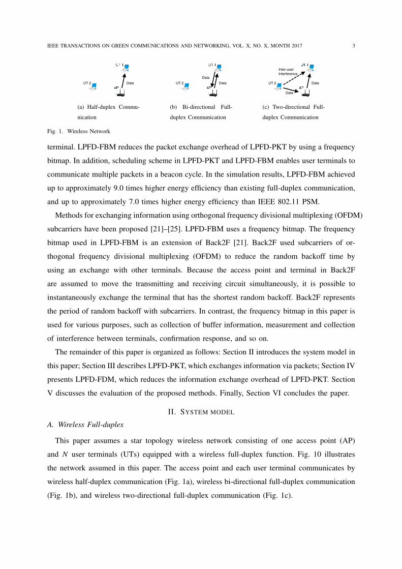
Fig. 1. Wireless Network
terminal. LPFD-FBM reduces the packet exchange overhead of LPFD-PKT by using a frequency
bitmap. In addition, scheduling scheme in LPFD-PKT and LPFD-FBM enables user terminals to
communicate multiple packets in a beacon cycle. In the simulation results, LPFD-FBM achieved
up to approximately 9.0 times higher energy efficiency than existing full-duplex communication,
and up to approximately 7.0 times higher energy efficiency than IEEE 802.11 PSM.
Methods for exchanging information using orthogonal frequency divisional multiplexing (OFDM)
subcarriers have been proposed [21]–[25]. LPFD-FBM uses a frequency bitmap. The frequency
bitmap used in LPFD-FBM is an extension of Back2F [21]. Back2F used subcarriers of or-
thogonal frequency divisional multiplexing (OFDM) to reduce the random backoff time by
using an exchange with other terminals. Because the access point and terminal in Back2F
are assumed to move the transmitting and receiving circuit simultaneously, it is possible to
instantaneously exchange the terminal that has the shortest random backoff. Back2F represents
the period of random backoff with subcarriers. In contrast, the frequency bitmap in this paper is
used for various purposes, such as collection of buffer information, measurement and collection
of interference between terminals, confirmation response, and so on.
The remainder of this paper is organized as follows: Section II introduces the system model in
this paper; Section III describes LPFD-PKT, which exchanges information via packets; Section IV
presents LPFD-FDM, which reduces the information exchange overhead of LPFD-PKT. Section
V discusses the evaluation of the proposed methods. Finally, Section VI concludes the paper.
II. SYSTEM MODEL
A. Wireless Full-duplex
This paper assumes a star topology wireless network consisting of one access point (AP)
and N user terminals (UTs) equipped with a wireless full-duplex function. Fig. 10 illustrates
the network assumed in this paper. The access point and each user terminal communicates by
wireless half-duplex communication (Fig. 1a), wireless bi-directional full-duplex communication
(Fig. 1b), and wireless two-directional full-duplex communication (Fig. 1c).
IEEE TRANSACTIONS ON GREEN COMMUNICATIONS AND NETWORKING, VOL. X, NO. X, MONTH 2017 4
!"#$%&'%%'($)*
+,-,./'($0$/,$$#
MainDeviceBody
ControlCircuit
AnalogTransmission
Circuit
AnalogReceptionCircuit
Data
Data
Data
Data
DigitalReceptionCircuit
DigitalTransmission
Circuit
DigitalSignal
DigitalSignal
AnalogSignal
AnalogSignal
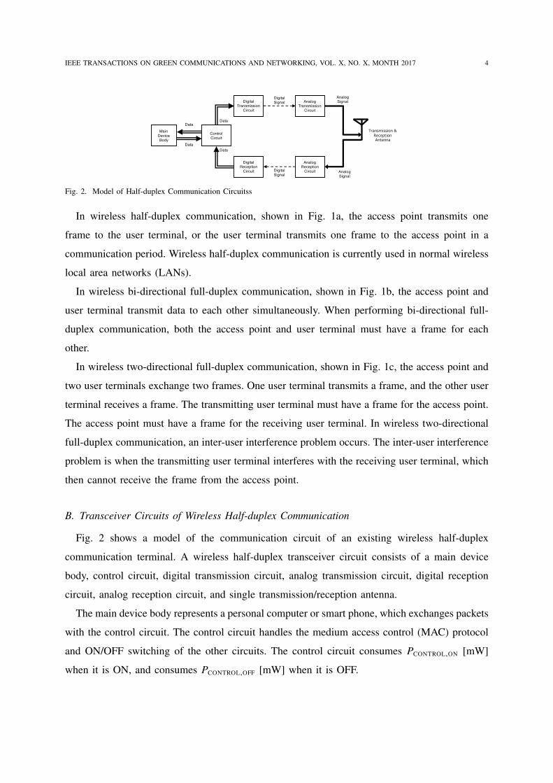
Fig. 2. Model of Half-duplex Communication Circuitss
In wireless half-duplex communication, shown in Fig. 1a, the access point transmits one
frame to the user terminal, or the user terminal transmits one frame to the access point in a
communication period. Wireless half-duplex communication is currently used in normal wireless
local area networks (LANs).
In wireless bi-directional full-duplex communication, shown in Fig. 1b, the access point and
user terminal transmit data to each other simultaneously. When performing bi-directional full-
duplex communication, both the access point and user terminal must have a frame for each
other.
In wireless two-directional full-duplex communication, shown in Fig. 1c, the access point and
two user terminals exchange two frames. One user terminal transmits a frame, and the other user
terminal receives a frame. The transmitting user terminal must have a frame for the access point.
The access point must have a frame for the receiving user terminal. In wireless two-directional
full-duplex communication, an inter-user interference problem occurs. The inter-user interference
problem is when the transmitting user terminal interferes with the receiving user terminal, which
then cannot receive the frame from the access point.
B. Transceiver Circuits of Wireless Half-duplex Communication
Fig. 2 shows a model of the communication circuit of an existing wireless half-duplex
communication terminal. A wireless half-duplex transceiver circuit consists of a main device
body, control circuit, digital transmission circuit, analog transmission circuit, digital reception
circuit, analog reception circuit, and single transmission/reception antenna.
The main device body represents a personal computer or smart phone, which exchanges packets
with the control circuit. The control circuit handles the medium access control (MAC) protocol
and ON/OFF switching of the other circuits. The control circuit consumes PCONTROL,ON [mW]
when it is ON, and consumes PCONTROL,OFF [mW] when it is OFF.
IEEE TRANSACTIONS ON GREEN COMMUNICATIONS AND NETWORKING, VOL. X, NO. X, MONTH 2017 5
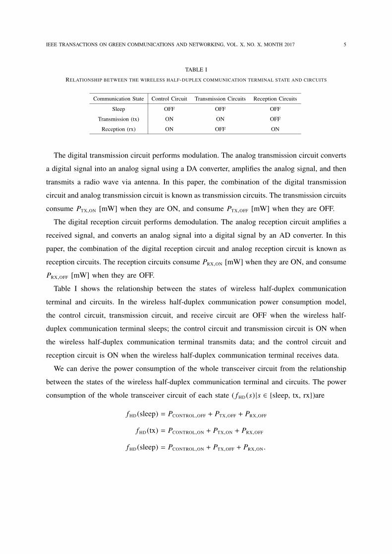
TABLE I
RELATIONSHIP BETWEEN THE WIRELESS HALF-DUPLEX COMMUNICATION TERMINAL STATE AND CIRCUITS
Communication State Control Circuit Transmission Circuits Reception Circuits
Sleep OFF OFF OFF
Transmission (tx) ON ON OFF
Reception (rx) ON OFF ON
The digital transmission circuit performs modulation. The analog transmission circuit converts
a digital signal into an analog signal using a DA converter, amplifies the analog signal, and then
transmits a radio wave via antenna. In this paper, the combination of the digital transmission
circuit and analog transmission circuit is known as transmission circuits. The transmission circuits
consume PTX,ON [mW] when they are ON, and consume PTX,OFF [mW] when they are OFF.
The digital reception circuit performs demodulation. The analog reception circuit amplifies a
received signal, and converts an analog signal into a digital signal by an AD converter. In this
paper, the combination of the digital reception circuit and analog reception circuit is known as
reception circuits. The reception circuits consume PRX,ON [mW] when they are ON, and consume
PRX,OFF [mW] when they are OFF.
Table I shows the relationship between the states of wireless half-duplex communication
terminal and circuits. In the wireless half-duplex communication power consumption model,
the control circuit, transmission circuit, and receive circuit are OFF when the wireless half-
duplex communication terminal sleeps; the control circuit and transmission circuit is ON when
the wireless half-duplex communication terminal transmits data; and the control circuit and
reception circuit is ON when the wireless half-duplex communication terminal receives data.
We can derive the power consumption of the whole transceiver circuit from the relationship
between the states of the wireless half-duplex communication terminal and circuits. The power
consumption of the whole transceiver circuit of each state ( fHD (s) |s ∈ {sleep, tx, rx})are
fHD (sleep) = PCONTROL,OFF + PTX,OFF + PRX,OFF
fHD (tx) = PCONTROL,ON + PTX,ON + PRX,OFF
fHD (sleep) = PCONTROL,ON + PTX,OFF + PRX,ON .
IEEE TRANSACTIONS ON GREEN COMMUNICATIONS AND NETWORKING, VOL. X, NO. X, MONTH 2017 6
AnalogSignal
ControlCircuit
AnalogTransmission
Circuit
AnalogReception
Circuit
AnalogCancellation
Circuit
TransmissionAntenna
ReceptionAntenna
MainDeviceBody
+
Data
Data
Data
Data
Analog Signal
Analog Signal
AnalogSignal
DigitalReception
Circuit
DigitalTransmission
Circuit
DigitalCancellation
Circuit
DigitalSignal
Digital Signal
Digital Signal
DigitalSignal
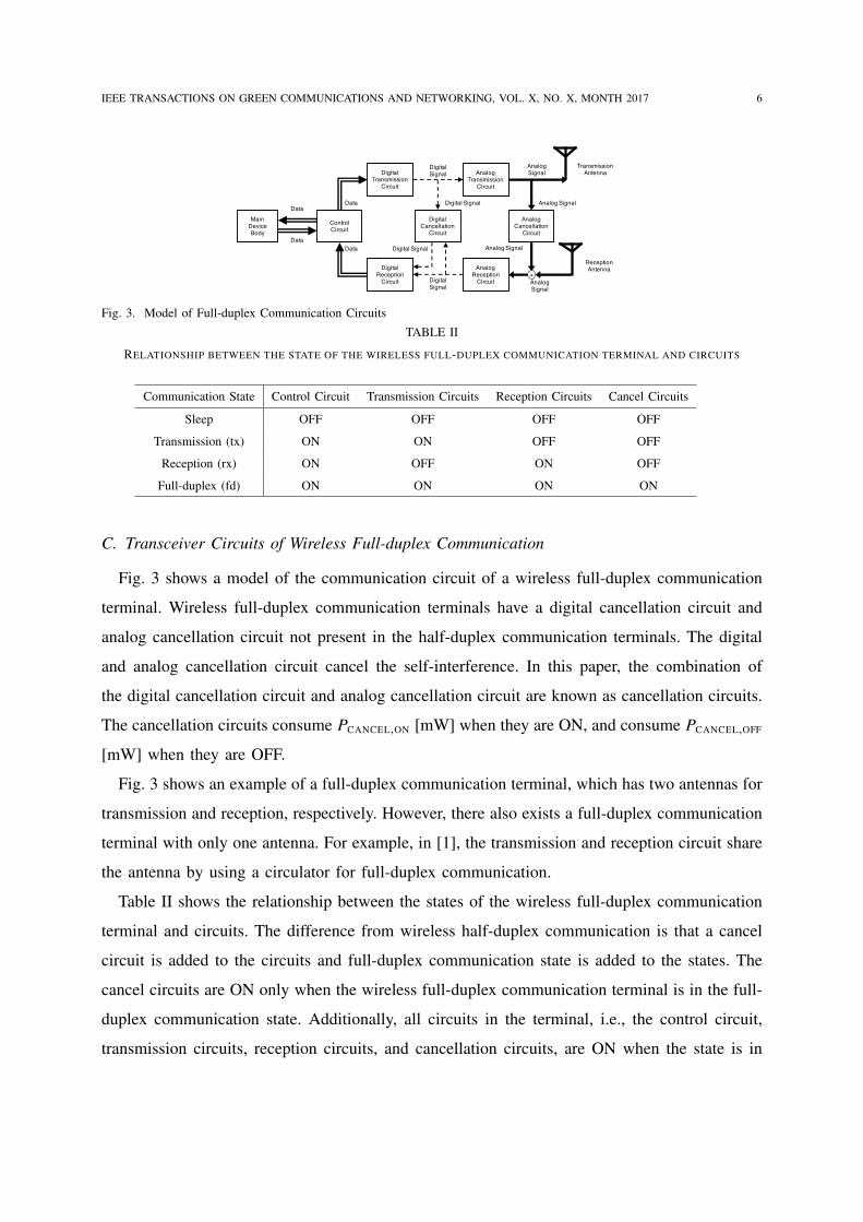
Fig. 3. Model of Full-duplex Communication Circuits
TABLE II
RELATIONSHIP BETWEEN THE STATE OF THE WIRELESS FULL-DUPLEX COMMUNICATION TERMINAL AND CIRCUITS
Communication State Control Circuit Transmission Circuits Reception Circuits Cancel Circuits
Sleep OFF OFF OFF OFF
Transmission (tx) ON ON OFF OFF
Reception (rx) ON OFF ON OFF
Full-duplex (fd) ON ON ON ON
C. Transceiver Circuits of Wireless Full-duplex Communication
Fig. 3 shows a model of the communication circuit of a wireless full-duplex communication
terminal. Wireless full-duplex communication terminals have a digital cancellation circuit and
analog cancellation circuit not present in the half-duplex communication terminals. The digital
and analog cancellation circuit cancel the self-interference. In this paper, the combination of
the digital cancellation circuit and analog cancellation circuit are known as cancellation circuits.
The cancellation circuits consume PCANCEL,ON [mW] when they are ON, and consume PCANCEL,OFF
[mW] when they are OFF.
Fig. 3 shows an example of a full-duplex communication terminal, which has two antennas for
transmission and reception, respectively. However, there also exists a full-duplex communication
terminal with only one antenna. For example, in [1], the transmission and reception circuit share
the antenna by using a circulator for full-duplex communication.
Table II shows the relationship between the states of the wireless full-duplex communication
terminal and circuits. The difference from wireless half-duplex communication is that a cancel
circuit is added to the circuits and full-duplex communication state is added to the states. The
cancel circuits are ON only when the wireless full-duplex communication terminal is in the full-
duplex communication state. Additionally, all circuits in the terminal, i.e., the control circuit,
transmission circuits, reception circuits, and cancellation circuits, are ON when the state is in
IEEE TRANSACTIONS ON GREEN COMMUNICATIONS AND NETWORKING, VOL. X, NO. X, MONTH 2017 7
full-duplex communication.
We can derive the power consumption of the whole transceiver circuit from the relationship
between the states of the wireless full-duplex communication terminal and circuits. The power
consumption of the whole transceiver circuit of each state ( fHD (s) |s ∈ {sleep, tx, rx, fd})are
fFD (sleep) = PCONTROL,OFF + PTX,OFF + PRX,OFF + PCANCEL,OFF
fFD (tx) = PCONTROL,ON + PTX,ON + PRX,OFF + PCANCEL,OFF
fFD (sleep) = PCONTROL,ON + PTX,OFF + PRX,ON + PCANCEL,OFF
fFD (fd) = PCONTROL,ON + PTX,ON + PRX,ON + PCANCEL,ON .
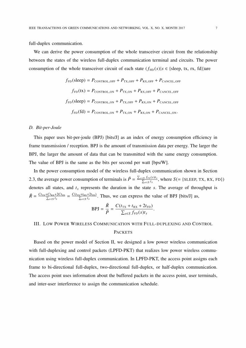
D. Bit-per-Joule
This paper uses bit-per-joule (BPJ) [bits/J] as an index of energy consumption efficiency in
frame transmission / reception. BPJ is the amount of transmission data per energy. The larger the
BPJ, the larger the amount of data that can be transmitted with the same energy consumption.
The value of BPJ is the same as the bits per second per watt [bps/W].
In the power consumption model of the wireless full-duplex communication shown in Section
2.3, the average power consumption of terminals is P̄ =∑
s∈S fFD (s)ts∑s∈S ts
, where S(= {SLEEP, TX, RX, FD})denotes all states, and ts represents the duration in the state s. The average of throughput is
R̄ = CtTX+CtRX+2CtFD∑s∈S ts
=C(tTX+tRX+2tFD)∑
s∈S ts. Thus, we can express the value of BPJ [bits/J] as,
BPJ =R̄P̄=
C(tTX + tRX + 2tFD)∑s∈S fFD (s)ts
.
III. LOW POWER WIRELESS COMMUNICATION WITH FULL-DUPLEXING AND CONTROL
PACKETS
Based on the power model of Section II, we designed a low power wireless communication
with full-duplexing and control packets (LPFD-PKT) that realizes low power wireless commu-
nication using wireless full-duplex communication. In LPFD-PKT, the access point assigns each
frame to bi-directional full-duplex, two-directional full-duplex, or half-duplex communication.
The access point uses information about the buffered packets in the access point, user terminals,
and inter-user interference to assign the communication schedule.
IEEE TRANSACTIONS ON GREEN COMMUNICATIONS AND NETWORKING, VOL. X, NO. X, MONTH 2017 8
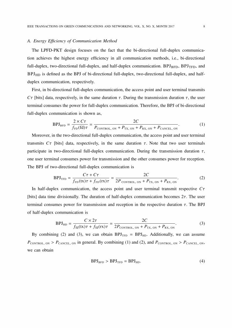
A. Energy Efficiency of Communication Method
The LPFD-PKT design focuses on the fact that the bi-directional full-duplex communica-
tion achieves the highest energy efficiency in all communication methods, i.e., bi-directional
full-duplex, two-directional full-duplex, and half-duplex communication. BPJBFD, BPJTFD, and
BPJHD is defined as the BPJ of bi-directional full-duplex, two-directional full-duplex, and half-
duplex communication, respectively.
First, in bi-directional full-duplex communication, the access point and user terminal transmits
Cτ [bits] data, respectively, in the same duration τ. During the transmission duration τ, the user
terminal consumes the power for full-duplex communication. Therefore, the BPJ of bi-directional
full-duplex communication is shown as,
BPJBFD =2 × CτfFD (fd)τ
=2C
PCONTROL, ON + PTX, ON + PRX, ON + PCANCEL, ON. (1)
Moreover, in the two-directional full-duplex communication, the access point and user terminal
transmits Cτ [bits] data, respectively, in the same duration τ. Note that two user terminals
participate in two-directional full-duplex communication. During the transmission duration τ,
one user terminal consumes power for transmission and the other consumes power for reception.
The BPJ of two-directional full-duplex communication is
BPJTFD =Cτ + Cτ
fFD (tx)τ + fFD (rx)τ=
2C2P CONTROL, ON + PTX, ON + PRX, ON
. (2)
In half-duplex communication, the access point and user terminal transmit respective Cτ
[bits] data time divisionally. The duration of half-duplex communication becomes 2τ. The user
terminal consumes power for transmission and reception in the respective duration τ. The BPJ
of half-duplex communication is
BPJHD =C × 2τ
f fd(tx)τ + f fd(rx)τ=
2C2PCONTROL, ON + PTX, ON + PRX, ON
. (3)
By combining (2) and (3), we can obtain BPJTFD = BPJHD. Additionally, we can assume
PCONTROL, ON > PCANCEL, ON in general. By combining (1) and (2), and PCONTROL, ON > PCANCEL, ON,
we can obtain
BPJBFD > BPJTFD = BPJHD . (4)
IEEE TRANSACTIONS ON GREEN COMMUNICATIONS AND NETWORKING, VOL. X, NO. X, MONTH 2017 9
UT 3
UT 5
AP
UT 4
UT 1
UT 2
Inter-user
Interference
Inter-user
Interference
Inter-user
Interference
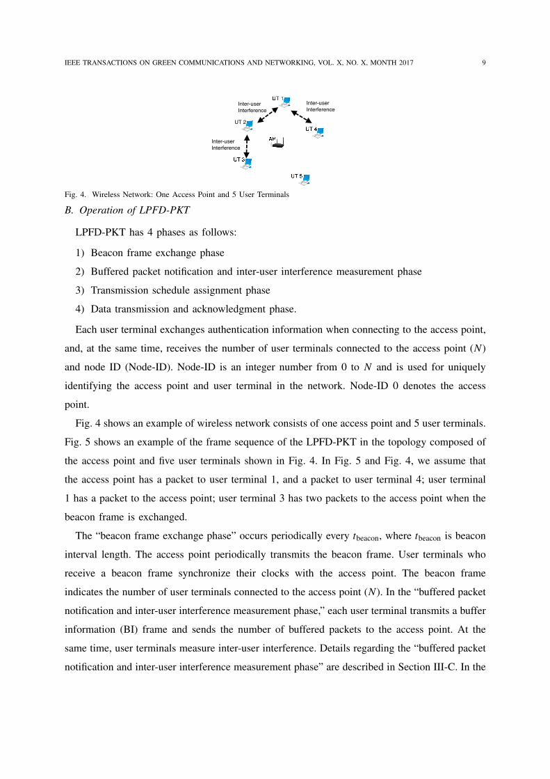
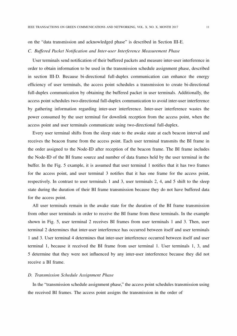
Fig. 4. Wireless Network: One Access Point and 5 User Terminals
B. Operation of LPFD-PKT
LPFD-PKT has 4 phases as follows:
1) Beacon frame exchange phase
2) Buffered packet notification and inter-user interference measurement phase
3) Transmission schedule assignment phase
4) Data transmission and acknowledgment phase.
Each user terminal exchanges authentication information when connecting to the access point,
and, at the same time, receives the number of user terminals connected to the access point (N)
and node ID (Node-ID). Node-ID is an integer number from 0 to N and is used for uniquely
identifying the access point and user terminal in the network. Node-ID 0 denotes the access
point.
Fig. 4 shows an example of wireless network consists of one access point and 5 user terminals.
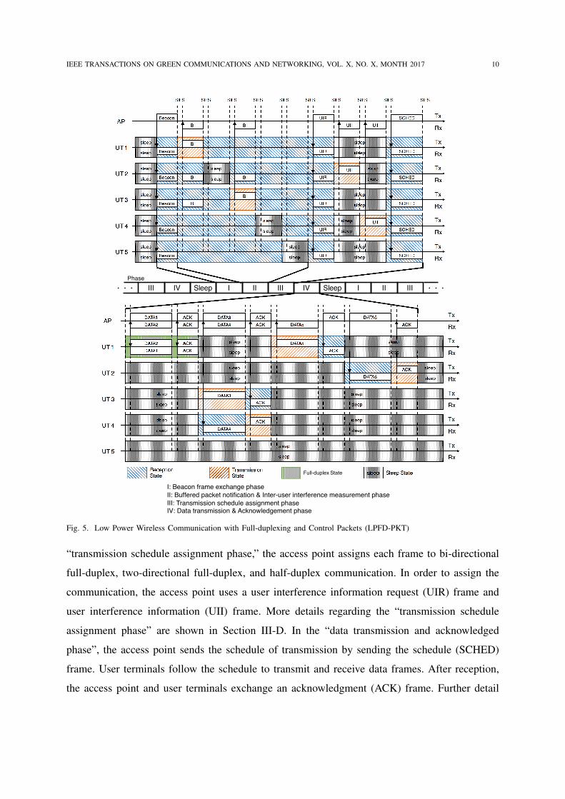
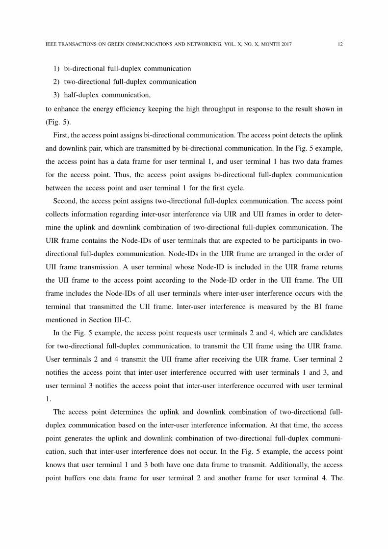
Fig. 5 shows an example of the frame sequence of the LPFD-PKT in the topology composed of
the access point and five user terminals shown in Fig. 4. In Fig. 5 and Fig. 4, we assume that
the access point has a packet to user terminal 1, and a packet to user terminal 4; user terminal
1 has a packet to the access point; user terminal 3 has two packets to the access point when the
beacon frame is exchanged.
The “beacon frame exchange phase” occurs periodically every tbeacon, where tbeacon is beacon
interval length. The access point periodically transmits the beacon frame. User terminals who
receive a beacon frame synchronize their clocks with the access point. The beacon frame
indicates the number of user terminals connected to the access point (N). In the “buffered packet
notification and inter-user interference measurement phase,” each user terminal transmits a buffer
information (BI) frame and sends the number of buffered packets to the access point. At the
same time, user terminals measure inter-user interference. Details regarding the “buffered packet
notification and inter-user interference measurement phase” are described in Section III-C. In the
IEEE TRANSACTIONS ON GREEN COMMUNICATIONS AND NETWORKING, VOL. X, NO. X, MONTH 2017 10
sleep
sleep
sleep
sleep
sleep
sleep
sleep
sleep
sleep
sleep
sleep
sleep
sleep
sleep
sleep
sleep
sleep
sleep
AP
UT 2
UT 1
UT 3
UT 4
SCHED
SCHED
SCHED
SCHED
SCHED
SIFS
UT 5
sleep
sleep
sleep
sleep
SIFS
sleep
sleep
sleep
sleep
UIR
UIR
UIR
UIR
UIR
Beacon
SIFS
UII
UII
SIFSSIFS
UII
UII
SIFS
SCHEDUIR
SIFS
BI
BI
BI
BI
SIFS
BI
BI
BI
SIFS
Beacon
Beacon
Beacon
Beacon
Beacon
SIFS
Tx
Rx
Tx
Rx
Tx
Rx
Tx
Rx
Tx
Rx
Tx
Rx
sleep
sleep
sleep
sleep
sleep
sleep
sleep
sleep
sleep
sleep
sleep
sleep
sleep
sleep
sleep
sleep
sleep
sleep
DATA1
ACK
DATA1
ACK
Tx
DATA2
DATA2
ACK
ACK DATA3
DATA3
DATA4
DATA4
ACK
ACK
ACK
ACK
DATA5
DATA5
ACK
ACK
DATA6
DATA6
ACK
ACK
Rx
Tx
Rx
Tx
Rx
Tx
Rx
Tx
Rx
Tx
Rx
AP
UT 2
UT 1
UT 3
UT 4
UT 5
Reception State
sleep Sleep StateTransmission State
Full-duplex State
Ⅰ: Beacon frame exchange phase
Ⅱ: Buffered packet notification & Inter-user interference measurement phase
Ⅲ: Transmission schedule assignment phaseⅣ: Data transmission & Acknowledgement phase
Ⅰ SleepⅡ Ⅲ ⅣSleepⅢ Ⅳ Ⅰ Ⅱ Ⅲ !!!!!!
Phase
Fig. 5. Low Power Wireless Communication with Full-duplexing and Control Packets (LPFD-PKT)
“transmission schedule assignment phase,” the access point assigns each frame to bi-directional
full-duplex, two-directional full-duplex, and half-duplex communication. In order to assign the
communication, the access point uses a user interference information request (UIR) frame and
user interference information (UII) frame. More details regarding the “transmission schedule
assignment phase” are shown in Section III-D. In the “data transmission and acknowledged
phase”, the access point sends the schedule of transmission by sending the schedule (SCHED)
frame. User terminals follow the schedule to transmit and receive data frames. After reception,
the access point and user terminals exchange an acknowledgment (ACK) frame. Further detail
IEEE TRANSACTIONS ON GREEN COMMUNICATIONS AND NETWORKING, VOL. X, NO. X, MONTH 2017 11
on the “data transmission and acknowledged phase” is described in Section III-E.
C. Buffered Packet Notification and Inter-user Interference Measurement Phase
User terminals send notification of their buffered packets and measure inter-user interference in
order to obtain information to be used in the transmission schedule assignment phase, described
in section III-D. Because bi-directional full-duplex communication can enhance the energy
efficiency of user terminals, the access point schedules a transmission to create bi-directional
full-duplex communication by obtaining the buffered packet in user terminals. Additionally, the
access point schedules two-directional full-duplex communication to avoid inter-user interference
by gathering information regarding inter-user interference. Inter-user interference wastes the
power consumed by the user terminal for downlink reception from the access point, when the
access point and user terminals communicate using two-directional full-duplex.
Every user terminal shifts from the sleep state to the awake state at each beacon interval and
receives the beacon frame from the access point. Each user terminal transmits the BI frame in
the order assigned to the Node-ID after reception of the beacon frame. The BI frame includes
the Node-ID of the BI frame source and number of data frames held by the user terminal in the
buffer. In the Fig. 5 example, it is assumed that user terminal 1 notifies that it has two frames
for the access point, and user terminal 3 notifies that it has one frame for the access point,
respectively. In contrast to user terminals 1 and 3, user terminals 2, 4, and 5 shift to the sleep
state during the duration of their BI frame transmission because they do not have buffered data
for the access point.
All user terminals remain in the awake state for the duration of the BI frame transmission
from other user terminals in order to receive the BI frame from these terminals. In the example
shown in Fig. 5, user terminal 2 receives BI frames from user terminals 1 and 3. Then, user
terminal 2 determines that inter-user interference has occurred between itself and user terminals
1 and 3. User terminal 4 determines that inter-user interference occurred between itself and user
terminal 1, because it received the BI frame from user terminal 1. User terminals 1, 3, and
5 determine that they were not influenced by any inter-user interference because they did not
receive a BI frame.
D. Transmission Schedule Assignment Phase
In the “transmission schedule assignment phase,” the access point schedules transmission using
the received BI frames. The access point assigns the transmission in the order of
IEEE TRANSACTIONS ON GREEN COMMUNICATIONS AND NETWORKING, VOL. X, NO. X, MONTH 2017 12
1) bi-directional full-duplex communication
2) two-directional full-duplex communication
3) half-duplex communication,
to enhance the energy efficiency keeping the high throughput in response to the result shown in
(Fig. 5).
First, the access point assigns bi-directional communication. The access point detects the uplink
and downlink pair, which are transmitted by bi-directional communication. In the Fig. 5 example,
the access point has a data frame for user terminal 1, and user terminal 1 has two data frames
for the access point. Thus, the access point assigns bi-directional full-duplex communication
between the access point and user terminal 1 for the first cycle.
Second, the access point assigns two-directional full-duplex communication. The access point
collects information regarding inter-user interference via UIR and UII frames in order to deter-
mine the uplink and downlink combination of two-directional full-duplex communication. The
UIR frame contains the Node-IDs of user terminals that are expected to be participants in two-
directional full-duplex communication. Node-IDs in the UIR frame are arranged in the order of
UII frame transmission. A user terminal whose Node-ID is included in the UIR frame returns
the UII frame to the access point according to the Node-ID order in the UII frame. The UII
frame includes the Node-IDs of all user terminals where inter-user interference occurs with the
terminal that transmitted the UII frame. Inter-user interference is measured by the BI frame
mentioned in Section III-C.
In the Fig. 5 example, the access point requests user terminals 2 and 4, which are candidates
for two-directional full-duplex communication, to transmit the UII frame using the UIR frame.
User terminals 2 and 4 transmit the UII frame after receiving the UIR frame. User terminal 2
notifies the access point that inter-user interference occurred with user terminals 1 and 3, and
user terminal 3 notifies the access point that inter-user interference occurred with user terminal
1.
The access point determines the uplink and downlink combination of two-directional full-
duplex communication based on the inter-user interference information. At that time, the access
point generates the uplink and downlink combination of two-directional full-duplex communi-
cation, such that inter-user interference does not occur. In the Fig. 5 example, the access point
knows that user terminal 1 and 3 both have one data frame to transmit. Additionally, the access
point buffers one data frame for user terminal 2 and another frame for user terminal 4. The
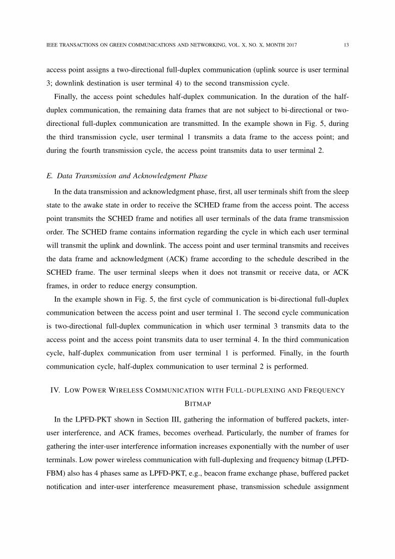
IEEE TRANSACTIONS ON GREEN COMMUNICATIONS AND NETWORKING, VOL. X, NO. X, MONTH 2017 13
access point assigns a two-directional full-duplex communication (uplink source is user terminal
3; downlink destination is user terminal 4) to the second transmission cycle.
Finally, the access point schedules half-duplex communication. In the duration of the half-
duplex communication, the remaining data frames that are not subject to bi-directional or two-
directional full-duplex communication are transmitted. In the example shown in Fig. 5, during
the third transmission cycle, user terminal 1 transmits a data frame to the access point; and
during the fourth transmission cycle, the access point transmits data to user terminal 2.
E. Data Transmission and Acknowledgment Phase
In the data transmission and acknowledgment phase, first, all user terminals shift from the sleep
state to the awake state in order to receive the SCHED frame from the access point. The access
point transmits the SCHED frame and notifies all user terminals of the data frame transmission
order. The SCHED frame contains information regarding the cycle in which each user terminal
will transmit the uplink and downlink. The access point and user terminal transmits and receives
the data frame and acknowledgment (ACK) frame according to the schedule described in the
SCHED frame. The user terminal sleeps when it does not transmit or receive data, or ACK
frames, in order to reduce energy consumption.
In the example shown in Fig. 5, the first cycle of communication is bi-directional full-duplex
communication between the access point and user terminal 1. The second cycle communication
is two-directional full-duplex communication in which user terminal 3 transmits data to the
access point and the access point transmits data to user terminal 4. In the third communication
cycle, half-duplex communication from user terminal 1 is performed. Finally, in the fourth
communication cycle, half-duplex communication to user terminal 2 is performed.
IV. LOW POWER WIRELESS COMMUNICATION WITH FULL-DUPLEXING AND FREQUENCY
BITMAP
In the LPFD-PKT shown in Section III, gathering the information of buffered packets, inter-
user interference, and ACK frames, becomes overhead. Particularly, the number of frames for
gathering the inter-user interference information increases exponentially with the number of user
terminals. Low power wireless communication with full-duplexing and frequency bitmap (LPFD-
FBM) also has 4 phases same as LPFD-PKT, e.g., beacon frame exchange phase, buffered packet
notification and inter-user interference measurement phase, transmission schedule assignment
IEEE TRANSACTIONS ON GREEN COMMUNICATIONS AND NETWORKING, VOL. X, NO. X, MONTH 2017 14
AP
UT2
AP
UT1
symbol1 2 3 4
AP Reception
UT1
subcarrier (Node-ID)
AP (0)
UT 1 (1)
UT 2 (2)
UT 3 (3)
UT 5 (5)
symbol1 2 3 4
UT 4 (4)
UT 1 Transmission
UT2
symbol1 2 3 4
UT 2 Transmission
subcarrier (Node-ID)
AP (0)
UT 1 (1)
UT 2 (2)
UT 3 (3)
UT 5 (5)
symbol1 2 3 4
UT 4 (4)
AP Transmission
OR
Operation
AP (0)
UT 1 (1)
UT 2 (2)
UT 3 (3)
UT 5 (5)
UT 4 (4)
subcarrier (Node-ID)
subcarrier (Node-ID)
AP (0)
UT 1 (1)
UT 2 (2)
UT 3 (3)
UT 5 (5)
UT 4 (4)
Fig. 6. Frequency Bitmap
phase, data transmission and acknowledgment phase. However, in contrast to LPFD-PKT, LPFD-
FBM reduces overhead by using a combination of full-duplex communication and frequency
bitmap. Specifically, LPFD-FBM uses 5 types of frequency bitmap, namely: buffer information
frequency bitmap (BI-FBM), reducing the overhead of gathering the buffered packet informa-
tion; user interference information request frequency bitmap (UIR-FBM) and user interference
information frequency bitmap (UII-FBM), reducing the overhead of gathering the inter-user
interference information; schedule frequency bitmap (SCHED-FBM), reducing the overhead of
the transmission schedule notification by the access point to user terminals; and acknowledgment
frequency bitmap (ACK-FBM), to reduce the acknowledgment overhead.
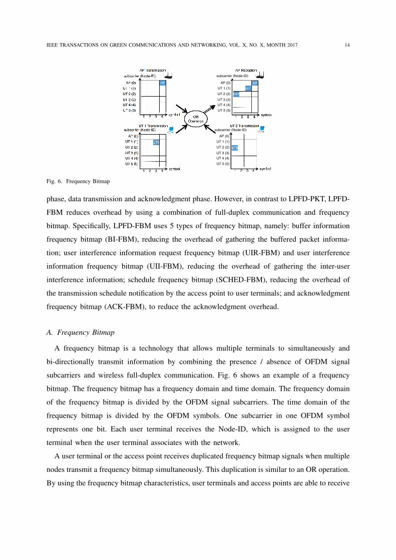
A. Frequency Bitmap
A frequency bitmap is a technology that allows multiple terminals to simultaneously and
bi-directionally transmit information by combining the presence / absence of OFDM signal
subcarriers and wireless full-duplex communication. Fig. 6 shows an example of a frequency
bitmap. The frequency bitmap has a frequency domain and time domain. The frequency domain
of the frequency bitmap is divided by the OFDM signal subcarriers. The time domain of the
frequency bitmap is divided by the OFDM symbols. One subcarrier in one OFDM symbol
represents one bit. Each user terminal receives the Node-ID, which is assigned to the user
terminal when the user terminal associates with the network.
A user terminal or the access point receives duplicated frequency bitmap signals when multiple
nodes transmit a frequency bitmap simultaneously. This duplication is similar to an OR operation.
By using the frequency bitmap characteristics, user terminals and access points are able to receive
IEEE TRANSACTIONS ON GREEN COMMUNICATIONS AND NETWORKING, VOL. X, NO. X, MONTH 2017 15
Ⅰ SleepⅡ Ⅲ ⅣSleepⅢ Ⅳ Ⅰ Ⅱ Ⅲ !!!!!!
sleep
sleep
sleep
sleep
sleep
sleep
sleep
sleep
AP
UT 2
UT 3
UT 4
SCHED-FBM
SCHED-FBM
SCHED-FBM
SCHED-FBM
SCHED-FBM
UT 5
sleep
sleep
sleep
sleep
UIR-FBM
UIR-FBM
UIR-FBM
UIR-FBM
UIR-FBM
Beacon
SIFS SIFSSIFS
UII-FBM
UII-FBM
SIFS
SCHED-FBM
BI-FBM
BI-FBM
BI-FBM
Beacon
Beacon
Beacon
UII-FBM
BI-FBM
BI-FBMsleep
sleep Beacon
sleep
sleep BeaconUT 1
sleep
sleep
sleep
sleep
sleep
sleep
sleep
sleep
sleep
sleep
sleep
sleep
sleep
sleep
sleep
sleep
sleep
sleep
sleep
sleep
sleep
sleep
sleep
sleep
DATA1
DATA1
Tx
DATA2
DATA2
DATA5
DATA5
DATA6
DATA6
Rx
Tx
Rx
Tx
Rx
Tx
Rx
Tx
Rx
Tx
Rx
DATA3
DATA3
DATA4
DATA4
ACK-FBM
ACK-FBM
ACK-FBM
ACK-FBM
ACK-FBM
ACK-FBM
ACK-FBM
AP
UT 2
UT 3
UT 4
UT 5
UT 1
Reception State
sleep Sleep StateTransmission State
Full-duplex State
Ⅰ: Beacon frame exchange phase
Ⅱ: Buffered packet notification & Inter-user interference measurement phase
Ⅲ: Transmission schedule assignment phaseⅣ: Data transmission & Acknowledgement phase
Phase
UIR-FBM
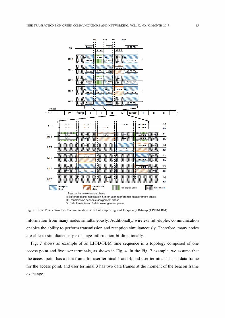
Fig. 7. Low Power Wireless Communication with Full-duplexing and Frequency Bitmap (LPFD-FBM)
information from many nodes simultaneously. Additionally, wireless full-duplex communication
enables the ability to perform transmission and reception simultaneously. Therefore, many nodes
are able to simultaneously exchange information bi-directionally.
Fig. 7 shows an example of an LPFD-FBM time sequence in a topology composed of one
access point and five user terminals, as shown in Fig. 4. In the Fig. 7 example, we assume that
the access point has a data frame for user terminal 1 and 4; and user terminal 1 has a data frame
for the access point, and user terminal 3 has two data frames at the moment of the beacon frame
exchange.
IEEE TRANSACTIONS ON GREEN COMMUNICATIONS AND NETWORKING, VOL. X, NO. X, MONTH 2017 16
All user terminals shift from the sleep state to the awake state to receive the beacon frame
in each beacon interval. LPFD-FBM uses the same beacon frame as the LPFD-PKT frame,
mentioned in Section III.
All user terminals who receive the beacon frame, sends a notification of buffered packets in
each terminal using BI-FBM. Additionally, at the same time, all user terminals measure inter-
user interference by receiving the BI-FBM from other user terminals with full-duplex reception
circuits. Details of the BI-FBM will be mentioned in Section IV-B.
The access point schedules bi-directional full-duplex communication after receiving BI-FBMs.
Then, the access point informs the reception destination candidates of downlink two-directional
full-duplex communication by transmitting a UIR-FBM to all user terminals. User terminals
who are mentioned as candidates, transmit the UII-FBM. UII-FBM indicates the buffered packet
information and inter-user interference of the transmitting user terminal. More detail regarding
the UIR-FBM and UII-FBM is given in Section IV-C and IV-D, respectively.
After receiving the UII-FBM frames, the access point schedules the data frame transmission by
using buffered packets in the access point and all user terminals, and inter user interference. The
scheduling algorithm uses the same thing as LPFD-PKT. The access point transmits the SCHED-
FBM to all user terminals. The SCHED-FBM includes the transmission schedule information.
More detail regarding SCHED-FBM is given in Section IV-E.
The user terminal that has received the SCHED-FBM transmits and receives data frames in
accordance with the schedule that the access point has determined. After the transmission and
reception of all data frames has been completed, the access point and all user terminals exchange
the ACK-FBM, which acknowledges data arrival. More detail regarding the ACK-FBM is given
in Section IV-F.
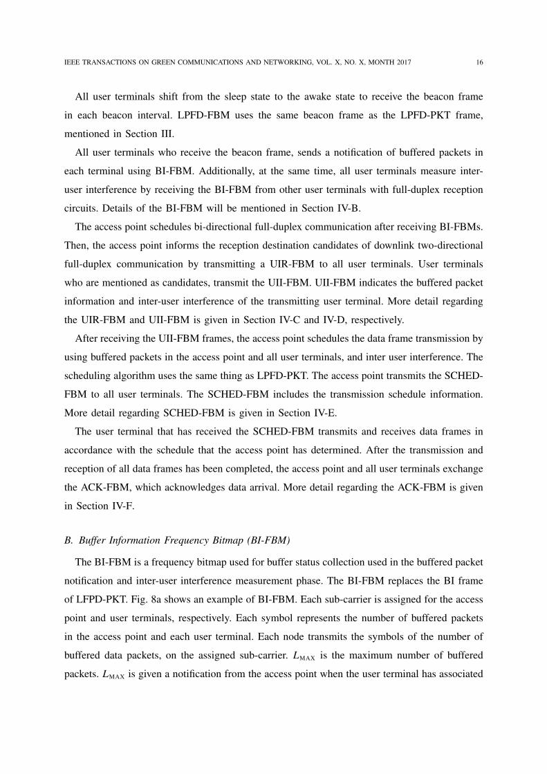
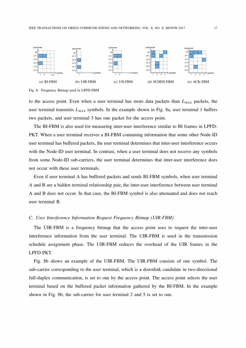
B. Buffer Information Frequency Bitmap (BI-FBM)
The BI-FBM is a frequency bitmap used for buffer status collection used in the buffered packet
notification and inter-user interference measurement phase. The BI-FBM replaces the BI frame
of LFPD-PKT. Fig. 8a shows an example of BI-FBM. Each sub-carrier is assigned for the access
point and user terminals, respectively. Each symbol represents the number of buffered packets
in the access point and each user terminal. Each node transmits the symbols of the number of
buffered data packets, on the assigned sub-carrier. LMAX is the maximum number of buffered
packets. LMAX is given a notification from the access point when the user terminal has associated
IEEE TRANSACTIONS ON GREEN COMMUNICATIONS AND NETWORKING, VOL. X, NO. X, MONTH 2017 17
UT 1
UT 3
UT 1
subcarrier
AP
UT 1
UT 2
UT 3
UT 5
symbol1 2 … !MAX
UT 4
(a) BI-FBM
AP
AP
subcarrier
AP
UT 1
UT 2
UT 3
UT 4
symbol1
UT 5
(b) UIR-FBM
UT 2
UT 4UT 2
subcarrier
AP
UT 1
UT 2
UT 3
UT 4
symbol1 2
UT 5
(c) UII-FBM
AP
AP
AP
AP
AP
subcarrier
AP
UT 1
UT 2
UT 3
UT 4
symbol1 2
AP
3 4
UT 5
(d) SCHED-FBM
UT 2
AP
UT 1
AP
UT 4
subcarrier
AP
UT 1
UT 2
UT 3
UT 4
symbol1 2 3 4
UT 5
AP
(e) ACK-FBM
Fig. 8. Frequency Bitmap used in LPFD-FBM
to the access point. Even when a user terminal has more data packets than LMAX packets, the
user terminal transmits LMAX symbols. In the example shown in Fig. 8a, user terminal 1 buffers
two packets, and user terminal 3 has one packet for the access point.
The BI-FBM is also used for measuring inter-user interference similar to BI frames in LPFD-
PKT. When a user terminal receives a BI-FBM containing information that some other Node-ID
user terminal has buffered packets, the user terminal determines that inter-user interference occurs
with the Node-ID user terminal. In contrast, when a user terminal does not receive any symbols
from some Node-ID sub-carriers, the user terminal determines that inter-user interference does
not occur with these user terminals.
Even if user terminal A has buffered packets and sends BI-FBM symbols, when user terminal
A and B are a hidden terminal relationship pair, the inter-user interference between user terminal
A and B does not occur. In that case, the BI-FBM symbol is also attenuated and does not reach
user terminal B.
C. User Interference Information Request Frequency Bitmap (UIR-FBM)
The UIR-FBM is a frequency bitmap that the access point uses to request the inter-user
interference information from the user terminal. The UIR-FBM is used in the transmission
schedule assignment phase. The UIR-FBM reduces the overhead of the UIR frames in the
LPFD-PKT.
Fig. 8b shows an example of the UIR-FBM. The UIR-FBM consists of one symbol. The
sub-carrier corresponding to the user terminal, which is a downlink candidate in two-directional
full-duplex communication, is set to one by the access point. The access point selects the user
terminal based on the buffered packet information gathered by the BI-FBM. In the example
shown in Fig. 8b, the sub-carrier for user terminal 2 and 5 is set to one.
IEEE TRANSACTIONS ON GREEN COMMUNICATIONS AND NETWORKING, VOL. X, NO. X, MONTH 2017 18
D. User Interference Information Frequency Bitmap (UII-FBM)
The UII-FBM is a frequency bitmap used for transmitting the inter-user interference between
user terminals to the access point from each user terminal. The UII-FBM is used in the trans-
mission schedule assignment phase. The UII-FBM replaces the UII frames of LPFD-PKT and
reduces the overhead of UII frames.
Fig. 8c shows an example of UII-FBM. The user terminal that has been requested to send the
inter-user interference information by the UIR-FBM from the access point, sends a UII-FBM.
The UII-FBM from each user terminal indicates that inter-user interference occurs between the
user terminal and two-directional full-duplex destination user terminal mentioned in the UIR-
FBM. In order to reduce the UII-FBM size, each user terminal sends inter-user interference
information via the following procedure: First, the user terminal receiving the UIR-FBM from
the access point, retrieves only the Node-ID which assigned subcarrier is 1, and arranges the
retrieved Node-ID ascending order. Note that the retrieved Node-ID represents the user terminal,
which is requested to transmit the inter-user interference information from access point in the
UIR-FBM. The requested user terminals transmit the UII-FBM in accordance with the order of
the retrieved Node-ID. Each user terminal sets the UII-FBM sub-carrier of the Node-ID causing
inter-user interference with itself to one.
In the example shown in Fig. 8c, user terminals 2 and 4 send the inter-user interference
information. The first symbol is assigned for user terminal 2; and the second is assigned for
user terminal 4. User terminal 2 sends a symbol with the sub-carrier for Node-ID 1 and 3 set
to one. Also, user terminal 4 sends a symbol with the sub-carrier for Node-ID 1 set to one.
E. Schedule Frequency Bitmap (SCHED-FBM)
The SCHED-FBM is a frequency bitmap for the access point to notify all user terminals of the
data frame transmission and reception schedule. The SCHED-FBM is used in the transmission
schedule assignment phase Fig. 8d shows an example of the SCHED-FBM. Subcarrier denotes
the Node-ID of each user terminal and access point. Symbol denotes the scheduled transmission
slot. For bi-directional full-duplex communication, the access point transmits a symbol in which
two subcarriers for the access point and communication partner user terminal is set to one. In
addition, for two-directional full-duplex communication, the access point transmits a symbol
in which two subcarriers are set to one, one is a subcarrier for the transmitter user terminal
Node-ID, the other is a subcarrier for the receiver Node-ID. For half-duplex communication,
IEEE TRANSACTIONS ON GREEN COMMUNICATIONS AND NETWORKING, VOL. X, NO. X, MONTH 2017 19
the access point transmits a symbol that a subcarrier for a transmitter or receiver user terminal
Node-ID is set to one.
In the example shown in Fig. 8d, the SCHED-FBM example shows that bi-directional full-
duplex communication between the access point and user terminal 1 will be performed in the first
transmission cycle; in the second transmission cycle, two-directional full-duplex communication,
an uplink from user terminal 3 and downlink to user terminal 4, will be performed; in the third
transmission cycle, an uplink half-duplex communication from user terminal 1 will be performed;
and in the fourth transmission cycle, a downlink half-duplex communication to user terminal 2
will be performed.
Note that user terminals are each able to distinguish whether they are transmitter or receiver
in two-directional full-duplex communication. This is because only transmission packets or
reception packets remain due to bi-directional full-duplex communication being performed just
before two-directional full-duplex communication. This mechanism enables the access point
to communicate the schedule of two-directional full-duplex communication and half-duplex
communication by only using the UIR-FBM and SCHED-FBM.
F. ACK-FBM
An example of the ACK-FBM is shown in Fig. 8e. The ACK-FBM is a frequency bitmap used
for acknowledgment in the data transmission and acknowledgement phase. Subcarriers represent
the Node-IDs of the access point and user terminals; symbols represent transmission cycles.
When each access point and user terminal transmits received data in a certain transmission
cycle, the access point and user set the symbol representing the transmission cycle to 1 in the
ACK-FBM. The access point and all user terminals transmit the ACK-FBMs simultaneously. In
the example shown in Fig. 8e, the access point transmits ACK for the uplink transmission from
user terminal 1 in the first symbol; the access point transmits ACK for the uplink transmission
from user terminal 3 in the second symbol; user terminal 4 transmits ACK for the downlink
transmission from user terminal 4 in the third symbol; and user terminal 2 transmits ACK for
the downlink transmission from the user terminal 2 in the fourth symbol.
V. PERFORMANCE EVALUATIONS
We performed a computer simulation to confirm the performance of LPFD-PKT and LPFD-
FBM.
IEEE TRANSACTIONS ON GREEN COMMUNICATIONS AND NETWORKING, VOL. X, NO. X, MONTH 2017 20
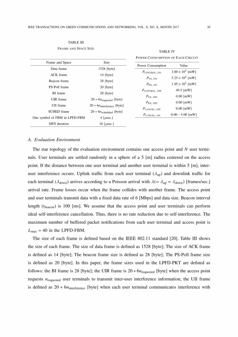
TABLE III
FRAME AND SPACE SIZE
Frame and Space Size
Data frame 1528 [byte]
ACK frame 14 [byte]
Beacon frame 28 [byte]
PS-Poll frame 20 [byte]
BI frame 28 [byte]
UIR frame 20 + 6nrequested [byte]
UII frame 20 + 6ninterference [byte]
SCHED frame 20 + 6nscheduled [byte]
One symbol of FBM in LPFD-FBM 4 [µsec.]
SIFS duration 16 [µsec.]
TABLE IV
POWER CONSUMPTION OF EACH CIRCUIT
Power Consumption Value
PCONTROL, ON 3.00 × 10² [mW]
PTX, ON 5.25 × 10² [mW]
PRX, ON 1.95 × 10² [mW]
PCONTROL, OFF 49.5 [mW]
PTX, OFF 0.00 [mW]
PRX, OFF 0.00 [mW]
PCANCEL, OFF 0.00 [mW]
PCANCEL, ON 0.00 − 5.00 [mW]
A. Evaluation Environment
The star topology of the evaluation environment contains one access point and N user termi-
nals. User terminals are settled randomly in a sphere of a 5 [m] radius centered on the access
point. If the distance between one user terminal and another user terminal is within 5 [m], inter-
user interference occurs. Uplink traffic from each user terminal (λup) and downlink traffic for
each terminal (λdown) arrives according to a Poisson arrival with λ(= λup = λdown) [frames/sec.]
arrival rate. Frame losses occur when the frame collides with another frame. The access point
and user terminals transmit data with a fixed data rate of 6 [Mbps] and data size. Beacon interval
length (tbeacon) is 100 [ms]. We assume that the access point and user terminals can perform
ideal self-interference cancellation. Thus, there is no rate reduction due to self-interference. The
maximum number of buffered packet notifications from each user terminal and access point is
Lmax = 40 in the LPFD-FBM.
The size of each frame is defined based on the IEEE 802.11 standard [20]. Table III shows
the size of each frame. The size of data frame is defined as 1528 [byte]; The size of ACK frame
is defined as 14 [byte]; The beacon frame size is defined as 28 [byte]; The PS-Poll frame size
is defined as 20 [byte]. In this paper, the frame sizes used in the LPFD-PKT are defined as
follows: the BI frame is 28 [byte]; the UIR frame is 20+6nrequested [byte] when the access point
requests nrequested user terminals to transmit inter-user interference information; the UII frame
is defined as 20 + 6ninterference [byte] when each user terminal communicates interference with
IEEE TRANSACTIONS ON GREEN COMMUNICATIONS AND NETWORKING, VOL. X, NO. X, MONTH 2017 21
ninterference user terminals; and the SCHED frame is 20+ 6nscheduled [byte] when the access point
communicates the schedule of nscheduled cycles data and ACK transmission. Additionally, the
length of one symbol in the frequency bitmap used in the LPFD-FBM is defined as 4 [µsec.].
SIFS duration is defined as 16 [µsec.] [20].
Power consumption of each circuit is defined based on the chipset of Wi-Fi, SX-SDCAG
802.11a/b/g SDIO Card Module [26]. Table IV shows the power consumption of each circuit.
PCONTROL, ON is 4.95 × 101 [mW]; PTX, ON is 7.76 × 10² [mW]; PRX, ON is 4.46 × 10² [mW];
PCONTROL, OFF is 2.00 [mW]; PTX, OFF is 0.00 [mW]; PRX, OFF is 0.00 [mW]; PCANCEL, OFF is 0.00
[mW]. Currently, no off-the-shelf self-interference cancellation circuit for full-duplex WLAN ex-
ists. The power consumption of cancelations, e.g., balun cancelation [1], [4], passive cancelation
[3], is small enough to neglect power consumption. In this paper, we evaluated with variable
PCANCEL, ON.
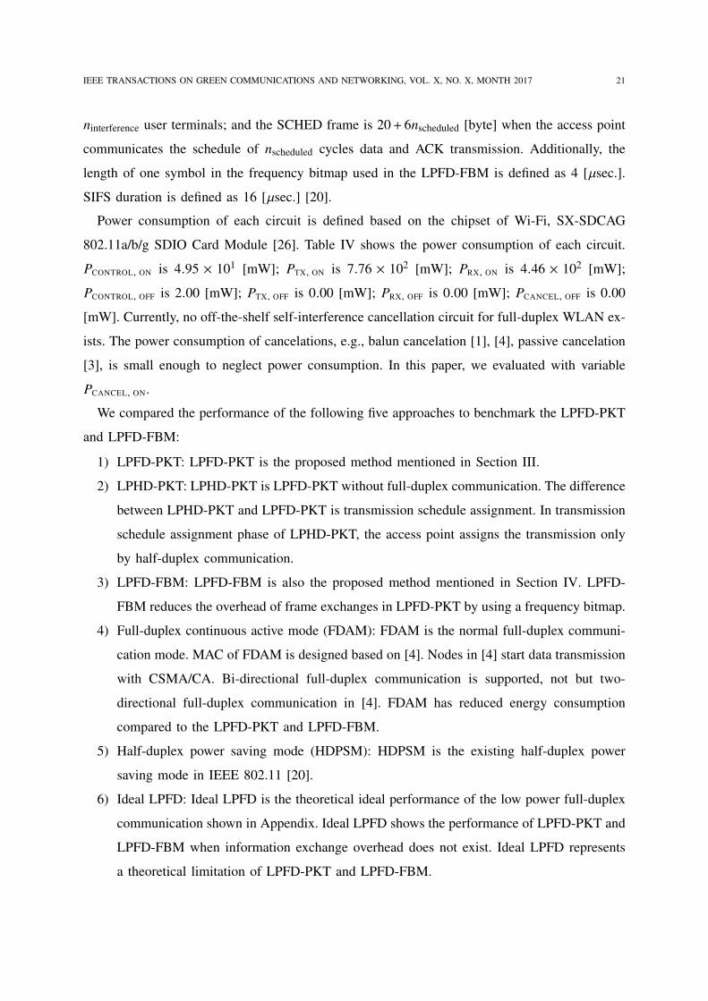
We compared the performance of the following five approaches to benchmark the LPFD-PKT
and LPFD-FBM:
1) LPFD-PKT: LPFD-PKT is the proposed method mentioned in Section III.
2) LPHD-PKT: LPHD-PKT is LPFD-PKT without full-duplex communication. The difference
between LPHD-PKT and LPFD-PKT is transmission schedule assignment. In transmission
schedule assignment phase of LPHD-PKT, the access point assigns the transmission only
by half-duplex communication.
3) LPFD-FBM: LPFD-FBM is also the proposed method mentioned in Section IV. LPFD-
FBM reduces the overhead of frame exchanges in LPFD-PKT by using a frequency bitmap.
4) Full-duplex continuous active mode (FDAM): FDAM is the normal full-duplex communi-
cation mode. MAC of FDAM is designed based on [4]. Nodes in [4] start data transmission
with CSMA/CA. Bi-directional full-duplex communication is supported, not but two-
directional full-duplex communication in [4]. FDAM has reduced energy consumption
compared to the LPFD-PKT and LPFD-FBM.
5) Half-duplex power saving mode (HDPSM): HDPSM is the existing half-duplex power
saving mode in IEEE 802.11 [20].
6) Ideal LPFD: Ideal LPFD is the theoretical ideal performance of the low power full-duplex
communication shown in Appendix. Ideal LPFD shows the performance of LPFD-PKT and
LPFD-FBM when information exchange overhead does not exist. Ideal LPFD represents
a theoretical limitation of LPFD-PKT and LPFD-FBM.
IEEE TRANSACTIONS ON GREEN COMMUNICATIONS AND NETWORKING, VOL. X, NO. X, MONTH 2017 22
(a) Throughput vs. Packet Arrival Rate (b) Power Consumption vs. Packet Arrival Rate
(c) Bit-per-Joule vs. Packet Arrival Rate
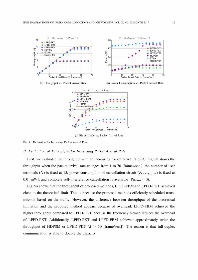
Fig. 9. Evaluation for Increasing Packet Arrival Rate
B. Evaluation of Throughput for Increasing Packet Arrival Rate
First, we evaluated the throughput with an increasing packet arrival rate (λ). Fig. 9a shows the
throughput when the packet arrival rate changes from 1 to 70 [frames/sec.], the number of user
terminals (N) is fixed at 15, power consumption of cancellation circuit (PCANCEL, ON) is fixed at
0.0 [mW], and complete self-interference cancellation is available (Prfdloss = 0).
Fig. 9a shows that the throughput of proposed methods, LPFD-FBM and LPFD-PKT, achieved
close to the theoretical limit. This is because the proposed methods efficiently scheduled trans-
mission based on the traffic. However, the difference between throughput of the theoretical
limitation and the proposed method appears because of overhead. LPFD-FBM achieved the
higher throughput compared to LPFD-PKT, because the frequency bitmap reduces the overhead
of LPFD-PKT. Additionally, LPFD-PKT and LPFD-FBM achieved approximately twice the
throughput of HDPSM or LPHD-PKT (λ ≥ 50 [frame/sec.]). The reason is that full-duplex
communication is able to double the capacity.
IEEE TRANSACTIONS ON GREEN COMMUNICATIONS AND NETWORKING, VOL. X, NO. X, MONTH 2017 23
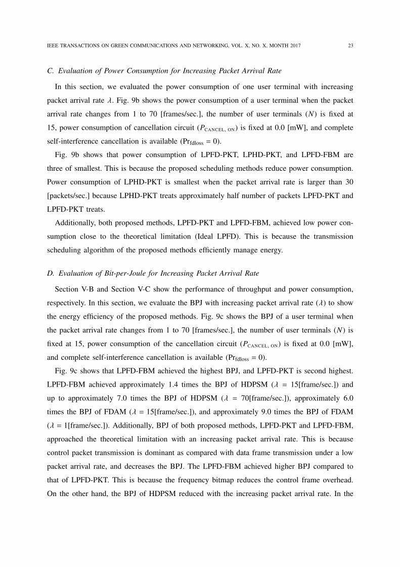
C. Evaluation of Power Consumption for Increasing Packet Arrival Rate
In this section, we evaluated the power consumption of one user terminal with increasing
packet arrival rate λ. Fig. 9b shows the power consumption of a user terminal when the packet
arrival rate changes from 1 to 70 [frames/sec.], the number of user terminals (N) is fixed at
15, power consumption of cancellation circuit (PCANCEL, ON) is fixed at 0.0 [mW], and complete
self-interference cancellation is available (Prfdloss = 0).
Fig. 9b shows that power consumption of LPFD-PKT, LPHD-PKT, and LPFD-FBM are
three of smallest. This is because the proposed scheduling methods reduce power consumption.
Power consumption of LPHD-PKT is smallest when the packet arrival rate is larger than 30
[packets/sec.] because LPHD-PKT treats approximately half number of packets LPFD-PKT and
LPFD-PKT treats.
Additionally, both proposed methods, LPFD-PKT and LPFD-FBM, achieved low power con-
sumption close to the theoretical limitation (Ideal LPFD). This is because the transmission
scheduling algorithm of the proposed methods efficiently manage energy.
D. Evaluation of Bit-per-Joule for Increasing Packet Arrival Rate
Section V-B and Section V-C show the performance of throughput and power consumption,
respectively. In this section, we evaluate the BPJ with increasing packet arrival rate (λ) to show
the energy efficiency of the proposed methods. Fig. 9c shows the BPJ of a user terminal when
the packet arrival rate changes from 1 to 70 [frames/sec.], the number of user terminals (N) is
fixed at 15, power consumption of the cancellation circuit (PCANCEL, ON) is fixed at 0.0 [mW],
and complete self-interference cancellation is available (Prfdloss = 0).
Fig. 9c shows that LPFD-FBM achieved the highest BPJ, and LPFD-PKT is second highest.
LPFD-FBM achieved approximately 1.4 times the BPJ of HDPSM (λ = 15[frame/sec.]) and
up to approximately 7.0 times the BPJ of HDPSM (λ = 70[frame/sec.]), approximately 6.0
times the BPJ of FDAM (λ = 15[frame/sec.]), and approximately 9.0 times the BPJ of FDAM
(λ = 1[frame/sec.]). Additionally, BPJ of both proposed methods, LPFD-PKT and LPFD-FBM,
approached the theoretical limitation with an increasing packet arrival rate. This is because
control packet transmission is dominant as compared with data frame transmission under a low
packet arrival rate, and decreases the BPJ. The LPFD-FBM achieved higher BPJ compared to
that of LPFD-PKT. This is because the frequency bitmap reduces the control frame overhead.
On the other hand, the BPJ of HDPSM reduced with the increasing packet arrival rate. In the
IEEE TRANSACTIONS ON GREEN COMMUNICATIONS AND NETWORKING, VOL. X, NO. X, MONTH 2017 24
(a) Throughput vs. Number of User Terminals (b) Power Consumption vs. Number of User Termi-
nals
(c) Bit-per-Joule vs. Number of User Terminals
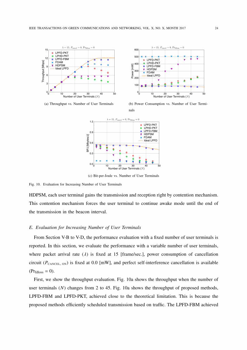
Fig. 10. Evaluation for Increasing Number of User Terminals
HDPSM, each user terminal gains the transmission and reception right by contention mechanism.
This contention mechanism forces the user terminal to continue awake mode until the end of
the transmission in the beacon interval.
E. Evaluation for Increasing Number of User Terminals
From Section V-B to V-D, the performance evaluation with a fixed number of user terminals is
reported. In this section, we evaluate the performance with a variable number of user terminals,
where packet arrival rate (λ) is fixed at 15 [frame/sec.], power consumption of cancellation
circuit (PCANCEL, ON) is fixed at 0.0 [mW], and perfect self-interference cancellation is available
(Prfdloss = 0).
First, we show the throughput evaluation. Fig. 10a shows the throughput when the number of
user terminals (N) changes from 2 to 45. Fig. 10a shows the throughput of proposed methods,
LPFD-FBM and LPFD-PKT, achieved close to the theoretical limitation. This is because the
proposed methods efficiently scheduled transmission based on traffic. The LPFD-FBM achieved
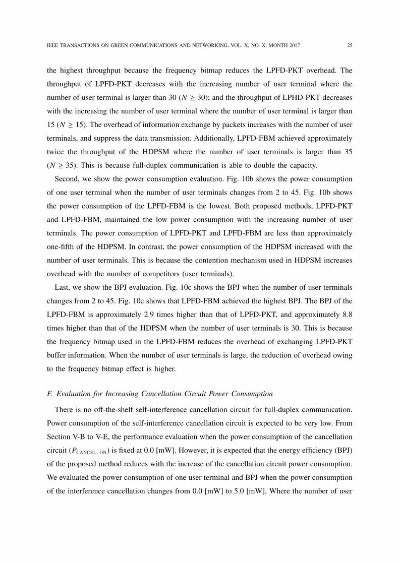
IEEE TRANSACTIONS ON GREEN COMMUNICATIONS AND NETWORKING, VOL. X, NO. X, MONTH 2017 25
the highest throughput because the frequency bitmap reduces the LPFD-PKT overhead. The
throughput of LPFD-PKT decreases with the increasing number of user terminal where the
number of user terminal is larger than 30 (N ≥ 30); and the throughput of LPHD-PKT decreases
with the increasing the number of user terminal where the number of user terminal is larger than
15 (N ≥ 15). The overhead of information exchange by packets increases with the number of user
terminals, and suppress the data transmission. Additionally, LPFD-FBM achieved approximately
twice the throughput of the HDPSM where the number of user terminals is larger than 35
(N ≥ 35). This is because full-duplex communication is able to double the capacity.
Second, we show the power consumption evaluation. Fig. 10b shows the power consumption
of one user terminal when the number of user terminals changes from 2 to 45. Fig. 10b shows
the power consumption of the LPFD-FBM is the lowest. Both proposed methods, LPFD-PKT
and LPFD-FBM, maintained the low power consumption with the increasing number of user
terminals. The power consumption of LPFD-PKT and LPFD-FBM are less than approximately
one-fifth of the HDPSM. In contrast, the power consumption of the HDPSM increased with the
number of user terminals. This is because the contention mechanism used in HDPSM increases
overhead with the number of competitors (user terminals).
Last, we show the BPJ evaluation. Fig. 10c shows the BPJ when the number of user terminals
changes from 2 to 45. Fig. 10c shows that LPFD-FBM achieved the highest BPJ. The BPJ of the
LPFD-FBM is approximately 2.9 times higher than that of LPFD-PKT, and approximately 8.8
times higher than that of the HDPSM when the number of user terminals is 30. This is because
the frequency bitmap used in the LPFD-FBM reduces the overhead of exchanging LPFD-PKT
buffer information. When the number of user terminals is large, the reduction of overhead owing
to the frequency bitmap effect is higher.
F. Evaluation for Increasing Cancellation Circuit Power Consumption
There is no off-the-shelf self-interference cancellation circuit for full-duplex communication.
Power consumption of the self-interference cancellation circuit is expected to be very low. From
Section V-B to V-E, the performance evaluation when the power consumption of the cancellation
circuit (PCANCEL, ON) is fixed at 0.0 [mW]. However, it is expected that the energy efficiency (BPJ)
of the proposed method reduces with the increase of the cancellation circuit power consumption.
We evaluated the power consumption of one user terminal and BPJ when the power consumption
of the interference cancellation changes from 0.0 [mW] to 5.0 [mW], Where the number of user
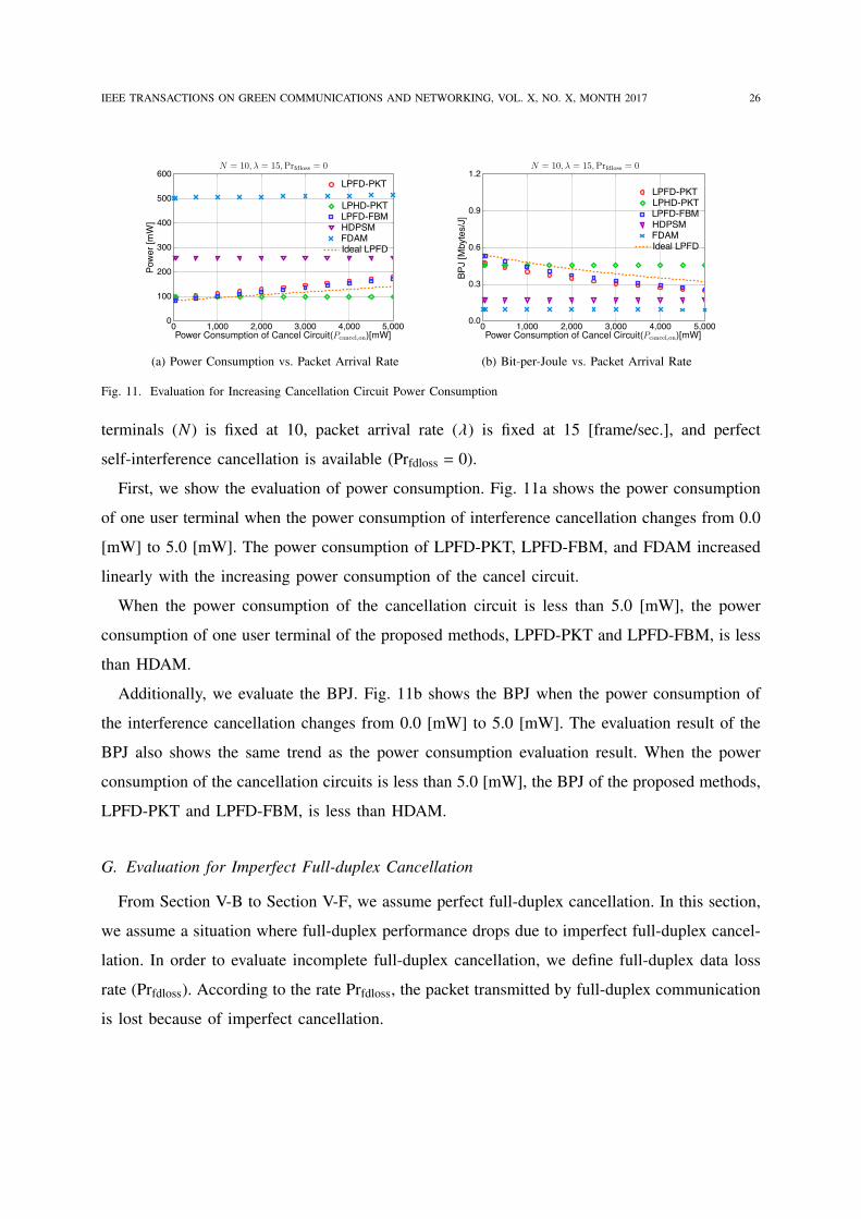
IEEE TRANSACTIONS ON GREEN COMMUNICATIONS AND NETWORKING, VOL. X, NO. X, MONTH 2017 26
(a) Power Consumption vs. Packet Arrival Rate (b) Bit-per-Joule vs. Packet Arrival Rate
Fig. 11. Evaluation for Increasing Cancellation Circuit Power Consumption
terminals (N) is fixed at 10, packet arrival rate (λ) is fixed at 15 [frame/sec.], and perfect
self-interference cancellation is available (Prfdloss = 0).
First, we show the evaluation of power consumption. Fig. 11a shows the power consumption
of one user terminal when the power consumption of interference cancellation changes from 0.0
[mW] to 5.0 [mW]. The power consumption of LPFD-PKT, LPFD-FBM, and FDAM increased
linearly with the increasing power consumption of the cancel circuit.
When the power consumption of the cancellation circuit is less than 5.0 [mW], the power
consumption of one user terminal of the proposed methods, LPFD-PKT and LPFD-FBM, is less
than HDAM.
Additionally, we evaluate the BPJ. Fig. 11b shows the BPJ when the power consumption of
the interference cancellation changes from 0.0 [mW] to 5.0 [mW]. The evaluation result of the
BPJ also shows the same trend as the power consumption evaluation result. When the power
consumption of the cancellation circuits is less than 5.0 [mW], the BPJ of the proposed methods,
LPFD-PKT and LPFD-FBM, is less than HDAM.
G. Evaluation for Imperfect Full-duplex Cancellation
From Section V-B to Section V-F, we assume perfect full-duplex cancellation. In this section,
we assume a situation where full-duplex performance drops due to imperfect full-duplex cancel-
lation. In order to evaluate incomplete full-duplex cancellation, we define full-duplex data loss
rate (Prfdloss). According to the rate Prfdloss, the packet transmitted by full-duplex communication
is lost because of imperfect cancellation.
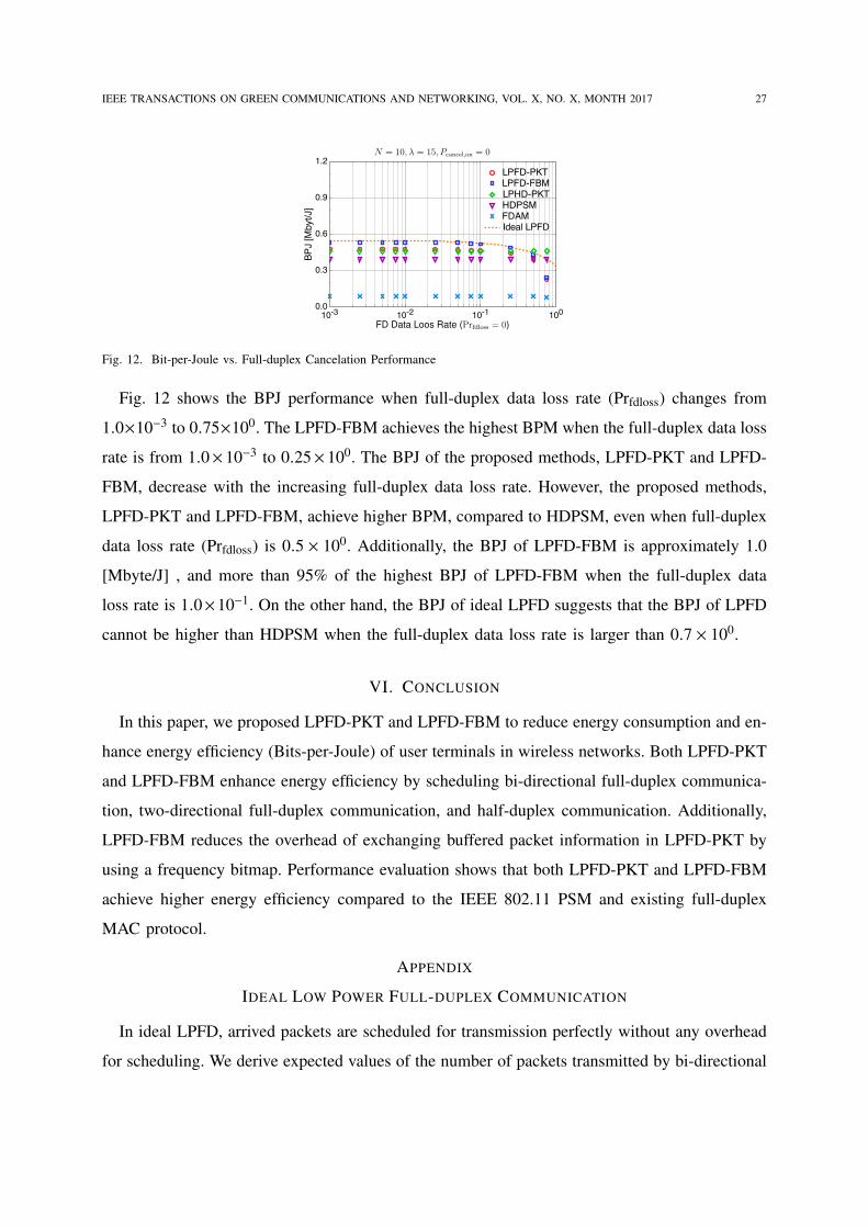
IEEE TRANSACTIONS ON GREEN COMMUNICATIONS AND NETWORKING, VOL. X, NO. X, MONTH 2017 27
Fig. 12. Bit-per-Joule vs. Full-duplex Cancelation Performance
Fig. 12 shows the BPJ performance when full-duplex data loss rate (Prfdloss) changes from
1.0×10⁻³ to 0.75×100. The LPFD-FBM achieves the highest BPM when the full-duplex data loss
rate is from 1.0× 10⁻³ to 0.25× 100. The BPJ of the proposed methods, LPFD-PKT and LPFD-
FBM, decrease with the increasing full-duplex data loss rate. However, the proposed methods,
LPFD-PKT and LPFD-FBM, achieve higher BPM, compared to HDPSM, even when full-duplex
data loss rate (Prfdloss) is 0.5 × 100. Additionally, the BPJ of LPFD-FBM is approximately 1.0
[Mbyte/J] , and more than 95% of the highest BPJ of LPFD-FBM when the full-duplex data
loss rate is 1.0×10⁻¹. On the other hand, the BPJ of ideal LPFD suggests that the BPJ of LPFD
cannot be higher than HDPSM when the full-duplex data loss rate is larger than 0.7 × 100.
VI. CONCLUSION
In this paper, we proposed LPFD-PKT and LPFD-FBM to reduce energy consumption and en-
hance energy efficiency (Bits-per-Joule) of user terminals in wireless networks. Both LPFD-PKT
and LPFD-FBM enhance energy efficiency by scheduling bi-directional full-duplex communica-
tion, two-directional full-duplex communication, and half-duplex communication. Additionally,
LPFD-FBM reduces the overhead of exchanging buffered packet information in LPFD-PKT by
using a frequency bitmap. Performance evaluation shows that both LPFD-PKT and LPFD-FBM
achieve higher energy efficiency compared to the IEEE 802.11 PSM and existing full-duplex
MAC protocol.
APPENDIX
IDEAL LOW POWER FULL-DUPLEX COMMUNICATION
In ideal LPFD, arrived packets are scheduled for transmission perfectly without any overhead
for scheduling. We derive expected values of the number of packets transmitted by bi-directional
IEEE TRANSACTIONS ON GREEN COMMUNICATIONS AND NETWORKING, VOL. X, NO. X, MONTH 2017 28
full-duplex, two-directional full-duplex, and half-duplex communication. Before deriving ex-
pected values, we define the probability p(λ, τ, k) of k packet arrivals in a time interval τ
becomes p(λ, τ, k) = exp(−λτ) (λτ)kk! , where the packet arrival rate is λ.
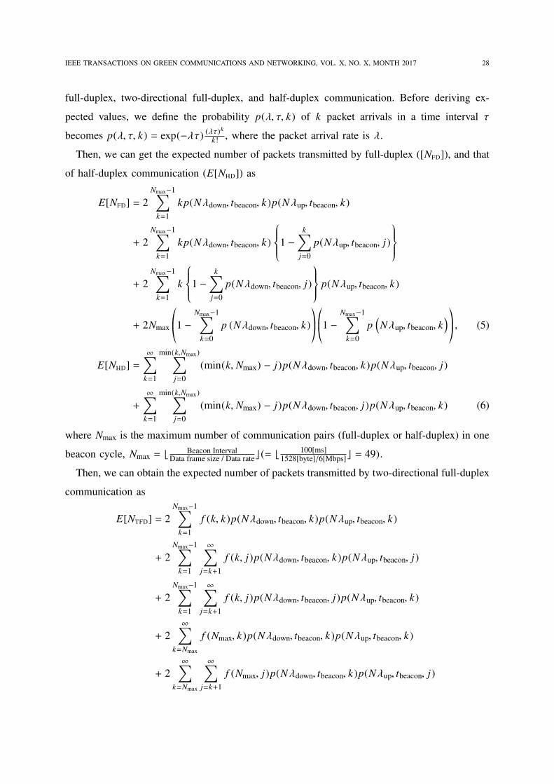
Then, we can get the expected number of packets transmitted by full-duplex ([NFD]), and that
of half-duplex communication (E[NHD]) as
E[NFD] = 2Nmax−1∑
k=1
kp(Nλdown, tbeacon, k)p(Nλup, tbeacon, k)
+ 2Nmax−1∑
k=1
kp(Nλdown, tbeacon, k)1 −
k∑
j=0
p(Nλup, tbeacon, j)
+ 2Nmax−1∑
k=1
k1 −
k∑
j=0
p(Nλdown, tbeacon, j) p(Nλup, tbeacon, k)
+ 2Nmax*.,1 −
Nmax−1∑
k=0
p (Nλdown, tbeacon, k)+/-*.,1 −
Nmax−1∑
k=0
p(Nλup, tbeacon, k
)+/- , (5)
E[NHD] =∞∑
k=1
min(k,Nmax)∑
j=0
(min(k, Nmax) − j)p(Nλdown, tbeacon, k)p(Nλup, tbeacon, j)
+
∞∑
k=1
min(k,Nmax)∑
j=0
(min(k, Nmax) − j)p(Nλdown, tbeacon, j)p(Nλup, tbeacon, k) (6)
where Nmax is the maximum number of communication pairs (full-duplex or half-duplex) in one
beacon cycle, Nmax = ⌊ Beacon IntervalData frame size / Data rate⌋ (= ⌊ 100[ms]
1528[byte]/6[Mbps]⌋ = 49).
Then, we can obtain the expected number of packets transmitted by two-directional full-duplex
communication as
E[NTFD] = 2Nmax−1∑
k=1
f (k, k)p(Nλdown, tbeacon, k)p(Nλup, tbeacon, k)
+ 2Nmax−1∑
k=1
∞∑
j=k+1
f (k, j)p(Nλdown, tbeacon, k)p(Nλup, tbeacon, j)
+ 2Nmax−1∑
k=1
∞∑
j=k+1
f (k, j)p(Nλdown, tbeacon, j)p(Nλup, tbeacon, k)
+ 2∞∑
k=Nmax
f (Nmax, k)p(Nλdown, tbeacon, k)p(Nλup, tbeacon, k)
+ 2∞∑
k=Nmax
∞∑
j=k+1
f (Nmax, j)p(Nλdown, tbeacon, k)p(Nλup, tbeacon, j)
IEEE TRANSACTIONS ON GREEN COMMUNICATIONS AND NETWORKING, VOL. X, NO. X, MONTH 2017 29
+ 2∞∑
k=Nmax
∞∑
j=k+1
f (Nmax, j)p(Nλdown, tbeacon, j)p(Nλup, tbeacon, k). (7)
where f (k, j) =∑k
i=0 i(
1N
) (k−i) ( N−1N
) {i+( j−k)} ( jk−i
). Function f (k, j) represents the bi-directional
transmission probability when k full-duplex pairs are communicated, and j is larger number of
packets arrived in access point or user terminals. Combining (5), (7), the expected number of
packets transmitted by two-directional full-duplex communication is
E[NBFD] = E[NFD] − E[NTFD]. (8)
Using (1) - (3) and (5) - (8), we can obtain the bit-per-joule of ideal LPFD as
BPJideal =BPJBFDE[NBFD] + BPJTFDE[NTFD] + BPJHDE[NHD]
E[NBFD] + E[NTFD] + E[NHD].
REFERENCES
[1] D. Bharadia, E. McMilin, and S. Katti, “Full duplex radios,” in Proceedings of the Annual Conference of the ACM Special
Interest Group on Data Communication (SIGCOMM’13), HongKong, China, August 2013, pp. 375–386.
[2] J. I. Choi, M. Jain, K. Srinivasan, P. Levis, and S. Katti, “Achieving single channel, full duplex wireless communication,”
in Proceedings of the 16th ACM Annual International Conference on Mobile Computing and Networking (MobiCom’10),
Chicago, Illinois, September 2010, pp. 1–14.
[3] E. Everett, A. Sahai, and A. Sabharwal, “Passive self-interference suppression for full-duplex infrastructure nodes,” IEEE
Transactions on Wireless Communications, vol. 13, no. 2, pp. 680–694, 2014.
[4] M. Jain, J. I. Choi, T. M. Kim, D. Bharadia, S. Seth, K. Srinivasan, P. Levis, S. Katti, and P. Sinha, “Practical, real-time, full
duplex wireless,” in Proceedings of the 17th ACM Annual International Conference on Mobile Computing and Networking
(MobiCom’11), Las Vegas, NV, September 2011, pp. 301–312.
[5] J. Bai and A. Sabharwal, “Distributed full-duplex via wireless side-channels: Bounds and protocols,” IEEE Transactions
on Wireless Communications, vol. 12, no. 8, pp. 4162–4173, 2013.
[6] D. Kim, H. Lee, and D. Hong, “A survey of in-band full-duplex transmission: From the perspective of phy and mac layers,”
IEEE Communications Surveys and Tutorials, vol. 17, no. 4, pp. 2017–2046, 2015.
[7] M. Duarte, A. Sabharwal, V. Aggarwal, R. Jana, K. K. Ramakrishnan, C. W. Rice, and N. K. Shankaranarayanan, “Design
and characterization of a full-duplex multiantenna system for wifi networks,” IEEE Transactions on Vehicular Technology,
vol. 63, no. 3, pp. 1160–1177, 2014.
[8] W. Choi, H. Lim, and A. Sabharwal, “Power-controlled medium access control protocol for full-duplex WiFi networks,”
IEEE Transactions on Wireless Communications, vol. 14, no. 7, pp. 3601–3613, 2015.
[9] A. Tang and X. Wang, “Medium access control for a wireless LAN with a full duplex AP and half duplex stations,” in
Proceedings of IEEE Global Communications Conference (IEEE GLOBECOM’14), 2014, pp. 4930–4935.
[10] ——, “A-duplex : Medium access control for efficient coexistence between full-duplex and half-duplex communications,”
IEEE Transactions on Wireless Communications, vol. 14, no. 10, pp. 5871–5885, 2015.
[11] W. Cheng, X. Zhang, and H. Zhang, “RTS/FCTS mechanism based full-duplex MAC protocol for wireless networks,” in
Proceedings of IEEE Global Communications Conference (IEEE GLOBECOM’13), dec 2013, pp. 5017–5022.
IEEE TRANSACTIONS ON GREEN COMMUNICATIONS AND NETWORKING, VOL. X, NO. X, MONTH 2017 30
[12] S. Sen, R. R. Choudhury, and S. Nelakuditi, “CSMA/CN: Carrier sense multiple access with collision notification,” in
Proceedings of the 16th Annual International Conference on Mobile Computing and Networking (MobiCom’10), Chicago,
Illinois, September 2010, pp. 25–36.
[13] Y. Zhang, L. Lazos, K. Chen, B. Hu, and S. Shivaramaiah, “FD-MMAC: Combating multi-channel hidden and exposed
terminals using a single transceiver,” in Proceedings of the 33rd Annual IEEE International Conference on Computer
Communications (IEEE INFOCOM’14), 2014, pp. 2742–2750.
[14] D. Nguyen, L.-N. Tran, P. Pirinen, and M. Latva-aho, “On the spectral efficiency of full-duplex small cell wireless systems,”
IEEE Transactions on Wireless Communications, vol. 13, no. 9, pp. 4896–4910, 2014.
[15] K. Tamaki, Y. Sugiyama, A. Raptino, M. Bandai, S. Saruwatari, and T. Watanabe, “Full duplex media access control
for wireless multi-hop networks,” in Proceedings of the IEEE 77th Vehicular Technology Conference (VTC’13-Spring),
German, Dresden, June 2013, pp. 1–6.
[16] T. Vermeulen and S. Pollin, “Energy-delay analysis of full duplex wireless communication for sensor networks,” in
Proceedings of IEEE Global Communications Conference (IEEE GLOBECOM’14), 2014, pp. 455–460.
[17] X. Xie and X. Zhang, “Does full-duplex double the capacity of wireless networks?” in Proceedings of the 33rd Annual
IEEE International Conference on Computer Communications (IEEE INFOCOM’14), no. 978, 2014, pp. 253–261.
[18] T. Riihonen, S. Werner, and R. Wichman, “Hybrid full-duplex/half-duplex relaying with transmit power adaptation,” IEEE
Transactions on Wireless Communications, vol. 10, no. 9, pp. 3074–3085, 2011.
[19] R. Murakami, M. Kobayashi, S. Saruwatari, and T. Watanabe, “An energy efficient MAC for wireless full duplex networks,”
in Proceedings of IEEE Globecom Workshops (GC Wkshps’16), 2016, pp. 1–6.
[20] “IEEE standard for information technology–telecommunications and information exchange between systems local and
metropolitan area networks–specific requirements part 11: Wireless lan medium access control (MAC) and physical layer
(PHY) specifications - redline,” IEEE Std 802.11-2012 (Revision of IEEE Std 802.11-2007) - Redline, pp. 1–5229, March
2012.
[21] S. Sen, R. Roy Choudhury, and S. Nelakuditi, “No time to countdown: Migrating backoff to the frequency domain,” in
Proceedings of the 17th annual international conference on Mobile computing and networking (MobiCom’11), 2011, p.
241.
[22] X. Feng, J. Zhang, and Q. Zhang, “Use your frequency wisely: Explore frequency domain for channel contention and
ACK,” in Proceedings of the 31st IEEE Conference on Information Communications (INFOCOM’12), Orlando, Florida,
March 2012, pp. 1064–1072.
[23] J. Fang, K. Tan, Y. Zhang, S. Chen, L. Shi, J. Zhang, Y. Zhang, and Z. Tan, “Fine-grained channel access in wireless lan,”
IEEE/ACM Transactions on Networking, vol. 21, no. 3, pp. 772–787, 2013.
[24] A. Dutta, D. Saha, D. Grunwald, and D. Sicker, “Smack: a smart acknowledgment scheme for broadcast messages in
wireless networks,” in Proceedings of the Annual Conference of the ACM Special Interest Group on Data Communication
(SIGCOMM’09), Barcelona, Spain, August 2009, pp. 15–26.
[25] D. Halperin, J. Ammer, T. Anderson, and D. Wetherall, “Interference cancellation: Better receivers for a new wireless
MAC,” in Proceedings of the 6th Workshop on Hot Topics in Networks (HotNets-VI), College Park, Maryland, November
2007, pp. 1–6.
[26] S. Technology. 802.11 a/b/g SDIO card module ultracompact wireless solution for embedded applications. [Online].
Available: http://www.mouser.com/ds/2/367/sx-sdcag_brief-2825.pdf