Enhancing the performance of LEACH protocol in wireless sensor networks
6
Enhancing the Performance of LEACH Protocol in Wireless Sensor Networks Yun Li 1,2 , Nan Yu 1 , Weiyi Zhang 3 , Weiliang Zhao 1 , Xiaohu You 2 , Mahmoud Daneshmand 4 1 Laboratory of Wireless Networks, Chongqing University of Posts and Telecommunications, Chongqing 400065, P.R. China 2 National Mobile Communications Research Laboratory, Southeast University of China, Nanjing 210096, P.R. China 3 North Dakota State University, Fargo, ND 58105, USA 4 AT&T Labs Research, Middletown, NJ, USA Abstract- LEACH protocol is one of the clustering routing protocols in wireless sensor networks. The advantage of LEACH is that each node has the equal probability to be a cluster head, which makes the energy dissipation of each node be relatively balanced. In LEACH protocol, time is divided into many rounds, in each round, all the nodes contend to be cluster head according to a predefined criterion. This paper focuses on how to set the time length of each round, to prolong the lifetime of the network and increase throughput, which is denoted as the amount of data packs sent to the sink node. The functions of lifetime and throughput related to the time length of each round are deduced. These functions can be used to enhance the performance of cluster-based wireless sensor networks in terms of lifetime and throughput. Keywords- wireless sensor networks; LEACH protocol; lifetime; throughput I. INTRODUCTION A wireless sensor network system usually includes sensor nodes, sink node and management node. A large number of sensor nodes are deployed in the monitored area, constituting a network through the way of self-organization. The data monitored by sensor nodes is transmitted along other nodes one by one, that will reach the sink node after a multi-hop routing and finally reach the management node through the wired and (or) wireless Internet[2]. The energy, the ability of signal process, storage capacity and communication capability of sensor nodes are very limited. A primary design goal for wireless sensor networks is to use the energy efficiently[3]. Cluster-based routing algorithm has a better energy utilization rate compared with non-cluster routing algorithm[8]. The basic idea of clustering routing[3][7] is to use the information aggregation mechanism in the cluster head to reduce the amount of data transmission, thereby, reduce the energy dissipation in communication and in turn achieve the purpose of saving energy of the sensor nodes. In the clustering routing algorithms for wireless networks, LEACH (low-energy adaptive clustering hierarchy)[4][5] is well-known because it is simple and efficient. LEACH divides the whole network into several clusters, and the run time of network is broken into many rounds. In each round, the nodes in a cluster contend to be cluster head according to a predefined criterion. In LEACH protocol, all the sensor nodes have the same probability to be a cluster head, which makes the nodes in the network consume energy in a relatively balanced way so as to prolong network lifetime. Although some works have been conducted on the performance and enhancement of LEACH protocol[1][6], there is few works to investigate the influence of time length of rounds on the performance of LEACH protocol. This paper aims at this issue and discusses how to prolong the lifetime and increase throughput of cluster-based wireless sensor network by configuring reasonable round time. The remainder of this paper is organized as follows. Section II gives the overview of LEACH protocol. Section III analyzes the relations of lifetime and throughput to the time length of rounds. The numerical results are given in Section IV. Section V concludes the work of this paper. II. LEACH PROTOCOL LEACH is an adaptive clustering routing protocol proposed by Wendi B. Heinzelman, et al. The implementation process of LEACH includes many rounds. Each round consists of the set- up phase and the steady data transmission phase. In the set-up phase, the cluster head nodes are randomly elected from all the sensor nodes and several clusters are constructed dynamically. In the steady data transmission phase, member nodes in every cluster send data to their own cluster head, the cluster head compresses the data that received from member nodes and sends the compressed data to the sink node. LEACH protocol periodically elects the cluster head nodes and re-establishes the clusters according to a round time, which ensures energy dissipation of each node in the network is relatively evenly. The cluster head election algorithm in LEACH is as follows[4]. All the sensor nodes generate a random number between 0~1, and if it is less than a threshold () Tn , the sensor nodes will broadcast an announcement message to notify others that it is a cluster head. In each round, if a node has been elected as a cluster head, its () Tn is set to zero, so that the node will not be elected as a cluster head again. () Tn can be expressed as: , 1 [ mod(1/ )] () otherwise P n G P r P Tn ⎧ ∈ ⎪ − × = ⎨ ⎪ ⎩ 0, IEEE INFOCOM 2011 Workshop on M2MCN-2011 978-1-4244-9920-5/11/$26.00 ©2011 IEEE 223
Transcript of Enhancing the performance of LEACH protocol in wireless sensor networks
Enhancing the Performance of LEACH Protocol in Wireless Sensor Networks
Yun Li1,2, Nan Yu1, Weiyi Zhang 3, Weiliang Zhao 1, Xiaohu You2, Mahmoud Daneshmand4 1 Laboratory of Wireless Networks, Chongqing University of Posts and Telecommunications, Chongqing 400065, P.R. China
2 National Mobile Communications Research Laboratory, Southeast University of China, Nanjing 210096, P.R. China 3 North Dakota State University, Fargo, ND 58105, USA
4 AT&T Labs Research, Middletown, NJ, USA
Abstract- LEACH protocol is one of the clustering routing protocols in wireless sensor networks. The advantage of LEACH is that each node has the equal probability to be a cluster head, which makes the energy dissipation of each node be relatively balanced. In LEACH protocol, time is divided into many rounds, in each round, all the nodes contend to be cluster head according to a predefined criterion. This paper focuses on how to set the time length of each round, to prolong the lifetime of the network and increase throughput, which is denoted as the amount of data packs sent to the sink node. The functions of lifetime and throughput related to the time length of each round are deduced. These functions can be used to enhance the performance of cluster-based wireless sensor networks in terms of lifetime and throughput.
Keywords- wireless sensor networks; LEACH protocol; lifetime; throughput
I. INTRODUCTION A wireless sensor network system usually includes sensor
nodes, sink node and management node. A large number of sensor nodes are deployed in the monitored area, constituting a network through the way of self-organization. The data monitored by sensor nodes is transmitted along other nodes one by one, that will reach the sink node after a multi-hop routing and finally reach the management node through the wired and (or) wireless Internet[2]. The energy, the ability of signal process, storage capacity and communication capability of sensor nodes are very limited. A primary design goal for wireless sensor networks is to use the energy efficiently[3]. Cluster-based routing algorithm has a better energy utilization rate compared with non-cluster routing algorithm[8].
The basic idea of clustering routing[3][7] is to use the information aggregation mechanism in the cluster head to reduce the amount of data transmission, thereby, reduce the energy dissipation in communication and in turn achieve the purpose of saving energy of the sensor nodes. In the clustering routing algorithms for wireless networks, LEACH (low-energy adaptive clustering hierarchy)[4][5] is well-known because it is simple and efficient. LEACH divides the whole network into several clusters, and the run time of network is broken into many rounds. In each round, the nodes in a cluster contend to be cluster head according to a predefined criterion. In LEACH protocol, all the sensor nodes have the same probability to be a cluster head, which makes the nodes in the network consume
energy in a relatively balanced way so as to prolong network lifetime.
Although some works have been conducted on the performance and enhancement of LEACH protocol[1][6], there is few works to investigate the influence of time length of rounds on the performance of LEACH protocol. This paper aims at this issue and discusses how to prolong the lifetime and increase throughput of cluster-based wireless sensor network by configuring reasonable round time.
The remainder of this paper is organized as follows. Section II gives the overview of LEACH protocol. Section III analyzes the relations of lifetime and throughput to the time length of rounds. The numerical results are given in Section IV. Section V concludes the work of this paper.
II. LEACH PROTOCOL LEACH is an adaptive clustering routing protocol proposed
by Wendi B. Heinzelman, et al. The implementation process of LEACH includes many rounds. Each round consists of the set-up phase and the steady data transmission phase. In the set-up phase, the cluster head nodes are randomly elected from all the sensor nodes and several clusters are constructed dynamically. In the steady data transmission phase, member nodes in every cluster send data to their own cluster head, the cluster head compresses the data that received from member nodes and sends the compressed data to the sink node. LEACH protocol periodically elects the cluster head nodes and re-establishes the clusters according to a round time, which ensures energy dissipation of each node in the network is relatively evenly.
The cluster head election algorithm in LEACH is as follows[4]. All the sensor nodes generate a random number between 0~1, and if it is less than a threshold ( )T n , the sensor nodes will broadcast an announcement message to notify others that it is a cluster head. In each round, if a node has been elected as a cluster head, its ( )T n is set to zero, so that the node will not be elected as a cluster head again. ( )Tn can be expressed as:
,1 [ mod(1/ )]( )
otherwise
P n GP r PT n
⎧ ∈⎪ − ×= ⎨⎪⎩0,
IEEE INFOCOM 2011 Workshop on M2MCN-2011
978-1-4244-9920-5/11/$26.00 ©2011 IEEE 223

Where P is the percentage of the number of clusters in the network (usually P is 0.05 in [1][5][6]), r is the number of the election rounds, mod(1/ )r P is the number of nodes which have been elected as cluster heads in the round r, and G is the set of nodes that have not been elected as cluster heads in round r.
After cluster head election, the cluster head broadcasts its identity message to non-cluster head nodes. The non-cluster head nodes send a join-REQ message to the nearest cluster head to join in the corresponding cluster. After the cluster head receives all the join-REQ information, it will produce a TDMA schedule, and notify all the member nodes in the cluster. After a member node receives the schedule, it sends data in its own time slots, and remains in the sleep state in other slots. After a frame time of data transmission, the cluster head runs the data compression algorithm to process the data and sends the results directly to the sink node[5].
LEACH protocol lets the data transmission phase last for a fixed period of time[5], then enter into a new round of cluster head election. The time length of round has obviously influence on the performance of LEACH protocol. In order to decrease the overhead of set-up phase, we hope to increase the time length of round, which increases the time for data transmission. However, prolonging the time length of round also increases the energy consumption of cluster head, which will causes some nodes die early and in turn shortens the lifetime of wireless sensor networks. So, regarding to configuration of time length of round, there is a trade off between lifetime and throughput.
The following will discuss how to set the time length of round according to life time and throughput.
III. ANALYZING THE INFLUENCE OF TIME LENGTH OF ROUND ON THE LIFETIME AND THROUGHPUT
We suppose that the time of set-up phase isα , and the steady data transmission time is t , then the time length of every round is ( )rt tα= + . For simpleness, we define the time when the first sensor node dies as the lifetime of the network, which is denoted as
fd nt . It is noted that the following analysis can be easily extended to other definition of lifetime.
The relationship of the lifetime fdnt and t is shown in Fig. 1.
From Fig.1, we can obtain that
( )fdnt n tα= ⋅ + (1)
Where n is the number of rounds after which the first sensor node dies.
Figure 1. The lifetimefdnt of the network.
According to LEACH protocol, there are m frames in the time t , so
framet m T= ⋅ , here frameT is the time length of each
frame. Therefore,
( )fdn r framet n t m Tα= ⋅ = + ⋅ (2)
Given the initial energy E0 of sensor node, the fdnt can be
deduced according to the energy dissipation in cluster set-up phase and data transmission phase.
A. The energy dissipation of a cluster head and a member node in the set-up phase Let the number of sensor nodes in a network is N, which
includes k clusters. Then there are average Nk
nodes in each
cluster, including one cluster head and ( 1)Nk− member (non-
cluster) nodes.
We assume N nodes are evenly distributed in M×M area, the coordinate of the sink node is (Xsink, Ysink), the initial energy of each node is E0, the length of data message is L bits, and the length of control message is P bits.
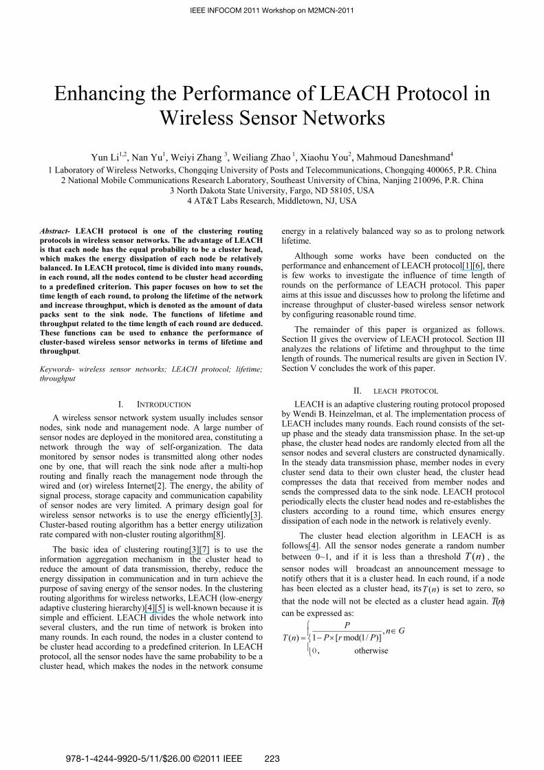
A simple model for the radio hardware energy dissipation is adopted [4][5]. The transmitter dissipates energy to run the radio electronics and the power amplifier. The receiver dissipates energy to run the radio electronics. The radio energy dissipation model is shown in Fig.2. Then the energy expenditure for transmitting L-bit message to d distance is:
( , )Tx elecE l d l E l d γε= ⋅ + ⋅ ⋅ (3)
And the energy expenditure for receiving L-bit message is:
( )Rx elecE l l E= ⋅ (4) In Eq. (3) and Eq. (4), the electronics energy expenditure for one bit,
elecE , depends on factors such as the digital coding, modulation, filtering and spreading of the signal. Whereas the amplifier energy expenditure for one bit, d γε⋅ , depends on the distance from the sender to the receiver and the acceptable bit-error rate. In this paper, the channel model in the cluster is free space propagation model, and the channels between cluster head nodes and the sink node are multi-path fading channel. For the free space propagation, 2γ = , and ε is denoted as
fsε . For multi-path fading channel, 4γ = , and ε is denoted as
mpε .
In this paper, we set the same communication energy parameters as that in [5] i.e.
50 / ,elecE nJ bit= 210 / / ,fs pJ bit mε = 40.0013 / /mp pJ bit mε = and the energy consumption for data aggregation is set to 5 / /DAE nJ bit signal= .
224
l d γε ⋅ ⋅elecE l⋅ elecE l⋅
Figure 2. Radio energy dissipation model.
According to the model shown in Fig.2, in the set-up phase the energy dissipation of the cluster head node and a member node is made up of the following components:
(1). 1chE : The energy consumption of a cluster head node that broadcasts its identity message to the whole network.
Assuming the broadcast range of a cluster head is the size of its cluster, 1chE is:
21ch elec fs tonon chE p E p dε −= ⋅ + ⋅ ⋅ (5)
(2). 2non chE − : The energy consumption that a member node receives a broadcast message is:
2non ch elecE p E− = ⋅ (6)
(3). 3non chE − : The energy dissipation for a member node to send join-REQ message to its cluster head is:
23non ch elec fs tochE p E p dε− = ⋅ + ⋅ ⋅ (7)
(4). 4chE : The energy consumption that a cluster head node receives join-REQ messages from the member nodes is:
4 ( 1)ch elecNE p Ek
= ⋅ ⋅ − (8)
(5). 5chE : The energy dissipation for a cluster head node to send TDMA schedule message to the member nodes is:
25 ( ) ( 1)ch elec fs tonon ch
NE p E p dk
ε −= ⋅ + ⋅ ⋅ ⋅ − (9)
(6). 6non chE − : The energy consumption that the member node receives a TDMA schedule is:
6non ch elecE p E− = ⋅ (10)
In Eq. (5), Eq. (7) and Eq. (9), the average distance from cluster head to the member nodes ( tonon chd − ) is equal to the distance from member nodes to the cluster head ( tochd ) [5], that is:
22 2 1[ ] [ ]
2tonon ch tochME d E dkπ− = = ⋅ (11)
In summary, the energy dissipation of a cluster head node in the set-up phase is:
, 1 4 5
21 (2 1)2
ch set up ch ch ch
elec fs
E E E E
N N Mp E pk k k
επ
− = + +
= − ⋅ ⋅ + ⋅ ⋅ ⋅ ⋅ (12)
The energy dissipation of a member node in the set-up phase is:
, 2 3 6
21 32
non ch set up non ch non ch non ch
elec fs
E E E E
Mp E pk
επ
− − − − −= + +
= ⋅ + ⋅ ⋅ ⋅ (13)
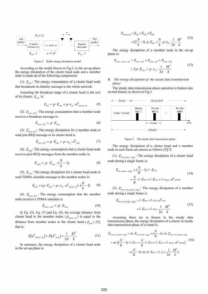
B. The energy dissipation of the steady data transmission phase The steady data transmission phase operation is broken into
several frames as shown in Fig.3.
Figure 3. The steady data transmission phase.
The energy dissipation of a cluster head and a member node in each frame are shown as follows [5][7]:
(1). ,ch steady stageE − : The energy dissipation of a cluster head node during a single frame is:
4
, ( 1) elec
DA elec mp toSI
ch steady
NK
stageN l EK
N l E l E l d
E
Kε
− = − ⋅ ⋅
+ ⋅ ⋅ + ⋅ + ⋅ ⋅
(14)
(2). ,non ch steady stageE − − : The energy dissipation of a member node during a single frame is:
,2
21 2
non ch steady stage elec fs toch
elec fs
l E l d
Ml E lk
E ε
επ
− − = ⋅ + ⋅ ⋅
= ⋅ + ⋅ ⋅ ⋅ (15)
Assuming there are m frames in the steady data transmission phase, the energy dissipation of a cluster in steady data transmission phase of a round is:
,,
4
2
,( 1)
[( 1) ]
1( 1) ( ) 2
cluster steady stage
ele
ch stea
c DA elec mp toSINK
elec
dy stage non ch steady stage
fs
NE m mK
N Nm l E l E l E l d
E
K KN Mm l E lK k
E
ε
επ
− − −− = ⋅ − ⋅ ⋅
= ⋅ − ⋅ ⋅ + ⋅ ⋅ + ⋅ + ⋅ ⋅
+ − ⋅ ⋅ ⋅ + ⋅ ⋅ ⋅
+
(16)
225
So, the energy dissipation of each cluster in every round is:
, ,
,
2
2
4
( 1)
(2 1)
1 ( 1) (32
1 ) [( 1)2
]
( 1)
ch set up non ch set up
cluster steady stage
elec fs
elec
elecfs
DA elec mp toSINK
Ne E EK
E
N Np E pk k
M N p Ek K
M Np m l Ek K
N l E l E l dKN mK
ε
π
επ
ε
− − −
−
= + − ⋅
+
= − ⋅ ⋅ + ⋅ ⋅
⋅ ⋅ + − ⋅ ⋅
+ ⋅ ⋅ ⋅ + ⋅ − ⋅ ⋅
+ ⋅ ⋅ + ⋅ + ⋅ ⋅
+ − ⋅21( )
2
elec fsMl E lk
επ
⋅ ⋅ + ⋅ ⋅ ⋅
(17)
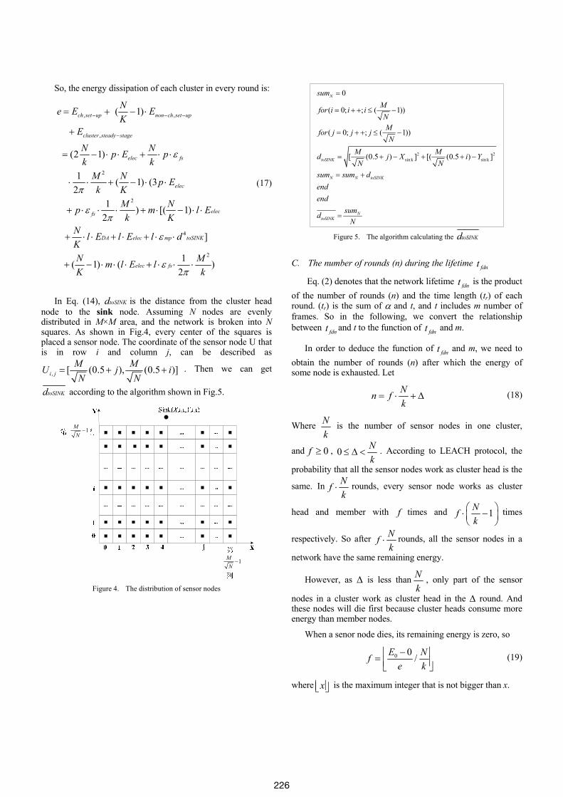
In Eq. (14), toSINKd is the distance from the cluster head node to the sink node. Assuming N nodes are evenly distributed in M×M area, and the network is broken into N squares. As shown in Fig.4, every center of the squares is placed a sensor node. The coordinate of the sensor node U that is in row i and column j, can be described as
, [ (0.5 ), (0.5 )]i jM MU jN N
i= + + . Then we can get
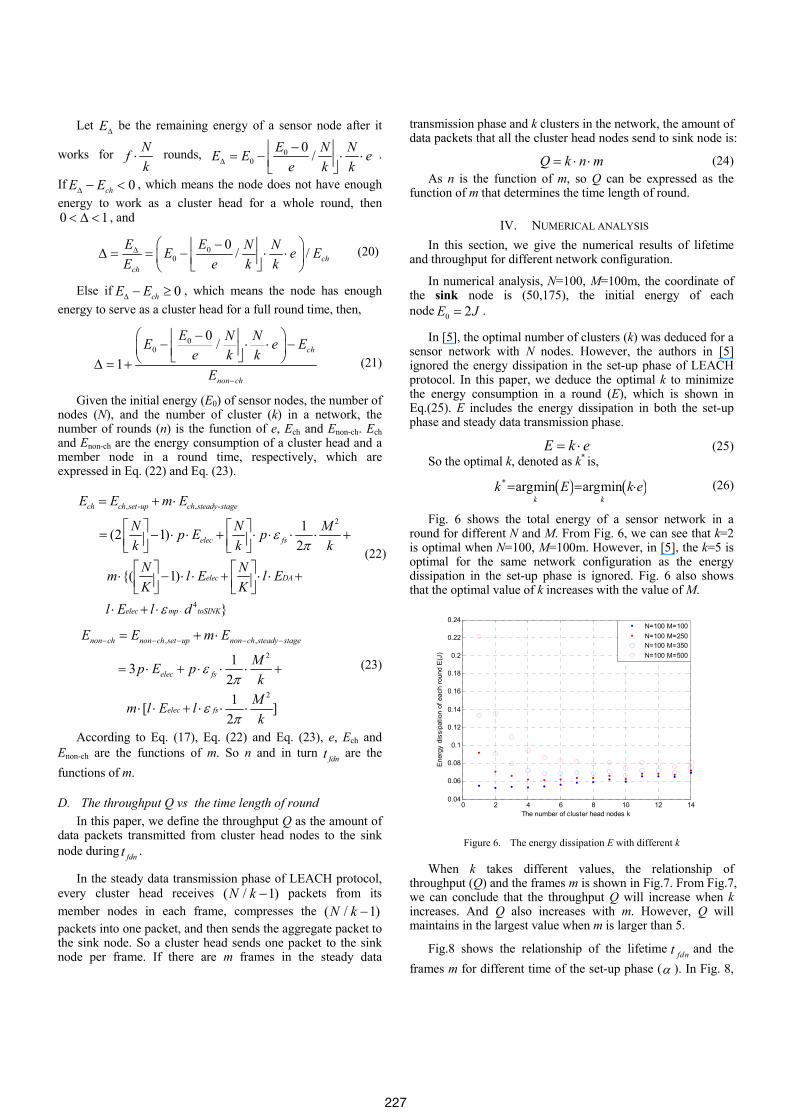
toSINKd according to the algorithm shown in Fig.5.
1MN−
1MN−
Figure 4. The distribution of sensor nodes
2sin k
2sin k[ (0.5 )
0
( 0; ; ( 1))
( 0; ; (
[( (0.] ]5 )
1))
N
toSINK
toSINK
toSINK
N N
N
sum
f M
M
M Md j i
sum sum d
or i i
endend
sumd
iN
for j j jN
X YN N
N
=
= + + ≤ −
= + + ≤ −
=
= + − + + −
= +
Figure 5. The algorithm calculating the toSINKd
C. The number of rounds (n) during the lifetime fdnt
Eq. (2) denotes that the network lifetime fdnt is the product of the number of rounds (n) and the time length (tr) of each round. (tr) is the sum of α and t, and t includes m number of frames. So in the following, we convert the relationship between fdnt and t to the function of fdnt and m.
In order to deduce the function of fdnt and m, we need to obtain the number of rounds (n) after which the energy of some node is exhausted. Let
Nn fk
= ⋅ + Δ (18)
Where Nk
is the number of sensor nodes in one cluster,
and 0f ≥ , 0 Nk
≤ Δ < . According to LEACH protocol, the
probability that all the sensor nodes work as cluster head is the
same. In Nfk
⋅ rounds, every sensor node works as cluster
head and member with f times and 1Nfk
⎛ ⎞⋅ −⎜ ⎟⎝ ⎠
times
respectively. So after Nfk
⋅ rounds, all the sensor nodes in a
network have the same remaining energy.
However, as Δ is less than Nk
, only part of the sensor
nodes in a cluster work as cluster head in the Δ round. And these nodes will die first because cluster heads consume more energy than member nodes.
When a senor node dies, its remaining energy is zero, so
0 0 /E Nfe k−⎢ ⎥= ⎢ ⎥⎣ ⎦
(19)
where x⎢ ⎥⎣ ⎦ is the maximum integer that is not bigger than x.
226
Let EΔ be the remaining energy of a sensor node after it
works for Nfk
⋅ rounds, 00
0 /E N NE E ee k kΔ
−⎢ ⎥= − ⋅ ⋅⎢ ⎥⎣ ⎦.
If 0chE EΔ − < , which means the node does not have enough energy to work as a cluster head for a whole round, then 0 1< Δ < , and
00
0 / / chch
EE N NE e EE e k k
Δ ⎛ − ⎞⎢ ⎥Δ = = − ⋅ ⋅⎜ ⎟⎢ ⎥⎣ ⎦⎝ ⎠ (20)
Else if 0chE EΔ − ≥ , which means the node has enough energy to serve as a cluster head for a full round time, then,
00
0 /1
ch
non ch
E N NE e Ee k k
E −
⎛ − ⎞⎢ ⎥− ⋅ ⋅ −⎜ ⎟⎢ ⎥⎣ ⎦⎝ ⎠Δ = + (21)
Given the initial energy (E0) of sensor nodes, the number of nodes (N), and the number of cluster (k) in a network, the number of rounds (n) is the function of e, Ech and Enon-ch. Ech and Enon-ch are the energy consumption of a cluster head and a member node in a round time, respectively, which are expressed in Eq. (22) and Eq. (23).
, -
2
4
, -
1(2 1)2
{( 1)
}
ch ch set up
elec fs
elec DA
elec mp toSI
ch steady stag
NK
eE E m
N N Mp E pk k k
N Nm l E l EK K
l E l d
E
επ
ε ⋅
= + ⋅
⎡ ⎤ ⎡ ⎤− ⋅ ⋅ + ⋅ ⋅ ⋅ ⋅ +⎢ ⎥ ⎢ ⎥⎣ ⎦ ⎣ ⎦⎡ ⎤ ⎡ ⎤⋅ − ⋅ ⋅ + ⋅ ⋅ +⎢ ⎥ ⎢ ⎥⎣ ⎦ ⎣
⋅ ⋅
=
⎦+
(22)
,,
2
2
1321 [ ]
2
non ch non ch set up
e
non ch st
lec fs
elec
eady st ge
s
a
f
E E m
Mp E pk
Mm l E lk
E
επ
επ
−− −− −= + ⋅
⋅ + ⋅ ⋅ ⋅ +
⋅ ⋅ + ⋅ ⋅ ⋅
=
(23)
According to Eq. (17), Eq. (22) and Eq. (23), e, Ech and Enon-ch are the functions of m. So n and in turn fdnt are the functions of m.
D. The throughput Q vs the time length of round In this paper, we define the throughput Q as the amount of
data packets transmitted from cluster head nodes to the sink node during fdnt .
In the steady data transmission phase of LEACH protocol, every cluster head receives ( / 1)N k − packets from its member nodes in each frame, compresses the ( / 1)N k − packets into one packet, and then sends the aggregate packet to the sink node. So a cluster head sends one packet to the sink node per frame. If there are m frames in the steady data
transmission phase and k clusters in the network, the amount of data packets that all the cluster head nodes send to sink node is:
Q k n m= ⋅ ⋅ (24) As n is the function of m, so Q can be expressed as the
function of m that determines the time length of round.
IV. NUMERICAL ANALYSIS In this section, we give the numerical results of lifetime
and throughput for different network configuration.
In numerical analysis, N=100, M=100m, the coordinate of the sink node is (50,175), the initial energy of each node 0 2E J= .
In [5], the optimal number of clusters (k) was deduced for a sensor network with N nodes. However, the authors in [5] ignored the energy dissipation in the set-up phase of LEACH protocol. In this paper, we deduce the optimal k to minimize the energy consumption in a round (E), which is shown in Eq.(25). E includes the energy dissipation in both the set-up phase and steady data transmission phase.
E k e= ⋅ (25) So the optimal k, denoted as k* is,
( ) ( )* argmin argmink k
k E k e= = ⋅ (26)
Fig. 6 shows the total energy of a sensor network in a round for different N and M. From Fig. 6, we can see that k=2 is optimal when N=100, M=100m. However, in [5], the k=5 is optimal for the same network configuration as the energy dissipation in the set-up phase is ignored. Fig. 6 also shows that the optimal value of k increases with the value of M.
0 2 4 6 8 10 12 140.04
0.06
0.08
0.1
0.12
0.14
0.16
0.18
0.2
0.22
0.24
The number of cluster head nodes k
Ene
rgy
diss
ipat
ion
of e
ach
roun
d E
(J)
N=100 M=100N=100 M=250N=100 M=350N=100 M=500
Figure 6. The energy dissipation E with different k
When k takes different values, the relationship of throughput (Q) and the frames m is shown in Fig.7. From Fig.7, we can conclude that the throughput Q will increase when k increases. And Q also increases with m. However, Q will maintains in the largest value when m is larger than 5.
Fig.8 shows the relationship of the lifetime fdnt and the frames m for different time of the set-up phase (α ). In Fig. 8,
227
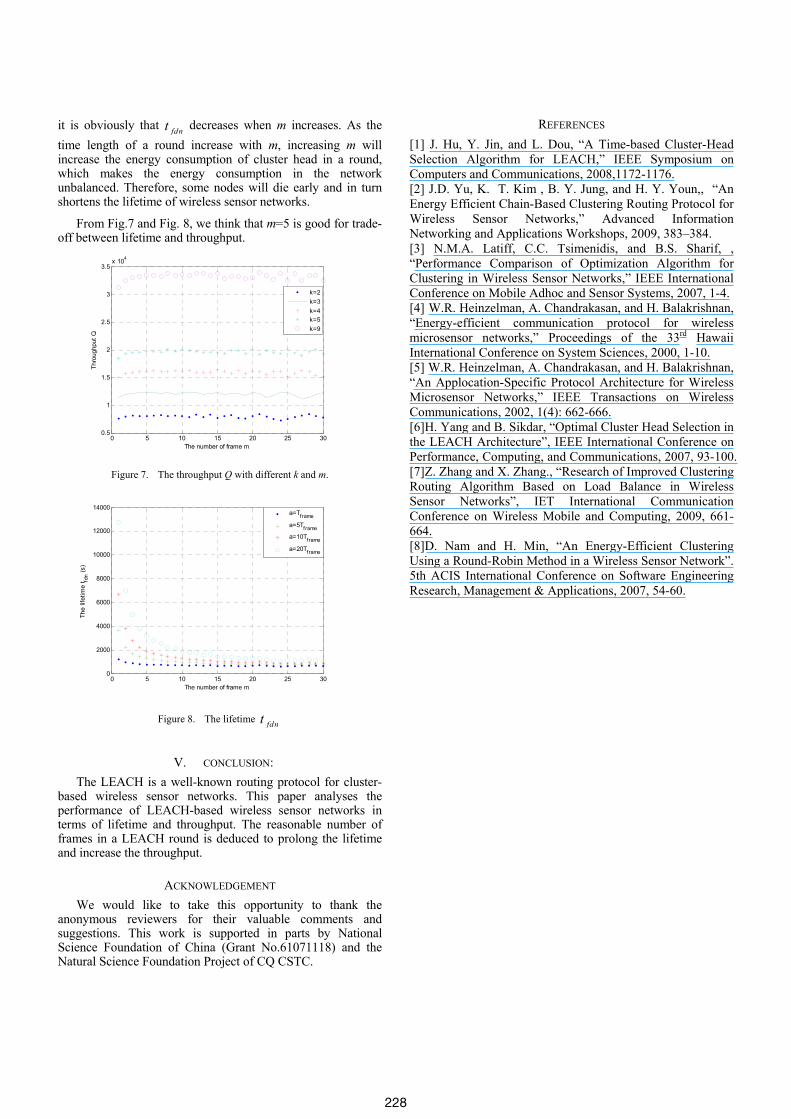
it is obviously that fdnt decreases when m increases. As the time length of a round increase with m, increasing m will increase the energy consumption of cluster head in a round, which makes the energy consumption in the network unbalanced. Therefore, some nodes will die early and in turn shortens the lifetime of wireless sensor networks.
From Fig.7 and Fig. 8, we think that m=5 is good for trade-off between lifetime and throughput.
0 5 10 15 20 25 300.5
1
1.5
2
2.5
3
3.5x 10⁴
The number of frame m
Thro
ughp
ut Q
k=2k=3k=4k=5k=9
Figure 7. The throughput Q with different k and m.
0 5 10 15 20 25 300
2000
4000
6000
8000
10000
12000
14000
The number of frame m
The
lifet
ime
t fdn (s
)
a=Tframe
a=5Tframea=10Tframe
a=20Tframe
Figure 8. The lifetime fdnt
V. CONCLUSION: The LEACH is a well-known routing protocol for cluster-
based wireless sensor networks. This paper analyses the performance of LEACH-based wireless sensor networks in terms of lifetime and throughput. The reasonable number of frames in a LEACH round is deduced to prolong the lifetime and increase the throughput.
ACKNOWLEDGEMENT We would like to take this opportunity to thank the
anonymous reviewers for their valuable comments and suggestions. This work is supported in parts by National Science Foundation of China (Grant No.61071118) and the Natural Science Foundation Project of CQ CSTC.
REFERENCES [1] J. Hu, Y. Jin, and L. Dou, “A Time-based Cluster-Head Selection Algorithm for LEACH,” IEEE Symposium on Computers and Communications, 2008,1172-1176. [2] J.D. Yu, K. T. Kim , B. Y. Jung, and H. Y. Youn,, “An Energy Efficient Chain-Based Clustering Routing Protocol for Wireless Sensor Networks,” Advanced Information Networking and Applications Workshops, 2009, 383–384. [3] N.M.A. Latiff, C.C. Tsimenidis, and B.S. Sharif, , “Performance Comparison of Optimization Algorithm for Clustering in Wireless Sensor Networks,” IEEE International Conference on Mobile Adhoc and Sensor Systems, 2007, 1-4. [4] W.R. Heinzelman, A. Chandrakasan, and H. Balakrishnan, “Energy-efficient communication protocol for wireless microsensor networks,” Proceedings of the 33rd Hawaii International Conference on System Sciences, 2000, 1-10. [5] W.R. Heinzelman, A. Chandrakasan, and H. Balakrishnan, “An Applocation-Specific Protocol Architecture for Wireless Microsensor Networks,” IEEE Transactions on Wireless Communications, 2002, 1(4): 662-666. [6]H. Yang and B. Sikdar, “Optimal Cluster Head Selection in the LEACH Architecture”, IEEE International Conference on Performance, Computing, and Communications, 2007, 93-100. [7]Z. Zhang and X. Zhang., “Research of Improved Clustering Routing Algorithm Based on Load Balance in Wireless Sensor Networks”, IET International Communication Conference on Wireless Mobile and Computing, 2009, 661-664. [8]D. Nam and H. Min, “An Energy-Efficient Clustering Using a Round-Robin Method in a Wireless Sensor Network”. 5th ACIS International Conference on Software Engineering Research, Management & Applications, 2007, 54-60.
228