enhancing and consolidating requirements specification in ...
10
ENHANCING AND CONSOLIDATING REQUIREMENTS SPECIFICATION IN TEACHING SYSTEM DESIGN BY ALIGNING CONCEPTS FROM HETEROGENEOUS DIAGRAMS A. Alyami 1,2 , S.F. Pileggi 2 , I. Hawryszkiewycz 2 1 Jouf University, Computer Science Department (SAUDI ARABIA) 2 University of Technology Sydney (AUSTRALIA) Abstract System analysis and design is a critical aspect of Information Systems, as the different courses in the field clearly demonstrate. Unified Modelling Language (UML), which comprises several structural and behavioural diagrams to formally specify the target system design, has been extensively adopted for a long time, and it is still very popular. Each diagram has a different purpose as it targets a different aspect or perspective of a given system, as well as diagrams may be used at different stages of the design process, which is not necessarily linear or prescriptive. However, the different diagrams are related and, in most cases, may be considered to be part of a seamless process. At an educational level, it is extremely important to approach system engineering in a systematic way in order to assure an effective process, which is correct and consistent. As students are not normally experienced professionals, it is important to create a learning environment that enhances the quality of experience and related learning outcomes. In this context, the alignment of concepts among the different diagrams may play a critical role as it can minimise inconsistencies in the design. In this paper, we discuss the alignment of concepts looking at a subset of UML (Use Case and Sequence diagrams) within the educational context. We analyse a simple scenario with an emphasis on interactions to highlight the relevance of the alignment of concepts from heterogeneous diagrams. Additionally, we provide future work and recommendations to explicit the seamless generation of information and its tracing from Use Case to Sequence diagrams. Keywords: UML, System Design, Requirements Engineering. 1 INTRODUCTION System analysis and design is an important field in information systems. Innovative methods and approaches are constantly required to improve design processes in terms of effectiveness and efficiency. Teaching in such a field may be challenging [1], [2] due to different reasons including, but not limited to, significant developments in the environment, the evolution of technology, needs of the sector, and emerging or changing business trends. It influences the way students learn and normally leads to the need to enhance teaching methods accordingly. Indeed, case studies and project outcomes should be well framed and realistic in the context of actual business environments. At the same time, educational institutions focus on integrated skills and design curriculum to prepare students to meet the current and future job requirements. This paper aims at a narrowed discussion on the alignment of concepts from multiple diagrams. It becomes relevant to enable the complexity of system design in teaching and to assure, at the same time, design consistency and better management. Unified Modelling Language (UML) became a common approach to model software requirements in the late 90s, when it was proposed in the context of object-oriented software engineering methods. UML has been in use widely in teaching system analysis and design [3], [4]. UML is an extensive collection of notations and offers different diagrams to model systems behaviours and characteristics. A single diagram is normally understood as a graphical representation of a certain aspect of the target system. The model can contain or be linked to descriptions or documents that lead to further stages of the development process [5], [6]. UML diagrams can be classified into two categories: static and dynamic. Static diagrams describe the structure of the system, and dynamic diagrams describe the behaviours of the system [7]. Representing key semantics by using these UML diagrams provide a concise view of aspects of the system. For example, Use Case diagrams depict and describe the users’ interaction with the system, while sequence diagrams mostly target the interactions among objects within the system. Class diagrams describe in detail objects, their attributes, and functionalities in the system. In general terms, diagrams facilitate team work, communication among members and to stakeholder, as well as they provide a direct Proceedings of EDULEARN21 Conference 5th-6th July 2021 ISBN: 978-84-09-31267-2 0132
-
Upload
khangminh22 -
Category
Documents
-
view
1 -
download
0
Transcript of enhancing and consolidating requirements specification in ...

ENHANCING AND CONSOLIDATING REQUIREMENTS SPECIFICATION IN TEACHING SYSTEM DESIGN BY ALIGNING
CONCEPTS FROM HETEROGENEOUS DIAGRAMS
A. Alyami1,2, S.F. Pileggi2, I. Hawryszkiewycz2 1Jouf University, Computer Science Department (SAUDI ARABIA)
2University of Technology Sydney (AUSTRALIA)
Abstract System analysis and design is a critical aspect of Information Systems, as the different courses in the field clearly demonstrate. Unified Modelling Language (UML), which comprises several structural and behavioural diagrams to formally specify the target system design, has been extensively adopted for a long time, and it is still very popular. Each diagram has a different purpose as it targets a different aspect or perspective of a given system, as well as diagrams may be used at different stages of the design process, which is not necessarily linear or prescriptive. However, the different diagrams are related and, in most cases, may be considered to be part of a seamless process. At an educational level, it is extremely important to approach system engineering in a systematic way in order to assure an effective process, which is correct and consistent. As students are not normally experienced professionals, it is important to create a learning environment that enhances the quality of experience and related learning outcomes. In this context, the alignment of concepts among the different diagrams may play a critical role as it can minimise inconsistencies in the design. In this paper, we discuss the alignment of concepts looking at a subset of UML (Use Case and Sequence diagrams) within the educational context. We analyse a simple scenario with an emphasis on interactions to highlight the relevance of the alignment of concepts from heterogeneous diagrams. Additionally, we provide future work and recommendations to explicit the seamless generation of information and its tracing from Use Case to Sequence diagrams. Keywords: UML, System Design, Requirements Engineering.
1 INTRODUCTION System analysis and design is an important field in information systems. Innovative methods and approaches are constantly required to improve design processes in terms of effectiveness and efficiency. Teaching in such a field may be challenging [1], [2] due to different reasons including, but not limited to, significant developments in the environment, the evolution of technology, needs of the sector, and emerging or changing business trends. It influences the way students learn and normally leads to the need to enhance teaching methods accordingly. Indeed, case studies and project outcomes should be well framed and realistic in the context of actual business environments. At the same time, educational institutions focus on integrated skills and design curriculum to prepare students to meet the current and future job requirements.
This paper aims at a narrowed discussion on the alignment of concepts from multiple diagrams. It becomes relevant to enable the complexity of system design in teaching and to assure, at the same time, design consistency and better management.
Unified Modelling Language (UML) became a common approach to model software requirements in the late 90s, when it was proposed in the context of object-oriented software engineering methods. UML has been in use widely in teaching system analysis and design [3], [4]. UML is an extensive collection of notations and offers different diagrams to model systems behaviours and characteristics. A single diagram is normally understood as a graphical representation of a certain aspect of the target system. The model can contain or be linked to descriptions or documents that lead to further stages of the development process [5], [6].
UML diagrams can be classified into two categories: static and dynamic. Static diagrams describe the structure of the system, and dynamic diagrams describe the behaviours of the system [7]. Representing key semantics by using these UML diagrams provide a concise view of aspects of the system. For example, Use Case diagrams depict and describe the users’ interaction with the system, while sequence diagrams mostly target the interactions among objects within the system. Class diagrams describe in detail objects, their attributes, and functionalities in the system. In general terms, diagrams facilitate team work, communication among members and to stakeholder, as well as they provide a direct
Proceedings of EDULEARN21 Conference 5th-6th July 2021
ISBN: 978-84-09-31267-20132

common understanding of the target system. Additionally, as visual tools, diagrams contribute to point out inconsistencies, discrepancies or conflicts in the system design. Some processes assume a diagram to be the input for the generation of other diagrams. For instance, a use case consists of basic flow steps that show actions to perform a particular task. Each step can be termed as the interaction among objects – i.e. described by Sequence diagrams – as well as UML communication diagrams can be generated accordingly by combining together information from class, sequence, and use case diagrams. After generation, such a diagram needs to be validated against the underpinning diagrams in order to confirm the correctness and the consistency of the design.
A seamless diagram generation requires the extraction of appropriate information from input diagrams and a proper mapping in the output. Such a process may be facilitated through concept alignment. In the context of this work, concept alignment can be defined as the identification and specification of semantic equivalences among concepts from different diagrams to be understood as a centralised knowledge base for the design. By explicitly formalising matching concepts, the design process increases its seamlessness features.
In this paper, we only consider two UML diagrams (use case and sequence diagram) to discuss the required alignment of concepts and generate recommendations within the educational context.
Structure of the paper. The introductory part is completed by Section 2, which briefly discusses the related work; Section 3 addresses the alignment of concepts, looking at use case and sequence diagram; finally, Section 4 provides the typical conclusions and an overview of future work.
2 RELATED WORK UML is considered a simple, yet effective, modelling language [12], which helps professionals to improve the system development process by using different diagrams at different stages. [8] lists down the most widely used UML diagrams looking at various sources (tools, books, training, and courses).
These diagrams address the same target system although reflecting different aspects. In such a context, the transformation of information and its propagation along the development process normally requires some mechanism, such as tracing or alignment [9]. Alignment and traceability can be defined as tracking the data, elements, and requirements along with the analysis and design phase.
Some studies consider the two concepts to be mostly equivalent [10][11][9]. In software development, traceability is commonly understood as a track of the flow of information [12], [13]. In [14], authors discussed the benefits of traceability for innovative engineering processes as it can support and improve the effective realization of innovative ideas, typically items & services. In [12], authors suggest some tracing practices that can be applied from Scrum [15] to Extreme programming [16] methods. Some of the tracing practices proposed involve requirements. Models development plays a critical role in agile methodologies, whereas traceability and alignment are important in improving the way of developing the system model effectively [17]. Effective alignment is relevant for model transformation within agile development methodologies [12], [18].
Different approaches of model transformation exist [19]. In [20], The authors implement a method to move information from UML class diagrams to another model with a focus on traceability. In [21] [22], the authors propose an approach to systematically and automatically develop test cases from use cases.
[23] proposes a method of traceability of requirements in the code by generating sequence diagrams automatically from activity diagrams. A framework for automatic model transformation is proposed in [24]. The transformation adopts rules to generate Entity Relationship Diagram (ERD) and Structured Query Language (SQL) from UML class diagrams.
[25] proposes a learning system for junior analysts and students to automatically generate a sequence diagram based on descriptions in a natural language. Other contributions [26] adopt a semi-automatic transformation approach supported, again, by a set of transformation rules. [27] focuses on creating traceability links from system requirements to the generated diagrams. Traceability is essential in software development since it helps engineers understand the relationships between different artifacts for the software system [17]. The study proposed [28] proposes a technique to facilitate the seamless transition from requirements to artifact design.
Design thinking is a method that can be adopted in innovation process to foster creativity [29] [14]. Alignment/ traceability plays a role also in such a context as concepts from different tools need to be aligned to ensure consistent design. [30] mentions two main benefits of tracing the requirements as
0133

traceability provides a guideline when changes have been made in the model, as well as it helps to better communicate the resulting model to external people.
As far as the authors know, there are not specific contributions in literature that discuss the value of concept alignment in the educational context with a specific focus on system design.
3 CONCEPT ALIGNMENT FROM USE CASE TO SEQUENCE DIAGRAMS Concept alignment can be defined as the identification and specification of semantic equivalences among concepts from different diagrams to be understood as a centralized knowledge base for the design. By explicitly formalizing matching concepts, the design process increases its seamlessness features.
Two different kinds of alignment can be identified as syntactic alignment and semantic alignment [31][32]. The syntactic approach is based on direct mapping of concepts from the source to the target model, such as objects in the communication diagram are the same as actors in use case diagram. Semantic alignment defines indirect mapping by looking at equivalent meanings among the different elements, such as actors in use case can be the same as objects in a sequence diagram, but the interaction between objects in sequence diagram can be mapped indirectly with the description of use case diagram's functions.
In this study, we focus on Use case and Sequence diagrams as an example to highlight the relevance of concept alignment along the design process. Related work showed that the correlation between these two aligned diagrams leads to a better design. We have created a syntactic alignment between two UML diagrams, use case and sequence, diagrams to aid learners and instructors in tasks related to system design. This alignment is expected to speed up the development that eventually helps in making system development more consistent and effective. This alignment is approached in general terms on basic elements of use.
3.1 CASE STUDY: Automated Teller Machines (ATM) Scenario As a case study, we analyse a simple scenario in which customers interact with an ATM system to perform typical operations related to their bank account. These operations are represented by adopting use case diagrams, which are integrated with aligned sequence diagrams. Use case diagrams normally include four different basic components:
• Use case task / use case scenario is referred to as the use case representing a feature needed in a software system. Use case scenario is associated with additional fields that describe the use case more in detail. These fields are described in the table below (Use Case Descriptions).
• An actor that can activate a use case by triggering it.
• A communication line establishes the communication between an actor and the use case. • Finally, the boundary is placed around the system.
Use Case Descriptions
Use Case Field Description Use case ID A unique ID for each use case Use case Name A unique name for each use case Brief Description A brief description of the process that is happening in the use case or what a user wants to
do with the system Pre-Condition Activities that must take place or any condition that should be true before the state of the use case
Actor A type of user who interacts with the system to accomplish the task. Actors are identified by role name
Dependency Activities that have already performed Basic flow steps User actions and system responses that will take place during the execution of the use case
On the other hand, a sequence diagram comprises objects and sequences of messages. Sequences are ordered set of interactions among objects. These interactions are numbered and specify the flow of
0134
steps in the system being performed. Sequence diagrams are typically the realization of use cases in a sequence for the system being developed.
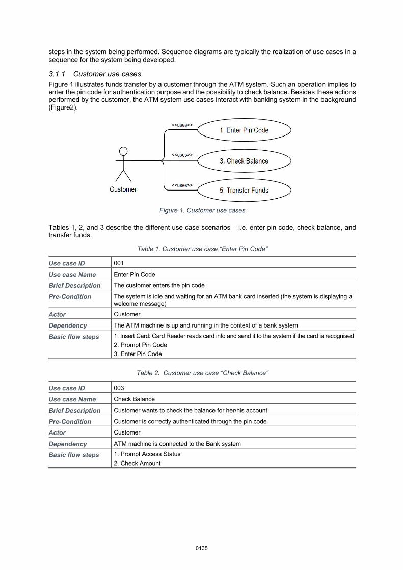
3.1.1 Customer use cases Figure 1 illustrates funds transfer by a customer through the ATM system. Such an operation implies to enter the pin code for authentication purpose and the possibility to check balance. Besides these actions performed by the customer, the ATM system use cases interact with banking system in the background (Figure2).
Figure 1. Customer use cases
Tables 1, 2, and 3 describe the different use case scenarios – i.e. enter pin code, check balance, and transfer funds.
Table 1. Customer use case “Enter Pin Code"
Use case ID 001
Use case Name Enter Pin Code
Brief Description The customer enters the pin code
Pre-Condition The system is idle and waiting for an ATM bank card inserted (the system is displaying a welcome message)
Actor Customer
Dependency The ATM machine is up and running in the context of a bank system
Basic flow steps 1. Insert Card: Card Reader reads card info and send it to the system if the card is recognised 2. Prompt Pin Code 3. Enter Pin Code
Table 2. Customer use case “Check Balance"
Use case ID 003
Use case Name Check Balance
Brief Description Customer wants to check the balance for her/his account
Pre-Condition Customer is correctly authenticated through the pin code
Actor Customer
Dependency ATM machine is connected to the Bank system
Basic flow steps 1. Prompt Access Status 2. Check Amount
0135
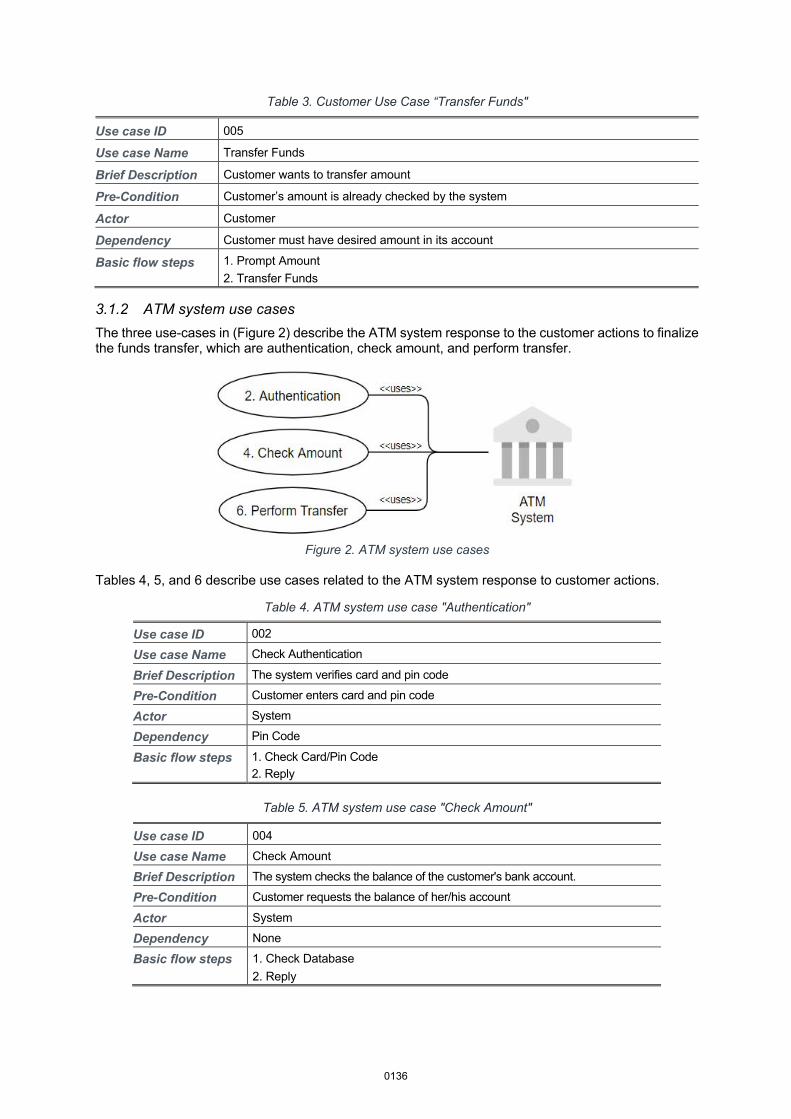
Table 3. Customer Use Case “Transfer Funds"
Use case ID 005
Use case Name Transfer Funds
Brief Description Customer wants to transfer amount
Pre-Condition Customer’s amount is already checked by the system
Actor Customer
Dependency Customer must have desired amount in its account
Basic flow steps 1. Prompt Amount 2. Transfer Funds
3.1.2 ATM system use cases The three use-cases in (Figure 2) describe the ATM system response to the customer actions to finalize the funds transfer, which are authentication, check amount, and perform transfer.
Figure 2. ATM system use cases
Tables 4, 5, and 6 describe use cases related to the ATM system response to customer actions.
Table 4. ATM system use case "Authentication"
Use case ID 002
Use case Name Check Authentication
Brief Description The system verifies card and pin code
Pre-Condition Customer enters card and pin code
Actor System
Dependency Pin Code
Basic flow steps 1. Check Card/Pin Code 2. Reply
Table 5. ATM system use case "Check Amount"
Use case ID 004
Use case Name Check Amount
Brief Description The system checks the balance of the customer's bank account.
Pre-Condition Customer requests the balance of her/his account
Actor System
Dependency None
Basic flow steps 1. Check Database 2. Reply
0136
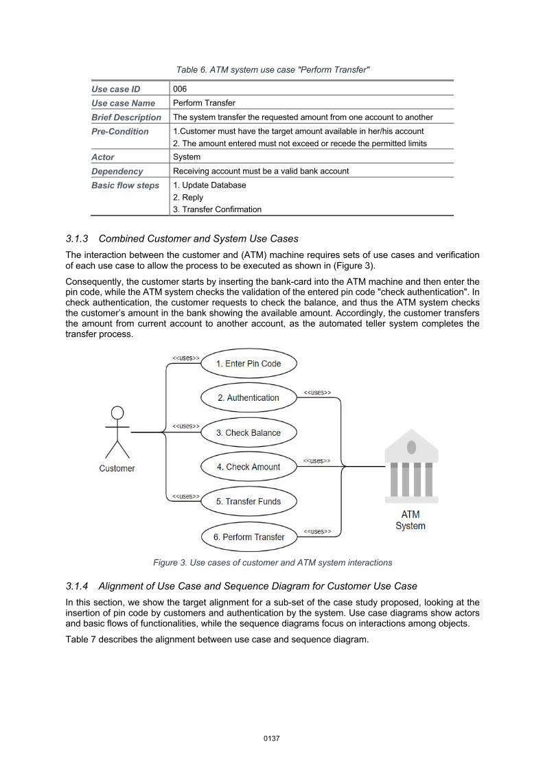
Table 6. ATM system use case "Perform Transfer"
Use case ID 006
Use case Name Perform Transfer
Brief Description The system transfer the requested amount from one account to another
Pre-Condition 1.Customer must have the target amount available in her/his account 2. The amount entered must not exceed or recede the permitted limits
Actor System
Dependency Receiving account must be a valid bank account
Basic flow steps 1. Update Database 2. Reply 3. Transfer Confirmation
3.1.3 Combined Customer and System Use Cases The interaction between the customer and (ATM) machine requires sets of use cases and verification of each use case to allow the process to be executed as shown in (Figure 3).
Consequently, the customer starts by inserting the bank-card into the ATM machine and then enter the pin code, while the ATM system checks the validation of the entered pin code "check authentication". In check authentication, the customer requests to check the balance, and thus the ATM system checks the customer’s amount in the bank showing the available amount. Accordingly, the customer transfers the amount from current account to another account, as the automated teller system completes the transfer process.
Figure 3. Use cases of customer and ATM system interactions
3.1.4 Alignment of Use Case and Sequence Diagram for Customer Use Case In this section, we show the target alignment for a sub-set of the case study proposed, looking at the insertion of pin code by customers and authentication by the system. Use case diagrams show actors and basic flows of functionalities, while the sequence diagrams focus on interactions among objects.
Table 7 describes the alignment between use case and sequence diagram.
0137
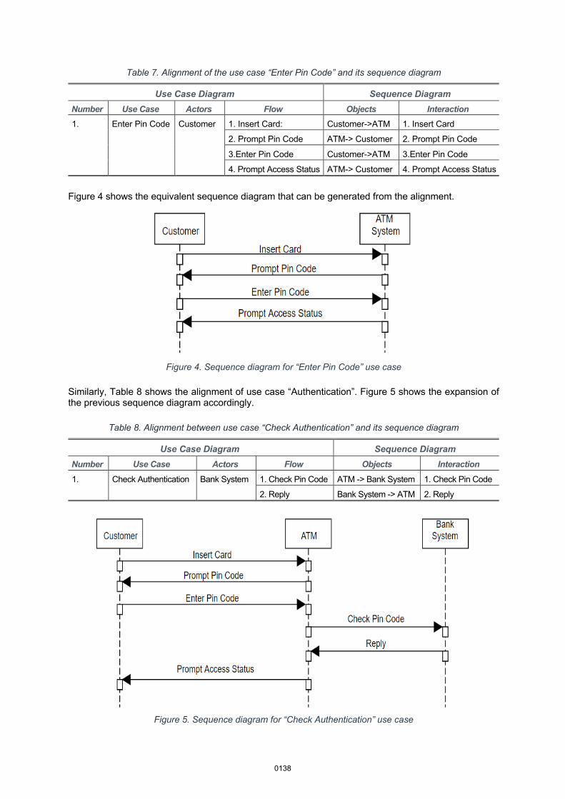
Table 7. Alignment of the use case “Enter Pin Code” and its sequence diagram
Use Case Diagram Sequence Diagram Number Use Case Actors Flow Objects Interaction 1. Enter Pin Code Customer 1. Insert Card: Customer->ATM 1. Insert Card
2. Prompt Pin Code ATM-> Customer 2. Prompt Pin Code
3.Enter Pin Code Customer->ATM 3.Enter Pin Code
4. Prompt Access Status ATM-> Customer 4. Prompt Access Status
Figure 4 shows the equivalent sequence diagram that can be generated from the alignment.
Figure 4. Sequence diagram for “Enter Pin Code” use case
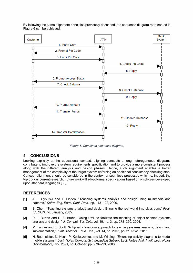
Similarly, Table 8 shows the alignment of use case “Authentication”. Figure 5 shows the expansion of the previous sequence diagram accordingly.
Table 8. Alignment between use case “Check Authentication” and its sequence diagram
Use Case Diagram Sequence Diagram Number Use Case Actors Flow Objects Interaction 1. Check Authentication Bank System 1. Check Pin Code ATM -> Bank System 1. Check Pin Code
2. Reply Bank System -> ATM 2. Reply
Figure 5. Sequence diagram for “Check Authentication” use case
0138
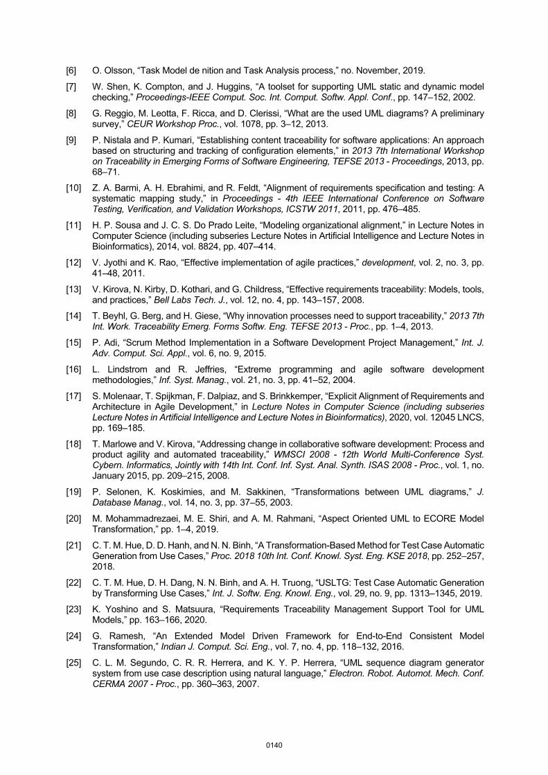
By following the same alignment principles previously described, the sequence diagram represented in Figure 6 can be achieved.
Figure 6. Combined sequence diagram.
4 CONCLUSIONS Looking explicitly at the educational context, aligning concepts among heterogeneous diagrams contribute to improve the system requirements specification and to provide a more consistent process along with the different analysis and design phases. Hence, such alignment enables a better management of the complexity of the target system enforcing an additional consistency-checking step. Concept alignment should be considered in the context of seamless processes which is, indeed, the topic of our current research. Future work will adopt formal specifications based on ontologies developed upon standard languages [33].
REFERENCES [1] J. L. Cybulski and T. Linden, “Teaching systems analysis and design using multimedia and
patterns,” Softw. Eng. Educ. Conf. Proc., pp. 113–122, 2000.
[2] B. Chen, “Teaching systems analysis and design: Bringing the real world into classroom,” Proc. ISECON, no. January, 2005.
[3] P. J. Burton and R. E. Bruhn, “Using UML to facilitate the teaching of object-oriented systems analysis and design,” J. Comput. Sci. Coll., vol. 19, no. 3, pp. 278–290, 2004.
[4] M. Tanner and E. Scott, “A flipped classroom approach to teaching systems analysis, design and implementation,” J. Inf. Technol. Educ. Res., vol. 14, no. 2015, pp. 219–241, 2015.
[5] H. Baumeister, N. Koch, P. Kosiuczenko, and M. Wirsing, “Extending activity diagrams to model mobile systems,” Lect. Notes Comput. Sci. (including Subser. Lect. Notes Artif. Intell. Lect. Notes Bioinformatics), vol. 2591, no. October, pp. 278–293, 2003.
0139
[6] O. Olsson, “Task Model de nition and Task Analysis process,” no. November, 2019.
[7] W. Shen, K. Compton, and J. Huggins, “A toolset for supporting UML static and dynamic model checking,” Proceedings-IEEE Comput. Soc. Int. Comput. Softw. Appl. Conf., pp. 147–152, 2002.
[8] G. Reggio, M. Leotta, F. Ricca, and D. Clerissi, “What are the used UML diagrams? A preliminary survey,” CEUR Workshop Proc., vol. 1078, pp. 3–12, 2013.
[9] P. Nistala and P. Kumari, “Establishing content traceability for software applications: An approach based on structuring and tracking of configuration elements,” in 2013 7th International Workshop on Traceability in Emerging Forms of Software Engineering, TEFSE 2013 - Proceedings, 2013, pp. 68–71.
[10] Z. A. Barmi, A. H. Ebrahimi, and R. Feldt, “Alignment of requirements specification and testing: A systematic mapping study,” in Proceedings - 4th IEEE International Conference on Software Testing, Verification, and Validation Workshops, ICSTW 2011, 2011, pp. 476–485.
[11] H. P. Sousa and J. C. S. Do Prado Leite, “Modeling organizational alignment,” in Lecture Notes in Computer Science (including subseries Lecture Notes in Artificial Intelligence and Lecture Notes in Bioinformatics), 2014, vol. 8824, pp. 407–414.
[12] V. Jyothi and K. Rao, “Effective implementation of agile practices,” development, vol. 2, no. 3, pp. 41–48, 2011.
[13] V. Kirova, N. Kirby, D. Kothari, and G. Childress, “Effective requirements traceability: Models, tools, and practices,” Bell Labs Tech. J., vol. 12, no. 4, pp. 143–157, 2008.
[14] T. Beyhl, G. Berg, and H. Giese, “Why innovation processes need to support traceability,” 2013 7th Int. Work. Traceability Emerg. Forms Softw. Eng. TEFSE 2013 - Proc., pp. 1–4, 2013.
[15] P. Adi, “Scrum Method Implementation in a Software Development Project Management,” Int. J. Adv. Comput. Sci. Appl., vol. 6, no. 9, 2015.
[16] L. Lindstrom and R. Jeffries, “Extreme programming and agile software development methodologies,” Inf. Syst. Manag., vol. 21, no. 3, pp. 41–52, 2004.
[17] S. Molenaar, T. Spijkman, F. Dalpiaz, and S. Brinkkemper, “Explicit Alignment of Requirements and Architecture in Agile Development,” in Lecture Notes in Computer Science (including subseries Lecture Notes in Artificial Intelligence and Lecture Notes in Bioinformatics), 2020, vol. 12045 LNCS, pp. 169–185.
[18] T. Marlowe and V. Kirova, “Addressing change in collaborative software development: Process and product agility and automated traceability,” WMSCI 2008 - 12th World Multi-Conference Syst. Cybern. Informatics, Jointly with 14th Int. Conf. Inf. Syst. Anal. Synth. ISAS 2008 - Proc., vol. 1, no. January 2015, pp. 209–215, 2008.
[19] P. Selonen, K. Koskimies, and M. Sakkinen, “Transformations between UML diagrams,” J. Database Manag., vol. 14, no. 3, pp. 37–55, 2003.
[20] M. Mohammadrezaei, M. E. Shiri, and A. M. Rahmani, “Aspect Oriented UML to ECORE Model Transformation,” pp. 1–4, 2019.
[21] C. T. M. Hue, D. D. Hanh, and N. N. Binh, “A Transformation-Based Method for Test Case Automatic Generation from Use Cases,” Proc. 2018 10th Int. Conf. Knowl. Syst. Eng. KSE 2018, pp. 252–257, 2018.
[22] C. T. M. Hue, D. H. Dang, N. N. Binh, and A. H. Truong, “USLTG: Test Case Automatic Generation by Transforming Use Cases,” Int. J. Softw. Eng. Knowl. Eng., vol. 29, no. 9, pp. 1313–1345, 2019.
[23] K. Yoshino and S. Matsuura, “Requirements Traceability Management Support Tool for UML Models,” pp. 163–166, 2020.
[24] G. Ramesh, “An Extended Model Driven Framework for End-to-End Consistent Model Transformation,” Indian J. Comput. Sci. Eng., vol. 7, no. 4, pp. 118–132, 2016.
[25] C. L. M. Segundo, C. R. R. Herrera, and K. Y. P. Herrera, “UML sequence diagram generator system from use case description using natural language,” Electron. Robot. Automot. Mech. Conf. CERMA 2007 - Proc., pp. 360–363, 2007.
0140
[26] F. C. De Souza, F. Antonio, D. C. Giorno, and S. Paulo, “Automatic Generation of Sequence Diagrams and Updating Domain Model from Use Cases,” no. c, pp. 85–92, 2015.
[27] T. Yue, L. C. Briand, and Y. Labiche, “Automatically Deriving UML Sequence Diagrams from Use Cases,” Qual. Eng., pp. 1–17, 2010.
[28] Y. A. Khan and S. Mahmood, “Generating UML Sequence Diagrams from Use Case Maps: A Model Transformation Approach,” Arab. J. Sci. Eng., vol. 41, no. 3, pp. 965–986, 2016.
[29] A. Alyami and I. Hawryszkiewycz, “Evaluating Design Thinking Teaching,” EDULEARN20 Proc., vol. 1, no. July, pp. 7063–7068, 2020.
[30] H. Liu, Z. Xu, and Y. Zou, “Deep learning based feature envy detection,” ASE 2018 - Proc. 33rd ACM/IEEE Int. Conf. Autom. Softw. Eng., pp. 385–396, 2018.
[31] S. Brockmans, M. Ehrig, A. Koschmider, A. Oberweis, and R. Studer, “Semantic alignment of business processes,” in ICEIS 2006 - 8th International Conference on Enterprise Information Systems, Proceedings, 2006, vol. ISAS, pp. 191–196.
[32] H. P. Branigan, M. J. Pickering, and C. Nass, “Syntactic alignment between computers and people: The role of belief about mental states Coordinating utterances during turn-taking View project joint naming View project,” researchgate.net, no. January, pp. 186–191, 2003.
[33] Pileggi, S., Antonio A. Lopez-Lorca, and Ghassan Beydoun. "Ontologies in Software Engineering." 29th Australasian Conference on Information Systems (ACIS2018). 2018.
0141