Engineering Specification: SuperTEK® Range (Rev. 1.0)
59
1 SuperTEK® Range ENGINEERING SPECIFICATION +44 (0) 141 647 7100 [email protected] Clyde Gateway Trade Park Dalmarnock Road Glasgow G73 1AN Evolution Fasteners UK
-
Upload
khangminh22 -
Category
Documents
-
view
1 -
download
0
Transcript of Engineering Specification: SuperTEK® Range (Rev. 1.0)

1
SuperTEK® Range
ENGINEERING SPECIFICATION
+44 (0) 141 647 7100 [email protected]
Clyde Gateway Trade Park Dalmarnock Road Glasgow G73 1AN
Evolution Fasteners UK

Evolution Fasteners UK Ltd Department of Engineering and Laboratory Services
Page 1 of 58 ©Evolution Fasteners UK Ltd, October 2019 Engineering Specification: SuperTEK® Range (Rev. 1.0)
0.0 Contents
Section Title Page(s) 1.0 Foreword 02 2.0 Scope 03 3.0 Normative references 04, 05 4.0 Terms, definitions, symbols and abbreviated terms
4.1 Terms and definitions 06, 07 4.2 Symbols and abbreviated terms 08
5.0 Dimensions and metrological properties 09 6.0 Installation procedure 10, 11 7.0 Standard product details 12 8.0 General mechanical properties of the screws 13 - 15 9.0 Mechanical properties of screws in conjunction with various substrates
9.1 SuperTEK® 6 and 7 products 9.1.1 Hot-rolled mild structural steels (pursuant to BS EN 10025) 17, 18 9.1.2 Cold-rolled structural steels (pursuant to BS EN 10346) 19, 20 9.1.3 Extruded aluminium alloys (pursuant to BS EN 485-2 or BS EN 755-2) 21, 22 9.2 SuperTEK® 8 and X products 9.2.1 Hot-rolled mild structural steels (pursuant to BS EN 10025) 23, 24 9.2.2 Cold-rolled structural steels (pursuant to BS EN 10346) 25, 26 9.2.3 Extruded aluminium alloys (pursuant to BS EN 485-2 or BS EN 755-2) 27, 28
10.0 List of figures 29 11.0 List of tables 29, 30 12.0 List of formulae 31, 32 13.0 Bibliography 33 14.0 Index 34
Appendix I Qualified vendors list (power tools for use with SuperTEK® products) 35 - 38 Appendix II Corrosion resistance and corrosivity categories 39 - 41 Appendix III Installation troubleshooting 42 Appendix IV Limitations of self-drilling screws (drilling capacity, tapping capacity, etc) 43 - 52 Appendix V Axis and planes in three dimensional objects 53 Appendix VI Explanation of elastic and plastic deformation in screws and substrates 54 - 56 Appendix VII Explanation of characteristic, design and recommended loadings 57, 58
This document contains a large amount of data, to expedite finding the pertinent information for your application, please use the lists of figures, tables and formulae to be re-directed to the page the information is presented on.

Evolution Fasteners UK Ltd Department of Engineering and Laboratory Services
Page 2 of 58 ©Evolution Fasteners UK Ltd, October 2019 Engineering Specification: SuperTEK® Range (Rev. 1.0)
1.0 Foreword
Evolution Fasteners UK Ltd is a manufacturer of various fasteners and fixings for applications intended in the construction industry as well as aerospace, automotive and marine industries.
Evolution Fasteners UK Ltd is a UKAS (United Kingdom Accreditation Service) accredited testing laboratory. The laboratory holds accreditation to BS EN ISO/IEC 17025: 2017 and the UKAS Schedule of Accreditation is No. 74851.
Use of the National Accreditation Logo is in compliance with governmental regulations (HM Government: Department for Business, Energy & Industrial Strategy, 2018) and use of the ILAC (International Laboratory Accreditation Cooperation) MRA (Mutual Recognition Agreement) Logo is in compliance with ILAC regulations (International Laboratory Accreditation Cooperation, 2019).
Where data is presented from tests that are not included in our Schedule of Accreditation, they will be notated with “NC”. Opinions and interpretations expressed herein are outside the scope of UKAS accreditation.
This document has been prepared by the Department of Engineering and Laboratory Services of Evolution Fasteners UK Ltd and takes a form (where possible) to conform with the general layout and conventions of ISO (International Standards Organisation) and CEN (Comité Européen de Normalisation) documents for the purposes of familiarity with readers.
This document is a copyright protected document published 2019 in the United Kingdom. This document shall not be reproduced except in full, without written approval of Evolution Fasteners UK Ltd. Results and data in this document relate only to the items stated alongside such data as the data is underpinned by empirical testing in our accredited laboratory.
This document is provided for educational purposes only.
This document is strictly provided without prejudice, without recourse, non-assumptist, errors and omissions excepted, no assured value, no liability and all rights reserved.
This document is updated periodically and latest revisions can be found at the links below:
Engineering and Technical Services
Laboratory and Analytical Services
NOTE: Compliance with this document does not of itself confer immunity from legal obligations.
1 Current revision of the Schedule of Accreditation may be obtained from UKAS,

Evolution Fasteners UK Ltd Department of Engineering and Laboratory Services
Page 3 of 58 ©Evolution Fasteners UK Ltd, October 2019 Engineering Specification: SuperTEK® Range (Rev. 1.0)
2.0 Scope
This document is intended to provide any prospective specifier (i.e. structural engineer, mechanical engineer or architect) with information above-and-beyond that which is generally available from our contemporaries which may assist them (as an educational tool) with their calculations and decision-making processes.
To that end this document specifies the characteristics and performance of Evolution SuperTEK® products, which are mechanical fasteners made of steel, intended for the fixing of steel fixtures to steel substrates or other ancillary products, as appropriate, in construction works.
The content of this document was, to the best of our knowledge, correct at time of publication, however is still provided on the basis of errors and omissions excepted.
This document is provided for educational purposes only.
This document is strictly provided without prejudice, without recourse, non-assumptist, errors and omissions excepted, no assured value, no liability and all rights reserved.
The use of this document does not alleviate, absolve or otherwise reprieve or diminish the user, designer or any other party from their respective obligations under the Building Regulations 2010, the Building (Amendment) Regulations 2018, the Construction (Design and Management) Regulations 2015 or any other law, statute, statutory instrument, directive, regulation or otherwise.
IMPORTANT NOTICE:
All values stated in this document are to be treated as characteristic loads. As such users of this document must treat the loads with factors of safety as part of their designs and calculations. Please refer to Appendix VII of this document.
For further information please contact the Technical Support Team.

Evolution Fasteners UK Ltd Department of Engineering and Laboratory Services
Page 4 of 58 ©Evolution Fasteners UK Ltd, October 2019 Engineering Specification: SuperTEK® Range (Rev. 1.0)
3.0 Normative references
The following documents, in whole or in part, are normatively referenced in this document and are indispensable for its application. For dated references, only the edition cited applies. For undated references, the latest edition of the referenced document (including any amendments) applies.
BS EN 166: 2002 “Personal eye protection. Specifications.”,
BS EN 140: 1999 “Respiratory protective devices. Half masks and quarter masks. Requirements, testing and marking.”,
BS EN 14387: 2004 & A1: 2008 “Respiratory protective devices. Gas filter(s) and combined filter(s). Requirements, testing and marking.”,
BS EN 388: 2016 “Protective gloves against mechanical risks.”,
Evolution EWD: 2019 “Evolution Standard Product Warranty (2019 Edition).”,
BS EN ISO/IEC 17025: 2017 “General requirements for the competence of testing and calibration laboratories.”,
UKAS Document M3003 “The expression of uncertainty and confidence in measurement (3rd Edition).”,
ISO/IEC 17043: 2010 “Conformity assessment. General requirements for proficiency testing.”,
BS ISO 9001: 2015 “Quality management systems. Requirements.”,
BS EN ISO 12944-2: 2017 “Paints and varnishes. Corrosion protection of steel structures by protective paint systems. Classification of environments.”,
BS EN ISO 9223: 2012 “Corrosion of metals and alloys. Corrosivity of atmospheres. Classification, determination and estimation.”,
ASTM A240/ A240M – 18 “Standard specification for chromium and chromium-nickel stainless steel plate, sheet and strip for pressure vessels and for general applications.”,
MIL-STD-1312-13 “Military standard. Fastener test methods (method 13). Double shear test.”,
BS EN ISO 10666: 1999 “Drilling screws with tapping screw thread – mechanical and functional properties.”,
BS EN ISO 6507-1: 2018 “Metallic materials – Vickers hardness test – Part 1: test method.”,

Evolution Fasteners UK Ltd Department of Engineering and Laboratory Services
Page 5 of 58 ©Evolution Fasteners UK Ltd, October 2019 Engineering Specification: SuperTEK® Range (Rev. 1.0)
BS EN ISO 898-1: 2013 “Mechanical properties of fasteners made of carbon steel and alloy steel. Part 1: bolts, screws and studs with specified property classes. Coarse thread and fine pitch thread.”,
BS EN 10025-1: 2004 “Hot rolled products of structural steels. General technical delivery conditions.”,
BS EN 10025-2: 2019 “Hot rolled products of structural steels. Technical delivery conditions for non-alloy structural steels.”,
BS EN 10346: 2015 “Continuously hot-dip coated steel flat products for cold forming. Technical delivery conditions.”,
BS EN 485-2: 2016 & A1: 2018 “Aluminium and aluminium alloys. Sheet, strip and plate. Mechanical properties.”,
BS EN 755-2: 2016 “Aluminium and aluminium alloys. Extruded rod/ bar, tube and profiles. Mechanical properties.”,
EAD 330046-01-0602 “Fastening screws for metal members and sheeting.”,

Evolution Fasteners UK Ltd Department of Engineering and Laboratory Services
Page 6 of 58 ©Evolution Fasteners UK Ltd, October 2019 Engineering Specification: SuperTEK® Range (Rev. 1.0)
4.0 Terms, definitions, symbols and abbreviated terms
This document utilises SI units and nomenclature in relation to units and prefixes/ suffixes pursuant to the International System of Units.
Where possible all terms, definitions and symbols used in this document are pursuant to Eurocodes 0 through 8 so that they are familiar to readers. Where such terms, definitions and symbols deviate from Eurocodes, this is due to a regulatory, statutory or standard (i.e. test standard) takes precedence over the Eurocode.
4.1 Terms and definitions
For the purpose of this document, the following terms and definitions apply:
Stock Keeping Unit (SKU) The unique identification code of the particular product in question, generally used in lieu of a longer description of the product.
Threads Per Inch (TPI) Number of thread peaks per measured inch along the shank of the screw. An anachronistic unit of measuring thread pitch.
Central Limit Theorem (CLT) A statistical analysis technique in probability theory, where standard deviations from mean provide an indicative % confidence.
Analysis of Variance (ANOVA) A statistical analysis technique used to analyse the differences among group means in a given data-set.
Axial, tangential or radial plane The cross-section through an object with respect to its’ orientation in space. Refer to Annex V of this document for further explanation.
Material yield strength The point on the stress/ strain graph where the material stops deforming elastically and begins to deform plastically.
Ultimate tensile strength The point on the stress/ strain graph where the material has reached maximum plastic deformation. After this point the material will begin to weaken due to loss of cross-sectional area in necking.

Evolution Fasteners UK Ltd Department of Engineering and Laboratory Services
Page 7 of 58 ©Evolution Fasteners UK Ltd, October 2019 Engineering Specification: SuperTEK® Range (Rev. 1.0)
Stress (ε) Force per unit area. Strain (σs) Proportional deformation. Young’s modulus Stiffness of a solid material, specifically the linear elasticity of a uniaxial deformation.
Elastic section modulus Stiffness as a geometric property for a known cross-section in a flexural member.
Bending moment capacity The capacity of a member to resist bending moment through the axial plane.
Lateral-Torsional Buckling (LTB) resistance The capacity of a member to resist combined concurrent bending through the axial and tangential planes.
Polar moment of inertia Rigidity of a cross-sectional area to resist deformation by torsion as function of its’ shape. Second moment of area Rigidity of a cross-sectional area to resist deformation by deflection as a function of its’ shape.
Poisson’s ratio The negative ratio of transverse strain to axial strain (i.e. transversal expansion divided by axial compression).
Elastic deformation (elasticity) The ability of the material to deform under the application of a force and to return to its’ original size and shape when such force is removed. This is the phase on a stress/ strain graph where the material is at a low stress and is fully recoverable once stress is removed.
Plastic deformation (plasticity) The ability of the material to deform under the application of a force and to remain in a permanently different size and shape when such force is removed. This is the phase on a stress/ strain graph where the material is at a high stress and is non-reversibly changed once stress is removed.
Hooke’s law Fundamental law of physics that force applied to a body is proportional to the extension of that body.

Evolution Fasteners UK Ltd Department of Engineering and Laboratory Services
Page 8 of 58 ©Evolution Fasteners UK Ltd, October 2019 Engineering Specification: SuperTEK® Range (Rev. 1.0)
4.2 Symbols and abbreviated terms
For the purpose of this simplification in product marking and performance information characteristics may be identified through the symbols and abbreviations given in Table 1:
Table 01: Symbols and designations Symbol Unit Designation
L mm Overall length of the screw.
S mm Length of threaded portion of the screw (including length of self-drilling point).
T mm Length of the self-drilling point. P mm Pitch of the screw thread (peak to peak distance).
D1 mm Diameter of the major thread. D2 mm Diameter of the minor thread. E mm Diameter of the self-drilling point.
Xst,m Statistical mean of a data set derived from empirical testing. Xn Number of individual results in a data set derived from empirical testing. σ Standard deviation of a data set derived from empirical testing. fy N/mm2 Material yield strength (synonymous with ReH pursuant to BS EN ISO 6892-1).
Rm N/mm2 Ultimate tensile strength pursuant to BS EN ISO 6892-1). FeH N Force recorded at fy. Fm N Force recorded at Rm. Vm N Force recorded at ultimate shear failure. S0 mm2 Smallest cross-sectional area subjected to stress/ strain. Y GPa Young’s modulus. G GPa Shear modulus (sometimes referred to as Modulus of rigidity).
WeL mm3 Elastic section modulus. Mc,Rd Nm Bending moment capacity. Mb,Rd Nm Lateral-torsional buckling resistance.
J mm4 Polar moment of inertia. τm Nm Ultimate torsional strength. ν Poisson’s ratio.
Hsurface HV Surface hardness. NRk N Characteristic withdrawal resistance (refer to Appendix VII of this document). VRk N Characteristic lap-shearing resistance (refer to Appendix VII of this document). NRd N Design withdrawal resistance (refer to Appendix VII of this document). VRd N Design lap-shearing resistance (refer to Appendix VII of this document). Nrec N Recommended withdrawal resistance (refer to Appendix VII of this document). Vrec N Recommended lap-shearing resistance (refer to Appendix VII of this document).
Evolution Fasteners UK Ltd Department of Engineering and Laboratory Services
Page 9 of 58 ©Evolution Fasteners UK Ltd, October 2019 Engineering Specification: SuperTEK® Range (Rev. 1.0)
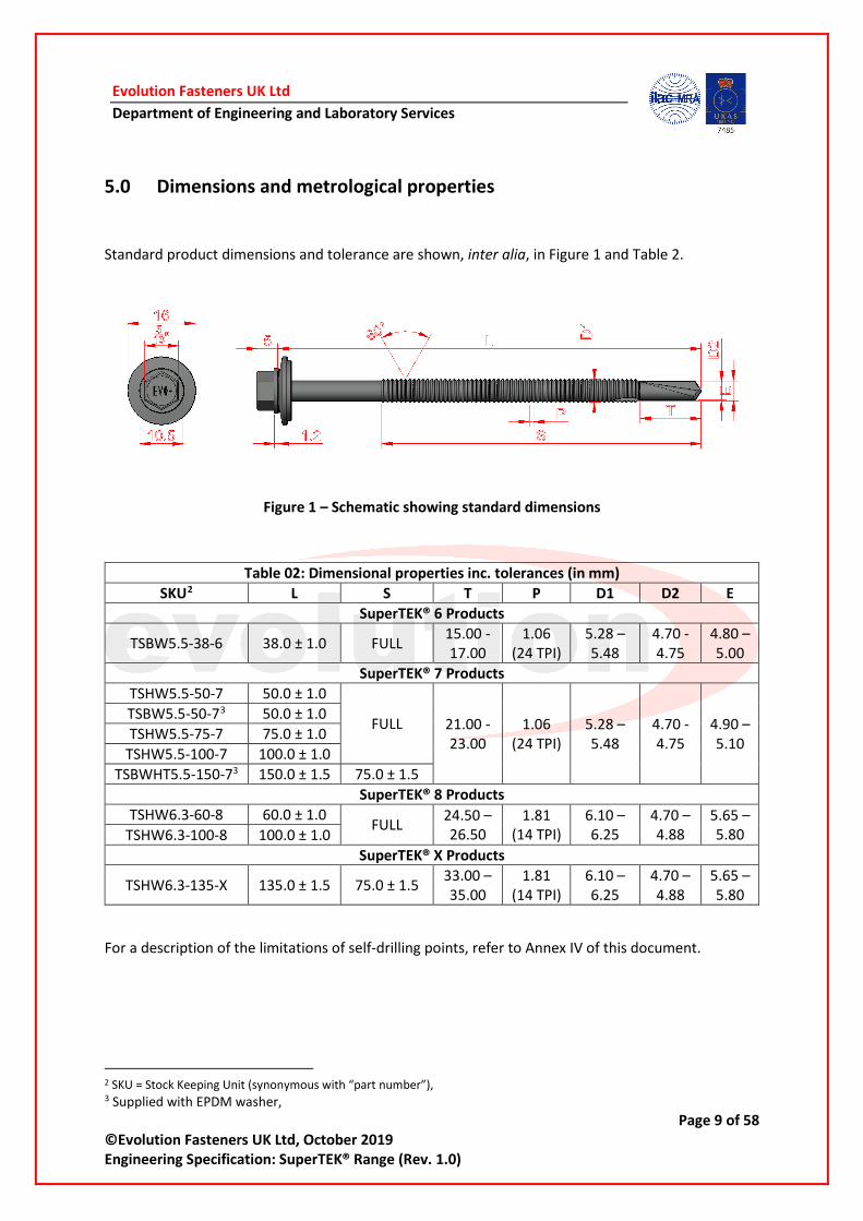
5.0 Dimensions and metrological properties
Standard product dimensions and tolerance are shown, inter alia, in Figure 1 and Table 2.
Figure 1 – Schematic showing standard dimensions
Table 02: Dimensional properties inc. tolerances (in mm) SKU2 L S T P D1 D2 E
SuperTEK® 6 Products
TSBW5.5-38-6 38.0 ± 1.0 FULL 15.00 -17.00
1.06 (24 TPI)
5.28 – 5.48
4.70 -4.75
4.80 – 5.00
SuperTEK® 7 Products TSHW5.5-50-7 50.0 ± 1.0
FULL 21.00 -23.00
1.06 (24 TPI)
5.28 – 5.48
4.70 -4.75
4.90 – 5.10
TSBW5.5-50-73 50.0 ± 1.0 TSHW5.5-75-7 75.0 ± 1.0
TSHW5.5-100-7 100.0 ± 1.0 TSBWHT5.5-150-73 150.0 ± 1.5 75.0 ± 1.5
SuperTEK® 8 Products TSHW6.3-60-8 60.0 ± 1.0 FULL 24.50 –
26.50 1.81
(14 TPI) 6.10 – 6.25
4.70 – 4.88
5.65 – 5.80 TSHW6.3-100-8 100.0 ± 1.0
SuperTEK® X Products
TSHW6.3-135-X 135.0 ± 1.5 75.0 ± 1.5 33.00 – 35.00
1.81 (14 TPI)
6.10 – 6.25
4.70 – 4.88
5.65 – 5.80
For a description of the limitations of self-drilling points, refer to Annex IV of this document.
2 SKU = Stock Keeping Unit (synonymous with “part number”), 3 Supplied with EPDM washer,

Evolution Fasteners UK Ltd Department of Engineering and Laboratory Services
Page 10 of 58 ©Evolution Fasteners UK Ltd, October 2019 Engineering Specification: SuperTEK® Range (Rev. 1.0)
6.0 Installation instructions4
Failure to abide by these instructions may void any warranty provided by Evolution Fasteners UK Ltd. This document does not alleviate, absolve or otherwise reprieve or diminish the user, designer or any other party from their respective obligations under the terms of the Warranty5.
The use of impact tooling is prohibited. Using such tooling will void the Warranty. Please refer to our Qualified Vendors List (QVL) in Appendix I of this document to confirm if your tooling is approved or prohibited.
Before installing the screws, please make sure that you have all appropriate tooling, equipment and apparatus before starting.
A REQUIRED EQUIPMENT AND APPARATUS
I Personal Protective Equipment (PPE):
1. Eyeglasses meeting BS EN 166: 2002 Class 1F (or better),
2. Dust mask with face piece meeting BS EN 140: 1999 and filters meeting BS EN 14387: 2004 & 2008 (or better),
3. Safety gloves meeting BS EN 388: 2016 (or better).
II Hand tools, accessories and other small items:
4. Degreasing agent and/ or cleaning solvent,
5. Wire brush or steel wool,
6. Automatic centre punch.
III Power tools:
7. Construction screwdriver (sometimes referred to as TEK screwdriver) with appropriate depth stopping nose-piece and a no-load RPM of ≥ 1,250 ≤ 2,500 RPM.
B INSTALLATION PROCEDURE
1. Ensure environmental conditions are correct for use and installation of the product, specifically (list is not exhaustive) that:
a) The products are being used in a dry and internal place (where possible), if being used externally: ensure that exposure of the screws does not exceed the appropriate corrosivity category for the product (for further information please refer to Appendix II of this document),
4 Video instructions available on our YouTube™ channel, 5 For further information, refer to the Evolution Product Warranty document hosted on our website,

Evolution Fasteners UK Ltd Department of Engineering and Laboratory Services
Page 11 of 58 ©Evolution Fasteners UK Ltd, October 2019 Engineering Specification: SuperTEK® Range (Rev. 1.0)
b) The products are being used in the correct application as per the limitations prescribed in Evolution Fasteners UK technical literature (Technical Manual, Technical Datasheet and Engineering Specification). If unsure, please contact the Evolution Technical Support Team either by phone to +44 (0) 141 647 7100 or e-mail to [email protected].
2. Clear the area of dirt and debris and ensure that no other contaminating substances such as oil, grease, etc present. If required, use a suitable degreasing agent or solvent and allow to air dry before installing the screws.
3. In accordance with the Engineers’ drawings, mark out where the fixings are to be placed as appropriate.
4. Using an automatic centerpunch, deform (punch) where screws will be installed as this will aid the user during screw installation as it stops screws “walking” on the face of the fixture material.
5. Using a non-impacting construction screwdriver, insert the screw into the fixture and substrate perpendicularly (maximum of ± 5° deviation from normal) using not greater than 1,750 RPM and a steady pressure on the tooling only (do not force the tool, allow the screw to cut).
6. Stop inserting the screw once the underside of the flange makes contact with the topside of the fixture material for screws which do not incorporate a washer.
For screws which incorporate a washer: continue inserting until the compression disc of the washer changes from convex to flat (not that if washer concaves, you have applied to much torque and need to remove the fastener and try again with an unused fastener).
If you are experiencing difficulties when installing screws, please refer to Appendix III of this document.

Evolution Fasteners UK Ltd Department of Engineering and Laboratory Services
Page 12 of 58 ©Evolution Fasteners UK Ltd, October 2019 Engineering Specification: SuperTEK® Range (Rev. 1.0)
7.0 Standard product details
Standard product dimensions and tolerance are shown, inter alia, in Table 3.
6 Only relates to products prefixed with TSBW or TSBWHT,
Table 03: Standard product details Designed for/
purpose: Fastening steel sections, sheeting, panels etc to steel or structural sections.
Head style and drive: 5/16” hexagonal (male) socket with flange.
Thread form: SuperTEK® 6 and 7 SKUs = Fine (1.06mm pitch), SuperTEK® 8 and X SKUs = Coarse (1.80mm pitch).
Material type and grade:
SAE C1022 carbon steel. For elemental composition see Appendix II of this document (Bringas, 2004)
Coating and corrosion resistance:
1. ≥ 1,000 Hour corrosion resistance (when tested in 5% NaCl accelerated corrosion test as per BS EN ISO 9227).
2. For use in atmospheric corrosivity categories of C3, C2 and C1 as per BS EN ISO 12994-2 and BS EN ISO 9223.
Washer details6: Compression disc = 1.0mm thick galvanised steel (16mm OD & 7.6mm ID), Gasket = 2.0mm thick EPDM (ethylene propylene diene monomer).

Evolution Fasteners UK Ltd Department of Engineering and Laboratory Services
Page 13 of 58 ©Evolution Fasteners UK Ltd, October 2019 Engineering Specification: SuperTEK® Range (Rev. 1.0)
8.0 General mechanical properties of the screws
General mechanical properties of the screws are shown, inter alia, in Figure 2 and Table 5.
Mechanical Properties of Screws
Tensile Capacity Shear Capacity Torque Capacity
Figure 2 – Graphical representation of failure modes of screws.
When interpreting the data in Table 05, it is important for the reader to understand that we analyse our empirical test data in accordance with UKAS Document M3003 and ISO/IEC 17043: 2010.
We use central limit theorem7 and ANOVA (Analysis of Variances) approach (Rutherford, 2011) to produce our stated performance values. Using a risk-based approach based on our ISO 9001 QMS we adopt the principals shown in Table 04 and illustrated in Figure 3:
Table 04: Formula applied to data-sets arising from empirical testing Data Type Risk Level Formula Formula8 No.
Mechanical properties of screws Low 𝑋𝑋𝑠𝑠𝑠𝑠,𝑚𝑚 = ��
∑𝑋𝑋𝑠𝑠𝑠𝑠,𝑚𝑚𝑋𝑋𝑛𝑛� � − 2 ∙ 𝜎𝜎� 1
Mechanical properties of substrates High 𝑋𝑋𝑠𝑠𝑠𝑠,𝑚𝑚 = ��
∑𝑋𝑋𝑠𝑠𝑠𝑠,𝑚𝑚𝑋𝑋𝑛𝑛� � − 3 ∙ 𝜎𝜎� 2
7 More information on central limit theorem can be obtained from Wikipedia, 8 Refer to Section 12 of this document,

Evolution Fasteners UK Ltd Department of Engineering and Laboratory Services
Page 14 of 58 ©Evolution Fasteners UK Ltd, October 2019 Engineering Specification: SuperTEK® Range (Rev. 1.0)
Figure 3 – Distribution and number of standard deviations from mean resulting in confidence %
Should you reader require more information on our testing methodology as well as our data analysis methodology, they can call our Technical Support Team who would be happy to discuss any issues the reader may have in following the methodology.
Please note that we give data on the performance of our screws and substrates that we test our screws in for both elastic and plastic deformation phases. For a more detailed explanation of the meanings, please refer to Appendix VI.

Evolution Fasteners UK Ltd Department of Engineering and Laboratory Services
Page 15 of 58 ©Evolution Fasteners UK Ltd, October 2019 Engineering Specification: SuperTEK® Range (Rev. 1.0)
Table 05: Mechanical Properties for C1022 Carbon Steel Screws9
Parameter Symbol Unit Nominal Diameter & TEK® Point
5.5mm SuperTEK® 6 & 7
6.3mm SuperTEK® 8 & X
Material yield strength10 fy N/mm2 810 Ultimate tensile strength11 Rm N/mm2 1,220
Maximum force at elastic limit10 FeH N 12,780 13,130 Ultimate force at plastic limit10 Fm N 19,250 19,780
Cross-sectional area S0 mm2 15.78 16.22 Young’s modulus of elasticity Y N/mm2 205,000
Elastic section modulus12 WeL mm3 10.36 10.79 Bending moment capacity13 Mc,Rd Nm 6.71 6.99
Lateral-torsional buckling resistance14 Mb,Rd Nm 2.89 3.01 Polar moment of inertia15 J mm4 15.58 16.45
Modulus of rigidity/ Shear modulus16 G N/mm2 74,000 Ultimate force at shear failure17 Vm N 14,435 14,835
Ultimate torsional strength18 τm Nm 14.25 15.05 Poisson’s Ratio19 ν 0.290
Surface Hardness (pre-hardening)20 Hsurface,1 HV 112 Surface Hardness (post-hardening)21 Hsurface,2 HV 580 600
The information in the table above requires a certain level of engineering knowledge to understand what the figures are portraying. If the reader does not understand the nomenclature, terminology or figures/ data shown in the above table, please call our Technical Support Team who will be happy to provide explanations.
9 𝑋𝑋𝑠𝑠𝑠𝑠,𝑚𝑚 = ��∑𝑋𝑋𝑠𝑠𝑠𝑠,𝑚𝑚
𝑋𝑋𝑛𝑛� � − 2 ∙ 𝜎𝜎�, rounded down to nearest 10 N,
10 Derived from empirical testing performed to BS EN ISO 6892-1NC (for the purposes of this document, fy = ReH), 11 Derived from empirical testing performed to BS EN ISO 6892-1NC, 12 Calculated as per formula 3, 13 Calculated as per formula 4, 14 Calculated as per formula 5, 15 Calculated as per formula 6, 16 As specified in ASTM A240/ A240M, 17 Derived from empirical testing performed to MIL-STD-1312NC, figure stated is the maximum shear during plastic deformation, if the reader requires the maximum shear during elastic deformation please contact the Technical Support Team, 18 Derived from empirical testing performed to BS EN ISO 10666NC, figure stated is the maximum torque during plastic deformation, if the reader requires the maximum torque during elastic deformation please contact the Technical Support Team, 19 Data obtained from mill specification (AZO Materials, 2012), 20 Data obtained from mill specification (AZO Materials, 2012), 21 Derived from empirical testing performed to BS EN ISO 6507-1: 2018 and definition of “surface” as per BS EN ISO 898-1: 2013,

Evolution Fasteners UK Ltd Department of Engineering and Laboratory Services
Page 16 of 58 ©Evolution Fasteners UK Ltd, October 2019 Engineering Specification: SuperTEK® Range (Rev. 1.0)
9.0 Mechanical properties of screws in conjunction with various substrates
When reading and interpreting the data in this section, it is important that the reader has a clear understanding of the mechanical relationship between the screw and the substrate the screw is being used in.
It is highly recommended that if the reader is unsure about the differences between elastic and plastic deformation that they read Annex VI of this document before continuing.
It is critical that the reader understands that in most cases, the screw itself is not failing, it is the substrate which is being deformed around the screw to a sufficient degree that the substrate itself has failed. For example, in withdrawal; it is likely that the female thread cut in the substrate will fail before the mail thread of the fastener. This is due to the fact that the screw has a much higher elastic and plastic tensile strengths compared to the substrate.
Mechanical Properties of Substrate
Withdrawal Resistance Lap-shearing Resistance Figure 4 – Graphical representation of failure modes of substrate
IMPORTANT NOTICE:
1. In instances where the tabulated data uses the term “Yield”, this is because the elastic limit of the screw itself has been reached and the reader should use the appropriate value from Table 5 (i.e. FeH),
2. In instances where the tabulated data uses the term “Ultimate”, this is because the ultimate plastic limit of the screw itself has been reached and the reader should use the appropriate value from Table 5 (i.e. Fm),
3. The tabulated data shows data without brackets and data within [brackets]:
a. The data without brackets is the force in the elastic deformation state for the substrate,
b. The data inside [brackets] is the force in the plastic deformation state for the substrate.

Evolution Fasteners UK Ltd Department of Engineering and Laboratory Services
Page 17 of 58 ©Evolution Fasteners UK Ltd, October 2019 Engineering Specification: SuperTEK® Range (Rev. 1.0)
9.1 SuperTEK® 6 and 7 products
The data portrayed in sections 9.1.1 through 9.1.3 solely relate to the withdrawal and lap-shearing characteristics of SuperTEK® 6 and 7 products, which are fine threaded.
9.1.1 Hot-rolled mild structural steels (pursuant to BS EN 1002522)
Table 06: Characteristic withdrawal resistance23,24 , NRk , of SuperTEK® 6 and 7 in various thicknesses of hot-rolled mild structural steels (in Newtons)
Grade Substrate thickness, t
4.0mm 5.0mm 8.0mm 10.0mm 12.5mm 15.0mm 18.0mm25
S235 JR 3,430 [6,360]
4,290 [7,950]
6,870 [12,720]
8,590 [15,900]
10,730 [Ultimate]
Yield [Ultimate]
Yield [Ultimate]
S275 JR 4,020 [7,380]
5,020 [9,230]
8,040 [14,770]
10,050 [18,460]
12565 [Ultimate]
Yield [Ultimate]
Yield [Ultimate]
S355 JR 5,190 [8,700]
6,480 [10,870]
10,380 [17,400]
Yield [Ultimate]
Yield [Ultimate]
Yield [Ultimate]
Yield [Ultimate]
S450 J0 6,580 [9,280]
8,220 [11,600]
Yield [18,570]
Yield [Ultimate]
Yield [Ultimate]
Yield [Ultimate]
Yield [Ultimate]
E295 4,310 [8,400]
5,390 [10,510]
8,620 [16,810]
10,780 [Ultimate]
Yield [Ultimate]
Yield [Ultimate]
Yield [Ultimate]
E335 4,890 [9,940]
6,120 [12,430]
9,790 [Ultimate]
12,240 [Ultimate]
Yield [Ultimate]
Yield [Ultimate]
Yield [Ultimate]
E360 5,260 [11,620]
6,580 [14,530]
10,520 [Ultimate]
Yield [Ultimate]
Yield [Ultimate]
Yield [Ultimate]
Yield [Ultimate]
Interpolation between values is forbidden.
IMPORTANT NOTICE:
Please note that values in this table, NRk , are “characteristic loads”, therefore the reader should apply an appropriate factor of safety (depending on their adopted design methodology) to the stated values to yield their own design load or recommended load. For further information on characteristic loads, design loads and recommended loads, please refer to Appendix VII of this document.
22 Specifically, BS EN 10025-1:2004 and BS EN 10025-2: 2019, 23 Values without brackets refer to characteristic value at ReH of substrate and values in [brackets] refer to characteristic value at Rm of substrate (tested in accordance with BS EN ISO 6892-1), rounded down to nearest 10 N, 24 Derived from empirical tests as per BS EN 14566: 2008 & A1: 2012, 25 Relates only to SuperTEK® 7 product as this thickness of substrate is beyond the self-drilling capacity of SuperTEK® 6,

Evolution Fasteners UK Ltd Department of Engineering and Laboratory Services
Page 18 of 58 ©Evolution Fasteners UK Ltd, October 2019 Engineering Specification: SuperTEK® Range (Rev. 1.0)
Table 07: Characteristic lap-shearing resistance26,27 , VRk , of SuperTEK® 6 and 7 in various thicknesses of hot-rolled mild structural steels (in Newtons)
Grade Substrate thickness, t 4.0mm 5.0mm 8.0mm 10.0mm 12.5mm 15.0mm 18.0mm28
S235 JR 2,070 [4,990]
2,390 [5,760]
3,350 [8,080]
3,990 [9,620]
4,800 [11,550]
5,600 [13,490]
6,560 [Ultimate]
S275 JR 2,380 [5,750]
2,740 [6,640]
3,850 [9,320]
4,590 [11,100]
5,510 [13,330]
6,430 [Ultimate]
Yield [Ultimate]
S355 JR 3,140 [6,830]
3,630 [7,890]
5,090 [11,060]
6,070 [13,180]
7,290 [Ultimate]
Yield [Ultimate]
Yield [Ultimate]
S450 J0 3,990 [7,290]
4,610 [8,420]
6,460 [11,810]
Yield [14,060]
Yield [Ultimate]
Yield [Ultimate]
Yield [Ultimate]
E295 2,610 [6,600]
3,010 [7,620]
4,220 [10,690]
5,030 [12,730]
6,040 [Ultimate]
7,050 [Ultimate]
Yield [Ultimate]
E335 2,910 [7,830]
3,360 [9,040]
4,720 [12,680]
5,620 [Ultimate]
6,750 [Ultimate]
Yield [Ultimate]
Yield [Ultimate]
E360 3,140 [9,130]
3,630 [10,550]
5,090 [Ultimate]
6,070 [Ultimate]
7,290 [Ultimate]
Yield [Ultimate]
Yield [Ultimate]
Interpolation between values is forbidden.
The figures shown are for a single lap thickness only. If your application has more than one element, for the purposes of your calculation, use the data for the smallest thickness in that application.
IMPORTANT NOTICE:
Please note that values in this table, VRk , are “characteristic loads”, therefore the reader should apply an appropriate factor of safety (depending on their adopted design methodology) to the stated values to yield their own design load or recommended load. For further information on characteristic loads, design loads and recommended loads, please refer to Appendix VII of this document.
26 Values without brackets refer to characteristic value at ReH of substrate and values in [brackets] refer to characteristic value at Rm of substrate (tested in accordance with BS EN ISO 6892-1), rounded down to nearest 10 N, 27 Derived from empirical tests as per EAD 330046-01-0602NC, 28 Relates only to SuperTEK® 7 product as this thickness of substrate is beyond the self-drilling capacity of SuperTEK® 6,

Evolution Fasteners UK Ltd Department of Engineering and Laboratory Services
Page 19 of 58 ©Evolution Fasteners UK Ltd, October 2019 Engineering Specification: SuperTEK® Range (Rev. 1.0)
9.1.2 Cold-rolled structural steels (pursuant to BS EN 1034629)
Table 08: Characteristic withdrawal resistance30,31 , NRk , of SuperTEK® 6 and 7 in various thicknesses of cold-rolled structural steels (in Newtons)
Grade Substrate thickness, t 4.0mm 5.0mm 8.0mm 10.0mm 12.5mm 15.0mm 18.0mm32
DX52D 3,210 [5,040]
4,020 [6,300]
6,430 [10,090]
8,040 [12,610]
10,050 [Ultimate]
12,060 [Ultimate]
Yield [Ultimate]
DX54D 2,480 [4,460]
3,100 [5,570]
4,970 [8,920]
6,210 [11,150]
7,760 [Ultimate]
9,320 [Ultimate]
11,180 [Ultimate]
S220GD 3,210 [4,380]
4,020 [5,480]
6,430 [8,770]
8,040 [10,960]
10,050 [Ultimate]
12,060 [Ultimate]
Yield [Ultimate]
S350GD 5,110 [6,140]
6,390 [7,670]
10,230 [12,280]
Yield [Ultimate]
Yield [Ultimate]
Yield [Ultimate]
Yield [Ultimate]
S550GD 8,040 [8,180]
10,050 [10,230]
Yield [Ultimate]
Yield [Ultimate]
Yield [Ultimate]
Yield [Ultimate]
Yield [Ultimate]
HX340BD 5,410 [7,010]
6,760 [8,770]
10,820 [Ultimate]
Yield [Ultimate]
Yield [Ultimate]
Yield [Ultimate]
Yield [Ultimate]
HX500LAD 5,260 [11,620]
6,580 [Ultimate]
10,520 [Ultimate]
Yield [Ultimate]
Yield [Ultimate]
Yield [Ultimate]
Yield [Ultimate]
Interpolation between values is forbidden.
IMPORTANT NOTICE:
Please note that values in this table, NRk , are “characteristic loads”, therefore the reader should apply an appropriate factor of safety (depending on their adopted design methodology) to the stated values to yield their own design load or recommended load. For further information on characteristic loads, design loads and recommended loads, please refer to Appendix VII of this document.
29 Specifically, BS EN 10346: 2014, 30 Values without brackets refer to characteristic value at ReH of substrate and values in [brackets] refer to characteristic value at Rm of substrate (tested in accordance with BS EN ISO 6892-1), rounded down to nearest 10 N, 31 Derived from empirical tests as per BS EN 14566: 2008 & A1: 2012, 32 Relates only to SuperTEK® 7 product as this thickness of substrate is beyond the self-drilling capacity of SuperTEK® 6,

Evolution Fasteners UK Ltd Department of Engineering and Laboratory Services
Page 20 of 58 ©Evolution Fasteners UK Ltd, October 2019 Engineering Specification: SuperTEK® Range (Rev. 1.0)
Table 09: Characteristic lap-shearing resistance33,34 , VRk , of SuperTEK® 6 and 7 in various thicknesses of cold-rolled structural steels (in Newtons)
Grade Substrate thickness, t 4.0mm 5.0mm 8.0mm 10.0mm 12.5mm 15.0mm 18.0mm35
DX52D 1,910 [3,910]
2,210 [4,520]
3,100 [6,340]
3,700 [Ultimate]
4,440 [Ultimate]
5,180 [Ultimate]
6,080 [Ultimate]
DX54D 1,450 [3,450]
1,680 [3,980]
2,360 [5,590]
2,810 [6,660]
3,370 [Ultimate]
3,940 [Ultimate]
4,620 [Ultimate]
S220GD 1,910 [3,450]
2,210 [3,980]
3,100 [5,590]
3,700 [6,660]
4,440 [Ultimate]
5,180 [Ultimate]
6,080 [Ultimate]
S350GD 3,070 [4,830]
3,540 [5,580]
4,970 [Ultimate]
5,920 [Ultimate]
7,110 [Ultimate]
Yield [Ultimate]
Yield [Ultimate]
S550GD 4,830 [6,440]
5,580 [Ultimate]
Yield [Ultimate]
Yield [Ultimate]
Yield [Ultimate]
Yield [Ultimate]
Yield [Ultimate]
HX340BD 3,220 [5,520]
3,720 [6,380]
5,220 [Ultimate]
6,220 [Ultimate]
Yield [Ultimate]
Yield [Ultimate]
Yield [Ultimate]
HX500 LAD
3,140 [Ultimate]
3,630 [Ultimate]
5,090 [Ultimate]
6,070 [Ultimate]
7,290 [Ultimate]
Yield [Ultimate]
Yield [Ultimate]
Interpolation between values is forbidden.
The figures shown are for a single lap thickness only. If your application has more than one element, for the purposes of your calculation, use the data for the smallest thickness in that application.
IMPORTANT NOTICE:
Please note that values in this table, VRk , are “characteristic loads”, therefore the reader should apply an appropriate factor of safety (depending on their adopted design methodology) to the stated values to yield their own design load or recommended load. For further information on characteristic loads, design loads and recommended loads, please refer to Appendix VII of this document.
33 Values without brackets refer to characteristic value at ReH of substrate and values in [brackets] refer to characteristic value at Rm of substrate (tested in accordance with BS EN ISO 6892-1), rounded down to nearest 10 N, 34 Derived from empirical tests as per EAD 330046-01-0602NC, 35 Relates only to SuperTEK® 7 product as this thickness of substrate is beyond the self-drilling capacity of SuperTEK® 6,

Evolution Fasteners UK Ltd Department of Engineering and Laboratory Services
Page 21 of 58 ©Evolution Fasteners UK Ltd, October 2019 Engineering Specification: SuperTEK® Range (Rev. 1.0)
9.1.3 Extruded aluminium alloys (pursuant to BS EN 485-2 or BS EN 755-236)
Table 10: Characteristic withdrawal resistance37,38 , NRk , of SuperTEK® 6 and 7 in various thicknesses of extruded aluminium alloys (in Newtons)
Grade Substrate thickness, t 4.0mm 5.0mm 8.0mm 10.0mm 12.5mm 15.0mm 18.0mm39
6061 – T6 3,500 [4,240]
4,380 [5,300]
7,010 [8,480]
8,770 [10,600]
10,960 [Ultimate]
Yield [Ultimate]
Yield [Ultimate]
6063 – T6 2,330 [2,770]
2,920 [3,470]
4,670 [5,550]
5,840 [6,940]
7,310 [8,680]
8,770 [10,410]
10,520 [12,500]
6082 – T6 3,720 [4,380]
4,660 [5,480]
7,450 [8,770]
8,320 [10,960]
11,650 [Ultimate]
Yield [Ultimate]
Yield [Ultimate]
6262 – T9 3,500 [3,800]
4,380 [4,750]
7,010 [7,600]
8,770 [9,500]
10,960 [11,880]
Yield [Ultimate]
Yield [Ultimate]
Interpolation between values is forbidden.
IMPORTANT NOTICE:
Please note that values in this table, NRk , are “characteristic loads”, therefore the reader should apply an appropriate factor of safety (depending on their adopted design methodology) to the stated values to yield their own design load or recommended load. For further information on characteristic loads, design loads and recommended loads, please refer to Appendix VII of this document.
36 Specifically, BS EN 485-2: 2016 & A1: 2018 and/ or BS EN 755-2: 2016, 37 Values without brackets refer to characteristic value at ReH of substrate and values in [brackets] refer to characteristic value at Rm of substrate (tested in accordance with BS EN ISO 6892-1), rounded down to nearest 10 N, 38 Derived from empirical tests as per BS EN 14566: 2008 & A1: 2012, 39 Relates only to SuperTEK® 7 product as this thickness of substrate is beyond the self-drilling capacity of SuperTEK® 6,

Evolution Fasteners UK Ltd Department of Engineering and Laboratory Services
Page 22 of 58 ©Evolution Fasteners UK Ltd, October 2019 Engineering Specification: SuperTEK® Range (Rev. 1.0)
Table 11: Characteristic lap-shearing resistance40,41 , VRk , of SuperTEK® 6 and 7 in various thicknesses of extruded aluminium alloys (in Newtons)
Grade Substrate thickness, t 4.0mm 5.0mm 8.0mm 10.0mm 12.5mm 15.0mm 18.0mm42
6061 – T6
2,070 [3,300]
2,390 [3,810]
3,350 [5,340]
3,990 [6,360]
4,800 [Ultimate]
5,600 [Ultimate]
6,560 [Ultimate]
6063 – T6
1,380 [2,140]
1,590 [2,480]
2,230 [3,480]
2,660 [4,140]
3,200 [4,970]
3,730 [5,810]
4,380 [6,800]
6082 – T6
2,220 [3,450]
2,570 [3,980]
3,600 [5,590]
4,290 [6,660]
5,150 [Ultimate]
6,010 [Ultimate]
7,050 [Ultimate]
6262 – T9
2,070 [2,990]
2,390 [3,450]
3,350 [4,840]
3,990 [5,770]
4,800 [6,930]
5,600 [Ultimate]
6,560 [Ultimate]
Interpolation between values is forbidden.
The figures shown are for a single lap thickness only. If your application has more than one element, for the purposes of your calculation, use the data for the smallest thickness in that application.
IMPORTANT NOTICE:
Please note that values in this table, VRk , are “characteristic loads”, therefore the reader should apply an appropriate factor of safety (depending on their adopted design methodology) to the stated values to yield their own design load or recommended load. For further information on characteristic loads, design loads and recommended loads, please refer to Appendix VII of this document.
40 Values without brackets refer to characteristic value at ReH of substrate and values in [brackets] refer to characteristic value at Rm of substrate (tested in accordance with BS EN ISO 6892-1), rounded down to nearest 10 N, 41 Derived from empirical tests as per EAD 330046-01-0602NC, 42 Relates only to SuperTEK® 7 product as this thickness of substrate is beyond the self-drilling capacity of SuperTEK® 6,

Evolution Fasteners UK Ltd Department of Engineering and Laboratory Services
Page 23 of 58 ©Evolution Fasteners UK Ltd, October 2019 Engineering Specification: SuperTEK® Range (Rev. 1.0)
9.2 SuperTEK® 8 and X products
The data portrayed in sections 9.2.1 through 9.2.3 solely relate to the withdrawal and lap-shearing characteristics of SuperTEK® 8 and X products, which are coarse threaded.
9.2.1 Hot-rolled mild structural steels (pursuant to BS EN 1002543)
Table 12: Characteristic withdrawal resistance44,45 , NRk , of SuperTEK® 8 and X in various thicknesses of hot-rolled mild structural steels (in Newtons)
Grade Substrate thickness, t
10.0mm 12.5mm 15.0mm 20.0mm 25.0mm 30.0mm46 35.0mm46
S235 JR 5,460 [10,100]
6,820 [12,630]
8,190 [15,160]
10,920 [Ultimate]
Yield [Ultimate]
Yield [Ultimate]
Yield [Ultimate]
S275 JR 6,390 [11,730]
7,980 [14,660]
9,580 [17,600]
12,780 [Ultimate]
Yield [Ultimate]
Yield [Ultimate]
Yield [Ultimate]
S355 JR 8,240 [13,820]
10,310 [17,280]
12,370 [Ultimate]
Yield [Ultimate]
Yield [Ultimate]
Yield [Ultimate]
Yield [Ultimate]
S450 J0 10,450 [14,750]
13,070 [18,440]
Yield [Ultimate]
Yield [Ultimate]
Yield [Ultimate]
Yield [Ultimate]
Yield [Ultimate]
E295 6,850 [13,360]
8,560 [16,700]
10,280 [Ultimate]
Yield [Ultimate]
Yield [Ultimate]
Yield [Ultimate]
Yield [Ultimate]
E335 7,780 [15,800]
9,730 [19,750]
11,670 [Ultimate]
Yield [Ultimate]
Yield [Ultimate]
Yield [Ultimate]
Yield [Ultimate]
E360 8,360 [18,470]
10,450 [Ultimate]
12,540 [Ultimate]
Yield [Ultimate]
Yield [Ultimate]
Yield [Ultimate]
Yield [Ultimate]
Interpolation between values is forbidden.
IMPORTANT NOTICE:
Please note that values in this table, NRk , are “characteristic loads”, therefore the reader should apply an appropriate factor of safety (depending on their adopted design methodology) to the stated values to yield their own design load or recommended load. For further information on characteristic loads, design loads and recommended loads, please refer to Appendix VII of this document.
43 Specifically, BS EN 10025-1:2004 and BS EN 10025-2: 2019, 44 Values without brackets refer to characteristic value at ReH of substrate and values in [brackets] refer to characteristic value at Rm of substrate (tested in accordance with BS EN ISO 6892-1), rounded down to nearest 10 N, 45 Derived from empirical tests as per BS EN 14566: 2008 & A1: 2012, 46 Relates only to SuperTEK® X product as this thickness of substrate is beyond the self-drilling capacity of SuperTEK® 8,

Evolution Fasteners UK Ltd Department of Engineering and Laboratory Services
Page 24 of 58 ©Evolution Fasteners UK Ltd, October 2019 Engineering Specification: SuperTEK® Range (Rev. 1.0)
Table 13: Characteristic lap-shearing resistance47,48 , VRk , of SuperTEK® 8 and X in various thicknesses of hot-rolled mild structural steels (in Newtons)
Grade Substrate thickness, t 10.0mm 12.5mm 15.0mm 20.0mm 25.0mm 30.0mm49 35.0mm49
S235 JR 2,710 [6,530]
3,180 [7,670]
3,660 [8,820]
4,610 [11,110]
5,560 [13,400]
6,510 [Ultimate]
7,470 [Ultimate]
S275 JR 3,110 [7,530]
3,660 [8,850]
4,200 [10,180]
5,300 [12,820]
6,390 [Ultimate]
7,480 [Ultimate]
Yield [Ultimate]
S355 JR 4,120 [8,940]
4,840 [10,510]
5,560 [12,080]
7,010 [Ultimate]
Yield [Ultimate]
Yield [Ultimate]
Yield [Ultimate]
S450 J0 5,220 [9,540]
6,140 [11,220]
7,050 [12,890]
Yield [Ultimate]
Yield [Ultimate]
Yield [Ultimate]
Yield [Ultimate]
E295 3,410 [8,640]
4,010 [10,150]
4,610 [11,670]
5,810 [14,700]
7,010 [Ultimate]
Yield [Ultimate]
Yield [Ultimate]
E335 3,810 [10,250]
4,480 [12,040]
5,150 [13,840]
6,490 [Ultimate]
Yield [Ultimate]
Yield [Ultimate]
Yield [Ultimate]
E360 4,120 [11,960]
4,840 [14,050]
5,560 [Ultimate]
7,010 [Ultimate]
Yield [Ultimate]
Yield [Ultimate]
Yield [Ultimate]
Interpolation between values is forbidden.
The figures shown are for a single lap thickness only. If your application has more than one element, for the purposes of your calculation, use the data for the smallest thickness in that application.
IMPORTANT NOTICE:
Please note that values in this table, VRk , are “characteristic loads”, therefore the reader should apply an appropriate factor of safety (depending on their adopted design methodology) to the stated values to yield their own design load or recommended load. For further information on characteristic loads, design loads and recommended loads, please refer to Appendix VII of this document.
47 Values without brackets refer to characteristic value at ReH of substrate and values in [brackets] refer to characteristic value at Rm of substrate (tested in accordance with BS EN ISO 6892-1), rounded down to nearest 10 N, 48 Derived from empirical tests as per EAD 330046-01-0602NC, 49 Relates only to SuperTEK® X product as this thickness of substrate is beyond the self-drilling capacity of SuperTEK® 8,

Evolution Fasteners UK Ltd Department of Engineering and Laboratory Services
Page 25 of 58 ©Evolution Fasteners UK Ltd, October 2019 Engineering Specification: SuperTEK® Range (Rev. 1.0)
9.2.2 Cold-rolled structural steels (pursuant to BS EN 1034650)
Table 14: Characteristic withdrawal resistance51,52 , NRk , of SuperTEK® 8 and X in various thicknesses of cold-rolled structural steels (in Newtons)
Grade Substrate thickness, t 10.0mm 12.5mm 15.0mm 20.0mm 25.0mm 30.0mm53 35.0mm53
DX52D 5,110 [8,010]
6,390 [10,020]
7,660 [12,020]
10,220 [Ultimate]
12,780 [Ultimate]
Yield [Ultimate]
Yield [Ultimate]
DX54D 3,950 [7,080]
4,930 [8,850]
5,920 [10,630]
7,900 [Ultimate]
9,870 [Ultimate]
11,850 [Ultimate]
Yield [Ultimate]
S220GD 5,110 [6,970]
6,390 [8,710]
7,660 [10,450]
10,220 [Ultimate]
12,780 [Ultimate]
Yield [Ultimate]
Yield [Ultimate]
S350GD 8,130 [9,750]
10,160 [12,190]
12,190 [Ultimate]
Yield [Ultimate]
Yield [Ultimate]
Yield [Ultimate]
Yield [Ultimate]
S550GD 12,780 [13,010]
Yield [Ultimate]
Yield [Ultimate]
Yield [Ultimate]
Yield [Ultimate]
Yield [Ultimate]
Yield [Ultimate]
HX340BD 8,590 [11,150]
10,740 [Ultimate]
12,895 [Ultimate]
Yield [Ultimate]
Yield [Ultimate]
Yield [Ultimate]
Yield [Ultimate]
HX500 LAD
8,360 [Ultimate]
10,450 [Ultimate]
12,540 [Ultimate]
Yield [Ultimate]
Yield [Ultimate]
Yield [Ultimate]
Yield [Ultimate]
Interpolation between values is forbidden.
IMPORTANT NOTICE:
Please note that values in this table, NRk , are “characteristic loads”, therefore the reader should apply an appropriate factor of safety (depending on their adopted design methodology) to the stated values to yield their own design load or recommended load. For further information on characteristic loads, design loads and recommended loads, please refer to Appendix VII of this document.
50 Specifically, BS EN 10346: 2014, 51 Values without brackets refer to characteristic value at ReH of substrate and values in [brackets] refer to characteristic value at Rm of substrate (tested in accordance with BS EN ISO 6892-1), rounded down to nearest 10 N, 52 Derived from empirical tests as per BS EN 14566: 2008 & A1: 2012, 53 Relates only to SuperTEK® X product as this thickness of substrate is beyond the self-drilling capacity of SuperTEK® 8,

Evolution Fasteners UK Ltd Department of Engineering and Laboratory Services
Page 26 of 58 ©Evolution Fasteners UK Ltd, October 2019 Engineering Specification: SuperTEK® Range (Rev. 1.0)
Table 15: Characteristic lap-shearing resistance54,55 , VRk , of SuperTEK® 8 and X in various thicknesses of cold-rolled structural steels (in Newtons)
Grade Substrate thickness, t 10.0mm 12.5mm 15.0mm 20.0mm 25.0mm 30.0mm56 35.0mm56
DX52D 2,510 [5,120]
2,950 [6,020]
3,390 [6,920]
4,270 [Ultimate]
5,150 [Ultimate]
6,510 [Ultimate]
7,470 [Ultimate]
DX54D 1,900 [4,520]
2,240 [5,310]
2,570 [6,100]
3,240 [Ultimate]
3,910 [Ultimate]
7,480 [Ultimate]
Yield [Ultimate]
S220GD 2,510 [4,520]
2,950 [5,310]
3,390 [6,100]
4,270 [Ultimate]
5,150 [Ultimate]
Yield [Ultimate]
Yield [Ultimate]
S350GD 4,020 [6,330]
4,720 [7,440]
5,430 [Ultimate]
6,830 [Ultimate]
Yield [Ultimate]
Yield [Ultimate]
Yield [Ultimate]
S550GD 6,330 [Ultimate]
7,440 [Ultimate]
Yield [Ultimate]
Yield [Ultimate]
Yield [Ultimate]
Yield [Ultimate]
Yield [Ultimate]
HX340BD 4,220 [7,230]
4,960 [Ultimate]
5,700 [Ultimate]
7,180 [Ultimate]
Yield [Ultimate]
Yield [Ultimate]
Yield [Ultimate]
HX500 LAD
4,120 [Ultimate]
4,840 [Ultimate]
5,560 [Ultimate]
7,010 [Ultimate]
Yield [Ultimate]
Yield [Ultimate]
Yield [Ultimate]
Interpolation between values is forbidden.
The figures shown are for a single lap thickness only. If your application has more than one element, for the purposes of your calculation, use the data for the smallest thickness in that application.
IMPORTANT NOTICE:
Please note that values in this table, VRk , are “characteristic loads”, therefore the reader should apply an appropriate factor of safety (depending on their adopted design methodology) to the stated values to yield their own design load or recommended load. For further information on characteristic loads, design loads and recommended loads, please refer to Appendix VII of this document.
54 Values without brackets refer to characteristic value at ReH of substrate and values in [brackets] refer to characteristic value at Rm of substrate (tested in accordance with BS EN ISO 6892-1), rounded down to nearest 10 N, 55 Derived from empirical tests as per EAD 330046-01-0602NC, 56 Relates only to SuperTEK® X product as this thickness of substrate is beyond the self-drilling capacity of SuperTEK® 8,

Evolution Fasteners UK Ltd Department of Engineering and Laboratory Services
Page 27 of 58 ©Evolution Fasteners UK Ltd, October 2019 Engineering Specification: SuperTEK® Range (Rev. 1.0)
9.2.3 Extruded aluminium alloys (pursuant to BS EN 485-2 or BS EN 755-257)
Table 16: Characteristic withdrawal resistance58,59 , NRk , of SuperTEK® 8 and X in various thicknesses of extruded aluminium alloys (in Newtons)
Grade Substrate thickness, t 10.0mm 12.5mm 15.0mm 20.0mm 25.0mm 30.0mm60 35.0mm60
6061 – T6 5,570 [6,730]
6,970 [8,420]
8,360 [10,100]
11,150 [Ultimate]
Yield [Ultimate]
Yield [Ultimate]
Yield [Ultimate]
6063 – T6 3,710 [4,410]
4,640 [5,510]
5,570 [6,620]
7,430 [8,825]
9,290 [11,035]
11,150 [Ultimate]
13,010 [Ultimate]
6082 – T6 5,920 [6,970]
7,400 [8,710]
8,880 [10,450]
11,850 [Ultimate]
Yield [Ultimate]
Yield [Ultimate]
Yield [Ultimate]
6262 – T9 5,570 [6,040]
6,970 [7,550]
8,360 [9,060]
11,150 [12,080]
Yield [Ultimate]
Yield [Ultimate]
Yield [Ultimate]
Interpolation between values is forbidden.
IMPORTANT NOTICE:
Please note that values in this table, NRk , are “characteristic loads”, therefore the reader should apply an appropriate factor of safety (depending on their adopted design methodology) to the stated values to yield their own design load or recommended load. For further information on characteristic loads, design loads and recommended loads, please refer to Appendix VII of this document.
57 Specifically, BS EN 485-2: 2016 & A1: 2018 and/ or BS EN 755-2: 2016, 58 Values without brackets refer to characteristic value at ReH of substrate and values in [brackets] refer to characteristic value at Rm of substrate (tested in accordance with BS EN ISO 6892-1), rounded down to nearest 10 N, 59 Derived from empirical tests as per BS EN 14566: 2008 & A1: 2012, 60 Relates only to SuperTEK® X product as this thickness of substrate is beyond the self-drilling capacity of SuperTEK® 8,

Evolution Fasteners UK Ltd Department of Engineering and Laboratory Services
Page 28 of 58 ©Evolution Fasteners UK Ltd, October 2019 Engineering Specification: SuperTEK® Range (Rev. 1.0)
Table 17: Characteristic lap-shearing resistance61,62 , VRk , of SuperTEK® 8 and X in various thicknesses of extruded aluminium alloys (in Newtons)
Grade Substrate thickness, t 10.0mm 12.5mm 15.0mm 20.0mm 25.0mm 30.0mm63 35.0mm46
6061 – T6
2,710 [4,320]
3,180 [5,070]
3,660 [5,830]
4,610 [7,350]
5,560 [Ultimate]
6,510 [Ultimate]
7,470 [Ultimate]
6063 – T6
1,800 [2,810]
2,120 [3,300]
2,440 [3,800]
3,070 [4,780]
3,710 [5,770]
4,340 [6,760]
4,980 [Ultimate]
6082 – T6
2,910 [4,520]
3,420 [5,310]
2,930 [6,100]
4,950 [Ultimate]
5,980 [Ultimate]
7,000 [Ultimate]
Yield [Ultimate]
6262 – T9
2,710 [3,910]
3,180 [4,600]
3,660 [5,290]
4,610 [6,660]
5,560 [Ultimate]
6,510 [Ultimate]
7,470 [Ultimate]
Interpolation between values is forbidden.
The figures shown are for a single lap thickness only. If your application has more than one element, for the purposes of your calculation, use the data for the smallest thickness in that application.
IMPORTANT NOTICE:
Please note that values in this table, VRk , are “characteristic loads”, therefore the reader should apply an appropriate factor of safety (depending on their adopted design methodology) to the stated values to yield their own design load or recommended load. For further information on characteristic loads, design loads and recommended loads, please refer to Appendix VII of this document.
61 Values without brackets refer to characteristic value at ReH of substrate and values in [brackets] refer to characteristic value at Rm of substrate (tested in accordance with BS EN ISO 6892-1), rounded down to nearest 10 N, 62 Derived from empirical tests as per EAD 330046-01-0602NC, 63 Relates only to SuperTEK® X product as this thickness of substrate is beyond the self-drilling capacity of SuperTEK® 8,

Evolution Fasteners UK Ltd Department of Engineering and Laboratory Services
Page 29 of 58 ©Evolution Fasteners UK Ltd, October 2019 Engineering Specification: SuperTEK® Range (Rev. 1.0)
10.0 List of figures
Figure 01 “Schematic showing standard dimensions” (Page 09)
Figure 02 “Graphical representation of failure modes of screws” (Page 13)
Figure 03 “Distribution and number of standard deviations from mean resulting in confidence %” (Page 14)
Figure 04 “Graphical representation of failure modes of substrate” (Page 16)
11.0 List of tables
Table 01: “Symbols and designations” (Page 08)
Table 02: “Dimensional properties inc. tolerances (in mm)” (Page 09)
Table 03: “Standard product details” (Page 12)
Table 04: “Formulae applied to data-sets arising from empirical testing” (Page 13)
Table 05: “Mechanical Properties for C1022 Carbon Steel Screws” (Page 15)
Table 06: “Characteristic withdrawal resistance, NRd , of SuperTEK® 6 and 7 in various thicknesses of hot-rolled mild structural steels (in Newtons)” (Page 17)
Table 07: “Characteristic lap-shearing resistance, VRd , of SuperTEK® 6 and 7 in various thicknesses of hot-rolled mild structural steels (in Newtons)” (Page 18)
Table 08: “Characteristic withdrawal resistance, NRd , of SuperTEK® 6 and 7 in various thicknesses of cold-rolled structural steels (in Newtons)” (Page 19)

Evolution Fasteners UK Ltd Department of Engineering and Laboratory Services
Page 30 of 58 ©Evolution Fasteners UK Ltd, October 2019 Engineering Specification: SuperTEK® Range (Rev. 1.0)
Table 09: “Characteristic lap-shearing resistance, VRd , of SuperTEK® 6 and 7 in various thicknesses of cold-rolled structural steels (in Newtons)” (Page 20)
Table 10: “Characteristic withdrawal resistance, NRd , of SuperTEK® 6 and 7 in various thicknesses of extruded aluminium alloys (in Newtons)” (Page 21)
Table 11: “Characteristic lap-shearing resistance, VRd , of SuperTEK® 6 and 7 in various thicknesses of extruded aluminium alloys (in Newtons)” (Page 22)
Table 12: “Characteristic withdrawal resistance, NRd , of SuperTEK® 8 and X in various thicknesses of hot-rolled mild structural steels (in Newtons)” (Page 23)
Table 13: “Characteristic lap-shearing resistance, VRd , of SuperTEK® 8 and X in various thicknesses of hot-rolled mild structural steels (in Newtons)” (Page 24)
Table 14: “Characteristic withdrawal resistance, NRd , of SuperTEK® 8 and X in various thicknesses of cold-rolled structural steels (in Newtons)” (Page 25)
Table 15: “Characteristic lap-shearing resistance, VRd , of SuperTEK® 8 and X in various thicknesses of cold-rolled structural steels (in Newtons)” (Page 26)
Table 16: “Characteristic withdrawal resistance, NRd , of SuperTEK® 8 and X in various thicknesses of extruded aluminium alloys (in Newtons)” (Page 27)
Table 17: “Characteristic lap-shearing resistance, VRd , of SuperTEK® 8 and X in various thicknesses of extruded aluminium alloys (in Newtons)” (Page 28)

Evolution Fasteners UK Ltd Department of Engineering and Laboratory Services
Page 31 of 58 ©Evolution Fasteners UK Ltd, October 2019 Engineering Specification: SuperTEK® Range (Rev. 1.0)
12.0 List of formulae
Equation 01: Formula to derive a statistical minimum value from a dataset for a low risk parameter. The resulting stated value shall have a confidence of 95.00%. (United Kingdom Accreditation Service, 2012)
𝑋𝑋𝑠𝑠𝑠𝑠,𝑚𝑚 = ��∑𝑋𝑋𝑠𝑠𝑠𝑠,𝑚𝑚
𝑋𝑋𝑛𝑛� � − 2 ∙ 𝜎𝜎�
Where: Xst,m is the statistical minimum value ∑ Xst,m is the summation of values in the dataset Xn is the number of incidences of values in the dataset σ is the statistical standard deviation of the dataset
Equation 02: Formula to derive a statistical minimum value from a dataset for a medium risk parameter. The resulting stated value shall have a confidence of 99.75%. (United Kingdom Accreditation Service, 2012)
𝑋𝑋𝑠𝑠𝑠𝑠,𝑚𝑚 = ��∑𝑋𝑋𝑠𝑠𝑠𝑠,𝑚𝑚
𝑋𝑋𝑛𝑛� � − 3 ∙ 𝜎𝜎�
Where: Xst,m is the statistical minimum value ∑ Xst,m is the summation of values in the dataset Xn is the number of incidences of values in the dataset σ is the statistical standard deviation of the dataset
Equation 03: Formula to derive the elastic section modulus. (Gere, 1980)
𝑊𝑊𝑒𝑒𝑒𝑒 = 𝜋𝜋∙𝑑𝑑3
32
Where: WeL is the elastic section modulus π is Pi d3 is the minor thread diameter (cubed)

Evolution Fasteners UK Ltd Department of Engineering and Laboratory Services
Page 32 of 58 ©Evolution Fasteners UK Ltd, October 2019 Engineering Specification: SuperTEK® Range (Rev. 1.0)
Equation 04: Formula to derive the bending moment capacity of an individual fastener. (European Committee for Standardisation, 2014)
𝑀𝑀𝑐𝑐,𝑅𝑅𝑑𝑑 = 𝑊𝑊𝑒𝑒𝑒𝑒∙𝑓𝑓𝑦𝑦𝛾𝛾𝑀𝑀0
Where: Mc,Rd is the bending moment capacity WeL is the elastic section modulus fy is the material yield strength γM0 is the partial safety factor for material strength
Equation 05: Formula to derive the lateral-torsional buckling resistance of an individual fastener. (European Committee for Standardisation, 2014)
𝑀𝑀𝑏𝑏,𝑅𝑅𝑑𝑑 = 𝑋𝑋𝑒𝑒𝐿𝐿 ∙ 𝑊𝑊𝑒𝑒𝑒𝑒 ∙ �𝑓𝑓𝑦𝑦𝛾𝛾𝑀𝑀0
�
Where: Mb,Rd lateral-torsional buckling resistance XLT reduction factor for lateral-torsional buckling (Brettle, 2009) WeL elastic section modulus fy material yield strength γM0 partial safety factor for material strength
Equation 06: Formula to derive the polar moment of inertia of a fastener. (Cobb, 2004)
𝐽𝐽 = 12∙ 𝜋𝜋 ∙ 𝑟𝑟4
Where: J is the polar moment of inertia π is Pi r4 is the minor thread radius (fourth power of)

Evolution Fasteners UK Ltd Department of Engineering and Laboratory Services
Page 33 of 58 ©Evolution Fasteners UK Ltd, October 2019 Engineering Specification: SuperTEK® Range (Rev. 1.0)
13.0 Bibliography
AZO Materials, 2012. AISI 1022 Low Carbon Steel. [Online] Available at: https://www.azom.com/article.aspx?ArticleID=6129 [Accessed October 2019].
Brettle, M. a. B. D., 2009. Steel Building Design: Concise Eurocodes. 1st ed. Ascot: Steel Construction Institute.
Bringas, J. E., 2004. Handbook of Comparative World Steel Standards. 3rd ed. s.l.:ASTM International (American Society for Testing and Materials).
Cobb, F., 2004. Structural Engineer's Pocket Book. 1st ed. Oxford: Butterworth-Heinemann.
European Committee for Standardisation, 2014. BS EN 1993-1-1: 2005 &A1: 2014 "Eurocode 3: Design of steel structures. General rules and rules for buildings.". London: British Standards Institute.
Gere, J. a. T. S., 1980. Mechanics of Materials. 4th ed. s.l.:Cengage Learning.
HM Government: Department for Business, Energy & Industrial Strategy, 2018. The National Accreditation Logo & Symbols: Conditions for use by UKAS and UKAS accreditated organistations.. [Online] Available at: https://assets.publishing.service.gov.uk/government/uploads/system/uploads/attachment_data/file/727923/UKAS_Accreditation_Logos__June18_final.pdf [Accessed October 2019].
International Laboratory Accreditation Cooperation, 2019. ILAC MRA and Signatories. [Online] Available at: https://ilac.org/ilac-mra-and-signatories/ [Accessed October 2019].
Rutherford, A., 2011. ANOVA and ANCOVA: A GLM Approach. 2nd ed. s.l.:Wiley-Blackwell.
Teknos Oy, 2013. Handbook for Corrosion Protection of Steel Surfaces by Painting. 2nd ed. s.l.:Offsetpaino Tuovinen Ky.
United Kingdom Accreditation Service, 2012. M3003: The expression of uncertainty and confidence in measurement. 3rd ed. London: United Kingdom Accreditation Service (Crown Copyright).

Evolution Fasteners UK Ltd Department of Engineering and Laboratory Services
Page 34 of 58 ©Evolution Fasteners UK Ltd, October 2019 Engineering Specification: SuperTEK® Range (Rev. 1.0)
14.0 Index
Axial, 6 Bending moment, 7, 8, 15 Cold-rolled structural steels, 1, 19, 25 cross-sectional, 7, 8 Elastic, 7, 8, 15 elastic limit, 15 Elastic section modulus, 7, 8, 15 Equation, 32, 33 Extruded aluminium alloys, 1, 21, 27 Force, 7, 8 Hot-rolled mild structural steels, 1, 17, 23 impact tooling, 10 lap-shearing resistance, 9, 18, 20, 22, 24, 26,
28, 30, 31
Mechanical Properties, 13, 15, 16, 30 Plastic, 7 plastic limit, 15 product details, 1, 12, 30 Shear, 8, 13, 16 Specification, 11 Stress, 7 tensile strength, 7, 8, 15 withdrawal resistance, 9, 18, 19, 21, 24, 25,
27, 30, 31 yield strength, 6, 8, 15, 33 Young’s modulus, 7, 8, 15

Evolution Fasteners UK Ltd Department of Engineering and Laboratory Services
Page 35 of 58 ©Evolution Fasteners UK Ltd, October 2019 Engineering Specification: SuperTEK® Range (Rev. 1.0)
APPENDIX I Qualified vendors list (power tools for use with SuperTEK® products)
The list in this appendix is not exhaustive and is provided only to give an indication of tooling which we have deemed acceptable for the installation of our products. Where a product is marked “prohibited”, the use of such tool will invalidate the Evolution Product Warranty.
If your power tool is not included in these lists, please contact our Technical Support Team. As a rule, all power tools which use an impact action are prohibited, this includes all drill-drivers, combi-drills, impact screwdrivers, impact wrenches, rotary hammer drills, percussion drills and breakers.
Bosch® Power Tools (logo and trademark are the property of Robert Bosch GmbH)
GSR 18 V-60 C PROHIBITED GSR 12 V-15 FC PROHIBITED GWB 10.8 V-LI PROHIBITED GSR 12 V-35 PROHIBITED GWB 12 V-10 PROHIBITED GSR 18 V-28 PROHIBITED GSR 1440-LI PROHIBITED GSR 18 V-EC PROHIBITED
GSR 18 V-EC FC2 PROHIBITED GTB 12V-11 PROHIBITED
GSR 18 V-EC TE PROHIBITED GSB 18V-60 C PROHIBITED GSB 18V-28 PROHIBITED
GSB 18 VE-2-LI PROHIBITED GSB 36 VE-2-LI PROHIBITED GBH 18V-26 D PROHIBITED GBH 36 VF-LI PROHIBITED GDR 12V-105 PROHIBITED GDR 18V-160 PROHIBITED GDX 18V-180 PROHIBITED
GDS 18 V-EC 250 PROHIBITED GDS 18 V-LI HT PROHIBITED
GSB 16 RE PROHIBITED GSB 1600 RE PROHIBITED GSB 21-2 RCT PROHIBITED GSR 6-25 TE APPROVED

Evolution Fasteners UK Ltd Department of Engineering and Laboratory Services
Page 36 of 58 ©Evolution Fasteners UK Ltd, October 2019 Engineering Specification: SuperTEK® Range (Rev. 1.0)
DeWalt® Power Tools (logo and trademark are the property of Stanley Black & Decker inc)
DCD790D2 PROHIBITED DCD791D2 PROHIBITED DCD701D2 PROHIBITED DCD985M2 PROHIBITED DCD795M2 PROHIBITED DCD797D2B PROHIBITED DCD716D2 PROHIBITED
DW217 PROHIBITED DW221 PROHIBITED DW241 PROHIBITED
D21717K PROHIBITED D2181KS PROHIBITED
DWD524KS PROHIBITED DCH253N PROHIBITED DCH273P2 PROHIBITED DCH333X2 PROHIBITED D25333K PROHIBITED DCF620N PROHIBITED DCF22P2 APPROVED DCF622N APPROVED DCF887P2 PROHIBITED DCF888N PROHIBITED
DCF894HN PROHIBITED DCF880M2 PROHIBITED
DW294 PROHIBITED DCF889N PROHIBITED DCF899N PROHIBITED DCF897N PROHIBITED
DCF902D2 PROHIBITED

Evolution Fasteners UK Ltd Department of Engineering and Laboratory Services
Page 37 of 58 ©Evolution Fasteners UK Ltd, October 2019 Engineering Specification: SuperTEK® Range (Rev. 1.0)
FEIN® Power Tools (logo and trademark are the property of C & E Fein GmbH)
ASCM 18 QSW PROHIBITED ASBU 12 W4 PROHIBITED
ABH18 PROHIBITED ABOP 6 PROHIBITED BOP 10 PROHIBITED BOS 16 PROHIBITED
BOZ 32-4M PROHIBITED ASCD 18-300 W2 (or W4) PROHIBITED ASCD 12-150 W8 (or W4) PROHIBITED
ASCD 12-100 W4C PROHIBITED ASM 18-12 PC PROHIBITED
SCT 5-40 X PROHIBITED ASCT 14 M PROHIBITED
ASCT 18 PROHIBITED SCS 4.8-25 PROHIBITED ASCS 6.3 APPROVED
HILTI® Power Tools (logo and trademark are the property of HILTI Corporation AG)
TE 6-A22 PROHIBITED TE 30-A36 PROHIBITED
TE 300-A36 PROHIBITED TE 500-A36 PROHIBITED SF 2H-A12 PROHIBITED SFD 2-A12 PROHIBITED SFC 22-A PROHIBITED
SF 6H-A22 PROHIBITED SF 8M-A22 PROHIBITED
SF 10W-A22 ATC PROHIBITED SD 5000-A22 PROHIBITED ST 1800-A22 APPROVED
SBT 4-A22 PROHIBITED SID 2-A12 PROHIBITED SID 4-A22 PROHIBITED SID 8-A22 PROHIBITED SIW 22T-A PROHIBITED SIW 9-A22 PROHIBITED

Evolution Fasteners UK Ltd Department of Engineering and Laboratory Services
Page 38 of 58 ©Evolution Fasteners UK Ltd, October 2019 Engineering Specification: SuperTEK® Range (Rev. 1.0)
Makita® Power Tools (logo and trademark are the property of Makita Kabushiki-gaisha Corporation)
BHR262TRDE (and all variants of) PROHIBITED DHR162RFE (and all variants of) PROHIBITED DHR171RMJ (and all variants of) PROHIBITED DHR202RMJ (and all variants of) PROHIBITED
DHR243RMJW (and all variants of) PROHIBITED DHR280ZJ (and all variants of) PROHIBITED
DHR400ZKU PROHIBITED HR166DZ PROHIBITED
DHP458RF3J PROHIBITED DHP482RTJ PROHIBITED
DTP141Z PROHIBITED DDF083Z PROHIBITED
DDF453RFE PROHIBITED DDF458Z PROHIBITED
DDF481RMJ PROHIBITED DDF484Z PROHIBITED
DTD152RMJ PROHIBITED DTD154RTJ PROHIBITED DTD171Z PROHIBITED DTS141ZJ PROHIBITED
DTW1001RTJ (and all variants of) PROHIBITED DTW285RMJ (and all variants of) PROHIBITED DTW450RMJ (and all variants of) PROHIBITED
DFS140RTJ PROHIBITED DFS251RTJ APPROVED DFS251Z APPROVED FS2500 APPROVED
DFS451RMJ PROHIBITED DFS452RMJ PROHIBITED

Evolution Fasteners UK Ltd Department of Engineering and Laboratory Services
Page 39 of 58 ©Evolution Fasteners UK Ltd, October 2019 Engineering Specification: SuperTEK® Range (Rev. 1.0)
APPENDIX II Corrosion resistance and corrosivity categories
Metal corrosion (erroneously, but generally referred to as “rusting”64) is the formation of an oxide layer due to the oxidation of the metal.
The mechanism of this is the formation of local electrochemical electrode pairs on the metal surface (i.e. an anode and a cathode) in the presence of an electrolyte (which could simply be moisture from atmosphere combined with dust as water itself is ionically non-conductive). Positive ions are dissolved from the anode to the electrolyte solution and produce negative electrons in the metal lattice, which then migrate in the metal to the cathode. In the cathode, the electrons are consumed in cathodic reactions. Where the electrolyte contains an acid (i.e. sulphuric acid from rainfall), hydrogen gas is produced, while in pH neutral electrolytes oxygen reduction produces hydroxide ions. The electrically conductive electrolyte between the anode and cathode closes the circuit. The anode and cathode sites can be next to one another, resulting in the formation of uniform corrosion or separated from one another resulting in localised corrosion. The anode site is the metal surface’s less noble site or a site with higher surface energy (Teknos Oy, 2013). Figure A.II-1 illustrates the formation of electrode pairs on the metal surface as well as the anodic and cathodic reactions for the oxidisation of Iron.
Figure A.II-1 – The formation of electrode pairs on a metal surface and the anodic and cathodic reactions
64 “Rust” is specifically the name for formation of Iron (III) Oxide (Chemical formula = Fe2O3), the oxidation product of steels due to their high Iron content,

Evolution Fasteners UK Ltd Department of Engineering and Laboratory Services
Page 40 of 58 ©Evolution Fasteners UK Ltd, October 2019 Engineering Specification: SuperTEK® Range (Rev. 1.0)
Knowing the mechanism of corrosion, tests have been derived to evaluate the integrity and resistance to corrosion of coatings, the three primary tests utilised by Evolution Fasteners are BS EN ISO 9227: 2017 “Corrosion tests in artificial atmospheres. Salt spray tests.”,
ASTM B117 – 18 “Standard practice for operating salt spray (fog) apparatus.”,
ISO 22479: 2019 “Corrosion of metals and alloys. Sulphur dioxide test in a humid atmosphere (fixed gas method).”.
The two former tests are known as neutral salt spray tests and the latter is known as the Kesternich test. Performing these tests in our UKAS accredited laboratory, we are able to determine a reasonable life expectancy for our fasteners and their coatings.
Combining this with a corrosivity category allows us to provide a warranted period which is dependent on both the coating/ material and the environmental conditions the screws will face in reality. Tables A.II – 01 and A.II – 02 show these parameters:
Table A.II – 01: Atmospheric corrosivity categories and examples of typical environments
Corrosivity category65 Risk Level
Estimated Steel Thickness Loss66
(µm/yr)
Examples of typical environmental conditions67
Exterior Interior
C1 Very low ≤ 1.3 Not applicable. Home, school, office, etc.
C2 Low > 1.3 ≤ 25.0 Rural area with no pollution. Sport hall, etc.
C3 Medium ≥ 25.0 ≤ 50.0 Urban area with low pollution.
Area with humidity, laundry, etc.
C4 High ≥ 50.0 ≤ 80.0 Industrial area with moderate pollution. Chemical plants, etc.
C5 Very high ≥ 80.0 ≤ 200.0 Area with high humidity or saline presence
Coastal building, swimming pool, etc.
CX Extreme ≥ 200.0 ≤ 700.0 Marine. Marine.
65 Pursuant to BS EN ISO 12944-2 and BS EN ISO 9223, 66 Values taken from BS EN ISO 9223 and are based on steel being a low-carbon steel alloy, 67 Informative only,

Evolution Fasteners UK Ltd Department of Engineering and Laboratory Services
Page 41 of 58 ©Evolution Fasteners UK Ltd, October 2019 Engineering Specification: SuperTEK® Range (Rev. 1.0)
Table A.II – 02: Warranty periods for differing coatings or materials in differing corrosivity categories.
Coating/ Material
NSST Rating (hours)
CCT Rating (cycles)
Corrosivity Category
Warranty Period (Years) Internal External
EvoShield® 500 ≥ 500 ≥ 30
C1 50 50 C2 50 25 C3 25 25 C4 Prohibited Prohibited C5 Prohibited Prohibited CX Prohibited Prohibited
EvoShield® 1000 ≥ 1,000 ≥ 100
C1 50 50 C2 50 50 C3 50 25 C4 25 25 C5 Prohibited Prohibited CX Prohibited Prohibited
EvoShield® 2000 ≥ 2,000 ≥ 200
C1 50 50 C2 50 50 C3 50 50 C4 50 25 C5 Prohibited Prohibited CX Prohibited Prohibited
Stainless Steel A2-80
(EN 1.4301) ≥ 2,000 ≥ 200
C1 50 50 C2 50 50 C3 50 25 C4 50 25 C5 Prohibited Prohibited CX Prohibited Prohibited
Stainless Steel A4-50
(EN 1.4401) ≥ 3,000 ≥ 300
C1 50 50 C2 50 50 C3 50 50 C4 50 50 C5 25 25 CX Prohibited Prohibited

Evolution Fasteners UK Ltd Department of Engineering and Laboratory Services
Page 42 of 58 ©Evolution Fasteners UK Ltd, October 2019 Engineering Specification: SuperTEK® Range (Rev. 1.0)
APPENDIX III Installation troubleshooting
Problem Cause Solution The drilling point is turning but not cutting! You have the tool in reverse. Switch direction of tool
rotation to clockwise.
The drilling point isn’t cutting and when I look at it: it’s turning flat or mushroom shaped!
You’re leaning on the tool too hard or you’re using an impact tool.
It only takes a few kilograms of weight on the back of the tool to provide enough force for cutting, just relax and let the drilling point do its’ work.
The drilling point isn’t cutting and when I look at it: it’s melted or turned a purple colour!
You’re turning the screw too fast or you’re using an impact tool.
Your screwdriver can go 2,500 RPM but it only takes about 750 RPM to cut steel. Back off the trigger to half revs and let the drilling point do its’ work.
The screw isn’t drilling the entire way through!
You’re probably trying to drill too thick a thickness of steel.
Ensure you’re using the right screw for the job and that your screws are being used within the limits outlined in Appendix IV.
The fixture is moving up the screw thread instead of drilling continuing!
You didn’t adequately clamp or restrain the substrate or there is a gap between the fixture and substrate.
Clamp the fixture to the substrate. Check that the drilling point is longer than the combined thickness of your fixture and substrate (including any air gap or void between them). If it is not long enough then you will need to call our Technical Support Team to consider your option.
The screw isn’t tapping and is getting stuck!
You’re probably using the wrong screw type for your substrate.
Ensure you’re using the right screw for the job and that your screws are being used within the limits outlined in Appendix IV.
The screw isn’t tapping and is snapping!
If you’ve selected the right screw for the thickness of steel, this only happens when you’re using an impact tool. Otherwise you’re using the wrong screw type for your substrate.
Ensure you’re using the right screw for the job and that your screws are being used within the limits outlined in Appendix IV.

Evolution Fasteners UK Ltd Department of Engineering and Laboratory Services
Page 43 of 58 ©Evolution Fasteners UK Ltd, October 2019 Engineering Specification: SuperTEK® Range (Rev. 1.0)
APPENDIX IV Limitations of self-drilling screws (drilling capacity, tapping capacity, etc)
In self-drilling screws there are limitations on the self-drilling capacity and tapping capacity. These limitations are caused by the physical characteristics of the screws as well as their metallurgical properties and the properties of the substrates that they are being used in.
Limitation on self-drilling capacity
Nominally, the biggest limitation is on the length of the self drilling point itself. The point has to be long enough so that it can drill through both the fixture and the substrate before the threads contact the fixture. If drilling is not completed before the threads start to engage this will cause the fixture to start riding up the thread of the screw in a phenomenon called “jacking” as shown in Figure A.IV - 1.
This happens because drilling is a low-torque-high-speed action and tapping is a high-torque-low-speed action, so when the drill can no longer spin fast enough to drill, it acts as a bearing face in the partially cut hole, the free rotation of which will cause the thread to proceed in the fixture.
Figure A.IV – 1: Schematic of jacking phenomenon
TEK Screws® are generally made of carbon steel, most commonly grades such as SAE C1020, SAE C1022 and JIS G4105 SCM 435. They are also heat treated to raise the tensile strength of the screws as well as the hardness as the hardness of the screw has to be several times more than the hardness of the substrate to stop the drilling point from blunting before successfully drilling the substrate materials.

Evolution Fasteners UK Ltd Department of Engineering and Laboratory Services
Page 44 of 58 ©Evolution Fasteners UK Ltd, October 2019 Engineering Specification: SuperTEK® Range (Rev. 1.0)
As such the materials and their mechanical properties which are used by Evolution Fasteners are summarised in Table A.IV - 01:
Table A.IV - 01: Typical mechanical properties of Evolution Fasteners product wire/ blanks
Grade
Pre-Hardening & Quenching Post-Hardening, Quenching & Tempering
Tensile Strength, Rm
(N/mm2)
Yield Strength,
ReH (N/mm2)
Hardness (HB)
Tensile Strength, Rm
(N/mm2)
Yield Strength,
ReH (N/mm2)
Hardness (HB)
SAE C1020/ C1022 550 330 330 1,220 980 550
JIS G4105 SCM 435 930 785 210 1,300 1,095 600
NOTE: Values provided are for educational purposes only – not for commercial purposes.
The screws are generally designed for use in the construction market of the United Kingdom and as such are likely to only be used in mild structural steels graded to BS EN 10025-2: 2004. The properties of the most common steels used are shown in Table A.IV - 0268 below (which is not exhaustive):
Table A.IV - 02: Typical mechanical properties of UK construction sector structural mild steels
Grade Tensile Strength, Rm (N/mm2)
Yield Strength, ReH (N/mm2)
Hardness (HB) Compatible with TEK Screws®
S185 290 185
140 - 290
Yes
S235 510 235 S275 560 275 S355 630 355 E295 610 295 E335 710 335 E360 830 360 No S450 720 460 Yes S500 770 500 S690 940 690 N/A No S960 1,150 960
NOTE: Values provided are for educational purposes only – not for commercial purposes.
68 Table derived from BS EN 10025-2: 2004, BS EN 10025-4: 2004 and BS EN 10024-6: 2004.

Evolution Fasteners UK Ltd Department of Engineering and Laboratory Services
Page 45 of 58 ©Evolution Fasteners UK Ltd, October 2019 Engineering Specification: SuperTEK® Range (Rev. 1.0)
Generally, as a rule; TEK Screws® cannot be used in substrates which are either too ductile (and will “gum” the blade (specifically become trapped in the tapered honed section of the cutting point blades) thus stopping the cutting point from advancing any further, or; cannot be used in substrates which have too high a hardness or tensile strength.
This can be summarised in a unity factor equation as below:
��𝑅𝑅𝑚𝑚𝑆𝑆𝑆𝑆𝑆𝑆𝑆𝑆𝑆𝑆𝑆𝑆𝑆𝑆𝑆𝑆𝑒𝑒
𝑅𝑅𝑚𝑚𝐹𝐹𝑆𝑆𝑆𝑆𝑆𝑆𝑒𝑒𝐹𝐹𝑒𝑒𝑆𝑆�2
+ �𝐻𝐻𝐵𝐵𝑆𝑆𝑆𝑆𝑆𝑆𝑆𝑆𝑆𝑆𝑆𝑆𝑆𝑆𝑆𝑆𝑒𝑒
𝐻𝐻𝐵𝐵𝐹𝐹𝑆𝑆𝑆𝑆𝑆𝑆𝑒𝑒𝐹𝐹𝑒𝑒𝑆𝑆 �
2� ≠ ≥ 0.80
Where: RmSubstrate = Tensile strength of the substrate material,
RmFastener = Tensile strength of the fastener material,
HBSubstrate = Hardness of the substrate material,
HBFastener = Hardness of the fastener material.
It is also important to calculate the various parameters effecting cutting and drilling operations, this requires the drilling time to be tested and recorded in various substrates. Fortunately, Evolution Fasteners (UK) Ltd are in the unique position of having a UKAS accredited testing laboratory in-house which has recorded the drilling time performance for various TEK screws in differing substrate thicknesses of the same material properties.

Evolution Fasteners UK Ltd Department of Engineering and Laboratory Services
Page 46 of 58 ©Evolution Fasteners UK Ltd, October 2019 Engineering Specification: SuperTEK® Range (Rev. 1.0)
A summarisation of the mean times taken to drill different thicknesses of mild steel substrate are given below in Table A.IV - 03. It should be noted that the figures presented in the table are the mean of 50 tests per variable minus twice the standard deviation of the individual tests per variable, this is in line with standard central limit theorem presentation as recommended by the National Physics Laboratory69:
Table A.IV - 03: Typical drilling times (Sd) of Evolution Fasteners product in varying substrate thicknesses (in seconds) – S275 JR mild steel
Point Type
Substrate Thicknesses, tsub (in mm) 0.7 1.2 1.5 2 2.5 3 4 5 8 10 12.5 15 20 25
1/2 0.3 0.6 1.0 1.2 1.5 3 1.1 1.2 1.6 2.2 2.8 3.7 4.0 5 4.0 4.3 6.7 9.8 14.6
6/7 3.2 3.9 6.1 8.3 10.0 12.1 8/10 3.6 4.1 7.0 9.2 10.9 12.8 21.9 28.0 NOTES:
1. Values provided are for educational purposes only – not for commercial purposes, 2. Interpolation is forbidden.
From Table A.IV - 03, it is possible now to calculate various other parameters such as drilling speed (vc), penetration rate (vf), feed per revolution (fn), substrate material removal rate (Q) and torque required to drill substrate (τc) using the formulae presented below70:
Cutting Speed:
𝑣𝑣𝑐𝑐 = �𝑠𝑠𝑆𝑆𝑆𝑆𝑆𝑆𝑆𝑆𝑑𝑑� × 60
Where: vc = Cutting speed,
tsub = Nominal substrate thickness,
Sd = Typical drilling time.
69 http://www.npl.co.uk/mathematics-scientific-computing/measurement-uncertainty-evaluation/research/propagation-of-distributions. 70 https://www.sandvik.coromant.com/en-gb/knowledge/machining-formulas-definitions/pages/drilling.aspx.

Evolution Fasteners UK Ltd Department of Engineering and Laboratory Services
Page 47 of 58 ©Evolution Fasteners UK Ltd, October 2019 Engineering Specification: SuperTEK® Range (Rev. 1.0)
Table A.IV - 04: Cutting speed (vc) in S275JR mild steel Point Type
Substrate Thicknesses, tsub (in mm) 0.7 1.2 1.5 2 2.5 3 4 5 8 10 12.5 15 20 25
1/2 36.0 mm/min 3 48.0 mm/min 5 51.4 mm/min
6/7 74.1 mm/min 8/10 53.5 mm/min
NOTE: Values provided are for educational purposes only – not for commercial purposes.
Feed per Revolution:
𝑓𝑓𝑛𝑛 = 𝑣𝑣𝑐𝑐𝑛𝑛
Where: fn = Feed per resolution.
Table A.IV - 05: Feed per revolution (fn) in S275JR mild steel
Point Type Cutting Speed, vc (mm/min)
Rotational Speed, n (RPM)
Feed per Revolution, fn
(mm/1rpm) 1/2 36.0
1,250
0.0288 3 48.0 0.0384 5 51.4 0.0411
6/7 74.1 0.0593 8/10 53.5 0.0428
NOTE: Values provided are for educational purposes only – not for commercial purposes.
Substrate Removal Rate:
𝑄𝑄 = �𝑑𝑑𝐹𝐹𝑛𝑛𝑚𝑚∙𝑓𝑓𝐹𝐹∙𝑣𝑣𝑐𝑐4
�
Where: Q = Substrate removal rate.

Evolution Fasteners UK Ltd Department of Engineering and Laboratory Services
Page 48 of 58 ©Evolution Fasteners UK Ltd, October 2019 Engineering Specification: SuperTEK® Range (Rev. 1.0)
Table A.IV - 06: Substrate removal rate in S275JR mild steel
Point Type Nominal
Diameter, dnom (mm)
Cutting Speed, vc
(mm/min)
Feed per Revolution, fn (mm/1rpm)
Substrate Removal Rate,
Q (cm3/min)
Substrate Removal Rate, Q (mm3/s)
1/2 4.2 36.0 0.0288 1.0886 18.14 4.8 1.2442 20.74
3 4.2
48.0 0.0384 1.9354 32.26
4.8 2.2118 36.86 5.5 2.5344 42.24
5 5.5 51.4 0.0411 2.9047 48.41 6/ 7 5.5 74.1 0.0593 6.0420 100.70
8/ 10/ X 6.3 53.5 0.0428 4.9968 83.28 NOTE: Values provided are for educational purposes only – not for commercial purposes.
Net Power Required to Drill Substrate:
𝑃𝑃𝑐𝑐 = 𝑓𝑓𝐹𝐹∙𝑣𝑣𝑐𝑐∙𝑑𝑑𝐹𝐹𝑛𝑛𝑚𝑚∙𝑘𝑘𝑐𝑐240×103
Where: Pc = Net power required to drill substrate,
kc = specific cutting force required to drill substrate71.
Table A.IV - 07: Net power required to drill substrate in S275JR mild steel
Point Type Nominal
Diameter, dnom (mm)
Cutting Speed, vc
(mm/min)
Feed per Revolution, fn (mm/1rpm)
Specific Cutting Force,
kc (N/mm2)
Net Power Required to Drill, Pc
(kW)
1/2 4.2 36.0 0.0288
3,610
0.07 4.8 0.08
3 4.2
48.0 0.0384 0.12
4.8 0.13 5.5 0.15
5 5.5 51.4 0.0411 0.17 6/ 7 5.5 74.1 0.0593 0.36
8/ 10/ X 6.3 53.5 0.0428 0.22 NOTE: Values provided are for educational purposes only – not for commercial purposes.
71http://www.mitsubishicarbide.net/contents/mhg/ru/html/product/technical_information/information/formula4.html.

Evolution Fasteners UK Ltd Department of Engineering and Laboratory Services
Page 49 of 58 ©Evolution Fasteners UK Ltd, October 2019 Engineering Specification: SuperTEK® Range (Rev. 1.0)
Peak Torque During Drilling Phase:
𝜏𝜏𝑐𝑐 = 𝑃𝑃𝑐𝑐∙30×103
𝜋𝜋∙𝑛𝑛
Where: τc = Peak torque required to drill substrate
Table A.IV - 08: Peak torque during drilling phase in S275JR mild steel
Point Type Nominal Diameter,
dnom (mm)
Substrate Thicknesses, tsub (in
mm)
Peak Torque, τc (Nm)
1/ 2 4.2 2.5 0.53 4.8 0.61
3 4.2
5.0 0.92
4.8 0.99 5.5 1.15
5 5.5 12.5 1.30 6/ 7 5.5 20.0 2.75
8/ 10/ X 6.3 25.0 1.68 NOTE: Values provided are for educational purposes only – not for commercial purposes.
Limitation on self-tapping capacity
The self-tapping performance of the fasteners is determined by both the torque capacity of the fasteners and the thickness of substrate material that is required to be tapped by the male thread of the fastener.
In the tapping phase there are two ways a female thread is formed in the substrate, the first way is where a sharp thread will cut the female thread, the second way is where a female thread is formed in the substrate by displacement of the substrate material around the male thread of the fastener.
In practice cut threading is used in fasteners which will have to tap a thread into thicknesses of steel greater than 2.5mm in thickness and as such these fasteners will generally have a thread with an angle of approximately 40˚. This is advantageous as it significantly reduces the torque required to form a thread is thicker substrates or even thinner substrates of a higher tensile strength.

Evolution Fasteners UK Ltd Department of Engineering and Laboratory Services
Page 50 of 58 ©Evolution Fasteners UK Ltd, October 2019 Engineering Specification: SuperTEK® Range (Rev. 1.0)
By comparison the thread-forming method by displacing substrate material is only used when fixing together thin substrates (generally of a thickness of 2.5mm or less), with the optimal thickness being between 0.5mm and 1.2mm. This method is preferred as it does not weaken the substrate by removing material and instead locally deforms the substrate over the male threads of the fasteners. This happens when the tensile strength (and hardness) of the fasteners is significantly higher than that of the substrate. This has the additional benefit of significantly mitigating against the possibility of the fastener reaming a clearance hole in the substrate when the torque required to install a screw is greater than the torque capacity of the female thread in the substrate. Generally, these kinds of threads have an angle of approximately 60˚ and a very high (comparatively) thread pitch (the distance between individual thread peaks).
The increasing of distance between threads has the advantage of mitigating against substrate reaming at the cost of heavily reduced pull-out (withdrawal resistance) capacity.
Peak Torque During Tapping Phase72:
𝜏𝜏𝑠𝑠 = 𝑔𝑔𝑃𝑃 ∙ 𝑘𝑘𝑠𝑠𝑠𝑠𝑏𝑏 ∙ 𝑡𝑡𝑠𝑠𝑠𝑠𝑏𝑏 ∙ 𝑃𝑃2
Where: τt = Peak torque during tapping phase,
gP = Gravitational constant converted to Power,
ksub = Coefficient for work hardening of substrate73,
tsub = Thickness of substrate,
P2 = Nominal thread pitch (squared).
Table A.IV - 09: Peak torque during tapping phase, τt (in Nm) – S275JR mild steel
Point Type Substrate Thicknesses, tsub (in mm) 0.7 1.2 1.5 2 2.5 3 4 5 8 10 12.5 15 20 25
1/2 0.3 0.5 0.6 0.9 1.0 3 0.6 0.6 0.9 1.1 1.4 1.8 2.3 5 1.2 1.5 2.4 3.1 4.0
6/7 1.1 1.3 2.2 2.8 3.4 4.1 8/10/X 1.4 1.7 2.8 3.7 3.9 4.4 6.2 7.1
NOTES: 1. Values provided are for educational purposes only – not for commercial purposes, 2. Interpolation is forbidden.
72 http://www.tanoi-mfg.co.jp/us/taflet/main.html, 73 “Prediction of tapping forces and torque for (sic) alloyed steel” by M. Popovic et al,

Evolution Fasteners UK Ltd Department of Engineering and Laboratory Services
Page 51 of 58 ©Evolution Fasteners UK Ltd, October 2019 Engineering Specification: SuperTEK® Range (Rev. 1.0)
Torque capacity of fasteners74:
𝜏𝜏𝑓𝑓 = ∫ �𝑅𝑅𝑒𝑒𝐻𝐻 ∙ �𝑘𝑘𝜏𝜏 ∙𝑑𝑑𝐹𝐹𝑛𝑛𝑚𝑚2�2�
Where: τf = Torque capacity of fastener,
ReH = Yield strength of fastener,
dnom = Nominal diameter of fastener,
kτ = Coefficient of torque (ratio of thread pitch/ diameter).
Table A.IV - 10: Torque capacity of fasteners (made of SAE C1022 carbon steel)
Point Type Nominal Diameter,
dnom (mm)
Yield Strength, ReH (N/mm2)
Torque Capacity, τf (Nm)
1/ 2 4.2
980
3.2 4.8 4.2
3 4.2 4.1 4.8 5.3 5.5
8.0 5 5.5 6/ 7 5.5
8/ 10/ X 6.3 9.2 NOTE: Values provided are for educational purposes only – not for commercial purposes.
74 https://www.colorado.edu/engineering/CAS/courses.d/Structures.d/IAST.Lect07.d/IAST.Lect07.pdf.

Evolution Fasteners UK Ltd Department of Engineering and Laboratory Services
Page 52 of 58 ©Evolution Fasteners UK Ltd, October 2019 Engineering Specification: SuperTEK® Range (Rev. 1.0)
Torque Capacity of Substrate:
This equation is derived from the theory of von Mises yield criterion75:
𝜏𝜏𝑠𝑠𝑠𝑠𝑏𝑏 = (𝑘𝑘𝑠𝑠𝑠𝑠 ∙ (𝜋𝜋 ∙ 𝑟𝑟2) ∙ 𝑅𝑅𝑒𝑒ℎ) ∙ 𝑡𝑡𝑠𝑠𝑠𝑠𝑏𝑏
Where: τsub = Torque capacity of the (female thread) substrate,
π = Ratio of a circles circumference to its diameter,
r2 = Radius of fastener nominal diameter (squared),
ReH = Yield strength of substrate material,
kts = Reduction factor due to thread diameter min-max ratio,
tsub = Thickness of substrate material.
Table A.IV - 11: Ultimate torque capacity of substrate (Nm) – S275JR mild steel
Point dnom Substrate Thicknesses, tsub (in mm)
0.7 1.2 1.5 2 2.5 3 4 5 8 10 12.5 15 20 25
1/2 4.2 1.5 2.6 3.3 4.4 5.5 4.8 2.0 3.4 4.3 5.7 7.1
3 4.2 3.0 3.8 5.0 6.3 7.6 10.1 12.7 4.8 4.0 5.0 6.6 8.2 10.0 13.2 16.6 5.5 5.2 6.5 8.7 10.9 13.0 17.4 21.8
5 5.5 15.1 18.8 30.1 37.7 47.1 6/7 5.5 15.1 18.8 30.1 37.7 47.1 56.5
8/10 6.3 19.8 24.7 39.6 49.4 61.8 74.1 98.9 123.7 NOTES:
1. Values provided are for educational purposes only – not for commercial purposes, 2. Interpolation is forbidden.
75 https://en.wikipedia.org/wiki/Von_Mises_yield_criterion.

Evolution Fasteners UK Ltd Department of Engineering and Laboratory Services
Page 53 of 58 ©Evolution Fasteners UK Ltd, October 2019 Engineering Specification: SuperTEK® Range (Rev. 1.0)
APPENDIX V Axis and planes in three dimensional objects
For the purposes of this document, the terminology used is consistent with that which is shown in Figure A.V – 1.
Figure A.V – 1 – Schematic showing direction of planes in 3D space: the radial plane (left), the tangential plane (middle) and the axial plane (right)

Evolution Fasteners UK Ltd Department of Engineering and Laboratory Services
Page 54 of 58 ©Evolution Fasteners UK Ltd, October 2019 Engineering Specification: SuperTEK® Range (Rev. 1.0)
APPENDIX VI Explanation of elastic and plastic deformation in screws and substrates
First, you must understand that when load (force) is applied to a body, it causes the body to deform in relation to both the magnitude and the vector of such load, for example:
1. A body in tension will deform axially by extension and tangentially by reduction, and,
2. A body in compression will deform axially by contraction and tangentially by expansion.
Figure A.VI – 1 – Diagram showing deformation of a body in tension and in compression.
You must also understand the way these bodies deform is not only in relation to their metrological properties but also their metallurgical properties. This is why different materials such as (but not limited to) steel, stainless steel, aluminium, copper, polymers, etc; behave differently. Even materials in the same broad group behave differently, for example SAE C1022 and S275 JR are both steels but their behaviour is wildly different due to the fact that SAE C1022 is a carbon steel and S275 JR is a mild steel.
The differences in behaviour are clearly shown in a stress-strain diagram such as Figure A.VI – 2 on the next page.

Evolution Fasteners UK Ltd Department of Engineering and Laboratory Services
Page 55 of 58 ©Evolution Fasteners UK Ltd, October 2019 Engineering Specification: SuperTEK® Range (Rev. 1.0)
Figure A.VI – 2 – Example stress-strain graph showing differing behaviour between types and grades of steels.
You should be able to see from this graph that:
1. Carbon steels are vastly stronger than a mild steel at a similar stage of elongation,
2. Carbon steels have a much faster transition between plastic and elastic phases of deformation than mild steels,
3. Carbon steels don’t elongate as much as mild steels, meaning carbon steels are brittle in nature while mild steels are ductile in nature.

Evolution Fasteners UK Ltd Department of Engineering and Laboratory Services
Page 56 of 58 ©Evolution Fasteners UK Ltd, October 2019 Engineering Specification: SuperTEK® Range (Rev. 1.0)
Knowing the differences in the behaviour of these differing steel grades should provide some insight into why this document gives details for elastic and plastic deformation. Some designers may wish to ensure that their design always remains in its’ elastic phase so that no permanent deformation occurs in the lifetime of the product. Other designers may not wish to take such a cautionary approach and instead opt to take a permissible stress approach and allow a certain degree of allowable permanent deformation.
It should be noted that Evolution Fasteners UK Ltd always recommends that designers defer to values for elastic deformation and that allowing the fasteners to be stressed into plastic deformation will invalidate the Warranty.
Readers should take careful note of the differences in elastic deformation in the screw and the substrate and remember that in withdrawal and lap-shearing conditions, the vast majority of cases mean that the substrate itself will fail elastically before the screw fails elastically, this consideration is extant in plastic deformation as well.
We accept that a designer or user of this document should have a minimum level of Engineering knowledge to Degree level (min. BSc level) to have the requisite understanding of materials science and that not all readers of this document may have such a level of understanding. To that end, should the reader not understand this or have any other queries regarding this, they should always defer to contacting the Evolution Technical Support Team for further advice.

Evolution Fasteners UK Ltd Department of Engineering and Laboratory Services
Page 57 of 58 ©Evolution Fasteners UK Ltd, October 2019 Engineering Specification: SuperTEK® Range (Rev. 1.0)
APPENDIX VII Explanation of characteristic, design and recommended loadings
It is understandable that some readers may be confused by nomenclature surrounding the type of load value that they are reading. For the avoidance of doubt, all values in this document are to be taken as characteristic loads unless explicitly noted to the contrary.
This is due to the fact that Evolution Fasteners UK Ltd have no control over how specifiers design their systems or end-users use our screws. We have no idea what methodology they are adopting whether it be based on a widely adopted building code/ design guide such as Eurocodes or British Standards (i.e. BS EN 1993 – Eurocode 3 and BS 5950 the old British Standard equivalent), or, the designer may be taking an entirely different approach: perhaps using limit state design theory or perhaps using permissible stress design theory.
To that end, our position is to provide characteristic values and that designers should then apply a factor of safety to that characteristic load to derive their own design and recommended loads.
The types of loadings:
Characteristic Load is the 5% fractile (or in some cases the 2.5% fractile) of the mean ultimate load which was determined by empirical testing. The 5% fractile is just another way of stating a % confidence level that was discussed earlier in Section 8.0 of this document (specifically, the 5% fractile is the subtraction of 2 standard deviations from the mean).
Design Load is the characteristic load divided by a factor of safety; most Engineers will adopt one of two common methods:
a) The more conservative method (and method we recommend) is a combination (multiplication) of the factor of safety for permanent actions (dead loads), γGk, with the factor of safety for variable actions (live loads), γQk. This is the preferred method by anyone designing using ultimate and serviceability limit states (limit state design/ load and resistance factor design),
b) material factor of safety, γm, which varies depending on the substrate material, the values for which will be dictated by the design standard the designer is using. This is not recommended by Evolution Fasteners as it is not as conservative as the approach in (a). However, in our experience this approach is favoured by designers using permissible stress design.

Evolution Fasteners UK Ltd Department of Engineering and Laboratory Services
Page 58 of 58 ©Evolution Fasteners UK Ltd, October 2019 Engineering Specification: SuperTEK® Range (Rev. 1.0)
Recommended Load is the characteristic load divided by a global factor of safety. This factor of safety is sometimes dictated by the design guide a designer is working to and other times is dictated at statute level by a country’s building regulations. In the absence of the aforementioned, Evolution Fasteners UK Ltd recommends a factor of safety of 4.0.
Table A.VII – 01: Equations for different load76 types Load Type Symbol Equation
Characteristic Load NRk = Tension VRk = Shearing 𝑁𝑁𝑅𝑅𝑘𝑘 = ��∑𝑥𝑥𝑖𝑖 𝑛𝑛𝑥𝑥� � − (2 ∙ 𝜎𝜎)�
Design Load NRd = Tension VRd = Shearing
𝑁𝑁𝑅𝑅𝑑𝑑 = 𝑁𝑁𝑅𝑅𝑘𝑘�𝛾𝛾𝐺𝐺𝑘𝑘 ∙ 𝛾𝛾𝑄𝑄𝑘𝑘��
Recommended Load NRec = Tension VRec = Shearing 𝑁𝑁𝑅𝑅𝑒𝑒𝑐𝑐 =
𝑁𝑁𝑅𝑅𝑘𝑘4.0
[END OF DOCUMENT]
76 For the purposes of this document, the terms “resistance” and “load” can be used synonymously.