ENGINEERING PROJECT COURS - World Energy Day 2021
60
MOI UNIVERSITY SCHOOL OF ENGINEERING DEPARTMENT OF MECHANICAL AND PRODUCTION ENGINEERING COURSE TITLE: ENGINEERING PROJECT COURSE CODE: MPE 580 2019/2020 ACADEMIC YEAR TITLE: DESIGN AND FABRICATION OF A SOLAR POWERED PORTABLE FOOD WARMER By NAME REG. NO. 1. KHASOA LYDIA MPE/09/16 2. GATU DERRICK MPE/06/16 SUPERVISOR: DR. STEPHEN TALAI This report is submitted in partial fulfillment of the requirements for the award of the degree of Bachelor of Engineering in Mechanical and Production Engineering MOI UNIVERSITY-ELDORET, KENYA
-
Upload
khangminh22 -
Category
Documents
-
view
2 -
download
0
Transcript of ENGINEERING PROJECT COURS - World Energy Day 2021
MOI UNIVERSITY
SCHOOL OF ENGINEERING
DEPARTMENT OF MECHANICAL AND PRODUCTION ENGINEERING
COURSE TITLE: ENGINEERING PROJECT
COURSE CODE: MPE 580
2019/2020 ACADEMIC YEAR
TITLE: DESIGN AND FABRICATION OF A SOLAR POWERED PORTABLE FOOD
WARMER
By
NAME REG. NO.
1. KHASOA LYDIA MPE/09/16
2. GATU DERRICK MPE/06/16
SUPERVISOR: DR. STEPHEN TALAI
This report is submitted in partial fulfillment of the requirements for the award of the degree of
Bachelor of Engineering in Mechanical and Production Engineering
MOI UNIVERSITY-ELDORET, KENYA

i
ACKNOWLEDGEMENT
We would like first of all to express our greatest appreciation to our supervisor Dr. Talai, for
playing a major role in the success of this project through his guidance and his support.
In addition, our heartfelt gratitude and appreciation goes to the entire teaching and non-teaching
staff of Department of Mechanical and Production Engineering for the knowledge from varied
courses and applications which have been fully applied in the design and fabrication.
We also appreciate our parents for their unwavering support in entire project progress and
encouragement they offered to us.
Much appreciation also goes to mechanical workshop staff for their support in accomplishing the
project. Their willingness and generosity has been highly appreciated.
To our fellow students who have been so encouraging and always supportive in giving us ideas.
Finally, we acknowledge the Almighty God for giving us life, health and wisdom during the five
year course in Moi University and especially for the far we have gone towards this project.

ii
DEDICATION
We dedicate this work to our families, lecturers and friends for their endless support and efforts
to make us better academically and life in general.
iii
DECLARATION
We hereby declare that this project report is an original work of our genuine efforts and has
never been submitted to any institution by another individual for the requirement of a course of
study. In addition, no part of this project can be reproduced without the prior permission of the
authors and Moi university school of engineering.
Students:
KHASOA KYDIA WAFULA MPE/09/16 DATE
Signature ……………………. ..........................
NAHASHON DERRICK GATU MPE/06/16 DATE
Signature……………………… ………………
APPROVAL BY THE PROJECT SUPERVISOR
This is to certify that the project entitled ‘‘DESIGN AND FABRICATION OF A SOLAR
POWERED PORTABLE FOOD WARMER” submitted by the students whose names appear
above is an authentic work carried by them under my supervision and guidance. To the best of
my knowledge, this project is an original work and has not been presented for any academic
award in any level of education such as certificate, diploma, degree, masters and PhD.
Dr. STEPHEN TALAI DATE
……………… ……… …………
Lecturer, Department of Mechanical and Production Engineering

iv
ABSTRACT
The growing need for energy by the human society and depletion of conventional energy sources
demands a renewable, safe, infinite, low-cost and omnipresent energy source. One of the most
suitable ways to solve the foreseeable world’s energy crisis is to use the power of the sun.
Photovoltaic devices are especially of wide interest as they can convert solar energy to
electricity. Energy is the prime mover of economic growth and it is vital to sustenance of a
modern economy, energy also drives and improves life cycle.
This project seeks to solve the challenges that come along with the use of charcoal as source of
energy in portable food warmers by replacing it with use of solar energy. The design and
methodology, challenges and recommendations that come along with the use of solar energy has
also being looked into in this project.

v
TABLE OF CONTENTS
ACKNOWLEDGEMENT ........................................................................................................... i
DEDICATION ........................................................................................................................... ii
DECLARATION ...................................................................................................................... iii
ABSTRACT ............................................................................................................................. iv
LIST OF FIGURES .................................................................................................................. ix
LIST OF TABLES .................................................................................................................. viii
LIST OF ABBREVIATIONS.................................................................................................... ix
1. CHAPTER 1 ........................................................................................................................1
INTRODUCTION ......................................................................................................................1
1.1 BACKGROUND INFORMATION ..............................................................................1
1.2 PROBLEM STATEMENT ...........................................................................................2
1.3 JUSTIFICATION .........................................................................................................3
1.4 OBJECTIVES ...............................................................................................................5
1.4.1 GENERAL OBJECTIVE .......................................................................................5
1.4.2 SPECIFIC OBJECTIVES ......................................................................................5
2. CHAPTER 2: .......................................................................................................................6
LITERATURE REVIEW ............................................................................................................6
2.1 INTRODUCTION ........................................................................................................6
2.2 Sources of energy currently used in food warmers .........................................................6
vi
2.2.1 Charcoal ................................................................................................................6
2.2.2 Electricity ..............................................................................................................7
2.3 Solar radiation in Kenya ................................................................................................8
2.4 Solar photovoltaic (PV) .................................................................................................9
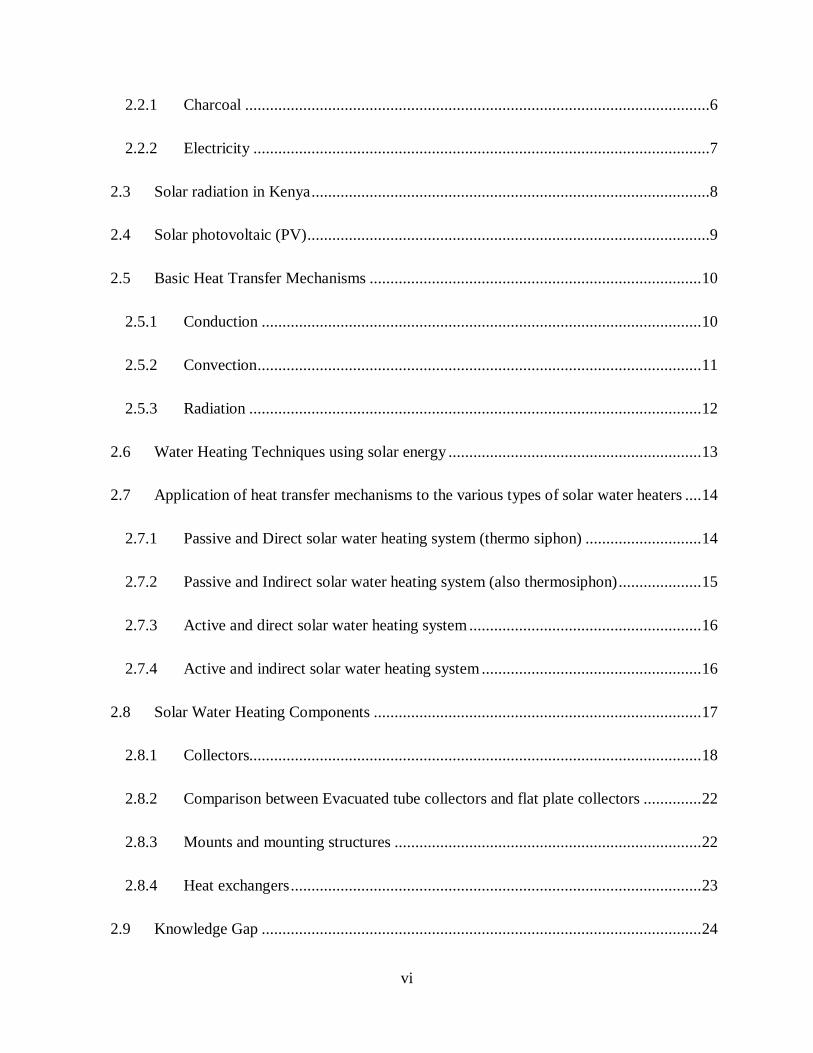
2.5 Basic Heat Transfer Mechanisms ................................................................................ 10
2.5.1 Conduction .......................................................................................................... 10
2.5.2 Convection ........................................................................................................... 11
2.5.3 Radiation ............................................................................................................. 12
2.6 Water Heating Techniques using solar energy ............................................................. 13
2.7 Application of heat transfer mechanisms to the various types of solar water heaters .... 14
2.7.1 Passive and Direct solar water heating system (thermo siphon) ............................ 14
2.7.2 Passive and Indirect solar water heating system (also thermosiphon) .................... 15
2.7.3 Active and direct solar water heating system ........................................................ 16
2.7.4 Active and indirect solar water heating system ..................................................... 16
2.8 Solar Water Heating Components ............................................................................... 17
2.8.1 Collectors............................................................................................................. 18
2.8.2 Comparison between Evacuated tube collectors and flat plate collectors .............. 22
2.8.3 Mounts and mounting structures .......................................................................... 22
2.8.4 Heat exchangers ................................................................................................... 23
2.9 Knowledge Gap .......................................................................................................... 24
vii
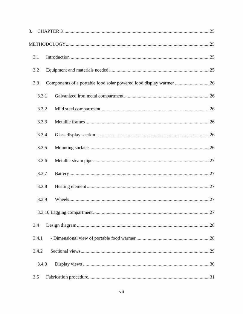
3. CHAPTER 3 ...................................................................................................................... 25
METHODOLOGY.................................................................................................................... 25
3.1 Introduction ................................................................................................................ 25
3.2 Equipment and materials needed ................................................................................. 25
3.3 Components of a portable food solar powered food display warmer ............................ 26
3.3.1 Galvanized iron metal compartment ..................................................................... 26
3.3.2 Mild steel compartment........................................................................................ 26
3.3.3 Metallic frames .................................................................................................... 26
3.3.4 Glass display section ............................................................................................ 26
3.3.5 Mounting surface ................................................................................................. 26
3.3.6 Metallic steam pipe .............................................................................................. 27
3.3.7 Battery ................................................................................................................. 27
3.3.8 Heating element ................................................................................................... 27
3.3.9 Wheels ................................................................................................................. 27
3.3.10 Lagging compartment .............................................................................................. 27
3.4 Design diagram ........................................................................................................... 28
3.4.1 - Dimensional view of portable food warmer ........................................................... 28
3.4.2 Sectional views ........................................................................................................ 29
3.4.3 Display views ...................................................................................................... 30
3.5 Fabrication procedure.................................................................................................. 31
viii
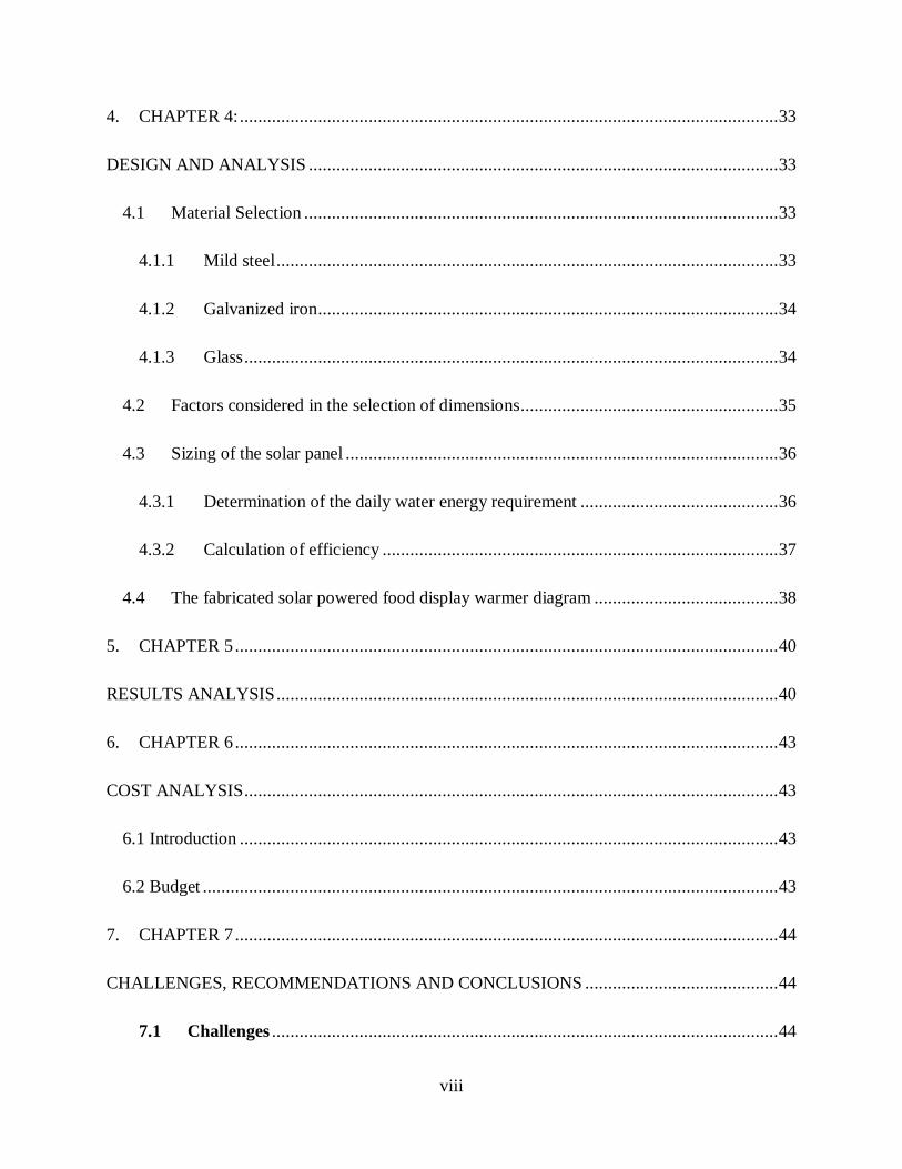
4. CHAPTER 4: ..................................................................................................................... 33
DESIGN AND ANALYSIS ...................................................................................................... 33
4.1 Material Selection ....................................................................................................... 33
4.1.1 Mild steel ............................................................................................................. 33
4.1.2 Galvanized iron .................................................................................................... 34
4.1.3 Glass .................................................................................................................... 34
4.2 Factors considered in the selection of dimensions........................................................ 35
4.3 Sizing of the solar panel .............................................................................................. 36
4.3.1 Determination of the daily water energy requirement ........................................... 36
4.3.2 Calculation of efficiency ...................................................................................... 37
4.4 The fabricated solar powered food display warmer diagram ........................................ 38
5. CHAPTER 5 ...................................................................................................................... 40
RESULTS ANALYSIS ............................................................................................................. 40
6. CHAPTER 6 ...................................................................................................................... 43
COST ANALYSIS .................................................................................................................... 43
6.1 Introduction ..................................................................................................................... 43
6.2 Budget ............................................................................................................................. 43
7. CHAPTER 7 ...................................................................................................................... 44
CHALLENGES, RECOMMENDATIONS AND CONCLUSIONS .......................................... 44
7.1 Challenges .............................................................................................................. 44

ix
7.2 Recommendations.................................................................................................. 44
7.3 Conclusion ............................................................................................................. 44
REFERENCES ......................................................................................................................... 45
APPENDICES .......................................................................................................................... 46
LIST OF FIGURES
Figure 2.1: warmer that uses charcoal as an energy source (https://jiji.co.ke/299-trolleys) ..........7
Figure 2.2: Heat transfer through conduction ............................................................................ 10
Figure 2.3: Heat transfer through convection ............................................................................. 11
Figure 2.4: heat transfer through radiation ................................................................................. 12
Figure 2.5: Example of collectors for various applications ......................................................... 14
Figure 2.6: Illustration of a direct SWH system ......................................................................... 15
Figure 2.7: Illustration of an indirect SWH system .................................................................... 15
Figure 2.8: Active and direct system with stratification ............................................................. 16
Figure 2.9: Active and indirect (closed loop) system ................................................................. 17
Figure 2.10: Parts of a flat collector ........................................................................................... 19
Figure 2.11: Evacuated heat pipe ............................................................................................... 21
Figure 2.12: Evacuated U tube .................................................................................................. 21
Figure 2.13: Internal helical coils and external plate exchanger ................................................. 23
figure 3.1 solar system connection ............................................................................................. 31
viii
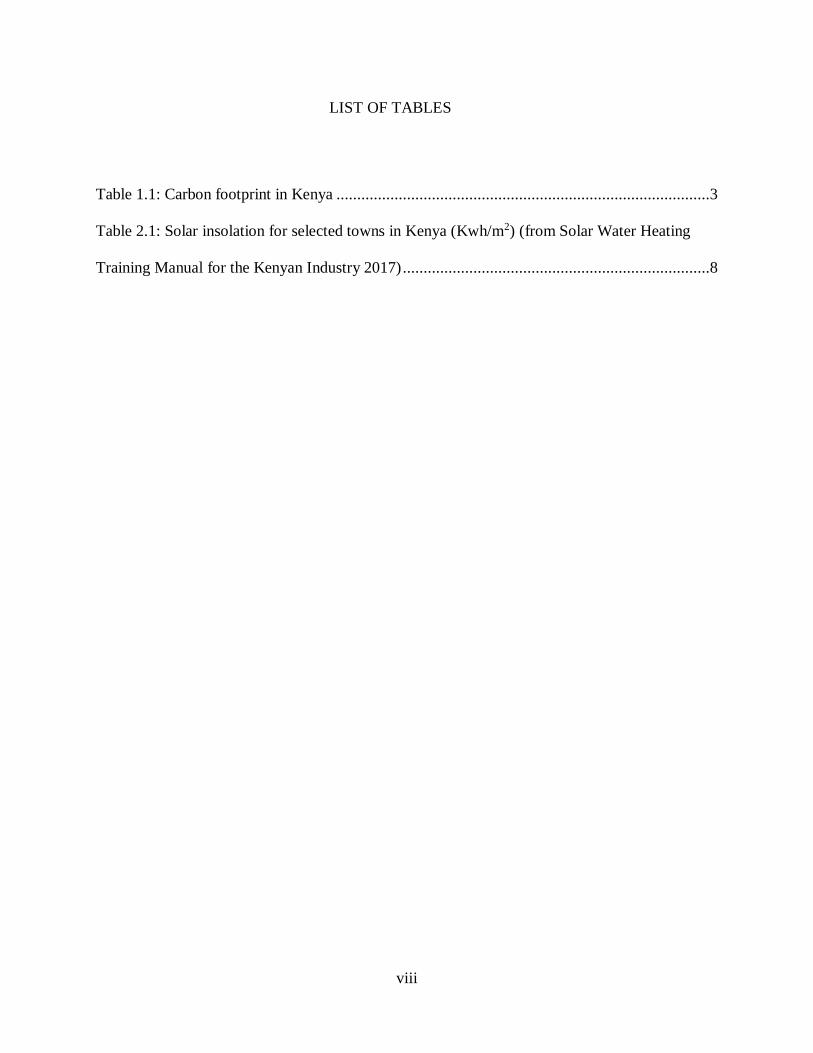
LIST OF TABLES
Table 1.1: Carbon footprint in Kenya ..........................................................................................3
Table 2.1: Solar insolation for selected towns in Kenya (Kwh/m2) (from Solar Water Heating
Training Manual for the Kenyan Industry 2017) ..........................................................................8
ix
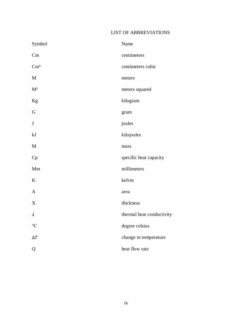
LIST OF ABBREVIATIONS
Symbol Name
Cm centimeters
Cm³ centimeters cubic
M meters
M² meters squared
Kg kilogram
G gram
J joules
kJ kilojoules
M mass
Cp specific heat capacity
Mm millimeters
K kelvin
A area
X thickness
𝜆 thermal heat conductivity
℃ degree celsius
Δ𝑇 change in temperature
Q heat flow rate

1
1. CHAPTER 1
INTRODUCTION
1.1 BACKGROUND INFORMATION
A portable food display warmer is typically a device used to keep foods warm at a certain
temperature and is usually for commercial purposes by vendors (https://en.m.wikipedia.org). The
device is equipped with three sets of wheels to make its movement much easier. Traditionally,
charcoal has been the source of energy for these devices. Charcoal is combusted and the heat
energy from charcoal is used to heat water contained in a different compartment to produce steam,
which is then used to heat the compartment containing the food to be warmed.
However, this method is associated with emission of carbon monoxide resulting from incomplete
combustion of charcoal since carbon is a major constituent of charcoal (Sajid et al., 1993).
Another source of energy that has been employed in this field is electric energy whereby there is
a heater connected to an electric circuit. Here the heating is either controlled by a switch where
one is required to keep switching it on and off manually or the heater can be linked to a thermostat
which will automatically regulate the temperatures.
This project seeks to address the complications that come with the use of charcoal as a source of
heat energy, and replace it with a presumably better source of energy for heating which in our case
we think, solar energy.
Solar powered food display warmers aim at using solar energy to heat water, a process that will
be followed by production of steam that would be used to heat the platform containing the foods.
2
1.2 PROBLEM STATEMENT
Emission of carbon monoxide causes a great concern when using charcoal as the source of energy
in the food warmers.
Carbon monoxide is produced as a result of incomplete combustion of charcoal. Incomplete
combustion arises due to limited supply of oxygen present since after the charcoal starts
combusting the compartment where it is placed is enclosed and small amounts of atmospheric air
penetrates inside meaning that the combustion solely relies on the air which was previously present
in the compartment.
Carbon monoxide is toxic and breathing it at high concentration has health effects that include
headaches, lightheadedness, weakness, vomiting, and nausea. At high concentration for long
enough exposure it can cause death. (National Academy of Sciences 2002)
Apart from health effects, when carbon monoxide is emitted into the atmosphere it affects the
amount of greenhouse gases such as carbon dioxide which is linked to climate change and global
warming (Australia’s carbon monoxide emission report, 2019)
Another concerning aspect of charcoal is that it is produced from forest resources resulting in the
extensive use of forest biomass which could represent a potential issue in regards to environmental
harm. Due to the large amount of charcoal that is needed deforestation could be an issue if high
demand is paired with poor forest management and regulations.
In addition, charcoal is also inefficient and dirty, creating a large amount of black soot. Charcoal
stoves have about 10% efficiency, meaning that 90% of the heat is lost while burning (Jen Boynton
May 7th 2015). Because of this inefficiency, charcoal stoves can take up to 30 minutes to heat up.
3
1.3 JUSTIFICATION
WHY SOLAR OVER CHARCOAL?
Solar power is good for the environment: the most commonly known fact about solar energy is
that it represents a clean, green source of energy. Solar power is a great way to reduce your
carbon footprint. There’s nothing about solar that pollutes the environment as it doesn’t release
any greenhouse gasses. (Greenmatch.co.uk last updated October 2019).
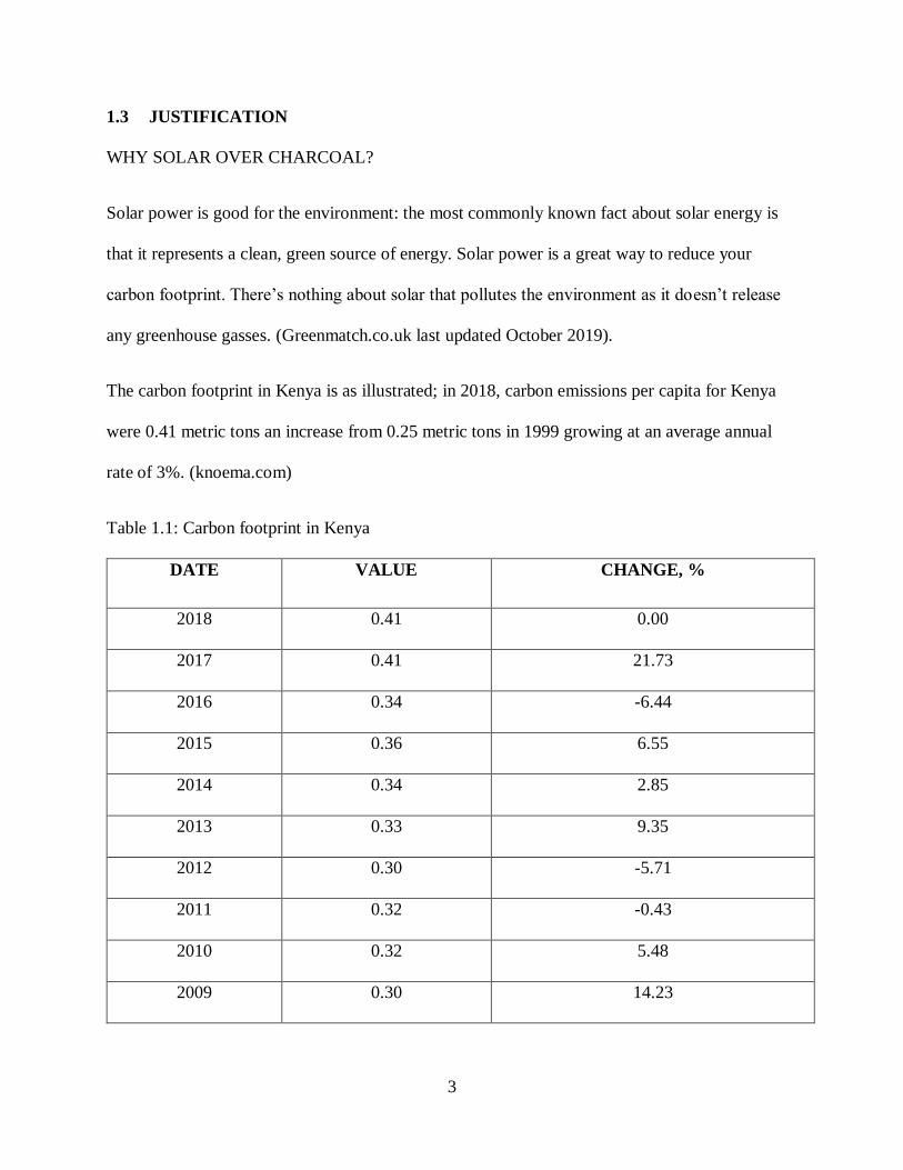
The carbon footprint in Kenya is as illustrated; in 2018, carbon emissions per capita for Kenya
were 0.41 metric tons an increase from 0.25 metric tons in 1999 growing at an average annual
rate of 3%. (knoema.com)
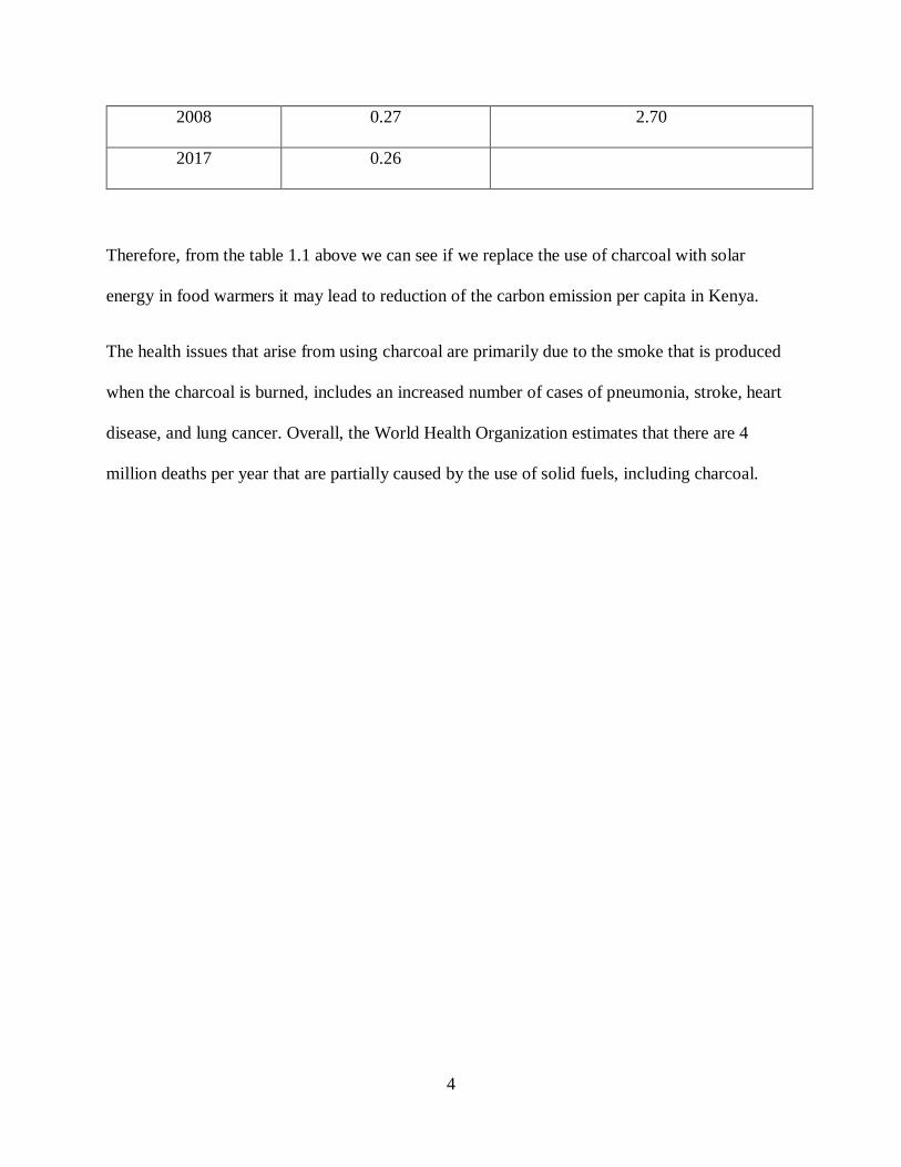
Table 1.1: Carbon footprint in Kenya
DATE VALUE CHANGE, %
2018 0.41 0.00
2017 0.41 21.73
2016 0.34 -6.44
2015 0.36 6.55
2014 0.34 2.85
2013 0.33 9.35
2012 0.30 -5.71
2011 0.32 -0.43
2010 0.32 5.48
2009 0.30 14.23
4
2008 0.27 2.70
2017 0.26
Therefore, from the table 1.1 above we can see if we replace the use of charcoal with solar
energy in food warmers it may lead to reduction of the carbon emission per capita in Kenya.
The health issues that arise from using charcoal are primarily due to the smoke that is produced
when the charcoal is burned, includes an increased number of cases of pneumonia, stroke, heart
disease, and lung cancer. Overall, the World Health Organization estimates that there are 4
million deaths per year that are partially caused by the use of solid fuels, including charcoal.

5
1.4 OBJECTIVES
1.4.1 GENERAL OBJECTIVE
The main objective of this project is to develop solar powered food display warmer
1.4.2 SPECIFIC OBJECTIVES
i. To design and fabricate a solar powered food display warmer.
ii. To determine the heat gain given by the heating element and the corresponding heat
output.
iii. To determine the rate of heat transfer.

6
2. CHAPTER 2:
LITERATURE REVIEW
2.1 INTRODUCTION
Energy resources are broadly classified as non-renewable and renewable. Non-renewable
resources, also known as conventional energy resources, are finite (exhaustible) in nature and are
mainly of fossil origin. These include coal, petroleum, natural gas, nuclear, tar sands, oil shale
and shale gas (Herzog et al., 2001). Renewable energy resources on the other hand are either
inexhaustible or can be replenished within a short period through natural cycles. These include
solar, wind, geothermal, hydropower (hydro-electricity, tidal and wave) and biomass.
Solar energy is indeed the primary source of energy as most of the other sources are derived
from it. For example, solar energy is naturally used by plants (through the process of
photosynthesis) to manufacture their food, storing it in a stable chemical form. As human beings,
we use the light and the heat generated by the sun for various applications, which can be
classified into solar photovoltaic and solar thermal applications.
For our project we will consider mainly the application of solar photovoltaic type.
This section will seek to describe and discuss the researches from various sources such as
textbooks articles and the internet. It consists of information which is vital in the development of
this project.
2.2 Sources of energy currently used in food warmers
Currently in the market the majorly applied sources of energy are charcoal and electricity.
2.2.1 Charcoal
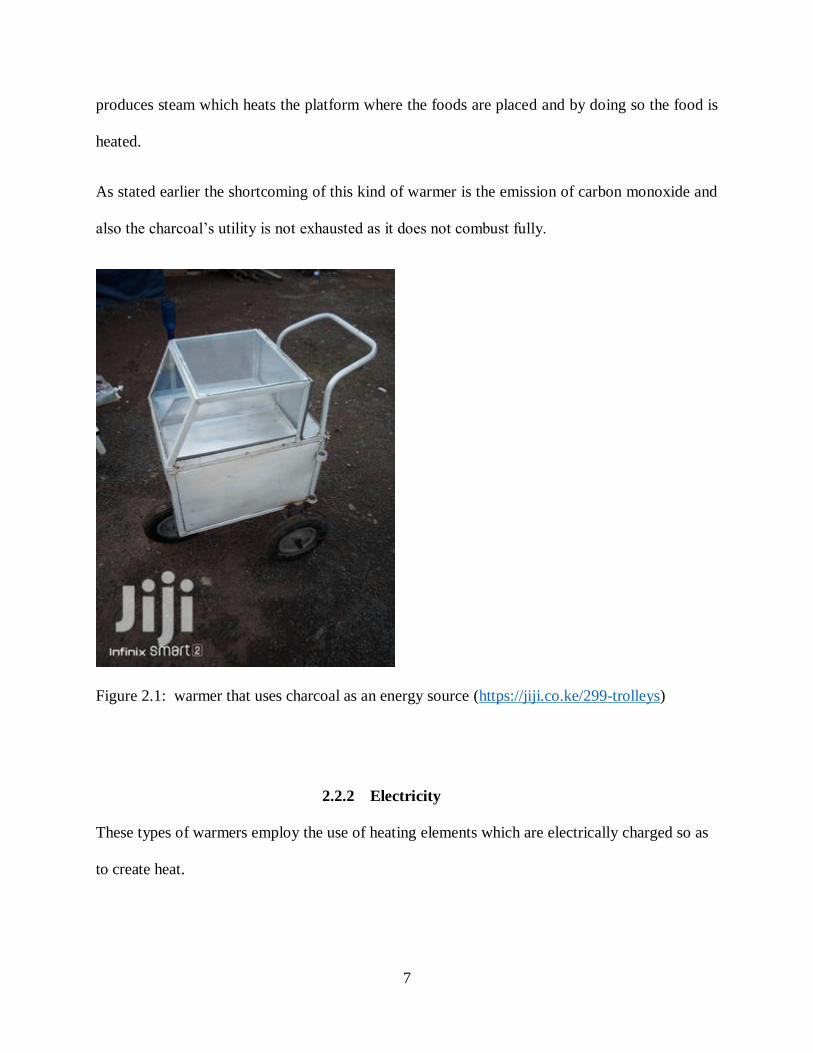
Below is a design of a food warmer that is currently in the market and it uses charcoal, burning
charcoal is placed below the water compartment, heat from the charcoal heats the water, water
7
produces steam which heats the platform where the foods are placed and by doing so the food is
heated.
As stated earlier the shortcoming of this kind of warmer is the emission of carbon monoxide and
also the charcoal’s utility is not exhausted as it does not combust fully.
Figure 2.1: warmer that uses charcoal as an energy source (https://jiji.co.ke/299-trolleys)
2.2.2 Electricity
These types of warmers employ the use of heating elements which are electrically charged so as
to create heat.
8
Although they are efficient, they are not portable as they need to be constantly connected to the
source of electricity.
Heat lamp is an example of the element that can be used among others.
2.3 Solar radiation in Kenya
The strength of solar intensity is measured in kW/m2 and varies from time to time. The daily
energy in kWh/m2 reaching a particular location is determined by measuring the intensity over a
period of time. When the weather at any location is cloudy or rainy, the intensity and the energy
received in a day will be less compared to that of a sunny day.
Kenya’s geographical location across the equator gives it a unique advantage as the natural sun-
earth movements do not significantly affect the total solar energy that reaches the surface all year
round.
However, other weather parameters such as clouds and mist cause the notable differences.
Generally, the country receives between 4 and 6kWh/m2 of solar energy. Table below shows some
monthly averages of selected towns and their respective annual averages just to show the potential
at a glance.
Table 2.1: Solar insolation for selected towns in Kenya (Kwh/m2) (from Solar Water Heating
Training Manual for the Kenyan Industry 2017)

9
2.4 Solar photovoltaic (PV)
Solar PV is a technology that converts solar energy to direct current (DC) electricity by exploiting
the properties of certain materials technically called semiconductors (e.g. Silicon). When solar
radiation falls on these materials, their atomic structures react in such a way that it generates
continuous electric current. The strength of the generated current is proportional to the strength of
the solar radiation: During cloudy or rainy weather, the strength of solar radiation is very low and
so is the generated current.
The power generated by solar PV is used to provide electricity for many different applications.
Due to the fluctuations of the strength of solar radiation, a battery is usually necessary to store
the generated electricity. It is also well suited for remote regions where there are no alternative
sources of electricity. To run alternating current (AC) appliances, an inverter is needed to convert
the DC electricity to AC electricity.
Usually, semiconductor materials are manufactured in form of cells. Cells are then connected in
series to make a solar PV module or solar panel (usually found in the shops). Solar PV modules
can also be joined together in series or parallel connections to provide even large amounts of
10
power to even megawatt (MW) capacity. Nowadays, solar PV can provide as much power as any
other technology available in the market and the quality of electricity is similar to grid electricity.
There are numerous applications that this generated electricity can be used for e.g. lighting
homes, providing power to (villages and grid networks), water pumping, air conditioning,
powering telecommunication masts and so forth.
In the recent years, photovoltaic (PV) cells have seen quite a number of new and more advanced
applications e.g. generating electricity to power electric vehicles and aeroplanes.
2.5 Basic Heat Transfer Mechanisms
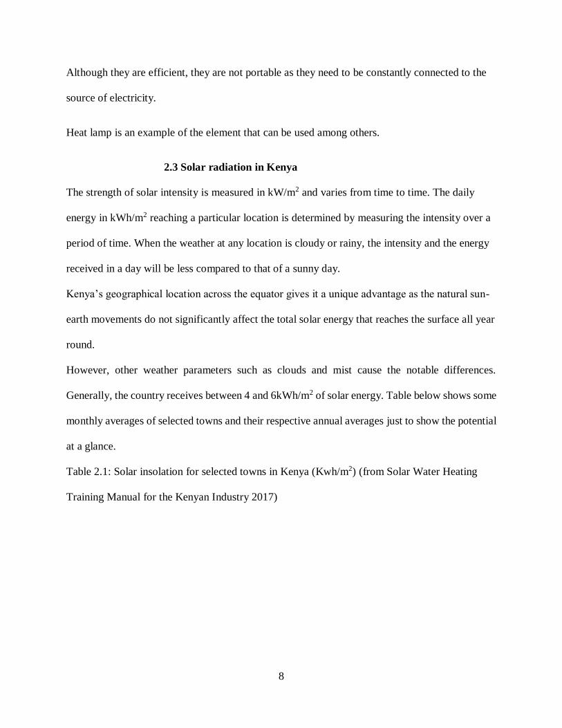
2.5.1 Conduction
Conduction is the transfer of heat by the movement of particles that are in contact with each
other caused by a temperature difference between them. Metals especially copper are good
examples of conductors. For this exchange to take place, the molecules must get into contact
with each other. If one heats one end of a copper rod, heat spreads very fast to the entire length
of the rod and it can be felt easily from the other end. Conduction is best in solids but also occurs
in liquids and gases or a combination of any of the two. Conduction cannot take place in
vacuum.
Figure 2.2: Heat transfer through conduction (Solar Water Heating Training Manual for the
Kenyan Industry, 2017)
11
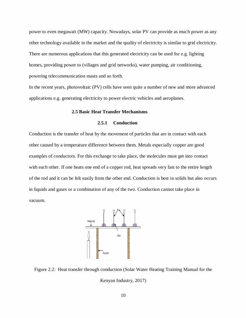
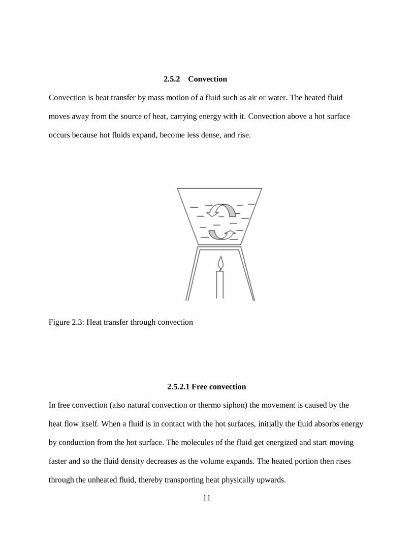
2.5.2 Convection
Convection is heat transfer by mass motion of a fluid such as air or water. The heated fluid
moves away from the source of heat, carrying energy with it. Convection above a hot surface
occurs because hot fluids expand, become less dense, and rise.
Figure 2.3: Heat transfer through convection
2.5.2.1 Free convection
In free convection (also natural convection or thermo siphon) the movement is caused by the
heat flow itself. When a fluid is in contact with the hot surfaces, initially the fluid absorbs energy
by conduction from the hot surface. The molecules of the fluid get energized and start moving
faster and so the fluid density decreases as the volume expands. The heated portion then rises
through the unheated fluid, thereby transporting heat physically upwards.

12
2.5.2.2 Forced convection
In forced convection the fluid is actively moved over the heating surface by an external force such
as a pump. The movement occurs independently of the heat transfer (i.e. is not a function of the
local temperature gradients).
2.5.3 Radiation
Radiation is the transfer of heat by means of electromagnetic waves. To radiate means to send out
or spread from a central location. Whether it is light, sound, waves, rays, flower petals, or pain, if
something radiates then it spreads outward from an origin. The transfer of heat by radiation
involves the carrying of energy from an origin to the space surrounding it. That is why we are able
to feel the heat from a fire place or an oven even from a distance. The energy is carried by
electromagnetic waves and does not involve the movement or the interaction of matter. The solar
water heating collector receives electromagnetic radiation from the sun which it converts to heat
energy.
Figure 2.4: Heat transfer through radiation
13
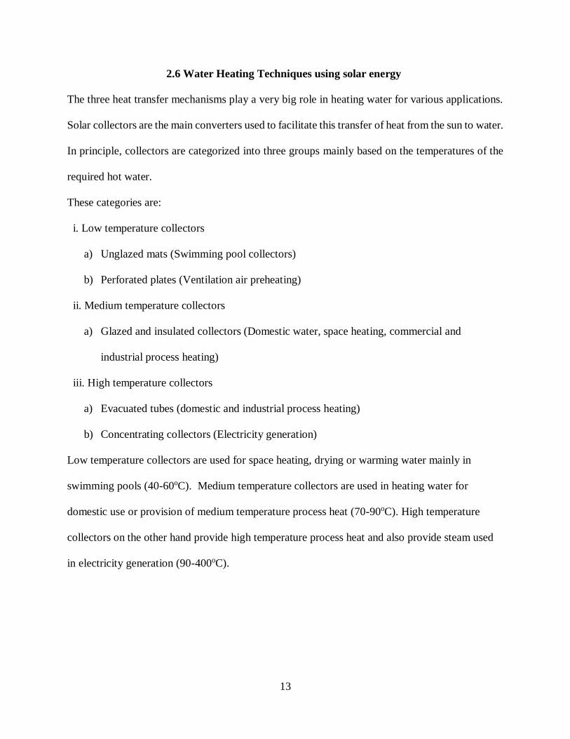
2.6 Water Heating Techniques using solar energy
The three heat transfer mechanisms play a very big role in heating water for various applications.
Solar collectors are the main converters used to facilitate this transfer of heat from the sun to water.
In principle, collectors are categorized into three groups mainly based on the temperatures of the
required hot water.
These categories are:
i. Low temperature collectors
a) Unglazed mats (Swimming pool collectors)
b) Perforated plates (Ventilation air preheating)
ii. Medium temperature collectors
a) Glazed and insulated collectors (Domestic water, space heating, commercial and
industrial process heating)
iii. High temperature collectors
a) Evacuated tubes (domestic and industrial process heating)
b) Concentrating collectors (Electricity generation)
Low temperature collectors are used for space heating, drying or warming water mainly in
swimming pools (40-60oC). Medium temperature collectors are used in heating water for
domestic use or provision of medium temperature process heat (70-90oC). High temperature
collectors on the other hand provide high temperature process heat and also provide steam used
in electricity generation (90-400oC).
14
Figure 2.5: Example of collectors for various applications
2.7 Application of heat transfer mechanisms to the various types of
solar water heaters
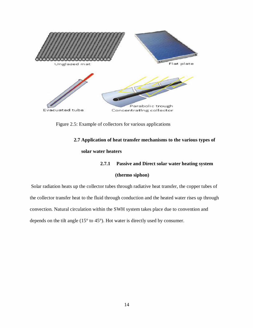
2.7.1 Passive and Direct solar water heating system
(thermo siphon)
Solar radiation heats up the collector tubes through radiative heat transfer, the copper tubes of
the collector transfer heat to the fluid through conduction and the heated water rises up through
convection. Natural circulation within the SWH system takes place due to convention and
depends on the tilt angle (15° to 45°). Hot water is directly used by consumer.
15
Figure 2.6: Illustration of a direct SWH system
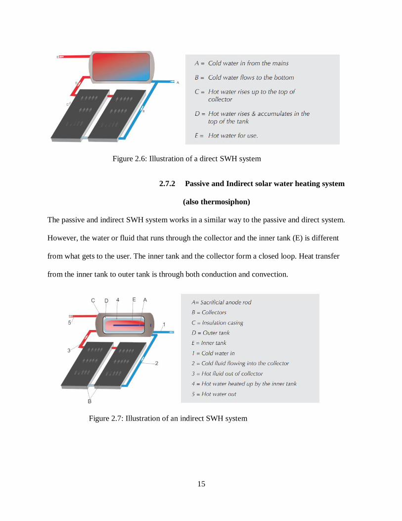
2.7.2 Passive and Indirect solar water heating system
(also thermosiphon)
The passive and indirect SWH system works in a similar way to the passive and direct system.
However, the water or fluid that runs through the collector and the inner tank (E) is different
from what gets to the user. The inner tank and the collector form a closed loop. Heat transfer
from the inner tank to outer tank is through both conduction and convection.
Figure 2.7: Illustration of an indirect SWH system
16
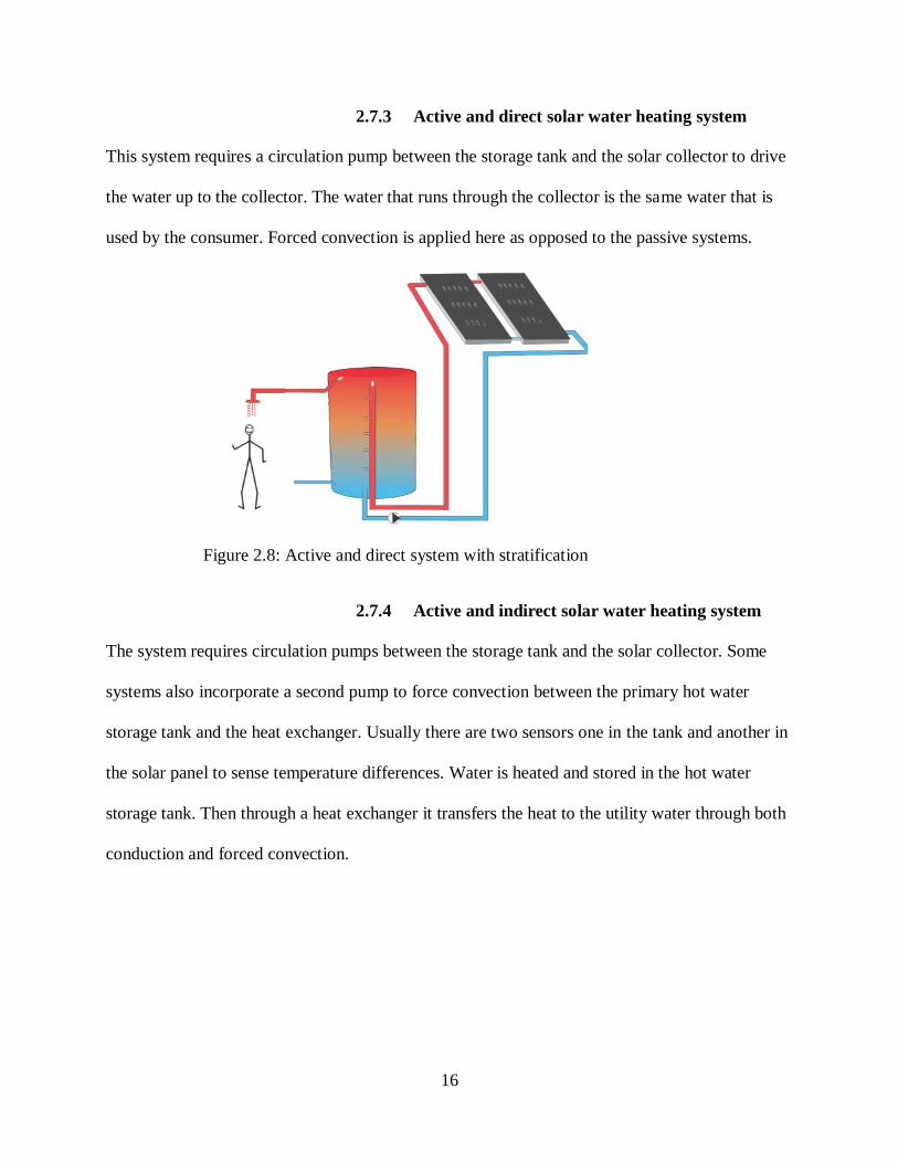
2.7.3 Active and direct solar water heating system
This system requires a circulation pump between the storage tank and the solar collector to drive
the water up to the collector. The water that runs through the collector is the same water that is
used by the consumer. Forced convection is applied here as opposed to the passive systems.
Figure 2.8: Active and direct system with stratification
2.7.4 Active and indirect solar water heating system
The system requires circulation pumps between the storage tank and the solar collector. Some
systems also incorporate a second pump to force convection between the primary hot water
storage tank and the heat exchanger. Usually there are two sensors one in the tank and another in
the solar panel to sense temperature differences. Water is heated and stored in the hot water
storage tank. Then through a heat exchanger it transfers the heat to the utility water through both
conduction and forced convection.
17
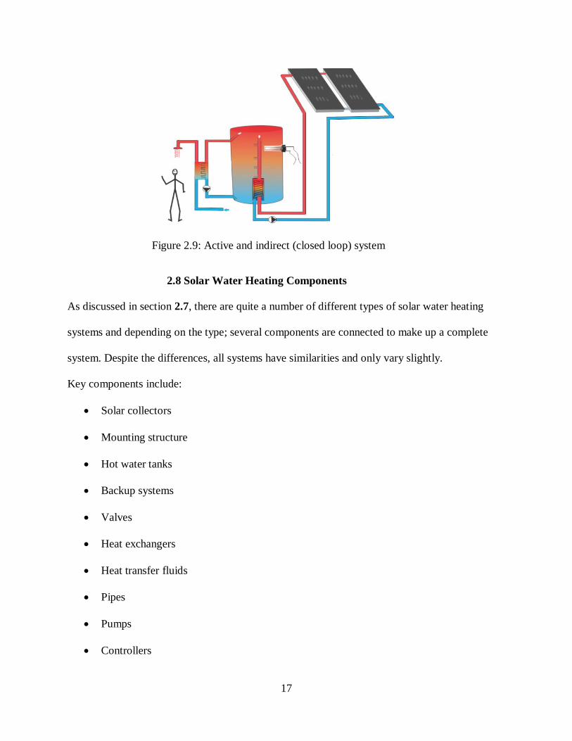
Figure 2.9: Active and indirect (closed loop) system
2.8 Solar Water Heating Components
As discussed in section 2.7, there are quite a number of different types of solar water heating
systems and depending on the type; several components are connected to make up a complete
system. Despite the differences, all systems have similarities and only vary slightly.
Key components include:
Solar collectors
Mounting structure
Hot water tanks
Backup systems
Valves
Heat exchangers
Heat transfer fluids
Pipes
Pumps
Controllers
18
Expansion tanks
However, this project has a major interest in solar collectors, mounting structure, charge
controller, battery and heat exchangers.
2.8.1 Collectors
A solar water heating collector captures or absorbs heat from the sun in form of electromagnetic
radiation and transfers that heat to the water. The collector is the main device in the system,
without which the system would not deliver hot water. Solar collectors are of two types; flat
plate and evacuated tube collectors.
2.8.1.1 Flat plate collectors
The flat plate collector is the most commonly used solar collector around the world. Although
there are a number of variations in the design of the flat plate collector, a typical flat-plate
collector is usually a metal box with a glass or plastic cover (called glazing) on top and a dark-
colored absorber plate with embodied fins (pipes) enclosed within. The sides and the bottom of
the collector are usually insulated to minimize heat loss.
Individual components of the collector consist of:
•Glazing: Toughened glass (glazing) that protects the absorber from the outside environment
while allowing over 90% of sunlight through. It also prevents heat loss in form of longer infrared
waves from leaving the housing.
• Absorber plate: A thin sheet made of copper or aluminum coated with a highly selective
material that is extremely efficient at absorbing sunlight and converting it into usable heat. The
copper or aluminum sheet is ultrasonically welded to the copper riser pipes sometimes called
fins.

19
• Riser & Header Pipe: There are both top and bottom headers connected to the riser pipes. The
risers are brazed together to form a heat exchanger that the system’s heat transfer fluid circulates
through. Solar energy incident on the absorber plate is transferred to the fluid flowing through
the riser tubes. Cool water enters from the bottom header and warmed water exits through the top
header. The risers should be good conductors and have a large surface area.
• Insulation: The insulation helps reduce heat loss from the sides and the back of the
collector. The material should be light in weight and low thermal conductivity. E.g. ultra-light
weight melamine foam or fiber glass, Collector frame: The outer framework of the collector is
made of a light and strong material and designed in such a way that it is easy to mount. E.g.
aluminium alloy
• Back Sheet: it seals the back of the collector and adds to the rigidity of the collector while
offering protection from weather elements. It can be made from aluminium alloy or galvanized
iron sheets etc.
Figure 2.10: Parts of a flat collector

20
2.8.1.2 Evacuated tube collectors
The evacuated tube collectors are made of a series of glass tubes mounted in rows and plugged
into a manifold box through which the heat transfer liquid (water or water/glycol) flows. Toxic
fluids such as ethylene glycol should not be used in potable water heating systems - only non-
toxic propylene glycol may be used. Inside each tube there is an absorber. The absorber is
located inside a double glass tube with a vacuum between the two tubes. The inner glass tube has
a selective surface facing outward to absorb the sun’s energy. The absorber contains copper
tubes or passageways through which the heat transfer fluid flows allowing the heat to be
transported away from the absorber. The loss of heat from the absorber by natural convection is
eliminated by the vacuum and, as a result, high operating fluid temperatures of up to 120oC can
be achieved. The possibility of higher temperatures is of particular importance for solar industrial
process heating application because it increases the number of applications where solar energy
can be used.
There are two common types of evacuated tube collectors; heat pipe and U-tube.
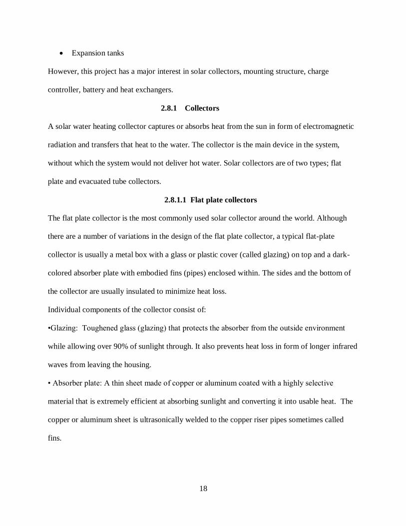
2.8.1.2.1 Evacuated heat pipe collectors
A heat pipe evacuated tube collector uses heat pipes to transfer the collected solar heat from the
tube into the flowing fluid in the manifold. Heat pipes are made up of copper tubes which
contain a very small amount of water in a partial vacuum. The heat pipe is encased in the inner
glass tube. When the heat pipe is heated, the small amounts of water inside vaporize and rise to
the top of the heat pipe into the heat exchanger in the manifold. The flowing cold water is heated
through the manifold and at the same time cools the vapor inside the heat pipe where it
condenses and falls to the bottom of the heat pipe.
21
Figure 2.11: Evacuated heat pipe
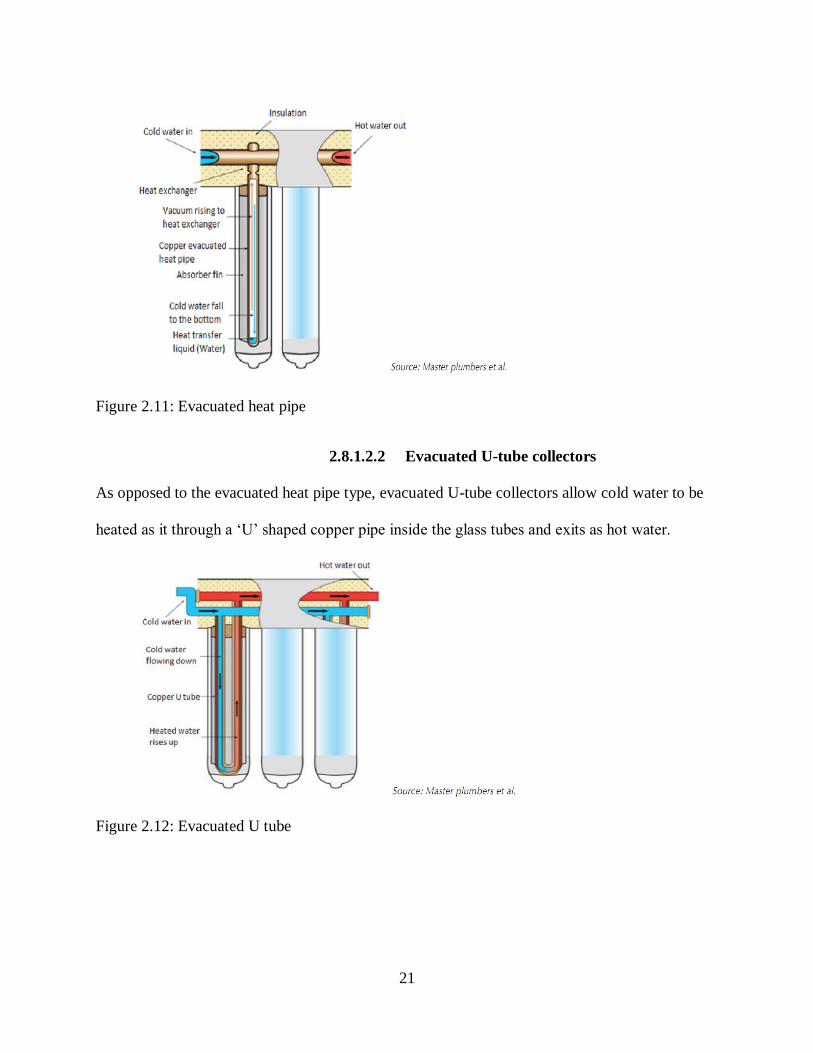
2.8.1.2.2 Evacuated U-tube collectors
As opposed to the evacuated heat pipe type, evacuated U-tube collectors allow cold water to be
heated as it through a ‘U’ shaped copper pipe inside the glass tubes and exits as hot water.
Figure 2.12: Evacuated U tube

22
2.8.2 Comparison between Evacuated tube collectors
and flat plate collectors
Advantages
• Evacuated-tube collectors are able to retain more heat than the flat-plate collectors and are
more efficient in cooler climates.
• The shape of evacuated-tube collectors ensures that the solar radiation is always perpendicular
to the surface of the outer glass tube.
• Capture sunlight better as they have a greater surface area exposed to the sun at any time
•They are durable and if a tube should be broken, it can be easily and cheaply replaced.
•Require a smaller roof area than comparable flat plate collectors
• Do not have the same level of corrosion problems as flat plate collectors
Disadvantages
•Increased cost of the evacuated-tube collector than the flat plate type collector
•The evacuated-tube collectors are more prone to damage from severe weather and handling due
to their delicate construction
• Vacuum tube collectors take more time to assemble while flat plate collectors take more effort
to hoist onto the roof.
2.8.3 Mounts and mounting structures
Collectors may be either roof mounted or ground mounted. They must be firmly mounted to
secure them against any external interference. Mounted collectors are not only exposed to the
sun but also to other weather conditions like the wind forces, rain, snow and ultra violet rays.
Winds and thermal expansion and contraction may cause installed bolts and roof seals to loosen
over time if not well done.

23
The most common arrangement is where the collector is above and parallel to a metal or tiled
roof. The minimum tilt for flat plate collectors required for effective cleaning by rainwater and
for thermosiphon effect is 15° while for evacuated tubes 20° to ensure reliable working of the
heat pipe to transfer heat to the manifold.
2.8.4 Heat exchangers
Heat exchangers can either be internal or external to the storage tank. It is important to bear in
mind that temperature stratification provides substantial operational performance benefits. For
internal heat exchangers, correct integration of the tank and heat exchangers in a passive system
is essential to allow for water stratification. The location of the heat exchanger and the flow rate
in the collector loop determines the degree of thermal stratification.
Helical coil heat exchangers can be integrated in the collector loop or in the load side hot water
storage. Plate type heat exchangers are commonly used externally with the fluid flowing in
opposite direction.
Figure 2.13: Internal helical coils and external plate exchanger

24
2.9 Knowledge Gap
From the literature review it’s clear that solar energy has not been utilized in portable food
warmers.
We are aiming that with a solar powered food warmer we can both address the issue of
portability and control of carbon monoxide emissions.

25
3. CHAPTER 3
METHODOLOGY
3.1 Introduction
Background information on the available portable food display warmers which uses charcoal as
the source of heat in the market would be accessed.
Literature review by using published books, article and internet materials to preview existing
designs of solar water heating systems shall be analyzed and utilized to develop cost effective
solar powered food display warmer.
Visited shops dealing with solar devices, Eldoret Jua Kali site and collected all the necessary
equipments, data and materials for fabrication.
The workability of the machine designed was tested and values were collected for analysis.
Utilization of practical knowledge acquired in workshop, industrial attachments and the internet
to aid in the fabrication of the portable warmer.
3.2 Equipment and materials needed
Solar panel
Diesel glow plug (heating element)
Battery
Mild steel sheet metal
Stainless steel metal
Pieces of Glasses (4)
Frames
Connection wires
Small sized wheels (3)

26
Welding machine and welding rods
Sheet metal bending machine
3.3 Components of a portable food solar powered food display warmer
3.3.1 Galvanized iron metal compartment
This compartment houses the battery and makes most of the part of the portable food warmer. It
is painted for anesthetic purposes and also to increase it resistance to corrosion.
3.3.2 Mild steel compartment
It holds the water that is to be heated to produce steam that is used to heat up the food. Mild steel
is the most preferred material in this case to stainless steel which is quite expensive. The mild
steel also forms the platform which will be in contact with the food.
3.3.3 Metallic frames
These are to contribute to the support of the glasses. They also act as a link between the metallic
compartment and the glass display section and support the surface on which the solar panel is
mounted.
3.3.4 Glass display section
The display area is mainly made up of glass for purposes of visibility and also to minimize on
heat losses from the device since glass is a poor conductor of heat.
3.3.5 Mounting surface
This is a metallic surface at the top of the food display warmer, on which the solar panel is to be
mounted on in a tilted position. The solar panel is to be tilted so as to ensure much of its surface
area is exposed to the sun for maximum absorption of solar energy.

27
3.3.6 Metallic steam pipe
This metallic pipe is attached onto the outside section of the mild steel water compartment. Its
main function is to act as an outlet of excess steam in the metallic compartment, the excess steam
cool into water and the pipe allows the water to flow back into the compartment.
3.3.7 Battery
This device is used to store energy which will be utilized in heating of the water in the absence
of the sun.
3.3.8 Heating element
This component is used to heat the water after it receives solar energy from either the panel or
the battery.
3.3.9 Wheels
These ensure the portability of the food display warmer.
3.3.10 Lagging compartment
This compartment carries soil to ensure the heat generated in the water compartment does not
reach the battery.
28
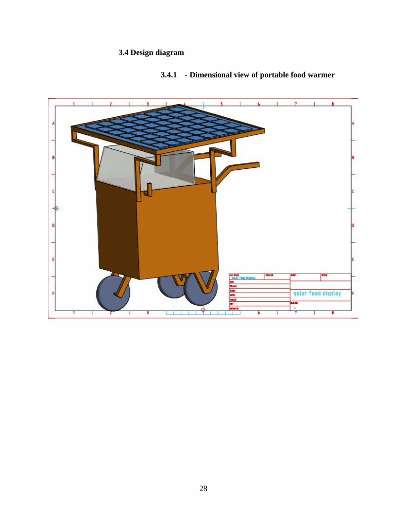
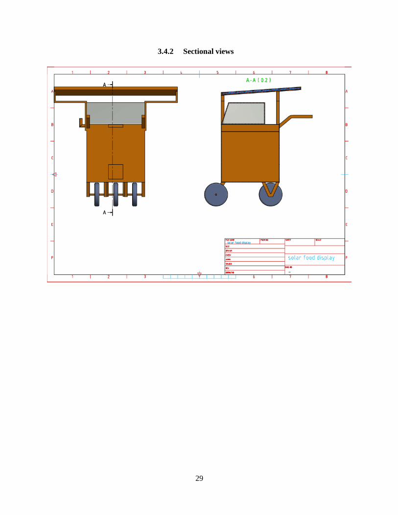
3.4 Design diagram
3.4.1 - Dimensional view of portable food warmer
29
3.4.2 Sectional views

30
3.4.3 Display views

31
3.5 Fabrication procedure
i. Forming the metallic frame structure by use of metallic tubes and joining them using
welding process and at the bottom installment of wheels done, one at the front and two
others at the back in adjacent positions and welding of a pushing handle onto the
structure.
ii. By use of sheet metal make a rectangular water compartment which is to be fitted
beneath the display unit.
iii. Cutting out the sheet metal according to the dimensions and welding them onto the
metallic frame structure.
iv. At the bottom of the water compartment drill a small hole that would facilitate the
insertion of the heating element which is to be fastened by use of a nut to prevent water
leakages.
v. On the opposite side drill another hole where the steam outlet tube will be fitted, this
steam outlet will also act as an inlet for the water.
vi. Making of a solar panel mounting surface on the top of the display unit.
vii. Installation of glasses at the display unit to the metallic frames.
viii. Lagging in the battery compartment by use of a soil that will be contained in a metallic
plate.
ix. Connection of the solar battery, battery and heating element to be done as shown below:
figure 3.1 solar system connection

32
Solar battery
Solar panel
Heating
element
33
4. CHAPTER 4:
DESIGN AND ANALYSIS
4.1 Material Selection
4.1.1 Mild steel
The carbon content in the alloy ranges between 0.05-0.309 percent.
Advantages
Efficiently malleable: it can be bent, cut and twisted to create the desired shape easier
than other metal.
Ductility: this is the measure of how much a material can be plastically deformed by
elongation without fracture.
Weld able: unlike high-carbon steel, mild steel can be coalesced with far greater ease.
Weight: compared to high carbon steel mild carbon steel is lighter. The proportion of
carbon is the main influencing factor for the weight. Working with mild steel is therefore
easier.
Greatly affordable: while working on a low budget, mild carbon steel proves to be the
best. It is an ideal material that keeps project cost as low as possible.
Disadvantages
Comparatively less strong: not suitable for applications where the material will be
subjected to high stress.
Limitation to heat treatment: heat treatment affects the carbon content in the mild steel.
Less resistant to corrosion: it rusts easily.

34
considering the above mentioned advantages, mild steel would be the most appropriate material
to be used for the water compartment. Due to the dimensions to be used for the water
compartment it will be economical to use mild steel.
Due to the ductility and malleability of mild steel it will be the most appropriate material to
undergo sheet forming process and give the best effective results.
4.1.2 Galvanized iron
Advantages of galvanized iron
Lower cost and lower maintenance
Long life expectancy
Outstanding resistance to mechanical damage
Easily machinable
Nice aesthetics and easy to paint.
Disadvantages of galvanized iron
The material is still susceptible to wearing over time, when the coating starts to chip off.
4.1.3 Glass
The most appropriate material to be used in the display unit is glass due to its visibility and it
being a poor conductor of heat.

35
4.2 Factors considered in the selection of dimensions
1. Amount of water to be used in the compartment; this is an important factor since it will be
used to determine the height of water in the mild steel water compartment.
2. Method of Heat transfer in the water compartment; since the heat transfer in the water will
be by convection the heating element should be located at much lower level in the water
compartment so that as the bottom water is heated it rises upwards and the cold water at
the top flows towards the bottom to the heated. Due to this reason the considered location
of where drilling is to be done is a height of 0.5cm from the bottom of the water
compartment at the rear side.
3. Steam expansion; after water boiling in the water compartment, steam will be given off,
hence the steam will require space for expansion as it heats the stainless steel platform
where the food is contained. Therefore, an allowance of a height of 1cm is given after the
height of water
4. Size of solar panel; this is crucial in the determination of the dimensions of the upper
surface of the food warmer.
5. Size of the Battery; This factor is very important in the determination of the length and
width of the surface extended from the mild steel water compartment that will support these
components.
6. Simplicity of the design; the dimensions that would be much easier to work with and
analyzed were selected.

36
4.3 Sizing of the solar panel
4.3.1 Determination of the daily water energy
requirement
The daily hot water energy demand (L) is calculated from;
𝐿 = 𝑉 × 𝜌 × 𝑐 (𝑇ℎ𝑜𝑡 − 𝑇𝑐𝑜𝑙𝑑) (4.1)
Where; L = Daily hot water energy demand (kWh/day)
V = volume of water per day (𝑚3/𝑑𝑎𝑦)
𝜌 = density of water (usually 1000 𝑘𝑔/𝑚3)
C = specific heat capacity of water (use 0.001167 𝑘𝑊ℎ/𝑘𝑔℃)
T hot = hot water delivery temperature
T cold = cold water temperature (usually 15 oC in Kenya)
Note: heat capacity of water=4185.5J/ (kgK)
1joule=1-watt second
2 litre=0.002 m3
The amount of water used 1litre which is an equivalent to 1kg
Water boils at 100℃
Energy demand= 0.002 × 1000 × 0.001167 × (100 − 15)
= 0.19839 kWh/day
= 198.39 Wh/day
Size of panel to be used= daily energy requirement
peak sun hours (4.2)
Peak hours = 4hours/day
Size of solar panel =198.39
4

37
=49.5975 watts
Therefore, a solar panel rated 50 watts and above would be applicable.
The calculations were sourced from Solar Water Heating Training Manual for the Kenyan
Industry 2017.
4.3.2 Calculation of efficiency
Efficiency= ℎ𝑒𝑎𝑡 𝑜𝑢𝑡𝑝𝑢𝑡
𝑢𝑠𝑒𝑓𝑢𝑙 ℎ𝑒𝑎𝑡 𝑔𝑎𝑖𝑛 ( 4.3)
Useful heat gain is equivalent to the daily energy demand (L)
Heat output=𝑚𝐶𝑝∆𝑇 (4.4)
Where m is the mass of the stainless steel
Cp is the specific heat capacity of the stainless steel
ΔT is the temperature change of the stainless steel

38
4.4 The fabricated solar powered food display warmer.

39

40
5. CHAPTER 5
RESULTS ANALYSIS
Test results
Initial water temperature =17.56℃
Initial surface temperature (the food platform) =20.94℃
Final water temperature = 62℃
Final surface temperature = 56℃
Dimensions of the mild steel water compartment
17 inches(43.18cm) by 15 inches (38.1cm) by 3cm
External volume of the compartment =43.18 × 38.1 × 3 = 4935.474cm³
The mild steel sheet metal had a thickness of approximately 2mm
Therefore, volume of the space occupied by water:
(43.18 − 0.4) × (38.1 − 0.4) × (3 − 0.4) = 4193.2956𝑐𝑚³
(Note: 0.4 thickness considering both sides)
Actual volume of mild steel used =4935.474 − 4193.2956 = 742.1784𝑐𝑚³
Heat gain
This is the heat in the water being heated by the heating element
41
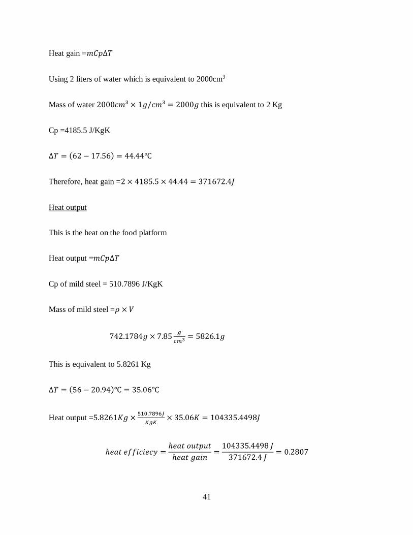
Heat gain =𝑚𝐶𝑝∆𝑇
Using 2 liters of water which is equivalent to 2000cm3
Mass of water 2000𝑐𝑚³ × 1𝑔/𝑐𝑚³ = 2000𝑔 this is equivalent to 2 Kg
Cp =4185.5 J/KgK
∆𝑇 = (62 − 17.56) = 44.44℃
Therefore, heat gain =2 × 4185.5 × 44.44 = 371672.4𝐽
Heat output
This is the heat on the food platform
Heat output =𝑚𝐶𝑝∆𝑇
Cp of mild steel = 510.7896 J/KgK
Mass of mild steel =𝜌 × 𝑉
742.1784𝑔 × 7.85𝑔
𝑐𝑚3 = 5826.1𝑔
This is equivalent to 5.8261 Kg
∆𝑇 = (56 − 20.94)℃ = 35.06℃
Heat output =5.8261𝐾𝑔 ×510.7896𝐽
𝐾𝑔𝐾× 35.06𝐾 = 104335.4498𝐽
ℎ𝑒𝑎𝑡 𝑒𝑓𝑓𝑖𝑐𝑖𝑒𝑐𝑦 =ℎ𝑒𝑎𝑡 𝑜𝑢𝑡𝑝𝑢𝑡
ℎ𝑒𝑎𝑡 𝑔𝑎𝑖𝑛=
104335.4498 𝐽
371672.4 𝐽= 0.2807

42
Rate of heat transfer through the mild steel
𝑄 =𝜆
𝑥𝐴 (∆𝑇)
𝜆- thermal conductivity of mild steel = 48.5𝑊/𝑀𝐾
x-thickness =2cm
Assumption: The temperature at the inner surface at the mild steel is the same as that of the
water.
𝑄
𝐴=
𝜆
𝑥(Δ𝑇)
𝑄
𝐴=
48.5
0.002(62 − 56) = 145500 𝑊/𝑀²
𝑄
𝐴 – rate of heat transfer per unit area

43
6. CHAPTER 6
COST ANALYSIS
6.1 Introduction
The following chapter looks into the cost that was incurred in the design and fabrication of the
solar powered portable food warmer. All costs were evaluated in Kenya shillings. The summary
of all costs that were incurred have been included in the budget below:
6.2 Budget
ITEM NO. DESCRIPTION COST IN KSH.
1 50 watts panel 3500
2 026/12 solar MF (Solar
battery)
4500
3 Glow plug( 12 volts) 500
4 Galvanized iron 1000
5 Mild steel 1600
6 Glass 2500
7 Miscellaneous 2500
TOTAL 16100

44
7. CHAPTER 7
CHALLENGES, RECOMMENDATIONS AND
CONCLUSIONS
7.1 Challenges
It was difficult to measure the exact temperature at the inner surface of the water compartment
that is the temperature transferred by the convection currents.
The amount of time taken to heat is long. It took approximately 1 hour 45 minutes to achieve the
corresponding surface and water temperatures from the ambient temperatures.
Heat losses by conduction inside the water compartment and by radiation on the food platform.
7.2 Recommendations
Since using a single DC element took a substantial amount of time for heating to be achieved, we
recommend using at least two heating elements for heating to be achieved faster. This would in
turn necessitate the use of a higher capacity battery and also a solar panel of higher rating.
Using a material with a higher specific heat capacity and higher thermal conductivity compared
to mild steel so as to get higher rate of heat flow.
7.3 Conclusion
The design managed to reach output temperatures of 56 degrees Celsius which is sufficient for
warming and maintaining desired temperatures of the foods associated with the design, such as,
sausages, smokies and boiled eggs. Therefore, solar energy can be applied in this field to replace
the designs using charcoal which are currently in use and by doing so addressing the issues to do
with carbon emissions.
45
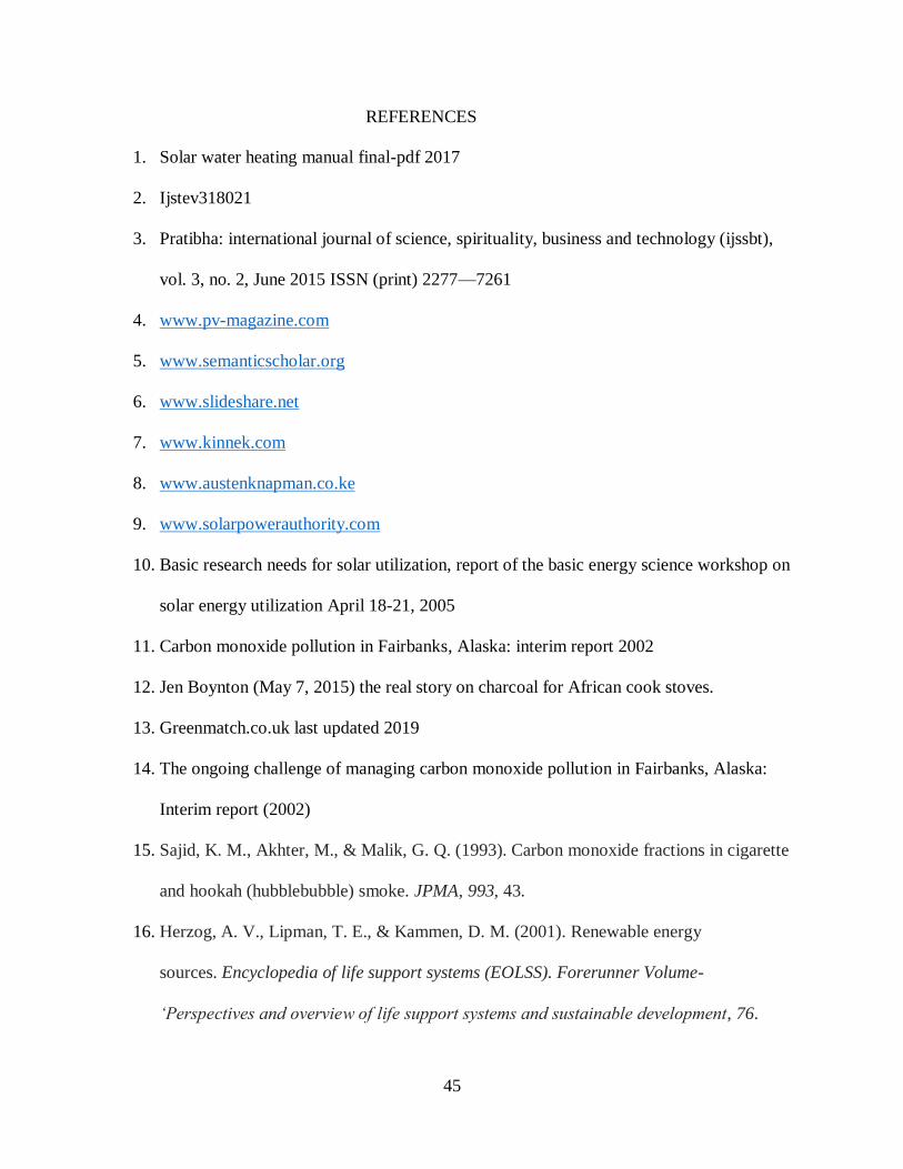
REFERENCES
1. Solar water heating manual final-pdf 2017
2. Ijstev318021
3. Pratibha: international journal of science, spirituality, business and technology (ijssbt),
vol. 3, no. 2, June 2015 ISSN (print) 2277—7261
4. www.pv-magazine.com
5. www.semanticscholar.org
6. www.slideshare.net
7. www.kinnek.com
8. www.austenknapman.co.ke
9. www.solarpowerauthority.com
10. Basic research needs for solar utilization, report of the basic energy science workshop on
solar energy utilization April 18-21, 2005
11. Carbon monoxide pollution in Fairbanks, Alaska: interim report 2002
12. Jen Boynton (May 7, 2015) the real story on charcoal for African cook stoves.
13. Greenmatch.co.uk last updated 2019
14. The ongoing challenge of managing carbon monoxide pollution in Fairbanks, Alaska:
Interim report (2002)
15. Sajid, K. M., Akhter, M., & Malik, G. Q. (1993). Carbon monoxide fractions in cigarette
and hookah (hubblebubble) smoke. JPMA, 993, 43.
16. Herzog, A. V., Lipman, T. E., & Kammen, D. M. (2001). Renewable energy
sources. Encyclopedia of life support systems (EOLSS). Forerunner Volume-
‘Perspectives and overview of life support systems and sustainable development, 76.

46
APPENDICES
The rise of temperature with time of the food platform surface

47
The temperature rise in the water compartment with time
48
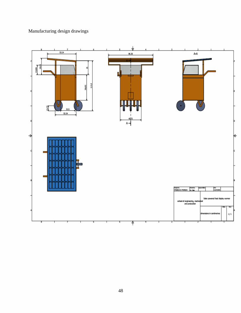
Manufacturing design drawings