Engineering Guide - Heat Wagon
28
(219) 464-8818 • Fax (219)462-7985 342 N. Co. Rd. 400 E. • Valparaiso, IN 46383 • www.heatwagon.com Temporary Heating Equipment Since 1981 ENGINEERING GUIDE A guide to the selection of temporary heaters and heating systems Rev. 12-21
-
Upload
khangminh22 -
Category
Documents
-
view
1 -
download
0
Transcript of Engineering Guide - Heat Wagon

(219) 464-8818 • Fax (219)462-7985 342 N. Co. Rd. 400 E. • Valparaiso, IN 46383 • www.heatwagon.com
Temporary Heating Equipment Since 1981
ENGINEERING GUIDE
A guide to the selection of temporary heaters and heating systems
Rev. 12-21
ENGINEERING GUIDE
2
TABLE OF CONTENTS
INTRODUCTION . . . . . . . . . . . . . . . . . . . . . . .2
BASICS OF TEMPORARY HEATING . . . . . . .3
RECIRCULATING vs PRESSURIZATION . . . .3
BASIC EQUIPMENT TYPES . . . . . . . . . . . . . .4
HEAT TRANSFER . . . . . . . . . . . . . . . . . . . . . .6
CONDUCTION, CONVECTION, RADIATION.. 6
HEAT LOSS/GAIN . . . . . . . . . . . . . . . . . . . . . .6
FUEL FACTS . . . . . . . . . . . . . . . . . . . . . . . . . .7
HOSE/PIPING . . . . . . . . . . . . . . . . . . . . . . . . .8
ELECTRIC POWER . . . . . . . . . . . . . . . . . . . . .8
BY-PRODUCTS . . . . . . . . . . . . . . . . . . . . . . . .8
COMMON PROBLEMS . . . . . . . . . . . . . . . . . .9
ON SITE HAZARDS . . . . . . . . . . . . . . . . . . . .9
JOB SIZING . . . . . . . . . . . . . . . . . . . . . . . . . . .9
FUEL AND POWER CONSUMPTION . . . . . . .9
CHARTS & TABLES . . . . . . . . . . . . . . . . .10-26
REGULATORS . . . . . . . . . . . . . . . . . . . . . . . .27
DRAGON WAGON . . . . . . . . . . . . . . . . . . . .28
INTRODUCTION
The purpose of the Heat Wagon Engineering Guide is to provide information and instruction in the selection of temporary heat equipment and systems for construction sites, primarily in the early and middle stages of building. There is no known text on this subject, although there are many on permanent heating systems. Some of the material from the Guide is drawn from such texts as well as from fuel gas codes, gas and propane association publications, and electrical engineering manuals. This guide is intended for use by individuals who sell temporary heating systems and those who provide technical support. While the purpose of the Heat Wagon Engineering Guide is to be helpful in the process of estimating temporary heating requirements, determining appropriate systems to use, fuel and electrical costs, and heater placement, Heat Wagon does not assume the ultimate responsibility for the overall effectiveness of individual projects. Actual jobsite conditions may require adjustments not anticipated in this general guide. In all events, federal, state and local codes take precedence over recommendations in this guide.
BASICS OF TEMPORARY HEATING In construction, temporary heating is commonly used to allow construction activities to continue throughout the win-ter season. On-going construction, worker comfort, safety, protection of structural components, concrete curing, and other factors during cold weather can make temporary heating a significant contributor to the profitability of winter work. Temporary heating is used because permanent heating systems are not yet installed or activated. Little attention has been paid to the necessities of temporary heating design even though there are many sources of information on permanent heat design. Insulating values of all structural components are taken into account. Structures that house people and equipment may require more heating and will be designed differently than buildings that serve the sole purpose of warehousing. System designs will account for outdoor design tempera-ture and desired indoor temperatures, wind forces, land mass and other factors. It is assumed that openings, such as doors and windows, will be installed and closed when making these calculations. From time to time, contractors or building owners will attempt to use permanent heating designs to determine temporary heat requirements. This is a poor way to calcu-late heat losses during the construction cycle. Designs for permanent systems do not adequately address heat loss issues such as infiltration of cold air in the early and middle stages of construction. Cold air infiltration is easily the greatest source of heat loss in a building under con-struction. Even a fully completed building, ready for occu-pation, suffers from infiltration of cold air. Another great heat loss is through the roof or ceilings due to conduction and radiation. Controlling these two main sources of heat loss, by proper system sizing and selection, will also address two other concerns for those contractors who are going to use tem-porary heat: the accumulation of moisture and the air quality within the building.
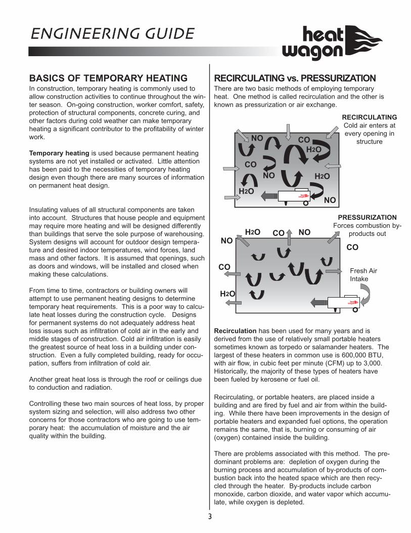
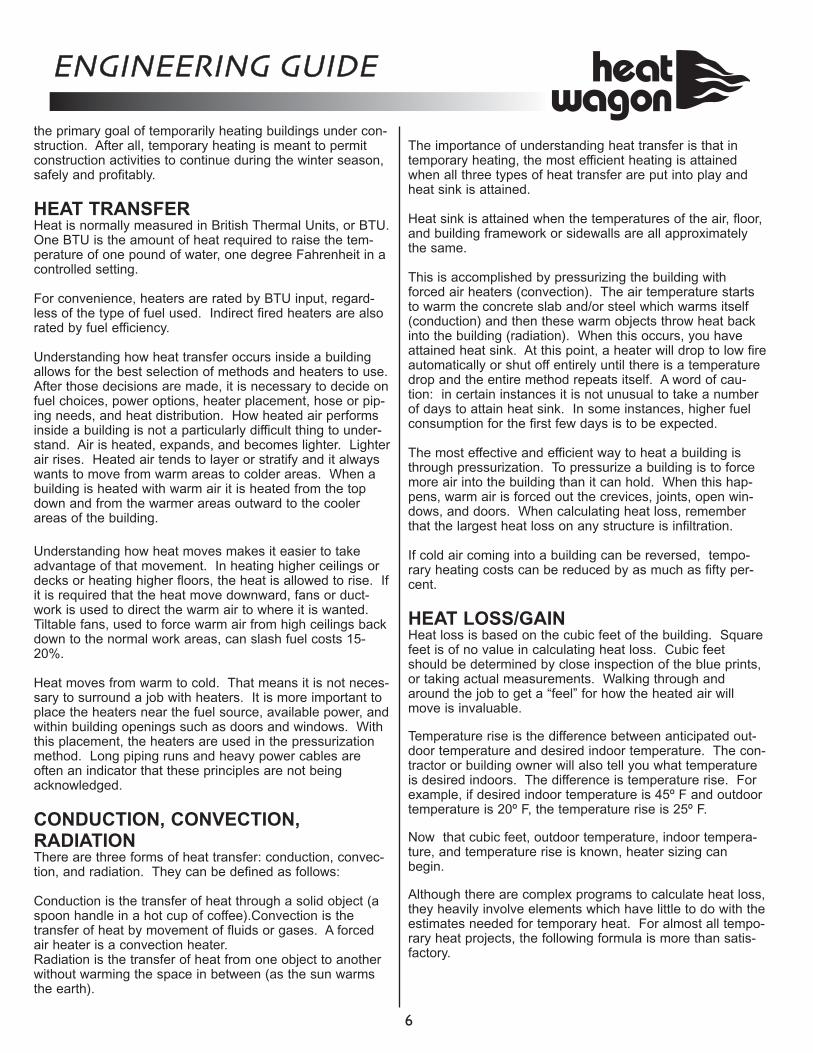
RECIRCULATING vs. PRESSURIZATION There are two basic methods of employing temporary heat. One method is called recirculation and the other is known as pressurization or air exchange.
Recirculation has been used for many years and is derived from the use of relatively small portable heaters sometimes known as torpedo or salamander heaters. The largest of these heaters in common use is 600,000 BTU, with air flow, in cubic feet per minute (CFM) up to 3,000. Historically, the majority of these types of heaters have been fueled by kerosene or fuel oil. Recirculating, or portable heaters, are placed inside a building and are fired by fuel and air from within the build-ing. While there have been improvements in the design of portable heaters and expanded fuel options, the operation remains the same, that is, burning or consuming of air (oxygen) contained inside the building. There are problems associated with this method. The pre-dominant problems are: depletion of oxygen during the burning process and accumulation of by-products of com-bustion back into the heated space which are then recy-cled through the heater. By-products include carbon monoxide, carbon dioxide, and water vapor which accumu-late, while oxygen is depleted.
ENGINEERING GUIDE
3
NO
NO
NO
H2O
H2O
H2O
RECIRCULATING Cold air enters at every opening in
structure
CO
NONO
H2O
H2O
CO
CO
CO
CO
Fresh Air Intake
PRESSURIZATION Forces combustion by-
products out
It is always recommended that outside air be introduced to the interior spaces to prevent the uncomfortable and sometimes dangerous accumulation of these by-products when using recirculating heaters. In addition to these drawbacks, combustion inside the building with interior air creates a partial vacuum, encour-aging infiltration of cold air. As said before, infiltration of cold air is a principal cause of heat loss. Heated air inside the building tends to be spotty and uneven under these conditions and potential code violations. Recirculating heaters also obstruct work in progress while providing uneven heat distribution. Hoses and tanks are also obstructions. The other method of employing temporary heat is referred to as the air exchange or the pressurization method. This method addresses all of the problems associated with the recirculation method. The pressurization type heaters range widely in BTU capacity. They are usually fueled by natural gas, vapor propane, liquid propane, or fuel oil. They all share the characteristic of having high temperature rises, i.e., the dif-ference between input air and output air, high air move-ment, expressed in cubic feet per minute (CFM), and high static pressure. High temperature rise with high CFM and high static pres-sure permit these types of heaters to use air from outside the building to pressurize the building. The net affect of this pressurized air flow is to spread heated air evenly throughout a building. Several important things begin to happen as this heated air spreads. The foremost is the reversal of infiltration of cooler air. Where cold air has been entering, it is forced back out of the building. The by-products of combustion, carbon monoxide and water vapor are expelled as well. Heated air tends to be more evenly spread throughout the building. Naturally, efforts to tighten the building enclosure must be made in order to achieve maximum results from pressur-ization. It is the contractor’s responsibility to continually tighten the enclosure. Regardless of the method selected, pressurizing or recir-culating, a consideration of the type of equipment used by either method is needed. The equipment should be portable and compact. Heaters should use readily avail-able fuel and power. Operational safety and environmen-tal safety are priorities. Heaters should be designed and engineered to meet high standards. It is to be expected that equipment has been tested and approved by inde-pendent laboratories for both manufacturing stan-dards and safe operation. There must be rational calcu-
lations of estimated fuel expenses, electric costs, set up and maintenance costs, supervisional costs, and so forth.
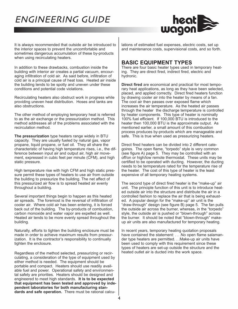
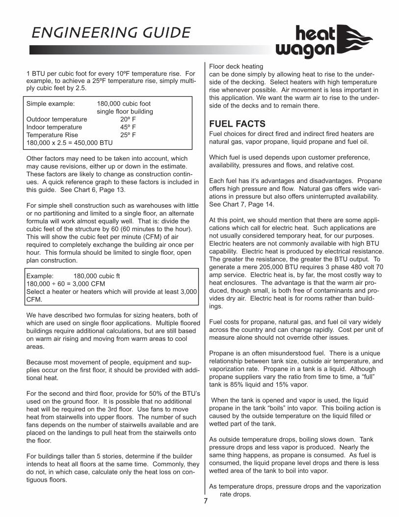
BASIC EQUIPMENT TYPES There are four basic heater types used in temporary heat-ing. They are direct fired, indirect fired, electric and hydronic. Direct fired are economical and practical for most tempo-rary heat applications, as long as they have been selected, placed, and applied correctly. Direct fired heaters function by drawing cooler air into the heater by means of a fan. The cool air then passes over exposed flame which increases the air temperature. As the heated air passes through the heater the discharge temperature is controlled by heater components. This type of heater is nominally 100% fuel efficient. If 100,000 BTU is introduced to the heater then 100,000 BTU is the approximate output. As mentioned earlier, a small amount of this combustion process produces by-products which are manageable and safe. This is true when used as pressurizing heaters. Direct fired heaters can be divided into 2 different cate-goires. The open flame, “torpedo” style is very common (see figure A) page 5. They may be controlled with an off/on or high/low remote thermostat. These units may be certified to be operated with ducting. However, the ducting needs to be termperature rated for the temperature rise of the heater. The cost of this type of heater is the least expensive of all temporary heating systems. The second type of direct fired heater is the “make-up” air unit. The principle function of this unit is to introduce heat-ed outside air into the structure and distribute the air in a controlled fashion to replace the air that is being exhaust-ed. A popular design for the “make-up” air unit is the “draw-through” design (see figure B) page 5. The fan pulls the outside air across the burner, whereas, in the “torpedo” style, the outside air is pushed or “blown-through” across the burner. It should be noted that “blown-through” make-up air units are also manufactured for temporary heating. In recent years, temporary heating quotation proposals have contained the statement: . . .No open flame salaman-der type heaters are permitted. . .Make-up air units have been used to comply with this requirement since these types of heaters are set-up outside the structure and the heated outlet air is ducted into the work space.
ENGINEERING GUIDE
4
Listed below are the major characteristics/differences between “torpedo” and “make-up” air heaters.
Indirect fired heaters operate differently. Cooler air is drawn into a contained burner chamber where the fuel is fired and the combustion process begins. The heater also draws cool air over a separate chamber called a heat exchanger. The two streams of air: combustion air and heat exchange air do not intermingle. Combustion air heats the heat exchanger air. Combustion by-products are dis-charged through a vent or flue along with the excess heat. Note: Indirect fired heaters always have a chimney. The air heated by the heat exchanger is discharged into the structure to be heated. Therefore, in a vented heater, the usable temporary heat is free of any contamination or water vapor produced in the combustion process. This heat is clean and it is dry. Though still simple in operation and application, indirect fired heaters require more components, mostly in sheet metal parts. It is the nature of vented heaters to produce some waste heat. In the past, the best fuel efficiencies pos-sible were in the 35% - 40% range. Today’s manufacturing and design capabilities make it possible to increase efficien-cies to about 80%. In short, direct fired heat is nearly 100% fuel efficient while the best available indirect fired heaters are about 80% fuel efficient. As a result, operating costs with indirect fired heaters can be somewhat greater than operating costs with direct fired heaters in the pressurization mode with outside air. However, in the recirculation mode, fuel savings up to 50% can be realized with indirect heaters. Indirect fired heaters are used in cases where air quality is of utmost importance, such as in hospitals or schools. These heaters are also used where drying is needed. Indirect fired heaters do not add moisture to the build-ing whether used as pressurizing or recirculating units. Temporary heat provides for a third type of heater. Electric heat is used in relatively small enclosures when clean, dry heat is required. The main drawback to electric heat is the small heat capacity relative to the cost to power them. Electric heat is considered to be six or eight times more costly to operate than gas or oil fired units. A more recent development in temporary heating is known as hydronic heat. It is a hot water circulating system. This type of equipment owes its design to ground thawing equip-ment which heats a glycol mix and transfers heat through flexible hose to the ground. Hydronic heaters, do not heat the air directly, but instead heat a water glycol mixture which is then pumped through flexible hose to heat exchangers. These heat exchangers are placed inside a building to provide warm air. The main advantage of this type of system is not the warm air provided which is some-what limited by its design, but rather the drying effect pro-duced by separating the combustion process from the heat transfer process, as in indirect fired heaters. All of the heaters described have their own purpose. The challenge is to determine the need, and to then balance cost, convenience, portability, and effectiveness in meeting
ENGINEERING GUIDE
5
Direct Fired-Fig. A Fresh Air
Hydronic-Fig. D
Indirect Fired-Fig. C
Torpedo Style Make-Up Air Style Open, Exposed Flame Yes Typically concealed Temperature Rise 200 to 400F 150 to 250F Fan Type Axial fan Centrifugal blower, with
(one speed) higher static pressure and possible variable drive for adjustable air output
Ducting Possible Yes, typically with longer duct length
Temperature Control Usually high/low May have additional or on/off thermostat control with modulating
gas valve to produce variable heat output. Up to 10:1 turn down ratio.
Products of Combustion CO, CO2 and H2O Identical to the Torpedo open flame
Make-Up Air-Fig. B
the primary goal of temporarily heating buildings under con-struction. After all, temporary heating is meant to permit construction activities to continue during the winter season, safely and profitably.
HEAT TRANSFER Heat is normally measured in British Thermal Units, or BTU. One BTU is the amount of heat required to raise the tem-perature of one pound of water, one degree Fahrenheit in a controlled setting. For convenience, heaters are rated by BTU input, regard-less of the type of fuel used. Indirect fired heaters are also rated by fuel efficiency. Understanding how heat transfer occurs inside a building allows for the best selection of methods and heaters to use. After those decisions are made, it is necessary to decide on fuel choices, power options, heater placement, hose or pip-ing needs, and heat distribution. How heated air performs inside a building is not a particularly difficult thing to under-stand. Air is heated, expands, and becomes lighter. Lighter air rises. Heated air tends to layer or stratify and it always wants to move from warm areas to colder areas. When a building is heated with warm air it is heated from the top down and from the warmer areas outward to the cooler areas of the building. Understanding how heat moves makes it easier to take advantage of that movement. In heating higher ceilings or decks or heating higher floors, the heat is allowed to rise. If it is required that the heat move downward, fans or duct-work is used to direct the warm air to where it is wanted. Tiltable fans, used to force warm air from high ceilings back down to the normal work areas, can slash fuel costs 15-20%. Heat moves from warm to cold. That means it is not neces-sary to surround a job with heaters. It is more important to place the heaters near the fuel source, available power, and within building openings such as doors and windows. With this placement, the heaters are used in the pressurization method. Long piping runs and heavy power cables are often an indicator that these principles are not being acknowledged.
CONDUCTION, CONVECTION, RADIATION There are three forms of heat transfer: conduction, convec-tion, and radiation. They can be defined as follows: Conduction is the transfer of heat through a solid object (a spoon handle in a hot cup of coffee).Convection is the transfer of heat by movement of fluids or gases. A forced air heater is a convection heater. Radiation is the transfer of heat from one object to another without warming the space in between (as the sun warms the earth).
The importance of understanding heat transfer is that in temporary heating, the most efficient heating is attained when all three types of heat transfer are put into play and heat sink is attained. Heat sink is attained when the temperatures of the air, floor, and building framework or sidewalls are all approximately the same. This is accomplished by pressurizing the building with forced air heaters (convection). The air temperature starts to warm the concrete slab and/or steel which warms itself (conduction) and then these warm objects throw heat back into the building (radiation). When this occurs, you have attained heat sink. At this point, a heater will drop to low fire automatically or shut off entirely until there is a temperature drop and the entire method repeats itself. A word of cau-tion: in certain instances it is not unusual to take a number of days to attain heat sink. In some instances, higher fuel consumption for the first few days is to be expected. The most effective and efficient way to heat a building is through pressurization. To pressurize a building is to force more air into the building than it can hold. When this hap-pens, warm air is forced out the crevices, joints, open win-dows, and doors. When calculating heat loss, remember that the largest heat loss on any structure is infiltration. If cold air coming into a building can be reversed, tempo-rary heating costs can be reduced by as much as fifty per-cent.
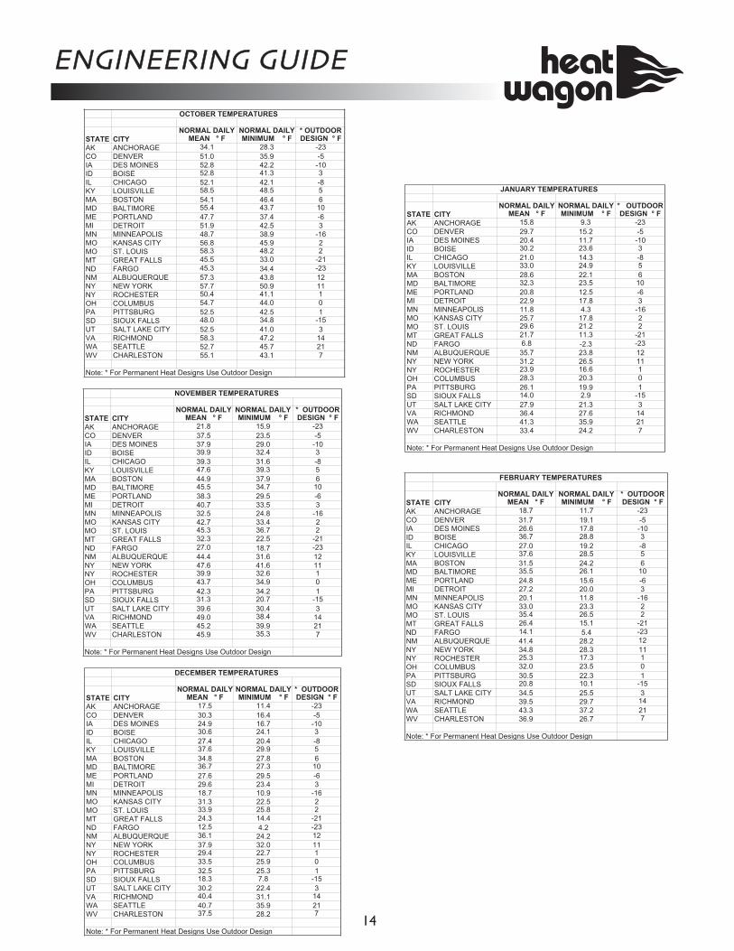
HEAT LOSS/GAIN Heat loss is based on the cubic feet of the building. Square feet is of no value in calculating heat loss. Cubic feet should be determined by close inspection of the blue prints, or taking actual measurements. Walking through and around the job to get a “feel” for how the heated air will move is invaluable. Temperature rise is the difference between anticipated out-door temperature and desired indoor temperature. The con-tractor or building owner will also tell you what temperature is desired indoors. The difference is temperature rise. For example, if desired indoor temperature is 45º F and outdoor temperature is 20º F, the temperature rise is 25º F. Now that cubic feet, outdoor temperature, indoor tempera-ture, and temperature rise is known, heater sizing can begin. Although there are complex programs to calculate heat loss, they heavily involve elements which have little to do with the estimates needed for temporary heat. For almost all tempo-rary heat projects, the following formula is more than satis-factory.
ENGINEERING GUIDE
6
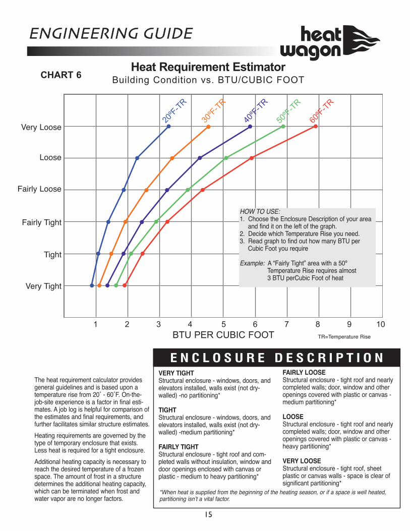
1 BTU per cubic foot for every 10ºF temperature rise. For example, to achieve a 25ºF temperature rise, simply multi-ply cubic feet by 2.5. Simple example: 180,000 cubic foot
single floor building Outdoor temperature 20º F Indoor temperature 45º F Temperature Rise 25º F 180,000 x 2.5 = 450,000 BTU Other factors may need to be taken into account, which may cause revisions, either up or down in the estimate. These factors are likely to change as construction contin-ues. A quick reference graph to these factors is included in this guide. See Chart 6, Page 13. For simple shell construction such as warehouses with little or no partitioning and limited to a single floor, an alternate formula will work almost equally well. That is: divide the cubic feet of the structure by 60 (60 minutes to the hour). This will show the cubic feet per minute (CFM) of air required to completely exchange the building air once per hour. This formula should be limited to single floor, open plan construction. Example: 180,000 cubic ft 180,000 ÷ 60 = 3,000 CFM Select a heater or heaters which will provide at least 3,000 CFM. We have described two formulas for sizing heaters, both of which are used on single floor applications. Multiple floored buildings require additional calculations, but are still based on warm air rising and moving from warm areas to cool areas. Because most movement of people, equipment and sup-plies occur on the first floor, it should be provided with addi-tional heat. For the second and third floor, provide for 50% of the BTU’s used on the ground floor. It is possible that no additional heat will be required on the 3rd floor. Use fans to move heat from stairwells into upper floors. The number of such fans depends on the number of stairwells available and are placed on the landings to pull heat from the stairwells onto the floor. For buildings taller than 5 stories, determine if the builder intends to heat all floors at the same time. Commonly, they do not, in which case, calculate only the heat loss on con-tiguous floors.
Floor deck heating can be done simply by allowing heat to rise to the under-side of the decking. Select heaters with high temperature rise whenever possible. Air movement is less important in this application. We want the warm air to rise to the under-side of the decks and to remain there. FUEL FACTS Fuel choices for direct fired and indirect fired heaters are natural gas, vapor propane, liquid propane and fuel oil. Which fuel is used depends upon customer preference, availability, pressures and flows, and relative cost. Each fuel has it’s advantages and disadvantages. Propane offers high pressure and flow. Natural gas offers wide vari-ations in pressure but also offers uninterrupted availability. See Chart 7, Page 14. At this point, we should mention that there are some appli-cations which call for electric heat. Such applications are not usually considered temporary heat, for our purposes. Electric heaters are not commonly available with high BTU capability. Electric heat is produced by electrical resistance. The greater the resistance, the greater the BTU output. To generate a mere 205,000 BTU requires 3 phase 480 volt 70 amp service. Electric heat is, by far, the most costly way to heat enclosures. The advantage is that the warm air pro-duced, though small, is both free of contaminants and pro-vides dry air. Electric heat is for rooms rather than build-ings. Fuel costs for propane, natural gas, and fuel oil vary widely across the country and can change rapidly. Cost per unit of measure alone should not override other issues. Propane is an often misunderstood fuel. There is a unique relationship between tank size, outside air temperature, and vaporization rate. Propane in a tank is a liquid. Although propane suppliers vary the ratio from time to time, a “full” tank is 85% liquid and 15% vapor. When the tank is opened and vapor is used, the liquid propane in the tank “boils” into vapor. This boiling action is caused by the outside temperature on the liquid filled or wetted part of the tank. As outside temperature drops, boiling slows down. Tank pressure drops and less vapor is produced. Nearly the same thing happens, as propane is consumed. As fuel is consumed, the liquid propane level drops and there is less wetted area of the tank to boil into vapor. As temperature drops, pressure drops and the vaporization
rate drops.
ENGINEERING GUIDE
7
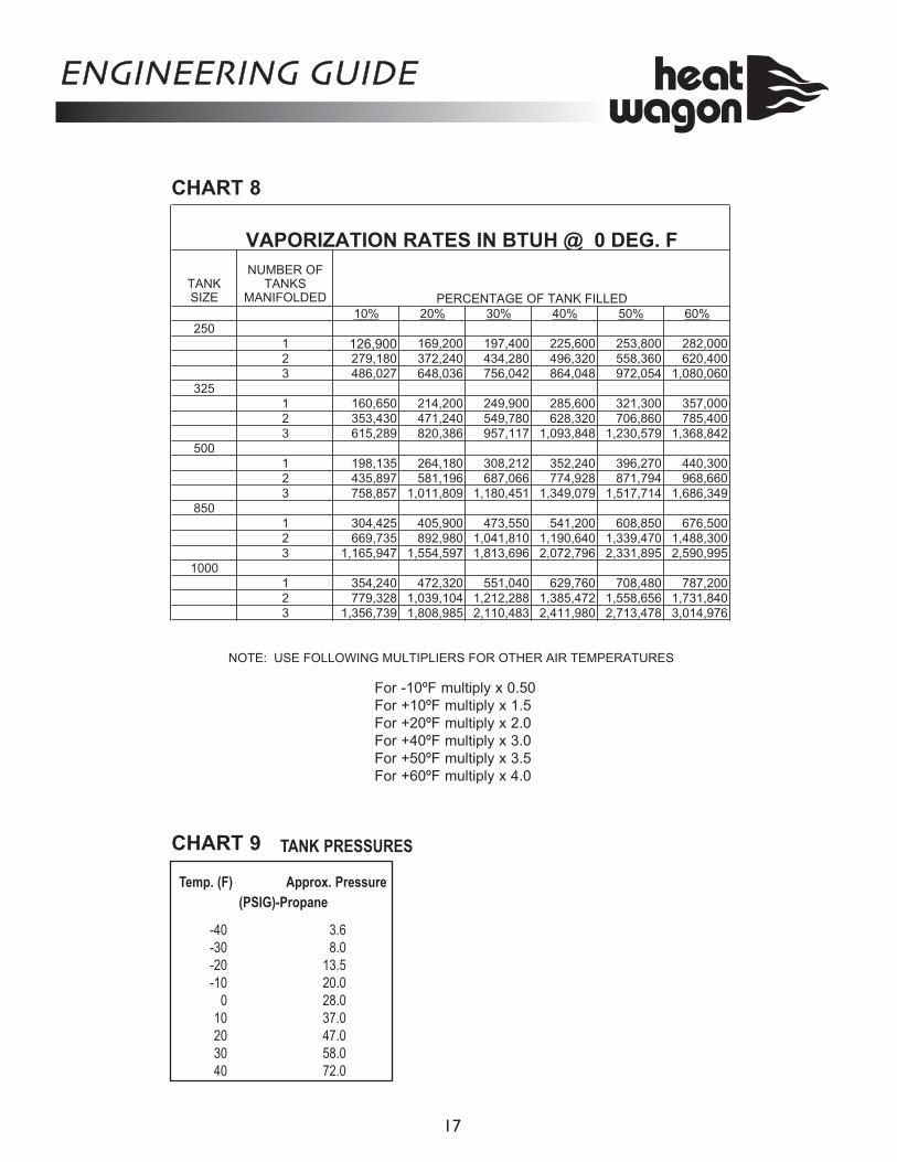
Chart 8, Page 15 demonstrates the rate of vaporization in various tank sizes, 250 gallons through 1,000 gallons, and manifolded at 0º F outside temperature and at 60% of liq-uid capacity. 60% is used to allow a comfortable margin in calculating tank requirements. Chart 9, Page 15 demonstrates bulk tank pressures at out-side temperatures from -40ºF to +40ºF. HOSE AND PIPING It is best practice to place heaters in building openings close to the fuel source and close to dependable electric power. In order to choose the correct hose or piping for a heater three things must be known.
• Fuel Type - natural gas, vapor propane or liquid propane • Fuel pressure at the source • Distance to the heater
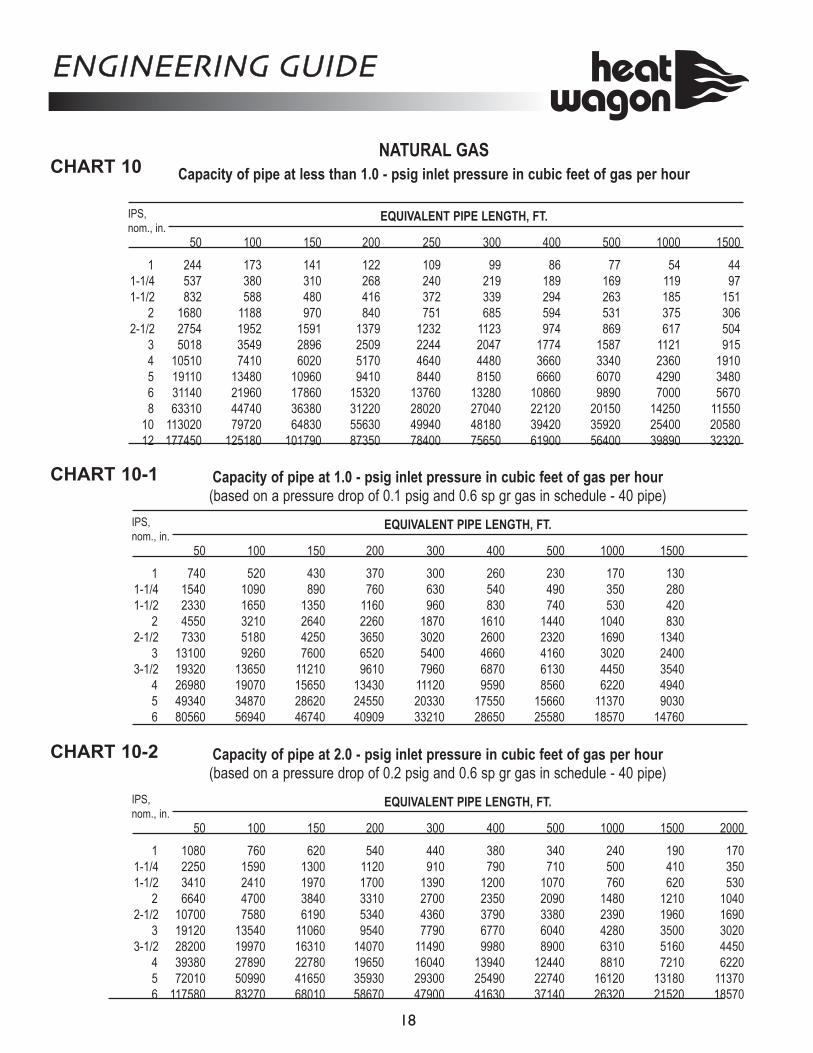
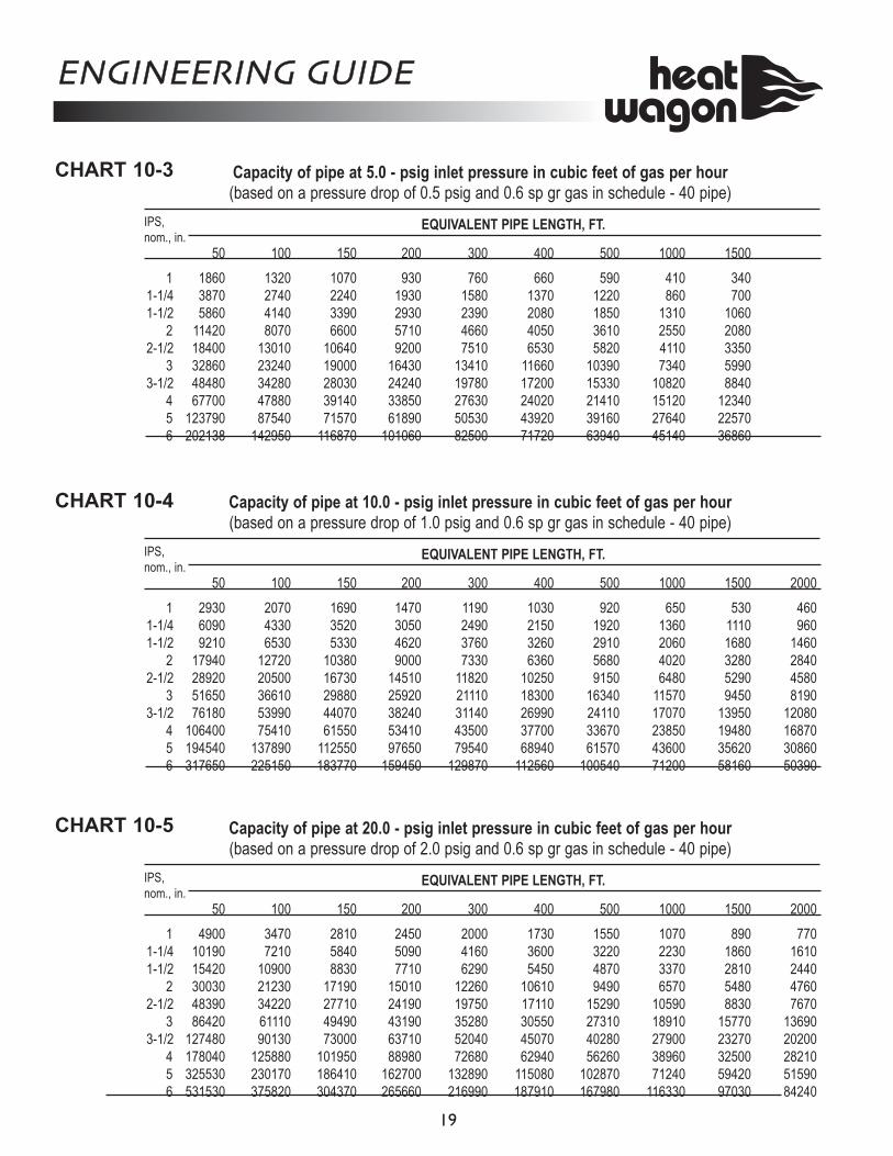
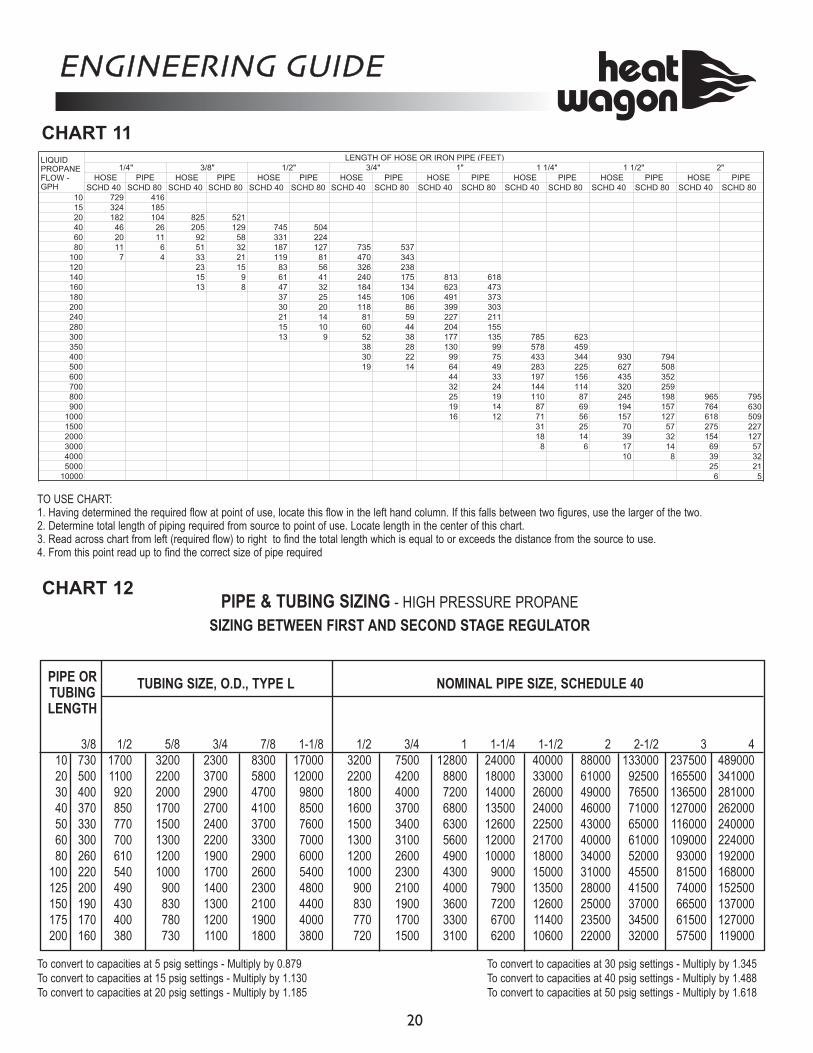
Chart 10, Page 16-17 illustrates flow rates for hose and piping at pressures from less than 1 pound per square inch (psi) through 20 psi for natural gas. The charts given do not give values for 3/4” hose; use 1” pipe as equivalent of 3/4” hose. An example of proper pipe sizing can be found on page 20. Chart 11, Page 18 shows flow rates for liquid propane in gallons per hour, for hose and piping in diameters from 1/4” through 2”. To eliminate potential problems with liquid propane called slugging, use the smallest diameter hose or piping possible, see liquid propane Chart 12, Page 18. Refer to page 21 for proper bulk tank placement. Liquid propane may not be used inside a building under any cir-cumstances. Place and use liquid propane heaters in building openings with all hose and piping outside the building.* *Please refer to federal, state and local codes for appropri-ate use of hose and piping. Some codes permit no hose to be used. HIGH PRESSURE REGULATORS Heater specifications include minimum and maximum inlet pressure requirement. Specifications may be in inches of water column (w.c.) or pounds per square inch (psi). 27.7 inches w.c. equals 1 psi. When inlet gas pressure is greater than the maximum pressure called for in the specifications, a high pressure regulator is required. For example, if the specifications reads 14 inches w.c. maximum inlet pressure and gas
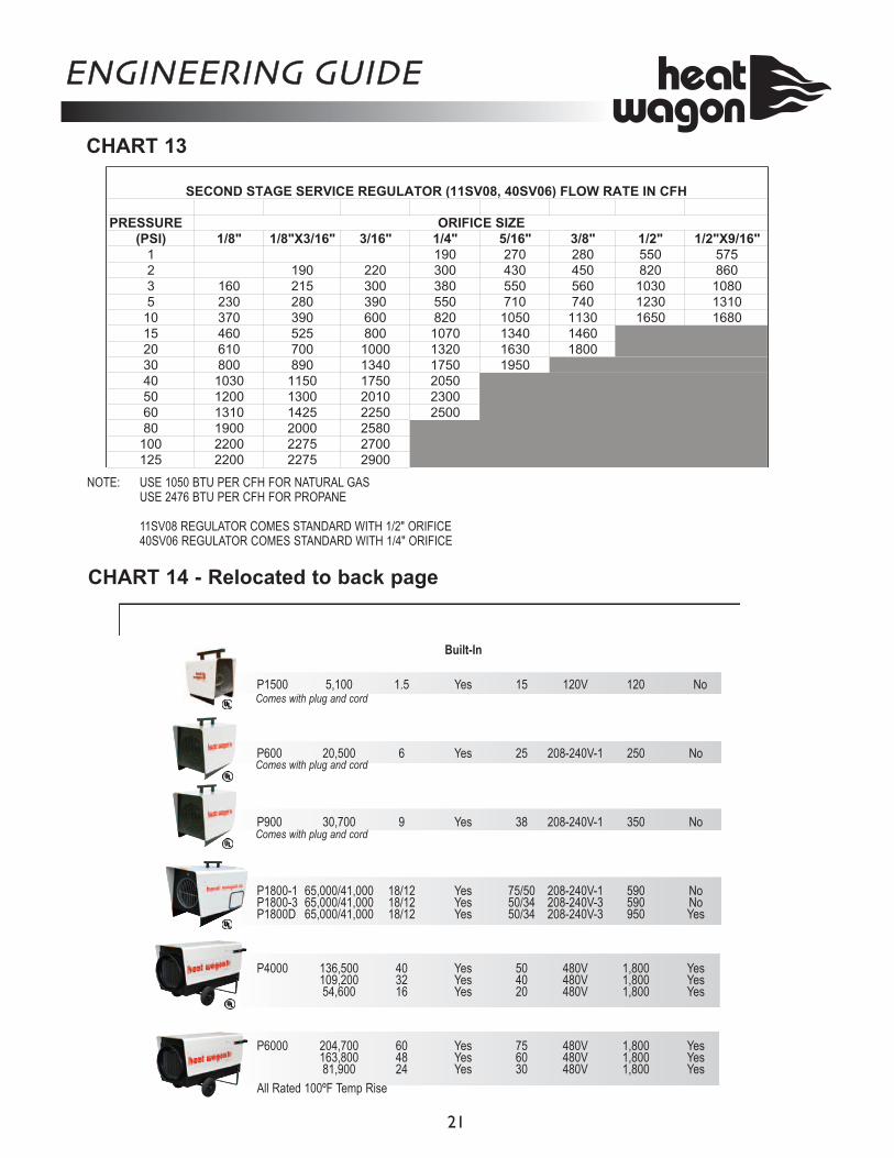
pressure is 5 psi, a regulator must be added to the heater at the inlet. Chart 13, Page 19 will guide you to the correct regulator as specified by Heat Wagon. For circumstances outside the chart parameters please call Heat Wagon Technical Support at 219.464.8818, extension 2003. ELECTRIC POWER All Heat Wagon heaters have recommended minimum cord size decals. Circumstances may arise where these recommendations are not suitable for a specific applica-tion. Refer to Chart 14, Page 24 for guidance. Whenever possible, place heaters as close as possible to the power source.
BY-PRODUCTS OF THE COMBUSTION PROCESS Direct fired heater by-products of combustion are carbon dioxide, carbon monoxide, nitrous oxide, and water vapor. Of these, only carbon monoxide and water vapor are of major concern. OSHA has established standards for carbon monoxide accumulation inside the building envelope. The standard can be found readily in the NIOSH Pocket Guide to Chemical Standards, Publication 97-140. The Pocket Guide is available at no charge from the US Government Printing Office at 866.512.1800. The 2004 issue of the pocket guide shows the 8 hour time weighted average accumulations for carbon monoxide to be 50 ppm. Please be aware that this standard applies not to heaters or other equipment, but rather the total accumulation of carbon monoxide in the building envelope over an 8 hour period. Heaters are probably not the cause for carbon monoxide accumulation, particularly when used in their proper mode, as pressurizing heaters. In many instances, other equipment on the job site may be producing far more carbon monoxide than the heaters. Troweling machines, generators, compressors and loaders are often found in the same work space. It has been said by some temporary heating suppliers that carbon monoxide should be estimated on the basis of the functionality of the heater. This is incorrect. Actual mea-surements of carbon monoxide accumulation should be taken over time throughout the structure, at various times in a work day. There are devices on the market for that express purpose.
ENGINEERING GUIDE
8
Water vapor, introduced by the combustion process with direct fired heaters, is reduced or eliminated by the pres-surization method. Further, for dehumidifying, air move-ment greatly aids the process. If water vapor becomes an issue, simply add fans to encourage air movement.
COMMON INSTALLATION AND OPERA-TIONAL PROBLEMS 1. Low Voltage - This is one of the most common problems and is usually the result of the supply cord having too small a wire gauge for its length. Low voltage results in the motor overheating, burnt relay contacts or a relay that will not make contact. 2. Gas Supply Line Too Small 3. Insufficient Vaporization At Supply - Normally caused by improperly sized propane tank. 4. Improper Gas Supply Pressure - Usually a result of sup-ply pressure being too high or too low because of improper or lack of regulation. Refer to the heater’s instruction plate for the maximum and minimum inlet pressure rating. 5. Dirty Gas Supply (Dirt in hose or supply pipe) - Dirty gas can cause strainers to plug or form a build up in the burner orifice. 6. Lack Of Preventative Maintenance - Heaters must be cleaned as required, especially when used in a dirty envi-ronment. ON SITE HAZARDS 1. Shorting Or Jumping Out Of Defective Components - This is a very common problem which saves short term expense at the risk of large future costs. Any heaters found in this condition should be removed immediately. 2. Improper Enclosure - When heaters are installed partial-ly to the outside for fresh air intake, strict adherence must be made to the minimum clearance to combustibles given on the instruction plate. Wood framing around a heater poses a potential hazard. 3. Supplying Liquid Propane To A Vapor Heater - This problem has occurred from time to time. To minimize the damage, shut off the gas supply and let the heaters run until all of the liquid in the lines has been burnt. 4. Improper Or No First Stage Regulator - Refer to the heater rating plate for the maximum and minimum inlet
pressure rating.
JOB SIZING Proper job sizing is result of finding out as much informa-tion about the construction project as possible. Key infor-mation that must be determined are:
1. Cubic feet of structure 2. Design temperature 3. Available fuel source 4. Available power source 5. Enclosure description
Page 22 of this guide will lead you through this process. Once this information is determined heating recommenda-tions can be made. FUEL AND POWER CONSUMPTION Many factors (building tightness and actual weather condi-tions) can effect the fuel consumption on a heating project. Therefore, any cost calculation is just an estimate. Page 23 of this guide provides a worksheet for estimating pro-ject costs. Follow up and communication with the contractor through-out the heating season are extremely important to a suc-cessful sale and repeat business. Keeping good records on every job will improve knowledge and future success.
ENGINEERING GUIDE
9
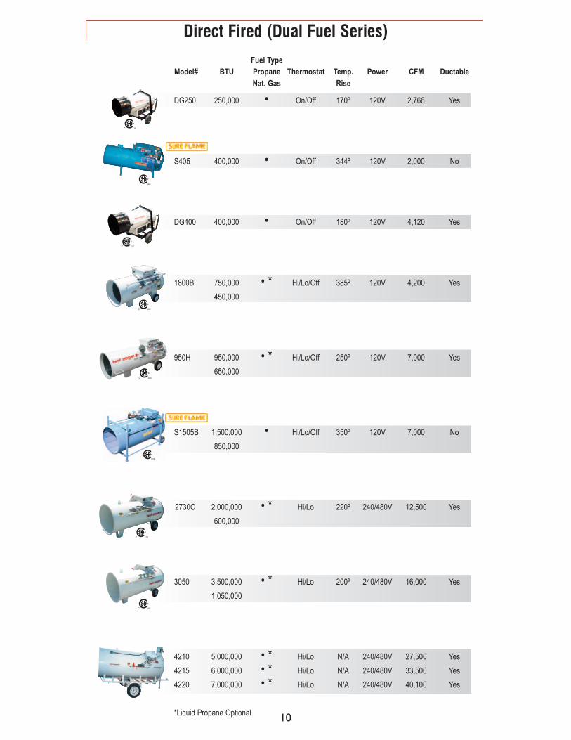
DG250 250,000 • On/Off 170º 120V 2,766 Yes
S405 400,000 • On/Off 344º 120V 2,000 No
DG400 400,000 • On/Off 180º 120V 4,120 Yes
1800B 750,000 • * Hi/Lo/Off 385º 120V 4,200 Yes
450,000
950H 950,000 • * Hi/Lo/Off 250º 120V 7,000 Yes
650,000
S1505B 1,500,000 • Hi/Lo/Off 350º 120V 7,000 No
850,000
2730C 2,000,000 • * Hi/Lo 220º 240/480V 12,500 Yes
600,000
3050 3,500,000 • * Hi/Lo 200º 240/480V 16,000 Yes
1,050,000
4210 5,000,000 • * Hi/Lo N/A 240/480V 27,500 Yes
4215 6,000,000 • * Hi/Lo N/A 240/480V 33,500 Yes
4220 7,000,000 • * Hi/Lo N/A 240/480V 40,100 Yes
*Liquid Propane Optional
Fuel Type Model# BTU Propane Thermostat Temp. Power CFM Ductable
Nat. Gas Rise
Direct Fired (Dual Fuel Series)
C US
C US
C US
C US
C US
C US
C US
C US
10
11
C US
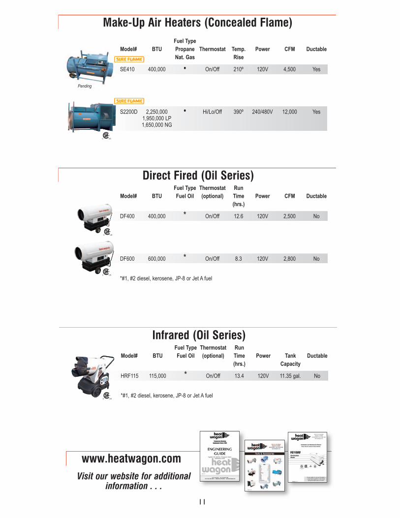
HRF115 115,000 * On/Off 13.4 120V 11.35 gal. No
*#1, #2 diesel, kerosene, JP-8 or Jet A fuel
Fuel Type Thermostat Run Model# BTU Fuel Oil (optional) Time Power Tank Ductable
(hrs.) Capacity
Infrared (Oil Series)
C US
DF400 400,000 * On/Off 12.6 120V 2,500 No
DF600 600,000 * On/Off 8.3 120V 2,800 No
*#1, #2 diesel, kerosene, JP-8 or Jet A fuel
Fuel Type Thermostat Run Model# BTU Fuel Oil (optional) Time Power CFM Ductable
(hrs.)
Direct Fired (Oil Series)
C US
C US
SE410 400,000 • On/Off 210º 120V 4,500 Yes
S2200D 2,250,000 • Hi/Lo/Off 390º 240/480V 12,000 Yes 1,950,000 LP 1,650,000 NG
Fuel Type Model# BTU Propane Thermostat Temp. Power CFM Ductable
Nat. Gas Rise
Make-Up Air Heaters (Concealed Flame)
www.heatwagon.comVisit our website for additional
information . . .
Pending
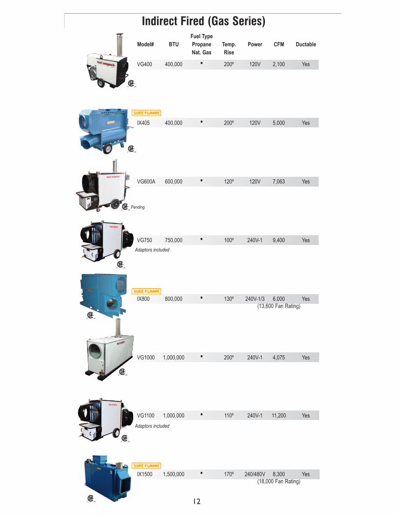
VG400 400,000 • 200º 120V 2,100 Yes
IX405 400,000 • 200º 120V 5,000 Yes
VG600A 600,000 • 120º 120V 7,063 Yes
VG750 750,000 • 100º 240V-1 9,400 Yes
IX800 800,000 • 130º 240V-1/3 6,000 Yes (13,600 Fan Rating)
VG1000 1,000,000 • 200º 240V-1 4,075 Yes
VG1100 1,000,000 • 110º 240V-1 11,200 Yes
IX1500 1,500,000 • 170º 240/480V 8,300 Yes (18,000 Fan Rating)
Fuel Type Model# BTU Propane Temp. Power CFM Ductable
Nat. Gas Rise
Indirect Fired (Gas Series)
C US
C US
C US
C US
C US
C US
C US
Adaptors included
Adaptors included
C USPending
12
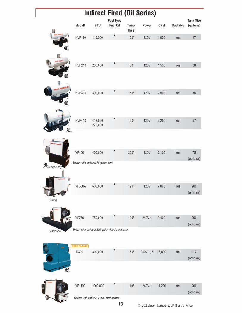
HVF110 110,000 * 160º 120V 1,020 Yes 17
HVF210 205,000 * 160º 120V 1,530 Yes 28
HVF310 300,000 * 160º 120V 2,500 Yes 36
HVF410 412,000 * 160º 120V 3,250 Yes 57 272,000
VF400 400,000 * 200º 120V 2,100 Yes 75
(optional)
VF600A 600,000 * 120º 120V 7,063 Yes 200
(optional)
VF750 750,000 * 100º 240V-1 9,400 Yes 200
(optional)
ID800 800,000 * 160º 240V-1, 3 13,600 Yes 117
(optional)
VF1100 1,000,000 * 110º 240V-1 11,200 Yes 200
(optional)
*#1, #2 diesel, kerosene, JP-8 or Jet A fuel
Fuel Type Tank Size Model# BTU Fuel Oil Temp. Power CFM Ductable (gallons)
Rise
Indirect Fired (Oil Series)
C US
C US
C US
C US
C US
Shown with optional 75 gallon tank
Heater Only Shown with optional 200 gallon double-wall tank
Shown with optional 2-way duct splitter
Pending
C US Heater Only
13
ENGINEERING GUIDE
14
STATE CITYNORMAL DAILY
MEAN ° FNORMAL DAILY MINIMUM ° F
* OUTDOOR DESIGN ° F
AK ANCHORAGE 17.5 11.4 -23CO DENVER 30.3 16.4 -5IA DES MOINES 24.9 16.7 -10ID BOISE 30.6 24.1 3IL CHICAGO 27.4 20.4 -8KY LOUISVILLE 37.6 29.9 5MA BOSTON 34.8 27.8 6MD BALTIMORE 36.7 27.3 10ME PORTLAND 27.6 29.5 -6MI DETROIT 29.6 23.4 3MN MINNEAPOLIS 18.7 10.9 -16MO KANSAS CITY 31.3 22.5 2MO ST. LOUIS 33.9 25.8 2MT GREAT FALLS 24.3 14.4 -21ND FARGO 12.5 4.2 -23NM ALBUQUERQUE 36.1 24.2 12NY NEW YORK 37.9 32.0 11NY ROCHESTER 29.4 22.7 1OH COLUMBUS 33.5 25.9 0PA PITTSBURG 32.5 25.3 1SD SIOUX FALLS 18.3 7.8 -15UT SALT LAKE CITY 30.2 22.4 3VA RICHMOND 40.4 31.1 14WA SEATTLE 40.7 35.9 21WV CHARLESTON 37.5 28.2 7
Note: * For Permanent Heat Designs Use Outdoor Design
DECEMBER TEMPERATURES
STATE CITYNORMAL DAILY
MEAN ° FNORMAL DAILY MINIMUM ° F
* OUTDOOR DESIGN ° F
AK ANCHORAGE 15.8 9.3 -23CO DENVER 29.7 15.2 -5IA DES MOINES 20.4 11.7 -10ID BOISE 30.2 23.6 3IL CHICAGO 21.0 14.3 -8KY LOUISVILLE 33.0 24.9 5MA BOSTON 28.6 22.1 6MD BALTIMORE 32.3 23.5 10ME PORTLAND 20.8 12.5 -6MI DETROIT 22.9 17.8 3MN MINNEAPOLIS 11.8 4.3 -16MO KANSAS CITY 25.7 17.8 2MO ST. LOUIS 29.6 21.2 2MT GREAT FALLS 21.7 11.3 -21ND FARGO 6.8 -2.3 -23NM ALBUQUERQUE 35.7 23.8 12NY NEW YORK 31.2 26.5 11NY ROCHESTER 23.9 16.6 1OH COLUMBUS 28.3 20.3 0PA PITTSBURG 26.1 19.9 1SD SIOUX FALLS 14.0 2.9 -15UT SALT LAKE CITY 27.9 21.3 3VA RICHMOND 36.4 27.6 14WA SEATTLE 41.3 35.9 21WV CHARLESTON 33.4 24.2 7
Note: * For Permanent Heat Designs Use Outdoor Design
JANUARY TEMPERATURES
STATE CITYNORMAL DAILY
MEAN ° FNORMAL DAILY MINIMUM ° F
* OUTDOOR DESIGN ° F
AK ANCHORAGE 34.1 28.3 -23CO DENVER 51.0 35.9 -5IA DES MOINES 52.8 42.2 -10ID BOISE 52.8 41.3 3IL CHICAGO 52.1 42.1 -8KY LOUISVILLE 58.5 48.5 5MA BOSTON 54.1 46.4 6MD BALTIMORE 55.4 43.7 10ME PORTLAND 47.7 37.4 -6MI DETROIT 51.9 42.5 3MN MINNEAPOLIS 48.7 38.9 -16MO KANSAS CITY 56.8 45.9 2MO ST. LOUIS 58.3 48.2 2MT GREAT FALLS 45.5 33.0 -21ND FARGO 45.3 34.4 -23NM ALBUQUERQUE 57.3 43.8 12NY NEW YORK 57.7 50.9 11NY ROCHESTER 50.4 41.1 1OH COLUMBUS 54.7 44.0 0PA PITTSBURG 52.5 42.5 1SD SIOUX FALLS 48.0 34.8 -15UT SALT LAKE CITY 52.5 41.0 3VA RICHMOND 58.3 47.2 14WA SEATTLE 52.7 45.7 21WV CHARLESTON 55.1 43.1 7
Note: * For Permanent Heat Designs Use Outdoor Design
OCTOBER TEMPERATURES
STATE CITYNORMAL DAILY
MEAN ° FNORMAL DAILY MINIMUM ° F
* OUTDOOR DESIGN ° F
AK ANCHORAGE 21.8 15.9 -23CO DENVER 37.5 23.5 -5IA DES MOINES 37.9 29.0 -10ID BOISE 39.9 32.4 3IL CHICAGO 39.3 31.6 -8KY LOUISVILLE 47.6 39.3 5MA BOSTON 44.9 37.9 6MD BALTIMORE 45.5 34.7 10ME PORTLAND 38.3 29.5 -6MI DETROIT 40.7 33.5 3MN MINNEAPOLIS 32.5 24.8 -16MO KANSAS CITY 42.7 33.4 2MO ST. LOUIS 45.3 36.7 2MT GREAT FALLS 32.3 22.5 -21ND FARGO 27.0 18.7 -23NM ALBUQUERQUE 44.4 31.6 12NY NEW YORK 47.6 41.6 11NY ROCHESTER 39.9 32.6 1OH COLUMBUS 43.7 34.9 0PA PITTSBURG 42.3 34.2 1SD SIOUX FALLS 31.3 20.7 -15UT SALT LAKE CITY 39.6 30.4 3VA RICHMOND 49.0 38.4 14WA SEATTLE 45.2 39.9 21WV CHARLESTON 45.9 35.3 7
Note: * For Permanent Heat Designs Use Outdoor Design
NOVEMBER TEMPERATURES
STATE CITYNORMAL DAILY
MEAN ° FNORMAL DAILY MINIMUM ° F
* OUTDOOR DESIGN ° F
AK ANCHORAGE 18.7 11.7 -23CO DENVER 31.7 19.1 -5IA DES MOINES 26.6 17.8 -10ID BOISE 36.7 28.8 3IL CHICAGO 27.0 19.2 -8KY LOUISVILLE 37.6 28.5 5MA BOSTON 31.5 24.2 6MD BALTIMORE 35.5 26.1 10ME PORTLAND 24.8 15.6 -6MI DETROIT 27.2 20.0 3MN MINNEAPOLIS 20.1 11.8 -16MO KANSAS CITY 33.0 23.3 2MO ST. LOUIS 35.4 26.5 2MT GREAT FALLS 26.4 15.1 -21ND FARGO 14.1 5.4 -23NM ALBUQUERQUE 41.4 28.2 12NY NEW YORK 34.8 28.3 11NY ROCHESTER 25.3 17.3 1OH COLUMBUS 32.0 23.5 0PA PITTSBURG 30.5 22.3 1SD SIOUX FALLS 20.8 10.1 -15UT SALT LAKE CITY 34.5 25.5 3VA RICHMOND 39.5 29.7 14WA SEATTLE 43.3 37.2 21WV CHARLESTON 36.9 26.7 7
Note: * For Permanent Heat Designs Use Outdoor Design
FEBRUARY TEMPERATURES
ENGINEERING GUIDE
15
The heat requirement calculator provides general guidelines and is based upon a temperature rise from 20˚ - 60˚F. On-the-job-site experience is a factor in final esti-mates. A job log is helpful for comparison of the estimates and final requirements, and further facilitates similar structure estimates. Heating requirements are governed by the type of temporary enclosure that exists. Less heat is required for a tight enclosure. Additional heating capacity is necessary to reach the desired temperature of a frozen space. The amount of frost in a structure determines the additional heating capacity, which can be terminated when frost and water vapor are no longer factors.
VERY TIGHT Structural enclosure - windows, doors, and elevators installed, walls exist (not dry-walled) -no partitioning* TIGHT Structural enclosure - windows, doors, and elevators installed, walls exist (not dry-walled) -medium partitioning* FAIRLY TIGHT Structural enclosure - tight roof and com-pleted walls without insulation, window and door openings enclosed with canvas or plastic - medium to heavy partitioning*
FAIRLY LOOSE Structural enclosure - tight roof and nearly completed walls; door, window and other openings covered with plastic or canvas - medium partitioning* LOOSE Structural enclosure - tight roof and nearly completed walls; door, window and other openings covered with plastic or canvas - heavy partitioning* VERY LOOSE Structural enclosure - tight roof, sheet plastic or canvas walls - space is clear of significant partitioning*
Heat Requirement Estimator Building Condition vs. BTU/CUBIC FOOT
E N C L O S U R E D E S C R I P T I O N
*When heat is supplied from the beginning of the heating season, or if a space is well heated, partitioning isn’t a vital factor.
1 2 3 4 5 6 7 8 9 10
20ºF
-TR
30ºF
-TR
40ºF
-TR
50ºF
-TR
60ºF
-TR
BTU PER CUBIC FOOT
HOW TO USE: 1. Choose the Enclosure Description of your area and find it on the left of the graph. 2. Decide which Temperature Rise you need. 3. Read graph to find out how many BTU per Cubic Foot you require Example: A “Fairly Tight” area with a 50º Temperature Rise requires almost 3 BTU perCubic Foot of heat
TR=Temperature Rise
Very Loose
Loose
Fairly Loose
Fairly Tight
Tight
Very Tight
CHART 6
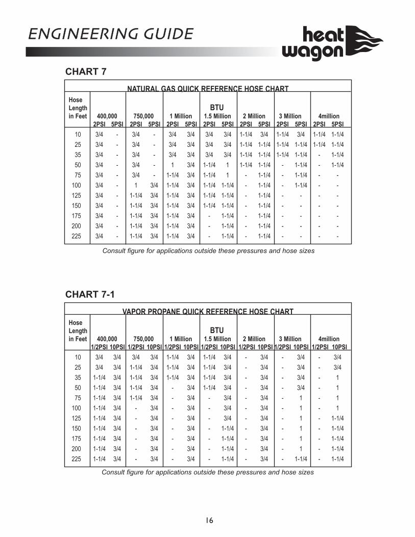
NATURAL GAS QUICK REFERENCE HOSE CHART Hose Length BTU in Feet 400,000 750,000 1 Million 1.5 Million 2 Million 3 Million 4million 2PSI 5PSI 2PSI 5PSI 2PSI 5PSI 2PSI 5PSI 2PSI 5PSI 2PSI 5PSI 2PSI 5PSI
10 3/4 - 3/4 - 3/4 3/4 3/4 3/4 1-1/4 3/4 1-1/4 3/4 1-1/4 1-1/4
25 3/4 - 3/4 - 3/4 3/4 3/4 3/4 1-1/4 1-1/4 1-1/4 1-1/4 1-1/4 1-1/4
35 3/4 - 3/4 - 3/4 3/4 3/4 3/4 1-1/4 1-1/4 1-1/4 1-1/4 - 1-1/4
50 3/4 - 3/4 - 1 3/4 1-1/4 1 1-1/4 1-1/4 - 1-1/4 - 1-1/4
75 3/4 - 3/4 - 1-1/4 3/4 1-1/4 1 - 1-1/4 - 1-1/4 - -
100 3/4 - 1 3/4 1-1/4 3/4 1-1/4 1-1/4 - 1-1/4 - 1-1/4 - -
125 3/4 - 1-1/4 3/4 1-1/4 3/4 1-1/4 1-1/4 - 1-1/4 - - - -
150 3/4 - 1-1/4 3/4 1-1/4 3/4 1-1/4 1-1/4 - 1-1/4 - - - -
175 3/4 - 1-1/4 3/4 1-1/4 3/4 - 1-1/4 - 1-1/4 - - - -
200 3/4 - 1-1/4 3/4 1-1/4 3/4 - 1-1/4 - 1-1/4 - - - -
225 3/4 - 1-1/4 3/4 1-1/4 3/4 - 1-1/4 - 1-1/4 - - - -
VAPOR PROPANE QUICK REFERENCE HOSE CHART Hose Length BTU in Feet 400,000 750,000 1 Million 1.5 Million 2 Million 3 Million 4million 1/2PSI 10PSI 1/2PSI 10PSI 1/2PSI 10PSI 1/2PSI 10PSI 1/2PSI 10PSI 1/2PSI 10PSI 1/2PSI 10PSI
10 3/4 3/4 3/4 3/4 1-1/4 3/4 1-1/4 3/4 - 3/4 - 3/4 - 3/4
25 3/4 3/4 1-1/4 3/4 1-1/4 3/4 1-1/4 3/4 - 3/4 - 3/4 - 3/4
35 1-1/4 3/4 1-1/4 3/4 1-1/4 3/4 1-1/4 3/4 - 3/4 - 3/4 - 1
50 1-1/4 3/4 1-1/4 3/4 - 3/4 1-1/4 3/4 - 3/4 - 3/4 - 1
75 1-1/4 3/4 1-1/4 3/4 - 3/4 - 3/4 - 3/4 - 1 - 1
100 1-1/4 3/4 - 3/4 - 3/4 - 3/4 - 3/4 - 1 - 1
125 1-1/4 3/4 - 3/4 - 3/4 - 3/4 - 3/4 - 1 - 1-1/4
150 1-1/4 3/4 - 3/4 - 3/4 - 1-1/4 - 3/4 - 1 - 1-1/4
175 1-1/4 3/4 - 3/4 - 3/4 - 1-1/4 - 3/4 - 1 - 1-1/4
200 1-1/4 3/4 - 3/4 - 3/4 - 1-1/4 - 3/4 - 1 - 1-1/4
225 1-1/4 3/4 - 3/4 - 3/4 - 1-1/4 - 3/4 - 1-1/4 - 1-1/4
Consult figure for applications outside these pressures and hose sizes
Consult figure for applications outside these pressures and hose sizes
ENGINEERING GUIDE
16
CHART 7
CHART 7-1
ENGINEERING GUIDE
17
TANK PRESSURES
TANK SIZE
NUMBER OF TANKS
MANIFOLDED 10% 20% 30% 40% 50% 60%
2501 12,690 169,200 197,400 225,600 253,800 282,0002 279,180 372,240 434,280 496,320 558,360 620,4003 486,027 648,036 756,042 864,048 972,054 1,080,060
3251 160,650 214,200 249,900 285,600 321,300 357,0002 353,430 471,240 549,780 628,320 706,860 785,4003 615,289 820,386 957,117 1,093,848 1,230,579 1,368,842
5001 198,135 264,180 308,212 352,240 396,270 440,3002 435,897 581,196 687,066 774,928 871,794 968,6603 758,857 1,011,809 1,180,451 1,349,079 1,517,714 1,686,349
8501 304,425 405,900 473,550 541,200 608,850 676,5002 669,735 892,980 1,041,810 1,190,640 1,339,470 1,488,3003 1,165,947 1,554,597 1,813,696 2,072,796 2,331,895 2,590,995
10001 354,240 472,320 551,040 629,760 708,480 787,2002 779,328 1,039,104 1,212,288 1,385,472 1,558,656 1,731,8403 1,356,739 1,808,985 2,110,483 2,411,980 2,713,478 3,014,976
For -10º F multiply x 0.50For + 10ºF multiply x 1.5 For +20ºF multiply x 2.0 For +40ºF multiply x 3.0 For +50ºF multiply x 3.5 For +60ºF multiply x 4.0
VAPORIZATION RATES IN BTUH @ 0 DEG. F
PERCENTAGE OF TANK FILLED
NOTE: USE FOLLOWING MULTIPLIERS FOR OTHER AIR TEMPERATURES
-40 3.6 -30 8.0 -20 13.5 -10 20.0 0 28.0 10 37.0 20 47.0 30 58.0 40 72.0
Temp. (F) Approx. Pressure (PSIG)-Propane
CHART 8
CHART 9
For -10ºF multiply x 0.50 For +10ºF multiply x 1.5 For +20ºF multiply x 2.0 For +40ºF multiply x 3.0 For +50ºF multiply x 3.5 For +60ºF multiply x 4.0
126,900
ENGINEERING GUIDE
18
EQUIVALENT PIPE LENGTH, FT.
50 100 150 200 250 300 400 500 1000 1500 1 244 173 141 122 109 99 86 77 54 44 1-1/4 537 380 310 268 240 219 189 169 119 97 1-1/2 832 588 480 416 372 339 294 263 185 151 2 1680 1188 970 840 751 685 594 531 375 306 2-1/2 2754 1952 1591 1379 1232 1123 974 869 617 504 3 5018 3549 2896 2509 2244 2047 1774 1587 1121 915 4 10510 7410 6020 5170 4640 4480 3660 3340 2360 1910 5 19110 13480 10960 9410 8440 8150 6660 6070 4290 3480 6 31140 21960 17860 15320 13760 13280 10860 9890 7000 5670 8 63310 44740 36380 31220 28020 27040 22120 20150 14250 11550 10 113020 79720 64830 55630 49940 48180 39420 35920 25400 20580 12 177450 125180 101790 87350 78400 75650 61900 56400 39890 32320
IPS, nom., in.
NATURAL GAS Capacity of pipe at less than 1.0 - psig inlet pressure in cubic feet of gas per hour
EQUIVALENT PIPE LENGTH, FT.
50 100 150 200 300 400 500 1000 1500 1 740 520 430 370 300 260 230 170 130 1-1/4 1540 1090 890 760 630 540 490 350 280 1-1/2 2330 1650 1350 1160 960 830 740 530 420 2 4550 3210 2640 2260 1870 1610 1440 1040 830 2-1/2 7330 5180 4250 3650 3020 2600 2320 1690 1340 3 13100 9260 7600 6520 5400 4660 4160 3020 2400 3-1/2 19320 13650 11210 9610 7960 6870 6130 4450 3540 4 26980 19070 15650 13430 11120 9590 8560 6220 4940 5 49340 34870 28620 24550 20330 17550 15660 11370 9030 6 80560 56940 46740 40909 33210 28650 25580 18570 14760
IPS, nom., in.
Capacity of pipe at 1.0 - psig inlet pressure in cubic feet of gas per hour (based on a pressure drop of 0.1 psig and 0.6 sp gr gas in schedule - 40 pipe)
EQUIVALENT PIPE LENGTH, FT.
50 100 150 200 300 400 500 1000 1500 2000 1 1080 760 620 540 440 380 340 240 190 170 1-1/4 2250 1590 1300 1120 910 790 710 500 410 350 1-1/2 3410 2410 1970 1700 1390 1200 1070 760 620 530 2 6640 4700 3840 3310 2700 2350 2090 1480 1210 1040 2-1/2 10700 7580 6190 5340 4360 3790 3380 2390 1960 1690 3 19120 13540 11060 9540 7790 6770 6040 4280 3500 3020 3-1/2 28200 19970 16310 14070 11490 9980 8900 6310 5160 4450 4 39380 27890 22780 19650 16040 13940 12440 8810 7210 6220 5 72010 50990 41650 35930 29300 25490 22740 16120 13180 11370 6 117580 83270 68010 58670 47900 41630 37140 26320 21520 18570
IPS, nom., in.
Capacity of pipe at 2.0 - psig inlet pressure in cubic feet of gas per hour (based on a pressure drop of 0.2 psig and 0.6 sp gr gas in schedule - 40 pipe)
CHART 10
CHART 10-1
CHART 10-2
ENGINEERING GUIDE
19
EQUIVALENT PIPE LENGTH, FT.
50 100 150 200 300 400 500 1000 1500 1 1860 1320 1070 930 760 660 590 410 340 1-1/4 3870 2740 2240 1930 1580 1370 1220 860 700 1-1/2 5860 4140 3390 2930 2390 2080 1850 1310 1060 2 11420 8070 6600 5710 4660 4050 3610 2550 2080 2-1/2 18400 13010 10640 9200 7510 6530 5820 4110 3350 3 32860 23240 19000 16430 13410 11660 10390 7340 5990 3-1/2 48480 34280 28030 24240 19780 17200 15330 10820 8840 4 67700 47880 39140 33850 27630 24020 21410 15120 12340 5 123790 87540 71570 61890 50530 43920 39160 27640 22570 6 202138 142950 116870 101060 82500 71720 63940 45140 36860
IPS, nom., in.
Capacity of pipe at 5.0 - psig inlet pressure in cubic feet of gas per hour (based on a pressure drop of 0.5 psig and 0.6 sp gr gas in schedule - 40 pipe)
EQUIVALENT PIPE LENGTH, FT.
50 100 150 200 300 400 500 1000 1500 2000 1 2930 2070 1690 1470 1190 1030 920 650 530 460 1-1/4 6090 4330 3520 3050 2490 2150 1920 1360 1110 960 1-1/2 9210 6530 5330 4620 3760 3260 2910 2060 1680 1460 2 17940 12720 10380 9000 7330 6360 5680 4020 3280 2840 2-1/2 28920 20500 16730 14510 11820 10250 9150 6480 5290 4580 3 51650 36610 29880 25920 21110 18300 16340 11570 9450 8190 3-1/2 76180 53990 44070 38240 31140 26990 24110 17070 13950 12080 4 106400 75410 61550 53410 43500 37700 33670 23850 19480 16870 5 194540 137890 112550 97650 79540 68940 61570 43600 35620 30860 6 317650 225150 183770 159450 129870 112560 100540 71200 58160 50390
IPS, nom., in.
Capacity of pipe at 10.0 - psig inlet pressure in cubic feet of gas per hour (based on a pressure drop of 1.0 psig and 0.6 sp gr gas in schedule - 40 pipe)
EQUIVALENT PIPE LENGTH, FT.
50 100 150 200 300 400 500 1000 1500 2000 1 4900 3470 2810 2450 2000 1730 1550 1070 890 770 1-1/4 10190 7210 5840 5090 4160 3600 3220 2230 1860 1610 1-1/2 15420 10900 8830 7710 6290 5450 4870 3370 2810 2440 2 30030 21230 17190 15010 12260 10610 9490 6570 5480 4760 2-1/2 48390 34220 27710 24190 19750 17110 15290 10590 8830 7670 3 86420 61110 49490 43190 35280 30550 27310 18910 15770 13690 3-1/2 127480 90130 73000 63710 52040 45070 40280 27900 23270 20200 4 178040 125880 101950 88980 72680 62940 56260 38960 32500 28210 5 325530 230170 186410 162700 132890 115080 102870 71240 59420 51590 6 531530 375820 304370 265660 216990 187910 167980 116330 97030 84240
IPS, nom., in.
Capacity of pipe at 20.0 - psig inlet pressure in cubic feet of gas per hour (based on a pressure drop of 2.0 psig and 0.6 sp gr gas in schedule - 40 pipe)
CHART 10-3
CHART 10-4
CHART 10-5
ENGINEERING GUIDE
20
3/8 1/2 5/8 3/4 7/8 1-1/8 1/2 3/4 1 1-1/4 1-1/2 2 2-1/2 3 4 10 730 1700 3200 2300 8300 17000 3200 7500 12800 24000 40000 88000 133000 237500 489000 20 500 1100 2200 3700 5800 12000 2200 4200 8800 18000 33000 61000 92500 165500 341000 30 400 920 2000 2900 4700 9800 1800 4000 7200 14000 26000 49000 76500 136500 281000 40 370 850 1700 2700 4100 8500 1600 3700 6800 13500 24000 46000 71000 127000 262000 50 330 770 1500 2400 3700 7600 1500 3400 6300 12600 22500 43000 65000 116000 240000 60 300 700 1300 2200 3300 7000 1300 3100 5600 12000 21700 40000 61000 109000 224000 80 260 610 1200 1900 2900 6000 1200 2600 4900 10000 18000 34000 52000 93000 192000 100 220 540 1000 1700 2600 5400 1000 2300 4300 9000 15000 31000 45500 81500 168000 125 200 490 900 1400 2300 4800 900 2100 4000 7900 13500 28000 41500 74000 152500 150 190 430 830 1300 2100 4400 830 1900 3600 7200 12600 25000 37000 66500 137000 175 170 400 780 1200 1900 4000 770 1700 3300 6700 11400 23500 34500 61500 127000 200 160 380 730 1100 1800 3800 720 1500 3100 6200 10600 22000 32000 57500 119000
PIPE OR TUBING LENGTH
TUBING SIZE, O.D., TYPE L NOMINAL PIPE SIZE, SCHEDULE 40
To convert to capacities at 5 psig settings - Multiply by 0.879 To convert to capacities at 30 psig settings - Multiply by 1.345 To convert to capacities at 15 psig settings - Multiply by 1.130 To convert to capacities at 40 psig settings - Multiply by 1.488 To convert to capacities at 20 psig settings - Multiply by 1.185 To convert to capacities at 50 psig settings - Multiply by 1.618
TO USE CHART: 1. Having determined the required flow at point of use, locate this flow in the left hand column. If this falls between two figures, use the larger of the two.2. Determine total length of piping required from source to point of use. Locate length in the center of this chart.3. Read across chart from left (required flow) to right to find the total length which is equal to or exceeds the distance from the source to use.4. From this point read up to find the correct size of pipe required
PIPE & TUBING SIZING - HIGH PRESSURE PROPANE
SIZING BETWEEN FIRST AND SECOND STAGE REGULATOR
HOSE PIPE HOSE PIPE HOSE PIPE HOSE PIPE HOSE PIPE HOSE PIPE HOSE PIPE HOSE PIPE SCHD 40 SCHD 80 SCHD 40 SCHD 80 SCHD 40 SCHD 80 SCHD 40 SCHD 80 SCHD 40 SCHD 80 SCHD 40 SCHD 80 SCHD 40 SCHD 80 SCHD 40 SCHD 80
10 729 41615 324 18520 182 104 825 52140 46 26 205 129 745 50460 20 11 92 58 331 22480 11 6 51 32 187 127 735 537
100 7 4 33 21 119 81 470 343120 23 15 83 56 326 238140 15 9 61 41 240 175 813 618160 13 8 47 32 184 134 623 473180 37 25 145 106 491 373200 30 20 118 86 399 303240 21 14 81 59 227 211280 15 10 60 44 204 155300 13 9 52 38 177 135 785 623350 38 28 130 99 578 459400 30 22 99 75 433 344 930 794500 19 14 64 49 283 225 627 508600 44 33 197 156 435 352700 32 24 144 114 320 259800 25 19 110 87 245 198 965 795900 19 14 87 69 194 157 764 630
1000 16 12 71 56 157 127 618 5091500 31 25 70 57 275 2272000 18 14 39 32 154 1273000 8 6 17 14 69 574000 10 8 39 325000 25 21
10000 6 5
3/4"1/2"3/8"1/4"LIQUID PROPANE FLOW - GPH
LENGTH OF HOSE OR IRON PIPE (FEET)2"1 1/2"1 1/4"1"
CHART 11
CHART 12
ENGINEERING GUIDE
PRESSURE(PSI) 1/8" 1/8"X3/16" 3/16" 1/4" 5/16" 3/8" 1/2" 1/2"X9/16"
1 190 270 280 550 5752 190 220 300 430 450 820 8603 160 215 300 380 550 560 1030 10805 230 280 390 550 710 740 1230 1310
10 370 390 600 820 1050 1130 1650 168015 460 525 800 1070 1340 146020 610 700 1000 1320 1630 180030 800 890 1340 1750 195040 1030 1150 1750 205050 1200 1300 2010 230060 1310 1425 2250 250080 1900 2000 2580
100 2200 2275 2700125 2200 2275 2900
ORIFICE SIZE
SECOND STAGE SERVICE REGULATOR (11SV08, 40SV06) FLOW RATE IN CFH
NOTE: USE 1050 BTU PER CFH FOR NATURAL GAS USE 2476 BTU PER CFH FOR PROPANE
11SV08 REGULATOR COMES STANDARD WITH 1/2" ORIFICE 40SV06 REGULATOR COMES STANDARD WITH 1/4" ORIFICE
CHART 13
CHART 14 - Relocated to back page
P1500 5,100 1.5 Yes 15 120V 120 No
P600 20,500 6 Yes 25 208-240V-1 250 No
P900 30,700 9 Yes 38 208-240V-1 350 No
P1800-1 65,000/41,000 18/12 Yes 75/50 208-240V-1 590 No P1800-3 65,000/41,000 18/12 Yes 50/34 208-240V-3 590 No P1800D 65,000/41,000 18/12 Yes 50/34 208-240V-3 950 Yes
P4000 136,500 40 Yes 50 480V 1,800 Yes 109,200 32 Yes 40 480V 1,800 Yes 54,600 16 Yes 20 480V 1,800 Yes
P6000 204,700 60 Yes 75 480V 1,800 Yes 163,800 48 Yes 60 480V 1,800 Yes 81,900 24 Yes 30 480V 1,800 Yes
All Rated 100ºF Temp Rise
Built-In
Electric Heaters
Comes with plug and cord
Comes with plug and cord
Comes with plug and cord
21
ENGINEERING GUIDE
22
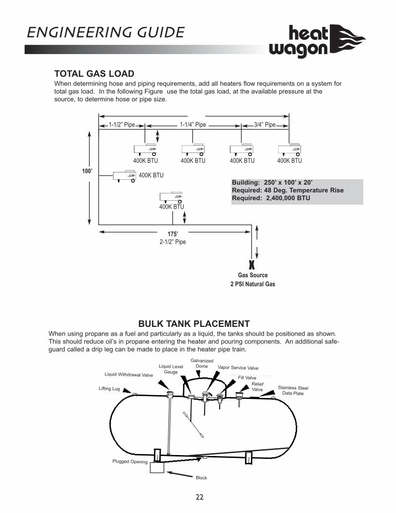
BULK TANK PLACEMENT When using propane as a fuel and particularly as a liquid, the tanks should be positioned as shown. This should reduce oil’s in propane entering the heater and pouring components. An additional safe-guard called a drip leg can be made to place in the heater pipe train.
TOTAL GAS LOAD When determining hose and piping requirements, add all heaters flow requirements on a system for total gas load. In the following Figure use the total gas load, at the available pressure at the source, to determine hose or pipe size.
Gas Source 2 PSI Natural Gas
Building: 250’ x 100’ x 20’ Required: 48 Deg. Temperature Rise Required: 2,400,000 BTU
175’ 2-1/2” Pipe
1-1/2” Pipe 1-1/4” Pipe 3/4” Pipe
X
400K BTU
400K BTU 400K BTU 400K BTU 400K BTU
400K BTU
100’
Lifting Lug
Liquid Withdrawal Valve
Liquid Level Gauge
Galvanized Dome
Fill ValveRelief Valve Stainless Steel
Data Plate
Plugged Opening
Block
Vapor Service Valve
GALLONS PER HOUR GALLONS/24 HR PERIODHIGH FIRE LOW FIRE HIGH FIRE LOW FIRE
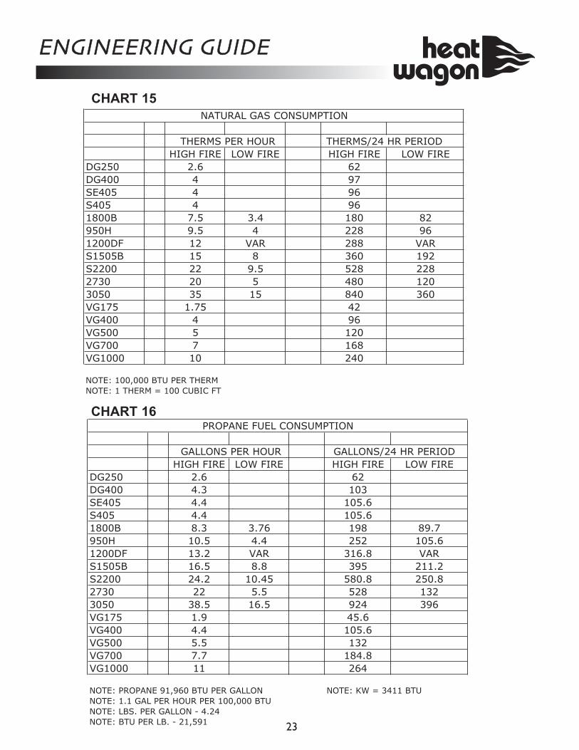
DG250 2.6 62DG400 4.3 103SE405 4.4 105.6S405 4.4 105.61800B 8.3 3.76 198 89.7950H 10.5 4.4 252 105.61200DF 13.2 VAR 316.8 VARS1505B 16.5 8.8 395 211.2S2200 24.2 10.45 580.8 250.82730 22 5.5 528 1323050 38.5 16.5 924 396VG175 1.9 45.6VG400 4.4 105.6VG500 5.5 132VG700 7.7 184.8VG1000 11 264
NOTE: PROPANE 91,960 BTU PER GALLON NOTE: KW = 3411 BTUNOTE: 1.1 GAL PER HOUR PER 100,000 BTUNOTE: LBS. PER GALLON - 4.24NOTE: BTU PER LB. - 21,591
PROPANE FUEL CONSUMPTION
ENGINEERING GUIDE
23
THERMS PER HOUR THERMS/24 HR PERIODHIGH FIRE LOW FIRE HIGH FIRE LOW FIRE
DG250 2.6 62DG400 4 97SE405 4 96S405 4 961800B 7.5 3.4 180 82950H 9.5 4 228 961200DF 12 VAR 288 VARS1505B 15 8 360 192S2200 22 9.5 528 2282730 20 5 480 1203050 35 15 840 360VG175 1.75 42VG400 4 96VG500 5 120VG700 7 168VG1000 10 240
NOTE: 100,000 BTU PER THERMNOTE: 1 THERM = 100 CUBIC FT
NATURAL GAS CONSUMPTION
CHART 15
CHART 16
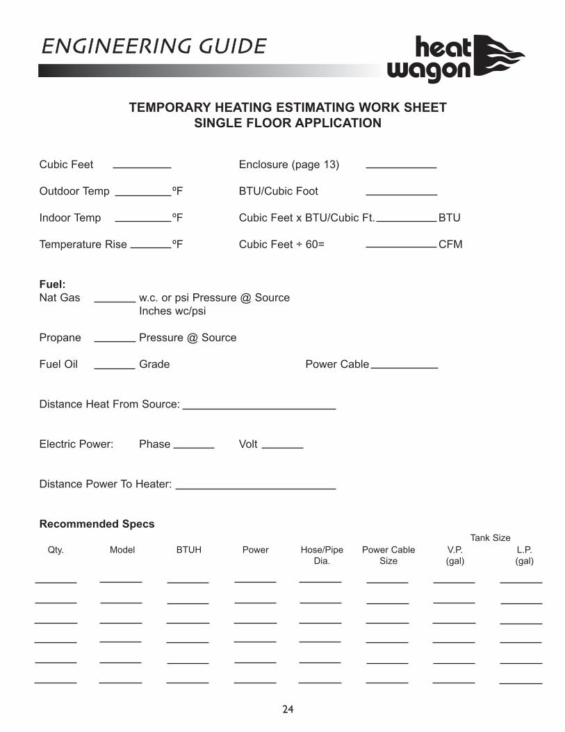
TEMPORARY HEATING ESTIMATING WORK SHEET SINGLE FLOOR APPLICATION
Cubic Feet Enclosure (page 13) Outdoor Temp ºF BTU/Cubic Foot
Indoor Temp ºF Cubic Feet x BTU/Cubic Ft. BTU Temperature Rise ºF Cubic Feet ÷ 60= CFM
Fuel: Nat Gas w.c. or psi Pressure @ Source
Inches wc/psi Propane Pressure @ Source Fuel Oil Grade Power Cable Distance Heat From Source: Electric Power: Phase Volt Distance Power To Heater: Recommended Specs Tank Size Qty. Model BTUH Power Hose/Pipe Power Cable V.P. L.P. Dia. Size (gal) (gal)
ENGINEERING GUIDE
24
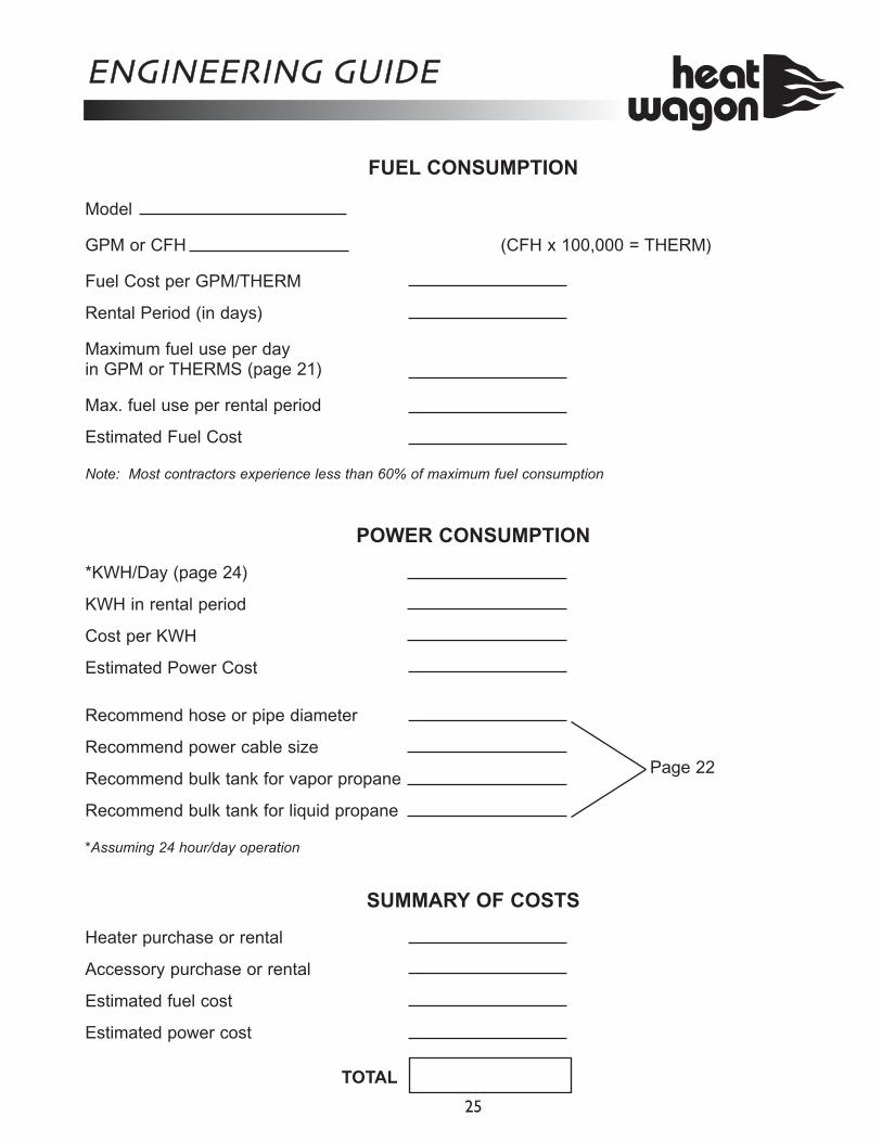
FUEL CONSUMPTION
Model GPM or CFH (CFH x 100,000 = THERM) Fuel Cost per GPM/THERM Rental Period (in days) Maximum fuel use per day in GPM or THERMS (page 21) Max. fuel use per rental period Estimated Fuel Cost Note: Most contractors experience less than 60% of maximum fuel consumption
POWER CONSUMPTION
*KWH/Day (page 24) KWH in rental period Cost per KWH Estimated Power Cost Recommend hose or pipe diameter Recommend power cable size Recommend bulk tank for vapor propane Recommend bulk tank for liquid propane *Assuming 24 hour/day operation
SUMMARY OF COSTS
Heater purchase or rental Accessory purchase or rental Estimated fuel cost Estimated power cost
TOTAL
ENGINEERING GUIDE
25
Page 22
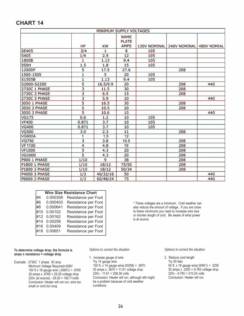
To determine voltage drop, the formula is amps x resistance = voltage drop
Example: 2730C 1 phase 30 amp Minimum Voltage Required=208V
150 ft x 18 gauge wire (.00651) = .9765 30 amps x .9765 = 29.29 voltage drop 220v (at source) - 29.29 = 190.71volts
Conclusion: Heater will not run, wire too small or cord too long
Options to correct the situation 1. Increase gauge of wire Try 14 gauge wire 150 ft. x 14 gauge wire(.00258) = .3870 30 amps x .3870 = 11.61 voltage drop 220v - 11.61 = 208.39 volts Conclusion: Heater will run, although still might be a problem because of cold weather conditions
Options to correct the situation 2. Reduce cord length Try 50 feet 50 ft. x 18 gauge wire(.00651) = .3255 30 amps x .3255 = 9.765 voltage drop 220v - 9.765 = 210.24 volts Conclusion: Heater will run
* These voltages are a minimum. Cold weather can also reduce the amount of voltage. If you are close to these minimums you need to increase wire size or shorten length of cord. Be aware of what power is at source.
CHART 14
Wire Size Resistance Chart #4 0.000308 Resistance per Foot #6 0.000403 Resistance per Foot #8 0.000641 Resistance per Foot #10 0.00102 Resistance per Foot #12 0.00162 Resistance per Foot #14 0.00258 Resistance per Foot #16 0.00409 Resistance per Foot #18 0.00651 Resistance per Foot
26
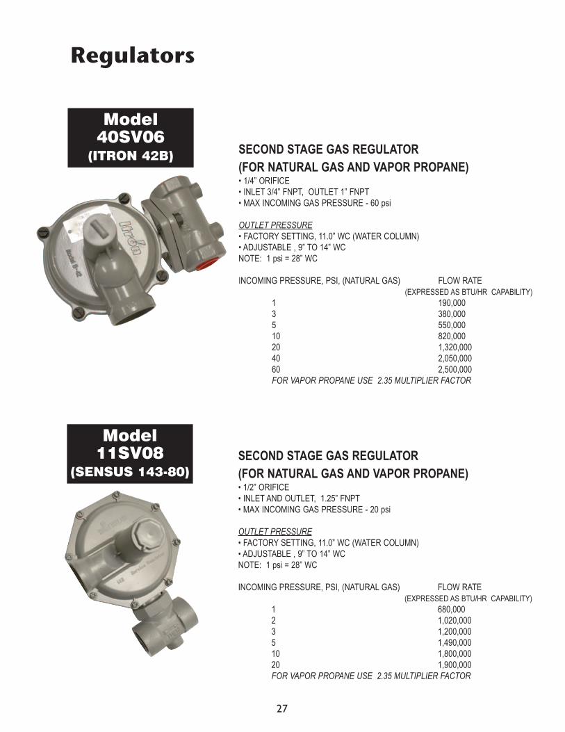
Regulators
SECOND STAGE GAS REGULATOR (FOR NATURAL GAS AND VAPOR PROPANE) • 1/4” ORIFICE • INLET 3/4” FNPT, OUTLET 1” FNPT • MAX INCOMING GAS PRESSURE - 60 psi OUTLET PRESSURE • FACTORY SETTING, 11.0” WC (WATER COLUMN) • ADJUSTABLE , 9” TO 14” WC NOTE: 1 psi = 28” WC INCOMING PRESSURE, PSI, (NATURAL GAS) FLOW RATE
(EXPRESSED AS BTU/HR CAPABILITY) 1 190,000 3 380,000 5 550,000 10 820,000 20 1,320,000 40 2,050,000 60 2,500,000 FOR VAPOR PROPANE USE 2.35 MULTIPLIER FACTOR
SECOND STAGE GAS REGULATOR (FOR NATURAL GAS AND VAPOR PROPANE) • 1/2” ORIFICE • INLET AND OUTLET, 1.25” FNPT • MAX INCOMING GAS PRESSURE - 20 psi OUTLET PRESSURE • FACTORY SETTING, 11.0” WC (WATER COLUMN) • ADJUSTABLE , 9” TO 14” WC NOTE: 1 psi = 28” WC INCOMING PRESSURE, PSI, (NATURAL GAS) FLOW RATE
(EXPRESSED AS BTU/HR CAPABILITY) 1 680,000 2 1,020,000 3 1,200,000 5 1,490,000 10 1,800,000 20 1,900,000 FOR VAPOR PROPANE USE 2.35 MULTIPLIER FACTOR
Model 40SV06
(ITRON 42B)
Model 11SV08
(SENSUS 143-80)
27
S P E C I F I C AT I O N S
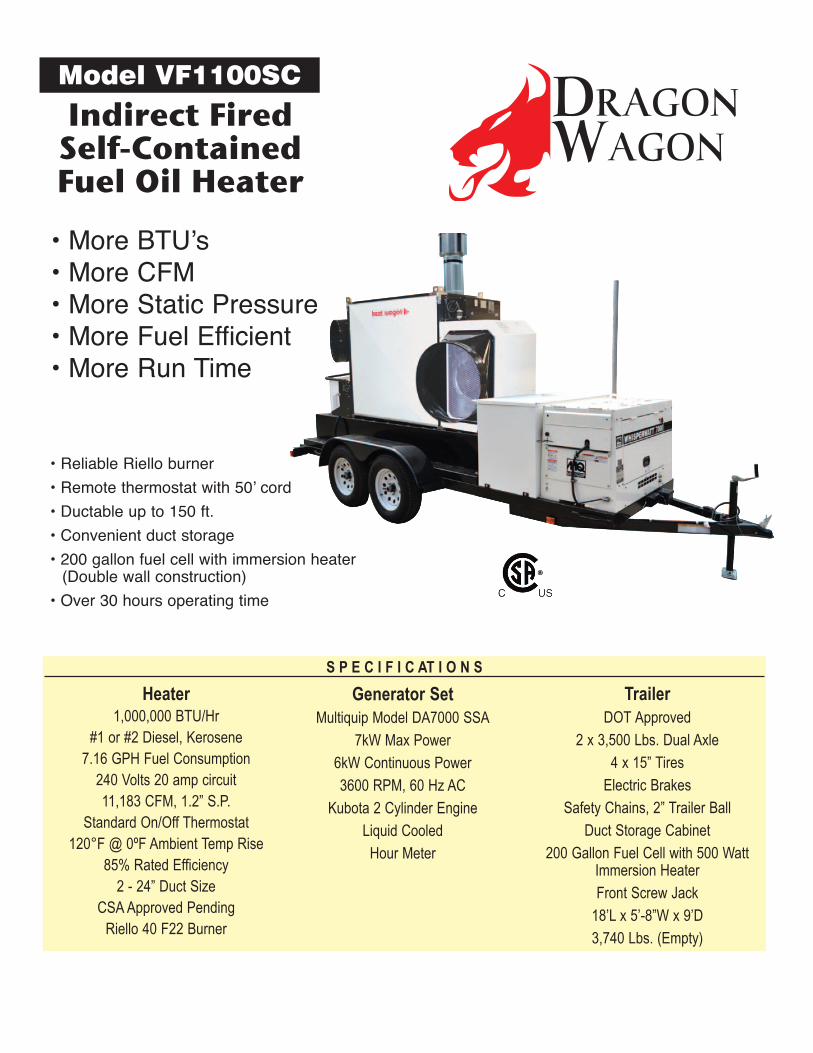
Indirect Fired Self-Contained Fuel Oil Heater
Model VF1100SC
• More BTU’s • More CFM • More Static Pressure • More Fuel Efficient • More Run Time
• Reliable Riello burner
• Remote thermostat with 50’ cord
• Ductable up to 150 ft.
• Convenient duct storage
• 200 gallon fuel cell with immersion heater (Double wall construction)
• Over 30 hours operating time
Generator Set Multiquip Model DA7000 SSA
7kW Max Power
6kW Continuous Power
3600 RPM, 60 Hz AC
Kubota 2 Cylinder Engine
Liquid Cooled
Hour Meter
Heater 1,000,000 BTU/Hr
#1 or #2 Diesel, Kerosene 7.16 GPH Fuel Consumption
240 Volts 20 amp circuit 11,183 CFM, 1.2” S.P.
Standard On/Off Thermostat 120°F @ 0ºF Ambient Temp Rise
85% Rated Efficiency 2 - 24” Duct Size
CSA Approved Pending Riello 40 F22 Burner
Trailer DOT Approved
2 x 3,500 Lbs. Dual Axle
4 x 15” Tires
Electric Brakes
Safety Chains, 2” Trailer Ball
Duct Storage Cabinet
200 Gallon Fuel Cell with 500 Watt Immersion Heater
Front Screw Jack
18’L x 5’-8”W x 9’D
3,740 Lbs. (Empty)
DRAGONWAGON