
HEAT ENGINE & THERMODYNAMICS - RSKR
29
1 HEAT ENGINE & THERMODYNAMICS Lesson-01 (INTRODUCTION) TEMPERATURE: - It is denoted as the degree of hotness or the level of heat intensity of a body. A hot body is said to be at higher temperature, where as the cold body at a lower temperature MEASUREMENTOF TEMPERATURE There are four types of temperature scale:- 1. Celsius or Centigrade scale :- 0º C --- 100º C 2. Reumer scale :- 0º R --- 80º R 3. Fahrenheit scale :- 32º F --- 212º F 4. Kelvin scale 273º K --- 373º K RELATION BETWEEN TEMPERATURE IN DIFFERENT SCALE C R F – 32 K - 273 ----- = ----- = ----------- = ------------- 5 4 9 5 ABSOLUTE TEMPERATURE:- Whenever the value of temperature is used in equation relating to fundamental laws, then the value of temperature, whose reference point is true zero or absolute zero is used The absolute zero temperature for all sorts of calculation is taken as -273 o C or -460 o F. The temperature measured from this zero are called absolute temperature. The absolute centigrade scale is called degree Kelvin ( o K ). Such that o K = o C+273 Similarly, absolute Fahrenheit scale is called as degree Rankine ( o R ). Such that o R = o F+460 HEAT:- It is defined as the form of energy capable of being transferred without transfer of mass, across the boundary of a system due to temperature difference between the system and surrounding. SPECIFIC HEAT:- The specific heat of a substance is defined as the amount of heat required to raise the temperature of a unit mass of any substance through 1 o . It is generally denoted by “c”. If ‘m’ kg of a substance of specific heat ‘c’ is required to raise the temperature through t o C, Then heat required=m.c.t k cal. THERMAL CAPACITY:- The thermal capacity of a substance is defined as the heat required to raise the temperature of a whole mass of a substance through 1 o THERMAL EQUILIBRIUM:- When there is variation in temperature from one point of an isolated system, the temperature at every point first changes with time. The rate of change decreases and eventually stops. When no further changes are observed, the system is said to be thermal equilibrium.
-
Upload
khangminh22 -
Category
Documents
-
view
0 -
download
0
Transcript of HEAT ENGINE & THERMODYNAMICS - RSKR

1
HEAT ENGINE & THERMODYNAMICS
Lesson-01 (INTRODUCTION)
TEMPERATURE: - It is denoted as the degree of hotness or the level of heat intensity of a body. A
hot body is said to be at higher temperature, where as the cold body at a lower temperature MEASUREMENTOF TEMPERATURE There are four types of temperature scale:- 1. Celsius or Centigrade scale :- 0º C --- 100º C 2. Reumer scale :- 0º R --- 80º R 3. Fahrenheit scale :- 32º F --- 212º F 4. Kelvin scale 273º K --- 373º K
RELATION BETWEEN TEMPERATURE IN DIFFERENT SCALE C R F – 32 K - 273 ----- = ----- = ----------- = ------------- 5 4 9 5
ABSOLUTE TEMPERATURE:- Whenever the value of temperature is used in equation relating to fundamental laws, then the value of temperature, whose reference point is true zero or absolute zero is used The absolute zero temperature for all sorts of calculation is taken as -273o C or -460o F. The temperature measured from this zero are called absolute temperature. The absolute centigrade scale is called degree Kelvin (oK ). Such that oK = oC+273 Similarly, absolute Fahrenheit scale is called as degree Rankine (oR ). Such that oR = oF+460 HEAT:- It is defined as the form of energy capable of being transferred without transfer of mass, across the boundary of a system due to temperature difference between the system and surrounding.
SPECIFIC HEAT:- The specific heat of a substance is defined as the amount of heat required to raise the temperature of a unit mass of any substance through 1o. It is generally denoted by “c”. If ‘m’ kg of a substance of specific heat ‘c’ is required to raise the temperature through toC, Then heat required=m.c.t k cal. THERMAL CAPACITY:- The thermal capacity of a substance is defined as the heat required to raise the temperature of a whole mass of a substance through 1o
THERMAL EQUILIBRIUM:- When there is variation in temperature from one point of an isolated system, the temperature at every point first changes with time. The rate of change decreases and eventually stops. When no further changes are observed, the system is said to be thermal equilibrium.

2
WATER EQUIVALENT:- The water equivalent of a substance is defined as the quantity of water, which requires the same amount of heat as the substance to raise the temperature through 1oC. THERMODYNAMICS:- It is the branch of science which deals with the energies possessed by the gases and vapours their conversion into various other forms and work.
THERMODYNAMICS SYSTEM:- It is defined as a definite area or a space where some thermodynamic process is taking place. Thermodynamic system has its boundaries and anything outside the boundaries is called its surroundings. These boundaries may be fixed or movable.
CLASSIFICATION OF THERMODYNAMIC SYSTEM:- 1. CLOSED SYSTEM: - This is the system of fixed mass and identity whose boundaries are determined by the space of the matter occupied in it. 2. OPEN SYSTEM: - In this system the working substance crosses boundary of the system. Heat and working substance cross the boundary. 3. ISOLATED SYSTEM: - A system which is influenced by the surrounding is called the isolated system. LAWS OF THERMODYNAMICS:-
1. ZEROTH LAW OF THERMODYNAMICS: - This law states when two bodies are in thermal
equilibrium with the third body they are also in thermal equilibrium with each other.
2. FIRST LAW OF THERMODYNAMICS:- This law states , the heat and mechanical work are mutually convertible. According to this law a definite amount of mechanical work is needed to produce a definite amount of heat and vice-versa. This law may also be stated as the energy can neither be created nor destroyed though it can be transferred from one form to another. According to this law the energy due to heat supply must be balanced by the external work done plus gain in internal energy due to raise in temperature, Mathematically:- H = E + W Where, H = Heat transferred ; E = Change in internal energy W = Work done in heat unit. 3. SECOND LAW OF THERMODYNAMICS:-This law states there is a definite limit to the amount of mechanical energy which can be obtained from a given quantity of heat energy. It states that, it is not possible for a self acting machine working in a cyclic process to transfer heat from a body at a lower temperature to higher temperature body without aid of an external source. HEAT ENGINE:- It is a device which converts heat energy into useful work when operating a cyclic process. The heat is obtained from the combustion of fuel which may be coal, petrol, diesel and some gases. Heat engine may be classified into two main categories:- 1. External combustion engine 2. Internal combustion engine.

3
Lesson-02 (PROPERTIES OF GASES)
PERFECT GAS:- A perfect gas or an ideal gas is one which strictly obeys all the gas laws under the condition of temperature and pressure. No gas known is perfect i.e. no gas strictly obeys the gas laws but within the temperature limit of applied thermodynamics many gases like hydrogen, oxygen and even air may be regarded as perfect gases. LAWS OF PERFECT GAS:- BOYLES LAW: - It states that the absolute pressure of a given mass of a perfect gas varies inversely as its volume, when the temperature remains constant. 1
P _______ V PV= constant Where, P = pressure V = volume CHARLES LAW: - It states that the volume of a given mass of a perfect gas varies directly as its absolute temperature, when the absolute pressure remains constant.
V T V _______ = constant T Gay Lussac Law:- This law states that the absolute pressure of a perfect gas varies directly as its temperature, when the volume remains constant.
P T P _______ = constant T
GENERAL GAS EQUATION:- In order to deal with all practical gases, the Boyles law and charles law are combined together, which gives us a general gas equation. According to Boyles Law, 1
P _______ (where T is constant) V 1
i.e, V _______ P

4
According to Charles Law,
V T (where P is constant) Combining them, we get; T
V _______ P
or PV T or PV = CT P V i.e, _______ = constant T Where , P =Pressure V = Volume T = Temperature. CHARESTERISTIC EQUATION OF A GAS:-It is a modified form of a general gas equation, which is written as; PV = mRT Where, R = Characteristic gas constant Unit of R = Kg.m. / Kg / º K m = The mass of gas in Kg / º K ; 1 Kg /cm² = 1 x 10⁴ Kg / m² JOULES LAW:- It states the change in internal energy of a perfect gas is directly proportional to the change of temperature. SPECIFIC HEAT OF A GAS:- It is the heat required to raise the temperature of unit mass of gas by one degree. There are two types of specific heat. 1. Specific heat at constant volume 2. Specific heat at constant pressure 1. SPECIFIC HEAT AT CONSTANT VOLUME:- It is the amount of heat required to raise the temperature of a unit mass of gas through 1ºc ,
when it is heated at a constant volume. It is denoted by Cv .
2. SPECIFIC HEAT AT CONSTANT PRESSURE:- The heat required to increase the temperature of one kg of gas by one degree when keeping the
pressure is constant. It is denoted by Cp
RATIO OF TWO SPECIFIC HEAT:-
Cp Cp -------- = ץ ,or ץ = -------- Cv Cv

5
METHOD OF HEATING AND EXPANDING GASES:- The method of heating and expanding of a gas is defined as a thermodynamic process. The Thermodynamic process may be performed in the following ways:-
1. CONSTANT VOLUME PROCESS:- In this process when a gas is heated at a constant volume the temperature and pressure will
increase. Since, there is no change in volume, no external work is done. So that heat supplied = internal energy =m Cv ( t2 – t1 ) 2. CONSTANT PRESSURE PROCESS:- In this process when s a gas is heated at a constant pressure, its temperature & volume will
increase. Since there is a change in volume. The heat supplied is utilized in increasing the internal energy of the gas and also for doing some external work.
So that heat supplied = m Cp ( t2 – t1 ). 3. HYPERBOLIC PROCESS:- In this process the gas is heated or expanded in such a way that the product of its pressure and
volume remains constant. This process is governed by boyles law, pv = constant. 4. ISOTHERMAL PROCESS (CONSTANT TEMPERATURE PROCESS):- A process in which the temperature of the working substance remains constant during expansion or compression. Work done during isothermal expansion; V2 W= 2.3 P1 V1 log _______ V1 V2 W= 2.3 m R T1 log _______ V1
Where V1 = initial volume V2 = final volume P1 = initial pressure P2 = final pressure 5. ADIABATIC PROCESS:- In this process working substance neither receives or gives out heat to its surrounding during its expansion or compression. P2 V2 – P1 V1 W = ________________________
-1
Where V1 = initial volume V2 = final volume P1 = initial pressure P2 = final pressure
6
Cp
----- = Cv
6. PRE- EXPANSION PROCESS:- This process occurs when a fluid is allowed to expand suddenly into vacuum chamber through an orifice of large dimension . In this process no heat is supplied or rejected and no external work is done.
7. THROTTLING PROCESS:- When a perfect gas is expanded through an aperture of minor dimension such as narrow throttle or a slightly open valve. The process is termed as throttling process. During this process no heat is supplied or rejected and no work is done. RELATION BETWEEN TWO SPECIFIC HEAT ( CP & CV ) :- Let m=Mass of the gas T1 = Initial absolute temperature of the gas T2 = Final absolute temperature of the gas V1 = Initial volume of the gas V2 = Final volume of the gas CP = Specific heat at constant pressure CV = Specific heat at constant volume P= Constant pressure We know that heat supplied at constant pressure (H) = m Cp ( T2 – T1 ). ---------------------(i) A part of this heat is utilized for doing some external work and is used in increasing the internal energy. P (V2 – V1 ) i.e. Heat utilized for external work (W) = ________________ ----------------------------------------------------------------- (ii) J
And increase in internal energy (E) = m Cv ( T2 – T1 ). --------------------------------------------------------------- (iii) P (V2 – V1 ) i.e. m CP ( T2 – T1 ) = _____________________ + m Cv ( T2 – T1 ). J PV2 –P V1 Or m CP ( T2 – T1 ). = _____________________ + m Cv ( T2 – T1 ). J We know that H = W + E From characteristic gas equation, PV = mRT PV1 = mRT1 PV2 = mRT2 Now putting the value of PV2 and PV1 we get; mRT2 – mRT1 m CP ( T2 – T1 ). = _____________________ + m Cv ( T2 – T1 ).

7
J
mR (T2 – T1 ) m CP ( T2 – T1 ). = _____________________ + m Cv ( T2 – T1 ). J R m CP ( T2 – T1 ). = m ( T2 – T1 ) ( ------ + Cv ) J R CP = -------- + Cv J R i.e, CP - Cv = ------ J
Lesson-03 ( STEAM )
The conversion of steam energy into mechanical work needs a working agent which can receive the heat released from a fuel and used to drive an engine to produce the required work. Steam is an excellent working agent because of its following properties: (i) It can carry large quantities of heat. (ii) It is produced from water which is cheap and readily available. (iii) It can be used for heating purposes after its duty as a working agent is completed. KIND OF STEAM:- (i) Wet steam: - When the steam contains moisture or particles of water in suspension, it is said to be wet steam. It means that the evaporation of water is not complete. (ii) Dry saturated steam: - When the wet steam is further heated and it does not contain any suspend particles of water, it is known as dry saturated steam. (III) Super heated steam: - When the dry steam is further heated at a constant pressure, thus raising its temperature, it is said to be superheated steam.
• DRYNESS FRACTION: - It is the ratio of the weight of actual dry steam to the weight of same quantity of wet steam. It is denoted by ‘q’.
Weight of dry steam q = ------------------------------------- Total weight of wet steam SENSIBLE HEAT OF WATER:- It may be defined as the quantity of heat required to raise the temperature of one kg of water from melting point of its boiling point corresponding to the pressure applied. LATENT HEAT OF STEAM:- Latent heat of steam at a particular pressure may be defined as the quantity
of heat required to convert one kg of water at its boiling point into dry saturated steam at the same pressure. It
is usually represented by ‘L’
8
STEAM GENERATOR / BOILER:- A steam generator or boiler is usually a closed vessel made of steel. Its function is to transfer the heat produced by the combustion of fuel (solid, liquid or gaseous) to water and ultimately to generate steam. CLASSIFICATION OF BOILER:- 1. According to the contents in the tube :- (a) Fire tube or smoke tube; (b) Water tube 2. According to the position of the furnace:- (a) Internal fired ; (b). Externally fired. 3. According to the axis of the shell :- (a). Vertical ; (b). Horizontal. 4. According to the number of tubes :- (a). Single tube ; (b). Multi tube. 5. According to the method of circulation of water and steam :- (a). Natural circulation ; (b). Forced circulation. 6. According to the use :- (a.) Stationary ; (b) Mobile . 7. According to the source of heat :- (a). Solid ; (b). Liquid ; (c). Gas IMPORTANT TERMS OF STEAM BOILER:-
• Boiler shell: - It is made up of steel plates bent in to cylindrical form and riveted or welded together. The ends of the steel plates are closed by means of end plates. A boiler shell should have sufficient capacity to contain water and steam.
• Combustion chamber: - It is the space generally below the boiler shell, meant for burning fuel in order to produce steam from water, contained in the shell.
• Grate: - It is a platform in the combustion chamber upon which fuel is burnt.
• Furnace:- It is the stage above the grate and below the boiler shell in which the fuel is burnt.
• Heating surface :- It is that part of the boiler surface which is exposed to the fire.
• Mountings: - These are the fittings which are mounted on the boiler shell for its proper safe functioning.
• Accessories:-These are the devices which form an integral part of a boiler but are not mounted on it. These are attached to the boiler to improve its overall efficiency.
BOILER MOUNTINGS:-
• WATER LEVEL INDICATOR: - It is an important fittings which indicates the water level inside the boiler to an observer.
• PRESSURE GAUGE: - A pressure gauge is used to measure the pressure of the steam inside the boiler.
• SAFETY VALVE: - This is a device attached to the steam chest for preventing explosion due to excessive internal pressure of steam.
9
• STOP VALVE:- It is the largest valve on the steam boiler. It controls the flow of steam from the boiler to the main steam pipe. It shut off the steam completely when required.
• BLOW OFF COCK: - Its function to empty the boiler whenever required and to discharge the mud, scale or sediments which are accumulated at the bottom.
• FEED CHECK VALVE:- It is a non-return valve. Its function is to regulate the supply of water, which is pumped into the boiler by the feed pump.
• FUSIBLE PLUG:- It is fitted to the crown plate of the furnace .Its function is to put off fire in the furnace of the boiler, when the level of water in the boiler falls to an unsafe limit.
BOILER ACCESSORIES:-
• FEED PUMP:- This is a pump provided to deliver water to boiler.
• SUPER HEATER: - A super heater is provided to increase the temperature of saturated steam without raising the pressure.
• ECONOMISER:- An economiser is a device used to heat feed water by utilizing the heat in the exhaust flue gases before leaving through the chimney .
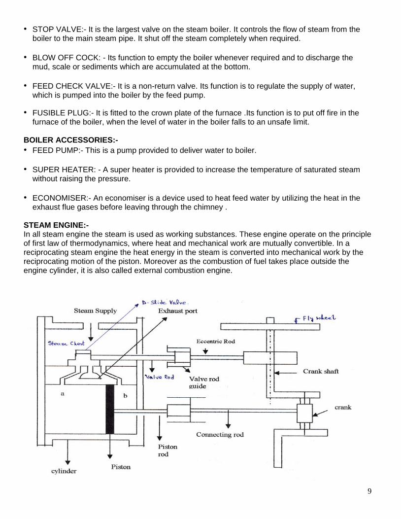
STEAM ENGINE:- In all steam engine the steam is used as working substances. These engine operate on the principle of first law of thermodynamics, where heat and mechanical work are mutually convertible. In a reciprocating steam engine the heat energy in the steam is converted into mechanical work by the reciprocating motion of the piston. Moreover as the combustion of fuel takes place outside the engine cylinder, it is also called external combustion engine.

10
WORKING OF A SINGLE CYLINDER DOUBLE ACTING HORIZONTAL RECIPROCATING STEAM ENGINE:- The super heated steam at a high pressure from the boiler is led into the steam chest. After that the steam makes its way into the cylinder through any of the port ‘a’ or ‘b’ depending upon the position of the D-slide valve. When the port ‘a’ is open the steam rushes to the left side of the piston and forces to the right. At this stage the slide valve covers the exhaust port and the other port ‘b’. Since the pressure of the steam is greater on the left side than that on the right side, the piston moves to the right. When the piston reaches near the end of the cylinder it closes the steam port ‘a’ and exhausts port. The steam port ‘b’ is now open and the steam rushes to the right side of the piston. This forces the piston to the left and the same time the exhaust steam goes out through the exhaust pipe and thus completes the cycle operation and as such engine works. STEAM TURBINE:- A steam turbine is a prime mover in which rotary motion is obtained by the gradual change of momentum of the steam. According to the mode of steam action, steam turbine are classified into two categories:- 1. Impulse Turbine and 2. Reaction turbine.
IMPULSE TURBINE:- An impulse turbine, as the name indicates, is a turbine which runs by the impulse of steam jet. In this turbine, the steam is first made to flow through nozzle. Then the steam jet impinges on the turbine blades (which are curved like buckets) and are mounted on the circumference of the wheel. The steam jet after impinging glides over the concave surface of the blades and finally leaves the turbine. REACTION TURBINE:- In a reaction turbine, the steam enters the wheel under pressure and flows over the blades. The steam, while gliding, propels the blades and makes them to move. As a matter of fact, the turbine runner is rotated by the reactive forces of steam jets. The backward motion of the blades is similar to the recoil of the gun. It may be noted that an absolute reaction turbine is rarely used in actual practice. COMPARISON BETWEEN IMPULSE TURBINE AND REACTION TURBINE
Sl.No Impulse Turbine Reaction Turbine
1 The steam flows through the nozzles and impinges on the moving blades.
The steam flows first through guide mechanism and then through the moving blades.
2 The stem impinges on the buckets with kinetic energy.
The .steam guides over the moving vanes with pressure.
3 The steam may or may not be admitted over the whole circumference.
The steam must be admitted over the whole circumference.
4 The steam pressure remains constant during its flow through the moving blades.
The steam pressure is reduced during its flow through the moving blades.

11
Impulse Turbine Reaction Turbine
5 The relative velocity of steam while gliding over the blades remains constant (assuming no friction).
The relative velocity of steam while gliding over the moving blades increases (assuming no friction).
6 The blades are symmetrical. The blades are not symmetrical.
7 The number of stages required is less for the same power developed.
The number of stages required is more for the same power developed.
Lesson-04 (Thermodynamic Air Cycle)
A thermodynamic cycle consists of a series of thermodynamic operations, which takes place in a certain order and the initial conditions are restored at the end of the process. CLASSIFICATION OF THERMODYNAMIC AIR CYCLE:- The thermodynamic air cycle is classified into two categories as:-
1. REVERSIBLE CYCLE: - A process in which some change in the reverse direction, reverses the process completely is known as reversible cycle.
2. IRREVERSIBLE CYCLE:-A process in which some change in the reverse direction does not change the process is known as irreversible process.
IMPORTANT TERMS IN THERMODYNAMIC CYCLE:- 1. CYLINDER BORE: - The diameter of the cylinder in which the piston moves is known as cylinder bore. 2. STROKE LENGTH: - The piston moves in the cylinder due to rotation of crank. Its extreme position is known as top dead centre (TDC) and bottom dead centre (BDC). The distance between the two extreme positions is known as stroke length. 3. CLEARENCE VOLUME: - The volume occupied by the working fluid when piston reaches the top dead centre is known as clearance volume. 4. STROKE VOLUME: - The volume swept by the piston when it moves between the two extreme positions is known as stroke volume. π Stroke Volume = ---- d² X l 4 Where, d = Diameter of the piston. l = stroke length. 6. FULL CYLINDER VOLUME: - It is equal to the sum of the stroke volume plus clearance volume. 7. COMPRESSION RATIO:-The ratio of full cylinder volume to the clearance volume is known as compression ratio.

12
Mathematically, Vs + Vc Total Volume Compression ratio, γ = ----------- = ------------------------- Vc Clearance Volume 8. MEAN EFFECTIVE PRESSURE: - It is the ratio of work done to the heat supplied during a cycle. Work Done Heat Supplied – Heat Rejected Mathematically, η = ----------------------- = ---------------------------------------------------------- Heat Supplied Heat Supplied TYPES OF THERMODYNAMIC CYCLE:- There are seven types of important thermodynamic cycle :-
1. Carnot Cycle, 2. Stirling Cycle, 3. Ericsson Cycle, 4. Joule Cycle, 5. Otto Cycle, 6. Diesel Cycle , 7. Dual Combustion Cycle.
1. CARNOT CYCLE: - In a Carnot cycle, the working substances is subjected to a cyclic operation consisting of two isothermal and two adiabatic operations.
p-v diagram t-s diagram Let us consider the four sage of Carnot cycle. Let the engine cylinder contains “M” kg of air at its original condition. 1. FIRST STAGE:-The air expands practically at constant temperature T1 from volume V1 to V2. It may be noted that the heat supplied is fully absorbed by air and is utilised in doing external works. i.e, Heat Supplied = Work done during isothermal expansion. V2
H = 2.3 mRT1log ---
V1
[ V2 ] = 2.3 mRT1log r [ --- = r ( Expansion ratio) ] [ V1 ]
VOLUME
PR
ES
SU
RE
ISO. EXP.
AD
IA
.EX
P
P
i
1
P
i
1 P
i
1 P
i
1
V V V V
T1 =
T2
T3 =
T4
ENTROP
Y
TE
MP
ER
AT
UR
E

13
2. SECOND STAGE: - In the second stage air is allowed to expand Adiabatically. In this case no heat is absorbed or rejected by the air; therefore, decrease in energy is equal to work done by the air.
P2V2 – P3V3 mRT2 - mRT3 mR ( T1 – T3) ---------------- = -------------------- = -------------------- [ Since T1 = T2 ] γ- 1 γ- 1 γ- 1 3. THIRD STAGE: - The air is compressed practically at a constant temperature. T3 from V3 to V4. In this process the heat rejected is equal to the work done on the air. V3
H = 2.3 mRT3log ---
V4
[ V3 ] = 2.3 mRT1log r [ --- = r (Compression ratio) ]
[ V4 ]
4. FOURTH STAGE: - In this process the air is allowed to compress adiabatically , so that no heat is absorbed or rejected by the air.
Therefore increase in internal energy = Work done on the air
P1V1 – P4V4 mRT1 - mRT4 mR ( T1 – T3) = ------------------ = -------------------- = -------------------- [ Since T3 = T4 ]
γ- 1 γ- 1 γ- 1 Therefore, Work Done = Heat Supplied – Heat Rejected = 2.3 mRT1log r - 2.3 mRT3log r = 2.3 mRlog r (T1- T3 ) Work Done 2.3 mRlog r (T1- T3 ) T1- T3 T3 Efficiency, η = ----------------------- = ---------------------------- = ---------- = 1- ---- Heat Supplied 2.3 mRlog r T1 T1 T1
From, Adiabatic expansion (2-3 ), T2 V3 γ- 1 T3 V2 γ- 1 1 γ- 1 V3 --- = --- = ---- = ---- = --- [ since, r = --- , where .r = Adiabatic expansion ] T3 V2 T1 V3 r V2
T3 1 γ- 1 Efficiency, η = 1 - ----- = 1- --- T1 r OTTO CYCLE: - It is known as constant volume cycle, as the heat is received and rejected at a constant volume. The engine conceived by Otto has air enclosed in a cylinder, whose walls are perfectly non-conductor of heat. But, the bottom is a perfect conductor of heat. There is also a hot body and cold

14
body and an insulating cap, which are alternately brought in contact with the bottom of the cylinder. The ideal Otto cycle consist of two constant volumes and two adiabatic processes. Let the engine cylinder contain “m” kg of air at starting, and p1, T1 & V1 be the pressure, temperature and volume of the air at starting. Following are the four stages of the ideal cycle. 1. FIRST STAGE: - The air is expanded adiabatically from initial temperature T1 to a temperature T2 . In this process no heat is absorbed or rejected by the air. 2. SECOND STAGE: - The air is cooled at constant volume from temperature T2 to a temperature T3.Heat is rejected by the air in this process. H2 = mCv (T2 - T3 ) 3. THIRD STAGE: - The air is compressed adiabatically from temperature T3 to a temperature T4. In this process no heat is absorbed or rejected. 4. FOURTH STAGE: - The air is now heated at constant volume from temperature T4 to a temperature T1; we know that heat absorbed by the air during this process. H1 = mCv (T1 - T4 ) We see that the air has been brought back to its original conditions of pressure, volume and temperature, thus completing the cycle. We know that, Work Done = Heat Absorbed – Heat Rejected = mCv (T1 - T4 ) - mCv (T2 - T3 ) Therefore, Ideal Efficiency or Air Standard Efficiency, Work Done η = ------------------------- Heat Absorbed mCv (T1 - T4 ) - mCv (T2 - T3 ) η = ------------------------------------------- mCv (T1 - T4 ) T2 - T3 η = 1 - ------------ T1 - T4
T2 T3 ( ------ - 1 ) T3 η = 1 - ------------------- T1 T4 ( ------ - 1 ) T4 1 γ- 1 Efficiency, η = 1 - --- r DIESEL CYCLE: - The ideal diesel cycle consist of two adiabatic, a constant pressure and a constant volume process. Let the engine cylinder contain “m” kg of air at starting, and P1,T1 & V1 be the pressure, temperature and volume of the air at starting. Following are the four stages of the ideal Diesel cycle.

15
1. FIRST STAGE: - The air is heated at constant pressure from initial temperature T1 to a temperature T2.
Therefore, Heat supplied to the air = mCv (T2 - T1 ) 2. SECOND STAGE:- The air is expanded adiabatically from temperature T2 to a temperature T3 . In this process, no heat is absorbed or rejected by the air. 3. THIRD STAGE: - THE air is now cooled at a constant volume from temperature T3 to a temperature T4. Therefore, Heat rejected by the air = mCv (T3 - T4 ). 4. FOURTH STAGE: - The air is compressed adiabatically from temperature T4 to a temperature T1. In this process no heat is absorbed or rejected by the air. We see that the air has brought back to its original condition of pressure, volume and temperature, thus completing the cycle. We know that, Work done = Heat Absorbed – Heat Rejected = mCp (T2 - T1 ) - mCv (T3 - T4 ) Therefore, Air Standard Efficiency, Work Done η = ------------------------- Heat Absorbed mCp (T2 - T1 ) - mCv (T3 - T4 ) η = ------------------------------------------ mCp (T2 - T1 ) Cv ( T3 - T4 ) η = 1- ----- -------------- Cp (T2 - T1 ) 1 ( T3 - T4 ) η = 1- ----- --------------
(T2 - T1 )
1 ρ - 1 η = 1 - --------- --------------
ry - 1 (ρ – 1)
Lesson-05 (Internal Combustion Engine)
IC engines are those engines in which the combustion of fuel takes place inside the engine cylinder. Example: Petrol, Diesel and Gas engines.
CLASSIFICATION OF I. C. ENGINE; The internal combustion engines may be classified in many ways, but the following are important from the subject point of view:-

16
• According to the type of fuel used:- i. Petrol engine ii. Gas engine iii. Diesel engine • According to the method of igniting the fuel. :- i. Spark ignition engine ii Compression ignition engine. • According the process of combustion :- i. Otto cycle ii. Diesel cycle iii. Dual combustion cycle • According to the speed of the engine:- i. Slow speed ii. Medium speed iii High speed • According to the cycle of operation i. Two stroke cycle ii. Four stroke cycle. • According to the cooling system :- i. Air cooled ii. Water cooled iii. Evaporative cooled. • According to the method of fuel injection;- i. Carburettor engine ii. Air injection iii. Solid injection. • According to the arrangement of cylinder:- i. Vertical ii Horizontal iii. Radial. MAIN COMPONENTS OF I.C.ENGINES:- 1. Cylinder: - It is one of the most important parts of the engine in which the piston moves to and fro in order to develop power. Generally, the engine cylinder has to withstand a high pressure (more than 50 kg./sq.cm.) and temperature (more than 2000° C). Thus the materials for an engine cylinder should be such that I can retain sufficient strength at such a high pressure and temperature. 2. Cylinder head: - It is fitted on one end of the cylinder and acts as cover to close the cylinder bore. Generally the cylinder head contains inlet and exit valves for admitting fresh charge and exhausting the burnt gases. In petrol engines, the cylinder head also contains a spark plug for igniting the fuel air mixture, towards the end of compression stroke. But in diesel engine, the cylinder head contains nozzle (i.e, fuel valve) for injecting the fuel into the cylinder. 3. Piston: - It s considered as the heart of the I.C. engine, whose main function is to transmit the force exerted by the burning of charge t the connecting rod. The pistons are generally made of aluminum alloys which are light in weight. They have good conducting property and also greater strength at higher temperatures. 4. Piston Rings: - These are circular rings and made of special alloys which retain elastic properties even at high temperatures. The piston rings are housed in the circumferential grooves provided on the outer surface of the piston. The function of the upper rings is to provide air tight seal to prevent leakage of the burnt gases into the lower portion . Similarly, the function of the lower rings is to provide effective seal to prevent leakage of the oil into the engine cylinder. 5. Connecting Rod: - It is a link between the piston and crankshaft, whose main function is to transmit force the piston to the crankshaft. Moreover, it converts reciprocating motion of the piston into circular motion of the crankshaft in the working stroke. The upper (smaller) end of the connecting rod is fitted to the piston and the lower (bigger) end to the crank.

17
6. Crank shaft: - It is considered as the back bone of an I.C.engine, whose function is to convert the reciprocating motion of the piston into the rotary motion with the help of connecting rod. Thus shafts contain one or more eccentric portion called cranks. That part of the crank to which bigger end of the connecting rod is fitted is called crank pin. 7. Crank case:-It is a cast iron case, which holds the cylinder and crank shaft, of an I.C.engine. It also serves as a sump for the lubricating oil. The lower portion of the crank case is known as bet plate, which is fixed with the help of bolts. 8. Fly wheel: - It is big wheel mounted on the crank shaft, whose function is to maintain its speed fairly constant. It is done by storing excess energy during the power stroke. SEQUENCE OF OPERATIONS IN A CYCLE (PETROL):- • 1. Suction Stroke:- In this stroke the fuel vapour in correct proportion, is supply to the engine
cylinder • 2. Compression Stroke: - In this stroke the fuel vapour is compressed in the engine cylinder. • 3. Expansion Stroke or Working Stroke: - In this stroke the fuel vapour is fired. It result in the
sudden rise of pressure, due to expansion of the combustion products in the engine cylinder. This sudden rise of the pressure pushes the piston with a great force and rotate the crank shaft in turn dries the machine connected to it.
• 4. Exhaust Stroke:- In this stroke, the burn gasses are exhaust from the engine cylinder so as to
make space available for the fresh fuel vapour. SEQUENCE OF OPERATIONS IN A CYCLE (DIESEL):- 1. Suction stroke
• Pure air is sucked in suction stroke. 2. Compression stroke
• Air is compressed during the compression stroke. 3. Expansion or working stroke
• The diesel oil is admitted into the engine cylinder just before the beginning of the expansion stroke and it is ignited by the hot air present in the cylinder.
• Results in the sudden rise of pressure, due to expansion of the combustion products in the engine cylinder.
• This sudden rise of the pressure pushes the piston with a great force, and rotates the crankshaft.
• The crankshaft, in turn, drives the machine connected to it. 4. Exhaust stroke
• In this stroke, the burnt gases or combustion products are exhausted from the engine cylinder, so as to make space available for the fresh fuel vapour.
TWO STROKE & FOUR STROKE CYCLE ENGINE:- In a two stroke engine, the working cycle is completed in two stroke of the piston or one revolution of the frank shaft. This is achieved by caring out the suction and compression process in one stroke, expansion and exhaust process in the second stroke.

18
In a four stroke engine, the working cycle is completed in four strokes of the piston or two revolution of the crank shaft. This is achieved by caring out suction, compression, expansion and exhaust process in each stroke. ADVANTAGES AND DISADVANTAGES OF TWO STROKE OVER FOUR STROKE CYCLE ENGINE Advantages:- 1. A two Stroke cycle engine gives twice the number of power strokes to the four stroke cycle
engine at the same speed 2. For the same power developed, a two stroke cycle engine is lighter, less bulky and occupies
less floor area. 3. As the number of working stroke in a two stroke cycle engine are twice than the four cycle
engine so the turning moment of a two stroke cycle engine is more uniform. 4. The initial cost of two stroke cycle engine is considerably less than a four stroke cycle engine. 5. The mechanism of a two stroke cycle engine is much simpler than a four stroke cycle engine. 6. The two stroke engines are much easier to start.
Disadvantages:-
1. Thermal efficiency of a two stroke cycle engine is less than that a four stroke cycle engine. 2. Over all efficiency of a two stroke cycle engine is also less than that of a four stroke cycle
engine. 3. In case of a two stroke cycle engine, the number of power stroke is twice as those of a four
stroke cycle engine. Thus the capacity of the cooling system must be higher. 4. The consumption of lubricating oil is large in a two stroke cycle engine because of high
operating temperature. 5. The exhaust gasses in a two stroke cycle engine create noise, because of short time available
for their exhaust. TWO STROKE CYCLE PETROL ENGINE:-
A two stroke cycle petrol engine was developed by Duglad Clerk in 1880. It works on Otto cycle. It requires two strokes of the piston to complete one cycle of operation .The charge is petrol mixed with proportionate quantity of air in the carburetor. In this cycle the suction, compression, expansion and exhaust takes place during two strokes of the piston. There is one working stroke after every revolution of the crank shaft. The Engine has ports instead of valves. All the four stages of two stroke petrol engine are described below:- 1. Suction stroke:- In this stage the piston moves from TDC to BDC. The pressure drops above the piston. Piston uncovers the inlet port (I). And fresh fuel air mixture flows into the engine cylinder from the crank case (C) 2. Compression:- In this stage the piston moves up. The piston covers the inlet port and then exhausts port. The fuel is compressed as the piston moves upwards. So that Pressure and temperature of the charge increases. In this stage the valve (V) opens and fresh fuel air mixture enters in to the crank case. 3. Expansion:-Shortly before the piston reaches the T.D.C. (during compression stroke) the charge is ignited with the help of a spark plug (P). It suddenly increases the pressure and temperature of the products of combustion. The volume practically remains constant. Due to rise in the pressure the piston is pushed downwards with a great force. The hot burnt gases expand

19
due to high speed of the piston. During this expansion some of the heat energy produced is trans formed into mechanical work. 4. Exhaust stroke:-In this stage the exhaust port is opened as the piston moves downwards. The products of combustion from the engine cylinder are exhausted through the exhaust port (E) into the atmosphere. This completes the cycle. Engine cylinder is ready to suck the charge once again.
TWO STROKE CYCLE DIESEL ENGINES:-A two stroke cycle diesel engine also has one working stroke after every revolution of the crank shaft. It requires two strokes of the piston to complete one cycle of operation .The charge is diesel .In this cycle the suction, compression, expansion and exhaust takes place during two strokes of the piston. Engine has ports instead of valves. All the four stages of two stroke diesel engine are described below:- 1. Suction stroke:-In this stage the piston moves from TDC.The pressure drops above the piston. Piston uncovers the inlet port (I) Fresh air flows into the engine cylinder from the crank case (C) 2. Compression:-In this stage the piston moves up. Piston covers the inlet port and then exhausts port. Air is compressed as the piston moves upwards. Pressure and temperature of the air increases. In this stage the valve (V) opens and fresh air enters in to the crank case. 3. Expansion:-Shortly before the piston reaches the T.D.C in compression stroke the fuel oil is injected in the form of very fine spray into the engine cylinder through the nozzle (N) known as fuel injection valve .At this moment, temperature of the compressed air is sufficiently high to ignite the fuel .It suddenly increases the pressure and temperature of the products of combustion. The volume practically remains constant. Due to rise in the pressure the piston is pushed downwards with a great force. The hot burnt gases expand due to high speed of the piston. During this expansion some of the heat energy produced is transformed into mechanical work. 4. Exhaust stroke:-In this stage the exhaust port is opened as the piston moves downwards. The products of combustion from the engine cylinder are exhausted through the exhaust port (E) into the atmosphere. This completes the cycle. Engine cylinder is ready to suck the charge once again. FOUR STROKE CYCLE PETROL ENGINE:-It works on Otto cycle. It requires four strokes of the piston to complete one cycle of operation .The charge petrol mixed with proportionate quantity of air in the carburetor. All the four stages of four stroke petrol engine are described below:- 1. Suction stroke:-Piston moves downwards (TDC-BDC) which causes the pressure drop inside the cylinder. Inlet valve opens and charge is sucked in to the cylinder. Crank shaft moves another 180o and completes one revolution 2. Compression:-Piston moves up wards (BDC-TDC) which causes the charge compressed and increases pressure with temperature inside the cylinder. Both the valve is in closed condition. Crank shaft moves 180o. 3. Expansion:-Shortly before the piston reaches TDC during compression stroke the charge is ignited with the help of spark plug. It results in the sudden increase of pressure and temperature due to expansion of the combustion products in the engine cylinder. The volume practically remains constant. This sudden rise of the pressure pushes the piston with a great force. Heat energy produced is transformed in to mechanical work results in rotation of the crankshaft. The crankshaft, in turn, drives the machine connected to it. Both the valve is in closed condition. Piston moves downwards (TDC-BDC) 4. Exhaust stroke:-In this stroke exhaust valve opens and the burnt gases or combustion products are exhausted from the engine cylinder, Piston moves up wards (BDC-TDC) which pushes out the product of combustion .This completes the cycle and the engine cylinder is ready for suck the fresh fuel vapour.

20
FOUR STROKE CYCLE DIESEL ENGINE:-It is also known as compression ignition engine because the ignition takes place due to the heat produced in the engine cylinder at the end of compression stroke. It works on Diesel cycle. It requires four strokes of the piston to complete one cycle of operation.
All the four stages of four stroke petrol engine are described below:- 1. Suction stroke:-Piston moves downwards (TDC-BDC) which causes the pressure drop inside the cylinder. Inlet valve opens and fresh air is sucked in to the cylinder. Crank shaft moves about 180˚ 2. Compression:-Piston moves Up wards from BDC to TDC. Air is compressed which causes increase in pressure and temperature of the air inside the cylinder. Both the valves are in closed condition. Crank shaft moves about 180˚. 3. Expansion:-Shortly before the piston reaches the TDC during the compression stroke, fuel oil is injected in the form of very fine spray into the engine cylinder, through the nozzle (N) known as fuel injection valve. Temperature of the compressed air is sufficiently high enough to ignite the fuel. The fuel oil is continuously injected for a fraction of the revolution. The fuel oil is assumed to be burnt at constant pressure. It suddenly increases the pressure and temperature of the products of combustion and pushes the piston with a great force. Both the valve is in closed condition. Piston moves downwards from TDC to BDC. 4. Exhaust stroke:-In this stroke exhaust valve opens and the burnt gases or combustion products are exhausted from the engine cylinder, Piston moves Up wards from BDC to TDC which pushes out the product of combustion This completes the cycle and the engine cylinder is ready for suck the fresh air. COMPARISION BETWEEN PETROL AND DIESEL ENGINE:-
Sr.No. Petrol Engine Diesel Engine
1
A petrol engine draws a mixture of petrol and air during suction.
A diesel engine draws only air during suction.
2 Pressure at the end of compression is about 10 kg /cm².
Pressure at the end of compression is about 35 kg /cm².
3 The charge is ignited with the help of spark plug.
The diesel fuel is injected in the form of fine spray.
4 The combustion of fuel takes place at a constant volume .
The combustion of fuel takes place at a constant volume.
5 A petrol engine has compression ratio approximately from 6 to 10.
A diesel engine has compression ratio approximately from 15 to 25.
6 As the compression ratio is low, the petrol engine is lighter and cheaper.
As the compression ratio is high, the diesel engine is heavier and costlier.
7 The running cost of a petrol engine is high because of the higher cost of petrol.
The running cost of a diesel engine is high because of the lower cost of diesel.

21
COMPARISION OF STEAM ENGINE & I. C. ENGINE:-
Sr.No. Steam Engine I.C.Engine
1 Fuel is burnt outside the engine cylinder Fuel is burnt inside the engine cylinder
2 Working pressure and temperature inside the engine cylinder is low.
Working pressure and temperature inside the engine cylinder is very high.
3
Because of low pressure and temperature, ordinary alloys are used for the manufacture of engine cylinder and its parts.
Because of very high pressure and temperature, special alloys are used for the manufacture of engine cylinder and its parts.
4
A steam engine requires a boiler and other components to transfer energy those are cumbersome.
An I. C. engine does not require a boiler or other components. Thus it is light and compact.
5 The steam engine has efficiency about 15 to 20 percent.
The I.C. engines have efficiency about 35 -40 percent.
6 It can not be started instantaneously. It can be started instantaneously.
SCAVENGING OF I.C.ENGINE:- The last stroke of an I.C. engine is the exhaust, which means the removal of burnt gases from the engine cylinder. It has been experienced that the burnt gases in the engine cylinder are not completely exhausted before the suction stroke ,but a part of the gases still remain inside the cylinder and mix with the fresh charge. As a result of this mixing, the fresh charge gets diluted and its strength is reduced. The process of removing burnt gases, from the combustion chamber of the engine cylinder is called scavenging. TYPES OF SCAVENGING:- 1. Cross Flow Scavenging:- In this method , the transfer port ( or inlet port) and exhaust port are situated on the opposite sides of the engine cylinder .The piston crown is designed into a particular shape , so that the fresh charge moves upwards and pushes out the burnt gases in the form of cross flow. 2. Back Flow Or Loop Scavenging:-In this method, the inlet and outlet port are situated on the same side of he engine cylinder. The fresh charge, while entering into the engine cylinder, forms a loop and pushes out the burnt gases. 3. Uniflow Scavenging: - In this method the fresh charge while entering from one side (or sometimes two sides) of the engine cylinder pushes out the gases through the exit valve situated on the top of the cylinder. In uniflow scavenging, both the fresh charge and burnt gases move in the same upward direction.
Lesson-06 (I.C. ENGINE SYSTEMS)
IGNITION SYSTEM OF PETROL ENGINE: The ignition in a petrol engine, takes place by means of spark plug at the end of compression stroke. The voltage required to produce a spark across the gap between the spring points of a plug is about 8000 volts. Thus the ignition system in a petrol engine has to transform the normal battery voltage (6 to 12 volts) to 8000 volts. In addition to this, the ignition system has to provide spark in each cylinder at the appropriate time.
22
Following three ignition system of petrol engine is important from the subject point of view:-
i. Coil ignition system. ii. Magneto ignition system.
iii. Electro ignition system. Coil Ignition System:-
It is also known as battery ignition system, and has an induction coil, which consists of two coils known as primary and secondary coils wound on a soft Iron core. The primary coil consists of few hundred turn of wire over this coil but insulated from it, is wound several thousand turns of secondary coil. The one end of the primary coil is connected to a switch and the other end to a battery generally of 6 volts. The secondary coil is connected to a distributor (in a multi-cylinder engine) with the central terminal of the sparking plugs. The outer terminals of the sparking plugs are earthed together and connected to the body of the engine When the current flows through the primary coil, it sets up a. magnetic field which surrounds both the primary and secondary coils. As the switch is on, the contact- breaker connects the two ends. The secondary coil has several thousand turns, so it develops a sufficient high voltage to overcome the resistance of the gap of the sparking plug. This high voltage then passes to a distributor. It connects the sparking plugs in rotation depending upon the firing order of the engine. Hence, the ignition of fuel takes place in all the engine cylinders. Magneto Ignition System:-
This system of ignition has the same principle of working as that of coil ignition system, except that no battery is required, as the magneto acts as its own generator. It consists of either rotating magnets in fixed coils, or rotating coils in fixed magnets. The current produced by the magneto is made to flow to the induction coil which works in the same way as that of coil ignition system. The high voltage current is then made to flow to the distributor, which connects the sparking plugs in rotation depending upon the firing of the engine.
COOLING SYSTEM OF I.C. ENGINE:- In order to avoid the adverse effect of over heating . It is very essential to provide some cooling system for I.C. Engine. Types of cooling system:- 1.Air Cooling System :- The air cooling system is used in the engines of Motor cycles, Scooters, Aeroplane and other stationary installations. In countries with cold climate, this system is also used in car engines. In this system, the heat is dissipated directly to the atmosphere air by conduction through the cylinder walls. In order to increase the rate of cooling the outer surface area of the cylinder and cylinder head is increased by providing radiating fins and flanges. In bigger units fans are provided to circulate the air around the cylinder walls and cylinder head. 2. Water Cooling System :- The water cooling system is used in the engines of cars, buses, trucks etc. in this system , the water is circulated through jackets around each of the combustion chambers, cylinders, valve seats and valve stems. The water is kept continuously in motion by a centrifugal water pump which is driven by a v-belt from the pulley on the engine crankshaft. After passing through the engine jackets in the block and cylinder heads, the water is passed through the engine jackets in the block and cylinder heads, the water is passed through the radiator. In the radiator, the water is cooled by air drawn through the radiator by a fan. Usually, fan and water pump are mounted and driven on a common shaft. After passing through the radiator, the water is drained and delivered to the water pump through a cylinder inlet passage. The water is again circulated through the engine jackets

23
COMPARISON OF AIR COOLING AND WATER COOLING SYSTEM :-
Sr. No. Air Cooling System Water Cooling System
1. The design of the system is simple and less costly
The design of the system is complicated and more costly
2. The weight of cooling system( per B.H.P. of the engine) is very less.
The weight of cooling system (per B.H.P. of the engine ) is much more.
3. The fuel consumption (per B.H.P. of the engine ) is more.
The fuel consumption (per B.H.P. of the engine) is less.
4 Its installation and maintenance is very easy and less costly
Its installation and maintenance is difficult and more costly
5. There is no danger of leakage or freezing of the coolant .
There is a danger of leakage or freezing of the coolant.
6. It works smoothly and continuously. Moreover it does not depend on any coolant.
If the system ails, it may cause serious damage to the engine within a short time.
LUBRICATION SYSTEM OF I.C. ENGINE:-
The moving parts of an I.C. engine are likely to wear off due to continuous rubbing action of one part with another. In order to avoid an early wearing of the engine parts, a proper lubrication arrangement is provided in I.C. engine.
In general following are the main advantage of lubrication of I.C. engines:-
i. It reduces wear and tear of the moving parts.
ii. It drops down the vibration.
iii. It dissipates the heat generated from the moving parts.
iv. It cleans the moving parts.
V. It makes the piston gas tight.
The following two lubrication systems of I.C. engine are important from the subject point of view:-
1. Splash Lubrication
2. Forced Lubrication
1. Splash Lubrication:-This method is generally employed for lubricating small I.C. engines. In this method, an oil sump fixed to the bottom of the crank case and the pump is immersed in the lubricating oil. A small hole is drilled in the crank shaft and the oil is forced through this hole to bearings, then to connecting rod. Gudgeon pin and piston. The surplus oil is thrown out, in the form of a spray from the bearings by centrifugal action, the surplus oil lubricates the cams, tappets & valve stems. The whole oil is drained back to sump
2. Forced Lubrication:- In this method , the lubricating oil is carried in a separate tank and is pumped at a high pressure to the main bearings. It passes at a lower pressure to the camshaft and timing gear. As the oil drains with the sump, it is pumped back by a pump known as scavenge pump through an oil cooler to the oil tank SUPERCHARGING OF I. C. ENGINE:- It is the process of increasing the weight or density of the air fuel mixture in spark ignition engine or air in compression ignition engine induced into the engine cylinder. This is usually done with the help of compressor or blower known as charging. METHOD OF SUPERCHARGING:-
A supercharger is an air pump, which receives air from the atmosphere surrounding the engine, compresses it to a higher pressure and then feeds it into the inlet valve of the engine.

24
Following two methods of supercharging are important from the subject point of view:
1. Reciprocating type:-
It has a piston which moves to and fro inside a cylinder. It is an old method and is not encouraged these days, as it occupies a large space and has lubrication problem.
2. Rotary type:-
It resembles a centrifugal pump in its outward appearance, but differs in action. There are many types of rotary pumps, but gear type, lobe type and vane type are commonly used. SCAVENGING OF I.C.ENGINE:- The last stroke of an I.C. engine is the exhaust, which means the removal of burnt gases from the engine cylinder. It has been experienced that the burnt gases in the engine cylinder are not completely exhausted before the suction stroke ,but a part of the gases still remain inside the cylinder and mix with the fresh charge. As a result of this mixing, the fresh charge gets diluted and its strength is reduced. The process of removing burnt gases, from the combustion chamber of the engine cylinder is called scavenging. TYPES OF SCAVENGING:- 1. Cross Flow Scavenging:- In this method , the transfer port ( or inlet port) and exhaust port are situated on the opposite sides of the engine cylinder .The piston crown is designed into a particular shape , so that the fresh charge moves upwards and pushes out the burnt gases in the form of cross flow. 2. Back Flow Or Loop Scavenging:-In this method, the inlet and outlet port are situated on the same side of he engine cylinder. The fresh charge, while entering into the engine cylinder, forms a loop and pushes out the burnt gases. 3. Uniflow Scavenging:- In this method the fresh charge while entering from one side ( or sometimes two sides) of the engine cylinder pushes out the gases through the exit valve situated on the top of the cylinder . In uniflow scavenging, both the fresh charge and burnt gases move in the same upward direction. CARBURETTOR:- The carburetor is a device for atomising and vapourising the fuel and mixing with the air in the varying proportion to suit the changing operating condition of the engine. The process of breaking up and mixing the fuel with the air is called carburetion. SPARK PLUG:- It is always screwed into the cylinder head for igniting the charge of petrol engine. It is usually designed to withstand a pressure up to 3 Kg /cm² and operate under a current of 10,000 to 30,000 volts. A spark plug consists of central porcelain insulator containing an axial electrode length wise and ground electrode welded to it. The electrodes are generally made from the alloys of platinum, chromium, barium.
EFFICIENCY OF I. C. ENGINE Indicated Horse Power: - The indicated horse power (I.H.P.) is the power actually developed by the engine cylinder. Pm L.A.N I.H.P. = -------------------------- ( for single cylinder engine) 4500

25
T.Pm L.A.N I.H.P. = -------------------------- ( for multi cylinder engine) 4500
Where, Pm = Actual m. e.f. in kg /cm² L =Length of stroke in metres. A = Area of piston in cm² n = Speed of the engine in r.p.m., Therefore, Number of working stroke / minute, N = n ( For two stroke cylinder ) n = n /2 ( For four stroke cylinder ) T = No. of cylinders.
Brake Horse Power: - The brake horse power ( B.H.P.) is the power available at the crank shaft. The brake horse power of an I.C. engine is usually measured by means f brake mechanism. ( Proney Brake or Rope Brake). Efficiency Of An I.C.Engine:- It is the general term used for the ratio of work don to the energy supplied to an engine. Mechanical Efficiency: - It is the ratio of brake horse power (B.H.P.) to the indicated horse power B.H.P Mechanical efficiency; ηm = -------------- I. H.P.
Frictional Horse power:- The power which is lost in overcoming the engine friction , is known as frictional horse power F.H.P. = I.H.P - B.H.P.
Overall Efficiency:- It is the ratio of work obtained at the crankshaft in a given time to the energy supplied during the same time. Mathematically,
B.H.P. X 4500 Overall Efficiency, η = ----------------------------------------------- Heat Supplied Per Minute X J
Where, J = Mechanical equivalent of heat
Lesson-07 (Air Compressor)
AIR COMPRESSOR:- An air compressor is a machine used to compress the air and to raise the air pressure. The air compressor sucks air from atmosphere, compresses it and then delivers the same under a high pressure. CLASSIFICATION OF AIR COMPRESSOR:-
1. According to working:- a . Reciprocating air compressor. b. Rotary compressor.
26
2. According to action:- a. Single acting compressor. b. Double acting compressor.
3. According to number of stage:- a. Single stage compressor. b. Double stage compressor.
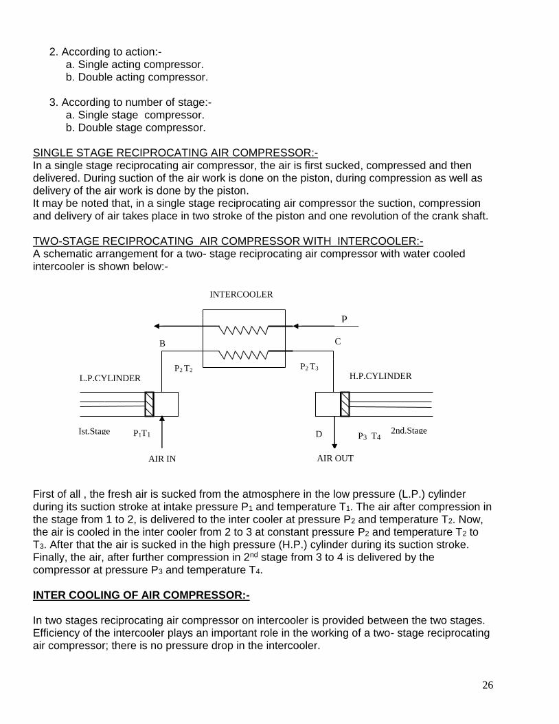
SINGLE STAGE RECIPROCATING AIR COMPRESSOR:- In a single stage reciprocating air compressor, the air is first sucked, compressed and then delivered. During suction of the air work is done on the piston, during compression as well as delivery of the air work is done by the piston. It may be noted that, in a single stage reciprocating air compressor the suction, compression and delivery of air takes place in two stroke of the piston and one revolution of the crank shaft. TWO-STAGE RECIPROCATING AIR COMPRESSOR WITH INTERCOOLER:- A schematic arrangement for a two- stage reciprocating air compressor with water cooled intercooler is shown below:-
First of all , the fresh air is sucked from the atmosphere in the low pressure (L.P.) cylinder during its suction stroke at intake pressure P1 and temperature T1. The air after compression in the stage from 1 to 2, is delivered to the inter cooler at pressure P2 and temperature T2. Now, the air is cooled in the inter cooler from 2 to 3 at constant pressure P2 and temperature T2 to T3. After that the air is sucked in the high pressure (H.P.) cylinder during its suction stroke. Finally, the air, after further compression in 2nd stage from 3 to 4 is delivered by the compressor at pressure P3 and temperature T4. INTER COOLING OF AIR COMPRESSOR:- In two stages reciprocating air compressor on intercooler is provided between the two stages. Efficiency of the intercooler plays an important role in the working of a two- stage reciprocating air compressor; there is no pressure drop in the intercooler.
B
INTERCOOLER
P
P
H.P.CYLINDER
AIR OUT
P3 T4 D
AIR IN
P1T1
P2 T2 P2 T3
C
L.P.CYLINDER
Ist.Stage 2nd.Stage

27
TYPES OF INTERCOOLER:- 1. Complete or perfect intercooler: Some times temperature of the air leaving the intercooler is equal to that of the original atmospheric air temperature. In such case the inter cooling is known as complete or perfect intercooler. 2. Incomplete or imperfect inter cooling: Some times temperature of the air leaving the intercooler is more than of the original atmospheric temperature. In such case the intercooler is known as incomplete or imperfect intercooler. ROTATORY COMPRESSOR:- In a rotary compressor the air is entrapped between two sets of engaging surface and the pressure of air is increased by back through of the air. Types of Rotary Air Compressor:- 1. Roots blower compressor. 2. Vane blower compressor. 3. Centrifugal compressor. 4. Axial flow compressor. COMPARISON OF RECIPROCATING AIR COMPRESSOR AND ROTARY AIR COMPRESSOR:-
Sr. No. Reciprocating Air Compressor Rotary Air Compressor
1. The maximum delivery pressure may be as high as 1000 Kg/cm2
The maximum delivery pressure is 10 Kg/cm2
2. The maximum free air charge is about 300 m3/min.
The maximum free air charge is about 3000 m3/min.
3. They are suitable for low discharge of air at very high pressure
They are suitable for large discharge of air at a low pressure.
4. The speed of air compressor is low. The speed of air compressor is high.
5. The air supply is intermittent. The air supply is continuous.
6. The size of air compressor is large for the given discharge.
The size of air compressor is small for the same discharge.
7. The balancing is a major problem. There is no balancing problem.
8. The lubricating system is complicated.
The lubricating system is simple.
9. The air delivered is less clean ,as it comes in contact with the lubricating oil.
The air delivered is more clean ,as it does not comes in contact with the lubricating oil.
10. Isothermal efficiency is used for all sorts of calculation.
Isentropic efficiency is used for all sorts of calculation.
***********

28

29