Energy and comfort analysis of glazed double skin facades for refurbishments in temperate climates
10
engineered transparency. International Conference at glasstec, Düsseldorf, Germany 21 and 22 October 2014 495 Energy and comfort analysis of glazed double skin facades for refurbishments in temperate climates Francesco POMPONI * , Kenneth IP a , Simeon OXIZIDIS a and Poorang A.E. PIROOZFAR a * Faculty of Science and Engineering, University of Brighton Division of Built Environment & Civil Engineering Lewes Road – BN2 4GJ – Brighton, United Kingdom [email protected] a Faculty of Science and Engineering, University of Brighton Abstract Double skin facades (DSFs) are gaining momentum in Europe as a low-energy design technique for the refurbishments of office buildings due to their potential to act as a thermal buffer in winter and maximise the use of natural ventilation in summer. Existing research suggests that DSFs are capable of significant reductions to the energy consumption of buildings as well as improvements to the thermal comfort achieved. However, the design of a DSF is highly complex due to the parameters and variables involved. By means of the dynamic energy simulation software IES VE 2013, energy analyses have been undertaken to evaluate the energy consumption under the variation of different aspects (namely, shading devices, type of glazing of the outer skin, operable inlets and outlets areas, and orientation). To assess the risk of overheating in DSFs, energy analyses have always been coupled with comfort assessments based on the adaptive method suited to the free-running nature of most of existing buildings. Eventually, the contribution of each aspect towards both energy saving and overheating has been assessed. Keywords: double skin facade, energy analysis, thermal comfort, natural ventilation 1 Introduction and research background According to the European Union [1], buildings account for 40 % of the total energy consumption in Europe. In this respect, all major governments in Europe have set targets to reduce building related greenhouse gases (GHG) emissions. Ferreira et al. [2] assessed that, in meeting GHG targets, existing buildings plays a crucial role and their sustainable refurbishment is one of the major challenges in the future.
Transcript of Energy and comfort analysis of glazed double skin facades for refurbishments in temperate climates

engineered transparency. International Conference at glasstec, Düsseldorf, Germany
21 and 22 October 2014
495
Energy and comfort analysis of glazed double skin
facades for refurbishments in temperate climates
Francesco POMPONI*, Kenneth IPa
, Simeon OXIZIDISa
and Poorang A.E. PIROOZFARa
* Faculty of Science and Engineering, University of Brighton
Division of Built Environment & Civil Engineering
Lewes Road – BN2 4GJ – Brighton, United Kingdom
a
Faculty of Science and Engineering, University of Brighton
Abstract
Double skin facades (DSFs) are gaining momentum in Europe as a low-energy design
technique for the refurbishments of office buildings due to their potential to act as a thermal
buffer in winter and maximise the use of natural ventilation in summer. Existing research
suggests that DSFs are capable of significant reductions to the energy consumption of
buildings as well as improvements to the thermal comfort achieved. However, the design of
a DSF is highly complex due to the parameters and variables involved. By means of the
dynamic energy simulation software IES VE 2013, energy analyses have been undertaken
to evaluate the energy consumption under the variation of different aspects (namely,
shading devices, type of glazing of the outer skin, operable inlets and outlets areas, and
orientation). To assess the risk of overheating in DSFs, energy analyses have always been
coupled with comfort assessments based on the adaptive method suited to the free-running
nature of most of existing buildings. Eventually, the contribution of each aspect towards
both energy saving and overheating has been assessed.
Keywords: double skin facade, energy analysis, thermal comfort, natural ventilation
1 Introduction and research background
According to the European Union [1], buildings account for 40 % of the total energy
consumption in Europe. In this respect, all major governments in Europe have set targets to
reduce building related greenhouse gases (GHG) emissions. Ferreira et al. [2] assessed that,
in meeting GHG targets, existing buildings plays a crucial role and their sustainable
refurbishment is one of the major challenges in the future.

engineered transparency. International Conference at glasstec, Düsseldorf, Germany
21 and 22 October 2014
496
At European level, Ebbert and Knaack [3] reported that 65 % of the non-residential
buildings in Western Europe have been constructed before 1978 and present an urgent need
for improvement. In refurbishments, Ardente et al. [4] indicated the improvement of the
envelope as the most beneficial action for energy savings and CO2 emissions reduction. To
adequately manage interactions between the inside and outside of a building, Shameri et al.
[5] stated a double-skin facade (DSF) represents one of the best options.
In renovations, a DSF consists of a second glazed skin added in front of the actual building
facade, from which it is separated by an air cavity that acts as a ventilation channel and may
accommodate shading devices. The benefits of DSFs are many such as providing a thermal
buffer zone, allowing for natural ventilation, solar preheating of indoor ventilation air, night
cooling ventilation, sound-, wind- and pollutant protection (even with open windows),
protection for shading devices, a higher degree of daylighting and an improved aesthetic of
the building they are applied to – see, among others, Streicher et al. [6].
In evaluating the suitability of DSFs for refurbishing offices, Pomponi et al. [7] reviewed
published studies of DSFs performances in temperate climates, showing this technology is
capable of significant reductions in operational energy consumption, with values in the
range of 30 %-60 %. Yet, current research seems focusing on detailed analyses of specific
design parameters (such as optimal position and orientation of shading devices) while a
broader approach to assess the influence of different aspects on the DSF performance is still
missing.
In this respect, this paper reports findings from an ongoing research on the performance of
DSFs for office refurbishments. The aim is to assess the influence of different aspects on
the energy savings achievable and the summer thermal comfort of the examined scenarios.
The focus on indoor comfort is due to the risk of summer overheating which can be
significant in buildings with DSFs (Gratia and De Herde [8]).
2 Methodology
To carry out the study, a location and a representative building model had to be chosen.
Additionally, aspects to be assessed and scenario to be simulated had to be established.
These aspects will now be dealt with in turn.
The location selected for the study is London due to its representativeness of the temperate
climate with mild winters and moderately warm summers. Therefore, a building model has
been developed which represents, in terms of facade characteristics, 20 % of large UK
offices (Figure 1). The building is 100% naturally ventilated.

engineered transparency. International Conference at glasstec, Düsseldorf, Germany
21 and 22 October 2014
497
Figure 1: View of the building model in IES VE
The hypothesis has been of a facade retrofit where all the thermal elements have been
retained and improved except windows and window frames which have been replaced with
new ones. U-values for the simulations (Table 1) have been adopted from the 2010 edition
of the UK Building Regulations.
Thermal element Thermal transmittance (U-value)
Double Glazed Windows + Frames 1.8 W/m² K
Wall (external insulation) 0.30 W/m² K
Flat roof 0.18 W/m² K
Table 1: U-values used in the simulations
The DSF studied is a multi-storey type with a cavity width of 1m. The multi-storey is one
of the commonest types of DSFs, and it is characterised by the cavity that spans on the
entire building without intermediate divisions (Oesterle et al. [9]). Additionally, inlets and
outlets are generally based only at the bottom and the top of the cavity.
The aspects considered and the different scenarios assessed are reported in Table 2.
Aspects Assessed Scenarios
Shading devices in the cavity Presence/absence and type (venetian/roller blinds)
Value of solar irradiance to lower the
shading devices (SD trigger)
100 – 600 [W/m²] (steps of 100)
Type of glazing of the outer skin Five different types as shown in Table 3
Operable areas of inlets and outlets 10 – 90 % (steps of 10 percentage points)
Orientation of the DSF Only N and S are considered in this study

engineered transparency. International Conference at glasstec, Düsseldorf, Germany
21 and 22 October 2014
498
Summer overheating Thermal discomfort as per CIBSE [10]
Table 2: Parameter assessed in the dynamic simulations
More specifically, in terms of glazing types, the choice tried to encompass a selection as
diverse as possible in terms of both spectrophotometric parameters and energy parameters
(Table 3).
Gla
zin
g
spectrophotometric
parameters
energy parameters
τν ρν τe ρe αe g SC
(light
transmit.)
(light
reflect.)
(solar direct
transmit.)
(solar
direct reflect.)
(solar
direct absorpt.)
(solar
factor)
(shading
coefficient = g/0.87)
Type #1 86% 8% 72% 8% 20% 0.78 0.90
Type #2 32% 13% 30% 11% 59% 0.44 0.51
Type #3 38% 34% 46% 29% 33% 0.55 0.63
Type #4 80% 11% 65% 9% 26% 0.69 0.79
Type #5 45% 32% 50% 25% 25% 0.56 0.64
Table 3 - Glass types analysed (Terminology as per BS EN 410)
It is worth specifying the operational mode of the bottom opening. In fact, Gratia and De
Herde [8] assessed the best conditions to open the inlets of the cavity in temperate climates
and maximise natural ventilation, which happen when the wind is blowing from the side
opposite to the one with the DSF (Figure 2).
Figure 2: View of the model from the top
engineered transparency. International Conference at glasstec, Düsseldorf, Germany
21 and 22 October 2014
499
Therefore, the simulations have been set up with a mathematical formula which opens
automatically the inlets of the DSF when the wind is blowing from any direction within the
range indicated in Figure 2. For what concerns the outlets, the formula opens them when
either the outside temperature is higher than 10 °C or the one in the cavity is higher than
20 °C. When both inlets and outlets are closed the buffer behaviour is realised which
corresponds to 0 % of operable areas. Finally, 100 % of operable area is never achieved due
to the presence of frames.
The simulated DSF has an aluminium supporting structure with walkway grills which
obstruct the flow in the cavity. Besides, the roughness of the inner walls introduces an
additional flow resistance. Both these elements have been taken into account by reviewing
the flow coefficient and correcting the equivalent areas for the air to flow (IES VE [11]).
Finally, to assess the overheating the adaptive method has been used which suits the free
running nature of the buildings. The assessment method is given in CIBSE [10] and it is
built on the European Standard EN 15251:2007 but includes more detailed criteria aimed at
assessing severity, frequency, and intensity of overheating. In this paper, internal rooms
which fail the TM52 assessment are classified as uncomfortable and are represented as a
percentage of the total occupied rooms.
3 Results
Preliminary assessment of the shading devices showed they are necessary if overheating is
to be avoided. In this respect, light coloured venetian blinds perform far better than roller
blinds. This depends on the nature of the device which is composed of swivelling slats able
to avoid glare while still allowing daylight which reduces the lighting energy consumption.
The most interesting results from the set of simulations run are presented below. Datasets
have been divided for the North and South cases. In terms of energy consumption the best
and worst cases for each orientation have been identified (Table 4). The gap between the
highest and lowest energy consumption achievable by the manipulation of the parameters
considered has been tagged as 100 %. Therefore, the contribution of each of the aspects
assessed can be presented in terms of percentage (Figure 3). For what concerns comfort, the
average influence of each parameter on overheated rooms along with its maximum and
minimum values have been assessed (Figure 4).

engineered transparency. International Conference at glasstec, Düsseldorf, Germany
21 and 22 October 2014
500
Orientation
Worst config.
assessed [kWh/m²]
Details
Best config.
assessed [kWh/m²]
Details
Net
difference [kWh/m²]
NORTH 191.2
Glass Type #4
143.1
Glass Type #5
48.1 (=
25.15%)
Inlet: 10% Inlet: 70%
Outlet: 90% Outlet: 10%
SD Trigger: 600
[W/m²]
SD Trigger: 100
[W/m²]
SOUTH 169.7
Glass Type #5
130
Glass Type #1
39.7 (=
23.39%)
Inlet: 10% Inlet: 90%
Outlet: 90% Outlet: 10%
SD Trigger: 100 [W/m²]
SD Trigger: 500 [W/m²]
Table 4: Overview of worst and best configurations assessed
Figure 3: Influence of each parameter on the energy reduction
engineered transparency. International Conference at glasstec, Düsseldorf, Germany
21 and 22 October 2014
501
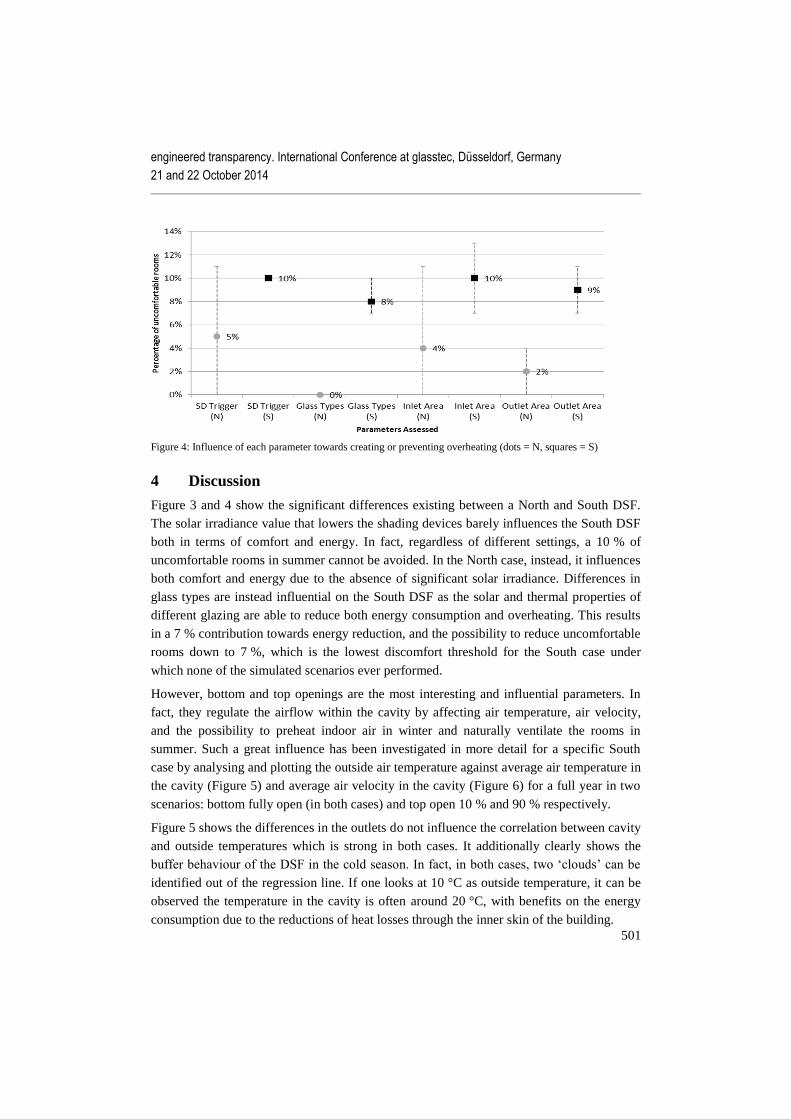
Figure 4: Influence of each parameter towards creating or preventing overheating (dots = N, squares = S)
4 Discussion
Figure 3 and 4 show the significant differences existing between a North and South DSF.
The solar irradiance value that lowers the shading devices barely influences the South DSF
both in terms of comfort and energy. In fact, regardless of different settings, a 10 % of
uncomfortable rooms in summer cannot be avoided. In the North case, instead, it influences
both comfort and energy due to the absence of significant solar irradiance. Differences in
glass types are instead influential on the South DSF as the solar and thermal properties of
different glazing are able to reduce both energy consumption and overheating. This results
in a 7 % contribution towards energy reduction, and the possibility to reduce uncomfortable
rooms down to 7 %, which is the lowest discomfort threshold for the South case under
which none of the simulated scenarios ever performed.
However, bottom and top openings are the most interesting and influential parameters. In
fact, they regulate the airflow within the cavity by affecting air temperature, air velocity,
and the possibility to preheat indoor air in winter and naturally ventilate the rooms in
summer. Such a great influence has been investigated in more detail for a specific South
case by analysing and plotting the outside air temperature against average air temperature in
the cavity (Figure 5) and average air velocity in the cavity (Figure 6) for a full year in two
scenarios: bottom fully open (in both cases) and top open 10 % and 90 % respectively.
Figure 5 shows the differences in the outlets do not influence the correlation between cavity
and outside temperatures which is strong in both cases. It additionally clearly shows the
buffer behaviour of the DSF in the cold season. In fact, in both cases, two ‘clouds’ can be
identified out of the regression line. If one looks at 10 °C as outside temperature, it can be
observed the temperature in the cavity is often around 20 °C, with benefits on the energy
consumption due to the reductions of heat losses through the inner skin of the building.

engineered transparency. International Conference at glasstec, Düsseldorf, Germany
21 and 22 October 2014
502
Figure 5: Two scenarios with different outlets areas in the South DSF
Figure 6: Influence of outlet opening areas on air velocity in the cavity
Figure 6 highlights how a smaller available area for the air to flow significantly increases
the average air velocity throughout the cavity in warm/hot days. This augmented chimney
effect allows to drag more heat out of the cavity and the rooms in summer, thus improving
the indoor comfort. In winter, if the cavity is open due to milder outside temperatures, a
smaller area implies less cold air coming in the cavity. The higher air temperature of the
cavity can be used to heat the rooms or to reduce the heat loss through the inner skin if the
internal windows are closed. Either way, this in turn reduces the energy consumption.
5 Conclusions
Existing buildings account for a significant amount of energy consumption and also often
have poor indoor thermal comfort. For these reasons, many of them will be refurbished in
the coming years. Interventions on the building facade are often the most effective way to
Inlet 90% - Outlet 10% Inlet 90% - Outlet 90%
Inlet 90% - Outlet 10% Inlet 90% - Outlet 90%

engineered transparency. International Conference at glasstec, Düsseldorf, Germany
21 and 22 October 2014
503
reduce energy consumption and enhance indoor comfort. In this respect, DSFs are
increasingly gaining momentum in Europe as a low-energy design technique. Knowledge
on the influence of different DSF design parameters on energy consumption and
overheating phenomena is still in its infancy. This paper represents a first attempt to fill this
gap. Energy analyses have been coupled with comfort assessment to address the
contribution that each of the aspects considered has towards energy savings and
overheating. Results revealed that inlets and outlets of the cavity appear to be the most
influential parameters among those assessed for what concerns both energy consumption
and indoor comfort. Not all the possible combinations of the aspects considered have been
analysed and this represents a limitation of the present study. Further research should
complete such analysis and address a broader number of parameters, like - for instance - the
cavity width or the type of supporting structure of the DSF, which may affect the airflow.
6 References
[1] EU, Directive 2010/31/EU of the European Parliament and of the Council of 19 May
2010 on the energy performance of buildings (recast), in, Official Journal of the
European Union, 2010, pp. L153/113-L153/135.
[2] J. Ferreira, M.D. Pinheiro, J.d. Brito, Refurbishment decision support tools review—
Energy and life cycle as key aspects to sustainable refurbishment projects, Energy
Policy, 62 (0) (2013) 1453-1460.
[3] T. Ebbert, U. Knaack, Office refusbishments by means of facades with integrated
building services, in: Proceedings of Building Stock Activation, Tokyo, Japan, 5-7
November 2007, 2007.
[4] F. Ardente, M. Beccali, M. Cellura, M. Mistretta, Energy and environmental benefits
in public buildings as a result of retrofit actions, Renewable and Sustainable Energy
Reviews, 15 (1) (2011) 460-470.
[5] M.A. Shameri, M.A. Alghoul, K. Sopian, M.F.M. Zain, O. Elayeb, Perspectives of
double skin facade systems in buildings and energy saving, Renewable & Sustainable
Energy Reviews, 15 (3) (2011) 1468-1475.
[6] W. Streicher, R. Heimrath, H. Hengsberger, T. Mach, R. Waldner, G. Flamant, X.
Loncour, G. Guarracino, H. Erhorn, H. Erhorn-Kluttig, M. Santamouris, I. Farou, S.
Zerefos, M. Assimakopoulos, R. Duarte, Å. Blomsterberg, L. Sjöberg, C. Blomquist,
On the Typology, Costs, Energy Performance, Environmental Quality and
Operational Characteristics of Double Skin Facades in European Buildings, Advances
in Building Energy Research, 1 (1) (2007) 1-28.
engineered transparency. International Conference at glasstec, Düsseldorf, Germany
21 and 22 October 2014
504
[7] F. Pomponi, K. Ip, P. Piroozfar, Assessment of Double Skin Facade Technologies for
Office Refurbishments in the United Kingdom, in: A. Passer, K. Höfler, P. Maydl
(Eds.) Sustainable Buildings – Construction Products & Technologies, Graz, Austria,
2013, pp. 1098-1109.
[8] E. Gratia, A. De Herde, Natural ventilation in a double-skin facade, Energy and
Buildings, 36 (2) (2004).
[9] E. Oesterle, R. Lieb, M. Lutz, W. Heusler, Double-Skin Facades. Integrated
Planning, Prestel, Munich - London - New York, 2001.
[10] CIBSE, TM 52: 2013 - The limits of thermal comfort: avoiding overheating in
European buildings, Great Britain, 2013.
[11] IES, MacroFlo Calculation Methods. Technical Manual, 2012.