
Hydrological impacts of climate change on inflows to Perth, Australia
Upload
independentCategory
view
0download
0
Aquam igne et aqua haurio – ‘I draw water by 6ire and water’
Perth Waterworks – conserving one of the world’s earliest cast iron facades.
Authors : David S Mitchell & Christopher McGregor
Presented at the Association for Preservation Technology Conference, Atlanta 2009
Abstract
Perth waterworks was constructed in 1832, designed by schoolmaster Adam Anderson and
manufactured by the Dundee Foundry Company. The importance of the building as a datum in
the technological evolution of the use of cast iron has not previously been identiDied, with
credit historically given to James Bogardus as a pioneer of the technique. The authors propose
that it may be the earliest known example of cast iron façade construction. The original
construction technique employed cast iron cement within Dlange faces, bolted with wrought
iron Dixings. SacriDicial corrosion caused widespread bolt failure and stress fractures to
Dlanges. Thermal movement and moisture ingress had exacerbated this problem.
The building was dismantled, and a combination of repair techniques employed. Retention of
historic fabric was considered of paramount importance with minimal amounts of re-‐casting
undertaken.
Whilst James Bogardus has generally been credited with inventing the cast iron façade form of pre-‐
fabricated construction, the $1.6 M conservation of an unusual Scottish building in 2004 / 2005, and
the research undertaken by the authors challenges the validiy of this. Perth Waterworks may well be
one of the earliest and most important cast iron structures, hitherto largely unknown.
The use of cast iron for structural columns, beams and spandrels was by the 1820’s reasonably
common in Britain and the United States. Sir William Fairbairn (1789-‐1874) has generally laid claim to
the Dirst complete iron building via the three storey Dlour mill he designed and shipped to Turkey in
1839. This was not however a fully cast iron constructon, instead using wrought iron plates for walls. A
fully cast iron lighthouse was constructed in London by Cottam and Hallen in 1844 before being
shipped to Bermuda. It utilised the bolted internal Dlange principle used extensively in cast iron
building construction thereafter.
Bostonian Daniel Bager, the pioneer of cast iron façade construction on a mass market basis wrote that
he was ‘the Dirst person who practically used iron as a building material for the exterior’ of a structure,
refering to an 1842 Boston Shopfront he had erected. Badgers’ shopfront, Fairbairns Mill and Cottam
and Hallems lighhouse were all later than Adam Anderson’s Perth Waterworks.
James Bogardus (1800 -‐1846) has generally been credited with inventing cast iron architecture. The
authors would submit that whilst he certainly popularised the material and the technology on a large
scale, he did not invent cast iron façade construction. That title may lie at the door of Adam Anderson,
the Perth schoolmaster. Bogardus was an inventor, and his move to cast iron buildings was prompted
by the two major New York Dires in 1835 and 1845.
Cast iron construction was seen as Direproof construction, and Badger established his foundry beside
the Columbia Ironworks and the foundry of Daniel Badger in New York, 1848. The modularity of the
cast iron components were such that from a limited number of patterns, high volumes of identical
components could be cast and assembled quickly. The secret, was of course in the design, the essence
of all prefabricated buildings. His Dirst cast iron building was the Milhau pharmacy of 1848 on the West
side of Broadway, a Dive story façade erected in three days.
In the years that followed, Bogardus designed and erected a profusion of cast iron buildings, notably
the Sun Building in Baltimore.
Whilst the work of Bogardus was sixteen years later than Anderson, there are some potentially
interesting connections. These may of course be cirumstantial, but perhaps there is something more to
be learned. Bogardus had married Margeret Maclay in 1831, a Scots immigrant to the united States and
daughter of inDluential Baptist Minister Archibald Maclay. His Dine engineering work sustained them in
the early years of their marriage. He met John Wylie Thomson, another Scot from Kilmarnock who
arrived in New York in 1832, the year that Perth Waterworks was completed, and who was to become
his trusted busines partner. We know that Bogardus left America for Britain in 1836 1, for a planned
short period to protect his overseas patents. He secured high quality engraving work, however, and
remained in Britain for four years. He was joined by his wife in 1838 who wished to visit her family
and that of Thomson, in Scotland. It was on a trip to Italy before they returned to New York in 1840,
that Bogardus is identiDied as forming his plans for cast iron architecture ;
‘ It was whilst in Italy, contemplating there the rich architectural designs of antiquity, That Mr
Bogardus 6irst conceived the idea of emulating them in modern times, by the aid of cast iron’ 2
Given the Scottish connections with Bogardus and his sharp engineering and inventive mind, it might
not be too much of an extrapolation to suggest that Bogardus was certainly aware of the erection Perth
Waterworks. Anderson notes that in 1837 the King of Prussia has asked for outline drawings of the
building in order that an identical structure be erected in Berlin. Whilst to date no record of such a
building has been determined, if the king of Prussia was to learn of it, surely a man in Borgardus’
position would also ?
Perth is situated at the heart of Scotland, some forty miles north of Edinburgh. The river Tay bisects the
town, one of the Dinest salmon rivers in Scotland with a steep runoff from the surrounding catchment
(Figure 1).

Figure 1 : Mid Nineteenth Century view of Perth showing Waterworks (Image from D S
Mitchell private collection)
Perth Waterworks is an A Listed structure which identiDies it as a building of national or international
importance. There are around forty thousand listed structures in Scotland, from grade C to A (highest)
as designated by Historic Scotland on behalf of Scottish Ministers. Historic Scotland served a number
of functions during this project, a statutory consent role for the conservation works undertaken, and as
a key funding partner for the project.
As early as 1751 Perth town council proposed pumping a water supply from the Tay, but it was not
until 1762 that a timber piped supply was installed, replaced thirty years later in lead. In 1810 The
Perth Water Commisioners requested that Adam Anderson evaluate the options of providing a water
supply.
Anderson was then local schoolmaster with an interest in science matters. Anderson conducted
extensive water sampling, and discovered that general abstraction from the land adjacent to the river
brought water that was contaminated from the alluvial deposits borne downstream by the river.
However, when sinking a nine foot cast iron pipe into the bed of the Tay itself, he discovered that he
could penetrate a clay band beneath the river bed where the staticial pressure forced the water level in
the pipe well above the river level, and raising good quality drinking water. Further evaluation

identiDied that the river had eroded through the clay band on Moncreiffe Island on the Tay, and this was
selected for the extraction point.
Andersons logic was simple, yet highly effective. Filter beds would be lain on Moncreiffe Island and the
water pumped to a high level storage tank or cistern. A deep well would be constructed beneath the
ground. The base level of the reservoir was set at four feet above the the level of the highest outlet
point in the town to ensure that the water supply would not fail. He designed an additional mechanism
to ensure that supplies were maintained to those properties which might be considered marginal
(Figure 2).
Figure 2 : Operational Sketch of Perth Waterworks by Adam Anderson (c. 1830). Image courtesy
of Perth and Kinross Council Archives.
Anderson Dirst selected a site adjacent to Grey Friars Graveyard, proposing a relatively plain structure
given its location. The local residents were unhappy about the prospect of the water supply for the
town being in such close proximity to the graveyard, and a new location on the corner of Marshall
Place and Tay Street selected. Given the prominent location, Anderson re-‐designed the building in the
ionic order (Figures 3 and 4).

Figure 3 : Anderson designs drawing for Perth Waterworks, c. 1830 (Image copyright of
Dundee Library)
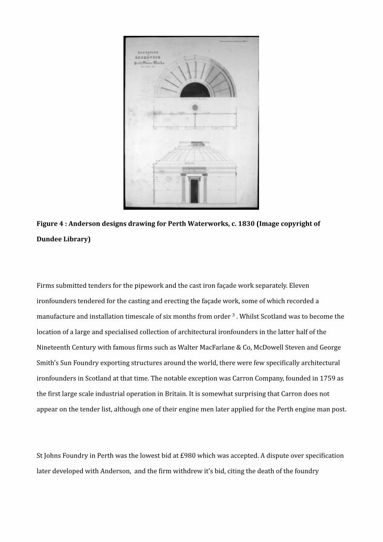
Figure 4 : Anderson designs drawing for Perth Waterworks, c. 1830 (Image copyright of
Dundee Library)
Firms submitted tenders for the pipework and the cast iron façade work separately. Eleven
ironfounders tendered for the casting and erecting the façade work, some of which recorded a
manufacture and installation timescale of six months from order 3 . Whilst Scotland was to become the
location of a large and specialised collection of architectural ironfounders in the latter half of the
Nineteenth Century with famous Dirms such as Walter MacFarlane & Co, McDowell Steven and George
Smith’s Sun Foundry exporting structures around the world, there were few speciDically architectural
ironfounders in Scotland at that time. The notable exception was Carron Company, founded in 1759 as
the Dirst large scale industrial operation in Britain. It is somewhat surprising that Carron does not
appear on the tender list, although one of their engine men later applied for the Perth engine man post.
St Johns Foundry in Perth was the lowest bid at £980 which was accepted. A dispute over speciDication
later developed with Anderson, and the Dirm withdrew it’s bid, citing the death of the foundry

manager who had agreed the contract originally. The contract for both the façade and the steam engine
was subsequently awarded to the Dundee Foundry 4.
The Dilter beds were excavated four feet below the river bed with a gravel base. Eight foot walls were
built in open stonework to allow water percolation. The beds were capped in Dlat Dine jointed stone to
prevent surface water seepage. The entire construction was then buried beneath clay and gravel to
offer protection in spate conditions. A masonry well was constructed in the centre of the bed from
which a cast iron pipe ran to the bank, and a cast iron trap was constructed to trap sediment . The river
pipe had a bore of one foot with a one inch wall thickness, and coated inside and out with India rubber
dissolved in linseed oil and coal tar. Anderson designed the system such that the pipe could be Dlushed
towards the Dilter bed using water from the cistern.
The cast iron wells were sunk to a depth of twenty three feet below the engine house Dloor, and four
feet below the river bed. This allowed the wells to Dill largely under their own pressure. Anderson
notes that
‘The unremitting exertions of 6ifty or sixty men with a couple of large pumps in an inclined
position were barely suf6icient for removing the water, as it 6lowed in from every side’ 5
The foundations were constructed to take a load of nine hundred tons in Perthshire sandstone and
lime, undertaken by the Dirm of Cameron and Galletly at a cost of £3127 6. The primary cylinder of
internally Dlanged cast iron supported a domed roof atop which was mounted a cupola. A steam pipe
was run from the boiler house around the internal face of the cistern to prevent freezing in winter. A
steam engine was incorporated to assist water movement. A beam engine was supplied by the Dundee
Foundry Company in 1832, with another from Russell of Kirkcaldy the following year.The Dundee
Foundry Company are not known for their architectural work, but are recognised for producing
engines, notably the Stirling Maxwell engine in later years. As previously indicated the 1830’s was
before the architectural ironfounders had become established generally in Scotland.
Perth waterworks opened in 1832 to considerable acclaim. By the 1860’s the works were no longer
considered adequate to meet the needs of the burgeoning population, and a reservoir was constructed
at WellsDield. The waterworks became a pumping station to supply the new reservoir. The
Commissioners planned to dismantle the ironwork in 1872 to raise funds, but public outcry prevented
this. The sole plates of the reservoir and the associated masonry were dismantled and raised £100 in
sale. In the same year a new boiler house and ofDice building was erected on the site. In 1878, eighty
unemployed men were taken on to dig a new well within the round house and construct foundations
for new engines supplied by Boulton and Watt’s famous Soho works.
A further supply was run into the building in 1888 from a new Dilter above Perth bridge, and a new
engine room erected in 1898 to house a triple expansion engine from GlenDield and Co to pump water
to the new Muirhall reservoir. Another pumping engine was installed in 1904.An attempt to sink an
artesian well was commenced in 1916, but abandoned the following year at a depth of 450 feet. The
original two beam engines were removed in 1928, not having been used for thirty years. The site
Dinally closed in 1965 when a new waterworks came online to serve the city.
A campaign was launched in 1967 to save the building by the newly formed Perth Civic Trust, with
extensive correspondence between the Trust, the Town Council, and the Ministry of Public Building
and Works (the predecessor of Historic Scotland). Interestingly a ‘specialist report’ from Robertson
and Robertson of Perth Foundry in 1964 considered the ironwork to be ‘in a remarkably good state of
preservation’ 7 but then notes that the frieze section is insecurely fastened and currently held on with
wire ! The foundryman does note that bolts were falling off the structure. Morris and Steedman
Architects were appointed to convert the building into a tourist information centre, which was
completed in 1974. the tradition of technological innovation continued, as the showpiece of the
building was a 360 degree scenic projection made possible by fourteen slide projectors.
The original engineering expertise required to cast radiused panels in relatively thin section to form a
perfect cylinder, as well as the highly decorative work, was considerable. The radiused panels which
form the core of the building were cast in grey iron with internally faced Dlanges on four sides. These
Dlanges are tapered inwards to effect a better seal. The jointing detail varies from location to location
but essentially comprises a wrought iron Ditting strip with cast iron cement inDill. In some locations
leather strips had been used where a Ditting problem had occurred. Cast iron cement was invented by
William Murdoch, a Scot who worked closely with James Watt and Mathew Boulton 8 . It comprises cast
iron Dilings mixed with sal amoniac (ammonium chloride) which sets hard in the joint, and was used
extensively in the jointing of pipework in both steam and water pipes.
The original proposal for the dome was relatively utilitarian due to it’s planned location next to the
graveyard, but the current prominent location prompted a more decorative approach. Ionic pilasters
and decorative corbels and friezes were cast and bolted through the primary structure to create a more
decorative building, including the city crest. References to the paintwork are somewhat conDlicting, one
specifying that the ornamentation should be a darker colour than the rest of the dome, another that it
should be ‘shaded as the stone below’ which matches another quote noting that it would be painted ‘in
imitation of ashlar’ at a cost of £13.50 9 . The second approach would appear to be the one employed
and ties in with later cast iron façade decoration where the cheaper cast iron could be made to appear
like Dinished ashlar.
The original decorative scheme was unfortunately destroyed in the 1972 restoration, when the
structure was coated in a rubber – type paint which caused subsequent problems due to its lack of
permeability to moisture.
The 1970’s project adopted a repair in situ approach, with key aspects being ;
•The later pumping house to the front elevation demolished to present the site in it’s original
conDiguration.
•The masonry to be extensively cleaned.
•Stress fractures to the primary panels repaired by the ‘Metalock’ TM process of cold metal stitching.
•Other fractures repaired using mild steel Dlat bar drilled and tapped to the cast iron panels.
•Limited re-‐bolting within Dlanges (the reasons for which became apparent later).
•Recasting missing or damaged components of the structure in Dibreglass.
•Replacement of damaged stone.

•Replicating the original urn from Anderson’s drawings, again in Dibreglass.
In the 1960’s structural steelwork was added to the interior of the dome to provide structural support
to the cast ironwork This work was undertaken by Frederick Braby and Co Ltd of Glasgow, who were
themselves manufacturers of architectural ironwork of note in the 19th and early 20th Century.
Thirty years later Perth Council had concerns over the structural stability of the structure, particularly
the profuse failure of Dlange bolts. Water ingress was such that a secondary waterproof membrane was
installed to the base of the dome to provide protection to the art gallery below. The tourist information
centre had been converted to an art gallery by this stage. Glasgow industrial heritage specialists
Heritage Engineering were appointed in 1998 to assess the structure, identifying ;
•90% failure of Dlange Dixings.
•Failure of previous cold metal stitch and plated repairs.
•Moisture entrapment caused by using a rubber -‐ type coating.
•Insecure ornamental work caused by the failure of external Dixings by sacriDicial corrosion.
•A microclimate was established in the dome with extensive temperature Dluctuations and a miniature
hydrological cycle of evaporation and condensation from the water ingress to the dome. Thermal
variations to the ironwork exposed and sheltered from the radiant energy, particularly in winter, were
noticeable in direct sunlight, with audible expansion and contraction of the cast iron structure.
•An electrochemical corrosion within the joint itself with the wrought iron sacriDicially corroding to
the cast iron fabric and cast iron cement. The wrought iron Ditting strips then corroding, with
expansive delamination causing extensive failure of the adjacent cast iron Dlanges (Figure 5).
•Similarly, the wrought iron bolts used to secure the Dlanges and decorative work corroded sacriDicially
to the cast iron structure. This caused stress fractures to the cast ironwork and Dlange failure in many
locations.

Figure 5 : Flang and bolt failure due to expansive corrosion of wrought iron packer (Image D S
Mitchell 1998)
Heritage Engineering proposed a complete dismantling of the cast iron dome to effect repairs, with
temporary repairs to Dixings until funding could be secured. Extreme difDiculty was found in removing
corroded wrought iron bolts without damage to Dlanges. Around 40 % replacement was achieved using
a custom jig and a hydraulic ram. Replacement bolts were in 318 Stainless steel, isolated from the cast
iron by nylon sleeves. Additional clamps were manufactured to pin the Dlange and loaded with a torque
wrench.
Perth Council provided the bulk of the project funds, with additional funding secured from the
Heritage Lottery Fund and Historic Scotland . The tendered works were secured by general contractors
John Dennis & Co with the specialised ironwork sub contracted to Casting Repairs Ltd.
The building was drawn up to identify each individual cast iron component, which was then assigned a
unique reference, and therefore location number. The externally secured ornamental castings were
removed fairly easily, many being held in tension, pulled into the structure by as much as three to four
inches by the movement of the cylindrical core – so much for grey iron lacking ductility !
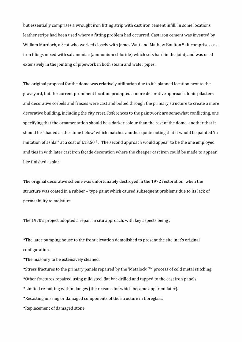
Major problems were encountered dismantling the primary structure. As previously noted many of the
bolts could not be removed, and the cast iron cement created a hard bond between Dlange faces. In
most cases the cement had to be weakened by using a cutting disc combined with a degree of lateral
movement under the load of a crane. This method was not ideal since it risked damage to the panels,
particularly the Dlanges. Delays were encountered at this point in the project due to the slow and
laborious nature of the operation to remove panels safely (Figure 6) .
Figure 6 : Dismantling the building, January 2003 (Image C Mcgregor)
On removal it was discovered that the 1970’s restoration had extensively utilised glass Dibre to repair
the decorative freize elements and other decorative components. The ironwork was transported off
site to the contractors workshops where it was blast cleaned using an inert mineral grit to Swedish
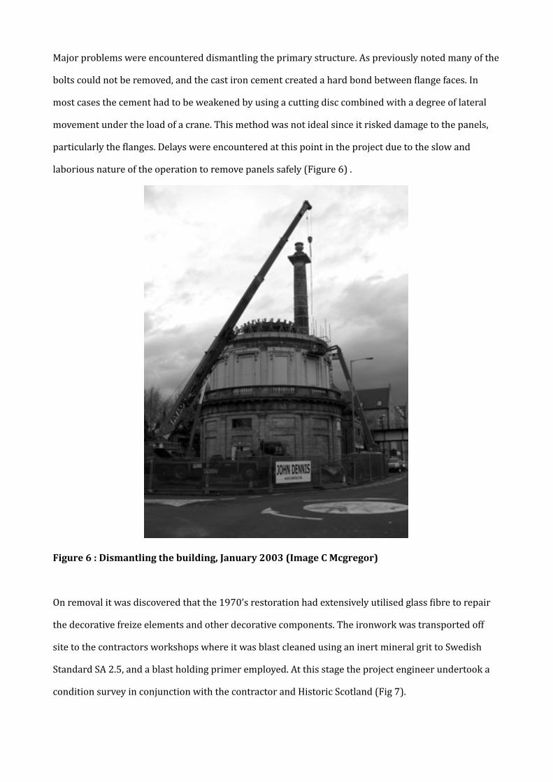
Standard SA 2.5, and a blast holding primer employed. At this stage the project engineer undertook a
condition survey in conjunction with the contractor and Historic Scotland (Fig 7).
Fig 7 : Condition survey – discussing repair methods (Image C McGregor)
A great deal of debate centred around the retention of historic fabric against re-‐casting components.
The number of repairs required to ensure structural stability far exceeded the provisional contract
sum, and the project manager was required to make cost savings in other areas to facilitate this. The
Historic Scotland ethos of conserving and retention of existing fabric demanded that repair
methodologies utilised a variety of techniques. Consequently, limited re-‐casting work was undertaken.
Cold metal stitching employed in the 1970’s restoration was again employed, but to a more limited
extent and only in appropriate scenarios. Great care was taken to stitch around historic cast detail.
Pinning using 318 stainless steel dowels and epoxy resins was also utilised. It was of course, much
easier to effect these repairs in a workshop environment than on site.
Painting issues were identiDied off site in terms of lack of suitable preparation and incomplete removal
of paint from decorative detail, and a lack of consistency of application. Lack of relative humidity
control also caused some degree of moisture bloom beneath the Dinished paint system. The coating
speciDication utilised a zinc – rich primer coat, followed by a micaceous iron oxide coat and two coats
of standard metal gloss.
Whilst the works to the cast iron structure were undertaken off site, the main contractor undertook
the repairs to the masonry elements, comprising indents using petrographically matched stone and
extensive replacement of ordinary portland cement pointing with an appropriate lime mortar
following analysis of an original sample. The original engine house roof was also re-‐roofed in lead to
match existing details.
As the cast ironwork was conserved off –site, the project team had extensive debate on how to re-‐
instate the primary cylindrical structure. It was agreed that the re-‐bolting would be undertaken using
stainless steel bolts and nuts on the proviso that there was no metal to metal contact by using nylon
insulators. Clearly the re-‐instatement of a wrought iron packer was not desirable, but some debate was
held on the possibility of using cast iron cement again. Attempts to source a commercial supplier
identiDied one potential in the United States, but the client held Dirm that it would not be in the best
interests of the building. Since there clearly had been a degree of electrochemical interaction between
the original cast iron cement and the cast panels, it was agreed that a long life pH neutral grout would
be employed, run into the joints post assembly. It would have been our preference to have seen a nylon
material acting as a gasket employed. A foam extrusion was used to prevent the grout from escaping
externally, and temporary tape used on the internal face.
Since the building no longer had to hold water, this meant that a number of fractured Dlanges did not
have to be repaired intrusively, but alternative Dixing points used where the fabric was sound. The main
cylinder came together in a reasonably straightforward manner, with some difDiculty encountered as
the Dinal panels were lifted into place in terms of alignment.
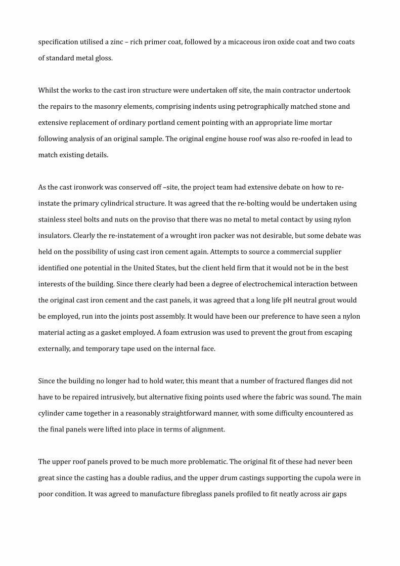
The upper roof panels proved to be much more problematic. The original Dit of these had never been
great since the casting has a double radius, and the upper drum castings supporting the cupola were in
poor condition. It was agreed to manufacture Dibreglass panels proDiled to Dit neatly across air gaps
here (Fig 8). These can be clearly identiDied as being later, and meant that a minimal intervention
approach could be maintained. It also means that the building becomes self documenting.
Fig 8 : Fitting Uibreglass panels to Uill air gaps in cupola (Image C Mcgregor)
Quality issues were picked up on site inspections made in terms of poor paintwork, handling damage
to the cast panels, and use of ferrous metal Dixings and plates rather than stainless steel. Over liberal
use of polysulphide mastic was picked up, as was over – torquing of Dixings resulting in additional
stress fractures to the repaired fabric. This required a greater deal of site management from the project
team than would have been expected and created tensions as the project grew to a close. The project
engineer is to be commended for his tenacity at this stage of the project.
A humidity controlled fan was installed in the cupola which could automatically effect an air change
within the structure fairly rapidly, but at the very least provided a means of promoting airDlow. This is
the Dirst real winter the building has faced, but we would realistically consider that the building will
not have a low level relative humidity as we might like.
The building re-‐opened to it’s current use as an art gallery in late 2005 (Fig 9). Whilst the project was
not without it’s difDiculties, we would hope that it will now become more widely recognised for the role
it has played in the development of cast iron façade construction, and that it is truly a building of
international importance.
Notes
1. Margot Gayle and Carol Gayle, Cast Iron Architecture in America (New York : WW Norton & Co,
1998).
2. John W Thomson, Cast Iron Buildings – Their construction and advantages (New York, 1856)
3. Perth Water Commisioners Archive, PCPE20 Bundle 5, Perth & Kinross Council Archives.
4. Perth Water Commisioners Archive, PWCPE20 Bundle 9, Perth & Kinross Council Archives.
5. Anderson quote…………….
6. Perth Water Commissioners Archives, PWCPE20 Bundle 4, Perth & Kinross Council Archives.
7. National Archives of Scotland Papers NAS DD27/4253.
8. Samuel Smiles, Lives of the Engineers, 3 Vol (London, 1862).
9. Perth Water Commissioners Archives, PEWCPE20 Bundle 11. Perth & Kinross Council Archives.
Acknowledgements
Perth City Archives and the National Archives of Scotland for access to archive documents, Moses
Jenkins, Researcher with Historic Scotland TCRE Group, John Sinclair of Allen Gordon & Co, Heritage
Engineering, Casting Repairs, Historic Scotland for supporting the writing and presentation of this
paper.

Contact Details
David S Mitchell
Director of Conservation
Historic Scotland
Longmore House
Edinburgh
EH9 1SH
+44 131 668 8929
Copyright © 2022 FDOKUMEN


![OF No. 15] PERTH: FRIDAY, 28th FEBRUARY [1975](https://static.fdokumen.com/doc/165x107/6320f1b7eb38487f6b0fd6fa/of-no-15-perth-friday-28th-february-1975.jpg)

![No, 58] PERTH : FRIDAY, 19th JUNE [1970](https://static.fdokumen.com/doc/165x107/6328b636cedd78c2b50e3033/no-58-perth-friday-19th-june-1970.jpg)