Factory without walls: Industrialization in residential construction
Upload
independentCategory
view
2download
0
12th Canadian Masonry Symposium Vancouver, British Columbia, June 2-5, 2013
DESIGN OF UNIQUE LANDSCAPE WALLS AND THEIR USE IN BUILDING FACADES
Brian E. Trimble1
1 PE, LEED, Regional VP, Engineering Services & Architectural Outreach, Brick Industry Association, Reston, VA, 20191, USA, [email protected]
ABSTRACT A variety of wall types have been used in landscape applications to satisfy project requirements. Two of the more unique wall systems that have been used include perforated (screen) walls and serpentine walls. Both of these walls have unique design and detailing requirements to assure their performance. This paper outlines the history of these wall types and offers some insight into past design practices. Design theories and procedures are provided that will assist designers in the practical design of these wall systems. Proper detailing requirements are outlined for these walls to perform in harsh climates. Case studies of unique projects showcasing both perforated walls and serpentine walls in building facades are provided to hopefully expand the use of these wall types in a variety of building applications. KEYWORDS: crinkle-crankle walls, jali, landscape walls, perforated walls, pierced walls, screen walls, serpentine walls INTRODUCTION Designers have used brick in a variety of applications for centuries. These designs have been used in building structures as well as site or landscape applications. Most walls were designed to do what they needed to do – hold up a building or keep the elements out. When builders introduced architecture into their projects they went beyond the utilitarian uses and made aesthetic expressions creating truly unique structures. Since brick is a rectangular material it is most easily used in solid straight walls or walls that have 90 degree angles. To make a wall different than that requires the bricklayer, or in some cases the designer, to figure out how to make things work without adding additional cost or time to the construction. Perforated walls and serpentine walls are not usually considered “normal” walls. While they seem commonplace to us today, there is some uniqueness to them. Landscapes and open spaces allow more freedom in creating shapes than a building. This could be why these wall types were used in landscape applications first. Over time, designers have incorporated these unique wall types into building facades for a variety of reasons, but mostly for variation in architectural expression. The lack of research on landscape walls can be attributed to the idea that these walls are more for decoration compared to walls in a building that are used for structure; therefore, we do not have a consensus on analytical methods or rules to design perforated or serpentine walls. This paper accumulates much of the technical information available to designers and proposes some methods to follow. Since it is always good to continue to push the envelope for new uses of brick, case studies are included that take these landscape walls and shows their incorporation into building facades.
The wall types described in this paper go by a variety of names as it appears that consensus has not been reached on the proper terminology. Perforated walls are also called screen walls and pierced walls. Serpentine walls also go by the name of crinkle-crankle walls. Often, each term has a regional or national origin. The terms pierced and crinkle-crankle walls are typically found in England or Europe while the other terms are most often used in the Americas. For the purposes of this paper, the American usage will be used. HISTORY OF PERFORATED AND SERPENTINE WALLS Straight walls have been used as far back in the past as masonry has been used. At a certain point, people must have been looking for alternate ways to build their walls showing some creativity. So they started to incorporate curves in the walls and experimented by eliminating alternating units that created voids in the wall for variety or for a way to allow light and air to penetrate the wall. Perforated walls have voids in the wall that are created by eliminating certain brick along its height and length, typically in a pattern. These voids allow privacy while allowing light, air and muffled sounds to pass through the wall. Perforated walls have been used throughout history especially in hot climates where partial blocking of the sun was desired, yet allowed air flow to help cool the interior. Persian architecture developed intricate and delicate brick screens which acted to divide space yet allow light and air to penetrate (Figure 1). Laurie Baker, British architect practicing in India, used perforated brick walls, or jali in Indian terminology, to provide passive cooling. An example of walls incorporating decorative perforations can be seen in his Center for Development Studies in Kerala, India (Figure 2).
Figure 2: Center for Development Studies, Kerala, India
Figure 1: Persian brick screen
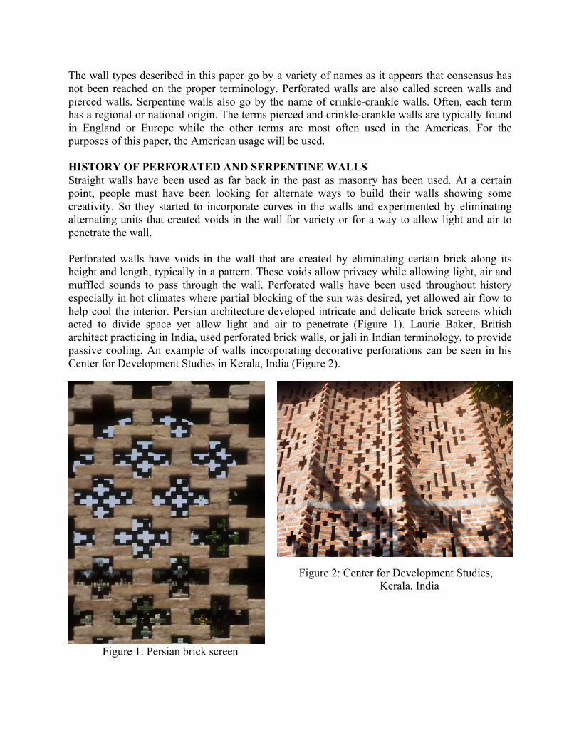
While these are decorative perforations they allow air to penetrate the walls. Some walls have very few openings as in Figure 3, while others are highly perforated as in Figure 4 as dictated by usage requirements. The number and size of openings is based on aesthetics and the desire to bring light and air through the wall. The more highly perforated the wall, the weaker the wall. No rules of thumb exist for perforated walls because of the wide variety of uses.
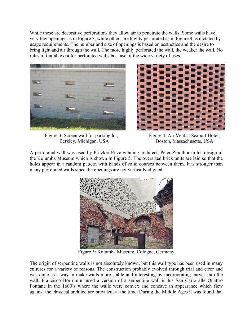
Figure 3: Screen wall for parking lot, Figure 4: Air Vent at Seaport Hotel, Berkley, Michigan, USA Boston, Massachusetts, USA A perforated wall was used by Pritzker Prize winning architect, Peter Zumthor in his design of the Kolumba Museum which is shown in Figure 5. The oversized brick units are laid so that the holes appear in a random pattern with bands of solid courses between them. It is stronger than many perforated walls since the openings are not vertically aligned.
Figure 5: Kolumba Museum, Cologne, Germany
The origin of serpentine walls is not absolutely known, but this wall type has been used in many cultures for a variety of reasons. The construction probably evolved through trial and error and was done as a way to make walls more stable and interesting by incorporating curves into the wall. Francisco Borromini used a version of a serpentine wall in his San Carlo alle Quattro Fontane in the 1600’s where the walls were convex and concave in appearance which flew against the classical architecture prevalent at the time. During the Middle Ages it was found that
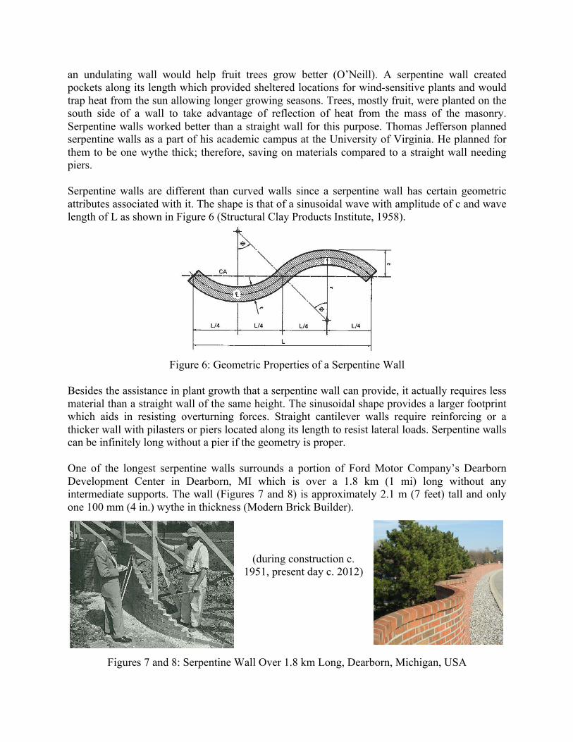
an undulating wall would help fruit trees grow better (O’Neill). A serpentine wall created pockets along its length which provided sheltered locations for wind-sensitive plants and would trap heat from the sun allowing longer growing seasons. Trees, mostly fruit, were planted on the south side of a wall to take advantage of reflection of heat from the mass of the masonry. Serpentine walls worked better than a straight wall for this purpose. Thomas Jefferson planned serpentine walls as a part of his academic campus at the University of Virginia. He planned for them to be one wythe thick; therefore, saving on materials compared to a straight wall needing piers. Serpentine walls are different than curved walls since a serpentine wall has certain geometric attributes associated with it. The shape is that of a sinusoidal wave with amplitude of c and wave length of L as shown in Figure 6 (Structural Clay Products Institute, 1958).
Figure 6: Geometric Properties of a Serpentine Wall
Besides the assistance in plant growth that a serpentine wall can provide, it actually requires less material than a straight wall of the same height. The sinusoidal shape provides a larger footprint which aids in resisting overturning forces. Straight cantilever walls require reinforcing or a thicker wall with pilasters or piers located along its length to resist lateral loads. Serpentine walls can be infinitely long without a pier if the geometry is proper. One of the longest serpentine walls surrounds a portion of Ford Motor Company’s Dearborn Development Center in Dearborn, MI which is over a 1.8 km (1 mi) long without any intermediate supports. The wall (Figures 7 and 8) is approximately 2.1 m (7 feet) tall and only one 100 mm (4 in.) wythe in thickness (Modern Brick Builder).
(during construction c. 1951, present day c. 2012)
Figures 7 and 8: Serpentine Wall Over 1.8 km Long, Dearborn, Michigan, USA

When a wall is only one wythe thick it makes the wall somewhat fragile when subjected to unusual loading conditions. The 100 mm (4 in.) thick serpentine walls at the University of Virginia have been repaired on a number of occasions due to accidental loading. Increasing the amplitude or depth of the wall typically increases the stability of the wall. Curvilinear walls have also been used in building facades, most famously by Eladio Dieste. Dieste, primarily a structural engineer from Uruguay, used a variety of techniques with structural brickwork to make his structures (Anderson). While the walls of the Church of Christ the Worker (Figure 9) are not true serpentine walls since the form changes with the height of the wall; they are similar and use geometry to its advantage. This magnificent building also uses an undulating roof form which meets the walls on a level plane. Other works of his that incorporate serpentine-type walls include the Church of Our Lady of Lourdes, Church of San Juan de Avila, and the Montevideo Shopping Center. His structural artistry allowed buildings to be built with efficiency – in materials and labor, all created in brick construction. Other architects have used serpentine shapes within their buildings including Eero Saarinen at the MIT Chapel.
Figure 9: Church of Christ the Worker, Uruguay
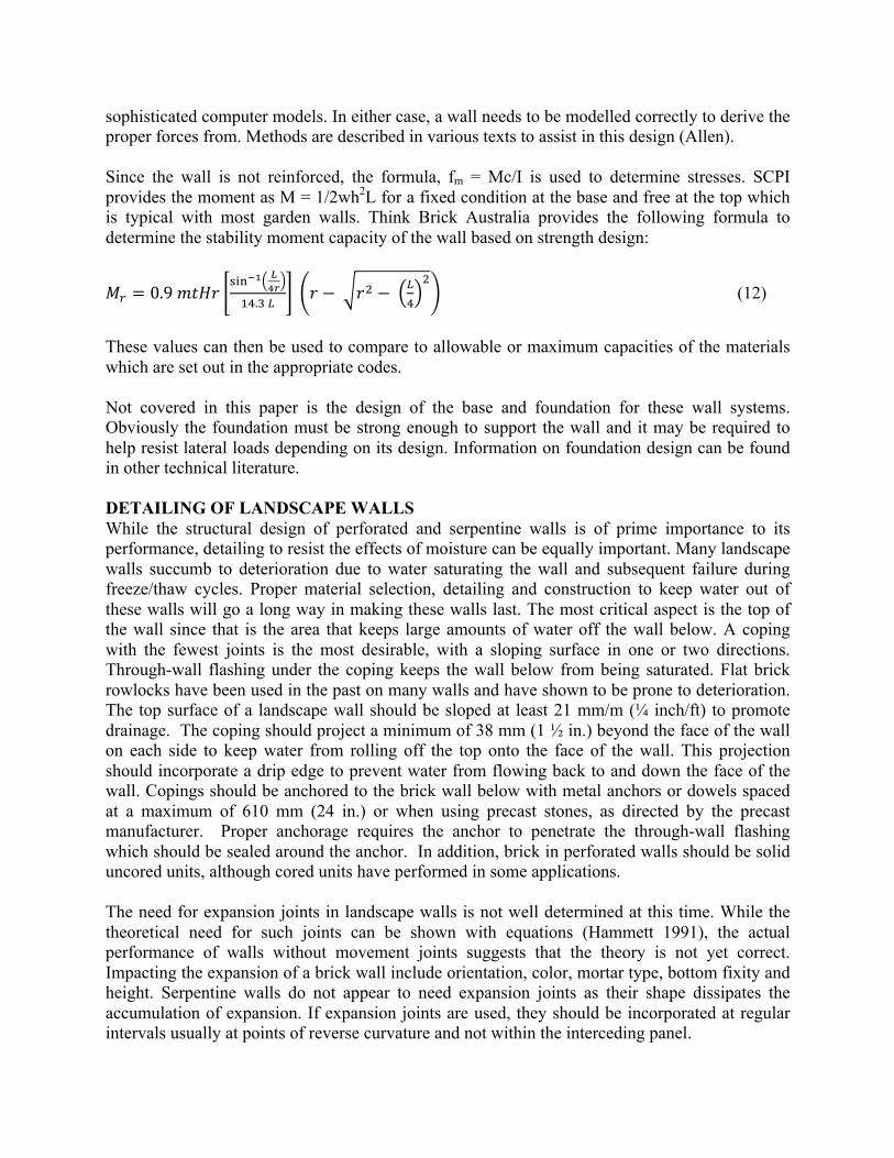
More recently, the works from Gramazio and Kohler and ETH in Switzerland have shown the possibility of computer aided design and digital fabrication in the design and construction of efficient structures. Their work on the Switzerland Pavilion at the Venice Biennale (Figure 10) is an example of not true serpentine walls, but walls that undulate both in the horizontal and vertical axis. The wall extends 100 m (328 ft.) turning back on itself several times. Further study of walls constructed with robots has shown promise for a variety of brick walls. Digital parametric design and fabrication has been mimicked and analysed at the Georgia Institute of Technology (Al-Haddad 2010), and the Harvard Graduate School of Design, and other experimental works in the US and Canada. With digital fabrication, expanded use of brick as a structural material in very efficient ways can become commonplace.
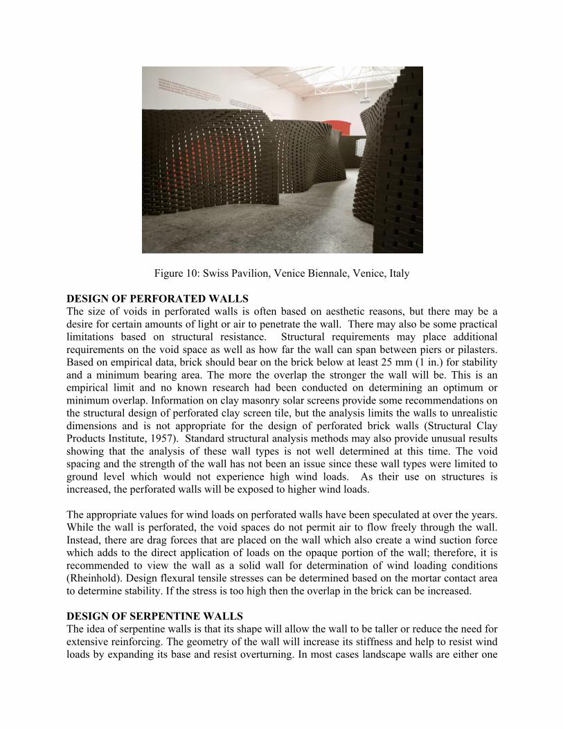
Figure 10: Swiss Pavilion, Venice Biennale, Venice, Italy DESIGN OF PERFORATED WALLS The size of voids in perforated walls is often based on aesthetic reasons, but there may be a desire for certain amounts of light or air to penetrate the wall. There may also be some practical limitations based on structural resistance. Structural requirements may place additional requirements on the void space as well as how far the wall can span between piers or pilasters. Based on empirical data, brick should bear on the brick below at least 25 mm (1 in.) for stability and a minimum bearing area. The more the overlap the stronger the wall will be. This is an empirical limit and no known research had been conducted on determining an optimum or minimum overlap. Information on clay masonry solar screens provide some recommendations on the structural design of perforated clay screen tile, but the analysis limits the walls to unrealistic dimensions and is not appropriate for the design of perforated brick walls (Structural Clay Products Institute, 1957). Standard structural analysis methods may also provide unusual results showing that the analysis of these wall types is not well determined at this time. The void spacing and the strength of the wall has not been an issue since these wall types were limited to ground level which would not experience high wind loads. As their use on structures is increased, the perforated walls will be exposed to higher wind loads. The appropriate values for wind loads on perforated walls have been speculated at over the years. While the wall is perforated, the void spaces do not permit air to flow freely through the wall. Instead, there are drag forces that are placed on the wall which also create a wind suction force which adds to the direct application of loads on the opaque portion of the wall; therefore, it is recommended to view the wall as a solid wall for determination of wind loading conditions (Rheinhold). Design flexural tensile stresses can be determined based on the mortar contact area to determine stability. If the stress is too high then the overlap in the brick can be increased. DESIGN OF SERPENTINE WALLS The idea of serpentine walls is that its shape will allow the wall to be taller or reduce the need for extensive reinforcing. The geometry of the wall will increase its stiffness and help to resist wind loads by expanding its base and resist overturning. In most cases landscape walls are either one

or two wythes thick. Designing these walls as unreinforced, and relying on flexural bond strength of the assembly, often limits the height. Thomas Jefferson designed the serpentine walls at the University of Virginia only one wythe in thickness. To accommodate this thickness, the wall had to take on a different form than a straight cantilever wall. It is difficult to determine where the first rules of design for serpentine walls were developed, but rules of thumb have been in place for a long time. The Structural Clay Products Institute (now the Brick Industry Association) published a Technical Note on this subject in 1958 and provided the following formulae for a serpentine wall’s geometric properties with the appropriate notation found in Figure 6: A = 4 Φ r t (1) L = 4 sinΦ (2) L℄ = 4 r Φ (3) c = r+ !
!− r cosΦ (4)
r = 1/2 !!
!" (!!!!)+ (c− !
!) (5)
Φ = 2 cot!! !
! !!!! (6)
I!" =
!!r! X+ !
!
! Y (7)
S!" =
!!" r! X+ !
!
! Y (8)
K!" = !!r! X+ !
!
! Y
!/! (9)
Where: A = cross-sectional area of the repeating section (sq. in.) L℄ = length along the centerline of the repeating section (in.) ICA = moment of inertia about the centroidal axis (in.4) KCA = radius of gyration about the centroidal axis (in.4) SCA = section modulus about the centroidal axis (in.4) X = 1− ! !"#! !"#!
!+ 2 cos!Φ (10)
Y = 1− !"#! !"#!!"
(11) These equations are based on radians and not degrees. Using these formulae, section properties can be easily determined. For the structural aspect of a serpentine wall, the usual rules of statics are used. Advanced analysis techniques have not appeared in the technical literature. The wall could be designed as a surface with corrugations or using finite element analyses, but approximate methods are often used to simplify the analysis. New computer applications are being used to design shells and other complicated geometries that may prove to be applicable to serpentine walls. Shell design is often accompanied with scale models to determine shape and size. Forces can often be determined using graphical methods as has been done before, or using
sophisticated computer models. In either case, a wall needs to be modelled correctly to derive the proper forces from. Methods are described in various texts to assist in this design (Allen). Since the wall is not reinforced, the formula, fm = Mc/I is used to determine stresses. SCPI provides the moment as M = 1/2wh2L for a fixed condition at the base and free at the top which is typical with most garden walls. Think Brick Australia provides the following formula to determine the stability moment capacity of the wall based on strength design:
𝑀! = 0.9 𝑚𝑡𝐻𝑟!"#!! !
!!!".! !
𝑟 − 𝑟! − !!
! (12)
These values can then be used to compare to allowable or maximum capacities of the materials which are set out in the appropriate codes. Not covered in this paper is the design of the base and foundation for these wall systems. Obviously the foundation must be strong enough to support the wall and it may be required to help resist lateral loads depending on its design. Information on foundation design can be found in other technical literature. DETAILING OF LANDSCAPE WALLS While the structural design of perforated and serpentine walls is of prime importance to its performance, detailing to resist the effects of moisture can be equally important. Many landscape walls succumb to deterioration due to water saturating the wall and subsequent failure during freeze/thaw cycles. Proper material selection, detailing and construction to keep water out of these walls will go a long way in making these walls last. The most critical aspect is the top of the wall since that is the area that keeps large amounts of water off the wall below. A coping with the fewest joints is the most desirable, with a sloping surface in one or two directions. Through-wall flashing under the coping keeps the wall below from being saturated. Flat brick rowlocks have been used in the past on many walls and have shown to be prone to deterioration. The top surface of a landscape wall should be sloped at least 21 mm/m (¼ inch/ft) to promote drainage. The coping should project a minimum of 38 mm (1 ½ in.) beyond the face of the wall on each side to keep water from rolling off the top onto the face of the wall. This projection should incorporate a drip edge to prevent water from flowing back to and down the face of the wall. Copings should be anchored to the brick wall below with metal anchors or dowels spaced at a maximum of 610 mm (24 in.) or when using precast stones, as directed by the precast manufacturer. Proper anchorage requires the anchor to penetrate the through-wall flashing which should be sealed around the anchor. In addition, brick in perforated walls should be solid uncored units, although cored units have performed in some applications. The need for expansion joints in landscape walls is not well determined at this time. While the theoretical need for such joints can be shown with equations (Hammett 1991), the actual performance of walls without movement joints suggests that the theory is not yet correct. Impacting the expansion of a brick wall include orientation, color, mortar type, bottom fixity and height. Serpentine walls do not appear to need expansion joints as their shape dissipates the accumulation of expansion. If expansion joints are used, they should be incorporated at regular intervals usually at points of reverse curvature and not within the interceding panel.
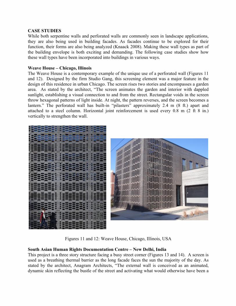
CASE STUDIES While both serpentine walls and perforated walls are commonly seen in landscape applications, they are also being used in building facades. As facades continue to be explored for their function, their forms are also being analyzed (Knaack 2008). Making these wall types as part of the building envelope is both exciting and demanding. The following case studies show how these wall types have been incorporated into buildings in various ways. Weave House – Chicago, Illinois The Weave House is a contemporary example of the unique use of a perforated wall (Figures 11 and 12). Designed by the firm Studio Gang, this screening element was a major feature in the design of this residence in urban Chicago. The screen rises two stories and encompasses a garden area. As stated by the architect, “The screen animates the garden and interior with dappled sunlight, establishing a visual connection to and from the street. Rectangular voids in the screen throw hexagonal patterns of light inside. At night, the pattern reverses, and the screen becomes a lantern.” The perforated wall has built-in “pilasters” approximately 2.4 m (8 ft.) apart and attached to a steel column. Horizontal joint reinforcement is used every 0.8 m (2 ft 8 in.) vertically to strengthen the wall.
Figures 11 and 12: Weave House, Chicago, Illinois, USA South Asian Human Rights Documentation Centre – New Delhi, India This project is a three story structure facing a busy street corner (Figures 13 and 14). A screen is used as a breathing thermal barrier as the long facade faces the sun the majority of the day. As stated by the architect, Anagram Architects, “The external wall is conceived as an animated, dynamic skin reflecting the bustle of the street and activating what would otherwise have been a
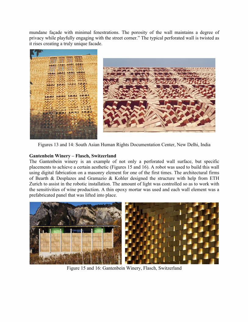
mundane façade with minimal fenestrations. The porosity of the wall maintains a degree of privacy while playfully engaging with the street corner.” The typical perforated wall is twisted as it rises creating a truly unique facade.
Figures 13 and 14: South Asian Human Rights Documentation Center, New Delhi, India
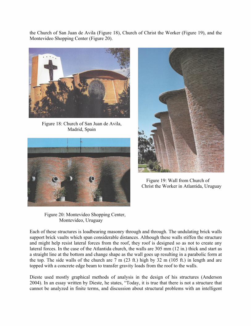
Gantenbein Winery – Flasch, Switzerland The Gantenbein winery is an example of not only a perforated wall surface, but specific placements to achieve a certain aesthetic (Figures 15 and 16). A robot was used to build this wall using digital fabrication on a masonry element for one of the first times. The architectural firms of Bearth & Desplazes and Gramazio & Kohler designed the structure with help from ETH Zurich to assist in the robotic installation. The amount of light was controlled so as to work with the sensitivities of wine production. A thin epoxy mortar was used and each wall element was a prefabricated panel that was lifted into place.
Figure 15 and 16: Gantenbein Winery, Flasch, Switzerland

Serpentine Walls – University of Virginia One of the best known examples of serpentine walls can be found at the University of Virginia (UVa) in Charlottesville, VA. The campus layout was the genius of Thomas Jefferson. As a part of his academic village, pavilions surrounding a broad lawn were planned with each one to house a particular professor and field of study. The rear of each pavilion was enclosed by a brick serpentine wall. It does not appear that Thomas Jefferson had any model or inspiration on which to draw from for these walls, but he had travelled extensively in Europe and studied classical architecture, especially that of Italian designer Andrea Palladio. His vast collection of books from noted architects also helped to shape his architectural theories. Based on notes from his design it almost appears that saving materials was an important factor in using serpentine walls. A serpentine wall would only need to be one wythe thick, and therefore, would not need as many brick as a straight wall that was two wythes thick and required pilasters or piers. The freestanding walls are 1.8 to 2.1 m (6 to 7 ft) high and are non-loadbearing and most do not retain any earth. The serpentine walls at UVa have performed relatively well, but they have taken the brunt of many changes to the campus. Major renovations completed in 1953 resulted in many of the walls being rebuilt. The geographic location of the university keeps the walls from seeing large seismic forces or high winds due to tornadoes or hurricane force winds. The walls are in a freezing climate so they do experience freeze/thaw conditions resulting in periodic repairs.
Figure 17: Serpentine Walls, University of Virginia, Charlottesville, VA, USA Eladio Dieste While he wasn’t the first person to design an undulating wall into the facade of a building, he did it with power and magnificence. Dieste was able to produce surfaces that acted as both cladding and structure. His structures, constructed in the second half of the 20th Century, were all designed around the idea of the efficient use of materials. He used reinforced and prestressed brickwork to his advantage, yet always relying on structural principles and intuition to design these unique structures. While his work with undulating walls showed innovation, it was his use of vaults in roofs that showed off his genius. Three of Dieste’s works that showcase undulating walls include
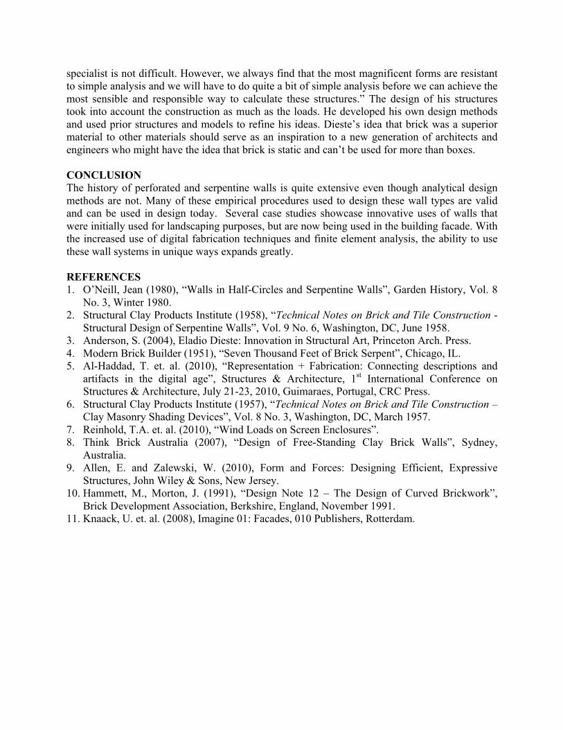
the Church of San Juan de Avila (Figure 18), Church of Christ the Worker (Figure 19), and the Montevideo Shopping Center (Figure 20).
Figure 18: Church of San Juan de Avila, Madrid, Spain
Figure 19: Wall from Church of Christ the Worker in Atlantida, Uruguay
Figure 20: Montevideo Shopping Center, Montevideo, Uruguay
Each of these structures is loadbearing masonry through and through. The undulating brick walls support brick vaults which span considerable distances. Although these walls stiffen the structure and might help resist lateral forces from the roof, they roof is designed so as not to create any lateral forces. In the case of the Atlantida church, the walls are 305 mm (12 in.) thick and start as a straight line at the bottom and change shape as the wall goes up resulting in a parabolic form at the top. The side walls of the church are 7 m (23 ft.) high by 32 m (105 ft.) in length and are topped with a concrete edge beam to transfer gravity loads from the roof to the walls. Dieste used mostly graphical methods of analysis in the design of his structures (Anderson 2004). In an essay written by Dieste, he states, “Today, it is true that there is not a structure that cannot be analyzed in finite terms, and discussion about structural problems with an intelligent
specialist is not difficult. However, we always find that the most magnificent forms are resistant to simple analysis and we will have to do quite a bit of simple analysis before we can achieve the most sensible and responsible way to calculate these structures.” The design of his structures took into account the construction as much as the loads. He developed his own design methods and used prior structures and models to refine his ideas. Dieste’s idea that brick was a superior material to other materials should serve as an inspiration to a new generation of architects and engineers who might have the idea that brick is static and can’t be used for more than boxes. CONCLUSION The history of perforated and serpentine walls is quite extensive even though analytical design methods are not. Many of these empirical procedures used to design these wall types are valid and can be used in design today. Several case studies showcase innovative uses of walls that were initially used for landscaping purposes, but are now being used in the building facade. With the increased use of digital fabrication techniques and finite element analysis, the ability to use these wall systems in unique ways expands greatly. REFERENCES 1. O’Neill, Jean (1980), “Walls in Half-Circles and Serpentine Walls”, Garden History, Vol. 8
No. 3, Winter 1980. 2. Structural Clay Products Institute (1958), “Technical Notes on Brick and Tile Construction -
Structural Design of Serpentine Walls”, Vol. 9 No. 6, Washington, DC, June 1958. 3. Anderson, S. (2004), Eladio Dieste: Innovation in Structural Art, Princeton Arch. Press. 4. Modern Brick Builder (1951), “Seven Thousand Feet of Brick Serpent”, Chicago, IL. 5. Al-Haddad, T. et. al. (2010), “Representation + Fabrication: Connecting descriptions and
artifacts in the digital age”, Structures & Architecture, 1st International Conference on Structures & Architecture, July 21-23, 2010, Guimaraes, Portugal, CRC Press.
6. Structural Clay Products Institute (1957), “Technical Notes on Brick and Tile Construction – Clay Masonry Shading Devices”, Vol. 8 No. 3, Washington, DC, March 1957.
7. Reinhold, T.A. et. al. (2010), “Wind Loads on Screen Enclosures”. 8. Think Brick Australia (2007), “Design of Free-Standing Clay Brick Walls”, Sydney,
Australia. 9. Allen, E. and Zalewski, W. (2010), Form and Forces: Designing Efficient, Expressive
Structures, John Wiley & Sons, New Jersey. 10. Hammett, M., Morton, J. (1991), “Design Note 12 – The Design of Curved Brickwork”,
Brick Development Association, Berkshire, England, November 1991. 11. Knaack, U. et. al. (2008), Imagine 01: Facades, 010 Publishers, Rotterdam.
Copyright © 2022 FDOKUMEN