Magnetoresistance behavior of ferromagnetic shape memory alloy Ni1.75Mn1.25Ga

Endovascular Navigation of a Ferromagnetic Microrobot UsingMRI-based Predictive Control
Karim Belharet, David Folio and Antoine Ferreira
Abstract— This paper presents real-time MRI-based controlof a ferromagnetic microcapsule for endovascular navigation.The concept was studied for future development of microdevicesdesigned to perform minimally invasive interventions in remotesites accessible through the human cardiovascular system. Asystem software architecture is presented illustrating the dif-ferent software modules to allow 3D navigation of a microdevicein blood vessels, namely: (i) vessel path planner, (ii) magneticgradient steering, (iii) tracking and (iv) closed-loop navigationcontrol. First, the position recognition of the microrobot into theblood vessel is extracted using Frangi vesselness filtering fromthe pre-operation images (3D MRI imaging). Then, a set ofminimal trajectory is predefined, using Fast Marching Method(FMM), to guide the microrobot from the injection point to thetumor area through the anarchic vessel network. Based on thepre-computed path, a Generalized Predictive Controller (GPC)is proposed for robust time-multiplexed navigation along a 2Dpath in presence of pulsative flow. The simulation results suggestthe validation of the proposed image processing and controlalgorithms. A series of disturbances introduced in the presenceand absence of closed-loop control affirms the robustness andeffectiveness of this predictive control system.
I. INTRODUCTION
Microrobots designed to perform targeted therapy by nav-igating in the cardiovascular system are a prolific researcharea for minimally invasive surgeries [1][2] and treatmentsefficiency through early diagnosis of diseases [3]. Cardiovas-cular problems are generally correlated with the obesity, hu-man sedentary lifestyle, or hereditary characteristics. Whenmicrorobots are propelled in the body fluids, especially inthe blood circulatory system, a very large number of remotelocations in the human body become accessible. However,since the diameters of the blood vessels in the humanbody may vary from approximately 25 mm (aorta) downto 0.010 mm (capillaries), it is obvious that propelling suchwireless microdevices in the human cardiovascular systemwith existing technologies represents a great technical chal-lenge [4]. Because the method of propulsion should allowsuch a microrobot to navigate through the cardiovascularsystem, the use of the normal blood flow itself must beconsidered only as a complementary means of propulsionwhen the travel path is in the direction of the blood flow.These untethered microrobots have been mainly developedaccording to three different designs: magnetic bead pulling[2], biomimetic flagellated robot [5] and magnetotactic bac-teria [6]. Furthermore, navigation requires observation ofthe scene in order either to plan the trajectory by off-line
The authors are with the Institute PRISME EA 4229; ENSI de Bourges,88 boulevard Lahitolle, 18020 Bourges, FRANCE; {karim.belharet,david.folio, antoine.ferreira} @ensi-bourges.fr
mapping, or to correct on-line the microrobot’s pose errorbetween the planned and the observed trajectory. Recently,magnetic resonance imaging (MRI)-based medical micro-robotic platforms are investigated to reach locations deep inthe human body while enhancing targeting efficacy usingreal-time navigational and trajectory control [7]. For theposition recognition of the microrobot in the blood vessels,from the pre-operation images, 3D path planning and routeoptimization solutions have been proposed. The authors in[8] proposed an endovascular path-planning method basedon 3D potential fields and enhanced breath-first search algo-rithms based on MR-imaging. In [9], Intra-Vascular Ultra-Sound medical imaging technique coupled to pre-operationalimages of computerized tomography renders possible 3Dnavigation in blood vessels. Based on these path-planningtechniques, only explorative 2D control strategies have beenadopted so far using simple proportional-integral-derivative(PID) controller [10]. However, stability and robustness arenot ensured against important perturbations. First, pulsatileflow whose variations in waveform, amplitude, and frequencyexists from one vessel to another. Second, variation oftime-multiplexed sequence parameters (duty cycle of thepropulsion gradients, and repetition time of the tracking se-quence) produce important trajectory errors during real-timenavigation. Finally, random imaging signal noise degradesthe localization of the microrobot during tracking.
The main objective of this paper is to propose an au-tomated technique based on image processing and controlalgorithms for path finding, reconstruction and navigationcontrol of a ferromagnetic microrobot using an MRI system.The MRI-based control of a ferromagnetic microcapsulepresented here is dedicated to macroscale navigation, whichfocuses in conveying the device in vessels such as arteriesand arterioles. As illustration of the concept, we consider apossible way for the microrobot get into the body throughthe femoral artery in the leg, which is the normal accesspoint to the circulatory system. One possible application isto locate atherosclerotic lesions in stenosed blood vessels,particularly in vasculary circulation, and treat them eitherchemically or pharmacologically by targeted drug delivery.Based on slice images provided by an MRI system, rel-evant information related to detection of blood vessels isextracted using robust Frangi vesselness filtering from thepre-operation images. Then, a set of minimal trajectory ispredefined, using Fast Marching Method (FMM), to guidethe ferromagnetic microrobot from the injection point to thetumor area through the anarchic vessel network. Based onthe precomputed path, a Generalized Predictive Controller
hal-0
0635
340,
ver
sion
1 -
25 O
ct 2
011
Author manuscript, published in "IEEE/RSJ International Conference on Intelligent Robots and Systems (IROS'2010), Taipei, Taiwan :France (2010)"
DOI : 10.1109/IROS.2010.5650803
(GPC) is designed for robust time-multiplexed navigationalong a 2D path in presence of pulsative flow. The simu-lation results suggest the validation of the proposed imageprocessing and control algorithms. A series of disturbancesintroduced in the presence and absence of closed-loop controlaffirms the robustness and effectiveness of this predictivecontrol system.
II. ENDOVASCULAR NAVIGATIONA. Finding Endovascular Navigation Path
In our context, the problem of finding the navigation pathwithin the MRI data can be formulated as finding the correctway through the data which follows the vessel of interestbetween its start and end point. Finding a navigation pathwithin the vessel network is then an essential, primary, andimportant step which must be addressed prior to the controlprocedure. The problem of vessels extraction has receivedconsiderable attention in the computer vision and medicalimaging communities [11]. Hence, several class of methodshave been proposed to find a path from a set of medicalimaging, such as using tracking methods [12] [7] [13], pathextraction methods [14][15][16], and so on. Most worksbased on in vivo MR-tracking methods usually need manyuser-defined way points as the input of a controller modulefor the navigation computation. A major drawback in generalremains when the user must define many points (e.g. wayor fiducial points) manually. Hence, for a complex structure(e.g. colon, small vessels. . . ) the required interactivity canbe very tedious. As consequence, if the path is not correctlybuild, it can cross an anatomical wall during the in vivonavigation. In opposition, path extraction approaches dependonly on the manual definition of the start and end points ofthe desired vascular path. Therefore, we propose in this workto use path extraction technique to find the desired path tobe followed in the vessel network.
1) Endovascular Path Extraction: The path extraction isuseful for a range of application domains including medicalimage analysis, robot navigation, and artificial intelligence.The path extraction technique needs a very simple ini-tialisation and leads to global minimum of a snake-likeenergy, thus avoiding local minima. Moreover it is fast andaccurate. This path finding problem has been studied forages by mathematicians, and has been solved numericallyusing graph theory or dynamic programming. Cohen andKimmel [17] solved the minimal path problem in 2D witha front propagation equation between the two fixed endpoints, using the Eikonal equation (that physically modelswave-light propagation), with a given initial front. Wink etal.[15] explored different methods to determine the minimumcost path through a pre-defined cost image, for extraction ofvessel centrelines from medical image data. Among themare Dijikstra’s algorithm [18], the A? algorithm [19], whichmakes use of additional heuristics to steer the search process,and wave front propagation analysis [16]. Early, Sethian[20] explore the use of Fast Marching Method (FMM) toextract minimal paths. This method relies on the fact thatthe gradient of the FMM arrival function has only one
local minimum, with is guaranteed to be global minimum[14]. Therefore the minimal path can be extracted by back-propagating from given seeds (e.g. the end point of thedesired path) to the starting point implicitly embedded inthe arrival function.
In this work the FMM is adopted to design a set oftrajectory to guide the micro-device from the injection pointto the tumor area through the vessel network. Our aimis to focus on the automation of the path construction,reducing the need of interaction and improving performance,in a robust way. Finally, as the proposed control strategy,presented in section III-B, is designed for 2D navigationproblem, we have limited our path extraction procedure to2D application.
2) Applications and Navigation Path Extraction Results:The FMM algorithm, introduced by Sethian [20] is appliedhere to extract a targeted navigation path within the vesselnetwork. The FMM is very closely related to Dijkstra’smethod [18], which is a very well-known method from the1950’s for computing the shortest path on a network. Hence,from the set of MRI data we have first to compute a speedmap (ie. a weighting image map), which must enhance therelevant intravascular network. Choosing an appropriate andefficient image cost function is the most difficult part of theentire process. The definition of the optimal speed functionis case dependent and should be set by the user, along withthe start and end points of the path. Hence, an optimal pathcould be found only if the optimal cost function is provided.In this work, we focus mainly on finding a path allowingreaching the targeted zone.
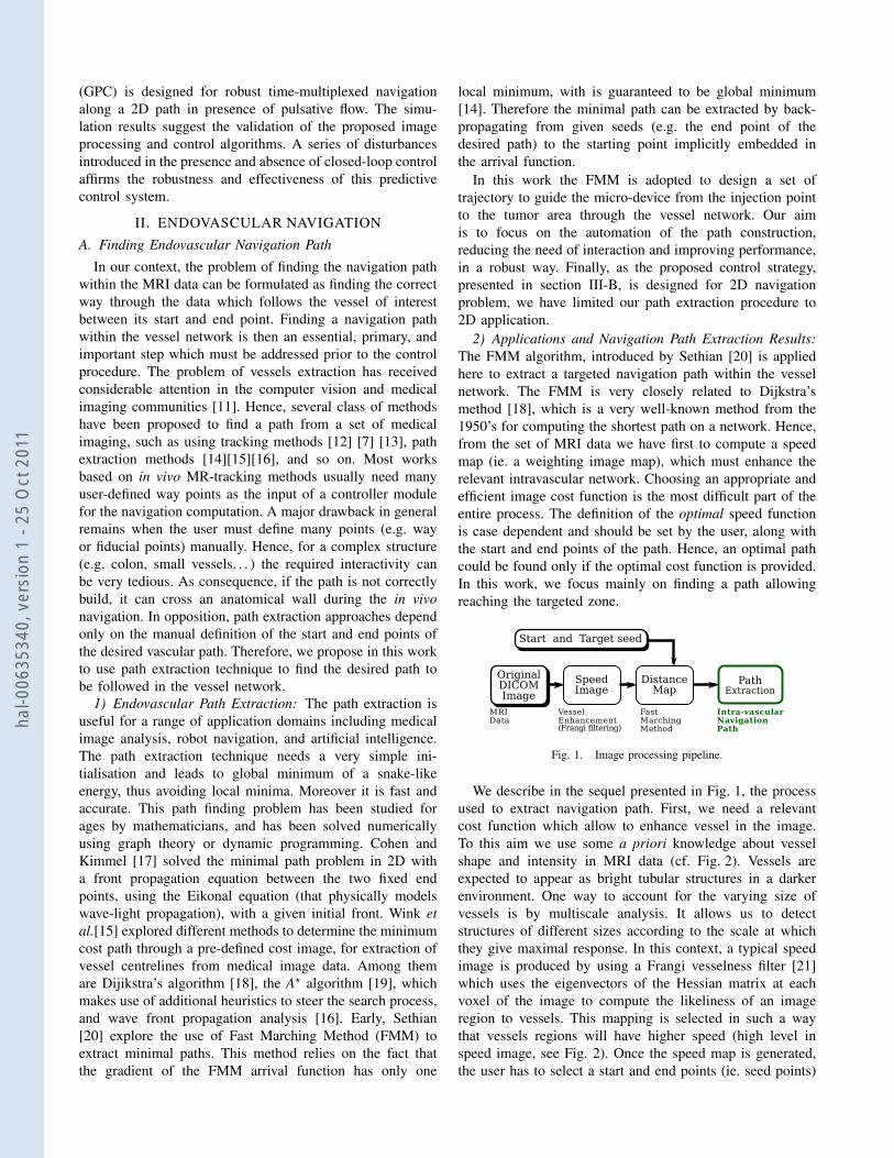
Fig. 1. Image processing pipeline.
We describe in the sequel presented in Fig. 1, the processused to extract navigation path. First, we need a relevantcost function which allow to enhance vessel in the image.To this aim we use some a priori knowledge about vesselshape and intensity in MRI data (cf. Fig. 2). Vessels areexpected to appear as bright tubular structures in a darkerenvironment. One way to account for the varying size ofvessels is by multiscale analysis. It allows us to detectstructures of different sizes according to the scale at whichthey give maximal response. In this context, a typical speedimage is produced by using a Frangi vesselness filter [21]which uses the eigenvectors of the Hessian matrix at eachvoxel of the image to compute the likeliness of an imageregion to vessels. This mapping is selected in such a waythat vessels regions will have higher speed (high level inspeed image, see Fig. 2). Once the speed map is generated,the user has to select a start and end points (ie. seed points)
hal-0
0635
340,
ver
sion
1 -
25 O
ct 2
011
(a) (b)
(c) (d)
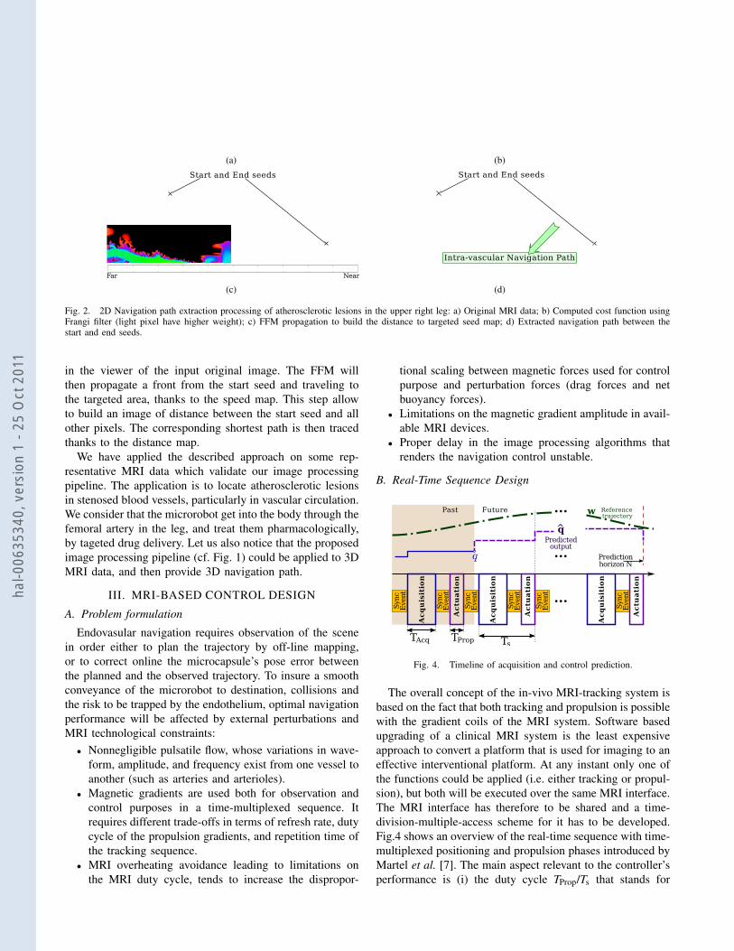
Fig. 2. 2D Navigation path extraction processing of atherosclerotic lesions in the upper right leg: a) Original MRI data; b) Computed cost function usingFrangi filter (light pixel have higher weight); c) FFM propagation to build the distance to targeted seed map; d) Extracted navigation path between thestart and end seeds.
in the viewer of the input original image. The FFM willthen propagate a front from the start seed and traveling tothe targeted area, thanks to the speed map. This step allowto build an image of distance between the start seed and allother pixels. The corresponding shortest path is then tracedthanks to the distance map.
We have applied the described approach on some rep-resentative MRI data which validate our image processingpipeline. The application is to locate atherosclerotic lesionsin stenosed blood vessels, particularly in vascular circulation.We consider that the microrobot get into the body through thefemoral artery in the leg, and treat them pharmacologically,by tageted drug delivery. Let us also notice that the proposedimage processing pipeline (cf. Fig. 1) could be applied to 3DMRI data, and then provide 3D navigation path.
III. MRI-BASED CONTROL DESIGN
A. Problem formulation
Endovasular navigation requires observation of the scenein order either to plan the trajectory by off-line mapping,or to correct online the microcapsule’s pose error betweenthe planned and the observed trajectory. To insure a smoothconveyance of the microrobot to destination, collisions andthe risk to be trapped by the endothelium, optimal navigationperformance will be affected by external perturbations andMRI technological constraints:• Nonnegligible pulsatile flow, whose variations in wave-
form, amplitude, and frequency exist from one vessel toanother (such as arteries and arterioles).
• Magnetic gradients are used both for observation andcontrol purposes in a time-multiplexed sequence. Itrequires different trade-offs in terms of refresh rate, dutycycle of the propulsion gradients, and repetition time ofthe tracking sequence.
• MRI overheating avoidance leading to limitations onthe MRI duty cycle, tends to increase the dispropor-
tional scaling between magnetic forces used for controlpurpose and perturbation forces (drag forces and netbuoyancy forces).
• Limitations on the magnetic gradient amplitude in avail-able MRI devices.
• Proper delay in the image processing algorithms thatrenders the navigation control unstable.
B. Real-Time Sequence Design
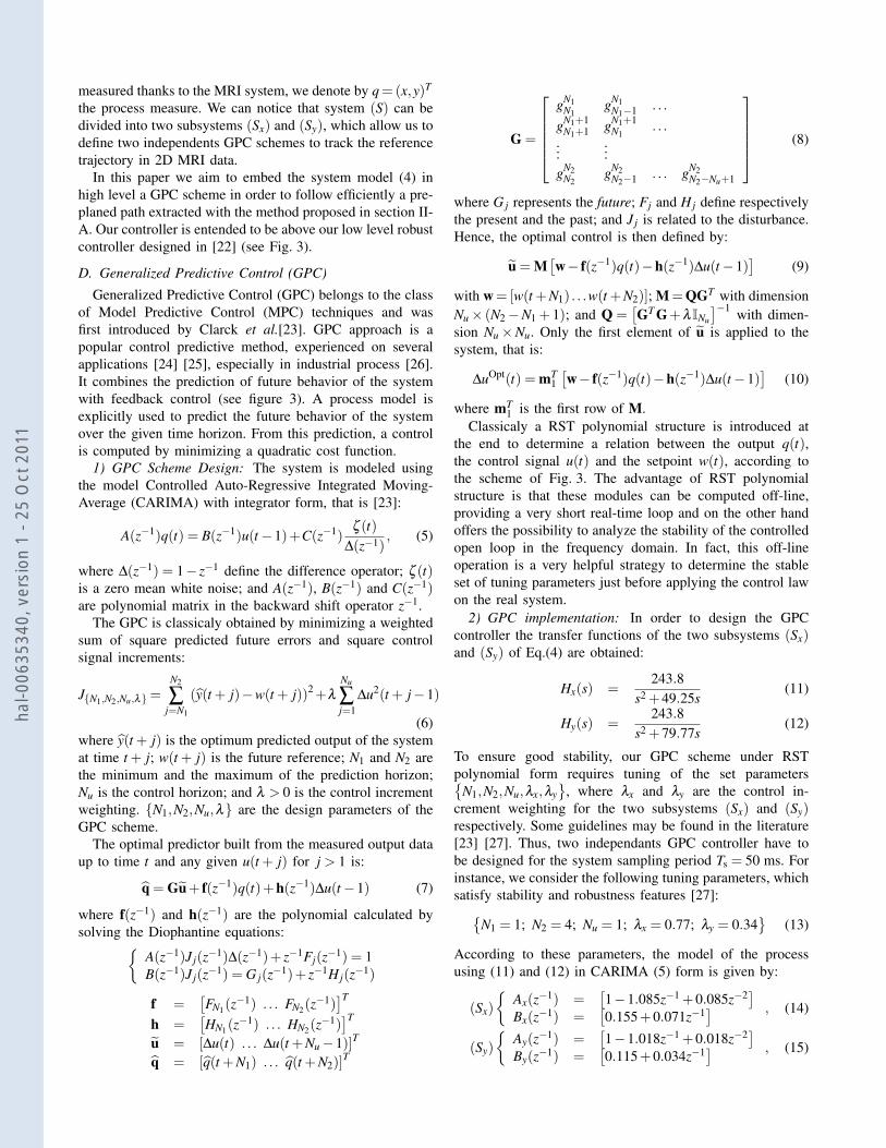
Fig. 4. Timeline of acquisition and control prediction.
The overall concept of the in-vivo MRI-tracking system isbased on the fact that both tracking and propulsion is possiblewith the gradient coils of the MRI system. Software basedupgrading of a clinical MRI system is the least expensiveapproach to convert a platform that is used for imaging to aneffective interventional platform. At any instant only one ofthe functions could be applied (i.e. either tracking or propul-sion), but both will be executed over the same MRI interface.The MRI interface has therefore to be shared and a time-division-multiple-access scheme for it has to be developed.Fig.4 shows an overview of the real-time sequence with time-multiplexed positioning and propulsion phases introduced byMartel et al. [7]. The main aspect relevant to the controller’sperformance is (i) the duty cycle TProp/Ts that stands for
hal-0
0635
340,
ver
sion
1 -
25 O
ct 2
011
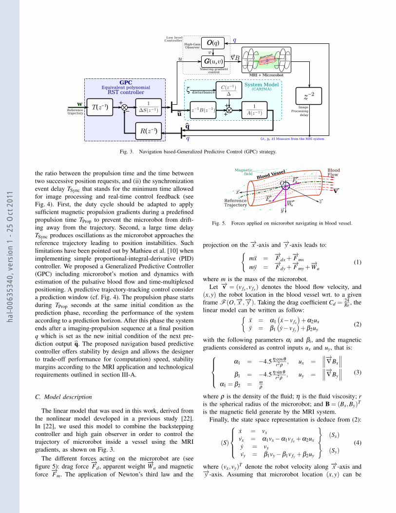
Fig. 3. Navigation based-Generalized Predictive Control (GPC) strategy.
the ratio between the propulsion time and the time betweentwo successive position requests, and (ii) the synchronizationevent delay TSync that stands for the minimum time allowedfor image processing and real-time control feedback (seeFig. 4). First, the duty cycle should be adapted to applysufficient magnetic propulsion gradients during a predefinedpropulsion time TProp to prevent the microrobot from drift-ing away from the trajectory. Second, a large time delayTSync produces oscillations as the microrobot approaches thereference trajectory leading to position instabilities. Suchlimitations have been pointed out by Mathieu et al. [10] whenimplementing simple proportional-integral-derivative (PID)controller. We proposed a Generalized Predictive Controller(GPC) including microrobot’s motion and dynamics withestimation of the pulsative blood flow and time-multiplexedpositioning. A predictive trajectory-tracking control considera prediction window (cf. Fig. 4). The propulsion phase startsduring TProp seconds at the same initial condition as theprediction phase, recording the performance of the systemaccording to a prediction horizon. After this phase the systemends after a imaging-propulsion sequence at a final positionq which is set as the new initial condition of the next pre-diction output q. The proposed navigation based predictivecontroller offers stability by design and allows the designerto trade-off performance for (computation) speed, stabilitymargins according to the MRI application and technologicalrequirements outlined in section III-A.
C. Model description
The linear model that was used in this work, derived fromthe nonlinear model developed in a previous study [22].In [22], we used this model to combine the backsteppingcontroller and high gain observer in order to control thetrajectory of microrobot inside a vessel using the MRIgradients, as shown on Fig. 3.
The different forces acting on the microrobot are (seefigure 5): drag force
−→Fd , apparent weight
−→Wa and magnetic
force−→Fm. The application of Newton’s third law and the
Fig. 5. Forces applied on microrobot navigating in blood vessel.
projection on the −→x -axis and −→y -axis leads to:{mx =
−→F dx +
−→F mx
my =−→F dy +
−→F my +
−→Wa
(1)
where m is the mass of the microrobot.Let −→v = (v fx ,v fx) denotes the blood flow velocity, and
(x,y) the robot location in the blood vessel wrt. to a givenframe F (O,−→x ,−→y ). Taking the drag coefficient Cd =
24Re , the
linear model can be written as follow:{x = α1
(x− v fx
)+α2ux
y = β1(y− v fy
)+β2uy
(2)
with the following parameters αi and βi, and the magneticgradients considered as control inputs ux and uy, that is:
α1 = −4.5 η cosθ
r2ρ, ux =
∥∥∥−→∇ Bx
∥∥∥β1 = −4.5 η sinθ
r2ρ, uy =
∥∥∥−→∇ By
∥∥∥α1 = β2 = m
ρ
(3)
where ρ is the density of the fluid; η is the fluid viscosity; ris the spherical radius of the microrobot; and B = (Bx,By)
T
is the magnetic field generate by the MRI system.Finally, the state space representation is deduce from (2):
(S)
x = vxvx = α1vx−α1v fx +α2ux
}(Sx)
y = vyvy = β1vy−β1v fy +β2uy
}(Sy)
(4)
where (vx,vy)T denote the robot velocity along −→x -axis and
−→y -axis. Assuming that microrobot location (x,y) can be
hal-0
0635
340,
ver
sion
1 -
25 O
ct 2
011
measured thanks to the MRI system, we denote by q=(x,y)T
the process measure. We can notice that system (S) can bedivided into two subsystems (Sx) and (Sy), which allow us todefine two independents GPC schemes to track the referencetrajectory in 2D MRI data.
In this paper we aim to embed the system model (4) inhigh level a GPC scheme in order to follow efficiently a pre-planed path extracted with the method proposed in section II-A. Our controller is entended to be above our low level robustcontroller designed in [22] (see Fig. 3).
D. Generalized Predictive Control (GPC)
Generalized Predictive Control (GPC) belongs to the classof Model Predictive Control (MPC) techniques and wasfirst introduced by Clarck et al.[23]. GPC approach is apopular control predictive method, experienced on severalapplications [24] [25], especially in industrial process [26].It combines the prediction of future behavior of the systemwith feedback control (see figure 3). A process model isexplicitly used to predict the future behavior of the systemover the given time horizon. From this prediction, a controlis computed by minimizing a quadratic cost function.
1) GPC Scheme Design: The system is modeled usingthe model Controlled Auto-Regressive Integrated Moving-Average (CARIMA) with integrator form, that is [23]:
A(z−1)q(t) = B(z−1)u(t−1)+C(z−1)ζ (t)
∆(z−1), (5)
where ∆(z−1) = 1− z−1 define the difference operator; ζ (t)is a zero mean white noise; and A(z−1), B(z−1) and C(z−1)are polynomial matrix in the backward shift operator z−1.
The GPC is classicaly obtained by minimizing a weightedsum of square predicted future errors and square controlsignal increments:
J{N1,N2,Nu,λ}=N2
∑j=N1
(y(t + j)−w(t + j))2+λ
Nu
∑j=1
∆u2(t + j−1)
(6)where y(t + j) is the optimum predicted output of the systemat time t + j; w(t + j) is the future reference; N1 and N2 arethe minimum and the maximum of the prediction horizon;Nu is the control horizon; and λ > 0 is the control incrementweighting. {N1,N2,Nu,λ} are the design parameters of theGPC scheme.
The optimal predictor built from the measured output dataup to time t and any given u(t + j) for j > 1 is:
q = Gu+ f(z−1)q(t)+h(z−1)∆u(t−1) (7)
where f(z−1) and h(z−1) are the polynomial calculated bysolving the Diophantine equations:{
A(z−1)J j(z−1)∆(z−1)+ z−1Fj(z−1) = 1B(z−1)J j(z−1) = G j(z−1)+ z−1H j(z−1)
f =[FN1(z
−1) . . . FN2(z−1)]T
h =[HN1(z
−1) . . . HN2(z−1)]T
u = [∆u(t) . . . ∆u(t +Nu−1)]T
q = [q(t +N1) . . . q(t +N2)]T
G =
gN1
N1gN1
N1−1 . . .
gN1+1N1+1 gN1+1
N1. . .
......
gN2N2
gN2N2−1 . . . gN2
N2−Nu+1
(8)
where G j represents the future; Fj and H j define respectivelythe present and the past; and J j is related to the disturbance.Hence, the optimal control is then defined by:
u = M[w− f(z−1)q(t)−h(z−1)∆u(t−1)
](9)
with w= [w(t +N1) . . .w(t +N2)]; M=QGT with dimensionNu× (N2−N1 + 1); and Q =
[GT G+λ INu
]−1 with dimen-sion Nu×Nu. Only the first element of u is applied to thesystem, that is:
∆uOpt(t) = mT1[w− f(z−1)q(t)−h(z−1)∆u(t−1)
](10)
where mT1 is the first row of M.
Classicaly a RST polynomial structure is introduced atthe end to determine a relation between the output q(t),the control signal u(t) and the setpoint w(t), according tothe scheme of Fig. 3. The advantage of RST polynomialstructure is that these modules can be computed off-line,providing a very short real-time loop and on the other handoffers the possibility to analyze the stability of the controlledopen loop in the frequency domain. In fact, this off-lineoperation is a very helpful strategy to determine the stableset of tuning parameters just before applying the control lawon the real system.
2) GPC implementation: In order to design the GPCcontroller the transfer functions of the two subsystems (Sx)and (Sy) of Eq.(4) are obtained:
Hx(s) =243.8
s2 +49.25s(11)
Hy(s) =243.8
s2 +79.77s(12)
To ensure good stability, our GPC scheme under RSTpolynomial form requires tuning of the set parameters{
N1,N2,Nu,λx,λy}
, where λx and λy are the control in-crement weighting for the two subsystems (Sx) and (Sy)respectively. Some guidelines may be found in the literature[23] [27]. Thus, two independants GPC controller have tobe designed for the system sampling period Ts = 50 ms. Forinstance, we consider the following tuning parameters, whichsatisfy stability and robustness features [27]:{
N1 = 1; N2 = 4; Nu = 1; λx = 0.77; λy = 0.34}
(13)
According to these parameters, the model of the processusing (11) and (12) in CARIMA (5) form is given by:
(Sx)
{Ax(z−1) =
[1−1.085z−1 +0.085z−2
]Bx(z−1) =
[0.155+0.071z−1
] , (14)
(Sy)
{Ay(z−1) =
[1−1.018z−1 +0.018z−2
]By(z−1) =
[0.115+0.034z−1
] , (15)
hal-0
0635
340,
ver
sion
1 -
25 O
ct 2
011

Fig. 6. Longitudinal position microrobot control.
and where Cx(z−1) and Cy(z−1) are set to 1. The RST formoptimal control is:
∆uOptx (t)Sx(z−1) = Tx(z−1)wx(t)−Rx(z−1)qx(t) (16)
∆uOpty (t)Sy(z−1) = Ty(z−1)wy(t)−Ry(z−1)qy(t) (17)
withRx(z−1) = 2.855−2.222z−1 +0.169z−2
Sx(z−1) = 1+0.140z−1
Tx(z−1) = 0.123z+0.273z2 +0.405z3(18)
Ry(z−1) = 4.0.61−2.906z−1 +0.052z−2
Sy(z−1) = 1+0.098z−1
Ty(z−1) = 0.206z+0.410z2 +0.592z3(19)
E. Results
Simulations are conducted within the scope of actualcommonly spread MRI system abilities. At the moment,MRI systems are able to generate magnetic gradients withan intensity of some tens of mT.m−1. Let us note that thislimitation is additionally affected by the gradient coils dutycycle and by the multiplexing needed both for controlling andobserving. In order to make sure that the amplitude of thecontrol inputs remains bounded by physical actuators limitsui,max and to protect the system, we perform a simple timescaling. Thus, the applied control law is given by ui
k(t) , with
k(t) =max{
1, uiui,max
}. The set of simulations corresponds to
microcapsule’s radius of r = 300 µm and a time scalingsettled at k(t) = 0.55. Different situations are considered inthis section to illustrate and validate the performance androbustness of the proposed MRI-based predictive controllershown on Fig. 3. As the considered system is decoupled intotwo subsystems (Sx) and (Sy) (4), we have first validate thecontrol strategy onto 1D longitudinal path. As illustration, themicrorobot has to follow a sinusoidal reference trajectory (cf.Fig. 6 and 7) for different time horizons N =N2−N1 (namelyN = 3,10, and 15).
Fig. 6 presents the trajectories followed by the microrobot,and the relative error between the current position q and
Fig. 7. Longitudinal position microrobot control with white noise.
the reference w. As one can see the system output followscorrectly the reference trajectory w for each consideredprediction horizon N. The output of the closed loop systemis dependent on the setting parameters of the GPC. Theprevious curves show the impact of N on the system. More-over, comparing the different plots, the nature of anticipationof the GPC scheme is illustrate —greater is N more isanticipate the path behaviour— Hence, a great value ofN does not necessarily guarantee good performance, andclassicaly increase the complexity of the scheme.
To evalute the efficiency of the proposed MRI-basedpredictive controller, we added a white Gaussian noise on thesytem output measure q. Fig. 7 shows the system responsein the presence of this disturbance on the system. Globally,tracking is not too much affected by the noise, since positionstandard deviation (std) and root mean square (RMS) errorare quite satisfactory (see table I).
TABLE IERROR STATISTICS
1D with noise 2D navigationN = 3 N = 10 N = 15 without noise with noise
std 0.2303 0.2971 0.2949 1.0438 1.2121RMS 0.2368 0.2967 0.2959 1.0480 1.2306
We validated the proposed control strategy on 2D en-dovascular navigation path extracted from MRI-data withthe method presented in section II-A. As shown in Fig. 8and 9, the system output q follows perfectly the referencetrajectory w, either without or with white Gaussian noiseadded. In particular, the microrobot are able to reach quicklythe navigation path, in spite of a big gap between the initialposition q and the begin of reference w (about 50 pixels).Fig. 8(b) and 9(b) describe the error evolution in both cases.Once again the error remains small with low values of std andRMS parameters. Let us notice that these 2D error statisticsgiven in table I take into account the gap between the initialmicrorobot position and the start of the reference path.
hal-0
0635
340,
ver
sion
1 -
25 O
ct 2
011

(a) 2D trajecrories without noise.
(b) Tracking error (N = 3): ‖q−w‖
Fig. 8. 2D MRI-based microrobot endovascular navigation (N = 3).
(a) 2D trajecrories with white noise.
(b) Tracking error: ‖q−w‖
Fig. 9. 2D MRI-based microrobot endovascular navigation (N = 3) witha white noise.
Fig. 10. 2D trajectory tracking error ‖q−w‖, with noise and wrong modelparamaters (r+30% and η +10%)
Finally, to evaluate the robustness of our strategy, we haveperformed some tests in which some model parameters (4)are not well identified, and the white noise still added. Asillustrated in Fig. 10, the 2D trajecrory tracking error is quiteimportant, but still remains satisfactory.
IV. CONCLUSIONSThe proposed MRI-based ferromagnetic microcapsule
steering and navigation strategy has been developed atmilliscale and microscale, where endovascular navigationpath extraction and predictive controller have been designed.The main drawback of MRI-based navigation stems fromthe strong limitations on the magnetic gradient amplitudeof available MRI devices. As magnetic forces used forpropelling are volumetric, whereas the drag force is atbest dependent on the microcapsule’s area, the smaller thecapsule, the higher the required control forces with respectto hydrodynamic perturbations. Consequently, this approachis well conditioned for beads whose radius is up to a fewdozen micrometers with actual MRI devices. Targeting aimsat focusing these micro-carriers and stopping them throughembolization at the arterioles entry close to the occludedblood vessels. Possible releasing mechanisms could rely onbiodegradable polymer and techniques used in hyperthermiawhere aggregates of nanocapsules can be heated to meltpolymer. Such a solution is actually under experimentationfor validation of the proposed minimally invasive MRI-basedmicrorobotic system.
V. ACKNOWLEDGMENTSThis work was supported by European Union’s 7th
Framework Program and its research area ICT-2007.3.6Micro/nanosystems under the project NANOMA (Nano-Actuactors and Nano-Sensors for Medical Applications). ThePhD student K. Belharet is supported by the Nano-IRMproject, founded by Region Centre and City of Bourges.
REFERENCES
[1] K. Ishiyama, M. Sendoh, and K. I. Arai, “Magnetic micromachinesfor medical applications,” J. of Magnetism and Magnetic Materials,vol. 242-245, pp. 41–46, 2002.
[2] J. Abbott, Z. Nagy, F. Beyeler, and B. Nelson, “Robotics in the Small,”IEEE Robot. Automat. Mag., p. 92, 2007.
[3] T. A. Cavalcanti, B. Shirinzadeh and S. Ikeda, “Nanorobot for BrainAneurysm,” Int. J. of Robotic Research, vol. 28, no. 4, pp. 558–570,2009.
[4] J. J. Abbott, K. E. Peyer, M. C. Lagomarsino, L. Zhang, L. X. Dong,I. K. Kaliakatsos, and B. J. Nelson, “How should microrobots swim?”Int. J. of Robotics Research, Jul. 2009.
[5] B. Behkam and M. Sitti, “Design methodology for biomimetic propul-sion of miniature swimming robots,” ASME J. Dyn. Syst. Meas.Control, pp. 36–43, 2006.
[6] S. Martel, M. Mohammadi, O. Felfoul, Z. Lu, and P. Poupon-neau, “Flagellated magnetotactic bacteria as controlled MRItrackablepropulsion and steering systems for medical nanorobots operating inthe human microvasculature,” Int. J. Robot. Res., vol. 28, no. 4, pp.571–582, 2009.
[7] O. Felfoul, J. Mathieu, G. Beaudoin, and S. Martel, “In vivo MR-tracking based on magnetic signature selective excitation,” IEEE Trans.Med. Imag., vol. 27, no. 1, pp. 28–35, Jan. 2008.
[8] W. Sabra, M. Khousam, and S. Martel, “Use of 3D potential fieldand an enhanced breath-first search algorithms for path-planning ofmicrodevices propelled in the cardiovascular system,” 27th IEEEEMBS Annual Int. Conf., pp. 91 – 100, 2005.
hal-0
0635
340,
ver
sion
1 -
25 O
ct 2
011

[9] S. Park and J.-O. Park, “Frontier research program on biomedicalrobot for intravascular therapy,” 2nd IEEE/RAS-EMBS Int. Conf. onBiomedical Robotics and Biomechatronics, pp. 360 – 365, 2008.
[10] S. Tamaz, A. Chanu, J.-B. Mathieu, R. Gourdeau, and S. Martel,“Real-time mri-based control of a ferromagnetic core for endovascularnavigation,” IEEE Trans. Bio-Med. Eng., vol. 55, no. 7, pp. 1854–1863,July 2008.
[11] C. Kirbas and F. Quek, “A review of vessel extraction techniques andalgorithms,” ACM Comput. Surv., vol. 36, no. 2, pp. 81–121, 2004.
[12] P. Reuze, J. Coatrieux, L. Luo, and J. Dillenseger, “A 3D momentbased approach for blood vessel detection and quantification in MRA,”Technology and Health Care, vol. 1, pp. 181–188, 1993.
[13] J. Tokuda, G. S. Fischer, S. P. DiMaio, D. G. Gobbi, C. Csoma,P. W. Mewes, G. Fichtinger, C. M. Tempany, and N. Hata, “Integratednavigation and control software system for mri-guided robotic prostateinterventions,” Computerized Medical Imaging and Graphics, vol. 34,no. 1, pp. 3–8, 2010, image-Guided Surgical Planning and Therapy.
[14] T. Deschamps, “Curve and shape extraction with minimal path andlevel-sets techniques: Applications to 3d medical imaging,” Ph.D.dissertation, University of Paris Dauphine, 2001.
[15] O. Wink, W. J. Niessen, and M. A. Viergever, “Minimum cost pathdetermination using a simple heuristic function,” Int. Conf. on PatternRecognition, vol. 3, p. 7010, 2000.
[16] O. Wink, W. Niessen, B. Verdonck, and M. Viergever, “Vessel axisdetermination using wave front propagation analysis,” Medical ImageComputing and Computer-Assisted Intervention, vol. 2208, pp. 845–853, 2001, lecture Notes in Computer Science.
[17] L. Cohen and R. Kimmel, “Global minimum for active contourmodels: A minimal path approach,” Int. J. of Computer Vision, vol. 24,no. 1, pp. 57–78, 1997.
[18] E. W. Dijkstra, “A note on two problems in connexion with graphs,”Numerische Mathematik, vol. 1, pp. 269–271, 1959.
[19] J. Pearl, Heuristics: intelligent search strategies for computer problemsolving. Boston, MA, USA: Addison-Wesley Longman PublishingCo., Inc., 1984.
[20] J. Sethian et al., Level set methods and fast marching methods.Cambridge university press Cambridge, 1999.
[21] A. Frangi, W. Niessen, K. Vincken, and M. Viergever, “Multiscalevessel enhancement filtering,” Lecture Notes in Computer Science, pp.130–137, 1998.
[22] L. Arcese, M. Fruchard, and A. Ferreira, “Nonlinear modeling androbust controller-observer for a magnetic microrobot in a fluidicenvironment using MRI gradients,” in IEEE/RSJ Int. Conf. on Intel.Robots and Systems, St. Louis, MO, USA, Oct. 2009, pp. 534–539.
[23] D. Clarke, C. Mohtadi, and P. Tuffs, “Generalized predictive control– Part I & II,” Automatica, vol. 23, pp. 137–160, 1987.
[24] M. Mahfouf and D. Linkens, Generalised predictive control andbioengineering, ser. Systems and Control. CRC press, August 1998.
[25] S. Huang, K. Tan, and T. Lee, Applied predictive control, ser. Advancesin Industrial Control. Springer Verlag, 2002.
[26] S. Qin and T. Badgwell, “A survey of industrial model predictivecontrol technology,” Control engineering practice, vol. 11, no. 7, pp.733–764, 2003.
[27] P. Boucher and D. Dumur, La commande predictive, TECHNIP ed.,ser. Collection Mthodes et Pratiques de l’Ingnieur, Paris, 1996.
hal-0
0635
340,
ver
sion
1 -
25 O
ct 2
011
Copyright © 2022 FDOKUMEN