
Endodontics Problem-Solving in Clinical Practice
206
-
Upload
khangminh22 -
Category
Documents
-
view
0 -
download
0
Transcript of Endodontics Problem-Solving in Clinical Practice


EndodonticsProblem-Solving in Clinical Practice
TR Pitt Ford, BDS, PhD, FDS RCPSJS Rhodes, BDS, MSc, MRD RCS, MFGDPHE Pitt Ford, FDS RCS
Department of Conservative DentistryGuy's, King's and St Thomas' Dental InstituteKing's College LondonLondon, UK
Martin Dunitz

@ 2002 Martin Dunitz Ltd, a member of the Taylor & Francis group
First published in the United Kingdom in 2002by Martin Dunitz Ltd, The Livery House, 7-9 Pratt Street, London NW1 OAE
Tel:
+44 (0) 20 74822202Fax:
+44 (0) 20 72670159E-mail: [email protected] kWebsite: http://www.dunitz.co.u k
All rights reserved. No part of this publication may be reproduced, stored in a retrieval system, or trans-mitted, in any form or by any means, electronic, mechanical, photocopying, recording, or otherwise, with-out the prior permission of the publisher or in accordance with the provisions of the Copyright, Designsand Patents Act 1988 or under the terms of any licence permitting limited copying issued by the CopyrightLicensing Agency, 90 Tottenham Court Road, London WIP OLP.
Although every effort has been made to ensure that all owners of copyright material have been acknowl-edged in this publication, we would be glad to acknowledge in subsequent reprints or editions any omis-sions brought to our attention.
Although every effort has been made to ensure that drug doses and other information are presented accu-rately in this publication, the ultimate responsibility rests with the prescribing physician. Neither the pub-lishers nor the authors can be held responsible for errors or for any consequences arising from the use ofinformation contained herein. For detailed prescribing information or instructions on the use of any prod-uct or procedure discussed herein, please consult the prescribing information or instructional materialissued by the manufacturer.
A CIP record for this book is available from the British Library.
ISBN 1-85317-695-8
Distributed in the United States and Canada by:Thieme New York333 Seventh AvenueNew York, NY 10001
Distributed in the rest of the world by:ITPS LimitedCheriton HouseNorth WayAndover, Hampshire SP10 5BE, UKTel: +44 (0)1264 332424E-mail: [email protected]
Composition by Wearset Ltd, Boldon, Tyne & Wear
Printed and bound in Singapore by Kyodo Printing Pte Ltd

CONTENTS
Acknowledgements
viPreface
vii
1
History, diagnosis and treatment planning
1
2
Three-dimensional root canal anatomy
27
3
Preparation prior to endodontics
45
4 Isolation
65
5
Root canal preparation
79
6
Irrigation and medication
111
7
Obturation techniques
121
8
Root canal retreatment
137
9
Restoration of the endodontically treated tooth
149
10
Complex endodontic problems
165
11
Endodontic care of permanent teeth in children
179
12
Endodontic emergencies
195
Index
201

ACKNOWLEDGEMENTS
The authors wish to thank the following for kind permission to reproduce figures:Dr M Mohammed (Figures 1.4 and 1.5)Schick Technologies Inc. (Figure 1.54)Dr J Lynch (Figure 2.3)Mr D Pittman (Figure 8.1)Dr E Sheehy (Figure 11.1).
Figures 1.56, 1.57 and 5.19 are from TR Pitt FordFigures 11.4-11.18 are from HE Pitt FordAll other figures are from JS Rhodes.
John Rhodes would like to acknowledge the contributions made by the following people duringthe writing of this book:Neil Conduit of QED, Douglas Pittman of DP Medical, Stuart Clark of Clark Dental, and KerrUK, who all loaned equipment for photographyThe patients and staff at Heath House Dental Health Centre, many of whom agreed to be pho-tographed for illustrative materialJohn Lynch and Charlie Bird, for their expertise in Micro Computed TomographyDr Chris Stock, an endodontic mentor, and my wife, Sarah, who supported me patientlythroughout the many hours spent word-processing.

PREFACE
This book has been primarily written for the practising dental practitioner, who would like tobe updated in modern clinical endodontics, although it will also be of benefit for practitionerswith a special interest in endodontics. With the rise in patient expectations about retainingendodontically involved posterior teeth as well as anteriors, busy dental practitioners need tobe aware of current views on diagnosis and treatment.
A problem-solving approach has been adopted since patients present with individual prob-lems, which require predictable and effective solutions. Considerable emphasis is placed onarriving at a reliable diagnosis, and making both the process and the outcome of treatment pre-dictable. With practitioners increasingly presented with patients who have failed root canaltreatment, a section is devoted to the effective management of these cases. The days of a 'try itand see' approach have passed; practitioners are now expected to make the correct diagnosisand carry out the appropriate treatment to a high standard, or to refer the patient to a suitablytrained person who can.
The book is profusely illustrated to help the reader understand the conditions and techniquesbeing described. The text has been written in an easy-to-read style devoid of original references,but further reading is included at the end of chapters. The authors hope that patients will be themain beneficiaries and that those practitioners who have struggled with root canal treatmentwill now find their work easier.
TR Pitt FordJS Rhodes
HE Pitt Ford

1
HISTORY, DIAGNOSIS AND TREATMENTPLANNING
CONTENTS • Introduction • Surgical Sieve • Medical History • A Medical HistoryProforma • Infective Endocarditis • Antibiotic Prophylaxis • Patients at Risk of InfectiveEndocarditis • Chief Complaint • History of Present Complaint • Dental History • SocialHistory • Extraoral Examination • Intraoral Examination • Special Tests • Radiography• Diagnosis • Further Reading
I NTRODUCTION
General dental practitioners routinely man-age the sequelae of pulpal and periapicalinflammation. Differential diagnosis of facialpain can however be very challenging. Thepatient with endodontic disease will notnecessarily present with toothache, and apain that may at first appear to be ofendodontic origin could be referred fromelsewhere or even be psychogenic. A carefuland methodical approach to history taking,examination and applying special tests willsave time and expense at a later date. Cuttingcorners can unfortunately lead to embarrass-ing mistakes, and possibly litigation.
Using a surgical sieve to aid history takingand examination is not an original method,but is an invaluable approach for diagnosis indentistry.
SURGICAL SIEVE
A typical surgical sieve will include the fol-lowing headings:
• Biographical details• Medical history• Chief complaint• History of present complaint• Dental history• Social history• Extraoral examination• Intraoral examination• Special tests
• Radiographs• Diagnosis• Treatment plan
MEDICAL HISTORY
There are virtually no medical contraindica-tions to routine endodontic treatment.Debilitating disease, recent myocardial infarc-tion and uncontrolled diabetes will delaytreatment. The dental practitioner mayrequire further advice from the patient's med-ical practitioner on the pharmacology associ-ated with complex drug regimes beforeembarking on treatment. Fortunately, mostpatients that present in the dental surgerywith systemic disease are well controlled andpose no problem to routine treatment.
A thorough and complete medical historyshould be taken when the patient has an initialconsultation; this is then updated regularly atsubsequent appointments. Working from a pro-forma is one of the most efficient and easiestmethods. Vital questions are not overlooked,and it is easy to update at following appoint-ments. Points of interest can be highlighted forall staff treating the patient, and may be particu-larly useful in an emergency situation.
More frequently patients present with aller-gies - those to antibiotics and latex arebecoming more common. Obviously prescrib-ing patterns should be consistent with anyallergy, and it is now possible to use non-latex gloves and rubber dam. The emergencytreatment of anaphylaxis is discussed later.

2
ENDODONTICS: PROBLEM-SOLVING IN CLINICAL PRACTICE
A MEDICAL HISTORY PROFORMA
CONFIDENTIAL - MEDICAL HISTORY
To be completed by patient (delete as appropriate)
FULL NAME .............................................................................................................
DATE OF BIRTH . . . . . . / ....../...... OCCUPATION . . . . . . . . . . . . . . . . . . . . . . . . . . . . . . . . . . . . . . . . . . . . .
WHO IS YOUR REGISTERED MEDICAL PRACTITIONER? ...........................................................
ADDRESS OF MEDICAL PRACTITIONER ......................................................................................
1. Have you ever had Rheumatic Fever?
Yes
No
2. Do you have Heart Trouble or High Blood Pressure?
Yes
No
3. Do you have Chest Trouble?
Yes
No
4. Have you had Jaundice or Hepatitis, or been refused as a blood donor?
Yes
No
5. Have you ever had severe bleeding that needed special treatment after ani njury or dental extraction?
Yes
No
6. Is there any family history of Bleeding Disorders?
Yes
No
7. Are you taking any Drugs, Tablets, or Medicines?
Yes
No
I f 'Yes' please list .....................................................................................................................
8. Do you suffer from any Allergies (e.g. Penicillin)?
Yes
No
I f 'Yes' please list ....................................................................................................................9. Are you Diabetic?
Yes
No
10. Do you have any history of Epilepsy?
Yes
No
11. Have you had any a) Serious Illnesses or Operations?
Yes
No
or b) Adverse reactions to Local or General Anaesthesia?
Yes
No
12. Have you come into contact with anybody who has AIDS or is HIV positive?
Yes
No
13. (Females only) Are you pregnant?
Yes
No
Please add anything else you feel might be of importance:
DATE CHECKED
HISTORY, DIAGNOSIS AND TREATMENT PLANNING
I NFECTIVE ENDOCARDITIS
There is general consensus on the recommen-dations for the prevention of infective endo-carditis following dentistry.
A working party of the British Society forAntimicrobial Chemotherapy advocated thatthe only dental procedures likely to produce asignificant bacteraemia were extractions, scal-ing or surgery involving the gingivae.Significant bacteraemia was unlikely to beproduced from root canal instrumentation.There are studies in the endodontic literaturethat support this. Only gross over-preparation beyond the apex of the tooth andinto periapical tissues has produced a bacter-aemia. Clinical conditions and presentationvary, and if in doubt a practitioner shouldcontact the patient's general medical practi-tioner or physician for advice and a secondopinion. It may for instance be prudent toprovide antibiotic prophylaxis where a toothis acutely infected or there is significant asso-ciated periodontal disease.
ANTIBIOTIC PROPHYLAXIS
Procedures under Local Anaesthetic
Patients who are not allergic to penicillin andhave not been prescribed a penicillin more thanonce in the preceding 4 weeks:
PATIENTS AT RISK OF INFECTIVEENDOCARDITIS
A known history of rheumatic feverCongenital heart diseaseMurmurs associated with cardiac diseaseValve replacementsPatients who have previously suffered anattack of infective endocarditis (this ismore common in diabetics, IV drugabusers and patients on haemodialysis)Patients deemed to be at risk by theirphysician
Patients who have undergone bypass graftingor heart transplant are not considered to be atrisk of endocarditis; but it would be wise toseek a medical opinion if in doubt.
The risk of bacteraemia can be reducedquite simply by using a 0.2% chlorhexidinemouthwash preoperatively. The solutionshould be swilled around the mouth for atleast one minute before endodontic treatmentor used three times daily, starting 24 hoursprior to treatment. Chlorhexidine mouthwashsignificantly reduces the bacterial load in theoral cavity. The patient will be best served bywell-planned and well-executed treatment, asopposed to ineffective root canal treatment.Antibiotic cover is obviously required for at-risk patients undergoing surgical endodonticprocedures and replantation of teeth.
CHIEF COMPLAINTAmoxycillinAdults: 3 g single oral dose 1 hour prior toprocedure (this should be supervised, as thereis a risk of anaphylaxis)Children 5-10 years: half adult doseChildren under 5 years: quarter adult dose
A second dose is recommended 6-8 hourslater to ensure adequate cover in high-riskpatients.
Patients allergic to penicillin or who have hadpenicillin prescribed within the preceding 4 weeks:
This is the opportunity for the general practi-tioner to let the patient describe a dental prob-lem as it appears to him/her. You may startwith 'Tell me about your problem' or 'Howcan I help?' Allowing time to listen to thepatient in a busy schedule can pay dividendsin reaching the correct diagnosis swiftly andavoiding embarrassing mistakes. A distressedpatient will be put at ease, and conversationcan then lead into more detailed discussion.
ClindamycinAdults: 600 mg single oral dose 1 hour priorto treatment (this should be supervised)Children 5-10 years: half the adult doseChildren under 5 years: quarter the adult dose
HISTORY OF PRESENT COMPLAINT
The discussion is now carefully guided toglean further more detailed and important
3
ENDODONTICS: PROBLEM-SOLVING IN CLINICAL PRACTICE
facts without pre-empting an answer.Leading questions should be avoided.
When did the pain or problem start?
Does anything make the pain better orworse? Application of heat, cloves or pres-sure may have eased the pain. Have any anal-gesics been taken? Large doses ofanti-inflammatory drugs can depress any dis-comfort and could alter the practitioner's pre-scription of further analgesics.
Relieving factors. Lying down, hot water bot-tles, whisky, and sucking on an aspirin tabletare often used by patients in an attempt torelieve pain!
The frequency of painful episodes. Do painscome and go, or is there a continuous ache?Pain when chewing could be due to apicalperiodontitis, a cracked cusp or an overbuiltfilling.
Intensity. Has the patient been kept awake atnight?
Location. An irreversibly pulpitic tooth maynot be easily identified by the patient, as thepain can be referred or radiate. Referral ofpain occurs along the jaw of the same side,from maxilla to mandible and vice versa,but never across the midline. A tooth withacute apical periodontitis is often tender tobite on and can therefore be identifiedeasily.
Duration. Spontaneous aching and throbbingis often indicative of an irreversible pulpitisor acute apical periodontitis. A tooth is classi-fied as chronic if it is symptomless; this doesnot however refer to the cell types histologi-cally.
Postural changes. Does the pain increasewhen lying down or bending over?
Does anything trigger the pain? Pain of shortduration following stimulation with hot orcold can often be due to a reversible pulpitis,as with a leaking or recent restoration. Painlasting several minutes, especially after ahot stimulus, may suggest an irreversiblepulpitis.
Quality of pain. Is it sharp, stabbing, radiat-ing, throbbing or dull?
DENTAL HISTORY
Is the patient a regular attender? Will he/shebe motivated enough to have the endodonti-cally treated tooth restored, or would extrac-tion be a better course of treatment?
Has he/she presented in pain? If so, howbad is it? Has it kept him/her awake? Ask thepatient to grade it on a scale of 1 to 10.
Is the patient particularly nervous of den-tistry? Is there a history of difficult extractionsor a particularly problematic root canal treat-ment? Referral to a specialist colleague maybe necessary.
Has the patient recently had any restora-tions placed? Overbuilt or deep fillings may beassociated with transient pain after placement.
SOCIAL HISTORY
A social history may be helpful when symp-toms and signs do not seem to fit the history ofdental pain. The highly distressed, depressedor stressed individual may present with anatypical or psychologically derived pain.
EXTRAORAL EXAMINATION
Palpation
Lymph nodes can be gently palpated with thefingertips. Lymphadenopathy of the sub-mandibular lymph nodes could be an indica-tion of infection in the oral cavity. Tendernessmay indicate a site of acute inflammationdeep to the skin (Fig. 1.1).
Facial Swelling
Are there any signs of acute inflammation -heat, swelling, redness, pain, loss of function- and does the patient have a raised bodytemperature?
Does the patient feel that his/her face isswollen in any way? Ask patients to look in amirror and point to any perceived swelling.The practitioner can assess the facial contourin profile and by looking down the bridge ofthe nose from above to see any asymmetry inthe nasolabial folds (Figs. 1.2, 1.3). Facial
4

HISTORY, DIAGNOSIS AND TREATMENT PLANNING
Figure 1.3
Asymmetry in the right nasolabial folds is more visiblewhen viewed from above.
Figure 1.1
Palpation of the submandibular lymph nodes. The clini-cian is positioned behind the patient and palpates thenodes gently with finger tips.
asymmetry can be due to guarding of painfultissues.
External Sinus Tracts
Figure 1.2
A patient with facial swelling (arrowed).
Rarely, a sinus tract leading from an abscess atthe apex of a tooth can point externally; this issometimes seen in the mandibular or maxil-lary incisor regions (Figs. 1.4, 1.5). The tractspoint as a spot on the chin or just inside thenares respectively. The spot does not heal, andmay discharge pus.
I NTRAORAL EXAMINATION
Ease of access: Is it possible for the patient toopen his/her mouth sufficiently wide for rootcanal treatment? If two fingers can be placedbetween the maxillary and mandibular incisortips then it should be possible to instrumentmost teeth (Fig. 1.6).
General condition of the mouth: Is the mouthin good health or neglected? Are there heavyplaque deposits and evidence of gross peri-odontal disease (Fig. 1.7)? Are restorations ofgood quality, or are the margins overhanging
5

ENDODONTICS: PROBLEM-SOLVING IN CLINICAL PRACTICE
Figure 1.4 Figure 1.6
An external sinus tract on the chin that drained from themandibular incisors.
Sufficient opening is required to gain access to the teethfor endodontic treatment. Two fingers' width in thei ncisor region is perfectly adequate.
Figure 1.7
A neglected mouth. The patient will need advice on oralhygiene prior to endodontic treatment.
Figure 1.5
A paralleling radiograph of the mandibular incisorsshowed a periapical radiolucency. The central incisorswere non-vital, and pus was draining through the exter-nal sinus tract.
and poorly finished? Is there obvious recur-rent caries present (Figs. 1.8, 1.9)?
Tooth mobility: A suspect tooth can bemoved gently by finger and thumb pressure;any horizontal mobility is then graded (Fig.1.10).
Grade I
1 mm SlightGrade II
1-2 mm ModerateGrade III
> 2 mm and vertical Extensive
Mobility can result from trauma, root frac-tures, periodontal disease and gross rootresorption. Sometimes a very slight (< 1 mm)degree of mobility may be normal. Forinstance, a tooth that has a horizontal rootfracture in the middle third could be expectedto have a degree of mobility, as would teethunder active orthodontic traction. Neitherwould necessarily require treatment purelybecause of the mobility.
6

HISTORY, DIAGNOSIS AND TREATMENT PLANNING
Figure 1.10
Testing tooth mobility by gently applying lateral forcesbetween finger and thumb.
Figure 1.8
The overhanging restoration on the buccal surface of thismandibular molar has provided a site for plaque accumu-lation, and active caries is now present under the restora-tion.
Figure 1.9
A radiograph showing advanced recurrent/root caries(arrowed). This tooth is probably unrestorable.
Figure 1.11
Gently percussing a tooth with a mirror handle may elicitthe classical ringing sound that occurs with replacementresorption (ankylosis).
Tenderness to palpation: The tooth is movedvertically and side to side with finger pres-sure. Teeth with acute apical periodontitiswill often be tender when palpated in thismanner.
Percussion: Tapping a tooth with a mirrorhandle can help identify replacement resorp-tion (ankylosis). A characteristic ringingsound is sometimes heard on percussion (Fig.1.11).
7

ENDODONTICS: PROBLEM-SOLVING IN CLINICAL PRACTICE
Palpation of the buccal sulcus: Running afinger gently along the buccal sulcus will helpelicit if there is any swelling or tendernessover the apex of an offending tooth (Figs.1.12, 1.13).
Intraoral sinus tracts: These are usually seenon the attached buccal gingiva. The gingivashould be gently dried with a three-in-onesyringe, and examined closely under goodillumination (Figs. 1.14, 1.15). Running a fin-ger along the mucosa may elicit a dischargefrom the sinus tract (Fig. 1.16). The tract exitmay not always be adjacent to the offendingtooth (Fig. 1.17). Sinus tracts exit less com-monly on the palate (Fig. 1.18). When taking aradiograph for diagnosis it is useful to place agutta percha point in the tract to identify thesource of the problem (Figs. 1.19, 1.20).
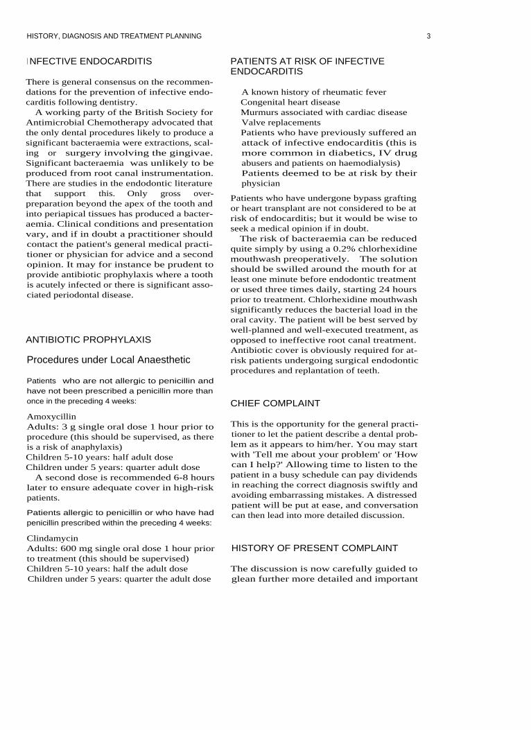
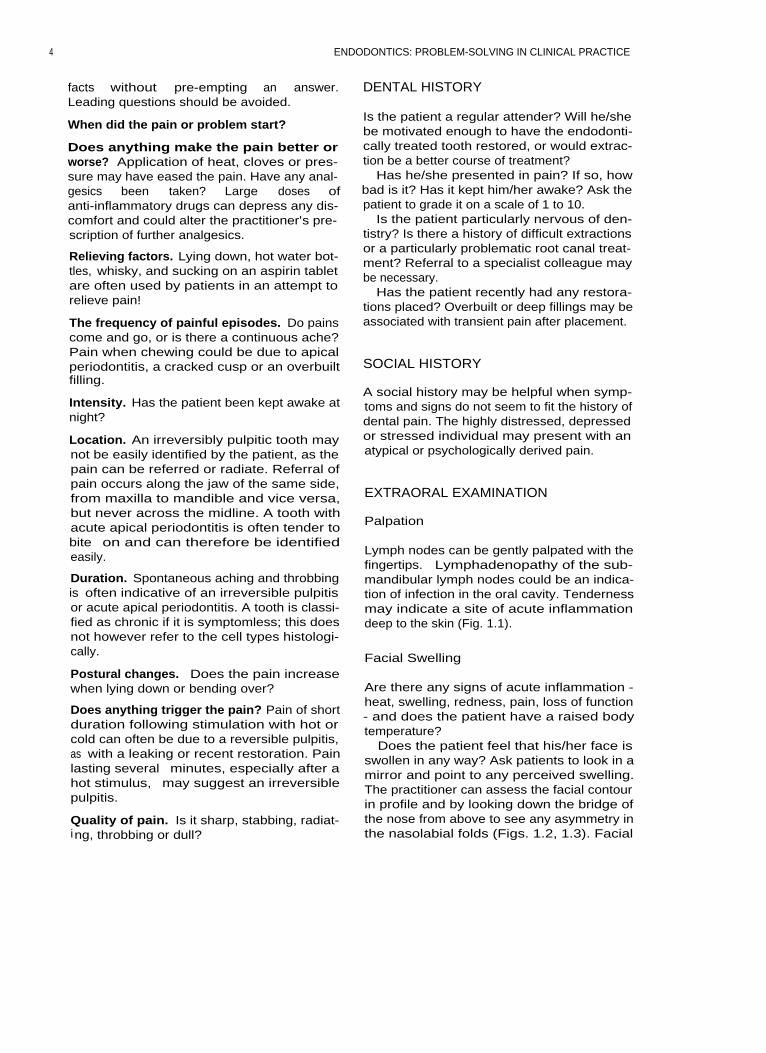
Periodontal pocketing: Probing depths shouldbe measured carefully with a periodontalprobe. Ideally a probe with a tip of 0.5 mmshould be used and pressure of no more than25 g applied (light pressure!). Broad pocketsare normally due to periodontal disease. Asudden increase in probing depth resulting ina narrow but deep pocket may indicate theposition of a vertical root fracture or sinustract lying within the periodontal ligament(Figs. 1.21-1.25).
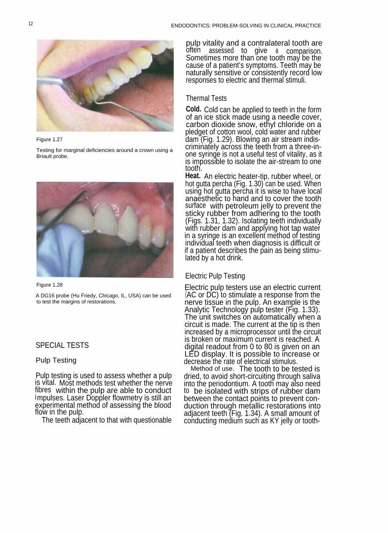
Mobility of fixed prosthodontics: Inserting aprobe under the pontic of a bridge and apply-ing a pulling force can be used to test whethereither abutment is loose (Fig. 1.26). The mar-gins of full crown restorations can be testedwith a probe (Figs. 1.27, 1.28).
Figure 1.12
Palpating the buccal sulcus over the apices of the teeth,with a finger tip. Any tenderness or swelling is noted.Tenderness may be an indication of acute apical peri-odontitis.
Figure 1.14
An intraoral sinus tract in the anterior region.
Figure 1.13
A buccal swelling in the anterior region. Some swellingsmay not be visible but can be palpated.
8

HISTORY, DIAGNOSIS AND TREATMENT PLANNING
Figure 1.15
An intraoral sinus tract in the posterior region.
Figure 1.17
In this patient a sinus tract opposite the lower molar(indicated by ring) tracked along the mandible to theperiapical abscess on the premolar. Sinus tracts do notalways point adjacent to the offending tooth. Vitality test-i ng and good radiological techniques are needed to iden-tify the source of the problem.
Figure 1.16
Pus discharging from the anterior sinus tract.
Figure 1.18
A palatal sinus tract in the anterior region.
9

Figure 1.19
Placing a gutta percha point in a sinus tract to identifythe source of the problem. This will not be painful, as thesinus tract is often epithelialized. Topical anaesthetic gelmay occasionally be required.
Figure 1.20
A radiograph of a gutta percha point inserted into a sinustract adjacent to a mandibular molar.
ENDODONTICS: PROBLEM-SOLVING IN CLINICAL PRACTICE
Figure 1.21
An extracted tooth with a vertical root fracture. In thiscase the tooth had fractured despite having beencrowned.
Figure 1.22
An occlusal view of a maxillary premolar that had frac-tured vertically in a mesial-occlusal-distal plane.
1 0
HISTORY, DIAGNOSIS AND TREATMENT PLANNING
Figure 1.25
Figure 1.23
The maximum periodontal probing depth on the mesialaspect was 7mm. The pocket shape was deep and nar-row.
The probing depth of 7mm on the distal aspect of thetooth directly opposite to that on the mesial aspect wasindicative of a vertical root fracture.
Figure 1.26
Inserting a probe under the pontic of a bridge to test formobility.
Figure 1.24
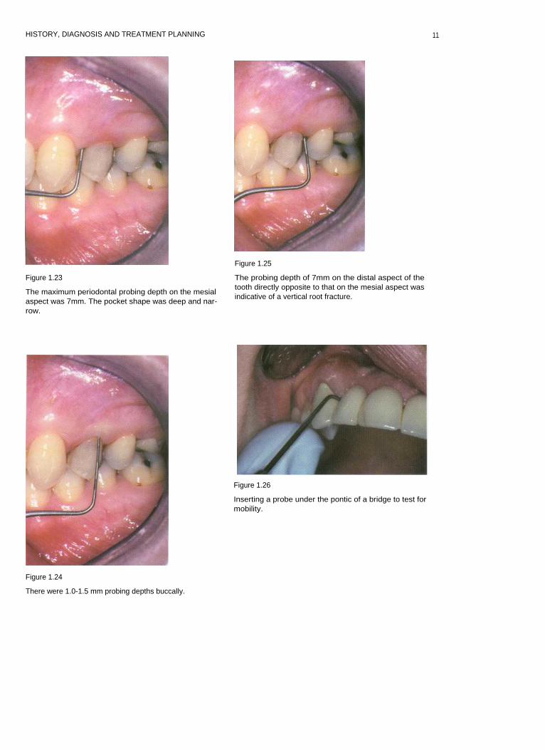
There were 1.0-1.5 mm probing depths buccally.
11
ENDODONTICS: PROBLEM-SOLVING IN CLINICAL PRACTICE
Figure 1.27
Testing for marginal deficiencies around a crown using aBriault probe.
Figure 1.28
A DG16 probe (Hu Friedy, Chicago, IL, USA) can be usedto test the margins of restorations.
SPECIAL TESTS
Pulp Testing
Pulp testing is used to assess whether a pulpis vital. Most methods test whether the nervefibres within the pulp are able to conductimpulses. Laser Doppler flowmetry is still anexperimental method of assessing the bloodflow in the pulp.
The teeth adjacent to that with questionable
pulp vitality and a contralateral tooth areoften assessed to give a comparison.Sometimes more than one tooth may be thecause of a patient's symptoms. Teeth may benaturally sensitive or consistently record lowresponses to electric and thermal stimuli.
Thermal TestsCold. Cold can be applied to teeth in the formof an ice stick made using a needle cover,carbon dioxide snow, ethyl chloride on apledget of cotton wool, cold water and rubberdam (Fig. 1.29). Blowing an air stream indis-criminately across the teeth from a three-in-one syringe is not a useful test of vitality, as itis impossible to isolate the air-stream to onetooth.Heat. An electric heater-tip, rubber wheel, orhot gutta percha (Fig. 1.30) can be used. Whenusing hot gutta percha it is wise to have localanaesthetic to hand and to cover the toothsurface with petroleum jelly to prevent thesticky rubber from adhering to the tooth(Figs. 1.31, 1.32). Isolating teeth individuallywith rubber dam and applying hot tap waterin a syringe is an excellent method of testingindividual teeth when diagnosis is difficult orif a patient describes the pain as being stimu-lated by a hot drink.
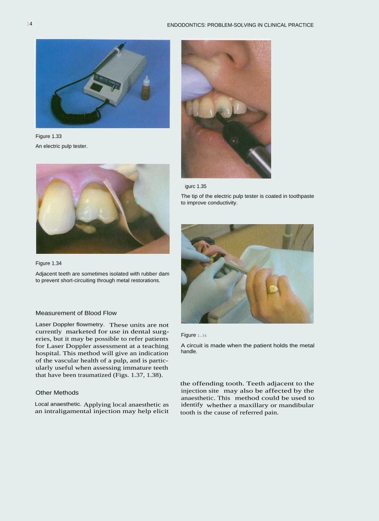
Electric Pulp TestingElectric pulp testers use an electric current(AC or DC) to stimulate a response from thenerve tissue in the pulp. An example is theAnalytic Technology pulp tester (Fig. 1.33).The unit switches on automatically when acircuit is made. The current at the tip is thenincreased by a microprocessor until the circuitis broken or maximum current is reached. Adigital readout from 0 to 80 is given on anLED display. It is possible to increase ordecrease the rate of electrical stimulus.
Method of use. The tooth to be tested isdried, to avoid short-circuiting through salivainto the periodontium. A tooth may also needto be isolated with strips of rubber dambetween the contact points to prevent con-duction through metallic restorations intoadjacent teeth (Fig. 1.34). A small amount ofconducting medium such as KY jelly or tooth-
12

HISTORY, DIAGNOSIS AND TREATMENT PLANNING
Figure 1.29 Figure 1.31
The tooth is isolated with rubber dam and immersed incold water.
Vaseline is placed on the tooth surface to prevent therubber sticking.
Figure 1.30
blot gutta percha can be used to test a tooth for heat sen-sitivitv.
Figure 1.32
The heated gutta percha is placed on to the tooth.
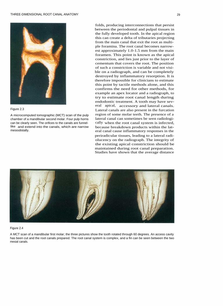
paste is then applied to the tip of the pulptester (Fig. 1.35). Mono-polar testers such asthe Analytic Technology tester require the cir-cuit to be completed by the operator orpatient. Since the operator is wearing rubbergloves, the circuit will not be complete. Thepatient is asked to hold the metal handle ofthe instrument until a tingling sensation is feltin the tooth (Fig. 1.36); at this point thepatient should let go and the stimulus will
cease. A reading can be taken from the LEDdisplay.
It should be remembered that electric pulptesting does not give an indication of vascularhealth, which is especially important in trau-matized immature teeth. It is possible to geta false positive reading via periodontal short-circuiting, and in multi-rooted teeth theremay be varying degrees of vitality in separateroots.
13
ENDODONTICS: PROBLEM-SOLVING IN CLINICAL PRACTICE
Figure 1.33
An electric pulp tester.
Figure 1.34
Adjacent teeth are sometimes isolated with rubber damto prevent short-circuiting through metal restorations.
Measurement of Blood Flow
Laser Doppler flowmetry. These units are notcurrently marketed for use in dental surg-eries, but it may be possible to refer patientsfor Laser Doppler assessment at a teachinghospital. This method will give an indicationof the vascular health of a pulp, and is partic-ularly useful when assessing immature teeththat have been traumatized (Figs. 1.37, 1.38).
Other Methods
Local anaesthetic. Applying local anaesthetic asan intraligamental injection may help elicit
I igurc 1.35
The tip of the electric pulp tester is coated in toothpasteto improve conductivity.
Figure 1.36
A circuit is made when the patient holds the metalhandle.
the offending tooth. Teeth adjacent to theinjection site may also be affected by theanaesthetic. This method could be used toidentify whether a maxillary or mandibulartooth is the cause of referred pain.
1 4

HISTORY, DIAGNOSIS AND TREATMENT PLANNING
Figure 1.37
A Laser Doppler machine.
Figure 1.39
A fibre optic light for assessment of cracks.
Figure 1.38
The Laser Doppler probe.
Figure 1.40
A tooth is illuminated to visualize a crack (arrowed)
Cutting a Test Cavity
As a last resort a cavity can be cut in the toothwith no local anaesthetic. This is not totallyreliable, however, as sometimes partiallynecrotic pulps in teeth that require root canaltreatment will respond to drilling. Coldcoolant spray can also stimulate adjacentteeth.
I dentifying Cracked Cusps
Teeth with cracked cusps are sometimes sen-sitive to thermal stimulation. Identifying thefractured cusp can be difficult, as the fractureline may not be visible to the naked eye.
Transillumination with a fibre optic lightmay highlight a crack (Figs. 1.39, 1.40).
15

ENDODONTICS: PROBLEM-SOLVING IN CLINICAL PRACTICE
A plastic 'Tooth Slooth' or wooden bitestick can be used to apply pressure to individ-ual cusps on a tooth (Figs. 1.41, 1.42).
Asking a patient to bite on the corner of afolded sheet of rubber dam may elicit painfrom a cracked cusp (Fig. 1.43).
RADIOGRAPHY
Accurate and predictable radiographic tech-niques are essential for endodontic diagnosisand treatment.
The X-ray Unit
The X-ray machine should comply with cur-rent ionizing radiation regulations. A tubevoltage of 70 kV is ideally suited for intraoralradiography. The beam produced by theX-ray head is divergent, and must be filteredand collimated to produce a parallel source.Filtration is equivalent to 1.5 mm of alu-minium for units up to 70 kV. Collimation
Figure 1.42
This tooth was completely fractured.
Figure 1.43
Biting on a rubber dam sheet may cause a cracked cuspto flex, aiding diagnosis.
Figure 1.41
A Tooth Slooth being used to apply pressure to an indi-vidual cusp.
1 6

HISTORY. DIAGNOSIS AND TREATMENT PLANNING
produces a beam that is no larger than 60 mm.A spacer cone allows correct alignment andcorrect distance from focal point to skin. Thisdistance should be 200 mm for units operat-ing at 70 kV. All X-ray units should have awarning light and sound to indicate whenX-rays are being emitted.
Dose Reduction
It is important to keep all exposure to ioniz-ing radiation as low as is reasonably achiev-able (ALARA). Whenever exposing thepatient to X-radiation the clinician mustassess the probability of obtaining usefulinformation and ensure that it is maximized.
Physical methods of limiting and reducingthe dose of radiation include:
• Only taking a radiograph when clinicallyessential
• Complying with Health and Safety regula-tions (including beam size and filtration)
• Using an X-ray unit with at least 70 kV out-put
• Using a film with the shortest exposuretime feasible for the clinical condition.
fast-acting chemicals can produce a readableimage for viewing in approximately 2 minutes.
Film speed. Film speed is a function of thenumber and size of the halide crystals in theemulsion. The larger the crystals the faster thefilm; but the quality of the image may suffer.In clinical situations the fastest film possiblethat will achieve the desired result should beused. For endodontic treatment there is no sig-nificant difference in the clarity of image whenusing D- or E-speed film. Most university den-tal schools now use E-speed film routinely.
Practical Points in General RadiographicFilm Technique
Film Storage
Radiographic film should be stored in cooldry conditions (in a refrigerator) away fromchemicals, especially mercury-containingcompounds. The film packets should bestored well away from sources of ionizingradiation and boxed until required; thisavoids films becoming damaged or bent.Films must not be bent, as otherwise an arte-fact will appear on the film.
All radiographic techniques should be madeas accurate as possible. Avoiding the need torepeat films obviously reduces X-ray doseand maximizes the diagnostic value of eachimage.
Techniques Available
Radiographic films are probably the mostwidely used method in general dentalpractice. However, with increasing computer-ization digital radiography offers a new andexciting alternative.
Radiographic Film
The D-Speed radiographic film was used formany years, but has now been superseded byE-speed film, which gives excellent clarity ofimage with fine detail. Wet processing using
Processing
Radiographic film can be developed manu-ally or automatically. Processing involves twostages, development and fixing. To obtaingood radiographic images careful qualitycontrol must be implemented and the physi-cal conditions under which the films areprocessed must be tightly controlled andstandardized.
Development
Development of the X-ray film should be car-ried out in complete darkness or filtered light,either in a darkroom or glove-box (Fig. 1.44).The entrance handles on such boxes shouldbe replaced if they become worn or damaged,
as this may allow light to penetrate the box. Itis very important to mix developer solutionsto the correct concentration according to themanufacturer's recommendations. Solutionsmust be replaced regularly and the containers
1 7

ENDODONTICS: PROBLEM-SOLVING IN CLINICAL PRACTICE
Figure 1.44
A hand-developing tank for radiographs.
washed thoroughly in clean water. Useddeveloper solution should not be discarded ina surgery sink. Ready-mixed solutions areobviously easier to use, as they require nodilution. The temperature of developing solu-tions should be maintained at an optimumlevel (usually 20°C). To avoid fluctuations intemperature a glove-box should be positionedin the surgery away from direct sunlight,heaters or autoclaves. Increasing the tempera-ture or extending development time will leadto dark unreadable films; if the solution is toocold or development time too short then apale film will result.
temperature of processing are maintained.The concentration of developer and fixersolutions is important for quality control andpredictable results. The rollers and containersof automatic developers should be washedregularly to prevent build-up of chemicals.
Digital Radiography
Digital radiography is a relatively new devel-opment for dental use. It offers an excitingalternative to radiographic film.
Digital radiography consists of a sensorthat creates an electrical signal that can beread by a computer and converted into agreyscale image. Most of the software neces-sary to produce digital radiographic imagescan be installed on computers routinely usedin the dental surgery. Images can beenhanced in terms of contrast, filtering,brightness, subtraction and the addition ofcolours (Fig. 1.45).
Digital radiography can be direct or indirect.Direct systems have a sensor that is attacheddirectly to the computer by a cable. This givesalmost instantaneous images. Indirect systemsuse a laser reading device to scan the exposedsensor before generating an image.
The X-ray dose with digital systems is sig-nificantly reduced compared with E-speedfilm. Sensors tend to be expensive, fragile andrelatively thick (5 mm). They have a lifeexpectancy of approximately 400000 doses(Figs. 1.46, 1.47).
Fixing Radiographic Techniques
Fixing should be carried out in a darkenvironment or under filtered light. The con-centration of the fixer solution is importantfor consistent results. Ideally the film shouldbe fixed for twice the development time. It ispossible however to view a film prematurely(working length estimation) before returningit to the fixing solution. Inadequate fixingresults in a green/yellow discoloration thateventually turns brown.
Automatic Processors
Automatic development ensures that con-trolled standardized conditions for time and
Paralleling TechniqueA paralleling technique is extremely useful inendodontics, and has several advantages overbisecting angle techniques.Advantages of paralleling technique:
a Geometrically accurate image with littlemagnification. This enables the dentist toestimate root canal length prior to instru-mentation.The periodontal membrane is well dis-played. This is very useful in endodontics,as its widening or destruction is a goodindicator of inflammation of endodonticorigin.
1 8

HISTORY, DIAGNOSIS AND TREATMENT PLANNING
Figure 1.45
A digital image of a root-treatedtooth taken with the Schick sys-tem (Schick Technologies Inc,Long Island City, NY, USA); theimage manipulation effects canbe seen at the top of the screen.
Figure 1.47
Figure 1.46
The Schick digital sensor.
The sensor is placed in a polythene cover to prevent cont-amination and cross-infection. It can be held in positionwith the patient's finger, or in a special Rinn holder.
There is minimal foreshortening or elonga-tion of the periapical tissues.Coning off is reduced.If the same technique is used routinely thenradiographs become almost reproducible.This is helpful for endodontic review.
Principles of the Paralleling TechniqueThe film packet is placed in a holder in thesame plane as the long axis of the tooth. The
tube-head is then aimed at a right angle to thetooth and film packet using an aiming device.
A holder should be used to help align theX-ray film and beam (Figs. 1.48-1.53).
The location of an area of radiolucency onthe side of a root may be a sign of a lateralcanal (Figs. 1.54, 1.55). Taking radiographsfrom a different horizontal angle can providefurther information, displaying for instanceextra root canals (Figs. 1.56, 1.57).
1 9

20
ENDODONTICS: PROBLEM-SOLVING IN CLINICAL PRACTICE
Figure 1.48
Figure 1.50
The Rinn holder paralleling device (Dentsply, Weybridge,
The Rinn holder paralleling device for the posteriorSurrey, UK) for the anterior region.
region.
Figure 1.49
Figure 1.51
The anterior Rinn holder, beam aiming device.
The posterior Rinn holder, beam aiming device.

HISTORY, DIAGNOSIS AND TREATMENT PLANNING
Figure 1.52
Figure 1.54
The anterior Rinn in use. The X-ray head is covered in adisposable polythene cover to prevent cross-infection.
A lateral radiolucency may be an indication of a lateralcanal.
Figure 1.53
The posterior Rion in use.
Figure 1.55
A lateral canal has been filled during obturation; it liesadjacent to a lateral radiolucency.
21

ENDODONTICS: PROBLEM-SOLVING IN CLINICAL PRACTICE
Figure 1.56
Rotating the cone produced a radiograph, showing anunfilled second canal.
The bisecting angle technique should reallybe reserved for cases in which it is impossibleto fit a holder into the patient's mouth. It isalso of value in locating a horizontal root frac-ture, especially if the fracture line lies in theplane of the X-ray beam (Fig. 1.58).
Retching. Using a topical local anaestheticgel or spray can reduce retching. Distractingthe patient by getting him/her to concentrateon gentle breathing can also help (Fig. 1.59).
Shallow palate. Placing a cotton wool roll onthe occlusal surface of the teeth will helpalign the holder.
Edentulous spaces. So that the holder doesnot become tilted when the patient bitestogether a cotton wool roll may be used tosupport the bite plate (Figs. 1.60, 1.61).
Small mouth. It may not be physically possi-ble to fit the holder plus standard film into apatient's mouth; in this case a small film can beused or a film can be held by artery forceps.
Figure 1.57 Figure 1.58
The completed obturation revealed an even more compli-
A bisecting angle film showed the horizontal root frac-cated root canal system.
ture (arrowed).
22

HISTORY, DIAGNOSIS AND TREATMENT PLANNING
Figure 1.59
Application of topical anaesthetic gel to prevent retching.
Figure 1.61
A cotton wool roll has been placed on the edentulousridge to prevent the holder rotating.
Figure 1.60
With an edentulous ridge the Rinn holder needs to besupported, as in this case, where a periapical radiographis required of the mandibular premolar.
DIAGNOSIS
The clinician must listen to the patient'ssymptoms and summate the findings of sev-eral tests to come to a decision as to the likelycause of the patient's pain and whether thehealth of the pulp of the suspect tooth isaffected. If two or more tests indicate that atooth is non-vital and there is evidence ofradiological change then the practitioner canbe relatively confident of the diagnosis. If oneis unsure or the findings are not conclusive aperiod of observation or referral would beappropriate (Figs. 1.62, 1.63).
Pulpal condition can clinically be classifiedunder simple headings:
Normal pulp. The normal pulp gives atransient response to thermal tests and can bestimulated by electric pulp testing; it may alsobe sensitive to sweet and to acidic foods. Theelectric pulp tester may produce feelingsvarying from a tingling sensation to pain.Palpation and percussion do not cause pain.Radiologically there is a normal periodontalligament space bounded by an intact laminadura. The periodontal ligament space canappear increased in width over the apex ofthe palatal roots of upper molar teeth, owingto the magnifying effect of the air sinus.
23

ENDODONTICS: PROBLEM-SOLVING IN CLINICAL PRACTICE
Figure 1.62
A diagnosis can be made after listening to the patient'ssymptoms and carrying out special tests. In this case themaxillary second molar appears to have an apical radi-olucency. Special tests however reveal that the maxillaryfirst molar is non-vital.
absence. Initially pain can be referred, and isusually stimulated by thermal tests, when itlasts several minutes or hours. When pulpalinflammation reaches the apex, the tooth maybecome tender to bite on or respond to palpa-tion. At this point there may be radiologicalchanges apically.
Pulpal necrosis. If the entire pulp isnecrotic then the tooth will fail to respond tothermal tests; however, in multi-rooted teeththe pulp in one root may remain vital, mak-ing diagnosis by thermal tests difficult.Radiologically, there are usually periapicalchanges (Fig. 1.64).
Pcriapically there may be:Acute periapical inflammation. Classically
the tooth becomes tender to bite on and ispainful when palpated or percussed. On aradiograph there may be slight widening ofthe periodontal ligament apically.
Acute apical abscess. Pus forms around theapex, there may be swelling, and the tooth istender to bite on. Severe infection may lead topyrexia and a possible spread of infectionalong tissue planes. Radiolucency at the apex
Figure 1.63
The completed root canal treatment shows that the rootsof the maxillary molars are superimposed on the radio-graph. A thorough and logical approach to diagnosis pre-vented incorrect treatment.
Reversible pulpitis. Pain induced by ther-mal stimuli tends to be of short duration (sec-onds rather than minutes), and does notradiate. Palpation and percussion do notstimulate pain. A filling may have beenrecently placed, or there may possibly becracked cusps.
Irreversible pulpitis. Pain can be variable,from a spontaneous deep ache to total
Figure 1.64
A radiograph of a tooth with pulpal necrosis; it was non-responsive to vitality testing.
2 4

HISTORY, DIAGNOSIS AND TREATMENT PLANNING
Figure 1.65
An acute abscess in the maxillary region has resulted inlocalized palatal swelling.
may not be readily observable in an acuteabscess (Fig. 1.65).
Chronic apical periodontitis. This isfrequently symptomless, but the tooth mayoccasionally produce symptoms.Radiologically there is a radiolucency at theapex of the tooth continuous with the peri-odontal ligament or adjacent to a lateral canal.A chronic lesion may become exacerbatedand produce acute symptoms and signs.
FURTHER READING
Baumgartner JC, Heggers JP, Harrison JW(1976). The incidence of bacteraemias relatedto endodontic procedures. I Nonsurgicalendodontics. Journal of Endodontics 2: 135-140.
Baumgartner JC, Heggers JP, Harrison JW(1977). The incidence of bacteraemias relatedto endodontic procedures. 11 Surgicalendodontics. Journal of Endodontics 3: 399-402.
British Society for Antimicrobial Chemo-therapy (1990). Prophylaxis of infective endo-carditis. Lancet 355: 88-89.
McGowan DA, Nair S, Macfarlane TW,Mackenzie D (1983). Prophylaxis of experi-mental endocarditis in rabbits using one ortwo doses of amoxycillin. British Dentaljournal 155: 88-90.
25

2 THREE-DIMENSIONAL ROOT CANALANATOMY
CONTENTS • Introduction • Basic Anatomy of the Tooth and Surrounding StructuresI ndividual Tooth Anatomy • Further Reading
I NTRODUCTION
A clear understanding of pulp anatomy andthe variations that occur in it are essential ifeffective cleaning, shaping and obturation ofthe pulp space are to be achieved. Manyproblems that occur during root canal treat-ment result from poor knowledge of thisanatomy: missed canals, perforation of thepulp floor or canal transportation. If the clini-cian can imagine a three-dimensional pictureof the root canal system prior to instrumenta-tion then iatrogenic errors are less likely tooccur. The practitioner should be aware ofhow many canals to expect, their location,length and relationship to each other.
BASIC ANATOMY OF THE TOOTH ANDSURROUNDING STRUCTURES
The Pulp
The pulp is connective tissue, consistingmainly of odontoblasts and fibroblasts.Glycosaminoglycans form the ground sub-stance, which is penetrated with collagenfibres. A main neurovascular bundle entersthe foramen at the apex of the tooth.Arterioles are the largest afferent vesselsfound in the pulp and pass towards thecrown along the axis of the tooth, giving offbranches that terminate in the subodontoblas-tic capillary plexus. There are interconnec-tions known as anastomoses between thevenules and arterioles. This feature allows there-routing of blood flow, preventing the
build-up of unsustainable pressure in theenclosed pulp environment. The pulp isrichly innervated, containing myelinated A8and AB fibres (fast-conducting) and unmye-linated C fibres (slow-conducting). Mild,transient, low-threshold noxious stimuli(mechanical, thermal, chemical or electrical)activate fast-conducting A8 fibres, while high-threshold, long-duration or inflammatorystimuli activate C fibre neurones. The C fibresgive rise to the sensation of poorly localized,throbbing and aching pain; stimulation doesnot occur until the pulp tissue is damaged.Myelinated AB fibres have the most rapidconduction velocity; they may be involved inregulating masticatory forces and could alsoprovide innervation for dentine sensitivity.Autonomic fibres of the sympathetic systemcontrol the microcirculation. The nerve fibresterminate in the pulp dentine border area asthe plexus of Raschkow; individual axonsthen branch into terminal filaments that entersome dentine tubules. The pulp is enclosed ina space surrounded by dentine, with which itforms the pulp dentine complex.
Dentine
Dentine is produced by odontoblasts andforms the bulk of the mineralized portion ofthe tooth. This dentine is covered by enamelon the crown of the tooth, and cementumover the root surface. Embryonically dentineand pulp are both derived from the dentalpapilla and have a close relationship in struc-ture, function and development. Dentine

ENDODONTICS: PROBLEM-SOLVING IN CLINICAL PRACTICE
tubules radiate from the pulp towards theenamel and cementum. There are approxi-mately 57 000 tubules per mm- in the dentineadjacent to the pulp, with an average diame-ter of approximately 3 um, making 80% of thevolume of the tissue. At the amelo-dentinejunction there are approximately 8000 tubulesper mm=, with diameters of about 1 um, or 4%of the total volume. In the crown the tubulesfollow an S-shaped curve. Odontoblast cellbodies are separated from the mineralizeddentine by the unmineralized predentinelayer, which is 15 um thick. The odontoblastsare arranged in a single layer, and haveprocesses that extend into the tubules of thedentine. The processes extend for some dis-tance within the tubules and have branches.In the inner dentine there are unmyelinatednerve terminals spiralling around some odon-toblast processes.
Primary dentine is laid down before thetooth is fully formed. Following this, regularsecondary dentine is formed at a much slowerrate. As this is laid down the pulp chamberbecomes smaller with age; this can makeendodontic treatment more difficult in elderlypatients. Peritubular dentine is also formedwith age, and lines the dentine tubules. Theproduction of dentine can be increased bystimuli such as caries, attrition and abrasion.Tubules can become completely occluded,giving rise to sclerotic dentine. The odonto-blasts lay down irritation dentine at a fast rateas a defence mechanism, and this can on occa-sions virtually occlude the pulp space.
Figure 2.1
Root canal anatomv
The mesial root of a mandibular first molar in buccal-lingual section, showing various types of complexanatomy.
Root Canals (Figs. 2.1-2.4)Figure 2.2
The apical constriction
The root canals are continuous with the pulpchamber. The root canal space is often com-plex, with canals that divide and rejoin, fins,deltas and lateral canals. It is more like a sub-terranean cave formation, with interconnect-ing chambers carved out of limestone, than asimple mine shaft. For this reason many clini-cians now refer to the root canal as a system,to convey this complexity. Attempts havebeen made to classify the different varieties ofcanal configuration, but most are two-dimensional and not always helpful clinically.
The average distance between the apical foramen and themost apical part of the root is 0.2-2.0 mm. The constric-tion can be 0.5-1.0 mm from the apical foramen.
are generally broader bucco-lingually; but unless the tooth is severelyrotated this is not apparent radiologically.This is of relevance because mechanicalinstrumentation will rarely be effective on allsurfaces of a canal with an oval cross-section.During root development the root sheath
Root canals
28
THREE-DIMENSIONAL ROOT CANAL ANATOMY
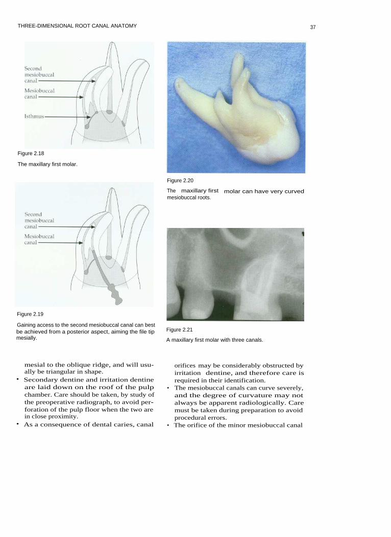
Figure 2.3
A microcomputed tomographic (MCT) scan of the pulpchamber of a mandibular second molar. Four pulp hornscan be clearly seen. The orifices to the canals are funnel-like and extend into the canals, which are narrowmesiodistally.
folds, producing interconnections that persistbetween the periodontal and pulpal tissues inthe fully developed tooth. In the apical regionthis can create a delta of tributaries projectingfrom the main canal that exit the root as multi-ple foramina. The root canal becomes narrow-est approximately 1.0-1.5 mm from the mainforamen. This point is known as the apicalconstriction, and lies just prior to the layer ofcementum that covers the root. The positionof such a constriction is variable and not visi-ble on a radiograph, and can be completelydestroyed by inflammatory resorption. It istherefore impossible for clinicians to estimatethis point by tactile methods alone, and thisconfirms the need for other methods, forexample an apex locator and a radiograph, totry to estimate root canal length duringendodontic treatment. A tooth may have sev-eral apical, accessory and lateral canals.Lateral canals are also present in the furcationregion of some molar teeth. The presence of alateral canal can sometimes be seen radiologi-cally when the root canal system is infected,because breakdown products within the lat-eral canal cause inflammatory responses in theperiradicular tissues, leading to a lateral radi-olucency on the radiograph. The integrity ofthe existing apical constriction should bemaintained during root canal preparation.Studies have shown that the average distance
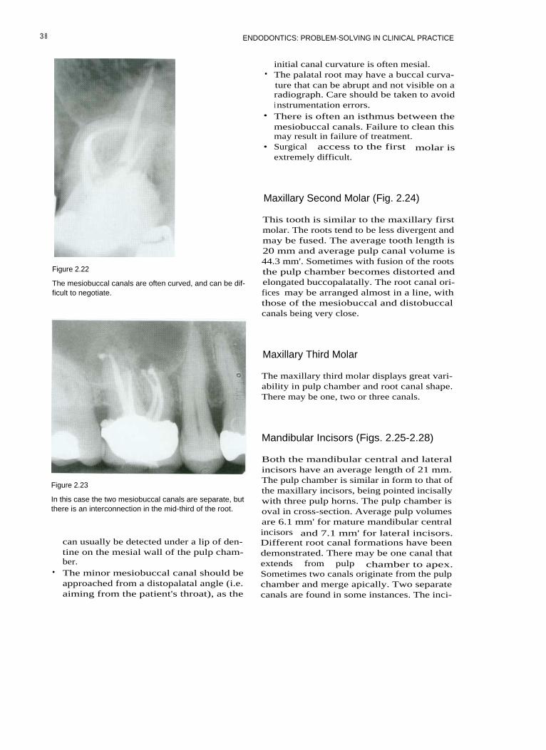
Figure 2.4
A MCT scan of a mandibular first molar; the three pictures show the tooth rotated through 60 degrees. An access cavityhas been cut and the root canals prepared. The root canal system is complex, and a fin can be seen between the twomesial canals.
29

ENDODONTICS: PROBLEM-SOLVING IN CLINICAL PRACTICE
between the apical foramen and the most api-cal part of the root is variable over0.2-2.0 mm, and furthermore the constrictioncan be 0.5-1.0 mm from the apical foramen.This gives credence to preparation techniquesthat maintain a small apical instrument size inorder to cause as little damage to this regionas possible.
Cementum
Cementum covers the radicular dentine.Acellular cementum does not contain cemen-tocyte cell bodies, and forms the imperviousinnermost layer of cementum covering theroot surface. The cementum forms a connec-tion between the periodontal ligament andthe tooth.
gival, transeptal, alveolar crest, horizontal,oblique and apical. There are many cellsfound in the periodontal ligament space:fibroblasts, occasionally defence cells, and thecell rests of Malassez. The cell rests areformed from the root sheath of Hertwig,which becomes perforated like a fishnetstocking. The periodontal ligament is sup-plied with nutrients from arterioles that enternear the apex of the root, and from the lateralwalls of the alveolar socket. Venules drainblood in the opposite direction. Nerves pro-vide sensory information for touch, pain andpressure, allowing proprioception duringmastication. The periodontal ligament pro-vides the visco-elastic connection between thetooth and the alveolar bone.
Alveolar Bone
Periodontal Ligament (Fig. 2.5)
The periodontal ligament is a fibrous connec-tive tissue. Fibres run in specific groups: gin-
Periodontal ligament
Figure 2.5
Periodontal fibres.
A Gingivalfibres
B Transeptalfibres
C Alveolarcrest fibres
D Obliquefibres
Alveolar bone is the mineralized tissue thatsurrounds the teeth in the jaws. It is continu-ously formed by osteoblasts, and when thesecells become incorporated in the tissue theyare called osteocytes. Bone resorption is con-tinuous and is carried out by osteoblasts,which lie in Howship's lacunae. There aretwo types of bone: cortical and cancellous.The spaces between the trabeculae of spongybone may be filled with marrow.
I NDIVIDUAL TOOTH ANATOMY (Table2.1)
Maxillary Central Incisor (Figs. 2.6, 2.7)
The average length of maxillary centralincisors is 22.5 mm. They normally have a sin-gle root and a single canal with an averagevolume of 12.4 mm3 when fully formed.Mesiodistally the pulp chamber follows thegeneral outline of the crown. It is widest atthe most coronal level and has pulp horns. Inyoung patients there may be three pulp hornsthat correspond to enamel mammelons on theincisal edge. Buccopalatally the pulp chamberis narrow as it transforms into the root canalwith a constriction just apical to the cervix. In
3 0

THREE-DIMENSIONAL ROOT CANAL ANATOMY
Table 2.1 Three-dimensional root canal anatomy
three dimensions it has a shape somewhat sim-ilar to a baseball glove. The constriction cannotalways be seen radiologically. Coronally, theroot canal is wider buccopalatally, with anoval cross-sectional shape; it becomes circularat the apex. With age the roof of the pulpchamber recedes and the canal appears muchnarrower on clinical radiographs. This can bedeceptive, because buccopalatally the canalmay still be much wider, and in three dimen-sions the canal is more ribbon-shaped.
Clinical Points
• In a young patient a pulp horn can beexposed following a relatively small frac-ture of an incisal corner. If a child presentswith a crown fracture then the dentine inthis region should be protected to preventbacterial ingress into the pulp chamber.
• Placing the access cavity too far palatallymakes straight-line access impossible.Transportation and ledging of the rootcanal will be more likely to occur on thebuccal surfaces of the root canal. It may be
31

ENDODONTICS: PROBLEM-SOLVING IN CLINICAL PRACTICE
Figure 2.7
A maxillary central incisor.
necessary to extend the access cavitytowards the incisal edge.
• Palatal tooth tissue should be conserved, asthis is important for retention of full cover-age restorations should they be necessary.
• In order to clean a ribbon-shaped canaleffectively the operator relies on irrigantpenetrating areas that the files do not reach.
Maxillary Lateral Incisor (Figs. 2.8, 2.9)
Lateral incisor teeth are generally shorter thanmaxillary central incisors, and have an aver-age length of 21 mm. There is usually onlyone canal, with an average mature pulp spacevolume of 11.4 mm3. Developmental anom-alies such as dens invaginatus are sometimesseen. Pulp horns are more marked than incentral incisors, and the incisal outline of thepulp chamber tends to be more rounded thanthat of central incisors. The apical region ofthe root canal is often curved in a palataldirection.
Clinical Points
• The palatal curvature of the apical region israrely seen radiologically. The curvaturecan be abrupt, and is easily ledged duringroot canal preparation. This is a commonfinding in lateral incisors where the rootfilling is short of the apex. Precurving filesor using a balanced force technique willhelp to avoid this.
• The cervical constriction may need to beremoved during coronal flaring to producea smooth progression from pulp chamberto root canal.
• In surgical endodontic treatment an apicalcurvature can complicate resection androot-end cavity preparation.
32

THREE-DIMENSIONAL ROOT CANAL ANATOMY
Figure 2.8
Maxillary lateral incisor.
to be narrow, and pointed incisally. There canbe a constriction at the cervix. The pulp spacehas an average mature volume of 14.7 mm3and is wider buccopalatally, along the lengthof the root. The root canal is, therefore, oval,in cross-section and only becomes circular inthe apical third. The root apex is often taperedand thin, and may occasionally curve ratherabruptly in a buccal or palatal direction.
Clinical Points
Figure 2.9
These young maxillary incisors have wide pulp chambers.
• When preparing long, sclerosed root canalsgreat care must be taken to avoid blockingthe root canal. Irrigation is imperative, anda lubricant may be helpful.
• The cervical constriction often needs to beshaped during coronal flaring to produce asmooth taper from the access cavity intothe main body of the root canal.
• Surgical access to the apical region can bedifficult when these teeth are particularlylong.
Maxillary Canine (Fig. 2. 10)
This is usually the longest tooth, with anaverage length of 26.5 mm. It rarely has morethan one root canal. The pulp chamber tends
Maxillary First Premolar (Figs. 2.11-2.14)
This tooth normally has two roots and twocanals; however, single-rooted maxillary firstpremolars occur in one-third of Caucasians. InMongoloids this figure is in excess of two-
33
Figure 2.10
Maxillary canine.

ENDODONTICS: PROBLEM-SOLVING IN CLINICAL PRACTICE
Figure 2.11
Maxillary first premolar.
thirds. Maxillary first premolars with threeroots have been reported; and these usuallyshow a similar morphological arrangement tomaxillary molars. Generally, the averagelength of the first premolar is 21 mm and theaverage pulp volume is 18.2 mm3. The pulpchamber is wider buccopalatally, with twopulp horns. The chamber appears muchnarrower on radiographs. Root canal orificeslie buccally and palatally. With age secondarydentine is deposited on the roof of the pulpchamber. The root canals are usually fairlystraight, divergent and round in cross-section.
Figure 2.13
A maxillary first premolar with two canals.
Clinical Points
• Taking radiographs from an angle can sep-arate the root canals and avoid superimpo-sition. The X-ray cone is usually rotatedanteriorly. A common reason for unsuc-cessful root canal treatment in maxillaryfirst premolars is a failure to locate bothcanals.
Figure 2.12
Maxillary first premolarroot canal configurations.
34

THREE-DIMENSIONAL ROOT CANAL ANATOMY
Figure 2.15
Maxillary second premolar.
Figure 2.14
A maxillary first premolar with three canals, these areorientated in a similar manner to the maxillary firstmolar.
• It is sometimes possible to mistake thepulp horns for the orifices of the canals.Measurement from the preoperative radio-graph and good intraoral illumination aswell as magnification should avoid thismistake.
• The buccal root often has a palatal groove,which can be perforated during instrumen-tation if the coronal part of the root canal isover-flared.
• Surgically the palatal root may be difficultto reach. This may not necessarily be obvi-ous on a preoperative radiograph, and sur-gical endodontics on maxillary firstpremolars should not be undertakenlightly for many reasons.
Figure 2.16
In this maxillary second premolar the single root canalhas a 'ribbon-like' shape.
Maxillary Second Premolar (Figs. 2.15,2.16)
The maxillary second premolar usually hasone root and a single canal, but the shape of
the canal system is variable. There may be asingle canal along the entire length of the root.A single orifice may divide into two canals andemerge apically as one or two canals. Rarelythere may be two or three separate canalsbranching from a single orifice. The averagelength of the maxillary second premolar is
35

ENDODONTICS: PROBLEM-SOLVING IN CLINICAL PRACTICE
21.5 mm
and
the
average
pulp
volume16.5 mm3. The
pulp
chamber
is
widebuccopalatally and has two well-definedpulp horns. The canal is also usually widerbuccopalatally. The canal system thereforeshould be thought of as ribbon-like. Thisribbon-like canal may be tortuous, becomingcircular in cross-section only in the apical2-3 mm. The root is generally straight; how-ever, with age the roof of the pulp chamberrecedes.
Clinical Points
• The canal can look deceptively thin onradiographs, but is ribbon-like in cross-section. This space can be difficult to cleanand obturate effectively.
• It is sometimes possible to mistake thepulp horns for the canal orifice.
Maxillary First Molar (Figs. 2.17-2.23)
The maxillary first molar is generally three-rooted, with three or four canals. Themesiobuccal root contains two canals inapproximately 60% of cases. The two canalsin the mesiobuccal root are usually closelyinterconnected and sometimes merge into onecanal or can be joined by a fin. The averagelength of this tooth is 21 mm, and the averagepulpal volume 68.2 mm3. The bulk of the pulp
chamber lies mesial to the oblique ridgeacross the occlusal surface of the tooth. Thepalatal root orifice is usually the largest andeasiest to locate, and appears funnel-like inthe floor of the pulp chamber. The distobuccalcanal orifice is located more palatally than themain mesiobuccal canal. The minormesiobuccal canal (MB2) is located on a linebetween the palatal canal orifice and the mainmesiobuccal canal orifice. The palatal rootcanal has a rounded triangular cross-sectioncoronally and becomes circular apically. Thecanal may curve buccally in the apical3-5 mm. The distobuccal canal tends tobe round in cross-section and is normallythe shortest canal; it may curve abruptlyat the apex. The main mesiobuccal canaloften exits the pulp chamber in a mesialdirection but then curves distopalatally.The mesial canals are often joined by anisthmus, especially in the apical 3-5 mm.This makes the canal ribbon-shaped. Theminor mesiobuccal canal can be extremelyfine and tortuous. With age all the canalsbecome narrower, and secondary dentine islaid down on the pulp chamber roof. A lip ofdentine often obscures the minor mesiobuccalcanal.
Clinical Points
• The pulp chamber lies mesial to theoblique ridge across the occlusal surface ofthe tooth. An access cavity should be cut
Figure 2.17
Maxillary first molar.
36
THREE-DIMENSIONAL ROOT CANAL ANATOMY
Figure 2.18
The maxillary first molar.
Figure 2.20
Figure 2.19
Gaining access to the second mesiobuccal canal can bestbe achieved from a posterior aspect, aiming the file tipmesially.
The maxillary first molar can have very curvedmesiobuccal roots.
Figure 2.21
A maxillary first molar with three canals.
mesial to the oblique ridge, and will usu-ally be triangular in shape.
• Secondary dentine and irritation dentineare laid down on the roof of the pulpchamber. Care should be taken, by study ofthe preoperative radiograph, to avoid per-foration of the pulp floor when the two arein close proximity.
• As a consequence of dental caries, canal
orifices may be considerably obstructed byirritation dentine, and therefore care isrequired in their identification.
• The mesiobuccal canals can curve severely,and the degree of curvature may notalways be apparent radiologically. Caremust be taken during preparation to avoidprocedural errors.
• The orifice of the minor mesiobuccal canal
37
ENDODONTICS: PROBLEM-SOLVING IN CLINICAL PRACTICE
Figure 2.22
The mesiobuccal canals are often curved, and can be dif-ficult to negotiate.
initial canal curvature is often mesial.• The palatal root may have a buccal curva-
ture that can be abrupt and not visible on aradiograph. Care should be taken to avoidinstrumentation errors.
• There is often an isthmus between themesiobuccal canals. Failure to clean thismay result in failure of treatment.
• Surgical access to the first molar isextremely difficult.
Maxillary Second Molar (Fig. 2.24)
This tooth is similar to the maxillary firstmolar. The roots tend to be less divergent andmay be fused. The average tooth length is20 mm and average pulp canal volume is44.3 mm'. Sometimes with fusion of the rootsthe pulp chamber becomes distorted andelongated buccopalatally. The root canal ori-fices may be arranged almost in a line, withthose of the mesiobuccal and distobuccalcanals being very close.
Maxillary Third Molar
The maxillary third molar displays great vari-ability in pulp chamber and root canal shape.There may be one, two or three canals.
Mandibular Incisors (Figs. 2.25-2.28)
Figure 2.23
In this case the two mesiobuccal canals are separate, butthere is an interconnection in the mid-third of the root.
can usually be detected under a lip of den-tine on the mesial wall of the pulp cham-ber.
• The minor mesiobuccal canal should beapproached from a distopalatal angle (i.e.aiming from the patient's throat), as the
Both the mandibular central and lateralincisors have an average length of 21 mm.The pulp chamber is similar in form to that ofthe maxillary incisors, being pointed incisallywith three pulp horns. The pulp chamber isoval in cross-section. Average pulp volumesare 6.1 mm' for mature mandibular centralincisors and 7.1 mm' for lateral incisors.Different root canal formations have beendemonstrated. There may be one canal thatextends from pulp chamber to apex.Sometimes two canals originate from the pulpchamber and merge apically. Two separatecanals are found in some instances. The inci-
3 8

THREE-DIMENSIONAL ROOT CANAL ANATOMY
Figure 2.24
Maxillary second molar.
Figure 2.25
Mandibular incisors.
Figure 2.27
A cleared mandibular incisor. The root canal space is
wider buccolingually than mesiodistally.
dence of cases of two canals can be as high as41%. The canals are wider buccolinguallythan mesiodistally.
Clinical Points
Figure 2.26
Mandibular incisor canal configurations.
• The presence of two canals may be missedon a preoperative radiograph if the canalsare superimposed.
39

ENDODONTICS: PROBLEM-SOLVING IN CLINICAL PRACTICE
Figure 2.29
Mandibular canine.
Figure 2.25
A mandibular incisor with two canals.
• The lingual canal is most often missed inteeth with two canals because the accesscavity, if placed too far lingually, restrictsstraight-line access.
• It is easy to over-prepare the root canals ofmandibular incisors, as the roots are fine.There is also a groove running down thelength of the root on the mesial and distalsurfaces. Over-preparation will weaken thetooth unnecessarily, and may result in stripperforation.
• The apices of mandibular incisors are oftenreclined lingually, and access for endodon-tic surgery can be extremely difficult.
Mandibular Canine (Figs. 2.29, 2.30)
Figure 2.30
This mandibular canine has two canals.
This tooth bears a striking resemblance to themaxillary canine, but is smaller, with an aver-age length of 22.5 mm and an average maturepulp volume of 14.2 mm3. This tooth usuallyhas one root and one canal, but can occasionallyhave two (14%). The pulp chamber is pointedcoronally, and there can be a cervical constric-tion. Coronally the root canal is oval in cross-section, becoming round in the apical region.
Clinical Point
• In older patients where there has been sig-nificant deposition of secondary dentine itmay be necessary to incorporate the incisaledge into the access cavity to ensurestraight-line access and locate the rootcanal.
40

THREE-DIMENSIONAL ROOT CANAL ANATOMY
Mandibular First Premolar (Figs. 2.31, 2.32)
This tooth usually has one root and one canal.However a second canal has been identifiedin up to a third of teeth, and three canalsoccasionally. The pulp chamber has two pulphorns, the buccal horn being most prominent.In cross-section the chamber is oval, with thegreatest dimension buccolingually. The aver-age root length is 21.5 mm and the averagemature pulp volume 14.9 mm3. Root canalcross-sections tend to be oval until the mostapical extents, where they become round.
Clinical Points
• The access cavity in these teeth may haveto extend on to the cusp tip, in order togain straight-line access.
• The lingual canal when present is notori-ously difficult to instrument. Access canusually be gained by running a fine instru-ment down the lingual wall of the mainbuccal canal until the orifice is located; thismay be several millimetres down the canal.
• Surgical access to the apex of the mandibu-lar first premolar is often complicated bythe proximity of the mental nerve.
Figure 2.32
A mandibular first premolar with two diverging canals.There is an interconnection in the apical third and a longlateral canal.
Mandibular Second Premolar (Fig. 2.33)
Figure 2.31
Mandibular first premolar.
This tooth usually has one root and onecanal. Up to 11 % of teeth have a secondcanal. The pulp chamber has two pulphorns; the lingual horn is more prominent
Figure 2.33
Mandibular second premolar.
41

ENDODONTICS: PROBLEM-SOLVING IN CLINICAL PRACTICE
than in the mandibular first premolar. Incross-section the pulp chamber is oval, withthe greatest dimension buccolingually. Theaverage root length is 22.5 mm and the aver-age mature pulp volume 14.9 mm3. Rootcanal cross-sections tend to be oval coronallyand round apically.
Clinical Points
Similar to mandibular first premolar.
Mandibular First Molar (Figs. 2.34-2.38)
This tooth usually has two roots, which haveaverage lengths of 21 mm and an averagemature pulp volume of 52.4 mm3. The pulpchamber is quadrilateral in cross-section atthe level of the pulp floor and is widermesially than distally. There may be four orfive pulp horns. The distal root tends to bemore rounded than the mesial root, whichhas a kidney bean shape in cross-section atthe mid-third. There are usually two canals inthe mesial roots and one in the distal.Approximately a third of distal roots containtwo canals. The two mesial canals merge inapproximately 45% of cases to a single fora-men. The single distal canal is ribbon-shapedand has its largest dimension buccolingually.The mesiobuccal canal is generally curved,and often exits the pulp chamber in a mesialdirection, while the mesiolingual canal tends
Figure 2.35
Mandibular first molar.
to be straighter. There is nearly always anisthmus between the two mesial canals in theapical third.
Clinical Points
• The mesial canals are small, and shouldnot be over-enlarged to avoid proceduralerrors such as transportation.
• The mesial canals are curved in a mesiodis-tal and a buccolingual direction. Thecurved furcation wall is particularlyvulnerable to perforation during root canalpreparation by filing, as instrumentsstraighten in the canal.
Distal root canhave two canals
Figure 2. 3 4
Mandibular first molar.
42

THREE-DIMENSIONAL ROOT CANAL ANATOMY
Figure 2.36
The mandibular first molar with three canals. A fin oristhmus often interconnects the mesial canals. There arelateral canals projecting from the main distal canal.
Figure 2.38
In this mandibular molar the canals are highly curvedand there are many interconnections. The distal canaldivides into two canals in the apical third.
Figure 2.37
A mandibular first molar with four separate canals, twoin each root.
• A working length radiograph should betaken at an angle to separate the mesialcanals.
• The distal canal often exits on the side ofthe root face short of the anatomical apex,and therefore a file can appear short on alength estimation radiograph.
Root-end surgery on the mandibular firstmolar is complicated. Access is often diffi-cult, and the root ends can be in closeproximity to the inferior dental nerve andmental nerve.
Mandibular Second Molar (Fig. 2.39)
In Caucasians the mandibular second molar issimilar to the mandibular first molar. Root
Figure 2.39
Mandibular second molar.
43

ENDODONTICS: PROBLEM-SOLVING IN CLINICAL PRACTICE
canal lengths are shorter, at 20 mm, and theaverage pulp volume is 32.9 mm'. The C-shaped canal is more common in Mongoloidraces; the mesial and distal canals becomefused into a fin.
Clinical Point
• The mandibular third molar is usuallymore easily instrumented than the maxil-lary third molar, because the tooth tends tobe tilted mesially, making access easier.
Clinical Points
• There may be only one mesial canal. Themesial and distal canals then lie in the mid-line of the tooth.
• The root canals are normally simpler thanin the mandibular first molar.
• C-shaped canals can be extremely difficultto instrument and clean effectively.Ultrasonic irrigation is invaluable, in addi-tion to allowing hypochlorite time to beeffective.
FURTHER READING
Black GV (1897). Descriptive anatomy of thehuman teeth, 4th edn. Philadelphia: SS WhiteDental Manufacturing Co.
Dummer PM, McGinn JH, Ress DG (1984).The position and topography of the apicalconstriction and apical foramen. InternationalEndodontic journal 17: 192-198.
Mandibular Third Molar
Fanibunda KB (1986). A method of measuringthe volume of human dental pulp cavities.International Endodontic journal 19: 194-197.
This tooth shows enormous variation; theremay be one, two or three canals.
Vertucci FJ (1984). Root canal anatomy ofhuman permanent teeth. Oral Surgery, OralMedicine and Oral Pathology 58: 589-599.
4 4
3 PREPARATION PRIOR TOENDODONTICS
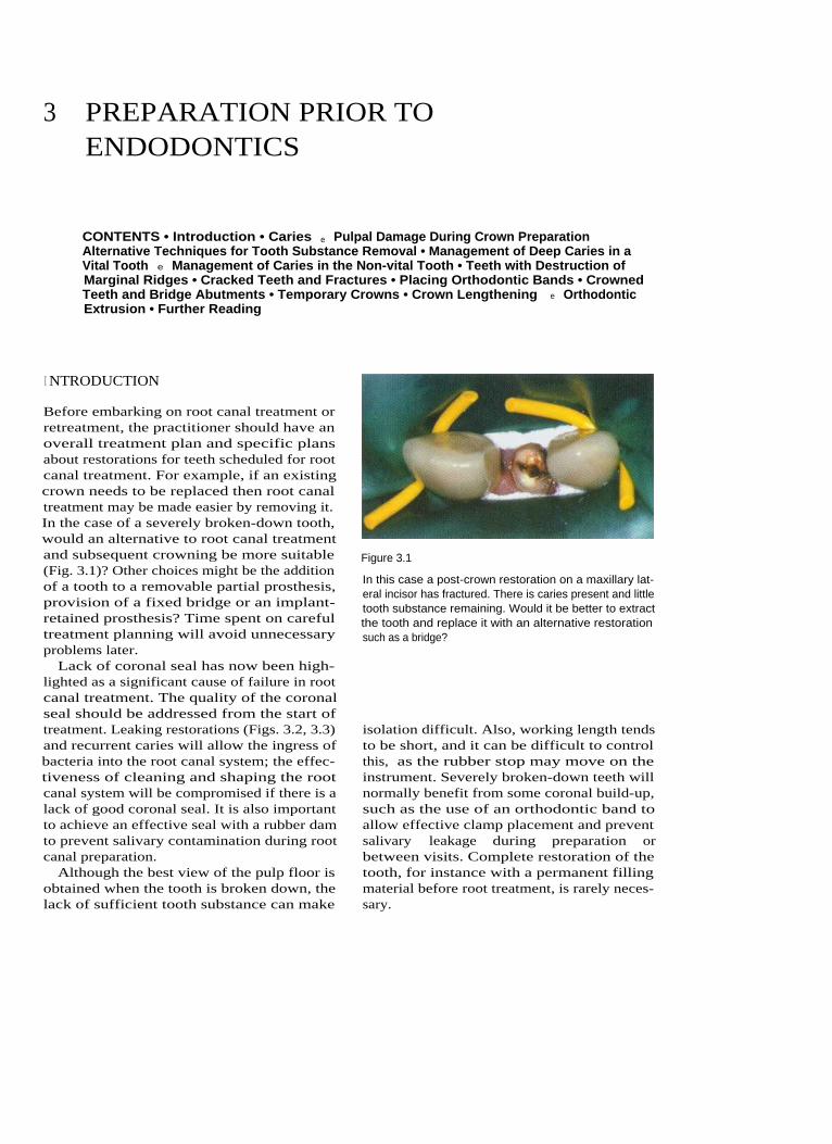
CONTENTS • Introduction • Caries e Pulpal Damage During Crown PreparationAlternative Techniques for Tooth Substance Removal • Management of Deep Caries in aVital Tooth e Management of Caries in the Non-vital Tooth • Teeth with Destruction ofMarginal Ridges • Cracked Teeth and Fractures • Placing Orthodontic Bands • CrownedTeeth and Bridge Abutments • Temporary Crowns • Crown Lengthening e OrthodonticExtrusion • Further Reading
I NTRODUCTION
Before embarking on root canal treatment orretreatment, the practitioner should have anoverall treatment plan and specific plansabout restorations for teeth scheduled for rootcanal treatment. For example, if an existingcrown needs to be replaced then root canaltreatment may be made easier by removing it.In the case of a severely broken-down tooth,would an alternative to root canal treatmentand subsequent crowning be more suitable(Fig. 3.1)? Other choices might be the additionof a tooth to a removable partial prosthesis,provision of a fixed bridge or an implant-retained prosthesis? Time spent on carefultreatment planning will avoid unnecessaryproblems later.
Lack of coronal seal has now been high-lighted as a significant cause of failure in rootcanal treatment. The quality of the coronalseal should be addressed from the start oftreatment. Leaking restorations (Figs. 3.2, 3.3)and recurrent caries will allow the ingress ofbacteria into the root canal system; the effec-tiveness of cleaning and shaping the rootcanal system will be compromised if there is alack of good coronal seal. It is also importantto achieve an effective seal with a rubber damto prevent salivary contamination during rootcanal preparation.
Although the best view of the pulp floor isobtained when the tooth is broken down, thelack of sufficient tooth substance can make
Figure 3.1
In this case a post-crown restoration on a maxillary lat-eral incisor has fractured. There is caries present and littletooth substance remaining. Would it be better to extractthe tooth and replace it with an alternative restorationsuch as a bridge?
isolation difficult. Also, working length tendsto be short, and it can be difficult to controlthis, as the rubber stop may move on theinstrument. Severely broken-down teeth willnormally benefit from some coronal build-up,such as the use of an orthodontic band toallow effective clamp placement and preventsalivary leakage during preparation orbetween visits. Complete restoration of thetooth, for instance with a permanent fillingmaterial before root treatment, is rarely neces-sary.

4 6
Figure 3.2
A radiograph showing a reasonable root canal treatmentbut poor coronal seal (arrowed).
Figure 3.3
Leaking restorations do not provide a good coronal seal.The buccal margin of this full crown restoration has amarginal deficiency (arrowed) that could allow coronalleakage during root canal treatment if an access cavitywere cut through the occlusal surface. It would be betterin this case to remove the crown before root canal prepa-ration and recement it temporarily between visits.
ENDODONTICS: PROBLEM-SOLVING IN CLINICAL PRACTICE
CARIES
The dentist's primary aim in managing cariesis to try and maintain the health of the dentalpulp. However, in the case of deep cariouslesions it can sometimes be difficult to ensurethe appropriate removal of softened dentinewhilst avoiding pulp exposure. Carious pulpexposure normally results in the mature toothrequiring root canal treatment. In this case allcaries should be removed before root canaltreatment is commenced.
The Dilemma of Deep Caries
There is now consensus amongst cliniciansthat during cavity preparation soft cariousdentine at the amelodentinal junction andover the pulp should be removed. Whenpreparing deep carious lesions in vital teethclinicians find it difficult to know when tostop excavation. If pulp exposure can beavoided then root canal treatment may oftenbe unnecessary in a tooth free of signs andsymptoms. There is, however, no justification
Figure 3.4
A molar tooth with active caries, which is lighter in colour.

PREPARATION PRIOR TO ENDODONTICS
for leaving carious dentine in the base of a
cavity merely to avoid carrying out root canaltreatment when there are signs or symptomsof pulpitis or pulp necrosis.
The colour of dentine can be used as anindicator of caries activity. Active caries tendsto be light (Fig. 3.4). Hardness is a better indi-cator of disease activity, but requires subjec-tive assessment, and is dependent on thesharpness of the probe and the pressureapplied (Fig. 3.5). An alternative approachinvolves the use of an indicator dye; but thereis some concern that this method may lead tounnecessary removal of the deepest layer ofsoftened but not infected dentine.
There are many ways in which caries canbe removed, from the routine to the experi-mental:
Mechanical rotary: Handpiece and bursMechanical non-rotary: Hand excavators, airabrasion, ultrasonics, sono-abrasionChemo-mechanical: Carisolv, CaridexPhoto-ablation: Lasers
Mechanical rotary techniques are the mostwidely used for caries removal. Carious den-
tine is most effectively removed using a
round bur in a slow-speed handpiece withwaterspray. Waterspray cools and lubricatesthe bur during cutting. The spray, by beingdirected at the cutting surface, prevents over-heating and consequent pulpal damage; thishas been shown experimentally. The largerthe area of dentine that is being prepared thegreater is risk of pulpal damage.
PULPAL DAMAGE DURING CROWNPREPARATION
The preparation of teeth for metal-ceramiccrowns is potentially damaging to the pulp.Extensive amounts of dentine are removed,especially from the buccal surface, exposingmany dentine tubules that can later beinvaded by micro-organisms. Pulpal bloodflow is also reduced owing to the action ofadrenaline in local anaesthetic. The depth of acavity, however, is of little significance untilpreparation extends to within 0.3 mm of thepulp tissue. Excessive drying of the cavityresults in odontoblasts being aspirated intothe dentine tubules; but this rarely results inpermanent pulp damage.
Figure 3.5
A probe can be used to test the hardness of caries.
ALTERNATIVE TECHNIQUES FORTOOTH SUBSTANCE REMOVAL
There have recently been some new develop-ments in techniques for caries removal.Chemo-mechanical techniques have showngood potential as a selective method of cariesremoval in lab-based experiments, and may beuseful in deep carious lesions to prevent pul-pal exposure. Air abrasion (Figs. 3.6, 3.7) usingaluminium oxide particles will remove soundenamel and dentine very efficiently, but notcarious dentine, as it is softer than the alu-minium particles themselves. Alternative par-ticles such as polycarbonate resin oralumina-hydroxyapatite are softer and mayselectively remove carious dentine whilst spar-ing healthy tissue. Favourable results have alsobeen reported for sono-abrasion of cariousdentine with specialized diamond-coated tips.
47

Figure 3.6
An air abrasion unit.
Figure 3.7
The air abrasion tip.
MANAGEMENT OF DEEP CARIES IN AVITAL TOOTH
Why?
To prevent irreversible damage to the pulp bybacterial microleakage, soft carious dentine isremoved from the base of deep cavities. Thetooth is then restored to function and thepulp protects itself by laying down irritationdentine. Leaving carious dentine may resultin the bacteria causing pulp necrosis and fur-ther destruction of the tooth by the spread orrecurrence of caries.
ENDODONTICS: PROBLEM-SOLVING IN CLINICAL PRACTICE
The pulp is remarkably resilient to irrita-tion by micro-organisms. No focus of inflam-matory cells is seen in the pulp until caries iswithin 1 mm, and only mild inflammation isseen microscopically when the advancing car-ious lesion is within 0.5 mm (Fig. 3.8). This isbecause the pulp dentine complex is able toprotect itself from irritants by the mecha-nisms of tubular sclerosis and irritation den-tine. When bacteria invade the irritationdentine severe inflammatory changes are seenin the pulp. Therefore if infected dentine isremoved and the cavity is then sealed, themajority of pulps will survive. Bacterial leak-
Figure 3.8
I rritationdentine
Histological section of advancing caries and correspond-ing diagram.
4 8

PREPARATION PRIOR TO ENDODONTICS
age occurs around most restorative materialsafter placement, and potentially can lead topulpal inflammation. It is therefore impera-tive that measures are taken to seal the cavityfollowing caries removal.
When?
Caries removal is carried out prior to theplacement of a restoration. The pulp will pro-tect itself from microleakage by tubular scle-rosis (Fig. 3.9), formation of irritation dentineand inflammation; but measures need to betaken to prevent pulp damage before thesebiological processes have taken place. Liningthe cavity for reasons of thermal protection orto prevent material irritation is unnecessary.Dentine has good insulation properties, andfew restorative materials are irritant. Most ofthe original work on material irritancy hasnow been shown to be due to bacterial leak-age and not to the materials themselves.Linings are therefore principally required toprevent bacterial leakage.
How?
4 9
All carious material is removed from theamelodentinal junction, and softened dentineis removed from the base of the cavity. Thecavity can then be sealed using a variety ofmethods according to the overlying restora-tive material:• Varnish• Zinc oxide eugenol-based cement• Composite and dentine-bonding agent• Glass ionomer or resin-modified glass
ionomer• Poly acid-modified composite (compomer)
Varnish
Copalite varnish can be used to seal the pre-pared cavity; two coats are recommended toensure complete coverage prior to placingamalgam. A varnish can also be used to sealexposed dentine following crown prepara-tion.
Figure 3.9
The pulp will protectitself from microleakageby tubular sclerosis, for-mation of irritation den-tine and inflammation.

50
ENDODONTICS: PROBLEM-SOLVING IN CLINICAL PRACTICE
Zinc Oxide and Eugenol-Based Cement
Eugenol-based materials prevent microleak-age because they have an antibacterial actionas eugenol is leached out. When treating deepcarious lesions some operators suggestremoving the bulk of the infected dentine andplacing a fortified zinc oxide eugenol tempo-rary filling for several months, as an indirectpulp cap (Fig. 3.10). The remaining smallamount of carious dentine is removed at alater date, when it is hoped that the pulp willhave laid down irritation dentine. The opera-tor should beware, however, that the tooth isnot necessarily healthy because it is symp-tom-free, as it may have become non-vitalbefore placing the definitive restoration!
Figure 3.11
Etching dentine for composite bonding.
Composite Resin and Dentine-Bonding
Agents
Modern composite resins placed followingtotal etch procedures bond well to hydrateddentine, using primer and bond systems(Figs. 3.11-3.13). Calcium hydroxide liners arenow rarely advocated to protect the dentine;
Figure 3.12
Addition of bonding agent to etched surfaces. Theseshould not be over-dried.
Figure 3.10
A reinforced zinc oxide eugenol cement such as IRM(Intermediate Restorative Material: Dentsply, Weybridge,Surrey, UK) is extremely useful in endodontics. The
Figure 3.13
eugenol content is antibacterial.
Composite is added in layers.

PREPARATION PRIOR TO ENDODONTICS
instead it is etched and protected with abonding agent. Dentine-bonding agents pro-vide a seal by penetrating dentine tubulesand producing a hybrid layer. The materialsare not irritant to pulp tissue. Poor techniqueand contamination with oil, saliva or bloodmay produce an inferior bond that allowsmicroleakage leading to pulpal inflammation.It has been recommended that cavity marginsare etched and sealed with a dentine-bondingagent following polishing of compositerestorations to help prevent microleakage.Composites are now available in a range ofviscosities, from flowable to packable. Theflowable variety may be particularly useful toseal the cavity before placement of a higher-viscosity material.
Dentine-bonding agents used with bifunc-tional primers can be used to bond amalgamrestorations, and may provide an element ofseal.
Glass lonomer
This material bonds to enamel and dentine,and can therefore be used to seal cavitiesprior to root canal treatment. The bond, aswith most adhesive materials, is vulnerable tocontamination. Glass ionomers undergo slowmaturation that is affected by the degree ofhydration. Glass ionomers can be particularlyuseful when placing an orthodontic band toprotect endodontically treated teeth.
Resin-modified glass ionomers have signifi-cantly higher intermediate strength than con-ventional glass ionomers. They are ideally usedin thick sections and are suitable for sandwich-style restorations with light-cured compositerestorative materials. They can be used to sealcavities prior to root canal treatment.
Poly Acid-modified Composite (Compomer)
This material has properties similar to that ofconventional composite, but uses slow wateruptake from the oral environment to mediatethe glass ionomer setting reaction. It can beused to build up a tooth prior to root canaltreatment.
MANAGEMENT OF CARIES IN THENON-VITAL TOOTH
Before a non-vital tooth is to be root treatedthe quality of coronal seal should be assessed.If the existing restoration has significantmarginal deficiencies or there is evidence ofrecurrent caries, it should be removed. If atooth is to be root canal retreated the operatorshould be questioning whether the demise ofthe previous root canal treatment could be dueto coronal leakage around a poor restoration. Itis now known that the quality of the coronalrestoration as well as the quality of the rootcanal treatment affects the long-term outcomeof root-filled teeth. Infected dentine is removedin exactly the same ways as with vital teeth.The quality of coronal seal is important duringroot canal treatment to prevent microleakagebetween visits and following root canal treat-ment. The cavities can be sealed with a rein-forced zinc oxide eugenol material. Materialsthat bond to dentine and enamel can be usefulwhere there is little tooth substance remaining,and may offer some protection from fractureduring root canal treatment by preventingcusps from flexing.
TEETH WITH DESTRUCTION OFMARGINAL RIDGES
As restorations become more extensive, theinherent strength of the remaining toothdecreases.
Teeth with large MOD restorations and lossof the roof of the pulp chamber are vulnerableto fracture.
If there are any signs of cracks in a tooththat is to be root-treated, cusps have brokenoff, or the restoration is particularly largewith vulnerable cusps remaining, it may beprudent to fit an orthodontic band before rootcanal treatment is started.
CRACKED TEETH AND FRACTURES
There is a difference between a cracked tooth(Fig. 3.14) and a longitudinally fractured tooth
51

ENDODONTICS: PROBLEM-SOLVING IN CLINICAL PRACTICE
Figure 3.11
A cracked tooth with a crack running mesiodistallythrough the crown.
Figure 3.15
A fractured tooth with a longitudinal fracture (arrowed)in the root.
(Fig. 3.15). The latter involves movement of thetwo or more fragments, radiological signs, orbone loss associated with the root defect. Heroicattempts have been made to bond together lon-gitudinally fractured teeth; however, the long-term prognosis is poor and extraction is usuallythe only treatment (Figs. 3.16-3.18).
Figure 3.16
A cuspal fracture; the tooth can be restored with fillingmaterial.
Figure 3.17
A severe cuspal fracture; root canal treatment and crownlengthening may be required. A subsequent crown willbe required to prevent vertical root fracture.
52

PREPARATION PRIOR TO ENDODONTICS
Figure 3.18
A longitudinal root fracture. This tooth would requireextraction.
Figure 3.19
The treatment of cracked teeth, however,depends on the severity of the crack and thedegree of inflammation within the pulp.Patients with a cracked cusp or tooth will oftencomplain of pain on biting, especially whenreleasing from the bolus. This can be explainedby the fact that the crack contains bacteria,which cause inflammation within the pulp.Chewing opens the crack, allowing oral fluidsto flow in. As the tooth fragments snap backtogether fluid movement is produced in thedentine tubules, eliciting pain in the inflamedpulp. If the tooth were vital and showed nosigns of irreversible pulpitis then treatmentwould involve removal of the fractured cuspand placement of a new restoration. A pinnedamalgam restoration may be suitable.Alternatively, the tooth could be restored witha cusp coverage restoration to reduce the stressapplied to the cusps during mastication.
A crack may run across the roof of the pulpchamber (Fig. 3.19). If the tooth is vital andsymptom-free then a sealing restoration, suchas zinc oxide and eugenol cement, glassionomer cement or a dentine-bonded compos-ite may prevent bacterial ingress sufficiently forroot canal treatment to be avoided. The toothmust be protected from stresses that couldresult in propagation of the crack, and a full
A crack (arrowed) running across the roof of the pulp ina buccal-lingual direction. The crack did not extend com-pletely through the coronal tooth substance. As the toothwas non-vital it was root-treated and restored with acrown.
coverage restoration may be required. Cracksthat run across the pulp chamber floor mayhave become infected with bacteria and aretherefore more difficult for the clinician to man-age. Some teeth will not be savable, while inothers it may be possible to seal the pulp floorand place a cusp coverage restoration, prolong-ing the life of the tooth for several years.
Teeth requiring endodontic treatment maybenefit from the placement of a band to pre-vent fracture. Following root canal treatmentit is normally recommended to place a fullcoverage crown or cusp coverage restorationto protect the tooth from subsequent fracture.
PLACING ORTHODONTIC BANDS
Why?
Unfortunately, a number of posterior teethundergoing root canal treatment are lost as a
5 3

ENDODONTICS: PROBLEM-SOLVING IN CLINICAL PRACTICE
Figure 3.20
A collection of orthodontic bands.
Figure 3.22
Checking the fit of a band.
Figure 3.21 Figure 3.23
A fractured first molar tooth that requires placement ofan orthodontic band prior to root canal treatment.
Zinc phosphate cement is placed on the band prior toseating. Excess cement is carefully removed.
result of fracture. If a band is fitted to thetooth before endodontic treatment, this willhelp prevent propagation of a crack or frac-ture. It will also help improve rubber damisolation of a severely broken-down tooth.
When?
If a posterior tooth shows early signs of frac-ture, such as crack-lines in the enamel, or issignificantly broken down, so that isolationwith rubber dam is difficult, a band can be fit-ted. Teeth with subgingival cavity marginsmay benefit from the placement of a band toachieve a good coronal seal for root canal treat-ment. Occasionally, the tooth might be crown-lengthened before root canal treatment.
54

PREPARATION PRIOR TO ENDODONTICS
Figure 3.24
Seating the band using an amalgam plugger.
Figure 3.25
The cavity in the banded tooth is filled with glassi onomer.
Figure 3.26
The margins are polished with an abrasive rubber cup.
Figure 3.27
How?A well-fitting orthodontic band in place on a mandibularfirst molar.
Orthodontic bands are made of stainless steeland can be purchased without brackets (Fig.3.20). They are manufactured to fit maxillaryand mandibular premolars and molars. A bandis selected that fits snugly around the tooth(Figs. 3.21, 3.22). The occlusion on the bandmay need to be adjusted. Bands are bondedusing zinc phosphate or glass ionomer cement
(Fig. 3.23). It may be necessary to ease the bandinto position using an amalgam plugger or atooth slooth (Fig. 3.24). If the tooth is severelybroken down then the entire band can be filledwith glass ionomer (Fig. 3.25). This will allowthe tooth to be isolated using rubber dam, andalso gives a good coronal seal between visits
5 5

ENDODONTICS: PROBLEM-SOLVING IN CLINICAL PRACTICE
during endodontic treatment. The edges arepolished with an abrasive rubber cup (Fig.3.26). Once bonded the occlusion is recheckedwith articulating paper, and any high spots areremoved with a diamond bur (Fig. 3.27).
It is often advisable to leave rubber damplacement to the following visit, when theluting cement will have set completely.
Copper Bands
Copper bands have long been used in den-tistry, for example as a matrix for amalgamcore fabrication and for taking impressions.They can be used in a similar manner toorthodontic bands to protect teeth that arevulnerable to fracture or to build up teeth thatare severely broken down. These bands arealso cemented with zinc phosphate or glassionomer cement. They tend to be cheaperthan orthodontic bands, but require more cus-tomization and are less well tolerated bypatients (they can taste metallic).
Metal Shell Crowns
Figure 3.28
A simple metal shell crown filled with zinc oxide andeugenol cement has been used to seal an endodonticallytreated tooth prior to permanent restoration. The marginsare supragingival and smooth, ensuring good periodon-tal health.
Metal shell crowns can be used as temporaryrestorations. These are filled with either glassionomer or zinc oxide eugenol cement. Themargins often need to be adjusted, smoothedand polished. Ideally the margins should besupra-gingival to prevent damage to the peri-odontal ligament and plaque accumulation(Fig. 3.28).
CROWNED TEETH AND BRIDGEABUTMENTS
Crowned Teeth
The dilemma when root-treating a crownedtooth is whether to remove the restoration ornot. Placing a rubber dam clamp on a tooththat has been prepared for a crown can be dif-ficult. If the margins of a cast restoration arepoor or appear to be leaking then the restora-tion is probably best removed. It can alwaysbe replaced as a temporary measure usingglass ionomer or zinc oxide eugenol cementafter caries removal. This will act as a sound
Figure 3.29
The crown on the first molar has gross caries under thedistal margin that will compromise coronal seal duringroot canal treatment.
56

PREPARATION PRIOR TO ENDODONTICS
Figure 3.30
The crown was partially split and then elevated and the
caries removed.
temporary restoration and aid rubber damisolation (Figs. 3.29-3.33).
It may not be possible to locate the pulpspace and remove all the carious dentineworking through an access cavity in acrown.
Removing Crowns
Why?A crown may be removed:
• To make access easier• To aid removal of caries• To improve the coronal seal• To improve visualization of cracks.
When?If a crown is due to be replaced then it may beeasier to remove it prior to endodontic treat-ment. However, if the crown is sound, rootcanal treatment may be carried out throughan access cavity in the occlusal surface. Thiscavity can be restored following root canaltreatment.
Figure 3.31
The crown is cleaned and filled with glass ionomer.
Figure 3.32
The crown is replaced.
Figure 3.33
Rubber dam can be fitted more easily and an access cav-
ity cut through the crown.
57
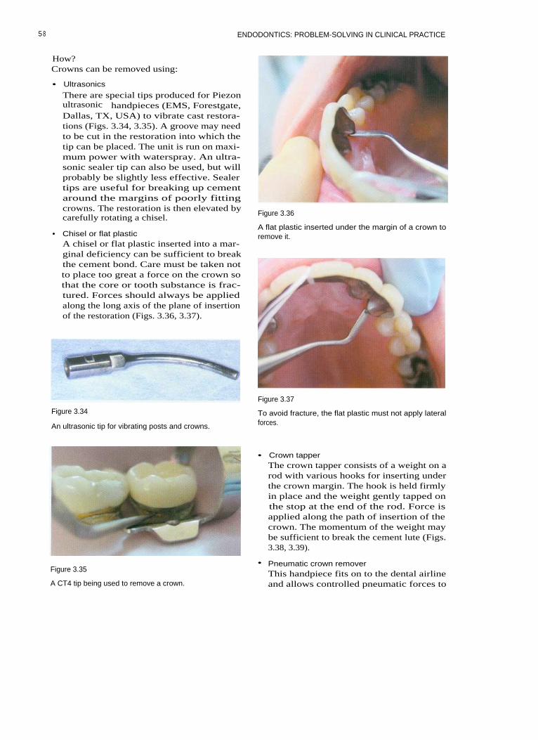
ENDODONTICS: PROBLEM-SOLVING IN CLINICAL PRACTICE
How?Crowns can be removed using:
• Ultrasonics
There are special tips produced for Piezonultrasonic handpieces (EMS, Forestgate,Dallas, TX, USA) to vibrate cast restora-tions (Figs. 3.34, 3.35). A groove may needto be cut in the restoration into which thetip can be placed. The unit is run on maxi-mum power with waterspray. An ultra-sonic sealer tip can also be used, but willprobably be slightly less effective. Sealertips are useful for breaking up cementaround the margins of poorly fittingcrowns. The restoration is then elevated bycarefully rotating a chisel.
•
Chisel or flat plasticA chisel or flat plastic inserted into a mar-ginal deficiency can be sufficient to breakthe cement bond. Care must be taken notto place too great a force on the crown sothat the core or tooth substance is frac-tured. Forces should always be appliedalong the long axis of the plane of insertionof the restoration (Figs. 3.36, 3.37).
Figure 3.36
A flat plastic inserted under the margin of a crown toremove it.
Figure 3.34
An ultrasonic tip for vibrating posts and crowns.
Figure 3.37
To avoid fracture, the flat plastic must not apply lateralforces.
• Crown tapperThe crown tapper consists of a weight on arod with various hooks for inserting underthe crown margin. The hook is held firmlyin place and the weight gently tapped onthe stop at the end of the rod. Force isapplied along the path of insertion of thecrown. The momentum of the weight maybe sufficient to break the cement lute (Figs.3.38, 3.39).
Figure 3.35
A CT4 tip being used to remove a crown.
• Pneumatic crown removerThis handpiece fits on to the dental airlineand allows controlled pneumatic forces to
5 8

PREPARATION PRIOR TO ENDODONTICS
Figure 3.40
The Kavo pneumatic crown and bridge remover.
Figure 3.38
The tip of the crown tapper is inserted under the margin.
Figure 3.39
Figure 3.41
This crown has been sectioned prior to removal.
ing the cement. If the crown is resistant toremoval then it can be sectioned com-pletely and the pieces elevated.
The crown tapper being used to remove a bridge.
Bridge Abutments
be applied to the crown via a speciallydesigned pair of forceps (Fig. 3.40).
• SectioningA crown can be partially sectioned by cut-ting a groove from the gingival on to theocclusal surface (Fig 3.41). A chisel is thenplaced in the groove and twisted, allowingthe crown to be flexed and thereby break-
It is useful to check if a bridge abutment hasdecemented and become loose by placing aprobe under the pontic and applying pressurecoronally (Fig. 3.42). If the restoration is loosethen the bridge abutment will move. Airbubbles in the saliva may be seen at the mar-gin of the bridge-tooth interface. If the abut-ment has decemented then it is prudent toremove the restoration. If the abutment has
59

ENDODONTICS: PROBLEM-SOLVING IN CLINICAL PRACTICE
Figure 3.42
Placing a probe under a bridge to check retention.Figure 3.43
been loose for some time then the coronaltooth tissue will often be grossly carious.
Alternatively, a bridge can be sectionedinto smaller pieces. The abutment and ponticcan be removed. Care should be taken if theremaining bridge section is left as a can-tilever, because excessive occlusal forcescould lead to the demise of the remainingabutment.
Removing a Bridge
Bridges can be removed using the same tech-niques as those for removing crowns. It canbe useful to attach a length of dental floss tothe bridge before removal in case it is acci-dentally dislodged into the back of thepatient's mouth.
When a bridge has multiple retainers itmay be necessary to cut grooves in the sepa-rate retainers, allowing the lute to be brokenon each before attempting removal.
Sectioning a bridge. The maxillary right second premolaris the post-retained distal abutment for a three-unitbridge. The tooth requires root canal retreatment. Theentire bridge could be removed in order to gain access.Alternatively, the bridge could be sectioned. In this case,the bridge was cut through mesial to the maxillary firstpremolar.
ing section of the bridge that is to remain inplace should be polished with a rubber wheel.If the remaining section becomes cantileveredthen the occlusion must be examined, asexcessive force placed on the remainingbridge components could lead to fracture ofthe remaining abutment. In such a case it maybe better to leave the abutment as a singleunit.
TEMPORARY CROWNS
Sectioning a Bridge
Metal ceramic bridges can be sectionedthrough appropriate approximal contactsusing a long tapered diamond bur on theceramic and a cross-cut tungsten carbide buron the metal (Fig. 3.43). It is useful to attach alength of dental floss to the portion that is tobe removed in case it is dislodged into thepatient's mouth, especially if the abutmenthas debonded. The cut surface of the remain-
Temporary crowns are constructed:
• To restore the occlusion and prevent over-eruption and tilting
• To prevent bacterial penetration by coronalleakage
• To prevent damage to the prepared tooth• To prevent damage to the periodontium
and food packing• To restore the aesthetic appearance of the
teeth.
6 0

PREPARATION PRIOR TO ENDODONTICS
Temporary crown forms are available foranterior teeth constructed from polycarbonateand acrylic (Fig. 3.44). These are usually filledwith methacrylate resin (e.g. Trim: Dentsply)and seated on the tooth by the practitioner.Preformed crowns require careful adjustmentto achieve a good fit and an aesthetic result.They should be cemented with a suitablecement to prevent microleakage (Fig. 3.45).
It is probably easier to construct well-fitting temporaries from a preoperative algi-nate impression. If the tooth is broken downthen the alginate impression can be modifiedusing an excavator or scalpel. Custom-casttemporaries made from bis-acryl resin (e.g.Protemp: ESPE, Seefeld, Oberlay, Germanyor Luxatemp: DMG, Hamburg, Germany)have a good appearance and are quick tomake, and the margins are easy to trim. Thetemporary can be adjusted with a mediumgrit sandpaper disc or a stone (Fig. 3.46).
Even if a posterior tooth has been root-filled it is important to place a well-fittingtemporary, for the above reasons. If the filledroot canals are left exposed to the oralenvironment then they could become re-infected.
Metal shell crown forms can be used(as discussed earlier). They are filled withzinc oxide eugenol cement and seated intoplace.
Modern syringe-mixed resins (Protemp,Luxatemp) make the fabrication of custom-cast temporary restorations much easier.These are cast using a preoperative alginate
impression. The temporary crowns should becemented with a eugenol-based temporarycement. Leakage is more of a problem withlong-term temporary restorations, and if they
Figure 3.45
A preformed acrylic temporary used to restore the toothduring endodontic treatment. As there was limited coro-nal tooth substance remaining the temporary acryliccrown was completely filled with glass ionomer cementand bonded in place. This provided a good seal duringroot canal treatment and avoided the need for a tempo-rary post crown.
Figure 3.44 Figure 3.46
A preformed acrylic crown; it is useful to roughen theinternal surface before bonding.
Trimming a custom-cast temporary restoration beforecementation.
61
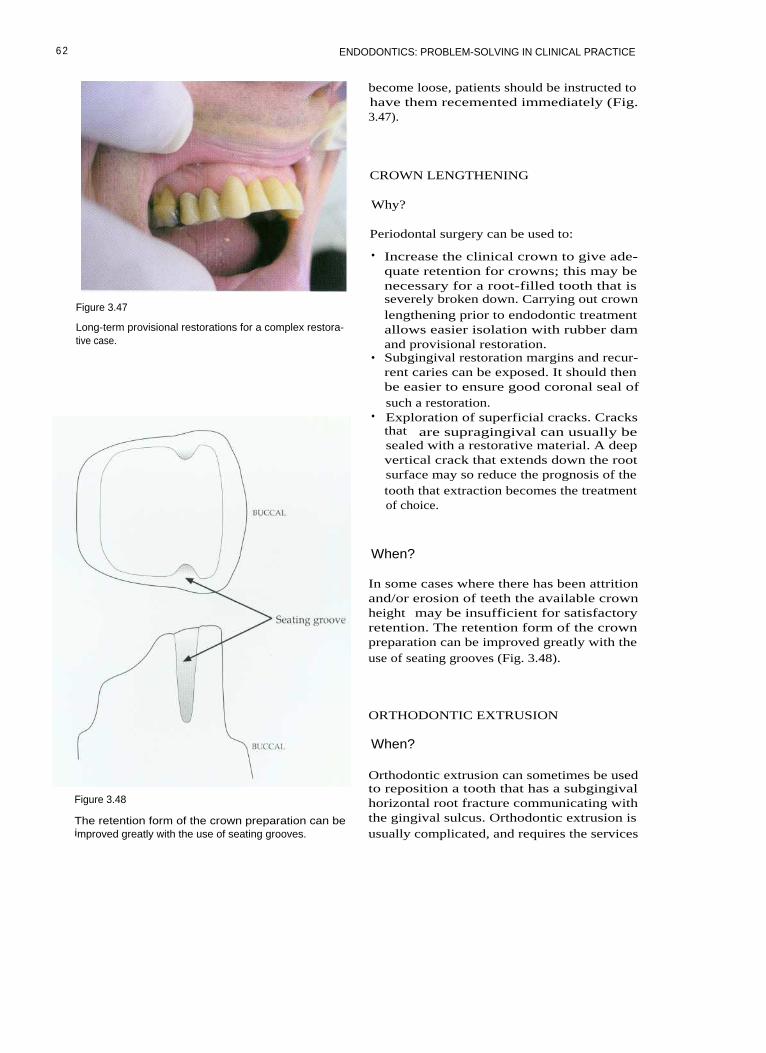
ENDODONTICS: PROBLEM-SOLVING IN CLINICAL PRACTICE
Figure 3.47
Long-term provisional restorations for a complex restora-tive case.
Figure 3.48
The retention form of the crown preparation can beimproved greatly with the use of seating grooves.
become loose, patients should be instructed tohave them recemented immediately (Fig.3.47).
CROWN LENGTHENING
Why?
Periodontal surgery can be used to:
• Increase the clinical crown to give ade-quate retention for crowns; this may benecessary for a root-filled tooth that isseverely broken down. Carrying out crownlengthening prior to endodontic treatmentallows easier isolation with rubber damand provisional restoration.
• Subgingival restoration margins and recur-rent caries can be exposed. It should thenbe easier to ensure good coronal seal ofsuch a restoration.
• Exploration of superficial cracks. Cracksthat are supragingival can usually besealed with a restorative material. A deepvertical crack that extends down the rootsurface may so reduce the prognosis of thetooth that extraction becomes the treatmentof choice.
When?
In some cases where there has been attritionand/or erosion of teeth the available crownheight may be insufficient for satisfactoryretention. The retention form of the crownpreparation can be improved greatly with theuse of seating grooves (Fig. 3.48).
ORTHODONTIC EXTRUSION
When?
Orthodontic extrusion can sometimes be usedto reposition a tooth that has a subgingivalhorizontal root fracture communicating withthe gingival sulcus. Orthodontic extrusion isusually complicated, and requires the services
62

PREPARATION PRIOR TO ENDODONTICS
of an orthodontist. There can be difficultyproviding a suitable provisional restoration,and in the long term it must be possible torestore the tooth, otherwise orthodonticextrusion is not indicated.
The practitioner must consider whether asuitable alternative to trying to save a badlyfractured tooth would be more successful.
Feiglin B (1986). Problems with the endodon-tic-orthodontic management of fracturedteeth. International Endodontic journal 19:57-63.
Kirkevang L-L, Orstavik D, Horsted-BindslevP, Wenzel A (2000). Periapical status andquality of root fillings and coronal restora-tions in a Danish population. InternationalEndodontic Journal 33: 509-511.
FURTHER READING
Banerjee A, Watson TF, Kidd EAM (2000).Dentine caries excavation: a review of currentclinical techniques. British Dental Journal 188:476-482.
Saunders WP, Saunders EM (1994). Coronalleakage as a cause of failure in root canal ther-apy: a review. Endodontics and DentalTraumatology 10: 105-108.
63

4 ISOLATION
CONTENTS • Isolation • Rubber Dam Frames • Rubber Dam Clamps • Rubber DamPunch • Rubber Dam Forceps • Lubricants, Tape and Wedgets • Sealants • RubberDam Placement • Rubber Dam Kit • Quick Single Tooth Isolation Method • MultipleTeeth Isolation • The Split-dam Technique • Using Wingless Clamps • Practical Solutionsto Isolation Problems
I SOLATION
The use of rubber dam is essential for good-quality endodontic treatment. With experi-ence it can be placed quickly and efficiently,and it improves treatment for both operatorand patient (Fig. 4.1).
When?
Any tooth that is undergoing an endodonticprocedure should be isolated with rubberdam. This includes a range of procedures,from an endodontic emergency such as pulpextirpation and placement of medicaments tomore complex and time-consuming root canalretreatment.
• To reduce and control the aerosol ofmicrobes and saliva produced when usinga turbine handpiece. In addition, thepatient does not have a mouth full ofwater.
• The soft tissues are retracted, affordingthem protection while the patient is beingtreated. The inquisitive tongue is kept outof the tooth being treated.
• Rubber dam allows unimpeded vision ofthe tooth that is being treated. This is espe-cially useful when using a surgical micro-scope.
• The operative field can be dried, andmirror fogging caused by breathing isprevented.
• Rubber damthat allowshypochloriteirrigants.
• Treatment is quicker and more pleasant forboth the patient and the clinician.
produces a watertight sealthe safe use of sodiumand other disinfectants as
Why?
There are many benefits from the use of rub-ber dam:
• To prevent the accidental aspiration orswallowing of instruments, irrigants, frag-ments of tooth and restorative materials.Practitioners who do not use rubber damcould be considered negligent and placethemselves at risk of litigation should anaccident occur.
• To prevent contamination of the accesscavity and root canal system with saliva.
How?
Rubber Dam
Rubber dam is usually made of latex,comes in sheets of varying thickness.sheets range from thin to extra-heavy,depending on thickness, and are 150 mmsquare. There are many different colours,flavours and aromas! (Fig. 4.2). For patientswho have an allergy to latex, a silicone (non-latex) rubber dam is available (Fig. 4.3).
andThe

ENDODONTICS: PROBLEM-SOLVING IN CLINICAL PRACTICE
Figure 4.1
Well-placed rubber dam aids endodontic treatment.
Figure 4.3
Non-latex dam is made of silicone.
Figure 4.4
Figure 4.2 Plastic 'U' shaped frame.
Different colours, sizes and grades of rubber dam areavailable.
RUBBER DAM FRAMES
radiopaque, so that they needed to beremoved to avoid obscuring important detailon radiographs.
Modern frames are constructed from plasticso that they can remain in place duringradiography. There are two basic types,Young's frame, which has a 'U' shape (Fig.4.4) and the Nygard-Ostby (Fig. 4.5), which isoval in shape. Frames were originally con-structed from metal (Fig. 4.6), and were
RUBBER DAM CLAMPS
Most rubber dam clamps are now manufac-tured from stainless steel, as this resists corro-sion much better than plated steel. They comewith or without wings. Clamps are essential
66

I SOLATION
Figure 4.5
Nygard-Ostby frame.
Figure 4.7
K clamp (Dentsply, Weybridge, Surrey, UK).
Figure 4.6
Metal frames are no longer used.Figure 4.8
14 clamp (Hygenic, Akron, OR USA).
for retaining rubber dam on posterior teeth,and very valuable for anterior teeth. Fullyerupted teeth can be isolated with an appro-priate clamp, although partially erupted teethand broken-down teeth can be difficult to iso-late. Manufacturers have produced a largerange of clamps. These can be identified bycatalogue number or letter, depending on themake (Figs. 4.7-4.11).
The advantage of a winged clamp on amolar tooth is that both clamp and dam canbe placed on the tooth simultaneously,thereby speeding up the process. When awingless clamp is used on a molar tooth, it is
Figure 4.9
EW clamp (Dentsply).
6 7
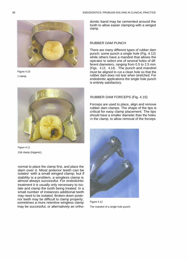
ENDODONTICS: PROBLEM-SOLVING IN CLINICAL PRACTICE
Figure 4.10
1 clamp.
dontic band may be cemented around thetooth to allow easier clamping with a wingedclamp.
RUBBER DAM PUNCH
There are many different types of rubber dampunch; some punch a single hole (Fig. 4.12)while others have a mandrel that allows theoperator to select one of several holes of dif-ferent diameters, ranging from 0.5 to 2.5 mm(Figs. 4.13, 4.14). The punch and mandrelmust be aligned to cut a clean hole so that therubber dam does not tear when stretched. Forendodontic applications the single hole punchis entirely satisfactory.
Figure 4.11
13A clamp (Hygenic).
normal to place the clamp first, and place thedam over it. Most anterior teeth can beisolated with a small winged clamp; but ifstability is a problem, a wingless clamp isalmost always successful. For endodontictreatment it is usually only necessary to iso-late and clamp the tooth being treated. In asmall number of instances additional teethmay need to be isolated. Broken-down poste-rior teeth may be difficult to clamp properly;sometimes a more retentive wingless clampmay be successful, or alternatively an ortho-
RUBBER DAM FORCEPS (Fig. 4.15)
Forceps are used to place, align and removerubber dam clamps. The shape of the tips iscritical for easy clamp placement. The tipsshould have a smaller diameter than the holesin the clamp, to allow removal of the forceps
Figure 4.12
The mandrel of a single hole punch.
68

ISOLATION
Table 4.1 Rubber dam clamps placed in groups according to catalogue letter and equivalent number
Figure 4.13
Figure 4.14
A multihole punch.
The mandrel of a multihole punch.
69

ENDODONTICS: PROBLEM-SOLVING IN CLINICAL PRACTICE
Figure 4.15
Rubber dam forceps.
following clamp placement. Sometimes it isnecessary to reduce the size of the tips ofnewly manufactured forceps; this can be donewith a diamond bur or a carborundum disc(Fig. 4.16).
Wedgets (Hygenic: Fig. 4.17) or strips ofrubber dam (Fig. 4.18) can be used to retainthe dam instead of a clamp in the front of themouth. This is especially useful in the ante-rior region when it is necessary to use a split-dam technique.
SEALANTS
Various caulking agents have been marketedto help seal around rubber dam. Orasealputty (Ultradent, South Jordan, UT, USA; Fig.4.19) and caulking are examples. For largerdeficiencies or in the absence of a commercialcaulking agent Cavit (ESPE, Seefeld, Oberlay,Germany) or Kalzinol (Dentsply) are useful.
LUBRICANTS, TAPE AND WEDGETS
Silicone lubricant or shaving foam can beused to ease the placement of rubber damthrough tight interproximal contacts,although they are not often required forendodontic applications. Dental tape can beused to take rubber dam through a contactpoint and can then act as a retainer.
Figure 4.17
Wedgets (arrowed) used to secure a split dam.
Figure 4.16
Adjusting rubber dam forceps with a carborundum disc.
Figure 4.18
A strip of rubber (arrowed) used to secure the mesial endof a multi-tooth isolation.
70
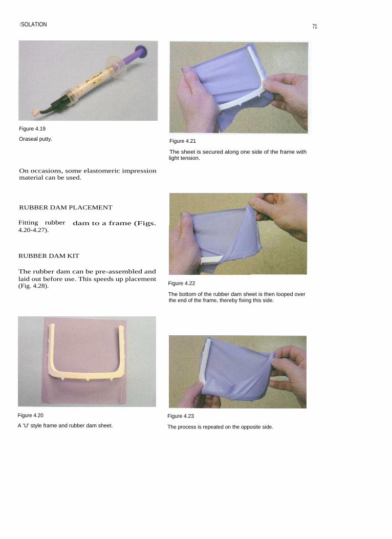
I SOLATION
71
Figure 4.19
Oraseal putty. Figure 4.21
The sheet is secured along one side of the frame withlight tension.
On occasions, some elastomeric impressionmaterial can be used.
RUBBER DAM PLACEMENT
Fitting rubber dam to a frame (Figs.4.20-4.27).
RUBBER DAM KIT
The rubber dam can be pre-assembled andlaid out before use. This speeds up placement(Fig. 4.28). Figure 4.22
The bottom of the rubber dam sheet is then looped overthe end of the frame, thereby fixing this side.
Figure 4.20 Figure 4.23
A 'U' style frame and rubber dam sheet.
The process is repeated on the opposite side.

ENDODONTICS: PROBLEM-SOLVING IN CLINICAL PRACTICE
Figure 4.24 Figure 4.27
When both sides have been folded a deep gutter is
The dam is ready for placement.created.
Figure 4.25
Pushing the overhanging dam back over the corners ofthe frame, on one side.
Figure 4.28
A rubber dam kit.
Figure 4.26
Then the other. Figure 4.29
A cross is imagined on the frame and a hole punched inthe relevant quadrant. The punch is positioned over themandibular left quadrant in this picture.
72

I SOLATION
QUICK SINGLE TOOTH ISOLATIONMETHOD
1. The rubber dam is fitted on to the rubberdam frame so that a gutter is created (seeFigs. 4.20-4.27).
2. Imagine a cross in the centre of the rubberdam; a hole is punched in the relevantquadrant (Fig. 4.29).
3. A winged clamp is selected and placed inthe rubber dam (Figs. 4.30, 4.31).
4. Using forceps the clamp is introduced onto the tooth. The operator must be carefulto make sure that the soft tissues are nottrapped (Fig. 4.32).
5. The clamp is allowed to close on to thetooth in the correct position, and the rubberdam is then released from the clamp wingsusing a flat plastic or fingers (Figs.4.33-4.36).
6. Sealant can be applied for extra protectionif necessary (Fig. 4.37).
Figure 4.31
The clamp is fitted to the rubber dam to isolate amandibular right molar.
Figure 4.30
Figure 4.32
A winged clamp is selected. In this case a hole has been
Using forceps the dam assembly is introduced to thepunched to isolate a mandibular right molar.
tooth.
7 3

74
ENDODONTICS: PROBLEM-SOLVING IN CLINICAL PRACTICE
Figure 4.35
Once the clamp is fully seated the forceps are removed.
Figure 4.33
Isolation of a mandibular left molar. The forceps are usedto carry the dam, frame and clamp to the tooth.
Figure 4.36
The dam is released from the wings.
Figure 4.34
The clamp is introduced over the tooth a1the clinician's finger.
Figure 4.37
In this case, sealant has been applied for extra protection.
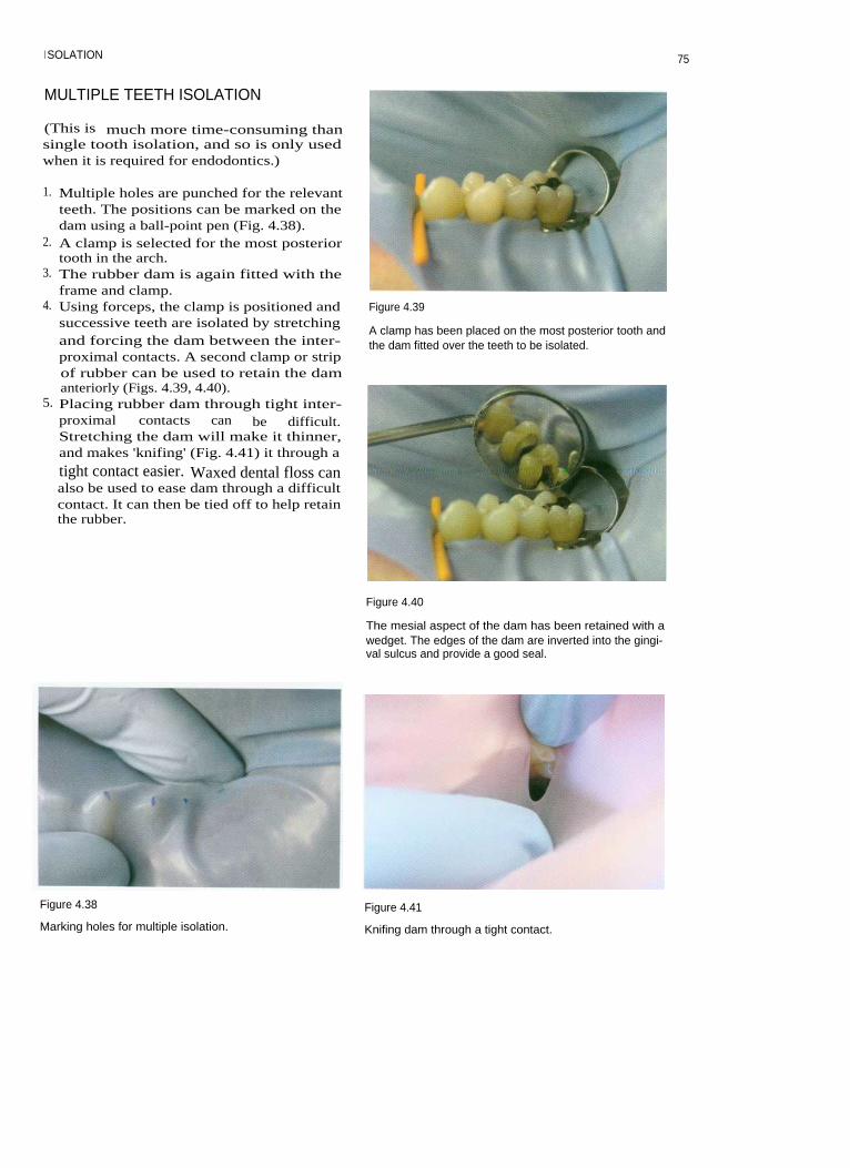
I SOLATION
MULTIPLE TEETH ISOLATION
(This is much more time-consuming thansingle tooth isolation, and so is only usedwhen it is required for endodontics.)
1. Multiple holes are punched for the relevantteeth. The positions can be marked on thedam using a ball-point pen (Fig. 4.38).
2. A clamp is selected for the most posteriortooth in the arch.
3. The rubber dam is again fitted with theframe and clamp.
4. Using forceps, the clamp is positioned andsuccessive teeth are isolated by stretchingand forcing the dam between the inter-proximal contacts. A second clamp or stripof rubber can be used to retain the damanteriorly (Figs. 4.39, 4.40).
5. Placing rubber dam through tight inter-proximal contacts can be difficult.Stretching the dam will make it thinner,and makes 'knifing' (Fig. 4.41) it through a
tight contact easier. Waxed dental floss canalso be used to ease dam through a difficultcontact. It can then be tied off to help retainthe rubber.
Figure 4.39
A clamp has been placed on the most posterior tooth andthe dam fitted over the teeth to be isolated.
Figure 4.40
The mesial aspect of the dam has been retained with awedget. The edges of the dam are inverted into the gingi-val sulcus and provide a good seal.
Figure 4.38
Marking holes for multiple isolation.
Figure 4.41
Knifing dam through a tight contact.
75

ENDODONTICS: PROBLEM-SOLVING IN CLINICAL PRACTICE
THE SPLIT-DAM TECHNIQUE
This technique is especially useful whenattempting to isolate a badly broken-downtooth, perhaps where there are subgingivalmargins and the standard method has failed.It may also be useful when attempting to iso-late abutment teeth on a bridge, those thathave been prepared for crown restorations orteeth that are not fully erupted.
1. Two holes are punched in the rubber damthat correspond to the teeth either side ofthat which is being isolated (Fig. 4.42).
2. A slit is cut in the dam to join the two holes(Fig. 4.43). The rubber dam can be retainedwith clamps, wedgets, or strips cut fromthe corners of a rubber dam sheet.Sometimes with anterior teeth extra reten-tion is not required (Fig. 4.44).
3. The split gives poor isolation; therefore acaulking agent is required to seal the defec-tive margins (Fig. 4.45).
Figure 4.44
A split dam has been fitted quickly and easily. It will pre-vent anything from dropping into the back of thepatient's mouth. An EW clamp could also have beenused in such a situation.
Figure 4.42 Figure 4.45
Two holes punched in the rubber dam for a split-damtechnique.
Caulking used to seal a split dam in the posterior region.The molar tooth had been prepared for a crown, andclamp placement was difficult.
Figure 4.43
A slit is cut between the holes.
USING WINGLESS CLAMPS
The wingless clamp (Fig. 4.46) is tried on thetooth that needs to be isolated to check forstability and fit. A length of dental flossshould be tied to the clamp, as this aidsretrieval should it be dropped in the patient'smouth during application. Dental floss can bepassed through a hole in the clamp, wound
76
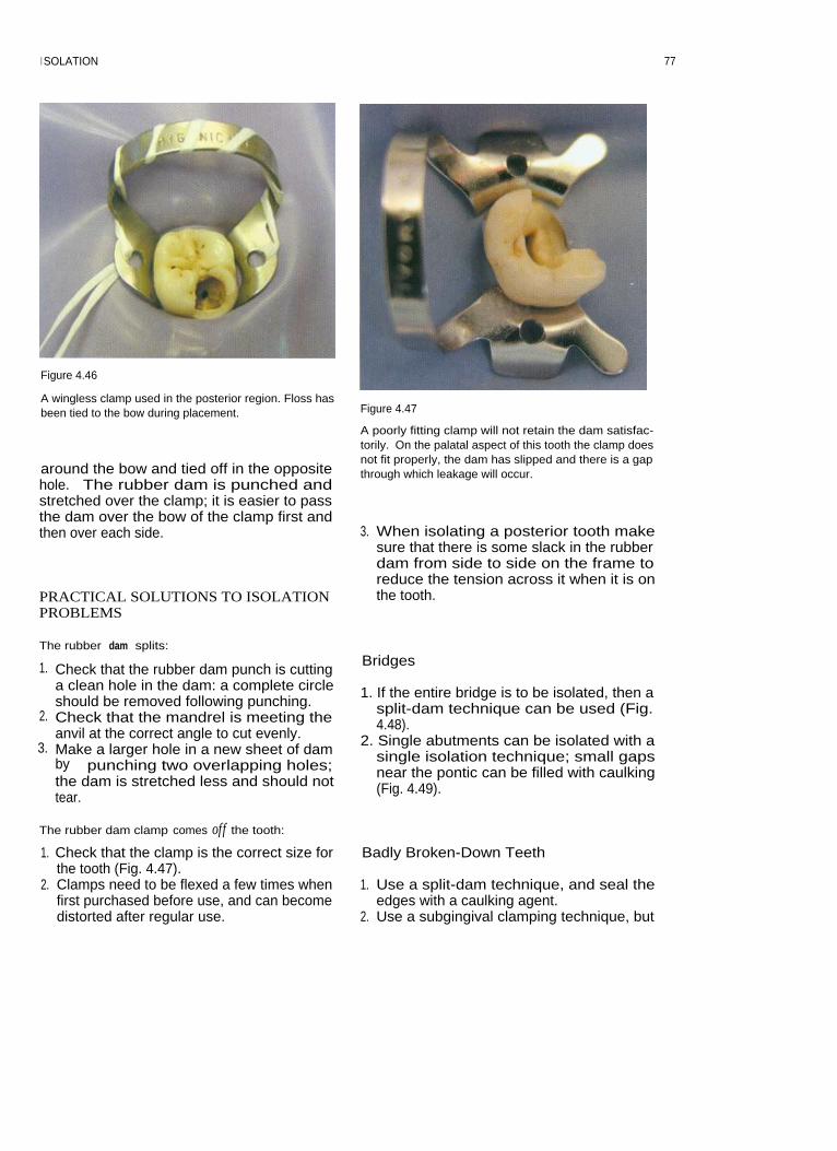
I SOLATION
Figure 4.46
A wingless clamp used in the posterior region. Floss hasbeen tied to the bow during placement.
around the bow and tied off in the oppositehole. The rubber dam is punched andstretched over the clamp; it is easier to passthe dam over the bow of the clamp first andthen over each side.
PRACTICAL SOLUTIONS TO ISOLATIONPROBLEMS
Figure 4.47
A poorly fitting clamp will not retain the dam satisfac-torily. On the palatal aspect of this tooth the clamp doesnot fit properly, the dam has slipped and there is a gapthrough which leakage will occur.
3. When isolating a posterior tooth makesure that there is some slack in the rubberdam from side to side on the frame toreduce the tension across it when it is onthe tooth.
The rubber dam splits:
1. Check that the rubber dam punch is cuttinga clean hole in the dam: a complete circleshould be removed following punching.
2. Check that the mandrel is meeting theanvil at the correct angle to cut evenly.
3. Make a larger hole in a new sheet of damby punching two overlapping holes;the dam is stretched less and should nottear.
Bridges
1. If the entire bridge is to be isolated, then asplit-dam technique can be used (Fig.4.48).
2. Single abutments can be isolated with asingle isolation technique; small gapsnear the pontic can be filled with caulking(Fig. 4.49).
The rubber dam clamp comes off the tooth:
1. Check that the clamp is the correct size forthe tooth (Fig. 4.47).
2. Clamps need to be flexed a few times whenfirst purchased before use, and can becomedistorted after regular use.
Badly Broken-Down Teeth
1. Use a split-dam technique, and seal theedges with a caulking agent.
2. Use a subgingival clamping technique, but
77

ENDODONTICS: PROBLEM-SOLVING IN CLINICAL PRACTICE
Figure 4.45
Isolation of a bridge using a split-dam technique.
Figure 4.49
An EW clamp has been used in the isolation of thesedouble-abutted bridge retainers. Gaps around the damand pontic have been filled with caulking. A line hasbeen drawn on the buccal surface of the crown to give anindication of the root angulation during access prepara-tion.
try to avoid traumatizing the gingivae.3. Build the tooth up with glass ionomer or
zinc phosphate cement and an orthodonticband. Dentine pins may occasionally berequired, but should be placed sparingly.Use of a band is particularly useful if thetooth is a lone standing posterior tooth,and will also improve the coronal sealbetween appointments (Fig. 4.50).
Situations where the crown length is longer thanthe height o f the clamp arch, preventing properseating:
1. Clamp the tooth more coronally.2. Use wedgets or strips of rubber dam in a
non-clamp technique.3. Use orthodontic separators to secure the
rubber dam around the neck of the tooth. Aheavier grade of dam may also help.
4. If the teeth are to be used for over-dentures, then reduce the clinical heightbefore placement of the rubber dam.
Figure 4.50
A clamp can easily be fitted to a tooth once it has beenrestored with an orthodontic band.
7 8

5 ROOT CANAL PREPARATION
CONTENTS • Rationale • Access Cavity Preparation • Hand Instruments • PreparationTechniques • Hand Preparation • Mechanical Preparation Techniques • Further Reading
RATIONALE
Microbiology
Apical periodontitis is caused by microbialinfection of the root canal system. Successfultreatment is dependent on the control of thismicrobial infection. An understanding of themicrobiology of apical periodontitis is a pre-requisite for effective treatment.
spreading down dentinal tubules. The peri-radicular tissues are normally separated fromthe flora in the root canal by a dense wall ofpolymorphonuclear leukocytes, and it is rareto see bacteria in the periapical tissues unlessthere is acute apical periodontitis.
Rationale for Root Canal Preparation
The General Microbial Flora
With the development of anaerobic culturingtechniques and sampling methods an insightinto the microbial flora of infected root canalshas become possible. Nowadays there aresophisticated techniques for identification ofbacteria that do not rely on culturing meth-ods. Indeed some bacteria that can be identi-fied by genetic techniques are non-cultivable.Apical periodontitis is typically a polymicro-bial infection dominated by obligately anaer-obic bacteria. Normally only a few species areisolated from any one case. Porphyromonasendodontalis is a species that seems to predom-inate in infected root canals. Others include:Streptococcus, Enterococcus, Actinomyces,Lactobacillus, Peptostreptococcus, Eubacterium,Propionibacterium, Prevotella, Fusobacterium,Eikenella, Capnocytophaga and Wolinella.
There are positive and negative interactionsbetween bacterial species as they compete inthe ecological niche of the root canal.Environmental conditions such as the amountof oxygen, availability of nutrients and hostdefence mechanisms will affect colonization.Bacteria infect the main canals and lateralcanals; they also may infect dentine by
Because the root canal system of a tooth is oftenextremely complex it is difficult to disinfect itcompletely and quickly. It may be that the bestattempts of the operator merely reduce theresidual bacterial load to a non-pathogenicnumber, or change the resident flora suffi-ciently to allow periapical healing, but this hasnot been proved. These microbes and their by-products can be removed by a combination ofmechanical and chemical means.
Mechanical removal relies on the ability ofthe operator to remove infected pulp anddentine from the surfaces of the root canal byplaning the walls; infected material in thelumen of the root canal will be removed. Innearly all cases this is impossible to achieve,partly because the instruments cannot actu-ally contact all the internal surfaces and alsobecause attempting to remove all the infecteddentine would severely weaken the tooth.That is why chemically active irrigants areused to destroy colonies of micro-organisms.Instrumentation of the root canal is carriedout to produce a pathway for the delivery ofan antibacterial irrigant to all the ramifica-tions of the root canal system. It also makesspace for medicaments and the final rootcanal filling.

ENDODONTICS: PROBLEM-SOLVING IN CLINICAL PRACTICE
Bacterial colonies may form themselvesinto multilayered biofilms, which can be diffi-cult to remove, as they adhere to the canalwall, while other microbes congregate in sus-pension. Irrigants must be delivered in suffi-cient volume and concentration to be effectiveagainst these colonies. Sodium hypochloriteirrigant is inactivated by its action on organicmaterial, and must be replenished.
ACCESS CAVITY PREPARATION
Preoperative Radiograph
A preoperative radiograph should normally betaken using a paralleling device, as this pro-duces an image that is almost actual size. Theradiograph must show the entire tooth and atleast 2 mm of bone surrounding the root apices(Fig. 5.1). Images of root canals can becomesuperimposed on radiographs and sometimesit will be necessary to take more than one viewfrom different angles to interpret the complexarrangement of multi-rooted teeth.
The preoperative radiograph(s) will allowan assessment of basic anatomy: number ofroots, size of pulp chamber, fit of coronalrestoration, caries, pulp stones, curvature ofroot canals, likelihood of lateral canals,iatrogenic damage (perforations and frac-tured instruments). When a tooth has been
crowned it is very important to assess theposition of the pulp space in relation to theartificial crown, or else the access cavity maybe misdirected.
Why? Aims of Access Cavity Preparation
The access cavity should be designed to allowdebridement of the pulp chamber and enableroot canal instruments to be introduced intothe canals without bending-i.e. for straight-line access. The tooth must be caries-free andany restorations with deficient margins mustbe removed.
All necrotic pulp remnants must beremoved from the pulp chamber, to preventinfected pulp material being pushed furtherinto the canals and causing recontaminationbetween visits. Necrotic material and break-down products may also be responsible forstaining dentine.
There should be some degree of resistanceform to the completed access cavity; thisensures that temporary restorations are notdislodged between visits and a coronal seal isachieved.
How? Location of Access Cavity
Historically access cavity designs have beenstandardized according to the type of tooth.Although the final cavity shape may resemblethe standardized form, using modern tech-niques the underlying pulp chamber shoulddictate the final shape. Small modifications tothe shape may be needed to allow straight-line access to all the root canals.
The Lid-off Approach to Access CavityPreparation (Fig. 5.2)
Figure 5.1
A good-quality radiograph of the mandibular first molarwhich requires root canal treatment.
1. Estimate length2. Penetrate to the pulp chamber3. Lift off the roof with a bur in a pulling
action4. Refine the access cavity.
80

ROOT CANAL PREPARATION
Preoperative carious
Dome-ended fissureexposure
bur is used to penetratepulp chamber
Roof of pulp chamber
Non end-cutting bur isremoved with round
used to 'lift lid' of pulpbur
chamber and refinecavity
Figure 5.2
Access cavity preparation: 'lid-off technique'.
Estimating the Depth
The depth of the roof of the pulp chamber canbe estimated from the preoperative radio-graph (Fig. 5.3).
Access is first made to this depth using atungsten carbide or diamond bur, FG557 orFG541, in a turbine (Fig. 5.4). Pre-measuringwill help prevent perforation of the pulp floorduring access cavity preparation. The bur isdirected towards the axis of the largest canal inmulti-rooted teeth, for example the palatal rootof maxillary molars and the distal root ofmandibular molars. Locating this canal firstmakes orientation easier and subsequent iden-tification of other canals more predictable.Further dentine can be removed with a long-shank low-speed round bur in a pulling action(Fig. 5.5). The remainder of the roof of the pulpchamber can now be removed using a nonend-cutting bur, FG332 safe-ended diamond orFG safe-ended TC Endo-Z ( Maillefer,Ballaigues, Switzerland: see Fig. 5.4). The non-cutting end can be safely guided over the floorof the pulp chamber whilst removing dentinefrom the walls of the cavity.
To gain straight-line entry into some canalorifices it may be necessary to enlarge theaccess in specific areas: for example to gainaccess to the curved mesiobuccal canal of themaxillary first molar tooth (Fig. 5.6).
Figure 5.3
The depth of the pulp chamber can be estimated from apreoperative radiograph.
The orifices of the root canals can now belocated. Some teeth have a variable number ofroot canals, and the clinician should be awareof how many canals are likely to be found ineach tooth (Figs. 5.7-5.12, Table 5.1).
81

82
ENDODONTICS: PROBLEM-SOLVING IN CLINICAL PRACTICE
Table 5.1 Number of roots and canals likely to be encountered in various types of tooth

ROOT CANAL PREPARATION
Figure 5.4
Burs for preparing an access cavity. The Jet Beaver dome-ended fissure bur (top: Beavers Dental, Morrisburg,Ontario, Canada) will cut through most restorations.Safe-ended diamond or Endo-Z burs are used to refinethe preparation.
Figure 5.7
A carious maxillary molar with pulpal exposure.
Figure 5.5
Round burs with different shank lengths (top: standardlength bur). Medium- and long-shanked burs are usefulin endodontics.
Figure 5.8
The cavity outline is prepared with a diamond bur (541).
Figure 5.6
The access cavity has been modified in order to gainstraight-line access to the mesiobuccal canal of this maxil-lary molar.
8 3

84
ENDODONTICS: PROBLEM-SOLVING IN CLINICAL PRACTICE
Figure 5.9
Figure 5.11
An Endo-Z non end-cutting tungsten carbide bur is
Remaining carious dentine is removed using a roundinserted into the pulp chamber to remove the 'lid' of the
bur.pulp chamber.
Figure 5.12
The completed access cavity gives straight-line access toall the canals.
Figure 5.10
The access is refined with the Endo-Z bur.

ROOT CANAL PREPARATION
The Pulp Floor Map
The floor of the pulp chamber can be read likea map. The dentine on the base of the cham-ber is generally darker (Figs. 5.13, 5.14) thanthat of the walls, and will normally indicatethe lateral extent of the pulp chamber. Thisjunction can be used to explore the extent ofthe pulp chamber.
An endodontic probe (e.g. DG16, HuFriedy, Chicago, IL, USA) is a double-endedlong probe designed for the exploration of thepulp floor and location of root canal orifices.A long-shanked excavator may also be helpfulfor removing small calcifications and obstruc-tions when locating canals (Fig. 5.15).
Troubleshooting Access Cavity Preparation
CalcificationsPulp stones and irritation dentine formed inresponse to caries and/or restorations maymake the location of root canal orifices diffi-cult. Special tips for ultrasonic handpieces(Fig. 5.16) are invaluable in this situation, asthey allow the precise removal of dentinefrom the pulp floor with minimal risk of per-foration. In the absence of a special tip apointed ultrasonic sealer tip can be used toremove pulp stones from the pulp chamber.
Ultrasonic tips are best used with irrigant.Occasionally they may be used without, and aStropko irrigator (Obtura Corporation,Fenton, MO, USA: Fig. 5.17) is then useful for
Figure 5.14
The access cavities in these maxillary molars have beenprepared conservatively but give good straight-lineaccess to the root canals.
Figure 5.15
Figure 5.13
The pulp floor is generally darker than the walls of thecavity.
A typical preparation tray of instruments for endodontictreatment (left to right): college tweezers, flat plastic, ball-ended burnisher, amalgam plugger, excavator, DG16probe, Briault probe, periodontal probe, mirror, number14 clamp, Jet dome-ended fissure bur, Endo-Z bur, finebore tip for Stropko irrigator.
85

ENDODONTICS: PROBLEM-SOLVING IN CLINICAL PRACTICE
Figure 5.16
An ultrasonic tip for removal of dentine on the pulp floor.
Figure 5.18
An operating microscope.
Figure 5.17
The Stropko irri
puffing away dentine chips. A solution of17% EDTA is excellent for clearing away thearea under exploration, as it removes thesmear layer. Flood the pulp chamber withEDTA solution and allow it to stand for 1-2minutes. Dentine chips and other debris canthen be washed away with a syringe ofsodium hypochlorite.
Sclerosed CanalsIllumination and magnification are vital forthe location of Sclerosed root canals. Theendodontist would use a surgical microscope(Fig. 5.18), while a general dental practitionermight have loupes (Fig. 5.19) and a headlightavailable. A thorough knowledge of the
Figure 5.19
Loupes give excellent magnification and illumination.
86
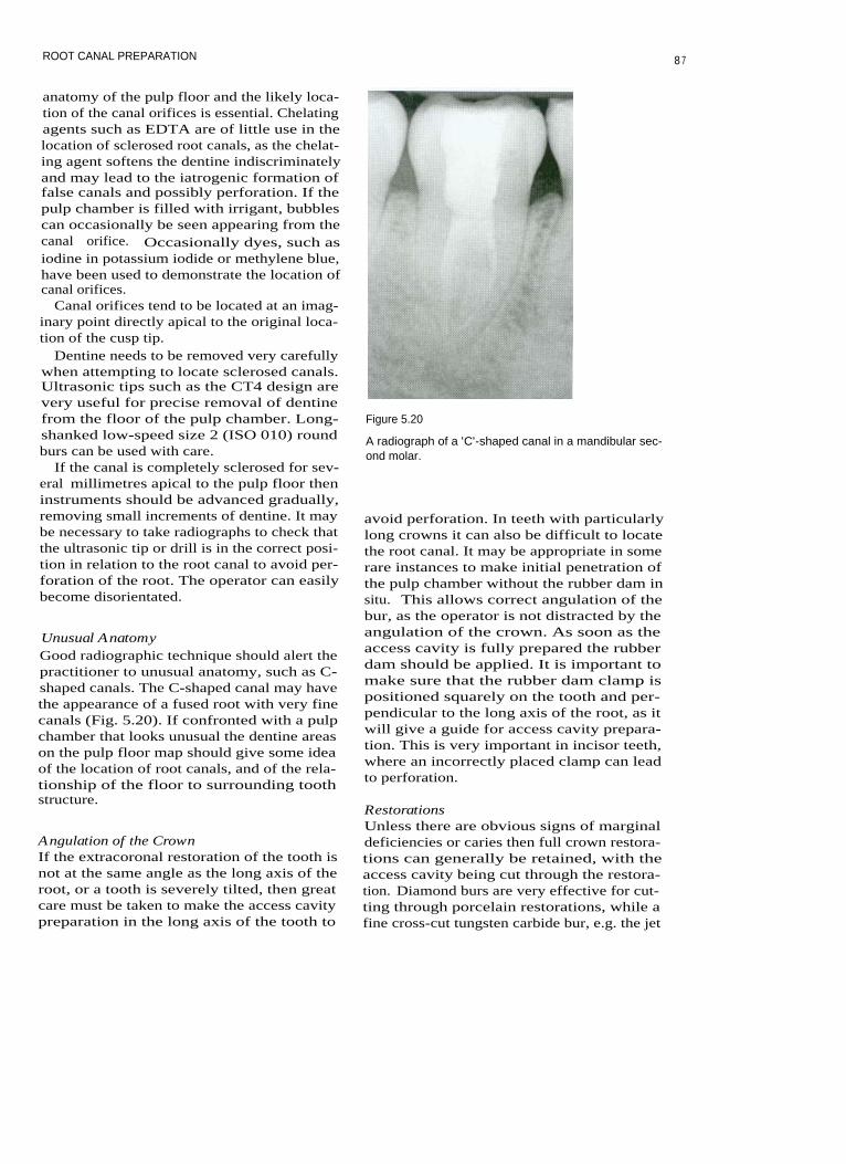
ROOT CANAL PREPARATION
anatomy of the pulp floor and the likely loca-tion of the canal orifices is essential. Chelatingagents such as EDTA are of little use in thelocation of sclerosed root canals, as the chelat-ing agent softens the dentine indiscriminatelyand may lead to the iatrogenic formation offalse canals and possibly perforation. If thepulp chamber is filled with irrigant, bubblescan occasionally be seen appearing from thecanal orifice. Occasionally dyes, such asiodine in potassium iodide or methylene blue,have been used to demonstrate the location ofcanal orifices.
Canal orifices tend to be located at an imag-inary point directly apical to the original loca-tion of the cusp tip.
Dentine needs to be removed very carefullywhen attempting to locate sclerosed canals.Ultrasonic tips such as the CT4 design arevery useful for precise removal of dentinefrom the floor of the pulp chamber. Long-shanked low-speed size 2 (ISO 010) roundburs can be used with care.
If the canal is completely sclerosed for sev-eral millimetres apical to the pulp floor theninstruments should be advanced gradually,removing small increments of dentine. It maybe necessary to take radiographs to check thatthe ultrasonic tip or drill is in the correct posi-tion in relation to the root canal to avoid per-foration of the root. The operator can easilybecome disorientated.
Unusual AnatomyGood radiographic technique should alert thepractitioner to unusual anatomy, such as C-shaped canals. The C-shaped canal may havethe appearance of a fused root with very finecanals (Fig. 5.20). If confronted with a pulpchamber that looks unusual the dentine areason the pulp floor map should give some ideaof the location of root canals, and of the rela-tionship of the floor to surrounding toothstructure.
Angulation of the CrownIf the extracoronal restoration of the tooth isnot at the same angle as the long axis of theroot, or a tooth is severely tilted, then greatcare must be taken to make the access cavitypreparation in the long axis of the tooth to
Figure 5.20
A radiograph of a 'C'-shaped canal in a mandibular sec-ond molar.
avoid perforation. In teeth with particularlylong crowns it can also be difficult to locatethe root canal. It may be appropriate in somerare instances to make initial penetration ofthe pulp chamber without the rubber dam insitu. This allows correct angulation of thebur, as the operator is not distracted by theangulation of the crown. As soon as theaccess cavity is fully prepared the rubberdam should be applied. It is important tomake sure that the rubber dam clamp ispositioned squarely on the tooth and per-pendicular to the long axis of the root, as itwill give a guide for access cavity prepara-tion. This is very important in incisor teeth,where an incorrectly placed clamp can leadto perforation.
RestorationsUnless there are obvious signs of marginaldeficiencies or caries then full crown restora-tions can generally be retained, with theaccess cavity being cut through the restora-tion. Diamond burs are very effective for cut-ting through porcelain restorations, while afine cross-cut tungsten carbide bur, e.g. the jet
8 7

ENDODONTICS: PROBLEM-SOLVING IN CLINICAL PRACTICE
Figure 5.21
Location of the second mesiobuccal canal in the maxillary first molar.
Beaver bur, is particularly useful for cuttingthrough metal.
PostsPosts should be identified from the preopera-tive radiograph. When cutting the access cav-ity maximum post material should beretained to make its later removal easier. Corematerial may need to be removed fromaround a post to facilitate subsequentremoval of the post.
The Location of `Extra' CanalsThe second mesiobuccal canal of maxillary molars(Fig. 5.21): There is a second mesiobuccalcanal in approximately 60% of maxillarymolars; it often lies under a lip of dentine onthe mesial wall of the access cavity (Figs. 5.22,5.23). Location of the orifice can be made byvisualizing a point at the intersection betweena line running from the mesiobuccal to thepalatal canal and a perpendicular from thedistobuccal canal. The lip of dentine in thisarea can be removed using an ultrasonic CT4
Figure 5.22
A lip of dentine has been removed using a round bur touncover the two mesiobuccal canals (arrowed) in thismaxillary molar.
88

ROOT CANAL PREPARATION89
tip or a size 2 round bur. There is often anisthmus between the main mesiobuccal canaland the second mesiobuccal (Fig. 5.24); thiscan be traced until the orifice is located. Thepulp floor map should be followed to avoid
overzealous exploration in the incorrect direc-tion.
Four canals in mandibular molars (Fig. 5.25):Four canals are found in approximately 38%of mandibular molars. If the distal canal doesnot lie in the midline of the tooth, then a sec-ond distal canal should be suspected. Thecanals are often equidistant from the midline.
Figure 5.23
The location of the two mesiobuccal canals (arrowed) canclearly be seen in this maxillary molar following prepara-tion.
Figure 5.24
I n this case the lip of dentine has been removed usingultrasonics to reveal an isthmus (arrowed).
Distal canal orifices lieequidistant to midline
Figure 5.25
Location of a second distal canal in the mandibular firstmolar.

ENDODONTICS: PROBLEM-SOLVING IN CLINICAL PRACTICE
Careful exploration with a CT4 ultrasonic tipor round bur should uncover the orifice. Itmay be necessary to take a radiograph from adifferent angle to confirm the presence of thesecond distal canal.
Two canals in mandibular incisors (Fig. 5.26):The incidence of two canals in lower incisorsmay be as high as 41 %. A common reason forfailure of root canal treatment in these teethoccurs when a second canal has not beenlocated and is consequently not cleaned.Canals may be missed owing to incorrectpositioning of the access cavity. If access isprepared too far lingually then it may beimpossible to locate a lingual canal. To gainentry into a lingual canal the access cavitymay sometimes need to be extended verynear to the incisal edge.
Two canals in a mandibular premolar(Fig. 5.27): The highest reported incidence oftwo canals in mandibular premolars is 11%.There are rarely two orifices. The lingualcanal normally projects from the wall of themain buccal canal at an acute angle. It canusually be located by running a fine (ISO 08or 10) file with a sharp bend in the tip alongthe lingual wall of the canal.
Incorrect access: placement
Access should be placedtoo far lingually prevents
more incisally; straight-lineentry into lingual canal
entry into buccal and lingualcanals can then be achieved
Figure 5.26
Location of the lingual canal in mandibular incisors.
Figure 5.27
Location of the lingual canal in mandibular premolars.
HAND INSTRUMENTS
Endodontic research has shown how differentinstruments and materials behave within theconfined space of the root canal system dur-ing instrumentation. In parallel withadvances in hand instruments come newpreparation techniques. These developmentscan occur so rapidly, however, that thechicken often precedes the egg!
Instrumentation techniques where apicalpreparation is carried out at the start of treat-ment have been superseded by crown-downtechniques, in which the coronal element ofthe root canal is prepared first. The actionswith which files can be used have beenanalysed, and now many modern methods ofinstrumentation use a balanced force motionas opposed to filing. With the introduction ofhighly flexible materials such as nickel-titanium alloys it has been possible to pro-duce instruments with tapers that are greaterthan the original stainless steel hand files,without losing flexibility; such instrumentsare invaluable for tapering the root canalpreparation predictably.
As new instrument systems are produced,
The lingual canal can be extremelyfine and difficult to locateUse a sharp bend in the file tip andrun it down the lingual wallThe file often catches on the lingualcanal orifice
9 0

ROOT CANAL PREPARATION
new preparation techniques evolve. The mor-phology of the root canal space is highly vari-able, however, and one preparation techniquecannot be applied to every situation. It is per-haps more useful to develop and understandbasic concepts of root canal preparation.These can then be implemented to master thediversity of root canal systems with which thedentist may be faced. This approach alsoallows the clinician to modify his or her cur-rent technique as new instruments are pro-duced. Unfortunately no one system can be apanacea. An understanding of endodonticconcepts and a consequent adaptation of tech-niques with which the clinician is conversantwill avoid the unfortunate accumulation ofexpensive equipment that becomes redun-dant when it fails to deliver its promises!There are no secrets to effective root canalpreparation: just practice, patience and persis-tence.
tion to be centred on the original canal curva-ture.
There is a non-linear increase in the diame-ter of tip sizes between consecutive instru-ments. To address this, one manufacturerproduced intermediate sizes between 10 and30. Golden Mediums (Maillefer) are availablein ISO sizes 12, 17, 22 and 27. Anothermethod of reducing the uneven 'jumps' indiameter between sizes has been to produceinstruments with a uniform increase in diam-eter between consecutively sized instruments.Series 29 (Dentsply, Weybridge, Surrey, UK)instruments have a 29% increase in tip sizebetween instruments.
Restoring Force
This is the force produced by a file when itresists bending. The restoring force for anickel-titanium instrument is 3-4 times lessthan that for an equivalent-sized stainlesssteel file. The restoring force increases with
Hand Files and Reamers
For the last forty years root canal instrumentshave been produced to international stan-dards. There are specifications for dimen-sions, fracture resistance, stiffness and colourcoding of endodontic files and reamers.Reamers have fewer turns per unit lengththan the equivalent-sized file.
Material
Endodontic files and reamers are mainlymanufactured from stainless steel, althoughcarbon steel, titanium and nickel-titanium arealso used. The different materials give theinstruments different properties, which inturn affect the way in which they should beused.
Tip Design
The tip of the instrument can have variousshapes. Originally instrument tips were sharpand had a cutting action; but non-cutting(bullet-shaped) tips are now available thatallow the instrument to slide along the outercurvature of a root canal, allowing prepara-
Table 5.2 ISO size and colour coding
9 1

ENDODONTICS: PROBLEM-SOLVING IN CLINICAL PRACTICE
file diameter: i.e. files get stiffer as their diam-eter increases.
TaperThe standards for instruments specify thathand files have a 0.02 taper; i.e. the diameterof the instrument increases by 0.02 mm permm along the length of the instrument.However because nickel-titanium is super-elastic, it has been possible to create flexibleinstruments with larger tapers such as 0.04,0.06, 0.08, 0.10 and 0.12.
I nstrument DesignEndodontic files can be twisted from square,rhomboid or triangular stainless steel blanks,or machined. The standardized length of a fileor reamer blade is 16 mm. Reamers normallyhave fewer flutes/blades per unit length thanan equivalent file, and are intended for use ina rotary action. Nickel-titanium instrumentsneed to be machined using computer-assistedmanufacturing (CAM), as the material issuperelastic and cannot be twisted. Modernmanufacturing methods allow complex cross-sectional shapes to be milled.
K-file (e.g. Dentsply) instruments can bemanufactured by twisting a square or trian-gular blank or by machining. Files with a tri-angular cross-section are more flexible thanthe equivalent-sized file with a square cross-section. Files with a triangular cross-sectiontend to have superior cutting characteristicsand are more flexible, and hence less likely totransport the canal during preparation.
K-Flex files (Kerr, Romulus, MI, USA) areproduced from a blank that is rhomboid incross-section; this forms both cutting andnon-cutting edges. The files are more flexiblethan an equivalent-sized K-file.
Flexofile (Maillefer: Fig. 5.28) instrumentshave a triangular cross-section and are manu-factured from flexible stainless steel.Flexofiles are more efficient at cutting andremoving dentine than an equivalent K-file,because the blade has a sharper angle andthere is more room for debris. The tip of thefile is non-cutting. This is an advantage whenpreparing curved canals, as the file is guidedalong the canal curvature, avoiding excessive
Figure 5.28
A range of Flexofile instruments. The size 20 instrumentis being measured using a ruler on the Endoring.
cutting into the outer curve of the root canalor transportation. Any flexible, triangularcross-sectioned file, such as a Flexofile, can beused with the balanced force action.
Hedstroem (e.g. Dentsply: Fig. 5.29) filesare machined from a tapered cylindricalblock. In cross-section they have the appear-ance of a series of intersecting cones.Hedstroem files are highly efficient at remov-ing dentine on the outstroke when used in afiling motion, but have poor fracture resis-tance in rotation.
Figure 5.29
Hedstroem files.
9 2
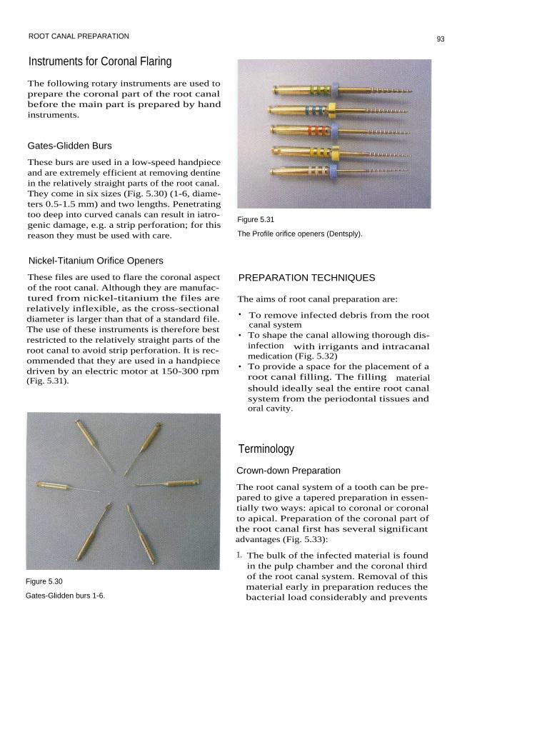
ROOT CANAL PREPARATION
Instruments for Coronal Flaring
The following rotary instruments are used toprepare the coronal part of the root canalbefore the main part is prepared by handinstruments.
Gates-Glidden Burs
These burs are used in a low-speed handpieceand are extremely efficient at removing dentinein the relatively straight parts of the root canal.They come in six sizes (Fig. 5.30) (1-6, diame-ters 0.5-1.5 mm) and two lengths. Penetratingtoo deep into curved canals can result in iatro-genic damage, e.g. a strip perforation; for thisreason they must be used with care.
Figure 5.31
The Profile orifice openers (Dentsply).
Nickel-Titanium Orifice Openers
These files are used to flare the coronal aspectof the root canal. Although they are manufac-tured from nickel-titanium the files arerelatively inflexible, as the cross-sectionaldiameter is larger than that of a standard file.The use of these instruments is therefore bestrestricted to the relatively straight parts of theroot canal to avoid strip perforation. It is rec-ommended that they are used in a handpiecedriven by an electric motor at 150-300 rpm(Fig. 5.31).
PREPARATION TECHNIQUES
The aims of root canal preparation are:
• To remove infected debris from the rootcanal system
• To shape the canal allowing thorough dis-infection with irrigants and intracanalmedication (Fig. 5.32)
• To provide a space for the placement of aroot canal filling. The filling materialshould ideally seal the entire root canalsystem from the periodontal tissues andoral cavity.
Figure 5.30
Gates-Glidden burs 1-6.
Terminology
Crown-down Preparation
The root canal system of a tooth can be pre-pared to give a tapered preparation in essen-tially two ways: apical to coronal or coronalto apical. Preparation of the coronal part ofthe root canal first has several significantadvantages (Fig. 5.33):
1. The bulk of the infected material is foundin the pulp chamber and the coronal thirdof the root canal system. Removal of thismaterial early in preparation reduces thebacterial load considerably and prevents
93

94
ENDODONTICS: PROBLEM-SOLVING IN CLINICAL PRACTICE
Region cleaned by irrigants
• Region cleaned by instruments
Figure 5.32
Chemo-mechanical preparation.
inoculation of the periapical tissues withbacteria extruded by hydraulic pressuresduring preparation. A file placed to theworking length before coronal flaring willact like a piston in a cylinder and forcematerial beyond the apex. Infected dentinechips and bacteria that are extruded willcause postoperative discomfort.
2. Early flaring of the coronal part of the rootcanal removes dentine constrictions, so thatsubsequent instruments do not bind shortof the working length.
3. If the working length is estimated follow-ing coronal preparation then there will belittle change in length during preparation.Over-preparation due to poor length
control could be a cause of postoperativepain.
4. Preparing the coronal part of the root canalfirst enables more rapid penetration of irri-gants apically. If a pool of irrigant is main-tained in the access cavity then this willbe guided into the root canal systemduring preparation. Dentine chips will bekept in suspension, thereby avoidingblockages.
Many procedural errors have been encoun-tered when the apical portion of the rootcanal system has been prepared first, such aszip and elbow formation, instrument fracture,and an increased chance of postoperative
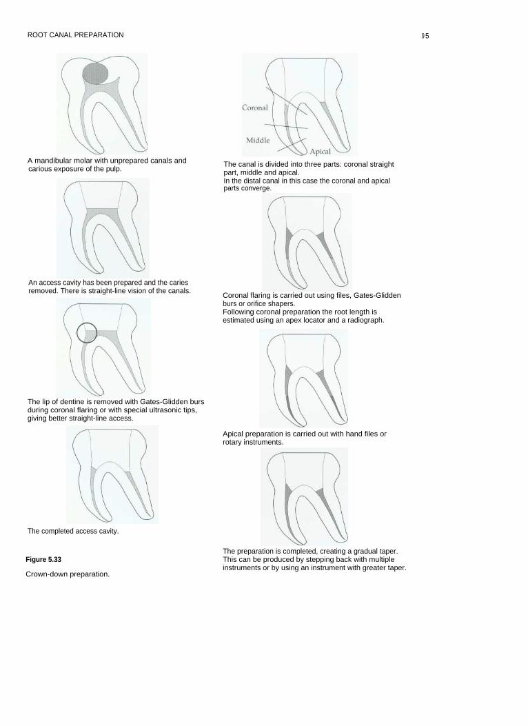
ROOT CANAL PREPARATION
A mandibular molar with unprepared canals andcarious exposure of the pulp.
An access cavity has been prepared and the cariesremoved. There is straight-line vision of the canals.
The lip of dentine is removed with Gates-Glidden bursduring coronal flaring or with special ultrasonic tips,giving better straight-line access.
The completed access cavity.
Figure 5.33
Crown-down preparation.
The canal is divided into three parts: coronal straightpart, middle and apical.In the distal canal in this case the coronal and apicalparts converge.
Coronal flaring is carried out using files, Gates-Gliddenburs or orifice shapers.Following coronal preparation the root length isestimated using an apex locator and a radiograph.
Apical preparation is carried out with hand files orrotary instruments.
The preparation is completed, creating a gradual taper.This can be produced by stepping back with multipleinstruments or by using an instrument with greater taper.
9 5
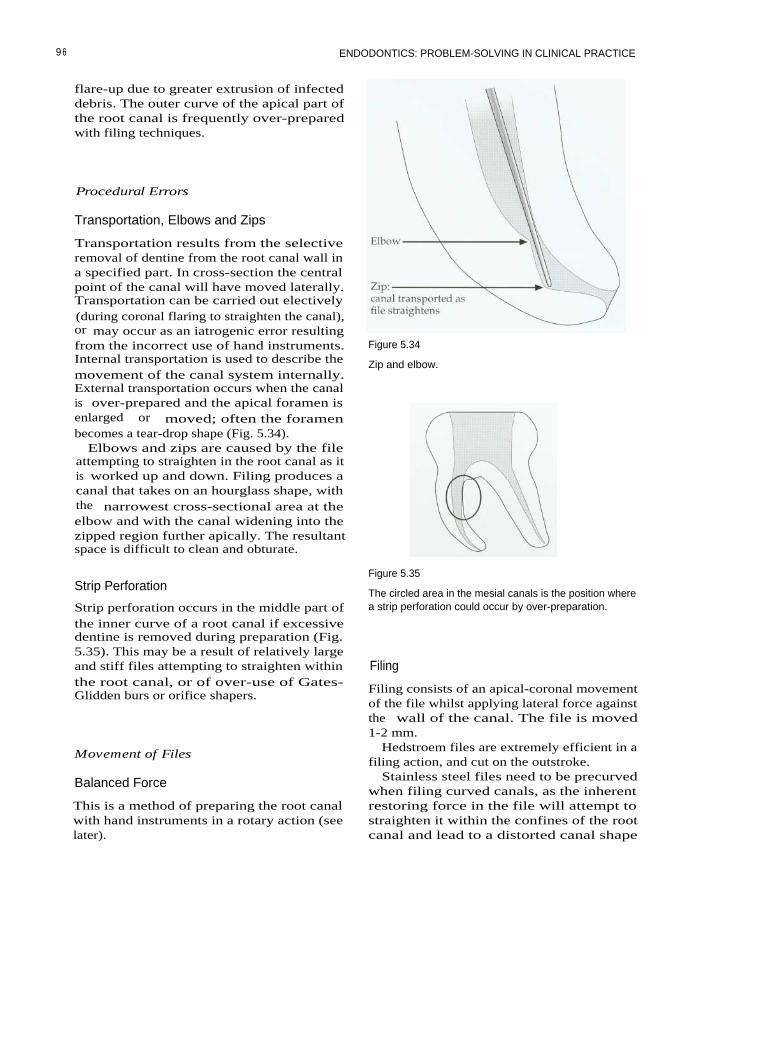
ENDODONTICS: PROBLEM-SOLVING IN CLINICAL PRACTICE
flare-up due to greater extrusion of infecteddebris. The outer curve of the apical part ofthe root canal is frequently over-preparedwith filing techniques.
Procedural Errors
Transportation, Elbows and Zips
Transportation results from the selectiveremoval of dentine from the root canal wall ina specified part. In cross-section the centralpoint of the canal will have moved laterally.Transportation can be carried out electively(during coronal flaring to straighten the canal),or may occur as an iatrogenic error resultingfrom the incorrect use of hand instruments.Internal transportation is used to describe themovement of the canal system internally.External transportation occurs when the canalis over-prepared and the apical foramen isenlarged or moved; often the foramenbecomes a tear-drop shape (Fig. 5.34).
Elbows and zips are caused by the fileattempting to straighten in the root canal as itis worked up and down. Filing produces acanal that takes on an hourglass shape, withthe narrowest cross-sectional area at theelbow and with the canal widening into thezipped region further apically. The resultantspace is difficult to clean and obturate.
Figure 5.34
Zip and elbow.
Strip Perforation
Strip perforation occurs in the middle part ofthe inner curve of a root canal if excessivedentine is removed during preparation (Fig.5.35). This may be a result of relatively largeand stiff files attempting to straighten withinthe root canal, or of over-use of Gates-Glidden burs or orifice shapers.
Movement of Files
Balanced Force
This is a method of preparing the root canalwith hand instruments in a rotary action (seelater).
Figure 5.35
The circled area in the mesial canals is the position wherea strip perforation could occur by over-preparation.
Filing
Filing consists of an apical-coronal movementof the file whilst applying lateral force againstthe wall of the canal. The file is moved1-2 mm.
Hedstroem files are extremely efficient in afiling action, and cut on the outstroke.
Stainless steel files need to be precurvedwhen filing curved canals, as the inherentrestoring force in the file will attempt tostraighten it within the confines of the rootcanal and lead to a distorted canal shape
9 6
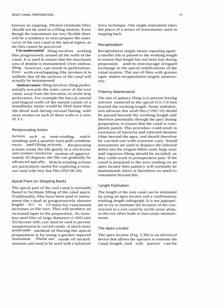
ROOT CANAL PREPARATION
known as zipping. Nickel-titanium filesshould not be used in a filing motion. Eventhough the instruments are very flexible therewill be a tendency to over-prepare the outercurve of the root canal in the apical region, asthe files cannot be precurved.
Circumferential filing involves workingfiles progressively around all the walls of thecanal. It is used to ensure that the maximumarea of dentine is instrumented. Over-zealousfiling, however, can result in perforation.Even with overlapping file strokes it isunlikely that all the surfaces of the canal willactually be instrumented.
Anticurvature filing involves filing prefer-entially towards the outer curve of the rootcanal, away from the furcation, to avoid stripperforation. For example the buccal, mesialand lingual walls of the mesial canals of amandibular molar would be filed more thanthe distal wall during coronal flaring, withmore strokes on each of these walls in a ratioof 3:1.
Reciprocating Action
Actions such as stem-winding, watch-winding and a quarter-turn pull combinerotary and filing actions. Reciprocatingactions rotate the file gently in a clockwiseand counter-clockwise motion of approxi-mately 45 degrees; the file can gradually beadvanced apically. Watch-winding actionsare particularly useful for exploring a tortu-ous canal with very fine files (ISO 06-10).
force technique. One single instrument takesthe place of a series of instruments used instepping back.
Recapitulation
Recapitulation simply means repeating again:a smaller file is passed to the working lengthto ensure that length has not been lost duringpreparation and to encourage irrigantexchange in the apical ramifications of thecanal system. The use of files with greatertaper makes recapitulation largely unneces-sary.
Patency Maintenance
The aim of patency filing is to prevent leavinginfected material in the apical 0.5-1.0 mmbeyond the working length. Some endodon-tists advocate that small files (<ISO 10) shouldbe passed beyond the working length andtherefore potentially through the apex duringpreparation, to ensure that the canal is com-pletely patent. This procedure could result inextrusion of bacteria and infected dentinechips beyond the apex, and should thereforebe carried out with extreme care. Smallinstruments are used to displace the infecteddebris into the irrigant-filled canal; large sizesand vigorous filing should be avoided, asthey could result in postoperative pain. If thecanal is prepared to the zero reading on anapex locator then patency will normally bemaintained; there is therefore no need toinstrument beyond this.
Apical Flare (or Stepping Back)
The apical part of the root canal is normallyflared to facilitate filling of the canal space.Traditionally, files have been used to instru-ment the canal at progressively shorterlengths (0.5 to 1.0 mm) for concurrentincreases in file size. This will produce anincreased taper to the preparation. As stain-less steel files of large diameters (>ISO size35) become stiff, care must be used to preventtransportation in curved canals. A much morepredictable method of flaring the apicalpreparation is by using a greater taperedinstrument. These are made of nickel-titanium and need to be used with a balanced
Length Estimation
The length of the root canal can be estimatedby using an apex locator and a confirmatoryworking length radiograph. It is not appropri-ate to try to estimate the location of the con-striction in a root canal by tactile sense alone,as this too often leads to inaccurate measure-ments.
The Apex Locator
The apex locator (Fig. 5.36) is an electricaldevice that allows the operator to estimate thecanal length, and with practice can be
9 7

ENDODONTICS: PROBLEM-SOLVING IN CLINICAL PRACTICE
Figure 5.36 Figure 5.37
Two popular apex locators; both work using multiplefrequencies and are extremely accurate.
The tip of the apex locator is kept in contact with the fileas it is advanced apically.
extremely accurate. Apex locators work byapplying an alternating current between twoelectrodes; one makes contact with the lip orcheek (the ground electrode), the other isattached to a file in the root canal (Fig. 5.37).The impedance at the apical foramen isapproximately equal to that between theperiodontal ligament and the oral mucosa;this value is used to calibrate the instrument.The apex locator has a display showingthe zero reading that indicates when the filetip is at the apical foramen. Some modernapex locators measure the impedance at twoor more frequencies to improve the accuracyof the instrument. Some can be used effec-tively even in the presence of electrolytessuch as sodium hypochlorite and blood,although these are best avoided; the pulpfloor should always be dry to prevent short-circuiting.
Troubleshooting with an Apex Locator
Short reading
• Is the file short-circuiting through a metal-lic restoration?
• Make sure the canals and pulp chamberare relatively dry.
• Is it likely that there may be a perforationin the root?
• Is there the likelihood of a large lateralcanal?
• Is there a communication betweencanals?-for instance, between mesiobuc-cal canals of maxillary first molars, ormesial canals of mandibular molars.
Long reading
• Is it possible that the apical region has beendestroyed by chronic inflammatory resorp-tion? (For instance, in cases with chronicapical periodontitis and large lesions; inthese cases try a larger file.)
• Check the battery power.
No reading
• Is the unit switched on?• Are the leads all connected and is the lip
hook in place?• Are the batteries fully charged?
Radiographic Techniques for LengthEstimation
Apex locators should not take the place ofworking length estimation radiographs, butmake an excellent adjunct for accurate identi-
98

ROOT CANAL PREPARATION
fication of the root canal terminus. In this sit-uation, when used regularly an apex locatorwill help reduce the number of radiographsrequired for endodontic treatment. The apexof the tooth is more likely to be locatedaccurately first time by these means than withtactile methods.
Taking a good radiograph with the rubberdam and clamp in situ can be difficult; withpractice, however, it becomes predictable.The Endoray (Dentsply) is particularly usefulfor ensuring that the X-ray beam is correctlyaligned and not coned off (Fig. 5.38). The filmmust never be bent. Cutting down on repeatexposures reduces the radiation dose to thepatient. If coronal flaring is carried out at thestart of root canal preparation it should bepossible to use at least a size 15 file to esti-mate working length. The tip of such a filecan easily be viewed on radiographs.
Figure 5.39
A length-estimation radiograph. The three files in thepremolar were not clearly visible and a separate radi-ograph was taken.
Estimating the Working Length
If the length radiograph shows that the file tipis more than 3 mm from the apical foramenthen the radiograph should be repeated(Fig. 5.39). On some occasions it may also benecessary to take more than one workinglength radiograph at varying angles. There isno significant difference in the ability toassess root length using digital radiographyor conventional film; however, there is a sig-nificant reduction in radiation dose and timewith digital radiography.
Figure 5.38
The Endoray.
Separating Root Canals in Length EstimationRadiographs
Mandibular incisors (Fig. 5.40)Separating the buccal and lingual canals of
mandibular incisors can be difficult, unlessthe X-ray cone is rotated by a few degrees,either left or right, to separate the canals; butcare must be taken to ensure that the treatedtooth is centred on the film.Mandibular premolars
The lingual canal of a mandibular premolarcan often be separated from the main (buccal)canal by aiming the beam from an anterior(and inferior) direction.Mandibular molars (Fig. 5.41)
Separating the buccal and lingual canals ofthe mesial or distal roots of mandibularmolars can be achieved by rotating the beamto a more anterior projection.Maxillary premolars
Separating buccal and lingual canals can beachieved by aiming the beam from an anteriordirection. If Spencer Wells forceps are used tohold the film behind the rubber dam, then it isnot necessary to remove the rubber dam frame.Maxillary molars
To separate the first and second mesiobuc-cal canals the cone should be aimed from thedistal aspect.
9 9
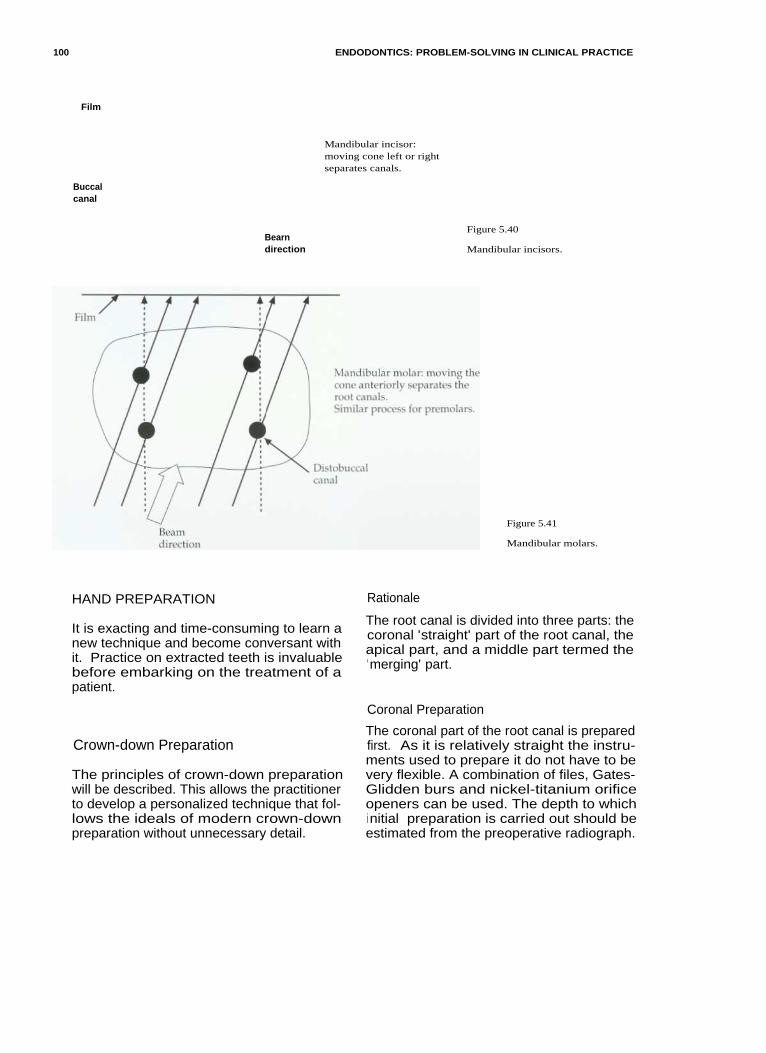
100
ENDODONTICS: PROBLEM-SOLVING IN CLINICAL PRACTICE
Film
Buccalcanal
Bearndirection
Mandibular incisor:moving cone left or rightseparates canals.
Figure 5.40
Mandibular incisors.
Figure 5.41
Mandibular molars.
HAND PREPARATION Rationale
It is exacting and time-consuming to learn anew technique and become conversant withit. Practice on extracted teeth is invaluablebefore embarking on the treatment of apatient.
The root canal is divided into three parts: thecoronal 'straight' part of the root canal, theapical part, and a middle part termed the'merging' part.
Coronal Preparation
Crown-down Preparation
The principles of crown-down preparationwill be described. This allows the practitionerto develop a personalized technique that fol-lows the ideals of modern crown-downpreparation without unnecessary detail.
The coronal part of the root canal is preparedfirst. As it is relatively straight the instru-ments used to prepare it do not have to bevery flexible. A combination of files, Gates-Glidden burs and nickel-titanium orificeopeners can be used. The depth to whichinitial preparation is carried out should beestimated from the preoperative radiograph.

ROOT CANAL PREPARATION
The canal must be irrigated throughoutpreparation to remove debris, kill microbesand prevent blocking. The use of files beforeGates-Glidden burs can be used to transportthe orifice of a canal deliberately. Thisdecreases the initial curvature of the canaland improves straight-line access. The bursshould be used in a planing action, cuttingagainst the thickest wall of the root canal asthe drill is withdrawn from the canal.Applying apical pressure and drilling into theroot canal should be avoided, as this can leadto over-enlargement and ledging.
Apical Preparation
This will involve preparation around a curvein the vast majority of canals, and is theregion in which most iatrogenic errors haveoccurred in the past. Once the coronal part ofthe root canal has been prepared, access to theapical part is made easier. Instruments usedto prepare the apical part of the root canalsystem need to be thin and flexible, and aremade of materials such as flexible stainlesssteel or nickel-titanium.
Before apical preparation is started an esti-mate of the root canal length must be made,ideally using an apex locator and confirmedwith a radiograph.
If coronal preparation has been carried out,then there will be less change in the length ofthe preparation during instrumentation. Thelengths are marked on the file with a rubberstop to a clearly definable and easily remem-
bered reference point, which is best recordedin the patient's notes.
The size of the apical preparation and mas-ter apical file will depend on:
1. The size of the natural canal.2. The obturation technique that is to be used
(with vertically compacted warm tech-niques the apical termination of the prepa-ration should be kept as small aspracticable).
3. The overall taper of the root canal.
The apex is prepared to the working lengthwith a file of not less than ISO size 25, as thisallows delivery of irrigant to the most apicalpart of the root canal system. Irrigant can becarried apically and replenished by recapitu-lation with files.
Using the Balanced Force Action for ApicalPreparation
The balanced force action when used withflexible files results in a more centred prepa-ration and less transportation than with a fil-ing technique.
The technique (Roane et al 1985)This instrumentation technique uses clock-wise/anticlockwise rotational motion toremove dentine with flexible stainless steelfiles or nickel-titanium files (Fig. 5.42). It isuseful for rapidly removing dentine in curvedcanals whilst maintaining curvature (files arenot precurved).
Figure 5.42
The Balanced Force action.
1 01

102 ENDODONTICS: PROBLEM-SOLVING IN CLINICAL PRACTICE
• Place the file into the canal until light resis-tance is met and turn it up to 90°-120°clockwise to engage the dentine walls (thepower phase).
• Whilst applying light apical pressure (toprevent the file backing out of the canal)turn 120°-360° anticlockwise. Listen for a'click' as a bite of dentine is removed (thecontrol phase).
• Repeat
the
clockwise /anticlockwisemotion until the file reaches the desiredlength. If the file does not appear to be cut-ting, then it should be rotated clockwise toload the flutes with debris and removedfor cleaning. Check the instrument fordamage; discard if evident.
Some instruments (e.g. Greater Taper files:Dentsply) are ground in the reverse directionand will therefore need to be used in theopposite manner.
Figure 5.43
Greater Taper hand files: white 0.06, yellow 0.08, red 0.10,blue 0.12.
Using Greater Taper Files for ApicalPreparation
Greater Taper files are manufactured fromnickel-titanium and have to be used with areverse balanced force action (Fig. 5.43). Toprevent the tip binding and possibly fractur-ing it is important to prepare a pilot channel(glide path) for the instruments to follow. Thecanal is instrumented to the working lengthusing a balanced force action with Flexofilesto at least a size 25. Greater Taper files canthen be worked to the same length instead ofstepping back with multiple instruments.
The different tapers may be appropriate fordifferent situations (Table 5.3).
Merging
The apical and coronal preparation shouldmerge into one another in a gradual smoothtaper. This can often be achieved with a singleGreater Taper instrument, as opposed to step-ping back with multiple instruments.
Crown-down Preparation Techniques
The following crown-down hand preparationtechniques are described:
• Stepdown• Modified Double Flare
Table 5.3 Tapers appropriate for various root canal situations

ROOT CANAL PREPARATION
Stepdown Technique of Canal Preparation
(A hand-filing technique with precurved files:Goerig et al (1982).)
canal shape. Pull the file back in a filingmotion. Reinsert and repeat, working aroundthe canal walls until the file is loose. Irrigate.Repeat with the next largest file up to size 25.
Precurving FilesFiles can be easily and accurately precurvedin a file-bending device (Fig. 5.44). The curveis estimated from the radiograph, and byfeedback from small files that are placed inthe canal at the start of treatment.
Apical Flare (Stepback)A Greater Taper instrument is selected andused with a reverse balanced force action toflare the apical preparation. It is no longernecessary to use a sequence of instruments tostep back.
Initial Coronal FlareInsert a size 15 Hedstroem file into thestraight part of the root canal (16 mm fromcusp tips in a typical molar). Pull back in a fil-ing motion and repeat, with more strokes onthe outer curved wall than the inner wall,until the file is loose. Irrigate with hypochlo-rite. Repeat with sizes 20 and 25.
Insert a Gates-Glidden bur size 1 into thestraight part of the canal; plane the outer wallgently in an apical-coronal direction. Repeatwith sizes 2 and 3 to shorter distances. Usecopious irrigation or waterspray to preventclogging the canals with dentine chips.
Apical PreparationInsert a fine Flexofile, such as size 10 or 15,0.5-1.0 mm short of the apical constriction.This is verified with an apex locator and radi-ograph. Files are precurved to conform to the
The Modified Double-Flare Technique
(A technique that uses the balanced forceinstrumentation action: Saunders andSaunders (1992).)
Coronal PreparationCheck the length of the straight section of thecoronal part of the root canal from a preoper-ative radiograph. Take a size 35 or 40 file withthe stop set at this length, coat with lubricantand instrument with balanced force action tothe full length of the straight part of the canal.If a size 35 is too tight then a smaller instru-ment will need to be used.
Continue to prepare the straight part ofthe canal with hand files until a size 1Gates-Glidden bur will fit in the canal. A size40 instrument will create a canal with an ori-fice diameter of at least 0.5 mm and shouldprovide sufficient space. Irrigate betweenfiles.
Use Gates-Glidden burs 1, 2 and 3 cuttingon outward stroke to flare the canal, beingcareful not to over-prepare. Use copious irri-gation with Gates-Glidden burs.
Figure 5.44
A Flexobend for precurving files.
Preparation of the Apical SectionA size 10 file should now pass just short ofthe full working length. Use a size 15 file toinstrument to the estimated working lengthusing balanced force action. Length is verifiedwith an apex locator and confirmed with aradiograph.
The canal is then prepared to the workinglength with increasing file sizes to a masterapical file (MAF) of 35-40 using balancedforce. The size of the MAF will depend on thesize of the original canal and the degree ofcurvature. Fine, severely curved canals may
1 0 3

ENDODONTICS: PROBLEM-SOLVING IN CLINICAL PRACTICE
only be prepared to the minimum size (ISO25). Irrigate between each file.
Apical Flaring (Stepping Back)This can be achieved with a Greater Taperfile, as already described.
Troubleshooting Preparation of RootCanals
Transportation
remove dentine selectively from the bulk-iest wall
7. Never forcing instruments or jumping sizesS. Irrigating copiously; not only will this
disinfect the root canal and dissolveorganic material, but it will also keep den-tine chips in suspension and prevent block-ing. If dentine chips are packed into theapical region of the root canal then thepreparation can become transported inter-nally. This could eventually lead to perfo-ration.
Precurving files reduces the restoring forcethat is applied to the root canal wall, and con-sequently reduces the chance of transporta-tion. Using the balanced force instrumentationtechnique with non-end cutting, flexible fileswill produce less transportation of the canal.
Ledges can also be created with Gates-Glidden burs during coronal flaring; this canbe avoided if the bur is used to plane the wallof the root canal as it is withdrawn, ratherthan being forced apically as if drilling downthe root canal.
Perforation
Perforation is the iatrogenic damage to thetooth or root canal wall that results in a con-nection being made with the periodontal liga-ment or oral cavity.
Perforation can be avoided by:
1. Using the pulp floor map to locate rootcanal orifices
2. Gradually working up the series fromsmall files to larger sizes, always recapitu-lating with a smaller file between sizes
3. Using an apex locator and radiograph toconfirm root canal length
4. Minimizing overuse of Gates-Glidden burs,either too deep or too large, in curvedcanals where a strip perforation may occur.Try and direct the cutting action intothe bulkiest wall of dentine; this alsohelps straighten the first curvature of theroot canal and improves straight-lineaccess.
5. Restricting the use of 'orifice openers' tosmall sizes in narrow canals
6. Using an anticurvature filing technique to
Blockage
Blockage can be avoided by:
1. Using copious amounts of irrigant. Thiswill keep dentine chips suspended in theirrigant so that they can be flushed fromthe root canal system during preparation.Solutions such as EDTA are particularlyuseful, as they act as chelating agents,causing clumping together of particles.
2. Keeping the pulp chamber flooded withirrigant during preparation; this allowsthe continuous transfer and replenish-ment of irrigant within the root canalsystem as each new file is introduced.Dentine chips are carried out into theaccess cavity in suspension for aspira-tion.
What To Do If Blockage OccursIf a blockage occurs suddenly during rootcanal preparation, place a small amount ofEDTA lubricant (Fig. 5.45) on a fine pre-curved file (ISO 10) (Fig. 5.46) and introduceit into the root canal. Use a gentle watch-winding action to work loose the dentinechips of the blockage. When patency isregained, irrigate the canal with sodiumhypochlorite. This will flush out the dentinechips (effervescence may possibly help in theprocess). Whatever happens do not try toforce instruments through a blockage; thiswill simply compact the dentine chips furtherand make the situation worse. If the blockageis persistent, endosonics may help to dislodgethe dentine chips. Ultrasonic irrigation sys-tems used at low power with full irrigantflow can sometimes dislodge blockages by the
1 04

ROOT CANAL PREPARATION
Figure 5.45
File-eze is an EDTA-based lubricant.
Figure 5.47
Figure 5.46
A sharp curve in a small file can be used to negotiate pastblockages.
Passing ledges and blockages.
2. Discarding all damaged files. Any that areoverwound or unwound should be dis-carded, as should those that have beenused in very tightly curved canals.
3. Taking particular care with nickel-titaniumfiles. The files should be used for only a lim-ited number of times and then discarded.
4. Not rotating Hedstroem files.
Loss of Length
action of acoustic microstreaming around avibrating file. Another method to bypass aledge is to put a sharp curve at the tip of thefile so that it overcomes the defect (Fig. 5.47).
Fractured Instrument
Unfortunately the occasional instrument mayfracture unexpectedly; but this should be arare occurrence. Fracture (or separation, as itis sometimes euphemistically called) is per-haps more frequent with nickel-titaniuminstruments. The risk of instrument fracturecan be reduced by:
1. Always progressing through the sizes offiles in sequence, and not jumping sizes.Forcing an instrument will inevitably leadto fracture.
Length of preparation can be lost if dentinechips are compacted into the apical part of theroot canal system during preparation. Thisoccurs if the root canal is devoid of irrigant.When patency is lost the canal may be trans-ported. A crown-down technique will help toreduce the chances of this happening byallowing more irrigant into the canal duringpreparation; the use of lubricant may alsoprevent packing of dentine chips.
Over-preparation
Over-preparation can be avoided by restrictinguse to smaller instruments. Over-flaring coro-nally should be avoided, as strip perforationcan occur in the danger areas of a root canalsystem and the tooth is unnecessarily weak-ened, compromising subsequent restoration.
10 5
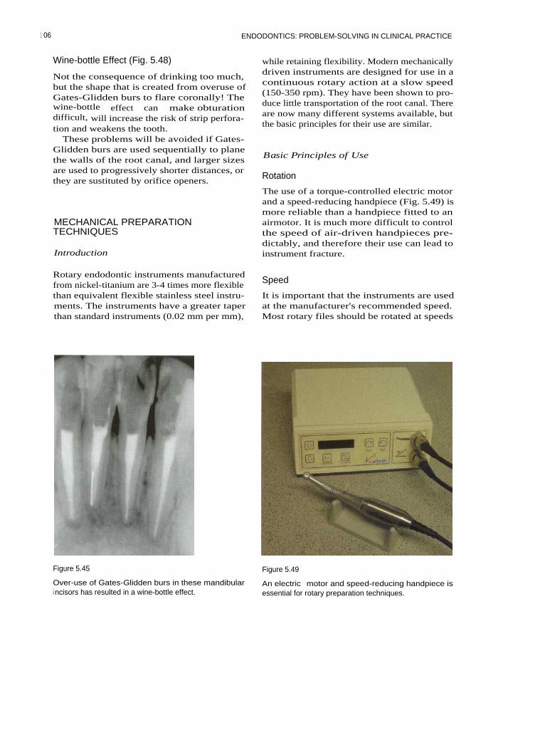
ENDODONTICS: PROBLEM-SOLVING IN CLINICAL PRACTICE
Wine-bottle Effect (Fig. 5.48)
Not the consequence of drinking too much,but the shape that is created from overuse ofGates-Glidden burs to flare coronally! Thewine-bottle effect can make obturationdifficult, will increase the risk of strip perfora-tion and weakens the tooth.
These problems will be avoided if Gates-Glidden burs are used sequentially to planethe walls of the root canal, and larger sizesare used to progressively shorter distances, orthey are sustituted by orifice openers.
MECHANICAL PREPARATIONTECHNIQUES
Introduction
while retaining flexibility. Modern mechanicallydriven instruments are designed for use in acontinuous rotary action at a slow speed(150-350 rpm). They have been shown to pro-duce little transportation of the root canal. Thereare now many different systems available, butthe basic principles for their use are similar.
Basic Principles of Use
Rotation
The use of a torque-controlled electric motorand a speed-reducing handpiece (Fig. 5.49) ismore reliable than a handpiece fitted to anairmotor. It is much more difficult to controlthe speed of air-driven handpieces pre-dictably, and therefore their use can lead toinstrument fracture.
Rotary endodontic instruments manufacturedfrom nickel-titanium are 3-4 times more flexiblethan equivalent flexible stainless steel instru-ments. The instruments have a greater taperthan standard instruments (0.02 mm per mm),
Speed
It is important that the instruments are usedat the manufacturer's recommended speed.Most rotary files should be rotated at speeds
Figure 5.45 Figure 5.49
Over-use of Gates-Glidden burs in these mandibulari ncisors has resulted in a wine-bottle effect.
An electric motor and speed-reducing handpiece isessential for rotary preparation techniques.
1 06

ROOT CANAL PREPARATION
between 150 and 350 rpm for routine rootcanal preparation.
Cutting Action
The instruments should be advanced into thecanal with a light apical-coronal action (peck-ing/pumping) in waves of 8-10 seconds. Theyare then withdrawn, assessed for damage,cleaned of debris and reinserted. Files mustbe kept moving coronally-apically within thecanal; rotating an instrument at a stationaryposition close to or at full working lengthresults in alternating compression and strainin the file at the greatest point of its curvature,and could eventually lead to instrument fail-ure. The root canals are flooded with irrigantor lubricant during instrumentation to pre-vent dentine chips compacting. Packing ofdentine chips around the file can lead to bind-ing and instrument fracture.
Canal Curvature
Nickel-titanium, because of its superelastic-ity, can be rotated in canals of sharp curva-ture; but care must be taken in severelycurved canals. In very curved canals or canalswith sudden abrupt apical curvatures handinstrumentation is preferred for completion ofpreparation.
Avoidance of Instrument Fracture
To avoid fracture it is important to create apilot channel that the non-cutting tip of arotary instrument can follow. If such a chan-nel is not created the tip may bind and frac-ture.
Preparation should be carried out in acrown-down manner, as this ensures that suc-cessive instruments are not overworked.
Nickel-titanium instruments can fractureunpredictably, and may not show signs ofpermanent deformation before failing.Instruments should therefore be changed reg-ularly and should never be forced duringpreparation. It is often recommended thatnickel-titanium instruments should not beused in more than 5-10 canals.
The Instruments
There are two basic types:
For Coronal Preparation
Orifice openers are usually relatively thick indiameter and are consequently not veryflexible. They are designed for coronal flaring,and should only be used in the 'straight' partof a root canal.
For Apical Preparation
Tapered rotary files are available in tapers of0.04, 0.06, 0.08, 0.10 and 0.12. Profiles(Dentsply), Quantec (Analytic Endodontics,Glendora, CA, USA), Hero (Micro-mega,Geneva, Switzerland), K3 (Kerr, Bretton,Peterborough, UK) and Greater Taper filesare essentially used to flare rapidly a pre-prepared pilot channel in the apical part ofthe root canal. Instruments are used in acrown-down manner (Figs. 5.50-5.53).
Figure 5.50
The Greater Taper rotary range of instruments: an acces-sory file for coronal flaring (left) and then tapers 0.06,0.08, 0.10, 0.12.
10 7
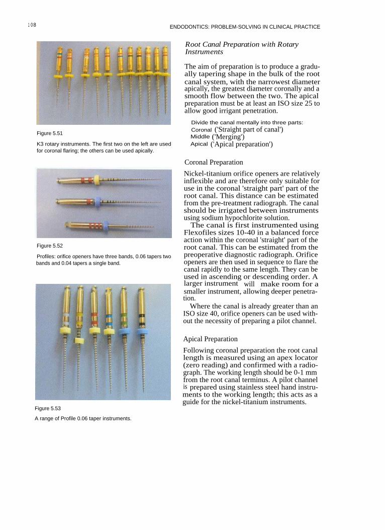
1 0 8 ENDODONTICS: PROBLEM-SOLVING IN CLINICAL PRACTICE
Figure 5.51
K3 rotary instruments. The first two on the left are usedfor coronal flaring; the others can be used apically.
Root Canal Preparation with RotaryInstruments
The aim of preparation is to produce a gradu-ally tapering shape in the bulk of the rootcanal system, with the narrowest diameterapically, the greatest diameter coronally and asmooth flow between the two. The apicalpreparation must be at least an ISO size 25 toallow good irrigant penetration.
Divide the canal mentally into three parts:Coronal ('Straight part of canal')Middle ('Merging')Apical ('Apical preparation')
Coronal Preparation
Figure 5.52
Profiles: orifice openers have three bands, 0.06 tapers twobands and 0.04 tapers a single band.
Figure 5.53
Nickel-titanium orifice openers are relativelyinflexible and are therefore only suitable foruse in the coronal 'straight part' part of theroot canal. This distance can be estimatedfrom the pre-treatment radiograph. The canalshould be irrigated between instrumentsusing sodium hypochlorite solution.
The canal is first instrumented usingFlexofiles sizes 10-40 in a balanced forceaction within the coronal 'straight' part of theroot canal. This can be estimated from thepreoperative diagnostic radiograph. Orificeopeners are then used in sequence to flare thecanal rapidly to the same length. They can beused in ascending or descending order. Alarger instrument will make room for asmaller instrument, allowing deeper penetra-tion.
Where the canal is already greater than anISO size 40, orifice openers can be used with-out the necessity of preparing a pilot channel.
Apical Preparation
Following coronal preparation the root canallength is measured using an apex locator(zero reading) and confirmed with a radio-graph. The working length should be 0-1 mmfrom the root canal terminus. A pilot channelis prepared using stainless steel hand instru-ments to the working length; this acts as aguide for the nickel-titanium instruments.
A range of Profile 0.06 taper instruments.

ROOT CANAL PREPARATION
Preparation of the Pilot Channel FURTHER READING
The pilot channel is prepared using Flexofilessizes 15-25 with the balanced force technique(see hand instrumentation). The canal is irri-gated with hypochlorite solution betweeninstruments, and in fine canals anEDTA-based lubricant may also be used toprevent binding of instruments and com-paction of any dentine chips that may havebeen created.
The canal can now be flared to the desiredtaper. Nickel-titanium instruments arerotated at 150-350 rpm in a speed-reducinghandpiece using an electric torque-controlledmotor. Instruments should be used sequen-tially. The master apical size must be at leastsize 25 for good irrigant penetration.
Middle Section of the Canal: `Merging'
If apical instrumentation has been completedwith a smaller-taper instrument (0.02, 0.04),the coronal and apical preparation may needto be merged by using an instrument with alarger taper. This will create a smooth flow tothe preparation.
During mechanical preparation the canal isthoroughly irrigated with sodium hypochlo-rite solution. This can be carried out withhand syringes or endosonic handpieces.
Buchanan LS (2000). The standardized-taperroot canal preparation-Part 1. Concepts forvariably tapered shaping instruments.International Endodontic journal 33: 516-529.
Goerig AC, Michelich RJ, Schultz HH (1982).Instrumentation of root canals in molar usingthe step-down technique. Journal ofEndodontics 8: 550-554.
Roane JB, Sabala CL, Duncanson MG (1985).The 'balanced force' concept for instrumenta-tion of curved canals. Journal of Endodontics11:203-211.
Saunders WP, Saunders EM (1992). Effect ofnon-cutting tipped instruments on the qualityof root canal preparation using a modifieddouble-flared technique. Journal of Endodontics18: 32-36.
Schilder H (1974). Cleaning and shaping theroot canal. Dental Clinics of North America 18:269-296.
European Society of Endodontology (1994).Consensus report of the European Society ofEndodontology on quality guidelines forendodontic treatment. International Endodonticjournal 27:115-124.
1 0 9

6 IRRIGATION AND MEDICATION
CONTENTS • Why? • Irrigants • How? • Medicaments • Further Reading
Following thorough instrumentation of aninfected root canal there will be a significantlyreduced number of bacteria present; but it iswell documented that instrumentation alonecannot clean all the internal surfaces of theroot canal. Bacteria can be found on the rootcanal walls, within dentine tubules and in lat-eral canals. Antibacterial irrigants and inter-appointment medicaments are needed to killthe remaining micro-organisms.
A large series of follow up studies haveshown that, by using thorough mechanicalpreparation, irrigation with sodiumhypochlorite and dressing with calciumhydroxide, predictable disinfection can beachieved in almost 100% of root canals. Thisin turn has produced clinical and radio-graphic evidence of healing apical periodonti-tis in over 90% of cases.
Medicaments are also invaluable in pre-venting the recolonization of the root canalbetween appointments. If the canal space isleft empty then the small number of bacteriaremaining can multiply to levels equivalent tothose that were initially present.
I RRIGANTS
Irrigants should:
• Be antimicrobial• Have a low surface tension• Not be mutagenic, carcinogenic or overtly
cytotoxic• Possess tissue-dissolving properties
• Remain active following storage• Be inexpensive.
Preparations Used as Irrigants
Sodium Hypochlorite
Sodium hypochlorite solution has been usedas an irrigant in endodontics for many years.It is inexpensive, readily available, and highlyantimicrobial, and has valuable tissue-dissolving properties. A 0.5% solution killsbacteria. Sodium hypochlorite solutionsgreater than 1 % will effectively dissolveorganic tissue. Solutions ranging in strengthfrom 0.5% to 5.25% have been recommendedfor use in endodontics (Fig. 6.1). Increasingthe concentration will increase the rate atwhich organic material is dissolved, and mayimprove its effectiveness as an antibacterialagent. Heating the solution will have a similareffect (Fig. 6.2). The tissue-dissolving abilityof sodium hypochlorite is affected by theamount of organic material present in thecanal, the fluid flow and the surface areaavailable.
The volume of solution used is probablymore important than the concentration.Several millilitres should be exchanged fre-quently throughout the root canal systemduring instrumentation. Frequent replenish-ment will improve the flushing action of theirrigant, which removes debris. Keeping thecanal system flooded with fresh solution at alltimes during preparation will improvedissolution of organic material and killing of

ENDODONTICS: PROBLEM-SOLVING IN CLINICAL PRACTICE
Figure 6.1
Household thin bleach is a readily available sodiumhypochlorite solution. It is important to check that thereare no additives such as perfumes or sodium hydroxide.
bacteria. Rubber dam is essential forendodontic treatment, and will prevent theleaking of sodium hypochlorite solution intothe patient's mouth; the patient's clothesshould be protected with a bib. Using a safe-ended needle can prevent extrusion ofsodium hypochlorite into the periapical tis-sues.
Saline
The use of saline as the sole irrigant is notconsidered appropriate, as normal solutionsare ineffective as antimicrobial agents andwill not dissolve organic material.
Local Anaesthetic
Local anaesthetic should not be used as thesole irrigant, as it has no advantages over nor-mal saline, which is not considered effective.
Chlorhexidine Gluconate
Chlorhexidine gluconate can be purchased asa mouthwash in a 0.2% solution.Chlorhexidine, while antibacterial, will notdissolve organic material, and is also rela-tively expensive. It may be effective in con-centrations from 0.2-2.0%, but there is littlepublished clinical evidence.
I odine in Potassium Iodide
Figure 6.2
A baby-bottle warmer is probably the easiest means ofheating hypochlorite solution. Prolonged heating willinactivate the solution.
There have been reports that some strains ofbacteria that are associated with failed rootcanal treatment have survived in the presenceof calcium hydroxide - for example, Entero-coccus faecalis. This bacterium is susceptible toiodine in potassium iodide, and therefore thissolution may be useful as an irrigant inretreatment cases. It is used as a 2% solutionof iodine in 4% aqueous potassium iodide(Fig. 6.3).
EDTA (Ethylene diaminetetraacetate)(Fig. 6.4)
This is a chelating agent, and will dissolvedentine chips within the root canal system. Itis not antibacterial, and will not dissolve
112
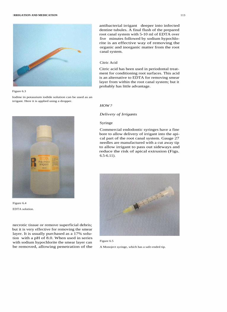
I RRIGATION AND MEDICATION
Figure 6.3
antibacterial irrigant deeper into infecteddentine tubules. A final flush of the preparedroot canal system with 5-10 ml of EDTA overfive minutes followed by sodium hypochlo-rite is an effective way of removing theorganic and inorganic matter from the rootcanal system.
Citric Acid
Citric acid has been used in periodontal treat-ment for conditioning root surfaces. This acidis an alternative to EDTA for removing smearlayer from within the root canal system; but itprobably has little advantage.
Iodine in potassium iodide solution can be used as an
irrigant. Here it is applied using a dropper.
HOW?
Delivery of Irrigants
Syringe
Commercial endodontic syringes have a finebore to allow delivery of irrigant into the api-cal part of the root canal system. Gauge 27needles are manufactured with a cut away tipto allow irrigant to pass out sideways andreduce the risk of apical extrusion (Figs.6.5-6.11).
Figure 6.4
EDTA solution.
necrotic tissue or remove superficial debris;but it is very effective for removing the smearlayer. It is usually purchased as a 17% solu-tion with a pH of 8.0. When used in serieswith sodium hypochlorite the smear layer canbe removed, allowing penetration of the
Figure 6.5
A Monoject syringe, which has a safe-ended tip.
113

114
ENDODONTICS: PROBLEM-SOLVING IN CLINICAL PRACTICE
Figure 6.6
Placing a rubber stop on the needle will prevent extru-sion of irrigant beyond the apex of the tooth
Figure 6.9
Using a forefinger to depress the plunger gives greatercontrol of irrigant delivery.
Figure 6.7
Prebending the needle against a ruler.Figure 6.10
Figure 6.8
Squeezing the plunger with the thumb may result inmore rapid delivery of irrigant and possible extrusion ofirrigant.
Hand irrigation in a mandibular molar.
Endosonics
Endosonics is a very useful means of deliver-ing irrigant.
Most portable ultrasonic units can be fittedwith an endosonic attachment that allows thedelivery of irrigant (Fig. 6.12). During ultra-sonic vibration of an endosonic file in the rootcanal, streaming of the irrigant is created, andthis may help dislodge material from thecanal system. It also ensures penetration ofirrigant into lateral canals, fins and anasto-moses, where files cannot penetrate.Ultrasonic streaming occurs best when asmall file (size 15) is vibrated freely within theroot canal (Fig. 6.13). Binding of the file
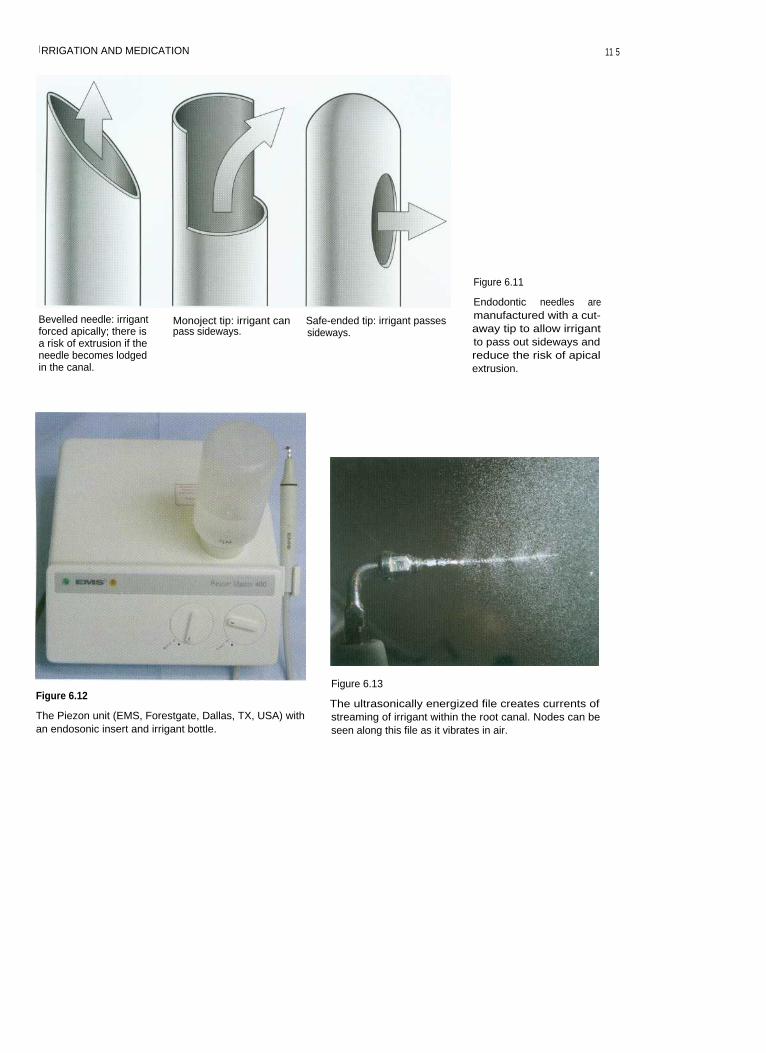
I RRIGATION AND MEDICATION
11 5
Bevelled needle: irrigantforced apically; there isa risk of extrusion if theneedle becomes lodgedin the canal.
Monoject tip: irrigant can
Safe-ended tip: irrigant passespass sideways.
sideways.
Figure 6.11
Endodontic needles aremanufactured with a cut-away tip to allow irrigantto pass out sideways andreduce the risk of apicalextrusion.
Figure 6.12
The Piezon unit (EMS, Forestgate, Dallas, TX, USA) withan endosonic insert and irrigant bottle.
Figure 6.13
The ultrasonically energized file creates currents ofstreaming of irrigant within the root canal. Nodes can beseen along this file as it vibrates in air.
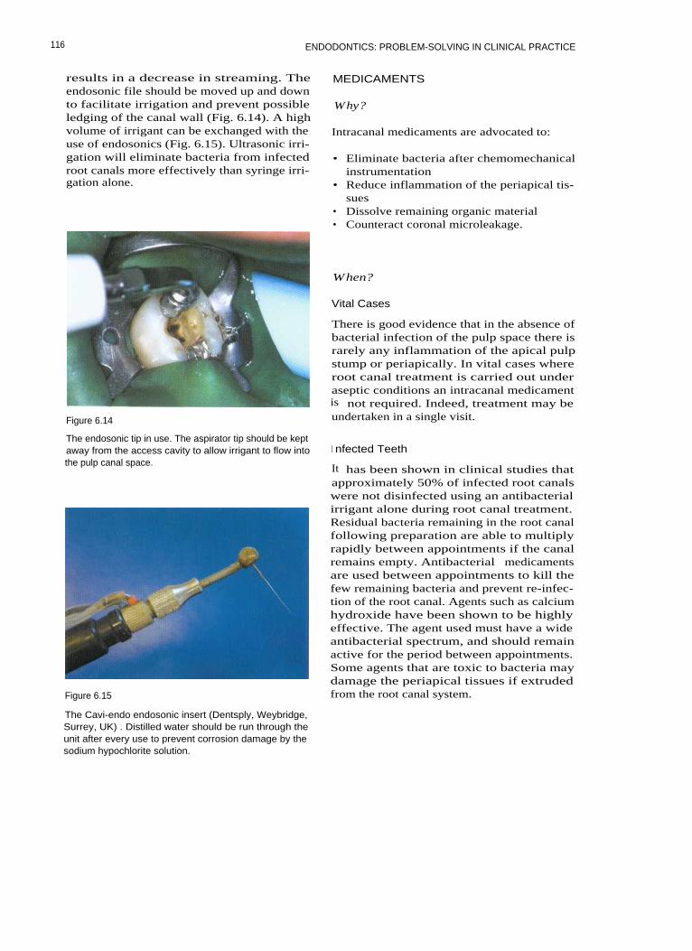
ENDODONTICS: PROBLEM-SOLVING IN CLINICAL PRACTICE
results in a decrease in streaming. Theendosonic file should be moved up and downto facilitate irrigation and prevent possibleledging of the canal wall (Fig. 6.14). A highvolume of irrigant can be exchanged with theuse of endosonics (Fig. 6.15). Ultrasonic irri-gation will eliminate bacteria from infectedroot canals more effectively than syringe irri-gation alone.
Figure 6.14
MEDICAMENTS
Why?
Intracanal medicaments are advocated to:
• Eliminate bacteria after chemomechanicalinstrumentation
• Reduce inflammation of the periapical tis-sues
• Dissolve remaining organic material• Counteract coronal microleakage.
When?
Vital Cases
There is good evidence that in the absence ofbacterial infection of the pulp space there israrely any inflammation of the apical pulpstump or periapically. In vital cases whereroot canal treatment is carried out underaseptic conditions an intracanal medicamentis not required. Indeed, treatment may beundertaken in a single visit.
The endosonic tip in use. The aspirator tip should be keptaway from the access cavity to allow irrigant to flow intothe pulp canal space.
Figure 6.15
I nfected Teeth
It has been shown in clinical studies thatapproximately 50% of infected root canalswere not disinfected using an antibacterialirrigant alone during root canal treatment.Residual bacteria remaining in the root canalfollowing preparation are able to multiplyrapidly between appointments if the canalremains empty. Antibacterial medicamentsare used between appointments to kill thefew remaining bacteria and prevent re-infec-tion of the root canal. Agents such as calciumhydroxide have been shown to be highlyeffective. The agent used must have a wideantibacterial spectrum, and should remainactive for the period between appointments.Some agents that are toxic to bacteria maydamage the periapical tissues if extrudedfrom the root canal system.
The Cavi-endo endosonic insert (Dentsply, Weybridge,Surrey, UK) . Distilled water should be run through theunit after every use to prevent corrosion damage by thesodium hypochlorite solution.
116
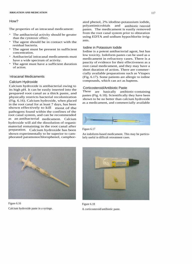
I RRIGATION AND MEDICATION
How?
The properties of an intracanal medicament:
• The antibacterial activity should be greaterthan the cytotoxic effect.
• The agent should be in contact with theresidual bacteria.
• The agent must be present in sufficientconcentration.
• Antibacterial intracanal medicaments musthave a wide spectrum of activity.
• The agent must have a sufficient durationof action.
I ntracanal Medicaments
Calcium HydroxideCalcium hydroxide is antibacterial owing toits high pH. It can be easily inserted into theprepared root canal as a thick paste, andphysically restricts bacterial recolonization(Fig. 6.16). Calcium hydroxide, when placedin the root canal for at least 7 days, has beenshown effectively to kill most of thepathogens found within the confines of theroot canal system, and can be recommendedas an antibacterial medicament. Calciumhydroxide will aid the dissolution of organicmaterial remaining in the root canal afterpreparation. Calcium hydroxide has beenshown experimentally to be superior to cam-phorated paramonochlorophenol, camphor-
ated phenol, 2% idodine-potasssium iodide,polyantimicrobials and antibiotic /steroidpastes. The medicament is easily removedfrom the root canal system prior to obturationusing EDTA and sodium hypochlorite irrig-ants.
Iodine in Potassium IodideIodine is a potent antibacterial agent, but haslow toxicity. lodoform pastes can be used as amedicament in refractory cases. There is apaucity of evidence for their effectiveness as aroot canal medicament, and they may have ashort duration of action. There are commer-cially available preparations such as Vitapex(Fig. 6.17). Some patients are allergic to iodinecompounds, which can act as haptens.
Corticosteroid/Antibiotic PasteThese are basically antibiotic-containingpastes (Fig. 6.18). Scientifically they have beenshown to be no better than calcium hydroxideas a medicament, and commercially available
Figure 6.17
An iodoform-based medicament. This may be particu-larly useful in difficult retreatment cases.
Figure 6.16 Figure 6.18
Calcium hydroxide paste in a syringe. A corticosteroid/antibiotic paste.
117

ENDODONTICS: PROBLEM-SOLVING IN CLINICAL PRACTICE
preparations tend to be more expensive.
The syringe tips on most commercial systemsMixing the paste with calcium hydroxide has
can be pre-measured to prevent extrusionbeen advocated, but this gives little advan-
(Fig. 6.20).tage and may decrease the effectiveness of theindividual components, as there is no syner-gism between the separate materials.
Hand FileA file can be used to place the medicament inthe canal. The agent should be smeared onthe walls of the root canals, and can be carriedto the working length by gently rotating thefile in an anti-clockwise direction (Fig. 6.21). Ifit is mixed to a thick paste consistency a plug-
Formaldehydes, Paraformaldehydes,Phenols, Camphorated Phenol, CamphoratedParamonochlorophenolThese materials have potential mutagenic andcarcinogenic properties, and can becomewidely distributed in the body. The effective-ness of vapour-forming solutions decreasestoo rapidly after insertion, and contact withtissue fluids renders them inactive. The use ofany of these materials can no longer be justi-fied.
Placement of Medicaments
Syringe DeliveryProbably the easiest way of applying amedicament. Calcium hydroxide prepara-tions come in different concentrations and indifferent formats. Disposable plastic tips areexcellent, as there is no risk of cross-infection(Fig. 6.19). Metal syringe tips must be auto-claved between patients. It is important toplace a fine file along the bore of the needle toensure that the tip does not become blocked.
Figure 6.20
Bending the needle tip or placing a rubber stop will pre-vent extrusion of the medicament.
Figure 6.19
Using a needle to deliver calcium hydroxide paste intothe root canals.
Figure 6.21
Calcium hydroxide can be placed using a file. The stopindicates the working length; medicament should coatthe entire canal.
1 1 8

I RRIGATION AND MEDICATION
ger can be used to ensure that the material iscarried completely to all parts of the preparedroot canal system.
Spiral FillersGreat care must be exercised when using spi-ral fillers, as the instrument can bind in thecanal and fracture (Fig. 6.22); the direction ofrotation must be verified before use. It is per-haps easiest to use spiral fillers by hand; butthey do not really offer any great benefit overapplying medicament with a hand instru-ment.
Calcium Hydroxide PointsCalcium hydroxide-containing points areavailable. They are not considered to be veryeffective, as little calcium hydroxide isreleased into the root canal (Fig. 6.23).
FURTHER READING
Bystr6m A, Sundqvist G (1981). Bacteriologicevaluation of the efficacy of mechanical rootcanal instrumentation in endodontic therapy.Scandinavian Journal of Dental Research 89:321-328.
Bystr6m A, Sundqvist G (1983). Bacteriologicevaluation of the effect of 0.5 per cent sodiumhypochlorite in endodontic therapy. OralSurgery, Oral Medicine, Oral Pathology 55:307-312.
Figure 6.22
Spiral fillers.
Bystr6m A, Claesson R, Sundqvist G (1985).The antibacterial effect of camphorated para-monochlorophenol, camphorated phenol andcalcium hydroxide in the treatment ofinfected root canals. Endodontics and DentalTraumatology 1: 170-175.
Chong BS, Pitt Ford TR (1992). The role ofintracanal medication in root canal treatment.International Endodontic journal 25: 97-106.
Figure 6.23
Calcium hydroxide points.
1 1 9

7 OBTURATION TECHNIQUES
CONTENTS • Introduction • Criteria for Obturation • Sealers • Root Filling MaterialsObturation Techniques • Troubleshooting Obturation Techniques • Further Reading
I NTRODUCTION
Following through cleaning and shaping, theroot canal system is obturated to:
• Prevent the ingress of micro-organismsinto the root canal system by coronal leak-age.
• Prevent the multiplication of micro-organisms remaining in the root canal sys-tem.
• Prevent percolation of tissue fluid intopulp space via apical foramina /lateralcanals or furcal canals. This fluid could actas a substrate for any viable bacteriaremaining following root canal treatment.
• Prevent bacterial percolation into the pulpcanal space via interconnections with thegingival sulcus or periodontal pockets.
Many materials have been suggested as suit-able root canal fillings; however the currentmaterial of choice is gutta percha used with asealer.
CRITERIA FOR OBTURATION
Historically, obturation of the root canalspace was often delayed until there weresigns of periapical healing, and a reduction inthe patient's symptoms. Delaying obturation,however, can lead to problems: if a temporaryrestoration fails to seal the coronal aspect ofthe root canal system then bacteria will enterthe canal by coronal microleakage and thepatient's symptoms may persist or becomeworse. Endodontically treated teeth can bevulnerable to fracture, and when this occursthe temporary restoration is often lost. There
is good evidence that following instrumenta-tion, irrigation and the placement of anantibacterial dressing such as calciumhydroxide, the majority of infected rootcanals are bacteria-free. This is the optimumtime to obturate the root canal system.
The root canal can be obturated when:
• There is an absence of pain and swelling.• There is no tenderness to percussion.• There is no patent sinus tract.• The canal is dry.• The canal is odour-free.• The cleaned and shaped root canal has had
a medicament placed for at least 1 week.
There has been a trend amongst specialistendodontists to undertake root canal treat-ment in a single visit. The rationale behindthis is that delaying obturation may allow re-contamination of the root canal system. Thereare specific indications for such an approach,namely: the treatment of teeth with vitalpulps (where microbial invasion should theo-retically be minimal and multiple visits maylead to further contamination); and the situa-tion where an immediate post crown isrequired.
Obturation should not be carried out imme-diately in the following situations:
• In teeth with apical periodontitis (radiolog-ical or symptomatic)
• Teeth with excessive exudate• Teeth with purulent discharge• Root canal retreatment• Complex treatment such as perforation
repair.

1 2 2 ENDODONTICS: PROBLEM-SOLVING IN CLINICAL PRACTICE
SEALERS
Root canal sealer is used to obliterate theirregularities and voids between the rootcanal filling material and the canal wall. Asealer improves the seal of the root canal fill-ing and should be antibacterial. The materialshould ideally have the capability of bindingto the core material and bonding to the den-tine of the root canal wall. It should fill thevoids that occur between the walls of thecanal and the core material, and fill lateralcanals and anastomoses that may not be filledby gutta percha. In cold lateral condensationsealer fills the spaces between cones of guttapercha. The sealer also acts as a lubricant dur-ing the placement of the cones.
The ideal sealer therefore has the followingproperties:
• Be able to achieve a seal• Antibacterial• Good wetting properties• Ability to adhere to both filling material
and root canal wall• Radiopaque• Non-irritant and well tolerated by periapi-
cal tissues• Insoluble in tissue fluid• Dimensionally stable• Easy to mix• Good working time (especially in thermo-
plasticized techniques)• Easy to remove if required (retreatment
and post preparation)• Non-staining
Unfortunately there are no materials thatsatisfy all the above criteria. Most sealers areabsorbable when exposed to tissue fluids, andtherefore the sealer becomes the weak link inproviding a seal; these materials are thereforeused in low volume, the majority of the rootcanal system being filled with the core mater-ial (gutta percha).
• Zinc oxide and eugenol• Calcium hydroxide• Resin• Glass ionomer
Radio-opacifiers are added, such as precipi-tated silver or bismuth salts. Binding resinssuch as staybelite, hydrogenated rosin ester,oleoresin and polymerized resin are added.Some sealers contain antibacterial substancessuch as thymol iodide and calcium hydrox-ide. Calcium hydroxide is unlikely to be oftherapeutic benefit in eugenol-based sealers,as it is chelated by eugenol.
Zinc Oxide and Eugenol-based Sealers
Many zinc oxide and eugenol-based sealersare available, and a number are variations onGrossman's original formula. It is possible tohave a sealer with extra working time (EWT)for use with heated gutta percha techniques.The eugenol in these sealers is antibacterial,but the material is porous and relatively weakwhen set. Zinc oxide and eugenol materialextruded through the apex will produce aninflammatory reaction in the periapical tis-sues, and this may last some time. All zincoxide and eugenol cements are cytotoxic, andhave been shown to lead to sensitization.Pulp canal sealer (Kerr, Peterborough, UK)includes silver particles to improve theradiopacity; this may potentially contribute todentine staining following root canal treat-ment, and care should be taken when treatinganterior teeth.
Examples are:
• Grossman's• Tubliseal (Kerr)• Roth (Roth International, Chicago, IL, USA)• Pulp Canal Sealer (Kerr) (Fig. 7.1)
Calcium Hydroxide Sealers
Types of Sealer
Sealers are mixed to a paste and set by chemi-cal reaction. They are based on the followingformulations:
These materials have been shown to havesimilar sealing ability to zinc oxide andeugenol preparations; however, long-termexposure to tissue fluid may possibly lead todissolution of the material as calcium hydrox-ide is leached out.
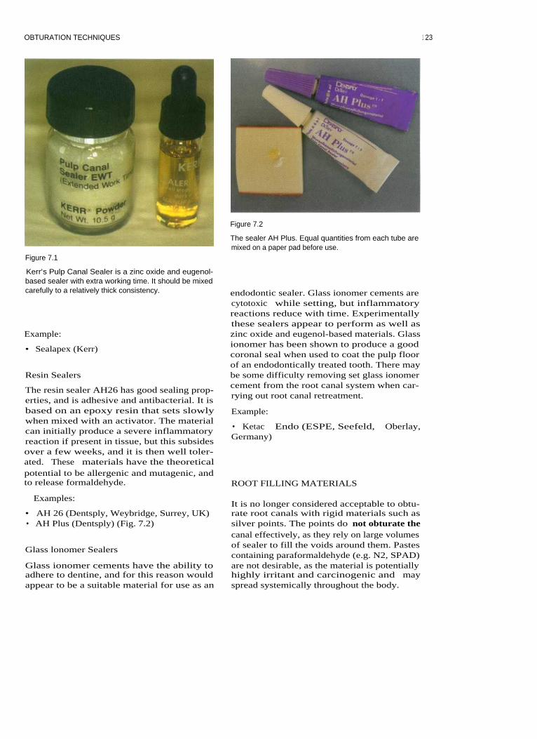
OBTURATION TECHNIQUES
Figure 7.1
Figure 7.2
The sealer AH Plus. Equal quantities from each tube aremixed on a paper pad before use.
Kerr's Pulp Canal Sealer is a zinc oxide and eugenol-based sealer with extra working time. It should be mixedcarefully to a relatively thick consistency.
Example:
• Sealapex (Kerr)
Resin Sealers
The resin sealer AH26 has good sealing prop-erties, and is adhesive and antibacterial. It isbased on an epoxy resin that sets slowlywhen mixed with an activator. The materialcan initially produce a severe inflammatoryreaction if present in tissue, but this subsidesover a few weeks, and it is then well toler-ated. These materials have the theoreticalpotential to be allergenic and mutagenic, andto release formaldehyde.
endodontic sealer. Glass ionomer cements arecytotoxic while setting, but inflammatoryreactions reduce with time. Experimentallythese sealers appear to perform as well aszinc oxide and eugenol-based materials. Glassionomer has been shown to produce a goodcoronal seal when used to coat the pulp floorof an endodontically treated tooth. There maybe some difficulty removing set glass ionomercement from the root canal system when car-rying out root canal retreatment.
Example:
• Ketac Endo (ESPE, Seefeld, Oberlay,Germany)
ROOT FILLING MATERIALS
Examples:
• AH 26 (Dentsply, Weybridge, Surrey, UK)• AH Plus (Dentsply) (Fig. 7.2)
Glass lonomer Sealers
Glass ionomer cements have the ability toadhere to dentine, and for this reason wouldappear to be a suitable material for use as an
It is no longer considered acceptable to obtu-rate root canals with rigid materials such assilver points. The points do not obturate thecanal effectively, as they rely on large volumesof sealer to fill the voids around them. Pastescontaining paraformaldehyde (e.g. N2, SPAD)are not desirable, as the material is potentiallyhighly irritant and carcinogenic and mayspread systemically throughout the body.
1 23

ENDODONTICS: PROBLEM-SOLVING IN CLINICAL PRACTICE
Gutta percha has been used to fill rootcanals for over a century, and remains thematerial of choice.
Gutta Percha
This natural rubber is the cis isomer of poly-isoprene. Gutta percha can exist in threephases: a, B and amorphous (molten). Con-ventional gutta percha points exist in the Bform, which transforms to the a phase onheating between 42 and 49°C; between 53 and59°C the material enters an amorphous phase.These phase transformations are very impor-tant: heating the gutta percha during obtura-tion results in shrinkage on cooling as thephase changes occur. Of practical importanceto the dentist is the fact that heated gutta per-cha requires pressure to compact it as it cools,to prevent contraction gaps from developing.
Other agents are added to the gutta perchato make the points that are used in dentistry.
The typical point consists of:
Figure 7.3
This premolar tooth has been obturated using a lateralcondensation technique.
percentage• Gutta percha
19-22• Zinc oxide
59-75
-for stiffness• Metal sulphates
1.5-17 -for radiopacity• Waxes/resins
1-4
-for handlingproperties
• Colouring agent
<1
-for visualcontrast
OBTURATION TECHNIQUES
There are many techniques for obturating theroot canal system:
• Cold lateral condensation• Warm lateral condensation (Fig. 7.3)• Warm vertical condensation (Fig. 7.4)• Thermocompaction (ultrasonic and mech-
anical) (Fig. 7.5)• Injection of thermoplasticized gutta percha• Chloropercha
Figure 7.4
Warm vertical condensation of the root canal space.Hydraulic forces during compaction will often obturatelateral canals.
12 4
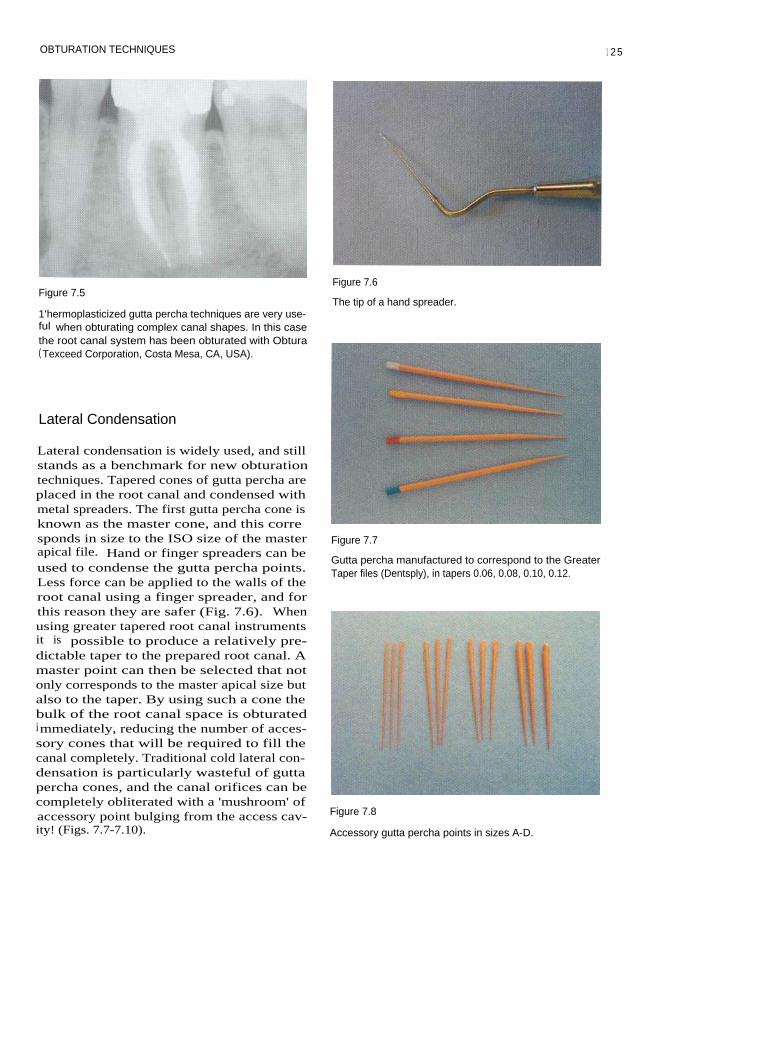
OBTURATION TECHNIQUES
Figure 7.5
1'hermoplasticized gutta percha techniques are very use-ful when obturating complex canal shapes. In this casethe root canal system has been obturated with Obtura( Texceed Corporation, Costa Mesa, CA, USA).
Lateral Condensation
Lateral condensation is widely used, and stillstands as a benchmark for new obturationtechniques. Tapered cones of gutta percha areplaced in the root canal and condensed withmetal spreaders. The first gutta percha cone isknown as the master cone, and this corresponds in size to the ISO size of the master
Figure 7.7apical file. Hand or finger spreaders can be
Gutta percha manufactured to correspond to the Greaterused to condense the gutta percha points.
Taper files (Dentsply), in tapers 0.06, 0.08, 0.10, 0.12.Less force can be applied to the walls of theroot canal using a finger spreader, and forthis reason they are safer (Fig. 7.6). Whenusing greater tapered root canal instrumentsit is possible to produce a relatively pre-dictable taper to the prepared root canal. Amaster point can then be selected that notonly corresponds to the master apical size butalso to the taper. By using such a cone thebulk of the root canal space is obturatedimmediately, reducing the number of acces-sory cones that will be required to fill thecanal completely. Traditional cold lateral con-densation is particularly wasteful of guttapercha cones, and the canal orifices can becompletely obliterated with a 'mushroom' ofaccessory point bulging from the access cav-
Figure 7.8
ity! (Figs. 7.7-7.10). Accessory gutta percha points in sizes A-D.
Figure 7.6
The tip of a hand spreader.
1 25

126
ENDODONTICS: PROBLEM-SOLVING IN CLINICAL PRACTICE
The Technique
Figure 7.9
Gutta percha points in ISO sizes.
Cone FittingA standardized gutta percha point of thesame size as the master apical file or a non-standardized gutta percha point that corre-sponds to the taper of the completed rootcanal preparation is selected. Non-standardtaper cones usually need to be trimmed attheir tip to correspond to the diameter of theapical preparation.
The point is then inserted into the canal,and should exhibit 'tug-back' at a point0.5-1.0 mm short of the working length.
A finger spreader when inserted on theouter curve of the canal wall alongside thepoint will drive it to the full working length.
• The cone is fitted so that tug-back is feltjust short of the working length.Sometimes it is necessary to prefabricatethe cone by rolling a large gutta perchapoint between two glass slabs, or alterna-tively, by blending several smaller pointstogether in the same manner (Fig. 7.11).
• Dip the tip of the gutta percha point in sol-Figure 7.1o
vent (e.g. chloroform) (Fig. 7.12).The ISO points are manufactured in a wide range of sizes
• Place the cone immediately into the pre-that correspond to the hand files.
pared root canal to the working length(Fig. 7.13).
• On removal the tip will have adapted toirregularities at the apical end of the rootcanal (Fig. 7.14).
• A thin coating of sealer is applied to thegutta percha, and the cone is refitted intothe root canal.
• During lateral condensation excessiveforces should be avoided to prevent dis-placing the master cone apically.
Figure 7.11
A customized cone has been rolled on a glass slab.
Custom-fitting a Gutta Percha ConeOccasionally the apical size of the preparedroot canal may be larger than a standardizedcone. In this case a customized gutta perchacone will need to be formed. The chloroformdip technique is useful in this situation.
Lateral CondensationAfter selection of a suitable point, root canalsealer is mixed and inserted in the canal. Allwalls should be coated evenly with a thinlayer, and this can be achieved with a paperpoint, a hand file or an endosonic file

OBTURATION TECHNIQUES
Figure 7.12
The tip is dipped in chloroform.
(Fig. 7.15). The master cone is then dipped insealer and inserted into the canal. It is con-densed into place with the finger spreaderplaced between it and the outer wall of thecurved canal wall. The spreader is pushedand rotated back and forth 45°. The size ofspreader will depend on the taper of thepreparation and the degree of curvature ofthe canal (Fig. 7.16). The tip of the instrumentshould pass to within a few millimetres of theworking length at the start of compaction(Fig. 7.17). Following lateral compaction theinstrument is withdrawn slowly.
Figure 7.15
Figure 7.13
The cone is immediately seated to working length.
Endosonics is highly effective for coating the walls of theroot canal with scalcr.
Figure 7.14
The tip has adapted to irregularities within the apical end
Figure 7.16
of the root canal.
A size B finger spreader and equivalent accessory point.
1 27

128 ENDODONTICS: PROBLEM-SOLVING IN CLINICAL PRACTICE
Figure 7.17
The spreader should be inserted to within a few millime-tres of the working length at the start of condensation(shown here in a transparent block).
to apply pressure to the gutta percha duringcooling to counteract the shrinkage thatoccurs as the filling material undergoes phasechanges on cooling.
By applying heat to the gutta percha theforces required for compaction are reduced. Itis also possible to adapt the thermoplasticizedmaterial to the irregularities within the canal.
The Technique
Cone FittingThe gutta percha points used in heated tech-niques are designed to thermoplasticize eas-ily, and their containers sometimes bear theinscription 'suitable for the Schilder tech-nique'.
A non-standardized gutta percha point thatcorresponds to the taper of the completedroot canal preparation is selected. The tip ofthe cone is trimmed to correspond to thediameter of the apical preparation. The pointwhen inserted into the canal should exhibit'tug-back' at a point 0.5-1.0 mm short of theworking length.
An accessory point of similar size to thespreader is chosen and placed into the vacatedspace. The spreader is again replaced betweenthe gutta percha and the outer wall of thecurved canal, and the procedure is repeateduntil the canal is filled. As condensation pro-gresses the spreader will penetrate less far.
Removal of Excess Gutta PerchaThe gutta percha points protruding into thepulp chamber can be removed with a heatedinstrument, such as an old excavator. The topof the root filling can be condensed verticallywith a cold plugger. The root canal fillingshould be finished flush with the orifice.Finally, a radiograph should be taken to ver-ify that the filling is properly placed and ade-quately condensed without voids.
Warm Lateral Condensation (Fig. 7.18)After selection of a suitable point, root canalsealer is mixed and inserted in the canal aspreviously. The master cone is then dipped insealer and inserted into the canal. It is con-densed into place with the finger spreaderplaced between it and the outer curve of thecanal wall. The spreader is pushed androtated back and forth 45°. The size ofspreader will depend on the taper of thepreparation and the degree of curvature ofthe canal. The tip of the instrument shouldpass to within a few millimetres of the work-ing length at the start of compaction.Following lateral compaction the instrumentis withdrawn slowly.
Application of HeatHeat can be applied to the gutta percha using:
Warm Lateral Condensation
In this technique heat is used to thermoplasti-cize the gutta percha and compact points.With any technique using heat it is important
1. A heat carrier2. An electrically heated tip (e.g. Touch and
Heat, or System B: both Analytic Endodon-tics, Redmond, WA, USA) (Fig. 7.19)
3. An ultrasonic tip (Figs. 7.20, 7.21)
Heat carriers are held in a Bunsen flame or a
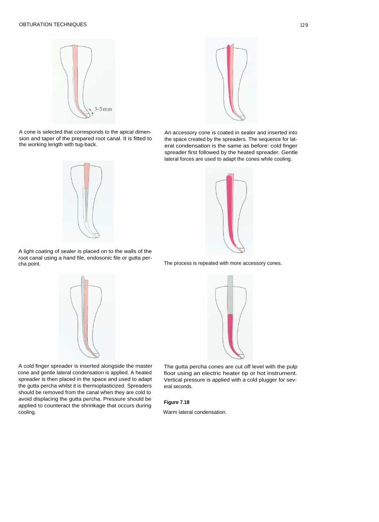
OBTURATION TECHNIQUES
A cone is selected that corresponds to the apical dimen-sion and taper of the prepared root canal. It is fitted tothe working length with tug-back.
A light coating of sealer is placed on to the walls of theroot canal using a hand file, endosonic file or gutta per-cha point.
An accessory cone is coated in sealer and inserted intothe space created by the spreaders. The sequence for lat-eral condensation is the same as before: cold fingerspreader first followed by the heated spreader. Gentlelateral forces are used to adapt the cones while cooling.
The process is repeated with more accessory cones.
A cold finger spreader is inserted alongside the mastercone and gentle lateral condensation is applied. A heatedspreader is then placed in the space and used to adaptthe gutta percha whilst it is thermoplasticized. Spreadersshould be removed from the canal when they are cold toavoid displacing the gutta percha. Pressure should beapplied to counteract the shrinkage that occurs duringcooling.
The gutta percha cones are cut off level with the pulpfloor using an electric heater tip or hot instrument.Vertical pressure is applied with a cold plugger for sev-eral seconds.
Figure 7.18
Warm lateral condensation.
12 9

130 ENDODONTICS: PROBLEM-SOLVING IN CLINICAL PRACTICE
Figure 7.19
The touch and heat electric heater.
Figure 7.20
An endosonic tip can be used to heat the gutta percha.
Figure 7.21
The ultrasonic thermoplasticized gutta percha is com-pacted into all the canal irregularities of the transparentplastic block.
• Place heated spreader into canal and later-ally condense until cool.
• Remove the spreader cold (thereby allow-ing for contraction and reducing the risk ofremoving the gutta percha with the instru-ment).
• Insert accessory cone and sealer.•
Repeat process until the canal is filled.
Removal of Excess Gutta PerchaThe gutta percha points protruding into thepulp chamber can be removed as describedpreviously.
salt bead sterilizer and carried to the rootcanal for use. Electrically heated tips offermore control, allowing the precise delivery ofheat where it is required at the press of a but-ton. Some clinicians use ultrasonically ener-gized spreader tips to achieve thermalcondensation.
The sequence of heat application is as follows:
• Make space for heated instrument with acold spreader.
Vertical Compaction of Gutta Percha(Fig. 7.22)
Vertical condensation techniques involve thecompaction of heated gutta percha in an api-cal direction using a variety of methods todeliver the heat.
Excessive flow of the obturating material api-cally must be resisted to avoid extrusion; this isensured by creating a tapered preparation. The

OBTURATION TECHNIQUES
The completed preparation should be tapered. As thediameter decreases the resistance to flow increases.Keeping the apical preparation as small as practical pre-vents extrusion of filling material.
A light coating of sealer is placed on the walls of thecanal, using a hand file, and onto the gutta percha point.
The System B tip is pre-measured. It should fit passively5-7 mm from the working length. A rubber stop is usedto mark the length against a reference point.
The down pack
•
The cone is cut off level with the pulp floor using thesystem B tip.
•
Light pressure is applied with a cold Machtou plugger(Maillefer, Bellaigues, Switzerland).
• The activated System B tip is plunged apically intothe gutta percha until the stop is 2-3 mm short of thereference point.
• The wave of compaction is continued without heatuntil the rubber stop is at the reference point.
•
Apical pressure is applied for 10 seconds as the guttapercha cools.
•
A short burst of heat is applied and the System B tipis removed.
•
A cold plugger is used to compact the apical segmentof gutta percha.
A tapered cone is selected that corresponds to the com-pleted preparation. If the tip of the gutta percha point istoo small then it can be trimmed with scissors. 'Tug-back'should be felt when the fit is correct.
Figure 7.22
Vertical compaction: System B..
131

ENDODONTICS: PROBLEM-SOLVING IN CLINICAL PRACTICE
The backfill
• The coronal portion of the canal is empty. It canbe obturated using small segments of heated guttapercha.
• When using the Obtura system, the tip should beinserted gently into the apical mass of gutta perchabefore injecting. Light apical pressure should bemaintained as the gutta percha is injected into theroot canal.
•
Alternatively, small segments of a gutta percha pointcan be placed in the canal, heated with the System Btip and compacted using cold Machtou pluggers.
Each segment is compacted vertically as it cools.
Figure 7.22 (contd) The canal is filled to the level of the pulp floor.
smallest diameter is apical and the greatest coro-nal; resistance to flow increases as the diameterof the preparation decreases. The gutta percha isheated and then condensed with each plugger inan apical direction. The maximum cross-sectionof gutta percha should be captured by eachplugger without binding on the canal walls. Iftoo small a plugger is used then it either slidesalongside the gutta percha or passes through itwithout applying apical pressure. The System Btechnique simplifies the original process by pro-viding vertical compaction in a single wave inan apical direction (Fig. 7.23).
The Cone FitGutta percha points used in vertical com-paction techniques must thermoplasticizeeasily.
A non-standardized gutta percha point thatcorresponds to the taper of the completedroot canal preparation is selected. The tip ofthe cone is trimmed to correspond to thediameter of the apical preparation. The pointwhen inserted into the canal should exhibit'tug-back' 0.5-1.0 mm short of the workinglength (Fig. 7.24).
The Technique
There are three phases to the vertical com-paction technique
• Cone fit• Down pack•
Back fill
Measuring the PluggerA plugger should be selected for the system Belectric heater that fits to within 5-7 mm ofthe working length, without binding exces-sively on the canal walls.
This point is marked with a rubber stop(Fig. 7.25).
A hand plugger (Schilder or Machtou plug-
1 3 2

OBTURATION TECHNIQUES
Figure 7.23
The system B unit.
Figure 7.25
The System B plugger has been marked with a rubberstop. Touching the spring on the handle causes the tip toheat up instantly.
Figure 7.24
If the tip of the gutta percha point is too small it shouldbe trimmed to correspond to the master apical file.
ger) is also measured to the same point(Fig. 7.26).
Figure 7.26
Machtou pluggers are used to compact the gutta perchafollowing heating.
Fitting the ConeSealers used in this technique must not set tooquickly, and have extended working time(EWT). Sealer is applied very thinly to thewalls of the canal and to the cone, which isthen seated into place (Fig. 7.27).
Figure 7.27
In this case all the gutta percha cones have been fittedbefore compaction. Gutta percha will often flow betweenthe mesial canals during compaction, and may preventcorrect insertion of a second master cone if the canals areobturated individually.
13 3

ENDODONTICS: PROBLEM-SOLVING IN CLINICAL PRACTICE
The Down PackThe cone is cut off at the level of the pulpfloor using the System B tip and then gentleforce is applied with a cold plugger. TheSystem B tip is then held at the canal orifice.The heater is activated and the tip is pushedinto the mass of gutta percha in an apicaldirection until the stop is 3 mm short of thedesired length. The finger is then removedfrom the heater switch and the plugger ispushed the final distance without applyingheat. Once at the working length the tip isheld in place for 10 seconds (to counteract theshrinkage that will occur as the gutta perchacools). A quick pulse of heat is applied and thetip is removed. (Gutta percha may well be seencoating the plugger.) The cold hand plugger isimmediately inserted into the canal to applyapical pressure for a further 20 seconds.
The BackfillThe empty coronal portion of the root canal iseasily obturated using thermoplasticized guttapercha delivered by a suitable system (e.g.Obtura or heated sections of gutta percha cone:Fig. 7.28). Several aliquots of gutta percha areinserted into the canal and plugged individuallyusing cold hand pluggers to reduce the coolingshrinkage. The obturating material is then fin-ished level with the pulp floor (Fig. 7.29).
TROUBLESHOOTING OBTURATIONTECHNIQUES
Figure 7.28
The Obtura 11 system.
Master Cone Will Not Fit to Length
• Dentine chips packed into the apical extentof the root canal preparation will lead to adecrease in working length, and conse-quently the master cone will appear to beshort. This can be avoided by using copi-ous amounts of irrigant during prepara-tion. (See section on preparation.)
• A ledge in the root canal wall can preventcorrect placement of the cone. If the conehits an obstruction during placement thenthe end may appear crinkled (Fig. 7.30). Itmay be possible to remove or smooth aledge by refining the preparation with agreater taper instrument.
Figure 7.29
Following backfilling the gutta percha is condensed levelwith the pulp floor.
• If the canal is insufficiently tapered, themaster cone may not fit correctly because itis binding against the canal walls coronallyor in the mid-third. The completed rootcanal preparation should follow a gradualtaper along its entire length. Further prepa-ration may be required with Gates-Gliddenburs, orifice shapers or a greater taperinstrument.
134

OBTURATION TECHNIQUES
Figure 7.30
Crinkling of the gutta percha point is often caused by the
tip hitting an obstruction.
• Check the size and taper of the mastercone. Gutta percha cones are not perfectlystandardized. Another cone from the samebox may fit.
removed during condensation.• Too much sealer acts as a lubricant; only a
light coating is required.• Sticky deposits of sealer on the spreader
may dislodge the gutta percha cones.Instruments must be wiped clean aftereach use.
• Spreaders that have damaged tips or bentshanks should be discarded.
• Sufficient space should be made during lat-eral condensation to compact the gutta per-cha cones before attempting to remove thespreader.
• When using an electrically activatedspreader to heat the gutta percha duringwarm lateral condensation the tip shouldbe allowed to cool before removing it fromthe root canal. Removing the tip while it ishot will result in gutta percha beingremoved from the canal. Continue laterallycondensing as the tip cools, thereby creat-ing space before removal.
Inability to Place the SpreaderlPlugger toLength
• If the root canal preparation is inade-quately tapered the spreader or pluggermay bind in the coronal or mid-third. Inthis case there will not be enough room toplace the instrument to the desired length.The preparation should be refined withGates-Glidden burs, orifice shapers, or agreater taper instrument.
• It is important to select the correct size ofspreader/ plugger. A System B tip shouldfit passively to within 5-7 mm of the work-ing length. For example, an FM tip shouldfit most 0.08 tapered preparations.
• Spreaders and System B pluggers can beprecurved to conform to the curved canalshapes if they are binding in a curved canal.
Voids in the Obturating Material
• Poor penetration of a finger spreader willprevent accessory cones from fitting cor-rectly. Voids will be created between thecones. A smaller spreader may be required.
• When using a vertical compaction tech-nique, a void may appear between thedownpack and backfill if the Obtura tip isnot placed deep enough into the canal. Thetip should be inserted until it just sinks intothe apical mass of gutta percha, beforeinjecting thermoplasticized gutta percha.
• It is tempting to withdraw the Obtura tipprematurely during backfilling as gutta per-cha is delivered, resulting in a void. Slightapical pressure must be applied as gutta per-cha is extruded from the Obtura tip.Pressure created within the root canal willgently force the needle back out of the canal.
Removing Cones during Condensing FURTHER READING
• If a cone has poor tug-back because it doesnot fit correctly, then it is more likely to be
Buchanan LS (1996). The continuous wave ofobturation technique: 'centered' condensation
1 35

136
ENDODONTICS: PROBLEM-SOLVING IN CLINICAL PRACTICE
of warm gutta percha in 12 seconds. Dentistry
Schilder H (1967). Filling root canals in threeToday 15(1): 60-62, 64-67.
dimensions. Dental Clinics o f North America
Liewehr F, Kulild JC, Primack PD (1993).
11:723-744.
Improved density of gutta-percha after warmlateral condensation. Journal of Endodontics 19:489-491.

8 ROOT CANAL RETREATMENT
CONTENTS • Introduction • Why? • When? • How? • Post Removal • LedgesPerforations • Preparation of Root Canals • Further Reading
I NTRODUCTION
When root canal treatment fails there arethree possible ways of dealing with the prob-lem:
in which root canal treatment or retreatmenthas been unsuccessful. Often a surgical ap-proach is difficult and may be beyond theexpertise of the operator.
• Root canal retreatment• Root end surgery• Extraction. Extraction
Root Canal Retreatment
Removing the tooth may be the best option ifthe tooth is unrestorable or the prognosis forroot canal retreatment is poor. It is not possi-ble to save every tooth.
The existing root filling is removed and theinfected root canal is disinfected using irrig-ants and medicaments. This is often the pre-ferred treatment modality for a failed rootfilling. Root canal retreatment can be compli-cated since restorations may need to be dis-mantled in order to gain access to the canalsystem. The tooth should be assessed forrestorability before this prolonged and oftenexpensive treatment is started. If the tooth isunrestorable then it may be better to extract itand provide an alternative replacement.
Root-End Surgery
Placing a root-end filling in a tooth with aninfected root canal will undoubtedly lead tofailure. Surgery is normally reserved for cases
WHY?
It has been shown that high success rates canbe achieved for root canal retreatment, espe-cially when failure of the existing root treat-ment was due to technical inadequacy.
Root canal retreatment encompasses theproblems encountered with routine root canaltreatment: invariably an infected root canalsystem; fine canals, fins, tight curves andother complex anatomy combined with iatro-genic difficulties; and existing root fillingmaterials, broken instruments, ledges andperforations. Retreatment is therefore moredemanding than primary root canal treat-ment. Patients are becoming more reluctant tohave teeth extracted, and difficult root canalretreatment may require specialist equipment

ENDODONTICS: PROBLEM-SOLVING IN CLINICAL PRACTICE
and expertise. Referral to an endodontistshould be offered to patients when the techni-cal difficulties exceed the practitioner's capa-bilities.
WHEN?
Root canal retreatment may be consideredwhen:
• Persistent pain or symptoms develop in atooth that has received root canal treatment
• The existing root treatment is deficienttechnically
• There have been procedural errors• A new coronal restoration (such as a
crown) is planned on a tooth with a techni-cally deficient root canal filling or in thepresence of nonresolving periapical radi-olucencies.
HOW?
Retreatment
Some of the retreatment problems faced inpractice are:
Figure 8.1
Loupes with illumination in the direction of sight.
cal microscope. Loupes offer magnification inthe range x2.5 to x4, which is ideal forendodontiss and routine dentistry. Theadvantage of such a system over using anoperating light is that the light source is muchbrighter and is directed in the line of sight(Fig. 8.1). Microscopes offer excellent illumi-nation and very high magnification but areconsiderably more expensive. Most endodon-tic specialists use microscopes routinely.
• Paste and cement root filling materials• Silver points• Fractured instruments• Post removal• Ledges• Perforations.
Illumination and Magnification
Good illumination is essential for predictableroot canal treatment. As retreatment cases aregenerally more demanding than previouslyuntreated cases, it is almost impossible, whileworking at the base of a dark access cavityusing tactile sense alone, to locate missed rootcanals, separated instruments or filling mater-ial lodged in the complex anatomy. Magnifi-cation can best be achieved with loupes thathave an additional headlamp or with a surgi-
Paste and Cement Root Filling Materials
Paste and cement root filling materialsinclude calcium hydroxide-based pastes, zincoxide and eugenol cements, and Endo-methazone (Septodent, Deprow, Maidstone,Kent, UK). Pastes are not recommended aspermanent root canal filling materials. Duringthe removal of pastes, extrusion of materialinto the periodontal space and excessive dam-age to the root canal walls must be prevented.
Removing Paste from the Pulp ChamberNonsetting materials can be effectively re-moved from the pulp chamber using:
• An ultrasonic sealer tip (Fig. 8.2)• An excavator•
Irrigant in a syringe.
138

ROOT CANAL RETREATMENT
mechanical removal using:
Figure 8.2
An ultrasonic sealer tip can be used to remove materialfrom the pulp chamber.
The irrigant flow on the ultrasonic sealershould be set at maximum. Acoustic micro-streaming and cavitation will dislodge pastematerial and wash it away.
• Ultrasonic sealer tip• Specialist ultrasonic tips (such as CT and
CPR) (Fig. 8.3)• An endosonic tip with shortened file• Round burs• Solvents.
Material can be removed in a controlled man-ner using a piezoelectric ultrasonic handpiecewith a sealer tip or specialist CT and CPRtips. Ultrasonic vibration breaks up thecement and is preferably used with irrigant.
Removing material from the root canalwith a round bur should really be a methodof last resort, unless it is possible to seedirectly where the bur is cutting, since there isa high risk of perforation. As swan neck burshave a flexible shaft, there is a tendency towander sideways while cutting. This couldresult in lateral perforation. The need for illu-mination and magnification cannot beoveremphasized.
Removing Paste from Root Canals Gutta Percha Removal
Paste can be removed from root canals: The Single Cone
• During coronal flaring• With endosonics• With hand irrigation.
If a root canal has been underprepared, coro-nal flaring will remove significant amounts ofmaterial early in the preparation sequence.Coronal flaring is normally carried out at thestart of modern preparation techniques, eitherwith a combination of files and Gates-Gliddenburs or with nickel-titanium rotary instru-ments.
Paste materials in the apical regions ofcanal systems can be removed using endoson-ics. Although cavitation is unlikely to occurwithin the confines of a canal system, acousticmicrostreaming and a high volume of irrigantwill help remove paste from the canals.
Single cone gutta percha root fillings can usu-ally be removed using:
• A Hedstroem file• Tweezers
Set Cements
Set cements are extremely difficult to removefrom the root canal system and require
Figure 8.3
The CPR set of ultrasonic tips: 1C is for vibrating posts,2C and 3C are for work on the pulp floor, and 4C and 5Care for use within the confines of root canal.
139

ENDODONTICS: PROBLEM-SOLVING IN CLINICAL PRACTICE
Figure 8.4
These Stieghtz forceps have been modified to make thebeak thinner.
•
Stieglitz forceps (Fig. 8.4)• Endosonics.
Hedstroem files are weakest in a rotary direc-tion and therefore the largest Hedstroem filethat will fit alongside the cone should be usedto help reduce the risk of file fracture. The fileis gently screwed into the canal alongside thegutta percha cone until resistance is met. Atthis point, the instrument is withdrawn fromthe canal, along with the gutta percha cone.Endosonics may loosen cement around a sin-gle cone, thereby aiding removal. Cones canbe gripped with tweezers or Stieglitz forcepsfor removal.
Heat
Heat is a useful means of removing guttapercha from the coronal portion of a rootcanal. A System B tip (Analytic Endodontics;Redmond, WA, USA) or heated plugger canbe used.
Gates-Glidden Burs, Rotary Instruments andHedstroem Files
When a root filling is well compacted, asmuch gutta percha as possible should beremoved from the root canal system beforesolvent is used. Gates-Glidden burs areextremely efficient for removing gutta perchafrom the coronal parts of the root canal. Theyneed to be rotated in a slow handpiece at rea-sonable speed, generating frictional heat thatwill aid gutta percha removal.
Rotary nickel-titanium instruments canalso be used to remove gutta percha; the ori-fice openers are particularly effective andneed to be rotated at 600 rpm.
A Hedstroem file is then used to removeany free cones and further fragments of guttapercha. Finally, a few drops of solvent (e.g.chloroform) are placed in the canal. Files areused to remove the bulk of dissolved guttapercha. The file is rotated into the mass ofgutta percha and withdrawn; it is then wipedclean on a gauze square and the process isrepeated. Finally, a few more drops of chloro-form are placed in the root canal and paperpoints are used to wick any remaining dis-solved gutta percha. When the paper pointsare clean on removal, the root canal systemshould be completely devoid of gutta perchafilling material (Figs. 8.5-8.7).
Solvents for Gutta Percha
Condensed Gutta Percha
Condensed gutta percha can be removedusing a combination of:
• Heat• Gates-Glidden burs• Nickel-titanium rotary instruments• Hand instruments such as Hedstroem files• Solvents.
Solvents include chloroform, xylene, rectifiedturpentine, methyl chloroform and euca-lyptus oil. There has been some concernexpressed in the literature about the carcino-genic potential of chloroform. It should onlybe used in small amounts and must be con-tained within the root canal system. Rectifiedturpentine is a useful alternative. Eucalyptusoil must be heated in order to be effective.Glass or polypropylene syringes should be
1 4 0

ROOT CANAL RETREATMENT
Figure 8.5
Dissolved gutta percha is being removed on the tip of aHedstroem file (arrow).
Figure 8.6
Paper points are used to wick the remaining dissolvedgutta percha from the root canals.
Figure 8.7
A typical gutta percha retreatment case. The existing rootfilling was removed using Gates-Glidden burs andHedstroem files followed by chloroform wicking. Thesecond canal in the mesial root was located. Followingthis all the canals were thoroughly disinfected beforebeing filled with gutta percha and sealer.
Thermafil
A Thermafil obturator (Dentsply, Weybridge,Surrey, UK) consists of a carrier coated withgutta percha; it is used in conjunction withsealer to obturate the root canal system. Whenremoving Thermafil, it is easier to remove thecarrier first and then remove the gutta percha.The modern carriers have a V-shaped notchalong one side, beside which a Hedstroem filecan be inserted. When the file is withdrawn,the carrier is usually removed. The remaininggutta percha can be removed as previouslydescribed. Plastic carriers are also soluble insome of the solvents used to remove gutta per-cha (such as chloroform).
used to dispense small amounts of these sol-vents, since they are not dissolved. Usingchloroform too early in treatment leaves amessy layer of dissolved gutta percha coatingthe root canals and pulp floor, which can thenbe difficult to remove. If most of the guttapercha has been removed mechanically, thena minimal amount of chloroform is requiredto dissolve the remaining filling materialcompletely.
Silver Points and Fractured Instruments
The position of the silver point within theroot canal will dictate the degree of difficultyin removal:
• Coronal position - easy• Middle position - intermediate• Apical position - difficult.
141

1 4 2 ENDODONTICS: PROBLEM-SOLVING IN CLINICAL PRACTICE
Coronal Position
If the coronal end of the silver point extendsinto the pulp chamber, then it should be pre-served. Cement can be removed carefullyfrom around the point using a Piezonultrasonic unit (EMS: Forestgate, Dallas, TX,USA) and CT4 tip or sealer tip. Great caremust be taken not to sever the point and dam-age the coronal end. The point is withdrawnusing Stieglitz forceps or small-ended arteryforceps (Figs. 8.8-8.10).
If a point has fractured within the canal orhas been cut off at the level of the pulp chamberfloor, then removal is more difficult. Fracturedinstruments present a similar problem.
In the coronal portion of the root canal, atrough can be created around the object usingspecialist ultrasonic tips (such as CT4 or UT).These are used to remove dentine and theycan be used dry or with irrigant. Gentlyworking a Hedstroem file between the pointand the canal wall may allow it to beremoved. An endosonic file gently insertedalongside a point may loosen cement and dis-lodge it.
Apical Position
Figure 8.9
A silver point being withdrawn using fine artery forceps.
Removing silver points from the apical thirdis extremely difficult. Two techniques can be
Figure 8.8
The core around the heads of the silver points being dis-mantled using a CT4 ultrasonic tip.
Figure 8.10
With care it is possible to remove a silver point evenwhen it is broken off at the level of the pulp floor andoverextended.
used in this region of the root canal system:
• Braiding• Cancellier.
Braiding is a technique that can be used toremove pieces of fractured instrument or sil-ver point from deeper in the root canal sys-tem. Although originally described using ISOsize 15 files, the largest size possible shouldbe used to help reduce the risk of file fracture.The first Hedstroem file is gently screwedinto the canal alongside the object, and twofurther Hedstroem files are then gentlyinserted. These files are then wound around

ROOT CANAL RETREATMENT 14 3
each other and withdrawn together (Figs. 8.11and 8.12). The object should be gripped by thefiles and removed.
Figure 8.11
A Cancellier is effectively a hollow tubethat can be inserted over a fractured instru-ment within the root canal. A small drop ofcyanoacrylate adhesive is used to bond thetwo and then the instrument is withdrawn(Fig. 8.13).
Middle Position
The basic principles for removing fracturedinstruments in the mid-third of the canal are:
1
Create space2
Use ultrasonic vibration3 Removal.
Space can be created using orifice openers,ultrasonics or Gates-Glidden burs. Sufficientspace must be created so that ultrasonic tipscan be inserted without perforating the root.A Gates-Glidden bur can be modified so thatis has a flat tip; this produces a neat table ofdentine around the fractured instrument andallows better access for CT tips. Under directvision using magnification and illumination,the piece of instrument is vibrated with ultra-sound; CT tips are often too thick for usewithin the confines of the root canal, whereas
Braiding can be used to remove objects from deeper inthe canal.
Figure 8.12
The file in this case (A) was removed using a braidingtechnique; the canal could then be relocated, prepared,cleaned and filled (B).
Figure 8.13
The Cancellier tube is filled with a drop of cyanoacrylateand placed over the object ready for removal.

1 44 ENDODONTICS: PROBLEM-SOLVING IN CLINICAL PRACTICE
Figure 8.14 Figure 8.15
Zirconium nitride ultrasonic tips for working deep in theroot canal under microscopic magnification.
zirconium nitride tips are longer and thinner(Fig. 8.14). Irrigant is used to wash awaydebris.
Once the instrument is loose then it can beremoved, using braiding, a Cancellier orendosonic irrigation (Fig. 8.15).
What Happens if the Instrument is notRemovable?
It is worth remembering that the pain experi-enced by a patient with a fractured instru-ment in a tooth is due to bacterial infection ofthe root canal space and not by the offendinginstrument. If the object cannot be removed,then an attempt should be made to bypass it,allowing penetration of irrigants beyond andaround the fragment to disinfect the rootcanal. Gently working a small file alongsidethe fractured instrument using ethylenediamine tetra-acetic acid (EDTA) to softendentine may create enough space to bypassfragment. If this is not possible, the root canalshould be cleaned thoroughly and obturatedto the level of the blockage.
POST REMOVAL
Screw Posts
A post with a screwhead, such as a Dentatus(Tricare, Bradford, UK) or Radix (Maillefer,
A nickel-titanium instrument fractured in the mid-thirdof a mesial canal (A) was removed using ultrasonicsunder the microscope. The canals were shaped, cleanedand filled (B).
Ballaigues, Switzerland) anchor, can usuallybe removed by cutting away any adherentcore material and using a wrench to unscrewit (Fig. 8.16). Placing an ultrasonic sealer tipon the post will loosen it, and it may evenstart to unscrew. Posts that are fracturedbeneath the pulp floor can be removed witheither ultrasound or the Masserann kit.Special long-necked ISO 006 burs are avail-able to cut a trough around posts that arefractured at the level of the root face, butextreme caution should be taken to avoid per-foration (Fig. 8.17).
The Masserann Kit
The Masserann kit is designed for theremoval of objects from the root canal. It con-sists of a range of trephine drills and aMasserann extractor (Fig. 8.18). The trephineis used to create a space around an object. Theextractor tube is then inserted over the frac-tured instrument or silver point, which isthen gripped by screwing in a rod. The holerequired to fit the Masserann extractor is rela-tively large and significant amounts of den-tine are removed. It should therefore only beused in the coronal third of the canal, whereaccess is relatively straight, to avoid perfora-

ROOT CANAL RETREATMENT
Figure 8.16
The Dentatus wrench.
Figure 8.18
The Masserann kit.
Figure 8.17
An attempt has been made to remove the post with a bur.Excessive dentine has been removed (arrow) resulting ina weakened, unrestorable tooth. Figure 8.19
A radiograph of a fractured post that was removed usingthe Masserann kit and ultrasonics.
tion. The trephines are fragile and can beeasily blunted. The cutting tips should bechecked before use and can be sharpenedcarefully with a carborundum disc.
Larger objects can be removed using theMasserann trephines, which are rotated byhand or in a handpiece, cutting in an anti-clockwise direction. Once luting cement hasbeen removed from around the object, thenext smallest trephine can be used to grip itfor removal (Figs. 8.19-8.23).
Cast Posts
An ultrasonic sealer tip or Piezon ultrasonictips (Fig. 8.24) can be used for vibrating a postto break up the cement lute surrounding it. Anotch can be cut in the post for placement ofan ultrasonic tip, which is oscillated againstthe post in a vertical direction.
1 45

ENDODONTICS: PROBLEM-SOLVING IN CLINICAL PRACTICE
Figure 8.22
Ultrasonics are used to vibrate the post.
Figure 8.20
Space is made around the tip of the post using aMasserann trephine.
Figure 8.23
The post was then removed with a further trephine.
Figure 8.21 Figure 8.24
The minimal removal of dentine can be seen (arrow). The 1CPR tip for vibrating posts ultrasonically.
Post Pullers
There are several types of post puller:
• Eggler (Fig. 8.25)• Ruddle (Fig. 8.26)• Gonon.
They are all used in a similar fashion; onepart grips the post while the other pushesagainst the root face. Post pullers can be cum-bersome and care should be taken not toplace torsional forces on the root, since thismay cause root fracture.
14 6

ROOT CANAL RETREATMENT
Figure 8.25
Post pullers require adequate space for use; in this case apost is being removed from a lateral incisor.
LEDGES
Ledges are created during root canal treat-ment as a result of the incorrect use of rootcanal instruments. A small file (such as ISOsize 006 or 008) with a tight curve in the tipwill sometimes allow negotiation beyond aledge when used with a watch-windingaction. A lubricant may be helpful. Once theledge has been bypassed, the file is workedin a filing action to attempt to smooth theledge and allow the introduction of largerfiles.
PERFORATIONS
The successful repair of a perforation isdependent on three variables:
• Time since occurrence• Size• Location.
Figure 8.26
The Ruddle post removing kit. A trephine is screwedonto the post. As the jaws of the post puller open the postis withdrawn from the canal.
Successful treatment of perforations dependson the ability to seal the area and preventinfection. The earlier a perforation can berepaired the better, and the possibility ofinfection must be kept to a minimum.
The size of a perforation will affect theprognosis, since large perforations are moredifficult to seal and are associated with moretissue destruction.
Location is probably of greatest impor-tance. Close proximity to the gingival sulcuscan lead to contamination by bacteria fromthe oral cavity. Perforations located belowcrestal bone have a better prognosis, as dothose away from canal orifices (Figs. 8.27and 8.28).
Perforations can be repaired nonsurgicallyusing modern endodontic techniques. Directvision is essential and treatment may requirethe use of a microscope. Materials used torepair perforations include Super EBA(ethoxybenzoic acid: Staident International,Staines, UK), Intermediate RestorativeMaterial (IRM: Dentsply) and MineralTrioxide Aggregate (MTA: Dentsply). Theperforation site must be thoroughly cleanedwith sodium hypochlorite before placementof the repair material. Alternatively, a calcium
14 7

1 4 8 ENDODONTICS: PROBLEM-SOLVING IN CLINICAL PRACTICE
hydroxide dressing could be placed and thecase referred for specialist treatment.
It may not be possible to achieve a successfulrepair of a long-term perforation, particularly ifthere has been periodontal breakdown.
PREPARATION OF ROOT CANALS
Figure 8.27
A perforation (arrow) that connects with the periodontalligament via a pocket. The prognosis is guarded.
Following dismantling and removal of theexisting root canal filling, the root canal sys-tem needs to be prepared and disinfected aswith primary treatment (see Chapter 5).Sodium hypochlorite is the irrigant of choicebecause of its antibacterial action, and it isoften used with endosonics. The bacterialecology of retreatment cases is different fromthat of untreated teeth and occasionally alter-native medicaments to calcium hydroxide arerequired (see Chapter 6).
FURTHER READING
Barbosa SV, Burkard DH, Spangberg LSW(1994). Cytotoxic effects of gutta percha sol-vents. Journal of Endodontics 20: 6-8.
Bergenholtz G, Lekholm U, Milthon R, HedenG, Odesjo B, Engstrom B (1979). Retreatmentof endodontic fillings. Scandinavian Journal ofDental Research 87: 217-224.
Hunter KR, Doblecki W, Pelleu GB Jr (1991).Halothane and eucalyptol as alternatives tochloroform for softening gutta percha. Journalof Endodontics 17: 310-312.
Kaplowitz GJ (1990). Evaluation of gutta per-cha solvents. Journal of Endodontics 16:539-540.
Figure 8.28
The root of this tooth has been perforated (A). The defectlies well within the alveolar bone and should have a bet-ter prognosis for healing following repair (B).
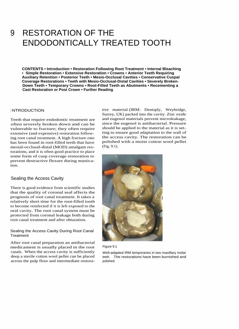
9 RESTORATION OF THEENDODONTICALLY TREATED TOOTH
CONTENTS • Introduction • Restoration Following Root Treatment • Internal Bleaching• Simple Restoration • Extensive Restoration • Crowns • Anterior Teeth RequiringAuxiliary Retention • Posterior Teeth • Mesio-Occlusal Cavities • Conservative CuspalCoverage Restorations • Teeth with Mesio-Occlusal-Distal Cavities • Severely Broken-Down Teeth • Temporary Crowns • Root-Filled Teeth as Abutments • Recementing aCast Restoration or Post Crown • Further Reading
I NTRODUCTION
Teeth that require endodontic treatment areoften severely broken down and can bevulnerable to fracture; they often requireextensive (and expensive) restoration follow-ing root canal treatment. A high fracture ratehas been found in root-filled teeth that havemesial-occlusal-distal (MOD) amalgam res-torations, and it is often good practice to placesome form of cusp coverage restoration toprevent destructive flexure during mastica-tion.
Sealing the Access Cavity
There is good evidence from scientific studiesthat the quality of coronal seal affects theprognosis of root canal treatment. It takes arelatively short time for the root-filled toothto become reinfected if it is left exposed to theoral cavity. The root canal system must beprotected from coronal leakage both duringroot canal treatment and after obturation.
Sealing the Access Cavity During Root CanalTreatment
After root canal preparation an antibacterialmedicament is usually placed in the rootcanals. When the access cavity is sufficientlydeep a sterile cotton wool pellet can be placedacross the pulp floor and intermediate restora-
tive material (IRM: Dentsply, Weybridge,Surrey, UK) packed into the cavity. Zinc oxideand eugenol materials prevent microleakage,since the eugenol is antibacterial. Pressureshould be applied to the material as it is set-ting to ensure good adaptation to the wall ofthe access cavity. The restoration can bepolished with a moist cotton wool pellet(Fig. 9.1).
Figure 9.1
Well-adapted IRM temporaries in two maxillary molarteeth. The restorations have been burnished andpolished.

15 0 ENDODONTICS: PROBLEM-SOLVING IN CLINICAL PRACTICE
Medicamentin root canal
Cotton wool
IRM packedfirmly intoaccess cavity
Gutta perchapacked acrosspulp floor
Figure 9.2
(A, B) Temporary restorations for sealing the access cavity during root canal treatment.
When there is less space, perhaps becausethe tooth is severely broken down or becausethere is decreased vertical height, a layer ofthermoplasticized gutta percha such as Obtura11 (Texceed Corporation, Costa Mesa, CA,USA) can be packed across the pulp floor andIRM or glass ionomer used to build up thecoronal tooth substance (Fig. 9.2).
Sealing the Access Cavity Following RootCanal Treatment
The root filling material is finished at the levelof the floor of the pulp chamber. A layer ofIRM, glass ionomer or dentine-bonded mater-ial is placed across the pulp floor, since thisapproach provides a better seal than a massof gutta percha and sealer (Fig. 9.3).
Glass ionomer materials such as Vitrebond(3M, St Paul, MN, USA) have been shown toprovide a good seal and can be used in con-junction with composite or amalgam cores.An amalgam bonding agent can be used withthe Nayyar core technique to provide a sealbetween the amalgam and dentine.
Figure 9.3
Zinc oxide and eugenol cement has been packed acrossthe pulp floor, and it seals the entire access cavity.
RESTORATION FOLLOWING ROOTTREATMENT
Why?
Treatment Planning
The restorability of the tooth should bedecided before endodontic treatment as part

RESTORATION OF THE ENDODONTICALLY TREATED TOOTH
of an overall treatment plan. The tooth willneed to be restored with an aesthetic, func-tional and cleansible restoration in order toprotect the adjacent teeth and periodontal tis-sues.
Occlusal Loading
Root-filled teeth are not more brittle thanunrestored teeth; however, they may beweaker as a result of unsupported or reducedtooth substance.
The likely occlusal loading can be assessedfrom the patient's history and a preliminaryexamination. Fractured restorations and teethmobility, increased size of the muscles ofmastication and faceting of occlusal contactareas may all indicate increased occlusal load-ing, and they all have a bearing on the treat-ment planning. Restoration should providefavourable distribution of any occlusalstresses within the remaining tooth substance.
Preservation of Tooth Substance
If tooth substance is conserved the remainingbody of tissue will be stronger. Therefore themost conservative restoration design thatcomplies with function, aesthetics and patientacceptance should be provided.
As a rough guideline, a full crown restora-tion should have a ferrule of at least 2 mm ofsound dentine around the margins for opti-mum retention (Fig. 9.4).
Figure 9.4
A full crown restoration should have margins resting onat least 2 rnm of sound dentine.
Is the Tooth Restorable?
It should be decided if the tooth is restorablebefore endodontic treatment is carried out,and this is a primary element of the basictreatment plan. Crowns fitted on teeth thathave little remaining coronal tooth tissue mayrequire additional retention in the form ofposts, pins or core material packed into thepulp space.
The patient should be made aware of thedifferent options and their possible prog-noses. Referral to a specialist may be requiredin some instances.
Example
The different options for restoring a fracturedmaxillary lateral incisor that has sheared offsubgingivally in an otherwise minimallyrestored mouth could be:
• To do nothing - this option would prob-ably be aesthetically unacceptable to thepatient
• To construct a single tooth removable over-denture - this could be a suitable interimor temporary solution, but it would not befunctionally or aesthetically acceptable as apermanent solution
• To root fill the tooth and place a post coreand crown - it would be difficult to placethe crown margins on sound dentine, anda post would be required to improve reten-tion. Teeth that have been damaged in thisway can be sometimes be extruded ortho-dontically but this is complex and the alve-olar bone must be recontoured as it isextruded with the root stump. Crownlengthening may be possible to exposedentine margins, but the final result couldbe compromised aesthetically. The long-term prognosis of such a restoration islikely to be guarded, especially if it isnot possible to finish the crown marginson sound dentine or if other cracks arepresent
• To extract the remaining root stump andplace a cantilever bridge - an adhesivecantilever bridge would be a conserva-tive means of restoring the space if theroot were extracted. Assuming that the
1 51

ENDODONTICS: PROBLEM-SOLVING IN CLINICAL PRACTICE
occlusion was not inhibitive the prognosisand aesthetics for such a restoration shouldbe good. Debonding is a recognized causeof failure and generally occurs between 5and 10 years. Refixing is often appropriate.A cantilever bridge that utilizes a full cov-erage crown as an abutment would bemuch less conservative.
• To extract and replace with a single toothimplant - assuming that the placement ofan osseointegrated implant was feasiblethen good aesthetics and a good long-termprognosis could be expected. Factorsaffecting the outcome of implant place-ment include the patient's medical history,the space available between adjacent teethand the quality and quantity of bone. Costmay be prohibitive to the patient.
When?
Timing of Restoration
The success rates for well-executed root canaltreatment should be high (80-95%) and theprognosis good. Therefore, if a patient'ssymptoms and signs have resolved followingendodontic treatment, restoration can pro-ceed immediately. A period of 2 weeks is usu-ally quite sufficient, by which time the toothshould not be uncomfortable when palpated;there should also be no tenderness in the buc-cal sulcus or over the apex of the tooth and noevidence of a discharging sinus tract.
When teeth require a core build-up perhapsthe best time to place the core is immediatelyafter obturation. This obviates the need for atemporary restoration and provides immediatecoronal seal. An amalgam core, for example ina molar tooth, can be used as an excellentinterim restoration before crowning. If furtherendodontic intervention is required then thetooth can be easily isolated with rubber dam.
Teeth with an uncertain or guarded progno-sis should be reviewed for a longer periodbefore restoration. It is imperative, however,that the tooth should be protected from possi-ble fracture and has good coronal seal duringthis interim period. Orthodontic bands canbe cemented around molar teeth using zinc
phosphate cement as a temporary measure toprevent cuspal flexing. A reinforced zinc oxideand eugenol temporary restoration (e.g. IRM)will prevent microleakage, since the eugenol isantibacterial. Glass ionomer cements are alsouseful for sealing the access cavity.
How?
Anterior Teeth
Severely broken down anterior teeth usuallyrequire restoration for aesthetic reasons.
Teeth that need to be reviewed before defini-tive restoration may have to be restored with along-term temporary. Temporary post crownrestorations may not be sufficiently retentivein the long term and may not provide ade-quate coronal seal. In this situation it would beappropriate to fit a permanent post and core.Temporary veneer crowns can easily be fabri-cated over the permanent post using a blow-down splint and a syringe-mixed polymericmaterial (e.g. Protemp - ESPE, Seefeld,Oberlay, Germany; Luxatemp - DMG, Ham-burg, Germany). If many anterior teeth aremissing then an interim overdenture (Fig. 9.5)may be an alternative solution. The quality ofrestoration is important for endodontic successand should be addressed with both temporaryand permanent restorations.
Figure 9.5
A temporary denture can sometimes be used when manyanterior teeth are missing.
1 5 2

RESTORATION OF THE ENDODONTICALLY TREATED TOOTH
I NTERNAL BLEACHING SIMPLE RESTORATION
Root canal-treated teeth are sometimes dis-coloured; however, it is not always necessaryto place a crown on the tooth to improve theaesthetics. Internal (walking) bleaching is atechnique that can be used after root canaltreatment to lighten even severely dis-coloured teeth (Fig. 9.6).
How?
Anterior teeth in which the majority of the coro-nal tooth substance is intact can normally berestored using adhesive restorative materialssuch as light cured composite (Figs. 9.7 and 9.8).
In moderately broken down teeth there maybe sufficient tooth substance remaining to builda core using a glass ionomer cement or lightcured composite to replace the missing dentine.If the buccal surface of the tooth is intact andhas good aesthetics then the tooth can usuallybe restored with a light cured composite
The root filling material is removed from theroot canal to just below gingival level. Glassionomer is then placed over the root filling.Sodium perborate powder is mixed withwater to a putty consistency. This is packedinto the access cavity and sealed in place withIRM. The tooth is checked 7 days later, bywhich time some colour change should haveoccurred. The process may need to berepeated two or three times to achieve thedesired result. When the tooth has lightenedsufficiently the access cavity can be restoredwith a light cured composite. The use of ashade that is lighter that the natural tooth
colour can sometimes improve the apear-ance if the tooth is still slightly dark.Figure 9.7
The access cavity in this canine can be restored with lightcured composite. The root filling has been covered withglass ionomer.
Figure 9.6
Internal bleaching.
Figure 9.8
The completed composite restoration.
1 53

15 4
restoration. Glass ionomer has the advantagesthat it does not shrink on setting, it bonds todentine and enamel and it leaches fluoride. If aglass ionomer and composite sandwich restora-tion is to be used, the tooth can be restoredwith glass ionomer first and then cut back andthe light cured composite filling materialplaced at a second appointment. This allowsmaturation of the glass ionomer.
A total etch technique and dentine bondingagent in combination with light cured compos-ite can be used to restore the entire cavity.Dentine is etched using an acid for approxi-mately 10 seconds to expose collagen fibres.Primer and bond, which are often combined,are then applied to the cavity walls. This solu-tion penetrates the layer of exposed collagenfibres to give an interface between the compos-ite and dentine. It is important not to over-drythe dentine after etching and the compositecore should be built up in small layers to pre-vent contraction. If the tooth requires a crownthen the glass ionomer or composite restorationcan be used as a core.
If more tooth substance is lost then cuttingan access cavity for root canal treatmentseverely weakens the tooth, and a crown maybe necessary. The classic situation is that of ananterior tooth with mesial and distal restora-tions that have the radiographic appearance ofan 'apple core' of remaining tooth substance.Cutting an access cavity removes the remainingspine of dentine, thereby weakening theremaining tooth substance.
When an anterior tooth is severely brokendown, discoloured or heavily restored withplastic materials, a full crown needs to be made.
CROWNS
ENDODONTICS: PROBLEM-SOLVING IN CLINICAL PRACTICE
(0.5 mm)
is
required
on
the palatal
andapproximal surfaces. This may be beneficialin a root-filled tooth with little remainingcoronal tooth substance. The buccal surface,however, requires more tooth reduction(1.0-1.5 mm) than a porcelain jacket crown(0.8-1.0 mm). Inadequate tooth reduction canlead to a bulky crown and poor aesthetics. Itis possible to finish the buccal margins with aporcelain butt shoulder to improve the mar-ginal fit and give excellent appearance (Fig.9.9).
Metal-Composite Crowns
Metal-composite crowns are often used aslong-term provisional restorations. The com-posite discolours with time.
Metal-Free Crowns
Porcelain Jacket Crown
Porcelain jacket crowns require a buccal toothreduction of between 0.8 and 1.3 mm, and cantherefore be more conservative on tooth sub-stance than a metal-ceramic crown. Staineddentine and metal posts affect the aestheticappearance of a porcelain jacket crown; how-ever, they can be placed over cores built up in
Metal-Ceramic Crowns
Metal-ceramic crowns are very strong and re-sist occlusal loads well. Minimal preparation
EXTENSIVE RESTORATION
Crowns with Metal Substructure
Figure 9.9
During crown preparation, sufficient buccal reduction oftooth substance is required.

RESTORATION OF THE ENDODONTICALLY TREATED TOOTH
composite or glass ionomer. Excessiveocclusal loading may be a problem and canresult in unpredictable fracture. In-ceramcrowns have a glass infiltrated aluminiumoxide ceramic core covered with conventionalporcelain. Greater tooth reduction is requiredthan with a metal-ceramic crown (1.5-2.0 mmfor In-ceram crowns). By using a compositecore, excellent aesthetics can be achieved. TheEmpress system uses heat and pressure toform a leucite glass-ceramic. A tooth reduc-tion of 1.5-2.0 mm is required for Empresscrowns. These crowns may be contraindicatedin cases where there is evidence of excessiveocclusal loading. The Procera technique usescomputer-aided design and manufacturingtechnology to cut the core from an aluminiumoxide block. The core is then coated in porce-lain in the laboratory. Tooth reduction is simi-lar to that of a metal-ceramic crown, but thelaboratory costs are considerably greater.
ANTERIOR TEETH REQUIRINGAUXILIARY RETENTION
they produce greater hydraulic forces duringcementation, they perform better during func-tion. Tapered posts can create wedging forceswhen occlusal loads are applied (Figs. 9.10and 9.11).
Length
In order to maintain an adequate seal theremust be at least 4 mm of root canal fillingmaterial present apical to the post. The size,length and curvature of the root also dictatesthe length of a post.
Many rules have been recommended as tothe ideal length of the post. However, there islittle clinical evidence to provide guidance.There is some indication, however, that a post
If there is insufficient coronal tooth tissueremaining for retention of the crown then apost and core is required.
Posts
A post purely increases the retention of thecore and crown; it does not strengthen thetooth. The choice of post is frequently empiri-cal and the evidence base for selection israther poor. A post that fits the remainingtooth substance should therefore be used,rather than adjusting the tooth to fit the post.
Figure 9.10
The Tenax (Whaledent, Mahwah, NJ, USA) titanium postkit (top to bottom): a wax burnout post, aluminium tem-porary post, titanium preformed post and a post drill.
Shape
The shape of the post is dictated primarilyfrom the space provided by the root canal.Preparation should be conservative, so as notto weaken the tooth unnecessarily by exces-sive removal of dentine. Posts can be parallel-sided, tapered or custom-made cast posts.Generally parallel-sided posts provide betterretention than tapered posts, and although
Figure 9.11
(Top to bottom) An impression post and a wax burnoutpost for a parallel, serrated post system.
15 5
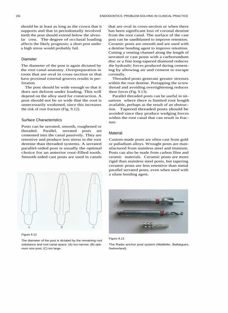
156
ENDODONTICS: PROBLEM-SOLVING IN CLINICAL PRACTICE
should be at least as long as the crown that itsupports and that in periodontally involvedteeth the post should extend below the alveo-lar crest. The degree of occlusal loadingaffects the likely prognosis; a short post undera high stress would probably fail.
Diameter
The diameter of the post is again dictated bythe root canal anatomy. Overpreparation inroots that are oval in cross-section or thathave proximal external grooves results in per-foration.
The post should be wide enough so that itdoes not deform under loading. This willdepend on the alloy used for construction. Apost should not be so wide that the root isunnecessarily weakened, since this increasesthe risk of root fracture (Fig. 9.12).
Surface Characteristics
Posts can be serrated, smooth, roughened orthreaded. Parallel, serrated posts arecemented into the canal passively. They areretentive and produce less stress in the rootdentine than threaded systems. A serratedparallel-sided post is usually the optimalchoice for an anterior root-filled tooth.Smooth-sided cast posts are used in canals
that are oval in cross-section or when therehas been significant loss of coronal dentinefrom the root canal. The surface of the castpost can be sandblasted to improve retention.Ceramic posts are smooth and are used witha dentine bonding agent to improve retention.Cutting a venting channel along the length ofserrated or cast posts with a carborundumdisc or a fine long-tapered diamond reducesthe hydraulic forces produced during cement-ing by allowing air and cement to escapecoronally.
Threaded posts generate greater stresseswithin the root dentine. Pretapping the screwthread and avoiding overtightening reducesthese forces (Fig. 9.13).
Parallel threaded posts can be useful in sit-uations where there is limited root lengthavailable, perhaps as the result of an obstruc-tion. Tapered threaded posts should beavoided since they produce wedging forceswithin the root canal that can result in frac-ture.
Material
Custom-made posts are often cast from goldor palladium alloys. Wrought posts are man-ufactured from stainless steel and titanium.Posts can also be made from carbon fibre andceramic materials. Ceramic posts are morerigid than stainless steel posts, but taperingceramic posts are less retentive than metalparallel serrated posts, even when used witha silane bonding agent.
Figure 9.12
The diameter of the post is dictated by the remaining rootsubstance and root canal space: (A) too narrow; (B) opti-mum size post; (C) too large.
Figure 9.13
The Radix anchor post system (Maillefer, Ballaigues,Switzerland).

RESTORATION OF THE ENDODONTICALLY TREATED TOOTH
1 5 7
Post and Core Fabrication
If a post is required to restore an anterior tooththen a parallel serrated post that is preformedor cast is usually the first choice, taking intoaccount the constraints of the remaining toothsubstance and root canal space.
Preparation of the Post Hole
Post holes can be prepared immediately afterroot canal obturation, since this will not affectthe quality of the seal. Gutta percha isremoved to the desired depth using Gates-Glidden burs in a slow-speed handpiece. Thiscreates a pilot channel for the post drill andhelps to prevent perforation of the root canalwall. The post space can be prepared using apost drill and is rotated by hand or in a slowspeed handpiece.
Using a Preformed Post
Serrated posts are cemented into the root canalusing zinc phosphate cement, glass ionomer ora dentine bonding agent. Some posts are ventedalong the length of the post to reduce hydraulicforces and allow the escape of air and cementfrom the post hole. The core is then built upwith light cured composite or glass ionomer.The composite is added in small increments toensure complete polymerization and to preventthe adverse effects of contraction.
core in vivo, which can then be cast directlyin the laboratory. The prepared dentine andpost hole are brushed with a light coating ofseparating medium. A burnout post isinserted into the canal. The acrylic material ismixed and placed into position to build upthe core. After the material has set, the corecan be trimmed and occlusal reduction con-firmed before casting is performed in the lab-oratory.
Figure 9.14
A cast core. There is a gradual junction between the postand core to distribute stresses more effectively.
I ndirect Cast Post and Cores
A small button is created on one end of theplastic post pattern. This is inserted into theroot canal and an impression is taken. Thepost is removed with the impression. Castpost and cores are sometimes useful whenmultiple teeth are being restored. Castingporosity can lead to a risk of failure, whichusually occurs at the junction between thepost and core. A gradually tapering formbetween the post and core is recommendedrather than a sharp junction between the two(Figs. 9.14 and 9.15).
Direct Cast Post and Core
An acrylic material such as Duralay (RelianteDentaman, IL, USA) can be used to create a
Figure 9.15
The post and core in situ on a stone die. The crown mar-gins are on sound dentine.

15 8 ENDODONTICS: PROBLEM-SOLVING IN CLINICAL PRACTICE
Cementing the Post
The post space in the root canal is coated withcement using a spiral filler or endodontic fileand the post is inserted. Pressure is applieduntil the cement is set. A venting groove pre-vents the post backing out of the canal as aresult of hydraulic forces. It is preferable toapply cement to the canal rather than solelyto the post, since in the latter case cementmay be removed from the post on seating,resulting in poor bonding at the apical end ofthe post. Zinc phosphate, polycarboxylateand glass ionomers can all be used to cementmetal posts. Chemically active resins such as4-metaldehyde-based materials bond themetal to tooth substance and improve reten-tion. Carbon fibre and ceramic posts are usedwith dentine bonding agents and chemicallyactive resins.
POSTERIOR TEETH
Simple Restoration
which does not need to be etched when plac-ing the composite.
MESIO-OCCLUSAL CAVITIES
Plastic Restorative Techniques
The best method of restoring a root-treatedtooth with an existing proximal box dependson the size and depth of the box and on theocclusal stresses that are applied during mas-tication. In a case with a shallow box and noevidence of occlusal loading, an amalgamrestoration could be used. If, however, thetooth provides lateral excursive guidance or ifthere is evidence of cracking, then some formof cusp coverage cast restoration would bemore appropriate.
It has been suggested that mesio-occlusalcavities could be restored with adhesive-styleplastic restorations, but this has yet to beproven clinically. If there is a risk of cuspalflexing and tooth fracture, some form of castcusp-coverage restoration is required.
If the remaining tooth is almost intact follow-ing endodontic treatment and there are nosigns of cracking, then the access cavity canbe filled using amalgam or light cured com-posite. An adequate coronal seal can beachieved by placing a zinc oxide and eugenolmaterial (IRM) across the pulp floor andpacking amalgam on top. When an adhesivesystem is used, a layer of IRM can be retainedacross the pulp floor; however, it must becovered with glass ionomer before light curedcomposite is placed, since the eugenol mayinhibit the action of dentine bonding agents.An alternative solution is to use a thin layerof glass ionomer across the pulp floor and tobond directly to this. A light cured glassionomer such as Vitrebond can be extremelyuseful for this purpose. If the tooth is to berestored with a glass ionomer or compositerestoration, the access can be filled with glassionomer immediately after completion of theroot canal treatment, and a few millimetrescan be cut back at a later appointment for theplacement of a light cured composite. Thisallows maturation of the glass ionomer,
CONSERVATIVE CUSPAL COVERAGERESTORATIONS
If there are signs of cracks in the cusps of atooth or across the marginal ridges then cus-pal coverage and protection is required.
A bevelled margin of I mm depth is pre-pared around the circumference of the tooth.Base metal alloys can be bonded to the etchedocclusal surface of the tooth using a silanebonding system. Extra retention will be pro-vided by the internal contours of the accesscavity, the majority of which is packed withIRM.
TEETH WITH MESIO-OCCLUSAL-DISTALCAVITIES
When a tooth has two proximal boxes it isextremely important to protect the tooth fromfracture.

RESTORATION OF THE ENDODONTICALLY TREATED TOOTH
Plastic Restoration
A capped cusp amalgam restoration can beused to protect the tooth from fracture. Thecusps are reduced in height and the entireocclusal surface is rebuilt in amalgam. Thetechnique is technically demanding since thecorrect occlusal contacts are difficult toachieve, and the material must be thickenough to withstand occlusal forces(2-3 mm). Direct light cured composite mate-rials are not really suitable for use in this situ-ation, and indirect composite or porcelainrestorations have not yet been tested in long-term clinical follow up studies.
Because amalgam has a slow setting reaction,crown preparation cannot always be carriedout at the same visit (Fig. 9.16).
The Nayyar core
The Nayyar core is a useful means of restor-ing a molar tooth after root treatment whenthere is sufficient remaining tooth substanceto support the core. Amalgam is packed intothe root canals to a depth of approximately3 mm and into the pulp chamber to givemechanical retention. An adhesive can beused to give extra retention (Fig. 9.17).
Cast Restorations
The most conservative cast restoration is thepartial veneer onlay.
If a metal-ceramic crown is required, sig-nificantly more tooth substance will need tobe removed (at least 1-1.5 mm). The clinicianneeds to be sure that sufficient tooth sub-stance will remain after preparation for reten-tion of the restoration to avoid an unneces-sarily weakened tooth.
SEVERELY BROKEN-DOWN TEETH
Figure 9.16
An amalgam core.
Core Materials
Amalgam
Amalgam is often the material of choice as acore material on posterior teeth. It is strongand easy to use. Added retention can begained by packing the amalgam into irregu-larities and undercuts in the pulp chamberand by using grooves, slots and pits in thecavity walls. Self-tapping dentine pins arerarely needed, and they may impartunwanted stresses within the dentine.Titanium rather than stainless steel pins mayhelp reduce these stresses. The pins should beplaced in sound dentine, well away from thefuture margins of any crown preparation. Abonding system may also provide increasedretention as well as reducing coronal leakage.
Figure 9.17
A Nayyar core. Amalgam has been packed into the coro-nal 2-3 mm of the root canals and the pulp chamber foradded retention.
1 5 9

ENDODONTICS: PROBLEM-SOLVING IN CLINICAL PRACTICE
Composite
Composite cores have the advantage that theycan be built up and prepared at the samevisit. Chemically activated materials such asTi Core (Essential Dental Systems, Hacken-sack, NJ, USA) have been shown to performwell. There is some concern in the literaturethat there may be risk of microleakagebetween the composite core and dentine(Figs. 9.18 and 9.19).
Cermets
Although cermets have been recommendedas core materials they are not as durable asamalgam or composite. Cermets such asKetac Silver (ESPE) are easy to use and bondto tooth substance. They should not be usedwhen strength is required, but they could beused as a space filler to reduce the amount ofalloy required in a cast restoration.
Figure 9.18
Building a composite core in a root-filled premolar. Atitanium preformed post has been cemented into the buc-cal canal.
Cast cores
Complex cast cores with removable accessoryposts are technically demanding to make andfit, and may be of little extra benefit com-pared with a well-placed amalgam core.
Using Posts in Posterior Teeth
Posts are rarely required in posterior teethand do not add strength to the tooth. If a postis required then it should be placed in thelargest canal. Posts are contraindicated in theminor canals of multirooted teeth. Prepara-tion of the post space in these curved finecanals increases the risk of perforation, andthe additional retention achieved is rarelyadvantageous over that provided by the pulpchamber and coronal aspect of the rootcanals. The post should ideally be parallel-sided and serrated. Venting grooves are cut inthe post before cementation. Tapered screwposts (such as Dentatus: Tricare, Bradford,UK) are avoided as they place excessive stresson the walls of the root and may lead to frac-ture. The forces produced by parallel-sidedscrew posts (such as the Radix anchor) can be
Figure 9.19
The completed core. Crown margins will be on sounddentine.
reduced by pretapping the screw thread andnot tightening the post down hard.
Crowns for Posterior Teeth
The types of crown available for restorationof posterior teeth are similar to those
1 60
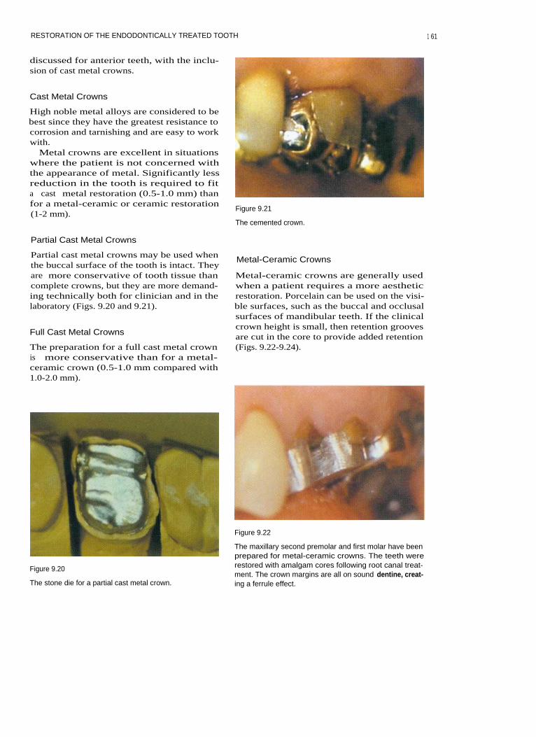
RESTORATION OF THE ENDODONTICALLY TREATED TOOTH
discussed for anterior teeth, with the inclu-sion of cast metal crowns.
Cast Metal Crowns
High noble metal alloys are considered to bebest since they have the greatest resistance tocorrosion and tarnishing and are easy to workwith.
Metal crowns are excellent in situationswhere the patient is not concerned withthe appearance of metal. Significantly lessreduction in the tooth is required to fita cast metal restoration (0.5-1.0 mm) thanfor a metal-ceramic or ceramic restoration(1-2 mm).
Figure 9.21
The cemented crown.
Partial Cast Metal Crowns
Partial cast metal crowns may be used whenthe buccal surface of the tooth is intact. Theyare more conservative of tooth tissue thancomplete crowns, but they are more demand-ing technically both for clinician and in thelaboratory (Figs. 9.20 and 9.21).
Full Cast Metal Crowns
The preparation for a full cast metal crownis more conservative than for a metal-ceramic crown (0.5-1.0 mm compared with1.0-2.0 mm).
Figure 9.20
The stone die for a partial cast metal crown.
Metal-Ceramic Crowns
Metal-ceramic crowns are generally usedwhen a patient requires a more aestheticrestoration. Porcelain can be used on the visi-ble surfaces, such as the buccal and occlusalsurfaces of mandibular teeth. If the clinicalcrown height is small, then retention groovesare cut in the core to provide added retention(Figs. 9.22-9.24).
Figure 9.22
The maxillary second premolar and first molar have beenprepared for metal-ceramic crowns. The teeth wererestored with amalgam cores following root canal treat-ment. The crown margins are all on sound dentine, creat-ing a ferrule effect.
1 61
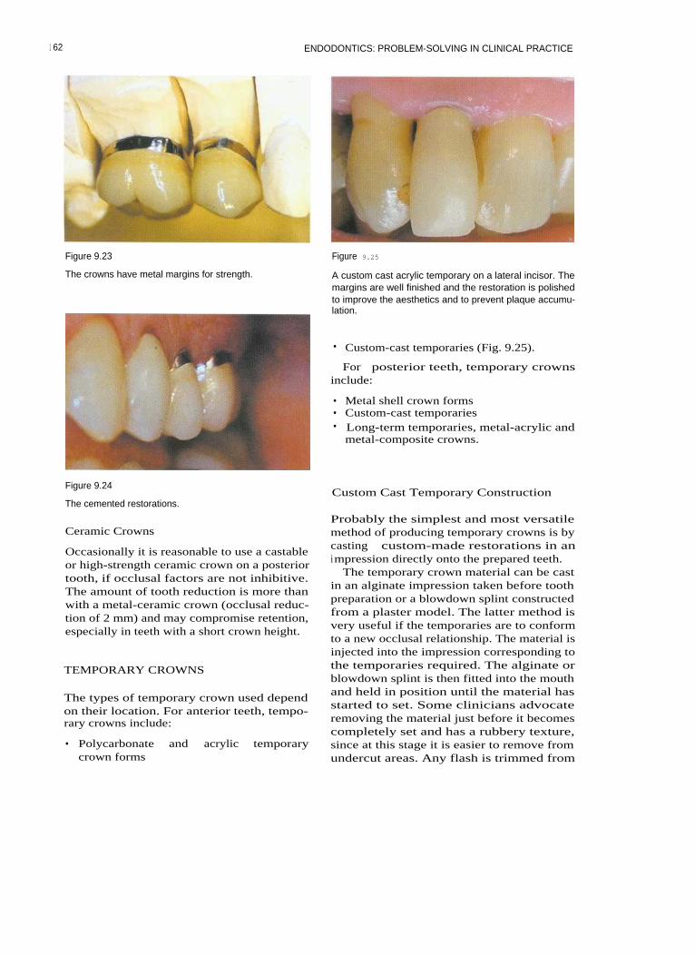
ENDODONTICS: PROBLEM-SOLVING IN CLINICAL PRACTICE
Figure 9.23
The crowns have metal margins for strength.
Figure 9.25
A custom cast acrylic temporary on a lateral incisor. Themargins are well finished and the restoration is polishedto improve the aesthetics and to prevent plaque accumu-lation.
• Custom-cast temporaries (Fig. 9.25).
For posterior teeth, temporary crownsinclude:
• Metal shell crown forms• Custom-cast temporaries• Long-term temporaries, metal-acrylic and
metal-composite crowns.
Figure 9.24
The cemented restorations.Custom Cast Temporary Construction
Ceramic Crowns
Occasionally it is reasonable to use a castableor high-strength ceramic crown on a posteriortooth, if occlusal factors are not inhibitive.The amount of tooth reduction is more thanwith a metal-ceramic crown (occlusal reduc-tion of 2 mm) and may compromise retention,especially in teeth with a short crown height.
TEMPORARY CROWNS
The types of temporary crown used dependon their location. For anterior teeth, tempo-rary crowns include:
• Polycarbonate and acrylic temporarycrown forms
Probably the simplest and most versatilemethod of producing temporary crowns is bycasting custom-made restorations in animpression directly onto the prepared teeth.
The temporary crown material can be castin an alginate impression taken before toothpreparation or a blowdown splint constructedfrom a plaster model. The latter method isvery useful if the temporaries are to conformto a new occlusal relationship. The material isinjected into the impression corresponding tothe temporaries required. The alginate orblowdown splint is then fitted into the mouthand held in position until the material hasstarted to set. Some clinicians advocateremoving the material just before it becomescompletely set and has a rubbery texture,since at this stage it is easier to remove fromundercut areas. Any flash is trimmed from
1 62
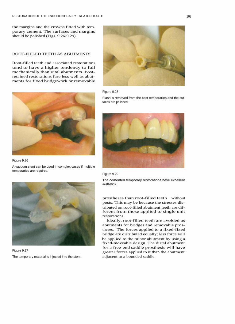
RESTORATION OF THE ENDODONTICALLY TREATED TOOTH
the margins and the crowns fitted with tem-porary cement. The surfaces and marginsshould be polished (Figs. 9.26-9.29).
ROOT-FILLED TEETH AS ABUTMENTS
Root-filled teeth and associated restorationstend to have a higher tendency to failmechanically than vital abutments. Post-retained restorations fare less well as abut-ments for fixed bridgework or removable
Figure 9.28
Flash is removed from the cast temporaries and the sur-faces are polished.
Figure 9.26
A vacuum stent can be used in complex cases if multipletemporaries are required.
Figure 9.29
The cemented temporary restorations have excellentaesthetics.
Figure 9.27
The temporary material is injected into the stent.
prostheses than root-filled teeth withoutposts. This may be because the stresses dis-tributed on root-filled abutment teeth are dif-ferent from those applied to single unitrestorations.
Ideally, root-filled teeth are avoided asabutments for bridges and removable pros-theses. The forces applied to a fixed-fixedbridge are distributed equally; less force willbe applied to the minor abutment by using afixed-moveable design. The distal abutmentfor a free-end saddle prosthesis will havegreater forces applied to it than the abutmentadjacent to a bounded saddle.
163

ENDODONTICS: PROBLEM-SOLVING IN CLINICAL PRACTICE
RECEMENTING A CAST RESTORATIONOR POST CROWN
When a cast restoration becomes decemented,the dentine of the tooth becomes covered inplaque. It is important to remove this beforerecementation, since it is full of bacteria andwill adversely affect the quality of the bond.The crown preparation or post space shouldtherefore be flushed with sodium hypochlo-rite before cementation to kill and dissolveany bacteria lining the walls.
Saunders WP, Saunders EM (1994). Coronalleakage as a cause of failure in root canal ther-apy: a review. Endodontics and DentalTraumatology 10: 105-108.
Saunders WP, Saunders EM (1996). Micro-leakage of bonding agents with wet and drybonding techniques. American Journal ofDentistry 9: 34-36.
Sorensen JA, Engleman MJ (1990). Ferruledesign and fracture resistance of endodonti-cally treated teeth. Journal of ProstheticDentistry 63: 529-536.
FURTHER READING
Sorensen JA, Martinoff JT (1984). Intracoronalreinforcement and coronal coverage: a studyof endodontically treated teeth. Journal ofProsthetic Dentistry 51: 780-784.
Kanca J (1992). Resin bonding to wet sub-strate. I. Bonding to dentine. QuintessenceInternational 22: 39-41.
Sorensen JA, Martinoff JT (1985). Endodon-tically treated teeth as abutments. Journal ofProsthetic Dentistry 53: 631-636.
Kvist T, Rydin E, Reit C (1989). The relativefrequency of periapical lesions in teeth withroot canal-retained posts. Journal of Endo-dontics 12: 578-580.
Torabinejad M, Ung B, Kettering JD (1990). Invitro bacterial penetration of coronallyunsealed endodontically treated teeth. Journalof Endodontics 16: 566-569.
16 4

10 COMPLEX ENDODONTIC PROBLEMS
CONTENTS • Introduction • Assessment of Success or Failure • Surgical EndodonticsPerio-Endo Lesions • Resorptions of Tooth Substance • Further Reading
I NTRODUCTION
After conventional root canal treatment hasbeen carried out the clinician must be able toassess whether it has been successful. Thepatient's symptoms should have resolved andany periapical lesion that was present shouldstart to resolve. Sometimes, difficult endodon-tic problems require combined treatment, withperhaps a surgical endodontic approach, peri-odontal treatment or long-term review. Thischapter discusses the indications and treatmentof complex endodontic problems, including:
• Assessment of success or failure• Surgical endodontics• Perio-endo lesions• Resorptions of tooth substance.
ASSESSMENT OF SUCCESS OR FAILURE
Success or failure in endodontic treatment isassessed using many criteria, including reso-lution of the patient's symptoms, reduction inswellings, healing of sinus tracts, and radio-logical evidence of bony healing.
Patient's Symptoms and Signs
Following root canal treatment the cliniciannormally expects resolution of the patient'ssymptoms and signs:
The patient should be pain-freeTenderness on palpation and percussionand discomfort in the buccal sulcus shouldall be relievedThere should be evidence of healing of anysinus tractsNo swelling adjacent to the offending toothshould be visible.
Radiological Evidence of Bony Healing
Comparison of preoperative and postopera-tive radiographs taken at intervals after treat-ment is used to assess success or failure.Conventional criteria for assessment are:
• Success - the width and contour of theperiodontal ligament is normal or slightlywidened around extruded filling material
• Uncertain - the size of a periapical lesionhas decreased but has not disappeared
• Failure - periapical radiolucency persists;the existing lesion has remained un-changed or has enlarged.
Scientific studies have shown that it is possi-ble to predict the outcome of treatment asearly as 1 year after treatment; however, theaccuracy of this assessment becomes greaterat 2 years, and up to 4 years may be requiredin some cases to reach a stable outcome.
Most healing occurs within the first year of
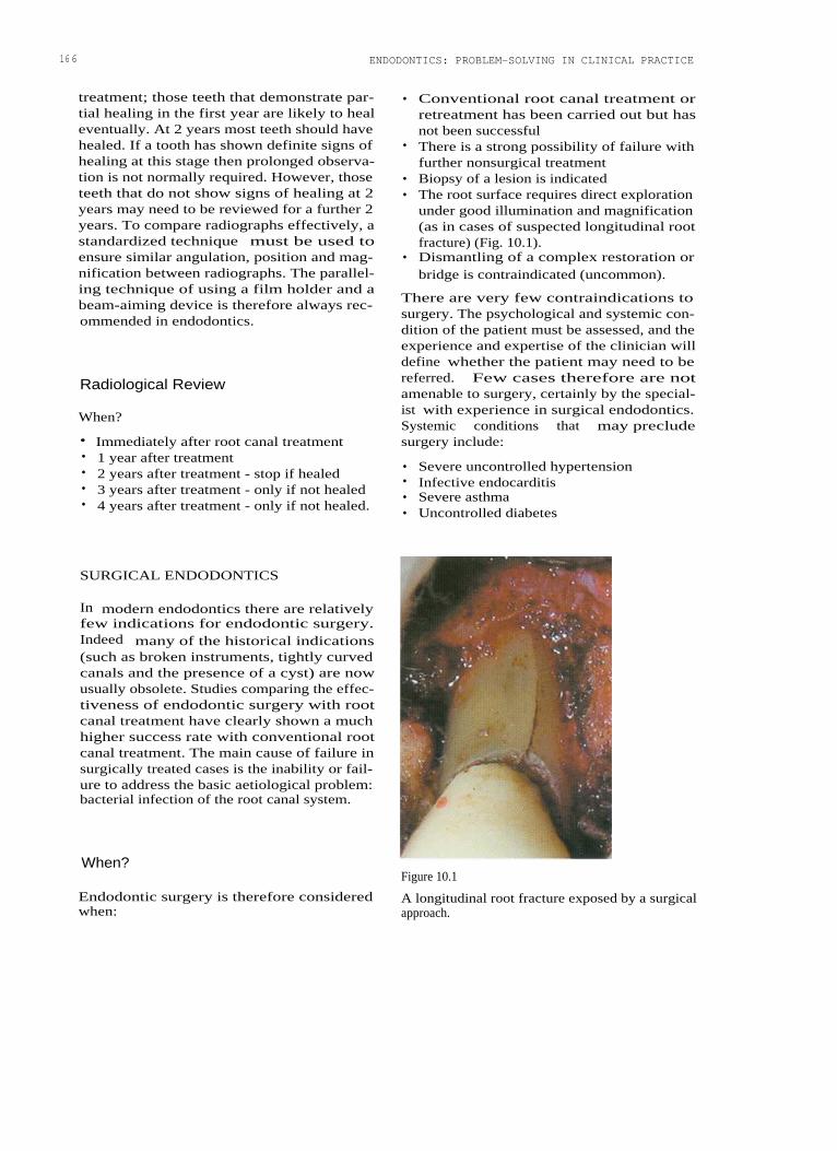
166
ENDODONTICS: PROBLEM-SOLVING IN CLINICAL PRACTICE
treatment; those teeth that demonstrate par-tial healing in the first year are likely to healeventually. At 2 years most teeth should havehealed. If a tooth has shown definite signs ofhealing at this stage then prolonged observa-tion is not normally required. However, thoseteeth that do not show signs of healing at 2years may need to be reviewed for a further 2years. To compare radiographs effectively, astandardized technique must be used toensure similar angulation, position and mag-nification between radiographs. The parallel-ing technique of using a film holder and abeam-aiming device is therefore always rec-ommended in endodontics.
Radiological Review
When?
• Immediately after root canal treatment•
1 year after treatment• 2 years after treatment - stop if healed• 3 years after treatment - only if not healed• 4 years after treatment - only if not healed.
• Conventional root canal treatment orretreatment has been carried out but hasnot been successful
• There is a strong possibility of failure withfurther nonsurgical treatment
• Biopsy of a lesion is indicated• The root surface requires direct exploration
under good illumination and magnification(as in cases of suspected longitudinal rootfracture) (Fig. 10.1).
• Dismantling of a complex restoration orbridge is contraindicated (uncommon).
There are very few contraindications tosurgery. The psychological and systemic con-dition of the patient must be assessed, and theexperience and expertise of the clinician willdefine whether the patient may need to bereferred. Few cases therefore are notamenable to surgery, certainly by the special-ist with experience in surgical endodontics.Systemic conditions that may precludesurgery include:
• Severe uncontrolled hypertension• Infective endocarditis• Severe asthma• Uncontrolled diabetes
SURGICAL ENDODONTICS
In modern endodontics there are relativelyfew indications for endodontic surgery.Indeed many of the historical indications(such as broken instruments, tightly curvedcanals and the presence of a cyst) are nowusually obsolete. Studies comparing the effec-tiveness of endodontic surgery with rootcanal treatment have clearly shown a muchhigher success rate with conventional rootcanal treatment. The main cause of failure insurgically treated cases is the inability or fail-ure to address the basic aetiological problem:bacterial infection of the root canal system.
When?
Endodontic surgery is therefore consideredwhen:
Figure 10.1
A longitudinal root fracture exposed by a surgicalapproach.

COMPLEX ENDODONTIC PROBLEMS
• Adrenal insufficiency or corticosteroidtherapyOrgan transplantRecent myocardial infarctionImpaired hepatic or renal functionCoagulation defects or therapy.
present inside the tooth. Root-end surgeryrequires the removal of the apical portion ofthe root, preparation of a root-end cavity andplacement of a sealing root-end filling.
Surgical intervention may be required forincision and drainage, apical surgery andreparative or corrective surgery.
Corrective Surgery
Perforation Repair
Incision and Drainage
Incision and drainage may be required whena patient presents with an acute apical abscessand fluctuant swelling in the buccal sulcus.Local anaesthesia is required.
Cortical trephination is a technique inwhich the cortical plate is punctured with afine instrument (usually rotary) to try toachieve drainage. This is not an easy task toperform and there is a high chance of causingdamage to the underlying root; it is not to berecommended.
Treatment of the acute abscess is covered inChapter 12.
Apical Surgery
Occasionally it is not possible to repair a per-foration effectively using conventional rootcanal treatment techniques. The three factorsthat are important in the successful treatmentof perforations are:
• The time since occurrence• The size of the perforation• The position relative to the crestal bone
level.
Root Resection
Root resection consists of the removal of anentire root from a multirooted tooth withoutremoval of the corresponding portion of thecrown. It may be required when a particularroot has had gross periodontal destructionaround it, when there has been extensiveinflammatory resorption or when there is avertical root fracture.
Apical Curettage Tooth Resection
Periradicular curettage involves removingany pathological soft tissue from around theapex or lateral surfaces of the root end. Thecementum at the apex of the root may becuretted and excess filling material removed.If tissue is required for biopsy, care must betaken to try and remove the lesion intact. Thetissue to be examined is then placed in a suit-able transport medium (such as 10% formolsaline) and sent for histological evaluation.Any tissue removed during apical surgeryshould normally be assessed histologically.
Root-End Surgery
Curettage is rarely carried out without root-end surgery, since an attempt should be madeto remove any residual infection that may be
In a tooth resection, the root and correspond-ing coronal tooth structure is removed. Theseparated part of the tooth may be retainedand restored individually or removed.
The Surgical Armamentarium
A normal layout for a surgical procedureincludes:
Local anaesthetic syringeAspiration tipsGauze swabsCotton wool rolls and pelletsContainer for sterile salineSpecimen pot and 10% formal saline
167

ENDODONTICS: PROBLEM-SOLVING IN CLINICAL PRACTICE
Micro scalpel bladesPeriosteal elevatorPeriosteal retractorsProbesFront surface mirrorMicro mirrorCollege tweezersRat tooth tissue forcepsSurgical handpiece (slow-speed or high-speed, or both)Burs for surgical handpieceBone curettesPeriodontal curettesUltrasonic handpieceSpecialist ultrasonic tips for root-end cav-ity preparationCarver, condensers and burnishers4-0, 5-0 monofilament suturesNeedle holdersSurgical scissorsChlorhexidine mouthwashRoot-end filling material (such as mineraltrioxide aggregate (MTA: Dentsply,Weybridge, Surrey, UK), Super EBA (ethoxy-benzoic acid: Staident International, Staines,UK) or Intermediate Restorative Material(IRM: Dentsply).
Anaesthesia for Procedures on MandibularTeeth
Inferior dental nerve blocks are supple-mented with buccal and lingual infiltrationfor procedures on mandibular teeth. Longbuccal infiltration and mental nerve blocksare also useful.
Pain Relief
The administration of a nonsteroidal anti-inflammatory drug at least 1 hour before thesurgical procedure should help to reducepostoperative discomfort. Some of the benefitmay however be a 'placebo effect'. A singledose of 500 mg paracetamol or 400 mgibuprofen should be sufficient.
Preoperative Mouthrinse
The patient is instructed to rinse thoroughlywith a 2% chlorhexidine gluconate solutionbefore surgery. This can be started 24 hoursbefore surgery, or at the time of surgerybefore the local anaesthetic is administered.The mouthrinse reduces the number of bacte-ria in the mouth.
Anaesthesia, Pain Control andHaemostasis Flap Design and Reflection
Good anaesthesia is obviously essential dur-ing surgical endodontics carried out on a con-scious patient. Profound and long-lastinganaesthesia can be achieved using 2% ligno-caine (lidocaine) with 1:80000 adrenaline (epi-nephrine). The vasoconstrictor in such ananaesthetic prolongs the duration of anaes-thesia and helps to induce haemostasis toprovide a blood-free operative site. If a solu-tion of 1:50000 adrenaline is available, betterhaemostasis is achieved.
Anaesthesia for Procedures on Maxillary Teeth
Procedures on maxillary teeth usually requirea combination of buccal and palatal infiltra-tion. Nerve blocks of the greater palatine,sphenopalatine and superior alveolar nervesmay also be required.
Full Flaps
Full flaps can be described as horizontal, tri-angular, rectangular or trapezoid (Figs. 10.2,10.3). For endodontic purposes the triangularflap is most appropriate in the posterior seg-ments and the rectangular flap in the anteriorsegments. (The trapezoid design may disruptthe vasculature of the attached gingiva thatruns in a vertical direction.)
Relieving incisions run across the attachedgingiva and into the alveolar mucosa.Interdental papillae are retained intact andthe relieving incision is normally started onthe distal aspect of the papilla.
Flap reflection is started in the attached gin-giva in the relieving incision, elevating theperiosteum from the alveolar bone. The papil-lae can then be eased away from the teethwith little trauma.
168

COMPLEX ENDODONTIC PROBLEMS
tions. They heal with scarring and are nolonger recommended for endodontic surgery.
A Leubke-Ochsenbein flap in the attachedgingiva does not impinge on crestal bone andcan be useful in the anterior region whenthere is a wide band of attached gingiva andthe teeth have been crowned. At least 2-4 mmof attached gingiva should remain betweenthe gingival margin and the scalloped hori-zontal incision line. Scarring with this designof flap is not a serious problem (Figs.10.4-10.6).
Figure 10.2
The outline of a triangular flap for surgery on the maxil-lary left lateral incisor.
Figure 10.4
A Leubke-Ochsenbein flap.
Figure 10.3
A rectangular flap for surgery on the maxillary left lateralincisor.
The flap is held away from the operativesite with a retractor that is held firmly againstthe alveolar bone. The tissues must notbecome trapped between the elevator andbone since this can result in trauma to thesedelicate tissues.
Limited Flaps
Semilunar flaps in the alveolar mucosa givelimited access and postoperative complica-
Figure 10.5
The Leubke-Ochsenbein flap 3 days following surgery.
1 6 9

1 70
Figure 10.6
The surgical site after 2 weeks' healing.
Figure 10.7
The Impact Air handpiece; the exhaust is directed awayfrom the surgical site to prevent air embolism.
Osseous Entry
ENDODONTICS: PROBLEM-SOLVING IN CLINICAL PRACTICE
Figure 10.8
A chronic periapical lesion has perforated the corticalplate (arrow).
Palisades Dental, Piscatoway, NJ, USA) (Figs.10.7 and 10.8). The lesion is excised using acurette and placed in 10% formol saline forhistological evaluation.
Root-End Resection and CavityPreparation
The apical 2-3 mm of the root is resected at aright angle to the long axis of the tooth (Fig.10.9). (It is no longer considered appropriateto cut a bevel or to remove valuable root sub-stance in order to gain access.) Microsurgicalinstruments are used to prepare the root-endcavity. These specialized tips are designed foruse in a Piezon ultrasonic unit (EMS,Forestgate, Dallas, TX, USA) with irrigant.The tips are fine enough to prepare a cavityalong the long axis of the root canal. Acousticmicrostreaming produced during ultrasonic
The bone around the apex of the tooth shouldbe examined under good illumination andmagnification. The cortical plate will be perfo-rated if there has been a sinus tract. In manycases a sharp probe can be used to locate andidentify the root apex and a curette used topeel away the cortical bone. The surgical sitecan then be modified if necessary with aslow-speed bur in a surgical handpiece withcold saline coolant or with a specialized high-speed surgical handpiece (Impact Air 45:
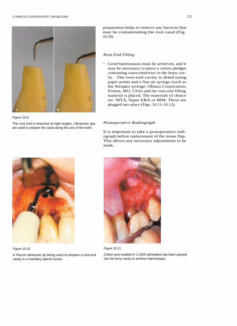
COMPLEX ENDODONTIC PROBLEMS
preparation helps to remove any bacteria thatmay be contaminating the root canal (Fig.10.10).
Root-End Filling
• Good haemostasis must be achieved, and itmay be necessary to place a cotton pledgetcontaining vasoconstrictor in the bony cav-ity. The root-end cavity is dried usingpaper points and a fine air syringe (such asthe Stropko syringe: Obtura Corporation,Fenton, MO, USA) and the root-end fillingmaterial is placed. The materials of choiceare MTA, Super EBA or IRM. These areplugged into place (Figs. 10.11-10.13).
Figure 10.9
The root end is resected at right angles. Ultrasonic tipsare used to prepare the canal along the axis of the tooth.
Postoperative Radiograph
It is important to take a postoperative radi-ograph before replacement of the tissue flap.This allows any necessary adjustments to bemade.
Figure 10.10 Figure 10.11
A Piezon ultrasonic tip being used to prepare a root-end
Cotton wool soaked in 1:1000 adrenaline has been packedcavity in a maxillary lateral incisor.
into the bony cavity to achieve haemostasis.
171

1 72
ENDODONTICS: PROBLEM-SOLVING IN CLINICAL PRACTICE
Figure 10.12
Mineral Trioxide Aggregate root-end fillings in the buc-cal roots of a maxillary first molar.
Figure 10.14
A triangular flap sutured with interrupted sutures.
Figure 10.13
Mineral Trioxide Aggregate.
Figure 10.15
Flap ReplacementPressure is applied to the flap following suturing.
The flap is returned to its original positionand stabilized with sutures. Fine (4-0 or 5-0)
in suture removal often leads to gingivalmonofilament sutures are probably best toler-
damage (Figs. 10.14 and 10.15).ated by the tissues. Firm pressure is thenapplied to the tissue flap with gauze soakedin saline for several minutes. This minimizesthe size of the blood clot between the tissue
Postoperative Instructionsand cortical bone, so that there will be lesspostoperative swelling and discomfort. The
The patient should be given the followingsutures are removed after 48-72 hours. Delay
instructions:

COMPLEX ENDODONTIC PROBLEMS
• Avoid strenuous activity, lifting heavyobjects or sport for 24 hours
• Do not smoke• Do not drink alcohol• Eat soft foods and have hot drinks cooler
than usual• Do not be tempted to look at the surgeon's
workmanship! This will pull unnecessarilyon the tissue flap
• Slight bruising and swelling can beexpected but should be minimal
• Take analgesics for up to 24-48 hours• For the first few hours after surgery an ice
pack should be applied to the face. Thiswill reduce swelling
• A chlorhexidine mouthwash should beused three times a day starting 24 hoursafter surgery
• Teeth in the remaining quadrants can bebrushed normally, but avoid the surgicalsite until the sutures have been removed
• Sutures should be removed after 48-72hours.
Patients should also be given an emergencytelephone number.
PERIO-ENDO LESIONS
I n teeth with perio-endo lesions, either anendodontic lesion mimics periodontal diseaseor vice versa. In a few cases both endodonticand periodontal disease are present.
Although there are numerous connectionsbetween the periodontal ligament and theroot canal (the apical foramen, lateral canals,furcal canals and a few dentinal tubules),there is little evidence that root canals becomeinfected following the removal of cementumduring periodontal debridement and rootplaning. Dentine has been shown to have alower permeability to bacterial toxins thanwas previously thought. Periodontal diseaseis unlikely to affect the pulp even after theloss of tooth substance in the furcationfollowing root planing.
17 3
Diagnosis
There are three main aids to the diagnosis ofperio-endo lesions:
1
Good clinical examination, including peri-odontal probing
2
Pulp vitality testing3
Good radiographs taken with a parallel-ing technique.
Periodontal Probing
Does the patient have evidence of marginalperiodontitis around several teeth or is theperiodontal condition generally good? Thismay give an initial indication as to the likelysource of the problem around a particulartooth.
The periodontium around the tooth is gen-tly probed using a fine tipped probe (0.5 mmand force of 25 g). Periodontal lesions tend tohave a broad base whereas lesions ofendodontic origin tend to result in a suddenincrease in periodontal probing depth. A verydeep but narrow pocket on opposite sides of atooth may indicate a vertical root fracture.
The teeth can be grouped into one of threecategories:
1
Teeth with a lesion of endodontic origin2
Vital teeth with marginal periodontitis3
Nonvital teeth with marginal periodonti-tis.
Pulp Vitality Testing
The pulp can be tested as described previ-ously, using electric pulp testers or cold andhot stimuli. If a vital response is obtainedfrom the pulp, the clinician may assume thatthe lesion is of periodontal origin, particularlywith a single-rooted tooth. If the tooth is non-vital then the assumption is that there is anendodontic problem. If the tooth is not rootfilled or if the root filling is of poor quality,then root canal treatment or retreatmentshould be carried out. If the root filling is ofvery good quality, then periodontal treatmentis required.

174 ENDODONTICS: PROBLEM-SOLVING IN CLINICAL PRACTICE
Paralleling Radiographs
The whole tooth must be visible on any diag-nostic radiograph, the image must be clearand of adequate contrast, and there must beno elongation or foreshortening. The Ruinholder (Dentsply) allows the use of the paral-leling technique, in which the film is held in aholder and the beam-aiming device ensuresthat the X-rays run perpendicular to the film.
The clinician must look for evidence ofperiapical radiolucency or of radiolucencyadjacent to a lateral canal; this is most likelyto be due to endodontic infection. Horizontalbone loss is found in periodontal disease. Apear-shaped radiolucency that follows thecontour of the root is often associated withvertical root fractures.
out root amputation or hemisection of thetooth. A 'try and see' approach to the treat-ment of perio-endo lesions is no longerappropriate. Successful treatment is based ona methodical approach to diagnosis (Fig.10.16).
RESORPTIONS OF TOOTH SUBSTANCE
Several different types of pathological rootresorption are recognized, and it can be diffi-cult for the clinician to differentiate betweenthem. Resorption can be classified into twotypes: internal and external. (External resorp-tions, except cervical resorption, are coveredin Chapter 11.)
Treatment
Correct treatment depends on accurate diag-nosis, which involves thorough examinationand testing. Treatment may be endodontic orperiodontal, or both. If the prognosis is poorthen the clinician must decide whether to pro-ceed with the indicated treatment, whether toextract the tooth or perhaps whether to carry
Internal Resorption
Internal resorption (Figs. 10.17-10.19) resultsfrom inflammation within the pulp. The pulp
Figure 10.16
In this case the second premolar was nonvital and hadboth endodontic and periodontal lesions associated withit. The first molar was vital and therefore the origin of thelesion was periodontal; however, elective root canal treat-ment was carried out so that the mesial root could beresected.
Figure 10.17
A case of internal resorption in a mandibular canine. (A)The patient presented with inadequate root canal treat-ment. (B) The canal system was retreated, irrigatedthroughly and filled with gutta percha.

COMPLEX ENDODONTIC PROBLEMS 17 5
Diagnosis
The diagnosis of internal resorption is indi-cated by the following features:
• Vitality testing usually gives a positiveresponse
• The lesion has a smooth border thatmerges with the outline of the root canal
• An angled radiograph shows the lesioncentred on the pulp space
• Probing at the cervical margin does notreveal a defect.
Figure 10.18 TreatmentInternal resorption can occur in any tooth such as this
molar.
Figure 10.19
(A) Internal and (13) external resorption. In radiographs of
external resorption the root canal is often still visible,
superimposed over the resorption defect. In internal
resorption the internal canal shape is altered.
is vital when the resorption is active, and thecondition is often asymptomatic. Radiologi-cally, the lesion has a smooth outline andappears as ballooning of the existing rootcanal. The pulp of the tooth may later becomenecrotic. Odontoclastic activity is triggeredwithin the root canal, possibly followingtrauma or infection. This form of resorption ismost common in incisor teeth but may occurin any tooth. The activity of the lesion is notcontinuous.
Conventional root canal treatment should bestarted immediately. The pulp of the toothmay haemorrhage during root canal treat-ment, and bleeding may be difficult to con-trol. Ultrasonic irrigation is invaluable forcleaning the irregularly shaped root canal. Asolution of sodium hypochlorite is used todissolve the organic material within the rootcanal and to kill any micro-organisms.Haemorrhaging ceases when the pulp tissuehas been completely removed. The root canalwall should be checked for perforation. Thiscan be carried out using direct vision withgood illumination and magnification, andalso with an apex locator.
After canal cleaning and shaping, the canalis packed with calcium hydroxide as a tempo-rary dressing between appointments. Owingto its high pH, this material is antibacterialand also helps to dissolve any remainingorganic material.
The root canal treatment can usually becompleted at a second visit. The irregularshape of the root canal is best obturated usinga warm, vertically compacted gutta perchatechnique.
If the root canal is perforated referral maybe indicated. On rare occasions large perfora-tions may require surgical repair, but access isoften extremely difficult.
Cervical Resorption
Cervical resorption (Figs. 10.20-10.22) mayoccur in the cervical region of a tooth following

ENDODONTICS: PROBLEM-SOLVING IN CLINICAL PRACTICE
Figure 10.20
Burrowing external cervical resorption.
Figure 10.22
A cervical resorption defect exposed surgically on the lin-gual surface of a mandibular canine (arrow).
Figure 10.21
External cervical resorption. The root canal is still visible(arrows in B) superimposed over the defect.
trauma, including replantation of teeth. It issometimes seen after a canine has beenremoved from the palate and transplanted, asa result of the trauma of extraction. It islocalized external resorption caused by
inflammation within the periodontal liga-ment. Trauma such as aggressive scalingcould possibly lead to odontoclastic activityin the cervical region of the tooth.
Clinically there may be a shallow cratersubgingivally or the resorption may be of aburrowing form. The tooth is usually asymp-tomatic, and the pulp is vital and not part ofthe disease process. The resorptive processavoids exposing the pulp.
Diagnosis
The diagnosis of cervical resorption is indi-cated by the following features:
• The lesion is usually subgingival anddetectable with a Briault probe; it must notbe confused with a carious lesion
• The tooth is vital to electric pulp testingand thermal stimuli
• Radiologically there is an irregular radiolu-cency in the cervical region of the tooth;the root canal is intact
• If two radiographs are taken at differenthorizontal angles the defect appears to
1 7 6

COMPLEX ENDODONTIC PROBLEMS
move in relation to the root canal; this dif-ferentiates the lesion from an internalresorption
• In the later stages a pink spot may beobserved in the coronal tooth substance.
Treatment
If the lesion is small and accessible, it shouldbe surgically exposed, a cavity prepared anda restoration inserted. Light cured compositeresin can be used. Lesions may sometimesrecur. If the lesion is large or inaccessible thenthe tooth may need to be extracted.
FURTHER READING
Heithersay GS (1999). Clinical, radiologic, andhistopathologic features of invasive cervicalresorption. Quintessence International 30:27-37.
Orstavik D (1996). Time-course and riskanalyses of the development and healing ofchronic apical periodontitis in man.International Endodontic journal 29: 150-155.
Simon JHS, Werksman LA (1994). Endo-dontic-periodontal relations. In: Cohen S,Burns RC, eds. Pathways of the Pulp, 6th edi-tion, Mosby, St Louis: 513-530.
Torabinejad M, Chivian N (1999). Clinicalapplications of Mineral Trioxide Aggregate.Journal of Endodontics 25: 197-205.
Carr G, Bentkover SK (1998). SurgicalEndodontics. In: Cohen S, Burns RC, eds.Pathways of the Pulp, 7th edition, Mosby, StLouis: 608-656.
1 77

11 ENDODONTIC CARE OF PERMANENTTEETH IN CHILDREN
CONTENTS • Introduction • Isolation for Endodontic Treatment • Trauma • RootResorption • Management of Carious Teeth • Endodontic Treatment of Molar Teeth inChildren • Teeth of Abnormal Form • Further Reading
I NTRODUCTION
This chapter will cover endodontic care ofpermanent teeth in children, trauma (which ismore common in children) and managementof tooth malformations.
The most significant characteristic of perma-nent teeth in children is their immaturity.Development is not complete until severalyears after eruption, and although teeth aregenerally fully formed approximately 6 yearsafter eruption, the process of maturation con-tinues throughout life, as secondary dentine islaid down by odontoblasts. Young teeth havelarge pulp chambers, wide root canals andthin-walled roots. They also have wide denti-nal tubules. Once pulpal vitality is lost, all mat-uration ceases. This leaves an immature toothwith a short root, thin fragile walls and a largepulp space that is readily contaminated bybacteria, which can enter through exposeddentinal tubules. Immature, pulpless incisorsare very prone to cervical fracture and areoften unsuitable for restoration with posts.
The main aim of care should be to preservethe vitality of the pulp, thereby allowing mat-uration to continue. The vitality of the pulpmay be threatened by bacteria followingtrauma, and by microleakage via a cariouslesion or leaking restoration. In each case theaim of treatment should be the same - toprevent the entry of bacteria or their toxinsinto the pulp, which results in loss of vitalityand cessation of maturation. In assessing a
damaged tooth it is therefore essential toascertain whether or not the pulp is vital orcapable of recovery. It is rarely necessary toremove the pulp immediately. Unless thereare obvious signs of infection, time can betaken to reassess, and if in doubt it is betternot to remove the pulp.
I SOLATION FOR ENDODONTICTREATMENT
Isolation for endodontic treatment has beencovered in Chapter 4, but children may pre-sent particular problems with partiallyerupted teeth. Most children accept rubberdam application if it is carefully explainedand if adequate local anaesthesia is used.
Suitable clamps for children include theAsh A or 14A (Dentsply, Weybridge, Surrey,UK) for partially erupted molars and theHygenic 8 for slightly more erupted teeth. AnAsh EW clamp fits most other teeth.
Sometimes it is not possible to clamp thetooth being treated, such as when it is par-tially erupted, crowded or badly fractured. Inthese cases it may be helpful to use two ormore confluent holes to include adjacent teethand to clamp one or both of these. This mayleave a gap in the dam palatally, which can besealed with Oraseal caulking (Ultradent, SouthJordan, UT, USA) or a light-bodied impressionmaterial to prevent irrigant from entering the

ENDODONTICS: PROBLEM-SOLVING IN CLINICAL PRACTICE
mouth. Local anaesthesia, including palatallyif necessary, makes placement of a clampmuch easier. In the mixed dentition stage thefirst premolar may be the most suitable toothfor clamping. A clamp can be placed over afixed orthodontic appliance, or alternativelythe arch wire should be removed by theorthodontist. Very occasionally it is really notpossible to use a clamp; then it may be help-ful to wedge a small portion of rubber dam ora Wedget (Hygienic, Akron, OH, USA)between two teeth, or alternatively to tie den-tal tape around the neck of the tooth.
An alternative method of isolation for ante-rior teeth is the Dry Dam (SDI Svenska DentalInstruments, Uplands Vasby, Sweden) (Fig.11.1), which fits around the patient's ears andis used without a clamp. This can be a greatadvantage in very anxious patients, especiallysince it does not require the use of local anaes-thesia. It is also very quick and easy to apply.
TRAUMA
Traumatic injury can result in fractures of thecrowns and roots of teeth, luxation and avul-sion injuries. Treatment should aim to pre-serve pulp vitality whenever possible.
General Considerations
• Are there other injuries? Bone and softtissue damage should be assessed.Lacerations and fractures require imme-diate attention and take precedence overdental trauma. It may be necessary to seekspecialist advice
• Is there any relevant medical history?• What is the patient's tetanus status?
Things to look for include:
• What is the nature of the injury?• Are the damaged teeth restorable?• Has there been a previous dental injury?
This may confuse the diagnosis• What is the likely prognosis?• What will the overall treatment plan
involve?• Has the vascular supply to the tooth been
impaired or severed? This is particularlyrelevant in luxation injuries
• Is it likely that the pulp has been con-taminated by micro-organisms? Micro-organisms can take many days to penetratea significant distance into the healthy pulpin an immature tooth
• Is the root fully developed?
Note that immature teeth with large pulpspaces and thin root canal walls can be diffi-cult to restore and are prone to fracture. Root-end closure procedures often take in excess of1 year to complete.
• Was the patient unconscious? If so seekmedical advice
Figure 11.1
The use of drv dam for isolation.
Diagnosis
An accurate diagnosis is essential if mistakesand incorrect treatment are to be avoided. Itcan be particularly confusing when severalteeth have received different injuries or whenthere has been a previous dental injury. It istherefore essential to take a careful anddetailed history. Often a traumatized toothdoes not respond to sensitivity testing duringthe first few months after injury, but this maybe transient and therefore the pulp should notbe removed on this evidence alone. Theremust be additional evidence that the pulp isi nfected before its removal is considered. Ifthe prognosis of a traumatized tooth is poor,consideration should be given at an early
1 80

ENDODONTIC CARE OF PERMANENT TEETH IN CHILDREN
stage to its eventual replacement. If the toothis not restorable it may be extracted or theroot may be retained to preserve alveolarbone.
success rate in immature teeth and a goodrecord with mature teeth. The aims of partialpulpotomy are to:
• Remove damaged pulp tissue• Seal the cavity to prevent microleakage.
Crown Fractures
Enamel or Dentine Fractures
Bacteria can enter the pulp through exposeddentinal tubules (resulting from a fractureinto dentine) either immediately after theinjury or at a later date. It is therefore essen-tial when this injury occurs that the exposeddentine should be covered as promptly aspossible to preserve the pulp. It is not alwaysnecessary to place a lining material over theexposed dentine, although many operatorsprefer to do this if the fracture is deep. Aneffective dentine bonding agent should beused, since the most important aspect of thistreatment is the exclusion of infection. It isbest to restore the tooth using etch-retainedcomposite resin at the first visit. The toothmay be built up at a subsequent visit torestore both its anatomical relationship withthe adjacent teeth and its appearance. Teethshould be monitored in case of later loss ofvitality. A concomitant luxation worsens theprognosis.
Crown Fractures that Expose the Pulp
Things to look for include:
• A fracture that involves enamel and den-tine
• Exposed pulp, with a red appearance,which indicates that the tooth is vital. If thepulp has a blue appearance in a tooth witha recent injury, this indicates that it is non-vital and is unsuitable for a pulpotomy
• Concomitant luxation injury.
Treatment
The exposed pulp must be protected fromcontamination in order to preserve its vitalityand allow continued maturation of the tooth.It has been shown that the size of exposuredoes not affect the outcome. Using localanaesthesia and rubber dam, a small cavity iscut at the exposure site, using a turbine burwith copious waterspray for cooling. Thismethod is less traumatic than using a slowhandpiece or excavators. It is important to cutthe cavity to the level of vital healthy pulp tis-sue. The cavity should be washed using ster-ile saline, and haemorrhage should becontrolled using sterile cotton pellets or largepaper points.
A calcium hydroxide dressing is normallyplaced over the pulp. This dressing may be asetting variety such as Dycal (Dentsply) orcalcium hydroxide powder mixed with wateror sterile saline. Coronal seal is important. Afortified zinc oxide eugenol cement, such asIRM (Intermediate Restorative Material:Dentsply), still within the cavity, will give agood seal and also have an antibacterial effect(Fig. 11.2).
A layer of glass ionomer cement, such asFuji IX (GC Corporation, Tokyo, Japan) pre-vents any interference with the setting of the
Partial PulpotomyPartial pulpotomy, as described by Cvek, isthe treatment of choice. It has a very high
Figure 11.2
Partial pulpotomy; a cavity has been cut at the exposuresite.
181
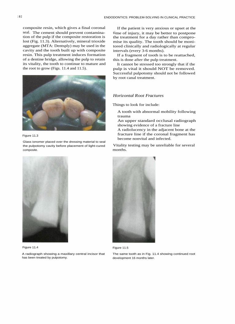
1 8 2 ENDODONTICS: PROBLEM-SOLVING IN CLINICAL PRACTICE
composite resin, which gives a final coronalseal. The cement should prevent contamina-tion of the pulp if the composite restoration islost (Fig. 11.3). Alternatively, mineral trioxideaggregate (MTA: Dentsply) may be used in thecavity and the tooth built up with compositeresin. This pulp treatment induces formationof a dentine bridge, allowing the pulp to retainits vitality, the tooth to continue to mature andthe root to grow (Figs. 11.4 and 11.5).
Figure 11.3
Glass ionomer placed over the dressing material to sealthe pulpotomy cavity before placement of light-curedcomposite.
If the patient is very anxious or upset at thetime of injury, it may be better to postponethe treatment for a day rather than compro-mise its quality. The tooth should be moni-tored clinically and radiologically at regularintervals (every 3-6 months).
If a fragment of tooth is to be reattached,this is done after the pulp treatment.
It cannot be stressed too strongly that if thepulp is vital it should NOT be removed.Successful pulpotomy should not be followedby root canal treatment.
Horizontal Root Fractures
Things to look for include:
A tooth with abnormal mobility followingtraumaAn upper standard occlusal radiographshowing evidence of a fracture lineA radiolucency in the adjacent bone at thefracture line if the coronal fragment hasbecome nonvital and infected.
Vitality testing may be unreliable for severalmonths.
Figure 11.4 Figure 11.5
A radiograph showing a maxillary central incisor thathas been treated by pulpotomy.
The same tooth as in Fig. 11.4 showing continued rootdevelopment 16 months later.

ENDODONTIC CARE OF PERMANENT TEETH IN CHILDREN
Treatment
If the coronal portion is vital, treatmententails:
• Repositioning the coronal fragment (andsplinting if indicated), soon after injury
• Observation.
If the coronal portion is nonvital andinfected, treatment entails:
• Treatment of the coronal fragment as anonvital tooth with an open apex
•
Root canal treatment to the fracture line. Figure 11.6
When a tooth sustains a horizontal root frac-ture the pulp normally remains vital; there-fore its removal is contraindicated. If thefracture is near the apex and there is normalmobility, no active treatment is required. Ifthere is abnormal mobility the coronal frag-ment should be splinted with a semirigidsplint, usually for 2-3 weeks, but for up to 6weeks if there is still excessive mobility.
If infection intervenes, the coronal fragmentmay become nonvital. The apical fragmentremains vital almost without exception, andtherefore any root canal treatment should beconfined to the coronal portion. The coronalfragment may be so displaced that its bloodsupply is severed at the fracture line. In thiscase there is easy access for revascularizationat the fracture line, and the coronal portionmay regain vitality. It is therefore importantnot to remove the coronal pulp on the evi-dence of sensitivity testing alone. Duringhealing there may be some remodellingresorption at the fracture line. This is part ofthe healing process and is not an indicationfor root canal treatment.
If there is also a coronal fracture, this pre-disposes to the ingress of bacteria and so theprognosis for pulp vitality may be worsened.Similarly, if the fracture line is close to thegingival sulcus, this can provide an entry forbacteria and so worsen the prognosis of thetooth. If a periodontal pocket communicateswith a deeper fracture line, the prognosis forthe coronal fragment of the tooth is very poor(Fig. 11.6).
A nonvital coronal fragment is treated in asimilar way to a nonvital tooth with an openapex. Access is gained to the root canal of the
A deep periodontal pocket has developed followingtrauma; this indicates a poor prognosis.
coronal fragment using a sufficiently largeaccess cavity to allow thorough cleaning. Aradiograph is taken to assess the length to thefracture line. The canal is gently cleaned withfiles and irrigated with sodium hypochlorite.Calcium hydroxide is packed to the fractureline and replaced only when its density isseen on a radiograph to be reduced. When ahard tissue barrier has formed at the fractureline, the canal of the coronal fragment may befilled with gutta percha. Alternatively, whenthe infection is controlled and soft tissue heal-ing has taken place, it may be possible toinsert a 'plug' of calcium hydroxide at thefracture line and fill the remaining space withgutta percha (Fig. 11.7).
Figure 11.7
(A) A radiograph of a nonvital maxillary central incisorwith a horizontal root fracture. (B) Calcium hydroxidehas been inserted to the fracture line. (C) The tooth hasbeen root filled to the fracture line.
1 83

ENDODONTICS: PROBLEM-SOLVING IN CLINICAL PRACTICE
If the coronal fragment is lost, a decisionmust be made as to whether or not sufficientroot remains to restore the tooth. In afavourable situation the apical fragmentcould be extruded, or gingival surgery couldperformed to allow construction of a postcrown. If this is not practical, it is oftenpreferable to leave the fragment in situ to pre-serve the alveolar bone, unless there is infec-tion or the space is required as part oforthodontic treatment.
Luxation Injuries
Following luxation injuries there is a possibleroute of infection via the damaged periodon-tal structures; therefore, after the tooth hasbeen repositioned and, if indicated, stabilized,a strict regimen of chlorhexidine mouth-washes should be instituted. A concomitantcrown fracture worsens the prognosis of thepulp because of possible ingress of infectionvia the dentinal tubules.
Figure 11.8
A tooth that was previously luxated and now shows cal-cification of the root canal.
Concussion
Concussion is a periodontal ligament injury.The tooth becomes tender to pressure andthere may be a temporary loss of response tosensitivity testing. The pulp is likely toremain vital.
sensitivity testing. If the apex is closed, pulpnecrosis is more likely. However, it is worthwaiting because of the possibility of healingafter transient apical breakdown (see p. 185).Inflammatory or replacement resorption mayoccur later as a result of periodontal damage.
Subluxation
In subluxation, the nerves and blood vesselsthat supply the pulp may be stretched or sev-ered. Loss of vitality is unlikely but it canoccur in mature teeth. Root resorption israrely a complication.
Lateral Luxation
Extrusive Luxation
If extrusive luxation is severe, the blood ves-sels and nerve fibres may be severed. Whenthe apex is open and there is no infection,there may be revascularization followed bypulp canal obliteration. If the apex is closed,necrosis is more likely. Inflammatory externalroot resorption is occasionally seen as a latecomplication.
Lateral luxation is a more severe injury to thepulp, causing stretching, crushing or sever-ance of the apical nerves and vessels. If theapex is open, revascularization is likely, fol-lowed by obliteration of the pulp space withhard tissue (Fig. 11.8). This dystrophic calcifi-cation is not an indication for root canal treat-ment, although the tooth may not respond to
I ntrusive Luxation
Intrusive luxation causes a severe crushinginjury to the periodontal ligament. Immatureteeth may re-erupt spontaneously. In imma-ture teeth there is a 30% chance of revascular-ization, whereas in mature teeth loss ofvitality is almost certain and therefore root
1 84

ENDODONTIC CARE OF PERMANENT TEETH IN CHILDREN
canal treatment is indicated. External inflam-matory or replacement resorption is fre-quently a complication.
Transient Apical Breakdown
Transient apical breakdown has been consid-ered to be nature's way of producing an openapex to allow regeneration of the pulp inmature luxated teeth. The tooth loses itsblood supply and it may darken, cease torespond to sensitivity testing and even havean apical radiolucent area. If there is no inter-vention, some apical resorption may takeplace, followed by a return to normal colour,positive sensitivity testing and healing of anyapical area. Frequently the pulp undergoesdystrophic calcification. Transient apicalbreakdown occurs in about 4% of mature lux-ated teeth.
immunosuppressed or has any other seri-ous systemic disorder, considerationshould be given as to whether replantationis appropriate, and if it is whether any spe-cial precautions should be taken. The clini-cian should consult contemporaryguidelines and, if possible, the patient'sphysician
• The condition of the tooth - if the tooth hasa very short root or is severely damaged,replantation may be contraindicated
• The age of the patient - in patients who arestill growing, replantation may not be indi-cated because an ankylosed tooth wouldinterfere with alveolar growth. The toothwould not erupt and would be in infraoc-clusion
• The extra-alveolar period and the storagemedium - if the tooth has been dry for morethan 1 hour, the cells of the periodontal liga-ment-cementum complex will have diedand the tooth will later become ankylosed.
Avulsion
If replantation is to be performed at thesurgery, the following points should be bornein mind:
When a tooth is avulsed, the blood vesselsand nerve fibres entering the pulp are sev-ered, as are the supporting periodontal fibres.
Emergency treatment involves cleaning thetooth if necessary, and then replacing it in itssocket as soon as possible. This is best done atthe site of the accident to reduce extra-alveolar time. The tooth may be rinsed undercold running tap water.
If immediate replantation is not possiblethe tooth should be kept in a suitable trans-port medium; cold milk has been shown to bethe best that is readily available. The patientshould seek expert advice as soon as possible.It is the length of dry storage time that is mostimportant for determining the prognosis ofthe tooth - the length of time in a suitablestorage medium is less critical.
At the dental surgery it should be decidedwhether replantation is indicated; in thisregard, consider the following points:
• Does the patient have a relevant medicalcondition? If the patient suffers from ableeding disorder, an autoimmune diseaseor a congenital cardiac abnormality, is
• Local anaesthesia is always required forreplantation, especially immediately afterthe accident
• Ask the patient to rinse first with achlorhexidine mouthwash
• Clean the tooth gently using saline, prefer-ably from a syringe, without handling theroot
• Examine the socket and flush away the clotgently with saline
• Insert the tooth and press gently into thesocket. If it will not seat correctly, re-examine the socket and, if necessary, gen-tly reposition any fractured alveolar bonethat is in the way
• The tooth should be splinted with a semi-rigid splint
• A radiograph should be taken to check theposition of the tooth
• Tetanus prophylaxis is given if appropriate• Chlorhexidine mouthwashes should be
instituted from the next day.
After 7-10 days the splint is removed. If thetooth is mature it is assumed that the pulpwill become necrotic and so it should be
185

18 6 ENDODONTICS: PROBLEM-SOLVING IN CLINICAL PRACTICE
removed at this stage. The pulp space is disin-fected and calcium hydroxide is insertedbefore definitive root filling.
If the tooth is immature it should be giventime for possible revascularization. If revascu-larization occurs, the tooth will usuallyrespond to sensitivity testing within 6months, although some teeth take up to 2years. External inflammatory resorption canoccur very rapidly after replantation, and thetooth should be assessed radiologically dur-ing the first few months. If this or any othersign of infection is seen, the pulp should beremoved and the pulp space promptly disin-fected. This arrests inflammatory resorption.The tooth is treated as any nonvital immaturetooth (Fig. 11.9).
restorable. If the tooth is not restorable or has apoor prognosis it is not always necessary toextract it immediately. It may be more practicalto wait until there is a problem before remov-ing it and providing a replacement. If the toothhas a very poor prognosis, an early consulta-tion should be arranged to plan for a replace-ment, which may be a bridge, a denture, animplant or a transplanted immature tooth.
Things to look for include:
• A history of trauma• Signs of infection, such as pain, swelling or
a sinus tract• A tooth that is immature compared with
antimere.
Treatment
The Nonvital Immature Tooth
A tooth that has lost its vitality at a young ageis likely to have a doubtful prognosis, andthis should be explained to the patient andthe patient's parents at the outset. It may beuseful to maintain such a tooth for a numberof years while the child is growing and untilan appropriate alternative can be provided.
The restorability of the tooth should beassessed at this stage to avoid prolongedtreatment on a tooth that is not ultimately
( A) (13) (C) ( D)
Figure 11.9
An avulsed maxillary incisor following its replantation
and splinting (A). The tooth filled with calcium hydrox-
ide (B). The same tooth showing the completed root fill-
ing (C). A successful outcome, 4 years after roottreatment (D).
Following isolation, an access cavity is cutincisal to the cingulum (larger than that in amature tooth) in order to clean the wide rootcanal space effectively. If the tip of the toothis restored, the access cavity may be extendedto the incisal edge (Fig. 11.10) to improveaccess to the root canal. A balance must besought between gaining adequate access andnot weakening the neck of the tooth unduly,since it has been shown that these teeth areprone to cervical fracture. Because bothsodium hypochlorite and calcium hydroxidedissolve organic matter it is not strictly neces-sary to have straight-line access to all parts ofthe canal. The most important aspect of treat-ment is to disinfect the root canal thoroughlywith sodium hypochlorite. The workinglength is determined radiologically and thecanal gently cleaned with files. The aim is toremove infected soft tissue, and not to file thealready thin walls of the root. The canal isthen dried and calcium hydroxide is inserted.Calcium hydroxide powder may be mixedwith sterile water or saline; and one part infive barium sulphate may be added toincrease radio-opacity. It is important to havea well-packed mass of calcium hydroxide inthe root canal at the desired working length.The calcium hydroxide should be mixed to athick putty consistency, which can then bepacked into the root canal space using rootcanal pluggers. A plugger should be premea-sured to the desired length and marked to a

ENDODONTIC CARE OF PERMANENT TEETH IN CHILDREN
Figure 11.10
An access cavity for root canal treatment of an immaturetooth. The cavity in the composite restoration has beenextended to the incisal edge.
reference point with a rubber stop. A smallamount of calcium hydroxide putty should beput into the root canal and packed down tolength (Fig. 11.11). If it is difficult to keep thecanal dry because of apical inflammation, theputty will become slurry-like; a paper pointshould be used to draw water gently from themedicament. This makes it easier to pack thefollowing section of putty.
Keep placing calcium hydroxide into thecanal and gently pack into place until thecanal is filled to the level of the cervical con-striction. Alternatively, a proprietary nonset-ting calcium hydroxide paste may be used,either by an injection technique such asHypocal (Ellman International, New York,USA) thickened with calcium hydroxide pow-der or by insertion with a spiral filler. A tem-porary restoration of reinforced zinc oxideand eugenol, at the appropriate powder-liq-uid ratio is used to prevent coronal leakage.
When it is not possible to pack the calciumhydroxide thoroughly at the first visit, itshould be replaced 1 or 2 weeks later.Normally it should be reviewed radiologi-cally after 1 month and replaced if the densityin the apical third is seen to have reduced.Thereafter it should be reviewed afterapproximately 3 months and then every 6months; the calcium hydroxide should bereplaced when necessary (and the canal irri-gated with sodium hypochlorite).
Figure 11.11
Placing calcium hydroxide in the access cavity with anamalgam plugger before finally packing the materialwith a root canal plugger.
In the early stages when the apex is wideopen and there is apical inflammation, thecalcium hydroxide may be seen to 'washaway' between visits. When the infection isbrought under control, and a barrier is form-ing, it appears stable. A hard tissue barriernormally forms at the apex. The time takenfor this to occur depends on the degree ofimmaturity of the tooth and the degree ofinfection at the beginning of treatment. Itshould form within 12 months (Fig. 11.12).There is no evidence of any advantage indelaying the permanent root filling until aftercompletion of orthodontic treatment.
Troubleshooting Apical Barrier Induction
Failure to achieve a barrier may occur if:
• There is long-standing infection outsidethe tooth; surgery may be required in thiscase
• There is a vertical root fracture; althoughsuch a fracture is not always visible radio-logically, there may be classical signs such
1 87

ENDODONTICS: PROBLEM-SOLVING IN CLINICAL PRACTICE
Figure 11.12
Nonvital maxillary central incisors in a young boy, aged9 years (A). Calcium hydroxide has been packed into thecanal and remains well condensed as apical growth con-tinues (B). Completed treatment. The pulp space hasbeen obturated with a gutta percha root filling (C).
hard tissue barrier has formed. As soon asthere is soft tissue healing at the apex, theMTA is inserted into the apical few millime-tres and gently condensed. A check radi-ograph is taken; if the filling is unsatis-factory it can be washed out immediatelywith water and then a new incrementrepacked. The material takes several hoursto set. A cotton pellet is inserted into the restof the canal and the access cavity is sealed.At a subsequent visit the rest of the canalmay be back-filled with gutta percha.
If the neck of the tooth is thin and at risk offracture and if the tooth is not suitable for apost, composite resin may be bonded into thecervical area to strengthen it. Using an acidetch technique and a dentine bonding agent,the light cured composite is added in smallincrements to ensure complete setting andeffective bonding.
as periodontal inflammation. Teeth thathave fractured vertically need to beextracted
• The root canal space has not been disin-fected effectively
• Failure of temporary restoration hasresulted in coronal leakage.
Filling the Root Canal
ROOT RESORPTION
Several different types of pathological rootresorption are recognized and it can be diffi-cult for the clinician to differentiate betweenthem. Resorption can be classified as eitherinternal or external. Internal resorption is cov-ered in Chapter 10.
When a hard tissue barrier has formed at theapex a permanent root filling may be inserted.Many of these teeth have very wide, irregu-larly shaped canals that are not readily filledby lateral condensation. A variety of methodsmay be employed. Gutta percha points maybe used upside down or rolled together as acustom-made filling. The most satisfactorymethod is to inject thermoplasticized guttapercha, such as with the Obtura system(Texceed Corporation, Costa Mesa, CA, USA).The canal is first lightly coated with sealer.The apical few millimetres are filled and thegutta percha is compacted using Machtoupluggers (Maillefer, Ballaigues, Switzerland).A check radiograph is taken and the rest ofthe canal is filled in increments.
Alternatively MTA may be used as a fill-ing material, and it can be inserted before a
External Resorption
There are six groups of external resorptionthat affect the teeth of children:
• Surface resorption• Inflammatory resorption• Replacement resorption• Pressure resorption• Systemic-related resorption• Idiopathic resorption.
Surface Resorption
Surface resorption usually occurs as theresponse to mild localized injury of the peri-odontal ligament and cementum. It is self-limiting and does not require treatment.
1 8 8

ENDODONTIC CARE OF PERMANENT TEETH IN CHILDREN
External Inflammatory Resorption
External inflammatory resorption (Figs. 11.13and 11.14) is associated with the presence ofdamaged cementum and an infected pulpspace. Toxins produced by the micro-organisms in the root canal system leave theroot canal through dentinal tubules; they arecovered by damaged cementum and stimu-late osteoclastic activity. External inflamma-tory resorption of an immature tooth mayprogress very rapidly; therefore careful radio-logical observation is necessary in the earlyweeks after injury. Resorption is sustained bypulp infection. External inflammatory resorp-tion occurs as a complication of severe luxa-tion injuries.
DiagnosisA diagnosis of inflammatory resorption isindicated by the following features:
• The tooth is nonvital to pulp testing• There are radiological signs of destruction
of the root of the tooth and adjacent bone,laterally or apically.
Figure 11.13
Early inflammatory resorption of maxillary centralincisor (arrows).
TreatmentTreatment must be instituted promptly, sincedestruction can be very rapid, and a largepart of the root may be destroyed withinweeks. This process is readily arrested by dis-infection of the pulp space.
The pulp space should be cleaned and disin-fected with sodium hypochlorite before place-ment of a calcium hydroxide dressing. Whenthe infection has been controlled, healing willtake place. A new periodontal ligament formsto surround the defect. A root filling may thenbe inserted when appropriate.
A variation of inflammatory resorption,cervical resorption, may occur in childrenafter trauma. It is discussed in Chapter 10.
Replacement Resorption
Replacement resorption (or ankylosis) is theslow replacement of the root by bone. Itresults from damage to the cells of thecementum-periodontal ligament complexand classically occurs in teeth that have beenreplanted or transplanted or have sufferedluxation injuries (Fig. 11.15).
Figure 11.14
Advanced inflammatory resorption of a maxillary centralincisor (arrows).
1 8 9
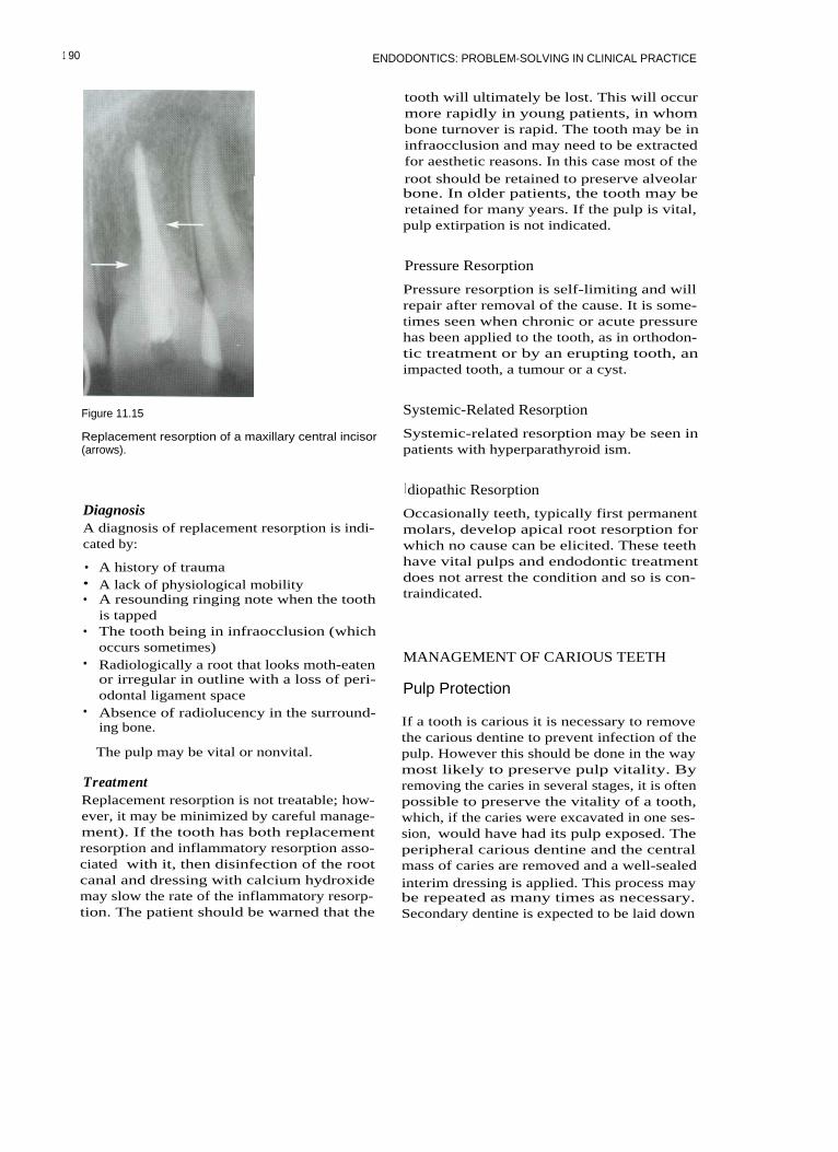
1 90 ENDODONTICS: PROBLEM-SOLVING IN CLINICAL PRACTICE
Figure 11.15
Replacement resorption of a maxillary central incisor(arrows).
tooth will ultimately be lost. This will occurmore rapidly in young patients, in whombone turnover is rapid. The tooth may be ininfraocclusion and may need to be extractedfor aesthetic reasons. In this case most of theroot should be retained to preserve alveolarbone. In older patients, the tooth may beretained for many years. If the pulp is vital,pulp extirpation is not indicated.
Pressure Resorption
Pressure resorption is self-limiting and willrepair after removal of the cause. It is some-times seen when chronic or acute pressurehas been applied to the tooth, as in orthodon-tic treatment or by an erupting tooth, animpacted tooth, a tumour or a cyst.
Systemic-Related Resorption
Systemic-related resorption may be seen inpatients with hyperparathyroid ism.
I diopathic Resorption
DiagnosisA diagnosis of replacement resorption is indi-cated by:
• A history of trauma• A lack of physiological mobility• A resounding ringing note when the tooth
is tapped• The tooth being in infraocclusion (which
occurs sometimes)• Radiologically a root that looks moth-eaten
or irregular in outline with a loss of peri-odontal ligament space
• Absence of radiolucency in the surround-ing bone.
The pulp may be vital or nonvital.
TreatmentReplacement resorption is not treatable; how-ever, it may be minimized by careful manage-ment). If the tooth has both replacementresorption and inflammatory resorption asso-ciated with it, then disinfection of the rootcanal and dressing with calcium hydroxidemay slow the rate of the inflammatory resorp-tion. The patient should be warned that the
Occasionally teeth, typically first permanentmolars, develop apical root resorption forwhich no cause can be elicited. These teethhave vital pulps and endodontic treatmentdoes not arrest the condition and so is con-traindicated.
MANAGEMENT OF CARIOUS TEETH
Pulp Protection
If a tooth is carious it is necessary to removethe carious dentine to prevent infection of thepulp. However this should be done in the waymost likely to preserve pulp vitality. Byremoving the caries in several stages, it is oftenpossible to preserve the vitality of a tooth,which, if the caries were excavated in one ses-sion, would have had its pulp exposed. Theperipheral carious dentine and the centralmass of caries are removed and a well-sealedinterim dressing is applied. This process maybe repeated as many times as necessary.Secondary dentine is expected to be laid down
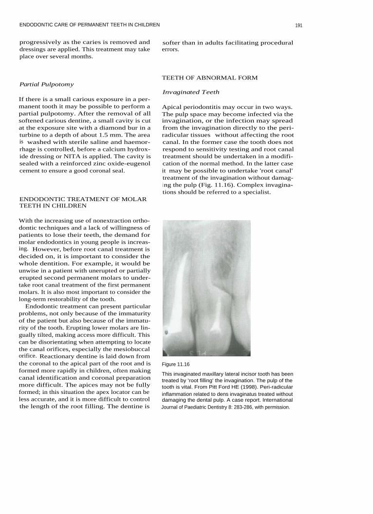
ENDODONTIC CARE OF PERMANENT TEETH IN CHILDREN
progressively as the caries is removed anddressings are applied. This treatment may takeplace over several months.
softer than in adults facilitating proceduralerrors.
Partial Pulpotomy
If there is a small carious exposure in a per-manent tooth it may be possible to perform apartial pulpotomy. After the removal of allsoftened carious dentine, a small cavity is cutat the exposure site with a diamond bur in aturbine to a depth of about 1.5 mm. The areais washed with sterile saline and haemor-rhage is controlled, before a calcium hydrox-ide dressing or NITA is applied. The cavity issealed with a reinforced zinc oxide-eugenolcement to ensure a good coronal seal.
ENDODONTIC TREATMENT OF MOLARTEETH IN CHILDREN
TEETH OF ABNORMAL FORM
Invaginated Teeth
Apical periodontitis may occur in two ways.The pulp space may become infected via theinvagination, or the infection may spreadfrom the invagination directly to the peri-radicular tissues without affecting the rootcanal. In the former case the tooth does notrespond to sensitivity testing and root canaltreatment should be undertaken in a modifi-cation of the normal method. In the latter caseit may be possible to undertake 'root canal'treatment of the invagination without damag-i ng the pulp (Fig. 11.16). Complex invagina-tions should be referred to a specialist.
With the increasing use of nonextraction ortho-dontic techniques and a lack of willingness ofpatients to lose their teeth, the demand formolar endodontics in young people is increas-ing. However, before root canal treatment isdecided on, it is important to consider thewhole dentition. For example, it would beunwise in a patient with unerupted or partiallyerupted second permanent molars to under-take root canal treatment of the first permanentmolars. It is also most important to consider thelong-term restorability of the tooth.
Endodontic treatment can present particularproblems, not only because of the immaturityof the patient but also because of the immatu-rity of the tooth. Erupting lower molars are lin-gually tilted, making access more difficult. Thiscan be disorientating when attempting to locatethe canal orifices, especially the mesiobuccalorifice. Reactionary dentine is laid down fromthe coronal to the apical part of the root and isformed more rapidly in children, often makingcanal identification and coronal preparationmore difficult. The apices may not be fullyformed; in this situation the apex locator can beless accurate, and it is more difficult to controlthe length of the root filling. The dentine is
Figure 11.16
This invaginated maxillary lateral incisor tooth has beentreated by 'root filling' the invagination. The pulp of thetooth is vital. From Pitt Ford HE (1998). Peri-radicularinflammation related to dens invaginatus treated withoutdamaging the dental pulp. A case report. InternationalJournal of Paediatric Dentistry 8: 283-286, with permission.
191

ENDODONTICS: PROBLEM-SOLVING IN CLINICAL PRACTICE
Evaginated Teeth Talon Cusp
Evaginated teeth tend to occur in the premo-lar teeth of people of mongoloid descent.There is a small outgrowth of tooth tissuefrom the crown (Fig. 11.17). This outgrowthusually contains pulp and tends to be frac-tured off during chewing, allowing infectionto enter the pulp. The treatment of choice is toremove the evagination electively and per-form a partial pulpotomy.
A talon cusp is similar to an evagination, butit usually affects incisor teeth (Fig. 11.18). Thecusp may or may not contain pulp. Cuspsmay be unsightly or may interfere with theocclusion. They may be treated if required ina similar manner to an evaginated tooth. Anyexposed dentine should be covered withrestorative material.
Figure 11.17
Evagination (arrow) affecting a mandibular secondpremolar.
FURTHER READING
Dajani AS, Taubert KA, Wilson W, et al.(1997). Prevention of bacterial endocarditis.Recommendations by the American HeartAssociation. Journal of the American MedicalAssociation 227: 1794-1801. Available on-lineat http://www.americanheart.org/Scientific/statements/ 1997/079701.html
Andreasen JO, Andreasen FM, Bakland LK,Flores MT (1999). Traumatic Dental Injuries: AManual. Munksgaard, Copenhagen.
Cvek M (1978). A clinical report on partialpulpotomy and capping with calciumhydroxide in permanent incisors with compli-cated crown fracture. Journal of Endodontics 4:232-237.
Figure 11.18
Talon cusps labially and palatally on a maxillary centralincisor.
Cvek M (1994). Endodontic management oftraumatized teeth. In: Andreasen JO,Andreasen FM, eds. Textbook and Colour Atlasof Traumatic Injuries to the Teeth, 3rd edition,Munksgaard, Copenhagen: 517-585.
Dental Practice Board for England and Wales(1999). National Clinical Guidelines and PolicyDocuments. Treatment of avulsed teeth in chil-dren. Treatment of traumatically intrudedpermanent incisor teeth in children.Management and root canal treatment of non-vital immature permanent incisor teeth.Dental Practice Board, Eastbourne.
Fuks AB, Chosack A, Klein H, Eidelman E(1987). Partial pulpotomy as a treatment alter-native for exposed pulps in crown-fracturedpermanent incisors. Endodontics and DentalTraumatology 3:100-102.
19 2

ENDODONTIC CARE OF PERMANENT TEETH IN CHILDREN
19 3
Jacobsen I (1980). Criteria for diagnosis in
Metzger Z, Solomonov M, Mass E (2001).traumatised permanent incisors. Scandinavian
Calcium hydroxide retention in wide rootJournal of Dental Research 88: 306-312.
canals
with
flaring
apices.
Dental
Leksell E, Ridell K, Cvek M, Mejare I (1996).
Traumatology 17: 86-92.
Pulp exposure after stepwise versus direct
Pitt Ford TR, Shabahang S (2002). Manage-complete excavation of deep carious lesions
ment of incompletely formed roots. In:in
young
posterior
permanent
teeth.
Walton R, Torabinejad M, eds. Principles and
Endodontics and Dental Traumatology 12: Practice of Endodontics, 3rd edition, WB192-196.
Saunders, Philadelphia: 388-404.
Mejare I, Cvek M (1993). Partial pulpotomy in
Sheehy EC, Roberts GJ (1997). Use of calciumyoung permanent teeth with deep carious
hydroxide for apical barrier formation andlesions. Endodontics and Dental Traumatology 9:
healing in non-vital immature permanent238-242.
teeth: a review. British Dental journal 183:241-246.

12 ENDODONTIC EMERGENCIES
CONTENTS • Introduction • Reversible Pulpitis • Irreversible Pulpitis • Problems withAnaesthesia • Acute Apical Periodontitis • Acute Apical Abscess • Hypochlorite Accident• Flare-up During Treatment
I NTRODUCTION
The treatment of endodontic emergencies canbe difficult in the general practice environ-ment, especially when the patient is in painand the clinician is short of time.
contacts. Teeth with cracks should be investi-gated. In small cavities a light-cured compos-ite restoration may be useful, to preventflexure of the fracture line. In some cases itmay be necessary to prepare the tooth for acast cusp-coverage restoration and to place atemporary crown.
REVERSIBLE PULPITIS
Signs and Symptoms
This is characterized by pain of short durationproduced by extremes of temperature andsometimes by sweet food. The pain is nor-mally of dentinal origin. No widening of theperiodontal ligament space should beexpected on radiological examination.
Look for:
• Exposed and sensitive dentine• Caries• Leaking restorations• Recently placed restorations• Cracks.
I RREVERSIBLE PULPITIS
Signs and Symptoms
Persistent symptoms following reversiblepulpitis may be indicative of irreversible pul-pitis. There is an increased duration andintensity of pain. Spontaneous aching, throb-bing and lingering pain, especially with hotstimuli, lasting several minutes or hours arecommon findings. Cold stimuli sometimesease the pain. The offending tooth may be dif-ficult to locate, and special tests could berequired to isolate it.
Radiologically there may be early signs ofperiodontal ligament widening.
Look for:
Treatment
Treatment involves removing the source ofdentinal irritation. Sensitive dentine may betreated with fluoride resin or desensitizingtoothpaste. Dental caries and leaking restora-tions should be removed and replaced with asedative dressing. Recently placed restora-tions may need time to settle down; it is wiseto check that there are no premature occlusal
• Extensive or recurrent caries• Teeth with large deep restorations, or cast
restorations• Evidence of cracks or fractures.
If identification of the tooth is difficult, iso-late the individual teeth with rubber dam andimmerse each tooth in hot water.

1 96 ENDODONTICS: PROBLEM-SOLVING IN CLINICAL PRACTICE
Treatment
I deal
The ideal treatment for irreversible pulpitis isto carry out complete cleaning and shaping ofthe root canal system. Sodium hypochlorite isused as an irrigant, and the canals are dressedwith calcium hydroxide. The patient shouldbe advised that the tooth could still be painfulwhen the anaesthetic wears off. It may there-fore be appropriate to prescribe analgesics,such as paracetamol (acetaminophen) 500 mgsix times daily or ibuprofen 200-400 mg sixtimes daily for 24 hours. The analgesicsshould be started immediately, before theanaesthetic begins to wear off. Sometimesusing a longer-acting anaesthetic such asMarcaine (bupivacaine hydrochloride) is use-ful.
Figure 12.1
Sealing a corticosteroid dressing into the pulp chamber ofa tooth with irreversible pulpitis. The root canals havenot been instrumented.
When Time is Short
Remove all pulp tissue from the pulp cham-ber and irrigate with sodium hypochlorite.Do not instrument the canals. A corticosteroidpreparation can be sealed in the pulp cham-ber with a temporary restoration of IRM(Intermediate Restorative Material: Dentsply,Weybridge, Surrey, UK: Fig. 12.1).
PROBLEMS WITH ANAESTHESIA
When attempting to root-treat a tooth that ispulpitic profound anaesthesia is important.Psychologically it is better for both the patientand the clinician to ensure good anaesthesiabefore embarking on treatment. It can be diffi-cult to regain a patient's confidence if treat-ment has been painful. The patient canbecome more nervous, and will anticipatefurther pain with every slight vibration on thetooth.
The classic tooth that is difficult to anaes-thetize is the mandibular molar; in this casethe following regime may help:
• Give two inferior dental block injections• A buccal and lingual infiltration• Use intraligamental infiltration around the
offending tooth (Fig. 12.2).
Figure 12.2
Intraligamental infiltration can be useful when anaesthe-sia is difficult to achieve.
If these still fail, intrapulpal anaesthesia canbe useful. Use a slow-speed round bur toexpose the pulp chamber. Warn the patientthat the following injection will be painful fora just a few seconds. Insert the hypodermicneedle into the pulp space and inject rapidly.Once anaesthesia has been achieved the pulpshould be extirpated as efficiently as possible.
Maxillary molar teeth require both a buccaland a palatal infiltration in order to achieveadequate anaesthesia.

ENDODONTIC EMERGENCIES
Intraosseous infiltration techniques can alsobe useful for pulpitic teeth, delivering localanaesthetic directly around the apices of theoffending tooth.
Long-acting anaesthetics, such as marcaine,that last for 6-8 hours are useful in the treat-ment of very painful teeth. If the patient hasbeen kept awake overnight with toothachethen the longer duration of anaesthesia willallow him or her some respite.
Analgesics may be required, and a combina-tion of paracetamol (500 mg six times daily)and ibuprofen (200 mg six times daily) shouldbe sufficient.
ACUTE APICAL ABSCESS
Signs and Symptoms
ACUTE APICAL PERIODONTITIS
Signs and Symptoms
The abscess may develop from apical peri-odontitis or an exacerbation of a chronic peri-apical abscess. The tooth is exquisitely painfulto touch, and may be extruded from itssocket. There may be buccal swelling, whichcan be diffuse or fluctuant.
The tooth will often be painful to bite on andthere will be tenderness over the apex of thetooth in the buccal sulcus. Radiologicallythere is usually widening of the periodontalligament space.
Look for:
• Tenderness in the buccal sulcus• Pain on palpation• A darkened tooth, particularly at the neck• Teeth with deep restorations or crowns• A tooth that does not respond to pulp test-
ing.
Treatment
To relieve the pain, drainage must be estab-lished, ideally through the root canal (Fig.12.3). Following this full root canal treatmentis carried out and the tooth is dressed withcalcium hydroxide. Fluctuant buccalswellings may be incised to drain pus (Figs.12.4-12.6). Teeth are generally not left open todrain unless there is an uncontrollable exu-date, and then only for no more than 24hours. Antibiotics may be required for apatient with systemic effects and a raised
Treatment
Root canal treatment is required. The rootcanals must be completely cleaned, shapedand dressed. The tooth may need to be stabi-lized whilst cutting the access cavity, as thevibration when cutting can be uncomfort-able. Sodium hypochlorite is used as an irri-gant, and calcium hydroxide as themedicament after complete cleaning. Theocclusion is adjusted to relieve any discom-fort on biting.
Antibiotics are ineffective for the treatmentof acute apical periodontitis if root canaltreatment is not carried out. Therefore thepractice of prescribing antibiotics instead ofundertaking root canal treatment is not rec-ommended, as pain will be prolonged.
Figure 12.3
Drainage through the root canal of a tooth with an acuteapical abscess.
19 7

19 8 ENDODONTICS: PROBLEM-SOLVING IN CLINICAL PRACTICE
Figure 12.4 Figure 12.6
A fluctuant buccal swelling. The root canal system of themaxillary first premolar has been thoroughly cleaned anddressed with calcium hydroxide. The swelling is to beincised.
Pus has stopped discharging. Antibiotics would not berequired in this case.
HYPOCHLORITE ACCIDENT
Signs and Symptoms
The patient will complain of severe painwhile the root canal is being irrigated.
Look for:
• Immediate swelling• Pain.
Treatment
Figure 12.5
The swelling has been incised; a microsurgical aspirationtip is being used to remove pus.
A hypochlorite accident will greatly under-mine the patient's confidence, and thereforethe main emphasis must be on prevention.Always use an endodontic irrigating syringe(Fig. 12.7), measure the length of the needle(Fig. 12.8), inject slowly and do not allow theneedle to bind.
temperature. Amoxycillin (250 mg three timesdaily) or metronidazole (200 mg three timesdaily) for three days should be sufficient.Some authorities recommend a single dose of3 g amoxycillin. Analgesics may also berequired. It is advisable to review all patientswithin 24 hours.
If extrusion occurs:
• Stop irrigating immediately• The best treatment is NO active interven-
tion• Extraction of the tooth is not indicated• Use long-acting block anaesthesia to
relieve the pain

ENDODONTIC EMERGENCIES 19 9
Figure 12.7
The tip of an endodontic irrigating syringe.
FLARE-UP DURING TREATMENT
Common causes of flare-ups following rootcanal preparation are over-instrumentation,extrusion of irrigants or medicaments andleaving the tooth in a traumatic occlusion.With good technique these can be avoided.
Signs and Symptoms
The patient will usually complain of a contin-uous dull ache, and the tooth will be tender totouch.
Figure 12.8
Measuring the irrigating needle to prevent extrusion ofsodium hypochlorite.
• Prescribe paracetamol for pain relief• Avoid aspirin (acetylsalicylic acid)• Warn the patient that there is likely to be
considerable swelling and bruising that islikely to last several days
• Follow up after 24 hours. In most casesthere is total resolution; however in someaffected tissues there may be abnormalfeeling for some time.
Treatment
• Re-irrigate the canals with sodiumhypochlorite
• Replace medicament and temporaryrestoration
• Check the occlusion. It may be necessary toremove the tooth completely from occlu-sion
• Analgesics may be required: 200-400 mgIbuprofen six times daily.
Late flare-up (after 24 hours) occurs mostcommonly following instrumentation of teethwith pre-existing chronic lesions. It is as if thebacteria within the root canal system are'stirred-up' by the cleaning process or per-haps inoculated through the apex. Perhaps afew viable bacteria remaining in fins or deltasare able to recolonize the root canal system.There is an exacerbation of the chronic condi-tion, leading to an acute apical abscess, andtreatment follows that for an acute apical abs-cess, already described.
Discomfort between appointments is alsoencountered with leaking coronal restora-tions. This should be considered when a toothdoes not settle following thorough prepara-tion, cleaning and medication. Microleakagewill allow recontamination of the root canalsystem. Inadequate restorations should beremoved prior to root canal treatment.

I NDEX
Note: page references in italics refer to Figures; those in bold refer to Tables
abscess, apical, acute 24-5, 25, 197-8access cavity preparation 80-90
aims 80depth estimation 81lid-off approach 80-90, 81location 80preoperative radiograph 80, 80troubleshooting 85-90unusual anatomy 87
acoustic microstreaming 139AH 26 sealer 123AH Plus sealer 123air abrasion 47, 48alveolar bone, anatomy 30amalgam 159,159
plugger 55, 55, 85amoxycillin 3anaesthesia
local 3, 14, 112problems with 196-7for procedures on maxillary teeth 168for procedures on mandibular teeth 168
Analytical Technology pulp tester 12,13anastomoses 27angulation of the crown 87ankylosis 7, 7antibiotics
allergy to 1prophylaxis 3
anticurvature filing 97apex locator 97-8, 98apical abscess, acute 24-5, 25, 197-8apical constriction 28, 29apical flare (stepback) 97,103, 104apical periodontitis 25, 79, 197assessment 165-6
patient's symptoms and signs 165radiological evidence of bony healing 165-6radiological review 166
asthma, as contraindication for surgicalendodontics 166
avulsion 185-6,186
bacteraemia 3bacteria 79, 112balanced force action 96,101-2, 101
blockage 104-6prevention 104technique of managing 104-5
blood flow measurement 14braiding 142, 143, 144Briault probe 12, 85bridge abutments 59-60
sectioning 60, 60removing 60root filled teeth 163
buccal sulcus, palpation of 8, 8burs 81, 83, 87-8, 93, 93, 95, 100, 101, 103, 134, 135
C-shaped canal 44calcifications 85-6calcium hydroxide 116, 117, 117, 118, 118, 121
liners 50pastes 138points 119,119sealer 122
camphorated paramonochlorophenol 118camphorated phenol 118Cancellier 142, 143, 143, 144cancellous bone 30cantilever bridge 151carborundum disc 70, 70caries 46-7, 46
hardness 47, 47management 48-51
in non-vital tooth 51reason for 48-9technique 49-51teeth with destruction of marginal ridges 51timing 49
paediatric 190-1recurrent 6, 6, 7removal 47
cast cores 160cast restoration 158caulking 70Cavi-endo endosonic insert 116Cavit 70cavitation 139cementum, anatomy 30cermets 160cervical resorption 175-7,176
I NDEX
chief complaint 3children
isolation for endodontic treatment 179-80management of carious teeth 190-1molar teeth 191root resorption 188-90teeth of abnormal form 191-2trauma 180-8
chisel, use in crown removal 58,58chlorhexidine gluconate mouthwash 3,112chloropercha 124circumferential filing 97citric acid 113clindamycin 3cold lateral condensation 124,125cold testing 12,13compomer 51composite resin 50-1, 50
core 160,160concussion 184copalite varnish 49copper bands 56coronal flaring 139coronal seal 45, 46cortical bone 30cortical trephination 167corticosteroid/antibiotic paste 117-18, 117cost post removal 145,146cracked cusps, identifying 15-16cracked teeth and fractures 51-3, 52-3crown-down preparation 100-2
apical preparation 101coronal preparation 100-1rationale 100techniques 102-4use of Greater Taper files for 102
crown tapper 58, 59crowned teeth 56-9, 57-8crown fractures 181
enamel or dentine fractures 181exposing the pulp 181-2lengthening 62, 62
crownsmetal-free 154-5
anterior teeth requiring auxiliary retention155
porcelain jacket crown 154-5with metal substructure 154
metal ceramic crowns 154, 161, 161-2metal composite crowns 154
for posterior teeth 160-3cast metal 161ceramic 162full cast metal 161metal ceramic 161,161-2partial cast metal 161, 161temporary 162
posts 155-8removing 57-9, 58-9temporary 60-2
C-shaped canal 87,87in Mongoloid races 44
cuspal coverage restorations 158
debonding 152dental tape 70Dentatus screw posts 144, 160Dentatus wrench 144,145dentine, anatomy 27-8
irritation 48peritubular 28primary 28secondary 28
dentine-bonding agents 50-1, 50dentine pins 78DG16 probe 12, 85,85diabetes, as contraindication 1, 3, 166diagnosis 23-5diamond bur 70, 81, 87drug abusers 3Dry Dam 180Dycal 181dyes 87
EDTA (ethylene diaminetetraacetate) 86, 87,104,112-13,113
Eggler post remover 146,147elbows 96, 96electric pulp testing 12-13,14endomethazone 138Endoray 99, 99endosonic file 126-7,127endosonic tip 128,130endosonics
gutta-percha removal using 140paste removing using 139
Endo-Z bur 84, 85Enteroeoccus faecalis 79, 112evaginated teeth 192,192excavator 138external resorption 188-90extraction 137Examination (extraoral) 4-5Examination (entraoral) 5-12
ease of access 5, 6general condition of mouth 5-6mobility of fixed prosthodontics 8, 11palpation of buccal sulcus 8, 8percussion 7, 7periodontal pocketing 8probing depth 8, 11sinus tracts 8, 8, 9tenderness to palpation 7tooth mobility 6, 7
202

I NDEX
facial swelling 4-5, 5File-eze 105filing 96-7finger spreader 125, 126, 127-8, 127-8flare-ups during treatment 199flat plastic in crown removal 58, 58Flexobend 103Flexofiles 92, 92, 102, 103formaldehydes 118fractured instrument 105,141-4
apical position 142-3,143coronal position 142, 142immovable instruments 144middle position 143-4
Gates-Glidden burs 93, 93, 95,100, 101, 103, 134,135
condensed gutta-percha removal using 140,141ledge formation using 104overuse 96, 106, 106paste removal using 139
glass ionomercement 51, 53, 55, 55, 56, 150, 158, 160,181sealer 123
Gonon post remover 146Greater Taper files 102,102Grossman's sealer 122gutta percha 8, 10, 122, 124, 125,125,126
condensed 140-1,141crinkling of 134,135custom-fitting a cone 126heat testing using 13,13removal 139-41,141removal of excess 128System B vertical compaction of 130-4,131-3
ibuprofen 196idiopathic resorption 190immature tooth, trauma to 186-8
filling the root canal 188treatment 186-7troubleshooting apical barrier induction 187-8
infective endocarditisas contraindication for surgical endodontics 166patients at risk of 3prevention 3
Intermediate Restorative Material (IRM) 147, 158,168, 171, 181, 196
internal resorption 174-5, 174-5invaginated teeth 32, 191, 191iodine in potassium iodide 112,113, 117,117irreversible pulpitis 24, 195-6irrigants
delivery 113-16endodonics 114-16,115-16syringe 113,113-15,138
types -111-13irrigation, reason for 111irritation dentine 48isolation
benefits 65reason for 65timing 65see also rubber dam
K3 rotary instruments 108Kalzinol 70Ketac Endo sealer 123Ketac Silver 160K-file instruments 92K-Flex files 92
haemostasis 168hand files 91-2
instrument design 92ISO sizes and colours 91, 91material 91placement of medicaments by 118-19,118restoring force 91-2taper 92tip design 91tip sizes 91
hand instruments 90-2hand spreader 125,125heart disease 3heat testing 12, 13Hedstroem file 92, 92, 96, 103, 139, 140, 141history taking 1-4Howship's lacunae 30hypertension, as contraindication for surgical
endodontics 166Hypocal 187
hypochlorite accident 198-9
Laser Doppler flowmetry 12, 14, 15lateral condensation 125-8
cold 124,125cone fitting 126,126-7custom-fitting a gutta percha cone 126removal of excess gutta percha 128see also warm lateral compaction
latex allergy 1, 65length of canal
estimation 97loss of 105
Leubke-Ochsenbein flap 169local anaesthetic 3, 14, 112loupes 86, 86lubricants 70Luxatemp 61,152luxation injuries 184-5
extrusive 184intrusive 184lateral 184
lymph nodes, palpation of 4, 5
203

20 4 I NDEX
lymphadenopathy of the submandibular lymphnodes 4
Machtou plugger 132-3,133,188mandibular canine, anatomy 40,40mandibular first molar, anatomy 42-3, 42-3mandibular first premolar, anatomy 41, 41mandibular incisors, anatomy 38-40, 39-40mandibular second molar, anatomy 43-4,43mandibular second premolar, anatomy 41-2,41mandibular third molar, anatomy 44Marcain 196Masserann kit 144-5, 145,146master apical file (MAF) 103maxillary canine 33,33maxillary central incisor, anatomy 30-2, 32maxillary first molar, anatomy 36-8,36-7maxillary first premolar, anatomy 33-5, 34maxillary lateral incisor, anatomy 32, 33maxillary second molar, anatomy 38,39maxillary second premolar, anatomy 35-6, 35maxillary third molar, anatomy 38,39medical history 1-2medicaments 116-19
intracanal 117-18placement 118-19
calcium hydroxide points 119,119hand file 118-19,118spiral fillers 119,119syringe delivery 118,118
reason for 116technique 117-19
mesio-occlusal cavities 158-9mesio-occlusal-distal cavities 158-9
cast restorations 159plastic restorations 159
metal shell crowns 56, 56, 61methacrylate resin 61microcomputed tomography (MCT) 29microorganisms 79,112Mineral Trioxide Aggregate (MTA) 147,168, 171,
172,182,188modified double-flare technique 103-4
apical flaring (stepping back) 104coronal preparation 103preparation of the apical section 103-4
nasolabial folds, asymmetry 4, 5Nayyar core 150, 159, 159nerve fibres 27nickel-titanium alloys 90, 92
files 97orifice openers 93, 93, 100rotary instruments 139
number of roots and canals 81, 82
Obtura system 134,134, 150, 188
obturation 121-35criteria for 121root filling materials 123-4sealers 122-3techniques 124-34
cold lateral condensation 124, 125System B vertical compaction of gutta percha
130-4,131 -3thermocompaction (ultrasonic and
mechanical) 124,125warm lateral condensation 124,124,128-30,129warm vertical condensation 124,124
troubleshooting 134-5crinkling of the gutta percha 134, 135inability to place the spreader/ plugger to
length 135master cone will not fit to length 134-5removing cones during condensing 135voids in the obturatiog material 135
operating microscope 86, 86Oraseal putty 70, 71orifice shapers 95, 96orthodontic bands, placing 53-6, 54
reasons for 53-4orthodontic extrusion 62-3osteocytes 30over-preparation 105
pain 24, 47from biting 16,16psychogenic 1
pain relief 168palpation 4
of buccal sulcus 8, 8tenderness to 7
paracetamol 196paraformaldehydes 118partial pulpotomy 181-2,181-2paste and cement root filling materials, removal
138-9removing paste from pulp chamber 138-9removing paste from root canals 139set cements 139
patency maintenance 97percussion 7, 7perforation 96, 96, 97,104periapical conditions 24-5, 25periapical inflammation, acute 24periodontal ligament, anatomy 30,30periodontal pocketing 8periodontal probe 85periodontitis, apical 25, 79, 197perio-endo lesions 173-4phenols 118Piezon unit 115plexus of Raschkow 27pneumatic crown remover 58-9, 59

I NDEX
poly acid-modified composite (compomer) 51polycarbonate resin 47post removal 144-7
cost posts 145, 146Masserann kit 144-5,145,146post removers 146, 147screw posts 144
posts 88, 155-8cementing 158diameter 156direct cast post and core 157indirect cast post and cores 157length 155-6material 156post and core fabrication 157, 157in posterior teeth 160preformed 157preparation of the post hole 157removal 144-7shape 155surface characteristics 156
preoperative mouthrinse 168preparation, root canal
access cavity preparation 80-90crown-down preparation 100-4hand 100-6instruments
for apical preparation 107, 107-8for coronal preparation 93,107hand instruments 90-2rotary instruments 108-9
mechanical preparation 106-9apical preparation 108avoidance of instrument fracture 107canal curvature 107coronal preparation 108cutting action 107merging middle section of canal 109pilot channel preparation 109rotation 106, 107
rationale 79-80techniques 93-9
chemo-mechanical 94crown-down preparation 93-6, 95movement of files 96-100procedural errors 96terminology 93-6
pressure resorption 190probing depth 8,11Procera technique 155Profile instruments 108prosthodontics, fixed, mobility of 8,11Protemp 61, 152pulp
anatomy 27condition 23-4damage during preparation 47
necrosis 24, 24, 47normal 23stones 85, 85testing 12
pulp dentine complex 27pulp floor map 85, 89pulpitis 47, 53
irreversible 24, 195-6reversible 24, 195
pyrexia 24
quarter-turn pull 97
radiographic film 17-18development 17-18,18film speed 17processing 17storage 17
radiography 16-23automatic processors 18digital radiography 18dose reduction 17fixing 18length estimation 98-9, 99postoperative 171preoperative 80, 80separating root canals 99
mandibular incisors 99, 100mandibular premolars 99mandibular molars 99, 100maxillary premolars 99maxillary molars 99
techniques 17,18-23edentulous spaces 22retching 22, 23shallow palate 22small mouth 22
X-ray unit 16-17Radix anchor post system 144, 156reamers 91-2
instrument design 92ISO sizes and colours 91, 91material 91restoring force 91-2taper 92tip design 91tip sizes 91
recapitulation 97recementing a cast restoration or post crown 164reciprocating action 97replacement resorption 189-90,190resin sealers 123resorption
cervical 175-7,176external 188-90internal 174-5,174-5pressure 190
20 5
20 6 I NDEX
resorption continuedreplacement 189-90,190surface 188
restorations 87-8anterior teeth 152cuspal coverage restorations 158extensive restoration 154internal bleaching 153,153mesio-occlusal cavities 158mesio-occlusal-distal cavities 158-9occlusal loading 151posterior teeth 158preservation of tooth substance 151, 151restorability 151-2severely broken-down teeth 159-63simple restoration 153-4,153timing 152treatment planning 150-1
retreatment, root canal 137-48gutta-percha removal 139-41, 141illumination and magnification 138,138ledges 147paste and cement root filling materials 138-9perforations 147-8, 148post removal 144-7preparation of root canals 148reason for 137-8silver points and fractured instruments 141-4single cone gutta-percha removal 139-40technique 138Thermafil 141timing 138
reversible pulpitis 24, 195rheumatic fever 3Rinn holder paralleling device 19,20-1, 23root canals
anatomy 28-30,28location of extra 88-90
four canals in mandibular molars 89-90, 89second mesiobuccal of maxillary molars 88-9,
88-9two canals in a mandibular premolar 90, 90two canals in mandibular incisors 90, 90
root end surgery 137root filling materials 123-4root fracture
horizontal 182-4longitudinal 16, 51-3, 52, 166,166
root resorption see resorptionrubber dam
badly broken-down teeth 77-8, 77bridges 77, 78clamps 66-8, 69, 78, 179forceps 68-70, 70frames 66, 66-7isolation problems 77-8kit 71, 72
multiple teeth isolation 75, 75placement 71, 71-2, 75punch 68, 68-9quick single tooth isolation method 73-4, 73-4sealants 70-1, 179sheet 71-2silicone 65, 66split-dam technique 76using wingless clamps 76-7, 77varieties 65, 66Wedgets, use of 70, 70,180
Ruddle post remover 146,147
Schick system (digital radiography) 19Schilder plugger 132-3sclerosed canals 86-7Sealapex 123sealers 122-3sealing access cavity 149-50sectioning, crown removal and 59,59severely broken-down teeth 159-63silver point removal 141-4
apical position 142-3,143coronal position 142, 142middle position 143-4
sinus tract 5, 6, 8, 8, 9sodium hypochlorite 80, 98, 111-12, 112, 148Spencer Wells forceps 99spiral fillers 119,119stepback (apical flare) 97, 103, 104stepdown technique of canal preparation 103
apical flare (stepback) 103initial coronal flare 103precurving files 103
Stieglitz forceps 140, 140strip perforation 96, 96Stropko irrigator 85, 85, 86subluxation 184Super EBA (ethoxybenzoic acid) 147, 168,171surface resorption 188surgical endodontics 166-73
anaesthesia, pain control and haemostasis 168apical surgery 167
apical curettage 167root-end surgery 167
corrective surgery 167perforation repair 167root resection 167tooth resection 167
flap design and reflection 168-9flap replacement 172,172incision and drainage 167i ndications 166-7osseous entry 169-70,169-70postoperative instructions 172-3postoperative radiograph 171root-end filling 171,171-2

I NDEX
root-end resection and cavity preparation 170-1,171
surgical armamentarium 167-8surgical sieve 1System B vertical compaction of gutta percha
130-4,131-3backfill 134,134cone fit 132down pack 134fitting the cone 133measuring the plugger 132-3,133
systemic-related resorption 190
talon cusp 192,192teeth of abnormal form 191-2Tenax titanium post kit 155test cavity, cutting 15Thermafil 141thermal tests 12thermocompaction (ultrasonic and mechanical)
124,125tooth mobility 6, 7Tooth Slooth 16, 16, 55transient apical breakdown 185transillumination with fibre optic light 15transportation 96, 96, 104trauma 180-8
diagnosis 180-1
troubleshootingapical barrier induction 187-8obturation 134-5root canal preparation 104-6
blockage 104-6fractured instrument 105loss of length 105over-preparation 105perforation 104transportation 104wine-bottle effect 106
Tubliseal 122tubular sclerosis 48tungsten carbide bur 81, 87
ultrasonic tip 87, 90, 138, 139, 144, 144,171ultrasonics in crown removal 58,58
varnish 49
warm lateral condensation 124,124,128-30,129warm vertical condensation 124,124
zinc oxide and eugenolcement 50, 50, 53, 61, 70,138,147,150,158,181, 186sealers 122
zinc phosphate cement 54, 56, 78zips 96, 96, 97
207