
EM 300 - Multibeam echo sounder - KONGSBERG
442
EM 300 Multibeam echo sounder Complete version Maintenance manual
-
Upload
khangminh22 -
Category
Documents
-
view
3 -
download
0
Transcript of EM 300 - Multibeam echo sounder - KONGSBERG

EM 300Multibeam echo sounderComplete version
Maintenance manual


EM 300
Multibeam echo sounder
Maintenance manual - Complete version
852--164892 / Rev.A

NoteKongsberg Maritime AS makes every effort to ensure that the information containedwithin this document is correct. However, our equipment is continuously beingimproved and updated, so we cannot assume liability for any errors which may occur.
WarningThe equipment to which this manual applies must only be used for the purpose forwhich it was designed. Improper use or maintenance may cause damage to theequipment or injury to personnel. The user must be familiar with the contents of theappropriate manuals before attempting to install, operate or maintain the equipment.Kongsberg Maritime AS disclaims any responsibility for damage or injury caused byimproper installation, use or maintenance of the equipment.
CopyrightE 2004 Kongsberg Maritime AS
The information contained within this document remains the sole property ofKongsberg Maritime AS. No part of this document may be copied or reproduced in anyform or by any means, and the information contained within is not to be communicatedto a third party, without the prior written consent of Kongsberg Maritime AS.
Contact informationSupport: [email protected]: [email protected] hrs support telephone: +47 99 20 38 01
Strandpromenaden 50P.O.Box 111N-3191 Horten,Norway
Maintenance manual
I852-164892 / A
Sections
This book is the Maintenance manual for the EM 300 multibeam echo sounder. Itdescribes how to perform intermediate maintenance on the system.The manual is divided into chapters that describe the different versions delivered.
1 IntroductionThis section presents a general introduction to the echo sounder system, anddefines the maintenance philosophy. Refer to page 1.
2 Technical specificationsThis chapter presents the main technical specifications. Refer to page 7.
3 Cable layout and interconnectionsThis chapter describes the cabling, and details the necessary cablespecifications. Refer to page 11.
4 Transceiver Unit 125-210131This chapter describes the design and operation of the Transceiver Unit withregistration number 125--210131. Each circuit board is explained, as well asoverall block diagrams and the theory of operation. Refer to page 41.
5 Transceiver Unit 125-211293This chapter describes the design and operation of the Transceiver Unit withregistration number 125--211293. Each circuit board is explained, as well asoverall block diagrams and the theory of operation. Refer to page 101.
6 Transceiver Unit 125-218182This chapter describes the design and operation of the Transceiver Unit withregistration number 125--218182. Each circuit board is explained, as well asoverall block diagrams and the theory of operation. Refer to page 161.
7 Raw Data Logger (optional)This chapter describes the design and operation of the RawData Logger. Referto page 213.
8 TroubleshootingThis chapter provides basic procedures for automatic and traditionaltroubleshooting. Refer to page 215.
9 Replacement proceduresThis chapter explains how to perform replacement of the line replaceable units(LRU). Refer to page 271.
10 Datagram formatsThe formats for data input and output to and from the EM Series multibeamecho sounders are described here. Refer to page 283.

EM 300 Complete version
II 852-164892 / A
11 System administrationThis chapter provides basic information useful for the EM 300 systemsupervisor. Refer to page 329.
12 Spare partsThis chapter provides a listing of the line replaceable units with illustrationsand order numbers. Refer to page 367.
13 Drawing file
Remarks
ReferencesFurther information about the EM 300 system supplied to Complete version may befound in the following manuals:• EM 300 Operator manual• EM 300 Installation manual
The readerThis maintenance manual is intended to be used by a trained maintenance technician orengineer, with experience of electronic and digital circuitry, computers andelectromechanical design. The level of information is based on Simrad’s maintenancephilosophy: The onboard technical personnel shall, with the help of the documentationand the system’s built-in test functions, be able to identify malfunctions, locate thefault, and replace major parts, modules and components on the “Line Replaceable Unit”(LRU) level. He/she will however not attempt to repair the LRUs.
NoteThis manual is issued according to a registered distribution list. In the event of changesto this manual, only authorized copies with copy numbers will be updated.

Maintenance manual
III852-164892 / A
Table of contents
1 INTRODUCTION 1. . . . . . . . . . . . . . . . . . . . . . . . . . . . . . . . . . . . . . . . .1.1 Overview 1. . . . . . . . . . . . . . . . . . . . . . . . . . . . . . . . . . . . . . . . . . . . . . . .
1.2 Maintenance philosophy 1. . . . . . . . . . . . . . . . . . . . . . . . . . . . . . . . . . . .
1.3 System description 3. . . . . . . . . . . . . . . . . . . . . . . . . . . . . . . . . . . . . . . .
Overview 3. . . . . . . . . . . . . . . . . . . . . . . . . . . . . . . . . . . . . . . . . . . . . . .Key features 3. . . . . . . . . . . . . . . . . . . . . . . . . . . . . . . . . . . . . . . . . . . . .
1.4 Note about changing AC supply voltage 6. . . . . . . . . . . . . . . . . . . . . . .
2 TECHNICAL SPECIFICATIONS 7. . . . . . . . . . . . . . . . . . . . . . . . . .Interfaces 7. . . . . . . . . . . . . . . . . . . . . . . . . . . . . . . . . . . . . . . . . . . . . . .Physical properties 7. . . . . . . . . . . . . . . . . . . . . . . . . . . . . . . . . . . . . . .Power requirements 8. . . . . . . . . . . . . . . . . . . . . . . . . . . . . . . . . . . . . . .Restrictions for use - limitations 9. . . . . . . . . . . . . . . . . . . . . . . . . . . . .Surface finish 9. . . . . . . . . . . . . . . . . . . . . . . . . . . . . . . . . . . . . . . . . . .Environmental specifications 9. . . . . . . . . . . . . . . . . . . . . . . . . . . . . . .System performance data 9. . . . . . . . . . . . . . . . . . . . . . . . . . . . . . . . . .
3 CABLE LAYOUT 11. . . . . . . . . . . . . . . . . . . . . . . . . . . . . . . . . . . . . . . . . .3.1 Introduction 11. . . . . . . . . . . . . . . . . . . . . . . . . . . . . . . . . . . . . . . . . . . . . .
3.2 System cabling 12. . . . . . . . . . . . . . . . . . . . . . . . . . . . . . . . . . . . . . . . . . .
Cable layout 12. . . . . . . . . . . . . . . . . . . . . . . . . . . . . . . . . . . . . . . . . . . .Shipyard and system cables 12. . . . . . . . . . . . . . . . . . . . . . . . . . . . . . . .Operator Station cables 13. . . . . . . . . . . . . . . . . . . . . . . . . . . . . . . . . . . .Transceiver Unit cables 17. . . . . . . . . . . . . . . . . . . . . . . . . . . . . . . . . . . .Generic RS-232 serial line (DCE) 20. . . . . . . . . . . . . . . . . . . . . . . . . . . .Generic RS-232 Serial line 21. . . . . . . . . . . . . . . . . . . . . . . . . . . . . . . . .Generic RS-232 Serial line 22. . . . . . . . . . . . . . . . . . . . . . . . . . . . . . . . .Generic coax cable 23. . . . . . . . . . . . . . . . . . . . . . . . . . . . . . . . . . . . . . .Sound speed probe interface 24. . . . . . . . . . . . . . . . . . . . . . . . . . . . . . . .EM Remote synchronisation and On/Off 25. . . . . . . . . . . . . . . . . . . . . .Generic RJ45 extender 26. . . . . . . . . . . . . . . . . . . . . . . . . . . . . . . . . . . .Standard AC power cable 27. . . . . . . . . . . . . . . . . . . . . . . . . . . . . . . . . .Ethernet with RJ45 28. . . . . . . . . . . . . . . . . . . . . . . . . . . . . . . . . . . . . . .Standard VGA cable 29. . . . . . . . . . . . . . . . . . . . . . . . . . . . . . . . . . . . . .Keyboard cable 30. . . . . . . . . . . . . . . . . . . . . . . . . . . . . . . . . . . . . . . . . .Mouse or pointing device cable 31. . . . . . . . . . . . . . . . . . . . . . . . . . . . .Centronics printer cable 32. . . . . . . . . . . . . . . . . . . . . . . . . . . . . . . . . . .EM 300 Synchronization 33. . . . . . . . . . . . . . . . . . . . . . . . . . . . . . . . . .

EM 300 Complete version
IV 852-164892 / A
3.3 Transducer cables 34. . . . . . . . . . . . . . . . . . . . . . . . . . . . . . . . . . . . . . . . .Introduction 34. . . . . . . . . . . . . . . . . . . . . . . . . . . . . . . . . . . . . . . . . . . . .Transmit array cable markings 35. . . . . . . . . . . . . . . . . . . . . . . . . . . . . .Receive array cable markings 36. . . . . . . . . . . . . . . . . . . . . . . . . . . . . . .
6 TRANSCEIVER UNIT 125-218182 41. . . . . . . . . . . . . . . . . . . . . .6.1 Description and main functions 41. . . . . . . . . . . . . . . . . . . . . . . . . . . . . .
Overview 41. . . . . . . . . . . . . . . . . . . . . . . . . . . . . . . . . . . . . . . . . . . . . . .6.2 Transceiver Unit 125--218182 42. . . . . . . . . . . . . . . . . . . . . . . . . . . . . . . .
The Processing Rack 46. . . . . . . . . . . . . . . . . . . . . . . . . . . . . . . . . . . . . .The Receiver Rack 48. . . . . . . . . . . . . . . . . . . . . . . . . . . . . . . . . . . . . . .The Transmitter Rack 49. . . . . . . . . . . . . . . . . . . . . . . . . . . . . . . . . . . . .
6.3 Theory of operation 50. . . . . . . . . . . . . . . . . . . . . . . . . . . . . . . . . . . . . . .Overview 50. . . . . . . . . . . . . . . . . . . . . . . . . . . . . . . . . . . . . . . . . . . . . . .Simplified block diagram 50. . . . . . . . . . . . . . . . . . . . . . . . . . . . . . . . . .Control functions 51. . . . . . . . . . . . . . . . . . . . . . . . . . . . . . . . . . . . . . . . .
6.5 Circuit board descriptions 54. . . . . . . . . . . . . . . . . . . . . . . . . . . . . . . . . . .Overview 54. . . . . . . . . . . . . . . . . . . . . . . . . . . . . . . . . . . . . . . . . . . . . . .
6.4 Processing rack details 55. . . . . . . . . . . . . . . . . . . . . . . . . . . . . . . . . . . . .Location 55. . . . . . . . . . . . . . . . . . . . . . . . . . . . . . . . . . . . . . . . . . . . . . . .Circuit boards and modules 55. . . . . . . . . . . . . . . . . . . . . . . . . . . . . . . . .4-Ports Serial Line Board (C114P) 56. . . . . . . . . . . . . . . . . . . . . . . . . . .Beamformer & Signal Processor (BSP) 58. . . . . . . . . . . . . . . . . . . . . . .Ethernet Adapter 61. . . . . . . . . . . . . . . . . . . . . . . . . . . . . . . . . . . . . . . . .ROM board 63. . . . . . . . . . . . . . . . . . . . . . . . . . . . . . . . . . . . . . . . . . . . .Control Processor Unit board 64. . . . . . . . . . . . . . . . . . . . . . . . . . . . . . .Processing Unit Power Supply 69. . . . . . . . . . . . . . . . . . . . . . . . . . . . . .Motherboard 71. . . . . . . . . . . . . . . . . . . . . . . . . . . . . . . . . . . . . . . . . . . .
6.6 Receiver rack details 72. . . . . . . . . . . . . . . . . . . . . . . . . . . . . . . . . . . . . . .Location 72. . . . . . . . . . . . . . . . . . . . . . . . . . . . . . . . . . . . . . . . . . . . . . . .Circuit boards and modules 72. . . . . . . . . . . . . . . . . . . . . . . . . . . . . . . . .Transmitter/Receiver Board (TRB) 73. . . . . . . . . . . . . . . . . . . . . . . . . . .Low Voltage Power Unit (LVPU) 76. . . . . . . . . . . . . . . . . . . . . . . . . . . .High Voltage Power Unit (HVPU) 79. . . . . . . . . . . . . . . . . . . . . . . . . . .Signal Processor Board (SPB31) 80. . . . . . . . . . . . . . . . . . . . . . . . . . . .Receiver Backplane (RXBP) 86. . . . . . . . . . . . . . . . . . . . . . . . . . . . . . . .
6.7 Transmitter rack details 92. . . . . . . . . . . . . . . . . . . . . . . . . . . . . . . . . . . . .Location 92. . . . . . . . . . . . . . . . . . . . . . . . . . . . . . . . . . . . . . . . . . . . . . . .Circuit boards and modules 92. . . . . . . . . . . . . . . . . . . . . . . . . . . . . . . . .64-Channel Transmitter (TX64) 93. . . . . . . . . . . . . . . . . . . . . . . . . . . . .

Maintenance manual
V852-164892 / A
Transmitter Backplane (TXBP) 97. . . . . . . . . . . . . . . . . . . . . . . . . . . . . .
6 TRANSCEIVER UNIT 125-218182 101. . . . . . . . . . . . . . . . . . . . . .6.1 Description and main functions 101. . . . . . . . . . . . . . . . . . . . . . . . . . . . . .
Overview 101. . . . . . . . . . . . . . . . . . . . . . . . . . . . . . . . . . . . . . . . . . . . . . .6.2 Transceiver Unit 125--218182 102. . . . . . . . . . . . . . . . . . . . . . . . . . . . . . . .
The Processing Rack 108. . . . . . . . . . . . . . . . . . . . . . . . . . . . . . . . . . . . . .The Receiver Rack 110. . . . . . . . . . . . . . . . . . . . . . . . . . . . . . . . . . . . . . .The Transmitter Rack 111. . . . . . . . . . . . . . . . . . . . . . . . . . . . . . . . . . . . .
6.3 Theory of operation 112. . . . . . . . . . . . . . . . . . . . . . . . . . . . . . . . . . . . . . .Overview 112. . . . . . . . . . . . . . . . . . . . . . . . . . . . . . . . . . . . . . . . . . . . . . .Simplified block diagram 112. . . . . . . . . . . . . . . . . . . . . . . . . . . . . . . . . .Control functions 113. . . . . . . . . . . . . . . . . . . . . . . . . . . . . . . . . . . . . . . . .
6.5 Circuit board descriptions 116. . . . . . . . . . . . . . . . . . . . . . . . . . . . . . . . . . .Overview 116. . . . . . . . . . . . . . . . . . . . . . . . . . . . . . . . . . . . . . . . . . . . . . .
6.4 Processing rack details 117. . . . . . . . . . . . . . . . . . . . . . . . . . . . . . . . . . . . .Location 117. . . . . . . . . . . . . . . . . . . . . . . . . . . . . . . . . . . . . . . . . . . . . . . .Circuit boards and modules 117. . . . . . . . . . . . . . . . . . . . . . . . . . . . . . . . .4-Ports Serial Line Board (C114P) 118. . . . . . . . . . . . . . . . . . . . . . . . . . .Beamformer & Signal Processor (BSP) 120. . . . . . . . . . . . . . . . . . . . . . .Control Processor Unit board 123. . . . . . . . . . . . . . . . . . . . . . . . . . . . . . .Ethernet Adapter 128. . . . . . . . . . . . . . . . . . . . . . . . . . . . . . . . . . . . . . . . .Processing Unit Power Supply 130. . . . . . . . . . . . . . . . . . . . . . . . . . . . . .Motherboard 133. . . . . . . . . . . . . . . . . . . . . . . . . . . . . . . . . . . . . . . . . . . .
6.6 Receiver rack details 134. . . . . . . . . . . . . . . . . . . . . . . . . . . . . . . . . . . . . . .Location 134. . . . . . . . . . . . . . . . . . . . . . . . . . . . . . . . . . . . . . . . . . . . . . . .Circuit boards and modules 134. . . . . . . . . . . . . . . . . . . . . . . . . . . . . . . . .Transmitter/Receiver Board (TRB) 135. . . . . . . . . . . . . . . . . . . . . . . . . . .Low Voltage Power Unit (LVPU) 138. . . . . . . . . . . . . . . . . . . . . . . . . . . .High Voltage Power Unit (HVPU) 141. . . . . . . . . . . . . . . . . . . . . . . . . . .Signal Processor Board (SPB31) 142. . . . . . . . . . . . . . . . . . . . . . . . . . . .Receiver Backplane (RXBP) 148. . . . . . . . . . . . . . . . . . . . . . . . . . . . . . . .
6.7 Transmitter rack details 152. . . . . . . . . . . . . . . . . . . . . . . . . . . . . . . . . . . . .Location 152. . . . . . . . . . . . . . . . . . . . . . . . . . . . . . . . . . . . . . . . . . . . . . . .Circuit boards and modules 152. . . . . . . . . . . . . . . . . . . . . . . . . . . . . . . . .64-Channel Transmitter (TX64) 153. . . . . . . . . . . . . . . . . . . . . . . . . . . . .Transmitter Backplane (TXBP) 157. . . . . . . . . . . . . . . . . . . . . . . . . . . . . .
6 TRANSCEIVER UNIT 125-218182 161. . . . . . . . . . . . . . . . . . . . . .6.1 Description and main functions 161. . . . . . . . . . . . . . . . . . . . . . . . . . . . . .
Overview 161. . . . . . . . . . . . . . . . . . . . . . . . . . . . . . . . . . . . . . . . . . . . . . .
EM 300 Complete version
VI 852-164892 / A
6.2 Transceiver Unit 125--218182 162. . . . . . . . . . . . . . . . . . . . . . . . . . . . . . . .The Processing Rack 167. . . . . . . . . . . . . . . . . . . . . . . . . . . . . . . . . . . . . .The Transmitter Rack 169. . . . . . . . . . . . . . . . . . . . . . . . . . . . . . . . . . . . .The Receiver Rack 170. . . . . . . . . . . . . . . . . . . . . . . . . . . . . . . . . . . . . . .
6.3 Theory of operation 171. . . . . . . . . . . . . . . . . . . . . . . . . . . . . . . . . . . . . . .Overview 171. . . . . . . . . . . . . . . . . . . . . . . . . . . . . . . . . . . . . . . . . . . . . . .Simplified block diagram 171. . . . . . . . . . . . . . . . . . . . . . . . . . . . . . . . . .Control functions 172. . . . . . . . . . . . . . . . . . . . . . . . . . . . . . . . . . . . . . . . .
6.4 Processing rack details 175. . . . . . . . . . . . . . . . . . . . . . . . . . . . . . . . . . . . .Location 175. . . . . . . . . . . . . . . . . . . . . . . . . . . . . . . . . . . . . . . . . . . . . . . .Circuit boards and modules 175. . . . . . . . . . . . . . . . . . . . . . . . . . . . . . . . .
6.5 Circuit board descriptions 176. . . . . . . . . . . . . . . . . . . . . . . . . . . . . . . . . . .Overview 176. . . . . . . . . . . . . . . . . . . . . . . . . . . . . . . . . . . . . . . . . . . . . . .Serial Line Board (CI-104JS) 177. . . . . . . . . . . . . . . . . . . . . . . . . . . . . . .Beamformer & Signal Processor (BSP) 179. . . . . . . . . . . . . . . . . . . . . . .VIPer 629 Control Processor Board 182. . . . . . . . . . . . . . . . . . . . . . . . . .Processing Unit Power Supply 183. . . . . . . . . . . . . . . . . . . . . . . . . . . . . .Motherboard 186. . . . . . . . . . . . . . . . . . . . . . . . . . . . . . . . . . . . . . . . . . . .
6.6 Receiver rack details 187. . . . . . . . . . . . . . . . . . . . . . . . . . . . . . . . . . . . . . .Location 187. . . . . . . . . . . . . . . . . . . . . . . . . . . . . . . . . . . . . . . . . . . . . . . .Circuit boards and modules 187. . . . . . . . . . . . . . . . . . . . . . . . . . . . . . . . .Transmitter/Receiver Board (TRB) 188. . . . . . . . . . . . . . . . . . . . . . . . . . .Low Voltage Power Unit (LVPU) 191. . . . . . . . . . . . . . . . . . . . . . . . . . . .High Voltage Power Unit (HVPU) 194. . . . . . . . . . . . . . . . . . . . . . . . . . .Signal Processor Board (SPB31) 195. . . . . . . . . . . . . . . . . . . . . . . . . . . .Receiver Backplane (RXBP) 201. . . . . . . . . . . . . . . . . . . . . . . . . . . . . . . .
6.7 Transmitter rack details 205. . . . . . . . . . . . . . . . . . . . . . . . . . . . . . . . . . . . .Location 205. . . . . . . . . . . . . . . . . . . . . . . . . . . . . . . . . . . . . . . . . . . . . . . .Circuit boards and modules 205. . . . . . . . . . . . . . . . . . . . . . . . . . . . . . . . .64-Channel Transmitter (TX64) 206. . . . . . . . . . . . . . . . . . . . . . . . . . . . .Transmitter Backplane (TXBP) 210. . . . . . . . . . . . . . . . . . . . . . . . . . . . . .
7 RAW DATA LOGGER 213. . . . . . . . . . . . . . . . . . . . . . . . . . . . . . . . . . . . .7.1 Description and main functions 213. . . . . . . . . . . . . . . . . . . . . . . . . . . . . .
Overview 213. . . . . . . . . . . . . . . . . . . . . . . . . . . . . . . . . . . . . . . . . . . . . . .
8 TROUBLESHOOTING 215. . . . . . . . . . . . . . . . . . . . . . . . . . . . . . . . . . . . .8.1 Messages 215. . . . . . . . . . . . . . . . . . . . . . . . . . . . . . . . . . . . . . . . . . . . . . . .
Introduction 215. . . . . . . . . . . . . . . . . . . . . . . . . . . . . . . . . . . . . . . . . . . . .Setup messages 217. . . . . . . . . . . . . . . . . . . . . . . . . . . . . . . . . . . . . . . . . .Launchpad messages 225. . . . . . . . . . . . . . . . . . . . . . . . . . . . . . . . . . . . . .

Maintenance manual
VII852-164892 / A
ESO messages 247. . . . . . . . . . . . . . . . . . . . . . . . . . . . . . . . . . . . . . . . . . .8.2 Sound Speed Profile Editor messages 251. . . . . . . . . . . . . . . . . . . . . . . . .
Sound Speed Profile Editor messages 251. . . . . . . . . . . . . . . . . . . . . . . . .8.3 Ping Display messages 254. . . . . . . . . . . . . . . . . . . . . . . . . . . . . . . . . . . . .
Ping Display messages 254. . . . . . . . . . . . . . . . . . . . . . . . . . . . . . . . . . . .8.4 Hardware messages 255. . . . . . . . . . . . . . . . . . . . . . . . . . . . . . . . . . . . . . . .
Hardware messages 255. . . . . . . . . . . . . . . . . . . . . . . . . . . . . . . . . . . . . . .8.5 CPU CMOS SETUP 257. . . . . . . . . . . . . . . . . . . . . . . . . . . . . . . . . . . . . . .
Setup for SSC-486H 257. . . . . . . . . . . . . . . . . . . . . . . . . . . . . . . . . . . . . .Setup for SSC-5x86H 259. . . . . . . . . . . . . . . . . . . . . . . . . . . . . . . . . . . . .
8.6 CMOS SETUP -- standard Processing Unit 262. . . . . . . . . . . . . . . . . . . . .
Setup for VIPer 262. . . . . . . . . . . . . . . . . . . . . . . . . . . . . . . . . . . . . . . . . .8.7 CMOS SETUP -- Processing Unit 268. . . . . . . . . . . . . . . . . . . . . . . . . . . .
Setup for Smartio CI-104JS 268. . . . . . . . . . . . . . . . . . . . . . . . . . . . . . . .SmartIO serial card and SSC-5x86H AND SCC-4x86H 268. . . . . . . . . .SmartIO serial card and VIPER CPU card 269. . . . . . . . . . . . . . . . . . . . .
9 REPLACEMENT PROCEDURES 271. . . . . . . . . . . . . . . . . . . . . . . . . . .9.1 Introduction 271. . . . . . . . . . . . . . . . . . . . . . . . . . . . . . . . . . . . . . . . . . . . . .
Overview 271. . . . . . . . . . . . . . . . . . . . . . . . . . . . . . . . . . . . . . . . . . . . . . .Tools required 272. . . . . . . . . . . . . . . . . . . . . . . . . . . . . . . . . . . . . . . . . . .
9.2 Transceiver Unit procedures 273. . . . . . . . . . . . . . . . . . . . . . . . . . . . . . . . .
Overview for Transceiver Unit 125-210131 273. . . . . . . . . . . . . . . . . . . .Overview for Transceiver Unit 125-211293 273. . . . . . . . . . . . . . . . . . . .Overview for Transceiver Unit 125-218182 274. . . . . . . . . . . . . . . . . . . .Circuit boards and modules 275. . . . . . . . . . . . . . . . . . . . . . . . . . . . . . . . .Fan drawers 276. . . . . . . . . . . . . . . . . . . . . . . . . . . . . . . . . . . . . . . . . . . . .Heater element 276. . . . . . . . . . . . . . . . . . . . . . . . . . . . . . . . . . . . . . . . . . .High Voltage Power Supply 276. . . . . . . . . . . . . . . . . . . . . . . . . . . . . . . .AC mains circuit breaker 277. . . . . . . . . . . . . . . . . . . . . . . . . . . . . . . . . .AC mains filter 278. . . . . . . . . . . . . . . . . . . . . . . . . . . . . . . . . . . . . . . . . .Fuse replacement 278. . . . . . . . . . . . . . . . . . . . . . . . . . . . . . . . . . . . . . . . .TX64 Fuse replacement 279. . . . . . . . . . . . . . . . . . . . . . . . . . . . . . . . . . .Software replacement 280. . . . . . . . . . . . . . . . . . . . . . . . . . . . . . . . . . . . .Fan drawers 282. . . . . . . . . . . . . . . . . . . . . . . . . . . . . . . . . . . . . . . . . . . . .
10 DATAGRAM FORMATS 283. . . . . . . . . . . . . . . . . . . . . . . . . . . . . . . . . . .10.1 Introduction 283. . . . . . . . . . . . . . . . . . . . . . . . . . . . . . . . . . . . . . . . . . . . . .
10.2 Presentation format 283. . . . . . . . . . . . . . . . . . . . . . . . . . . . . . . . . . . . . . . .
10.3 Input datagrams 284. . . . . . . . . . . . . . . . . . . . . . . . . . . . . . . . . . . . . . . . . . .

EM 300 Complete version
VIII 852-164892 / A
Introduction 284. . . . . . . . . . . . . . . . . . . . . . . . . . . . . . . . . . . . . . . . . . . . .Position 284. . . . . . . . . . . . . . . . . . . . . . . . . . . . . . . . . . . . . . . . . . . . . . . .Attitude data 292. . . . . . . . . . . . . . . . . . . . . . . . . . . . . . . . . . . . . . . . . . . .Clock 296. . . . . . . . . . . . . . . . . . . . . . . . . . . . . . . . . . . . . . . . . . . . . . . . . .Sound Speed 297. . . . . . . . . . . . . . . . . . . . . . . . . . . . . . . . . . . . . . . . . . . .Depth input from single beam echo sounder 301. . . . . . . . . . . . . . . . . . .Remote control 302. . . . . . . . . . . . . . . . . . . . . . . . . . . . . . . . . . . . . . . . . .Introduction 304. . . . . . . . . . . . . . . . . . . . . . . . . . . . . . . . . . . . . . . . . . . . .Depth 305. . . . . . . . . . . . . . . . . . . . . . . . . . . . . . . . . . . . . . . . . . . . . . . . . .Raw range and beam angle 308. . . . . . . . . . . . . . . . . . . . . . . . . . . . . . . . .Seabed image 309. . . . . . . . . . . . . . . . . . . . . . . . . . . . . . . . . . . . . . . . . . .Central beams echogram 310. . . . . . . . . . . . . . . . . . . . . . . . . . . . . . . . . . .Position 311. . . . . . . . . . . . . . . . . . . . . . . . . . . . . . . . . . . . . . . . . . . . . . . .Height 313. . . . . . . . . . . . . . . . . . . . . . . . . . . . . . . . . . . . . . . . . . . . . . . . .Tide 314. . . . . . . . . . . . . . . . . . . . . . . . . . . . . . . . . . . . . . . . . . . . . . . . . . .Attitude 314. . . . . . . . . . . . . . . . . . . . . . . . . . . . . . . . . . . . . . . . . . . . . . . .Heading 315. . . . . . . . . . . . . . . . . . . . . . . . . . . . . . . . . . . . . . . . . . . . . . . .Mechanical transducer tilt 316. . . . . . . . . . . . . . . . . . . . . . . . . . . . . . . . . .Clock 317. . . . . . . . . . . . . . . . . . . . . . . . . . . . . . . . . . . . . . . . . . . . . . . . . .Surface sound speed 317. . . . . . . . . . . . . . . . . . . . . . . . . . . . . . . . . . . . . .Sound speed profile 318. . . . . . . . . . . . . . . . . . . . . . . . . . . . . . . . . . . . . . .Kongsberg Maritime SSP output 319. . . . . . . . . . . . . . . . . . . . . . . . . . . .Single beam echo sounder depth 319. . . . . . . . . . . . . . . . . . . . . . . . . . . . .Runtime parameter 320. . . . . . . . . . . . . . . . . . . . . . . . . . . . . . . . . . . . . . .Installation parameters 324. . . . . . . . . . . . . . . . . . . . . . . . . . . . . . . . . . . .
11 SYSTEM ADMINISTRATION 329. . . . . . . . . . . . . . . . . . . . . . . . . . . . .11.1 Introduction 329. . . . . . . . . . . . . . . . . . . . . . . . . . . . . . . . . . . . . . . . . . . . . .
11.2 Passwords 330. . . . . . . . . . . . . . . . . . . . . . . . . . . . . . . . . . . . . . . . . . . . . . .
EM 300 Installation setup 330. . . . . . . . . . . . . . . . . . . . . . . . . . . . . . . . . .11.3 EM 300 File system 331. . . . . . . . . . . . . . . . . . . . . . . . . . . . . . . . . . . . . . .
Introduction 331. . . . . . . . . . . . . . . . . . . . . . . . . . . . . . . . . . . . . . . . . . . . .Survey files 331. . . . . . . . . . . . . . . . . . . . . . . . . . . . . . . . . . . . . . . . . . . . .Sound speed profiles 331. . . . . . . . . . . . . . . . . . . . . . . . . . . . . . . . . . . . . .Absorption coefficient file 332. . . . . . . . . . . . . . . . . . . . . . . . . . . . . . . . .Workstation I/O 332. . . . . . . . . . . . . . . . . . . . . . . . . . . . . . . . . . . . . . . . . .Echo sounder parameters 332. . . . . . . . . . . . . . . . . . . . . . . . . . . . . . . . . .BIST files 333. . . . . . . . . . . . . . . . . . . . . . . . . . . . . . . . . . . . . . . . . . . . . .Logfiles 334. . . . . . . . . . . . . . . . . . . . . . . . . . . . . . . . . . . . . . . . . . . . . . . .Operator configuration files 334. . . . . . . . . . . . . . . . . . . . . . . . . . . . . . . .

Maintenance manual
IX852-164892 / A
Survey jobs 335. . . . . . . . . . . . . . . . . . . . . . . . . . . . . . . . . . . . . . . . . . . . .TOC files 335. . . . . . . . . . . . . . . . . . . . . . . . . . . . . . . . . . . . . . . . . . . . . . .
11.4 File formats 336. . . . . . . . . . . . . . . . . . . . . . . . . . . . . . . . . . . . . . . . . . . . . .Introduction 336. . . . . . . . . . . . . . . . . . . . . . . . . . . . . . . . . . . . . . . . . . . . .Survey format and I/O library 336. . . . . . . . . . . . . . . . . . . . . . . . . . . . . . .The survey format 336. . . . . . . . . . . . . . . . . . . . . . . . . . . . . . . . . . . . . . . .
11.5 Survey Predefined Files 353. . . . . . . . . . . . . . . . . . . . . . . . . . . . . . . . . . . .Introduction 353. . . . . . . . . . . . . . . . . . . . . . . . . . . . . . . . . . . . . . . . . . . . .File locations 353. . . . . . . . . . . . . . . . . . . . . . . . . . . . . . . . . . . . . . . . . . . .Using the Survey Predefined Files 353. . . . . . . . . . . . . . . . . . . . . . . . . . .
11.6 Survey format conversion tools 354. . . . . . . . . . . . . . . . . . . . . . . . . . . . . .Introduction 354. . . . . . . . . . . . . . . . . . . . . . . . . . . . . . . . . . . . . . . . . . . . .
11.7 Projection data 355. . . . . . . . . . . . . . . . . . . . . . . . . . . . . . . . . . . . . . . . . . .Scope and purpose 355. . . . . . . . . . . . . . . . . . . . . . . . . . . . . . . . . . . . . . . .Projection overview 355. . . . . . . . . . . . . . . . . . . . . . . . . . . . . . . . . . . . . .Projection protocol 355. . . . . . . . . . . . . . . . . . . . . . . . . . . . . . . . . . . . . . .Notes 357. . . . . . . . . . . . . . . . . . . . . . . . . . . . . . . . . . . . . . . . . . . . . . . . . .
11.8 Dynamic Projection Library 359. . . . . . . . . . . . . . . . . . . . . . . . . . . . . . . . .Introduction 359. . . . . . . . . . . . . . . . . . . . . . . . . . . . . . . . . . . . . . . . . . . . .Overview 359. . . . . . . . . . . . . . . . . . . . . . . . . . . . . . . . . . . . . . . . . . . . . . .Dynamic projection library definitions 359. . . . . . . . . . . . . . . . . . . . . . . .Dynamic projection library protocol 359. . . . . . . . . . . . . . . . . . . . . . . . . .Example 360. . . . . . . . . . . . . . . . . . . . . . . . . . . . . . . . . . . . . . . . . . . . . . . .Notes 365. . . . . . . . . . . . . . . . . . . . . . . . . . . . . . . . . . . . . . . . . . . . . . . . . .
12 SPARE PARTS 367. . . . . . . . . . . . . . . . . . . . . . . . . . . . . . . . . . . . . . . . . . . .12.1 Overview 367. . . . . . . . . . . . . . . . . . . . . . . . . . . . . . . . . . . . . . . . . . . . . . . .
12.2 Spares data presentation 367. . . . . . . . . . . . . . . . . . . . . . . . . . . . . . . . . . . .Spares table 367. . . . . . . . . . . . . . . . . . . . . . . . . . . . . . . . . . . . . . . . . . . . .Parts list codes 368. . . . . . . . . . . . . . . . . . . . . . . . . . . . . . . . . . . . . . . . . . .
12.3 Transceiver Unit 125 -- 210131 369. . . . . . . . . . . . . . . . . . . . . . . . . . . . . . .Overview 369. . . . . . . . . . . . . . . . . . . . . . . . . . . . . . . . . . . . . . . . . . . . . . .Processing Rack 370. . . . . . . . . . . . . . . . . . . . . . . . . . . . . . . . . . . . . . . . .Receiver Rack 372. . . . . . . . . . . . . . . . . . . . . . . . . . . . . . . . . . . . . . . . . . .Transmitter Rack 373. . . . . . . . . . . . . . . . . . . . . . . . . . . . . . . . . . . . . . . . .
12.4 Transceiver Unit 125 -- 211293 374. . . . . . . . . . . . . . . . . . . . . . . . . . . . . . .Overview 374. . . . . . . . . . . . . . . . . . . . . . . . . . . . . . . . . . . . . . . . . . . . . . .Processing Rack 375. . . . . . . . . . . . . . . . . . . . . . . . . . . . . . . . . . . . . . . . .Receiver Rack 377. . . . . . . . . . . . . . . . . . . . . . . . . . . . . . . . . . . . . . . . . . .Transmitter Rack 378. . . . . . . . . . . . . . . . . . . . . . . . . . . . . . . . . . . . . . . . .

EM 300 Complete version
X 852-164892 / A
12.5 Transceiver Unit 125 -- 218182 379. . . . . . . . . . . . . . . . . . . . . . . . . . . . . . .
Overview 379. . . . . . . . . . . . . . . . . . . . . . . . . . . . . . . . . . . . . . . . . . . . . . .Processing Rack 380. . . . . . . . . . . . . . . . . . . . . . . . . . . . . . . . . . . . . . . . .Receiver Rack 382. . . . . . . . . . . . . . . . . . . . . . . . . . . . . . . . . . . . . . . . . . .Transmitter Rack 383. . . . . . . . . . . . . . . . . . . . . . . . . . . . . . . . . . . . . . . . .
13 DRAWING FILE 385. . . . . . . . . . . . . . . . . . . . . . . . . . . . . . . . . . . . . . . . . .13.1 Introduction 385. . . . . . . . . . . . . . . . . . . . . . . . . . . . . . . . . . . . . . . . . . . . . .
13.2 Drawing list 385. . . . . . . . . . . . . . . . . . . . . . . . . . . . . . . . . . . . . . . . . . . . . .

Maintenance manual
XI852-164892 / A
Document logistics
Rev Date Written Checked Approved
A 09.01.04 EGj GFS KN
B
C
D
E
F
G
(The original signatures are recorded in the company’s logistic database.)
Rev Comments
A Original issue -- complete version. It contains information about the three differentversions that have been made.
B
C
D
To assist us in making improvements to the product and to this manual, we wouldwelcome comments and constructive criticism. Please send all such - in writing or bye-mail - to:
Kongsberg Maritime ASDocumentation DepartmentP.O.Box 111N-3191 HortenNorwayor e-mail:[email protected]

EM 300 Complete version
XII 852-164892 / A
High voltage safety warning
Precautionary measuresThe voltages used to power this equipmentare potentially lethal. Even 110 volts can kill.Whenever possible, the followingprecautionary measures must be taken beforeany work is carried out inside the equipment:S Switch off all high-voltage power supplies.S Check the operation of any door interlocks
and any other safety devices.S Completely discharge all high-voltage
capacitors.It should be noted that interlocks and safetydevices are normally located only at regularaccess points, and high voltages may beexposed during dismantling.Never work alone on high-voltageequipment!
First aid in the event ofelectric shockNormally, even a high voltage electric shockwill not kill instantly. The victim can still berevived even when his breathing andheart-beat have ceased.Could YOU save someone’s life?In the event of electric shock, the correctactions, performed quickly may well save thevictim’s life. Make sure you know what todo!
Immediate action
While shouting for help, remove the source ofpower from the victim. Switch off the supplyif possible, or using a dry, non-conductivematerial (rubber gloves, broom handle etc.) toinsulate yourself, separate the victim from thesource. If the voltage exceeds 1000 volts,switch off the supply and be ready to catchthe victim. Take care- do not become a victimyourself.Commence first aid on the spot. Continue toshout for assistance till someone arrives.1 Lay the victim flat on his back and loosen
any tight clothing (collar, tie, belt etc.).
2 Open his mouth and check for and removeany false teeth, chewing gum etc.
3 Check if the victim is breathing. If not,check if his heart is beating. The pulse isnormally easily found in the main arteriesof the neck, either side of the throat, upunder the chin.
If his heart is beating but he is not breathing,commence artificial respiration. If thevictim’s heart is not beating, commenceexternal cardiac massage (ECM). Continue toshout for assistance till someone arrives.
External cardiac massage1 Kneel beside the victim. Place the heel of
one hand in the centre of his chest, at aposition half way between the notchbetween the collar-bones at the top of hischest, and the dip in the breast-bone at thebase of his rib cage. Place the other handon top of the first.
2 Keeping the arms straight and using yourentire weight, press down rapidly so thatthe breast bone is depressed four- five cm,then release the pressure. Repeatrhythmically at a rate of one cycle persecond. This will be hard work, but keepgoing. His life depends on YOU. Do notworry about breaking his ribs - these willheal if he survives.

Maintenance manual
XIII852-164892 / A
Artificial respiration1 Kneel besides the victim’s head. Place one
hand under his neck and lift, allowing hishead to fall back. This will lift his tongueand open the air passage in his throat.
2 Place the palm of the hand on his foreheadto maintain the ”chin-up” position.
3 Using the index finger and thumb of thesame hand, pinch the victim’s nostrilsclosed. Open his mouth.
4 Take a deep breath and cover his mouthwith yours. Blow steadily into his lungs toexpand his chest. Remove your mouthfrom his to allow the air to escape from hischest. You should be able to see his chestdeflate.
5 Repeat the ”inflation-deflation” cycle at arate of about 12 cycles per minute till thevictim begins to breath normally again.
Combining ECM and artificialrespirationIf you are alone, perform one cycle ofartificial respiration for every five cycles ofECM. This will be hard work, but keep going.His life depends on you!If there are other people available to help, oneshould perform the ECM while one performsthe artificial respiration for every five cyclesof ECM. It will be much more efficient withtwo people.Once the victim’s heart is beating and he isbreathing, roll him onto his side and supporthim in that position. As consciousness returnshe may vomit, and this will allow any liquidto drain out of his mouth.
Remove the victim to a hospital as soon aspossible, but do not interrupt the artificialrespiration and ECM cycles till his heart beatand breathing returns.If started quickly and performed correctly, theresuscitation methods described will keep asufficient volume of oxygenated bloodflowing trough the victims body to allow fullrecovery.Proficiency in the resuscitation methods canonly be achieved trough training. Allpersonnel concerned should attend courses ona regular basis. Remember, someone’s lifecould depend on you.
Do you know what to do?

EM 300 Complete version
XIV 852-164892 / A
Blank page
Introduction
1852-164892 / A
1 INTRODUCTION
1.1 OverviewThis is the maintenance manual for the EM 300 multibeam echosounder system.
Note This manual describes all versions of the EM 300.
The manual contains detailed descriptions of each of the units inthe system. Each circuit board and mechanical assembly isdescribed. The manual also describes the troubleshootingprocess based on the Built-In Self test (BIST) software, and itincludes procedures for disassembly and reassembly of thereplaceable items.The manual will also list the unique boards in the differentsystem delivered.This manual does not describe the maintenance of the OperatorStation and the peripheral devices (printers, plotters andsensors). For information about these items, refer to theapplicable manufacturer’s documentation.
1.2 Maintenance philosophyKongsberg Maritime AS defines three levels for maintenancemanuals:Organizational - You will only perform limited preventive andcorrective maintenance on the system. There is no need fortechnical education or training, and no need for any instruments.Typical tasks are exterior cleaning, or changing fuses.Intermediate - You will perform overall preventive andcorrective maintenance on the system. It is recommended thatyou are an educated engineer with experience fromcomputerized design and mechanical systems. It is furtherexpected that you can use standard electronic instruments, suchas an oscilloscope. You should be trained by KongsbergMaritime to perform maintenance on the system. Typical tasksmay include troubleshooting, testing and circuit boardreplacement.

EM 300 Complete version
2 852-164892 / A
Depot - You will perform detailed maintenance on the systemand on the circuit boards and modules. You must be an educatedengineer with experience of computerized design andmechanical systems. It is further expected that you can usestandard electronic instruments, such as an oscilloscope. Youshould be trained by Kongsberg Maritime to performmaintenance on the system. Typical tasks are circuit boardrepair.
Note This maintenance manual is prepared for the intermediate level.

Introduction
3852-164892 / A
1.3 System description
OverviewThe EM 300 multibeam echo sounder is designed to do mappingfrom 10 m depth to beyond the continental rises, including theshallower ocean basins. It operates down to more than 5000 mdepth with swath widths up to about 5000 m. Small transducersand compact electronics make the installation easy, and thesystem accuracy is generally well within the IHO standards.The design of the EM 300 is based on more than 50 years ofhydrographic experience with echo sounders, sonars andunderwater positioning for civilian and military use. KongsbergMaritime is today a part of the Kongsberg Group, a world wideorganisation supplying advanced instrumentation for civilian,research and military maritime communities.The EM 300 is a complete system. All necessary sensorinterfaces, data displays for quality control and sensorcalibration, seabed visualization, and data logging are a standardpart of the system, as is integrated seabed acoustical imagingcapability (sidescan).Including a shallow water multibeam echo sounder with the EM300 system will give a total system solution meeting IHOrequirements for all depths. The EM 3000 multibeam echosounder is the recommended additional system, with theadvantages of having the same user interface on a commonoperator station, and common spare parts.
Key features
Operating frequency and coverage sector
The nominal sonar frequency is 30 kHz with an angularcoverage sector of up to 150 degrees and 135 beams per ping asnarrow as 1 degree. Achievable swath width on a flat bottomwill normally be up to 5.5 times the water depth. The angularcoverage sector and beam pointing angles may be set to varyautomatically with depth according to achievable coverage. Thismaximizes the number of usable beams. The beam spacing isnormally equidistant with equiangle available.
Transmission
The transmit fan is split in several individual sectors withindependent active steering according to vessel roll, pitch andyaw. This place all soundings on a “best fit” to a lineperpendicular to the survey line, thus ensuring a uniformsampling of the bottom and 100% coverage.

EM 300 Complete version
4 852-164892 / A
The sectors are frequency coded (30 to 34 kHz), and they are alltransmitted sequentially at each ping. The sector steering is fullytaken into account when the position and depth of each soundingis calculated, as is the refraction due to the sound speed profile,vessel attitude and installation angles. Pulse length and rangesampling rate are variable with depth for best resolution, and inshallow waters due care is taken to the near field effects.The ping rate is mainly limited by the round trip travel time inthe water up to a ping rate of 10 Hz.
Transducer arrays
The EM 300 transducers are linear arrays in a Mills crossconfiguration with separate units for transmit and receive. Thearrays are divided into modules, these may be replaced by adiver. The number of modules used (and hence the beamwidth)may be adjusted according to particular installationrequirements. For both arrays 1 and 2 degrees beamwidths arestandard options, and 4 degrees beamwidth is available for thereceive array. The resulting array lengths are between 0.8 and3.3 m.A combination of phase and amplitude detection is used,resulting in an instrument measurement accuracy practicallyindependent of beam pointing angle.
Post-processing
Postprocessing software is available from both KongsbergMaritime and third-party suppliers. A world-wide marketing andservice organization having many years of multibeamexperience is in place for supporting the EM 300.
Introduction
5852-164892 / A
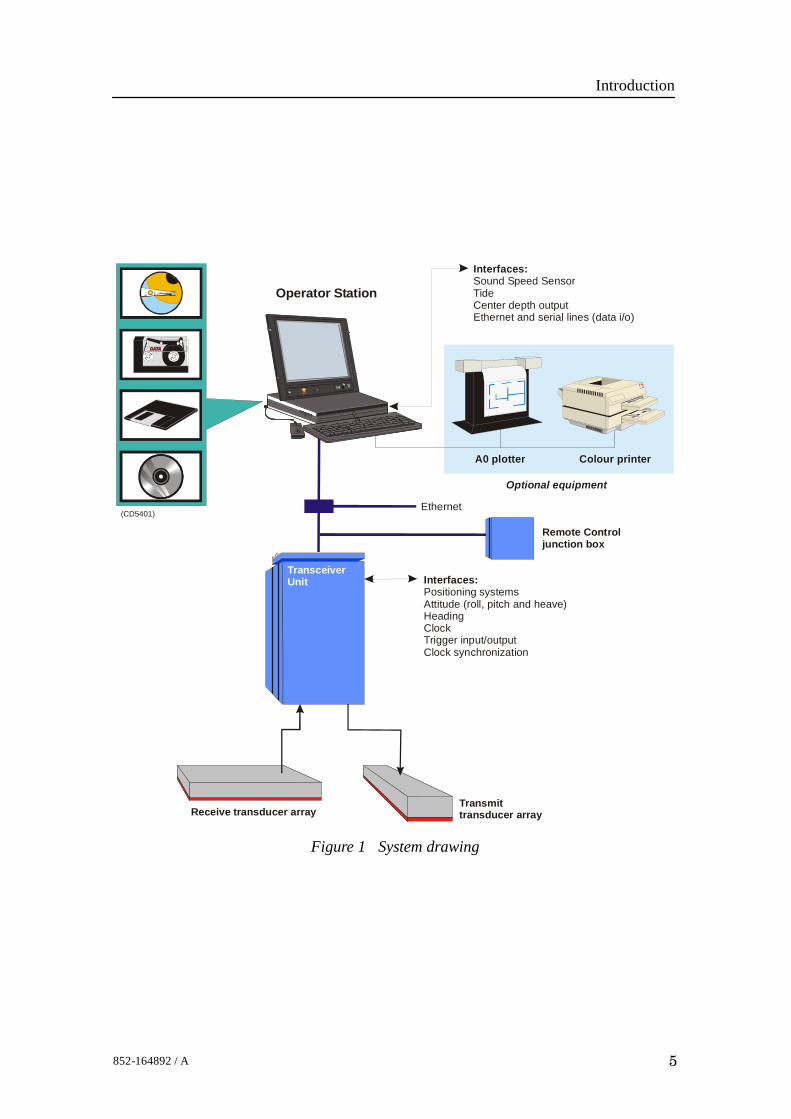
Figure 1 System drawing
Transmittransducer array
Operator Station
Receive transducer array
Interfaces:Sound Speed SensorTideCenter depth outputEthernet and serial lines (data i/o)
Interfaces:Positioning systemsAttitude (roll, pitch and heave)HeadingClockTrigger input/outputClock synchronization
Ethernet
Colour printerA0 plotter
Optional equipment
(CD5401)
Sub BottomProfilerTransceiverUnit(Option)
TransceiverUnit
Remote Control junction box

EM 300 Complete version
6 852-164892 / A
1.4 Note about changing AC supply voltageThe EM 300 is wired for 230 Vac when it comes from thefactory. If it is desireable to change to 115 Vac, do thefollowing:• The Processing Rack power must be rewired.• Switch LVPS (Low Voltage Power Supply) to 115 Vac.• Switch HVPS (High Voltage Power Supply) to 115 Vac.• The 220 Vac fans must be changed to 115 Vac type.→ Refer to page 284.

Technical specifications
7852-164892 / A
2 TECHNICAL SPECIFICATIONSNote Kongsberg Maritime is engaged in continuous developments of
its products and reserves the right to alter specifications withoutprior notice.
Interfaces• Serial lines with operator adjustable baud rate, parity, data
length and stop bit length for:- Motion sensor (roll, pitch, heave and optionally heading)
in format supported by sensors from Applied Analytics,iXSEA, Seatex and TSS
- Gyrocompass in either NMEA 0183 HDT orSKR82/LR60 format
- Positions in either Simrad 90, NMEA 0183 GGA or GGKformat
- External clock in NMEA 0183 ZDA format- Sound speed profile- Sound speed at transducer- Sea level height (tide)- Output of depth straight down in NMEA 0183 DPT
format• Interface for 1 PPS (pulse per second) clock synchronisation
signal• Optional SCSI interface for tape drive (DAT or Exabyte),
additional disk drives and optional greyscale recorder forseabed image
• Parallel interface for Postscript colour graphics printer/plotter• Ethernet interface for input of sound speed profile data and
output of all data normally logged to disk and/or tape
Physical properties
Transmit transducer
• Module:- Length: 371.5 mm- Width: 350 mm (add 130 mm for frame)- Height: 160 mm (add 38 mm for frame)- Weight: 32 kg + 15 kg cables
• Frame length: 1505 mm (2 degr) or 2992 mm (1 degr)

EM 300 Complete version
8 852-164892 / A
Receive transducer
• Module:- Length: 406 mm- Width: 200 mm (add 130 mm for frame)- Height: 160 mm (add 38 mm for frame)- Weight: 16 kg + 5 kg cables
• Frame length: 829 mm (4 degr), 1643 mm (2 degr), or 3271mm (1 degr)
Transceiver Unit
• Height: 1760 mm• Width: 600 mm• Depth: 630 mm• Weight: Approximately 197 kg
Operator Station
Dimensions and weight will depend upon choice of workstationmodel, thus the following figures serve as a guideline only.• Chassis:
- Height: 118 mm- Width: 445 mm- Depth: 464 mm- Weight: Approximately 16 kg
• Monitor (CRT type, 21 inch display):- Height: 487 mm- Width: 475 mm- Depth: 506 mm- Weight: Approximately 31 kg
• External storage unit:- Height: 68 mm- Width: 190 mm- Depth: 310 mm- Weight: Approximately 3 kg
Power requirements• Fuse: The single phase supply must be protected with 16A
slow-blow fuses.

Technical specifications
9852-164892 / A
• Operational voltage and frequency:- Transceiver Unit: 115 or 230 Vac (±10%), < 300 W, 47 to
63 Hz, 10 A slow blow fuse input.Note For 110 Vac operation, please contact
- Operator Station: 110 or 240 Vac (±10%), < 300 W, 47to 63 Hz, 16 A slow blow fuse input.
• Acceptable transients:- Short time (max 2 sec): ±25%, 42 to 69 Hz- Spikes (max 50 µS): < 1000 V
• Power interrupts: Menu settings, all parameters and thesound speed profile are stored on the Operator Station’sharddisk during operation, so operation can continue afterpower interruption. However, the file system may bedamaged, so the use of an uninterruptable power supply(UPS) is higly recommended.
Restrictions for use - limitationsNo specific restrictions apply.
Surface finishAll cabinets are painted. System units exposed to salt watermust be treated accordingly.
Environmental specifications• Operating temperatures:
- Transceiver Unit: 0 to +45_C- Operator Station: 0 to +40_C
• Storage temperatures:- Transceiver Unit: -30 to +70_C- Operator Station: -30 to +70_C
System performance data• Main operational frequency: 30 kHz
- Frequencies in the range of 30 to 34 kHz are employed tocode the different transmit sectors.
• Number of beams for each ping: 135• Beamwidths: 1x1, 1x2, 2x2 or 2x4 degrees
- Other beamwidth combinations are are possible inaccordance with the number of transducer modulesinstalled.

EM 300 Complete version
10 852-164892 / A
• Beam spacing: Equidistant or equiangle
• Coverage sector: Up to 150 degrees
• Transmit beam steering: Stabilized for roll, pitch and yaw
• Receive beam steering: Stabilized for roll
• Maximum ping rate: 10 Hz
• Depth range from transducers: 10 to 5,000 meters
• Depth resolution: 1 to 16 cm
• Pulse lengths: 0.7, 2, 5 and 15 ms
• Range sampling rate: 4.5 kHz (17 cm)

Cable layout and interconnections
11852-164892 / A
3 CABLE LAYOUT
3.1 IntroductionThe standard cables used between the EM 300 system units andbetween the units and their external devices are shown here. Forlarger installations where the EM 300 is a subsystem, the cableswill also be shown in the cable layout plan and interconnectiondiagram specific for the vessel into which the system isinstalled.
Note All cable connections may have to be made in accordance withthe guidelines laid down by the vessel’s classification society.
If no such guidelines exist, Kongsberg Maritime ASrecommends that Det norske Veritas (DnV) Report No. 80-P008«Guidelines for Installation and Proposal for Test ofEquipment» be used as a guide.

EM 300 Complete version
12 852-164892 / A
3.2 System cabling
Cable layoutThe interconnection cables are identified on the cable layoutdrawings. Each cable is then listed in the corresponding list,which refer to the required cable specifications. On thefollowing pages, each cable is identified with the appropriateterminations.
Shipyard and system cables
General
Each individual cable is identified on the cable plan. The cablesfall into two categories:• Cables provided by the installation shipyard or owner
• System cables supplied with the delivery
Shipyard cables
The cables that must be provided by the shipyard or owner areidentified as such in the descriptions. Note that the cablespecifications given are the minimum specifications.For each cable, the following information is provided:• Connection to be made on each end of the cable (including
system unit, terminal board identification and plug/socket tobe used)
• Number of cores
• Recommended cable type
• Minimum cable specifications
The necessary considerations must be taken to suit specialrequirements. Kongsberg Maritime accepts no responsibility fordamage to the system or reduced operational performance if thisis caused by improper cabling.
System cables
Several cables will be supplied with the system. Such cablesnormally comprise power cables for peripheral equipment, andinterconnection cables for computers and/or workstations. Thesecables will normally be delivered with the units.
Cable layout and interconnections
13852-164892 / A
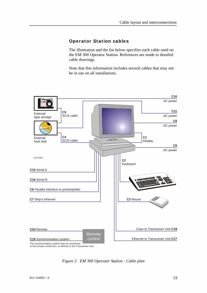
Operator Station cables
The illustration and the list below specifies each cable used onthe EM 300 Operator Station. References are made to detailedcable drawings.
Note that this information includes several cables that may notbe in use on all installations.
Figure 2 EM 300 Operator Station - Cable plan
Externalhard disk
Externaltape storage
(CD7030)
C4SCSI cable
C3 Mouse
C1Display
C2Keyboard
C8AC power
C9AC power
C10AC power
C11AC power
C18Coax to Transceiver Unit
Ethernet to Transceiver Unit C17
C7 Ship’s ethernet
C6 Parallel interface to printer/plotter
C24 Remote
C19 Synchronisation system
C16 Serial B
C15 Serial A
C5SCSI cable
Remotecontrol
The synchronisation system may be connectedto the remote control box, or directly to the Transceiver Unit.

EM 300 Complete version
14 852-164892 / A
C1 - Display
This is a standard VGA cable. It is normally supplied with thedisplay unit.
→ Cable details on page 29.
Specific installations may include multiple displayconfigurations with video splitters and/or switches.
C2 - Keyboard
This is a standard keyboard cable. It is normally supplied withthe keyboard.
→ Cable details on page 30.
C3 - Mouse or pointing device
This is a standard mouse cable. It is normally supplied with thekeyboard. Note that different workstation types allow fordifferent mouse connections. On Unix workstations, the mouseis often connected to the keyboard, while most PCs provide asocket on the computer assembly.→ Cable details on page 31.
C4 / C5 - SCSI cables
These cables are used only if the Operator Station is suppliedwith external SCSI storage devices.
When applicable, the cables are provided by the manufacturer.
C6 - Centronics printer
The Operator Station only provides one parallel interface toplotter or printer. In most cases, plotters and printers areconnected directly to the ship’s ethernet network.→ Cable details on page 32.
When applicable, the cable is provided by the manufacturer.
C7 - Ship’s’ethernet
The Operator Station may be equipped with one or two ethernetinterface boards. When two -2- boards are provided, one is usedto communicate with the ship’s ethernet while the other (C17) isused to communicate with the Transceiver Unit.
→ Cable details on page 31 and 28.
The ethernet cable must be provided by the installationshipyard.
Cable layout and interconnections
15852-164892 / A
C8 / C9 / C10 / C11 - AC power
These are AC mains cables. Note that C10 and C11 are onlyrequired if external SCSI storage devices are implemented.
→ Cable details on page 27.
All AC mains cables are normally supplied by the manufacturer.
C12 / C13 / C14 - Not used
For future expansion.
C15 - Serial A
This serial line is intended for a sound speed probe, which isnormally interfaced by means of a small junction box and apower supply.
If a sound speed probe is not used, the serial line may be usedfor other purposes.
→ Sound speed probe cable details on page 24.
→ Standard 9-pin RS-232 serial line details on page 22.
The cables must be provided by the installation shipyard.
C16 - Serial B
This serial line is intended for a tide/depth sensor. If such asensor is not used, the serial line may be used for otherpurposes.
→ Standard 25-pin RS-232 serial line details on page 20.
→ Standard 9-pin RS-232 serial line details on page 22.
The cable must be provided by the installation shipyard.
C17 - Transceiver Unit RJ-45 interface
The Operator Station may be equipped with one or two ethernetinterface boards. When two -2- boards are provided, one is usedto communicate with the ship’s ethernet (C7) while the other(C17) is used to communicate with the Transceiver Unit.
The interface between the Operator Station and the TransceiverUnit is made with either C17 or C18. In some cases two parallelethernet cables may be used. These are then normally identifiedas C17A and C17B.
→ Cable details on page 28.
The cable must be provided by the installation shipyard.

EM 300 Complete version
16 852-164892 / A
C18 - Transceiver Unit Coax interface
The interface between the Operator Station and the TransceiverUnit is made with either C17 or C18.→ Cable details on page 23.
When applicable, the cable must be provided by the installationshipyard.
C19 - Synchronisation system
Refer to the Transceiver Unit cabling.
C24 - Remote
Refer to the Transceiver Unit cabling.

Cable layout and interconnections
17852-164892 / A
Transceiver Unit cablesThe illustration and the list below specifies each cable used onthe EM 300 Transceiver Unit. References are made to detailedcable drawings.Note that this information includes several cables that may notbe in use on all installations.
Figure 3 EM 300 Transceiver Unit - Cable plan
Transmittransducer
array
Receivetransducer
array
Note 1: C17 C18 is used.Either or
Transducer cablessupplied by themanufacturer
(CD
3691
B)
C17 (See note 1)
Ethernet to Operator Station
C18 Coax to Operator Station
(See note 1)
C20Position system (serial 1)
C21Motion sensor (serial 2)
C22Auxiliary interface (serial 3)
C23Auxiliary interface (serial 4)
C19Synchronisation system
C251 PPS from Navigation system
C24Remote On/Off
C26 AC Power
EM 300TransceiverUnit
EM 300 Complete version
18 852-164892 / A
C17 - Transceiver Unit RJ-45 interface
Refer to the Operator Station cabling.
C18 - Transceiver Unit Coax interface
Refer to the Operator Station cabling.
C19 - Synchronisation
An external system may be used to synchronise the echosounder’s transmissions. This system is connected to theRemote plug on the Transceiver Unit.In most cases, an external junction box is located in thevincinity of the Operator Station to facilitate on/off control. Thesynchronisation system may then be connected to this junctionbox, or directly to the Remote plug.→ Cable details on page 25.
The cable must be provided by the installation shipyard.
C20 / C21 / C22 / C23 - Serial lines 1 - 4
The Transceiver Unit is equipped with four serial lines. Allconnectors are 9-pin male D-connectors. The serial lines arenormally set up as follows:Serial Port 1 - Positioning systemsSerial Port 2 - Motion sensorSerial Port 3 - Auxiliary 1Serial Port 4 - Auxiliary 2→ Cable details on page 21.
The cables must be provided by the installation shipyard.
C24 - Remote
In most cases, an external Remote Control junction box islocated in the vincinity of the Operator Station to facilitateon/off control. The cable from this box is connected to theRemote plug on the Transceiver Unit.→ Cable details on page 25.
The cable must be provided by the installation shipyard.
C25 - 1PPS
This is a timing signal terminated in a coax connector.→ Cable details on page 23.
The cable must be provided by the installation shipyard.

Cable layout and interconnections
19852-164892 / A
C26 - AC power
These are the AC mains cables to the Transceiver Unit.→ Cable details on page 27.
The cable is provided by the manufacturer.
Transducer cables
The transducer cables are supplied by the manufacturer. Notethat the number of transducer cables depend on the chosensystem resolution.

EM 300 Complete version
20 852-164892 / A
Generic RS-232 serial line (DCE)This cable described the pin configuration for an RS-232interface. The Data Circuit terminating Equipment (DCE) end isshown.
W102 / Rev. B RS-232 serial line (DCE )
14
4
11
1
18
8
16
6
13
3
15
5
12
2
19
9
202122232425
10
Original and complete RS-232 signaldefinition shown. The most commonlyused signals are shown in bold.
(DCE = Data Circuit terminating equipment)
17
7
25-pin D-sub connector
Looking into a female 25-pin D-pin connector1425
13 1
ShieldReceived data (Rx)
Transmitted data (Tx)Clear to send (CTS)
Request to send (RTS)DCE Ready
Signal groundReceived line signal detect
Reserved for testingReserved for testing
UnassignedSec. Rx line signal detect
Sec. Request to sendSec. Rx data
Transmitter signal timingSec. Tx data
Rx signal timing (DCE source)Local loopback
Sec. Clear to sendDTE Ready
Remote loopbackRing indicator
Data signal rate selectorTx signal timing (DTE Source)
Test mode
Conductors XX x 2 x 0.5 mm2
Screen Overall braided
Voltage 60V
Max.diameter Set by the plugs

Cable layout and interconnections
21852-164892 / A
Generic RS-232 Serial lineThis cable comprises a multi-purpose serial line. It providesinterface with any peripheral unit. One end of the cable connectsto the local unit (DTE) with a 9-pin ’D’ connector, while theother connects to the peripheral (DCE) as described in theperipheral unit’s documentation.Note that this cable does not support all the signals in thestandard RS-232 specification.
W103 / Rev G Standard RS-232 serial line
235
RxTx
Ground
View
Local (DTE) 9-pin‘D’ connector
Remote unit (DCE) tobe connected as describedin applicable documentation
Looking intofemale 9-pin
D-pin connector
5 1
69
Looking intomale 9-pin
D-pin connector
1 5
96
Screen
To plug housing
Conductors 3 x 2 x 0.5 mm2
Screen Overall braided
Voltage 60V
Max.diameter Set by the plugs
EM 300 Complete version
22 852-164892 / A
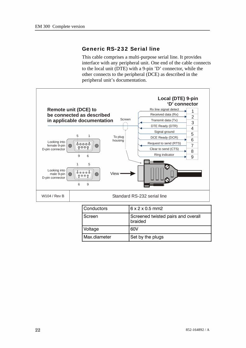
Generic RS-232 Serial lineThis cable comprises a multi-purpose serial line. It providesinterface with any peripheral unit. One end of the cable connectsto the local unit (DTE) with a 9-pin ’D’ connector, while theother connects to the peripheral (DCE) as described in theperipheral unit’s documentation.
W104 / Rev B Standard RS-232 serial line
1234
6
987
5
Rx line signal detectReceived data (Rx)
Transmit data (Tx)
DTE Ready (DTR)
Signal ground
DCE Ready (DCR)
Request to send (RTS)
Clear to send (CTS)
Ring indicator
View
Local (DTE) 9-pin‘D’ connector
Remote unit (DCE) tobe connected as describedin applicable documentation
5 1
69
1 5
96
Screen
To plughousingLooking into
female 9-pinD-pin connector
Looking intomale 9-pin
D-pin connector
Conductors 6 x 2 x 0.5 mm2
Screen Screened twisted pairs and overallbraided
Voltage 60V
Max.diameter Set by the plugs

Cable layout and interconnections
23852-164892 / A
Generic coax cableThis cable is used for connections to peripheral units ornetworks.In the EM 1002, EM 120 and EM 300 systems, this cableconnects the 1 PPS timing signal to the Transceiver Unit. It isalso possible to use a coax connection between the TransceiverUnit and the Operator Station.
W105 / Rev.D Coax connection to peripheral unit or network
LiveGnd
LiveGround
LocalCoax connector
Peripheral unit tobe connected as describedin applicable documentation
Live
Screen/Ground

EM 300 Complete version
24 852-164892 / A
Sound speed probe interfaceThis cable provides the interconnection between the ProcessorUnit work station and the sound speed probe. This connection isnormally made through a small junction box and with a powersupply as indicated in the drawing.
W119 / Rev.C Sound speed probe interface
This cable can be either male 25-pin D-connector (x = 7) ormale 9-pin D-connector (x = 5)
8 - 16 Vdc
AC Power
(W301)
Tx
Rx
Ground
2
1
5432
3x
Male 25-pinD-pin connector
14 25
131
1:1 Junction box
Probe
Work Station
Powersupply
ViewMale 9-pinD-pin connector
6 9
51
The cable between the junction box and the probe is supplied bythe probe manufacturer.
Conductors 2 x 2 x 0.5 mm2
Screen Overall braided
Voltage 60V
Max.diameter Set by the plugs

Cable layout and interconnections
25852-164892 / A
EM Remote synchronisation and On/Off
This cable connects the Transceiver Unit to a remote On/Offswitch located in a Remote Control junction box (typeEM1-212595). The same connection allows trigger output andremote control (synchronisation) with a serial line.
Note This information is also valid for Remote Control junction box108-212591.
W202 / Rev C Transceiver Unit - Junction Box
1
32
45
76
899
9
1
1
3
3
2
2
4
4
5
5
7
7
6
6
8
8
Junction box EM1-212595Terminal block
Trigger out
Trigger out
Trigger GND
Trigger GND
Standby +
Standby -
On
RTS
RTS
CTS
CTS
GND
GND
(Not connected)
Transceiver Unit9-pin ‘D’ connector
‘Remote’
Trigger out toexternal system(synchronisation)
Serial line to/fromexternal system (synchronisation)
Junction box EM1-212595
System On/Off
Conductors 5 x 2 x 0.5 mm2
Screen Overall braided
Voltage 60V
Max.diameter Set by the plugs

EM 300 Complete version
26 852-164892 / A
Generic RJ45 extenderThis is a standard Category 5 cable for extension of keyboard,video and mouse.
W222 / Rev. A KVM Extender interconnection
4
1
7
3
5
2
8
64
1
7
3
5
2
8
6
RJ-45 connectorMale
RJ-45 connectorFemale
Blue
White / Blue
White / Green
Green
White / Brown
Brown
White / Orange
Orange
Pin 1Pin 8
Conductors 4 x 2 / twisted pairs
Screen N/A
Voltage N/A
Max. diameter Limited by the plugs

Cable layout and interconnections
27852-164892 / A
Standard AC power cableThis cable is a standard three-wire power cable. It iscommercially available in standard lengths, or may be producedlocally to suit the specific installation needs. The instrument endis terminated in a standard IEC female socket, while the otherend is terminated in a plug suitable for the local standard.
W301 / Rev B Standard power cable for 115/230 Vac 2-phase
Live (normally Blue)
Neutral (normally Brown)
Use the applicable plug to suitlocal standard. British standardplug used as example only.
Ground (always Yellow or Yellow/Green)
IEC plug
Note Different cable colours may be used for the “live” and“neutral” wires. Ground is however always on green/yellow.
Conductors 2 x 1.5 mm2 + GND
Screen None
Voltage 750 V
Max. diameter Set by the plugs

EM 300 Complete version
28 852-164892 / A
Ethernet with RJ45This cable contains the Ethernet connection. RJ45 plugs areused to terminate the cable. Note that these plugs must bescreened to comply to EC rules.
W400 / Rev E Ethernet 10Base-T with RJ45 plugs
Pairs
Pairs
1
1
3
3
2
2
4
4
5
5
7
7
6
6
8
8
1
1
3
3
2
2
4
4
5
5
7
7
6
6
8
8
RJ45 plug
RJ45 plug
RJ45 plug
Ethernet 10Base-T “Straight Through”
Ethernet 10Base-T “Crossover”The “crossover” cable is used to cascade HUBs, or for connecting two ethernet stations or computers back-to-back without a HUB)
NOTE: In order to prevent noise and crossover, you are strongly adviced to use the cable pairs indicated above.
TX Data + (White/Orange)
(1) TX Data + to (3) Recv Data +
Tx Data - (Orange)
(2) Tx Data - to (6) Recv Data -
Recv Data + (White/Green)
(3) Recv Data + to (1) Tx Data +
(Blue)
(White/Blue)
Recv Data - (Green)
(6) Recv Data - to (2) Tx Data -
(White/Brown)
(Brown)
RJ45 plug
Pin 8
Pin 8
View
Pin 1
Pin 1

Cable layout and interconnections
29852-164892 / A
Standard VGA cableThis is a standard display cable used to connect the videosignals.The cable is normally physically fastened to the display unit,and it is provided with the plug(s) readily attached.
W500 / Rev.A Standard VGA cable
1
32
456
87
91011
1312
1415
Red
Ground
NC
Green
Ground
NC
Blue
Ground
5 1510
4 149
3 138
2 127
1 116
Horizontal Sync
Field
NC
Vertical Sync
Ground
Ground
NC
15-pin ‘D’ connector (VGA type)

EM 300 Complete version
30 852-164892 / A
Keyboard cableThis is a standard keyboard cable. In most cases, the cable isphysically connected to the keyboard. It is terminated in a plugsuited to fit the computer.Several keyboard types are available for different languages andhardware platforms. Both the keyboard and the attached cableare commercial items.
W503 / Rev C Keyboard
Keyboard(Different keyboard types are supplied)
In most cases, the keyboardcable is physically connected
to the computer
Plug suited for the computer

Cable layout and interconnections
31852-164892 / A
Mouse or pointing device cableThis is a standard mouse cable. It is physically connected to themouse. It is terminated in a plug suited to fit the computer.
Note On Unix work stations, the mouse is normally connected to thekeyboard.
Several mouse and pointing device types are available with twoor three buttons, and with or without a scroll wheel. Both themouse and the attached cable are commercial items.
W504 / Rev B Mouse / Pointing device
Mouse(Different mouse types and other pointing devices are supplied)
The cable is physically connectedto the mouse
Plug suited for the computer
Note that certain mouse typesfor Unix work stationsare connected to the keyboard.
Various mouse types support twoor three buttons, and may also
provide a scroll wheel.

EM 300 Complete version
32 852-164892 / A
Centronics printer cableThis is a standard Centronics printer cable.
W505 / Rev C Centronics printer cable
1
32
45
76
89
1110
1518-24
StrobeData 0Data 1Data 2Data 3Data 4Data 5Data 6Data 7AcknowledgeBusyErrorGround
Printerplug
25-pinD-connector
25 14
113The socket on the rearside of the computeris normally a 25-pin femaleD-connector.

Cable layout and interconnections
33852-164892 / A
EM 300 SynchronizationThis cable provides the control signals between the EM 300 andthe Synchronization System.
W707 / Rev. A Simrad Synchronization Unit - EM 300 System
1
8
2
40
5
2125
6
26
Sensor bus
Sensor bus
SSU
Trigger monitor
Trigger
EM 300
Test, DB-9 female
Trig, DB-9 female
Input ch 1+
- 12 VOutput ch 1 -
Input ch 1 -
Output ch 1 ++12 V
CTS
Trig out
Sensor bus Ready for next trigger Trig, DB-9 female
77 Input ch 2 + RTS
Trig ref
10 kohm
1 kohm
2
Sensor bus GND
GND
Trig, DB-9 female
58 Input ch 2 - GND
Conductors 6 x 2 x 0.25 mm2
Screen Overall braided
Voltage 60V
Max. diameter Set by the plugs

EM 300 Complete version
34 852-164892 / A
3.3 Transducer cables
IntroductionThe transducer cables between the transducer arrays and theTransceiver Unit are all supplied by Kongsberg Maritime withthe EM 300 system.The physical number of cables depends on the chosen systembeamwidth as shown the following tables.
TX Cables
Systembeamwidth
Number of cables = 3 x Number of transducer modules
1 degree 24(Four Tx1 and four Tx2 modules, each with threecables)
2 degrees 12(Two Tx1 and two Tx2 modules, each with threecables)
RX Cables
Systembeamwidth
Number of transducer modules = Number of cables
1 degree 8
2 degrees 4
4 degrees 2
The following cable information is available both in the EM 300installation and maintenance manuals. The cable markings arenormally recorded in the installation manual first, and it isrecommended to copy these records to the maintenance manuallater.
Cable layout and interconnections
35852-164892 / A
Transmit array cable markingsEach transducer module and its cable is identified with a serialnumber as follows:Tx1 modules: Tx1D<nnn>, Tx1E<nnn>, Tx1F<nnn>
Tx2 modules: Tx1A<nnn>, Tx1B<nnn>, Tx1C<nnn>
Each transducer module is also identified by its physicallocation in the array (frame). This location number must berecorded during the installation of the transducer modules, andwritten down in the tables provided in this chapter.
Note In order to ensure proper operation by the EM 300 system, it isof vital importance that the physical location of the transducermodules fits the designated module number in the transmit andreceive circuitry.
The Tx transducer array is physically positioned in thefore-and-aft direction under the hull.• Transducer module number 1 is always the most forward
module.• Module number 2 is the second forward, and so on.→ Refer to figure 4 on page 37.
During installation, you can select any Tx module you wish andplace them in random order in the frame. However, you MUSTwrite down the serial number on each module in the order theyhave been positioned in the frame, so that you later can identifythe modules in positions 1, 2, 3 and so on.The connections to the Transceiver Unit are made with 25-pin“D” connectors.
Note During the installation of the transmit array, you must fill in thetable below.
Note In a 2 degree system, you will only need the first 4 transducermodules (12 channels).
Note The cables from the Tx modules must exit on the starboard side.
EM 300 Complete version
36 852-164892 / A
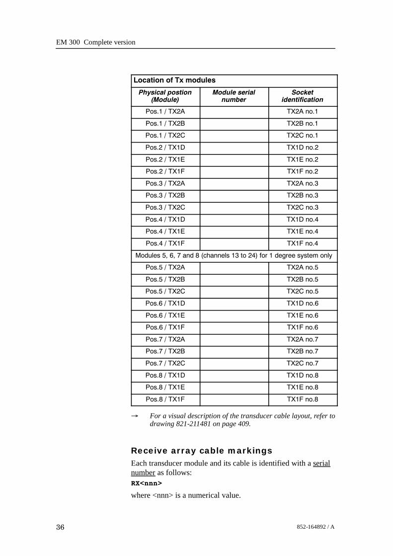
Location of Tx modules
Physical postion(Module)
Module serialnumber
Socketidentification
Pos.1 / TX2A TX2A no.1
Pos.1 / TX2B TX2B no.1
Pos.1 / TX2C TX2C no.1
Pos.2 / TX1D TX1D no.2
Pos.2 / TX1E TX1E no.2
Pos.2 / TX1F TX1F no.2
Pos.3 / TX2A TX2A no.3
Pos.3 / TX2B TX2B no.3
Pos.3 / TX2C TX2C no.3
Pos.4 / TX1D TX1D no.4
Pos.4 / TX1E TX1E no.4
Pos.4 / TX1F TX1F no.4
Modules 5, 6, 7 and 8 (channels 13 to 24) for 1 degree system only
Pos.5 / TX2A TX2A no.5
Pos.5 / TX2B TX2B no.5
Pos.5 / TX2C TX2C no.5
Pos.6 / TX1D TX1D no.6
Pos.6 / TX1E TX1E no.6
Pos.6 / TX1F TX1F no.6
Pos.7 / TX2A TX2A no.7
Pos.7 / TX2B TX2B no.7
Pos.7 / TX2C TX2C no.7
Pos.8 / TX1D TX1D no.8
Pos.8 / TX1E TX1E no.8
Pos.8 / TX1F TX1F no.8
→ For a visual description of the transducer cable layout, refer todrawing 821-211481 on page 409.
Receive array cable markingsEach transducer module and its cable is identified with a serialnumber as follows:RX<nnn>
where <nnn> is a numerical value.

Cable layout and interconnections
37852-164892 / A
Figure 4 Location of the first module ineach array (example)
Number of modules dependson system beamwidth
Num
ber o
f mod
ules
dep
ends
on s
yste
m b
eam
wid
th
Forward
Port Starboard
Note: Top view!TXtransducerarray
RX transducer array
Module no.1
Module no.1
(CD
4971
)
Each transducer module is also identified by its physicallocation in the array (frame). This location number must berecorded during the installation of the transducer modules, andwritten down in the tables provided in this chapter.
Note In order to ensure proper operation by the EM 300 system, it isof vital importance that the physical location of the transducermodules fits the designated module number in the transmit andreceive circuitry.The cables between the Preamplifier Unit and the TransceiverUnit are identified as follows:R<n>
where <n> is a serial number.The Rx transducer array is physically positioned in athwartshipdirection under the hull.
EM 300 Complete version
38 852-164892 / A
• Transducer module number 1 is always the first on the portside.
• Module number 2 is the second on the port side, and so on.→ Refer to figure 4.
During installation, you can select any Rx module you wish andplace them in random order in the frame. However, you MUSTwrite down the serial number on each module in the order theyhave been positioned in the frame, so that you later can identifythe modules in positions 1, 2, 3 and so on.The connections to the Transceiver Unit are made with 25-pin“D” connectors.
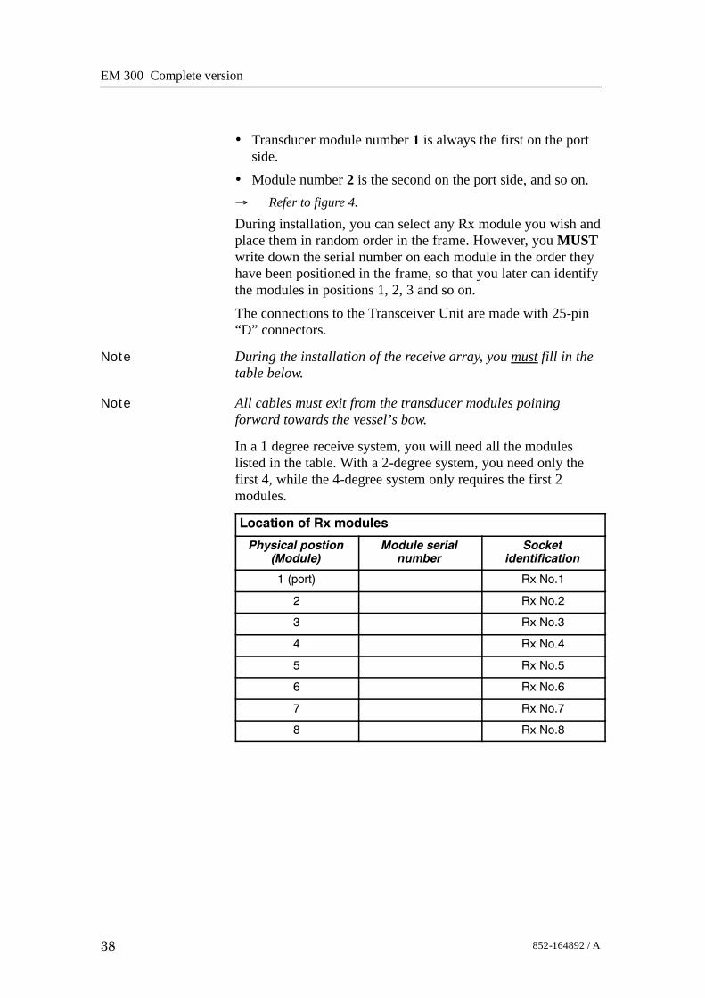
Note During the installation of the receive array, you must fill in thetable below.
Note All cables must exit from the transducer modules poiningforward towards the vessel’s bow.
In a 1 degree receive system, you will need all the moduleslisted in the table. With a 2-degree system, you need only thefirst 4, while the 4-degree system only requires the first 2modules.
Location of Rx modules
Physical postion(Module)
Module serialnumber
Socketidentification
1 (port) Rx No.1
2 Rx No.2
3 Rx No.3
4 Rx No.4
5 Rx No.5
6 Rx No.6
7 Rx No.7
8 Rx No.8

Cable layout and interconnections
39852-164892 / A
Figure 5 EM 300 Transceiver Unit’s bottom panel with all the sockets for theinterconnection and transducer cables. This drawing is valid for Transceiver Units
with registration number: 125-210131.
REAR
115/230VAC 50/60Hz800W
ETHERNET1.PPS
EXTE
RN
AL
SEN
SO
RS
Serial port 1
Serial port 3
TestR
emote
Serial port 2
Serial port 4
T 17
T 9
T 1
R 8
T 18
T 10
T 2
R 7
T 19
T 11
T 3
R 6
T 20
T 12
T 4
R 5
T 21
T 13
T 5
R 4
T 22
T 14
T 6
R 3
T 23
T 15
T 7
R 2
T 24
T 16
T 8
R 1
(CD21110)
ETHERNET
RX No.4
TX1E No.2
TX2A No.5
TX2C No.7
115/230VAC 50/60Hz300W
1 PPS
RX No.8
TX2A No.1
TX2C No.3
TX1E No.6
RX No.7
TX2B No.1
RX No.6
TX2C No.1
TX1D No.4
TX1F No.6
TX1E No.4
TX2A No.7
TX1D No.2
RX No.5
TX1F No.4
TX2B No.7
Serial ports: 3 4 1 2
Remote
Test
External sensors
RX No.3
TX1F No.2
TX2B No.5
TX1D No.8
RX No.2
TX2A No.3
RX No.1
TX2B No.3
TX2C No.5
TX1E No.8
TX1D No.6
TX1F No.8
(CD5234B / 873-210829/A)
Figure 6 EM 300 Transceiver Unit’s bottom panel with all the sockets for theinterconnection and transducer cables. This drawing is valid for Transceiver Units
with registration numbers: 125-211293 and 125-218182.

EM 300 Complete version
40 852-164892 / A
Blank page

Transceiver Unit 125 - 210131
41852-164892 / A
4 TRANSCEIVER UNIT 125-210131
4.1 Description and main functions
OverviewThe EM 300 Transceiver Unit performs the reception, dataacquisition, received signal processing and transmission for themultibeam echo sounder system. The cabinet holds three wiredracks containing the system circuit boards.• The top Processing Rack holds the complete Processing Unit
with its own power supply. This unit provides dataacquisition, signal processing and function control.
• The middle Receiver Rack holds the receiver boards, acontroller, two power supplies and a large capacitor bank.
• The bottom Transmitter Rack holds the transmitter circuitryand a dedicated controller.
Three different versions of the Transciever Unit have beendelivered. The registration number of the Transceiver Unitwill determine which version you have:125-210131, more information on page 41.125-211293, more information on page 101.125-218182, more information on page 161.This number is to be found on the Transceiver Unit chassis.All versions are described in this manual. Please check yourTransceiver Unit to find out which version you have.

EM 300 Complete version
42 852-164892 / A
4.2 Transceiver Unit 125-210131This chapter provides the following information:→ Description and main functions, page 41.→ Transceiver Unit outline, page 43.→ Transceiver Unit racks, page 46.→ Theory of operation, page 50.→ Processing rack, details, page 55→ Receiver rack, details, page 72.→ Transmitter rack, details, page 92→ Circuit board descriptions, page 54.

Transceiver Unit 125 - 210131
43852-164892 / A
630 mm 600 mm
1834
mm
1995
mm
1600
mm
Min
303
mm
(CD3694)
Figure 7 Standard EM 300 Transceiver Unit - Outline dimensions

EM 300 Complete version
44 852-164892 / A
Shock absorber
Base section
Mid section
Mid section
Door
RDL
Seen from top
Shock absorber
Base sectionDoor
RDL
245
1170
1540
(CD21000B)
Note:All measurements are in mm.The drawing is not in scale.
Figure 8 Transceiver Unit with Raw Data Logger,seen from above.

Transceiver Unit 125 - 210131
45852-164892 / A
Figure 9 EM 300 Transceiver Unit wired racks
HIGHMIDDLELOWf (SW)
L207
F206
L206
L205
F2018A
F2028A
SLOWBLOW
F2048A
F2058A
SLOWBLOW
L201
CAUTION
DO NOT PULL OUT THIS UNITBEFORE THE METER SHOWSZERO (0) VOLTAGE.
FOR CONTINUED PROTECTIONAGAINST RISK OF FIREREPLACE ONLY WITH SAMETYPE AND RATING OF FUSE.
S203230V ac
S201230Vac P201
MAINS INPUT115/230V ac
EA
ACI I TY
L
RTH F
ESD
SIMRADHV-POW ER UN IT 290-112751
SIMRADPOWER SUPPLY 290-112750
L202+24VREF
ON/OFFRELAY
24VSTAND
BY
S202SERVICE
OFF
NORMAL
L204
F203
L203
ANALOGPOWERSUPPLY
+7.5VREF-7.5V+5va-5va+5V
+12V-12V+24VGND
SWITCHEDPOWERSUPPLY
10050
0150
(CD
4472
E /
860-
2101
32 /
A)
Processingrack
Transmitterrack
Receiverrack
Coolingfans
ProcessingUnit
Groundingstrap
Circuitbreaker
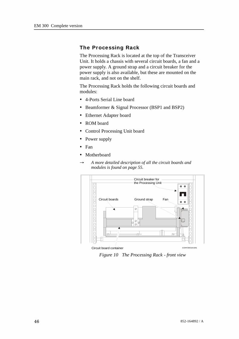
EM 300 Complete version
46 852-164892 / A
The Processing RackThe Processing Rack is located at the top of the TransceiverUnit. It holds a chassis with several circuit boards, a fan and apower supply. A ground strap and a circuit breaker for thepower supply is also available, but these are mounted on themain rack, and not on the shelf.The Processing Rack holds the following circuit boards andmodules:• 4-Ports Serial Line board• Beamformer & Signal Processor (BSP1 and BSP2)• Ethernet Adapter board• ROM board• Control Processing Unit board• Power supply• Fan• Motherboard→ A more detailed description of all the circuit boards and
modules is found on page 55.
Figure 10 The Processing Rack - front view
(CD4472B/210132A)
EA
ACII T
YL
RTH F
ESD
Circuit board container
Ground strapCircuit boards Fan
Circuit breaker forthe Processing Unit

Transceiver Unit 125 - 210131
47852-164892 / A
Figure 11 Processing Rack circuit board locationswith power supply
GND +12V -12V -5V +5V
(CD
4472
A / 8
60-2
1013
2 / A
)
P7
P7
P1
P5
P5
P1
Slot 8 - Serial card
Slot 7
Slot 6 - BSP2
Slot 5
Slot 4 - BSP1
Slot 3 - Ethernet adapter
Slot 2 - ROM bank
Slot 1 - Processor (486x2)
Fan
Power supply

EM 300 Complete version
48 852-164892 / A
The Receiver RackThe Receiver Rack is located at the middle of the TransceiverUnit. It holds several circuit boards, power supplies and acapacitor bank. All the units are accessed from the front of therack.
HIGHMIDDLELOWf (SW)
L207
F206
L206
L205
F2018A
F2028ASLOW
BLOW
F2048A
F2058A
SLOWBLOW
L201
CAUTION
DO NOT PULL OUT THIS UNITBEFORE THE METER SHOWSZERO (0) VOLTAGE.
FOR CONTINUED PROTECTIONAGAINST RISK OF FIREREPLACE ONLY WITH SAMETYPE AND RATING OF FUSE.
S203230V ac
S201230Vac P201
MAINS INPUT115/230V ac
SIMRADHV-POWER UNIT 290-112751
SIMRADPOWER SUPPLY 290-112750
L202+24VREF
ON/OFFRELAY
24VSTAND
BY
S202SERVICE
OFF
NORMAL
L204
F203
L203
ANALOGPOWERSUPPLY
+7.5VREF-7.5V+5va-5va+5V+12V-12V+24VGND
SWITCHEDPOWERSUPPLY
10050
0150
(CD4472C/210132A)
Transmitter/Receiver boards High Voltage Power Supply Capacitor bank
Low Voltage Power Supply Signal Processor Board RX (SPBRX)
Figure 12 The Receiver RackThe Receiver Rack holds the following circuit boards andmodules (from left):• TRB 32/Receiver board (max 4)
• Low Voltage Power Supply• High Voltage Power Supply
• Signal Processor Board RX (SPRX)• Capacitor bank→ A more detailed description is found on page 73.

Transceiver Unit 125 - 210131
49852-164892 / A
The Transmitter RackThe Transmitter Rack is located at the bottom of the theTransceiver Unit. It holds one processor board and a number oftransmitters.
Figure 13 The Transmitter Rack
(CD4472D/210132A)
64-Channel Transmitter Boards (Tx64)
Signal Processor Board TX (SPBTX)
The Transmitter Rack holds the following circuit boards andmodules (from left):• 64-Channel Transmitter Board (TX64)• Signal Processor Board TX (SPTX)→ A more detailed description is found on page 91

EM 300 Complete version
50 852-164892 / A
4.3 Theory of operation
OverviewThis chapter presents a functional description of the TransceiverUnit.
Figure 14 Transceiver Unit, simplified block diagram
Control Processor
Beamformer and SignalProcessor (BSP) x 2
Signal Processor Rx(SPRX)
Serial lines to/fromthe sensors
Ethernet to/from theOperator Station
Signal Processor Tx(SPTX)
Command andcontrol (serial line)
16-bitsampleddata
TransmitterRack
Processing Rack
ReceiverRack
Transmitter/ReceiverBoard (TRB) x 4
64-Channel Transmitter(64CHTX) x 14
Transmit array Receive array
Filter Filter
Commandand control
(CD
4551
)
Simplified block diagramThe simplified block diagram for the Transceiver Unit presentsthe following main functions:• Transmission• Reception• Processing

Transceiver Unit 125 - 210131
51852-164892 / A
→ Refer to figure 14.The various parameter settings made on the Operator Station aresent to the Control Processor in the Processing Rack. Theinformation (roll, pitch, pulse length etc.) is interpreted, andpassed on to the Signal Processor TX (SPTX), which is the“master” processor in the TX/RX system.After the transmission, the Signal Processor RX (SPRX) isinstructed to receive the samples for all the receiver staves andpass them on to the two Beamformer and Signal Processors(SBP’s) in the Processing Rack.
Control functionsThe control functions in the Transceiver Unit are mainlyhandled by the three processor boards, but additional peripheralboards are also used. The majority of the control boards arecontained in the Processing Unit.
Figure 15 The control functions
Seriallines
PROM bank Controlprocessor
Ethernetadapter
BSP x 2
Signal Processor Rx(SPRX)
Serial lines to/fromthe sensors
Ethernet to/from theOperator Station
Signal Processor Tx(SPTX)
Command andcontrol (serial line)
Processing Rack
Receive circuitryTransmit circuitry
Commandand control
Bus system
(CD4554)
The Control Processor in the Processing Unit is not equippedwith interface capabilities, and thus requires external boards tohandle ethernet and serial lines interface. It also relies on anexternal memory board for the software contained in the ROMdevice. All the peripheral boards used here are commercial.

EM 300 Complete version
52 852-164892 / A
Note Newer Control Processor Units (CPU) handles ethernetinterface and have a DiskOnModule installed (containingsoftware). This kind of CPU also relies on an external board tohandle serial line interface.
One serial line is used to interface the command and controlsignals to and from the TX/RX controllers. The SignalProcessor TX is the “master”.
External synchronisation
The serial line RTS and CTS signals are used for externalsynchronisation. In addition a trig out signal is issued by theTRU.Levels:
RTS, CTS:H=high= +3 to +15 VL=low= -3 to -15 VTrig out:TTL LevelOutputs from TRU:
Trig out=1 TX is off(High TTL level)Trig out=0 TX is active(Low TTL level)
RTS=H TRU is ready for a new pingRTS=L TRU is not readyRTS is pin 7 on the CPU card D connector. (Pin 6 on EM120and EM300 “remote” plug).Inputs to TRU:
CTS=H Ping commandCTS=L WaitCTS is pin 8 on the CPU card D connector. (Pin 7 on theEM120 and EM300 “remote” plug). The CTS pulse length mustbe minimum 30 milliseconds.Gnd is pin 5 on the CPU card D connector. (Pin 8 on EM120and EM300 “remote” plug).Typical sequence:CTS _____________- - - - - - - ________________- - - - - - - - - - _________
TXCommand
RTS - - - - - - - - - - - - - - _______________- - - - - - - ________________- - -(TRU ready) (TRU busy) (TRU busy)
Trig out - - - - - - - - - - - - - - __- - - - - - - - - - - - - - - - - - - - __- - - - - - - - - - - - - - - - -TXPulse

Transceiver Unit 125 - 210131
53852-164892 / A
When the TRU is ready for a new ping, RTS is set to H. Whenthe external device is ready for a new ping, CTS shall bechanged to H. The TRU will then start a ping, change RTS to L(busy), and the Trig out will be low during the transmit pulse.After the Trig out is received, the external device should turnCTS to L. (Or at least keep it high for 35 milliseconds).When the received period is finished and the TRU is ready for anew ping, the RTS will be changed to H, and the TRU will waitfor new trigger (a high level on CTS).If CTS is H all the time, or if external sync in the installationmenu is switched off, the TRU will ping at its maximum rate.

EM 300 Complete version
54 852-164892 / A
4.4 Circuit board descriptions
OverviewThis chapter describes all the circuit boards and modules in theEM 300 Transceiver Unit. A functional description with a blockdiagram is provided, as well as the facilities provided formaintenance.Remember that all versions of the Transceiver Unit is in thismanual. Different boards and power supplies are thereforedescribed for the EM 300 system. Check the reg.no. on yourTransceiver Unit to find out which version you have.

Transceiver Unit 125 - 210131
55852-164892 / A
4.5 Processing rack details
LocationThe Processing Rack is located at the top of the the TransceiverUnit. It holds a chassis with several circuit boards, fans and apower supply. A ground strap and a circuit breaker for thepower supply is also available, but these are mounted on themain rack, and not on the shelf.
Circuit boards and modules
4-ports Serial Line Board
This is a commercial circuit board. It provides the TransceiverUnit with four serial lines.→ The interface board C114P is explained on page 56.
Beamformer & Signal Processor (BSP)
These are the main processing boards in the Transceiver Unit.→ The circuit board is explained on page 58.
Control Processor Unit board (CPU)
This processor board acts as a function controller.→ The circuit board, SSC-5x86H, is explained on page 64.
Ethernet Adapter
This is a commercial circuit board. It provides the TransceiverUnit with the ethernet communication to the Operator Station.→ The circuit board is explained on page 61.
ROM board
This is a commercial ROM (Read Only Memory) board.→ The circuit board is explained on page 63.
Power supply
The Processing Rack contains a commercial switch-mode powersupply located behind the circuit board.→ The power supply is explained on page 69.
Motherboard
This is a commercial circuit board.→ The circuit board is explained on page 72
Fan
The fan is located on the right side of the Processing Rack,when seen from the front.

EM 300 Complete version
56 852-164892 / A
4-Ports Serial Line Board (C114P)
Purpose and description
This is a commercial circuit board designed and produced byMoxa Technologies. It is identified as C114P, and is located inthe Processing Rack.
P1
JP1 JP3 JP5 JP7
JP2 JP4 JP6 JP8
JP9
JP10
JP11
JP12
COM1
COM2
COM3
COM4
(CD5561)
Figure 16 The C114P layout
How it works
Each of the 4 ports can be configured to RS-232, RS-422, orRS-485 interface individually, but only RS-232 will work on theEM 300 system.
Facilities
LEDs
None.
Jumpers
The C114 is set up with IRQ 11 on the jumpers JP9, JP10, JP11and JP12.

Transceiver Unit 125 - 210131
57852-164892 / A
Links
Note The following settings are only valid for new boards. Forboards older than spring 2001 the settings will be inverted. Thesettings that are OFF on these drawings will be ON and viceversa.
The settings of the C114P DIP switches for use in the EM 300are listed in the table below:
Switch 1 2 3 4 5 6 7SW 5 ON ON OFF OFF OFF ON ON
SW 1 ON ON ON ON OFF OFF ON
SW 2 OFF ON ON ON OFF OFF ON
SW 3 ON OFF ON ON OFF OFF ON
SW 4 OFF OFF ON ON OFF OFF ON
Connections
The C114P contains one DB-37 female connector on the rearside of the circuit board. It comes with a cable; one terminal is a37-pin male D-type and the other terminal is a four 9-pin maleD-type connectors. This is not used.→ Refer to figure 17 for pin assignments.
In addition, four 10-pin pin-head connectors corresponds to theDB-37 connector on the board of C114P. These four connectorsare called COM1, COM2, COM3 and COM4, and are connecteddirectly to the Transceiver Unit bottom plate.
10
9
8
7
6
5
4
3
2
1
NC
RI
CTS
RTS
DSR
GND
DTR
TXD
RXD
DCD(CD5573)
Figure 17 10-pinheader connectorpin assignment

EM 300 Complete version
58 852-164892 / A
Beamformer & Signal Processor (BSP)
Purpose and description
The Beamforming & Signal Processing (BSP) board is a multidigital signal processor (DSP) board. It is designed to performthe beamforming and signal processing in sonars and multibeamecho sounders. It is controlled from a host processor.
The processing power in the Beamforming & Signal Processing(BSP) board is based on eight Texas TMS320C50 fixed pointdigital signal processors working in parallel while beamformingthe data. Next, there are four Texas TMS320C44 floating pointdigital signal processors interconnected to use both parallel andsequential processing of the beamformed data from the fixedpoint processors.
The Beamforming & Signal Processing (BSP) board is a singleslot full length standard ISA format circuit board made to fitinto a personal computer.
How it works
The Beamforming & Signal Processing (BSP) board containsfour main sections:
• Sonar Input Data
• Beamforming
• Signal Processing
• Host Interface
The Sonar Input Data interfaces an 18-bit wide and 1k deepInput FIFO (First-In-First-Out) register. This input FIFO holdsthe data received from the transducer array through the receiverprocessing circuitry. A dedicated digital signal processor readsthe input FIFO.
There are two identical Beamforming digital signal processingbranches. Each consists of four digital signal processors and a16-bit wide and 8k deep dual port memory (DPRAM). The twobranches are exchanging data by means of this DPRAM.
The Signal Processing section comprises three digital signalprocessors dedicated to do further processing of thebeamformed data.
The Host Interface function is maintained by the masterprocessor on the Beamforming & Signal Processing (BSP)board. It exchanges data with the host processor via a 16-bitwide and 8k deep dual port memory (DPRAM) on the ISA bus.

Transceiver Unit 125 - 210131
59852-164892 / A
Facilities
LEDs
D1 (LED): C44 D
Test points
There is one test point for each C50 digital signal processor(eight total). These testpoints are all connected to the XF/ signalwhich is active while that particular C50 access the sharedDPRAM.There is also one test point for each C44 digital signal processor(four total). These test points are connected to the IIOF2/ signal,which is a general purpose I/O port bit that can be controlled bythe software.The C44-D testpoint is also connected to a light emitting diode(D1) for visual observation. The LED will be activated duringeach ping.
TP1 C50 E0
TP2 C50 E1
TP3 C50 E2
TP4 C50 E3
TP5 C50 F0
TP6 C50 F1
TP7 C50 F2
TP8 C50 F3
TP11 C44 A
TP12 C44 B
TP13 C44 C
TP14 (& D1) C44 D
The testpoints will be active when the corresponding processoris working.
Links
A number of links are implemented on the board to allow forseveral different applications. Links LK1, LK2 and LK3 areused to identify the board as one out of maximum eight boardsin one system.

EM 300 Complete version
60 852-164892 / A
LK3 LK2 LK1 BSP ID
0 0 0 BSP 0
0 0 1 BSP 1
0 1 0 BSP 2
0 1 1 BSP 3
1 0 0 BSP 4
1 0 1 BSP 5
1 1 0 BSP 6
1 1 1 BSP 7
Link applications
The following links are ON (closed) in this application:- BSP0 is the master processor (no links).
- BSP1 is the slave processor (link LK1).
Switches
There are no switches on the board.
Connections
The Beamforming & Signal Processing (BSP) holds thefollowing plugs and sockets:
P1 Sonar input data
P2 ISA bus component
P3 Emulator
P4 Direct memory access
P5 External communication port
P6 Test access port
P7 External communication port
The P1, sonar input data, is connected to SPRX via a flat cableplug connected to the Reciever Backplane, plug P11.

Transceiver Unit 125 - 210131
61852-164892 / A
Ethernet Adapter
Purpose and description
This is a 16-bit ISA adapter designed and produced by 3Com,identified as 3C509B-COMBO. The purpose of the adapter is toconnect the transceiver unit to the operator unit. The circuitboard is located in the Processing Rack.
How it works
The cable types and connector specifications in the EthernetAdapter are:
• 10BASE5 thick Ethernet coaxial, 10BASE2, fibre etc. withan AUI connector.
• 10BASE2 thin Ethernet coaxial with a BNC connector.
• 10BASE-T, twisted-pair cable with a RJ-45 connector.
→ The 3C509B-COMBO edge connectors is shown in figure 18.
The 3C509B-COMBO has a LED for the link beat. This LEDconfirms that there is an active connection between the adapterand the hub. The thin ethernet segment is terminated at bothends with a 50 Ω terminator.
The maximum bus speed supported by the Ethernet Adapter is10 MHz.
AUIconnector
BNCconnector
RJ-45connector
(CD
4612
)
LED
Figure 18 The 3C509B-COMBO backplate with itsconnectors
EM 300 Complete version
62 852-164892 / A
Facilities
LEDs
Confirms that there is an active connection between the adapterand the hub.• If the LED is on, the link beat is working. (The connection is
correct).• If the LED is off, the link beat has not been established or
there is a problem with the connection between the adapterand the hub.
• If the LED is blinking, the cable polarity is reversed.→ See figure 18
Connections
The internal wiring gives access to the BNC and RJ45connections at the bottom plate of the Transceiver Unit.
Setup of the board
If the type of ethernet cable is known at delivery time, the boardis set up accordingly. If not, the board is set up for 10BASE-T(RJ-45).It is difficult to reconfigure the board on site. (A PC withISA-bus and special software is needed).

Transceiver Unit 125 - 210131
63852-164892 / A
ROM board
Purpose and description
The ROM (Read Only Memory) board is an ISA bus card thatadds an EPROM socket to a PC motherboard. This is acommercial circuit board designed and produced by BlunkMicrosystems. The ROM board is located in the processingrack.It provides a means of auto-starting embedded applications. If aproperly formatted EPROM is installed, the BIOS willrecognize the EPROM during its ROM scan and pass control toit after completing the power-up tests. The ROM board uses one27010, 27020 or 27040, booting applications as large as 128K,256K or 512K, respectively.
Facilities
LEDs
None
Test points
None
Links
Jumper Base Address
1-8 CE000
2-7 CE800
3-6 CF000
4-5 CF800
When used in EM 300, the default settings for the ROM boardare jumpers 2-7, and base address CE800.

EM 300 Complete version
64 852-164892 / A
Control Processor Unit board
Purpose and description
This circuit board is an ISA Half-sized Single Board Computerdelivered by ICP. It is equipped with a 486 CPU and advancedhigh performance multi-mode I/O. There are two variants of thecircuit board that might be placed in the system. These areidentified as:• SSC-486Hor• SSC-5x86HBoth of them are explained in this chapter. The ControlProcessor Board is located in the Processing rack.
SpecificationsAn advanced high performance super AT I/O chip is used in theSSC. Both on-chip UARTs are compatible with the NS16C550.The parallel port and IDE interface are compatible with IBMPC/AT and XT architecture’s. The super AT I/O chipincorporates sophisticated power control circuitry (PCC). ThePCC supports multiple low power down modes.In addition, both the SSC-486H and the SSC-5x86H, providestwo 72-pin SIMM sockets for their on-board DRAM. The72-pin accepts 1MB, 2MB, 4MB, 16MB and 32MB SIMM.Thus, the total on-board memory can be configured from 1MBto 64MB.The Half-sized Single Board Computers SSC-486H andSSC-5x86H provides the following specifications:
SSC--486H SSC--5x86H
CPU 486SX/DX/DX2 or DX4 486SX/DX/DX2/DX4 orCyrix/AMD 5x86
Bus PC/104 bus ISA bus and PC/104bus
DMA channels 7 7
Interrupt levels 15 15
Chipset UM8498F and UM8496 M1489 and M1487
Real--timeclock/calendar
DS--12887 chip andquartz oscillator, 128BCMOS memory, pow-ered by lithium batteryfor over 10 years ofdata retension.
DS--12887 chip andquartz oscillator, 128BCMOS memory, pow-ered by lithium batteryfor over 10 years ofdata retension.
RAM memory 1MB to 64MB 1MB to 64MB, EDOand standard DRAMsupported.
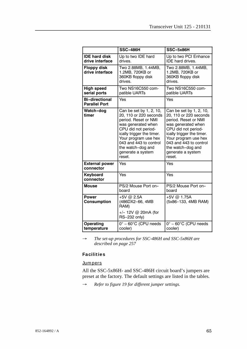
Transceiver Unit 125 - 210131
65852-164892 / A
SSC--5x86HSSC--486H
IDE hard diskdrive interface
Up to two IDE harddrives.
Up to two PCI EnhanceIDE hard drives.
Floppy diskdrive interface
Two 2.88MB, 1.44MB,1.2MB, 720KB or360KB floppy diskdrives.
Two 2.88MB, 1.44MB,1.2MB, 720KB or360KB floppy diskdrives.
High speedserial ports
Two NS16C550 com-patible UARTs
Two NS16C550 com-patible UARTs
Bi--directionalParallel Port
Yes Yes
Watch--dogtimer
Can be set by 1, 2, 10,20, 110 or 220 secondsperiod. Reset or NMIwas generated whenCPU did not period-ically trigger the timer.Your program use hex043 and 443 to controlthe watch--dog andgenerate a systemreset.
Can be set by 1, 2, 10,20, 110 or 220 secondsperiod. Reset or NMIwas generated whenCPU did not period-ically trigger the timer.Your program use hex043 and 443 to controlthe watch--dog andgenerate a systemreset.
External powerconnector
Yes Yes
Keyboardconnector
Yes Yes
Mouse PS/2 Mouse Port on--board
PS/2 Mouse Port on--board
PowerConsumption
+5V @ 2.5A(486DX2--66, 4MBRAM)
+/-- 12V @ 20mA (forRS--232 only)
+5V @ 1.75A(5x86--133, 4MB RAM)
Operatingtemperature
0° ∼ 60°C (CPU needscooler)
0° ∼ 60°C (CPU needscooler)
→ The set-up procedures for SSC-486H and SSC-5x86H aredescribed on page 257
Facilities
Jumpers
All the SSC-5x86H- and SSC-486H circuit board’s jumpers arepreset at the factory. The default settings are listed in the tables.→ Refer to figure 19 for different jumper settings.

EM 300 Complete version
66 852-164892 / A
1 2 3 1 2 3
1
2
3
4
1
2
3
4
1
2
3
4
1 - 2 2 - 3
1 - 2 2 - 3 2 - 4
(CD
5549
)
Closed Open
Figure 19 Different applicable jumper settings
The SSC-486H circuit board:
Jumpers Settings Description
SSC--486H CPU JP1 2 -- 3 --
JP2 1 -- 23 -- 4
--
JP3 Open --
JP4 Open --
JP5 1 -- 2 --
JP6 Open --
JP7 Open --
CPU ClockGenerator Speed (33MHz)
JP8 1 -- 2 Closed3 -- 4 Closed5 -- 6 Open7 -- 8 Open
--
CPU Voltage(+3.3 V)
JP12 2 -- 3 --(+3.3 V)
JP24 Open --
Upgrade theExternal Cache
JP13 2 -- 3 --External Cache(128KB, 32K x 8) JP14 1-- 2
3 -- 4--
Watch--Dog Timer,Active Type
JP18 1 -- 2 Open whenWDT time--out
WDT Time--out period(10 sec.)
JP17 1 -- 2 Open3 -- 4 Closed5 -- 6 Open7 -- 8 Open
--
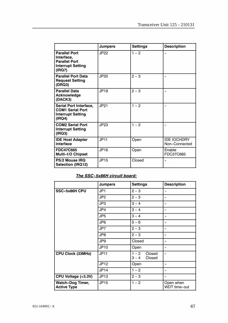
Transceiver Unit 125 - 210131
67852-164892 / A
DescriptionSettingsJumpers
Parallel PortInterface,Parallel PortInterrupt Setting(IRQ7)
JP22 1 -- 2 --
Parallel Port DataRequest Setting(DRQ3)
JP20 2 -- 3 --
Parallel DataAcknowledge(DACK3)
JP19 2 -- 3 --
Serial Port Interface,COM1 Serial PortInterrupt Setting(IRQ4)
JP21 1 -- 2 --
COM2 Serial PortInterrupt Setting(IRQ3)
JP23 1 -- 2 --
IDE Host AdapterInterface
JP11 Open IDE IOCHDRYNon--Connected
FDC47C665Multi--I/O Chipset
JP16 Open EnableFDC37C665
PS/2 Mouse IRQSelection (IRQ12)
JP15 Closed --
The SSC-5x86H circuit board:
Jumpers Settings Description
SSC--5x86H CPU JP1 2 -- 3 --
JP2 2 -- 3 --
JP3 3 -- 4 --
JP4 3 -- 4 --
JP5 3 -- 4 --
JP6 5 -- 6 --
JP7 2 -- 3 --
JP8 2 -- 3 --
JP9 Closed --
JP10 Open --
CPU Clock (33MHz) JP11 1 -- 2 Closed3 -- 4 Closed
--
JP12 Open --
JP14 1 -- 2 --
CPU Voltage (+3.3V) JP13 2 -- 3 --
Watch--Dog Timer,Active Type
JP15 1 -- 2 Open whenWDT time--out

EM 300 Complete version
68 852-164892 / A
DescriptionSettingsJumpers
WDT Time--out period(10 sec.)
JP16 1 -- 2 Open3 -- 4 Closed5 -- 6 Open7 -- 8 Open
--
DiskOnChip MemoryAddress
JP17 5 -- 6 AddressE000
PS/2 Mouse JP18 Closed Enable PS/2Mouse, IRQ12
Connections
COM1 is used for external sync (RTS, CTS). COM1, pinRX/TX, is also connected to the test connector at theTransceiver Unit bottom plate, for debug purposes and factoryproduction testing.→ Refer to description page 52.
1PPS signal is connected from the parallel port (signal on pin10, GND (ground) on pin 23) to the bottom plate in theTransceiver Unit.

Transceiver Unit 125 - 210131
69852-164892 / A
Processing Unit Power Supply
Note The power supply distributes voltages that can result in personalinjuries. Please take necessary precautions.
Purpose and description
The purpose of the power supply (NFS200-7602CFM) is to feed5 Vdc and 12 Vdc to the Processing Rack. It is located on therear side of the Processing Rack, hidden behind a cover plate.
How it works
This is a commercial switch-mode power supply that feeds 5Vdc and 12 Vdc to the Processing Rack. It is also connected tothe TX backplane with a 12 Vdc and a ground signal.
24 Vdc24 Vdc RTN -12 Vdc+12 VdcRTNRTNRTN+5 Vdc+5 Vdc
(9)(8)(7)(6)(5)(4)(3)(2)(1)
(3)(2)(1)
FG (GND)N 220 VacL 220 Vac
(CD
5519
/113
218A
)
Figure 20 The power supply (NFS200-7602CFM)
PUpassivebackplane
Fan
Power supply
FG (GND)
N 220 Vac
L 220 Vac
24 Vdc24 Vdc RTN
-12 Vdc+12 Vdc
RTNRTNRTN
+5 Vdc+5 Vdc
To fuse
Varistor
Groundpoint in PU shelf
1.5 Ye
1.5 Bl1.5 Bl
1.5 Bk
1.5 Bk GND+12 V-12 V
+5 V
1.5 Wh
1.5 R
0.75
Bk
0.75
Bl
(CD5519B/113218A)
Figure 21 Power supply, block diagram

EM 300 Complete version
70 852-164892 / A
FacilitiesConnections
• From the 9-pin plug (Pin 1, 3, 8 and 9 not in use):
Pin Signal Connection
2 +5 Vdc +5 Vdc in PU
4 GND GND in PU
4 GND Fans in PU
5 GND TX backplane--P1 pin 3
5 GND TX backplane--P1 pin 4
6 +12 Vdc +12 Vdc in PU
6 +12 Vdc Fans in PU
6 +12 Vdc TX backplane--P1 pin 1
6 +12 Vdc TX backplane--P1 pin 2
7 --12 Vdc --12 Vdc in PU
• From the 3-pin plug
Pin Signal Connection
1 220 Vac Circuit breaker
2 220 Vac Circuit breaker
3 GND Groundpoint in PU shelf

Transceiver Unit 125 - 210131
71852-164892 / A
Motherboard
How it works
This is a passive backplane with standard ISA-bus.
Facilities
LEDs
The board has four LEDs:• + 5V• - 5V• + 12V• - 12V- 5V is not used and is not lit. The three others should be lit atall times.
Test points
None
Links
None
Connections
+ 5V, + 12V and - 12V.

EM 300 Complete version
72 852-164892 / A
4.6 Receiver rack details
LocationThe Receiver Rack is located at the middle of the theTransceiver Unit. It holds several circuit boards, power suppliesand a capacitor bank.→ Refer to the illustration on page 48.
Circuit boards and modules
Transmitter/Receiver board
These four boards hold the amplifiers for all the individualreceive channels. (The boards may also provide poweramplification of the transmitted signal, but as this function is notused in the EM 300, these components have been omitted).→ The circuit board is explained on page 73.
Low Voltage Power Supply
This is a commercial linear power supply mounted on a chassisfor easy replacement. It also contains linear supplies for theTRB’s.→ The Low Voltage Power Supply is explained on page 76.
High Voltage Power Supply
This is a switching power supply. It provides the high outputvoltage for the transmitters, and uses the Capacitor bank to storethe energy between the pings.→ The High Voltage Power Supply HVPU is explained on page
79.
Signal Processor Board RX (SPRX)
The processor board is used as a function controller. This is acommon circuit board whose name is SPB31, and it is both usedin the Transmitter Rack and the Receiver Rack.→ The Signal Processor Board is explained on page 80.
Backplane (RXBP)
The Receiver Rack uses a passive backplane. All connections tothe circuit boards (except transmission signals) are made on thisbackplane.→ The RX Backplane is explained on page 86
Capacitor bank
This unit stores transmission energy temporarily.

Transceiver Unit 125 - 210131
73852-164892 / A
Transmitter/Receiver Board (TRB)
Purpose and description
The purpose of the Transmitter/Receiver Board (TRB) is toprovide amplification of the signals received from thePreamplifier Unit. The board has 32 individual channels. Theboard is designed to provide transmission as well, but thesecomponents are not mounted on the circuit boards used in theEM 300 Transceiver UnitThe TRB is fastened to a combined strengthening plate and heatsink which covers the entire component side of the board andalso forms a “front panel” to the board. The board is located intracks within the Transceiver Unit to ensure correct location,and is held in position by four screws.The TRB has two 34-pin connectors on its front edge whichcarry the signals from the Preamplifier Unit.A one degree system needs four Transmitter/Receiver (TRB)boards. This means that all 128 channels are used.A two degree system needs two Transmitter/Receiver (TRB)boards, while a four degree system only have one.How it worksTransmission
The TRB contains a control interface that controls the 32transmitters on the board.The transmitters can be controlled individually to enablebeamforming of the transmitted pulse.Reception
The TRB receives signals from 32 transducer elements. Thesignals are individually amplified, time-varied-gain regulated,demodulated, and analogue-to-digital converted. The convertedsignals are then output from the board and sent to the BSP’s forfurther processing.Technical details
Dimensions(Width x Heigh x Depth)
220 x 233.35 x 0.32 mm
Analogue input/output 32 channels, 60W, + T/R switch
Connectors Two 96--pin euro on back edge of boardTwo 34--pin flat cables on front edge
Analogue to digital 12--bits resolutionI/Q simultaneously converted to 32--bit latched bus
Power requirements + 5 Vdc, 8 Vdc, + 24 Vdc

EM 300 Complete version
74 852-164892 / A
Figure 22Transmitter/Receiver
(TRB)block diagram
(Cd3
428B
)
32 TxChannels
32 RxChannels
RX and Txcontrol circuitry
Dataaquisition
Not mounted in the EM 300
Rx control
2 x 16-bitdata buses
Data out to the SPRX
Tx control
Data aquisitioncontrol
Address bus from SPRX
Facilities
Test points
The test points listed below are available to assist themaintenance engineer. They are located on the front edge of theboard between the two connectors, in front of the correspondingLED.AVCC analogue voltage + 5 V. . . . . . . . . . . . . . . . . . . . . . . . . . . . .
AVDD analogue voltage NA. . . . . . . . . . . . . . . . . . . . . . . . . . . . . .
VCC digital voltage + 5 V. . . . . . . . . . . . . . . . . . . . . . . . . . . . . . . . .
AVEE analogue voltage - 5 V. . . . . . . . . . . . . . . . . . . . . . . . . . . . . .
HV1 high voltage transmitter + 8 - + 80 Vdc. . . . . . . . . . . . . . . .
HV2 high voltage transmitter NA. . . . . . . . . . . . . . . . . . . . . . . . .
HV3 high voltage transmitter NA. . . . . . . . . . . . . . . . . . . . . . . . .
HV4 high voltage transmitter NA. . . . . . . . . . . . . . . . . . . . . . . . .
TX transmitter indicator NA. . . . . . . . . . . . . . . . . . . . . . . . . . . . . .
The testpoints marked with NA are not used on EM 300.
Links
The TRB holds no links that can be set by the maintenanceengineer.
Switches
The TRB holds no switches that can be adjusted by themaintenance engineer.
LEDs
The TRB holds ten red LEDs on its front edge, mounted in avertical line between the connectors. When these LEDs are lit,they indicate the presence of the corresponding voltage levels.

Transceiver Unit 125 - 210131
75852-164892 / A
Connectors
The TRB carries four connectors, two located at each end of theboard. P1 is a 96-pin, male right-angled euro-connector, locatedon the rear edge of the board, carrying power. P2 is a 96-pin,male, right-angled euro-connector, also located on the rear edgeof the board, carrying power and digital control signals. P3 andP4 are 34-pin, male, right-angled connectors with ejector/latch,located on the front edge of the board. Each connector carries16 input/outputs to the transducer/preamplifier.

EM 300 Complete version
76 852-164892 / A
Low Voltage Power Unit (LVPU)
Purpose and description
The purpose of the Low Voltage Power Unit (LVPU) is tosupply power to all the modules in the Transceiver Unit, exceptthe high voltage power for the transmission, power to PU and+12Vdc.The Low Voltage Power Unit is located between theTransmitter/Receiver Boards and the High Voltage PowerSupply in the Receiver Rack. The power supply is a plug-inmodule. It has two front mounted fuses, one service switch, andone switch to select 115 or 230 Vac mains input.
TB1
A1
521
13
(CD5488A)
Power supply MAP55-1024MStand-by power
Mains transformer Ulveco N14034-TDUsed in analogue power supply
Switched power supplyMAP55-4001
On/off relay
Line
filte
r
P1
P2
Figure 23 The Low Voltage Power Supply

Transceiver Unit 125 - 210131
77852-164892 / A
How it works
The power unit contains two separate power supplies. Theoutput of the stand-by power supply is 24 Vdc.The power unit has a service switch. When this is set to normal,the power supply is controlled by the on/off relay. This relay isremote controlled from a switch in the operator room. Whenyou disengage the relay, you can control the power supplymanually from the Transceiver Rack using the service switch. Itis then possible to activate parts of the system (service mode).The transformers and rectifiers function is to provide 8 Vdcoutput for the receivers either we have 115 Vac or 230 Vacinput.The LVPU also supplies + 5 V to several boards. See figurebelow.→ Refer to the block diagram in figure 24 and the circuit diagram
on page 386.
115/230 Vac in
Normal
OffService
115/230 Vac to HVPS, fans and Processing Rack
Stand-bypower
+12 Vdc, not used
-12 Vdc, not used
+24 Vdc, not used
GND
Switchmodepower
+
-
+
-
8 Vdc to TRB boards
8 Vdc to TRB boards
+24 Vdc to heater
(CD5497B)
230 V
115 V
S201
S202
24 Vdc stand-by power to ON/OFFswitch in the remote control junction box
From ON/OFF switch in theremote control junction box
gnd also connected to the remote control junction box.
+5 Vdc to TRB, SPRX, SPTX, TX64 & HVPS boardsFigure 24 The Low
Voltage Power Unit -simplified block diagram

EM 300 Complete version
78 852-164892 / A
Facilities
LEDs
• L201: Indicator for mains input• L202: Indicator for 24 Vdc stand by mode• L203: Lit to indicate AC supply to switched
and analogue• L204: Lit to indicate AC supply to
analogue power.
Test points
None
Links
None
Switches
• S201: Switch for mains input 115/230 Vac• S202: Service/Off/Normal switch
Connections
• P1• P2
Fuses
• F201: Primary fuse• F202: Primary fuse• F203: Thermostat fuse inside the torodial
transformer
SIMRADPOWER SUPPLY 290-112750
AnalogPowerSupply
SwitchedPowerSupply
Service
OFF
Normal
On/offRelay
24VStand-by
SlowBlow
Mains input115/230Vac
S 201230Vac
+7,5VREF-7,5V+5VA-5VA+5V+12V-12V+24VGND
F203
+24VREF
F201 8A
F202 8A
L203
L202
L201
S202
S201
On/off relay
F203
(CD
5488
B)
Figure 25 The front panel

Transceiver Unit 125 - 210131
79852-164892 / A
High Voltage Power Unit (HVPU)
Purpose and description
The purpose of the High Voltage Power Unit (HVPU) is toprovide the power for the output amplifiers.The input is to the system is 85 to 265 Vac. The output is 80Vdc. The output voltage can be reduced to -10 dB (25 Vdc) or-20dB (8 Vdc). The values can be adjusted.
Figure 26 The High Voltage Power Supply

EM 300 Complete version
80 852-164892 / A
Signal Processor Board (SPB31)
Purpose and description
The Signal Processor Board (SPB31) is designed for high speedbeamforming and sonar signal processing. The board design isbased on the TMS 320C31 floating point DSP (Digital SignalProcessor) from Texas Instruments.
The Signal Processor Board is designed as a ”double Europe”standard sized printed circuit board. It is equipped with anumber of front mounted LEDs, test points, potentiometers andcoax connectors.
The board is used two places in the EM 300 Transceiver Unit; tocontrol the transmission (SPTX) and the reception (SPRX).
The reg.no. for SPB31 Tx is 382-133472 and 382-134469 forSPB31 Rx.
How it works
The main components of the Signal Processor Board are:
1 TMS 320C31 Digital Signal Processor
- Clock frequency 33.33 or 40 MHz- 32-bit data bus- 24-bit address bus- 40/32-bit floating point unit- 1 internal serial line- 2 pc 32-bit timers- 4 interrupt inputs- DMA controller- Programmable in C and assembly- Emulator and symbolic de-bugger available
2 256k x 32 bit PROM.
3 512 x 32 bit SRAM 25 ns
4 Complex multiplier.
5 4 serial lines RS422/RS232.
6 Programmable counter for TX clock, 64 CHTX.
7 Dual port interface to P1 bus (Multibus I type).
8 Bus interface to P2 bus.
9 Control bus for control outputs compatible with SPB29.

Transceiver Unit 125 - 210131
81852-164892 / A
The Signal Processor Board works very similar to othermicroprocessor boards. The TMS 320C31 Digital SignalProcessor operates with standard peripheral circuitry such asRAM, PROM (with software) and the interface controllers.Devices for disk drive control are omitted, but Dual Port RAMand a complex multiplier is implemented instead. Refer to theblock diagram.
Businterface
16-bit databus and24-bit address bus
16-bit databus
Serial line
Serial lines
(CD
1401
)
Emulator
Data bus
24-bit address bus
Address bus
Dual portRAM (DPRAM)
Signal processorTMS320C31
Serial lineinterface (4 ea)
Businterface
Programcounter
256k x 32 PROM512k x 32 RAM
Dual portRAM (DPRAM)
Multipliers
16-bit databus and24-bit address bus
P1
P2
Figure 27 Signal ProcessorBoard SPB31 - simplified
block diagram
An emulator for the TMS 320C31 processor is developed. Itconsists of a controller board in a PC and an active pod which isconnected to the target board by a 12 pin plug.
Facilities
Unmounted devices
Note that several sockets on the Signal Processor Board may beempty. On EM 300 the Mulitpliers with corresponding DPRAMare not mounted.

EM 300 Complete version
82 852-164892 / A
Links
A large number of links are implemented on the processor boardto allow for several different applications. The links are used asfollows:
LK 1 2BI422 to RXDB on U15
LK 2 RXDB2 input to RXDB on U15
LK 3 2AI422 to RXDA on U15
LK 4 RXDA2 input to RXDA on U15
LK 5 CLKIN to U64
LK 6 FSRO and DRO to set frame sync for sercom onU32
LK 7 RDRO to DRO when sercom in U32 is used onRS232
LK 8 Clock to U36
LK 9 RXDA input to RXDA on U63
LK 10 RXDB input to RXDB on U63
LK 11 BI422 input to RXDB on U63
LK 12 AI422 input to RXDA on U63
LK 13 CLQ to P2A25, U60 must not be mounted
LK 14 TXCLK to P2B24, U60 must not be mounted
LK 15 CLI to P2A24, U60 must not be mounted
LK 16 TSTSIG to P2C23, U60 must not be mounted
LK 17 TXEN~ to P2A22, U60 must no be mounted
LK 18 MEM3 to P2C3, LK30 must be OFF
LK 19A XF0~ as output
LK 19B XF0 as input
LK 20A XF0 as output
LK 20B XF0~ as input
LK 23A XF1~ as output
LK 23B XF1 as input
LK 24A XF1 as output
LK 24B XF1~ as input
LK 25A TCLK0~ as output
LK 25B TCLK0 as input
LK 26A TCLK0 as output
LK 26B TCLK0~ as input
LK 27A TCLK1~ as output
LK 27B TCLK1 as input
LK 28A TCKL1 as output
LK 28B TCLK1~ as input
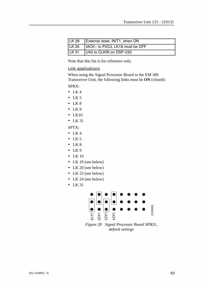
Transceiver Unit 125 - 210131
83852-164892 / A
LK 29 External reset, INIT1, when ON
LK 30 IACK~ to P2C3, LK18 must be OFF
LK 31 U40 to CLKIN on DSP U32
Note that this list is for reference only.
Link applications
When using the Signal Processor Board in the EM 300Transceiver Unit, the following links must be ON (closed):SPRX:• LK 4• LK 5• LK 8• LK 9• LK10• LK 31SPTX:• LK 4• LK 5• LK 8• LK 9• LK 10• LK 19 (see below)• LK 20 (see below)• LK 23 (see below)• LK 24 (see below)• LK 31
(Cd5
684)
Figure 28 Signal Processor Board SPB31,default settings

EM 300 Complete version
84 852-164892 / A
LED’s
LED’s used for SPTX:D1: program initialized OK
D2: ready for new command
D3: transmit active
D4: BIST active
D5: not used
D6: test purpose
D7: test purpose
D8: test purpose
LED’s used for SPRX:D1: program initialized OK
D2: BIST active
D3: aquisition of reciever data
D4: aquisition of reciever data
D5: simulator active
D6: not used
D7: not used
D8: not used
Test points
TP 1: GND
TP 2: General purpose test output no.1
TP 3: General purpose test output no.2
TP 4: General purpose test output no.3
TP 5: General purpose test output no.4
TP 6: General purpose test output no.5
TP 7: General purpose test output no.6
TP 8: General purpose test output no.7
TP 9: General purpose test output no.8
TP 10: +5 Vdc
TP 11: Clock pulse, CP, monitor
TP 12: WE~ for testing RAM loading
TP 13: GND
TP 14: GND
TP 15: GND

Transceiver Unit 125 - 210131
85852-164892 / A
Figure 29 SignalProcessor Board SPB31,
front mounted devices
(CD4340)
TP 2
TP 3
TP 4
TP 5
TP 6
TP 7
TP 8
TP 9
TP 10
TP 1
D 2D 1
D 3D 4D 5D 6D 7D 8
D 9
P3
S1
TP 11
TP 12
J2
P9
J1
TP 15
Same as LED D1Same as LED D2
Same as LED D3Same as LED D4
Same as LED D5Same as LED D6
Same as LED D7Same as LED D8
Clock pulse
WE/ to test RAM
Ground
Ground
Test signal output
Reset
Softwarecontrolled
LEDs
Serial lines
Emulator
Serial lines
+5 Vdc
+5 Vdc
Connections
The following connections are made to the Signal ProcessorBoard:
P1 Multibus
P2 Signal processor external bus
P3 Test signal output
J1 Serial lines
J2 Serial lines
The trig out puls is active during transmit, and generated bySPRX. This is a TTL level pulse and is active when low.
→ The connections are explained in the figure on page 52.
→ The Receiver Backplane connections(PXB-P3) are explained onpage 87.

EM 300 Complete version
86 852-164892 / A
Receiver Backplane (RXBP)
Purpose and description
The purpose of the Receiver Backplane is to enablecommunication between the circuit boards plugged into it, andbetween these circuit boards and the external circuitry in thecabinet. The RXBP is located behind the middle wired rack inthe Transceiver Unit, and holds the following circuit boards:• Transmitter/Receiver Board 1• Transmitter/Receiver Board 2• Transmitter/Receiver Board 3• Transmitter/Receiver Board 4• Low Voltage Power Supply• High Voltage Power Supply• Signal Processor Board RX• Capacitor Bank
How it works
There are no active components on this backplane.
Facilities
LEDs
None

Transceiver Unit 125 - 210131
87852-164892 / A
TP10 TP9
TP12TP11
TP13 TP8 TP7
TP6
TP3TP5
TP4 TP2
TP1
LK1LK2LK3LK4
LK5
LK7
LK8
LK6
P12
P11
P6
P7
P8
P2
P3
P5
P10 P13
P4
P1
(Cd5527 / 134122/B)
Figure 30 Receiver Backplane, rear side
J1 J3 J5 J7 J9 J11 J13 J15
J2 J4 J6 J8 J10 J12 J14 J16
(CD5527B / 134122/B)
Figure 31 Receiver Backplane, front side

EM 300 Complete version
88 852-164892 / A
Links
There are four links on this backplane:LK6: ONLK7: ON, HVCLK to HVCKRLK8: ON, DA0 to DB0LK9: OFF
Test points
All the test points listed below are only used duringdevelopment and debugging:TP 1: GNDTP 2: Read pulse to the TRBTP 3: Filter clk. to PDH’s on the TRBTP 4: Write pulse to the TRBTP 5: Sample and hold to PDH’s on the TRBTP 6: Four times demodulater frequency to PDH’s on the TRBTP 7: TX enable to the TRBTP 8: GNDTP 9: GNDTP 10: Write pulse to fifo on the BSPTP 11: Read pulse to 2 port RAM on the SPTXTP 12: Write pulse to 2 port RAM on the SPTXTP 13: Test signal input to PDH’s on the TRBOnly links LK7 and LK8 are applicable for system setup. Theseare closed as shown in the illustration.
Figure 32 Applicable links
DBT0
DA0
DB0
HV
CK
R
HV
CLK
HV
CK
LK7
LK8(Cd5482)
Connections
The sockets on the rear side of the backplane and theirconnections in the EM 300 Transceiver Unit are described in thetables below.
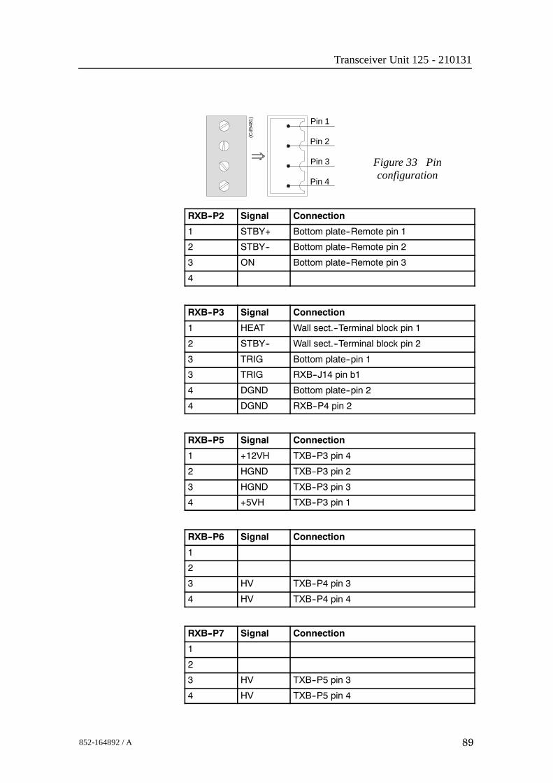
Transceiver Unit 125 - 210131
89852-164892 / A
Pin 1
Pin 2
Pin 3
Pin 4
(Cd5
481)
Figure 33 Pinconfiguration
RXB--P2 Signal Connection
1 STBY+ Bottom plate--Remote pin 1
2 STBY-- Bottom plate--Remote pin 2
3 ON Bottom plate--Remote pin 3
4
RXB--P3 Signal Connection
1 HEAT Wall sect.--Terminal block pin 1
2 STBY-- Wall sect.--Terminal block pin 2
3 TRIG Bottom plate--pin 1
3 TRIG RXB--J14 pin b1
4 DGND Bottom plate--pin 2
4 DGND RXB--P4 pin 2
RXB--P5 Signal Connection
1 +12VH TXB--P3 pin 4
2 HGND TXB--P3 pin 2
3 HGND TXB--P3 pin 3
4 +5VH TXB--P3 pin 1
RXB--P6 Signal Connection
1
2
3 HV TXB--P4 pin 3
4 HV TXB--P4 pin 4
RXB--P7 Signal Connection
1
2
3 HV TXB--P5 pin 3
4 HV TXB--P5 pin 4

EM 300 Complete version
90 852-164892 / A
RXB--P8 Signal Connection
1
2
3 HV TXB--P6 pin 3
4 HV TXB--P6 pin 4
RXB--P9 Signal Connection
1 POW1 TX/RX Fan pin 1
2 POW2 TX/RX Fan pin 3
3 POW1 PU Fuse pin 3
4 POW2 PU Fuse pin 4
RXB--P13 Signal Connection
1 +5 Vdc TXB--P2 pin 1
2 +5Vdc TBX--P2 pin 2
3 DGND TBX--P2 pin 3
4 DGND TBX--P2 pin 4
RXB--J16 Signal Connection
d14 HGND TXB--P5 pin 1
d14 HGND TXB--P6 pin 1
d18 HGND TXB--P5 pin 2
d18 HGND TXB--P6 pin 2
z12 HGND TXB--P4 pin 1
z16 HGND TXB--P4 pin 2
RXB--P14 Signal Connection
1 +5 Vdc TXB--P2 pin 1
2 +5Vdc TBX--P2 pin 2
3 DGND TBX--P2 pin 3
4 DGND TBX--P2 pin 4

Transceiver Unit 125 - 210131
91852-164892 / A
P11
P6
P7
P8
P5
P2
P3
(CD5533 / 210142A)
J16
J14
P10 P9
P13
P4
P1
P12
Figure 34 The Receiver Backplane

EM 300 Complete version
92 852-164892 / A
4.7 Transmitter rack details
LocationThe Transmitter Rack is located at the bottom of the TransceiverUnit. It holds one processor board and a number of transmitterboards.→ Refer to the illustration on page 49
The physical number of transmitter boards is defined by thespecified system accuracy:• A 1 degree system has 14 transmitter boards
Circuit boards and modules
64-Channel Transmitter Board (TX64)
Each of these circuit boards holds 64 individual poweramplifiers, each controlled by the function controller.→ The circuit board is explained on page 93
Signal Processor Board TX (SPTX)
The processor board is used as a function controller.→ The circuit board is explained on page 80
Backplane (TXBP)
The Transmitter Rack uses a passive backplane.→ The TX Backplane is explained on page 97

Transceiver Unit 125 - 210131
93852-164892 / A
64-Channel Transmitter (TX64)
Purpose and description
Once the transmission parameters have been calculated by theSignal Processor Tx (SPTX), each of the transmitter boards isaddressed. The data-bus from the SPTX is connected to all theboards, and data for the individual transmitters is loaded into theonboard RAMs as they are addressed from the SPTX. Theoutput from the TX64 RAM bank is connected to the outputstages, which are implemented using KongsbergMaritime-designed amplifier hybrids.
The physical number of TX64 boards fitted to the EM 300transceiver depends on the chosen system specifications. Thus,up to 14 64-Channel Transmitter (TX64) boards are used.
A one degree transmitter has 864 elements in the transducer anda two degree transmitter 432 elements. Hence a one degree Txsystem needs 14 TX64 boards, the last 32 transmitters on theTX64 #14 is not used.
A two degree Tx system needs seven TX64 boards. Here the last16 transmitters are not used on TX64 board # 7.
How it works
Overview
The TX64 boards are controlled by the Signal Processor TX(SPTX), and the output signals are made available on the frontmounted sockets. Flat ribbon cables connect these output pulsesto the filters.
The TX64 board is equipped with two large front mountedconnectors. Two LED indicators and one test point are locatedbetween these connectors. The test point is a ground (GND)connection, while the LEDs monitor the +5 Vdc and +12 Vdcsupply voltages.
The TX64 board is equipped with eight onboard fuses. Thesefuses are located on the High Voltage (HV) supply line, andeach fuse protects a group of eight transmitters. Fuse rating is 4A, physical size is 5 x 20 mm.
The functions of the transmitter may be divided into three parts:
• The power unit (Power & Fuses)
• The digital control unit
• The analogue transmitter driver unit (TX Hybrid)

EM 300 Complete version
94 852-164892 / A
Figure 35 64-Channel Transmitter (TX64)block diagram
Data, address andcontrol buffers
Fault detectionbuffer
On-board errors
Address latch andsequential counter
Data and address busesto/from the Signal Processor Tx (SPTX)
Latch 1-15 Latch 16
Outputhybrid
Outputhybrid
Outputhybrid
Outputhybrid
Random AccessMemory
(CD
1405
C)
To the filters
To the remaining60 output hybrids
Power unit
The power unit includes the three separate supply voltages usedand the components around them. The voltages are +12 Vdc, +5Vdc and High Voltage (HV). The value of the HV depends onthe desired output power. Typical range is +8 to +80 Vdc.
Digital control unit
The main function of the digital control unit is to supply theanalogue transmitter unit with the correct driving signals.
The shape of the driving signals are temporarily stored in RAMson the board. The RAMs are filled by the host processor. Thedrive signals for the output pulses are derived from the pattern.The signals are clocked and latched before they are supplied tothe transmitter hybrids.

Transceiver Unit 125 - 210131
95852-164892 / A
The transmitted pulse is controlled by the address latches andthe controller. The transmitted frequency is increased by 64times, and is then supplied to the CLK input. The TX Enable(TXEN/) input enables the transmitters and controls the transmitpulse length.Status information such as fuse blown can be read from the faultdetect buffer on the data bus.To lower the sidelobe level, IC U89 is omitted and a piggy backboard is inserted. This piggy back board contains a PLD withdoubled resolution for transmit beampattern.Analogue transmitter unitThere are 64 transmitters on the board. Each of these is a thickfilm hybrid designed by Kongsberg Maritime. There are nofrequency dependent components on the board. The transmittersare electrically designed into in groups of eight, each groupbeing protected by a 4 A fuse. The transmitter outputs arebrought to the front edge connectors P3 and P4.
Facilities
LEDsD 9 +5 Vdc. . . . . . . . . . . . . . . . . . . . . . . . . . . . . . . . . . . . . . . . . . . . .D 10 +12 Vdc. . . . . . . . . . . . . . . . . . . . . . . . . . . . . . . . . . . . . . . . . . .
Figure 36 64-ChannelTransmitter (TX64) front mounted
devices
P3
D9
D10
+12 Vdc
+5 Vdc
P4
Outputs
(CD
4417
)
Test pointsTP 1 GND. . . . . . . . . . . . . . . . . . . . . . . . . . . . . . . . . . . . . . . . . . . . . . .
LinksA number of links are implemented on the board to allow forseveral different applications. The links are used as follows:

EM 300 Complete version
96 852-164892 / A
LK1 Selects PROM (when ON). . . . . . . . . . . . . . . . . . . . . . . . . . . . .
LK2 Selects RAM (when ON). . . . . . . . . . . . . . . . . . . . . . . . . . . . . .
Link applications
The following links are ON (closed) in this application:• LK2
Switches
None
Connections
The TX64 is equipped with the following connectors:P 1 Connections to the external power supply. . . . . . . . . . . . . . .
P 2 Interface to control processor. . . . . . . . . . . . . . . . . . . . . . . . . . .
P 3 Outputs from channels 01-32. Front mounted. . . . . . . . . . . .
P 4 Outputs from channels 33-64. Front mounted. . . . . . . . . . . .
Fuses
F 1 TX group 1, Channels 01-08. . . . . . . . . . . . . . . . . . . . . . . . . . . .
F 2 TX group 2, Channels 09-16. . . . . . . . . . . . . . . . . . . . . . . . . . . .
F 3 TX group 3, Channels 17-24. . . . . . . . . . . . . . . . . . . . . . . . . . . .
F 4 TX group 4, Channels 25-32. . . . . . . . . . . . . . . . . . . . . . . . . . . .
F 5 TX group 5, Channels 33-40. . . . . . . . . . . . . . . . . . . . . . . . . . . .
F 6 TX group 6, Channels 41-48. . . . . . . . . . . . . . . . . . . . . . . . . . . .
F 7 TX group 7, Channels 49-56. . . . . . . . . . . . . . . . . . . . . . . . . . . .
F 8 TX group 8, Channels 57-64. . . . . . . . . . . . . . . . . . . . . . . . . . . .
Fuse rating is 4 A. Physical fuse size is 4 x 20 mm.
Oscilloscope check points
• The Clock (CLK) is input on pin P2 B24, and connected tobuffer U90, pin 4. The clock frequency varies with thetransmission frequency, and will be 64 times this. Frequencyalterations during one transmission are achieved by changingthe clock frequency.
• The TX Enable (TXEN/) is input on pin P2 A22, andconnected to buffer U90, pin 2. The TXEN/ pulse is thetransmit trigger, and the length of the TXEN is also thelength of the transmitted pulse. For EM 300 the TXfrequency is from 30 to 34 kHz.

Transceiver Unit 125 - 210131
97852-164892 / A
Transmitter Backplane (TXBP)Purpose and description
The purpose of the transmitter Backplane is to enablecommunication between the circuit boards plugged into it, andbetween these circuit boards and the external circuitry in thecabinet. The TXBP is located behind the bottom wired rack inthe Transceiver Unit, and holds the following circuit boards:• 64-channel Transmitter Board (TX64)• Signal Processor Board TX (SPB31)
C1
C2
C3
C4
C5
C6
C7
C8
C9
C10
C11
C12
C13
C14
C17
C16C18
C19C19
C20
C21
C22
C23
C24
P7
P8
P9
TP6TP5
TP3TP4
P2
P6 P5 P4 P3 P1
TP1
+ +
+ + + + + +++ + + + +
++++++++ ++
(Cd5522 / 113186/A)
Figure 37 Transmitter Backplane, rear side
How it works
There are no active components on this backplane.Facilities
LEDs
None
Test points
The following testpoints are only used during development anddebugging.TP 1: DGNDTP 2: DGNDTP 3: SMEM/ Active low when data is read from TX64
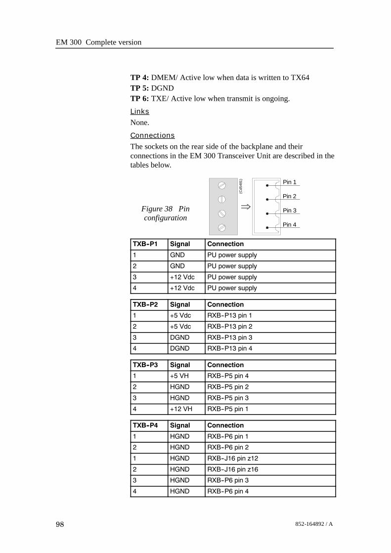
EM 300 Complete version
98 852-164892 / A
TP 4: DMEM/ Active low when data is written to TX64TP 5: DGNDTP 6: TXE/ Active low when transmit is ongoing.Links
None.Connections
The sockets on the rear side of the backplane and theirconnections in the EM 300 Transceiver Unit are described in thetables below.
Pin 1
Pin 2
Pin 3
Pin 4
(Cd5
481)
Figure 38 Pinconfiguration
TXB--P1 Signal Connection
1 GND PU power supply
2 GND PU power supply
3 +12 Vdc PU power supply
4 +12 Vdc PU power supply
TXB--P2 Signal Connection
1 +5 Vdc RXB--P13 pin 1
2 +5 Vdc RXB--P13 pin 2
3 DGND RXB--P13 pin 3
4 DGND RXB--P13 pin 4
TXB--P3 Signal Connection
1 +5 VH RXB--P5 pin 4
2 HGND RXB--P5 pin 2
3 HGND RXB--P5 pin 3
4 +12 VH RXB--P5 pin 1
TXB--P4 Signal Connection
1 HGND RXB--P6 pin 1
2 HGND RXB--P6 pin 2
1 HGND RXB--J16 pin z12
2 HGND RXB--J16 pin z16
3 HGND RXB--P6 pin 3
4 HGND RXB--P6 pin 4

Transceiver Unit 125 - 210131
99852-164892 / A
TXB--P5 Signal Connection
1 HGND RXB--P7 pin 1
2 HGND RXB--P7 pin 2
1 HGND RXB--J16 pin d14
2 HGND RXB--J16 pin d18
3 HGND RXB--P7 pin 3
4 HGND RXB--P7 pin 4
TXB--P6 Signal Connection
1 HGND RXB--P8 pin 1
2 HGND RXB--P8 pin 2
1 HGND RXB--J16 pin d14
2 HGND RXB--J16 pin d18
3 HGND RXB--P8 pin 3
4 HGND RXB--P8 pin 4
The bleeder is mounted on the Processing Unit power supplycover.
Fan TX/RX
123
P8
P7 P6 P5 P4 P3 P1
P2
Vorsicht Spannung
AttentionD anger
(Cd5
525
/ 210
142/
A)
Figure 39 The Transmitter Backplane

EM 300 Complete version
100 852-164892 / A
Blank page

Transceiver Unit 125 - 211293
101852-164892 / A
5 TRANSCEIVER UNIT 125-211293
5.1 Description and main functions
OverviewThe EM 300 Transceiver Unit performs the reception, dataacquisition, received signal processing and transmission for themultibeam echo sounder system. The cabinet holds three wiredracks containing the system circuit boards.• The top Processing Rack holds the complete Processing Unit
with its own power supply. This unit provides dataacquisition, signal processing and function control.
• The middle Receiver Rack holds the receiver boards, acontroller, two power supplies and a large capacitor bank.
• The bottom Transmitter Rack holds the transmitter circuitryand a dedicated controller.
Three different versions of the Transciever Unit have beendelivered. The registration number of the Transceiver Unitwill determine which version you have:125-210131, more information on page 41.125-211293, more information on page 101.125-218182, more information on page 161.This number is to be found on the Transceiver Unit chassis.All versions are described in this manual. Please check yourTransceiver Unit to find out which version you have.

EM 300 Complete version
102 852-164892 / A
5.2 Transceiver Unit 125-211293This chapter provides the following information:→ Circuit board descriptions, page 116.→ Description and main functions, page 101.→ Transceiver Unit outline, page 103.→ Transceiver Unit racks, page 108.→ Theory of operation, page 112.→ Processing rack, details, page 117→ Receiver rack, details, page 134.→ Transmitter rack, details, page 152→ Circuit board descriptions, page 116.

Transceiver Unit 125 - 211293
103852-164892 / A
630 mm 600 mm
1834
mm
1995
mm
1600
mm
Min
303
mm
(CD3694)
Figure 40 Standard EM 300 Transceiver Unit - Outline dimensions

EM 300 Complete version
104 852-164892 / A
Figure 41 EM 300 Transceiver Unit with the optionalRaw Data Logger - Outline dimensions
A
A
A
A
A-A
600 195
ø11
83
260
0 190
330
520
630
8383
1760
1600
Min
303
(Cd21000)
→ Please refer to the Raw Data Logger Instruction Manual formaore information about installation with Raw Data Logger.

Transceiver Unit 125 - 211293
105852-164892 / A
Shock absorber
Base section
Mid section
Mid section
Door
RDL
Seen from top
Shock absorber
Base sectionDoor
RDL
245
1170
1540
(CD21000B)
Note:All measurements are in mm.The drawing is not in scale.
Figure 42 Transceiver Unit with Raw Data Logger,seen from above.
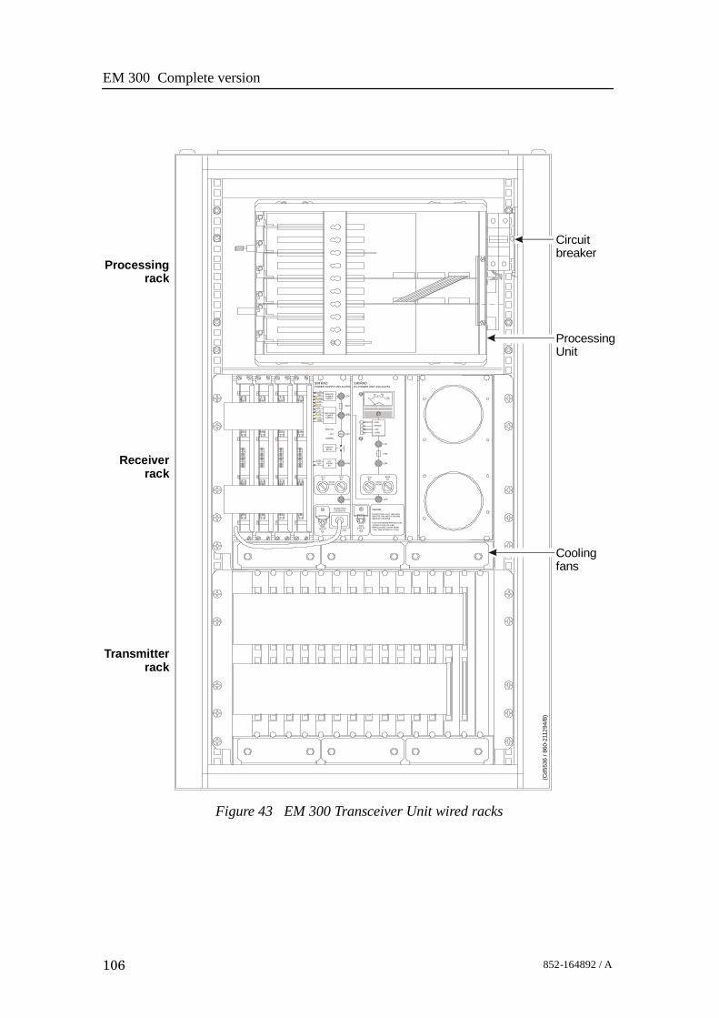
EM 300 Complete version
106 852-164892 / A
SIMRAD SIM RADPOWER SUPPLY 290-112750 HV-POWER UNIT 290-112751
7.5V
7.5VREF
5VA5VA5V12V12V24VGND
ANALOGPOWERSUPPLY
SWITCHEDPOWERSUPPLY
L204
F203
L203
S202
SERVICE
OFF
NORMAL
ON/OFFRELAY
24VSTAND
BYL202
24VREF
F2018A
F2028A
SLOWBLOW
L201
MAINS INPUT115/230V AC
S201230V AC
P201
0
50 100150
HIGH
MIDDLE
LOW
f (SW)
L207
F206
L206
F2048A
F2058A
SLOWBLOW
L205
S203230V AC
CAUTION
DO NOT PULL OUT THIS UNITBEFORE THE METER SHOWSZERO (0) VOLTAGE
FOR CONTINUED PROTECTIONAGAINST RISK OF F IREREPLACE ONLY WITH SAMETYPE AND RATING OF FUSE
(Cd5
536
/ 860
-211
294/
B)
Processingrack
Receiverrack
Transmitterrack
Circuitbreaker
ProcessingUnit
Coolingfans
Figure 43 EM 300 Transceiver Unit wired racks
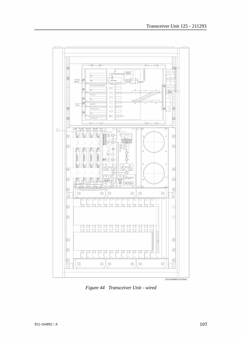
Transceiver Unit 125 - 211293
107852-164892 / A
ZERO ( 0 ) VOLTAGEBEFORE THE METER SHOWSDO NOT PULL OUT THIS UNIT
AGAINST RISK OF FIRE
TYPE AND RATING OF FUSE.REPLACE ONLY WITH SAME
FOR CONTINUED PROTECTION
CAUTION
BLOWSLOW
230V ACS 201
230V ACP201
S203
115/230V AC
MAINS INPUT
BLOW
24V
REF
8AF201
SLOW
STAND24V
BY
L201
F2028A
L202
F2048A
L205
F2058A
L206
6
ETH-J50ETH-J70
CPU-CN12
LOW
f (SW)
HV-POWER UNIT 290-112751
HIGH
MIDDLE
+ 5VA
SERVICE
RELAYON/OFF
NORMAL
OFF
- 5VA
+ 5V
+ 12V
- 12V
+ 24V
GND
POWERSUPPLY
SWITCHED
S202
F203
L203
POWER SUPPLY 290-112750
REF
- 7.5V
+ 7.5V
SIMRAD
POWERSUPPLY
ANALOG
SIMRAD
L204
0
50
L207
F206
100
150
P1 P7P5
P1 P7P5
22DiskOnModule
1 1
43
43
TX14
-P4
S lot 8 Processor card SSC-5X86H
Slot 4 BSP 2
Slot 6 BSP 1
Slot 3 Ethernet card
Slot 1 Serial card
Slot 2
Slot 5
Slot 7
Slot 9
Slot 9
14
32
(CD21108/860-211294A)
Figure 44 Transceiver Unit - wired

EM 300 Complete version
108 852-164892 / A
The Processing Rack
The Processing Rack is located at the top of the TransceiverUnit. It holds a chassis with several circuit boards, fans and apower supply. A ground strap and a circuit breaker for thepower supply is also available, but these are mounted on themain rack, and not on the shelf.
The Processing Rack holds the following circuit boards andmodules:
• 4-Ports Serial Line board
• Beamformer & Signal Processor (BSP1 and BSP2)
• Ethernet Adapter
• Control Processing Unit board
• DiskOnModule flash disk (mounted on the ControlProcessing Unit board)
• Power supply
• Fan
• Motherboard→ A more detailed description of all the circuit boards and
modules is found on page 117.
ETH-J50ETH-J70
CPU-CN12
P1 P7P5
P1 P7P5
22DiskOnModule
1 1
43
43
S lot 8 Processor card SSC-5X86H
Slot 4 BSP 2
Slot 6 BSP 1
Slot 3 Ethernet card
Slot 1 Ser ial card
Slot 2
Slot 5
Slot 7
Slot 9
Slot 9
14
32
(CD21108/860-211294A)
Control Processor Unit (CPU) board(with DiskOnModule, DOM)
BSP1 board
BSP2 board Ethernet adapter Serial line board
Figure 45 Processing Rack, circuit board locations

Transceiver Unit 125 - 211293
109852-164892 / A
Vorsicht! Spann ung
DangerAt tention
Power supplyHN5-9/OVP-A
Power supplyOLD-12/15BB
(CD5403B / 861-212871/A)
Figure 46 Power supplies on the rear panel

EM 300 Complete version
110 852-164892 / A
The Receiver RackThe Receiver Rack is located at the middle of the TransceiverUnit. It holds several circuit boards, power supplies and acapacitor bank. All the units are accessed from the front of therack.
HIGHMIDDLELOWf (SW)
L207
F206
L206
L205
F2018A
F2028ASLOW
BLOW
F2048A
F2058A
SLOWBLOW
L201
CAUTION
DO NOT PULL OUT THIS UNITBEFORE THE METER SHOWSZERO (0) VOLTAGE.
FOR CONTINUED PROTECTIONAGAINST RISK OF FIREREPLACE ONLY WITH SAMETYPE AND RATING OF FUSE.
S203230V ac
S201230Vac P201
MAINS INPUT115/230V ac
SIMRADHV-POWER UNIT 290-112751
SIMRADPOWER SUPPLY 290-112750
L202+24VREF
ON/OFFRELAY
24VSTAND
BY
S202SERVICE
OFF
NORMAL
L204
F203
L203
ANALOGPOWERSUPPLY
+7.5VREF-7.5V+5va-5va+5V+12V-12V+24VGND
SWITCHEDPOWERSUPPLY
10050
0150
(CD4472C/210132A)
Transmitter/Receiver boards High Voltage Power Supply Capacitor bank
Low Voltage Power Supply Signal Processor Board RX (SPBRX)
Figure 47 The Receiver RackThe Receiver Rack holds the following circuit boards andmodules (from left):• TRB 32/Receiver board (max 4)
• Low Voltage Power Supply• High Voltage Power Supply
• Signal Processor Board RX (SPRX)• Capacitor bank→ A more detailed description is found on page 134.

Transceiver Unit 125 - 211293
111852-164892 / A
The Transmitter RackThe Transmitter Rack is located at the bottom of the theTransceiver Unit. It holds one processor board and a number oftransmitters.
Figure 48 The Transmitter Rack
(CD4472D/210132A)
64-Channel Transmitter Boards (Tx64)
Signal Processor Board TX (SPBTX)
The Transmitter Rack holds the following circuit boards andmodules (from left):• 64-Channel Transmitter Board (TX64)• Signal Processor Board TX (SPTX)→ A more detailed description is found on page 152

EM 300 Complete version
112 852-164892 / A
5.3 Theory of operation
OverviewThis chapter presents a functional description of the TransceiverUnit.
Figure 49 Transceiver Unit, simplified block diagram
Control Processor
Beamformer and SignalProcessor (BSP) x 2
Signal Processor Rx(SPRX)
Serial lines to/fromthe sensors
Ethernet to/from theOperator Station
Signal Processor Tx(SPTX)
Command andcontrol (serial line)
16-bitsampleddata
TransmitterRack
Processing Rack
ReceiverRack
Transmitter/ReceiverBoard (TRB) x 4
64-Channel Transmitter(64CHTX) x 14
Transmit array Receive array
Filter Filter
Commandand control
(CD
4551
)
Simplified block diagramThe simplified block diagram for the Transceiver Unit presentsthe following main functions:• Transmission• Reception• Processing

Transceiver Unit 125 - 211293
113852-164892 / A
The various parameter settings made on the Operator Station aresent to the Control Processor in the Processing Rack. Theinformation (roll, pitch, pulse length etc.) is interpreted, andpassed on to the Signal Processor TX (SPTX), which is the“master” processor in the TX/RX system.
After the transmission, the Signal Processor RX (SPRX) isinstructed to receive the samples for all the receiver staves andpass them on to the two Beamformer and Signal Processors(SBP’s) in the Processing Rack.
Control functions
The control functions in the Transceiver Unit are mainlyhandled by the three processor boards, but additional peripheralboards are also used. The majority of the control boards arecontained in the Processing Unit.
Figure 50 The control functions
Seriallines
DiskOnModule Controlprocessor
Ethernetadapter
BSP x 2
Signal Processor Rx(SPRX)
Serial lines to/fromthe sensors
Ethernet to/from theOperator Station
Signal Processor Tx(SPTX)
Command andcontrol (serial line)
Processing Rack
Receive circuitryTransmit circuitry
Commandand control
Bus system
(Cd4554a)
The Control Processor in the Processing Unit is not equippedwith interface capabilities, and thus requires external boards tohandle ethernet and serial lines interface. It also relies on anexternal memory board for the software contained in the ROMdevice. All the peripheral boards used here are commercial.

EM 300 Complete version
114 852-164892 / A
Note Newer Control Processor Units (CPU) handles ethernetinterface and have a DiskOnModule installed (containingsoftware). This kind of CPU also relies on an external board tohandle serial line interface.
One serial line is used to interface the command and controlsignals to and from the TX/RX controllers. The SignalProcessor TX is the “master”.
External synchronisation
The serial line RTS and CTS signals are used for externalsynchronisation. In addition a trig out signal is issued by theTRU.Levels:
RTS, CTS:H=high= +3 to +15 VL=low= -3 to -15 VTrig out:TTL LevelOutputs from TRU:
Trig out=1 TX is off(High TTL level)Trig out=0 TX is active(Low TTL level)
RTS=H TRU is ready for a new pingRTS=L TRU is not readyRTS is pin 7 on the CPU card D connector. (Pin 6 on EM120and EM300 “remote” plug).Inputs to TRU:
CTS=H Ping commandCTS=L WaitCTS is pin 8 on the CPU card D connector. (Pin 7 on theEM120 and EM300 “remote” plug). The CTS pulse length mustbe minimum 30 milliseconds.Gnd is pin 5 on the CPU card D connector. (Pin 8 on EM120and EM300 “remote” plug).Typical sequence:CTS _____________- - - - - - - ________________- - - - - - - - - - _________
TXCommand
RTS - - - - - - - - - - - - - - _______________- - - - - - - ________________- - -(TRU ready) (TRU busy) (TRU busy)
Trig out - - - - - - - - - - - - - - __- - - - - - - - - - - - - - - - - - - - __- - - - - - - - - - - - - - - - -TXPulse

Transceiver Unit 125 - 211293
115852-164892 / A
When the TRU is ready for a new ping, RTS is set to H. Whenthe external device is ready for a new ping, CTS shall bechanged to H. The TRU will then start a ping, change RTS to L(busy), and the Trig out will be low during the transmit pulse.After the Trig out is received, the external device should turnCTS to L. (Or at least keep it high for 35 milliseconds).When the received period is finished and the TRU is ready for anew ping, the RTS will be changed to H, and the TRU will waitfor new trigger (a high level on CTS).If CTS is H all the time, or if external sync in the installationmenu is switched off, the TRU will ping at its maximum rate.
EM 300 Complete version
116 852-164892 / A
5.4 Circuit board descriptions
OverviewThis chapter describes all the circuit boards and modules in theEM 300 Transceiver Unit. A functional description with a blockdiagram is provided, as well as the facilities provided formaintenance.Remember that all versions of the Transceiver Unit is in thismanual. Different boards and power supplies are thereforedescribed for the EM 300 system. Check the reg.no. on yourTransceiver Unit to find out which version you have.
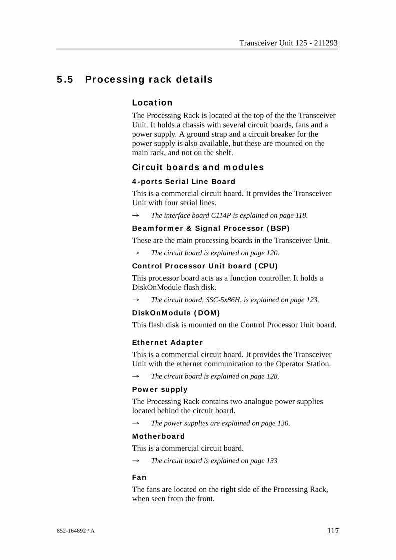
Transceiver Unit 125 - 211293
117852-164892 / A
5.5 Processing rack details
LocationThe Processing Rack is located at the top of the the TransceiverUnit. It holds a chassis with several circuit boards, fans and apower supply. A ground strap and a circuit breaker for thepower supply is also available, but these are mounted on themain rack, and not on the shelf.
Circuit boards and modules
4-ports Serial Line Board
This is a commercial circuit board. It provides the TransceiverUnit with four serial lines.→ The interface board C114P is explained on page 118.
Beamformer & Signal Processor (BSP)
These are the main processing boards in the Transceiver Unit.→ The circuit board is explained on page 120.
Control Processor Unit board (CPU)
This processor board acts as a function controller. It holds aDiskOnModule flash disk.→ The circuit board, SSC-5x86H, is explained on page 123.
DiskOnModule (DOM)
This flash disk is mounted on the Control Processor Unit board.
Ethernet Adapter
This is a commercial circuit board. It provides the TransceiverUnit with the ethernet communication to the Operator Station.→ The circuit board is explained on page 128.
Power supply
The Processing Rack contains two analogue power supplieslocated behind the circuit board.→ The power supplies are explained on page 130.
Motherboard
This is a commercial circuit board.→ The circuit board is explained on page 133
Fan
The fans are located on the right side of the Processing Rack,when seen from the front.

EM 300 Complete version
118 852-164892 / A
4-Ports Serial Line Board (C114P)
Purpose and description
This is a commercial circuit board designed and produced byMoxa Technologies. It is identified as C114P, and is located inthe Processing Rack.
P1
JP1 JP3 JP5 JP7
JP2 JP4 JP6 JP8
JP9
JP10
JP11
JP12
COM1
COM2
COM3
COM4
(CD5561)
Figure 51 The C114P layout
How it works
Each of the 4 ports can be configured to RS-232, RS-422, orRS-485 interface individually, but only RS-232 will work on theEM 300 system.
Facilities
LEDs
None.
Jumpers
The C114 is set up with IRQ 11 on the jumpers JP9, JP10, JP11and JP12.

Transceiver Unit 125 - 211293
119852-164892 / A
Links
Note The following settings are only valid for new boards. Forboards older than spring 2001 the settings will be inverted. Thesettings that are OFF on these drawings will be ON and viceversa.
The settings of the C114P DIP switches for use in the EM 300are listed in the table below:
Switch 1 2 3 4 5 6 7SW 5 ON ON OFF OFF OFF ON ON
SW 1 ON ON ON ON OFF OFF ON
SW 2 OFF ON ON ON OFF OFF ON
SW 3 ON OFF ON ON OFF OFF ON
SW 4 OFF OFF ON ON OFF OFF ON
Connections
The C114P contains one DB-37 female connector on the rearside of the circuit board. It comes with a cable; one terminal is a37-pin male D-type and the other terminal is a four 9-pin maleD-type connectors. This is not used.→ Refer to figure 52 for pin assignments.
In addition, four 10-pin pin-head connectors corresponds to theDB-37 connector on the board of C114P. These four connectorsare called COM1, COM2, COM3 and COM4, and are connecteddirectly to the Transceiver Unit bottom plate.
10
9
8
7
6
5
4
3
2
1
NC
RI
CTS
RTS
DSR
GND
DTR
TXD
RXD
DCD(CD5573)
Figure 52 10-pinheader connectorpin assignment

EM 300 Complete version
120 852-164892 / A
Beamformer & Signal Processor (BSP)
Purpose and description
The Beamforming & Signal Processing (BSP) board is a multidigital signal processor (DSP) board. It is designed to performthe beamforming and signal processing in sonars and multibeamecho sounders. It is controlled from a host processor.
The processing power in the Beamforming & Signal Processing(BSP) board is based on eight Texas TMS320C50 fixed pointdigital signal processors working in parallel while beamformingthe data. Next, there are four Texas TMS320C44 floating pointdigital signal processors interconnected to use both parallel andsequential processing of the beamformed data from the fixedpoint processors.
The Beamforming & Signal Processing (BSP) board is a singleslot full length standard ISA format circuit board made to fitinto a personal computer.
How it works
The Beamforming & Signal Processing (BSP) board containsfour main sections:
• Sonar Input Data
• Beamforming
• Signal Processing
• Host Interface
The Sonar Input Data interfaces an 18-bit wide and 1k deepInput FIFO (First-In-First-Out) register. This input FIFO holdsthe data received from the transducer array through the receiverprocessing circuitry. A dedicated digital signal processor readsthe input FIFO.
There are two identical Beamforming digital signal processingbranches. Each consists of four digital signal processors and a16-bit wide and 8k deep dual port memory (DPRAM). The twobranches are exchanging data by means of this DPRAM.
The Signal Processing section comprises three digital signalprocessors dedicated to do further processing of thebeamformed data.
The Host Interface function is maintained by the masterprocessor on the Beamforming & Signal Processing (BSP)board. It exchanges data with the host processor via a 16-bitwide and 8k deep dual port memory (DPRAM) on the ISA bus.

Transceiver Unit 125 - 211293
121852-164892 / A
Facilities
LEDs
D1 (LED): C44 D
Test points
There is one test point for each C50 digital signal processor(eight total). These testpoints are all connected to the XF/ signalwhich is active while that particular C50 access the sharedDPRAM.There is also one test point for each C44 digital signal processor(four total). These test points are connected to the IIOF2/ signal,which is a general purpose I/O port bit that can be controlled bythe software.The C44-D testpoint is also connected to a light emitting diode(D1) for visual observation. The LED will be activated duringeach ping.
TP1 C50 E0
TP2 C50 E1
TP3 C50 E2
TP4 C50 E3
TP5 C50 F0
TP6 C50 F1
TP7 C50 F2
TP8 C50 F3
TP11 C44 A
TP12 C44 B
TP13 C44 C
TP14 (& D1) C44 D
The testpoints will be active when the corresponding processoris working.
Links
A number of links are implemented on the board to allow forseveral different applications. Links LK1, LK2 and LK3 areused to identify the board as one out of maximum eight boardsin one system.

EM 300 Complete version
122 852-164892 / A
LK3 LK2 LK1 BSP ID
0 0 0 BSP 0
0 0 1 BSP 1
0 1 0 BSP 2
0 1 1 BSP 3
1 0 0 BSP 4
1 0 1 BSP 5
1 1 0 BSP 6
1 1 1 BSP 7
Link applications
The following links are ON (closed) in this application:- BSP0 is the master processor (no links).
- BSP1 is the slave processor (link LK1).
Switches
There are no switches on the board.
Connections
The Beamforming & Signal Processing (BSP) holds thefollowing plugs and sockets:
P1 Sonar input data
P2 ISA bus component
P3 Emulator
P4 Direct memory access
P5 External communication port
P6 Test access port
P7 External communication port
The P1, sonar input data, is connected to SPRX via a flat cableplug connected to the Reciever Backplane, plug P11.
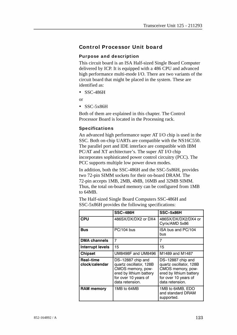
Transceiver Unit 125 - 211293
123852-164892 / A
Control Processor Unit board
Purpose and description
This circuit board is an ISA Half-sized Single Board Computerdelivered by ICP. It is equipped with a 486 CPU and advancedhigh performance multi-mode I/O. There are two variants of thecircuit board that might be placed in the system. These areidentified as:• SSC-486Hor• SSC-5x86HBoth of them are explained in this chapter. The ControlProcessor Board is located in the Processing rack.
SpecificationsAn advanced high performance super AT I/O chip is used in theSSC. Both on-chip UARTs are compatible with the NS16C550.The parallel port and IDE interface are compatible with IBMPC/AT and XT architecture’s. The super AT I/O chipincorporates sophisticated power control circuitry (PCC). ThePCC supports multiple low power down modes.In addition, both the SSC-486H and the SSC-5x86H, providestwo 72-pin SIMM sockets for their on-board DRAM. The72-pin accepts 1MB, 2MB, 4MB, 16MB and 32MB SIMM.Thus, the total on-board memory can be configured from 1MBto 64MB.The Half-sized Single Board Computers SSC-486H andSSC-5x86H provides the following specifications:
SSC--486H SSC--5x86H
CPU 486SX/DX/DX2 or DX4 486SX/DX/DX2/DX4 orCyrix/AMD 5x86
Bus PC/104 bus ISA bus and PC/104bus
DMA channels 7 7
Interrupt levels 15 15
Chipset UM8498F and UM8496 M1489 and M1487
Real--timeclock/calendar
DS--12887 chip andquartz oscillator, 128BCMOS memory, pow-ered by lithium batteryfor over 10 years ofdata retension.
DS--12887 chip andquartz oscillator, 128BCMOS memory, pow-ered by lithium batteryfor over 10 years ofdata retension.
RAM memory 1MB to 64MB 1MB to 64MB, EDOand standard DRAMsupported.

EM 300 Complete version
124 852-164892 / A
SSC--5x86HSSC--486H
IDE hard diskdrive interface
Up to two IDE harddrives.
Up to two PCI EnhanceIDE hard drives.
Floppy diskdrive interface
Two 2.88MB, 1.44MB,1.2MB, 720KB or360KB floppy diskdrives.
Two 2.88MB, 1.44MB,1.2MB, 720KB or360KB floppy diskdrives.
High speedserial ports
Two NS16C550 com-patible UARTs
Two NS16C550 com-patible UARTs
Bi--directionalParallel Port
Yes Yes
Watch--dogtimer
Can be set by 1, 2, 10,20, 110 or 220 secondsperiod. Reset or NMIwas generated whenCPU did not period-ically trigger the timer.Your program use hex043 and 443 to controlthe watch--dog andgenerate a systemreset.
Can be set by 1, 2, 10,20, 110 or 220 secondsperiod. Reset or NMIwas generated whenCPU did not period-ically trigger the timer.Your program use hex043 and 443 to controlthe watch--dog andgenerate a systemreset.
External powerconnector
Yes Yes
Keyboardconnector
Yes Yes
Mouse PS/2 Mouse Port on--board
PS/2 Mouse Port on--board
PowerConsumption
+5V @ 2.5A(486DX2--66, 4MBRAM)
+/-- 12V @ 20mA (forRS--232 only)
+5V @ 1.75A(5x86--133, 4MB RAM)
Operatingtemperature
0° ∼ 60°C (CPU needscooler)
0° ∼ 60°C (CPU needscooler)
→ The set-up procedures for SSC-486H and SSC-5x86H aredescribed on page 258
Facilities
Jumpers
All the SSC-5x86H- and SSC-486H circuit board’s jumpers arepreset at the factory. The default settings are listed in the tables.→ Refer to figure 53 for different jumper settings.

Transceiver Unit 125 - 211293
125852-164892 / A
1 2 3 1 2 3
1
2
3
4
1
2
3
4
1
2
3
4
1 - 2 2 - 3
1 - 2 2 - 3 2 - 4
(CD
5549
)
Closed Open
Figure 53 Different applicable jumper settings
The SSC-486H circuit board:
Jumpers Settings Description
SSC--486H CPU JP1 2 -- 3 --
JP2 1 -- 23 -- 4
--
JP3 Open --
JP4 Open --
JP5 1 -- 2 --
JP6 Open --
JP7 Open --
CPU ClockGenerator Speed (33MHz)
JP8 1 -- 2 Closed3 -- 4 Closed5 -- 6 Open7 -- 8 Open
--
CPU Voltage(+3.3 V)
JP12 2 -- 3 --(+3.3 V)
JP24 Open --
Upgrade theExternal Cache
JP13 2 -- 3 --External Cache(128KB, 32K x 8) JP14 1-- 2
3 -- 4--
Watch--Dog Timer,Active Type
JP18 1 -- 2 Open whenWDT time--out
WDT Time--out period(10 sec.)
JP17 1 -- 2 Open3 -- 4 Closed5 -- 6 Open7 -- 8 Open
--
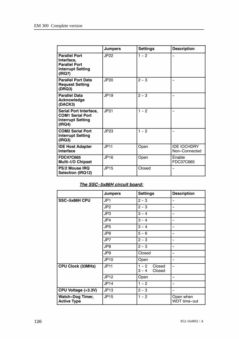
EM 300 Complete version
126 852-164892 / A
DescriptionSettingsJumpers
Parallel PortInterface,Parallel PortInterrupt Setting(IRQ7)
JP22 1 -- 2 --
Parallel Port DataRequest Setting(DRQ3)
JP20 2 -- 3 --
Parallel DataAcknowledge(DACK3)
JP19 2 -- 3 --
Serial Port Interface,COM1 Serial PortInterrupt Setting(IRQ4)
JP21 1 -- 2 --
COM2 Serial PortInterrupt Setting(IRQ3)
JP23 1 -- 2 --
IDE Host AdapterInterface
JP11 Open IDE IOCHDRYNon--Connected
FDC47C665Multi--I/O Chipset
JP16 Open EnableFDC37C665
PS/2 Mouse IRQSelection (IRQ12)
JP15 Closed --
The SSC-5x86H circuit board:
Jumpers Settings Description
SSC--5x86H CPU JP1 2 -- 3 --
JP2 2 -- 3 --
JP3 3 -- 4 --
JP4 3 -- 4 --
JP5 3 -- 4 --
JP6 5 -- 6 --
JP7 2 -- 3 --
JP8 2 -- 3 --
JP9 Closed --
JP10 Open --
CPU Clock (33MHz) JP11 1 -- 2 Closed3 -- 4 Closed
--
JP12 Open --
JP14 1 -- 2 --
CPU Voltage (+3.3V) JP13 2 -- 3 --
Watch--Dog Timer,Active Type
JP15 1 -- 2 Open whenWDT time--out
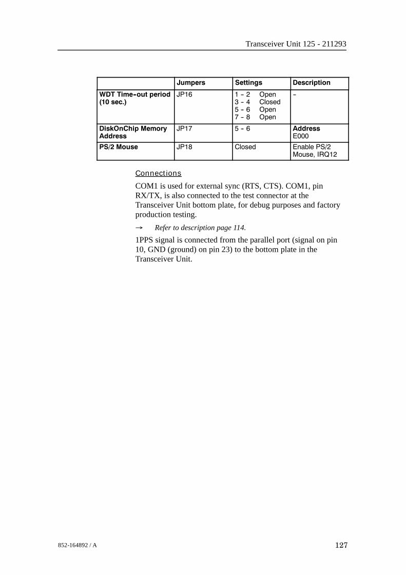
Transceiver Unit 125 - 211293
127852-164892 / A
DescriptionSettingsJumpers
WDT Time--out period(10 sec.)
JP16 1 -- 2 Open3 -- 4 Closed5 -- 6 Open7 -- 8 Open
--
DiskOnChip MemoryAddress
JP17 5 -- 6 AddressE000
PS/2 Mouse JP18 Closed Enable PS/2Mouse, IRQ12
Connections
COM1 is used for external sync (RTS, CTS). COM1, pinRX/TX, is also connected to the test connector at theTransceiver Unit bottom plate, for debug purposes and factoryproduction testing.→ Refer to description page 114.
1PPS signal is connected from the parallel port (signal on pin10, GND (ground) on pin 23) to the bottom plate in theTransceiver Unit.

EM 300 Complete version
128 852-164892 / A
Ethernet Adapter
Purpose and description
This is a 16-bit ISA adapter designed and produced by 3Com,identified as 3C509B-COMBO. The purpose of the adapter is toconnect the transceiver unit to the operator unit. The circuitboard is located in the Processing Rack.
How it works
The cable types and connector specifications in the EthernetAdapter are:
• 10BASE5 thick Ethernet coaxial, 10BASE2, fibre etc. withan AUI connector.
• 10BASE2 thin Ethernet coaxial with a BNC connector.
• 10BASE-T, twisted-pair cable with a RJ-45 connector.
→ The 3C509B-COMBO edge connectors is shown in figure 54.
The 3C509B-COMBO has a LED for the link beat. This LEDconfirms that there is an active connection between the adapterand the hub. The thin ethernet segment is terminated at bothends with a 50 Ω terminator.
The maximum bus speed supported by the Ethernet Adapter is10 MHz.
AUIconnector
BNCconnector
RJ-45connector
(CD
4612
)
LED
Figure 54 The 3C509B-COMBO backplate with itsconnectors

Transceiver Unit 125 - 211293
129852-164892 / A
Facilities
LEDs
Confirms that there is an active connection between the adapterand the hub.• If the LED is on, the link beat is working. (The connection is
correct).• If the LED is off, the link beat has not been established or
there is a problem with the connection between the adapterand the hub.
• If the LED is blinking, the cable polarity is reversed.→ See figure 54
Connections
The internal wiring gives access to the BNC and RJ45connections at the bottom plate of the Transceiver Unit.
Setup of the board
If the type of ethernet cable is known at delivery time, the boardis set up accordingly. If not, the board is set up for 10BASE-T(RJ-45).It is difficult to reconfigure the board on site. (A PC withISA-bus and special software is needed).

EM 300 Complete version
130 852-164892 / A
Processing Unit Power Supply
Note The power supply distributes voltages that can result in personalinjuries. Please take necessary precautions.
Purpose and description
The Processing Rack contains two analogue power supplies(HN5-9/OVP-A and OLD-12/15BB). The purpose of those is tofeed power to the circuit boards in the Processing Rack,respectively 5 Vdc and +12 Vdc, and +12Vdc to the TransmitterRack.The power supplies are located on the rear side of theProcessing Rack, hidden behind a cover plate.
How it works
This is two analogue power supplies that feed respectively5 Vdc and +12 Vdc to the Processing Rack. Both haveconnections to the same 16-pin socket.In addition, the +12Vdc is running the two fans in theProcessing Rack and feeding +12Vdc to the Transmitter Rack.From this socket the connections goes further to the PUbackplane, to the fans in the Processing Rack and to the maincircuit breaker. It is also connected to the TX backplane with a12 Vdc and a ground signal.→ Refer to the block diagram in figure 55, with 230 Vac, and
figure 56, with 110 Vac.

Transceiver Unit 125 - 211293
131852-164892 / A
Figure 55 Power supplies- internal block diagram
230 Vac.
+ utO+S-S-Out
+5V
com
+Out-S-SCom+S-S-Out
+12V
-12V
16 15 14 13 12 11 10 9 8 7 6 5 4 3 2 1
-12V
+12V
+12V
GN
D
GN
D
GN
DG
ND
GN
D+5
V
+5V
+5V
AC
1
AC1
AC2AC2
AC1
AC
1
AC2
AC2
0.75
Bl
0.75
Gn
0.75
Gn
0.75
Bk
0.75
Bk
2.5
Bk2.
5 Bk
2.5
Bk
2.5
R2.
5 R
2.5
R
0.75
Bn
0.75
Bn
0.75
Wh
0.75
Wh
HN5-9/OVP-A
4 2 3 1 5 4 2 3 1 5
OLD-12/15BB
0.75
Bn
0.75
Bn
(CD
5520
/212
871A
)
Figure 56 Power supplies - internal block diagram (110 Vac).
-Out +S-S-Out -12V
AC1
AC2AC2
AC1
HN5-9/OVP-A
4 2 3 1 5 4 2 3 1 5
OLD-12/15BB
-Out +S-S-Out -12V
AC1
AC2AC2
AC1
HN5-9/OVP-A
4 2 3 1 5 4 2 3 1 5
OLD-12/15BB
(CD
5520
E)
-Out +S-S-Out -12V
AC1
AC2AC2
AC1
HN5-9/OVP-A
4 2 3 1 5 4 2 3 1 5
OLD-12/15BB
(CD
5520
E)

EM 300 Complete version
132 852-164892 / A
FacilitiesConnectionsPins 2, 4, 5 and 9 are not in use.
Pin Signal Connection
1 AC2 Circuit breaker
3 AC1 Circuit breaker
6 +5 Vdc PU backplane--P9 pin 4
7 +5 Vdc PU backplane--P9 pin 5
8 +5 Vdc PU backplane--P9 pin 6
10 GND PU backplane--P8 pin 5
10 GND TX backplane--P1 pin 1
11 GND PU backplane--P8 pin 6
11 GND TX backplane--P1 pin 2
12 GND PU backplane--P9 pin 1
13 GND PU backplane--P9 pin 2
13 GND PU backplane--P9 pin 2
14 +12 Vdc Fans in PU
14 +12 Vdc TX backplane--P1 pin 3
15 +12 Vdc Fans in PU
16 --12 Vdc PU Backplane--P8 pin 4

Transceiver Unit 125 - 211293
133852-164892 / A
Motherboard
How it works
This is a passive backplane with standard ISA-bus.
Facilities
LEDs
The board has four LEDs:• + 5V• - 5V• + 12V• - 12V- 5V is not used and is not lit. The three others should be lit atall times.
Test points
None
Links
None
Connections
+ 5V, + 12V and - 12V.

EM 300 Complete version
134 852-164892 / A
5.6 Receiver rack details
LocationThe Receiver Rack is located at the middle of the theTransceiver Unit. It holds several circuit boards, power suppliesand a capacitor bank.→ Refer to the illustration on page 110.
Circuit boards and modules
Transmitter/Receiver board
These four boards hold the amplifiers for all the individualreceive channels. (The boards may also provide poweramplification of the transmitted signal, but as this function is notused in the EM 300, these components have been omitted).→ The circuit board is explained on page 135.
Low Voltage Power Supply
This is a commercial linear power supply mounted on a chassisfor easy replacement. It also contains linear supplies for theTRB’s.→ The Low Voltage Power Supply is explained on page 138.
High Voltage Power Supply
This is a switching power supply. It provides the high outputvoltage for the transmitters, and uses the Capacitor bank to storethe energy between the pings.→ The High Voltage Power Supply HVPU is explained on page
141.
Signal Processor Board RX (SPRX)
The processor board is used as a function controller. This is acommon circuit board whose name is SPB31, and it is both usedin the Transmitter Rack and the Receiver Rack.→ The Signal Processor Board is explained on page 142.
Backplane (RXBP)
The Receiver Rack uses a passive backplane. All connections tothe circuit boards (except transmission signals) are made on thisbackplane.
Capacitor bank
This unit stores transmission energy temporarily.

Transceiver Unit 125 - 211293
135852-164892 / A
Transmitter/Receiver Board (TRB)
Purpose and description
The purpose of the Transmitter/Receiver Board (TRB) is toprovide amplification of the signals received from thePreamplifier Unit. The board has 32 individual channels. Theboard is designed to provide transmission as well, but thesecomponents are not mounted on the circuit boards used in theEM 300 Transceiver UnitThe TRB is fastened to a combined strengthening plate and heatsink which covers the entire component side of the board andalso forms a “front panel” to the board. The board is located intracks within the Transceiver Unit to ensure correct location,and is held in position by four screws.The TRB has two 34-pin connectors on its front edge whichcarry the signals from the Preamplifier Unit.A one degree system needs four Transmitter/Receiver (TRB)boards. This means that all 128 channels are used.A two degree system needs two Transmitter/Receiver (TRB)boards, while a four degree system only have one.How it worksTransmission
The TRB contains a control interface that controls the 32transmitters on the board.The transmitters can be controlled individually to enablebeamforming of the transmitted pulse.Reception
The TRB receives signals from 32 transducer elements. Thesignals are individually amplified, time-varied-gain regulated,demodulated, and analogue-to-digital converted. The convertedsignals are then output from the board and sent to the BSP’s forfurther processing.Technical details
Dimensions(Width x Heigh x Depth)
220 x 233.35 x 0.32 mm
Analogue input/output 32 channels, 60W, + T/R switch
Connectors Two 96--pin euro on back edge of boardTwo 34--pin flat cables on front edge
Analogue to digital 12--bits resolutionI/Q simultaneously converted to 32--bit latched bus
Power requirements + 5 Vdc, 8 Vdc, + 24 Vdc
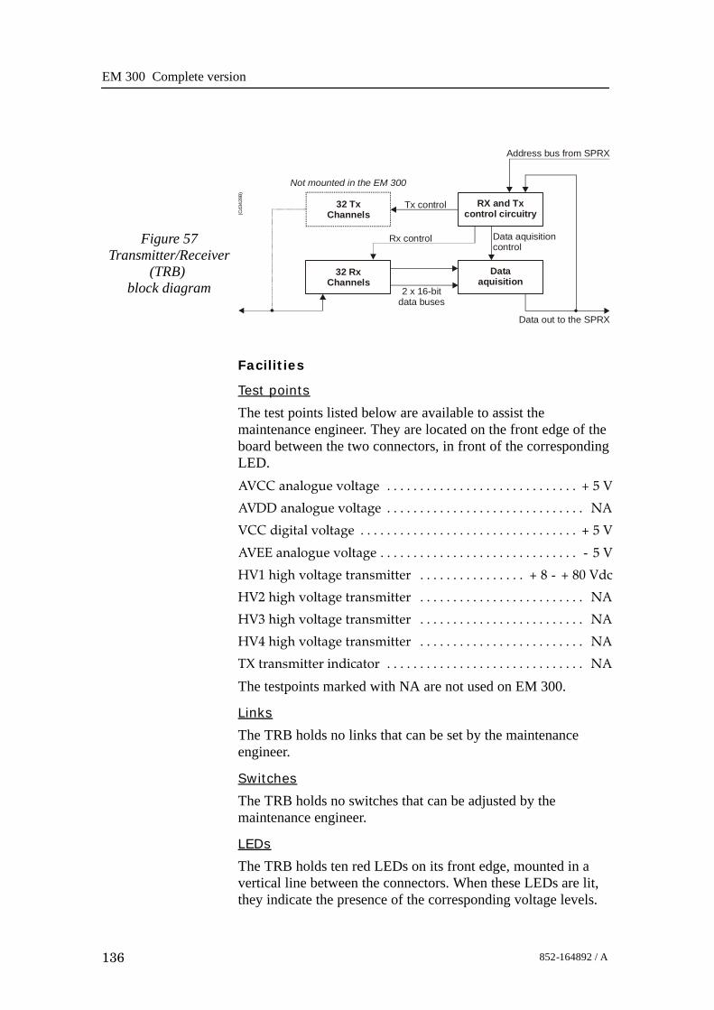
EM 300 Complete version
136 852-164892 / A
Figure 57Transmitter/Receiver
(TRB)block diagram
(Cd3
428B
)
32 TxChannels
32 RxChannels
RX and Txcontrol circuitry
Dataaquisition
Not mounted in the EM 300
Rx control
2 x 16-bitdata buses
Data out to the SPRX
Tx control
Data aquisitioncontrol
Address bus from SPRX
Facilities
Test points
The test points listed below are available to assist themaintenance engineer. They are located on the front edge of theboard between the two connectors, in front of the correspondingLED.AVCC analogue voltage + 5 V. . . . . . . . . . . . . . . . . . . . . . . . . . . . .
AVDD analogue voltage NA. . . . . . . . . . . . . . . . . . . . . . . . . . . . . .
VCC digital voltage + 5 V. . . . . . . . . . . . . . . . . . . . . . . . . . . . . . . . .
AVEE analogue voltage - 5 V. . . . . . . . . . . . . . . . . . . . . . . . . . . . . .
HV1 high voltage transmitter + 8 - + 80 Vdc. . . . . . . . . . . . . . . .
HV2 high voltage transmitter NA. . . . . . . . . . . . . . . . . . . . . . . . .
HV3 high voltage transmitter NA. . . . . . . . . . . . . . . . . . . . . . . . .
HV4 high voltage transmitter NA. . . . . . . . . . . . . . . . . . . . . . . . .
TX transmitter indicator NA. . . . . . . . . . . . . . . . . . . . . . . . . . . . . .
The testpoints marked with NA are not used on EM 300.
Links
The TRB holds no links that can be set by the maintenanceengineer.
Switches
The TRB holds no switches that can be adjusted by themaintenance engineer.
LEDs
The TRB holds ten red LEDs on its front edge, mounted in avertical line between the connectors. When these LEDs are lit,they indicate the presence of the corresponding voltage levels.

Transceiver Unit 125 - 211293
137852-164892 / A
Connectors
The TRB carries four connectors, two located at each end of theboard. P1 is a 96-pin, male right-angled euro-connector, locatedon the rear edge of the board, carrying power. P2 is a 96-pin,male, right-angled euro-connector, also located on the rear edgeof the board, carrying power and digital control signals. P3 andP4 are 34-pin, male, right-angled connectors with ejector/latch,located on the front edge of the board. Each connector carries16 input/outputs to the transducer/preamplifier.

EM 300 Complete version
138 852-164892 / A
Low Voltage Power Unit (LVPU)
Purpose and description
The purpose of the Low Voltage Power Unit (LVPU) is tosupply power to all the modules in the Transceiver Unit, exceptthe high voltage power for the transmission, power to PU and+12Vdc.The Low Voltage Power Unit is located between theTransmitter/Receiver Boards and the High Voltage PowerSupply in the Receiver Rack. The power supply is a plug-inmodule. It has two front mounted fuses, one service switch, andone switch to select 115 or 230 Vac mains input.
TB1
A1
521
13
(CD5488A)
Power supply MAP55-1024MStand-by power
Mains transformer Ulveco N14034-TDUsed in analogue power supply
Switched power supplyMAP55-4001
On/off relay
Line
filte
r
P1
P2
Figure 58 The Low Voltage Power Supply

Transceiver Unit 125 - 211293
139852-164892 / A
How it works
The power unit contains two separate power supplies. Theoutput of the stand-by power supply is 24 Vdc.The power unit has a service switch. When this is set to normal,the power supply is controlled by the on/off relay. This relay isremote controlled from a switch in the operator room. Whenyou disengage the relay, you can control the power supplymanually from the Transceiver Rack using the service switch. Itis then possible to activate parts of the system (service mode).The transformers and rectifiers function is to provide 8 Vdcoutput for the receivers either we have 115 Vac or 230 Vacinput.The LVPU also supplies + 5 V to several boards. See figurebelow.→ Refer to the block diagram in figure 59 and the circuit diagram
on page 388.
115/230 Vac in
Normal
OffService
115/230 Vac to HVPS, fans and Processing Rack
Stand-bypower
+12 Vdc, not used
-12 Vdc, not used
+24 Vdc, not used
GND
Switchmodepower
+
-
+
-
8 Vdc to TRB boards
8 Vdc to TRB boards
+24 Vdc to heater
(CD5497B)
230 V
115 V
S201
S202
24 Vdc stand-by power to ON/OFFswitch in the remote control junction box
From ON/OFF switch in theremote control junction box
gnd also connected to the remote control junction box.
+5 Vdc to TRB, SPRX, SPTX, TX64 & HVPS boardsFigure 59 The Low
Voltage Power Unit -simplified block diagram

EM 300 Complete version
140 852-164892 / A
Facilities
LEDs
• L201: Indicator for mains input• L202: Indicator for 24 Vdc stand by mode• L203: Lit to indicate AC supply to switched
and analogue• L204: Lit to indicate AC supply to
analogue power.
Test points
None
Links
None
Switches
• S201: Switch for mains input 115/230 Vac• S202: Service/Off/Normal switch
Connections
• P1• P2
Fuses
• F201: Primary fuse• F202: Primary fuse• F203: Thermostat fuse inside the torodial
transformer
SIMRADPOWER SUPPLY 290-112750
AnalogPowerSupply
SwitchedPowerSupply
Service
OFF
Normal
On/offRelay
24VStand-by
SlowBlow
Mains input115/230Vac
S 201230Vac
+7,5VREF-7,5V+5VA-5VA+5V+12V-12V+24VGND
F203
+24VREF
F201 8A
F202 8A
L203
L202
L201
S202
S201
On/off relay
F203
(CD
5488
B)
Figure 60 The front panel

Transceiver Unit 125 - 211293
141852-164892 / A
High Voltage Power Unit (HVPU)
Purpose and description
The purpose of the High Voltage Power Unit (HVPU) is toprovide the power for the output amplifiers.The input is to the system is 85 to 265 Vac. The output is 80Vdc. The output voltage can be reduced to -10 dB (25 Vdc) or-20dB (8 Vdc). The values can be adjusted.
Figure 61 The High Voltage Power Supply

EM 300 Complete version
142 852-164892 / A
Signal Processor Board (SPB31)
Purpose and description
The Signal Processor Board (SPB31) is designed for high speedbeamforming and sonar signal processing. The board design isbased on the TMS 320C31 floating point DSP (Digital SignalProcessor) from Texas Instruments.
The Signal Processor Board is designed as a ”double Europe”standard sized printed circuit board. It is equipped with anumber of front mounted LEDs, test points, potentiometers andcoax connectors.
The board is used two places in the EM 300 Transceiver Unit; tocontrol the transmission (SPTX) and the reception (SPRX).
The reg.no. for SPB31 Tx is 382-133472 and 382-134469 forSPB31 Rx.
How it works
The main components of the Signal Processor Board are:
1 TMS 320C31 Digital Signal Processor
- Clock frequency 33.33 or 40 MHz- 32-bit data bus- 24-bit address bus- 40/32-bit floating point unit- 1 internal serial line- 2 pc 32-bit timers- 4 interrupt inputs- DMA controller- Programmable in C and assembly- Emulator and symbolic de-bugger available
2 256k x 32 bit PROM.
3 512 x 32 bit SRAM 25 ns
4 Complex multiplier.
5 4 serial lines RS422/RS232.
6 Programmable counter for TX clock, 64 CHTX.
7 Dual port interface to P1 bus (Multibus I type).
8 Bus interface to P2 bus.
9 Control bus for control outputs compatible with SPB29.
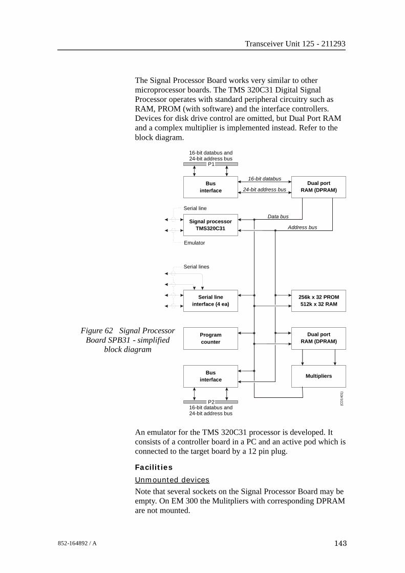
Transceiver Unit 125 - 211293
143852-164892 / A
The Signal Processor Board works very similar to othermicroprocessor boards. The TMS 320C31 Digital SignalProcessor operates with standard peripheral circuitry such asRAM, PROM (with software) and the interface controllers.Devices for disk drive control are omitted, but Dual Port RAMand a complex multiplier is implemented instead. Refer to theblock diagram.
Businterface
16-bit databus and24-bit address bus
16-bit databus
Serial line
Serial lines
(CD
1401
)
Emulator
Data bus
24-bit address bus
Address bus
Dual portRAM (DPRAM)
Signal processorTMS320C31
Serial lineinterface (4 ea)
Businterface
Programcounter
256k x 32 PROM512k x 32 RAM
Dual portRAM (DPRAM)
Multipliers
16-bit databus and24-bit address bus
P1
P2
Figure 62 Signal ProcessorBoard SPB31 - simplified
block diagram
An emulator for the TMS 320C31 processor is developed. Itconsists of a controller board in a PC and an active pod which isconnected to the target board by a 12 pin plug.
Facilities
Unmounted devices
Note that several sockets on the Signal Processor Board may beempty. On EM 300 the Mulitpliers with corresponding DPRAMare not mounted.

EM 300 Complete version
144 852-164892 / A
Links
A large number of links are implemented on the processor boardto allow for several different applications. The links are used asfollows:
LK 1 2BI422 to RXDB on U15
LK 2 RXDB2 input to RXDB on U15
LK 3 2AI422 to RXDA on U15
LK 4 RXDA2 input to RXDA on U15
LK 5 CLKIN to U64
LK 6 FSRO and DRO to set frame sync for sercom onU32
LK 7 RDRO to DRO when sercom in U32 is used onRS232
LK 8 Clock to U36
LK 9 RXDA input to RXDA on U63
LK 10 RXDB input to RXDB on U63
LK 11 BI422 input to RXDB on U63
LK 12 AI422 input to RXDA on U63
LK 13 CLQ to P2A25, U60 must not be mounted
LK 14 TXCLK to P2B24, U60 must not be mounted
LK 15 CLI to P2A24, U60 must not be mounted
LK 16 TSTSIG to P2C23, U60 must not be mounted
LK 17 TXEN~ to P2A22, U60 must no be mounted
LK 18 MEM3 to P2C3, LK30 must be OFF
LK 19A XF0~ as output
LK 19B XF0 as input
LK 20A XF0 as output
LK 20B XF0~ as input
LK 23A XF1~ as output
LK 23B XF1 as input
LK 24A XF1 as output
LK 24B XF1~ as input
LK 25A TCLK0~ as output
LK 25B TCLK0 as input
LK 26A TCLK0 as output
LK 26B TCLK0~ as input
LK 27A TCLK1~ as output
LK 27B TCLK1 as input
LK 28A TCKL1 as output
LK 28B TCLK1~ as input

Transceiver Unit 125 - 211293
145852-164892 / A
LK 29 External reset, INIT1, when ON
LK 30 IACK~ to P2C3, LK18 must be OFF
LK 31 U40 to CLKIN on DSP U32
Note that this list is for reference only.
Link applications
When using the Signal Processor Board in the EM 300Transceiver Unit, the following links must be ON (closed):SPRX:• LK 4• LK 5• LK 8• LK 9• LK10• LK 31SPTX:• LK 4• LK 5• LK 8• LK 9• LK 10• LK 19 (see below)• LK 20 (see below)• LK 23 (see below)• LK 24 (see below)• LK 31
(Cd5
684)
Figure 63 Signal Processor Board SPB31,default settings

EM 300 Complete version
146 852-164892 / A
LED’s
LED’s used for SPTX:D1: program initialized OK
D2: ready for new command
D3: transmit active
D4: BIST active
D5: not used
D6: test purpose
D7: test purpose
D8: test purpose
LED’s used for SPRX:D1: program initialized OK
D2: BIST active
D3: aquisition of reciever data
D4: aquisition of reciever data
D5: simulator active
D6: not used
D7: not used
D8: not used
Test points
TP 1: GND
TP 2: General purpose test output no.1
TP 3: General purpose test output no.2
TP 4: General purpose test output no.3
TP 5: General purpose test output no.4
TP 6: General purpose test output no.5
TP 7: General purpose test output no.6
TP 8: General purpose test output no.7
TP 9: General purpose test output no.8
TP 10: +5 Vdc
TP 11: Clock pulse, CP, monitor
TP 12: WE~ for testing RAM loading
TP 13: GND
TP 14: GND
TP 15: GND
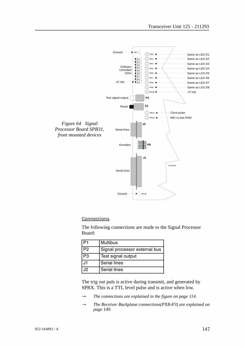
Transceiver Unit 125 - 211293
147852-164892 / A
Figure 64 SignalProcessor Board SPB31,
front mounted devices
(CD4340)
TP 2
TP 3
TP 4
TP 5
TP 6
TP 7
TP 8
TP 9
TP 10
TP 1
D 2D 1
D 3D 4D 5D 6D 7D 8
D 9
P3
S1
TP 11
TP 12
J2
P9
J1
TP 15
Same as LED D1Same as LED D2
Same as LED D3Same as LED D4
Same as LED D5Same as LED D6
Same as LED D7Same as LED D8
Clock pulse
WE/ to test RAM
Ground
Ground
Test signal output
Reset
Softwarecontrolled
LEDs
Serial lines
Emulator
Serial lines
+5 Vdc
+5 Vdc
Connections
The following connections are made to the Signal ProcessorBoard:
P1 Multibus
P2 Signal processor external bus
P3 Test signal output
J1 Serial lines
J2 Serial lines
The trig out puls is active during transmit, and generated bySPRX. This is a TTL level pulse and is active when low.
→ The connections are explained in the figure on page 114.
→ The Receiver Backplane connections(PXB-P3) are explained onpage 149.

EM 300 Complete version
148 852-164892 / A
Receiver Backplane (RXBP)
Purpose and description
The purpose of the Receiver Backplane is to enablecommunication between the circuit boards plugged into it, andbetween these circuit boards and the external circuitry in thecabinet. The RXBP is located behind the middle wired rack inthe Transceiver Unit, and holds the following circuit boards:
• Transmitter/Receiver Board 1
• Transmitter/Receiver Board 2
• Transmitter/Receiver Board 3
• Transmitter/Receiver Board 4
• Low Voltage Power Supply
• High Voltage Power Supply
• Signal Processor Board RX
• Capacitor Bank
How it works
There are no active components on this backplane.
Facilities
LEDs
None
Figure 65 Receiver Backplane, rear side
P14
TP1
P2
P3
P5
P6
P7
P8
P11
LK6
TP10 TP9
P12
TP12
TP11
LK7
TP13
LK8
TP8
P10
TP2
TP3
TP4
TP5
TP6
TP7
P4
P13
TP14
(CD5466B / 382-134122D)
LK9
P9

Transceiver Unit 125 - 211293
149852-164892 / A
LinksThere are four links on this backplane:LK6: ONLK7: ON, HVCLK to HVCKRLK8: ON, DA0 to DB0LK9: OFFTest pointsAll the test points listed below are only used duringdevelopment and debugging:TP 1: GNDTP 2: Read pulse to the TRBTP 3: Filter clk. to PDH’s on the TRBTP 4: Write pulse to the TRBTP 5: Sample and hold to PDH’s on the TRBTP 6: Four times demodulater frequency to PDH’s on the TRBTP 7: TX enable to the TRBTP 8: GNDTP 9: GNDTP 10: Write pulse to fifo on the BSPTP 11: Read pulse to 2 port RAM on the SPTXTP 12: Write pulse to 2 port RAM on the SPTXTP 13: Test signal input to PDH’s on the TRBOnly links LK7, LK8 and LK9 are applicable for system setup.These are closed as shown in the illustration.
DBT0
DA0
DB0
HVC
KL
HV
CLK
HV
CK
LK7
LK8
LK9
Limit
GN
D
(CD5532)
Figure 66 Links applicable
Connections
The sockets on the rear side of the backplane and theirconnections in the EM 300 Transceiver Unit are described in thetables below.

EM 300 Complete version
150 852-164892 / A
Pin 1
Pin 2
Pin 3
Pin 4
(Cd5
481)
Figure 67 Pinconfiguration
RXB--P2 Signal Connection
1 STBY+ Bottom plate--Remote pin 1
2 STBY-- Bottom plate--Remote pin 2
3 ON Bottom plate--Remote pin 3
4
RXB--P3 Signal Connection
1 HEAT Wall sect.--Terminal block pin 1
2 STBY-- Wall sect.--Terminal block pin 2
3 TRIG Bottom plate--pin 1
4 DGND Bottom plate--pin 2
RXB--P5 Signal Connection
1 +12VH TXB--P3 pin 4
2 HGND TXB--P3 pin 2
3 HGND TXB--P3 pin 3
4 +5VH TXB--P3 pin 1
RXB--P6 Signal Connection
1 HGND TXB--P4 pin 1
2 HGND TXB--P4 pin 2
3 HV TXB--P4 pin 3
4 HV TXB--P4 pin 4
RXB--P7 Signal Connection
1 HGND TXB--P5 pin 1
2 HGND TXB--P5 pin 2
3 HV TXB--P5 pin 3
4 HV TXB--P5 pin 4

Transceiver Unit 125 - 211293
151852-164892 / A
RXB--P8 Signal Connection
1 HGND TXB--P6 pin 1
2 HGND TXB--P6 pin 2
3 HV TXB--P6 pin 3
4 HV TXB--P6 pin 4
RXB--P9 Signal Connection
1 POW1 TX/RX Fan pin 1
2 POW2 TX/RX Fan pin 3
3 POW1 PU Fuse pin 3
4 POW2 PU Fuse pin 4
RXB--P13 Signal Connection
1 +5 Vdc TXB--P2 pin 1
2 +5Vdc TBX--P2 pin 2
3 DGND TBX--P2 pin 3
4 DGND TBX--P2 pin 4
TP1
TP4
TP5
TP6
TP3
TP2
P6
P7
P8
P10 P9
P4
P13
P5
P2
P3 P14
TP10 TP9
TP12
TP11
LK7
TP13
LK8
(CD5461A / 861-213155/A)
Figure 68 The Receiver Backplane

EM 300 Complete version
152 852-164892 / A
5.7 Transmitter rack details
LocationThe Transmitter Rack is located at the bottom of the TransceiverUnit. It holds one processor board and a number of transmitterboards.→ Refer to the illustration on page 111
The physical number of transmitter boards is defined by thespecified system accuracy:• A 1 degree system has 14 transmitter boards
Circuit boards and modules
64-Channel Transmitter Board (TX64)
Each of these circuit boards holds 64 individual poweramplifiers, each controlled by the function controller.→ The circuit board is explained on page 153
Signal Processor Board TX (SPTX)
The processor board is used as a function controller.→ The circuit board is explained on page 142
Backplane (TXBP)
The Transmitter Rack uses a passive backplane.→ The TX Backplane is explained on page 157

Transceiver Unit 125 - 211293
153852-164892 / A
64-Channel Transmitter (TX64)
Purpose and description
Once the transmission parameters have been calculated by theSignal Processor Tx (SPTX), each of the transmitter boards isaddressed. The data-bus from the SPTX is connected to all theboards, and data for the individual transmitters is loaded into theonboard RAMs as they are addressed from the SPTX. Theoutput from the TX64 RAM bank is connected to the outputstages, which are implemented using KongsbergMaritime-designed amplifier hybrids.
The physical number of TX64 boards fitted to the EM 300transceiver depends on the chosen system specifications. Thus,up to 14 64-Channel Transmitter (TX64) boards are used.
A one degree transmitter has 864 elements in the transducer anda two degree transmitter 432 elements. Hence a one degree Txsystem needs 14 TX64 boards, the last 32 transmitters on theTX64 #14 is not used.
A two degree Tx system needs seven TX64 boards. Here the last16 transmitters are not used on TX64 board # 7.
How it works
Overview
The TX64 boards are controlled by the Signal Processor TX(SPTX), and the output signals are made available on the frontmounted sockets. Flat ribbon cables connect these output pulsesto the filters.
The TX64 board is equipped with two large front mountedconnectors. Two LED indicators and one test point are locatedbetween these connectors. The test point is a ground (GND)connection, while the LEDs monitor the +5 Vdc and +12 Vdcsupply voltages.
The TX64 board is equipped with eight onboard fuses. Thesefuses are located on the High Voltage (HV) supply line, andeach fuse protects a group of eight transmitters. Fuse rating is 4A, physical size is 5 x 20 mm.
The functions of the transmitter may be divided into three parts:
• The power unit (Power & Fuses)
• The digital control unit
• The analogue transmitter driver unit (TX Hybrid)

EM 300 Complete version
154 852-164892 / A
Figure 69 64-Channel Transmitter (TX64)block diagram
Data, address andcontrol buffers
Fault detectionbuffer
On-board errors
Address latch andsequential counter
Data and address busesto/from the Signal Processor Tx (SPTX)
Latch 1-15 Latch 16
Outputhybrid
Outputhybrid
Outputhybrid
Outputhybrid
Random AccessMemory
(CD
1405
C)
To the filters
To the remaining60 output hybrids
Power unit
The power unit includes the three separate supply voltages usedand the components around them. The voltages are +12 Vdc, +5Vdc and High Voltage (HV). The value of the HV depends onthe desired output power. Typical range is +8 to +80 Vdc.
Digital control unit
The main function of the digital control unit is to supply theanalogue transmitter unit with the correct driving signals.
The shape of the driving signals are temporarily stored in RAMson the board. The RAMs are filled by the host processor. Thedrive signals for the output pulses are derived from the pattern.The signals are clocked and latched before they are supplied tothe transmitter hybrids.

Transceiver Unit 125 - 211293
155852-164892 / A
The transmitted pulse is controlled by the address latches andthe controller. The transmitted frequency is increased by 64times, and is then supplied to the CLK input. The TX Enable(TXEN/) input enables the transmitters and controls the transmitpulse length.Status information such as fuse blown can be read from the faultdetect buffer on the data bus.To lower the sidelobe level, IC U89 is omitted and a piggy backboard is inserted. This piggy back board contains a PLD withdoubled resolution for transmit beampattern.Analogue transmitter unitThere are 64 transmitters on the board. Each of these is a thickfilm hybrid designed by Kongsberg Maritime. There are nofrequency dependent components on the board. The transmittersare electrically designed into in groups of eight, each groupbeing protected by a 4 A fuse. The transmitter outputs arebrought to the front edge connectors P3 and P4.
Facilities
LEDsD 9 +5 Vdc. . . . . . . . . . . . . . . . . . . . . . . . . . . . . . . . . . . . . . . . . . . . .D 10 +12 Vdc. . . . . . . . . . . . . . . . . . . . . . . . . . . . . . . . . . . . . . . . . . .
Figure 70 64-ChannelTransmitter (TX64) front mounted
devices
P3
D9
D10
+12 Vdc
+5 Vdc
P4
Outputs
(CD
4417
)
Test pointsTP 1 GND. . . . . . . . . . . . . . . . . . . . . . . . . . . . . . . . . . . . . . . . . . . . . . .
LinksA number of links are implemented on the board to allow forseveral different applications. The links are used as follows:

EM 300 Complete version
156 852-164892 / A
LK1 Selects PROM (when ON). . . . . . . . . . . . . . . . . . . . . . . . . . . . .
LK2 Selects RAM (when ON). . . . . . . . . . . . . . . . . . . . . . . . . . . . . .
Link applications
The following links are ON (closed) in this application:• LK2
Switches
None
Connections
The TX64 is equipped with the following connectors:P 1 Connections to the external power supply. . . . . . . . . . . . . . .
P 2 Interface to control processor. . . . . . . . . . . . . . . . . . . . . . . . . . .
P 3 Outputs from channels 01-32. Front mounted. . . . . . . . . . . .
P 4 Outputs from channels 33-64. Front mounted. . . . . . . . . . . .
Fuses
F 1 TX group 1, Channels 01-08. . . . . . . . . . . . . . . . . . . . . . . . . . . .
F 2 TX group 2, Channels 09-16. . . . . . . . . . . . . . . . . . . . . . . . . . . .
F 3 TX group 3, Channels 17-24. . . . . . . . . . . . . . . . . . . . . . . . . . . .
F 4 TX group 4, Channels 25-32. . . . . . . . . . . . . . . . . . . . . . . . . . . .
F 5 TX group 5, Channels 33-40. . . . . . . . . . . . . . . . . . . . . . . . . . . .
F 6 TX group 6, Channels 41-48. . . . . . . . . . . . . . . . . . . . . . . . . . . .
F 7 TX group 7, Channels 49-56. . . . . . . . . . . . . . . . . . . . . . . . . . . .
F 8 TX group 8, Channels 57-64. . . . . . . . . . . . . . . . . . . . . . . . . . . .
Fuse rating is 4 A. Physical fuse size is 4 x 20 mm.
Oscilloscope check points
• The Clock (CLK) is input on pin P2 B24, and connected tobuffer U90, pin 4. The clock frequency varies with thetransmission frequency, and will be 64 times this. Frequencyalterations during one transmission are achieved by changingthe clock frequency.
• The TX Enable (TXEN/) is input on pin P2 A22, andconnected to buffer U90, pin 2. The TXEN/ pulse is thetransmit trigger, and the length of the TXEN is also thelength of the transmitted pulse. For EM 300 the TXfrequency is from 30 to 34 kHz.

Transceiver Unit 125 - 211293
157852-164892 / A
Transmitter Backplane (TXBP)Purpose and description
The purpose of the transmitter Backplane is to enablecommunication between the circuit boards plugged into it, andbetween these circuit boards and the external circuitry in thecabinet. The TXBP is located behind the bottom wired rack inthe Transceiver Unit, and holds the following circuit boards:• 64-channel Transmitter Board (TX64)• Signal Processor Board TX (SPB31)
C1
C2
C3
C4
C5
C6
C7
C8
C9
C10
C11
C12
C13
C14
C17
C16C18
C19C19
C20
C21
C22
C23
C24
P7
P8
P9
TP6TP5
TP3TP4
P2
P6 P5 P4 P3 P1
TP1
+ +
+ + + + + +++ + + + +
++++++++ ++
(Cd5522 / 113186/A)
Figure 71 Transmitter Backplane, rear side
How it works
There are no active components on this backplane.Facilities
LEDs
None
Test points
The following testpoints are only used during development anddebugging.TP 1: DGNDTP 2: DGNDTP 3: SMEM/ Active low when data is read from TX64

EM 300 Complete version
158 852-164892 / A
TP 4: DMEM/ Active low when data is written to TX64TP 5: DGNDTP 6: TXE/ Active low when transmit is ongoing.
Links
None.
Connections
The sockets on the rear side of the backplane and theirconnections in the EM 300 Transceiver Unit are described in thetables below.
Pin 1
Pin 2
Pin 3
Pin 4(C
d548
1)
Figure 72 Pinconfiguration
TXB--P1 Signal Connection
1 GND PU power supply
2 GND PU power supply
3 +12 Vdc PU power supply
4 +12 Vdc PU power supply
TXB--P2 Signal Connection
1 +5 Vdc RXB--P13 pin 1
2 +5 Vdc RXB--P13 pin 2
3 DGND RXB--P13 pin 3
4 DGND RXB--P13 pin 4
TXB--P3 Signal Connection
1 +5 VH RXB--P5 pin 4
2 HGND RXB--P5 pin 2
3 HGND RXB--P5 pin 3
4 +12 VH RXB--P5 pin 1
TXB--P4 Signal Connection
1 HGND RXB--P6 pin 1
2 HGND RXB--P6 pin 2
3 HGND RXB--P6 pin 3
4 HGND RXB--P6 pin 4

Transceiver Unit 125 - 211293
159852-164892 / A
TXB--P5 Signal Connection
1 HGND RXB--P7 pin 1
2 HGND RXB--P7 pin 2
3 HGND RXB--P7 pin 3
4 HGND RXB--P7 pin 4
TXB--P6 Signal Connection
1 HGND RXB--P8 pin 1
2 HGND RXB--P8 pin 2
3 HGND RXB--P8 pin 3
4 HGND RXB--P8 pin 4
The bleeder is mounted on the Processing Unit power supplycover.
Fan TX/RX
123
P8
P7 P6 P5 P4 P3 P1
P2
Vorsicht Spannung
AttentionD anger
(Cd5
525
/ 210
142/
A)
Figure 73 The Transmitter Backplane

EM 300 Complete version
160 852-164892 / A
Blank page

Transceiver Unit 125 - 218182
161852-164892 / A
6 TRANSCEIVER UNIT 125-218182
6.1 Description and main functions
OverviewThe EM 300 Transceiver Unit performs the reception, dataacquisition, received signal processing and transmission for themultibeam echo sounder system. The cabinet holds three wiredracks containing the system circuit boards.• The top Processing Rack holds the complete Processing Unit
with its own power supply. This unit provides dataacquisition, signal processing and function control.
• The middle Receiver Rack holds the receiver boards, acontroller, two power supplies and a large capacitor bank.
• The bottom Transmitter Rack holds the transmitter circuitryand a dedicated controller.
Three different versions of the Transciever Unit have beendelivered. The registration number of the Transceiver Unitwill determine which version you have:125-210131, more information on page 41.125-211293, more information on page 101.125-218182, more information on page 161.This number is to be found on the Transceiver Unit chassis.All versions are described in this manual. Please check yourTransceiver Unit to find out which version you have.

EM 300 Complete version
162 852-164892 / A
6.2 Transceiver Unit 125-218182This chapter provides the following information:→ Circuit board descriptions, page 177.→ Description and main functions, page 161.→ Transceiver Unit outline, page 163.→ Transceiver Unit racks, page 167.→ Theory of operation, page 172.→ Processing rack, details, page 176→ Receiver rack, details, page 188.→ Transmitter rack, details, page 206→ Circuit board descriptions, page 177.

Transceiver Unit 125 - 218182
163852-164892 / A
630 mm 600 mm
1834
mm
1995
mm
1600
mm
Min
303
mm
(CD3694)
Figure 74 Standard EM 300 Transceiver Unit - Outline dimensions
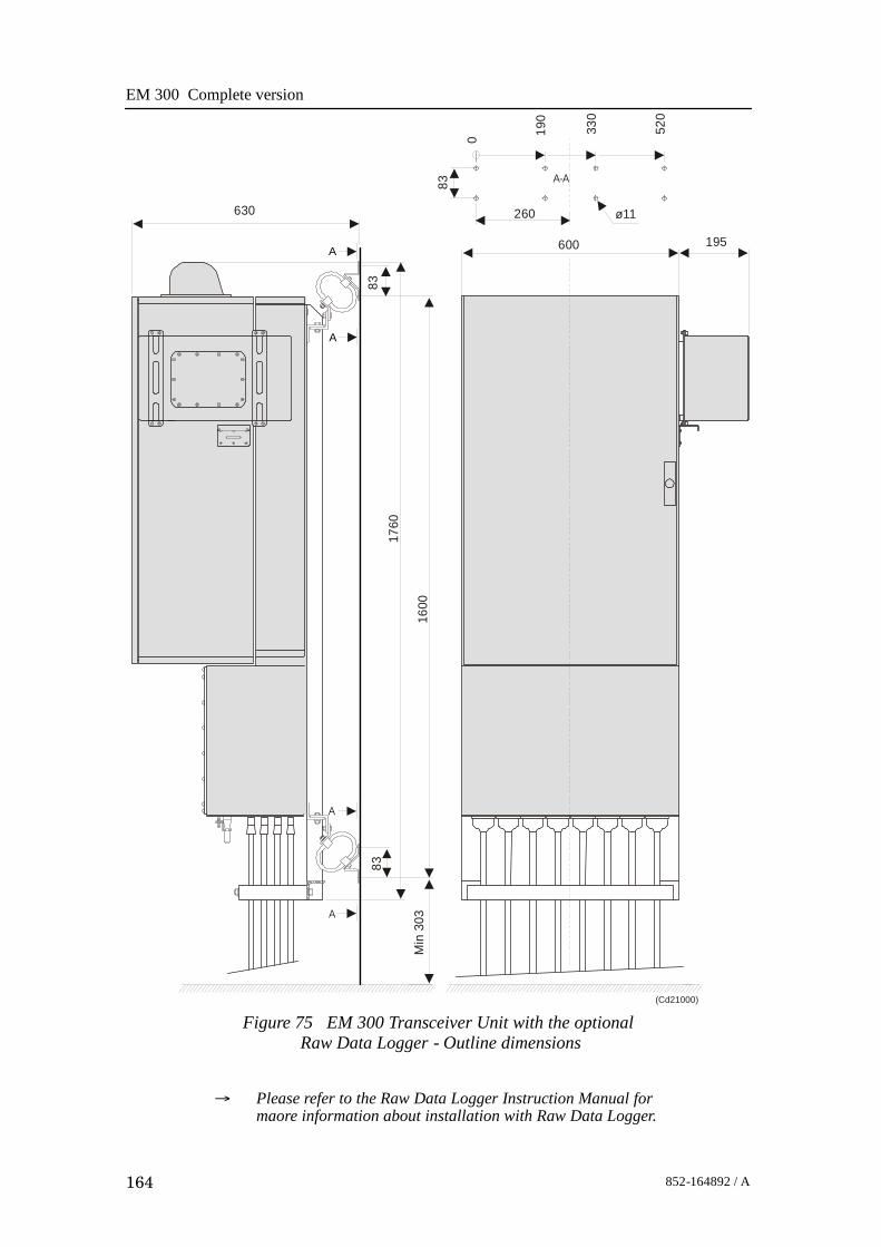
EM 300 Complete version
164 852-164892 / A
Figure 75 EM 300 Transceiver Unit with the optionalRaw Data Logger - Outline dimensions
A
A
A
A
A-A
600 195
ø11
83
260
0 190
330
520
630
8383
1760
1600
Min
303
(Cd21000)
→ Please refer to the Raw Data Logger Instruction Manual formaore information about installation with Raw Data Logger.

Transceiver Unit 125 - 218182
165852-164892 / A
Shock absorber
Base section
Mid section
Mid section
Door
RDL
Seen from top
Shock absorber
Base sectionDoor
RDL
245
1170
1540
(CD21000B)
Note:All measurements are in mm.The drawing is not in scale.
Figure 76 Transceiver Unit with Raw Data Logger,seen from above.
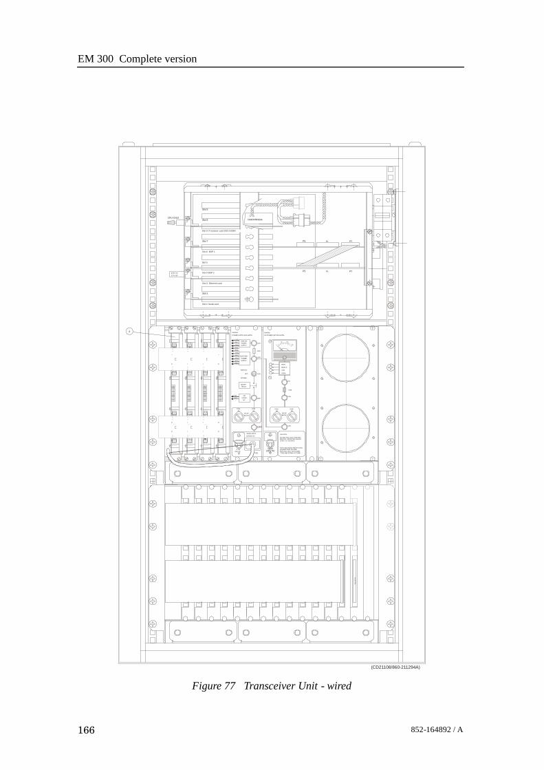
EM 300 Complete version
166 852-164892 / A
ZERO ( 0 ) VOLTAGEBEFORE THE METER SHOWSDO NOT PULL OUT THIS UNIT
AGAINST RISK OF FIRE
TYPE AND RATING OF FUSE.REPLACE ONLY WITH SAME
FOR CONTINUED PROTECTION
CAUTION
BLOWSLOW
230V ACS 201
230V ACP201
S203
115/230V AC
MAINS INPUT
BLOW
24V
REF
8AF201
SLOW
STAND24V
BY
L201
F2028A
L202
F2048A
L205
F2058A
L206
6
ETH-J50ETH-J70
CPU-CN12
LOW
f (SW)
HV-POWER UNIT 290-112751
HIGH
MIDDLE
+ 5VA
SERVICE
RELAYON/OFF
NORMAL
OFF
- 5VA
+ 5V
+ 12V
- 12V
+ 24V
GND
POWERSUPPLY
SWITCHED
S202
F203
L203
POWER SUPPLY 290-112750
REF
- 7.5V
+ 7.5V
SIMRAD
POWERSUPPLY
ANALOG
SIMRAD
L204
0
50
L207
F206
100
150
P1 P7P5
P1 P7P5
22DiskOnModule
1 1
43
43
TX14
-P4
S lot 8 Processor card SSC-5X86H
Slot 4 BSP 2
Slot 6 BSP 1
Slot 3 Ethernet card
Slot 1 Serial card
Slot 2
Slot 5
Slot 7
Slot 9
Slot 9
14
32
(CD21108/860-211294A)
Figure 77 Transceiver Unit - wired

Transceiver Unit 125 - 218182
167852-164892 / A
The Processing Rack
The Processing Rack is located at the top of the TransceiverUnit. It holds a chassis with several circuit boards, fans and apower supply. A ground strap and a circuit breaker for thepower supply is also available, but these are mounted on themain rack, and not on the shelf.
The Processing Rack holds the following circuit boards andmodules:
• 4-Ports Serial Line board
• Beamformer & Signal Processor (BSP1 and BSP2)
• Control Processing Unit (CPU) board with ethernetconnection
• DiskOnModule flash disk (mounted on the ControlProcessing Unit board)
• Power supplies
• Two fans
• Motherboard
→ A more detailed description of all the circuit boards andmodules is found on page 175.
CPU Board with DOM(719-098108)
BSP1(382-218016)
Serial card(719-098382)
BSP2(382-218016)
Fan(129-096870)
CPU-J7
P1 P7P5
P1 P7P5
22DiskOnModule
1 1
43
43
S lot 8
Slot 4
Slot 6
Slot 3
Slot 1
Slot 2
Slot 5
Slot 7
Slot 9
Slot 9
14
32
(CD5344F/860-218183A)
CPU-J8
Serial 3
Serial 1Serial 2
Serial 4
ETH -J12
Figure 78 Processing Rack, circuit board locations

EM 300 Complete version
168 852-164892 / A
Figure 79 Power supplies on the rear panel
(Cd21111)
8 125 4 37 610 913 12 1116 15 14
Vorsicht! Spannung
Danger
Attention
+5VHE5-18/OVP-A
15 23 4
OLD
-12/15BB
%%
p12V
G
ND
-out
+5V
S-
S+
+out
OLS-12C
+12V

Transceiver Unit 125 - 218182
169852-164892 / A
The Transmitter RackThe Transmitter Rack is located at the bottom of the theTransceiver Unit. It holds one processor board and a number oftransmitters.
Figure 80 The Transmitter Rack
(CD4472D/210132A)
64-Channel Transmitter Boards (Tx64)
Signal Processor Board TX (SPBTX)
The Transmitter Rack holds the following circuit boards andmodules (from left):• 64-Channel Transmitter Board (TX64)• Signal Processor Board TX (SPTX)→ A more detailed description is found on page 205

EM 300 Complete version
170 852-164892 / A
The Receiver RackThe Receiver Rack is located at the middle of the TransceiverUnit. It holds several circuit boards, power supplies and acapacitor bank. All the units are accessed from the front of therack.
HIGHMIDDLELOWf (SW)
L207
F206
L206
L205
F2018A
F2028ASLOW
BLOW
F2048A
F2058A
SLOWBLOW
L201
CAUTION
DO NOT PULL OUT THIS UNITBEFORE THE METER SHOWSZERO (0) VOLTAGE.
FOR CONTINUED PROTECTIONAGAINST RISK OF FIREREPLACE ONLY WITH SAMETYPE AND RATING OF FUSE.
S203230V ac
S201230Vac P201
MAINS INPUT115/230V ac
SIMRADHV-POWER UNIT 290-112751
SIMRADPOWER SUPPLY 290-112750
L202+24VREF
ON/OFFRELAY
24VSTAND
BY
S202SERVICE
OFF
NORMAL
L204
F203
L203
ANALOGPOWERSUPPLY
+7.5VREF-7.5V+5va-5va+5V+12V-12V+24VGND
SWITCHEDPOWERSUPPLY
10050
0150
(CD4472C/210132A)
Transmitter/Receiver boards High Voltage Power Supply Capacitor bank
Low Voltage Power Supply Signal Processor Board RX (SPBRX)
Figure 81 The Receiver RackThe Receiver Rack holds the following circuit boards andmodules (from left):• TRB 32/Receiver board (max 4)
• Low Voltage Power Supply• High Voltage Power Supply
• Signal Processor Board RX (SPRX)• Capacitor bank→ A more detailed description is found on page 187.

Transceiver Unit 125 - 218182
171852-164892 / A
6.3 Theory of operation
OverviewThis chapter presents a functional description of the TransceiverUnit.
Figure 82 Transceiver Unit, simplified block diagram
Control Processor
Beamformer and SignalProcessor (BSP) x 2
Signal Processor Rx(SPRX)
Serial lines to/fromthe sensors
Ethernet to/from theOperator Station
Signal Processor Tx(SPTX)
Command andcontrol (serial line)
16-bitsampleddata
TransmitterRack
Processing Rack
ReceiverRack
Transmitter/ReceiverBoard (TRB) x 4
64-Channel Transmitter(64CHTX) x 14
Transmit array Receive array
Filter Filter
Commandand control
(CD
4551
)
Simplified block diagramThe simplified block diagram for the Transceiver Unit presentsthe following main functions:• Transmission• Reception• Processing

EM 300 Complete version
172 852-164892 / A
The various parameter settings made on the Operator Station aresent to the Control Processor in the Processing Rack. Theinformation (roll, pitch, pulse length etc.) is interpreted, andpassed on to the Signal Processor TX (SPTX), which is the“master” processor in the TX/RX system.After the transmission, the Signal Processor RX (SPRX) isinstructed to receive the samples for all the receiver staves andpass them on to the two Beamformer and Signal Processors(SBP’s) in the Processing Rack.
Control functionsThe control functions in the Transceiver Unit are mainlyhandled by the three processor boards, but additional peripheralboards are also used. The majority of the control boards arecontained in the Processing Unit.
Figure 83 The control functions
Seriallines
DiskOnFlash module
Controlprocessor
Ethernetadapter
BSP x 2
Signal Processor Rx(SPRX)
Serial lines to/fromthe sensors
Ethernet to/from theOperator Station
Signal Processor Tx(SPTX)
Command andcontrol (serial line)
Processing Rack
Receive circuitryTransmit circuitry
Commandand control
Bus system
(Cd4554b)
The Control Processor in the Processing Unit is not equippedwith interface capabilities, and thus requires external boards tohandle ethernet and serial lines interface. It also relies on anexternal memory board for the software contained in the ROMdevice. All the peripheral boards used here are commercial.

Transceiver Unit 125 - 218182
173852-164892 / A
Note Newer Control Processor Units (CPU) handles ethernetinterface and have a DiskOnModule installed (containingsoftware). This kind of CPU also relies on an external board tohandle serial line interface.
One serial line is used to interface the command and controlsignals to and from the TX/RX controllers. The SignalProcessor TX is the “master”.
External synchronisation
The serial line RTS and CTS signals are used for externalsynchronisation. In addition a trig out signal is issued by theTRU.Levels:
RTS, CTS:H=high= +3 to +15 VL=low= -3 to -15 VTrig out:TTL LevelOutputs from TRU:
Trig out=1 TX is off(High TTL level)Trig out=0 TX is active(Low TTL level)
RTS=H TRU is ready for a new pingRTS=L TRU is not readyRTS is pin 7 on the CPU card D connector. (Pin 6 on EM120and EM300 “remote” plug).Inputs to TRU:
CTS=H Ping commandCTS=L WaitCTS is pin 8 on the CPU card D connector. (Pin 7 on theEM120 and EM300 “remote” plug). The CTS pulse length mustbe minimum 30 milliseconds.Gnd is pin 5 on the CPU card D connector. (Pin 8 on EM120and EM300 “remote” plug).Typical sequence:CTS _____________- - - - - - - ________________- - - - - - - - - - _________
TXCommand
RTS - - - - - - - - - - - - - - _______________- - - - - - - ________________- - -(TRU ready) (TRU busy) (TRU busy)
Trig out - - - - - - - - - - - - - - __- - - - - - - - - - - - - - - - - - - - __- - - - - - - - - - - - - - - - -TXPulse

EM 300 Complete version
174 852-164892 / A
When the TRU is ready for a new ping, RTS is set to H. Whenthe external device is ready for a new ping, CTS shall bechanged to H. The TRU will then start a ping, change RTS to L(busy), and the Trig out will be low during the transmit pulse.After the Trig out is received, the external device should turnCTS to L. (Or at least keep it high for 35 milliseconds).When the received period is finished and the TRU is ready for anew ping, the RTS will be changed to H, and the TRU will waitfor new trigger (a high level on CTS).If CTS is H all the time, or if external sync in the installationmenu is switched off, the TRU will ping at its maximum rate.

Transceiver Unit 125 - 218182
175852-164892 / A
6.4 Processing rack details
LocationThe Processing Rack is located at the top of the the TransceiverUnit. It holds a chassis with several circuit boards, fans and apower supply. A ground strap and a circuit breaker for thepower supply is also available, but these are mounted on themain rack, and not on the shelf.
Circuit boards and modules
4-ports Serial Line Board
This is a commercial circuit board. It provides the TransceiverUnit with four serial lines.→ The interface board, CI-104JS, is explained on page 177.
Beamformer & Signal Processor (BSP)
These are the main processing boards in the Transceiver Unit.→ The circuit board is explained on page 179.
Control Processor Unit board (CPU)
This processor board acts as a function controller. It holds aDiskOnModule flash disk.→ The circuit board, VIPer, is explained on page 182.
DiskOnModule (DOM)
This flash disk is mounted on the Control Processor Unit board.
Power supply
The Processing Rack contains three analogue power supplieslocated behind the circuit board.→ The power supplies are explained on page 183.
Motherboard
This is a commercial circuit board.→ The circuit board is explained on page 186
Fan
The fans are located on the right side of the Processing Rack,when seen from the front.

EM 300 Complete version
176 852-164892 / A
6.5 Circuit board descriptions
OverviewThis chapter describes all the circuit boards and modules in theEM 300 Transceiver Unit. A functional description with a blockdiagram is provided, as well as the facilities provided formaintenance.Remember that all versions of the Transceiver Unit is in thismanual. Different boards and power supplies are thereforedescribed for the EM 300 system. Check the reg.no. on yourTransceiver Unit to find out which version you have.

Transceiver Unit 125 - 218182
177852-164892 / A
Serial Line Board (CI-104JS)If more information is needed, refer to webpagewww.moxa.com.
Purpose and description
This is a commercial circuit board designed and produced byMoxa Technologies. It is located in the Processing Unit.The board is a cabling space saver that features a built-in RJ45bracket to save cable layout space and reduce cost.It has surge protection and ISA bus.
Note A software setup has been done at Kongsberg Maritime toconfigure the board.
How it works
The Smartio CI-104JS Series provides 4 RJ-45 sockets forconnection, which save a lot of cable space.
Surge Protection
To prevent the board from damage caused by lighting or highpotential voltage, TVSS (Transient Voltage Surge Suppressor)technology is introduced in Smartio CI-104JS to protect theboard. This is critical to harsh environment such as factory.
Specifications
Connector type RJ--45
Bus ISA (16 bit)
Serial RS--232
Ports (interface) 4
Power requirements 83 mA max. (--12V),57 mA max. (+12V),100 mA max. (+5V)
Operating temperature 0_ -- 55_C
Dimesions 157 x 83 mm(width x depth)
Surge protection 25 KV ESD2 KV EFT

EM 300 Complete version
178 852-164892 / A
Facilities
No switches.
CAPJumper
Smartio CI-104J series
Jp1
Figure 84 Illustration of the Serial Line Board.

Transceiver Unit 125 - 218182
179852-164892 / A
Beamformer & Signal Processor (BSP)
Purpose and description
The Beamforming & Signal Processing (BSP) board is a multidigital signal processor (DSP) board. It is designed to performthe beamforming and signal processing in sonars and multibeamecho sounders. It is controlled from a host processor.
The processing power in the Beamforming & Signal Processing(BSP) board is based on eight Texas TMS320C50 fixed pointdigital signal processors working in parallel while beamformingthe data. Next, there are four Texas TMS320C44 floating pointdigital signal processors interconnected to use both parallel andsequential processing of the beamformed data from the fixedpoint processors.
The Beamforming & Signal Processing (BSP) board is a singleslot full length standard ISA format circuit board made to fitinto a personal computer.
How it works
The Beamforming & Signal Processing (BSP) board containsfour main sections:
• Sonar Input Data
• Beamforming
• Signal Processing
• Host Interface
The Sonar Input Data interfaces an 18-bit wide and 1k deepInput FIFO (First-In-First-Out) register. This input FIFO holdsthe data received from the transducer array through the receiverprocessing circuitry. A dedicated digital signal processor readsthe input FIFO.
There are two identical Beamforming digital signal processingbranches. Each consists of four digital signal processors and a16-bit wide and 8k deep dual port memory (DPRAM). The twobranches are exchanging data by means of this DPRAM.
The Signal Processing section comprises three digital signalprocessors dedicated to do further processing of thebeamformed data.
The Host Interface function is maintained by the masterprocessor on the Beamforming & Signal Processing (BSP)board. It exchanges data with the host processor via a 16-bitwide and 8k deep dual port memory (DPRAM) on the ISA bus.

EM 300 Complete version
180 852-164892 / A
Facilities
LEDs
D1 (LED): C44 D
Test points
There is one test point for each C50 digital signal processor(eight total). These testpoints are all connected to the XF/ signalwhich is active while that particular C50 access the sharedDPRAM.There is also one test point for each C44 digital signal processor(four total). These test points are connected to the IIOF2/ signal,which is a general purpose I/O port bit that can be controlled bythe software.The C44-D testpoint is also connected to a light emitting diode(D1) for visual observation. The LED will be activated duringeach ping.
TP1 C50 E0
TP2 C50 E1
TP3 C50 E2
TP4 C50 E3
TP5 C50 F0
TP6 C50 F1
TP7 C50 F2
TP8 C50 F3
TP11 C44 A
TP12 C44 B
TP13 C44 C
TP14 (& D1) C44 D
The testpoints will be active when the corresponding processoris working.
Links
A number of links are implemented on the board to allow forseveral different applications. Links LK1, LK2 and LK3 areused to identify the board as one out of maximum eight boardsin one system.

Transceiver Unit 125 - 218182
181852-164892 / A
LK3 LK2 LK1 BSP ID
0 0 0 BSP 0
0 0 1 BSP 1
0 1 0 BSP 2
0 1 1 BSP 3
1 0 0 BSP 4
1 0 1 BSP 5
1 1 0 BSP 6
1 1 1 BSP 7
Link applications
The following links are ON (closed) in this application:- BSP0 is the master processor (no links).
- BSP1 is the slave processor (link LK1).
Switches
There are no switches on the board.
Connections
The Beamforming & Signal Processing (BSP) holds thefollowing plugs and sockets:
P1 Sonar input data
P2 ISA bus component
P3 Emulator
P4 Direct memory access
P5 External communication port
P6 Test access port
P7 External communication port
The P1, sonar input data, is connected to SPRX via a flat cableplug connected to the Reciever Backplane, plug P11.
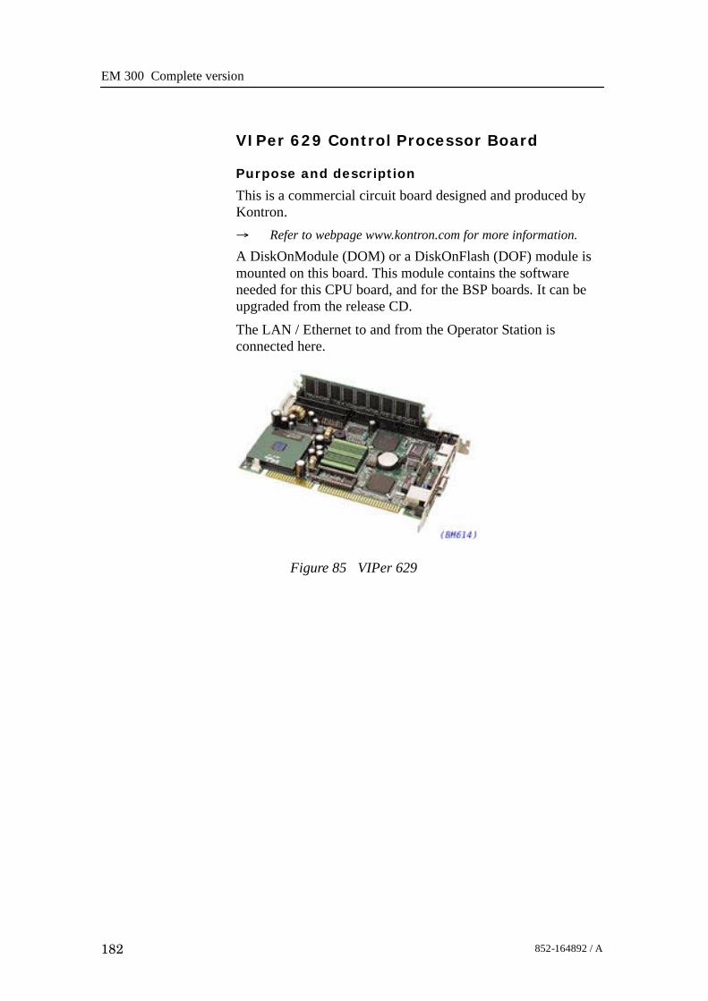
EM 300 Complete version
182 852-164892 / A
VIPer 629 Control Processor Board
Purpose and description
This is a commercial circuit board designed and produced byKontron.→ Refer to webpage www.kontron.com for more information.
A DiskOnModule (DOM) or a DiskOnFlash (DOF) module ismounted on this board. This module contains the softwareneeded for this CPU board, and for the BSP boards. It can beupgraded from the release CD.The LAN / Ethernet to and from the Operator Station isconnected here.
Figure 85 VIPer 629

Transceiver Unit 125 - 218182
183852-164892 / A
Processing Unit Power Supply
Note The power supply distributes voltages that can result in personalinjuries. Please take necessary precautions.
Purpose and description
The HE5-18 power supply is feeding +5V to the ProcessingRack. The new Control Processing Unit (CPU) board, calledVIPer, requires more 5V than other CPU boards.The OLD-12/15BB power supply is feeding +12Vdc to all theboards and the two fans in the Processing Rack.The OLS-12C power supply is feeding +12Vdc to thetransmitter backplane (TXPB).The power supplies are located on the rear side of theProcessing Rack, hidden behind a cover plate.
How it works
→ Refer to the block diagram in figure 86, with 110 Vac, andfigure 87, with 230 Vac.
Figure 86 Power supplies - internal block diagram (110 Vac).
42315
HE5-18/OVP-A+5V
0.75
BN
AC2
AC1
OLD-12/15BB
%%p12V
24 13 5
0.75
BN
AC2
AC1
(Cd21008)

EM 300 Complete version
184 852-164892 / A
OLS-12C
35 1 2 4
AC
1
0.75
BN
AC
2
+S
+12V+out
-out
-SCOM
+5V
GN
D42315
HE5-18/OVP-A+5V
-out
S-
S+
+out
0.75
BL
GN
D
0.75
GN
0.75
GN
2.5
BK
0.75
BK
0.75
BK
+12V
+12V
-12V
GN
D
GN
D
2.5
R
2.5
BK
2.5
BK
2.5
R
2.5
R
GN
D
GN
D
+5V
+5V
+5V
1516 14 13 12 1011 9 8 67
0.75
BN
AC2
AC1
OLD-12/15BB
%%p12V
24 13
-out
-S-12V
5
com
+S
-S
+out
+S+12V
0.75
BN
0.75
BN
0.75
WH
0.75
WH
AC1
AC1
AC2
AC2
5 4 23 1
0.75
BN
AC2
AC1
TRTB1
(Cd21008)
Figure 87 Power supplies- internal block diagram
230 Vac.
Input voltage Link Input
110 Vac + 10%, -- 13%1 3 d 2 4
1 -- 5
120 Vac + 10%, -- 13% 1 -- 3 and 2 -- 4 1 -- 4
230 Vac + 10%, -- 13% 2 -- 3 1 -- 5
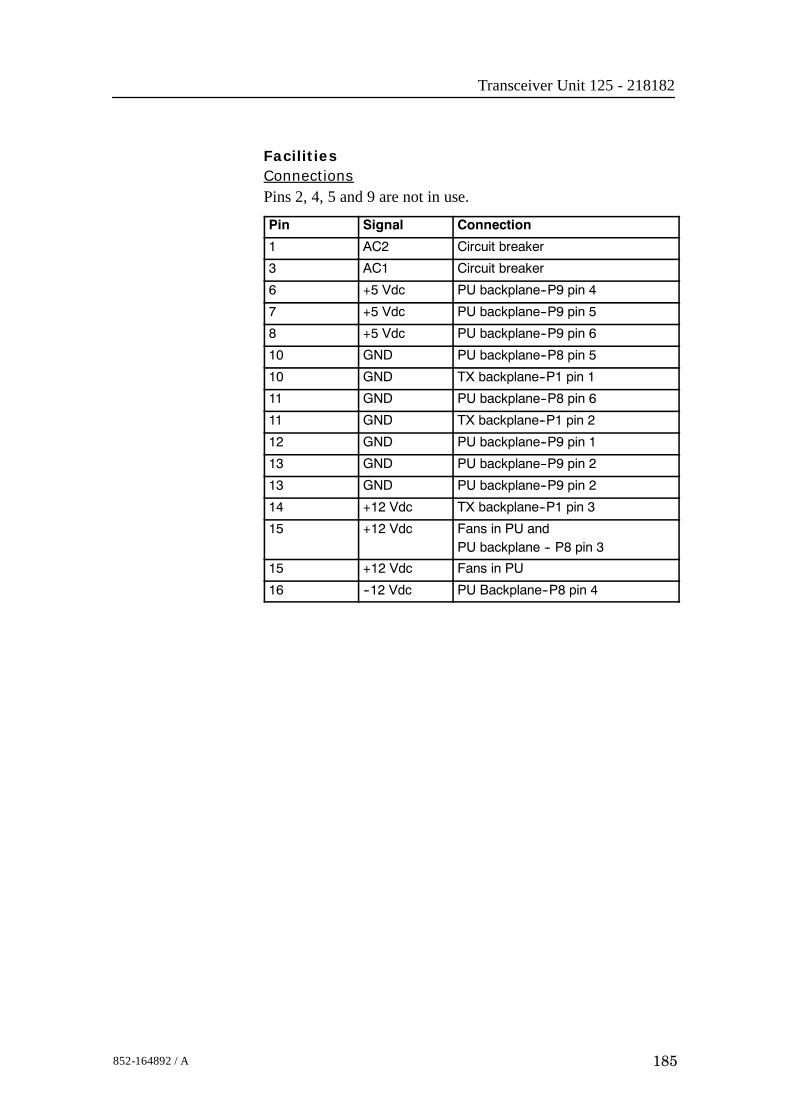
Transceiver Unit 125 - 218182
185852-164892 / A
FacilitiesConnectionsPins 2, 4, 5 and 9 are not in use.
Pin Signal Connection
1 AC2 Circuit breaker
3 AC1 Circuit breaker
6 +5 Vdc PU backplane--P9 pin 4
7 +5 Vdc PU backplane--P9 pin 5
8 +5 Vdc PU backplane--P9 pin 6
10 GND PU backplane--P8 pin 5
10 GND TX backplane--P1 pin 1
11 GND PU backplane--P8 pin 6
11 GND TX backplane--P1 pin 2
12 GND PU backplane--P9 pin 1
13 GND PU backplane--P9 pin 2
13 GND PU backplane--P9 pin 2
14 +12 Vdc TX backplane--P1 pin 3
15 +12 Vdc Fans in PU andPU backplane -- P8 pin 3
15 +12 Vdc Fans in PU
16 --12 Vdc PU Backplane--P8 pin 4

EM 300 Complete version
186 852-164892 / A
Motherboard
How it works
This is a passive backplane with standard ISA-bus.
Facilities
LEDs
The board has four LEDs:• + 5V• - 5V• + 12V• - 12V- 5V is not used and is not lit. The three others should be lit atall times.
Test points
None
Links
None
Connections
+ 5V, + 12V and - 12V.

Transceiver Unit 125 - 218182
187852-164892 / A
6.6 Receiver rack details
LocationThe Receiver Rack is located at the middle of the theTransceiver Unit. It holds several circuit boards, power suppliesand a capacitor bank.→ Refer to the illustration on page 170.
Circuit boards and modules
Transmitter/Receiver board
These four boards hold the amplifiers for all the individualreceive channels. (The boards may also provide poweramplification of the transmitted signal, but as this function is notused in the EM 300, these components have been omitted).→ The circuit board is explained on page 188.
Low Voltage Power Supply
This is a commercial linear power supply mounted on a chassisfor easy replacement. It also contains linear supplies for theTRB’s.→ The Low Voltage Power Supply is explained on page 191.
High Voltage Power Supply
This is a switching power supply. It provides the high outputvoltage for the transmitters, and uses the Capacitor bank to storethe energy between the pings.→ The High Voltage Power Supply HVPU is explained on page
194.
Signal Processor Board RX (SPRX)
The processor board is used as a function controller. This is acommon circuit board whose name is SPB31, and it is both usedin the Transmitter Rack and the Receiver Rack.→ The Signal Processor Board is explained on page 195.
Backplane (RXBP)
The Receiver Rack uses a passive backplane. All connections tothe circuit boards (except transmission signals) are made on thisbackplane.
Capacitor bank
This unit stores transmission energy temporarily.

EM 300 Complete version
188 852-164892 / A
Transmitter/Receiver Board (TRB)
Purpose and description
The purpose of the Transmitter/Receiver Board (TRB) is toprovide amplification of the signals received from thePreamplifier Unit. The board has 32 individual channels. Theboard is designed to provide transmission as well, but thesecomponents are not mounted on the circuit boards used in theEM 300 Transceiver UnitThe TRB is fastened to a combined strengthening plate and heatsink which covers the entire component side of the board andalso forms a “front panel” to the board. The board is located intracks within the Transceiver Unit to ensure correct location,and is held in position by four screws.The TRB has two 34-pin connectors on its front edge whichcarry the signals from the Preamplifier Unit.A one degree system needs four Transmitter/Receiver (TRB)boards. This means that all 128 channels are used.A two degree system needs two Transmitter/Receiver (TRB)boards, while a four degree system only have one.How it worksTransmission
The TRB contains a control interface that controls the 32transmitters on the board.The transmitters can be controlled individually to enablebeamforming of the transmitted pulse.Reception
The TRB receives signals from 32 transducer elements. Thesignals are individually amplified, time-varied-gain regulated,demodulated, and analogue-to-digital converted. The convertedsignals are then output from the board and sent to the BSP’s forfurther processing.Technical details
Dimensions(Width x Heigh x Depth)
220 x 233.35 x 0.32 mm
Analogue input/output 32 channels, 60W, + T/R switch
Connectors Two 96--pin euro on back edge of boardTwo 34--pin flat cables on front edge
Analogue to digital 12--bits resolutionI/Q simultaneously converted to 32--bit latched bus
Power requirements + 5 Vdc, 8 Vdc, + 24 Vdc

Transceiver Unit 125 - 218182
189852-164892 / A
Figure 88Transmitter/Receiver
(TRB)block diagram
(Cd3
428B
)
32 TxChannels
32 RxChannels
RX and Txcontrol circuitry
Dataaquisition
Not mounted in the EM 300
Rx control
2 x 16-bitdata buses
Data out to the SPRX
Tx control
Data aquisitioncontrol
Address bus from SPRX
Facilities
Test points
The test points listed below are available to assist themaintenance engineer. They are located on the front edge of theboard between the two connectors, in front of the correspondingLED.AVCC analogue voltage + 5 V. . . . . . . . . . . . . . . . . . . . . . . . . . . . .
AVDD analogue voltage NA. . . . . . . . . . . . . . . . . . . . . . . . . . . . . .
VCC digital voltage + 5 V. . . . . . . . . . . . . . . . . . . . . . . . . . . . . . . . .
AVEE analogue voltage - 5 V. . . . . . . . . . . . . . . . . . . . . . . . . . . . . .
HV1 high voltage transmitter + 8 - + 80 Vdc. . . . . . . . . . . . . . . .
HV2 high voltage transmitter NA. . . . . . . . . . . . . . . . . . . . . . . . .
HV3 high voltage transmitter NA. . . . . . . . . . . . . . . . . . . . . . . . .
HV4 high voltage transmitter NA. . . . . . . . . . . . . . . . . . . . . . . . .
TX transmitter indicator NA. . . . . . . . . . . . . . . . . . . . . . . . . . . . . .
The testpoints marked with NA are not used on EM 300.
Links
The TRB holds no links that can be set by the maintenanceengineer.
Switches
The TRB holds no switches that can be adjusted by themaintenance engineer.
LEDs
The TRB holds ten red LEDs on its front edge, mounted in avertical line between the connectors. When these LEDs are lit,they indicate the presence of the corresponding voltage levels.

EM 300 Complete version
190 852-164892 / A
Connectors
The TRB carries four connectors, two located at each end of theboard. P1 is a 96-pin, male right-angled euro-connector, locatedon the rear edge of the board, carrying power. P2 is a 96-pin,male, right-angled euro-connector, also located on the rear edgeof the board, carrying power and digital control signals. P3 andP4 are 34-pin, male, right-angled connectors with ejector/latch,located on the front edge of the board. Each connector carries16 input/outputs to the transducer/preamplifier.

Transceiver Unit 125 - 218182
191852-164892 / A
Low Voltage Power Unit (LVPU)
Purpose and description
The purpose of the Low Voltage Power Unit (LVPU) is tosupply power to all the modules in the Transceiver Unit, exceptthe high voltage power for the transmission, power to PU and+12Vdc.The Low Voltage Power Unit is located between theTransmitter/Receiver Boards and the High Voltage PowerSupply in the Receiver Rack. The power supply is a plug-inmodule. It has two front mounted fuses, one service switch, andone switch to select 115 or 230 Vac mains input.
TB1
A1
521
13
(CD5488A)
Power supply MAP55-1024MStand-by power
Mains transformer Ulveco N14034-TDUsed in analogue power supply
Switched power supplyMAP55-4001
On/off relay
Line
filte
r
P1
P2
Figure 89 The Low Voltage Power Supply
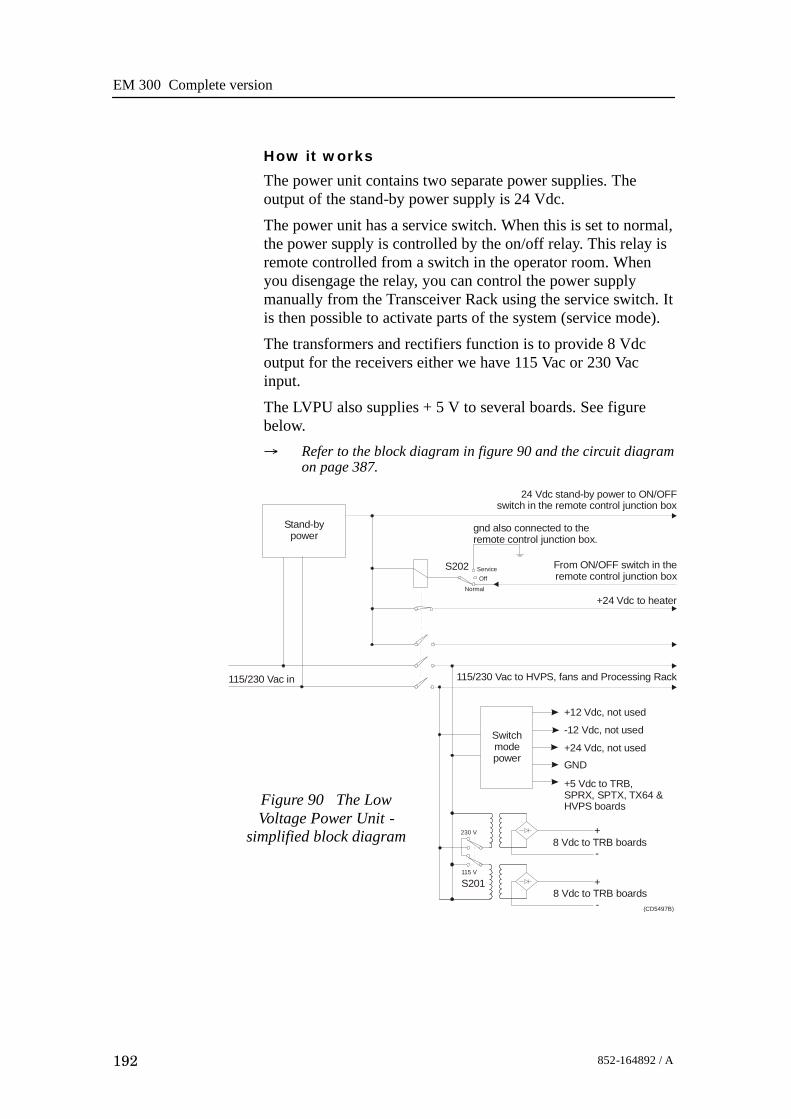
EM 300 Complete version
192 852-164892 / A
How it works
The power unit contains two separate power supplies. Theoutput of the stand-by power supply is 24 Vdc.The power unit has a service switch. When this is set to normal,the power supply is controlled by the on/off relay. This relay isremote controlled from a switch in the operator room. Whenyou disengage the relay, you can control the power supplymanually from the Transceiver Rack using the service switch. Itis then possible to activate parts of the system (service mode).The transformers and rectifiers function is to provide 8 Vdcoutput for the receivers either we have 115 Vac or 230 Vacinput.The LVPU also supplies + 5 V to several boards. See figurebelow.→ Refer to the block diagram in figure 90 and the circuit diagram
on page 387.
115/230 Vac in
Normal
OffService
115/230 Vac to HVPS, fans and Processing Rack
Stand-bypower
+12 Vdc, not used
-12 Vdc, not used
+24 Vdc, not used
GND
Switchmodepower
+
-
+
-
8 Vdc to TRB boards
8 Vdc to TRB boards
+24 Vdc to heater
(CD5497B)
230 V
115 V
S201
S202
24 Vdc stand-by power to ON/OFFswitch in the remote control junction box
From ON/OFF switch in theremote control junction box
gnd also connected to the remote control junction box.
+5 Vdc to TRB, SPRX, SPTX, TX64 & HVPS boardsFigure 90 The Low
Voltage Power Unit -simplified block diagram

Transceiver Unit 125 - 218182
193852-164892 / A
Facilities
LEDs
• L201: Indicator for mains input• L202: Indicator for 24 Vdc stand by mode• L203: Lit to indicate AC supply to switched
and analogue• L204: Lit to indicate AC supply to
analogue power.
Test points
None
Links
None
Switches
• S201: Switch for mains input 115/230 Vac• S202: Service/Off/Normal switch
Connections
• P1• P2
Fuses
• F201: Primary fuse• F202: Primary fuse• F203: Thermostat fuse inside the torodial
transformer
SIMRADPOWER SUPPLY 290-112750
AnalogPowerSupply
SwitchedPowerSupply
Service
OFF
Normal
On/offRelay
24VStand-by
SlowBlow
Mains input115/230Vac
S 201230Vac
+7,5VREF-7,5V+5VA-5VA+5V+12V-12V+24VGND
F203
+24VREF
F201 8A
F202 8A
L203
L202
L201
S202
S201
On/off relay
F203
(CD
5488
B)
Figure 91 The front panel

EM 300 Complete version
194 852-164892 / A
High Voltage Power Unit (HVPU)
Purpose and description
The purpose of the High Voltage Power Unit (HVPU) is toprovide the power for the output amplifiers.The input is to the system is 85 to 265 Vac. The output is 80Vdc. The output voltage can be reduced to -10 dB (25 Vdc) or-20dB (8 Vdc). The values can be adjusted.
Figure 92 The High Voltage Power Supply
Transceiver Unit 125 - 218182
195852-164892 / A
Signal Processor Board (SPB31)
Purpose and description
The Signal Processor Board (SPB31) is designed for high speedbeamforming and sonar signal processing. The board design isbased on the TMS 320C31 floating point DSP (Digital SignalProcessor) from Texas Instruments.
The Signal Processor Board is designed as a ”double Europe”standard sized printed circuit board. It is equipped with anumber of front mounted LEDs, test points, potentiometers andcoax connectors.
The board is used two places in the EM 300 Transceiver Unit; tocontrol the transmission (SPTX) and the reception (SPRX).
The reg.no. for SPB31 Tx is 382-133472 and 382-134469 forSPB31 Rx.
How it works
The main components of the Signal Processor Board are:
1 TMS 320C31 Digital Signal Processor
- Clock frequency 33.33 or 40 MHz- 32-bit data bus- 24-bit address bus- 40/32-bit floating point unit- 1 internal serial line- 2 pc 32-bit timers- 4 interrupt inputs- DMA controller- Programmable in C and assembly- Emulator and symbolic de-bugger available
2 256k x 32 bit PROM.
3 512 x 32 bit SRAM 25 ns
4 Complex multiplier.
5 4 serial lines RS422/RS232.
6 Programmable counter for TX clock, 64 CHTX.
7 Dual port interface to P1 bus (Multibus I type).
8 Bus interface to P2 bus.
9 Control bus for control outputs compatible with SPB29.

EM 300 Complete version
196 852-164892 / A
The Signal Processor Board works very similar to othermicroprocessor boards. The TMS 320C31 Digital SignalProcessor operates with standard peripheral circuitry such asRAM, PROM (with software) and the interface controllers.Devices for disk drive control are omitted, but Dual Port RAMand a complex multiplier is implemented instead. Refer to theblock diagram.
Businterface
16-bit databus and24-bit address bus
16-bit databus
Serial line
Serial lines
(CD
1401
)
Emulator
Data bus
24-bit address bus
Address bus
Dual portRAM (DPRAM)
Signal processorTMS320C31
Serial lineinterface (4 ea)
Businterface
Programcounter
256k x 32 PROM512k x 32 RAM
Dual portRAM (DPRAM)
Multipliers
16-bit databus and24-bit address bus
P1
P2
Figure 93 Signal ProcessorBoard SPB31 - simplified
block diagram
An emulator for the TMS 320C31 processor is developed. Itconsists of a controller board in a PC and an active pod which isconnected to the target board by a 12 pin plug.
Facilities
Unmounted devices
Note that several sockets on the Signal Processor Board may beempty. On EM 300 the Mulitpliers with corresponding DPRAMare not mounted.

Transceiver Unit 125 - 218182
197852-164892 / A
Links
A large number of links are implemented on the processor boardto allow for several different applications. The links are used asfollows:
LK 1 2BI422 to RXDB on U15
LK 2 RXDB2 input to RXDB on U15
LK 3 2AI422 to RXDA on U15
LK 4 RXDA2 input to RXDA on U15
LK 5 CLKIN to U64
LK 6 FSRO and DRO to set frame sync for sercom onU32
LK 7 RDRO to DRO when sercom in U32 is used onRS232
LK 8 Clock to U36
LK 9 RXDA input to RXDA on U63
LK 10 RXDB input to RXDB on U63
LK 11 BI422 input to RXDB on U63
LK 12 AI422 input to RXDA on U63
LK 13 CLQ to P2A25, U60 must not be mounted
LK 14 TXCLK to P2B24, U60 must not be mounted
LK 15 CLI to P2A24, U60 must not be mounted
LK 16 TSTSIG to P2C23, U60 must not be mounted
LK 17 TXEN~ to P2A22, U60 must no be mounted
LK 18 MEM3 to P2C3, LK30 must be OFF
LK 19A XF0~ as output
LK 19B XF0 as input
LK 20A XF0 as output
LK 20B XF0~ as input
LK 23A XF1~ as output
LK 23B XF1 as input
LK 24A XF1 as output
LK 24B XF1~ as input
LK 25A TCLK0~ as output
LK 25B TCLK0 as input
LK 26A TCLK0 as output
LK 26B TCLK0~ as input
LK 27A TCLK1~ as output
LK 27B TCLK1 as input
LK 28A TCKL1 as output
LK 28B TCLK1~ as input

EM 300 Complete version
198 852-164892 / A
LK 29 External reset, INIT1, when ON
LK 30 IACK~ to P2C3, LK18 must be OFF
LK 31 U40 to CLKIN on DSP U32
Note that this list is for reference only.Link applications
When using the Signal Processor Board in the EM 300Transceiver Unit, the following links must be ON (closed):SPRX:• LK 4• LK 5• LK 8• LK 9• LK10• LK 31SPTX:• LK 4• LK 5• LK 8• LK 9• LK 10• LK 19 (see below)• LK 20 (see below)• LK 23 (see below)• LK 24 (see below)• LK 31
(Cd5
684)
LED’s
LED’s used for SPTX:D1: program initialized OKD2: ready for new command
D3: transmit activeD4: BIST activeD5: not used

Transceiver Unit 125 - 218182
199852-164892 / A
D6: test purposeD7: test purpose
LED’s used for SPRX:D1: program initialized OKD2: BIST active
D3: aquisition of reciever dataD4: aquisition of reciever dataD5: simulator activeD6: not usedD7: not usedD8: not used
Figure 94 SignalProcessor Board SPB31,
front mounted devices
(CD4340)
TP 2
TP 3
TP 4
TP 5
TP 6
TP 7
TP 8
TP 9
TP 10
TP 1
D 2D 1
D 3D 4D 5D 6D 7D 8
D 9
P3
S1
TP 11
TP 12
J2
P9
J1
TP 15
Same as LED D1Same as LED D2
Same as LED D3Same as LED D4
Same as LED D5Same as LED D6
Same as LED D7Same as LED D8
Clock pulse
WE/ to test RAM
Ground
Ground
Test signal output
Reset
Softwarecontrolled
LEDs
Serial lines
Emulator
Serial lines
+5 Vdc
+5 Vdc
Test pointsTP 1: GNDTP 2: General purpose test output no.1TP 3: General purpose test output no.2

EM 300 Complete version
200 852-164892 / A
TP 4: General purpose test output no.3
TP 5: General purpose test output no.4
TP 6: General purpose test output no.5
TP 7: General purpose test output no.6
TP 8: General purpose test output no.7
TP 9: General purpose test output no.8
TP 10: +5 Vdc
TP 11: Clock pulse, CP, monitor
TP 12: WE~ for testing RAM loading
TP 13: GND
TP 14: GND
TP 15: GND
Connections
The following connections are made to the Signal ProcessorBoard:
P1 Multibus
P2 Signal processor external bus
P3 Test signal output
J1 Serial lines
J2 Serial lines
The trig out puls is active during transmit, and generated bySPRX. This is a TTL level pulse and is active when low.→ The connections are explained in the figure on page 173.→ The Receiver Backplane connections(PXB-P3) are explained on
page 202.

Transceiver Unit 125 - 218182
201852-164892 / A
Receiver Backplane (RXBP)
Purpose and description
The purpose of the Receiver Backplane is to enablecommunication between the circuit boards plugged into it, andbetween these circuit boards and the external circuitry in thecabinet. The RXBP is located behind the middle wired rack inthe Transceiver Unit, and holds the following circuit boards:
• Transmitter/Receiver Board 1
• Transmitter/Receiver Board 2
• Transmitter/Receiver Board 3
• Transmitter/Receiver Board 4
• Low Voltage Power Supply
• High Voltage Power Supply
• Signal Processor Board RX
• Capacitor Bank
How it works
There are no active components on this backplane.
Facilities
LEDs
None
Figure 95 Receiver Backplane, rear side
P14
TP1
P2
P3
P5
P6
P7
P8
P11
LK6
TP10 TP9
P12
TP12
TP11
LK7
TP13
LK8
TP8
P10
TP2
TP3
TP4
TP5
TP6
TP7
P4
P13
TP14
(CD5466B / 382-134122D)
LK9
P9
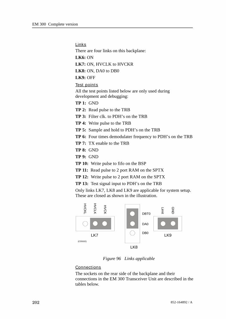
EM 300 Complete version
202 852-164892 / A
LinksThere are four links on this backplane:LK6: ONLK7: ON, HVCLK to HVCKRLK8: ON, DA0 to DB0LK9: OFFTest pointsAll the test points listed below are only used duringdevelopment and debugging:TP 1: GNDTP 2: Read pulse to the TRBTP 3: Filter clk. to PDH’s on the TRBTP 4: Write pulse to the TRBTP 5: Sample and hold to PDH’s on the TRBTP 6: Four times demodulater frequency to PDH’s on the TRBTP 7: TX enable to the TRBTP 8: GNDTP 9: GNDTP 10: Write pulse to fifo on the BSPTP 11: Read pulse to 2 port RAM on the SPTXTP 12: Write pulse to 2 port RAM on the SPTXTP 13: Test signal input to PDH’s on the TRBOnly links LK7, LK8 and LK9 are applicable for system setup.These are closed as shown in the illustration.
DBT0
DA0
DB0
HVC
KL
HV
CLK
HV
CK
LK7
LK8
LK9
Limit
GN
D
(CD5532)
Figure 96 Links applicable
Connections
The sockets on the rear side of the backplane and theirconnections in the EM 300 Transceiver Unit are described in thetables below.

Transceiver Unit 125 - 218182
203852-164892 / A
Pin 1
Pin 2
Pin 3
Pin 4
(Cd5
481)
Figure 97 Pinconfiguration
RXB--P2 Signal Connection
1 STBY+ Bottom plate--Remote pin 1
2 STBY-- Bottom plate--Remote pin 2
3 ON Bottom plate--Remote pin 3
4
RXB--P3 Signal Connection
1 HEAT Wall sect.--Terminal block pin 1
2 STBY-- Wall sect.--Terminal block pin 2
3 TRIG Bottom plate--pin 1
4 DGND Bottom plate--pin 2
RXB--P5 Signal Connection
1 +12VH TXB--P3 pin 4
2 HGND TXB--P3 pin 2
3 HGND TXB--P3 pin 3
4 +5VH TXB--P3 pin 1
RXB--P6 Signal Connection
1 HGND TXB--P4 pin 1
2 HGND TXB--P4 pin 2
3 HV TXB--P4 pin 3
4 HV TXB--P4 pin 4
RXB--P7 Signal Connection
1 HGND TXB--P5 pin 1
2 HGND TXB--P5 pin 2
3 HV TXB--P5 pin 3
4 HV TXB--P5 pin 4
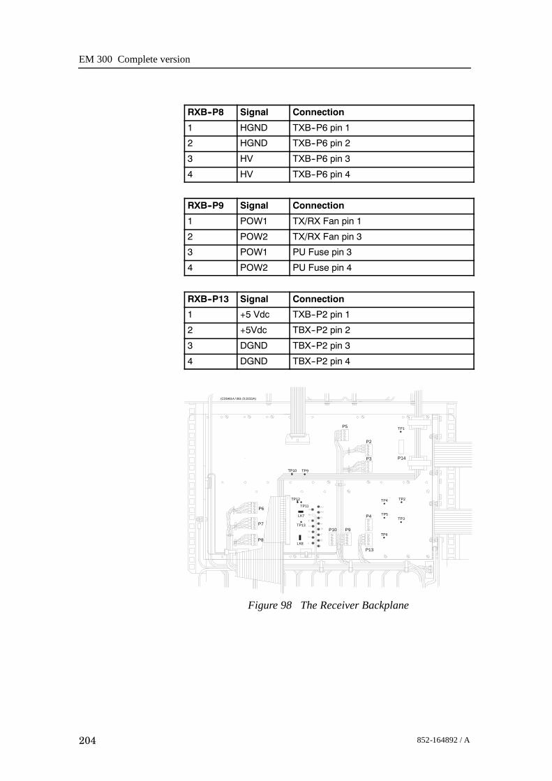
EM 300 Complete version
204 852-164892 / A
RXB--P8 Signal Connection
1 HGND TXB--P6 pin 1
2 HGND TXB--P6 pin 2
3 HV TXB--P6 pin 3
4 HV TXB--P6 pin 4
RXB--P9 Signal Connection
1 POW1 TX/RX Fan pin 1
2 POW2 TX/RX Fan pin 3
3 POW1 PU Fuse pin 3
4 POW2 PU Fuse pin 4
RXB--P13 Signal Connection
1 +5 Vdc TXB--P2 pin 1
2 +5Vdc TBX--P2 pin 2
3 DGND TBX--P2 pin 3
4 DGND TBX--P2 pin 4
TP1
TP4
TP5
TP6
TP3
TP2
P6
P7
P8
P10 P9
P4
P13
P5
P2
P3 P14
TP10 TP9
TP12
TP11
LK7
TP13
LK8
(CD5461A / 861-213155/A)
Figure 98 The Receiver Backplane

Transceiver Unit 125 - 218182
205852-164892 / A
6.7 Transmitter rack details
LocationThe Transmitter Rack is located at the bottom of the TransceiverUnit. It holds one processor board and a number of transmitterboards.→ Refer to the illustration on page 169
The physical number of transmitter boards is defined by thespecified system accuracy:• A 1 degree system has 14 transmitter boards
Circuit boards and modules
64-Channel Transmitter Board (TX64)
Each of these circuit boards holds 64 individual poweramplifiers, each controlled by the function controller.→ The circuit board is explained on page 206
Signal Processor Board TX (SPTX)
The processor board is used as a function controller.→ The circuit board is explained on page 195
Backplane (TXBP)
The Transmitter Rack uses a passive backplane.→ The TX Backplane is explained on page 210

EM 300 Complete version
206 852-164892 / A
64-Channel Transmitter (TX64)
Purpose and description
Once the transmission parameters have been calculated by theSignal Processor Tx (SPTX), each of the transmitter boards isaddressed. The data-bus from the SPTX is connected to all theboards, and data for the individual transmitters is loaded into theonboard RAMs as they are addressed from the SPTX. Theoutput from the TX64 RAM bank is connected to the outputstages, which are implemented using KongsbergMaritime-designed amplifier hybrids.
The physical number of TX64 boards fitted to the EM 300transceiver depends on the chosen system specifications. Thus,up to 14 64-Channel Transmitter (TX64) boards are used.
A one degree transmitter has 864 elements in the transducer anda two degree transmitter 432 elements. Hence a one degree Txsystem needs 14 TX64 boards, the last 32 transmitters on theTX64 #14 is not used.
A two degree Tx system needs seven TX64 boards. Here the last16 transmitters are not used on TX64 board # 7.
How it works
Overview
The TX64 boards are controlled by the Signal Processor TX(SPTX), and the output signals are made available on the frontmounted sockets. Flat ribbon cables connect these output pulsesto the filters.
The TX64 board is equipped with two large front mountedconnectors. Two LED indicators and one test point are locatedbetween these connectors. The test point is a ground (GND)connection, while the LEDs monitor the +5 Vdc and +12 Vdcsupply voltages.
The TX64 board is equipped with eight onboard fuses. Thesefuses are located on the High Voltage (HV) supply line, andeach fuse protects a group of eight transmitters. Fuse rating is 4A, physical size is 5 x 20 mm.
The functions of the transmitter may be divided into three parts:
• The power unit (Power & Fuses)
• The digital control unit
• The analogue transmitter driver unit (TX Hybrid)
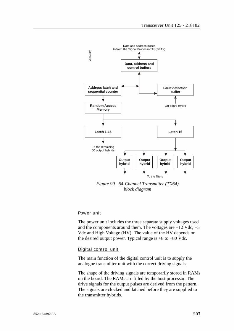
Transceiver Unit 125 - 218182
207852-164892 / A
Figure 99 64-Channel Transmitter (TX64)block diagram
Data, address andcontrol buffers
Fault detectionbuffer
On-board errors
Address latch andsequential counter
Data and address busesto/from the Signal Processor Tx (SPTX)
Latch 1-15 Latch 16
Outputhybrid
Outputhybrid
Outputhybrid
Outputhybrid
Random AccessMemory
(CD
1405
C)
To the filters
To the remaining60 output hybrids
Power unit
The power unit includes the three separate supply voltages usedand the components around them. The voltages are +12 Vdc, +5Vdc and High Voltage (HV). The value of the HV depends onthe desired output power. Typical range is +8 to +80 Vdc.
Digital control unit
The main function of the digital control unit is to supply theanalogue transmitter unit with the correct driving signals.
The shape of the driving signals are temporarily stored in RAMson the board. The RAMs are filled by the host processor. Thedrive signals for the output pulses are derived from the pattern.The signals are clocked and latched before they are supplied tothe transmitter hybrids.

EM 300 Complete version
208 852-164892 / A
The transmitted pulse is controlled by the address latches andthe controller. The transmitted frequency is increased by 64times, and is then supplied to the CLK input. The TX Enable(TXEN/) input enables the transmitters and controls the transmitpulse length.Status information such as fuse blown can be read from the faultdetect buffer on the data bus.To lower the sidelobe level, IC U89 is omitted and a piggy backboard is inserted. This piggy back board contains a PLD withdoubled resolution for transmit beampattern.Analogue transmitter unitThere are 64 transmitters on the board. Each of these is a thickfilm hybrid designed by Kongsberg Maritime. There are nofrequency dependent components on the board. The transmittersare electrically designed into in groups of eight, each groupbeing protected by a 4 A fuse. The transmitter outputs arebrought to the front edge connectors P3 and P4.
Facilities
LEDsD 9 +5 Vdc. . . . . . . . . . . . . . . . . . . . . . . . . . . . . . . . . . . . . . . . . . . . .D 10 +12 Vdc. . . . . . . . . . . . . . . . . . . . . . . . . . . . . . . . . . . . . . . . . . .
Figure 100 64-ChannelTransmitter (TX64) front mounted
devices
P3
D9
D10
+12 Vdc
+5 Vdc
P4
Outputs
(CD
4417
)
Test pointsTP 1 GND. . . . . . . . . . . . . . . . . . . . . . . . . . . . . . . . . . . . . . . . . . . . . . .
LinksA number of links are implemented on the board to allow forseveral different applications. The links are used as follows:

Transceiver Unit 125 - 218182
209852-164892 / A
LK1 Selects PROM (when ON). . . . . . . . . . . . . . . . . . . . . . . . . . . . .
LK2 Selects RAM (when ON). . . . . . . . . . . . . . . . . . . . . . . . . . . . . .
Link applications
The following links are ON (closed) in this application:• LK2
Switches
None
Connections
The TX64 is equipped with the following connectors:P 1 Connections to the external power supply. . . . . . . . . . . . . . .
P 2 Interface to control processor. . . . . . . . . . . . . . . . . . . . . . . . . . .
P 3 Outputs from channels 01-32. Front mounted. . . . . . . . . . . .
P 4 Outputs from channels 33-64. Front mounted. . . . . . . . . . . .
Fuses
F 1 TX group 1, Channels 01-08. . . . . . . . . . . . . . . . . . . . . . . . . . . .
F 2 TX group 2, Channels 09-16. . . . . . . . . . . . . . . . . . . . . . . . . . . .
F 3 TX group 3, Channels 17-24. . . . . . . . . . . . . . . . . . . . . . . . . . . .
F 4 TX group 4, Channels 25-32. . . . . . . . . . . . . . . . . . . . . . . . . . . .
F 5 TX group 5, Channels 33-40. . . . . . . . . . . . . . . . . . . . . . . . . . . .
F 6 TX group 6, Channels 41-48. . . . . . . . . . . . . . . . . . . . . . . . . . . .
F 7 TX group 7, Channels 49-56. . . . . . . . . . . . . . . . . . . . . . . . . . . .
F 8 TX group 8, Channels 57-64. . . . . . . . . . . . . . . . . . . . . . . . . . . .
Fuse rating is 4 A. Physical fuse size is 4 x 20 mm.
Oscilloscope check points
• The Clock (CLK) is input on pin P2 B24, and connected tobuffer U90, pin 4. The clock frequency varies with thetransmission frequency, and will be 64 times this. Frequencyalterations during one transmission are achieved by changingthe clock frequency.
• The TX Enable (TXEN/) is input on pin P2 A22, andconnected to buffer U90, pin 2. The TXEN/ pulse is thetransmit trigger, and the length of the TXEN is also thelength of the transmitted pulse. For EM 300 the TXfrequency is from 30 to 34 kHz.

EM 300 Complete version
210 852-164892 / A
Transmitter Backplane (TXBP)Purpose and description
The purpose of the transmitter Backplane is to enablecommunication between the circuit boards plugged into it, andbetween these circuit boards and the external circuitry in thecabinet. The TXBP is located behind the bottom wired rack inthe Transceiver Unit, and holds the following circuit boards:• 64-channel Transmitter Board (TX64)• Signal Processor Board TX (SPB31)
C1
C2
C3
C4
C5
C6
C7
C8
C9
C10
C11
C12
C13
C14
C17
C16C18
C19C19
C20
C21
C22
C23
C24
P7
P8
P9
TP6TP5
TP3TP4
P2
P6 P5 P4 P3 P1
TP1
+ +
+ + + + + +++ + + + +
++++++++ ++
(Cd5522 / 113186/A)
Figure 101 Transmitter Backplane, rear side
How it works
There are no active components on this backplane.Facilities
LEDs
None
Test points
The following testpoints are only used during development anddebugging.TP 1: DGNDTP 2: DGNDTP 3: SMEM/ Active low when data is read from TX64

Transceiver Unit 125 - 218182
211852-164892 / A
TP 4: DMEM/ Active low when data is written to TX64TP 5: DGNDTP 6: TXE/ Active low when transmit is ongoing.
Links
None.
Connections
The sockets on the rear side of the backplane and theirconnections in the EM 300 Transceiver Unit are described in thetables below.
Pin 1
Pin 2
Pin 3
Pin 4(C
d548
1)
Figure 102 Pinconfiguration
TXB--P1 Signal Connection
1 GND PU power supply
2 GND PU power supply
3 +12 Vdc PU power supply
4 +12 Vdc PU power supply
TXB--P2 Signal Connection
1 +5 Vdc RXB--P13 pin 1
2 +5 Vdc RXB--P13 pin 2
3 DGND RXB--P13 pin 3
4 DGND RXB--P13 pin 4
TXB--P3 Signal Connection
1 +5 VH RXB--P5 pin 4
2 HGND RXB--P5 pin 2
3 HGND RXB--P5 pin 3
4 +12 VH RXB--P5 pin 1
TXB--P4 Signal Connection
1 HGND RXB--P6 pin 1
2 HGND RXB--P6 pin 2
3 HGND RXB--P6 pin 3
4 HGND RXB--P6 pin 4

EM 300 Complete version
212 852-164892 / A
TXB--P5 Signal Connection
1 HGND RXB--P7 pin 1
2 HGND RXB--P7 pin 2
3 HGND RXB--P7 pin 3
4 HGND RXB--P7 pin 4
TXB--P6 Signal Connection
1 HGND RXB--P8 pin 1
2 HGND RXB--P8 pin 2
3 HGND RXB--P8 pin 3
4 HGND RXB--P8 pin 4
The bleeder is mounted on the Processing Unit power supplycover.
Fan TX/RX
123
P8
P7 P6 P5 P4 P3 P1
P2
Vorsicht Spannung
AttentionD anger
(Cd5
525
/ 210
142/
A)
Figure 103 The Transmitter Backplane

Raw Data Logger
213852-164892 / A
7 RAW DATA LOGGER
7.1 Description and main functions
OverviewThe Raw Data Logger is an option that can be mounted on theEM 300 Transceiver Unit. The main purpose is to log thesamples throught out the water column for all 128 staves. Thesample data can also be presented on the display.The data logger contains:• CD-writer• harddisk• Beamformer Signal Processing (BSP) board• Control Processing Unit (CPU) boardA ribbon cable is connecting the EM 300 Transceiver Unit andthe Raw Data Logger.The CD-writer is used to load the Kongsberg Maritime softwareand to backup sample data to a CD-disk.Software is installed on the BSP board and on the harddisk.This chapter provides the following information:→ Description and main functions, page 213.→ Raw Data Logger outline, page 214.
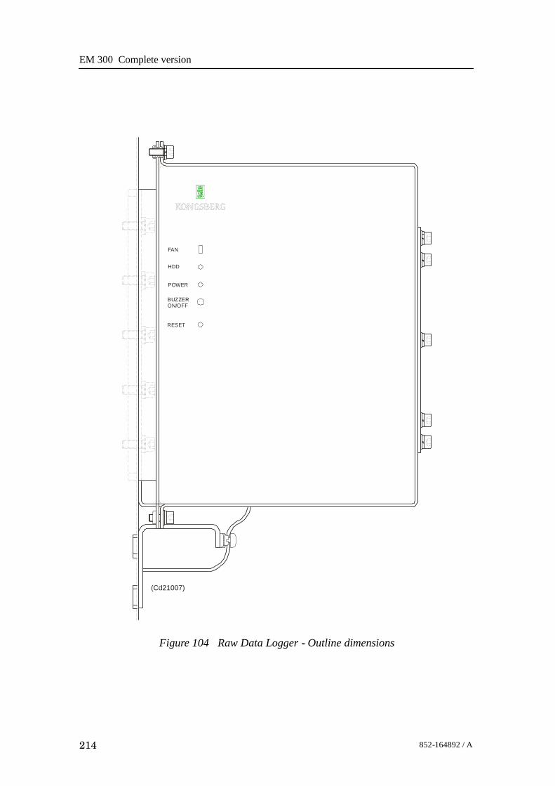
EM 300 Complete version
214 852-164892 / A
Figure 104 Raw Data Logger - Outline dimensions
FAN
HDD
POWER
BUZZERON/OFF
RESET
(Cd21007)

Troubleshooting
215852-164892 / A
8 TROUBLESHOOTING
8.1 Messages
IntroductionThe EM 300 provides numerous messages to inform you ofmajor and minor hardware and software errors.The messages, if they occur, will be displayed in the StatusDisplay in the Message field.The different utilities operating on the EM 300 Operator Stationeach issue several messages. These messages can be sorted infour categories:• display warnings• display errors• warnings• errorsThe messages presented as display warnings and warningsmerely point out small inaccuracies, and must be regarded asguidelines to the normal operation of the system.The display errors and operational errors reflect major andminor hardware and software errors, some of which must beacted upon to ensure the normal operational capability.The following chapters present all the possible messages, andbriefly explain the proper action to be taken.The information is provided as follows:<Nxxx>: -- <Message text>
Necessary action with applicable references.<Nxxx> is the message identifier. The number will allow you tofind the message easier in this document, and it tells you whichutility issued it.N - module/utility identifier.xxx - message identifierIn the list below you will find one letter representing eachmodule. Each module is described in its own chapter. Thenumber xxx is only an identifier.
S: setup messagesW: ESO/workstation messages

EM 300 Complete version
216 852-164892 / A
L: launchpad messagesE: sound speed profile editor messagesP: Ping Display messages
The Hardware and CPU CMOS setup messages are presentedwith the exact same layout. The Hardware messages also startwith a message identifier <Nxxx>, and have a followingmessage text.The message text contains an error code which has to bedecoded to get the exact error condition.Most display errors are equipped with a help-textfunction,giving additional help on the errors. This text will, in mostcases, be identical to the action text found in this manual.
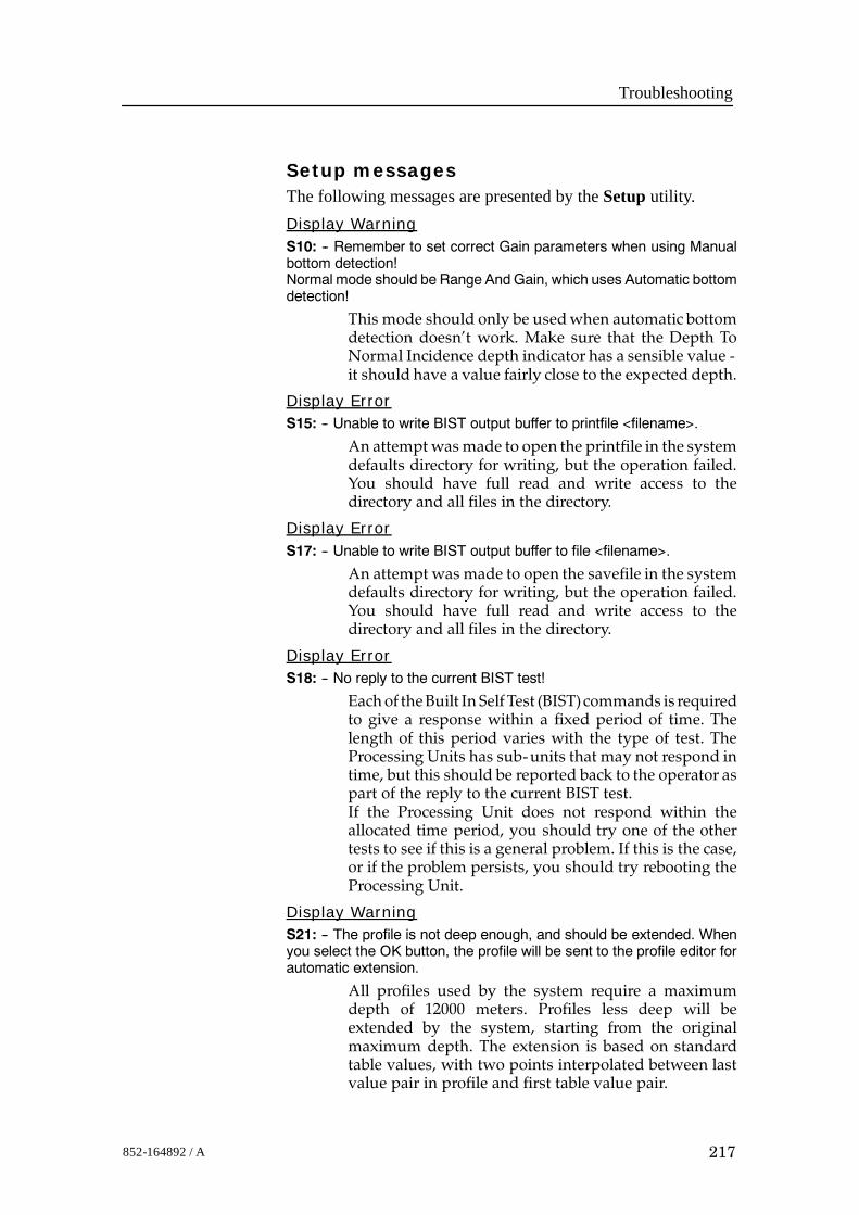
Troubleshooting
217852-164892 / A
Setup messagesThe following messages are presented by the Setup utility.Display WarningS10: -- Remember to set correct Gain parameters when using Manualbottom detection!Normal mode should be Range And Gain, which uses Automatic bottomdetection!
This mode should only be usedwhen automatic bottomdetection doesn’t work. Make sure that the Depth ToNormal Incidence depth indicator has a sensible value -it should have a value fairly close to the expected depth.
Display ErrorS15: -- Unable to write BIST output buffer to printfile <filename>.
An attemptwasmade to open the printfile in the systemdefaults directory for writing, but the operation failed.You should have full read and write access to thedirectory and all files in the directory.
Display ErrorS17: -- Unable to write BIST output buffer to file <filename>.
An attempt was made to open the savefile in the systemdefaults directory for writing, but the operation failed.You should have full read and write access to thedirectory and all files in the directory.
Display ErrorS18: -- No reply to the current BIST test!
Eachof theBuilt In SelfTest (BIST)commands is requiredto give a response within a fixed period of time. Thelength of this period varies with the type of test. TheProcessing Units has sub-units that may not respond intime, but this should be reported back to the operator aspart of the reply to the current BIST test.If the Processing Unit does not respond within theallocated time period, you should try one of the othertests to see if this is a general problem. If this is the case,or if the problem persists, you should try rebooting theProcessing Unit.
Display WarningS21: -- The profile is not deep enough, and should be extended. Whenyou select the OK button, the profile will be sent to the profile editor forautomatic extension.
All profiles used by the system require a maximumdepth of 12000 meters. Profiles less deep will beextended by the system, starting from the originalmaximum depth. The extension is based on standardtable values, with two points interpolated between lastvalue pair in profile and first table value pair.

EM 300 Complete version
218 852-164892 / A
ErrorS25: -- The Profile contains errors and will not be used. Errors detected:
The samemessage is used for several types ofwarnings:
1. Out-of-bounds depth values. Legal interval is0 - 12000m.
2. Out-of-bounds sound speed values. Legal interval is1400 - 1700 m/s.
3. Fewer actual samples than stated in profile header,using actual no. of samples in profile.
4. Gradient anolomies checking two neighbouring valuepairs.
Even though you are given the choice to use the profile,it is recommended that you use the profile editor toverify and correct it. Otherwise, the echo soundersoundings may suffer quality degradation.
ErrorS28: -- Too step gradients...
If one or more of the samples are spike values, theyshould be removed from the profile.
Display WarningS32: -- The sound velocity profile <name> contains too few samples.
The profile header says that the profile contains less thantwo entries. At least two entries are required, and for anyreal life sounding that is really too few entries.
Display WarningS33: -- The sound velocity profile <name> contains more than 1000samples!
The system is not designed to handle profiles exceeding1000 depth/speed pairs. You should use the profile, ordownload again, using 1000 depth/speed pairs as amaximum.
Display ErrorS37: -- Sound Velocity Profile <name> was not found!
The specified profile was not located in the directorycontaining the soundspeedprofiles ($SHAREDHOME).You could have misspelt the profile name, or the profilehas been removed from this directory after it wasselected. Try selecting the profile from the pull-downmenu. Thismenu is updated every time it is opened, andshould give you the exact list of available profiles.
Display ErrorS50: -- The file <filename> is not found in the $HOME/<directory>, or inthe $NEPTUNEHOME/defaults directory.
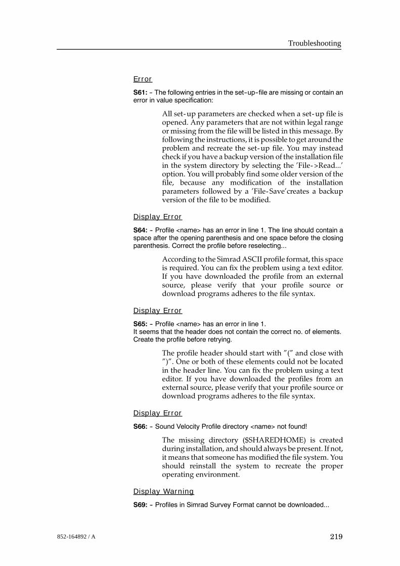
Troubleshooting
219852-164892 / A
Error
S61: -- The following entries in the set--up--file are missing or contain anerror in value specification:
All set-up parameters are checked when a set-up file isopened. Any parameters that are not within legal rangeormissing from the file will be listed in this message. Byfollowing the instructions, it is possible toget around theproblem and recreate the set-up file. You may insteadcheck if you have a backup version of the installation filein the system directory by selecting the ’File->Read...’option. You will probably find some older version of thefile, because any modification of the installationparameters followed by a ’File-Save’creates a backupversion of the file to be modified.
Display Error
S64: -- Profile <name> has an error in line 1. The line should contain aspace after the opening parenthesis and one space before the closingparenthesis. Correct the profile before reselecting...
According to the SimradASCII profile format, this spaceis required. You can fix the problem using a text editor.If you have downloaded the profile from an externalsource, please verify that your profile source ordownload programs adheres to the file syntax.
Display Error
S65: -- Profile <name> has an error in line 1.It seems that the header does not contain the correct no. of elements.Create the profile before retrying.
The profile header should start with ”(” and close with”)”. One or both of these elements could not be locatedin the header line. You can fix the problem using a texteditor. If you have downloaded the profiles from anexternal source, please verify that your profile source ordownload programs adheres to the file syntax.
Display Error
S66: -- Sound Velocity Profile directory <name> not found!
The missing directory ($SHAREDHOME) is createdduring installation, and shouldalways bepresent. If not,it means that someone has modified the file system. Youshould reinstall the system to recreate the properoperating environment.
Display Warning
S69: -- Profiles in Simrad Survey Format cannot be downloaded...
EM 300 Complete version
220 852-164892 / A
The system cannot use this format for sound speedprofiles. These profiles are producedwhen logging data,based on a Simrad ASCII format profile selected by theuser. If this ASCII profile is no longer available, and youwould like to use it again, you could use the ProfileEditor to convert the profile into the Simrad ASCIIprofile format.
Display Error
S70: -- The BIST for SW version returned an empty string!
Each of the Built In Self Test commands will return withthe result being displayed in the BIST output area. Thismessage informs you that a reply arrived, but that thereply contained no text to be displayed. This is clearly anerror. Please repeat BIST command to check if theproblem is repeatable. Errors like this should not occur,and if the problempersists, you are advised to reboot theProcessing Unit and restart the operation stationsoftware.
Error
S71: -- The Set--up--file is empty. Do you want to reinstall the defaultSimrad file?
The file containing installation parameter set-up valueswas empty. When this happens, the system canautomatically install the default version of the file. Thefile may have been corrupted during a program crash.Confirming installation of default file allows you tocontinue. Otherwise, the system cannot be operated...
Display Error
S73: -- Format error in BIST return for SW version request!
Each of the Built In Self Test commands will return withthe result being displayed in the BIST output area. Thismessage informs you that a reply arrived, but that thereply did not match the expected format. This is clearlyan error. Please repeat BIST command to check if theproblem is repeatable. Errors like this should not occur,and if the problempersists, you are advised to reboot theProcessing Unit and restart the operation stationsoftware.
Display Error
S74: -- ’BSP Test’ failed -- do you want to reboot the BSP unit?

Troubleshooting
221852-164892 / A
The BSP sub-unit may occasionally lock up, with nopings being produced from the echo sounder.When thathappens, the BSP BIST command will fail with thismessage. It is, however, possible to restart the BSPwithout rebooting the Processing Unit. This will happenwhen you confirm that a reboot is wanted. When theboot is completed, you should run the BSP BISTcommand again to verify that the unit respondscorrectly.
Display ErrorS96: -- Environment ’MODULE_ADDRESSES’ undefined!
The program cannot operate without the specifiedenvironment. Please verify that the correct start-upprocedure is used.
Display ErrorS97: -- Network Configuration File not found! File: <filename>
The program cannot operate without the specified file.Please verify that the file specified by the environment’MODULE_ADDRESSES’withhostnameas extension ispresent in your home directory, and that you at leasthave ’Read’ permission.
ErrorS98: -- Error in connecting to input socket for program <program name>.
The set-upprogram tries toopen an inputsocket, but theoperation failed. The most likely explanation, is that theport no. specified for the set-up program already is inuse. Check if any of the programs started from aprevious session of the system are still running. If so,terminate these programs. If you donot knowhow to dothis, it will in most cases be sufficient to log out and thenback in. This will terminate any running programs andfree up resources. Then restart the operator stationsoftware...
Display ErrorS147: -- Error sending datagrams to Ping Display!
Communication with the Ping Display uses IP socketcommunication, where the Ping Display has opened aspecific port for data input. This error occurs when theset-upprogram tries to send to that port. Themost likelyexplanation is that the port no. specified for the PingDisplay is in use by another program.
Display ErrorS148: -- No profile name entered!
You have not specified a profile name - the input field isempty. Enter a profile name to proceed...

EM 300 Complete version
222 852-164892 / A
Display WarningS150: -- The file <filename> was empty, and factory defaults was read.Please verify all settings and save all settings using the ’File-->Save’menu option.
The specified file containing set-up parameters(runtime or installation)was empty.When this happens,the system automatically installs the default version ofthe file. The file may have been corrupted during aprogram crash.
Display ErrorS151: -- The file <filename> is not found in the $HOME directory, or inthe $NEPTUNEHOME/defaults directory. After verifying the settings,you may create the file by using the ’File-->Save’ menu option. Theprogram terminates when you select the OK button.
The specified file containing set-up parameters(runtime or installation) is missing from the systemdirectory, and was not located in any of the predefinedlocations for the file. The error indicates that the systemsomehow has been corrupted, possible due to manualoperations in the file system. It is advisable to reinstallthe system to re-establish system integrity.
Display ErrorS152: -- Not able to copy the file <filename> to $HOME/<filename>.The program terminates when you select the OK button.
The specified file containing set-up parameters(runtime or installation) was missing from the systemdirectory, and could not be copied to this directory. Duetoproblemswith thedirectory access. The error indicatesthat the system somehow has been corrupted, possibledue to manual operations in the file system. It isadvisable to reinstall the system to re-establish systemintegrity.
Display ErrorS206: -- Min. Depth must be less than Max. Depth!
It should be fairly easy to fix - just enter a minimumvalue less than the maximum value...
Display Error
S207: -- Max. Depth must be greater than Min. Depth!
It should be fairly easy to fix - just enter a maximumvalue greater than the minimum value...
Display ErrorS208: -- Legal interval: [<value>, <value>]
The input value is outside the specified interval -re-enter value to proceed...

Troubleshooting
223852-164892 / A
Display ErrorS211: -- Couldn’t locate Workspace of Main Program!
If this error occurs, it means that certain workspacefunctions will be disabled, but that the overallfunctionality will be present. It has been observed thatrestarting theOperator Station softwaremay remove theproblem.
Display ErrorS212: -- Couldn’t connect to SMS Server!
Occurs when the program is started independent of therest of the system, orwhen the operating environment isinsufficiently defined. It means that none of thefunctionality based on running an integrated systemwill be present, thereby rendering the systeminoperable. If restarting the system does not remove theproblem, it is likely, that the easiest way to fix it is toreinstall the software.
Display ErrorS213: -- Illegal Window Configuration Command received: <command>
An unknown workspace or window command wasreceived. Should not affect the main functionality of theprogram.
Display ErrorS214: -- Couldn’t send status to SMS Server!
This is a serious error, which should not occur. It reflectsinternal corruption in the communication link with therest of the system. Itmeans that none of the functionalitybased on running an integrated system will be present,thereby rendering the system inoperable. If restartingthe system does not remove the problem, it is likely, thatthe easiest way to fix it is to reinstall the software.
Display ErrorS215: -- Server Connection Broken!
This is a serious error, which should not occur. It reflectsinternal corruption in the communication link with therest of the system. Itmeans that none of the functionalitybased on running an integrated system will be present,thereby rendering the system inoperable. If restartingthe system does not remove the problem, it is likely, thatthe easiest way to fix it is to reinstall the software.
Display WarningS237: -- No profile downloaded...
The system has not received any download profiles.When downloading takes place, the set-up program isnotified of the profile name. So far, it seems that nothinghas arrived.
EM 300 Complete version
224 852-164892 / A
Display Warning
S238: -- Profile not located in profile directory!
When downloading takes place, the set-up program isnotified of the profile name. The system has received adownload profile, but it could not be located in thedirectory used for sound speed profiles.
Display Error
S239: -- Sensor Offset + current sound speed exceeds maximum speedof 1700.0 m/s.
The system does not recognise sound speeds in waterexceeding 1700 m/s. To correct, enter an offset value,which keeps the sum of sound speed and offset valuebelow or equal to 1700 m/s.

Troubleshooting
225852-164892 / A
Launchpad messages
The following messages are presented by the Launchpadutility.
Display Error
L12: -- The following Program(s) should always run, but is still NOTrunning:
The Operator Station software is an integrated system,and is based on having a predefined set of programsrunning. If not, the echo sounder cannot be operated.You may look for any messages related to the offendingprogram in the ’Messages’ area of the ’Status Display’,or use the ’File->Print /View’menu item tobring up the’Message Viewer’.Select the icon for the offending program(s) to check forany messages that could help you locate and fix theproblem.
Display Error
L13: -- Echo Sounder Not Ready!The Initial ’Power Up’ Built In Self Test (BIST) has failed. Details may befound in the ESO Set--up BIST Self Test (Show-->Testing) menu.
The Echo Sounder has a range of Built In Self Test (BIST)commands, testing various parts of the Sounder.Every time the Operator Station software is started, alink to the Processing Unit is established and the InitialPower-Up-Test is performed. If this fails, the EchoSounder is inoperable, and the operator should examinethe error messages in the BIST test window in theSet-up-program.Additional status information may be obtained usingthe other BIST tests available.
Display Error
L15: -- Error in Runtime or Installation set--up values!Must be corrected before activating!
All parameters go through verification checks. Firstwhile reading from the Set-up- file, and second whileentering parameters manually. The reported error isdetectedwhile reading froma Set-up- file, andwill blockEcho Sounder operation until corrected.Set the correct value for the offendingparameter(s) in theset-up program, and use the ’File’ menu ’Read’command to read the set-up back in.This will automatically verify the new set-up.
Display Warning
L16: -- No reply from PU on ’Time Request’. Logging NOT started!

EM 300 Complete version
226 852-164892 / A
When activating logging of data, the system timestampssome of the datagrams used in the process.The time to usewas requested from the ProcessingUnit,but the reply did not arrivewithin a fixed period of time.This may be due to a Processing Unit running at fullcapacity, or - if the situation continues, while having anormal load on the system - that youmay have networkproblems.
Display Warning
L39: -- The <program name> program has not yet registered.Do you still want to wait for the program to come up?
When starting one of the programs used by the system,it will try to hook up to enable the necessarycommunication and supervision. If a program does notsucceed with this initial registration or hook up, it mayhave problems in the initial phase of starting up.Please refer to the ’Status Display, Messages Section’ forpossible error messages that may help sorting out theproblems.
Display Error
L40: -- The following Program(s) has not yet registered:
All programs started and supervised by the Launchpadestablishes a communication link with the systemwhenthey are launched. The listed program(s)did not succeedin establishing this link. It could be that the program (s)crashed before the linkup was attempted. If so, theprogram(s) has no possibility to communicate with therest of the system. You may try a manual start of thesystem in a window, to see if you can find any usefulmessages written in the window.
Warning
L45: -- Error reading input datagram...
Reading from the communication input socket failed.This is a low- level error, and should not occur if thesystemmanaged to start properly. If the error persist, tryterminating the system and restart the software again.
Display Error
L47: -- The Initial Power Up Self Test failed.Do you want to repeat the test?
Please refer to the testmenus in theEchoSounder Set-upprogram for details.
Warning
L52: -- Sound Speed At Transducer deviates more than X m/s from thecorresponding value defined by the current Sound Speed Profile!
Troubleshooting
227852-164892 / A
The sound speed at transducer depth received from theprobe exceeded the selected alarm offset 5 times in a row.You should verify that you are using the correct soundspeed profile, and also verify the size of the alarm offset.
Warning
L54: -- Current Center Depth exceeds original maximum depth from thecurrent Sound Speed Profile!
Center Beam Depth = <depth>Profile Max. Depth = <depth>.
The original profile had a maximum depth before theautomaticprofile extension extended theprofiledownto12000m. The depth you now are registering exceeds thisdepth. This could mean that your original profile isn’tdeep enough for this area.
Display Error
L59: -- Echo Sounder Not Ready!Error in Sound Speed Profile!
There are no samples in the current Sound SpeedProfile!Verify& correct current profile, or select anewone!Afterdoing this, you should run the Power Up Built In SelfTest (BIST) to enable the system.
Display Error
L60: -- Echo Sounder Not Ready!Error in echo sounder set--up parameters!
All parameters go through verification checks. Firstwhile reading from set-up- file and second whenentering parameters manually. The reported error isdetectedwhile reading from the set-up- file, andmust becorrected before continuing! After doing this, youshould run the Power Up Built In Self Test (BIST) toenable the system.
Display Error
L62: -- No Processing Unit has been detected while scanning theNetwork.Do you want to terminate the Launchpad?
The Operator Station is not receiving broadcastdatagrams from the Processing Unit. The continuingflow of broadcast datagrams tells the rest of the systemthat the PU is still alive. To prevent gaps in the line andpossible data corruption, logging was stopped. Possiblereasons for loss of contact:. Processing Unit is not Powered On. Network Cable Problems. Configuration Errors. Processing Unit Hardware / Software malfunction

EM 300 Complete version
228 852-164892 / A
Error
L64: -- Connection timeout -- Logging switched Off!
The Operator Station stopped receiving broadcastdatagrams from the Processing Unit. The continuingflow of broadcasts datagrams tells the rest of the systemthat the PU is still alive. To prevent gaps in the line andpossible data corruption, logging was stopped. Possiblereasons for loss of contact:
.Processing Unit is not Powered On
.Network Cable Problems
.Configuration Errors
.Processing Unit Hardware / Software malfunction
Error
L65: -- Connection timeout -- Pinging switched Off!
The Operator Station stopped receiving broadcastdatagrams from the Processing Unit. The continuingflow of broadcast datagrams tells the rest of the systemthat the PU is still alive. The system status was set to NoPinging. Possible reasons for loss of contact:
.Processing Unit is not Powered On
.Network Cable Problems
.Configuration Errors
.Processing Unit Hardware / Software malfunction
Error
L66: -- Timeout in Processing Unit <--> Launchpad Connection!
TheOperator Station stopped receiving broadcasts fromthe Processing Unit. The continuing flow of broadcaststells the rest of the system that the PU is still alive.Possible reasons for loss of contact:
.Processing Unit is not Powered On
.Network Cable Problems
.Configuration Errors
.Processing Unit Hardware / Software malfunction
Display Error
L67: -- Format Error in Processing Unit Broadcast!
The Processing Units broadcast their presence on theNetwork. Such a broadcast message was received, butdid not meet the format specification.
Display Error
L76: -- No reply to the Initial Power--Up BIST.Do you want to Retry?
Troubleshooting
229852-164892 / A
The network connection is OK, but the Processing Unitis not responding. Cancel the current attempt. Power theProcessing Unit ’Off’ and then ’On’ again. Then tryrestarting the operating software.
Display ErrorL83: -- Could not create Config--file!
An attempt was made to store the current layoutconfiguration onto the system defaults directory, but theoperation failed. You should have full read & writeaccess to this directory.
Display ErrorL84: -- Error in retrieving ’All Workspaces’ info!
This is an internal error in the Launchpad, and shouldnever happen. If it does occur, it will be during saving ofthe layout configuration to file. You should then restartthe Operator Station software, and try the samecommand once again. This error may indicate internalproblems for the Launchpad program, and should bereported.
Display ErrorL85: -- Program <name> contains an error in the configuration--filestart--string!
This is a serious error. An attempt was made to updatethe main configuration file from data in memory. Theattempt failed because the internal information did notadhere to the syntax for this type of information. Youshould exit and restart the system to avoid loss ofoperational control.
Display ErrorL89: -- Could not create Log--file Backup!
An attempt was made to open the log- file in the systemdefaults directory, but the operation failed. You shouldhave full read & write access to this directory.
Display ErrorL99: -- Not able to change to Raw Data Directory <name> whengenerating Survey Parameters file.
An attempt was made to change the internal workingdirectory to the one used for raw data($RAWDATAHOME), but the operation failed. Pleaseverify that you have full read, write & execute access tothis directory.
Display WarningL111: -- Tape Operation Aborted!Reason:

EM 300 Complete version
230 852-164892 / A
The reason for an aborted tape operationmay vary.Withthe exception of a user- triggered abort, the reason statedin the message body originates from the operatingsystem, but should be fairly easy to understand.Examples of this could be amessage stating that the tapedrive is offline or that no data cartridge is loaded.
Display WarningL112: -- You cannot delete the current survey!
The current survey could be active, meaning that theassociated directories and files are in use for data storageand processing. Removal of the current survey istherefore prohibited.
Display WarningL113: -- The Log--file is quite large: size X Mb -- reset recommended!
The messages in the log- file may be viewed using the’File->Print / View’ command. If the file contains toomany messages, it may be prove too ’crowded’ forpracticalpurposes. It is recommended that youpayheedto the suggestions of reset offered by the system. Use the’File->Reset Log- file’ option. If you are afraid of loosinguseful information, please note that any errors reportedwhile logging data, is logged in a separate log- file alongwith the survey data. Also remember, that you areoffered the option of backing up your log- file beforeresetting.
Display WarningL114: -- You cannot alter logging set--up while logging is Active!
Due to the programmed functionality of the system,some parameters (logging set-up & installationparameters) may not be modified, because that woulddisrupt proper functionality and data integrity.
Display WarningL117: -- The root partition of this system now has less than 2Mb spaceleft...
If the disk space on the root partition falls to zero, youmay experience various types of problems whileoperating the system. It is advisable to increase thisspace to a minimum of 10 - 20 Mb.
Display Warning
Display Warning
Display ErrorL120: -- Themain configuration file <filename> was not found. Since thisis a vital file for the system, the Launchpadwill terminatewhen you selectthe OK button...

Troubleshooting
231852-164892 / A
This file contains the overall configuration of theoperator station software. The system can’t operatewithout this file. The file was copied to the systemdirectory during installation, and may have beenaccidentally removed.
Display Error
L121: -- Error(s) found in the Launchpad Configuration File!When you select the ’OK’ button, the file will be deleted and this programwill terminate.When restarting the system, the Factory Default Configuration File willbe installed.
The Launchpadprogram uses a text- file to definewhichprograms are included in the system. Quite a few bits ofinformation are stored here, using a fixed syntax. Thiserror occurs because the line for this program does notadhere to the syntax. An erroneous modification mayhave been done using a text editor. A new defaultversion of the file will automatically be installed whenrestarting the system.
Error
L122: -- There are too many entries in setup--file! Max = 18.
The configuration file contains all programs included inthe integrated system, but may also contain programsadded by the user. These programs may be started fromthe Launchpad, but are not supervised as the otherprograms.The total number of entries has exceeded the maximumlimit, probably due to manual modifications of thisconfiguration file.To restore the default file supplied by the system,remove the $HOME/.eso_system/esoEmX_config file,and restart the system.
Error
L123: -- Not able to obtain the icon for <this utility>!
Each of the programs integrated into the system has abutton in the rightmost part of the Launchpad, and eachof these buttons should have a symbol / icon foridentification purposes.The symbol name specified in the external configurationfile was not found, indicating an error in the file, or amismatch between the configuration file and the filecontaining the icon descriptions.If this error occurs, a capital ’X’ is drawn instead of theproper icon.
Error
L124: -- Not able to obtain default icon!

EM 300 Complete version
232 852-164892 / A
Each of the programs integrated into the system has abutton in the rightmost part of the Launchpad, and eachof these buttons should have a symbol / icon foridentification purposes.The symbol name specified in the external configurationfile was not found, indicating an error in the file, or amismatch between the configuration file and the filecontaining the icon descriptions.If this error occurs, a capital ’X’ is drawn instead of theproper icon. Thismessage indicates that the ’X’ iconwasnot found.
Display Error
L137: -- A survey name must be provided before this program can start!
Fill in or select a survey name to continue!
Display Error
L140: -- Illegal character(s) in the Survey Name!
The characters (’>’ or ’<’) are illegal as part of allfile-names, survey-names and operator names. Space (’’) will be substituted with ’_’.
Display Error
L141: -- Illegal character(s) in the Operator Name!
The characters (’>’ or ’<’) are illegal as part of allfile-names, survey-names and operator names. Space (’’) will be substituted with ’_’.
Error
L142: -- Environment ’MODULES_ICON_FILE’ not found, or empty! Fixand restart!
The file containing the icon descriptions used by thesystem cannot be located, because the environmentvariable, giving the name of this file, was undefined. Allenvironment variables used by the system are definedwhen installing the system, so this message indicates asystem installation error.
Error
L143: -- Unable to open module icon description file <name> specifiedin environment ’MODULES_ICON_FILE. Fix and restart!
The file containing the icon descriptions could not beopened. The file may bemissing, or you do not have theproper file access.

Troubleshooting
233852-164892 / A
Display ErrorL144: -- Program<name> (possibly specified by theenvironment symbol<symbol name> in the start--up script) was not found in the NetworkConfiguration File.
File: DPC.addresses.<hostname>
The system cannot work until the problem is fixed, and will terminatewhen you select the ’OK’ button.
The specified file contains network addresses and portno.’s for all programs attached to the system. The erroroccurs when the program listed in the error messagedoes not have an appropriate entry in the file.
Display ErrorL145: -- Error opening Network Configuration File!
File: DPC.addresses.<hostname>
The system cannot work until the problem is fixed, and will terminatewhen you select the ’OK’ button.
The specified file contains network addresses and portno.’s for all programs attached to the system. The erroroccurs when your program tries to access this file, but isdenied access. Several possible reasons:
1. The file does not exist. Removed? Wrong Name?2. You have no file system access.
Display ErrorL146: -- Error in connecting to socket given by <entry name> in the file:DPC.addresses.<hostname>.The system cannot work until the problem is fixed, and will terminatewhen you select the ’OK’ button.
All programs in this system have an entry in thespecified file. The most likely reason for this problem isthat this entry is in use by a process (program) runningon the system now. If you cannot find and terminatesuch a process, then try logging out and logging onbefore restarting the system.
Display ErrorL147: -- The following environment variables are undefined:<variable list>
Part of the system uses external definition of variouselements used within the programs. One such type ofexternal definition is Environment Variables. One ormore of these are undefined, leaving the systemwithoutall information needed to function properly. Theenvironment variables should be defined as part of theinstallation process, and these error points to either anerror in the installation, or manual interference in thefiles defining these variables.

EM 300 Complete version
234 852-164892 / A
Display ErrorL149: -- Active Pos. Sys.: No Input...
The system does not receive any input from thepositioning system defined as Active. This could be dueto the wrong system being selected as Active. Youshould also check input port parameters in the set-upprogram, and finally, check that the cabling is OK andthat the positioning system unit generates the correctdatagrams.
Display ErrorL150: -- Heading Sensor: No Input...
The system does not receive any input from the systemgenerating the Heading. This could be due to thewrongsystem being selected for Active Heading. You shouldalso check input port parameters in the set-up program,and finally, check that the cabling is OK and that the unitfrom which heading is used, generates the correctdatagrams.
Display ErrorL151: -- Attitude Sensor: No Input...
The system does not receive any input from the attitudesensor. You should check input port parameters in theset-up program, and that the cabling is OK. Also checkthat the attitude sensor generates the correct datagrams.
ErrorL152: -- Clock: No Input...
The system does not receive any clock input from thepositioning system. You should check input portparameters in the set-up program, and that the cablingis OK. Also check that the positioning system generatesthe correct datagram.
ErrorL154: -- Logging of Survey Data to Disk was switchedOff due to an errorin the <name> program!
Refer to messages in the Status Display for furtherdetails.
ErrorL155: -- Logging of Raw Data to Disk was switched Off due to an errorin the <name> program!
Refer to messages in the Status Display for furtherdetails.
Display ErrorL163: -- Quit Signal Received! System will shut down when you selectthe ’OK’ button!

Troubleshooting
235852-164892 / A
The system uses built- in mechanisms to handle signals(interrupts) originating both internally and externally.The typeof signal is described in themessage.All, exceptthe external Terminate Signal, is caused by errors in theprogram.
Display ErrorL164: -- Floating Point Exeption! System will shut down when you selectthe ’OK’ button!
The system uses built- in mechanisms to handle signals(interrupts) originating both internally and externally.The typeof signal is described in themessage.All, exceptthe external Terminate Signal, is caused by errors in theprogram.
Display ErrorL165: -- Bus Error! System will shut down when you select the ’OK’button!
The system uses built- in mechanisms to handle signals(interrupts) originating both internally and externally.The typeof signal is described in themessage.All, exceptthe external Terminate Signal, is caused by errors in theprogram.
Display ErrorL166: -- Segmentation Violation! System will shut down when you selectthe ’OK’ button!
The system uses built- in mechanisms to handle signals(interrupts) originating both internally and externally.The typeof signal is described in themessage.All, exceptthe external Terminate Signal, is caused by errors in theprogram.
Display ErrorL167: -- Terminate Signal Received! System will shut down when youselect the ’OK’ button!
The system uses built- in mechanisms to handle signals(interrupts) originating both internally and externally.The type of signal is described in themessage. All exceptthe external Terminate Signal, is caused by errors in theprogram.
Display ErrorL168: -- Illegal Instruction Signal Received! System will shut down whenyou select the ’OK’ button!
The system uses built- in mechanisms to handle signals(interrupts) originating both internally and externally.The typeof signal is described in themessage.All, exceptthe external Terminate Signal is caused by errors in theprogram.

EM 300 Complete version
236 852-164892 / A
Display ErrorL169: -- SIGNAL <signal no.> received! Systemwill shut downwhen youselect the ’OK’ button!
The system uses built- in mechanisms to handle signals(interrupts) originating both internally and externally.The typeof signal is described in themessage.All, exceptthe external Terminate Signal, is caused by errors in theprogram.
ErrorL170: -- Unable to create Process List!
An attempt was made to open the process id log- file inthe systemdirectory forwriting, but theoperation failed.You should have full read&write access to the specifiedfile and directory.
ErrorL171: -- Unable to open Process List!
An attempt was made to open the process id log- file inthe system directory for reading, but the operationfailed. You should have full read & write access to thespecified file and directory.
Display ErrorL172: -- The following Programsare still running, andmust be terminatedbefore continuing:
The operating software uses several programs in anintegrated system. Each runningprogram is representedinternally as aprocess. It has beenobserved,mostly aftera crash, that these processes may continue to be activewhen they should not have been. The system detectsthese processes when it is restarted, and will, on usersconfirmation, issue termination commands before thesystem continues initialisation. But on rare occasions,the termination signal sent to these processes fails, andmanual intervention is requiredas instructed in the errormessage.
Display ErrorL173: -- The following Programs could not be terminated:
The operating software uses several programs in anintegrated system. Each runningprogram is representedinternally as aprocess. It has beenobserved,mostly aftera crash, that these processes continue to be active whenthey should not have been. The system detects theseprocesses when it is restarted, and will, on userconfirmation, issue termination commands before thesystem continues initialisation. But on rare occasions,the termination signal sent to these processes fails, andmanual intervention is requiredas instructed in the errormessage.

Troubleshooting
237852-164892 / A
Display Error
L176: -- The following Program(s) should always run, but is still NOTrunning:
All programs started and supervised by the Launchpadestablishes a communication link with the systemwhenthey are launched. The listed program(s)did not succeedin establishing this link. It could be that the program (s)crashed before the linkup was attempted. In that case,the program(s) has no possibility to communicate withthe rest of the system. You may try to start the systemmanually in a window, to see if you can find any usefulmessages written in thewindow. These programs are socalled system programs, and it will be impossible to runthe system when they are not running as intended.
Display Error
L177: -- Could not read Raw Data directory for survey <name>.
You do not have the correct access to the specifieddirectory. Correct ownership of directories and files aredefined when the system is installed, so this problemcould be the result of a manual operation in the filesystem. Pleaseverify that youhave read,write&executeaccess to the storage directories for raw data($RAWDATAHOME).
Display Error
L178: -- Not able to change to Survey Directory <name> when fetchingLine Statistics file!
The system could not perform an internal change ofdirectory to the specified directory due to error indirectory access. You should have read, write & executeaccess to all directories and files in the data storagelocations. Please verify and correct.
Display Error
L179: -- Not able to change to Home Directory when fetching LineStatistics file!
The system could not perform an internal change ofdirectory back to your login directory due to error indirectory access. You should have read, write & executeaccess to all directories and files in the data storagelocations. Please verify and correct.

EM 300 Complete version
238 852-164892 / A
Display ErrorL181: -- Not able to copy the file <filename> to $HOME/<filename>.Program terminates when you select the OK button!
This is the file setting up the configuration of the statusfiled in the Launchpad. An attempt was made to copythis file from the system defaults directory, but failed.You should have read & write access to all files in thesystem directory and to the directory itself. Please verifyand correct.
Display ErrorL182: -- Could not open Operators File!
Open a terminal window, and go to the$HOME/.eso_system directory. Verify that you haveboth Read and Write access to the file’esoSetup.operators’.
Display ErrorL183: -- Not able to copy the Status Config file to <directory name>.Using default values...
This is the file setting up the configuration of the statusfields in the Launchpad. An attempt was made to copythe file from the system defaults directory, but failed.You should have read & write access to all files in thesystem directory and to the directory itself. Please verifyand correct.
Display ErrorL184: -- Status Config file not found.Using default values...
This is the file setting up the configuration of the statusfields in the Launchpad. It was not located in any of thepredefined locations. This is an error by itself - but thesystemuses adefault set-up, andwill beoperable. If youdefine a new status set-up, remember to save the set-upfor later use.
Display ErrorL186: -- Could not init log--file!
It was not possible to create the file due to error inpermissions. You should have read & write access to allfiles in the system directory and to the directory itself.Please verify and correct.
Display ErrorL187: -- Could not open log--file for append!
It was not possible to open the file for append due toerror in file access. You should have read & write accessto all files in the system directory. Please verify andcorrect.

Troubleshooting
239852-164892 / A
Display Error
L189: -- Line Statistics File could not be opened!
Survey: <survey name>File: <line name>.linestat
The line statistics file for the specified line exists, but itcould not be opened due to error in file access. Youshould have read, write& execute access to all files in thedata storage directories. Please verify and correct.
Display Error
L190: -- Statistics File for Survey <survey name>, line <line name> isempty!
The line statistics file for the specified line exists, but itwas empty. It is difficult to state the reason for this,because all lines, no matter how small, should havesomething in this type of file. The file should beremoved.
Display Error
L193: -- Raw Data Parameters File for Survey <survey name> could notbe opened!
The line parameters file for the specified line exists, butit could not be opened due to error in file access. Youshould have read, write and execute access to all datastorage files and directories. Please verify and correct.
Display Error
L194: -- Survey Parameters File for Survey <survey name>, line <linename> is empty!
The line parameters file for the specified line exists, butit was empty. It is difficult to state the reason for this,because all lines, no matter how small, should havesomething in this type of file. The file should beremoved.
Display Error
L198: -- Not able to change to Survey Directory <directory name> whenfetching Line Statistics file!
There can be several reasons for this error, the mostprobable is that you don’t have the correct access to thespecified survey directory. Please verify that you haveread, write & execute access to all directories in the$PROCHOME location. ’$PROCHOME’ is anenvironment variable defining the top location of yourstorage area for processed data (not raw data).
Display Error
L209: -- You do not have WRITE access to file <name>.

EM 300 Complete version
240 852-164892 / A
You do not have the correct access to the specified file.Correct ownership of directories and files are definedwhen the system is installed, so this problem could bethe result of amanual operation in the file system. Pleaseverify that you have read, write & execute access to theshared system directory ($SHAREDHOME) and all filesand subdirectories.
Display Error
L212: -- Operation cancelled!Echo Sounder not ready!
The system was interrupted while performing a PowerUp test. One of themain criteria for initiating the systemis that the Power Up test is completed without error.When this test is cancelled, the system is defined to beinoperable. It will remain so until the test is completedsuccessfully.
Display Error
L222: -- Line Statistics File not found.
Survey: <survey name>File: <line name>.linestat
The specified Line Statistics File does not exist. Whenterminating logging to a line, such a file is producedautomatically. This error indicates that the file systemhas been manually modified.
Display Error
L228: -- The file <filename> is not found on $HOME/<name> directory,or on $NEPTUNEHOME/defaults directory.Since this is a vital file for the system, the Launchpadwill terminate whenyou select the OK button...
The main configuration file is not located in any of thepredefined locations. The system cannot be operatedwithout this file. You should check if you have anybackups of the system directory - one is made duringevery upgrade / reinstall of the system. If that fails,reinstall the system.
Display Error
L229: -- The file <filename> is not found on $HOME/<name> directory,or on $NEPTUNEHOME/defaults directory.Using default set--up...
The main configuration file is not located in any of thepredefined locations. The system cannot be operatedwithout this file. You should check if you have anybackups of the system directory - one is made duringevery upgrade / reinstall of the system. If that fails,reinstall the system.

Troubleshooting
241852-164892 / A
Display WarningL230: -- Operator <name> has no Config--file...
Use the ’Update Operator’s ’Config- file’ popup menuoption on the ’All Programs’ icon in the ’Programs’sectionof theLaunchpad. Thiswill generate adefault filefor the current operator.
Display ErrorL231: -- The file <filename> is not found on $HOME/<name> directory,or on $NEPTUNEHOME/defaults directory.
The specified file is not located in any of the predefinedlocations. The system cannot be operated without thisfile. You should check if you have any backups of thesystem directory - there is made one during everyupgrade / reinstall of the system. If that fails, reinstallthe system.
Display ErrorL232: -- Not able to remove the file <file name>.
Check access andowner of the file. Program terminateswhen you selectthe OK button.
You do not have the correct access to the specified file.Correct ownership of directories and files are definedwhen the system is installed, so this problem could bethe result of amanual operation in the file system. Pleaseverify that you have read, write & execute access to thesystem directory and all files in this directory($HOME/.eso_system).
Display ErrorL233: -- Unable to open Table Of Contents!
You do not have the correct access to the selected file.Correct ownership of directories and files are definedwhen the system is installed, so this problem could bethe result of amanual operation in the file system. Pleaseverify that you have read, write & execute access to thesystem directory and all files in this directory($HOME/.eso_system).
Display ErrorL234: -- Unable to open temporary copy of the log--file!
It was not possible to open the file, due to an error in fileaccess. You should have read&write access to all files inthe system directory ($HOME/.eso_system). Pleaseverify and correct.
Display ErrorL235: -- Cannot allocate enough memory for viewing the log--file. Youshould reset the file using the ’File-->Reset Log--file’ option.

EM 300 Complete version
242 852-164892 / A
The log- file was too big for the available memoryresources. If it is important to view the log- file, youcould try terminating as many of the programs aspossible before retrying. If the problem persists, youshould reset the log- file. When resetting, it is possible totake a backup copy of the log- file.
Display ErrorL297: -- Raw Data Parameters File forSurvey <survey name>Line <line name>could not be opened!
The parameter file for the specified survey exists, but itcould not be opened due to error in file access. Youshould have read, write and execute access to all datastorage files and directories. Please verify and correct.Due to the sequence of events producing this file, thiserror is not likely to occur.
Display ErrorL298: -- Survey Parameters File for Survey <name> does not exist!
The survey parameter file is based on the parameters foreach line, andpresents information regarding changes inline parameter set-up. For some reason, this file couldnot be produced. It may be, that there are no lines in thesurvey, or that the logged lines are corrupted.
Display ErrorL299: -- Raw Data Parameters File forSurvey <survey name>Line <line name>does not exist!
The file contains the parameter set-up being usedwhenlogging the line. For some reason, this file could not beproduced. It may be that the logged line is corrupted.
Display ErrorL300: -- Environment variable forNetwork ConfigurationFile not defined!
Some of the information required to have the systemrunning properly, is set outside of the actual programs,using environment variables. The specified variable isnot defined, andprobablymeans an installation error, ormanual modification in the definition of variables.
Display ErrorL301: -- Could not open Network Configuration File!File: <filename>
It was not possible to open the file due to error in fileaccess. You should have read&write access to all files inthe system directory. Please verify and correct.

Troubleshooting
243852-164892 / A
Display ErrorL302: -- Unable to open Serial Datagram Set--up--file
It was not possible to open the file due to error in fileaccess. You should have read&write access to all files inthe system directory. Please verify and correct.
Display ErrorL303: -- Unable to open Datagram Set--up--file!File: <filename>
This file contains the datagrams available forsubscription. It will not be possible to use thesubscription facility without this file. You should haveread & write access to all files in the system directory.Please verify and correct.
Display ErrorL304: -- Format error on input from Datagram Set--up--file!File: <filename>
Datagrams available for user-defined distribution aredefined using a fixed format. One or more of the entriesin this file does not fit this format. The safest way to fixthe problem is to remove the file, and restart the system.The filewill then be copied to the systemdirectory, usingthe default version supplied with the installation.
Display ErrorL318: -- Illegal format on IP address!
Format: ddd.ddd.ddd.ddd, where ’d’ is a digit.Leading zeros may be omitted.
The networking addresses used by the system mustfollow the specified syntax. Normally, if you havesubscribers running on the same computer as theoperating software, you should use the IP address of thiscomputer.
Display WarningL321: --This is the system’s broadcast IP address, and cannot bedeleted. If you were thinking of defining a new broadcast address, thisone will be automatically adjusted whenever the system’s IP address ismodified.
When removing an IP address, all programs having theselected address will be modified. Since the selectedaddress is of vital importance for the system, deletion ormodification is not allowed. The address is used toestablish and maintain the connection with the echosounder.
Display WarningL325: -- You cannot change the datagram set--up of the system’sreserved programs!

EM 300 Complete version
244 852-164892 / A
Currently, only user-defined datagram subscriptionsmay be modified. Allowing the user to modify the flowof datagrams needed for proper operation of the systemcould result in operational problems.
Display Warning
L326: -- You cannot modify the IP address of the system’s reservedprograms!
Currently, only user-defined datagram subscriptionset-up may be modified. Allowing the user to modifythe networking set-up, needed for proper operation ofthe system, could result in operational problems.
Display Warning
L327: -- The specified IP Port no. is outside bounds!Legal interval: [2000, 6000]
The interval is limited to avoid interfering with theinternal port no. usage of the system. Using port no.’salready in use will give operational problems, both forthe system programs and for user programs.
Display Warning
L328: -- IPPort no. <port no.> is already in use by the <subscriber name>subscriber!Legal IP Port interval: [2000, 6000]
Opening and using the same port no. for reading is notallowed. You may send datagrams to the same port no.from several programs, but since you are definingdatagram distribution, you cannot use the same port asanother program.
Display Warning
L333: -- Logging cannot be started when Edit Mode is enabled in theSet--up menu!
The reason for this restriction is that when logging to aline is started, all current values of the installationparameters are loggedwith the data. And since only onesuch representation is possible per line, editing of theseparameters is prohibited when already logging.
Display Error
L334: -- PPS not received!
The system does not receive any input from the systemgenerating the 1PPS. This could be due to the wrongsystem being selected for 1PPS. You should also checkinput port parameters in the set-up program, andfinally, check that the cabling is OK and that the unitfrom which heading is used, generates the correctdatagrams.

Troubleshooting
245852-164892 / A
Display Warning
L335: -- Initial Power--Up Test was interrupted!Echo Sounder Not Ready!
The initial power-up test was interrupted by the user.And since it is an absolute requirement that this test issuccessfully completed, this test should be performed(with no errors reported).
Display Warning
L336: -- No Sound Speed Probe values received!
The system is supposed to receive Sound Speed Probevalues, bot does not receive any. Verify probeconnections, set-up and power.
Display Error
L337: -- Depth/Height Sensor: No Input...
The system is supposed to receive sensor input, butdoesnot receive any. Verify sensor connections, set-up andpower.
Warning
L355: -- Unknown NMEA Telegram received...
The datagram receivedwere not uniquely recognised. Itseems to be a NMEA datagram, but one not supportedby the system. The datagram may also contain formaterrors. Please refer to separate documentation ondatagram definitions.
Error
L356: -- Format Error in Remote Control Telegram!
The datagram received was recognised as a RemoteControl datagram, but the content does not adhere to thedatagram syntax. Please refer to separatedocumentation on datagram definitions.
Display Warning
L357: -- Datagram subscriber ’remoteLogging’ not defined!Use ’Options-->DatagramSubscriptions...’to enter ’remoteLogging’ as asubscriber. Remember to supply IP address and port.no. to receivedatagrams on!
The system has received a Remote Control datagram,but vital information is missing from the datagramdistribution set-up. Without this, none of the remotecontrol functionality will be available. The rest of thesounder will operate as normal.

EM 300 Complete version
246 852-164892 / A
Display Warning
L358: -- No datagrams are selected for the ’remoteLogging’ subscriber!Use ’Options-->DatagramSubscriptions...’ and select datagrams forsubscription for the ’remoteLogging’ subscriber.
When using the Remote Control functionality, youmustdefine a selection of datagrams that you wantdistributed to the ’remoteLogging’ subscriber.Otherwise, nothing will flow to this subscriber, eventhough it is properly definedwith an IP address andportnumber.
Display Error
L364: -- The system is currently configured NOT to launch the SurveyDisplay automatically. Changing this mode requires changing theconfiguration file...
Some installations have their own Survey Controlsoftware. The message indicates that the currentconfiguration of the system has disabled this particularfeature. Please refer to the documentation forinformation on how to enable this software.
Display Warning
L372: -- Could not verify incoming profile!
The Profile Editor is already running, and profileverification is currently suspended. Terminating thecurrent editor session will automatically bring up thereceived profile for verification.
Display Error
L400: -- Could not open print tmp--file.
You do not have the correct access to awork- file in yourown home directory. Correct ownership of directoriesand files are definedwhen the system is installed, so thisproblem could be the result of a manual operation in thefile system. Please verify that you have read, write &execute access to your login directory and the files in thisdirectory.
Display Error
L401: -- Error in Launchpad Message Server Initialize!
Some system resources could not be allocated, becausesome other program is holding these resources. Check ifany of the programs started from a previous session ofthe system are still running. If so, terminate theseprograms. If you do not know how to do this, it will inmost cases be sufficient to log out and then back in. Thiswill terminate any running programs and free upresources. Then restart the operator station software...
Troubleshooting
247852-164892 / A
ESO messagesThe following messages are presented by the ESO utility.
Display error
W5: -- Serial Set--up--file <filename> missing. Install Default file?
The specified file is either removed or renamed.However, the default file provided will enable allfunctions on a system not extended with a serial portexpansion card.
Display error
W9: -- No Serial input device is open! Select the ’Smart Probe ProfileInputs’ as the current serial I/O function in the ’Workstation I/OInterfaces’ menu.
The serial port specified for this function could not beopened as expected probably due to error in read/writepermission, or that a non-existing device is specified inthe set-up- file.
Display error
W12: -- Unable to open temporary file <filename>!
The error occurs because of inaccurate read/writepermissions to the system directory. This is either aninstallation error, or an error introduced afterinstallation.
Display error
W17: -- Input Error. To enable new input, you must reselect the currentinput function.
The input format was not recognised. Reading from theserial portwas disabled to avoid further input, andmustbe reactivated by reselecting the input function.
Display warning
W22: -- No probe samples logged!
The sampling of probe values was terminated, but novalues were actually received. Check probe connectionsand serial port set-up.
Display warning
W26: -- The file <name> was empty. Factory Defaults was used instead.Please verify settings and use the ’File --> Save’ command to makesettings permanent.

EM 300 Complete version
248 852-164892 / A
This means that the set-up- file somehow has beencorrupted. (E.g. system crash, text editor). Aworkaround is to set all parameters in the menus asrequired, and recreate the set-up- file using the’File->Save’ command. If this is followed by the’File->Read’ command, full functionality should berestored. Alternatively, you could exit the program -remove the empty file - and then restart the program.This will enable you to install the default set-up- filedelivered with the system.
Display error
W27: -- The file <filename> is not found in the $HOME directory, or on$NEPTUNEHOME/defaults directory.
The set-up- file should be present in both the indicatedlocations. If you at any point have done a systemupgrade, you should check for backup copies in any ofthe system directory backups in the login directory.Backup file syntax: ”.eso_system<date_time>/.esoSetup.serial”. If no such files are found, search for thefile on the CD-ROM containing the installation.
Display errorW28: -- Not able to copy the file <filename> to $HOME/.eso_system.Program terminates when you select the OK button.
The error occurs because of inaccurate read/writepermissions to the system directory. This is either aninstallation error, or an error introduced afterinstallation.
Display error
W29: --Not able to remove the file <filename>. Check access and ownerof the file. Program terminates when you select the OK button.
The error occurs because of inaccurate read/writepermissions to the system directory. This is either aninstallation error, or an error introduced afterinstallation.
Display errorW30: -- Unable to open device <device--name>! You may have apermission problem.
The error occurs because of inaccurate read/writepermissions to the specified serial port device. This iseither an installation error, or an error introduced afterinstallation.
Display error
W40: -- The set--up file is incomplete. Verify all parameters. Then saveyour configuration using the ’File-->Save Set--up’ menu option. Thenread the set--up using the ’File-->Read Set--up’ to reinitiate the system!

Troubleshooting
249852-164892 / A
The file could be corrupted (system crash), or modifiedoutside the program (text editor), accidentally removingparts of the file.
Display errorW41: -- Incomplete SVP CALC profile received on the network...
When receiving from the network, AML CALC files aresupposed to be received in one go, i.e. complete withboth profile identifier and termination sequence. In thiscase, no termination sequence was found in input.
WarningW43: -- The device associated with this function is in active use by thefollowing function:<function>.To use the selected function:1. Switch OFF the other function
or2. Change device associated with one of the two functions.
WarningW44: -- You must terminate any active functions before reading set--upfile!
WarningW45: -- Could not open tide output file: <filename>. You may have apermission problem...
An attempt was made to open the tide file in the currentsurvey directory, but the operation failed. You shouldhave full read&write access to the directory and all filesin the directory.Correct the directory & file access and activate the tideinput function again.
WarningW46: -- The <name> function cannot share device with the <name>function. Per definition, only the following functions may share device:
<list of functions>
These functions may all be active at the same time.
WarningW53: -- Serial Port input not recognised! To enable new input, you mustreselect the last selected input function
The input received was not recognized. This could bedue to errors in the format used for transmitted data, or,if a serial line is used, errors in setting up serial linecharacteristics.

EM 300 Complete version
250 852-164892 / A
Warning
W54: -- Input buffer overrun -- function disabled! To enable new input, youmust reselect the currently disabled input function.
Error
W60: -- The last command sequence to the probe failed. Repeat yourlatest action to retransmit sequence. If this message was issued whenbringing up this window, select the ’Apply Settings’ button in the’Sampling Parameters’ section to repeat sequence.
The probe did not recognize the last command issued.This could be caused by garbled serial line transfer.Verify your serial line settings and retry the commandonce again.
Error
W61: -- No reply to last SV Plus command! Probe may be disconnectedor without power...
Error
W62: Format Error in SV Plus Input!
The input from the probewas not recognized.This couldbe caused by garbled serial line transfer. Verify yourserial line settings and retry the command once again.

Troubleshooting
251852-164892 / A
8.2 Sound Speed Profile Editor messages
Sound Speed Profile Editor messagesThe following messages are presented by the SSP Editor utility.
Warning
E10: -- Profile contains fewer points than specified in Profile Header.Using number of points read from file!
The profile may have been edited manually, creating amismatch between header no. of entries and actual no.of entries. The profile was automatically corrected.
Warning
E11: -- Profile contains more points than specified in Profile Header.Using number of points read from file!
The profile may have been edited manually, creating amismatch between header no. of entries and actual no.of entries. The profile was automatically corrected.
Warning
E13: -- Youhave noWRITE access to profile directory <directory name>.
The profile directory is created with full Read andWriteaccess when installing the system. This problemmay becaused by manual modifications of the file system. Setthe correct directory access before retransmitting.
Warning
E33: -- The file <filename> containing the selected SoundProfile was notfound.
Someone has deleted the selected SoundVelocity Profilefrom the disk after the list was created! The list wasproduced using only actual and existing profiles. If youhaveno idea howthis couldhave happened, get in touchwith the System Administrator.
Warning
E38: -- YouhavenoWRITEaccess to the selectedSoundVelocity Profiledirectory!
The File Selection Box enables traversal of the file systemdirectory structure, which means that you may selectany directory as a storage area for the SV Profile - eventhoseyoudonothaveWRITEaccess to. If you aredeniedaccess to a directory that you would like to have accessto, check theSystemManager to see if this is permissible.
Warning
E42: -- You have no DELETE access to the selected Sound VelocityProfile!

EM 300 Complete version
252 852-164892 / A
The profile directory is created with full Read andWriteaccess when installing the system. This problemmay becaused bymanualmodification of the file system. Set thecorrect directory & file access before retrying.
Error
E46: --Environment ’SVP_EDITOR_MODULE_NO’ not defined or empty!Environment ’SVP_EDITOR_MODULE_NAME’ not defined or empty!These errors results in a program that does not work properly. Fix andrestart!
Most of the variable elements of the systemconfiguration can be configured outside the programs.This is done by quite a few ’environment variables’,which is set to an initial value when installing thesystem, and then fetchedby theprogramswhenneeded.The environment variables listed in the error messagemust be set to match the initial values.
Warning
E54: -- Please use the ’Save As...’ command to give the profile a name.
Warning
E56: -- No points in Profile...
The editable buffer is empty. Create a profile using theNew Profile command in the File menu. You may alsouse theCopySVProfile or theCombine SVProfiles in theEdit menu.
Warning
E60: -- Illegal Survey Format File Name: <filename>
The survey format profile name does not match thesyntax, which is as follows:
<line_no_yyyymmdd_hhmmss_sensor_version>.sfsvp
The only way to correct this is to do a manual profilerename. Since the survey profiles are namedautmatically, this is an error that should not haveoccurered.
Warning
E61: -- Empty file: <filename>
The file does not contain any samples, and cannot beused. It is not possible to state any reasons for this. Thefile should be removed from the profiles directory.
Warning
E62: -- Currently no editable profiles in work area to save!

Troubleshooting
253852-164892 / A

EM 300 Complete version
254 852-164892 / A
8.3 Ping Display messages
Ping Display messagesThe following messages are presented by the Ping Displayutility.P32: -- No information received from the ESO! Ignore this message ifused in stand--alone mode.
When starting up, the program tries to get someinformation from the ESO system. But when running ina standalone mode, it does not receive any answer. Therequested information is not important in thestandalonemode.
If you get this message when running as part of the completesystem, try restarting the operator software.

Troubleshooting
255852-164892 / A
8.4 Hardware messages
Hardware messagesThe following messages are reported by the software monitoringthe hardware circuitry in the Transceiver Unit.400: Illegal parameter value in command fromPU to SPTX
402: High voltage power supply too low.
This is a failure reported by the SPRX.
Action: Run the BIST program for more details.
403: High Voltage power supply too high.
This is a failure reported by the SPRX.
Action: Run the BIST program for more details.
404: Low Voltage power supply failure.
This is a failure reported by the SPRX.
Action: Run the BIST program for more details.
406: DC offset problem on a number of receiver channels.
This is a warning reported by the SPRX.
Action: Run the RX_CHANNELS BIST program formore details.
420: Illegal parameter value in command from PU.
This is a warning reported by the BSP.
Action:RunBSP BIST. If this does not help, restart theecho sounder.
421: Communication problem between SPRX and BSP.
This is a warning reported by the BSP.
Action: Run SPRX and link SPRX-BSP BIST.
422: Internal synchronisation problem on BSP.
This is a warning reported by the BSP.
Action: Run BSP BIST.
460: No valid heading input.
This is a failure reported by the PU.
Action: Check heading input from sensor andinstallation parameters on the Operator Station.
461: No valid attitude input.
This is a warning reported by the PU.
Action: Check heading input from sensor andinstallation parameters on the Operator Station.

EM 300 Complete version
256 852-164892 / A
462: No valid position input.
This is a failure reported by the PU.
Action: Check heading input from sensor andinstallation parameters on the Operator Station.
463: No valid 1 PPS input.
This is a failure reported by the PU.
Action: Check heading input from sensor andinstallation parameters on the Operator Station.
464: Error in communication with TRU.
This is a failure reported by the PU.
Action:Check SPRX, LV power BIST. Check power inTRU RX.
465: Error in communication with BSP.
This is a failure reported by the PU.
Action:
466: Illegal parameter value in command from OS to PU.
This is a warning reported by the PU.
Action:
467: No external trigger received.
This is a warning reported by the PU.
Action: Check heading input from sensor andinstallation parameters on the Operator Station.

Troubleshooting
257852-164892 / A
8.5 CPU CMOS SETUP
Setup for SSC-486HTo change the setup you must mount a standard VGA card andconnect a VGA monitor and a keyboard.This setup is based on BIOS:KU26C-03B. Hit ”DEL” key afterpower on and confirm/change to following settings in CMOS:
Advanced setup
Typematic rate (char/sec): 30System keyboard: AbsentPrimary display: AbsentMouse support: DisableAbove 1MB memory test: EnableMemory test tick sound: EnableParity error check: EnableHit ”DEL” message display: EnableExtended Bios RAM area: 0:300Wait for ”F1” if any error: EnableSystem boot up num-lock: OnNumeric processor test: EnableWietek processor: AbsentFloppy drive seek at boot: DisableSystem boot up sequence: A:,C:System boot up CPU speed: HighExternal cache: EnableInternal cache: EnableInternal cache WB or WT: WR-thruTurbo switch function: EnablePassword checking: SetupVideo shadow, C000, 16k: EnableVideo shadow, C400, 16k: EnableShadow, C800, 16k: DisableShadow, CC00, 16k: DisableShadow, D000, 16k: Disable

EM 300 Complete version
258 852-164892 / A
Shadow, D400, 16k: DisableShadow, D800, 16k: DisableShadow, DC00, 16k: DisableShadow, E000, 64k: DisableIDE multi-sector transfer: AutoPrimary IDE 32-bit transfer: DisablePrimary IDE block mode: MasterPrimary IDE LBA mode: Mas/SlaSecondary IDE present: NoneSecondary IDE 32 bit transfer: DisableSecondary IDE Block mode: DisableSecondary IDE LBA mode: Mas/sla
Peripheral setup
Onboard FDC: EnableOnboard IDE: Enb-priSerial port 1: 3F8hSerial port 2: 2F8hParallel port: 378hParallel port mode: NormalParallel extended mode: ECP
Chipset setup
Auto config function: EnableCache read: 3-2-2-2Cache write: 1 wsDRAM wait: 1 wsDRAM page: FastKeyboard clock: 9.5 MHzAT clock select: PCLK/4Local ready: Delay 1TCPU ADS# delay: No delayAlt bit in tag SRAM: 7+1 bitSignal LDEV# sample time: in T3HW DRAM parity check: Disable

Troubleshooting
259852-164892 / A
ISA bus refresh disable bit: FastDRAM refresh method: Ras onlyDevider for refresh: Reserved (1/1)Video ROM cache C000, 16k: DisableVideo ROM cache C400, 16k: DisableAdapter ROM cache: DisableSystem memory remap or not: EnableLOWA20# select: ChipsetRC reset select: ChipsetIO recovery time select: 5 BCLKHold CPU percentage: DisableSoftware flush 80486: DisableEnable force read miss: Disable
Setup for SSC-5x86HThis setup is based on Award Bios v4.51G. ICP versionKU35-LSV3.2. Hit ”DEL” key after poweron andconfirm/change to following settings in CMOS:
Standard setup
Primary Master: NonePrimary Slave: NoneDrive A: NoneDrive B: NoneVideo: EGA/VGAHalt on: All, but keyboard
BIOS features setup
Virus Warning: DisabledCPU internal cache: EnabledExternal cache: EnabledQuick power on self test: DisabledBoot sequence: A,CSwap floppy drive: DisabledBoot up floppy seek: DisabledBoot up Numlock status: On

EM 300 Complete version
260 852-164892 / A
Boot up system speed: HighGate A20 option: FastMemory parity check: DisabledTypematic rate setting: DisabledTypematic rate (chars/sec): 6Typematic delay (msec): 250Security option: SetupPS/2 mouse functional ctrl: DisabledPCI/VGA Palette snoop: DisabledOS selector for DRAM>64Mb: Non OS2Video bios shadow: EnabledC8000-CFFFF Shadow: DisabledD0000-D7FFF Shadow: DisabledD8000-DFFF Shadow: Disabled
Chipset features
Auto configuration: EnabledAT-BUS CLK: CLK/4DRAM read timing: NormalDRAM write timing: NormalSRAM read timing: 3-1-1-1SRAM write timing: 0 WaitHidden refresh: DisabledMemory hole (15M-16M): DisabledISA I/O recovery: EnabledFast back to back: Enabled
Power managment setup
Power Management: DisablePM control by APM: YesVideo Off Option: Susp/stby -> OFFVideo Off Method: V/H Sync+BlankMODEM use IRQ: 3
PM TIMERS
HDD power down: Disabled

Troubleshooting
261852-164892 / A
Doze mode: DisabledStandby mode: DisabledSuspend mode: Disabled
PM EVENTS
VGA: OffFDD (3FxH): OnLPT & COM: LPT/COMHDD (1FXH): OnNMI: OFFIRQ3 (COM2): OnIRQ4 (COM1): OnIRQ5 (LPT2): OnIRQ6 Floppy disk: OnIRQ7 LPT1: OnIRQ8 RTC Alarm: OffIRQ9 IRQ2 redir: OnIRQ10 Reserved: OffIRQ11 Reserved: OffIRQ12 PS/2 Mouse: OnIRQ13 Coprocessor: OffIRQ14 Hard disk: OnIRQ15 Reserved: Off
Integrated peripherals
On-chip Local Bus IDE: DisabledOnboard FDC control: EnabledOnboard UART1: 3F8/IRQ4Onboard UART2: 2F8/IRQ3Onboard paralell port: 378Parallel port mode: Normal

EM 300 Complete version
262 852-164892 / A
8.6 CMOS SETUP - standard Processing Unit
Setup for VIPer
Standard CMOS Setup
DateTime
HARD DISKS type Mode
Primary Master Auto Auto
Primary Slave Auto Auto
Secondary Master Auto Auto
Secondary Master Auto Auto
Drive A: 1.44M, 3.5 in.Drive B: None
Video: EGA/VGAHalt On: All, But Disk/Key
BIOS Feature Setup
Note While setting up the DiskOnModule or DiskOnFlash module,the CPU has to boot on the floppy drive!
Boot Sequence: A,C,SCSI
Note Remember to put back before booting from DiskOnModule!
Boot Sequence: C,A,SCSI
Virus Warning: DisabledCPU Internal Cache: EnabledExternal Cache: EnabledCPU L2 Cache ECC Checking: EnabledProcessor Number Feature: EnabledQuick Power On Self Test: EnabledBoot Sequence: C,A,SCSISwap Floppy Drive: DisabledBoot Up Floppy Seek: Disabled

Troubleshooting
263852-164892 / A
Boot Up NumLock: OnGate A20 Option: FastTypematic Rate Setting: DisabledTypematic Rate (Char/Sec): 6Typematic Delay (Msec): 250Security Option: SetupPCI/VGA Palette Snoop: DisabledOS Select For DRAM > 64MB: Non-OS2Report No FDD Fpr WIN 95: Yes
Video BIOS Shadow: DisabledC8000-CBFFF Shadow: DisabledCC000-CFFFF Shadow: DisabledD0000-D3FFF Shadow: DisabledD4000-D7FFF Shadow: DisabledD8000-DBFFF Shadow: DisabledDC000-DFFFF Shadow: Disabled
Chipset Features Setup
SDRAM RAS-to-CAS Delay: 3SDRAM RAS Precharge Time: 3SDRAM CAS latency Time: 3SDRAM Precharge Control: DisabledDRAM Data Integrity Mode: Non-ECCSystem BIOS Chacheable: DisabledVideo BIOS Chacheable: DisabledVideo RAM Chacheable: Disabled8 Bit I/O Recovery Time: 316 Bit I/O Recovery Time: 2Memory Hole at 15M-16M: EnabledPassive Release: EnabledDelayed Transaction: DisabledAGP Aperture Size (MB): 64

EM 300 Complete version
264 852-164892 / A
CPU Warning Temperature: 66°C/151°FCurrent System Temp:Current CPU TemperatureCPU FAN Speed
VCCP: VTT:VCC3: + 5 V:+12 V: -12 V:- 5 V:Shutdown Temperature: 70°C/158°F
Power Management Setup
ACPI function: DisabledPower Management: User DefinePM Control by APM: NoVideo Off Method: V/H SYNC+BlankVideo Off After: NAMODEM Use IRQ: NADoze Mode: DisableStandby Mode: DisableSuspend Mode: DisableHDD Power Down: DisableThrottle Duty Cycle: 62.5%PCI/VGA Act-Monitor: DisabledSoft-Off by PWR-BTTN: Instant-OffPowerOn by Ring: EnabledResume by Alarm: Disabled
IRQ 8 Break Suspend: Disabled
** Reload Global Timer Events **IRQ[3-7,9-15],NMI: Disabled

Troubleshooting
265852-164892 / A
Primary IDE 0: DisabledPrimary IDE 1: DisabledSecondary IDE 0: DisabledSecondary IDE 1: DisabledFloppy Disk: DisabledSerial Port: EnabledParallel Port: Disabled
PNP/PCI Configuration
PNP OS Installed: NoResource Controlled By: ManualReset Configuration: Disabled
IRQ-3 assigned to: Legacy ISAIRQ-4 assigned to: Legacy ISAIRQ-5 assigned to: PCI/ISA PnPIRQ-7 assigned to: Legacy ISAIRQ-9 assigned to: Legacy ISAIRQ-10 assigned to: Legacy ISAIRQ-11 assigned to: Legacy ISAIRQ-12 assigned to: Legacy ISAIRQ-14 assigned to: PCI/ISA PnPIRQ-15 assigned to: PCI/ISA PnPDMA-0 assigned to: PCI/ISA PnPDMA-1 assigned to: PCI/ISA PnPDMA-3 assigned to: PCI/ISA PnPDMA-5 assigned to: PCI/ISA PnPDMA-6 assigned to: PCI/ISA PnPDMA-7 assigned to: PCI/ISA PnP
Used MEM base addr: N/A
Load BIOS Defaults
NO

EM 300 Complete version
266 852-164892 / A
Load Setup Defaults
NO
Integrated peripherals
IDE HDD Block Mode: EnabledIDE Primary Master PIO: AutoIDE Primary Slave PIO: AutoIDE Secondary Master PIO: AutoIDE Secondary Slave PIO: AutoIDE Primary Master UDMA: AutoIDE Primary Slave UDMA: AutoIDE Secondary Master UDMA: AutoIDE Secondary Slave UDMA: AutoOn-Chip Primary PCI IDE: EnabledOn-Chip Secondary PCI IDE: EnabledUSB Keyboard Support: DisabledInit Display first: PCI Slot
KBC input clock: 8 MHzOnboard FDC Controller: EnabledOnboard Serial Port 1: 3F8/IRQ4Onboard Serial Port 2: 2F8/IRQ3UART Mode Select: Normal
Onboard Parallel Port: 378/IRQ7Parallel Port Mode: SPP
Supervisor password
PASSWORD DISABLED
User password
PASSWORD DISABLED

Troubleshooting
267852-164892 / A
IDE HDD Auto detection
Do not choose Disk On Module here, it should be set to auto:Primary Master: NoPrimary Slave: NoSecondary Master: NoSecondary Slave: No
Save and Exit Setup
YES

EM 300 Complete version
268 852-164892 / A
8.7 CMOS SETUP - Processing Unit
Setup for Smartio CI-104JS
Installation - jumper settings
Three serial cards are being used in the EMx Processing Rack.These cards must be set up in a slightly different manner. TheVersion 1 and 2 of the old card had jumper settings, while thenew one must use software to program the flash on the card.
Programming of the serial-card - SmartioCI-104JS
The card is to be re-programmed for the use of correct ports andinterrupts. This applies to both using the card with existingequipment, and with newer versions of the EM series that are tobe produced in the future.
Note This card is for RS232 only!
The card is programmed with the program IO_IRQ.EXE. This ison the accompanying CD, and a copy is also available on afloppy disc.Before programming JP-1 must be set on the card. JP-1 canbe found in the upper left-hand corner of the card.Insert the card in a PC running MS-DOS, boot the PC and startthe program IO-IRQ.EXE. Please use online help to configurethe card to the following set-up:
Resource PU withSSC--4x86H andSSC--5x86H
PU with Viper CPU
IRQ 15 11
Interrupt vector 0x2C0 0x1C0
I/O address, port 1 0x280 0x180
I/O address, port 2 0x288 0x188
I/O address, port 3 0x290 0x190
I/O address, port 4 0x298 0x198
Save this configuration in the card, exit and turn the power off.Remove the jumper JP-1 before the card is to be used.
SmartIO serial card and SSC-5x86H ANDSCC-4x86HSerial-card is set up with IRQ 11 on the jumpers JP9, JP10,JP11, and JP12.
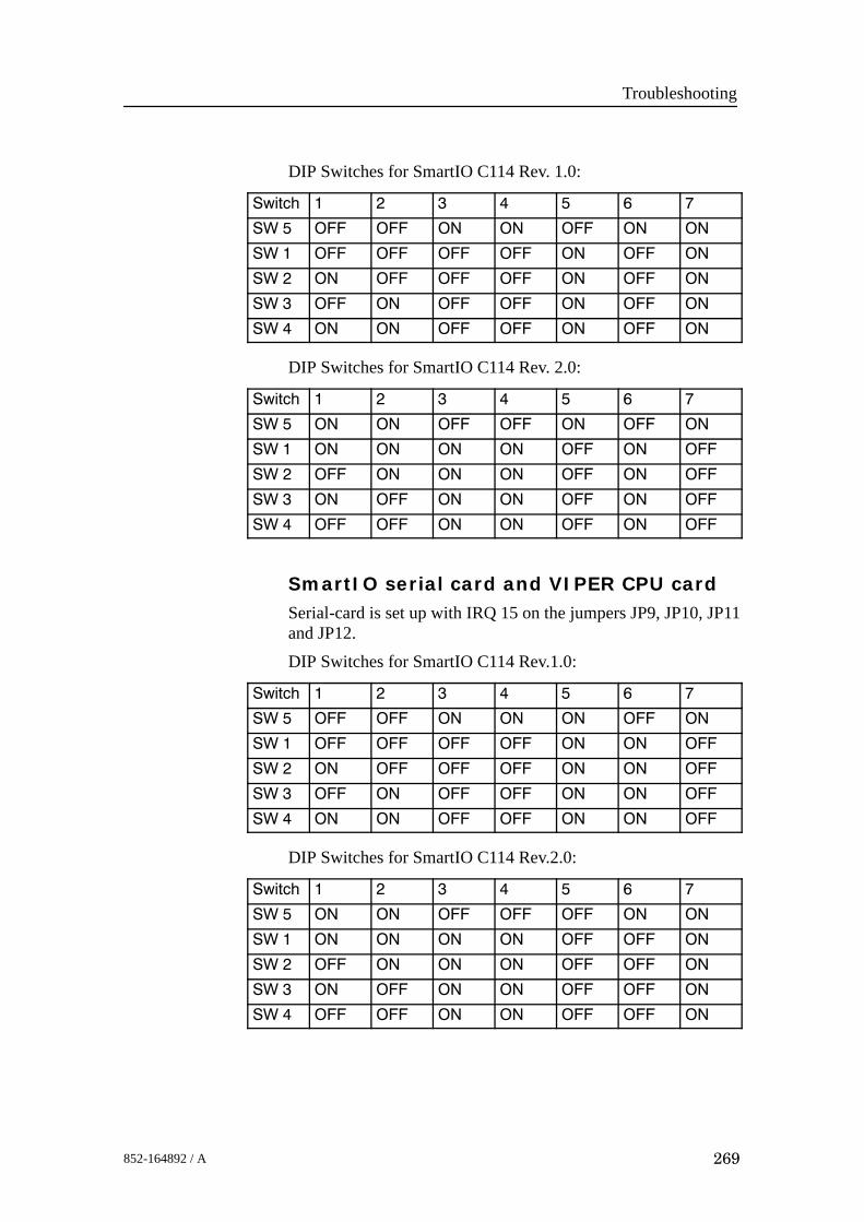
Troubleshooting
269852-164892 / A
DIP Switches for SmartIO C114 Rev. 1.0:
Switch 1 2 3 4 5 6 7
SW 5 OFF OFF ON ON OFF ON ON
SW 1 OFF OFF OFF OFF ON OFF ON
SW 2 ON OFF OFF OFF ON OFF ON
SW 3 OFF ON OFF OFF ON OFF ON
SW 4 ON ON OFF OFF ON OFF ON
DIP Switches for SmartIO C114 Rev. 2.0:
Switch 1 2 3 4 5 6 7
SW 5 ON ON OFF OFF ON OFF ON
SW 1 ON ON ON ON OFF ON OFF
SW 2 OFF ON ON ON OFF ON OFF
SW 3 ON OFF ON ON OFF ON OFF
SW 4 OFF OFF ON ON OFF ON OFF
SmartIO serial card and VIPER CPU cardSerial-card is set up with IRQ 15 on the jumpers JP9, JP10, JP11and JP12.DIP Switches for SmartIO C114 Rev.1.0:
Switch 1 2 3 4 5 6 7
SW 5 OFF OFF ON ON ON OFF ON
SW 1 OFF OFF OFF OFF ON ON OFF
SW 2 ON OFF OFF OFF ON ON OFF
SW 3 OFF ON OFF OFF ON ON OFF
SW 4 ON ON OFF OFF ON ON OFF
DIP Switches for SmartIO C114 Rev.2.0:
Switch 1 2 3 4 5 6 7
SW 5 ON ON OFF OFF OFF ON ON
SW 1 ON ON ON ON OFF OFF ON
SW 2 OFF ON ON ON OFF OFF ON
SW 3 ON OFF ON ON OFF OFF ON
SW 4 OFF OFF ON ON OFF OFF ON

EM 300 Complete version
270 852-164892 / A
Blank page

Replacement procedures
271852-164892 / A
9 REPLACEMENT PROCEDURES
9.1 Introduction
OverviewThis chapter presents the basic procedures for disassembly andreassembly of the replaceable parts in the EM 300 sonar system.

EM 300 Complete version
272 852-164892 / A
Tools requiredA standard tool set is required to perform the removal andreplacement of the modules. This tool set should contain thefollowing tools:• Cabinet key• Standard screwdrivers in different widths and lengths• Standard cross-slot screwdrivers in different widths and
lengths• Allen keys in metric sizes• Philips screwdrivers in different sizes• Pozidrive screwdrivers in different sizes• Flat nosed pliers• Lap jointed pliers• Wire cutters• Soldering iron• Open ended and ring spanners in metric sizes• Adjustable spanners• Socket setThe following expendables are recommended:• Solder• Wire straps in different sizes

Replacement procedures
273852-164892 / A
9.2 Transceiver Unit procedures
Overview for Transceiver Unit 125-210131The Line Replaceable Units (LRUs) in the EM 300 TransceiverUnit with reg.no. 125-210131 are:• Processing rack:
- 4-Ports Serial Line Board- Beamformer & Signal Processor 1/2 (BSP1 and BSP2)- Ethernet Adapter- ROM bank- Control Processor Board (486)- Power supply- Fan- Motherboard
• Receiver rack:- Transmitter/Receiver board (x4) (TRB)- Low Voltage Power Unit (LVPU)- High Voltage Power Supply (HVPU)- Signal Processor Board RX (SPRX)- Capacitor bank
• Transmitter rack:- 64-Channel Transmitter Board (TX64)- Signal Processor Board TX (SPTX)
• Other devices:- AC mains fuse and filters- Fuses- Fan drawers
Overview for Transceiver Unit 125-211293The Line Replaceable Units (LRUs) in the EM 300 TransceiverUnit with reg.no. 125-211293 are:• Processing rack:
- 4-Ports Serial Line Board- Beamformer & Signal Processor 1/2 (BSP1 and BSP2)- Ethernet Adapter- DiskOnModule flash disk (mounted on the CPU board)- Control Processor Board (586)- Power supply X 2 (HN5-9/OVP-A and OLD-12/15BB)- Fan- Motherboard

EM 300 Complete version
274 852-164892 / A
• Receiver rack:- Transmitter/Receiver board (x4) (TRB)- Low Voltage Power Unit (LVPU)- High Voltage Power Supply (HVPU)- Signal Processor Board RX (SPRX)- Capacitor bank
• Transmitter rack:- 64-Channel Transmitter Board (TX64)- Signal Processor Board TX (SPTX)
• Other devices:- AC mains fuse and filters- Fuses- Fan drawers
Overview for Transceiver Unit 125-218182The Line Replaceable Units (LRUs) in the EM 300 TransceiverUnit with reg.no. 125-218182 are:• Processing rack:
- 4-Ports Serial Line Board- Beamformer & Signal Processor 1/2 (BSP1 and BSP2)- DiskOnFlash module (mounted on the CPU board)- Control Processor (CPU) Board (Viper)- Power supply X 3
(OLD-12C, OLD-12/15BB and IHE5-18)- Fan- Motherboard
• Receiver rack:- Transmitter/Receiver board (x4) (TRB)- Low Voltage Power Unit (LVPU)- High Voltage Power Supply (HVPU)- Signal Processor Board RX (SPRX)- Capacitor bank
• Transmitter rack:- 64-Channel Transmitter Board (TX64)- Signal Processor Board TX (SPTX)
• Other devices:- AC mains fuse and filters- Fuses- Fan drawers

Replacement procedures
275852-164892 / A
The replacement procedures for these parts are described in thefollowing disassembly & reassembly procedures.
Circuit boards and modules
Introduction
The Transceiver Unit holds three wired racks. All the wiredracks hold plug-in circuit boards and modules. The replacementof these modules is described in this procedure.The system must be switched off prior to disassembly. Access isgained to the wired racks by opening the front door of theTransceiver Unit. To open the front door, use the special tool forthe cabinet doors. Before removing any modules, be sure thatvoltmeter on front of the High Voltage Supply shows zero (0)voltage.• Processing rack→ The circuit boards and modules in the Processing rack are
shown on page 55.• Receiver rack→ The circuit boards and modules in the Receiver rack are shown
on page 72.• Transmitter rack→ The circuit boards and modules in the Transmitter rack are
shown on page 49.
Disassembly procedure
1 Remove the front mounted cables from the applicablecircuit boards.
2 Release the thumb-screws if required.3 Pull the board/unit carefully out.
Software replacement→ Refer to page 280.
Replacement of all the circuit boards
In some cases, it might be necessary to replace all the circuitboards in the Transceiver Unit. The following procedure is thensuggested:1 Open the front door of the Transceiver Unit as previously
described.2 Switch off the circuit breaker on the right side of the
Processor rack, and pull out the contact on the LowVoltage Power Unit. Wait until voltmeter on the HighVoltage Supply shows “zero” volts.

EM 300 Complete version
276 852-164892 / A
3 Unplug the front mounted flat ribbon cable connectors onthe Transmitter/Receiver boards and 64-ChannelTransmitter (TX64) circuit boards. Use care; do not pullby the cables !
4 Remove the circuit boards and modules carefully.5 Insert new circuit boards and modules in reverse order.
Mount the front mounted flat ribbon cable connectors andthe front covers.
6 Check that the circuit boards and modules have beeninstalled in their correct locations! Refer to the applicablepictures and drawings.
Fan drawers→ Refer to page 282.
Heater element
IntroductionA heater element is mounted on the right wall in the bottomwired rack. The heater is included to ensure the temperatureinside the cabinet remains stable when the system is switchedoff, thus preventing condensation forming inside the cabinet.The heater is a commercial item.
Disassembly procedure1 Open the front door of the Transceiver Unit.2 Switch off the front mounted circuit breaker located on the
right side of the Processor rack3 Open up the middle section of the cabinet
Caution Do not open the middle cabinet while in rough sea. Thecabinet is heavy, and sudden movements may causedamage or injury to personnel.
4 Note down the location of the wires prior to removal !5 Locate the heater. Follow the heater cables to the terminal
block, and disconnect the wires.6 Loosen the rail support holding the heater in place, and
allow the heater to slide out (forward).
Reassembly procedureThe new heater is replaced reversing the above procedure.
High Voltage Power Supply
IntroductionThe power supply is located in the Receiver Rack, between theLow Voltage Power Supply and the Capacitor bank.

Replacement procedures
277852-164892 / A
The High Voltage Power Supply (HVPS) is located in themiddle wired rack. It is mounted on the right side of the LowVoltage Power Unit, behind the front panel.
Disassembly procedure
1 Open the front door of the Transceiver Unit.2 Switch off the circuit breaker on the right side of the
Processor rack, and pull out the contact on the LowVoltage Power Unit.
Caution Do not pull out the unit before the voltmeter showszero (0) voltage.
3 Unbolt the unit. It is mounted with four captive-bolts sothey cannot fall out. The nuts and spring washers areaccessible.
4 Locate the power supply.5 Note down the location of the wires prior to removal !6 Disconnect the wires.7 Unbolt the screws that holds the power supply.8 Remove the power supply.
Reassembly procedure
The new power supply is replaced by reversing the aboveprocedure.
AC mains circuit breaker
Introduction
The circuit breaker is located on the right side of the Processingrack.
Disassembly procedure
1 Switch off the AC input to the cabinet.
2 Open the front door of the Transceiver Unit. Open up themiddle part of the cabinet and swing the middle sectiontowards the left.
Caution Do not open the middle cabinet while in rough sea. Thecabinet is heavy, and sudden movements may causedamage or injury to personnel.
Caution Make sure that the input AC voltage is switched offprior to commencing the disassembly.

EM 300 Complete version
278 852-164892 / A
3 Unbolt the 4 screws on each side of the Processor rack toloosen the entire rack. Push the rack carefully backwardsuntil the screws that hold the circuit breaker are availablewith a screwdriver. It might be necessary to loosen somestraps that holds the cables.
4 Note down the location of the wires prior to removal !5 Disconnect the wires on the faulty circuit breaker.6 Unbolt the screws that holds the circuit breaker7 Remove the circuit breaker carefully.
Reassembly procedure
Replace by reversing the above procedure.
AC mains filter
Introduction
The mains AC filter is located on the bottom plate of theTransceiver Unit.
Disassembly procedure
1 Switch off the AC input to the cabinet.2 Open the front door of the Transceiver Unit. Open up the
middle part of the cabinet and swing the middle sectiontowards the left.
Caution Do not open the middle cabinet while in rough sea. Thecabinet is heavy, and sudden movements may causedamage or injury to personnel.
Caution Make sure that the input AC voltage is switched offprior to commencing the disassembly.
3 Note down the location of the wires prior to removal !4 Disconnect the wires on the faulty AC filter.5 Unbolt the 2 screws that holds the AC filter from the
undeside of the bottom plate and remove the filter.
Reassembly procedure
Replace by reversing the above procedure.
Fuse replacement
Introduction
The Transceiver Unit holds several power supplies. Two ofthese are equipped with primary fuses.
Replacement procedures
279852-164892 / A
• Low Voltage Power Unit• High Voltage Power Supply
Disassembly procedure
The fuses on these power supplies are front mounted. Nodisassembly is required.
Reassembly procedure
Replace with the same type of fuse.
TX64 Fuse replacement
Introduction
The 64-Channel Transmitter Board (TX64) is equipped witheight fuses. These are located side by side on the circuit board.Each fuse protects a group of eight output channels.• Physical dimensions: 5 x 20 mm• Rating: 4 AIf any of the fuses blow, the appropriate group of transmitterswill fail.
Disassembly procedure
1 Open the front door of the Transceiver Unit.2 Remove the flat ribbon cables on the TX64 boards.3 Pull out the board.
Reassembly procedure
Reverse the above procedure.

EM 300 Complete version
280 852-164892 / A
Software replacement
Overview
Normally the spare boards are fully equiped with software. Ifthis is not the case, follow the instructions below.Several of the circuit boards in the wired racks hold software ononboard PROMs and PALs. These devices must be moved froma faulty circuit board to a new spare. This is a delicate job, andthe circuit board and the memory devices must be handled withgreat care.The following precautions must be taken:• The software replacement operation must be performed on a
stable workbench or table.• The table must be covered with an antistatic mat connected to
the ship’s ground• The maintenance technician or engineer must wear a
grounding bracelet, firmly connected to the ship’s ground.• All circuit boards must be stored in anti-static bags while not
in use.Each software device is identified with a white label. This labelholds the following information:
- Circuit board E.g. SPB- Device number E.g. U15- Software version E.g. V1.1- Date E.g. 90.09.15- Checksum (in hexadecimal) E.g. 05A3
Disassembly
1 Identify the device to be removed and write down thelocation of pin 1.
2 Use a small screwdriver or a special extraction tool andremove the device carefully from its socket on the sourcecircuit board.
3 Enure that the device is lifted as vertically as possible toprevent damage to the pins.
Caution Once the device has been removed, handle it with care!
Insertion
1 Identify the socket where the device is to be located, placethe device carefully into the socket, and ensure that it isorientated correctly.

Replacement procedures
281852-164892 / A
2 Press the device gently but firmly into the socket usingeven pressure over the whole surface area.
3 After insertion, check that all the pins are properlyinserted into the socket, and that no pins are bent.
Resassembly procedure
Note Several circuit boards contain software mounted in PROMs, orother hardware devices. In the event of board replacement,ensure that the correct firmware devices are mounted and thatcorrect links are fitted.
1 Locate the new module in the rack ensuring that module iscorrectly positioned in the guide rails.
2 Slide the board gently into the rack ensuring that the rearconnectors mate correctly. Secure the thumb-screws.
3 Reconnect the flat ribbon cables (if any) onto the front ofthe board. Ensure that no pins are bent or broken, and thatthe plugs connect properly. Clip the locks onto theconnectors to ensure the board is held securely in position.
4 Close the cabinet door.

EM 300 Complete version
282 852-164892 / A
Fan drawers
Introduction
There are several fan drawers in the sonar system. Three fansare located in the bottom of the Receiver Rack and theTransmitter Rack. They are either 230 Vac or 110 Vac. The twofans in the Processing Rack are 12 Vdc.
The sonar system must be switched off. Access is gained to thewired racks by opening the front door of the Transceiver Unit.
Disassembly procedure
The fan drawers located underneath the wired racks:
1 Gain access to the wired rack.
2 Twist the right thumb-screw on the fan draweranti-clockwise a few turns, and the left thumb-screwclockwise a few turns.
3 Pull out the fan drawer.
The two fan drawers located in the Processing Rack:
1 Gain access to the Processing Rack by opening the frontdoor.
2 Loosen the ribbon cable connected to RXB-P11.
3 Unscrew the eight screws holding the Processing Rack (inthe front) and carefully pull it out. The screws are locatedon top and bottom of the rack.
Note Some cables might have to be loosened.
4 The fans are located on the right hand side.
Reassembly procedure
The fan drawers located underneath the wired racks:
1 Push the drawer in. Make sure that the unit connectsproperly to the rear socket.
2 Secure the unit with the thumbscrews.
3 Close the cabinet door.
The two fan drawers located in the Processing Rack:
1 Replace the fan back on the chassis.
2 Put the chassis back into the rack.
3 Close the front door.

Datagram formats
283852-164892 / A
10 DATAGRAM FORMATS
10.1 Introduction
Note The information herein is common for the EM 3000, EM 2000,EM 1002, EM 300 and EM 120 multibeam echo sounders. Someof the information may not be relevant for your specific system.Please disregard this.
Note The information in this document is not valid for the EM 12, EM100, EM 950 and EM 1000 multibeam echo sounders.
The formats for data input and output to and from the EM Seriesmultibeam echo sounders are described here. The informationgiven here is valid for the Kongsberg Maritime multibeam echosounders introduced after 1995.
Note In order to meet special customer requirements, KongsbergMaritime may have to change the datagram formats describedhere. The formats presented in this document may therefore bealtered without prior notice, although backward compatibilitywill be maintained as far as possible. Before software is writtenin accordance with this document, it is strongly recommended tocontact Kongsberg Maritime to ensure that the latest version isused, and that any planned changes are taken into account.
10.2 Presentation formatThe format description is according to the NMEA 0183 standardfor ASCII fields, with the ASCII character(s) given as follows:• “x.x” defines a variable length numerical field, with
optionally included decimal point and sign.• “c--c” defines a variable length field of printable characters.
• “x--x” defines a variable length field of numeric characters.
• “a_ _” defines a fixed length field of alphabetical characters(for example “aa”= two character long field.
• “x_ _” defines a fixed length field of numeric characters.
For binary fields, the length is given in number of bytes plus“U” for unsigned and “S” for signed data.

EM 300 Complete version
284 852-164892 / A
10.3 Input datagrams
IntroductionOnly a limited number of input formats from external sensorsare accepted. These are primarily in accordance with the NMEA0183 specification, or based upon the principles of thatspecification.
Note The majority of these formats have not been defined byKongsberg Maritime. Thus, these formats are not controlled byKongsberg Maritime.Almost all input formats are ASCII. Serial line input on themultibeam echo sounder’s Processing Unit is most common, butsome datagrams - which are not time critical - are interfaced onserial line(s) or Ethernet to the Operator Station.
Position
OverviewThe EM Series accepts position data in the following formats:• NMEA 0183 GGA• GGK• SIMRAD 90• With the GGA and GGK datagrams, information contained in
NMEA 0183 VGST and VTG datagrams will also beaccepted and used.
• A datagram format for Sonar Head depth is provided for theEM 3000 and the EM 2000. Note that the format is the sameas that used by the Paroscientific Digiquartz pressure sensor.This format may also be used for input of for examplevarying datum heights or other special height information onall models.
• A datagram format for input of tidal height is provided.The GGA format is given below according to the NMEA 0183version 2.30 description. Additional data at the end of thedatagram is accepted to cater for users who need to logadditional information than what is provided in the standardformat. This is also supported with the GGK format. The totaldatagram length must be limited to less than 128 bytes ifadditional data is included.
Note While such additional data will be logged, it is up to the user toextract the data to whatever use is required in postprocessing.Anyone using this possibility must also be aware that any futurechanges to the GGA or GGK format may require modificationsin the datagrams and hence data decoding.

Datagram formats
285852-164892 / A
The GGK format was originally defined by the US ArmyCorps of Engineers for their tests with kinematic GPS.Trimble’s proprietary version of the format is supported. If anychanges to the format are made if it becomes part of the NMEAstandard, this will be implemented.
To preserve the inherent accuracy of the kinematic GPS data itis necessary to correct the data for vessel motion. This requiresaccurate timing synchronisation between the motion sensor andthe GPS receiver. It is therefore imperative that:
• the position datagram has a constant and known time delay
or
• the time stamp in the datagram is actually the time of theposition fix, that synchronisation to the 1 PPS signal of theGPS receiver is enabled, and that the system clock has beenset correctly
As neither of these conditions may not be possible to achievewith a sufficient accuracy, the application of motion correctionis operator selectable. Motion compensation may be applied toany position input, not only kinematic GPS.
In addition to position data from the GGA or GGK datagrams,speed and course over ground from NMEA VTG datagramsmay also be copied into the position output datagram. Thesevalues may be useful in filtering of the positioning duringpostprocessing. If a VTG datagram does not follow the GGA orGGK datagram the course and speed fields of the outputdatagrams will be set to their invalid values.
The “Standard deviation of semi-major axis of error ellipse”field in a NMEA GST datagram may also be copied to theposition output datagram as its ”Measure of position fixquality”. It will then replace the use of the HDOP or DOP fieldin the GGA or GGK datagram respectively to derive this field.This must be enabled by the operator however, and then if theGST datagram does not follow the GGA or GGK the qualitymeasure field of the output datagram will be set to its invalidvalue.
As an alternative to GGA, the SIMRAD 90 format positiondatagram may be used. The SIMRAD 90 format is intended tobe the format of choice when the positioning system is not astand-alone GPS receiver supplying GGA or GGK formatdatagrams. The SIMRAD 90 format can in addition to globallongitude latitude coordinates also be used for Northing Eastingtype projection coordinates (e.g. UTM).

EM 300 Complete version
286 852-164892 / A
To cater for applications where the EM 2000 or EM 3000 SonarHead is mounted on a subsea vehicle, the original SIMRAD 90format has been expanded to allow inclusion of the depth of thevehicle in addition to its horizontal position in longitude latitudeor Northing Easting coordinates.Also for EM 2000 and EM 3000 applications with separatesurface and underwater positioning systems, the SIMRAD 90format will allow the underwater position to be provided relativeto the vessel, with the vessel surface position given in a separateGGA, GGK or SIMRAD 90 datagram.
GGA Datagram
Data Description Format Valid range NoteStart identifier = $ Always 24h --- ---Talker identifier aa Capital letters ---Sentence formatter Always GGA, --- ---UTC of position hhmmss.ss, 000000 to
235959.9...---
Latitude in degrees and minutes, plusoptional decimal minutes
llll.ll, 0000 to 9000.0... ---
Latitude --- N/S a, N or S ---Longitude in degrees and minutes, plusoptional decimal minutes
yyyyy.yy, 00000 to 18000.0... ---
Longitude --- E/W a, E or W ---GPS quality indicator x, 0 to 8 1Number of satellites in use xx, 00 to 12 ---HDOP x.x, 0 to 1Antenna altitude re mean sea level (geoid) x.x, --- 2Units of antenna altitude M, --- ---Geoidal separation (sea level re WGS---84) x.x, --- 2Units of geoidal separation M, --- ---Age of differential GPS data x.x, --- ---Differential reference station id xxxx, 0000 to 1023 ---Possible extension of datagram with userdefined data (addition to NMEA format)
c--- ---c --- 3
Checksum *hh --- ---End of sentence delimiter = CRLF Always 0Dh 0Ah --- ---
Note 1The HDOP (Horizontal Dilution Of Precision) value will bescaled and copied to the ”Measure of position fix quality” fieldin the position output datagram. The scale factor depends uponthe GPS quality indicator’s value:• 1 - (SPS or standard GPS) => 1000• 2 - (differential GPS) => 100

Datagram formats
287852-164892 / A
• 3 - (PPS or precise GPS) => 200, but 10 if GGA is treated asRTK. (See Note 2)
• 4 - (kinematic GPS with fixed integers) => 10
• 5 - (kinematic GPS with floating integers) => 50
• 6 - (estimated or dead reckoning mode) => 1000
• 7 - (manual input mode) => 1000
• 8 - (test mode) => 1000, but 10 if GGA is treated as RTK.(See Note 2)
• The ”Measure of position fix quality” field will be set to65534 (largest valid number) if the indicator is zero(non-valid position).
This scaling is used to give at least a relatively correct positionfix quality change (in the order of cm) if there are dropouts indifferential, precise or kinematic measurements, althoughHDOP is not a meter value.Note 2When the quality factor is 4 or 5 a height output datagram isautomatically generated, and also if the quality factor is 3 or 8and the operator has set the GGA position to be an RTKposition. The height is the sum of these two fields which areassumed positive upwards (antenna above geoid).Note 3The maximum length of this field should is restricted so that thetotal datagram length is not more than 127 bytes.
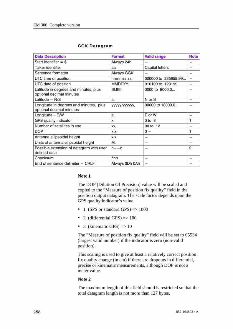
EM 300 Complete version
288 852-164892 / A
GGK Datagram
Data Description Format Valid range NoteStart identifier = $ Always 24h --- ---Talker identifier aa Capital letters ---Sentence formatter Always GGK, --- ---UTC time of position hhmmss.ss, 000000 to 235959.99... ---UTC date of position MMDDYY, 010100 to 123199 ---Latitude in degrees and minutes, plusoptional decimal minutes
llll.llllll, 0000 to 9000.0... ---
Latitude --- N/S a, N or S ---Longitude in degrees and minutes, plusoptional decimal minutes
yyyyy.yyyyyy, 00000 to 18000.0... ---
Longitude – E/W a, E or W ---GPS quality indicator x, 0 to 3 1Number of satellites in use xx, 00 to 12 ---DOP x.x, 0 --- 1Antenna ellipsoidal height x.x, --- ---Units of antenna ellipsoidal height M, --- ---Possible extension of datagram with userdefined data
c--- ---c --- 2
Checksum *hh --- ---End of sentence delimiter = CRLF Always 0Dh 0Ah --- ---
Note 1
The DOP (Dilution Of Precision) value will be scaled andcopied to the ”Measure of position fix quality” field in theposition output datagram. The scale factor depends upon theGPS quality indicator’s value:
• 1 (SPS or standard GPS) => 1000
• 2 (differential GPS) => 100
• 3 (kinematic GPS) => 10
The ”Measure of position fix quality” field will be set to 65534(largest valid number) if the indicator is zero (non-validposition).
This scaling is used to give at least a relatively correct positionfix quality change (in cm) if there are dropouts in differential,precise or kinematic measurements, although DOP is not ameter value.
Note 2
The maximum length of this field should is restricted so that thetotal datagram length is not more than 127 bytes.

Datagram formats
289852-164892 / A
GST Datagram
Data Description Format Valid range NoteStart identifier = $ Always 24h --- ---Talker identifier aa Capital letters ---Sentence formatter Always GST, --- ---UTC time of the GGA or GGK associated with thissentence
hhmmss.ss, 000000 to235959.9...
---
RMS value of the standard deviation of the rangeinputs to the navigation process
x.x, 0 --- ---
Standard deviation of semi---major axis of errorellipse in meters
x.x, 0 --- 1
Standard deviation of semi---minor axis of errorellipse in meters
x.x, 0 --- ---
Orientation of semi---major axis of error ellipse indegrees from true North
x.x, 0 --- ---
Standard deviation of latitude error in meters x.x, 0 --- ---Standard deviation of longitude error in meters x.x, 0 --- ---Standard deviation of altitude error in meters x.x, 0 --- ---Checksum *hh --- ---End of sentence delimiter = CRLF Always 0Dh 0Ah --- ---
Note 1The term ”standard deviation of error” in the format descriptionimplies that the GST datagram was originally intended tocontain statistics. Such a use may invalidate the intended usehere, namely to derive a better quality measure than the HDOPin the GGA or DOP in the GGK datagram. Thus, the GSTdatagram should only be used if one is certain that this fieldcontains the semi-major axis of the error ellipse for the latestfix, and not a statistical measure calculated over a number offixes.
VTG Datagram
Data Description Format Valid range NoteStart identifier = $ Always 24h --- ---Talker identifier aa Capital letters ---Sentence formatter Always VTG, --- ---Course over ground, degrees true x.x,T, 0 to 359.9... 1Course over ground, degrees magnetic x.x,M, 0 to 359.9.. 1Speed over ground, knots x.x,N, 0 --- 1Speed over ground, km/h x.x,K, 0 --- 1Mode indicator a A,D,E,M,S or N ---Checksum *hh --- ---End of sentence delimiter = CRLF Always 0Dh 0Ah --- ---

EM 300 Complete version
290 852-164892 / A
Note 1
Only true course and the first valid speed field will be used.
Simrad 90 Datagram
Data Description Format Length Valid range NoteStart identifier = $ Always 24h 1 --- ---Talker identifier aa 2 Capital letters ---Sentence formatter Always S90, 4 --- ---Date of position DDMMYY, 7 010100 to 311299 ---UTC of position as hour,minute, second, hundredth ofsecond
hhmmssss, 9 00000000 to23595999
---
Latitude in degrees, minutesand decimal minutes
xxxx.xxxx 9 0000.0000 to9999.9999
A
Hemisphere identifier a, 2 N or S ALongitude in degrees, minutesand decimal minutes, or depthin meters
xxxxx.xxxx 10 00000.0000 to18000.0000
A
Hemisphere or depth identifier a, 2 E, W or D ANorthing or range in meters xxxxxxxxx.x, 12 000000000.0 to
999999999.9B
Easting or depth in meters xxxxxxx.x, 10 0000000.0 to9999999.9
B
UTM zone number xx, 3 01 to 60 ---User defined central meridianlongitude or bearing
xxxxx.xxxx 10 00000.0000 to35999.9999
C
Hemisphere or bearingidentifier
a, 2 E, W, or B C
System descriptor x, 2 0 to 7 1Position fix quality indicator x, 2 0 to 9 and A to F 2Speed over ground in m/s xx.x, 5 00.0 to 99.9 3Course over ground in degrees xxx.x 5 000.0 to 359.9 3End of sentence delimiter =,CRLF
Always 2Ch 0Dh 0Ah 3 --- ---
Note 1
Value of system descriptor defines content of datagram asfollows. (Note that the Kongsberg Maritime EM 12, the EM 950and the EM 1000 multibeam echo sounders will only acceptvalues less than 3):
- 0 - The position is longitude latitude in global coordinatesgiven in the fields noted A.

Datagram formats
291852-164892 / A
- 1 - The position is Northing Easting on the Northernhemisphere given in the fields noted B. If the projection isdefined to be UTM the UTM zone number or a userdefinable central meridian longitude may be given in thefield noted C.
- 2 - As for system descriptor equal to 1, but the position ison the Southern Hemisphere.
- 3 - As for system descriptor equal to 0, but in addition thedepth is given in the Easting field noted B.
- 4 - As for system descriptor equal to 1, but in addition thedepth is given in the longitude field noted A.
- 5 - As for system descriptor equal to 2, but in addition thedepth is given in the longitude field noted A.
- 6 - The position is given relative to the vessel in a polarcoordinate system with horizontal range and depthprovided in the fields noted B and bearing re true North inthe field noted C.
- 7 - As for system descriptor 6, but the bearing is re thevessel centerline.
Note 2The position fix quality given in the position output datagramwill be derived from the quality indicator (this differs from theoriginal definition of the format) as follows (in m):
F E D C B A 9 8 7 6 5 4 3 2 1 0
0.01 0.02 0.05 0.1 0.2 0.5 1 2 5 10 20 50 100 200 500 1000
Note 3If these fields have valid values they will be copied toequivalent fields in the position output datagram. They may beused in filtering of the positioning during postprocessing. (Theoriginal definition of the format had line heading in the coursefield and its use was to orient real-time displays).
Tide input
Data Description Format Valid range NoteStart identifier = $ Always 24h --- ---Talker identifier a Capital letter ---Sentence formatter Always TIDE, --- ---Date and time of prediction /measurement
YYYYMMDDhhmm, 199601010000 to999912312359
---
Tide offset in meters and decimal meters x.x ±327.66 1Optional checksum *hh --- ---End of sentence delimiter = CRLF Always 0Dh 0Ah --- ---

EM 300 Complete version
292 852-164892 / A
Note 1A negative number will be assumed to indicate an increase insea level.
Depth or height input
Data Description Format Valid range NoteStart identifier = * Always 2Ah --- ---Sentence identifier ii 00 to 09 1Talker identifier ii 00 to 99 ---Depth or height in meters and decimal meters x.x --- 2End of sentence delimiter = CRLF Always 0Dh 0Ah --- ---
Note 1A sentence identifier equal to 00 is used for underwater vehicledepth, all other identifiers are customer specific (usually adatum height).Note 2If input is depth, it will be used in the depth output datagram tooffset the transmit transducer depth. If input is height, whichwill usually imply a time or position variable datum height, itsuse will depend on the sentence identifier and will beimplemented as required by a specific customer. Depth ispositive downwards. Depths may be scaled and offset byoperator settable constants:output_depth [m] = scale_factor * (input_depth - offset)
Attitude data
Overview
Attitude data is generally accepted on one or more serial inputport(s) as:• roll, pitch, heave and heading on one port,or• roll, pitch and heave on one port and heading separately on
another port.The data update rate should be commensurate with the expecteddynamics of the vessel (typically up to 100 Hz).The acceptable format for roll, pitch, heave and optionally alsoheading is a 10 byte long message originally defined in the EM1000 for use with digital motion sensors. It is supported by thefollowing sensors:
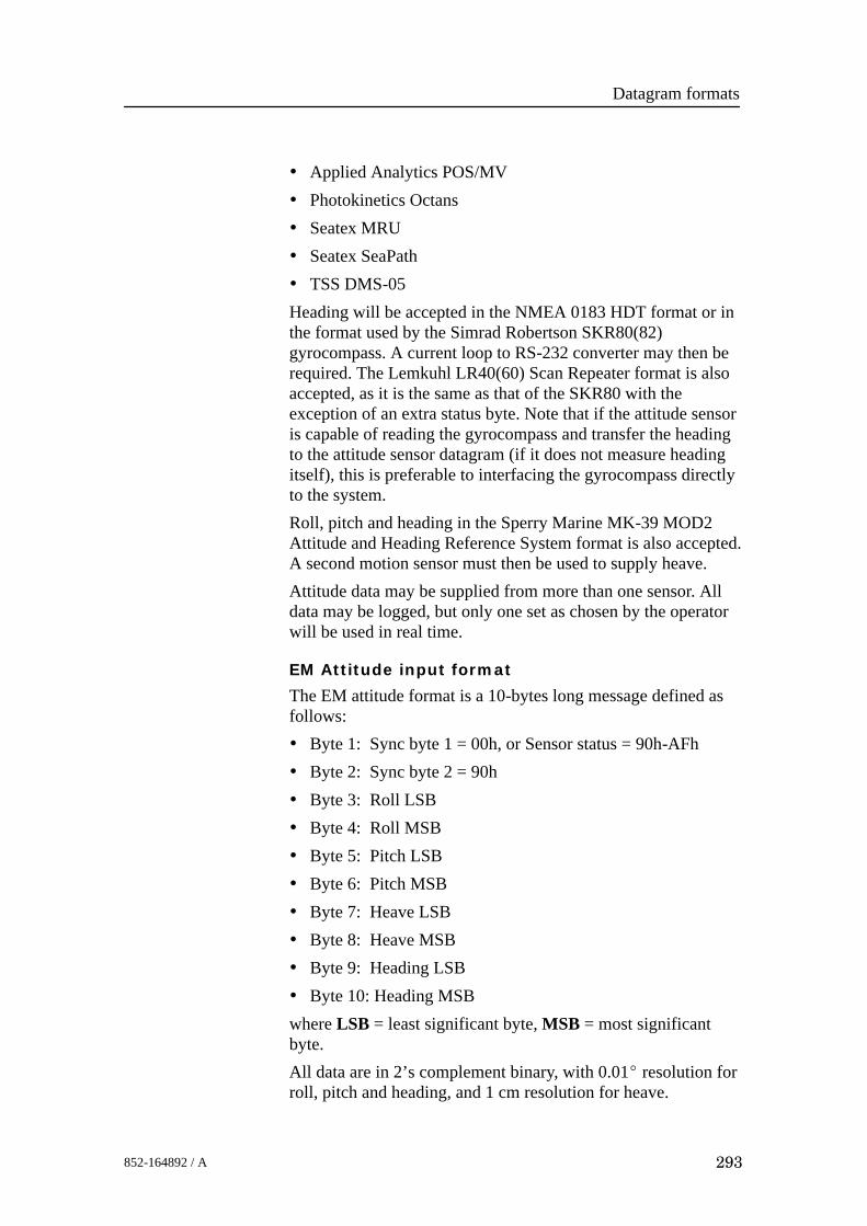
Datagram formats
293852-164892 / A
• Applied Analytics POS/MV• Photokinetics Octans• Seatex MRU• Seatex SeaPath• TSS DMS-05Heading will be accepted in the NMEA 0183 HDT format or inthe format used by the Simrad Robertson SKR80(82)gyrocompass. A current loop to RS-232 converter may then berequired. The Lemkuhl LR40(60) Scan Repeater format is alsoaccepted, as it is the same as that of the SKR80 with theexception of an extra status byte. Note that if the attitude sensoris capable of reading the gyrocompass and transfer the headingto the attitude sensor datagram (if it does not measure headingitself), this is preferable to interfacing the gyrocompass directlyto the system.Roll, pitch and heading in the Sperry Marine MK-39 MOD2Attitude and Heading Reference System format is also accepted.A second motion sensor must then be used to supply heave.Attitude data may be supplied from more than one sensor. Alldata may be logged, but only one set as chosen by the operatorwill be used in real time.
EM Attitude input format
The EM attitude format is a 10-bytes long message defined asfollows:• Byte 1: Sync byte 1 = 00h, or Sensor status = 90h-AFh• Byte 2: Sync byte 2 = 90h• Byte 3: Roll LSB• Byte 4: Roll MSB• Byte 5: Pitch LSB• Byte 6: Pitch MSB• Byte 7: Heave LSB• Byte 8: Heave MSB• Byte 9: Heading LSB• Byte 10: Heading MSBwhere LSB = least significant byte, MSB = most significantbyte.All data are in 2’s complement binary, with 0.01_ resolution forroll, pitch and heading, and 1 cm resolution for heave.

EM 300 Complete version
294 852-164892 / A
• Roll is positive with port side up with ±179.99_ valid range• Pitch is positive with bow up with ±179.99_ valid range• Heave is positive up with ±9.99 m valid range• Heading is positive clockwise with 0to 359.99_ valid range.Non-valid data are assumed when a value is outside the validrange.How roll is assumed to be measured is operator selectable,either with respect to the horizontal plane (the Hippy 120 orTSS convention) or to the plane tilted by the given pitch angle(i.e. as a rotation angle around the pitch tilted forward pointingx-axis). The latter convention (called Tate-Bryant in thePOS/MV documentation) is used inside the system in all datadisplays and in logged data (a transformation is applied if theroll is given with respect to the horizontal).Note that heave is displayed and logged as positive downwards(the sign is changed) including roll and pitch induced lever armtranslation to the system’s transmit transducer.This format has previously been used with the EM 950 and theEM 1000 with the first synchronisation byte always assumed tobe zero. The sensor manufacturers have been requested toinclude sensor status in the format using the firstsynchronisation byte for this purpose. It is thus assumed that:• 90h in the first byte indicates a valid measurements with full
accuracy• any value from 91h to 99h indicates valid data with reduced
accuracy (decreasing accuracy with increasing number)• any value from 9Ah to 9Fh indicates non-valid data but
normal operation (for example configuration or calibrationmode)
• and any value from A0h to AFh indicates a sensor errorstatus
Sperry Mk.39 Attitude input format
The format is 18 bytes long, and it is organised as 9 words. Themost significant byte of a word is transmitted first.• Word 1 AA55h• Word 2 Status and time• Word 3 Heading• Word 4 Roll• Word 5 Pitch

Datagram formats
295852-164892 / A
• Word 6 Heading rate
• Word 7 Roll rate
• Word 8 Pitch rate
• Word 9 Checksum (MSB) and 1’s complement of checksum(LSB)
All data are in 2’s complement binary. Heading is given within±180_, roll and pitch within ±90_. (Note however that thevalues +180_ and +90_ are not permitted, as these are one bittoo high.)
Heading is measured with reference to true North, and positivewhen the bow points eastwards. Roll is per definition a rotationangle (Tate-Bryant) and positive when the starboard side goesup. Pitch is positive when the bow goes down.
HDT format
Data Description Format Valid range NoteStart identifier = $ Always 24h --- ---Talker identifier aa Capital letters ---Sentence formatter Always HDT, --- ---Heading, degrees true x.x,T 0 to 359.9... ---Checksum *hh --- ---End of sentence delimiter = CRLF Always 0Dh 0Ah --- ---
SKR80 format
The SKR80 sends out a stream of data with four bytes for eachmeasurement. There is one byte for each digit:
• The first byte for the decimal degree (Example: xxx.X)
• The second for the degree (Example: xxX.x)
• The third for the 10’s degree (Example: xXx.x)
• The fourth for the 100’s degree (Example: Xxx.x)
The two uppermost bits of a byte are always zero, the next twobits give the digit, 00 for the decimal, 01 for the degree, 10 forthe 10’s degree, and 11 for the 100’s degree. The lowest fourbits give the digit value in 4-bit BCD format. As an example aheading of 234.5_ will give the four bytes 05h 14h 23h 32h. TheLR40 adds a fifth byte at the end for status with the two upperbits of the status byte set to 11 (11000000 for OK, 11001010 foralarm). This status byte is ignored.
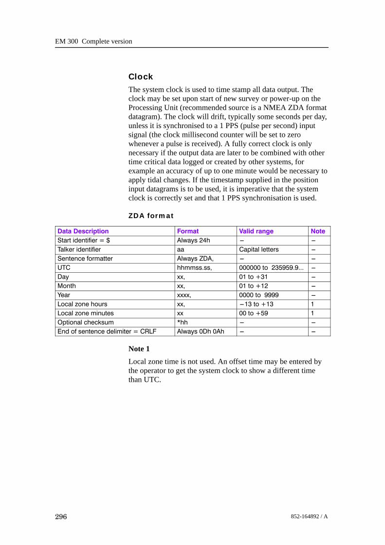
EM 300 Complete version
296 852-164892 / A
ClockThe system clock is used to time stamp all data output. Theclock may be set upon start of new survey or power-up on theProcessing Unit (recommended source is a NMEA ZDA formatdatagram). The clock will drift, typically some seconds per day,unless it is synchronised to a 1 PPS (pulse per second) inputsignal (the clock millisecond counter will be set to zerowhenever a pulse is received). A fully correct clock is onlynecessary if the output data are later to be combined with othertime critical data logged or created by other systems, forexample an accuracy of up to one minute would be necessary toapply tidal changes. If the timestamp supplied in the positioninput datagrams is to be used, it is imperative that the systemclock is correctly set and that 1 PPS synchronisation is used.
ZDA format
Data Description Format Valid range NoteStart identifier = $ Always 24h --- ---Talker identifier aa Capital letters ---Sentence formatter Always ZDA, --- ---UTC hhmmss.ss, 000000 to 235959.9... ---Day xx, 01 to +31 ---Month xx, 01 to +12 ---Year xxxx, 0000 to 9999 ---Local zone hours xx, ---13 to +13 1Local zone minutes xx 00 to +59 1Optional checksum *hh --- ---End of sentence delimiter = CRLF Always 0Dh 0Ah --- ---
Note 1Local zone time is not used. An offset time may be entered bythe operator to get the system clock to show a different timethan UTC.

Datagram formats
297852-164892 / A
Sound Speed
Overview
A sound speed profile may be loaded into the Operator Stationeither on a serial line or on Ethernet. Formats previously usedwith existing Kongsberg Maritime echo sounders (KongsbergMaritime ASCII and Binary Sound Velocity Profile inputdatagrams) will be accepted, but since their resolution in depthis limited to 1 m and the number of entries to 100, a new formatgiven below without these limitations is recommended. Thisformat is also accepted by the Kongsberg Maritime HIPAP andHPR underwater positioning systems (but not necessarilyvice-versa). Note that a complete profile may be pieced togetherfrom several datagrams and edited with the Operator Station’sSound Speed Editor.The new format is completely in ASCII and allows 9998 entrieswithout limitations in resolution. In addition to depth and soundspeed, it allows input of absorption coefficient, pressure,temperature and salinity or conductivity. The latter parametersmay be used to calculate depth, sound speed and absorptioncoefficient. Use of a depth dependent absorption coefficientallows a more accurate determination of bottom backscatterstrength.Note that this datagram may also be logged as output, retaininginformation not included in the standard sound speed profileoutput datagram, such as where and when the profile has beentaken.
Kongsberg Maritime SSP format
Data Description Format Length Valid range NoteStart identifier = $ Always 24h 1 --- ---Talker identifier aa 2 Capital letters ---Datagram identifier Always Sxx, 4 S00to S53 1,2Data set identifier xxxxx, 6 00000 to 65535 ---Number of measurements = N xxxx, 5 0001 to 9999 ---UTC time of data acquisition hhmmss, 7 000000 to 235959 3Day of data acquisition xx, 3 00 to 31 3Month of data acquisition xx, 3 00 to 12 3Year of data acquisition xxxx, 5 0000 to 9999 3N entries of the next 5 fields --- See note 4--- Depth in m from water levelor Pressure in MPa
x.x, 2 --- 0 to 12000.000 to 1.0000
---
--- Sound velocity in m/s x.x, 1 --- 1400 to 1700.00 ------ Temperature in _C x.x, 1 --- ---5 to 45.00 ---

EM 300 Complete version
298 852-164892 / A
Data Description NoteValid rangeLengthFormat--- Salinity in parts perthousand or Conductivity inS/m
x.x, 1 --- 0 to 45.000 to 7.000
---
Absorption coefficient in dB/km x.x 0 --- 0 to 200.00 ---Data set delimiter CRLF 2 0Dh 0Ah ---End of repeat cycleLatitude in degrees andminutes, plus optional decimalminutes
llll.ll, Variable 5--- 0000 to 9000.0... 5
Latitude --- N/S a, 2 N or S 5Longitude in degrees andminutes, plus optional decimalminutes
yyyyy.yy, Variable 6--- 00000 to 18000.0... 5
Longitude --- E/W a, 2 E or W 5Atmospheric pressure in MPa x.x, 1 --- 0 to 1.0000 5User given comments c--- ---c Variable --- 5Optional checksum *hh --- --- 6End of datagram delimiter =\CRLF
5Ch 0Dh 0Ah 3 --- ---
Note 1
The datagram identifier identifies what type of data is included.This is shown in the following table where D is depth, P ispressure, S is salinity, C is conductivity, c is sound speed, α isabsorption coefficients, and L is latitude. The notation c(T,S)indicates for example that the sound speed is to be calculatedfrom the temperature and salinity input data. When pressure isused, the atmospheric pressure must be given if the pressure isabsolute, otherwise the pressure must be given re the sea leveland the atmospheric pressure must be zero.
Identifier Input data Data to be usedS00 D, c D, cS10 D, c D, cS11 D, c, α D, c, αS12 D, c, T, S D, c, α(D,T,S,L)S20 D, T, S D, c(D,T,S,L)S21 D, T, S, α D, c(D,T,S,L), αS22 D, T, S D, c(D,T,S,L), α(D,T,S,L)S30 D, T, C D, c(D,T,C,L)S31 D, T, C, α D, c(D,T,C,L), αS32 D, T, C D, c(D,T,C,L), α(D,T,C,L)S40 P, T, S D(P,T,S,L), c(P,T,S,L)S41 P, T, S, α D(P,T,S,L), c(P,T,S,L), α

Datagram formats
299852-164892 / A
Identifier Data to be usedInput dataS42 P, T, S D(P,T,S,L), c(P,T,S,L), α(P,T,S,L)S50 P, T, C D(P,T,C,L), c(P,T,C,L)S51 P, T, C, α D(P,T,C,L), c(P,T,C,L), αS52 P, T, C D(P,T,C,L), c(P,T,C,L) , α(P,T,C,L)
Note 2S00 is a special case because then the sound speed profile willbe taken into use immediately without further operatorintervention. The checksum is then mandatory and must becorrect. Furthermore entries for zero depth and a deeper depththan expected during the survey must be included.Note 3Note that these fields have fixed length and leading zeros mustbe used.Note 4The depth or pressure field is always required while the otherfields are optional except for those required by the datagramidentifier. The field-delimiting commas must always be includedeven if the fields are empty.Note 5The positions, atmospheric pressure and comment fields areoptional. Note that the option field must not include a \. It isrecommended to include sensor type in the comment field.Note 6The checksum field is calculated between the $ and the *delimiters by exclusive OR’ing of all bytes. The checksum isrequired for datagram S00, but is optional for the others.
AML CALC format
Sound speed profile data input in the CALC format is used bythe Applied Microsystems Ltd. (AML) Total System Softwarepackage to support AML’s complete range of sensors is alsoaccepted.This format is an ASCII format with a five line header plus avariable number of lines with data as follows:Line 1: CALC, sn, date, depth increment, depth display• sn is the sensor serial number• date is current date taken from computer• depth increment is logging depth increment

EM 300 Complete version
300 852-164892 / A
• depth display is depth units (meters or decibars)Line 2: AML SOUND VELOCITY PROFILER S/N: xxxxxLine 3: DATE:xxxxx TIME:xxxxx• This line gives the Julian date and time at start of sensor
loggingLine 4: DEPTH OFFSET(M): xxxx.x• This line gives the pressure offset at sea level.Each line of data contains three numbers:• depth (in meters)• sound velocity (in m/s)• temperature (in degrees Celsius)Line 5: DEPTH(M) VELOCITY (M/S) TEMPERATURE (_C)The numbers are separated by a space, and each line isterminated with a linefeed (LF). The numbers shall all include adecimal point (xxx.x xxxx.x xx.xLF). The data are terminatedby a line with three zeros with two spaces between the zeros (00 0).
AML Smart Sensor format
The AML Smart SV&P sensor and later the SVPlus sensormay be used directly for sound speed profile input on serial lineto the Operator Station. Both these sensors may also be used tomeasure the sound speed at the transducer depth continuouslyduring the surveying.A measurement is requested from a smart sensor by issuing theword ’scan’ as four ASCII characters terminated by CR. Thereply from the SV sensor is a string of ASCII characters:
’S’CRLF xxxx.x CRLF>where xxxx.x is the measured sound speed in m/s (in bytes5-11). From the SV&P sensor the received string is:
’S’CRLF ±xxx.xx xxxx.x CRLF>where the first number is the pressure in decibars relative to thesurface and the second sound speed in m/s (in bytes 13-19).Smart sensors with autonomous output may also be used, bothP&SV (sound speed with pressure) and T&SP (sound speedwith temperature).The P&SV format is:
±xxx.xx xxxx.x CRLF
The T&SP format is:

Datagram formats
301852-164892 / A
±xx.xxx xxxx.x CRLF
The last field in both of these formats give the sound speed andthe first field either pressure in decibars or temperature indegrees Celsius.
Depth input from single beam echosounder
Overview
Depth datagrams from a single beam echo sounder are acceptedfor display and logging on the system. The following formatsare supported:• NMEA 0183 DBS• NMEA 0183 DPT• binary datagrams from the Kongsberg Maritime EA 500 echo
sounder series.
DBS format
Data Description Format Valid range NoteStart identifier = $ Always 24h --- ---Talker identifier aa Capital letters ---Sentence formatter Always DBS, --- ---Depth in feet x.x,f, 0.1 --- 1Depth in meters x.x,M, 0.1 --- 1Depth in fathoms x.x,F 0.1 --- 1Checksum *hh --- ---End of sentence delimiter = CRLF Always 0Dh 0Ah --- ---
Note 1The decoding priority will be meter field, feet field and fathomfield with the depth value extracted from the first field withvalid data.
DPT format
Data Description Format Valid range NoteStart identifier = $ Always 24h --- ---Talker identifier aa Capital letters ---Sentence formatter Always DPT, --- ---Depth in meters from the transducer x.x, 0.1 --- ---Offset of transducer from waterline in meters x.x, 0 --- 1Maximum range scale in use x.x --- ---
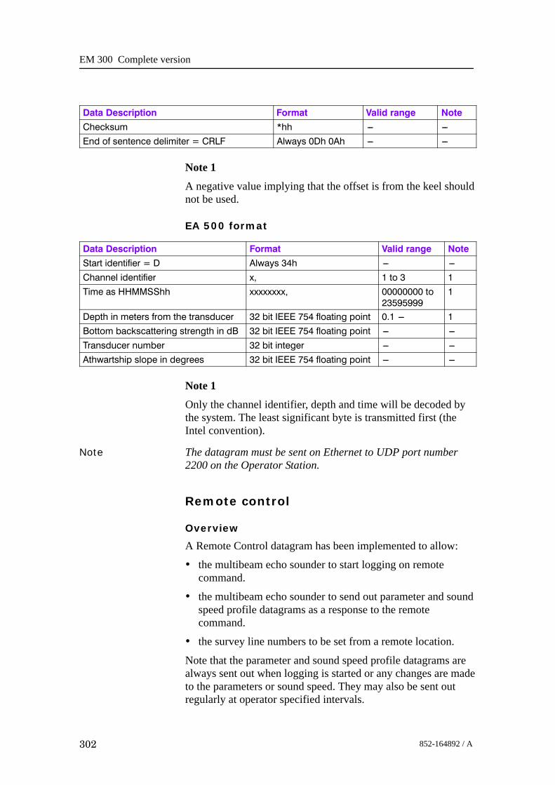
EM 300 Complete version
302 852-164892 / A
Data Description NoteValid rangeFormatChecksum *hh --- ---End of sentence delimiter = CRLF Always 0Dh 0Ah --- ---
Note 1
A negative value implying that the offset is from the keel shouldnot be used.
EA 500 format
Data Description Format Valid range NoteStart identifier = D Always 34h --- ---Channel identifier x, 1 to 3 1Time as HHMMSShh xxxxxxxx, 00000000 to
235959991
Depth in meters from the transducer 32 bit IEEE 754 floating point 0.1 --- 1Bottom backscattering strength in dB 32 bit IEEE 754 floating point --- ---Transducer number 32 bit integer --- ---Athwartship slope in degrees 32 bit IEEE 754 floating point --- ---
Note 1
Only the channel identifier, depth and time will be decoded bythe system. The least significant byte is transmitted first (theIntel convention).
Note The datagram must be sent on Ethernet to UDP port number2200 on the Operator Station.
Remote control
Overview
A Remote Control datagram has been implemented to allow:
• the multibeam echo sounder to start logging on remotecommand.
• the multibeam echo sounder to send out parameter and soundspeed profile datagrams as a response to the remotecommand.
• the survey line numbers to be set from a remote location.
Note that the parameter and sound speed profile datagrams arealways sent out when logging is started or any changes are madeto the parameters or sound speed. They may also be sent outregularly at operator specified intervals.

Datagram formats
303852-164892 / A
The datagram currently only allows survey related parameters tobe transferred to the system. It will later be expanded to allowremote setting of all installation parameters, and then basicallyas a copy of the standard start/stop datagram with identicalconventions with regard to order (which is not important), butrequiring only the parameters actually to be set.
Data Description Format Valid range NoteStart identifier = $ Always 24h --- ---Talker identifier aa Capital letters ---Datagram identifier Rxx, R00 to R20 1EM model number EMX=dddd, --- 2Responsible operator ROP=a--- ---a, --- ---Survey identifier SID=a--- ---a, --- ---Survey line number PLN=d..d, --- ---Survey line identifier (planned line no) PLL=d--- ---d, --- ---Comment COM=a--- ---a --- ---Optional checksum *hh --- ---End of datagram delimiter = \CRLF 5Ch 0Dh 0Ah --- ---
Note 1
Rxx defines what action the system is to take with respect topinging and logging of data in addition to changes in theparameters. Note that logging of survey data on local storage isnot affected, this is determined by operator control from themenu only.
• R00 - System to stop pinging (and logging if on)
• R10 - System to stop all logging (but continue or startpinging).
• R11 - System to start logging on new line to both local andremote
• R12 - System to star logging on new line but only to localstorage
• R13 - System to start logging on new line but only to remote
• R20 - System to send installation parameter datagram andsound speed profile datagrams to remote
Note 2
The EM model number will be required when parameterchanges are made with respect to transducer location or systemgain settings.
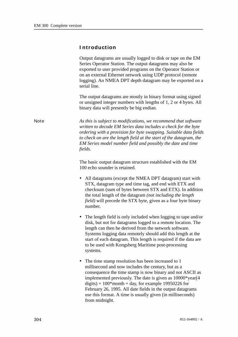
EM 300 Complete version
304 852-164892 / A
Introduction
Output datagrams are usually logged to disk or tape on the EMSeries Operator Station. The output datagrams may also beexported to user provided programs on the Operator Station oron an external Ethernet network using UDP protocol (remotelogging). An NMEA DPT depth datagram may be exported on aserial line.
The output datagrams are mostly in binary format using signedor unsigned integer numbers with lengths of 1, 2 or 4 bytes. Allbinary data will presently be big endian.
Note As this is subject to modifications, we recommend that softwarewritten to decode EM Series data includes a check for the byteordering with a provision for byte swapping. Suitable data fieldsto check on are the length field at the start of the datagram, theEM Series model number field and possibly the date and timefields.
The basic output datagram structure established with the EM100 echo sounder is retained.
• All datagrams (except the NMEA DPT datagram) start withSTX, datagram type and time tag, and end with ETX andchecksum (sum of bytes between STX and ETX). In additionthe total length of the datagram (not including the lengthfield) will precede the STX byte, given as a four byte binarynumber.
• The length field is only included when logging to tape and/ordisk, but not for datagrams logged to a remote location. Thelength can then be derived from the network software.Systems logging data remotely should add this length at thestart of each datagram. This length is required if the data areto be used with Kongsberg Maritime post-processingsystems.
• The time stamp resolution has been increased to 1millisecond and now includes the century, but as aconsequence the time stamp is now binary and not ASCII asimplemented previously. The date is given as 10000*year(4digits) + 100*month + day, for example 19950226 forFebruary 26, 1995. All date fields in the output datagramsuse this format. A time is usually given (in milliseconds)from midnight.

Datagram formats
305852-164892 / A
• The datagrams identify the multibeam echo sounder modeland its serial number. The system model number is 120 forthe EM 120, 300 for the EM 300, etc. For the EM 3000D (thedual head system) the model number was originally given as3002 and the serial number is that of Sonar Head number 1.However in the depth datagram model numbers 3003-3008are now used to also identify the actual transmit andsampling frequencies of the two heads. If only one head isactivate on the EM 3000D, it is coded as a single headsystem.
• Due care has been taken to include all parameters needed inpostprocessing in the relevant datagrams, with a minimum ofdata duplication. Where resolution of a data field is variable,a resolution descriptor is included.
• Invalid data are always identified by the highest positivenumber allowed in a field unless otherwise noted.
• A real-time parameter datagram has been added to enablelogging of parameters not used in postprocessing, but whichmay be important in checking the quality of the logged data,or to allow tracing of reasons for possible malfunctions.
• Attitude data as time continuous records and raw ranges andbeam pointing angles are logged to allow eventualpostprocessing corrections. The logged attitudes are valid atthe transmit transducer, and are corrected for any sensoroffsets.
Depth
Data Description Format Valid range NoteNumber of bytes in datagram 4U --- ---Start identifier = STX (Always 02h) 1U --- ---Type of datagram = D(epth data) (Always 44h) 1U --- ---EM model number(Example: EM 3000 = 3000)
2U --- 4
Date = year*10000 + month*100 + day(Example: Feb 26, 1995 = 19950226)
4U --- ---
Time since midnight in milliseconds(Example: 08:12:51.234 = 29570234)
4U 0 to 86399999 ---
Ping counter (sequential counter) 2U 0 to 65535 ---System serial number 2U 100 --- ---Heading of vessel in 0.01° 2U 0 to 35999 ---Sound speed at transducer in dm/s 2U 14000 to 16000 ---Transmit transducer depth re water level at time ofping in cm
2U 0 to 65536 1

EM 300 Complete version
306 852-164892 / A
Data Description NoteValid rangeFormatMaximum number of beams possible 1U 48 --- ---Number of valid beams = N 1U 1 to 254 ---z resolution in cm 1U 1 to 254 ---x and y resolution in cm 1U 1 to 254 ---Sampling rate (f) in Hzor
Depth difference between sonar heads in the EM3000D
2U
2S
300 to 30000
---32768 to 32766
3
4
Repeat cycle --- N entries of : 16*N --- ------ Depth (z) from transmit transducer
(unsigned for EM 120 and EM 300)2Sor2U
---32768 to +32766or1 to 65534
2
--- Acrosstrack distance (y) 2S ---32768 to 32766 2--- Alongtrack distance (x) 2S ---32768 to 32766 2--- Beam depression angle in 0.01° 2S ---11000 to 11000 3--- Beam azimuth angle in 0.01° 2U 0 to 56999 3--- Range (one---way travel time) 2U 0 to 65534 3--- Quality factor 1U 0 to 254 5--- Length of detection window (samples/4) 1U 1 to 254 ------ Reflectivity (BS) in 0.5 dB resolution)
(Example: ---20 dB = 216)1S ---128 to +126 ---
--- Beam number 1U 1 to 254 6End of repeat cycleTransducer depth offset multiplier 1S ---1 to +17 1End identifier = ETX (Always 03h) 1U --- ---Check sum of data between STX and ETX 2U --- ---
Note 1The transmit transducer depth plus the depth offset multipliertimes 65536 cm should be added to the beam depths to derivethe depths re the water line. The depth offset multiplier willusually be zero, except when the EM 2000/3000 Sonar Head ison an underwater vehicle at a depth larger than 655.36 m. Notethat the offset multiplier will be negative (-1) if the actual heaveis large enough to bring the transmit transducer above the waterline. This may represent a valid situation, but may also be due toan erroneously set installation depth of either the transducer orthe water line.Note 2The beam data are given re the transmit transducer or sonar headdepth and the horizontal location of the active positioningsystem’s antenna. Heave, roll, pitch, sound speed at thetransducer depth and ray bending through the water column

Datagram formats
307852-164892 / A
have been applied. On the EM 1002/2000/3000 the beam depthsmust be regarded as signed values to take into account beamswhich may be going upwards. On the EM 120/300 the beamdepths are always positive and the values are therefore unsigned.
Note 3
The range, beam depression angle (positive downwards and 90_for a vertical beam) and beam azimuth angle (re vesselcenterline) are given relative to the transducer (sonar head) atthe ping transmit time. Heave, roll, pitch and sound speed at thetransducer depth have been applied, but not ray bending. Thesevalues may thus be directly used for a new ray bendingcalculation with a revised sound speed profile to generate newsounding depths and positions without any need for usingattitude data. The range resolution in time is the inverse of therange sampling rate (i.e. nominally equivalent to about 70 µs forthe EM 3000).
Note that if the data need to be reprocessed with a new soundspeed at the transducer depth or new roll, pitch or heave values,full reprocessing starting with the raw range and beam angledata is required. Attitude data is also required in thisreprocessing, and both these data types will in the future belogged as standard.
If the beam azimuth angle has a value larger than 35999, thebeam pointing angle has replaced the beam depression angle,and the raw two-way travel time has replaced the one-way heaveand beam angle corrected travel time. The transmit tilt angleplus 54000 is given in the beam azimuth angle field. The use ofthis data definition is available on remote output to a port namedas “RawDepth...” for use by other systems which do their ownattitude and sound speed processing.
Note 4
In an EM 3000D the transmit transducer depth is that of SonarHead number 1, taking into account the depth offset multiplieras described in note 1. The range multiplier is replaced by thedifference in depth between Sonar Head number 1 and 2, i.e.head 2 depth is equal to head 1 depth (possibly modified withdepth offset multiplier) plus the depth difference. The rangesampling rates in Hz of the two heads is given through the EMmodel number according to the following table:
EM model number 3003 3004 3005 3006 3007 3008Sonar Head 1 13956 14293 13956 14621 14293 14621Sonar Head 2 14621 14621 14293 14293 13956 13956

EM 300 Complete version
308 852-164892 / A
Previously the model number of the EM 3000D was given as3002 with head sample rates of 13956 and 14621 Hzrespectively. The head depths in this case should be assumed tobe equal, and although the mathematical derivation of finalbeam depths would otherwise be the same as described above,the transmit transducer depth was not actually exactly that of thesonar heads.Note 5The quality number’s upper bit signifies whether amplitude (0)or phase (1) detection has been used. If amplitude the 7 lowestbits give the number of samples used in the centre of gravitycalculation. If phase the second highest bit signifies whether asecond (0) or first (1) order curve fit has been applied todetermine the zero phase range, and the 6 lowest bits indicatesthe quality of the fit (actually the normalized variance of the fitre the maximum allowed, i.e. with a lower number the better thefit).Note 6Beam 128 is the first beam on the second sonar head in an EM3000D dual head system.
Raw range and beam angle
Data Description Format Valid range NoteNumber of bytes in datagram 4U --- ---Start identifier = STX (Always 02h) 1U --- ---Type of datagram = F (Always 46h) 1U --- ---EM model number(Example: EM 3000 = 3000)
2U --- ---
Date = year*10000 + month*100 + day(Example: Feb 26, 1995 = 19950226)
4U --- ---
Time since midnight in milliseconds(Example: 08:12:51.234 = 29570234)
4U 0 to 86399999 ---
Ping counter (sequential counter) 2U 0 to 65535 ---System serial number 2U 100 --- ---Maximum number of beams possible 1U 48 --- ---Number of valid beams = N 1U 1 to 254 ---Sound speed at transducer in dm/s 2U 14000 to 16000 ---Repeat cycle --- N entries of : 8*N ------ Beam pointing angle in 0.01° 2S ---11000 to 11000 1--- Transmit tilt angle in 0.01° 2U ---2999 to 2999 1--- Range (two---way travel time) 2U 0 to 65534 1--- Reflectivity (BS) in 0.5 dB resolution 1S ---128 to 126 ------ Beam number 1U 1 to 254 ---

Datagram formats
309852-164892 / A
Data Description NoteValid rangeFormatEnd of repeat cycleSpare (Always 0) 1U --- ---End identifier = ETX (Always 03h) 1U --- ---Check sum of data between STX and ETX 2U --- ---
Note 1The beam pointing angle is positive to port and the transmit tiltangle is positive forwards for a normally mounted systemlooking downwards. The range resolution in time is the inverseof the range sampling rate given in the depth datagrams.
Seabed image
Data Description Format Valid range NoteNumber of bytes in datagram 4U --- ---Start identifier = STX (Always 02h) 1U --- ---Type of datagram = S(eabed image data) (Always 53h) 1U --- ---EM model number(Example: EM 3000 = 3000)
2U --- ---
Date = year*10000 + month*100 + day(Example: Feb 26, 1995 = 19950226)
4U --- ---
Time since midnight in milliseconds(Example: 08:12:51.234 = 29570234
4U 0 to 86399999 ---
Ping counter (sequential counter) 2U 0 to 65535 ---System serial number 2U 100 --- ---Mean absorption coefficient in 0.01 dB/km 2U 1 to 20000 1Pulse length in µs 2U 50 --- 1Range to normal incidence used to correct sampleamplitudes in no. of samples
2U 1 to 16384 ---
Start range sample of TVG ramp if not enough dynamicrange (0 else)
2U 0 to 16384 ---
Stop range sample of TVG ramp if not enough dynamicrange (0 else)
2U 0 to 16384 ---
Normal incidence BS in dB (BSN)(Example: ---20 dB = 236)
1S ---50 to 10 ---
Oblique BS in dB (BSO)(Example: ---1 dB = 255)
1S ---60 to 0 ---
Tx beamwidth in 0.1° 2U 1 to 300 ---TVG law crossover angle in 0.1_ 1U 20 to 300 ---Number of valid beams (N) 1U 1 to 254 ---Repeat cycle --- N entries of : 6*N ------ beam index number 1U 0 to 253 2--- sorting direction 1S ---1 or 1 3--- number of samples per beam = Ns 2U 1 --- ---

EM 300 Complete version
310 852-164892 / A
Data Description NoteValid rangeFormat--- centre sample number 2U 1 --- 4End of repeat cycleRepeat cycle --- ΣNs entries of: ΣNs ------ Sample amplitudes in 0.5 dB
(Example: ---30 dB = 196)1S ---128 to 126 ---
End of repeat cycleSpare byte if required to get even length (Always 0 ifused)
0---1U --- ---
End identifier = ETX (Always 03h) 1U --- ---Check sum of data between STX and ETX 2U --- ---
Note 1These fields have earlier had other definitions.Note 2The beam index number is the beam number - 1.Note 3The first sample in a beam has lowest range if 1, highest if -1.Note that the range sampling rate is defined by the sampling ratein the depth output datagram and that the ranges in the seabedimage datagram are all two-way from time of transmit to time ofreceiveNote 4The centre sample number is the detection point of a beam.
Central beams echogram
Data Description Format Valid range NoteNumber of bytes in datagram 4U --- ---Start identifier = STX (Always 02h) 1U --- ---Type of datagram = K (Always 4Bh) 1U --- ---EM model number(Example: EM 3000 = 3000)
2U --- ---
Date = year*10000 + month*100 + day(Example: Feb 26, 1995 = 19950226)
4U --- ---
Time since midnight in milliseconds(Example: 08:12:51.234 = 29570234)
4U 0 to86399999
---
Ping counter (sequential counter) 2U 0 to 65535 ---System serial number 2U 100 --- ---Mean absorption coefficient in 0.01 dB/km 2U 1 to 20000 1Pulse length in µs 2U 50 --- 1Range to normal incidence used in TVG 2U 1 to 16384 1Start range sample of TVG ramp if not enough dynamicrange (0 else)
2U 0 to 116384 ---

Datagram formats
311852-164892 / A
Data Description NoteValid rangeFormatStop range sample of TVG ramp if not enough dynamicrange (0 else)
2U 0 to 16384 ---
Normal incidence BS in dB (BSN)(Example: ---20 dB = 236)
1S ---50 to +10 1
Oblique BS in dB (BSO)(Example: ---1 dB = 255)
1S ---60 to 0 1
Tx beamwidth in 0.1° 2U 1 to 300 1TVG law crossover angle in 0.1_ 1U 20 to 300 1Number of included beams (N) 1U 1 --- ---Repeat cycle --- N entries of : 6*N ------ beam index number 1U 0 to 253 2
- spare byte to get even length (Always 0) 1U --- ---
- number of samples per beam = Ns 2U 1 - ---
- start range in samples 2U 1 - 3
End of repeat cycleRepeat cycle --- ΣNs entries of: ΣNs ------ Sample amplitudes in 0.5 dB
(Example: ---30 dB = 196)1S ---128 to
+126---
End of repeat cycleSpare byte if required to get even length (Always 0 if used) 0---1U --- ---End identifier = ETX (Always 03h) 1U --- ---Check sum of data between STX and ETX 2U --- ---
Note 1The sample amplitudes are not corrected in accordance with thedetection parameters derived for the ping, as is done for theseabed image data.Note 2The beam index number is the beam number - 1.Note 3The range for which the first sample amplitude is valid for thisbeam given as a two-way range. The detection range is given inthe raw range and beam angle datagram. Note that data areprovided regardless of whether a beam has a valid detection ornot.
Position
Data Description Format Valid range NoteNumber of bytes in datagram 4U --- ---Start identifier = STX (Always 02h) 1U --- ---Type of datagram = P(osition data) (Always 050h) 1U --- ---
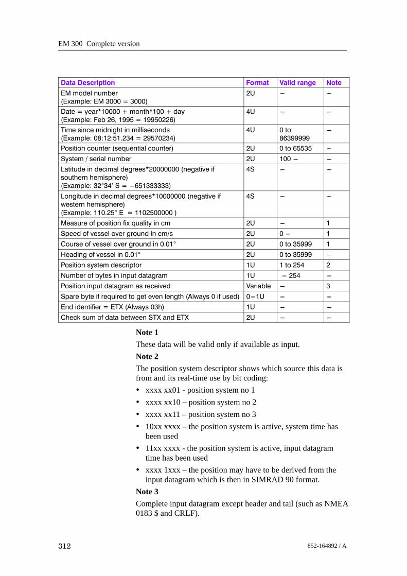
EM 300 Complete version
312 852-164892 / A
Data Description NoteValid rangeFormatEM model number(Example: EM 3000 = 3000)
2U --- ---
Date = year*10000 + month*100 + day(Example: Feb 26, 1995 = 19950226)
4U --- ---
Time since midnight in milliseconds(Example: 08:12:51.234 = 29570234)
4U 0 to86399999
---
Position counter (sequential counter) 2U 0 to 65535 ---System / serial number 2U 100 --- ---Latitude in decimal degrees*20000000 (negative ifsouthern hemisphere)(Example: 32°34’ S = ---651333333)
4S --- ---
Longitude in decimal degrees*10000000 (negative ifwestern hemisphere)(Example: 110.25° E = 1102500000 )
4S --- ---
Measure of position fix quality in cm 2U --- 1Speed of vessel over ground in cm/s 2U 0 --- 1Course of vessel over ground in 0.01° 2U 0 to 35999 1Heading of vessel in 0.01° 2U 0 to 35999 ---Position system descriptor 1U 1 to 254 2Number of bytes in input datagram 1U --- 254 ---Position input datagram as received Variable --- 3Spare byte if required to get even length (Always 0 if used) 0---1U --- ---End identifier = ETX (Always 03h) 1U --- ---Check sum of data between STX and ETX 2U --- ---
Note 1These data will be valid only if available as input.Note 2The position system descriptor shows which source this data isfrom and its real-time use by bit coding:• xxxx xx01 - position system no 1• xxxx xx10 – position system no 2• xxxx xx11 – position system no 3• 10xx xxxx – the position system is active, system time has
been used• 11xx xxxx - the position system is active, input datagram
time has been used• xxxx 1xxx – the position may have to be derived from the
input datagram which is then in SIMRAD 90 format.Note 3Complete input datagram except header and tail (such as NMEA0183 $ and CRLF).

Datagram formats
313852-164892 / A
Height
Data Description Format Valid range NoteNumber of bytes in datagram 4U --- ---Start identifier = STX (Always 02h) 1U --- ---Type of datagram = h(eight data) (Always 068h) 1U --- ---EM model number(Example: EM 3000 = 3000)
2U --- ---
Date = year*10000 + month*100 + day(Example: Feb 26, 1995 = 19950226)
4U --- ---
Time since midnight in milliseconds(EXample: 08:12:51.234 = 29570234)
4U 0 to 86399999 ---
Height counter (sequential counter) 2U 0 to 65535 ---System serial number 2U 100 --- ---Height in cm 4S ---4294967296
to 4294967295---
Heigth type 1U 0 to 99 1End identifier = ETX (Always 03h) 1U --- ---Check sum of data between STX and ETX 2U --- ---
Note 1The height type is as given in the height input datagram unless itis zero. Then the height is derived from the GGK or GGAdatagram and is the height of the water level re the verticaldatum (possibly motion corrected).

EM 300 Complete version
314 852-164892 / A
Tide
Data Description Format Valid range Note
Number of bytes in datagram 4U - -Start identifier = STX (Always 02h) 1U - -
Type of datagram = T(ide data) (Always 054h) 1U --- ---
EM model number(Example: EM 3000 = 3000)
2U - -
Date = year*10000 + month*100 + day(Example: Feb 26, 1995 = 19950226)
4U - -
Time since midnight in milliseconds(Example: 08:12:51.234 = 29570234)
4U 0 to86399999
-
Tide counter (sequential counter) 2U 0 to 65535 -System serial number 2U 100 - -Date = year*10000 + month*100 + day (from inputdatagram)(Example: Feb 26, 1995 = 19950226)
4U - -
Time since midnight in milliseconds (from inputdatagram)(Example: 08:12:51.234 = 29570234)
4U 0 to86399999
-
Tidal offset in cm 2S -32768 to32766
-
Spare (Always 0) 1U - -End identifier = ETX (Always 03h) 1U - -Check sum of data between STX and ETX 2U - -
Attitude
Data Description Format Valid range NoteNumber of bytes in datagram 4U --- ---Start identifier = STX (Always 02h) 1U --- ---Type of datagram = A(ttitude data) (Always 041h) 1U --- ---EM model number(Example: EM 3000 = 3000)
2U --- ---
Date = year*10000 + month*100 + day (at start of datarecord)(Example: Feb 26, 1995 = 19950226)
4U --- ---
Time since midnight in milliseconds (at start of datarecord)(Example: 08:12:51.234 = 29570234)
4U 0 to86399999
---
Attitude counter (sequential counter) 2U 0 to 65535 ---System serial number 2U 100 --- ---Number of entries = N 2U 1 --- ---Repeat cycle --- N entries of: 12*N ---

Datagram formats
315852-164892 / A
Data Description NoteValid rangeFormat--- Time in milliseconds since record start 2U 0 to 65534 ------ Sensor status 2U --- 1--- Roll in 0.01° 2S ---18000 to
18000---
--- Pitch in 0.01° 2S ---18000 to18000
---
--- Heave in cm 2S ---1000 to10000
---
--- Heading in 0.01° 2U 0 to 35999 ---End of repeat cycleSensor system descriptor 1U --- 2End identifier = ETX (Always 03h) 1U --- ---Check sum of data between STX and ETX 2U --- ---
Note 1The sensor status will be copied from the input datagram’s twosync bytes if the sensor uses the EM format, and from thesensor’s status word if it is a Sperry Mk39. See the input formatdescription for further details.Note 2The sensor system descriptor will show which sensor the data isderived from, and which of the sensor’s data have been used inreal time by bit coding:• xx01 xxxx – motion sensor number 1• xx10 xxxx – motion sensor number 2• xxxx xxx1 – heading from the sensor is active• xxxx xx0x – roll from the sensor is active• xxxx x0xx – pitch from the sensor is active• xxxx 0xxx – heave from the sensor is active
Heading
Data Description Format Valid range NoteNumber of bytes in datagram 4U --- ---Start identifier = STX (Always 02h) 1U --- ---Type of datagram = H(eading data) (Always 048h) 1U --- ---EM model number(Example: EM 3000 = 3000)
2U --- ---
Date = year*10000 + month*100 + day (at start of datarecord)(Example: Feb 26, 1995 = 19950226)
4U --- ---
Time since midnight in milliseconds (at start of datarecord)(System: 08:12:51.234 = 29570234)
4U 0 to86399999
---

EM 300 Complete version
316 852-164892 / A
Data Description NoteValid rangeFormatHeading counter (sequential counter) 2U 0 to 65535 ---System serial number 2U 100 --- ---Number of entries = N 2U 1 --- ---Repeat cycle --- N entries of: 4*N --- ------ Time in milliseconds since record start 2U 0 to 65534 ------ Heading in 0.01° 2U 0 to 35999 ---End of repeat cycleHeading indicator (active or not) (0 = inactive) 1U --- ---End identifier = ETX (Always 03h) 1U --- ---Check sum of data between STX and ETX 2U --- ---
Mechanical transducer tilt
Data Description Format Valid range NoteNumber of bytes in datagram 4U ---Start identifier = STX (Always 02h) 1U ---Type of datagram = J (Always 4Ah) 1U ---EM model number(Example: EM 1002 = 1002)
2U ---
Date = year*10000 + month*100 + day (at start of datarecord)(Example: Feb 26, 1995 = 19950226)
4U --- ---
Time since midnight in milliseconds(at start of data record)(Example: 08:12:51.234 = 29570234)
4U 0 to86399999
---
Tilt counter (sequential counter) 2U 0 to 65535 ---System serial number 2U 100 --- ---Number of entries = N 2U 1 --- ---Repeat cycle --- N entries of: 4*N ------ Time in milliseconds since record start 2U 0 to 65534 ------ Tilt in 0.01 degrees 2S ---1499 to
+14991
End of repeat cycleSpare (Always zero) 1U --- ---End identifier = ETX (Always 03h) 1U --- ---Check sum of data between STX and ETX 2U --- ---
Note 1
This tilt angle is the measured mechanical tilt of a hull unit suchas that often supplied with the EM 1002. It is positive when thetransducer is tilted forwards.

Datagram formats
317852-164892 / A
Clock
Data Description Format Valid range Note
Number of bytes in datagram 4U --- ---Start identifier = STX (Always 02h) 1U --- ---Type of datagram = C(lock data) (Always 043h) 1U --- ---EM model number (Example: EM 3000 = 3000) 2U --- ---Date = year*10000 + month*100 + day (of EM clock)(Example: Feb 26, 1995 = 19950226)
4U --- ---
Time since midnight in milliseconds (of EM clock)(Example: 08:12:51.234 = 29570234)
4U 0 to86399999
---
Clock counter (sequential counter) 2U 0 to 65535 ---System serial number 2U 100 --- ---Date = year*10000 + month*100 + day(from external clock input)(Example: Feb 26, 1995 = 19950226)
4U --- ---
Time since midnight in milliseconds(from external clock datagram)(Example: 08:12:51.234 = 29570234)
4U 0 to86399999
---
1 PPS use (active or not) (0 = inactive) 1U --- 1End identifier = ETX (Always 03h) 1U --- ---Check sum of data between STX and ETX 2U --- ---
Note 1Shows if the system clock is synchronised to an external 1 PPSsignal or not.
Surface sound speed
Data Description Format Valid range Note
Number of bytes in datagram 4U --- ---Start identifier = STX (Always 02h) 1U --- ---Type of datagram = G (Always 047h) 1U --- ---EM model number(Example: EM 3000 = 3000)
2U --- ---
Date = year*10000 + month*100 + day(at start of data record)(Example: Feb 26, 1995 = 19950226)
4U --- ---
Time since midnight in milliseconds(at start of data record)(Example: 08:12:51.234 = 29570234)
4U 0 to86399999
---
Sound speed counter (sequential counter) 2U 0 to 65535 ---System serial number 2U 100 --- ---Number of entries = N 2U 1 --- ---Repeat cycle --- N entries of: 4*N ---

EM 300 Complete version
318 852-164892 / A
Data Description NoteValid rangeFormat--- Time in seconds since record start 2U 0 to 65534 ------ Sound speed in dm/s (including offset) 2U 14000 to
15999---
End of repeat cycleSpare (Always 0) 1U --- ---End identifier = ETX (Always 03h) 1U --- ---Check sum of data between STX and ETX 2U --- ---
Sound speed profileThis datagram will contain the profile actually used in the realtime raybending calculations to convert range and angle to xyzdata. It will usually be issued together with the installationparameter datagram.
Note The format as given below has been changed from previouseditions of this manual. The former format is identified by itstype which was “V” (056h). The previous format had 2 bytelong fields for depth and sound speed, this is now 4 bytes.
Data Description Format Valid range NoteNumber of bytes in datagram 4U --- ---Start identifier = STX (Always 02h) 1U --- ---Type of datagram = U (Always 055h) 1U --- ---EM model number(Example: EM 3000 = 3000)
2U --- ---
Date = year*10000 + month*100 + day (at start of use)(Example: Feb 26, 1995 = 19950226)
4U --- ---
Time since midnight in milliseconds(at start of use)(Example: 08:12:51.234 = 29570234)
4U 0 to86399999
---
Profile counter (sequential counter) 2U 0 to 65535 ---System serial number 2U 100 --- ---Date = year*10000 + month*100 + day(when profile was made)(Example: Feb 26, 1995 = 19950226)
4U --- ---
Time since midnight in milliseconds(when profile was made)(Example: 08:12:51.234 = 29570234)
4U 0 to86399999
---
Number of entries = N 2U 1 --- ---Depth resolution in cm 2U 1 to 254 ---Repeat cycle --- N entries of: 8*N --- ---
- Depth 4U 0 to 1200000 ---
--- Sound speed in dm/s 4U 14000 to17000
---

Datagram formats
319852-164892 / A
Data Description NoteValid rangeFormatEnd of repeat cycleSpare byte to get even length (Always 0) 1U --- ---End identifier = ETX (Always 03h) 1U --- ---Check sum of data between STX and ETX 2U --- ---
Kongsberg Maritime SSP outputThis datagram will contain the profile as received as input, andis logged as is to enable use of its data in postprocessing. Thereal time use of its data is decided by the operator, the soundspeed profile actually being used is given by the sound speedprofile output datagram (see above).
Data Description Format Valid range NoteNumber of bytes in datagram 4U --- ---Start identifier = STX (Always 02h) 1U --- ---Type of datagram = W (Always 057h) 1U --- ---EM model number(Example: EM 3000 = 3000)
2U --- ---
Date = year*10000 + month*100 + day(Example: Feb 26, 1995 = 19950226)
4U --- ---
Time since midnight in milliseconds(Example: 08:12:51.234 = 29570234)
4U 0 to86399999
---
SSP counter (sequential counter) 2U 0 to 65535 ---System serial number 2U 100 --- ---Input datagram starting with Sentence formatter and endingwith Comment
Variable --- ---
Spare byte if required to get even length (Always 0 if used ) 0 --- 1U --- ---End identifier = ETX (Always 03h) 1U --- ---Check sum of data between STX and ETX 2U --- ---
Single beam echo sounder depth
Data Description Format Valid range Note
Number of bytes in datagram 4U --- ---Start identifier = STX (Always 02h) 1U --- ---Type of datagram = E(cho sounder data) (Always 045h) 1U --- ---EM model number(Example: EM 3000 = 3000)
2U --- ---
Date = year*10000 + month*100 + day (of EM clock)(Example: Feb 26, 1995 = 19950226)
4U --- ---
Time since midnight in milliseconds (of EM clock)(Example: 08:12:51.234 = 29570234)
4U 0 to86399999
---

EM 300 Complete version
320 852-164892 / A
Data Description NoteValid rangeFormatEcho sounder counter (sequential counter) 2U 0 to 65535 ---System serial number 2U 100 --- ---Date = year*10000 + month*100 + day (from inputdatagram if available)(Example: Feb 26, 1995 = 19950226)
4U --- ---
Time since midnight in milliseconds (from input datagram ifavailable)(Example: 08:12:51.234 = 29570234)
4U 0 to86399999
---
Echo sounder depth from waterline in cm 4U 0 to 1200000 ---Source identifier (S, T, 1, 2 or 3) ASCII --- 1End identifier = ETX (Always 03h) 1U --- ---Check sum of data between STX and ETX 2U --- ---
Note 1Identifies the source datagram type, i.e. NMEA DBS, NMEADPT or EA 500 series channel 1-3 respectively.
Runtime parameter
Data Description Format Valid range Note
Number of bytes in datagram 4U --- ---Start identifier = STX (Always 02h) 1U --- ---Type of datagram = R(untime parameter) (Always 052h) 1U --- ---EM model number/Example: EM 3000 = 3000)
2U --- ---
Date = year*10000 + month*100 + day(Example: Feb 26, 1995 = 19950226)
4U --- ---
Time since midnight in milliseconds(Example: 08:12:51.234 = 29570234)
4U 0 to86399999
---
Ping counter 2U 0 to 65535 ---System serial number 2U 100 --- ---Operator Station status 1U --- 1Processing Unit status 1U --- 1BSP status 1U --- 1Sonar Head or Transceiver status 1U --- 1Mode 1U 1 --- 2Filter identifier 1U 0 to 254 3Minimum depth in m 2U 0 to 10000 ---Maximum depth in m 2U 1 to 12000 ---Absorption coefficient in 0.01 dB/km 2U 1 to 20000 4Transmit pulse length in µs 2U 1 to 50000 ---Transmit beamwidth in 0.1 degrees 2U 1 to 300 ---Transmit power re maximum in dB 1S 0 to ---50 ---Receive beamwidth in 0.1 degrees 1U 5 to 80 ---
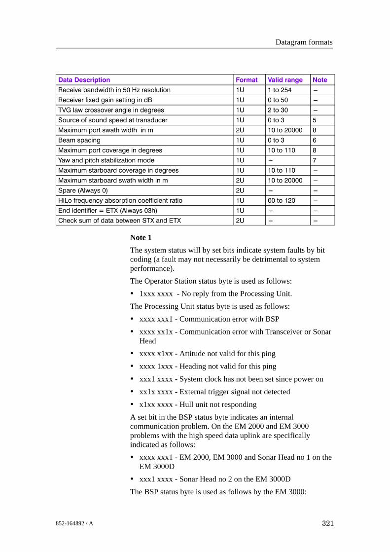
Datagram formats
321852-164892 / A
Data Description NoteValid rangeFormatReceive bandwidth in 50 Hz resolution 1U 1 to 254 ---Receiver fixed gain setting in dB 1U 0 to 50 ---TVG law crossover angle in degrees 1U 2 to 30 ---Source of sound speed at transducer 1U 0 to 3 5Maximum port swath width in m 2U 10 to 20000 8Beam spacing 1U 0 to 3 6Maximum port coverage in degrees 1U 10 to 110 8Yaw and pitch stabilization mode 1U --- 7Maximum starboard coverage in degrees 1U 10 to 110 ---Maximum starboard swath width in m 2U 10 to 20000 ---Spare (Always 0) 2U --- ---HiLo frequency absorption coefficient ratio 1U 00 to 120 ---End identifier = ETX (Always 03h) 1U --- ---Check sum of data between STX and ETX 2U --- ---
Note 1The system status will by set bits indicate system faults by bitcoding (a fault may not necessarily be detrimental to systemperformance).The Operator Station status byte is used as follows:• 1xxx xxxx - No reply from the Processing Unit.The Processing Unit status byte is used as follows:• xxxx xxx1 - Communication error with BSP• xxxx xx1x - Communication error with Transceiver or Sonar
Head• xxxx x1xx - Attitude not valid for this ping• xxxx 1xxx - Heading not valid for this ping• xxx1 xxxx - System clock has not been set since power on• xx1x xxxx - External trigger signal not detected• x1xx xxxx - Hull unit not respondingA set bit in the BSP status byte indicates an internalcommunication problem. On the EM 2000 and EM 3000problems with the high speed data uplink are specificallyindicated as follows:• xxxx xxx1 - EM 2000, EM 3000 and Sonar Head no 1 on the
EM 3000D• xxx1 xxxx - Sonar Head no 2 on the EM 3000DThe BSP status byte is used as follows by the EM 3000:
EM 300 Complete version
322 852-164892 / A
• xxxx xxx1 - Ping rejected due to errors in received data onBSP1
• xxxx xx1x - Too much seabed image data on BSP1
• xxxx x1xx - Invalid command received by BSP1
• xxx1 xxxx - Ping rejected due to errors in received data onBSP2
• xx1x xxxx - Too much seabed image data on BSP2
• x1xx xxxx - Invalid command received by BSP2
The Sonar Head status byte is used as follows by the EM 2000and EM 3000:• xxxx xxx1 - Temperature too high on Sonar Head 1
• xxxx xx1x - Data link failure on Sonar Head 1
• xxxx x1xx - Voltages out of range on Sonar Head 1
• xxx1 xxxx - Temperature too high on Sonar Head 2 of EM3000D
• xx1x xxxx - Data link failure on Sonar Head 2 of EM 3000D
• x1xx xxxx - Voltages out of range on Sonar Head 2 of EM3000D
The Transceiver status byte is used as follows by the EM 120,EM 300 and EM 1002:• xxxx xxx1 - Transmit (HV) voltage out of range
• xxxx xx1x - PSU voltage out of range
• xxxx x1xx - Internal communication error
• xxxx 1xxx - Receive channel DC offset(s) out of range
• xxx1 xxxx - Internal communication error
• x1xx xxxx - Internal communication error
• 1xxx xxxx - Defective fuse(s) in transmitter
Note 2The mode identifier byte is used as follows:• 0000 0000 - Nearfield (EM 3000) or Very Shallow
• 0000 0001 - Normal (EM 3000) or Shallow (default for EM2000)
• 0000 0010 - Target detect (EM 3000) or Medium
• 0000 0011 - Deep
• 0000 0100 - Very deep

Datagram formats
323852-164892 / A
• 0000 0101 - Extra deep (EM 300)Note 3The filter identifier byte is used as follows:• xxxx xx00 - Spike filter set to Off• xxxx xx01 - Spike filter is set to Weak• xxxx xx10 - Spike filter is set to Medium• xxxx xx11 - Spike filter is set to Strong• xxxx x1xx - Slope filter is on• xxxx 1xxx - Sector tracking or Robust Bottom Detection
(EM 3000) is on• 0xx0 xxxx - Range gates have Normal size• 0xx1 xxxx - Range gates are Large• 1xx0 xxxx - Range gates are Small• xx1x xxxx - Aeration filter is on• x1xx xxxx - Interference filter is onNote 4The used absorption coefficient should be derived from theseabed image or central beams echogram datagram if it isautomatically updated with changing depth.Note 5The sound speed (at the transducer depth) source identifier isused as follows :• 0000 0000 - From real time sensor• 0000 0001 - Manually entered by operator• 0000 0010 - Interpolated from currently used sound speed
profileNote 6The beamspacing identifier is used as follows:• 0000 0000 - Determined by beamwidth (FFT beamformer of
EM 3000)• 0000 0001 - Equidistant• 0000 0010 - Equiangle• 0000 0011 - Equiangle around nadir, equidistant in betweenNote 7The yaw and pitch stabilization identifier is set as follows:

EM 300 Complete version
324 852-164892 / A
• xxxx xx00 - No yaw stabilization• xxxx xx01 - Yaw stabilization to survey line heading (Not
used)• xxxx xx10 - Yaw stabilization to mean vessel heading• xxxx xx11 - Yaw stabilization to manually entered heading• 1xxx xxxx - Pitch stabilization is on.Note 8Port swath width and coverage was in earlier versions the sumof port and starboard
Installation parametersThis datagram is an ASCII datagram except for the headerwhich is formed as in all other output datagrams. The datagramis issued as a start datagram when logging is switched on and asa stop datagram when logging is turned off, i.e. at the start andend of a survey line. It may also be sent to a remote port as aninformation datagram. It is usually followed by a sound speedprofile datagram.In the datagram all ASCII fields start with a unique threecharacter identifier followed by “=”. This should be used whensearching for a specific field as the position of a field within thedatagram is not guaranteed. The number or character partfollowing is in a variable format with a minus sign and decimalpoint if needed, and with “,” as the field delimiter. The formatmay at any time later be expanded with the addition of newfields at any place in the datagram.For the EM 3000 the transducer 1 data are for the Sonar Headand the transducer 2 data are for the second Sonar Head of anEM 3000D. For other new EM systems with separate transmitand receive transducers, transducer 1 refers to the transmittransducer, and transducer 2 refers to the receive transducer.
Data Description Example Format Valid range NoteNumber of bytes in datagram --- 4U --- 1Start identifier = STX Always 02h 1U --- ---Type of datagram = I or i(nstallationparameters) or r(emote information)
Start = 049hStop = 069hRemote info =70h
1U --- ---
EM model number EM 3000 =3000
2U --- ---
Date = year*10000 + month*100 + day Feb 26, 1995 =19950226
4U --- ---

Datagram formats
325852-164892 / A
Data Description NoteValid rangeFormatExampleTime since midnight in milliseconds 08:12:51.234 =
295702344U 0 to
86399999---
Survey line number --- 2U 0 to 65534 ---System serial number --- 2U 100 --- ---Serial number of second sonar head --- 2U 100 --- ---Water line vertical location in m WLZ=x.x, ASCII --- ---System main head serial number SMH=x.x, ASCII 100 --- 1Hull Unit HUN=x ASCII 0 or 1 ---Hull Unit tilt offset HUT=x.x ASCII --- ---Transducer 1 vertical location in m S1Z=x.x, ASCII --- ---Transducer 1 along location in m S1X=x.x, ASCII --- ---Transducer 1 athwart location in m S1Y=x.x, ASCII --- ---Transducer 1 heading in degrees S1H=x.x, ASCII --- ---Transducer 1 roll in degrees re horizontal S1R=x.x, ASCII --- ---Transducer 1 pitch in degrees S1P=x.x, ASCII --- ---Transducer 1 no of modules S1N=x--- ---x, ASCII --- ---Transducer 2 vertical location in m S2Z=x.x, ASCII --- ---Transducer 2 along location in m S2X=x.x, ASCII --- ---Transducer 2 athwart location in m S2Y=x.x, ASCII --- ---Transducer 2 heading in degrees S2H=x.x, ASCII --- ---Transducer 2 roll in degrees re horizontal S2R=x.x, ASCII --- ---Transducer 2 pitch in degrees S2P=x.x, ASCII --- ---Transducer 2 no of modules S2N=x--- ---x, ASCII --- ---System (sonar head 1) gain offset GO1=x.x, ASCII --- ---Sonar head 2 gain offset GO2=x.x, ASCII --- ---Outer beam offset OBO=x.x ASCII --- ---High/Low Frequency Gain Difference FGD=x.x ASCII --- ---Transmitter (sonar head no1) softwareversion
TSV=c--- ---c, ASCII --- 2
Receiver (sonar head 2) software version RSV=c--- ---c, ASCII --- 2BSP software version BSV=c--- ---c, ASCII --- 2Processing unit software version PSV=c--- ---c, ASCII --- 2Operator station software version OSV=c--- ---c, ASCII --- 2Datagram format version DSV=c--- ---c, ASCII --- 2Depth sensor time delay in millisec DSD=x--- ---x, ASCII --- ---Depth sensor offset DSO=x.x, ASCII --- ---Depth sensor scale factor DSF=x.x, ASCII --- ---Depth sensor heave DSH=aa, ASCII IN or NI 3Active position system number APS=x, ASCII 0 to 2 7Position system 1 motion compensation P1M=x, ASCII 0 or 1 4Position system 1 time stamp used P1T=x, ASCII 0 or 1 5

EM 300 Complete version
326 852-164892 / A
Data Description NoteValid rangeFormatExamplePosition system 1 vertical location in m P1Z=x.x, ASCII --- ---Position system 1 along location in m P1X=x.x, ASCII --- ---Position system 1 athwart location in m P1Y=x.x, ASCII --- ---Position system 1 time delay in seconds P1D=x.x, ASCII --- ---Position system 1 geodetic datum P1G=c--- ---c, ASCII --- ---Position system 2 motion compensation P2M=x, ASCII 0 or 1 4Position system 2 time stamp use P2T=x, ASCII 0 or 1 5Position system 2 vertical location in m P2Z=x.x, ASCII --- ---Position system 2 along location in m P2X=x.x, ASCII --- ---Position system 2 athwart location in m P2Y=x.x, ASCII --- ---Position system 2 time delay in seconds P2D=x.x, ASCII --- ---Position system 2 geodetic datum P2G=c--- ---c, ASCII --- ---Position system 3 motion compensation P3M=x, ASCII 0 or 1 4Position system 3 time stamp use P3T=x, ASCII 0 or 1 5Position system 3 vertical location in m P3Z=x.x, ASCII --- ---Position system 3 along location in m P3X=x.x, ASCII --- ---Position system 3 athwart location in m P3Y=x.x, ASCII --- ---Position system 3 time delay in seconds P3D=x.x, ASCII --- ---Position system 3 geodetic datum P3G=c--- ---c, ASCII --- ---Position system 3 on serial line or Ethernet P3S= x, ASCII 0 for
Ethernet---
Motion sensor 1 vertical location in m MSZ=x.x, ASCII --- ---Motion sensor 1 along location in m MSX=x.x, ASCII --- ---Motion sensor 1 athwart location in m MSY=x.x, ASCII --- ---Motion sensor 1 roll reference plane MRP=aa, ASCII HO or RP ---Motion sensor 1 time delay in milliseconds MSD=x--- ---x, ASCII --- ---Motion sensor 1 roll offset in degrees MSR=x.x, ASCII --- ---Motion sensor 1 pitch offset in degrees MSP=x.x, ASCII --- ---Motion sensor 1 heading offset in degrees MSG=x.x, ASCII --- ---Motion sensor 2 vertical location in m NSZ=x.x, ASCII --- 6Motion sensor 2 along location in m NSX=x.x, ASCII --- 6Motion sensor 2 athwart location in m NSY=x.x, ASCII --- 6Motion sensor 2 roll reference plane NRP=aa, ASCII HO or RP 6Motion sensor 2 time delay in milliseconds NSD=x--- ---x, ASCII --- 6Motion sensor 2 roll offset in degrees NSR=x.x, ASCII --- 6Motion sensor 2 pitch offset in degrees NSP=x.x, ASCII --- 6Motion sensor 2 heading offset in degrees NSG=x.x, ASCII --- 6Gyrocompass heading offset in degrees GCG=x.x, ASCII --- ---Roll scaling factor MAS=x.x, ASCII --- ---Transducer depth sound speed source SHC=x ASCII 0 or 1 8Active heading sensor AHS=x, ASCII 1 to 4 ---

Datagram formats
327852-164892 / A
Data Description NoteValid rangeFormatExampleActive roll sensor ARO=x, ASCII 1 to 4 ---Active pitch sensor port no API=x, ASCII 1 to 4 ---Active heave sensor port no AHE=x, ASCII 1 to 4 ---Cartographic projection CPR=aaa, ASCII --- ---Responsible operator ROP=c--- ---c, ASCII --- ---Survey identifier SID=c--- ---c, ASCII --- ---Survey line identifier (planned line no) PLL=x--- ---x, ASCII --- ---Comment COM=c--- ---c, ASCII --- ---Spare byte if required to get even length Always 0 if
used0---1U --- ---
End identifier = ETX Always 03h 1U --- ---Check sum of data between STX and ETX 2U --- ---
Note 1Serial number of head no 2 if that head is the only one in usewith the EM 3000D, otherwise the serial number of head no 1 inthe EM 3000D or the only head in the EM 3000.Note 2A version number is given as 3 alphanumerical fields separatedby decimal points, plus date as yymmdd (for example 3.02.11991124).Note 3IN = the heave of an underwater vehicle is presumed to bemeasured by the vehicle’s depth sensor and the heave sensorinput is not used by system.Note 41 = the positions are motion compensated0 = the positions are not motion compensatedNote 50 = the system has used its own time stamp for the valid time ofthe positions1 = the system has used the time stamp of the position inputdatagram (external time).Note 6If entries for a second motion sensor are not included althoughtwo sensors are being used, they are presumed to have the sameparameters.Note 7Position system number -1.

EM 300 Complete version
328 852-164892 / A
Note 80 = Transducer depth sound speed is used as the initial entry thesound speed profile used in the raytracing calculations.1 = Transducer depth sound speed is NOT used for raytracingcalculations.Note that the source of the sound speed at the transducer depth(and this sound speed is always used to calculate beam pointingangles if required) is logged in the runtime datagram.

System administration
329852-164892 / A
11 SYSTEM ADMINISTRATION
11.1 IntroductionThis chapter provides basic reference information useful for theEM 300 system supervisor. In order to make the most of theinformation provided, you may need some basic knowledge ofthe Unix operating system.

EM 300 Complete version
330 852-164892 / A
11.2 Passwords
EM 300 Installation setupIn order to change the installation parameters on the EM 300system, you need to enter a password. This password is commonfor all the operators of the EM 300 system. You willautomatically be prompted to enter the password once you selectEdit enable in the Edit menu.If a password has not been identified, the first attempt to modifythe installation parameters will prompt you to enter a newpassword.If the password is lost, the current password can be deleted bydeleting the following file:$HOME/.eso_system/.esoEM 300_protection
No special privileges are required to delete this file. Once it isgone, the system will prompt you for a new password next timeyou choose Edit enable.

System administration
331852-164892 / A
11.3 EM 300 File system
IntroductionThe EM 300 requires a large number of individual files. Someare used for data storage, others for system setup, while someare used to store operator and system configurations. Thischapter lists the various file types and provides briefexplanations.The notation $<name> is an “environment variable”, usuallyspecifying a filsystem directory.
Survey filesDuring a survey, the EM 300 system will record and store thefollowing file types:• Raw data• Survey dataThe information is stored on the Operator Station harddisk ondedicated data formats defined by Kongsberg Maritime..
Survey data
These are the data files generated by the system. Note that fileswill only be stored if the Survey Format To Disk option ischecked in the window opened by Options -> Logging.These files are used by the post-processing software, and by theSurvey Display program.
Note Unless this data is stored, the Survey Display application willnot work.
Raw data
These are the files containing the raw data retrieved during thesurvey. These files are the most important files collected duringa survey. If you accidentally loose your survey data format files(required by the post-processing software), you can recreatethese files based on the raw data files. Care should be taken tobackup raw data files on a regular basis, using the backupfacilities supplied as an integral part of the system.
Sound speed profilesAll the sound speed profiles are stored as separate files indirectory specified by the environment variable.

EM 300 Complete version
332 852-164892 / A
$SHAREDHOMEThe files have extension *.asvp
Absorption coefficient fileThe absorption coefficient file contains number pairs ofabsorption coefficients and corresponding depths. Thecoefficients are integrated during loading to the echo sounderand the integrated value is used. The file is namedabsorption.coef and is stored in directory:$SHAREDHOME
Workstation I/OWhen you define the use of the Operator Station’s serial lines,the setup information is stored in the following file:$HOME/.eso_system/esoSetup.serial
Echo sounder parametersThese are the files determining how the current echo soundersystem is set up. The system uses separate files for runtime andinstallation parameters.
Installation setup
The installation setup information is saved in the following file:$HOME/.eso_system/esoEM300Setup.installationEvery time you save this file, a backup file is generatedautomatically. This file is named:esoEM300Setup.installation.yyyy_mmdd_hhmmwhere:
yyyy=yearmm=monthdd=dayhh=hourmm=minute.
You can also save the setup files with other names you chooseyourself. You can then pick any name, but you must keep theextension as “.installation”. The extension is addedautomatically if you only specify the file name.
Runtime setup
The runtime setup information is saved in the following file:esoEM300Setup.runtime

System administration
333852-164892 / A
Every time you save this file, a backup file is generatedautomatically. This file is named:$HOME/.eso_system/esoEM300Setup.runtime.yyyy_mmdd_hhmmwhere:
yyyy=yearmm=monthdd=dayhh=hourmm=minute.
You can also save the runtime files with other names you chooseyourself. You can then pick any name, but you must keep theextension as “.runtime”. The extension is added automatically ifyou only specify the file name.
Echo sounder status
The information in the Status Field in the Launchpad is stored inthe following file:$HOME/.eso_system/esoSetup.status
IP addresses, ports and datagrams
The IP addresses for the various items in the system, the portsused for the various applications, and the datagram distributionare collected in the following file:$HOME/DPC.addresses.<host>where <host> is the name of the Operator Station.You may modify the contents of this file by using the Options-> Datagram subscriptions choices on the Launchpad.The datagrams available are listed in the following file:$HOME/.eso_system/esoSetup.datagramsThis is a static file, and will only be used by the system.
NMEA 0183
The information for the NMEA 0183 depth serial line is storedin the following file:$HOME/.eso_system/esoSetup.serial
BIST filesWhen you run the built-in test applications, the results displayedin the output area in the BIST window may be saved to disk.The file is created with the following location and file name:
EM 300 Complete version
334 852-164892 / A
$HOME/.eso_system/BISToutputEvery time you save the information, the old file will bereplaced. The information is stored in ASCII format.
LogfilesEach application in the EM 300 system issues report and errormessages when required. These messages are collected inlogfiles.The size of the current logfile is monitored by the system. If itexceeds 8Mb, a warning dialogue pops up recommending a resetof the file. The actual reset is done using the File->ResetLogfile option, as instructed in the popup dialogue.When you reset the logfile using the File -> Reset logfilecommand on the Launchpad, you may create a backup copy ofthe logfile. The backup is named:$HOME/.eso_system/esoLogfile.yyyy_mmdd_hhmmwhere:
yyyy=yearmm=monthdd=dayhh=hourmm=minute.
In most cases you do not need to create backup copies of thelogfile, since errors and warnings are logged to the surveylogfiles during active surveying.In addition to this logfile, the errors and warnings issued duringa survey are saved on a separate file for the active survey. Thisfile is only created while logging takes place. The file is:$PROCHOM/<survey>/esoLogfilewhere <survey> is the chosen name for the active survey.
Operator configuration filesThese are the individual files containing the operator specifiedwindow layouts and desktop workspaces for the programssupervised by the EM 300 Launchpad.
Default window layout
Each operator can define a preferred window and workspacelayout, and then use the Window Layout -> Save Operator’sLayout command on the launchpad’s main menu to save thisinformation. The name of the file will be:

System administration
335852-164892 / A
$HOME/.eso_system/esoEmX_config.<operator>where <operator> is the current operator of the system, asdefined in the Launchpad’s Survey field (below the programicons).The default window layout is:$HOME/.eso_system/esoEmX_config
List of known operators
The list of the operators known to the system is stored in thefollowing file:$HOME/.eso_system/esoSetup.operators
User preferences
All the preferences you define during the survey are stored in aseparate file.$HOME/.eso_system/esoSetup.launchpadThis file is created using the Options -> User preferencescommand on the Launchpad’s main menu.
Survey jobsThese are the files generated by the Survey Display’s Planningmodule. All these plans are located in the following directory:$SHAREDHOME/<job name>.asciiplan
TOC filesThe TOC (Table of Contents) files are created automaticallywhen you select the Generate Tape TOC operation in the FileAdmin window.Each TOC file contains a list of oll the files on the tape. This isnormally all the files used for a specific survey, but in general itcan be any file types recognized by the File Admin utility.The TOC files can be named manually, or they can be assigneda name automatically. This name is then defined based on thecurernt date and time with extension *.TOC.The files are stored in the following directory:$HOME/.eso_system/

EM 300 Complete version
336 852-164892 / A
11.4 File formats
IntroductionThe main files are described in this chapter, but the header filesthat follow the system are only referred to and must be inspectedby listing the header file of current interest or by checking thecomputer display.
Survey format and I/O libraryThe Survey Format (SF) files are the key files of theKongsberg Maritime workstation systems. The files are locatedin the $PROCHOME directory. An I/O library fromKongsberg Maritime is supplied to the users who wish to accessthe data themselves. You can then install the I/O librarywhereever it fits for your development. Header files andlibraries are available.The SF is a Kongsberg Maritime defined format that fits for allKongsberg multibeam echo sounder data, and for the EA 500and EK 500 single beam echo sounders. The data is converteddirectly to this format if a Kongsberg Maritime logging systemis used. As the lines are run, the raw data is fed into thehandleMessage or handleEmX filter and stored correctly onthe $PROCHOME/<SurveyName> directory, while thesurvey.lines file on the same directory is updated withinformation about the same line.
The survey format
Introduction
This is the Kongsberg Maritime workstation processing formatthat applies to all multibeam echo sounders and also to somesingle beam echo sounders. The format is used in otherworkstation products in addition to Neptune, such as Merlin,Poseidon and Triton.The format is based on indexed files. For each line there is anindex file which holds some common index data for each ping.The files handled by the index file are:1 Depth file2 Sonar Image file3 Classification fileThe following files have been defined as system administrationfiles:

System administration
337852-164892 / A
4 Parameter file5 sound speed fileThese files contain parameter settings and information about thesound speed that has been used during the data collection. Theinformation about the used sound speed is vital for reprocessingold data with new sound speed profiles.The position files (there might be several due to more than onepositioning system) are treated separately. After positionprocessing, a new valid position file is generated and will beused for further processing (Sensor 00), version 02.A representation of the file structure is described by thefollowing:Index file Depth file Position fileFileHeadrec FileHeadRec FileHeadrecPingHeadRed DepthFileRec 1 PosHeadRecIndexFileRec 1 DepthFileRec 2 PositionFileRec1IndexFileRec 2 ........ PositionFileRec2.......... ......... ................... DepthFileRec i .........IndexFileRec i ......... PositionFileRec i......... DepthFileRec n .........IndexFileRec n ......... PositionFileRecn
Raw sidescan file Parameter file sound speed fileFileHeadRec FileHeadRec FileheadRecSideHeadRec ParameterRec 1 SndVelFileRec 1SideRawFileRec 1 ParameterRec 2 SndVelFileRec 2SideRawFileRec 2 ......... .................. ......... .................. ParameterRec i SndVelFileRec iSideRawFileRec i ......... .................. ParameterRec n SndVelFileRec nSideRawFileRec n

EM 300 Complete version
338 852-164892 / A
Survey format I/O library
The I/O sub-routine library can be used by a company orinstitution who have bought a license for a Kongsberg Maritimeworkstation product. It can also be distributed by the KongsbergMaritime customer to others after agreement betweenKongsberg Maritime and the institution or company.Maintenance and help with the library and files are given tothose who have maintenance contract with Kongsberg Maritime.
The Survey format coordinate system
The coordinate system of the vessel has an x-axis along theships keel pointing forwards from the origin of the ship. They-axis points to starboard, and the z-axis points straight downgiving the depths as positive values increasing with depth.This generates the right-hand coordinate system on board theship. Positive rotation around the axis is defined by theright-hand rule, giving a positive rotation of angles in thehorizontal plane in the same way as the gyro rotates positively(Clockwise as seen from above the ship).The data that is logged on files is in latitude/longitudecoordinates. The data is represented by a 4-byte integer that hasthe following resolutions:Latitude :
2*10E7 decimal degrees per number unit (+90 to -90degrees).
Longitude:1*10E7 decimal degrees per number unit (+180 to -180degrees).
Depths are treated with centimetre resolution in the EM 300system, and represented in this resolution on the XYZ files.
Use of the Kongsberg Maritime I/O library
Introduction
The Kongsberg Maritime I/O library consists of two differentparts. One part is intended to be used by those who want to fittheir own data into Kongsberg Maritime’s Survey Format (SF)file format. The modules supported for this use are msgSim andhandleMessage. The handleMessage takes its input data fromthe logging program (Mermaid/Merlin) or from msgSim. Theother part is intended to be used by those who want to useSurvey Format data. This part of the library is called RWlib(Read and Write library). All routines in the library return aninteger as return parameter. This parameter is negative ifsomething went wrong or the data returned are not valid.

System administration
339852-164892 / A
Message simulator
The message simulator (msgSim) simulates messages from thelogging system by reading one or more raw data files, puttingthe message length in front of each message and writing it tostdout. If the messages are separated on different data files, thefiles containing the depth data message must end with .dpt,position data with .pos, sidescan data with .rss andstart/stop/parameter data with .inf. The module also handles thesituation when all messages are collected in one file. All ofthese data files must only contain valid, complete messages andnothing else.
Message handling
Messages from Mermaid/Merlin or msgSim may be ’piped’ intohandleMessage. This module reads the messages from stdin,decodes them into survey format and writes them to file. Thefiles written are:• position files (.pos)• depth files (.depth)• sidescan files (.sidescan)• parameter files (.para)• sound speed files (.svel)• index files (.ind).The name of the new file starts with the line number, anunderscore, the date of the start telegram, an underscore, thetime, an underscore, sensor number, an underscore, versionnumber and the extension.Example:0183_19921031_155630_00_01.depthThe module starts decoding and writing when a start telegramarrives and stops when a stop telegram arrives. If sidescan datais to be handled, depth data must be present, and if the data is tobe used with ”near real time” visualization (i.e. Merlin), positiondata must also be present. For information on how to runhandleMessage, see the section ”Command references”.
Library calls
Introduction
The library is written in the ANSI “C” programming language.The definition and prototyping is done in the *.h files:• readWriteFile.h

EM 300 Complete version
340 852-164892 / A
• SurveyLines.h
• newFormat.h
The return structures that you need to know about are found inthe newFormat.h file. This file is documented internally in thefile, while the other *.h files not are intended to be read, justincluded to supply you with the structures required for some ofthe calls. These calls are described here, and the prototyping isfound in the above listed header files.
Writing new files
For writing new files in SF the library libRW is supported. Withthis library you can open, write and close new files in SF.Before a file (of any type) can be written, it must be opened bythe appropriate open routine for this file type. The inputparameters for these routines are:• file directory,
• generic file name,
• sensor number (set to 0->zero)
• type specific header,
• a comment and a description of the process which created thefile.
In addition file handler newFilePnt must be supported for eachfile (except for opening the index file) and one common writehandler. E.g. this write handler is used for writing indices tofiles. To write new records to file, a set of writing routines aresupported. All those writing routines have their specific recordformat, their file handler (except for writing pings) and thecommon write handler as parameters. When depth data orsidescan data is written, it must be specified which sounder (portor starboard for dual system or single for single system) the datacomes from. To close the file (except the index file which isclosed with a specific routine) the routine closeNewFile is calledwith the file handler as input.

System administration
341852-164892 / A
All data are written to file in the native format (little or bigEndian) in which the program is running. The index file (withping data) is written every time the ping number changes. Thisis done automatically in writeDepth or writePing, which meansthat these routines must be called in order to let the index andping records be written (ping number must be supplied andproperly changed if not present in the raw datagram). Date andtime must also be supplied for each record (ping and position)so that it will be possible to index a ping from position throughdata and time. When the index file is written, all indices arewritten including those for sidescan and position. As sidescandata only are accessible through the index file, all calls to eitherwriteDepth or writePing must be made. Position data, on theother hand, may either be accessed via index (for ”near realtime”) or via time. But in order to make indices for the positiondata correct, all data must be written in time sequence. Thepositions are also filtered for coarse jumps (i.e. more than onedegree) and flagged accordingly before they are written.Available routines are described in the following paragraphs.
Open files
newIndexFile: Open and init index file
(IN: writeHandler, directory, fileName, sensor,pingHeader, comment, process)
newPosFile: Open and init position file
(IN: fileHandler, writeHandler, directory, fileName,sensor, posHeader, comment, process)
newDepthFile: Open and init depth file
(IN: fileHandler, writeHandler, directory, fileName,sensor, comment, process)
newSideFile: Open and init sidescan file
(IN: fileHandler, writeHandler, directory, fileName,sensor, sideHeader, comment, process)
newSvelFile: Open sound speed file
(IN: fileHandler, writeHandler, directory, fileName,sensor, comment, process)
newParaFile: Open parameter (start/stop/parameter) file
(IN: fileHandler, writeHandler, directory, fileName,sensor, comment, process)
Write files
writePos:-- Write position data to file
(IN: fileHandler, writeHandler, positionRecord)

EM 300 Complete version
342 852-164892 / A
writeDepth:Write depth data to file (and possible also index and ping)
(IN: fileHandler, writeHandler, sounder, depthRecord)writeSidescan:Write sidescan data to file
(IN: fileHandler, writeHandler, sounder, sidescanRecord)writePing: Set current ping data, write ping and index data to file
(IN: writeHandler, sounder, pingRecord)writeSvel:Write sound speed data to file
(IN: fileHandler, writeHandler, soundVelRecord)writePara:Write parameter data to file
(IN: fileHandler, writeHandler, parameterRecord)Close filescloseNewFile: Close a file
(IN: fileHandler)closeIndexFile: Write last index/ping to file (if necessary), close index
file
(IN: writeHandler)
Reading and updating survey data
For those who only want to read or update data on SF, thelibrary libRW is supplied. With this library you can open, read,copy, update and close the files containing SF data.Before anything can be done with a file, it must be opened bythe appropriate opening routine. These routines have theparameters:1 file mode (r or r+)2 directory3 file name4 sensor number (set to 0)5 file version number as inputIn addition a file handler must be supported for each file. Forthe index file an index handler must also be supported. It isthrough this index handler that depth, sidescan and (for ”nearreal time”) position data are accessible. The different openingroutines then return some type specific data (e.g. a file headerand number of record). To open a file for reading, set file modeto r and for updating set file mode to r+.If the data is written on a machine with little Endian and read ona machine with big Endian format (or vice versa), it isautomatically swapped when read, or updated. If the file iscopied, then it is always copied to the native format of themachine the program is running on.

System administration
343852-164892 / A
Note Compressed data can not be transferred between little Endianand big Endian machines.
Compressed data can not be transferred between little Endianand big Endian machines.
The data can be accessed in several different ways. Ping data,position data, sound speed data and parameter data are accessedvia an index number which starts at 0 (zero) and goes up to thenumber of records (minus one) for each file. Depth data andsidescan data are accessed via the file index. This index is setwith the setFileIndexno routine. If the depth and sidescan datawere produced by a dual echo sounder system, the port andstarboard can be accessed via the port and stb parameters; forsingle echo sounder system, the sing parameter is used.
To get an interpolated position for a ping, one must first call theroutine initPosInter. This routine incudes an index to the firstposition and number of positions as input parameters. This isbecause all indexing on a file within a region is based on theindices from the position file. The routine uses a handlerposSearchPnt and returns the first valid ping index and numberof indices within the positions. These parameters should then beused in the loop to access the ping, depth and sidescan data.
To get a ping with its position the routine getPingPos is used.This uses the parameter indexHandler set by setFileIndexno.You may also specify the maximum legal difference in time andin distance from the ping to the two nearest positions. If youonly want ping data at a specific delta distance, this may also beset. If the routine returns with a negative number, no validposition exists for this ping. When finished, freePosInter iscalled.
To update a file, the file must be opened with file mode = r+.Then all the update routines can be used. Access through theindex handler to depth and sidescan files must still be used.When the updating is finished, updateHeader must be called toset the right time and process for file updated. If you want tochange other data in the files than flags, the file should becopied (with copyFile) before it is updated. The routinecopyFile has as input parameter the file handler and the newdirectory, and it returns the new file version number.
To make a new position file from several position files(combine), the general file header must be copied withcopyHeader. Then the copied file (header) must be openedwith openPosFileAppend and position can be written (insequence) with updatePostion.

EM 300 Complete version
344 852-164892 / A
There are also some convenience routines to update flags forposition, ping and depth data. These routines read the data,check if some flags are changed and if so, write the changeddata back. Modules that keep original survey data structures inmemory, should use the ordinary update routines instead. It ishowever strongly recommended that you keep track of whatflags (e.g. one variable that tells whether some of the depth flagsfor a ping are changed) that are changed, in order to minimizeinput/output. When depth flags are updated only those flagswhich are not equal NaN (Not a Number) are updated.The module does also (for the time being) contain some routinesto transform across- and along-data for each beam to eitherlatitude and longitude or to UTM and to calculate the distancebetween two positions. Supplied routines are described in thefollowing paragraphs.
Open files
openIndexFile Open index file
IN: fileHandler, indexHandler, fileMode, directory,fileName, sensor, versionNumber,OUT: pingHeader, sounderSystem, numbOfPing
openPosFile Open position file
IN: fileHandler, fileMode, directory, fileName, sensor,versionNumber,OUT: posHeader, numbOfPos
openDepthFile Open depth file
IN: fileHandler, fileMode, directory, fileName, sensor,versionNumber
openSideFile Open sidescan file
IN: fileHandler, fileMode, directory, fileName, sensor,versionNumber,OUT: sideHeader
openSvelFile Open sound speed file
IN: fileHandler, fileMode, directory, fileName, sensor,versionNumber,OUT: numbOfSvel
openParaFile Open parameter file
IN: fileHandler, fileMode, directory, fileName, sensor,versionNumber,OUT: numbOfPara

System administration
345852-164892 / A
openPosFileAppend Open position file for append
IN: fileHandler, directory, fileName, sensor,versionNumber, posHeader)
Reading data
setFileIndexno Set index and get ping data
IN: fileHandler, indexHandler, pingIndex,OUT: pingRecord
getDepth Get depth data
IN: fileHandler, indexHandler,OUT: singDepthRecord, stbDepthRecord,portDepthRecord
getSidescan Get sidescan data
IN: fileHandler, indexHandler,OUT: singSidescanRecord, stbSidescanRecord, portSide-scanRecord
getPosition Get position data
IN: fileHandler, posIndex,OUT: positionRecord
getManyPos Convenience routine to get manypositions
IN: fileHandler, fromPosIndex, numbOfPos,OUT: positionRecords
getSvel Get sound speed data
IN: fileHandler, svelIndex,OUT: soundVelRecord
getPara Get parameter data
IN: fileHandler, paraIndex,OUT: parameterRecord
getPosIndDateTime Get position indexes from date and time
IN: fileHandler, totNumbOfPos, fromDate, fromTime,toDate, toTimeOUT: fromPosIndex, numbOfPos
initPosInter Initiate for accessing interpolatedpositions for ping
IN: positionFileHandler, indexFileHandler, posSearchPnt,posHeader, fromPosIndex, numbOfPos, totalNumbofPing,

EM 300 Complete version
346 852-164892 / A
OUT: fromPingIndex, numbOfPinggetPingPos Get ping with interpolated position
IN: indexFileHandler, indexHandler, posSearchPnt,pingIndex, deltaDistance, maximumDistance, maximumTimeDifference,OUT: pingRecord, positionRecord
freePosInter Free data for position interpolation
IN: posSearchPntgetManyIndex- Get noPing pings from fromPing
IN: indexFileHandler, fromPing, noPing,OUT: indexes
getNoPing- Get number of ping in file
IN: indexFileHandler,OUT: noPing
getInterPos Interpolate position from time and date
IN: positionFileHandler, indexFileHandler, posHead,maxDist, maxTimeDiff,OUT: newPos
getPosList Get position data into position list
IN: positionFileHandler, posHead, fromPos, noPos,deltaDist, maxDist,OUT: pingPosList
getPingList Get position data into ping list
IN: pingHead, posSearch, fromPing, noPing, deltaDist,maxDist, maxTimeDiff,OUT: pingPosList
getFromNoOfPing Get fromping and no of pings for pingsthat are between two valid positions
IN: positionFileHandler, indexFileHandler, fromPos,noPos, totPing,OUT: fromPing, noPing
flagPosJump Mark all position with pos_jump_flagwhich are outside a given range from themedian of the surrounding positions
IN: posHead, noPos, pos, medianFilterType, maxDist
Copy file
copyFile Copy file
IN: fileHandler, directory,

System administration
347852-164892 / A
OUT: versionNumbercopyHeader Copy general file header
IN: fileHandler, directory,OUT: versionNumber
Update file
updatePing Update ping data and set index
IN: fileHandler, indexhandler, pingIndex, pingRecordupdateDepth Update depth data
IN: fileHandler, indexHandler, singDepthRecord,stbDepthRecord, portDepthRecord
updateSidescan Update sidescan data
IN: fileHandler, indexHandler, singSidescanRecord, stbSidescanRecord, portSidescanRecord
updatePosition Update position
IN: fileHandler, posIndex, positionRecordupdateHeader Update file header after updating file
IN: fileHandler, process, comment
Update flags
updatePosFlag Update position flag
IN: fileHandler, posIndex, positionFlagupdatePingFlag Update ping flag and set index
IN: fileHandler, indexHandler, pingIndex, pingFlagupdateDepthFlag Update depth flag for current index
IN: fileHandler, indexHandler, singDepthFlagList,stbDepthFlagList, portDepthFlagList
Close file
closeFile Close a file
IN: fileHandler
Convenience routines
Some routines has been developed to make life easier for theprogrammers. These functions are listed below.
Transform
toLL Transform each beam to latitude andlongitude
IN: positionRecord, posHeader, gyroHeading,depthRecord,OUT: latLongPositions

EM 300 Complete version
348 852-164892 / A
toUTM Transform each beam to UTM
IN: utmSone, positionRecord, posHeader, gyroHeading,depthRecord,OUT: utmPositions
getDiffDist Calculate distance between to positions(in centimetres)
IN: fromPositionRecord, toPositionRecord, posHeaderOUT: distance
calcDirection Calculate the direction from one positionto another (in milli-degrees)
IN: fromPositionRecord, toPositionRecord, posHeaderOUT: direction
Header filesFor each file there is a description on what it contains. Thedocumentation is on the header file itself, and the user shouldconsult this file. It is found in the IO library distribution.For each file there is a description on what it contains. Thedocumentation is on the header file itself, and the user shouldconsult this file. It is found in the IO library distribution.readWriteFile.h Handlers and prototypes for
readWriteFile.cnewFormat.h Definition of survey format.process.h Process id. descriptiondatum.h List of datumscdefine.h Definitions of some C programming
definitions used in the programs.general.h Definition of some general structures that
are used several places in the code.
SurveyLines libraryThis file is important for all the processing. It includes all thelines of the survey, and identifies which versions are the mostrecent. The file is binary and is located on the$PROCHOME/<SurveyName> directory.The file survey.lines is an index of all existing SF data files oncurrent directory. The file current.line identifies the linecurrently being processed. These two files must be updated bythe modules writing or updating SF files. All modules readingSF files get a list of existing survey format files by reading thesurvey.lines file. The sensors that exists for the different linesare also listed on a specific file. This is the line.sensors file. Inaddition a file called adm.data contains the sensors of thesurvey with their name and their id numbers.

System administration
349852-164892 / A
Writing and updating
The following routines are supplied:
int SlAdd (s110FileType ioFileType /* IN: SL_SURVEY_L or SL_CURRENT_L */
char *dir, /* IN: Directory name */char *prefix, /* IN: File name prefix */SlsurveyFileType survFileType /* IN: SL_POS, SL_INDEX, SL_DEPTH,or
SL_SIDESCAN */int version, /* IN: File version */ProDescType lastProc /* IN: Process identification */)
This function adds a new record to the survey.lines file. If arecord for the directory/file name prefix combination of currentinterest already exists, this record is updated and no new recordis added. For current.line SlAdd has the same functionality asfor survey.lines, except that when a new record is added, theprevious record is deleted.
int SlUpdate (SlIoFileType ioFileType, /* IN: SL_SURVEY_L or SL_CURRENT_L */char *dir, /* IN: Directory name */char *prefix, /* IN: File name prefix */SlSurveyFileType survFileType /* IN: SL_POS, SL_INDEX, SL_DEPTH,or
SL_SIDESCAN */int version, /* IN: File version */ProDescType lastProc /* IN: Process identification */)
This function is equal to the SlAdd function, except that thecurrent directory/file name prefix combination must exist. Ifthe new version number is lower than the version number on thesurvey.lines file, then the datafiles (.pos, .ind, .depth, or.sidescan) with version number higher than the new versionnumber will be deleted.
int SlDelete(

EM 300 Complete version
350 852-164892 / A
SlIoFileType ioFileType, /* IN: SL_SURVEY_L or SL_CURRENT_L */
char *dir, /* IN: Directory name */
char *prefix, /* IN: File name prefix */
SlSurveyFileType survFileType, /* IN: SL_POS,SL_INDEX,SL_DEPTH, orSL_SIDESCAN */
ProDescType lastPro /* IN: Process identification */
)
Delete a survey format file by setting the version equal to 0.The record is deleted in the survey.lines file. The datafile (.pos,.ind, .depth, or .sidescan) will be deleted.
int SlDeleteLine(
SlIoFileType ioFileType, /* IN: SL_SURVEY_L or SL_CURRENT_L */
char *dir, /* IN: Directory name */
char *prefix, /* IN: File name prefix */
ProDescType lastPro /* IN: Process identification */
)
Deletes all survey format files for a line by setting the versionsequal to 0. The datafiles (.pos, .ind, .depth, and .sidescan) willbe deleted and the file [<dir>/]<prefix>_00_01.para will bedeleted
Reading
The following functions return information in a SlList structure(See the SurveyLines.h file for information about the structure).The following routines are supplied:
SlList *SlCreateList (
SlIoFileType ioFileType, /* IN: SL_SURVEY_L or SL_CURRENT_L */
)
Function for reading survey.lines and current.line. SlCreateListreturns a SlList structure.

System administration
351852-164892 / A
int SlUpdateList (SlIoFileType ioFileType, /* IN: SL_SURVEY_L or SL_CURRENT_L */SlList *ioList /* IN: Pointer to structure from the
SlCreateList function */)
SlUpdateList updates an existing SlList structure. UseSlCreateList once to create the list. Then call SlUpdateListrepeatedly to get information on changes made to thesurvey.lines or current.line.
Header files
This is where the programmers can find the definitions of thestructures of this library. The actual header files are:SurveyLines.h Survey line and current line structures.
lineSensors.h Structures and routines for theline.sensors file.
Administration file I/O
File format
The adm.data file contains the names of the different sensors.The file is an ASCII file named where for each sensor thefollowing data are written:sensor <sensorType1> <N1> <name1>sensor <sensorType2> <N2> <name2>sensor <sensorType1> <N3> <name3>where Nx is the sensor number on the Survey Format files, andnamex is the name of the sensor. The sensorTypex is positionor depth. This is when more than the usual EM sensor exists.The Merlin logging system will build this file and thesurvey.lines file automatically, and the default EM sensor isgiven by:sensor position 0 undefined
Reading
To read the file, the following routine is called:AdReadAdm ( EvHandler *evHand )And to fetch the sensors read:AdGetSensors ( int *noSensors, SensorPnt *snrPnt )

EM 300 Complete version
352 852-164892 / A
Structures and files
The structures are defined in the adm.h file.

System administration
353852-164892 / A
11.5 Survey Predefined Files
IntroductionWhen you define and run a survey, you will always needinformation describing basic data or set-up, such as:• projection data• user defined colours• user defined show/hide settings• coastline contours• course deviationThe Survey Predefined Files function allows you to build a setof templates to hold this kind of information.
File locationsThe Survey Predefined Files are located in the$SHAREDHOME directory. In this directory, you can createsubdirectories defining specific survey types, where the type canbe defined by your own choice. You can for example create setsof files to match specific bottom conditions or geographicallocations.The result may be (for example):$SHAREDHOME/Oslofjord/*.*$SHAREDHOME/Mercator_30_degrees/*.*
In order to create the file structure, and to copy in the files youwish to use, you need to open a terminal window on yourOperator Station and use the standard Unix commands.→ Refer to the applicable instruction manual(s) for a description
of the terminal window and the Unix commands.
Using the Survey Predefined FilesWhen you define a new survey using the options on the EM 300launchpad, you are asked which of the Survey Predefined Filesyou will use. When you select any of the templates on the list,the files in that directory are copied over to the survey directoryon $PROCHOME.

EM 300 Complete version
354 852-164892 / A
11.6 Survey format conversion tools
IntroductionThis information will be provided later.

System administration
355852-164892 / A
11.7 Projection data
Scope and purposeThis document defines the interfaces and use of the componentProjection. The purpose with the document is to describe howthe component interfaces with other components, and how thecomponent is to be used.
Projection overviewEach and every survey should have a well defined projection.The Kongsberg Maritime Software will use the definedprojection in all geographic displays and in many otherprograms where a projection is needed.There are three major different ways to define a projection inthe Kongsberg Maritime Software:1 You have full access to the library PROJ.4 from USGS.2 You can give Kongsberg Maritime the source code (in
“C”) to his preferred projection, and make that projectiona permanent part of all Kongsberg Maritime Software.
3 You can program your own projections into the sharedlibrary (libsharedProj.so) which is used in all KongsbergMaritime Software. A template of the source code issupplied by Kongsberg Maritime.
It should be noted that Kongsberg Maritime knows nothingabout what goes on inside your projection routines. Some ofthese routines may contain datum transformations which shouldbe known to the system operator.
Projection protocolYou should for each and every survey define your preferredprojection. The projection used in a survey is defined in the file$PROCHOME/<survey>/projection.dataThe first word in the first line defines which projection to use.The file may look like this:1 If the first word is “RijksDriehoksnet”, the preferred
projection for the Netherlands is used.2 If the first word is “utm”, a UTM-projection is used.
Setting the UTM zone is however a little tricky:utm0 3

EM 300 Complete version
356 852-164892 / A
0 3If the file looks like the above, UTM zone 31 is selected.The number 3 is the longitude.
3 If the first word is “sharedlib”, the projection from theshared library libsharedProj.so is used
4 If the first word is “user_defined”, a user definedprojection from the USGS PROJ.4 library is used.The file $PROCHOME/<survey>/projection.data maythen look like this:user_defined defaultProjections:proj1This means that the user defined projection using PROJ.4is found in the file $PROJ_LIB/defaultsProjections andthat the setup for the projection is taken from <proj1>.The file $PROJ_LIB/defaultsProjections may look likethis:(which is standard PROJ.4, ref. [1], [2] and [3]):<proj1>proj=sterex_0=155000y_0=463000k=0.9996lat_0=52.156160556lon_o=5.387638889<proj2>proj=utmzone=31
5 If the first word is “GK_AUSTRIA”, the preferredprojection for Austria is selected. There are 16 parameterswhich controls this projection and they are all kept in thesame file. These 16 parameters must be in the specifiedorder in the file, the rest of the file is comments. As wecan see this projection performs a datum transformationfrom WGS 84 to Bessel (Europe) prior to the projection.The projection itself is a Gauss-Krüger.$PROCHOME/<survey>/projection.data may look likethis:GK_AUSTRIA-563.9-82.3-463.44.474.85

System administration
357852-164892 / A
1.884.466377397.155299.1528128516.3333333333336378137.0298.2572235630-5000000500! Line1: GK_AUSTRIA tells Simrad Software! to use Gauss-Kruger for Austria.! Transformationsparameter! für die Umwandlung von WGS84-Koordinaten! nach Gauss-Krüger-Koordinaten bezogen! auf das Datum MGI! Zeile 1: Translation in x [m]! Zeile 2: Translation in y [m]! Zeile 3: Translation in z [m]! Zeile 4: Maßstab! Zeile 5: Rotation in x [”]! Zeile 6: Rotation in y [”]! Zeile 7: Rotation in z [”]! Zeile 8: große Halbachse [m]! Nutzersystem (z.B. Bessel)! Zeile 9: Abplattung Nutzersystem! (z.B. Bessel)! Zeile 10: Zentralmeridian Nutzersystem! (z.B. Bessel)! Zeile 11: große Halbachse [m] WGS84! Zeile 12: Abplattung WGS84! Zeile 13: Zuschlag Rechtswert! Zeile 14: Zuschlag Hochwert! Last line: Fixed height used in! projections.
Notes
The setup of the projection is quite important to do right whichmeans that this should be done by qualified persons only. In theNeptune/Survey Display system it is possible to set up defaultsurveys that you can use as templates for new surveys. Thesedefault surveys can then be set up with the correct projectionsand given names which makes it easy for the operator to choosea default survey of the correct type.

EM 300 Complete version
358 852-164892 / A
There is already a file $PROJ_LIB/defaultsProjections which isin use if some of the standard default surveys are used.
System administration
359852-164892 / A
11.8 Dynamic Projection Library
IntroductionThis chapter defines the interfaces and use of the componentDynamic Projection Library.The purpose is to describe how the component interfaces withother components and how the component is to be used.
OverviewThere need to be defined a shared library where the customercan implement his own projection routines to use withKongsberg Maritime’s Graphic System. This shared library willthen be a permanent part of all graphic windows.
Dynamic projection library definitionsIn the graphic system today you can set projection and someprojection parameters in the file$PROCHOME/<survey>/projection.data.This file will also be used when you specify that projectionsshall be taken from the shared library libsharedProj.so. Theshared library for customer defined projections,libsharedProj.so, must be put somewhere where the loaderwill find it at startup, /usr/lib/libsharedProj.so.
Dynamic projection library protocolWhen you wish to use a projection defined in the shared library,the first line in the file$PROCHOME/<survey>/projection.data must look like this:sharedlib 5The number (here: 5) is defined by you.When the program (i.e. Survey, Merlin, GridDisplay) starts, itwill look for the file$PROCHOME/<survey>/projection.data. When it finds theword sharedlib as the first word in the file, the next word isread as an integer which identifies which projection will beused.The initUserProjection routine is then called with this numberas a parameter. This enables you to do additional initialisation tothe projection. Since only the first line in $PROCHOME/<survey>/projection.data is used by the system, you canfreely use the rest of this file for additional parameters to beread at startup time.

EM 300 Complete version
360 852-164892 / A
Each and every projection should be associated with a name.This name will appear when you wish to plot something on aplotter. For Kongsberg Maritime’s Graphic System to get thisname, you must supply a routine getUserProjectionNamewhich also has the number as an input parameter and returns astring with the name to be used for the projection.When Kongsberg Maritime’s Graphic System is set up to useprojection routines from the shared library libsharedProj.so, itwill do so by calling two routines. The routine used forprojection is userProjectionLatLongToNorthEast, and theroutine used for the reverse projection isuserProjectionNorthEastToLatLong.
ExampleThis is an example of how the codes for• initUserProjection• getUserProjectionName• userProjectionLatLongToNorthEast• userProjectionNorthEastToLatLongshould look like:
/* **FILEHEADER**
** $Id: dummyRoutines.c,v 1.1.1.1
** 1997/01/23 08:45:44 tp Exp $
**
** Filename: dummyRoutines.c
** Date of creation: 23 Jan 1997
** Creator: Terje Pedersen
** Purpose: Dummy-routines for the shared
** library libsharedProj.so
** which can be changed by the customer.
** Copyright: Kongsberg Simrad AS
** **_FILEHEADER */
#include <stdlib.h> /*calloc-function*/
#include <string.h> /*memcpy-function*/
/* **S***************************************
* Routine:
* initUserProjection
* Purpose:
* Initialize the user’s preferred

System administration
361852-164892 / A
* projection. The programmer has access to
* the file projection.data in current
* directory which the user controls.
* Parameters:
* int userProjectionNumber (input)
* This is the number found in
* projection.data
* where the first line looks like this:
* sharedlib 4
* In this case userProjectionNumber will be
* 4.
* Return values:
* 0 on success, -1 on error.
* References:
* The Component Interface
* Doucument: Neptune/UserProjections.
* Changes:
* **_S** **********************************/
int initUserProjection(intuserProjectionNumber)
switch (userProjectionNumber)
case 1:
break;
default:
return -1;
/*switch*/
return 0;
/*initUserProjection*/
/* **S****************************************
* Routine:
* getUserProjectionName
* Purpose:
* Get the name to display in the
* menus for this user projection.
* Parameters:
* int userProjectionNumber (input):
* This is the number found in
* projection.data
* where the first line looks like this:
* sharedlib 4
* In this case userProjectionNumber will

EM 300 Complete version
362 852-164892 / A
* be 4.
* Return values:
* A dynamically allocated character array
* containing the name of the projection to
* use. On error NULL is returned.
* References:
* The Component Interface Doucument:
* Neptune/UserProjections.
* Changes:
* **_S** ************************************/
char *getUserProjectionName(intuserProjectionNumber)
char *p;
if ((p = calloc(20,sizeof(char)))==NULL)return NULL;
switch (userProjectionNumber)
case 1:
memcpy(p,”User Projection 1”,18);
break;
default:
free(p);
return NULL;
/*switch*/
return p;
/*getUserProjectionName*/
/* **S** *************************************
* Routine:
* userProjectionLatLongToNorthEast
* Purpose:
* This routine is called to get the
* projection coordinates from the
* geographic coordinates.
* Parameters:
* int userProjectionNumber (input):
* See initUserProjection.
* double latitude, double longitude (input):
* latitude and longitude in decimal
* degrees.
* double *north, double *east (input/output):
* pointers to doubles where to store the
* projection coordinates north and east

System administration
363852-164892 / A
* (in meters).
* Return values:
* 0 on success, -1 on error.
* References:
* The Component Interface Doucument:
* Neptune/UserProjections.
* Changes:
* **_S** ************************************/
int userProjectionLatLongToNorthEast(intuserProjectionNumber,
double latitude, double longitude,
double *north, double *east)
if (north == NULL || east == NULL) return-1;
switch (userProjectionNumber)
case 1:
break;
default:
return -1;
/*switch*/
return 0;
/*userProjectionLatLongToNorthEast*/
/* **S** *************************************
* Routine:
* userProjectionNorthEastToLatLong
* Purpose:
* This routine is called to get the
* geographic coordinates from the
* projection coordinates.
* Parameters:
* int userProjectionNumber (input):
* See initUserProjection.
* double north, double east (input):
* Projection coordinates (meters)
* double *latitude, double *longitude
* (input/output):
* Pointers to doubles where to store the
* geographic coordinates latitude and
* longitude (desimal degrees).
* Return values:
* 0 on success, -1 on error.

EM 300 Complete version
364 852-164892 / A
* References:
* The Component Interface Doucument:
* Neptune/UserProjections.
* Changes:
* **_S** ************************************/
int userProjectionNorthEastToLatLong(intuserProjectionNumber,
double north, double east,
double *latitude, double *longitude)
if (latitude == NULL || longitude == NULL)return -1;
switch (userProjectionNumber)
case 1:
break;
default:
return -1;
/*switch*/
return 0;
/*userProjectionNorthEastToLatLong*/
The makefile on a DEC OSF1 UNIX workstation looks likethis:
# $Id: Makefile,v 1.1 1997/01/23 11:12:07 tpExp $
# Makefile to create libsharedProj.so.
#
# 23 Jan 1997, Terje Pedersen
#
# Copyright: Kongsberg Simrad AS
#
#
.PHONY:install lib clean
CC=cc
LD=ld
LDFLAGS=-shared -no_archive
INSTALL=/usr/local/lib
dummyRoutines.o: dummyRoutines.c
@$(CC) -c $<
lib: dummyRoutines.o

System administration
365852-164892 / A
@$(LD) $(LDFLAGS) -o libsharedProj.so
dummyRoutines.o -lc
install: lib
@cp libsharedProj.so
$(INSTALL)/libsharedProj.so
@cp dummyRoutines.h
$(NEPTUNEHOME)/include/simrad/.
@ls -l $(INSTALL)/libsharedProj.so
@ls -l
$(NEPTUNEHOME)/include/simrad/dummyRoutines.h
clean:
@rm dummyRoutines.o libsharedProj.so
The makefile is probably very similar on other platforms.
NotesThere are some restrictions on shared libraries on everyplatform. You should be aware of this. When upgradingKongsberg Maritime Software the customer’s shared libraryshould be reinstalled to make sure it is the one being used. Youare encouraged to use the initialisation routine to test that theprojection is working.Heights are not used in Kongsberg Maritime’s Graphic system.It is not necessary in the projections since the height varies verylittle within one survey that a fixed height will suffice. This canbe a parameter in $PROCHOME/<survey>/projection.datathat you can read at startup time and use in the projectionsinternally.

EM 300 Complete version
366 852-164892 / A
Blank page

Spare parts
367852-164892 / A
12 SPARE PARTS
12.1 OverviewThis chapter contains an illustrated presentation of the spareparts available for the EM 300 multibeam echo sounder. All theparts are not listed her, only those defined as Line ReplaceableUnits (LRU) to be changed by the on-board maintenancepersonnel.
12.2 Spares data presentation
Spares tableThe parts are presented in a table format (”5008”) specified bythe Royal Norwegian Navy.An example is shown below.
10SNo
11Drawing ref
13Prod.p.no
15Article name
18Price
21Unit
22Quantity
12Other ref.
14TM part.no
16Technical data
19TMcode
26User-spares
27Basespares
24Date
17NATO No
23Status
20Comp
25Ser.no.
1 Fig.1--05.03.97
290--085827----
Powec Power Supply
PMP 4M.02
------
EA0C
10N/A
2 Fig.105.03.97
299--049179----
Fan Drawer Assembly ------
EA0C
30N/A
The parts information in this table also conforms to the civilianstandard NS 5820 specified by the Norwegian StandardisationSociety (Norges Standardiserings Forbund).

EM 300 Complete version
368 852-164892 / A
Parts list codesThese are the code descriptions for the information in the table.
Key codes to the parts listNo Caption Description
10 Serial no. Row number in list.
11 Drawing no. & item no. The number of the drawing, and the position on thatdrawing, of the part.
12 Other references Any other applicable references are included here.
13 Producer’s part no. The part number to be used when ordering spares fromKongsberg Maritime AS.
14 True manufacturer’spart no.
Part number designated by manufacturer of part. Will besame as (13) if part is manufactured or assembled byKongsberg Maritime AS.
15 Article name The name of the unit or part.
16 Technical data Any additional technical information which may berelevant.
17 NATO catalogue no. The NATO stock number will be added where appropriate.
18 Currency/unit price Price of the part, and the applicable currency
19 True manufacturer’scode
This is a code number to identify the suppliers of the partsto enableyou to order directly from the suppliers in anemergency.
20 Component Component definition.
C = a component which cannot be broken down intosmaller units.
P = a part which may contain separately replaceablecomponents.
S = a set of parts.
21 Unit The SI units applicable to the component. E.G. m = metricunits for bolts etc.
22 Quantity The total number of that particular part included in thesystem.
23 Status Code for use by the Navy. Will be completed by the Navy
24 Date This is the date the row was last updated.
25 Serial number The component serial number where applicable.
26 User spares The suggested number of spares to be held by the user.
27 Spares at base The suggested number of spares to be held at the user’shome base.

Spare parts
369852-164892 / A
12.3 Transceiver Unit 125 - 210131
OverviewThe line replaceable units in the EM 300 Transceiver Unit are:• Circuit boards• Capacitor battery• Power supplies• Fan drawers

EM 300 Complete version
370 852-164892 / A
Processing Rack
The spare parts in The Processing Rack are those circuit boardsused in the chassis.
Figure 105 ProcessingRack spares
(CD
4472
F / 8
60-2
1013
2 / A
)
Serial card (719-087002)
BSP2 (382-214580) Power supply (290-087005)
BSP1 (382-214580) Fan (129-096870)Ethernet adapter (719-087003)
ROM Card (382-210767)Processor Board (719-097239)
SNo Drawing ref Prod.p.no Article name Price Unit Quantity
Other ref. TM part.no Technical data TMcode
User-spares
Basespares
Date NATO No Other information Status Comp Ser.no.
1 Fig.105--13.11.03
382--210767----
ROM Card ------
EA1C
10N/A
2 Fig.105
13.11.03
719--097239----
Control Processor Unit (CPU)Board
Commercial item
------
EA0C
10N/A
3 Fig.105
13.11.03
382--214580----
Beamformer & Signal Processor ------
EA0C
21N/A
4 Fig.105
13.11.03
719--087002
----
Serial card
Commercial item
------
EA0C
11N/A
5 Fig.105
13.11.03
719--087003----
Ethernet Adapter
Commercial item
------
EA0C
11N/A

Spare parts
371852-164892 / A
6 Fig.105
13.11.03
290--087005----
Power supply
Commercial item
------
EA0C
11N/A
7 Fig.105
13.11.03
129--096870----
Fan, axial, 12 Vdc
Commercial item
------
EA0C
21N/A

EM 300 Complete version
372 852-164892 / A
Receiver Rack
The following spare parts are those circuit boards and powersupplies used in the Receiver Rack.
HIGHMIDDLELOWf (SW)
L207
F206
L206
L205
F2018A
F2028ASLOW
BLOW
F2048A
F2058A
SLOWBLOW
L201
CAUTION
DO NOT PULL OUT THIS UNITBEFORE THE METER SHOWSZERO (0) VOLTAGE.
FOR CONTINUED PROTECTIONAGAINST RISK OF FIREREPLACE ONLY WITH SAMETYPE AND RATING OF FUSE.
S203230V ac
S201230Vac
P201
MAINS INPUT115/230V ac
SIMRADHV-POWER UNIT 290-112751
SIMRADPOWER SUPPLY 290-112750
L202+24VREF
ON/OFFRELAY
24VSTAND
BY
S202SERVICE
OFF
NORMAL
L204
F203
L203
ANALOGPOWERSUPPLY
+7.5VREF-7.5V+5va-5va+5V+12V-12V+24VGND
SWITCHEDPOWERSUPPLY
10050
0150
(CD4472G/210132A)
Transmitter/Receiver boards(382-134113)
High Voltage Power Supply(290-112751)
Capacitor bank(299-113105)
Low Voltage Power Supply(290-112750)
Signal Processor Board RX (SPBRX)(382-134469)
Figure 106 Receiver Rackspares
SNo Drawing ref Prod.p.no Article name Price Unit Quantity
Other ref. TM part.no Technical data TMcode
User-spares
Basespares
Date NATO No Other information Status Comp Ser.no.
1 Fig.106--13.11.03
382--134113----
Transmitter / Receiver Board ------
EA0C
41N/A
2 Fig.106--13.11.03
290--112750----
Low Voltage Power Supply ------
EA0C
11N/A
3 Fig.106--13.11.03
290--112751----
High Voltage Power Supply ------
EA0C
11N/A
4 Fig.106--13.11.03
382--134469----
Signal Processor Board RX ------
EA0C
11N/A
5 Fig.106--13.11.03
299--113105----
Capacitor Bank ------
EA0C
11N/A

Spare parts
373852-164892 / A
Transmitter RackThe following spare parts are those circuit boards used in theTransmitter Rack.
(CD4472H/210132A)
64-Channel Transmitter Boards (64CHTX)(382-134512)
Signal Processor Board TX (SPBTX)(382-134472)
Figure 107 Transmitter Rack spares
SNo Drawing ref Prod.p.no Article name Price Unit Quantity
Other ref. TM part.no Technical data TMcode
User-spares
Basespares
Date NATO No Other information Status Comp Ser.no.
1 Fig.107--13.11.03
382--134472----
Signal Processor Board TX ------
EA0C
11N/A
2 Fig.107--13.11.03
382--134512----
64--Channel Transmitter Board ------
EA0C
11N/A

EM 300 Complete version
374 852-164892 / A
12.4 Transceiver Unit 125 - 211293
OverviewThe line replaceable units in the EM 300 Transceiver Unit are:• Circuit boards• Capacitor battery• Power supplies• Fans

Spare parts
375852-164892 / A
Processing RackThe spare parts in The Processing Rack are those circuit boardsused in the chassis.
Figure 108 ProcessingRack spares
CPU Board with DOM(719-097239)
BSP1(382-214580)
Serial card(719-087002)
Ethernet adapter(719-087003)
BSP2(382-214580)
Fan(129-096870)
Circuit breaker
(CD5344D / 860-211294C)
ETH-J50ETH-J70
CPU-CN12
P1 P7P5
P1 P7P5
22DiskOnModule
1 1
43
43
S lot 8
Slot 4
Slot 6
Slot 3
Slot 1
Slot 2
Slot 5
Slot 7
Slot 9
Slot 9
14
32
SNo Drawing ref Prod.p.no Article name Price Unit Quantity
Other ref. TM part.no Technical data TMcode
User-spares
Basespares
Date NATO No Other information Status Comp Ser.no.
1 Fig.108--13.11.03
719--097597----
DiskOnModule (DOM) ------
EA1C
10N/A
2 Fig.108
13.11.03
719--097239----
Control Processor Unit (CPU)Board
Commercial item
------
EA0C
10N/A
3 Fig.108
13.11.03
382--214580----
Beamformer & Signal Processor ------
EA0C
21N/A
4 Fig.108
13.11.03
719--087002----
Serial card
Commercial item
------
EA0C
11N/A
5 Fig.108
13.11.03
719--087003----
Ethernet Adapter
Commercial item
------
EA0C
11N/A
6 Fig.108
13.11.03
129--096870----
Fan, axial, 12 Vdc
Commercial item
------
EA0C
21N/A
SNo Drawing ref Prod.p.no Article name Price Unit Quantity
Other ref. TM part.no Technical data TMcode
User-spares
Basespares
Date NATO No Other information Status Comp Ser.no.

EM 300 Complete version
376 852-164892 / A
Figure 109 Processing Rack spares - power supplies
Vorsicht! Spann ung
DangerAt tention
Power supplyHN5-9/OVP-A(290-086216)
Power supplyOLD-12/15BB(290-087850)
(CD5403C / 861-212871/A)
1 Fig.109--13.11.03
290--086216----
Power supply HN5--9/OVP--A
Commercial item
------
EA0C
11N/A
2 Fig.109
13.11.03
290--087850----
Power supply OLD--12/15BB
Commercial item
------
EA0C
11N/A

Spare parts
377852-164892 / A
Receiver RackThe following spare parts are those circuit boards and powersupplies used in the Receiver Rack.
HIGHMIDDLELOWf (SW)
L207
F206
L206
L205
F2018A
F2028ASLOW
BLOW
F2048A
F2058A
SLOWBLOW
L201
CAUTION
DO NOT PULL OUT THIS UNITBEFORE THE METER SHOWSZERO (0) VOLTAGE.
FOR CONTINUED PROTECTIONAGAINST RISK OF FIREREPLACE ONLY WITH SAMETYPE AND RATING OF FUSE.
S203230V ac
S201230Vac
P201
MAINS INPUT115/230V ac
SIMRADHV-POWER UNIT 290-112751
SIMRADPOWER SUPPLY 290-112750
L202+24VREF
ON/OFFRELAY
24VSTAND
BY
S202SERVICE
OFF
NORMAL
L204
F203
L203
ANALOGPOWERSUPPLY
+7.5VREF-7.5V+5va-5va+5V+12V-12V+24VGND
SWITCHEDPOWERSUPPLY
10050
0150
(CD4472G/210132A)
Transmitter/Receiver boards(382-134113)
High Voltage Power Supply(290-112751)
Capacitor bank(299-113105)
Low Voltage Power Supply(290-112750)
Signal Processor Board RX (SPBRX)(382-134469)
Figure 110 Receiver Rack spares
SNo Drawing ref Prod.p.no Article name Price Unit Quantity
Other ref. TM part.no Technical data TMcode
User-spares
Basespares
Date NATO No Other information Status Comp Ser.no.
1 Fig.110--13.11.03
382--134113----
Transmitter / Receiver Board ------
EA0C
41N/A
2 Fig.110--13.11.03
290--112750----
Low Voltage Power Supply ------
EA0C
11N/A
3 Fig.110--13.11.03
290--112751----
High Voltage Power Supply ------
EA0C
11N/A
4 Fig.110--13.11.03
382--134469----
Signal Processor Board RX ------
EA0C
11N/A
5 Fig.110--13.11.03
299--113105----
Capacitor Bank ------
EA0C
11N/A
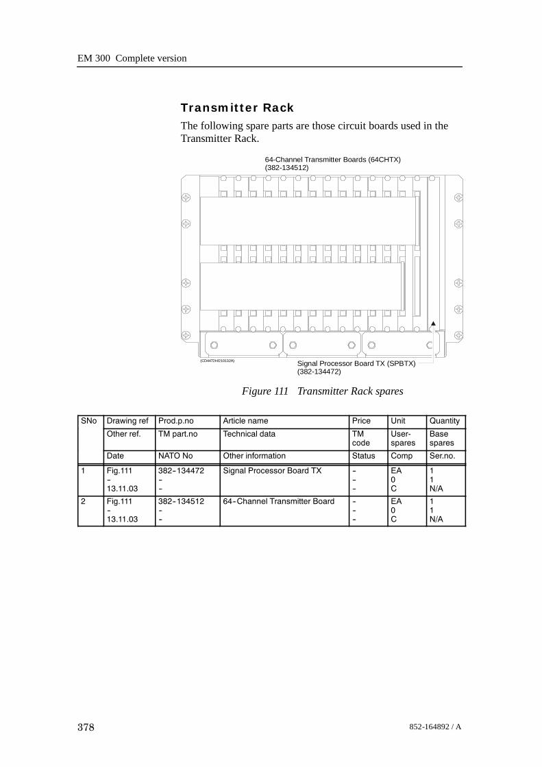
EM 300 Complete version
378 852-164892 / A
Transmitter RackThe following spare parts are those circuit boards used in theTransmitter Rack.
(CD4472H/210132A)
64-Channel Transmitter Boards (64CHTX)(382-134512)
Signal Processor Board TX (SPBTX)(382-134472)
Figure 111 Transmitter Rack spares
SNo Drawing ref Prod.p.no Article name Price Unit Quantity
Other ref. TM part.no Technical data TMcode
User-spares
Basespares
Date NATO No Other information Status Comp Ser.no.
1 Fig.111--13.11.03
382--134472----
Signal Processor Board TX ------
EA0C
11N/A
2 Fig.111--13.11.03
382--134512----
64--Channel Transmitter Board ------
EA0C
11N/A

Spare parts
379852-164892 / A
12.5 Transceiver Unit 125 - 218182
OverviewThe line replaceable units in the EM 300 Transceiver Unit are:• Circuit boards• Capacitor battery• Power supplies• Fans

EM 300 Complete version
380 852-164892 / A
Processing RackThe spare parts in The Processing Rack are those circuit boardsused in the chassis.
Figure 112 ProcessingRack spares parts
CPU Board with DOM(719-098108)
BSP1(382-218016)
Serial card(719-098382)
BSP2(382-218016)
Fan(129-096870)
CPU-J7
P1 P7P5
P1 P7P5
22DiskOnModule
1 1
43
43
S lot 8
Slot 4
Slot 6
Slot 3
Slot 1
Slot 2
Slot 5
Slot 7
Slot 9
Slot 9
14
32
(CD5344F/860-218183A)
CPU-J8
Seria l 3
Seria l 1Seria l 2
Seria l 4
ETH -J12
SNo Drawing ref Prod.p.no Article name Price Unit Quantity
Other ref. TM part.no Technical data TMcode
User-spares
Basespares
Date NATO No Other information Status Comp Ser.no.
1 Fig.108--13.11.03
719--098387----
DiskOnModule (DOM) flash disk(mounted on the CPU board)
------
EA1C
10N/A
2 Fig.108
13.11.03
719--098108----
Control Processor Board (VIPer)
Commercial item
------
EA0C
10N/A
3 Fig.108
13.11.03
382--218016----
Beamformer & Signal Processor ------
EA0C
21N/A
4 Fig.108
13.11.03
719--098382----
Serial card
Commercial item
------
EA0C
11N/A
5 Fig.108
13.11.03
129--096870----
Fan, axial, 12 Vdc
Commercial item
------
EA0C
21N/A
6 Fig.108
13.11.03
719--087748----
SDRAM(mounted on the CPU board)
Commercial item
------
EA0C
21N/A

Spare parts
381852-164892 / A
Figure 113 Processing Rack spares - power supplies
(Cd21111)
8 125 4 37 610 913 12 1116 15 14
Vorsicht! Spannung
Dange r
Attention
+5VHE5-18/OVP-A
15 23 4
OLD
-12/15BB
%%
p12V
G
ND
-out
+5V
S-
S+
+out
OLS-12C
+12V
SNo Drawing ref Prod.p.no Article name Price Unit Quantity
Other ref. TM part.no Technical data TMcode
User-spares
Basespares
Date NATO No Other information Status Comp Ser.no.
1 Fig.113--13.11.03
290--087843----
Power supply
Commercial item
------
EA0C
11N/A
2 Fig.113
13.11.03
290--087850----
Power supply OLD--12/15BB
Commercial item
------
EA0C
11N/A
3 Fig.113
13.11.03
290--098674----
Power supply
Commercial item
------
EA0C
11N/A

EM 300 Complete version
382 852-164892 / A
Receiver RackThe following spare parts are those circuit boards and powersupplies used in the Receiver Rack.
Figure 114 Receiver Rack spares
HIGHMIDDLELOWf (SW)
L207
F206
L206
L205
F2018A
F2028ASLOW
BLOW
F2048A
F2058A
SLOWBLOW
L201
CAUTION
DO NOT PULL OUT THIS UNITBEFORE THE METER SHOWSZERO (0) VOLTAGE.
FOR CONTINUED PROTECTIONAGAINST RISK OF FIREREPLACE ONLY WITH SAMETYPE AND RATING OF FUSE.
S203230V ac
S201230Vac
P201
MAINS INPUT115/230V ac
SIMRADHV-POWER UNIT 290-112751
SIMRADPOWER SUPPLY 290-112750
L202+24VREF
ON/OFFRELAY
24VSTAND
BY
S202SERVICE
OFF
NORMAL
L204
F203
L203
ANALOGPOWERSUPPLY
+7.5VREF-7.5V+5va-5va+5V+12V-12V+24VGND
SWITCHEDPOWERSUPPLY
10050
0150
(CD4472J)
Transmitter/Receiver boards(382-211025)
High Voltage Power Supply(290-112751)
Capacitor bank(299-113105)
Low Voltage Power Supply(290-112750)
Signal Processor Board RX (SPBRX)(382-134469)
SNo Drawing ref Prod.p.no Article name Price Unit Quantity
Other ref. TM part.no Technical data TMcode
User-spares
Basespares
Date NATO No Other information Status Comp Ser.no.
1 Fig.114--02.12.03
382--211025----
Transmitter / Receiver Board ------
EA0C
41N/A
2 Fig.115--02.12.03
290--112750----
Low Voltage Power Supply ------
EA0C
11N/A
3 Fig.115--02.12.03
290--112751----
High Voltage Power Supply ------
EA0C
11N/A
4 Fig.115--02.12.03
382--134469----
Signal Processor Board RX ------
EA0C
11N/A
5 Fig.115--02.12.03
299--113105----
Capacitor Bank ------
EA0C
11N/A

Spare parts
383852-164892 / A
Transmitter RackThe following spare parts are those circuit boards used in theTransmitter Rack.
(CD4472H/210132A)
64-Channel Transmitter Boards (64CHTX)(382-134512)
Signal Processor Board TX (SPBTX)(382-134472)
Figure 115 Transmitter Rack spares
SNo Drawing ref Prod.p.no Article name Price Unit Quantity
Other ref. TM part.no Technical data TMcode
User-spares
Basespares
Date NATO No Other information Status Comp Ser.no.
1 Fig.115--13.11.03
382--134472----
Signal Processor Board TX ------
EA0C
11N/A
2 Fig.115--13.11.03
382--134512----
64--Channel Transmitter Board ------
EA0C
11N/A

EM 300 Complete version
384 852-164892 / A
Blank page

Drawing file
385852-164892 / A
13 DRAWING FILE
13.1 IntroductionThis chapter holds the drawings referenced to in the othersections of the manual.
Note These drawings are available from Kongsberg Maritime onelectronic format (normally AutoCad) upon request. Please state10-digit drawing number when ordering.
13.2 Drawing listThe following drawings are included (listed in numerical order):1 211009 (Rev. -)
Low Voltage Power Supply (page 387)2 499-133996 (Rev.B)
Rx Mounting frame assembly, outline, 1 degree (page388)
3 499-134005 (Rev.A)Tx Mounting frame assembly, outline, 1 degree (page390)
4 599-134008 (Rev.A)Casing for Tx Mounting frame, 1 degree (page 392)
Note Only casing for a 1 degree system is shown. For other systems,the length of the casing must be adjusted to fit the mountingframe.
5 599-134009 (Rev.A)Cover frame for casing, Tx array (page 395)
6 599-134010 (Rev.A)Casing for mounting frame, Rx array (page 396)
Note Only casing for a 1 degree system is shown. For other systems,the length of the casing must be adjusted to fit the mountingframe.
7 830-210021 (Rev.A)Arrangement drawing for Tx array, 1 degree (page 399)
Note Only the arrangement drawing for a 1 degree system is shown.For other systems, the length of the array must be adjusted.
8 830-210025 (Rev.A)Arrangement drawing for Rx array, 1 degree (page 402)

EM 300 Complete version
386 852-164892 / A
Note Only the arrangement drawing for a 1 degree system is shown.For other systems, the length of the array must be adjusted.
9 860-210440 (Rev.A)Tx Mounting frame assembly, outline, 2 degrees (page410)
10 860-210446 (Rev.A)Rx Mounting frame assembly, outline, 2 degrees (page405)
11 860-210592 (Rev.A)Rx Mounting frame assembly, outline, 4 degrees (page412)
12 821-211481 (Rev.A)EM 300A Transducer cable layout (page 407)
13 599-211475 (Rev.A)Outline dimensions, RX module (page 417)
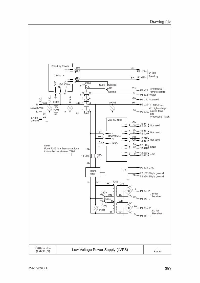
Drawing file
387852-164892 / A
Stand by Power
24Vdc24Vdc
115/230Vac
115/230Vac
115/230Vac
N
N
L
L
GN
D
GRGR GR
BKBK
BKBK
BK
BK
BK
BKBK
A+A-
K201
21 22
5 6
S202
P1 d22+
P1 d26- Stand by
ServiceOff
Normal
WHWH
++
--
YE
YE
Ship’sground
P20
1
LP20
1
LP20
2
LP203F202
F2018A
8A1 2
3 4
VIO
BL
BLBL
GN
GNGN
WH
WH GRGR
RR
Map 55-4001
P1 z28
P1 z32 Heater
P1 d30 Not used
P2 d26
P2 d30
115/230 Vacto high voltagepower, fans andProcessing Rack
P2 z4P2 d6
P2 z8P2 d10
P2 z12P2 d14
P2 z16P2 d18
P2 z20P2 d22
Not used
Not used
Not used
GND
+5V
L
N
GND
NTC22
YE
YE
F203
Note:Fuse F203 is a thermostat fuseinside the transformer T201
Mains filter
1µFP2 z24 GND
P2 z32 Ship’s groundP2 z28 Ship’s ground
YE
BL
BL
BN
BN T201BK GN
230V
115VLP204
S201R
O
WH
GR
AC
AC
AC
AC-
-
+
+
P1 z4 +
P1 d6 -
P1 d10 +
P1 z8 -
8V forReceiver
8V forReceiver
R
WH
BK
BL
-Rev.A
Page 1 of 1(Cd21109) Low Voltage Power Supply (LVPS)
On/off fromremote control

EM 300 Complete version
388 852-164892 / A
3271
mm
150 mm240 mm
(139.25 mm)
330 mm197 mm
499-133996Rev.B
Page 1 of 2(CD5211A) Mounting frame assembly, Rx array, 1 degree
NOTE:The drawingis not in scale.
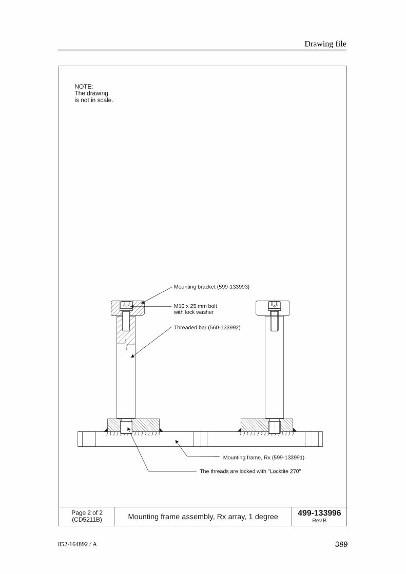
Drawing file
389852-164892 / A
Mounting bracket (599-133993)
M10 x 25 mm boltwith lock washer
Threaded bar (560-133992)
Mounting frame, Rx (599-133991)
The threads are locked with "Locktite 270"
499-133996Rev.B
Page 2 of 2(CD5211B) Mounting frame assembly, Rx array, 1 degree
NOTE:The drawingis not in scale.

EM 300 Complete version
390 852-164892 / A
197 mm 480 mm
390 mm300 mm
2992
mm
(139.25 mm)
499-134005Rev.A
Page 1 of 2(CD5213A) Mounting frame assembly, Tx array, 1 degree
Mounting bracket (599-134004)
NOTE:The drawingis not in scale.
Mounting bracket (599-134003)
Mounting bracket (599-134002)
Mounting bracket (599-134001)
Mounting frame (599-134000)

Drawing file
391852-164892 / A
Threaded bar (560-133992)
Mounting bracket
The threads are locked with "Locktite" 270
M10 x 25 mm boltwith lock washer
499-134005Rev.A
Page 2 of 2(CD5213B) Mounting frame assembly, Tx array, 1 degree
NOTE:The drawingis not in scale.

EM 300 Complete version
392 852-164892 / A
Depends of the zinc size
142.50 165.00 142.50
12.50
127.50
242.50
0
357.50
472.50
587.50
600.00+20
12.500
110.00
135.50
258.50
381.50
504.50
873.50
840.00
750.50
627.50
1119.50
996.50
20x M16
60x M10
1242.50
1365.50
1488.50
1550.00
1980.50
1875.50
1734.50
1611.50
2349.50
2260.002226.50
2103.50
~75
2472.50
2595.50
2718.50
2990.002964.50
2841.50
599-134008Rev.A
Page 1 of 3(CD5245A) Casing for mounting frame, Tx, EM 300
3087.50
3100.00
624
3124
550
3050
+20
600 +/- 0.5
3100+/- 1

Drawing file
393852-164892 / A
599-134008Rev.A
Page 2 of 3(CD5245B) Casing for mounting frame, Tx, EM 300
2235.00
2965.00 +/- 2.5
2590.00 +/- 5
2845.00 +/- 5
1525.00 +/- 2.5
1105.00 +/- 5
815.00 +/- 2.5
75+5/-0
150+5/-0
360.00 +/- 5
85.00 +/- 2.5
0
R25
x8Bothsides

EM 300 Complete version
394 852-164892 / A
599-134008Rev.A
Page 3 of 3(CD5245C) Casing for mounting frame, Tx, EM 300
15
15+ -
0.5
197+ -
0.5
299+2
.5-2
.5
500+- 2.5
50+2.50
20
2.5x4.5o
Ø50
M10
50
Item Qty Description Dimension
Note 1
Note 2:
Weight:
Surface treatment:
1 1 Steel plate 12 x 3124 x 624 mm2 2 Steel plate 12 x 3124 x 299 mm3 2 Steel plate 12 x 600 x 299 mm4 5 Steel plate 50 x 100 x 600 mm5 10 Steel plate 15 x 157 x 50 mm6 Steel plate 15 x 25 x 7300 mm
Welding procedure to be given by the shipyard
Steel quality NVA equal to BS 4360, 40B
Approx 550 kg
Sandblast Sa 2.5, 1 coatd ironoxide primer 30 micron
653
1
42

Drawing file
395852-164892 / A
599-134009Rev.A
Page 1 of 1(CD5249A) Cover frame, casing, Tx array, EM 300
392
3098
598
6074
3.50
3075
= 2
5x 1
23
575 = 5x 115
103
A
B
A
A
B B
8x45
60x 11ø0.5 A B
11
743
743
743.
50
19+1/-0
19+1/-0
(11.50)
90°
5+0.5
/-0
(11.50)
(60)
90°
(103)
15
15SECTION A-A
SECTION B-B
ITEM 1
ITEM 2

EM 300 Complete version
396 852-164892 / A
Depends of the
size of the zinc anode
599-134010Rev.A
Page 1 of 3(CD5246A) Casing for mounting frame, Rx, EM 300

Drawing file
397852-164892 / A
599-134010Rev.A
Page 2 of 3(CD5246B) Casing for mounting frame, Rx, EM 300

599-134010Rev.A
Page 3 of 3(CD5246C) Casing for mounting frame, Rx, EM 300
Item Qty Description Dimension
Note 1
Note 2:
Weight:
Surface treatment:
1 1 Steel plate 12 x 3341 x 474 mm2 2 Steel plate 12 x 3341 x 285 mm3 2 Steel plate 12 x 450 x 285 mm4 7 Steel plate 50 x 100 x 450 mm5 14 Steel plate 10 x 156 x 40 mm6 Steel plate 15 x 25 x 7600 mm
Welding procedure to be given by the shipyard
Steel quality NVA equal to BS 4360, 40B
Approx 550 kg
Sandblast Sa 2.5, 1 coatd ironoxide primer 30 micron
EM 300 Complete version
398 852-164892 / A

Drawing file
399852-164892 / A
830-210021Rev.A
Page 1 of 3(CD5247A)
Arrangement drawing, casing with mounting frameTX Array, 1 degree system, EM 300
4 ea ~8Kg Zinc anodes
Depends of the size of the zinc anode
(425)
Casing (shipyard supply)
Mounting Frame assembly(Supplied by manufacturer)
20 ea M16x60 Hex cap screw with washer.Supplied by the manufacturer.Tightening torque: 187 NmMust be secured with Loctite 270

EM 300 Complete version
400 852-164892 / A
830-210021Rev.A
Page 2 of 3(CD5247B)
Arrangement drawing, casing with mounting frameTX Array, 1 degree system, EM 300
TX Modul 1
TX Modul 1
TX M
odul 1TX
Modul 1
TX M
odul 2TX M
odul 2TX M
odul 2TX
Modul 2
3124
599-134009 Cover Frame(Shipyard supply)
60 ea M10x30 Socket flat head screw(Shipyard supply)
830-134325 Outline drawing TX Module 2
830-134324 Outline drawing TX Module 1
624
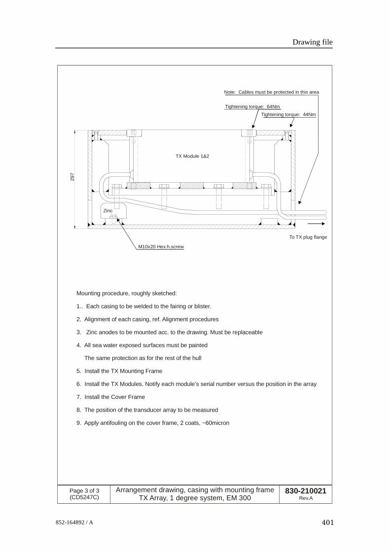
Drawing file
401852-164892 / A
830-210021Rev.A
Page 3 of 3(CD5247C)
Arrangement drawing, casing with mounting frameTX Array, 1 degree system, EM 300
297
TX Module 1&2
Zinc
M10x20 Hex.h.screw
To TX plug flange
Note: Cables must be protected in this area
Tightening torque: 64NmTightening torque: 44Nm
Mounting procedure, roughly sketched:
1.. Each casing to be welded to the fairing or blister.
2. Alignment of each casing, ref. Alignment procedures
3. Zinc anodes to be mounted acc. to the drawing. Must be replaceable
4. All sea water exposed surfaces must be painted
The same protection as for the rest of the hull
5. Install the TX Mounting Frame
6. Install the TX Modules. Notify each module’s serial number versus the position in the array
7. Install the Cover Frame
8. The position of the transducer array to be measured
9. Apply antifouling on the cover frame, 2 coats, ~60micron

EM 300 Complete version
402 852-164892 / A
821-210025Rev.A
Page 1 of 3(CD5248A)
Arrangement drawing, casing with moutning frame,Rx array, 1 degree system, EM 300
474
(400)
Depends of the size of the Zinc anode
3341
4x ~8Kg Zinc anode
Casing (Shipyard supply)
Mounting Frame assembly(Supplied by Kongsberg Simrad)
21 ea M16x60 Hex cap screw with washer.Supplied by Kongsberg Simrad.Tightening torque: 187NmTo be secured with Loctite 270

Drawing file
403852-164892 / A
821-210025Rev.A
Page 2 of 3(CD5248B)
Arrangement drawing, casing with moutning frame,Rx array, 1 degree system, EM 300
RX
Modul
RX
Modul
RX
Modul
RX
Modul
RX M
odulR
X M
odulR
X M
odulR
XM
odul
Cover Frame (Shipyard supply)
60 ea M10x30 Socket flat head screw(Shipyard supply)
830-134288 Outline drawing RX Module

EM 300 Complete version
404 852-164892 / A
821-210025Rev.A
Page 3 of 3(CD5248C)
Arrangement drawing, casing with moutning frame,Rx array, 1 degree system, EM 300
297
RX Modul
Zinc
M10x20 Hex.h.screw
Note: Cablesmust beprotectedin this area
To RX plug flange
Tightening torque: 64Nm
Tightening torque: 44Nm
Mounting procedure, roughly sketched:
1.. Each casing to be welded to the fairing or blister.
2. Alignment of each casing, ref. Alignment procedures
3. Zinc anodes to be mounted acc. to the drawing. Must be replaceable
4. All sea water exposed surfaces must be painted
The same protection as for the rest of the hull
5. Install the RX Mounting Frame
6. Install the RX Modules. Notify each module’s serial number versus the position in the array
7. Install the Cover Frame
8. The position of the transducer array to be measured
9. Apply antifouling on the cover frame, 2 coats, ~60micron

Drawing file
405852-164892 / A
150 mm
240 mm
330 mm
829
mm
139.25 mm
197 mm
860-210446Rev.A
Page 1 of 2(CD5212A) Mounting frame assembly, Rx array, 4 degrees
NOTE:The drawingis not in scale.

EM 300 Complete version
406 852-164892 / A
Mounting bracket (599-133993)
M10 x 25 mm boltwith lock washer
Threaded bar (560-133992)
Mounting frame, Rx (599-210443)
The threads are locked with "Locktite 270"
860-210446Rev.A
Page 2 of 2(CD5212B) Mounting frame assembly, Rx array, 4 degrees
NOTE:The drawingis not in scale.

Drawing file
407852-164892 / A
Rx no.8
Pos.8
Pos.7
Pos.6
Pos.5
Pos.4
Pos.3
Pos.2
Pos.1
Rx no.7
Rx no.6
Rx no.5
Rx no.4
Rx no.3
Rx no.2
Rx no.1
Part of TransceiverUnit's bottom plate
Steel tube, recommended size: ø177.8 x 145.8Quality: St52-3N according to DIN 17121with certificate EN 10204/3.1B
1 degree system: All Rx modules are used.2 degrees system: Rx modules 1, 2, 3 and 4 are used.4 degrees systems: Rx modules 1 and 2 are used.
Air outlet
Detail "A" on page 3/3,drawing CD5223C
Shell plate
Position 8Rx moduleSer.no.zzh
Position 7Rx moduleSer.no.zzg
Position 6Rx moduleSer.no.zzf
Position 5Rx moduleSer.no.zze
Position 4Rx moduleSer.no.zzd
Position 3Rx moduleSer.no.zzc
Position 2Rx moduleSer.no.zzb
Position 1Rx moduleSer.no.zza
Forward
Port
821-211481Rev.A
Page 1 of 3(CD5223A) EM 300A Transducer cable layout
View from below
Rx modules and cables
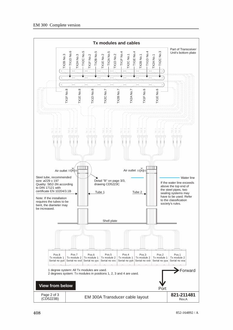
EM 300 Complete version
408 852-164892 / A
TX2B
No.
3
TX1D
No.
6
TX2A
No.
3
TX2C
No.
5
TX1F
No.
2
TX2B
No.
5
TX2A
No.
5
TX1F
No.
4
TX1E
No.
4
TX1D
No.
4
TX2C
No.
3
TX1E
No.
2
TX1D
No.
2
TX2C
No.
1
TX2B
No.
1
TX2A
No.
1
Pos.8Tx module 1Serial no yyd
Pos.7Tx module 2Serial no xxd
Pos.6Tx module 1Serial no yyc
Pos.5Tx module 2Serial no xxc
Pos.4Tx module 1Serial no yyb
Pos.3Tx module 2Serial no xxb
Pos.2Tx module 1Serial no yya
Pos.1Tx module 2Serial no xxa
Water lineIf the water line exceedsabove the top end ofthe steel pipes, two sealing systems mayhave to be used. Referto the classificationsociety's rules.
Steel tube, recommendedsize: ø229 x 197Quality: St52-3N accordingto DIN 17121 withcertificate EN 10204/3.1B
Note: If the installationrequires the tubes to bebent, the diameter maybe increased.
Air outlet
Detail "B" on page 3/3,drawing CD5223C
Shell plate
Tube 1 Tube 2
Air outlet
TX1F
No.
8
TX1E
No.
8
TX1D
No.
8
TX2C
No.
7
TX2B
No.
7
TX2A
No.
7
TX1F
No.
6
TX1E
No.
6
821-211481Rev.A
Page 2 of 3(CD5223B) EM 300A Transducer cable layout
Tx modules and cables
Forward
PortView from below
Part of TransceiverUnit's bottom plate
1 degree system: All Tx modules are used.2 degrees system: Tx modules in positions 1, 2, 3 and 4 are used.

Drawing file
409852-164892 / A
ø 150 mm+2 / -0
ø 200 mm+2 / -0
70 mm
70 mm
Approx 150 mm
Approx 150 mm
Detail "A" from page 1; top of tube
Detail "B" from page 2; top of tubes
821-211481Rev.A
Page 3 of 3(CD5223C) EM 300A Transducer cable layout
Note 1: The cable seal system used is the "Roxtec" system. Other cable seal systemmay be used provided that the seal is gas- and watertight to 4 bar.
Note 2: Transducer cables:Tx cable - diameter ø17.07 +/- 0.5 mm, minimum bending radius is 105 mmRx cable - diamater ø17.11 +/- 0.5 mm, minimum bending radius is 105 mmStandard length is 15 meters.The length may be increased on the "dry side" with extension cables.
Note 3: Roxtec system:"R" type frames, Tx size: R-200, Rx size: R-150with 32 pcs multidiameter modules, size RM30, and 9 spares (solid) size RM30/0.
Note 4: EM 300:It is possible to pull Rx and Tx cables through common tubes.
Sealing system, see Notes 1 and 3 below.
Tx
Rx

EM 300 Complete version
410 852-164892 / A
300 mm
Mounting frame, Tx(599-210389)
Part no. 499-210441
NOTE:The drawing isnot in scale.
Mounting bracket(599-134001)
Mounting bracket(599-134002)
Mounting bracket(599-134003)
Mounting bracket(599-134004)15
05 m
m
139.25 mm
167 mm390 mm
480 mm
860-210440Rev.A
Page 1 of 2(CD5214A) Mounting frame assembly, Tx array, 2 degrees
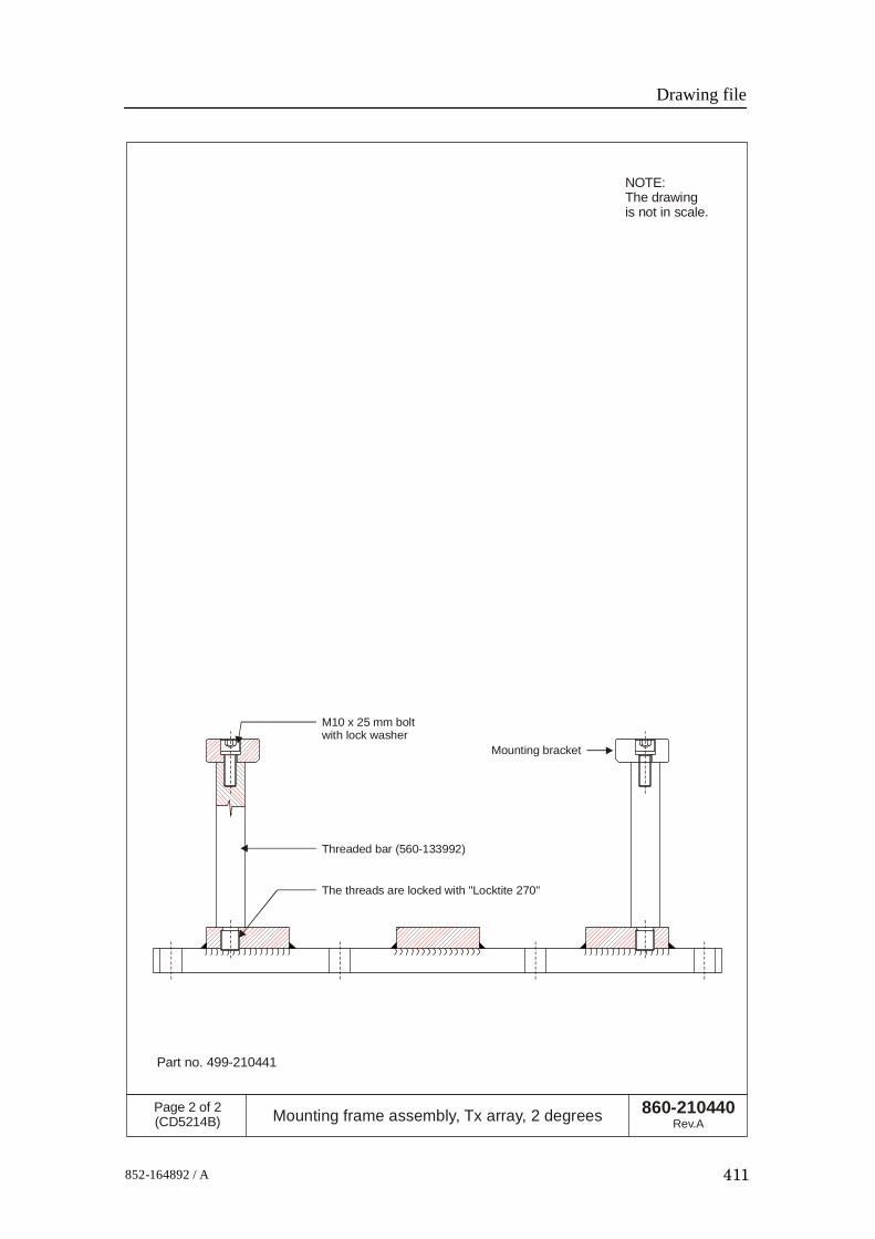
Drawing file
411852-164892 / A
Threaded bar (560-133992)
Mounting bracket
The threads are locked with "Locktite 270"
M10 x 25 mm boltwith lock washer
860-210440Rev.A
Page 2 of 2(CD5214B) Mounting frame assembly, Tx array, 2 degrees
NOTE:The drawingis not in scale.
Part no. 499-210441

EM 300 Complete version
412 852-164892 / A
330 mm
150 mm
240 mm
139.25 mm
1643
mm
197 mm
860-210592Rev.A
Page 1 of 2(CD5215A) Mounting frame assembly, Rx array, 2 degrees
NOTE:The drawingis not in scale.

Drawing file
413852-164892 / A
Mounting bracket (599-133993)
M10 x 25 mm boltwith lock washer
Threaded bar (560-133992)
Mounting frame, Rx (599-210387)
The threads are locked with "Locktite 270"
860-210592Rev.A
Page 2 of 2(CD5215B) Mounting frame assembly, Rx array, 2 degrees
NOTE:The drawingis not in scale.

EM 300 Complete version
414 852-164892 / A
Rx no.8
Pos.8
Pos.7
Pos.6
Pos.5
Pos.4
Pos.3
Pos.2
Pos.1
Rx no.7
Rx no.6
Rx no.5
Rx no.4
Rx no.3
Rx no.2
Rx no.1
Part of TransceiverUnit's bottom plate
Steel tube, recommended size: ø177.8 x 145.8Quality: St52-3N according to DIN 17121with certificate EN 10204/3.1B
1 degree system: All Rx modules are used.2 degrees system: Rx modules 1, 2, 3 and 4 are used.4 degrees systems: Rx modules 1 and 2 are used.
Air outlet
Detail "A" on page 3/3,drawing CD5223C
Shell plate
Position 8Rx moduleSer.no.zzh
Position 7Rx moduleSer.no.zzg
Position 6Rx moduleSer.no.zzf
Position 5Rx moduleSer.no.zze
Position 4Rx moduleSer.no.zzd
Position 3Rx moduleSer.no.zzc
Position 2Rx moduleSer.no.zzb
Position 1Rx moduleSer.no.zza
Forward
Port
821-211481Rev.A
Page 1 of 3(CD5223A) EM 300A Transducer cable layout
View from below
Rx modules and cables

Drawing file
415852-164892 / A
TX2B
No.
3
TX1D
No.
6
TX2A
No.
3
TX2C
No.
5
TX1F
No.
2
TX2B
No.
5
TX2A
No.
5
TX1F
No.
4
TX1E
No.
4
TX1D
No.
4
TX2C
No.
3
TX1E
No.
2
TX1D
No.
2
TX2C
No.
1
TX2B
No.
1
TX2A
No.
1
Pos.8Tx module 1Serial no yyd
Pos.7Tx module 2Serial no xxd
Pos.6Tx module 1Serial no yyc
Pos.5Tx module 2Serial no xxc
Pos.4Tx module 1Serial no yyb
Pos.3Tx module 2Serial no xxb
Pos.2Tx module 1Serial no yya
Pos.1Tx module 2Serial no xxa
Water lineIf the water line exceedsabove the top end ofthe steel pipes, two sealing systems mayhave to be used. Referto the classificationsociety's rules.
Steel tube, recommendedsize: ø229 x 197Quality: St52-3N accordingto DIN 17121 withcertificate EN 10204/3.1B
Note: If the installationrequires the tubes to bebent, the diameter maybe increased.
Air outlet
Detail "B" on page 3/3,drawing CD5223C
Shell plate
Tube 1 Tube 2
Air outlet
TX1F
No.
8
TX1E
No.
8
TX1D
No.
8
TX2C
No.
7
TX2B
No.
7
TX2A
No.
7
TX1F
No.
6
TX1E
No.
6
821-211481Rev.A
Page 2 of 3(CD5223B) EM 300A Transducer cable layout
Tx modules and cables
Forward
PortView from below
Part of TransceiverUnit's bottom plate
1 degree system: All Tx modules are used.2 degrees system: Tx modules in positions 1, 2, 3 and 4 are used.
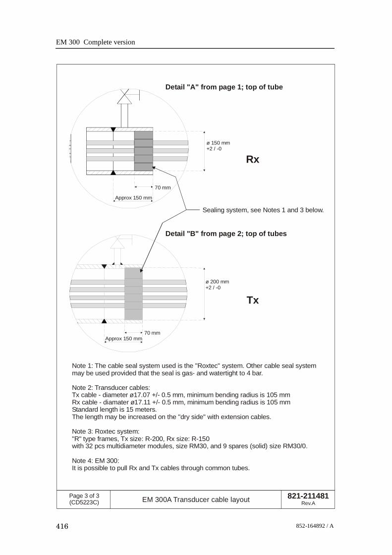
EM 300 Complete version
416 852-164892 / A
ø 150 mm+2 / -0
ø 200 mm+2 / -0
70 mm
70 mm
Approx 150 mm
Approx 150 mm
Detail "A" from page 1; top of tube
Detail "B" from page 2; top of tubes
821-211481Rev.A
Page 3 of 3(CD5223C) EM 300A Transducer cable layout
Note 1: The cable seal system used is the "Roxtec" system. Other cable seal systemmay be used provided that the seal is gas- and watertight to 4 bar.
Note 2: Transducer cables:Tx cable - diameter ø17.07 +/- 0.5 mm, minimum bending radius is 105 mmRx cable - diamater ø17.11 +/- 0.5 mm, minimum bending radius is 105 mmStandard length is 15 meters.The length may be increased on the "dry side" with extension cables.
Note 3: Roxtec system:"R" type frames, Tx size: R-200, Rx size: R-150with 32 pcs multidiameter modules, size RM30, and 9 spares (solid) size RM30/0.
Note 4: EM 300:It is possible to pull Rx and Tx cables through common tubes.
Sealing system, see Notes 1 and 3 below.
Tx
Rx

Drawing file
417852-164892 / A
20
1R
X
830-211475Rev.A
Page 1 of 1(Cd21001) Outline dimensions, Rx module, EM 300
159.75
2028.5
200
25.5
149
R2.5~1
5000
200
206 100
406
R13
54
17
50 pins D-connector

EM 300 Complete version
418 852-164892 / A
Blank page


E 2003 Kongsberg MaritimeISBN

Blank page

Blank page


EM300
Maintenance
manualCom
pleteversion
EM300
Maintenance
manualCom
pleteversion
EM300
Maintenance
manualCom
pleteversion
EM300
Maintenance
manualCom
pleteversion