
Elyasi-Sheemet2009
10
Investigation of Die Corner Filling in Hydroforming of Cylindrical Stepped Tubes Using Finite Element Simulation and Experiment M. Bakhshi-Jooybari 1, a , M. Elyasi 1,b , A. Gorji 1,c , G. Alinejad 1, d , S. J. Hosseinipour 1, e and S. Nourouzi 1, f 1 Faculty of Mechanical Engineering, Babol Noshirvani University of Technology, Babol, P. O. Box 484, Mazandaran, Iran a [email protected], b [email protected], c [email protected], d [email protected], e [email protected], f [email protected] Keywords: tube hydroforming, hydroforming die design, stepped tubes, finite element simulation. Abstract. Seamless tubular components, such as stepped tubes, conical tubes and box shape tubes, are mainly produced in tube hydroforming process. In forming the components in this process, complete filling the die corners is very difficult. In this paper, the mechanism of improvement of die corner filling in a proposed tube hydroforming die was investigated. The FEM simulation results showed that the material flow and stress distribution could theoretically clarify the die corner filling in the proposed die. Also, the comparison of the die corner filling between the new die and a conventional die was explained. In order to verify the simulation results, some experiments were performed. Introduction Tube hydroforming has recently found a wide application in different industries, due to the advantages encountered in this process. Geometry of die and workpiece, initial tube dimension, tube anisotropy, and internal pressure are of the important parameters in this process [1-3]. A typical conventional hydroforming die set for stepped tubes is illustrated in Fig. 1. By applying simultaneously the internal fluid pressure and axial feeding, the tube is formed to the shape of the die cavity. One of the main characteristics of the tube hydroforming process is filling the die cavities. This will greatly affect the maximum internal pressure. If the internal pressure, before filling the die corners, reaches a critical value, then it is required to apply higher pressure to fill the corners. This will most likely lead to bursting of the tube. On the other hand, depending on the process parameters, different pressure paths are required to obtain the desired products. The pressure paths will influence the die cavity filling and the dimensional accuracy of the products [4-7]. Some researchers investigated the die corner filling in tube hydroforming. Kridli et al. [5] stated that the thickness distribution is a function of the die corner radius and strain-hardening behavior of tube material. They also stated that the thickness distribution could be reduced if a larger die corner radius was selected. Hwang et al. [7] examined the corner filling in a square cross sectional hydroforming. They concluded that higher pressure was required to fill the die corner if the corner radius was decreased. Loh-Mousavi et al. [8, 9] studied the filling of the die corner in box shape and T-shape tube hydroforming dies. They used a pulsating pressure path to improve the die filling. Although they improved the filling of the die corners, but the dies were not filled completely. In addition, producing a pulsating pressure path is more difficult than linear or constant pressure paths. A new tube hydroforming die was proposed by the authors [10] that improves the die corner filling in cylindrical stepped tube dies. Fig. 2 illustrates the schematic of the forming steps in the new die. This die set contains two additional bushes, compared with the conventional tube hydroforming dies [4-8]. Initially, the tube is placed in the die, filled with liquid, and sealed with the punches, as shown in Fig. 2-a. Then, by increasing the internal pressure, the tube is bulged (Fig. 2-b). By Key Engineering Materials Vols. 410-411 (2009) pp 335-343 online at http://www.scientific.net © (2009) Trans Tech Publications, Switzerland All rights reserved. No part of contents of this paper may be reproduced or transmitted in any form or by any means without the written permission of the publisher: Trans Tech Publications Ltd, Switzerland, www.ttp.net. (ID: 78.38.77.3-06/02/09,12:47:39)
Transcript of Elyasi-Sheemet2009
Investigation of Die Corner Filling in Hydroforming of Cylindrical
Stepped Tubes Using Finite Element Simulation and Experiment
M. Bakhshi-Jooybari 1, a, M. Elyasi 1,b, A. Gorji1,c, G. Alinejad1, d, S. J. Hosseinipour 1, e and S. Nourouzi1, f
1Faculty of Mechanical Engineering, Babol Noshirvani University of Technology,
Babol, P. O. Box 484, Mazandaran, Iran
Keywords: tube hydroforming, hydroforming die design, stepped tubes, finite element simulation.
Abstract. Seamless tubular components, such as stepped tubes, conical tubes and box shape tubes,
are mainly produced in tube hydroforming process. In forming the components in this process,
complete filling the die corners is very difficult. In this paper, the mechanism of improvement of die
corner filling in a proposed tube hydroforming die was investigated. The FEM simulation results
showed that the material flow and stress distribution could theoretically clarify the die corner filling
in the proposed die. Also, the comparison of the die corner filling between the new die and a
conventional die was explained. In order to verify the simulation results, some experiments were
performed.
Introduction
Tube hydroforming has recently found a wide application in different industries, due to the
advantages encountered in this process. Geometry of die and workpiece, initial tube dimension, tube
anisotropy, and internal pressure are of the important parameters in this process [1-3].
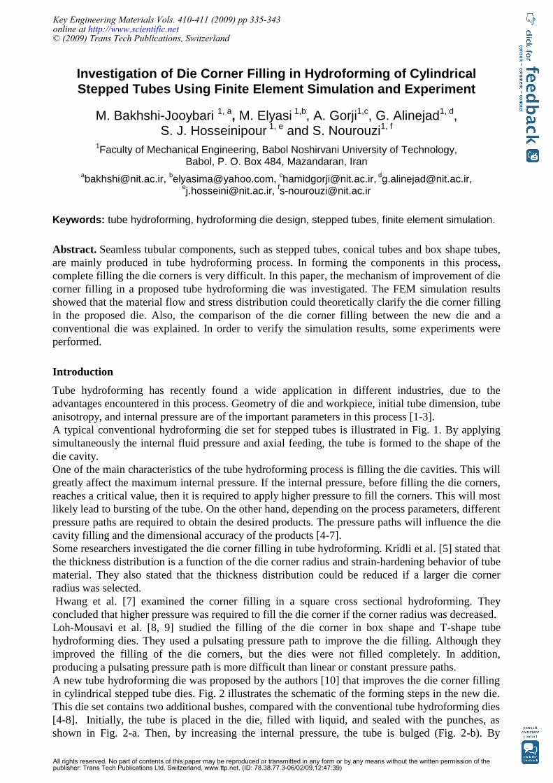
A typical conventional hydroforming die set for stepped tubes is illustrated in Fig. 1. By applying
simultaneously the internal fluid pressure and axial feeding, the tube is formed to the shape of the
die cavity.
One of the main characteristics of the tube hydroforming process is filling the die cavities. This will
greatly affect the maximum internal pressure. If the internal pressure, before filling the die corners,
reaches a critical value, then it is required to apply higher pressure to fill the corners. This will most
likely lead to bursting of the tube. On the other hand, depending on the process parameters, different
pressure paths are required to obtain the desired products. The pressure paths will influence the die
cavity filling and the dimensional accuracy of the products [4-7].
Some researchers investigated the die corner filling in tube hydroforming. Kridli et al. [5] stated that
the thickness distribution is a function of the die corner radius and strain-hardening behavior of tube
material. They also stated that the thickness distribution could be reduced if a larger die corner
radius was selected.
Hwang et al. [7] examined the corner filling in a square cross sectional hydroforming. They
concluded that higher pressure was required to fill the die corner if the corner radius was decreased.
Loh-Mousavi et al. [8, 9] studied the filling of the die corner in box shape and T-shape tube
hydroforming dies. They used a pulsating pressure path to improve the die filling. Although they
improved the filling of the die corners, but the dies were not filled completely. In addition,
producing a pulsating pressure path is more difficult than linear or constant pressure paths.
A new tube hydroforming die was proposed by the authors [10] that improves the die corner filling
in cylindrical stepped tube dies. Fig. 2 illustrates the schematic of the forming steps in the new die.
This die set contains two additional bushes, compared with the conventional tube hydroforming dies
[4-8]. Initially, the tube is placed in the die, filled with liquid, and sealed with the punches, as
shown in Fig. 2-a. Then, by increasing the internal pressure, the tube is bulged (Fig. 2-b). By
Key Engineering Materials Vols. 410-411 (2009) pp 335-343online at http://www.scientific.net© (2009) Trans Tech Publications, Switzerland
All rights reserved. No part of contents of this paper may be reproduced or transmitted in any form or by any means without the written permission of thepublisher: Trans Tech Publications Ltd, Switzerland, www.ttp.net. (ID: 78.38.77.3-06/02/09,12:47:39)
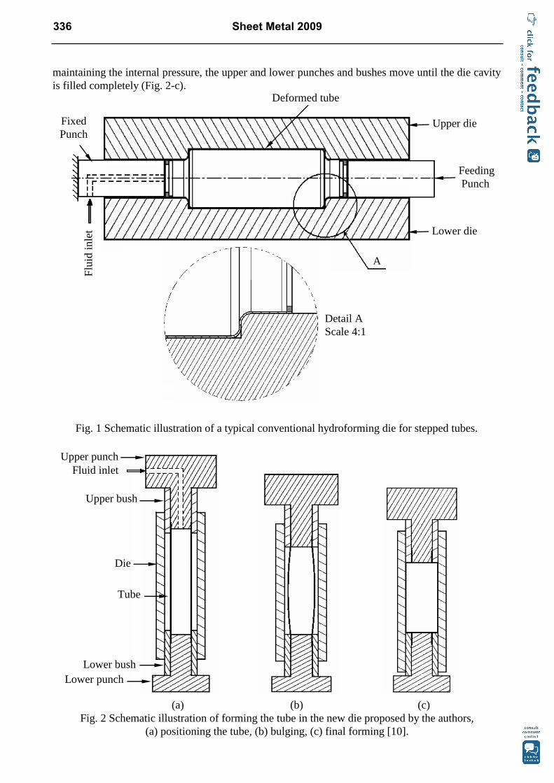
maintaining the internal pressure, the upper and lower punches and bushes move until the die cavity
is filled completely (Fig. 2-c).
Fig. 1 Schematic illustration of a typical conventional hydroforming die for stepped tubes.
(a) (b) (c)
Fig. 2 Schematic illustration of forming the tube in the new die proposed by the authors,
(a) positioning the tube, (b) bulging, (c) final forming [10].
Deformed tube
Fixed
Punch
A
Upper die
Lower die
Feeding
Punch
Flu
id i
nle
t
Detail A
Scale 4:1
Fluid inlet
Lower punch
Tube
Die
Lower bush
Upper bush
Upper punch
336 Sheet Metal 2009
As it can be seen from Fig.1, in the conventional dies, the feeding punch that is in contact with the
tube end, exerts the axial feeding on the tube. In this case, the die corners cannot be filled
completely. In the proposed method shown in Fig. 2, in each side of the tube, even though the punch
is similarly in contact with the tube end, but the bush gradually contacts the tube. At the end of the
forming step, both the punch and bush will be in complete contact with the tube and will exert axial
feeding on it. This will lead to complete filling of the die corners.
In this paper, the mechanism of improvement of die corner filling in the new hydroforming die is
investigated. The results obtained for the new die is compared with those of a conventional die.
FEM Analysis
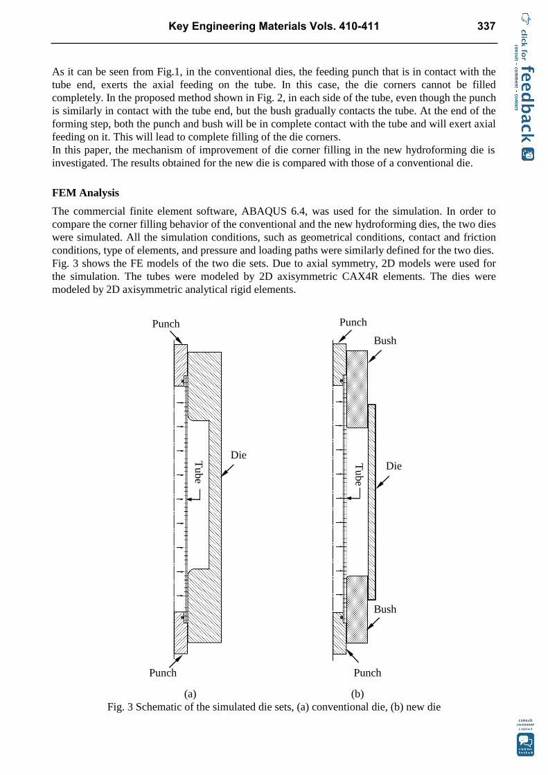
The commercial finite element software, ABAQUS 6.4, was used for the simulation. In order to
compare the corner filling behavior of the conventional and the new hydroforming dies, the two dies
were simulated. All the simulation conditions, such as geometrical conditions, contact and friction
conditions, type of elements, and pressure and loading paths were similarly defined for the two dies.
Fig. 3 shows the FE models of the two die sets. Due to axial symmetry, 2D models were used for
the simulation. The tubes were modeled by 2D axisymmetric CAX4R elements. The dies were
modeled by 2D axisymmetric analytical rigid elements.
(a) (b)
Fig. 3 Schematic of the simulated die sets, (a) conventional die, (b) new die
Die
Punch Punch
Die
Bush
Bush
Punch
Tube
Punch
Tube
Key Engineering Materials Vols. 410-411 337
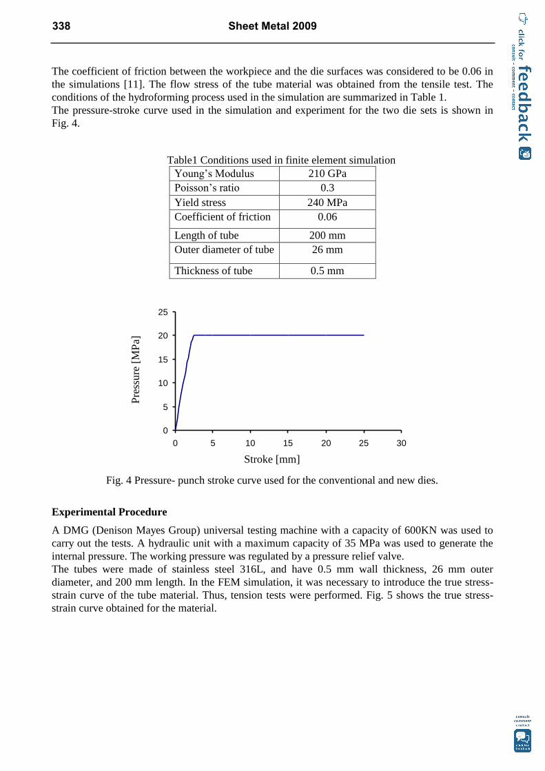
The coefficient of friction between the workpiece and the die surfaces was considered to be 0.06 in
the simulations [11]. The flow stress of the tube material was obtained from the tensile test. The
conditions of the hydroforming process used in the simulation are summarized in Table 1.
The pressure-stroke curve used in the simulation and experiment for the two die sets is shown in
Fig. 4.
Table1 Conditions used in finite element simulation
Young’s Modulus 210 GPa
Poisson’s ratio 0.3
Yield stress 240 MPa
Coefficient of friction 0.06
Length of tube 200 mm
Outer diameter of tube 26 mm
Thickness of tube 0.5 mm
Fig. 4 Pressure- punch stroke curve used for the conventional and new dies.
Experimental Procedure
A DMG (Denison Mayes Group) universal testing machine with a capacity of 600KN was used to
carry out the tests. A hydraulic unit with a maximum capacity of 35 MPa was used to generate the
internal pressure. The working pressure was regulated by a pressure relief valve.
The tubes were made of stainless steel 316L, and have 0.5 mm wall thickness, 26 mm outer
diameter, and 200 mm length. In the FEM simulation, it was necessary to introduce the true stress-
strain curve of the tube material. Thus, tension tests were performed. Fig. 5 shows the true stress-
strain curve obtained for the material.
0
5
10
15
20
25
0 5 10 15 20 25 30
Pre
ssure
[M
Pa]
Stroke [mm]
338 Sheet Metal 2009
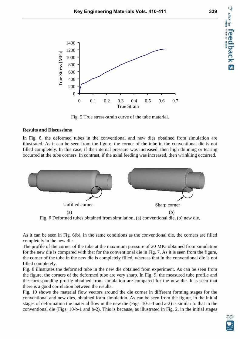
Fig. 5 True stress-strain curve of the tube material.
Results and Discussions
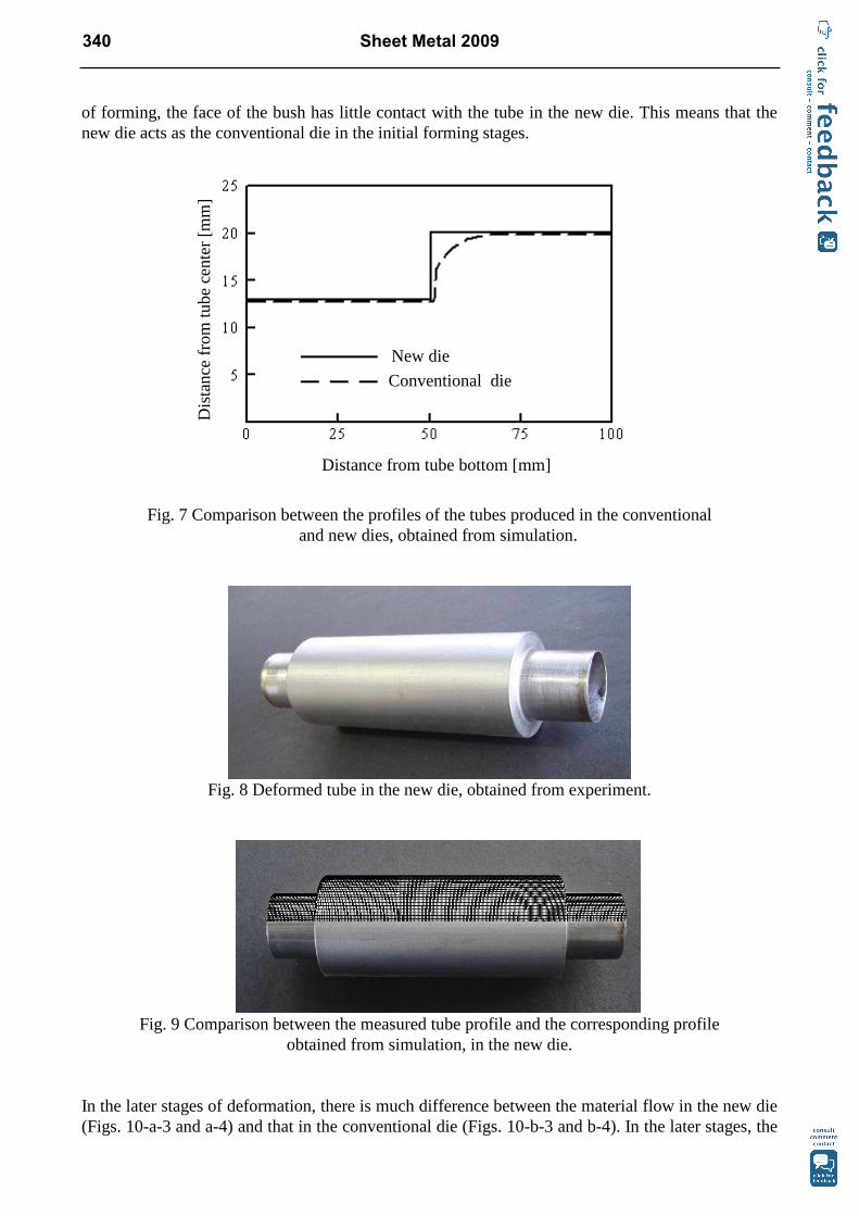
In Fig. 6, the deformed tubes in the conventional and new dies obtained from simulation are
illustrated. As it can be seen from the figure, the corner of the tube in the conventional die is not
filled completely. In this case, if the internal pressure was increased, then high thinning or tearing
occurred at the tube corners. In contrast, if the axial feeding was increased, then wrinkling occurred.
(a) (b)
Fig. 6 Deformed tubes obtained from simulation, (a) conventional die, (b) new die.
As it can be seen in Fig. 6(b), in the same conditions as the conventional die, the corners are filled
completely in the new die.
The profile of the corner of the tube at the maximum pressure of 20 MPa obtained from simulation
for the new die is compared with that for the conventional die in Fig. 7. As it is seen from the figure,
the corner of the tube in the new die is completely filled, whereas that in the conventional die is not
filled completely.
Fig. 8 illustrates the deformed tube in the new die obtained from experiment. As can be seen from
the figure, the corners of the deformed tube are very sharp. In Fig. 9, the measured tube profile and
the corresponding profile obtained from simulation are compared for the new die. It is seen that
there is a good correlation between the results.
Fig. 10 shows the material flow vectors around the die corner in different forming stages for the
conventional and new dies, obtained form simulation. As can be seen from the figure, in the initial
stages of deformation the material flow in the new die (Figs. 10-a-1 and a-2) is similar to that in the
conventional die (Figs. 10-b-1 and b-2). This is because, as illustrated in Fig. 2, in the initial stages
Tru
e S
tres
s [M
Pa]
0
200
400
600
800
1000
1200
1400
0 0.1 0.2 0.3 0.4 0.5 0.6 0.7
True Strain
Sharp corner Unfilled corner
Key Engineering Materials Vols. 410-411 339
of forming, the face of the bush has little contact with the tube in the new die. This means that the
new die acts as the conventional die in the initial forming stages.
Fig. 7 Comparison between the profiles of the tubes produced in the conventional
and new dies, obtained from simulation.
Fig. 8 Deformed tube in the new die, obtained from experiment.
Fig. 9 Comparison between the measured tube profile and the corresponding profile
obtained from simulation, in the new die.
In the later stages of deformation, there is much difference between the material flow in the new die
(Figs. 10-a-3 and a-4) and that in the conventional die (Figs. 10-b-3 and b-4). In the later stages, the
New die
Conventional die
Distance from tube bottom [mm]
Dis
tance
fro
m t
ube
cente
r [m
m]
Str
ess
[MP
a]
340 Sheet Metal 2009
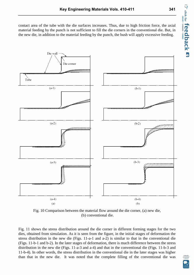
contact area of the tube with the die surfaces increases. Thus, due to high friction force, the axial
material feeding by the punch is not sufficient to fill the die corners in the conventional die. But, in
the new die, in addition to the material feeding by the punch, the bush will apply excessive feeding.
Fig. 10 Comparison between the material flow around the die corner, (a) new die,
(b) conventional die.
Fig. 11 shows the stress distribution around the die corner in different forming stages for the two
dies, obtained from simulation. As it is seen from the figure, in the initial stages of deformation the
stress distribution in the new die (Figs. 11-a-1 and a-2) is similar to that in the conventional die
(Figs. 11-b-1 and b-2). In the later stages of deformation, there is much difference between the stress
distribution in the new die (Figs. 11-a-3 and a-4) and that in the conventional die (Figs. 11-b-3 and
11-b-4). In other words, the stress distribution in the conventional die in the later stages was higher
than that in the new die. It was noted that the complete filling of the conventional die was
Key Engineering Materials Vols. 410-411 341
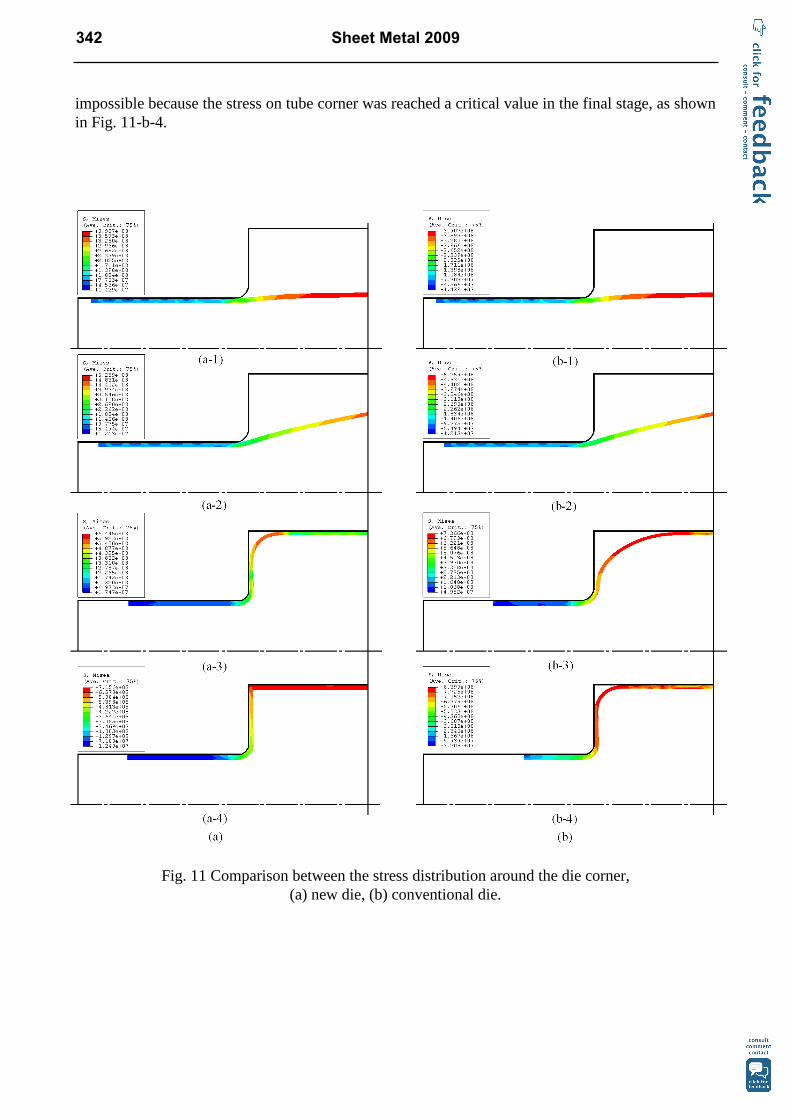
impossible because the stress on tube corner was reached a critical value in the final stage, as shown
in Fig. 11-b-4.
Fig. 11 Comparison between the stress distribution around the die corner,
(a) new die, (b) conventional die.
342 Sheet Metal 2009
Conclusions
In this paper, the mechanism of improvement of die corner filling in a new tube hydroforming die
was investigated. The results obtained indicated that the new die improves the corner filling. The
FEM simulation results showed that the material flow and stress distribution could theoretically
clarify the die corner filling in hydroforming of cylindrical stepped tubes.
References
[1] M. Koc, T. Allen, S. Jiratheranat and T. Altan, Int. J. Mach. Tools & Manuf., Vol. 40 (2000), p.
2249.
[2] J. Kim and B.-S. Kang, J. Mater. Process. Technol., Vol.125-126 (2002), p. 839.
[3] M. Koc and T. Altan, Int. J. Mach. Tools & Manuf., Vol. 42 (2002), p. 1285.
[4] M. Koc and T. Altan, Int. J. Mach. Tools & Manuf., Vol. 42 (2002), p.123.
[5] G.T. Kridli, L. Bao, P.K. Mallick and Y. Tian, J. Mater. Process. Technol., Vol. 133 (2003), p.
287.
[6] K.J. Fann and P.-Y. Hsiao, J. Mater. Process. Technol., Vol. 140 (2003), p. 520.
[7] Y.M. Hwang and W.C. Chen, Int. J. of Plasticity, Vol. 21 (2005), p.1815.
[8] M. Loh-Mousavi, M. Bakhshi-Jooybari, K. Mori and K. Hyashi, Proc. IMechE, Part B: J.
Engineering Manufacture, Vol. 222 (2008), p. 1139.
[9] M. Loh-Mousavi, K. Mori, K. Hyashi and M. Bakhshi-Jooybari, Key Engineering Materials,
Vol. 344 (2007), p. 461.
[10] Elyasi, M., Gorji, A.H., Bakhshi-Jooybari, and Alinejad, G.M., Paper accepted for publication
in AMPT2008 Conference, Manama, Bahrain, (2008).
[11] S.W. Lee, J. Mater. Process. Technol., Vol. 130-131 (2002), p.47.
[12] G.Ngaile, S.Jaeger and T. Altan, J. Mater. Process. Technol., Vol. 146 (2004), p. 108.
Key Engineering Materials Vols. 410-411 343

Sheet Metal 2009 doi:10.4028/3-908454-14-XInvestigation of Die Corner Filling in Hydroforming of Cylindrical Stepped TubesUsing Finite Element Simulation and Experiment doi:10.4028/3-908454-14-X.335
344 Sheet Metal 2009