Eliminating the effect of noise, crosstalk and DC interference while prototyping the Surface EMG...
24
Summer Internship Report on Eliminating the effect of noise, crosstalk and DC interference while prototyping the Surface EMG Acquisition Circuit Prepared by Ritambhar Burman Department of Electronics & Telecommunication Engineering Jadavpur University (15th May 2013- 30th June 2013) Under the guidance of Jayanta Mukhopadhyay Professor Computer Science Engineering Department Indian Institute of Technology Kharagpur
Transcript of Eliminating the effect of noise, crosstalk and DC interference while prototyping the Surface EMG...
Summer Internship Report on
Eliminating the effect of noise, crosstalk and DC
interference while prototyping the Surface EMG Acquisition
Circuit
Prepared by
Ritambhar Burman
Department of Electronics & Telecommunication Engineering
Jadavpur University
(15th May 2013- 30th June 2013)
Under the guidance of
Jayanta Mukhopadhyay
Professor
Computer Science Engineering Department
Indian Institute of Technology Kharagpur
iii
Acknowledgements
First of all, I would like to thank Prof. Jayanta Mukhopadhyay, Computer Science Engineering
Department, IIT Kharagpur and Prof. Manjunatha Mahadevappa, School of Medical Science and
Technology, IIT Kharagpur for guiding me with my project and providing me with necessary resources.
I thank National Institute for the Orthopaedically Handicapped (NIOH) Kolkata, Computer Science
Engineering Department, IIT Kharagpur and Medical Instrumentation Laboratory (SMST- IIT Kharagpur)
for providing clinical and financial support to this work. I would also like to thank Mr. P.K.Purkait who has
helped me immensely with the circuitry and providing resources from Computer Science Engineering
Department. I would like to thank Mr. Chandrasekhar Shendkar, Senior research Fellow (DDH Project) of
Medical Instrumentation Laboratory, School of Medical Science & Technology, IIT Kharagpur, for
immensely helping me acquire knowledge about EMG, providing me with all the components used and
giving me support.

iv
Ethical Approval and Registration of Clinical Trial
The study presented in this report is approved by ethical committee of IIT Kharagpur and NIOH-Kolkata.
The study is registered at Clinical Trial Registry- India bearing registration number CTRI/2012/09/003019.
v
OBJECTIVE
ELIMINATING THE EFFECTS OF NOISE, CROSSTALK AND DC INTERFERENCE IN AC SURFACE
EMG ACQUISITION CIRCUIT
TABLE OF CONTENTS
ACKNOWLEDGEMENT ….................................................................................................................. iii
OBJECTIVE ............................................................................................................................................. v
ABBREVIATIONS ................................................................................................................................. vii
LIST OF TABLES .................................................................................................................................. vii
LIST OF FIGURES ................................................................................................................................ vii
CHAPTER 1: INTRODUCTION TO ELECTROMYOGRAPHY AND ITS ACQUISITION
1.1 INTRODUCTION TO EMG
1.1.1 Introduction and definition ........................................................................................................ 1 1.1.2 Importance of EMG .................................................................................................................. 1 1.1.3 Overview of EMG acquisition ................................................................................................... 1 1.1.4 General precautions …............................................................................................................. 1
CHAPTER 2: PROPOSED CIRCUIT FOR SEMG ACQUISITION AND FILTERING
2.1 sEMG ACQUISITION CIRCUIT …...................................................................................................... 2
2.2 INSTRUMENTATION AMPLIFIERS (INA) 2.2.1 Introduction ….......................................................................................................................... 2 2.2.2 Introduction to INA128P............................................................................................................ 2 2.2.3 Choice of INA128P for EMG ..............................................................................................….. 3
2.3 BANDPASS FILTER 2.3.1 Introduction ….......................................................................................................................... 3 2.3.2 Summary of band pass filter …................................................................................................ 4
2.4 LOW PASS FILTER 2.4.1 Introduction ............................................................................................................................. 5 2.4.2 Types of filter .......................................................................................................................... 5 2.4.3 Butterworth filter ...................................................................................................................... 5 2.4.4 Order of the filter ..................................................................................................................... 5 2.4.5 Cutoff frequency ...................................................................................................................... 5 2.4.6 Gain of pass band ................................................................................................................... 5
vi
2.4.7 Need for low pass filter ........................................................................................................... 5 2.4.8 Analysis of low pass filter ........................................................................................................ 6
2.5 HIGH PASS FILTER 2.5.1 Introduction ............................................................................................................................. 7 2.5.2 Types of filter .......................................................................................................................... 7 2.5.3 Order of the filter ..................................................................................................................... 7 2.5.4 Cutoff frequency ..................................................................................................................... 7 2.5.5 Gain of pass band .................................................................................................................. 7 2.5.6 Need for low pass filter ........................................................................................................... 7 2.5.7 Analysis of low pass filter ........................................................................................................ 8
CHAPTER 3: NATURE OF PROBLEMS OCCURRED WHILE PROTOTYPING THE
CIRCUIT AND IMPLEMENTATION STRATEGY USED FOR SOLVING THEM
3.1 PROBLEMS AND SOLUTIONS OF THE EMG ACQUISITION CIRCUITRY 3.1.1 Problem while standing on ground …....................................................................................... 9
3.1.2 Problem while accidental touch with a surface ….................................................................. 10 3.1.3 DC baseline shift …................................................................................................................ 12 3.1.4 Miscellaneous sources of distortion 3.1.4.1 Nature of distortion …........................................................................................... 14 3.1.4.2 DC baseline shift …............................................................................................... 14 3.1.4.3 Crosstalk …........................................................................................................... 14 3.1.4.4 Solution …............................................................................................................. 14
CHAPTER 4: HARDWARE IMPLEMENTATION OF sEMG CIRCUIT WITH CORRECTIONS
INCORPORATED 4.1 sEMG acquisition circuit …........................................................................................................ 15 4.2 Band pass filter circuit …........................................................................................................... 16 4.3 Band pass filter circuit connected to sEMG acquisition circuit ….............................................. 16 4.4 sEMG acquisition output along with filtered EMG output .......................................................... 17
DISCUSSION ............................................................................................................................................ 17
REFERENCES …...................................................................................................................................... 18

vii
ABBREVIATION
sEMG = Surface Electromyography
DC = Direct Current
AC = Alternating Current
LIST OF TABLES
1.1 Characteristics of the EMG acquisition waveform of right arm standing on insulator …..................... 10
1.2 Characteristics of the EMG acquisition waveform of right leg with heel touching the ground …......... 11
LIST OF FIGURES
1.1: General internal structure of instrumentation amplifier ……............................................................................ 2
1.2: Internal structure of INA128P, with a gain of 417 …...................................................................................... 3
1.3: Block diagram of sEMG filtering circuit proposed …...................................................................................... 4
1.4: Low pass filter for sEMG filtering as proposed by me …............................................................................... 6.
1.5: High pass filter for sEMG filtering as proposed by me …............................................................................... 8
2.1 Comparisons of EMG acquisition waveforms standing on different surfaces …................................................. 9
.
2.2 EMG acquisition waveform taken from the right lower limb muscle with heel touching the ground …................. 11
2.3: sEMG acquisition circuit output waveform ….............................................................................................. 12
2.4: sEMG band pass filter circuit output waveform …....................................................................................... 13
2.5: ECG signals distorting the EMG signals …................................................................................................. 13
2.6: Surface electrodes used for EMG acquisition …......................................................................................... 14
2.7: Shielded wires for carrying the sEMG signal from surface electrodes to the circuit …..................................... 14
2.8: Circuit proposed by me to nullify the dc value of the sEMG acquisition waveform …....................................... 15
3.1: EMG acquisition circuit with different parts labeled …................................................................................. 15
3.2: sEMG filter circuit implemented by me ….................................................................................................... 16
3.3: Band pass filtering circuit connected to sEMG acquisition circuit made on National Instruments manufactured
breadboard …............................................................................................................................................... 16
3.4: Output of sEMG acquisition circuit along with filtered EMG output …..........…..................................................... 17
Page 1 CHAPTER 1
1.1 Introduction to EMG
1.1.1 What is EMG?
Electromyography (EMG) is a technique for evaluating and recording the electrical activity produced by
skeletal muscles. "Electromyography (EMG) is an experimental technique concerned with the
development, recording and analysis of myoelectric signals. Myoelectric signals are formed by
physiological variations in the state of muscle fiber membranes."
1.1.2 Importance of EMG
The raw EMG recording serves as a first objective information and documentation of the muscle
innervations. The signals can be analyzed to detect medical abnormalities, activation level, recruitment
order or to analyze the biomechanics of human or animal movement.
1.1.3 How is EMG signal acquired?
EMG signal can be acquired through EMG contact electrodes and amplified with the help of INA128P.
The EMG recording should not use any hardware filters (e.g. notch filters) as it may destroy useful
information, except the amplifier band pass (10 – 500 Hz) filters that are needed to avoid anti-aliasing
effects within sampling.
1.1.4 Precautions to be taken while the EMG is acquired
The quality of an EMG measurement strongly depends on a proper skin preparation and electrode
positioning. The main strategy of skin preparation is stable electrode contact and low skin impedance.
Usually it is necessary to perform some skin preparation before the electrodes can be applied. Another
important consideration is the targeted test condition and exercise. If a somewhat static or slow motion
movement is planned (e.g. a clinical muscle function test) and the basic analysis idea is qualitative
(amplitude changes in terms of more/less), a simple alcohol cleaning may be sufficient. If very dynamic
conditions with risk of movement artifacts (e.g. fast walking, running or other highly accelerated
movements is planned), a very thorough preparation is imperative. So, EMG experts should be consulted
for proper skin preparations. Otherwise, there may be sources of noise which may be high enough to
distort the signal.
Page 2
CHAPTER 2
2.1 sEMG acquisition circuit
EMG signal can be acquired through EMG contact electrodes and amplified with the help of
Instrumentation amplifiers. The EMG recording should not use any hardware filters (e.g. notch filters) as it
may destroy useful information, except the amplifier band pass (10 – 500 Hz) filters that are needed to
avoid anti-aliasing effects within sampling. In this context, INA is introduced.
2.2 Instrumentation amplifiers (INA)
2.2.1 Introduction
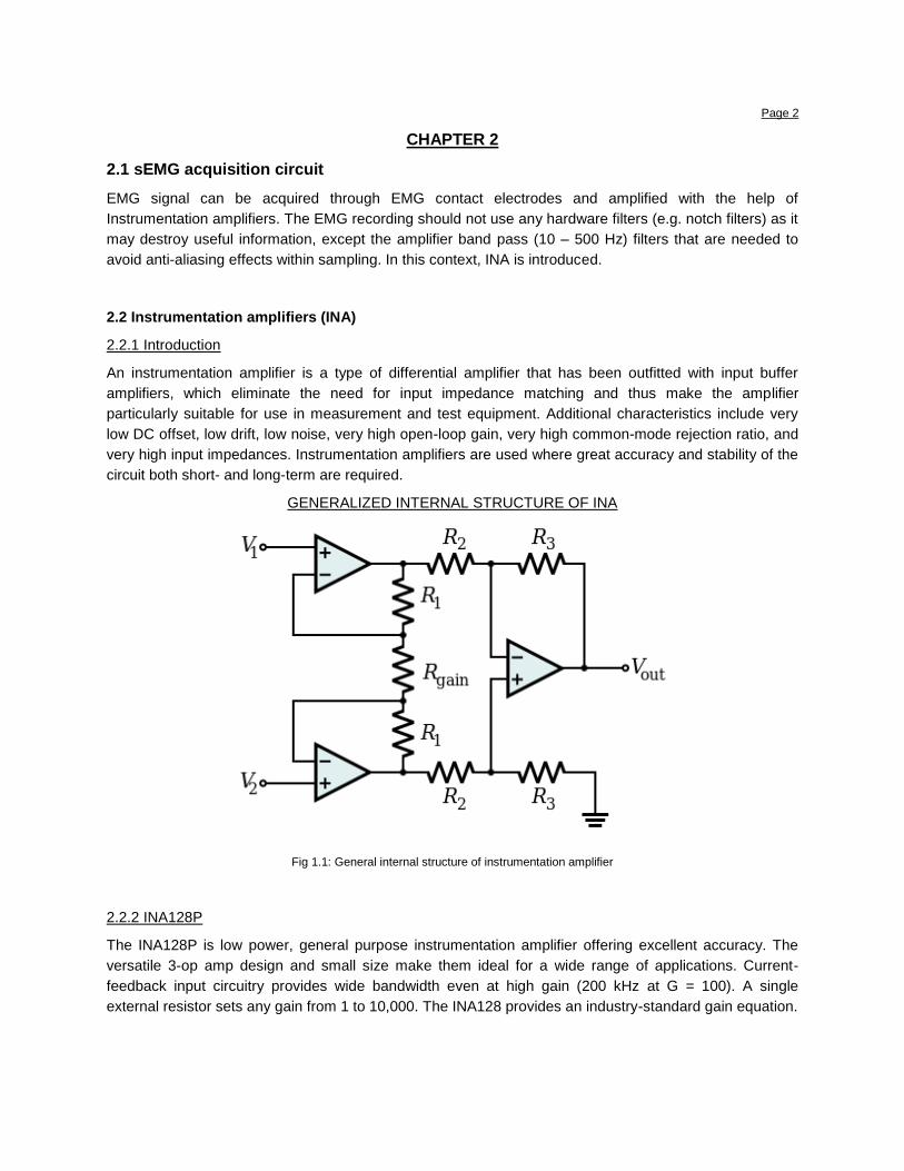
An instrumentation amplifier is a type of differential amplifier that has been outfitted with input buffer
amplifiers, which eliminate the need for input impedance matching and thus make the amplifier
particularly suitable for use in measurement and test equipment. Additional characteristics include very
low DC offset, low drift, low noise, very high open-loop gain, very high common-mode rejection ratio, and
very high input impedances. Instrumentation amplifiers are used where great accuracy and stability of the
circuit both short- and long-term are required.
GENERALIZED INTERNAL STRUCTURE OF INA
Fig 1.1: General internal structure of instrumentation amplifier
2.2.2 INA128P
The INA128P is low power, general purpose instrumentation amplifier offering excellent accuracy. The
versatile 3-op amp design and small size make them ideal for a wide range of applications. Current-
feedback input circuitry provides wide bandwidth even at high gain (200 kHz at G = 100). A single
external resistor sets any gain from 1 to 10,000. The INA128 provides an industry-standard gain equation.
Page 3
2.2.3 Why is INA128P useful for EMG?
1. The on-chip metal film resistors are laser trimmed to accurate absolute values.
2. The typical performance curve Gain vs. Frequency shows that, despite its low quiescent current, the
INA128P achieves wide bandwidth, even at high gain.
3. The INA128P provides very low noise which is desired in EMG acquisition circuitry.
4. The INA128P can be operated on power supplies as low as ±2.25V.
5. INA128P is more precise than other INAs and so can be applied in EMG circuitry. Characteristics
include: Quiescent Current: 60mA, Common Mode Range :( V–)–0.1V, Output Swing: Rail-to-rail
Offset Voltage: 250 mV (max), Input Bias Current: 25nA max.
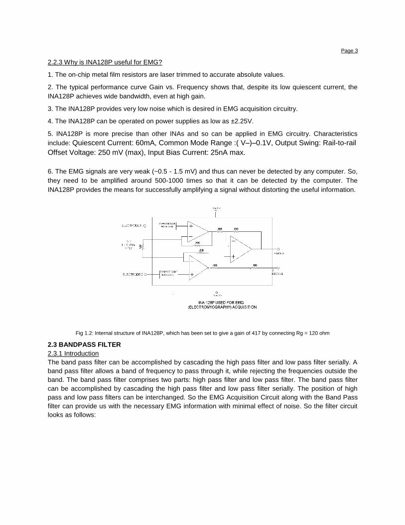
6. The EMG signals are very weak (~0.5 - 1.5 mV) and thus can never be detected by any computer. So,
they need to be amplified around 500-1000 times so that it can be detected by the computer. The
INA128P provides the means for successfully amplifying a signal without distorting the useful information.
Fig 1.2: Internal structure of INA128P, which has been set to give a gain of 417 by connecting Rg = 120 ohm
2.3 BANDPASS FILTER
2.3.1 Introduction
The band pass filter can be accomplished by cascading the high pass filter and low pass filter serially. A
band pass filter allows a band of frequency to pass through it, while rejecting the frequencies outside the
band. The band pass filter comprises two parts: high pass filter and low pass filter. The band pass filter
can be accomplished by cascading the high pass filter and low pass filter serially. The position of high
pass and low pass filters can be interchanged. So the EMG Acquisition Circuit along with the Band Pass
filter can provide us with the necessary EMG information with minimal effect of noise. So the filter circuit
looks as follows:
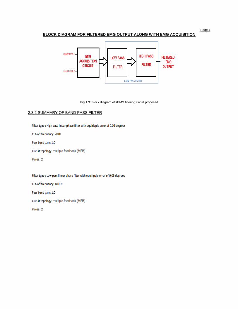
Page 4 BLOCK DIAGRAM FOR FILTERED EMG OUTPUT ALONG WITH EMG ACQUISITION
Fig 1.3: Block diagram of sEMG filtering circuit proposed
2.3.2 SUMMARY OF BAND PASS FILTER
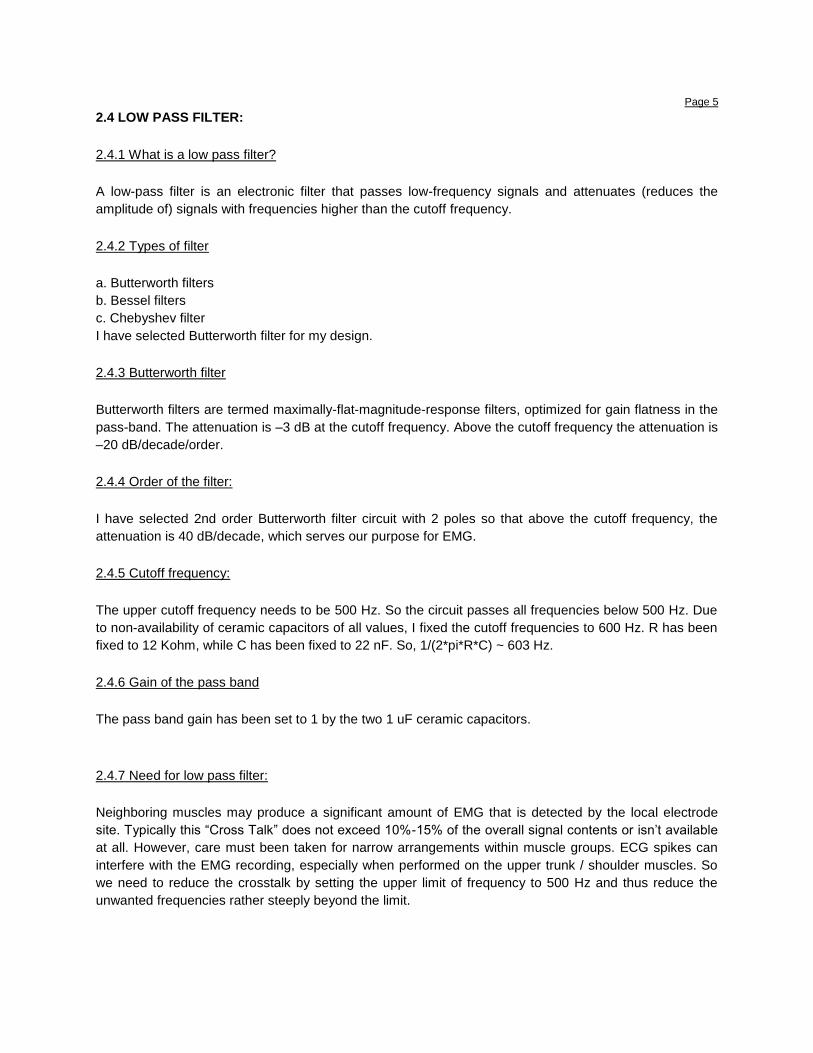
Page 5 2.4 LOW PASS FILTER:
2.4.1 What is a low pass filter?
A low-pass filter is an electronic filter that passes low-frequency signals and attenuates (reduces the
amplitude of) signals with frequencies higher than the cutoff frequency.
2.4.2 Types of filter
a. Butterworth filters
b. Bessel filters
c. Chebyshev filter
I have selected Butterworth filter for my design.
2.4.3 Butterworth filter
Butterworth filters are termed maximally-flat-magnitude-response filters, optimized for gain flatness in the
pass-band. The attenuation is –3 dB at the cutoff frequency. Above the cutoff frequency the attenuation is
–20 dB/decade/order.
2.4.4 Order of the filter:
I have selected 2nd order Butterworth filter circuit with 2 poles so that above the cutoff frequency, the
attenuation is 40 dB/decade, which serves our purpose for EMG.
2.4.5 Cutoff frequency:
The upper cutoff frequency needs to be 500 Hz. So the circuit passes all frequencies below 500 Hz. Due
to non-availability of ceramic capacitors of all values, I fixed the cutoff frequencies to 600 Hz. R has been
fixed to 12 Kohm, while C has been fixed to 22 nF. So, 1/(2*pi*R*C) ~ 603 Hz.
2.4.6 Gain of the pass band
The pass band gain has been set to 1 by the two 1 uF ceramic capacitors.
2.4.7 Need for low pass filter:
Neighboring muscles may produce a significant amount of EMG that is detected by the local electrode
site. Typically this “Cross Talk” does not exceed 10%-15% of the overall signal contents or isn’t available
at all. However, care must been taken for narrow arrangements within muscle groups. ECG spikes can
interfere with the EMG recording, especially when performed on the upper trunk / shoulder muscles. So
we need to reduce the crosstalk by setting the upper limit of frequency to 500 Hz and thus reduce the
unwanted frequencies rather steeply beyond the limit.
Page 6
Fig 1.4: Low pass filter for sEMG filtering as proposed by me
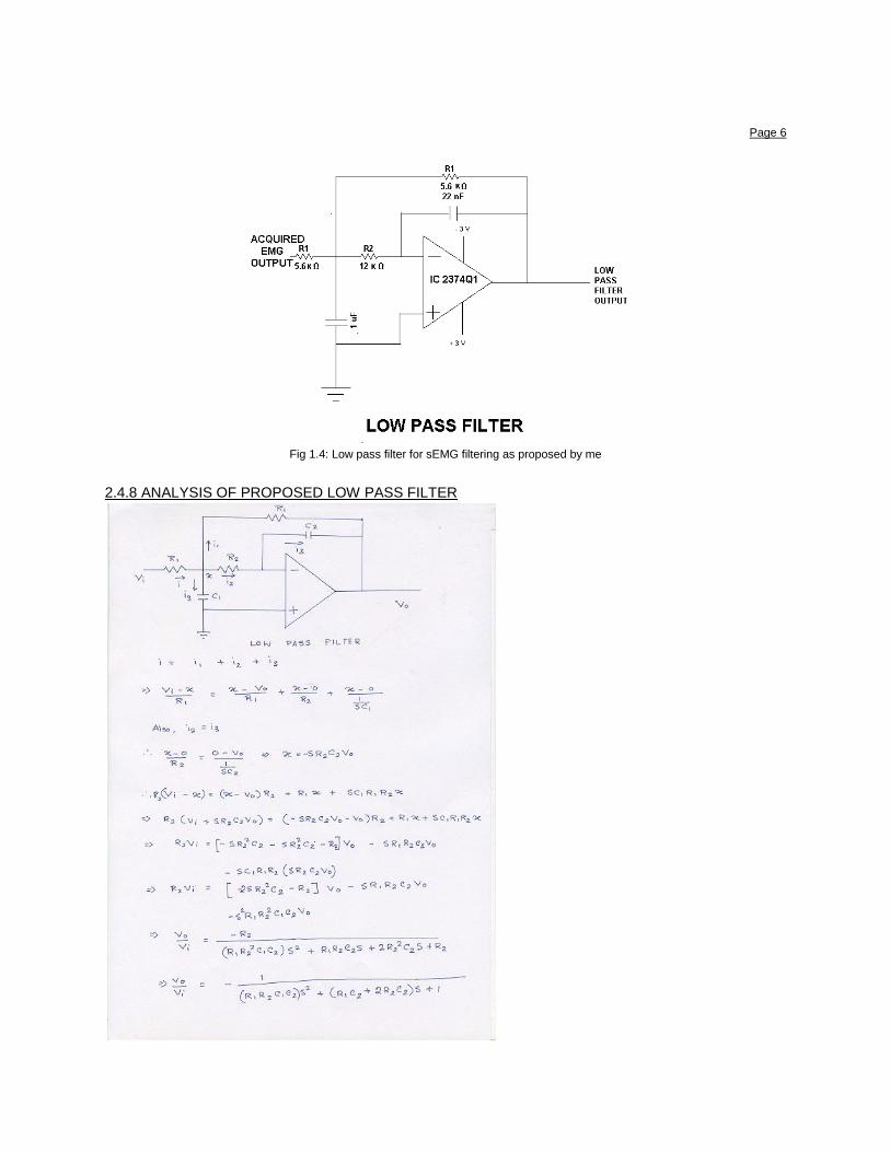
2.4.8 ANALYSIS OF PROPOSED LOW PASS FILTER

Page 7 2.5 HIGH PASS FILTER:
2.5.1 What is a high pass filter?
A high-pass filter (HPF) is an electronic filter that passes high-frequency signals but attenuates (reduces
the amplitude of) signals with frequencies lower than the cutoff frequency. The actual amount of
attenuation for each frequency varies from filter to filter. A high-pass filter is usually modeled as a linear
time-invariant system. It is sometimes called a low-cut filter or bass-cut filter. High-pass filters have many
uses, such as blocking DC from circuitry sensitive to non-zero average voltages or RF devices.
2.5.2 Types of filter
a. Butterworth filters
b. Bessel filters
c. Chebyshev filter
I have selected Butterworth filter for my design.
2.5.3 Order of the filter
I have selected 2nd order Butterworth filter circuit with 2 poles so that below the cutoff frequency, the
attenuation is 40 dB/decade, which serves our purpose for EMG.
2.5.4 Cutoff frequency
The lower cutoff frequency needs to be 10 Hz. So the circuit passes all frequencies above 10 Hz. Due to
non-availability of ceramic capacitors of all values, I fixed the cutoff frequencies to 13 Hz. R has been
fixed to 33 (15+18) Kohm, while C has been fixed to 474 nF. So, 1/(2*pi*R*C) ~ 13 Hz.
2.5.5 Gain of the pass band
The pass band gain has been set to 1 by the two 5.6 K Ohm resistances.
2.5.6 Need for high pass filter
The filters are applied at the output of the preamplifier, so that they prevent noise that has been amplified
by the preamplifier. The filter also helped to sink any DC current that could cause bias for the signal.
Page 8
Fig 1.5: High pass filter for sEMG filtering as proposed by me
2.5.7 ANALYSIS OF PROPOSED HIGH PASS FILTER
Page 9
CHAPTER 3
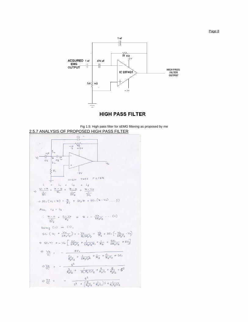
3.1 Problems and Solutions of the EMG acquisition circuit
3.1.1 PROBLEM 1: If EMG signal is acquired standing on the floor, it gives erroneous result.
Solution:
EMG signal should be acquired standing on a wooden surface placed on a mat, more precisely, standing
on an insulator.
COMPARISONS OF EMG ACQUISITION WAVEFORMS TAKEN STANDING ON DIFFERENT
SURFACES
Fig 2.1: EMG waveform 1 is taken while standing on insulated wooden surface kept on rubber mat while EMG waveform 2 is taken
while standing on ground
Page 10
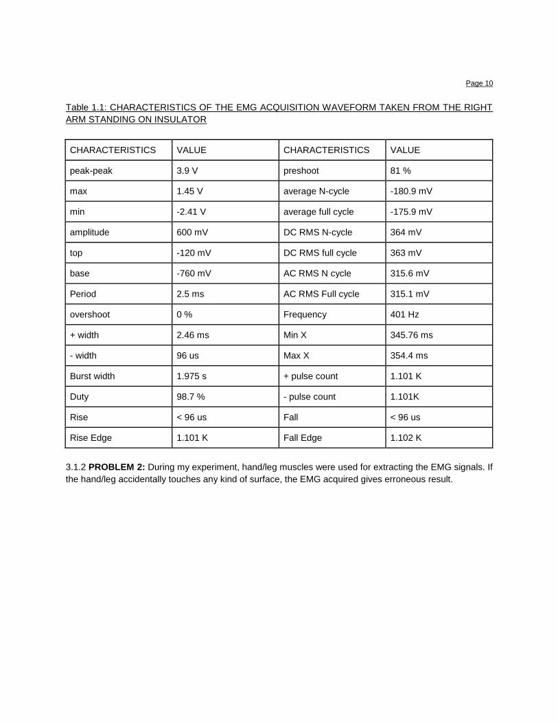
Table 1.1: CHARACTERISTICS OF THE EMG ACQUISITION WAVEFORM TAKEN FROM THE RIGHT
ARM STANDING ON INSULATOR
CHARACTERISTICS VALUE CHARACTERISTICS VALUE
peak-peak 3.9 V preshoot 81 %
max 1.45 V average N-cycle -180.9 mV
min -2.41 V average full cycle -175.9 mV
amplitude 600 mV DC RMS N-cycle 364 mV
top -120 mV DC RMS full cycle 363 mV
base -760 mV AC RMS N cycle 315.6 mV
Period 2.5 ms AC RMS Full cycle 315.1 mV
overshoot 0 % Frequency 401 Hz
+ width 2.46 ms Min X 345.76 ms
- width 96 us Max X 354.4 ms
Burst width 1.975 s + pulse count 1.101 K
Duty 98.7 % - pulse count 1.101K
Rise < 96 us Fall < 96 us
Rise Edge 1.101 K Fall Edge 1.102 K
3.1.2 PROBLEM 2: During my experiment, hand/leg muscles were used for extracting the EMG signals. If
the hand/leg accidentally touches any kind of surface, the EMG acquired gives erroneous result.
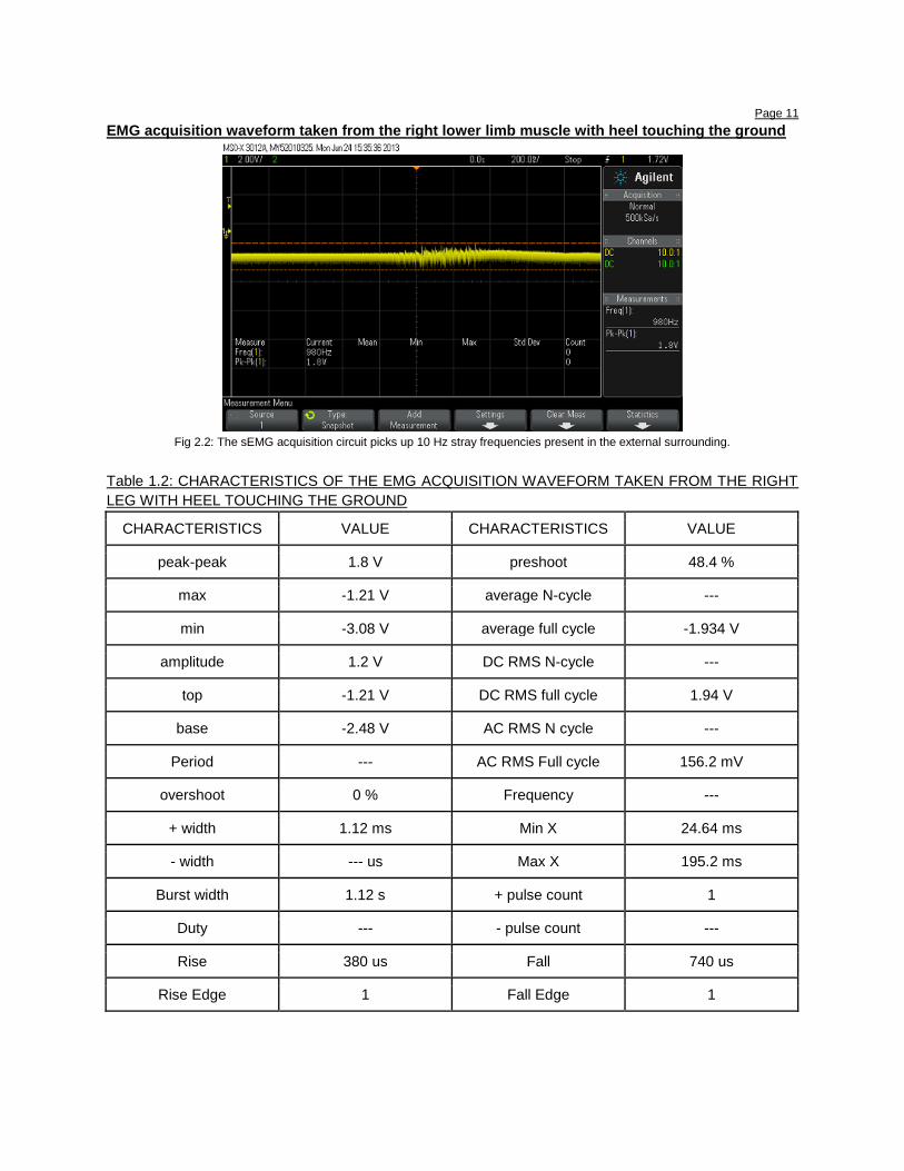
Page 11 EMG acquisition waveform taken from the right lower limb muscle with heel touching the ground
Fig 2.2: The sEMG acquisition circuit picks up 10 Hz stray frequencies present in the external surrounding.
Table 1.2: CHARACTERISTICS OF THE EMG ACQUISITION WAVEFORM TAKEN FROM THE RIGHT
LEG WITH HEEL TOUCHING THE GROUND
CHARACTERISTICS VALUE CHARACTERISTICS VALUE
peak-peak 1.8 V preshoot 48.4 %
max -1.21 V average N-cycle ---
min -3.08 V average full cycle -1.934 V
amplitude 1.2 V DC RMS N-cycle ---
top -1.21 V DC RMS full cycle 1.94 V
base -2.48 V AC RMS N cycle ---
Period --- AC RMS Full cycle 156.2 mV
overshoot 0 % Frequency ---
+ width 1.12 ms Min X 24.64 ms
- width --- us Max X 195.2 ms
Burst width 1.12 s + pulse count 1
Duty --- - pulse count ---
Rise 380 us Fall 740 us
Rise Edge 1 Fall Edge 1
Page 12 Reason: EMG signal frequency lies between 10 Hz and 500 Hz. 10 Hz stray frequency signals are
present everywhere, in the circuit components, any external surface and also in the contact points. Stray
noises are picked up from loose connections, unshielded wires, etc, which are amplified by the INA128P
to such a considerable extent that it interferes with the important EMG information.
Solution:
a. Care should be taken that the entire body part (in our case, the leg) should not touch any kind of
surface.
b. The circuit should be placed on an insulated board so that the effect of stray noise is reduced.
c. Shielded wires should be used which carries the raw EMG signal from the surface electrodes to the
input of the circuit.
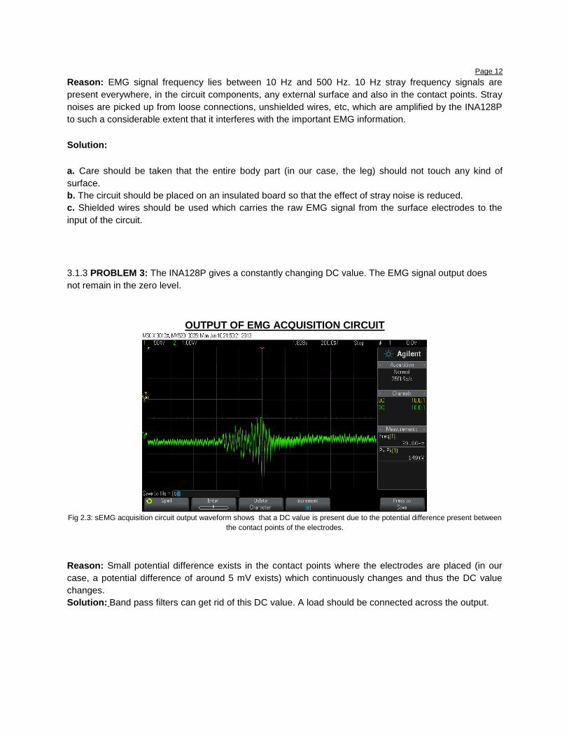
3.1.3 PROBLEM 3: The INA128P gives a constantly changing DC value. The EMG signal output does
not remain in the zero level.
OUTPUT OF EMG ACQUISITION CIRCUIT
Fig 2.3: sEMG acquisition circuit output waveform shows that a DC value is present due to the potential difference present between
the contact points of the electrodes.
Reason: Small potential difference exists in the contact points where the electrodes are placed (in our
case, a potential difference of around 5 mV exists) which continuously changes and thus the DC value
changes.
Solution: Band pass filters can get rid of this DC value. A load should be connected across the output.
Page 13
OUTPUT OF FILTERED EMG CIRCUIT
Fig 2.4: sEMG band pass filter circuit output waveform shows that the DC value has gone
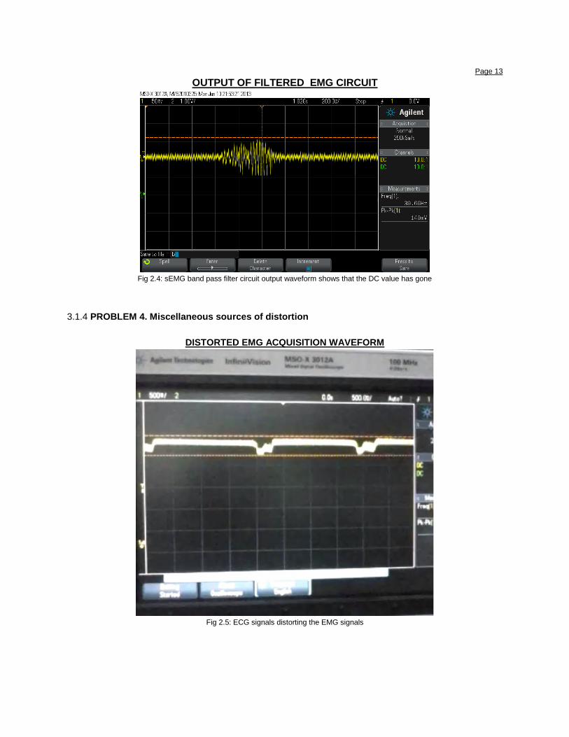
3.1.4 PROBLEM 4. Miscellaneous sources of distortion
DISTORTED EMG ACQUISITION WAVEFORM
Fig 2.5: ECG signals distorting the EMG signals
Page 14
3.1.4.1 NATURE OF DISTORTION:
From the above waveform, we find that the distortion occurs periodically. This waveform was recorded
when the hand muscles lay relaxed hanging in the air. The ideal waveform should have been a zero DC
value. But we find that a DC value is present, as explained earlier. In addition to that, there are noises(
i.e. unwanted pulses) in the output waveform.
POSSIBLE REASON OF DISTORTION:
3.1.4.2 DC BASELINE SHIFT: a. The wires for retrieving EMG signals were not shielded properly.
b. The wires are long. So swinging of the wires produce noise hums which are sources of noise in EMG
circuitry.
c. There may be loose contact between the skin and the surface electrodes.
d. No band pass filter was used.
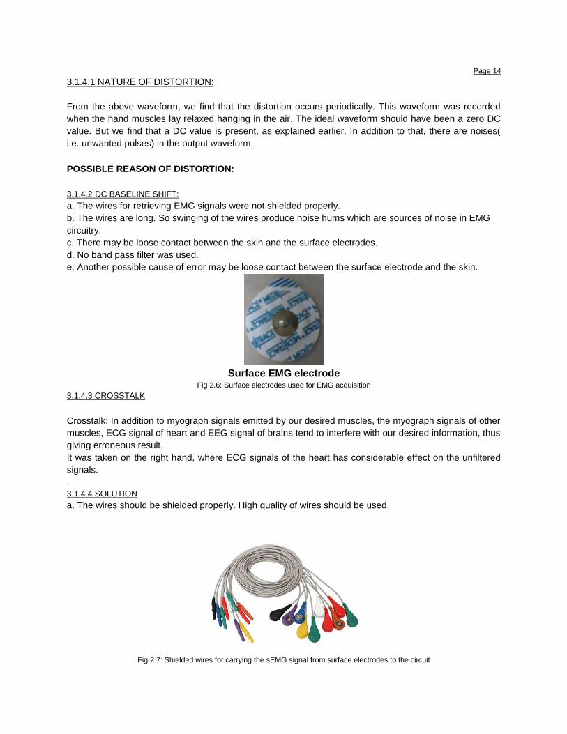
e. Another possible cause of error may be loose contact between the surface electrode and the skin.
Surface EMG electrode
Fig 2.6: Surface electrodes used for EMG acquisition 3.1.4.3 CROSSTALK
Crosstalk: In addition to myograph signals emitted by our desired muscles, the myograph signals of other
muscles, ECG signal of heart and EEG signal of brains tend to interfere with our desired information, thus
giving erroneous result.
It was taken on the right hand, where ECG signals of the heart has considerable effect on the unfiltered
signals.
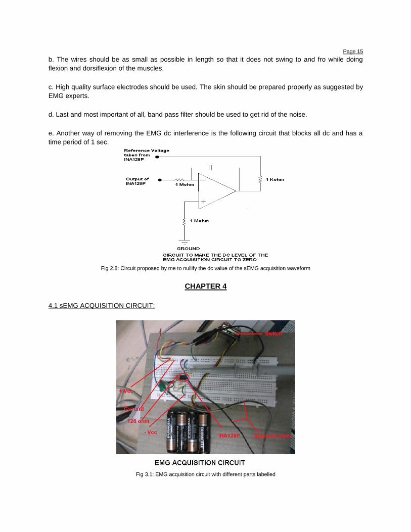
. 3.1.4.4 SOLUTION a. The wires should be shielded properly. High quality of wires should be used.
Fig 2.7: Shielded wires for carrying the sEMG signal from surface electrodes to the circuit
Page 15 b. The wires should be as small as possible in length so that it does not swing to and fro while doing
flexion and dorsiflexion of the muscles.
c. High quality surface electrodes should be used. The skin should be prepared properly as suggested by
EMG experts.
d. Last and most important of all, band pass filter should be used to get rid of the noise.
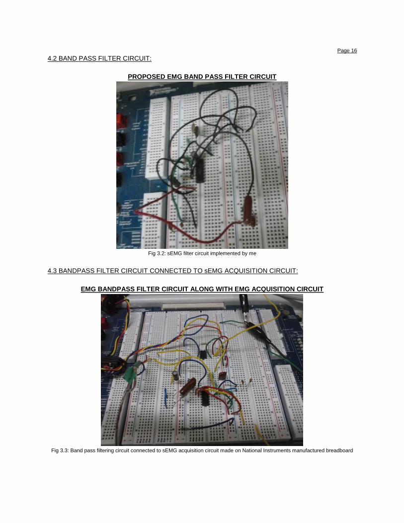
e. Another way of removing the EMG dc interference is the following circuit that blocks all dc and has a
time period of 1 sec.
Fig 2.8: Circuit proposed by me to nullify the dc value of the sEMG acquisition waveform
CHAPTER 4
4.1 sEMG ACQUISITION CIRCUIT:
Fig 3.1: EMG acquisition circuit with different parts labelled
Page 16 4.2 BAND PASS FILTER CIRCUIT:
PROPOSED EMG BAND PASS FILTER CIRCUIT
Fig 3.2: sEMG filter circuit implemented by me
4.3 BANDPASS FILTER CIRCUIT CONNECTED TO sEMG ACQUISITION CIRCUIT:
EMG BANDPASS FILTER CIRCUIT ALONG WITH EMG ACQUISITION CIRCUIT
Fig 3.3: Band pass filtering circuit connected to sEMG acquisition circuit made on National Instruments manufactured breadboard
Page 17 4.4 OUTPUT OF sEMG ACQUISITION CIRCUIT ALONG WITH FILTERED EMG OUTPUT:
OUTPUT OF EMG ACQUISITION CIRCUIT AND FILTERED EMG CIRCUIT
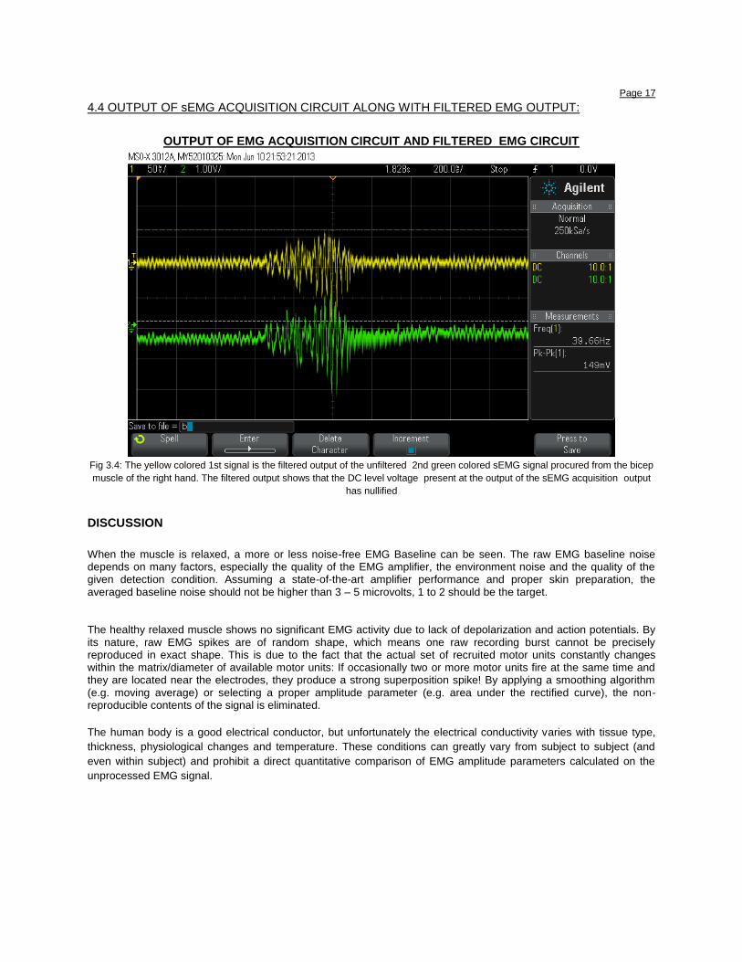
Fig 3.4: The yellow colored 1st signal is the filtered output of the unfiltered 2nd green colored sEMG signal procured from the bicep
muscle of the right hand. The filtered output shows that the DC level voltage present at the output of the sEMG acquisition output
has nullified
DISCUSSION
When the muscle is relaxed, a more or less noise-free EMG Baseline can be seen. The raw EMG baseline noise depends on many factors, especially the quality of the EMG amplifier, the environment noise and the quality of the given detection condition. Assuming a state-of-the-art amplifier performance and proper skin preparation, the averaged baseline noise should not be higher than 3 – 5 microvolts, 1 to 2 should be the target.
The healthy relaxed muscle shows no significant EMG activity due to lack of depolarization and action potentials. By its nature, raw EMG spikes are of random shape, which means one raw recording burst cannot be precisely reproduced in exact shape. This is due to the fact that the actual set of recruited motor units constantly changes within the matrix/diameter of available motor units: If occasionally two or more motor units fire at the same time and they are located near the electrodes, they produce a strong superposition spike! By applying a smoothing algorithm (e.g. moving average) or selecting a proper amplitude parameter (e.g. area under the rectified curve), the non- reproducible contents of the signal is eliminated.
The human body is a good electrical conductor, but unfortunately the electrical conductivity varies with tissue type,
thickness, physiological changes and temperature. These conditions can greatly vary from subject to subject (and
even within subject) and prohibit a direct quantitative comparison of EMG amplitude parameters calculated on the
unprocessed EMG signal.
Page 18
REFERENCE
1. C. V. Shendkar, M. Mahadevappa, P.K. Lenka, A. Biswas and R. Kumar, “Hardware Implementation of
adaptive closed-loop feedback control for Functional Electrical Stimulator device”, ASME journal for
medical Devices [communicated- under review process].
2. “The ABC of EMG : A Practical Introduction to Kinesiological Electromyography”, Peter Konrad,
Version 1.0 April 2005 Noraxon INC. USA. Powered by: NORAXON U.S.A ., INC.
3.. “Computer-Based Inexpensive Surface Electromyography Recording for a Student Laboratory”, Anand
Bhaskar, Elizabeth Tharion and Suresh R. Devasahayam, Advan in Physiol Educ 31:242-243, 2007. ; doi:
10.1152/advan.00041.2006
4. “Active Low-Pass Filter Design”, Jim Karki, AAP Precision Analog, Application Report, Texas
Instruments, SLOA049A - October 2000.
5. “Design and Development of a Low Cost EMG Signal Acquisition System Using Surface EMG
Electrode”, T. S. POO, K. Sundaraj
5. Datasheet of IC-23741: http://datasheetz.com/data/Integrated%20Circuits%20(ICs)/Amplifiers%20-
%20Instrumentation,%20OP%20Amps,%20Buffer%20Amps/TLV2374QDRQ1-datasheetz.html
6. Datasheet of INA128P: http://www.ti.com/product/ina128
7. Agilent Technologies Oscilloscope Guide:
http://www.home.agilent.com/agilent/software.jspx?cc=IN&lc=eng&nid=-11143.0.00&id=2019021