Electropolymerization and catalysis of well-dispersed polyaniline/carbon nanotube/gold composite
7
This article was originally published in a journal published by Elsevier, and the attached copy is provided by Elsevier for the author’s benefit and for the benefit of the author’s institution, for non-commercial research and educational use including without limitation use in instruction at your institution, sending it to specific colleagues that you know, and providing a copy to your institution’s administrator. All other uses, reproduction and distribution, including without limitation commercial reprints, selling or licensing copies or access, or posting on open internet sites, your personal or institution’s website or repository, are prohibited. For exceptions, permission may be sought for such use through Elsevier’s permissions site at: http://www.elsevier.com/locate/permissionusematerial
-
Upload
independent -
Category
Documents
-
view
2 -
download
0
Transcript of Electropolymerization and catalysis of well-dispersed polyaniline/carbon nanotube/gold composite
This article was originally published in a journal published byElsevier, and the attached copy is provided by Elsevier for the
author’s benefit and for the benefit of the author’s institution, fornon-commercial research and educational use including without
limitation use in instruction at your institution, sending it to specificcolleagues that you know, and providing a copy to your institution’s
administrator.
All other uses, reproduction and distribution, including withoutlimitation commercial reprints, selling or licensing copies or access,
or posting on open internet sites, your personal or institution’swebsite or repository, are prohibited. For exceptions, permission
may be sought for such use through Elsevier’s permissions site at:
http://www.elsevier.com/locate/permissionusematerial

Autho
r's
pers
onal
co
py
Electropolymerization and catalysis of well-dispersedpolyaniline/carbon nanotube/gold composite
Zhijuan Wang a,b, Junhua Yuan a, Meiye Li a,1, Dongxue Han a, Yuanjian Zhang a,Yanfei Shen a, Li Niu a,*, Ari Ivaska b
a State Key Laboratory of Electroanalytical Chemistry, Changchun Institute of Applied Chemistry,
Graduate School of the Chinese Academy of Sciences, Chinese Academy of Sciences, Changchun 130022, PR Chinab Laboratory of Analytical Chemistry, Process Chemistry Centre, Abo Akademi University, FI-20500, Abo-Turku, Finland
Received 13 May 2006; received in revised form 24 July 2006; accepted 20 September 2006Available online 1 November 2006
Abstract
Polyaniline/multi-walled carbon nanotube/gold (PANI/MWNT/Au) composite film was synthesized via a two-step electrochemicalprocess. First the mixture of aniline and MWNT was heated at refluxing and was electropolymerized. Then, the Au nanoparticles weredispersed into the film of PANI/MWNT by electrochemical reduction of HAuCl4. The morphology of sample was analyzed by scanningelectron microscopy (SEM). Raman measurement indicates a well electrochemical deposition of PANI on MWNT, and XPS result con-firms the formation of Au0 nanoparticles. Further, cyclic voltammograms show that the film exhibits a good electrochemical activity andelectrocatalysis towards ascorbic acid. Based on these investigations, a formation mechanism of the PANI/MWNT composite film wasproposed.� 2006 Elsevier B.V. All rights reserved.
Keywords: Carbon nanotubes; Polyaniline; Electropolymerization; Catalysis
1. Introduction
Carbon nanotubes (CNTs), discovered by Iijima [1],have attracted tremendous interests in view of a varietyof their applications in fabricating a new class of advancedmaterials due to their unique structure, and mechanical,electronic, and thermal properties. Apart from potentialuses in molecular electronic devices, micromechanics, elec-tron field emission, nano-conductive wires, etc., they arealso considered for some electrochemical applications, suchas membrane support of catalyst for the electrocatalyticreduction of oxygen and the oxidation of methanol [2],the storage of hydrogen and lithium [3,4], and super-capac-itors [5]. With highly promising potential for the applica-
tions, they become attractive building blocks for thedevelopment of future nanotechnology, resulting in novelmaterials and devices of great practical interests [6]. Forexample, CNTs are considered as the potential supportsfor making heterogeneous catalysts [7–9]. Electrocatalystswith Pt nanoparticles loaded onto carbon tubule mem-branes [2] have been proven to be effective towards oxida-tion/reduction reactions. However, there are difficulties indispersing metal nanoparticles with uniform dispersionand regular sizes on the CNTs surfaces. So, in order toobtain a good mono-dispersity of metal nanoparticles,the surface of CNTs must be modified via a properfunctionalization.
Conducting polymers have been proven to be suitablehost matrices for dispersing metallic particles. The compos-ites of conducting polymers with metal nanoparticles per-mit a facile flow of electronic charges across the polymermatrix during electrochemical processes. Conducting poly-mer plays an additional role in the electrochemical
0022-0728/$ - see front matter � 2006 Elsevier B.V. All rights reserved.
doi:10.1016/j.jelechem.2006.09.021
* Corresponding author. Tel.: +86 431 525 2425; fax: +86 431 526 2800.E-mail address: [email protected] (L. Niu).
1 National Analytical Research Center of Electrochemistry and Spec-troscopy, CIAC, CAS.
www.elsevier.com/locate/jelechem
Journal of Electroanalytical Chemistry 599 (2007) 121–126
Journal ofElectroanalytical
Chemistry

Autho
r's
pers
onal
co
py
processes. In addition, metallic nanoparticles can also bedispersed well into the matrix of these polymers [10]. Asall we know, gold nanoparticles have unique optoelec-tronic, magnetic and mechanical properties, and potentialapplications in microscopic research and nanodevices[11]. So, through a suitable combination of conductingpolymers and gold nanoparticles, newly modified surfacescould be generated with higher surface area and enhancedcatalytical/electrocatalytical activities.
Herein, we reported a preparation and application ofPANI/MWNT/Au composite film. MWNT was used toform pendant chains of polyaniline (PANI) through elec-trochemical polymerization. Au nanoparticles were electro-chemically dispersed into the matrix of PANI/MWNT.Electrochemical technique, field emission scanning electronmicroscopy (FESEM), Raman spectroscopy, and X-rayphotoelectron spectroscopy (XPS) were applied to investi-gate the morphology and properties of the composite film.Based on our observation, the mechanism of the formationof PANI/MWNT/Au composite film was proposed.
2. Experimental
2.1. Chemical and reagents
Multi-walled carbon nanotubes (sponsored by North-east Normal University) and HAuCl4 (Shanghai ChemicalReagent Company) were used as received except aniline(Beijing Chemicals Company) which was distilled under anitrogen atmosphere at reduced pressure and kept below0 �C. Other chemicals were analytical pure. All aqueoussolutions were prepared with ultrapure water obtainedfrom Millipore System (>18 MXcm). And all experimentswere carried out at room temperature (25 �C).
2.2. Apparatus
Electropolymerization and electrochemical characteriza-tions were carried out with a CHI660 (CH Instruments,USA) Electrochemical Workstation.
The morphology of the resulting precipitates was char-acterized with a XL 30 ESEM FEG scanning electronmicroscopy at an accelerating voltage of 20 kV and a JEOL2000 transmission electron microscopy (TEM) operating at200 kV. Raman spectrum was recorded with a Renishaw2000 system using an Argon ion laser operating at514.5 nm with a CCD detector. XPS measurements wereconducted with an ESCLAB MK II spectrometer (VGCo.) with Mg Ka radiation as the X-ray source. The UV–visible absorbance spectra were acquired with a Cary 500UV–Visible-NIR spectrometer (Varian).
2.3. Preparation of MWNT–aniline solutions
Multi-walled carbon nanotubes were treated using a 3:1mixture of concentrated H2SO4/HNO3 prior to the experi-ments. The obtained MWNT were then added into 5 ml of
aniline. The mixture was heated at refluxing in the dark.After a while, the refluxing solution of the colorless anilinefirst became brownish and then turned dark, indicatingthat MWNTs have been dissolved well into aniline. Afterrefluxing for 3 h, the solution was cooled to room temper-ature, a MWNTs solution was obtained by filtrationthrough a 0.1 lm diameter Supor Membrane Disc Filter(Gelman).
2.4. Preparation of PANI/MWNT/Au composite film
PANI/MWNT composite film was deposited in a solu-tion of 1 M H2SO4 containing appropriate aniline dis-solved MWNTs (as-produced by refluxing) in a threecompartment cell. The cleaned silicon wafer sputtered withPt, a KCl-saturated silver–silver chloride (AgjAgCl) and aplatinum wire were used as the working, reference andcounter electrodes, respectively. All potential reportedrefers to this AgjAgCl (sat. KCl) reference electrode. Cyclicvoltammograms were recorded from �0.20 to 0.72 V at ascan rate of 0.1 Vs�1.
And finally the silicon wafer deposited with PANI/MWNT composite film was dipped into the solution ofHAuCl4, and gold nanoparticles were prepared by pulsevoltammetry with a pulse width of 5 s and the high poten-tial and low potential were 1.1 V and �0.2 V, respectively,which resulted in the PANI/MWNT/Au composite film.
3. Results and discussion
3.1. Electropolymerization of PANI/MWNT/Aucomposite film
Modification of the surface of working electrode wasperformed in two steps. First, PANI/MWNT compositefilm was deposited onto the working electrode using cyclicvoltammetry. Second, Au nanoparticles were incorporatedinto PANI/MWNT composite film by pulse voltammetry.
Fig. 1 displays a cyclic voltammogram (CV) recordedin a solution of 1 M H2SO4 without addition of anilinemonomer after the electrochemical polymerization in thesolution containing 10 mg MWNT and 5 mL aniline (5potential cycles) at 0.1 Vs�1. The formation of PANI/MWNT film was evident from the CV findings. In the firstpotential cycle, a significantly high peak current at thepotential of aniline oxidation was noted for the solutionof MWNT–aniline. This gives a clue that the amine groupin MWNT–aniline was oxidized at the potential of anilineoxidation. Moreover, the current values at the redox peakscorresponding to PANI showed the continuous increaseswith the number of potential cycles. These observationsindicate that the formation of PANI/MWNT compositefilm.
At the same time, the result of Raman spectra (Fig. 2)further confirms the formation of PANI on MWNT. Forcomparison, this figure also includes the spectra of pureMWNT, PANI, and PANI/Au composite. The pattern of
122 Z. Wang et al. / Journal of Electroanalytical Chemistry 599 (2007) 121–126

Autho
r's
pers
onal
co
py
MWNT indicates that the surface derivatization does notaffect the graphite structure of the MWNT and the reactioncan be used to produce carboxylic acid groups at localdefects in the curved graphite sheets and tube ends [12].Two strong peaks at 1584 cm�1 (G mode) which is theRaman-allowed phonon high-frequency mode and a disor-dered-induced peak at 1350 cm�1 (D mode) which mayoriginate from the defects in the curved graphite sheetsand tube ends. Comparing the IG/ID ratio of the MWNTwith those without carboxylic acid group, which is much
lower than that in previous report [12] (1.11 versus 1.72),it reveals that the chemical derivatization increases thedegree of disorder. This finding indicates the presence ofdefects at both the ends and the sidewalls of theMWNT [13]. But, these two peaks do not appear in PANI/MWNT and PANI/MWNT/Au composites. For PANI/MWNT and PANI/MWNT/Au composites, C–H bendingof the quinoid ring at 1162 cm�1, C–H bending of thebenzenoid ring at 1256 cm�1, C–N+� stretching at1324 cm�1, and C–C stretching of the benzene ring at
Fig. 2. Raman spectra of (a) PANI, (b) PANI/Au composite, (c) PANI/MWNTs composite, (d) PANI/MWNTs/Au composite, and (e) pureMWNTs.
Fig. 1. Cyclic voltammogram (5 cycles) recorded in a solution of 1 MH2SO4 without addition of aniline monomer after the electrochemicalpolymerization in the solution containing 10 mg MWNT and 5 mL aniline(scan rate: 0.1 Vs�1).
Fig. 3. SEM images of (a) the MWNTs film, (b) the PANI/MWNTs composite film, (c) the PANI/MWNTs/Au composite film, and (d) TEM image ofMWNTs–aniline solution diluted with acetone. Scale bars: (a) 500 nm, (b) 500 nm, (c) 200 nm, (d) 100 nm.
Z. Wang et al. / Journal of Electroanalytical Chemistry 599 (2007) 121–126 123
Autho
r's
pers
onal
co
py
1491 cm�1 and at 1622 cm�1 are observed, revealing thepresence of the doped PANI structure [12]. The Ramanspectra indicate that the MWNT serve as the core in theformation of a tubular shell of PANI/MWNT and PANI/MWNT/Au composites. In other words, in these twocomposite films, PANI film is present on the MWNT surface.
Also, the morphology of the products was tested bySEM and TEM. The SEM images of MWNT, PANI/MWNT, and PANI/MWNT/Au composite film andTEM image of MWNT–aniline solution diluted with ace-tone are shown in Fig. 3. Clearly, the SEM image of thepurified MWNT shows that the MWNT are very longand present as highly entangled network structure, whichare responsible for the difficulty to disperse the MWNTin the polymer matrix and the relatively low solubility ofthe MWNT in most solvents (Fig. 3a). In addition, theMWNT are not uniform and the diameter of the MWNTranges from ca. 13 to 50 nm. The TEM image ofMWNT–aniline solution diluted with acetone (Fig. 3b)shows that the tubes are still hollow, which indicates thataniline monomers have been adsorbed entirely on the sur-face of MWNT. This result is in consistent with the resultof Raman. Moreover, Fig. 3c shows that a tubular layer ofa highly uniformed PANI-coated film is present on theMWNT surface. After the deposition of gold nanoparticles(Fig. 3d), it can be clearly seen that most of gold nanopar-ticles dispersed uniformly into the PANI/MWNT compos-ite film and the diameter of these particles is ca. 19 nm.These particles are separated from each other, but notaggregation.
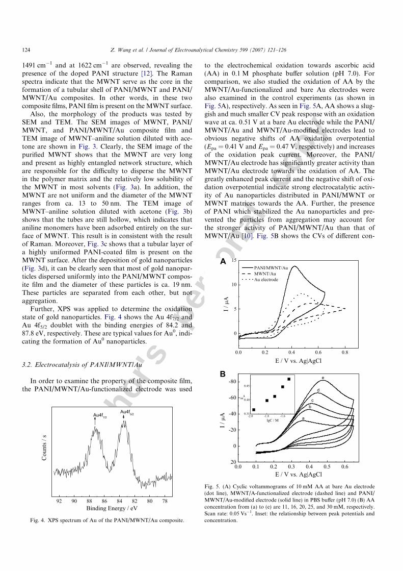
Further, XPS was applied to determine the oxidationstate of gold nanoparticles. Fig. 4 shows the Au 4f7/2 andAu 4f5/2 doublet with the binding energies of 84.2 and87.8 eV, respectively. These are typical values for Au0, indi-cating the formation of Au0 nanoparticles.
3.2. Electrocatalysis of PANI/MWNT/Au
In order to examine the property of the composite film,the PANI/MWNT/Au-functionalized electrode was used
to the electrochemical oxidation towards ascorbic acid(AA) in 0.1 M phosphate buffer solution (pH 7.0). Forcomparison, we also studied the oxidation of AA by theMWNT/Au-functionalized and bare Au electrodes werealso examined in the control experiments (as shown inFig. 5A), respectively. As seen in Fig. 5A, AA shows a slug-gish and much smaller CV peak response with an oxidationwave at ca. 0.51 V at a bare Au electrode while the PANI/MWNT/Au and MWNT/Au-modified electrodes lead toobvious negative shifts of AA oxidation overpotential(Epa = 0.41 V and Epa = 0.47 V, respectively) and increasesof the oxidation peak current. Moreover, the PANI/MWNT/Au electrode has significantly greater activity thanMWNT/Au electrode towards the oxidation of AA. Thegreatly enhanced peak current and the negative shift of oxi-dation overpotential indicate strong electrocatalytic activ-ity of Au nanoparticles distributed in PANI/MWNT orMWNT matrices towards the AA. Further, the presenceof PANI which stabilized the Au nanoparticles and pre-vented the particles from aggregation may account forthe stronger activity of PANI/MWNT/Au than that ofMWNT/Au [10]. Fig. 5B shows the CVs of different con-
Fig. 4. XPS spectrum of Au of the PANI/MWNT/Au composite.
Fig. 5. (A) Cyclic voltammograms of 10 mM AA at bare Au electrode(dot line), MWNT/A-functionalized electrode (dashed line) and PANI/MWNT/Au-modified electrode (solid line) in PBS buffer (pH 7.0) (B) AAconcentration from (a) to (e) are 11, 16, 20, 25, and 30 mM, respectively.Scan rate: 0.05 Vs�1. Inset: the relationship between peak potentials andconcentration.
124 Z. Wang et al. / Journal of Electroanalytical Chemistry 599 (2007) 121–126
Autho
r's
pers
onal
co
py
centrations of AA at the PANI/MWNT/Au-functionalizedAu electrode. It is clear that the oxidation peak current isincreasing with the increase of AA concentration. The insetin Fig. 5B shows the relationship between shift in peakpotentials and concentration. The peak potential is propor-tional to the log of the AA concentration.
The shift in peak potentials with concentration (Fig. 5B)may result from the two possible reasons. First, the prod-uct of ascorbic acid, according to previous reports [17],can easily adsorb on the electrode surface and fouled thesurface, which can depress the effect of catalyst. Second,the concentration of ascorbic acid we used in this case,
>10 mM, was considered too high due to quite limitedactive sites (Au sites) on the electrode surface. Then, adepression in electrocatalytical response at higher concen-trations of ascorbic acid was resulted.
3.3. Reaction mechanism
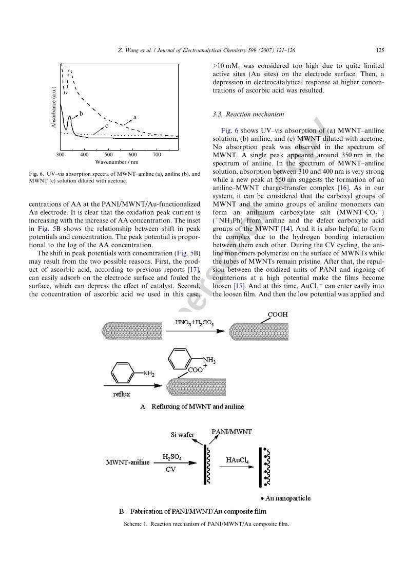
Fig. 6 shows UV–vis absorption of (a) MWNT–anilinesolution, (b) aniline, and (c) MWNT diluted with acetone.No absorption peak was observed in the spectrum ofMWNT. A single peak appeared around 350 nm in thespectrum of aniline. In the spectrum of MWNT–anilinesolution, absorption between 310 and 400 nm is very strongwhile a new peak at 550 nm suggests the formation of ananiline–MWNT charge-transfer complex [16]. As in oursystem, it can be considered that the carboxyl groups ofMWNT and the amino groups of aniline monomers canform an anilinium carboxylate salt ðMWNT-CO2
�Þ(+NH3Ph) from aniline and the defect carboxylic acidgroups of the MWNT [14]. And it is also helpful to formthe complex due to the hydrogen bonding interactionbetween them each other. During the CV cycling, the ani-line monomers polymerize on the surface of MWNTs whilethe tubes of MWNTs remain pristine. After that, the repul-sion between the oxidized units of PANI and ingoing ofcounterions at a high potential make the films becomeloosen [15]. And at this time, AuCl4
� can enter easily intothe loosen film. And then the low potential was applied and
300 400 500 600 700
Abs
orba
nce
(a.u
.)
Wavenumber / nm
ab
c
Fig. 6. UV–vis absorption spectra of MWNT–aniline (a), aniline (b), andMWNT (c) solution diluted with acetone.
Scheme 1. Reaction mechanism of PANI/MWNT/Au composite film.
Z. Wang et al. / Journal of Electroanalytical Chemistry 599 (2007) 121–126 125

Autho
r's
pers
onal
co
py
the AuCl4� is reduced into Au0 nanoparticles, and synchro-
nously, the films become much tight, and the gold nanopar-ticles can be enwrapped entirely in this film (as illustratedin Scheme 1).
4. Conclusions
In summary, PANI/MWNT/Au composite film wasprepared via a simple electropolymerization. And the resultof SEM indicated that the composite film was composed ofnanotubes and uniformly dispersed gold nanoparticles inthe film. Raman measurement indicated a well electropoly-merization of PANI on MWNT, and XPS result confirmedthe formation of Au0 nanoparticles. In addition, cyclicvoltammograms showed that the film exhibited goodelectrocatalysis towards AA oxidation. This investigationindicates that catalytic electrodes based on a combinationof substrate, carbon nanotubes, polymers, and electro-chemically dispersed metals, mixed metals, or metal oxidescan be generated by the same way.
Acknowledgements
The authors are most grateful to the NSFC, China (No.20475053) and to Department of Science and Technologyof Jilin Province (No. 20050102) for their financialsupports.
References
[1] S. Iijima, Nature 354 (1991) 56.[2] G.L. Che, B.B. Lakshmi, E.R. Fischer, C.R. Martin, Nature 393
(1998) 346.[3] C. Nutzenadel, A. Zuttel, D. Chartouni, L. Schlapbach, Nature 2
(1999) 30.[4] E. Frackowiak, S. Gautier, H. Gaucher, S. Bonnamy, F. Beguin,
Carbon 37 (1999) 61.[5] E. Frackowoak, K. Metenier, T. Kyotani, S. Bonnamy, F. Beguin,
Am. Carbon Soc. II (1999) 544.[6] R.H. Baughman, A.A. Zakhidov, W.A. de Heer, Science 297 (2002)
787.[7] J.M. Planeix, N. Coustel, B. Coq, V. Brotons, P.S. Kumbhar, R.
Dutartre, P. Geneste, P. Bernier, P.M. Ajayan, J. Am. Chem. Soc. 116(1994) 7935.
[8] C. Pham-Huu, N. Keller, M.J. Ledoux, L.J. Charbonniere, R. Ziessel,Chem. Commun. (2000) 1871.
[9] C.H. Liang, Z.L. Li, J.S. Qiu, C. Li, J. Catal. 211 (2002) 278.[10] P. Santhosh, A. Gopalan, K.P. Lee, J. Catal. 238 (2006) 177.[11] C.A. Foss, G.L. Hornyak, J.A. Stockert, C.R. Martin, J. Phys. Chem.
96 (1992) 7497.[12] J. Sanchez-Gonzalez, A. Macias-Garcia, M.F. Alexandre-Franco,
Carbon 43 (2005) 741.[13] Z.X. Wei, M.X. Wan, T. Lin, L.M. Dai, Adv. Mater. 15 (2003) 136.[14] D.F. Perepichka, F. Wudl, S.R. Wilson, Y. Sun, D.I. Schuster, J.
Mater. Chem. 14 (2004) 2749.[15] S.A. Curran, P.M. Ajayan, W.J. Blau, D.L. Caroll, J.N. Coleman,
A.B. Dolton, A.P. Davey, A. Drury, B. McCarthy, S. Maier, A.Strevens, Adv. Mater. 10 (1998) 1091.
[16] Y. Sun, S.R. Wilson, D.I. Schuster, J. Am. Soc. Chem. 123 (2001)5348.
[17] J. Zhang, P.H. Deng, Y.L. Feng, Y.F. Kuang, J.J. Yang, Microchim.Acta 147 (2004) 279.
126 Z. Wang et al. / Journal of Electroanalytical Chemistry 599 (2007) 121–126