Electrochemical performance of LiCoO 2 cathodes by surface modification using lanthanum aluminum...
10
Journal of Power Sources 184 (2008) 392–401 Contents lists available at ScienceDirect Journal of Power Sources journal homepage: www.elsevier.com/locate/jpowsour Electrochemical performance of LiCoO 2 cathodes by surface modification using lanthanum aluminum garnet Cheng-Zhang Lu a , Jin-Ming Chen b , Yung-Da Cho a , Wen-Hsiang Hsu a , P. Muralidharan a , George Ting-Kuo Fey a,∗ a Department of Chemical and Materials Engineering, National Central University, Chung-Li 320, Taiwan b Material Chemical Laboratories, Industrial Technology Research Institute, Hsinchu 310, Taiwan article info Article history: Received 15 January 2008 Received in revised form 15 April 2008 Accepted 24 April 2008 Available online 13 May 2008 Keywords: Cathodes Coating 3LaAlO3:Al2O3 LiCoO2 Lithium-ion battery abstract LiCoO 2 particles were coated with various wt.% of lanthanum aluminum garnets (3LaAlO 3 :Al 2 O 3 ) by an in situ sol–gel process, followed by calcination at 1123K for 12h in air. X-ray diffraction (XRD) pat- terns confirmed the formation of a 3LaAlO 3 :Al 2 O 3 compound and the in situ sol–gel process synthesized 3LaAlO 3 :Al 2 O 3 -coated LiCoO 2 was a single-phase hexagonal -NaFeO 2 -type structure of the core mate- rial without any modification. Scanning electron microscope (SEM) images revealed a modification of the surface of the cathode particles. Transmission electron microscope (TEM) images exposed that the surface of the core material was coated with a uniform compact layer of 3LaAlO 3 :Al 2 O 3 , which had an average thickness of 40 nm. Galvanostatic cycling studies demonstrated that the 1.0 wt.% 3LaAlO 3 :Al 2 O 3 -coated LiCoO 2 cathode showed excellent cycle stability of 182 cycles, which was much higher than the 38 cycles sustained by the pristine LiCoO 2 cathode material when it was charged at 4.4 V. © 2008 Elsevier B.V. All rights reserved. 1. Introduction The most popular cathode material used in commercial lithium- ion batteries is LiCoO 2 because of its high electronic conductivity, good rate capability, ease of preparation and excellent cycling performance with a stable layered structure, where Li + and Co 3+ ions occupy alternate (1 1 1) planes of a rock salt structure [1–5]. The LiCoO 2 cathode material exhibits excellent electrochemical performance with a high theoretical capacity of 274 mAh g −1 [6]. However, from the layered structure, only 0.5mol of lithium ion is extractable within the voltage range of 3–4.2 V vs. Li + /Li, which can deliver a reversible capacity of around 140 mAh g −1 of the theoret- ical capacity of LiCoO 2 [7]. Alternatively, a higher capacity could be obtained from this material by charging it beyond 4.2 V vs. Li + /Li, which generally leads to a dissolution of strongly oxidized Co 4+ ions into the electrolyte and a fast impedance growth on the surface of the cathode during the (de)lithiation process, thereby negatively affecting capacity retention (C.R.) and cycle stability [8,9]. In order to prevent major chemical side reactions on the surface of the cathode materials, novel approaches have been developed ∗ Corresponding author. Tel.: +886 3 425 7325; fax: +886 3 425 7325. E-mail address: [email protected] (G.T.-K. Fey). to coat the surface of cathode materials with various oxides to improve electrode performance in terms of cyclability, thermal sta- bility, and high temperature capacity. Various groups of researchers have followed the surface coating technique to coat both layered and spinel cathode oxides, which resulted in improved cycle stabil- ity and capacity retention even at higher voltages of the lithium extraction process. The surface of the cathode materials coated with Li 2 O·2B 2 O 3 [10], Li 4 Ti 5 O 12 [11], La 2 O 3 [12], ZrTiO 4 [13], Al 2 O 3 [8,14–16], ZrO 2 [7,8,14,17], CeO 2 [18], metal phosphate [19–21] and MgAl 2 O 4 [22] demonstrated enhanced cycling performance in terms of higher capacity. The materials used for surface coating play a significant role by shielding the highly active core material, thereby preventing many side reactions that would lead to faster impedance growth. Chung et al. [17] have reported using in situ X-ray diffraction (XRD) to study the effect of a ZrO 2 coating buffer layer on capacity retention during high voltage cycling when the cathode was protected from the electrolyte. The surface coating procedure and the materials [7,8,10–21] employed for coating are integral to the configuration of a uni- form and well-adhered coating on the surface of the core material with low temperature syntheses. In general, ceramic materials are suitable candidates due to their high thermo-mechanical stabil- ity, resistance to both oxidizing and reducing atmospheres at high temperatures, and resistance to attack by moisture and chemical 0378-7753/$ – see front matter © 2008 Elsevier B.V. All rights reserved. doi:10.1016/j.jpowsour.2008.04.087
Transcript of Electrochemical performance of LiCoO 2 cathodes by surface modification using lanthanum aluminum...
Eba
CPa
b
a
ARRAA
KCC3LL
1
igpiTpHediowita
o
0d
Journal of Power Sources 184 (2008) 392–401
Contents lists available at ScienceDirect
Journal of Power Sources
journa l homepage: www.e lsev ier .com/ locate / jpowsour
lectrochemical performance of LiCoO2 cathodesy surface modification using lanthanumluminum garnet
heng-Zhang Lua, Jin-Ming Chenb, Yung-Da Choa, Wen-Hsiang Hsua,. Muralidharana, George Ting-Kuo Feya,∗
Department of Chemical and Materials Engineering, National Central University, Chung-Li 320, TaiwanMaterial Chemical Laboratories, Industrial Technology Research Institute, Hsinchu 310, Taiwan
r t i c l e i n f o
rticle history:eceived 15 January 2008eceived in revised form 15 April 2008ccepted 24 April 2008
a b s t r a c t
LiCoO2 particles were coated with various wt.% of lanthanum aluminum garnets (3LaAlO3:Al2O3) byan in situ sol–gel process, followed by calcination at 1123 K for 12 h in air. X-ray diffraction (XRD) pat-terns confirmed the formation of a 3LaAlO3:Al2O3 compound and the in situ sol–gel process synthesized3LaAlO3:Al2O3-coated LiCoO2 was a single-phase hexagonal �-NaFeO2-type structure of the core mate-
vailable online 13 May 2008
eywords:athodesoatingLaAlO3:Al2O3
iCoO
rial without any modification. Scanning electron microscope (SEM) images revealed a modification of thesurface of the cathode particles. Transmission electron microscope (TEM) images exposed that the surfaceof the core material was coated with a uniform compact layer of 3LaAlO3:Al2O3, which had an averagethickness of 40 nm. Galvanostatic cycling studies demonstrated that the 1.0 wt.% 3LaAlO3:Al2O3-coatedLiCoO2 cathode showed excellent cycle stability of 182 cycles, which was much higher than the 38 cyclessustained by the pristine LiCoO2 cathode material when it was charged at 4.4 V.
tibhaiew[atptiXl
2
ithium-ion battery
. Introduction
The most popular cathode material used in commercial lithium-on batteries is LiCoO2 because of its high electronic conductivity,ood rate capability, ease of preparation and excellent cyclingerformance with a stable layered structure, where Li+ and Co3+
ons occupy alternate (1 1 1) planes of a rock salt structure [1–5].he LiCoO2 cathode material exhibits excellent electrochemicalerformance with a high theoretical capacity of 274 mAh g−1 [6].owever, from the layered structure, only 0.5 mol of lithium ion isxtractable within the voltage range of 3–4.2 V vs. Li+/Li, which caneliver a reversible capacity of around 140 mAh g−1 of the theoret-
cal capacity of LiCoO2 [7]. Alternatively, a higher capacity could bebtained from this material by charging it beyond 4.2 V vs. Li+/Li,hich generally leads to a dissolution of strongly oxidized Co4+ ions
nto the electrolyte and a fast impedance growth on the surface of
he cathode during the (de)lithiation process, thereby negativelyffecting capacity retention (C.R.) and cycle stability [8,9].In order to prevent major chemical side reactions on the surfacef the cathode materials, novel approaches have been developed
∗ Corresponding author. Tel.: +886 3 425 7325; fax: +886 3 425 7325.E-mail address: [email protected] (G.T.-K. Fey).
c
efwsit
378-7753/$ – see front matter © 2008 Elsevier B.V. All rights reserved.oi:10.1016/j.jpowsour.2008.04.087
© 2008 Elsevier B.V. All rights reserved.
o coat the surface of cathode materials with various oxides tomprove electrode performance in terms of cyclability, thermal sta-ility, and high temperature capacity. Various groups of researchersave followed the surface coating technique to coat both layerednd spinel cathode oxides, which resulted in improved cycle stabil-ty and capacity retention even at higher voltages of the lithiumxtraction process. The surface of the cathode materials coatedith Li2O·2B2O3 [10], Li4Ti5O12 [11], La2O3 [12], ZrTiO4 [13], Al2O3
8,14–16], ZrO2 [7,8,14,17], CeO2 [18], metal phosphate [19–21]nd MgAl2O4 [22] demonstrated enhanced cycling performance inerms of higher capacity. The materials used for surface coatinglay a significant role by shielding the highly active core material,hereby preventing many side reactions that would lead to fastermpedance growth. Chung et al. [17] have reported using in situ-ray diffraction (XRD) to study the effect of a ZrO2 coating buffer
ayer on capacity retention during high voltage cycling when theathode was protected from the electrolyte.
The surface coating procedure and the materials [7,8,10–21]mployed for coating are integral to the configuration of a uni-
orm and well-adhered coating on the surface of the core materialith low temperature syntheses. In general, ceramic materials areuitable candidates due to their high thermo-mechanical stabil-ty, resistance to both oxidizing and reducing atmospheres at highemperatures, and resistance to attack by moisture and chemical
wer Sources 184 (2008) 392–401 393
rggcliad3tarpicwcsa
2
2
tcAatiatsw13
2c
scds03baflo
pM(smesomT
Fb
pcirir0tE
dwdw
mar(aiA
7cn1a4c
C.-Z. Lu et al. / Journal of Po
eactions. Among the ceramic materials currently being investi-ated, yttrium aluminum garnet (YAG) and lanthanum aluminumarnet (LAG) ceramic powders are promising materials for opti-al, electronic and structural applications [23–25]. In particular,anthanum aluminum garnet mainly formed as 3LaAlO3:Al2O3nstead of single La3Al5O12, with alumina that are possiblymorphous [23], finds many applications as superconductingevices and dielectric materials with good thermal stability. TheLaAlO3:Al2O3 coating may play a dual role in improving elec-rochemical properties of coated cathodes. Amorphous aluminacts as an amphoteric oxide that scavenges PF6
− anion and itselated contaminants (HF and PF5) produced during the cyclingrocess in the liquid electrolyte. LaAlO3 forms an adherent coat-
ng surface on the cathode material and acts as an electroniconductor under specific circumstances [26–28]. In this paper,e have attempted to synthesize different wt.% 3LaAlO3:Al2O3-
oated LiCoO2 cathode materials by an in situ sol–gel process andtudy their electrochemical performance at higher charging volt-ges.
. Experimental
.1. Synthesis of lanthanum aluminum garnet by a sol–gel process
Lanthanum aluminum garnet ceramic powders were syn-hesized by an alkoxide sol–gel process [23]. Analytical gradehemicals of lanthanum nitrate hexahydrate (La(NO3)3·6H2O,ldrich), aluminum nitrate nonahydrate (Al(NO)3·9H2O, Aldrich)nd ethylene glycol (EG) were used in the preparation process. Ini-ially, Al(NO)3·9H2O and La(NO3)3·6H2O were dissolved separatelyn deionized water with continuous stirring. Ethylene glycol wasdded as a complexing agent and mixed together to form the lan-hanum alumina sol precursor solution. The sol was allowed toet into a gel at 343 K, maintained in an oven and later the gelas aged at 393 K for 48 h. The dried gel was heated at 1023 and
273 K for 10 h at a heating ramp of 2 K min−1 to yield crystallineLaAlO3:Al2O3 ceramic powders.
.2. In situ sol–gel synthesis of lanthanum aluminum garnetoated LiCoO2
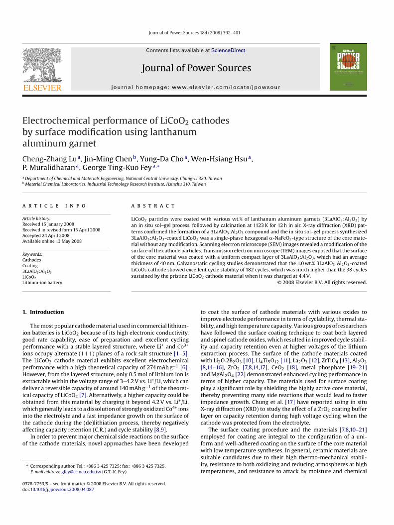
Fig. 1 represents the in situ sol–gel coating procedure for theynthesis of 3LaAlO3:Al2O3-coated LiCoO2 cathode material. Thealculated amount of LiCoO2 cathode powders was dispersed ineionized water and sonicated for 5 h and then added to the initu synthesized 3LaAlO3:Al2O3 sol precursor under sonication for.5 h. The sonicated mixture was continuously stirred for 10 h at53 K. The excess EG and water were evaporated to form a thicklack gel. The gel was dried in an oven at 393 K for 48 h to formdry black powder, which was calcined at 1023, 1123 and 1223 K
or 12 h in air at a heating ramp of 2 K min−1 to form a thin bufferayer of 3LaAlO3:Al2O3 coating on LiCoO2 within the weight ratiosf 0.5:99.5, 1.0:99.0 and 1.5:98.5, respectively.
Structural and phase analyses were carried out using aowder X-ray diffractometer, Siemens D-5000, Mac ScienceXP18, equipped with a nickel-filtered Cu K� radiation source
� = 1.5405 A). The diffraction patterns were recorded betweencattering angles of 15◦ and 80◦ in steps of 0.05◦. The surfaceorphology of the coated materials was studied using a scanning
lectron microscope, Hitachi model S-3500V. The sol–gel synthe-ized 3LaAlO3:Al2O3 particle size and the coating layer morphologyf the coated particles were examined by a JEOL JEM-200FXII trans-ission electron microscope (TEM) equipped with a LaB6 gun.
he sample for transmission electron microscope study was pre-
twamt
ig. 1. Schematic for the 3LaAlO3:Al2O3-coated LiCoO2 cathode materials preparedy an in situ sol–gel process.
ared by dispersing the powder in ethanol, placing a drop of thelear solution on a carbon-coated copper grid, and subsequent dry-ng. X-ray photon spectroscopy (XPS) and the depth profiles wereecorded by an electron spectroscopy for chemical analysis (ESCA)nstrument (VG Scientific ESCALAB 250) with monochromatic Al K�adiation 1486.6 eV. The survey spectra were scanned in the range.00–1400.00 eV binding energy (BE) in 1.00 eV steps. The elemen-al analysis was carried out by an ICP/AES instrument (PE-SCIEXLAN 6100 DRC).
The cathodes for electrochemical studies were prepared by aoctor-blade coating method. The cell performance of the cathodesas evaluated with coin-type cells of the 2032 configuration. Theetailed procedure and operation were described in our previousork [11].
Coin cells cycled at different cycles were subjected to impedanceeasurements. The impedance spectra were recorded usingSchlumberger 1286 electrochemical interface and frequency
esponse analyzer (Model 1255), driven by Corrware softwareScribner Associates). The frequency range was 65 kHz to 0.001 Hznd the amplitude of the perturbation signal was 20 mV. Thempedance spectra were analyzed with Z-view software (Scribnerssociates).
Thermal stability analysis was carried out on a PerkinElmer DSCdifferential scanning calorimeter (DSC) for the bare and LAG-
oated LiCoO2 samples. The measurements were performed in aitrogen atmosphere between 313 and 673 K, at a heating rate of0 K min−1. The samples for the DSC experiments were prepareds follows. The coin cells were first galvanostatically charged to.4 V at a 0.2C rate and then potentiostated at 4.4 V for 10 h. Theoin cells were then opened inside a glove box. The cathode inhe coin cell was carefully removed, and the excess electrolyte was
iped with Kimwipes. The cathode was gently scraped from theluminum current collector, loaded on to an aluminum pan, her-etically sealed, placed in an airtight container, and transferred to
he DSC instrument.
394 C.-Z. Lu et al. / Journal of Power So
Ff
3
3
31rcwpams
3TpsitXpii1
3
cLccdr
LfstTbtactletew
LcpttpddLt
aa solid solution or remained on the surface of the core material.Fig. 7a–c displays the XPS spectra of O 1s, La 3d and Al 2p at depthlevels of 0 and 20 nm, respectively, for the LAG-coated LiCoO2 mate-rial. The O 1s spectra in Fig. 7a exhibit a median intensity peak at a
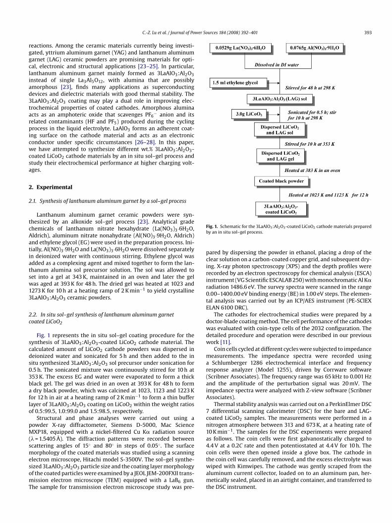
ig. 2. X-ray diffraction patterns of the synthesized 3LaAlO3:Al2O3 particles heatedor 10 h at (a) 1023 K, (b) 1273 K and (c) JCPDS data.
. Results and discussion
.1. X-ray diffraction
Fig. 2a–c exhibits the XRD patterns for sol–gel prepared pureLaAlO3:Al2O3 ceramic powders by calcination of dried gel at023 and 1223 K for 10 h in air, and JCPDS # 82-0478 of LaAlO3,espectively. In Fig. 2a, the dried gel calcined at 1023 K remainedrystalline embedded on an amorphous compound and when itas further calcined at 1223 K for 10 h in air, resulted in the com-lete formation of crystalline 3LaAlO3:Al2O3, in which Al2O3 wasmorphous [23]. The pure phase of the synthesized 3LaAlO3:Al2O3aterial could be indexed to the JCPDS # 82-0478 pattern [23], as
hown in Fig. 2c.Fig. 3a–d shows the XRD patterns for 1.5, 1.0 and 0.5 wt.%
LaAlO3:Al2O3-coated LiCoO2 and pristine LiCoO2, respectively.he diffraction patterns of all the materials conform to a single-hase hexagonal structure of �-NaFeO2 type with space group R3mymmetry of the core material. The absence of secondary phasesn the complete range of diffraction patterns may correspond tohe presence of low concentrations of 3LaAlO3:Al2O3 particles. TheRD patterns of the coated particles revealed that the a and c latticearameters and the 2� values of the peaks did not change, which
ndicates 3LaAlO3:Al2O3 does not form a solid solution by interact-ng with core material during the calcination process at 1123 K for2 h.
.2. Morphology
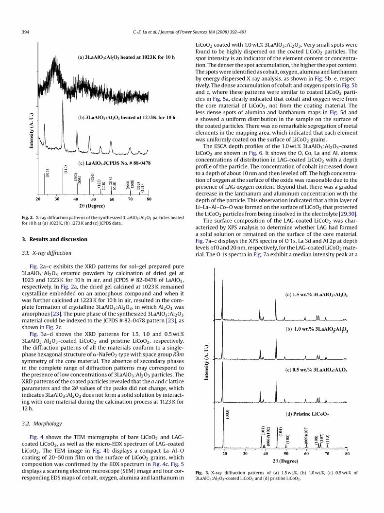
Fig. 4 shows the TEM micrographs of bare LiCoO2 and LAG-oated LiCoO2, as well as the micro-EDX spectrum of LAG-coated
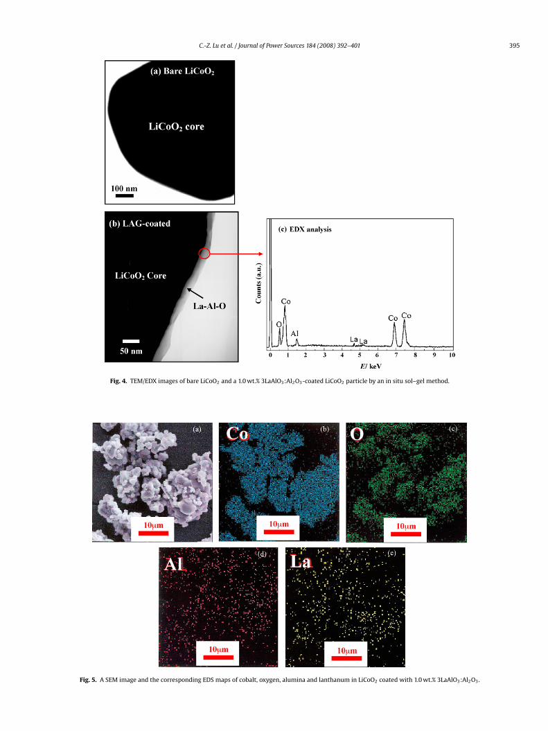
iCoO2. The TEM image in Fig. 4b displays a compact La–Al–Ooating of 20–50 nm film on the surface of LiCoO2 grains, whichomposition was confirmed by the EDX spectrum in Fig. 4c. Fig. 5isplays a scanning electron microscope (SEM) image and four cor-esponding EDS maps of cobalt, oxygen, alumina and lanthanum inF3
urces 184 (2008) 392–401
iCoO2 coated with 1.0 wt.% 3LaAlO3:Al2O3. Very small spots wereound to be highly dispersed on the coated LiCoO2 particles. Thepot intensity is an indicator of the element content or concentra-ion. The denser the spot accumulation, the higher the spot content.he spots were identified as cobalt, oxygen, alumina and lanthanumy energy dispersed X-ray analysis, as shown in Fig. 5b–e, respec-ively. The dense accumulation of cobalt and oxygen spots in Fig. 5bnd c, where these patterns were similar to coated LiCoO2 parti-les in Fig. 5a, clearly indicated that cobalt and oxygen were fromhe core material of LiCoO2, not from the coating material. Theess dense spots of alumina and lanthanum maps in Fig. 5d and
showed a uniform distribution in the sample on the surface ofhe coated particles. There was no remarkable segregation of metallements in the mapping area, which indicated that each elementas uniformly coated on the surface of LiCoO2 grains.
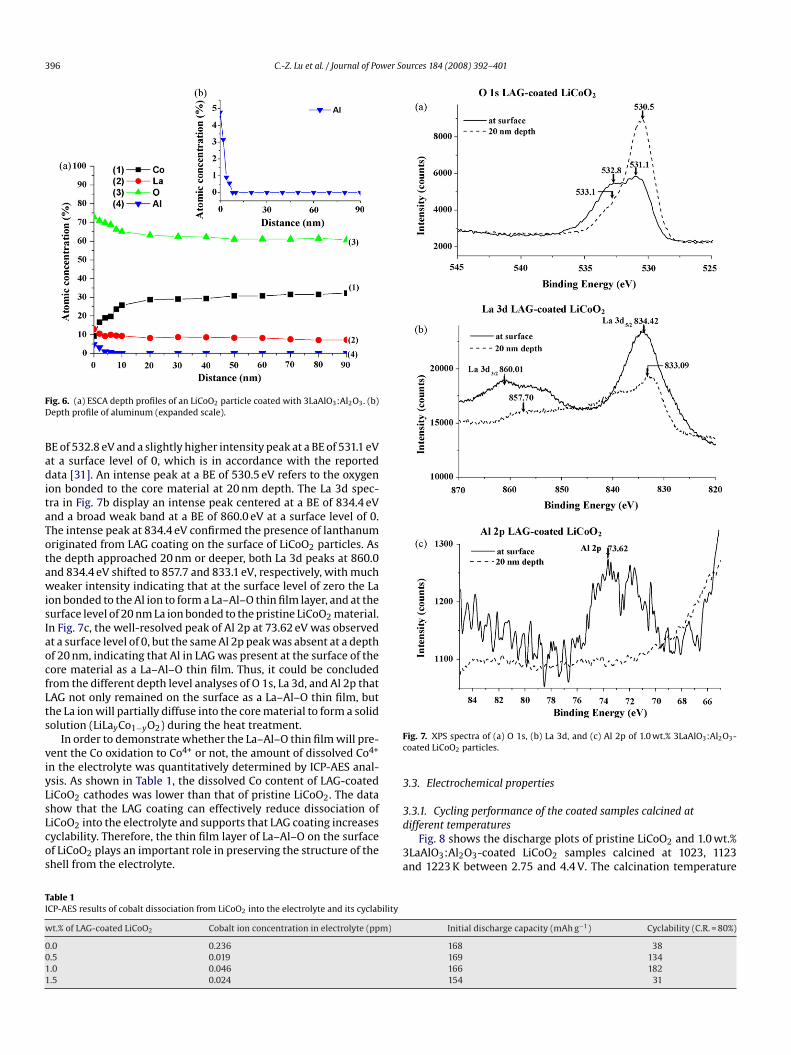
The ESCA depth profiles of the 1.0 wt.% 3LaAlO3:Al2O3-coatediCoO2 are shown in Fig. 6. It shows the O, Co, La and Al, atomiconcentrations of distribution in LAG-coated LiCoO2 with a depthrofile of the particle. The concentration of cobalt increased downo a depth of about 10 nm and then leveled off. The high concentra-ion of oxygen at the surface of the oxide was reasonable due to theresence of LAG oxygen content. Beyond that, there was a gradualecrease in the lanthanum and aluminum concentration with theepth of the particle. This observation indicated that a thin layer ofi–La–Al–Co–O was formed on the surface of LiCoO2 that protectedhe LiCoO2 particles from being dissolved in the electrolyte [29,30].
The surface composition of the LAG-coated LiCoO2 was char-cterized by XPS analysis to determine whether LAG had formed
ig. 3. X-ray diffraction patterns of (a) 1.5 wt.%, (b) 1.0 wt.%, (c) 0.5 wt.% ofLaAlO3:Al2O3-coated LiCoO2 and (d) pristine LiCoO2.
C.-Z. Lu et al. / Journal of Power Sources 184 (2008) 392–401 395
Fig. 4. TEM/EDX images of bare LiCoO2 and a 1.0 wt.% 3LaAlO3:Al2O3-coated LiCoO2 particle by an in situ sol–gel method.
Fig. 5. A SEM image and the corresponding EDS maps of cobalt, oxygen, alumina and lanthanum in LiCoO2 coated with 1.0 wt.% 3LaAlO3:Al2O3.
396 C.-Z. Lu et al. / Journal of Power Sources 184 (2008) 392–401
FD
BaditaTotawisIaocfLts
viyLsLcos
Fc
3
TI
w
0011
ig. 6. (a) ESCA depth profiles of an LiCoO2 particle coated with 3LaAlO3:Al2O3. (b)epth profile of aluminum (expanded scale).
E of 532.8 eV and a slightly higher intensity peak at a BE of 531.1 eVt a surface level of 0, which is in accordance with the reportedata [31]. An intense peak at a BE of 530.5 eV refers to the oxygen
on bonded to the core material at 20 nm depth. The La 3d spec-ra in Fig. 7b display an intense peak centered at a BE of 834.4 eVnd a broad weak band at a BE of 860.0 eV at a surface level of 0.he intense peak at 834.4 eV confirmed the presence of lanthanumriginated from LAG coating on the surface of LiCoO2 particles. Ashe depth approached 20 nm or deeper, both La 3d peaks at 860.0nd 834.4 eV shifted to 857.7 and 833.1 eV, respectively, with mucheaker intensity indicating that at the surface level of zero the La
on bonded to the Al ion to form a La–Al–O thin film layer, and at theurface level of 20 nm La ion bonded to the pristine LiCoO2 material.n Fig. 7c, the well-resolved peak of Al 2p at 73.62 eV was observedt a surface level of 0, but the same Al 2p peak was absent at a depthf 20 nm, indicating that Al in LAG was present at the surface of theore material as a La–Al–O thin film. Thus, it could be concludedrom the different depth level analyses of O 1s, La 3d, and Al 2p thatAG not only remained on the surface as a La–Al–O thin film, buthe La ion will partially diffuse into the core material to form a solidolution (LiLayCo1−yO2) during the heat treatment.
In order to demonstrate whether the La–Al–O thin film will pre-ent the Co oxidation to Co4+ or not, the amount of dissolved Co4+
n the electrolyte was quantitatively determined by ICP-AES anal-sis. As shown in Table 1, the dissolved Co content of LAG-coatediCoO2 cathodes was lower than that of pristine LiCoO2. The datahow that the LAG coating can effectively reduce dissociation of
iCoO2 into the electrolyte and supports that LAG coating increasesyclability. Therefore, the thin film layer of La–Al–O on the surfacef LiCoO2 plays an important role in preserving the structure of thehell from the electrolyte.3d
3a
able 1CP-AES results of cobalt dissociation from LiCoO2 into the electrolyte and its cyclability
t.% of LAG-coated LiCoO2 Cobalt ion concentration in electrolyte (ppm)
.0 0.236
.5 0.019
.0 0.046
.5 0.024
ig. 7. XPS spectra of (a) O 1s, (b) La 3d, and (c) Al 2p of 1.0 wt.% 3LaAlO3:Al2O3-oated LiCoO2 particles.
.3. Electrochemical properties
.3.1. Cycling performance of the coated samples calcined at
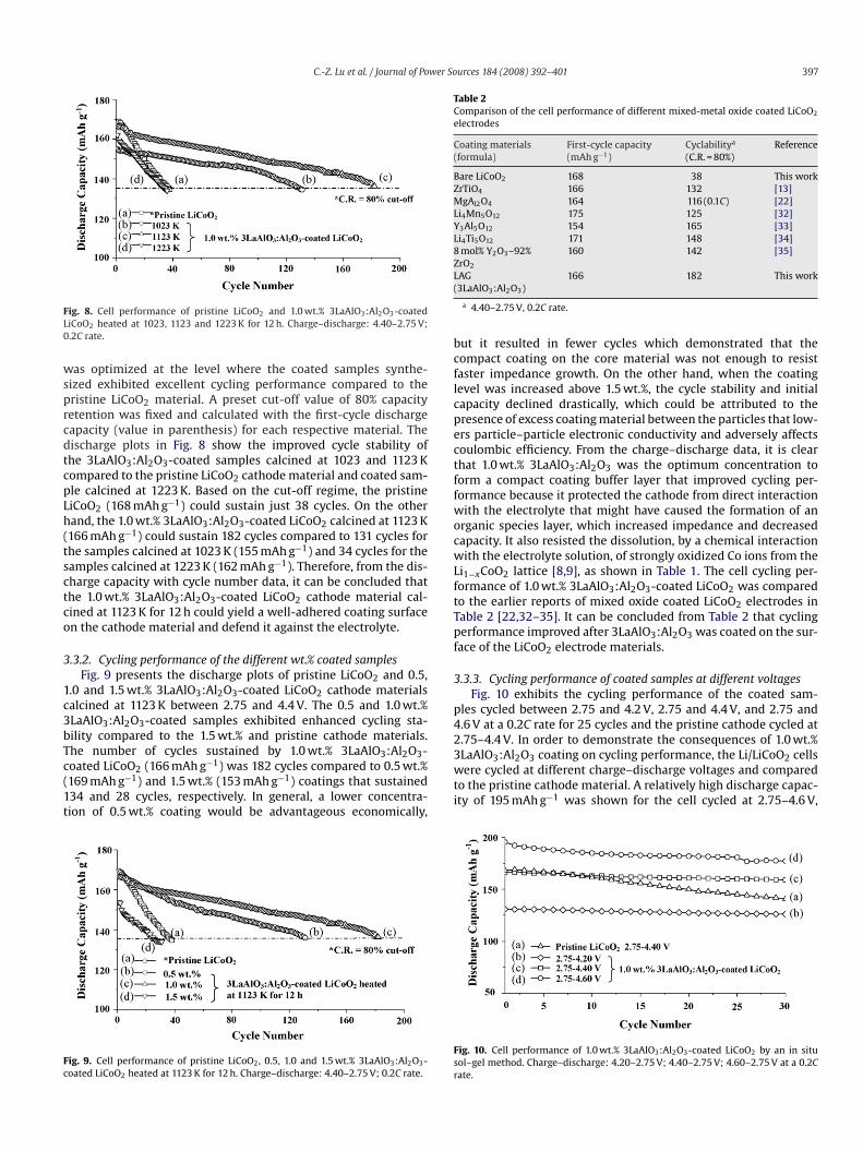
ifferent temperaturesFig. 8 shows the discharge plots of pristine LiCoO2 and 1.0 wt.%LaAlO3:Al2O3-coated LiCoO2 samples calcined at 1023, 1123nd 1223 K between 2.75 and 4.4 V. The calcination temperature
Initial discharge capacity (mAh g−1) Cyclability (C.R. = 80%)
168 38169 134166 182154 31
C.-Z. Lu et al. / Journal of Power Sources 184 (2008) 392–401 397
FL0
wsprcdtcpLh(tsctco
3
1c3bTc(1t
Fc
Table 2Comparison of the cell performance of different mixed-metal oxide coated LiCoO2
electrodes
Coating materials(formula)
First-cycle capacity(mAh g−1)
Cyclabilitya
(C.R. = 80%)Reference
Bare LiCoO2 168 38 This workZrTiO4 166 132 [13]MgAl2O4 164 116 (0.1C) [22]Li4Mn5O12 175 125 [32]Y3Al5O12 154 165 [33]Li4Ti5O12 171 148 [34]8 mol% Y2O3–92%ZrO2
160 142 [35]
L(
bcflcpectffwocwLftTpf
3
p42.75–4.4 V. In order to demonstrate the consequences of 1.0 wt.%
ig. 8. Cell performance of pristine LiCoO2 and 1.0 wt.% 3LaAlO3:Al2O3-coatediCoO2 heated at 1023, 1123 and 1223 K for 12 h. Charge–discharge: 4.40–2.75 V;.2C rate.
as optimized at the level where the coated samples synthe-ized exhibited excellent cycling performance compared to theristine LiCoO2 material. A preset cut-off value of 80% capacityetention was fixed and calculated with the first-cycle dischargeapacity (value in parenthesis) for each respective material. Theischarge plots in Fig. 8 show the improved cycle stability ofhe 3LaAlO3:Al2O3-coated samples calcined at 1023 and 1123 Kompared to the pristine LiCoO2 cathode material and coated sam-le calcined at 1223 K. Based on the cut-off regime, the pristineiCoO2 (168 mAh g−1) could sustain just 38 cycles. On the otherand, the 1.0 wt.% 3LaAlO3:Al2O3-coated LiCoO2 calcined at 1123 K166 mAh g−1) could sustain 182 cycles compared to 131 cycles forhe samples calcined at 1023 K (155 mAh g−1) and 34 cycles for theamples calcined at 1223 K (162 mAh g−1). Therefore, from the dis-harge capacity with cycle number data, it can be concluded thathe 1.0 wt.% 3LaAlO3:Al2O3-coated LiCoO2 cathode material cal-ined at 1123 K for 12 h could yield a well-adhered coating surfacen the cathode material and defend it against the electrolyte.
.3.2. Cycling performance of the different wt.% coated samplesFig. 9 presents the discharge plots of pristine LiCoO2 and 0.5,
.0 and 1.5 wt.% 3LaAlO3:Al2O3-coated LiCoO2 cathode materialsalcined at 1123 K between 2.75 and 4.4 V. The 0.5 and 1.0 wt.%LaAlO3:Al2O3-coated samples exhibited enhanced cycling sta-ility compared to the 1.5 wt.% and pristine cathode materials.he number of cycles sustained by 1.0 wt.% 3LaAlO :Al O -
3 2 3oated LiCoO2 (166 mAh g−1) was 182 cycles compared to 0.5 wt.%169 mAh g−1) and 1.5 wt.% (153 mAh g−1) coatings that sustained34 and 28 cycles, respectively. In general, a lower concentra-ion of 0.5 wt.% coating would be advantageous economically,ig. 9. Cell performance of pristine LiCoO2, 0.5, 1.0 and 1.5 wt.% 3LaAlO3:Al2O3-oated LiCoO2 heated at 1123 K for 12 h. Charge–discharge: 4.40–2.75 V; 0.2C rate.
3wti
Fsr
AG3LaAlO3:Al2O3)
166 182 This work
a 4.40–2.75 V, 0.2C rate.
ut it resulted in fewer cycles which demonstrated that theompact coating on the core material was not enough to resistaster impedance growth. On the other hand, when the coatingevel was increased above 1.5 wt.%, the cycle stability and initialapacity declined drastically, which could be attributed to theresence of excess coating material between the particles that low-rs particle–particle electronic conductivity and adversely affectsoulombic efficiency. From the charge–discharge data, it is clearhat 1.0 wt.% 3LaAlO3:Al2O3 was the optimum concentration toorm a compact coating buffer layer that improved cycling per-ormance because it protected the cathode from direct interactionith the electrolyte that might have caused the formation of an
rganic species layer, which increased impedance and decreasedapacity. It also resisted the dissolution, by a chemical interactionith the electrolyte solution, of strongly oxidized Co ions from the
i1−xCoO2 lattice [8,9], as shown in Table 1. The cell cycling per-ormance of 1.0 wt.% 3LaAlO3:Al2O3-coated LiCoO2 was comparedo the earlier reports of mixed oxide coated LiCoO2 electrodes inable 2 [22,32–35]. It can be concluded from Table 2 that cyclingerformance improved after 3LaAlO3:Al2O3 was coated on the sur-
ace of the LiCoO2 electrode materials.
.3.3. Cycling performance of coated samples at different voltagesFig. 10 exhibits the cycling performance of the coated sam-
les cycled between 2.75 and 4.2 V, 2.75 and 4.4 V, and 2.75 and.6 V at a 0.2C rate for 25 cycles and the pristine cathode cycled at
LaAlO3:Al2O3 coating on cycling performance, the Li/LiCoO2 cellsere cycled at different charge–discharge voltages and compared
o the pristine cathode material. A relatively high discharge capac-ty of 195 mAh g−1 was shown for the cell cycled at 2.75–4.6 V,
ig. 10. Cell performance of 1.0 wt.% 3LaAlO3:Al2O3-coated LiCoO2 by an in situol–gel method. Charge–discharge: 4.20–2.75 V; 4.40–2.75 V; 4.60–2.75 V at a 0.2Cate.
398 C.-Z. Lu et al. / Journal of Power Sources 184 (2008) 392–401
Fs
1pitvfitrhwo
3
3bf1ig3cdl
3
epeoLsoattfaHaam
Fa
tlait
gpccchanges in the content of the conducting species in the solution[42,43]. The high-frequency resistance of the cell in Fig. 12a andb, as a function of cycle number, showed the resistance of the sur-face film on the cathode particles were 20.87 � after 10 cycles to
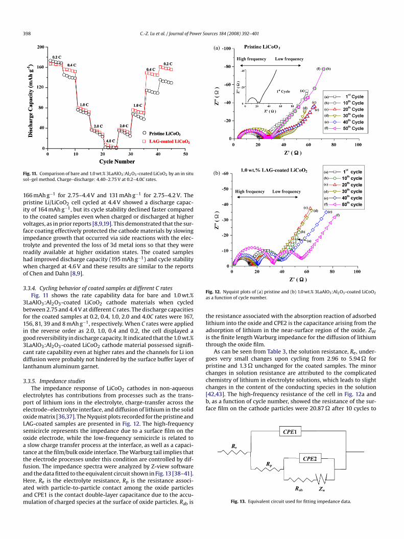
ig. 11. Comparison of bare and 1.0 wt.% 3LaAlO3:Al2O3-coated LiCoO2 by an in situol–gel method. Charge–discharge: 4.40–2.75 V at 0.2–4.0C rates.
66 mAh g−1 for 2.75–4.4 V and 131 mAh g−1 for 2.75–4.2 V. Theristine Li/LiCoO2 cell cycled at 4.4 V showed a discharge capac-
ty of 164 mAh g−1, but its cycle stability declined faster comparedo the coated samples even when charged or discharged at higheroltages, as in prior reports [8,9,19]. This demonstrated that the sur-ace coating effectively protected the cathode materials by slowingmpedance growth that occurred via side reactions with the elec-rolyte and prevented the loss of 3d metal ions so that they wereeadily available at higher oxidation states. The coated samplesad improved discharge capacity (195 mAh g−1) and cycle stabilityhen charged at 4.6 V and these results are similar to the reports
f Chen and Dahn [8,9].
.3.4. Cycling behavior of coated samples at different C ratesFig. 11 shows the rate capability data for bare and 1.0 wt.%
LaAlO3:Al2O3-coated LiCoO2 cathode materials when cycledetween 2.75 and 4.4 V at different C rates. The discharge capacitiesor the coated samples at 0.2, 0.4, 1.0, 2.0 and 4.0C rates were 167,56, 81, 39 and 8 mAh g−1, respectively. When C rates were appliedn the reverse order as 2.0, 1.0, 0.4 and 0.2, the cell displayed aood reversibility in discharge capacity. It indicated that the 1.0 wt.%LaAlO3:Al2O3-coated LiCoO2 cathode material possessed signifi-ant rate capability even at higher rates and the channels for Li ioniffusion were probably not hindered by the surface buffer layer of
anthanum aluminum garnet.
.3.5. Impedance studiesThe impedance response of LiCoO2 cathodes in non-aqueous
lectrolytes has contributions from processes such as the trans-ort of lithium ions in the electrolyte, charge-transfer across thelectrode–electrolyte interface, and diffusion of lithium in the solidxide matrix [36,37]. The Nyquist plots recorded for the pristine andAG-coated samples are presented in Fig. 12. The high-frequencyemicircle represents the impedance due to a surface film on thexide electrode, while the low-frequency semicircle is related toslow charge transfer process at the interface, as well as a capaci-
ance at the film/bulk oxide interface. The Warburg tail implies thathe electrode processes under this condition are controlled by dif-usion. The impedance spectra were analyzed by Z-view software
nd the data fitted to the equivalent circuit shown in Fig. 13 [38–41].ere, Re is the electrolyte resistance, Rp is the resistance associ-ted with particle-to-particle contact among the oxide particlesnd CPE1 is the contact double-layer capacitance due to the accu-ulation of charged species at the surface of oxide particles. Rab isig. 12. Nyquist plots of (a) pristine and (b) 1.0 wt.% 3LaAlO3:Al2O3-coated LiCoO2
s a function of cycle number.
he resistance associated with the absorption reaction of adsorbedithium into the oxide and CPE2 is the capacitance arising from thedsorption of lithium in the near-surface region of the oxide. ZWs the finite length Warburg impedance for the diffusion of lithiumhrough the oxide film.
As can be seen from Table 3, the solution resistance, Re, under-oes very small changes upon cycling from 2.96 to 5.94 � forristine and 1.3 � unchanged for the coated samples. The minorhanges in solution resistance are attributed to the complicatedhemistry of lithium in electrolyte solutions, which leads to slight
Fig. 13. Equivalent circuit used for fitting impedance data.
C.-Z. Lu et al. / Journal of Power Sources 184 (2008) 392–401 399
Table 3Variation in the particle-to-particle resistance as a function of cycle number
Coating precursor Cycle number Re (�) Rp (�) Rab (�) CPE1 (F) CPE2 (F) ZW (�)
T × 10−6 P T × 10−3 P R T P
PristineLiCoO2
1 2.96 17.09 3.12 7.70 0.86 7.89 0.77 56 114 0.6310 3.51 20.87 5.62 5.80 0.89 9.26 0.63 203 923 0.6220 5.39 35.67 16.28 7.60 0.90 9.63 0.64 258 1185 0.6530 5.56 51.24 24.58 6.90 0.91 9.15 0.66 359 2401 0.6740 5.58 62.33 40.46 6.80 1.01 9.61 0.61 420 3015 0.8150 5.94 100.24 50.51 7.60 1.21 9.77 0.80 674 4268 0.75
1.0 wt.%LAG-cL
1 1.30 13.50 22.00 13.00 0.85 9.97 0.94 88 900 0.5610 1.30 17.50 19.00 11.30 0.83 9.97 0.94 108 1000 0.5920 1.30 16.50 14.00 12.10 0.83 9.97 0.91 104 1000 0.55
113
13pcctprbtmoso
[rtbotLdtd(opss
3
cc4
L
LomprTc
pttc
LiarstAwtdctbottgaOSiO2-coated LiNi0.8Co0.2O2 after charging the cells to 4.3 V. Table 4presents a comparison of the thermal analysis data for LAG-coatedLiCoO2 with previously reported results for coated LiCoO2 andLiNi0.8Co0.2O2 electrode materials.
oatediCoO2
30 1.30 17.20 14.5040 1.30 19.30 17.4050 1.30 31.80 20.20
00.24 � after 50 cycles for the pristine and 17.5 � after 10 cycles to1 � after 50 cycles for the coated sample (Table 3). Therefore, theristine sample showed an increase in resistance of 79.37 � for 40ycles, while the coated sample showed an increase of 13.5 � for 40ycles. Table 3 also shows the resistance associated with the absorp-ion reaction, Rab, of the cathode materials increased as the cyclingroceeded for pristine compared to coated samples. This result cor-esponds to a fast increase in impedance growth over the surfacey a passive film on the pristine vs. the LAG-coated LiCoO2. Thus,he equivalent circuit model remains the best fit of the Nyquist plot
easured for both pristine LiCoO2 and coated LiCoO2. In the casef pristine and coated LiCoO2, the angle of depression of the secondemicircle varied depending on the insulation layer on the surfacef the LiCoO2.
The impedance results revealed that the passive surface film42,43], which formed on the pristine cathode particles increasedesistance faster with cycle number (Fig. 12a). In contrast, forma-ion of the passive surface film was controlled and the reactionetween the electrolyte and the oxide particles was suppressedn the LAG-coated LiCoO2 surface (Fig. 12b). The constituents ofhe surface passive film (polycarbonates, polymeric hydrocarbons,i2CO3, LiF, LixPFy and LixPFyOz) formed on the cathode particlesuring the electrochemical reaction changes with the oxide andhe electrolyte that increases the resistance of the surface film andynamically hinders the movement of the lithium ion during thede)lithiation process [38,39]. Thus, during cycling, the formationf a passive surface film, resulting in impedance growth of theristine LiCoO2 resulted in faster capacity fade and lower cycletability during repeated cycling compared to LAG-coated LiCoO2amples.
.4. Thermal stability studies
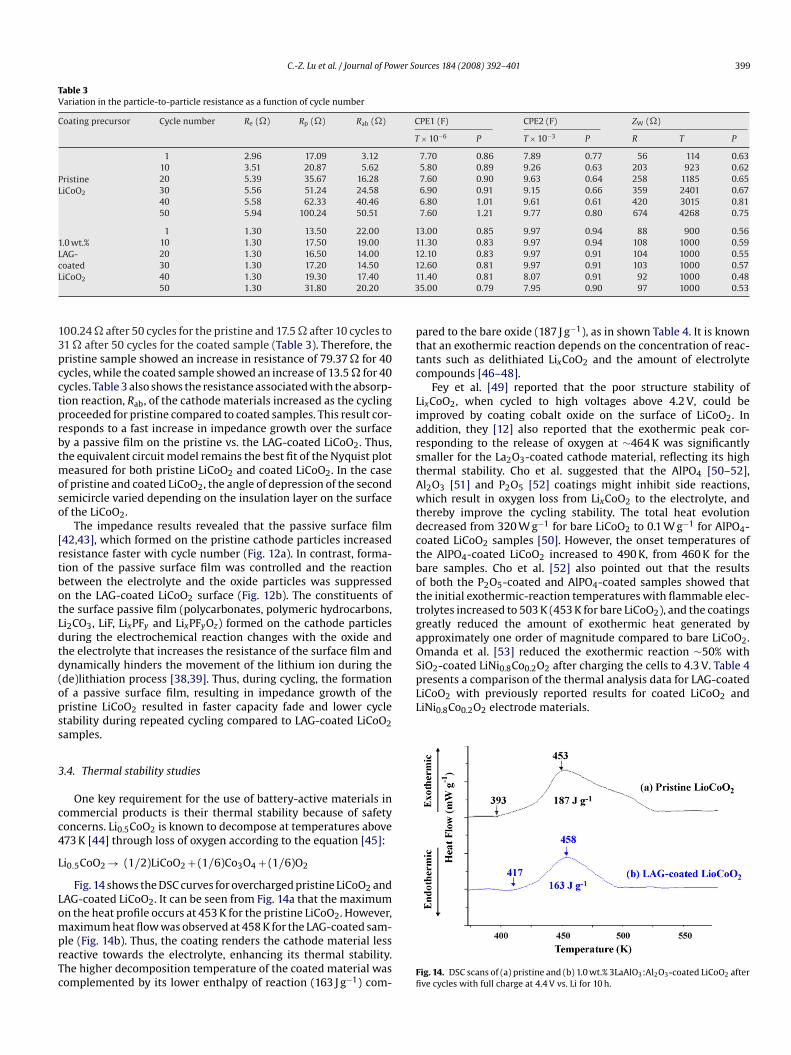
One key requirement for the use of battery-active materials inommercial products is their thermal stability because of safetyoncerns. Li0.5CoO2 is known to decompose at temperatures above73 K [44] through loss of oxygen according to the equation [45]:
i0.5CoO2 → (1/2)LiCoO2 + (1/6)Co3O4 + (1/6)O2
Fig. 14 shows the DSC curves for overcharged pristine LiCoO2 andAG-coated LiCoO2. It can be seen from Fig. 14a that the maximumn the heat profile occurs at 453 K for the pristine LiCoO2. However,
aximum heat flow was observed at 458 K for the LAG-coated sam-le (Fig. 14b). Thus, the coating renders the cathode material lesseactive towards the electrolyte, enhancing its thermal stability.he higher decomposition temperature of the coated material wasomplemented by its lower enthalpy of reaction (163 J g−1) com-
Ffi
2.60 0.81 9.97 0.91 103 1000 0.571.40 0.81 8.07 0.91 92 1000 0.485.00 0.79 7.95 0.90 97 1000 0.53
ared to the bare oxide (187 J g−1), as in shown Table 4. It is knownhat an exothermic reaction depends on the concentration of reac-ants such as delithiated LixCoO2 and the amount of electrolyteompounds [46–48].
Fey et al. [49] reported that the poor structure stability ofixCoO2, when cycled to high voltages above 4.2 V, could bemproved by coating cobalt oxide on the surface of LiCoO2. Inddition, they [12] also reported that the exothermic peak cor-esponding to the release of oxygen at ∼464 K was significantlymaller for the La2O3-coated cathode material, reflecting its highhermal stability. Cho et al. suggested that the AlPO4 [50–52],l2O3 [51] and P2O5 [52] coatings might inhibit side reactions,hich result in oxygen loss from LixCoO2 to the electrolyte, and
hereby improve the cycling stability. The total heat evolutionecreased from 320 W g−1 for bare LiCoO2 to 0.1 W g−1 for AlPO4-oated LiCoO2 samples [50]. However, the onset temperatures ofhe AlPO4-coated LiCoO2 increased to 490 K, from 460 K for theare samples. Cho et al. [52] also pointed out that the resultsf both the P2O5-coated and AlPO4-coated samples showed thathe initial exothermic-reaction temperatures with flammable elec-rolytes increased to 503 K (453 K for bare LiCoO2), and the coatingsreatly reduced the amount of exothermic heat generated bypproximately one order of magnitude compared to bare LiCoO2.manda et al. [53] reduced the exothermic reaction ∼50% with
ig. 14. DSC scans of (a) pristine and (b) 1.0 wt.% 3LaAlO3:Al2O3-coated LiCoO2 afterve cycles with full charge at 4.4 V vs. Li for 10 h.

400 C.-Z. Lu et al. / Journal of Power So
Tab
le4
Com
par
ison
ofth
eD
SCre
sult
sfo
rp
rist
ine
and
LAG
-coa
ted
LiC
oO2
sam
ple
s
Au
thor
sSa
mp
les
Dec
omp
osit
ion
tem
per
atu
re(K
)Ex
oth
erm
icen
thal
py(J
g−1)
Con
dit
ion
Ref
eren
ce
Fey
etal
.
Pris
tin
eLi
xC
oO2
453
187
Aft
erfi
vecy
cles
wit
hfu
llch
arge
at4.
4V
for
10h
at0.
2Cra
teTh
isw
ork
1.0
wt.
%LA
G-c
oate
dLi
xC
oO2
458
163
Pris
tin
eLi
xC
oO2
525
12.8
Ch
arge
dto
4.4
Vat
0.1C
rate
[49]
0.3
wt.
%co
balt
oxid
e-co
ated
LixC
oO2
536
8.8
Pris
tin
eLi
xC
oO2
458
The
rela
tive
exot
her
mic
area
un
der
the
pea
kw
assm
alle
rby
afa
ctor
of3
tim
esvs
.th
ep
rist
ine
mat
eria
lC
har
ged
to4.
6V
at0.
2Cra
te[1
2]2.
0w
t.%
La2O
3-c
oate
dLi
xC
oO2
464
Ch
oet
al.
Pris
tin
eLi
xC
oO2
373
320
Ch
arge
dto
4.7
Vat
0.1C
rate
[50]
P10-
AlP
O4-c
oate
dLi
xC
oO2
490
35Pr
isti
ne
LixC
oO2
443
–C
har
ged
to4.
3V
[51]
Al 2
O3-c
oate
dLi
xC
oO2
463
–A
lPO
4-c
oate
dLi
xC
oO2
503
–Pr
isti
ne
LixC
oO2
453
–C
har
ged
to4.
3V
[52]
P 2O
5-c
oate
dLi
xC
oO2
503
–
Om
and
aet
al.
Pris
tin
eLi
xN
i 0.8
Co 0
.2O
24
8746
2C
har
ged
to4.
3V
atC/
16ra
te[5
3]Si
O2-c
oate
dLi
xN
i 0.8
Co 0
.2O
247
620
7
4
aXiw3ctttpp3c
A
S9d
R
[[
[[
[
[
[[
[
[
[[[[[[
[[
[
[
[[[
[
[
[
urces 184 (2008) 392–401
. Conclusions
Different wt.% 3LaAlO3:Al2O3-coated LiCoO2 cathode materi-ls were successfully prepared by an in situ sol–gel process. TheRD patterns confirmed that the core material retained its orig-
nal structure without any alteration upon coating with differentt.% of 3LaAlO3:Al2O3 particles. The TEM image displayed that
LaAlO3:Al2O3 was formed as a compact layer over the LiCoO2athode particle. Coating improved cycle stability by primarily pro-ecting the cathode surface from thick impedance film formationhat is normally attributed to the surface chemistry of LiCoO2 andhe reactivity of the electrolyte at higher voltage charge–dischargerocesses. The 1.0 wt.% 3LaAlO3:Al2O3-coated LiCoO2 cathode dis-layed excellent cycle stability of 182 cycles, which was superior to8 cycles sustained by the pristine LiCoO2 cathode material whenycled between 2.75 and 4.4 V.
cknowledgements
Financial support for this work was provided by the Nationalcience Council of the Republic of China under contract No. NSC3-2214-E-008-004. PMD thanks the NSC for the award of a post-octoral fellowship.
eferences
[1] L.D. Dyer, B.S. Borie Jr., G.P. Smith, J. Am. Chem. Soc. 76 (1954) 1499.[2] H.F. Wang, Y.I. Jang, B.Y. Huang, D.R. Sadoway, Y.M. Chiang, J. Electrochem. Soc.
146 (1999) 473.[3] G.G. Amatucci, J.M. Tarascon, L.C. Klein, Solid State Ionics 83 (1996) 167.[4] J.M. Tarascon, M. Armand, Nature (London) 414 (2001) 359.[5] C. Julien, S. Gastro-Garcia, J. Power Sources 97–98 (2001) 290.[6] M. Winter, J.O. Besenhard, M.E. Spahr, P. Novak, Adv. Mater. 10 (1998) 725.[7] J. Cho, G. Kim, Electrochem. Solid-State Lett. 2 (1999) 253.[8] Z. Chen, J.R. Dahn, Electrochem. Solid-State Lett. 5 (2002) A213.[9] Z. Chen, J.R. Dahn, Electrochim. Acta 49 (2004) 1079.10] N.V. Kosova, E.T. Devyatkina, J. Power Sources 174 (2007) 959.11] G.T.K. Fey, C.-F. Huang, P. Muralidharan, E.S.S. Chang, J. Power Sources 174 (2007)
1147.12] G.T.K. Fey, P. Muralidharan, C.Z. Lu, Y.D. Cho, Electrochim. Acta 51 (2006) 4850.13] G.T.K. Fey, C.Z. Lu, J.D. Huang, T.P. Kumar, Y.C. Chang, J. Power Sources 146 (2005)
65.14] A.M. Kannan, L. Rabenberg, A. Manthiram, Electrochem. Solid-State Lett. 6
(2003) A16.15] G.T.K. Fey, H.M. Kao, P. Muralidharan, T.P. Kumar, Y.D. Cho, J. Power Sources 163
(2006) 135.16] G.T.K. Fey, J.G. Chen, T.P. Kumar, J. Appl. Electrochem. 35 (2005) 177.17] K.Y. Chung, W.S. Yoon, J. McBreen, X.Q. Yang, S.H. Oh, H.C. Shin, W.I. Cho, B.W.
Cho, J. Power Sources 174 (2007) 619.18] H.W. Ha, N.J. Yun, M.H. Kim, M.H. Woo, K. Kim, Electrochim. Acta 51 (2006)
3297.19] J. Cho, T.G. Kim, C. Kim, J.G. Lee, Y.W. Kim, B. Park, J. Power Sources 146 (2005)
58.20] J.G. Lee, T.G. Kim, B. Park, Mater. Res. Bull. 42 (2007) 1201.21] H. Wang, W.D. Zhang, L.Y. Zhu, M.C. Chen, Solid State Ionics 178 (2007) 131.22] G.T.K. Fey, Z.F. Wang, C.Z. Lu, T.P. Kumar, J. Power Sources 146 (2005) 245.23] A. Leleckaite, A. Kareiva, Opt. Mater. 26 (2004) 123.24] R.C. Pullar, M.D. Taylor, A.K. Bhattacharya, J. Eur. Ceram. Soc. 19 (1999) 1747.25] M. Veith, S. Mathur, A. Kareiva, M. Jilavi, M. Zimmer, V. Huch, J. Mater. Chem. 9
(1999) 3069.26] K. Xiong, J. Robertson, S.J. Clark, Microelectron. Eng. 85 (2008) 65.27] L. John Berchmans, S. Angappana, A. Visuvasama, K.B. Ranjith Kumar, Mater.
Chem. Phys. 109 (2008) 113.28] M. Nieminen, T. Sajavaara, E. Rauhala, M. Putkonen, L. Niinisto, J. Mater. Chem.
11 (2001) 2340.29] N. Van Landschoot, E.M. Kelder, P.J. Kooyman, C. Kwakernaak, J. Schoonmana, J.
Power Sources 138 (2004) 262.30] A.T. Appapillai, A.N. Mansour, J. Cho, Y.S. Horn, Chem. Mater. 19 (2007) 5748.31] http://www.xpsdata.com/XI BE Lookup table.pdf.32] C.F. Huang, Master thesis, National Central University, Taiwan, ROC, 2006.
http://thesis.lib.ncu.edu.tw/ETD-db/ETD-search-c/view etd?URN=93324032.33] J.M. Chen, C.L. Hsiao, G.T.K. Fey, Abstracts of the 2007 Conference of the Inter-
national Battery Materials Association, Shenzhen, China, 2007, p. 115.34] G.T.K. Fey, C.F. Huang, P. Muralidharan, E. Chang, J. Power Sources 174 (2007)
1147.35] G.T.K. Fey, C.L. Hsiao, P. Muralidharan, J. Nanomaterials, in press.

wer So
[
[
[
[[[[[
[[[[[[
C.-Z. Lu et al. / Journal of Po
36] D. Aurbach, M.D. Levi, E. Levi, H. Teller, B. Markovsky, G. Salitra, L. Heider, U.Heider, J. Electrochem. Soc. 145 (1998) 3024.
37] F. Croce, F. Nobili, A. Deptula, W. Lada, R. Tossici, A. D’Epifanio, B. Scrosati, R.Marassi, Electrochem. Commun. 1 (1999) 605.
38] M.G.S.R. Thomas, P.G. Bruce, J.B. Goodenough, J. Electrochem. Soc. 132 (1985)1521.
39] K. Xu, Chem. Rev. 104 (2004) 4303.40] Y.M. Choi, S.I. Pyun, S.I. Moon, Solid Stale Ionics 89 (1996) 43.41] H.E. Conway, J. Electrochem. Soc. 138 (1991) 1569.42] D. Aurbach, A. Schechter, Electrochim. Acta 46 (2001) 2395.43] D. Aurbach, B. Markovsky, M.D. Levi, E. Levi, A. Schechter, M. Moshkovich, Y.S.
Cohen, J. Power Sources 81–82 (1999) 95.
[[
[[
urces 184 (2008) 392–401 401
44] J. Cho, Y.J. Kim, T.J. Kim, B. Park, Chem. Mater. 13 (2001) 18.45] H.J. Kweon, S.J. Kim, D.G. Park, J. Power Sources 88 (2000) 255.46] H. Maleki, G. Deng, A. Anani, J. Howard, J. Electrochem. Soc. 146 (1999) 3224.47] Y. Baba, S. Okada, J. Yamaki, Solid State Ionics 148 (2000) 311.48] D.D. Macneil, J.R. Dahn, J. Electrochem. Soc. 148 (2001) A1205.49] G.T.K. Fey, Y.Y. Lin, T.P. Kumar, Surf. Coat. Technol. 191 (2005) 68.
50] J. Cho, Electrochim. Acta 48 (2003) 2807.51] J. Cho, T.G. Kim, C. Kim, J.G. Lee, Y.-W. Kim, B. Park, J. Power Sources 146 (2005)58.52] J. Cho, J.G. Lee, B. Kim, B. Park, Chem. Mater. 15 (2003) 3190.53] H. Omanda, T. Brousse, C. Marhic, D.M. Schleich, J. Electrochem. Soc. 151 (6)
(2004) A922.