Se-modified Ru nanoparticles as ORR catalysts:: Part 2: Evaluation for use as DMFC cathodes
10
Se-modified Ru nanoparticles as ORR catalysts – Part 1: Synthesis and analysis by RRDE and in PEFCs Christina M. Johnston a,⇑ , Dianxue Cao b,1 , Jong-Ho Choi a,2 , Panakkattu K. Babu b,3 , Fernando Garzon a , Piotr Zelenay a,⇑ a Materials Physics and Applications Division, Los Alamos National Laboratory, Los Alamos, NM 87545, USA b Department of Chemistry, University of Illinois at Urbana-Champaign, Urbana, IL 61801, USA article info Article history: Available online 24 July 2011 Keywords: Se/Ru Oxygen reduction Methanol tolerance Direct methanol fuel cell abstract We report a new method of preparation of a methanol-tolerant Se/Ru cathode catalyst for the direct methanol fuel cell (DMFC) [1,2], whereby selenium is deposited on ruthenium nanoparticles by H 2 -reduc- tion of SeO 2 in aqueous solution at room temperature. The obtained Se/Ru(aq) was studied by electro- chemical measurements and tested as a cathode catalyst in H 2 –air and direct methanol fuel cells. The new catalyst formulation (Se/Ru(aq)) is shown to be superior to Se/Ru synthesized from xylenes solvent [3] and to Ru black by RRDE measurements, in terms of both activity and selectivity for complete oxygen reduction to water. Although Ru black is less active, the Tafel slopes and activation energies of Se/Ru cat- alysts and reduced-Ru black are similar, implying similar ORR mechanisms. In H 2 –air fuel cell tests, Se/ Ru(aq) was more active than Se/Ru(xyl) at all voltages. Compared to Ru black, Se/Ru(aq) was superior at low current densities, but Ru black slightly exceeded the performance of Se/Ru at high current densities. To explain the RRDE and fuel cell observations, the two roles of Se as an inhibitor of Ru oxidation and as a site-blocker are discussed. Ó 2011 Elsevier B.V. All rights reserved. 1. Introduction Direct methanol fuel cells (DMFCs) are attractive power sources for applications ranging from portable electronic devices (e.g., laptops and cell phones) to small electric vehicles [4–7]. The performance of DMFCs, however, is limited by a number of fundamental issues. These include the sluggish kinetics of methanol oxidation at the Pt/Ru anode and oxygen reduction at the Pt-based cathode, as well as methanol crossover from the anode to the cathode through the proton-exchange mem- brane [4,6]. Kinetic losses manifest themselves as large anode and cathode overpotentials, leading to reduced cell voltage. Crossover of methanol and its subsequent oxidation at the cath- ode result in the formation of a mixed potential, further increas- ing the overpotential of the oxygen reduction reaction (ORR) [8–10]. While methanol oxidation and oxygen reduction occur simultaneously on platinum, some degree of selectivity is possi- ble using other materials [11–19]. Therefore, developing cathode catalysts that are simultaneously methanol-tolerant and suffi- ciently ORR active is a viable path forward for current DMFC de- signs using methanol-permeable Nafion Ò membranes, and particularly for mixed-reactant direct methanol fuel cell designs [20–22]. Catalysts of sufficiently high activity could also be used as cathode catalysts in hydrogen–air fuel cells, but this is an even more challenging goal. Oxygen reduction electrocatalysts that are more methanol-tol- erant than platinum include platinum alloy nanoparticles [11,12], transition metal chalcogenides [13–15], and pyrolyzed metal mac- rocycles [16–19]. Of these materials, the transition metal chalcog- enides are particularly promising because they show a greater potential for durability than pyrolyzed catalysts [23]. Studies on chalcogenide cluster-like Ru x Se y catalysts have demonstrated a high methanol-tolerance and comparable catalytic activity to Pt nanoparticles for ORR in the presence of methanol [14]. These cat- alysts are highly selective for oxygen reduction to H 2 O (via the four-electron pathway) with less than 5% H 2 O 2 formation (via the two-electron pathway) [15]. Generally, selenium has been proposed to reduce the affinity of Ru sites for oxygen, thereby partly inhibiting the OH/O forma- tion on Ru sites that blocks (di)oxygen adsorption during the oxygen reduction reaction. Several reports support this explana- tion [24–28]. For example, in situ EXAFS structural studies have 1572-6657/$ - see front matter Ó 2011 Elsevier B.V. All rights reserved. doi:10.1016/j.jelechem.2011.07.015 ⇑ Corresponding authors. Tel.: +1 505 667 4900; fax: +1 505 665 4292 (C.M. Johnston), tel.: +1 505 667 0197; fax: +1 505 665 4292 (P. Zelenay). E-mail addresses: [email protected] (C.M. Johnston), [email protected] (P. Zelenay). 1 Present address: College of Material Science and Chemical Engineering, Harbin Engineering University, Harbin 150001, China. 2 Present address: Department of New & Renewable Energy, Kyungil University, Hayang 712-701, South Korea. 3 Present address: Department of Physics, Western Illinois University, Macomb, IL 61455, USA. Journal of Electroanalytical Chemistry 662 (2011) 257–266 Contents lists available at SciVerse ScienceDirect Journal of Electroanalytical Chemistry journal homepage: www.elsevier.com/locate/jelechem
-
Upload
independent -
Category
Documents
-
view
0 -
download
0
Transcript of Se-modified Ru nanoparticles as ORR catalysts:: Part 2: Evaluation for use as DMFC cathodes
Journal of Electroanalytical Chemistry 662 (2011) 257–266
Contents lists available at SciVerse ScienceDirect
Journal of Electroanalytical Chemistry
journal homepage: www.elsevier .com/locate / je lechem
Se-modified Ru nanoparticles as ORR catalysts – Part 1: Synthesis and analysisby RRDE and in PEFCs
Christina M. Johnston a,⇑, Dianxue Cao b,1, Jong-Ho Choi a,2, Panakkattu K. Babu b,3, Fernando Garzon a,Piotr Zelenay a,⇑a Materials Physics and Applications Division, Los Alamos National Laboratory, Los Alamos, NM 87545, USAb Department of Chemistry, University of Illinois at Urbana-Champaign, Urbana, IL 61801, USA
a r t i c l e i n f o
Article history:Available online 24 July 2011
Keywords:Se/RuOxygen reductionMethanol toleranceDirect methanol fuel cell
1572-6657/$ - see front matter � 2011 Elsevier B.V. Adoi:10.1016/j.jelechem.2011.07.015
⇑ Corresponding authors. Tel.: +1 505 667 490(C.M. Johnston), tel.: +1 505 667 0197; fax: +1 5
E-mail addresses: [email protected] (C.M.(P. Zelenay).
1 Present address: College of Material Science andEngineering University, Harbin 150001, China.
2 Present address: Department of New & RenewablHayang 712-701, South Korea.
3 Present address: Department of Physics, Western I61455, USA.
a b s t r a c t
We report a new method of preparation of a methanol-tolerant Se/Ru cathode catalyst for the directmethanol fuel cell (DMFC) [1,2], whereby selenium is deposited on ruthenium nanoparticles by H2-reduc-tion of SeO2 in aqueous solution at room temperature. The obtained Se/Ru(aq) was studied by electro-chemical measurements and tested as a cathode catalyst in H2–air and direct methanol fuel cells. Thenew catalyst formulation (Se/Ru(aq)) is shown to be superior to Se/Ru synthesized from xylenes solvent[3] and to Ru black by RRDE measurements, in terms of both activity and selectivity for complete oxygenreduction to water. Although Ru black is less active, the Tafel slopes and activation energies of Se/Ru cat-alysts and reduced-Ru black are similar, implying similar ORR mechanisms. In H2–air fuel cell tests, Se/Ru(aq) was more active than Se/Ru(xyl) at all voltages. Compared to Ru black, Se/Ru(aq) was superior atlow current densities, but Ru black slightly exceeded the performance of Se/Ru at high current densities.To explain the RRDE and fuel cell observations, the two roles of Se as an inhibitor of Ru oxidation and as asite-blocker are discussed.
� 2011 Elsevier B.V. All rights reserved.
1. Introduction simultaneously on platinum, some degree of selectivity is possi-
Direct methanol fuel cells (DMFCs) are attractive powersources for applications ranging from portable electronic devices(e.g., laptops and cell phones) to small electric vehicles [4–7].The performance of DMFCs, however, is limited by a numberof fundamental issues. These include the sluggish kinetics ofmethanol oxidation at the Pt/Ru anode and oxygen reductionat the Pt-based cathode, as well as methanol crossover fromthe anode to the cathode through the proton-exchange mem-brane [4,6]. Kinetic losses manifest themselves as large anodeand cathode overpotentials, leading to reduced cell voltage.Crossover of methanol and its subsequent oxidation at the cath-ode result in the formation of a mixed potential, further increas-ing the overpotential of the oxygen reduction reaction (ORR)[8–10]. While methanol oxidation and oxygen reduction occur
ll rights reserved.
0; fax: +1 505 665 429205 665 4292 (P. Zelenay).
Johnston), [email protected]
Chemical Engineering, Harbin
e Energy, Kyungil University,
llinois University, Macomb, IL
ble using other materials [11–19]. Therefore, developing cathodecatalysts that are simultaneously methanol-tolerant and suffi-ciently ORR active is a viable path forward for current DMFC de-signs using methanol-permeable Nafion� membranes, andparticularly for mixed-reactant direct methanol fuel cell designs[20–22]. Catalysts of sufficiently high activity could also be usedas cathode catalysts in hydrogen–air fuel cells, but this is aneven more challenging goal.
Oxygen reduction electrocatalysts that are more methanol-tol-erant than platinum include platinum alloy nanoparticles [11,12],transition metal chalcogenides [13–15], and pyrolyzed metal mac-rocycles [16–19]. Of these materials, the transition metal chalcog-enides are particularly promising because they show a greaterpotential for durability than pyrolyzed catalysts [23]. Studies onchalcogenide cluster-like RuxSey catalysts have demonstrated ahigh methanol-tolerance and comparable catalytic activity to Ptnanoparticles for ORR in the presence of methanol [14]. These cat-alysts are highly selective for oxygen reduction to H2O (via thefour-electron pathway) with less than 5% H2O2 formation (via thetwo-electron pathway) [15].
Generally, selenium has been proposed to reduce the affinityof Ru sites for oxygen, thereby partly inhibiting the OH/O forma-tion on Ru sites that blocks (di)oxygen adsorption during theoxygen reduction reaction. Several reports support this explana-tion [24–28]. For example, in situ EXAFS structural studies have

258 C.M. Johnston et al. / Journal of Electroanalytical Chemistry 662 (2011) 257–266
revealed that in cluster-like RuxSey compounds, longer Ru–Obond lengths are observed compared to pure Ru [24,25]. RecentXPS results [26] obtained by the UIUC authors et al. on a Se/Rucatalyst prepared from xylenes – the same catalyst used forcomparison to the new catalyst in this study – show that thepresence of the Se additive protects against the oxidation of Runanoparticles over a wide potential range, as well as makingthe Ru (hydr)oxides that are present more reversibly reducible.In another report by Colmenares et al. stepwise chronoampe-rometry of SeRu/C catalysts and Ru/C catalysts to increasinglypositive potentials has demonstrated that the amount of chargepassed due to (hydr)oxide formation is significantly lessened inthe presence of Se [27].
Previously, we demonstrated that the surface modification ofcommercial Ru nanoparticles with Se in organic solvents leads tothe formation of a Se/Ru catalyst with similar ORR activity andmethanol tolerance to RuxSey prepared from Ru3(CO)12 precursors[3]. We proposed that this Se/Ru catalyst has a similar surfacestructure to RuxSey [14], as well as similar active sites for ORR. Inthis study, we have prepared a Se/Ru catalyst by a new methodthat is simpler and more environmentally-benign compared tothe high temperature/xylenes method previously reported [3].The new Se/Ru(aq) catalyst was prepared by reductive depositionof Se (from SeO2) onto surfaces of commercial Ru nanoparticlesin aqueous medium. The oxygen reduction activity, selectivity forO2 reduction to H2O vs. H2O2, and methanol tolerance of the Se/Ru(aq) catalyst were evaluated by RRDE and compared to the priorSe/Ru(xyl) formulation and Ru black. ORR parameters such as theTafel slopes, %H2O2 yield, and activation energies were calculatedand are compared below. After the RRDE evaluation, some relevanthydrogen–air fuel cell performance data is presented. In part 2, acomplete series of direct methanol fuel cell data obtained withthe new Se/Ru catalyst is presented and discussed.
During this study we noted in the patent literature an applica-tion [29] describing a water-based method for synthesizing Rux-
Sey nanoparticles that preceeds our recent reports [1,2]. Thereare many notable differences between the syntheses, including(1) our method is a surface modification of Ru nanoparticles,rather than a reaction of Ru and Se precursors; (2) Ru nanoparti-cles and SeO2 react at room temperature in our synthesis ratherthan at 80 �C, unlike for the Ru and Se precursors; (3) no hightemperature step at 600–700 �C is required post-synthesis, unlikethe preceding method; and (4) based on the presented Tafelplots, the catalysts discussed herein have a higher mass activity,� 13 A g�1
Ru vs. � 5 A g�1Ru , at 0.80 V vs. RHE, respectively. Thus, the
very benign synthetic conditions and relatively high ORR activitydemonstrated here are significant improvements for chalcogen-ide-type catalysts.
We provide evaluation of and commentary on the performanceof the Se/Ru catalysts in both hydrogen–air (part 1) and directmethanol fuel cells (DMFCs, part 2). By first examining the perfor-mance of the Se/Ru catalyst for the ORR in the absence of methanolin part 1, we can better separate the effect of the catalyst’s ORRactivity from the effect of its methanol tolerance on the fuel cellperformance in part 2. Although there have been a few reports thathave examined the performance of other chalcogenides at thehydrogen–air cathode [30,31] and at the DMFC cathode [32–36],none have specifically demonstrated the conditions under whichsuch catalysts perform better than pure Ru or, in the case ofDMFCs, pure Pt catalysts. The former comparison to Ru is impor-tant for fundamental understanding, and the latter comparison toPt is necessary to define the conditions of technological relevancefor Ru-based catalysts. The performances of MEAs prepared withthis new Se/Ru catalyst in H2–air fuel cell tests [30,31,37] andDMFC tests [30,31,35] are also higher than those described inprevious reports.
2. Experimental
2.1. Synthesis of Se/Ru
2.1.1. Xylenes methodAs was reported before [3], 150 mg of as-received Ru black (Alfa
Aesar, 99.9%) was reduced under hydrogen flow conditions using ahome-designed apparatus [38]. The reduced Ru black was cooledto room temperature under the protection of UHP hydrogen gas,which was then replaced by UHP argon. Se-modified Ru nanopar-ticles were next prepared by reacting the reduced Ru black withSe. Namely, a suspension of Se (35 mg in 100 mL of xylenes) previ-ously purged by Ar for 30 min was injected into the flask contain-ing the reduced Ru black. The mixture was heated to the solventboiling temperature and kept under reflux for 24 h (140 �C) underslow Ar bubbling. Se/Ru nanoparticles thus obtained were sepa-rated from the solvent by centrifuging, washed with anhydrousethyl ether (Fisher Scientific, certified ACS) six times, and finallydried under vacuum for 2 h. The xylenes solvent (Fisher Scientific,certified ACS) was dried using molecular sieves (4A, Aldrich) forone week prior to use. The Se powder (Alfa Aesar, 200 mesh) wasused as received. Catalysts prepared by this method are referredto as Se/Ru(xyl).
2.1.2. Aqueous methodOne-hundred and fifty milligram of commercial ruthenium
black (Alfa Aesar, 99.9%) was reduced at 100 �C under flowing ultrahigh purity (UHP) hydrogen for 4 h, and mixed with 50 mL of0.01 M SeO2 aqueous solution. The mixture was then stirred underslow H2 bubbling for 1.5 h at room temperature. The resulting Se/Ru nanoparticles were separated from the mixture by vacuum fil-tration using 0.22 mm filter paper and washed six times withdeionized water (Millipore). The solid particles were then driedat room temperature in air for 12 h. Catalysts prepared by thismethod are referred to as Se/Ru(aq).
2.2. X-ray diffraction and X-ray fluorescence
2.2.1. X-ray diffraction (XRD)The Ru black and Se/Ru nanoparticles were characterized by X-
ray diffraction (XRD) to determine the crystal structure, phasepurity, and crystallite size. The measurements were made witha Siemens D5000 diffractometer fitted with a Cu target and agraphite monochromator. The operating conditions were 40 kVaccelerating voltage and 35 mA beam current. The analysis ofthe XRD data was carried out using the SHADOW full profilerefinement package written by Materials Data Corporation. Fullprofile analysis methods model the entire X-ray pattern ratherthan simply determine the d-spacings from peak maxima. Themeasured peak profile function was modeled by convolution ofan experimentally determined instrument function and a Lorentz-ian peak profile sample function. The average crystallite size ofthe catalyst was determined using a Scherrer crystallite sizebroadening model after deconvoluting the sample profile fromthe instrument function.
2.2.2. X-ray fluorescence (XRF)A Spectrace QuanX energy dispersive X-ray fluorescence ana-
lyzer, equipped with a Cu filter and a liquid nitrogen-cooled Si(Li)detector was used to measure the Ru and Se composition of the as-synthesized Se/Ru catalysts. The weight percentages of Ru and Sewere calculated using a fundamental parameter method includedin the QuanX analysis software.

Fig. 1. XRD patterns of Ru and Se/Ru nanoparticle catalysts. The Ru black powderwas exposed to H2 at 100 �C for 4 h before taking the XRD measurement.
C.M. Johnston et al. / Journal of Electroanalytical Chemistry 662 (2011) 257–266 259
2.3. Electrochemical measurements
Electrochemical measurements, including cyclic voltammetry,CO stripping, and rotating ring disk electrode (RRDE) studies ofORR, were conducted in a standard three-electrode electrochemi-cal cell with a Pt wire in bubbling 6% hydrogen gas as referenceelectrode and using gold gauze as the counter electrode. All poten-tials are reported versus the reversible hydrogen electrode (RHE).The working electrode was prepared by uniformly depositing10–20 lg of catalyst onto a glassy carbon rotating-disk electrodeor rotating-ring disk electrode (PINE RDE and RRDE GC tips,d = 4.6 or 5.6 mm, respectively), giving a catalyst loading of40–80 lg cm�2. The GC tips were polished with 0.05 lm aluminapaste prior to depositing catalysts. The collection efficiencies ofthe rings were determined empirically with ferricyanide solutions.The apparent geometric areas of the GC tips were employed for thecalculation of current densities.
A recent joint publication [39] from Dalhousie and UIUC authorsdemonstrated the impact of loading on the RRDE disk on detectedH2O2 at the ring for Se/Ru/C catalysts. In that report, catalyst layersof Se/Ru/C with 10 lg cm�2 of metal loading (Ru + Se) generated ahigh peroxide yield of up to 40%, compared to <10% yield detectedfor the same catalyst at 30 lg cm�2 loading. To address this con-cern, data sets were obtained in this work with a lower loadingof 10 lg cm�2 and carefully compared to data obtained with higherloadings. The detected H2O2 for the Se/Ru catalysts examined herevaried by less than 0.5% with catalyst loading, demonstrating theinherently low peroxide yield of these unsupported catalysts. Also,because the catalysts examined herein are unsupported, the cata-lytic layer on the RRDE disk is much thinner and probably less por-ous (qCarbon = 1.7–1.9 g cm�3 vs. qRu = 12.2 g cm�3). Thus, thedetection of peroxide should vary much less with metal loading.The peroxide yield reported for the 40–80 lg cm�2 metal loadingused throughout this report is therefore truly representative ofthe catalyst performance.
Doubly-distilled 0.1 M HClO4 (GFS), prepared with ultrapurewater (Millipore, 18 MX cm, P4 ppb TOC) was used as electrolyte.For voltammetric characterization of catalysts, the electrolyte waspurged and blanketed with Ar. For oxygen reduction reactionexperiments, the electrolyte was saturated with O2, and kept underan atmosphere of oxygen during the measurements. Prior to(R)RDE and CO stripping measurements, the Se/Ru samples werecycled at 50 mV s�1 for six sweeps between 0.00 and 0.85 V vs.RHE to achieve a steady-state CV, as shown in Ref. [3]. For theCO stripping measurements, the electrolyte was bubbled with10% CO (UHP, Scott Specialty gases) for 30 min and then Ar for10 min at a constant electrode potential of 0.10 V (vs. RHE). Thedata were taken using a computer-controlled CH Instruments750 B potentiostat.
It is important to note that the Se adlayer was not stable inaqueous electrolyte at temperatures of 50–60 �C at open circuit po-tential. (At room temperature, the Se adlayer was stable for theduration of the experiments, as assessed by CVs taken after thecompletion of ORR curves.) To preserve the integrity of the surface,the catalyst was immersed into the 50–60 �C aqueous electrolytewith the potentiostat set to hold the potential at 0.10 V vs. RHE,and the catalyst potential was never allowed to reach OCP. Inter-estingly, as discussed in part 2, the Se adlayer was observed tobe more stable in polymer electrolyte under fuel cell testing condi-tions at 80 �C.
2.4. Fuel cell tests
Fuel cell catalyst inks were prepared by a thorough blending ofcatalysts (Pt/Ru black (Johnson Matthey) for anode and Se/Ru (as-synthesized) or Pt black (Johnson Matthey) for cathode with water
and recast Nafion� ionomer. The required amount of catalyst pow-der was first wetted by dispersing the catalyst in de-ionized water.The amount of water was 10 times that of catalysts by weight. Anappropriate quantity of 5% Nafion� solution (1100 equivalent,Solution Technology, Inc.) was then added to the wet catalyst toobtain a 1:1 dry volume ratio of the catalyst to Nafion� in the elect-rocatalyst layer. The solutions were sonicated for 90 s in an icebath, used to prevent excessive solvent loss and local overheating.
Membrane electrode assemblies (MEA) were prepared using thestandard procedure developed in Los Alamos National Laboratory.In brief, a piece of an ionomeric membrane (Nafion�-212, -1135 or-117, as noted) was placed on a vacuum table and heated to 75 �C.The ink was then painted on the membrane using a camelhairbrush. Upon completion of painting, the MEA was left on theheated vacuum table for 30 min to allow the catalyst layers todry completely. The MEA was then assembled in a standard 5-cm2 fuel cell hardware. Hydrophobic double-sided carbon-cloth(E-TEK, Inc.) was used as the gas diffusion layer (GDL) on boththe cathode and the anode side of the cell. The nominal anodeand cathode catalyst loadings based on the amount of powder usedin the ink were approximately 8 and 5 mg cm�2, respectively. Theactual Ru loading was measured by XRF due to the expected cata-lyst losses to the camelhair brush and the ink container walls. Thefinal loading of Ru at the cathodes was reproducibly found to be3 mg/cm2 by XRF.
The hydrogen and air flow rates used in testing were kept at lev-els assuring highly efficient operation of the cell, as specified in thefigure captions. Ultra high-purity grade hydrogen was used to re-cord H2–air polarization plots and life tests.
3. Results and discussion
3.1. X-ray diffraction and X-ray fluorescence
The as-received Ru black, H2-reduced Ru black, and as-synthe-sized Se/Ru catalysts were analyzed by XRD to determine the crys-tallite phases and to estimate the crystallite size. According to theXRD patterns shown in Fig. 1, the RuO2 phase present in the as-received Ru black sample is nearly completely converted to Ru me-tal by heating the particles in H2 flow at 100 �C for 4 h (RuO2 peakmarkers were omitted for clarity). The Ru metal peaks correspondto a crystallite size of �3.2 nm. For both the Se/Ru(xyl) and the Se/Ru(aq) catalysts, the peak width decreases slightly, indicating anincrease in crystallite size to �3.7 nm after further synthetic stepsinvolving the addition of Se. This indicates a 10–15% change in the

260 C.M. Johnston et al. / Journal of Electroanalytical Chemistry 662 (2011) 257–266
nanoparticle crystallite size during the addition of Se, which shouldnot dominate the performance results.
Regarding the Se phases, peaks related to large particles (ca.50 nm) of un-reacted Se metal were observed for Se/Ru(xyl) asshown in Fig. 1, but these peaks were not present in the diffractionpattern of Se/Ru(aq). Based on the peak intensities, these Se metalparticles appear to be a minority phase. No peaks corresponding toany other crystalline forms of Se, including SeO2, were observed ineither sample. Based on the amount of amorphous material re-quired to fit the XRD pattern (see Section 2 for procedure), up to10 vol.% of the Se/Ru samples was composed of amorphousmaterial.
X-ray fluorescence was used to estimate the as-synthesizedcomposition of the Se/Ru samples. The Se/Ru(xyl) sample wasdetermined to contain �80 wt.% Ru and �20 wt.% Se, whereasthe Se/Ru(aq) catalyst comprises �90 wt.% Ru and �10 wt.% Se.
3.2. CO stripping voltammetry
Because Ru sites are known to be active for ORR in contrast topure Se, quantifying the number of Ru sites serves as a first approx-imation of the active surface area. Assuming that adsorption of COoccurs only on Ru atoms but not on Se, based on inference fromdata obtained with Se/Pt(111) [40], CO was used as a probe mole-cule to determine Se coverage on the Ru surface. Fig. 2 shows thestripping curves of pre-adsorbed CO from Ru surfaces (a) beforeSe deposition, (b) after Se deposition from xylenes and (c) afterSe deposition from water. Note that the Ru black was subjectedto polarization at �0.25 V for 2 h before the CO stripping experi-ment, in accordance with electrochemical procedures verified byXPS experiments [26] to achieve a fully-metallic Ru black surface.A conversion factor of 420 lC cm�2 was used to convert the COstripping charge to Ru surface area, due to the comparable inter-atomic distances of the dominant Pt and Ru crystal facets(0.277 nm in Pt(111) vs. 0.271 nm in Ru(0001)). The following sur-face area values were obtained for 10 lg of each type of catalyst:
Fig. 2. CO-stripping voltammograms of (a) Ru and Se/Ru nanoparticle catalystssynthesized using either xylenes (b) or water (c) as the solvent in 0.1 M HClO4 at ascan rate of 5 mV s�1. See Section 2 for synthetic details. Catalyst loading:50 lg cm�2. The Ru black powder was exposed to H2 at 100 �C for 4 h. Afterpreparing the Ru black electrode from this powder, it was subjected to a �0.25 Vpotential step for 2 h to achieve an initially metallic Ru surface, according to aprocedure verified by XPS experiments [8].
reduced-Ru black – 2.6 cm2 (17 m2/g); Se/Ru(xyl) – 1.5 cm2
(10 m2/g); and Se/Ru(aq) – 1.7 cm2 (11 m2/g). From these valuesthe Se coverage estimated from the CO oxidation charge is �40%for Se/Ru(xyl) and �35% for Se/Ru(aq).
According to some other reports, using the CO stripping charge todetermine the surface area of Ru can result in an overestimate by afactor of two [41–44]. One reason cited was the contribution of Ruoxidation to the CO stripping peak [42,43]. In our study, however,the surface area value determined from the CO stripping chargeon reduced-Ru black fits within the range of expected BET surfacearea values (e.g., 15–25 m2/g [41] for a comparable Ru black cata-lyst). Studies of CO adsorption on Ru single crystals also have not re-sulted in unexpectedly high CO stripping peak areas [45]. BecauseRu oxidation has been suppressed in our experiments by the useof electrochemical pretreatment (temporary suppression) or Seaddition (long-term suppression), charge due to Ru oxidation pro-cesses should not contribute as much to the CO stripping peakand the error should be less than in previous reports [41,42]. Thesuppression of Ru OH/O formation in our experiments can be clearlyseen when comparing the shape of Ru black CV and CO strippingcurves in Fig. 2 to, for example, Fig. 1 in Ref. [44]. Note that the‘‘hydrogen region’’ (ca. 0.0–0.3 V) is better defined for our samples,and the CO stripping peak has far less tailing beyond the main peak,indicative of fewer ongoing OH/O readsorption processes after COremoval. From our own before and after experiments, it is quiteclear that the CV thickness greatly collapses after applying thereducing treatment to the Ru black, which also indicates that OH/O coverage has been temporarily lowered.
The likely error associated with using CO stripping on rutheniumwould seem to indicate that Cuupd is a better choice for determiningthe surface area of Se/Ru catalysts [41], but this is not necessarily thecase for Se/Ru. In previous work with Se/Ru catalysts, better agree-ment was found between the Se coverage and the mass spectromet-ric charge for CO2 detected during CO stripping by differentialelectrochemical mass spectrometry (DEMS), compared to the agree-ment between the Se coverage and the Cuupd charge [27]. At lower Secoverage, the Cuupd method tends to underestimate Ru surface areaon Se-modified Ru surfaces, whereas at high Se coverage the Cuupd
method tends to overestimate the Ru surface area [27]. This wasrationalized previously by considering that when Se coverage islow, the Ru sites still have a relatively high coverage by OH/O spe-cies, and CO is more effective than Cu2+ at displacing OHad. WhenSe coverage is high, Cu2+ may react with Se species to form CuxSey
[27]. In another report, Se was deposited onto Ru multilayers onPt(poly) and the surface area was assessed by both CO stripping/DEMS experiments and Cu upd [43]. A large discrepancy betweenthe CO2 signal and the Cu upd charge was again observed. In follow-ing work, Cu upd was suggested as a way to determine the Se surfacearea, but only after assessment of Ru sites using CO stripping/DEMSexperiments [44]. Weighing these considerations, we selected COstripping to obtain the best possible estimate of Ru surface area withthe available means (i.e., without DEMS equipment).
3.3. ORR measurements
3.3.1. ORR activityTo evaluate the activity and selectivity with respect to peroxide
generation of the catalysts for the oxygen reduction reaction, mea-surements on Ru black and Se/Ru catalysts were conducted in anO2-saturated 0.10 M HClO4 solution using an RRDE configuration,as shown in Fig. 3. H2-reduced Ru black (see Section 3.1 for proce-dure) which was further electrochemically reduced was used in-stead of as-received Ru black to see if the activity of Se/Ru could bedirectly correlated to that of initially-metallic Ru sites, since inhibi-tion of Ru oxidation is assumed to be the main effect of Se addition. Aprocedure verified by XPS to convert all Ru black species to the

Fig. 3. RRDE curves for oxygen reduction on Ru black and Se/Ru nanoparticles,synthesized using either xylenes solvent or aqueous solvent (see Section 2 fordetails). The Ru black catalyst was subjected to the same reducing treatments asdescribed in the Fig. 2 caption before taking the measurement. (a) Disk currents; (b)ring currents; and (c) calculated values of %H2O2 generated as defined in the text.Measurements were carried out in an O2-saturated 0.1 M HClO4 solution at a scanrate of 5 mV s�1 and rotation speed of 1600 rpm. Current densities were normalizedto the geometric surface area of the disk. Catalyst loading: 75 lg cm�2.
C.M. Johnston et al. / Journal of Electroanalytical Chemistry 662 (2011) 257–266 261
metallic state was used immediately before recording the RRDEcurves: a potential hold at �0.25 V vs. RHE for 2 h [26]. The RRDEscan was initiated from the negative potential limit to maintainthe reduced state for as long as possible. From the subsequent posi-tive-to-negative scan, the onset potential for oxygen reduction canbe obtained, defined arbitrarily here as �0.2 mA cm�2. As shownin Fig. 3(a), the half wave potential is �0.60 V vs. RHE (average ofthe forward and reverse runs) for the reduced-Ru black, comparedto �0.55 V for the as-received Ru black [3], demonstrating that theelectrochemical reduction step results in an improvement in ORR,at least temporarily (the effect of time spent at OCP shown later).The onset potential occurs at �0.80 V for reduced-Ru black, butthe addition of Se improves the onset potential to �0.85 V for Se/Ru(xyl) and to�0.87 V for Se/Ru(aq). The half wave potential also in-
creases with Se addition, to 0.72 V and 0.74 V, respectively, for Se/Ru(xyl) and Se/Ru(aq). The open circuit potentials of the Se/Ru cata-lysts in O2-saturated 0.1 M HClO4 are 0.92–0.94 V vs. RHE comparedto 0.89–0.90 V for Ru black, also indicating improved activity. Thus,the protective effect of Se against Ru oxidation cannot be completelymimicked by pretreatments intended to reduce the Ru oxides to Rumetal.
The reduced-Ru-black catalyst never approaches a limiting cur-rent value, likely due to the constantly changing number of activesites with potential [15]. As the potential is scanned negatively,ORR becomes possible on more of the Ru sites, and vice versa asthe potential is scanned positively. This can be envisioned as theremoval of site-blocking oxygen species from the Ru sites. In con-trast, the ORR current of Se/Ru only changes slightly as it ap-proaches a limiting value, suggesting a more constant number ofactive sites across this potential range. This agrees with XPS spec-tra [26] and EXAFS spectra [46,47] that show that the Se additivereduces the extent of oxidation of the Ru sites over a wide potentialrange, i.e., fewer site-blocking oxygen species are present on the Rusites. The improvement in the activity of the Se-modified Ru cata-lyst is thus attributed to the inhibition of Ru oxidation, analogouslyto the inhibition of Pt–OH formation by the addition of cobalt [48],although the details of the enhancement are likely to be different.The Ru–O bond strength may also be correspondingly lower on Se/Ru than on Ru black, which would also improve the ORR kinetics[49]. A weaker Ru–O bond for Se/Ru is indicated (but not proven)by X-ray adsorption results for RuxSey compounds that show alonger Ru–O bond length [24,25], as discussed in the Introduction.The suppression of OH/O formation compared to Ru black based onthe XPS results discussed above and chronoamperometry results inRef. [27] may in itself indicate a weaker Ru–O bond. A combinedexperimental and computational study of Pt monolayers on differ-ent substrates demonstrated a connection between the onset ofhydroxide formation and the calculated oxygen binding energy[50]; such a relationship has not yet been examined for Se/Ru cat-alysts. Despite the enhancing effect of Se, the Se/Ru catalysts do notattain activity as high as platinum with a �0.20 V increase in over-potential still required for the onset of ORR.
The Se/Ru(aq) catalyst shows a higher onset potential thanother Se/Ru-catalysts in the literature, with previously reportedonset values ranging from 0.78 V [51] to 0.85 V [27,52], althoughthe adsorbing electrolyte used in other work (H2SO4 vs. HClO4)may have hindered the performance. The 20 mV-difference be-tween the ORR curves of the two types of Se/Ru catalyst examinedhere is maintained across all potentials until the limiting current isnearly reached at �0.40 V. The increased activity of Se/Ru(aq) ver-sus Se/Ru(xyl) is partly due to the �5% more Ru sites available forreaction, but the intrinsic activity of the Ru sites on Se/Ru(aq) mayalso be somewhat higher (as supported by the Tafel plots in Fig. 4c,discussed later). The positive shift in the CO stripping peak of Se/Ru(aq) compared to Se/Ru(xyl) in Fig. 3 suggests that the availabil-ity of OH/O for reaction with CO to form CO2 may be lower on Se/Ru(aq). Future experiments using CO-saturated solution could per-haps better discriminate between the two Se/Ru surfaces, due tothe better resolved CO oxidation peaks that can be obtained [53].If fewer OH/O species that can block the adsorption of oxygenare indeed present on Se/Ru(aq) compared to Se/Ru(xyl), then ahigher ORR rate would be expected. Although lower Se contentwas before shown to correspond to lower intrinsic activity for Rusites on Se-modified Ru before [27], in contrast to this result, in thisstudy the synthetic path differs between the two samples. Thus,the higher intrinsic activity of Se/Ru(aq) could arise from a differ-ent Se deposit structure that gives a more favorable active siteensemble distribution. This interpretation is supported by the sig-nificant difference in peroxide production between the two sam-ples, discussed below.

Fig. 4. Mass-transport corrected (using Koutecky–Levich equation) Tafel plots forRu black and Se/Ru catalysts: (a) mass-specific; (b) normalized to disk area; and (c)normalized to the active surface area from CO stripping analysis (from data inFig. 2). The Ru black catalyst was subjected to the same reducing treatments asdescribed in the Fig. 2 caption before taking the measurement. The RRDE data usedfor analysis are presented in Fig. 3.
262 C.M. Johnston et al. / Journal of Electroanalytical Chemistry 662 (2011) 257–266
3.3.2. Peroxide generationBecause complete reduction of O2 to water rather than H2O2 is
desired for both efficiency and durability considerations, theamount of H2O2 generated was measured. Fig. 3b shows the ringcurrent due to collected H2O2 which has been converted to%H2O2 in Fig. 3c according to the equation:
%H2O2 ¼ 100 � ð2IR=NÞ=ðID þ IR=NÞ ð1Þ
where IR = ring current, ID = disk current, and N = the collection effi-ciency of the ring. The production of peroxide is highest for Rublack, approaching 8% above 0.60 V in the positive-to-negativesweep. The two humps observed in the negative-to-positive sweepwere previously observed in H2SO4-solution and were assigned to(1) sulfate adsorption + hydroxyl formation and (2) Ru oxide forma-tion [15], but in perchloric acid solution, generally considered to bea non-adsorbing electrolyte, only oxygen-adsorption processes arelikely to be involved. At lower potentials the peroxide generationon Ru black decreases, in contrast to Pt. Ru may experience a netgain in ORR active sites capable of the complete 4-e� reduction assurface oxides are reduced, whereas Pt sites are lost to Hads site-blocking (discussed in more detail below). The relatively highamount of peroxide generated at technologically-relevant poten-tials (P0.50 V) may prohibit the use of unmodified Ru black in fuelcells due to ionomer durability considerations.
In contrast, the Se/Ru catalysts exhibit a much lower rate of per-oxide generation at technologically-relevant potentials, particu-larly the Se/Ru(aq) catalyst. The Se/Ru(xyl) catalyst generatessomewhat more peroxide, 1–4%, versus 0.5–2% for Se/Ru(aq). Witha lower coverage of strongly-adsorbed oxygen species on Se/Ruthan Ru black, there may be more two-site ensembles availablefor the adsorption of O2 in the bridge position which, accordingto several reports [54–57], is conducive to the complete 4 e�
reduction to water, as opposed to end-on oxygen adsorption on asingle metal site that favors incomplete oxidation to peroxide.The explanation offered here derives from those used to describethe increase in H2O2 production on Pt single crystals in the Hupd po-tential region [58,59], or when Pt sites are blocked by Ag [54], Cl�
[55], or CO species [60]. The disruption of two-site ensembles re-quired for adsorption of O2 in the bridge position could also ac-count for why a higher coverage of Se could lead to moreperoxide formation in the Se/Ru(xyl) case than in the Se/Ru(aq)case. Although Se/Ru(aq) generates much less peroxide than Rublack, the amount is still much higher than platinum at technolog-ically-relevant potentials. Platinum generates negligible H2O2 atpotentials above 0.40 V [58]. The level of peroxide generation thatis technologically acceptable remains an open question, especiallyin light of recent advancements in polymer electrolyte membranedurability. For example, the inclusion of hydroxyl scavengers suchas Ce3+ into PFSA-type (e.g., Nafion�) membranes mitigates the im-pact of H2O2 generation on polymer degradation [61].
For all the catalysts, there is a large hysteresis in peroxide pro-duction with scan direction. The Ru-based catalysts do not reachequilibrium during the 5 mV/s scans, and the hysteresis in perox-ide generation follows expectation based on the history of the elec-trode. The negative scan from 0.85 V to 0.0 V begins with anoxidized Ru surface with a larger initial population of site-blockingspecies leading to a higher rate of peroxide generation throughoutthe scan compared to the positive scan. The positive scan origi-nates near 0 V in the hydrogen adsorption region, leading to a low-er Ru oxidation state, lower coverage by oxygen species, and lowerperoxide generation overall during that scan. The exception to thistrend is that the Ru black catalyst has higher peroxide generationinitially during the positive scan due to site-blocking by adsorbedhydrogen.
3.3.3. Tafel analysis of ORR curvesFurther insight into to the oxygen reduction activity can be
gained by viewing the currents from Fig. 3 plotted in Tafel formin Fig. 4, normalized against (a) mass, (b) disk area, and (c) areadetermined by CO stripping. Partly because these are unsupportedcatalysts with a larger particle size (>4 nm, inferred from XRD data)than state-of-the-art supported platinum nanoparticles (�2.2 nm,

Fig. 5. Current–potential curves for oxygen reduction on Ru black and Se/Ru(aq),before and after exposure to open circuit potential for 1 h. The Ru black catalyst wassubjected to the same reducing treatments as described in the Fig. 2 caption beforestarting the scan. Measurements were carried out in an O2-saturated 0.1 M HClO4
solution at a scan rate of 5 mV s�1 and rotation speed of 1600 rpm. Catalyst loading:50 lg cm�2 (lower than Fig. 3, resulting in a less-defined limiting current). Scan wasfrom negative to positive potentials.
C.M. Johnston et al. / Journal of Electroanalytical Chemistry 662 (2011) 257–266 263
from E-TEK web-site, and ref[62]), the mass activity is much lowerthan desired. The 20% Pt/C (E-TEK) catalyst generates 110 mA/mgPt
at 0.90 V [63], which is not reached by the Se/Ru(aq) catalyst until�0.7 V. The Se/Ru(aq) catalyst does outperform the mass activity ofpreviously reported Ru/C (E-TEK, 4.4 nm) at potentials higher than0.70 V [15], with a mass activity of �40 mA cm�2 compared to�30 mA cm�2 at 0.75 V. The Ru black used here only achieves�7 mA cm�2 at 0.75 V. Since the Se/Ru catalysts were preparedfrom a version of Ru with relatively low surface area, higher activ-ity may be possible by starting with a highly-dispersed Ru catalyst.
The Tafel curves were normalized to the estimated surface areasas determined by CO stripping (Fig. 4c) in order to compare thespecific activities of the catalysts. Because the available Ru surfacearea is much lower on Se/Ru catalysts due to the presence of Se, theaverage activity of the (Se)-Ru sites is more than an order of mag-nitude higher than that of the unmodified-Ru sites. This resultqualitatively agrees with the work of Colmenares et al. (Fig. 6 intheir report) [27], although the activities of the catalysts presentedhere are higher.
The slopes of the Tafel plots in Fig. 4b normalized to the diskarea, as are commonly used in the literature, may be comparedto other catalyst materials. As is usually the case, the Tafel slopescontinually change with potential, and so the choice of potentiallimits is somewhat arbitrary. Reduced-Ru black shows a Tafel slopeof �90 mV dec�1 above ca. 0.75 V, �130 mV dec�1 above ca. 0.65 V,and �200 mV dec�1 in the high overpotential/high current densityregion. Similarly, the Se/Ru catalysts show Tafel slopes of�80 mV dec�1, �120 mV dec�1, and �200 mV dec�1. (The poten-tials limits used to calculate the Se/Ru Tafel slopes were shiftedpositively versus those used for reduced-Ru black by the differencein the ORR onset potentials.)
Compared to Pt catalysts with typical 60 mV dec�1 and120 mV dec�1 Tafel slopes that are observed at low overpotentialand high overpotential, respectively, these Se/Ru catalysts behavemore like platinum with low-overpotential Tafel slopes of�80 mV dec�1 than many Se/Ru-type catalysts reported in the lit-erature. The Tafel slopes for other Se/Ru catalysts tend to be muchhigher at low overpotential, up to 135 mV dec�1 [51,52]. Theobservance of a Tafel slope much lower than 120 mV dec�1 (the va-lue associated with a one-electron, rate-limiting electrochemicalstep) for ORR on the Pt surface at low overpotential has been pre-viously explained by assuming that the removal of site-blockingoxygen species from Pt sites as the potential is scanned negativelyresults in an increasingly higher number of active sites that areavailable for ORR [64,65]. Conversely, if site-blocking oxygen spe-cies present on the surface of another type of metal catalyst arebound too strongly and cannot be effectively removed as the po-tential is scanned, the Tafel slope should be higher and closer tothe expected value of 120 mV/dec. Consistent with this interpreta-tion, a typical Ru surface (not electrochemically-reduced) has ahigh coverage of site-blocking oxygen species that cannot be re-moved effectively as the potential is scanned negatively, resultingin a higher Tafel slope of �100 mV dec�1 [66] at low overpotential.In this study, the reduced-Ru black has (temporarily) lower oxidecoverage than un-treated Ru; its Tafel slope value of 90 mV dec�1
is also lower, which is again consistent with the model. With Tafelslope values of �80 mV, the Se/Ru catalysts behave more like Ptthan either Ru black or reduced-Ru black, which follows from therole of Se in preventing/removing site-blocking oxygen speciesfrom Ru sites.
3.3.4. Tolerance to open circuit potentialTo further explore the protective effect of Se modification against
Ru oxidation, the catalysts were subjected to technologically-relevant condition of spending time at the open circuit potential.After reduced-Ru black has been exposed to OCP for 1 h in O2-
saturated solution, as shown in Fig. 5, the ORR activity is greatlyreduced, even though the scan was started at 0.20 V (to remain con-sistent with data in Fig. 3). In contrast, the Se/Ru(aq) can be 95%reactivated by spending only a few seconds at 0.20 V. The reversibil-ity of oxide formation is relevant for fuel cell strategies involving po-tential pulses or air breaks (see part 2) at the cathode to restoreactivity to the cathode catalyst that was lost because of oxidationof active sites; based on this result, such strategies should be moreeffective (see part 2) for Se/Ru catalysts than with un-modified Rublack.
3.3.5. Temperature studyStudies of the ORR with respect to temperature were conducted
to gain insight into the ORR reaction mechanism, and because cat-alyst performance at higher temperature is relevant to fuel celloperation. Fig. 6a shows current–potential curves obtained forSe/Ru(aq) from 0 �C to 60 �C, plotted versus overpotential, g = ERHE
� Erev,RHE. The values for Erev,SHE were calculated using the follow-ing relation (similarly to Ref. [67], and in quantitative agreementwith Refs. [68,69]):
Erev;SHEðTÞ ffi 1:23 V� 0:846� 103 V=K � ðT� 298 KÞ ð2Þ
The potentials in this report are expressed in terms of RHE for0.10 M HClO4 (aHþ ffi 0:1), so the reversible potential was expressedin terms of RHE using a version of the Nernst equation:
Erev;RHE ¼ Erev;SHE þ RT=nFln aHþ=a1=2H2
� �ð3Þ
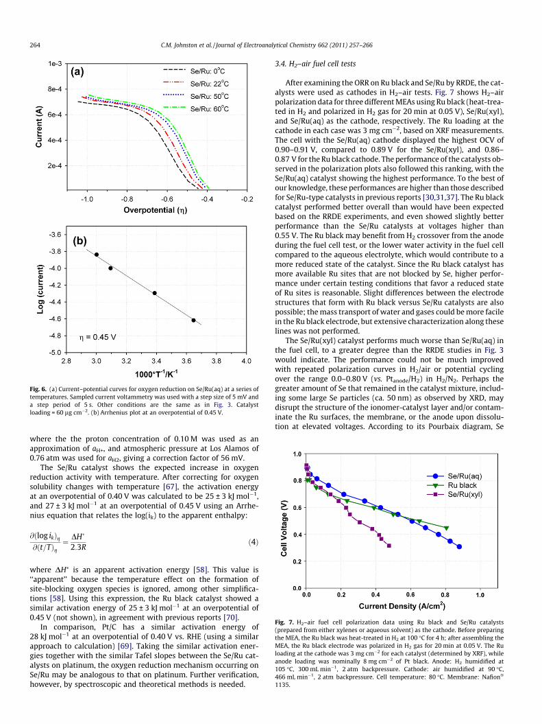
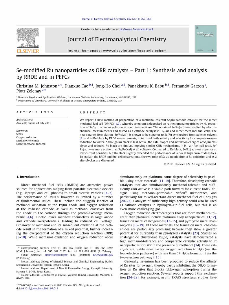
Fig. 6. (a) Current–potential curves for oxygen reduction on Se/Ru(aq) at a series oftemperatures. Sampled current voltammetry was used with a step size of 5 mV anda step period of 5 s. Other conditions are the same as in Fig. 3. Catalystloading = 60 lg cm�2. (b) Arrhenius plot at an overpotential of 0.45 V.
Fig. 7. H2–air fuel cell polarization data using Ru black and Se/Ru catalysts(prepared from either xylenes or aqueous solvent) as the cathode. Before preparingthe MEA, the Ru black was heat-treated in H2 at 100 �C for 4 h; after assembling theMEA, the Ru black electrode was polarized in H2 gas for 20 min at 0.05 V. The Ruloading at the cathode was 3 mg cm�2 for each catalyst (determined by XRF), whileanode loading was nominally 8 mg cm�2 of Pt black. Anode: H2 humidified at105 �C, 300 mL min�1, 2 atm backpressure. Cathode: air humidified at 90 �C,466 mL min�1, 2 atm backpressure. Cell temperature: 80 �C. Membrane: Nafion�
1135.
264 C.M. Johnston et al. / Journal of Electroanalytical Chemistry 662 (2011) 257–266
where the the proton concentration of 0.10 M was used as anapproximation of aH+, and atmospheric pressure at Los Alamos of0.76 atm was used for aH2, giving a correction factor of 56 mV.
The Se/Ru catalyst shows the expected increase in oxygenreduction activity with temperature. After correcting for oxygensolubility changes with temperature [67], the activation energyat an overpotential of 0.40 V was calculated to be 25 ± 3 kJ mol�1,and 27 ± 3 kJ mol�1 at an overpotential of 0.45 V using an Arrhe-nius equation that relates the log(ik) to the apparent enthalpy:
@ðlog ikÞg@ðt=TÞg
¼ DH�
2:3Rð4Þ
where DH⁄ is an apparent activation energy [58]. This value is‘‘apparent’’ because the temperature effect on the formation ofsite-blocking oxygen species is ignored, among other simplifica-tions [58]. Using this expression, the Ru black catalyst showed asimilar activation energy of 25 ± 3 kJ mol�1 at an overpotential of0.45 V (not shown), in agreement with previous reports [70].
In comparison, Pt/C has a similar activation energy of28 kJ mol�1 at an overpotential of 0.40 V vs. RHE (using a similarapproach to calculation) [69]. Taking the similar activation ener-gies together with the similar Tafel slopes between the Se/Ru cat-alysts on platinum, the oxygen reduction mechanism occurring onSe/Ru may be analogous to that on platinum. Further verification,however, by spectroscopic and theoretical methods is needed.
3.4. H2–air fuel cell tests
After examining the ORR on Ru black and Se/Ru by RRDE, the cat-alysts were used as cathodes in H2–air tests. Fig. 7 shows H2–airpolarization data for three different MEAs using Ru black (heat-trea-ted in H2 and polarized in H2 gas for 20 min at 0.05 V), Se/Ru(xyl),and Se/Ru(aq) as the cathode, respectively. The Ru loading at thecathode in each case was 3 mg cm�2, based on XRF measurements.The cell with the Se/Ru(aq) cathode displayed the highest OCV of0.90–0.91 V, compared to 0.89 V for the Se/Ru(xyl), and 0.86–0.87 V for the Ru black cathode. The performance of the catalysts ob-served in the polarization plots also followed this ranking, with theSe/Ru(aq) catalyst showing the highest performance. To the best ofour knowledge, these performances are higher than those describedfor Se/Ru-type catalysts in previous reports [30,31,37]. The Ru blackcatalyst performed better overall than would have been expectedbased on the RRDE experiments, and even showed slightly betterperformance than the Se/Ru catalysts at voltages higher than0.55 V. The Ru black may benefit from H2 crossover from the anodeduring the fuel cell test, or the lower water activity in the fuel cellcompared to the aqueous electrolyte, which would contribute to amore reduced state of the catalyst. Since the Ru black catalyst hasmore available Ru sites that are not blocked by Se, higher perfor-mance under certain testing conditions that favor a reduced stateof Ru sites is reasonable. Slight differences between the electrodestructures that form with Ru black versus Se/Ru catalysts are alsopossible; the mass transport of water and gases could be more facilein the Ru black electrode, but extensive characterization along theselines was not performed.
The Se/Ru(xyl) catalyst performs much worse than Se/Ru(aq) inthe fuel cell, to a greater degree than the RRDE studies in Fig. 3would indicate. The performance could not be much improvedwith repeated polarization curves in H2/air or potential cyclingover the range 0.0–0.80 V (vs. Ptanode/H2) in H2/N2. Perhaps thegreater amount of Se that remained in the catalyst mixture, includ-ing some large Se particles (ca. 50 nm) as observed by XRD, maydisrupt the structure of the ionomer-catalyst layer and/or contam-inate the Ru surfaces, the membrane, or the anode upon dissolu-tion at elevated voltages. According to its Pourbaix diagram, Se
C.M. Johnston et al. / Journal of Electroanalytical Chemistry 662 (2011) 257–266 265
exists as H2Se, Se, H2SeO3, and H2SeO�4 across the range of fuel cellrelevant potentials (0.0–1.2 V vs. SHE). The polymer electrolyteenvironment is more likely to trap Se contamination in whateverform than the aqueous electrolyte. The higher Se coverage on thecatalyst itself could also have affected its wetting properties inthe electrode ink, and in turn the electrode structure that formed.Because the RDE experiment is inherently simpler and easier tocontrol, we are confident that the discrepancy arises from someun-optimized aspect of the fuel cell experiment, not the RDEresults. These issues have not been thoroughly investigated; ourfocus instead has been placed on the better-performing Se/Ru(aq)catalyst.
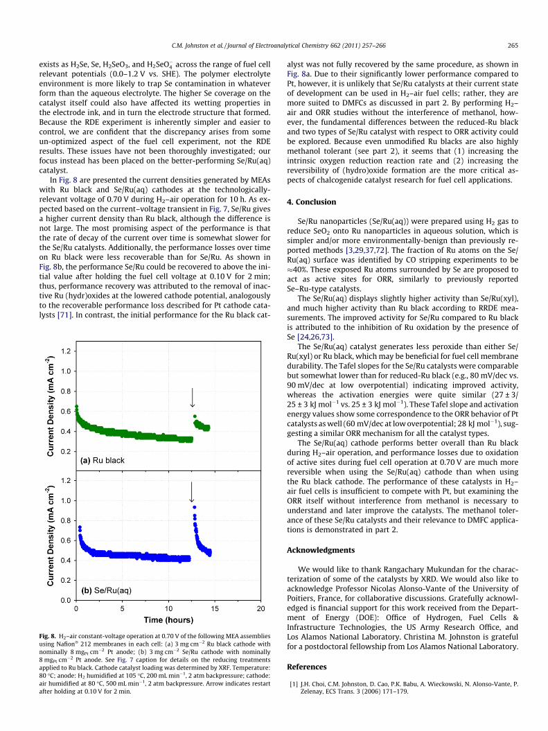
In Fig. 8 are presented the current densities generated by MEAswith Ru black and Se/Ru(aq) cathodes at the technologically-relevant voltage of 0.70 V during H2–air operation for 10 h. As ex-pected based on the current–voltage transient in Fig. 7, Se/Ru givesa higher current density than Ru black, although the difference isnot large. The most promising aspect of the performance is thatthe rate of decay of the current over time is somewhat slower forthe Se/Ru catalysts. Additionally, the performance losses over timeon Ru black were less recoverable than for Se/Ru. As shown inFig. 8b, the performance Se/Ru could be recovered to above the ini-tial value after holding the fuel cell voltage at 0.10 V for 2 min;thus, performance recovery was attributed to the removal of inac-tive Ru (hydr)oxides at the lowered cathode potential, analogouslyto the recoverable performance loss described for Pt cathode cata-lysts [71]. In contrast, the initial performance for the Ru black cat-
Fig. 8. H2–air constant-voltage operation at 0.70 V of the following MEA assembliesusing Nafion� 212 membranes in each cell: (a) 3 mg cm�2 Ru black cathode withnominally 8 mgPt cm�2 Pt anode; (b) 3 mg cm�2 Se/Ru cathode with nominally8 mgPt cm�2 Pt anode. See Fig. 7 caption for details on the reducing treatmentsapplied to Ru black. Cathode catalyst loading was determined by XRF. Temperature:80 �C; anode: H2 humidified at 105 �C, 200 mL min�1, 2 atm backpressure; cathode:air humidified at 80 �C, 500 mL min�1, 2 atm backpressure. Arrow indicates restartafter holding at 0.10 V for 2 min.
alyst was not fully recovered by the same procedure, as shown inFig. 8a. Due to their significantly lower performance compared toPt, however, it is unlikely that Se/Ru catalysts at their current stateof development can be used in H2–air fuel cells; rather, they aremore suited to DMFCs as discussed in part 2. By performing H2–air and ORR studies without the interference of methanol, how-ever, the fundamental differences between the reduced-Ru blackand two types of Se/Ru catalyst with respect to ORR activity couldbe explored. Because even unmodified Ru blacks are also highlymethanol tolerant (see part 2), it seems that (1) increasing theintrinsic oxygen reduction reaction rate and (2) increasing thereversibility of (hydro)oxide formation are the more critical as-pects of chalcogenide catalyst research for fuel cell applications.
4. Conclusion
Se/Ru nanoparticles (Se/Ru(aq)) were prepared using H2 gas toreduce SeO2 onto Ru nanoparticles in aqueous solution, which issimpler and/or more environmentally-benign than previously re-ported methods [3,29,37,72]. The fraction of Ru atoms on the Se/Ru(aq) surface was identified by CO stripping experiments to be�40%. These exposed Ru atoms surrounded by Se are proposed toact as active sites for ORR, similarly to previously reportedSe–Ru-type catalysts.
The Se/Ru(aq) displays slightly higher activity than Se/Ru(xyl),and much higher activity than Ru black according to RRDE mea-surements. The improved activity for Se/Ru compared to Ru blackis attributed to the inhibition of Ru oxidation by the presence ofSe [24,26,73].
The Se/Ru(aq) catalyst generates less peroxide than either Se/Ru(xyl) or Ru black, which may be beneficial for fuel cell membranedurability. The Tafel slopes for the Se/Ru catalysts were comparablebut somewhat lower than for reduced-Ru black (e.g., 80 mV/dec vs.90 mV/dec at low overpotential) indicating improved activity,whereas the activation energies were quite similar (27 ± 3/25 ± 3 kJ mol�1 vs. 25 ± 3 kJ mol�1). These Tafel slope and activationenergy values show some correspondence to the ORR behavior of Ptcatalysts as well (60 mV/dec at low overpotential; 28 kJ mol�1), sug-gesting a similar ORR mechanism for all the catalyst types.
The Se/Ru(aq) cathode performs better overall than Ru blackduring H2–air operation, and performance losses due to oxidationof active sites during fuel cell operation at 0.70 V are much morereversible when using the Se/Ru(aq) cathode than when usingthe Ru black cathode. The performance of these catalysts in H2–air fuel cells is insufficient to compete with Pt, but examining theORR itself without interference from methanol is necessary tounderstand and later improve the catalysts. The methanol toler-ance of these Se/Ru catalysts and their relevance to DMFC applica-tions is demonstrated in part 2.
Acknowledgments
We would like to thank Rangachary Mukundan for the charac-terization of some of the catalysts by XRD. We would also like toacknowledge Professor Nicolas Alonso-Vante of the University ofPoitiers, France, for collaborative discussions. Gratefully acknowl-edged is financial support for this work received from the Depart-ment of Energy (DOE): Office of Hydrogen, Fuel Cells &Infrastructure Technologies, the US Army Research Office, andLos Alamos National Laboratory. Christina M. Johnston is gratefulfor a postdoctoral fellowship from Los Alamos National Laboratory.
References
[1] J.H. Choi, C.M. Johnston, D. Cao, P.K. Babu, A. Wieckowski, N. Alonso-Vante, P.Zelenay, ECS Trans. 3 (2006) 171–179.

266 C.M. Johnston et al. / Journal of Electroanalytical Chemistry 662 (2011) 257–266
[2] C.M. Johnston, J.H. Choi, P.K. Babu, A. Wieckowski, P. Zelenay, Performance anddurability of chalcogen-modified ruthenium catalysts for oxygen reduction:hydrogen–air MEA and RRDE studies, in: 211th ECS Meeting, twenty-fifth ed.,Chicago, IL, USA, 2008, pp. 117–125.
[3] D. Cao, A. Wieckowski, J. Inukai, N. Alonso-Vante, J. Electrochem. Soc. 153(2006) A869–A874.
[4] A.S. Arico, S. Srinivasan, V. Antonucci, Fuel Cells 1 (2001) 133–161.[5] K. Kordesch, G. Simader, Fuel Cells and their Applications, Wiley-VCH,
Weinheim, 1996.[6] S. Wasmus, A. Kuver, J. Electroanal. Chem. 461 (1999) 14–31.[7] M.P. Hogarth, G.A. Hards, Plat. Met. Rev. 40 (1996) 150.[8] D. Chu, S. Gilman, J. Electrochem. Soc. 141 (1994) 1770–1773.[9] A. Heinzel, V.M. Barragan, J. Power Sour. 84 (1999) 70–74.
[10] Z. Jusys, R.J. Behm, Electrochim. Acta 49 (2004) 3891–3900.[11] H. Yang, C. Coutanceau, J.-M. Leger, N. Alonso-Vante, C. Lamy, J. Electroanal.
Chem. 576 (2005) 305–313.[12] H. Yang, N. Alonso-Vante, J.-M. Leger, C. Lamy, J. Phys. Chem. B 108 (2004)
1938–1947.[13] O. Solorza-Feria, K. Ellmer, M. Giersig, N. Alonso-Vante, Electrochim. Acta 39
(1994) 1647–1653.[14] N. Alonso-Vante, P. Bogdanoff, H. Tributsch, J. Catal. 190 (2000) 240–246.[15] T.J. Schmidt, U.A. Paulus, H.A. Gasteiger, N. Alonso-Vante, R.J. Behm, J.
Electrochem. Soc. 147 (2000) 2620–2624.[16] M. Bron, J. Radnik, M. Fieber-Erdmann, P. Bogdanoff, S. Fiechter, J. Electroanal.
Chem. 535 (2002) 113–119.[17] G. Faubert, R. Cote, J.P. Dodelet, M. Lefevre, P. Bertrand, Electrochim. Acta 44
(1999) 2589–2603.[18] S.L. Gojkovic, S. Gupta, R.F. Savinell, J. Electroanal. Chem. 462 (1999) 63–72.[19] G. Lalande, G. Faubert, R. Cote, D. Guay, J.P. Dodelet, L.T. Weng, P. Bertrand, J.
Power Sour. 61 (1996) 227–237.[20] S.C. Barton, T. Patterson, E. Wang, T.F. Fuller, A.C. West, J. Power Sour. 96
(2001) 329–336.[21] K. Scott, A.K. Shukla, C.L. Jackson, W.R.A. Meuleman, J. Power Sour. 126 (2004)
67–75.[22] M.A. Priestnall, V.P. Kotzeva, D.J. Fish, E.M. Nilsson, J. Power Sour. 106 (2002)
21–30.[23] N. Alonso Vante, in: W. Vielstich, H. Gasteiger, A. Lamm (Eds.), Handbook of
Fuel Cells–Fundamental Technology and Applications, Wiley and Sons,Chichester, 2003.
[24] F. Dassenoy, W. Vogel, N. Alonso-Vante, J. Phys. Chem. B 106 (2002) 12152–12157.
[25] N. Alonso-Vante, I.V. Malakhov, S.G. Nikitenko, E.R. Savinova, D.I. Kochubey,Electrochim. Acta 47 (2002) 3807–3814.
[26] A. Lewera, J. Inukai, W.P. Zhou, D. Cao, H.T. Duong, N. Alonso-Vante, A.Wieckowski, Electrochim. Acta 52 (2007) 5759–5765.
[27] L. Colmenares, Z. Jusys, R.J. Behm, Langmuir 22 (2006) 10437–10445.[28] H. Schulenburg, M. Hilgendorff, I. Dorbandt, J. Radnik, P. Bogdanoff, S. Fiechter,
M. Bron, H. Tributsch, J. Power Sour. 155 (2006) 47–51.[29] S.A. Campbell, Non-noble metal catalysts for the oxygen reduction reaction, in:
U. Patent (Ed.), Ballard Power Systems Inc., USA, 2006.[30] A. Garsuch, X. Michaud, K. Böhme, G. Wagner, J.R. Dahn, J. Power Sour. 189
(2009) 1008–1011.[31] R.G. González-Huerta, A. Guzman-Guzman, O. Solorza-Feria, Int. J. Hydrog.
Energy 35 (2010) 12115–12119.[32] K. Wippermann, B. Richter, K. Klafki, J. Mergel, G. Zehl, I. Dorbandt, P.
Bogdanoff, S. Fiechter, S. Kaytakoglu, J. Appl. Electrochem. 37 (2007) 1399–1411.
[33] A.A. Serov, M. Min, G. Chai, S. Han, S. Kang, C. Kwak, J. Power Sour. 175 (2008)175–182.
[34] C. Christenn, G. Steinhilber, M. Schulze, K.A. Friedrich, Physical andelectrochemical characterization of catalysts for oxygen reduction in fuelcells, Efficient Oxygen Reduction for Electrochemical Energy Conversion(2007).
[35] C. Cremers, M. Scholz, W. Seliger, A. Racz, W. Knechtel, J. Rittmayr, F.Grafwallner, H. Peller, U. Stimming, Fuel Cells 7 (2007) 21–31.
[36] S. Fiechter, P. Bogdanoff, G. Zehl, I. Dorbandt, G. Schmithals, K. Wippermann, J.Radnik, B. Richter, ECS Trans. 3 (2006) 1261–1270.
[37] C. Delacote, A. Bonakdarpour, C.M. Johnston, P. Zelenay, A. Wieckowski,Faraday Discuss. 140 (2009) 269–281.
[38] S.T. Kuk, A. Wieckowski, J. Power Sour. 141 (2005) 1–7.[39] A. Bonakdarpour, C. Delacote, A. Wieckowski, R. Yang, J.R. Dahn, Electrochem.
Commun. 10 (2008) 611–615.[40] E. Herrero, A. Rodes, J.M. Perez, J.M. Feliu, A. Aldaz, J. Electroanal. Chem. 412
(1996) 165–174.[41] C.L. Green, A. Kucernak, J. Phys. Chem. B 106 (2002) 1036–1047.[42] Z. Jusys, J. Kaiser, R.J. Behm, Electrochim. Acta 47 (2002) 3693–3706.[43] T. Nagel, N. Bogolowski, H. Baltruschat, J. Appl. Electrochem. 36 (2006) 1297–
1306.[44] N. Bogolowski, T. Nagel, B. Lanova, S. Ernst, H. Baltruschat, K. Nagabhushana, H.
Boennemann, J. Appl. Electrochem. 37 (2007) 1485–1494.[45] W.F. Lin, T. Iwasita, W. Vielstich, J. Phys. Chem. B (1999) 3250–3257 (PL).[46] I.V. Malakhov, S.G. Nikitenko, E.R. Savinova, D.I. Kochubey, N. Alonso-Vante,
Nucl. Instrum. Meth. A 448 (2000) 323–326.[47] I.V. Malakhov, S.G. Nikitenko, E.R. Savinova, D.I. Kochubey, N. Alonso-Vante, J.
Phys. Chem. B 106 (2002) 1670–1676.[48] U.A. Paulus, A. Wokaun, G.G. Scherer, T.J. Schmidt, V. Stamenkovic, V.
Radmilovic, N.M. Markovic, P.N. Ross, J. Phys. Chem. B 106 (2002) 4181–4191.[49] J.K. Nørskov, J. Rossmeisl, A. Logadottir, L. Lindqvist, J.R. Kitchin, T. Bligaard, H.
Jónsson, The Journal of Physical Chemistry B 108 (2004) 17886–17892.[50] J. Zhang, M.B. Vukmirovic, Y. Xu, M. Mavrikakis, R.R. Adzic, Angewandte
Chemie – International Edition 44 (2005) 2132–2135.[51] D. Leveratto, A. Racz, E.R. Savinova, U. Stimming, Fuel Cells 6 (2006) 203–207.[52] D.C. Papageorgopoulos, F. Liu, O. Conrad, Electrochim. Acta 52 (2007) 4982–
4986.[53] O.B. Alves, H.E. Hoster, R.J. Behm, Phys. Chem. Chem. Phys. 13 (2011) 6010–
6021.[54] R.R. Adzic, J.X. Wang, The J. Phys. Chem. B 102 (1998) 8988–8993.[55] V. Stamenkovic, N.M. Markovic, P.N. Ross, J. Electroanal. Chem. 500 (2001) 44–
51.[56] R.A. Sidik, A.B. Anderson, J. Electroanal. Chem. 528 (2002) 69–76.[57] A.B. Anderson, T.V. Albu, J. Electrochem. Soc. 147 (2000) 4229–4238.[58] U.A. Paulus, A. Wokaun, G.G. Scherer, T.J. Schmidt, V. Stamenkovic, N.M.
Markovic, P.N. Ross, Electrochim. Acta 47 (2002) 3787–3798.[59] V. Stamenkovic, T.J. Schmidt, P.N. Ross, N.M. Markovic, J. Phys. Chem. B 106
(2002) 11970–11979.[60] Z. Jusys, R.J. Behm, The J. Phys. Chem. B 108 (2004) 7893–7901.[61] F.D. Coms, H. Liu, J.E. Owejan, Mitigation of perfluorosulfonic acid membrane
chemical degradation using cerium and manganese ions, in: 214th ECSMeeting, 2 PART 2 ed., Electrochemical Society Inc., Honolulu, HI, pp. 1735–1747, 2008.
[62] W. Vogel, The J. Phys. Chem. C 112 (2008) 13475–13482.[63] H.A. Gasteiger, S.S. Kocha, B. Sompalli, F.T. Wagner, Appl. Catal. B: Environ. 56
(2005) 9–35.[64] S. Gottesfeld, ECS Trans. 6 (2008) 51–67.[65] F.A. Uribe, T.E. Springer, S. Gottesfeld, J. Electrochem. Soc. 139 (1992) 765–773.[66] O. Solorza-Feria, S. Duron, Int. J. Hydrog. Energy 27 (2002) 451–455.[67] N. Wakabayashi, M. Takeichi, M. Itagaki, H. Uchida, M. Watanabe, J.
Electroanal. Chem. 574 (2005) 339–346.[68] A. Parthasarathy, S. Srinivasan, A.J. Appleby, C.R. Martin, J. Electrochem. Soc.
139 (1992) 2530–2537.[69] U.A. Paulus, T.J. Schmidt, H.A. Gasteiger, R.J. Behm, J. Electroanal. Chem. 495
(2001) 134–145.[70] L. Colmenares, Z. Jusys, R.J. Behm, J. Phys. Chem. C 111 (2007) 1273–1283.[71] C. Eickes, P. Piela, J. Davey, P. Zelenay, J. Electrochem. Soc. 153 (2006) A171–
A178.[72] N. Alonso-Vante, H. Tributsch, O. Solorza-Feria, Electrochim. Acta 40 (1995)
567–576.[73] V.I. Zaikovskii, K.S. Nagabhushana, V.V. Kriventsov, K.N. Loponov, S.V.
Cherepanova, R.I. Kvon, H. Bonnemann, D.I. Kochubey, E.R. Savinova, J. Phys.Chem. B 110 (2006) 6881–6890.