Electro-deposition and re-oxidation of carbon in carbonate-containing molten salts
12
Electro-deposition and re-oxidation of carbon in carbonate-containing molten salts Happiness V. Ijije, Richard C. Lawrence, Nancy J. Siambun,† Sang Mun Jeong,‡ Daniel A. Jewell,§ Di Hu and George Z. Chen * Received 21st March 2014, Accepted 6th May 2014 DOI: 10.1039/c4fd00046c The electrochemical deposition and re-oxidation of solid carbon were studied in CO 3 2 ion-containing molten salts (e.g. CaCl 2 –CaCO 3 –LiCl–KCl and Li 2 CO 3 –K 2 CO 3 ) at temperatures between 500 and 800 C under Ar, CO 2 or N 2 –CO 2 atmospheres. The electrode reactions were investigated by thermodynamic analysis, cyclic voltammetry and chronopotentiometry in a three-electrode cell under various conditions. The findings suggest that the electro-reduction of CO 3 2 is dominated by carbon deposition on all three tested working electrodes (Ni, Pt and mild steel), but partial reduction to CO can also occur. Electro-re-oxidation of the deposited carbon in the same molten salts was investigated for potential applications in, for example, direct carbon fuel cells. A brief energy and cost analysis is given based on results from constant voltage electrolysis in a two-electrode cell. Introduction Electrochemical reduction of the carbonate ion (CO 3 2 ) to solid carbon in molten salts has been known to be possible since the mid-1960s. 1,2 It then gained only a limited interest, 3,4 possibly because of the ready availability of various forms of carbon from fossil resources and biomass. However, in recent years renewed interest has grown fairly fast, 5–11 due largely to the need to reduce CO 2 emissions to avoid detrimental climate change, and, more importantly, to utilise this waste gas as a carbon source for the synthesis and processing of materials and chem- icals, such as steel carburisation and the production of so called solar fuels. 8,12 In Department of Chemical and Environmental Engineering, and Energy and Sustainability Research Division, Faculty of Engineering, University of Nottingham, University Park, Nottingham NG7 2RD, UK. E-mail: [email protected] † Current address: School of Engineering and Information Technology, Universiti Malaysia Sabah, 88999 Kota Kinabalu, Sabah, Malaysia. ‡ Current address: Department of Chemical Engineering, Chungbuk National University, 410 Seongbongno, Heungduk-gu, Cheongju-si, Chungcheongbuk-do, 361-763, Republic of Korea. § Current address: Coogee Titanium, Unit 4/25, Agosta Drive, Laverton North, VIC Australia 3026. This journal is © The Royal Society of Chemistry 2014 Faraday Discuss., 2014, 172, 105–116 | 105 Faraday Discussions Cite this: Faraday Discuss. , 2014, 172, 105 PAPER
-
Upload
nottingham -
Category
Documents
-
view
1 -
download
0
Transcript of Electro-deposition and re-oxidation of carbon in carbonate-containing molten salts

Faraday DiscussionsCite this: Faraday Discuss., 2014, 172, 105
PAPER
Electro-deposition and re-oxidation ofcarbon in carbonate-containing moltensalts
Happiness V. Ijije, Richard C. Lawrence, Nancy J. Siambun,†Sang Mun Jeong,‡ Daniel A. Jewell,§ Di Hu and George Z. Chen*
Received 21st March 2014, Accepted 6th May 2014
DOI: 10.1039/c4fd00046c
The electrochemical deposition and re-oxidation of solid carbon were studied in CO32�
ion-containing molten salts (e.g. CaCl2–CaCO3–LiCl–KCl and Li2CO3–K2CO3) at
temperatures between 500 and 800 �C under Ar, CO2 or N2–CO2 atmospheres. The
electrode reactions were investigated by thermodynamic analysis, cyclic voltammetry
and chronopotentiometry in a three-electrode cell under various conditions. The
findings suggest that the electro-reduction of CO32� is dominated by carbon deposition
on all three tested working electrodes (Ni, Pt and mild steel), but partial reduction to CO
can also occur. Electro-re-oxidation of the deposited carbon in the same molten salts
was investigated for potential applications in, for example, direct carbon fuel cells. A
brief energy and cost analysis is given based on results from constant voltage
electrolysis in a two-electrode cell.
Introduction
Electrochemical reduction of the carbonate ion (CO32�) to solid carbon in molten
salts has been known to be possible since the mid-1960s.1,2 It then gained only alimited interest,3,4 possibly because of the ready availability of various forms ofcarbon from fossil resources and biomass. However, in recent years renewedinterest has grown fairly fast,5–11 due largely to the need to reduce CO2 emissionsto avoid detrimental climate change, and, more importantly, to utilise this wastegas as a carbon source for the synthesis and processing of materials and chem-icals, such as steel carburisation and the production of so called solar fuels.8,12 In
Department of Chemical and Environmental Engineering, and Energy and Sustainability Research Division,
Faculty of Engineering, University of Nottingham, University Park, Nottingham NG7 2RD, UK. E-mail:
† Current address: School of Engineering and Information Technology, Universiti Malaysia Sabah, 88999Kota Kinabalu, Sabah, Malaysia.
‡ Current address: Department of Chemical Engineering, Chungbuk National University, 410Seongbongno, Heungduk-gu, Cheongju-si, Chungcheongbuk-do, 361-763, Republic of Korea.
§ Current address: Coogee Titanium, Unit 4/25, Agosta Drive, Laverton North, VIC Australia 3026.
This journal is © The Royal Society of Chemistry 2014 Faraday Discuss., 2014, 172, 105–116 | 105
Faraday Discussions Paper
fact, solar fuel production can be regarded as an energy storage process that isvery suitable for remote and seasonal purposes. Yet, considering its high energycontent, carbon production from CO2 is far better for energy storage (DHo ¼�25.97 MJ L�1 at 20 �C for a carbon powder packed to 0.792 g mL�1 in apparentdensity) in comparison with, for example, methanol production from CO2 andH2O (DHo ¼ �16.71 MJ L�1 at 20 �C for liquid CH3OH of 0.792 g mL�1 indensity).13 This simple thermodynamic comparison has formed the basis of ourresearch programme since 2006.14 Herein we summarise our ndings on theelectro-deposition of solid carbon from molten salts under CO2 containingatmospheres,8,11 and report for the rst time our investigation on the electro-chemical oxidation of electro-deposited carbon in molten salts.
The molten salt suitable for the electrolytic production of carbon from CO2
should be able to dissolve the O2� ion which is a product of carbon deposition,and also helps to absorb CO2 and convert it to the CO3
2� ion. Because of their lowcosts and environmental impacts, both chloride and carbonate salts, and inparticular their mixtures, were investigated in this laboratory.8,11 It has beenobserved that electro-deposition of carbon can proceed in all tested molten saltcombinations, as long as Li+ ions are present.1–4 In other cases, deposition is notimpossible, but occurs at much lower rates.15 This phenomenon may beaccounted for by the relative deposition potential of Li, Na, or K metal comparedwith that of carbon, as expressed by the following reactions:
2M2CO3 ¼ 4M + 2CO2 + O2 (M ¼ Li, Na or K) (1)
3M2CO3 ¼ C + 3M2O + 2CO2 + O2 (2)
Note that reaction (2) is actually the sum of the following reactions (3) and(4) � 2:
M2CO3 ¼ C + M2O + O2 (3)
M2CO3 ¼ M2O + CO2 (4)
This combination aids electrochemical analysis, since both reactions (1) and(2) have the same anodic reaction (5) below:
2CO32� ¼ 2CO2 + O2 + 4e (Eo ¼ 0 V) (5)
The potentials of reactions (1) and (2) against reaction (5), i.e. a hypotheticalreference electrode of CO3
2�/CO2–O2, are listed in Table 113 which shows that in
Table 1 Deposition potentials (vs. CO32�/CO2–O2) of alkali and alkaline earth metals via
reaction (1), and carbon via reaction (2) in their own molten carbonate salts at 600 �C
Molten salt Alkali metal Carbon
Li2CO3 �2.964 V �1.719 VNa2CO3 �2.546 V �2.551 VK2CO3 �2.612 V �3.083 VCaCO3 �3.033 V �1.349 VBaCO3 �3.069 V �1.992 V
106 | Faraday Discuss., 2014, 172, 105–116 This journal is © The Royal Society of Chemistry 2014
Paper Faraday Discussions
molten alkali carbonates, carbon deposition is thermodynamically preferred to Lideposition, but more difficult than Na or K deposition, which is in line withexperimental observations of the authors and others.1–4,15 (With reference toCO3
2�/CO2–O2, in the following discussion, the standard potential, Eo, providednext to the electrode reaction, is for the reaction occurring in pure molten Li2CO3
at 600 �C.)Previous studies of the electro-deposition of carbon were mostly carried out in
molten alkali metal salts. However, thermodynamic calculations show that it isalso possible to use molten alkaline earth metal salts. It can be seen in Table 1that carbon deposition is also preferred to alkaline earth metal deposition in bothmolten CaCO3 and BaCO3. However, CaCO3 decomposes at temperatures onlyslightly above its melting point (825 �C). MgCO3 is even worse and decomposes attemperatures below 350 �C before melting, which is the reason why Table 1 doesnot contain data for MgCO3. BaCO3 is thermally more stable but it is expensive touse, whilst barium salt toxicity is also a concern. Nevertheless, in this work, it wasfound that electro-deposition of carbon could be achieved in the molten mixtureof CaCl2 and CaCO3 (84 : 16 in a molar ratio) at temperatures higher than 730 �C.To lower the working temperature, mixtures of chlorides were used in some casesto dissolve CaCO3 and enable electro-deposition of carbon.
Experimental
Details of chemicals, materials, experimental equipment, set up and procedurescan either be found in previous publications from this laboratory,8,11,17 or arespecied in this paper.
Results and discussion
Fig. 1a presents the cyclic voltammogram (CV) of a Ni wire working electrode inthe quaternary mixture of 0.30CaCl2–0.17CaCO3–0.43LiCl–0.10KCl in a molarratio. The CV was recorded under argon, instead of CO2, so that if carbon depo-sition does occur, it can be attributed without doubt to the reduction of the CO3
2�
ion. Themost prominent feature of the CV in Fig. 1a is an almost symmetrical andlarge reduction current peak C1. To conrm carbon deposition, the Ni wireworking electrode was removed from the molten salt bath aer recording twoconsecutive CVs similar to that in Fig. 1a. A carbon coating was clearly seen on theNi wire as evidenced by the photograph in Fig. 1b. According to Table 1, peak C1can be attributed to carbon deposition because its potential was less negativethan those of the other two reduction peaks (C2 and C3). The potentials of C2 andC3 relative to that of C1 suggest K and Li deposition, respectively. Deposition ofCa requires a more negative potential and hence did not appear on the CV.
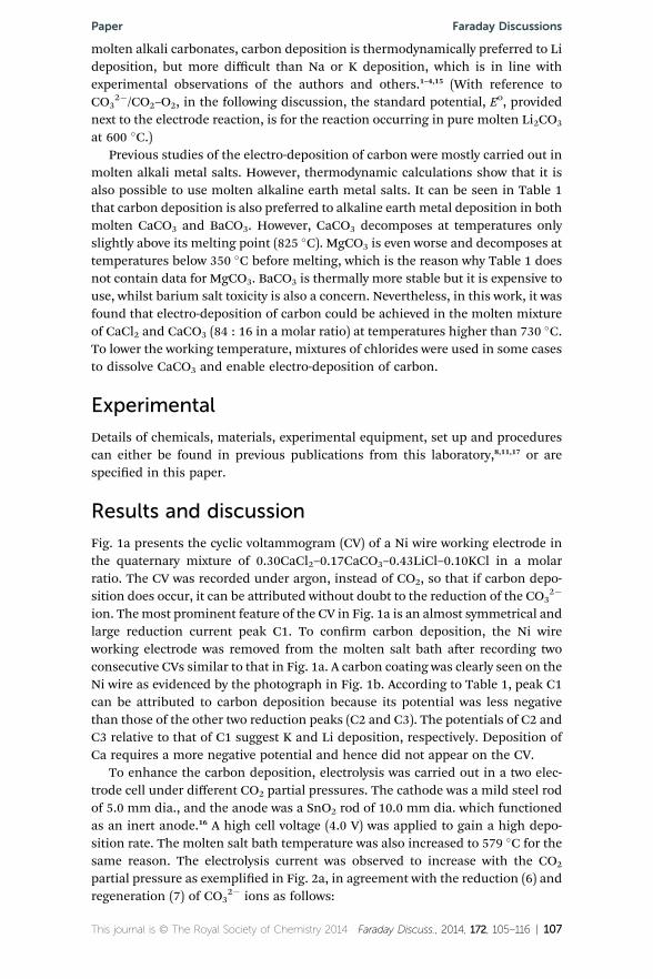
To enhance the carbon deposition, electrolysis was carried out in a two elec-trode cell under different CO2 partial pressures. The cathode was a mild steel rodof 5.0 mm dia., and the anode was a SnO2 rod of 10.0 mm dia. which functionedas an inert anode.16 A high cell voltage (4.0 V) was applied to gain a high depo-sition rate. The molten salt bath temperature was also increased to 579 �C for thesame reason. The electrolysis current was observed to increase with the CO2
partial pressure as exemplied in Fig. 2a, in agreement with the reduction (6) andregeneration (7) of CO3
2� ions as follows:
This journal is © The Royal Society of Chemistry 2014 Faraday Discuss., 2014, 172, 105–116 | 107

Fig. 1 (a) The cyclic voltammogram (CV) of a nickel wire in a quaternary molten salt bath.Experimental conditions are indicated with the bath composition in a molar ratio. Thepotential scan started cathodically from 0 V as indicated by the round solid spot on the CV.(b) A photograph showing the Ni wire working electrode (1mmdia.) with deposited carbonafter recording two consecutive CVs.
Faraday Discussions Paper
CO32� + 4e ¼ C + 3O2� (C1, Eo ¼ �1.719 V) (6)
CO2 + O2� ¼ CO32� (7)
Note that the bath compositions differ slightly in Fig. 1a and 2a, which was notintentional, but was due to the inconvenience of preparing the multicomponentmolten salt bath. To compare the results, electrolysis was terminated at 1 h, andthe cathode was removed from the bath. Fig. 2b displays a photograph of thecathodes, showing an increasing thickness of the deposited carbon coating withincreasing CO2 partial pressure.
It is interesting to note in Fig. 2b that the surface of the deposited carbon wascovered by small craters that were strong evidence of gas bubbles being formed onthe cathode during electrolysis. This was thought to be CO formation via reaction(8). If not escaping from the molten salt, CO may undergo further changes on theelectrode via reactions (9) and/or (10):
CO32� + 2e ¼ CO + 2O2� (Eo ¼ �0.947 V, A2) (8)
CO + 2e ¼ C + O2� (Eo ¼ �1.442 V, A10) (9)
2CO + O2� ¼ CO32� + C (10)
Note that (10) ¼ (9) � (8), and it is a chemical reaction. However, the observedsmall craters in Fig. 2b seem to indicate slower kinetics of reactions (9) and (10),likely because CO was in the gas phase. Also, reactions (8) and (10) suggest thatthe O2� ions could prevent or reduce the formation of CO bubbles, which agrees
108 | Faraday Discuss., 2014, 172, 105–116 This journal is © The Royal Society of Chemistry 2014
Fig. 2 (a) Current–time plots recorded during constant voltage (4.0 V) electrolysis in aquaternary molten salt bath with amild steel cathode (5mmdia. rod) and a SnO2 anode (10mm dia. rod) under different atmospheres as indicated. (b) The mild steel rod cathodeswith carbon deposits collected after 1 h of electrolysis. The electro-deposition on eachcathode was carried out consecutively in the same bath, but under different ratios of N2
and CO2 flow rates (mL min�1, from left to right): 200 : 0 (pure N2); 150 : 50, 100 : 100,50 : 150 and 0 : 200 (pure CO2). The total pressure in the electrolyser was 1 atm.
Paper Faraday Discussions
with the absence of craters on the carbon coatings deposited from carbonatedominated baths, as discussed below.
The fairly symmetrical shape of peak C1 in Fig. 1a implies that Ni may havesome catalytic effect on CO3
2� reduction. It was also observed that the current ofthe symmetrical peak C1 decreased signicantly on the 2nd potential cycle, whichmay result from the Ni surface being covered by the deposited carbon and hencelosing its catalytic effect. On the other hand, the absence of a re-oxidationcounterpart of peak C1 suggests the irreversibility of the carbon deposition in thechloride dominated molten salt bath. This could be related to the CV beingrecorded under Ar, and that there were too few O2� and/or CO3
2� ions in thechloride dominated molten salt bath to assist carbon oxidation via reaction (11)or (12) below:6
C + 2O2� ¼ CO2 + 4e (A1, Eo ¼ �1.488 V) (11)
C + 2CO32� ¼ 3CO2 + 4e (A3, Eo ¼ �1.025 V) (12)
It was then thought that if the CVs were recorded in a carbonate dominatedmolten salt bath under CO2, carbon deposition and re-oxidation of the deposited
This journal is © The Royal Society of Chemistry 2014 Faraday Discuss., 2014, 172, 105–116 | 109

Faraday Discussions Paper
carbon could both be facilitated. To conrm this, the molten eutectic mixture ofLi2CO3–K2CO3 (molar ratio: 62 : 38) was used to record CVs.11 Note that the Niwire was replaced by a Pt wire which can offer a greater stability at more positivepotentials to allow studies of all possible anodic reactions. Also, an aluminamembrane Ag/AgCl reference electrode was used to offer a more stable referencepotential.16
Typical CVs obtained in Li2CO3–K2CO3 are presented in Fig. 3. The potentialwindow is about 1.90 V between the current onset potentials of peaks C1 (�1.65 Vvs. Ag/AgCl) and A4 (0.25 V vs. Ag/AgCl) measured in Fig. 3a. This is slightly widerthan that of pure Li2CO3 (1.72 V, Table 1), but it is understandable considering theinuence of K2CO3. The CVs present a signicant reduction peak C1, and severalre-oxidation peaks as highlighted in Fig. 3b. To conrm that these anodic peaksare indeed due to re-oxidation of the deposited carbon, the potential was held atthe cathodic limit (�2.0 V) for 10 s before the scan was reversed. In response, allanodic peaks increased signicantly in current, whilst peak A10 was engulfed in
Fig. 3 CVs of a Pt wire (0.25 mm dia.) in molten Li2CO3–K2CO3 (62 : 38 molar ratio) at540� C; scan rate: 100 mV s�1. (a) Full potential range. (b) Enlargement of the anodicbranches of the CVs in (a).
110 | Faraday Discuss., 2014, 172, 105–116 This journal is © The Royal Society of Chemistry 2014
Paper Faraday Discussions
A1. This phenomenon can be explained as follows: more carbon was depositedwhen the potential was held at �2.0 V and hence contributed to greater re-oxidation currents. According to their relative potentials, peaks A1 and A3 can beattributed to reactions (11) and (12), respectively. Peaks A10 and A2 were likely thereversals of reactions (9) and (8), respectively, considering their potentials relativeto that of A1 for reaction (11). Interestingly, both peaks A2 and A3 shied nega-tively aer holding the potential scan at �2.0 V for 10 s. It is very likely that whenCO is produced aer peak A10 via the reverse of reaction (9), it adsorbs on thecarbon surface, impeding reaction (12) and hence there is a more positivepotential for peak A3. Thus, the absence of A10 on the CV aer holding thepotential at�2.0 V means a lowered inuence of CO, and hence the negative shiof A3. If peak A2 corresponds to the reverse of reaction (8), its negative shi mayresult from a smaller number and size of the CO nuclei on the deposited carbon.
The oxidation current, A4, at the anodic potential limit (0.5 V) may be attrib-uted to the discharge of either the O2� ion to form O2 (13), or of the CO3
2� ion toform O2 and CO2 (5).
2O2� ¼ O2 + 4e (Eo ¼ �0.463 V) (13)
If reaction (13) had occurred, its current should have appeared at potentialsbetween A3 and A4 on the CV. However, for reaction (13) to proceed, a signicantamount of O2� ions should be present near the electrode. This was unlikely to bethe case, considering that the O2� ions, including those already present in themolten carbonate salts and those produced during carbon deposition via reaction(6), should have mostly been consumed in the course of the potential scan fromA1 to A3. Thus, A4 should correspond to reaction (5).
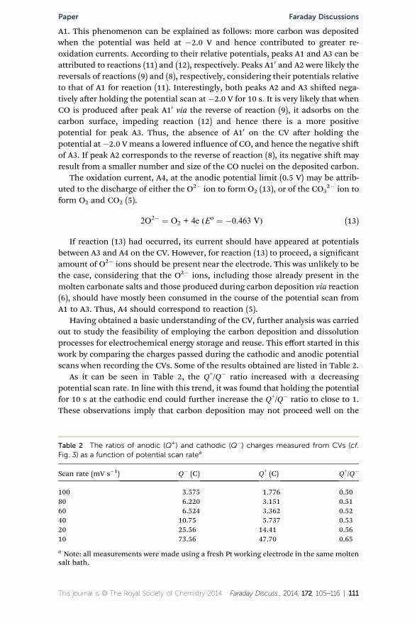
Having obtained a basic understanding of the CV, further analysis was carriedout to study the feasibility of employing the carbon deposition and dissolutionprocesses for electrochemical energy storage and reuse. This effort started in thiswork by comparing the charges passed during the cathodic and anodic potentialscans when recording the CVs. Some of the results obtained are listed in Table 2.
As it can be seen in Table 2, the Q+/Q� ratio increased with a decreasingpotential scan rate. In line with this trend, it was found that holding the potentialfor 10 s at the cathodic end could further increase the Q+/Q� ratio to close to 1.These observations imply that carbon deposition may not proceed well on the
Table 2 The ratios of anodic (Q+) and cathodic (Q�) charges measured from CVs (cf.Fig. 3) as a function of potential scan ratea
Scan rate (mV s�1) Q� (C) Q+ (C) Q+/Q�
100 3.575 1.776 0.5080 6.220 3.151 0.5160 6.524 3.362 0.5240 10.75 5.737 0.5320 25.56 14.41 0.5610 73.56 47.70 0.65
a Note: all measurements were made using a fresh Pt working electrode in the same moltensalt bath.
This journal is © The Royal Society of Chemistry 2014 Faraday Discuss., 2014, 172, 105–116 | 111

Faraday Discussions Paper
fresh Pt electrode, but becomes more efficient (although not necessarily quicker)aer the Pt electrode is covered by the deposited carbon. In other words, carbondeposition on the Pt surface may proceed in competition with other reactionswhose products do not remain on the electrode (e.g. CO formation), but these sidereactions encounter higher kinetic barriers on the carbon surface. This under-standing is practically important because it basically means that for the electro-deposition of carbon, the cathodematerial can be anymetal or alloy as long as it iscathodically stable in the molten salt.
To further study the electro-oxidation of the deposited carbon, potentiostaticcontrol was applied to produce a sufficient amount of carbon deposit for furtheranalyses. In particular, chronopotentiometry was carried out to conrm reactions(11) and (12) as the main anodic reactions on the deposited carbon. In theseexperiments, the working electrode was a 5 mm dia. mild steel rod, whilstgraphite, SnO2 and stainless steel were all tested as the counter electrode mate-rial, and similar results were obtained. However, stainless steel was proven to bethe most convenient choice for various carbonate dominated baths, althoughminor anode dissolution and consequent contamination of the deposited carbonwere observed.11 Thus, the following discussion will focus on data obtained fromusing the stainless steel counter electrode.
Fig. 4 compares the chronopotentiometric plots recorded during anodicoxidation (dissolution or galvanostatic discharge) of the electro-deposited carbonobtained under potentiostatic control. Both pure Li2CO3 and Li2CO3–K2CO3 weretested for comparison. On all plots in Fig. 4, there are two clearly distinguishableplateaux at potentials corresponding approximately to those of reactions (11) and(12). In Fig. 4b and c, a third potential plateau is shown at a more positivepotential. The potential difference between the lowest and highest plateaux isabout 1.75 V which can be explained by polarisations in addition to the theoreticalvalue of 1.488 V between reactions (5) and (11). Polarisation is evident from acomparison between Fig. 4a and b. The potential difference between the rst andsecond plateaux is about 0.40 V in Fig. 4a, but it increases to about 0.78 V inFig. 4b. The larger current and lower temperature for recording Fig. 4b would havecontributed to increasing both the ohmic and charge transfer polarisations. Thus,the third plateau can be attributed to reaction (5), i.e. electro-oxidation of theCO3
2� ion.Similar to the CVs in Fig. 3 which indicate no clear presence of direct anodic
discharge of the O2� ion, i.e. reaction (13), the plots in Fig. 4 also show only abarely visible inexion of the rapidly increasing current between the 2nd and 3rd
plateaux. This is understandable because the O2� activity must be signicantlylower than that of the CO3
2� ion in the molten carbonate salts used. Also, theseexperiments were carried out under CO2 which could also help convert O2� toCO3
2�.For energy storage, a high Q+/Q� ratio approaching 1 is desirable. Cyclic vol-
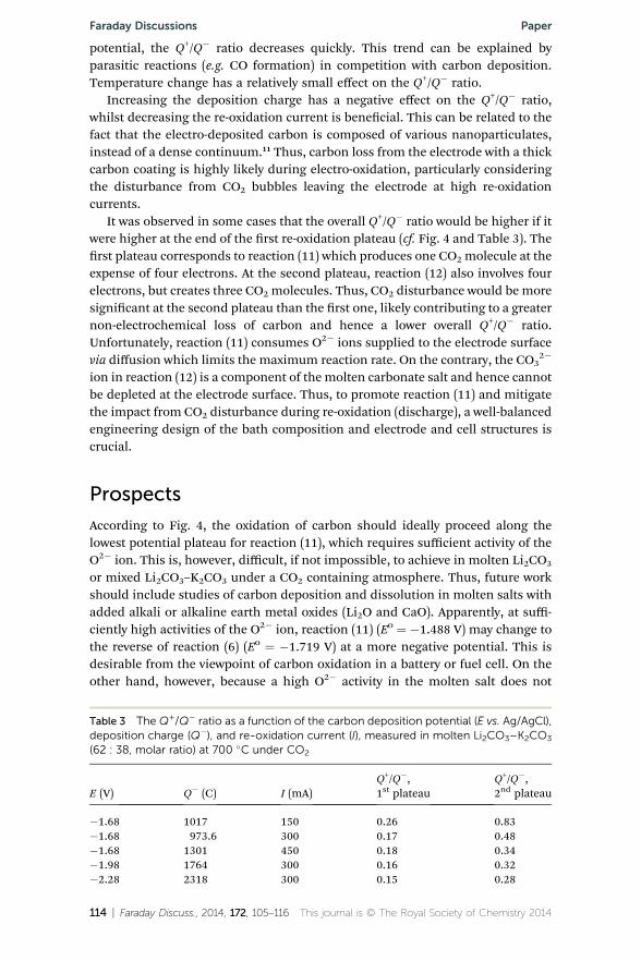
tammetry has revealed promising results as shown in Table 2. More analyses werecarried out on carbon coatings deposited under potentiostatic control and dis-charged (re-oxidised) via chronopotentiometry. Some of the preliminary ndingsare presented in Table 3.
The Q+/Q� ratio was found to be a complex function of both deposition and re-oxidation variables. The deposition potential (and voltage if in a two-electrodecell) plays the most signicant role. With an increasingly negative deposition
112 | Faraday Discuss., 2014, 172, 105–116 This journal is © The Royal Society of Chemistry 2014

Fig. 4 Chronopotentiometric plots for anodic oxidation of the electro-deposited carbonin the same molten salt under CO2. (a) Li2CO3 at 800 �C, oxidation: 100 mA, deposition:�1.8 V vs. Ag/AgCl, 3600 s. (b) Li2CO3 at 753 �C, oxidation: 150 mA, deposition: �2.1 V for600 s. (c) Li2CO3–K2CO3 (molar ratio: 62 : 38) at 574 �C, oxidation: 450 mA, deposition:�2.6 V for 600 s. The photographs in (a) show the working electrode (5 mm dia. mild steelrod) with the carbon deposit (left), and after anodic oxidation (right). Counter electrode:10 mm diameter graphite rod.
Paper Faraday Discussions
This journal is © The Royal Society of Chemistry 2014 Faraday Discuss., 2014, 172, 105–116 | 113
Faraday Discussions Paper
potential, the Q+/Q� ratio decreases quickly. This trend can be explained byparasitic reactions (e.g. CO formation) in competition with carbon deposition.Temperature change has a relatively small effect on the Q+/Q� ratio.
Increasing the deposition charge has a negative effect on the Q+/Q� ratio,whilst decreasing the re-oxidation current is benecial. This can be related to thefact that the electro-deposited carbon is composed of various nanoparticulates,instead of a dense continuum.11 Thus, carbon loss from the electrode with a thickcarbon coating is highly likely during electro-oxidation, particularly consideringthe disturbance from CO2 bubbles leaving the electrode at high re-oxidationcurrents.
It was observed in some cases that the overall Q+/Q� ratio would be higher if itwere higher at the end of the rst re-oxidation plateau (cf. Fig. 4 and Table 3). Therst plateau corresponds to reaction (11) which produces one CO2 molecule at theexpense of four electrons. At the second plateau, reaction (12) also involves fourelectrons, but creates three CO2 molecules. Thus, CO2 disturbance would be moresignicant at the second plateau than the rst one, likely contributing to a greaternon-electrochemical loss of carbon and hence a lower overall Q+/Q� ratio.Unfortunately, reaction (11) consumes O2� ions supplied to the electrode surfacevia diffusion which limits the maximum reaction rate. On the contrary, the CO3
2�
ion in reaction (12) is a component of the molten carbonate salt and hence cannotbe depleted at the electrode surface. Thus, to promote reaction (11) and mitigatethe impact from CO2 disturbance during re-oxidation (discharge), a well-balancedengineering design of the bath composition and electrode and cell structures iscrucial.
Prospects
According to Fig. 4, the oxidation of carbon should ideally proceed along thelowest potential plateau for reaction (11), which requires sufficient activity of theO2� ion. This is, however, difficult, if not impossible, to achieve in molten Li2CO3
or mixed Li2CO3–K2CO3 under a CO2 containing atmosphere. Thus, future workshould include studies of carbon deposition and dissolution in molten salts withadded alkali or alkaline earth metal oxides (Li2O and CaO). Apparently, at suffi-ciently high activities of the O2� ion, reaction (11) (Eo ¼ �1.488 V) may change tothe reverse of reaction (6) (Eo ¼ �1.719 V) at a more negative potential. This isdesirable from the viewpoint of carbon oxidation in a battery or fuel cell. On theother hand, however, because a high O2� activity in the molten salt does not
Table 3 The Q+/Q� ratio as a function of the carbon deposition potential (E vs. Ag/AgCl),deposition charge (Q�), and re-oxidation current (I), measured in molten Li2CO3–K2CO3
(62 : 38, molar ratio) at 700 �C under CO2
E (V) Q� (C) I (mA)Q+/Q�,1st plateau
Q+/Q�,2nd plateau
�1.68 1017 150 0.26 0.83�1.68 973.6 300 0.17 0.48�1.68 1301 450 0.18 0.34�1.98 1764 300 0.16 0.32�2.28 2318 300 0.15 0.28
114 | Faraday Discuss., 2014, 172, 105–116 This journal is © The Royal Society of Chemistry 2014
Paper Faraday Discussions
favour electro-deposition of carbon via reaction (6) (nor the reduction of O2 gas ina direct carbon fuel cell), a careful balance is needed.
In addition to energy storage through electrochemical deposition anddissolution, the process of, and products from, indirect electro-reduction ofCO2 to carbon can have other applications. For example, the deposited carboncan be used directly for making the electrodes of supercapacitors,10 or, aer aproper treatment, for pollutant absorption. The process itself may be used toconvert CO2 gas back to O2 gas, and hence support life in space, undersea, or inmines. It is thus worth making an estimation of the cost of the electro-depo-sition itself. In this work, a very high current efficiency (e.g. 95%) has beenachieved in carbonate dominated baths. However, a voltage of or higher than4.0 V was found to be necessary for electrolysis in the two-electrode cell,11 whichis much higher than the thermodynamically predicted voltage as shown inTable 1. A possible reason is the relatively low activity of O2� ions in thecarbonate dominated bath under CO2 that invokes reaction (5) instead of (13)as the anode reaction. Thus, it is reasonable to predict that the electrolysisvoltage can be reduced to below 3.0 V if either Li2O or CaO is added to themolten salts. Nevertheless, even assuming a cell voltage of 3.0–4.0 V and a 95%current efficiency, the energy consumption of the electrolysis can be derived as28.2–37.6 W h per kg-C, which can be translated to a cost of less than $5 per kg-C considering a 20% margin for heating and pre- and post-processing. Forcomparison, the current market price for supercapacitor grade activatedcarbon falls in the range of $20–40 per kg-C.
Summary
The electrochemical deposition and dissolution of carbon can be achieved incarbonate containing molten salts. The deposition becomes faster when CO2 ispresent in the atmosphere above the molten salts. The cathodic process isdominated by carbon deposition at high current efficiency (up to 95%), whilst COformation and other reactions may also occur. It was observed that carbondeposition occurs on the deposited carbon more efficiently than on a freshlyprepared metal electrode. Electro-re-oxidation of the deposited carbon can beachieved with the aid of either the preferred O2� ion, or the CO3
2� ion at a morepositive potential. Both chronopotentiometry and cyclic voltammetry revealed afairly high ratio of deposition and dissolution charges, but also a large differencebetween the carbon deposition and dissolution potentials. A brief analysis of theprocess suggests addition of the O2� ion in the form of either Li2O or CaO to themolten salts may not only be benecial for decreasing the electrolysis voltage byavoiding direct anodic oxidation of the CO3
2� ion, but also enable anodicoxidation of the deposited carbon at more negative potentials.
Acknowledgements
This research received nancial support from the Royal Society (2007–2009, BrianMercer Feasibility Award), the EPSRC (2010–2015, Doctor Training Grant, EP/F026412/1, and EP/J000582/1), and the University of Nottingham (2011–2014,Dean of Engineering Scholarships).
This journal is © The Royal Society of Chemistry 2014 Faraday Discuss., 2014, 172, 105–116 | 115

Faraday Discussions Paper
Notes and references
1 Y. K. Delimarskii, O. V. Gorodiskii and V. F. Grishchenko, Dokl. Akad. NaukSSSR, 1964, 156, 650–651.
2 M. D. Ingram, B. Baron and G. J. Janz, Electrochim. Acta, 1966, 11, 1629–1639.3 H. Kawamura and Y. Ito, J. Appl. Electrochem., 2000, 30, 571–574.4 L. Massot, P. Chamelot, F. Bouyer and P. Taxil, Electrochim. Acta, 2003, 48, 465–471.
5 H. Groult, B. Kaplan, F. Lantelme, S. Komaba, N. Kumagai, H. Yashiro,T. Nakajima, B. Simon and A. Barhoun, Solid State Ionics, 2006, 177, 869–875.
6 K. Le Van, H. Groult, F. Lantelme, M. Dubois, D. Avignant, A. Tressaud,S. Komaba, N. Kumagai and S. Sigrist, Electrochim. Acta, 2009, 54, 4566–4573.
7 S. Licht, B. Wang, S. Ghosh, H. Ayub, D. Jiang and J. Ganley, J. Phys. Chem. Lett.,2010, 1, 2363–2368.
8 N. J. Siambun, H. Mohamed, D. Hu, D. Jewell, Y. K. Beng and G. Z. Chen, J.Electrochem. Soc., 2011, 158, H1117–H1124.
9 Q. S. Song, Q. Xu, Y. Wang, X. J. Shang and Z. Y. Li, Thin Solid Films, 2012, 520,6856–6863.
10 H. Yin, X. Mao, D. Tang, W. Xiao, L. Xing, H. Zhu, D. Wang and D. R. Sadoway,Energy Environ. Sci., 2013, 6, 1538–1545.
11 H. V. Ijije, C. Sun and G. Z. Chen, Carbon, 2014, 73, 163–174.12 M. Tahir and N. S. Amin, Energy Convers. Manage., 2013, 76, 194–214.13 HSC Chemistry 6, v. 6.12, Outotec Research Oy, 2007.14 G. Z. Chen, A feasibility study of solar-electrochemical cells for capturing
atmospheric carbon, Application for The Royal Society 2007 Brian MercerFeasibility Award, October 2006.
15 I. A. Novoselova, N. F. Oliinyk, S. V. Volkov, A. A. Konchits, I. B. Yanchuk,V. S. Yefanov, S. P. Kolesnik and M. V. Karpets, Phys. E, 2008, 40, 2231–2237.
16 R. Barnett, K. T. Kilby and D. J. Fray,Metall. Mater. Trans. B, 2009, 40, 150–157.17 H.Wang, N. J. Siambun, L. P. Yu and G. Z. Chen, J. Electrochem. Soc., 2012, 159,
H740–H746.
116 | Faraday Discuss., 2014, 172, 105–116 This journal is © The Royal Society of Chemistry 2014