
Electrifying innovation changing the future of mobility - Norwatt ::
17
10/2018 Customer Magazine informative · up-to-date · pioneering www.benning.de Electrifying innovation changing the future of mobility Rapid-charging modules for E-mobility 14 – 17 Secure offshore power supplies 3 – 5 30 – 31 Greater efficiency for the NY metro Photo: © Scharfsinn/Shutterstock.com
-
Upload
khangminh22 -
Category
Documents
-
view
1 -
download
0
Transcript of Electrifying innovation changing the future of mobility - Norwatt ::

10/2018
Customer Magazine informative · up-to-date · pioneering
www.benning.de
Electrifying innovation changing the future of mobility
28– 31
12– 16
17– 19
Rapid-charging modules for E-mobility 14– 17
Secure offshore power supplies 3– 5
30– 31Greater efficiency for the NY metro
Photo: ©
Scha
rfsinn/Sh
utterstock.com

BENNING | POWER news | 10/2018 | 3
POWER news 10/2018 Editorial
Publication detailsBENNING Elektrotechnik und ElektronikGmbH & Co. KG’s client magazine
Publisher: BENNING Elektrotechnik undElektronik GmbH & Co. KG,Münsterstrasse 135-137, 46397 Bocholt
Design und Production: Advertising AgencyPaus Design & Medien GmbH & Co. KG,Brinkstegge 13, 46395 Bocholt
Liability and CopyrightAll texts are protected by copyright. Thepublication, adoption or use of texts, pic-tures or other information is subject to thewritten agreement from BENNING GmbH.No liability is accepted for any guidance,references, recommendations or evalua-tions. In spite of making every effort tocarry out a correct presentation andchecking of the subject matter, errors ormistakes in interpretation remain pos sible.
Picture credits© BENNING Elektrotechnik und Elektronik GmbH & Co. KG /
© Anatoliy Sribny© IABG© Oleksandr Ananyev© Uniper© WSW Wuppertaler Stadtwerke GmbH© arsdigital, beermedia, brianwhittaker,Christian Delbert, cphotos100, DamienGeso, envfx, Gorodenkoff,
industrieblick, Jakub Jirsák, Kadmy, Manuel Adorf, mariana_designer, Max Topchii, Natalia Bratslavsky, newb1,Nick Moulds, Petrovich12, Pixel Embargo,rabbit75_fot, royyimzy, scharfsinn86,Sergey Novikov, sirikornt, sk_design,Tobias Arhelger, Torbz, Varunyu, Vera Kuttelvaserova / Fotolia.com
© buffaloboy, Scharfsinn / Shutterstock.com
Dear reader,
The UK is planning to build the world's largest battery power supplynetwork, consisting of 45 battery storage systems with a total capacity of more than two gigawatts, helping balance any fluctuationsin electricity production and demand, so that a constant and stablepower supply is maintained – an important step towards better man-agement of the transition to renewable energy. In parallel with the installation of the battery power supply network, one of the largestnetworks of rapid-charging stations for electric vehicles will be
created. The UK power network will experience additional strain due to the electrification ofroad vehicles, these storage systems will help by reacting flexibly and compensating for anyfluctuations.BENNING is also committed to making sure that the use of electric cars, trucks and busesbecomes central to a smart, resource-conserving urban lifestyle. For this purpose, we havedeveloped the HPC rapid-charging BELATRON modular range whose advantages we willbe highlighting in this issue of POWER news.You can also read about how BENNING uses highly efficient modular power systems to contribute to CO2 savings and greater efficiency in other areas, e.g. the modernisation of apower station in the UK, and the expansion of the Ukrainian mobile network or the moderni-sation of the New York metro.
I hope you enjoy reading this issue and look forward to your feedback.
Yours, Stephan Ratermann
e-mail: [email protected]
telephone: +49 2871 93 0
Contents
2 | BENNING | POWER news | 10/2018
19” modular rectifier plug-in unit with
4 modules TEBECHOP 3000 HDI
and remote monitoring unit
MCU 2500
Energy transition is an issue that affectsus all. At the UN Climate Change Con-ference in Paris in 2015, the Assemblyadopted a climate agreement that pro-vides for global warming to be limited to at least two degrees and ideally to 1.5 degrees Celsius. At the same time,CO2 emissions are to be significantly reduced.
To achieve this goal, we want to implementa gradual transition from conventional energysources to fully renewable ones. This articledescribes the way the offshore wind industryis contributing to the latest trends and devel-opments and the role of BENNING in this regard.
Promotion of wind energy
In addition to the study of sustainable tech-nologies, the promotion of wind energy is ofparticular importance when it comes to thesustainable implementation of the energytransition. As the construction of larger wind farmsturns out to be fairly complex in rural areas,the focus is placed on the development ofOffshore Wind Farms (OWF), which are con-structed in coastal areas (e. g. in the Northand Baltic Seas, the Irish Sea or the IberianAtlantic coast) and supply energy to thecoast via submarine cables to feed into thegeneral power grid.
For transmission distances of less than 30kilometres, the principle of alternating currenttransmission is generally used. For longerdistances and high wind farm performance,
however, high-voltage direct current (HVDC)transmission is used, as this allows a lowerloss of energy and thus more efficient energytransmission.
Increase in capacity
While the first OWF received substantial sub-sidies from the government, the first projectsare currently being implemented withoutstate funding. This is a clear sign that the off-shore wind industry has established itself inrecent years as a new and strong industrialsector in Europe.
Safe power supplies for offshore wind farms
BENNING greatly contributes to energy transition:
It supports offshore wind farm projects throughout Europe with
secure power supply systems and customised services.
3– 5 Safe power supplies for offshore windfarmsContributing to the energy revolution: Europe-wide support for offshore wind farm projects
6– 9 Modular power protection in industrial applications Technical and economic advantages of modular technology in the design and operation of UPS systems
10– 13 Power supply systems and services for the Ukrainian telephone network For more than 20 years, BENNING Ukrainehas provided highly efficient power suppliesfor reliable, energy-efficient operation
14– 17 Highly efficient, fast-charging module for electric vehicles BELATRON modular – the new high-performancecharging module for constructing high availability,economical electric vehicle charging stations
18– 21 Built to last for a power plant’s lifetimeBENNING contracted to supply UPS systems toone of the UK's largest and most energy-efficientfired coal power stations
22 Energy Technology List Certification forthe ENERTRONIC modular SE BENNING’s modular UPS systems have received an award for their particularly highenergy efficiency.
23– 25 IABG certification for earthquake safetyin the maximum danger zoneEvidence of superb design: The UC-HE cabinet system, especially developed for usein earthquake zones, has been certified byIndustrieanlagen-Betriebsgesellschaft mbH(IABG).
26– 29 New Drive Motors for historical KaiserwagenRetrofit: BENNING has carried out a rotor-stator configuration for the historic Wup-pertal Suspension Railway Kaiserwagen.
30– 31 Increased safety for one of the world'slargest underground networksIndividual product solutions and engineeringservices make New York's rail transportsafer and more efficient.
32 Fairs, events and exhibitions 2018

4 | BENNING | POWER news | 10/2018 BENNING | POWER news | 10/2018 | 5
Redundant and modular power supply system
with rectifier, inverter and DC/DC converter
Scan the QR code for
further information
The high wind farm capacities of
the artificially constructed energy
islands require high-voltage direct
current (HVDC) transmission.
This ensures a highly efficient and
low-loss energy transport over
long distances.
A B
C D
Especially in Germany, the offshore sector isin the ascendancy. At the end of 2017, a totalof 1,196 offshore wind turbines were con-nected to the grid in 20 OWFs with a totalcapacity of around 5,387 MW. But that is notall: According to the plan, this figure is to beincreased to 10,700 MW by 2025 – andother European countries also wish to followsuit. The Netherlands, for example, plans toexpand its offshore capacity from 1,120 MWcurrently to 7,000 MW by 2030.
Over the past five to ten years, a large num-ber of OWFs have already been built and putinto operation – especially in European coun-tries such as Great Britain, France, Germanyor the Netherlands. Most of these wind farmshave a total capacity ranging between 300 and 700 MW.
A single wind turbine has an average poweroutput of 10 MW and is connected to a central platform (called hub) where all the energy isaccumulated and routed to the mainland.
Not only the number of wind turbines, butalso their average power has significantly in-creased to 10 MW. At the same time, thevoltage level and thus the use of DC connec-tions has increased – as a result of the largeramounts of energy, some of which are trans-ported over very long distances.
Artificial energy islands
Several European energy companies are cur-rently working on a major project which issignificantly contributing to the implementa-tion of the goals of the UN Climate ChangeAgreement. It consists of several man-madeNorth Sea islands, on which various windfarms are connected to generate electricityfor the surrounding countries. By the year 2027, they should be able to produce sufficient energy to supply approx.80 million households. There are also centralfacilities such as accommodation for techni-cal and operational personnel as well as anairport and water port close to these hubs.
Secure power systems
For almost 15 years now, BENNING hasproven to be a reliable designer and manu-facturer of flexible and, above all, safe powersupply systems in the offshore sector. It sup-plies both rectifier systems and UPS systemswith batteries, which are primarily used onoffshore platforms where permanent avail-ability of critical loads (e. g. switchgear forhigh voltage, communication and safety sys-tems) must be ensured by means of uninter-ruptible power supplies. BENNING also offers tailor-made solutionsfor the wind turbines themselves, especiallyin transition pieces. The systems used heremust meet the highest requirements in termsof EMC, vibration and climatic influences.
Customised service
BENNING provides its customers with an ex-perienced team of competent experts whoseaim is to maximise the use of power supplied
in the offshore wind energy sector in terms ofsafety and efficiency. BENNING is continuallyseeking to optimise service performancefrom planning through to maintenance in atargeted fashion.
BENNING’s extensive service package alsoincludes the Hotline support service for itscustomers. On request, BENNING also pro-vides employees who specialise in offshoreoperations for on-site deployment. This en-sures continuous operational safety of thewind turbine. A small but important contribution on the wayto the energy transition.
contact: Bram Slaager
telephone: +31 30 63 46 010
e-mail: [email protected]

BENNING’s UPS system is scalable and can
increase in size in line with load requirements
6 | BENNING | POWER news | 10/2018
Modular power protection and conversion technology, partic-ularly in the form of UPSs, has long been used in commercialapplications, but take-up in industrial applications has, todate, been relatively slow.
This relatively slow uptake is due, in part, toa limited understanding of the “ilities” (“Avail-ability”, “Reliability”, “Scalability”, “Flexibility”and “Maintainability”) commonly associatedwith modular technology and how the vari-ous “ilities” complement each other.
The fourth of five articles within our 'ility' se-ries focuses on flexibility. We will define thisin the context of the increasingly importantand popular modular technology and discusshow truly flexible systems allow system de-signers to design power protection systemscapable of adapting to the potentially chang-ing needs of a site and/or its critical load.
Flexibility
In previous articles within this series we havedefined modularity and discussed how mod-ular UPS systems can be designed to eithermaximise system availability or minimise totalcost of ownership (TCO). We must now con-sider how we can design a single system thatis flexible enough to have the highest avail-ability or lowest TCO with the ability to switchbetween the two depending upon the pre-vailing needs of the site/critical load.
Modular power protection in industrial applications
The principle of modularity provides significant
technical and economic benefits in the design
and operation of UPS systems.
Such a system could, for example, be in-creased or decreased in size (see “scalability”article) to optimise TCO or additional mod-ules could be added to it to introduce parallelredundancy (i.e. N+n) if maximised systemavailability became a requirement. Finally, it would allow for power capacity tobe relocated from system to system if theneeds of the critical load(s) across numeroussystems ever needed to change. With the above “ideal world” we can define“flexibility” as a system’s ability to adapt tothe ever-changing needs of the site/criticalload. High levels of system flexibility help de-signers to “future-proof” their design andbelow we will consider a practical example tosee how the inherent flexibility of rack-mounted modular UPS helped to future-proof a system and thereby provided numer-ous financial and operational benefits to thesystem operator.
An example of a highly flexible systemdesign
Let us assume that a pharmaceutical com-pany decides to start up an experimentalproduction line that needs 60 kW of UPS
Determination of functional characteristics
At the initial design stage of a power protec-tion system, the designer will prioritise themost important aspects of the required system and will most likely compromise onother design aspects. For example, if theload is considered to be business critical thedesigner will prioritise availability above TCO.
Such prioritisation is not a problem if theneeds of the site and/or critical load are guar-anteed to never change over the working lifeof the system (typically 20-25 years), how-ever, we live in an ever-changing world andsuch guarantees can rarely be given. Thedanger, therefore, is that a system that wasinitially designed to meet one set of site/crit-ical load needs may no longer be suitable ifthe needs of the site/critical load everchange. If this situation ever occurs it may bean expensive problem to correct.
In an ideal world, a system would be de-signed with the capability to quickly and easily adapt to the prevailing needs of the siteand/or critical load.
power. Because of its experimental nature,the directors of our fictitious company restrictthe project’s budget and because it does nothave a production line, the UPS system is not“business critical”, making TCO a greaterconsideration than system availability. Tomeet this design brief a modular UPS sys-tem, “rightsized” to the initial critical load byusing two 40 kW modules, is installed (seephase 1).
Assuming that the company’s experimentalproduction line is an initial success, directorswant to see how easily production capacitycan be increased on the experimental line,adding 50% capacity to the production line.This increases the production line power re-quirement by 30 kW from 60 kW to 90 kW.This challenge is overcome by simply addingone additional 40 kW module to the modularUPS system (see phase 2) to accommodatethe increased load and still meet the initial de-sign brief of lowest TCO.
The directors – who are delighted with theperformance of the now larger experimentalproduction line, decide to turn it into a realproduction line and begin serial production of
a new drug. This decision now fundamentallychanges the design brief of the power pro-tection system because if a power problemcauses the production line to be stoppedmid-batch, the entire batch must bescrapped, costing the pharmaceutical com-pany tens of thousands of pounds.
The design brief is now to maximise systemavailability and an additional 40 kW moduleis added to the modular UPS (see phase 3)to add parallel redundancy and thereby meetthe new design brief of maximum availability.
As a result of increasing sales, the pharma-ceutical company opens up a new productionfacility in a town, which is a 30-minute driveaway, and decides to move the new drug’sproduction line to the new production facility.The drug production line’s modular UPS isonly 3 years old and rather than investing in acompletely new UPS system the directors de-cide to relocate it to the new facility. However,the downtime on the production line must beminimised and the time needed to decom-mission, de-install, physically relocate, re-in-stall and recommission the existing UPS isconsidered to be too great.
ENERTRONIC modular SE,
40 kW modules
BENNING | POWER news | 10/2018 | 7

8 | BENNING | POWER news | 10/2018
The solution is to install and commission anempty modular UPS cabinet at the new pro-duction facility (see phase 4).
When the production line is switched off atthe old facility, the four UPS modules arethen simply switched off, removed from theoriginal modular UPS cabinet, driven by carto the new production facility, fitted into thenew modular UPS cabinet and switchedback on (see phase 5). Because the newproduction facility was only a 30-minute driveaway, the whole process took less than 90 minutes in total. The pharmaceutical company now decidesto start up another experimental productionline on the original site and this line nowneeds 30 kW of UPS power. Again, because of its experimental nature,the directors restrict the project’s budget andbecause it not a real production line, andtherefore not “business critical”, TCO is agreater consideration than system availability.
To meet this design brief a single 40 kW mod-ule is fitted into the original modular UPS sys-tem cabinet and the whole “experimental pro-duction line” cycle starts again (see phase 6).
The above example shows the flexibility of atrue modular UPS. In this example, we haveseen a simple, cost effective:
• Increase in system capacity • Conversion from a TCO priority to an avail-ability priority design
• Relocation to new premises • Reduction in system capacity and conver-sion back to a TCO priority design
Inbuilt intelligence for true flexibility
The example above needed the pharmaceu-tical company to make decisions and takephysical actions to adapt the system to thechanging needs of the site/critical load. In most cases this is perfectly acceptable,however, there may be occasions when itwould be beneficial if the system itself wereintelligent enough to make decisions andtake automated actions to maximise systemavailability or minimise TCO. Of course, such decision-making capabilitymust be user configurable to ensure that thesystem operator retains ultimate system con-trol, but such inbuilt intelligence will furtherenhance system flexibility.
Conclusion
With industrial power protection systemshaving a design life of >20 years, one of thegreatest challenges faced by system design-ers is how to future-proof their design by en-abling it to adapt to the potentially changingneeds of the site and/or critical load. Rack-mounted modular UPS systems canbe quickly and easily reconfigured to allowthe power protection system to adapt tosite/critical load changes and can prioritiseeither highest availability or lowest TCO depending upon the prevailing needs of thesite/critical load. Rack-mounted UPS modules with user con-figurable inbuilt intelligence will automaticallyfurther enhance system flexibility without removing ultimate control from the systemoperator. The next, and final, article in the “ilities” serieswill discuss “maintainability” and how select-ing the right UPS topology will reduce servic-ing costs, minimise “local” spare parts hold-ings and enable rapid “first line” faultrectification, all of which will ultimately max-imise system availability and minimise totalcost of ownership.
Modular systems with modules that have theinbuilt intelligence to be parallel redundant(e.g. N+1) when the size of the load meansthey can be; or parallel capacity (i.e. N+0)when they need to be, enable automatic,real-time flexibility and ensure that the criticalload is always supplied with the highest levelof protection possible. This capability auto-matically maximises system availability.
Reduction of power consumption
Similarly, modular systems with modules thathave the inbuilt intelligence to use only the required number of UPS modules necessaryto supply power to the critical load by putting“excess” modules into a “sleep mode” en-able the system to automatically operate asefficiently as it can whilst ensuring that thecritical load continues to receive the requiredlevel of protection.
If the critical load increases, a “sleeping”module will automatically be returned to fullservice and if the critical load decreases fur-ther then another module will automaticallybe sent to “sleep”. This capability automati-cally optimises system TCO.
contact: Alexander Proemel
telephone: +49 2871 93 238
e-mail: [email protected]
Scan the QR code for
further information
Modular power protection
Location B
Time
Location A
Phase 6Location BLocation ALocation BLocation A
Phase 4Location A
Phase 3Location A
Phase 2
200
kW (n
+1)
120
kW (n
+1)
40 k
W30
kW
160
kW (n
+1)
90 k
W (n
+1)
160
kW (n
+1)
90 k
W (n
+1)
160
kW (n
+1)
90 k
W (n
+1)
120
kW90
kW
80 k
W60
kW
Location A
Phase 1
Power[kW]
20
0
40
60
80
100
120
140
160
180
Phase 5
installed power
requested power newlocation
oldlocation
Transfer
BENNING | POWER news | 10/2018 | 9

10 | BENNING | POWER news | 10/2018
between the two companies. Since 2005,Vodafone Ukraine has received more than 500DC systems with associated distribution sys-tems. These conform to the relevant interna-tional and regional standards and are perfectlytailored to the strict individual requirements ofthe Ukrainian telecommunications system,which repeatedly experiences network out-ages, especially outside major cities.
Over 500 DC systems for Vodafone
Vodafone, one of the largest telecommunica-tions network providers in Ukraine, also usesknow-how from BENNING for power suppliesfor 3G and 4G telecommunications systems.The positive experiences since the start of thecollaboration have served to underpin thegood relationship that continues to exist
Virtually all the regions of the Ukrainian Vodafone network are now equipped withBENNING telecommunications power sup-plies – and Vodafone Ukraine is currentlyusing BENNING solutions for new mobile cellsites that are to be erected. The power sup-plies delivered are based on SLIMLINE,TEBECHOP 12000 and TEBECHOP 13500 SEseries rectifiers.
At the beginning of the new millennium,there was a surge in development in thetelecommunications market in Ukraine,attributable to the economic progress ofthe country. This was also reflected inhigh demand for uninterruptible powersupplies for setting up network infra -structures. Despite the high competitionin that market sector, many high-profile
Power supply systems and services for the Ukrainian telephone networkBENNING Ukraine has been supplying the Ukrainian telecom-
munications market with high-efficiency power supplies
for energy-saving, reliable operation for over twenty years.
The rear cabinet series has a 48 V / 216 kW telecommunications system with TEBECHOP 13500
modules consisting of module cabinets, mains supply fields as well as battery and load output fields,
including a monitoring system. The front contains the battery system, along with battery connection
boxes.
Ukrainian telecommunication operatorschose products and services from BENNING. At that stage, the companyhad already accrued ten years’ experi-ence in the Ukrainian market and nur-tured trust from a large number of cus-tomers with its bespoke productsolutions, high standards of quality andreliable support.
BENNING | POWER news | 10/2018 | 11
Pho
to: ©
Oleksandr Ananyev
Pho
to: ©
Oleksandr Ananyev
Pho
to: ©
Anatoliy Srib
ny

... Turnkey Service
BENNING power supply system
for telecommunication applications
12 | BENNING | POWER news | 10/2018
Rectifier series
TEBECHOP 13500 SE,
48 V - 250 A (300 A)
Proactive Service – Technical On-Site Service
Power capacities up to several hundred kilo-watts are covered, depending on customer re-quirements and purpose. The modular tech-nology of the power supply systems alsoprovides customers with a quick and easy op-tion for capacity scalability (pay as you grow).
Furthermore, each of the systems has an indi-vidually developed DC distribution unit, an on-line monitoring system (TCP-IP and SNMPprotocol), as well as a temperature compen-sation system for gentler charging of batteries.
maintenance work, as well as training forVodafone Ukraine service technicians. AsBENNING has highly qualified personnel andtechnical resources, it is in a position to re-spond quickly at any time to requests fromcustomers from a wide range of sectors andto offer bespoke solutions.
Vodafone Ukraine requires optimum technicalsolutions and services, and not only for 48 VDC power supplies. As BENNING Elek-trotechnik und Elektronik GmbH & Co. KG has
developed the state-of-the-art ENERTRONICModular SE UPS system, the cooperation willbe intensified even further. The new high-techproduct was unveiled in Ukraine at ElcomUkraine 2017, an international trade fair forpower engineering, electrical engineering, en-ergy efficiency and automation.
author/contact: Andrij Piatachenko
telephone: 0038 044 501 40 45
e-mail: [email protected]
Largest system in the Ukraine
The telecommunications system in Kharkiv,a large city in the east of Ukraine, is not onlythe biggest one in the country with a capacityof 48 V and 14,000 A, it is also one of thebiggest in the whole of Europe. It consists ofTEBECHOP 13500 rectifier modules,TEBEVERT DSP power inverter modules andfour distribution cabinets. These are respon-sible for the power supply to the entire 3G and 4G network and include both an
on-board control system and extensive mon-itoring and diagnostic functions (remotemonitoring) for preventative early detection.
Individual turnkey services
However, central to the service portfolio pro-vided for Vodafone Ukraine are not only prod-uct solutions, but also various individualturnkey services. In addition to the develop-ment, manufacture, installation and start-upof the systems, this also includes service and
High-efficiency power supplies
BENNING has delivered battery-powered AC and DC power supplies to many mobilephone and landline operators around theworld for decades. In recent years, it hasmade particular investments in the develop-ment of high-efficiency power supplies forenergy-saving, reliable operation. The latestcircuit topologies and state-of-the-art electricalcomponents support a very compact and reliable design of system.
BENNING | POWER news | 10/2018 | 13
Scan the QR code for
further information
INVERTRONIC compact,
modular, single phase inverters –
19” Sub-rack with 5 inverters

14 | BENNING | POWER news | 10/2018 BENNING | POWER news | 10/2018 | 15
The German automotive industry isgoing to invest around 40 billion euros ine-mobility by 2020. This should make theuse of electric vehicles a key feature ofa smart, resource-friendly urban lifestyle.
There is a clear need for optimisation, espe-cially with regard to the charging infrastruc-ture. According to a recent study, about 25 percent of all potential car buyers are con-cerned about not finding an e-charging sta-tion in the vicinity if needed.
In particular, the idea of experiencing this onthe way to work or on holiday, was unwel-come. Consequently, the installation of fast-charging systems will be the high-prioritytask in the near future.
The challenge is to design the interfaces be-tween electric vehicles, charging devices andpower grids as open systems. This wouldenable a wide variety of companies to collab-orate and jointly develop product modules fora common platform.
A key component in this context is the newlydeveloped BENNING HPC rapid chargingmodule the BELATRON modular. POWERnews took the opportunity to discuss thiswith Reinhard Erfen, Key Account Managerof the E-Mobility Division at BENNING.
PN: Mr. Erfen, could you briefly explain whatmakes the new BELATRON modular fastcharging module stand out?
Erfen:With pleasure. BELATRON modular isa highly efficient modular system for effectiveinstallation of DC charging stations.
The three-phase fast charging modules canbe flexibly combined and are suitable forcharging a wide variety of vehicle types suchas cars, trucks and buses.
With the different configurable power ratings(e. g. 150 kW or 350 kW), vehicles with both 400 V and 800 V batteries can be chargedefficiently.
PN: Before going into more detail, can youplease explain to our readers what are themost important benefits of this new range ofdevices?
Erfen: Each 87.5 kW module has freely con-figurable interfaces and is therefore an idealbuilding block for the installation of chargingsystems at fuel stations and motorway ser-vice areas, for example. The modules aretherefore aimed, in particular, at companiesthat plan and install the charging infrastruc-tures. By opting for charging modules of the BELATRON modular series, they will provide fu-ture e-filling station operators with tailored con-figurations that combine maximum systemavailability with extremely efficient operation.
PN:With this equipment range, BENNING isentering a completely new market segment.That’s a major risk for the company and itspotential customers, isn’t it?
Erfen: We do not see it that way. For morethan 80 years, BENNING products have im-proved safety and efficiency and contributedto better utilisation of energy resources. Eversince it began, the company has been pro-ducing smart solutions for the conversion ofelectricity into multi-purpose or storable en-ergy. Today, BENNING is known worldwideas a ‘quality leader’ for reliable smart-effi-ciency AC and DC power supplies for thetelecommunications, power plant technol-ogy, medical and IT industries.
Highly efficient, fast-charging modulefor electric vehicles
With the BELATRON modular series, BENNING provides
equipment suppliers and operators of EV charging stations with
high-performance charging modules and systems which
combine the highest level of system availability with maximum
cost-efficiency.
BELATRON modular system cabinet
350 kW / 875 VDC
19” module (87.5 kW)
Block diagram: combination of rectifier and
DC/DC converter in the 19” module (87.5 kW)
of the BELATRON modular
Output per module: 200 V to 950 V
max. 100 A
Input per module: 3 x 400 V / 50 Hz 3 x 150 A (max.)
19” module (87.5 kW)
Pho
to: ©
Scharfsinn/Shutterstoc
k.co
m
Pho
to: ©
buffalobo
y/Shu
tterstoc
k.co
m

16 | BENNING | POWER news | 10/2018 BENNING | POWER news | 10/2018 | 17
The power module components consist of aredundant control unit, a three-phase rectifierand a DC/DC converter. Rectifiers and con-verters are implemented in a 3-level IGBTtechnology, ensuring low power input distor-tion and active power factor correction at alltimes. While the harmonic content of themains power consumption (THDi) is 3%, theinput current is sinusoidal with cos ϕ ofnearly 1.
PN: The module is offered not only as astand-alone unit, but also as an integratedsystem in a cabinet housing. To what extentdoes the system design you develop affectthe costs of rented areas or new buildingswhere the relevant equipment is installed?
Erfen: The charging system has an output ofapprox. 729 kW/m². Since the air flow is dis-charged through the system roof, its installa-tion is extremely space-saving. The systemscan be easily placed ‘back to back’ on a wallor in a corner.
Optionally, a rear ventilation system can beintegrated. These possibilities ensure a highdegree of flexibility and save a lot of space,which in turn leads to a reduction in costs interms of rented areas or building invest-ments, for example.
PN: The goal is to achieve a fast chargingtime of approx. 20 minutes for electric vehi-cles, which is still relatively long as comparedto the refuelling process with conventional
fuels. It is the top-priority task of the operatorof an EV filling station to ensure that all EVcharging stations are available for operationon a permanent basis. How do you meet thisrequirement for maximum product availability?
Erfen: In the new BELATRON modular se-ries, BENNING combines the advantages ofmaximum reliability and shortest repair times(MTTR) in a product that meets the highest requirements regarding the availability andquality of a safe and reliable power supply ofEV charging systems. By using high-quality components and theirgenerous performance rating in the criticalpath, the design of the BELATRON modularsystem is optimally adapted to the harshconditions of rapid charging with high cur-rents and voltages.
PN: You mention short repair times. Couldyou briefly explain how these are achieved?
Erfen: The modular component concept isthe basis for a significant reduction in instal-lation and assembly times as well as for moreuser-friendly and efficient maintenance activ-ities in subsequent operation. All settings andservice work can be configured and under-taken from the front. The ‘hot swap’ capability allows each mod-ule to be replaced in less than ten minuteswhich equates to a maximum availability of 99.9999%.
PN: You mention quick replacement on site.Is the technical support provided for a largenumber of scattered locations not a criticalfactor?
Erfen: BENNING has always invested agreat deal of effort in maintaining the highestservice standards for its customers. Our cus-tomers value the reliable, globally orientedservice structure that provides the best pos-sible support for their respective require-ments.
In anticipation of future requirements, the ser-vice department has been greatly expandedover the past few years. We are talking aboutService 4.0 which is offered as a proactive360° service.
BENNING 360° services encompass reliablemaintenance and spare parts management,with individual service contracts, which helpsafeguard the business and production pro-cesses of our customers, as well as prevent
potential downtime and ensure long-termcost-efficiency. Thus, our customers are wellprepared for the challenges of today and theopportunities of tomorrow.
PN:Mr. Erfen, thank you for the detailed andvery interesting conversation.
contact: Reinhard Erfen
telephone: +49 2163 500 994
e-mail: [email protected]
And it’s not really a new market segment forus. BENNING has been supplying chargersfor forklift trucks for almost 50 years now.The name BELATRON is synonymous withhigh-quality, robust and highly efficient charg-ing systems for lead and lithium batteries.
PN: At whom is the newly developed productaimed?
Erfen: With the BELATRON modular series,BENNING is providing equipment suppliersand operators of EV charging stations withhigh-performance charging modules and sys-tems that are specifically tailored to the ex-tremely high requirements of fast-charging op-eration. In addition to the cost-efficiency, thesealso offer maximum operational safety, relia-bility, energy efficiency as well as easily con-figurable User Space at the installation site.
PN: You have mentioned cost-efficiency as akey feature. This becomes evident when youconsider the system total operating costs.These include, among other things, the in-vestment costs, the energy costs as well asmaintenance and service costs. How doesthe BELATRON modular meet these require-ments exactly?
Erfen: Each 19” power module is stand-alone and highly efficient. Due to the highestmodule efficiency of 97% the ongoing oper-ating costs are minimised without compro-mising the voltage quality.
Plug & play technology ensures quick and easy
exchange of modules
The block diagrams demonstrate how to use the 87.5 kW modules
as a basis to configure different DC charging systems
[V]Battery charge voltage
Charging
pow
er
Charging power characteristics
[kW]
Charging
current 4
00 A
Charging curren
t 200 A
Charging current 100 A
The characteristics show the linear change of
the charging power in relation to the battery
charging voltage at different charging currents
of 100 A, 200 A and 400 A.
175 kW
875 VDC@
2 x 175 kW / 875 VDC
175 kW
875 VDC@
350 kW
875 VDC@
Transformer
Module 1
Module 2
Module 3
Module 4 UC system cabinet with distribution and overvoltage protection W 600 mm x D 800 mm x H 1800 mm
Pri.1
0 kV
/ 20
kV
Sec.:
3 x
400 V
Transformer
Module 1
Module 2
Module 3
Module 4 UC system cabinet with distribution and overvoltage protection W 600 mm x D 800 mm x H 1800 mm
Publi
c main
s (10
kV . 2
0 kV
) Pri.1
0 kV
/ 20
kV
Sec.1
: 3x4
00 V
Sec.2:
3x40
0 V
Scan the QR code for
further information
350 kW / 875 VDC
Publi
c main
s (10
kV . 2
0 kV
)
Pho
to: ©
Scharfsinn/Shutterstoc
k.co
m

For both large projects, BENNING proposednew redundant systems, incorporating effi-cient and digitally controlled solutions, whichprovide a high level of availability, whilst min-imising risk and cost in maintaining theequipment.
Project one - 'critical supplies' upgrade
It is crucial for power plants to have back uppower systems in place that can start andcontrol their operation if the mains supply isinterrupted. To achieve this most effectively, BENNINGdesigned two rectifier/charger systems forthe site’s critical supplies. Accordingly, two1000A, 240VDC station charger systems(A+B) were supplied and installed in thepower station and one 400A, 240VDCcharger system is installed in the coal plant.The coal plant charger/rectifier, which feedsbatteries within the coal plant area of thepower station, has a future capability of 400Aat 240VAC, which was de-rated at deliveryto 200A to match the incoming AC supply.All three systems were designed to use anidentical voltage so that they can be coupledif needed during maintenance or in emer-gency situations, increasing the powerplant's high availability level.
Ratcliffe Power Station appointed BENNINGfor two contracts and some additional sys-tems:
• The first contract was to replace the oldstation and coal battery charger systems /rectifiers which support critical power plantsystems. The new systems were to includeadditional capacity and be relocated withinthe building.
• The second contract was to replace the ex-isting site instrument, computer, measur-ing, recording and regulating device UPS /inverter/converter systems with a set ofmodular UPS systems.
• In addition, BENNING won orders to re-place multiple smaller emergency lightingsystems with modular UPS system de-signs.
Uniper's power station in Ratcliffe-on-Soar is a 2,000MW coal-fired power station,which can meet the electricity needs of approximately two million homes. Commis-sioned in 1970, the power station has four coal-fired boilers made by Babcock &Wilcox, each of which drives a 500-megawatt (MW) Parsons generator set. In addition to the plant's enormous capacity, it is also the first power station in theUK to be fitted with Selective Catalytic Reduction technology (SCR), which reducesthe emissions of nitrogen oxides through the injection of ammonia directly into theflue gas.
In April 2016, Ratcliffe Power Station's leadelectrical engineer contacted BENNING toenquire about a small inverter system. Whenvisiting the site, it became clear that theplant's UPS systems for ‘Critical Supplies’ re-quired an upgrade.
BENNING was identified as the right partnerfor this project because of its specialisationin providing robust, industrial-scale modularpower solutions.
In contrast to power solutions for the com-mercial sector, BENNING's industrial gradesolutions achieve a prolonged lifetime andhigher availability by over-specifying compo-nents and developing hardware that is de-signed to withstand the harsh conditionsfaced in the environment of industrial-scaleapplications such as dust, temperature chan -ges or water ingress.
Built to last for a power plant’s lifetime
BENNING contracted to supply UPS systems to one of the UK's
largest and most energy-efficient fired coal power stations.
BENNING | POWER news | 10/2018 | 1918 | BENNING | POWER news | 10/2018
UPS subsystem for instrumentation

this project." According to the loads thesesupported, these systems were:• 1 x Station Instrument UPS 30kVA N+Nsystem with N+1 on each side and dualbattery strings
• 1 x Coal Plant UPS 20kVA N+1 using sta-tion battery set
• 1 x FDG UPS 7.5kVA n+1 using dual bat-tery strings
• 1 x Communications UPS 7.5kVA N+1using three battery strings
• 1 x IT infrastructure UPS 25kVA N+1 usingsingle battery strings
• 4 x Instrumentation UPS 20kVA using sta-tion battery sets
• 4 x Computer UPS 20kVA using batterysets
The fully installed and commissioned stationUPS system comprises a dual redundantENERTRONIC modular SE UPS range, which
• Modules interchangeable with other sys-tems: Modules can be swapped betweensystems and spare parts can be kept to aminimum due to their interchangeability
• Expandability and flexibility: The UPS sys-tem can grow with power requirements, asmodules can simply be added to achieve ahigher capacity, giving operators a greatdeal of flexibility
• UPS black start function allows station toinitiate a recovery procedure following anextensive loss of supply
According to Uniper’s Lead Engineer Christo-pher Howe, “BENNING were the only indus-trial supplier of such modular technology,and this coupled with the flexibility of a mod-ular system, led to the decision to employBENNING as the partner of choice to deliver
is a modular, transformerless three-phaseoutput UPS system based on IGBT/MOSFETsemiconductor and DSP processor technol-ogy. It has been designed to provide thehighest level of protected power availabilityfor critical loads within the utilities, oil, gas,transport and other high-demand industries.As previously introduced, the truly modulardesign means that each ENERTRONIC mod-ule contains its own rectifier, inverter, con-troller and static bypass switch, ensuring thatthere is no single point of failure within theUPS system. This, coupled with a modular,hot-swappable design ensures a high systemMTBF and low MTTR. A manual bypassswitch is provided for maintenance pur-poses. The provided system also included2 x100% rated 12-15 Year design life VRLAbatteries.Low input harmonic distortion and high effi-ciency, even at partial load, significantly
Hier steht jetzt noch Blindtext als
Beispiel für die Bildunterschrift
BENNING | POWER news | 10/2018 | 21
The two 1000A, 240VDC station chargersprovide the power station with a fully redun-dant N+N system (A+B), which ensures ahigh level of availability. The systems, whichneeded to be positioned in a new locationwithin the building, were not only designedbut also manufactured, installed and com-missioned by BENNING. One challenge wasto correctly position the systems over thecable tunnels, however, the team took allclient specifics into consideration, ensuringthat the systems were perfectly levelled,aligned and positioned over the cable tunnelsin their new location.
Project two - UPS & inverter systems
Following the success of the first "critical sup-plies" upgrade program contract, BENNINGwas asked to take part in the bidding pro-cess for replacing 13 separate UPS/invertersystems across the entire Ratcliffe-on-Soarsite. Most systems were at the end of theirlife and an appropriate, future-proof replace-ment needed to be found. During survey vis-its with Uniper's team, BENNING were ableto assess the exact requirements of the siteand gain an appreciation of the level of criti-cality involved. Closely working with the leadengineer throughout, BENNING recommen -ded a modular approach for the new sys-tems. This modular approach is well-estab-lished in the commercial sector, when lookingat smaller scale data centre UPS systems, forexample. However, its advantages have notfound their way into industrial environmentsyet, as these environments require longerUPS lifetimes, greater installed system com-plexity, and rugged system hardware. BENNING is the only manufacturer to meetthese unique industrial requirements whilstproviding a highly functional modular systemarchitecture. Rather than a monobloc sys-tem, the UPS is built out of smaller units, or
modules, which can simply be added or re-moved from the larger UPS chassis unit,which has no single point of failure.
Key benefits of BENNING's suggestedmodular system are:
• Increased availability: Units can be easilyadded or replaced, as none represent asingle point of failure
• Reduced MTTR: It only takes a few min-utes to remove or swap modules, all ofwhich can be done whilst the overall sys-tem is online and running
• Simple spare holding: Due to their smallsize, UPS modules can be easily lifted andcarried by one person, while spare mod-ules can be stored to facilitate quick re-placements
20 | BENNING | POWER news | 10/2018
reduce running costs and environmental im-pact, while modular design allows for rapidrepair and pay as you grow system scalabilitythrough the installation of additional parallelconnected modules.
BENNING completed the positioning, instal-lation and SAT/commissioning of all of the re-maining UPS systems within the completiontarget of November 2017.
author/contact: Dirk Meyer
telephone: +49 2871 93 261
e-mail: [email protected]
Easy module swap due
to hot plug technology
and automatic module
configuration
ENERTRONIC modular SE
40 kW module, developed for
the most demanding requirements
Scan the QR code for
further information
... advantages thanks tomodularity

22 | BENNING | POWER news | 10/2018
For more than 80 years, BENNING prod-ucts have stood for maximum security,efficiency and optimised resource utili-sation.
Thecompanyhasnowreceivedaspecial commendation for its efforts – the inclu-sion of the ENERTRONIC modular SE UPS systems in the Energy TechnologyList (ETL) for Enhanced Capital Al-lowances (ECA). This is official confir-mation of the particularly high energyefficiency of this BENNING UPS range.
The ETL certificate has been awarded byCarbon Trust, an organisation founded by the British government for the reductionof greenhouse gases.
The ECA system supports companies in in-vesting in energy-efficient equipment andmachinery which allows them to receive financial benefits. Tax exemptions enablethe total cost of the new asset or machineto be offset against the taxable profit for the full financial year in which the purchasewas made.
Maximum Energy Efficiency
The energy optimisation mode, selectableand configurable by the user, automaticallyminimises the total cost of ownership (TCO)while maximising system availability.
An intelligent algorithm determines thenumber of modules required for safe oper-ation and switches all other modules to hi-bernation mode. System efficiency is max-imised by making the latter available onlywhen they are really needed, e.g. when
there is a load increase. Therefore, the sys-tem has the capability to automatically main-tain the highest system availability, while en-suring the lowest operating costs.
Combined with the repair and maintenancebenefits of true “hot swap” modularity,through which a whole UPS module can bereplaced in just a few minutes, this results ina UPS system with 99.9999% availability.
Minimising Operating Costs
Thanks to the “pay as you grow” scalabilityand very high operating efficiency, even atpartial load, the actual operating costs of the ENERTRONIC modular series are kept to aminimum, without compromising on networkquality. Every UPS module therefore repre-sents a highly efficient, serial online UPS (VFI-SS-111). The supply of the critical load via the rectifierand inverter of the ENERTRONIC modular SE also eliminates all voltage and frequency fluctuations of the national grid and thus secures the operation of loads sensitive to interference.
If maximum profitability and energy efficiencyare of greater importance than the voltageand frequency quality, it is possible to oper-ate in “Super Efficiency Mode”. This allowsthe supply of the load to be achieved via thestatic bypass, as long as the voltage and/orfrequency of the supplying network lie withinthe preset tolerance ranges.
As soon as one of these values leaves itsrange, automatic and uninterrupted switch-ing into double conversion operation takesplace. At the same time, the load receivescomplete protection against harmful networkinfluences.
contact: Dirk Meyer
telephone: +49 2871 93 261
e-mail: [email protected]
Energy Technology List Certification for the ENERTRONIC modular SE
The modular UPS systems in the ENERTRONIC modular SE
range developed by BENNING have received a commendation
for their particularly high energy efficiency.
Scan the QR code for
further information
“We are proudto be includedin the ETL. Thisis evidence thatwe offer our
customers highly efficient productsolutions that contribute to a reduc-tion of ongoing operating costs andlower CO2 emissions.”
David Whitlow, Managing Director BENNING UK
ENERTRONIC modular SE,40kW Module IT Series
Natural Resources
Energy Efficiency
CO2
BENNING | POWER news | 10/2018 | 23
IABG certification for earthquake safetyin the maximum danger zoneThe UC-HE cabinet system specifically developed
for use in seismic areas has been certified
by Industrieanlagen-Betriebsgesellschaft mbH.
This is testament to the excellent design work
created on PC-based simulation technology.
Highest safety standards
The highest safety standards must be met,although a classification into different prioritylevels is also necessary. The failure of thetelecommunications system, for example,poses a much lower risk than a blackout ofthe pump system that supplies the coolingcircuits.
In order to meet the variety of high demands,BENNING has developed an individually con-figurable cabinet system that can be perfectlyadapted to the different earthquake cate-gories and safety requirements. It is availablein the following versions: UC (Standard), UC-LE (Light Earthquake Resistant), UC-ME(Middle Earthquake Resistant) and UC-HE(Heavy Earthquake Resistant).
In comparison to conventional designs thatseek to achieve the necessary earthquakeresistance of housing through high rigidity,the new UC cabinet variants are charac-terised by a cutting-edge approach. This ap-proach and the use of high strength steelallow a structure to perform well-definedmovements without weakening the cabinetsystem. A construction method that has alsofound its way into the automotive sector, forexample.
The need to consider earthquake risksis almost everywhere. Currently, morethan 2.7 billion people live in an earth-quake-prone area. If you take a look atthe earthquake zone map, you will seethat many densely populated cities suchas Los Angeles, Shanghai, Tokyo, Limaor Istanbul are located in seismogeniczones. In this case, we are talking aboutCategory 4 hazard zones, based on USUBC standard classification. If a majorearthquake occurs in one of these re-gions, it can cause severe damage tobuildings, infrastructure or technicalplant - affecting, among other things,transport, industry, healthcare system orenergy supply.
On average, large earthquakes with a mag-nitude of 6.0 and higher occur about threetimes a week - nearly 100 earthquakes a yearcause structural damage, according to re-cent statistics from the National EarthquakeInformation Centre (NEIC). This unpredictabil-ity makes it necessary to protect electricalequipment by using UPS systems for bridg-ing any power outages and network failures,for example.
But how are the UPS and power plants pro-tected against the impact of an earthquake?
An individual configurable
UC-HE cabinet system by BENNING

BENNING | POWER news | 10/2018 | 2524 | BENNING | POWER news | 10/2018
TRS = transmissed response spectrum (x-axis, y-axis, z-axis)
RRS = required response spectrum (xy-axis, z-axis)
[Hz]
TRS_xTRS_yTRS_zRRS_xyRRS_z
acceleration-frequency-diagramresponse spectrum – 5 % damping[m/s2]
a welded structure and the other has abolted structure. During an earthquake, thestructural elements in the bolted housingmove relative to each other, causing frictionand noise, such that the seismic energy dissipates much faster than in the weldedhousing. The bolted cabinet will thus dampenthe energy faster than the welded one, thusreducing the time required to build up seis-mic response. The damping properties of asystem are indicative of the system's abilityto dissipate earthquake energy. Without at-tenuation, the resonance gain of the equip-
ferent is the system casing, i.e. the enclosure.Due to this technical and functional analogy,a technician can find his/her way around aservicing task faster. This provides the highestlevel of safety with maximum cost-efficiency.
Seismic switchgear terminology
The damping characteristic of a switchingdevice limits the overall gain that it experi-ences during resonance. Suppose, for exam-ple, that two cabinets are identical in design,assembly, and weight, but one cabinet has
ment increases without resonance. Thehigher the attenuation factor of the device,the lower its response curves.
author/contact: Stefan Kleefeld
telephone: +49 2871 93 358
e-mail: [email protected]
struction exceeds all normative requirementsin terms of earthquake resistance, even in theworst-case scenario.
Maximum cost-efficiency
Another decisive advantage arises from thefact that all four cabinet system versions de-veloped by BENNING are based on the samedesign principle. Suppose, for example, thatin earthquake zone 2, a rectifier system inUC-ME design is used to secure the telecom -munications system. At the same time, the
rectifier system, which supplies the pumps ofthe internal cooling circuit, ensures maximumsafety and therefore chooses an housing cer-tified to the highest earthquake categories forthis area. In this way, both power supply sys-tems used are provided with the optimal pro-tection that complies with the cost-efficiencyand safety requirements. On the other hand,this provides for easy and quick maintenancebecause the base frame of the cabinet con-struction as well as the arrangement of thepower and functional elements are identicalin both systems. The only thing which is dif-
Specific simulation options
The cabinet system development processhas also changed. The method used in thepast was to first produce drawn construc-tions as test objects and then to exposethem to extensive tests. If the expected as-sumptions were not confirmed, the engineerswould repeat the process chain (Design >Construction > Tests) until the target wasachieved.
An integral part of the state-of-the-art con-struction processes at BENNING, however,is computer-aided development with specificsimulation options, which are carried out be-fore the actual hardware tests. This makesthe development process significantly shorterand more efficient.
BENNING has also developed a simulationtool which can determine the cabinet require-ments prior to the construction stage in orderto select a suitable cabinet.
Finite element method
Computer-aided simulations are used tocheck the load limits using structural and dy-namic calculations based on the finite ele-ment method (FEM). This results in a stan-dard- compliant analysis and calculation ofthe deformations or stresses of a cabinetframe during the construction. In addition,physical properties of the cabinet system canbe visualised, and potential weaknesses canbe precisely located for targeted optimisationmeasures.
Stringent requirements fulfilled
The construction of a test housing and theverification of the calculations in the com-pany's own environmental laboratory do nottake place until the simulation process hasbeen successfully completed. Here, so-called vibrating tables are used, which mimicthe vibrations and shock loads caused by anearthquake. In addition to its own test results, BENNINGhas had the current UC-HE cabinet designcertified by a recognised testing laboratory,the IABG (Industrieanlagen- Betriebsgesell -schaft mbH), with the result that this con-
... certified by IABG
Pho
to: ©
IABG
Seismic verification,
vibration test and
certification by IABG
Example construction earthquake cabinet UC-HE
H 2200 x W 800 x D 800 mm
UPS-System ENERTRONIC I in seismic design UC-HE
H 2200 x W 800 x D 800 mm
Scan the QR code for
further information

The Wuppertal suspension railway is con -sidered one of the longest engineeringlandmarks in the world. On the route of a13.3-kilometre long railway system, it trans -ports around 70,000 passengers a daythrough the capital of Bergisches Land. A special highlight is a ride in the nostalgicambience of the historic Kaiserwagen. Kaiser Wilhelm II and his wife Auguste Vik-toria made the inaugural trip through theWupper Valley in 1900 - about two and ahalf years after the start of construction ofthe suspension railway.
To date, the Kaiserwagen has been pre-served for posterity, surviving the two worldwars as well as several generations of oldercars. In addition to the regular transportationservices, it is not only used for round trips,but also as a venue for birthdays, anniver-saries or weddings, for example. To ensure that 'the good parlour of Wuppertal',as the historic car is commonly called, is alsoavailable for rides and festivities in the future,it must be adapted to meet the increasedmains voltage requirement of the new gener-ation of cars.
New Drive Motorsfor historical KaiserwagenBENNING carried out a rotor-stator re-build on the historic
Kaiserwagen of the Wuppertal suspension railway to ensure
that it can continue to be used for round trips and festivities
in the future.
26 | BENNING | POWER news | 10/2018
Reduction of headway
WSW Mobil GmbH aims to replace all 27 oldvehicles with 31 new vehicles by spring 2019.These should achieve a higher averagespeed thereby reducing the rush hour head-way from three to two minutes.
As in the case with the power increase, therequirements for the mains voltage havealso changed: All new vehicles and the his-toric Kaiserwagen are no longer designedfor a mains voltage of 600 V, but, rather, for750 V DC.
configuration needed to be implemented. Aspart of the modernisation, this represents aparticularly complex and costly process,which can only be professionally fulfilled byvery few companies.How and where does one start if no technicaldocuments are available, only an outdated,albeit functional, sample frame, which wasused back in 1900 to support the suspen-sion railway?
A challenge facing the BENNING electricalmachines (BeM) department, who developed
Historically, the Kaiserwagen has beenpowered by four 25 kW series motors using600 V DC, whilst the new 'Generation 15' ve-hicle series will only use 750 V DC mains volt-age for the three-phase asynchronous motors,to allow a headway of only two minutes (seeinfo box at top right).
Adaptation to the new operating system
To ensure that the engines of the Kaiserwagencan be adapted to the voltage requirements ofthe new operating system, a new rotor-stator
and implemented the appropriate solutionstrategies using its technical know-how andextensive experience in the repair, construc-tion and reconstruction of electric motors.The customer was WSW Mobil GmbH as theoperator of the Wuppertal suspension rail-way.
Rotor-stator configuration
As part of the rotor-stator configuration, fol-lowing successful assembly of the samplerack on BENNING's own test station,
BENNING | POWER news | 10/2018 | 27
Pho
to: ©
WSW W
uppe
rtaler Stadtwerke GmbH
.
Historical running gear, disassembled
for data capture
Historical wheel set of the Kaiserwagen
Data capture in BEM test bay
Original design: Rotor and field coil
from 1900
all relevant parameters could be recorded,which were possible on the basis of the largewheel/small wheel tooth calculations. This en-abled the generation of the operating charac-teristics at a rated voltage of 600 V DC. Thiswas followed by the coupling of the framewith a drive motor to ensure idle run by theuse of a generator. The values measuredwere then used to re-design the drive motorsat a rated voltage of 750 V DC.
Disassembly of the windings
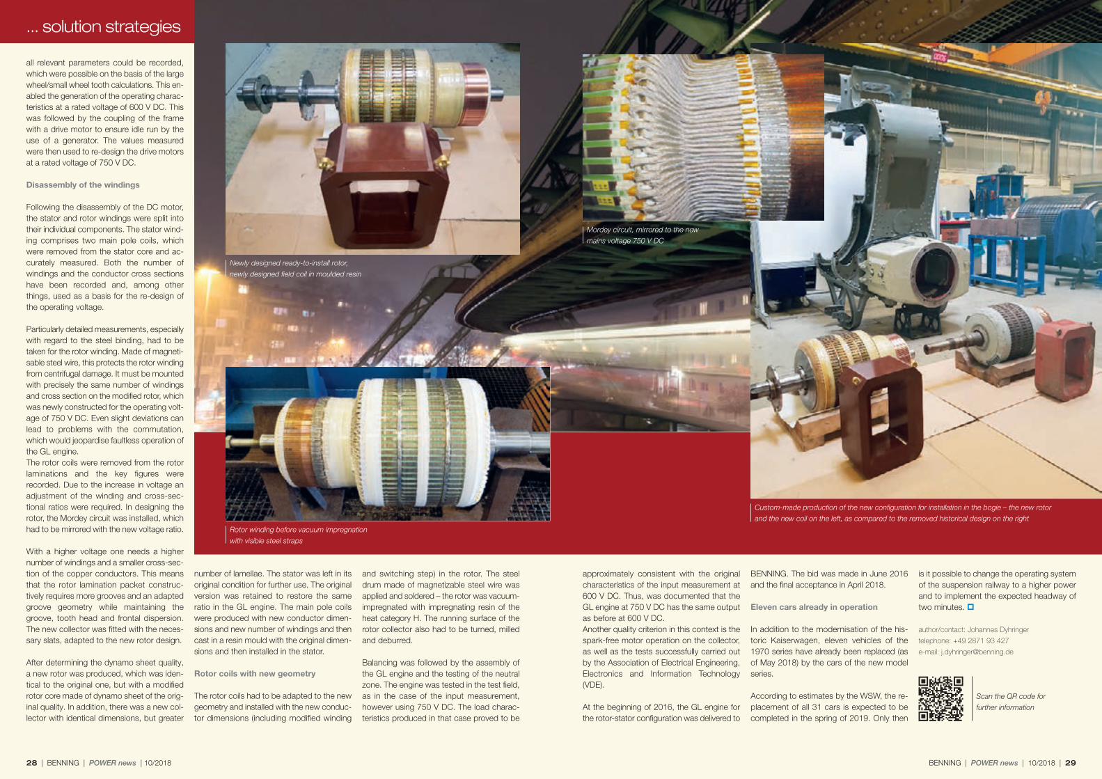
Following the disassembly of the DC motor,the stator and rotor windings were split intotheir individual components. The stator wind-ing comprises two main pole coils, whichwere removed from the stator core and ac-curately measured. Both the number ofwindings and the conductor cross sectionshave been recorded and, among otherthings, used as a basis for the re-design ofthe operating voltage.
Particularly detailed measurements, especiallywith regard to the steel binding, had to betaken for the rotor winding. Made of magneti-sable steel wire, this protects the rotor windingfrom centrifugal damage. It must be mountedwith precisely the same number of windingsand cross section on the modified rotor, whichwas newly constructed for the operating volt-age of 750 V DC. Even slight deviations canlead to problems with the commutation,which would jeopardise faultless operation ofthe GL engine. The rotor coils were removed from the rotorlaminations and the key figures wererecorded. Due to the increase in voltage anadjustment of the winding and cross-sec-tional ratios were required. In designing therotor, the Mordey circuit was installed, whichhad to be mirrored with the new voltage ratio.
With a higher voltage one needs a highernumber of windings and a smaller cross-sec-tion of the copper conductors. This meansthat the rotor lamination packet construc-tively requires more grooves and an adaptedgroove geometry while maintaining thegroove, tooth head and frontal dispersion.The new collector was fitted with the neces-sary slats, adapted to the new rotor design.
After determining the dynamo sheet quality,a new rotor was produced, which was iden-tical to the original one, but with a modifiedrotor core made of dynamo sheet of the orig-inal quality. In addition, there was a new col-lector with identical dimensions, but greater
number of lamellae. The stator was left in itsoriginal condition for further use. The originalversion was retained to restore the sameratio in the GL engine. The main pole coilswere produced with new conductor dimen-sions and new number of windings and thencast in a resin mould with the original dimen-sions and then installed in the stator.
Rotor coils with new geometry
The rotor coils had to be adapted to the newgeometry and installed with the new conduc-tor dimensions (including modified winding
28 | BENNING | POWER news | 10/2018
approximately consistent with the originalcharacteristics of the input measurement at600 V DC. Thus, was documented that theGL engine at 750 V DC has the same outputas before at 600 V DC. Another quality criterion in this context is thespark-free motor operation on the collector,as well as the tests successfully carried outby the Association of Electrical Engineering,Electronics and Information Technology(VDE).
At the beginning of 2016, the GL engine forthe rotor-stator configuration was delivered to
and switching step) in the rotor. The steeldrum made of magnetizable steel wire wasapplied and soldered – the rotor was vacuum- impregnated with impregnating resin of theheat category H. The running surface of therotor collector also had to be turned, milledand deburred.
Balancing was followed by the assembly ofthe GL engine and the testing of the neutralzone. The engine was tested in the test field,as in the case of the input measurement,however using 750 V DC. The load charac-teristics produced in that case proved to be
BENNING. The bid was made in June 2016and the final acceptance in April 2018.
Eleven cars already in operation
In addition to the modernisation of the his-toric Kaiserwagen, eleven vehicles of the1970 series have already been replaced (asof May 2018) by the cars of the new modelseries.
According to estimates by the WSW, the re-placement of all 31 cars is expected to becompleted in the spring of 2019. Only then
BENNING | POWER news | 10/2018 | 29
... solution strategies
is it possible to change the operating systemof the suspension railway to a higher powerand to implement the expected headway oftwo minutes.
author/contact: Johannes Dyhringer
telephone: +49 2871 93 427
e-mail: [email protected]
Scan the QR code for
further information
Rotor winding before vacuum impregnation
with visible steel straps
Newly designed ready-to-install rotor,
newly designed field coil in moulded resin
Mordey circuit, mirrored to the new
mains voltage 750 V DC
Custom-made production of the new configuration for installation in the bogie – the new rotor
and the new coil on the left, as compared to the removed historical design on the right

Scan the QR code for
further information.
With more than seven million journeys perday, New York City operates the largestpublic transport infrastructure in the USA.The Metro, one of the world's largestrapid transit systems, plays a decisiverole in this. With its 472 stations, 36 trainlines, and 1370 kilometres (850 miles) longrail system, it makes up a large part of theurban transportation network. It also in-cludes a rapid transit line in the city dis-trict of Staten Island and a bus network.
Security of operational activities
The main task of the public transportation authority is to ensure safe and trouble-freemovement of people throughout the city 24 hours a day. Therefore, the complex trans -portation infrastructure has to be permanentlymonitored for schedule, security and mainte-nance. An essential prerequisite for this is the con-tinuous functioning of their communicationsystem over different networks. It enablesmonitoring, control and coordination of theentire railway system. Here, current trafficmovements and technical systems along theroute are monitored for their function, pas-sengers are notified of operating delays, sta-tions are monitored for safety and the railway
staff are provided with vital, real time data(e. g. with regard to the rail condition). Thisresults in a constant exchange of information,whose continuous operation has the highestpriority. The following functions are supported sys-tem-wide: public address (PA) system con-sisting of microphones, speakers and ampli-fiers; customer information systems andsigns; a bus and police radio network andCCTV video surveillance systems all beingcarried over their ATM (Asynchronous Trans-fer Mode) and SONET (Synchronous OpticalNetwork) fiber optic network. When com-bined together, this results in a very complexand sensitive system that requires maximumsecurity and critical availability.If a complete, or even partial, power outageoccurs, e. g. due to a network failure, this cannot only have a catastrophic impact on oper-ational processes, but, in the worst-case sce-nario, also the potential safety of passengersand railway personnel. To avoid this worse-case scenario, highly available and reliablepower supplies to support the system are es-sential. These have to work continuously in ahighly demanding harsh environment, butmust also be designed to meet the specificand bespoke requirements of the public trans-portation services.
Increased safety for one of the world's largest underground networksWith a combination of individual product solutions and engineering
services, BENNING contributes to making New York's rail traffic
safer and more efficient.
30 | BENNING | POWER news | 10/2018
(48 V range) rectifiers, TEBECHOP 3000 HDconverters, DSP and INVERTRONIC modular 3 Phase inverters, and UPS systems of theENERTRONIC modular series.
Protection against heat and dust
The extremely harsh conditions near the sub-way tracks are a particular challenge. Manyrooms in which the power supply systemsare integrated have ambient temperatures ofapprox. 95 - 104 F° and a high concentration of corrosive steel dust resulting from the fre-quent braking of the trains. The systems pro-duced and used by BENNING are designedin such a way that they can withstand theseenvironmental challenges without any reduc-tion in their functionality.
Furthermore, the height, width and weight ofthe systems require flexibility so that they canbe adapted to the spatial requirements of thesite installation. This means also that specialmethods of delivery, e. g. via a staircase or amanhole in the street, can be undertakenwithout any problems.
Exchange of knowledge
Searching for a partner who would provideboth, tailored product solutions and the associated engineering expertise, the coop-eration with BENNING was formed approxi-mately ten years ago. Engineers and design-ers of both companies are in constant con tactto bring their ideas, requirements and solu-tions together and coordinate them in themost effective solutions. BENNING received its first order in 2005 forthe installation of Phase II of the ATM networkfor a large portion of the subway system.Since completion of the ATM project, a largenumber of projects have been deployedthroughout their rail network, in cooperationwith the client’s development and designteams.BENNING power systems are currently inuse at more than 600 different locationsthroughout New York city – including reliablepower systems for the bus and police radionetworks. The following product familieshave been deployed in the power systems:the TEBECHOP 3000 HD and SLIMLINE SE
Further railway projects in the USA
The reputation that BENNING has earned inNey York City has also paved the way formany other rail projects in the USA – for ex-ample in Philadelphia and Washington (seePOWER news 9/2017). Again, in these projects, the combination ofcustomized product solutions and services(turnkey services, maintenance and repair)play a key role in ensuring the smooth andcontinuous operation of railway and commu-nication systems, as well as making railtransport mobility considerably safer, moreefficient and more modern.
contact: Eric McDonald
telephone: +1 214 755 7233
e-mail: [email protected]
Slim Power System with 3000 HD Rectifier
(9kW @ 48V DC) and HDi DC Converters
(3kW @ 24V DC) for installation into restricted
space locations for Public Safety Radio Systems
BENNING | POWER news | 10/2018 | 31
Multi-Cabinet Power System with 3000 HD Rectifiers (672A @ 48V DC)
and three independent DSP Inverters (12.5kVA @ 120VAC each)
providing backup to the Fiber Network, CCTV, and PA Systems.

www.benning.de
10151956.10 GB | 07/2018 | paus Design & Medien, Bocholt | Subject to alterations. Printed on chlorine free paper.
BENNING Elektrotechnik und Elektronik GmbH & Co. KG
Factory IMünsterstr. 135-137
Factory II Robert-Bosch-Str. 20
46397 BOCHOLTGERMANY
Tel.: +49 2871 93 0 Fax: +49 2871 93 297
E-Mail: [email protected]
All details provided without liability
Fairs, events and exhibitions2018
ENERGETAB11/09 – 13/09 in Bielsko-Biala/Poland
InnoTrans18/09 – 21/09 in Berlin/Germany
Petrochymia19/09 – 20/09 in Martigues/France
GET Nord22/11 – 24/11 in Hamburg/Germany
Electrical networks of Russia04/12 – 07/12 in Moscow/Russia
Photo: ©buffaloboy/Shutterstock.com