Electrical Communication - World Radio History
116
VOLUME 58 No 3 1984 THE TECHNICAL JOURNAL OF ITT
-
Upload
khangminh22 -
Category
Documents
-
view
0 -
download
0
Transcript of Electrical Communication - World Radio History

VOLUME 58 No 3 1984 THE TECHNICAL JOURNAL OF ITT


Volume 58
Number 3 1984
Electrical Communication is the technicaljournal of the ITT System reporting theresearcn, development, and productionachievements of its affiliates worldwide. Firstpublished in 1922, Electrical Communicationappears in four language editions distributedthroughout the world. Contributions areinvited from ITT engineers and scientists;summaries of papers should be sent tothe English edition Editor for consideration.
Executive Editor, BrusselsLester A. Gimpelson
Editor, Electrical Communication, HarlowMichael Deason
Editor, Elektrisches Nachrichtenwesen,StuttgartOtto Grewe
Editor, Comunicaciones Electricas, MadridAntonio Soto
ElectricalCommunication
Technical Journal Published Quarterly by ITT Corporation
Acting Editor, Revue des Telecommunications,BrusselsLester A. Gimpelson
Subscriptions cost $ 20 (£ 13.00) per volume (4 issues)Individual copies $ 5 (£ 3.25).Editorial and subscription enquiries should be addressedto the Editor, Electrical Communication, Great EasternHouse, Ecinburgh Way, Harlow, Essex, England,or Editors of other editions.Published 28 March 1984.© ITT Corporation 1984.
Coden: ELCMAX 58 (3) 249-360 (1984)ISSN: 0013-4252
Navigation Aids
250 Overview
251 Civil Navigation Aids in ITT,S. H. Dodington
256 Second Generation Vortac Equipment,A. H. Lang
263 Ground -Based Air Traffic ControlCommunication Equipment,D. W. Walters
270 System 4000 Navigation Aids,H. Kleiber, N. Knoppik, and H. Vogel
277 Hardware and Software Structures forSystem 4000 Navigation Aids,F. L mbach and K. Pahlig
283 VHF Radio Lighthouse,R. Johannessen
289 New Family of Tacan and DME Equipment,G. Bertocchi
293 Civil Use of Tacan,E. Lazzaron
299 Scanning Pencil Beam Precision ApproachRadar,R. E. Johnson
305 Further Development of the DPS Techniquefor Precision DME,G. Corazza and F. Vatalaro
310 RF Subsystems for Precision DME,F. Ardemagni, P. Basile, and A. Clementi
314 Fiber Optic Gyroscope,W. Auch anc E. Schlemper
319 Off -Shore Helicopter Radio Navigation usingDME-based Positioning System,M. Bohm
326 Space Qualified L -Band Triplexer for GlobalPositioning System,G. Gorder and J. Ranghelli
332 Receiver for Global Positioning System,A. Bethmann and H. Tschiesche
336 Precision Distance Measuring Equipment forthe Microwave Landing System,K. Becker, A. Muller, and H. Vogel
344 Loran -C Navigation System for Saudi Arabia,W. J. Garmany, V. L. Johnson, and W. J. Romer
352 Satellite Navigation,P. K. Blair arid P. J. Hargrave
359 This Issue in Brief
ITT
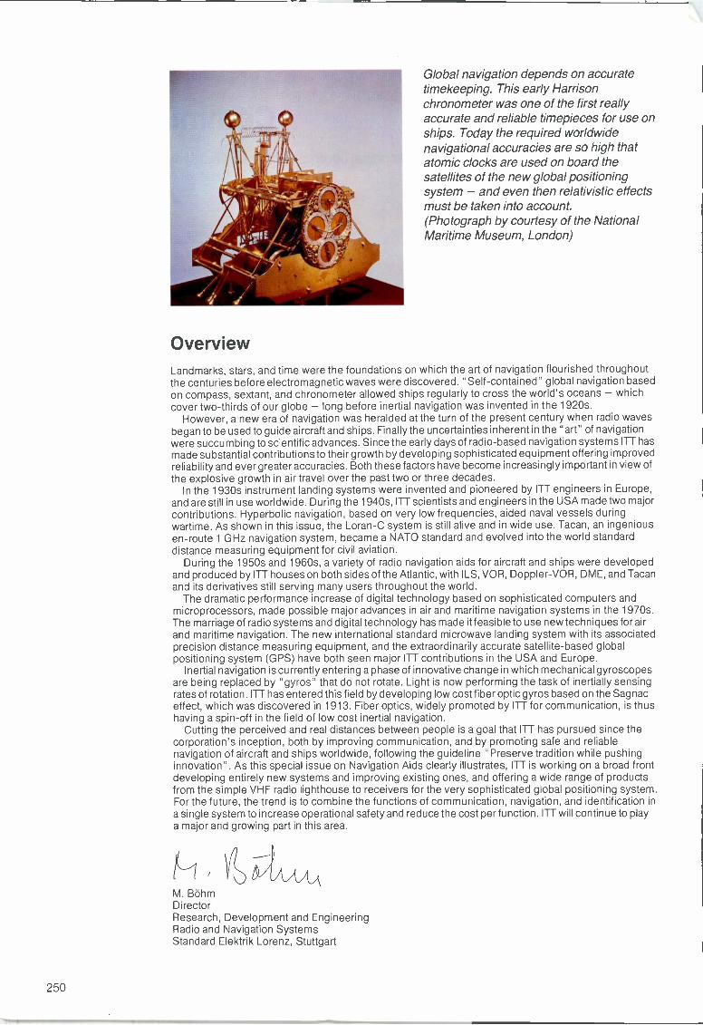
Global navigation depends on accuratetimekeeping. This early Harrisonchronometer was one of the first reallyaccurate and reliable timepieces for use onships. Today the required worldwidenavigational accuracies are so high thatatomic clocks are used on board thesatellites of the new global positioningsystem - and even then relativistic effectsmust be taken into account.(Photograph by courtesy of the NationalMaritime Museum, London)
OverviewLandmarks, stars, and time were the foundations on which the art of navigation flourished throughoutthe centuries before electromagnetic waves were discovered. "Self-contained" global navigation basedon compass, sextant, and chronometer allowed ships regularly to cross the world's oceans - whichcover two-thirds of our globe - long before inertial navigation was invented in the 1920s.
However, a new era of navigation was heralded at the turn of the present century when radio wavesbegan to be used to guide aircraft and ships. Finally the uncertainties inherent in the "art" of navigationwere succumbing to scientific advances. Since the early days of radio -based navigation systems ITT hasmade substantial contributions to their growth by developing sophisticated equipment offering improvedreliability and ever greater accuracies. Both these factors have become increasingly important in view ofthe explosive growth in air travel over the past two or three decades.
In the 1930s instrument landing systems were invented and pioneered by ITT engineers in Europe,and are still in use worldwide. During the 1940s, ITT scientists and engineers in the USA made two majorcontributions. Hyperbolic navigation, based on very low frequencies, aided naval vessels duringwartime. As shown in this issue, the Loran -C system is still alive and in wide use. Tacan, an ingeniousen -route 1 GHz navigation system, became a NATO standard and evolved into the world standarddistance measuring equipment for civil aviation.
During the 1950s and 1960s, a variety of radio navigation aids for aircraft and ships were developedand produced by ITT houses on both sides of the Atlantic, with I LS, VOR, Doppler-VOR, D ME, and Tacanand its derivatives still serving many users throughout the world.
The dramatic performance increase of digital technology based on sophisticated computers andmicroprocessors, made possible major advances in air and maritime navigation systems in the 1970s.The marriage of radio systems and digital technology has made it feasible to use new techniques for airand maritime navigation. The new international standard microwave landing system with its associatedprecision distance measuring equipment, and the extraordinarily accurate satellite -based globalpositioning system (GPS) have both seen major ITT contributions in the USA and Europe.
Inertial navigation is currently entering a phase of innovative change in which mechanical gyroscopesare being replaced by "gyros" that do not rotate. Light is now performing the task of inertially sensingrates of rotation. ITT has entered this field by developing low cost fiber optic gyros based on the Sagnaceffect, which was discovered in 1913. Fiber optics, widely promoted by ITT for communication, is thushaving a spin-off in the field of low cost inertial navigation.
Cutting the perceived and real distances between people is a goal that ITT has pursued since thecorporation's inception, both by improving communication, and by promoting safe and reliablenavigation of aircraft and ships worldwide, following the guideline "Preserve tradition while pushinginnovation". As this special issue on Navigation Aids clearly illustrates, ITT is working on a broad frontdeveloping entirely new systems and improving existing ones, and offering a wide range of productsfrom the simple VHF radio lighthouse to receivers for the very sophisticated global positioning system.For the future, the trend is to combine the functions of communication, navigation, and identification ina single system to increase operational safety and reduce the cost per function. ITT will continue to playa major and growing part in this area.
M. BohmDirectorResearch, Development and EngineeringRadio and Navigation SystemsStandard Elektrik Lorenz, Stuttgart
250
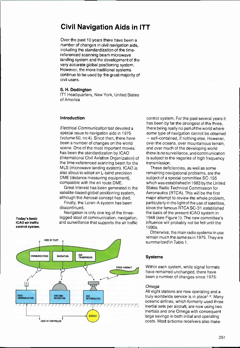
Today's basicICAO air trafficcontrol system.
USED BY PILOT
VOCECOMMUNICATION
Civil Navigation Aids in ITT
Over the past 10 years there have been anumber of changes in civil navigation aids,including the standardization of the time -referenced scanning beam microwavelanding system and the development of thevery accurate global positioning system.However, the more traditional systemscontinue to be used by the great majority ofcivil users.
S. H. DodingtonITT Headquarters, New York, United Statesof America
Introduction
Electrical Communication last devoted aspecial issue to navigation aids in 1975(volume 50, no 4). Since then, there havebeen a number of changes on the worldscene. One of the most important moveshas been the standardization by ICAO(International Civil Aviation Organization) ofthe time -referenced scanning beam for theMLS (microwave landing system). ICAO isalso about to adopt an L -band precisionDME (distance measuring equipment),compatible with the en route DME.
Great interest has been generated in thesatellite -based global positioning system,although the Aerosat concept has died.
Finally, the Loran -A system has beendiscontinued.
Navigation is only one leg of the three-legged stool of communication, navigation,and surveillance that supports the air traffic
VON/DMENAVIGATION
OTHER AIRCRAFT
SSRINTERROGATOR
/A/ / / / I I / / / / / / /
USED BY CONTROLLER
/ / / / / / / / / / /
control system. For the past several years ithas been by far the strongest of the three,there being really no part of the world wheresome type of navigation cannot be obtained- self-contained, if nothing else. However,over the oceans, over mountainous terrain,and over much of the developing worldthere is no surveillance, and communicationis subject to the vagaries of high frequencytransmission.
These deficiencies, as well as someremaining navigational problems, are thesubject of a special committee SC -155which was established in 1983 by the UnitedStates Radio Technical Commission forAeronautics (RTCA). This will be the firstmajor attempt to review the whole problem,particularly in the light of the use of satellites,since the famous RTCA SC -31 establishedthe basis of the present ICAO system in1948 (see Figure 1). The new committee'sinfluence will probably not be felt until the1990s.
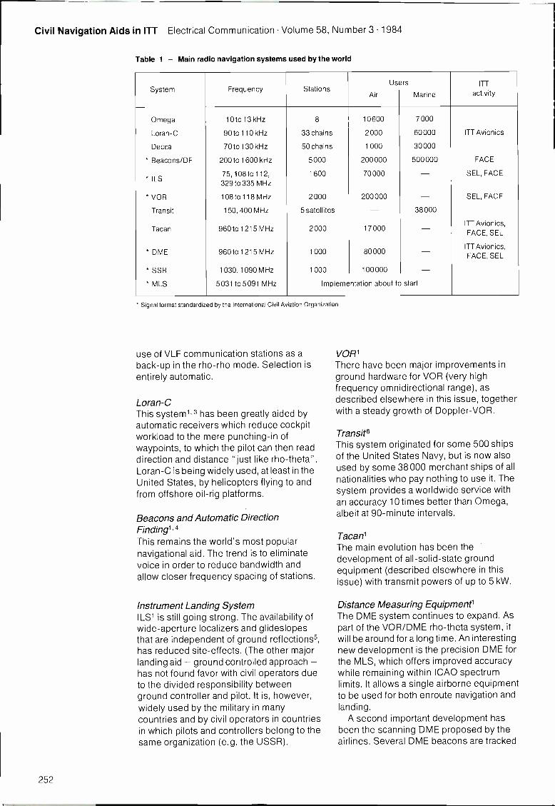
Otherwise, the main radio systems in useremain much the same as in 1975. They aresummarized in Table 1.
Systems
Within each system, while signal formatshave remained unchanged, there havebeen a number of changes since 1975:
OmegaAll eight stations are now operating and atruly worldwide service is in place' 2. Manyoceanic airlines, which formerly used threeinertial sets per aircraft, are now using twoinertials and one Omega with consequentlarge savings in both initial and operatingcosts. Most airborne receivers also make
251
Civil Navigation Aids in ITT Electrical Communication Volume 58, Number 3 1984
Table 1 - Main radio navigation systems used by the world
System Frequency StationsUsers
Air Marine
ITT
activity
Omega 10 to 13 kHz 8 10600 7000
Loran -C 90 to 110 kHz 33 chains 2000 60000 ITT Avionics
Decca 70 to 130 kHz 50 chains 1000 30000
* Beacons/DF 200 to 1600 kHz 5000 200000 500000 FACE
* ILS75, 108to 112,329 to 335 MHz
1600 70000 - SEL, FACE
* VOR 108to 118 MHz 2000 200000 - SEL, FACE
Transit 150, 400 MHz 5 satellites - 38000
Tacan 960 to 1215 MHz 2000 17000 - ITT Avionics,FACE, SEL
* DME 960 to 1215 MHz 1000 80000 - ITT Avionics,FACE, SEL
* SSR 1030, 1090 MHz 1000 100000 -* MLS 5031 to 5091 MHz Implementation about to start
* Signal format standardized by the International Civil Aviation Organization
use of VLF communication stations as aback-up in the rho -rho mode. Selection isentirely automatic.
Loran -CThis system1.3 has been greatly aided byautomatic receivers which reduce cockpitworkload to the mere punching -in ofwaypoints, to which the pilot can then readdirection and distance "just like rho -theta".Loran -C is being widely used, at least in theUnited States, by helicopters flying to andfrom offshore oil -rig platforms.
Beacons and Automatic DirectionFinding', 4This remains the world's most popularnavigational aid. The trend is to eliminatevoice in order to reduce bandwidth andallow closer frequency spacing of stations.
Instrument Landing SystemILS1 is still going strong. The availability ofwide -aperture localizers and glideslopesthat are independent of ground reflections5,has reduced site -effects. (The other majorlanding aid - ground controlled approach -has not found favor with civil operators dueto the divided responsibility betweenground controller and pilot. It is, however,widely used by the military in manycountries and by civil operators in countriesin which pilots and controllers belong to thesame organization (e.g. the USSR).
VOR'There have been major improvements inground hardware for VOR (very highfrequency omnidirectional range), asdescribed elsewhere in this issue, togetherwith a steady growth of Doppler-VOR.
TransitsThis system originated for some 500 shipsof the United States Navy, but is now alsoused by some 38000 merchant ships of allnationalities who pay nothing to use it. Thesystem provides a worldwide service withan accuracy 10 times better than Omega,albeit at 90 -minute intervals.
Tacan'The main evolution has been thedevelopment of all -solid-state groundequipment (described elsewhere in thisissue) with transmit powers of up to 5 kW.
Distance Measuring Equipment'The DME system continues to expand. Aspart of the VOR/DME rho -theta system, itwill be around for a long time. An interestingnew development is the precision DME forthe MLS, which offers improved accuracywhile remaining within ICAO spectrumlimits. It allows a single airborne equipmentto be used for both enroute navigation andlanding.
A second important development hasbeen the scanning DME proposed by theairlines. Several DME beacons are tracked
252
Electrical Communication Volume 58, Number 3 1984 Civil Navigation Aids in ITT
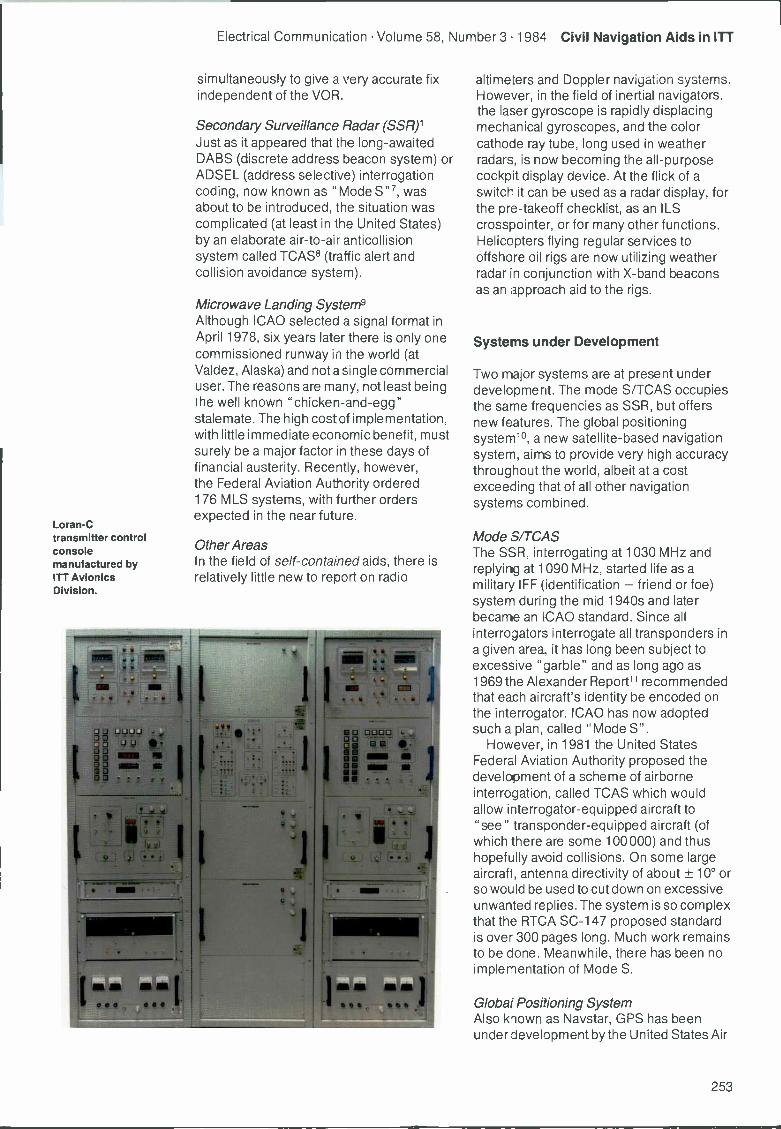
Loran -Ctransmitter controlconsolemanufactured byITT AvionicsDivision.
simultaneously to give a very accurate fixindependent of the VOR.
Secondary Surveillance Radar (SSR)1Just as it appeared that the long-awaitedDABS (discrete address beacon system) orADSEL (address selective) interrogationcoding, now known as "Mode S"7, wasabout to be introduced, the situation wascomplicated (at least in the United States)by an elaborate air-to-air anticollisionsystem called TCAS8 (traffic alert andcollision avoidance system).
Microwave Landing System9Although ICAO selected a signal format inApril 1978, six years later there is only onecommissioned runway in the world (atValdez, Alaska) and not a single commercialuser. The reasons are many, not least beingthe well known "chicken -and -egg"stalemate. The high cost of implementation,with little immediate economic benefit, mustsurely be a major factor in these days offinancial austerity. Recently, however,the Federal Aviation Authority ordered176 MLS systems, with further ordersexpected in the near future.
Other AreasIn the field of self-contained aids, there isrelatively little new to report on radio
00000 00 00 0
0 I
0O 0 0000
0 -o a 138 0Ei a MNa a a
altimeters and Doppler navigation systems.However, in the field of inertial navigators.the laser gyroscope is rapidly displacingmechanical gyroscopes, and the colorcathode ray tube, long used in weatherradars, is now becoming the all-purposecockpit display device. At the flick of aswitch it can be used as a radar display, forthe pre -takeoff checklist, as an ILScrosspointer, or for many other functions.Helicopters flying regular services tooffshore oil rigs are now utilizing weatherradar in conjunction with X -band beaconsas an approach aid to the rigs.
Systems under Development
Two major systems are at present underdevelopment. The mode S/TCAS occupiesthe same frequencies as SSR, but offersnew features. The global positioningsystem10, a new satellite -based navigationsystem, aims to provide very high accuracythroughout the world, albeit at a costexceeding that of all other navigationsystems combined.
Mode S/TCASThe SSR, interrogating at 1030 MHz andreplying at 1090 MHz, started life as amilitary IFF (identification - friend or foe)system during the mid 1940s and laterbecame an ICAO standard. Since allinterrogators interrogate all transponders ina given area, it has long been subject toexcessive "garble" and as long ago as1969 the Alexander Report11 recommendedthat each aircraft's identity be encoded onthe interrogator. ICAO has now adoptedsuch a plan, called "Mode S".
However, in 1981 the United StatesFederal Aviation Authority proposed thedevelopment of a scheme of airborneinterrogation, called TCAS which wouldallow interrogator -equipped aircraft to"see" transponder -equipped aircraft (ofwhich there are some 100000) and thushopefully avoid collisions. On some largeaircraft, antenna directivity of about ± 10° orso would be used to cut down on excessiveunwanted replies. The system is so complexthat the RTCA SC -147 proposed standardis over 300 pages long. Much work remainsto be done. Meanwhile, there has been noimplementation of Mode S.
Global Positioning SystemAlso known as Naystar, GPS has beenunder development by the United States Air
253
Civil Navigation Aids in ITT Electrical Communication Volume 58, Number 3 1984
Force since about 1960 and is currentlyproposed as using 18 satellites in 12 -hourorbits, transmitting phase -codedcontinuous wave signals around 1200 and1500 MHz. (Details are describedelsewhere in this issue). Continuousaccuracy of about 20 m anywhere in theworld is claimed. The initial cost is estimatedat $6 billion and the annual operating cost$250 million, both figures greater thanthose for the sum of all other radionavigation systems in existence. For thisreason, the United States Department ofDefense is anxious to secure its use by thecivil sector and the shutdown of all othercivil aids. However, to preclude the use ofGPS by potential enemies, civil users willonly be allowed 100 m accuracy (by codingthe signal) and they will also be charged$400 per year each. (There are no usercharges for any of the present navigationaids). Civil users have unanimously rejectedthese conditions; even helicopteroperators, who are not happy with VOR/DME, have balked at the 100 m limitation onaccuracy. Furthermore, there is littleindication that any of ICAO's 130 countriescares to abandon its home -based navigationaids in favor of one controlled by the militaryservice of a foreign government.
At present, about 100 receivers of varioustypes are being produced by two non -ITTcontractors in the United States. Five usablesatellites are in orbit. Within ITT, the DefenseCommunications Division has built thesatellite L -Band transmitters, BellTelephone Manufacturing Company(Antwerp, Belgium) and Standard ElektrikLorenz (Stuttgart, Federal Republic ofGermany) have study and hardwarecontracts. ITT affiliate StandardTelecommunication Laboratories (Harlow,England) has built eight receivers.
Personal Forecast for the Year 2000
The following is a personal prediction of thestatus of navigation aids in the year 2000:
GPS will be in use as a military system,with some civil users. There will probablybe no user fees and no accuracyrestrictions.
All systems in Table 1 will still be in use,with the possible exception of Transit,which, as a purely United States -paidsystem, might be shut down to help payfor GPS.
Increased use of self-contained systemsof all kinds.
Systems will increasingly use digitalcircuits and electronic systems willreplace electromechanical systems.
ILS installations will continue tooutnumber MLS, both airborne andground.
Only modest use will be made of Mode -S,and even less of TCAS.
Any "new" systems will attempt to useexisting signal formats and hardware;SSR/Mode S/TCAS is probably anextreme example of this. Precision DMEis another example and, to a lesserextent, so is STL's radio lighthouse. MLSis an example of the opposite approach.New ground, airborne, and testequipment are all required -a formidableset of hurdles to overcome.
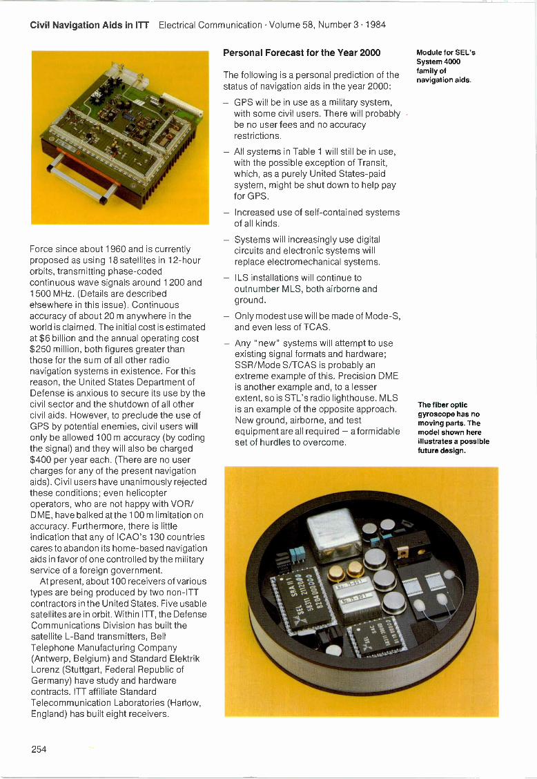
Module for SEL'sSystem 4000family ofnavigation aids.
The fiber opticgyroscope has nomoving parts. Themodel shown hereillustrates a possiblefuture design.
254
Electrical Communication Volume 58, Number 3 1984 Civil Navigation Aids in ITT
The effects of SC -155's recommendationswill begin to be felt, but are likely to be in therealms of communication and surveillancemore than in navigation.
Conclusions
The articles in this issue describe some ofthe equipment that ITT companies, on bothsides of the Atlantic, are building to fit intothe world environment. As in the 1975issue, emphasis is on equipment that fitsinto standard systems with well establishedsignal formats.
References
1 Electronic Engineers Handbook, 2nd edition,chapter 25, McGraw-Hill, New York, 1982.
2 W. K. May: The Omega Navigation System: AnOverview: Proceedings of the Institute of Electricaland Electronics Engineers PLANS -82 Symposium,December 1982.
3 US Navigation: Special issue on Loran -C, Spring1982, volume 28, no 1.
4 Minimum Performance Standard for AJF: RTCASC -146, 1982.
5 C. Watts: A New End -Fire Glide -Slope. Proceedingsof the Institute of Electrical and Electronics EngineersPLANS -80 Symposium, December 1980.
6 T. A. Stansell: The Many Faces of Transit: USNavigation, Spring 1978, volume 25, no 1.
7 Minimum Performance Standard for Mode S: RTCASC -142, 1983.
8 Minimum Performance Standard for TCAS: RTCASC -147, 1983.
9 H. Redlien and R. Kelly: MLS: Academic Press,410 pp, 1981. (Paperback available from BendixCorporation, Baltimore).
1C US Navigation: Special Issue on GPS, Summer1978, volume 25, no 2.
11 Report of the DOT ATC Advisory Committee, UnitedStates Department of Transportation, December1969.
Sven H. Dodington was born in Vancouver, Canada, in1912. He was awarded an AB degree from StanfordUniversity in 1934. The following year -re joinedScophony Ltd, London, to work on the desigr of large -screen television projectors. In 1941 he joined ITT inNew York and has been with them ever since. From 1941to 1945 he headed much of the wartime effort onairborne radar counter measures of the decep-ive type.He was then appointed head of the ITT radio navigationlaboratory in Nutley, New Jersey, where the groundworkwas laid for today's distance measuring equipment. As aresult he won the IEEE/AESS Pioneer Award Hebecame president of ITT Avionics Division in 1958, apost he held until moving to the Technical Department atITT headquarters in New York as a consultant on avionicsand radio navigation. Since 1969 he has been atechnicaladvisor to the Radio Technical Commission forAeronautics. In 1982 he was named "Inventor of theYear" by the New York Patent Law Association.
255
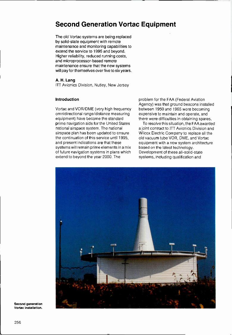
Second Generation Vortac Equipment
The old Vortac systems are being replacedby solid-state equipment with remotemaintenance and monitoring capabilities toextend the service to 1995 and beyond.Higher reliability, reduced running costs,and microprocessor -based remotemaintenance ensure that the new systemswill pay for themselves over five to six years.
A. H. LangITT Avionics Division, Nutley, New Jersey
Introduction
Vortac and VOR/DME (very high frequencyomnidirectional range/distance measuringequipment) have become the standardprime navigation aids for the United Statesnational airspace system. The nationalairspace plan has been updated to ensurethe continuation of this service until 1995,and present indications are that thesesystems will remain prime elements in a mixof future navigation systems in plans whichextend to beyond the year 2000. The
Second generationVortac installation.
problem for the FAA (Federal AviationAgency) was that ground beacons installedbetween 1950 and 1965 were becomingexpensive to maintain and operate, andthere were difficulties in obtaining spares.
To resolve this situation, the FAA awardeda joint contract to ITT Avionics Division andWilcox Electric Company to replace all theold vacuum tube VOR, DME, and Vortacequipment with a new system architecturebased on the latest technology.Development of these all -solid-statesystems, including qualification and
256
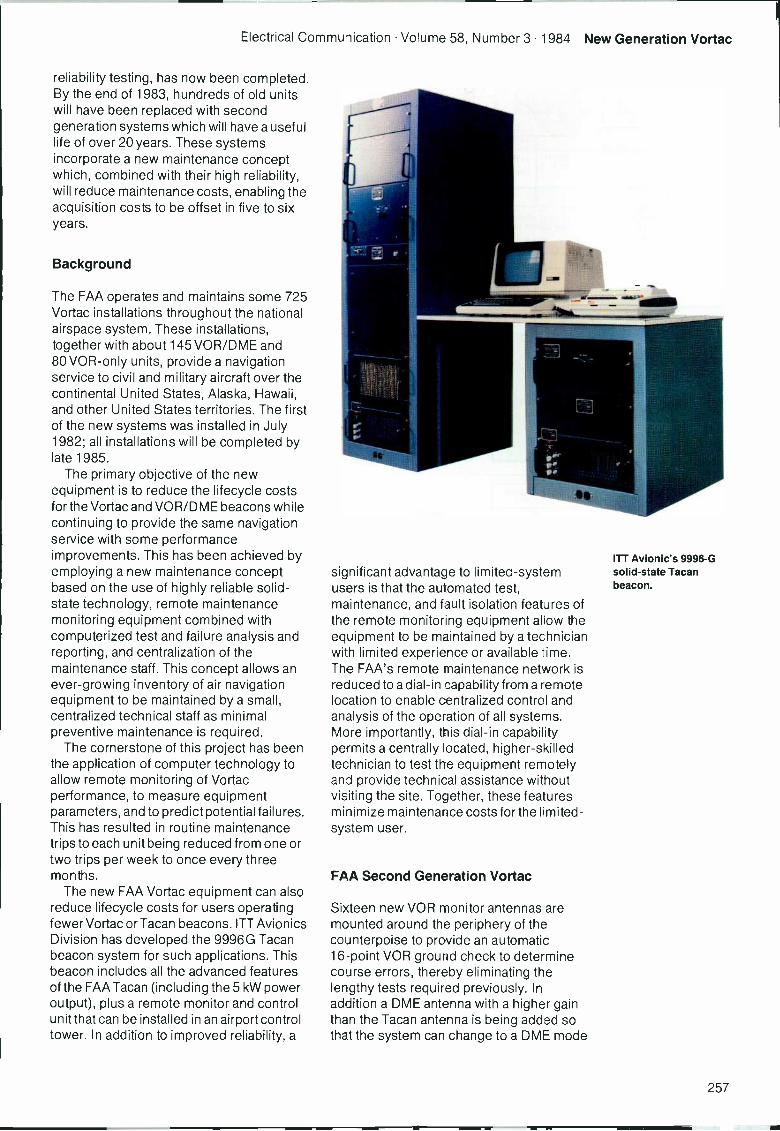
Electrical Communication Volume 58, Number 3 1984 New Generation Vortac
reliability testing, has now been completed.By the end of 1983, hundreds of old unitswill have been replaced with secondgeneration systems which will have a usefullife of over 20 years. These systemsincorporate a new maintenance conceptwhich, combined with their high reliability,will reduce maintenance costs, enabling theacquisition costs to be offset in five to sixyears.
Background
The FAA operates and maintains some 725Vortac installations throughout the nationalairspace system. These installations,together with about 145 VOR/DME and80 VOR-only units, provide a navigationservice to civil and military aircraft over thecontinental United States, Alaska, Hawaii,and other United States territories. The firstof the new systems was installed in July1982; all installations will be completed bylate 1985.
The primary objective of the newequipment is to reduce the lifecycle costsfor the Vortac and VOR/DME beacons whilecontinuing to provide the same navigationservice with some performanceimprovements. This has been achieved byemploying a new maintenance conceptbased on the use of highly reliable solid-state technology, remote maintenancemonitoring equipment combined withcomputerized test and failure analysis andreporting, and centralization of themaintenance staff. This concept allows anever-growing inventory of air navigationequipment to be maintained by a small,centralized technical staff as minimalpreventive maintenance is required.
The cornerstone of this project has beenthe application of computer technology toallow remote monitoring of Vortacperformance, to measure equipmentparameters, and to predict potential failures.This has resulted in routine maintenancetrips to each unit being reduced from one ortwo trips per week to once every threemonths.
The new FAA Vortac equipment can alsoreduce lifecycle costs for users operatingfewer Vortac or Tacan beacons. ITT AvionicsDivision has developed the 9996G Tacanbeacon system for such applications. Thisbeacon includes all the advanced featuresof the FAA Tacan (including the 5 kW poweroutput), plus a remote monitor and controlunit that can be installed in an airport controltower. In addition to improved reliability, a
significant advantage to limitec-systemusers is that the automated test,maintenance, and fault isolation features ofthe remote monitoring equipment allow theequipment to be maintained by a technicianwith limited experience or available time.The FAA's remote maintenance network isreduced to a dial -in capability from a remotelocation to enable centralized control andanalysis of the operation of all systems.More importantly, this dial -in capabilitypermits a centrally located, higher -skilledtechnician to test the equipment remotelyand provide technical assistance withoutvisiting the site. Together, these featuresminimize maintenance costs for the limited -system user.
FAA Second Generation Vortac
Sixteen new VOR monitor antennas aremounted around the periphery of thecounterpoise to provide an automatic16 -point VOR ground check to determinecourse errors, thereby eliminating thelengthy tests required previously. Inaddition a DME antenna with a higher gaintnan the Tacan antenna is being added sothat the system can change to a DME mode
ITT Avionic's 9996-Gsolid-state Tacanbeacon.
257
New Generation Vortac Electrical Communication Volume 58, Number 3 1984
MAINTENANCEPROCESSINGSYSTEM
REMOTE MONITORand CONTROL UNIT
CONTROLand DATA
V I.
i
OTHER FLIGHT SERVICE STATIONS
FLIGHTSERVICESTATION
FLIGHT SERVICESTATION CONSOLE
r
AIRROUTE
TRAFFICCONTROLCENTER
REMOTE MONITORand CONTROL UNIT
(RMC-F)
CONTROL,DATA andVOICE
1.,1111,OTHER VORTAC STATIONS
TACANANTENNASYSTEM
V
TEST
REMOTECOMMUNICATIONOUTLET
VOICE
DMETANTENNA
SYSTEM
TACANDATA
CONTROL
,1 ENGINEGENERATOR
PRIMARY AC POWER
r
FACILITY
CENTRALPROCESSINGUNIT
BATTERY CHARGERPOWER SUPPLY
DIAL -INTERMINAL
GROUNDCHECK
DATA
BATTERY BANK
CONTROLand VOICE
VOR
ANTENNA
V
VOR
VORTAC
STATION
Figure 1Block schematic of theVortac system withremote maintenanceand monitoringfacilities.
of operation in the event of a Tacan azimuth -function failure, partial loss of Tacan outputpower, or loss of AC power. This feature hasbeen used on numerous occasions inwinter at a mountain -top site in Californiawhere sudden storms caused ice and snowto accumulate on the Tacan antennaradomes, resulting in azimuth monitoralarms. Automatic transfer to the backupDME mode maintained DME navigationservice to civil aircraft on these occasions.
Inside the Vortac shelter, the new systemoccupies only three equipment cabinets,compared with the 16 previously required.The IOT (input/output terminal) and printerprovide control and data display for theequipment. The small equipment sizeallows most of the shelter to be partitionedoff. Together with the wide operatingtemperature range of - 40°C to + 50°C andthe lower power dissipation of the solid-state equipment, this reduces heating andcooling requirements, and cuts operatingcosts.
In all respects the performance of thenew FAA Vortac is equivalent to or betterthan that provided by the previous system.A 5 kW power output from the Tacan power
amplifier and a receiver sensitivity of greaterthan - 94 dBm ensure the required130 n mile (240 km) coverage at 18000 feet(5486 m) with a high availability. The VORpower output of 150 W provides the samecoverage. Performance improvementsof the Tacan system include backupmodes of operation such as fallbackto DME operation, first pulse timing,Y -channel mode, increased traffic handlingcapability, and improved system accuracy.Also, problems such as false distancelock -on have been resolved. New VORfeatures include solid-state voice messagerecording, automatic 16 -point groundcheck, and a solid-state goniometer and RF(radio frequency) amplifier that can operatewith the Y -channel 50 kHz VOR channelspacing.
The operational configuration of thesecond -generation system is shown inFigure 1. All of the units, apart from the basicTacan and VOR equipments, have beenprovided to meet the maintenanceobjectives. Microprocessor technology hasbeen used extensively; both the VOR andTacan include dual monitors which containmicrocomputers, permitting multiple usageof a minimal amount of hardware. In additionto monitoring the key navigation functions,the microcomputers provide systemcontrol, remote adjustment of thetransmitter operating parameters andmonitor alarm limits. Also, the operation andsequencing of all automatic maintenancetests, and the storage and reporting of alldata are performed by thesemicrocomputers. The built-in testequipment is automatically programmed bythe computer monitoring and test programsto perform repetitive and routinemeasurements. Special tests can beperformed by operating the test equipmentin the manual mode; this allows a technicianto set up the frequency, power output, pulserates, etc.
Control of the monitors and datacollection from the monitors are remoted bythe FCPU (facility central processing unit).This microcomputer -controlled unitincludes the interfaces with the local IOTand teleprinter. The FCPU also providesother facility control and status reportingfunctions, such as remotely turning theobstruction lights on and off, and test andcontrol of the remote communication outletreceivers.
The battery charger power supplyprovides the main DC voltages to the Tacan,VOR, and FCPU. This unit, in conjunction
258
Electrical Communication Volume 58, Number 3 1984 New Generation Vortac
with the associated battery bank, ensuresuninterrupted service during switchover tothe standby engine generator in the event offailure of the AC primary power. More thantwo hours of battery operation are availableafter complete loss of AC power. The float-type approach to the battery systemprovides transient -free DC power to thesystem microcomputers, thereby reducingtransient -related computer faults.
The Vortac equipment communicates, viathe FCPU, with an RMC-F (remote monitorand control unit F) located at a flight servicestation. Up to eight Vortac facilities cancommunicate with one RMC-F overstandard telephone lines. Each RMC-F isconnected to an RMC-C at one of the 23 airroute traffic control centers via acommunication network that permits up to128 Vortacs to report to a single RMC-C.The system allows status reporting andfacility maintenance to be implemented atthe flight service station as well as at acentralized status and control terminal in theair route traffic control center. Also, dial -intelephone ports enable a remote terminalwith a modem to access the system,allowing a technician to perform tests fromany telephone.
Maintenance and Monitoring Operation
Initial experience with the systems hasconfirmed that the operational objectives ofthe maintenance and monitoring system arebeing achieved. The system has proved itsvalue in isolating faults, especially in theearly stages of installation. Designengineers were able to remain at the factory,dial into any Vortac installation, and remotelydiagnose a fault, thereby aiding thetechnicians. As the FAA assumes control ofthe new installations, its technicians arenow performing these functions.
All system operation, control, and testingcan be performed from any IOT in thenetwork. Additionally, the status of thefacilities is continuously displayed on the10Ts. A system alarm initiates a flashingdisplay on the IOT screen and an alarm bell.
If an operator wants to observe themonitor or test data, or to perform tests, hefirst requests access to the FCPU. A specialsecurity code, which prevents unauthorizedaccess or tampering with the system, mustthen be entered. A high-level security code(released to only a few people) allowsparameters to be changed, tests to be run,and data to be observed. A person with a
Lower security code only has access to thedata screens.
Every screen that is available to the usermay be selected via a menu. Prompts areprovided on each screen to facilitateparameter entry or testing.
A trend data test displays the criticalequipment parameters which could vary asdegradation occurs. Since digitaltechniques are extensively used, trend datagenerally applies to DC voltages, control -looplevels and, in the case of Tacan, the numberof failed power amplifier output transistors.Any change in equipment operation can
thus be ascertained and, if required, amaintenance trip scheduled to repair theequipment. If a marginal condition isobserved, it may be possible to improvesystem operation by transferring to a backupmode or changing an operational parameter.The system can thus remain in operationuntil a repair can be effected.
Routine certification tests of the keytransponder parameters and monitor alarmlimits can be run automatically without
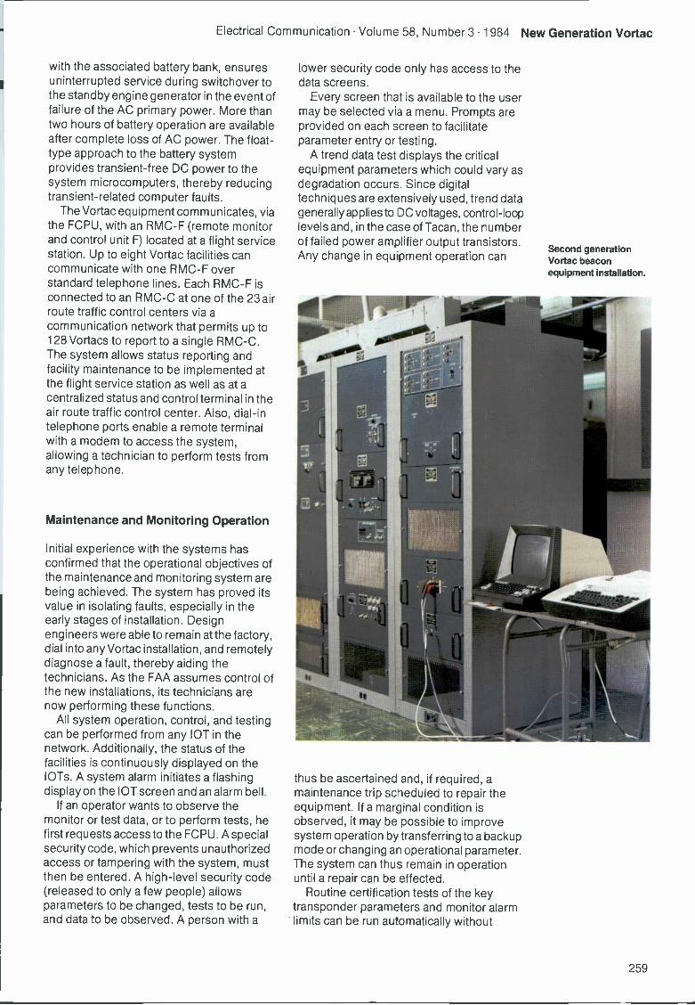
Second generationVortac beaconequipment installation.
259
New Generation Vortac Electrical Communication Volume 58, Number 3 1984
interrupting system operation. These tests,which previously took two days a week, arenow performed in less than four minutes. Allcertification data is automatically displayedand printed, providing a permanent time -tagged log of test results. Similarly, anumber of other tests that previously took along time can now be carried outautomatically using built-in test equipment.
During normal operation, if any of themonitored parameters is outside the limits,a system alarm is initiated. A fault isolationtest is then run automatically, followed bychangeover to the backup mode orshutdown. The operator can requestdifferent types of data and tests. First he cananalyze the fault -history file, which containsthe monitored data at the time of theproblem, to determine which parameterswere out -of -limits and what their measuredvalues were at that time. Second, he canobserve the fault isolation file whichindicates the exact time at which the eventtook place, the state of the system at thattime and, finally, the most -likely failedmodule which was selected as a result ofthe fault isolation test. Based on this data,he can plan a trip to the facility. If the systemis operating in a backup mode, an immediatetrip is not necessary as a second failure ofthe highly reliable equipment is unlikely.The technician can also determine whichmodules are needed for the repair.Experience indicates that the failed moduleis correctly identified by the fault isolationtests in at least 90% of failures. Inconjunction with other remotely availabledata, generally the remaining failures can beisolated to a group of no more than threemodules, thereby expediting repair.
Tacan/DME System
Some of the major issues for the second -generation Tacan/DME system illustratethe approaches used in the Vortacequipment design to meet the primaryobjectives of high reliability and remotemaintenance.
Reliability and AvailabilityHigh reliability and availability are providedby solid-state circuits in a judicious mix ofdual and redundant circuit elements andfallback modes of operation. The previousTacan tube -type equipment exhibited verypoor reliability by today's standards (a fewhundred hours mean time betweenfailures). However, by utilizing dualtransponders, carrying out extensive
maintenance, and immediately repairingfailed units, a high navigation systemavailability (approximately 99.7%) wasachieved.
Basic requirements for the secondgeneration Vortac were:
- Availability of 99.7%; this was specifiedas a MTBO (mean time between outages)of 9600 hours for the Tacan system.
Lowest possible system procurementcosts, consistent with the low lifecyclecost requirements.
- Single -string elements, where used,must be at least as reliable as the single -string elements (e.g. control and transferunit) of the previous dual tube system.
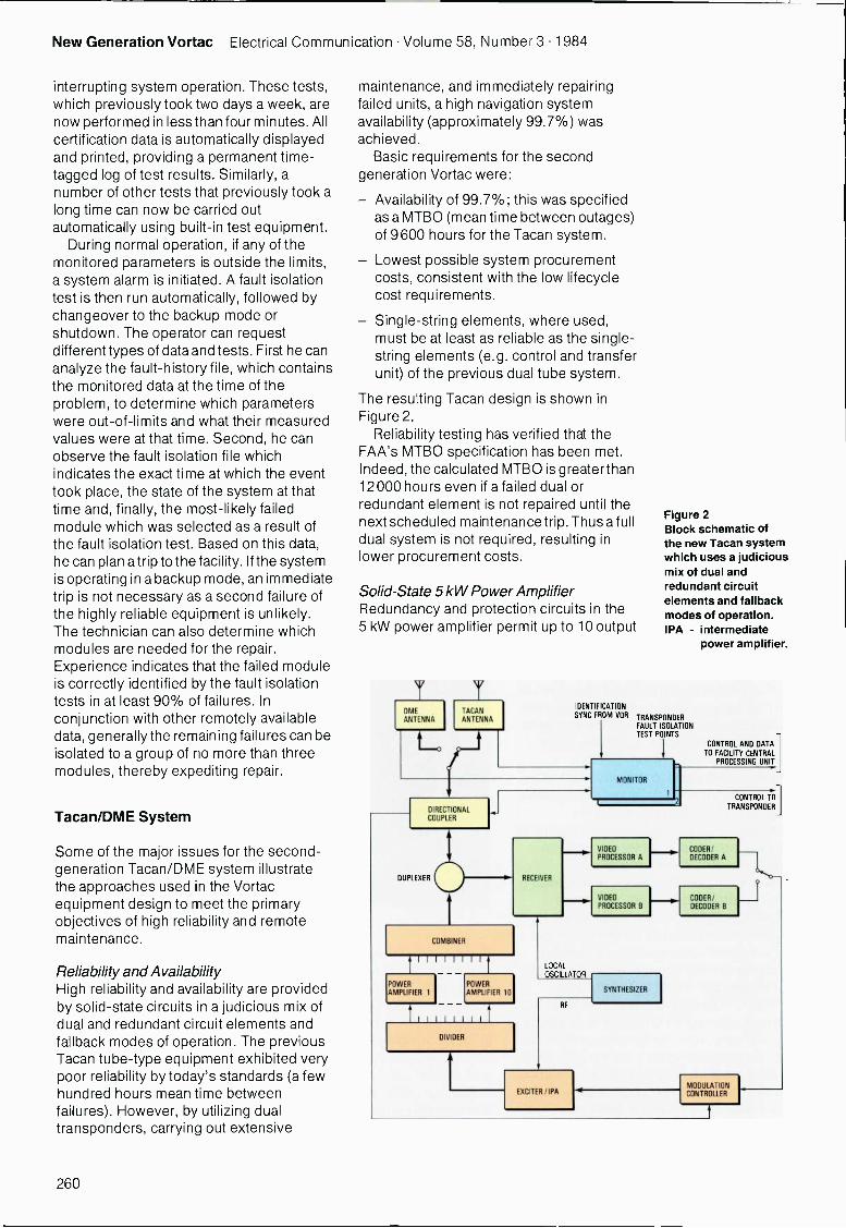
The resulting Tacan design is shown inFigure 2.
Reliability testing has verified that theFAA's MTBO specification has been met.Indeed, the calculated MTBO is greater than12000 hours even if a failed dual orredundant element is not repaired until thenext scheduled maintenance trip. Thus a fulldual system is not required, resulting inlower procurement costs.
Solid -State 5 kW Power AmplifierRedundancy and protection circuits in the5 kW power amplifier permit up to 10 output
OME
ANTENNATACANANTENNA
!UNTIE CATIONSYNC FROM VOR
DIRECTIONALCOUPL R
Figure 2Block schematic ofthe new Tacan systemwhich uses a judiciousmix of dual andredundant circuitelements and fallbackmodes of operation.IPA - intermediate
power amplifier.
TRANSPONDERFAULT ISOLATIONTEST POINTS
MONITOR
CONTROL AND DATATO FACILITY CENTRAL
PROCESSING UNIT
CONTROL TO]TRANSPONDER
VIDEO CODER/ IPROCESSOR A DECODER A
RECEIVERDUPLEXER
VIDEO CODER/PROCESSOR B DECODER B
COMBINER
III IIIPOWERAMPLIFIER 1
POWERAMPLIFIER 10
1111 IIDIVIDER
LOCALOSCILLATOR
RF
EXCITER/IPA
SYNTHESIZER
MODULATIONCONTROLLER
260
Electrical Communication Volume 58, Number 3 1984 New Generation Vortac
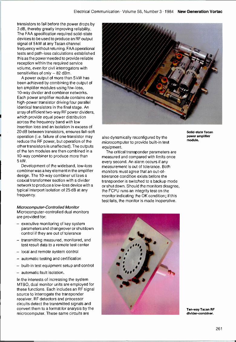
transistors to fail before the power drops by3 dB, thereby greatly improving reliability.The FAA specification required solid-statedevices to be used to produce an RF outputsignal of 5 kW at any Tacan channelfrequency without retuning. FAA operationaltests and path -loss calculations establishedthis as the power needed to provide reliablereception within the required servicevolume, even for civil interrogators withsensitivities of only - 82 dBm.
A power output of more than 5 kW hasbeen achieved by combining the output often amplifier modules using low -loss,10 -way divider and combiner networks.Each power amplifier module contains onehigh -power transistor driving four parallelidentical transistors in the final stage. Anarray of efficient two-way RF power dividers,which provide equal power distributionacross the frequency band with lowinsertion loss and an isolation in excess of20 dB between transistors, ensures fail -softoperation (i.e. failure of one transistor mayreduce the RF power, but operation of theother transistors is unaffected). The outputsof the ten modules are then combined in a10 -way combiner to produce more than5 kW.
Development of the wideband, low -losscombiner was a key element in the amplifierdesign. The 10 -way combiner utilizes acoaxial transformer section with a dividernetwork to produce a low -loss device with atypical interport isolation of 25 dB at anyfrequency.
Microcomputer -Controlled MonitorMicrocomputer -controlled dual monitorsare provided for:
- executive monitoring of key systemparameters and changeover or shutdowncontrol if they are out of tolerance
- transmitting measured, monitored, andtest result data to a remote test center
local and remote system control
- automatic testing and certification
built-in test equipment setup and control
- automatic fault isolation.
In the interests of increasing the systemMTBO, dual monitor units are employed forthese functions. Each includes an RF signalsource to interrogate the transponderreceiver. RF detectors and processorcircuits detect the transmitted signals andconvert them to a format for analysis by themicrocomputer. These same circuits are
also dynamically reconfigured by themicrocomputer to provide built-in testequipment.
The critical transponder parameters aremeasured and compared with limits onceevery second. An alarm occurs if anymeasurement is out of tolerance. Bothmonitors must agree that an out -of -tolerance condition exists before thetransponder is switched to a backup modeor shut down. Should the monitors disagree,the FCPU runs an integrity test on themonitor indicating the OK condition; if thistest fails, the monitor is made inoperative.
Solid-state Tacanpower amplifiermodule.
Ten -way Tacan RFdivider -combiner.
261
New Generation Vortac Electrical Communication Volume 58, Number 3 1984
Additionally, routine tests are performedon every critical monitor measurementcircuit. The monitor is automaticallyinactivated if any test fails. These fail-safefeatures make it safe to use this unit toperform other functions. For system control,one of the two monitors is designated as the"controller" which then interfaces with theFCPU for the transmission of all status andcontrol data, and controls transponderoperation. In the event of a fault in the"controller" monitor, the second monitorassumes control. Complete redundancy ofthe system control functions is therebyprovided with no additional hardware.
Conclusions
The basic goal of extending the useful life ofVortac systems beyond 1995 has been
achieved by the second -generation Tacanequipment. This completely integratedsystem is reliable and inexpensive toprocure and maintain, ensuring that initialreplacement costs will be paid back in five tosix years. Extensive use of microcomputertechnology means that the remotemaintenance and monitoring system can bereadily reconfigured to tailor a system to aparticular application, including those usersoperating only a few installations.
Arnold H. Lang was born in Hackensack, New Jersey,in 1932. He received his BS degree in 1954 and an MSdegree in 1960, both from Stevens Institute ofTechnology. He joined ITT Laboratories at Nutley, NewJersey, in 1954, initially working on missile guidancesystem design. Subsequently, he was responsible forsystem engineering of telemetry and missile test rangeinstrumentation. Since 1969, Mr Lang has beenresponsible for system engineering for DME and Tacansystems. He was the lead systems engineer for thesecond -generation Vortac programme.
262

Ground -Based Air Traffic ControlCommunication Equipment
ITT Aerospace/Optical Division producessingle channel ground -lo -air receivers andtransmitters which have become thestandard for air traffic control voicecommunication. New technology will leadto improved performance and capabilitiesto meet the needs of expanded air travel inthe future.
D. W. WaltersITT Aerospace/Optical Division,Fort Wayne, Indiana, United States ofAmerica
Introduction
The primary objective of air traffic control isto guarantee the safe and effective controlof aircraft. The timely arrival and departureof aircraft, movement of cargo, operationalcosts, and passenger and crew safety alldepend on effective air traffic control.Intelligible and reliable radio communicationbetween flight crew and air traffic controllers
VHF/UHFtransmitter.
is generally cited as the most criticalelement of such control.
Air Traffic Control CommunicationRequirements
An ATCCS (air traffic control communicationsystem) has to perform varied tasks tofacilitate orderly operation of an airport.
263
ATC Communication Equipment Electrical Communication Volume 58, Number 3 1984
Peak traffic loads at major airports reach oneaircraft per minute, demanding clear voicechannels and close teamwork between thepilot and controller. The importance ofpilot -controller coordination is illustrated bythe considerable exchange of informationthat must take place to handle a singlearrival or departure:
Assignment of heading, altitude, airspeed, communication frequency,configuration, and transponder code forefficient use of the air corridor and forseparation of air traffic within the vicinity.
- Reports of aircraft and passenger statusto controller.
- Reports of airport, weather, navaid, andtraffic status to aircraft.
- Changes and clearances withacknowledgments as each flightprogresses.
Direction of aircraft and vehicular groundtraffic within the airport.
Ground -Air Radio System Requirements
One proven voice communicationequipment offering the clear, dependableperformance required for safe air trafficcontrol operations is the VHF (very highfrequency) and UHF (ultra high frequency)carrier amplitude modulated equipmentdescribed in this article.
The VHF band between 118 and 136 MHzand the UHF band between 225 and400 MHz are allocated for voicecommunication between pilot and controllerfor departing and arriving aircraft. The VHFband is more frequently used because ofthe availability and lower cost of hardware.
Basic to system performance are theoperational characteristics of the individualcomponents which make up the system.Many of the performance criteria discussedhere for ground equipment also apply to theairborne system. The ATCCS consists ofthree basic units: receiver, transmitter, andantenna. The operational performance ofthese units is affected by the ground stationinstallation. A critical parameter is thetransmitter to receiver antenna isolation as itaffects transmitter to receiver colocationperformance. Availability of building landand the required number of communicationchannels also put constraints on the groundinstallation.
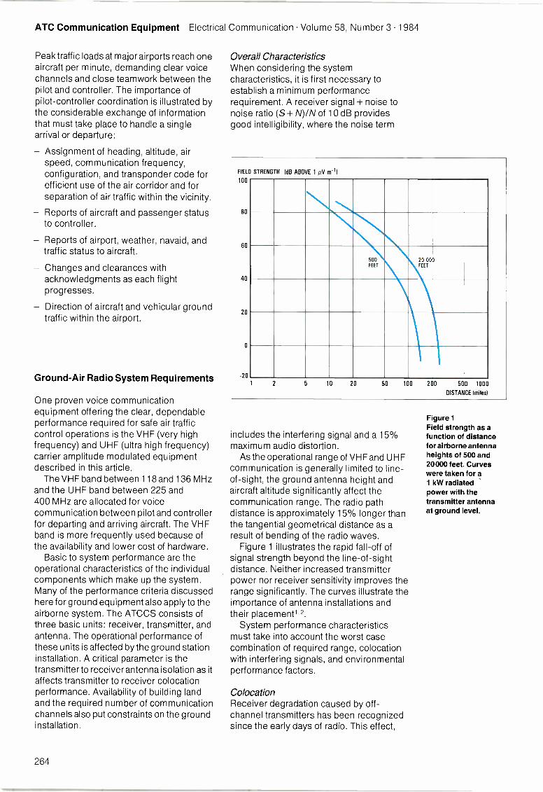
Overall CharacteristicsWhen considering the systemcharacteristics, it is first necessary toestablish a minimum performancerequirement. A receiver signal + noise tonoise ratio (S + N)/N of 10 dB providesgood intelligibility, where the noise term
FIELD
100
80
60
40
20
0
-20
STRENGTH (dB ABOVE 1 iV m-1)
500FEET
20 000FEET
1 2 5 10 20 50 100 200 500 1000
DISTANCE (miles)
includes the interfering signal and a 15%maximum audio distortion.
As the operational range of VHF and UHFcommunication is generally limited to line -
of -sight, the ground antenna height andaircraft altitude significantly affect thecommunication range. The radio pathdistance is approximately 15% longer thanthe tangential geometrical distance as aresult of bending of the radio waves.
Figure 1 illustrates the rapid fall -off ofsignal strength beyond the line -of -sightdistance. Neither increased transmitterpower nor receiver sensitivity improves therange significantly. The curves illustrate theimportance of antenna installations andtheir placement1,2.
System performance characteristicsmust take into account the worst casecombination of required range, colocationwith interfering signals, and environmentalperformance factors.
ColocationReceiver degradation caused by off -channel transmitters has been recognizedsince the early days of radio. This effect,
Figure 1Field strength as afunction of distancefor airborne antennaheights of 500 and20000 feet. Curveswere taken for a1 kW radiatedpower with thetransmitter antennaat ground level.
264
Electrical Communication Volume 58, Number 3 1984 ATC Communication Equipment
now known as crossmodulation distortion,has in many cases been made more severeby the use of solid-state technology inmodern communication equipment. At thesame time, the number of radio systemshas increased and user requirements oftendictate colocated operation. Receiverdegradation due to noise and off -channelsignals is often referred to asdesensitization.
General ConsiderationsWhen two or more radio antennas arelocated close together (colocated), there isa possibility of interference. Successfulcommunication system design requirescareful consideration of the many possiblesources of interference.
The variables involved in colocationdesign are the basic performance of theindividual radios, the minimum isolationbetween individual antennas in the antennasystem, and the improved performanceobtainable from such add-on devices asnarrowband tunable bandpass filters. Theuse of such filters in the antenna lead of theradio improves rejection of nearby signalsfor receivers or provides greater attenuationof spurious outputs from transmitters. Thefollowing paragraphs discuss the effectsthat must be taken into consideration whendesigning a colocated system.
Transmitter -TransmitterIntermodulation
When two transmitters radiatesimultaneously using closely spacedantennas, some signal from each is crosscoupled into the opposite antenna. Thetransmitted signal and the cross -coupledsignal interact in the nonlinearities of thetransmitter output stages and producemany spurious products. For the usualsystem, the most important is given by:
f, = -f2where
f, - frequency of the spurious product- frequency of transmitter 1
f2 - frequency of transmitter 2.
This is a third -order product, but in generalmany other products are generated givenby the general term:
fs = m nf2
where m and n are positive integers. Theorder is given by (m + n).
The third -order term represents the worstcase. The level of the third -orderintermodulation products for an ITT air trafficcontrol communication transmitter is atleast 40 dB below the generatingtransmitter's carrier level when the coupledcarrier from the adjacent transmitter is20 dB below the generating transmitter'scarrier. Furthermore, the value of 40 dBincreases by 1 dB for every dB increase inthe 20 dB value.
Receiver desensitization caused by front-end overload. High level signals entering areceiver from a colocated transmitter cancause receiver front-end circuits to saturateand reduce the receiver's sensitivity. ITT airtraffic control receivers will accept a-10 dBm signal without significantsaturation desensitization.
Receiver desensitization caused bytransmitter wideband noise and receiverlocal oscillator noise. These two effects aretreated together because they are, in mostcases, difficult if not impossible to observeseparately. They occur because both thesignal from a colocated transmitter and thereceiver local oscillator are not spectrallypure but exhibit components that extendfrom the desired carrier out to several tensor hundreds of MHz on either side. Noisefrom the transmitter enters the adjacentreceiver and masks the desired signal.Local oscillator noise is transferred to theintermediate frequency pass band by mixingwith strong off -channel signals impinging
on the receiver front end. This again masksthe desired signal. For ITT air traffic controlradios, a total transmitter -to -receiverisolation of 24 dB at UHF and 30 dB at VHFis required for satisfactory operation atfrequency separations of 7 MHz and 3 MHz,respectively.
Receiver crossmodulation. This occurswhen a strong off -channel signal interactswith the desired signal in the receiver front-
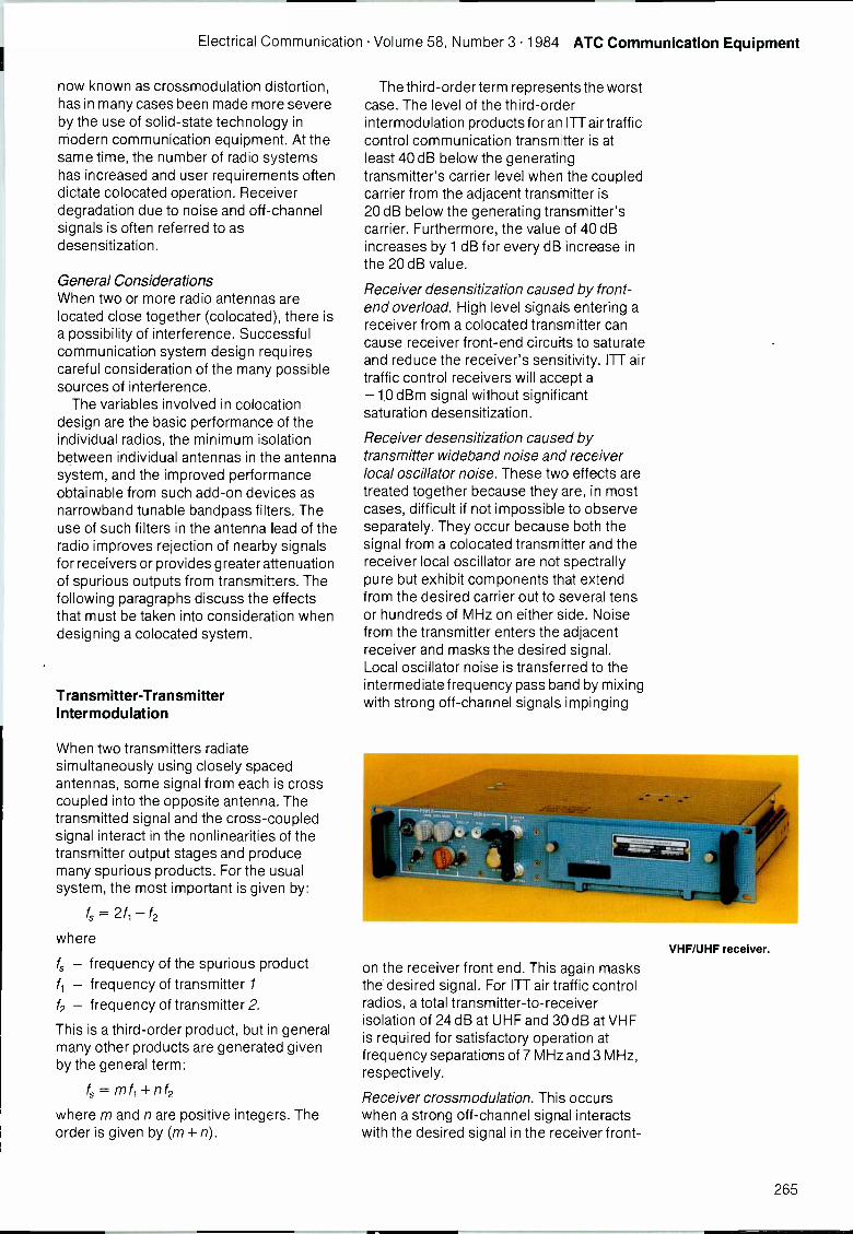
VHF/UHF receiver.
265
ATC Communication Equipment Electrical Communication Volume 58, Number 3 1984
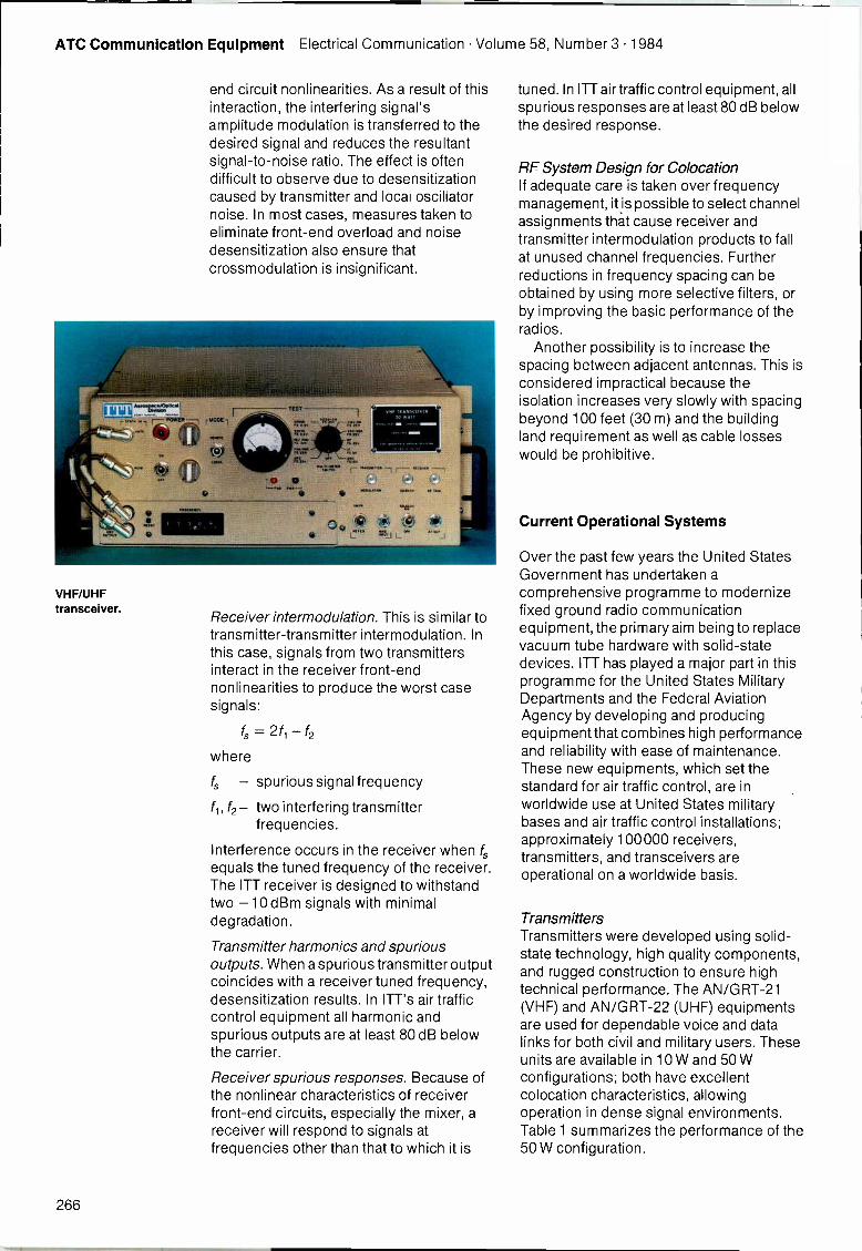
VHF/UHFtransceiver.
end circuit nonlinearities. As a result of thisinteraction, the interfering signal'samplitude modulation is transferred to thedesired signal and reduces the resultantsignal-to-noise ratio. The effect is oftendifficult to observe due to desensitizationcaused by transmitter and local oscillatornoise. In most cases, measures taken toeliminate front-end overload and noisedesensitization also ensure thatcrossmodulation is insignificant.
Receiver intermodulation. This is similar totransmitter -transmitter intermodulation. Inthis case, signals from two transmittersinteract in the receiver front-endnonlinearities to produce the worst casesignals:
f, = 2f, -f2
where
f, - spurious signal frequency
f2- two interfering transmitterfrequencies.
Interference occurs in the receiver when f,equals the tuned frequency of the receiver.The ITT receiver is designed to withstandtwo -10 dBm signals with minimaldegradation.
Transmitter harmonics and spuriousoutputs. When a spurious transmitter outputcoincides with a receiver tuned frequency,desensitization results. In ITT's air trafficcontrol equipment all harmonic andspurious outputs are at least 80 dB belowthe carrier.
Receiver spurious responses. Because ofthe nonlinear characteristics of receiverfront-end circuits, especially the mixer, areceiver will respond to signals atfrequencies other than that to which it is
tuned. In ITT air traffic control equipment, allspurious responses are at least 80 dB belowthe desired response.
RF System Design for ColocationIf adequate care is taken over frequencymanagement, it is possible to select channelassignments that cause receiver andtransmitter intermodulation products to fallat unused channel frequencies. Furtherreductions in frequency spacing can beobtained by using more selective filters, orby improving the basic performance of theradios.
Another possibility is to increase thespacing between adjacent antennas. This isconsidered impractical because theisolation increases very slowly with spacingbeyond 100 feet (30 m) and the buildingland requirement as well as cable losseswould be prohibitive.
Current Operational Systems
Over the past few years the United StatesGovernment has undertaken acomprehensive programme to modernizefixed ground radio communicationequipment, the primary aim being to replacevacuum tube hardware with solid-statedevices. ITT has played a major part in thisprogramme for the United States MilitaryDepartments and the Federal AviationAgency by developing and producingequipment that combines high performanceand reliability with ease of maintenance.These new equipments, which set thestandard for air traffic control, are inworldwide use at United States militarybases and air traffic control installations;approximately 100000 receivers,transmitters, and transceivers areoperational on a worldwide basis.
TransmittersTransmitters were developed using solid-state technology, high quality components,and rugged construction to ensure hightechnical performance. The AN/GRT-21(VHF) and AN/GRT-22 (UHF) equipmentsare used for dependable voice and datalinks for both civil and military users. Theseunits are available in 10 W and 50 Wconfigurations; both have excellentcolocation characteristics, allowingoperation in dense signal environments.Table 1 summarizes the performance of the50 W configuration.
266
Electrical Communication Volume 58, Number 3 1984 ATC Communication Equipment
ReceiversThe AN/GRR-23 (VHF) and AN/GRR-24(UHF) receivers incorporate solid-statedevices and high quality components; they
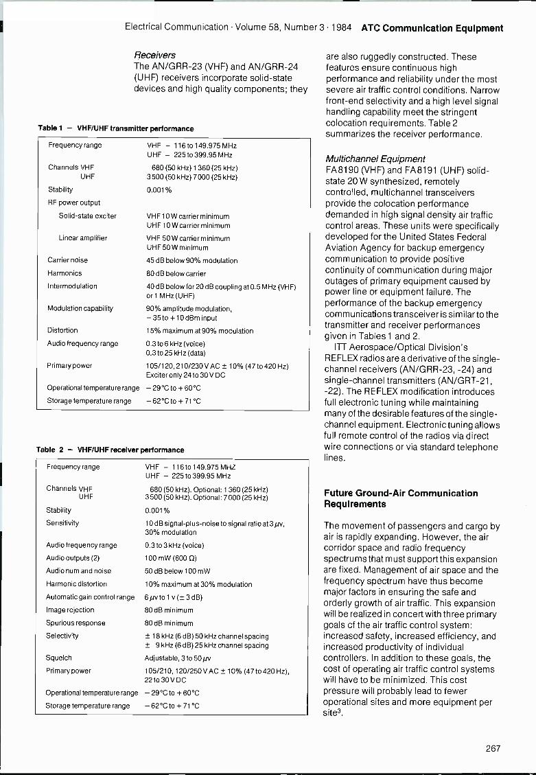
Table 1 - VHF/UHF transmitter performance
Frequency range
Channels VHFUHF
Stability
RF power output
Solid-state exciter
Linear amplifier
Carrier noise
Harmonics
Intermodulation
Modulation capability
Distortion
Audio frequency range
Primary power
Operational temperature range
Storage temperature range
VHF - 116 to 149.975 MHzUHF - 225 to 399.95 MHz
680 (50 kHz) 1 360 (25 kHz)3500 (50 kHz) 7000 (25 kHz)
0.001%
VHF 10 W carrier minimumUHF 10 W carrier minimum
VHF 50 W carrier minimumUHF 50 W minimum
45 dB below 90% modulation
80 dB below carrier
40 dB below for 20 dB coupling at 0.5 MHz (VHF)or 1 MHz (UHF)
90% amplitude modulation,- 35 to +10 dBm input
15% maximum at 90% modulation
0.3 to 6 kHz (voice)0.3 to 25 kHz (data)
105/120, 210/230 V AC ± 10% (47 to 420 Hz)Exciter only 24 to 30 V DC
- 29°C to + 60°C
- 62°C to + 71°C
Table 2 - VHF/UHF receiver performance
Frequency range VHF - 116 to 149.975 MHZUHF - 225 to 399.95 MHz
Channels VHF 680 (50 kHz). Optional: 1 360 (25 kHz)UHF 3500 (50 kHz). Optional: 7000 (25 kHz)
Stability 0.001%
Sensitivity 10 dB signal -plus -noise to signal ratio at 3 pv,30% modulation
Audio frequency range 0.3 to 3 kHz (voice)
Audio outputs (2) 100 mW (600 0)
Audio hum and noise 50 dB below 100 mW
Harmonic distortion 10% maximum at 30% modulation
Automatic gain control range 6 pv to 1 v (± 3 dB)
Image rejection 80 dB minimum
Spurious response 80 dB minimum
Selectivity ± 18 kHz (6 dB) 50 kHz channel spacing± 9 kHz (6 dB) 25 kHz channel spacing
Squelcn Adjustable, 3 to 50 pv
Primary power 105/210, 120/250 V AC ± 10% (47 to 420 Hz),22 to 30 V DC
Operational temperature range - 29°C to + 60°C
Storage temperature range - 62°C to + 71 °C
are also ruggedly constructed. Thesefeatures ensure continuous highperformance and reliability under the mostsevere air traffic control conditions. Narrowfront-end selectivity and a high level signalhandling capability meet the stringentcolocation requirements. Table 2summarizes the receiver performance.
Multichannel EquipmentFA 8190 (VHF) and FA 8191 (UHF) solid-state 20 W synthesized, remotelycontrolled, multichannel transceiversprovide the colocation performancedemanded in high signal density air trafficcontrol areas. These units were specificallydeveloped for the United States FederalAviation Agency for backup emergencycommunication to provide positivecontinuity of communication during majoroutages of primary equipment caused bypower line or equipment failure. Theperformance of the backup emergencycommunications transceiver is similar to thetransmitter and receiver performancesgiven in Tables 1 and 2.
ITT Aerosoace/Optical Division'sREFLEX radios are a derivative of the single -channel receivers (AN/GRR-23, -24) andsingle -channel transmitters (AN/GRT-21,-22). The RE FLEX modification introducesfull electronic tuning while maintainingmany of the desirable features of the single -channel equipment. Electronic tuning allowsfull remote control of the radios via directwire connections or via standard telephonelines.
Future Ground -Air CommunicationRequirements
The movement of passengers and cargo byair is rapidly expanding. However, the aircorridor space and radio frequencyspectrums that must support this expansionare fixed. Management of air space and thefrequency spectrum have thus becomemajor factors in ensuring the safe andorderly growth of air traffic. This expansionwill be realized in concert with three primarygoals of the air traffic control system:increased safety, increased efficiency, andincreased productivity of individualcontrollers. In addition to these goals, thecost of operating air traffic control systemswill have to be minimized. This costpressure will probably lead to feweroperational sites and more equipment persite3.
267
ATC Communication Equipment Electrical Communication Volume 58, Number 3 1984
As the system evolves, increasedautomation will affect ground -to -air radios.This will require computer interfaces in theradios along with improved colocationperformance because there will be moreequipment at fewer sites. The criticalquestion in designing the air traffic controlsystem of the future is not what can bedone, but what should be done. Exactly howmuch and what kind of automation shouldassist or replace the human controller.Once the system has been designed, thenthe concern becomes how it should beimplemented. All this means that new airtraffic control ground -to -air radios will needimproved control flexibility and improvedcolocation capabilities4.
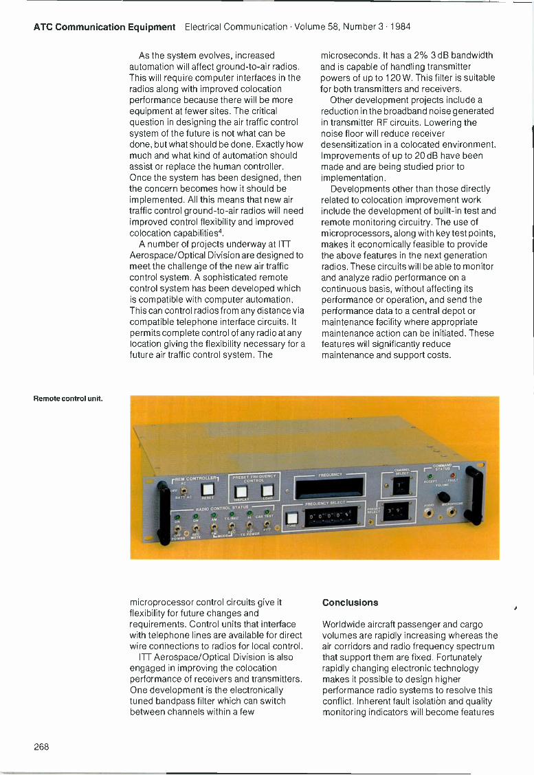
A number of projects underway at ITTAerospace/Optical Division are designed tomeet the challenge of the new air trafficcontrol system. A sophisticated remotecontrol system has been developed whichis compatible with computer automation.This can control radios from any distance viacompatible telephone interface circuits. Itpermits complete control of any radio at anylocation giving the flexibility necessary for afuture air traffic control system. The
Remote control unit.
microprocessor control circuits give itflexibility for future changes andrequirements. Control units that interfacewith telephone lines are available for directwire connections to radios for local control.
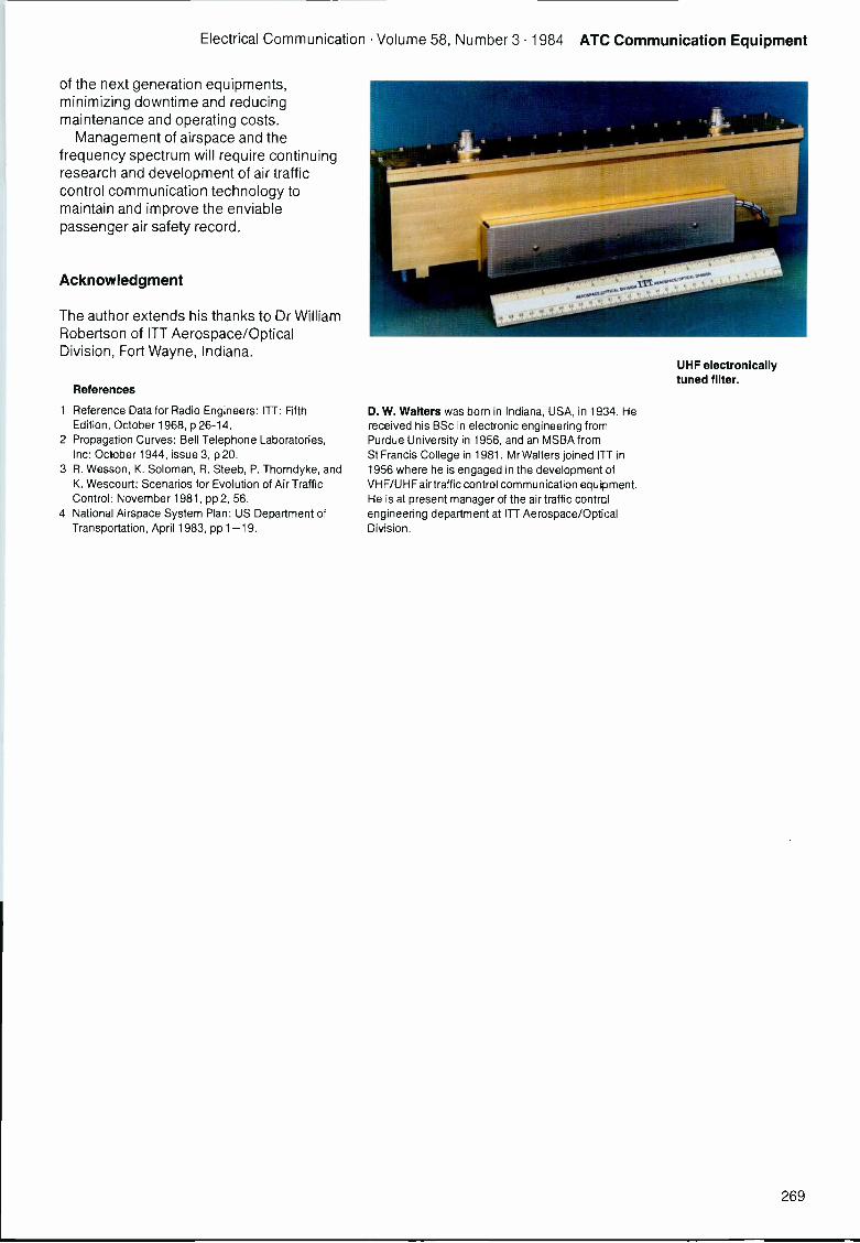
ITT Aerospace/Optical Division is alsoengaged in improving the colocationperformance of receivers and transmitters.One development is the electronicallytuned bandpass filter which can switchbetween channels within a few
microseconds. It has a 2% 3 dB bandwidthand is capable of handling transmitterpowers of up to 120 W. This filter is suitablefor both transmitters and receivers.
Other development projects include areduction in the broadband noise generatedin transmitter RF circuits. Lowering thenoise floor will reduce receiverdesensitization in a colocated environment.Improvements of up to 20 dB have beenmade and are being studied prior toimplementation.
Developments other than those directlyrelated to colocation improvement workinclude the development of built-in test andremote monitoring circuitry. The use ofmicroprocessors, along with key test points,makes it economically feasible to providethe above features in the next generationradios. These circuits will be able to monitorand analyze radio performance on acontinuous basis, without affecting itsperformance or operation, and send theperformance data to a central depot ormaintenance facility where appropriatemaintenance action can be initiated. Thesefeatures will significantly reducemaintenance and support costs.
Conclusions
Worldwide aircraft passenger and cargovolumes are rapidly increasing whereas theair corridors and radio frequency spectrumthat support them are fixed. Fortunatelyrapidly changing electronic technologymakes it possible to design higherperformance radio systems to resolve thisconflict. Inherent fault isolation and qualitymonitoring indicators will become features
268
Electrical Communication Volume 58, Number 3 1984 ATC Communication Equipment
of the next generation equipments,minimizing downtime and reducingmaintenance and operating costs.
Management of airspace and thefrequency spectrum will require continuingresearch and development of air trafficcontrol communication technology tomaintain and improve the enviablepassenger air safety record.
Acknowledgment
The author extends his thanks to Dr WilliamRobertson of ITT Aerospace/OpticalDivision, Fort Wayne, Indiana.
References
1 Refererce Data for Radio Engineers: ITT: FifthEdition, October 1968, p 26-14.
2 Propagation Curves: Bell Telephone Laboratories,Inc: October 1944, issue 3, p 20.
3 R. Wesson, K. Soloman, R. Steeb, P. Thorndyke, andK. Wescourt: Scenarios for Evolution of Air TrafficControl: November 1981, pp 2, 56.
4 National Airspace System Plan: US Department ofTransportation, April 1983, pp 1-19.
D. W. Walters was born in Indiana, USA, in 1934. Hereceived his BSc in electronic engineering fromPurdue University in 1956, and an MSBA fromSt Francis College in 1981. Mr Walters joined ITT in/956 where he is engaged in the development ofVHF/UHF air traffic control communication equipment.He is at present manager of the air traffic controlengineering department at ITT Aerospace/OpticalDivision.
UHF electronicallytuned filter.
269
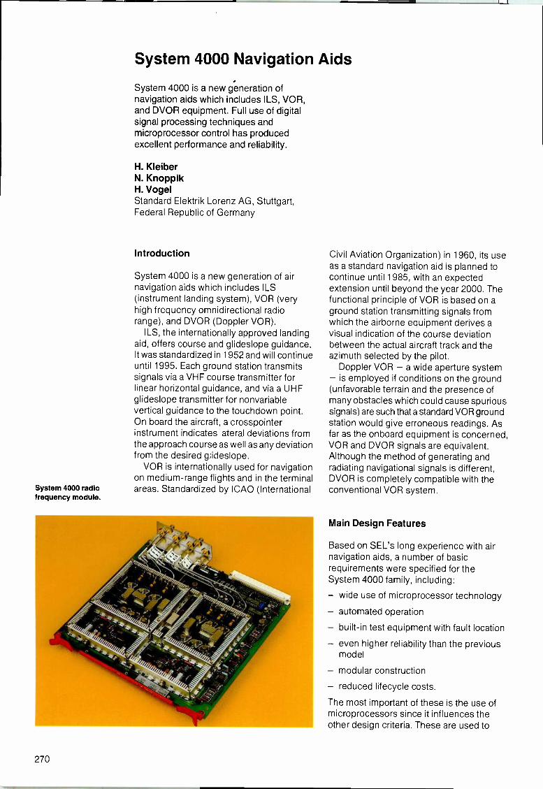
System 4000 radiofrequency module.
System 4000 Navigation Aids
System 4000 is a new generation ofnavigation aids which includes ILS, VOR,and DVOR equipment. Full use of digitalsignal processing techniques andmicroprocessor control has producedexcellent performance and reliability.
H. KleiberN. KnoppikH. VogelStandard Elektrik Lorenz AG, Stuttgart,Federal Republic of Germany
Introduction
System 4000 is a new generation of airnavigation aids which includes ILS(instrument landing system), VOR (veryhigh frequency omnidirectional radiorange), and DVOR (Doppler VOR).
ILS, the internationally approved landingaid, offers course and glideslope guidance.It was standardized in 1952 and will continueuntil 1995. Each ground station transmitssignals via a VHF course transmitter forlinear horizontal guidance, and via a UHFglideslope transmitter for nonvariablevertical guidance to the touchdown point.On board the aircraft, a crosspointerinstrument indicates lateral deviations fromthe approach course as well as any deviationfrom the desired glideslope.
VOR is internationally used for navigationon medium -range flights and in the terminalareas. Standardized by ICAO (International
Civil Aviation Organization) in 1960, its useas a standard navigation aid is planned tocontinue until 1985, with an expectedextension until beyond the year 2000. Thefunctional principle of VOR is based on aground station transmitting signals fromwhich the airborne equipment derives avisual indication of the course deviationbetween the actual aircraft track and theazimuth selected by the pilot.
Doppler VOR - a wide aperture system- is employed if conditions on the ground(unfavorable terrain and the presence ofmany obstacles which could cause spurioussignals) are such that a standard VOR groundstation would give erroneous readings. Asfar as the onboard equipment is concerned,VOR and DVOR signals are equivalent.Although the method of generating andradiating navigational signals is different,DVOR is completely compatible with theconventional VOR system.
Main Design Features
Based on SEL's long experience with airnavigation aids, a number of basicrequirements were specified for theSystem 4000 family, including:
- wide use of microprocessor technology
- automated operation
built-in test equipment with fault location
- even higher reliability than the previousmodel
modular construction
- reduced lifecycle costs.
The most important of these is the use ofmicroprocessors since it influences theother design criteria. These are used to
270
Electrical Communication Volume 58, Number 3 1984 System 4000 Navaids
Figure 1Signal generationconcept forSystem 4000.DiA - digital/analog
Table 1 - Main parameters of modern navigation aids
Specific parameters VORDoppler
VORILS
localizerILS
glideslopeRange of parameters
Radio frequency range (MHz) 108 to 117.975 108 to 112 328.6 to 335.4 108 to 118 and 325 to 340
Carrier power (WI 25 to 100 20 to 25 10to 15 25 to 100
Modulation(Hz)
frequencies
9960 30 90.150
30 to 99601020 1020 -300 to 3000 (300 to 3000) -
Navigationsignals %
ModulationIdentity %
depths
Voice %
30 2 x 20 2 x 40
5 to 8510 5 to 15 -
20 to 30 (20 to 30) -Modulation sum (carrier) % 60 to 70
45 to 55(65 to 85)
80
Input
Monitoring Level
Phase
RF RFField strengths
Modulation signal levels
Bearing
30 Hz, 9960 Hz (1020 Hz) RF, 90 Hz, 150 Hz
Reference/variable -control equipment functions, therebysimplifying and automating operation andmaintenance, and to generate all sinusoidalmodulation signals and control theamplitudes and phases of the RF (radiofrequency) signals. By using digitaltechnology, analog circuits with their criticaladjustments have been elominated, with aconsequent improvement in the quality andlong-term stability of the radiated signals.
System 4000 Concept
The main components of the ILS and VORsystems are the antenna system and dual
MODULATORADDRESS COUNTER
CLOCK
[UNMODULATED RF
ADORES:
VOLTA3EVn
IIfrimmi
READ-ONLY MEMORYSINE TABLE
I SINEDATA
0/A CONVERTER
NEVOLTAGE
RF OUTPUT
0 1 2 3 4 5 6 TIME to
transmitters, monitors, and power supplies.The standard signals for VHF/UHFnavigation systems are summarized inTable 1.
Signal quality is particularly significant forthe ground error component of systemaccuracy. Signal quality depends on severalparameters:
phase and frequency stability of themodulation frequencies
- stability of the carrier and sidebandamplitudes
phase and frequency stability of the RFsignal
distortion of the modulation waveforms
- stability of the depth of modulation.
The use of digital components, such asmicroprocessors and memory and analog/digital converters, simplifies partitioning ofthe hardware and software into modules.
Signal Generation Concept
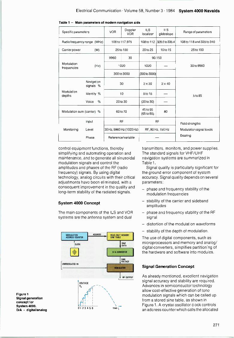
As already mentioned, excellent navigationsignal accuracy and stability are required.Advances in semiconductor technologyallow cost-effective generation of tonemodulation signals which can be called upfrom a stored sine table, as shown inFigure 1. A crystal oscillator clock controlsan address counter which calls the allocated
271
System 4000 Navaids Electrical Communication Volume 58, Number 3 1984
KEYBOARD
and DISPLAY
PROCESSOR
MONITOR
MEMORY FORAMPLITUDEENVELOPE
MODULATIONADDRESSCOUNTER
MEMORYFOR PHASE F
0/ACONVERTER
0/ACONVERTER
Figure 2Concept of System 4000transmitter showinghow the sidebandsignal is generatedusing digitaltechniques.
Figure 3Monitoring concept forthe Sytem 4000family of navigationaids.
A/DCONVERTER
EXCITER
ANTENNA
CONTROLCOUPLER
amplitude value from read-only memory.The amplitude values, presented in binaryform, are converted into analog form toproduce a sine shaped voltage for envelopemodulation of the RF signal. Using such anarrangement the tone frequency can beselected by changing the clock frequency.
To minimize the roughness of thestepped sine waves, a sufficient number ofstored amplitude values and a high enoughamplitude resolution are needed. For ILS,1024 addresses are required for a 30 Hzsine half -period, with 10 -bit resolution ofamplitude.
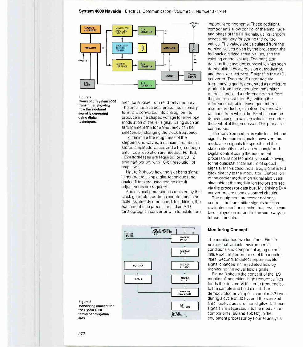
Figure 2 shows how the sideband signalis generated using digital techniques; noanalog filters are used and no circuitadjustments are required'.
Audio signal generation is realized by theclock generator, address counter, and sinetable, as already mentioned. In addition, theequipment data processor and an A/D(analog/digital) converter with translator are
[SWITCHCONTROL
MONITOR SENSORS(INTERNAL, INTEGRAL,FIELD)
OSCILLATOR
DIVIDER
PIN -0100ESWITCH
BANDPASSFILTER
PRECISIONDETECTOR
ALIASINGFILTER
SAMPLE ANDHOLD CIRCUIT
AIDCONVERTER
DATA TOPROCESSOR
important components. These additionalcomponents allow control of the amplitudeand phase of the RF signals, using randomaccess memory for storing the controlvalues. The values are calculated from thenominal values given by the processor, thefed back digitized actual values, and theexisting control values. The translatordelivers the envelope curve which has beendemodulated by a precision demodulator,and the so-called zero IF signal to the A/Dconverter. The zero IF (intermediatefrequency) signal is generated as a mixtureproduct from the decoupled transmitteroutput signal and a reference output fromthe control oscillator. By shifting thereference output in phase quadrature amixture product u, sin cP and us cos 0 isobtained from which the RF phase can bederived using an arc -tan calculation underthe control of the processor. This process iscontinuous.
The above procedure is valid for sidebandsignals. For carrier signals, however, tonemodulation signals for speech and thestation identity must also be considered.Digital control using the equipmentprocessor is not technically feasible owingto the quasistatistical nature of speechsignals. In this case the analog signal is fedback directly to the modulator. Generationof the carrier modulation signal also usessine tables; the modulation factors are setvia the processor data bus. Multiplying D/Aconverters are used as control circuits.
The equipment processor not onlycontrols the transmitter signals but alsoevaluates monitor signals; thus results canbe displayed on request in the same way astransmitter data.
Monitoring Concept
The monitor has two functions. First toensure that variable environmentalconditions and component aging do notinfluence the performance of the monitoritself. Second, to detect impermissiblesignal changes in the radiated field bymonitoring the actual field signals.
Figure 3 shows the concept of the ILSmonitor. A noncritical high frequency filterfeeds the desired VHF carrier frequenciesto the sample and hold circuit. Thedemodulated envelope is sampled 32 timesduring a cycle of 30 Hz, and the sampledamplitude values are then digitized. Thesesignals are separated into the modulationcomponents (90 and 150 Hz) in theequipment processor by Fourier analysis
272
Electrical Communication Volume 58, Number 3 1984 System 4000 Navaids
and the signal parameters (modulationdepth, RF level, etc) are calculated andcompared to programmable alarm limits.The critical 90 and 150 Hz filters which werepreviously necessary have been eliminated.The VOR monitor also utilizes discreetFourier transformation of 32 samplingvalues during a 30 Hz period; in addition, anFM (frequency modulation) discriminator isprovided for the reference signal2.
Equipment Design
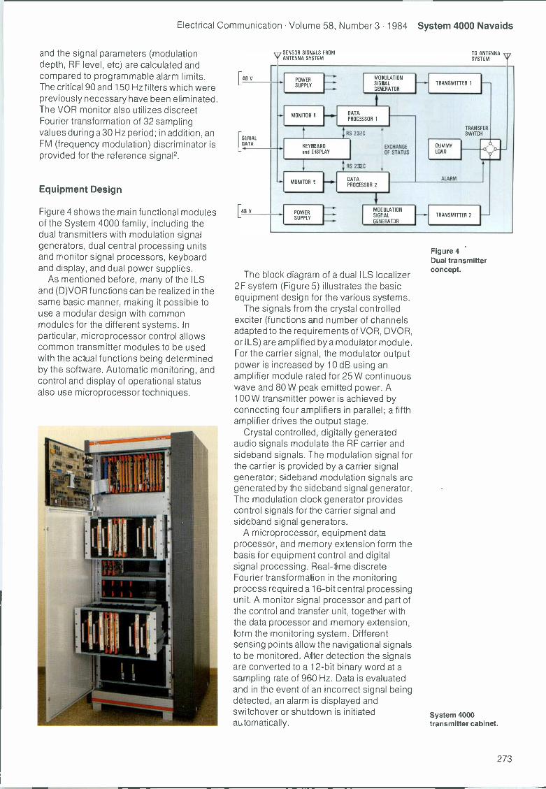
Figure 4 shows the main functional modulesof the System 4000 family, including thedual transmitters with modulation signalgenerators, dual central processing unitsand monitor signal processors, keyboardand display, and dual power supplies.
As mentioned before, many of the ILSand (D)VOR functions can be realized in thesame basic manner, making it possible touse a modular design with commonmodules for the different systems. Inparticular, microprocessor control allowscommon transmitter modules to be usedwith the actual functions being determinedby the software. Automatic monitoring, andcontrol and display of operational statusalso use microprocessor techniques.
[48 V
[SERIALDATA
[48 V
QSENSOR SIGNALS FROMv ANTENNA SYSTEM
TO ANTENNASYSTEM
POWERSUPPLY
.FIN.MONITOR
1
MODULATIONSIGIALGEPERATOR
fDATAPROCESSOR 1
RS 232C
KEYEE:IARO
and I ISPLAY
EIP^MONITOR
POWERSUPPLY
RS 232C
EXCHANGEOF STATUS
DATAPROCESSOR 2
TRANSMITTER 1 1-
DUMMYLOAD
TRANSFERSWITCH
ALARM
a
MOE ULATIONSIGH AL
GENERATOR
TRANSMITTER 2
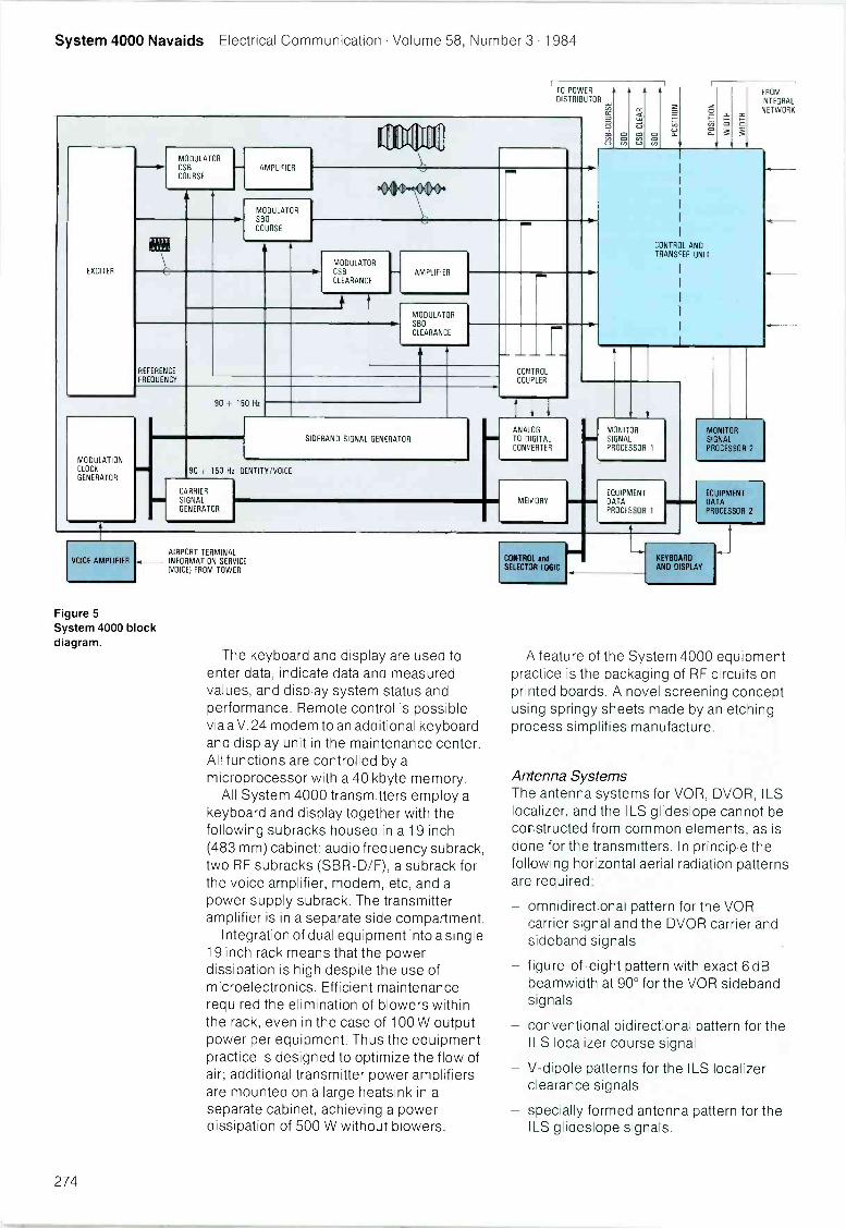
The blockblock diagram of a dual ILS localizer2F system (Figure 5) illustrates the basicequipment design for the various systems.
The signals from the crystal controlledexciter (functions and number of channelsadapted to the requ rements of VOR, DVOR,or ILS) are amplified by a modulator module.Fcr the carrier signal, the modulator outputpower is increased by 10 dB using anamplifier module rated for 25 W continuouswave and 80 W peak emitted power A100 W transmitter power is achieved byconnecting four amplifiers in parallel; a fifthamplifier drives the output stage.
Crystal controlled, digitally generatedaudio signals modulate the RF carrier andsideband signals. The modulation signal forthe carrier is provided by a carrier signalgenerator; sideband modulation signals aregenerated by the sideband signal generator.The modulation clock generator providescontrol signals for the carrier signal andsideband signal generators.
A microprocessor, equipment dataprocessor, and memory extension form thebasis for equipment control and digitalsignal processing. Real-time discreteFourier transformation in the monitoringprocess required a 16 -bit central processingunit. A monitor signal processor and part ofthe control and transfer unit, together withthe data processor and memory extension,form the monitoring system. Differentsensing points allow the navigational signalsto be monitored. Alter detection the signalsare converted to a 12 -bit binary word at asampling rate of 960 Hz. Data is evaluatedand in the event of an incorrect signal beingdetected, an alarm is displayed andswitchover or shutdown is initiatedautomatically.
Figure 4Dual transmitterconcept.
System 4000transmitter cabinet.
273
System 4000 Navaids Electrical Communication Volume 58, Number 3 1984
TO POWERDISTRIBUTOR
EXCITER
MODULATIONCLOCK
GENERATOR
MODULATORCSB
COURSE
REFERENCE
FREQUENCY
AMPLIFIER
wiMODULATORSBO
COURSE
MODULATORCSB
CLEARANCE
.111,111[ QP
AMPLIFIER
MODULATORSBO
CLEARANCE
90 150 Hz
SIDEBAND SIGNAL GENERATOR
90+ 150 Hz IDENTITY/VOICE
CARRIERSIGNALGENERATOR
CONTROLCOUPLER
ANA..OGTO DIGITALCONVERTER
MEMORY
OCO
OCO
SO
FROMFROMINTEGRALNETWORK
CONTROL ANDTRANSFER UNIT
MONITORSIGNAPROCESSOR 1
EQUIPMENTDATAPROCESSOR 1
VOICE AMPLIFIERAIRPORT TERMINAL
- INFORMATION SERVICE(VOICE) FROM TOWER
Figure 5System 4000 blockdiagram.
The keyboard and display are used toenter data, indicate data and measuredvalues, and display system status andperformance. Remote control is possiblevia a V.24 modem to an additional keyboardand display unit in the maintenance center.All functions are controlled by amicroprocessor with a 40 kbyte memory.
All System 4000 transmitters employ akeyboard and display together with thefollowing subracks housed in a 19 inch(483 mm) cabinet: audio frequency subrack,two RF subracks (SBR-D/F), a subrack forthe voice amplifier, modem, etc, and apower supply subrack. The transmitteramplifier is in a separate side compartment.
Integration of dual equipment into a single19 inch rack means that the powerdissipation is high despite the use ofmicroelectronics. Efficient maintenancerequired the elimination of blowers withinthe rack, even in the case of 100 W outputpower per equipment. Thus the equipmentpractice is designed to optimize the flow ofair; additional transmitter power amplifiersare mounted on a large heatsink in aseparate cabinet, achieving a powerdissipation of 500 W without blowers.
CONTROL andSELECTJR LOGIC
MONITORSIGNALPROCESSOR 2
EQUIPMENTDATAPROCESSOR 2
KEYBOARD
AND DISPLAY
A feature of the System 4000 equipmentpractice is the packaging of RF circuits onprinted boards. A novel screening conceptusing springy sheets made by an etchingprocess simplifies manufacture.
Antenna SystemsThe antenna systems for VOR, DVOR, ILSlocalizer, and the ILS glideslope cannot beconstructed from common elements, as isdone for the transmitters. In principle thefollowing horizontal aerial radiation patternsare required:
- omnidirectional pattern for the VORcarrier signal and the DVOR carrier andsideband signals
- iigure-of-eight pattern with exact 6 dBbeamwidth at 90° for the VOR sidebandsignals
- conventional bidirectional pattern for theILS localizer course signal
V -dipole patterns for the ILS localizerclearance signals
specially formed antenna pattern for theILS glideslope signals.
274
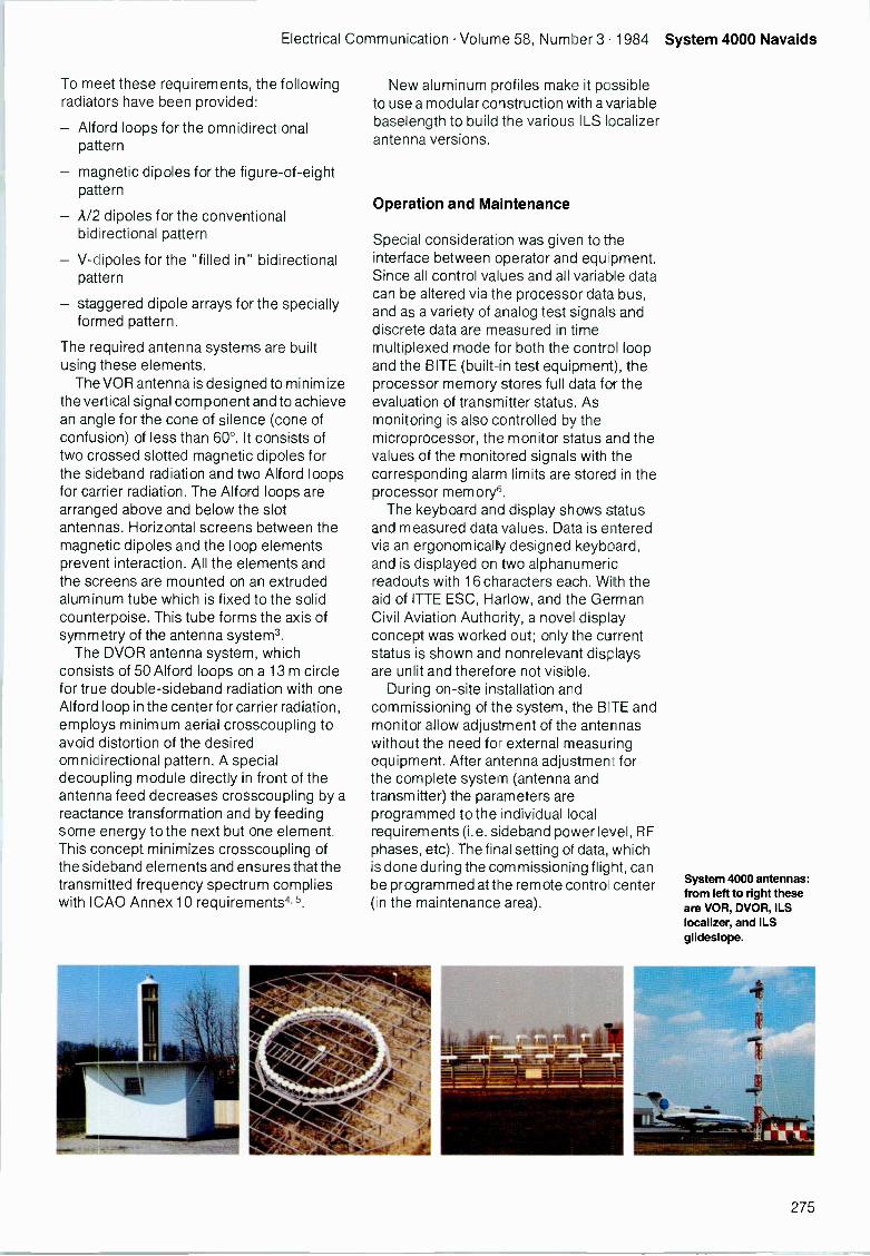
Electrical Communication Volume 58, Number 3 1984 System 4000 Navaids
To meet these requirements, the followingradiators have been provided:
- Alford loops for the omnidirectionalpattern
- magnetic dipoles for the figure -of -eightpattern
- A/2 dipoles for the conventionalbidirectional pattern
- V -dipoles for the "filled in" bidirectionalpattern
- staggered dipole arrays for the speciallyformed pattern.
The required antenna systems are builtusing these elements.
The VOR antenna is designed to minimizethe vertical signal component and to achievean angle for the cone of silence (cone ofconfusion) of less than 60°. It consists oftwo crossed slotted magnetic dipoles forthe sideband radiation and two Alford loopsfor carrier radiation. The Alford loops arearranged above and below the slotantennas. Horizontal screens between themagnetic dipoles and the loop elementsprevent interaction. All the elements andthe screens are mounted on an extrudedaluminum tube which is fixed to the solidcounterpoise. This tube forms the axis ofsymmetry of the antenna system3.
The DVOR antenna system, whichconsists of 50 Alford loops on a 13 m circlefor true double-sideband radiation with oneAlford loop in the center for carrier radiation,employs minimum aerial crosscoupling toavoid distortion of the desiredomnidirectional pattern. A specialdecoupling module directly in front of theantenna feed decreases crosscoupling by areactance transformation and by feedingsome energy to the next but one element.This concept minimizes crosscoupling ofthe sideband elements and ensures that thetransmitted frequency spectrum complieswith ICAO Annex 10 requirements4,5.
New aluminum profiles make it possibleto use a modular construction with a variablebaselength to build the various ILS localizerantenna versions.
Operation and Maintenance
Special consideration was given to theinterface between operator and equopment.Since all control values and all variable datacan be altered via the processor data bus,and as a variety of analog test signals anddiscrete data are measured in timemultiplexed mode for both the control loopand the BITE (built-in test equipment), theprocessor memory stores full data for theevaluation of transmitter status. Asmonitoring is also controlled by themicroprocessor, the monitor status and thevalues of the monitored signals with thecarresponding alarm limits are stored in theprocessor memory6.
The keyboard and display shows statusand measured data values. Data is enteredvia an ergonomically designed keyboard,and is displayed on two alphanumericreadouts with 16 characters each. With theaid of ITTE ESC, Harlow, and the GermanCivil Aviation Authority, a novel displayconcept was worked out; only the currentstatus is shown and nonrelevant displaysare unlit and therefore not visible.
During on -site installation andcommissioning of the system, the BITE andmonitor allow adjustment of the antennaswithout the need for external measuringequipment. After antenna adjustment forthe complete system (antenna andtransmitter) the parameters areprogrammed to the individual localrequirements (i.e. sideband power level, RFphases, etc). The final setting of data, whichis done during the commissioning flight, canbe programmed at the remote contrail center(in the maintenance area).
System 4000 antennas:from left to right theseare VOR. DVOR, ILSlocalizer, and ILSglideslope.
275
System 4000 Navaids Electrical Communication Volume 58, Number 3 1984
As already mentioned, data transfer fromthe local keyboard and display to the remoteone is via an RS232C serial interface, usingfrequency shift keying with a 2 -wire line.From one equipment in the remote centralsite up to seven facilities can be interrogatedin time multiplex mode. In the event of analarm, the main alarm status signal in thecentral maintenance station is setautomatically. At the local site, theequipment data processor checks the BITEsignals continuously; in the event of anequipment fault the BITE routine detects thefaulty module. Maintenance personnelobtain the information by pushing thecorresponding keys in the operational datafield of the keyboard and display.Replacement of the detected faulty moduleby a spare module can be carried out withoutthe need to make measurements on site.No adjustments are required after changingmodules. Automatic dial -up service ispossible for VOR/DVOR using additionaloptional hardware. The concept ofequipment control by microprocessorreduces commissioning and maintenanceto a minimum.
Conclusions
The new generation System 4000navigational aids have been developed inclose cooperation with West Germany'sFederal Authority for Flight Safety with thesupport of the Federal Ministry of Researchand Technology. Modern technologycombined with high reliability and systemintegrity ensure that this new navaids familywill serve aviation till the end of the century.
References
1 H. Kleiber, H. Idler, and J. Stammelbach: ATransmitter for a Navigation System: PatentP 30 29 169.
2 S. Bloch, K. Bressler, H. Idler, and H. Kleiber: Facilityfor Monitoring the Level of a Radio Frequency Signal:Patent Application P 31 03118.8.
3 H. Wiirth and G. Greying: Antenna for a VHFOmnidirectional Range: Patent Application.
4 W. Kautz: Doppler VHF Omnidirectional Range:Patent Application P 31 08 980.
5 W. Kautz: Doppler VHF Omnidirectional Range:Patent Application P 33 09 784.4.
6 H. Vogel and H. Kleiber: MikroprozessorgesteuerteFunknavigationshilfen fur die Zivilluftfahrt.
Herbert Kleiber was born in Neutitschein, CSR, in1942. He attended Gesamthochschule Kassel andgraduated as a Dipl-Ing. He joined SEL in 1966 as anR & D engineer and worked on the development ofnavigational systems. Since 1979 he has been projectengineer for Navaids System 4000 and is responsible forcivil navigation ground equipment.
Norbert Knoppik was born in 1944 in Henzegrund,Lower Silesia. He graduated in telecommunicationengineering from the Technische Hochschule, Aachen.He holds a Dipl-Ing and received a Dr-lng for research inmillimeter -wave technology. Dr Knoppik joined SEL in1982 and is the RD & E manager for avionics, navigation,and surveillance. He is a member of VDE/NTG.
Horst Vogel was born in Stuttgart, Germany, in 1936.He studied communications engineering in Esslingenand graduated as a Dipl-Ing. He joined SEL in 1962 andwas active in the fields of large computers, Tacan, andcivil navigation. In 1967 he became developmentmanagerfor avionics and then in 1976 he was appointedchief engineer for civil navigation, responsible for alldevelopment activities in this field. In 1983 he took overas program manager in which capacity he superviseslarge scale SEL projects.
276
Figure 1Block diagram of adual equipmentNovaids System 4000.AF - audio
frequencyFSK - frequency shift
keying.
SERIAL
FOK DATATO TOWER
Hardware and Software Structuresfor System 4000 Navigation Aids
The application of digital techniques tocontrolling and monitoring the System 4000family of navigation aids enables ILS, VOR,and DVOR functions to be realized usingcommon hardware and software modules.
F. LimbachK. PahligStandard Elektrik Lorenz AG, Stuttgart,Federal Republic of Germany
Introduction
A standard navigation system such as VOR(very high frequency omnidirectionalrange), DVOR (Doppler VOR), or ILS(instrument landing system) consists ofdual transmitters, antenna systems, anddual monitors. Figure 1 shows theconfiguration for the System 4000 family ofnavigation aids, including the control andmonitoring functions.
In System 4000, the control andmonitoring functions are clearly separatedfrom each other (Figure 2). While themonitor bus works continuously duringnormal system operation, the transmittercontrol bus need not be used if thecorresponding transmitter is switched off.The transmitter control bus is used to carryout all I/O (input/output) operationsnecessary to initialize the transmitter controllogic and transfer the modulation signalwaveforms. It is also used for digitaladjustment of sideband signal curves andRF (radio frequency) sideband phases. Theprocessor has direct access to transmitterparameters such as carrier power,modulation depth, built-in test equipment
CENTRALPROCESSINGUNIT 1
:RS232C
KEYBOARD andDISPLAYREMOTE CONTROL
:RS232C
=STATUSEXCHANGE
CENTRALPROCESSINGUNIT 2
TRANSMITTER 1
RI AND AFSECTION
MONITORSIGNALPROCESSOR 1
MONITORCHANNHTCONIHUI
MONITORSIGNALPROCESSOR 2
TRANSMITTER 2RF AND AFSECTION
CONTROLAND TRANSFERUNIT
TRANSMITANTENNA
DUMMYLOADS
MONITORSENSORSIGNALS
signals, and some other control functions,but has no direct access to the independentMSG (modulation signal generator) bus.The memories of the MSG, which containthe modulation envelope curves, theparameters to control RF sideband phases,and the station identity morse code, can beread or written only via an interface. Datatransfers are carried out using handshakeprocedures with the ECPU (equipmentcentral processing unit) as the activepartner.
Modulation Signal Generator
The MSG and its bus system appears to theECPU as an I/O subsystem decoupled fromthe central processor and workingindependently (Figure 3). Amplitude andphase memories are loaded from the CPUwhen the transmitter is switched on, orduring monitoring. Normally the operatorselects test mode, adjusts the equipmentfor correct operation, and then switches thetest mode off to allow the monitors to takecontrol.
The MSG random access memory iswritten with defined values duringtransmitter initialization. The bus controlunit of the MSG cyclically reads thesevalues and transfers them to D/A (digital/analog) converter registers. Thus, in thecase of an ILS station the following fivequasiparallel signals are generated:
- K90*sin (2*rr*90*t) + K150*sin (2*rr*150*t) for amplitude modulation of thecourse and clearance carrier transmitter
- Ki* (sin (2*n*90*t) - sin (2*rr*150*t))for envelope modulation of the coursesideband transmitter
- appropriate RF phase control voltage
277
System 4000 Hardware and Software Electrical Communication Volume 58, Number 3 1984
MSP
I 0 PORTSFOR
ronNIITRINr.
4MONITORBUS SYSTEM
ECPU
PROCESSOR
USARTINTERRUPTCONTROI
RAMBAT IERYBUFFERED
IMER
960 HzHARDWAREINTERRUPT
PROM
BUS
DECOUPLINGGATES
PARALLEL0
TRANSMITTERBUS SYSTEM
SERIAL DATA LINKTO KEYBOARD
- K2* (sin (2*n*90*t) - sin (2*n*150*t))for envelope modulation of the clearancesideband transmitter.
- appropriate RF phase control voltage.
Distortion of the generated carrier signalscaused by modulation can only beeliminated by analog feedback loopsbecause of the additional modulation withvoice and identity tones. However, thesideband envelopes and RF phases can becorrected by digitally controlled loops. TheCPU only has to undertake this additionalprocessing during the adjustmentprocedures in the test mode; programmodules are provided that facilitateadjustment of the sideband levels and RFphases. In the monitoring mode, however,the main task is evaluation of the monitorsensor signals. In this mode, the processoruses otherwise inactive periods to servicethe keyboard. Furthermore, it adjusts thesideband envelope curves and RF phasevoltages and collects data from the built-intest equipment. To accomplish this, data inthe MSG memory is manipulated via theinterface or corresponding actions aretriggered by the MSG.
The bus control logic of the MSG providesthe timing for up to eight quasiparallel analogsignals with a bus access rate of 61.44 kHz,reads and transfers the station morse code,and controls data transfer to and from theECPU. These tasks require very fast controllogic which cannot be realized usingstandard microprocessors. However, thecontrol functions are relatively simple,allowing the MSG control part to be builtwith discrete logic components.
STATUS EXCHANGEWITH SECONDCENTRAL PROCESSING UNIT
OUTPUT SIGNALSTO TRANSMITTER
MSG
MSGSUBSYSTEM
PARALLELI 0
AjD +BITE
PARALLELI/O
TRANSMITTER CONTROLAND BITE SIGNALS
The keyboard incorporates its ownprocessor, primarily to serve the interfacethat connects the system to its environment.
Hardware Components for Monitoring
The processor controls the monitoringcomponents directly via the monitor bus.Parallel I/O ports are used to control the RFmultiplexers that select the monitor sensorsignals. The demodulated monitor signalsare converted into digital form and read bythe processor for signal analysis. Theresults relating to equipment status and theself tests are exchanged by the ECPUs overthe status exchange bus.
Figure 2Simplified blockdiagram of theSystem 4000 controland monitoringequipment.A/D - analog to
digitalBITE - built-in test
equipmentMSP - monitor
signalprocessor
USART - universalsynchronous -asynchronousreceiver -transmitter.
Figure 3Block diagram of theMSG subsystem.MSG bus operationsare independent ofECPU activities.RAM - random
accessmemory.
OUTPUT SIGNALSTO TRANSMITTER
IDENTITYGENERATORAND CONTROL
MSG
RAM SE :TIONFOR MO JULATIONWAVEFORMS
MSG BUS
SIGNALGENERATION
D/A CONVERTERS
REGISTER SECTION
U MSG INTERFACE
ADDRESS, DATA andHANDSHAKE SIGNALS
PARALLELI/O PORTS
DIRECT
CONTROLFUNCTIONS
MSG BUSAND INTERFACECONTROL LOGIC
BITE MSG
PARALLELI'0 PORTS
TRANSMITTER BUS SYSTEM
278
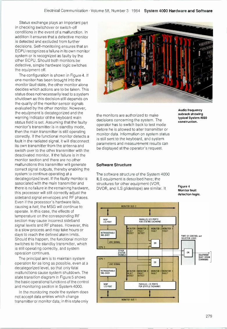
Electrical Communication Volume 58, Number 3 1984 System 4000 Hardware and Software
Status exchange plays an important partin checking switchover or switch -offconditions in the event of a malfunction. Inaddition it ensures that a defective monitoris detected and excluded from furtherdecisions. Self -monitoring ensures that anECPU recognizes a failure in its own monitorsystem or is recognized as faulty by theother ECPU. Should both monitors bedefective, simple hardware logic switchesthe equipment off.
The configuration is shown in Figure 4. Ifone monitor has been brought into themonitor fault state, the other monitor alonedecides which actions are to be taken. Thisstatus does not necessarily lead to a systemshutdown as this decision still depends onthe quality of the monitor sensor signalsevaluated by the other monitor. However,the equipment is decategorized and thewarning indicator of the keyboard mainstatus field is set. Assuming that the faultymonitor's transmitter is in standby mode,then the main transmitter is still operatingcorrectly. If the functional monitor detects afault in the radiated signal, it will disconnectits own transmitter from the antenna andswitch over to the other transmitter with thedeactivated monitor. If the failure is in themonitor section and there are no othermalfunctions this transmitter will generatecorrect signal outputs, thereby enabling thesystem to continue operating at adecategorized level. If the faulty monitor isassociated with the main transmitter andthere is no failure in the remaining hardware,this processor will still correctly adjust thesideband signal envelopes and RF phases.Even if the processor's hardware fails,causing a halt, the MSG will continue tooperate. In this case, the effects oftemperature on the corresponding RFsection may cause incorrect sidebandsignal levels and RF phases. However, thisis a slow process and may take hours ordays to reach the defined alarm limits.Should this happen, the functional monitorswitches to the standby transmitter, whichis still operating correctly, and systemoperation continues.
The principal aim is to maintain systemoperation for as long as possible, even at adecategorized level, so that only fatalmalfunctions cause system shutdown. Thestate transition diagram in Figure 5 showsthe basic operational functions of the controland monitoring section in System 4000.
In the monitoring mode the system doesnot accept data entries which changetransmitter or monitor data; in this state only
the monitors are authorized to makedecisions concerning the system. Theoperator has to switch back to test modebefore he is allowed to alter transmitter ormonitor data. Information on system statusis still sent to the keyboard, and systemparameters and measurement results canbe displayed at the operator's request.
Software Structure
The software structure of the System 4000ILS equipment is described here; thestructures for other equipment (VOR,DVOR, and ILS glideslope) are similar. It
MONITOF BUS 2
3ETRIGGERABLENE -SHOT
ETU 2
LIVE SIGNAL
PARALLEL I/O PORT:FOR STATIS EXCHAt` GE
ME MICR 1FAJLTDETECT
MONITOR 2FAULTDETECT
MONITOR 2FAULT
OR
MONITOR 1FAULT
Audio frequencysubrack showingtypical System 4000construction.
Figure 4Monitor faultdetection logic.
PART OF CONTROL andSELECTOR LOGIC
OTHERSTALLSSIGNALS
EC'U 1
LIVE SIGNAL
TRIGGHABLENE l,HOT
MONITOR 1MONITOR 2FAJLT FAULTDETECT DETECT
OR
MONITOR 2FAULT
MONITOR 1
FAULT
PARALLEL 0 PORTSFOR STATL S EXCHAW E
MONITOF BUS 1
OR
EQUIPMENTSHUT DOWNCOMMAND
279
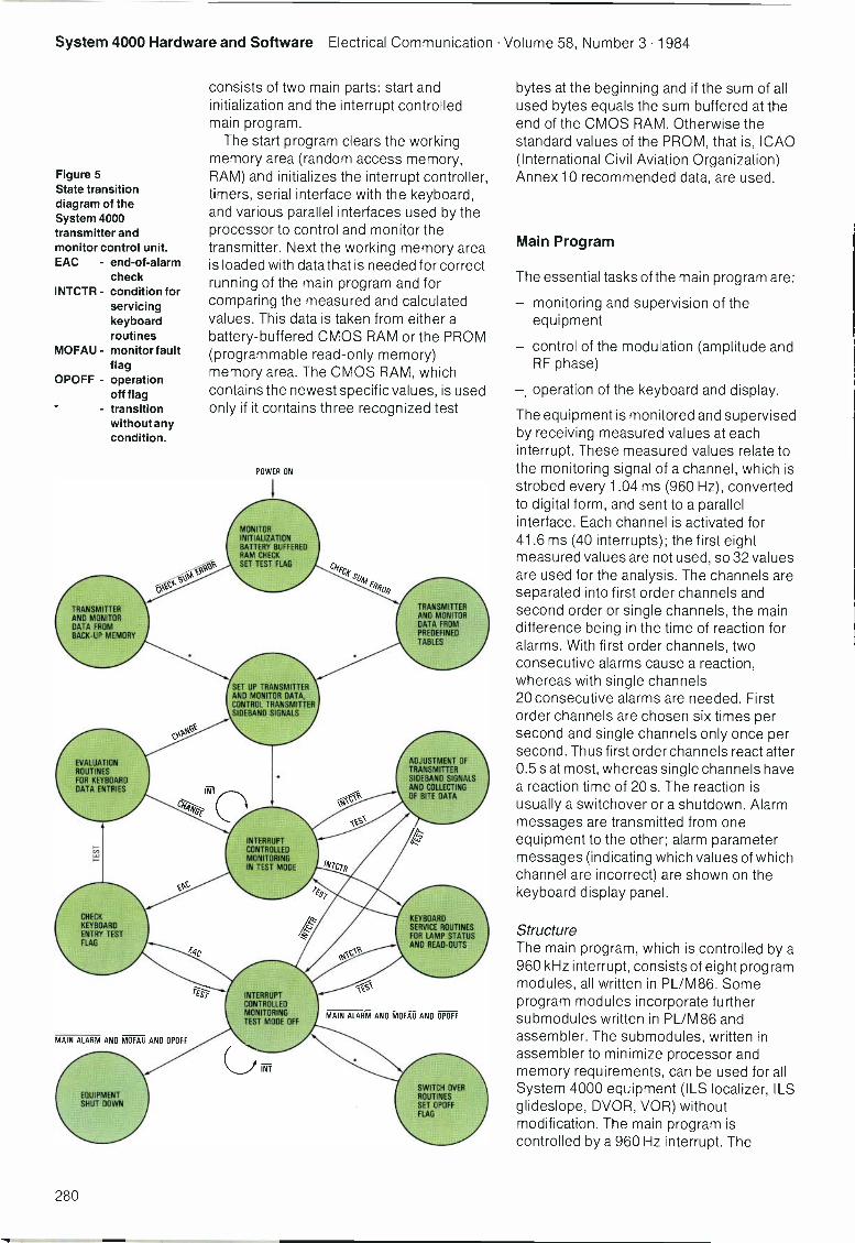
System 4000 Hardware and Software Electrical Communication Volume 58, Number 3 1984
Figure 5State transitiondiagram of theSystem 4000transmitter andmonitor control unit.EAC - end -of -alarm
checkINTCTR - condition for
servicingkeyboardroutines
MOFAU - monitor faultflag
OPOFF - operationoff flagtransitionwithout anycondition.
4t11/4CkEcl4-°
TRANSMITTER
DATA FROMBACK-UP MEMORY
EVALUATIONROUTINESFOR KEYBOARDDATA ENTRIES
CHECKKEYBOAROENTRY TESTFLAG
MAIN ALARM AND MOFAU AND OPOFF
EQUIPMENTSHUT DOWN
consists of two main parts: start andinitialization and the interrupt controlledmain program.
The start program clears the workingmemory area (random access memory,RAM) and initializes the interrupt controller,timers, serial interface with the keyboard,and various parallel interfaces used by theprocessor to control and monitor thetransmitter. Next the working memory areais loaded with data that is needed for correctrunning of the main program and forcomparing the measured and calculatedvalues. This data is taken from either abattery -buffered CMOS RAM or the PROM(programmable read-only memory)memory area. The CMOS RAM, whichcontains the newest specific values, is usedonly if it contains three recognized test
TEST
POWER ON
MONITORINITIALIZATIONBATTERY BUFFEREDRAM CHECKSET TEST FLAG
SET UP TRANSMITTERAND MONITOR DATA,CONTROL TRANSMITTERSIDEBAND SIGNALS
INTERRUPTCONTROLLEDMONITORINGIN TEST MODE
INTERRUPTCONTROLLEDMONITORINGTEST MODE OFF
INT
C/q-
TRANSMITTERAND MONITORDATA FROMPREDEFINEDTABLES
ADJUSTMENT OFTRANSMITTERSIDEBAND SIGNALSAND COLLECTINGOF BITE DATA
KEYBOARDSERVICE ROUTINESFOR LAMP STATUSAND READ-OUTS
MAIN ALARM AND MOFAU AND OPOFF
SWITCH OVERROUTINESSET OPOFFFLAG
bytes at the beginning and if the sum of allused bytes equals the sum buffered at theend of the CMOS RAM. Otherwise thestandard values of the PROM, that is, ICAO(International Civil Aviation Organization)Annex 10 recommended data, are used.
Main Program
The essential tasks of the main program are:
- monitoring and supervision of theequipment
- control of the modulation (amplitude andRF phase)
- operation of the keyboard and display.
The equipment is monitored and supervisedby receiving measured values at eachinterrupt. These measured values relate tothe monitoring signal of a channel, which isstrobed every 1.04 ms (960 Hz), convertedto digital form, and sent to a parallelinterface. Each channel is activated for41.6 ms (40 interrupts); the first eightmeasured values are not used, so 32 valuesare used for the analysis. The channels areseparated into first order channels andsecond order or single channels, the maindifference being in the time of reaction foralarms. With first order channels, twoconsecutive alarms cause a reaction,whereas with single channels20 consecutive alarms are needed. Firstorder channels are chosen six times persecond and single channels only once persecond. Thus first order channels react after0.5 sat most, whereas single channels havea reaction time of 20 s. The reaction isusually a switchover or a shutdown. Alarmmessages are transmitted from oneequipment to the other; alarm parametermessages (indicating which values of whichchannel are incorrect) are shown on thekeyboard display panel.
StructureThe main program, which is controlled by a960 kHz interrupt, consists of eight programmodules, all written in PL/M86. Someprogram modules incorporate furthersubmodules written in PL/M86 andassembler. The submodules, written inassembler to minimize processor andmemory requirements, can be used for allSystem 4000 equipment (ILS localizer, ILSglideslope, DVOR, VOR) withoutmodification. The main program iscontrolled by a 960 Hz interrupt. The
280
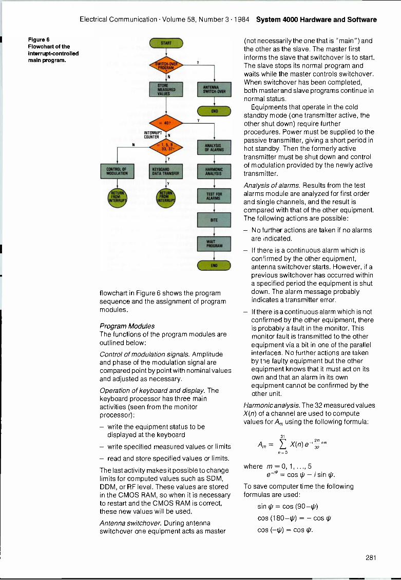
Electrical Communication Volume 58, Number 3 1984 System 4000 Hardware and Software
Figure 6Flowchart of theinterrupt -controlledmain program.
CONTROL OFMODULATION
WITCH-OVEPROGRAM
STORE
MEASURED
VALUES
= 40,
INTERRUPTCOUNTER
33, 37
KEYBOARDDATA TRANSFEF
lY
RUNFROM
NTERRU
ANALYSISOF ALARMS
HARMONICANALYSIS
TEST FORALARMS
BITE
flowchart in Figure 6 shcws the programsequence and the assignment of programmodules.
Program ModulesThe functions of the program modules areoutlined below:
Control of modulation signals. Amplitudeand phase of the modulation signal arecompared point by point with nominal valuesand adjusted as necessary.
Operation of keyboard and display. Thekeyboard processor has three mainactivities (seen from the monitorprocessor):
- write the equipment status to bedisplayed at the keyboard
- write specified measured values or limits
- read and store specified values or limits.
The last activity makes it possible to changelimits for computed values such as SDM,DDM, or R F level. These values are storedin the CMOS RAM, so when it is necessaryto restart and the CMOS RAM is correct,these new values will be used.
Antenna switchover. During antennaswitchover one equipment acts as master
(not necessarily the one that is "main") andthe other as the slave. The master firstinforms the slave that switchover is to start.The slave stops its normal program andwaits while the master controls switchover.When switchover has been completed,both master and slave programs continue innormal status.
Equipments that operate in the coldstandby mode (one transmitter active, theother shut down) require furtherprocedures. Power must be supplied to thepassive transmitter, giving a short period inhot standby. Then the formerly activetransmitter must be shut down and controlof modulation provided by the newly activetransmitter.
Analysis of alarms. Results from the testalarms module are analyzed for first orderand single channels, and the result iscompared with that of the other equipment.The following actions are possible:
No further actions are taken if no alarmsare indicated.
If there is a continuous alarm which isconfirmed by the other equipment,antenna switchover starts. However, if aprevious switchover has occurred withina specified period the equipment is shutdown. The alarm message probablyindicates a transmitter error.
If there is a continuous alarm which is notconfirmed by the other equipment, thereis probably a fault in the monitor. Thismonitor fault is transmitted to the otherequipment via a bit in one of the parallelinterfaces. No further actions are takenby the faulty equipment but the otherequipment knows that it must act on itsown and that an alarm in its ownequipment cannot be confirmed by theother unit.
Harmonic analysis. The 32 measured valuesX(n) of a channel are used to computevalues for A, using the following formula:
Am =31
2rtE X(n) e 32'm=0
where m = 0, 1, ..., 5
e = cos (I/ - i sin (p.
To save computer time the followingformulas are used:
sin (p = cos (90-(p)
cos (180 -(p) = - cos (p
cos (-(p) = cos tp.
281
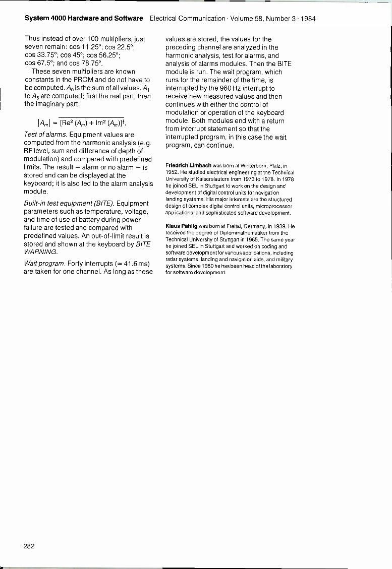
System 4000 Hardware and Software Electrical Communication Volume 58, Number 3 1984
Thus instead of over 100 multipliers, justseven remain: cos 11.25°; cos 22.5°;cos 33.75°; cos 45°; cos 56.25°;cos 67.5°; and cos 78.75°.
These seven multipliers are knownconstants in the PROM and do not have tobe computed. Ao is the sum of all values. Alto A5 are computed; first the real part, thenthe imaginary part:
Am = [Re2 (Am) + Im2 (Am)j'.
Test of alarms. Equipment values arecomputed from the harmonic analysis (e.g.RF level, sum and difference of depth ofmodulation) and compared with predefinedlimits. The result - alarm or no alarm - isstored and can be displayed at thekeyboard; it is also fed to the alarm analysismodule.
Built-in test equipment (BITE). Equipmentparameters such as temperature, voltage,and time of use of battery during powerfailure are tested and compared withpredefined values. An out -of -limit result isstored and shown at the keyboard by BITEWARNING.
Wait program. Forty interrupts (= 41.6 ms)are taken for one channel. As long as these
values are stored, the values for thepreceding channel are analyzed in theharmonic analysis, test for alarms, andanalysis of alarms modules. Then the BITEmodule is run. The wait program, whichruns for the remainder of the time, isinterrupted by the 960 Hz interrupt toreceive new measured values and thencontinues with either the control ofmodulation or operation of the keyboardmodule. Both modules end with a returnfrom interrupt statement so that theinterrupted program, in this case the waitprogram, can continue.
Friedrich Limbach was born at Winterborn, Pfalz, in1952. He studied electrical engineering at the TechnicalUniversity of Kaiserslautern from 1973 to 1978. In 1978he joined SEL in Stuttgart to work on the design anddevelopment of digital control units for navigationlanding systems. His major interests are the structureddesign of complex digital control units, microprocessorapplications, and sophisticated software development.
Klaus Pahlig was born at Freital, Germany, in 1939. Hereceived the degree of Diplommathematiker from theTechnical University of Stuttgart in 1965. The same yearhe joined SEL in Stuttgart and worked on coding andsoftware development for various applications, includingradar systems, landing and navigation aids, and militarysystems. Since 1980 he has been head of the laboratoryfor software development.
282
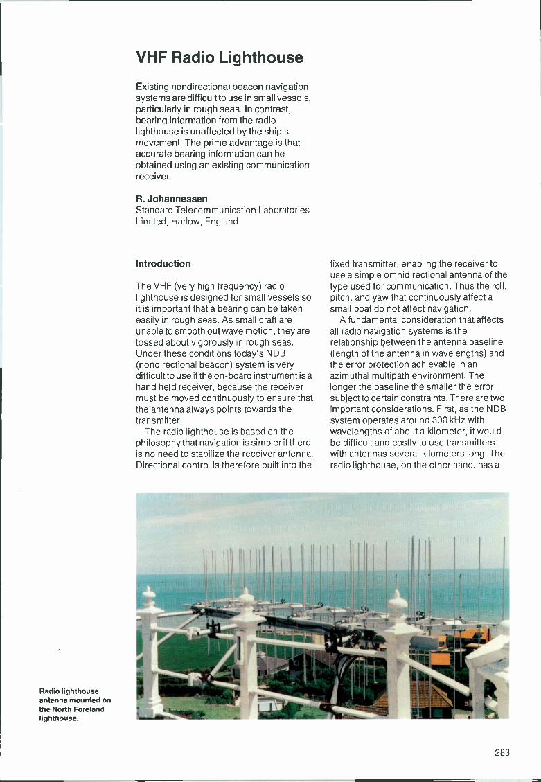
VHF Radio Lighthouse
Existing nondirectional beacon navigationsystems are difficult to use in small vessels,particularly in rough seas. In contrast,bearing information from the radiolighthouse is unaffected by the ship'smovement. The prime advantage is thataccurate bearing information can beobtained using an existing communicationreceiver.
R. JohannessenStandard Telecommunication LaboratoriesLimited, Harlow, England
Introduction
The VHF (very high frequency) radiolighthouse is designed for small vessels soit is important that a bearing can be takeneasily in rough seas. As small craft areunable to smooth out wave motion, they aretossed about vigorously in rough seas.Under these conditions today's NDB(nondirectional beacon) system is verydifficult to use if the on -board instrument is ahand held receiver, because the receivermust be moved continuously to ensure thatthe antenna always points towards thetransmitter.
The radio lighthouse is based on thephilosophy that navigation is simpler if thereis no need to stabilize the receiver antenna.Directional control is therefore built into the
Radio lighthouseantenna mounted onthe North Forelandlighthouse.
fixed transmitter, enabling the receiver touse a simple omnidirectional antenna of thetype used for communication. Thus the roll,pitch, and yaw that continuously affect asmall boat do not affect navigation.
A fundamental consideration that affectsall radoo navigation systems is therelationship between the antenna baseline(length of the antenna in wavelengths) andthe error protection achievable in anazimuthal multipath environment. Thelonger the baseline the smaller the error,subject to certain constraints. There are twoimportant considerations. First, as the NDBsystem operates around 300 kHz withwavelengths of about a kilometer, it wouldbe difficult and costly to use transmitterswith antennas several kilometers long. Theradio lighthouse, on the other hand, has a
VHF Radio Lighthouse Electrical Communication Volume 58, Number 3 1984
Figure 1Tone level variationat different bearings(a) bearing 4° intothe coverage sector(b) bearing 36° intothe coverage sector(c) bearing 68° intothe coverage sector(d) bearing 110° intothe coverage sector.
2 m wavelength and so the 4.5 m antenna ismore than two wavelengths long, thusoffering significant error reduction potential.The second consideration is that it is simplerto locate, mount, and maintain a largeantenna structure ashore than on board avessel which is subject to violent pitch, roll,and yaw.
Operation
The radio lighthouse operates in theinternational marine VHF band atapproximately 160 MHz. An audio tone isheard when the receivers are tuned to the
TONE INTENSITY
9
00
25
Is)
41
90
80 BEATS AT 0.5 s 82= 30 s
BEAT 7 BEAT 67
TIME
correct channel. The transmitter is soarranged that within the coverage sector thetone is heard in all directions from thetransmitter, except one radial along whichthere is a marked reduction in tone level.This null radial is slowly rotated by thetransmitter at 4° per second. Knowing thisrate and the reference time at which theradial passes through a reference bearing,which is published for each beacon, thereceiver's bearing is obtained by noting theduration from the reference time until thenull radial passes through the bearing atwhich the receiver is located. To simplifythis still further, the transmission is brokeninto a series of 0.5 s beats so that the
bearing can be obtained by counting beatsfrom the reference time until the null radialpasses through the receiver. While theradial is approaching, the tone graduallydecreases in intensity and after the radialhas passed, the tone increases again.
The transmitting antenna is fixed and thenull radial is rotated electronically,eliminating all moving parts.
Signal Format for Each Beacon
Transmissions commence on the hour andevery minute thereafter. Each transmissionlasts 58 s and is followed by a 2 s pausebefore the next one commences. The 58 sare made up from three parts:
- morse identification which identifies thetransmitting beacon
- navigation signal which enables thenavigator to determine his bearing withrespect to the transmitter
- morse identification which repeats theidentity of the transmitting beacon.
Pauses between these parts of thetransmission simplify signal recognition.Between the first and second parts, andafter the third part, digital data is transmittedfor use by test instruments.
The navigation signal comprises 70 beatseach made up of a 0.4 s tone and 0.1 ssilence. Of these, beats 7 to 67 (inclusive)are used for navigation. During these beats,the null radial sweeps a 120° azimuth sectorwhich is the beacon's published coveragesector. As seen on a chart, the radial sweepsclockwise from the bearing correspondingto beat 7 to the bearing corresponding tobeat 67. Beats 1, 2, 3, and 4 help thenavigator get the counting rhythm, whilebeat 70 marks the end of the sequence.Figure 1 shows how the tone intensity variesat different bearings from the transmitter.
The further the navigator is into the 120°sector, the higher the beat number he getsto before the null radial passes. If the null isheard during beats 3, 4, 5, 6, 68, or 69, thenavigator should conclude that he is outsidethe published sector.
Time Sharing of Several Beacons
To conserve the frequency spectrum, it ispossible to arrange several beacons to timeshare a common frequency channel. Twobeacons may transmit alternately for 58 s
284
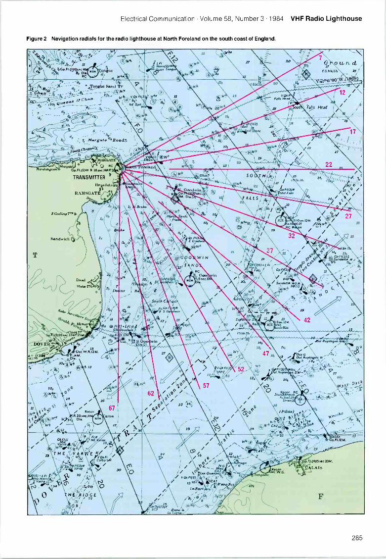
Electrical Communication Volume 58, Number 3 1984 VHF Radio Lighthouse
Figure 2 Navigation radials for the radio lighthouse at North Foreland on the south coast of Englaid.
3s4te - 5 54'7.C.P.F141*.K.11
4,14. 82 DiaRC WS.
.7
Qngue
e Sand;7'4To on h
- - erNEN:Spd
Birehtngton
1,4, - ; Margate Road7,
}WorgaffGp.F1.(5)W.R.20sec.181311
TRANSMITTER
Brakadstairs
RAMSGATECI.
3 Cooloing7T.
Sandwich
10,
1(6) t F11;hos Horn 8
Were;a-,
..414
0
14
DealWaot8r
Racon.R.20sec.II
/i?2.iwk
30
/2.3L FlHorn(2)W i..g0"?`
w ter Tango
17116
1111
1919° //
19
a / GP Xii2)
BRI34;1,
Sandettl* WSW16FI G
.5sec.I2M.'ren
.143 Mut Ruyongen,N
47 A3 /010°uCC/RGuytim
./i3 ...'
/24 49,-71' 1°3
irti n $10..-.7
3, _ ;....::5 - -
/ / Li -....CN
2..5
71' 06!%1 riit S
-.I --.-7, 1....
r . .....
12 ,.. 2 7
kl 6A /G 411rancNe
.F1.(4)15sec.20M.
285
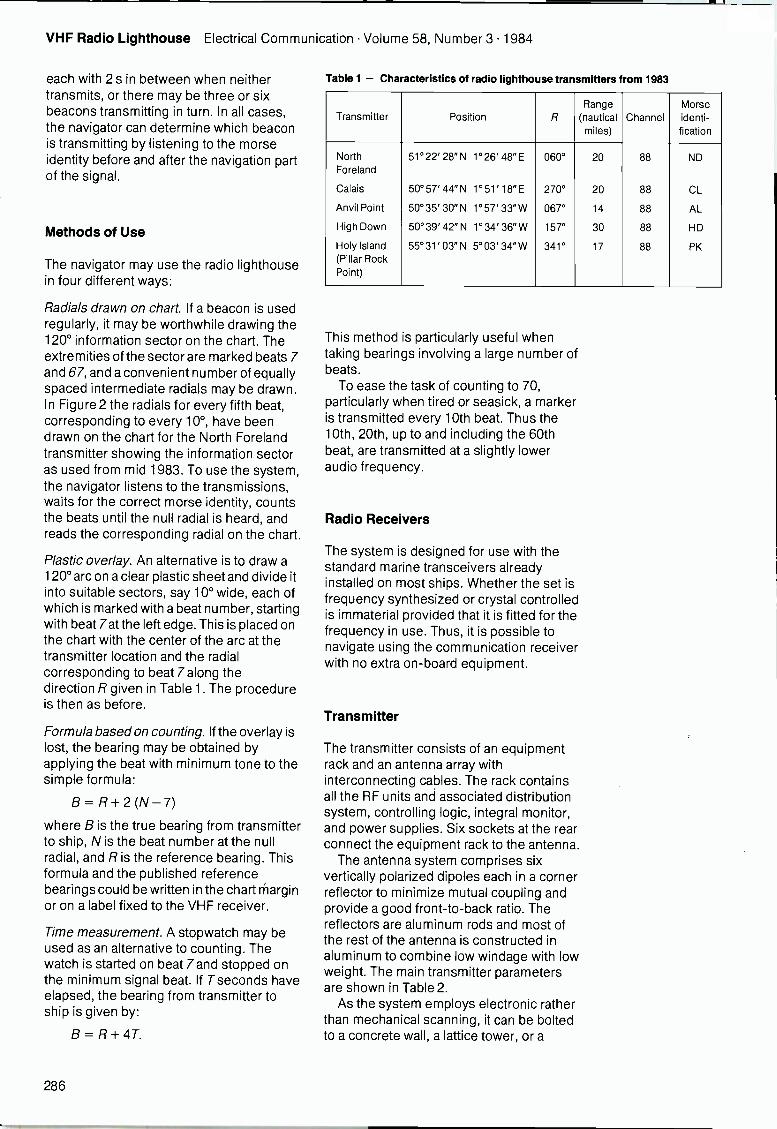
VHF Radio Lighthouse Electrical Communication Volume 58, Number 3 1984
each with 2 s in between when neithertransmits, or there may be three or sixbeacons transmitting in turn. In all cases,the navigator can determine which beaconis transmitting by listening to the morseidentity before and after the navigation partof the signal.
Methods of Use
The navigator may use the radio lighthousein four different ways:
Radials drawn on chart. If a beacon is usedregularly, it may be worthwhile drawing the120° information sector on the chart. Theextremities of the sector are marked beats 7and 67, and a convenient number of equallyspaced intermediate radials may be drawn.In Figure 2 the radials for every fifth beat,corresponding to every 10°, have beendrawn on the chart for the North Forelandtransmitter showing the information sectoras used from mid 1983. To use the system,the navigator listens to the transmissions,waits for the correct morse identity, countsthe beats until the null radial is heard, andreads the corresponding radial on the chart.
Plastic overlay. An alternative is to draw a120° arc on a clear plastic sheet and divide itinto suitable sectors, say 10° wide, each ofwhich is marked with a beat number, startingwith beat 7atthe left edge. This is placed onthe chart with the center of the arc at thetransmitter location and the radialcorresponding to beat 7 along thedirection R given in Table 1. The procedureis then as before.
Formula based on counting. If the overlay islost, the bearing may be obtained byapplying the beat with minimum tone to thesimple formula:
B = R + 2 (N - 7)
where B is the true bearing from transmitterto ship, N is the beat number at the nullradial, and R is the reference bearing. Thisformula and the published referencebearings could be written in the chart marginor on a label fixed to the VHF receiver.
Time measurement. A stopwatch may beused as an alternative to counting. Thewatch is started on beat 7 and stopped onthe minimum signal beat. If T seconds haveelapsed, the bearing from transmitter toship is given by:
B = R + 4T.
Table 1 - Characteristics of radio lighthouse transmitters from 1983
Transmitter Position R
Range(nauticalmiles)
ChannelMorseidenti-fication
North 51°22' 28" N 1°26' 48" E 060° 20 88 NDForeland
Calais 50° 57' 44" N 1° 51' 18" E 270° 20 88 CL
Anvil Point 50°35' 30" N 1°57' 33"W 067° 14 88 AL
High Down 50°39' 42" N 1°34' 36" W 157° 30 88 HD
Holy Island 55°31' 03" N 5°03'34"W 341° 17 88 PK(Pillar RockPoint)
This method is particularly useful whentaking bearings involving a large number ofbeats.
To ease the task of counting to 70,particularly when tired or seasick, a markeris transmitted every 10th beat. Thus the10th, 20th, up to and including the 60thbeat, are transmitted at a slightly loweraudio frequency.
Radio Receivers
The system is designed for use with thestandard marine transceivers alreadyinstalled on most ships. Whether the set isfrequency synthesized or crystal controlledis immaterial provided that it is fitted for thefrequency in use. Thus, it is possible tonavigate using the communication receiverwith no extra on -board equipment.
Transmitter
The transmitter consists of an equipmentrack and an antenna array withinterconnecting cables. The rack containsall the RF units and associated distributionsystem, controlling logic, integral monitor,and power supplies. Six sockets at the rearconnect the equipment rack to the antenna.
The antenna system comprises sixvertically polarized dipoles each in a cornerreflector to minimize mutual coupling andprovide a good front -to -back ratio. Thereflectors are aluminum rods and most ofthe rest of the antenna is constructed inaluminum to combine low windage with lowweight. The main transmitter parametersare shown in Table 2.
As the system employs electronic ratherthan mechanical scanning, it can be boltedto a concrete wall, a lattice tower, or a
286
Electrical Communication Volume 58, Number 3 1984 VHF Radio Lighthouse
balcony; it could even be mounted betweenuprights poles. Thus it is generally easy tomount the system on a lighthouse, acoastguard site, or other building.
At the North Foreland lighthouse in Kent,Southern England, the antenna is bolted toguard rails immediately below the focalplane. As another example, at Anvil Point,also on the south coast of England, theantenna is bolted to the roof of the foghornhousing.
The connecting cables can be simplecoaxial cables with a 50 0 impedance, goodphase stability, and a maximum insertionloss of 3 dB.
It should be noted that the equipment isdesigned for automatic operation and cantherefore be used on unattended sites.
Range and Information Sector
The system range depends upon a numberof factors including the elevations of thetransmitter antenna and receiver antenna,feeder losses at both ends, receiverantenna type and mounting method, andreceiver type.
In a typical case, the working range isabout 20 n miles (37 km) for a receiverdipole aerial mounted at the masthead28 feet (8.5 m) above the sea surface and atransmitter elevation of 57 m. Halving thetransmitter antenna elevation reduces therange by about 40%.
The information sector is 120° end to end.If 240° coverage is required, twotransmitters may be used each covering itsown 120° sector.
System Testing
During 1981 over 1000 measurements ofsystem accuracy were carried out; these
Table 2 - Specification summary for transmitter
Output frequency:
Frequency stability
Aerial gain:
Power out ofequipment bay:
Input power:
Any marine channel in therange 160.625 to 162.125 MHz
Better than 10 parts per million
Nominally + 7 dBi*
2W 3 dB
Both (a) and (b)(a) 110to120 Vor220to
240 VAC45 to 400 Hz at 280 VA
(b) 22 to 30 V DC, less than 1 A
* dBi: decibels relative to an isotropic source.
indicated a standard deviation of about 2°.System improvements made during 1983reduced the standard deviation to only 1.6°.
In the period 1981-1983, far -fieldmonitors were installed in three fixedlocations so that long-term transmissionstability could be assessed. Between4 December 1981 and 10 September 1983,2406 readings were taken with a standarddeviation better than 0.6°.
During extensive sea trials, tests werecarried out to determine the ease of use ofthe system. A number of observers onboard the testing ship were askedsimultaneously but independently todetermine the ship's bearing from a shorestation by counting beats until he null radialpassed. For each position of the ship, thespread of the observations was studied.Clearly the smaller this spread, the easierthe system was to use. During the trials3952 bearings were taken and in 99.2% ofcases the options expressed were withinone beat of the mean bearing,corresponding to a spread of only ±2°.
Steps Taken to Safeguard the Navigator
It is important for the navigator to haveconfidence in the integrity of the system. Toensure this, a built-in monitor in eachtransmitter automatically and continuouslychecks that the carrier power is above apreset level, the sideband energy is above apreset level, and the electronic alignmentwhich controls the directional information isbetween preset limits.
If a fault develops (permanent ortransitory) the system immediately signals
Radio lighthouseantenna mounted onthe fog signal housingat Anvil Point, England.
287
VHF Radio Lighthouse Electrical Communication Volume 58, Number 3 1984
this to the navigator by warbling the audiotone (varying it between two distinctfrequencies). If this happens, the navigatorshould not use the bearing information.
At the end of the transmitter sequence,the system tries again. If the fault persists,the transmitter is closed down until it can berepaired.
Periodically, maintenance engineersexamine the system. If for any reason theyneed to cause unreliable information to betransmitted, they first alter the morseidentity to TEST. Thus, the navigator isrecommended always to check that themorse signal received is that published forthe station.
Development History
The radio lighthouse was developed byStandard Telecommunication Laboratoriesin conjunction with STC International Marineand the Corporation of Trinity House onbehalf of the General Lighthouse Authority.
The first system was made available tomariners at North Foreland, Kent, inEngland, from March 1980. In 1981 fourmore transmitters were added, so that bythe end of 1981 systems were under
evaluation in England, Scotland, andFrance. During 1983, their morse identitiesand signal format were brought into line withthe details given in Table 1.
Plans are now in hand for the productionsystems to be manufactured at STCInternational Marine.
Conclusions
The radio lighthouse allows small vessels toreceive accurate bearing information usingan existing communication receiver. As thebearing information is under the control ofthe transmitter, it is unaffected by thevessel's movement, even in rough seas.Neither the ship's heading or the magneticdeviation are required to determine theship's bearing.
R. Johannessen was born in 1937. In 1962 he wasawarded a BSc from the University of St Andrews inScotland. For three years he worked with STC in Londonon aircraft radio navigation systems. Following this hespent a period with International Computers beforejoining STL in Harlow where he has worked since then.He was responsible for the concept and development ofthe VHF radio lighthouse, and his work in this area gainedhim a PhD from London University. Dr Johannessen is aFellow of the Institution of Electrical Engineers in London.
288
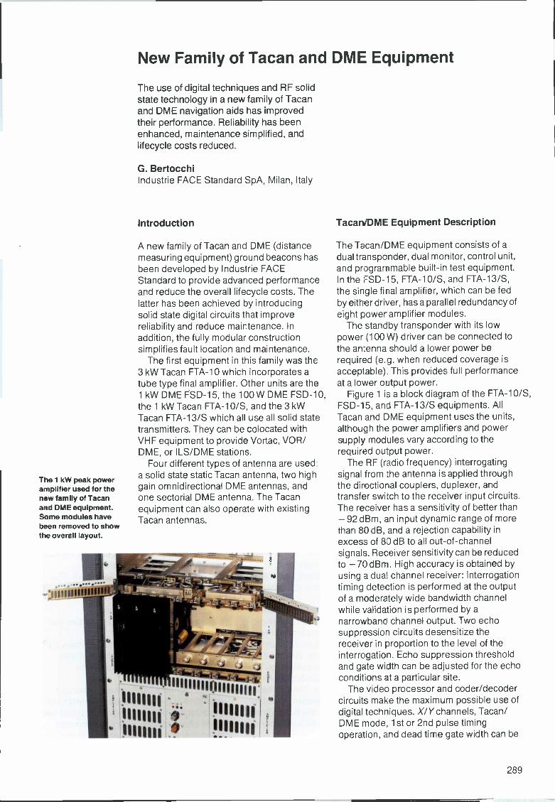
The 1 kW peak poweramplifier used for thenew family of Tacanand DME equipment.Some modules havebeen removed to showthe overall layout.
-)111111111111
New Family of Tacan and DME Equipment
The use of digital techniques and RF solidstate technology in a new family of Tacanand DME navigation aids has improvedtheir performance. Reliability has beenenhanced, maintenance simplified, andlifecycle costs reduced.
G. BertocchiIndustrie FACE Standard SpA, Milan, Italy
Introduction
A new family of Tacan and DME (distancemeasuring equipment) ground beacons hasbeen developed by Industrie FACEStandard to provide advanced performanceand reduce the overall lifecycle costs. Thelatter has been achieved by introducingsolid state digital circuits that improvereliability and reduce maintenance. Inaddition, the fully modular constructionsimplifies fault location and maintenance.
The first equipment in this family was the3 kW Tacan FTA-10 which incorporates atube type final amplifier. Other units are the1 kW DME FSD-15, the 100 W DME FSD-10,the 1 kW Tacan FTA-10/S, and the 3 kWTacan FTA-13/S which all use all solid statetransmitters. They can be colocated withVHF equipment to provide Vortac, VOR/DME, or ILS/DME stations.
Four different types of antenna are used:a solid state static Tacan antenna, two highgain omnidirectional DME antennas, andone sectorial DME antenna. The Tacanequipment can also operate with existingTacan antennas.
11111111111111111
11111111
1111111111111111 1.'inn
Tacan/DME Equipment Description
The Tacan/DME equipment consists of adual transponder, dual monitor, control unit,and programmable built-in test equipment.In the FSD-15, FTA-10/S, and FTA-13/S,the single final amplifier, which can be fedby either driver, has a parallel redundancy ofeight power amplifier modules.
The standby transponder with its lowpower (100 W) driver can be connected tothe antenna should a lower power berequired (e.g. when reduced coverage isacceptable) This provides full performanceat a lower output power.
Figure 1 is a block diagram of the FTA-10/S,FSD-15, and FTA-13/S equipments. AllTacan and DME equipment uses the units,although the power amplifiers and powersupply modules vary according to therequired output power.
The RF (radio frequency) interrogatingsignal from the antenna is applied throughthe directional couplers, duplexer, andtransfer switch to the receiver input circuits.The receiver has a sensitivity of better than- 92 dBm, an input dynamic range of morethan 80 dB, and a rejection capability inexcess of 80 dB to all out -of -channelsignals. Receiver sensitivity can be reducedto -70 dBm. High accuracy is obtained byusing a dual channel receiver: interrogationtiming detection is performed at the outputof a moderately wide bandwidth channelwhile validation is performed by anarrowbanc channel output. Two echosuppression circuits desensitize thereceiver in proportion to the level of theinterrogatio-i. Echo suppression thresholdand gate width can be adjusted for the echoconditions at a particular site.
The video processor and coder/decodercircuits make the maximum possible use ofdigital techniques. X/Ychannels, Tacan/DME mode, 1st or 2nd pulse timingoperation, and dead time gate width can be
289
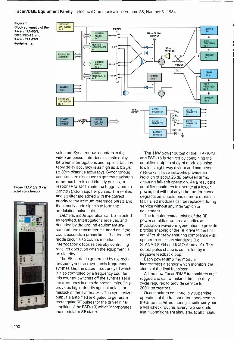
Tacan/DME Equipment Family Electrical Communication Volume 58, Number 3 1984
Figure 1Block schematic of theTacan FTA-10/S,DME FSD-15, andTacan FTA-13/Sequipments.
Tacan FTA-13/S, 3 kWsolid state beacon.
FREQUENCY
SYNTHESIZERNo 1
BUILT-IN TESTEQUIPMENT
CONTROLUNIT
FREQUENCY
SYNTHESIZERNo 2
MONITORALARMALARMNo 1
MONITORINTERROGATORNo 1
MONITORALARMNo 2
MONITORINTERROGATORNo 2
TACAN OR DME
ANTENNA
1
DUMMYLOAD
N 11
TACANAMPLIFIER
DRIVERNo 1
VIDEO
PROCESSOR
No 1
RECEIVER
No 1
VIDEO
PROCESSORNo 2
RECEIVER
No 2
MAINS AC/DC DC/DCSUPPLY CONVERTER CONVERTER
No 1
TELEPHONE
J>
MAINSFAILSWITCH
REMOTE REMOTECONTROL CONTROL
AC/DC DC/DC
SYSTEM LINESYSTEM
CONVERTER CONVERTERNo 2
selected. Synchronous counters in thevideo processor introduce a stable delaybetween interrogations and replies; beaconreply delay accuracy is as high as ± 0.2 ps(± 30 m distance accuracy). Synchronouscounters are also used to generate azimuthreference bursts and identity pulses, inresponse to Tacan antenna triggers, and tocontrol random squitter pulses. The repliesand squitter are added with the correctpriority to the azimuth reference bursts andthe identity code signals to form themodulation pulse train.
Demand mode operation can be selectedas required. Interrogations received anddecoded by the ground equipment arecounted; the transmitter is turned on if thecount exceeds a preset limit. The demandmode circuit also counts monitorinterrogation decodes thereby controllingreceiver operation when the equipment ison standby.
The RF carrier is generated by a direct-frequency/indirect-synthesis frequencysynthesizer, the output frequency of whichis also controlled by a frequency counter;this counter switches off the synthesizer ifthe frequency is outside preset limits. Thisprovides high integrity against unlock ormislock of the synthesizer. The synthesizeroutput is amplified and gated to generaterectangular RF pulses for the driver (finalamplifier of the FSD-10) which incorporatesthe modulator RF stage.
BATTERYCHARGER
BATTERY
The 1 kW power output of the FTA-10/Sand FSD-15 is derived by combining theamplified outputs of eight modules usinglow loss eight -way divider and combinernetworks. These networks provide anisolation of about 25 dB between arms,ensuring fail -soft operation. As a result theamplifier continues to operate at a lowerpower, but without any other performancedegradation, should one or more modulesfail. Failed modules can be replaced duringservice without any interruption oradjustment.
The transfer characteristic of the RFpower amplifier requires a particularmodulation waveform generation to provideprecise shaping of the RF drive to the finalamplifier, thereby ensuring compliance withspectrum emission standards (i.e.STANAG 5034 and ICAO Annex 10). Theoutput pulse shape is controlled by anegative feedback loop.
Each power amplifier moduleincorporates a sensor which monitors thestatus of the final transistor.
All the new Tacan/DME transmitters arerugged and can withstand the high dutycycle required to provide service to200 interrogators.
Dual monitors continuously superviseoperation of the transponder connected tothe antenna. All monitoring circuits carry outa self -check routine. Every two secondsalarm conditions are simulated to all circuits;
290
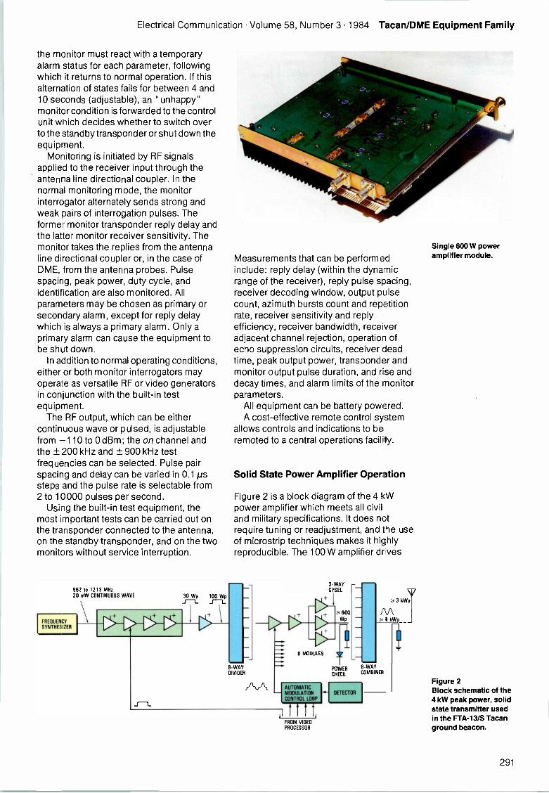
Electrical Communication Volume 58, Number 3 1984 Tacan/DME Equipment Family
the monitor must react with a temporaryalarm status for each parameter, followingwhich it returns to normal operation. If thisalternation of states fails for between 4 and10 seconds (adjustable), an "unhappy"monitor condition is forwarded to the controlunit which decides whether to switch overto the standby transponder or shut down theequipment.
Monitoring is initiated by RF signalsapplied to the receiver input through theantenna line directional coupler. In thenormal monitoring mode, the monitorinterrogator alternately sends strong andweak pairs of interrogation pulses. Theformer monitor transponder reply delay andthe latter monitor receiver sensitivity. Themonitor takes the replies from the antennaline directional coupler or, in the case ofDME, from the antenna probes. Pulsespacing, peak power, duty cycle, andidentification are also monitored. Allparameters may be chosen as primary orsecondary alarm, except for reply delaywhich is always a primary alarm. Only aprimary alarm can cause the equipment tobe shut down.
In addition to normal operating conditions,either or both monitor interrogators mayoperate as versatile RF or video generatorsin conjunction with the built-in testequipment.
The RF output, which can be eithercontinuous wave or pulsed, is adjustablefrom -110 to 0 dBm; the on channel andthe ± 200 kHz and ± 900 kHz testfrequencies can be selected. Pulse pairspacing and delay can be varied in 0.1 pssteps and the pulse rate is selectable from2 to 10000 pulses per second.
Using the built-in test equipment, themost important tests can be carried out onthe transponder connected to the antenna,on the standby transponder, and on the twomonitors without service interruption.
FREQUENCYSYNTHESIZER
962 to 1213 MHz20 mW CONTINUOUS WAVE 30 Wp 100 WpJZ J --L
Measurements that can be performedinclude: reply delay (within the dynamicrange of the receiver), reply pulse spacing,receiver decoding window, output pulsecount, azimuth bursts count and repetitionrate, receiver sensitivity and replyefficiency, receiver bandwidth, receiveradjacent channel rejection, operation ofecho suppression circuits, receiver deadtime, peak output power, transponder andmonitor output pulse duration, and rise anddecay times, and alarm limits of the monitorparameters.
All equipment can be battery powered.A cost-effective remote control system
allows controls and indications to beremoted to a central operations facility.
Solid State Power Amplifier Operation
Figure 2 is a block diagram of the 4 kWpower amplifier which meets all civiland military specifications. It does notrequire tuning or readjustment, and the useof microstrip techniques makes it highlyreproducible. The 100 W amplifier dr ves
8 -WAYDIVIDER
8 MODULES
3 -WAYGYSEL
POWER
CH CK
-WAYCOMBINER
AUTOMATICMODULATIONCONTROL LOOP
DETECTOR
iiiilFROM VIDEOPROCESSOR
3 kWp
4 W
1
Single 600 W poweramplifier module.
Figure 2Block schematic of the4 kW peak power, solidstate transmitter usedin the FTA-13/S Tacanground beacon.
291
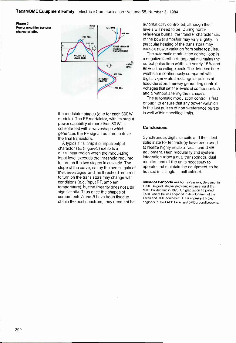
Tacan/DME Equipment Family Electrical Communication Volume 58, Number 3 1984
Figure 3Power amplifier transfercharacteristic.
INPUTLEVEL
1213 MHz
962 MHz
1213 MHz
ij){.....962 MHz
POWER AMPLIFIERTRANSFERCHARACTERISTIC
OUTPUTLEVEL
the modulator stages (one for each 600 Wmodule). The RF modulator, with its outputpower capability of more than 80 W, iscollector fed with a waveshape whichgenerates the RF signal required to drivethe final transistors.
A typical final amplifier input/outputcharacteristic (Figure 3) exhibits aquasilinear region when the modulatinginput level exceeds the threshold requiredto turn on the two stages in cascade. Theslope of the curve, set by the overall gain ofthe three stages, and the threshold requiredto turn on the transistors may change withconditions (e.g. input RF, ambienttemperature), but the linearity does not altersignificantly. Thus once the shapes ofcomponents A and B have been fixed toobtain the best spectrum, they need not be
automatically controlled, although theirlevels will need to be. During north -reference bursts, the transfer characteristicof the power amplifier may vary slightly. Inparticular heating of the transistors maycause a power variation from pulse to pulse.
The automatic modulation control loop isa negative feedback loop that maintains theoutput pulse time widths at nearly 15% and85% of the voltage peak. The detected timewidths are continuously compared withdigitally generated rectangular pulses offixed duration, thereby generating controlvoltages that set the levels of components Aand B without altering their shapes.
The automatic modulation control is fastenough to ensure that any power variationin the last pulses of north -reference burstsis well within specified limits.
Conclusions
Synchronous digital circuits and the latestsolid state RF technology have been usedto realize highly reliable Tacan and DMEequipment. High modularity and systemintegration allow a dual transponder, dualmonitor, and all the units necessary tooperate and maintain the equipment, to behoused in a single, small cabinet.
Giuseppe Bertocchi was born in Vertova, Bergamo, in1950. He graduated in electronic engineering at theMilan Polytechnic in 1975. On graduation he joinedFACE where he was engaged in development of theTacan and DME equipment. He is at present projectengineer forthe FACE Tacan and DME ground beacons.
292
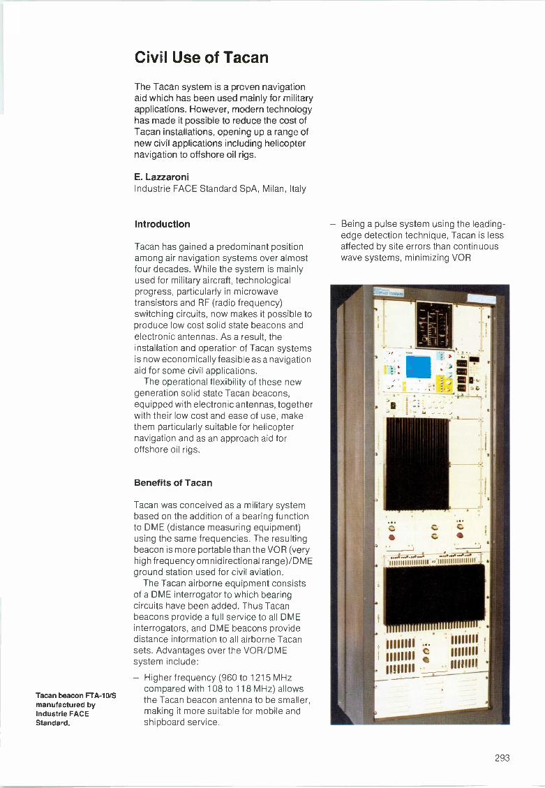
Tacan beacon FTA-10/Smanufactured byIndustrie FACEStandard.
Civil Use of Tacan
The Tacan system is a prcven navigationaid which has been used mainly for militaryapplications. However, modern technologyhas made it possible to reduce the cost ofTacan installations, opening up a range ofnew civil applications including helicopternavigation to offshore oil rigs.
E. LazzaroniIndustrie FACE Standard SpA, Milan, Italy
Introduction
Tacan has gained a predominant positionamong air navigation systems over almostfour decades. While the system is mainlyused for military aircraft, technologicalprogress, particularly in microwavetransistors and RF (radio frequency)switching circuits, now makes it possible toproduce low cost solid state beacons andelectronic antennas. As a result, theinstallation and operation of Tacan systemsis now economically feasible as a navigationaid for some civil applications.
The operational flexibility of these newgeneration solid state Tacan beacons,equipped with electronic antennas, togetherwith their low cost and ease of use, makethem particularly suitable for helicopternavigation and as an approach aid foroffshore oil rigs.
Benefits of Tacan
Tacan was conceived as a military systembased on the addition of a Dearing functionto DME (distance measuring equipment)using the same frequencies. The resultingbeacon is more portable than the VOR (veryhigh frequency omnidirectional range)/DMEground station used for civil aviation.
The Tacan airborne equipment consistsof a DME interrogator to which bearingcircuits have been added. Thus Tacanbeacons provide a full service to all DMEinterrogators, and DME beacons providedistance information to all airborne Tacansets. Advantages over the VOR/DMEsystem include:
- Higher frequency (960 to 1215MHzcompared with 108 to 118 MHz) allowsthe Tacan beacon antenna to be smaller,making it more suitable for mobile andshipboard service.
- Being a pulse system using the leading -edge detection technique, Tacan is lessaffected by site errors than continuouswave systems, minimizing VOR
_I-9 r .
111111111111111111 '11111111111111111/
1111111111111111
111111.11111111
- 11111111111111
293
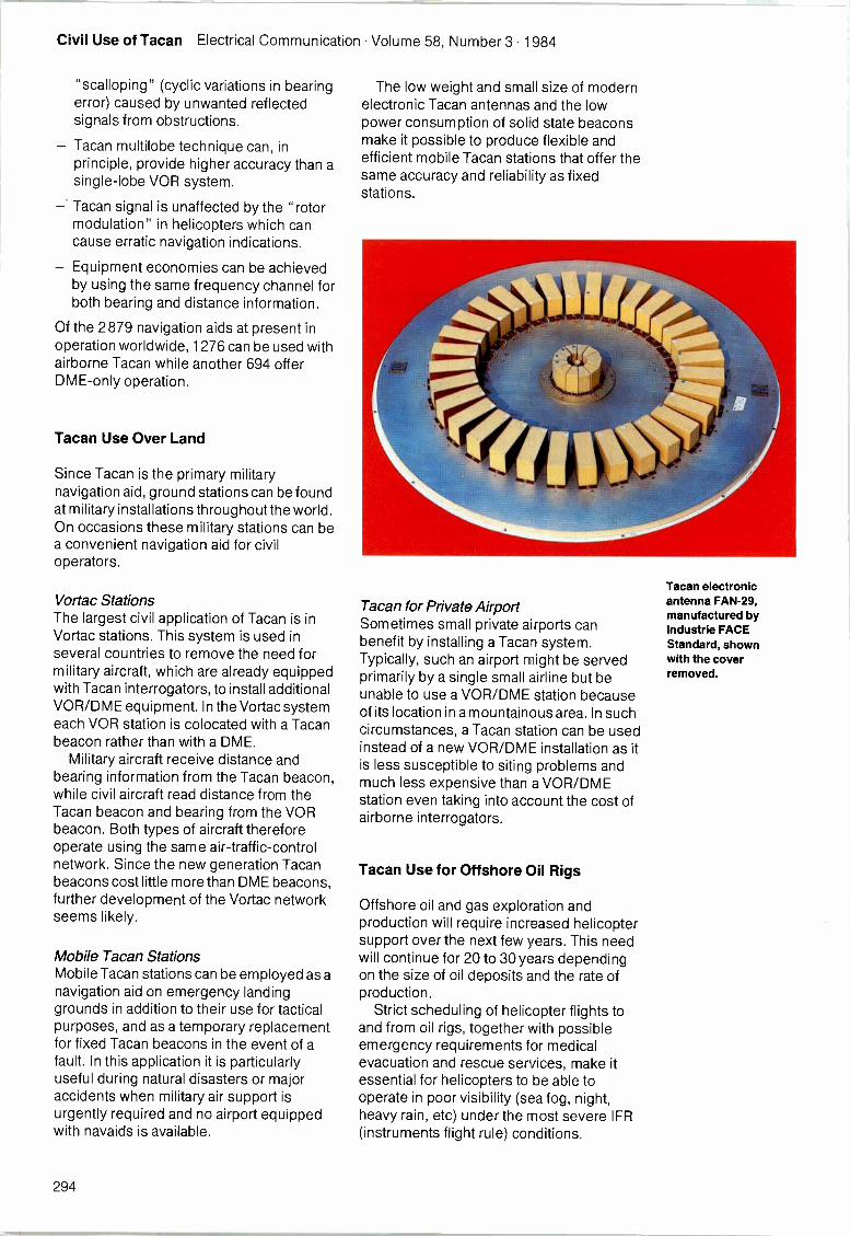
Civil Use of Tacan Electrical Communication Volume 58, Number 3 1984
"scalloping" (cyclic variations in bearingerror) caused by unwanted reflectedsignals from obstructions.
- Tacan multilobe technique can, inprinciple, provide higher accuracy than asingle -lobe VOR system.
- Tacan signal is unaffected by the "rotormodulation" in helicopters which cancause erratic navigation indications.
- Equipment economies can be achievedby using the same frequency channel forboth bearing and distance information.
Of the 2879 navigation aids at present inoperation worldwide, 1276 can be used withairborne Tacan while another 694 offerDME-only operation.
Tacan Use Over Land
Since Tacan is the primary militarynavigation aid, ground stations can be foundat military installations throughout the world.On occasions these military stations can bea convenient navigation aid for civiloperators.
Vortac StationsThe largest civil application of Tacan is inVortac stations. This system is used inseveral countries to remove the need formilitary aircraft, which are already equippedwith Tacan interrogators, to install additionalVOR/DME equipment. In the Vortac systemeach VOR station is colocated with a Tacanbeacon rather than with a DME.
Military aircraft receive distance andbearing information from the Tacan beacon,while civil aircraft read distance from theTacan beacon and bearing from the VORbeacon. Both types of aircraft thereforeoperate using the same air -traffic -controlnetwork. Since the new generation Tacanbeacons cost little more than DME beacons,further development of the Vortac networkseems likely.
Mobile Tacan StationsMobile Tacan stations can be employed as anavigation aid on emergency landinggrounds in addition to their use for tacticalpurposes, and as a temporary replacementfor fixed Tacan beacons in the event of afault. In this application it is particularlyuseful during natural disasters or majoraccidents when military air support isurgently required and no airport equippedwith navaids is available.
The low weight and small size of modernelectronic Tacan antennas and the lowpower consumption of solid state beaconsmake it possible to produce flexible andefficient mobile Tacan stations that offer thesame accuracy and reliability as fixedstations.
Tacan for Private AirportSometimes small private airports canbenefit by installing a Tacan system.Typically, such an airport might be servedprimarily by a single small airline but beunable to use a VOR/DME station becauseof its location in a mountainous area. In suchcircumstances, a Tacan station can be usedinstead of a new VOR/DME installation as itis less susceptible to siting problems andmuch less expensive than a VOR/DMEstation even taking into account the cost ofairborne interrogators.
Tacan Use for Offshore Oil Rigs
Offshore oil and gas exploration andproduction will require increased helicoptersupport over the next few years. This needwill continue for 20 to 30 years dependingon the size of oil deposits and the rate ofproduction.
Strict scheduling of helicopter flights toand from oil rigs, together with possibleemergency requirements for medicalevacuation and rescue services, make itessential for helicopters to be able tooperate in poor visibility (sea fog, night,heavy rain, etc) under the most severe IFR(instruments flight rule) conditions.
Tacan electronicantenna FAN -29,manufactured byIndustrie FACEStandard, shownwith the coverremoved.
294
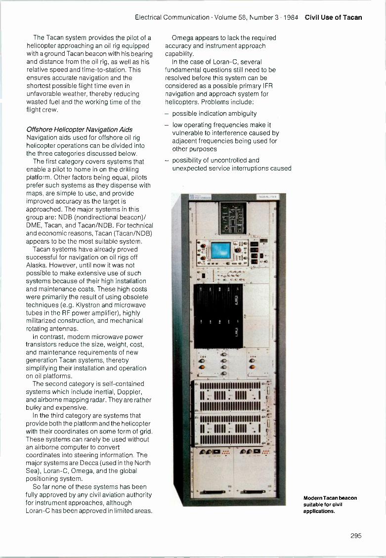
Electrical Communication Volume 58, Number 3 1984 Civil Use of Tacan
The Tacan system provides the pilot of ahelicopter approaching an oil rig equippedwith a ground Tacan beacon with his bearingand distance from the oil rig, as well as hisrelative speed and time -to -station. Thisensures accurate navigation and theshortest possible flight time even inunfavorable weather, thereby reducingwasted fuel and the working time of theflight crew.
Offshore Helicopter Navigation AidsNavigation aids used for offshore oil righelicopter operations can be divided intothe three categories discussed below.
The first category covers systems thatenable a pilot to home in on the drillingplatform. Other factors being equal, pilotsprefer such systems as they dispense withmaps, are simple to use, and provideimproved accuracy as the target isapproached. The major systems in thisgroup are: NDB (nondirectional beacon)/DME, Tacan, and Tacan/NDB. For technicaland economic reasons, Tacan (Tacan/NDB)appears to be the most suitable system.
Tacan systems have already provedsuccessful for navigation on oil rigs offAlaska. However, until now it was notpossible to make extensive use of suchsystems because of their high installationand maintenance costs. These high costswere primarily the result of using obsoletetechniques (e.g. Klystron and microwavetubes in the RF power amplifier), highlymilitarized construction, and mechanicalrotating antennas.
In contrast, modern microwave powertransistors reduce the size, weight, cost,and maintenance requirements of newgeneration Tacan systems, therebysimplifying their installation and operationon oil platforms.
The second category is self-containedsystems which include inertial, Doppler,and airborne mapping radar. They are ratherbulky and expensive.
In the third category are systems thatprovide both the platform and the helicopterwith their coordinates on some form of grid.These systems can rarely be used withoutan airborne computer to convertcoordinates into steering information. Themajor systems are Decca (used in the NorthSea), Loran -C, Omega, and the globalpositioning system.
So far none of these systems has beenfully approved by any civil aviation authorityfor instrument approaches, althoughLoran -C has been approved in limited areas.
Omega appears to lack the requiredaccuracy and instrument approachcapability.
In the case of Loran -C, severalfundamental questions still need to beresolved before this system can beconsidered as a possible primary IFRnavigation and approach system forhelicopters. Problems include:
- possible indication ambiguity
- low operating frequencies make itvulnerable to interference caused byadjacent frequencies being used forother purposes
- possibility of uncontrolled andunexpected service interruptions caused
Modern Tacan beaconsuitable for civilapplications.
295
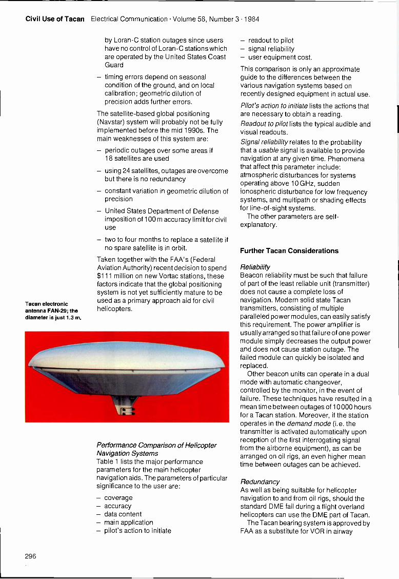
Civil Use of Tacan Electrical Communication Volume 58, Number 3 1984
Tacan electronicantenna FAN -29; thediameter is just 1.3 m.
by Loran -C station outages since usershave no control of Loran -C stations whichare operated by the United States CoastGuard
- timing errors depend on seasonalcondition of the ground, and on localcalibration; geometric dilution ofprecision adds further errors.
The satellite -based global positioning(Naystar) system will probably not be fullyimplemented before the mid 1990s. Themain weaknesses of this system are:
periodic outages over some areas if18 satellites are used
- using 24 satellites, outages are overcomebut there is no redundancy
- constant variation in geometric dilution ofprecision
United States Department of Defenseimposition of 100 m accuracy limit for civiluse
- two to four months to replace a satellite ifno spare satellite is in orbit.
Taken together with the FAA's (FederalAviation Authority) recent decision to spend$111 million on new Vortac stations, thesefactors indicate that the global positioningsystem is not yet sufficiently mature to beused as a primary approach aid for civilhelicopters.
Performance Comparison of HelicopterNavigation SystemsTable 1 lists the major performanceparameters for the main helicopternavigation aids. The parameters of particularsignificance to the user are:
- coverage- accuracy- data content- main application- pilot's action to initiate
- readout to pilot- signal reliability- user equipment cost.
This comparison is only an approximateguide to the differences between thevarious navigation systems based onrecently designed equipment in actual use.
Pilot's action to initiate lists the actions thatare necessary to obtain a reading.
Readout to pilot lists the typical audible andvisual readouts.
Signal reliability relates to the probabilitythat a usable signal is available to providenavigation at any given time. Phenomenathat affect this parameter include:atmospheric disturbances for systemsoperating above 10 GHz, suddenionospheric disturbance for low frequencysystems, and multipath or shading effectsfor line -of -sight systems.
The other parameters are self-explanatory.
Further Tacan Considerations
ReliabilityBeacon reliability must be such that failureof part of the least reliable unit (transmitter)does not cause a complete loss ofnavigation. Modern solid state Tacantransmitters, consisting of multipleparalleled power modules, can easily satisfythis requirement. The power amplifier isusually arranged so that failure of one powermodule simply decreases the output powerand does not cause station outage. Thefailed module can quickly be isolated andreplaced.
Other beacon units can operate in a dualmode with automatic changeover,controlled by the monitor, in the event offailure. These techniques have resulted in amean time between outages of 10000 hoursfor a Tacan station. Moreover, if the stationoperates in the demand mode (i.e. thetransmitter is activated automatically uponreception of the first interrogating signalfrom the airborne equipment), as can bearranged on oil rigs, an even higher meantime between outages can be achieved.
RedundancyAs well as being suitable for helicopternavigation to and from oil rigs, should thestandard DME fail during a flight overlandhelicopters can use the DME part of Tacan.
The Tacan bearing system is approved byFAA as a substitute for VOR in airway
296

Electrical Communication Volume 58, Number 3 1984 Civil Use of Tacan
navigation (navigation along predeterminedroutes formed by VOR/VORTAC. DME, andother navigation aids) and for nonprecisionapproaches using a Vortac facility. Since theVOR and Tacan systems use separateequipment both in the aircraft and on thegrourd, a VOR failure in the airborne orground equipment will not disable the Tacan
system; if Tacan equipped, the helicoptercan continue the flight using Tacan bearinginformation instead of VOR.
Area NavigationLow cost area navigation airborneccmputers are available for helicopters,with preselection and storage of up to
Table 1 - Performance comparison of modern helicopter navigation systems
N/stem
Parameter
NDB/DME Tacan Tacan/NDB Decca Loran -C Omega GPS Inertial Doppler Airborne radar
Coverage NDB dependingon transmissionpower (typically> 200 n milesDME: line -of-
sight
Line -of-
sightNDB dependingon transmissionpower (typically> 200 n miles
Tacan line-
of -sight
> 200 n miles(but notglobal
coverageof the earth'ssurface)
1200 n miles(but not
global
coverageof the earth'ssurface)
Global Global Unlimited Unlimited Unlimited
Error NDB: variable
DME: 160 rn*
Range
<160m*Bearing:<2°`
NDB: variable
Tacan:
Range:
<160m*Bearing: <2°'
20 to 3000 m
dependingon range
30 to 400 m
dependingon range
1 to 2 n miles
RMS
100m(civil use)
1.5 to 2 nmiles
per hourCEP
0.5 to 1%CEP
Variable
Data
conten:NDB
Relative
direction
DME: distance
Relative
bearing,
distance,
velocity,time to
station
Tacan:
bearing,distance,
velocity,
time to station
NDB:
relative
directionoutsideTacan
coverage
Absolute 2Dposition
Absolute 2Dposition
Absolute 2Dposition
Absolute 3Dposition,
3D velocity,time
3D position3D velocity
2D position3D velocity
Relative
Rho/theta2D position
Main
applicationMedium rangenavigation
Short tomedium rangenavigation,approach
Medium rangenavigation,
approach
Long rangenavigation
Long rangenavigation
Long range
navigation
Long range
navigationLong range
navigation
Long range
navigationIntermittentposition fix
Pilot'saction toinitiate
NDB:
1) Select one of1400 channels2) Place set in
ADF modeDME:
Select one
of 252 channels
1) Selectone of252 channels2) Selectdesiredbearing
Tacan:
1) Select one of252 channels2) Selectdesired bearingNDB:
1) Select one of
1400 channels2) Place set in
ADF mode
1) Select oneof 64 channels2) Insertmap in flight
log
1) Select oneof 40 rates2) Insertstart time
difference(in some sets)
1) Select 3 of8 stations2) Correctfor knowndelay usingtables
1) Insert
presentpositionand time.
This overridesautomatic
initializationreducingtime to first fix
1) Start
warm up2) Performinitial
alignment3) Insertdestinationcoordinates4) Switch to"navigation"mode
1) Enter
navigationdata
necessaryfor the flight
Readout:to pilot
NDB:Read360° dial:DME:Read distanceon digital
counter
1) Read
distance ondigital counter.Read bearingon 360° dial
2) Read left- right meterRead velocityand time to
station
Tacan:Readout aspreviouscolumn +NDBreadout on360° dial
outsideTacan
coverage
1) Read lanesand fractionsor 3 decom-meters.Plot positionon hyperbolicmap
2) Read
positionon map
Read timedelay ondigital display.
Plot positionon hyperbolicmap
Read timedelay ondigital display.Plot positionon hyperbolicmap
Read positionin any 3Dcoordinatesystem
Read rangeand bearingto destination
Read on thedisplay:- ground
speed- left/right
steeringinformation
- distanceto go
Observe themaplike imageon the radarindicator
Signal
reliability
NDB:
Fair (200 to
500 kHz)
DME:High (L Band)
High
(L Band)
Tacan:
High (L Band)
NDB:
Fair (200 to
500 kHz)
Fair
(70 to
130 kHz)
Fair
(100 kHz)
Fair
(10 to 14 kHz)
High
(1230 to1575 kHz)
Moderate(13 GHz)
Moderate(5 to 16 GHz)
Userequipmentcost
Low Low Moderate Moderate Moderateto high
Macerateto high
High Moderateto high
High High
= in proximity to the station
297
Civil Use of Tacan Electrical Communication Volume 58, Number 3 1984
10 way points (selected points on or near acourse line which are used for navigation).The Tacan-based RNAV capability, besidespermitting flights to a Tacan-equipped rig,also allows the pilot to use any other rig as areference point provided it is in the areaserved by Tacan. The same station caneven be used for the flight back to base.
Several Tacan stations can thus be simplyinterconnected to form a network allowingnavigation over a wide area using either thesame procedures as for VOR-DME stationsor RNAV procedures.
Conclusions
The Tacan system has some interestingcivil applications, among which its use forhelicopter navigation to offshore oil rigsappears particularly promising. Comparison
with other navigation systems shows thatTacan offers a better approach capabilitytogether with the highest data content innavigation information. In addition, the costis lower than for the other systems.
Bibliography
1 M. Kayton and W. R. Fried: Avionics NavigationSystems: John Wiley & Sons, New York.
2 W. R. Fried: A Comparative Performance Analysis ofModern Ground Based, Air -Based, and SatelliteBased Radio Navigation Systems: Navigation, Spring1977, volume 24, no 1, pp 48-58.
3 E. Lazzaroni: A Solution for Helicopter Navigation toOffshore Oil Rigs: November 1982, Industrie FACEStandard, Milan.
Elio Lazzaroni was born in Genoa in 1939. Hegraduated as a telecommunication engineer from GenoaUniversity. In 1969 he joined Industrie FACE Standard towork as a design and development engineer in thenavigation aid laboratory. Mr Lazzaroni is currentlyproject leader in the field of navigation aids within FACE.
298
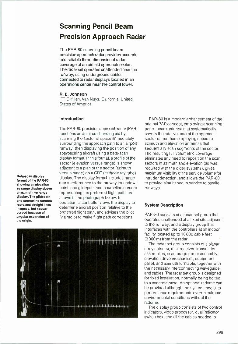
Beta -scan displayformat of the PAR -80,showing an elevationvs range display abovean azimuth vs rangedisplay. The glidepathand courseline cursorsrepresent straight linesin space, but appearcurved because ofangular expansion ofthe origin.
Scanning Pencil Beam
Precision Approach Radar
The PAR -80 scanning pencil beamprecision approach radar provides accurateand reliable three-dimensional radarcoverage of an airfield approach sector.The radar set operates unattended near therunway, using underground cablesconnected to radar displays located in anoperations center near the control tower.
R. E. JohnsonITT Gilfillan, Van Nuys, California, UnitedStates of America
Introduction
The PAR -80 precision approach radar (PAR)functions as an aircraft landing aid byscanning the sector of space immediatelysurrounding the approach path to an airportrunway, then displaying the position of anyapproaching aircraft using a beta -scandisplay format. In this format, a profile of thesector (elevation versus range) is shownadjacent to a plan of the sector (azimuthversus range) on a CRT (cathode ray tube)display. The display format includes rangemarks referenced to the runway touchdownpoint, and glidepath and courseline cursorsrepresenting the preferred flight path, asshown in the photograph below. Inoperation, a controller views the display todetermine aircraft position relative to thepreferred flight path, and advises the pilot(via radio) to make flight path corrections.
PAR -80 is a modern enhancement of theoriginal PAR concept, employing a scanningpencil beam antenna that systematicallycovers the total volume of the approachsector rather than employing separateazimuth and elevation antennas thatsequentially scan segments of the sector.The resulting full volumetric coverageeliminates any need to reposition the scansectors in azimuth and elevation (as wasrequired with the older systems), givesmaximum visibility of the service volume forintruder detection, and allows the PAR -80to provide simultaneous service to parallelrunways.
System Description
PAR -80 consists of a radar set group thatoperates unattended at a fixed site adjacentto the runway, and a display group thatinterfaces with the controllers at an indoorfacility located up to 10000 cable feet(3000 m) from the radar.
The radar set group consists of a planararray antenna, dual receiver -transmitterassemblies, scan programmer assembly,elevation drive mechanism, equipmentpallet, and azimuth turntable, together withthe necessary interconnecting waveguideand cables. The radar set group is designedfor fixed installation, normally being boltedto a concrete base. An optional radome canbe provided although the system meets itsperformance requirements even in extremeenvironmental conditions without theradome.
The display group consists of two controlindicators, video processor, dual indicatorswitch box, and all the cables needed to
299
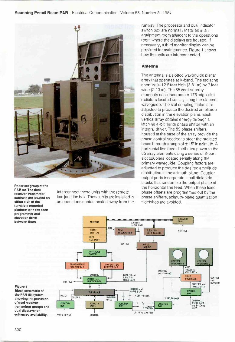
Scanning Pencil Beam PAR Electrical Communication Volume 58, Number 3 1984
Radar set group of thePAR -80. The dualreceiver -transmittercabinets are located oneither side of theturntable -mountedplatform with the scanprogrammer andelevation drivebetween them.
Figure 1Block schematic ofthe PAR -80 systemshowing the provisionof dual receiver -transmitter groups anddual displays forenhanced availability.
interconnect these units with the remoteline junction box. These units are installed inan operations center located away from the
ANTENNA
runway. The processor and dual indicatorswitch box are normally installed in anequipment room adjacent to the operationsroom where the displays are housed. Ifnecessary, a third monitor display can beprovided for maintenance. Figure 1 showshow the units are interconnected.
Antenna
The antenna is a slotted waveguide planararray that operates at X -band. The radiatingaperture is 12.5 feet high (3.81 m) by 7 feetwide (2.13 m). The 85 vertical arrayelements each incorporate 176 edge -slotradiators located serially along the elementwaveguide. The slot coupling factors areadjusted to produce the desired amplitudedistribution in the elevation plane. Eachvertical array obtains energy through alatching 4 -bit ferrite phase shifter with anintegral driver. The 85 phase shiftershoused at the base of the array provide thephase control needed to steer the radiatedbeam through a range of ± 15° in azimuth. Ahorizontal line feed distributes power to the85 array elements using a series of 3 -portslot couplers located serially along theprimary waveguide. Coupling factors areadjusted to produce the desired amplitudedistribution in the azimuth plane. Coupleroutput ports incorporate small dielectricblocks that randomize the output phase ofthe horizontal line feed. When these fixedphase offsets are programmed out by thephase shifters, azimuth -plane quantizationsidelobes are avoided.
PHASESHIFTERS
FEED
ASSEMBLY
TRANSMITTER/RECEIVER No 1
CONTROL
POWER
JUNCTIONBOX
PRIME POWER
CONTROL
WAVEGUIDESWITCH
CONTROL
SWITCH andJUNCTION BOX
AZIMUTHDRIVE
CONTROL
AZIMUTHANGLE DATA
EWLBITE
CONTROL
TRANSMITTER/RECEIVER No 2
SYNCHRODATA
AZIMUTH andELEVATIONANGLE DATA
CONTROL andANGLE DATA
VIDEDTRIGGER
CONTROL
UP TO 10 000 FEET
ELEVATIONDRIVE
CONTROL
CONTROLand SYNCHRO
VIDEOTRIGGERIandANGLE DATA
PROCESSOR IVIDEO
CONTROL andANGLE DATA
VIDEO,TRIGGER
SWITCHBOX
CONTROL.ANGLE DATAand SYNCHRODATA
CONTROLandSYNCHRO
300
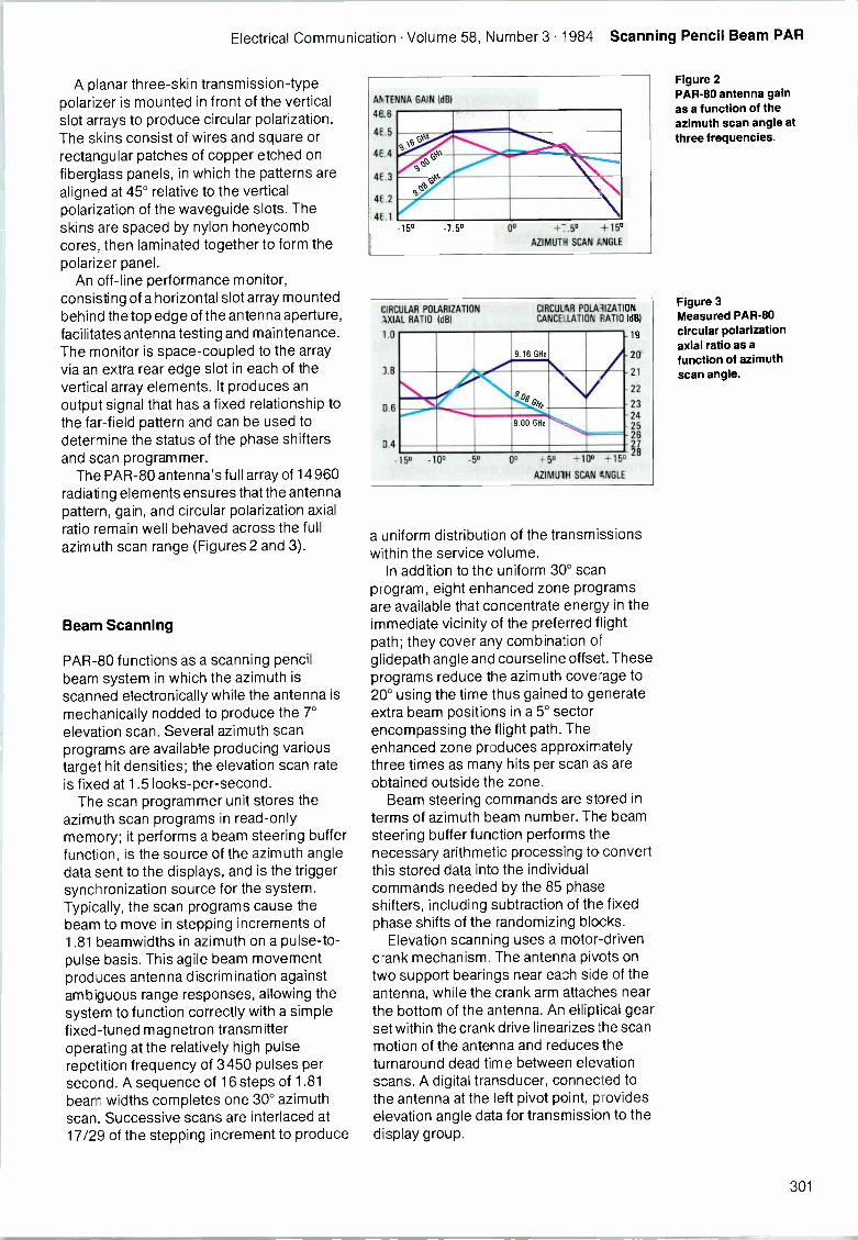
Electrical Communication Volume 58, Number 3 1984 Scanning Pencil Beam PAR
A planar three -skin transmission -typepolarizer is mounted in front of the verticalslot arrays to produce circular polarization.The skins consist of wires and square orrectangular patches of copper etched onfiberglass panels, in which the patterns arealigned at 45° relative to the verticalpolarization of the waveguide slots. Theskins are spaced by nylon honeycombcores, then laminated together to form thepolarizer panel.
An off-line performance monitor,consisting of a horizontal slot array mountedbehind the top edge of the antenna aperture,facilitates antenna testing and maintenance.The monitor is space -coupled to the arrayvia an extra rear edge slot in each of thevertical array elements. It produces anoutput signal that has a fixed relationship tothe far -field pattern and can be used todetermine the status of the phase shiftersand scan programmer.
The PAR -80 antenna's full array of 14960radiating elements ensures that the antennapattern, gain, and circular polarization axialratio remain well behaved across the fullazimuth scan range (Figures 2 and 3).
Beam Scanning
PAR -80 functions as a scanning pencilbeam system in which the azimuth isscanned electronically while the antenna ismechanically nodded to produce the 7°elevation scan. Several azimuth scanprograms are available producing varioustarget hit densities; the elevation scan rateis fixed at 1.5 looks -per -second.
The scan programmer unit stores theazimuth scan programs in read-onlymemory; it performs a beam steering bufferfunction, is the source of the azimuth angledata sent to the displays, and is the triggersynchronization source for the system.Typically, the scan programs cause thebeam to move in stepping increments of1.81 beamwidths in azimuth on a pulse -to -pulse basis. This agile beam movementproduces antenna discrimination againstambiguous range responses, allowing thesystem to function correctly with a simplefixed -tuned magnetron transmitteroperating at the relatively high pulserepetition frequency of 3450 pulses persecond. A sequence of 16 steps of 1.81beam widths completes one 30° azimuthscan. Successive scans are interlaced at17/29 of the stepping increment to produce
ANTENNA
46.6
4E.5
4E.4
4E.3
4E.2
4E 1
GAIN (dB)
c"\v-s .....sai\44'
NPs.
%c,0
s.
-15° -7 5° 0° +7.5° +15AZIMUTH SCAN ANGLE
CIRCULAR POLARIZATIONAXIAL RATIO (dB)
1.0
11.6
3.4
- 5° -10°
CIRCULAR POLAlIZATIONCANCELLATION RATIO (dB)
19
20
21
22
2324252627
+1528
9.16 GHz
9.00 GHz
r
-5° 0° +5°
AZIMUTH SCAN ANGLE
+100
a uniform distribution of the transmissionswithin the service volume.
In addition to the uniform 30° scanprogram, eight enhanced zone programsare available that concentrate energy in theimmediate vicinity of the preferred flightpath; they cover any combination ofglidepath angle and courseline offset. Theseprograms reduce the azimuth coverage to20° using the time thus gained to generateextra beam positions in a 5° sectorencompassing the flight path. Theenhanced zone produces approximatelythree times as many hits per scan as areobtained outside the zone.
Beam steering commands are stored interms of azimuth beam number. The beamsteering buffer function performs thenecessary arithmetic processing to convertthis stored data into the individualcommands needed by the 85 phaseshifters, including subtraction of the fixedphase shifts of the randomizing blocks.
Elevation scanning uses a motor -drivencrank mechanism. The antenna pivots ontwo support bearings near each side of theantenna, while the crank arm attaches nearthe bottom of the antenna. An elliptical gearset within the crank drive linearizes the scanmotion of the antenna and reduces theturnaround dead time between elevationscans. A digital transducer, connected tothe antenna at the left pivot point, provideselevation angle data for transmission to thedisplay group.
Figure 2PAR -80 antenna gainas a function of theazimuth scan angle atthree frequencies.
Figure 3Measured PAR -80circular polarizationaxial ratio as afunction of azimuthscan angle.
301
Scanning Pencil Beam PAR Electrical Communication Volume 58, Number 3 1984
This combination of electronic andmechanical scanning achieves the desiredbeam placement agility without the expenseof having one phase shifter for each antennaradiating element. The resulting antennahas excellent beamforming characteristics.
Receiver -Transmitter
The receiver -transmitter group is based onthe proven MK -V Quad radar, with minormodifications. Two receiver -transmittergroups are used to increase reliability andoperational availability. Remotely controlledswitching connects one group to theantenna while the other is on standbyconnected to a dummy load.
The receiver is a single conversionsuperheterodyne type employing a long -lifepassive transmit -receive tube in anotherwise all solid-state design. Typicallythe noise figure is around 8.9 dB. A low -
noise RF (radio frequency) amplifier wasunnecessary because of the high antennagain and relatively low instrumented rangeof 20 n miles (37 km). The receiver operateswith a 30 MHz intermediate frequency, andhas a bandwidth of 4 MHz. The receiver has54 dB of sensitivity time control, and givesthe operator a selection between linear,linear fast time constant, or logarithmic fasttime constant video.
The transmitter employs a coaxialmagnetron driven by a proven reliableline -type modulator. Resonant charging isutilized for the capacitance of a pulseforming network, then a ceramic thyratron isfired to discharge the pulse forming networkthrough a pulse transformer to drive thecathode of the magnetron. The output istunable between 9.0 and 9.16 GHz; thenominal peak power is 180 kW, with apulsewidth of 0.24 ps and a pulse repetitionfrequency of 3450 pulses per second.
Video Processor
The video processor contains the remotevideo line compensation amplifier and theangle data decoding circuitry that convertsthe digital angle data from the radar setgroup into the analog format required by thedisplays. It also performs video timecompression and clutter censoring.
In a scanning pencil beam system of thistype, the received target video reports arerelevant to both the elevation and azimuth
parts of the display. A video timecompression circuit retains all data for bothparts of the display, and yet allows thedisplay to operate with a single -gun CRT.The video time compression function isperformed by converting analog video intodigital form and writing it into memory at a7 MHz clock rate, then reading the data frommemory twice at a 14 MHz clock rate. Twovideo memories are used, each capable ofstoring all information received during anactive radar interpulse period. While onememory is writing data, the other is readingdata twice at the higher rate - once for theelevation display and once for the azimuthdisplay.
Video processing circuits include cluttercensoring, which prevents off -angle groundclutter from being superimposed withtargets of interest on the display. Thisfeature utilizes the inherent high resolutionof the pencil beam antenna to detect targetsand ground clutter separately, and thenselectively eliminate clutter from the display.The censor consists of a series of three-dimensional cells that occupy approximatelythe bottom half of the radar service volume.Individual cells are 562 feet (170 m) inrange, 1.034° in azimuth, and 0.35° inelevation (except for the top layer of cellswhich is adjustable in elevation). The cluttercensor employs a sequential observeralgorithm in which a cell is said to containclutter if video threshold crossings aredetected for a time greater than the normallyexpected dwell time of a moving aircraft. Oneach sweep of the elevation scan, thevolume is examined for threshold crossings.If a preset number of crossings is detectedin a cell, the count in the correspondingmemory cell is incremented. The thresholdlevel and required number of crossings areadjusted to establish the desired false alarmrate. If that number of threshold crossings isnot detected, the count is decremented.When the accumulated count reaches apreset level, censoring is initiated for thatcell unless it is deactivated by the clear zonelogic. The preset switching level for thecounter is adjusted to allow the slowestaircraft of interest to traverse the cell withoutswitching.
Clear zones are preset volumes, withinthe clutter censor operating volume, inwhich the clutter censor is not allowed toperform its censoring function but allowswhatever video is present to be displayed.The clear zones are normally adjusted toinclude the space immediately surroundingthe flight path cursors. For test and
302
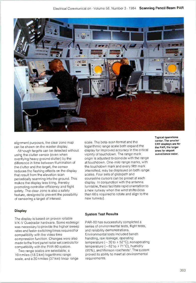
Electrical Communication Volume 58, Number 3 1984 Scanning Pencil Beam PAR
alignment purposes, the clear zone mapcan be shown on the master display.
Altiough targets can be detected withoutusing the clutter censor (even whenoverflying heavy ground clutter) by thedifference in time between illumination ofthe clutter and the target, the censorreduces the flashing effects on the displaythat result from the elevation scanperiodically scanning into the ground. Thismakes the display less tiring, therebypromoting controller efficiency and flightsafety. The clear zone is also a safetyfeature, designed to prevent the possibilityof censoring a target of interest.
Display
The display is based on proven reliableMK -V Quadradar hardware. Some redesignwas necessary to provide the higher sweeprates and faster switching times required forcompatibility with the video timecompression function. Changes were alsomade to the front panel radar set controls forcompatibility with the PAR -80 system.
Two range scales are selectable; a10 n miles (18.5 km) logarithmic rangescale, and a 20 n miles (37 km) linear range
scale. The beta -scan format and thelogarithmic range scale both expand thedisplay for improved accuracy in the criticalvicinity of touchdown. The range markorigin is adjusted to coincide with the rangeat touchdown. One -mile range marks, withthe touchdown mark and every fifth markintensified, may be displayed on both rangescales. Four sets of glidepath andcourseline cursors can be preset at eachdisplay. In conjunction with the antennaturntable, these facilitate rapid orientation toa new runway when the wind shifts (lessthan 60 s required to rotate and align to thenew runway).
System Test Results
PAR -80 has successfully completed aseries of environmental tests, flight tests,and reliability demonstrations.Environmental tests included benchhandling, rain leakage, operatingtemperature (- 30 to + 52°C), nonoperatingtemperature (- 62 to + 71°C), humidity(95%), and Munson road tests'. The systemproved its ability to meet all environmentalrequirements.
Typical operationscenter. The smallerCRT displays are forthe PAR, the largerones for airportsurveillance radar.
303
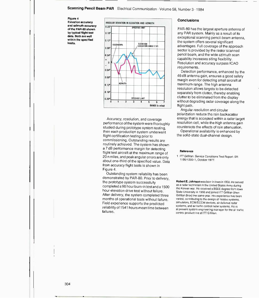
Scanning Pencil Beam PAR Electrical Communication Volume 58, Number 3 1984
Figure 4Elevation accuracyand azimuth accuracyof the PAR -80 shownby typical flight testdata. Both are wellwithin the specifiedlimits.
ANGULAR DEVIATION IN ELEVATION AND AZIMUTH
0.20°
0.16°
0.12°
0.08°
0.04°
0
0.04°
0.08°
0.12°
0.16°
0 20°
SPECIFIED LIMIT
TOUCHDOWN
//N0......
ELEVATION(ELEVATION
ANGLE 2.5 I
AZIMUTH
SPECIFIED LIMIT
0 2 3 4 5 6
RANGE In miles
Accuracy, resolution, and coverageperformance of the system were thoroughlystudied during prototype system testing,then each production system underwentflight certification testing prior tocommissioning. Outstanding results areroutinely achieved. The system has showna 7 dB performance margin for detectingflight test aircraft at the maximum range of20 n miles, and peak angular errors are onlyabout one-third of the specified value. Datafrom accuracy flight tests is shown inFigure 4.
Outstanding system reliability has beendemonstrated by PAR -80. Prior to delivery,the prototype system successfullycompleted a 96 hour burn -in test and a 1500hour elevation drive test without failure.After delivery, the system completed threemonths of operational tests without failure.Field experience supports the predictedreliability of 1541 hours mean time betweenfailures.
Conclusions
PAR -80 has the largest aperture antenna ofany PAR system. Mainly as a result of itsexceptional scanning pencil -beam antenna,the system offers several significantadvantages. Full coverage of the approachsector is provided by the raster scannedpencil beam, and the wide azimuth scancapability increases siting flexibility.Resolution and accuracy surpass ICAOrequirements.
Detection performance, enhanced by the46 dB antenna gain, ensures a good safetymargin even for detecting small aircraft atmaximum range. The high antennaresolution allows targets to be detectedseparately from clutter, thereby enablingclutter to be eliminated from the displaywithout degrading radar coverage along theflight path.
Angular resolution and circularpolarization reduce the rain backscatterenergy that is accepted within a radar targetresolution cell, while the high antenna gaincounteracts the effects of rain attenuation.
Operational availability is enhanced bythe solid-state dual -channel design.
Reference
1 ITT Gilfillan: Service Conditions Test Report: ER1195/1200-1, October 1977.
Robert E. Johnson was born in Iowa in 1930. He servedas a radar technician in the United States Army duringthe Korean war. He received a BSEE degree from IowaState University in 1956 and joined ITT Gilfillan (thenGilfillan Bros) the same year. His experience has beenvaried, contributing to the design of missile systems,simulators, ECM/ECCM devices, air defense radarsystems, and air traffic control radar systems. He isat present system engineering manager for the air trafficcontrol product line at ITT Gilfillan.
304
Further Development of the DPS Techniquefor Precision DME
The double pulse shaping technique iscompatible with the latest requirements forprecision distance measuring equipmentdefined by the ICAO. It is particularlysuitable where high postional accuracy isrequired.
G. CorazzaDipartimento di Elettronica, Informatica eSistemistica, University di Bologna, ItalyF. VatalaroFACE -RC, Industrie FACE Standard SpA,Pomezia, Italy
Introduction
The standardization of MLS (microwavelanding system) by the International CivilAviation Organization is already welladvanced. Final approval of the standardsfor the elevation and azimuth functions wasgiven in April 1981. The attention of theOrganization's AWOP (All WeatherOperationsDME/P (precision distance measuringequipment).
At the same time, FACE Standard wasinvolved in a sponsored research programwhich led to an Italian proposal based on theDPS (double pulse shaping) technique, aspreviously described in ElectricalCommunication and elsewherel. 2' 3
During 1981 and 1982 several meetingsof the AWOP and its working groups wereheld, and many useful results wereobtained. Some of the findings resulted inchanges to the configuration of the originalItalian proposals. In late 1982 the panelcompleted its work on drafting the SARPs(standards and recommended practices)and related guidelines for the new system4.
Two accuracy standards were defined:standard 1 for most conventional take -offand landing operations, and standard 2 forshort take -off and landing and vertical take-off and landing applications, and otherspecial functions. Both standards specifyremarkably low upper limits for pathfollowing errors: ± 30 m and ± 12 m,respectively, at the MLS approachreference datum. Guidelines were alsodrawn up for control motion noise, togetherwith detailed error budgets.
In addition the AWOP chose the two-pulse/two-mode DME/P system conceptwhich has the following maincharacteristics:
Interrogations and replies are still carriedout by pulse pairs.
An initial approach mode is available foraircraft at ranges between about 7 and22 n miles from the transponder site. Inthis case the equipment performance isessentially indistinguishable fromconventional DME/N, although withslightly higher accuracy.
At ranges below about 7 n miles the finalapproach mode applies; this uses adifferent time spacing between thepulses of the pair than in the initialapproach mode (e.g. for X channels thetime spacing changes from 12 to 18µs).Clearly higher accuracies are specified inthis mode.
During the discussions that led to the choiceof system concept, the DPS technique wascarefully considered4. The discussionsrecognized that it is a promising techniquebut too far from the traditional DME conceptto be accepted without the support of a largenumber of field trials. Nevertheless it wasalso recognized that it is compatible with thetwo-pulse/two-mode concept and thatpotentially it offers scope for furtherimprovements in system capabilities tocope with advanced applications.
Several requirements concerning thetransmitted pulse waveform were alsoassessed: for the final approach mode thepulse shape Is almost fully specified. Thepulse must have:
305
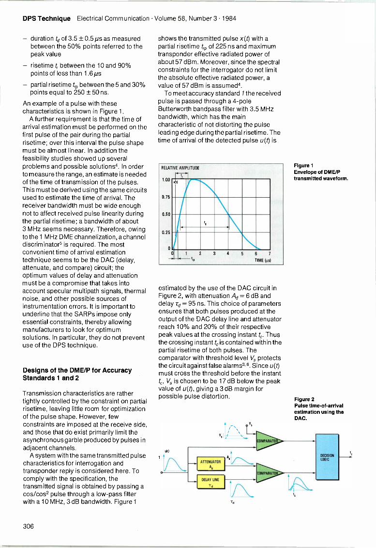
DPS Technique Electrical Communication Volume 58, Number 3 1984
- duration td of 3.5 ± 0.5 ps as measuredbetween the 50% points referred to thepeak value
- risetime t, between the 10 and 90%points of less than 1.6µs
- partial risetime trp between the 5 and 30%points equal to 250 ± 50 ns.
An example of a pulse with thesecharacteristics is shown in Figure 1.
A further requirement is that the time ofarrival estimation must be performed on thefirst pulse of the pair during the partialrisetime; over this interval the pulse shapemust be almost linear. In addition thefeasibility studies showed up severalproblems and possible solutions4. In orderto measure the range, an estimate is neededof the time of transmission of the pulses.This must be derived using the same circuitsused to estimate the time of arrival. Thereceiver bandwidth must be wide enoughnot to affect received pulse linearity duringthe partial risetime; a bandwidth of about3 MHz seems necessary. Therefore, owingto the 1 MHz DME channelization, a channeldiscriminators is required. The mostconvenient time of arrival estimationtechnique seems to be the DAC (delay,attenuate, and compare) circuit; theoptimum values of delay and attenuationmust be a compromise that takes intoaccount specular multipath signals, thermalnoise, and other possible sources ofinstrumentation errors. It is important tounderline that the SARPs impose onlyessential constraints, thereby allowingmanufacturers to look for optimumsolutions. In particular, they do not preventuse of the DPS technique.
Designs of the DME/P for AccuracyStandards 1 and 2
Transmission characteristics are rathertightly controlled by the constraint on partialrisetime, leaving little room for optimizationof the pulse shape. However, fewconstraints are imposed at the receive side,and those that do exist primarily limit theasynchronous garble produced by pulses inadjacent channels.
A system with the same transmitted pulsecharacteristics for interrogation andtransponder reply is considered here. Tocomply with the specification, thetransmitted signal is obtained by passing acos/cost pulse through a low-pass filterwith a 10 MHz, 3 dB bandwidth. Figure 1
shows the transmitted pulse x(t) with apartial risetime tip of 225 ns and maximumtransponder effective radiated power ofabout 57 dBm. Moreover, since the spectralconstraints for the interrogator do not limitthe absolute effective radiated power, avalue of 57 dBm is assumed4.
To meet accuracy standard 1 the receivedpulse is passed through a 4 -poleButterworth bandpass filter with 3.5 MHzbandwidth, which has the maincharacteristic of not distorting the pulseleading edge during the partial risetime. Thetime of arrival of the detected pulse u(t) is
x(t)
1...
1d .
0 2 3 4 5 6 7
estimated by the use of the DAC circuit inFigure 2, with attenuation Ad = 6 dB anddelay Td = 95 ns. This choice of parametersensures that both pulses produced at theoutput of the DAC delay line and attenuatorreach 10% and 20% of their respectivepeak values at the crossing instant tc. Thusthe crossing instant t, is contained within thepartial risetime of both pulses. Thecomparator with threshold level Vs protectsthe circuit against false alarms3,6. Since u(t)must cross the threshold before the instanttc, Vs is chosen to be 17 dB below the peakvalue of u(t), giving a 3 dB margin forpossible pulse distortion.
Td
Figure 1Envelope of DME/Ptransmitted waveform.
Figure 2Pulse time -of -arrivalestimation using theDAC.
DECISIONLOGIC
306
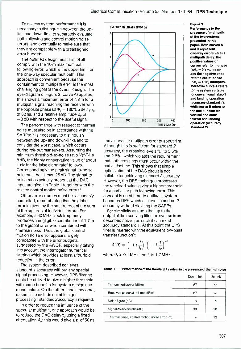
Electrical Communication Volume 58, Number 3 1984 DPS Technique
To assess system performance it isnecessary to distinguish between the up-link and down -link, to separately evaluatepath following and control motion noiseerrors, and eventually to make sure thatthey are compatible with a preassignederror budget'.
The outlined design must first of allcomply with the 10 m maximum pathfollowing error, which is the upper limit forthe one-way specular multipath. Thisapproach is convenient because thecontainment of multipath error is the mostchallenging goal of the overall design. Theeye -diagram of Figure 3 (curve A) applies;this shows a maximum error of 7.3 m for amultipath signal reaching the receiver withthe opposite phase (L (De = 180°), a delay -reof 60 ns, and a relative amplitude pe of-3 dB with respect to the useful signal.
The performance with respect to thermalnoise must also be in accordance with theSARPs: it is necessary to distinguishbetween the up- and down -links and toconsider the worst case, which occursduring roll -out maneuvers. Assuming theminimum threshold -to -noise ratio Vs2/N is8 dB, the highly conservative value of about1 Hz for the false alarm rate6 follows.Correspondingly the peak signal-to-noiseratio must be at least 25 dB. The signal-to-noise ratios actually present at the DACinput are given in Table 1 together with therelated control motion noise errors'.
Other error sources must be reasonablycontrolled, remembering that the globalerror is given by the square root of the sumof the squares of individual errors. Forexample, a 60 MHz clock frequencyproduces a negligible contribution of 1.7 mto the global error when combined withthermal noise. Thus the global controlmotion noise error appears largelycompatible with the error budgetssuggested by the AWOP, especially takinginto account the interrogator numericalfiltering which provides at least a fourfoldreduction in the error.
The system described achievesstandard 1 accuracy without any specialsignal processing. However, DPS filteringcould be utilized to give a higher thresholdwith some benefits for system design andmanufacture. On the other hand it becomesessential to include suitable signalprocessing if standard 2accuracy is required.
In order to reduce the influence of thespecular multipath, one approach would beto reduce the DAC delay Td using a fixedattenuation Ad: this would give a rd of 50 ns,
ONE-WAY
6
4
2
0
2
-4
6
-8
MULTIPATH ERROR (m)
A
8
A
0 100 200 300 400
TIME DELAY Ins)
and a specular multipath error of about 4 m.Although this is sufficient for standard 2accuracy, the crossing levels fall to 5.5%and 2.8%, which violates the requirementthat both crossings must occur within thepartial risetime. This shows that simpleoptimization of the DAC circuit is notsuitable for achieving standard 2 accuracy.However, the DPS technique processesthe received pulse, giving a higher thresholdfor a particular path following error. Thisconcept is used here to outline a systembased on DPS which achieves standard 2accuracy without violating the SARPs.
For simplicity assume that up to theoutput of the receiv ng filter the system is asdescribed above; as such it can meetaccuracy standard 1. At this point the DPSfilter is inserted with the equivalent low-passtransfer functions:
A' (f) =\1+/ Tif ) (1 + j ) 1
where 11 is 0.1 MHz and f2 is 1.7 MHz.
Figure 3Performance in thepresence of multipathof the two systemspresented in thispaper. Both curves Aand B representone-way errors versusmultipath delay: thepositive values ofcurves refer to in -phase(6.1), = 0°) multipathand the negative onesrefer to out -of -phase(6,0e = 180°) multipath.Moreover curve A refersto the system suitablefor conventional takeoffand landing operation(accuracy standard 1),while curve B refers tothe one suitable forvertical and shorttakeoff and landingoperation (accuracystandard 2).
Table 1 - Performance of the standard / system in the presence of thermal noise
Down -link Up -link
Transmitted power (dBm) 57 57
Received power at roll -out (dBm) -67 -73
Noise figure (dB) 6 9
Signal-to-noise ratio (dB) 39 30
Thermal noise, control motion noise error (m) 4 12
307
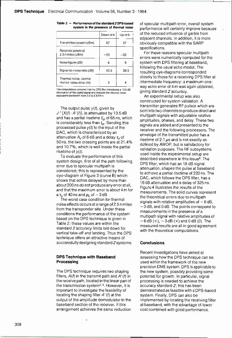
DPS Technique Electrical Communication Volume 58, Number 3 1984
Table 2 - Performance of the standard 2 DPS-basedsystem in the presence of thermal noise
Down -link Up -link
Transmitted power (dBm) 57 57
Received power at2.5 n miles (dBm) -53 -52
Noise figure (dB) 6 9
Signal-to-noise ratio (dB) 40.5 38.5
Thermal noise, controlmotion noise error (m)
34
The computations assume that the DPS filter introduces a 13.5 dBattenuation of the useful signal and reduces the receiver noiseequivalent bandwidth from 3.5 to 2.8 MHz.
The output pulse y(t), given byJ-1 [X(f) A' (0], is attenuated by 13.5 dBand has a partial risetime tr'p of 65 ns, whichis considerably less than trp. Sending thisprocessed pulse y(t) to the input of theDAC, which is characterized by anattenuation Ad of 6 dB and a delay Td of50 ns, the two crossing points are at 21.4%and 10.7%, which is well inside the partialrisetime of y(t).
To evaluate the performance of thissystem design, first of all the path followingerror due to specular multipath isconsidered; this is represented by theeye -diagram of Figure 3 (curve B) whichshows that echos delayed by more thanabout 200 ns do not produce any error at all,and that the maximum error is about 4 m fora re of 40 ns and p e of -3 dB.
The worst case condition for thermalnoise effects occurs at a range of 2.5 n milesfrom the transponder site. Under theseconditions the performance of the systembased on the DPS technique is given inTable 2; these values are within thestandard 2 accuracy limits laid down forvertical take -off and landing. Thus the DPStechnique offers an attractive means ofsuccessfully designing standard 2 systems.
DPS Technique with BasebandProcessing
The DPS technique requires two shapingfilters, A (f) in the transmit path and A' (f) inthe receive path, located in the linear part ofthe transmission system2. 3. However, it isimportant to investigate the feasibility oflocating the shaping filter A' (f) at theoutput of the amplitude demodulator in thebaseband section of the receiver. If thisarrangement achieves the same reduction
of specular multipath error, overall systemperformance will certainly improve becauseof the reduced influence of garble fromadjacent channels. In addition, it is moreobviously compatible with the SARPspecifications.
For these reasons specular multipatherrors were numerically computed for thesystem with DPS filtering at baseband,following the usual echo model. Theresulting eye -diagrams correspondedclosely to those for a receiving DPS filter atintermediate frequency: a maximum one-way echo error of 4 m was again obtained,giving standard 2 accuracy.
An experimental setup was alsoconstructed for system validation. Atransmitter generates RF pulses which aresent into two channels to produce direct andmultipath signals with adjustable relativeamplitudes, phases, and delay. These twosignals are added and presented to thereceiver and the following processors. Theenvelope of the transmitted pulse has arisetime of 2.1 µs and is not exactly asdefined by AWOP, but is satisfactory forvalidation purposes. The RF subsystemsused inside the experimental setup aredescribed elsewhere in this issue8. TheDPS filter, which has an 18 dB signalattenuation, shapes the pulse at basebandto achieve a partial risetime of 220 ns. TheDAC, which follows the DPS filter, has a16 dB attenuation and a delay of 325 ns.Figure 4 illustrates the results of themeasurements. The solid curves representthe theoretical errors due to multipathsignals with relative amplitudes of -6 dB,-3 dB, and 0 dB. The points correspond tomeasurements in the presence of amultipath signal with relative amplitudes of-6 dB (+), -3 dB (x) and 0 dB (0). Themeasured results are all in good agreementwith the theoretical computations.
Conclusions
Recent investigations have aimed atassessing how the DPS technique can beused within the framework of the newprecision DME system. DPS is applicable tothe new system, possibly providing somepotential for growth. In particular, signalprocessing is needed to achieve theaccuracy standard 2; this has beendemonstrated as feasible with a DPS-basedsystem. Finally, DPS can also beimplemented by locating the receiving filterat baseband, with the advantage of lowercost combined with good performance.
308
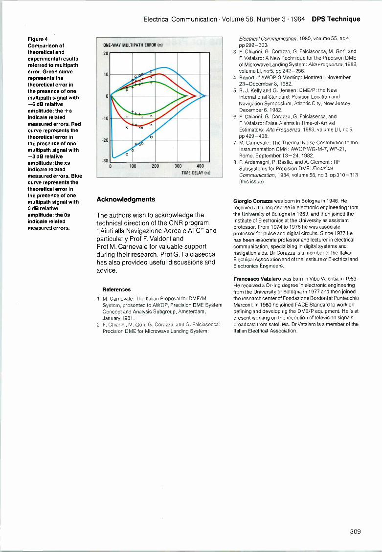
Electrical Communication Volume 58, Number 3 1984 DPS Technique
Figure 4Comparison oftheoretical andexperimental resultsreferred to multipatherror. Green curverepresents thetheoretical error inthe presence of onemultipath signal with-6 dB relativeamplitude: the +sindica- e relatedmeasured errors. Redcurve -epresents thetheoretical error inthe presence of onemultipath signal with-3 dB relativeamplitude: the xsindica.:e relatedmeasured errors. Bluecurve -epresents thetheoretical error inthe presence of onemultipath signal with0 dB relativeamplitude: the Osindicate relatedmeasured errors.
ONE-WAY MULTIPATH ERROR Iml
20
10
0
-10
-20
-30
x
00
0 100 200 300 400
TIME DELAY Ins)
Acknowledgments
The authors wish to acknowledge thetechnical direction of the CNR program"Aiuti alla Navigazione Aerea e ATC" andparticularly Prof F. Valdoni andProf M. Carnevale for valuable supportduring their research. Prof G. Falciaseccahas also provided useful discussions andadvice.
References
1 M. Carnevale: The Italian Proposal for DME/MSystem, presented to AWOP, Precision DME SystemConcept and Analysis Subgroup, Amsterdam,January 1981.
2 F. Chiarini, M. Gori, G. Corazza, and G. Falciasecca:Precision DME for Microwave Landing System:
Electrical Communication, 1980, volume 55, no 4,pp 292-303.
3 F. Chiarini, G. Corazza, G. Falciasecca, M. Gori, andF. Vatalaro: A New Technique for the Precision DMEof Microwave Landing System: Alta Frequenza, 1982,volume LI, no5, pp 242-256.
4 Report of AWDP-9 Meeting: Montreal, November23-December 8, 1982.
5 R. J. Kelly and G. Jensen: DME/P: the NewInternational Standard: Position Location andNavigation Symposium, Atlantic City, New Jersey,December 6, 1982.
6 F. Chiarini, G. Corazza, G. Falciasecca, andF. Vatalaro: False Alarms in Time -of -ArrivalEstimators: Alta Frequenza, 1983, volume LII, no 5,pp 429-438.
7 M. Carnevale: The Thermal Noise Contribution to theInstrumentation CMN: AWOP WG-M-7, WP -21,Rome, September 13-24, 1982.
8 F. Ardemagni, P. Basile, and A. Clement): RFSubsystems for Precision DME: ElectricalCommunication, 1984, volume 58, no 3, pp 310-313(this issue).
Giorgio Corazza was born in Bologna in 1946. Hereceived a Dr-Ing degree in electronic engineering fromthe University of Bologna in 1969, and then joined theInstitute of Electronics at the University as assistantprofessor. From 1974 to 1976 he was associateprofessor for pulse and digital circuits. Since 1977 hehas been assocate professor and lecturer in electricalcommunication, specializing in digital systems andnavigation aids. Dr Corazza is a member of the ItalianElectrical Association and of the Institute of Electrical andElectronics Engineers.
Francesco Vatalaro was born in Vibo Valentia in 1953.He received a Dr-Ing degree in electronic engineeringfrom the University of Bologna in 1977 and then joinedthe research center of Fondazione Bordoni at PontecchioMarconi. In 1980 he joined FACE Standard to work ondefining and developing the DME/P equipment. He is atpresent working on the reception of television signalsbroadcast from satellites. Dr Vatalaro is a member of theItalian Electrice4 Association.
309
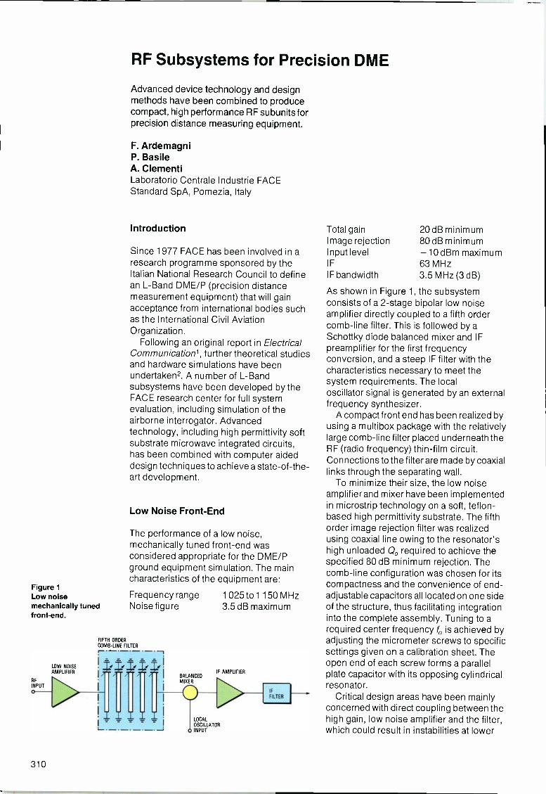
Figure 1Low noisemechanically tunedfront-end.
OW NOISEAMPLIFIER
RF Subsystems for Precision DME
Advanced device technology and designmethods have been combined to producecompact, high performance RF subunits forprecision distance measuring equipment.
F. ArdemagniP. BasileA. ClementiLaboratorio Centrale Industrie FACEStandard SpA, Pomezia, Italy
Introduction
Since 1977 FACE has been involved in aresearch programme sponsored by theItalian National Research Council to definean L -Band DME/P (precision distancemeasurement equipment) that will gainacceptance from international bodies suchas the International Civil AviationOrganization.
Following an original report in ElectricalCommunication', further theoretical studiesand hardware simulations have beenundertaken2. A number of L -Bandsubsystems have been developed by theFACE research center for full systemevaluation, including simulation of theairborne interrogator. Advancedtechnology, including high permittivity softsubstrate microwave integrated circuits,has been combined with computer aideddesign techniques to achieve a state-of-the-art development.
Low Noise Front -End
The performance of a low noise,mechanically tuned front-end wasconsidered appropriate for the DME/Pground equipment simulation. The maincharacteristics of the equipment are:
Frequency range 1 025 to 1150 MHzNoise figure 3.5 dB maximum
FIFTH ORDERCOMB -LINE FILTER
BALANCEDMIXER
IF AMPLIFIER
LOCAL
OSCILLATORINPUT
IF
FILTER
Total gain 20 dB minimumImage rejection 80 dB minimumInput level -10 dBm maximumIF 63 MHzIF bandwidth 3.5 MHz (3 dB)
As shown in Figure 1, the subsystemconsists of a 2 -stage bipolar low noiseamplifier directly coupled to a fifth ordercomb -line filter. This is followed by aSchottky diode balanced mixer and IFpreamplifier for the first frequencyconversion, and a steep IF filter with thecharacteristics necessary to meet thesystem requirements. The localoscillator signal is generated by an externalfrequency synthesizer.
A compact front end has been realized byusing a multibox package with the relativelylarge comb -line filter placed underneath theRF (radio frequency) thin-film circuit.Connections to the filter are made by coaxiallinks through the separating wall.
To minimize their size, the low noiseamplifier and mixer have been implementedin microstrip technology on a soft, teflon-based high permittivity substrate. The fifthorder image rejection filter was realizedusing coaxial line owing to the resonator'shigh unloaded Q, required to achieve thespecified 80 dB minimum rejection. Thecomb -line configuration was chosen for itscompactness and the convenience of end -adjustable capacitors all located on one sideof the structure, thus facilitating integrationinto the complete assembly. Tuning to arequired center frequency fo is achieved byadjusting the micrometer screws to specificsettings given on a calibration sheet. Theopen end of each screw forms a parallelplate capacitor with its opposing cylindricalresonator.
Critical design areas have been mainlyconcerned with direct coupling between thehigh gain, low noise amplifier and the filter,which could result in instabilities at lower
310
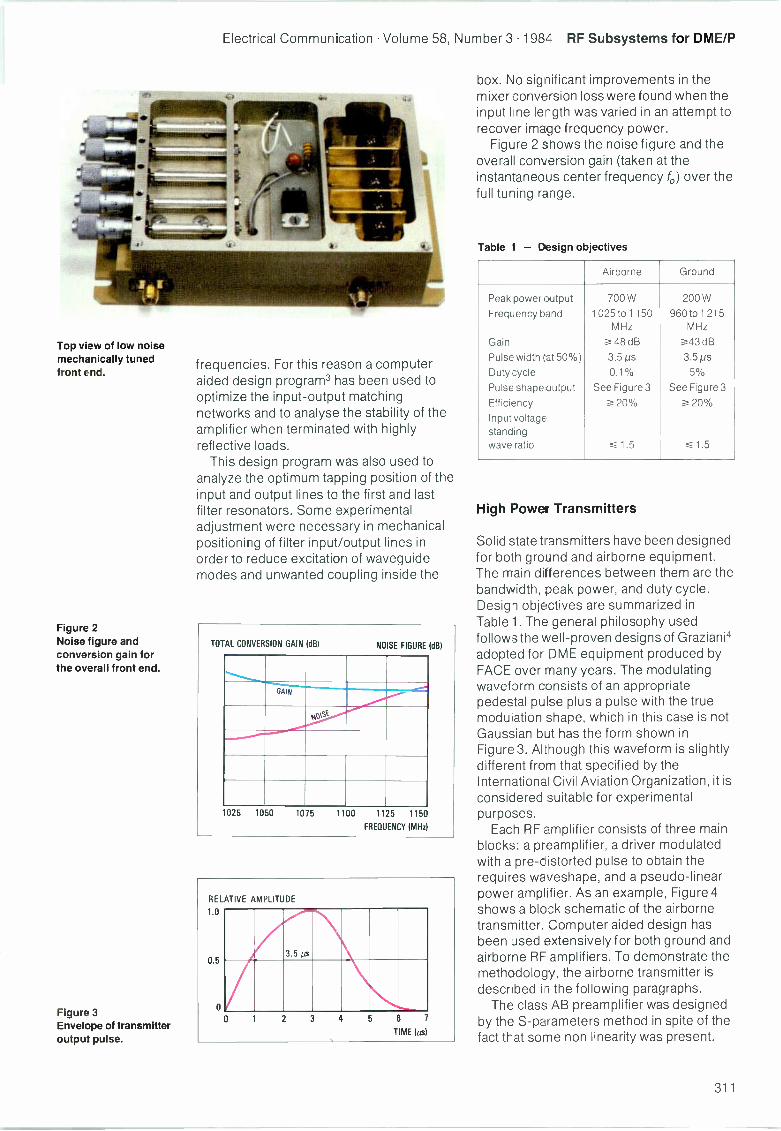
Electrical Communication Volume 58, Number 3 1984 RF Subsystems for DME/P
Top view of low noisemechanically tunedfront end.
Figure 2Noise figure andconversion gain forthe overall front end.
Figure 3Envelope of transmitteroutput pulse.
frequencies. For this reason a computeraided design program3 has been used tooptimize the input-output matchingnetworks and to analyse the stability of theamplifier when terminated with highlyreflective loads.
This design program was also used toanalyze the optimum tapping position of theinput and output lines to the first and lastfilter resonators. Some experimentaladjustment were necessary in mechanicalpositioning of filter input/output lines inorder to reduce excitation of waveguidemodes and unwanted coupling inside the
TOTAL CONVERSION GAIN (dB) NOISE FIGURE (dB)
GAIN
OSt
1025 1050 1075 1100 1125 1150
FREQUENCY (MHz
box. No significant improvements in themixer conversion loss were found when theinput lone length was varied in an attempt torecover image frequency power.
Figure 2 shows the noise figure and theoverall conversion gain (taken at theinstantaneous center frequency fo) over thefull tuning range.
Table 1 - Design objectives
Airborne Ground
Peak power output 700 W 200 W
Frequency band 1 025 to 1150 960 to 1 215MHz MHz
Gain .?-- 48 dB _..43 dB
Pulse width (at 50%) 3.5 pS 3.5 Ns
Duty cycle 0.1% 5%
Pulse shape output See Figure 3 See Figure 3
Efficiency a 20% a 20%
Inputvoltagestandingwave ratio --._. 1.5 ,1.5
High Power Transmitters
Solid state transmitters have been designedfor both ground and airborne equipment.The main differences between them are thebandwidth, peak power, and duty cycle.Design objectives are summarized inTable 1. The general philosophy usedfollows the well -proven designs of Graziani4adopted for DME equipment produced byFACE over many years. The modulatingwaveform consists of an appropriatepedestal pulse plus a pulse with the truemodulation shape, which in this case is notGaussian but has the form shown inFigure 3. Al tnough this waveform is slightlydifferent from that specified by theInternational Civil Aviation Organization, it isconsidered suitable for experimentalpurposes.
Each RF amplifier consists of three mainblocks: a preamplifier, a driver modulatedwith a pre -distorted pulse to obtain therequires waveshape, and a pseudo -linearpower amplifier. As an example, Figure 4shows a block schematic of the airbornetransmitter. Computer aided design hasbeen used extensively for both ground andairborne RF amplifiers. To demonstrate themethodology, the airborne transmitter isdescribed in the following paragraphs.
The class AB preamplifier was designedby the S -parameters method in spite of thefact that some non linearity was present.
311

RF Subsystems for DME/P Electrical Communication Volume 58, Number 3 1984
[INPUT PULSE
[ RF INPUT
=. 10 dBm
CLASS A PREAMPLIFIER
27 dBm
MODULATOR
DRIVER
This was accepted because of the smallmeasured variations of the S -matrix atworking power levels. Transistorparameters were obtained by an automaticnetwork analyzer over the requiredfrequency band and processed to selectinput/output matching characteristics thatcombine flat input voltage standing waveratio with gain roll -off compensation.
A final optimization over the completebandwidth was then performed to achievemaximum flatness and stability. Obviously,this linear approach cannot be used forcharacteristics of the pulsed, class Camplifier stages that form the driver and finaloutput. In this case each transistor wasinserted in a special fixture with a pair ofinput/output tuners and fed with the nominalinput power at a fixed frequency I,. Thetuners were then adjusted for minimumreflection and maximum gain. Optimumreflection coefficients [Gopt(fx)] and [Lopt(fx)]were determined by removing the transistorand looking from suitable reference planestowards the generator and the load with alow power network analyzer at the samefrequency k. Repeating the procedure for anumber of frequencies over the range ofinterest led to a full transistorcharacterization. The whole sequence ofoperation, except for tuner adjustment, wasperformed by an automatic test benchcontrolled by a microcomputer. Animportant feature of this experimentalarrangement is the possibility of obtaining agreat deal of related data, such as thetransistor behavior when bias, peak power,or duty cycle are varied.
Once the active components had beenfully assessed, suitable input/output andinterstage matching networks were derivedby computer aided design techniques,using the same methodology as for thepreamplifier. Figure 5 shows the transmitteroutput peak power as a function offrequency.
The airborne transmitter and the L -Bandamplifier for the ground equipment areshown opposite. The main difference
53 dBm
3 dB HYBRID
POWER AMPLIFIER
3 dB HYBRID
58.5 dBm
RF OUTPUT]
between the two equipments is concernedwith the modulator; in the case of the groundequipment, pulsed video signals are fed tothe RF transistors by connections throughthe common wall of the double box package.
All the circuit stages except the balancedfinal stage of the airborne equipment arearranged transversely. This solution hasproved to be compact and offers easyaccess for final testing.
As in the case of the previously describedfront-end, all the RF circuits have beenconstructed using microstrip on soft, highpermittivity substrates.
Acknowledgments
The authors wish to thank P. Monti andG. Selvazzo for synthesizer development,and F. Cecchini and M. Caruso for supportin thin-film circuit implementation.
References
1 F. Chiarini, M. Gori, G. Corazza, and G. Falciasecca:Precision DME for Microwave Landing Systems:Electrical Communication, 1980, volume 55, no 4,pp 292-303.
2 G. Corazza and F. Vatalaro: Further Development ofthe DPS Technique for Precision DME: ElectricalCommunication, 1983, volume 58, no 3, pp ??-??(this issue).
3 COMPACT User Manual, version 5.1, August 1979Comsat General Integrated Systems, 1131 SanAntonio Road, Palo Alto, California 94303.
PEAK POWER OUT (dBm)
BO
58
56
54
52
50
AIRBORNE PIN = 10 dBm
GROUND PIN = 10 dBm
980 1025 1150 1215
FREQUENCY (MHz
Figure 4Block schematic ofthe airbornetransmitter.
Figure 5Transmitter outputpeak power as afunction of frequency.
312
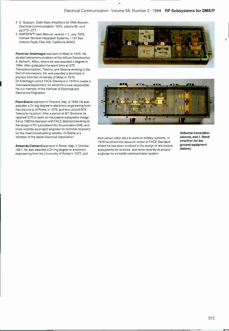
Electrical Communication Volume 58, Number 3 1984 RF Subsystems for DME/P
4 D. Graziani: Solid State Amplifiers for DME Beacon:Electrical Communication, 1975, volume 50, no 4,pp 273-277.
5 AMPSYNTm User Manual, version 1.1, July 1978,Comsat General Integrated Systems, 1131 SanAntonio Road, Palo Alto, California 94303.
Fiorenzo Ardemagni was born in Milan in 1945. Hestudied teiecommunications at the Istituto RadiotecnicoA. Beltrami, Milan, where he was awarded a degree in1964. After graduation he spent time at GTETelecomunicazioni, Telettra, and Selenia working in thefiled of microwaves. He was awarded a doctorate inphysics from the University of Milan in 1976.Dr Ardemagni joined FACE Standard in 1979 to create amicrowave department, for which he is now responsible.He is a member of the Institute of Electrical andElectronics Engineers.
Piero Basile was born in Pescara, Italy, in 1948. He wasawarded a Dr-Ing degree in electronic engineering fromthe University of Rome in 1975, and then joined GTETelecomunicazioni. After a period at SIT Siemens herejoined GTE to work on microwave subsystem design.Since 1980 he has been with FACE Standard working onthe design of RF subsystems forthe precision DME, andmore recently as project engineer for terminal receiversfor the direct broadcasting satellite. Dr Basile is amember of the Italian Electrical Association.
Armando Clementi was born in Rome, Italy, in October1951. He was awarded a Dr-Ing degree in electronicengineering from the University of Rome in 1977, and
then joined Litton Italia to work on military systems. In1978 he joined the research center of FACE Standardwhere he has been involved in the des gn of microwavesubsystems for avionics, and more recently as projectengineer fora mobile communication system.
Airborne transmitter(above), and L -Bandamplifier for theground equipment(below).
313
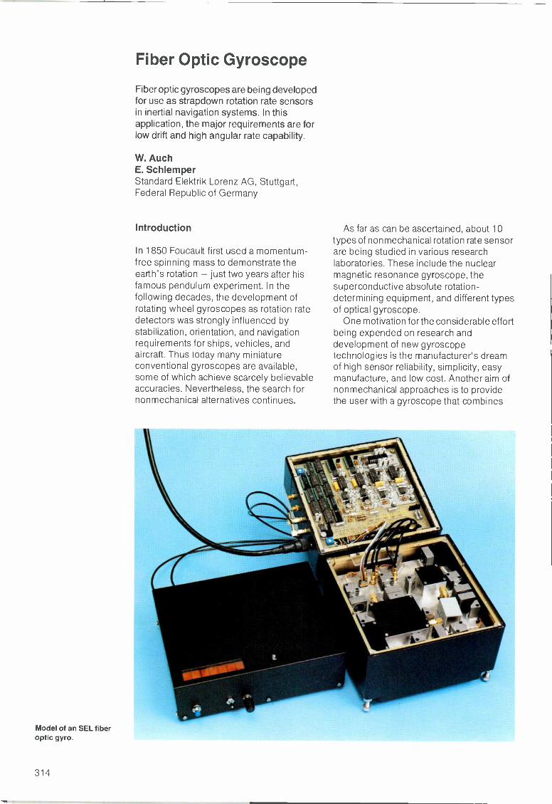
Fiber Optic Gyroscope
Fiber optic gyroscopes are being developedfor use as strapdown rotation rate sensorsin inertial navigation systems. In thisapplication, the major requirements are forlow drift and high angular rate capability.
W. AuchE. SchlemperStandard Elektrik Lorenz AG, Stuttgart,Federal Republic of Germany
Introduction
In 1850 Foucault first used a momentum -free spinning mass to demonstrate theearth's rotation - just two years after hisfamous pendulum experiment. In thefollowing decades, the development ofrotating wheel gyroscopes as rotation ratedetectors was strongly influenced bystabilization, orientation, and navigationrequirements for ships, vehicles, andaircraft. Thus today many miniatureconventional gyroscopes are available,some of which achieve scarcely believableaccuracies. Nevertheless, the search fornonmechanical alternatives continues.
Model of an SEL fiberoptic gyro.
As far as can be ascertained, about 10types of nonmechanical rotation rate sensorare being studied in various researchlaboratories. These include the nuclearmagnetic resonance gyroscope, thesuperconductive absolute rotation -determining equipment, and different typesof optical gyroscope.
One motivation for the considerable effortbeing expended on research anddevelopment of new gyroscopetechnologies is the manufacturer's dreamof high sensor reliability, simplicity, easymanufacture, and low cost. Another aim ofnonmechanical approaches is to providethe user with a gyroscope that combines
314
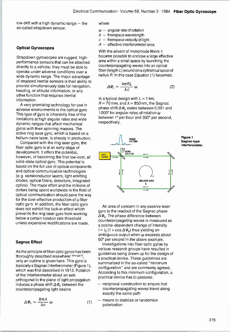
Electrical Communication Volume 58, Number 3 1984 Fiber Optic Gyroscope
low drift with a high dynamic range - theso-called strapdown sensor.
Optical Gyroscopes
Strapdown gyroscopes are rugged, high-performance sensors that can be attacheddirectly to a vehicle; they must be able tooperate under adverse conditions over awide dynamic range. The major advantageof strapped inertial sensors is their ability toprovide simultaneously data for navigation,heading, or altitude information, or anyother function that requires inertialinformation.
A very promising technology for use inadverse environments is the optical gyro.This type of gyro is inherently free of thelimitations at high angular rates and widedynamic ranges that affect mechanicalgyros with their spinning masses. Theactive ring laser gyro, which is based on ahelium -neon laser, is already in production.
Compared with the ring laser gyro, thefiber optic gyro is at an early stage ofdevelopment. It offers the potential,however, of becoming the first low-cost, allsolid-state optical gyro. This potential isbased on the full use of optical componentsand optical communication technologies(e.g. semiconductor lasers, light emittingdiodes, optical fibers, detectors, integratedoptics). The major effort and the millions ofdollars being spent worldwide in the field ofoptical communication should pave the wayfor the cost-effective production of a fiberoptic gyro. In addition, the fiber optic gyrodoes not exhibit the lock -in effect whichprevents the ring laser gyro from workingbelow a certain rotation rate thresholdunless expensive modifications are made.
Sagnac Effect
As the principle of fiber optic gyros has beenthoroughly described elsewhere1 through 8,only an outline is given here. This gyro isbasically a Sagnac interferometer (Figure 1),which was first described in 1913. Rotationof the interferometer about an axisorthogonal to the plane of light propagationinduces a phase shift LO, between thecounterpropagating light beams
8 nAAcPs Ac
(1)
where
w - angular rate of rotationA - freespace wavelengthc - freespace velocity of lightA - effective interferometer area.
With the advent of monomode fibers inbecame possible to enclose a large effectivearea within a small space by launching thecounterpropagating waves into an opticalfiber (length L) wound on a cylindrical spool ofradius R. In this case Equation (1) becomes:
- 4nrRL
Ac(2)
In a typical design with L= 1 km,R= 70 mm, and A= 850 nm, the Sagnacphase shift LO, varies between 0.001 and1000° for angular rates of rotation wbetween 1° per hour and 300° per second,respectively.
LIGHTSOURCE
FRINGE
PATTERN
11 BEAM -
SPUTTER
ENCLOSED AREA
A
An area of concern in any passive lasergyro is the readout of the Sagnac phaseLOs. The phase difference betweencounterpropagating waves is measured asa cosine -dependent change of intensityI= /0 (1 + cos Los) thus yielding anambiguous output when w exceeds about50° per second in the above example.
Investigations into fiber optic gyros byvarious research groups have resulted inguidelines being drawn up for the design ofa practical device. These guidelines aresummarized in the so-called "minimumconfiguration" and are commonly agreed.According to this minimum configuration, apractical device has to possess:
- reciprocal construction to ensure thatcounterpropagating waves travel alongexactly the same path
- means to stabilize or randomizepolarization
Figure 1Sagnac-typeinterferometer.
315
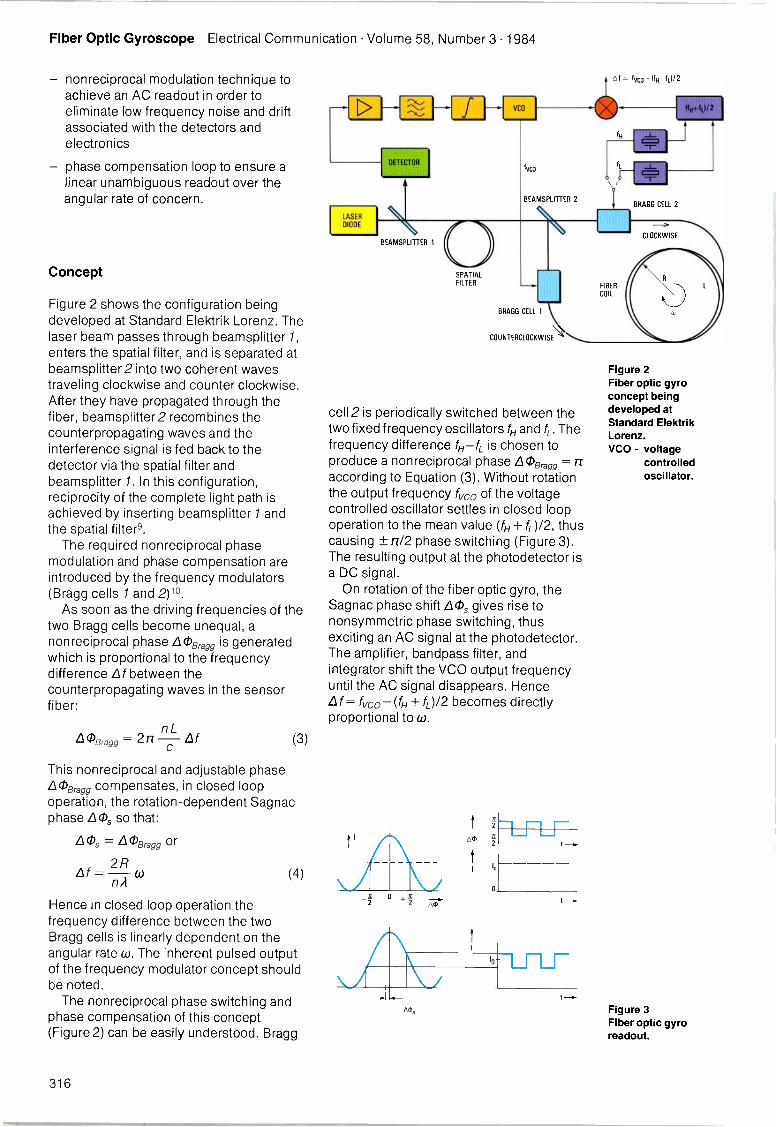
Fiber Optic Gyroscope Electrical Communication Volume 58, Number 3 1984
nonreciprocal modulation technique toachieve an AC readout in order toeliminate low frequency noise and driftassociated with the detectors andelectronics
phase compensation loop to ensure alinear unambiguous readout over theangular rate of concern.
Concept
Figure 2 shows the configuration beingdeveloped at Standard Elektrik Lorenz. Thelaser beam passes through beamsplitter 1,enters the spatial filter, and is separated atbeamsplitter2 into two coherent wavestraveling clockwise and counter clockwise.After they have propagated through thefiber, beamsplitter2 recombines thecounterpropagating waves and theinterference signal is fed back to thedetector via the spatial filter andbeamsplitter 1. In this configuration,reciprocity of the complete light path isachieved by inserting beamsplitter 1 andthe spatial filter9.
The required nonreciprocal phasemodulation and phase compensation areintroduced by the frequency modulators(Bragg cells 1 and 2)10.
As soon as the driving frequencies of thetwo Bragg cells become unequal, anonreciprocal phase L0Bgg is generatedwhich is proportional to the frequencydifference Lf between thecounterpropagating waves in the sensorfiber:
0Bragg =n
This nonreciprocal and adjustable phase'Bragg compensates, in closed loopoperation, the rotation -dependent Sagnacphase LO, so that:
LOs = LOBragg or
Lf =2Rn A
(3)
(4)
Hence in closed loop operation thefrequency difference between the twoBragg cells is linearly dependent on theangular rate w. The inherent pulsed outputof the frequency modulator concept shouldbe noted.
The nonreciprocal phase switching andphase compensation of this concept(Figure 2) can be easily understood. Bragg
LASER
DIODE
DETECTOR
BEAMSPLITTER 1
SPATIALFILTER
4f= 1VCO - UNTILI/ 2
lvco
BEAMSPLITTER 2
BRAGG CELL 1
COUNTERCLOCKWISE
cell 2 is periodically switched between thetwo fixed frequency oscillators fH and fL. Thefrequency difference fH-fL is chosen toproduce a nonreciprocal phase LOBragg= rraccording to Equation (3). Without rotationthe output frequency f vc0 of the voltagecontrolled oscillator settles in closed loopoperation to the mean value (fH + 0/2, thuscausing ± rrI2 phase switching (Figure 3).The resulting output at the photodetector isa DC signal.
On rotation of the fiber optic gyro, theSagnac phase shift LO, gives rise tononsymmetric phase switching, thusexciting an AC signal at the photodetector.The amplifier, bandpass filter, andintegrator shift the VCO output frequencyuntil the AC signal disappears. HenceLf = fvco- (fH + fL)/2 becomes directlyproportional to co.
oms
1
-
Ito
0
fL
BRAGG CELL 2
CLOCKWISE
FIBER
COIL
Figure 2Fiber optic gyroconcept beingdeveloped atStandard ElektrikLorenz.VCO - voltage
controlledoscillator.
Figure 3Fiber optic gyroreadout.
316
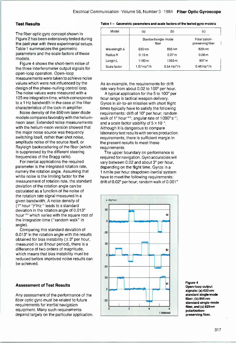
Electrical Communication Volume 58, Number 3 1984 Fiber Optic Gyroscope
Test Results
The fiber optic gyro concept shown inFigure 2 has been extensively tested duringthe past year with three experimental setups.Table 1 summarizes the geometricparameters and the scale factors of thesemodels.
Figure 4 shows the short-term noise ofthe three interferometer output signals foropen -loop operation. Open -loopmeasurements were taken to achieve noisevalues which were not influenced by thedesign of the phase -nulling control loop.The noise values were measured with a125 ms integration time, which correspondsto a 1 Hz bandwidth in the case of the filtercharacteristics of the lock -in amplifier.
Noise density of the 850 nm laser diodemodels compares favorably with the helium -neon laser. Extended noise measurementswith the helium -neon version showed thatthe major noise source was frequencyswitching itself, rather than shot noise,amplitude noise of the source itself, orRayleigh backscattering of the fiber (whichis suppressed by the different steeringfrequencies of the Bragg cells).
For inertial applications the requiredparameter is the integrated rotation rate,namely the rotation angle. Assuming thatwhite noise is the limiting factor for themeasurement of rotation rate, the standarddeviation of the rotation angle can becalculated as a function of the noise ofthe rotation rate signal measured in agiven bandwidth. A noise density of(1° hour -1)2 Hz -1 leads to a standarddeviation in the rotation angle of 0.013°hour"' which varies with the square root ofthe integration time ("random walk" inangle).
Comparing this standard deviation of0.013° in the rotation angle with the resultsobtained for bias instability (± 3° per hour,measured in an 8 hour period), there is adifference of two orders of magnitude,which means that bias instability must bereduced before improved noise results canbe achieved.
Assessment of Test Results
Any assessment of the performance of thefiber optic gyro must be related to futurerequirements for inertial navigationequipment. Many such requirementsdepend largely on the particular application.
Table 1 - Geometric parameters and scale factors of the tested gyro models
Model (a) (b) (c)
Wavelength A
Radius R
Length L
Scale factor
Standard single -modefiber
633 nm 855 nm
0.15m 0.07m
1180m 1055 m
1.57 Hz/°/h 0.54 Hz/°/h
Polarization -preserving fiber
829 nm
0.06m
937 m
0.46 Hz/°/h
As an example, the requirements for driftrate vary from about 0.02 to 100° per hour.
A typical application for the 5 to 100° perhour range is tactical weapon delivery.Gyros in air-to-air missiles with short flighttimes typically have to satisfy the followingrequirements: drift of 10° per hour; randomwalk of 1° hour -'5; angular rate of 1000° s-1;and a scale factor stability of 5 xAlthough it is dangerous to comparelaboratory test results with series productionrequirements, there is sufficient margin inthe present results to meet theserequirements.
The upper boundary on performance isrequired for navigation. Gyro accuracies willvary between 0.02 and about 3° per hour,depending on the flight time. Gyros in a1 n mile per hour strapdown inertial systemhave to meet the following requirements:drift of 0.02° per hour; random walk of 0.001°
Niiihowipape48-wroOpprookoRwAr-"0111
la)
(h)
- .004,
lc)
amium.----~"limilw4k-waisvivr-vo
I I I
Figure 4Open -loop outputsignals: (a) 633 nmstandard single -modefiber; (b) 855 nmstandard single -modefiber, and (c) 829nmpolarization -preserving fiber.
317
Fiber Optic Gyroscope Electrical Communication Volume 58, Number 3 1984
hour's; angular rate of 500° s-1; scale factorstability of 10-5.
At present it is difficult to project with anyaccuracy what drift improvements can beachieved in the near future. However, itmust not be forgotten that fiber optic gyrodrift analysis is a new area for study, thatpresent test models allow preciseseparation of drift origins, and that recenttest results already show that drift rates aslow as ± 3° per hour can be achieved.
Conclusions
Initial test results show that medium -
performance requirements can, in principle,be met with fiber optic gyros. Beyond thisapplication, there are indications that suchgyros will be able to satisfy the even moredemanding requirements for navigation. Interms of dynamic range and noise, the fiberoptic gyro already performs remarkablywell. Dynamic range is clearly not a matterof concern in fiber optic gyros withfrequency modulators. One can say that ifthe vehicle can cope with the dynamics, thegyro can do so as well. However, to becomea viable option as a strapdown sensor ininertial navigation systems, considerabledevelopment is still necessary to improvethe drift behavior.
References
1 S. Ezekiel and H. J. Arditty: Fiber -Optic RotationSensors: Springer-Verlag, 1982, Berlin.
2 V. Vali and R. W. Shorthill: Fiber Ring Interferometer:Applied Optics, 1976, volume 15, p 1099.
3 K. Bohm, P. Russer, E. Weide!, and R. Ulrich: LowNoise Fiber Optic Rotation Sensing: Optics Letters,1981, volume 6, p 64.
4 R. A. Bergh, H. C. Lefevre, and H. J. Shaw: AllSingle -Mode Fiber Optic Gyroscope: Optics Letters,1981, volume 6, p 198.
5 R. F. Cahill and E. Udd: Phase Milling Fiber OpticLaser Gyro: Optics Letters, 1979, volume 4, p 93.
6 J. L. Davis and S. Ezekiel: Closed Loop, Low -NoiseFiber Optic Rotation Sensor: Optics Letters, 1981,volume 6, p505.
7 C. C. Cutler, S. A. Newton, and H. J. Shaw: Limitationof Rotation Sensing by Scattering: Optics Letters,1980, volume 5, p 488.
8 W. Auch and E. Schlemper: Drift Behaviour of aFiber -Optic Rotation Sensor Using PolarizationPreserving Fiber: First International Conference onOptical Fibre Sensors: Institution of ElectricalEngineers, 1983, London.
9 R. Ulrich: Fiber Optic Rotation Sensing with LowDrift: Optics Letters, 1980, volume 5, p 173.
10 J. L. Davis and S. Ezekiel: Techniques for Shot -Noise -Limited Inertial Rotation Measurement Usinga Multi -turn Fiber Sagnac Interferometer:Proceedings of the Society of Photo -OpticalInstrument Engineers, 1978, volume 157, p 131.
W. Auch was born in Waldenbucher, Germany, inAugust 1949. He received his Diplom-Physiker degreefrom Stuttgart University in 1977, and his Dr rer natdegree in 1980 for his work on optically pumped nuclearpolarization in solids. He joined SEL in 1980 as a systemplanning engineer. Since 1982 Dr Auch has been headof fiber gyro development at SEL. He is a member of theOptical Society of America.
Eberhard Schlemper was born in Erbach, Germany, in1945. He received a Dipl-Ing degree in electricalengineering from Stuttgart Technical University in 1971.The same year he joined SEL to work on thedevelopment of telemetry and telecommand equipmentfor satellites. In 1977 Mr Schlemper transferred to thesystem planning group, and is now technical manager ofthe SEL Avionics Division with responsibility for radioand self-contained navigation equipment.
318
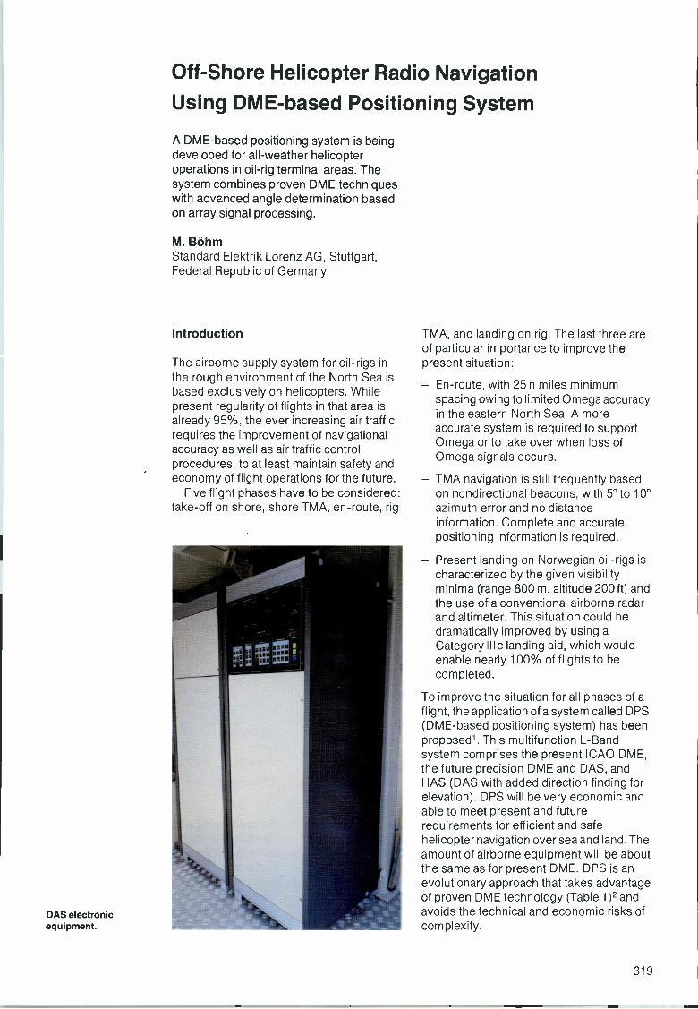
Off -Shore Helicopter Radio Navigation
Using DME-based Positioning System
A DME-based positioning system is beingdeveloped for all-weather helicopteroperations in oil -rig terminal areas. Thesystem combines proven DME techniqueswith advanced angle determination basedon array signal processing.
M. BohmStandard Elektrik Lorenz AG, Stuttgart,Federal Republic of Germany
Introduction
The airborne supply system for oil -rigs inthe rough environment of the North Sea isbased exclusively on helicopters. Whilepresent regularity of flights in that area isalready 95%, the ever increasing air trafficrequires the improvement of navigationalaccuracy as well as air traffic controlprocedures, to at least maintain safety andeconomy of flight operations for the future.
Five flight phases have to be considered:take -off on shore, shore TMA, en -route, rig
DAS electronicequipment.
TMA, and landing on rig. The last three areof particular importance to improve thepresent situation:
En -route, with 25 n miles minimumspacing owing to limited Omega accuracyin the eastern North Sea. A moreaccurate system is required to supportOmega or to take over when loss ofOmega signals occurs.
TMA navigation is still frequently basedon nondirectional beacons, with 5° to 10°azimuth error and no distanceinformation. Complete and accuratepositioning information is required.
Present landing on Norwegian oil -rigs ischaracterized by the given visibilityminima (range 800 m, altitude 200 ft) andthe use of a conventional airborne radarand altimeter. This situation could bedramatically improved by using aCategory III c landing aid, which wouldenable nearly 100% of flights to becompleted.
To improve the situation for all phases of aflight, the application of a system called DPS(DME-based positioning system) has beenproposed'. This multifunction L -Bandsystem comprises the present ICAO DME,the future precision DME and DAS, andHAS (DAS with added direction finding forelevation). DPS will be very economic andable to meet present and futurerequirements for efficient and safehelicopter navigation over sea and land. Theamount of airborne equipment will be aboutthe same as for present DME. DPS is anevolutionary approach that takes advantageof proven DME technology (Table 1)2 andavoids the technical and economic risks ofcomplexity.
319
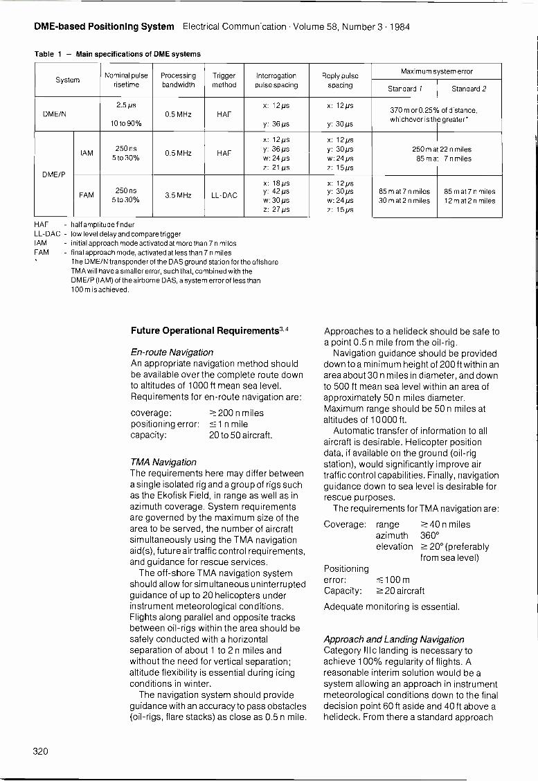
DME-based Positioning System Electrical Communication Volume 58, Number 3 1984
Table 1 - Main specifications of DME systems
SystemNominal pulse
risetimeProcessingbandwidth
Triggermethod
Interrogationpulse spacing
Reply pulsespacing
Maximum system error
Standard 1 Standard 2
DME/N2.5 Ns
10 to 90°/0
0.5 MHz HAFx: 12ps
y: 36 ps
x: 12ps
y: 30 in
370 m or 0.25%whichever is the
of distance,greater*
DME/P
IAM250 ns
5 to 30°/00.5 MHz HAF
x: 12psy: 36µsw: 24 psz: 21 Ns
x: 12 psy: 30 Nsw: 24 psz: 15ps
250 m at85 m at
22 n miles7 n miles
FAM250 ns
5 to 30`)/03.5 MHz LL-DAC
x: 18 Nsy: 42 psw: 30 psz: 27 Ns
x: 12 Nsy: 30 psw: 24 Nsz: 15ps
85 m at 7 n miles30 m at 2 n miles
85 m at 7 n miles12 m at 2 n miles
HAF - half amprtude finderLL-DAC - low level delay and compare triggerIAM - initial approach mode activated at more than 7 n milesFAM - final approach mode, activated at less than 7 n miles
The DME/N transponder of the DAS ground station for the offshoreTMA will have a smaller error, such that, combined with theDME/P (IAM) of the airborne DAS, a system error of less than100 m is achieved.
Future Operational Requirements3,4
En -route NavigationAn appropriate navigation method shouldbe available over the complete route downto altitudes of 1000 ft mean sea level.Requirements for en -route navigation are:
coverage:positioning error:capacity:
200 n miles1 n mile
20 to 50 aircraft.
TMA NavigationThe requirements here may differ betweena single isolated rig and a group of rigs suchas the Ekofisk Field, in range as well as inazimuth coverage. System requirementsare governed by the maximum size of thearea to be served, the number of aircraftsimultaneously using the TMA navigationaid(s), future air traffic control requirements,and guidance for rescue services.
The off -shore TMA navigation systemshould allow for simultaneous uninterruptedguidance of up to 20 helicopters underinstrument meteorological conditions.Flights along parallel and opposite tracksbetween oil -rigs within the area should besafely conducted with a horizontalseparation of about 1 to 2 n miles andwithout the need for vertical separation;altitude flexibility is essential during icingconditions in winter.
The navigation system should provideguidance with an accuracy to pass obstacles(oil -rigs, flare stacks) as close as 0.5 n mile.
Approaches to a helideck should be safe toa point 0.5 n mile from the oil -rig.
Navigation guidance should be provideddown to a minimum height of 200 ft within anarea about 30 n miles in diameter, and downto 500 ft mean sea level within an area ofapproximately 50 n miles diameter.Maximum range should be 50 n miles ataltitudes of 10000 ft.
Automatic transfer of information to allaircraft is desirable. Helicopter positiondata, if available on the ground (oil -rigstation), would significantly improve airtraffic control capabilities. Finally, navigationguidance down to sea level is desirable forrescue purposes.
The requirements for TMA navigation are:
Coverage: rangeazimuthelevation
40 n miles360°
20° (preferablyfrom sea level)
Positioningerror: 100 mCapacity: 20 aircraft
Adequate monitoring is essential.
Approach and Landing NavigationCategory III c landing is necessary toachieve 100% regularity of flights. Areasonable interim solution would be asystem allowing an approach in instrumentmeteorological conditions down to the finaldecision point 60 ft aside and 40 ft above ahelideck. From there a standard approach
320
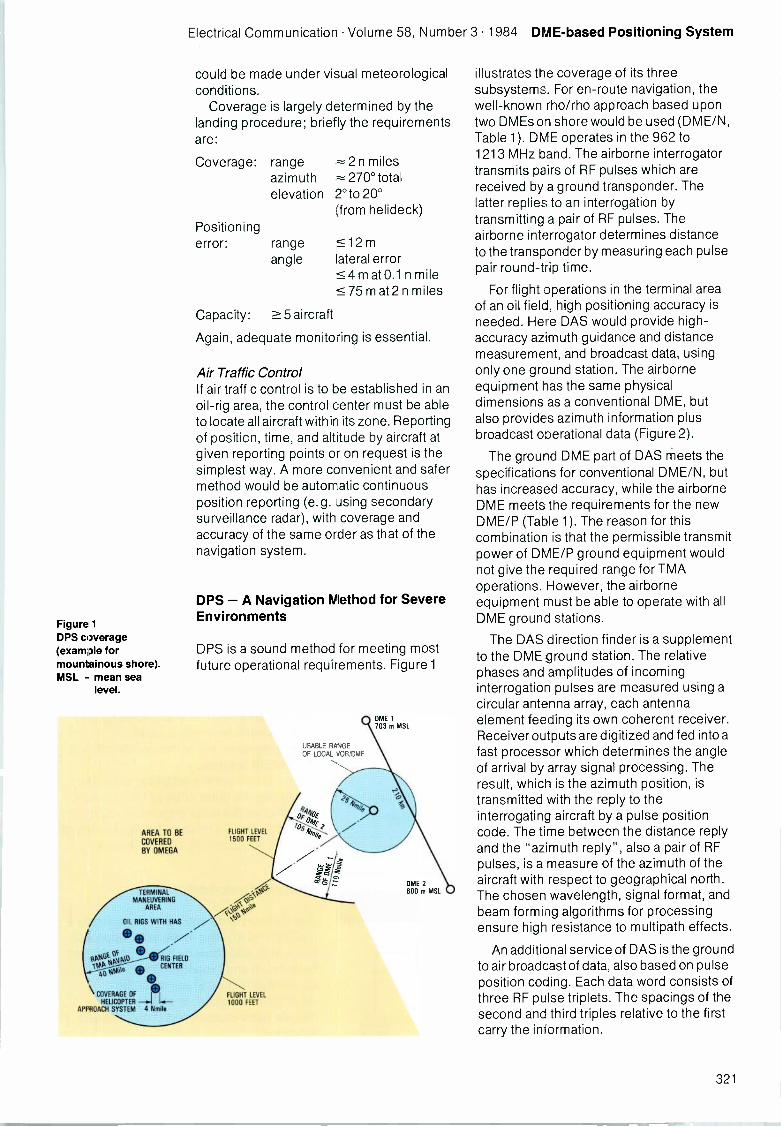
Electrical Communication Volume 58, Number 3 1984 DME-based Positioning System
Figure 1DPS coverage(example formountainous shore).MSL - mean sea
level.
AREA TO BECOVEREDBY OMEGA
TERMINALMANEUVERING
AREA
could be made under visual meteorologicalconditions.
Coverage is largely determined by thelanding procedure; briefly the requirementsare:
Coverage: range = 2 n milesazimuth 270° totalelevation 2°to 20°
(from helideck)Positioningerror: range
angle12 m
lateral errorm at 0.1 n mile
75 m at 2 n miles
Capacity: 5 aircraft
Again, adequate monitoring is essential.
Air Traffic ControlIf air traffic control is to be established in anoil -rig area, the control center must be ableto locate all aircraft within its zone. Reportingof position, time, and altitude by aircraft atgiven reporting points or on request is thesimplest way. A more convenient and safermethod would be automatic continuousposition reporting (e.g. Jsing secondarysurveillance radar), with coverage andaccuracy of the same order as that of thenavigation system.
DPS -A Navigation Method for SevereEnvironments
DPS is a sound method for meeting mostfuture operational requirements. Figure 1
OIL RIGS WITH HAS 7/ak
otWA* LIMO RIG FIELDTq0 CENTER,
ti*
COVERAGE OF
HELICOPTER -.1APPROACH SYSTEM 4 Nmile
FLIGHT LEVEL1500 FEET
FLIGHT LEVEL1000 FEET
USABLE RANGEOF LOCAL VORIDME
DME 1703 m MSL
DME 2800 m MSL
illustrates the coverage of its threesubsystems. For en -route navigation, thewell-known rho/rho approach based upontwo DMEs on shore would be used (DME/N,Table 1). DME operates in the 962 to1213 MHz band. The airborne interrogatortransmits pairs of RF pulses which arereceived by a ground transponder. Thelatter replies to an interrogation bytransmitting a pair of RF pulses. Theairborne interrogator determines distanceto the transponder by measuring each pulsepair round-trip time.
For flight operations in the terminal areaof an oil field, high positioning accuracy isneeded. Here DAS would provide high -accuracy azimuth guidance and distancemeasurement, and broadcast data, usingonly one ground station. The airborneequipment has the same physicaldimensions as a conventional DME, butalso provides azimuth information plusbroadcast operational data (Figure 2).
The ground DME part of DAS meets thespecifications for conventional DME/N, buthas increased accuracy, while the airborneDME meets the requirements for the newDME/P (Table 1). The reason for thiscombination is that the permissible transmitpower of DME/P ground equipment wouldnot give the required range for TMAoperations. However, the airborneequipment must be able to operate with allDME ground stations.
The DAS direction finder is a supplementto the DME ground station. The relativephases and amplitudes of incominginterrogation pulses are measured using acircular antenna array, each antennaelement feeding its own coherent receiver.Receiver outputs are digitized and fed into afast processor which determines the angleof arrival by array signal processing. Theresult, which is the azimuth position, istransmitted with the reply to theinterrogating aircraft by a pulse positioncode. The time between the distance replyand the "azimuth reply", also a pair of RFpulses, is a measure of the azimuth of theaircraft with respect to geographical north.The chosen wavelength, signal format, andbeam forming algorithms for processingensure high resistance to multipath effects.
An additional service of DAS is the groundto air broadcast of data, also based on pulseposition coding. Each data word consists ofthree RF pulse triplets. The spacings of thesecond and third triples relative to the firstcarry the information.
321
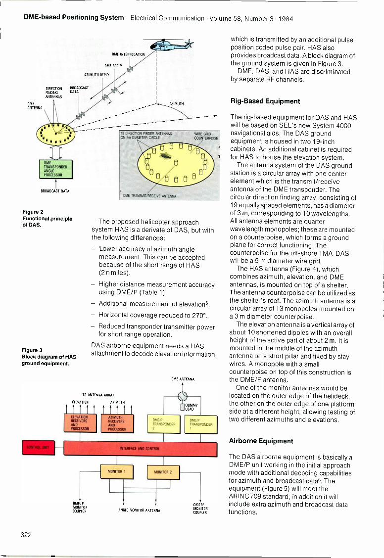
DME-based Positioning System Electrical Communication Volume 58, Number 3 1984
DIRECTIONFINDINGANTENNAS
DME
ANTENNA
BROADCAST DATA
OME INTERROGATION
DME REPLY
AZIMUTH REPLY
BROADCASTDATA
Figure 2Functional principleof DAS.
Figure 3Block diagram of HASground equipment.
AZIMUTH
19 DIRECTION FINDER ANTENNASON 3m DIAMETER CIRCLE
DME TRANSMIT/RECEIVE ANTENNA
WIRE GRID
COUNTERPOISE
The proposed helicopter approachsystem HAS is a derivate of DAS, but withthe following differences:
- Lower accuracy of azimuth anglemeasurement. This can be acceptedbecause of the short range of HAS(2 n miles).
- Higher distance measurement accuracyusing DME/P (Table 1).
- Additional measurement of elevations.
- Horizontal coverage reduced to 270°.
- Reduced transponder transmitter powerfor short range operation.
DAS airborne equipment needs a HASattachment to decode elevation information,
TO ANTENNA ARRAY
ELEVATION AZIMUTH
ELEVATIONRECEIVERS
ANDPROCESSOR
AZIMUTHRECEIVERS
ANDPROCESSOR
OME ANTENNA
DME,P
TRANSPONDER2
DUMMYLOAD
DME/P
TRANSPONDER1
INTERFACE ANO CONTROL
DME/PMONITORCOUPLER
N. ONITOR 1 MONITOR 2
ANGLE MONITOR ANTENNA
DME/PMONITORCOUPLER
which is transmitted by an additional pulseposition coded pulse pair. HAS alsoprovides broadcast data. A block diagram ofthe ground system is given in Figure 3.
DME, DAS, and HAS are discriminatedby separate RF channels.
Rig -Based Equipment
The rig -based equipment for DAS and HASwill be based on SEL's new System 4000navigational aids. The DAS groundequipment is housed in two 19 -inchcabinets. An additional cabinet is requiredfor HAS to house the elevation system.
The antenna system of the DAS groundstation is a circular array with one centerelement which is the transmit/receiveantenna of the DME transponder. Thecircular direction finding array, consisting of19 equally spaced elements, has a diameterof 3 m, corresponding to 10 wavelengths.All antenna elements are quarterwavelength monopoles; these are mountedon a counterpoise, which forms a groundplane for correct functioning. Thecounterpoise for the off -shore TMA-DASwill be a 5 m diameter wire grid.
The HAS antenna (Figure 4), which
antennas, is mounted on top of a shelter.The antenna counterpoise can be utilized asthe shelter's roof. The azimuth antenna is acircular array of 13 monopoles mounted ona 3 m diameter counterpoise.
The elevation antenna is a vertical array ofabout 10 shortened dipoles with an overallheight of the active part of about 2 m. It ismounted in the middle of the azimuthantenna on a short pillar and fixed by staywires. A monopole with a smallcounterpoise on top of this construction isthe DME/P antenna.
One of the monitor antennas would belocated on the outer edge of the helideck,the other on the outer edge of one platformside at a different height, allowing testing oftwo different azimuths and elevations.
Airborne Equipment
The DAS airborne equipment is basically aDME/P unit working in the initial approachmode with additional decoding capabilitiesfor azimuth and broadcast date. Theequipment (Figure 5) will meet theARINC 709 standard; in addition it willinclude extra azimuth and broadcast datafunctions.
322
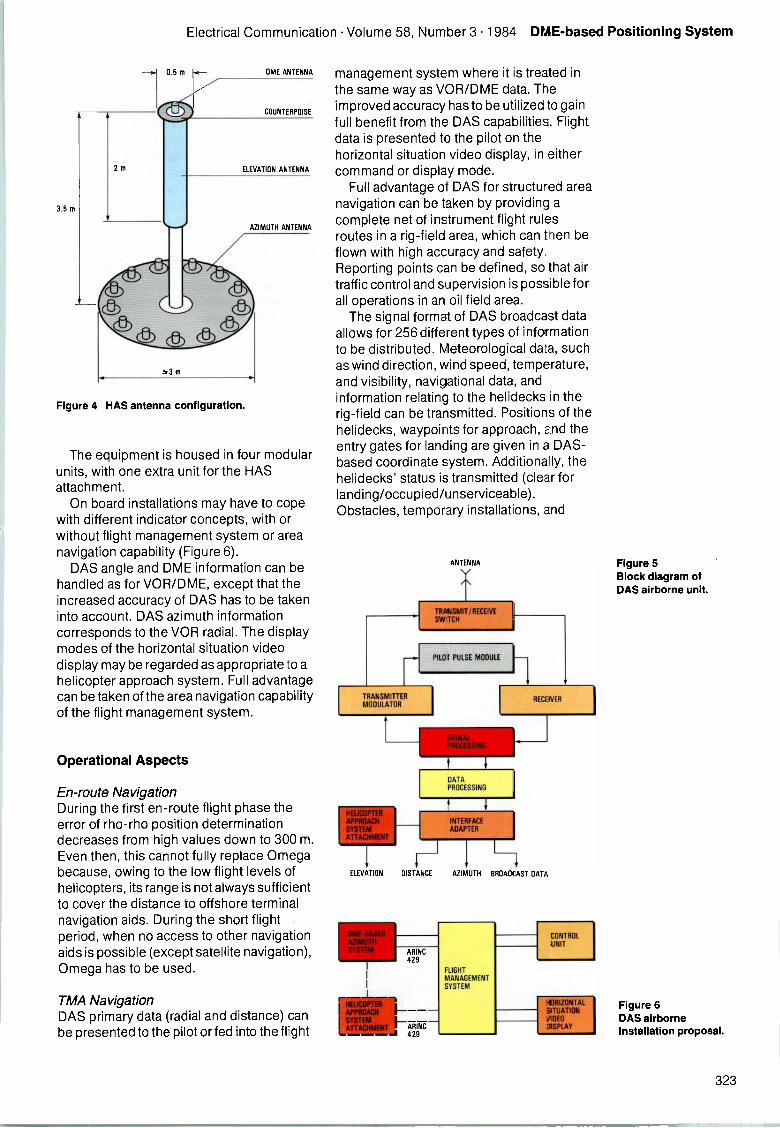
Electrical Communication Volume 58, Number 3 1984 DME-based Positioning System
2m
3.5 m
0.5 m
m
OME ANTENNA
COUNTERPOISE
ELEVATION ANTENNA
AZIMUTH ANTENNA
Figure 4 HAS antenna configuration.
The equipment is housed in four modularunits, with one extra unit for the HASattachment.
On board installations may have to copewith different indicator concepts, with orwithout flight management system or areanavigation capability (Figure 6).
DAS angle and DME information can behandled as for VOR/DME, except that theincreased accuracy of DAS has to be takeninto account. DAS azimuth informationcorresponds to the VOR radial. The displaymodes of the horizontal situation videodisplay may be regarded as appropriate to ahelicopter approach system. Full advantagecan be taken of the area navigation capabilityof the flight management system.
Operational Aspects
En -route NavigationDuring the first en -route flight phase theerror of rho -rho position determinationdecreases from high values down to 300 m.Even then, this cannot fully replace Omegabecause, owing to the low flight levels ofhelicopters, its range is not always sufficientto cover the distance to offshore terminalnavigation aids. During the short flightperiod, when no access to other navigationaids is possible (except satellite navigation),Omega has to be used.
TMA NavigationDAS primary data (radial and distance) canbe presented to the pilot or fed into the flight
management system where it is treated inthe same way as VOR/DME data. Theimproved accuracy has to be utilized to gainfull benefit from the DAS capabilities. Flightdata is presented to the pilot on thehorizontal situation video display, in eithercommand or display mode.
Full advantage of DAS for structured areanavigation can be taken by providing acomplete net of instrument flight rulesroutes in a rig -field area, which can then beflown with high accuracy and safety.Reporting points can be defined, so that airtraffic control and supervision is possible forall operations in an oil field area.
The signal format of DAS broadcast dataallows for 256 different types of informationto be distributed. Meteorological data, suchas wind direction, wind speed, temperature,and visibility, navigational data, andinformation relating to the helidecks in therig -field can be transmitted. Positions of thehelidecks, waypoints for approach, and theentry gates for landing are given in a DAS-based coordinate system. Additionally, thehelidecks' status is transmitted (clear forlanding/occupied/unserviceable).Obstacles, temporary installations, and
ANTENNA
TRANSMIT /RECEIVESW TCH
PILOT PULSE MODULE
TRANSMITTERMODULATOR
ELEVATION
RECEIVER
DATAPROCESSING
DISTANCE
ARINC429
ARINC429
AZIMUTH BROADCAST DATA
RIGHTMANAGEMENTSYSTEM
CONTROLUNIT
illifill4STAL
Figure 5Block diagram ofDAS airborne unit.
Figure 6DAS airborneinstallation proposal.
323
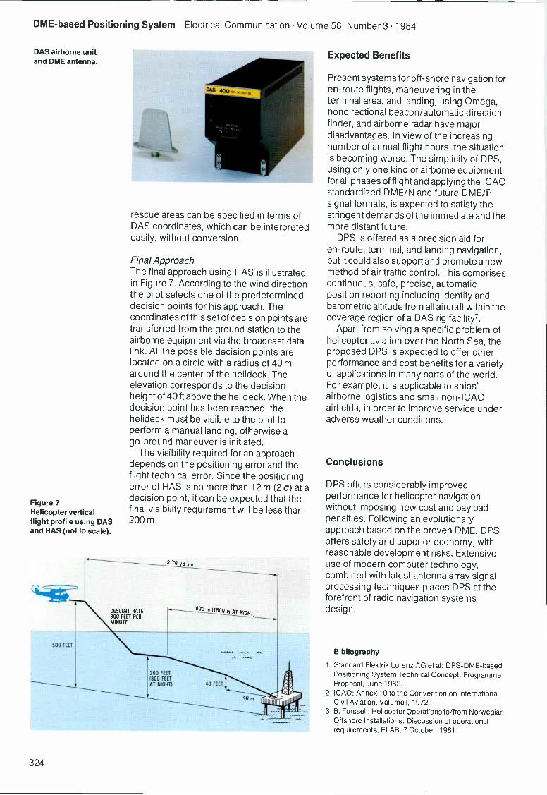
DME-based Positioning System Electrical Communication Volume 58, Number 3 1984
DAS airborne unitand DME antenna.
Figure 7Helicopter verticalflight profile using DASand HAS (not to scale).
rescue areas can be specified in terms ofDAS coordinates, which can be interpretedeasily, without conversion.
Final ApproachThe final approach using HAS is illustratedin Figure 7. According to the wind directionthe pilot selects one of the predetermineddecision points for his approach. Thecoordinates of this set of decision points aretransferred from the ground station to theairborne equipment via the broadcast datalink. All the possible decision points arelocated on a circle with a radius of 40 maround the center of the helideck. Theelevation corresponds to the decisionheight of 40 ft above the helideck. When thedecision point has been reached, thehelideck must be visible to the pilot toperform a manual landing, otherwise ago -around maneuver is initiated.
The visibility required for an approachdepends on the positioning error and theflight technical error. Since the positioningerror of HAS is no more than 12 m (2 a) at adecision point, it can be expected that thefinal visibility requirement will be less than200 m.
9 TO 18 km
DESCENT RATE300 FEET PERMINUTE
BOO m(15
500 FEET
200 FEET(300 FEETAT NIGHT) 40 FEET
40 m
Expected Benefits
Present systems for off -shore navigation foren -route flights, maneuvering in theterminal area, and landing, using Omega,nondirectional beacon/automatic directionfinder, and airborne radar have majordisadvantages. In view of the increasingnumber of annual flight hours, the situationis becoming worse. The simplicity of DPS,using only one kind of airborne equipmentfor all phases of flight and applying the ICAOstandardized DME/N and future DME/Psignal formats, is expected to satisfy thestringent demands of the immediate and themore distant future.
DPS is offered as a precision aid foren -route, terminal, and landing navigation,but it could also support and promote a newmethod of air traffic control. This comprisescontinuous, safe, precise, automaticposition reporting including identity andbarometric altitude from all aircraft within thecoverage region of a DAS rig facility7.
Apart from solving a specific problem ofhelicopter aviation over the North Sea, theproposed DPS is expected to offer otherperformance and cost benefits for a varietyof applications in many parts of the world.For example, it is applicable to ships'airborne logistics and small non -ICAOairfields, in order to improve service underadverse weather conditions.
Conclusions
DPS offers considerably improvedperformance for helicopter navigationwithout imposing new cost and payloadpenalties. Following an evolutionaryapproach based on the proven DME, DPSoffers safety and superior economy, withreasonable development risks. Extensiveuse of modern computer technology,combined with latest antenna array signalprocessing techniques places DPS at theforefront of radio navigation systemsdesign.
Bibliography
1 Standard Elektrik Lorenz AG et al: DPS-DME-basedPositioning System Technical Concept: ProgrammeProposal, June 1982.
2 ICAO: Annex 10 to the Convention on InternationalCivil Aviation, Volume I, 1972.
3 B. Forssell: Helicopter Operations to/from NorwegianOffshore Installations: Discussion of operationalrequirements, ELAB, 7 October, 1981.
324

Electrical Communication Volume 58, Number 3 1984 DME-based Positioning System
List of abbreviations
DAS
DME
DME/P
DPS
HAS
ICAO
TMA
VOR
DME-based azimuth system
distance measuring equipment
precision DME
DME-based positioning system
helicopter approach system
International Civil Aviation Organization
terminal maneuvering area
VHF omnidirectional range
4 T. Porteous: Navigation of Helicopters in Support ofthe North Sea Oil Industry, Colloquium on HelicopterGuidance and Navigation Systems, London,12 January, 1981.
5 Der Bundesminister fur Verkehr (The Federal Ministerof Transport): DME-based Landing System DLS:Federal Republic of Germany, November 1976,submission to the ICAO.
6 DAS, a Future Navigation System: Standard ElektrikLorenz AG, on behalf of the BMFT, Brochure, 1980.
7 A. Becker et al: Dreiweg-DME mit DAS: DFVLRInstitutsbericht IB 112-82/06, February 1982.
Manfred Bohm was born in Schlewecke, Wolfenbuttel,in 1934. He studied telecommunications in Darmstadtand Berlin from 1954 to 1960. In 1960 he started workwith Standard Elektrik Lorenz AG, in the field of digitalremote control, but soon changed to radio navigationtasks, with special emphasis on digital signal processing.In 1977, Dr Bohm became director RD & E of navigationsystems; since 1980 he has been director RD& E ofradio and navigation systems.
325
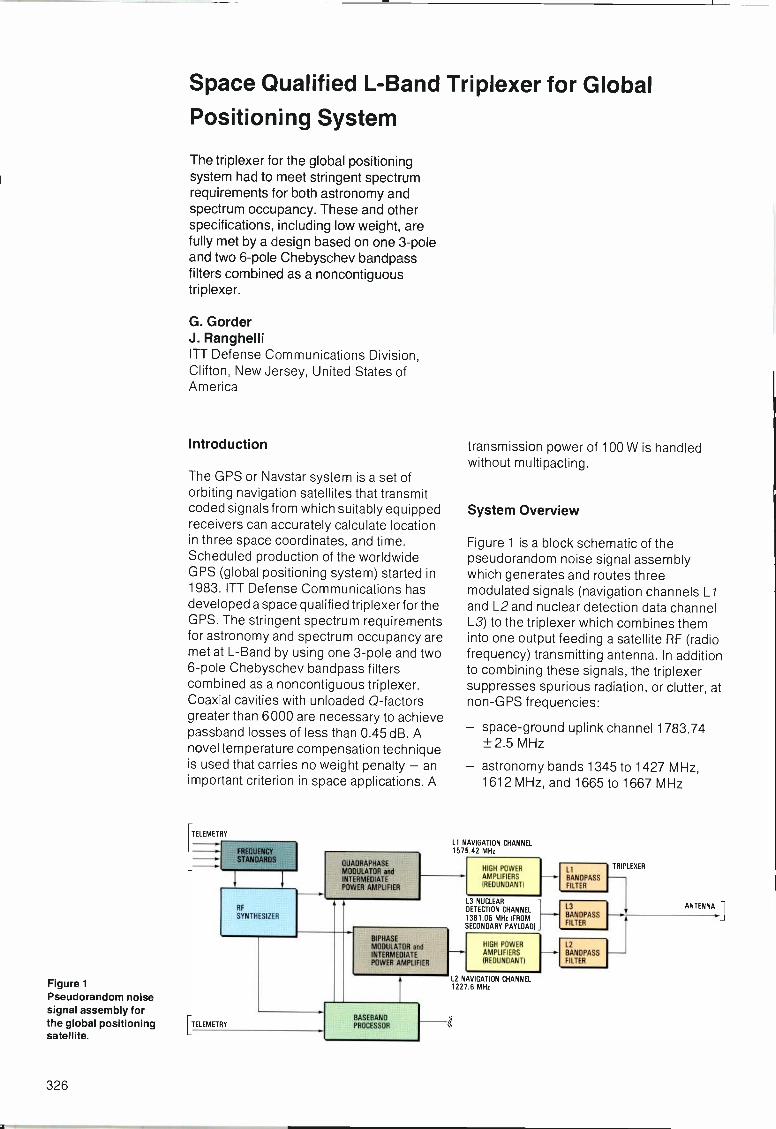
Figure 1Pseudorandom noisesignal assembly forthe global positioningsatellite.
Space Qualified L -Band Triplexer for Global
Positioning System
The triplexer for the global positioningsystem had to meet stringent spectrumrequirements for both astronomy andspectrum occupancy. These and otherspecifications, including low weight, arefully met by a design based on one 3 -poleand two 6 -pole Chebyschev bandpassfilters combined as a noncontiguoustriplexer.
G. GorderJ. RanghelliITT Defense Communications Division,Clifton, New Jersey, United States ofAmerica
Introduction
The GPS or Naystar system is a set oforbiting navigation satellites that transmitcoded signals from which suitably equippedreceivers can accurately calculate locationin three space coordinates, and time.Scheduled production of the worldwideGPS (global positioning system) started in1983. ITT Defense Communications hasdeveloped a space qualified triplexer for theGPS. The stringent spectrum requirementsfor astronomy and spectrum occupancy aremet at L -Band by using one 3 -pole and two6 -pole Chebyschev bandpass filterscombined as a noncontiguous triplexer.Coaxial cavities with unloaded 0 -factorsgreater than 6000 are necessary to achievepassband losses of less than 0.45 dB. Anovel temperature compensation techniqueis used that carries no weight penalty - animportant criterion in space applications. A
TELEMETRY
RF
SYNTHESIZER
TELEMETRY
OUADRAPHASEMODULATOR andINTERMEDIATEPOWER AMPLIFIER
transmission power of 100 W is handledwithout multipacting.
System Overview
Figure 1 is a block schematic of thepseudorandom noise signal assemblywhich generates and routes threemodulated signals (navigation channels L/and L2 and nuclear detection data channelL3) to the triplexer which combines theminto one output feeding a satellite RF (radiofrequency) transmitting antenna. In additionto combining these signals, the triplexersuppresses spurious radiation, or clutter, atnon-GPS frequencies:
- space -ground uplink channel 1783.74± 2.5 MHz
- astronomy bands 1345 to 1427 MHz,1612 MHz, and 1665 to 1667 MHz
LI NAVIGATION CHANNEL1575.42 MHz
BIPHASEMODULATOR andINTERMEDIATEPOWER AMPLIFIER
BASEBANDPROCESSOR
HIGH POWERAMPLIFIERS(REDUNDANT)
3 NUCLEARDETECTION CHANNEL1381 05 MHz (FROMSECONDARY PAYLOAD)
HIGH POWERAMPLIFIERS(REDUNDANT)
L2 NAVIGATION CHANNEL1227.6 MHz
CZ
LIBANDPASSFILTER
L3BANDPASSFILTER
TRIPLEXER
ANTENNA
L2BANDPASSFILTER
326
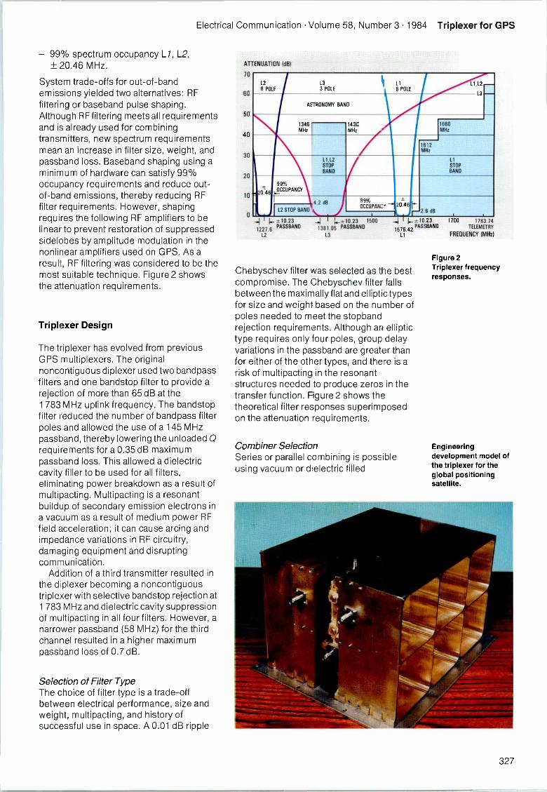
Electrical Communication Volume 58, Number 3 1984 Triplexer for GPS
- 99% spectrum occupancy L/, L2,± 20.46 MHz.
System trade-offs for out -of -bandemissions yielded two alternatives: RFfiltering or baseband pulse shaping.Although RF filtering meets all requirementsand is already used for combiningtransmitters, new spectrum requirementsmean an increase in filter size, weight, andpassband loss. Baseband shaping using aminimum of hardware can satisfy 99%occupancy requirements and reduce out -of -band emissions, thereby reducing RFfilter requirements. However, shapingrequires the following RF amplifiers to belinear to prevent restoration of suppressedsidelobes by amplitude modulation in thenonlinear amplifiers used on GPS. As aresult, RF filtering was considered to be themost suitable technique. Figure 2 showsthe attenuation requirements.
Triplexer Design
The triplexer has evolved from previousGPS multiplexers. The originalnoncontiguous diplexer used two bandpassfilters and one bandstop filter to provide arejection of more than 65 dB at the1 783 MHz uplink frequency. The bandstopfilter reduced the number of bandpass filterpoles and allowed the use of a 145 MHzpassband, thereby lowering the unloadedrequirements for a 0.35 dB maximumpassband loss. This allowed a dielectriccavity filler to be used for all filters,eliminating power breakdown as a result ofmultipacting. Multipacting is a resonantbuildup of secondary emission electrons ina vacuum as a result of medium power RFfield acceleration; it can cause arcing andimpedance variations in RF circuitry,damaging equipment and disruptingcommunication.
Addition of a third transmitter resulted inthe diplexer becoming a noncontiguoustriplexer with selective bandstop rejection at1 783 MHz and dielectric cavity suppressionof multipacting in all four filters. However, anarrower passband (58 MHz) for the thirdchannel resulted in a higher maximumpassband loss of 0.7 dB.
Selection of Filter TypeThe choice of filter type is a trade-offbetween electrical performance, size andweight, multipacting, and history ofsuccessful use in space. A 0.01 dB ripple
ATTENUATION (dB)
70
60
50
40
30
20
10
0
L26 POLE
L33 POLE
11 11,126 POLE
L3
-ASTRONOMY BAND
13451MHz I
143CMHz
1660MHz
1612MHz
11,12STOP
BAND
LtSTOPBAND
99%
2074OCCUPANCY
4 2 dB
L2 STOP BAND \OCCU PAN: ' 20 46 b
dB(-2.6... 1 I
-±10.23
1227.6PASSBAND
L2
1381.05 PASSBAND.I I 1.-± 0.23 1500
L3
_.1 -±10.23 1700 1783.74
1575.42PASSBAND TELEMETRY
11 FREQUENCY (MHz)
Chebyschev filter was selected as the bestcompromise. The Chebyschev filter fallsbetween the maximally flat and elliptic typesfor size and weight based on the number ofpoles needed to meet the stopbandrejection requirements. Although an elliptictype requires only four poles, group delayvariations in the passband are greater thanfor either of the other types, and there is arisk of multipacting in the resonantstructures needed to produce zeros in thetransfer function. Figure 2 shows thetheoretical filter responses superimposedon the attenuation requirements.
Combiner SelectionSeries or parallel combining is possibleusing vacuum or dielectric filled
Figure 2Triplexer frequencyresponses.
Engineeringdevelopment model ofthe triplexer for theglobal positioningsatellite.
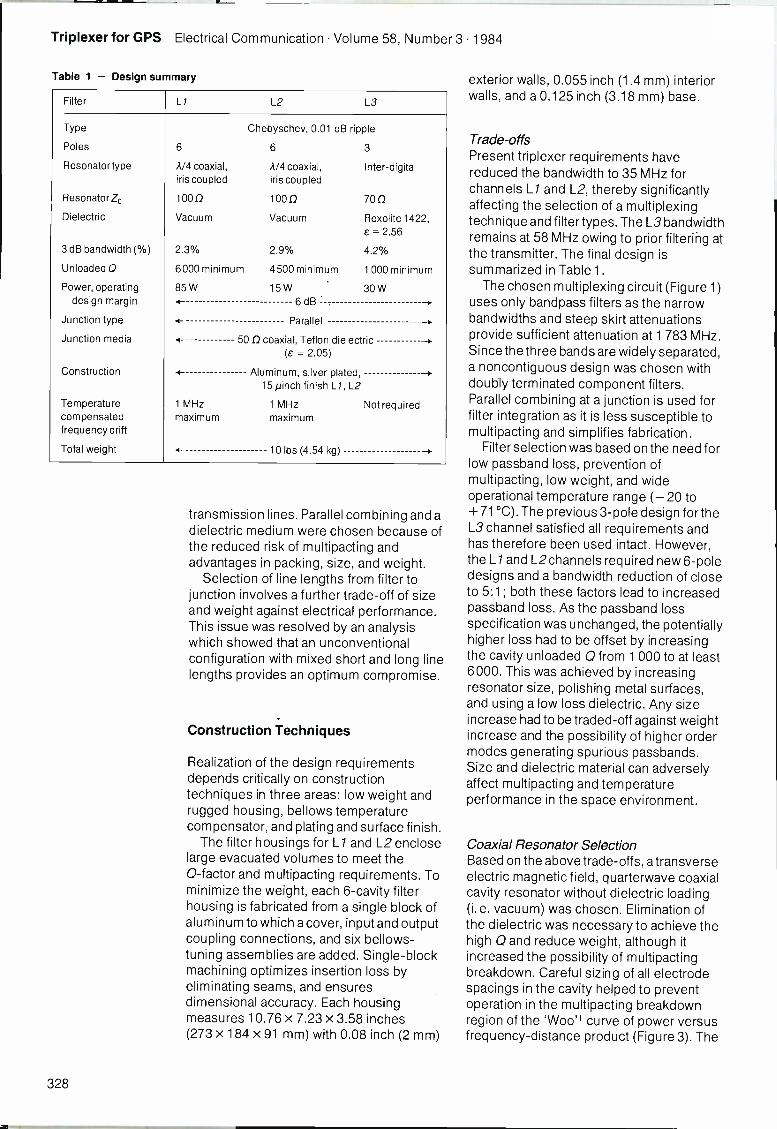
Triplexer for GPS Electrical Communication Volume 58, Number 3 1984
Table 1 - Design summary
Filter Li L2 L3
Type
Poles
Resonator type
Resonator Zo
Dielectric
3 dB bandwidth (%)
Unloaded Q
Power, operatingdesign margin
Junction type
Junction media
Construction
Temperaturecompensatedfrequency drift
Total weight
Chebyschev, 0.01 dB ripple
6 6 3
A/4 coaxial, A/4 coaxial, Inter -digitaliris coupled iris coupled
1000 1000 700Vacuum Vacuum Rexolite 1422,
a= 2.56
2.3% 2.9% 4.2%
6000 minimum 4500 minimum 1 000 minimum
85W 15W 30W4- 6 dB . --.
4- Parallel -1.
4- 50 0 coaxial, Teflon dielectric -).(e = 2.05)
1 MHzmaximum
Aluminum, silver plated,15 µinch finish Li, L2
1 MHzmaximum
10 lbs (4.54 kg)
Not required
transmission lines. Parallel combining and adielectric medium were chosen because ofthe reduced risk of multipacting andadvantages in packing, size, and weight.
Selection of line lengths from filter tojunction involves a further trade-off of sizeand weight against electrical performance.This issue was resolved by an analysiswhich showed that an unconventionalconfiguration with mixed short and long linelengths provides an optimum compromise.
Construction Techniques
Realization of the design requirementsdepends critically on constructiontechniques in three areas: low weight andrugged housing, bellows temperaturecompensator, and plating and surface finish.
The filter housings for L/ and L2 encloselarge evacuated volumes to meet the0 -factor and multipacting requirements. Tominimize the weight, each 6 -cavity filterhousing is fabricated from a single block ofaluminum to which a cover, input and outputcoupling connections, and six bellows -tuning assemblies are added. Single -blockmachining optimizes insertion loss byeliminating seams, and ensuresdimensional accuracy. Each housingmeasures 10.76 x 7.23 x 3.58 inches(273 x 184 x 91 mm) with 0.08 inch (2 mm)
exterior walls, 0.055 inch (1.4 mm) interiorwalls, and a 0.125 inch (3.18 mm) base.
Trade-offsPresent triplexer requirements havereduced the bandwidth to 35 MHz forchannels L/ and L2, thereby significantlyaffecting the selection of a multiplexingtechnique and filter types. The L3 bandwidthremains at 58 MHz owing to prior filtering atthe transmitter. The final design issummarized in Table 1.
The chosen multiplexing circuit (Figure 1)uses only bandpass filters as the narrowbandwidths and steep skirt attenuationsprovide sufficient attenuation at 1 783 MHz.Since the three bands are widely separated,a noncontiguous design was chosen withdoubly terminated component filters.Parallel combining at a junction is used forfilter integration as it is less susceptible tomultipacting and simplifies fabrication.
Filter selection was based on the need forlow passband loss, prevention ofmultipacting, low weight, and wideoperational temperature range (- 20 to+ 71 °C). The previous 3 -pole design for theL3 channel satisfied all requirements andhas therefore been used intact. However,the L/ and L2channels required newdesigns and a bandwidth reduction of closeto 5:1; both these factors lead to increasedpassband loss. As the passband lossspecification was unchanged, the potentiallyhigher loss had to be offset by increasingthe cavity unloaded Q from 1 000 to at least6000. This was achieved by increasingresonator size, polishing metal surfaces,and using a low loss dielectric. Any sizeincrease had to be traded -off against weightincrease and the possibility of higher ordermodes generating spurious passbands.Size and dielectric material can adverselyaffect multipacting and temperatureperformance in the space environment.
Coaxial Resonator SelectionBased on the above trade-offs, a transverseelectric magnetic field, quarterwave coaxialcavity resonator without dielectric loading(i.e. vacuum) was chosen. Elimination ofthe dielectric was necessary to achieve thehigh Q and reduce weight, although itincreased the possibility of multipactingbreakdown. Careful sizing of all electrodespacings in the cavity helped to preventoperation in the multipacting breakdownregion of the 'Woo" curve of power versusfrequency -distance product (Figure 3). The
328
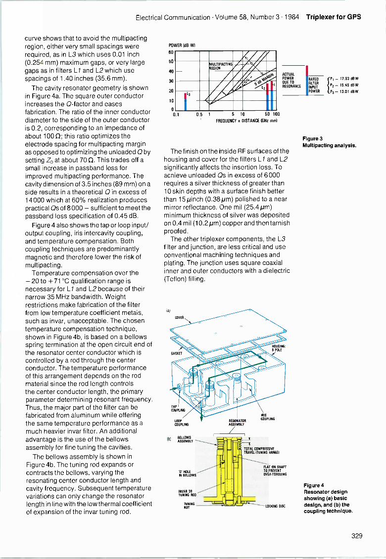
Electrical Communication Volume 58, Number 3 1984 Triplexer for GPS
curve shows that to avoid the multipactingregion, either very small spacings wererequired, as in L3 which uses 0.01 inch(0.254 mm) maximum gaps, or very largegaps as in filters LI and L2 which usespacings of 1.40 inches (35.6 mm).
The cavity resonator geometry is shownin Figure 4a. The square outer conductorincreases the 0 -factor and easesfabrication. The ratio of the inner conductordiameter to the side of the outer conductoris 0.2, corresponding to an impedance ofabout 1000; this ratio optimizes theelectrode spacing for multipacting marginas opposed to optimizing the unloaded 0 bysetting Z0 at about 70 0. This trades off asmall increase in passband loss forimproved multipacting performance. Thecavity dimension of 3.5 inches (89 mm) on aside results in a theoretical Q in excess of14000 which at 60% realization producespractical Qs of 8000 - sufficient to meet thepassband loss specification of 0.45 dB.
Figure 4 also shows the tap or loop input/output coupling, iris intercavity coupling,and temperature compensation. Bothcoupling techniques are predominantlymagnetic and therefore lower the risk ofmultipacting.
Temperature compensation over the-20 to +71°C qualification range isnecessary for Ll and L2 because of theirnarrow 35 MHz bandwidth. Weightrestrictions make fabrication of the filterfrom low temperature coefficient metals,such as invar, unacceptable. The chosentemperature compensation technique,shown in Figure 4b, is based on a bellowsspring termination at the open circuit end ofthe resonator center conductor which iscontrolled by a rod through the centerconductor. The temperature performanceof this arrangement depends on the rodmaterial since the rod length controlsthe center conductor length, the primaryparameter determining resonant frequency.Thus, the major part of the filter can befabricated from aluminum while offeringthe same temperature performance as amuch heavier invar filter. An additionaladvantage is the use of the bellowsassembly for fine tuning the cavities.
The bellows assembly is shown inFigure 4b. The tuning rod expands orcontracts the bellows, varying theresonating center conductor length andcavity frequency. Subsequent temperaturevariations can only change the resonatorlength in line with the low thermal coefficientof expansion of the invar tuning rod.
POWER (dB WI
60
50
40
30
20
10
0
MULTIPACTINGREGION
VP1
0,t4,9
et,
L2
1.3
0 1 0.5 1 5 10 5C 100
FREQUENCY x DISTANCE (GHz mm)
ACTUALPOWERDUE TORESONANCE
IRATEDFILTERINPUTPOWER
The finish on the inside RF surfaces of thehousing and cover for the filters LI and L2significantly affects the insertion loss. Toachieve unloaded Os in excess of 6000requires a silver thickness of greater than10 skin depths with a surface finish betterthan 15 pinch (0.38pm) polished to a nearmirror reflectance. One mil (25.4pm)minimum thickness of silver was depositedon 0.4 mil (10.2 pm) copper and then tarnishproofed.
The other triplexer components, the L3filter and junction, are less critical and useconventional machining techniques andplating. The junction uses square coaxialinner and outer conductors with a dielectric(Teflon) filling.
LOOP
COUPLING
,b, BELLOWSASSEMBLY ----
'ET HOLEIN BELLOWS
INVAR 36TUNING ROO
TUNINGNUT
RESONATORASSEMBLY
IRIS
COUPLING
TRAVEL (TUNING RANGE)TOTAL COMPRESSIVE
II IFLAT ON SHAFTTO PREVENTOVER -TORQUING
- LOCKING DISC
P1= 17.93 dB W
P2= 15.45 dB W
P3= 13.01 dBW
Figure 3Multipacting analysis.
Figure 4Resonator designshowing (a) basicdesign, and (b) thecoupling technique.
329
Triplexer for GPS Electrical Communication Volume 58, Number 3 1984
Two final construction features were theuse of silver-plated brass gasket materialset in channels in the covers of Li and L2,and strategically placed through -holes toallow efficient evacuation of air during thetransition from atmospheric to vacuumconditions. The gaskets were vital inreducing insertion loss by providing acompressible seam of low resistance. Theevacuation holes were designed as cutoffwaveguide attenuators.
Experimental Results
Development of the LI and L2 filters beganwith experimental verification of the basiccavity concept, and determination ofintercavity coupling as afunction of iris size.Based on these results, full 6 -cavity filterswere built and tested. Similarly, the junctionconcept was tested by simulating the filterterminations using 2 -pole filters.
A single cavity was fabricated withbellows tuning and silver plated surfacespolished to 15 pinch (0.38pm). Measuredresults included an unloaded Q of 7800 anda 6:1 reduction in frequency drift to± 0.45 MHz. Power testing in vacuum attemperatures between - 20 and +71°Cshowed no multipacting. The powers usedin both LI and L2 exceeded thespecification.
Iris coupling cannot usually be calculatedaccurately for practical cavity shapes. Forthe cavity used, a general equation isavailable which requires the constants to bedetermined experimentally2:
K = B L3 cos2 (A L)
where
K - coupling factorL - iris lengthA, B- constants.
A 2 -cavity filter was used to makemeasurements, using Dishal's method3, forseveral iris sizes spanning the requirementsfor LI and L2; the constants A and B werethen determined. The resulting curves areshown in Figure 5. Perturbationmeasurements indicated that fabricationtolerances of 5 mils (127pm) or less wererequired.
Interpolating the iris coupled dataprovided the iris sizes for the experimental6 -pole L1 and L2 filters; these did notrequire modification. Tap coupling locationswere also determined experimentally.
The junction design was validatedexperimentally by using 2 -cavity filters as
preliminary terminations. The design wasbased on an analysis which showed that anexact match could be achieved in all threebands with an unconventional arrangementof interconnecting line length: two atapproximately quarter wavelength and thethird at approximately half wavelength.Measured results showed excellent voltagestanding wave ratio performance andtherefore a valid baseline design from whichthe final design evolved.
K: COUPLING FACTOR x 10-3
37.5
30
22.5
15
7.5
0
EXPERIMENTAL DATA POINT
I I
REQUIRED COUPLING FACTORSFOR 6 -POLE 0.01 dBCHEBYSCHEV FILTER
L1L2
0 05 15 2 2.5
L: IRIS LENGTH (inches)
Triplexer Results
A full triplexer, incorporating filters L/, L2,and L3 and the junction, was assembledand tested. Small adjustments to thejunction line length were necessary tomatch the pre -integrated filter responses.Table 2 gives the measured results after linelength optimization.
During development the housings werebuilt without final details, such as irises, andupdated as design information becameavailable from the experiments. Thisallowed critical experiments on the vibrationresponse of a realistic 'dummy' triplexer tobe carried out concurrently with electricaldevelopment. Early vibration data validatedthe thin wall design and allowed judicioustrimming to reduce the weight even further.
References
1 P. F. Clancy: Multipactor Control in Microwave SpaceSystems: Microwave Journal, March 1978.
Figure 5Dual cavity testresults.
330
Electrical Communication Volume 58, Number 3 1984 Triplexer for GPS
2 Matthaei, Young, and Jones: Microwave Filters,Impedance Matching Networks and CouplingStructures: McGraw Hill, New York, 1964, p 1016.
3 M. Dishal: Alignment and Adjustment ofSynchronously Tuned Multiple Resonant Filters:Electrical Communication, 1952, volume 29, n° 2,pp 154 -164.
Greta Gorder was born in Oak Ridge, Tennessee, USAin 1959. She received a BSEE from Brown University,Providence, Rhode Island in 1981 and has participated ingraduate courses in electrical engineering. She hasworked as a microwave design engineer in the field offilters and low noise amplifiers. Ms Garde', who joinedITT DCD in 1981, is currently involved in the design of alow noise monolithic amplifier.
Joseph Ranghelli was born in Brooklyn, New York, in1931. He studied electrical engineering at thePolytechnic Institute of New York, graduating as a BSEEin 1959 and MSEE in 1965. He worked in severalcompanies doing research and development onmicrowave components and systems prior to joining ITTDCD. Mr Ranghelli has extensive experience in filterdesign, phased array antennas, adaptive arrays, andswitching devices. He has been with ITT for ten yearsand is currently section head in the microwave group atDCD and project leader for the GPS triplexer engineeringdevelopment.
Table 2 - Measured performance of the triplexer engineering developmentmodel (EDM)
ParameterL / filter
Spec EDML2filter
Spec EDML3filter
Spec EDM
F0 1575.42 1227.6 1381.05
3 dB bandwidth (MHz) > 30 36.2 > 30 38 > 58 63
Width of passband (MHz) +10.23 +10.23 +10.23Loss at F0 (dB) < 0.45 0.29 < 0.45 0.31 < 0.7 0.50
Passband loss variation
(dB) < 0.10 0.07 < 0.10 0.07 < 0.10 0.08
Stopband loss:
1345 to 1427 MHz (dB) > 50 >70* > 50 > 70* NA
1612 MHz (dB) > 35 44.23 > 50 > 70* NA
1665 to 1667 MHz (dB) > 50 65 > 50 > 70* NA
99% bandwidth,maximum (MHz) ± 20.5 ± 18.4 ± 20.5 ± 19 NA
Cross coupling
J2 -J3 @ L2(dB) NA NA > 39 47J2 -J1 @ L2(dB) > 50 > 70* NA NAJ1 -J3 @ L / (dB) NA NA > 39 52J1 -J2 @ L / (dB) NA > 50 > 70* NAJ3 -J2 @ L3 (dB) NA > 50 > 70* NAJ3 -J1 @ L3 (dB) > 50 > 70' NA NA
Impedance (0) 50 50 50 50 50 50
Passband VSWR (:1) < 1.20 1.18 < 1.20 1.13 < 1.22 1.11
Group delayvariation (ns) < +1 0.22 < +1 0.05 < + 1 0.26
Temperature range (°C) -20/+7' -20/+71 -20/+71Power (W) 85 100 15 40 30 30
Uplink isolationat 1783.74 + 2.5 MHz(dB) > 65 > 70* > 65 > 70* > 60 68.3
Number of poles 6 6 3
noise floor
331
Receiver for Global Positioning System
The satellite -based global positioningsystem will become a major system forposition -finding and navigation within thenext few years. SEL is developing aprototype receiver which will have one of itsfirst applications in the German Spacelabnavigation experiment.
A. BethmannH. TschiescheStandard Elektrik Lorenz AG, Stuttgart,Federal Republic of Germany
Introduction
Land based navigation systems for shipsand air traffic are based either on themeasurement of propagation delay of radiosignals from stations with knowncoordinates or on bearing measurements.The progress in space technology nowmakes it possible to produce satellitenavigation systems with very highaccuracies. The GPS (global positioningsystem) satellite -based navigation systemwill become the most important system forposition finding and navigation within thenext six to seven years, providing users allover the world with position and timinginformation of unprecedented accuracy.The position finding procedure is based onthe measurement of propagation delay
LI AND L2PSEUDO RANGEAND RANGE RATE
times for radio signals from at least foursatellites out of a constellation of 18.
Standard Elektrik Lorenz (SEL) isdeveloping a prototype GPS receiver forcivil applications, which can also beupgraded for military users.
GPS System
The United States' Naystar-GPSprogramme is divided into three operationalphases. The original objective ofestablishing an operational system with 24satellites by 1984 can no longer be achievedfor technical and financial reasons.Nevertheless the programme is continuingand the system will be fully operational in1987 with 18 satellites. Five satellites are
SPACE SEGMENT
LI AND L2 SATELLITE TRANSMISSION- PSEUDO RANGE/RANGE RATE- EPHEMERIS
SATELLITE CLOCK DATAEi
1S -BAND UPLINK
Figure 1Naystar-GPS system.
VANDENBURGAIR FORCE BASE
CONTROL SEGMENT
MILITARYAND CIVILAIR-, SEA -AND LANOVEHICLES
USER SEGMENT
332
Electrical Communication Volume 58, Number 3 1984 GPS Receiver
already in operation. Figure 1 shows thethree key components of Naystar-GPS:space segment, control segment, and usersegment.
The space segment will consist of18 satellites in six 12 -hour orbit planes at analtitude of about 20000 km. These willprovide visibility of at least four satellites at5° or more above the horizon to userslocated anywhere in the world at any time.Signals are transmitted at two L -Bandfrequencies (Table 1) to permit correctionsto be made for ionospheric delays inpropagation time. Signals are modulatedwith two pseudorandom codes: P forprecise time measurements, and C/A foreasy lock -on to the desired signal withreduced accuracy. In addition, each signalis modulated with navigation messages(ephemeris, correction, system status, andsystem control parameters). The accuracyin position and time which can be achievedwith the two codes is shown in Table 1. Eachsatellite has an atomic clock which isupdated by the control segment once a day.A computer in each satellite calculates theactual ephemeris and updates thenavigation message.
The control segment consists of fourmonitor stations, an upload station, and amaster control station. Each monitor stationserves as a data collection center; itcontains a high performance four -channelreceiver, an atomic clock, and a computerwhich controls data collection and providesthe interface to the processor of the mastercontrol station. The upload station providesthe interface between the control segmentand the space segment via an S -Band radiolink. The master control station performs thecomputations necessary to determinesatellite ephemeris and atomic clock errors,generates satellite upload of user navigationdata, and maintains a record of satelliteprocessor contents and status.
The user segment (GPS receiver withantenna and periphery) depends on theapplication. It may vary from a five -channeltwo -frequency receiver for military userswith high demands on accuracy andreliability down to a simple single -channelreceiver for civil users. Thus the usersegment must be constructed from modularhardware and software so that it can meetthese varying requirements.
GPS Receiver
Figure 2 is a block schematic of SEL'sprototype civil receiver. The main
Table 1 - Signal characteristics ard system accuracy
Satellite signalCarrier
frequencyCode Bandwidth
L/L2
1575.42 MHz1227.60 MHz
C/A and PC/A or P
2 MHz at C/A and20 MHz at Pcode signal
Parameter C/A code P code Data
Chipping rate
Code type
Period
1.023 MHz
Gold code
1 ms
10.23 MHz
200 dayPRN* code
7 days
50 bit s-1--
Navigation accuracy Position Velocity Time
With C/A code 100 to 300 m 0.3 ms -1 50 to 100 ns
With Pcode 17 m 0.2 ms-' 11 ns
* pseudorandom noise
components are the antenna withpreamplifier, receiver/processor unit,control/display unit, and power supply. Themodular structure enables the receiver tobe adapted to nearly all planned applicationssimply by changing or adding hardware orsoftware modules. In addition, it can beexpanded from a single -channel receiverfor civil users up to a multichannel receiverwith auxiliary sensors for military users.Figure 2 shows the receiver modules for thefirst application within the planned Germantest and trial programme and for use in theNavex ground segment.
The receiver has a data channel and anavigation channel. The navigation channelperforms the sequential pseudorangemeasurements to the best four satelliteswhile the data channel collects data from allvisible satellites. A delay lock loop and aCostas loop are used for signal acquisitionand tracking of the C/A code and the carrier.
The GPS receiver must be capable ofmeasuring its range from four satellites. Todo this it must amplify the signal, despreadthe code, demodulate, decode, andinterpret the 50 bit s-1 data stream of eachsatellite signal. The data stream conveysthe satellite status, correction parametersfor the satellite clock and for signal delaysthrough the atmosphere, the ephemeris ofthe satellite, and other system control andstatus parameters to the user. In additionthe data stream contains the almanacinformation that defines the approximateephemerides and status of all satellites'.Range measurements together with theinformation from the navigation data streamenable the user receiver to perform the
333
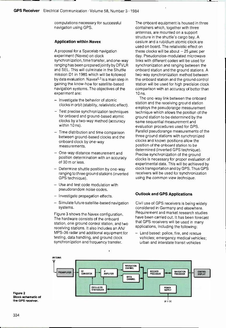
GPS Receiver Electrical Communication Volume 58, Number 3 1984
computations necessary for successfulnavigation using GPS.
Application within Navex
A proposal for a Spacelab navigationexperiment (Navex) on clocksynchronization, time transfer, and one-wayranging has been prepared jointly by DFVLRand SEL. This will culminate in the Shuttlemission D1 in 1985 which will be followedby data evaluation. Navex2,3 is a main step ingaining the know-how for satellite -basednavigation systems. The objectives of theexperiment are:
Investigate the behavior of atomicclocks in orbit (stability, relativistic effect).
Test precise synchronization techniquesfor onboard and ground -based atomicclocks by a two-way method (accuracywithin 10 ns).
Time distribution and time comparisonbetween ground -based clocks and theonboard clock by one-waymeasurements.
One-way distance measurement andposition determination with an accuracyof 30 m or less.
Determine shuttle position by one-wayranging to three ground stations (invertedGPS technique).
Use and test code modulation withpseudorandom noise codes.
- Investigate propagation effects.
Simulate future satellite -based navigationsystems.
Figure 3 shows the Navex configuration.The hardware consists of the onboardstation, one ground control station, and tworeceiving stations. It also includes an AN/MPS -36 radar and additional equipment fortesting, data handling, and ground clocksynchronization and frequency transfer.
ANTENNA
PREAMPLIFIER
Figure 2Block schematic ofthe GPS receiver.
The onboard equipment is housed in threecontainers which, together with threeantennas, are mounted on a supportstructure in the shuttle's cargo bay. Acesium and a rubidium atomic clock areused on board. The relativistic effect onthese clocks will be about - 25 //sec perday. Pseudonoise-modulated microwavelinks with different codes will be used forsynchronization and ranging between theonboard station and the ground stations. Atwo-way synchronization method betweenthe onboard station and the ground controlstation will be used for high precision clockcomparison with an accuracy of better than10 ns.
The one-way link between the onboardstation and the receiving ground stationemploys the pseudorange measurementtechnique which allows the position of theground station to be determined by thesame sequential measurement andevaluation procedures used for GPS.Parallel pseudorange measurements of thethree ground stations with synchronizedclocks and known positions allow theposition of the onboard station to bedetermined (inverted GPS technique).Precise synchronization of the groundclocks is necessary for proper evaluation ofexperimental data. This will be achieved byclock transportation and by GPS. Thus GPSreceivers will be used for synchronizationusing the common view technique.
Outlook and GPS Applications
Civil use of GPS receivers is being widelyconsidered in Germany and elsewhere.Requirement and market research studieshave been carried out. It has been forecastthat GPS receivers will be used in manyapplications, including the following:
- Land based: police, fire, and rescuevehicles; emergency medical vehicles;urban and interstate transit vehicles
NAVIGATIONCHANNEL
RF
CONVERTER
IF
AMPLIFIERRECEIVER Hp.PROCESSOR
DATACHANNEL
OSCILLATORSYNTHESIZER
F...NAVIGATIONPROCESSOR
POWER
SUPPLY
28 V DC
CONTROLDISPLAY
334
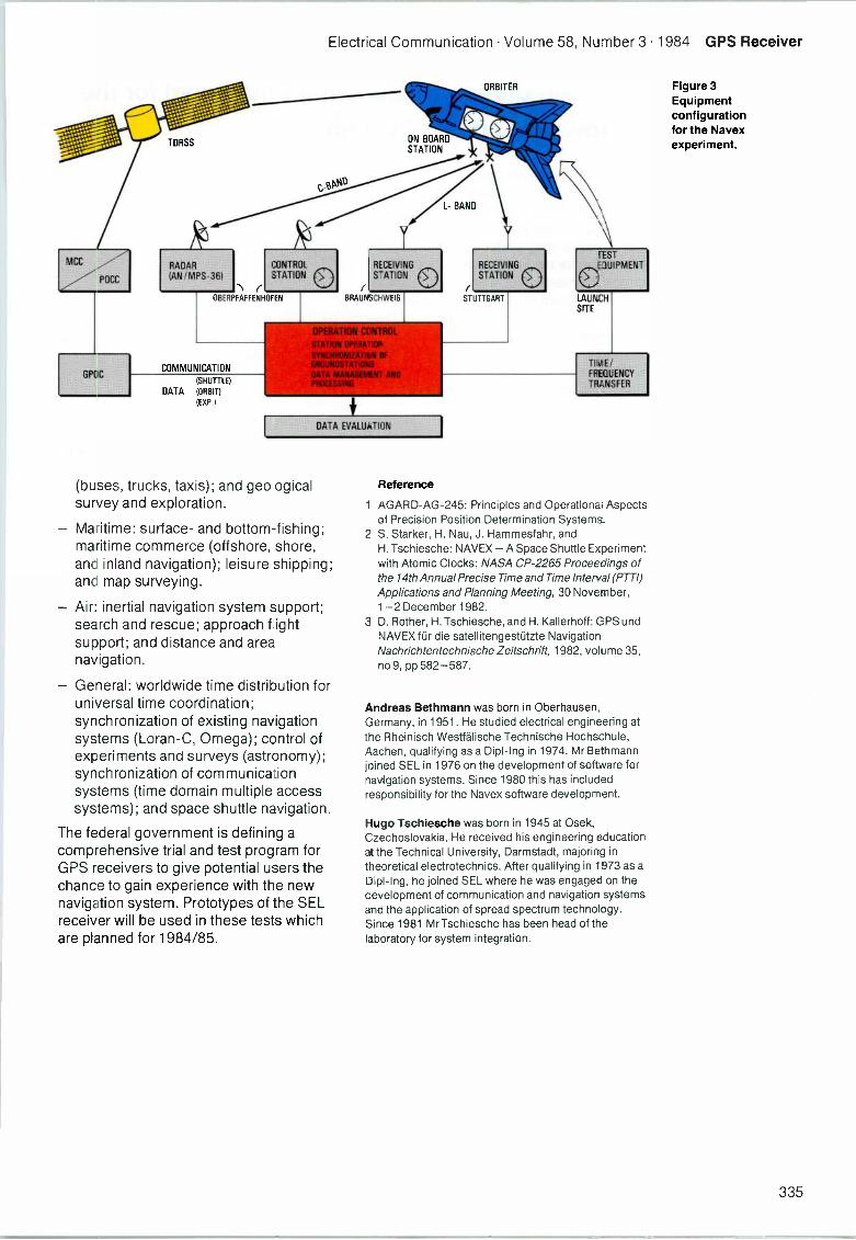
Electrical Communication Volume 58, Number 3 1984 GPS Receiver
GPOC
RADAR
(AN/MPS-36)CONTROLSTATION CI)
OBERPFAFFENHOFEN
COMMUNICATION
(SHUTTLE)
DATA (ORBIT)
(EXP.)
ON BOARDSTATION
ORBITER
bAr
BAND
BRAUNSCHWEIG(
STUTTGART
RECEIVING
STATION 0RECEIVINGSTATION
TESTEQUIPMENT
LAUNCHSITE
DATA EVALUATION
(buses, trucks, taxis); and geologicalsurvey and exploration.
- Matime: surface- and bottom -fishing;maritime commerce (offshore, shore,and inland navigation); leisure shipping;and map surveying.
- Air: inertial navigation system support;search and rescue; approach flightsupport; and distance and areanavigation.
- General: worldwide time distribution foruniversal time coordination;synchronization of existing navigationsystems (Loran -C, Omega); control ofexperiments and surveys (astronomy);synchronization of communicationsystems (time domain multiple accesssystems); and space shuttle navigation.
The federal government is defining acomprehensive trial and test program forGPS receivers to give potential users thechance to gain experience with the newnavigation system. Prototypes of the SELreceiver will be used in these tests whichare planned for 1984/85.
Reference
TIME/FREQUENCY
TRANSFER
1 AGARD-AG-245: Principles and Operational Aspectsof Precision Position Determination Systems -
2 S. Starker, H. Nau, J. Hammesfahr, andH. Tschiesche: NAVEX -A Space Shuttle Experimentwith Atomic Clocks: NASA CP-2265 Proceedings ofthe 14th Annual Precise Time and Time Interval (PTTI)Applications and Planning Meeting, 30 November,1-2 December 1982.
3 D. Rother, H. Tschiesche, and H. Kallerhoff: GPS andNAVEX fur die satellitengestutzte Navigation:Nachrichtentechnische Zeitschrift, 1982, volume 35,no 9, pp 582-587.
Andreas Bethmann was born in Oberhausen,Germany, in 1951. He studied electrical engineering atthe Rheinisch Westfalische Technische Hochschule,Aachen, qualifying as a Dipl-Ing in 1974. Mr Bethmannjoined SEL in 1976 on the development of software fornavigation systems. Since 1980 this has includedresponsibility for the Navex software development.
Hugo Tschiesche was born in 1945 at Osek,Czechoslovakia. He received his engineering educationat the Technical University, Darmstadt, majoring intheoretical electrotechnics. After qualifying in 1973 as aDipl-Ing, he joined SEL where he was engaged on thedevelopment of communication and navigation systemsand the application of spread spectrum technology.Since 1981 Mr Tschiesche has been head of thelaboratory for system integration.
Figure 3Equipmentconfigurationfor the Navexexperiment.
335
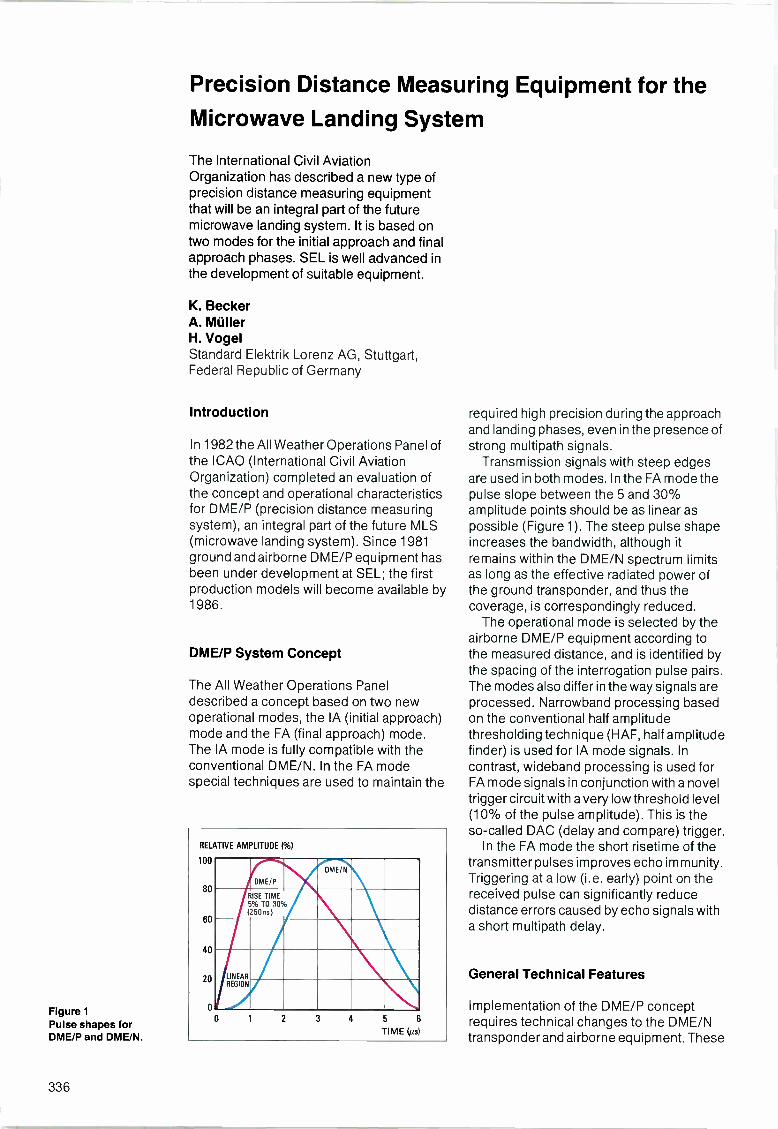
Figure 1Pulse shapes forDME/P and DME/N.
Precision Distance Measuring Equipment for theMicrowave Landing System
The International Civil AviationOrganization has described a new type ofprecision distance measuring equipmentthat will be an integral part of the futuremicrowave landing system. It is based ontwo modes for the initial approach and finalapproach phases. SEL is well advanced inthe development of suitable equipment.
K. BeckerA. MullerH. VogelStandard Elektrik Lorenz AG, Stuttgart,Federal Republic of Germany
Introduction
In 1982 the All Weather Operations Panel ofthe ICAO (International Civil AviationOrganization) completed an evaluation ofthe concept and operational characteristicsfor DME/P (precision distance measuringsystem), an integral part of the future MLS(microwave landing system). Since 1981ground and airborne DME/P equipment hasbeen under development at SEL; the firstproduction models will become available by1986.
DME/P System Concept
The All Weather Operations Paneldescribed a concept based on two newoperational modes, the IA (initial approach)mode and the FA (final approach) mode.The IA mode is fully compatible with theconventional DME/N. In the FA modespecial techniques are used to maintain the
RELATIVE AMPLITUDE 06)
100
80
60
40
20
0
DME/P
DME/N
RISE TIME5% TO 30%(250ns)
LINEARREGION
0 2 3 4 5 6
TIME Lis)
required high precision during the approachand landing phases, even in the presence ofstrong multipath signals.
Transmission signals with steep edgesare used in both modes. In the FA mode thepulse slope between the 5 and 30%amplitude points should be as linear aspossible (Figure 1). The steep pulse shapeincreases the bandwidth, although itremains within the DME/N spectrum limitsas long as the effective radiated power ofthe ground transponder, and thus thecoverage, is correspondingly reduced.
The operational mode is selected by theairborne DME/P equipment according tothe measured distance, and is identified bythe spacing of the interrogation pulse pairs.The modes also differ in the way signals areprocessed. Narrowband processing basedon the conventional half amplitudethresholding technique (HAF, half amplitudefinder) is used for IA mode signals. Incontrast, wideband processing is used forFA mode signals in conjunction with a noveltrigger circuit with a very low threshold level(10% of the pulse amplitude). This is theso-called DAC (delay and compare) trigger.
In the FA mode the short risetime of thetransmitter pulses improves echo immunity.Triggering at a low (i.e. early) point on thereceived pulse can significantly reducedistance errors caused by echo signals witha short multipath delay.
General Technical Features
Implementation of the DME/P conceptrequires technical changes to the DME/Ntransponder and airborne equipment. These
336
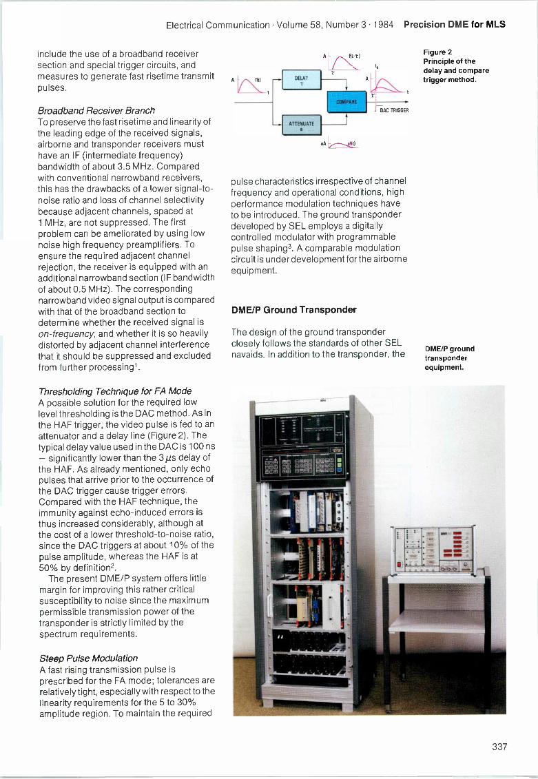
Electrical Communication Volume 58, Number 3 1984 Precision DME for MLS
include the use of a broadband receiversection and special trigger circuits, andmeasures to generate fast risetime transmitpulses.
Broadband Receiver BranchTo preserve the fast risetime and linearity ofthe leading edge of the received signals,airborne and transponder receivers musthave an IF (intermediate frequency)bandwidth of about 3.5 MHz. Comparedwith conventional narrowband receivers,this has the drawbacks of a lower signal-to-noise ratio and loss of channel selectivitybecause adjacent channels, spaced at1 MHz, are not suppressed. The firstproblem can be ameliorated by using lownoise high frequency preamplifiers. Toensure the required adjacent channelrejection, the receiver is equipped with anadditional narrowband section (IF bandwidthof about 0.5 MHz). The correspondingnarrowband video signal output is comparedwith that of the broadband section todetermine whether the received signal ison -frequency, and whether it is so heavilydistorted by adjacent channel interferencethat it should be suppressed and excludedfrom further processing'.
Thresholding Technique for FA ModeA possible solution for the required lowlevel thresholding is the DAC method. As inthe HAF trigger, the video pulse is fed to anattenuator and a delay line (Figure 2). Thetypical delay value used in the DAC is 100 ns- significantly lower than the 3 ps delay ofthe HAF. As already mentioned, only echopulses that arrive prior to the occurrence ofthe DAC trigger cause trigger errors.Compared with the HAF technique, theimmunity against echo -induced errors isthus increased considerably, although atthe cost of a lower threshold -to -noise ratio,since the DAC triggers at about 10% of thepulse amplitude, whereas the HAF is at50% by definition2.
The present DME/P system offers littlemargin for improving this rather criticalsusceptibility to noise since the maximumpermissible transmission power of thetransponder is strictly limited by thespectrum requirements.
Steep Pulse ModulationA fast rising transmission pulse isprescribed for the FA mode; tolerances arerelatively tight, especially with respect to thelinearity requirements for the 5 to 30%amplitude region. To maintain the required
fit) DELAY
ATTENUATEa
aA
to
T;
i-OAC TRIGGER
pulse characteristics irrespective of channelfrequency and operational conditions, highperformance modulation techniques haveto be introduced. The ground transponderdeveloped by SEL employs a digitallycontrolled modulator with programmablepulse shaping3. A comparable modulationcircuit is under development for the airborneequipment.
DME/P Ground Transponder
The design of the ground transponderclosely follows the standards of other SELnavaids. In addition to the transponder, the
Figure 2Principle of thedelay and comparetrigger method.
DME/P groundtransponderequipment.
I : .. wry
MN
II 2 e fe,
n ea a a tallAtte .....,
337
Precision DME for MLS Electrical Communication Volume 58, Number 3 1984
Figure 3Simplified functionalblock diagram of theDME/P transponder.
ground equipment incorporates one (ortwo) monitor unit(s) and a control unit.Figure 3 shows the basic functions of thetransponder. The main characteristics aregiven in Table 1.
Two -Mode TechniqueWhen the ground transponder receives aninterrogation from the airborne equipment itmust first analyze whether it is aconventional DME/N, DME/P IA mode, orDME/P FA mode interrogation. This isachieved by pulse pair decoding of eachinterrogation to determine how it is to beprocessed. For the receiver section thisimplies simultaneous narrowband andbroadband processing, and HAF and DACthresholding.
Table 1 - Main characteristics of theDME/P transponder
Design specifications:
AWOP-WP/401 (12/82)
FAA -E-2721/3 (9/82)
EUROCAE ED -31 (7/80) as applicable
Main features:
Transmit power 300 W EIRP
Sensitivity
IA mode < - 82 dBm 1 for 30 dB videoFA mode: < - 76 dBm J signal-to-noise ratio
Instrumentationerror < 10 m path following error
(IA mode)
< 8 m control motion noise(FA mode)
ANTENNA
V
TRANSMITTER
DEMODULATOR
MODULATORCONTROL
MODULATOR
r
PROM
ASYNTHESIZER
CIRCULATOR
CALIBRATION MODULE
63 MHz LOCALOSCILLATOR
START
VARIABLEATTENUATOR
RECEIVER
PRESE ECTOR
CALIBRATIONCONTROL
INTERNALDELAYCOUNTER
STOP
UHF AMPLIFIER
PULSE PAIRGENERATOR
PULSE RATE
COUNTER
ID
KEYER
PRIORITYCONTROL
SOUITTERGENERATOR
DELAYCOUNTER
PROCESSOR
+IF -1w AMPLITUDE VALIDATION
AMDECODER
DELAYCONTROL
FAM
DECODER
MODEDISCRIMINATOR
SIGNAL PROCESSOR
TOA
TOA
63 MHz
IF AMPLIFIER= 3.5 MHz
LOGARITHMICLEVEL DETECTOR
DELAYLINE
GAINCONTROL
CHANNELDISCRIMINATOR
GAINCONTROLLEDLINEAR IF AMP.
FILTER
BW = 0.8 MHz
DEMODULATOR
HAFTRIGGER
338
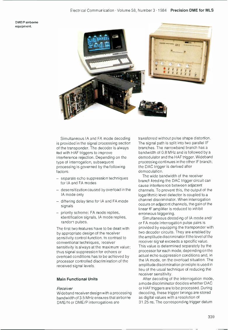
Electrical Communication Volume 58, Number 3 1984 Precision DME for MLS
DME/P airborneequipment.
Simultaneous IA and FA mode decodingis provided in the signal processing sectionof the transponder. The decoder is alwaysfed with HAF triggers to improveinterference rejection. Depending on thetype of interrogation, subsequentprocessing is governed by the followingfactors:
- separate echo suppression techniquesfor IA and FA modes
desensitization caused by overload in theIA mode only
- differing delay time for IA and FA modesignals
- priority scheme: FA mode replies,identification signals, IA mode replies,random pulses.
The first two features have to be dealt withby appropriate design of the receiversensitivity control function. In contrast toconventional techniques, receiversensitivity is always at the maximum value;thus signal suppression for echoes oroverload conditions has to be achieved byprocessor controlled discrimination of thereceived signal levels.
Main Functional Units
ReceiverWideband receiver design with a processingbandwidth of 3.5 MHz ensures that airborneDME/N or DME/P interrogations are
transferred without pulse shape distortion.The signal path is split into two parallel IFbranches. The narrowband branch has abandwidth of 0.8 MHz and is followed by ademodulator and the HAF trigger. Widebandprocessing continues in the other IF branch;the DAC trigger is derived afterdemodulation.
The wide bandwidth of the receiverbranch feed ng the DAC trigger circuit cancause interference between adjacentchannels. To prevent this, the output of thelogarithmic level detector is coupled to achannel discriminator. When interrogationoccurs on adjacent channels, the gain of thelinear IF amplifier is reduced to inhibiterroneous triggering.
Simultaneous decoding of IA mode and/or FA mode interrogation pulse pairs isprovided by equipping the transponder withtwo decoder circuits. They are enabled bythe amplitude discriminator if the level of thereceiver signal exceeds a specific value.This value is determined separately by theprocessor for each mode, depending on theactual echo suppression conditions and, inthe IA mode, on the overload situation. Theamplitude discrimination principle is used inlieu of the usual technique of reducing thereceiver sensitivity.
After decoding of the interrogation mode,a mode discriminator decides whether DACor HAF triggers are to be processed. Duringdecoding, these trigger timings are storedas digital values with a resolution of31.25 ns. The corresponding trigger datum
339
Precision DME for MLS Electrical Communication Volume 58, Number 3 1984
is then used to preset and start the delaycounter, which counts at a clock frequencyof 32 MHz until it reaches the preset stopvalue. The stop value is determined by thecombined result of the calibration cycles,the received signal level, and the systemdelay specified for the particular mode.
At the end of delay timing the reply triggeris issued; after gating by the priority logic itis then fed via the pulse pair encoder to thetransmitter. In the event of simultaneousrequests for transmission by reply pulsesand identification pulses or random pulses,a priority logic is used to resolve the conflict.The specific priority requirement for DME/Pis also catered for; FA mode replies have ahigher priority than identification pulses.
TransmitterThe transmitter (synthesizer, amplifier, andmodulator) outputs transponder pulses ofup to 100 W peak power. A new digitallycontrolled modulator is used to maintain therequired pulse shape accuracy irrespectiveof operational conditions. The modulationsignal is applied to the preamplifier andpower amplifier stages of the transmitter.Continuous comparison of the ideal pulseshape (stored in programmable read-onlymemory) and the actual pulse shape, whichis sensed by a high precision demodulator,produces a control voltage which is used tomaintain the optimum shape of modulationsignal.
Calibration Pulse ModuleThe high precision of the delay time in theDME/P transponder is ensured by arelatively high clock frequency (32 MHz)and automatic equipment self -calibration.Calibration is controlled by the processorwhich periodically initiates calibration cyclesand analyzes the results.
Prior to initiation of the next transmissionpulse, the calibration cycle is started byswitching the receiver input to thecalibration module. The next transmittertrigger is used to start the calibration delaytime counter. The corresponding RFtransmitter pulse is coupled out, mixed with63 MHz, and thus converted to the receivefrequency. Prior to injection into thereceiver, the level ordered by the processoris preset using a switchable attenuator.
At the receiver output, injected calibrationpulses are triggered in the same way as anyother receiver signal and then stop thecalibration time interval counter. Theprocessor decides whether DAC or HAF
triggers will be used. The measured valueincludes the delay time of the transmitterplus that of the receiver (the delay time ofthe calibration module is negligible). Thisdelay is correlated with the various inputlevels simulated by the attenuator settingsand stored in processor memory.
As the calibration process cyclescontinuously through the various receiverinput levels, two complete sets of delay timevalues are built up relating to the varyinginput levels of the received signals. One setrefers to the IA mode, the other to the FAmode. The tabulated sets of calibrationvalues are updated continuously, allowingcompensation of delay drifts or variationscaused by, for example, temperature andaging and the differences in level of thereceived signals. Depending on theoperational mode and the measuredreceived signal level, the processor derivesa correction from the tabulated data which isused to preset the delay counter. In thisway, the transponder delay time remainsaccurate to within one period of the clockfrequency (31.25 ns).
DME/P Airborne Equipment
The new DME system permits DME/N andDME/P functions to be combined in a singleinterrogator. To ensure interchangeability,the form, fit, and function should meet theARINC (Aeronautical Radio Inc)characteristics for conventional airborneDME.
The similarity between DME/N andDME/P made it practical to use a modernseries DME as the kernel for a DME/Plaboratory model. Its receiver and signalprocessing sections were replaced bynewly developed units, and modules suchas the modulator/transmitter and centralprocessing unit were suitably modified.Figure 4 is a simplified block diagram of theDME/P airborne unit. The maincharacteristics are given in Table 2.
Two -Mode Technique
The airborne functions in the IA mode aresimilar to those in DME/N, although theaccuracy requirements are moredemanding. After selection of the DME/Pbeacon frequency and at an approachdistance greater than 10 n miles, the aircrafttransmits IA mode interrogation pulse pairs
340
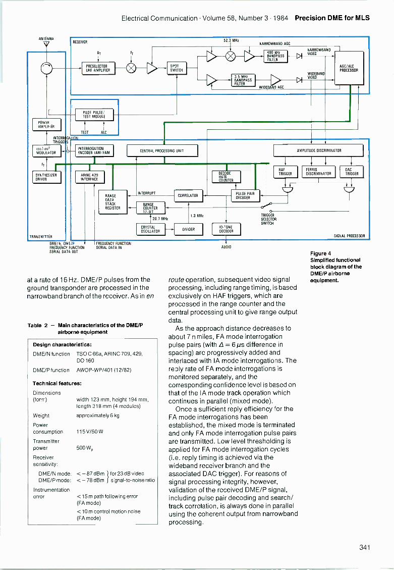
Electrical Communication Volume 58, Number 3 1984 Precision DME for MLS
ANTENNA
V RECEIVER
UT
PRESELECTORUHF AMPLIFIER
SPYSWITCH
52.3 MHz
3.5 MHzBANDPASSFILTER
NARROWBAND AGC
480 kHzBANDPASSFILTER
NARROWBANDVIDEO
WIDEBANDVIDEO
WIDEBA 0 AGC
AGC/ALCPROCESSOR
POWERAMPLIFIIER
INTERR GTRIGGE S
cos ,:os2
MOO JTA TOR
SYNTHESIZERDRIVER
TRANSMITTER
PILOT PULSE/TEST MODULE
TEST ALC
TION
INTERROGATIONENCODER IAM /FAM
ARINC 429INTERFACE
CENTRAL PROCESSING UNIT
RANGEDATASTACKREGISTER
INTERRUPT
RANGECOUNTER17-B T
CORRELATOR
DECODERATECOUNTER
PULSE PAIRDECODER
AMPLITUDE DISCRIMINATOR
HAF
TRIGGERFERRIS
DISCRIMINATOR
20.7 MHz
CRYSTALOSCILLATOR
1.3 MHz
DIVIDERID-1ONEDECODER
OC)0
TRIGGERSELECTOR
SWITCH
DAC
TRIGGER
SIGNAL PROCESSOR
DME/N, DMEIP t FREQUENCY FUNCTIONFREQUENCY FUNCTION SERIAL DATA INSERIAL DATA OUT
at a rate of 16 Hz. DME/P pulses from theground transponder are processed in thenarrowband branch of the receiver. As in en
Table 2 - Main characteristics of the DME/Pairborne equipment
Design characteristics:
DME/N function TSO C 66a, ARINC 709, 429,00160
DME/P function AWOP-WP/401 (12/82)
Technical features:
Dimensions(form) width 123 mm, height 194 mm,
length 318 mm (4 modules)
Weight approximately 6 kg
Powerconsumption 115 V/50 W
Transmitterpower 500 WP
Receiversens-tivity:
1DME/N mode: < - 87 dBm for 23 dB videoDME/P mode: < - 78 dBm signal-to-noise ratio
Instrumentationerror <15 m path following error
(FA mode)
<10 m control motion noise(FA mode)
AUDIO
route operation, subsequent video signalprocessing, including range timing, is basedexclusively on HAF triggers, which areprocessed in the range counter and thecentral processing unit to give range outputdata.
As the approach distance decreases toabout 7 n miles, FA mode interrogationpulse pairs (with .8= 6 ps difference inspacing) are progressively added andinterlaced with IA mode interrogations. Thereply rate of FA mode interrogations ismonitored separately, and thecorresponding confidence level is based onthat of the IA mode track operation whichcontinues in parallel (mixed mode).
Once a sufficient reply efficiency for theFA mode interrogations has beenestablished, the mixed mode is terminatedand only FA mode interrogation pulse pairsare transmitted. Low level thresholding isapplied for FA mode interrogation cycles(i.e. reply timing is achieved via thewideband receiver branch and theassociated DAC trigger). For reasons ofsignal processing integrity, however,validation of the received DME/P signal,including pulse pair decoding and search/track correlation, is always done in parallelusing the coherent output from narrowbandprocessing.
Figure 4Simplified functionalblock diagram of theDME/P airborneequipment.
341
Precision DME for MLS Electrical Communication Volume 58, Number 3 1984
Main Functional Units
Transmitter Frequency SynthesizerThe synthesizer operates in the range256.25 to 287.50 MHz. It is followed by aquadrupler/power-driver stage whichprovides the carrier and local oscillatorfrequencies. The transmitter is a 4 -stagepower amplifier; the steep DME/Pinterrogation pulse shape is generated bycollector modulation. The pulse shape is thesame in all operational modes of theairborne equipment.
ReceiverThe receiver front end comprises a 2 -polepreselection filter and 2 -stage preamplifierfollowed by a 3 -pole postselector; thebandwidth is about 25 MHz. Filter tuning iscontrolled by the central processing unitusing varactor diodes. The noise figure iswell below 8 dB.
After conversion to 63 MHz IF, thereceived signal is split and fed to thenarrowband and wideband IF amplifiers. Asecond conversion down to 10.7 MHz takesplace in the narrowband branch. Thenarrowband 6 -pole LC filter has a bandwidthof about 480 kHz. The corresponding linearIF amplifier has a dynamic range exceeding80 dB. The AGC voltage is derived from thenarrowband video pulse amplitudes inconjunction with the linear signal processingcircuitry. The characteristics of thenarrowband IF amplifier determine theselectivity in both IA and FA modes.
In the wideband branch, the signalprocessing bandwidth is 3.5 MHz. Thecorresponding bandpass filter is a 10 -polefilter/FET cascade. A Ferris discriminator isused to achieve the required 42 dB adjacentchannel rejection. Its function is similar tothat of the transponder. The widebandamplifier is also controlled by a linear AGCvoltage derived from the narrowband AGCvoltage already mentioned, with some fineadjustment to compensate for gain driftbetween the IF amplifier branches.
The wideband IF amplifier feeds the DACtrigger via a precision demodulator.Frequency response and dynamic range ofthe demodulator, in particular its low levellinearity, are of prime importance for theprecision and noise immunity of the DACthreshold performance.
Signal ProcessorPrecise time interval measurement is basedon a range counter clocked at 20.7 MHz.The range count is started by the detected
interrogation pulse. Upon arrival of anytrigger pulse (DAC trigger in FA mode, orHAF triggers in all other modes) thecorresponding range count -a 17 -bit wordrepresenting the time of arrival - istransferred to a stack register. Final transferto the CPU occurs only after detectionand/or repetitive validation of thesynchronous reply pulse by the correlatorcircuit. The CPU then sorts out time ofarrival data belonging to the first pulse of thesynchronous reply pulse pair.
The range correlator consists of a 10 -bitshift register, which divides the DME rangein a numbered sequence of 1024 time cells,each 6 ps wide. Associated with each cell isa counter, which is incremented when atrigger pulse occurs in the correspondingtime cell; otherwise the cell counter isdecremented. Only the counter associatedwith the cell that contains the synchronousrange will attain a higher count than theothers, thereby identifying the coarse valueof the time of arrival of the synchronousreply pulse. To protect against noise andfalse lock-ons, correlation is always basedon decoded pulse pairs from thenarrowband video signal. Furtherprocessing of the DME raw data in the CPUincludes range data limiting (outlierrejection), raw data filtering, and scaling andformatting of the output data.
For simplicity of software design a digitalfilter of the a/13 type was chosen. It has thecharacteristics of a type II, second -orderservo loop, and was implemented as anadaptive filter. Selection of the filterparameters is rather limited owing to theirclose interdependence on the prescribedspectral distribution of the path followingerror and control motion noise components.In the present design the value of a is variedwithin specific limits, depending on theoperational mode and the variance ofincoming raw data. Filter constants arechosen for a compromise betweensmoothing capability and dynamicresponse.
Self -Calibration ModuleA self -calibration loop which closely followsthe IF pilot pulse technique proven in MITACairborne equipment, is incorporated tocompensate for delay variations andequipment tolerances.
In the pilot pulse/test module the RFinterrogation pulses are converted down to63 MHz carrier frequency and the resultingpilot pulses are fed to the narrowband andwideband receiver branches. The pilot
342
Electrical Communication Volume 58, Number 3 1984 Precision DME for MLS
pulse level is adapted automatically to thatof the incoming receiver signal. DAC orHAF triggers derived from the pilot pulseare processed in the same way as all otherreceived pulses. After conversion into timeof arrival data by the range counter andtransfer to the CPU, a special filter algorithmis applied, yielding a high precision zeron mile reference value on which subsequentrange computations are based.
The front end section of the receiver isexcluded from the IF pilot pulse loop.However, the preselector filter bandwidth iswide enough for delay timing variationerrors to be negligible.
The pilot pulse/test module alsoincorporates the test signal generation forbuilt-in self -testing.
Simulation and Test Equipment
Special equipment was developed to testthe DME/P ground and airborne equipment.The new DME/P ground beacon simulatorbecame an indispensable tool for testingDME/P airborne equipment. It features adelay accuracy of better than 5 m andoutputs range replies with superimposedechoes. Echo parameters such as delaytime, amplitude, and RF phase differencecan be preset, as well as the change rate ofthe phase difference, the so-calledscalloping frequency.
The SEL DME/P interrogator simulator isused to test ground transponders: timeinterval measurement accuracy is betterthan 5 m. The parameters of the output testinterrogations are presettable. Time interval,pulse pair spacing, pulse rate, relative replyrate, and pulse level are measured. Also, anew identification tone decoding standardfor the FA mode is incorporated. Simulationof specific echo signal situations can beachieved by combining two of theseequipments.
Conclusions
It will be some years before the first DME/Pequipment goes into service since itdepends on widespread installation of thenew microwave landing system. Also theconventional DME is presumed to beadequate for MLS Category I installations atregional airports.
In general, however, DME is likely tobecome increasingly important. In scan
mode, modern airborne DME providesmultiplexed distance measurements toseveral ground transponders, enabling anairborne computer to calculate the positionof the aircraft. As part of an area navigationsystem this cost-effective multi-DME couldoffer a major breakthrough.
The Deutsche Forschungs- undVersuchsanstalt ffir Luft- und Raumfahrt isinvestigating a three-way DME whichprovides complete position data and aircraftidentification information to the groundstation, offering cost-effective air trafficcontrol. This philosophy could culminate ina multi -three-way DME with three-wayairborne DMEs operating in scan mode. Theconfiguration coulc eventually lead to acombined navigation/air traffic controlsystem based exclusively on the DMEtechnique.
References
1 W. J. Koller: Mafehler des Entfernungsmegsystems.Sonderforschungsbereich Flugfuhrung der TUBraunschweig: Wissenschaftliche Berichte, 1982,229-260.
2 R. Ullrich: Fehlerverhalten eines DME-Verfahrens mitTrapezimpulsen bei Wrung durch Mehrwegeeffekteund Rauschen: DFVLR-Forschungsbericht 81- 34,Cologne, 1981.
3 SEL-Patent: HF-Leistungsverstarker mit einerModulationsschaltung: Deutsches Patentamt,Auslegeschrift 2835751, 1979, Munchen.
Klaus Becker was born in Andernach, Germany, in1943. He studied communications engineering at theUniversity of Karlsruhe, graduating as a Dipl-Ing. Hejoined SEL in 1970, where he worked on thedevelopment and qualification of the MITAC airborneTacan equipment, DME, and DAS. In 1981 he wasappointed head of the development group for civilnavigational airborne equipment and is responsible forthe DME/P airborne system.
Albrecht Milner was bom in Leipzig, Germany, in 1945.He studied communications engineering at theTechnicalUniversity of Darmstadt. After graduating as a Dipl-Inghe became a lecturer at the same university. In 1978 hereceived the degree of Dr-Ing. He thert joined SEL towork on development of DAS. In 1981 he was appointedhead of the development group for civil navigationsystems planning and in 1983 became Chief engineer forcivil navigation. Dr Muller has led development of theDME/P ground station.
Horst Vogel was born in Stuttgart, Germany, vn 1936.He studied communications engineering in Esslingenand graduated as a Dipl-Ing. He joined SEL in 1962 andwas active in the fields of large computers, Tacan, andcivil navigation. In 1967 he became developmentmanager for avionics; from 1976 to 1982 he was chiefengineer for civil navigation. In 1983 Mr Vogel wasappointed program manager and now supervises largescale SEL projects.
343
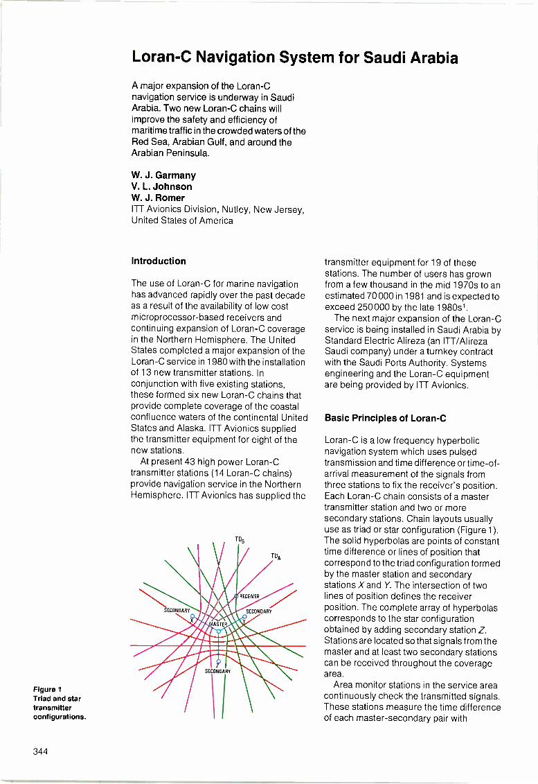
Figure 1Triad and startransmitterconfigurations.
Loran -C Navigation System for Saudi Arabia
A major expansion of the Loran -Cnavigation service is underway in SaudiArabia. Two new Loran -C chains willimprove the safety and efficiency ofmaritime traffic in the crowded waters of theRed Sea, Arabian Gulf, and around theArabian Peninsula.
W. J. GarmanyV. L. JohnsonW. J. RomerITT Avionics Division, Nutley, New Jersey,United States of America
Introduction
The use of Loran -C for marine navigationhas advanced rapidly over the past decadeas a result of the availability of low costmicroprocessor -based receivers andcontinuing expansion of Loran -C coveragein the Northern Hemisphere. The UnitedStates completed a major expansion of theLoran -C service in 1980 with the installationof 13 new transmitter stations. Inconjunction with five existing stations,these formed six new Loran -C chains thatprovide complete coverage of the coastalconfluence waters of the continental UnitedStates and Alaska. ITT Avionics suppliedthe transmitter equipment for eight of thenew stations.
At present 43 high power Loran -Ctransmitter stations (14 Loran -C chains)provide navigation service in the NorthernHemisphere. ITT Avionics has supplied the
TDB
TDA
RECEIVER
SECONDARY
4 SECONDARY
d6 tZt_t
SECONDARY
\ I
transmitter equipment for 19 of thesestations. The number of users has grownfrom a few thousand in the mid 1970s to anestimated 70000 in 1981 and is expected toexceed 250000 by the late 1980s1.
The next major expansion of the Loran -Cservice is being installed in Saudi Arabia byStandard Electric Alireza (an ITT/AlirezaSaudi company) under a turnkey contractwith the Saudi Ports Authority. Systemsengineering and the Loran -C equipmentare being provided by ITT Avionics.
Basic Principles of Loran -C
Loran -C is a low frequency hyperbolicnavigation system which uses pulsedtransmission and time difference or time -of -
arrival measurement of the signals fromthree stations to fix the receiver's position.Each Loran -C chain consists of a mastertransmitter station and two or moresecondary stations. Chain layouts usuallyuse as triad or star configuration (Figure 1).The solid hyperbolas are points of constanttime difference or lines of position thatcorrespond to the triad configuration formedby the master station and secondarystations X and Y. The intersection of twolines of position defines the receiverposition. The complete array of hyperbolascorresponds to the star configurationobtained by adding secondary station Z.Stations are located so that signals from themaster and at least two secondary stationscan be received throughout the coveragearea.
Area monitor stations in the service areacontinuously check the transmitted signals.These stations measure the time differenceof each master -secondary pair with
344
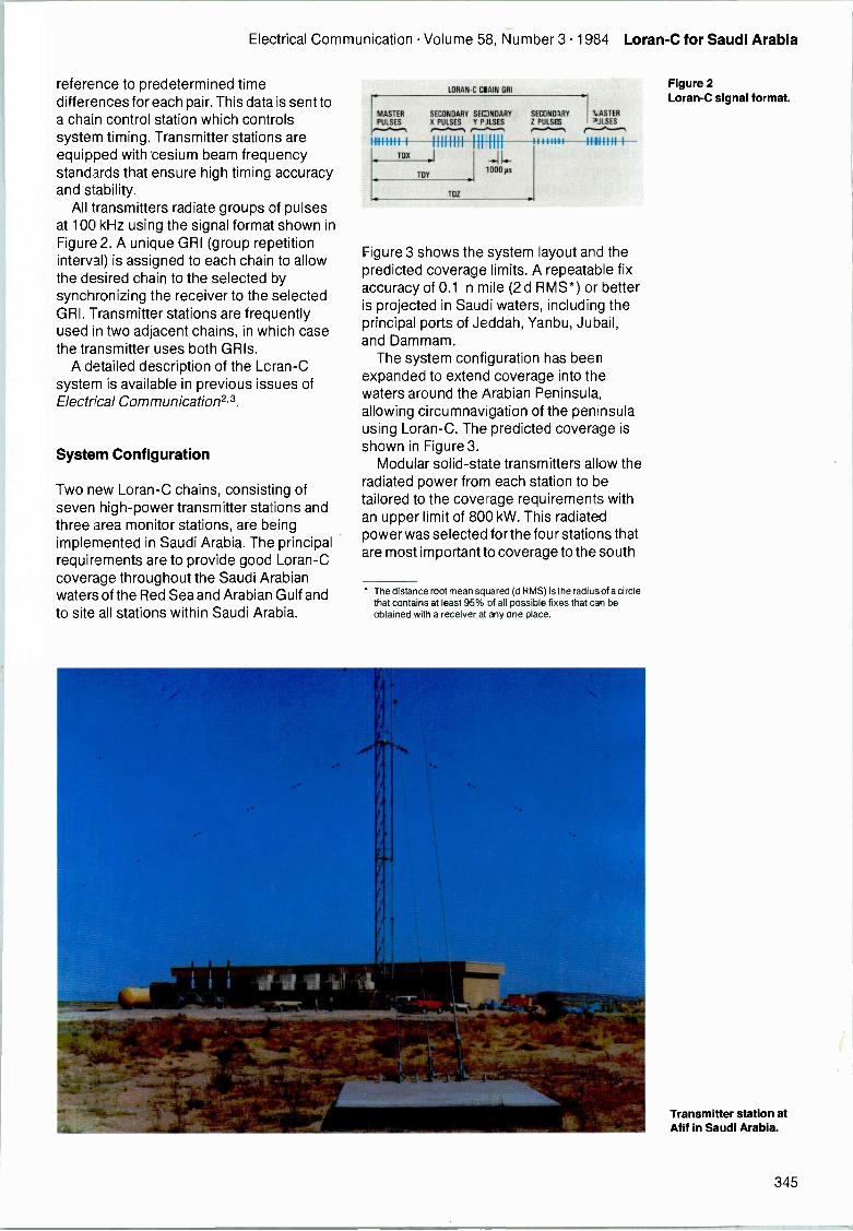
Electrical Commulication Volume 58, Number 3 1984 Loran -C for Saudi Arabia
reference to predetermined timedifferences for each pair. This data is sent toa chain control station which controlssystem timing. Transmitter stations areequipped with 'cesium beam frequencystandards that ensure high timing accuracyand stability.
All transmitters radiate groups of pulsesat 100 kHz using the signal format shown inFigure 2. A unique GRI (group repetitioninterval) is assigned to each chain to allowthe desired chain to the selected bysynchronizing the receiver to the selectedGRI. Transmitter stations are frequentlyused in two adjacent chains, in which casethe transmitter uses both GRIs.
A detailed description of the Loran -Csystem is available in previous issues ofElectrical Communicationz 3.
System Configuration
Two new Loran -C chains, consisting ofseven high -power transmitter stations andthree area monitor stations, are beingimplemented in Saudi Arabia. The principalrequirements are to provide good Loran -Ccoverage throughout the Saudi Arabianwaters of the Red Sea and Arabian Gulf andto site all stations within Saudi Arabia.
LORAN -C CRAIN SRI
MASTERPULSES
M11111 1
TIM
SECONDARY SEONDARYX PULSES Y PJLSES
1111111I II IIII
TDY
TOZ
SECONDARY I.ASTERZ PULSES
11111111
I 2.-ILSES
11111111 1
Figure 3 shows the system layout and thepredicted coverage limits. A repeatable fixaccuracy of 0.1 n mile (2 d RMS*) or betteris projected in Saudi waters, including theprincipal ports of Jeddah, Yanbu, Jubail,and Dammam.
The system configuration has beenexpanded to extend coverage into thewaters around the Arabian Peninsula,allowing circumnavigation of the peninsulausing Loran -C. The predicted coverage isshown in Figure 3.
Modular solid-state transmitters allow theradiated power from each station to betailored to the coverage requirements withan upper limit of 800 kW. This radiatedpower was selected for the four stations thatare most important to coverage to the south
The distance root mean squared (d RMS) is the radius of a circlethat contains at least 95% of all possible fixes that can beobtained with a receiver at any one place.
Figure 2Loran -C signal format.
Transmitter station atAf if in Saudi Arabia.
345
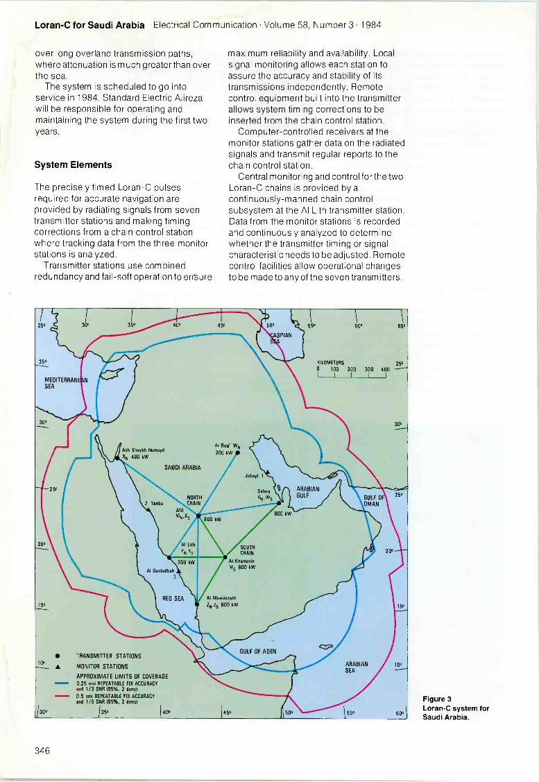
Loran -C for Saudi Arabia Electrical Communication Volume 58, Number 3 1984
over long overland transmission paths,where attenuation is much greater than overthe sea.
The system is scheduled to go intoservice in 1984. Standard Electric Alirezawill be responsible for operating andmaintaining the system during the first twoyears.
System Elements
The precisely timed Loran -C pulsesrequired for accurate navigation areprovided by radiating signals from seventransmitter stations and making timingcorrections from a chain control stationwhere tracking data from the three monitorstations is analyzed.
Transmitter stations use combinedredundancy and fail -soft operation to ensure
250
35°
MEDITERRANSEA
300
20°
15°
10°
Ash Shaykh Humayd
XN 400 kW
25°
TRANSMITTER STATIONS
A MONITOR STATIONS
APPROXIMATE LIMITS OF COVERAGE0.25 nmi REPEATABLE FIX ACCURACYand 1/3 SNR (95%, 2 firms)0.5 nmi REPEATABLE FIX ACCURACYand 1/5 SNR 195%, 2 drms1
130° /350
2 Yanbu
SAUDI ARABIA
NORTHCHAIN
AfifMN,XS
Al Lith
200 kW
Al Gunfudhah3
RED SEA
40°
maximum reliability and availability. Localsignal monitoring allows each station toassure the accuracy and stability of itstransmissions independently. Remotecontrol equipment built into the transmitterallows system timing corrections to beinserted from the chain control station.
Computer -controlled receivers at themonitor stations gather data on the radiatedsignals and transmit regular reports to thechain control station.
Central monitoring and control for the twoLoran -C chains is provided by acontinuously -manned chain controlsubsystem at the Al Lith transmitter station.Data from the monitor stations is recordedand continuously analyzed to determinewhether the transmitter timing or signalcharacteristic needs to be adjusted. Remotecontrol facilities allow operational changesto be made to any of the seven transmitters.
Ar Ruqi WN
200 kW
800 kW
Jubayl 1
SOUTHCHAIN
Al KhamasinMs 800 kW
Al Muwassam
ZN,Zs BOO kW
450
Salwa
ON ,W5
800 kW
GULF OF ADEN
50°
KILOMETERS 3500 100 200 300 400
I I I II
GULF OFOMAN
ARABIAN 10°SEA
55° 600
Figure 3Loran -C system forSaudi Arabia.
346
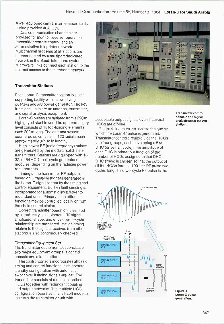
Electrical Communication Volume 58, Number 3 1984 Loran -C for Saudi Arabia
A well equipped central maintenance facilityis also provided at Al Lith.
Data communication channels areprovided for monitor receiver operation,transmitter remote control, and anadministrative teleprinter network.Multichannel modems at all stations areinterconnected by a multiport dedicatednetwork in the Saudi telephone system.Microwave links connect each station to thenearest access to the telephone network.
Transmitter Stations
Each Loran -C transmitter station is a self-supporting facility with its own livingquarters and AC power generator. The keyfunctional units are an antenna, transmitter,and signal analysis equipment.
Loran -C pulses are radiated from a 220 mhigh guyed steel tower. The uppermost guylevel consists of 18 top -loading elementseach 200 m long. The antenna systemcounterpoise consists of 120 radials eachapproximately 325 m in length.
High -power RF (radio frequency) pulsesare generated by the modular solid-statetransmitters. Stations are equipped with 16,32, or 64 HCG (half -cycle generator)modules, depending on the radiated powerrequirements.
Timing of the transmitter RF output isbased on ultrastable triggers generated inthe Loran -C signal format by the timing andcontrol equipment. Built-in fault sensing isincorporated for automatic switchover toredundant units. Primary transmitterfunctions may be controlled locally or fromthe chain control station.
Correct transmitter operation is verifiedby signal analysis equipment. RF signalamplitude, shape, and envelope -to -cyclerelationship are monitored; station timingrelative to the signals received from otherstations is also continuously checked.
Transmitter Equipment SetThe transmitter equipment set consists oftwo major equipment groups: a controlconsole and a transmitter.
The control console incorporates all basictiming and control functions in an operate -standby configuration with automaticswitchover if timing signals are lost. Thetransmitter consists of multiple identicalHCGs together with redundant couplingand output networks. The multiple HCGconfiguration operates in a fail -soft mode tomaintain the transmitter on -air with
acceptable output signals even if severalHCGs are off-line.
Figure 4 illustrates the basic technique bywhich the Loran -C pulse is generated.Transmitter control circuits divide the HCGsinto four groups, each developing a 5psDHC (drive half cycle). The amplitude ofeach DHC is primarily a function of thenumber of HCGs assigned to that DHC.DHC timing is chosen so that the output ofall the HCGs forms a 100 kHz RF pulse twocycles long. This two-cycle RF pulse is the
CYCLE ZEROCROSSING TO BEIDENTIFIED ANDTRACKED
HALF -CYCLE
GENERATORS
DRIVE -HALF -CYCLENO 1
ORIVE-HALFCYCLENO 2
DRIVE -HALF -CYCLE
NO 3
DRIVE -HALF -CYCLE
NO 4
5jos
-"1IIIIIALLIIIIIIIIIII
II
IIII
OUTPUTNETWORK
rCOUPLINGNETWORK
Transmitter controlconsole and signalanalysis set at the Afifstation.
Figure 4Loran -C pulsegeneration.
347
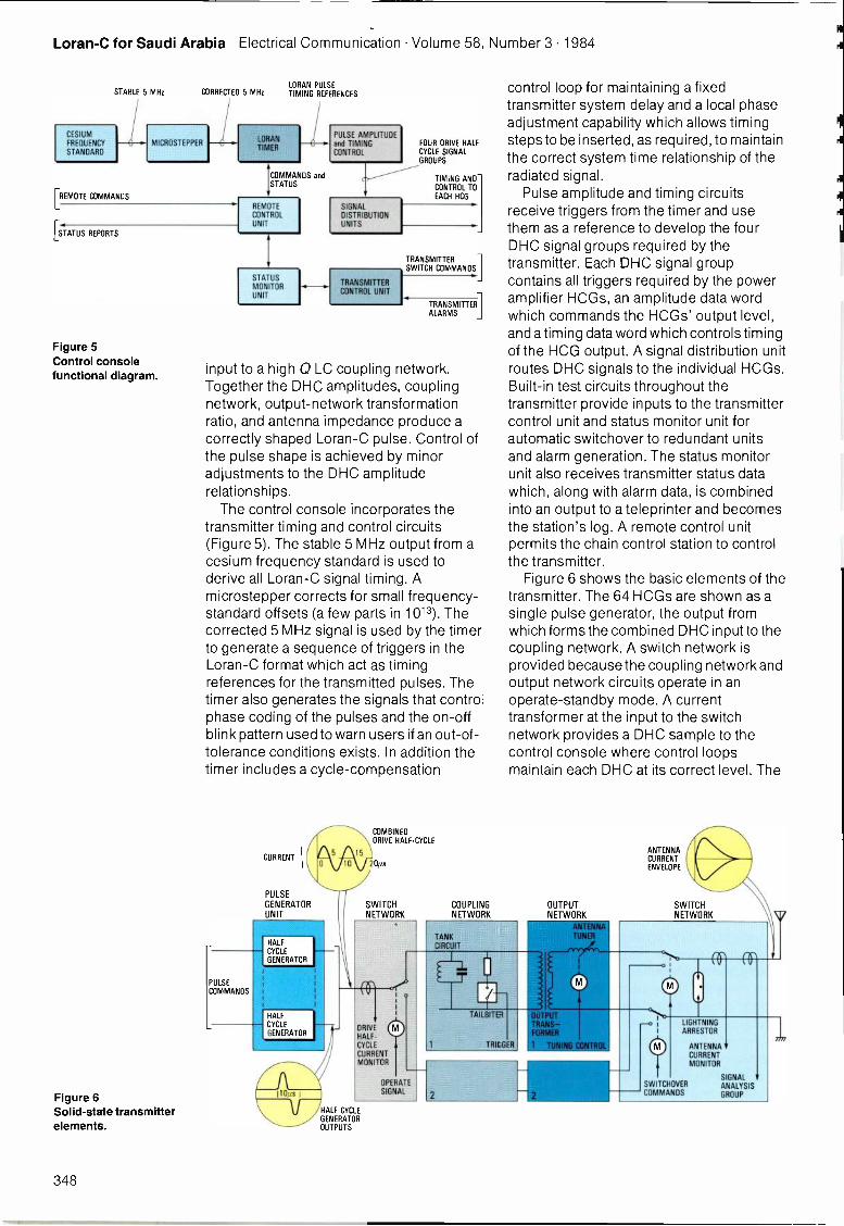
Loran -C for Saudi Arabia Electrical Communication Volume 58, Number 3 1984
STABLE 5 MHz CORRECTEDLORAN
5 MHz TIMINGPULSE
REFERENCES
CESIUM
FREQUENCY
STANDARDMICRO STEPPER
LORANTIMER
PULSE AMPLITUDEand TIMINGCONTROL
FOUR DRIVE HALFCYCLE SIGNALGROUPS
COMMANDS and TIMING ANDSTATUS
CONTROL TO[REMOTE COMMANDS EACH HCG
REMOTE SIGNALCONTROL DISTRIBUTIONUNIT UNITS
[STATUS REPORTS
Figure 5Control consolefunctional diagram.
Figure 6Solid-state transmitterelements.
STATUSMONITORUNIT
TRANSMITTERCONTROL UNIT
TRANSMITTERSWITCH COMMANDS
TRANSMITTER]ALARMS
input to a high 0 LC coupling network.Together the DHC amplitudes, couplingnetwork, output -network transformationratio, and antenna impedance produce acorrectly shaped Loran -C pulse. Control ofthe pulse shape is achieved by minoradjustments to the DHC amplituderelationships.
The control console incorporates thetransmitter timing and control circuits(Figure 5). The stable 5 MHz output from acesium frequency standard is used toderive all Loran -C signal timing. Amicrostepper corrects for small frequency -standard offsets (a few parts in 1013). Thecorrected 5 MHz signal is used by the timerto generate a sequence of triggers in theLoran -C format which act as timingreferences for the transmitted pulses. Thetimer also generates the signals that controlphase coding of the pulses and the on -offblink pattern used to warn users if an out -of -tolerance conditions exists. In addition thetimer includes a cycle -compensation
PULSECOMMANDS
CURRENT
PULSE
GENERATORUNIT
HALF
CYCLE
GENERATOR
HALFCYCLE
GENERATOR
HALF CYCLEGENERATOROUTPUTS
COMBINEDDRIVE HALF -CYCLE
20ps
SWITCHNETWORK
COUPLINGNETWORK
control loop for maintaining a fixedtransmitter system delay and a local phaseadjustment capability which allows timingsteps to be inserted, as required, to maintainthe correct system time relationship of theradiated signal.
Pulse amplitude and timing circuitsreceive triggers from the timer and usethem as a reference to develop the fourDHC signal groups required by thetransmitter. Each DHC signal groupcontains all triggers required by the poweramplifier HCGs, an amplitude data wordwhich commands the HCGs' output level,and a timing data word which controls timingof the HCG output. A signal distribution unitroutes DHC signals to the individual HCGs.Built-in test circuits throughout thetransmitter provide inputs to the transmittercontrol unit and status monitor unit forautomatic switchover to redundant unitsand alarm generation. The status monitorunit also receives transmitter status datawhich, along with alarm data, is combinedinto an output to a teleprinter and becomesthe station's log. A remote control unitpermits the chain control station to controlthe transmitter.
Figure 6 shows the basic elements of thetransmitter. The 64 HCGs are shown as asingle pulse generator, the output fromwhich forms the combined DHC input to thecoupling network. A switch network isprovided because the coupling network andoutput network circuits operate in anoperate -standby mode. A currenttransformer at the input to the switchnetwork provides a DHC sample to thecontrol console where control loopsmaintain each DHC at its correct level. The
OUTPUTNETWORK
ANTENNACURRENTENVELOPE
SWITCHNETWORK
LIGHTNINGARRESTOR
SWITCHOVERCOMMANDS
ANTENNACURRENTMONITOR
SIGNALANALYSISGROUP
348
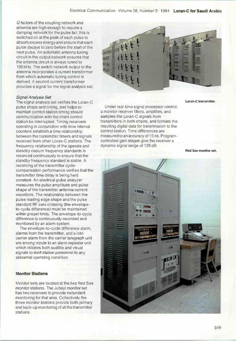
Electrical Communication Volume 58, Number 3 1984 Loran -C for Saudi Arabia
factors of the coupling network andantenna are high enough to require adamping network for the pulse tail; this isswitched on at the peak of each pulse toabsorb excess energy and ensure that eachpulse decays to zero before the start of thenext pulse. An automatic antenna tuningcircuit in the output network ensures thatthe antenna circuit is always tuned to100 kHz. The switch network output to theantenna incorporates a current transformerfrom which automatic tuning control isderived. A second current transformerprovides a signal for the signal analysis set.
Signal Analysis SetThe signal analysis set verifies the Loran -Cpulse shape and timing, and helps tomaintain correct station timing shouldcommunication with the chain controlstation be interrupted. Timing receiversoperating in conjunction with time intervalcounters establish a time relationshipbetween the transmitter timers and signalsreceived from other Loran -C stations. Thefrequency relationship of the operate andstandby cesium frequency standards isrecorded continuously to ensure that thestandby frequency standard is stable. Arecording of the transmitter cycle -compensation performance verifies that thetransmitter time delay is being heldconstant. An electrical pulse analyzermeasures the pulse amplitude and pulseshape of the transmitter antenna currentwaveform. The relationship between thepulse leading edge shape and the pulsestandard RF zero crossing (the envelope -to -cycle difference) must be maintainedwithin preset limits. The envelope -to -cycledifference is continuously recorded andmonitored by an alarm system.
The envelope -to -cycle difference alarm,alarms from the transmitter, and a lost -carrier alarm from the carrier telegraph unitare among inputs to an alarm repeater unitwhich initiates both audible and visualsignals to alert station personnel to anyabnormal operating condition.
Monitor Stations
Monitor sets are located at the two Red Seamonitor stations. The Jubayl monitor sethas two receivers to provide redundantmonitoring for that area. Collectively thethree monitor stations provide both primaryand back-up monitoring of all the transmitterstations.
:c
:Lc Et
: I
Under real-time signal processor control,a monitor receiver filters, amplifies, andsamples the Loran -C signals fromtransmitters in both chains, and formats theresulting digital data for transmission to thecontrol station. Time differences aremeasured to an accuracy of 15 ns. Program -controlled gain stages give the receiver adynamic signal range of 128 dB.
Loran -C transmitter.
Red Sea monitor set.
349
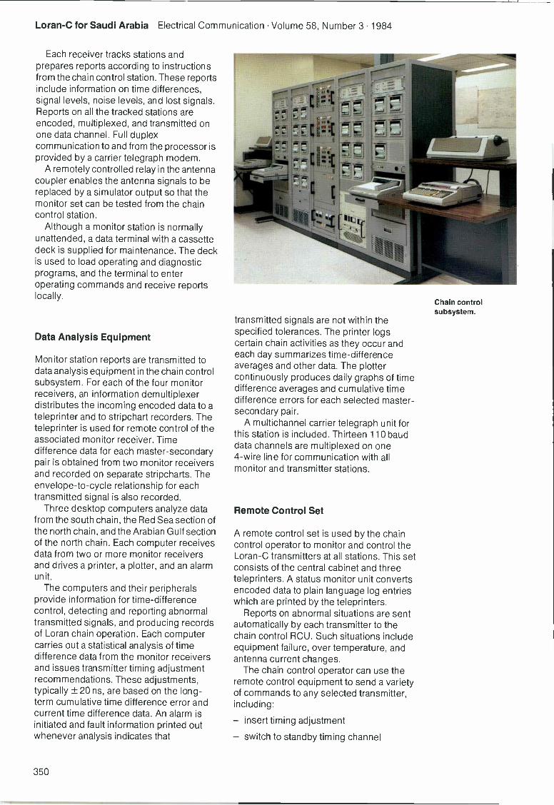
Loran -C for Saudi Arabia Electrical Communication Volume 58, Number 3 1984
Each receiver tracks stations andprepares reports according to instructionsfrom the chain control station. These reportsinclude information on time differences,signal levels, noise levels, and lost signals.Reports on all the tracked stations areencoded, multiplexed, and transmitted onone data channel. Full duplexcommunication to and from the processor isprovided by a carrier telegraph modem.
A remotely controlled relay in the antennacoupler enables the antenna signals to bereplaced by a simulator output so that themonitor set can be tested from the chaincontrol station.
Although a monitor station is normallyunattended, a data terminal with a cassettedeck is supplied for maintenance. The deckis used to load operating and diagnosticprograms, and the terminal to enteroperating commands and receive reportslocally.
Data Analysis Equipment
Monitor station reports are transmitted todata analysis equipment in the chain controlsubsystem. For each of the four monitorreceivers, an information demultiplexerdistributes the incoming encoded data to ateleprinter and to stripchart recorders. Theteleprinter is used for remote control of theassociated monitor receiver. Timedifference data for each master -secondarypair is obtained from two monitor receiversand recorded on separate stripcharts. Theenvelope -to -cycle relationship for eachtransmitted signal is also recorded.
Three desktop computers analyze datafrom the south chain, the Red Sea section ofthe north chain, and the Arabian Gulf sectionof the north chain. Each computer receivesdata from two or more monitor receiversand drives a printer, a plotter, and an alarmunit.
The computers and their peripheralsprovide information for time -differencecontrol, detecting and reporting abnormaltransmitted signals, and producing recordsof Loran chain operation. Each computercarries out a statistical analysis of timedifference data from the monitor receiversand issues transmitter timing adjustmentrecommendations. These adjustments,typically ± 20 ns, are based on the long-term cumulative time difference error andcurrent time difference data. An alarm isinitiated and fault information printed outwhenever analysis indicates that
transmitted signals are not within thespecified tolerances. The printer logscertain chain activities as they occur andeach day summarizes time -differenceaverages and other data. The plottercontinuously produces daily graphs of timedifference averages and cumulative timedifference errors for each selected master -
secondary pair.A multichannel carrier telegraph unit for
this station is included. Thirteen 110 bauddata channels are multiplexed on one4 -wire line for communication with allmonitor and transmitter stations.
Remote Control Set
A remote control set is used by the chaincontrol operator to monitor and control theLoran -C transmitters at all stations. This setconsists of the central cabinet and threeteleprinters. A status monitor unit convertsencoded data to plain language log entrieswhich are printed by the teleprinters.
Reports on abnormal situations are sentautomatically by each transmitter to thechain control RCU. Such situations includeequipment failure, over temperature, andantenna current changes.
The chain control operator can use theremote control equipment to send a varietyof commands to any selected transmitter,including:
- insert timing adjustment
- switch to standby timing channel
Chain controlsubsystem.
350
Electrical Communication Volume 58, Number 3 1984 Loran -C for Saudi Arabia
- turn transmitter output on or off
- send status summary report.
One duplex data channel is provided foreach chain control RCU. Each outgoingmessage includes an address code so thatonly the selected transmitter responds.Transmitter RCUs check the incoming line 3
and delay data transmission when it is busy.
Conclusions
The Red Sea and Arabian Gulf arewaterways of significant marinetransportation. The increase in trafficthrough the Suez Canal together with rapidgrowth in the size and number of operationalports on both coasts of Saudi Arabia isleading to further increases in the alreadyheavy traffic in these areas. Much of thecoastline is almost totally devoid of naturalor man-made landmarks and has reefs faroffshore, thus making navigation difficult.The increasing use of offshore mining rigsand platforms also gives rise to the need foraccurate all-weather navigation both toprevent collisions and to support suchoffshore operations.
The Saudi Loran -C system provides arepeatable fix accuracy of 0.1 to 0.2 n mileday and night and in all seasons withinSaudi Arabia's coastal confluence waters ofthe Red Sea and Arabian Gulf. In addition, itprovides good coverage in the waters southand east of the Arabian Peninsula, allowingcircumnavigation of the peninsula usingLoran -C. The signal availability of thesystem is estimated to exceed 99.5%.
2
References
Edward L. McGann: The Evolution of Loran -CCoverage: Navigation, Spring 1982, volume 29, no 1,pp 89-101.J. P. Van Etten: Navigation Systems - Fundamentalsof Low- and Very -Low -Frequency HyperbolicTechniques: Electrical Communication, 1970,volume 45, no 3, pp 192-212.J. P. Van Etten: Loran -C System and ProductDevelopment: Electrical Communication, 1970,volume 45, no 2, pp 100-115.
William J. Garmany received a BS degree in electricalengineering from Newark College of Engineering in1942 and joined ITT in 1946. He has been closelyinvolved in the design, manufacture, and installation ofITT Loran -C equipment. Mr Garmany is a principalmember of the technical staff of the Loran systemengineering group. He is a member of the Institute ofElectrical and Electronic Engineers, the Institute ofNavigation, and the Wild Goose Association (Loranprofessional organization).
Vernon L. Johnson received a BS degree in electricalengineering from North Carolina State College in 1949and an MS degree in electrical engineering from NewarkCollege of Engineering in 1954. He has been associatedwith ITT Avionics Division since 1949 and is at presentthe engineering manager for Loran programmes. Heworked earlier on development of the rho -theta Tacannavigation system and on a naval shipboardcommunication system. MrJohnson is a member of theInstitute of Electrical and Electronics Engineers, theInstitute of Navigation, and the Wild Goose Association.
William J. Romer received a BS degree in electricalengineering from Newark College of Engineering in1950. He joined ITT Avionics Division in 1972 as aprincipal member of the technical staff in the Loransystem engineering group. Prior to joining ITT he was aLoran systems engineer with the US Coast Guard. He isa member of the Institute of Navigation and the WildGoose Association.
351
Satellite Navigation
Navigation of ships and aircraft usingsatellite transmissions is already a proventechnique with the Transit system. TheNaystar system, scheduled to go into fulloperation in 1987, offers even higheraccuracies with virtually continuousworldwide coverage.
P. K. BlairP. J. HargraveStandard Telecommunication LaboratoriesLimited, Harlow, Essex, England
Introduction
The basic measurements that can be madefrom satellite transmissions are range andrelative line of sight velocity (or range -rate).Range can be measured from the transittime of a signal from the satellite to theobserver, and the relative line of sightvelocity can be deduced from the Dopplershift in frequency of the received signals.These measurements can be used to derivenavigational information by observing asingle satellite over a period of time as itpasses across the hemisphere, as in theTransit system, or by makingmeasurements to a number of satellites thatare in view simultaneously, as in the Naystarsystem.
Range Measurement
The measurement of range requires thatsignals from the satellite contain amodulation of effectively marked time. Inthe Naystar system this is achieved byusing PRN (pseudorandom noise) codes. Acarrier is effectively multiplied by anapparently random sequence of + ls and- ls of duration 1/br, where b, is the bit -rateof the code. If the sequence is agreed ratherthan being truly random, the arrival of codestates can be timed in order to derive rangeinformation.
PRN code modulation spreads the energyof the original carrier into a [sin x/x]2 powerspectrum, centered on the carrier frequencyand with the first nulls offset by ± br. Areceiver measures the arrival time of thecode by aligning a locally generated codewith the received signal. When the alignedlocal code is mixed with the downconvertedreceived signal it removes all the phase
reversals produced by PRN codemodulation, leaving a carrier with afrequency that can be measured to providerange -rate information. In the Naystar signalthe underlying carrier is slightly broadenedby low bit -rate (50 bit s-1) phase modulationwhich conveys ephemeris data detailing theposition and motion of the satellite.
As well as providing range information,PRN codes give protection against jamming.As the phase reversals are being removedfrom the desired signal, they are applied toany narrow band jamming waveform, thus
bandwidth of about b,, so that after filteringthe remaining jammer power is substantiallyreduced. The resulting increase in signal-to-noise ratio is said to be brought about by thespread spectrum processing gain availablefrom the PRN code.
A third reason for employing PRN codesis that they may be used for spectraldivision. A number of satellites can transmitat the same frequency using modulatingcodes with low cross correlation functions.Families of codes can be constructed withgood cross correlation properties bysumming the outputs of two n -stage shiftregisters with each producing a maximallength sequence1,2. The two maximal lengthsequences are carefully chosen and giverise to (2"+1) Gold codes. These arisebecause the two sequences can becombined with (2 n- 1) possible shifts, andthe two basic maximal length sequencesare also members of the family.
PRN codes are employed for timing thetransit of a radio signal along the line of sightfrom the satellite to the observer. Effectivelywhat is measured is:
Observer
Lt= [Vg(1)]-1 dl
Satellite
352
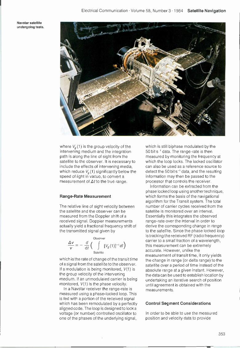
Electrical Communication Volume 58, Number 3 1984 Satellite Navigation
Naystar satelliteundergoing tests.
where Vg (1) is the group velocity of theintervening medium and the integrationpath is along the line of sight from thesatellite to the observer. It is necessary toinclude the effects of intervening media,which reduce Vg (1) significantly below thespeed of light in vacuo, to convert ameasurement of Lt to the true range.
Range -Rate Measurement
The relative line of sight velocity betweenthe satellite and the observer can bemeasured from the Doppler shift of areceived signal. Doppler measurementsactually yield a fractional frequency shift ofthe transmitted signal given by
Observer
= -d f [V9(1))-1 di)dtSatellite
which is the rate of change of the transit timeof a signal from the satellite to the observer.If a modulation is being monitored, V(1) isthe group velocity of the interveningmedium. if an unmodulaled carrier is beingmonitored, V(1) is the phase velocity.
In a Naystar receiver the range -rate ismeasured using a phase -locked loop. Thisis fed with a portion of the received signalwhich has been remodulated by a perfectlyaligned code. The loop is designed to lock avoltage (or number) controlled oscillator toone of the phases of the underlying signal,
which is still biphase modulated by the50 bit s-1 data. The range -rate is thenmeasured by monitoring the frequency atwhich the loop locks. The locked oscillatorcan also be used as a reference source todetect the 50 bit s-1 data, and the resultinginformation may then be passed to theprocessor that controls the receiver.
Information can be extracted from thephase locked loop using another technique,which forms the basis of the navigationalalgorithm for the Transit system. The totalnumber of carrier cycles received from thesatellite is monitored over an interval.Essentially this integrates the observedrange -rate over the interval in order toderive the corresponding change in rangeto the satellite. Since the phase locked loopis tracking the received RF (radio frequency)carrier to a small fraction of a wavelength,this measurement can be extremelyaccurate. However, unlike themeasurement of transit time, it only yieldsthe change in range (or delta range) to thesatellite over a period of time instead of theabsolute range at a given instant. However,the data can be used to establish location byundertaking an iterative search of positionuntil agreement is obtained with themeasurements.
Control Segment Considerations
In order to be able to use the measuredposition and velocity data to provide
353
Satellite Navigation Electrical Communication Volume 58, Number 3 1984
navigational information relative to thesurface of the earth, an observer requiresinformation about the positions andvelocities of the satellites as a function oftime. This ephemeris data must also betransmitted by the satellites. In both theTransit and Naystar systems the data isphase modulated onto the transmittedcarriers which are used for Dopplermeasurements.
The ephemeris data for Transit andNaystar satellites is computed from dataobtained by ground tracking stations. Thesestations, which are at known locations, usethe relative navigational information derivedfrom the satellite's transmissions tocompute the orbital parameters. Theinformation is then communicated to thesatellite via an uplink for processing andsubsequent relaying to the observer. Asuplink transmissions may be infrequent,satellites are equipped with clocks ofsufficient accuracy to maintain the precisionof the downlink transmissions betweenupdates.
Any frequency error in the satellite masteroscillator will produce a timing error LT inthe transmissions. When the range to asatellite is being measured by monitoringthe transit time of a signal along the line ofsight, this timing error will produce a positionerror of about C.6 T, where c is the velocity oflight in vacuo. Systems using suchmeasurements (e.g. Naystar) thereforerequire very accurate on -board timingsystems, such as atomic clocks, and aprocedure for locking the receiver clock tothose in the satellites.
Measurement Corrections
Transmissions from satellite to observertraverse the ionosphere and troposphere.The group and phase velocities of radiosignals in both media are significantlydifferent from those in vacuo. Rawnavigational measurements must thereforebe corrected for the perturbing effects ofthese media before being processed in thenavigational algorithm.
For a system measuring satellite rangefrom the transit time and employing accuratetiming standards in the satellites, the effectsof special and general relativity must also beconsidered. Both affect the rate at which thesatellites' clocks run, and must be allowedfor if precise navigational fixes are to beobtained.
The IonosphereAt Naystar and Transit frequencies thegroup velocity appropriate to transmissionthrough the ionosphere can be calculatedusing a standard approximation. Then,using the expression for the group velocity,the extra transit time imposed on amodulation waveform passing through theionosphere can be determined. It can beshown that the delaying effect of theionosphere can be characterized by thesurface density of electrons along the line ofsight between the observer and the satellite.
If information about appropriate surfacedensities is available, the observer cancorrect for ionospheric delay. To make thispossible, parameters characterizing amodel of the ionosphere are transmitted byNaystar satellites as part of the 50 bit s--1data stream. Alternatively, since Lt isproportional to 1/v2, ionospheric delay canbe corrected by measuring the transit timeat two frequencies. This technique isemployed by the Naystar system to providethe most precise navigational service. TwoL -band signals modulated by PRN codesare transmitted by all satellites.
The Doppler shift of an RF carrier isnormally monitored when making range -rate measurements. The observer is thenmonitoring the rate of change of the transittime of a signal from the satellite, where therelevant velocity of propagation is the phasevelocity in the ionosphere. Again it ispossible to correct for the effect of theionosphere by making range -ratemeasurements at two carrier frequencies.
The TroposphereThe transit time of a ranging signal is furtherincreased by its passage through thetroposphere. Unlike the ionosphere, thetroposphere is a nondispersive medium atradio frequencies. That is, the group velocityis independent of the frequency of the radiocarrier, and the medium can becharacterized by a frequency -independentrefractive index n(1). Thus the extra delayimposed on the received signal by thetroposphere can be expressed as:
Observer
Lt = c-1 f [n(1) -1]d/
Satellite
Since the troposphere is nondispersive,this delay cannot be corrected by multiplefrequency observations. It becomesnecessary to model the effect. The simplestmodels usually assume a height dependentrefractive index.
354
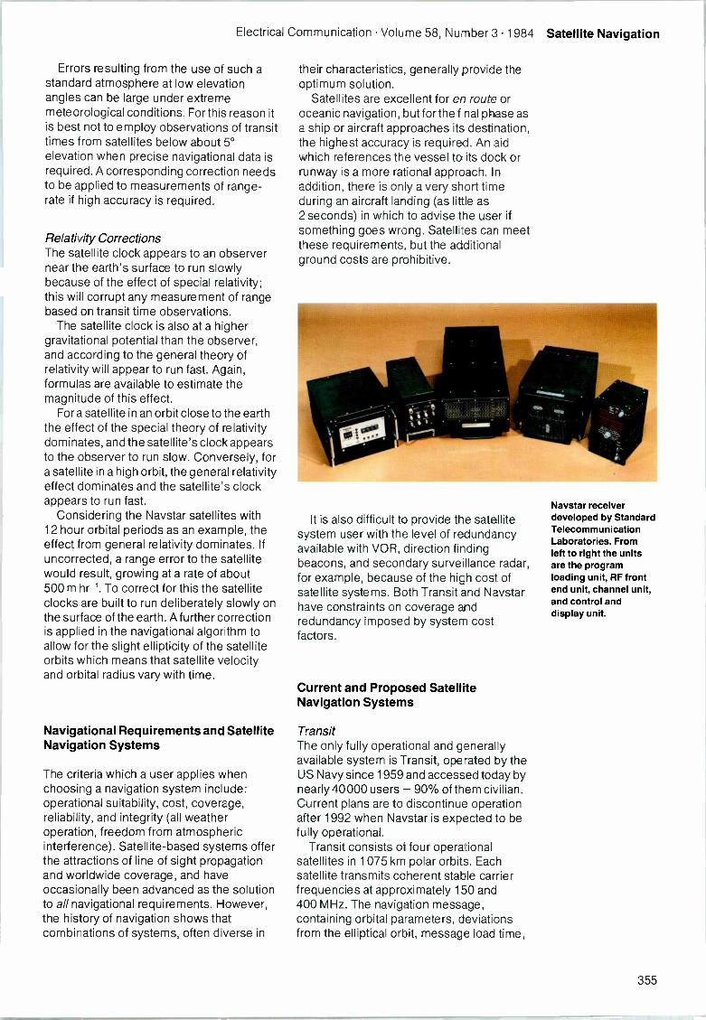
Electrical Communication Volume 58, Number 3 1984 Satellite Navigation
Errors resulting from the use of such astandard atmosphere at low elevationangles can be large under extrememeteorological conditions. For this reason itis best not to employ observations of transittimes from satellites below about 5°elevation when precise navigational data isrequired. A corresponding correction needsto be applied to measurements of range -
rate if high accuracy is required.
Relativity CorrectionsThe satellite clock appears to an observernear the earth's surface to run slowlybecause of the effect of special relativity;this will corrupt any measurement of rangebased on transit time observations.
The satellite clock is also at a highergravitational potential than the observer,and according to the general theory ofrelativity will appear to run fast. Again,formulas are available to estimate themagnitude of this effect.
For a satellite in an orbit close to the earththe effect of the special theory of relativitydominates, and the satellite's clock appearsto the observer to run slow. Conversely, fora satellite in a high orbit, the general relativityeffect dominates and the satellite's clockappears to run fast.
Considering the Naystar satellites with12 hour orbital periods as an example, theeffect from general relativity dominates. Ifuncorrected, a range error to the satellitewould result, growing at a rate of about500 m hr -1. To correct for this the satelliteclocks are built to run deliberately slowly onthe surface of the earth. A further correctionis applied in the navigational algorithm toallow for the slight ellipticity of the satelliteorbits which means that satellite velocityand orbital radius vary with time.
Navigational Requirements and SatelliteNavigation Systems
The criteria which a user applies whenchoosing a navigation system include:operational suitability, cost, coverage,reliability, and integrity (all weatheroperation, freedom from atmosphericinterference). Satellite -based systems offerthe attractions of line of sight propagationand worldwide coverage, and haveoccasionally been advanced as the solutionto all navigational requirements. However,the history of navigation shows thatcombinations of systems, often diverse in
their characteristics, generally provide theoptimum solution.
Satellites are excellent for en route oroceanic navigation, but for the final phase asa ship or aircraft approaches its destination,the highest accuracy is required. An aidwhich references the vessel to its dock orrunway is a more rational approach. Inaddition, there is only a very short timeduring an aircraft landing (as little as2 seconds) in which to advise the user ifsomething goes wrong. Satellites can meetthese requirements, but the additionalground costs are prohibitive.
It is also difficult to provide the satellitesystem user with the level of redundancyavailable with VOR, direction findingbeacons, and secondary surveillance radar,for example, because of the high cost ofsatellite systems. Both Transit and Naystarhave constraints on coverage andredundancy imposed by system costfactors.
Current and Proposed SatelliteNavigation Systems
TransitThe only fully operational and generallyavailable system is Transit, operated by theUS Navy since 1959 and accessed today bynearly 40000 users - 90% of them civilian.Current plans are to discontinue operationafter 1992 when Naystar is expected to befully operational.
Transit consists of four operationalsatellites in 1075 km polar orbits. Eachsatellite transmits coherent stable carrierfrequencies at approximately 150 and400 MHz. The navigation message,containing orbital parameters, deviationsfrom the elliptical orbit, message load time,
Naystar receiverdeveloped by StandardTelecommunicationLaboratories. Fromleft to right the unitsare the programloading unit. RF frontend unit, channel unit,and control anddisplay unit.
355
Satellite Navigation Electrical Communication Volume 58, Number 3 1984
etc, is transmitted every two minutes byphase modulating the two signals. The userreceiver measures the Doppler frequencyshift during a satellite pass and thencalculates its geographic position.
Corrections are made for troposphericand ionospheric refraction. The accuracy ofthe final position fix depends on the user'sknowledge of velocity and height above thereference spheroid.
Transit has four US located ground basedmonitor stations which provide theinformation necessary to update satelliteorbital parameters every 12 hours. Twodimensional RMS predictable positioningaccuracy is quoted3 as 25 m from a two -frequency measurement, but considerableerrors can result from inaccurate velocityestimates. The coverage of Transit isperhaps its main drawback; the fix ratevaries from about 30 minutes at 80° latitudeto 110 minutes at the equator.
Considerable use has been made ofTransit for surveying with differentialaccuracies of under one meter4 andnavigation receivers are available for a widerange of users from submarines to pleasurecraft with the simplest sets costing less than£1000.
NaystarThe success of Transit provided thestimulus for the US Department of Defenseto examine more advanced systemsproviding capabilities for high dynamicusers. This led to the birth of the Naystarsystem which is currently underexperimental evaluation and developmentin the USA and other countries, notably theUnited Kingdom.
The complete Naystar system is plannedto consist of 18 operational satellites withthree in -orbit spares arranged in nearlycircular orbits with radii of 26600 km and aninclination to the earth's equatorial plane of55°. Each satellite transmits two navigationsignals centered on 1575 and 1228 MHz.Both signals are derived from atomicfrequency standards within the satellites,and convey range information by means ofmodulations which are locked in time to theatomic standards. These modulations areunique to each satellite. By measuring thephases of the received codes against aclock in the receiver, together with theDoppler shifts of the radio frequencycarriers, an observer can calculate therange and range -rate to a particular satellite.These calculations contain uncertaintiesresulting from inaccuracies in the receiver
clock which does not have the inherentstability of the atomic standards in thesatellites.
However, by monitoring four satellites(and decoding data about their motionswhich are also modulated onto thetransmitted signals), the observer candetermine his three-dimensional positionand velocity and apply corrections to hisclock, making it conform to satellite time.Alternatively, if he is constrained to move onthe surface of the earth or is at a knownaltitude, he can take two-dimensionalmeasurements using three satellites. Thesoftware controlling the receiver mustchoose, from the satellites in view, thesubset which gives the most favorablegeometry for the navigational calculations.As in the Transit system, two signals can beused to correct for the perturbing effects ofthe ionosphere.
Two pseudorandom codes aretransmitted by each satellite. The first, acoarse acquisition code, is used to aidacquisition of the satellite signals and toprovide coarse navigation. (More recentlythis has been called the standard positioningservice). The second, designated theprecision code or precision positioningservice, has a 10 -times higher modulationrate which yields the full navigationalaccuracy of the system.
Satellite transmissions are continuouslymonitored by widely spaced fixed monitorstation receivers which measure thesatellite ranges and enable the mastercontrol station to accurately determinesatellite positions and clock errors. Thisinformation is relayed via a master controlstation to the satellite, enabling it to updateits navigation message3,5.
Naystar Navigation ProcessTo obtain a complete three-dimensionalposition and velocity estimation, a receivermust be locked to transmissions from foursatellites. Four measurements ofpseudorange are made by locking codetracking loops to the received signals andthen timing the occurrence of certain statesor epochs of the code generators within theloops with the aid of the receiver's clock.The measurements are of pseudorangerather than true range because of the (asyet) undetermined receiver clock offset.Similarly, by measuring the frequencies ofthe carrier tracking loop voltage controlledoscillators over a gating time determined bythe receiver clock, four measurements ofpseudorange rate are obtained. These differ
356
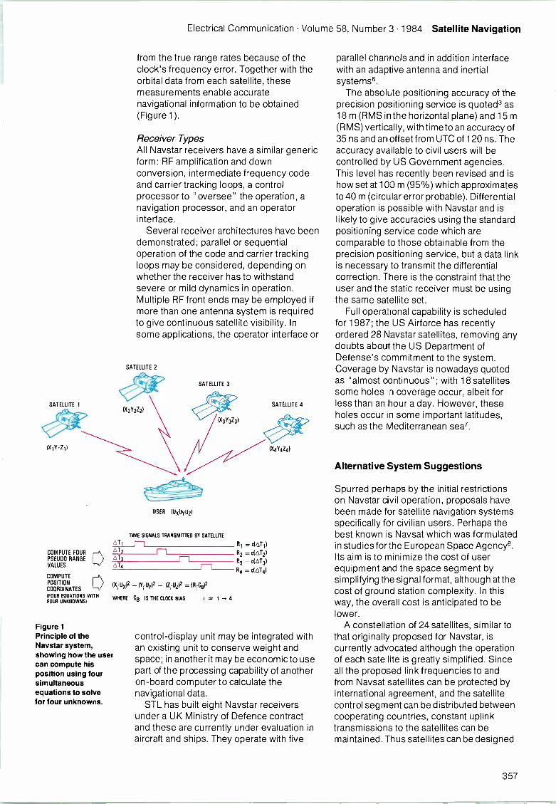
Electrical Communication Volume 58, Number 3 1984 Satellite Navigation
SATELLITE 1Iffy(X1Y1Z1)
COMPUTE FOURPSEUDO RANGEVALUES
COMPUTEPOSITIONCOORDINATES(FOUR EQUATIONS WITHFOUR UNKNOWNS)
AT1
AT2
AT3
ALL
from the true range rates because of theclock's frequency error. Together with theorbital data from each satellite, thesemeasurements enable accuratenavigational information to be obtained(Figure 1).
Receiver TypesAll Naystar receivers have a similar genericform: RF amplification and downconversion, intermediate frequency codeand carrier tracking loops, a controlprocessor to "oversee" the operation, anavigation processor, and an operatorinterface.
Several receiver architectures have beendemonstrated; parallel or sequentialoperation of the code and carrier trackingloops may be considered, depending onwhether the receiver has to withstandsevere or mild dynamics in operation.Multiple RF front ends may be employed ifmore than one antenna system is requiredto give continuous satellite visibility. Insome applications, the operator interface or
SATELLITE 2
SATELLITE 3
edreP
(X3Y3Z3
USER (UxUyilz(
TIME SIGNALS TRANSMITTED BY SATELLITE
R1 = cl,o,T1)
R2 - cI4T21
R3 = c(4T3)
114 = c(4T4)
(Xrilx)2 (Y,-UO2 (ZrUzP = (fli-0O2
WHERE CB IS THE CLOCK BIAS ' = 1 4
Figure 1Principle of theNaystar system,showing how the usercan compute hisposition using foursimultaneousequations to solvefor four unknowns.
SATELLITE 4
(X4T4Z4)
control -display unit may be integrated withan existing unit to conserve weight andspace; in another it may be economic to usepart of the processing capability of anotheron -board computer to calculate thenavigational data.
STL has built eight Naystar receiversunder a UK Ministry of Defence contractand these are currently under evaluation inaircraft and ships. They operate with five
parallel channels and in addition interfacewith an adaptive antenna and inertialsystems6.
The absolute positioning accuracy of theprecision positioning service is quoted3 as18 m (RMS in the horizontal plane) and 15 m(RMS) vertically, with time to an accuracy of35 ns and an offset from UTC of 120 ns. Theaccuracy available to civil users will becontrolled by US Government agencies.This level has recently been revised and ishow set at 100 m (95%) which approximatesto 40 m (circular error probable). Differentialoperation is possible with Naystar and islikely to give accuracies using the standardpositioning service code which arecomparable to those obtainable from theprecision positioning service, but a data linkis necessary to transmit the differentialcorrection. There is the constraint that theuser and the static receiver must be usingthe same satellite set.
Full operational capability is scheduledfor 1987; the US Airforce has recentlyordered 28 Naystar satellites, removing anydoubts about the US Department ofDefense's commitment to the system.Coverage by Naystar is nowadays quotedas "almost continuous"; with 18 satellitessome holes on coverage occur, albeit forless than an hour a day. However, theseholes occur in some important latitudes,such as the Mediterranean sea'.
Alternative System Suggestions
Spurred perhaps by the initial restrictionson Naystar civil operation, proposals havebeen made for satellite navigation systemsspecifically for civilian users. Perhaps thebest known is Naysat which was formulatedin studies for the European Space Agency8.Its aim is to minimize the cost of userequipment and the space segment bysimplifying the signal format, although at thecost of ground station complexity. In thisway, the overall cost is anticipated to belower.
A constellation of 24 satellites, similar tothat originally proposed for Naystar, iscurrently advocated although the operationof each satellite is greatly simplified. Sinceall the proposed link frequencies to andfrom Naysat satellites can be protected byinternational agreement, and the satellitecontrol segment can be distributed betweencooperating countries, constant uplinktransmissions to the satellites can bemaintained. Thus satellites can be designed
357

Satellite Navigation Electrical Communication Volume 58, Number 3 1984
to act merely as transponders, relayingnavigational transmissions from the controlsegment and simplifying the spacesegment.
The method of determining positionwhich is advocated for Naysat is again themeasurement of pseudoranges to foursatellites that are in view simultaneously. Tosimplify the user equipment, and sincejamming protection of downlinktransmissions is not required, a simplersignal format can be considered. Oneproposal is for the satellites to transmit timedivision multiplexed bursts. These maycontain pseudorandom code modulations,but they need not vary from satellite tosatellite. Thus the receiver does not need toknow which satellites are in view initially,and need not perform any sequencingoperation in order to receive transmissionsfrom different satellites.
A requirement for the control segment isthat each satellite is visible from at least oneground station at all times, which needsabout five stations. These have the task ofdetermining the precise orbits of thesatellites and generating the uplinktransmissions. Standard Elektrik Lorenz isproposing a system known as GRANASwhich has similarities to the Naysat system.
It is not necessary to use dedicatedsatellites to provide positional information.In 1981 it was demonstrated that theposition of a riverboat could be determinedto an accuracy of 0.1 n mile by a techniquewhich involved tone ranging through theATS6 satellite coupled with a time of arrivalmeasurement from the NOAA-GOESsatellites.
In the future one may envisage satellitesproviding communications, navigation, andsurveillance, thus sharing the high cost overseveral functions and recovering them fromat least some of the users.
Acknowledgments
The authors gratefully acknowledge thesupport of the UK Ministry of Defence(Procurement Executive) for the Naystarreceiver development.
References
1 R. Gold: Maximal Recursive Sequences with 3 -valuedRecursive Cross Correlation Functions: Institute ofElectrical and Electronics Engineers Transactions onInformation Theory, pp 154-156, January 1968.
2 R. Gold: Optimal Binary Sequences for SpreadSpectrum Multiplexing: Institute of Electrical andElectronics Engineers Transactions on InformationTheory, pp 619-621, October 1967.
3 Federal Radio Navigation Plan, March 1982: DOD -4650.4 -P, DOT-TSC-RSPA-81-12, volume 3, RadioNavigation System Characteristics.
4 W. F. Blanchard: The Continuing Development ofTransit: Third International Conference on SatelliteSystems for Mobile Communication and Navigation,Institution of Electrical Engineers ConferencePublication No 222, pp 189 -199.
5 Journal of International Navigation: Summer 1978,volume 25, not.
6 J. P. Sudworth et al: Design and PerformanceEvaluation of a Five Channel Naystar Receiver:Proceedings of the Military Microwaves Conference,October 1982.
7 P. Kruh: Satellite Constellation: Proceedings of theGlobal Positioning System Symposium, 21-22 April1983, Arlington, Virginia.
8 P. Diederich: The promise of Naysat for CivilNavigation: Third International Conference on SatelliteSystems for Mobile Communications and Navigation,Institute of Electrical Engineers ConferencePublication No 222, pp 200 -206.
9 R. E. Anderson et al: Position Surveillance using oneActive Ranging Satellite and Time -of -Arrival of aSignal from an Independent Satellite: Navigation,Winter 1980-81, volume 27, no 4.
Peter Kenneth Blair was born in 1937. He studied forhis HNC in electrical engineering and DipEE whileapprenticed to the Marconi Company. He joined STL in1962 as a research engineer working on high speedPCM systems, solid state microwave transmitters, andtelevision transposers. In 1971 he became departmentmanager of the navigational aid and mobile radiodepartment. Since 1977 he has been division managerof the Defence and Related Systems Division where hisresponsibilities include the Naystar GPS programme,radar systems, civil marine navaids, and advancedantenna research. Mr Blair is a member of the IEE.
Philip J. Hargrave received his BSc degree inphysics from the University of Bristol in 1971. He thenundertook research in radio astronomy at the CavendishLaboratory, Cambridge, and was awarded his PhDdegree in 1975. In 1977 he joined STL where he hasbeen involved in the design of high performance Naystarreceivers, the study of adaptive antenna systems, andmore recently the mathematical modeling of a widerange of defense systems. Dr Hargrave is a member ofthe IEE and a fellow of the Royal Astronomical Society.He is currently manager of the adaptive systemsdepartment at STL.
358
This Issue in Brief
Dodington, S. H.Civil Navigation Aids in ITTElectrical Communication (1984), volume 58, no 3, pp 251-255
A number of changes have taken place over the past 10 years is the fieldof navigation aids. One of the most important of these is thestandardization by ICAO of the time -referenced scanning beam conceptfor the microwave landing system. In addition, great interest has beengenerated by the satellite -based global positioning system which offersaccuracies of 20 m. The author looks at these new developments andthe evolution of existing systems, and provides a brief forecast of thestatus of the major navigation aids at the end of the century.
Lang, A. H.Second Generation Vortac EquipmentElectrical Communication (1984), volume 58, no 3, pp 256-262
Vortac and VOR/DME are the prime navigation aids for the United Statesnational airspace system. The existing vacuum tube equipment, whichhad become costly to maintain, is being replaced to ensure thecontinuation of this service beyond 1995. The author describes the newequipment which utilizes modern technology to provide higherreliability, remote maintenance and monitoring capabilities, andimproved system availability. The introduction of microcomputertechniques permits the remote maintenance and control system to beused for all station control functions, automatic certification testing, andremote diagnostic and trend testing to improve maintenance evenfurther. The resulting all -solid-state Vortac system provides theextended 20 -year life at a reduced lifecycle cost.
Walters, D. W.Ground -Based Air Traffic Control Communication EquipmentElectrical Communication (1984), volume 58, no 3, pp 263 - 269
Fixed tuned single channel receivers and transmitters produced by ITTAerospace/Optical Division are being used in voice communications forATC (air traffic control). Performance of the ATC radio, colocated withother radios and electronic equipment, is critical in terms of passengersafety, efficiency, and air controller productivity. Development of newtechnology will lead to improved radio performance and allow additionalfeatures to be added to the radios to meet the challenges of increasingair travel and tight budgets.
Kleiber, H.; Knoppik, N.; Vogel, H.System 4000 Navigation AidsElectrical Communication (1984), volume 58, no 3, pp 270-276
System 4000 is a new generation of navigation equipment for ILS(instrument landing system), VOR (VHF omnidirectional range), andDVOR (Doppler VOR). Higher performance and reliability than previoussystems has been achieved by extensive use of microprocessors forcontrol and monitoring, and the application of digital techniques toanalog signal generation. All systems can be configured from a limitedrange of hardware and software modules. Equipment practice employsplug-in printed boards in 19 -inch subracks. Good heat dissipationwithout fans is ensured by mounting transmitter modules on a largeheatsink on the cabinet side. Comprehensive keyboard and displayfacilities are built in. A range of antennas is available for the variousapplications, providing omnidirectional and figure -of -eight patterns forVOR, and bidirectional, dipole and special patterns for ILS.
Limbach, F.; Pahlig, K.Hardware and Software Structures for System 4000 NavigationAidsElectrical Communication (1984), volume 58, no 3, pp 277-282
The application of digital technology to the control and monitoringfun.ctions in the Navaids System 4000 has allowed common design anddevelopment of both low frequency signal processing and highfrequency modules, enabling ILS, VOR, and DVOR functions to berealized with virtually identical hardware. System control and monitoringis performed by a 16 -bit microprocessor which undertakes the main taskof monitoring radiated and standby transmitter signals. The authorsdescribe how these requirements have been met by using a modularhardware structure. The accompanying software is subdivided intomodules which can be compiled and tested independently to performspecific functions for a variety of equipment configurations.
Johannessen, R.VHF Radio LighthouseElectrical Communication (1984), volume 58, no 3, pp 283 - 288
The radio lighthouse is a radio navigation aid designed specifically forsmall coasters, in -shore fishing boats, and pleasure craft. Additionally, ithas proved to be a very useful aid for larger vessels when othernavigation receivers become unusable through, for instance, heavyelectrostatic interference. It provides bearing information for any shipwithin the coverage area equipped with a suitable VHF communicationtransceiver or receiver. No other onboard equipment is required. As theradio information is independent of the ship's heading and of its roll,pitch, and yaw in heavy seas, taking a bearing is very easy. The systemis attractive to the authorities responsible for the shore beacon since itis simple to install, has a very low cost antenna installation, and requiresvirtually no maintenance.
Bertocchi, G.New Family of Tacan and DME EquipmentElectrical Communication (1984), volume 58, no 3, pp 289-292
Much of the existing Tacan and DME navigation equipment usedworldwide has been in operation for many years and is becomingexpensive to maintain. As both these navigation aids are likely to bewidely used well into the 1990s, FACE undertook the development of anew family of Tacan and DME equipment with better performance andreliability, easier maintenance, and a reduced lifecycle cost. The authordiscusses how these objectives have been met in practice by usingdigital techniques and modern RF solid state technology, dualtransponder and monitors, and built-in test equipment. The result is abroadband design that meets all civil and military specifications.
Lazzaroni, E.Civil Use of TacanElectrical Communication (1984), volume 58, no 3, pp 293-298
The Tacan system is a proven navigation aid which has been usedmainly for military applications. The author describes how moderntechnology has made it possible to reduce the cost of Tacaninstallations, opening up a range of new civil applications includinghelicopter navigation to offshore oil rigs. A broad comparison of Tacanwith other major navigation aids leads the author to the conclusion thatmodern solid state Tacan beacons with solid state antennas offerseveral advantages for such applications.
Johnson. R. E.Scanning Pencil Beam Precision Approach RadarElectrical Communication (1984), volume 58, no 3, pp 299-304
The PAR -80 is a scanning pencil beam precision approach radar (PAR)developed and produced by ITT Gilfillan. This air traffic control radar isutilized to provide guidance to aircraft during approach to landing. Thearticle describes the PAR -80 and shows samples of its excellent testresults. The system is dual channel for enhanced operational availability.Its large aperture planar array antenna is instrumental in providingadvantages in radar coverage, resolution, accuracy, and clutterperformance. By combining a mechanical elevation scan with anelectronic azimuth scan, these advantages which promote flight safetyare obta ned in a very cost-effective manner.
Corazza, G.; Vatalaro, F.Further Development of the DPS Technique for Precision DMEElectrical Communication (1984), volume 58, no 3, pp 305-309
Recently the International Civil Aviation Organization decided on analmost final standardization of the precision DME system. The authorsdescribe how the DPS (double pulse shaping) technique can becompatibly utilized with the latest ICAO standards; in particular it isuseful in those applications requiring higher accuracies. The authorsalso outline a feasible implementation of the DPS technique usingbaseband analog signal processing, and show that it offers significantcost benefits combined with good performance.
359

This Issue in Brief Electrical Communication Volume 58, Number 3 1984
Ardemagni, F.; Basile, P.; Clementi, A.RF Subsystems for Precision DMEElectrical Communication (1984), volume 58, no 3, pp 310-313
Much theoretical and practical work has been undertaken in the area ofRF subsystems operating at L -Band for precision distance measuringequipment. The performance of several system components has nowbeen evaluated under a FACE research programme. Two designs aredescribed in the article: a low noise, mechanically tuned front end and asolid state high power transmitter. State-of-the-art technology is used,including the use of soft, high permittivity substrate microwaveintegrated circuits. The designs have been optimized using computeraided design techniques.
Auch, W.; Schlemper, E.Fiber Optic GyroscopeElectrical Communication (1984), volume 58, no 3, pp 314 -318
Although miniature mechanical gyroscopes offer very high accuracies,many different nonmechanical rotation rate sensors are underdevelopment in laboratories throughout the world. The authors outlinethe principle, construction, and test results of a fiber optic gyroscopewhich offers considerable potential as a strapdown sensor for inertialnavigation systems. Test results on laboratory models indicate that it isalready possible to meet the requirements for some applications, butthat further reductions in drift are necessary in order to meet theexacting demands of navigation systems.
Bohm, M.Off -Shore Helicopter Radio Navigation using DME-basedPositioning SystemElectrical Communication (1984), volume 58, no 3, pp 319-325
The DME-based positioning system will allow all-weather helicopteroperations within offshore oil -rig terminal areas. The present regularityof flights in these areas is already 95%, but increasing trafficrequires the improvement of navigational accuracy and airtraffic controlprocedures to maintain safety and economy. The system combinesproven DME (distance measuring equipment) techniques withadvanced angle determination by array signal processing. The articleconsiders each flight phase and describes ground based and airborneequipment suitable for en route navigation and final approach to the rig.
Gorder, G.; Ranghelli, J.Space Qualified L -Band Triplexer for Global Positioning SystemElectrical Communication (1984), volume 58, no 3, pp 326-331
The triplexer for the global positioning satellite system had to meetstringent spectrum requirements for both astronomy and spectrumoccupancy. These and other specifications, including low weight, arefully met by a design based on one 3 -pole and two 6 -pole Chebyschevbandpass filters combined as a noncontiguous triplexer. The authorsdescribe how the final design was developed from earlier versions, andthe changes that were necessary to provide the high Q factor of around8000. One feature of the design was a novel temperature compensationtechnique that allowed the operating temperature range of -20 to+71°C to be achieved without a weight penalty.
Bethmann, A.; Tschiesche, H.Receiver for Global Positioning SystemElectrical Communication (1984), volume 58, no 3, pp 332-335
Advances in satellite technology are now making it possible to usesatellite -based systems to provide very high accuracy navigationthroughout the world for both civil and military users. The authorsdescribe the basic elements of the system and discuss a globalpositioning system receiver being developed for civil applications,including emergency medical services, fishing, and space shuttlenavigation. A prototype of this receiver will form part of a navigationexperiment. The experiment, which will be included in the shuttle/Spacelab system, is scheduled for the German Dl -mission in 1985.
Becker. K.: Willer, A.: Vogel. H.Precision Distance Measuring Equipment for the MicrowaveLanding SystemElectrical Communication (1984), volume 58, no 3, pp 336 - 343
Standard Elektrik Lorenz has been closely involved in internationalstandardization of DME/P (precision distance measuring equipment) forthe future microwave landing system. Since 1981 ground and airborneDME/P equipment has been under development at SEL; seriesproduction will start in 1986. The authors give an account of the systemoperational requirements, concept, and general technical features, anddescribe the main functional units. The article is concluded with asummary of the prospects for DME/P.
Garmany, W. J.: Johnson, V. L.: Romer. W. J.Loran -C Navigation System for Saudi ArabiaElectrical Communication (1984), volume 58, no 3, pp 344-351
Two new Loran -C chains are being installed in Saudi Arabia to providea comprehensive and reliable navigation service in the Red Sea,Arabian Gulf, and other waters around the Arabian Peninsula wherethere is heavy maritime traffic. The authors describe the Saudi systemwhich consists of seven high -power transmitter stations and threemonitor stations. The new Loran -C installation will provide a repeatableposition fix accuracy of 0.1 to 0.2 n mile day and night in all seasons,thereby increasing the safety and efficiency of marine transport in thearea.
Blair, P. K.; Hargrave, P. J.Satellite NavigationElectrical Communication (1984), volume 58, no 3, pp 352-358
This paper examines the fundamental principles of satellite navigationwith particular reference to the factors affecting the accuracy of basicmeasurements and their corrections. It then considers the usage andoperation of current systems and concludes with an outline of alternativeproposed systems.
Editorial Offices
Enquiries relating to the different language editions of Electrical Communication shouldto the appropriate editor, as follows:
English Edition
Editor: Michael DeasonDeputy Editor: Rod HazellEditorial Secretary: Pamela BrownjohnSubscriptions: Mary LinceText Processing: Doreen Cullen
Electrical CommunicationGreat Eastern HouseEdinburgh WayHarlow, EssexEngland
Otto GreweElektrisches NachrichtenwesenHellmuth-Hirth-StraBe 427000 Stuttgart 40Federal Republic of Germany
Antonio SotoComunicaciones ElectricasRamirez de Prado 5MadridSpain
be addressed
Lester A. GimpelsonRevue des TelecommunicationsITT Europe IncAvenue Louise 4801050 BrusselsBelgium
360

1

Navigation Aids
Civil Navigation Aids in ITT
Second Generation Vortac Equipment
Ground -Based Air Traffic Control Communication Equipment
System 4000 Navigation Aids
Hardware and Software Structures for System 4000 Navigation Aids
VHF Radio Lighthouse
New Family of Tacan and DME Equipment
Civil Use of Tacan
Scanning Pencil Beam Precision Approach Radar
Further Development of the DPS Technique for Precision DME
RF Subsystems for Precision DME
Fiber Optic Gyroscope
Off -Shore Helicopter Radio Navigation using DME-based Positioning System
Space Qualified L -Band Triplexer for Global Positioning System
Receiver for Global Positioning System
Precision Distance Measuring Equipment for the Microwave Landing System
Loran -C Navigation System for Saudi Arabia
Satellite Navigation
ITT CORPORATION ITT
Volume 58
Number 3
1984 Priried in Germany by C F Hoes GmbH D-7970 Fieldenbeirn (Brenr)