Effects of sedimentary interfaces on fracture pattern, linkage, and cluster formation in peritidal...
20
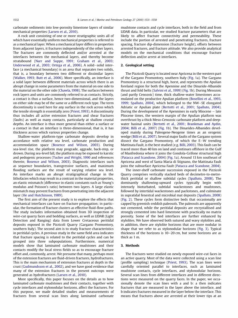
Effects of sedimentary interfaces on fracture pattern, linkage, and cluster formation in peritidal carbonate rocks Belinda Larsen a, * , Agust Gudmundsson b , Ivar Grunnaleite c , Gunnar Sælen a, c , Michael R. Talbot a,1 , Simon J. Buckley d a Department of Earth Science, The University of Bergen, Allegaten 41, N-5007 Bergen, Norway b Department of Earth Sciences, Queen’s Building, Royal Holloway University of London, Egham TW20 0EX, UK c International Research Institute of Stavanger, Bergen, Norway d Centre for Integrated Petroleum Research, Bergen, Norway article info Article history: Received 5 August 2009 Received in revised form 11 March 2010 Accepted 18 March 2010 Available online 25 March 2010 Keywords: Fracture propagation Fracture arrest Permeability Rock properties Crustal stresses Fractured reservoirs abstract The permeability of a reservoir is particularly dependent upon the proportion of its fractures that penetrate or are arrested at interfaces such as contacts and discontinuities. Here we report on fracture penetration and fracture arrest in Lower Cretaceous peritidal deposits exposed in the Pizzicoli Quarry, Gargano Promontory, southern Italy. We measured more than 2000 fractures, in the field and using LIDAR data, of which 564 fractures from the field and 518 from LIDAR studies are the focus of this paper. Fracture arrest/deflection and penetration depend much on the effects of peritidal cycle interfaces such as paleosol horizons, laminated carbonate mudstones, and stylonodular horizons. The laminated mudstones have the greatest effect; 63e99% of the fractures are deflected or arrested at such interfaces, whereas 63e90% are deflected/arrested at paleosols, and 20e35% at stylonodular horizons. In the mudstones, many fractures are arrested at thin, internal laminae, such that few penetrate the entire laminated layer, and fewer still the boundaries between the layers. Paleosol interfaces deflect/arrest more than 60% of all fractures. However, when small-offset fractures above and below paleosols are regarded as penetrating, they are evenly spaced (non-clustered), so that fracture-related fluid transport may occur across the entire paleosol. Stylonodular horizons deflect/arrest and split some fractures, but generally have little effect compared with the other types of interfaces. We present three main mech- anisms for fracture deflection and/or arrest: (1) the fracture-induced tensile stress ahead of its tip, referred to as the Cook-Gordon debonding mechanism; (2) rotation of the principal stresses at and across the interface, resulting in the formation of stress barriers; and (3) large elastic mismatch (particularly as regards Young’s moduli) between layers across an interface. All these mechanisms are likely to have operated during fracture propagation and arrest in the carbonate rocks of the Pizzicoli Quarry. Ó 2010 Elsevier Ltd. All rights reserved. 1. Introduction A significant proportion of the world’s hydrocarbon reserves are contained within carbonate reservoirs, many of which are fractured (Lucia, 1999; Ahr, 2008). The hydraulic properties of a fractured reservoir depend on the matrix and fracture characteristics. Particularly important are the capability of the matrix and fractures to store (porosity) and transport (permeability) fluids. Whether or not fractured carbonate reservoir rocks are permeable depends largely on the fracture connectivity, namely how and to what degree fractures link up to form a continuous network (Aguilera, 1995; Nelson, 2001; Zhang and Sanderson, 2002; Lonergan et al., 2007). Fractured carbonate reservoirs are seldom homogeneous, and the development of a network of fluid-transmitting fractures is controlled by the local stresses, mechanical properties, and layering of the various lithotypes, as well as their spatial distribution (Helgesen and Aydin,1991; Gillespie et al., 2001; Rijken and Cooke, 2001; Stowell, 2001; Gale et al., 2004; Larsen et al., 2010). Rock lithology may have large effects on fracture distribution. Some rocks show a relationship between grain size and degree of fracturing. For example, a carbonate mudstone fractures more easily than a grainstone (Eyssautier-Chuine et al., 2002; Wennberg et al., 2006). The mechanical properties of rocks, however, change with time. For instance, carbonate sediments of initially dissimilar properties may undergo extensive alteration after deposition involving cementation and recrystallisation, converting the * Corresponding author. Present address: Statoil ASA, Bergen, Norway. E-mail address: [email protected] (B. Larsen). 1 Deceased. Contents lists available at ScienceDirect Marine and Petroleum Geology journal homepage: www.elsevier.com/locate/marpetgeo 0264-8172/$ e see front matter Ó 2010 Elsevier Ltd. All rights reserved. doi:10.1016/j.marpetgeo.2010.03.011 Marine and Petroleum Geology 27 (2010) 1531e1550
Transcript of Effects of sedimentary interfaces on fracture pattern, linkage, and cluster formation in peritidal...
lable at ScienceDirect
Marine and Petroleum Geology 27 (2010) 1531e1550
Contents lists avai
Marine and Petroleum Geology
journal homepage: www.elsevier .com/locate/marpetgeo
Effects of sedimentary interfaces on fracture pattern, linkage, and clusterformation in peritidal carbonate rocks
Belinda Larsen a,*, Agust Gudmundsson b, Ivar Grunnaleite c, Gunnar Sælen a,c,Michael R. Talbot a,1, Simon J. Buckley d
aDepartment of Earth Science, The University of Bergen, Allegaten 41, N-5007 Bergen, NorwaybDepartment of Earth Sciences, Queen’s Building, Royal Holloway University of London, Egham TW20 0EX, UKc International Research Institute of Stavanger, Bergen, NorwaydCentre for Integrated Petroleum Research, Bergen, Norway
a r t i c l e i n f o
Article history:Received 5 August 2009Received in revised form11 March 2010Accepted 18 March 2010Available online 25 March 2010
Keywords:Fracture propagationFracture arrestPermeabilityRock propertiesCrustal stressesFractured reservoirs
* Corresponding author. Present address: Statoil ASE-mail address: [email protected] (B. Larsen).
1 Deceased.
0264-8172/$ e see front matter � 2010 Elsevier Ltd.doi:10.1016/j.marpetgeo.2010.03.011
a b s t r a c t
The permeability of a reservoir is particularly dependent upon the proportion of its fractures thatpenetrate or are arrested at interfaces such as contacts and discontinuities. Here we report on fracturepenetration and fracture arrest in Lower Cretaceous peritidal deposits exposed in the Pizzicoli Quarry,Gargano Promontory, southern Italy. We measured more than 2000 fractures, in the field and usingLIDAR data, of which 564 fractures from the field and 518 from LIDAR studies are the focus of this paper.Fracture arrest/deflection and penetration depend much on the effects of peritidal cycle interfaces suchas paleosol horizons, laminated carbonate mudstones, and stylonodular horizons. The laminatedmudstones have the greatest effect; 63e99% of the fractures are deflected or arrested at such interfaces,whereas 63e90% are deflected/arrested at paleosols, and 20e35% at stylonodular horizons. In themudstones, many fractures are arrested at thin, internal laminae, such that few penetrate the entirelaminated layer, and fewer still the boundaries between the layers. Paleosol interfaces deflect/arrestmore than 60% of all fractures. However, when small-offset fractures above and below paleosols areregarded as penetrating, they are evenly spaced (non-clustered), so that fracture-related fluid transportmay occur across the entire paleosol. Stylonodular horizons deflect/arrest and split some fractures, butgenerally have little effect compared with the other types of interfaces. We present three main mech-anisms for fracture deflection and/or arrest: (1) the fracture-induced tensile stress ahead of its tip,referred to as the Cook-Gordon debonding mechanism; (2) rotation of the principal stresses at and acrossthe interface, resulting in the formation of stress barriers; and (3) large elastic mismatch (particularly asregards Young’s moduli) between layers across an interface. All these mechanisms are likely to haveoperated during fracture propagation and arrest in the carbonate rocks of the Pizzicoli Quarry.
� 2010 Elsevier Ltd. All rights reserved.
1. Introduction
A significant proportion of the world’s hydrocarbon reserves arecontainedwithin carbonate reservoirs, many of which are fractured(Lucia, 1999; Ahr, 2008). The hydraulic properties of a fracturedreservoir depend on the matrix and fracture characteristics.Particularly important are the capability of the matrix and fracturesto store (porosity) and transport (permeability) fluids. Whether ornot fractured carbonate reservoir rocks are permeable dependslargely on the fracture connectivity, namely how and to whatdegree fractures link up to form a continuous network (Aguilera,
A, Bergen, Norway.
All rights reserved.
1995; Nelson, 2001; Zhang and Sanderson, 2002; Lonergan et al.,2007). Fractured carbonate reservoirs are seldom homogeneous,and the development of a network of fluid-transmitting fractures iscontrolled by the local stresses, mechanical properties, and layeringof the various lithotypes, as well as their spatial distribution(Helgesen and Aydin, 1991; Gillespie et al., 2001; Rijken and Cooke,2001; Stowell, 2001; Gale et al., 2004; Larsen et al., 2010).
Rock lithology may have large effects on fracture distribution.Some rocks show a relationship between grain size and degree offracturing. For example, a carbonate mudstone fractures moreeasily than a grainstone (Eyssautier-Chuine et al., 2002; Wennberget al., 2006). The mechanical properties of rocks, however, changewith time. For instance, carbonate sediments of initially dissimilarproperties may undergo extensive alteration after depositioninvolving cementation and recrystallisation, converting the
B. Larsen et al. / Marine and Petroleum Geology 27 (2010) 1531e15501532
carbonate sediments into low-porosity limestone layers of similarmechanical properties (Larsen et al., 2010).
A rock unit consisting of one or more stratigraphic units all ofwhich have essentially uniformmechanical properties is referred toas amechanical layer. When amechanical layer differs in propertiesfrom adjacent layers, it fractures independently of the other layers.The fractures are commonly deflected and/or arrested at theinterfaces between the mechanical layers, and thereby becomestratabound (Narr and Suppe, 1991; Graham et al., 2003;Underwood et al., 2003; Ortega et al., 2006). A solidesolid inter-face (a mechanical boundary) is an area that separates two solids,that is, a boundary between two different or dissimilar layers(Walker, 1993; Butt et al., 2006). More specifically, an interface isa solid layer between different materials across which there is anabrupt change in some parameters from the material on one side tothematerial on the other side (Chawla,1998). The surfaces betweenrock layers and units are commonly referred to as contacts. Strictly,a contact is thus a surface, hence two-dimensional, and the layerson either side may be of the same or a different rock type. The termdiscontinuity is used here for any surface in the rock across whichthe tensile strength is essentially zero (Priest, 1993). A discontinuitythus includes all active extension fractures and shear fractures(faults) as well as many contacts, particularly at shallow crustaldepths. An interface is thus more general than either a surface ora contact in that an interface is three-dimensional, that is, it hasthickness across which various properties change.
Shallow-water platform-type carbonate deposits develop inaccordance with relative sea level, carbonate production andaccommodation space (Bosence and Wilson, 2003). Duringsea-level rise, the platform may prograde, aggrade, back-step, ordrown. During sea-level fall, the platformmay be exposed to karsticand pedogenic processes (Tucker and Wright, 1990 and referencestherein; Bosence and Wilson, 2003). Diagnostic interfaces suchas sequence boundaries, transgressive surfaces, and maximumflooding surfaces are the result of varying relative sea level.An interface marks an abrupt stratigraphical change in thelithofacies whichmay result in a contrast in thematerial properties,an elastic mismatch (difference in elastic constants such as Young’smodulus and Poisson’s ratio) between two layers. A large elasticmismatchmay prevent fractures from penetrating into the adjacentlayer (He and Hutchinson, 1989).
The first aim of the present study is to explore the effects thatmechanical interfaces can have on fracture propagation; in partic-ular, the formation of fracture clusters as effective fluid-flow paths.The study includes information obtained from 3D inspection ofwire-cut quarry faces and bedding surfaces, as well as LIDAR (LightDetection and Ranging) data from Lower Cretaceous peritidaldeposits exposed in the Pizzicoli Quarry (Gargano Promontory,southern Italy). The second aim is to study fracture characteristicsin peritidal cycles. A previous study in the same field area indicatesthat fracture spacing is related to the peritidal cycles and can begrouped into three subpopulations. Furthermore, numericalmodels show that laminated carbonate mudstones and theircontacts modify the local stress fields so as to encourage fractureoffset and, commonly, arrest. We presume that many, perhaps mostof the extension fractures are fluid-driven fractures, hydrofractures.This is the main mechanism of extension fractures at depth in thecrust (Gudmundsson et al., 2002), and we have good evidence thatmany of the extension fractures in the present outcrops weregenerated as hydrofractures (Larsen et al., 2010).
More specifically, this paper focuses on the details as to howlaminated carbonate mudstones and their contacts, together withcycle interfaces and stylonodular horizons, affect the fractures. Forthis purpose, we made detailed studies and measurements offractures from several scan lines along laminated carbonate
mudstone contacts and cycle interfaces, both in the field and fromLIDAR data. In particular, we studied fracture parameters that arelikely to affect fracture connectivity and permeability. Theseinclude the portion of arrested and penetrating fractures, fracturespacing, fracture dip-dimension (fracture height), offsets betweenarrested fractures, and fracture attitude. We also provide analyticalmodels on the mechanical conditions that encourage fracturedeflection and/or arrest at interfaces.
2. Geological setting
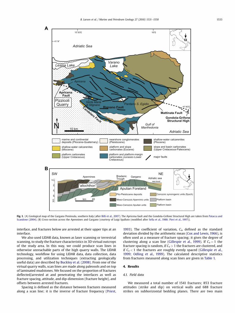
The Pizzicoli Quarry is located near Apricena in the western partof the Gargano Promontory, southern Italy (Fig. 1a). The GarganoPromontory is a structural high, horst, and represents the Apulianforeland region for both the Apennine and the Dinaride-Albanidethrust and fold belts (Salvini et al., 1999) (Fig. 1b). During Mesozoic(and partly Cenozoic) time, thick shallow-water limestones accu-mulated on the productive Apulian platform (Bosellini et al., 1993,1999; Spalluto, 2004), which belonged to the NWeSE elongatedAdriatic or Apulian plate (Bertotti et al., 2001; Spalluto, 2004).During the development of the Apennines in early Miocene e latePliocene times, the western margin of the Apulian platform wasoverthrust by a thick Meso-Cenozoic carbonate platform and deep-water basinal units (Bertotti et al., 2001; Brankman and Aydin,2004; Billi et al., 2007) (Fig. 1b). The Dinarides-Albanides devel-oped mainly during Paleogene-Neogene times as an orogenicwedge (Billi et al., 2007). Several major faults of the Gargano systemdissect the Gargano Promontory, of which the EeW trendingMattinata Fault, is the best studied (e.g. Billi, 2003). This fault can betraced more than 40 km on land and continues offshore in the Gulfof Manfredonia where it joins the Gondola-Grifone structural high(Patacca and Scandone, 2004) (Fig. 1a). Around 13 km southeast ofApricena and west of Santa Maria di Stignano, the Mattinata Faultjoins the subsurface Apricena Fault (Patacca and Scandone, 2004).
The inner-shelf carbonate succession exposed in the PizzicoliQuarry comprises vertically stacked beds of decimetre-to-metre-thick peritidal or shallow subtidal cycles (Spalluto, 2008). Thedominantly shallowing-upward cycles typically begin withintensely bioturbated, subtidal wackestones and mudstones,followed by intertidal wackestones and packstones, and culminatein supratidal fenestral and microbial mat deposits (Spalluto, 2008)(Fig. 2). These cycles form distinctive beds that occasionally arecapped by greenish-reddish paleosols. The paleosols are apparentlynot cemented, while the peritidal deposits are recrystallised andstrongly cemented into hard limestone with practically no matrixporosity. Some of the bed interfaces are further enhanced bystylolites. We have observed both sutured and wavy stylolites and,in addition, there are stylolite horizons that are more nodular inshape that we refer to as stylonodular horizons (Fig. 3). Typicalthickness of the horizons is 10e20 cm, but some horizons are asthick as 1 m.
3. Methods
The fractures were studied on newly exposed wire-cut faces inan active quarry. Most of the data were collected using a scan line(profile sampling) technique (Priest, 1993). The scan lines werecarefully oriented parallel to interfaces, such as laminatedmudstone contacts, cycle interfaces, and stylonodular horizons.Several scan lines from different interfaces and in different direc-tions were measured on the quarry faces. In the paper, we occa-sionally denote the scan lines with a and b: a then indicatesfractures that are measured in the layer above the interface, andb indicates fracturesmeasured in the layer below the interface. Thismeans that fractures above are arrested at their lower tips at an
A
B
Fig. 1. (A) Geological map of the Gargano Peninsula, southern Italy (after Billi et al., 2007). The Apricena fault and the Gondola-Grifone Structural High are taken from Patacca andScandone (2004). (B) Cross-section across the Apennines and Gargano (courtesy of Luigi Spalluto (modified after Sella et al., 1988; Pieri et al., 1997)).
B. Larsen et al. / Marine and Petroleum Geology 27 (2010) 1531e1550 1533
interface, and fractures below are arrested at their upper tips at aninterface.
We also used LIDAR data, known as laser scanning or terrestrialscanning, to study the fracture characteristics in 3D virtual outcropsof the study area. In this way, we could produce scan lines inotherwise unreachable parts of the high quarry walls. The LIDARtechnology, workflow for using LIDAR data, data collection, dataprocessing, and utilization techniques (extracting geologicallyuseful data) are described by Buckley et al. (2008). From one of thevirtual quarry walls, scan lines are made along paleosols and on topof laminated mudstones. We focused on the proportion of fracturesdeflected/arrested at and penetrating the interfaces as well asfracture spacing, attitude, and dip-dimension (fracture height), andoffsets between arrested fractures.
Spacing is defined as the distance between fractures measuredalong a scan line; it is the inverse of fracture frequency (Priest,
1993). The coefficient of variation, Cv, defined as the standarddeviation divided by the arithmetic mean (Cox and Lewis, 1966), isoften used as a measure of fracture spacing; it gives the degree ofclustering along a scan line (Gillespie et al., 1999). If Cv¼ 1 thefracture spacing is random, if Cv> 1 the fractures are clustered, andif Cv< 1 the fractures are roughly evenly spaced (Gillespie et al.,1999; Odling et al., 1999). The calculated descriptive statisticsfrom fractures measured along scan lines are given in Table 1.
4. Results
4.1. Field data
We measured a total number of 1541 fractures; 853 fractureattitudes (strike and dip) on vertical walls and 688 fracturestrikes on subhorizontal bedding planes. There are two main
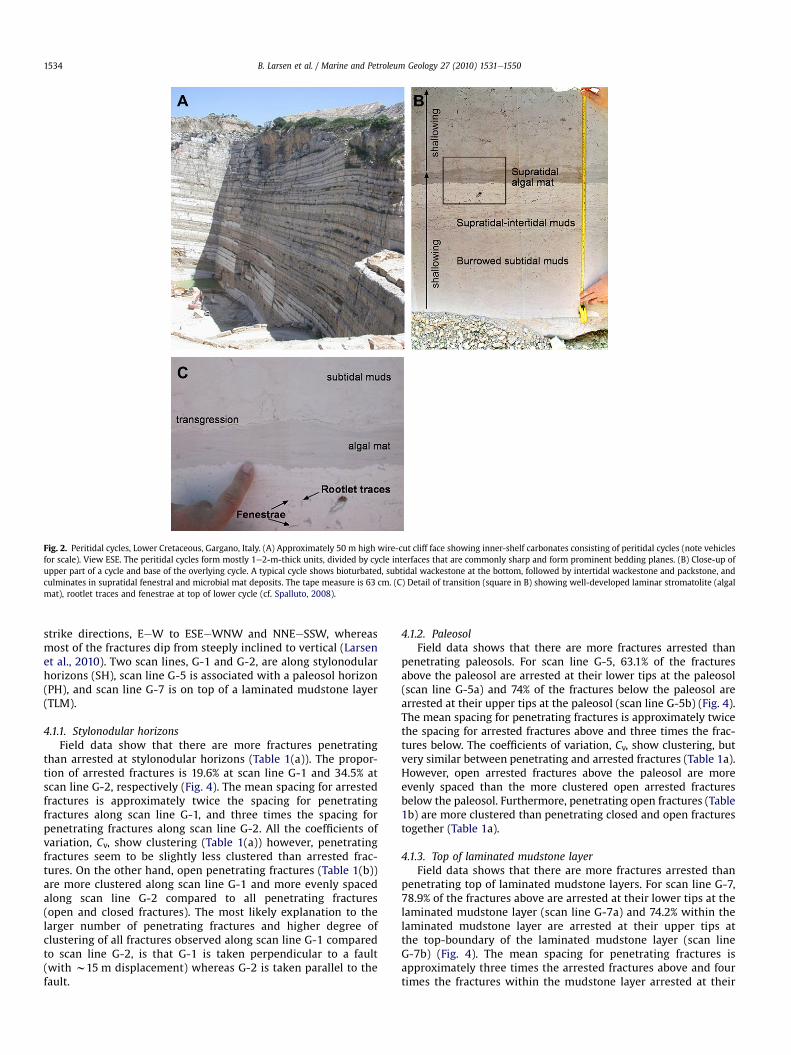
Fig. 2. Peritidal cycles, Lower Cretaceous, Gargano, Italy. (A) Approximately 50 m high wire-cut cliff face showing inner-shelf carbonates consisting of peritidal cycles (note vehiclesfor scale). View ESE. The peritidal cycles form mostly 1e2-m-thick units, divided by cycle interfaces that are commonly sharp and form prominent bedding planes. (B) Close-up ofupper part of a cycle and base of the overlying cycle. A typical cycle shows bioturbated, subtidal wackestone at the bottom, followed by intertidal wackestone and packstone, andculminates in supratidal fenestral and microbial mat deposits. The tape measure is 63 cm. (C) Detail of transition (square in B) showing well-developed laminar stromatolite (algalmat), rootlet traces and fenestrae at top of lower cycle (cf. Spalluto, 2008).
B. Larsen et al. / Marine and Petroleum Geology 27 (2010) 1531e15501534
strike directions, EeW to ESEeWNW and NNEeSSW, whereasmost of the fractures dip from steeply inclined to vertical (Larsenet al., 2010). Two scan lines, G-1 and G-2, are along stylonodularhorizons (SH), scan line G-5 is associated with a paleosol horizon(PH), and scan line G-7 is on top of a laminated mudstone layer(TLM).
4.1.1. Stylonodular horizonsField data show that there are more fractures penetrating
than arrested at stylonodular horizons (Table 1(a)). The propor-tion of arrested fractures is 19.6% at scan line G-1 and 34.5% atscan line G-2, respectively (Fig. 4). The mean spacing for arrestedfractures is approximately twice the spacing for penetratingfractures along scan line G-1, and three times the spacing forpenetrating fractures along scan line G-2. All the coefficients ofvariation, Cv, show clustering (Table 1(a)) however, penetratingfractures seem to be slightly less clustered than arrested frac-tures. On the other hand, open penetrating fractures (Table 1(b))are more clustered along scan line G-1 and more evenly spacedalong scan line G-2 compared to all penetrating fractures(open and closed fractures). The most likely explanation to thelarger number of penetrating fractures and higher degree ofclustering of all fractures observed along scan line G-1 comparedto scan line G-2, is that G-1 is taken perpendicular to a fault(with w15 m displacement) whereas G-2 is taken parallel to thefault.
4.1.2. PaleosolField data shows that there are more fractures arrested than
penetrating paleosols. For scan line G-5, 63.1% of the fracturesabove the paleosol are arrested at their lower tips at the paleosol(scan line G-5a) and 74% of the fractures below the paleosol arearrested at their upper tips at the paleosol (scan line G-5b) (Fig. 4).The mean spacing for penetrating fractures is approximately twicethe spacing for arrested fractures above and three times the frac-tures below. The coefficients of variation, Cv, show clustering, butvery similar between penetrating and arrested fractures (Table 1a).However, open arrested fractures above the paleosol are moreevenly spaced than the more clustered open arrested fracturesbelow the paleosol. Furthermore, penetrating open fractures (Table1b) are more clustered than penetrating closed and open fracturestogether (Table 1a).
4.1.3. Top of laminated mudstone layerField data shows that there are more fractures arrested than
penetrating top of laminated mudstone layers. For scan line G-7,78.9% of the fractures above are arrested at their lower tips at thelaminated mudstone layer (scan line G-7a) and 74.2% within thelaminated mudstone layer are arrested at their upper tips atthe top-boundary of the laminated mudstone layer (scan lineG-7b) (Fig. 4). The mean spacing for penetrating fractures isapproximately three times the arrested fractures above and fourtimes the fractures within the mudstone layer arrested at their
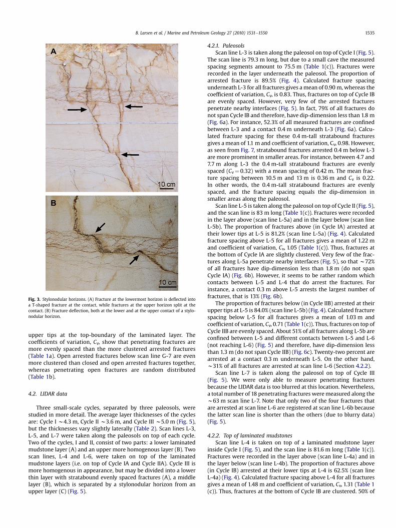
Fig. 3. Stylonodular horizons. (A) Fracture at the lowermost horizon is deflected intoa T-shaped fracture at the contact, while fractures at the upper horizon split at thecontact. (B) Fracture deflection, both at the lower and at the upper contact of a stylo-nodular horizon.
B. Larsen et al. / Marine and Petroleum Geology 27 (2010) 1531e1550 1535
upper tips at the top-boundary of the laminated layer. Thecoefficients of variation, Cv, show that penetrating fractures aremore evenly spaced than the more clustered arrested fractures(Table 1a). Open arrested fractures below scan line G-7 are evenmore clustered than closed and open arrested fractures together,whereas penetrating open fractures are random distributed(Table 1b).
4.2. LIDAR data
Three small-scale cycles, separated by three paleosols, werestudied in more detail. The average layer thicknesses of the cyclesare: Cycle I w4.3 m, Cycle II w3.6 m, and Cycle III w5.0 m (Fig. 5),but the thicknesses vary slightly laterally (Table 2). Scan lines L-3,L-5, and L-7 were taken along the paleosols on top of each cycle.Two of the cycles, I and II, consist of two parts: a lower laminatedmudstone layer (A) and an upper more homogenous layer (B). Twoscan lines, L-4 and L-6, were taken on top of the laminatedmudstone layers (i.e. on top of Cycle IA and Cycle IIA). Cycle III ismore homogenous in appearance, but may be divided into a lowerthin layer with stratabound evenly spaced fractures (A), a middlelayer (B), which is separated by a stylonodular horizon from anupper layer (C) (Fig. 5).
4.2.1. PaleosolsScan line L-3 is taken along the paleosol on top of Cycle I (Fig. 5).
The scan line is 79.3 m long, but due to a small cave the measuredspacing segments amount to 75.5 m (Table 1(c)). Fractures wererecorded in the layer underneath the paleosol. The proportion ofarrested fracture is 89.5% (Fig. 4). Calculated fracture spacingunderneath L-3 for all fractures gives amean of 0.90 m, whereas thecoefficient of variation, Cv, is 0.83. Thus, fractures on top of Cycle IBare evenly spaced. However, very few of the arrested fracturespenetrate nearby interfaces (Fig. 5). In fact, 79% of all fractures donot span Cycle IB and therefore, have dip-dimension less than 1.8 m(Fig. 6a). For instance, 52.3% of all measured fractures are confinedbetween L-3 and a contact 0.4 m underneath L-3 (Fig. 6a). Calcu-lated fracture spacing for these 0.4 m-tall stratabound fracturesgives a mean of 1.1 m and coefficient of variation, Cv, 0.98. However,as seen from Fig. 7, stratabound fractures arrested 0.4 m below L-3are more prominent in smaller areas. For instance, between 4.7 and7.7 m along L-3 the 0.4 m-tall stratabound fractures are evenlyspaced (Cv¼ 0.32) with a mean spacing of 0.42 m. The mean frac-ture spacing between 10.5 m and 13 m is 0.36 m and Cv is 0.22.In other words, the 0.4 m-tall stratabound fractures are evenlyspaced, and the fracture spacing equals the dip-dimension insmaller areas along the paleosol.
Scan line L-5 is taken along the paleosol on top of Cycle II (Fig. 5),and the scan line is 83 m long (Table 1(c)). Fractures were recordedin the layer above (scan line L-5a) and in the layer below (scan lineL-5b). The proportion of fractures above (in Cycle IA) arrested attheir lower tips at L-5 is 81.2% (scan line L-5a) (Fig. 4). Calculatedfracture spacing above L-5 for all fractures gives a mean of 1.22 mand coefficient of variation, Cv, 1.05 (Table 1(c)). Thus, fractures atthe bottom of Cycle IA are slightly clustered. Very few of the frac-tures along L-5a penetrate nearby interfaces (Fig. 5), so that w72%of all fractures have dip-dimension less than 1.8 m (do not spanCycle IA) (Fig. 6b). However, it seems to be rather random whichcontacts between L-5 and L-4 that do arrest the fractures. Forinstance, a contact 0.3 m above L-5 arrests the largest number offractures, that is 13% (Fig. 6b).
The proportion of fractures below (in Cycle IIB) arrested at theirupper tips at L-5 is 84.0% (scan line L-5b) (Fig. 4). Calculated fracturespacing below L-5 for all fractures gives a mean of 1.03 m andcoefficient of variation, Cv, 0.71 (Table 1(c)). Thus, fractures on top ofCycle IIB are evenly spaced. About 51% of all fractures along L-5b areconfined between L-5 and different contacts between L-5 and L-6(not reaching L-6) (Fig. 5) and therefore, have dip-dimension lessthan 1.3 m (do not span Cycle IIB) (Fig. 6c). Twenty-two percent arearrested at a contact 0.3 m underneath L-5. On the other hand,w31% of all fractures are arrested at scan line L-6 (Section 4.2.2).
Scan line L-7 is taken along the paleosol on top of Cycle III(Fig. 5). We were only able to measure penetrating fracturesbecause the LIDAR data is too blurred at this location. Nevertheless,a total number of 18 penetrating fractures weremeasured along thew63 m scan line L-7. Note that only two of the four fractures thatare arrested at scan line L-6 are registered at scan line L-6b becausethe latter scan line is shorter than the others (due to blurry data)(Fig. 5).
4.2.2. Top of laminated mudstonesScan line L-4 is taken on top of a laminated mudstone layer
inside Cycle I (Fig. 5), and the scan line is 81.6 m long (Table 1(c)).Fractures were recorded in the layer above (scan line L-4a) and inthe layer below (scan line L-4b). The proportion of fractures above(in Cycle IB) arrested at their lower tips at L-4 is 62.5% (scan lineL-4a) (Fig. 4). Calculated fracture spacing above L-4 for all fracturesgives a mean of 1.48 m and coefficient of variation, Cv, 1.31 (Table 1(c)). Thus, fractures at the bottom of Cycle IB are clustered. 50% of
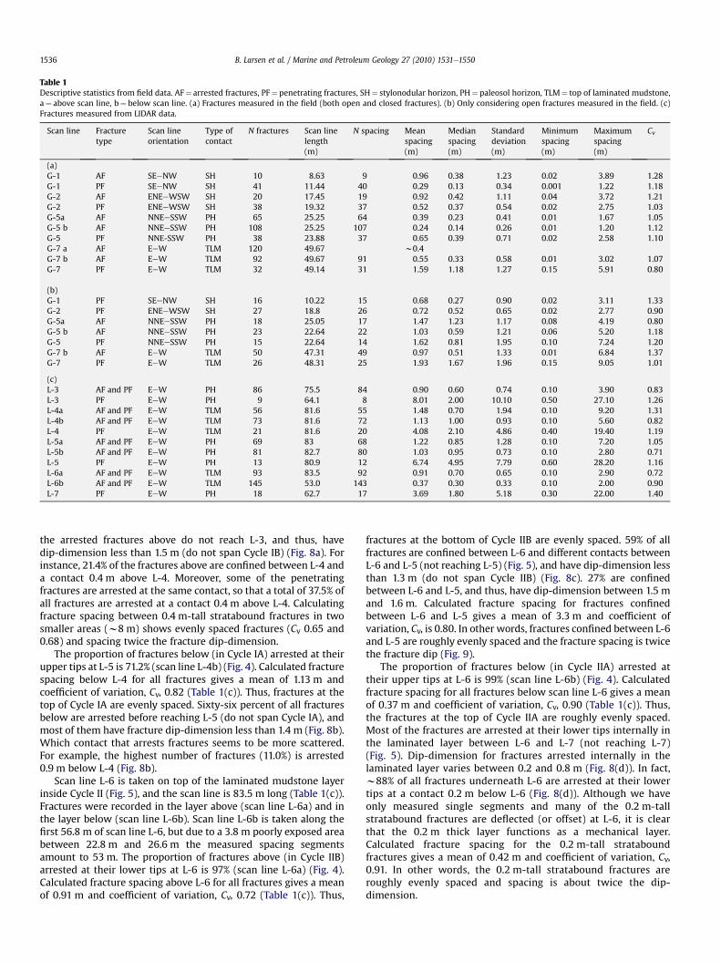
Table 1Descriptive statistics from field data. AF¼ arrested fractures, PF¼ penetrating fractures, SH¼ stylonodular horizon, PH¼ paleosol horizon, TLM¼ top of laminated mudstone,a¼ above scan line, b¼ below scan line. (a) Fractures measured in the field (both open and closed fractures). (b) Only considering open fractures measured in the field. (c)Fractures measured from LIDAR data.
Scan line Fracturetype
Scan lineorientation
Type ofcontact
N fractures Scan linelength(m)
N spacing Meanspacing(m)
Medianspacing(m)
Standarddeviation(m)
Minimumspacing(m)
Maximumspacing(m)
Cv
(a)G-1 AF SEeNW SH 10 8.63 9 0.96 0.38 1.23 0.02 3.89 1.28G-1 PF SEeNW SH 41 11.44 40 0.29 0.13 0.34 0.001 1.22 1.18G-2 AF ENEeWSW SH 20 17.45 19 0.92 0.42 1.11 0.04 3.72 1.21G-2 PF ENEeWSW SH 38 19.32 37 0.52 0.37 0.54 0.02 2.75 1.03G-5a AF NNEeSSW PH 65 25.25 64 0.39 0.23 0.41 0.01 1.67 1.05G-5 b AF NNEeSSW PH 108 25.25 107 0.24 0.14 0.26 0.01 1.20 1.12G-5 PF NNE-SSW PH 38 23.88 37 0.65 0.39 0.71 0.02 2.58 1.10G-7 a AF EeW TLM 120 49.67 w0.4G-7 b AF EeW TLM 92 49.67 91 0.55 0.33 0.58 0.01 3.02 1.07G-7 PF EeW TLM 32 49.14 31 1.59 1.18 1.27 0.15 5.91 0.80
(b)G-1 PF SEeNW SH 16 10.22 15 0.68 0.27 0.90 0.02 3.11 1.33G-2 PF ENEeWSW SH 27 18.8 26 0.72 0.52 0.65 0.02 2.77 0.90G-5a AF NNEeSSW PH 18 25.05 17 1.47 1.23 1.17 0.08 4.19 0.80G-5 b AF NNEeSSW PH 23 22.64 22 1.03 0.59 1.21 0.06 5.20 1.18G-5 PF NNEeSSW PH 15 22.64 14 1.62 0.81 1.95 0.10 7.24 1.20G-7 b AF EeW TLM 50 47.31 49 0.97 0.51 1.33 0.01 6.84 1.37G-7 PF EeW TLM 26 48.31 25 1.93 1.67 1.96 0.15 9.05 1.01
(c)L-3 AF and PF EeW PH 86 75.5 84 0.90 0.60 0.74 0.10 3.90 0.83L-3 PF EeW PH 9 64.1 8 8.01 2.00 10.10 0.50 27.10 1.26L-4a AF and PF EeW TLM 56 81.6 55 1.48 0.70 1.94 0.10 9.20 1.31L-4b AF and PF EeW TLM 73 81.6 72 1.13 1.00 0.93 0.10 5.60 0.82L-4 PF EeW TLM 21 81.6 20 4.08 2.10 4.86 0.40 19.40 1.19L-5a AF and PF EeW PH 69 83 68 1.22 0.85 1.28 0.10 7.20 1.05L-5b AF and PF EeW PH 81 82.7 80 1.03 0.95 0.73 0.10 2.80 0.71L-5 PF EeW PH 13 80.9 12 6.74 4.95 7.79 0.60 28.20 1.16L-6a AF and PF EeW TLM 93 83.5 92 0.91 0.70 0.65 0.10 2.90 0.72L-6b AF and PF EeW TLM 145 53.0 143 0.37 0.30 0.33 0.10 2.00 0.90L-7 PF EeW PH 18 62.7 17 3.69 1.80 5.18 0.30 22.00 1.40
B. Larsen et al. / Marine and Petroleum Geology 27 (2010) 1531e15501536
the arrested fractures above do not reach L-3, and thus, havedip-dimension less than 1.5 m (do not span Cycle IB) (Fig. 8a). Forinstance, 21.4% of the fractures above are confined between L-4 anda contact 0.4 m above L-4. Moreover, some of the penetratingfractures are arrested at the same contact, so that a total of 37.5% ofall fractures are arrested at a contact 0.4 m above L-4. Calculatingfracture spacing between 0.4 m-tall stratabound fractures in twosmaller areas (w8 m) shows evenly spaced fractures (Cv 0.65 and0.68) and spacing twice the fracture dip-dimension.
The proportion of fractures below (in Cycle IA) arrested at theirupper tips at L-5 is 71.2% (scan line L-4b) (Fig. 4). Calculated fracturespacing below L-4 for all fractures gives a mean of 1.13 m andcoefficient of variation, Cv, 0.82 (Table 1(c)). Thus, fractures at thetop of Cycle IA are evenly spaced. Sixty-six percent of all fracturesbelow are arrested before reaching L-5 (do not span Cycle IA), andmost of them have fracture dip-dimension less than 1.4 m (Fig. 8b).Which contact that arrests fractures seems to be more scattered.For example, the highest number of fractures (11.0%) is arrested0.9 m below L-4 (Fig. 8b).
Scan line L-6 is taken on top of the laminated mudstone layerinside Cycle II (Fig. 5), and the scan line is 83.5 m long (Table 1(c)).Fractures were recorded in the layer above (scan line L-6a) and inthe layer below (scan line L-6b). Scan line L-6b is taken along thefirst 56.8 m of scan line L-6, but due to a 3.8 m poorly exposed areabetween 22.8 m and 26.6 m the measured spacing segmentsamount to 53 m. The proportion of fractures above (in Cycle IIB)arrested at their lower tips at L-6 is 97% (scan line L-6a) (Fig. 4).Calculated fracture spacing above L-6 for all fractures gives a meanof 0.91 m and coefficient of variation, Cv, 0.72 (Table 1(c)). Thus,
fractures at the bottom of Cycle IIB are evenly spaced. 59% of allfractures are confined between L-6 and different contacts betweenL-6 and L-5 (not reaching L-5) (Fig. 5), and have dip-dimension lessthan 1.3 m (do not span Cycle IIB) (Fig. 8c). 27% are confinedbetween L-6 and L-5, and thus, have dip-dimension between 1.5 mand 1.6 m. Calculated fracture spacing for fractures confinedbetween L-6 and L-5 gives a mean of 3.3 m and coefficient ofvariation, Cv, is 0.80. In other words, fractures confined between L-6and L-5 are roughly evenly spaced and the fracture spacing is twicethe fracture dip (Fig. 9).
The proportion of fractures below (in Cycle IIA) arrested attheir upper tips at L-6 is 99% (scan line L-6b) (Fig. 4). Calculatedfracture spacing for all fractures below scan line L-6 gives a meanof 0.37 m and coefficient of variation, Cv, 0.90 (Table 1(c)). Thus,the fractures at the top of Cycle IIA are roughly evenly spaced.Most of the fractures are arrested at their lower tips internally inthe laminated layer between L-6 and L-7 (not reaching L-7)(Fig. 5). Dip-dimension for fractures arrested internally in thelaminated layer varies between 0.2 and 0.8 m (Fig. 8(d)). In fact,w88% of all fractures underneath L-6 are arrested at their lowertips at a contact 0.2 m below L-6 (Fig. 8(d)). Although we haveonly measured single segments and many of the 0.2 m-tallstratabound fractures are deflected (or offset) at L-6, it is clearthat the 0.2 m thick layer functions as a mechanical layer.Calculated fracture spacing for the 0.2 m-tall strataboundfractures gives a mean of 0.42 m and coefficient of variation, Cv,0.91. In other words, the 0.2 m-tall stratabound fractures areroughly evenly spaced and spacing is about twice the dip-dimension.
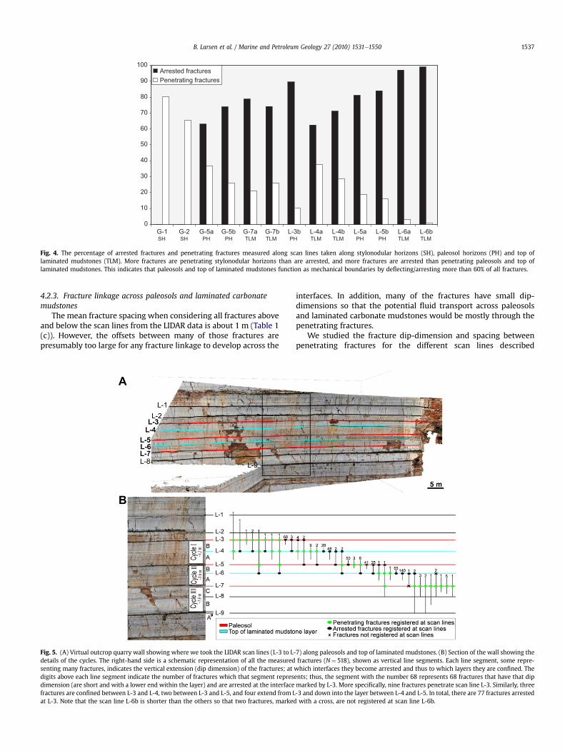
Fig. 4. The percentage of arrested fractures and penetrating fractures measured along scan lines taken along stylonodular horizons (SH), paleosol horizons (PH) and top oflaminated mudstones (TLM). More fractures are penetrating stylonodular horizons than are arrested, and more fractures are arrested than penetrating paleosols and top oflaminated mudstones. This indicates that paleosols and top of laminated mudstones function as mechanical boundaries by deflecting/arresting more than 60% of all fractures.
B. Larsen et al. / Marine and Petroleum Geology 27 (2010) 1531e1550 1537
4.2.3. Fracture linkage across paleosols and laminated carbonatemudstones
The mean fracture spacing when considering all fractures aboveand below the scan lines from the LIDAR data is about 1 m (Table 1(c)). However, the offsets between many of those fractures arepresumably too large for any fracture linkage to develop across the
Fig. 5. (A) Virtual outcrop quarry wall showing where we took the LIDAR scan lines (L-3 to L-details of the cycles. The right-hand side is a schematic representation of all the measuredsenting many fractures, indicates the vertical extension (dip dimension) of the fractures; atdigits above each line segment indicate the number of fractures which that segment represdimension (are short and with a lower end within the layer) and are arrested at the interfacefractures are confined between L-3 and L-4, two between L-3 and L-5, and four extend from Lat L-3. Note that the scan line L-6b is shorter than the others so that two fractures, marked
interfaces. In addition, many of the fractures have small dip-dimensions so that the potential fluid transport across paleosolsand laminated carbonate mudstones would be mostly through thepenetrating fractures.
We studied the fracture dip-dimension and spacing betweenpenetrating fractures for the different scan lines described
7) along paleosols and top of laminated mudstones. (B) Section of the wall showing thefractures (N¼ 518), shown as vertical line segments. Each line segment, some repre-
which interfaces they become arrested and thus to which layers they are confined. Theents; thus, the segment with the number 68 represents 68 fractures that have that dipmarked by L-3. More specifically, nine fractures penetrate scan line L-3. Similarly, three-3 and down into the layer between L-4 and L-5. In total, there are 77 fractures arrestedwith a cross, are not registered at scan line L-6b.
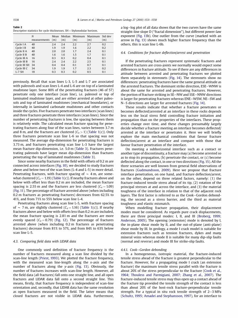
Table 2Descriptive statistics for cycle thicknesses. SH¼ Stylonodular horizon.
Nmeasurements
Mean(m)
Median(m)
Minimum(m)
Maximum(m)
Std dev(m)
Cycle I A 40 2.4 2.4 2.2 2.7 0.2Cycle I B 40 1.9 1.9 1.6 2.2 0.2Cycle II A 40 2.0 2.0 1.7 2.4 0.1Cycle II B 40 1.6 1.6 1.5 1.7 0.1Cycle III A 16 0.3 0.3 0.2 0.4 0.1Cycle III B 16 2.4 2.4 2.2 2.5 0.1Cycle III SH 34 0.4 0.4 0.1 0.7 0.1Cycle III C 34 1.9 1.9 1.7 2.3 0.2L-7 SH 18 0.3 0.3 0.2 0.5 0.1
B. Larsen et al. / Marine and Petroleum Geology 27 (2010) 1531e15501538
previously. Recall that scan lines L-3, L-5 and L-7 are associatedwith paleosols and scan lines L-4 and L-6 are on top of a laminatedmudstone layer. Some 80% of the penetrating fractures (46 of 57)penetrate only one interface (scan line), i.e. paleosol or top oflaminated mudstone layer, and are either arrested at other paleo-sols and top of laminated mudstones (mechanical boundaries), orinternally in laminated carbonate mudstones and other contactsinside the cycles. Five fractures penetrate two interfaces (scan lines)and three fractures penetrate three interfaces (scan lines). Since thenumber of penetrating fractures is low, the spacing between themis relatively wide. The calculated mean fracture spacing for pene-trating fractures along four of the scan lines, varies between 3.7 mand 8 m, and the fractures are clustered (Cv> 1) (Table 1(c)). Onlythree fractures penetrate scan line L-6 so that spacing was notmeasured. The average dip-dimension for penetrating fractures is3.73 m, and fractures penetrating scan line L-3 have the largestmean fracture dip-dimension, i.e. 5.0 m (Table 3). Fractures pene-trating paleosols have larger mean dip-dimension than fracturespenetrating the top of laminated mudstones (Table 3).
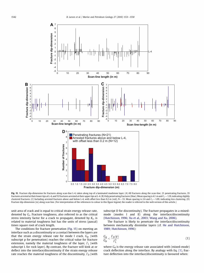
Since some nearby fractures in the field with offsets of 0.2 m areconnected across interfaces (Fig. 10), we decided to study fracturesabove and below two of the scan lines (L-4 and L-5) in more detail.Penetrating fractures, with fracture spacing of w 4 m, are some-what clustered (Cv¼ 1.19) (Table 1(c)). If nearby fractures above andbelow with offset less than 0.2 m are included, the mean fracturespacing is 2.55 m and the fractures are less clustered (Cv¼ 1.09)(Fig. 11). The percentage of fracture arrested above (when including0.2 m fractures as penetrating fractures) decreases from 62.5% to41%, and from 71% to 55% below scan line L-4.
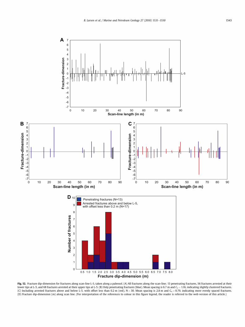
Penetrating fractures along scan line L-5, with fracture spacingof w 7 m, are slightly clustered (Cv¼ 1.16) (Table 1(c)). If nearbyfractures above and belowwith offsets less than 0.2 m are included,the mean fracture spacing is 2.81 m and the fractures are moreevenly spaced (Cv¼ 0.79) (Fig. 12). The percentage of fracturesarrested above (when including 0.2 m fractures as penetratingfractures) decrease from 81% to 57%, and from 84% to 63% belowscan line L-5.
4.3. Comparing field data with LIDAR data
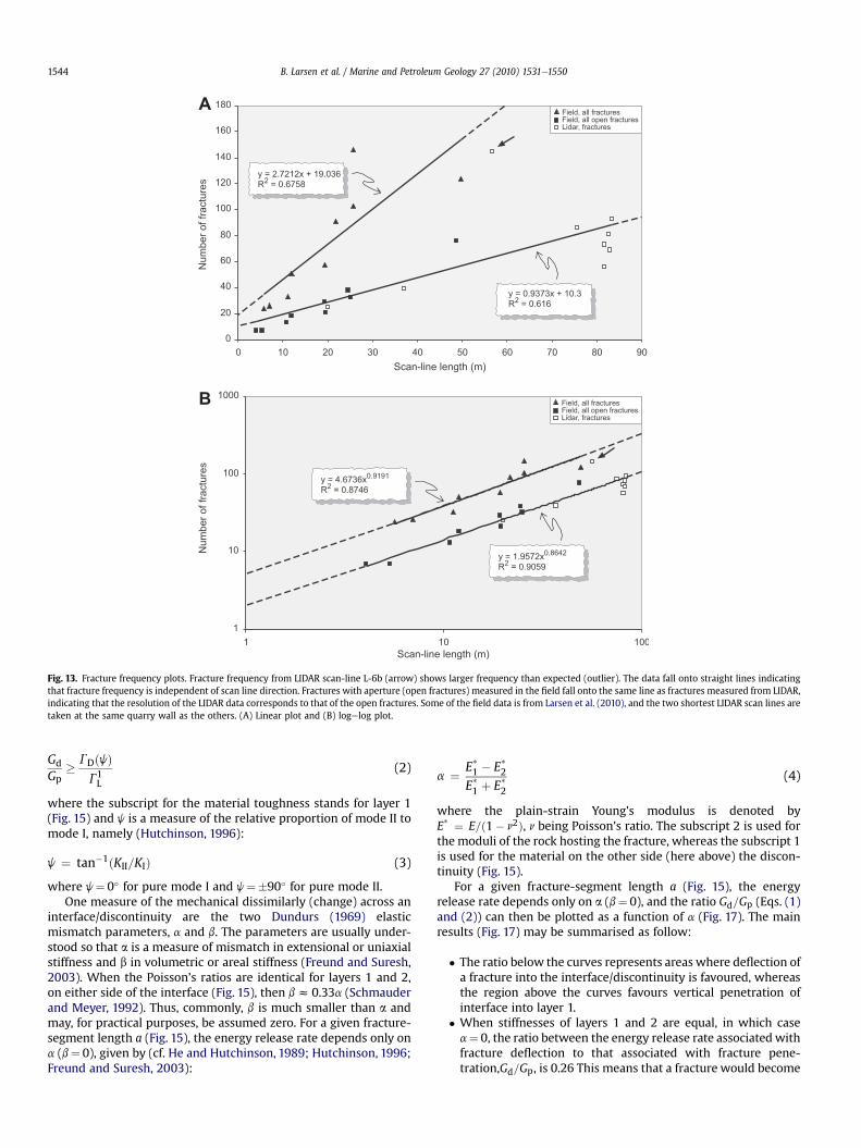
One commonly used definition of fracture frequency is thenumber of fractures measured along a scan line divided by thescan-line length (Priest, 1993). We plotted the fracture frequency,with the measured scan line-length along the x-axis and thenumber of fractures along the y-axis (Fig. 13). Obviously, thenumber of fractures increases with scan-line length. However, allthe field data (all fractures) fall onto one straight line, and all openfractures and LIDAR data fall onto a second straight line. Thismeans, firstly, that fracture frequency is independent of scan-lineorientation and, secondly, that LIDAR data has the same resolutionas open fractures measured in the field. The latter means thatclosed fractures are not visible in LIDAR data. Furthermore,
a logelog plot of all data shows that the two curves have the samestraight-line slope D (“fractal dimension”), but different power-lawexponent (Fig. 13b). One outlier from the curve (marked with anarrow in Fig. 13) shows much higher fracture frequency than theothers, this is scan line L-6b.
4.4. Conditions for fracture deflection/arrest and penetration
If the penetrating fractures represent systematic fractures andarrested fractures are cross-joints we normally would expect somedifferences in fracture attitude. To see if there are any differences inattitude between arrested and penetrating fractures we plottedthem separately in stereonets (Fig. 14). The stereonets show nodifferences: penetrating fractures have the same general attitude asthe arrested fractures. The dominant strike direction, ESEeWNW isabout the same for arrested and penetrating fractures. However,the portion of fracture striking in SEeNWand SSEeNNWdirectionsis larger for penetrating fractures whereas ENEeWSW, NEeSWandNeS directions are larger for arrested fractures (Fig. 14).
These results indicate that whether a fracture penetrates orbecomes deflected/arrested at an interface in these rocks dependsless on the local stress field controlling fracture initiation andpropagation than on the properties of the interfaces. These prop-erties change over time, and these changes presumably largelydecide whether a fracture meeting an interface becomes deflected/arrested at the interface or penetrates it. Here we will brieflyexplore the main mechanical conditions that favour fracturedeflection/arrest at an interface and compare with those thatfavour fracture penetration of the interface.
On meeting a subhorizontal interface such as a contact oranother type of discontinuity, a fracturemay (a) become arrested soas to stop its propagation, (b) penetrate the contact, or (c) becomedeflected along the contact, in one or two directions (Fig.15). All thethree scenarios are well known from general field observations offractures (Gudmundsson, 2009). Here we propose that fractureinterface penetration, on one hand, and fracture deflection/arrest,on the other, depend on three related factors, namely: (1) thefracture-induced tensile stress ahead of its tip, (2) rotation of theprincipal stresses at and across the interface, and (3) the materialtoughness of the interface in relation to that of the adjacent rocklayers. The first factor is referred to as the CookeGordon debond-ing, the second as a stress barrier, and the third as materialtoughness and elastic mismatch.
When modelling fracture propagation, their displacementmodes must be considered. As regards pure crack displacements,there are three principal modes: I, II, and III (Broberg, 1999;Anderson, 2005). The opening (extension) mode is denoted by I,the in-plane shear mode by II, and the out-of-plane (anti-plane)shear mode by III. In geology, a mode I crack model is suitable forextension fractures such as tension fractures, dykes and manymineral veins whereas mode II is suitable for many dip-slip faults(normal and reverse) and mode III for strike-slip faults.
4.4.1. CookeGordon debondingIn a homogeneous, isotropic material, the fracture-induced
tensile stress ahead of the fracture is greatest perpendicular to thefracture. However, for a propagating mode I crack (an extensionfracture) the maximum tensile stress parallel with the fracture isabout 20% of the stress perpendicular to the fracture (Cook et al.,1964; Thouless and Parmigiani, 2007; Zhang et al., 2007). Thefracture-induced tensile stressmay thus open up a contact ahead ofthe fracture tip provided the tensile strength of the contact is lessthan about 20% of the host-rock fracture-perpendicular tensilestrength. For a typical in situ rock tensile strength of 2e3 MPa(Schultz, 1995; Amadei and Stephansson, 1997), for an interface to
A
B
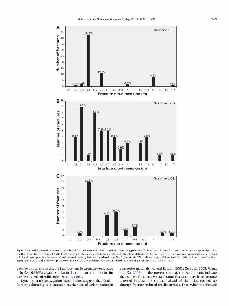
C
Fig. 6. Fracture dip-dimension (m) versus number of fractures measured along scan lines taken along paleosols. (A) Scan line L-3. Only fractures arrested at their upper tips at L-3and their lower tips between L-3 and L-4 (not reaching L-4) are considered here, N¼ 68 (constitute 79% of all fractures). (B) Scan line L-5a. Only fractures arrested at their lower tipsat L-5 and their upper tips between L-5 and L-4 (not reaching L-4) are considered here, N¼ 50 (constitute 72% of all fractures). (C) Scan line L-5b. Only fractures arrested at theirupper tips at L-5 and their lower tips between L-5 and L-6 (not reaching L-6) are considered here, N¼ 41 (constitute 51% of all fractures).
B. Larsen et al. / Marine and Petroleum Geology 27 (2010) 1531e1550 1539
open by this tensile stress, the interface tensile strengthwould haveto be 0.4e0.6 MPa, a value similar to the common minimum in situtensile strength of solid rocks (Schultz, 1995).
Dynamic crack-propagation experiments suggest that CookeGordon debonding is a common mechanism of delamination in
composite materials (Xu and Rosakis, 2003; Xu et al., 2003; Wangand Xu, 2006). In the present context, the experiments indicatethat some of the many stratabound fractures may have becomearrested because the contacts ahead of their tips opened upthrough fracture-induced tensile stresses. Thus, when the fracture
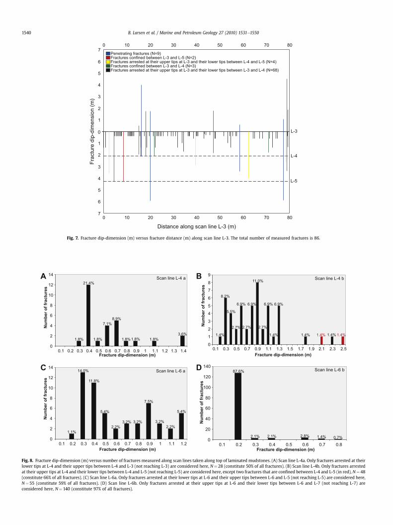
Fig. 7. Fracture dip-dimension (m) versus fracture distance (m) along scan line L-3. The total number of measured fractures is 86.
A B
C D
Fig. 8. Fracture dip-dimension (m) versus number of fractures measured along scan lines taken along top of laminated mudstones. (A) Scan line L-4a. Only fractures arrested at theirlower tips at L-4 and their upper tips between L-4 and L-3 (not reaching L-3) are considered here, N¼ 28 (constitute 50% of all fractures). (B) Scan line L-4b. Only fractures arrestedat their upper tips at L-4 and their lower tips between L-4 and L-5 (not reaching L-5) are considered here, except two fractures that are confined between L-4 and L-5 (in red), N¼ 48(constitute 66% of all fractures). (C) Scan line L-6a. Only fractures arrested at their lower tips at L-6 and their upper tips between L-6 and L-5 (not reaching L-5) are considered here,N¼ 55 (constitute 59% of all fractures). (D) Scan line L-6b. Only fractures arrested at their upper tips at L-6 and their lower tips between L-6 and L-7 (not reaching L-7) areconsidered here, N¼ 140 (constitute 97% of all fractures).
B. Larsen et al. / Marine and Petroleum Geology 27 (2010) 1531e15501540
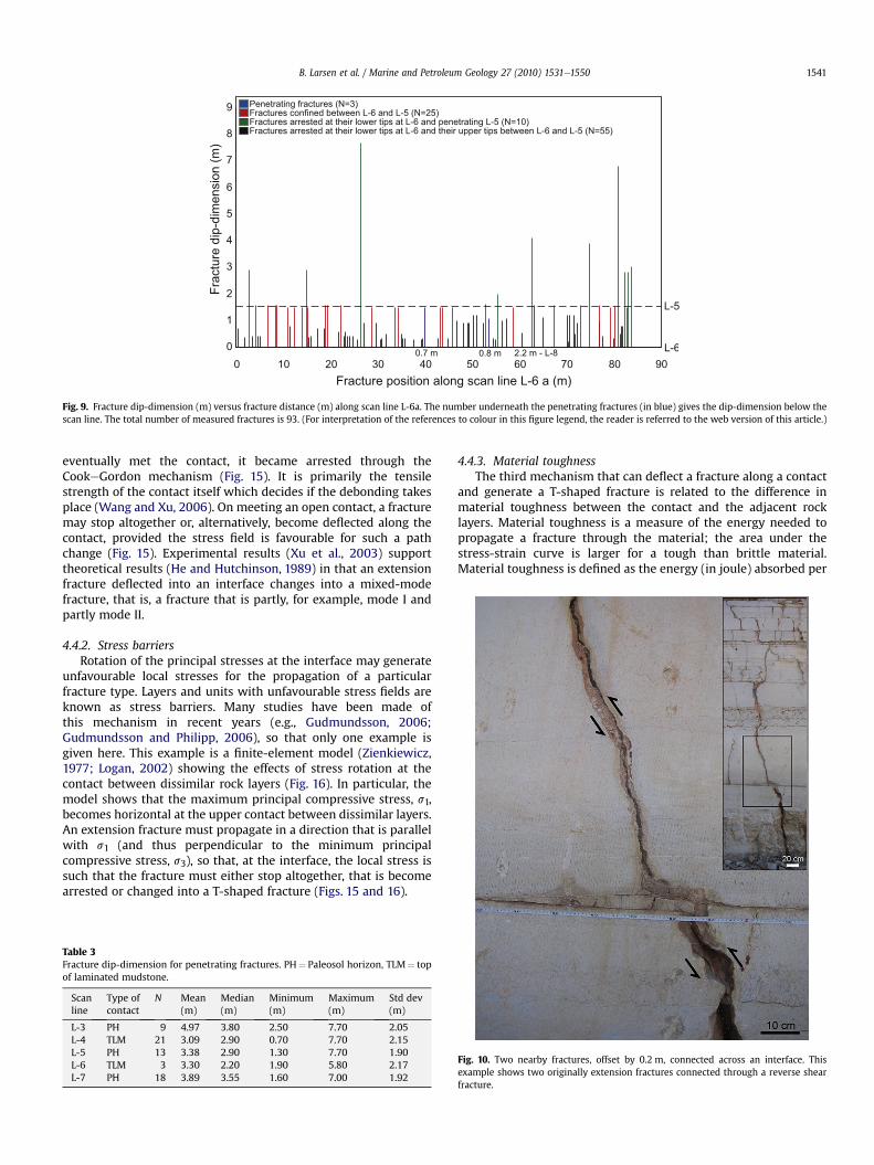
Fig. 9. Fracture dip-dimension (m) versus fracture distance (m) along scan line L-6a. The number underneath the penetrating fractures (in blue) gives the dip-dimension below thescan line. The total number of measured fractures is 93. (For interpretation of the references to colour in this figure legend, the reader is referred to the web version of this article.)
B. Larsen et al. / Marine and Petroleum Geology 27 (2010) 1531e1550 1541
eventually met the contact, it became arrested through theCookeGordon mechanism (Fig. 15). It is primarily the tensilestrength of the contact itself which decides if the debonding takesplace (Wang and Xu, 2006). On meeting an open contact, a fracturemay stop altogether or, alternatively, become deflected along thecontact, provided the stress field is favourable for such a pathchange (Fig. 15). Experimental results (Xu et al., 2003) supporttheoretical results (He and Hutchinson, 1989) in that an extensionfracture deflected into an interface changes into a mixed-modefracture, that is, a fracture that is partly, for example, mode I andpartly mode II.
4.4.2. Stress barriersRotation of the principal stresses at the interface may generate
unfavourable local stresses for the propagation of a particularfracture type. Layers and units with unfavourable stress fields areknown as stress barriers. Many studies have been made ofthis mechanism in recent years (e.g., Gudmundsson, 2006;Gudmundsson and Philipp, 2006), so that only one example isgiven here. This example is a finite-element model (Zienkiewicz,1977; Logan, 2002) showing the effects of stress rotation at thecontact between dissimilar rock layers (Fig. 16). In particular, themodel shows that the maximum principal compressive stress, s1,becomes horizontal at the upper contact between dissimilar layers.An extension fracture must propagate in a direction that is parallelwith s1 (and thus perpendicular to the minimum principalcompressive stress, s3), so that, at the interface, the local stress issuch that the fracture must either stop altogether, that is becomearrested or changed into a T-shaped fracture (Figs. 15 and 16).
Table 3Fracture dip-dimension for penetrating fractures. PH¼ Paleosol horizon, TLM¼ topof laminated mudstone.
Scanline
Type ofcontact
N Mean(m)
Median(m)
Minimum(m)
Maximum(m)
Std dev(m)
L-3 PH 9 4.97 3.80 2.50 7.70 2.05L-4 TLM 21 3.09 2.90 0.70 7.70 2.15L-5 PH 13 3.38 2.90 1.30 7.70 1.90L-6 TLM 3 3.30 2.20 1.90 5.80 2.17L-7 PH 18 3.89 3.55 1.60 7.00 1.92
4.4.3. Material toughnessThe third mechanism that can deflect a fracture along a contact
and generate a T-shaped fracture is related to the difference inmaterial toughness between the contact and the adjacent rocklayers. Material toughness is a measure of the energy needed topropagate a fracture through the material; the area under thestress-strain curve is larger for a tough than brittle material.Material toughness is defined as the energy (in joule) absorbed per
Fig. 10. Two nearby fractures, offset by 0.2 m, connected across an interface. Thisexample shows two originally extension fractures connected through a reverse shearfracture.
A
B C
D
Fig. 11. Fracture dip-dimension for fractures along scan-line L-4, taken along top of a laminated mudstone layer. (A) All fractures along the scan-line; 21 penetrating fractures, 35fractures arrestedat their lower tips at L-4, and52 fractures arrested at their upper tips at L-4. (B)Onlypenetrating fractures (blue).Mean spacing is 4.1 mandCv¼ 1.19, indicating slightlyclustered fractures. (C) Including arrested fractures above and below L-4, with offset less than 0.2 m (red), N¼ 33. Mean spacing is 2.6 and Cv¼ 1.09, indicating less clustering. (D)Fracture dip-dimension (m) along scan line. (For interpretation of the references to colour in this figure legend, the reader is referred to the web version of this article.)
B. Larsen et al. / Marine and Petroleum Geology 27 (2010) 1531e15501542
unit area of crack and is equal to critical strain energy release rate,denoted by Gc. Fracture toughness, also referred to as the criticalstress intensity factor for a crack to propagate, denoted by Kc, isrelated to material toughness but has the units of stress (pascal)times square root of crack length.
The conditions for fracture penetration (Fig. 15) on meeting aninterface such as a discontinuity or a contact between the layers arethat the strain energy release rate for mode I crack, Gp, (withsubscript p for penetration) reaches the critical value for fractureextension, namely the material toughness of the layer, GL (withsubscript L for rock layer). By contrast, the fracture will kink at ordeflect into the interface/discontinuity if the strain energy releaserate reaches the material toughness of the discontinuity, GD (with
subscript D for discontinuity). The fracture propagates in a mixed-mode (modes I and II) along the interface/discontinuity(Hutchinson, 1996; Xu et al., 2003; Wang and Xu, 2006).
The fracture is likely to penetrate the interface/discontinuitybetween mechanically dissimilar layers (cf. He and Hutchinson,1989; Hutchinson, 1996):
GdGp
<GDðjÞG1L
(1)
where Gd is the energy release rate associated with (mixed-mode)crack deflection along the interface. By analogy with Eq. (1), frac-ture deflection into the interface/discontinuity is favoured when:
A
B C
D
Fig. 12. Fracture dip-dimension for fractures along scan-line L-5, taken along a paleosol. (A) All fractures along the scan-line; 13 penetrating fractures, 56 fractures arrested at theirlower tips at L-5, and 68 fractures arrested at their upper tips at L-5. (B) Only penetrating fractures (blue). Mean spacing is 6.7 m and Cv¼ 1.16, indicating slightly clustered fractures.(C) Including arrested fractures above and below L-5, with offset less than 0.2 m (red), N¼ 30. Mean spacing is 2.8 m and Cv¼ 0.79, indicating more evenly spaced fractures.(D) Fracture dip-dimension (m) along scan line. (For interpretation of the references to colour in this figure legend, the reader is referred to the web version of this article.)
B. Larsen et al. / Marine and Petroleum Geology 27 (2010) 1531e1550 1543
A
B
Fig. 13. Fracture frequency plots. Fracture frequency from LIDAR scan-line L-6b (arrow) shows larger frequency than expected (outlier). The data fall onto straight lines indicatingthat fracture frequency is independent of scan line direction. Fractures with aperture (open fractures) measured in the field fall onto the same line as fractures measured from LIDAR,indicating that the resolution of the LIDAR data corresponds to that of the open fractures. Some of the field data is from Larsen et al. (2010), and the two shortest LIDAR scan lines aretaken at the same quarry wall as the others. (A) Linear plot and (B) logelog plot.
B. Larsen et al. / Marine and Petroleum Geology 27 (2010) 1531e15501544
GdGp
� GDðjÞG1L
(2)
where the subscript for the material toughness stands for layer 1(Fig. 15) and j is a measure of the relative proportion of mode II tomode I, namely (Hutchinson, 1996):
j ¼ tan�1ðKII=KIÞ (3)
where j¼ 0� for pure mode I and j¼�90� for pure mode II.One measure of the mechanical dissimilarly (change) across an
interface/discontinuity are the two Dundurs (1969) elasticmismatch parameters, a and b. The parameters are usually under-stood so that a is a measure of mismatch in extensional or uniaxialstiffness and b in volumetric or areal stiffness (Freund and Suresh,2003). When the Poisson’s ratios are identical for layers 1 and 2,on either side of the interface (Fig. 15), then bz 0.33a (Schmauderand Meyer, 1992). Thus, commonly, b is much smaller than a andmay, for practical purposes, be assumed zero. For a given fracture-segment length a (Fig. 15), the energy release rate depends only ona (b¼ 0), given by (cf. He and Hutchinson, 1989; Hutchinson, 1996;Freund and Suresh, 2003):
a ¼ E*1 � E*2E*1 þ E*2
(4)
where the plain-strain Young’s modulus is denoted byE* ¼ E=ð1� n2Þ, n being Poisson’s ratio. The subscript 2 is used forthe moduli of the rock hosting the fracture, whereas the subscript 1is used for the material on the other side (here above) the discon-tinuity (Fig. 15).
For a given fracture-segment length a (Fig. 15), the energyrelease rate depends only on a (b¼ 0), and the ratio Gd=Gp (Eqs. (1)and (2)) can then be plotted as a function of a (Fig. 17). The mainresults (Fig. 17) may be summarised as follow:
� The ratio below the curves represents areas where deflection ofa fracture into the interface/discontinuity is favoured, whereasthe region above the curves favours vertical penetration ofinterface into layer 1.
� When stiffnesses of layers 1 and 2 are equal, in which casea¼ 0, the ratio between the energy release rate associatedwithfracture deflection to that associated with fracture pene-tration,Gd=Gp, is 0.26 This means that a fracture would become

Fig. 14. Stereonets showing fractures measured from scan lines in the field. Black squares are arrested fractures and white squares are penetrating fractures. G-1 and G-2 are takenalong stylonodular horizons, G-5 is taken along a paleosol, and G-7 is taken along top of a laminated mudstone layer. The histogram shows the strike directions given as proportionof arrested and penetrating fractures. The dominant strike direction, ESEeWNW is about the same for arrested and penetrating fractures.
B. Larsen et al. / Marine and Petroleum Geology 27 (2010) 1531e1550 1545
deflected along the interface/discontinuity only if the materialtoughness of the interface (GD) was less than 26% of thematerial toughness of layer 1 ðG1
L Þ above the interface.� The curves for the formation of a single-directed and a double-directed deflection along the interface/discontinuity (Fig. 15) arevery similar formost values of a. Thus, for practical purposes, thetendency for a fracture to form a single or double-directeddeflection along an interface may be regarded as the same.
� When a is negative, that is, the stiffness of layer 1 is less thanthat of layer 2, there is generally much less tendency fordeflection of a fracture into the interface than when a is posi-tive. As the positive value of a increase, so that layer 1 becomesstiffer in relation to layer 2 (Eq. (4)), there is a greatly increasedtendency for a fracture to deflect into the interface. Thisconclusion is supported by many experiments on fracturepropagation and arrest at contacts between dissimilar layers(Kim et al., 2006), and in geological analogue experiments(Kavanagh et al., 2006; Menand, 2008). When the deflection is
not possible because of the orientation of the principal stresses(Fig. 16), fracture propagating from a soft towards a stiff layerwould tend to become arrested at the contact.
5. Discussion
In this paper we discuss the effects of key sedimentary inter-faces, such as paleosols and laminated carbonate mudstones, onfracture pattern, linkage, and cluster formation in shallow-watercarbonate rocks.We focus on the statistical aspects of the field data,but also discuss the mechanical aspects of fracture penetration ofand deflection into interfaces. Part of the study is on fracturebehaviour at stylonodular horizons. In particular, we pay attentionto the fracture connectivity. The Lower Cretaceous rocks exposed inwestern Gargano provide an excellent example of peritidal metre-scaled cycles where key sedimentary interfaces are prominent(Figs. 2 and 5). Additionally, the exposed rocks are recrystallisedand cemented, thereby resulting in low intrinsic porosity and
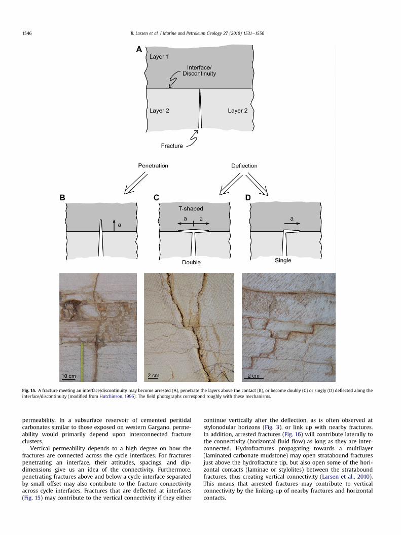
Fig. 15. A fracture meeting an interface/discontinuity may become arrested (A), penetrate the layers above the contact (B), or become doubly (C) or singly (D) deflected along theinterface/discontinuity (modified from Hutchinson, 1996). The field photographs correspond roughly with these mechanisms.
B. Larsen et al. / Marine and Petroleum Geology 27 (2010) 1531e15501546
permeability. In a subsurface reservoir of cemented peritidalcarbonates similar to those exposed on western Gargano, perme-ability would primarily depend upon interconnected fractureclusters.
Vertical permeability depends to a high degree on how thefractures are connected across the cycle interfaces. For fracturespenetrating an interface, their attitudes, spacings, and dip-dimensions give us an idea of the connectivity. Furthermore,penetrating fractures above and below a cycle interface separatedby small offset may also contribute to the fracture connectivityacross cycle interfaces. Fractures that are deflected at interfaces(Fig. 15) may contribute to the vertical connectivity if they either
continue vertically after the deflection, as is often observed atstylonodular horizons (Fig. 3), or link up with nearby fractures.In addition, arrested fractures (Fig. 16) will contribute laterally tothe connectivity (horizontal fluid flow) as long as they are inter-connected. Hydrofractures propagating towards a multilayer(laminated carbonate mudstone) may open stratabound fracturesjust above the hydrofracture tip, but also open some of the hori-zontal contacts (laminae or stylolites) between the strataboundfractures, thus creating vertical connectivity (Larsen et al., 2010).This means that arrested fractures may contribute to verticalconnectivity by the linking-up of nearby fractures and horizontalcontacts.
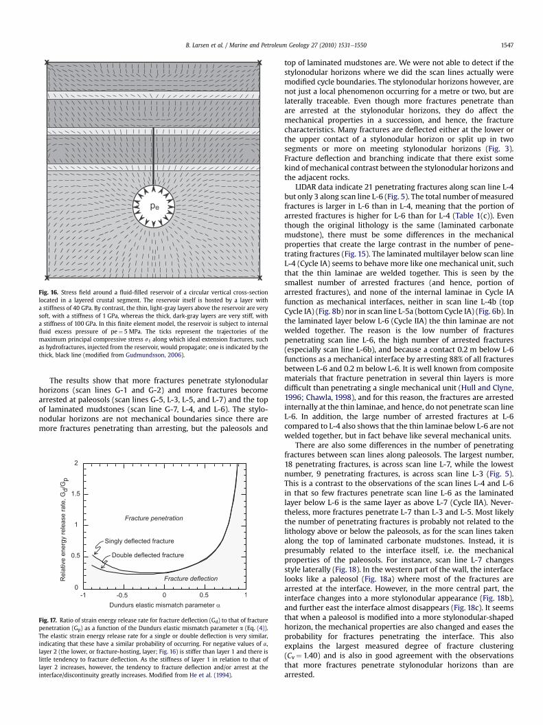
Fig. 16. Stress field around a fluid-filled reservoir of a circular vertical cross-sectionlocated in a layered crustal segment. The reservoir itself is hosted by a layer witha stiffness of 40 GPa. By contrast, the thin, light-gray layers above the reservoir are verysoft, with a stiffness of 1 GPa, whereas the thick, dark-gray layers are very stiff, witha stiffness of 100 GPa. In this finite element model, the reservoir is subject to internalfluid excess pressure of pe¼ 5 MPa. The ticks represent the trajectories of themaximum principal compressive stress s1 along which ideal extension fractures, suchas hydrofractures, injected from the reservoir, would propagate; one is indicated by thethick, black line (modified from Gudmundsson, 2006).
B. Larsen et al. / Marine and Petroleum Geology 27 (2010) 1531e1550 1547
The results show that more fractures penetrate stylonodularhorizons (scan lines G-1 and G-2) and more fractures becomearrested at paleosols (scan lines G-5, L-3, L-5, and L-7) and the topof laminated mudstones (scan line G-7, L-4, and L-6). The stylo-nodular horizons are not mechanical boundaries since there aremore fractures penetrating than arresting, but the paleosols and
Fig. 17. Ratio of strain energy release rate for fracture deflection (Gd) to that of fracturepenetration (Gp) as a function of the Dundurs elastic mismatch parameter a (Eq. (4)).The elastic strain energy release rate for a single or double deflection is very similar,indicating that these have a similar probability of occurring. For negative values of a,layer 2 (the lower, or fracture-hosting, layer; Fig. 16) is stiffer than layer 1 and there islittle tendency to fracture deflection. As the stiffness of layer 1 in relation to that oflayer 2 increases, however, the tendency to fracture deflection and/or arrest at theinterface/discontinuity greatly increases. Modified from He et al. (1994).
top of laminated mudstones are. We were not able to detect if thestylonodular horizons where we did the scan lines actually weremodified cycle boundaries. The stylonodular horizons however, arenot just a local phenomenon occurring for a metre or two, but arelaterally traceable. Even though more fractures penetrate thanare arrested at the stylonodular horizons, they do affect themechanical properties in a succession, and hence, the fracturecharacteristics. Many fractures are deflected either at the lower orthe upper contact of a stylonodular horizon or split up in twosegments or more on meeting stylonodular horizons (Fig. 3).Fracture deflection and branching indicate that there exist somekind of mechanical contrast between the stylonodular horizons andthe adjacent rocks.
LIDAR data indicate 21 penetrating fractures along scan line L-4but only 3 along scan line L-6 (Fig. 5). The total number of measuredfractures is larger in L-6 than in L-4, meaning that the portion ofarrested fractures is higher for L-6 than for L-4 (Table 1(c)). Eventhough the original lithology is the same (laminated carbonatemudstone), there must be some differences in the mechanicalproperties that create the large contrast in the number of pene-trating fractures (Fig. 15). The laminated multilayer below scan lineL-4 (Cycle IA) seems to behave more like one mechanical unit, suchthat the thin laminae are welded together. This is seen by thesmallest number of arrested fractures (and hence, portion ofarrested fractures), and none of the internal laminae in Cycle IAfunction as mechanical interfaces, neither in scan line L-4b (topCycle IA) (Fig. 8b) nor in scan line L-5a (bottom Cycle IA) (Fig. 6b). Inthe laminated layer below L-6 (Cycle IIA) the thin laminae are notwelded together. The reason is the low number of fracturespenetrating scan line L-6, the high number of arrested fractures(especially scan line L-6b), and because a contact 0.2 m below L-6functions as a mechanical interface by arresting 88% of all fracturesbetween L-6 and 0.2 m below L-6. It is well known from compositematerials that fracture penetration in several thin layers is moredifficult than penetrating a single mechanical unit (Hull and Clyne,1996; Chawla, 1998), and for this reason, the fractures are arrestedinternally at the thin laminae, and hence, do not penetrate scan lineL-6. In addition, the large number of arrested fractures at L-6compared to L-4 also shows that the thin laminae below L-6 are notwelded together, but in fact behave like several mechanical units.
There are also some differences in the number of penetratingfractures between scan lines along paleosols. The largest number,18 penetrating fractures, is across scan line L-7, while the lowestnumber, 9 penetrating fractures, is across scan line L-3 (Fig. 5).This is a contrast to the observations of the scan lines L-4 and L-6in that so few fractures penetrate scan line L-6 as the laminatedlayer below L-6 is the same layer as above L-7 (Cycle IIA). Never-theless, more fractures penetrate L-7 than L-3 and L-5. Most likelythe number of penetrating fractures is probably not related to thelithology above or below the paleosols, as for the scan lines takenalong the top of laminated carbonate mudstones. Instead, it ispresumably related to the interface itself, i.e. the mechanicalproperties of the paleosols. For instance, scan line L-7 changesstyle laterally (Fig. 18). In the western part of the wall, the interfacelooks like a paleosol (Fig. 18a) where most of the fractures arearrested at the interface. However, in the more central part, theinterface changes into a more stylonodular appearance (Fig. 18b),and further east the interface almost disappears (Fig. 18c). It seemsthat when a paleosol is modified into a more stylonodular-shapedhorizon, the mechanical properties are also changed and eases theprobability for fractures penetrating the interface. This alsoexplains the largest measured degree of fracture clustering(Cv¼ 1.40) and is also in good agreement with the observationsthat more fractures penetrate stylonodular horizons than arearrested.
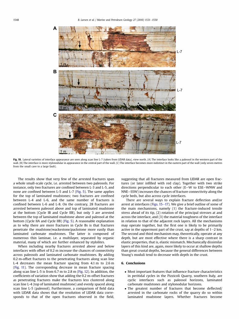
Fig. 18. Lateral varieties of interface appearance are seen along scan line L-7 (taken from LIDAR data), view north. (A) The interface looks like a paleosol in the western part of thewall. (B) The interface is more stylonodular in appearance in the central part of the wall. (C) The interface becomes more indistinct in the eastern part of the wall (only seven metresfrom the small cave to a large fault).
B. Larsen et al. / Marine and Petroleum Geology 27 (2010) 1531e15501548
The results show that very few of the arrested fractures spana whole small-scale cycle, i.e. arrested between two paleosols. Forinstance, only two fractures are confined between L-3 and L-5, andnone are confined between L-5 and L-7 (Fig. 5). The same appliesfor the top of laminated mudstones; two fractures are confinedbetween L-4 and L-6, and the same number of fractures isconfined between L-6 and L-8. On the contrary, 28 fractures arearrested between paleosol above and top of laminated mudstoneat the bottom (Cycle IB and Cycle IIB), but only 3 are arrestedbetween the top of laminated mudstone above and paleosol at thebottom (Cycle IIA and Cycle IIB) (Fig. 5). A reasonable explanationas to why there are more fractures in Cycle Bs is that fracturespenetrate the mudstone/wackestone/packstone more easily thanlaminated carbonate mudstones. The latter is composed ofnumerous thin laminae, i.e. a multilayer, separated by organicmaterial, many of which are further enhanced by stylolites.
When including nearby fractures arrested above and belowinterfaces with offset of 0.2 m increase the chances of connectivityacross paleosols and laminated carbonate mudstones. By adding0.2 m-offset fractures to the penetrating fractures along scan lineL-4 decreases the mean fracture spacing from 4.1 m to 2.6 m(Fig. 11). The corresponding decrease in mean fracture spacingalong scan line L-5 is from 6.7 m to 2.8 m (Fig. 12). In addition, thecoefficients of variation show that adding the 0.2 m-offset fracturesas penetrating fractures make the fractures less clustered alongscan line L-4 (top of laminated mudstone) and evenly spaced alongscan line L-5 (paleosol). Furthermore, a comparison of field datawith LIDAR data shows that the resolution of LIDAR data corre-sponds to that of the open fractures observed in the field,
suggesting that all fractures measured from LIDAR are open frac-tures (or later infilled with red clay). Together with two strikedirections perpendicular to each other (EeW to ESEeWNW andNNEeSSW) increases the chances of fracture connectivity along thecycle beds, but also across cycle interfaces.
There are several ways to explain fracture deflection and/orarrest at interfaces (Figs. 15e17). We give a brief outline of some ofthe main mechanisms, namely (1) the fracture-induced tensilestress ahead of its tip, (2) rotation of the principal stresses at andacross the interface, and (3) the material toughness of the interfacein relation to that of the adjacent rock layers. All the mechanismsmay operate together, but the first one is likely to be primarilyactive in the uppermost part of the crust, say at depths of 1e2 km.The second and third mechanism may, theoretically, operate at anydepth, but are most effective where there is a sharp contrast inelastic properties, that is, elastic mismatch. Mechanically dissimilarlayers of this kind are, again, more likely to occur at shallow depthsthan great crustal depths, because the general differences betweenYoung’s moduli tend to decrease with depth in the crust.
6. Conclusions
� Most important features that influence fracture characteristicsin peritidal cycles in the Pizzicoli Quarry, southern Italy, arecyclic interfaces such as paleosol horizons, laminatedcarbonate mudstones and stylonodular horizons.
� The greatest number of fractures that become deflected/arrested in the carbonate rocks of the quarry do so withinlaminated mudstone layers. Whether fractures become
B. Larsen et al. / Marine and Petroleum Geology 27 (2010) 1531e1550 1549
deflected/arrested within the mudstones, or penetrate them,however, depends much on whether or not the mudstones arewelded, and timing of welding.
� More specifically, in the laminated carbonate mudstones manyfractures are deflected/arrested at the internal thin laminae sothat very few fractures are confined between the top and thebottom of the laminatedmudstone, together with few fracturespenetrating the boundaries of the laminated carbonatemudstones.
� Cycle interfaces such as paleosols are mechanical boundariesthat arrest/deflect more than 60% of all fractures. Nevertheless,there are fractures penetrating paleosols, and including frac-tures above and below paleosols with small offset decrease themean fracture spacing by more than half and the fracturescrossing paleosols are evenly spaced.
� More specifically, this means that potential fluid flow acrosspaleosols will not only be restricted to certain parts along thepaleosols (clustered fractures), but may happen along the totalpaleosol (evenly spaced fractures).
� Stylonodular horizons do affect the mechanical properties ina succession by deflecting and split fractures
� The main mechanisms of fracture deflection and/or arrest are(1) the fracture-induced tensile stress ahead of its tip, referredto as the Cook-Gordon debonding mechanism; (2) rotation ofthe principal stresses at and across the interface, resulting inthe formation of stress barriers; and (3) large elastic mismatch(particularly as regards Young’s moduli) between layers acrossan interface. All these mechanisms are likely to have operatedduring fracture propagation and arrest in the carbonate rocksof the Pizzicoli Quarry in southern Italy.
Acknowledgements
This work was supported by the Norwegian Research CouncilPetromaks project no. 163316/S30 “Carbonate Reservoir Geo-models”. We thank Niels Bo-Jensen, Peter Gutteridge, Luigi Spallutoand other members of the Carbonate Research Group for fruitfuldiscussions and support, Peppino Pizzicoli for giving permission towork in his quarry and Julia F.W. Gale and an anonymous reviewerfor very helpful comments.
References
Aguilera, R., 1995. Naturally Fractured Reservoirs. PennWell Books, Tulsa, Okla, 521 pp.Ahr, W.M., 2008. Geology of Carbonate Reservoirs: The Identification, Description
and Characterization of Hydrocarbon Reservoirs in Carbonate Rocks. Wiley,New Jersey, 278 pp.
Amadei, B., Stephansson, O., 1997. Rock Stress and Its Measurement. Chapman &Hall, London, 490 pp.
Anderson, T.L., 2005. Fracture Mechanics: Fundamentals and Applications.Chapman & Hall, London, 621 pp.
Bertotti, G., Picotti, V., Chilovi, C., Fantoni, R., Merlini, S., Mosconi, A., 2001. Neogeneto Quaternary sedimentary basins in the south Adriatic (Central Mediterra-nean): foredeeps and lithospheric buckling. Tectonics 20, 771e787.
Billi, A., 2003. Solution slip and separations on strike-slip fault zones: theory andapplication to the Mattinata Fault, Italy. Journal of Structural Geology 25,703e715.
Billi, A., Gambini, R., Nicolai, C., Storti, F., 2007. Neogene-Quaternary intraforelandtranspression along a Mesozoic platform-basin margin: the Gargano faultsystem, Adria, Italy. Geosphere 3, 1e15.
Bosellini, A., Neri, C., Luciani, V., 1993. Platform margin collapses and sequencestratigraphic organization of carbonate slopes: CretaceouseEocene, GarganoPromontory, Southern Italy. Terra Nova 5, 282e297.
Bosellini, A., Morsilli, M., Neri, C., 1999. Long-term event stratigraphy of the ApuliaPlatform margin (Upper Jurassic to Eocene, Gargano, southern Italy). Journal ofSedimentary Research 69, 1241e1252.
Bosence, D.W.J., Wilson, R.C.L., 2003. Carbonates. In: Coe, A.L. (Ed.), The SedimentaryRecord of Sea-level Change. Cambridge University Press, Cambridge, pp. 209e274.
Brankman, C.M., Aydin, A., 2004. Uplift and contractional deformation alonga segmented strike-slip fault system: the Gargano Promontory, southern Italy.Journal of Structural Geology 26, 807e824.
Broberg, K.B., 1999. Cracks and Fracture. Academic Press, New York, 752 pp.Buckley, S.J., Howell, J.A., Enge, H.D., Kurz, T.H., 2008. Terrestrial laser scanning in
geology: data acquisition, processing and accuracy considerations. Journal ofthe Geological Society 165, 625e638.
Butt, H.J., Graf, K., Kappl, M., 2006. Physics and Chemistry of Interfaces. Wiley,Weinheim (Germany), 386 pp.
Chawla, K.K., 1998. Composite Materials: Science and Engineering. Springer,New York, 483 pp.
Cook, J., Gordon, J.E., Evans, C.C., Marsh, D.M., 1964. A mechanism for the control ofcrack propagation in all-brittle systems. Proceedings of the Royal Society ofLondon. Series A. Mathematical and Physical Sciences 282, 508e520.
Cox, D.R., Lewis, P.A.W., 1966. The Statistical Analysis of Series of Events. Chapmanand Hall, London, 285 pp.
Dundurs, J., 1969. Edge-bonded dissimilar orthogonal wedges. Journal of AppliedMechanics 36, 650e652.
Eyssautier-Chuine, S., Odonne, F., Massonnat, G., 2002. Control of bioclast abun-dance on natural joint density in carbonate rocks: data from Oman, Provenceand Languedoc (France). Terra Nova 14, 198e204.
Freund, L.B., Suresh, S., 2003. Thin Film Materials: Stress, Defect Formation andSurface Evolution. Cambridge University Press, Cambridge, 750 pp.
Gale, J.F.W., Laubach, S.E., Marrett, R.A., Olson, J.E., Holder, J., Reed, R.M., 2004.Predicting and characterizing fractures in dolostone reservoirs: using the linkbetween diagenesis and fracturing. In: Braithwaite, C.J.R., Rizzi, G., Darke, G.(Eds.), The Geometry and Petrogenesis of Dolomite Hydrocarbon Reservoirs.Geological Society of London, Special Publication, vol. 235, pp. 177e192.
Gillespie, P.A., Johnston, J.D., Loriga, M.A., McCaffrey, K.J.W., Walsh, J.J., Watterson, J.,1999. Influenceof layeringonvein systematics in line samples. In:McCaffrey, K.J.W.,Lonergan, L., Wilkinson, J.J. (Eds.), Fractures, Fluid Flow and Mineralization.Geological Society of London, Special Publication, vol. 155, pp. 35e56. London,United Kingdom.
Gillespie, P.A., Walsh, J.J., Watterson, J., Bonson, C.G., Manzocchi, T., 2001. Scalingrelationships of joint and vein arrays from The Burren, Co. Clare, Ireland. Journalof Structural Geology 23, 183e201.
Graham, B., Antonellini, M., Aydin, A., 2003. Formation and growth of normal faultsin carbonates within a compressive environment. Geology (Boulder) 31, 11e14.
Gudmundsson, A., 2006. How local stresses control magma-chamber ruptures, dykeinjections, and eruptions in composite volcanoes. Earth-Science Reviews 79,1e31.
Gudmundsson, A., 2009. Toughness and failure of volcanic edifices. Tectonophysics471, 27e35.
Gudmundsson, A., Fjeldskaar, I., Brenner, S.L., 2002. Propagation pathways and fluidtransport in jointed and layered rocks in geothermal fields. Journal of Volca-nology and Geothermal Research 116, 257e278.
Gudmundsson, A., Philipp, S.L., 2006. How local stress fields prevent volcaniceruptions. Journal of Volcanology and Geothermal Research 158, 257e268.
He, M.Y., Hutchinson, J.W., 1989. Crack deflection at an interface between dissimilarelastic materials. International Journal of Solids and Structures 25, 1053e1067.
He, M.Y., Evans, A.G., Hutchinson, J.W., 1994. Crack deflection, at an interfacebetween dissimilar elastic materials: role of residual stresses. InternationalJournal of Solids and Structures 31, 3443e3455.
Helgesen, D.E., Aydin, A., 1991. Characteristics of joint propagation across layerinterfaces in sedimentary rocks. Journal of Structural Geology 13, 897e911.
Hull, D., Clyne, T.W., 1996. An Introduction to Composite Materials. CambridgeUniversity Press, Cambridge, 326 pp.
Hutchinson, J.W., 1996. Stresses and Failure Modes in Thin Films and Multilayers.Notes for a Dcamm Course. Technical University of Denmark, Lyngbø, pp. 1e45.
Kavanagh, J.L., Menand, T., Sparks, R.S.J., 2006. An experimental investigation of sillformation and propagation in layered elastic media. Earth and PlanetaryScience Letters 245, 799e813.
Kim, J.-W., Bhowmick, S., Hermann, I., Lawn, B.R., 2006. Transverse fracture of brittlebilayers: relevance to failure of all-ceramic dental crowns. Journal of BiomedicalMaterials Research Part B: Applied Biomaterials 79B, 58e65.
Larsen, B., Grunnaleite, I., Gudmundsson, A., 2010. How fracture systems affectpermeability development in shallow-water carbonate rocks: an example fromthe Gargano Peninsula, Italy. Journal of Structural Geology, in press, doi:10.1016/j.jsg.2009.05.009.
Logan, D.L., 2002. A First Course in the Finite Element method. Brooks/Cole, PacificGrove, US, 696 pp.
Lonergan, L., Jolly, R.J.H., Rawnsley, K., Sanderson, D.J., 2007. Fractured Reservoirs.Geological Society of London, London, 285 pp.
Lucia, F.J., 1999. Carbonate Reservoir Characterization. Springer Verlag, Berlin, 226 pp.Menand, T., 2008. The mechanics and dynamics of sills in layered elastic rocks and
their implications for the growth of laccoliths and other igneous complexes.Earth and Planetary Science Letters 267, 93e99.
Narr, W., Suppe, J., 1991. Joint spacing in sedimentary rocks. Journal of StructuralGeology 13, 1037e1048.
Nelson, R.A., 2001. Geologic Analysis of Naturally Fractured Reservoirs.Gulf Professional Publications, Boston, 332 pp.
Odling, N.E., Gillespie, P., Bourgine, B., Castaing, C., Chiles, J.P., Christensen, N.P.,Fillion, E., Genter, A., Olsen, C., Thrane, L., Trice, R., Aarseth, E., Walsh, J.J.,Watterson, J., 1999. Variations in fracture system geometry and their implica-tions for fluid flow in fractured hydrocarbon reservoirs. Petroleum Geoscience5, 373e384.
Ortega, O.J., Marrett, R., Laubach, S.E., 2006. A scale-independent approach tofracture intensity and average fracture spacing. AAPG Bulletin 90, 193e208.
B. Larsen et al. / Marine and Petroleum Geology 27 (2010) 1531e15501550
Patacca, E., Scandone, P., 2004. The 1627 Gargano earthquake (Southern Italy):identification and characterization of the causative fault. Journal of Seismology8, 259e273.
Pieri, P., Festa, V., Moretti, M., Tropeano, M., 1997. Quaternary tectonic activity of theMurge area (Apulian foreland -Southern Italy). Annali Di Geofisica 40,1395e1404.
Priest, S.D., 1993. Discontinuity Analysis for Rock Engineering. Chapman & Hall.473pp.
Rijken, P., Cooke, M.L., 2001. Role of shale thickness on vertical connectivity offractures: application of crack-bridging theory to the Austin Chalk, Texas.Tectonophysics 337, 117e133.
Salvini, F., Billi, A., Wise, D.U., 1999. Strike-slip fault-propagation cleavage incarbonate rocks: the Mattinata Fault Zone, Southern Apennines, Italy. Journal ofStructural Geology 21, 1731e1749.
Schmauder, S., Meyer, M., 1992. Correlation between Dundurs’ parameters andelastic constants. Zeitschrift für Metallkunde 83, 524e527.
Schultz, R.A., 1995. Limits on strength and deformation properties of jointed basalticrock masses. Rock Mechanics and Rock Engineering 28, 1e15.
Sella, M., Turci, C., Riva, A., 1988. Sintesi geopetrolifera della Fossa bradanica.Memoirs of the Geological Society of Italy 41, 87e108.
Spalluto, L., 2004. The Gargano Promontory: Geological Framework, Stratigraphy ofMesozoic Carbonate Units and Tectonic Setting. Unpublished Ph.D. thesis,Universita’ Degli Studi di Bari.
Spalluto, L., 2008. Sedimentology and high-resolution sequence stratigraphy oflower Cretaceous shallow-water carbonate succession from the WesternGargano Promontory (Apulia, Southern Italy). GeoActa, 77e96.
Stowell, J.F.W., 2001. Characterization of opening-mode fracture systems in theAustin chalk. Gulf Coast Association of Geological Societies Transactions 51,313e319.
Thouless, M.D., Parmigiani, J.P., 2007. Mixed-mode cohesive-zone models fordelamination and deflection in composites. In: Sørensen, B.F., Mikkelson, L.P.,
Lilhot, H.S.G., Abdul-Mahdi, F.S. (Eds.), Proceedings of the 28th Risø Interna-tional Symposium on Material Science: Interface Design of Polymer matrixComposites, Roskilde (Denmark), pp. 93e111.
Tucker, M.E., Wright, P., 1990. Carbonate Sedimentology. Blackwell Science, Oxford,482 pp.
Underwood, C.A., Cooke, M.L., Simo, J.A., Muldoon, M.A., 2003. Stratigraphiccontrols on vertical fracture patterns in Silurian dolomite, northeasternWisconsin. AAPG Bulletin 87, 121e142.
Walker, P.M.B., 1993. Chambers Materials Science and Technology Dictionary.Chambers, Edinburgh, 352 pp.
Wang, P., Xu, L.R., 2006. Dynamic interfacial debonding initiation induced byan incident crack. International Journal of Solids and Structures 43,6535e6550.
Wennberg, O.P., Svana, T., Azizzadeh, M., Aqrawi, A.M.M., Brockbank, P., Lyslo, K.B.,Ogilvie, S., 2006. Fracture intensity vs. mechanical stratigraphy in platform topcarbonates: the Aquitanian of the Asmari Formation, Khaviz Anticline, Zagros,SW Iran. Petroleum Geoscience 12, 235e245.
Xu, L.R., Rosakis, A.J., 2003. An experimental study of impact-induced failure eventsin homogeneous layered materials using dynamic photoelasticity and high-speed photography. Optics and Lasers in Engineering 40, 263e288.
Xu, L.R., Huang, Y.Y., Rosakis, A.J., 2003. Dynamic crack deflection and penetra-tion at interfaces in homogeneous materials: experimental studies andmodel predictions. Journal of the Mechanics and Physics of Solids 51,461e486.
Zhang, X., Sanderson, D.J., 2002. Numerical Modelling and Analysis of Fluid Flowand Deformation of Fractured Rock Masses. Pergamon, London, 288 pp.
Zhang, X., Jeffrey, R.G., Thiercelin, M., 2007. Deflection and propagation of fluid-driven fractures at frictional bedding interfaces: a numerical investigation.Journal of Structural Geology 29, 396e410.
Zienkiewicz, O.C., 1977. The Finite Element Method. McGraw-Hill, New York,787 pp.