 2](https://static.fdokumen.com/doc/165x107/6333ca3928cb31ef600d6bc8/two-temperature-independent-spinomers-of-the-dinuclear-mniii-compound-mnh-2.jpg)
Effect of water vapour content in H 2 –H 2 O–CO–CO 2 mixtures on activity of iron oxide in...
11
Effect of water vapour content in H 2 –H 2 O–CO– CO 2 mixtures on activity of iron oxide in slags relevant to novel flash ironmaking technology M. Yousef Mohassab-Ahmed* and H. Y. Sohn As an integral part of developing a novel flash ironmaking technology at the University of Utah, the activity of iron oxide in the slag was studied under three different gas atmospheres: H 2 /H 2 O (H 2 ), CO/CO 2 /H 2 /H 2 O (reformed natural/coal gas), and CO/CO 2 . The conditions of the slags investigated were MgO-saturated CaO–FeO–Al 2 O 3 –SiO 2 –MnO (0?2–0?8 wt-%)–P 2 O 5 (0?1–0?9 wt-%) in the temperature range 1550–1600uC with wt-% CaO/wt-% SiO 2 of 0?8 to 1?2, and under pO 2 52610 210 –2610 29 atm. Water increased the activity coefficient of FeO in the slag and accordingly lowered the FeO content. The average FeO content was found to be 10, 11 and 16 wt- % under H 2 /H 2 O (H 2 ), CO/CO 2 /H 2 /H 2 O (reformed natural/coal gas), and CO/CO 2 , respectively. An empirical correlation for c FeO in slags under H 2 /H 2 O atmospheres was formulated to give log c FeO 523?0623 X FeO 23?1421 X CaO 22?5068 X MgO z2?1957 Keywords: Green ironmaking, Flash process, Slag, Iron oxide Introduction Iron oxide plays an important role in metal–slag reactions including those involved in sulphur and phosphorus distribution. In addition, FeO in the slag is considered as a loss in ironmaking and steelmaking processes. Moreover, FeO content in the slag affects its viscosity, corrosivity, and redox potential of the slag. 1 Thus, FeO activity (a FeO ) in slag and the related thermodynamics attracted the attention of many researchers. 2–6 The present work is an integral part of a research project that aims to develop a novel green ironmaking process based on the direct gaseous reduc- tion of iron oxide fine concentrate in a flash process. The ultimate goal of this new process is to significantly reduce CO 2 emissions, energy consumption, and envir- onmental pollution in the steel industry. 7 Hydrogen, natural gas and coal gas are the proposed reducing agents in that new process. To date, only a few studies have been performed to measure FeO activities under gas atmospheres containing H 2 O and H 2 . 8–10 Thus, as part of the development of this new green ironmaking project, there was a need to investigate thoroughly the behaviour of FeO in H 2 /H 2 O and CO/CO 2 /H 2 /H 2 O atmospheres, corresponding to an oxygen partial pressure (pO 2 ) range of 10 210 –10 29 atm. In addition, the activity of FeO under CO/CO 2 was investigated for comparison. The major slag components were CaO, MgO, SiO 2 , Al 2 O 3 and FeO. The FeO activity coefficient was studied in the temperature range 1550–1650uC encompassing the expected operating temperatures in the proposed process. There are two main methods to determine FeO activity. The first method is the thermodynamic relation- ships and EMF (electromotive force) measurements. In this method, FeO activity is measured using an oxygen sensor and thermodynamic relationship between Fe (l) – FeO (slag) expressed as follows 11 Fe (l) z 1 2 O 2(g) ~FeO (l) , DG 0 FeO ~{225 460z41:26 T (J mol {1 ) (1) Using the EMF reading from an oxygen sensor, the equilibrium pO 2 can be calculated by the Nernst equation. 12 This technique was adopted by Liu et al., 12,13 Ogura et al., 14 Iwase et al., 15 and Hamm et al. 16 The second method is the thermodynamic equilibrium technique with chemical analysis. This technique is the most common one used to measure a FeO in which the slag sample is equilibrated with liquid iron or solid iron at a fixed temperature and under a stable atmosphere. In this technique, different principles could be employed to calculate the FeO or Fe t O activity in the slags. These principles are listed as follows. Slag–metal equilibrium technique This technique is based on the following reactions Fe (l) z O~FeO (slag) (2) Department of Metallurgical Engineering, University of Utah, Salt Lake City, UT, USA *Corresponding author, email [email protected] ß 2014 Institute of Materials, Minerals and Mining Published by Maney on behalf of the Institute Received 12 November 2013; accepted 9 January 2014 DOI 10.1179/1743281214Y.0000000180 Ironmaking and Steelmaking 2014 VOL 41 NO 9 665
Transcript of Effect of water vapour content in H 2 –H 2 O–CO–CO 2 mixtures on activity of iron oxide in...
Effect of water vapour content in H2–H2O–CO–CO2 mixtures on activity of iron oxide in slagsrelevant to novel flash ironmaking technology
M. Yousef Mohassab-Ahmed* and H. Y. Sohn
As an integral part of developing a novel flash ironmaking technology at the University of Utah, the
activity of iron oxide in the slag was studied under three different gas atmospheres: H2/H2O (H2),
CO/CO2/H2/H2O (reformed natural/coal gas), and CO/CO2. The conditions of the slags investigated
were MgO-saturated CaO–FeO–Al2O3–SiO2–MnO (0?2–0?8 wt-%)–P2O5 (0?1–0?9 wt-%) in the
temperature range 1550–1600uC with wt-% CaO/wt-% SiO2 of 0?8 to 1?2, and under
pO252610210–261029 atm. Water increased the activity coefficient of FeO in the slag and
accordingly lowered the FeO content. The average FeO content was found to be 10, 11 and 16 wt-
% under H2/H2O (H2), CO/CO2/H2/H2O (reformed natural/coal gas), and CO/CO2, respectively. An
empirical correlation for cFeO in slags under H2/H2O atmospheres was formulated to give
log cFeO523?0623 XFeO23?1421 XCaO22?5068 XMgOz2?1957
Keywords: Green ironmaking, Flash process, Slag, Iron oxide
IntroductionIron oxide plays an important role in metal–slagreactions including those involved in sulphur andphosphorus distribution. In addition, FeO in the slagis considered as a loss in ironmaking and steelmakingprocesses. Moreover, FeO content in the slag affects itsviscosity, corrosivity, and redox potential of the slag.1
Thus, FeO activity (aFeO) in slag and the relatedthermodynamics attracted the attention of manyresearchers.2–6 The present work is an integral part ofa research project that aims to develop a novel greenironmaking process based on the direct gaseous reduc-tion of iron oxide fine concentrate in a flash process. Theultimate goal of this new process is to significantlyreduce CO2 emissions, energy consumption, and envir-onmental pollution in the steel industry.7 Hydrogen,natural gas and coal gas are the proposed reducingagents in that new process. To date, only a few studieshave been performed to measure FeO activities undergas atmospheres containing H2O and H2.8–10 Thus, aspart of the development of this new green ironmakingproject, there was a need to investigate thoroughlythe behaviour of FeO in H2/H2O and CO/CO2/H2/H2Oatmospheres, corresponding to an oxygen partial pressure(pO2) range of 10210–1029 atm. In addition, the activityof FeO under CO/CO2 was investigated for comparison.The major slag components were CaO, MgO, SiO2, Al2O3
and FeO. The FeO activity coefficient was studied inthe temperature range 1550–1650uC encompassing theexpected operating temperatures in the proposed process.
There are two main methods to determine FeOactivity. The first method is the thermodynamic relation-ships and EMF (electromotive force) measurements. Inthis method, FeO activity is measured using an oxygensensor and thermodynamic relationship between Fe(l)–FeO(slag) expressed as follows11
Fe(l)z1
2O2(g)~FeO(l),
DG0FeO~{225 460z41:26 T (J mol{1)
(1)
Using the EMF reading from an oxygen sensor, theequilibrium pO2 can be calculated by the Nernstequation.12 This technique was adopted by Liu et al.,12,13
Ogura et al.,14 Iwase et al.,15 and Hamm et al.16
The second method is the thermodynamic equilibriumtechnique with chemical analysis. This technique is themost common one used to measure aFeO in which theslag sample is equilibrated with liquid iron or solid ironat a fixed temperature and under a stable atmosphere. Inthis technique, different principles could be employed tocalculate the FeO or FetO activity in the slags. Theseprinciples are listed as follows.
Slag–metal equilibrium techniqueThis technique is based on the following reactions
Fe(l)zO~FeO(slag) (2)
Department of Metallurgical Engineering, University of Utah, Salt LakeCity, UT, USA
*Corresponding author, email [email protected]
� 2014 Institute of Materials, Minerals and MiningPublished by Maney on behalf of the InstituteReceived 12 November 2013; accepted 9 January 2014DOI 10.1179/1743281214Y.0000000180 Ironmaking and Steelmaking 2014 VOL 41 NO 9 665
Fe(l)zO~FeO(l) (3)
aFeO~(wt-% O)
(wt-% O)o (4)
where aFeO is FeO activity in the slag sample; (wt-%O) isanalysed oxygen content in liquid iron in equilibriumwith molten slag under consideration, equilibrium (2);(wt-% O)o is analysed oxygen content in liquid iron inequilibrium with pure liquid FeO, equilibrium (3).
This technique was adopted by Winkler andChipman17 and Bishop et al.18 The technique wasfurther modified to become more accurate by replacingthe weight per cent oxygen in equation (4) with theactivity (by multiplying both the numerator anddenominator by the corresponding Henrian activitycoefficients). Furthermore, the interaction between otherimpurities and alloying elements was considered.12
Alternatively, molten slags contained in an ironcrucible would be brought into equilibrium under aCO/CO2 or H2/H2O atmosphere. The FeO activity canbe obtained from the expression
aFeO~pO2
pO02
� �1=2
(5)
where pO2 is the equilibrium oxygen partial pressure fora mixture of solid FezFeO in liquid slag; pO0
2 is theequilibrium oxygen partial pressure for a mixture ofsolid Fezpure liquid FeO.
This technique was used by Schuhmann and Ensio.19
This technique requires a relatively complex experimen-tal setup and long duration.15
Gas–slag–metal equilibrium techniqueA different method to calculate the FeO activityconsidering the gas–slag–metal equilibria uses reac-tion (1), for which the equilibrium constant is given by
KFeO~e{DG0
FeORT ~
aFeO
aFe: pO
1=22
~xFeO : cFeO
aFe: pO
1=22
(6)
where xFeO and cFeO are FeO mole fraction andRaultian activity coefficient in the slag. This techniquewas employed in this study. DG0
FeOwas calculated using
HSC 5?11 (Outokumpu Oyj, Riihitontuntie 7, Finland).
Minor elements distribution techniquesAlternatively, FeO activity can be obtained fromsulphide capacity or phosphate capacity.12 Using thefollowing equation from Bell’s work20
LS~fS:CS
: aFe:KFeO
aFeO:KS
(7)
Also, using a relation obtained by Lee and Fruehan,21
FeO activity can be obtained from the phosphorusdistribution and phosphate capacity data.
FeO activity has been studied under different atmo-spheres. Basu et al.,3 Hamm et al.,16 Liu et al.,12,13 Moralesand Fruehan22 and Park and Lee23 used argon atmo-sphere. More commonly, a larger number of research-ers4,24–26 determined FeO activity by controlling pO2
through the CO/CO2 equilibrium. Among the few studiesperformed to determine the free energy of formation ofFeO using H2/H2O mixtures are that of Chipman8 whoused the equilibrium between liquid electrolytic iron andH2/H2O gas mixtures. Also, Chipman and Marshall27
studied the equilibria between solid iron and both liquidand solid wustite (separately) under H2/H2O gas mixtures.To the best of the authors’ knowledge, there were noavailable data on the FeO activity coefficient under H2/H2O gas mixtures in ironmaking slags.
In this study, the following mass concentration ratiowas used as slag basicity index
Basicity~wt-% CaO
wt-% SiO2
(8)
The non-stoichiometry of ferrous oxide observed byDarken and Gurry28 was found to be of negligiblesignificance by Deo and Boom.29 They suggested thatthe free energy of formation of ‘FeO’ and that of FexOmay be considered as the same. Thus, this conventionwas adopted in the present work.
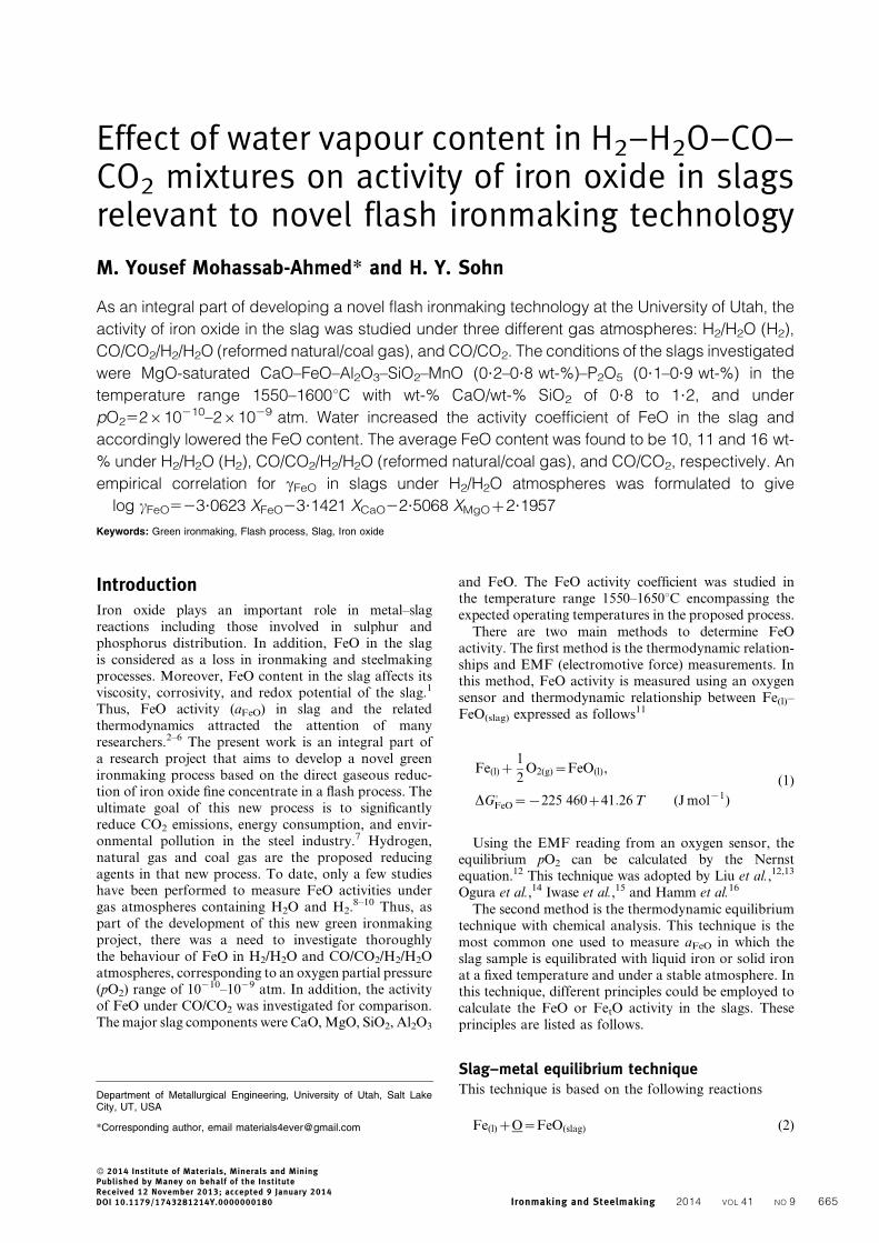
Experimental detailsMixtures of dry powders of SiO2, Al2O3 and MgO werepre-melted at 1600uC for homogeneity. The pre-meltedslag was ground to less than 40 mm particle size andmixed for 36 h in a tumbler mixer (Bioengineering Inc.,Cambridge, MA, USA). This was done to achievehomogeneity of the slag powder and reduce time toreach equilibrium in the subsequent experiments. Thenthe synthetic slag was stored in a desiccator to be used inthe experiments. A horizontal electrical resistant fur-nace, shown in Fig. 1, heated by MoSi2 heating elementswith an alumina reaction tube (8 cm OD, 7 cm ID,120 cm length) was used in the experimental set-up,which was equipped with a water vapour generator
1: fume hood; 2: valve; 3 water cooling jacket; 4 alumina shield; 5 NaOH scrubber; 6 MoSi2 heating elements; 7 aluminasample holder; 8 alumina gutter; 9 heating tape; 10 B-type thermocouple
1 Reactor setup
Mohassab-Ahmed and Sohn Effect of water vapour content on iron oxide in slags
666 Ironmaking and Steelmaking 2014 VOL 41 NO 9

system. Temperature was controlled and monitored insidethe tube by two B-type thermocouples (Pt6%Rh/Pt30%Rh): One was connected to a 708P temperaturecontroller (MTI Corporation, Richmond, CA, USA) withan advanced PID adjustment to control the powersupplied to the heating elements in the furnace to atemperature accuracy of ¡1uC. The other thermocouplemonitored the experimental temperature near the sample,indicating a constant temperature within 0?2–0?5uC. The
gas flowrates were controlled by mass flow controllers(AALBORG, Orangeburg, NY, USA) with an accuracy of¡0?1, ¡2, ¡1?5, ¡1?5 mL min21 for SO2, H2, CO andCO2 gases, respectively. Water was injected as a liquidusing a MASTERFLEX digital peristaltic pump drive(Cole-Parmer Instrument, Vernon Hills, IL, USA), whichprovided flowrates from 0?001 to 3400 mL min21 (using aset of 10 different diameter tubing) with the same brandpump head with an accuracy of ¡0?1% of the flowrate.
Table 1 Chemical analysis of samples under H2/H2O atmosphere
Sample T/uC pO2 CaO/SiO2 FeO/wt-% MgO/wt-% CaO/wt-% Al2O3/wt-% SiO2/wt-% XFeO cFeO aFeO
S5 1550 7.0610210 0.8 21.6 19.2 20.9 8.7 28.3 0.21 2.17 0.45S6 1550 7.0610210 1 19.9 20.2 23.0 8.0 33.0 0.18 2.54 0.45S7 1550 7.0610210 1.2 22.3 15.2 29.8 9.5 26.4 0.21 2.16 0.45S8 1550 7.0610210 1.4 20.7 10.6 32.1 9.4 23.7 0.21 2.15 0.45S9 1550 1.0610210 0.8 11.5 22.4 24.9 8.2 32.3 0.10 1.75 0.17S10 1550 1.0610210 1 12.0 18.7 29.0 9.7 29.9 0.10 1.64 0.17S11 1550 1.0610210 1.2 12.4 17.0 30.9 10.7 29.0 0.11 1.58 0.17S12 1550 1.0610210 1.4 14.2 14.5 34.7 9.8 31.0 0.12 1.41 0.17S13 1550 2.0610210 0.8 12.2 22.5 25.1 9.4 32.6 0.10 2.34 0.24S14 1550 2.0610210 1 12.6 16.9 27.4 8.8 39.7 0.10 2.31 0.24S15 1550 2.0610210 1.2 18.7 15.4 34.7 10.2 16.4 0.18 1.33 0.24S16 1550 2.0610210 1.4 15.3 16.3 32.4 10.4 28.4 0.13 1.80 0.24S17 1600 5.061029 0.8 41.1 15.1 15.8 6.2 19.5 0.49 1.57 0.77S18 1600 5.061029 1 34.6 13.6 20.4 7.4 24.4 0.37 2.06 0.77S19 1600 5.061029 1.2 42.8 11.3 18.1 6.3 17.0 0.54 1.41 0.77S20 1600 5.061029 1.4 52.8 12.4 14.9 4.9 12.2 0.74 1.03 0.77S21 1600 2.061029 0.8 20.4 22.6 20.7 7.6 27.7 0.19 2.60 0.49S21 1600 2.061029 0.8 20.3 22.6 20.7 8.6 27.6 0.18 2.62 0.49S22 1600 2.061029 1 27.1 15.7 22.7 8.2 23.5 0.28 1.73 0.49S22 1600 2.061029 1 27.0 17.6 22.6 8.2 23.2 0.28 1.76 0.49S23 1600 2.061029 1.2 29.7 14.2 26.2 8.8 22.0 0.30 1.62 0.49S23 1600 2.061029 1.2 29.7 14.2 23.7 8.3 22.0 0.32 1.52 0.49S24 1600 2.061029 1.4 31.1 14.7 24.9 7.9 21.7 0.31 1.55 0.49S25 1600 3.0610210 0.8 8.7 25.5 24.3 9.7 36.0 0.07 2.77 0.19S26 1600 3.0610210 1 9.3 21.2 27.1 9.8 31.5 0.08 2.42 0.19S27 1600 3.0610210 1.2 11.8 18.7 29.1 10.1 28.2 0.10 1.84 0.19S28 1600 3.0610210 1.4 13.2 19.4 31.0 9.9 23.9 0.11 1.64 0.19S29 1600 5.0610210 0.8 7.1 23.9 23.9 9.6 31.5 0.06 4.09 0.24S30 1600 5.0610210 1 14.7 20.9 25.5 9.6 28.9 0.13 1.88 0.24S31 1600 5.0610210 1.2 14.9 25.3 25.2 8.9 23.6 0.13 1.90 0.24S37 1650 4.061029 0.8 32.6 20.5 17.8 7.6 23.5 0.34 1.33 0.45S38 1650 4.061029 1 47.5 14.2 13.5 5.5 16.3 0.63 0.72 0.45
Table 2 Calculated gas partial pressures at experimental temperatures and PT50?85 atm* using CO/CO2/H2O/H2 gasmixtures (1 atm5101?3 kPa)
Temperature/uC Partial pressure/atm Sample designation Partial pressure/atm Sample designation
pO2/atm 1550 1.961029 R10–R12 1.6610210 R19–R211600 4.861029 R13–R15 3.6610210 R22–R241630 8.061029 R16–R18 6.1610210 R25–R27
pCO/atm 1550 2.461021 R10–R12 2.761021 R19–R211600 2.461021 R13–R15 2.761021 R22–R241630 2.461021 R16–R18 2.761021 R25–R27
pCO2/atm 1550 4.461022 R10–R12 1.461022 R19–R211600 4.261022 R13–R15 1.461022 R22–R241630 4.261022 R16–R18 1.461022 R25–R27
pH2O/atm 1550 2.461021 R10–R12 1.061021 R19–R211600 2.461021 R13–R15 1.061021 R22–R241630 2.461021 R16–R18 1.061021 R25–R27
pH2/atm 1550 3.361021 R10–R12 4.761021 R19–R211600 3.361021 R13–R15 4.761021 R22–R241630 3.261021 R16–R18 4.761021 R25–R27
Flowrates/mL min21{ H2 90 R10–R18 128 R19–R27H2O 0.054 0.022CO 69 77CO2 13 5
*Atmospheric pressure at Salt Lake City.{Flowrates are calculated at 25uC and 0?85 atm (atmospheric pressure at Salt Lake City).
Mohassab-Ahmed and Sohn Effect of water vapour content on iron oxide in slags
Ironmaking and Steelmaking 2014 VOL 41 NO 9 667
The initial slag composition other than FeO waschosen to be close to that in the blast furnace. Thetemperature and oxygen partial pressure ranges werechosen to be 1550–1650uC and 10210–1029 atm, respec-tively, which were wide enough to encompass theexpected operating temperature of the new processbased on the hydrogen or natural gas reduction of ironore concentrate.
The samples were prepared as 2?5 and 1?0 g of slagmixed with 2?5 and 1?0 g of iron powder, respectively,for experiments under H2/H2O and the comparisonexperiments under the three gas atmospheres. They weremixed well to reduce the time to reach equilibrium inmagnesia crucibles (1?8 cm OD, 4 cm height, 0?25 cmwall thickness) supplied by Ozark Technical Ceramics,Inc. (Webb City, MO, USA). The furnace was heated tothe target temperature under a flow of N2. At the targettemperature, a four-sample alumina holder was placed in
the even temperature zone of the furnace, which wasmeasured accurately prior to the actual experiment bymeasuring the temperature profile inside the tube over itsentire length. Then, N2 was switched to the experimentalgas mixture. From preliminary experiments,30,31 it wasconfirmed that no measurable change in FeO content inthe slag occurred after 4 h. To assure three-phase (gas–slag–metal) equilibria, 10 and 15 h were chosen in thiswork. After equilibrium, the system was purged withultra-high purity N2 for 5 min. The sample holder wasquickly pulled out of the furnace, and the samples werequenched in ice bath or cold water. The crucible itselftogether with the sample was crushed, and iron wasseparated from the slag. Then, the slag was finely ground.
The composition of the slag phase was analysed byinductively coupled plasma optical emission spectroscopy.Prior to the analysis, the samples were digested in closedSavillex microwavable vessels. The chemical analysis results
Table 3 Calculated gas partial pressures at experimental temperatures and PT50?85 atm* using H2/H2O/SO2 gas mixtures
Temperature/uC Partial pressure/atm Sample designation Partial pressure/atm Sample designation
pO2 1550 2.261029 S1–S4 7.0610210 S5–S81600 4.861029 S17–S20 1.861029 S21–S241650 … … 4.261029 S37–S38
pH2 1550 4.7610210 S1–S4 1.261023 S5–S81600 4.161024 S17–S20 1.361023 S21–S241650 4.361024 … 1.361023 S37–S38
pS2 1550 1.461023 S1–S4 1.061023 S5–S81600 1.761023 S17–S20 1.361023 S21–S241650 2.061023 … 1.661023 S37–S38
pH2O 1550 3.661021 S1–S4 2.661021 S5–S81600 3.661021 S17–S20 2.661021 S21–S241650 3.661021 … 2.661021 S37–S38
Flowrates/mL min21{ H2 125 149H2O (liq.) 0.047 0.032
pO2 1550 2.4610210 S13–S16 1.1610210 S9–S121600 5.3610210 S29–S32 2.7610210 S25–S281650 … … … …
pH2 1550 1.361023 S13–S16 1.361023 S9–S121600 1.361023 S29–S32 1.461023 S25–S281650 1.461023 … 1.461023 …
pS2 1550 8.361024 S13–S16 7.361024 S9–S121600 1.061023 S29–S32 9.561024 S25–S281650 1.361023 … 1.261023 …
pH2O 1550 1.761021 S13–S16 1.361021 S9–S121600 1.761021 S29–S32 1.361021 S25–S281650 1.761021 … 1.361021 …
Flowrates/mL min21{ H2 170 181H2O (liq.) 0.018 0.011
*Atmospheric pressure at Salt Lake City.{Flowrates are calculated at 25uC and 0?85 atm (atmospheric pressure at Salt Lake City).
Table 4 Calculated gas partial pressures at experimental temperatures and PT50?85 atm* using CO/CO2 gas mixtures
Temperature/uC Partial pressure/atm Sample designation Partial pressure/atm Sample designation
pO2 1550 3.4961028 R37–R39 1.37610210 R46–R481600 9.3161028 R40–R42 3.67610210 R49–R511630 1.6361027 R43–R45 6.44610210 R52–R54
pCO 1550 4.7861021 R37–R39 8.1061021 R46–R481600 4.7861021 R40–R42 8.1061021 R49–R511630 4.7861021 R43–R45 8.1061021 R52–R54
pCO2 1550 3.7261021 R37–R39 3.9661022 R46–R481600 3.7261021 R40–R42 3.9661022 R49–R511630 3.7261021 R43–R45 3.9661022 R52–R54
Flowrates/mL min21{ CO 103 R37–R45 66 R46–R54CO2 30 7
*Atmospheric pressure at Salt Lake City.{Flowrates are calculated at 25uC and 0?85 atm (atmospheric pressure at Salt Lake City).
Mohassab-Ahmed and Sohn Effect of water vapour content on iron oxide in slags
668 Ironmaking and Steelmaking 2014 VOL 41 NO 9
are listed in Tables 1 and 2, respectively. The equilibriumpartial pressures of gases calculated by HSC 5?11(Outokumpu Oyj, Riihitontuntie 7, Finland) are presentedin Tables 3–5. Reproducibility of the experiments wasconfirmed by the consistency of the results of repeatedexperiments under the same conditions, as well as thereproducibility of the analysis method.30,31 The experimen-tal accuracy was within ¡10%. Other details of theexperimental procedure have been discussed elsewhere.30–32
Results and discussionThe first part of this paper is devoted to the discussion ofthe effects of different slag parameters such as basicity,FeO concentration and MgO on cFeO under H2/H2O,which were calculated using equation (6). In addition,various models to estimate cFeO were evaluated topredict cFeO under an H2/H2O atmosphere. An empiricalformula was developed to correlate cFeO under theexperimental conditions adopted in this work. Thesecond part of this paper compares the effect of gascomposition on cFeO. A separate set of experiments wascarefully carried out under the same conditions butdifferent gas atmospheres (CO/CO2/H2/H2O, CO/CO2
and H2/H2). It is noted that although CO/CO2 mixturesin the similar pO2 range were tested for comparison, thisdoes not closely represent the blast furnace conditions inwhich the 4–5 wt-%C33 in iron in the hearth makes pO2
at the interface between molten iron and the slag much
lower (10215–10214 atm)11,34–36 than the 10210 to 1029 atmrange expected in the new flash ironmaking process. Thus,the FeO content in the blast furnace slag is expected to beaccordingly lower at around 1%.
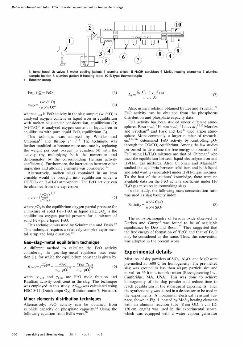
Effect of XFeO on its activity aFeO
Figure 2 presents the variation of aFeO with XFeO
obtained in this work. It is apparent that FeO exhibits apositive deviation from ideality for all slag compositionsinvestigated. Similar behaviour was reported by severalauthors,13,37,38 whereas Basu et al.3 observed the positivedeviation only up to XFeO50?4 as shown in Fig. 3.
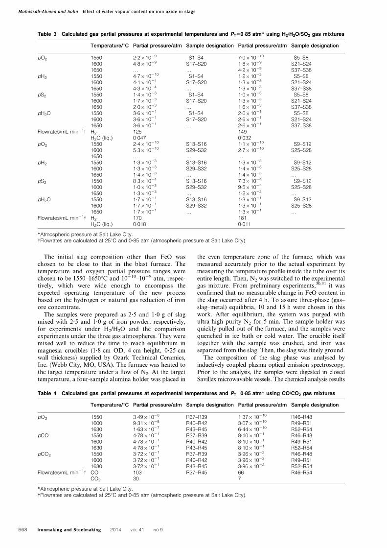
The results of the present work have been presented inFig. 3 along with those of the earlier work3,13,37,38 forcomparison. Positive deviation of the activity of FeO wasobserved by these workers. Turkdogan and Pearson38
had reported positive deviation of aFeO in CaO–MgO–MnO–FeO–SiO2 slags at all FeO concentrations with theexception of negative deviation only when XSiO2 was lessthan 0?008. Ichise and Iwase39 observed negative devia-tion in a few cases at low iron oxide concentrations(XFeO,0?1), whereas Wrampelmeyer et al.40 observedsome incidents of negative deviation of FeO at inter-mediate concentrations (XFeO50?25 to 0?4). In contrast,Chipman8 reported no positive deviation at all, but asmall negative deviation of aFeO at XFeO exceeding 0?4.
Effect of basicity on cFeO
Figures 4–7 show the variation of cFeO with basicity,defined as (wt-% CaO/wt-% SiO2), equation (8), for
Table 5 Calculated gas partial pressures at the experimental temperatures and PT50?85 atm* using H2/H2O gas mixtures
Temperature/uC Partial pressure/atm Sample designation Partial pressure/atm Sample designation
pO2 1550 3.4961028 R64–R66 1.39610210 R73–R751600 8.4661028 R67–R69 3.35610210 R76–R78
pH2O 1550 6.4361021 R64–R66 1.3961021 R73–R751600 6.4361021 R67–R69 1.3961021 R76–R78
pH2 1550 2.0661021 R64–R66 7.1061021 R73–R751600 2.0661021 R67–R69 7.1061021 R76–R78
Flowrates/mL min21{ H2 68 R64–R72 97 R73–R81H2O 0.04 0.017
*Atmospheric pressure at Salt Lake City.{Flow rates are calculated at 25uC and 0?85 atm (atmospheric pressure at Salt Lake City).
2 Variation of activity of FeO with mole fraction under
H2/H2O atmospheres in temperature range 1550 to
1650uC for slags with CaO/SiO2 of 0?8 to 1?4
3 Variation of activity of FeO with mole fraction in com-
plex slags reported by others1–4
Mohassab-Ahmed and Sohn Effect of water vapour content on iron oxide in slags
Ironmaking and Steelmaking 2014 VOL 41 NO 9 669
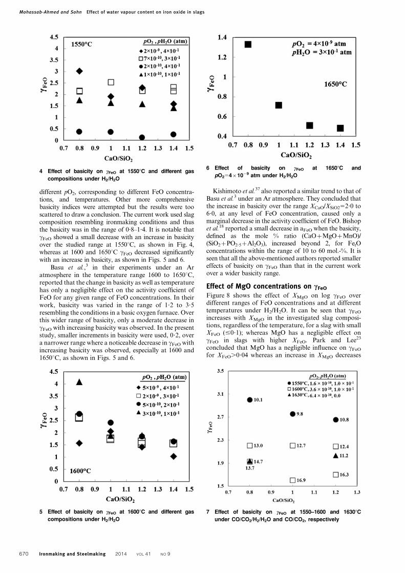
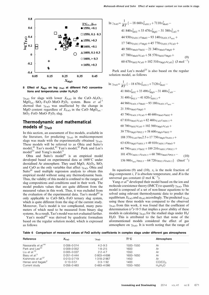
different pO2, corresponding to different FeO concentra-tions, and temperatures. Other more comprehensivebasicity indices were attempted but the results were tooscattered to draw a conclusion. The current work used slagcomposition resembling ironmaking conditions and thusthe basicity was in the range of 0?8–1?4. It is notable thatcFeO showed a small decrease with an increase in basicityover the studied range at 1550uC, as shown in Fig. 4,whereas at 1600 and 1650uC cFeO decreased significantlywith an increase in basicity, as shown in Figs. 5 and 6.
Basu et al.,3 in their experiments under an Aratmosphere in the temperature range 1600 to 1650uC,reported that the change in basicity as well as temperaturehas only a negligible effect on the activity coefficient ofFeO for any given range of FeO concentrations. In theirwork, basicity was varied in the range of 1?2 to 3?5resembling the conditions in a basic oxygen furnace. Overthis wider range of basicity, only a moderate decrease incFeO with increasing basicity was observed. In the presentstudy, smaller increments in basicity were used, 0?2, overa narrower range where a noticeable decrease in cFeO withincreasing basicity was observed, especially at 1600 and1650uC, as shown in Figs. 5 and 6.
Kishimoto et al.37 also reported a similar trend to that ofBasu et al.3 under an Ar atmosphere. They concluded thatthe increase in basicity over the range XCaO/XSiO252?0 to6?0, at any level of FeO concentration, caused only amarginal decrease in the activity coefficient of FeO. Bishopet al.18 reported a small decrease in aFeO when the basicity,defined as the mole % ratio (CaOzMgOzMnO)/(SiO2zPO2?5zAl2O3), increased beyond 2, for FetOconcentrations within the range of 10 to 60 mol.-%. It isseen that all the above-mentioned authors reported smallereffects of basicity on cFeO than that in the current workover a wider basicity range.
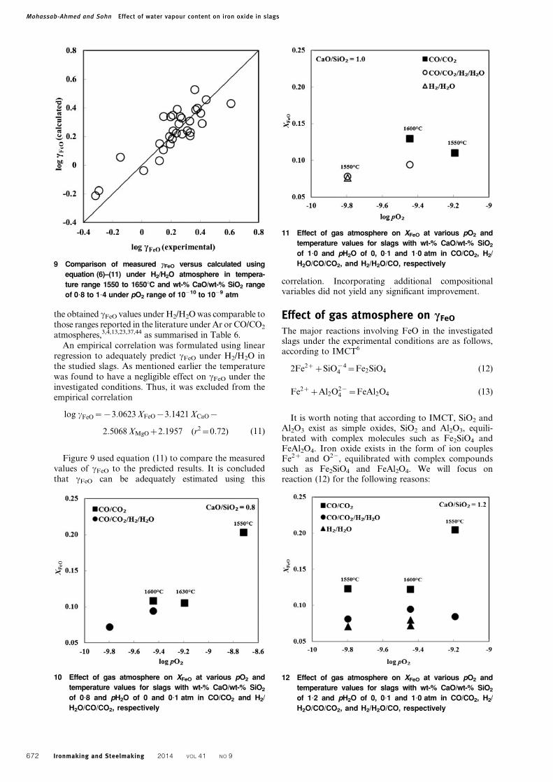
Effect of MgO concentrations on cFeO
Figure 8 shows the effect of XMgO on log cFeO overdifferent ranges of FeO concentrations and at differenttemperatures under H2/H2O. It can be seen that cFeO
increases with XMgO in the investigated slag composi-tions, regardless of the temperature, for a slag with smallXFeO (#0?1); whereas MgO has a negligible effect oncFeO in slags with higher XFeO. Park and Lee23
concluded that MgO has a negligible influence on cFeO
for XFeO.0?04 whereas an increase in XMgO decreases
4 Effect of basicity on cFeO at 1550uC and different gas
compositions under H2/H2O
5 Effect of basicity on cFeO at 1600uC and different gas
compositions under H2/H2O
6 Effect of basicity on cFeO at 1650uC and
pO25461029 atm under H2/H2O
7 Effect of basicity on cFeO at 1550–1600 and 1630uCunder CO/CO2/H2/H2O and CO/CO2, respectively
Mohassab-Ahmed and Sohn Effect of water vapour content on iron oxide in slags
670 Ironmaking and Steelmaking 2014 VOL 41 NO 9
cFeO for slags with lower XFeO in the CaO–Al2O3–MgOsat.–SiO2–FetO–MnO–P2O5 system. Basu et al.3
showed that cFeO was unaffected by the change inMgO content regardless of XFeO in the CaO–MgOsat.–SiO2–FeO–MnO–P2O5 slag.
Thermodynamic and mathematicalmodels of cFeO
In this section, an assessment of five models, available inthe literature, for predicting cFeO in multicomponentslags was made with the experimentally obtained cFeO.These models will be referred to as Ohta and Suito’smodel,41 Tao’s model,42 Yan’s model,43 Park and Lee’smodel23 and Yang’s model.6
Ohta and Suito’s model41 is an empirical modeldeveloped based on experimental data at 1600uC underdeoxidised Ar atmosphere. They used MgO, Al2O3, SiO2
and CaO as the only variables that affect cFeO. Ohta andSuito41 used multiple regression analysis to obtain thisempirical model without using any thermodynamic basis.Thus, the validity of this model is confined to the ranges ofslag compositions and conditions used in their work. Themodel predicts values that are quite different from themeasured values in this work. Thus, it was excluded fromthe evaluation of the experimental data. Tao’s model42 isonly applicable to CaO–SiO2–FeO ternary slag system,which is quite different from the slag of the current study.Moreover, Tao’s model is too complicated, many para-meters of which need to be measured from binary slagsystems. As a result, Tao’s model was not evaluated further.
Yan’s model43 was derived by quadratic formalismbased on the regular solution model, which is expressedas follows
ln cFeO~1
RTf{18 660x2
FeO1:5z7110x2MnO{
41 840x2SiO2z33 470x2
MgO{31 380x2CaOz
44 930xFeO1:5xMnO{93 140xFeO1:5xSiO2
z
17 740xFeO1:5xMgOz45 770xFeO1:5xCaOz
40 580xMnOxSiO2{21 340xMnOxMgOz
67 780xMnOxCaOz58 570xSiO2xMgOz
60 670xSiO2xCaOz102 510xMgOxCaOg (J mol{1)
(9)
Park and Lee’s model23 is also based on the regularsolution model, as follows
ln cFeO~1
RTf{18 670x2
FeO1:5z7120x2MnO{
41 860x2SiO2z33 490x2
MgO{31 400x2CaO{
31 400x2PO2:5{41 020x2
AlO1:5z
44 960xFeO1:5xMnO{93 180xFeO1:5xSiO2
{
21 350xMnOxMgOz
45 790xFeO1:5xCaOz40 600xMnOxSiO2z
67 810xMnOxCaOz82 460xCaOxAlO1:5z
60 700xSiO2xCaOz102 560xMgOxCaOz
39 770xMgOxPO2:5z58 600xMgOxSiO2z
188 370xCaOxPO2:5z17 750xMgOxFeO1:5z
63 630xMgOxAlO1:5z49 810xAlO1:5xMnOz
44 790xAlO1:5xSiO2z189 210xAlO1:5xPO2:5z
101 470xAlO1:5xFeO1:5z60 700xMnOxPO2:5{
156 980xSiO2
xPO2:5{64 720xPO2:5xFeO1:5g (Jmol{1)
(10)
In equations (9) and (10), xi is the mole fraction ofslag component i, T is absolute temperature, and R is theuniversal gas constant (J mol K21).
Yang et al.6 developed their model based on the ion andmolecule coexistence theory (IMCT) to quantify cFeO. Thismodel is composed of a set of non-linear equations to besolved using relevant thermodynamic data to predict theequilibrium XFeO and aFeO accordingly. The predicted cFeO
using these three models was compared to the observedcFeO from this work, it was found that the coefficient ofdetermination (r2),0?5 that implies a poor ability of thesemodels in calculating cFeO for the studied slags under H2/H2O. This is attributed to the fact that none of theaforementioned models considered the effect of gasatmosphere on cFeO. It is worth noting that the range of
8 Effect of XMgO on log cFeO at different FeO concentra-
tions and temperatures under H2/H2O
Table 6 Comparison of measured values of FeO activity coefficients in complex slags under different gas atmospheres
Reference XFeO cFeO T/uC Atmosphere
Nassaralla et al.44 0.006–0.014 4.2–9.3 1500–1550 ArPark and Lee23 0.009–0.052 1.8–2.5 1600 ArLiu et al.13 0.005–0.037 2.2–4.7 1550 ArBasu et al.3 0.051–0.444 0.803–4.698 1600–1650 ArKishimoto et al.37 0.013–0.719 1.318–2.967 1450 ArHenao and Itagaki4 0.13–0.51 0.3–1.92 1400 CO/CO2
Current study 0.056–0.483 0.483–4.086 1550–1650 H2/H2O
Mohassab-Ahmed and Sohn Effect of water vapour content on iron oxide in slags
Ironmaking and Steelmaking 2014 VOL 41 NO 9 671
the obtained cFeO values under H2/H2O was comparable tothose ranges reported in the literature under Ar or CO/CO2
atmospheres,3,4,13,23,37,44 as summarised in Table 6.
An empirical correlation was formulated using linearregression to adequately predict cFeO under H2/H2O inthe studied slags. As mentioned earlier the temperaturewas found to have a negligible effect on cFeO under theinvestigated conditions. Thus, it was excluded from theempirical correlation
log cFeO~{3:0623 XFeO{3:1421 XCaO{
2:5068 XMgOz2:1957 (r2~0:72) (11)
Figure 9 used equation (11) to compare the measuredvalues of cFeO to the predicted results. It is concludedthat cFeO can be adequately estimated using this
correlation. Incorporating additional compositionalvariables did not yield any significant improvement.
Effect of gas atmosphere on cFeO
The major reactions involving FeO in the investigatedslags under the experimental conditions are as follows,according to IMCT6
2Fe2zzSiO{44 ~Fe2SiO4 (12)
Fe2zzAl2O2{4 ~FeAl2O4 (13)
It is worth noting that according to IMCT, SiO2 andAl2O3 exist as simple oxides, SiO2 and Al2O3, equili-brated with complex molecules such as Fe2SiO4 andFeAl2O4. Iron oxide exists in the form of ion couplesFe2z and O22, equilibrated with complex compoundssuch as Fe2SiO4 and FeAl2O4. We will focus onreaction (12) for the following reasons:
9 Comparison of measured cFeO versus calculated using
equation (6)–(11) under H2/H2O atmosphere in tempera-
ture range 1550 to 1650uC and wt-% CaO/wt-% SiO2 range
of 0?8 to 1?4 under pO2 range of 10210 to 1029 atm
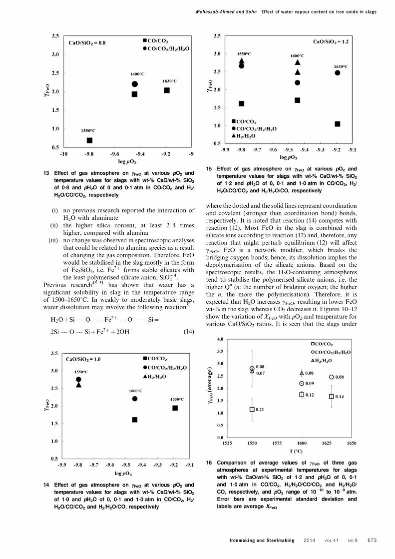
10 Effect of gas atmosphere on XFeO at various pO2 and
temperature values for slags with wt-% CaO/wt-% SiO2
of 0?8 and pH2O of 0 and 0?1 atm in CO/CO2 and H2/
H2O/CO/CO2, respectively
12 Effect of gas atmosphere on XFeO at various pO2 and
temperature values for slags with wt-% CaO/wt-% SiO2
of 1?2 and pH2O of 0, 0?1 and 1?0 atm in CO/CO2, H2/
H2O/CO/CO2, and H2/H2O/CO, respectively
11 Effect of gas atmosphere on XFeO at various pO2 and
temperature values for slags with wt-% CaO/wt-% SiO2
of 1?0 and pH2O of 0, 0?1 and 1?0 atm in CO/CO2, H2/
H2O/CO/CO2, and H2/H2O/CO, respectively
Mohassab-Ahmed and Sohn Effect of water vapour content on iron oxide in slags
672 Ironmaking and Steelmaking 2014 VOL 41 NO 9
(i) no previous research reported the interaction ofH2O with aluminate
(ii) the higher silica content, at least 2–4 timeshigher, compared with alumina
(iii) no change was observed in spectroscopic analysesthat could be related to alumina species as a resultof changing the gas composition. Therefore, FeOwould be stabilised in the slag mostly in the formof Fe2SiO4, i.e. Fe2z forms stable silicates withthe least polymerised silicate anion, SiO{4
4 .
Previous research45–51 has shown that water has asignificant solubility in slag in the temperature rangeof 1500–1650uC. In weakly to moderately basic slags,water dissolution may involve the following reaction51
H2OzSi�� O{ � � �Fe2z � � �O{ �� Si~
2Si��O�� SizFe2zz2OH{ (14)
where the dotted and the solid lines represent coordinationand covalent (stronger than coordination bond) bonds,respectively. It is noted that reaction (14) competes withreaction (12). Most FeO in the slag is combined withsilicate ions according to reaction (12) and, therefore, anyreaction that might perturb equilibrium (12) will affectcFeO. FeO is a network modifier, which breaks thebridging oxygen bonds; hence, its dissolution implies thedepolymerisation of the silicate anions. Based on thespectroscopic results, the H2O-containing atmospherestend to stabilise the polymerised silicate anions, i.e. thehigher Qn (n: the number of bridging oxygen; the higherthe n, the more the polymerisation). Therefore, it isexpected that H2O increases cFeO, resulting in lower FeOwt-% in the slag, whereas CO2 decreases it. Figures 10–12show the variation of XFeO with pO2 and temperature forvarious CaO/SiO2 ratios. It is seen that the slags under
13 Effect of gas atmosphere on cFeO at various pO2 and
temperature values for slags with wt-% CaO/wt-% SiO2
of 0?8 and pH2O of 0 and 0?1 atm in CO/CO2 and H2/
H2O/CO/CO2, respectively
14 Effect of gas atmosphere on cFeO at various pO2 and
temperature values for slags with wt-% CaO/wt-% SiO2
of 1?0 and pH2O of 0, 0?1 and 1?0 atm in CO/CO2, H2/
H2O/CO/CO2 and H2/H2O/CO, respectively
15 Effect of gas atmosphere on cFeO at various pO2 and
temperature values for slags with wt-% CaO/wt-% SiO2
of 1?2 and pH2O of 0, 0?1 and 1?0 atm in CO/CO2, H2/
H2O/CO/CO2 and H2/H2O/CO, respectively
16 Comparison of average values of cFeO of three gas
atmospheres at experimental temperatures for slags
with wt-% CaO/wt-% SiO2 of 1?2 and pH2O of 0, 0?1
and 1?0 atm in CO/CO2, H2/H2O/CO/CO2 and H2/H2O/
CO, respectively, and pO2 range of 10210 to 1029 atm.
Error bars are experimental standard deviation and
labels are average XFeO
Mohassab-Ahmed and Sohn Effect of water vapour content on iron oxide in slags
Ironmaking and Steelmaking 2014 VOL 41 NO 9 673
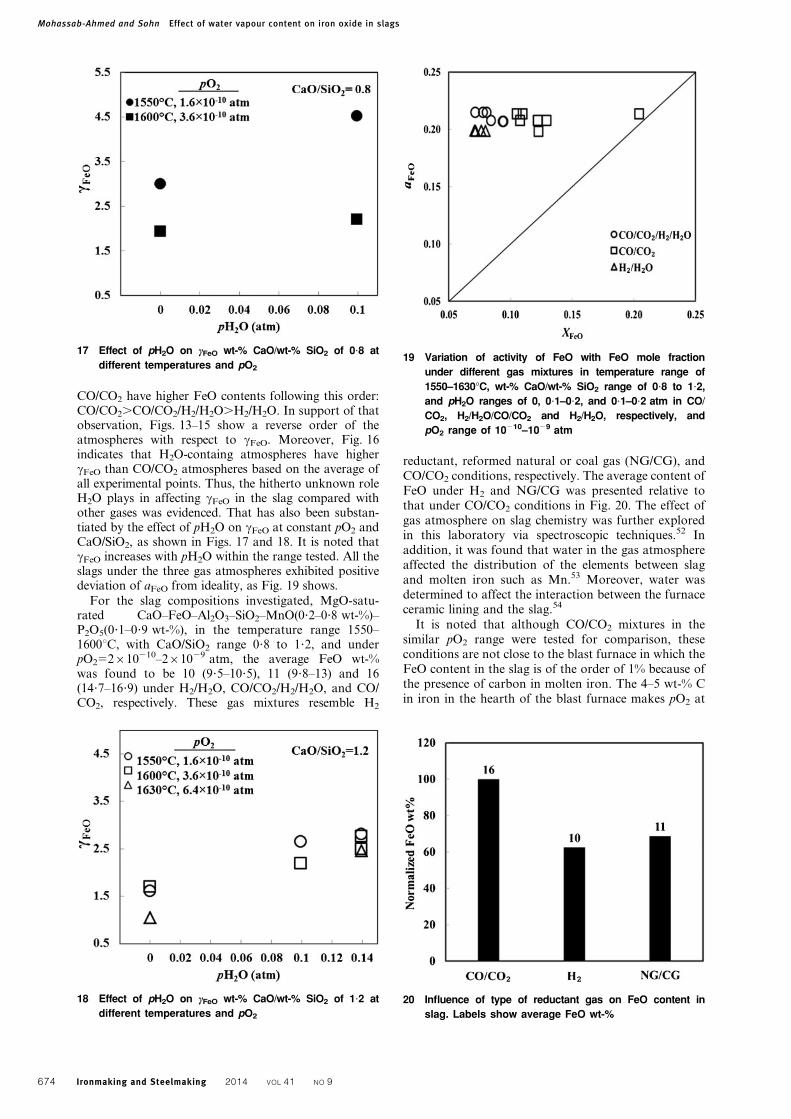
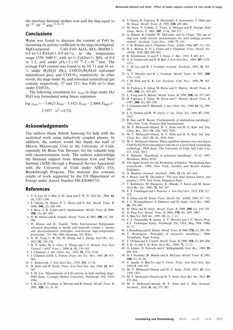
CO/CO2 have higher FeO contents following this order:CO/CO2.CO/CO2/H2/H2O.H2/H2O. In support of thatobservation, Figs. 13–15 show a reverse order of theatmospheres with respect to cFeO. Moreover, Fig. 16indicates that H2O-containg atmospheres have highercFeO than CO/CO2 atmospheres based on the average ofall experimental points. Thus, the hitherto unknown roleH2O plays in affecting cFeO in the slag compared withother gases was evidenced. That has also been substan-tiated by the effect of pH2O on cFeO at constant pO2 andCaO/SiO2, as shown in Figs. 17 and 18. It is noted thatcFeO increases with pH2O within the range tested. All theslags under the three gas atmospheres exhibited positivedeviation of aFeO from ideality, as Fig. 19 shows.
For the slag compositions investigated, MgO-satu-rated CaO–FeO–Al2O3–SiO2–MnO(0?2–0?8 wt-%)–P2O5(0?1–0?9 wt-%), in the temperature range 1550–1600uC, with CaO/SiO2 range 0?8 to 1?2, and underpO252610210–261029 atm, the average FeO wt-%was found to be 10 (9?5–10?5), 11 (9?8–13) and 16(14?7–16?9) under H2/H2O, CO/CO2/H2/H2O, and CO/CO2, respectively. These gas mixtures resemble H2
reductant, reformed natural or coal gas (NG/CG), andCO/CO2 conditions, respectively. The average content ofFeO under H2 and NG/CG was presented relative tothat under CO/CO2 conditions in Fig. 20. The effect ofgas atmosphere on slag chemistry was further exploredin this laboratory via spectroscopic techniques.52 Inaddition, it was found that water in the gas atmosphereaffected the distribution of the elements between slagand molten iron such as Mn.53 Moreover, water wasdetermined to affect the interaction between the furnaceceramic lining and the slag.54
It is noted that although CO/CO2 mixtures in thesimilar pO2 range were tested for comparison, theseconditions are not close to the blast furnace in which theFeO content in the slag is of the order of 1% because ofthe presence of carbon in molten iron. The 4–5 wt-% Cin iron in the hearth of the blast furnace makes pO2 at
18 Effect of pH2O on cFeO wt-% CaO/wt-% SiO2 of 1?2 at
different temperatures and pO2
17 Effect of pH2O on cFeO wt-% CaO/wt-% SiO2 of 0?8 at
different temperatures and pO2
19 Variation of activity of FeO with FeO mole fraction
under different gas mixtures in temperature range of
1550–1630uC, wt-% CaO/wt-% SiO2 range of 0?8 to 1?2,
and pH2O ranges of 0, 0?1–0?2, and 0?1–0?2 atm in CO/
CO2, H2/H2O/CO/CO2 and H2/H2O, respectively, and
pO2 range of 10210–1029 atm
20 Influence of type of reductant gas on FeO content in
slag. Labels show average FeO wt-%
Mohassab-Ahmed and Sohn Effect of water vapour content on iron oxide in slags
674 Ironmaking and Steelmaking 2014 VOL 41 NO 9
the interface between molten iron and the slag equal to10215–10214 atm.11,34–36
ConclusionsWater was found to decrease the content of FeO byincreasing its activity coefficient in the slags investigated,MgO-saturated CaO–FeO–Al2O3–SiO2–MnO(0?2–0?8 wt-%)–P2O5(0?1–0?9 wt-%), in the temperaturerange 1550–1600uC, with wt-% CaO/wt-% SiO2 of 0?8to 1?2, and under pO252610210–261029 atm. Theaverage FeO content was found to be 10, 11 and 16 wt-% under H2/H2O (H2), CO/CO2/H2/H2O (reformednatural/coal gas), and CO/CO2, respectively. In otherwords, the slags under H2 and reformed natural/coal gascontain, respectively, 37 and 31% less FeO wt-% thanunder CO/CO2.
The following correlation for cFeO in slags under H2/H2O was formulated using linear regression
log cFeO~{3:0623 XFeO{3:1421 XCaO{2:5068 XMgOz
2:1957 (r2~0:72)
Acknowledgements
The authors thank Adirek Janwong for help with theanalytical work using inductively coupled plasma. Inaddition, the authors would like thank the staff ofMicron Microscopy Core at the University of Utah,especially Dr Brian Van Devener, for the valuable helpwith characterisation work. The authors acknowledgethe financial support from American Iron and SteelInstitute (AISI) through a Research Service Agreementwith the University of Utah under AISI’s CO2
Breakthrough Program. This material also containsresults of work supported by the US Department ofEnergy under Award Number DE-EE0005751.
References1. Y. S. Lee, D. J. Min, S. M. Jung and S. H. Yi: ISIJ Int., 2004, 44,
(8), 1283–1290.
2. S. Nikolic, H. Henao, P. C. Hayes and E. Jak: Metall. Trans. B,
2008, 39B, (2), 189–199.
3. S. Basu, A. K. Lahiri and S. Seetharaman: Metall. Trans. B, 2008,
39B, (3), 447–456.
4. H. M. Henao and K. Itagaki: Metall. Trans. B, 2007, 38B, (5), 769–
780.
5. H. Henao and K. Itagaki: ‘Sohn International Symposium;
advanced processing of metals and materials volume 1: thermo
and physicochemical principles: non-ferrous high-temperature
processing’, 755–766; 2006, Somerset, NJ, Wiley.
6. X. M. Yang, C. B. Shi, M. Zhang and J. Zhang: Steel Res. Int.,
2012, 83, 244–258.
7. H. Y. Sohn, M. E. Choi, Y. Zhang and J. E. Ramos: Iron Steel
Technol. (AIST Trans.), 2009, 6, (8), 158–165.
8. J. Chipman: J. Am. Chem. Soc., 1933, 55, 3131–3139.
9. J. Chipman and K. L. Fetters: Trans. Am. Soc. Met., 1941, 29, 953–
966.
10. C. Bodsworth: J. Iron Steel Inst., 1959, 193, 13–24.
11. H. Suito and R. Inoue: Trans. Iron Steel Inst. Jpn, 1984, 24, 301–
307.
12. S. H. Liu: ‘Measurement of FeO activity in bath smelting slags’,
PhD thesis, Carnegie Mellon University, Pittsburgh, PA, USA,
1996.
13. S. H. Liu, R. Fruehan, A. Morales and B. Ozturk: Metall. Trans. B,
2001, 32B, (1), 31–36.
14. T. Ogura, R. Fujiwara, R. Mochizuki, Y. Kawamoto, T. Oishi and
M. Iwase: Metall. Trans. B, 1992, 23B, 459–466.
15. M. Iwase, Y. Uchida, Y. Tomii, A. McLean and K. Katogi: High
Temp. Mater. P, 2001, 20P, (3–4), 269–277.
16. A. Hamm, B. Cundiff, W. McCauley and G. Frigm: ‘The use of
slag iron oxide activity measurements for steel making process
control’, Steelmak. Conf. Proc., 1994, 77, 156.
17. T. B. Winkler and J. Chipman: Trans. AIME, 1946, 167, 111–133.
18. H. L. Bishop, Jr, N. J. Grant and J. Chipman: Trans. Metall. Soc.
AIME, 1958, 212, 890–892.
19. R. Schuhmann, Jr and P. J. Ensio: J. Met., 1951, 3, 401–411.
20. A. S. Venkatradi and H. B. Bell: J. Iron Steel Inst., 1969, 207, 1110–
1113.
21. C. M. Lee and R. J. Fruehan: Ironmak. Steelmak., 2005, 32, 503–
508.
22. A. T. Morales and R. J. Fruehan: Metall. Trans. B, 1997, 28B,
1111–1118.
23. J. M. Park and K. K. Lee: Steelmak. Conf. Proc., 1996, 79, 165–
171.
24. H. Fujiwara, E. Ichise, M. Kitou and T. Matsui: Metall. Trans. B,
1999, 30B, (3), 419–427.
25. L. Yang and G. Belton: Metall. Trans. B, 1998, 29B, (4), 837–845.
26. H. Fujiwara, E. Ichise, M. Kitou and T. Matsui: Metall. Trans. B,
1997, 28B, (2), 243–250.
27. J. Chipman and S. Marshall: J. Am. Chem. Soc., 1940, 62, (2), 299–
305.
28. L. S. Darken and R. W. Gurry: J. Am. Chem. Soc., 1945, 67, 1398–
1412.
29. B. Deo and R. Boom: ‘Fundamentals of steelmaking metallurgy’;
1993, New York, Prentice Hall International.
30. M. Y. Mohassab-Ahmed, H. Y. Sohn and H. G. Kim: Ind. Eng.
Chem. Res., 2012, 51, (20), 7028–7034.
31. M. Y. Mohassab-Ahmed, H. Y. Sohn and H. G. Kim: Ind. Eng.
Chem. Res., 2012, 51, (9), 3639–3645.
32. M. Y. Mohassab Ahmed: ‘Phase equilibria between iron and slag in
CO/CO2/H2/H2O atmospheres relevant to a novel flash ironmaking
technology’, PhD thesis, The University of Utah, Salt Lake City,
UT, USA, 2013.
33. F. Habashi: ‘Handbook of extractive metallurgy’, 53–55; 1997,
Weinheim, Wiley-VCH.
34. The Japan Society for the Promotion of Science: ‘Steelmaking data
sourcebook’, 1988, New York, Gordon and Breach Science
Publishers.
35. A. Shankar: Ironmak. Steelmak., 2006, 33, (5), 413–418.
36. J. Peacey and W. Davenport: ‘The iron blast furnace theory and
practice’; 1979, New York, Pergamon Press.
37. T. Kishimoto, M. Hasegawa, K. Ohnuki, T. Sawai and M. Iwase:
Steel Res. Int., 2005, 76, 341–347.
38. E. T. Turkdogan and J. Pearson: J. Iron Steel Inst., 1953, 173, 217–
223.
39. E. Ichise and M. Iwase: Trans. Metall. Soc. AIME, 1984, 517–531.
40. J. C. Wrampelmeyer, S. Dimitrov and D. Janke: Steel Res., 1989,
60, 539–549.
41. H. Ohta and H. Suito: Metall. Trans. B, 1998, 29B, (1), 119–129.
42. D. Ping Tao: Metall. Trans. B, 2006, 37B, (6), 1091–1097.
43. S. Ban-Ya: ISIJ Int., 1993, 33, (1), 2–11.
44. C. L. Nassaralla, B. Sarma, A. T. Morales and J. C. Myers: Proc.
E.T. Turkdogan Symp., Pittsburgh, PA, USA, May 1994, TMS,
61–71.
45. J. Brandberg and D. Sichen: Metall. Trans. B, 2006, 37B, (3), 389–393.
46. T. Rosenqvist: ‘Principles of extractive metallurgy’; 2004,
Trondheim, Tapir Forlag.
47. C. Orrling and A. Cramb: Metall. Trans. B, 2000, 31B, (2), 403–406.
48. S. K. Jo and S. H. Kim: Steel Res., 2000, 71, 15–21.
49. G. Leekes, N. Nowack and F. Schlegelmilch: Steel Res., 1988, 59,
406–416.
50. D. J. Sosinsky, M. Maeda and A. McLean: Metall. Trans. B, 1985,
16B, (1), 61–66.
51. Y. Iguchi, S. Ban-Ya and T. Fuwa: Trans. Iron Steel Inst. Jpn,
1969, 9, 189–195.
52. M. Y. Mohassab-Ahmed and H. Y. Sohn: JOM, 2013, 65, (11),
1559–1565.
53. M. Y. Mohassab-Ahmed and H. Y. Sohn: Steel Res. Int., 2013, 85,
875–884.
54. M. Y. Mohassab-Ahmed, H. Y. Sohn and L. Zhu: Ironmak.
Steelmak., 2014, 41, (8), 575–582.
Mohassab-Ahmed and Sohn Effect of water vapour content on iron oxide in slags
Ironmaking and Steelmaking 2014 VOL 41 NO 9 675


![1-[2-(2,6-Dichlorobenzyloxy)-2-(2-furyl)ethyl]-1 H -benzimidazole](https://static.fdokumen.com/doc/165x107/63152ec4fc260b71020fe0ce/1-2-26-dichlorobenzyloxy-2-2-furylethyl-1-h-benzimidazole.jpg)

![Lippke (2014.2), Verbindungslinien [RVO 2|CO 1,1]](https://static.fdokumen.com/doc/165x107/6320792ea3cd9cf896067893/lippke-20142-verbindungslinien-rvo-2co-11.jpg)


![1-[2-(3,4-Dichlorobenzyloxy)-2-phenylethyl]-1 H -benzimidazole](https://static.fdokumen.com/doc/165x107/63152ee185333559270d05af/1-2-34-dichlorobenzyloxy-2-phenylethyl-1-h-benzimidazole.jpg)

