Effect of Symmetric & Asymmetric Span Morphing on Flight Dynamics
15
Effect of Symmetric & Asymmetric Span Morphing on Flight Dynamics C. S. Beaverstock * J.H.S Fincham † M. I. Friswell ‡ Swansea University, Singleton Park, Swansea, SA2 8PP, UK R. Ajaj § University of Southampton, Southampton, SO17 1BJ, UK R. de Breuker ¶ and N. Werter k TUDelft, Postbus 5, 2600 AA Delft, The Netherlands To increase aerodynamic efficiency over the operational flight envelope, span morphing has been proposed as a method to better optimise the aircraft geometry for varying flight conditions. Due to the significant planform change undertaken during span morphing, aero- dynamic and structural changes lead to changes in the force, moment and mass property modelled for varying aircraft state. The effect of which on the flight dynamics and control can be significant. A low-fidelity framework is proposed to capture the effect of morphing, to model the change in behaviour such that flight performance and dynamic analysis can be performed. This framework prospectively enables development of morphing concepts, in addition to assessment activities from a conceptual design phase. An example small/ medium Unmanned Air Vehicle (UAV) (mass of 25 kg and nominal aspect ratio of 6.67) is used to demonstrate the tool, presenting results for both symmetric and asymmetric span retraction. The span retraction is performed using the outboard 50% of the main wing, with up to 50% allowable span retraction. Results presented are for a loiter mission. The loiter is at 55 (km/r) where the high speed cruise is from 75-110 km/hr. Span retraction is used to optimise the configuration performance for these flight phases. LTrim and dy- namic (both longitudinal and lateral) results are presented for both high speed cruise and loiter for straight and level conditions. Loiter results include lateral coordinated turn with varying strategies, which include using either rudder span retraction, to trim the UAV. Final results show the effect of modelling ˙ Ixx using a reduced model for roll dynamics. This investigation shows that the maximum error occurs where the roll and inertia dynamics are matched. Nomenclature α (AoA), β, V t Angle of attack, and side-slip angle (deg), Total Velocity (km/hr) p, q, r Roll, pitch and yaw rate (deg/s) φ, θ, ψ Euler angles: Roll, pitch and yaw (deg) X, Y , Z Position (m) L Rolling moment (N.m) Δ HSTAB ,Δ RUDD ,Δ StarBrdSpan Control angles: Stabiliser, rudder (deg) and spanwise retraction (0 to 1 for full span η thrust Engine thrust (N) L/D Aerodynamic efficiency (lift-to-drag ratio) AR Aspect Ratio * Research Officer, College of Engineering, [email protected] † Research Officer, College of Engineering, j.h.s.fi[email protected] ‡ Professor of Aerospace Structures, College of Engineering, [email protected] § Lecturer, Aeronautics, Astronautics and Computational Engineering Unit, [email protected] ¶ Assistant Professor, TU Delft, [email protected] k Research Assistant, TU Delft, [email protected] 1 of 15 American Institute of Aeronautics and Astronautics AIAA Atmospheric Flight Mechanics Conference 13-17 January 2014, National Harbor, Maryland AIAA 2014-0545
-
Upload
independent -
Category
Documents
-
view
1 -
download
0
Transcript of Effect of Symmetric & Asymmetric Span Morphing on Flight Dynamics
Effect of Symmetric & Asymmetric Span Morphing on
Flight Dynamics
C. S. Beaverstock∗ J.H.S Fincham† M. I. Friswell‡
Swansea University, Singleton Park, Swansea, SA2 8PP, UK
R. Ajaj§
University of Southampton, Southampton, SO17 1BJ, UK
R. de Breuker¶ and N. Werter‖
TUDelft, Postbus 5, 2600 AA Delft, The Netherlands
To increase aerodynamic efficiency over the operational flight envelope, span morphinghas been proposed as a method to better optimise the aircraft geometry for varying flightconditions. Due to the significant planform change undertaken during span morphing, aero-dynamic and structural changes lead to changes in the force, moment and mass propertymodelled for varying aircraft state. The effect of which on the flight dynamics and controlcan be significant. A low-fidelity framework is proposed to capture the effect of morphing,to model the change in behaviour such that flight performance and dynamic analysis canbe performed. This framework prospectively enables development of morphing concepts,in addition to assessment activities from a conceptual design phase. An example small/medium Unmanned Air Vehicle (UAV) (mass of 25 kg and nominal aspect ratio of 6.67) isused to demonstrate the tool, presenting results for both symmetric and asymmetric spanretraction. The span retraction is performed using the outboard 50% of the main wing,with up to 50% allowable span retraction. Results presented are for a loiter mission. Theloiter is at 55 (km/r) where the high speed cruise is from 75-110 km/hr. Span retractionis used to optimise the configuration performance for these flight phases. LTrim and dy-namic (both longitudinal and lateral) results are presented for both high speed cruise andloiter for straight and level conditions. Loiter results include lateral coordinated turn withvarying strategies, which include using either rudder span retraction, to trim the UAV.Final results show the effect of modelling Ixx using a reduced model for roll dynamics. Thisinvestigation shows that the maximum error occurs where the roll and inertia dynamicsare matched.
Nomenclature
α (AoA), β, Vt Angle of attack, and side-slip angle (deg), Total Velocity (km/hr)p, q, r Roll, pitch and yaw rate (deg/s)φ, θ, ψ Euler angles: Roll, pitch and yaw (deg)X, Y , Z Position (m)L Rolling moment (N.m)∆HSTAB , ∆RUDD, ∆StarBrdSpan Control angles: Stabiliser, rudder (deg) and spanwise retraction (0 to 1 for full span to 90% retraction)ηthrust Engine thrust (N)L/D Aerodynamic efficiency (lift-to-drag ratio)AR Aspect Ratio
∗Research Officer, College of Engineering, [email protected]†Research Officer, College of Engineering, [email protected]‡Professor of Aerospace Structures, College of Engineering, [email protected]§Lecturer, Aeronautics, Astronautics and Computational Engineering Unit, [email protected]¶Assistant Professor, TU Delft, [email protected]‖Research Assistant, TU Delft, [email protected]
1 of 15
American Institute of Aeronautics and Astronautics
AIAA Atmospheric Flight Mechanics Conference
13-17 January 2014, National Harbor, Maryland
AIAA 2014-0545

MAC Mean Aerodynamic ChordS, St, Sv Wing area, tail area and vertical tail area (m2)c, b MAC and span (m)lt, lv Tail and vertical tail moment arms (m)
Ixx, Iyy, Izz Moments of inertia about axes (kg.m2)
Ixy, Iyz, Ixz Products of inertia about axes (kg.m2)
I. Introduction
Aircraft undergo a wide variety of aerodynamic (and structural) loading conditions across the operationalflight envelope. The loading analysis space can be discretized into several phases, each representing a rangeof conditions with similar objectives and constraints. These are executed sequentially to form a missionprofile. Classic and contemporary aircraft development usually set the geometric parameters to optimisemission performance and efficiency, which is typically driven by a specific flight phase or condition. It isassumed that the basic geometry remains constant, and flight control is achieved by actuation of discretesurfaces. Geometry variations of this type can be considered a form of morphing, where significant geometricchanges are achieved by elements such as flaps and slats, which have been used for extreme configurationmodifications.
A contemporary description of morphing has been proposed, whereby geometry modifications are achievedthrough compliant structural concepts to actuate the geometry, or mechanisms that enable significant changesto the wing planform and cross-section. It is postulated that by allowing the aircraft geometry to varythrough an adaptive structure, the optimum configuration can be obtained for each flight phase and con-dition. Although optimum geometries for each conceivable flight phase and condition can be computed,implementation of a structural design to actuate between each optimum geometry may not be feasible orpractical. Furthermore, implementation of such a structure may also reduce the achievable optimum in bothperformance and efficiency through cost (e.g. aerodynamic drag) or weight penalties.
Contemporary structural morphing concepts have been developed and investigated, which enable sub-stantial wing planform1,2, 3 and cross-sectional modifications.4 These address actuator requirements andbasic analysis to reveal potential performance benefits. The FishBAC concept developed by Woods et. al.5
at Swansea University modifies the cross-section camber (twist and chord length as secondary effects) via acompliant ‘spine’ and ‘tendon’ system. This is compared to a conventional flap, where due to removal of thediscontinuity in the structure (and camber line) a reduction in drag, or increase in aerodynamic efficiencyis observed. Systems level implementation and analysis of morphing has also been considered,1,6 where thepotential for improving the global or mission performance and efficiency are investigated.
Aircraft design is typically a multi-disciplinary process. A research community for morphing has primarilyfocused on addressing aerodynamic and structural requirements. These are essential in subsequent systemslevel investigations. Where systems level investigations of performance metrics such as aerodynamic efficiencyand endurance have been conducted, few investigations have been dedicated to the flight dynamics andcontrol.
This paper shall present a framework suitable for conceptual investigations of morphing concepts. Thisshall be used to present an example application to a UAV platform designed for a loiter mission. The geom-etry and mission are representative, where morphing parameters shall be introduced to allow independentmodification of the main wing semi-spans. Semi-span control is investigated about the optimum scheduledmorphing position. This includes semi-span morphing for roll control, and an investigation to the effect ofspan morphing on the lateral dynamics.
II. Background
In the context of aircraft, morphing generally refers to structural actuation concepts or technologiesdeveloped to enable significant modification to the wing planform and cross-sections. Classically, morphingwas embodied within the flight control system. The primary flight control system used to control of theflight mechanics is generally implemented through discrete ‘camber morphing’ surfaces near the trailingedge. Furthermore, secondary flight control systems, such as flaps, have also been deployed to prepare theaircraft for flight phases such as take-off and landing, by effectively extending the chord length and increasing
2 of 15
American Institute of Aeronautics and Astronautics

the wing area also to extend the operating lift coefficient.Contemporary morphing concepts attempt to integrate actuation methods and technologies, whether they
be based on compliant mechanisms or compliant structures, to initiate shape changes without necessitatinga discrete surface for a so called ‘gap-less’ aerodynamic shape and structure. One purpose is to reduce theoperating cost of the aircraft, through either reducing systems weight, or by decreasing fuel burn throughincreasing lift-to-drag ratio. Furthermore, as these morphing concepts generally increase the parameter spaceavailable, performance can be augmented to improve stability, controllability and/ or manoeuvrability as wellas other performance parameters. Therefore this has the potential to expand the normal operational flightenvelope, where numerous challenging flight conditions exist. Other potential benefits of a morphing conceptenable not only flight phase adaptation, but also accommodate alterations to the mission specification.
Smith et al.7 presents an investigation of the effect of variable cant and twist at two outboard cross-sections. The analysis presented optimised the aerodynamic configuration for flight efficiency and specificair range, whilst satisfying a bending moment constraint. Variations in the flight mechanics observed inthis concept are likely to have an effect on the stability characteristics, in addition to the development of asuitable flight control system. Research at University of Bristol by Bourdin et al.3 and Ameri et al.8 focusedon the dynamic response of various cant angle winglet configurations, and their application to control aflying wing micro air vehicle. Bourdin et al.3 suggest that these winglets can be used as an effective controlstrategy for roll and yaw, where the original elevons integrated onto the wing assume the more traditionalroll pitch effector (or elevator). Wind tunnel results are presented alongside computational results to verifytrends, and provide some validation of the computational results. This is followed by an investigation thatincludes trim results in turning flight, deploying this novel control strategy. The authors note that, althoughit is possible to deploy this highly coupled control strategy about an orthogonal set of body fixed axes, thecontrol capacity about each axis of rotation is less than that of a configuration that employs a fully decoupledcontrol strategy, whereby each control is provided by an independent effector about each axis of rotation.Moreover, this strategy could not provide sufficient control authority compared to more conventional flightcontrol topologies. Ameri et al.8 further discusses the effect of variable cant winglets on the flight dynamicbehaviour, characterising the modes, and discovering/ revealing the effect of varying cant angle via rootlocus plots. Through a combination of aerodynamic and mass property changes induced by these significantgeometric modifications, both the longitudinal and lateral dynamics are affected. Other work by Ameri etal.9 describes a system that could be employed for use in flight control applications.
Texas A & M University is another institute that has shown interest, dedicating resources to investigatingthe flight dynamic and control aspects of morphing wing concepts. Niksch et al.10,11 develop an aerodynamicmodel suitable for flight dynamic analysis. The model uses a source-doublet panel method, allowing themain lifting surface to vary chord, sweep, thickness and dihedral. Valasek12 presents a novel adaptivecontroller that learns the dynamics of the modified shape, and given a set of goals generate commandsto satisfy. Obradovic and Subbarao13,14 model the dynamic loads generated during morphing, with theobjective of estimating/ predicting the actuation power required to morph, and hence the concept feasibility.The intended application, or example presented, is that of a polymorphing ‘gull-wing’ concept, involvingsignificant morphing deformation of the airframe. This necessitates extending the flight dynamics model toinclude modelling of the unsteady components such as a time varying inertial tensor. Other research thatfocuses on dynamic simulation and control concepts using morphing structures include Boothe et al.15 andGandhi et al.16 These studies demonstrate interest in the effect of morphing structures on system levelparameters such as aerodynamic performance, operational efficiency and the consequent effect on the flightdynamics stability and control.
III. The CHANGE Project
Combined morphing assessment software using flight envelope data and mission based morphing pro-totype wing development (CHANGE) is an EU funded FP7 project which focuses on the development ofa suite of assessment tools, ranging from low to high fidelity, suitable for analysis of morphing wing plan-forms (http://change.tekever.com/). These tools are used within the project to develop and assess asmall/ medium UAV platform, designed for a loiter reconnaissance, with multiple contemporary morphingconcepts integrated into the wing structure. The work proposed includes: development of a low fidelityassessment framework, high fidelity tools to validate low-fidelity models and provide analysis and assessmentdata of the platform, a wing that integrates multiple morphing concepts onto the wing along with supporting
3 of 15
American Institute of Aeronautics and Astronautics

wind-tunnel and flight test data.Objectives of the project include: providing a basis for further research into the synthesis and integration
of morphing technologies, highlighting the challenges of analysis and integration of these concepts ontoworking platforms, and development of a tool to enable assessment of a morphing concept using both lowand high fidelity modelling methods.
IV. Low-fidelity Software Framework
Before any meaningful development can begin, a proposed framework is required to guide tool assemblyand development for the aircraft synthesis environment. In the following section, a structure of the low-fidelityenvironment for design and assessment of morphing wing configurations is proposed. Figure 1 presents aproposal for the hierarchy for the low-fidelity framework.
Figure 1. Outline of Low-Fidelity Software Framework
From Figure 1, there are two main subcomponents; the morphing wrapper and mission parameter mod-ules. The morphing wrapper generates a morphed geometry from a baseline geometry and the sum of anumber of geometry perturbations, g. These perturbations are expressed as parametric functions of x; themorphing parameters. For example, a particular morphing concept will be associated with a parameter xm
that vary from 0 (unmorphed) to 1 (morphed). Each perturbation, gn, represents a change in one of thekey parameters that define the wing. Figure 2 shows the parameters, and each is described briefly in thefollowing bullet points:
• Twist - Local aerodynamic twist applied to panel cross-section, trailing edge down.• Camber - Camber at cross-section defined as closed curve aerofoil section from trailing edge to leading
edge to trailing edge, where leading and trailing edge lie on the chord line .• Span - Panel span morph along specified axis according to the equation yInner = y0 and yOuter =
y0 + yp0 + ∆ymorph, where the baseline spanwise position, y0 is the sum of all previous panels spanyp0 is the panel span, and ∆ymorph is the change in span due to morphing.
4 of 15
American Institute of Aeronautics and Astronautics

• Dihedral - Panel dihedral is the angle about the panel root chord axis, where the baseline value is thesum of all previous panel dihedral values, similar to span morphing.
• Sweep - Sweep morphing is implemented as a skew rather than actual sweep, due to the low fidelityVortex Lattice Method (VLM) used to model the aerodynamics, which requires cross-sections to bealigned with the flow. Like span and dihedral, sweep is accumulative from root to tip.
(a) Twist (b) Camber (c) Span (d) Dihedral (e) Sweep
Figure 2. Fundamental morphing types
The morphed geometry G is then expressed as cross sectional co-ordinates at spanwise stations, to beused in aerodynamic or structural analysis. This geometry is translated into the necessary form for theappropriate analysis tool. Using Figure 1, a tool to generate an N dimensional table of morphing parametersis used. This includes setting the dependent and independent morphing parameters to generate tables ofvarying dimensions.
Similarly, generation of the flight conditions to be considered uses a similar table generation protocol,where the morphing parameters are replaced by aircraft states. From this a flight mechanics model canbe generated suitable for flight mechanics analysis which includes performance and dynamic investigations.These are applied to each morphed configuration, which can then be used to schedule control of the morphingparameters.
The primary objective of the framework presented is to deliver a tool which can investigate the effectof integrating morphing technologies on an aircraft concept, enabling systems level assessments to revealsolutions with potential performance benefits. This can be to determine the operational performance, theoptimal morphed configuration for varying flight conditions (morphing parameter scheduling), control gainscheduling, optimisation of design parameters for a morphing platform and given flight envelope.
In this section a general methodology is presented for a proposed structure to the following analysis. Thishas been distributed into 3 main themes mission specification, aircraft model, and control development. Themission specification is the main driver in the analysis, the aircraft model is subject of assessment, whilstdesign variable optimisation and the controller development provides an alternate method to expand theparameters available to obtain a better solution.
A. Mission Specification: Profile, Requirements & Constraints
The first, and most important step when assessing a design is definition of the mission about which investi-gations are considered. The mission profile outlines a specification of the flight path to be followed by theaircraft. This includes definition of an operational envelope to define flight conditions likely to be encoun-tered, and required performance and constraints. The mission profile is generally segmented into severalphases, each with a unique set of objectives and constraints. Figure 3 is a representation of loiter missionprofile used in this paper.
The results focus on the loiter and medium/ high speed cruise phases. Dynamic results shall be presentedat the speed limits of the cruise phase, in addition to the loiter phase which includes both straight and levelflight, and banked turn with a radius of 200 metres. The altitude is to be fixed at 500 metres throughout.
B. Representative UAV Aircraft Model
The example geometry selected for the investigation is based on a UAV developed for loitering type missions.The reference aspect ratio for the configuration is 6.67, the mass of the configuration is 25 kg, with the Centreof Gravity (CoG) located at 0.3763 and 0.3002 %MAC from the leading edge of the main wing. Figure 4presents illustrations of the platform’s general arrangement. The morphing applied allows span extension
5 of 15
American Institute of Aeronautics and Astronautics

Figure 3. Loiter mission profile
through a telescopic actuation arrangement, where the outboard section can be retracted by 25% of thetotal span. The platform also has an all moving horizontal tail-plane, and a constant chord length rudder asdepicted in the illustration. Aerofoil sections used on the horizontal and vertical tail are symmetric, whilstthe wing is cambered to three-quarter span after which it decreases linearly to zero camber at the tip.
(a) Unmorphed span (b) Asymmetric span morph (c) Symmetric span morph
Figure 4. Representative UAV Geometry Definition
Table 1 provides an overview of the geometry and mass properties of these three configurations presentedin Figure 4.
As can be observed, span morphing not only affects the aerodynamic model but also the mass properties.
6 of 15
American Institute of Aeronautics and Astronautics

Table 1. Varying properties of the reference UAV
Parameter Unmorphed Morphed Symmetric Morphed Asymmetric
AR 6.67 5 5.83
H-Tail Volume (StltSc ) 0.2966 0.3954 0.3389
V-Tail Volume (SvlvSb ) 0.0258 0.0458 0.0336
CoG Y Pos (% Span) 0 ±0.28 0
[Ixx ,Iyy ,Izz] (kg.m2) [7.54,6.88,13.14] [6.68,6.88,12.28] [5.83,6.88,11.42]
[Ixy,Ixz,Iyz] (kg.m2) [0,0.28,0] [±0.02,0.28,±0.05] [0,0.28,0]
Because morphing the span asymmetrically causes an asymmetry in the mass distribution, indicated by thecross-coupling product of inertia terms (Ixy, Ixz and Iyz), motion is now coupled in all axes, and so thesymmetric assumption used to reduce the Equations of Motion (EoM) can no longer be used. Additionally,the mass and inertia of the morphing partition is not negligible. Motion of the surface can be considered quasi-static only if the dynamic inertial component is significantly less than the moment generated. Equation 1presents an equation of motion for a pure roll for a rigid body with varying inertia.
L = Ixxp+ pIxx (1)
where Ixx is the mass moment of inertia of the vehicle around the x-axis and p is the roll rate. The term(pIxx) is a time varying inertial term induced by asymmetric span morphing. Rearranging the equation:
p =L− pIxxIxx
(2)
Equation 2 shows that a quasi-static treatment of mass dynamics can be used if L >> pIxx. Unfortunatelythe rolling moment is also a function of roll rate, in addition to roll rate being a function of time until asteady state is attained. This equation suggests that if the roll rate is negligible, the time varying roll inertiais small relative to the rolling moment, or if the roll damping term, Lp, is much larger than the varying rollinertia, then its affect on the dynamic behaviour is negligible. The variation in inertia about the CoG dueto lateral migration of the CoG. The nondimensional roll damping derivative is taken about the nominalreference position.
V. Results
In this section results are presented for a cruise at minimum and maximum velocity, as well as straightand level and banked turn results for the loiter.
A. Medium/ High Speed Cruise
The speed range for the cruise is 75-110 km/h, at an altitude of 500 meters. The desired trim is a straight andlevel flight, where the tail is used to trim the pitch dynamics and thrust to trim the drag. Table 2 presentsthe trim data for the two flight conditions at maximum span and 90% span retraction of the maximum.
This table shows that for both speeds, the maximum aerodynamic efficiency occurs where span is at itsgreatest. Unsurprisingly, the required angle of incidence increases with span retraction. This leads to greaterrequired trim thrust relative to the larger span. The change in aerodynamic efficiency is less pronouncedas the speed increases ( 21% as opposed to 36%), which was observed in a previous investigation,17 whereit was hypothesised that this was due to the dependence of the empirical relationship used to model theskin friction drag and its dependence on Reynolds Number. This was verified to be the case by running themodel with and without the inclusion of skin friction. However, from this table, prospective advantages tospan retraction include reduction in stabiliser angles, and decreased bending moments. Table 3 presents thedynamics at these trim conditions:
7 of 15
American Institute of Aeronautics and Astronautics

Table 2. Trim parameters for straight and level cruise at 500 meters altitude morphed and unmorphedconfigurations
Parameters Unmorphed 90 % Morph
Vt (km/hr) 75 110 75 110
AoA (θ) (deg) 0.12 -2.99 2.26 -2.30
∆HSTAB (deg) -4.68 -3.90 -4.32 -2.79
ηthrust (N) 13.86 21.68 17.93 22.29
L/D 17.69 11.27 13.80 10.97
Root Bending Moment (N.m) 123.84 137.45 98.77 112.78
Table 3. Modal dynamics for straight and level cruise at 500 meters altitude morphed and unmorphed con-figurations
Dynamic Mode Unmorphed 90 % Morph
Short Period −4.57 ± 10.03i −6.56 ± 14.66i −3.69 ± 8.82i −5.28 ± 12.92i
Phugoid [-0.06 0.37] [-0.09 0.25] [-0.1 0.4] [-0.12 0.27]
Dutch Roll −0.46 ± 3.47i −0.72 ± 4.73i −0.37 ± 3.83i −0.72 ± 5.05i
Roll -11.89 -17.64 −3.78 ± 0.41i -8.06
Spiral -0.84 -0.47 – -1.34
The results show that the short period damping decreases with increasing speed in both the unmorphed(ζsp decreases from 0.415 to 0.408) and morphed conditions (ζsp decreases from 0.386 to 0.378). This isconsistent with a decrease in pitch damping derivative, with decreasing wing area and lower aspect ratio(similar results were presented in Beaverstock et. al.18). The frequency, however, increases with speed (from1.75 to 2.56 and 1.52 to 2.23 Hz for unmorphed and morphed cases respectively) and decreases with spanmorph. For the Dutch roll lateral mode, on the other hand, the damping is observed to increase with speed inboth cases (0.13 to 0.15 for the unmorphed, and 0.095 to 0.14 in the morphed), although the results suggestthe unmorphed damping is less sensitive to changes in speed than the morphed configuration. Symmetricspan morphing also decreases the Dutch roll damping. The frequency results show an increase with speed(0.56 to 0.76 in the unmorphed case and 0.61 to 0.81 Hz) and also an increase with symmetric span reduction.Results suggest that the frequency is more sensitive to speed in the unmorphed case.
B. Loiter
The loiter is performed at a speed of 55 km/h and altitude of 500 meters. Table 4 presents the straight andlevel trim information. This is only at maximum span, the design point of the wing unless span is used fortrimming the lateral dynamics.
Table 4. Trim parameters for straight and level cruise at 55 km/hr and 500 meters altitude
Parameters AoA (θ) (deg) ∆HSTAB (deg) ηthrust (N) L/D Root Bending
Moment (N.m)
Values 5.10 -5.00 14.59 16.96 117.17
Interestingly the aerodynamic efficiency is lower than that observed in Table 4 for unmorphed flight at75 km/hr. When optimising the model used in this paper, it was observed that the optimum occurred at 65km/hr, with a value of 18.26. The induced drag is expected to be the dominant component at speeds belowthe optimum, skin friction dominates at high speeds. The induced drag in the model is observed to be moresensitive to variations in induced drag with speed. Table 5 presents trim results for a banked coordinatedturn, to be performed during the loiter, at 55 km/hr, and altitude of 500 meters, and a turn radius of 200
8 of 15
American Institute of Aeronautics and Astronautics

meters. As is observed, using only the rudder, the Angle of Attack (AoA) is reasonable, and is lower thanthat required for the trim in the straight and level case. As a result the aerodynamic efficiency during theloiter is greater. The value of this approaches that of the optimum, and one reason for this is that the angleof incidence, or optimum lift coefficient, approaches optimal conditions (optimum spanwise lift distributionof the wing) when performing a coordinated turn. When using the starboard spanwise partition to trim,it was found that an increase in angle of incidence but decrease in required stabiliser angle is required totrim. The efficiency reduced, and noting that there are significant modifications to other trim parameters,for example, the sign of side-slip required alters. Additionally, the thrust model output displayed negativedrag. The results would suggest that morphing is effective in trimming the aircraft model with or without arudder input. Furthermore root bending moments when performing the manoeuvre are decreased using thespan morphing strategy. It is however observed that the model extrapolated values for side-slip, and thiscould be a significant source of error.
Table 5. Trim parameters for coordinated banked turn at 55 km/h, 500 meters altitude and a turn radius of200 meters
Parameters Rudder only Morph with Morph without
rudder Rudder
AoA (θ) (deg) 3.57 4.63 4.64
Side-slip (deg) -7.72 13.80 13.82
q (deg/s) -3.97 -3.71 -3.70
r (deg/s) 5.20 5.10 5.09
φ (deg) 10.67 10.36 10.35
θ (deg) 2.07 7.07 7.07
φ (deg/s) 0.16 0.54 0.54
θ (deg/s) -4.86 -4.56 -4.56
ψ (deg/s) 4.38 4.38 4.38
∆HSTAB (deg) -0.80 -0.0299 -0.0299
∆Rudd (deg) 24.67 0.0220 0
∆StarBrdSpan (deg) 0 0.5636 0.5641
ηthrust (N) 19.53 – –
L/D 18.18 15.67 15.66
Root Bending Moment (N.m) 100.03 77.77 1
Figure 5 presents the dynamics of the loiter for each trimming strategy. It was observed that longitudi-nally, there is little change in the dynamic behaviour of the aircraft; generally a reduction in frequency ofthe short period is observed when trimming laterally in a bank. There is marginal variation in the damp-ing. There are two real, aperiodic modes, with large time constants. Typically these would be a complexconjugate pair known as the phugoid. One of the modes is approximately stable whilst the mode with thesmaller time constant is generally unstable. It is important to note that the longitudinal dynamic charac-teristics are not significantly modified by either the lateral trim, or using asymmetric deflection of the span,where the variation in short period damping and frequency varies ??? respectively. Laterally, the dutch rollmarginally changes with lateral trim, where the rudder trim displays primarily a decrease in frequency andthe span morphing reduces the damping with the frequency approximately unchanged. The effect on theaperiodic real lateral modes, spiral and roll subsidence, shows them to remain stable. The roll subsidencemode time constant increases when introducing span morphing significantly increases the roll convergencetime constant. The spiral mode time constant, using the rudder trim strategy, is observed to increase thetime constant marginally, with a significant decrease in time constant where the asymmetric span morphingstrategy is used. Employing the rudder when using the span to trim had little effect on the lateral dynamics.
Figure 6 suggests that although the dynamic trim results show only marginal changes in the periodic/harmonic motion characteristics, the eigenvectors, which indicate the shape of the mode, vary considerably,as the longitudinal and lateral mode motion is coupled in all axes of rotation. This is through the asymmetryof both the flight condition, and the model. The results do suggest that the mode shapes remain dominant
9 of 15
American Institute of Aeronautics and Astronautics

(a) Longitudinal modes (b) Lateral modes
Figure 5. Dynamics of the loiter banked turn trim
in the states traditionally associated with each respective mode. This may have an effect on the controldevelopment, which may favour decoupling the modes to purely longitudinal and lateral. Using a controlsynthesis method similar to Eigenstructure Assignment, enables decoupling of these modes.
(a) Short period (b) Dutch roll
(c) Roll convergence/ subsidence (d) Spiral
Figure 6. Eigen vector magnitude for modes of motion
C. Effect of Unstable Inertial Term Ixx
The unstable inertial term presented in Equation 1 is generally not considered, as the magnitude of theproduct Ixxp is negligible for conventional aircraft relative to the magnitude of the rolling moment. This is
10 of 15
American Institute of Aeronautics and Astronautics
because either the rolling rates are small, or the unsteady inertial term is negligible.For a morphing wing however, the mass and inertia of the morphing partition forms a significant fraction
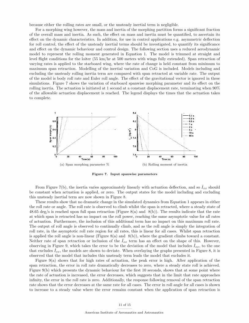
of the overall mass and inertia. As such, the effect on mass and inertia must be quantified, to ascertain itseffect on the dynamic characteristics. In addition, for use in control applications e.g. asymmetric deflectionfor roll control, the effect of the unsteady inertial terms should be investigated, to quantify its significanceand effect on the dynamic behaviour and control design. The following section uses a reduced aerodynamicmodel to represent the rolling moment generated in Equation 1. The model is trimmed at straight andlevel flight conditions for the loiter (55 km/hr at 500 meters with wings fully extended). Span retraction ofvarying rates is applied to the starboard wing, where the rate of change is held constant from minimum tomaximum span retraction. Modelling of the inertial variation and CoG is included. Models including andexcluding the unsteady rolling inertia term are compared with span retracted at variable rate. The outputof the model is body roll rate and Euler roll angle. The effect of the gravitational vector is ignored in thesesimulations. Figure 7 shows the variation of starboard spanwise morphing parameter and its effect on therolling inertia. The actuation is initiated at 1 second at a constant displacement rate, terminating when 90%of the allowable actuation displacement is reached. The legend displays the times that the actuation takesto complete.
(a) Span morphing parameter % (b) Rolling moment of inertia
Figure 7. Input spanwise parameters
From Figure 7(b), the inertia varies approximately linearly with actuation deflection, and so Ixx shouldbe constant when actuation is applied, or zero. The output states for the model including and excludingthis unsteady inertial term are now shown in Figure 8.
These results show that no dramatic change in the simulated dynamics from Equation 1 appears in eitherthe roll rate or angle. The roll rate is observed to climb whilst the span is retracted, where a steady state of48.65 deg/s is reached upon full span retraction (Figure 8(a) and 8(b)). The results indicate that the rateat which span is retracted has no impact on the roll power, reaching the same asymptotic value for all ratesof actuation. Furthermore, the inclusion of this additional term has no impact on this maximum roll rate.The output of roll angle is observed to continually climb, and as the roll angle is simply the integration ofroll rate, in the asymptotic roll rate region for all rates, this is linear for all cases. Whilst span retractionis applied the roll angle is non-linear (Figure 8(a) and 8(b)), where the gradient climbs toward a constant.Neither rate of span retraction or inclusion of the Ixx term has an effect on the shape of this. However,observing in Figure 9, which takes the error to be the deviation of the model that includes Ixx, to the onethat excludes Ixx, the models are shown to deviate. When overlaying the graphs presented in Figure 8, it isobserved that the model that includes this unsteady term leads the model that excludes it.
Figure 9(a) shows that for high rates of actuation, the peak error is high. After application of thespan retraction, the error in roll rate dramatically decreases to zero, where a steady state roll is achieved.Figure 9(b) which presents the dynamic behaviour for the first 10 seconds, shows that at some point wherethe rate of actuation is increased, the error decreases, which suggests that in the limit that rate approachesinfinity, the error in the roll rate is zero. Additionally, the response following removal of the span retractionrate shows that the error decreases at the same rate for all cases. The error in roll angle for all cases is shownto increase to a steady value where the error remains constant when the application of span retraction is
11 of 15
American Institute of Aeronautics and Astronautics

(a) Roll rate incl. Ixx (b) Roll rate excl. Ixx
(c) Roll angle incl. Ixx (d) Roll angle excl. Ixx
Figure 8. Output states of the full and reduced model
terminated (Figure 9(c) and 9(d)). This steady state value continuously increases with decreasing actuationrate. This steady state value tends asymptotically toward 0.3 degrees beyond which decreasing the ratefurther has no effect on the steady state error in roll angle. Figure 10 summarises the errors plotted inFigure 9, showing clearly that as rate of actuation is decreased (x-axis shows time to actuate from 0 to 90% span retraction, so the x-axis is inverse actuation rate), the maximum error in roll rate decreases. Themaximum error in predicted roll angle increases with decreasing roll rate, asymptomatically approaching 0.3degrees.
This result implies that if the actuation rate is high enough, approaching infinity, the error in the rollrate approaches zero. This is observed in Figure 10(b). This also shows clearly that the maximum errorversus time to actuate occurs at a finite rate (between 0 and 1 seconds to actuate), approximately 0.65 deg/swhere the maximum error drops of rapidly, asymptotically towards zero. The implication of this is that onceit passes a threshold, the problem can be considered quasi-steady with respect to the mass model. The rollangle, however, is observed to continuously increase as actuation rate decreases, asymptotically towards 0.3,which implies that the roll angle without modelling the Ixx lags the model which includes this term.
This data would suggest that dynamically, modelling this term is more necessary if the actuation band-width correlates to the actuation rate region associated with high peak error. This term appears to effectthe dynamics, adjusting the response of the damping term. In this equation, this term for span retractionappears to decrease roll damping (Ixx ≤ 0 so −pIxx ≥ 0 where Lpp ≤ 0 and dLp/dδStarBrdSpan ≤ 0), andas such the control design maybe required to augment this. Furthermore, for quasi-steady span morphing,tracking the roll angle showed that this is likely to lag the true roll angle.
This model does not include modelling of the effect of mass migration. Inclusion of this ads an oscillatorycomponent with a period that matches the roll rate of the aircraft.
12 of 15
American Institute of Aeronautics and Astronautics

(a) Error in roll rate (b) Error in roll rate t ≤ 10s
(c) Error in roll angle (d) Error in roll angle t ≤ 10s
Figure 9. Error in the states due to excluding Ixx
(a) Error (b) Error t ≤ 10s
Figure 10. Variation of error with decreasing actuation rate
VI. Conclusions & Further Work
From the results presented, for both symmetric span morphing in the high speed dash, increasing speedgenerally decreases short period damping where the dutch roll damping increases with speed. Span retractiongenerally decreases the short period damping, attributed to the reduction in pitch damping derivative. Thedutch roll damping is also observed to decrease with span retraction, this implies that the effect of the tipvortices on the wing influence the vertical tail such as to reduce its effectiveness. The dutch roll damping isalso observed to be less sensitive to speed in an unmorphed configuration. Short period frequency is observed
13 of 15
American Institute of Aeronautics and Astronautics

to increase with speed and decrease with span retraction, where the dutch roll frequency increases with bothspeed and span retraction. With these changes in dynamic stability, controllers designed to augment modalcharacteristics may also be required to be scheduled to both flight condition (speed in this case) and spanmorphing parameter for span retraction.
Loiter results suggested that the trim inputs required for a trim strategy using the rudder varied greatlyfrom that using span retraction in a lateral coordinated turn. When using a strategy that includes both spanretraction and rudder control, the trimmed inputs were dominated by the span retraction parameter. Theseresults suggest that control allocation for roll and yaw control requires careful control design, for a bankedcoordinated turn the span retraction strategy results presented show that it can be used but with excessiverequired sideslip angles to trim. It is noted that the mode was extrapolating some of the trim forces as thesideslip was observed to become larger than what was modelled using the framework to build the model.Dynamic results suggest that the longitudinal modal characteristics are not significantly affected by either thelateral flight conditions, or the strategy used to trim for a coordinated turn. Marginal changes to the dutchroll characteristics are observed for a coordinated turn and varying the trim strategy. Small differences areobserved between trimming using the rudder or trimming using starboard span retraction, where using bothrudder and span retraction favoured larger use of the span to trim, and so the trim parameters and dynamicsare close to this. The real lateral modes, spiral and roll convergence/ subsidence, are both marginally affectedby trimming laterally using the rudder. Where span morphing is used, considerable migration of these twomodes is observed. It is supposed that this is caused by both the variation in inertia and modification of theaerodynamic model through reduction in the surface area.
A large difference is observed in the mode shapes, characterised by the Eigen vector, for lateral trimming.Each of the modes shows significant increases in Eigen vector magnitude for states not typically associatedwith the mode. For example, a longitudinal mode characterised by angle of attack and pitch rate variation,the short period, now coupled through rolling and yawing. Similarly, pitch rate and angle of attack arecomponents of the dutch roll. Further work is required to ascertain the control requirements for the lateraltrim, development of a suitable control structure and choice of synthesis method to generate the controller.
Finally, the results for a simple model to observe the effect of unsteady rolling inertia in a roll motion.This showed that the error in the pitch rate for excluding this unsteady inertia term is related to the rateof actuation. As the rate of span retraction is increased, the influence of this term is observed to increase,leading to an increase in pitch rate and roll rate error when excluding this unsteady mass term. This errorincreases to a maximum, at which point increasing the rate further, the error decreases. It was proposedthat effect of this unsteady inertial term (which is a product along with roll rate), is more pronounced whenincreasing the rate of actuation, due to the increase in Ixx. However due to the influence of roll rate,p, atvery high roll rates, the product pIxx becomes negligible due to the roll rate dynamics lagging the inertialdynamics.
The results also showed that the maximum steady state error in roll angle generally increases with adecreasing span retraction rate. In the case presented the maximum error is bounded, as span retractionrate is increased, the error in roll angle moves asymptotically towards a constant value ( 0.3 degrees in theexample shown). The effect of this unsteady term in the model presented is transient, and only affects thedynamics whilst span retraction is applied, having no affect on the overall roll power. However, this unsteadyterm is observed to effectively reduce the roll damping.
This could have an effect on the control synthesis to provide desired dynamic performance, if the rate ofspan actuation falls within a bandwidth where the roll rate error is high.
These results imply that where the actuation of a surface with large inertia, if the rate of actuation is high,then the influence of the unsteady inertial terms is low, for both the dynamics, and tracking the orientation.If the actuation is very slow, below a threshold which can be considered quasi-steady, the unsteady inertialterms can be ignored, as the error in the dynamics is negligible. It must be noted that error in the trackingof the orientation for quasi-steady actuation of these surfaces is bounded, and so must be considered ifmodelling the evolution of the aircraft over a flight mission, where performance of navigation, or tracking isrequired.
Further work is required in characterising the effect of: the baseline inertia on the rate at which a surfaceis actuated; the effect of increasing the range of change in the inertia; extension of this model to a full 6Degrees of Freedom (DoF) model, to observe the effect of coupling in the nonlinear equations; the effect ofanother morphing concept on the results; and the effect on a proposed control synthesised including andexcluding the effect of this term.
14 of 15
American Institute of Aeronautics and Astronautics

Acknowledgements
The authors would like to recognise the European Commission and partners of CHANGE, an EU FP7project, for there technical and financial support in writing this paper.
References
1Rafic Ajaj, Michael Friswell, E. Saavedra Flores, Owain Little, and Askin Isikveren. Span morphing: A conceptual designstudy. In 53rd AIAA/ASME/ASCE/AHS/ASC Structures, Structural Dynamics and Materials Conference, 2004.
2Rafic Ajaj, Michael Friswell, Wulf Dettmer, Askin Isikveren, and G. Allegri. Conceptual modeling of an adaptive torsionwing structure. In 52nd AIAA/ASME/ASCE/AHS/ASC Structures, Structural Dynamics and Materials Conference, 2011.
3P. Bourdin, A. Gatto, and M.I. Friswell. The application of variable cant angle winglets for morphing aircraft control.In 24th Applied Aerodynamics Conference, San Francisco, California, 5 - 8 June 2006.
4Onur Bilgen, Michael Friswell, Kevin Kochersberger, and Daniel Inman. Surface actuated variable-camber and variable-twist morphing wings using piezocomposites. In 52nd AIAA/ASME/ASCE/AHS/ASC Structures, Structural Dynamics andMaterials Conference, 2011.
5Benjamin King Sutton Woods, Onur Bilgen, and Michael I. Friswell. Wind tunnel testing of the fishbone active cambermorphing concept. Journal of Intelligent Material Systems and Structures, 2013.
6Cody Lafountain, Kelly Cohen, and Shaaban Abdallah. Camber controlled airfoil design for morphing uav. In 47th AIAAAerospace Sciences Meeting, 2009.
7David D. Smith, Askin Isikveren, Rafic Ajaj, and Michael Friswell. Multiobjective optimization for the multi-phasedesign of active polymorphing wings. In 52nd AIAA/ASME/ASCE/AHS/ASC Structures, Structural Dynamics and MaterialsConference, 2011.
8N. Ameri, M. H. Lowenberg, and M.I. Friswell. Modelling the dynamic response of a morphing wing with active winglets.In AIAA Atmospheric Flight Mechanics Conference and Exhibit, Hilton Head, South Carolina, 20 - 23 August 2007.
9N. Ameri, E. Livne, M. H. Lowenberg, and M.I. Friswell. Modelling continuously morphing aircraft for flight control. InAIAA Guidance, Navigation and Control Conference and Exhibit, Honolulu, Hawaii, 18 - 21 August 2008.
10Adam Niksch, John Valasek, Thomas W. Strganac, and Leland A. Carlson. Morphing aircraft dynamical model: Lon-gitudinal shape changes. In AIAA Atmospheric Flight Mechanics Conference and Exhibit, Honolulu, Hawaii, 18 - 21 August2008.
11Adam Niksch, John Valaseky, Thomas W. Strganacz, and Leland A. Carlson. Six degree of freedom dynamical model ofa morphing aircraft. In AIAA Atmospheric Flight Mechanics Conference, Chicago, Illinois, 10 - 13 August 2009.
12John Valasek, Amanda Lampton, and Monika Marwaha. Morphing unmanned air vehicle intelligent shape and flightcontrol. In AIAA Infotech@Aerospace Conference and AIAA Unmanned...Unlimited Conference, Seattle, Washington, 6 - 9April 2009.
13B. Obradovic and K. Subbarao. Modeling of dynamic loading of morphing-wing aircraft. Journal of Aircraft, 48:424–435,2011.
14B. Obradovic and K. Subbarao. Modeling of flight dynamics of morphing-wing aircraft. Journal of Aircraft, 48:391–402,2011.
15Kenneth Boothe, Kristin Fitzpatrick, and Rick Lind. Controllers for disturbance rejection for a linear input-varyingclass of morphing aircraft. In 46th AIAA/ASME/ASCE/AHS/ASC Structures, Structural Dynamics & Materials Conference,Austin, Texas, 18 - 21 April 2005.
16Neha Gandhi, Akhilesh Jha, Jeffrey Monaco, Thomas Michael Seigler, David Ward, and Daniel J. Inman. Intelligentcontrol of a morphing aircraft. In 48th AIAA/ASME/ASCE/AHS/ASC Structures, Structural Dynamics, and MaterialsConference, Honolulu, Hawaii, 23 - 26 April 2007.
17C. S. Beaverstock, R. M. Ajaj, M. I. Friswell, R. De Breuker, and N. P. M. Werter. Optimising mission performance fora morphing mav. In 7th Ankara International Aerospace Conference, 12-13th of September 2013.
18C S Beaverstock, R M Ajaj M I Friswell, W G Dettmer, R de Breuker, and N P M Werter. Effect of span-morphing onthe longitudinal flight stability and control. In AIAA Guidance, Navigation, and Control Conference, 19-22 August 2013.
15 of 15
American Institute of Aeronautics and Astronautics