Forecasting interface roughness from kinetic parameters of corrosion mechanisms
Upload
khangminh22Category
view
4download
0
�����������������
Citation: Laska, A.; Szkodo, M.;
Koszelow, D.; Cavaliere, P. Effect of
Processing Parameters on Strength
and Corrosion Resistance of Friction
Stir-Welded AA6082. Metals 2022, 12,
192. https://doi.org/10.3390/
met12020192
Academic Editor: Byeong
Choon Goo
Received: 30 December 2021
Accepted: 19 January 2022
Published: 20 January 2022
Publisher’s Note: MDPI stays neutral
with regard to jurisdictional claims in
published maps and institutional affil-
iations.
Copyright: © 2022 by the authors.
Licensee MDPI, Basel, Switzerland.
This article is an open access article
distributed under the terms and
conditions of the Creative Commons
Attribution (CC BY) license (https://
creativecommons.org/licenses/by/
4.0/).
metals
Article
Effect of Processing Parameters on Strength and CorrosionResistance of Friction Stir-Welded AA6082Aleksandra Laska 1 , Marek Szkodo 1 , Damian Koszelow 2 and Pasquale Cavaliere 3,*
1 Faculty of Mechanical Engineering and Ship Technology, Gdansk University of Technology,Narutowicza 11/12, 80-233 Gdansk, Poland; [email protected] (A.L.); [email protected] (M.S.)
2 Faculty of Electronics, Telecommunications and Informatics, Gdansk University of Technology,Narutowicza 11/12, 80-233 Gdansk, Poland; [email protected]
3 Department of Innovation Engineering, University of Salento, Via per Arnesano, 73100 Lecce, Italy* Correspondence: [email protected]
Abstract: The friction stir welding method is increasingly attracting interest in the railway sector dueto its environmental friendliness, low cost, and ease of producing high-quality joints. Using aluminumalloys reduces the weight of structures, increasing their payload and reducing fuel consumption andrunning costs. The following paper presents studies on the microstructure, strength, and corrosionresistance of AA6082 aluminum alloy sheets joined via friction stir welding. The sheets were joinedby employing two different traverse speeds (200 and 250 mm/min), two different rotational speeds(1000 and 1250 rpm), and two different tool tilt angles (0◦ and 2◦). It was observed that the use ofthe inclined tool provides finer microstructure in the nugget zone, higher value of microhardness,and better corrosion resistance, compared to the tilt angle equal to 0◦. By increasing the value ofrevolutionary pitch, finer grains are observed in the nugget zone and the measured hardness ishigher. It was also observed that the change in process parameters strongly influences the radius ofthe nugget zone and the potentiodynamic properties of the friction stir-welded material. The jointsproduced with the tool tilt angle equal to 2◦, the tool traverse speed of 200 mm/min, and its rotationalspeed of 1250 rpm revealed the highest hardness in the nugget zone (about 92% of the base material).Moreover, the finest grain size in the nugget with the average value of 9.8 ± 1.5 µm was found.The lowest corrosion current density equal to 16.029 µA cm−2 was noted for the sample with thehighest strength, which also provides its good corrosion resistance.
Keywords: friction stir welding; aluminum alloy; mechanical properties; corrosion; potentiody-namic behavior
1. Introduction
Friction stir welding (FSW) is a solid-state joining technique developed three decadesago at The Welding Institute of the United Kingdom [1]. During the process, a speciallydesigned non-consumable tool, consisting of a pin and a shoulder rotates and moves alongthe weld line, while inserted between the contact line of two sheets to be joined. The frictiongenerated by the contact of the rotating shoulder with the component surface generatesintense heating always well below the melting point of the joined materials [2]. As thesolid-state nature of the process is retained, the maximum temperature can approach up to0.95 of the melting temperature TM, depending on the process parameters, tool geometry,and material to be friction stir welded [3,4]. The plasticized material undergoes severeplastic deformations and its flow around the pin produces complex patterns from theadvancing side, where the rotational direction and the welding direction are the same,to the retreating side, where the directions are opposite. Generally, FSW does not producesymmetric deformation with respect to the center line of the advancing tool. When aclockwise direction rotation is employed the less resistant area is the one on the advancingside of the tool [5].
Metals 2022, 12, 192. https://doi.org/10.3390/met12020192 https://www.mdpi.com/journal/metals
Metals 2022, 12, 192 2 of 16
Aluminum alloys, belonging to the 6xxx series, are among the most employed materi-als for transportation, aerospace, and marine industries. They are characterized by siliconand magnesium elements added to induce intense second phases precipitation duringthermo-mechanical treatments [6–8]. Owing to their stiffness, aluminum alloys can reducethe weight of structures by up to three times compared to steel structures. This aspectis crucial in transportation applications [9,10]. Using aluminum in train carriage bodiesreduces the weight and energy amount that is needed to accelerate and deaccelerate them.Owing to this feature, the payload of vehicles can be increased, which leads to reduced fuelconsumption and lower machine running costs [11]. According to The Welding Institute ofthe United Kingdom, there is an increasing number of railway sector companies applyingthe FSW method in the vehicle constructions. Many international companies leading therail industry use the FSW method to create many series of trains and vehicles servingsubway lines around the world [12].
6082 aluminum alloy has the highest strength of 6000 series in plate form [13–15].It shows excellent machinability, good welding performances, and high corrosion resis-tance [16]. AA6082 alloy is widely used in the high-speed train industry, such as profilesand carriage components [17,18]. Conventional welding methods might lead to the for-mation of defects due to the change of state, such as poor solidification and porosity inthe nugget zone. FSW allows to improve the weld quality and is widely used in joiningAA6082 alloy [19–22]. Fewer scientific evidence are present in the literature on the effectof processing parameters on the electrochemical behavior of friction stir-welded AA6082sheets. Gharavi et al. [23] investigated the electrochemical properties of AA6061-T6 alloybutt welds. It was revealed that the friction stir welds produced with the tool traversespeed of 60 mm/min, tool rotational speed equal to 1000 rpm, and tool tilt angle of 3◦
showed lower electrochemical properties in 3.5 (wt)% NaCl solution compared to the basematerial. The intergranular corrosion type was dominant, with a small number of pitsobserved on the weld surface. On the other hand, Padovani et al. [24] noted that thepitting corrosion occurs on the friction stir welds and the base materials of AA2024 T351and AA7449-T7951, but the weld region exhibited higher susceptibility to corrosion lossescompared to the base material after the exposure to 0.1 M NaCl solution. In the studiesof Ales et al. [25] the AA2024-T4 butt weld was produced with a tool traverse speed of100 mm/min, tool rotational speed of 1000 rpm, and tool tilt angle 2◦. It was noted that themost serious corrosion losses occurred in the weld nugget zone while exposed to 3.5 (wt)%NaCl solution. In the studies, also the finest microstructure of the nugget zone was found,and a significant drop of the hardness in the thermo-mechanically affected zone was noted.No influence of the process parameters on the properties of the joints was investigated.
As general behavior, tool shoulder and pin geometries and types have a large influenceon the microstructural and mechanical properties of FSWed joints [26]. In [27], Rambabuet al. developed a mathematical model for a friction stir-welded AA2219 aluminum alloysample immersed in 3.5 (wt)% NaCl solution. The influence of process parameters on theelectrochemical properties of the samples was investigated. It was revealed that the shapeof the pin has also a crucial effect on the friction stir-welded structure and the corrosionproperties. The best quality was attained with a hexagonal pin shape. For a hexagonalpin shape, the highest hardness was noted for AA6082-T6 friction stir welds, producedwith different welding speed values by Patil et al. [28]. This is generally due to the factthat, by employing such a hexagonal shape, it is demonstrated that the material mixingis optimized during welding. This is mainly due to the phenomenon of reprecipitationbecause of the increased heating due to the complex geometry [29].
The purpose of this study was to analyze the effect of friction stir welding parameterssuch as tool traverse speed, tool rotational speed and its tilt angle on microstructure,hardness and electrochemical properties of AA6082 friction stir welds by employing aspecial designed hexagonal pin tool.
Metals 2022, 12, 192 3 of 16
2. Materials and Methods
Base material AA6082 aluminum alloy, solution heat-treated and artificially agedto T651 condition, was used for the above studies. The chemical composition of thechosen alloy was determined by the X-ray energy-dispersive spectrometer (EDS) (Edax Inc.,Mahwah, NJ, USA) and is shown in Table 1.
Table 1. Chemical composition of AA6082.
Chemical Composition [wt%]Zn Mg Cr Ti Fe Si Cu Mn Al
AA6082 0.20 1.03 0.25 0.10 0.50 0.90 0.10 0.42 Balance
About 3-mm-thick plates were used to perform the friction stir welding process ona conventional milling machine (FU251, Friedrich Engels Kazanluk, Bulgaria). Figure 1depicts the tool adopted for studies. The tool of 18 mm shoulder diameter, with the distanceacross flats of the hexagonal pin was equal to 6 mm and the pin length equal to 2.5 mmwas used to produce the butt welds. The shoulder plunge depth was equal to 0.3 mm.The hexagonal pin with grooves was made of 73MoV52 steel and the shoulder material wasX210Cr12 steel. The measured hardness of the pin and the shoulder were equal to 58 and61 HRC (Wilson Mechanical Instrument Co. Inc., New York, NY, USA), respectively. Basedon an extensive literature review, published in [2], the following process parameters wereselected for the studies: the FSW process was performed at two different travel speeds: 200and 250 mm/min, two different rotational speeds: 1000 and 1250 rpm, and two different tiltangles: 0◦ and 2◦. The tilt direction of the tool was opposite to the direction of its traversemotion. The designation of the samples is shown in Table 2. The revolutionary pitch values,defined as the tool rotational speed divided by the tool traverse speed, are also presentedin Table 2.
Metals 2022, 12, 192 3 of 17
The purpose of this study was to analyze the effect of friction stir welding parameters such as tool traverse speed, tool rotational speed and its tilt angle on microstructure, hard-ness and electrochemical properties of AA6082 friction stir welds by employing a special designed hexagonal pin tool.
2. Materials and Methods Base material AA6082 aluminum alloy, solution heat-treated and artificially aged to
T651 condition, was used for the above studies. The chemical composition of the chosen alloy was determined by the X-ray energy-dispersive spectrometer (EDS) (Edax Inc., Mah-wah, NJ, USA) and is shown in Table 1.
Table 1. Chemical composition of AA6082.
Chemical Composition [wt%] Zn Mg Cr Ti Fe Si Cu Mn Al
AA6082 0.20 1.03 0.25 0.10 0.50 0.90 0.10 0.42 Balance
About 3-mm-thick plates were used to perform the friction stir welding process on a conventional milling machine (FU251, Friedrich Engels Kazanluk, Bulgaria). Figure 1 de-picts the tool adopted for studies. The tool of 18 mm shoulder diameter, with the distance across flats of the hexagonal pin was equal to 6 mm and the pin length equal to 2.5 mm was used to produce the butt welds. The shoulder plunge depth was equal to 0.3 mm. The hexagonal pin with grooves was made of 73MoV52 steel and the shoulder material was X210Cr12 steel. The measured hardness of the pin and the shoulder were equal to 58 and 61 HRC (Wilson Mechanical Instrument Co. Inc., New York, NY, USA), respectively. Based on an extensive literature review, published in [2], the following process parame-ters were selected for the studies: the FSW process was performed at two different travel speeds: 200 and 250 mm/min, two different rotational speeds: 1000 and 1250 rpm, and two different tilt angles: 0° and 2°. The tilt direction of the tool was opposite to the direction of its traverse motion. The designation of the samples is shown in Table 2. The revolutionary pitch values, defined as the tool rotational speed divided by the tool traverse speed, are also presented in Table 2.
Figure 1. Schematic illustration of the geometry of the tool used for FSW of AA6082 (a) with its dimensions (b). Figure 1. Schematic illustration of the geometry of the tool used for FSW of AA6082 (a) with itsdimensions (b).
Metals 2022, 12, 192 4 of 16
Table 2. Designation of the samples, corresponding process parameters and revolutionary pitch values.
Sample Tool RotationalSpeed [rpm]
Tool Travel Speed[mm/min]
Tool TiltAngle [◦]
RevolutionaryPitch [rot/min]
FSW1 1000 200 0 5FSW2 1000 250 0 4FSW3 1250 200 0 6.25FSW4 1250 250 0 5FSW5 1000 200 2 5FSW6 1000 250 2 4FSW7 1250 200 2 6.25FSW8 1250 250 2 5
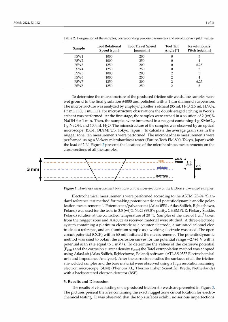
To determine the microstructure of the produced friction stir welds, the samples werewet ground to the final gradation #4000 and polished with a 1 µm diamond suspension.The microstructure was analyzed by employing Keller’s etchant (95 mL H2O, 2.5 mL HNO3,1.5 mL HCl, 1 mL HF). For microstructure observations the double-staged etching in Weck’setchant was performed. At the first stage, the samples were etched in a solution of 2 (wt)%NaOH for 1 min. Then, the samples were immersed in a reagent containing 4 g KMnO4,1 g NaOH, and 100 mL H2O. The microstructure of the samples was observed by an opticalmicroscope (BX51, OLYMPUS, Tokyo, Japan). To calculate the average grain size in thenugget zone, ten measurements were performed. The microhardness measurements wereperformed using a Vickers microhardness tester (Future-Tech FM-800, Tokyo, Japan) withthe load of 2 N. Figure 2 presents the locations of the microhardness measurements on thecross-sections of all the samples.
Metals 2022, 12, 192 4 of 17
Table 2. Designation of the samples, corresponding process parameters and revolutionary pitch values.
Sample Tool Rotational Speed [rpm]
Tool Travel Speed [mm/min]
Tool Tilt Angle [°]
Revolutionary Pitch [rot/min]
FSW1 1000 200 0 5 FSW2 1000 250 0 4 FSW3 1250 200 0 6.25 FSW4 1250 250 0 5 FSW5 1000 200 2 5 FSW6 1000 250 2 4 FSW7 1250 200 2 6.25 FSW8 1250 250 2 5
To determine the microstructure of the produced friction stir welds, the samples were wet ground to the final gradation #4000 and polished with a 1 μm diamond suspension. The microstructure was analyzed by employing Keller’s etchant (95 mL H2O, 2.5 mL HNO3, 1.5 mL HCl, 1 mL HF). For microstructure observations the double-staged etching in Weck’s etchant was performed. At the first stage, the samples were etched in a solution of 2 (wt)% NaOH for 1 min. Then, the samples were immersed in a reagent containing 4 g KMnO4, 1 g NaOH, and 100 mL H2O. The microstructure of the samples was observed by an optical microscope (BX51, OLYMPUS, Tokyo, Japan). To calculate the average grain size in the nugget zone, ten measurements were performed. The microhardness measure-ments were performed using a Vickers microhardness tester (Future-Tech FM-800, Tokyo, Japan) with the load of 2 N. Figure 2 presents the locations of the microhardness measure-ments on the cross-sections of all the samples.
Figure 2. Hardness measurement locations on the cross-sections of the friction stir-welded sam-ples.
Electrochemical measurements were performed according to the ASTM G5-94 “Standard reference test method for making potentiostatic and potentiodynamic anodic polarization measurements”. Potentiostat/galvanostat (Atlas 0531, Atlas Sollich, Rębiechowo, Poland) was used for the tests in 3.5 (wt)% NaCl (99.8% purity, CHEMPUR, Piekary Śląskie, Poland) solution at the controlled temperature of 20 °C. Samples of the area of 1 cm2 taken from the nugget zone and AA6082 as received material were studied. A three-electrode system containing a platinum electrode as a counter electrode, a satu-rated calomel electrode as a reference, and an aluminum sample as a working electrode was used. The open circuit potential (OCP) within 60 min initiated the measurements. The potentiodynamic method was used to obtain the corrosion curves for the potential range −2/+1 V with a potential scan rate equal to 1 mV/s. To determine the values of the corrosive potential (Ecorr) and the corrosion current density (icorr) the Tafel extrapolation method was adopted using AtlasLab (Atlas Sollich, Rębiechowo, Poland) software (ATLAS 0532 Elec-trochemical unit and Impedance Analyser). After the corrosion studies the surfaces of all the friction stir-welded samples and the base material were observed using a high resolu-tion scanning electron microscope (SEM) (Phenom XL, Thermo Fisher Scientific, Breda, Netherlands) with a backscattered electron detector (BSE).
Figure 2. Hardness measurement locations on the cross-sections of the friction stir-welded samples.
Electrochemical measurements were performed according to the ASTM G5-94 “Stan-dard reference test method for making potentiostatic and potentiodynamic anodic polar-ization measurements”. Potentiostat/galvanostat (Atlas 0531, Atlas Sollich, Rebiechowo,Poland) was used for the tests in 3.5 (wt)% NaCl (99.8% purity, CHEMPUR, Piekary Slaskie,Poland) solution at the controlled temperature of 20 ◦C. Samples of the area of 1 cm2 takenfrom the nugget zone and AA6082 as received material were studied. A three-electrodesystem containing a platinum electrode as a counter electrode, a saturated calomel elec-trode as a reference, and an aluminum sample as a working electrode was used. The opencircuit potential (OCP) within 60 min initiated the measurements. The potentiodynamicmethod was used to obtain the corrosion curves for the potential range −2/+1 V with apotential scan rate equal to 1 mV/s. To determine the values of the corrosive potential(Ecorr) and the corrosion current density (icorr) the Tafel extrapolation method was adoptedusing AtlasLab (Atlas Sollich, Rebiechowo, Poland) software (ATLAS 0532 Electrochemicalunit and Impedance Analyser). After the corrosion studies the surfaces of all the frictionstir-welded samples and the base material were observed using a high resolution scanningelectron microscope (SEM) (Phenom XL, Thermo Fisher Scientific, Breda, Netherlands)with a backscattered electron detector (BSE).
3. Results and Discussion
The results of visual testing of the produced friction stir welds are presented in Figure 3.The pictures present the area containing the exact nugget zone cutout location for electro-chemical testing. It was observed that the top surfaces exhibit no serious imperfections
Metals 2022, 12, 192 5 of 16
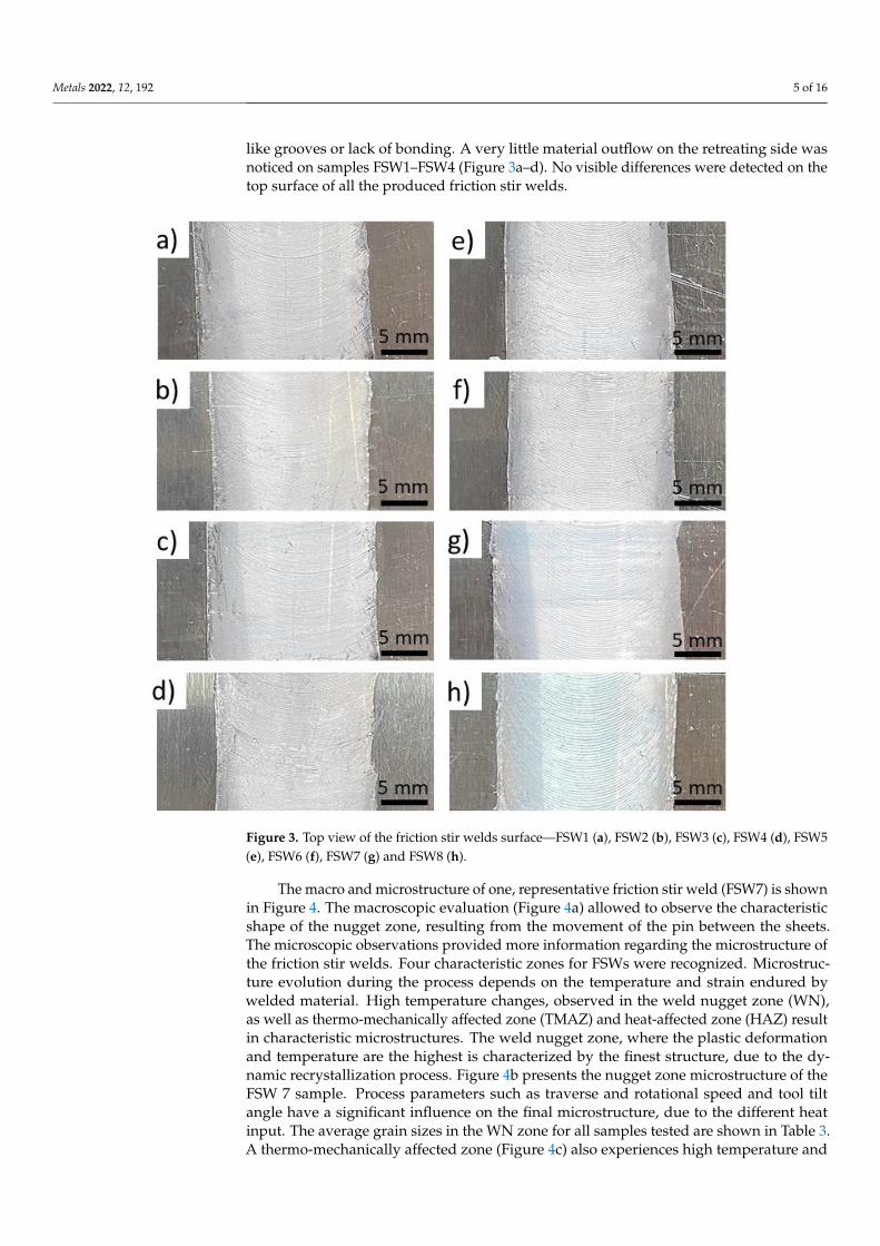
like grooves or lack of bonding. A very little material outflow on the retreating side wasnoticed on samples FSW1–FSW4 (Figure 3a–d). No visible differences were detected on thetop surface of all the produced friction stir welds.
Metals 2022, 12, 192 5 of 17
3. Results and Discussion The results of visual testing of the produced friction stir welds are presented in Figure
3. The pictures present the area containing the exact nugget zone cutout location for elec-trochemical testing. It was observed that the top surfaces exhibit no serious imperfections like grooves or lack of bonding. A very little material outflow on the retreating side was noticed on samples FSW1–FSW4 (Figure 3a–d). No visible differences were detected on the top surface of all the produced friction stir welds.
Figure 3. Top view of the friction stir welds surface—FSW1 (a), FSW2 (b), FSW3 (c), FSW4 (d), FSW5 (e), FSW6 (f), FSW7 (g) and FSW8 (h).
The macro and microstructure of one, representative friction stir weld (FSW7) is shown in Figure 4. The macroscopic evaluation (Figure 4a) allowed to observe the charac-teristic shape of the nugget zone, resulting from the movement of the pin between the sheets. The microscopic observations provided more information regarding the micro-structure of the friction stir welds. Four characteristic zones for FSWs were recognized. Microstructure evolution during the process depends on the temperature and strain en-dured by welded material. High temperature changes, observed in the weld nugget zone (WN), as well as thermo-mechanically affected zone (TMAZ) and heat-affected zone (HAZ) result in characteristic microstructures. The weld nugget zone, where the plastic deformation and temperature are the highest is characterized by the finest structure, due
Figure 3. Top view of the friction stir welds surface—FSW1 (a), FSW2 (b), FSW3 (c), FSW4 (d), FSW5(e), FSW6 (f), FSW7 (g) and FSW8 (h).
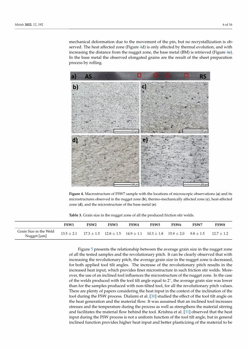
The macro and microstructure of one, representative friction stir weld (FSW7) is shownin Figure 4. The macroscopic evaluation (Figure 4a) allowed to observe the characteristicshape of the nugget zone, resulting from the movement of the pin between the sheets.The microscopic observations provided more information regarding the microstructure ofthe friction stir welds. Four characteristic zones for FSWs were recognized. Microstruc-ture evolution during the process depends on the temperature and strain endured bywelded material. High temperature changes, observed in the weld nugget zone (WN),as well as thermo-mechanically affected zone (TMAZ) and heat-affected zone (HAZ) resultin characteristic microstructures. The weld nugget zone, where the plastic deformationand temperature are the highest is characterized by the finest structure, due to the dy-namic recrystallization process. Figure 4b presents the nugget zone microstructure of theFSW 7 sample. Process parameters such as traverse and rotational speed and tool tiltangle have a significant influence on the final microstructure, due to the different heatinput. The average grain sizes in the WN zone for all samples tested are shown in Table 3.A thermo-mechanically affected zone (Figure 4c) also experiences high temperature and
Metals 2022, 12, 192 6 of 16
mechanical deformation due to the movement of the pin, but no recrystallization is ob-served. The heat affected zone (Figure 4d) is only affected by thermal evolution, and withincreasing the distance from the nugget zone, the base metal (BM) is retrieved (Figure 4e).In the base metal the observed elongated grains are the result of the sheet preparationprocess by rolling.
Metals 2022, 12, 192 6 of 17
to the dynamic recrystallization process. Figure 4b presents the nugget zone microstruc-ture of the FSW 7 sample. Process parameters such as traverse and rotational speed and tool tilt angle have a significant influence on the final microstructure, due to the different heat input. The average grain sizes in the WN zone for all samples tested are shown in Table 3. A thermo-mechanically affected zone (Figure 4c) also experiences high tempera-ture and mechanical deformation due to the movement of the pin, but no recrystallization is observed. The heat affected zone (Figure 4d) is only affected by thermal evolution, and with increasing the distance from the nugget zone, the base metal (BM) is retrieved (Figure 4e). In the base metal the observed elongated grains are the result of the sheet preparation process by rolling.
Figure 4. Macrostructure of FSW7 sample with the locations of microscopic observations (a) and its microstructures observed in the nugget zone (b), thermo-mechanically affected zone (c), heat-af-fected zone (d), and the microstructure of the base metal (e).
Table 3. Grain size in the nugget zone of all the produced friction stir welds.
FSW1 FSW2 FSW3 FSW4 FSW5 FSW6 FSW7 FSW8
Grain Size in the Weld Nugget [µm] 13.5 ± 2.1 17.3 ± 1.5 12.8 ± 1.5 14.9 ± 1.1 10.3 ±
1.8 15.9 ± 2.0 9.8 ± 1.5 12.7 ± 1.2
Figure 5 presents the relationship between the average grain size in the nugget zone of all the tested samples and the revolutionary pitch. It can be clearly observed that with increasing the revolutionary pitch, the average grain size in the nugget zone is decreased, for both applied tool tilt angles. The increase of the revolutionary pitch results in the in-creased heat input, which provides finer microstructure in such friction stir welds. More-over, the use of an inclined tool influences the microstructure of the nugget zone. In the case of the welds produced with the tool tilt angle equal to 2°, the average grain size was lower than for the samples produced with non-tilted tool, for all the revolutionary pitch values. There are plenty of papers considering the heat input in the context of the inclina-tion of the tool during the FSW process. Dialami et al. [30] studied the effect of the tool tilt angle on the heat generation and the material flow. It was assumed that an inclined tool
Figure 4. Macrostructure of FSW7 sample with the locations of microscopic observations (a) and itsmicrostructures observed in the nugget zone (b), thermo-mechanically affected zone (c), heat-affectedzone (d), and the microstructure of the base metal (e).
Table 3. Grain size in the nugget zone of all the produced friction stir welds.
FSW1 FSW2 FSW3 FSW4 FSW5 FSW6 FSW7 FSW8
Grain Size in the WeldNugget [µm] 13.5 ± 2.1 17.3 ± 1.5 12.8 ± 1.5 14.9 ± 1.1 10.3 ± 1.8 15.9 ± 2.0 9.8 ± 1.5 12.7 ± 1.2
Figure 5 presents the relationship between the average grain size in the nugget zoneof all the tested samples and the revolutionary pitch. It can be clearly observed that withincreasing the revolutionary pitch, the average grain size in the nugget zone is decreased,for both applied tool tilt angles. The increase of the revolutionary pitch results in theincreased heat input, which provides finer microstructure in such friction stir welds. More-over, the use of an inclined tool influences the microstructure of the nugget zone. In the caseof the welds produced with the tool tilt angle equal to 2◦, the average grain size was lowerthan for the samples produced with non-tilted tool, for all the revolutionary pitch values.There are plenty of papers considering the heat input in the context of the inclination of thetool during the FSW process. Dialami et al. [30] studied the effect of the tool tilt angle onthe heat generation and the material flow. It was assumed that an inclined tool increasesstresses and the temperature during the process as well as strengthens the material stirringand facilitates the material flow behind the tool. Krishna et al. [31] observed that the heatinput during the FSW process is not a uniform function of the tool tilt angle, but in generalinclined function provides higher heat input and better plasticizing of the material to be

Metals 2022, 12, 192 7 of 16
welded. Analysis of Meshram et al. [32] shows that the tool tilt angle of 2◦ provides thehighest temperature of both advancing and retreating sides of the friction stir weld andthus proper plasticizing, mixing, and recrystallization are achieved.
Metals 2022, 12, 192 7 of 17
increases stresses and the temperature during the process as well as strengthens the ma-terial stirring and facilitates the material flow behind the tool. Krishna et al. [31] observed that the heat input during the FSW process is not a uniform function of the tool tilt angle, but in general inclined function provides higher heat input and better plasticizing of the material to be welded. Analysis of Meshram et al. [32] shows that the tool tilt angle of 2° provides the highest temperature of both advancing and retreating sides of the friction stir weld and thus proper plasticizing, mixing, and recrystallization are achieved.
Figure 5. Average grain size in the nugget zone as a function of revolutionary pitch.
Figure 6 presents the Vickers microhardness profiles measured in different locations on the cross-sections of the friction stir welds. The microhardness of the base material was about 100 HV. Friction stir welding of precipitation hard-enable alloys, among them AA6082 aluminum alloy, results in the inhomogeneous hardness distribution leading to the formation of a softened area. The dissolution of the strengthening particles in the alu-minum matrix and the decrease of the dislocation density causes the decrease of the hard-ness in the thermo-mechanically affected zone (TMAZ) and heat-affected zone (HAZ) [33–35]. In all the cases, the minimum hardness was observed in the heat-affected zone, while in the nugget zone a recovered hardness was noted. Due to the fine microstructure of the nugget zone, the increase in the hardness can be explained by the Hall-Petch relationship, which indicates the increase of the hardness as the grain size decreases [36]. The Hall-Petch equation can be expressed as: σ = σ + kd / (1)
where σ is the yield stress, 𝜎 is the resistance to the dislocation motion in the grain inte-rior, k is a measure of the local stress needed to initiate plastic flow at grain boundaries, and d is a grain size [37]. In the case of the hardness, the Equation (1) can be presented as: H = H + k′d / (2)
where H is the hardness of the material, H0 and k’ are empirical constants [38]. The highest hardness of the nugget zone of about 92 HV was noted for FSW7 samples. Moreover, the smallest grain size was observed for this sample, which is in agreement with the Hall-Petch relationship.
The characteristic for the cross-sections of FSW joints hardness distribution is often reported in the case of aluminum alloys [39–44].
Figure 5. Average grain size in the nugget zone as a function of revolutionary pitch.
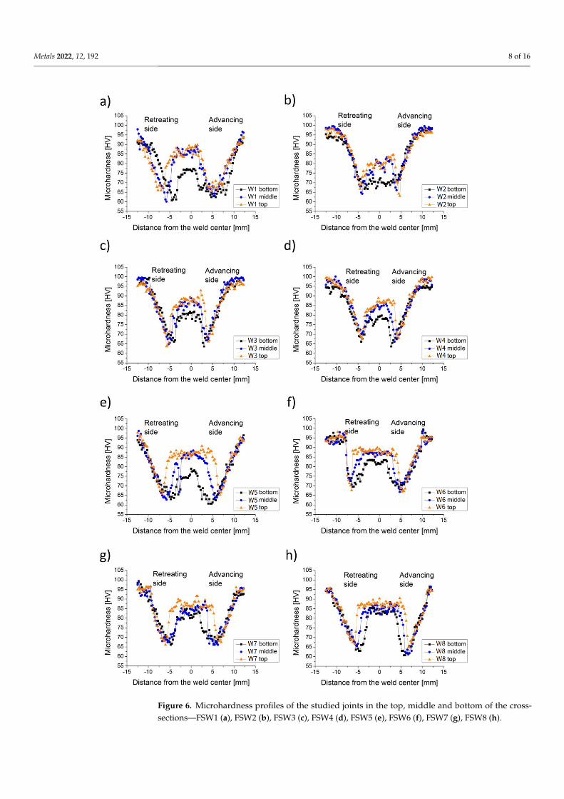
Figure 6 presents the Vickers microhardness profiles measured in different locationson the cross-sections of the friction stir welds. The microhardness of the base materialwas about 100 HV. Friction stir welding of precipitation hard-enable alloys, among themAA6082 aluminum alloy, results in the inhomogeneous hardness distribution leading to theformation of a softened area. The dissolution of the strengthening particles in the aluminummatrix and the decrease of the dislocation density causes the decrease of the hardness inthe thermo-mechanically affected zone (TMAZ) and heat-affected zone (HAZ) [33–35].In all the cases, the minimum hardness was observed in the heat-affected zone, while inthe nugget zone a recovered hardness was noted. Due to the fine microstructure of thenugget zone, the increase in the hardness can be explained by the Hall-Petch relationship,which indicates the increase of the hardness as the grain size decreases [36]. The Hall-Petchequation can be expressed as:
σ = σ0 + kd−1/2 (1)
where σ is the yield stress, σ0 is the resistance to the dislocation motion in the grain interior,k is a measure of the local stress needed to initiate plastic flow at grain boundaries, and d isa grain size [37]. In the case of the hardness, the Equation (1) can be presented as:
H = H0 + k′d−1/2 (2)
where H is the hardness of the material, H0 and k′ are empirical constants [38]. The highesthardness of the nugget zone of about 92 HV was noted for FSW7 samples. Moreover,the smallest grain size was observed for this sample, which is in agreement with theHall-Petch relationship.
Metals 2022, 12, 192 8 of 16Metals 2022, 12, 192 8 of 17
Figure 6. Microhardness profiles of the studied joints in the top, middle and bottom of the cross-sections—FSW1 (a), FSW2 (b), FSW3 (c), FSW4 (d), FSW5 (e), FSW6 (f), FSW7 (g), FSW8 (h). Figure 6. Microhardness profiles of the studied joints in the top, middle and bottom of the cross-sections—FSW1 (a), FSW2 (b), FSW3 (c), FSW4 (d), FSW5 (e), FSW6 (f), FSW7 (g), FSW8 (h).

Metals 2022, 12, 192 9 of 16
The characteristic for the cross-sections of FSW joints hardness distribution is oftenreported in the case of aluminum alloys [39–44].
The summary of the main observations regarding the hardness profiles behavior isshown in Figure 7. It presents the correlation of the maximum hardness observed in thecross-sections of the nugget zone and the revolutionary pitch for the friction stir weldsproduced with the tool tilt angle of 0◦ (a) and 2◦ (b). In the case of 0◦ tool tilt angle,the observed values of hardness were lower than the ones observed in the case of thesamples FSW5–FSW8. Clearly, in all the cases the lowest values were noted in the bottomof all the friction stir welds, while the highest were observed in the top of the samples.The top of the friction stir welds experienced the most significant heating due to the contactwith the tool shoulder and the frictional heating, resulting in the finest microstructure andthe highest microhardness. Among all the welds, the maximum hardness, reaching ap-proximately 92% of the base material, was observed for the samples with the revolutionarypitch value equal to 6.25, for both applied the tool tilt angle values. As the revolutionarypitch increases, the heat input and the temperature during the process also increase. It canallow observing the most effective dynamic recrystallization. It can be also observed thatfor the samples produced with the highest revolutionary pitch the finest microstructure ofthe nugget zone was found. By decreasing the revolutionary pitch, the improper plasticflow might be observed and not sufficient dynamic recrystallization process can be noted.However, for further increase of the revolutionary pitch, the mixed material can be ex-tremely softened and subjected to the grain growth, which would result in the significantdecrease of the hardness in the nugget zone [45].
Metals 2022, 12, 192 9 of 17
The summary of the main observations regarding the hardness profiles behavior is shown in Figure 7. It presents the correlation of the maximum hardness observed in the cross-sections of the nugget zone and the revolutionary pitch for the friction stir welds produced with the tool tilt angle of 0° (a) and 2° (b). In the case of 0° tool tilt angle, the observed values of hardness were lower than the ones observed in the case of the samples FSW5–FSW8. Clearly, in all the cases the lowest values were noted in the bottom of all the friction stir welds, while the highest were observed in the top of the samples. The top of the friction stir welds experienced the most significant heating due to the contact with the tool shoulder and the frictional heating, resulting in the finest microstructure and the highest microhardness. Among all the welds, the maximum hardness, reaching approxi-mately 92% of the base material, was observed for the samples with the revolutionary pitch value equal to 6.25, for both applied the tool tilt angle values. As the revolutionary pitch increases, the heat input and the temperature during the process also increase. It can allow observing the most effective dynamic recrystallization. It can be also observed that for the samples produced with the highest revolutionary pitch the finest microstructure of the nugget zone was found. By decreasing the revolutionary pitch, the improper plastic flow might be observed and not sufficient dynamic recrystallization process can be noted. However, for further increase of the revolutionary pitch, the mixed material can be ex-tremely softened and subjected to the grain growth, which would result in the significant decrease of the hardness in the nugget zone [45].
Figure 7. Maximum hardness of the nugget zone as a function of the revolutionary pitch—relation-ship for the friction stir welds produced with the tilt angle 0° (a) and 2° (b).
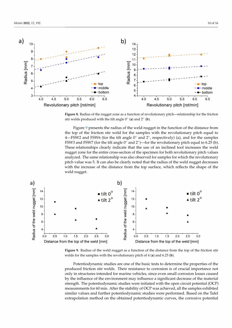
The radius of the nugget zone in the exact locations of the cross-sections of the friction stir welds as a function of the revolutionary pitch is presented in Figure 8. It can be clearly seen that in all the cases the highest values were observed in the top of the samples and the lowest in the bottom, which reflects the characteristic shape of the weld nugget [46–48]. It can be observed that with an increase of the revolutionary pitch, also the radius of the nugget zone increases. It is also attributed to the increase of the heat input during the process, as the revolutionary pitch is higher. In this case, the zone interested by the con-tinuous dynamic recrystallization increases in dimensions and consequently the meas-ured radius increases showing a larger zone of increased hardness with respect to TMAZ and HAZ.
Figure 7. Maximum hardness of the nugget zone as a function of the revolutionary pitch—relationshipfor the friction stir welds produced with the tilt angle 0◦ (a) and 2◦ (b).
The radius of the nugget zone in the exact locations of the cross-sections of the frictionstir welds as a function of the revolutionary pitch is presented in Figure 8. It can be clearlyseen that in all the cases the highest values were observed in the top of the samples andthe lowest in the bottom, which reflects the characteristic shape of the weld nugget [46–48].It can be observed that with an increase of the revolutionary pitch, also the radius ofthe nugget zone increases. It is also attributed to the increase of the heat input duringthe process, as the revolutionary pitch is higher. In this case, the zone interested bythe continuous dynamic recrystallization increases in dimensions and consequently themeasured radius increases showing a larger zone of increased hardness with respect toTMAZ and HAZ.
Metals 2022, 12, 192 10 of 16Metals 2022, 12, 192 10 of 17
Figure 8. Radius of the nugget zone as a function of revolutionary pitch—relationship for the friction stir welds produced with the tilt angle 0° (a) and 2° (b).
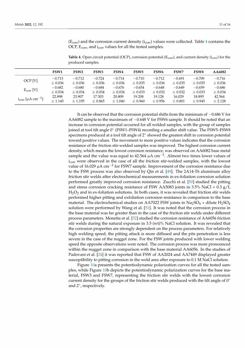
Figure 9 presents the radius of the weld nugget in the function of the distance from the top of the friction stir weld for the samples with the revolutionary pitch equal to 4—FSW2 and FSW6 (for the tilt angle 0° and 2°, respectively) (a), and for the samples FSW3 and FSW7 (for the tilt angle 0° and 2°)—for the revolutionary pitch equal to 6.25 (b). These relationships clearly indicate that the use of an inclined tool increases the weld nugget zone for the entire cross-section of the specimen for both revolutionary pitch values ana-lyzed. The same relationship was also observed for samples for which the revolutionary pitch value was 5. It can also be clearly noted that the radius of the weld nugget decreases with the increase of the distance from the top surface, which reflects the shape of the weld nugget.
Figure 9. Radius of the weld nugget as a function of the distance from the top of the friction stir welds for the samples with the revolutionary pitch of 4 (a) and 6.25 (b).
Potentiodynamic studies are one of the basic tests to determine the properties of the produced friction stir welds. Their resistance to corrosion is of crucial importance not only in structures intended for marine vehicles, since even small corrosion losses caused by the influence of the environment may influence a significant decrease of the material strength. The potentiodynamic studies were initiated with the open circuit potential (OCP) meas-urements for 60 min. After the stability of OCP was achieved, all the samples exhibited similar values and further potentiodynamic studies were performed. Based on the Tafel extrapolation method on the obtained potentiodynamic curves, the corrosive potential (Ecorr) and the corrosion current density (icorr) values were collected. Table 4 contains the OCP, Ecorr, and icorr values for all the tested samples.
Figure 8. Radius of the nugget zone as a function of revolutionary pitch—relationship for the frictionstir welds produced with the tilt angle 0◦ (a) and 2◦ (b).
Figure 9 presents the radius of the weld nugget in the function of the distance fromthe top of the friction stir weld for the samples with the revolutionary pitch equal to4—FSW2 and FSW6 (for the tilt angle 0◦ and 2◦, respectively) (a), and for the samplesFSW3 and FSW7 (for the tilt angle 0◦ and 2◦)—for the revolutionary pitch equal to 6.25 (b).These relationships clearly indicate that the use of an inclined tool increases the weldnugget zone for the entire cross-section of the specimen for both revolutionary pitch valuesanalyzed. The same relationship was also observed for samples for which the revolutionarypitch value was 5. It can also be clearly noted that the radius of the weld nugget decreaseswith the increase of the distance from the top surface, which reflects the shape of theweld nugget.
Metals 2022, 12, 192 10 of 17
Figure 8. Radius of the nugget zone as a function of revolutionary pitch—relationship for the friction stir welds produced with the tilt angle 0° (a) and 2° (b).
Figure 9 presents the radius of the weld nugget in the function of the distance from the top of the friction stir weld for the samples with the revolutionary pitch equal to 4—FSW2 and FSW6 (for the tilt angle 0° and 2°, respectively) (a), and for the samples FSW3 and FSW7 (for the tilt angle 0° and 2°)—for the revolutionary pitch equal to 6.25 (b). These relationships clearly indicate that the use of an inclined tool increases the weld nugget zone for the entire cross-section of the specimen for both revolutionary pitch values ana-lyzed. The same relationship was also observed for samples for which the revolutionary pitch value was 5. It can also be clearly noted that the radius of the weld nugget decreases with the increase of the distance from the top surface, which reflects the shape of the weld nugget.
Figure 9. Radius of the weld nugget as a function of the distance from the top of the friction stir welds for the samples with the revolutionary pitch of 4 (a) and 6.25 (b).
Potentiodynamic studies are one of the basic tests to determine the properties of the produced friction stir welds. Their resistance to corrosion is of crucial importance not only in structures intended for marine vehicles, since even small corrosion losses caused by the influence of the environment may influence a significant decrease of the material strength. The potentiodynamic studies were initiated with the open circuit potential (OCP) meas-urements for 60 min. After the stability of OCP was achieved, all the samples exhibited similar values and further potentiodynamic studies were performed. Based on the Tafel extrapolation method on the obtained potentiodynamic curves, the corrosive potential (Ecorr) and the corrosion current density (icorr) values were collected. Table 4 contains the OCP, Ecorr, and icorr values for all the tested samples.
Figure 9. Radius of the weld nugget as a function of the distance from the top of the friction stirwelds for the samples with the revolutionary pitch of 4 (a) and 6.25 (b).
Potentiodynamic studies are one of the basic tests to determine the properties of theproduced friction stir welds. Their resistance to corrosion is of crucial importance notonly in structures intended for marine vehicles, since even small corrosion losses causedby the influence of the environment may influence a significant decrease of the materialstrength. The potentiodynamic studies were initiated with the open circuit potential (OCP)measurements for 60 min. After the stability of OCP was achieved, all the samples exhibitedsimilar values and further potentiodynamic studies were performed. Based on the Tafelextrapolation method on the obtained potentiodynamic curves, the corrosive potential
Metals 2022, 12, 192 11 of 16
(Ecorr) and the corrosion current density (icorr) values were collected. Table 4 contains theOCP, Ecorr, and icorr values for all the tested samples.
Table 4. Open circuit potential (OCP), corrosion potential (Ecorr), and current density (icorr) for theproduced samples.
FSW1 FSW2 FSW3 FSW4 FSW5 FSW6 FSW7 FSW8 AA6082
OCP [V] −0.713± 0.036
−0.712± 0.036
−0.724± 0.036
−0.714± 0.036
−0.710± 0.035
−0.712± 0.036
−0.691± 0.035
−0.709± 0.035
−0.716± 0.036
Ecorr [V] −0.682± 0.034
−0.680± 0.034
−0.684± 0.034
−0.676± 0.034
−0.654± 0.033
−0.648± 0.032
−0.649± 0.032
−0.659± 0.033
−0.686± 0.034
icorr [µA·cm−2]22.898± 1.145
23.907± 1.195
17.303± 0.865
20.809± 1.040
19.208± 0.960
19.128± 0.956
16.029± 0.801
18.895± 0.945
42.564± 2.128
It can be observed that the corrosion potential shifts from the minimum of−0.686 V forAA6082 sample to the maximum of −0.648 V for FSW6 sample. It should be noted that anincrease in corrosion potential occurred for all welded samples, with the group of samplesjoined at tool tilt angle 0◦ (FSW1–FSW4) recording a smaller shift value. The FSW5–FSW8specimens produced at a tool tilt angle of 2◦ showed the greatest shift in corrosion potentialtoward positive values. The movement to more positive values indicates that the corrosionresistance of the friction stir-welded samples was improved. The highest corrosion currentdensity, which means the lowest corrosion resistance, was observed on AA6082 base metalsample and the value was equal to 42.564 µA cm−2. Almost two times lower values oficorr were observed in the case of all the friction stir-welded samples, with the lowestvalue of 16.029 µA cm−2 for FSW7 sample. Improvement of the corrosion resistance dueto the FSW process was also observed by Qin et al. [49]. The 2A14-T6 aluminum alloyfriction stir welds after electrochemical measurements in ex-foliation corrosion solutionperformed greatly improved corrosion resistance. Zucchi et al. [50] studied the pittingand stress corrosion cracking resistance of FSW AA5083 joints in 3.5% NaCl + 0.3 g/LH2O2 and in ex-foliation solutions. In both cases, it was revealed that friction stir weldsperformed higher pitting and exfoliation corrosion resistance in comparison to the basematerial. The electrochemical studies on AA7022 FSW joints in Na2SO4 + dilute H2SO4solution were performed by Wang et al. [51]. It was noted that the corrosion process inthe base material was far greater than in the case of the friction stir welds under differentprocess parameters. Monetta et al. [52] studied the corrosion resistance of AA6056 frictionstir welds during the natural exposure in 3.5 (wt)% NaCl solution. It was revealed thatthe corrosion properties are strongly dependent on the process parameters. For relativelyhigh welding speed, the pitting attack is more diffused and the pits penetration is lesssevere in the case of the nugget zone. For the FSW joints produced with lower weldingspeed the opposite observations were noted. The corrosion process was more pronouncedwithin the nugget zone in comparison with the base material AA6056. In the studies ofPadovani et al. [24] it was reported that FSW of AA2024 and AA7449 displayed greatersusceptibility to pitting corrosion in the weld area after exposure to 0.1 M NaCl solution.
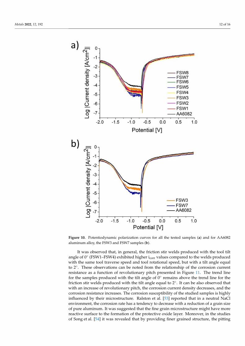
Figure 10a presents the potentiodynamic polarization curves for all the tested sam-ples, while Figure 10b depicts the potentiodynamic polarization curves for the base ma-terial, FSW3 and FSW7, representing the friction stir welds with the lowest corrosioncurrent density for the groups of the friction stir welds produced with the tilt angle of 0◦
and 2◦, respectively.
Metals 2022, 12, 192 12 of 16Metals 2022, 12, 192 12 of 17
Figure 10. Potentiodynamic polarization curves for all the tested samples (a) and for AA6082 alu-minum alloy, the FSW3 and FSW7 samples (b).
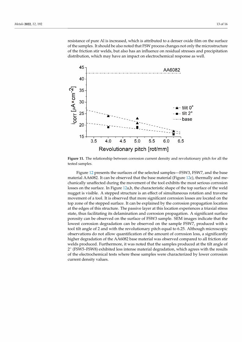
It was observed that, in general, the friction stir welds produced with the tool tilt angle of 0° (FSW1–FSW4) exhibited higher icorr values compared to the welds produced with the same tool traverse speed and tool rotational speed, but with a tilt angle equal to 2°. These observations can be noted from the relationship of the corrosion current re-sistance as a function of revolutionary pitch presented in Figure 11. The trend line for the samples produced with the tilt angle of 0° remains above the trend line for the friction stir welds produced with the tilt angle equal to 2°. It can be also observed that with an increase of revolutionary pitch, the corrosion current density decreases, and the corrosion re-sistance increases. The corrosion susceptibility of the studied samples is highly influenced by their microstructure. Ralston et al. [53] reported that in a neutral NaCl environment, the corrosion rate has a tendency to decrease with a reduction of a grain size of pure alu-minum. It was suggested that the fine grain microstructure might have more reactive sur-face to the formation of the protective oxide layer. Moreover, in the studies of Song et al.
Figure 10. Potentiodynamic polarization curves for all the tested samples (a) and for AA6082aluminum alloy, the FSW3 and FSW7 samples (b).
It was observed that, in general, the friction stir welds produced with the tool tiltangle of 0◦ (FSW1–FSW4) exhibited higher icorr values compared to the welds producedwith the same tool traverse speed and tool rotational speed, but with a tilt angle equalto 2◦. These observations can be noted from the relationship of the corrosion currentresistance as a function of revolutionary pitch presented in Figure 11. The trend linefor the samples produced with the tilt angle of 0◦ remains above the trend line for thefriction stir welds produced with the tilt angle equal to 2◦. It can be also observed thatwith an increase of revolutionary pitch, the corrosion current density decreases, and thecorrosion resistance increases. The corrosion susceptibility of the studied samples is highlyinfluenced by their microstructure. Ralston et al. [53] reported that in a neutral NaClenvironment, the corrosion rate has a tendency to decrease with a reduction of a grain sizeof pure aluminum. It was suggested that the fine grain microstructure might have morereactive surface to the formation of the protective oxide layer. Moreover, in the studiesof Song et al. [54] it was revealed that by providing finer grained structure, the pitting
Metals 2022, 12, 192 13 of 16
resistance of pure Al is increased, which is attributed to a denser oxide film on the surfaceof the samples. It should be also noted that FSW process changes not only the microstructureof the friction stir welds, but also has an influence on residual stresses and precipitationdistribution, which may have an impact on electrochemical response as well.
Metals 2022, 12, 192 13 of 17
[54] it was revealed that by providing finer grained structure, the pitting resistance of pure Al is increased, which is attributed to a denser oxide film on the surface of the samples. It should be also noted that FSW process changes not only the microstructure of the friction stir welds, but also has an influence on residual stresses and precipitation distribution, which may have an impact on electrochemical response as well.
Figure 11. The relationship between corrosion current density and revolutionary pitch for all the tested samples.
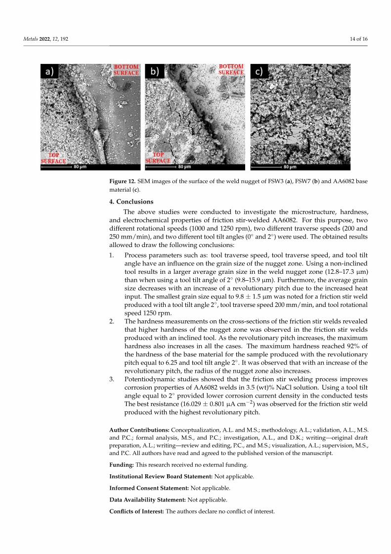
Figure 12 presents the surfaces of the selected samples—FSW3, FSW7, and the base material AA6082. It can be observed that the base material (Figure 12c), thermally and mechanically unaffected during the movement of the tool exhibits the most serious corro-sion losses on the surface. In Figure 12a,b, the characteristic shape of the top surface of the weld nugget is visible. A stepped structure is an effect of simultaneous rotation and trav-erse movement of a tool. It is observed that more significant corrosion losses are located on the top zone of the stepped surface. It can be explained by the corrosion propagation location at the edges of this structure. The passive layer at this location experiences a tri-axial stress state, thus facilitating its delamination and corrosion propagation. A signifi-cant surface porosity can be observed on the surface of FSW3 sample. SEM images indicate that the lowest corrosion degradation can be observed on the sample FSW7, produced with a tool tilt angle of 2 and with the revolutionary pitch equal to 6.25. Although micro-scopic observations do not allow quantification of the amount of corrosion loss, a signifi-cantly higher degradation of the AA6082 base material was observed compared to all fric-tion stir welds produced. Furthermore, it was noted that the samples produced at the tilt angle of 2° (FSW5–FSW8) exhibited less intense material degradation, which agrees with the results of the electrochemical tests where these samples were characterized by lower corrosion current density values.
Figure 11. The relationship between corrosion current density and revolutionary pitch for all thetested samples.
Figure 12 presents the surfaces of the selected samples—FSW3, FSW7, and the basematerial AA6082. It can be observed that the base material (Figure 12c), thermally and me-chanically unaffected during the movement of the tool exhibits the most serious corrosionlosses on the surface. In Figure 12a,b, the characteristic shape of the top surface of the weldnugget is visible. A stepped structure is an effect of simultaneous rotation and traversemovement of a tool. It is observed that more significant corrosion losses are located on thetop zone of the stepped surface. It can be explained by the corrosion propagation locationat the edges of this structure. The passive layer at this location experiences a triaxial stressstate, thus facilitating its delamination and corrosion propagation. A significant surfaceporosity can be observed on the surface of FSW3 sample. SEM images indicate that thelowest corrosion degradation can be observed on the sample FSW7, produced with atool tilt angle of 2 and with the revolutionary pitch equal to 6.25. Although microscopicobservations do not allow quantification of the amount of corrosion loss, a significantlyhigher degradation of the AA6082 base material was observed compared to all friction stirwelds produced. Furthermore, it was noted that the samples produced at the tilt angle of2◦ (FSW5–FSW8) exhibited less intense material degradation, which agrees with the resultsof the electrochemical tests where these samples were characterized by lower corrosioncurrent density values.
Metals 2022, 12, 192 14 of 16Metals 2022, 12, 192 14 of 17
Figure 12. SEM images of the surface of the weld nugget of FSW3 (a), FSW7 (b) and AA6082 base material (c).
4. Conclusions The above studies were conducted to investigate the microstructure, hardness, and
electrochemical properties of friction stir-welded AA6082. For this purpose, two different rotational speeds (1000 and 1250 rpm), two different traverse speeds (200 and 250 mm/min), and two different tool tilt angles (0° and 2°) were used. The obtained results allowed to draw the following conclusions: 1. Process parameters such as: tool traverse speed, tool traverse speed, and tool tilt an-
gle have an influence on the grain size of the nugget zone. Using a non-inclined tool results in a larger average grain size in the weld nugget zone (12.8–17.3 µm) than when using a tool tilt angle of 2° (9.8–15.9 µm). Furthermore, the average grain size decreases with an increase of a revolutionary pitch due to the increased heat input. The smallest grain size equal to 9.8 ± 1.5 µm was noted for a friction stir weld pro-duced with a tool tilt angle 2°, tool traverse speed 200 mm/min, and tool rotational speed 1250 rpm.
2. The hardness measurements on the cross-sections of the friction stir welds revealed that higher hardness of the nugget zone was observed in the friction stir welds pro-duced with an inclined tool. As the revolutionary pitch increases, the maximum hardness also increases in all the cases. The maximum hardness reached 92% of the hardness of the base material for the sample produced with the revolutionary pitch equal to 6.25 and tool tilt angle 2°. It was observed that with an increase of the revo-lutionary pitch, the radius of the nugget zone also increases.
3. Potentiodynamic studies showed that the friction stir welding process improves cor-rosion properties of AA6082 welds in 3.5 (wt)% NaCl solution. Using a tool tilt angle equal to 2° provided lower corrosion current density in the conducted tests The best resistance (16.029 ± 0.801 µA cm−2) was observed for the friction stir weld produced with the highest revolutionary pitch.
Author Contributions: Conceptualization, A.L. and M.S.; methodology, A.L.; validation, A.L., M.S. and P.C.; formal analysis, M.S., and P.C.; investigation, A.L., and D.K.; writing—original draft prep-aration, A.L.; writing—review and editing, P.C., and M.S.; visualization, A.L.; supervision, M.S., and P.C. All authors have read and agreed to the published version of the manuscript.
Funding: This research received no external funding.
Institutional Review Board Statement: Not applicable.
Informed Consent Statement: Not applicable.
Data Availability Statement: Not applicable.
Conflicts of Interest: The authors declare no conflict of interest.
Figure 12. SEM images of the surface of the weld nugget of FSW3 (a), FSW7 (b) and AA6082 basematerial (c).
4. Conclusions
The above studies were conducted to investigate the microstructure, hardness,and electrochemical properties of friction stir-welded AA6082. For this purpose, twodifferent rotational speeds (1000 and 1250 rpm), two different traverse speeds (200 and250 mm/min), and two different tool tilt angles (0◦ and 2◦) were used. The obtained resultsallowed to draw the following conclusions:
1. Process parameters such as: tool traverse speed, tool traverse speed, and tool tiltangle have an influence on the grain size of the nugget zone. Using a non-inclinedtool results in a larger average grain size in the weld nugget zone (12.8–17.3 µm)than when using a tool tilt angle of 2◦ (9.8–15.9 µm). Furthermore, the average grainsize decreases with an increase of a revolutionary pitch due to the increased heatinput. The smallest grain size equal to 9.8 ± 1.5 µm was noted for a friction stir weldproduced with a tool tilt angle 2◦, tool traverse speed 200 mm/min, and tool rotationalspeed 1250 rpm.
2. The hardness measurements on the cross-sections of the friction stir welds revealedthat higher hardness of the nugget zone was observed in the friction stir weldsproduced with an inclined tool. As the revolutionary pitch increases, the maximumhardness also increases in all the cases. The maximum hardness reached 92% ofthe hardness of the base material for the sample produced with the revolutionarypitch equal to 6.25 and tool tilt angle 2◦. It was observed that with an increase of therevolutionary pitch, the radius of the nugget zone also increases.
3. Potentiodynamic studies showed that the friction stir welding process improvescorrosion properties of AA6082 welds in 3.5 (wt)% NaCl solution. Using a tool tiltangle equal to 2◦ provided lower corrosion current density in the conducted testsThe best resistance (16.029 ± 0.801 µA cm−2) was observed for the friction stir weldproduced with the highest revolutionary pitch.
Author Contributions: Conceptualization, A.L. and M.S.; methodology, A.L.; validation, A.L., M.S.and P.C.; formal analysis, M.S., and P.C.; investigation, A.L., and D.K.; writing—original draftpreparation, A.L.; writing—review and editing, P.C., and M.S.; visualization, A.L.; supervision, M.S.,and P.C. All authors have read and agreed to the published version of the manuscript.
Funding: This research received no external funding.
Institutional Review Board Statement: Not applicable.
Informed Consent Statement: Not applicable.
Data Availability Statement: Not applicable.
Conflicts of Interest: The authors declare no conflict of interest.
Metals 2022, 12, 192 15 of 16
References1. Thomas, W.M.W.; Norris, I.; Nicholas, E.D.; Needham, J.C.; Murch, M.G.; Temple-Smith, P.; Dawes, C.J. Friction Stir Welding Pro-
cess Developments and Variant Techniques. International Patent Application No. PCT/GB92/02203 and GB Patent ApplicationNo. 9125978.8. 1991. Available online: https://www.scirp.org/(S(lz5mqp453ed%20snp55rrgjct55))/reference/referencespapers.aspx?referenceid=2200506 (accessed on 29 December 2021).
2. Laska, A.; Szkodo, M. Manufacturing Parameters, Materials, and Welds Properties of Butt Friction Stir Welded Joints–Overview.Materials 2020, 13, 4940. [CrossRef] [PubMed]
3. Sato, Y.S.; Urata, M.; Kokawa, H. Parameters controlling microstructure and hardness during friction-stir welding of precipitation-hardenable aluminum alloy 6063. Metall. Mater. Trans. A 2002, 33, 625–635. [CrossRef]
4. Ma, Z.Y.; Feng, A.H.; Chen, D.L.; Shen, J. Recent Advances in Friction Stir Welding/Processing of Aluminum Alloys: Microstruc-tural Evolution and Mechanical Properties. Crit. Rev. Solid State Mater. Sci. 2018, 43, 269–333. [CrossRef]
5. Cavaliere, P.; Rossi, G.L.; Di Sante, R.; Moretti, M. Thermoelasticity for the evaluation of fatigue behavior of 7005/Al2O3/10pmetal matrix composite sheets joined by FSW. Int. J. Fatigue 2008, 30, 198–206. [CrossRef]
6. Dursun, T.; Soutis, C. Recent developments in advanced aircraft aluminium alloys. Mater. Des. 2014, 56, 862–871. [CrossRef]7. Hirsch, J. Aluminium in innovative light-weight car design. Mater. Trans. 2011, 52, 818–824. [CrossRef]8. Ertug, B.; Kumruoglu, C. 5083 type Al-Mg and 6082 type Al-Mg-Si alloys for ship building. Am. J. Eng. Res. 2015, 4, 146–150.9. Ancona, A.; Daurelio, G.; De Filippis, L.A.C.; Ludovico, A.D.; Spera, A.M. CO2 Laser Welding of Aluminium Shipbuilding
Industry Alloys: AA 5083, AA 5383, AA 5059, and AA 6082. In Proceedings of the XIV International Symposium on Gas Flow,Chemical Lasers, and High-Power Lasers, Wroclaw, Poland, 25–30 August 2002; pp. 577–587.
10. Thomas, W.M.; Nicholas, E.D. Friction stir welding for the transportation industries. Mater. Des. 1997, 18, 269–273. [CrossRef]11. Kawasaki, T.; Makino, T.; Masai, K.; Ohba, H.; Ina, Y.; Ezumi, M. Application of friction stir welding to construction of railway
vehicles. JSME Int. J. Ser. A Solid Mech. Mater. Eng. 2004, 47, 502–511. [CrossRef]12. Davenport, A.J.; Kallee, S.W.; Wylde, G.J. Creating a Stir in the Rail Industry. Available online: https://www.twi-global.com/
technical-knowledge/published-papers/creating-a-stir-in-the-rail-industry-november-2001 (accessed on 29 December 2021).13. Prabhukhot, A.R. Effect of Heat Treatment on Hardness and Corrosion Behavior of 6082-T6 Aluminium Alloy in Artificial Sea
Water. Rev. Matéria 2015, 3, 544–549. [CrossRef]14. Singh, G.; Kumar, S.; Singh, A. Influence of Current on Microstructure and Hardness of Butt Welding Aluminium AA 6082 Using
GTAW Process. Int. J. Res. Mech. Eng. Technol. 2013, 3, 143–146.15. Koprivica, A.; Bajic, D.; Šibalic, N.; Vukcevic, M. Analysis of welding of aluminium alloy AA6082-T6 by TIG, MIG and FSW
processes from technological and economic aspect. Mach. Technol. Mater. 2020, 5, 194–198.16. Ericsson, M.; Sandström, R. Influence of welding speed on the fatigue of friction stir welds, and comparison with MIG and TIG.
Int. J. Fatigue 2003, 25, 1379–1387. [CrossRef]17. Hoyos, E.; Escobar, S.; De Backer, J.; Martin, J.; Palacio, M. Manufacturing concept and prototype for train component using the
fsw process. J. Manuf. Mater. Process. 2021, 5, 19. [CrossRef]18. Liu, Q.; Han, R.; Gao, Y.; Ke, L. Numerical investigation on thermo-mechanical and material flow characteristics in friction stir
welding for aluminum profile joint. Int. J. Adv. Manuf. Technol. 2021, 114, 2457–2469. [CrossRef]19. Baratzadeh, F.; Boldsaikhan, E.; Nair, R.; Burford, D.; Lankarani, H. Investigation of mechanical properties of AA6082-T6/AA6063-
T6 friction stir lap welds. J. Adv. Join. Process. 2020, 1, 100011. [CrossRef]20. Varma, K.V.K.; Baig, I.; Kumar, B.V.R.R.; Ramana, M.V. Effect of friction stir welding parameters on tool geometry and metallurgical
properties of AA 6082-T6 weldments at different weld zones. Mater. Today Proc. 2021, 45, 3195–3200. [CrossRef]21. Maciel, R.; Bento, T.; Braga, D.F.O.; da Silva, L.F.M.; Moreira, P.M.G.P.; Infante, V. Fatigue properties of combined friction stir and
adhesively bonded AA6082-T6 overlap joints. Fatigue Fract. Eng. Mater. Struct. 2020, 43, 2169–2180. [CrossRef]22. Leal, R.M.; Galv, I. Recent Developments in Non-Conventional Welding of Materials. Materials 2022, 15, 171. [CrossRef]23. Gharavi, F.; Matori, K.A.; Yunus, R.; Othman, N.K.; Fadaeifard, F. Corrosion evaluation of friction stir welded lap joints of
AA6061-T6 aluminum alloy. Trans. Nonferrous Met. Soc. China Engl. Ed. 2016, 26, 684–696. [CrossRef]24. Padovani, C.G.; Davenport, A.J.; Connolly, B.J.; Williams, S.W.; Groso, A.; Stampanoni, M.; Bellucci, F. Corrosion and Protection
of friction stir welds in aerospace aluminium alloys. La Metall. Ital. 2008, 100, 29–42.25. Ales, S.K.; Wang, L. Effects of Friction Stir Welding on Corrosion Behaviors of AA2024-T4 Aluminum Alloy. MATEC Web Conf.
2017, 109, 02003. [CrossRef]26. Scialpi, A.; De Filippis, L.A.C.; Cavaliere, P. Influence of shoulder geometry on microstructure and mechanical properties of
friction stir welded 6082 aluminium alloy. Mater. Des. 2007, 28, 1124–1129. [CrossRef]27. Rambabu, G.; Balaji Naik, D.; Venkata Rao, C.H.; Srinivasa Rao, K.; Madhusudan Reddy, G. Optimization of friction stir welding
parameters for improved corrosion resistance of AA2219 aluminum alloy joints. Def. Technol. 2015, 11, 330–337. [CrossRef]28. Patil, H.S.; Soman, S.N. Effect of tool geometry and welding speed on mechanical properties and microstructure of friction stir
welded joints of Aluminium alloys AA6082-T6. Arch. Mech. Eng. 2014, 61, 455–468. [CrossRef]29. Naumov, A.; Rylkov, E.; Polyakov, P.; Isupov, F.; Rudskoy, A.; Aoh, J.N.; Popovich, A.; Panchenko, O. Effect of different tool probe
profiles on material flow of al–mg–cu alloy joined by friction stir welding. Materials 2021, 14, 6296. [CrossRef] [PubMed]30. Dialami, N.; Cervera, M.; Chiumenti, M. Effect of the tool tilt angle on the heat generation and the material flow in friction stir
welding. Metals 2019, 9, 28. [CrossRef]
Metals 2022, 12, 192 16 of 16
31. Krishna, G.G.; Reddy, P.R.; Hussain, M.M. Effect of Tool Tilt Angle on Aluminum 2014 Friction Stir Welds. Glob. J. Res. Eng. 2014,14, 61–70.
32. Meshram, S.D.; Madhusudhan Reddy, G. Influence of tool tilt angle on material flow and defect generation in friction stir weldingof AA2219. Def. Sci. J. 2018, 68, 512–518. [CrossRef]
33. Baghdadi, A.H.; Sajuri, Z.; Omar, M.Z.; Rajabi, A. Friction stir welding parameters: Impact of abnormal grain growth duringpost-weld heat treatment on mechanical properties of Al–Mg–Si welded joints. Metals 2020, 10, 1607. [CrossRef]
34. Huang, Y.; Meng, X.; Zhang, Y.; Cao, J.; Feng, J. Micro friction stir welding of ultra-thin Al-6061 sheets. J. Mater. Process. Technol.2017, 250, 313–319. [CrossRef]
35. Huang, Y.; Meng, X.; Lv, Z.; Huang, T.; Zhang, Y.; Cao, J.; Zhou, L.; Feng, J. Microstructures and mechanical properties of microfriction stir welding (µFSW) of 6061-T4 aluminum alloy. J. Mater. Res. Technol. 2019, 8, 1084–1091. [CrossRef]
36. Naik, S.N.; Walley, S.M. The Hall–Petch and inverse Hall–Petch relations and the hardness of nanocrystalline metals. J. Mater. Sci.2020, 55, 2661–2681. [CrossRef]
37. Song, Y.; Yeon, J.; Na, B. Numerical simulations of the hall-petch relationship in aluminium using gradient-enhanced plasticitymodel. Adv. Civ. Eng. 2019, 2019, 7356581. [CrossRef]
38. Facchini, D. Biomedical nanocrystalline metals and alloys: Structure, properties and applications. Nanomedicine Technol. Appl.2012, 1, 36–67. [CrossRef]
39. Morozova, I.; Obrosov, A.; Naumov, A.; Królicka, A.; Golubev, I.; Bokov, D.O.; Doynov, N.; Weiß, S.; Michailov, V. Impact ofimpulses on microstructural evolution and mechanical performance of al-mg-si alloy joined by impulse friction stir welding.Materials 2021, 14, 347. [CrossRef]
40. Abbas, A.A.; Abdulkadhum, H.H. Effect of Shoulder–Workpiece Interference Depth on the Quality of Friction Stir Welding ofAA7075-T6 Aluminium Alloy. Assoc. Arab Univ. J. Eng. Sci. 2019, 26, 150–159. [CrossRef]
41. Dawood, H.I.; Mohammed, K.S.; Rajab, M.Y. Advantages of the green solid state FSW over the conventional GMAW process.Adv. Mater. Sci. Eng. 2014, 2014, 105713. [CrossRef]
42. Pastor, A.; Svoboda, H.G. Time-evolution of Heat Affected Zone (HAZ) of Friction Stir Welds of AA7075-T651. J. Mater. Phys.Chem. 2013, 1, 58–64. [CrossRef]
43. Rodríguez, A.; Calleja, A.; López de Lacalle, L.N.; Pereira, O.; González, H.; Urbikain, G.; Laye, J. Burnishing of FSWAluminumAl-Cu-Li components. Metals 2019, 9, 260. [CrossRef]
44. Wahid, M.A.; Khan, Z.A.; Siddiquee, A.N. Review on underwater friction stir welding: A variant of friction stir welding withgreat potential of improving joint properties. Trans. Nonferrous Met. Soc. China Engl. Ed. 2018, 28, 193–219. [CrossRef]
45. Cavaliere, P.; Squillace, A.; Panella, F. Effect of welding parameters on mechanical and microstructural properties of AA6082joints produced by friction stir welding. J. Mater. Process. Technol. 2008, 200, 364–372. [CrossRef]
46. Ahmed, M.M.Z.; Abdelazem, K.A.; El-Sayed Seleman, M.M.; Alzahrani, B.; Touileb, K.; Jouini, N.; El-Batanony, I.G.; Abd El-Aziz,H.M. Friction stir welding of 2205 duplex stainless steel: Feasibility of butt joint groove filling in comparison to gas tungsten arcwelding. Materials 2021, 14, 4597. [CrossRef] [PubMed]
47. Krasnowski, K.; Sedek, P.; Łomozik, M.; Pietras, A. Impact of selected FSW process parameters on mechanical properties of6082-T6 aluminium alloy butt joints. Arch. Metall. Mater. 2011, 56, 965–973. [CrossRef]
48. Aldanondo, E.; Vivas, J.; Alvarez, P.; Hurtado, I. Effect of Tool Geometry and Welding Parameters on Friction Stir Welded LapJoint Formation with AA2099-T83 and AA2060-T8E30 Aluminium Alloys. Metals 2020, 10, 872. [CrossRef]
49. Qin, H.L.; Zhang, H.; Sun, D.T.; Zhuang, Q.Y. Corrosion behavior of the friction-stir-welded joints of 2A14-T6 aluminum alloy.Int. J. Miner. Metall. Mater. 2015, 22, 627–638. [CrossRef]
50. Zucchi, F.; Trabanelli, G.; Grassi, V. Pitting and stress corrosion cracking resistance of friction stir welded AA 5083. Werkstoffe undKorrosion 2001, 52, 853–859. [CrossRef]
51. Wang, H.F.; Wang, J.L.; Song, W.W.; Zuo, D.W.; Shao, D.L. Analysis on the corrosion performance of friction stir welding joint of7022 aluminum alloy. Int. J. Electrochem. Sci. 2016, 11, 6933–6942. [CrossRef]
52. Monetta, T.; Montuori, M.; Squillace, A.; Bellucci, F. The Effect of Heat Treatment and Welding Parameters on the CorrosionBehaviour of a Friction Stir Welded 6056 Aluminium Alloy. Adv. Mater. Res. 2008, 38, 285–297. [CrossRef]
53. Ralston, K.D.; Fabijanic, D.; Birbilis, N. Effect of grain size on corrosion of high purity aluminium. Electrochim. Acta 2011, 56,1729–1736. [CrossRef]
54. Song, D.; Ma, A.; Jiang, J.; Lin, P.; Yang, D. Corrosion behavior of ultra-fine grained industrial pure Al fabricated by ECAP.Trans. Nonferrous Met. Soc. China Engl. Ed. 2009, 19, 1065–1070. [CrossRef]
Copyright © 2022 FDOKUMEN