EFFECT OF END SILL IN RADIAL BASIN ON CHARACTERISTICS OF FREE HYDRAAULIC JUMPS
13
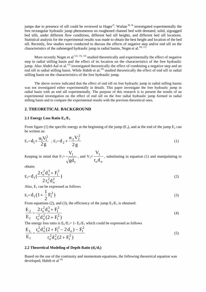
1 st International Conference of Civil Engineering Science, ICCES1, Vol. 1, 2003 EFFECT OF END SILL IN RADIAL BASIN ON CHARACTERISTICS OF FREE HYDRAAULIC JUMPS Abdel-Azim M. Negm, Gamal M. Aabdel-Aal, Amany A. Habib and T.M.Owais Dept. of Water & Water Structures Eng., Faculty of Engineering, Zagazig University, Zagazig, Egypt, E-mail: [email protected] ABSTRACT The end sill may be used in stilling basin to produce double effect on the flow upstream the sill and downstream of it. Upstream of the end sill, the characteristics of the hydraulic jump may be affected. Downstream of the end sill, the scour hole may be formed away from the apron and also may be modified in its dimensions. In this paper, the effect of end sill on the characteristics of the free hydraulic jump formed upstream of the sill in a radial basin is investigated experimentally. Sills of different heights were tested under wide range of flow conditions. It was found that the basic characteristics of the free radial hydraulic jump formed upstream of end sill are function of the supercritical flow Froude number and the relative height of the sill. The experimental data was used to estimate the derived functional relationship using the dimensional analysis. The developed statistical model agreed well with the experimental data. Moreover, a theoretical model for the energy loss ratio through the jump was developed and found to be in good agreement with the experimental data. Keywords: Hydraulic jump, Empirical modeling, Stilling basin, Non-prismatic basins, Expanding channels, End sill, Experimental studies 1. INTRODUCTION Hydraulic jumps are advantageous for dissipating kinetic energy in stilling basins. It may be free or submerged depending on both the location and the initial depth of the jump relative to the gate. The different classifications of jumps were reported in Chow 1) . The hydraulic jump may be also formed in prismatic or in non-prismatic channels (diverging or sudden expanded), and may be forced or non-forced. Most of the studies on different types of hydraulic jump are presented in Hager 2) . Khalifa and McCorquodale 3) , studied the radial hydraulic jump occurs in stilling basins with diverging side-walls. They concluded that the sequent depth ratio of the radial jump is less than that of the rectangular jump, and the length of the radial hydraulic jump is about 70% of that of rectangular jump with the same flow conditions. Also, the energy loss in a radial hydraulic jump was 15% higher than that of the rectangular jump. According to the various methods used in practice, stilling basins were arranged in a variety of geometrical configurations. On the other hand, sills or blocks were used in stilling basins to increase the rate of energy dissipation and to reduce the bed velocity in the region of the hydraulic jump. Many studies had been conducted to investigate the effect of sills in rectangular basins. The effect of the sill on the jump characteristics depends on factors such as the sill configuration, sill location and sill spacing when more than one sill was used. Several investigations dealt with the effect of sill on the hydraulic jump characteristics when the sill was constructed beneath hydraulic jump such as Shukry 4) , Rajaratnam 5) , Ohtsu and Yasuda 6) , and Hager and Li 7) . Hager and Li gave one of these classifications of the forced hydraulic jump due to vertical sill. They classified the jump over vertical sill into A-jump, B- jump, minimum B-jump and C-jump. The A-jump was corresponding to the classical hydraulic jump, which was characterized by the maximum sequent depth ratio for the free jumps. They stated that, A-jump in which the jump characteristics are not influenced by the presence of sill (or weak effect are present) as the sill was found at the end of the surface roller and thus it was out side the effective zone for the sill to affect the jump flow. Other studies on the effect of vertical sill on the jump and different classification of
Transcript of EFFECT OF END SILL IN RADIAL BASIN ON CHARACTERISTICS OF FREE HYDRAAULIC JUMPS
1st International Conference of Civil Engineering Science, ICCES1, Vol. 1, 2003
EFFECT OF END SILL IN RADIAL BASIN ON
CHARACTERISTICS OF FREE HYDRAAULIC JUMPS
Abdel-Azim M. Negm, Gamal M. Aabdel-Aal, Amany A. Habib and T.M.Owais
Dept. of Water & Water Structures Eng., Faculty of Engineering, Zagazig University,
Zagazig, Egypt, E-mail: [email protected]
ABSTRACT The end sill may be used in stilling basin to produce double effect on the flow upstream the
sill and downstream of it. Upstream of the end sill, the characteristics of the hydraulic jump may
be affected. Downstream of the end sill, the scour hole may be formed away from the apron and
also may be modified in its dimensions. In this paper, the effect of end sill on the characteristics of
the free hydraulic jump formed upstream of the sill in a radial basin is investigated experimentally.
Sills of different heights were tested under wide range of flow conditions. It was found that the
basic characteristics of the free radial hydraulic jump formed upstream of end sill are function of
the supercritical flow Froude number and the relative height of the sill. The experimental data was
used to estimate the derived functional relationship using the dimensional analysis. The developed
statistical model agreed well with the experimental data. Moreover, a theoretical model for the
energy loss ratio through the jump was developed and found to be in good agreement with the
experimental data.
Keywords: Hydraulic jump, Empirical modeling, Stilling basin, Non-prismatic basins, Expanding
channels, End sill, Experimental studies
1. INTRODUCTION
Hydraulic jumps are advantageous for dissipating kinetic energy in stilling basins. It may be
free or submerged depending on both the location and the initial depth of the jump relative to the gate.
The different classifications of jumps were reported in Chow1)
. The hydraulic jump may be also
formed in prismatic or in non-prismatic channels (diverging or sudden expanded), and may be forced
or non-forced. Most of the studies on different types of hydraulic jump are presented in Hager2)
.
Khalifa and McCorquodale3)
, studied the radial hydraulic jump occurs in stilling basins with
diverging side-walls. They concluded that the sequent depth ratio of the radial jump is less than that of the
rectangular jump, and the length of the radial hydraulic jump is about 70% of that of rectangular jump
with the same flow conditions. Also, the energy loss in a radial hydraulic jump was 15% higher than that
of the rectangular jump. According to the various methods used in practice, stilling basins were arranged
in a variety of geometrical configurations. On the other hand, sills or blocks were used in stilling basins to
increase the rate of energy dissipation and to reduce the bed velocity in the region of the hydraulic jump.
Many studies had been conducted to investigate the effect of sills in rectangular basins. The effect of the
sill on the jump characteristics depends on factors such as the sill configuration, sill location and sill
spacing when more than one sill was used. Several investigations dealt with the effect of sill on the
hydraulic jump characteristics when the sill was constructed beneath hydraulic jump such as Shukry 4)
,
Rajaratnam5)
, Ohtsu and Yasuda6), and Hager and Li
7). Hager and Li gave one of these classifications of
the forced hydraulic jump due to vertical sill. They classified the jump over vertical sill into A-jump, B-
jump, minimum B-jump and C-jump. The A-jump was corresponding to the classical hydraulic jump,
which was characterized by the maximum sequent depth ratio for the free jumps. They stated that, A-jump
in which the jump characteristics are not influenced by the presence of sill (or weak effect are present) as
the sill was found at the end of the surface roller and thus it was out side the effective zone for the sill to
affect the jump flow. Other studies on the effect of vertical sill on the jump and different classification of
jumps due to presence of sill could be reviewed in Hager2). Wafaie
8), 9) investigated experimentally the
free rectangular hydraulic jump phenomenon on roughened channel bed with dentated, solid, zigzagged
bed sills, under different flow conditions, different bed sill heights, and different bed sill locations.
Statistical analysis for the experimental results was made to obtain the best height and location of the bed
sill. Recently, few studies were conducted to discuss the effects of negative step and/or end sill on the
characteristics of the submerged hydraulic jump in radial basins, Negm et al.10), 11)
More recently Negm et al 12), 13), 14)
studied theoretically and experimentally the effect of negative
step in radial stilling basin and the effect of its location on the characteristics of the free hydraulic
jump. Also Abdel-Aal et al.15)
investigated theoretically the effect of combining a negative step and an
end sill in radial stilling basin. While Habib et al.16)
studied theoretically the effect of end sill in radial
stilling basin on the characteristics of the free hydraulic jump.
The above review indicated that the effect of end sill on free hydraulic jump in radial stilling basins
was not investigated either experimentally in details. This paper investigate the free hydraulic jump in
radial basin with an end sill experimentally. The purpose of this research is to present the results of an
experimental investigation on the effect of end sill on the free radial hydraulic jump formed in radial
stilling basin and to compare the experimental results with the previous theoretical ones.
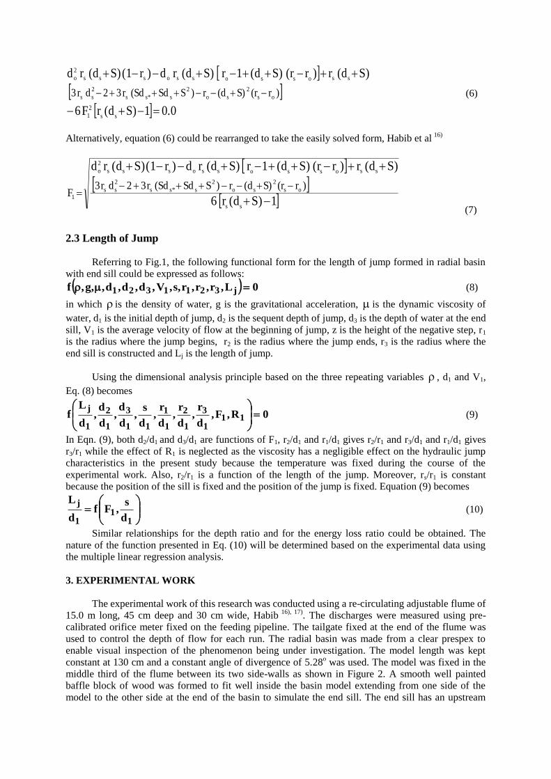
2. THEORETICAL BACKGROUND
2.1 Energy Loss Ratio EL/E1
From figure (1) the specific energy at the beginning of the jump (E1), and at the end of the jump E2 can
be written as:
E1=g2
Vαd
211
1 ; E2=g2
Vαd
222
2 (1)
Keeping in mind that F1=
1
1
gd
V, and V2=
oo
1
dr
V, substituting in equation (1) and manipulating to
obtain:
E2= )dr2
Fdr2(d
2o
2o
21
3o
2o
1
(2)
Also, E1 can be expressed as follows
E1= )F2
1(1d 2
11 (3)
From equations (2), and (3), the efficiency of the jump E2/E1 is obtained:
1
2
E
E=
)F(2dr
Fdr2
21
2o
2o
21
3o
2o
(4)
The energy loss ratio is EL/E1= 1- E2/E1 which could be expressed as follows
1
L
E
E=
)F(2dr
F)d2F(2dr
21
2o
2o
21o
21
2o
2o
(5)
2.2 Theoretical Modeling of Depth Ratio (d2/d1)
Based on the use of the continuity and momentum equations, the following theoretical equation was
developed, Habib et al 16)
0.01S)(drF6
S)(dr)r(rS)(d1rS)(drd)r(1S)(drd
ss
2
1
os
2
so
2
ss*s
2
ss
ssossossosss
2
o
)r(rS)(dr)SSd(Sdr32dr3
(6)
Alternatively, equation (6) could be rearranged to take the easily solved form, Habib et al 16)
1S)(dr6
S)(dr)r(rS)(d1rS)(drd)r(1S)(drd
ss
os
2
so
2
ss*s
2
ss
ssossossosss
2
o
1
)r(rS)(dr)SSd(Sdr32dr3F
(7)
2.3 Length of Jump
Referring to Fig.1, the following functional form for the length of jump formed in radial basin
with end sill could be expressed as follows:
0L,r,r,r,s,V,d,d,d,,g,f j3211321 (8)
in which is the density of water, g is the gravitational acceleration, is the dynamic viscosity of
water, d1 is the initial depth of jump, d2 is the sequent depth of jump, d3 is the depth of water at the end
sill, V1 is the average velocity of flow at the beginning of jump, z is the height of the negative step, r1
is the radius where the jump begins, r2 is the radius where the jump ends, r3 is the radius where the
end sill is constructed and Lj is the length of jump.
Using the dimensional analysis principle based on the three repeating variables , d1 and V1,
Eq. (8) becomes
0R,F,d
r,
d
r,
d
r,
d
s,
d
d,
d
d,
d
Lf 11
1
3
1
2
1
1
11
3
1
2
1
j
(9)
In Eqn. (9), both d2/d1 and d3/d1 are functions of F1, r2/d1 and r1/d1 gives r2/r1 and r3/d1 and r1/d1 gives
r3/r1 while the effect of R1 is neglected as the viscosity has a negligible effect on the hydraulic jump
characteristics in the present study because the temperature was fixed during the course of the
experimental work. Also, r2/r1 is a function of the length of the jump. Moreover, rs/r1 is constant
because the position of the sill is fixed and the position of the jump is fixed. Equation (9) becomes
11
1
j
d
s,Ff
d
L (10)
Similar relationships for the depth ratio and for the energy loss ratio could be obtained. The
nature of the function presented in Eq. (10) will be determined based on the experimental data using
the multiple linear regression analysis.
3. EXPERIMENTAL WORK
The experimental work of this research was conducted using a re-circulating adjustable flume of
15.0 m long, 45 cm deep and 30 cm wide, Habib 16), 17)
. The discharges were measured using pre-
calibrated orifice meter fixed on the feeding pipeline. The tailgate fixed at the end of the flume was
used to control the depth of flow for each run. The radial basin was made from a clear prespex to
enable visual inspection of the phenomenon being under investigation. The model length was kept
constant at 130 cm and a constant angle of divergence of 5.28o was used. The model was fixed in the
middle third of the flume between its two side-walls as shown in Figure 2. A smooth well painted
baffle block of wood was formed to fit well inside the basin model extending from one side of the
model to the other side at the end of the basin to simulate the end sill. The end sill has an upstream
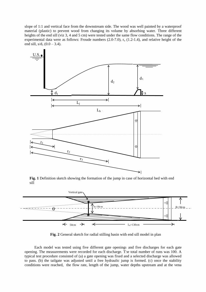
slope of 1:1 and vertical face from the downstream side. The wood was well painted by a waterproof
material (plastic) to prevent wood from changing its volume by absorbing water. Three different
heights of the end sill (viz 3, 4 and 5 cm) were tested under the same flow conditions. The range of the
experimental data were as follows: Froude numbers (2.0-7.0), ro (1.2-1.4), and relative height of the
end sill, s/d1 (0.0 – 3.4).
Fig. 1 Definition sketch showing the formation of the jump in case of horizontal bed with end
sill
Each model was tested using five different gate openings and five discharges for each gate
opening. The measurements were recorded for each discharge. The total number of runs was 100. A
typical test procedure consisted of (a) a gate opening was fixed and a selected discharge was allowed
to pass. (b) the tailgate was adjusted until a free hydraulic jump is formed. (c) once the stability
conditions were reached, the flow rate, length of the jump, water depths upstream and at the vena
Vertical gate
b=18cm
50cm Lb=130cm
Fig. 2 General sketch for radial stilling basin with end sill model in plan
B=30cm
r3
d2
d3
d1
s
r2
Lb Lj
U.S.
r1
1st International Conference of Civil Engineering Science, ICCES1, Vol. 1, 2003
contracta downstream of the gate in addition to the tail water depth and the depth of water above the
step were recorded. The length of jump was taken to be the section at which the flow depth becomes
almost fixed. These steps were repeated for different discharges and different gate openings and so on
till the required ranges of the parameters being under investigation were covered.
4. ANALYSIS AND DISCUSSIONS OF RESULTS
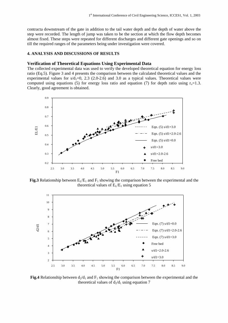
Verification of Theoretical Equations Using Experimental Data The collected experimental data was used to verify the developed theoretical equation for energy loss
ratio (Eq.5). Figure 3 and 4 presents the comparison between the calculated theoretical values and the
experimental values for s/d1=0, 2.3 (2.0-2.6) and 3.0 as a typical values. Theoretical values were
computed using equations (5) for energy loss ratio and equation (7) for depth ratio using ro=1.3.
Clearly, good agreement is obtained.
Fig.3 Relationship between EL/E1 and F1 showing the comparison between the experimental and the
theoretical values of EL/E1 using equation 5
Fig.4 Relationship between d2/d1 and F1 showing the comparison between the experimental and the
theoretical values of d2/d1 using equation 7
2.5 3.0 3.5 4.0 4.5 5.0 5.5 6.0 6.5 7.0 7.5 8.0 8.5 9.0
F1
0.2
0.3
0.4
0.5
0.6
0.7
0.8
0.9
EL
/E1 Eqn. (5) s/d1=3.0
Eqn. (5) s/d1=2.0-2.6
Eqn. (5) s/d1=0.0
s/d1=3.0
s/d1=2.0-2.6
Free bed
2.5 3.0 3.5 4.0 4.5 5.0 5.5 6.0 6.5 7.0 7.5 8.0 8.5 9.0
F1
2
3
4
5
6
7
8
9
10
11
d2
/d1 Eqn. (7) s/d1=0.0
Eqn. (7) s/d1=2.0-2.6
Eqn. (7) s/d1=3.0
Free bed
s/d1=2.0-2.6
s/d1=3.0
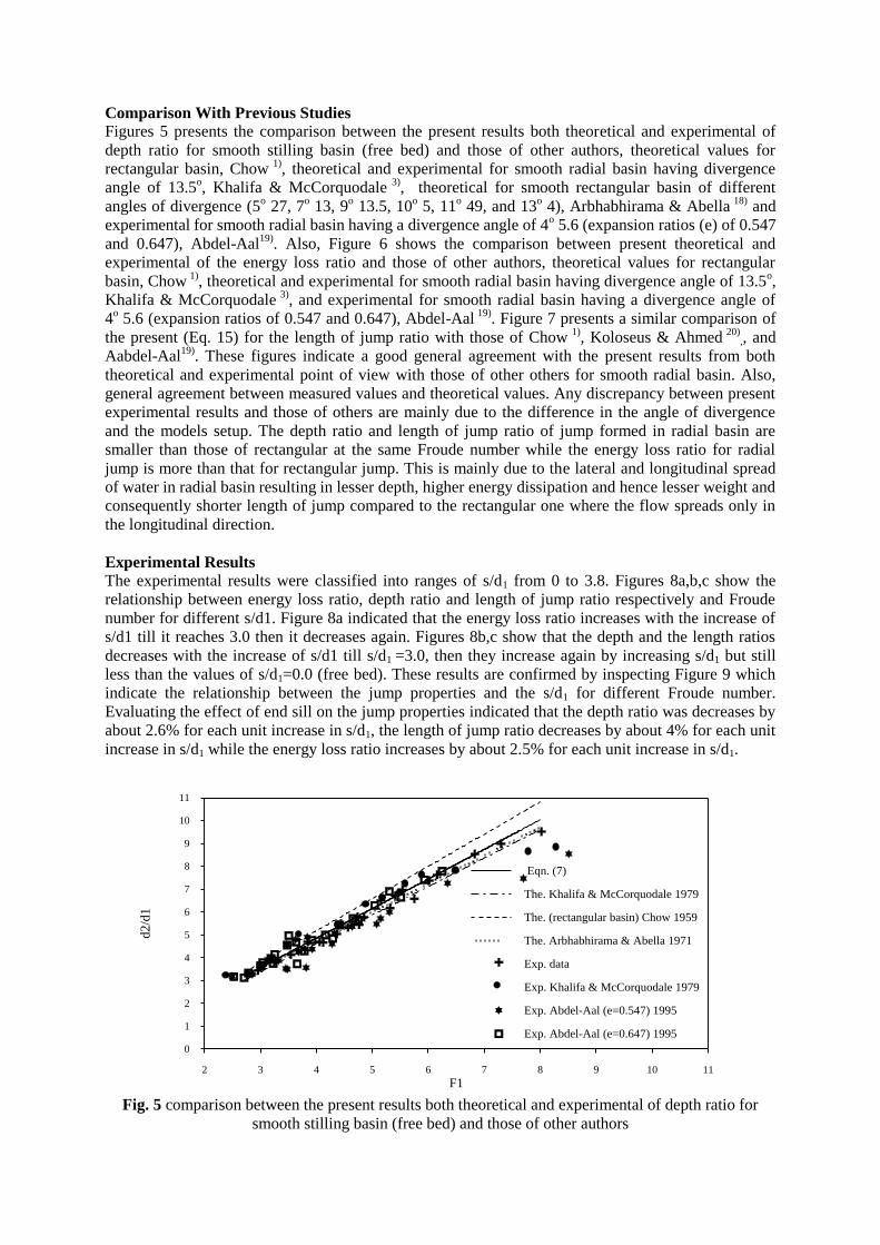
Comparison With Previous Studies
Figures 5 presents the comparison between the present results both theoretical and experimental of
depth ratio for smooth stilling basin (free bed) and those of other authors, theoretical values for
rectangular basin, Chow 1)
, theoretical and experimental for smooth radial basin having divergence
angle of 13.5o, Khalifa & McCorquodale
3), theoretical for smooth rectangular basin of different
angles of divergence (5o 27, 7
o 13, 9
o 13.5, 10
o 5, 11
o 49, and 13
o 4), Arbhabhirama & Abella
18) and
experimental for smooth radial basin having a divergence angle of 4o 5.6 (expansion ratios (e) of 0.547
and 0.647), Abdel-Aal19)
. Also, Figure 6 shows the comparison between present theoretical and
experimental of the energy loss ratio and those of other authors, theoretical values for rectangular
basin, Chow 1)
, theoretical and experimental for smooth radial basin having divergence angle of 13.5o,
Khalifa & McCorquodale 3)
, and experimental for smooth radial basin having a divergence angle of
4o 5.6 (expansion ratios of 0.547 and 0.647), Abdel-Aal
19). Figure 7 presents a similar comparison of
the present (Eq. 15) for the length of jump ratio with those of Chow 1)
, Koloseus & Ahmed 20)
,, and
Aabdel-Aal19)
. These figures indicate a good general agreement with the present results from both
theoretical and experimental point of view with those of other others for smooth radial basin. Also,
general agreement between measured values and theoretical values. Any discrepancy between present
experimental results and those of others are mainly due to the difference in the angle of divergence
and the models setup. The depth ratio and length of jump ratio of jump formed in radial basin are
smaller than those of rectangular at the same Froude number while the energy loss ratio for radial
jump is more than that for rectangular jump. This is mainly due to the lateral and longitudinal spread
of water in radial basin resulting in lesser depth, higher energy dissipation and hence lesser weight and
consequently shorter length of jump compared to the rectangular one where the flow spreads only in
the longitudinal direction.
Experimental Results
The experimental results were classified into ranges of s/d1 from 0 to 3.8. Figures 8a,b,c show the
relationship between energy loss ratio, depth ratio and length of jump ratio respectively and Froude
number for different s/d1. Figure 8a indicated that the energy loss ratio increases with the increase of
s/d1 till it reaches 3.0 then it decreases again. Figures 8b,c show that the depth and the length ratios
decreases with the increase of s/d1 till s/d1 =3.0, then they increase again by increasing s/d1 but still
less than the values of s/d1=0.0 (free bed). These results are confirmed by inspecting Figure 9 which
indicate the relationship between the jump properties and the s/d1 for different Froude number.
Evaluating the effect of end sill on the jump properties indicated that the depth ratio was decreases by
about 2.6% for each unit increase in s/d1, the length of jump ratio decreases by about 4% for each unit
increase in s/d1 while the energy loss ratio increases by about 2.5% for each unit increase in s/d1.
Fig. 5 comparison between the present results both theoretical and experimental of depth ratio for
smooth stilling basin (free bed) and those of other authors
2 3 4 5 6 7 8 9 10 11
F1
0
1
2
3
4
5
6
7
8
9
10
11
d2
/d1
Eqn. (7)
The. Khalifa & McCorquodale 1979
The. (rectangular basin) Chow 1959
The. Arbhabhirama & Abella 1971
Exp. data
Exp. Khalifa & McCorquodale 1979
Exp. Abdel-Aal (e=0.547) 1995
Exp. Abdel-Aal (e=0.647) 1995
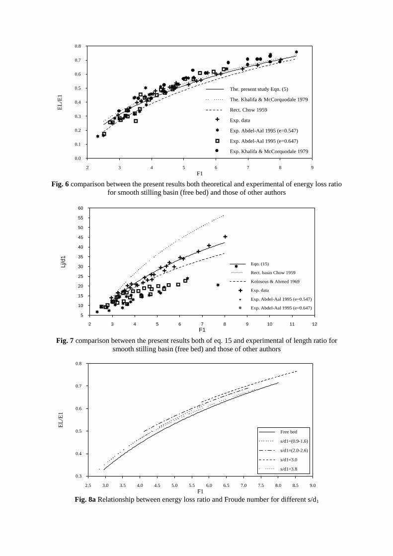
Fig. 6 comparison between the present results both theoretical and experimental of energy loss ratio
for smooth stilling basin (free bed) and those of other authors
Fig. 7 comparison between the present results both of eq. 15 and experimental of length ratio for
smooth stilling basin (free bed) and those of other authors
Fig. 8a Relationship between energy loss ratio and Froude number for different s/d1
2 3 4 5 6 7 8 9
F1
0.0
0.1
0.2
0.3
0.4
0.5
0.6
0.7
0.8
EL
/E1
The. present study Eqn. (5)
The. Khalifa & McCorquodale 1979
Rect. Chow 1959
Exp. data
Exp. Abdel-Aal 1995 (e=0.547)
Exp. Abdel-Aal 1995 (e=0.647)
Exp. Khalifa & McCorquodale 1979
2 3 4 5 6 7 8 9 10 11 12
F1
5
10
15
20
25
30
35
40
45
50
55
60
Lj/d
1
Eqn. (15)
Rect. basin Chow 1959
Koloseus & Ahmed 1969
Exp. data
Exp. Abdel-Aal 1995 (e=0.547)
Exp. Abdel-Aal 1995 (e=0.647)
Free bed
s/d1=(0.9-1.6)
s/d1=(2.0-2.6)
s/d1=3.0
s/d1=3.8
2.5 3.0 3.5 4.0 4.5 5.0 5.5 6.0 6.5 7.0 7.5 8.0 8.5 9.0
F1
0.3
0.4
0.5
0.6
0.7
0.8
EL
/E1
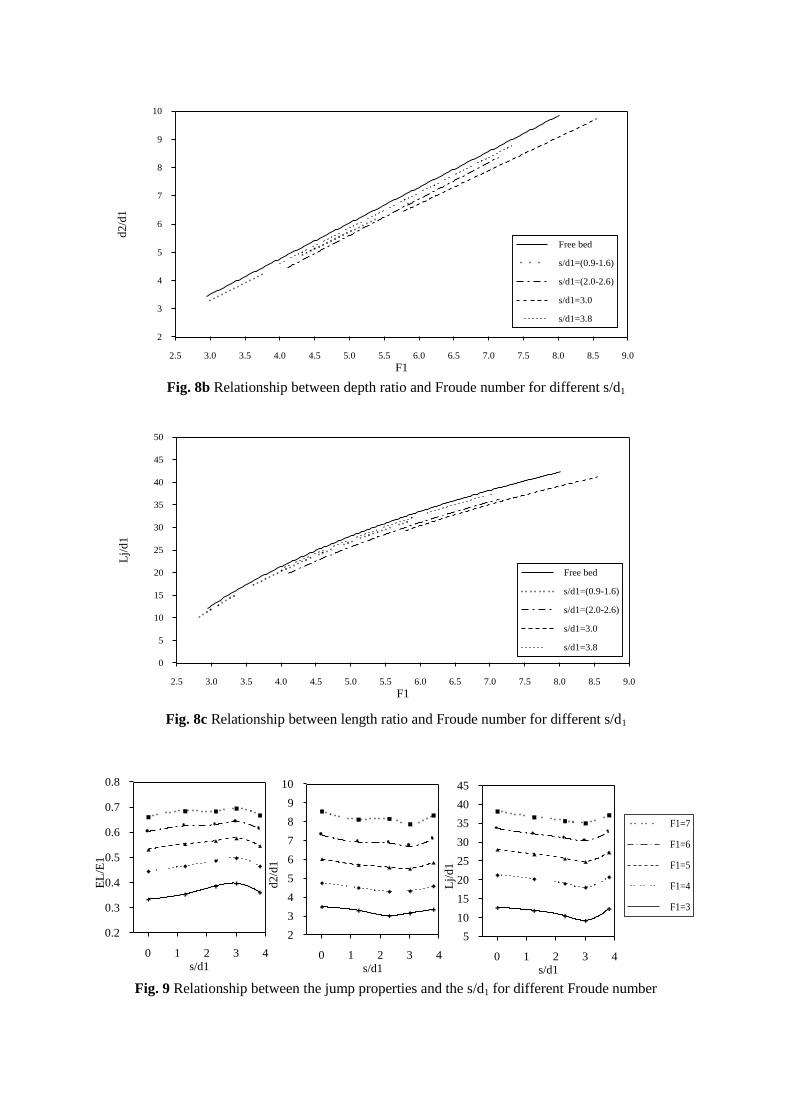
Fig. 8b Relationship between depth ratio and Froude number for different s/d1
Fig. 8c Relationship between length ratio and Froude number for different s/d1
Fig. 9 Relationship between the jump properties and the s/d1 for different Froude number
2.5 3.0 3.5 4.0 4.5 5.0 5.5 6.0 6.5 7.0 7.5 8.0 8.5 9.0
F1
2
3
4
5
6
7
8
9
10d
2/d
1
Free bed
s/d1=(0.9-1.6)
s/d1=(2.0-2.6)
s/d1=3.0
s/d1=3.8
Free bed
s/d1=(0.9-1.6)
s/d1=(2.0-2.6)
s/d1=3.0
s/d1=3.8
2.5 3.0 3.5 4.0 4.5 5.0 5.5 6.0 6.5 7.0 7.5 8.0 8.5 9.0
F1
0
5
10
15
20
25
30
35
40
45
50
Lj/
d1
0 1 2 3 4
s/d1
5
10
15
20
25
30
35
40
45
Lj/
d1
0 1 2 3 4
s/d1
0.2
0.3
0.4
0.5
0.6
0.7
0.8
EL
/E1
0 1 2 3 4
s/d1
2
3
4
5
6
7
8
9
10
d2/d
1
F1=7
F1=6
F1=5
F1=4
F1=3
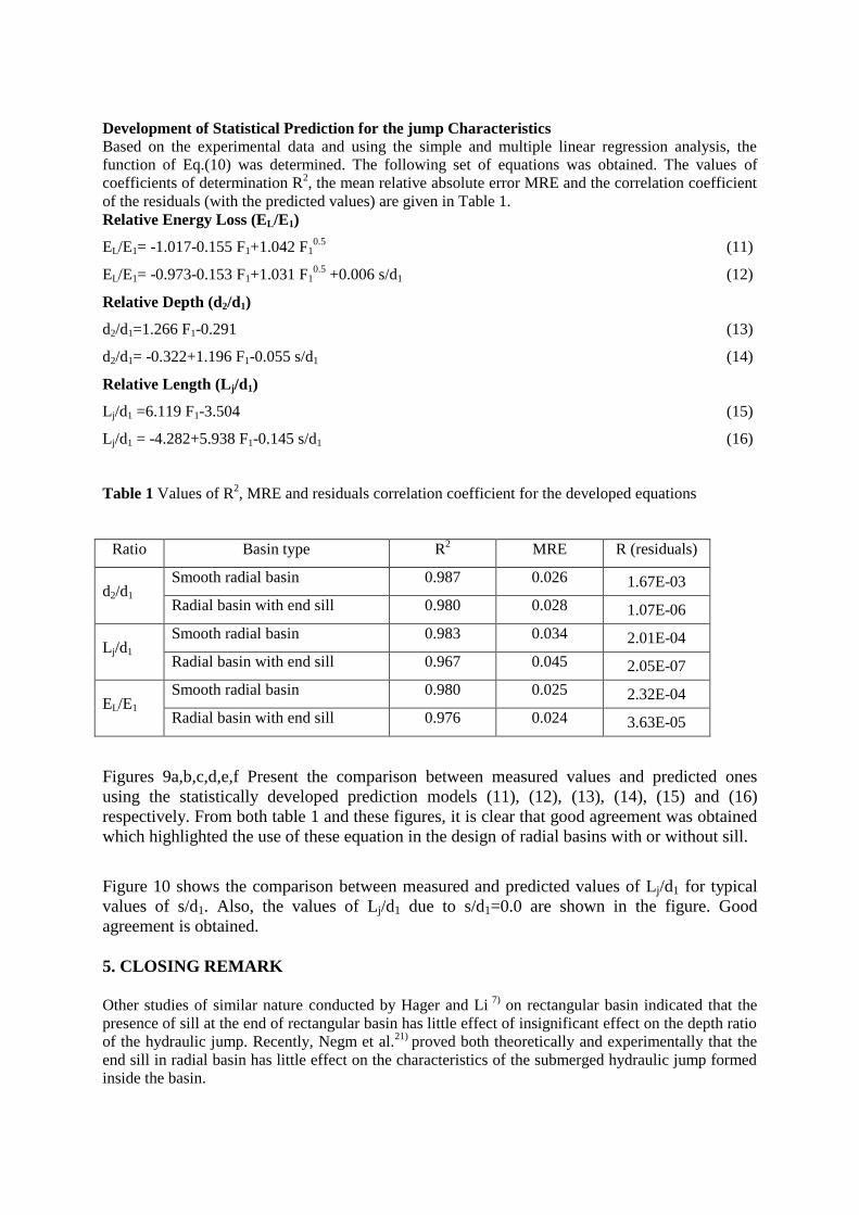
Development of Statistical Prediction for the jump Characteristics
Based on the experimental data and using the simple and multiple linear regression analysis, the
function of Eq.(10) was determined. The following set of equations was obtained. The values of
coefficients of determination R2, the mean relative absolute error MRE and the correlation coefficient
of the residuals (with the predicted values) are given in Table 1.
Relative Energy Loss (EL/E1)
EL/E1= -1.017-0.155 F1+1.042 F10.5
(11)
EL/E1= -0.973-0.153 F1+1.031 F10.5
+0.006 s/d1 (12)
Relative Depth (d2/d1)
d2/d1=1.266 F1-0.291 (13)
d2/d1= -0.322+1.196 F1-0.055 s/d1 (14)
Relative Length (Lj/d1)
Lj/d1 =6.119 F1-3.504 (15)
Lj/d1 = -4.282+5.938 F1-0.145 s/d1 (16)
Table 1 Values of R2, MRE and residuals correlation coefficient for the developed equations
Ratio Basin type R2
MRE R (residuals)
d2/d1 Smooth radial basin 0.987 0.026 1.67E-03
Radial basin with end sill 0.980 0.028 1.07E-06
Lj/d1 Smooth radial basin 0.983 0.034 2.01E-04
Radial basin with end sill 0.967 0.045 2.05E-07
EL/E1 Smooth radial basin 0.980 0.025 2.32E-04
Radial basin with end sill 0.976 0.024 3.63E-05
Figures 9a,b,c,d,e,f Present the comparison between measured values and predicted ones
using the statistically developed prediction models (11), (12), (13), (14), (15) and (16)
respectively. From both table 1 and these figures, it is clear that good agreement was obtained
which highlighted the use of these equation in the design of radial basins with or without sill.
Figure 10 shows the comparison between measured and predicted values of Lj/d1 for typical
values of s/d1. Also, the values of Lj/d1 due to s/d1=0.0 are shown in the figure. Good
agreement is obtained.
5. CLOSING REMARK
Other studies of similar nature conducted by Hager and Li
7) on rectangular basin indicated that the
presence of sill at the end of rectangular basin has little effect of insignificant effect on the depth ratio
of the hydraulic jump. Recently, Negm et al.21)
proved both theoretically and experimentally that the
end sill in radial basin has little effect on the characteristics of the submerged hydraulic jump formed
inside the basin.
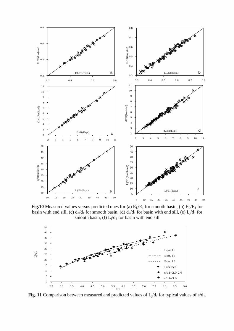
Fig.10 Measured values versus predicted ones for (a) EL/E1 for smooth basin, (b) EL/E1 for
basin with end sill, (c) d2/d1 for smooth basin, (d) d2/d1 for basin with end sill, (e) Lj/d1 for
smooth basin, (f) Lj/d1 for basin with end sill
Fig. 11 Comparison between measured and predicted values of Lj/d1 for typical values of s/d1.
0.2 0.4 0.6 0.8
EL/E1(Exp.)0.2
0.4
0.6
0.8
EL
/E1(
Pre
dict
ed)
0.2 0.3 0.4 0.5 0.6 0.7 0.8
EL/E1(Predicted)-0.04
-0.02
0.00
0.02
0.04
Res
idua
ls
Fig. (7.35) Results of statistical model of (Eqn 7.29)
a) Predicted EL/E1 versus Exp.
b) Residuals versus Predicted
a
b
0.3 0.4 0.5 0.6 0.7 0.8
EL/E1(Exp.)0.3
0.4
0.5
0.6
0.7
0.8
EL
/E1(
Pre
dict
ed)
b
2 3 4 5 6 7 8 9 10 11
d2/d1(Exp.)2
3
4
5
6
7
8
9
10
11
d2/d
1(P
redi
cted
)
c
2 3 4 5 6 7 8 9 10 11
d2/d1(Exp.)2
3
4
5
6
7
8
9
10
11
d2/d
1(P
redi
cted
)
d
10 15 20 25 30 35 40 45 50
Lj/d1(Exp.)10
15
20
25
30
35
40
45
50
Lj/
d1(P
redi
cted
)
e
2.5 3.0 3.5 4.0 4.5 5.0 5.5 6.0 6.5 7.0 7.5 8.0 8.5 9.0
F1
0
5
10
15
20
25
30
35
40
45
50
Lj/d
1
Eqn. 15
Eqn. 16
Eqn. 16
Free bed
s/d1=2.0-2.6
s/d1=3.0
5 10 15 20 25 30 35 40 45 50
Lj/d1(Exp.)5
10
15
20
25
30
35
40
45
50
Lj/
d1
(Pre
dic
ted)
f
6. CONCLUSIONS
An experimental investigation was conducted to study the effect of using end sills in the radial stilling
basin on the characteristics of free hydraulic jump. Sills of different heights were tested under wide
range of flow conditions, each height was tested under similar flow conditions. It was found that the
characteristics of the free hydraulic jump in radial basin with end sill are a function of the supercritical
Froude number and the relative height of the end sill. The optimal height of end sill in radial basin is
triple the initial depth of jump. This height minimizes both the depth and the length ratio of the jump
and maximizes the energy loss ratio. The analysis of results indicates that a unit increase in the relative
height of sill increases the energy dissipation by about 2.5% and decreases the depth ratio of the jump
by about 2.6% and the length ratio by about 4%. The experimental data were used to calibrate several
proposed regression prediction models and the best ones was presented to be used in the prediction of
the jump characteristics for both radial basins with and without end sills. Also, a theoretical prediction
model for the energy loss ratio was developed based on the use of energy equation. The present
developed theoretical model for energy loss ratio and the previously developed theoretical model for
depth ratio were verified using the experimental data. Good agreement between results of the
developed models and the experimental results.
7. NOMENCLATURE
B = width of the channel;
b = contracted width of the channel ;
d1 = water depth at vena contracta downstream the gate where the channel width is b1 ;
d2 = sequent water depth where the channel width is b2;
d3 = water depth over end sill where the channel width is b3 ;
do = the relative water depth, d2/d1;
ds = the ratio of d3 to d1;
e = b/B (expansion ratio)
F1 = Froude’s number at the initial depth;
Lj = the length of the hydraulic jump;
Lb= the length of the stilling basin;
Q = discharge;
r1 = radius at the beginning of the jump ;
r2 = radius at the end of the jump ;
ro = the ratio of r2 to r1;
r3 = radius at the end sill;
rs = the ratio of r3 to r1;
R2= the coefficient of determination;
s = the sill height;
S= the ratio of s to d1;
V1= average velocity at the initial depth;
V2= average velocity at the sequent depth;
γ = the specific weight, and
θ = the angle of divergence.
7. REFERENCES
1) Chow, V.T., “Open Channel Hydraulics”, McGraw-Hill Book Co., Inc., New York, 1959.
2) Hager, W.H., "Energy Dissipators and Hydraulic Jumps", Kluwer Academic Publications, Dordrecht, The Netherlands,
1992.
3) Khalifa, A.M. and McCorquodale, J.A., “Radial Hydraulic Jump”, Journal of the Hydraulic Division, ASCE, Vol. 105,
No HY9, 1979, pp. 1065-1078.
4) Shukry, A. , “The Efficiency of Floor Sills Under Drowned Hydraulic Jumps”, J. Hydraulics Division, ASCE Vol. 83,
No. HY3, 1958, pp. 1-18; No. HY5, p.31; No. HY6, pp.15-24; Vol.84, pp.33-37; Vol.84, 1958, No. HY5, pp.35-38.
5) Rajaratnam, N., Hydraulic jumps, in "Advances in Hydro-Science", (V.T. Chow editor), Vol. 4, Academic Press, New
York, 1967, pp.197-280.

1st International Conference of Civil Engineering Science, ICCES1, Vol. 1, 2003
6) Ohtsu, I., Yasuda, Y., and Yamanaka, Y., “ Drag on Vertical Sill of Forced Jump”, Journal of Hydraulic Research,
IAHR, Vol. 29, No. 1, 1991, pp.29-47, Discussions 1992, Vol. 30, No.2, pp. 277-288.
7) Hager, W.H. and Li, D., “Sill-Controlled Energy Dissipator”, J. Hydraulic Research, IAHR, Vol. 30, No. 2, 1992, pp. 165-
181.
8) Wafaie, E. M., “Optimum Height For Bed Sills in Stilling Basins”, Bulletin of the Faculty of Engineering, Assiut
University, Vol. 29, No. 1, Jan., 2001a, pp.1-12.
9) Wafaie, E.M., “Optimum Location For Bed Sills in Stilling Basins”, Bulletin of the Faculty of Engineering, Assiut
University, Vol. 29, No. 1, Jan., 2001b, pp.13-24.
10) Negm, A.M., Abdel-Aal, G.M., Elfiky, M.I., and Mohmed, Y.A.; “Characteristics of Submerged Hydraulic Jump in Radial
basins with a Vertical Drop in the Bed”, AEJ, Faculty of Eng., Alex. Univ., Egypt, Accepted 2002.
11) Negm, A.M., Abdel-Aal, G.M., Elfiky, M.I., and Mohmed, Y.A., “Hydraulic Characteristics of Submerged Flow in
Non-prismatic Stilling Basins”, Int. Conf. On Hydroscience and Engineering, ICHE2002, Sept., Warsw, Poland,
Published on CD-ROM, 2002b.
12) Negm, A.M., Abdel-Aal, G.M., Owais, T.M. and Habib, A.A., Theoretical modeling of hydraulic jumps at negative
step in radial stilling basin., Proc. of 6th Int. Conf. on River Engineering, Published on CD, Jan. 28-30, Ahvaz, Iran,
2003.
13) Negm, A.M., Abdel-Aal, G.M. and Habib, A.A., Effect of location of negative step on hydraulic characteristics of
jumps in radial stilling basins under free flow conditions, Proc. of Alazhar Engineering 7th Int. Conf., 7-10 April,
Alazhar University, Faculty of Eng., Cairo, Egypt, Vol. 4, 2003
14) Negm, A.M., Abdel-Aal, G.M., Owais, T.M. and Habib, A.A., Investigation of B-jump negative step in radial stilling
basins, Proc. of 7th Int. Conf. on Water Technology, IWTC2003, April 1-3, Cairo, 2003.
15) Abdel-Aal, G.M, Negm, A.M., Owais, T.M. and Habib, A.A., Theoretical modeling of hydraulic jumps at negative
step in radial stilling basins with end sill, Proc. of 7th Int. Conf. on Water Technology, IWTC2003, April 1-3, Cairo,
2003
16) Habib, A.A., Abdel-Aal, G.M., Negm, A.M. and Owais, T.M., Theoretical modeling of hydraulic jumps in radial
stilling basins ended with sills, Proc. of 7th Int. Water and Technology Conference, IWTC-2003, 1-3 April Cairo,
Egypt., 2003.
17) Habib, A.A. “Characteristics of Flow in Diverging Stilling Basins”, Ph. D. Thesis, Submitted to the Faculty of
Engineering, Zagazig University, Zagazig, Egypt.
18) Arbhabhirama, A. and Abella, A.U.; “Hydraulic Jump Within Gradually Expanding Channel”, Journal of the
Hydraulics Division, Vol. 97, No HYI, Jan., 1972, pp. 31-41.
19) Abdel-Aal G. M.; “Control of Hydraulic Jump in Contracted Streams by Gradual Expansion”, Unpublished Ph. D.,
Faculty of Engineering, Zagazig University, Egypt, 1995.
20) Koloseus, H.J.; and Ahmed D.; “Circular Hydraulic Jump”, Journal of the Hydraulics Division, ASCE, Vol. 95, No HY
1, proc. Paper 6367, Jan. 1969, pp409-422.
21) Negm, A.M., Abdel-Aal, G.M., Elfiky, M.I., and Mohmed, Y.A., “Theoretical and Experimental Evaluation of the Effect
of End Sill on Characteristics of Submerged Radial Hydraulic Jump”, Scientific Bulettin, Faculty of Engineering, Ain
Shams Univ., Cairo, Egypt, 2002a, (Accepted).