InvestIgatIng MesopotaMIan CylInder seals IConography by ...
Upload
iitbmonashCategory
view
0download
0
This article appeared in a journal published by Elsevier. The attachedcopy is furnished to the author for internal non-commercial researchand education use, including for instruction at the authors institution
and sharing with colleagues.
Other uses, including reproduction and distribution, or selling orlicensing copies, or posting to personal, institutional or third party
websites are prohibited.
In most cases authors are permitted to post their version of thearticle (e.g. in Word or Tex form) to their personal website orinstitutional repository. Authors requiring further information
regarding Elsevier’s archiving and manuscript policies areencouraged to visit:
http://www.elsevier.com/copyright
Author's personal copy
Effect of cross-stream buoyancy and rotation on the free-streamflow and heat transfer across a cylinder
Sachin B. Paramane, Atul Sharma*
Department of Mechanical Engineering, Indian Institute of Technology Bombay, Mumbai 400076, India
a r t i c l e i n f o
Article history:Received 19 March 2010Received in revised form17 May 2010Accepted 27 May 2010Available online 10 July 2010
Keywords:RotationCross-stream buoyancyFlow transitionsOnsetSuppressionVortex sheddingSecondary frequencyConstant wall temperature
a b s t r a c t
Cross-stream buoyancy-induced formation of VS (vortex shedding) past a rotating cylinder maintained atconstant wall temperature is studied at Re ¼ 40 and 100. The non-dimensional rotational velocity (a) isvaried from 0 to 8 and Richardson number from 0 to 1 with air as the working fluid. Semi-explicit finite-volume method code implemented on colocated Cartesian multi-block grid is used. Buoyancy-inducedonset of vortex shedding is found for stationary/rotating cylinder at sub-critical Re ¼ 40. Steady-VS flowtransitionmap is shown for the different rotational velocity and Ri; and reasoned using vorticity dynamics.At higher rotational velocity, origin of buoyancy-induced secondary frequency for Re¼ 40 at a¼ 6 and for100 at a ¼ 5 is discussed using spectral analysis and phase portrait technique. The VS frequency is muchsmaller at higher as compared to lower rotational velocity and increases with increasing Ri. A monotonicincrease in the downward lift force and a reversal in the direction of drag force is found with increasingrotational velocity. Rotation can be used as a drag reduction and heat transfer suppression technique.
� 2010 Elsevier Masson SAS. All rights reserved.
1. Introduction
Free-stream flow across a stationary cylinder undergoes two-dimensional steady to unsteady periodic flow transition leading toonset of vortex shedding (VS) at a critical Reynolds number,Rec z 49 [1]. At sub-critical Re < 49 (super-critical Re > 49), theonset (suppression) of VS under the influence of opposing buoy-ancy (aiding-buoyancy/rotation) is reported [2e6]. The VS forma-tion causes flow unsteadiness andmixingwhich enhances heat andmass transfer between the cylinder and its surrounding. Whereas,VS suppression stops the periodic variation of the forces actingon the cylinder and thus, prevents flow-induced vibration of thecylinder. Thus, the formation and suppression of the VS arepreferred according to an engineering application and can becontrolled under the influence of rotation and buoyancy.
Buoyancy-induced free-stream flow across a cylinder posesa challenging fluid mechanics and heat transfer problem. The effectof buoyancy on heat transfer in a forced flow is strongly influencedby the direction of the buoyancy force relative to that of the forcedflow. Three special cases with buoyancy induced and forced flowhaving the same directions (“aiding” buoyancy), opposite directions
(“opposing” buoyancy) and perpendicular directions (“cross-stream” buoyancy) are studied extensively for stationary cylinder[7e14]. Free-stream flow across a cylinder under the combinedeffect of forced and rotation-induced flow [15e25] is considered asone of the direct disturbing method to control or lessen the unde-sirable effect of vortex shedding behind the cylinder. The cylinder isrotated at a uniform angular velocity about the axis of the cylinder.
For rotation-induced free-stream flowacross a cylinder under theinfluence of buoyancy, other than the Reynolds number, Reh uND/n;Richardson number, Ri h Gr/Re2 (Grashof number Gr h gb(TW�TN)D3/n2) comes as an additional governing flow parameter. For aidingbuoyancy at a super-critical Re, the VS suppression was foundexperimentally [2] for Re¼ 800 and numerically [3e6] atRi¼ 0.15 forRe ¼ 100. VS suppression under the effect of aiding buoyancy atRi ¼ 0.12 for Re ¼ 100 and at Ri ¼ 0.2 for Re ¼ 200 was reported byPatnaik et al. [5]. Furthermore, for opposing-buoyancy case, theyreported the onset of VS atRi¼e 0.35 for Re¼ 20 and atRi¼e 0.1 forRe ¼ 40.
Finally, for cross-stream buoyancy, the previous studies [7e10]reported steady flow at a sub-critical Re whereas at super-criticalRe, a 2D to 3D flow transitionwas found experimentally at Ri> 1 forRe ¼ 100 [11] and at Riz 0.3 for Re¼ 117 [12]. Thus, they found thetransition at a Re lower than Re z 160e194 at which it occurs forunheated (Ri ¼ 0) cylinder ([1] and [26]). For square cylinder,
* Corresponding author. Tel.: þ91 22 25767505; fax: þ91 22 25726875.E-mail address: [email protected] (A. Sharma).
Contents lists available at ScienceDirect
International Journal of Thermal Sciences
journal homepage: www.elsevier .com/locate/ i j ts
1290-0729/$ e see front matter � 2010 Elsevier Masson SAS. All rights reserved.doi:10.1016/j.ijthermalsci.2010.05.020
International Journal of Thermal Sciences 49 (2010) 2008e2025
Author's personal copy
Sharma [13] at Re ¼ 100 and Turki [14] at Re ¼ 150 reportedincrease in the rms value of lift coefficient with increasing Ri.
For rotation-induced free-stream flow across a cylinder, otherthan the Reynolds number, non-dimensional rotational velocity,a h DU/2uN comes as an additional governing parameter.The rotational velocity represents the cylinder surface tangentialvelocity in terms of free-stream flow velocity. For a super-criticalRe ¼ 50, suppression of vortex shedding at a critical rotationalvelocity a > aI was first predicted by Hu et al. [15] using a low-dimensional Galerkin method. Later, Kang et al. [16] observed noonset of vortex shedding regardless of a at a sub-critical Re¼ 40. Forsuper-critical 60 � Re � 200 ([17] and [18]), Re ¼ 200 [19] and60 � Re � 160 ([20] and [21]), with further increase in rotationalvelocity after VS suppression i.e. a > aI, the vortex shedding reap-pears for a narrow intermediate range of a and remains steadyat higher a. An excellent review of this problem can be foundelsewhere [17] and [19]. In recent times, at much higher Re, the VSsuppression is reported experimentally at a � 2 for Re ¼ 9000 [22]and at a ¼ 1.9 for 3600 � Re � 5000 [23].
For rotation-induced non-isothermal flow across a cylinder,there are various studies [20,21,24,25] for forced-convection heattransfer where the critical Re does not change as compared toisothermal flows. In our earlier studies, the study was done for thecylinder subjected to constant wall temperature [20] and constantheat flux [21] for awider range of Reynolds number (20� Re� 160)and rotational velocity (0 � a � 6) at Pr ¼ 0.7. Furthermore, thereasons for the flow transitions are discussed in detail and theforced-convection heat transfer suppression from the cylinder isstudied using heatline as heat transfer visualization technique.
From the literature survey for stationary cylinder, it is concludedthat the cross-stream buoyancy destabilizes the flow (discussedabove, [11e14]); however, there is no studywhich shows onset of VSat sub-critical Re. Under the influence of rotation, it is found thatalthough there are number of studies for the flow across a cylindersubjected to no (Ri ¼ 0) buoyancy (shown in Table 1 of our earlier
work [20]) where suppression of VS at super-critical Re and the noonset of VS at sub-critical Re is reported; there is no such study onthe cylinder under the additional influence of buoyancy. The mixedconvective flow is more realistic heat transfer phenomenon ascompared to forced convection, and the results are expected to be offundamental value in addition to several engineering applications.
Fluid dynamics and heat transfer across a cylinder, under thecombined effect of free stream, buoyancy-induced and rotation-induced flow, is studied in the present work. For the flow pasta horizontal cylinder maintained at constant wall temperature, theobjective is to investigate whether the onset of VS occurs underthe influence of cross-stream buoyancy at a sub-critical Reynoldsnumber of 40; and determine VS critical Richardson number for thecylinder subjected to a constant rotational velocity. Furthermore,the rotation-induced steadyeunsteady flow transitions at a sub-critical Re ¼ 40 and a super-critical Re ¼ 100 is investigated, todetermine critical rotational velocity, for a cylinder subjected tolow, moderate and high heating corresponding to Ri ¼ 0, 0.5 and 1,respectively. Air is assumed as the working fluid with Pr ¼ 0.7.Finally, the objective is to provide the reasons for the flow transi-tions with the help of vorticity dynamics; and to investigatethe effect of the flow transitions on the flow and heat transferparameters. We also aim to explain the origin of a new/secondarybuoyancy-induced frequency for the flow across a cylinder athigher rotational velocity.
2. Physical description of the problem
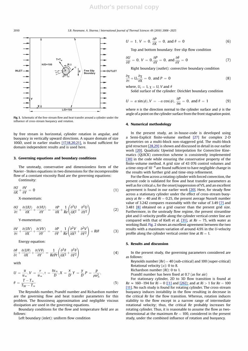
The flow configuration is shown in Fig. 1. A two-dimensionalhorizontal circular cylinder with diameter D, is exposed toa uniform horizontal cross-flow with velocity and ambienttemperature represented by uN and TN, respectively. Cylinder isrotating in a counterclockwise direction with constant angularvelocity U and heated to a constant temperature TW > TN. Thisproblem has an interaction of three types of flows: flow generated
Nomenclature
CD total drag coefficient (¼CDp þ CDv)CDp pressure drag coefficient ð¼ FDp=12ru
2NDÞ
CDv viscous drag coefficient ð¼ FDv=12ru2NDÞ
CL total Lift coefficient (¼CLp þ CLv)CLp pressure lift coefficient ð¼ FLp=12ru
2NDÞ
CLv viscous lift coefficient ð¼ FLv=12ru2NDÞ
f frequency of vortex sheddingFDp pressure drag force on the cylinderFDv viscous drag force on the cylinderFLp pressure lift force on the cylinderFLv viscous lift force on the cylinderGr Grashof number (¼gb(TW�TN)D3/n2)n cylinder surface normal directionNu average Nusselt numberNuL local Nusselt number ð¼ �vq
vnÞpN free-stream pressureP non-dimensional pressure (¼p/ruN2 )Pr Prandtl number (¼mcp/k)Re Reynolds number (¼uND/n)Ri Richardson number (¼Gr/Re2)St non-dimensional vortex-shedding frequency (¼fD/uN)TN free-surface temperatureu streamwise velocityuN free-stream velocityU non-dimensional streamwise velocity (¼u/uN)
v cross-stream velocityV non-dimensional cross-stream velocity (¼v/uN)x streamwise dimension of coordinatesX non-dimensional streamwise dimension of
coordinates (¼x/D)y cross-stream dimension of coordinatesY non-dimensional cross-stream dimension of
coordinates (¼y/D)
Greek Symbolsa non-dimensional rotational velocity (¼uD/2uN)b coefficient of volumetric thermal expansionm dynamic viscosity of the fluidn kinematic viscosity of the fluidr density of the fluidf angular displacement from the front stagnation point,
�
s non-dimensional time (¼t/(D/uN))q non-dimensional temperature [¼(T�TN)/(TW�TN)]U constant angular velocity of the cylinder rotationu vorticity
Subscriptsc critical valuemax maximum valueprod productionW surface of the cylinder
S.B. Paramane, A. Sharma / International Journal of Thermal Sciences 49 (2010) 2008e2025 2009
Author's personal copy
by free stream in horizontal, cylinder rotation in angular, andbuoyancy in vertically upward directions. A square domain of size100D, used in earlier studies [17,18,20,21], is found sufficient fordomain independent results and is used here.
3. Governing equations and boundary conditions
The unsteady, conservative and dimensionless form of theNaviereStokes equations in two dimensions for the incompressibleflow of a constant viscosity fluid are the governing equations:
Continuity:
vUvX
þ vVvY
¼ 0 (1)
X-momentum:
vUvs
þ vðUUÞvX
þ vðVUÞvY
¼ �vPvX
þ 1Re
v2UvX2 þ v2U
vY2
!(2)
Y-momentum:
vVvs
þ vðUVÞvX
þ vðVVÞvY
¼ �vPvY
þ 1Re
v2VvX2 þ v2V
vY2
!þ Riq (3)
Energy equation:
vq
vsþ vðUqÞ
vXþ vðVqÞ
vY¼ 1
RePr
v2q
vX2 þv2q
vY2
!(4)
with
U ¼ uuN
;V ¼ v
uN; s ¼ tuN
D;X ¼ x
D; Y ¼ y
D; P ¼ p
ru2N;
q ¼ T � TNTW � TN
ð5Þ
The Reynolds number, Prandtl number and Richardson numberare the governing flow and heat transfer parameters for thisproblem. The Boussinesq approximation and negligible viscousdissipation are used in the governing equations.
Boundary conditions for the flow and temperature field are asfollows:
Left boundary (inlet): uniform flow condition
U ¼ 1; V ¼ 0;vPvX
¼ 0; and q ¼ 0 (6)
Top and bottom boundary: free slip flow condition
vUvY
¼ 0; V ¼ 0;vPvY
¼ 0; andvq
vY¼ 0 (7)
Right boundary (outlet): convective boundary condition
vc
vsþ Uc
vc
vX¼ 0; and P ¼ 0 (8)
where, Uc ¼ 1, c ¼ U, V and q
Solid surface of the cylinder: Dirichlet boundary condition
U ¼ a sinðfÞ;V ¼ �a cosðfÞ; vPvn
¼ 0; and q ¼ 1 (9)
where n is the direction normal to the cylinder surface and f is theangle of a pointon the cylinder surface from the front stagnationpoint.
4. Numerical methodology
In the present study, an in-house-code is developed usinga Semi-Explicit finite-volume method [27] for complex 2-Dgeometries on a multi-block non-staggered grid. The multi-blockgrid structure [28,29] is shown and discussed in detail in our earlierwork [20]. Quadratic Upwind Interpolation for Convective Kine-matics (QUICK) convection scheme is consistently implemented[30] in the code while ensuring the conservative property of thefinite-volume method. A grid size of 43 076 control volumes anda time-step of 10�4 are found sufficient to have negligible change inthe results with further grid and time-step refinement.
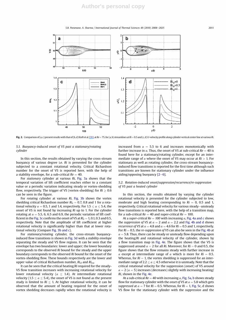
For theflowacross a rotating cylinderwith forced convection, thepresent code is validated for flow and heat transfer parameters aswell as for critical a, for the onset/suppression of VS, and an excellentagreement is found in our earlier work [20]. Here, for steady flowacross a stationary cylinder under the effect of cross-stream buoy-ancy at Re ¼ 40 and Ri ¼ 0.25, the present average Nusselt numbervalue of 3.242 compares reasonably with the value of 3.49 [7] and3.481 [8] obtained on a grid coarser than the present grid size.Furthermore, in the unsteady flow regime, the present streamlineplot and U-velocity profile along the cylinder vertical center line arecompared with that of Kieft et al. [31], at Re ¼ 75, with water asworking fluid. Fig. 2 shows an excellent agreement between the tworesults with a maximum variation of around 4.9% in the U-velocityprofile along the cylinder vertical center line at Ri ¼ 1.
5. Results and discussion
In the present study, the governing parameters considered areas follows:
Reynolds number (Re)¼ 40 (sub-critical) and 100 (super-critical)Rotational velocity (a): 0 to 8.Richardson number (Ri): 0 to 1.Prandtl number has been fixed at 0.7 (as for air)For stationary cylinder, 2D to 3D flow transition is found at
Re z 160e194 for Ri ¼ 0 ([1] and [26]); and at Ri > 1 for Re ¼ 100[11]. No such study is found for rotating cylinder. The cross-streambuoyancy induces instability in the flow resulting in decrease inthe critical Re for the flow transition. Whereas, rotation inducesstability to the flow except in a narrow range of intermediaterotational velocity; thus, the critical Re probably increases forrotating cylinder. Thus, it is reasonable to assume the flow as two-dimensional at the maximum Re ¼ 100, considered in the presentstudy, under the combined influence of rotation and buoyancy.
Fig. 1. Schematic of the free-stream flow and heat transfer around a cylinder under theinfluence of cross-stream buoyancy and rotation.
S.B. Paramane, A. Sharma / International Journal of Thermal Sciences 49 (2010) 2008e20252010
Author's personal copy
5.1. Buoyancy-induced onset of VS past a stationary/rotatingcylinder
In this section, the results obtained by varying the cross-streambuoyancy of various degree i.e. Ri is presented for the cylindersubjected to a constant rotational velocity. Critical Richardsonnumber for the onset of VS is reported here, with the help ofa stability envelope, for a sub-critical Re ¼ 40.
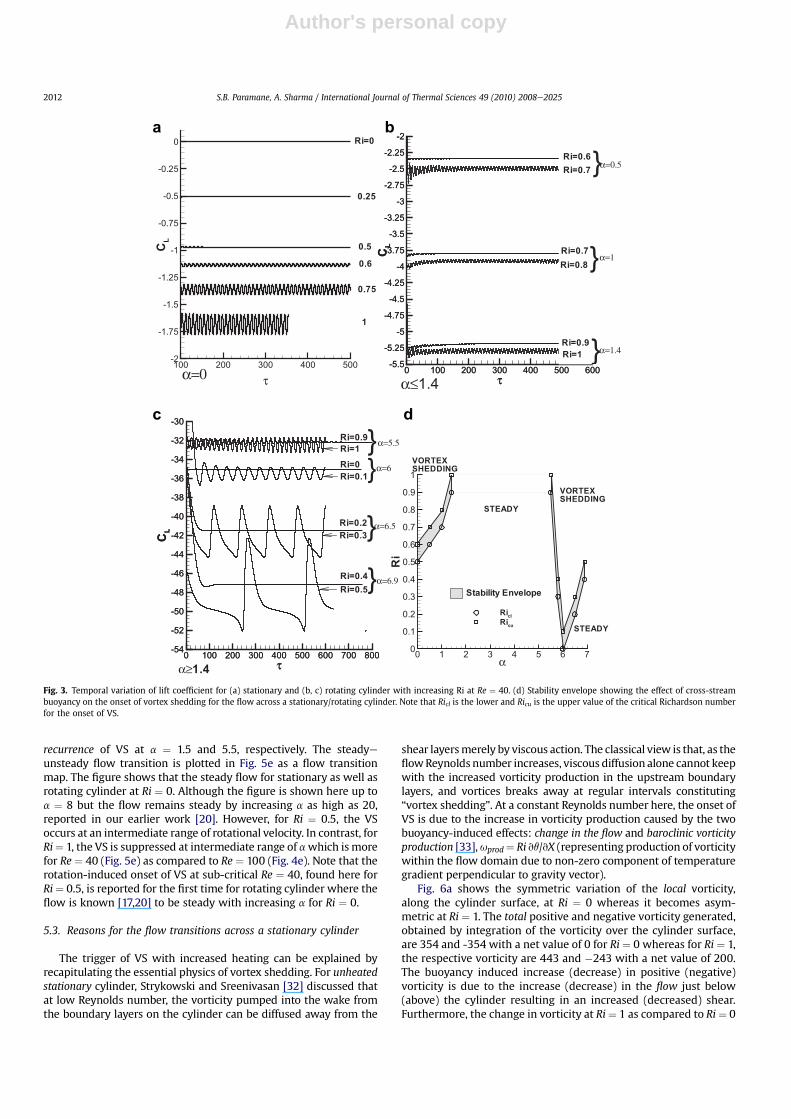
For stationary cylinder at various Ri, Fig. 3a shows that thetemporal variation of lift coefficient reaches either to a constantvalue or a periodic variation indicating steady or vortex-sheddingflow, respectively. The trigger of VS (vortex-shedding) for Ri � 0.6can be seen in the figure.
For rotating cylinder at various Ri, Fig. 3b shows the vortexshedding critical Richardson number Ric ¼ 0.7, 0.8 and 1 for a rota-tional velocity a ¼ 0.5, 1 and 1.4, respectively. For 1.5 � a � 5.4, theonset of VS is not found by increasing Ri up to 1. For the cylinderrotating at a ¼ 5.5, 6, 6.5 and 6.9, the periodic variation of lift coef-ficient in the Fig. 3c confirms the onset of VS atRic¼ 1, 0.1, 0.3 and0.5,respectively. Note that the amplitude of lift coefficient at higherrotational velocity is significantly higher than that at lower rota-tional velocity (Compare Fig. 3b and c).
For stationary/rotating cylinder, the cross-stream buoyancy-induced flow transitions is shown in Fig. 3d with a stability envelopeseparating the steady and VS flow regions. It can be seen that theenvelope has two boundaries: lower and upper; the lower boundarycorresponds to the observed Ri bound for the steady and the upperboundary corresponds to the observed Ri bound for the onset of thevortex-shedding flow. These bounds respectively are the lower andupper value of critical Richardson number, Ricl and Ricu.
It can be seen that the critical heating/Ri required for the steady-VS flow transition increases with increasing rotational velocity forlower rotational velocity (a � 1.4). At intermediate rotationalvelocity (1.5 � a � 5.4), the onset of VS is not found as the presentstudy is limited to Ri � 1. At higher rotational velocity, it can beobserved that the amount of heating required for the onset ofvortex shedding decreases rapidly when the rotational velocity is
increased from a ¼ 5.5 to 6 and increases monotonically withfurther increase in a. Thus, the onset of VS at sub-critical Re ¼ 40 isfound here for a stationary/rotating cylinder, except for an inter-mediate range of a where the onset of VS may occur at Ri > 1. Forstationary as well as rotating cylinder, the cross-stream buoyancy-induced flow transitions is reported for the first time although suchtransitions are known for stationary cylinder under the influenceaiding/opposing buoyancy [2e6].
5.2. Rotation-induced onset/suppression/recurrence/re-suppressionof VS past a heated cylinder
In this section, the results obtained by varying the cylinderrotational velocity is presented for the cylinder subjected to low,moderate and high heating corresponding to Ri ¼ 0, 0.5 and 1,respectively. Critical rotational velocity for various steadyeunsteadyflow transitions is reported here, with the help of a transition map,for a sub-critical Re ¼ 40 and super-critical Re ¼ 100.
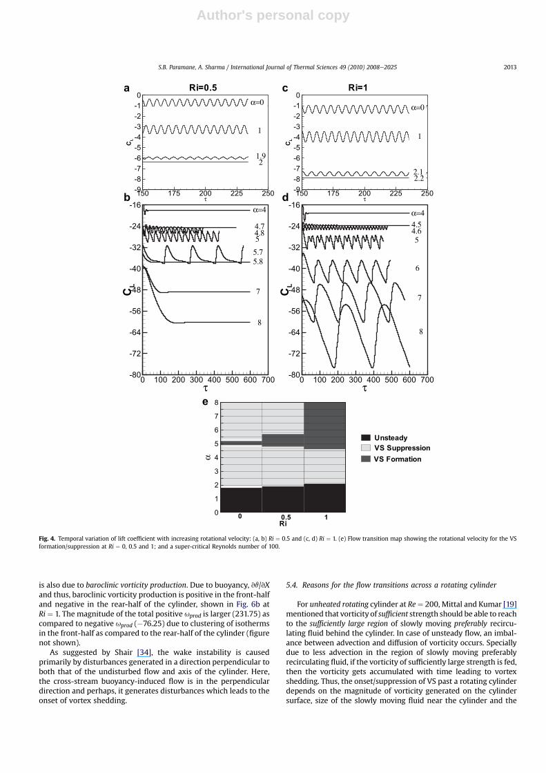
At a super-critical Re ¼ 100with increasing a, Fig. 4a and c showsthe suppression of VS at a ¼ 2 and a ¼ 2.2 and Fig. 4b and d showsrecurrence of VS at a¼ 4.8 and a¼ 4.6 for Ri¼ 0.5 and 1, respectively.For Ri¼ 0.5, the re-suppression of VS can also be seen in the Fig. 4b ata¼ 5.8. Thus, there can be steady or unsteady flow depending uponthe heating/Ri and rotational velocity of the cylinder, shown bya flow transition map in Fig. 4e. The figure shows that the VS issuppressed around a ¼ 2 for all Ri. Moreover, for Ri ¼ 0 and 0.5, thefigure shows that the flow remains steady with further increase ina except at intermediate range of a which is more for Ri ¼ 0.5.Whereas, for Ri ¼ 1, the vortex shedding is suppressed for an inter-mediate range of 2.2� a� 4.5 otherwise it is unsteady. Note that thecritical rotational velocity for the suppression (onset) of VS arounda ¼ 2 (a ¼ 5) increases (decreases) slightly with increasing heating/Ri, shown in the Fig. 4e.
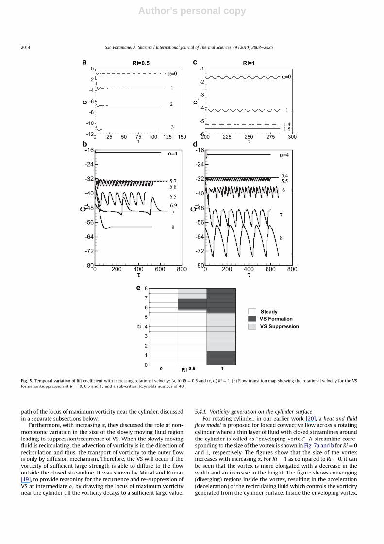
At a sub-critical Re¼ 40with increasing a, Fig. 5a, b shows steadyflow for stationary cylinder with the onset of VS at a¼ 5.8 which getssuppressed at a ¼ 7 for Ri ¼ 0.5. Whereas, for Ri ¼ 1, Fig. 5c, d showsVS flow for the stationary cylinder with the suppression and the
Fig. 2. Comparisonof (a, c)presentresultswith thatof (b, d)Kieftet al. [31], atRe¼75, for (a,b) streamlinesatRi¼0.5and(c, d)U-velocityprofilealongcylindervertical center lineatvariousRi.
S.B. Paramane, A. Sharma / International Journal of Thermal Sciences 49 (2010) 2008e2025 2011
Author's personal copy
recurrence of VS at a ¼ 1.5 and 5.5, respectively. The steadyeunsteady flow transition is plotted in Fig. 5e as a flow transitionmap. The figure shows that the steady flow for stationary as well asrotating cylinder at Ri ¼ 0. Although the figure is shown here up toa ¼ 8 but the flow remains steady by increasing a as high as 20,reported in our earlier work [20]. However, for Ri ¼ 0.5, the VSoccurs at an intermediate range of rotational velocity. In contrast, forRi¼ 1, the VS is suppressed at intermediate range of awhich is morefor Re ¼ 40 (Fig. 5e) as compared to Re ¼ 100 (Fig. 4e). Note that therotation-induced onset of VS at sub-critical Re ¼ 40, found here forRi¼ 0.5, is reported for the first time for rotating cylinder where theflow is known [17,20] to be steady with increasing a for Ri ¼ 0.
5.3. Reasons for the flow transitions across a stationary cylinder
The trigger of VS with increased heating can be explained byrecapitulating the essential physics of vortex shedding. For unheatedstationary cylinder, Strykowski and Sreenivasan [32] discussed thatat low Reynolds number, the vorticity pumped into the wake fromthe boundary layers on the cylinder can be diffused away from the
shear layersmerely by viscous action. The classical view is that, as theflowReynolds number increases, viscous diffusion alone cannot keepwith the increased vorticity production in the upstream boundarylayers, and vortices breaks away at regular intervals constituting“vortex shedding”. At a constant Reynolds number here, the onset ofVS is due to the increase in vorticity production caused by the twobuoyancy-induced effects: change in the flow and baroclinic vorticityproduction [33],uprod¼ Ri vq/vX (representing production of vorticitywithin the flow domain due to non-zero component of temperaturegradient perpendicular to gravity vector).
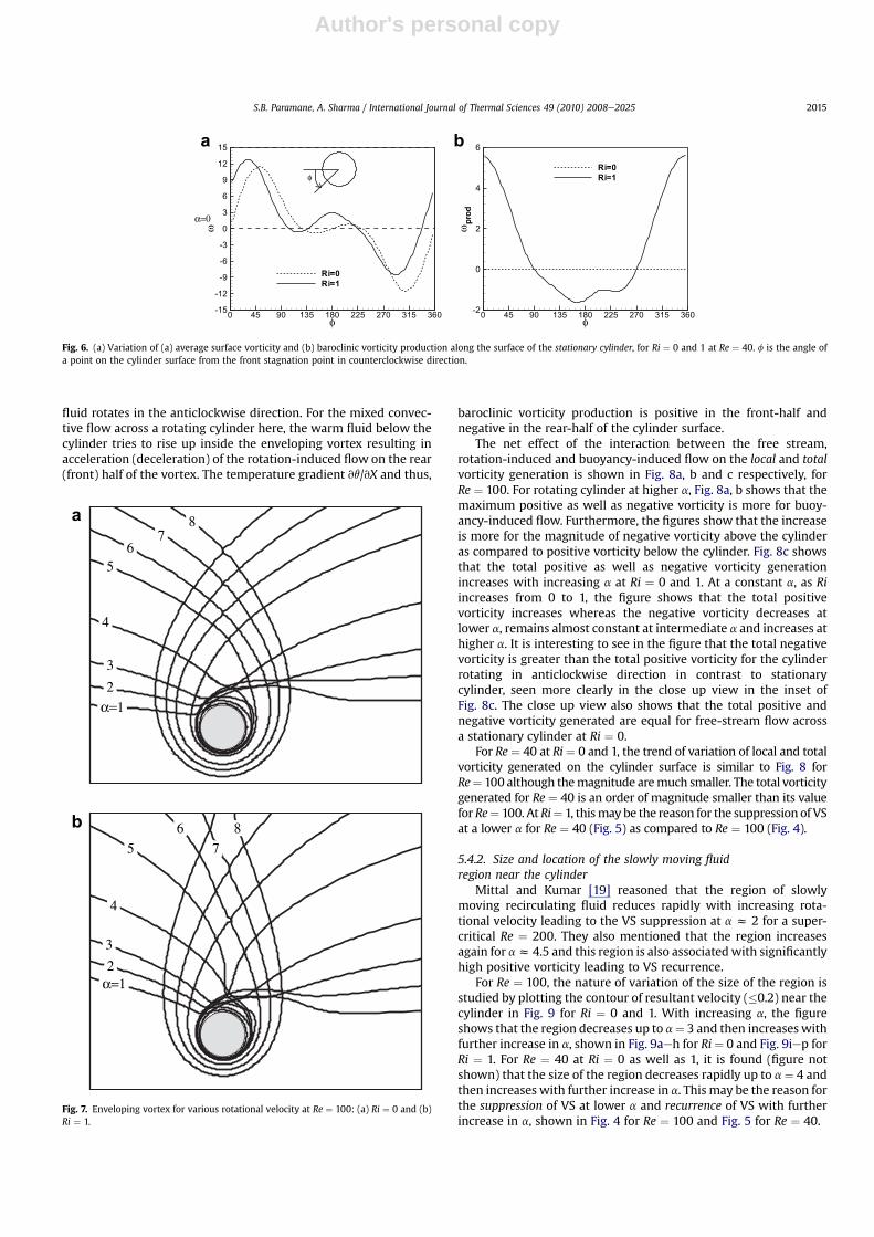
Fig. 6a shows the symmetric variation of the local vorticity,along the cylinder surface, at Ri ¼ 0 whereas it becomes asym-metric at Ri ¼ 1. The total positive and negative vorticity generated,obtained by integration of the vorticity over the cylinder surface,are 354 and -354 with a net value of 0 for Ri ¼ 0 whereas for Ri ¼ 1,the respective vorticity are 443 and �243 with a net value of 200.The buoyancy induced increase (decrease) in positive (negative)vorticity is due to the increase (decrease) in the flow just below(above) the cylinder resulting in an increased (decreased) shear.Furthermore, the change in vorticity at Ri¼ 1 as compared to Ri¼ 0
c
ba
d
Fig. 3. Temporal variation of lift coefficient for (a) stationary and (b, c) rotating cylinder with increasing Ri at Re ¼ 40. (d) Stability envelope showing the effect of cross-streambuoyancy on the onset of vortex shedding for the flow across a stationary/rotating cylinder. Note that Ricl is the lower and Ricu is the upper value of the critical Richardson numberfor the onset of VS.
S.B. Paramane, A. Sharma / International Journal of Thermal Sciences 49 (2010) 2008e20252012
Author's personal copy
is also due to baroclinic vorticity production. Due to buoyancy, vq/vXand thus, baroclinic vorticity production is positive in the front-halfand negative in the rear-half of the cylinder, shown in Fig. 6b atRi ¼ 1. The magnitude of the total positive uprod is larger (231.75) ascompared to negative uprod (�76.25) due to clustering of isothermsin the front-half as compared to the rear-half of the cylinder (figurenot shown).
As suggested by Shair [34], the wake instability is causedprimarily by disturbances generated in a direction perpendicular toboth that of the undisturbed flow and axis of the cylinder. Here,the cross-stream buoyancy-induced flow is in the perpendiculardirection and perhaps, it generates disturbances which leads to theonset of vortex shedding.
5.4. Reasons for the flow transitions across a rotating cylinder
For unheated rotating cylinder at Re¼ 200, Mittal and Kumar [19]mentioned that vorticity of sufficient strength should be able to reachto the sufficiently large region of slowly moving preferably recircu-lating fluid behind the cylinder. In case of unsteady flow, an imbal-ance between advection and diffusion of vorticity occurs. Speciallydue to less advection in the region of slowly moving preferablyrecirculating fluid, if the vorticity of sufficiently large strength is fed,then the vorticity gets accumulated with time leading to vortexshedding. Thus, the onset/suppression of VS past a rotating cylinderdepends on the magnitude of vorticity generated on the cylindersurface, size of the slowly moving fluid near the cylinder and the
τ
CL
150 175 200 225 250-9-8-7-6-5-4-3-2-10
c Ri=1
τ
CL
150 175 200 225 250-9-8-7-6-5-4-3-2-10
a Ri=0.5
Unsteady
VS Formation
VS Suppression
α=0
1
1.92
α=0
1
2.12.2
Ri
α
0
1
2
3
4
5
6
7
8
10 0.5
e
τ
CL
0 100 200 300 400 500 600 700-80
-72
-64
-56
-48
-40
-32
-24
-16α=4
d
4.54.65
6
7
8
τ
CL
0 100 200 300 400 500 600 700-80
-72
-64
-56
-48
-40
-32
-24
-16b
α=4
4.8
5.75.8
4.75
7
8
Fig. 4. Temporal variation of lift coefficient with increasing rotational velocity: (a, b) Ri ¼ 0.5 and (c, d) Ri ¼ 1. (e) Flow transition map showing the rotational velocity for the VSformation/suppression at Ri ¼ 0, 0.5 and 1; and a super-critical Reynolds number of 100.
S.B. Paramane, A. Sharma / International Journal of Thermal Sciences 49 (2010) 2008e2025 2013
Author's personal copy
path of the locus of maximum vorticity near the cylinder, discussedin a separate subsections below.
Furthermore, with increasing a, they discussed the role of non-monotonic variation in the size of the slowly moving fluid regionleading to suppression/recurrence of VS. When the slowly movingfluid is recirculating, the advection of vorticity is in the direction ofrecirculation and thus, the transport of vorticity to the outer flowis only by diffusion mechanism. Therefore, the VS will occur if thevorticity of sufficient large strength is able to diffuse to the flowoutside the closed streamline. It was shown by Mittal and Kumar[19], to provide reasoning for the recurrence and re-suppression ofVS at intermediate a, by drawing the locus of maximum vorticitynear the cylinder till the vorticity decays to a sufficient large value.
5.4.1. Vorticity generation on the cylinder surfaceFor rotating cylinder, in our earlier work [20], a heat and fluid
flow model is proposed for forced convective flow across a rotatingcylinder where a thin layer of fluid with closed streamlines aroundthe cylinder is called as “enveloping vortex”. A streamline corre-sponding to the size of the vortex is shown in Fig. 7a and b for Ri¼ 0and 1, respectively. The figures show that the size of the vortexincreases with increasing a. For Ri ¼ 1 as compared to Ri ¼ 0, it canbe seen that the vortex is more elongated with a decrease in thewidth and an increase in the height. The figure shows converging(diverging) regions inside the vortex, resulting in the acceleration(deceleration) of the recirculating fluid which controls the vorticitygenerated from the cylinder surface. Inside the enveloping vortex,
τ
CL
0 200 400 600 800-80
-72
-64
-56
-48
-40
-32
-24
-16d
τ
CL
200 225 250 275 300-6
-5
-4
-3
-2
-1c Ri=1
τ
CL
0 200 400 600 800-80
-72
-64
-56
-48
-40
-32
-24
-16b
τ
CL
0 25 50 75 100 125 150-12
-10
-8
-6
-4
-2
0a Ri=0.5
VS Suppression
Steady
VS Formation
α=0
1
2
3
α=0
1
1.41.5
α=4
5.75.8
6.56.97
8
α=4
5.45.56
7
8
α
0
1
2
3
4
5
6
7
8
10 0.5Ri
e
Fig. 5. Temporal variation of lift coefficient with increasing rotational velocity: (a, b) Ri ¼ 0.5 and (c, d) Ri ¼ 1. (e) Flow transition map showing the rotational velocity for the VSformation/suppression at Ri ¼ 0, 0.5 and 1; and a sub-critical Reynolds number of 40.
S.B. Paramane, A. Sharma / International Journal of Thermal Sciences 49 (2010) 2008e20252014
Author's personal copy
fluid rotates in the anticlockwise direction. For the mixed convec-tive flow across a rotating cylinder here, the warm fluid below thecylinder tries to rise up inside the enveloping vortex resulting inacceleration (deceleration) of the rotation-induced flow on the rear(front) half of the vortex. The temperature gradient vq/vX and thus,
baroclinic vorticity production is positive in the front-half andnegative in the rear-half of the cylinder surface.
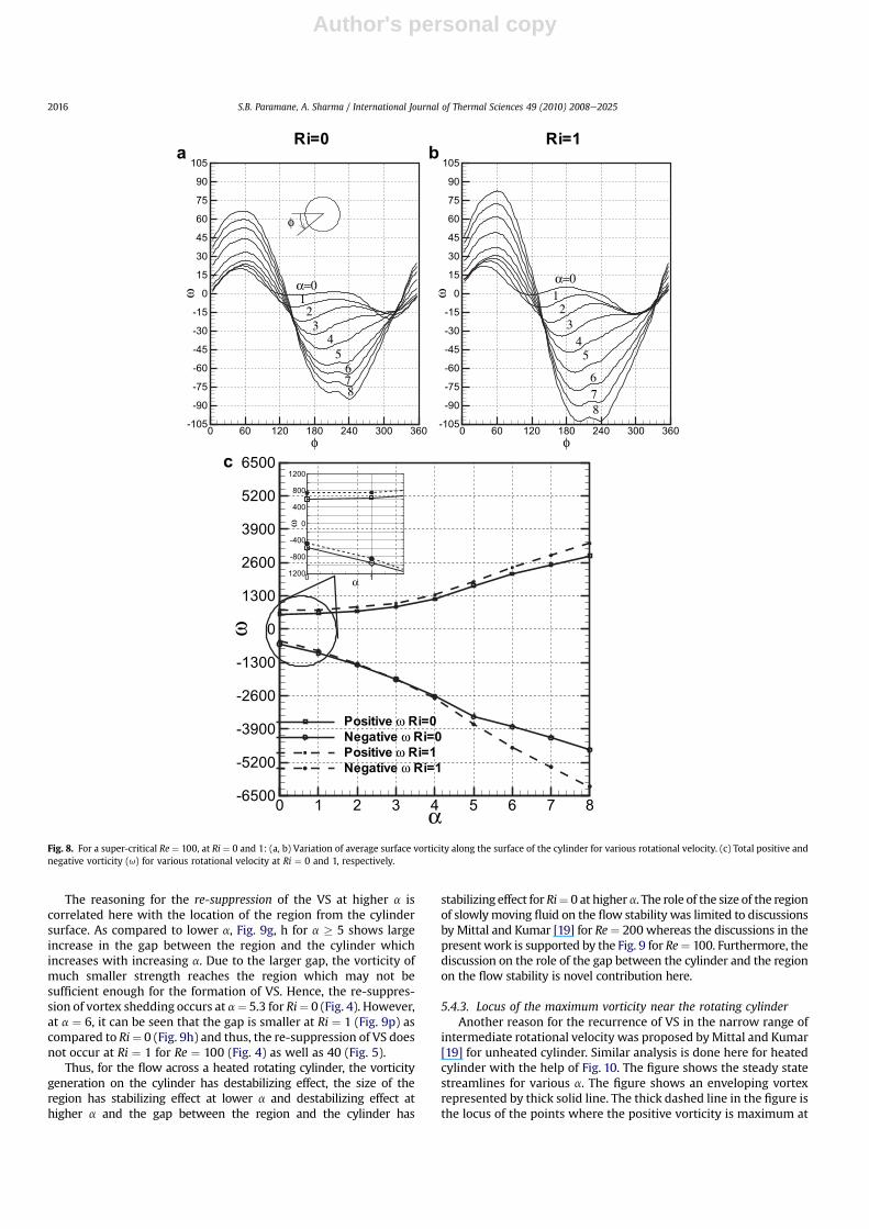
The net effect of the interaction between the free stream,rotation-induced and buoyancy-induced flow on the local and totalvorticity generation is shown in Fig. 8a, b and c respectively, forRe ¼ 100. For rotating cylinder at higher a, Fig. 8a, b shows that themaximum positive as well as negative vorticity is more for buoy-ancy-induced flow. Furthermore, the figures show that the increaseis more for the magnitude of negative vorticity above the cylinderas compared to positive vorticity below the cylinder. Fig. 8c showsthat the total positive as well as negative vorticity generationincreases with increasing a at Ri ¼ 0 and 1. At a constant a, as Riincreases from 0 to 1, the figure shows that the total positivevorticity increases whereas the negative vorticity decreases atlower a, remains almost constant at intermediate a and increases athigher a. It is interesting to see in the figure that the total negativevorticity is greater than the total positive vorticity for the cylinderrotating in anticlockwise direction in contrast to stationarycylinder, seen more clearly in the close up view in the inset ofFig. 8c. The close up view also shows that the total positive andnegative vorticity generated are equal for free-stream flow acrossa stationary cylinder at Ri ¼ 0.
For Re¼ 40 at Ri¼ 0 and 1, the trend of variation of local and totalvorticity generated on the cylinder surface is similar to Fig. 8 forRe¼ 100 although themagnitude aremuch smaller. The total vorticitygenerated for Re ¼ 40 is an order of magnitude smaller than its valuefor Re¼ 100. At Ri¼ 1, thismay be the reason for the suppression of VSat a lower a for Re ¼ 40 (Fig. 5) as compared to Re ¼ 100 (Fig. 4).
5.4.2. Size and location of the slowly moving fluidregion near the cylinder
Mittal and Kumar [19] reasoned that the region of slowlymoving recirculating fluid reduces rapidly with increasing rota-tional velocity leading to the VS suppression at a z 2 for a super-critical Re ¼ 200. They also mentioned that the region increasesagain for az 4.5 and this region is also associatedwith significantlyhigh positive vorticity leading to VS recurrence.
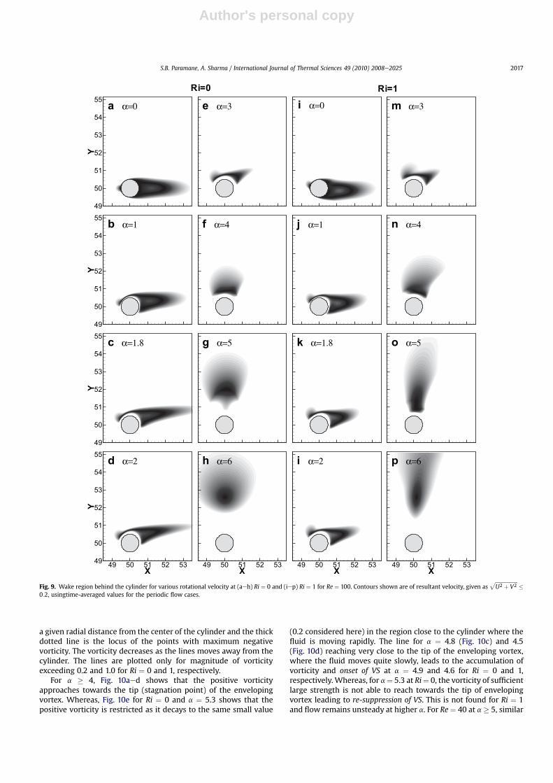
For Re ¼ 100, the nature of variation of the size of the region isstudied by plotting the contour of resultant velocity (�0.2) near thecylinder in Fig. 9 for Ri ¼ 0 and 1. With increasing a, the figureshows that the region decreases up to a¼ 3 and then increases withfurther increase in a, shown in Fig. 9aeh for Ri¼ 0 and Fig. 9iep forRi ¼ 1. For Re ¼ 40 at Ri ¼ 0 as well as 1, it is found (figure notshown) that the size of the region decreases rapidly up to a¼ 4 andthen increases with further increase in a. This may be the reason forthe suppression of VS at lower a and recurrence of VS with furtherincrease in a, shown in Fig. 4 for Re ¼ 100 and Fig. 5 for Re ¼ 40.
φ
ω
0 45 90 135 180 225 270 315 360-15
-12
-9
-6
-3
0
3
6
9
12
15
Ri=0
Ri=1
a
α=0
φ
φ
ω
0 45 90 135 180 225 270 315 360-2
0
2
4
6
Ri=0
Ri=1
prod
b
Fig. 6. (a) Variation of (a) average surface vorticity and (b) baroclinic vorticity production along the surface of the stationary cylinder, for Ri ¼ 0 and 1 at Re ¼ 40. f is the angle ofa point on the cylinder surface from the front stagnation point in counterclockwise direction.
a
α=12
8
3
4
56
7
b
α=123
4
56
78
Fig. 7. Enveloping vortex for various rotational velocity at Re ¼ 100: (a) Ri ¼ 0 and (b)Ri ¼ 1.
S.B. Paramane, A. Sharma / International Journal of Thermal Sciences 49 (2010) 2008e2025 2015
Author's personal copy
The reasoning for the re-suppression of the VS at higher a iscorrelated here with the location of the region from the cylindersurface. As compared to lower a, Fig. 9g, h for a � 5 shows largeincrease in the gap between the region and the cylinder whichincreases with increasing a. Due to the larger gap, the vorticity ofmuch smaller strength reaches the region which may not besufficient enough for the formation of VS. Hence, the re-suppres-sion of vortex shedding occurs at a¼ 5.3 for Ri¼ 0 (Fig. 4). However,at a ¼ 6, it can be seen that the gap is smaller at Ri ¼ 1 (Fig. 9p) ascompared to Ri¼ 0 (Fig. 9h) and thus, the re-suppression of VS doesnot occur at Ri ¼ 1 for Re ¼ 100 (Fig. 4) as well as 40 (Fig. 5).
Thus, for the flow across a heated rotating cylinder, the vorticitygeneration on the cylinder has destabilizing effect, the size of theregion has stabilizing effect at lower a and destabilizing effect athigher a and the gap between the region and the cylinder has
stabilizing effect for Ri¼ 0 at highera. The role of the size of the regionof slowlymoving fluid on the flow stability was limited to discussionsby Mittal and Kumar [19] for Re¼ 200 whereas the discussions in thepresent work is supported by the Fig. 9 for Re¼ 100. Furthermore, thediscussion on the role of the gap between the cylinder and the regionon the flow stability is novel contribution here.
5.4.3. Locus of the maximum vorticity near the rotating cylinderAnother reason for the recurrence of VS in the narrow range of
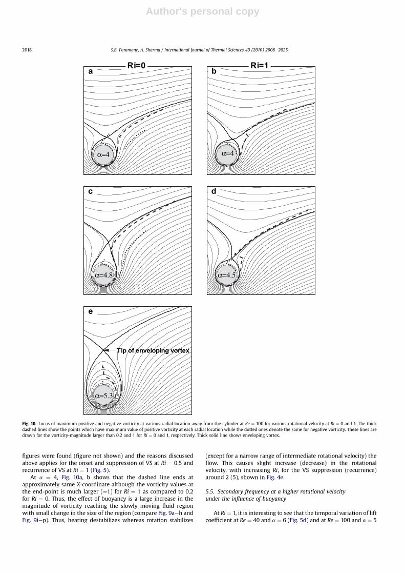
intermediate rotational velocity was proposed byMittal and Kumar[19] for unheated cylinder. Similar analysis is done here for heatedcylinder with the help of Fig. 10. The figure shows the steady statestreamlines for various a. The figure shows an enveloping vortexrepresented by thick solid line. The thick dashed line in the figure isthe locus of the points where the positive vorticity is maximum at
α
ω
0 11200
-800
-400
0
400
800
1200
φω
0 60 120 180 240 300 360-105
-90
-75
-60
-45
-30
-15
0
15
30
45
60
75
90
105b
α=01
23
45
678
Ri=1
α
ω
0 1 2 3 4 5 6 7 8-6500
-5200
-3900
-2600
-1300
0
1300
2600
3900
5200
6500
Positive ω Ri=0Negative ω Ri=0Positive ω Ri=1Negative ω Ri=1
c
φ
ω
0 60 120 180 240 300 360-105
-90
-75
-60
-45
-30
-15
0
15
30
45
60
75
90
105a
123
45
678
Ri=0
α=0
φ
Fig. 8. For a super-critical Re ¼ 100, at Ri ¼ 0 and 1: (a, b) Variation of average surface vorticity along the surface of the cylinder for various rotational velocity. (c) Total positive andnegative vorticity (u) for various rotational velocity at Ri ¼ 0 and 1, respectively.
S.B. Paramane, A. Sharma / International Journal of Thermal Sciences 49 (2010) 2008e20252016
Author's personal copy
a given radial distance from the center of the cylinder and the thickdotted line is the locus of the points with maximum negativevorticity. The vorticity decreases as the lines moves away from thecylinder. The lines are plotted only for magnitude of vorticityexceeding 0.2 and 1.0 for Ri ¼ 0 and 1, respectively.
For a � 4, Fig. 10aed shows that the positive vorticityapproaches towards the tip (stagnation point) of the envelopingvortex. Whereas, Fig. 10e for Ri ¼ 0 and a ¼ 5.3 shows that thepositive vorticity is restricted as it decays to the same small value
(0.2 considered here) in the region close to the cylinder where thefluid is moving rapidly. The line for a ¼ 4.8 (Fig. 10c) and 4.5(Fig. 10d) reaching very close to the tip of the enveloping vortex,where the fluid moves quite slowly, leads to the accumulation ofvorticity and onset of VS at a ¼ 4.9 and 4.6 for Ri ¼ 0 and 1,respectively.Whereas, for a¼ 5.3 at Ri¼ 0, the vorticity of sufficientlarge strength is not able to reach towards the tip of envelopingvortex leading to re-suppression of VS. This is not found for Ri ¼ 1and flow remains unsteady at higher a. For Re¼ 40 at a� 5, similar
m α=3
n α=4
i α=0
j α=1
e α=3
Y
49
50
51
52
53
54
55a α=0
f α=4
Ri=0 Ri=1Y
49
50
51
52
53
54
55b α=1
o α=5
X
49 50 51 52 53
p α=6
X
49 50 51 52 53
i α=2
k α=1.8g α=5
Y
49
50
51
52
53
54
55c α=1.8
X
49 50 51 52 53
h α=6
X
Y
49 50 51 52 5349
50
51
52
53
54
55d α=2
Fig. 9. Wake region behind the cylinder for various rotational velocity at (aeh) Ri ¼ 0 and (iep) Ri ¼ 1 for Re ¼ 100. Contours shown are of resultant velocity, given asffiffiffiffiffiffiffiffiffiffiffiffiffiffiffiffiffiffiU2 þ V2
p�
0:2, usingtime-averaged values for the periodic flow cases.
S.B. Paramane, A. Sharma / International Journal of Thermal Sciences 49 (2010) 2008e2025 2017
Author's personal copy
figures were found (figure not shown) and the reasons discussedabove applies for the onset and suppression of VS at Ri ¼ 0.5 andrecurrence of VS at Ri ¼ 1 (Fig. 5).
At a ¼ 4, Fig. 10a, b shows that the dashed line ends atapproximately same X-coordinate although the vorticity values atthe end-point is much larger (¼1) for Ri ¼ 1 as compared to 0.2for Ri ¼ 0. Thus, the effect of buoyancy is a large increase in themagnitude of vorticity reaching the slowly moving fluid regionwith small change in the size of the region (compare Fig. 9aeh andFig. 9iep). Thus, heating destabilizes whereas rotation stabilizes
(except for a narrow range of intermediate rotational velocity) theflow. This causes slight increase (decrease) in the rotationalvelocity, with increasing Ri, for the VS suppression (recurrence)around 2 (5), shown in Fig. 4e.
5.5. Secondary frequency at a higher rotational velocityunder the influence of buoyancy
At Ri ¼ 1, it is interesting to see that the temporal variation of liftcoefficient at Re ¼ 40 and a ¼ 6 (Fig. 5d) and at Re ¼ 100 and a ¼ 5
α=4
Ri=0a
α=4
Ri=1b
α=4.8
c
α=4.5
d
α=5.3
Tip of enveloping vortex
e
Fig. 10. Locus of maximum positive and negative vorticity at various radial location away from the cylinder at Re ¼ 100 for various rotational velocity at Ri ¼ 0 and 1. The thickdashed lines show the points which have maximum value of positive vorticity at each radial location while the dotted ones denote the same for negative vorticity. These lines aredrawn for the vorticity-magnitude larger than 0.2 and 1 for Ri ¼ 0 and 1, respectively. Thick solid line shows enveloping vortex.
S.B. Paramane, A. Sharma / International Journal of Thermal Sciences 49 (2010) 2008e20252018
Author's personal copy
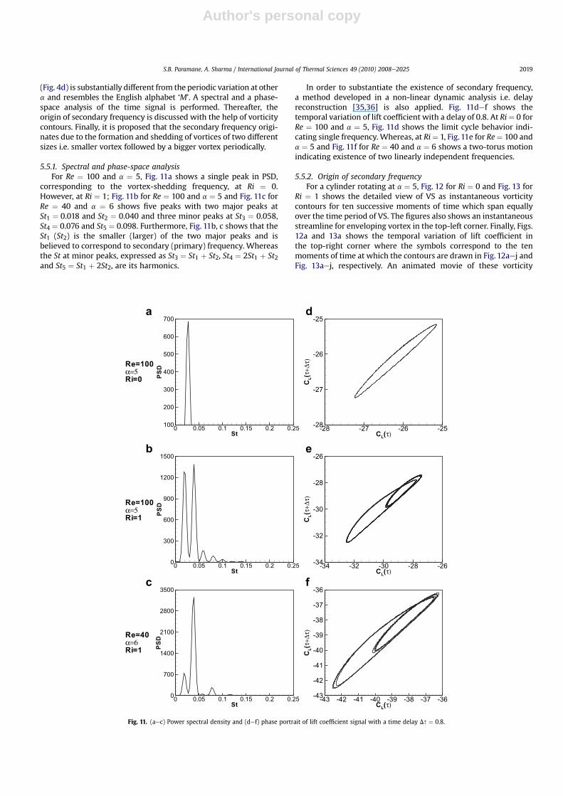
(Fig. 4d) is substantially different from the periodic variation at othera and resembles the English alphabet ‘M’. A spectral and a phase-space analysis of the time signal is performed. Thereafter, theorigin of secondary frequency is discussed with the help of vorticitycontours. Finally, it is proposed that the secondary frequency origi-nates due to the formation and shedding of vortices of two differentsizes i.e. smaller vortex followed by a bigger vortex periodically.
5.5.1. Spectral and phase-space analysisFor Re ¼ 100 and a ¼ 5, Fig. 11a shows a single peak in PSD,
corresponding to the vortex-shedding frequency, at Ri ¼ 0.However, at Ri ¼ 1; Fig. 11b for Re ¼ 100 and a ¼ 5 and Fig. 11c forRe ¼ 40 and a ¼ 6 shows five peaks with two major peaks atSt1 ¼ 0.018 and St2 ¼ 0.040 and three minor peaks at St3 ¼ 0.058,St4 ¼ 0.076 and St5 ¼ 0.098. Furthermore, Fig. 11b, c shows that theSt1 (St2) is the smaller (larger) of the two major peaks and isbelieved to correspond to secondary (primary) frequency. Whereasthe St at minor peaks, expressed as St3 ¼ St1 þ St2, St4 ¼ 2St1 þ St2and St5 ¼ St1 þ 2St2, are its harmonics.
In order to substantiate the existence of secondary frequency,a method developed in a non-linear dynamic analysis i.e. delayreconstruction [35,36] is also applied. Fig. 11def shows thetemporal variation of lift coefficient with a delay of 0.8. At Ri¼ 0 forRe ¼ 100 and a ¼ 5, Fig. 11d shows the limit cycle behavior indi-cating single frequency. Whereas, at Ri¼ 1, Fig. 11e for Re¼ 100 anda ¼ 5 and Fig. 11f for Re ¼ 40 and a ¼ 6 shows a two-torus motionindicating existence of two linearly independent frequencies.
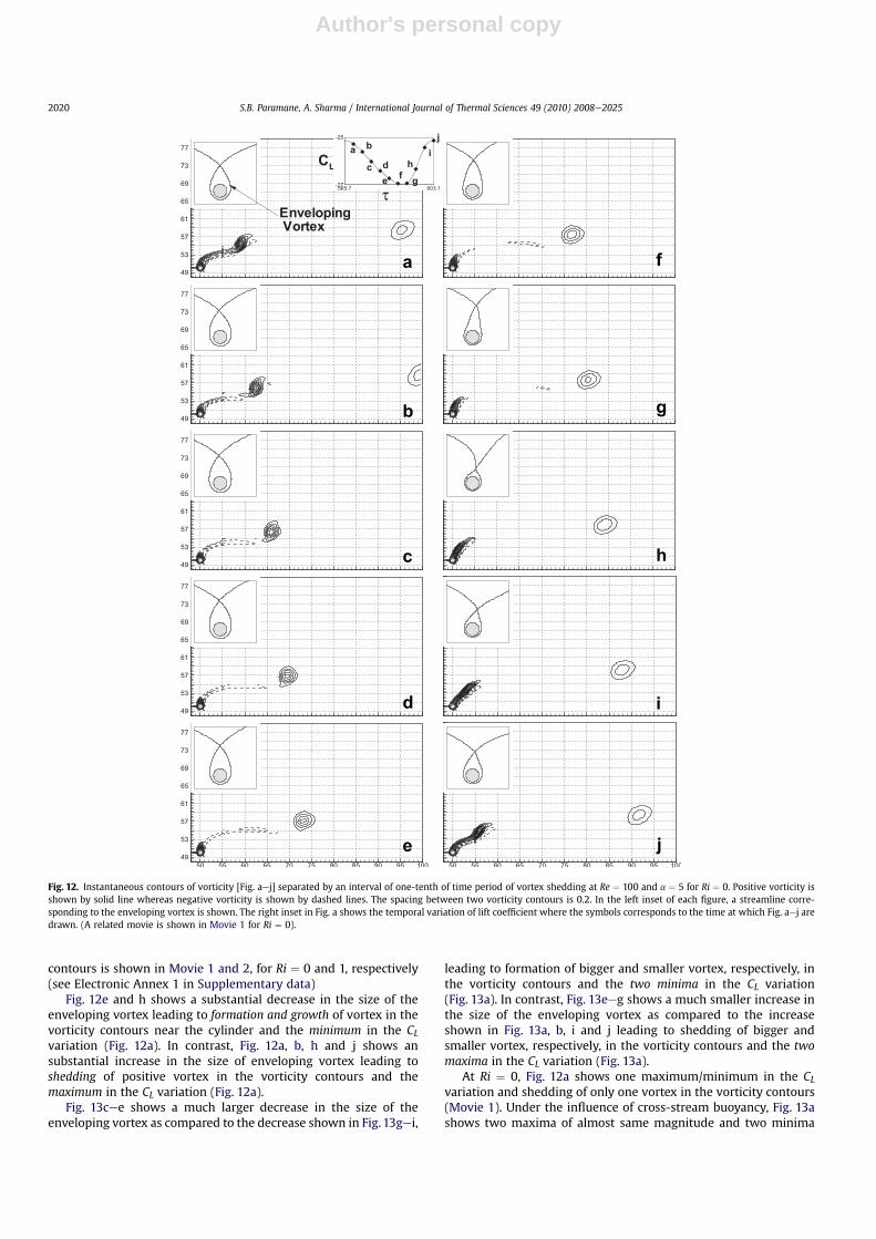
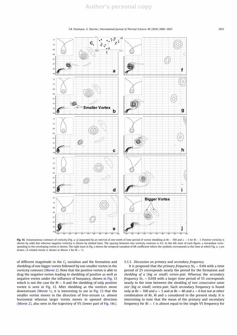
5.5.2. Origin of secondary frequencyFor a cylinder rotating at a ¼ 5, Fig. 12 for Ri ¼ 0 and Fig. 13 for
Ri ¼ 1 shows the detailed view of VS as instantaneous vorticitycontours for ten successive moments of time which span equallyover the time period of VS. The figures also shows an instantaneousstreamline for enveloping vortex in the top-left corner. Finally, Figs.12a and 13a shows the temporal variation of lift coefficient inthe top-right corner where the symbols correspond to the tenmoments of time at which the contours are drawn in Fig. 12aej andFig. 13aej, respectively. An animated movie of these vorticity
St
PSD
0 0.05 0.1 0.15 0.2 0.250
300
600
900
1200
1500b
St
PSD
0 0.05 0.1 0.15 0.2 0.250
700
1400
2100
2800
3500c
Re=100
α=5Ri=0
Re=40
α=6Ri=1
Re=100
α=5Ri=1
St
PSD
0 0.05 0.1 0.15 0.2 0.25100
200
300
400
500
600
700a
CL(τ)
CL(τ+
Δτ)
-28 -27 -26 -25-28
-27
-26
-25d
CL(τ)
CL(τ+
Δτ)
-34 -32 -30 -28 -26-34
-32
-30
-28
-26e
CL(τ)
CL(τ+
Δτ)
-43 -42 -41 -40 -39 -38 -37 -36-43
-42
-41
-40
-39
-38
-37
-36f
Fig. 11. (aec) Power spectral density and (def) phase portrait of lift coefficient signal with a time delay Ds ¼ 0.8.
S.B. Paramane, A. Sharma / International Journal of Thermal Sciences 49 (2010) 2008e2025 2019
Author's personal copy
contours is shown in Movie 1 and 2, for Ri ¼ 0 and 1, respectively(see Electronic Annex 1 in Supplementary data)
Fig. 12e and h shows a substantial decrease in the size of theenveloping vortex leading to formation and growth of vortex in thevorticity contours near the cylinder and the minimum in the CLvariation (Fig. 12a). In contrast, Fig. 12a, b, h and j shows ansubstantial increase in the size of enveloping vortex leading toshedding of positive vortex in the vorticity contours and themaximum in the CL variation (Fig. 12a).
Fig. 13cee shows a much larger decrease in the size of theenveloping vortex as compared to the decrease shown in Fig. 13gei,
leading to formation of bigger and smaller vortex, respectively, inthe vorticity contours and the two minima in the CL variation(Fig. 13a). In contrast, Fig. 13eeg shows a much smaller increase inthe size of the enveloping vortex as compared to the increaseshown in Fig. 13a, b, i and j leading to shedding of bigger andsmaller vortex, respectively, in the vorticity contours and the twomaxima in the CL variation (Fig. 13a).
At Ri ¼ 0, Fig. 12a shows one maximum/minimum in the CLvariation and shedding of only one vortex in the vorticity contours(Movie 1). Under the influence of cross-stream buoyancy, Fig. 13ashows two maxima of almost same magnitude and two minima
a
e
d
c
b
j
i
h
g
f
Fig. 12. Instantaneous contours of vorticity [Fig. aej] separated by an interval of one-tenth of time period of vortex shedding at Re ¼ 100 and a ¼ 5 for Ri ¼ 0. Positive vorticity isshown by solid line whereas negative vorticity is shown by dashed lines. The spacing between two vorticity contours is 0.2. In the left inset of each figure, a streamline corre-sponding to the enveloping vortex is shown. The right inset in Fig. a shows the temporal variation of lift coefficient where the symbols corresponds to the time at which Fig. aej aredrawn. (A related movie is shown in Movie 1 for Ri ¼ 0).
S.B. Paramane, A. Sharma / International Journal of Thermal Sciences 49 (2010) 2008e20252020
Author's personal copy
of different magnitude in the CL variation and the formation andshedding of one bigger vortex followed by one smaller vortex in thevorticity contours (Movie 2). Note that the positive vortex is able todrag the negative vortex leading to shedding of positive as well asnegative vortex under the influence of buoyancy, shown in Fig. 13which is not the case for Ri ¼ 0 and the shedding of only positivevortex is seen in Fig. 12. After shedding as the vortices movedownstream (Movie 1), it is interesting to see in Fig. 13 that thesmaller vortex moves in the direction of free-stream i.e. almosthorizontal whereas larger vortex moves in upward direction(Movie 2), also seen in the trajectory of VS (lower part of Fig. 14c).
5.5.3. Discussion on primary and secondary frequencyIt is proposed that the primary frequency St2 ¼ 0.04 with a time
period of 25 corresponds nearly the period for the formation andshedding of a (big or small) vortex-pair. Whereas the secondaryfrequency St1 ¼ 0.018 with a larger time period of 55 correspondsnearly to the time between the shedding of two consecutive samesize (big or small) vortex-pair. Such secondary frequency is foundonly at Re¼ 100 and a¼ 5 and at Re ¼ 40 and a¼ 6 but not at othercombination of Re, Ri and a considered in the present study. It isinteresting to note that the mean of the primary and secondaryfrequency for Ri ¼ 1 is almost equal to the single VS frequency for
g
j
Bigger Vortex
b
Smaller Vortex
a
CL
τ
e
d
c
f
i
h
Fig. 13. Instantaneous contours of vorticity [Fig. aej] separated by an interval of one-tenth of time period of vortex shedding at Re ¼ 100 and a ¼ 5 for Ri ¼ 1. Positive vorticity isshown by solid line whereas negative vorticity is shown by dashed lines. The spacing between two vorticity contours is 0.2. In the left inset of each figure, a streamline corre-sponding to the enveloping vortex is shown. The right inset in Fig. a shows the temporal variation of lift coefficient where the symbols corresponds to the time at which Fig. aej aredrawn. (A related movie is shown in Movie 2 for Ri ¼ 1).
S.B. Paramane, A. Sharma / International Journal of Thermal Sciences 49 (2010) 2008e2025 2021
Author's personal copy
Ri ¼ 0 at a ¼ 5 and Re ¼ 100. Thus, under the influence of cross-stream buoyancy-induced flow, the VS shedding frequency of thecylinder rotating at high velocity breaks into two frequencies: onegreater and other smaller by the same magnitude.
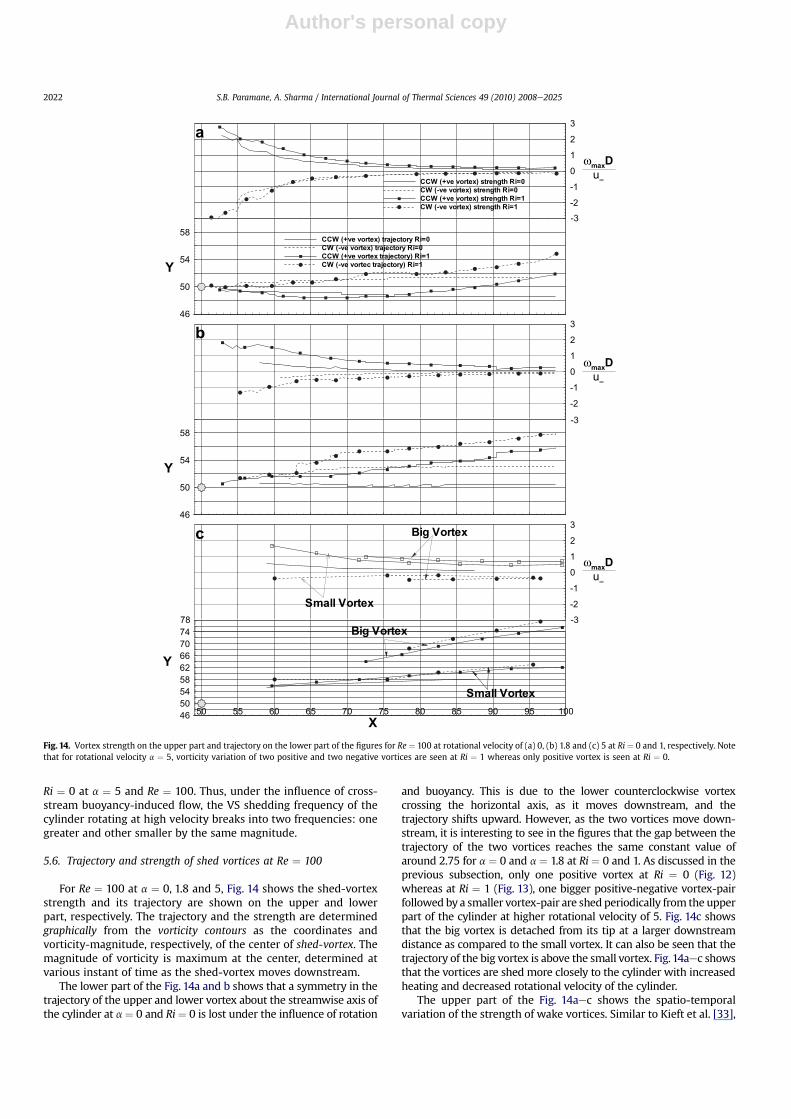
5.6. Trajectory and strength of shed vortices at Re ¼ 100
For Re ¼ 100 at a ¼ 0, 1.8 and 5, Fig. 14 shows the shed-vortexstrength and its trajectory are shown on the upper and lowerpart, respectively. The trajectory and the strength are determinedgraphically from the vorticity contours as the coordinates andvorticity-magnitude, respectively, of the center of shed-vortex. Themagnitude of vorticity is maximum at the center, determined atvarious instant of time as the shed-vortex moves downstream.
The lower part of the Fig. 14a and b shows that a symmetry in thetrajectory of the upper and lower vortex about the streamwise axis ofthe cylinder at a¼ 0 and Ri ¼ 0 is lost under the influence of rotation
and buoyancy. This is due to the lower counterclockwise vortexcrossing the horizontal axis, as it moves downstream, and thetrajectory shifts upward. However, as the two vortices move down-stream, it is interesting to see in the figures that the gap between thetrajectory of the two vortices reaches the same constant value ofaround 2.75 for a ¼ 0 and a ¼ 1.8 at Ri ¼ 0 and 1. As discussed in theprevious subsection, only one positive vortex at Ri ¼ 0 (Fig. 12)whereas at Ri ¼ 1 (Fig. 13), one bigger positive-negative vortex-pairfollowed by a smaller vortex-pair are shed periodically from the upperpart of the cylinder at higher rotational velocity of 5. Fig. 14c showsthat the big vortex is detached from its tip at a larger downstreamdistance as compared to the small vortex. It can also be seen that thetrajectory of the big vortex is above the small vortex. Fig.14aec showsthat the vortices are shed more closely to the cylinder with increasedheating and decreased rotational velocity of the cylinder.
The upper part of the Fig. 14aec shows the spatio-temporalvariation of the strength of wake vortices. Similar to Kieft et al. [33],
-2
-1
0
1
2
3c
Small Vortex
Big Vortex
-2
-1
0
1
2
3
CCW (+ve vortex) strength Ri=0
CW (-ve vortex) strength Ri=0
CCW (+ve vortex) strength Ri=1
CW (-ve vortex) strength Ri=1
a
-2
-1
0
1
2
3b
ωmaxD
u∝
Y
Y
Y
ωmaxD
u∝
X
ωmaxD
u∝
-3
-3
46
50
54
58
-3
46
50
54
58CCW (+ve vortex) trajectory Ri=0
CW (-ve vortex) trajectory Ri=0
CCW (+ve vortex trajectory) Ri=1
CW (-ve vortec trajectory) Ri=1
50 55 60 65 70 75 80 85 90 95 1004650545862667074
Small Vortex
Big Vortex
78
Fig. 14. Vortex strength on the upper part and trajectory on the lower part of the figures for Re ¼ 100 at rotational velocity of (a) 0, (b) 1.8 and (c) 5 at Ri ¼ 0 and 1, respectively. Notethat for rotational velocity a ¼ 5, vorticity variation of two positive and two negative vortices are seen at Ri ¼ 1 whereas only positive vortex is seen at Ri ¼ 0.
S.B. Paramane, A. Sharma / International Journal of Thermal Sciences 49 (2010) 2008e20252022

Author's personal copy
peak vorticity value (occurs at the vortex center) is used as ameasureof the strength of a vortex structure in the present study. It can beobserved from the Fig. 14 that the strength of the shed-vorticesincreaseswith increasing Ri anddecreaseswith increasing rotationalvelocity. Furthermore, it can be seen that the strength of the vorticesdecreases as it moves downstream due to advection and diffusion ofvorticity. At a constant X-coordinate, Fig.14c shows that the strengthof the big vortex is more as compared to small vortex. The rotationof the cylinder causes the weakening whereas buoyancy causes thestrengthening of the upper and lower shed-vortices.
5.7. Flow and heat transfer parameters
5.7.1. Strouhal numberThe periodic VS flow oscillation frequency is represented by
Strouhal number, St¼ fD/uN and is determined from power spectradensity of temporal variation of lift coefficient. Its variation withincreasing rotational velocity is shown in Fig. 15 for various Re andheating/Ri. The figure shows that the recurrence of VS at a � 4.6 iswith a Strouhal number (on the right Y-axis) which is one order ofmagnitude smaller than its value (on the left Y-axis) at a� 2.1, withzero values at intermediate rotational velocity as the flow is steady.
For Re ¼ 100, the figure shows the Strouhal number of stationarycylinder is almost equal to that of cylinder rotating at a ¼ 1and increases with increasing Ri for the stationary/rotating cylinder.Vortex-shedding process takes place in two consecutive parts i.e.vortex formation followed by actual vortex shedding.With increase inheating of the cylinder, the vortex formation is enhanced due toaccelerated boundary layers leading to faster movement of thevortices. With further increase in a, the Strouhal number dropssharply for Re¼ 40 aswell as 100 leading toVS suppression. Thefigureat a� 4.6 shows sharp decrease in St leading to VS re-suppression forRi¼ 0 and amonotonic decrease for Ri¼ 1. For Ri¼ 1 at a constant a, itcan also be seen that the St at Re¼ 40 is less as compared to Re¼ 100fora� 2.1whereas an opposite variation is seen fora� 4.6. Thus,withincreasing Re, VS is faster (slower) at low (high) rotational velocity.
5.7.2. Mean lift and drag coefficientFor the free-stream flow across a cylinder rotating in counter-
clockwise direction or/and a heated cylinder, the lift force acts in
downward direction. This is due to acceleration of the fluid near thebottom as compared to top of the cylinder with increased rotation/heating which results in higher pressure at the top compared to thebottom of the cylinder. Combined effect of rotation and heatingon the variation of lift coefficient is seen in Fig. 16a where itsmagnitude increases with increasing rotational velocity and withincreasing Ri.
With increasing rotational velocity, Fig. 16b shows that the meandrag coefficient decreases at lower a and increases at at higher a.However, the decrease and increase is more at Ri¼ 1 as compared toRi ¼ 0. For the range of a considered, it is interesting to see in the
α
St
St
0 1 2 3 4 5 6 7 80.11
0.115
0.12
0.125
0.13
0.135
0.14
0.145
0.15
0.155
0.16
0.165
0.17
0
0.005
0.01
0.015
0.02
0.025
0.03
0.035
0.04
0.045
0.05
0.055
0.06
0.065
0.07
Ri=0
Ri=1
Re=100
Re=40
Fig. 15. Variation of Strouhal number with increasing rotational velocity for variousRichardson number and Reynolds number in the VS regime. Note that the Strouhalnumber on the left and right Y-axis corresponds to a � 2.1 and a � 4.6, respectively,with zero values at intermediate a.
b
c
a
Fig. 16. Variation of total (a) lift (CL) and (b) drag coefficient (CD) with increasingrotational velocity a for various Richardson number and Reynolds number. (c) Varia-tion of critical rotational velocity with increasing Ri.
S.B. Paramane, A. Sharma / International Journal of Thermal Sciences 49 (2010) 2008e2025 2023
Author's personal copy
figure that the drag coefficient is mostly positive for Ri ¼ 0 and ismostly negative for Ri ¼ 1. With increasing a at a constant Ri, it isfound that the contribution of viscous drag increases and evenbecomes comparablewith pressure drag at larger rotational velocity.With increasing Ri at a constant a, the viscous drag coefficient isfound to be almost constant whereas the pressure drag forcedecreases for both the Re. This is also confirmed from the pressurevariation along the cylinder surface (figure not shown) wherepressure at the front part of the cylinder decreaseswith increasing Riwhereas at rear part there is small increase in pressure.
The drag coefficient is positive for stationary cylinder andbecomes negative for rotating cylinder after certain rotationalvelocity indicating the reversal in the direction of drag force fromforward (þX) to backward (�X) direction. The critical rotationalvelocity ac atwhich the drag force is zero decreaseswith increasing Rifor Re¼ 40 and 100, shown in Fig. 16c. However, as Re increases from40 to 100, thefigure shows that the acdecreases forRi¼ 0 and0.5 andincreases for Ri ¼ 1. Probably, this is due to the steady flow for Ri¼ 0and 0.5 and VS flow for Ri¼ 1 at a¼ ac, shown in the Figs. 4e and 5e.
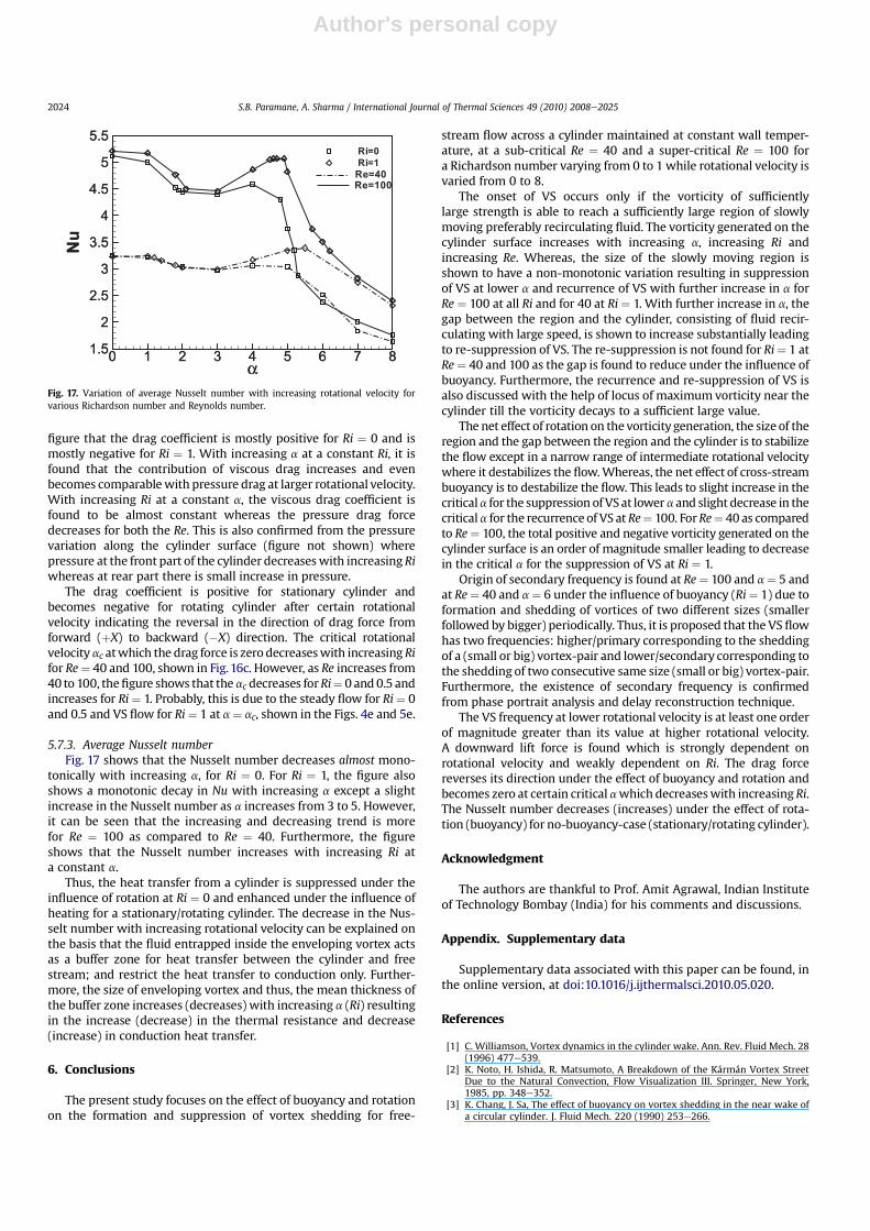
5.7.3. Average Nusselt numberFig. 17 shows that the Nusselt number decreases almost mono-
tonically with increasing a, for Ri ¼ 0. For Ri ¼ 1, the figure alsoshows a monotonic decay in Nu with increasing a except a slightincrease in the Nusselt number as a increases from 3 to 5. However,it can be seen that the increasing and decreasing trend is morefor Re ¼ 100 as compared to Re ¼ 40. Furthermore, the figureshows that the Nusselt number increases with increasing Ri ata constant a.
Thus, the heat transfer from a cylinder is suppressed under theinfluence of rotation at Ri ¼ 0 and enhanced under the influence ofheating for a stationary/rotating cylinder. The decrease in the Nus-selt number with increasing rotational velocity can be explained onthe basis that the fluid entrapped inside the enveloping vortex actsas a buffer zone for heat transfer between the cylinder and freestream; and restrict the heat transfer to conduction only. Further-more, the size of enveloping vortex and thus, the mean thickness ofthe buffer zone increases (decreases) with increasing a (Ri) resultingin the increase (decrease) in the thermal resistance and decrease(increase) in conduction heat transfer.
6. Conclusions
The present study focuses on the effect of buoyancy and rotationon the formation and suppression of vortex shedding for free-
stream flow across a cylinder maintained at constant wall temper-ature, at a sub-critical Re ¼ 40 and a super-critical Re ¼ 100 fora Richardson number varying from 0 to 1 while rotational velocity isvaried from 0 to 8.
The onset of VS occurs only if the vorticity of sufficientlylarge strength is able to reach a sufficiently large region of slowlymoving preferably recirculating fluid. The vorticity generated on thecylinder surface increases with increasing a, increasing Ri andincreasing Re. Whereas, the size of the slowly moving region isshown to have a non-monotonic variation resulting in suppressionof VS at lower a and recurrence of VS with further increase in a forRe ¼ 100 at all Ri and for 40 at Ri¼ 1. With further increase in a, thegap between the region and the cylinder, consisting of fluid recir-culating with large speed, is shown to increase substantially leadingto re-suppression of VS. The re-suppression is not found for Ri¼ 1 atRe¼ 40 and 100 as the gap is found to reduce under the influence ofbuoyancy. Furthermore, the recurrence and re-suppression of VS isalso discussed with the help of locus of maximum vorticity near thecylinder till the vorticity decays to a sufficient large value.
The net effect of rotation on the vorticity generation, the size of theregion and the gap between the region and the cylinder is to stabilizethe flow except in a narrow range of intermediate rotational velocitywhere it destabilizes the flow.Whereas, the net effect of cross-streambuoyancy is to destabilize the flow. This leads to slight increase in thecriticala for the suppression of VSat lowera and slight decrease in thecriticala for the recurrence of VS at Re¼ 100. ForRe¼ 40 as comparedto Re¼ 100, the total positive and negative vorticity generated on thecylinder surface is an order of magnitude smaller leading to decreasein the critical a for the suppression of VS at Ri ¼ 1.
Origin of secondary frequency is found at Re¼ 100 and a¼ 5 andat Re¼ 40 and a¼ 6 under the influence of buoyancy (Ri¼ 1) due toformation and shedding of vortices of two different sizes (smallerfollowed by bigger) periodically. Thus, it is proposed that the VS flowhas two frequencies: higher/primary corresponding to the sheddingof a (small or big) vortex-pair and lower/secondary corresponding tothe shedding of two consecutive same size (small or big) vortex-pair.Furthermore, the existence of secondary frequency is confirmedfrom phase portrait analysis and delay reconstruction technique.
The VS frequency at lower rotational velocity is at least one orderof magnitude greater than its value at higher rotational velocity.A downward lift force is found which is strongly dependent onrotational velocity and weakly dependent on Ri. The drag forcereverses its direction under the effect of buoyancy and rotation andbecomes zero at certain critical awhich decreaseswith increasingRi.The Nusselt number decreases (increases) under the effect of rota-tion (buoyancy) for no-buoyancy-case (stationary/rotating cylinder).
Acknowledgment
The authors are thankful to Prof. Amit Agrawal, Indian Instituteof Technology Bombay (India) for his comments and discussions.
Appendix. Supplementary data
Supplementary data associated with this paper can be found, inthe online version, at doi:10.1016/j.ijthermalsci.2010.05.020.
References
[1] C. Williamson, Vortex dynamics in the cylinder wake. Ann. Rev. Fluid Mech. 28(1996) 477e539.
[2] K. Noto, H. Ishida, R. Matsumoto, A Breakdown of the Kármán Vortex StreetDue to the Natural Convection, Flow Visualization III. Springer, New York,1985, pp. 348e352.
[3] K. Chang, J. Sa, The effect of buoyancy on vortex shedding in the near wake ofa circular cylinder. J. Fluid Mech. 220 (1990) 253e266.
Fig. 17. Variation of average Nusselt number with increasing rotational velocity forvarious Richardson number and Reynolds number.
S.B. Paramane, A. Sharma / International Journal of Thermal Sciences 49 (2010) 2008e20252024
Author's personal copy
[4] K. Hatanaka, M. Kawahara, A numerical study of vortex shedding arounda heated/cooled circular cylinder by the three-step TayloreGalerkin method.Int. J. Numer. Meth. Fluids 21 (1995) 857e867.
[5] B. Patnaik, P. Narayana, K. Seetharamu, Numerical simulation of vortexshedding past a circular cylinder under the influence of buoyancy. Int. J. HeatMass Transfer 42 (1999) 3495e3507.
[6] A. Sharma, V. Eswaran, Effect of aiding and opposing buoyancy on the heatand fluid flow across a square cylinder at Re¼100. Numer. Heat Transfer-A 45(2004) 601e624.
[7] H. Badr, A theoretical study of laminar mixed convection from a horizontalcylinder in a cross stream. Int. J. Heat Mass Transfer 26 (1983) 639e653.
[8] C. Chen, Y. Yan, S. Wu, Laminar mixed convection from a circular cylinder usinga body-fitted coordinate. J. Thermophys. Heat Transfer 8 (1994) 695e701.
[9] R. Ahmad, Z. Qureshi, Laminar mixed convection from a uniform heat fluxhorizontal cylinder in a cross-flow. J. Thermophys. Heat Transfer 6 (1992)277e287.
[10] B. Abu-Hijleh, Laminar mixed convection correlations for an isothermalcylinder in cross flow at different angles of attack. Int. J. Heat Mass Transfer 42(1999) 1383e1388.
[11] A. Steenhoven, C. Rindt, Flow transition behind a heated cylinder. Int. J. HeatFluid Flow 24 (2003) 322e333.
[12] M. Mass, C. Rindt, A. van Steenhoven, The influence of heat on the 3-Dtransition of the von Kármán vortex street. Int. J. Heat Mass Transfer 46 (2003)3069e3081.
[13] A. Sharma, Numerical investigation of unconfined and channel-confined flowacross a square cylinder with forced and mixed convection heat transfer, PhDthesis (2003), IIT Kanpur, India.
[14] S. Turki, Buoyancy effect on the flow and heat transfer around an unconfinedheated square cylinder, Proc. 4th ICHMT and International Symposium onAdvances in Computational Heat Transfer Conf., Marrakech, Morocco, (2008)CHT-08e134.
[15] G. Hu, D. Sun, X. Yin, B. Tong, Hopf Bifurcation in wakes behind a rotating andtranslating circular cylinder. Phys. Fluids 8 (1996) 1972e1974.
[16] S. Kang, H. Choi, Laminar flow past a rotating circular cylinder. Phys. Fluids 11(1999) 3312e3321.
[17] D. Stojkovic, M. Breuer, F. Durst, Effect of high rotation rates on the laminarflow around a circular cylinder. Phys. Fluids 14 (2002) 3160e3178.
[18] D. Stojkovic, P. Schon, M. Breuer, F. Durst, On the new vortex shedding modepast a rotating circular cylinder. Phys. Fluids 15 (2003) 1257e1260.
[19] S.Mittal,B.Kumar, Flowpastarotatingcylinder. J. FluidMech.476 (2003)303e334.[20] S. Paramane, A. Sharma, Numerical investigation of heat and fluid flow across
a rotating circular cylinder maintained at constant temperature in 2-Dlaminar flow regime. Int. J. Heat Mass Transfer 52 (2009) 3205e3216.
[21] S. Paramane, A. Sharma, Heat and fluid flow across a rotating circular cylinderdissipating uniform heat flux in 2D laminar flow regime. Int. J. Heat MassTransfer (2010), doi:10.1016/j.ijheatmasstransfer.2010.06.026
[22] S. Dol, G. Kopp, R. Martinuzzi, The suppression of periodic vortex sheddingfrom a rotating circular cylinder. J. Wind Engg. Ind. Aerodynamics. 96 (2008)1164e1184.
[23] K. Lam, Vortex shedding flow behind a slowly rotating circular cylinder.J. Fluid Struct. 25 (2009) 245e262.
[24] H. Badr, S. Dennis, Laminar forced convection from a rotating cylinder. Int.J. Heat Mass Transfer 28 (1985) 253e264.
[25] Y. Yan, Y. Zu, Numerical simulation of heat transfer and fluid flow pasta rotating isothermal cylinder e a LBM approach. Int. J. Heat Mass Transfer 51(2008) 2519e2536.
[26] L. Baranyi, Computation of unsteady momentum and heat transfer froma fixed circular cylinder in laminar flow. J. Comp. App. Mech. 4 (2003) 13e25.
[27] A. Sharma, V. Eswaran, A Finite Volume Method Narosa Publishing House,New Delhi, and Alpha Science, UK. in: K. Muralidhar, T. Sundararajan (Eds.),Computational Fluid Flow and Heat Transfer (2003), pp. 445e483.
[28] Y. Yan, H. Lai, R. Gentle, J. Smith, Numerical analysis of fluid flows inside andaround a liquid drop using an incorporation of multi-block iteration andmoving mesh. Chem. Eng. Res. Des. 80 (2002) 325e331.
[29] H. Lai, Y. Yan, J. Smith, A calculation procedure with multi-block iteration andmoving mesh for heat and fluid flows in complex time-dependent geometries.Int. J. Numer. Methods for Heat Fluid Flow 12 (2002) 106e125.
[30] S. Paramane, A. Sharma, Consistent implementation and comparison of FOU,CD, SOU and QUICK convection schemes on square, skew, trapezoidal, andtriangular lid driven cavity flow. Numer. Heat Transfer: Part B. 54 (2008)84e102.
[31] R. Kieft, C. Rindt, A. van Steenhoven, Near-wake effects of a heat input on thevortex shedding mechanism. Int. J. Heat Fluid Flow 28 (2007) 938e947.
[32] P. Strykowski, K. Sreenivasan, On the formation and suppression of vortexshedding at low Reynolds numbers. J. Fluid Mech. 218 (1990) 71e107.
[33] R. Kieft, C. Rindt, A. van Steenhoven, G. van Heijst, On the wake structurebehind a heated horizontal cylinder in cross-flow. J. Fluid Mech. 486 (2003)189e211.
[34] F. Shair, A. Grove, E. Petersen, A. Acrivos, The effect of confining walls on thestability of the steady wake behind a circular cylinder. J. Fluid Mech. 17 (1963)547e550.
[35] F. Takens, Detecting Strange Attractors in Turbulence, Lecture Notes inMathematics. Springer-Verlag, New York, 1981, pp. 366e381.
[36] K. Sreenivasan, Transition and Turbulence in Fluid Flows and Low Dimen-sional Chaos. in: S.H. Davis, J.L. Lumley (Eds.), Frontiers in Fluid Mechanics.Springer, New York, 1985, pp. 41e67.
S.B. Paramane, A. Sharma / International Journal of Thermal Sciences 49 (2010) 2008e2025 2025
Copyright © 2022 FDOKUMEN