Edward and Anchor/Darling - Nuclear Application Valves
260
Edward and Anchor/Darling Nuclear Application Valves Experience In Motion
-
Upload
khangminh22 -
Category
Documents
-
view
1 -
download
0
Transcript of Edward and Anchor/Darling - Nuclear Application Valves
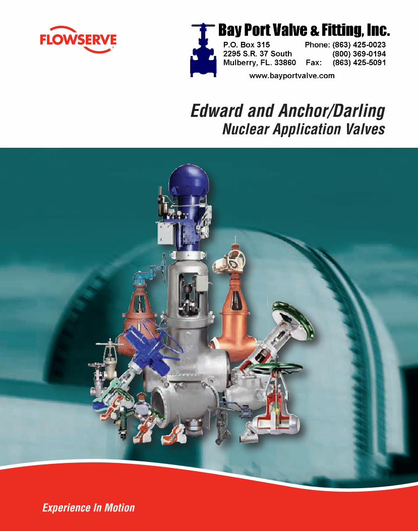
Edward and Anchor/DarlingNuclear Application Valves
Experience In Motion
147-10057 EAD_Bro_6-18.indd 1 8/6/09 5:03:20 PM
scott
bpv logo 1

2
Flowserve Edward and Anchor/Darling Valves • 1900 South Saunders Street, Raleigh, North Carolina 27603 • 1-800-225-6989 • 1-919-832-0525 • Fax 1-919-831-3369
We’ll Support YouFlowserve’s Flow Control Division is dedicated to providing continuous aftermarket support to our nuclear customers. Safety-related valves and parts are supplied in accordance with ASME Section III and 10 CFR 50 Appendix B on a routine basis; and more importantly, in support of refueling outages and forced outages at nuclear generating stations.
Flowserve engineers, with working knowledge of nuclear applications and requirements are available on a 24-hour basis to respond to phone calls from nuclear customers with critical outage and unforeseen forced outage help requirements. At Flowserve, we understand the necessity of maintaining critical-path schedules!
When you specify Flowserve nuclear safety-related valves, you can rest ensured that the ongoing support and technical backup you may need down the road will be available to you right now!
Flowserve’s Edward and Anchor/Darling valves are manufactured exclusively at our Raleigh, North Carolina, operation. Of the various Flowserve manufacturing facilities, the Flow Control Division’s Raleigh operation is the sole holder of ASME Section III N and NPT stamps, as well as the National Board’s Nuclear Repair (NR) stamp.
We maintain a quality assurance system in accordance with ASME Section III and 10 CFR 50 Appendix B with controlled copies of our QA Manual available to nuclear customers. Non-destructive testing including radiography, liquid penetrant inspection, mag particle inspection, ultrasonic testing, PMI and mechanical property testing are performed in-house by ASNT/EN 473 qualified examiners and inspection personnel. Design reports, seismic reports, environmental qualification reports and certified drawings are prepared by Raleigh’s engineering department. Additionally, Flowserve’s Flow Control Division offers dedication of commercial-grade items by qualified inspection personnel based on engineering-prescribed critical characteristics and dedication methods.
Specify Flowserve Edward and Anchor/Darling valves for nuclear safety-related requirements to ensure strict adherence to applicable nuclear codes and standards, on-time delivery and continuing aftermarket parts support.
147-10057 EAD_Bro_6-18.indd 2 8/6/09 5:03:20 PM

flowserve.com
3
Table of ContentsEdward
Edward Gate Valves 25
Anchor/Darling Gate Valves 35
Edward Globe and Stop-Check Valves 57
Anchor/Darling Globe Valves 89
Edward Check Valves 107
Anchor/Darling Check Valves 125
Anchor/Darling Ball Valves 149

4
Anchor/Darling Butterfly Valves 173
Accessories/Actuators 187
Tables and Charts 193
Technical Information 211
Maintenance
References to Related Brochures
Brochure Document Number
Anchor/Darling Valves
In addition to the valves featured in this catalog, Flowserve’s Flow Control Division also supplies the following valves for nuclear power plant service:

flowserve.com
5 These valves can be constructed for nuclear service. Note: See “References to Related Brochures” chart in the Table of Contents to locate figures that do not appear in this brochure.
Flowserve - Edward Figure Number IndexFigure Forged Cast Nuclear Figure Forged Cast Nuclear Figure Forged Cast Nuclear Figure Forged Cast Nuclear

6
Description 1,2 2
Flanged
Flanged
Flanged
Flanged Univalve Flanged
1. See paragraph 3.2, page 255 for definition of various pressure ratings available. 2. Metric equivalent values for ratings and sizes are in parentheses.
Flowserve - Edward Valves Availability Chart, Forged Steel Valve Catalog (EVENCT0001)

flowserve.com
7
Description 1,2 2
Flanged
Flanged
Flanged
®
Flanged
®
Flanged
®
Flanged
1. See paragraph 3.2, page 255 for definition of various pressure ratings available. 2. Metric equivalent values for ratings and sizes are in parentheses.
Flowserve - Edward Valves Availability Chart, Cast Steel Valve Catalog (EVENCT0002)

8
CF8C
C5
F11
F22
F91
F316
F316L
F347
LF2
B
C
CD
DD
DDI
F
FF
J
K
L
LD
N
Q
UF
Y
Edward Description of Figure Number System

flowserve.com
9
Unless otherwise specified when ordering Edward valves, the standard material of construction for Forged products is A/SA105 Carbon Steel, and for Cast products is SA216 Grade WCB Carbon Steel.
G J Y
Edward Description of Figure Number SystemExample

10
These valves can be constructed for nuclear service. Note: See “References to Related Brochures” chart in the Table of Contents to locate figures that do not appear in this brochure.
Flowserve - Anchor/Darling Figure Number Index
Figure Nuclear Figure Nuclear Figure Nuclear Figure Nuclear

flowserve.com
11
Description 1,2 2
1. See paragraph 3.2, page 255 for definition of various pressure ratings available. 2. Metric equivalent values for ratings and sizes are in parentheses.
Flowserve - Anchor/Darling Valves Availability Chart

12
Description 1,2 2
Flanged
Flanged
Flanged
Flanged
1. See paragraph 3.2, page 255 for definition of various pressure ratings available. 2. Metric equivalent values for ratings and sizes are in parentheses.
Flowserve - Anchor/Darling Valves Availability Chart

flowserve.com
13
Description 1,2 2
Bolted BonnetFlanged
Flanged
Flanged
Flanged
Flanged
Flanged
1. See paragraph 3.2, page 255 for definition of various pressure ratings available. 2. Metric equivalent values for ratings and sizes are in parentheses.
Flowserve - Anchor/Darling Valves Availability Chart

14
AG
DDDrainer
DVFG
GV
YA Y Angle
YG
YV
Anchor/Darling Description of Figure Number System
A
DEFGHJ
U
FeaturesA
DEFG
UV
Description
Example
Unless otherwise specified when ordering Anchor/Darling valves, the standard material of construction for Small Bore products and for Cast products is A/SA216 Grade WCB Carbon Steel.
E DD U

flowserve.com
15

16
Nuclear Safety Related
they exceed them.
absolute necessity of dependability
Conservative Design
industry standards
repeatability, parts interchangeability and spot-on perfect dependability
every time
working knowledge of the nuclear power business
speak the language
For nuclear power plant applications, call the professionals at Flowserve’s Flow Control
High Performance for Critical Service

flowserve.com
17
Designed with an Eye on Your Bottom Line

18
Testing Beyond Code Requirements

flowserve.com
19
A History of FirstsFeature Benefit
wedge halves
®

20
Flowserve - Edward and Anchor/Darling Valves Available for Nuclear Service
Simulated line rupture test confirms closing speed of Edward main steam isolation valve against differential pressure of 1500 psi.
Univalve
Note: See pages 5 and 10 for indicated figure numbers available for nuclear service.
constructed for nuclear service can be

flowserve.com
21
Flowserve Forged and Cast Steel Valves for Nuclear Service
Edward Equiwedge gate valve with an Edward gas hydraulic actuator being prepared for shipment.
Flowserve Edward and Anchor/Darling have
Flowserve Edward and Anchor/Darling
Edward and Anchor/Darling valves constructed for nuclear service can be offered for Code class 1, 2 or 3.

22
Checklist of Customer Information Required for Nuclear Valve Proposals
Flowserve Edward Stored Energy Actuator

flowserve.com
23
Gas-Hydraulic Actuators for Fail-Safe Isolation Valves
Flowserve Edward gas-hydraulic actuator for large, fast-closing valves is subjected to seismic testing during rigorous qualification program to provide dependability of operation under the most adverse conditions.
Standard Features
Flowserve - Edward Actuator DesignationUnits
Values tabulated are “nominal.” For special applications; otherwise, standard actuators may be modified for shorter or longer travel with corresponding effects on weight. Environmental temperature range of the application will influence thrust.
Diagram of Flowserve Edward Equiwedge gate valve and gas-hydraulic actuator assembly.

24
Main Steam and Main Feedwater Isolation ValvesGas / Hydraulic Actuated Equiwedge Gate Valves
Since 1985, over 80% of the world’s MSIVs and MFIVs have been supplied by Flowserve!

flowserve.com
25

26
Features and Description of Flowserve Edward Equiwedge® Gate Valves
1.23.
4.
5.
6.7.
8.
9.
10.
11.
12.
13.
14.15.16.17.
18.
19.

flowserve.com
27
Description
*Hardfaced wedge guide rails and seating surfaces. **Size 2½ through 6, Class 600 & Size 2½ through 4, Class 900 also available with bolted bonnet/flat gasket. ***Use A-368 Grade 660 T2 for applications over 1100°F
Parts Specification List for Edward Gate Valves

28
Features and Description of Flowserve Edward Equiwedge® Gate Valves
Center Cavity Overpressurization
Figure 1
Groove
Wedge Halves
Figure 2
Figure 3 Figure 4

flowserve.com
29
Equiwedge Stop Valves, Class 600
Standard Features Pressure Class 600 (PN 110)
Bonnet
Flanged
* Flanges to size 24 only.
Dimensions – Equiwedge Gate
* E, G, and other dimensions and information supplied upon request.
Refer to page 27 for materials of construction.

30
Equiwedge Stop Valves, Class 600
Dimensions – Equiwedge Gate Venturi Pattern
Refer to page 27 for materials of construction.
Dimensions – Equiwedge Gate (continued)
* E, G and other dimensions and information supplied upon request.

flowserve.com
31
Equiwedge Stop Valves, Class 900
Standard Features Pressure Class 900 (PN 150)
Bonnet
Flanged
Dimensions – Equiwedge Gate
Refer to page 27 for materials of construction.

32
Equiwedge Stop Valves, Class 900
Dimensions – Equiwedge Gate Venturi Pattern
Refer to page 27 for materials of construction.
Dimensions – Equiwedge Gate (continued)

flowserve.com
33
Equiwedge Stop Valves, Class 1500
Standard Features
Pressure Class 1500 (PN 260)
* Optional weld-on flanges.
Dimensions – Equiwedge Gate
Refer to page 27 for materials of construction.

34
Equiwedge Stop Valves, Class 1500
Dimensions – Equiwedge Gate Venturi Pattern
Refer to page 27 for materials of construction.

flowserve.com
35

36
Features and Description of Anchor/Darling 800 Series Gate Valves
1.
2.
3.
4.
6.
7.
5.

flowserve.com
37
Parts Specification List for Anchor/Darling 800 Series Gate ValvesStandard Features
Description
Bonnet
Disc

38
800 Series Stop Valves, Class 800
Features
®
Pressure Class 800 (PN 130)
½
½
Dimensions – Gate½ ¾
A
D
F
G
Refer to page 37 for materials of construction.
D
F
A
G

flowserve.com
39
NEED PDF: Anchor/Darling Double Disc Gate Valves.pdf
provides a
design allows
Features and Description of 1888 Series Double-Disc Gate Valve

40
Parts Specification List for Anchor/Darling 1888 Series Double-Disc Gate ValvesStandard Features
Description
Bonnet
Disc

flowserve.com
41
Series 1888 Stop Valves, Class 1888
Features
Dimensions – Gate¾
A
H
Refer to page 40 for materials of construction.
Pressure Class 1888 (PN 325)
¾
¾
Double-Disc OptionDisc Pack, Exploded View
Parallel Slide OptionDisc Pack
H
A
D

42
Features and Description of Anchor/Darling Double-Disc Gate Valves
Reliable Under the Toughest Conditions

flowserve.com
43
Description
Discs
Bonnet Nuts
Parts Specification List for Anchor/Darling Double-Disc Gate Valves

44
Dimensions – Double-Disc
D
E
Refer to page 43 for materials of construction.
Features
Pressure Class 150 (PN 25)
Flanged
Double-Disc Stop Valves, Class 150
E
D

flowserve.com
45
Dimensions – Double-Disc
D
E
Refer to page 43 for materials of construction.
Double-Disc Stop Valves, Class 300
Standard Features Pressure Class 300 (PN 50)
Flanged
D
E

46
D
E
Dimensions – Double-Disc
D
E
Refer to page 43 for materials of construction.
Double-Disc Stop Valves, Class 600
Standard Features
Pressure Class 600 (PN 110)Bonnet
Flanged
Flanged

flowserve.com
47
Dimensions – Double-Disc
D
E
Refer to page 43 for materials of construction.
Double-Disc Stop Valves, Class 900
Standard FeaturesPressure Class 900 (PN 150)
Flanged
G
E
D

48
Dimensions – Double-Disc
D
E
Refer to page 43 for materials of construction.
Double-Disc Stop Valves, Class 1500
Standard FeaturesPressure Class 1500 (PN 260)
Flanged
G
E
D

flowserve.com
49
Features and Description of Flowserve Anchor/Darling Flex-Wedge Gate Valves
Bolted Bonnet DesignPressure Seal Design
is achieved
2.
3.
4.5.
6.
1.

50
Description
*Hardfaced wedge guide rails and seating surfaces. **Size 2½ through 6, Class 600 & Size 2½ through 4, Class 900 also available with bolted bonnet/flat gasket. ***Use A-368 Grade 660 T2 for applications over 1100°F
Parts Specification List for Anchor/Darling Flex-Wedge Gate Valves

flowserve.com
51
Features
Pressure Class 150 (PN 25)
Flanged
Flex-Wedge Stop Valves, Class 150
Dimensions – Flex Wedge, Butt Weld end only. Flanged dimensions available on request.
D
E
Refer to page 50 for materials of construction.
D
E

52
Standard Features
Flex-Wedge Stop Valves, Class 300
Pressure Class 300 (PN 50)
Flanged
Dimensions – Flex Wedge
D
E
Refer to page 50 for materials of construction.
D
E

flowserve.com
53
Flex-Wedge Stop Valves, Class 600
D
E
Dimensions – Flex Wedge
D
E
Refer to page 50 for materials of construction.
Standard FeaturesPressure Class 600 (PN 110)
Flanged
Flanged

54
Dimensions – Flex Wedge
D
E
G
Refer to page 50 for materials of construction.
Flex-Wedge Stop Valves, Class 900
Standard FeaturesPressure Class 900 (PN 150)
Flanged
D
G
E

flowserve.com
55
Dimensions – Flex Wedge
D
E
Refer to page 50 for materials of construction.
Flex-Wedge Stop Valves, Class 1500
Standard Features Pressure Class 1500 (PN 260)
Flanged
D
G
E

56

flowserve.com
57

58
Features and Description of Edward Bolted Bonnet Globe Valves
1.
2.
3.
4. 6.
7.
8.9.
5.
provides
flowserve.com
59
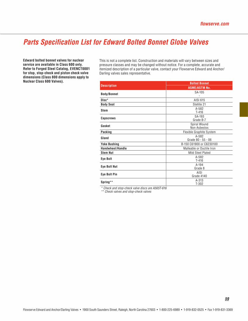
Parts Specification List for Edward Bolted Bonnet Globe Valves
DescriptionBolted Bonnet
Capscrews
* Check and stop-check valve discs are A565T-616** Check valves and stop-check valves
60
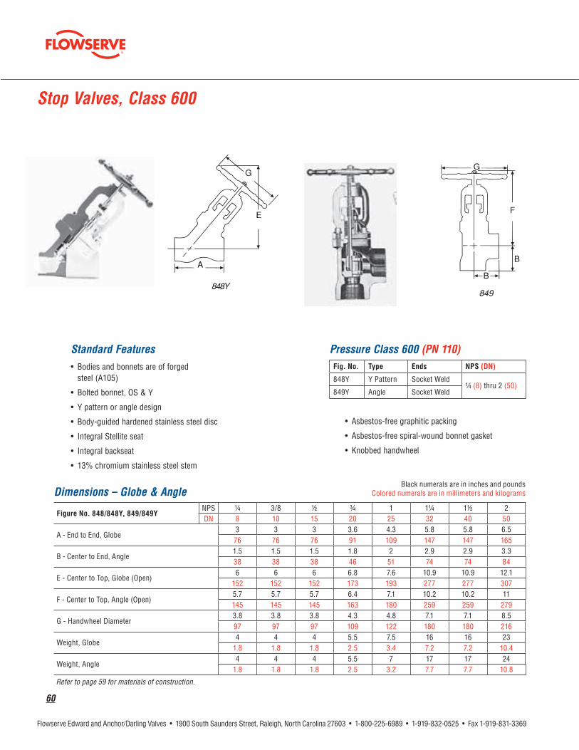
Stop Valves, Class 600
Standard Features
Pressure Class 600 (PN 110)
¼ Angle
Dimensions – Globe & Angle¼ ½ ¾
Refer to page 59 for materials of construction.

flowserve.com
61
Stop-Check Valves, Class 600
Standard Features
Pressure Class 600 (PN 110)
¼ Angle
Dimensions – Globe & Angle¼ ½ ¾
Refer to page 59 for materials of construction.

62
Features and Description of Edward Univalve® Globe Valves7.
8.
9.
10.
11.
12.
1.
2.
3.
4.
5.6.
Welded
Unwelded

flowserve.com
63
Parts Specification List for Edward Univalve® ValvesStandard Features ®
Description
Bonnet
Cobalt-free materials available for wetted parts.
*Check valves only. **Unwelded valves only.
64
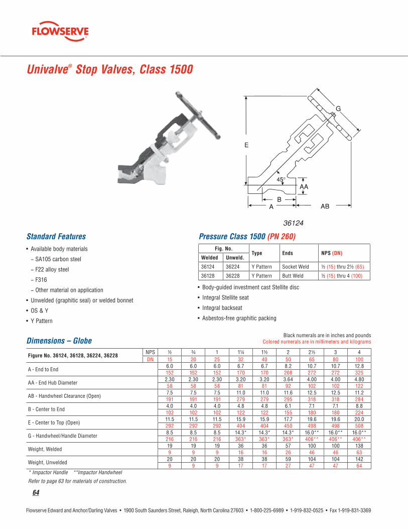
Univalve® Stop Valves, Class 1500
Standard Features Pressure Class 1500 (PN 260)
½
½
Dimensions – Globe½ ¾
* Impactor Handle **Impactor Handwheel
Refer to page 63 for materials of construction.

flowserve.com
65
Univalve® Stop-Check Valves, Class 1500
Standard Features Pressure Class 1500 (PN 260)
½
½
Dimensions – Globe½ ¾
* Impactor Handle ** Impactor Handwheel
Refer to page 63 for materials of construction.
36164

66
Univalve® Stop Valves, Class 2500
Standard Features
Dimensions – Globe½ ¾
* Impactor Handle ** Impactor Handwheel
Refer to page 63 for materials of construction.
Pressure Class 2500 (PN 420)
½
½

flowserve.com
67
Univalve® Stop-Check Valves, Class 2500
Standard FeaturesPressure Class 2500 (PN 420)
½
½
Dimensions – Globe½ ¾
* Impactor Handle **Impactor Handwheel
Refer to page 63 for materials of construction.

68
9.
8.
1.
2.
3.
4.
5.
6.
7.
10.11.
12.
13.
14.
15.
16.
17.
18.
Features and Description of Edward Hermavalve® Hermetically Sealed Valves

flowserve.com
69
Features and Description of Edward Hermavalve® Hermetically Sealed Valves
V

70
Parts Specification List for Edward Hermavalve®
Description
Disc
Bonnet
Diaphragm Disc
Disc Collar
Indicator
Lube FittingNote: Cobalt-free materials available for wetted parts.

flowserve.com
71
Hermavalve® Hermetically Sealed Valves ASME SECTION III – Code Class 1, 2, or 3Nuclear Service Guarantee
Standard Features
Pressure Class 1690 (PN 290)
½
½
Dimensions
½ ¾
*Available in buttweld only.
Refer to page 70 for materials of construction.

72
Features and Description of Flowserve Edward Stop-Check (Non-Return) Valves
Equalizer
®for full disc lift
NOTE 1: Guide ribs are hardfaced on Flite-Flow and some angle pattern valves.
NOTE 1

flowserve.com
73
Parts Specification List for Edward Globe Valves, Stop-Check and Piston Lift Check
Description
Disc
(1) Through Class 2500, for Series 4500 valves, some construction differences exist. Contact your Edward valves sales representative for more information. * Other material grades available on application.

74
Features and Description of Edward Flite-Flow® Globe Valves
For high-pressure/high-temperature installation, the Flite-Flow valve is capable of handling millions of pounds per hour of fluid flow–without sacrificing low-pressure drop or piping flexibility.
1.
2.
3.
4.
5.
6.
7.
8.
9.
10.
11.
12.
13.
14.

flowserve.com
75
Special Application Valves
Flowserve - Edward Throttle Valves

76
Stop Valves, Class 600
Standard Features
Pressure Class 600 (PN 110)
Flanged
Angle Flanged
Angle
Flanged
Angle Flanged
Angle
Dimensions – Globe & Angle*
* Angle valves only. Also available in sizes 24, 28 and 30. Dimensions available upon request. ** Impactor handwheel is standard on all size valves.
flanged end valves. Refer to page 73 for materials of construction.
D
E F
G
D
G

flowserve.com
77
Standard Features
Stop Valves, Class 600
Pressure Class 600 (PN 110)*
Bonnet
Flanged
* 3 and 4 bolted bonnet with asbestos-free spiral-wound gasket.
* Size 3 and 4 butt weld valves are Class 700.
Dimensions – Flite-Flow®
A
A
* Dimensions and information supplied upon request. ** Impactor handwheel standard on all Flite-Flow valves. *** Flanged valves are available in sizes 3 through 16. Refer to page 73 for materials of construction.
G
A
E

78
Dimensions – Globe & Angle*
* Angle valves only. Also available in sizes 24, 28 and 30. Dimensions available upon request. ** Center-to-end or end-to-end dimensions for welding and valves same as center to contact-face or contact-face-to-contact-face dimensions for flanged end valves. # Impactor handwheel is standard on all size valves. Refer to page 73 for materials of construction.
Standard Features
Pressure Class 600 (PN 110)
Flanged
Angle Flanged
Angle
Flanged
Angle Flanged
Angle
Stop-Check (Non-Return) Valves, Class 600
D
E F
G
D
GH
flowserve.com
79
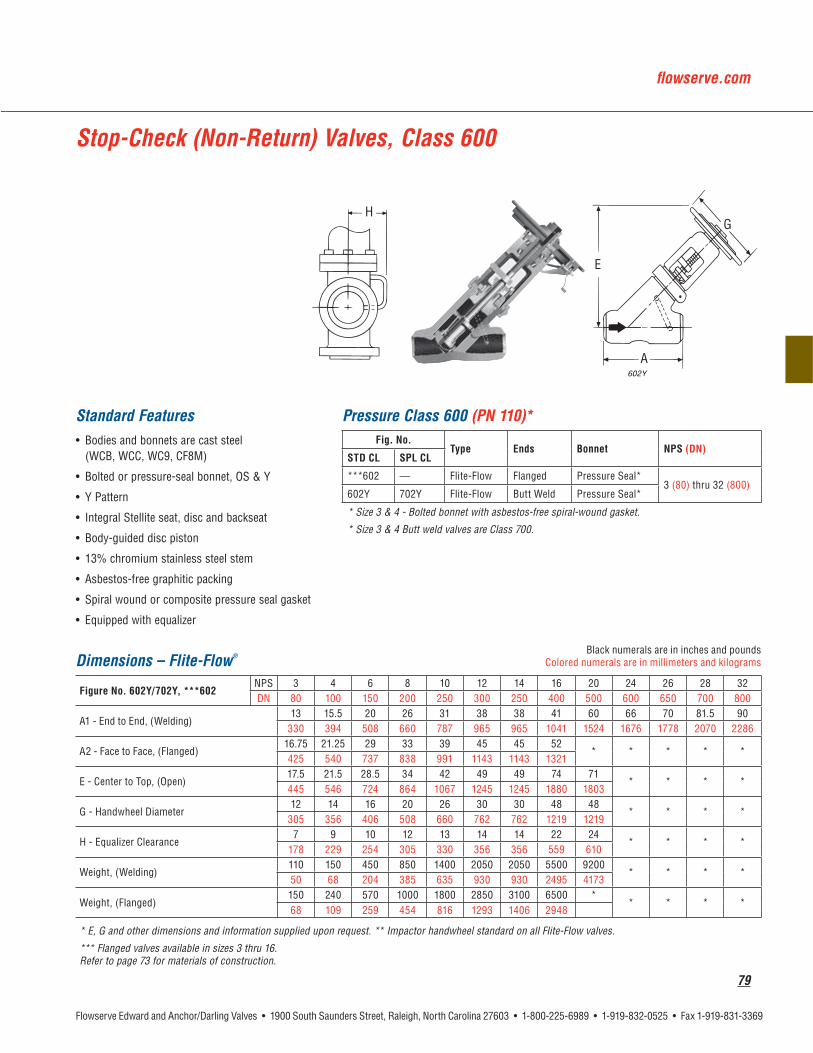
Stop-Check (Non-Return) Valves, Class 600
Standard Features Pressure Class 600 (PN 110)*
Bonnet
Flanged
* Size 3 & 4 - Bolted bonnet with asbestos-free spiral-wound gasket.
* Size 3 & 4 Butt weld valves are Class 700.
Dimensions – Flite-Flow®
* E, G and other dimensions and information supplied upon request. ** Impactor handwheel standard on all Flite-Flow valves.
*** Flanged valves available in sizes 3 thru 16. Refer to page 73 for materials of construction.
A
E
GH

80
Stop Valves, Class 900
Standard Features Pressure Class 900 (PN 150)*
Flanged
Angle Flanged
Angle
Flanged
Size 3 and 4 Butt weld Flite-Flow valves are class 1100.
Dimensions – Globe & Angle
4316Y, 4317Y
* Impactor handwheel is standard on all valves. Refer to page 73 for materials of construction.

flowserve.com
81
Stop Valves, Class 900
Dimensions – Angle
** Size 18 angle - available upon request.
Dimensions – Flite-Flow®
A
A
Note: Refer to page 73 for materials of construction.

82
Stop-Check (Non-Return) Valves, Class 900
Standard Features
Pressure Class 900 (PN 150)*
Flanged
Angle Flanged
Angle
Flanged
* Size 3 and 4 Butt weld Flite-Flow valves are Class 1100.
Dimensions – Globe & Angle
* Impactor handwheel is standard on all valves. Refer to page 73 for materials of construction.

flowserve.com
83
Stop-Check (Non-Return) Valves, Class 900
Dimensions – Angle
** Size 18 Angle - Available upon request.
Dimensions – Flite-Flow
A
A
Note: * Impactor handwheel is standard on all valves. Refer to page 73 for materials of construction.

84
Stop Valves, Class 1500
Standard Features Pressure Class 1500 (PN 260)*
Flanged
Angle Flanged
Angle
Dimensions – Globe & Angle
*Impactor handle is standard on size 2½ Globe and Angle valves. *Impactor handwheel is standard on all other size Globe and Angle valves and all Flite-Flow valves. *Impactogear is available on size 8 and larger Globe, Angle and Flite-Flow valves. Refer to page 73 for materials of construction.

flowserve.com
85
Stop Valves, Class 1500
Dimensions – Globe & Angle
Dimensions – Flite-Flow®
Notes:
*Impactor handle is standard on size 2½ Globe and Angle valves. *Impactor handwheel is standard on all other size Globe and Angle valves and all Flite-Flow valves. *Impactogear is available on size 8 and larger Globe, Angle and Flite-Flow valves. Refer to page 73 for materials of construction.

86
Stop-Check (Non-Return) Valves, Class 1500
Standard Features
Pressure Class 1500 (PN 260)*
Flanged
Angle Flanged
Angle
* Size 3 and 4 Buttweld Flite-Flow valves are Class 1800.
Dimensions – Globe & Angle
* Impactor handle is standard on size 2½ Globe and Angle valves. *Impactor handwheel is standard on all other size Globe and Angle valves and all Flite-Flow valves. *Impactogear is available on size 8 and larger Globe, Angle and Flite-Flow valves. Refer to page 73 for materials of construction.

flowserve.com
87
Stop-Check (Non-Return) Valves, Class 1500
Dimensions – Angle
Dimensions – Flite-Flow
Note:
*Impactor handle is standard on size 2½ Globe and Angle valves. *Impactor handwheel is standard on all other size Globe and Angle valves and all Flite-Flow valves. *Impactogear is available on size 8 and larger Globe, Angle and Flite-Flow valves. Refer to page 73 for materials of construction.

88

flowserve.com
89
90
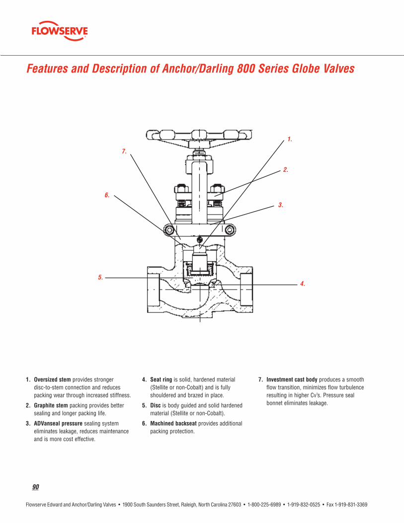
Features and Description of Anchor/Darling 800 Series Globe Valves
1.
2.
3.
4.
6.
7.
5.

flowserve.com
91
Parts Specification List for Anchor/Darling 800 Series Globe Valves
Standard Features
Description
Disc
92
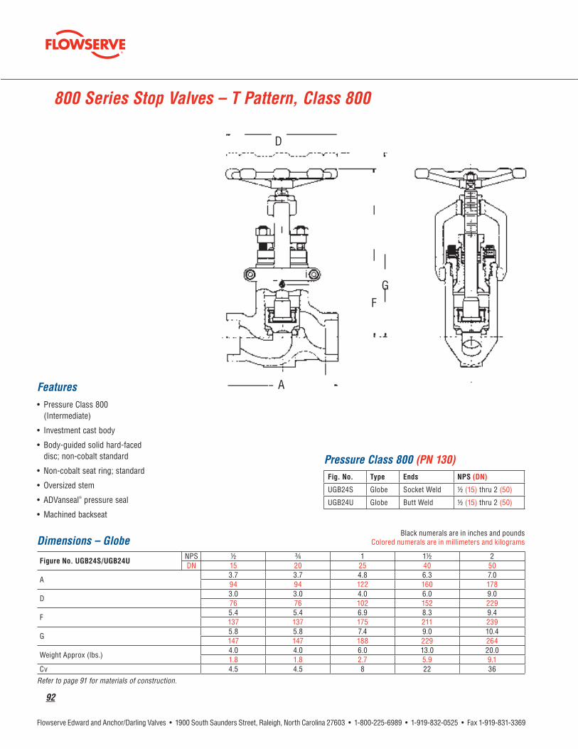
800 Series Stop Valves – T Pattern, Class 800
Features
®
Dimensions – Globe½ ¾
A
D
F
G
Refer to page 91 for materials of construction.
Pressure Class 800 (PN 130)
½
½
D
F
A
G

flowserve.com
93
Features and Description of 1878 Series Globe Valve
Standard Valve Features
provide
provides
6.
7.
8.
9.
5.
3.
4.
2.
1.
10.

94
Parts Specification List for Anchor/Darling 1878 Series Globe ValvesStandard Features
Description
Disc

flowserve.com
95
Series 1878 Stop Valves, Class 1878
Features Pressure Class 1878 (PN 325)
½
½
Dimensions – Globe½ ¾
A
* Reduced ports ** Quick open – Flow under disc Refer to page 94 for materials of construction.
A
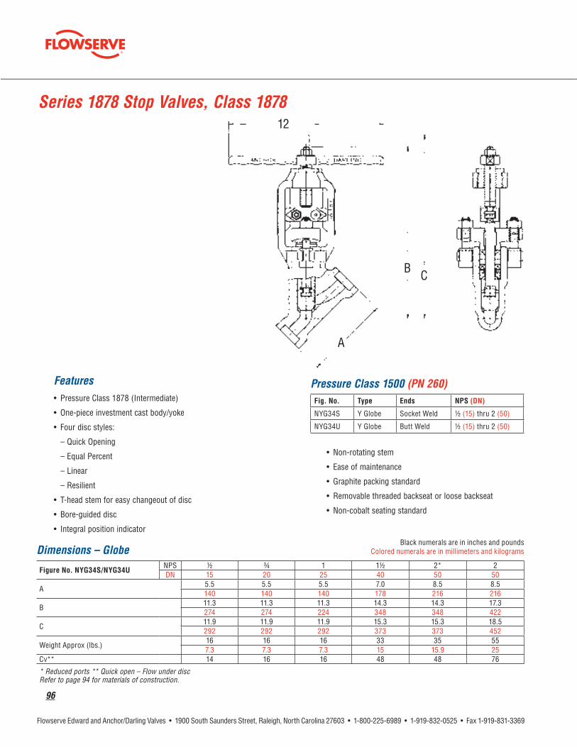
96
Features
Series 1878 Stop Valves, Class 1878
Dimensions – Globe½ ¾
A
* Reduced ports ** Quick open – Flow under disc Refer to page 94 for materials of construction.
Pressure Class 1500 (PN 260)
½
½
A

flowserve.com
97
Features
®
Series 1878 Stop Valves – Y Pattern Bellows Seal, Class 1878
Rapid Change Kit
®
Rapid Change Kit
Pressure Class 1500 (PN 260)
½
½
Dimensions – Globe
½ ¾
A
Other sizes available upon request. Refer to page 94 for materials of construction.
A

98
Series 1878 Instrument Valves – T Pattern, Class 1878
Features
V
Pressure Class 1500 (PN 260)
½
½
Refer to page 94 for materials of construction.

flowserve.com
99
Features and Description of Flowserve Anchor/Darling Globe Valves
Horizontal Globe Angle GlobeY GlobeY Angle Globe
1. 2.
4. 5.
3.

100
Standard Plug Cage Plug Parabolic Plug
Power-Actuated Globe Valves
Custom-Designed Plugs
4" 600# Globe Valve 18" 300# Angle Globe 24" 900# Y-Globe

flowserve.com
101
Parts Specification List for Anchor/Darling Globe Valves
Description
Disc
* Other material grades available on application.

102
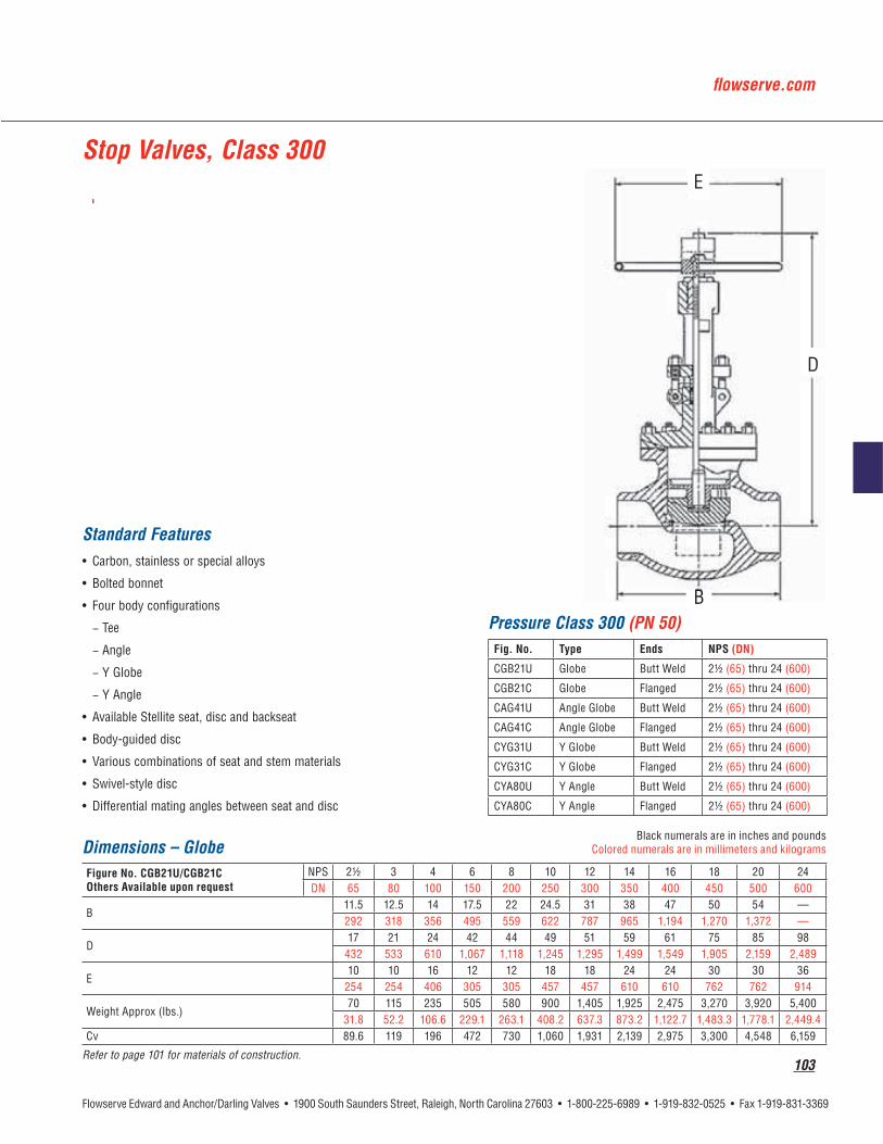
Standard Features
Stop Valves, Class 150
Dimensions – Globe
D
E
Refer to page 101 for materials of construction.
Pressure Class 150 (PN 25)
Y Angle
Flanged
Flanged
Flanged
Y Angle Flanged
D
E
flowserve.com
103
D
E
Dimensions – Globe
D
E
Refer to page 101 for materials of construction.
Stop Valves, Class 300
Standard Features
Pressure Class 300 (PN 50)
Flanged
Flanged
Flanged
Y Angle
Y Angle Flanged

104
Dimensions – Globe
D
E
Refer to page 101 for materials of construction.
Stop Valves, Class 600
Standard Features Pressure Class 600 (PN 110)
Flanged
Flanged
Flanged
Flanged
Flanged
Flanged
Flanged
Flanged
D
E

flowserve.com
105
Dimensions – Globe
D
E
Refer to page 101 for materials of construction.
Stop Valves, Class 900
Standard Features
Pressure Class 600 (PN 150)
Y Angle
D
E

106
Standard Features
Dimensions – Globe
D
E
Refer to page 101 for materials of construction.
Pressure Class 1500 (PN 260)
Y Angle
Stop Valves, Class 1500
D
E

flowserve.com
107

108
Piston Check Valves, Class 600
Standard Features Pressure Class 600 (PN 110)
¼
¼
Dimensions – Globe¼ ½ ¾
Refer to page 59 for materials of construction.
838

flowserve.com
109
Univalve® Piston Check Valves, Class 1500
Standard Features Pressure Class 1500 (PN 260)
½
½
Dimensions½ ¾
Refer to page 63 for materials of construction.

110
Univalve® Piston Check Valves, Class 2500
Standard Features
Pressure Class 2500 (PN 420)
½
½
Dimensions – Globe½ ¾
Refer to page 63 for materials of construction.
flowserve.com
111
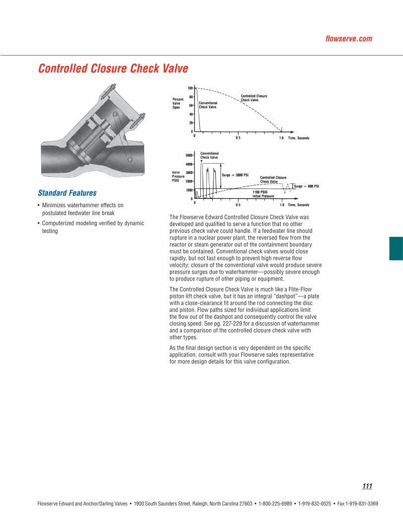
Controlled Closure Check Valve
Standard Features

112
Features and Description of Flowserve Edward Check Valves
®
V
Flowserve - Edward Skirted Check Valves

flowserve.com
113
Features and Description of Flowserve Edward One-Piece Tilting-Disc Check Valves
1.
2.
3.
4.
5.
6.
7.
8.
9.

114
Description
Disc††
3, 4
Larger
*Other material grades available on application. **All ANSI Class 600 valves utilize an asbestos-free spiral wound bonnet gasket. †Hinge Pin Torsion Springs required in size 6 and larger valves only. ††Sizes 2½, 3 and 4, Pressure Classes 900, 1500 and 2500 – disc material is A732-GR21
Parts Specification List for Flowserve Edward One-Piece Tilting-Disc Check Valve

flowserve.com
115
Check Valves, Class 600
Standard Features
Pressure Class 600 (PN 110)*
Bonnet
Flanged
Angle Flanged
Angle
Flanged
Flanged
Angle Flanged
Angle
* Size 3 and 4 - Bolted bonnet with asbestos-free spiral-wound gasket.
* Size 3 and 4 Butt weld Flite-Flow valves are Class 700.
Dimensions – Globe & Angle
valves.
# Long Terne steel is a product coated by immersion in molten Terne metal. Terne metal is an alloy of lead and a small amount (about 3%) of tin.
*** Flanged valves available in sizes 3 through 16.
Refer to page 114 for materials of construction.

116
Standard Features
Dimensions – Flite-Flow
A
Notes: * E, H and other dimensions and information supplied upon request. *** Flanged valves available in sizes 3 through 16.
Dimensions – Tilting Disc
Refer to page 114 for materials of construction.
692Y
Check Valves, Class 600

flowserve.com
117
Check Valves, Class 900
Standard Features
Pressure Class 900 (PN 150)*
Disc
Flanged
Angle Flanged
Angle
Flanged
*Size 3 and 4 Buttweld Flite-Flow Valves are Class 1100
Dimensions – Globe & Angle
Refer to page 114 for materials of construction.

118
Check Valves, Class 900
Standard Features
Dimensions – Flite-Flow
A
A
Note: * Impactor handwheel is standard on all valves. Refer to page 114 for materials of construction.
H

flowserve.com
119
Check Valves Class 900
Dimensions – Angle
Dimensions – Tilting-Disc
* Spiral-wound hinge pin gaskets; hinge pin torsion spring not required.
Refer to page 114 for materials of construction.

120
Check Valves, Class 1500
Standard Features Pressure Class 1500 (PN 260)*
Flanged
Angle Flanged
Angle
*Size 3 and 4 Buttweld Flite-Flow Valves are Class 1800.
Dimensions – Globe & Angle
Refer to page 114 for materials of construction.

flowserve.com
121
Check Valves, Class 1500
Dimensions – Globe & Angle
Refer to page 114 for materials of construction.

122
Check Valves, Class 1500
Standard Features
Dimensions – Flite-Flow
Refer to page 114 for materials of construction.

flowserve.com
123
Check Valves, Class 1500
Standard Features Pressure Class 1500 (PN 260)
Dimensions – Tilting-Disc
* Spiral-wound hinge pin gaskets; hinge pin torsion spring not required.
Refer to page 114 for materials of construction.

124

flowserve.com
125

126
Features and Description of 1878 Series Piston Check Valves
®
5.
3.
4.
2.
1.

flowserve.com
127
Parts Specification List for Anchor/Darling 1878 Piston Check Valves
Standard Features
pressure classes are also available
Description
BonnetDisc

128
Features
®
Series 1878 Piston Check Valves, Class 1878
Dimensions – Y Pattern½ ¾
A
* Reduced ports Refer to page 127 for materials of construction.
Pressure Class 1878 (PN 325)
½
½
A

flowserve.com
129
Series 1878 Piston Check Valves, Class 1878
Features
®
Dimensions – T Pattern½ ¾
A
* Reduced ports Refer to page 127 for materials of construction.
Pressure Class 1878 (PN 325)
½
½
A

130
NEED PDF: Anchor/Darling Double Disc Gate Valves.pdf
as shown
Features and Description of 1878 Series Swing-Check Valves
6.
5.
7.
4.
2.
1.
3.

flowserve.com
131
Parts Specification List for Anchor/Darling 1878 Swing-Check Valves
Standard Features
pressure classes are also available
Description
Bonnet
Disc

132
Series 1878 Swing-Check Valves – Bolted Bonnet, Class 1878
Features
Dimensions½ ¾
A
AA
Cv is based on sufficient flow to maintain disc in full open position. Refer to page 131 for materials of construction.
Pressure Class 1878 (PN 325)
½
½
A
AA

flowserve.com
133
Series 1878 Swing-Check Valves – Pressure Seal Bonnet, Class 1878
Features
®
Dimensions½ ¾
A
Other sizes available upon request. Refer to page 131 for materials of construction.
Pressure Class 1878 (PN 325)
½
½
A

134
Features and Description of Anchor/Darling Check Valves
achieves
Swing Check Tilting-Disc Check Angle - Lift Check
Swing Check

flowserve.com
135
Features and Description of Flowserve – Anchor/Darling Check Valves
Tilting-Disc Check
Lift Check

136
Description
Bonnet Cap
Disc
Bonnet Nuts
*Other material grades available on application.
Parts Specification List for Flowserve Anchor/Darling Tilting-Disc Check Valves

flowserve.com
137
Description
Bonnet Cap
Disc
Bonnet Cover Nuts
*Other material grades available on application.
Parts Specification List for Flowserve Anchor/Darling Swing-Check Valves

138
Description
Disc
Cover Nuts
*Other material grades available on application.
Parts Specification List for Flowserve Anchor/Darling Lift-Check Valves

flowserve.com
139
Dimensions
A
Refer to page 136 for materials of construction.
Tilting-Disc Check Valves, Class 150
Standard Features
Pressure Class 150 (PN 25)
Flanged
A

140
Dimensions
A
Refer to page 136 for materials of construction.
Tilting-Disc Check Valves, Class 300
Standard Features
Pressure Class 300 (PN 50)
Flanged
A

flowserve.com
141
Dimensions – Tilting-Disc
A
Refer to page 136 for materials of construction.
Tilting-Disc Check Valves, Class 600
Standard Features
Pressure Class 600 (PN 110)
Flanged
Flanged
A

142
Dimensions – Tilting-Disc
A
Refer to page 136 for materials of construction.
Tilting-Disc Check Valves, Class 900
Standard Features Pressure Class 900 (PN 150)
Flanged
A

flowserve.com
143
A
Tilting-Disc Check Valves, Class 1500
Standard Features Pressure Class 1500 (PN 260)
Flanged
Dimensions
A
Refer to page 136 for materials of construction.

144
Dimensions
A
Refer to page 137 for materials of construction.
Standard Features
Swing-Check Valves, Class 150
Pressure Class 150 (PN 25)
Flanged
A

flowserve.com
145
Dimensions
A
Refer to page 137 for materials of construction.
Swing-Check Valves, Class 300
Standard Features
Pressure Class 300 (PN 50)
Flanged
A

146
Dimensions – Swing
A
Refer to page 137 for materials of construction.
Swing-Check Valves, Class 600
Standard Features Pressure Class 600 (PN 110)
Flanged
Flanged
A

flowserve.com
147
Dimensions – Swing
A
Refer to page 137 for materials of construction.
Swing-Check Valves, Class 900
Standard Features Pressure Class 900 (PN 150)
Flanged
A

148
Pressure Class 1500 (PN 260)
Flanged
Dimensions – Swing
A
Refer to page 137 for materials of construction.
Swing-Check Valves, Class 1500
Standard Features
A

flowserve.com
149

150
Features and Description of Flowserve Anchor/Darling Ball ValvesApplications
Valve Options
Features

flowserve.com
151
Materials
Description
Handle
*Denotes with zinc and plastisol coatings
Seat & Seal Material Selection Chart
A
D
Standard Features
Parts Specification List for Anchor/Darling Ball Valves

152
Standard Seating Materials
E-Series/C-Series/Top-Entry Ball Valve Data
Flow Coefficients (CV )
Optional seating materials are available for severe service applications; contact Flowserve for application assistance. Higher temperature excursions are permissible; consult factory for limitations.
Valve Operators
Other valve operators can be specified and supplied to suit customer requirements. Additionally, valves can be configured to mate with many existing valve operators (if appropriately sized) and accessory items (i.e., position indicating and limit switches).
Note: Values based on flow of water in gallons per minute (GPM) at standard conditions to achieve a one (1) PSI pressure drop.

flowserve.com
153
Top-Entry Ball Valves, Class 150
Dimensions
A
G
Dimensions
A
G
Valve weights for top-entry valves are not published due to the customized nature of this product and the associated variables, which can affect total weight. After receiving customer’s requirements for valve size, materials, valve operator requirements, etc., Anchor/Darling can furnish assembly weights. Consult factory for certified weights.Refer to page 151 for materials of construction.
Pressure Class 150 (PN 25)
Pressure Class 150 (PN 25)
A
G

154
Top-Entry Ball Valves, Class 300
Dimensions
A
G
Dimensions
A
G
Valve weights for top-entry valves are not published due to the customized nature of this product and the associated variables, which can affect total weight. After receiving customer’s requirements for valve size, materials, valve operator requirements, etc., Anchor/Darling can furnish assembly weights. Consult factory for certified weights.
Refer to page 151 for materials of construction.
Pressure Class 300 (PN 50)
Pressure Class 300 (PN 50)
A
G
flowserve.com
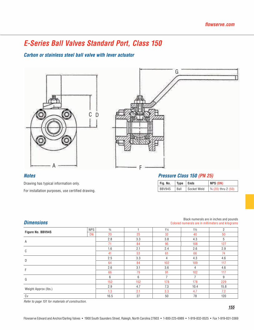
155
Dimensions¾
A
D
F
G
Refer to page 151 for materials of construction.
Pressure Class 150 (PN 25)
¾
Notes
E-Series Ball Valves Standard Port, Class 150 Carbon or stainless steel ball valve with lever actuator
A
D
F
G

156
Dimensions
A
D
F
G
Refer to page 151 for materials of construction.
Pressure Class 150 (PN 25)Notes
E-Series Ball Valves, Standard Port, Class 150Carbon or stainless steel ball valve with lever actuator
A F
D
G

flowserve.com
157
Notes
Dimensions
A
D
F
G
Refer to page 151 for materials of construction.
Pressure Class 150 (PN 25)
Flanged
E-Series Ball Valves, Standard Port, Class 150Carbon or stainless steel ball valve with lever actuator
A F
G
D

158
Dimensions½ ¾
A
D
F
G
Refer to page 151 for materials of construction.
E-Series Ball Valves Full Port, Class 150Carbon or stainless steel ball valve with lever actuator
Pressure Class 150 (PN 25)
½
Notes
A
D
F
G

flowserve.com
159
Dimensions
A
D
F
G
Refer to page 151 for materials of construction.
Pressure Class 150 (PN 25)Notes
E-Series Ball Valves, Full Port, Class 150Carbon or stainless steel ball valve with lever actuator
AF
D
G

160
Dimensions
A
D
F
G
Refer to page 151 for materials of construction.
E-Series Ball Valves, Full Port, Class 150Carbon or stainless steel ball valve with lever actuator
Notes Pressure Class 150 (PN 25)
Flanged
F A
G
D

flowserve.com
161
A
D
F
G
Notes Pressure Class 300 (PN 50)
¾
Dimensions¾
A
D
F
G
Refer to page 151 for materials of construction.
E-Series Ball Valves Standard Port, Class 300Carbon or stainless steel ball valve with lever actuator

162
Notes Pressure Class 300 (PN 50)
E-Series Ball Valves, Standard Port, Class 300Carbon or stainless steel ball valve with lever actuator
Dimensions
A
D
F
G
Refer to page 151 for materials of construction.
A F
D
G

flowserve.com
163
Notes Pressure Class 300 (PN 50)
Flanged
E-Series Ball Valve, Standard Port, Class 300Carbon or stainless steel ball valve with lever actuator
Dimensions
A
D
F
G
Refer to page 151 for materials of construction.
A F
G
D

164
A
D
F
G
Notes
E-Series Ball Valves Full Port, Class 300Carbon or stainless steel ball valve with lever actuator
Pressure Class 300 (PN 50)
Dimensions½ ¾
A
D
F
G
Refer to page 151 for materials of construction.

flowserve.com
165
Notes
E-Series Ball Valves, Full Port, Class 300Carbon or stainless steel ball valve with lever actuator
Pressure Class 300 (PN 50)
Dimensions
A
D
F
G
Refer to page 151 for materials of construction.
F A
G
D

166
Notes Pressure Class 300 (PN 50)
Flanged
E-Series Ball Valves, Full Port, Class 300Carbon or stainless steel ball valve with lever actuator
Dimensions
A
D
F
G
Refer to page 151 for materials of construction.
F
G
D
A

flowserve.com
167
E-Series Ball Valves Standard Port, Class 600Carbon or stainless steel ball valve with lever actuator
A
D D
F
G
F
Dimensions¾
A
D
F
G
Refer to page 151 for materials of construction.
Notes Pressure Class 600 (PN 100)
½

168
Notes
Ball Valves, Standard Port, E-Series, Flanged Ends, Class 600Carbon or stainless steel ball valve with lever actuator
Dimensions¾
A
D
F
G
Refer to page 151 for materials of construction.
Pressure Class 600 (PN 110)
Flanged ¾
A F
D
G

flowserve.com
169
A
D D
F
G
F
Notes Pressure Class 600 (PN 100)
½
E-Series Ball Valves Full Port, Class 600Carbon or stainless steel ball valve with lever actuator
Dimensions½ ¾
A
D
F
G
Refer to page 151 for materials of construction.

170
D
FA
G
Notes Pressure Class 600 (PN 100)
Flanged ½
Dimensions½ ¾
A
D
F
G
Refer to page 151 for materials of construction.
Ball Valves, Full Port, E-Series, Raised Face Flanged Ends, Class 600Carbon or stainless steel ball valve with lever actuator

flowserve.com
171

172

flowserve.com
173
174
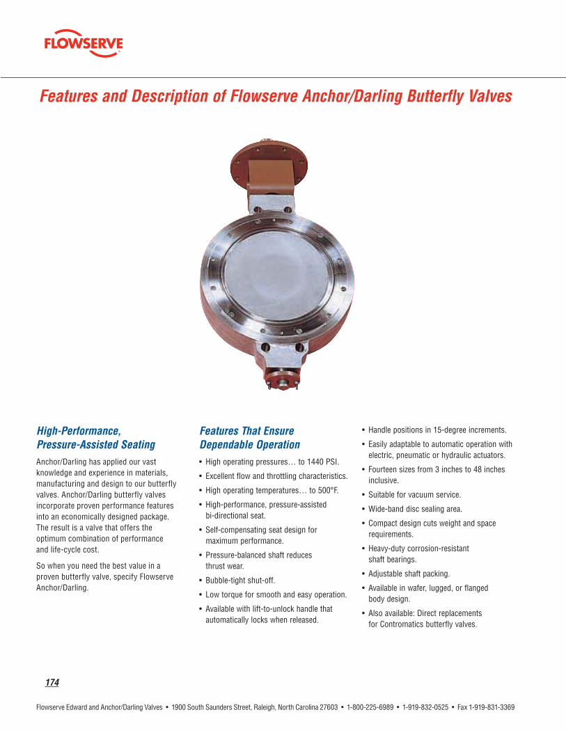
High-Performance, Pressure-Assisted Seating
Features That Ensure Dependable Operation
Features and Description of Flowserve Anchor/Darling Butterfly Valves

flowserve.com
175
Standard Materials of ConstructionAnchor/Darling High-Performance Valves
Notes:
Approximate Weights by Valve Design (lb)
Notes:

176
Standard Materials of ConstructionAnchor/Darling High-Performance Valves
Notes:

flowserve.com
177
Performance CharacteristicsAnchor/Darling High-Performance Valves
Class 150 and 300 ANSI Class 600 ANSI
Flow CharacteristicsCv values

178
FA
H
Butterfly Valve, Class 150
Dimensions
A
F
H
Dimensions are approximate and may vary. Always consult installation drawing. Refer to page 175 for materials of construction.
Pressure Class 150 (PN 25)

flowserve.com
179
FA
H
Dimensions
A
F
H
Dimensions are approximate and may vary. Always consult installation drawing. Refer to page 175 for materials of construction.
Butterfly Valve, Class 150
Pressure Class 150 (PN 25)

180
Butterfly Valve, Class 300
Dimensions
A
F
H
Dimensions are approximate and may vary. Always consult installation drawing.Refer to page 175 for materials of construction.
A F
H
Pressure Class 300 (PN 50)

flowserve.com
181
A F
H
Butterfly Valve, Class 600
Dimensions
A
F
H
Dimensions are approximate and may vary. Always consult installation drawing. Sizes 16 through 20 employ upper and lower shaftsRefer to page 175 for materials of construction.
Pressure Class 600 (PN 110)

182
Butterfly Valve, Class 600
Dimensions
A
F
H
Dimensions are approximate and may vary. Always consult installation drawing.Refer to page 175 for materials of construction.
A F
H

flowserve.com
183
Dimensions
A
F
H
Refer to page 175 for materials of construction.
Pressure Class 150 (PN 25)
Butterfly Valve, Class 150
A
F
H

184
Butterfly Valve, Class 300
Dimensions
A
F
H
Refer to page 175 for materials of construction.
Pressure Class 300 (PN 50)
H
A

flowserve.com
185
Butterfly Valve, Class 600
Dimensions
A
F
H
Dimensions are approximate and may vary. Always consult installation drawing.Refer to page 175 for materials of construction.
Pressure Class 600 (PN 110)
A F
H

186
Butterfly Valve, Class 600
Dimensions
A
F
H
Dimensions are approximate and may vary. Always consult installation drawing.Refer to page 175 for materials of construction.
A F
H

flowserve.com
187

188
Accessories
Globe, Angle, Gate
Edward Forged Steel Valves for use as by-passes
* ALL MOTOR ACTUATED BY-PASS VALVES WILL BE FURNISHED WITH FIG. D36224. ** ALL MOTOR ACTUATED BY-PASS VALVES WILL BE FURNISHED WITH FIG. D36264.
Standard sizes of by-pass valves*
½ ¾ ¾ ¾
* By-passes are provided only when specified. Standard sizes of by-pass valves are in accordance with the table above. Larger size by-pass valves will be furnished on special order.
Floor Stands Chain Wheels Valve Extension

flowserve.com
189
Accessories – Cast and Forged Steel
Impactor Handwheel Impactogear® Custom Paint
Flow
Drain or Vent
External Equalizer
Internal Equalizer
Relief Valve
Automatic Center Cavity Equalizing Valve

190
Accessories – Cast and Forged Steel
Leakoff
Live Loading
Locking Devices
Position Indicators & Limit Switches
Soft Seats
Washout Connections
Automatic Center Cavity Equalizing Valve (ACCEV)

flowserve.com
191
Actuators – Forged and Cast Steel

192
_____________________________________ psig ______________________________________ psig
____________________________________ psig
__________________ ___________________ ___________________ _____________________ _________________
________________________________________________________________
__________________________________________________________
____________________ ___________________________
___________________ ___________________ ____________________________ ___________________
___________________________________________________________ ____________________________________________________________________________
______________________________________________________________________________________ _______________________________________________________________________________________________
______________________________________________________________________________________
STANDARD IS NEMA 4 (WEATHERPROOF), IF OTHERWISE, PLEASE LIST
_______________________________________________________________________________________________
______________________________________________
__________________________________________ ____________________________________________________
Data in the Table above represents the minimum information that should be provided when ordering a valve equipped with a motor operator.
Required Information for Motor Actuators

flowserve.com
193

194
Material Chemical Analysis (ASME or ASTM)
®
*The equivalent Flowserve valve material specification for valve bodies meets the requirements of the referenced ASME Specification; additionally Flowserve restricts certain elements (i.e. carbon, manganese) to tighter allowable ranges to enhance weldability.
Flowserve Valves

flowserve.com
195
Reference: ASME B16.34 – 2004 Pressure/Temperature Ratings*Forged Steel, Bolted Bonnet
1. Permissible but not recommended for prolonged use at temperatures above approx. 800°F.
2. Shaded ratings exceed those of Edward Valves. Consult your Flowserve sales representative for applications in these ranges.
* Consult the applicable version of ASME section III for the correct version of ASME B16.34 to use.

196
Reference: ASME B16.34 – 2004 Pressure/Temperature Ratings (metric)*
Forged Steel, Bolted Bonnet
1. Permissible but not recommended for prolonged use at temperatures above approx. 427°C.
2. Shaded ratings exceed those of Edward Valves. Consult your Flowserve sales representative for applications in these ranges.
* Consult the applicable version of ASME section III for the correct version of ASME B16.34 to use.

flowserve.com
197
Reference: ASME B16.34 – 2004 Pressure/Temperature Ratings*Forged Steel Univalves
NOTES: 1. Standard Class, Flanged Ends only. 2. Limited Class, Sizes 2 ½ and smaller, butt weld and socket weld ends. Limited Class Threaded ends limited to Size 1 and smaller, 1000°F maximum and Class 2500 maximum. 3. Special Class, Sizes 3 and 4, Butt-weld ends only. 4. Permissible but not recommended for prolonged usage above approx. 800°F. 5. Permissible but not recommended for use above 1100°F. 6. Shaded ratings may require special trim and packing. Consult your Flowserve sales representative for applications in these ranges.* Consult the applicable version of ASME section III for the correct version of ASME B16.34 to use.

198
Reference: ASME B16.34 – 2004 Pressure/Temperature Ratings (metric)*Forged Steel Univalves
NOTES: 1. Standard Class, Flanged Ends only. 2. Limited Class, Sizes 2 ½ and smaller, butt weld and socket weld ends.
Limited Class Threaded ends limited to Size 1 and smaller, 538°C maximum and Class 2500 maximum. 3. Special Class, Sizes 3 and 4, Butt-weld ends only. 4. Permissible but not recommended for prolonged usage above approx. 425°C. 5. Permissible but not recommended for use above 595°C. 6. Shaded ratings may require special trim and packing. Consult your Flowserve sales representative for applications in these ranges.* Consult the applicable version of ASME section III for the correct version of ASME B16.34 to use.

flowserve.com
199
Reference: ASME B16.34 – 2004 Pressure/Temperature Ratings*
Forged Steel Univalves®
NOTES: 1. Standard Class, Flanged Ends only. 2. Limited Class, Sizes 2 ½ and smaller, butt weld and socket weld ends.
Limited Class Threaded ends limited to Size 1 and smaller, 1000°F maximum and Class 2500 maximum. 3. Special Class, Sizes 3 and 4, Butt-weld ends only. 4. Shaded ratings may require special trim and packing. Consult your Flowserve sales representative for applications in these ranges.* Consult the applicable version of ASME section III for the correct version of ASME B16.34 to use.

200
Reference: ASME B16.34 – 2004 Pressure/Temperature Ratings (metric)*
Forged Steel Univalves®
F316
NOTES: 1. Standard Class, Flanged Ends only. 2. Limited Class, Sizes 2 ½ and smaller, butt weld and socket weld ends.
Limited Class Threaded ends limited to Size 1 and smaller, 538°C maximum and Class 2500 maximum. 3. Special Class, Sizes 3 and 4, Butt-weld ends only. 4. Shaded ratings may require special trim and packing. Consult your Flowserve sales representative for applications in these ranges.* Consult the applicable version of ASME section III for the correct version of ASME B16.34 to use.

flowserve.com
201
Reference: ASME B16.34 – 2004 Pressure/Temperature Ratings*Cast Steel + (Gate, Globe & Check Valves)
Note: Flanged End Valve ratings are limited to standard class only. 1. Permissible but not recommended for prolonged use at temperatures above approx. 800°F. 2. Shaded ratings exceed those of standard Flowserve Valves. Consult your Flowserve sales representative for applications in these ranges. + Pressure temperature ratings are from ASME B16.34 “Valves, Flanged, Threaded and Welding Ends.” Consult your Flowserve sales representative for pres-
sure temperature ratings of materials not included in this catalog. * Consult the applicable version of ASME section III for the correct version of ASME B16.34 to use.

202
Reference: ASME B16.34 – 2004 Pressure/Temperature Ratings (metric)*
Cast Steel + (Gate, Globe & Check Valves)
1. Permissible but not recommended for prolonged use at temperatures above approx. 427°C. 2. Shaded ratings exceed those of standard Edward Valves. Consult your Flowserve sales representative for applications in these ranges. + Pressure temperature ratings are from ASME B16.34 “Valves, Flanged, Threaded and Welding Ends.” Consult your Flowserve sales representative for
pressure temperature ratings of materials not included in this catalog.* Consult the applicable version of ASME section III for the correct version of ASME B16.34 to use.

flowserve.com
203
Cast Steel + (Gate, Globe & Check Valves)
Note: Flanged End Valve ratings are limited to standard class only and terminate at 1000°F. 1. Permissible but not recommended for prolonged use at temperatures above approx. 800°F. 2. Shaded ratings may require special trim and packing. Consult your Flowserve sales representative for applications in these ranges. + Pressure temperature ratings are from ASME B16.34 “Valves, Flanged, Threaded and Welding Ends.” Consult your Flowserve sales representative for
pressure temperature ratings of materials not included in this catalog.* Consult the applicable version of ASME section III for the correct version of ASME B16.34 to use.
Reference: ASME B16.34 – 2004 Pressure/Temperature Ratings*

204
Cast Steel + (Gate, Globe & Check Valves)
1. Permissible but not recommended for prolonged use at temperatures above approx. 427°C. 2. Shaded ratings may require special trim and packing. Consult your Flowserve sales representative for applications in these ranges. + Pressure temperature ratings are from ASME B16.34 “Valves, Flanged, Threaded and Welding Ends.” Consult your Flowserve sales representative for
pressure temperature ratings of materials not included in this catalog.* Consult the applicable version of ASME section III for the correct version of ASME B16.34 to use.
Reference: ASME B16.34 – 2004 Pressure/Temperature Ratings (metric)*
flowserve.com
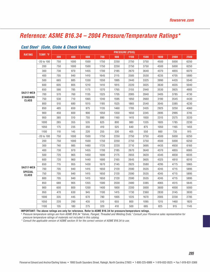
205
Reference: ASME B16.34 – 2004 Pressure/Temperature Ratings*
Cast Steel + (Gate, Globe & Check Valves)
+ Pressure temperature ratings are from ASME B16.34 “Valves, Flanged, Threaded and Welding Ends.” Consult your Flowserve sales representative for pressure temperature ratings of materials not included in this catalog.
* Consult the applicable version of ASME section III for the correct version of ASME B16.34 to use.

206
Reference: ASME B16.34 – 2004 Pressure/Temperature Ratings (metric)*Cast Steel + (Gate, Globe & Check Valves)
1. Shaded ratings may require special trim and packing. Consult your Flowserve sales representative for applications in these ranges. + Pressure temperature ratings are from ASME B16.34 “Valves, Flanged, Threaded and Welding Ends.” Consult your Flowserve sales representative for
pressure temperature ratings of materials not included in this catalog.* Consult the applicable version of ASME section III for the correct version of ASME B16.34 to use.

flowserve.com
207
Reference: ASME B16.34 – 2004 Pressure/Temperature Ratings*Cast Steel + (Gate, Globe & Check Valves)
1. Shaded ratings may require special trim and packing, consult your Flowserve representative for applications in these ranges. + Pressure temperature ratings are from ASME B16.34 “Valves, Flanged, Threaded and Welding Ends.” Consult your Flowserve sales representative for
pressure temperature ratings of materials not included in this catalog.* Consult the applicable version of ASME section III for the correct version of ASME B16.34 to use.

208
Reference: ASME B16.34 – 2004 Pressure/Temperature Ratings*Cast Steel + (Gate, Globe & Check Valves)
1. Shaded ratings may require special trim and packing, consult your Flowserve representative for applications in these ranges. + Pressure temperature ratings are from ASME B16.34 “Valves, Flanged, Threaded and Welding Ends.” Consult your Flowserve sales representative for
pressure temperature ratings of materials not included in this catalog.* Consult the applicable version of ASME section III for the correct version of ASME B16.34 to use.

flowserve.com
209
Reference: ASME B16.34 – 2004 Pressure/Temperature Ratings (metric)*
Cast Steel + (Gate, Globe & Check Valves)
1. Shaded ratings may require special trim and packing, consult your Flowserve representative for applications in these ranges. + Pressure temperature ratings are from ASME B16.34 “Valves, Flanged, Threaded and Welding Ends.” Consult your Flowserve sales representative for
pressure temperature ratings of materials not included in this catalog.* Consult the applicable version of ASME section III for the correct version of ASME B16.34 to use.

210
Reference: ASME B16.34 – 2004 Pressure/Temperature Ratings (metric)*
Cast Steel + (Gate, Globe & Check Valves)
1. Shaded ratings may require special trim and packing, consult your Flowserve representative for applications in these ranges. + Pressure temperature ratings are from ASME B16.34 “Valves, Flanged, Threaded and Welding Ends.” Consult your Flowserve sales representative for
pressure temperature ratings of materials not included in this catalog.* Consult the applicable version of ASME section III for the correct version of ASME B16.34 to use.

flowserve.com
211
212
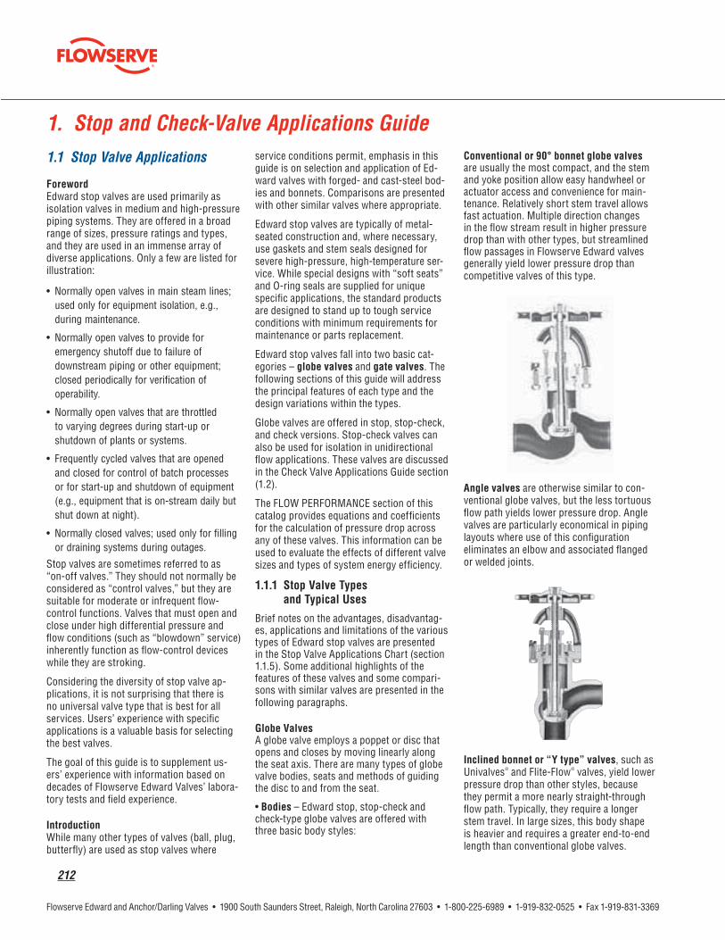
1.1 Stop Valve Applications
Foreword
Introduction
egories – globe valves and gate valves
Bodies
Univalves® ®
1. Stop and Check-Valve Applications Guide

flowserve.com
213
V
®

214
Note: ASME/ANSI B16.34-1988 (paragraph 2.3.3) places the responsibility of the purchaser to ensure that the pressure in the valve will not exceed that allowed by the standard. Special operating procedures, such as partially opening a valve during warm-up, may be considered. Special internal design features or external bypass arrangements are required in many applications. Consult Flowserve regarding Edward Equiwedge gate valve applications that may be subject to possible center-cavity over-pressurization.
Parallel Slide Gate
Wedge Half
CapturedStem Cavity
Hard Surfaced
Double Wedge Design

flowserve.com
215
Inherent Flow Characteristics
Valve Opening – Percent1 - Conventional 90° bonnet globe valve2 - Angle valve3 - Flite-Flow4 - Univalve5 - Equiwedge Gate valve
acteristic
percentage
Note: Users sometimes specify that valves be operable at maximum differential pressure with very low rim-pull forces. This may require selection of gearing that may cause two problems: (1) literally thousands of handwheel turns for full-stroke valve operation and/or (2) capability to damage the valve easily with rim-pull forces that are readily applied by many operating personnel. Manual gear actuators with high ratios provide relatively little “feel” to the operator, and it is difficult to tell when a valve is fully open or closed. Good judgment should be exercised in specifying practical rim-pull force requirements.

216
General schematic of stored energy gas-hydraulic actuator.

flowserve.com
217
Disadvantages Limitations
an angle
response
®
or severe service

218
1.2 Check Valve Applications Guide
Foreword
Introduction

flowserve.com
219

220

flowserve.com
221
Disadvantages Limitations
in angle valves
service
design
service
valve

222
1.3 Check and Stop-Check Valve Installation Guidelines
Figure 2
Figure 1
Note: For piston lift check valves, any installation resulting in combined out-of-position orientation, such as a valve in an inclined line with a rollover angle as well, should limit the angle of the bonnet to the following:

flowserve.com
223
Figure 3
Orientation Limits
Figure 4
Orientation Limits
Figure 5
Figure 7
Figure 6

224
Figure 8
Figure 9
V
V

flowserve.com
225
1
Inlet
Flow
1: Tests were conducted with single 90° elbows in the horizontal plane and in the vertical plane (with flow both from above and below).2: One size 2 valve exhibited flutter at lower lifts; another was stable.

226
1.4 Check Valve Performance

flowserve.com
227
Curve B

228
Curve C
Curve D
Curve F

flowserve.com
229

230
valve

flowserve.com
231
2.1 Choose the Best Valve Size for Your Service Conditions
Caution: Pressure drop, flow rate and check valve lift estimates provided by Edward calculation methods are “best estimate” valves. Calculations are based on standard equations of the Instrument Society of America (ISA), flow rate and fluid data provided by the user, and valve flow coefficients provided by Flowserve.
Flow rate and fluid data are often design or best-estimate values. Actual values may dif-fer from original estimates. Flow and check valve lift coefficients are based on labora-tory testing. Valves of each specific type are tested, and results are extended to sizes not tested using model theory. This approach
is fundamentally correct, but there is some uncertainty because of geometric variations between valves.
These uncertainties prevent a guarantee with respect to valve pressure drop, flow rate and lift performance, but we expect results of cal-culations using Flowserve methods to be at least as accurate as comparable calculations involving flow and pressure drop of other pip-ing system components.
Note: In preliminary calculations using the following equations, a piping geometry factor, Fp = 1.0, may be used, assuming that the valve size is the same as the nominal pipe size. How-ever, if an application involves installing a valve in a larger-sized piping system (or piping with a lower pressure rating than the valve, which will have a larger inside diameter), determine Fp from the Pipe Reducer Coefficients section when final calculations are made.
2. Flow Performance

232
V
d
F
Fp
G
GV
i
p
pV
F
p
V
w
Y
ρ
2.2 Basic Calculations
ρ
FIND: V
=D c m
=D c m
.P F Cw
63 3 P V
2
=D t c m1
.P F Cw
27 3 P V
2
=D c mt
1
V
ρ
V
FG
Vp
=D
FG
Vp
=D
wV =
tD
wV =
tD
V

flowserve.com
233
Caution: In applications of stop-check or check valves, the results of these equations will apply only if the valve is fully open. Always use the methods given in the Check Valve Sizing section (2.4) to ensure that the valve will be fully open or to make appropriate corrections.
ρ
FIND: V
G=D
G=D
w F= tD
w F= tD
ρ
FIND:
V d=
V d=
V dw
=t
V dw
=t
Caution: These equations assume that the pressure drop used for the calculation is available for the valve. In many piping systems with Edward Valves, flow is limited by pressure drop in pipe and fittings, so these equations should not be used as a substitute for piping calculations.
Note: If a specific pipe inside diameter is known, that di-ameter may be used as the “d” value in the equation above to calculate the fluid velocity in the upstream pipe.
2.3 Corrections Required with Large Pressure Drops
i
p
Note: Because large pressure drop problems are not encountered frequently, equations are presented in terms of weight flow rate (w) and density (ρ) only. See the Con-version of Measurement Units section for converting other units of flow rate to weight flow rate.
p=D

234
1 for use of Basic
Angle
G p=Dc m
Note: The ΔP in this equation is the uncorrected value from the Basic Calculations. Values of xT are given in valve data tables, and values of k are given in Figure 21.
the flow is not fully choked
Y=D D
flow is choked
w F= t
w F= t
$D
is
/Y= -Dc m
w Ywc =
w
Caution: Choked or near-choked flow condi-tions may produce significant flow-induced noise and vibration. Prolonged operation with flow rates in this region may also cause ero-sion damage within a valve or in downstream piping, particularly if the flow condition involve “wet” steam. Edward valves tolerate these conditions well in services involving limited time periods during plant start-up, shutdown, etc., but consult Flowserve about applications involving long exposure to such conditions.
and Flashing
Figure 15
flowserve.com
235
v
p pV=
-D
^ h
i and FV
i
i
i
i
V
p p FV$
-D
^ h
p pV$ -D ^ h
w F p p= -t^ h
w F p p= -t^ h
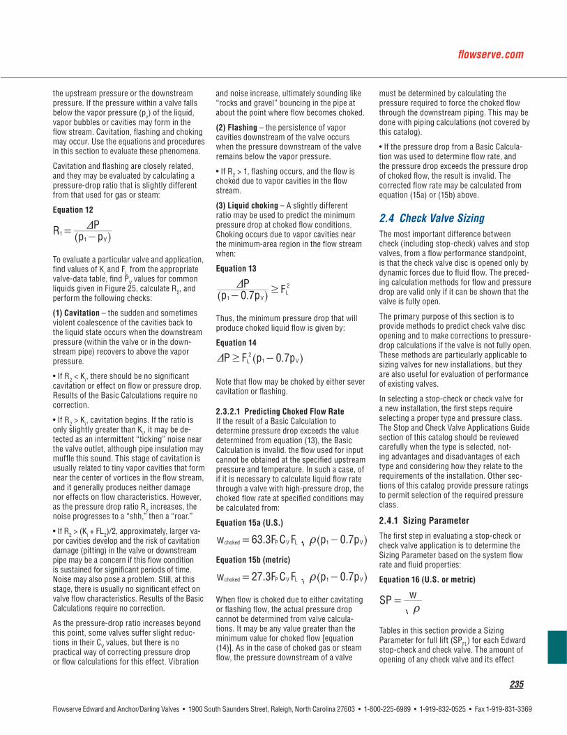
2.4 Check Valve Sizing
w=
t

236
Note: EPRI Report No. NP 5479 (Application Guideline 2.1) uses a “C” factor to calculate the minimum flow velocity required to fully open a check valve. The sizing procedures in this catalog do not employ the “C” factor, but values are given in the valve data tables for readers who prefer to use the EPRI methods. Since the EPRI methods are based on velocity, a flow area is required as a basis. Valve Inlet Diameters presented in data tables are the basis for correlation between flow rate and velocity.
F =
Determine the disc operating position:F
Calculate the pressure drop:F
=D D
Note: The values of the various valve coefficients given in the tabulations are based on testing of a substantial number of valves. Most are applicable to any line fluid, but those involving check valve lift are influenced by buoyancy. Tabulated values are based on reference test conditions with room-temperature water. SPFL and ΔPFL are slightly higher in applications involving lower-density line fluids. Considering the expected accuracy of these calcula-tions, the following corrections may be considered:
V i
Note: Preferably, there should be a good margin between SP and SPFL to be sure the valve will be fully open. In the specific case of tilting-disc check valves, it is recommend-ed that SPFL be less than 0.83 (SP) to be sure that the disc is fully loaded against its stop (particularly if it is close to a flow disturbance).
V

flowserve.com
237
– “High
F
Caution: Check valve operation at less than 25% opening is not recommended. Any check valve that operates for sustained periods at partial openings should be monitored or inspected periodically for evidence of instabil-ity or wear.
p
tions
V
Caution: This arrangement could produce cavitation or flow-choking problems if the flow rate is increased substantially without lifting the valve stem to compensate.
2.5 Pipe Reducer Coefficient
p
p V
p
Note: These equations apply only where the valve diameter is less than the connecting pipe diameter.

238
Dd
= - c m; E
Dd
= - c m; E
= +/
F
d
=+ c m/
F
d
=+ c m/
Note: If D1 and D2 are not the same, use of FP calculated in this manner accounts for energy losses associated with flow contraction and expansion, and the pressure drop cal-culated using this factor represents energy loss. Bernoulli effects may cuase a different static pressure change between upstream and downstream pipes.
Dd
= - c m
F dii
i
V=
++b bl l; E
F dii
i
V=
+ +^ bh l; E
F
F dF=
++b bl l
F
F dF V
=
+ +^ bh l
F dV
=+
+^ bh l; E
dV
=+ +^ bh l; E
i
ii
V
d
D
D
F
Fp
i
Nomenclature
*Double subscripts (e.g. Kii) represent values corrected for effects of pipe reducers.

flowserve.com
239
Table 1 – Edward Cast Steel Globe Flow Coefficients
Curves DN C FL Ki d CO FL FL C
Figure No. 4016/4016Y, 4316Y Stop valves, 4006/4006Y, 4306Y Stop-Check valves, 4094/4094Y, 4394Y Check valves
See note following section 2.4.1 for discussion of C factor.
Figure No. 2016, 7516/7516Y Stop valves, 2006Y, 7506/7506Y Stop-Check valves, 2094Y, 7594/7594Y Check valves

240
Figure 16B

flowserve.com
241
Table 2 – Edward Cast Steel Angle Valve Flow Coefficients
Curves DN C FL Ki d CO FL FL C
Figure No. 4017/4017Y, 4317Y Stop valves, 4007/4007Y, 4307Y Stop-Check valves, 4095/4095Y, 4395Y Check valves
Figure No. 2017Y, 7517/7517Y Stop valves, 2007Y, 7507/7507Y Stop-Check valves, 2095Y, 7595/7595Y Check valves
See note following section 2.4.1 for discussion of C factor.
* Consult Flowserve Edward Valves Sales Representative

242
Figure 17 – Edward Cast Steel Angle Piston Lift Check Valve Performance Curves
Figure 17B

flowserve.com
243
Figure No. 2014Y, 7514Y Stop valves; 2002Y, 7502Y Stop-Check valves; 2092Y, 7592Y Check valves
See note following section 2.4.1 for discussion of C factor.
* Consult Flowserve Edward Valves Sales Representative.
Figure No. 614, 614Y, 714Y Stop valves; 602, 602Y, 702Y Stop-Check valves; 692, 692Y, 792Y Piston Lift Check valves
Figure No. 4014, 4014Y, 4314Y Stop valves; 4002, 4002Y, 4302Y Stop-Check valves; 4092, 4092Y, 4392Y Piston Lift Check valves
Table 3 – Edward Cast Steel Flite-Flow® Stop and Stop-Check Valve Flow Coefficients
Curves DN C FL Ki d CO FL FL C

244
Figure 18 – Cast Steel Flite-Flow® Piston Lift Check Valve Performance Curves
Figure 18B

flowserve.com
245
Table 4 – Edward Cast Steel Tilting-Disc check Valve Flow Coefficients1
Curves DN C FL Ki d FL FL C
Figure No. 670Y, 770Y
Figure No. 970Y, 4370Y
Figure No. 1570Y, 2070Y
See note following section 2.4.1 for discussion of C factor.1 Crack open pressure drop ΔPCO values are generally less than 0.25 psi (0.01 bar).

246
Figure 19 – Tilting-Disc Check Valve Performance Curves
Figure 19B

flowserve.com
247
Table 5 – Edward Cast Steel Equiwedge® Gate Valve Flow Coefficients
C FL Ki dDN
Figure No. 1611/ 1611Y, 1711Y Stop valves Figure No. 1611BY, 1711BY Stop valves
C FL Ki dDN

248
Figure No. 1911/ 1911Y, 14311Y Stop valves
C FL Ki dDN
Figure No. 11511/11511Y, 12011Y Stop valves
C FL Ki dDN
Figure No. 1911BY, 14311BY Stop valves
Figure No. 11511BY, 12011BY Stop valves
Table 5 (continued) – Edward Cast Steel Equiwedge® Gate Valve Flow Coefficients

flowserve.com
249
Table 6 – Edward Forged Steel Hermavalve® Flow Coefficients
DN
dC FL Ki C FL Ki

250
Table 7 – Forged Steel Univalve® Flow Coefficients
DN C FL Ki d FL FL C FL FL C
All Stop valves, all Stop-Check valves, all Piston Check valves
All Stop valves, all Stop-Check valves, all Piston Check valves
NOTES: See Table 9 for ΔPCO. See notes following section 2.4.1 for discussion of C factor.
* Stop-check valves are only furnished without springs.
Figure No. 848/848Y Stop valve, 868/868Y Stop-Check valve, 838/838Y Piston Check valve
Table 8 – Forged Steel Inclined Bonnet Valve Flow Coefficients
DN C FL Ki d FL FL C FL FL C
NOTES: See Table 9 for ΔPCO. See note following section 2.4.1 for discussion of C factor.

flowserve.com
251
Table 9 – Crack-Open ΔP for Edward Forged Steel Check Valves, ΔPCO – PSI (BAR)
Installation Orientation
®
* Not recommended because of possible accumulation of debris in valve neck.

252
Figure 20 – Ratio of Specific heats (k) for some gasses
Air
Figure 21A – Saturated Water - Temperature, Pressure & Density (U.S. Units)
ρ
P = Pressure in psia, ρ = Density in lb./ft3
Figure 21B – Saturated Water - Temperature, Pressure & Density (Metric)
ρ
P = Pressure in Bar Absolute, ρ = Density in Kg/m3

flowserve.com
253
Figure 22 – Density of Steam Figure 23 – Density of Air
Figure 24 – Vapor Pressure of Liquid

254
Length
G e cd
=
°G
and atmospheric pressuredensity of water at F
density ofl iquid60I =
G =t
°G
and atmospheric pressuredensity of water at C
density of liquid4I =
//
G =t
G
G F° / ° ..
API60 60 131 5 degrees141 5
I =+
G e and e oas
e p e and eirg =
G r w airr w gas
gW= =
p psiee d#
=t
d#=
t
ard#
=t
/hr
ρ
G r w airr w gas
gW= =
ρρ
g
g
g
ρ
g

flowserve.com
255
3.1 Codes and Standards
3.2 Pressure Ratings
3. Flowserve Valve Design Standards and Features

256
Notes:
3.3 Pressure-Seal Construction

flowserve.com
257
3.4 Hardfacing
®
®
®
3.5 Valve-Stem Packing

258
coverage
MaintenanceFLOWSERVE EDWARD VALVES ON-SITE FIELD SERVICE REPAIR CAPABILITIES
OUR FACILITY OFFERS

flowserve.com
259
Flowserve Edward and Anchor/Darling Valves • 1900 South Saunders Street, Raleigh, North Carolina 27603 • 1-800-225-6989 • 1-919-832-0525 • Fax 1-919-831-3369
We design and manufacture our valves for 40 years’ life in the field. That means not just building a reliable product, but one that is easy to maintain and service. It also means providing a team of experienced, dedicated professionals to keep your Flowserve valves operating at peak performance.
HighlyExperiencedTechnicians
Flowserve brings unmatched experience to the field. Our service technicians have an average 20 years in the industry, and 15 years with Flowserve. Each has special skills, such as welding and machining, that we can target for the needs of the individual job.
ComprehensiveRecord-keeping
Our files include original specifications for every Flowserve valve sold since 1908. All valves are coded for easy identi-fication. On new and replacement orders, Flowserve stands ready to provide the complete lot-traceability required for nuclear and other critical services.
In-lineService
We are dedicated to on-site service whenever possible. To this end, we not only provide highly experienced, expert personnel—but we also support those technicians with field equipment, including portable boring, lapping, welding and weld-cutting machines. Major parts, such as discs or bon-nets, can be air-shipped back to the factory for service and repaired while service personnel perform other tasks.
PartsReplacement
Our comprehensive record-keeping system also facilitates replacement of parts. Our computer database can quickly show us if we have the part in stock or on order, or how we can best coordinate raw materials and factory resources for the quickest possible turnaround time.
New90-dayWarranty
On all valves repaired to Flowserve’s standards, we will issue a new 90-day warranty.
FactoryRepair&Upgrading
Our After-Hours Coverage Team (AHCT) specialists are on-call around the clock, seven days a week, to deliver on our commitment to provide immediate response to our customers’ requirements. Whether your requirements are for a planned outage, preventive maintenance or an emergency demand, Flowserve will remanufacture or upgrade valves to the original or most current specification. Our in-house engineering and quality assurance support is committed to meet the required turnaround time.
Planned&EmergencyOutages
Our service managers will coordinate scheduled mainte-nance, and also get technical assistance to your facility quickly for emergency needs.
STAYING ON-LINE WITH FLOWSERVE
147-10057 EAD_Bro_6-18.indd 259 8/6/09 5:06:56 PM

scott
bpv logo 4