Laser polishing of additive manufactured CoCr alloy ... - PolyU
Upload
independentCategory
view
1download
0
Edges in CNC polishing: from mirror-segments
towards semiconductors, paper 1: edges on
processing the global surface
David Walker,1,2,3,*
Guoyu Yu,1,2
Hongyu Li,1,4
Wilhelmus Messelink,1,3
Rob Evans,2 and
Anthony Beaucamp3,5
1Department of Physics and Astronomy, University College, Gower St, London, WC1E 6BT, UK
2OpTIC-Glyndŵr, Glyndŵr University, St Asaph Business Park, Fford William Morgan, St Asaph,, North Wales,
LL17 0JD, UK 3Zeeko Ltd, 4 Vulcan Court, Vulcan Way, Coalville, Leicestershire, LE67 3FW, UK
4Research Center for Space Optical Engineering, Harbin Institute of Technology, Harbin, 150001, China 5Dept. of Mechanical Engineering, Chubu University, 1200 Matsumoto-cho, Kasugai, Aichi 487-8501, Japan
Abstract: Segment-edges for extremely large telescopes are critical for
observations requiring high contrast and SNR, e.g. detecting exo-planets. In
parallel, industrial requirements for edge-control are emerging in several
applications. This paper reports on a new approach, where edges are
controlled throughout polishing of the entire surface of a part, which has
been pre-machined to its final external dimensions. The method deploys
compliant bonnets delivering influence functions of variable diameter,
complemented by small pitch tools sized to accommodate aspheric mis-fit.
We describe results on witness hexagons in preparation for full size
prototype segments for the European Extremely Large Telescope, and
comment on wider applications of the technology.
©2012 Optical Society of America
OCIS codes: (220.0220) Optical design and fabrication; (220.5450) Polishing; (230.4040)
Mirrors; (110.6770) Telescopes.
References and links
1. P. Wehinger, “Steward Observatory Mirror Lab,” (accessed March. 2012) http://mirrorlab.as.arizona.edu/.
2. J. Nelson and T. S. Mast, “Construction of the Keck Observatory,” Proc. SPIE 1236, 47–55 (1990).
3. P. Alvarez, J. M. Rodríguez Espinosa, and F. Sánchez, “The Gran Telescopio Canarias (GTC) project,” New
Astron. Rev. 42(6-8), 553–556 (1998).
4. H. M. Martin, J. H. Burge, B. Cuerden, W. B. Davison, J. S. Kingsley, W. C. Kittrell, R. D. Lutz, S. M. Miller, C.
Zhao, and T. Zobrist, “Progress in manufacturing the first 8.4 m off-axis segment for the Giant Magellan
Telescope,” Proc. SPIE 7018, 70180C (2008).
5. J. Lubliner and J. E. Nelson, “Stressed Mirror Polishing. 1: A technique for producing nonaxisymmetric mirrors,”
Appl. Opt. 19(14), 2332–2340 (1980).
6. J. E. Nelson and G. M. Smith, “W. M. Keck Observatory,” Bull. Astron. Soc. 22, 310 (1990).
7. J. W. Pepi, “Test and theoretical comparisons for bending and springing of the Keck segmented 10 m telescope,”
Opt. Eng. 29(11), 1366–1372 (1990).
8. R. Gilmozzi and J. Spyromilio, “The European Extremely Large Telescope (E-ELT),” The Messenger 127, 11–
19 (2007).
9. L. Christensen, “ESO moves one step closer to the first Extremely Large Telescope,” (accessed Sept. 2011)
http://www.eso.org/public/announcements/ann11034/.
10. E. Swat, “ESO prototype segment specification,” E-SPE-ESO-300–0150 Issue 4, 29th July, (2009).
11. X. Tonnellier, P. Morantz, P. Shore, and P. Comley, “Precision grinding for rapid fabrication of segments for
extremely large telescopes using the Cranfield BoX,” Proc. SPIE 7739, 773905, 773905-8 (2010).
12. P. Comley, P. Morantz, P. Shore, and X. Tonnellier, “Grinding metre scale mirror segments for the E-ELT
ground based telescope,” CIRP Annals, Manufacturing Technology 60(1), 379–382 (2011).
13. X. Tonnellier, P. Shore, P. Morantz, A. Baldwin, D. Walker, G. Yu, and R. Evans, “Sub surface damage issues
for effective fabrication of large optics,” Proc. SPIE 7018, 70180F, 70180F-10 (2008).
14. C. R. Dunn and D. D. Walker, “Pseudo-random tool paths for CNC sub-aperture polishing and other
applications,” Opt. Express 16(23), 18942–18949 (2008).
#170198 - $15.00 USD Received 7 Jun 2012; revised 3 Aug 2012; accepted 3 Aug 2012; published 14 Aug 2012(C) 2012 OSA 27 August 2012 / Vol. 20, No. 18 / OPTICS EXPRESS 19787
15. D. W. Kim, W. H. Park, S. W. Kim, and J. H. Burge, “Parametric modeling of edge effects for polishing tool
influence functions,” Opt. Express 17(7), 5656–5665 (2009).
16. F. W. Preston, “The theory and design of plate glass polishing machines,” J. Soc. Glass Technol. 11, 214–256
(1927).
17. G. Yu, H. Li, and D. D. Walker, “Removal of mid spatial-frequency features in mirror segments,” J. Eur. Opt.
Soc. Rap. Pub. 6, 11044 (2011).
18. C. Song, D. D. Walker, and G. Yu, “Misfit of rigid tools and interferometer sub-apertures on off-axis aspheric
mirror segments,” Opt. Eng. 50(7), 073401 (2011).
19. D. D. Walker, D. Brooks, A. King, R. Freeman, R. Morton, G. McCavana, and S. W. Kim, “The ‘Precessions’
tooling for polishing and figuring flat, spherical and aspheric surfaces,” Opt. Express 11(8), 958–964 (2003).
20. H. Li, G. Yu, D. D. Walker, and R. Evans, “Modeling and measurement of polishing tool influence functions for
edge control,” J. Eur. Opt. Soc. Rap. Pub. 6, 11048 (2011).
21. D. D. Walker, A. Beaucamp, C. Dunn, R. Evans, R. Freeman, R. Morton, X. Wei, and G. Yu, “Edge-control and
surface-smoothness in sub-aperture polishing of mirror segments,” Proc. SPIE 7018, 67–76 (2008).
22. H. Jing, C. King, and D. D. Walker, “Measurement of influence function using swing arm profilometer and laser
tracker,” Opt. Express 18(5), 5271–5281 (2010).
1. Introduction
With the 8.4m mirrors produced by the Steward Observatory Mirror Lab monolithic primary
mirrors for optical/IR astronomical telescopes have probably reached their ultimate size [1].
This is not limited by manufacturing technology, but practical considerations due to the costs
of large production equipment and coating plants, and the shipping of mirrors through a road
network to a remote mountain site. Therefore, optical/IR telescopes from 10m aperture and
upwards have segmented primary mirrors. The two Keck telescopes [2], and Gran Telescopio
Canarias (‘Grantecan’) [3], epitomize the tessellated hexagonal segment approach; the
forthcoming Giant Magellan Telescope (GMT) [4], the use of circular segments.
The now-considered “classical” method to manufacture hexagonal segments is based on
stressed-mirror lapping and polishing of the blank to a true spherical form whilst in its circular
state. The applied stresses are then relaxed, after which the mirror approximates to the
required off-axis aspheric form [5]. The part is then cut to the final hexagonal shape, but this
causes some warping [6] due to changed boundary-conditions in the stress-field. The mirror is
finished by ion-figuring in a vacuum chamber. The method was used successfully for the
thirty-six segments for each of the Keck telescopes, and a comparison of test and theoretical
predictions of mirror stressing has been reported [7].
The design of the European Extremely Large telescope (E-ELT), with its original 42m
aperture [8], deployed 984 x 1.4m across-corners segments, with a total requirement of 1,148
segments including one complement of spares (based on 6-fold symmetry). In June 2011 [9],
ESO announced a de-scope to 39.3m aperture on cost-grounds. The corresponding segment
numbers are now 798 in the telescope and 931 with spares.
The 36 segments for each of Keck 1&2, and Grantecan, are akin to repeated prototype-
scale manufacture. In contrast, the numbers for the E-ELT demand a new approach,
approaching mass-production. Key pointers are minimizing manual interventions (e.g. for
attachment and removal of the stressing fixtures), mitigating risk associated with cutting
hexagonal when the part has significant added value, and the use of ion figuring which is slow
and requires evacuation and further handling. The emphasis moves from minimizing times for
individual process-steps, to risk and total cycle time including all ancillary operations.
For these reasons, we report on a new approach which has been developed in the context
of E-ELT segment fabrication. All surface processing is performed on the blank in its final
hexagonal shape. Minimum manual intervention is needed, no stressing, and processing
entirely in air. Edge-control presents the most difficult challenge, combined with speed of
processing. We have considered sacrificial wasters around the perimeter of a segment to
mitigate edge-roll in polishing. However, we have rejected this option because (i) adhesive-
bonds can potentially distort the surface, and (ii) due to the extra handling and risk with
waster attachment and detachment, which we contend is not suitable for a mass-production
process.
#170198 - $15.00 USD Received 7 Jun 2012; revised 3 Aug 2012; accepted 3 Aug 2012; published 14 Aug 2012(C) 2012 OSA 27 August 2012 / Vol. 20, No. 18 / OPTICS EXPRESS 19788

The current paper reports on process development results on witness parts from the
perspective of edge and corner control, supported by 3D interferometer measurements on
complete hexagons, and embracing multi-stage processes for increased speed. The methods
developed are scalable applicable to larger and smaller sizes, and to other market sectors. In
particular, we have received commercial enquiries for edge-control on a variety of
components already cut to their final external dimensions. One example concerns thermal
imaging semiconductors that have been diced to final size, and the polishing is required to
unify the thickness of a deposited layer. Another case concerns the Zerodur datum straight
edges that form part of the interferometric metrology in wafer stepper machines. Other edge-
critical applications arise in image or pupil slicing optics, and in optics where loss of captured
energy is critical.
2. Interpretation of ESO’s specification for full-size prototype mirror segments
The segment specification provided by ESO [10], defines the ‘useful area’ of the segment as
the bulk surface excluding a peripheral zone 10mm wide (requirement) and 6mm wide (goal),
as shown in Fig. 1. The maximum edge-misfigure in the peripheral zone is specified to be
<400nm PV wavefront, and the average of the six edges <200nm PV wavefront. This
translates to <200 and <100nm surface misfigure, respectively. This specification has
introduced two ambiguities which we have identified and resolved as follows:-
• The PV metric is extremely sensitive to one or more anomalous pixels in the
interferometer data. We have adopted the PVq (95%) metric, which is more
representative of the functional requirement of the segments.
• The datum with respect to which the edge-misfigure is to be measured is ambiguous, but
has been resolved through the following metrology protocol:-
1. The part is measured on the interferometer.
2. A 0.5mm wide band around the periphery is removed from the data, to represent the
margin for final beveling after all other operations are complete.
3. Tip/tilt, de-focus and astigmatism are removed from the resulting data set.
4. The Useful Area is defined as the surface excluding the 10mm wide peripheral zone.
5. The Useful Area is cut out of the data set and analyzed to provide the RMS.
6. The remaining 10mm wide hexagonal ring is divided into six individual trapezoidal
edge-segments, each of which is analyzed separately to provide the PVq (95%) edge
misfigure numbers.
Fig. 1. Analysis of interferometry data for edge mis-figure.
#170198 - $15.00 USD Received 7 Jun 2012; revised 3 Aug 2012; accepted 3 Aug 2012; published 14 Aug 2012(C) 2012 OSA 27 August 2012 / Vol. 20, No. 18 / OPTICS EXPRESS 19789

3. Outline of the new segment process chain
Our E-ELT process-chain starts with a blank pre-machined hexagonal to final external
dimensions (other than a small overage on thickness), and with a rear cavity for the lateral
support system. Next, the off-axis asphere is ground using the Cranfield University BoXTM
ultra-precision grinding machine, which was optimized for low-slope optics. The grinding
preserves pristine edges, and delivers a surface with <1 µm RMS and 6 µm p-v form error,
when mounted on a precision diamond-turned grinding fixture [11, 12]. Sub-surface damage
is ~6 µm on Zerodur; a little more on ULE [13]. Our experience is that the grinding process
leaves residual mid spatial frequency errors, which are not removed by bonnet polishing, even
after long runs. This is because the very property of the bonnet that allows it to adapt to the
spatial frequency content in the asphere, also allows it to adapt to the mid spatials.
After BoXTM
grinding, we apply half of the specified 1mm final bevel, and the segment
proceeds through polish/metrology cycles. The final 0.5mm bevel is applied at the end. This
provides a contingency for rolling of the extreme edges in polishing, as they are subsequently
removed.
For the work reported in this first paper, we utilize 200mm and 400mm across corners
hexagonal witness parts, pre-machined to a 3m concave spherical radius, and lapped with C9
aluminum oxide on a matching convex cast iron tool.
The standard tooling for the Zeeko machines comprises compressible bonnets, covered
with standard polishing cloths, and which naturally adapt to the local asphere. The bonnet is
rotated about its axis by the H-axis spindle. The rotation axis is precessed with respect to the
local normal to the surface being polished, in different pre-determined directions, delivering a
near-Gaussian integrated influence function. The tool is moved across the surface of the part
in a pre-determined tool-path and dwell-time control is used to rectify measured form errors.
The standard tool-path is a regular raster. However, other tool-paths can confer advantages,
such as the pseudo-random, zero-crossing tool-path [14], which can help randomize a surface.
Standard bonnet polishing can be supplemented by other specialized tooling, and we
describe two examples of a family of tools mounted on bonnets, as shown in Fig. 2: (i) a pitch
button used with cerium oxide, which plays a key role in edge-rectification, and (ii) a
‘grolishing’ smoothing tool comprising a brass button used with C9 aluminum oxide abrasive.
4. The challenge of edges – rotating rigid tools
4. 1 Analysis of rigid tools edge effect
We first consider a pivoted, rotating, rigid tool, much smaller than the segment, performing a
predetermined regular tool-path at uniform traverse-speed, in the presence of an abrasive
slurry. Three main effects arise when the surface of the tool overlaps the edge of the segment:
a. For the tool-path to be fully executed and give uniform removal, all areas of the
segment should experience the same treatment. To achieve this, the boundary of the
tool-path should allow the tool to leave the part completely at every point along the
edge. However, were even the tool’s center to reach the edge of the part, the tool
would tip. The envelope of the tool-path must therefore be constrained, the tool-path
is consequently incomplete, and the missing removal tends to turn the edge-zone up.
b. The area of the tool in contact with the edge decreases as the tool overhangs. For a
given tool-mass, or constant applied force, the pressure exerted by the tool increases.
This tends to roll the edge-zone down.
c. The bow-wave of slurry, when the local speed-vector due to the tool-rotation attacks
the edge of the part, can turn the very extreme edge down.
#170198 - $15.00 USD Received 7 Jun 2012; revised 3 Aug 2012; accepted 3 Aug 2012; published 14 Aug 2012(C) 2012 OSA 27 August 2012 / Vol. 20, No. 18 / OPTICS EXPRESS 19790

The first two are geometric. The third disturbs the physical process of removal. A fourth
factor applies to a compliant bonnet when the polishing spot encroaching an edge:
d. The bonnet material can additionally deform and mold around the edge of the part,
and cause a highly localized increase in applied pressure, creating a sharp down-turn.
The effects (a) and (b) above are amenable to numerical modeling and calculation
respectively, parametric results being presented in Figs. 3, 4, 5, and 6. Effects (c) and (d) are
mitigated by applying the final half of the bevel after all other processing is complete.
Fig. 2. An example of a pitch
tool (left) and a brass
grolishing tool (right) mounted
on a bonnet.
Fig. 3. A rigid tool
overhanging a segment corner
and edge (right), along its
tool-path trajectory.
Considering the incomplete tool-path Case (a) above, the efficiency of removal at the
extreme edge of the part is given below, and plotted in Fig. 4.
Edge to edge:
1 11 1( cos( ) ) sin(2 cos( ) ))
2 2edge
AS ar R d R ar R d R
A
π
π
− −= = ⋅ ⋅ − ⋅ − − ⋅ (1)
Corner to corner
0 0 (1 3 / 2)corner
S d= ≤ ≤ − (2)
1 2 1 2
2 2
1 3 1 3(2 sin ( 2 ( )) sin(2 sin ( 2
2 2 2 2
1 3 1( )) ( 2 ( )) (1 3 / 2)
2 4 2
cornerS ar R Rd d R d ar R Rd d
R d Rd d R d R d R
π
− −= ⋅ ⋅ − − − − ⋅ −
− − + − − − − ⋅ ≤ ≤
(3)
1 1
2 2 2 2 1
1 5 5( cos( ) sin( cos( ) ))
2 6 6
3 3( ( ( ) ( ) ) ( ) 2
4 3
cornerS ar d R R ar d R R
d R R d R R R d R
π π
π
π
− −
−
= ⋅ − − ⋅ − − − ⋅
+ ⋅ − + − − ⋅ ≤ ≤
(4)
where, R is the radius of the spot size, d is the overhang distance as per Fig. 3, A1 is the area of
the overhang, and A is the area of the full spot. As per section 4.1a, zero tool overhang
corresponds to the extreme edge of the circular polishing spot just touching the extreme edge
of the part, giving zero removal at this precise location. 100% removal would occur were the
polishing spot permitted to leave the part entirely (prohibited in practice by tipping of the
tool).
#170198 - $15.00 USD Received 7 Jun 2012; revised 3 Aug 2012; accepted 3 Aug 2012; published 14 Aug 2012(C) 2012 OSA 27 August 2012 / Vol. 20, No. 18 / OPTICS EXPRESS 19791

Fig. 4. The polishing efficiency at the precise edge for different edge-overhang due to
incomplete tool path.
Fig. 5. Profiles of pressure
distribution at corner for
different edge-overhangs.
Fig. 6. Pressure distribution in
the contact area between tool
and work- piece for an
overhang of 35mm.
Consider a rigid tool pressed onto a part with a constant force at the center of the tool. The
pressure distribution over the contact area must change if the tool hangs over the edge, due to
the reduced contact-area. Assuming that the tool does not tip, the sums of the moments must
be equal to zero. Due to the lost contact on one side of the tool this results in a pressure
distribution skewed towards the edge of the part, which leads to edge-roll. This effect has
been simulated for a circular rigid tool near the corner of a hexagonal part for different values
of tool-overhang. Starting with a uniform pressure distribution over the contact area, an
iterative optimization has been performed finding the least squares of three equations: the total
force and the sums of the two moments.
The profiles in the radial direction of the resulting pressure distributions for different
overhang distances of the tool are shown in Fig. 5. These results are local minima and not
necessary global minima since the problem is under-defined. The results are in agreement
with the linear pressure distribution model used by D.W. Kim et al. [15] on a single edge, with
the addition that if the tool overhangs two edges (near a corner) the lines of equal pressure are
no longer parallel to an edge but in a direction in-between that of the two edges, as can be
seen from the pressure distribution in Fig. 6.
The opposing effects of Figs. 4 and 5 are amenable to optimization, available variables
being:
a. Z-offsets, and hence the range of spring-forces exerted by the tool
b. tool-path traverse-speeds (and so, the effective local dwell-times)
#170198 - $15.00 USD Received 7 Jun 2012; revised 3 Aug 2012; accepted 3 Aug 2012; published 14 Aug 2012(C) 2012 OSA 27 August 2012 / Vol. 20, No. 18 / OPTICS EXPRESS 19792
c. H-axis speeds (tool rotation speeds)
d. Tool overhang at the edge
In terms of modeling volumetric removal rate, the first three can be continuously varied as
a function of tool-overhang, but are effectively equivalent through Preston’s Law [16].
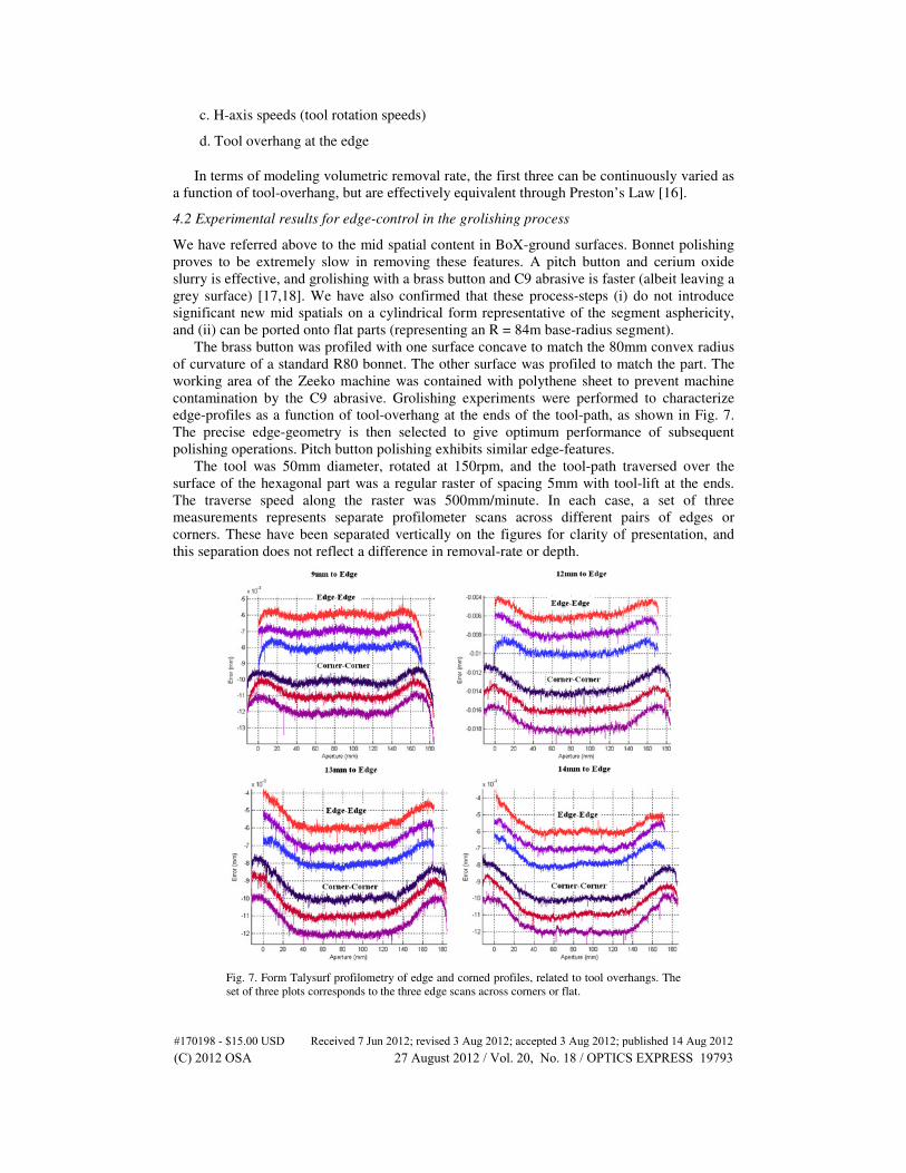
4.2 Experimental results for edge-control in the grolishing process
We have referred above to the mid spatial content in BoX-ground surfaces. Bonnet polishing
proves to be extremely slow in removing these features. A pitch button and cerium oxide
slurry is effective, and grolishing with a brass button and C9 abrasive is faster (albeit leaving a
grey surface) [17,18]. We have also confirmed that these process-steps (i) do not introduce
significant new mid spatials on a cylindrical form representative of the segment asphericity,
and (ii) can be ported onto flat parts (representing an R = 84m base-radius segment).
The brass button was profiled with one surface concave to match the 80mm convex radius
of curvature of a standard R80 bonnet. The other surface was profiled to match the part. The
working area of the Zeeko machine was contained with polythene sheet to prevent machine
contamination by the C9 abrasive. Grolishing experiments were performed to characterize
edge-profiles as a function of tool-overhang at the ends of the tool-path, as shown in Fig. 7.
The precise edge-geometry is then selected to give optimum performance of subsequent
polishing operations. Pitch button polishing exhibits similar edge-features.
The tool was 50mm diameter, rotated at 150rpm, and the tool-path traversed over the
surface of the hexagonal part was a regular raster of spacing 5mm with tool-lift at the ends.
The traverse speed along the raster was 500mm/minute. In each case, a set of three
measurements represents separate profilometer scans across different pairs of edges or
corners. These have been separated vertically on the figures for clarity of presentation, and
this separation does not reflect a difference in removal-rate or depth.
Fig. 7. Form Talysurf profilometry of edge and corned profiles, related to tool overhangs. The
set of three plots corresponds to the three edge scans across corners or flat.
#170198 - $15.00 USD Received 7 Jun 2012; revised 3 Aug 2012; accepted 3 Aug 2012; published 14 Aug 2012(C) 2012 OSA 27 August 2012 / Vol. 20, No. 18 / OPTICS EXPRESS 19793

5. The challenge of edges—bonnet polishing
5.1 The philosophy of practical edge control
The Zeeko Precessions process in its standard form utilizes compliant bonnets, covered with
polishing cloth, spun about their axis, precessed about the local normal to the surface, and
operated in the presence of re-circulated cerium oxide slurry. High removal rates suitable for
segment fabrication result from the high surface-speed and applied pressure [19].
A compliant bonnet pressed against a surface acts differently from a rigid tool,
specifically:-
a. Changing the Z-offset modifies the size of the polishing spot (influence function)
b. The precess angle changes the direction of the local speed vector
c. The influence function is pseudo-Gaussian, rather than M-shaped with a central zero
d. Bonnet deformation around the extreme edge of the segment, as mentioned above
The ability to reduce the spot-size along the tool-path, by decreasing the Z-offset (lifting
the bonnet) has proved particularly useful for edge control [20, 21]. Once the leading edge of
the full-size spot encounters the edge of the part, the spot-size is controlled, by optimizing the
trajectory of the bonnet. By this means, the spot’s leading edge can remain registered with the
segment-edge, avoiding any overhang. This is shown schematically in Fig. 8, where a raster
tool-path proceeds towards the segment-edge (dashed). The raster then turns around in air (not
shown).
Fig. 8. Polishing spot encountering an edge with tool-lift enabled.
The reduced removal in the edge-zone can be compensated by increasing dwell-times
(reducing traverse speed), or increasing H-axis speed. Even so, the removal at the precise edge
remains exactly zero. This can be mitigated by allowing the spots to overlap the edge slightly,
within a range constrained by the onset of the bonnet molding around the extreme edge and
turning it down. Note that the edge-overhang can be varied independently for each spot-size.
Based on the above, the overall strategy we have developed is as follows. The largest
bonnets/spots available are first used for fast pre-polishing. The tool-lift parameters are
defined to give an edge-zone meeting the following criteria:-
• never dipping below the extrapolated bulk-form
• of minimum height (microns), but with a contingency for any process-variability
• of width sufficient to give benign slopes, always within the measurement-range of the
full-aperture interferometric test
#170198 - $15.00 USD Received 7 Jun 2012; revised 3 Aug 2012; accepted 3 Aug 2012; published 14 Aug 2012(C) 2012 OSA 27 August 2012 / Vol. 20, No. 18 / OPTICS EXPRESS 19794
The last criterion has required a careful analysis of the interferometric configuration for
measuring a full-size segment, including the lateral sampling of the interferometer used in that
application. The test of witness parts is configured to approximate this condition.
The form-corrective process then proceeds through smaller bonnets delivering a range of
smaller spots, which gives capability progressively to control the edge profiles.
During measurement, fiducial shadow-masks are temporarily attached to the optical
surface to identify the true edge (start of bevel), and are imaged through the interferometer.
By this means, loss of data due to an unexpected sharp down-turn can be correctly identified.
On witness parts, this is further confirmed by scanning the part with an Extended Range Form
Talysurf stylus profilometer. To provide a datum for absolute measurement of removal-depth
throughout processing, witness parts are marked with a linear scratch at the approximate
center. The scratch-depths are measured across the scratches with the Form Talysurf.
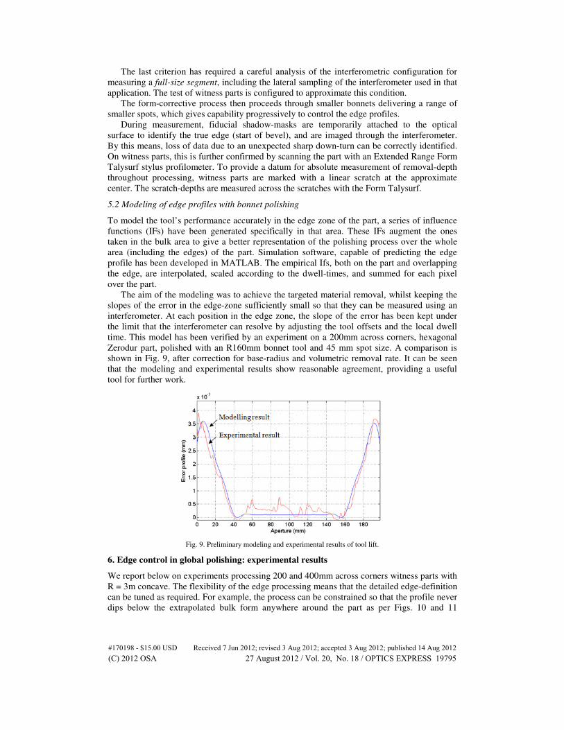
5.2 Modeling of edge profiles with bonnet polishing
To model the tool’s performance accurately in the edge zone of the part, a series of influence
functions (IFs) have been generated specifically in that area. These IFs augment the ones
taken in the bulk area to give a better representation of the polishing process over the whole
area (including the edges) of the part. Simulation software, capable of predicting the edge
profile has been developed in MATLAB. The empirical Ifs, both on the part and overlapping
the edge, are interpolated, scaled according to the dwell-times, and summed for each pixel
over the part.
The aim of the modeling was to achieve the targeted material removal, whilst keeping the
slopes of the error in the edge-zone sufficiently small so that they can be measured using an
interferometer. At each position in the edge zone, the slope of the error has been kept under
the limit that the interferometer can resolve by adjusting the tool offsets and the local dwell
time. This model has been verified by an experiment on a 200mm across corners, hexagonal
Zerodur part, polished with an R160mm bonnet tool and 45 mm spot size. A comparison is
shown in Fig. 9, after correction for base-radius and volumetric removal rate. It can be seen
that the modeling and experimental results show reasonable agreement, providing a useful
tool for further work.
Fig. 9. Preliminary modeling and experimental results of tool lift.
6. Edge control in global polishing: experimental results
We report below on experiments processing 200 and 400mm across corners witness parts with
R = 3m concave. The flexibility of the edge processing means that the detailed edge-definition
can be tuned as required. For example, the process can be constrained so that the profile never
dips below the extrapolated bulk form anywhere around the part as per Figs. 10 and 11
#170198 - $15.00 USD Received 7 Jun 2012; revised 3 Aug 2012; accepted 3 Aug 2012; published 14 Aug 2012(C) 2012 OSA 27 August 2012 / Vol. 20, No. 18 / OPTICS EXPRESS 19795

(effective for a possible local edge-rectification process-step). Alternatively, edge-misfigure
can be balanced about the neutral position as per Fig. 12. Phase maps and numerical results
are presented after allowance for the final 0.5mm of edge beveling.
6.1 200mm hexagonal part, Zerodur
Measurements of a 200mm across-corners hexagonal Zerodur witness part, R = 3m concave,
are shown in Figs. 10, 11, and 12. This part was prepared by abrasive-lapping, and it was then
bonnet pre-polished on an IRP1200 Zeeko machine. The tool was a 160mm radius-of-
curvature (‘R160’) bonnet, precessed at 15 degrees, and with Z-offset to deliver a 45mm full
spot-size. Measurements were conducted using a 4D Technologies 6000 simultaneous phase
interferometer. The part of Fig. 10 was then form-corrected using an R80 bonnet and 20mm
spot size, in order to narrow and reduce the peripheral up-stand. Results are in Fig. 11.
Fig. 10. Fringes and phase map from turned-up edges after pre-polishing with R160 bonnet and
60mm spot. The surface figure of the entire surface including edge-zone, but excluding the
0.5mm allowance for the bevel is 1084nm RMS.
Fig. 11. Fringes and phase map after correction with R80 bonnet and 20mm spot. The surface
figure of the entire surface including edge-zone, but excluding the 0.5mm allowance for the
bevel is 67nm RMS.
Finally, the entire part was treated with a 100mm diameter pitch tool, furnished with
grooves in the traditional manner, and mounted on a metal carrier, on the Zeeko machine. The
tool-path was a regular raster with 4mm spacing, the rotation-speed was 260rpm and the
traverse speed along the raster was 3000 mm/min. The operation of the tool was separately
qualified on a cylindrical asphere representative of the segment, in order to ensure that it did
not introduce any surface defects due to aspheric misfit. Results are shown in Fig. 12.
#170198 - $15.00 USD Received 7 Jun 2012; revised 3 Aug 2012; accepted 3 Aug 2012; published 14 Aug 2012(C) 2012 OSA 27 August 2012 / Vol. 20, No. 18 / OPTICS EXPRESS 19796

Fig. 12. Fringes (left), phase map (centre), and PVq (95%) edges (right), after rectification with
a pitch tool.
6.2 400mm hexagonal part, borosilicate glass
The edge control process has also been demonstrated on a 400mm hexagonal, borosilicate
glass part. In this process, an R200 bonnet was deployed, delivering a 55mm spot size. This
was used in pre-polish to achieve a higher removal rate than the previous R160 bonnet. An
R80 bonnet and 20mm spot size were then used to correct form. Finally, the entire surface
was polished by a pitch tool on the Zeeko machine. The final results are shown in Fig. 13,
where 23nm RMS was achieved for the entire surface including the edge-zone (excluding the
0.5mm margin), and edge results PVq (95%) were measured according to the protocol defined
in Section 2.
Fig. 13. Final results on the 400mm across corners part: fringes (left), phase map (center) and
PVq (95%) edges (right).
7. Conclusion and further work
In this paper we have discussed the context of edges on extremely large telescope segments,
and briefly reviewed the E-ELT edge specification. We have also drawn attention to
increasing enquiries we have received for edge-control in other industrial applications.
The paper has reviewed the physical mechanisms causing edge-misfigure in loose-
abrasive processing, and presented a preliminary modeling method which can be used to
optimize processes for specific applications. We have gone on to consider three basic
manufacturing processes in the context of edge-properties – hard tooling for (i) grolishing and
(ii) pitch-polishing (both methods to mitigate mid-spatial frequency defects from prior CNC-
grinding), and (iii) compliant bonnets for pre- and corrective polishing.
We have outlined a novel process-chain for E-ELT segments and other components that
are sensitive to edge mis-figure. All surface processing steps can be conducted after the part
has been pre-machined to the final external dimensions. In support, we have conducted
numerous trials using 200mm and 400mm witness parts, where the blank was pre-machined to
the final external dimensions, and the surface profiled leaving a grey surface. A sample of
results has been presented.
#170198 - $15.00 USD Received 7 Jun 2012; revised 3 Aug 2012; accepted 3 Aug 2012; published 14 Aug 2012(C) 2012 OSA 27 August 2012 / Vol. 20, No. 18 / OPTICS EXPRESS 19797

We have shown how pre-polishing the global surface with R160 and R200 compliant
bonnets can be configured to produce surfaces with gently-sloping peripheral up-stands and
no downturned edges, amenable to full-aperture interferometric measurement. Further results
have demonstrated how these surfaces can be corrective-polished using R80 bonnets, leaving
residual edge features that can be controlled by traditional pitch techniques on the Zeeko
machine. We have drawn attention to the flexibility of the methods in regard either to tuning
for optimum edges where residual misfigure is turned both up and down, or for tuning where
all residuals are turned-up. Overall, results are close to the ESO specification.
Future work will follow two parallel tracks. First, we plan to deploy a larger bonnet
(nominally R400) before the R200, delivering 100-110mm spot-sizes, and leaving a broader
turned-up edge-zone, again amenable both to interferometry and to controlled reduction using
the R200 process. The objective is to accelerate the pre-polish phase for the entire surface. To
support the practical use of such tooling, we should have the capability to measure the tool
influence functions on a flat witness part. This demands a sizeable land of material around the
influence function to provide a suitable datum for measurement. With this in view, we have
developed the use of swing arm profilometry for this purpose, which we have reported [22].
Second, we have started developing a new local edge rectification method as a final
process step, which is constrained to operate within the edge-zone of the part. This has two
roles. The first is to address the natural tendency of hard tools to leave corners that are slightly
higher than the edges. The second is to provide a method to correct residual edge misfigure.
In summary, the work reported has demonstrated for the first time a methodology for
manufacturing segments for extremely large telescopes, where all the optical work is
performed with the blank machined to its final dimensions. This methodology clearly has
potential in the other applications to which we have referred, and which we shall pursue in
due course.
Acknowledgments
We gratefully acknowledge financial support under an RCUK Basic Technology Translation
Grant, ‘Ultra Precision Surfaces: A New Paradigm’, through an R&D project funded under
the EPSRC Integrated Knowledge Centre in Ultra Precision and Structured Surfaces, and
through an STFC IPS grant. Particular thanks are also due to Glyndŵr University, and to the
Vice Chancellor Prof. Mike Scott, in regard to their substantial commitment and financial
support of the segment project. We also wish to thank Zeeko Ltd for assistance in many ways,
not least developing the code for edge-control in polishing. H. Li’s PhD studentship has been
sponsored by UCL and OpTIC, and W. Messelink through a UCL Impact studentship.
#170198 - $15.00 USD Received 7 Jun 2012; revised 3 Aug 2012; accepted 3 Aug 2012; published 14 Aug 2012(C) 2012 OSA 27 August 2012 / Vol. 20, No. 18 / OPTICS EXPRESS 19798
Copyright © 2022 FDOKUMEN